electric-potential-and-capacitance.pdf - Tejas Engineers ...
25
visit : www.TejasAcademy.in XII / PHYSICS ELEC. POTENTIAL & CAPACITANCE 12/PA 1 CONCEPT OF ELECTRIC POTENTIAL Electric potential is a scalar quantity, and is related to the work done. Electric potential difference between any two points in an electric field is defined as the amount of work done in bringing a charge of one coulomb between those points along any path. Electric potential difference is a scalar quantity and is denoted by V AB , where the suffix AB tells us that potential difference is between points A and B. By definition it is given by: 0 q W V AB AB 0 q W V V AB A B Where q 0 stands for a unit positive test charge. CONCEPT OF LINE INTEGRAL Consider any two points A and B in an electric field of a source charge q placed at the origin as shown in fig. Position vector of points A and B are r A and r B respectively. Small work done in bringing charge q 0 over very small displacement PQ (=dl), is given by: l d F dW . Where F is the force applied on the charge q 0 . Putting: E q F 0 Therefore. l d E q dW . 0 -------------------------------------------------------------(1) Integrating above equation gives net work done in bringing charge from A to B B A r r AB l d E q W . 0 A B O
-
Upload
khangminh22 -
Category
Documents
-
view
1 -
download
0
Transcript of electric-potential-and-capacitance.pdf - Tejas Engineers ...
visit : www.TejasAcademy.in
XII / PHYSICS ELEC. POTENTIAL & CAPACITANCE 12/PA
1
CONCEPT OF ELECTRIC POTENTIAL
Electric potential is a scalar quantity, and is related to the work done.
Electric potential difference between any two points in an electric field is defined as the amount of work done in bringing a
charge of one coulomb between those points along any path.
Electric potential difference is a scalar quantity and is denoted by VAB, where the suffix AB tells us that potential difference is
between points A and B.
By definition it is given by:
0q
WV AB
AB
0q
WVV AB
AB
Where q0 stands for a unit positive test charge.
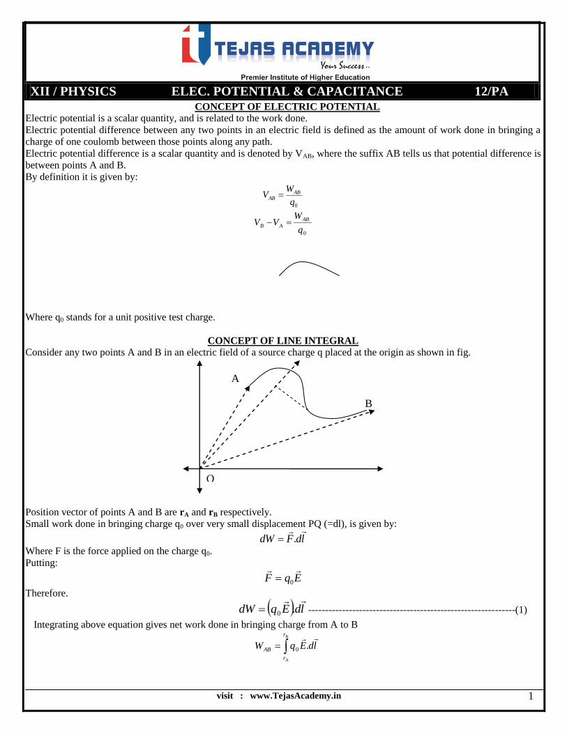
CONCEPT OF LINE INTEGRAL
Consider any two points A and B in an electric field of a source charge q placed at the origin as shown in fig.
Position vector of points A and B are rA and rB respectively.
Small work done in bringing charge q0 over very small displacement PQ (=dl), is given by:
ldFdW
.
Where F is the force applied on the charge q0.
Putting:
EqF
0
Therefore.
ldEqdW
.0 -------------------------------------------------------------(1)
Integrating above equation gives net work done in bringing charge from A to B
B
A
r
r
AB ldEqW
.0
A
B
O
visit : www.TejasAcademy.in
XII / PHYSICS ELEC. POTENTIAL & CAPACITANCE 12/PA
2
B
A
r
r
AB ldEq
W .
0
--------------------------------------------------------(2)
RHS of above equation is called line integral of electric field.
Angle between E and dl is θ, therefore
B
A
r
r
AB Edlq
Wcos
0
-----------------------------------------------------------(3)
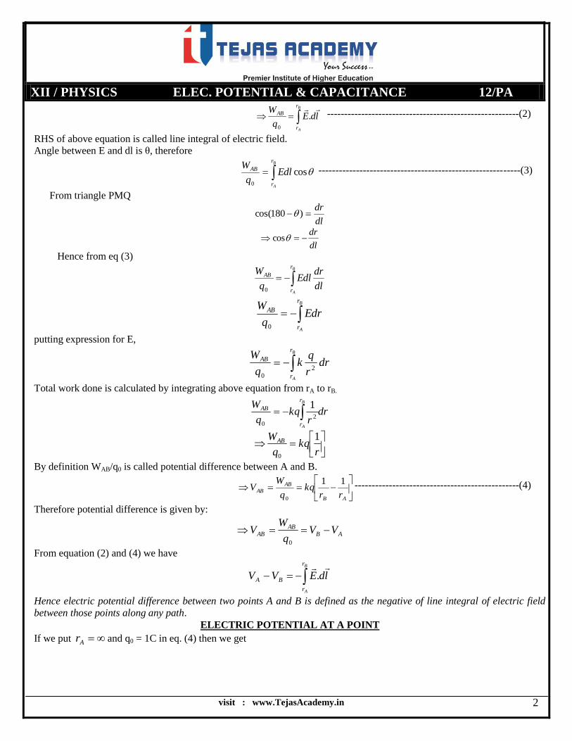
From triangle PMQ
dl
dr )180cos(
dl
dr cos
Hence from eq (3)
B
A
r
r
AB
dl
drEdl
q
W
0
B
A
r
r
AB Edrq
W
0
putting expression for E,
B
A
r
r
AB drr
qk
q
W2
0
Total work done is calculated by integrating above equation from rA to rB.
drr
kqq
W B
A
r
r
AB
2
0
1
rkq
q
WAB 1
0
By definition WAB/q0 is called potential difference between A and B.
AB
AB
ABrr
kqq
WV
11
0
------------------------------------------------(4)
Therefore potential difference is given by:
ABAB
AB VVq
WV
0
From equation (2) and (4) we have
B
A
r
r
BA ldEVV
.
Hence electric potential difference between two points A and B is defined as the negative of line integral of electric field
between those points along any path.
ELECTRIC POTENTIAL AT A POINT
If we put Ar and q0 = 1C in eq. (4) then we get
visit : www.TejasAcademy.in
XII / PHYSICS ELEC. POTENTIAL & CAPACITANCE 12/PA
3
B
BB
B
B Vr
qk
r
qk
WV
01
[Electric potential of point B]
Therefore electric potential of a point is defined as the amount of work done in bringing a charge of 1 coulomb from to
that point.
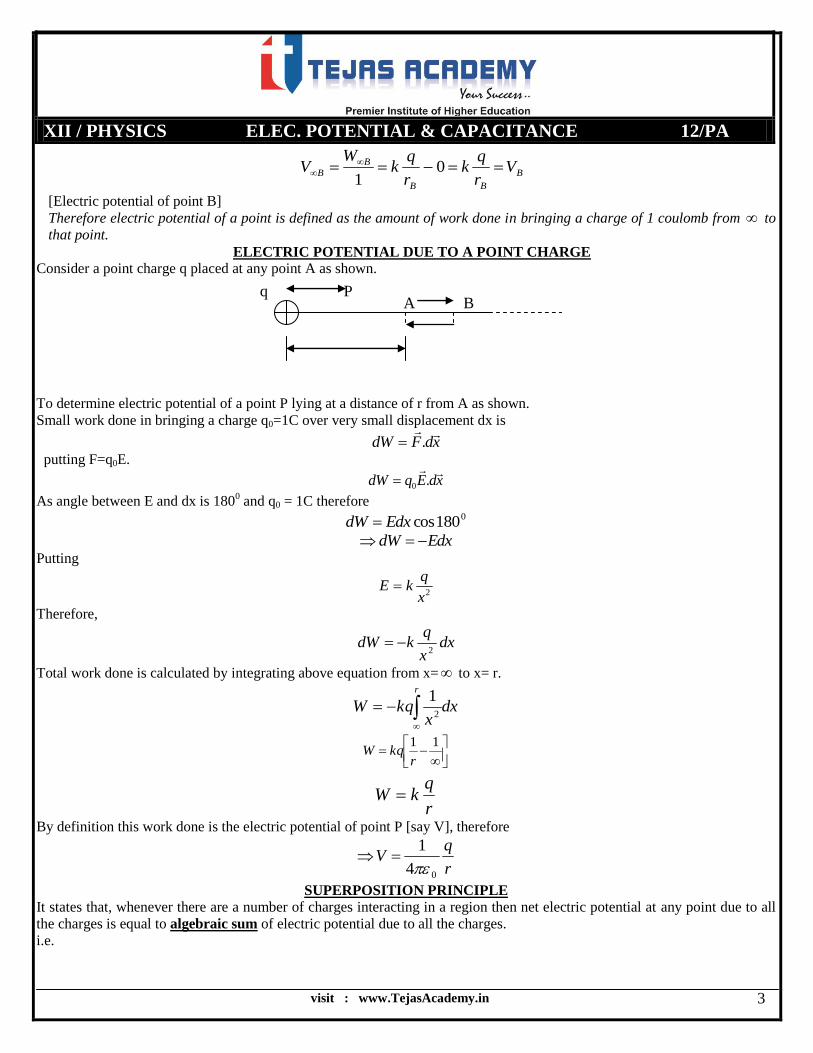
ELECTRIC POTENTIAL DUE TO A POINT CHARGE
Consider a point charge q placed at any point A as shown.
To determine electric potential of a point P lying at a distance of r from A as shown.
Small work done in bringing a charge q0=1C over very small displacement dx is
xdFdW
.
putting F=q0E.
xdEqdW
.0
As angle between E and dx is 1800 and q0 = 1C therefore
0180cosEdxdW
EdxdW
Putting
2x
qkE
Therefore,
dxx
qkdW
2
Total work done is calculated by integrating above equation from x= to x= r.
dxx
kqW
r
2
1
11
rkqW
r
qkW
By definition this work done is the electric potential of point P [say V], therefore
r
qV
04
1
SUPERPOSITION PRINCIPLE
It states that, whenever there are a number of charges interacting in a region then net electric potential at any point due to all
the charges is equal to algebraic sum of electric potential due to all the charges.
i.e.
q P A B

visit : www.TejasAcademy.in
XII / PHYSICS ELEC. POTENTIAL & CAPACITANCE 12/PA
4
V = V1+V2+V3+----------
i.e.
2
2
1
1
r
q
r
qkV
thus
n
i i
i
r
qkV
1
POTENTIAL DUE TO AN ELECTRIC DIPOLE
Consider an electric dipole consisting of charges +q and –q separated by very small distance 2l.
To determine net electric potential at any point P, lying at a distance r from the centre of dipole as shown.
Produce OP and draw AN and BN perpendicular to OP produced as shown.
In right ANO
OA
ONcos
coslON
Similarly from right ΔBNO
coslMO
So from diagram we may write
coscos lrrlOPMOMP ----------------------------------------------(1)
In similar manner we have:
coslrONOPNP ---------------------------------------------------(2)
Suppose VA and VB are the respective electric potential produced by +q charge at A and –q charge at B.
Net electric potential at P will be:
BA VVV
Using formula of electric potential as r
qkV
)(
)(
)( BP
qk
AP
qkV
As electric dipole is very small so we have
NPAP and MPBP
A B O
P
r
visit : www.TejasAcademy.in
XII / PHYSICS ELEC. POTENTIAL & CAPACITANCE 12/PA
5
So )()( MP
qk
NP
qkV
using equations (1) and (2)
)cos(
1
)cos(
1
lrlrkqV
)cos)(cos(
)cos()cos(
lrlr
lrlrkqV
)cos)(cos(
cos2
lrlr
lkqV
)cos(
cos2222
lr
lkqV
)cos(
cos)2(222
lr
lqkV
)cos(
cos222
lr
pkV
Where p is electric dipole moment of dipole.
)cos(
cos
4
1222
0
lr
pV
CASE-1
If point P lies on the equatorial line of dipole on that case, θ = 900. And we have
)90cos(
90cos
4
10222
0
0 lr
pV
As cos900 = 0, so
V = 0
Net electric potential at any point on equatorial line of dipole is always zero, so a vertical plane passing through equatorial
line of dipole is an equipotential surface of dipole.
CASE-2
If point P lies on axial line of dipole then,
θ = 00.
In such case:

visit : www.TejasAcademy.in
XII / PHYSICS ELEC. POTENTIAL & CAPACITANCE 12/PA
6
)0cos(
0cos
4
10222
0
0 lr
pV
)(4
122
0 lr
pV
So electric potential at any point of axial line of dipole varies inversely as square of distance of point from centre of
dipole.
ELECTRIC POTENTIAL GRADIENT
Consider two points A and B in the electric field E due to a Point charge q placed at O. We assume that points A and B are so
close to each other that electric field intensity between A and B is uniform.
Small amount of work done in bringing charge q0 over very small displacement dr is given by:
rdFdW
.
Now putting EqF
.0 , we get
rdEqdW
.0
As angle between E and dr is 1800, thus
0
0 180cosEdrqdW
EdrqdW 0
Edrq
dW
0
As 0q
dWis potential difference [say dV], thus
EdrdV
Hence electric potential gradient
Edr
dV
Thus electric potential gradient is the negative of electric field intensity.
ELECTROSTATIC FORCES ARE CONSERVATIVE
Considering two points A and B, lying in the electric field. Suppose VA is the electric potential at A and VB is the electric
potential at B.
Work done in bringing charge q1 from A to B:
ABAB VVqW 0 ---------------------------------------------------------(1)
q A B
A B
visit : www.TejasAcademy.in
XII / PHYSICS ELEC. POTENTIAL & CAPACITANCE 12/PA
7
Work done in bringing back q0 from B to A:
BABA VVqW 0 ---------------------------------------------------------(2)
Net work done by electrostatic forces over round loop is:
000 BAABBAAB VVqVVqWW
This shows that electrostatic forces are conservative, as work done in round loop is zero.
EQUIPOTENTIAL SURFACES
An equipotential surface is that at every point of which electric potential is same.
Properties of equipotential surfaces:
1.No work is done in bringing a charge from one point to the other on an equipotential surface
Proof:
Consider an equipotential surface at which there are two points A and B with electric potential VA and VB.
Now work done in bringing a charge q0 from A to B is given by:
ABAB VVqW 0
Now on an equipotential surface electric potential of each point is same, so VA=VB.
Thus
0ABW
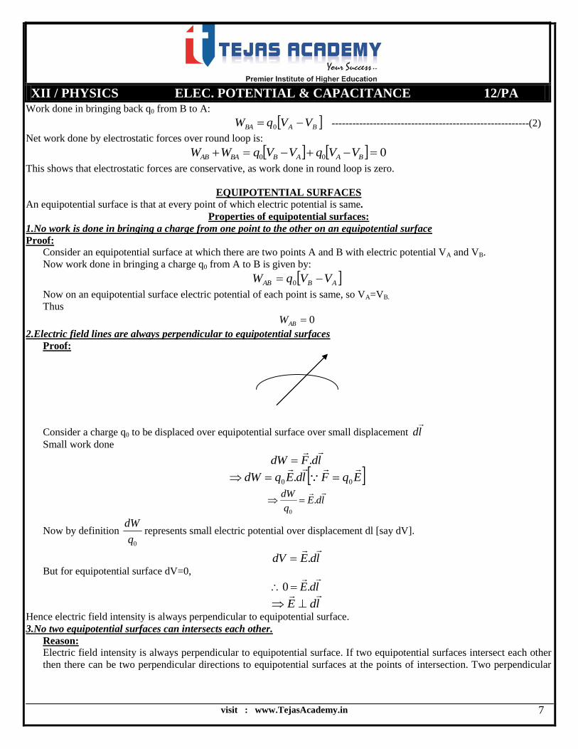
2.Electric field lines are always perpendicular to equipotential surfaces
Proof:
Consider a charge q0 to be displaced over equipotential surface over small displacement ld
Small work done
ldFdW
.
EqFldEqdW
00 .
ldEq
dW .
0
Now by definition 0q
dWrepresents small electric potential over displacement dl [say dV].
ldEdV
.
But for equipotential surface dV=0,
ldE
.0
ldE
Hence electric field intensity is always perpendicular to equipotential surface.
3.No two equipotential surfaces can intersects each other.
Reason:
Electric field intensity is always perpendicular to equipotential surface. If two equipotential surfaces intersect each other
then there can be two perpendicular directions to equipotential surfaces at the points of intersection. Two perpendicular

visit : www.TejasAcademy.in
XII / PHYSICS ELEC. POTENTIAL & CAPACITANCE 12/PA
8
directions indicate two directions of electric field intensity. Electric field is a vector quantity and it has a unique direction
therefore it is not possible for equipotential surfaces to intersect each other.
4. Equipotential surfaces indicate regions of strong or weak electric fields
Explanation:
We know that
dr
dVE
E
dVdr
Since dV is constant on the equipotential surface, so
Edr
1
If ‘E’ is strong, ‘dr’ will be small i.e. the separation of equipotential surfaces will be smaller.
Thus equipotential surfaces are closer in the region of strong electric field.
ELECTROSTATIC POTENTIAL ENERGY
Electrostatic potential energy of a system of point charges is defined as the total work done in bringing them to their
respective locations from infinity.
(a) Potential energy of a system of two point charges
Consider a system of two point charges q1 and q2 lying at a distance r from each other as shown.
no work is done in bringing charge q1 from infinity to point A, thus:
01 W ----------------------------------------------------------------(1)
Now we have to carry out charge q2 from infinity to point B, total work done will be:
VVqW B22
Electric potential at infinity is 0
Therefore,
0
4
1 1
0
22r
qqW
r
qqW 21
0
24
1
---------------------------------------------------------(2)
By definition, electric potential energy is net work done in bringing charges from infinity, thus
r
qqWWU 21
0
214
1
q1 q2

visit : www.TejasAcademy.in
XII / PHYSICS ELEC. POTENTIAL & CAPACITANCE 12/PA
9
(b) Potential energy of a system of three point charges. Consider three point charges q1, q2 and q3 such that distance between q1 and q2 is r12, distance between q2 and q3 is r23 and
distance between q1 and q3 is r13.
Suppose initially q2 and q3 are placed at very large distance from q1.
No work is done in bringing q1 from infinity to A.
01 W -----------------------------------------------------------------(1)
Work done in bringing charge q2 from infinity to point P.
VVqW B22
electric potential of infinity is zero.
0
4
1
12
1
0
22r
qqW
----------------------------------------------(2)
Now work done in bringing charge q3 from infinity to point R
VVqW C33
There are two types of electric potential at C, produced by charge q1 and q2.
0
23
2
13
133
r
qk
r
qkqW ----- -----------------------------------------(3)
By definition total work done in bringing all the charges to their respective locations is electric potential energy:
321 WWWU
using (1), (2) and (3)
31
13
23
32
12
21
r
r
r
qqkU
(c) Potential energy of a system of n point charges: Consider a system of n point charges q1, q2, --- and so on. Let they are separated by distances of r12, r23 and so on.
Then electric potential energy of n charge system will be of the form
31
13
23
32
12
21
r
r
r
qqkU
CONDUCTORS
The substances which allow the flow of electric charge through them are called conductor. A conductor has large number of
free electrons.
q1
q2 q3
visit : www.TejasAcademy.in
XII / PHYSICS ELEC. POTENTIAL & CAPACITANCE 12/PA
10
These electrons are free to move under the effect of external applied electric field.
BEHAVIOUR OF CONDUCTOR IN EXTERNAL ELECTRIC FIELD
1. Net electric field intensity in the interior of a conductor is always zero.
A conductor consists of large number of electrons. When it is placed in external electric field, opposite charges get
induced on opposite faces of conductor as shown. An internal electric field exists in the interior of conductor which is
opposite direction to external applied electric field. Conductor has infinite no. of free electrons, thus charges induced on
opposite faces of conductor get accumulated till internal electric field just balances external electric field. So, net electric
field in the interior of conductor is always zero.
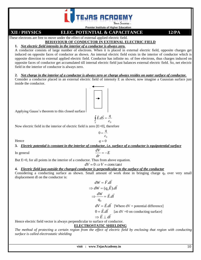
2. Net charge in the interior of a conductor is always zero or charge always resides on outer surface of conductor.
Consider a conductor placed in an external electric field of intensity E as shown; now imagine a Gaussian surface just
inside the conductor.
Applying Gauss’s theorem to this closed surface
0
.
qSdE
S
Now electric field in the interior of electric field is zero [E=0], therefore
0
0
q
Hence 0q
3. Electric potential is constant in the interior of conductor, i.e. surface of a conductor is equipotential surface
In general Edr
dV
But E=0, for all points in the interior of a conductor. Thus from above equation.
tconsVdV tan0
4. Electric field just outside the charged conductor is perpendicular to the surface of the conductor
Considering a conducting surface as shown. Small amount of work done in bringing charge q0 over very small
displacement dl on the conductor is:
ldFdW
.
ldEqdW
).( 0
ldEq
dW .
0
ldEdV
. [Where dV = potential difference]
ldE
.0 [as dV =0 on conducting surface]
ldE
Hence electric field vector is always perpendicular to surface of conductor.
ELECTROSTATIC SHIELDING
The method of protecting a certain region from the effect of electric field by enclosing that region with conducting
surface is called electrostatic shielding
visit : www.TejasAcademy.in
XII / PHYSICS ELEC. POTENTIAL & CAPACITANCE 12/PA
11
Sensitive instruments and appliances are affected seriously with strong external electrostatic fields. To protect them from
harmful effects of electric field, we enclose them with conductor, i.e. electrostatic shielding.
DIELECTRICS AND POLARISATION
A substance which does not have any free electrons and therefore cannot conduct electricity is known as the dielectric.
whenever a dielectric substance is placed in an external electric field its molecules get polarized. Polarization means that,
equal and opposite charges get induced on its opposite surfaces as shown below.
CAPACITANCE
The measure of ability of a conductor to hold electric charge on it is called its capacitance.
When we provide some charge to a conductor, it is raised to some electric potential, thus charge given to a conductor is
directly proportional to its electric potential.
Vq
CVq
Where C is a constant of proportionality for a given conductor and is know as capacitance or capacity of that conductor
Definition of capacitance: We have
V
qC
Thus capacitance of a conductor is defined as the ratio of charge given to the conductor to its electric potential due to that
charge.
Units of capacitance: In SI the unit of capacitance if Farad [F]
We have
V
qC ,
putting q=1C, and V=1 volt
FV
CC 1
1
1
Thus capacitance of a body is said to be one farad if its electric potential rises to one volt by giving it a charge of one
coulomb.
CAPACITANCE OF A SPHERICAL BODY
Consider a spherical body of radius R, to which a charge of Q is given.
Its electric potential is given by
R
QV
04
1
Electric capacitance of the body is given by:
V
QC
R
Q
QC
04
1
RC 04
Note: capacitance of conductor depends upon two parameters, size of body and the nature of material of body.
Capacitance of earth: Consider earth to be a spherical body or radius R=6.4×10⁶m
visit : www.TejasAcademy.in
XII / PHYSICS ELEC. POTENTIAL & CAPACITANCE 12/PA
12
its capacitance is given by C=6
9104.6
109
1
=711µF.
Thus capacitance of even earth is in micro farad. Hence farad is too big unit of capacitance.
CAPACITOR
A capacitor is a device which is used to store large amount of electric charge.
PRINCIPLE OF CAPACITOR
It states that the capacitance of a conductor can be increased gradually by bringing near it an uncharged earthed conductor.
Whenever uncharged earthed conductor is placed near charged conductor, there exists opposite charge on earthed conductor,
due to which electric potential on charged body is decreased.
As we know that
V
qC ,
i.e. V
C1
, thus decrease in V causes C to increase.
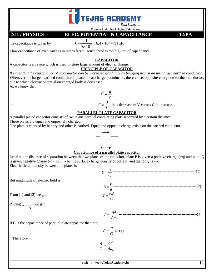
PARALLEL PLATE CAPACITOR
A parallel plated capacitor consists of two plane parallel conducting plats separated by a certain distance.
These plates are equal and oppositely charged.
One plate is charged by battery and other is earthed. Equal and opposite charge exists on the earthed conductor.
Capacitance of a parallel plate capacitor
Let d be the distance of separation between the two plates of the capacitor, plate P is given a positive charge (+q) and plate Q
is given negative charge (-q). Let +σ be the surface charge density of plate P, and that of Q is –σ.
Electric field intensity between the plates is
0
E -----------------------------------------------------------------(1)
But magnitude of electric field is
d
VE -----------------------------------------------------------------(2)
From (1) and (2) we get
0
.
dV
Putting A
q , we get
0A
qdV -------------------------------------------------------------(3)
If C is the capacitance of parallel plate capacitor then put
C
qV in (3)
Therefore
0A
qd
C
q
visit : www.TejasAcademy.in
XII / PHYSICS ELEC. POTENTIAL & CAPACITANCE 12/PA
13
Hence
d
AC 0 --------------------------------------------------------------(4)
Special case:
If the medium between the plates is filled with some dielectric of constant k, then the permittivity of medium will be
0 km
Now new capacitance of capacitor with medium between the plates
d
AC m'
Thus d
AkC 0'
----------------------------------------------------------------(5)
Comparing (4) and (5) we have
kCC '
or C
Ck
'
Defn of Dielectric constant: Dielectric constant of a medium is defined as the ratio of capacitance of a parallel plate
capacitor having that medium between the plates to the capacitance of same capacitor having air as a medium.
GROUPING OF CAPACITORS
Capacitors can be grouped in two ways. (i) in series and (ii) in parallel.
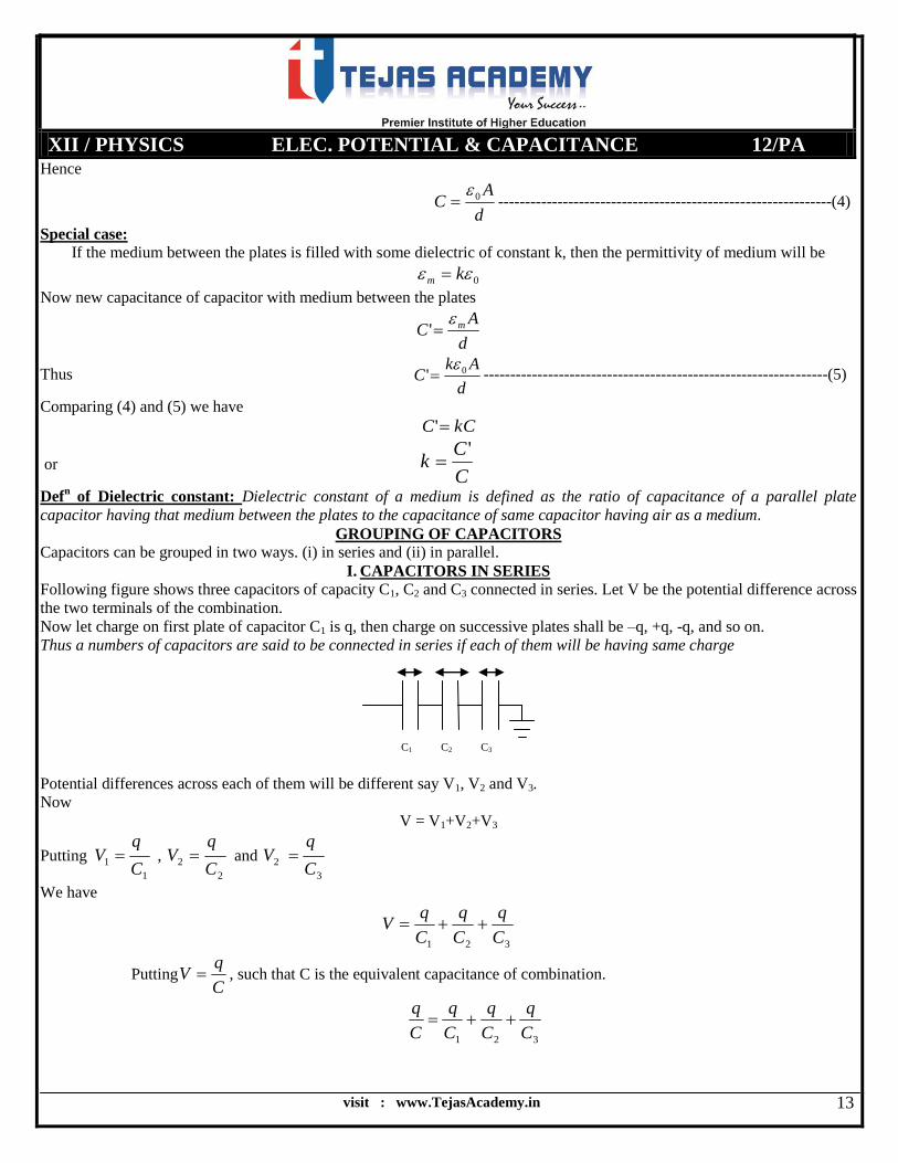
I. CAPACITORS IN SERIES
Following figure shows three capacitors of capacity C1, C2 and C3 connected in series. Let V be the potential difference across
the two terminals of the combination.
Now let charge on first plate of capacitor C1 is q, then charge on successive plates shall be –q, +q, -q, and so on.
Thus a numbers of capacitors are said to be connected in series if each of them will be having same charge
Potential differences across each of them will be different say V1, V2 and V3.
Now
V = V1+V2+V3
Putting 1
1C
qV ,
2
2C
qV and
3
2C
qV
We have
321 C
q
C
q
C
qV
PuttingC
qV , such that C is the equivalent capacitance of combination.
321 C
q
C
q
C
q
C
q
C1 C2 C3
visit : www.TejasAcademy.in
XII / PHYSICS ELEC. POTENTIAL & CAPACITANCE 12/PA
14
321
1111
CCCC
If there are n capacitor in series then we will be having
nCCCCC
11111
321
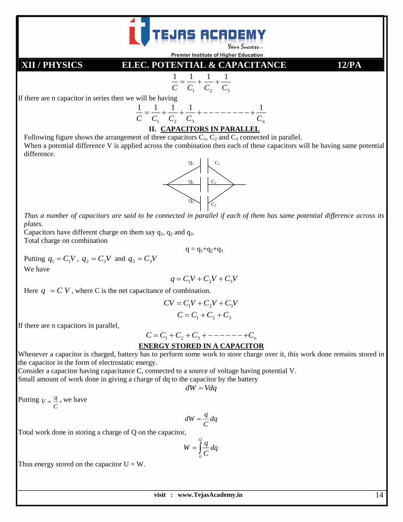
II. CAPACITORS IN PARALLEL
Following figure shows the arrangement of three capacitors C1, C2 and C3 connected in parallel.
When a potential difference V is applied across the combination then each of these capacitors will be having same potential
difference.
Thus a number of capacitors are said to be connected in parallel if each of them has same potential difference across its
plates.
Capacitors have different charge on them say q1, q2 and q3.
Total charge on combination
q = q1+q2+q3
Putting VCq 11 , VCq 22 and VCq 33
We have
VCVCVCq 321
Here VCq , where C is the net capacitance of combination.
VCVCVCCV 321
321 CCCC
If there are n capacitors in parallel,
nCCCCC 321
ENERGY STORED IN A CAPACITOR
Whenever a capacitor is charged, battery has to perform some work to store charge over it, this work done remains stored in
the capacitor in the form of electrostatic energy.
Consider a capacitor having capacitance C, connected to a source of voltage having potential V.
Small amount of work done in giving a charge of dq to the capacitor by the battery
VdqdW
Putting C
qV , we have
dqC
qdW
Total work done in storing a charge of Q on the capacitor,
Q
dqC
qW
0
Thus energy stored on the capacitor U = W.
C1
C2
C3
Q1
Q2
Q3
visit : www.TejasAcademy.in
XII / PHYSICS ELEC. POTENTIAL & CAPACITANCE 12/PA
15
Q
qdqC
U0
1
2
1 2Q
CU
C
QU
2
2
Putting Q=CV,
2
2
1CVU
Or putting C=Q/V
QVU2
1
ENERGY DENSITY STORED IN CAPACITOR
Energy density is defined as the amount of energy stored per unit volume.
Thus energy density u Volume
Energy
Ad
CV
u
2
2
1
As V=Ed,
d
AC 0 ,
Ad
Edd
A
u
20
2
1
2
22
0
2Ad
dEu
Hence
2
02
1Eu
COMMON POTENTIAL
Whenever two charged conductors are connected to each other with the help of wires, the flow of charge takes place from one
conductor at higher potential to the other at lower potential till both acquires the same potential. This potential is referred to
as the common potential.
Consider two conductors having initial charges Q1 and Q2, and potentials V1 and V2 respectively. After sharing of charges
their potential becomes V and charges on them are Q1’ and Q2’.
Since charge is conserved:
Q1 + Q2 = Q1’ +Q2’
VCVCVCVC 21221
where V is the common potential.

visit : www.TejasAcademy.in
XII / PHYSICS ELEC. POTENTIAL & CAPACITANCE 12/PA
16
21
2211
CC
VCVCV
LOSS OF ENERGY ON SHARING CHARGES
Considering two conductors having capacitances C1 and C2 charged to electric potentials V1 and V2. When both of them are
connected with the help of conducting wires, they share electric charges and their final potential is V [common potential].
Total loss of energy on sharing charges is the difference of total initial energy and final energy:
U = [Total initial energy] – [Total final energy]
2
2
2
1
2
22
2
112
1
2
1
2
1
2
1VCVCVCVCU
2
21
2
22
2
11 )(2
1VCCVCVCU
Putting for common potential
2
21
221121
2
22
2
11 )(2
1
CC
VCVCCCVCVCU
)(
)(
2
1
21
2
22112
22
2
11CC
VCVCVCVCU
21
2121
2
2
2
2
2
1
2
1
2
221
2
2
2
2
2
121
2
1
2
1 2
2
1
CC
VVCCVCVCVCCVCVCCVCU
)(2
)(
21
2
2121
CC
VVCCU
This is an expression of energy loss on sharing charges.
CAPACITANCE OF A PARALLEL PLATE CAPACITOR WITH CONDUCTING SLAB IN BETWEEN THE
PLATES
Consider a parallel plate capacitor with a conducting slab of thickness t in between the plates as shown. Suppose C0=
capacitance of capacitor with no slab, σ= surface charge density on each plate, V=potential difference between the plates.
As there is no electric field in between the plates of capacitor thus, electric field exists only in thickness d-t.
Hence
)( tdEV
As
0
E ,
visit : www.TejasAcademy.in
XII / PHYSICS ELEC. POTENTIAL & CAPACITANCE 12/PA
17
)(0
tdV
As C
QV and
A
Q
)(0
tdA
Q
C
Q
)(
0
td
AC
-------------------------------------------------------------(1)
Capacitance without conducting slab
d
AC 0
0
-----------------------------------------------------------------(2)
Comparing (1) and (2) we find that C>C0, thus, capacitance increases on introducing a conducting slab between the plates
of capacitor.
Special Case: Assuming the slab is introduced such that d = t, i.e. entire region is filled with conductor, then.
Cdd
AC 0
Hence capacitance of capacitor becomes infinite on filling entire region of a capacitor with conductor.
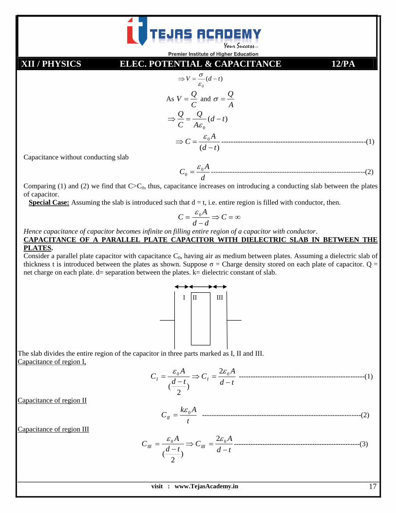
CAPACITANCE OF A PARALLEL PLATE CAPACITOR WITH DIELECTRIC SLAB IN BETWEEN THE
PLATES.
Consider a parallel plate capacitor with capacitance C0, having air as medium between plates. Assuming a dielectric slab of
thickness t is introduced between the plates as shown. Suppose σ = Charge density stored on each plate of capacitor. Q =
net charge on each plate. d= separation between the plates. k= dielectric constant of slab.
The slab divides the entire region of the capacitor in three parts marked as I, II and III.
Capacitance of region I,
td
AC
td
AC II
00 2
)2
(
-----------------------------------------------------(1)
Capacitance of region II
t
AkCII
0 -------------------------------------------------------------------(2)
Capacitance of region III
td
AC
td
AC IIIIII
00 2
)2
(
-----------------------------------------------------(3)
I II III

visit : www.TejasAcademy.in
XII / PHYSICS ELEC. POTENTIAL & CAPACITANCE 12/PA
18
Now capacitor CI, CII, and CIII are in series thus net capacitance is given by:
IIIIII CCCC
1111
using (1), (2) and (3) we get.
)2
(
1
)(
1
)2
(
11
000
td
A
t
Ak
td
AC
Ak
t
A
td
C 00
1
Finally
k
ttd
AC 0
11
ktd
AC
11
11
0
ktd
AC
11
0
Note: The capacitance of parallel plate capacitor increases on introducing a dielectric slab as, C>C0.
VAN DE GRAFF’S ELECTROSTATIC GENERATOR A van de Graff’s electrostatic generator is a device which is used to store a large amount of electric charge on a conductor.
Due to this large amount of charge a huge potential difference is created and charge particles are accelerated. Thus its major
use is to accelerate charge particles. Van de Graff’s generator is used as a particle accelerator.
Principle:
The working of van de Graff’s electrostatic generator is based on following two properties:
(a) The property of a conductor that charge given to it shifts immediately to its outer surface.
(b) The action of sharp points that is phenomenon of corona discharge.
Construction:
It consists of a large hollow metallic shell of radius few meters which is supported over two wooden pillars p1 and p2. There
are two metallic combs (Or brushes) B1 and B2, having some sharp points. B1 is provided near center of shell and is connected
to it via metallic contacts. Whereas B2 is provided near the bottom of generator. A rayon or nylon belt is wounded over
pulleys P1 and P2 which is kept rotating with the help of electric motor. Comb B2 is connected with a high tension battery
which provides it a potential of about 104 volts. A tube D is provided near center of the shell in which the charge particles to
be accelerated are provided.

visit : www.TejasAcademy.in
XII / PHYSICS ELEC. POTENTIAL & CAPACITANCE 12/PA
19
ASSIGNMENT
1. Illustrate a condition in which the net electric potential at a point is zero but electric field is non zero.
2. How the potential due to a dipole at any point varies with distance?
3. A charge of 10C is placed at the centre of shell. What will be the work done in bringing a charge of 1C over a
distance of 5 cm on the surface of the shell?
4. What will be the work done if a point charge q is moved on the circumference of the circle from point A to another
point B such that a point charge q is placed at the centre of the shell?
5. An uncharged conductor is brought near a charged conductor. What happens to the charge and the potential of
conductor of uncharged conductor?
6. Show that electrostatic forces are conservative in nature.
7. A charge q moves between two points with potential difference V volts what would be the potential energy acquired
by the charge?
8. Can two equipotential surfaces intersect each other? If no then why?
9. Electric field at a point is zero what about the electric potential at that point? Use this information to discuss what is
the electric potential at a point inside the charged shell?
10. What is the work done by the field of nucleus in a complete circular and elliptical orbit of the electron?
11. Show mathematically that net electric potential at any point lying on the equatorial line of an electric dipole is zero.
12. A safely sits on a bare high power transmission wire, while a man standing on the ground touches the same with bare
feet and gets a fatal shock. Why?
13. Calculate the amount of work done in bringing a charge q from the centre of a ring having charge Q on it to the centre
of an uncharged ring. Given that both the rings have same radius R.
14. Derive an expression for the net electric field intensity at any point lying on the
(i) Axial line of the electric dipole.
(ii) Equatorial line of an electric dipole

visit : www.TejasAcademy.in
XII / PHYSICS ELEC. POTENTIAL & CAPACITANCE 12/PA
20
15. A cube of side b has a charge q at each of its vertices. Determine the potential and electric field due to this charge
array at the centre of the cube. [NCERT]
------------------------NUMERICALS---------------------
16. The work done in carrying a charge of 5×10-19
C upto a point is 2.4×10⁻⁵
j. What is the electric potential at that point?
[4.8×10¹³
V]
17. A charge of 6 mC is located at the origin of a coordinate system. Find the work done in taking a small charge of -
2×10-12
C fro a point A(0,0,2) to a point B(0.3 cm,0) via a point C (0,4cm,5cm). [1.8×10⁻³
J]
18. Calculate the electric potential at the surface of a gold nucleus. Given radius of nucleus = 6.6×10⁻¹⁵
m and atomic
number of the gold is 79. [1.72×10⁷ V]
19. Electric field at a point due to a point charge is 20 NC-1
and the electric potential at that point is 10 JC-1
. Calculate the
distance of the point from the charge and e magnitude of the charge. [5.56×10⁻¹⁰
C]
20. Two charges 4×10⁻⁹
C and -3×10⁻⁹
C are located 0.1m apart. At what point on the line joining the two charges is the
electrical potential zero? Take the potential at infinity to be zero. [0.057 m]
21. Three charges 1×10⁻⁹
C , 2×10⁻⁹
C and 3×10⁻⁹
C are placed at the corners of an equilateral triangle of side 100 cm.
Calculate the potential at O point equidistant from three corners of the triangle. [93.6V]
22. If 100 J of work is done in carrying a charge of 2C from a place where the potential is -10 V to another point where
potential is V, find the value of V. [40 V]
23. Two charges of 3×10⁻⁸
C and -2×10⁻⁸
C are located 15 cm apart. At what point on the line joining the two charges the
electric potential zero? [9 cm from 3×10⁶ V]
24. A regular hexagon of side 10 cm has a charge of 10μC at each of its vertices. Calculate the potential at the centre of
the hexagon. [5.4×10⁶ V]
25. A wire is bent in a circle of radius 10 cm. It is given a charge of 200 μC which spreads uniformly. Calculate the
electric potential at the centre of the circle. [1.8×10⁷V]
26. Eight charged water droplets, each with a radius of 1 mm and a charge of 10-9
C coalesce to form a single drop.
Calculate the potential of the bigger drop. [3.6×10⁴ V]
27. 100J of work is done in carrying a charge of 2 C from a place where the potential is -10 V to another point where
potential is find the value of V. [40 V]
28. A wire is bent in a circle of radius 10, it is given a charge of 200 μC which spreads uniformly. Calculate the electric
potential at the centre of the circle. [1.8×10⁷ V]
29. ABCD is a square of side 0.2 m. Charges of 2 nC, 4nC, 8nC are placed at the corners A, B and C respectively.
Calculate the work required to transfer a charge of 2 nC from D to the centre of the square. [6.48×10⁻⁷
J]
30. Two point charges 5×10⁻⁸
C and -3×10⁻⁸
C are located 16 cm apart. At what point on the line joining the two charges is
the electric potential zero? [10cm, 40 cm away from the positive charge on the side of the negative charge.]
31. A regular hexagon having its each side equal to 10 cm has a charge of 5μC at each of its vertices. Calculate the net
electric field and net electric potential at the centre of the hexagon. [2.7×10⁶V]
32. (i) Determine the electrostatic potential energy of a system containing two charges 7 μC and -2 μC separated by a
distance o0f 18 cm.
(i) How much work is done in bringing them infinite distance apart?
33. A charge 8 mC is located at the origin. Calculate the work done in taking a small charge of -2×10⁻⁹
C from a point
P(0,0,3) to a point Q(0,4,0). [1.2J]
34. Two point electric charges 4 μC , -2 μC are separated by a distance of 1m in air. At what point on the line joining the
charges is the electric potential zero [0.66mfrom 4]
35. Sixty four drops each of radius 2 cm and carrying 5C of charge combine to form a bigger drop. Find its potential.
[3.6×10¹³
V]
ELECTRIC POTENTIAL ENERGY
36. Two protons in a nucleus are 3.0×10⁻¹⁵
m apart. What is their mutual electric potential energy? [7.68×10⁻¹⁴
J]
37. In an atom two protons are separated by a distance of 3×10⁻¹⁰
m and an electron is at a distance of 1.5×10⁻¹⁰
m from
each proton. Calculate the potential energy of this system. [-7.68×10⁻¹⁹
J]
visit : www.TejasAcademy.in
XII / PHYSICS ELEC. POTENTIAL & CAPACITANCE 12/PA
21
38. Two positive charges of 0.2 μC and 0.01 μC are placed 10 cm apart. Calculate the work done in reducing their
distance to 5 cm. [180×10-6
J]
CAPACITANCE AND CONDUCTORS
39. What are the forms on energies into which the electrical energy of the atmosphere is dissipated during a lightning?
[NCERT]
40. What happens to the capacity of a capacitor when a dielectric is placed between its plates?
41. Write the physical quantity having units’ coulomb/volt. Is it a vector or a scalar quantity?
42. The plates of a charged capacitor are connected to voltmeter. If the plates of the capacitor are separated further, what
will be the effect on the reading of the voltmeter?
43. What is the effect of temperature on the dielectric constant of a medium?
44. How dielectric constant of a medium can be expressed in terms of the capacitance of the medium?
45. How will you obtain maximum capacitance by combining three capacitors?
46. Three capacitors of capacitance 3, 4, 5 µF are in series. What is the ratio of charges on them? [1:1:1]
47. If N capacitors each of capacitance C are in series. What is the effective capacitance of the combination?
48. If N capacitors are in parallel then what is the net capacitance of the combination?
49. What happens to the capacitance of a parallel plate capacitor when the distance between its plates is reduced?
50. The potential of a capacitor is doubled. How does its energy change?
51. A voltmeter is connected between the plates of a charged capacitor. When a dielectric slab is placed between the
plates of the capacitor what happens to the voltmeter reading?
52. If the area of one plate of a parallel plate capacitor is doubled and that of the other is reduced to half, what happens to
its capacity?
53. What is the effect of the potential difference of plates on the capacity of a parallel plate capacitor?
54. When a conductor is placed near an uncharged earthed conductor what happens to its charge, potential, and
capacitance?
55. What is the capacitance of a conductor having 1 C charge and whose potential is 1 volt? [1F]
56. A 12pF capacitor is connected to a 50 V battery. How much electrostatic energy is stored in the capacitor? [1.5×10⁻⁸
J]
57. Why Van de Graff generator is enclosed in a steel tank filled with air?
58. Three capacitors of equal capacitances were connected in series have net capacitance C1 and when connected in
parallel have net capacitance C2. What is the value of C1/C2 ? [1/9]
59. What is the function of the second plate in the parallel plate capacitor?
60. Two rectangular metal plates each of area A are kept parallel to each other at a distance of d apart to form a parallel
plate capacitor. If the area of each of the plates is doubled and their separation is decreased to ½ of its initial value
calculate the ratio their capacitances in the two cases?
61. Derive an expression for the energy stored in a charged parallel plate capacitor with air as the medium between its
plates.
62. Explain how the introduction of a dielectric slab between the plates of a capacitor changes the value of
(i) Electric field between the plates of the capacitor.
(ii) The potential difference between the plate of the capacitor.
(iii) Capacitance of the capacitor.
63. A sheet of Aluminium is placed exactly at the centre of the two plates of a parallel plate capacitor. What effect has it
on the capacitance if (i) the foil is electrically insulated and (ii) the foil is connected with the upper layer?
64. A parallel plate capacitor has the space between the plates filled with two slabs of dielectric constants K(1) and K(2)
each thickness d/2 where d is the plate separation. Calculate the effective capacity?
65. A parallel plate capacitor with air between the plates has a capacitance of 8 pF. What will be the capacitance if the
distance between the plates reduced by half and the space between them is filled with substance of dielectric constant
6? [NCERT] [96 pF]
66. Three capacitors of capacitances 2 pF, 3pF and 4 pF are connected in parallel.
visit : www.TejasAcademy.in
XII / PHYSICS ELEC. POTENTIAL & CAPACITANCE 12/PA
22
(a) What is the total capacitance of the combination?
(b) Determine the charge on each capacitor if the combination is connected to a100V supply? [NCERT] [9 pF, 2,3,4
×10-10
each]
67. In a parallel plate capacitor with air between the plates each late has an area of 0.006 m2 and the distance between the
plates is 3 mm. Calculate the capacitance of the capacitor. If this capacitor is connected to supply what is the charge
on each plate of the capacitor? [NCERT] [18pF, 1.8 nC]
68. A 12 pF capacitor is connected to a 50 V battery. How much electrostatic energy is stored on the capacitor?
[NCERT] ,[15 nJ]
69. A 600 pF capacitor is charged by a 200 V supply. It is then disconnected from the supply and is connected to another
uncharged 600pF capacitor. How much energy is lost in the process? [NCERT] [6 µJ]
70. Obtain the equivalent capacitance of the network in fig (1). For a 300V supply of the charge, determine the charge
and voltage across each capacitor? [NCERT] [200/3 pF]
71. The plates of a parallel plate capacitor have an area of 90 sq. cm each and are separated by 2.5mm. The capacitor is
charged by connected it to a 400 supply.
(a) How much electrostatic energy is stored by the capacitor?
(b) Give the energy density stored in the capacitor?
72. Find the equivalent capacitance of the combination shown in fig-2. Assume the values shown on the fig.
73. Find the equivalent capacitance of the combination between the terminals as shown in fig
74. Find the equivalent capacitance between A and B in the given fig-4. Take the values shown in the fig.
75. A 400pF capacitor charged by a 100 V d.c supply is disconnected from the supply and connected to another
uncharged 400pF capacitor. How much energy is lost?
76. The capacitance of a parallel plate capacitor is 200pF. If the potential difference between the plates is 100 volts, then
what is the charge on each plate? [20nC]
77. Calculate the charge on each plate of a 5×10⁻⁹
F capacitor when the potential difference between the plates is 100
volts. [0.5μC]
78. The distance between the plates of a parallel plate capacitor is 1.0 mm. What must be the area of the plate of the
capacitor if the capacitance is to be 1.0 μF? [112.9m2]
79. Calculate the equivalent capacitance of the network shown in figure between A and B.
visit : www.TejasAcademy.in
XII / PHYSICS ELEC. POTENTIAL & CAPACITANCE 12/PA
23
80. Two capacitors have a capacitance of 25μF when connected in parallel and 6 μF when connected in series. Find their
individual cpacitance. [15μF and 10μF]
81. Calculate the energy stored in a capacitor of 100 μF charged to 200 volts. [2J]
82. A capacitor is charged to a potential of 1000 volt. If the capacitance of the capacitor is 8μF, calculate the energy
stored in the capacitor. [4 J]
83. How much energy is stored in the electric field of an isolated conducting sphere of radius 6.85 cm and on which
charge is 1.25×10⁻⁹
C? [1.03×10⁻⁷
J]
84. A capacitor of 20 μF and charged to 500 V is connected in parallel with another capacitor of 10μF charged to 200 V.
Find the common potential. [400 V]
85. The capacitors shown in following fig are initially uncharged. Determine the voltage across each capacitor after
switch S is closed.
86. The charge on each capacitor is 24μC. Find the capacitance of C1 and the total energy stored in the system.
[0.192µF]
87. Calculate the equivalent capacitance between the points A and B. [15 μF]
88. What is the area of the plates of a 2 F parallel plated capacitor, given that the separation between the plates is 0.5 cm?
[1130km2]
89. Show that the force on each plate of a parallel plated capacitor has a magnitude equal to (½)QE, where Q is the chare
on the capacitor, and E is the magnitude of electric field between the plates. [NCERT]
90. What meaning would you give top the capacity of a single conductor?
91. A parallel plate capacitor is to be designed with a voltage rating 1 kV, using a material of dielectric constant 3 and
dielectric strength about 107 V/m. For safety, we should like the field never to exceed, say 10% of the dielectric
strength. What minimum area of the plates is required to have a capacitance of 50 pF? [E=10% of 107 and d=V/E,
then use formula for C] [NCERT]
92. Describe schematically the equipotential surfaces corresponding to
(a) A constant electric field in the z- direction,
(b) A field that uniformly increases in magnitude but remains in a constant direction
(c) A single positive charge at the origin
visit : www.TejasAcademy.in
XII / PHYSICS ELEC. POTENTIAL & CAPACITANCE 12/PA
24
93. A parallel plate capacitor with air between the plates has a capacitance of 8pF. What will be the capacitance if the
distance between the plates is reduced by half, and the space between them is filled with a substance of dielectric
constant 6? [Final capacitance 96pF] [NCERT]
94. In a parallel plate capacitor with air between the plates, each plate has an area of 6×10⁻³
m2 and the distance between
the plates is 3 mm. Calculate the capacitance of the capacitor. If this capacitor is connected to a 100 V supply, what is
the charge on each plate of the capacitor? [18pF, and charge 1.8×10⁻⁹
C] [NCERT]
95. What is the area of the plates of a 2 F parallel plate capacitor, given that the separation between the plates is 0.5 cm?
[You will realize from your answer why ordinary capacitors are in the range of µF or less. However, electrolytic
capacitors do have a much larger capacitance (0.1 F) because of very minute separation between the conductors.]
[1130 km2 ] [NCERT]

By: H.S KOHLI: M.Sc ; (M) 9818227041