EHA Magazine Vol.4 No.1 January 2022 - Engineers Australia
36
EHA MAGAZINE The Machine Shop, Port Melbourne Engineering Works, circa 1920. Engineering Heritage Australia Magazine Volume 4 No.1 January 2022
-
Upload
khangminh22 -
Category
Documents
-
view
5 -
download
0
Transcript of EHA Magazine Vol.4 No.1 January 2022 - Engineers Australia

EHA MAGAZINE
The Machine Shop, Port Melbourne Engineering Works, circa 1920.
Engineering Heritage Australia Magazine Volume 4 No.1 January 2022

Engineering Heritage Australia MagazineISSN 2206-0200 (Online)
This is a free magazine covering stories and news items about
industrial and engineering heritage in Australia and elsewhere.
It is published online as a down-loadable PDF document for
readers to view on screen or print their own copies. EA members
and non-members on the EHA mailing lists will receive emails
notifying them of new issues, with a link to the relevant Engineers
Australia website page.
CONTENTSEditorial 3
Sydney’s Balls Head Coal Loader 4
Canberra's ill-fated City Railway 14
The Lake Canobolas Pump House, Orange, NSW. 19
A.T. Harman’s Port Melbourne Engineering Works 26
EA’s Tasmania Division Archives & Library Go Digital 34
Review – A History of Clyde Engineering by D. Jehan 35
This EA Centenary book is still for sale at
https://www.eabooks.com.au/Anything-is-Possible
January 2022
Volume 4 Number 1
EDITOR:
Margret Doring, FIEAust. CPEng. M.ICOMOS
The Engineering Heritage Australia Magazine is
published by Engineers Australia’s National
Committee for Engineering Heritage. Statements
made or opinions expressed in the Magazine are
those of the authors and do not necessarily reflect
the views of Engineers Australia.
Contact EHA by email at:
or visit the website at:
https://www.engineersaustralia.org.au/Communiti
es-And-Groups/Special-Interest-Groups/Engineerin
g-Heritage-Australia
Unsubscribe: If you do not wish to receive any
further material from Engineering Heritage
Australia, contact EHA at :
Subscribe: Readers who want to be added to the
subscriber list can contact EHA via our email at :
Readers wishing to submit material for publication
in the Engineering Heritage Australia Magazine,
can contact the Editor via email at :
Cover Images:
Front: The Machine Shop of A.T. Harman’s Port
Melbourne Engineering Works, circa 1920.
Source: Port Melbourne Historical
& Preservation Society.
Back: The back cover of David Jehan’s book
“A History of Clyde Engineering – 1898 to
1948", showing a variety of the products
manufactured by the Company.
Source: Australian Railway
Historical Society (NSW).
2 Engineering Heritage Australia Vol.3 No.9 September 2021

Balls Head Coal Loader seen from CockatooIsland. Photo: Max Underhill, 27
th May 2021.
EditorialSome of the stories in this issue are both dense and longer than usual – so much so that the magazine runs to
eight more pages than usual. And it appears that most stories required a great deal of intensive research, by theirauthors, to get the facts right. I can tell them all, that they have been extremely fortunate to have had access to somany of their subject’s historical records – fortunate indeed, that such records still existed at all. It is veryunfortunate – and sad – that the records of probably hundreds of prominent businesses and companies since (say)the 1800s have entirely vanished over the years – often through carelessness, but also often through deliberatedestruction. That old rubbish? Just take it all down to the tip! A classic careless example was the GovernmentDepartment (no names, no pack drill) which microfilmed its historic drawings, then shredded the originals becausethey took up too much space, then discovered the microfilm camera hadn’t been working!
Bob Taaffe and other volunteers at Engineering Heritage Tasmania (see Tasmania Division Archives & Library GoDigital – p34) should be congratulated for their forethought and efforts in forestalling a similar disaster happeningto the records of the Engineers Australia’s Tasmania Division. Further, in reviewing David Jehan’s book (AHistory of Clyde Engineering, Engineers & Manufacturers – The Steam Era: 1898–1948. – see p35), Bill Phippenrecognises the significance of the actions of a Clyde Engineering employee Ronald Drummond who collected andsaved records as the company moved locations and eventually closed. His was the garage to which colleagues took otherwise to-be-discarded volumes when offices were emptied. Would that other employees of other companies in the past, withmanagements which had no understanding of their place in history, had a similar prescience of mind toDrummond! In our nearly 40 years of work as heritage conservationists, we (Carl and I) have come across manypainful examples of careless or deliberate destruction of records inhibiting our industrial heritage research – and afew (very few) serendipitous examples of actions like Mr Drummond’s. Imight write about them sometime, if that doesn’t prove too depressing.
And now a couple of other stories in this issue. Frank Johnson, Chair ofthe Engineering Heritage Sydney (EHS) Committee, has been a railwayengineer throughout his career, but has developed many new interests throughhis membership of EHS – a notable example being the history and workingsof the Balls Head Coal Loader, and its recent transformation into a source ofcivic recreation and pride without losing all reminders of its industrial history. Frank has done an excellent job in recounting to me the significance andoperation of a site I never understood. In the 1980s, Carl and I lived inWollstonecraft and used to walk the dogs down to Berry Island and aroundBalls Head Bay, past the Gas Works and the Coal Loader towards Balls Head. The Coal Loader was thriving industrially then, but the Gas Works was a sad relic. I wonder if any of it still exists? Perhaps one of our readers can revive its memory for me, with a future story?
The author of Canberra’s ill-fated City Railway: a particularly sorry tale, Mark Butz,tells us he is a freelance consultant and writer and researches social andenvironmental history with a focus on the Canberra area. He says he is close tofinishing a history of the Molonglo floodplain in Canberra. Perhaps he under-estimates his talents as an historian. He has been very successful in reviving for ushere the memory of a long-lost project of the famous designer of Canberra – theAmerican architect Walter Burley Griffin. I am unfamiliar with Canberra, despitebeing a long-time student of the works of WB and Marion Mahony Griffin. To methe words WB Griffin and Canberra are almost synonymous, and I was not awarethat there was no physical memorial in the city, of the old fashioned sort, to eitherof them, except a mural created recently. Mark sent a photograph of it, so here itis, with his caption.
Canberra designers Walter Burley Griffin and Marion Mahony Griffin memorialised on a new buildingadjacent to The Causeway, flanked by a stylised 1913 city plan, with the proposed railway on the Causeway
Axis in bold black (and with lamp post in foreground. Ed..). Photo: Mark Butz, 2020.
And now I have left little space to discuss the other stories and authors. Peter Brown, the author of The LakeCanobolas Pump House, Orange, NSW is a local of Orange, an accountant with a strong interest in things mechanical,and great skill in mechanical model making. David Radcliffe, the author of the Alfred Thomas Harmon story is anengineer and academic, who settled in Port Melbourne and became interested in its industrial history. In our issue
a year ago, we published his story of Malcolm Moore Ltd, a former Port Melbourne firm. M.J. Doring.
3Engineering Heritage Australia Vol.4 No.1 January 2022

The carving of a whale at Balls Head, photographed around 1900, Source: Stanton Library, North Sydney Council (NSC).
Map showing the location of the Balls Head Coal Loader in Sydney Harbour. Source: Sydway Directory..
Henry Lidgbird Ball. Source: National Library of Australia - 4549406.
Sydney’s Balls Head Coal LoaderEngineering Heritage becomes Heritage Engineering
By Frank Johnson
Introduction
The Balls Head Coal Loader site,at Waverton in Sydney, is a strikingexample of how engineering haschanged Sydney Harbour over thepast two centuries and how it is stillchanging. The site has developedfrom one of striking natural beauty,through construction and operationof a dust laden coal loader, to now acentre for sustainability and publicenjoyment. Thus, while the BallsHead Coal Loader is a significantexample of engineering heritage, it isalso an excellent example of heritageengineering, re-purposing it from anabandoned industrial site into avibrant community facility.
History of the Site & Area – Indigenous history
Balls Head had a history for thousands of years beforeEuropean settlement, with the original inhabitants beingCammeraygal people, who called it Yerroulbine. The peninsulawas a shellfish gathering area for women and children, and part ofa “canoe highway” on the harbour where men fished with spears. Evidence of the first inhabitants include fire-charred caves andmiddens of whitened seashells. Further, the site also hadimportant spiritual significance, demonstrated by the stencilledhands painted on stone and engravings of animals and weaponson rocks. The largest engraving was that of a whale, which is stillvisible today.
History of the Site & Area – European History
The European history of this part of Sydney began in 1788. The headlandwas named after Lieutenant Henry Lidgbird Ball, who commanded H.M.S. Supplyin the First Fleet. Ball also undertook voyages to Lord Howe Island, NorfolkIsland and Batavia. It seems appropriate that he is remembered on a site soclosely associated with shipping.
The Coal Loader is located in what was Alexander Berry’s North ShoreEstate. Berry and his business partner, Edward Wollstonecraft, were the firstEuropeans to utilise Berrys Bay for maritime purposes in the 1800s. Theyconstructed a stone wharf, then a stone warehouse, and workers’ cottages andhuts.
The NSW Government took over the harbour foreshore in 1906 and leasedthe land to the Sydney Coal Bunkering Company, a subsidiary of the Union SteamShip Company of New Zealand. At that time, most big ships were still coal fired, but Sydney did not have anymodern facilities to handle the large quantities of coal fuel required by the many big ships passing through the Port.
4 Engineering Heritage Australia Vol.4 No.1 January 2022
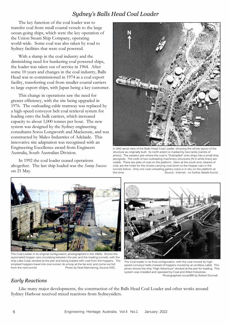
Construction of the seawall on Balls Head Bay. Source: Stanton Library, NSC.
Construction of tunnels 1-4 and the south sandstone wall, Balls Head Coal Loader, 1918. Note theincoming coal unloading gantry cranes already in situ, and probably in use unloading building materials
from the ship lying alongside the wharf. The coal outloading pier is under construction in the
background. Source: Stanton Library, NSC.
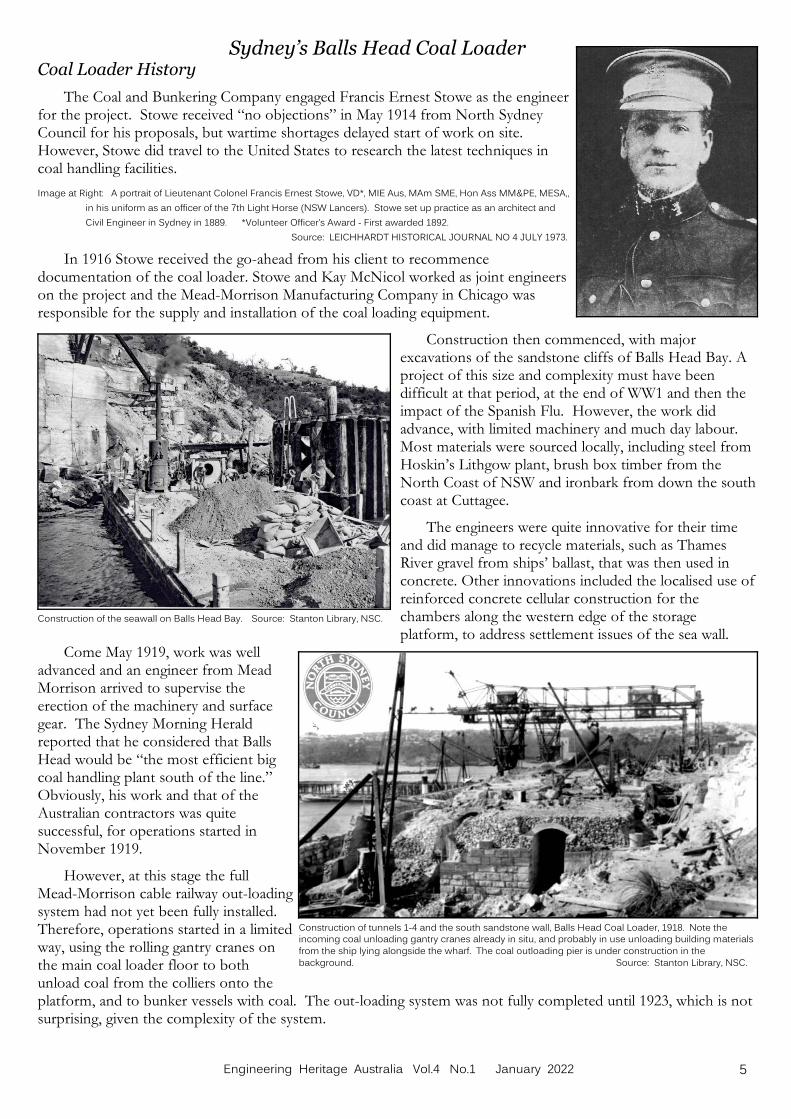
Sydney’s Balls Head Coal LoaderCoal Loader History
The Coal and Bunkering Company engaged Francis Ernest Stowe as the engineerfor the project. Stowe received “no objections” in May 1914 from North SydneyCouncil for his proposals, but wartime shortages delayed start of work on site. However, Stowe did travel to the United States to research the latest techniques incoal handling facilities.
Image at Right: A portrait of Lieutenant Colonel Francis Ernest Stowe, VD*, MIE Aus, MAm SME, Hon Ass MM&PE, MESA,,
in his uniform as an officer of the 7th Light Horse (NSW Lancers). Stowe set up practice as an architect and
Civil Engineer in Sydney in 1889. *Volunteer Officer’s Award - First awarded 1892.
Source: LEICHHARDT HISTORICAL JOURNAL NO 4 JULY 1973.
In 1916 Stowe received the go-ahead from his client to recommencedocumentation of the coal loader. Stowe and Kay McNicol worked as joint engineerson the project and the Mead-Morrison Manufacturing Company in Chicago wasresponsible for the supply and installation of the coal loading equipment.
Construction then commenced, with majorexcavations of the sandstone cliffs of Balls Head Bay. Aproject of this size and complexity must have beendifficult at that period, at the end of WW1 and then theimpact of the Spanish Flu. However, the work didadvance, with limited machinery and much day labour. Most materials were sourced locally, including steel fromHoskin’s Lithgow plant, brush box timber from theNorth Coast of NSW and ironbark from down the southcoast at Cuttagee.
The engineers were quite innovative for their timeand did manage to recycle materials, such as ThamesRiver gravel from ships’ ballast, that was then used inconcrete. Other innovations included the localised use ofreinforced concrete cellular construction for thechambers along the western edge of the storageplatform, to address settlement issues of the sea wall.
Come May 1919, work was welladvanced and an engineer from MeadMorrison arrived to supervise theerection of the machinery and surfacegear. The Sydney Morning Heraldreported that he considered that BallsHead would be “the most efficient bigcoal handling plant south of the line.” Obviously, his work and that of theAustralian contractors was quitesuccessful, for operations started inNovember 1919.
However, at this stage the fullMead-Morrison cable railway out-loadingsystem had not yet been fully installed. Therefore, operations started in a limitedway, using the rolling gantry cranes onthe main coal loader floor to bothunload coal from the colliers onto theplatform, and to bunker vessels with coal. The out-loading system was not fully completed until 1923, which is notsurprising, given the complexity of the system.
5Engineering Heritage Australia Vol.4 No.1 January 2022
The Coal loader in its final configuration, with the coal moved by high-speed conveyor belts instead of hoppers moved by an endless cable. This
photo shows the ship “High Adventure” docked at the pier for loading. This
system was installed and operated by Coal and Allied Industries.
Photographed circa1990 by Robert Donnell.
The Coal Loader in its original configuration, photographed in the 1960s. Shows theautomated hopper cars circulating between the pier and the loading tunnels, with the
ship Lake Colac docked at the pier and being loaded with coal from the hoppers.. The
emptied hoppers travel into one tunnel, do a loop at the far end, and come out full
from the next tunnel. Photo by Noel Mannering, Source NSC.
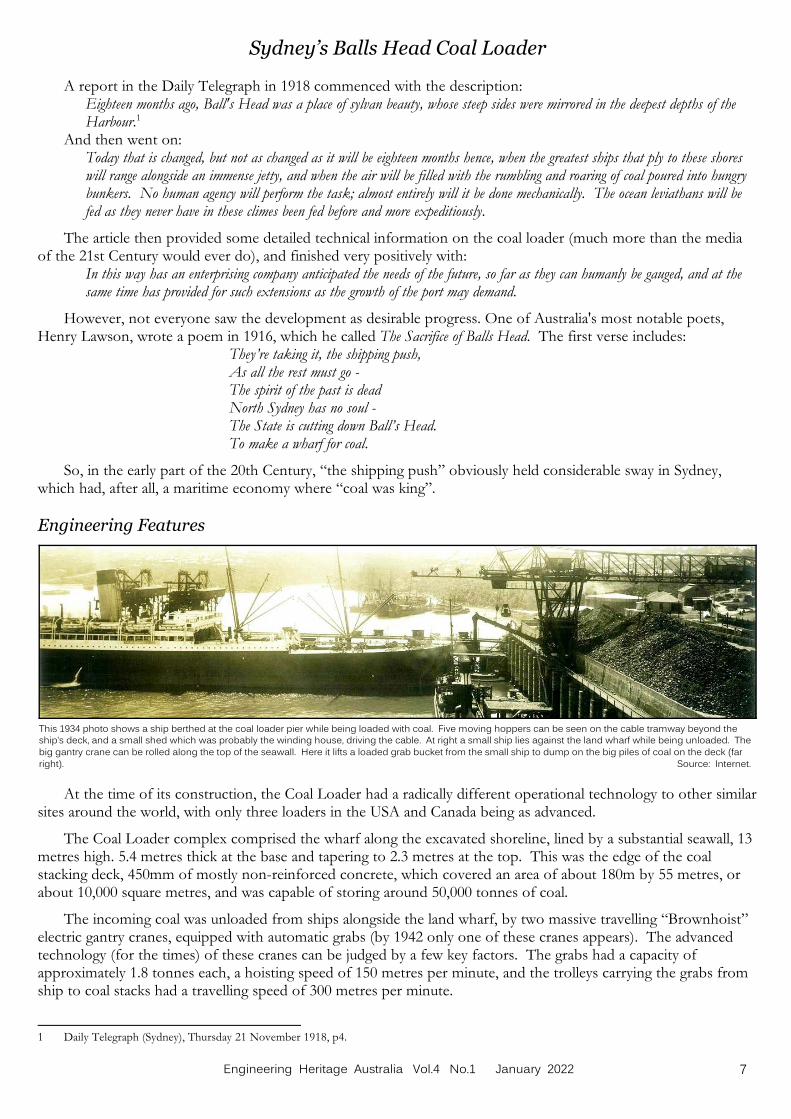
A 1942 aerial view of the Balls Head Coal Loader, showing the whole layout of thestructure as originally built. Its north extent is marked by two tanks (centre of
photo). The western pier where the coal is “Outloaded” onto ships has a small ship
alongside. The roofs of two outloading machinery structures (N-S white lines) are
visible. There are piles of coal on the platform, Seen at the south end, cleared ofcoal, are the holes for the chutes carrying coal down to the hopper cars in the
tunnels below. Only one coal unloading gantry crane is in situ on the platform at
this time. Source: Internet - no further details found. .
Sydney’s Balls Head Coal Loader
The key function of the coal loader was totransfer coal from small coastal vessels to the largeocean-going ships, which were the key operation ofthe Union Steam Ship Company, operatingworld-wide. Some coal was also taken by road toSydney facilities that were coal powered.
With a slump in the coal industry and thediminishing need for bunkering coal powered ships,the loader was taken out of service in 1964. Aftersome 10 years and changes in the coal industry, BallsHead was re-commissioned in 1974 as a coal exportfacility, transferring coal from smaller coastal carriersto large export ships, with Japan being a key customer.
This change in operations saw the need forgreater efficiency, with the site being upgraded in1976. The outloading cable tramway was replaced bya high-speed conveyor belt coal retrieval system forloading onto the bulk carriers, which increasedcapacity to about 1,000 tonnes per hour. The newsystem was designed by the Sydney engineeringconsultants Soros Longworth and Mackenzie, and wasconstructed by Malco Industries of Adelaide. Thisinnovative site adaptation was recognised with anEngineering Excellence award from EngineersAustralia, South Australian Division.
In 1992 the coal loader ceased operationsaltogether. The last ship loaded was the Sunny Successon 21 May.
Early Reactions
Like many major developments, the construction of the Balls Head Coal Loader and other works aroundSydney Harbour received mixed reactions from Sydneysiders.
6 Engineering Heritage Australia Vol.4 No.1 January 2022
This 1934 photo shows a ship berthed at the coal loader pier while being loaded with coal. Five moving hoppers can be seen on the cable tramway beyond theship’s deck, and a small shed which was probably the winding house, driving the cable. At right a small ship lies against the land wharf while being unloaded. The
big gantry crane can be rolled along the top of the seawall. Here it lifts a loaded grab bucket from the small ship to dump on the big piles of coal on the deck (far
right). Source: Internet.
Sydney’s Balls Head Coal Loader
A report in the Daily Telegraph in 1918 commenced with the description:Eighteen months ago, Ball's Head was a place of sylvan beauty, whose steep sides were mirrored in the deepest depths of theHarbour.1
And then went on:Today that is changed, but not as changed as it will be eighteen months hence, when the greatest ships that ply to these shoreswill range alongside an immense jetty, and when the air will be filled with the rumbling and roaring of coal poured into hungrybunkers. No human agency will perform the task; almost entirely will it be done mechanically. The ocean leviathans will befed as they never have in these climes been fed before and more expeditiously.
The article then provided some detailed technical information on the coal loader (much more than the mediaof the 21st Century would ever do), and finished very positively with:
In this way has an enterprising company anticipated the needs of the future, so far as they can humanly be gauged, and at thesame time has provided for such extensions as the growth of the port may demand.
However, not everyone saw the development as desirable progress. One of Australia's most notable poets,Henry Lawson, wrote a poem in 1916, which he called The Sacrifice of Balls Head. The first verse includes:
They’re taking it, the shipping push, As all the rest must go - The spirit of the past is dead North Sydney has no soul - The State is cutting down Ball’s Head. To make a wharf for coal.
So, in the early part of the 20th Century, “the shipping push” obviously held considerable sway in Sydney,
which had, after all, a maritime economy where “coal was king”.
Engineering Features
At the time of its construction, the Coal Loader had a radically different operational technology to other similarsites around the world, with only three loaders in the USA and Canada being as advanced.
The Coal Loader complex comprised the wharf along the excavated shoreline, lined by a substantial seawall, 13metres high. 5.4 metres thick at the base and tapering to 2.3 metres at the top. This was the edge of the coalstacking deck, 450mm of mostly non-reinforced concrete, which covered an area of about 180m by 55 metres, orabout 10,000 square metres, and was capable of storing around 50,000 tonnes of coal.
The incoming coal was unloaded from ships alongside the land wharf, by two massive travelling “Brownhoist”electric gantry cranes, equipped with automatic grabs (by 1942 only one of these cranes appears). The advancedtechnology (for the times) of these cranes can be judged by a few key factors. The grabs had a capacity ofapproximately 1.8 tonnes each, a hoisting speed of 150 metres per minute, and the trolleys carrying the grabs fromship to coal stacks had a travelling speed of 300 metres per minute.
1 Daily Telegraph (Sydney), Thursday 21 November 1918, p4.
7Engineering Heritage Australia Vol.4 No.1 January 2022
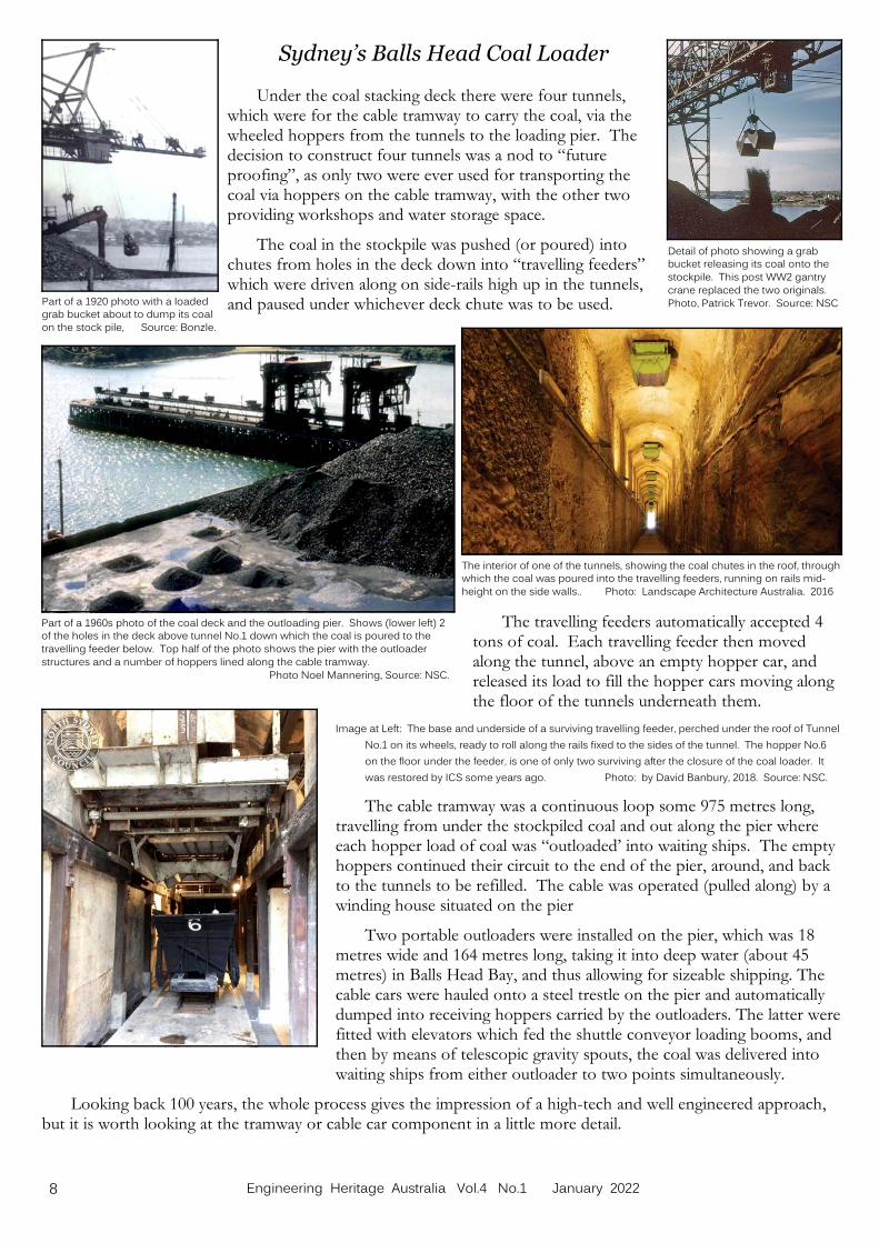
Detail of photo showing a grabbucket releasing its coal onto the
stockpile. This post WW2 gantry
crane replaced the two originals.
Photo, Patrick Trevor. Source: NSC Part of a 1920 photo with a loadedgrab bucket about to dump its coal
on the stock pile, Source: Bonzle.
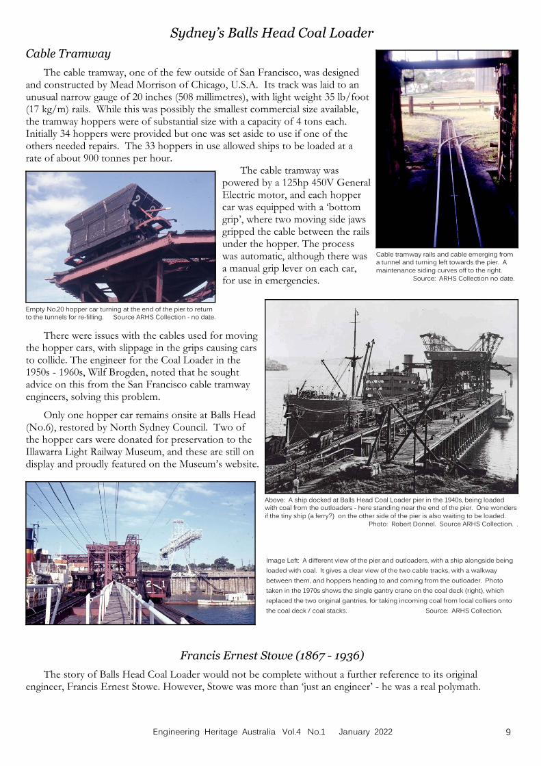
The interior of one of the tunnels, showing the coal chutes in the roof, throughwhich the coal was poured into the travelling feeders, running on rails mid-
height on the side walls.. Photo: Landscape Architecture Australia. 2016
Part of a 1960s photo of the coal deck and the outloading pier. Shows (lower left) 2of the holes in the deck above tunnel No.1 down which the coal is poured to the
travelling feeder below. Top half of the photo shows the pier with the outloader
structures and a number of hoppers lined along the cable tramway.
Photo Noel Mannering, Source: NSC.
Sydney’s Balls Head Coal Loader
Under the coal stacking deck there were four tunnels,which were for the cable tramway to carry the coal, via thewheeled hoppers from the tunnels to the loading pier. Thedecision to construct four tunnels was a nod to “futureproofing”, as only two were ever used for transporting thecoal via hoppers on the cable tramway, with the other twoproviding workshops and water storage space.
The coal in the stockpile was pushed (or poured) intochutes from holes in the deck down into “travelling feeders”which were driven along on side-rails high up in the tunnels,and paused under whichever deck chute was to be used.
The travelling feeders automatically accepted 4tons of coal. Each travelling feeder then movedalong the tunnel, above an empty hopper car, andreleased its load to fill the hopper cars moving alongthe floor of the tunnels underneath them.
Image at Left: The base and underside of a surviving travelling feeder, perched under the roof of Tunnel
No.1 on its wheels, ready to roll along the rails fixed to the sides of the tunnel. The hopper No.6
on the floor under the feeder, is one of only two surviving after the closure of the coal loader. It
was restored by ICS some years ago. Photo: by David Banbury, 2018. Source: NSC.
The cable tramway was a continuous loop some 975 metres long,travelling from under the stockpiled coal and out along the pier whereeach hopper load of coal was “outloaded’ into waiting ships. The emptyhoppers continued their circuit to the end of the pier, around, and backto the tunnels to be refilled. The cable was operated (pulled along) by awinding house situated on the pier
Two portable outloaders were installed on the pier, which was 18metres wide and 164 metres long, taking it into deep water (about 45metres) in Balls Head Bay, and thus allowing for sizeable shipping. Thecable cars were hauled onto a steel trestle on the pier and automaticallydumped into receiving hoppers carried by the outloaders. The latter werefitted with elevators which fed the shuttle conveyor loading booms, andthen by means of telescopic gravity spouts, the coal was delivered intowaiting ships from either outloader to two points simultaneously.
Looking back 100 years, the whole process gives the impression of a high-tech and well engineered approach,but it is worth looking at the tramway or cable car component in a little more detail.
8 Engineering Heritage Australia Vol.4 No.1 January 2022
Empty No.20 hopper car turning at the end of the pier to returnto the tunnels for re-filling. Source ARHS Collection - no date.
Above: A ship docked at Balls Head Coal Loader pier in the 1940s, being loaded with coal from the outloaders - here standing near the end of the pier. One wonders
if the tiny ship (a ferry?) on the other side of the pier is also waiting to be loaded.
Photo: Robert Donnel. Source ARHS Collection. .
Cable tramway rails and cable emerging froma tunnel and turning left towards the pier. A
maintenance siding curves off to the right.
Source: ARHS Collection no date.
Sydney’s Balls Head Coal Loader
Cable Tramway
The cable tramway, one of the few outside of San Francisco, was designedand constructed by Mead Morrison of Chicago, U.S.A. Its track was laid to anunusual narrow gauge of 20 inches (508 millimetres), with light weight 35 lb/foot(17 kg/m) rails. While this was possibly the smallest commercial size available,the tramway hoppers were of substantial size with a capacity of 4 tons each. Initially 34 hoppers were provided but one was set aside to use if one of theothers needed repairs. The 33 hoppers in use allowed ships to be loaded at arate of about 900 tonnes per hour.
The cable tramway waspowered by a 125hp 450V GeneralElectric motor, and each hoppercar was equipped with a ‘bottomgrip’, where two moving side jawsgripped the cable between the railsunder the hopper. The processwas automatic, although there wasa manual grip lever on each car,for use in emergencies.
There were issues with the cables used for movingthe hopper cars, with slippage in the grips causing carsto collide. The engineer for the Coal Loader in the1950s - 1960s, Wilf Brogden, noted that he soughtadvice on this from the San Francisco cable tramwayengineers, solving this problem.
Only one hopper car remains onsite at Balls Head(No.6), restored by North Sydney Council. Two ofthe hopper cars were donated for preservation to theIllawarra Light Railway Museum, and these are still ondisplay and proudly featured on the Museum’s website.
Image Left: A different view of the pier and outloaders, with a ship alongside being
loaded with coal. It gives a clear view of the two cable tracks, with a walkway
between them, and hoppers heading to and coming from the outloader. Photo
taken in the 1970s shows the single gantry crane on the coal deck (right), which
replaced the two original gantries, for taking incoming coal from local colliers onto
the coal deck / coal stacks. Source: ARHS Collection.
Francis Ernest Stowe (1867 - 1936)
The story of Balls Head Coal Loader would not be complete without a further reference to its originalengineer, Francis Ernest Stowe. However, Stowe was more than ‘just an engineer’ - he was a real polymath.
9Engineering Heritage Australia Vol.4 No.1 January 2022

Stowe's 1922 concept drawing for a Sydney Harbour Bridge. We are used to themap convention with North at the top of the page. Stowe has upended this
convention, with Balls Head (north) at the bottom of the page, Goat Island in the
centre, Millers Point top left, and Balmain top right. Perhaps Stowe invented a
roundabout to solve the inevitable traffic congestion on Goat Island! Source: NSW State Library.
Sydney’s Balls Head Coal Loader
Francis Ernest Stowe (1867 - 1936) – Cont.
An Irish immigrant, Stowe set up practice inAustralia as a civil engineer and architect, establishing theSydney Marine Engineers College. Stowe's interestswere remarkably varied and included designing acounterweight tramway leading down to the Darling StWharf in Balmain. He developed a concept for aharbour bridge in Sydney which had three arms, linkingMillers Points, Balmain and Balls Head. Reportedly, thiswas only narrowly passed over by the Government infavour of the Bradfield proposal which was built.
Stowe was also in the Government’s TechnicalEducation Branch, as a teacher in ‘Slide Rule’, whichperhaps should be an item of engineering heritage itself?
Beyond engineering and architecture, Stowe becamea Lieutenant-Colonel in the Australian 7th Light Horse(the NSW Lancers). His interests ranged fromphilosophy, to writing books such as Cancer and its Cause,Sunlight and Relativity and A New Universal Time System. Hewas a prolific inventor, with many patents ranging fromthe prevention of corrugation in steel traction rails to adust-proof picture rail.
With today's interest in the role of women in theprofessions, it is interesting that Stowe befriended oneFlorence Parsons, and employed her in his office. Heencouraged her in her studies in architecture, and shelater became well known as Florence Taylor, the first woman architect in Australia and the first female member ofthe Institution of Structural Engineers in the United Kingdom.
Stowe died in July 1936. When one looks at the extraordinary range of Stowe’s experiences and achievements,it is no wonder that the Balls Head Coal Loader was such an innovative project.
Operation of the Coal Loader
Engineering Heritage generally focuses on the design and construction of engineering facilities, but equallyimportant in my view is the aspect of operation. We are fortunate that aspects of the Coal Loader’s operation wererecorded in an oral history interview with Wilf Brogden, who was engineer and then manager of the facility from1952 to 1982.2
When Wilf Brogden took on the role of engineer in 1952, he found that the Coal Loader was very run-downoverall, with the wharf ‘disreputable’ and the machinery in very poor condition. There was only one craneoperating and the daily output of some 800 to 900 tonnes was really very slow, despite there being hundreds ofmen on site. Work methods had not advanced since the loader commenced operations in 1919, as the coal loadedinto ships had to be trimmed by hand, and by candlelight.
Brogden noted that he had problems with noise, as some ships arrived at 3am, and with dust. In addition,some ships discharged polluted water ballast into Balls Head Bay, which killed off mussels on the pier, forcingBrogden to complain to the Maritime Services Board. Brogden lived on site, and monitored the dust situation24/7. Dust suppression water sprayers from the coal stockpiles were used to wash the accumulated coal dust fromtrees in the area, a system designed by Brogden and his staff.
2 Brogden, Wilf. – Balls Head Coal Loader (Waverton, N.S.W.) – Coal & Allied Pty. Ltd. – Park, Margaret, Sydney, 1999 (Stanton LH REF OH/212)
10 Engineering Heritage Australia Vol.4 No.1 January 2022

David Banbury (left) and Max Irvine on site at the Coal Loader in 2021. Photo: Frank Johnson.
Sydney’s Balls Head Coal Loader
End of the Line?
When the Balls Head Coal Loader ceased operations in 1992 , the terms of the lease required the dismantlingof the site. Only the wharf, coal loading platform, tunnels and a few administrative buildings remained as evidenceof its former operation. If Balls Head had been like so many other former industrial sites, this would have been‘the end of the line’, with the site being left to deteriorate or handed over to developers. Fortunately, this did notoccur and through community pressure and professional involvement, we now have an excellent example ofheritage engineering.
Reconfiguration – Heritage Engineering
In the mid-1990s the local community became concerned about NSW State Government plans to sell off theformer industrial sites in this area for housing. There was concerted lobbying and action, and in 1997 the thenPremier, Bob Carr, finally dedicated the site as public open space.
The success of any project is very much dependent onthe people involved and the reconfiguration of Balls HeadCoal Loader is no exception. Three key professionals standout here:
• David Banbury: Project Manager, North SydneyCouncil;
• Max Irvine: Structural Engineer, PMI Engineers;• Steve Debello: Architect, Perform Architecture.
The work undertaken by these three was a classic case ofsuccess through collaboration, and shows what can be doneby a dedicated team of professional engineers and architects.
North Sydney Council had a Master Plan for the siteprepared by Clouston in 1999, which was when DavidBanbury commenced his role as Project Manager. One ofthe reasons for the success of the project and a lesson forother heritage engineering works is that Banbury is stillinvolved over 22 years later. Another key success factor was that of community backing, a long-standing aspect ofthe Balls Head site.
Detailed planning work started in 2005, when Council engaged the architecture firm Hassell to prepare theDevelopment Application, which consent was approved in 2008. Site works commenced in 2009 and proceeded infour stages:
• Stage 1 (2009): adaptive reuse of the former Mess Hall and Powerhouse Building and immediate surrounds;
• Stage 2a (2009-10): lower terrace area and one of the tunnels, including a connection to Balls Head Reserve;
• Stage 2b (2010-11): adaptive reuse of the remaining upper terrace administration precinct and the curtilage tothe aboriginal engraving;
• The final main stage (2016-2018): coal loader platform, including the three remaining tunnels.
When work started in 2005, the coal loader was almost 90 years old and site had been out of use for over 20years, so this was a real challenge. There were parts that were failing and in a dangerous condition and had to beremoved. Safety was always the first consideration, but an overriding objective was to demolish as little as possible,maintaining the heritage of the site. Works undertaken to restore and convert the coal loader included:
a) Keeping the water out as much as possible.
b) Investigating and overcoming the concrete cancer in the reinforced sections.
c) Determining how to merge the old structure with the new works, given the age-old problem of works notexactly conforming to design drawings. This necessitated a complete on-site measurement exercise, and inthe design phase the whole structure was put into a 3D model. This innovative initiative allowed theproject manager and designers to walk around in a virtual space and visualise the various proposedalterations.
11Engineering Heritage Australia Vol.4 No.1 January 2022

The Coal Loader Deck in 2021. Photo: Frank Johnson.
Sydney’s Balls Head Coal Loader
d) Contending with uncertain ground conditions, for which ground penetrating radar provided real assistance.
e) Consideration of the current Building Code of Australia requirements, which required creating extradoorways, etc.
f) Where elements had to be replaced, e.g. timber supports, the new ones replicated the original as much aspossible, even to the extent of ‘dummy fixings’ to look like the old style of construction.
g) Use of low maintenance materials, including concrete, hot-dipped galvanised steel and stainless steel,recycled hardwood timbers, and micaceous oxide paint.
Every effort was made to ensure that the new works did not overpower or detract from the heritage of the site. Due consideration was given by the structural engineer to avoid ‘over-engineering’, which is an important factor. For example, the coal stacking deck once supported 50,000 tons of coal but now only has pedestrians, a fewlightweight structures and maintenance vehicles.
The work was undertaken in a staged program, as funding became available from Council. This was a keysuccess factor, as there is usually a greater chance of obtaining relatively small parcels of funding, rather than a largeamount up front. The periods of no funding also provided time to plan and design later stages. The ongoingprogram enabled the community commitment to be built up, as the locals came to use parts of the site and toappreciate its potential.
Current activity
The site now operates as the Coal LoaderCentre for Sustainability, under the control ofNorth Sydney Council. The Council pamphleton the site describes it as:
The Coal Loader demonstrates the layering ofhuman history, from the ancient culture of theCammeraygal people, to an industrial coalbunkering facility, to a showcase for sustainability. Be inspired by innovative sustainable designtechnology, community gardens, native plant nursery,regenerated parklands and much more.
The ‘much more’ includes the tramwaytunnels, offices and workshops from itsoperational period, the visitor orientation deck
with displays on the history and operation of the coal loader, and thepromenade area over the coal loader platform. The wharf used forunloading is currently home to two vintage ships, MV Cape Don and MVBaragoola (a former Manly Ferry), which are both there for refurbishment.
The tramway tunnels are of much interest and can be accessed. No 1Tunnel is used for art exhibitions, displays and small live musicperformances. In March 2021, there was an art exhibition, titledHomeward Bound, which provided a very esoteric contrast to the way thetunnels were used in times past.
Overall, the site is very popular, with locals and tourists alike and iswell worth a visit, as is the remainder of Balls Head. To make a visit evenmore pleasant, there is a great café on site, open Wednesdays to Sunday.
Image at Left: A ghostly art exhibition in one of the tunnels. Photo: Frank Johnson 2021.
12 Engineering Heritage Australia Vol.4 No.1 January 2022

The dilapidated state of the Coal Loader Pier in 2021.Photo: Frank Johnson.
Sydney’s Balls Head Coal Loader
The Pier
One element of the Balls Head Coal Loader that has not fared well isthe pier, for it is rapidly deteriorating. While the rest of the Coal Loader isunder the control and management of North Sydney Council, the pier isthe property of the NSW State Government,
The pier was to be demolished, but this was put on hold after protestsfrom the local community and intervention by the NSW Heritage Office. In July 2019, the then Roads and Maritime Services undertook safety workto erect piles and netting around the wharf to contain any fallen wharfelements, and navigation lights were installed to aid marine traffic. However, no work was done on the pier itself.
More recently, some interest has been shown by Transport for NSW (TfNSW), the current custodians, whounderstand the significance of the maritime structure to the Coal Loader story. TfNSW and North Sydney Councilare now working together on an appropriate reuse scheme which balances heritage and contemporary useobjectives. Given the condition of the wharf, this certainly presents some significant engineering challenges.
And the Future?
Engineering structures are not fixed in time and the Balls Head Coal Loader is no exception. While the majorstructural re-purposing has been largely completed and is designed to be low maintenance, that is not the end ofthe story. Water penetration is still a major issue, and an ongoing inspection regime is in place. The key is toremain flexible, to be able to deal with whatever arises or is uncovered in the future.
The coal loader has recently been listed on the NSW State Heritage Register and a submission is beingprepared for it to be included on the Engineers Australia Engineering Heritage Register. Such recognition isappropriate, for the Balls Head Coal Loader site is a prime example of what can be done with engineering heritage. Anyone can walk around the coal stacking area, look down on the wharf and pier, then stroll through the cabletramway tunnels. There are not many industrial engineering sites where this level of interaction is so accessible, sowell developed and so popular.
Finally, one could conclude that Ernest Stowe, our polymath engineer, would have approved of the way inwhich his Balls Head Coal Loader has been re-purposed into a facility relevant to its current time, just as he was sokeen to do 100 years ago.
Acknowledgements
Researching this article was made so much easier with the assistance of Max Irvine and David Banbury, both ofwhom were generous with their time for site visits and discussions. It was obvious that they shared a very highdegree of professionalism and passion for the redevelopment of the Balls Head Coal Loader. Also, my thanks toBill Phippen of the Australian Railway Historical Society for providing images of the cable tramway.
Dedication
On my first visit to the Balls Head Coal Loader, my good friend and fellow engineering heritage enthusiast,Bruce Yates, accompanied me. Bruce was very impressed with the history of the coal loader and its current re-purposing and enjoyed our time on site. Sadly, Bruce passed away very suddenly just a few days before this articlewas submitted, and only hours after I had spoken with him about the progress of my writing. So, this article isdedicated to Bruce Yates, a true friend and fellow traveller on the engineering heritage road.
References
The Balls Head Coal Loader, Ken McCarthy, Trolley Wire, December 1975
The Coal Loader - CENTRE FOR SUSTAINABILITY, Pamphlet by North Sydney Council.
Oral History Interview with Wilf Brogden, by Margaret Park, Sydney 1999, Stanton Library, North Sydney Council.
13Engineering Heritage Australia Vol.4 No.1 January 2022

Part of a drawing (dated 17th March 1908) showing, with a dotted line, the route of the ‘fairly easy’ railway line from Yass (top left) to Queanbeyan (at bottom)
and passing through the ‘Suitable City Site’ which would become Canberra. Source: National Library of Australia (NLA).
Canberra's ill-fated City Railway: a particularly sorry tale By Mark Butz
Rail transport was fundamental to developing the new Australian Federal Capital at Canberra in the early 20thcentury. The site for the city was in something of a rural backwater, poorly served by both road and rail. American architect Walter Burley Griffin and his wife/partner Marion Mahony Griffin had prepared the prizewinning design for the city, which included a planned railway to connect Canberra with two existing major railwaylines in New South Wales (NSW). This was a potentially ‘fairly easy’ line through Canberra that would connectYass on the Sydney to Melbourne Great Southern Railway, with Queanbeyan on the Goulburn to Cooma line.
Work on the railway began even before the winning design plan could be put in place, and this set the tone forfractious relationships between the planner and administrators in the fledgling city. This City railway was aparticularly sorry tale, shaped by professional animosities, wartime austerity, poor understanding of the localenvironment, and rapid change in the period from the 1910s to 1950s.
The new Federal Capital was to be built on the Molonglo River, a rather erratic stream with a broadfloodplain. At the heart of the Griffins’ 1912 design was a string of three formal sculpted central lake basins onthe floodplain, flanked by two larger informal lakes (West Lake and East Lake). The design worked from thegeometry of the landscape to define a series of radial axes from high points on both sides of the river, some namedas the Land Axis, Water Axis and Municipal Axis. The enormous East Lake was separated from East Basin by along ‘weir bridge’ that gave its name to the Causeway Axis of the plan. This embankment was to be about 6,000feet (1,830m) long, rising 30ft (9m) above the central lake level. It was to be aesthetic, but also functional byprotecting the central lake basins from silting up.
14 Engineering Heritage Australia Vol.4 No.1 January 2022
Arrival of the first train to Canberra carrying coal for the Powerhouse 1914 - a CG class locolater renumbered as 1210 - photo A D McDonald. Source: NLA.
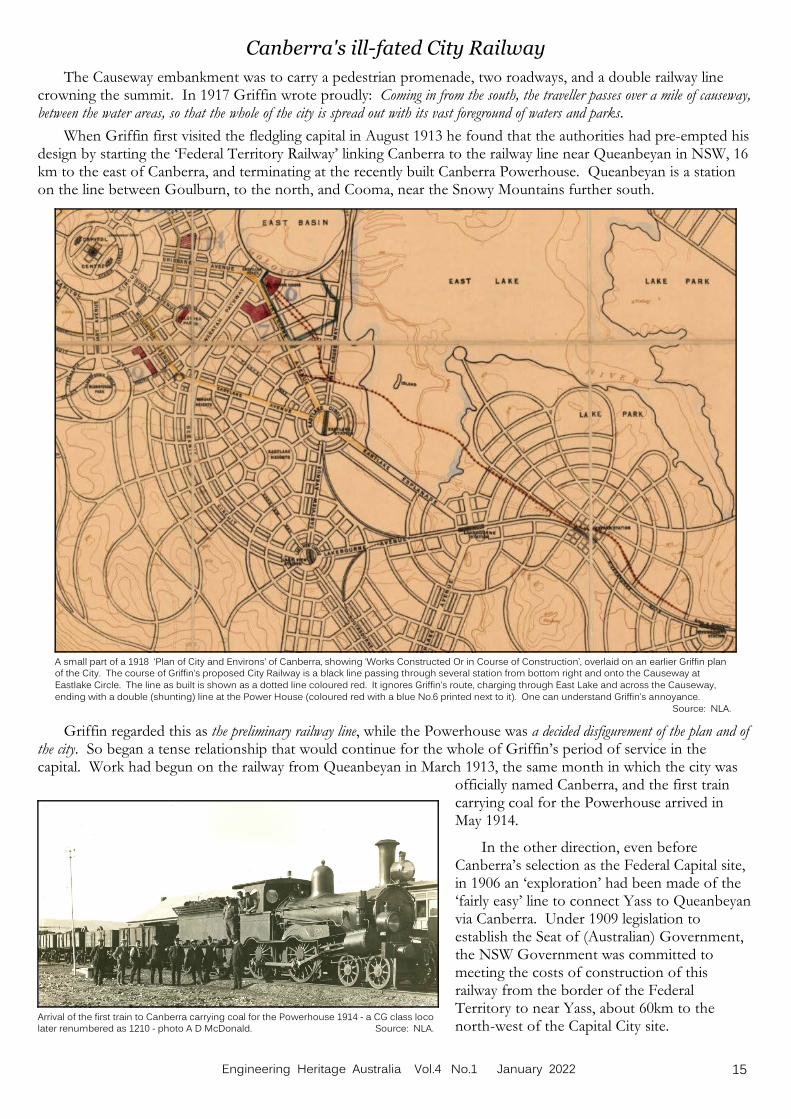
A small part of a 1918 ‘Plan of City and Environs’ of Canberra, showing ‘Works Constructed Or in Course of Construction’, overlaid on an earlier Griffin planof the City. The course of Griffin’s proposed City Railway is a black line passing through several station from bottom right and onto the Causeway at
Eastlake Circle. The line as built is shown as a dotted line coloured red. It ignores Griffin’s route, charging through East Lake and across the Causeway,
ending with a double (shunting) line at the Power House (coloured red with a blue No.6 printed next to it). One can understand Griffin’s annoyance.
Source: NLA.
Canberra's ill-fated City Railway
The Causeway embankment was to carry a pedestrian promenade, two roadways, and a double railway linecrowning the summit. In 1917 Griffin wrote proudly: Coming in from the south, the traveller passes over a mile of causeway,between the water areas, so that the whole of the city is spread out with its vast foreground of waters and parks.
When Griffin first visited the fledgling capital in August 1913 he found that the authorities had pre-empted hisdesign by starting the ‘Federal Territory Railway’ linking Canberra to the railway line near Queanbeyan in NSW, 16km to the east of Canberra, and terminating at the recently built Canberra Powerhouse. Queanbeyan is a stationon the line between Goulburn, to the north, and Cooma, near the Snowy Mountains further south.
Griffin regarded this as the preliminary railway line, while the Powerhouse was a decided disfigurement of the plan and ofthe city. So began a tense relationship that would continue for the whole of Griffin’s period of service in thecapital. Work had begun on the railway from Queanbeyan in March 1913, the same month in which the city was
officially named Canberra, and the first traincarrying coal for the Powerhouse arrived inMay 1914.
In the other direction, even beforeCanberra’s selection as the Federal Capital site,in 1906 an ‘exploration’ had been made of the‘fairly easy’ line to connect Yass to Queanbeyanvia Canberra. Under 1909 legislation toestablish the Seat of (Australian) Government,the NSW Government was committed tomeeting the costs of construction of thisrailway from the border of the FederalTerritory to near Yass, about 60km to thenorth-west of the Capital City site.
15Engineering Heritage Australia Vol.4 No.1 January 2022

Sketch showing the intended route of the Griffin’s ‘City Railway’. Close to and west of it, is the StandardGauge Construction Railway (or Tramway) that was actually built in 1920-21. The narrow gauge Brickworks
Railway (or tramway), used for moving construction materials, was built in 1923 from Yarralumla, past
Capital Hill and the provisional Parliament House to the Power House at Kingston, with a branch from it
travelling north and crossing the river to end at City Station. Source: Canberra’s Engineering Heritage, 2
nd Ed., 1990, Ch.2, Railways, P.60.
Canberra's ill-fated City Railway
Griffin encouraged construction of this link at the earliest possible time, and both the Federal and NSWgovernments began surveys for a suitable route in 1916. The Seat of Government Act also provided for a railconnection between Canberra and the coast, specifically to the Commonwealth Territory at Jervis Bay. A routewas explored in 1909 commencing at Civic centre, and a survey was completed in 1914.
Back in Canberra itself, after leaving Queanbeyan, Griffin's railway was to pass through six stations beforeterminating (initially) at City Station. It would have a very gentle grade of 1 in 200, and in the city area it would besunken below ground level. Griffin had to work with and through a Departmental Board which did not agree withmany of his ideas, considering them impractical and extravagant. The City railway was one of the earliest and mostprominent of their clashes, being challenged as early as October 1913, and the Minister’s intervention was requiredto confirm selection of his route.
Having been stalled by Departmental opposition, Griffin’s ambitious plans had barely commenced when theGreat War broke out in July 1914. Funds were withdrawn and nearly all works stopped, and any hopes of a strongstart to developing the capital were dashed. By 1919 the Federal Territory population was smaller than it had beenin 1913.
The ‘Construction Tramway’: a Modest Start
As Australia emerged fromwartime constraints, an initial railway(the ‘construction tramway’) was builtto the west of the alignment proposedfor the permanent line (Griffin’s CityRailway). This too required aMinisterial decision. A timber trestlebridge (20 trestles and 68 piles) tocarry the line across the Molongloriver was very conspicuous in the flatfloodplain landscape, and it wastangible evidence that the capital wasemerging from the retarding effect ofthe War.
Between the trestle bridge andbranching off the 1913-14 railway lineto the Powerhouse, an earthenembankment about 6ft (1.8m) highwas built across the floodplain.
The standard gauge (4ft 8½ins/1435mm) line to the Civic Centrewas officially opened for goods trafficin 1921. This followed verification ofthe size of locomotive that could beused and the speeds that werepermitted – not more than 6mph (10kmh), and reduced to 4mph (6.4 kmh)over the Molonglo Bridge and for ¾ mile (1.2km) to and from the terminus at Civic Centre.
In addition to construction materials, the service was carrying labourers, with a long siding close to thetemporary workers’ camp at Russell Hill, which may also have served the Royal Military College at Duntroon. Another platform and three loop sidings about 800ft (240m) long were built in the Civic Centre. At the sametime, in the second half of 1921, the rail connection to Yass was being actively pursued. These signs of progresswere short-lived.
16 Engineering Heritage Australia Vol.4 No.1 January 2022

A view of the destroyed trestle bridge after the flood of July 1922. Source: NAA A3560, 228.
Canberra's ill-fated City Railway
Image Above: Timber trestle bridge over the Molonglo River, to carry the
‘Construction Railway’ (or Tramway) from the Power House line to
City Station (now Civic). Mt Pleasant can be seen at left rear.
Photo c.1921, Source: NAA: A3560, 230.
Image at Right: A postcard c.1920 shows the ‘Construction Railway’
trestle bridge over the Molonglo River. The Power House and
Workshops are in the middle distance. Source: Sylvia Curley, “A
Long Journey”, pub. Canberra, 1998.
Floods … In July 1922 Canberra experienced its largest flood in
30 years, which severely damaged the new railwayembankment and trestle bridge. Eight of the middletrestles were lost completely, and the foundations ofseveral others were badly damaged. The main timbers anddecking were swinging unsupported but held together bythe rails. The flood badly scoured the rail embankment,washing out most of the ballast and displacing the track.
In the slowdown during the War, Griffin had held outagainst strident criticism to ensure that the railwayembankment and bridge were built. Now they lay broken,with holes through the embankment and rails dipping intothe river.
The temporary and downscaled version of the railwayhad provided savings, but it was poorly sited and constructed from an engineering point of view:
• Firstly, Jerrabomberra Creek had been diverted to avoid the need to construct an additional bridge. Theswollen creek’s contribution to the flood built up along the bank and discharged just upstream of thetrestle bridge, also adding to pressure on the supporting piles. Then floodwaters punched holes throughthe bank, and the creek reclaimed its original course.
• Secondly, the trestles had been oriented at right angles to the line of the railway (aligned with the Causewayaxis) but obliquely to the course of the river, presenting a series of large surfaces that resisted floodwatersand trapped large woody debris.
• Thirdly, it was later found that the piles had been poorly installed and were insecure at the base.
There was really no chance that the line could withstand such a flood event. The unthinkable was probablyinevitable. And then, in May 1925 an even larger flood set a new record, inflicting further severe damage. Thewaters had gone high over the top of the railway embankment, depositing big logs and debris 3-4ft deep andwashing it out completely in places. At the trestle bridge the flood tore apart the sagging railway line, and washed amass of rails, sleepers and bridge timbers downstream.
Not everyone was aghast at the sweeping away of the damaged bridge, the Federal Capital Pioneer newspaperreporting that the flood: has removed an object of ridicule and cutting cynicism from the gaze of anti-Canberra-ians [sic].
Despite loss of the railway crossing, city construction work needed to continue, as inability to deliver materialsput workers’ jobs at risk. With road bridges also destroyed by the floods, a new light tramway connection to thenorth side of the river was added as an expedient, crossing from the Parliament House construction site via alow-level timber bridge. This was an offshoot of the narrow gauge (3'6") tramway that ran from 1923 between theBrickworks at Yarralumla and the Powerhouse.
17Engineering Heritage Australia Vol.4 No.1 January 2022

Canberra's ill-fated City Railway
This offshoot was linked to the stranded standard gaugeCity railway, with one rail moved inward on the existingsleepers. In this way the northern part of the City railwaycontinued to serve, delivering bricks to build the city, untilthe whole Brickworks tramway was removed in 1927, to tidyup ahead of the opening of Parliament House.
Image Left: Low-level bridge over the Molonglo river, carrying the narrow gauge
Brickworks railway link to the then disused City railway c.1926-27.
Source: Canberra’s Engineering Heritage, 2nd
Ed., 1990, p.62.
The End of the City railway ... and others
Numerous alternative schemes for the City railway were proposed but they all soon came to a halt in the faceof a dismal sequence: drastic budget pruning for the Federal Capital; the Great Depression; cancellation of publicservice transfers from Melbourne; and notions of abandoning development of Canberra altogether. Significantflooding in 1931, 1934, 1945, 1947 and 1948 caused many to doubt the wisdom and expense of ever replacing arailway bridge over the fickle Molonglo. In 1950 it was decided to delete from the City Plan both East Lake andthe City railway, while leaving open the possibility of a future rail link ‘outside the city’. The remaining rails andsleepers were removed, most cuttings and embankments were filled or re-graded, and railway easements throughthe city were reallocated to other uses. The last bridge was removed in 1959.1
The City railway line was never rebuilt, complicating future rail links to Yass and Jervis Bay. As early as 1921,in the post-WW1 doldrums, the Jervis Bay railway appeared to be a distant dream, and it remained so. The link toYass did remain a hope, until 1972 when the Bureau of Transport Economics determined that it would not beviable. Now it was official: after 50 years the City railway had been cut off at both ends and would be obliterated.
The Modern Traces
Some sections of the old track had simply been paved over, as evidenced by rails and a sleeper unearthed byexcavations in 1989, by which time many residents had never known that the City railway had ever existed. Thisexcavated track section clearly showed adjustment from standard gauge to narrow gauge.
The only tangible trace of the City railway remaining today is a truncated set of standard gauge rails andsleepers that run under the fence of the railway station and yards at Kingston. It dates from 1914 when theQueanbeyan-Canberra rail connection was established, with two short branch lines to the west serving Stores andthe Powerhouse. A third branch was added, curving to the north-east to carry the ill-fated construction tramwayto the embankment across the river and on to the City. This was cut after destruction of the railway trestle bridgein 1922. There are some physical indications of the route of the construction tramway and the planned Cityrailway, despite extensive redevelopment of some areas. Enough spaces remain to get a sense of its path, rangingfrom gaps left between buildings, to streets that were once railway easements, to one remnant embankment.
Conclusion
Railway development has been a rather neglected aspect of Canberra’s history, known mainly to a fewenthusiasts. Engineering Heritage Canberra (EHC) recently operated a bus tour of Canberra’s rail remnants as aprelude to release of a self-guided itinerary/brochure. This follows on from two previous self-guided engineeringheritage tours developed by EHC within the ‘Canberra Tracks’ network. It brings largely-forgotten rail heritage tothe attention of residents and visitors, taking in the original Queanbeyan-Canberra railway, the lost City railway(tramway), and iterations of Brickworks tramways that helped to build the city in the 1920s.
Acknowledgements
Research has been assisted by: ACT Heritage Library; ArchivesACT; Canberra & District Historical Society; National Archives of Australia (Canberra and Adelaide); National Library of Australia (including Trove); ArmyMuseum-Duntroon; and the helpful staff and volunteers of those repositories.
Development of the rail remnant self-guided itinerary of Engineering Heritage Canberra has been assisted bythe ACT Government under the ACT Heritage Grants Program.
1 However it was not all gloom. In the 1960s,with a new vision by the Menzies Government for making Canberra a fitting capital city, Lake BurleyGriffin was constructed to a modified plan, with concrete road bridges across the lake defining the Parliamentary Triangle. Footnote – KB.
18 Engineering Heritage Australia Vol.4 No.1 January 2022

This map, adapted from an NRMA Touring Map (Sydney to Orange), shows the relativepositions of the centre of the City of Orange (large blue dot) and the Pumphouse (red dot) in
the Lake Canobolas Reserve & close to the Lake (dark green).
The Pumphouse is about 10 km from Orange.
The Lake Canobolas Pump House, Orange, NSWBy Peter Brown.
Introduction
The Lake Canobolas Pump House pumping technology represents an extremely rare example of a “transition”technology – the internal combustion Producer Gas Engine (aka a Suction Gas Engine) – coming as it didbetween steam power and other forms of internal combustion engines and electricity as power sources.
This is an example of a large scale, complete and authentic installation, in (almost) working order apart fromthe gas producer. As such, it deserves to be recognised as an important example of a significant technicaldevelopment and an opportunity to preserve knowledge.
Location
The City of Orange is situated in theCentral West of New South Wales,approximately 260 kilometres west of Sydney. In 2018 it had a population of approximately40,000. Growth in the past few years has largelybeen due to the opening of the Cadia goldmine, 20 km to the south of Orange, and theneed for its support services. Cadia is currentlythe most productive gold mine in Australia .
In the past the district depended mainly onfruit growing and agriculture. Orange is a majorcentre for Health Services in Central WesternNew South Wales. Due to its high altitude, theOrange district is also becoming well knownfor the production of cool climate fine winesand food.
Early History
European settlement of the area began in the 1820s, and the railway arrived in 1877. Orange is not situated ona river and so in the early days of the city every Orange home had its own well which tapped into an undergroundsource of water which was hard ( hard water is high in dissolved minerals). In addition, house drainage oftencontaminated it. Most residents used a windlass and bucket to access the supply. The more affluent had a smallDouglas force pump. The coming of the railway led to development of the town and the need for a reticulatedwater supply. The first was a 400 ML reservoir constructed at Gosling Creek in 1889 and, on completion, this wasstocked with 2,000 cod, perch, silver bream and yellow belly, a gift from Mr J.W. Smith of the Royal Hotel.
The then Governor of NSW, Lord Charles B Carrington, turned on the first town supply on the 8th October1890. The total cost of this scheme, including reticulation, was £32,688 and it was anticipated it would cover theneeds of the city for the next twenty years. In fact the storage, being of such a capacity, could cope without anyinflows for two years. The residents were able to have lawns and gardens, though by 1911 an additional supplymain had to be installed. A sewerage system for the city was contemplated in 1914 and as a result, surveys werecarried out to find a suitable location for a second reservoir.
The Meadow Creek Water Supply Scheme
After an enquiry by the NSW Public Works Committee the decision was made to locate the additional supplyon what was then known as Meadow Creek. Urgent preliminary works were approved and commenced on 4thJanuary 1915. These included the laying of the rising and service mains and the erection of a Service Reservoiradjacent to the Cargo Road. In December of the same year the Orange Water Supply Act was passed by the NSWParliament. This Act authorised the Minister for Public Works to complete the Meadow Creek water supplyscheme at a cost of £49,160.
19Engineering Heritage Australia Vol.4 No.1 January 2022

Lake Canobolas and the Pump House. The location of the Pump House is marked by thered dot at top right. Source: Google Earth.
Lake Canobolas Pump House
The works included the Storage Reservoir (682 megalitres), a building to house the pumps and associatedequipment, all of the necessary plant, the rising and service mains, the service reservoir on the Cargo Road and anextension of the reticulation system into the previously separate town of East Orange. A caretaker’s cottage offive rooms was also constructed. This was built near the pump house and was constructed from brick, concreteand timber with a galvanised iron roof . These works were commenced during January 1916 and completed inOctober 1918. The completed cost was £50,668 and the storage reservoir became known as Lake Canobolas. Thecreek was later renamed Molong Creek.
This is the pumping station which is thesubject of this article. The plant was used topump water from Lake Canobolas for use inOrange from 1918 to 1932. However, the older(Gosling Creek) scheme was cheaper to operate,so the Lake Canobolas plant was not usedcontinuously throughout that time. The town’swater supply problems had not been solved bythe 1918 scheme so a third and much largerscheme (4,680 ML) was built on Spring Creek. The Lake Canobolas plant continued to bemaintained and in 1944 and 1945 and for aperiod in 1957 was used to supplement supplyduring droughts. Since 1962 water for the cityhas been supplied from Suma Park Reservoir onSummer Hill Creek (17,300 ML), Gosling CreekReservoir and Spring Creek Reservoir, and from1962 water from Lake Canobolas was no longerpumped to Orange, and the plant wasabandoned.
Since water from Lake Canobolas is nolonger pumped to Orange the Lake has becomea popular venue for family recreation includingfishing, swimming and other activities. In July1972 Council decided to drain Lake Canobolas inorder to restore the lake bed, carry out foreshore improvements and attempt to reduce the number of redfinwhich are prolific breeders. They had all but taken over the lake with a population estimated at 100,000 and onlyabout 200 of the preferable trout were left. It has since been restocked with trout fingerlings.
Much of the waste water from the city is treated and pumped to the Cadia gold mine. There it is used in thetreatment of the ore from an open cut and underground mines. In 2009, due to a recent prolonged drought, theCity Council constructed a storm water harvesting scheme, in order to supplement the City’s water supply. Thisscheme was the first large scale storm water harvesting project in NSW. In the longer term the scheme should beable to supply up to 2,000 megalitres of water into Orange’s water supply system. Council has also built a pipelinefrom the Macquarie River to the Suma Park Dam, so it is able to draw water from the Macquarie when flows inthat river are above a certain volume. Consideration is also being given to the raising of the Suma Park Dam wall.
Description of the Site
The gravity dam holding the waters of Lake Canobolas is constructed of concrete with a central spillway. Thewall is 39 feet high and 1,000 feet long. A large sluice valve is located at its base so that the lake can be drained. When built the lake held 150,000,000 gallons of water and the maximum depth of the lake was 40 feet. It’s surfaceis 3,000 feet above sea level. The valley in which the Molong Creek flows is well known for its scenic beauty, withorchards covering the surrounding hills which rise up to Mount Canobolas 1395 metres above sea level, the highestpoint between the Blue Mountains in the east and the Indian Ocean, several thousand kilometres to the West.
20 Engineering Heritage Australia Vol.4 No.1 January 2022
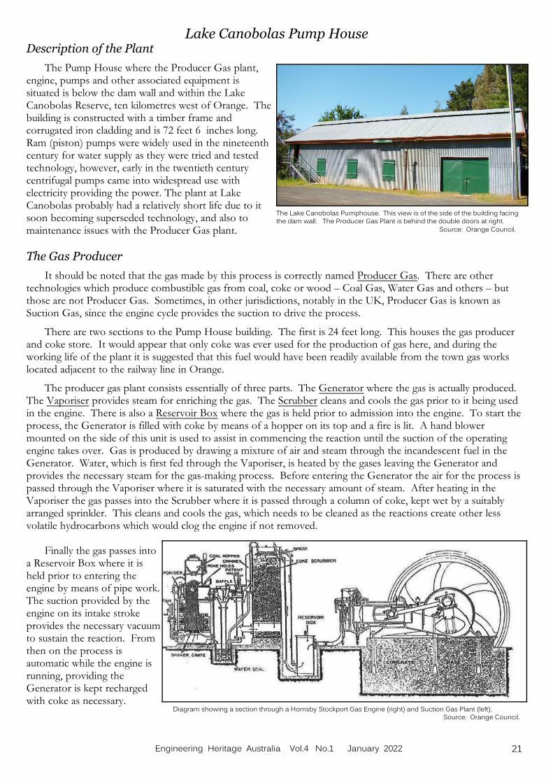
Diagram showing a section through a Hornsby Stockport Gas Engine (right) and Suction Gas Plant (left). Source: Orange Council.
The Lake Canobolas Pumphouse. This view is of the side of the building facingthe dam wall. The Producer Gas Plant is behind the double doors at right.
Source: Orange Council.
Lake Canobolas Pump HouseDescription of the Plant
The Pump House where the Producer Gas plant,engine, pumps and other associated equipment issituated is below the dam wall and within the LakeCanobolas Reserve, ten kilometres west of Orange. Thebuilding is constructed with a timber frame andcorrugated iron cladding and is 72 feet 6 inches long. Ram (piston) pumps were widely used in the nineteenthcentury for water supply as they were tried and testedtechnology, however, early in the twentieth centurycentrifugal pumps came into widespread use withelectricity providing the power. The plant at LakeCanobolas probably had a relatively short life due to itsoon becoming superseded technology, and also tomaintenance issues with the Producer Gas plant.
The Gas Producer
It should be noted that the gas made by this process is correctly named Producer Gas. There are othertechnologies which produce combustible gas from coal, coke or wood – Coal Gas, Water Gas and others – butthose are not Producer Gas. Sometimes, in other jurisdictions, notably in the UK, Producer Gas is known asSuction Gas, since the engine cycle provides the suction to drive the process.
There are two sections to the Pump House building. The first is 24 feet long. This houses the gas producerand coke store. It would appear that only coke was ever used for the production of gas here, and during theworking life of the plant it is suggested that this fuel would have been readily available from the town gas workslocated adjacent to the railway line in Orange.
The producer gas plant consists essentially of three parts. The Generator where the gas is actually produced. The Vaporiser provides steam for enriching the gas. The Scrubber cleans and cools the gas prior to it being usedin the engine. There is also a Reservoir Box where the gas is held prior to admission into the engine. To start theprocess, the Generator is filled with coke by means of a hopper on its top and a fire is lit. A hand blowermounted on the side of this unit is used to assist in commencing the reaction until the suction of the operatingengine takes over. Gas is produced by drawing a mixture of air and steam through the incandescent fuel in theGenerator. Water, which is first fed through the Vaporiser, is heated by the gases leaving the Generator andprovides the necessary steam for the gas-making process. Before entering the Generator the air for the process ispassed through the Vaporiser where it is saturated with the necessary amount of steam. After heating in theVaporiser the gas passes into the Scrubber where it is passed through a column of coke, kept wet by a suitablyarranged sprinkler. This cleans and cools the gas, which needs to be cleaned as the reactions create other lessvolatile hydrocarbons which would clog the engine if not removed.
Finally the gas passes intoa Reservoir Box where it isheld prior to entering theengine by means of pipe work. The suction provided by theengine on its intake strokeprovides the necessary vacuumto sustain the reaction. Fromthen on the process isautomatic while the engine isrunning, providing theGenerator is kept rechargedwith coke as necessary.
21Engineering Heritage Australia Vol.4 No.1 January 2022

Side view of the Hornsby-Stockport Gas Engine. The flywheel is centre, one pulley operating a pumpis at right, the other pulley operating the other pump is barely visible behind the flywheel. The gas
plant is out of the picture to the left, and the two pumps are out of the picture to the right.
Source: Orange Council.
Plan view of the equipment layout in the Pump House. The producer gas plant is on the right, and the water pumps on the left. Source: Orange Council.
Lake Canobolas Pump House
The process will stop when the engine is shut down. The gas produced by this process is generally known asProducer Gas and is similar to the gas used by many motor vehicles during the Second World War, when petrolwas in short supply. Older people in the community will remember the ungainly gas producer units attached totaxis, cars and commercial vehicles, and the gas bags lying on the roofs of the vehicles..
Producer Gas is a mixture of carbon monoxide, hydrogen, carbon dioxide and inert nitrogen. RichardHornsby and Sons Ltd of Grantham and Stockport, England, the manufacturers of the plant, recommended thatthe Suction Gas Plant should be located in a well ventilated location or situated in the open air. Their primaryconcern was that the fuel gas produced contained carbon monoxide, a colourless, odourless and tasteless gas whichis very toxic to human beings. A test cock was provided close to the engine to check when the gas was ofsufficient quality to run the engine. The instructions said: It should burn continuously with a good blue flame.
The Engine
The second section of the buildinghouses the Hornsby – Stockport Suction(or Producer) Gas Engine, which operatedthe pumps. This unit is a two cylinderengine, Works number 50137, rated at 128brake horsepower with an operating speedof 230 rpm. It has the distinction ofbeing the last engine manufactured byRichard Hornsby prior to the First WorldWar and it was shipped to Melbourne,Australia on 24th February 1915. TheAdmiralty took over the Hornsby factoryfor the duration of the war. As a matterof interest, the first engine (No.52138)built by the Company after the war wasalso shipped to Melbourne, for installationat Mildura, on the 17th August 1920.
22 Engineering Heritage Australia Vol.4 No.1 January 2022
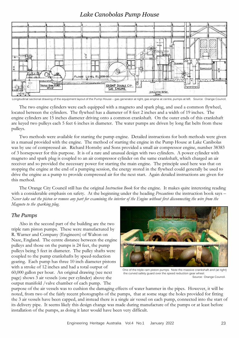
Longitudinal sectional drawing of the equipment layout of the Pump House – gas generator at right, gas engine at centre, pumps at left. Source: Orange Council.
One of the triple ram piston pumps. Note the massive crankshaft and (at right) the curved safety guard over the speed reduction gear wheel.
Source: Orange Council.
Lake Canobolas Pump House
The two engine cylinders were each equipped with a magneto and spark plug, and used a common flywheel,located between the cylinders. The flywheel has a diameter of 8 feet 2 inches and a width of 19 inches. Theengine cylinders are 15 inches diameter driving onto a common crankshaft. On the outer ends of this crankshaftare keyed two pulleys each 5 feet 6 inches in diameter. The water pumps are driven by long flat belts from thesepulleys.
Two methods were available for starting the pump engine. Detailed instructions for both methods were givenin a manual provided with the engine. The method of starting the engine in the Pump House at Lake Canibolaswas by use of compressed air. Richard Hornsby and Sons provided a small air compressor engine, number 38383of 3 horsepower for this purpose. It is of a rare and unusual design with two cylinders. A power cylinder withmagneto and spark plug is coupled to an air compressor cylinder on the same crankshaft, which charged an airreceiver and so provided the necessary power for starting the main engine. The principle used here was that onstopping the engine at the end of a pumping session, the energy stored in the flywheel could generally be used todrive the engine as a pump to provide compressed air for the next start. Again detailed instructions are given forthis method.
The Orange City Council still has the original Instruction Book for the engine. It makes quite interesting readingwith a considerable emphasis on safety. At the beginning under the heading Precautions the instruction book says –Never take out the piston or remove any part for examining the interior of the Engine without first disconnecting the wire from theMagneto to the sparking plug.
The Pumps
Also in the second part of the building are the twotriple ram piston pumps. These were manufactured byR. Warner and Company (Engineers) of Walton onNaze, England. The centre distance between the enginepulleys and those on the pumps is 24 feet, the pumppulleys being 5 feet in diameter. The pulley shafts werecoupled to the pump crankshafts by speed-reductiongearing. Each pump has three 10 inch diameter pistonswith a stroke of 12 inches and had a total output of60,000 gallon per hour. An original drawing (see nextpage) shows 3 air vessels (one per cylinder) above theoutput manifold /valve chamber of each pump. Thepurpose of the air vessels was to cushion the damaging effects of water hammer in the pipes. However, it will benoted, from two of the fairly recent photographs of the pumps, that at some stage the holes provided for fittingthe 3 air vessels have been capped, and instead there is a single air vessel on each pump, connected into the start ofits delivery pipe. It seems likely this design change was made during manufacture of the pumps or at least beforeinstallation of the pumps, as doing it later would have been very difficult.
23Engineering Heritage Australia Vol.4 No.1 January 2022

Cross section of the Pump House building showing the two triple ram pumps, the delivery pipes from each of them, and the 12" cast iron rising main to the servicetank, with its concrete supports. The three air vessels shown on each pump (the original design) were replaced by a single, larger air vessel on each pump (as
built).The rising main, its valves, and its concrete supports are all still in situ (see the photos below). Source: Orange Council.
Lake Canobolas Pump House
Image Right: Shows the silver coloured single air vessel and delivery
pipe from the right-hand pump (in the drawing above), the left-hand pump
(green) and its single air vessel (black). Source: Orange Council.
Image Left: Shows the delivery pipe from the left-hand pump in the drawing above,
rising outside the shed wall, to join the delivery pipe from the other pump, and the start ofthe long 12" rising main on its concrete support.
Source: Peter Bell.
Water from the two pumps was fed into a common cast iron rising main, 12 inches in diameter, with 9/16"thick walls, and just under two miles long. The water flowed through this to a 500,000 gallon service tank, nearly140 feet above the pumps, at an elevation of 3,036 feet on the Cargo Road near the outskirts of Orange. It wasthen reticulated by a 10 inch gravity main to the homes and businesses in the city.
Preservation
The plant operated for the last time in 1957. Thirty years later, and at the instigation of Mr R.N. (Bob)Copleston, Head Teacher of Fitting and Machining at the Orange College of TAFE, Orange City Council gaveapproval for restoration of the building and its equipment. Work commenced in March 1987. Taking part in therestoration work, with Mr Bob Copleston as Project Manager, were students from the Fitting and Machining,Carpentry and Joinery, Painting and Decorating, Plumbing and Welding disciplines of the TAFE College. Mr DickPage and other staff at the College were also involved. The first priority was the removal of water, rust, also drysilt, mud and other debris. Externally the building was overgrown with trees and blackberries some of which hadfound their way into the interior of the structure.
The second stage of the project involved cleaning and dismantling the engine and pumps and removing seizedpistons, cleaning and reassembly. Bearings were also dismantled, cleaned and lubricated before reassembly. Afterthirty years of inactivity the plant was finally able to turn over freely.
24 Engineering Heritage Australia Vol.4 No.1 January 2022

Lake Canobolas Pump House
The final stage of the project was the constructionof a viewing platform and a drive so that the engineand pumps could be viewed in motion. The platform,of welded steel construction, is 72 feet 6 inches long,allowing visitors to walk the full length of the buildingand view the complete plant. The gas engine can nowbe run (for demonstration purposes) by means of afriction drive via a pneumatic-tyred wheel, pressingagainst the rim of the much larger engine flywheel. This pneumatic tyred wheel is driven by a small electricmotor via a 200:1 reduction gearbox.
Image Right: Shows the elevated viewing platform/walkway (left). The
camera looks down on the Hornsby Stockport Gas engine, with the two
pumps seen in the distance. Source: Orange Council.
Statement of Significance
From The Lake Canobolas Pump House Conservation Management Plan:Lake Canobolas Pump House is historically, aesthetically, and technologically significant as a rare surviving early twentieth
century pumping station. The pumping station was built between 1915 and 1918 as part of the Meadow Creek Water SupplyScheme. The purpose of the Scheme was to augment the existing water supply for the growing town of Orange. The Lake CanobolasPump House illustrates historical efforts to provide an adequate water supply for Orange which, unlike many other NSW towns, is notlocated on a river.
The Pump House demonstrates the effectiveness of the Country Towns Water Supply and Sewerage Act 1880 in the provision ofwater supply infrastructure for country towns in NSW.
The Pump House has a raw industrial aesthetic and illustrates working conditions in small industrial work places at thebeginning of the twentieth century.
The Pump House includes a remarkably intact collection of pumping equipment, the purpose of which was to pump water fromMeadow Creek reservoir (Lake Canobolas) to the Cargo Road service reservoir. The Pump House has the ability to provide furtherinformation about the history, technology, operation, and rarity of individual pieces of its equipment collection.
The Pump House demonstrates the reliance of Australia on British technology and manufacturing in the early twentieth century,and the use of technology common at this time.
Conclusion
The Lake Canobolas gas producer, suction gas engine, pumps and associated equipment are quite remarkablein their completeness. The only item missing is a large 112 pound spanner which was used on the large nuts of theengine flywheel boss. Given the necessary funding and expertise it should be possible to restore this historic andrare equipment to working order. As far as this writer knows, the only surviving similar engine in Australia is asmaller Hornsby Suction Gas Engine being run on Propane gas at a museum in Gatton, Queensland. Council hashad experts survey the Lake Canobalas plant and prepare a Conservation Management Plan so that it can beproperly conserved.
The writer wishes to acknowledge the valued assistance freely given to him by Bill Phippen and by the staff ofthe Orange City Council, especially Alison Russell. Bill is also hopeful that in due course, the Pump House and itsequipment will be placed on the NSW Heritage Register and that an Engineers Australia Heritage Marker will beapproved.
References
Records and Documents held by the Orange City Council.Lake Canobolas (Meadow Creek) Pump House, by Mr R N Copleston, 1988.Orange and District Illustrated, Orange City Council, 1989.Lake Canobolas Conservation Management Plan by Kate Higgins and K & H Ainsworth Engineering Pty. Ltd.
25Engineering Heritage Australia Vol.4 No.1 January 2022

Advertisement for Alfred Hugh Harman photography (1874) Source: Graces Guide
A 1939 aerial photo showing (in colour) the Port Melbourne Engineering Works (at left) and the Port Melbourne Engineering Machinery Stores (at right). The view isfrom North (bottom) to South (top). Williamstown Road runs across the width of the photo, Derham St runs off Williamstown Rd and between the coloured
buildings. Part of Port Melbourne Cricket Ground is in the foreground with a match underway. Source: State Library Victoria
Alfred Thomas Harman& the Port Melbourne Engineering Works
by David RadcliffeIntroduction
From 1902 to 1975, the Port Melbourne Engineering Works, later Alfred T Harman & Sons Pty Ltd and SteelCastings Pty Ltd, was nestled amongst Victorian era cottages in Derham Street, Port Melbourne. Initially, theyproduced a variety of steam powered machinery before specialising in winches and winding gear used in maritime,mining and forestry operations. Their reputation for innovation and quality broadened as they diversified intodesigning and making a wide variety of excavation equipment used in infrastructure projects nationwide. Threegenerations of the Harman family led this evolving engineering business founded by Alfred Thomas Harman.
Background
Born in Peckham, Surrey in 1864, Alfred Thomas Harman came from a business background. His father,Alfred Hugh Harman, set up a small photographic printing company and patented a process to produce enlargedphotographs with an artistic finish. In 1879, he began to manufacture gelatine plates for other photographers, abusiness that grew to become the Ilford photographic film company in 1900.1 About the time A.H. Harman
began making photographic plates, heleft his wife and seven children,including Alfred Thomas, who wasthen in his teens. The fallout includedAlfred Thomas and his brother Percyemigrating to Melbourne in the early1880s.
By some accounts, Alfred T Harman began to offer his engineering services in 1885. Aged 24, he marriedMargaret Chrimes in 1888 and while his trade was listed as engineer, he was employed as a lumper on the wharves.By 1891, they had purchased a house in Port Melbourne near the corner of Derham Street, and in 1893 he built aworkshop in the backyard from which he operated his engineering business. He proudly advertised his services asan engineer, blacksmith and brass-founder offering engines and machinery of every description made to order and repaired at lowestpossible rates.2 In the early days of the business Alfred Harman also supplemented his income by working as aferry-master. The story goes that his passion for steam extended to racing steam ferries and on one occasion heran a ferry aground.3
Port Melbourne Engineering Works
In 1902, Alfred Harman purchased land on the south-east side of Derham Street, near the intersection withWilliamstown Road, where he erected the Port Melbourne Engineering Works. A contemporary newspaper articledescribed this new facility in glowing terms.
The engineering establishment of Mr. A. T. Harman is one of the most complete for its size of any about Melbourne, and some
1 Michael Pritchard, The Development & Growth of British Photographic Manufacturing and Retailing 1839-1914, PhD Thesis, De Montfort University, 2010.
2 Standard (Port Melbourne), 30 November, 1895, p. 2.
3 Jim West (2015), A History of Steel Castings Pty Ltd, Unpublished, 4 pages.
26 Engineering Heritage Australia Vol.4 No.1 January 2022

The Machine Shop, Port Melbourne Engineering Works, c.1920. Source: PMHPS Collection.
The Port Melbourne Engineering Works, on the south-east side of Derham Street, c.1920. The Harman family lived in a cottage on the right for a decade. Source: Port Melbourne Historical and Preservation Society (PMHPS) Collection.
Alfred Thomas Harman & the Port Melbourne Engineering Works
first-class work is turned out. The shop, which covers a good area, is fitted up in a most compact manner, and is a very comfortableplace to work in. One of the features of the place is the floor, which is laid- down entirely of hard wood, forming a durable and pleasantwalking foundation; it also gives the place a cleaner appearance than most engineering shops. The plant is a most replete one andcontains the latest drilling and planing machines and lathes. There are also appliances for brass moulding and a smithy's forge. Thepattern room is another feature of the establishment.4
By 1907, the firmemployed 40 workmenand specialised in steampowered winches with 32different models. Theywere also the onlymanufacturer in Australiaof Pickering governors forsteam engines.
There was a deepsense of pride in theengineering capabilities ofthis local manufacturerwhen they won thecontract to supply ahigh-speed winding plantfor the Sydney HarbourCollieries Company tohaul coal from underseadeposits. It was reportedthat this was the largestmachine of its kind inAustralia, built entirelyusing local materials andworkmanship.5
4 Local Industries: Mr Harman's Engineering Establishment, Standard (Port Melbourne), 10 June 1905, p. 3.
5 Mammoth winding plant: An Example of Local Skill, The Age (Melbourne), 19 November 1907, p. 7.
27Engineering Heritage Australia Vol.4 No.1 January 2022

Port Melbourne Machinery Stores, on the north-west side of Derham Street with a cottage on the right, c.1920. Source: PMHPS Collection.
Alfred Thomas Harman & the Port Melbourne Engineering Works
Machinery Store
Alfred Harman not only manufactured machinery but was also an agent for a variety of engineering equipmentmade by others. In 1911, he built the Port Melbourne Machinery Stores opposite the Engineering Works inDerham Street. They sold new and second-hand equipment manufactured by them and by others. This includedpetrol and suction gas engines (horizontal, vertical and compound), mining and sluicing plants, boilers(multi-tubular, vertical, jackass, colonial and Cornish), mining, dredge and ships winches, steam driven gravelpumps, wood working equipment (saw benches, mortising, moulding and planing machines), brick making plantsof all-kinds, nozzles, piping, wire ropes, shafting, pulleys and plummer blocks.6
Family Business
Alfred and Margaret Harman and their growing family of five children moved into Derham Street, next door to the factory in 1905. The business was profitable, and this was reflected in the upward mobility of the Harman family. In 1910, Alfred accompanied his eldest daughter, Margaret, aged 18, on a six-month trip to the ‘old country’ to visit family. On the eve of the trip, all 50 employees attended an ‘at home’ to bid them ‘au revoir’ and present the travellers with gifts, a beautiful travelling rug from the journeymen and tobacco pouch and pipe from the apprentices. There was a musical program performed by the guests and several spoke in eulogistic terms of Mr. Harman and he responded ‘in his usual good-humoured way’.7
Then in 1913, following the death of his father, Mrand Mrs Harman and their second daughter, Clara,visited England. By 1914, the Harman family hadmoved from Port Melbourne to live in the moresalubrious Canterbury, home of the well-to-do inMelbourne's leafy east. The following year, Margaretmarried an engineer from the company, Fred Dehais. However, tragically, she died during childbirth in 1916. Clara and their third daughter, Hazel, each married in1923, with both weddings being featured in Table Talk,a weekly social magazine of the time.
Image at left: The Harman Family – Left to right – Clara, Alfred Thomas
(seated), Alfred Henry, Harold Rowland (seated), Hazel (early 1920s).
Source: PMHPS Collection
6 The Age (Melbourne), 16 August 1913, p. 1.
7 'Au Revoir' to Mr A T Harman, Standard (Port Melbourne), 19 March 1910, p. 2.
28 Engineering Heritage Australia Vol.4 No.1 January 2022

Patent by Alfred Henry Harman for An Improved Log-Hauling Machine (1913). Source: Australian Patent Office .
Harman winches being machined and assembled at the Port Melbourne Engineering Works, c.1920. Source: PMHPS Collection.
Alfred Thomas Harman & the Port Melbourne Engineering Works
Log Haulers & Other Innovations
In 1913, Harman's eldest son, AlfredHenry, aged 24, applied successfully topatent an improved log-hauling machine.Log-haulers were a specialised form ofsteam powered winch used in forestry,especially where the terrain was notsuitable for bullock teams. Log-haulerswere developed in the US in the 1880s andwere being imported into Australia in theearly 1900s. Alfred Henry's innovationcentred on using a stronger frame andhaving a pair of winding drums capable ofbeing operated and reversed independentlyor together. Due to its superior quality, theHarman log hauler came to dominate themarket in Victoria,8 and they were usedacross Australia.
The Harman's were awarded patentsfor several other innovations related towinches and winding machines. These patents related to friction clutches for the drums of hoists (Alfred HenryHarman, 1913), self-lubricating snatch blocks (Alfred Thomas Harman and Jethro Fryer, 1919), friction clutchesfor the drums of hoists, cranes, and winches (Alfred Henry Harman, 1922), and a composite gear wheel (Alfred Thomas Harman and Herbert Bailey, 1925).
By the late 1930s, they offereddiesel powered log-haulers and theirwide range of winches used in shipsand mining were available in electric,diesel, petrol, and steam poweredmodels. Eventually crawler tractorsdisplaced log-haulers for forestrywork. Nevertheless, Harmanwinches continued to be used as anattachment on tractors made byInternational Harvester.
Harman Excavators
A second product line that grewout of Alfred Harman’s coreexpertise in the design andmanufacture of powered winchesand winding systems was excavators. In 1920, they sold their first, arail-mounted, crane excavator with1.5 cu.yard grab bucket, to theMetropolitan Water Supply and
Sewerage Board (MWSS) in Brisbane. It was assembled on-site and used in the construction of the Tarragindireservoir.9 The following year the Brisbane MWSS Board purchased a 1.5 cu.yard Harman steam shovel, reportedto be the first of its type manufactured in Australia.10
8 Peter Evans, The Harman steam logging winch, Australian Forest History Society, Newsletter No. 77, May 2019, pp. 12-13.
9 Water and sewerage, Telegraph (Brisbane), 5 May 1920, p. 4. On Tarragindi hill, Telegraph (Brisbane), 4 November 1921, p. 5.
10 Industrial News and Notes, Daily Commercial News and Shipping List (Sydney), 14 September, 1921, p.9.
29Engineering Heritage Australia Vol.4 No.1 January 2022

Steam powered, rail-mounted Harman grab bucket excavator of the type purchased by theBrisbane Metropolitan Water Supply & Sewerage Board in 1920. Source: Museums Victoria.
Harman steam shovel excavator used by Victorian Railways, c.1930. Source: Public Record Office, Victoria.
Alfred Thomas Harman & the Port Melbourne Engineering Works
The success of these early machines ledto orders from government agencies inVictoria. In 1923, the River MurrayCommission purchased a track mounted, 2cu.yd. Harman dragline weighing 60 tons witha working radius of 60 ft. It was for theexcavation of the lock canal at the weir atMildura. Virtually all the components forthese steam excavators were created in theirPort Melbourne factory. The onlymanufacturing operation performed outsidethe premises was gear cutting.11
Other contracts included a shovel of 0.88cu.yd. capacity weighing 25 tons, built for theVictorian Railways Construction Board in1927, and a 2.25 cu.yd. shovel which weighed70 tons was built for the Melbourne andMetropolitan Board of Works for use inconstruction of the Sylvan Dam in 1928. Bynow their excavators were mounted oncaterpillar tracks.
Over the next decade theydeveloped a series of excavatormodels that could be configuredas shovels, ditchers, skimmers,scoops, draglines, or grabbuckets. The capacity rangedfrom 1/3 cu.yd. up to 3 cu.yd. Initially steam powered, themotive power progressivelychanged to diesel, petrol orelectric depending on theapplication. Eventually therewere four model types: B, C, Dand E.
The early Harmanexcavators were fabricated usingrivets. In 1933 they built theirfirst all-welded machine.12 Australian industry was arelatively early adopter ofarc-welding technology, with thepioneering work by Harry
Grove, who headed the construction department at the Melbourne Metropolitan Gas Company.13 During the late1920s, the arc-welding technology was adopted by Harman’s engineering neighbour across Williamstown Road,Malcolm Moore Ltd, who began making all-welded grab-bucket cranes.14
11 Jim West (2015), A History of Steel Castings Pty Ltd, Unpublished, pp. 4.
12 The Age (Melbourne), 26 September 1933, p. 14.
13 Paul Savage, With Enthusiasm Burning: The Story of Welding and Associated Industries in Australia, 1974.
14 David Radcliffe (2021), Malcolm Moore & Albert Longoni: A Tale of Two Innovative Engineers, EHA Magazine, Vol 3 No. 7, Jan. 2021, pp. 23-30.
30 Engineering Heritage Australia Vol.4 No.1 January 2022
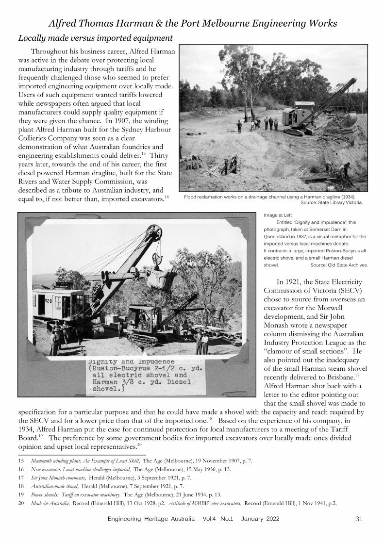
Flood reclamation works on a drainage channel using a Harman dragline (1934). Source: State Library Victoria.
Alfred Thomas Harman & the Port Melbourne Engineering Works
Locally made versus imported equipment
Throughout his business career, Alfred Harmanwas active in the debate over protecting localmanufacturing industry through tariffs and hefrequently challenged those who seemed to preferimported engineering equipment over locally made. Users of such equipment wanted tariffs loweredwhile newspapers often argued that localmanufacturers could supply quality equipment ifthey were given the chance. In 1907, the windingplant Alfred Harman built for the Sydney HarbourCollieries Company was seen as a cleardemonstration of what Australian foundries andengineering establishments could deliver.15 Thirtyyears later, towards the end of his career, the firstdiesel powered Harman dragline, built for the StateRivers and Water Supply Commission, wasdescribed as a tribute to Australian industry, andequal to, if not better than, imported excavators.16
Image at Left:
Entitled “Dignity and Impudence”, this
photograph, taken at Somerset Dam in
Queensland in 1937, is a visual metaphor for the
imported versus local machines debate.
It contrasts a large, imported Ruston-Bucyrus all
electric shovel and a small Harman diesel
shovel. Source: Qld State Archives.
In 1921, the State ElectricityCommission of Victoria (SECV)chose to source from overseas anexcavator for the Morwelldevelopment, and Sir JohnMonash wrote a newspapercolumn dismissing the AustralianIndustry Protection League as the“clamour of small sections”. Healso pointed out the inadequacyof the small Harman steam shovelrecently delivered to Brisbane.17 Alfred Harman shot back with aletter to the editor pointing outthat the small shovel was made to
specification for a particular purpose and that he could have made a shovel with the capacity and reach required bythe SECV and for a lower price than that of the imported one.18 Based on the experience of his company, in1934, Alfred Harman put the case for continued protection for local manufacturers to a meeting of the TariffBoard.19 The preference by some government bodies for imported excavators over locally made ones dividedopinion and upset local representatives.20
15 Mammoth winding plant: An Example of Local Skill, The Age (Melbourne), 19 November 1907, p. 7.
16 New excavator: Local machine challenges imported, The Age (Melbourne), 15 May 1936, p. 13.
17 Sir John Monash comments, Herald (Melbourne), 3 September 1921, p. 7.
18 Australian-made shovel, Herald (Melbourne), 7 September 1921, p. 7.
19 Power shovels: Tariff on excavator machinery. The Age (Melbourne), 21 June 1934, p. 13.
20 Made-in-Australia, Record (Emerald Hill), 13 Oct 1928, p2. Attitude of MMBW over excavators, Record (Emerald Hill), 1 Nov 1941, p.2.
31Engineering Heritage Australia Vol.4 No.1 January 2022
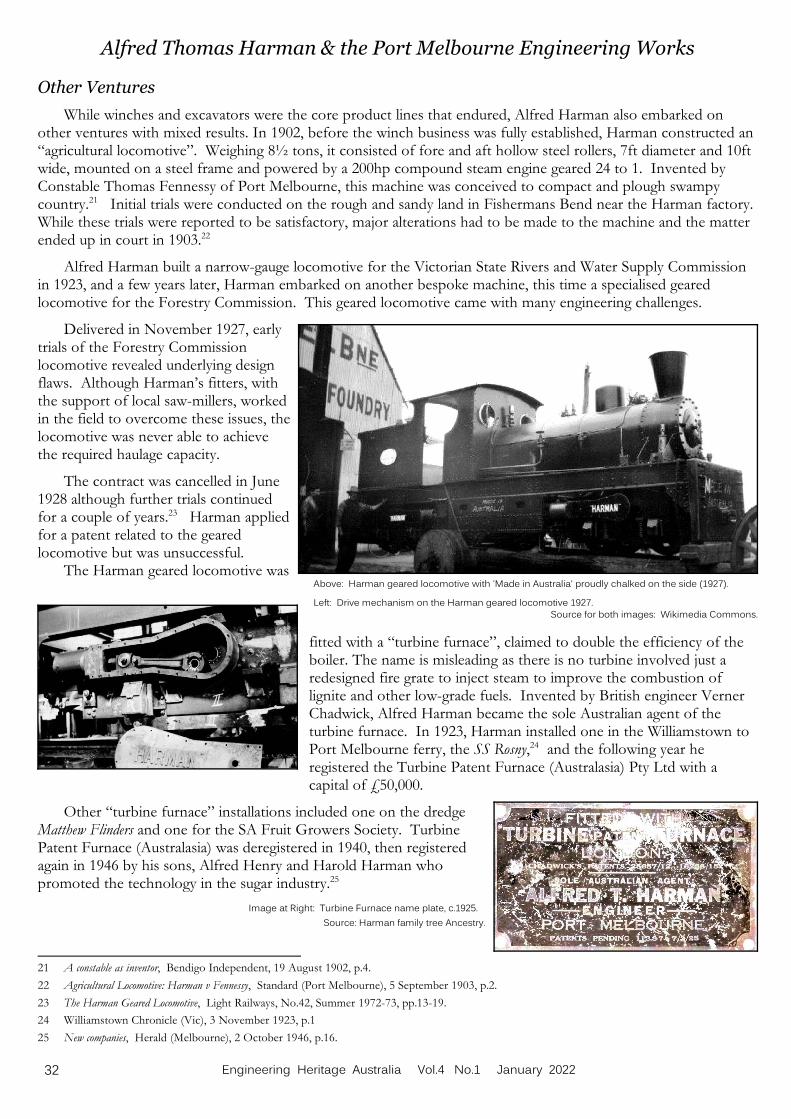
Above: Harman geared locomotive with 'Made in Australia' proudly chalked on the side (1927). Left: Drive mechanism on the Harman geared locomotive 1927.
Source for both images: Wikimedia Commons.
Alfred Thomas Harman & the Port Melbourne Engineering Works
Other Ventures
While winches and excavators were the core product lines that endured, Alfred Harman also embarked onother ventures with mixed results. In 1902, before the winch business was fully established, Harman constructed an“agricultural locomotive”. Weighing 8½ tons, it consisted of fore and aft hollow steel rollers, 7ft diameter and 10ftwide, mounted on a steel frame and powered by a 200hp compound steam engine geared 24 to 1. Invented byConstable Thomas Fennessy of Port Melbourne, this machine was conceived to compact and plough swampycountry.21 Initial trials were conducted on the rough and sandy land in Fishermans Bend near the Harman factory. While these trials were reported to be satisfactory, major alterations had to be made to the machine and the matterended up in court in 1903.22
Alfred Harman built a narrow-gauge locomotive for the Victorian State Rivers and Water Supply Commissionin 1923, and a few years later, Harman embarked on another bespoke machine, this time a specialised gearedlocomotive for the Forestry Commission. This geared locomotive came with many engineering challenges.
Delivered in November 1927, earlytrials of the Forestry Commissionlocomotive revealed underlying designflaws. Although Harman’s fitters, withthe support of local saw-millers, workedin the field to overcome these issues, thelocomotive was never able to achievethe required haulage capacity.
The contract was cancelled in June1928 although further trials continuedfor a couple of years.23 Harman appliedfor a patent related to the gearedlocomotive but was unsuccessful.
The Harman geared locomotive was
fitted with a “turbine furnace”, claimed to double the efficiency of theboiler. The name is misleading as there is no turbine involved just aredesigned fire grate to inject steam to improve the combustion oflignite and other low-grade fuels. Invented by British engineer VernerChadwick, Alfred Harman became the sole Australian agent of theturbine furnace. In 1923, Harman installed one in the Williamstown toPort Melbourne ferry, the SS Rosny,24 and the following year heregistered the Turbine Patent Furnace (Australasia) Pty Ltd with acapital of £50,000.
Other “turbine furnace” installations included one on the dredgeMatthew Flinders and one for the SA Fruit Growers Society. TurbinePatent Furnace (Australasia) was deregistered in 1940, then registeredagain in 1946 by his sons, Alfred Henry and Harold Harman whopromoted the technology in the sugar industry.25
Image at Right: Turbine Furnace name plate, c.1925.
Source: Harman family tree Ancestry.
21 A constable as inventor, Bendigo Independent, 19 August 1902, p.4.
22 Agricultural Locomotive: Harman v Fennessy, Standard (Port Melbourne), 5 September 1903, p.2.
23 The Harman Geared Locomotive, Light Railways, No.42, Summer 1972-73, pp.13-19.
24 Williamstown Chronicle (Vic), 3 November 1923, p.1
25 New companies, Herald (Melbourne), 2 October 1946, p.16.
32 Engineering Heritage Australia Vol.4 No.1 January 2022

Harman Excavator being loaded at Melbourne for shipment toCambodia as part of Columbo Plan (1955).
Source: Overseas Trading Magazine. .
Alfred Thomas Harman & the Port Melbourne Engineering Works
In the early 1920s, there was a major debate about the most effective mechanical method to unload coal fromships in Victorian ports. The authorities favoured grab cranes while local engineer George Chadwick advocated hispatented bucket elevator system.26 Alfred Harman won a tender to build a demonstration plant to allow interestedparties to see the Chadwick elevator system in action.27 One wonders if, when Alfred Harman worked as a lumperin the 1880s, this included unloading sacks of coal.
Changing of the Guard
As might be expected, the company experienced difficulties during the depression of the 1930s and nearly wentunder. Between 1931 and 1934, Harman had orders for only three excavators,28 and they relied heavily on thesecond-hand machinery side of the business. Alfred Henry Harman took over the reins in 1934. He partneredwith James Robertson to purchase the foundry part of the business from his father, forming J.V. Robertson PtyLtd. Then, following the death of Alfred Thomas Harman in 1937, the remainder of the original Port MelbourneEngineering Works was registered as Alfred T Harman & Sons Pty Ltd in 1938, with directors Alfred HenryHarman, Harold Rowland Harman and Margaret Harman.
During the Second World War, J.V. Robertson Pty Ltd shiftedproduction away from brass and iron to focus on steel castings withtheir wide application in defence equipment. They purchased newcasting furnaces and in 1943, the company changed its name to SteelCastings Pty Ltd. In the post-war period, it continued making castingsfor many clients including the Victorian Railways and Malcolm MooreIndustries. In 1955, Alfred Henry's son, Bruce Harman, became themanaging director of Steel Castings.29
Image at Right: War-time inspired Harman excavator advertisement (1944).
Source: Sands and McDougall Directory.
Opportunities and Challenges
Meanwhile, Alfred T Harman & Sons continued to makeexcavators to meet the demands of post-war construction anddevelopment projects. They exported some machines, principallythrough the Columbo Plan. Following the death of Alfred HenryHarman in 1958, the younger son of Alfred T Harman, HaroldRowland Harman, aged 54, took over the family business. However,the world was changing.
In 1962, Alfred T.Harman & Sons wassold to Swedish company Kockum. Operating as Harman-KockumLandsverk Australia Pty Ltd, they continued to make Harmanexcavators as well as the Kockum KL 225 face shovel and the KL250 dragline at the Port Melbourne factory, with a goal ofdeveloping export markets in SE Asia, New Zealand and thePacific.30 However, after Kockum changed its business direction inthe mid-1970s, the name Harman was dropped and production inPort Melbourne ceased. Meanwhile, Steel Castings Pty Ltd movedfrom Derham Street in 1972 but continued to operate frompremises in Bertie Street, Port Melbourne before they eventuallyclosed their doors in 2004.31
26 Grab or bucket: How to handle coal, Herald (Melbourne), 28 June 1921, p.9.
27 Port efficiency and the Chadwick rapid discharge system, Daily Commercial News and Shipping List (Sydney), 22 February 1922, p.16.
28 Power shovels: Tariff on excavator machinery. The Age (Melbourne), 21 June 1934, p. 13.
29 Jim West (2015), A History of Steel Castings Pty Ltd, Unpublished, pp.4.
30 New Australian-Swedish firm’s export plan, Overseas Trading, Vol.17 No.6, p.139.
31 Jim West (2015), A History of Steel Castings Pty Ltd, Unpublished, 4 pages.
33Engineering Heritage Australia Vol.4 No.1 January 2022

Above: Harman log-hauler in the high country ofVictoria, photographed in 2015.
Source: Australianimage.com.au.
Alfred Thomas Harman & the Port Melbourne Engineering Works
Thus, the enterprise that Alfred Thomas Harman founded inthe late 19th century, continued in one form or another, for nearly120 years. Harman’s avowed basis for doing business was “qualitybefore price” and “efficient service before and after sales”. Hisstory illustrates the interplay between ingenuity, enterprise, andindustry policy, specifically tariff protection. It is a microcosm ofthe history of manufacturing in Australia through the 20th century.
Image at Right: The premises of Steel Castings Pty Ltd in Derham St in 1972.
The only external change since these facilities were built as the Port Melbourne
Engineering Works in 1902 is the addition of the tall chimney. Source: PMHPS.
Remainders
As is the case with all manufacturers of constructionequipment, the legacy of Alfred Harman is manifest in numerousrusting machines scattered across the country. Many of these arephotographed where they rest, then posted online while some arepainstakingly restored by enthusiasts.
Left: The Port Melbourne Machinery Stores building in
Derham Street, Port Melbourne (2021).
Photo: David Radcliffe.
The Port Melbourne MachineryStores building still stands in DerhamStreet, Port Melbourne. While thedelightful lettering on the façade,inspired by the arts and craftsmovement, has been thoughtlesslyremoved, a ghostly ‘A Harman’ canstill just be made out.
Tasmania Division Archives & Library Go DigitalBob Taaffe, Chair, Engineering Heritage Tasmania.
In 2014 the Tasmania Division of Engineers Australia moved office from the Royal Engineers building inHobart to the Commonwealth Office Building. The new premises had far less room to hold the archives andlibrary. Engineering Heritage Tasmania was allocated a small amount of space and the rest of the collections wereconsigned to archive boxes and placed in storage. A general box list was created.
The Division was keen to reduce the cost of storage and having nearly all of the collection in storage made ithard to assess exactly what was in the boxes, plus access took around a week for each request. The authorvolunteered to look at digitising the contents, starting with four boxes as a sample.
As there was the desire to eliminate or reduce the storage costs, the questions became what do we do withdocuments after scanning and how were they to be scanned? Taking the second question first. Scanning bounddocuments produces a less than ideal result. It is better to be able to feed the sheets through the scanner. To dothat meant taking documents apart. That was a philosophical question - what is more important, the informationor the media? For us the answer was the information. Now back to the first question – what to do with thedocuments after scanning? It was decided to retain only those printed items that were created by the Division.
The first items chosen for scanning were the Journals of the Institution of Engineers Australia. The Divisionhad a reasonably complete set from 1920 through to the 1960's. They were scanned both in colour and black andwhite. Colour is usually better to preserve photo details. But as the paper and the photos were poor it was noadvantage to continue colour scans. The optical character recognition (OCR) engine was run through the journalsand then the result was assembled so that a single search reviewed every issue in very quick time.
Much of the material is typed, handwritten or photocopied, or books. These items were supposed to comprise48 boxes but ended up closer to 60 boxes. Much of the scanned material still requires proper indexing and filing.
34 Engineering Heritage Australia Vol.4 No.1 January 2022
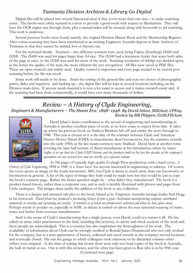
Tasmania Division Archives & Library Go Digital
Digital files will be placed into several functional areas if they cover more than one area – to make searchingeasier. The books were often scanned in colour to provide a good result with respect to illustrations. They willhave the OCR engine run through them, plus a manual index will be created, along with keywords to aid searching. This work is underway.
Several precious books were found, namely, the original Division Minute Book and the Membership Register. After colour scanning they have been transferred to an existing Engineers Australia deposit in State Archives ofTasmania so that they cannot be mislaid, lost or thrown out.
For the technical details: Scanners – two different scanners were used, being Fujitsu (ScanSnap) iX600 andiX500. The iX600 was used for pages larger than A4 size. The iX500 had a document feeder that scans both sidesof the page at once, so the iX500 was used for most of the work. Scanning resolution of 600dpi was decided upon,as the better the quality of the scan, the more efficient the text recognition. All files were saved as PDF files. These are open sourced, and widely used. Quality control is important and every page needed to be viewed postscanning before the file was saved.
Some work still needs to be done: finish the sorting of the general files and scan two boxes of photographicprints, slides and negatives; and backing up – the digital files will be kept in several locations including on theDivision main drive. If anyone needs material it is now a lot easier to access and it makes research easier and, ifthe scanning had been done commercially, it would have cost many thousands of dollars.
Review – A History of Clyde Engineering, Engineers & Manufacturers – The Steam Era: 1898–1948. By David Jehan, MIEAust, CPEng.
Review by Bill Phippen, OAM,FIEAust.
David Jehan’s latest contribution to the record of engineering and manufacturing inAustralia is another excellent piece of work, as we have come to expect from him. It takesup where his previous book on Hudson Brothers left off and carries the story through to1948. This year is chosen as it is the date of the contract between Clyde and AmericanElectro-Motive Diesel (EMD) to manufacture diesel locomotives, but the narrative extendsinto the early 1950s as the last steam contracts were finalised. David hints at another tomecovering the later half century of diesel manufacture in his introduction where he states: Suffice it to say that the Clyde-EMD history and the products built in the last five decades of the company’soperations are not covered here and are worthy of a separate volume.
At 336 pages of typically high-quality Eveleigh Press production, with a hard cover, AHistory of Clyde Engineering, 1898 to 1948 is a ‘must have’ for anyone interested in engineering or railways. Of course,the cover sports an image of the iconic locomotive 3801, but Clyde is about so much more than one locomotive orlocomotives in general. A list of the types of things they built could be made here but that would be just to copythe book’s contents page. Rather the better question might be – what didn’t they manufacture? The book is aproduct-based history, rather than a corporate one, and as such is lavishly illustrated with photos and pages fromClyde catalogues. The images alone justify the addition of the book to any collection.
There is a deeper and unstated sub-plot to the book, hinted at by Engineers Australia heritage leader Neil Hoggin his foreword: David Jehan has produced a fascinating history of how a great Australian manufacturing company contributedimmensely to creating and sustaining our society. It reminds us of what our predecessors achieved and what we have given away. Perhaps words to ponder on, especially in NSW, as debate is carried on about the near universal sourcing of trains,trams and ferries from overseas manufacturers.
Such is the scope of Clyde’s manufacturing that a single person, even David, could not master it all. He hascalled on many other practitioners in the field, including this reviewer, to advise and check sections of the work andthese people are acknowledged. This is a courtesy but also emphasises the thoroughness of his work. Theavailability of information about Clyde can be strongly credited to Ronald James Drummond who not only workedfor the company, but as a man appreciative of history, collected and saved records as the company moved locationsand eventually closed. His was the garage to which colleagues took otherwise to-be-discarded volumes whenoffices were emptied. At the time of writing this review there were only two hard copies of the book in Australia,the bulk in transit at sea. One is with this reviewer, and the other has been given to Ron who is in his 90th year.
(Continued next page)
35Engineering Heritage Australia Vol.4 No.1 January 2022
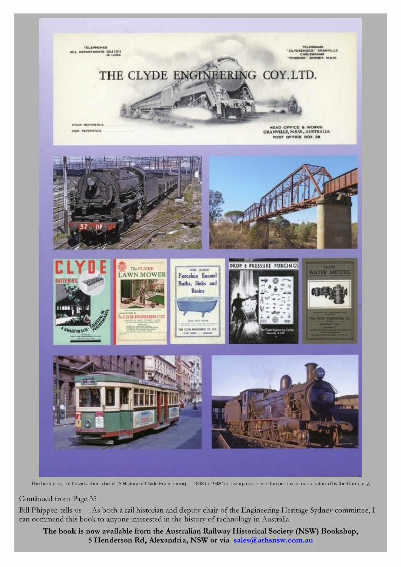
The back cover of David Jehan’s book “A History of Clyde Engineering – 1898 to 1948" showing a variety of the products manufactured by the Company,
Continued from Page 35
Bill Phippen tells us – As both a rail historian and deputy chair of the Engineering Heritage Sydney committee, Ican commend this book to anyone interested in the history of technology in Australia.
The book is now available from the Australian Railway Historical Society (NSW) Bookshop,5 Henderson Rd, Alexandria, NSW or via [email protected]