Efficient Traffic Priority Control for Ambulance Clearance
10
912 | Page Efficient Traffic Priority Control for Ambulance Clearance M.Srinivasan 1 ,K.Naveen 2 ,R.Srivatsan 3 ,J.Thanish 4 ,K.Ramkumar 5 1 Assistant Professor, Department of ECE, KGiSL Institute of Technology, Coimbatore, Tamilnadu, (India) 2,3,4,5 Student, Department of ECE, KGiSL Institute of Technology, Coimbatore, Tamilnadu, (India) ABSTRACT This paper presents an efficient priority control for ambulance clearance. Each ambulance is equipped with radio frequency transmitter (RFTx).We use RF receiver, PIC16F877A, liquid crystal display (LCD), piezo electric buzzer were attached to the traffic signals. It detects ambulance while arriving at 100 meters before reaching the signal.In addition, when an ambulance is approaching the junction it will communicate to the traffic signal in the junction to turn ON the green light. This module uses radio frequency (RF) transmitter, receiver and PIC16F877A for wireless communication between the ambulance and traffic signal. Keywords-RF Transmitter and Receiver, LCD, PIC16F877A, Piezoelectric buzzer, ambulance vehicle, traffic junction. I.INTRODUCTION INDIA is the second most populous Country in the World and is a fast growing economy. Infrastructure growth is slow as compared to the growth in number of vehicles, due to space and cost constraints [1]. Intelligent management of traffic flows can reduce the negative impact of congestion. In recent years, wireless networks are widely used in the road transport as they provide more cost effective options [2]. Technologies like RF Transmitter and Receiver, LCD, PIC16F877A and Piezo electric buzzer can be used in traffic control to provide cost effective solutions. RF is a wireless technology that uses radio frequency electromagnetic energy to carry information between the RF Transmitter and RF Receiver. Some RF systems will only work within the range 100 meters or more. The range of RF is about 3 Hz and 300 GHz and RF Transmitter and Receiver are available for operation in the 868-870 MHZ band in Europe and 902-928 MHZ band in North America [3], [4]. It uses ASK, FSK, OOK, Direct sequence spread spectrum and Frequency-hopping spread spectrum [5]. II.LITERATURE SURVEY Traffic congestion is a major problem in cities of developing Countries like India. Growth in urban population and the middle-class segment contribute significantly to the rising number of vehicles in the cities [6]. Congestion on roads eventually results in slow moving traffic, which increases the time of travel, thus stands- out as one of the major issues in metropolitan cities. In [7], green wave system was discussed; this was used to
-
Upload
khangminh22 -
Category
Documents
-
view
2 -
download
0
Transcript of Efficient Traffic Priority Control for Ambulance Clearance

912 | P a g e
Efficient Traffic Priority Control for Ambulance
Clearance
M.Srinivasan1,K.Naveen
2,R.Srivatsan
3,J.Thanish
4,K.Ramkumar
5
1Assistant Professor, Department of ECE,
KGiSL Institute of Technology, Coimbatore, Tamilnadu, (India)
2,3,4,5Student, Department of ECE,
KGiSL Institute of Technology, Coimbatore, Tamilnadu, (India)
ABSTRACT
This paper presents an efficient priority control for ambulance clearance. Each ambulance is equipped with
radio frequency transmitter (RFTx).We use RF receiver, PIC16F877A, liquid crystal display (LCD), piezo
electric buzzer were attached to the traffic signals. It detects ambulance while arriving at 100 meters before
reaching the signal.In addition, when an ambulance is approaching the junction it will communicate to the
traffic signal in the junction to turn ON the green light. This module uses radio frequency (RF) transmitter,
receiver and PIC16F877A for wireless communication between the ambulance and traffic signal.
Keywords-RF Transmitter and Receiver, LCD, PIC16F877A, Piezoelectric buzzer, ambulance
vehicle, traffic junction.
I.INTRODUCTION
INDIA is the second most populous Country in the World and is a fast growing economy. Infrastructure growth
is slow as compared to the growth in number of vehicles, due to space and cost constraints [1]. Intelligent
management of traffic flows can reduce the negative impact of congestion. In recent years, wireless networks
are widely used in the road transport as they provide more cost effective options [2]. Technologies like RF
Transmitter and Receiver, LCD, PIC16F877A and Piezo electric buzzer can be used in traffic control to provide
cost effective solutions. RF is a wireless technology that uses radio frequency electromagnetic energy to carry
information between the RF Transmitter and RF Receiver. Some RF systems will only work within the range
100 meters or more. The range of RF is about 3 Hz and 300 GHz and RF Transmitter and Receiver are available
for operation in the 868-870 MHZ band in Europe and 902-928 MHZ band in North America [3], [4]. It uses
ASK, FSK, OOK, Direct sequence spread spectrum and Frequency-hopping spread spectrum [5].
II.LITERATURE SURVEY
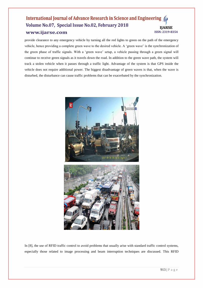
Traffic congestion is a major problem in cities of developing Countries like India. Growth in urban population
and the middle-class segment contribute significantly to the rising number of vehicles in the cities [6].
Congestion on roads eventually results in slow moving traffic, which increases the time of travel, thus stands-
out as one of the major issues in metropolitan cities. In [7], green wave system was discussed; this was used to
913 | P a g e
provide clearance to any emergency vehicle by turning all the red lights to green on the path of the emergency
vehicle, hence providing a complete green wave to the desired vehicle. A ‗green wave‘ is the synchronization of
the green phase of traffic signals. With a ‗green wave‘ setup, a vehicle passing through a green signal will
continue to receive green signals as it travels down the road. In addition to the green wave path, the system will
track a stolen vehicle when it passes through a traffic light. Advantage of the system is that GPS inside the
vehicle does not require additional power. The biggest disadvantage of green waves is that, when the wave is
disturbed, the disturbance can cause traffic problems that can be exacerbated by the synchronization.
.
In [8], the use of RFID traffic control to avoid problems that usually arise with standard traffic control systems,
especially those related to image processing and beam interruption techniques are discussed. This RFID
914 | P a g e
technique deals with multivehicle, multilane, multi road junction areas. It provides an efficient time
management scheme, in
which, a dynamic time schedule is worked out in real time for the passage of each traffic column. The real-time
operation of the system emulates the judgment of a traffic policeman on duty. The number of vehicles in each
column and the routing are properties, upon which the calculations and the judgments are done. The
disadvantage of this work is that it does not discuss what methods are used for communication between the
emergency vehicle and the traffic signal controller. In [9], it proposed a RFID and GPS based automatic lane
clearance system for ambulance. The focus of this work is to reduce the delay in arrival of the ambulance to the
hospital by automatically clearing the lane, in which, ambulance is travelling, before it reaches the traffic signal.
This can be achieved by turning the traffic signal, in the path of the ambulance, to green when the ambulance is
at a certain distance from the traffic junction. The use of RFID distinguishes between the emergency and non-
emergency cases, thus preventing unnecessary traffic congestion. The communication between the ambulance
and traffic signal post is done through the transceivers and GPS.The system is fully automated and requires no
human intervention at the traffic junctions. The disadvantage of this system is it needs all the information about
the starting point, end point of the travel. It may not work, if the ambulance needs to take another route for some
reasons or if the starting point is not known in advance.
Traffic is a critical issue of transportation system in most of all the cities of Countries. This is especially true for
Countries like India and China, where the population is increasing at higher rate. In [10], some of the main
challenges are management of more than 36,00,000 vehicles, annual growth of 7–10% in traffic, roads operating
at higher capacity ranging from 1 to 4, travel speed less than 10 Km/h at some central areas in peak hours,
insufficient or no parking space for vehicles, limited number of policemen. In, currently video traffic
surveillance and monitoring system commissioned in Bangalore city. It involves a manual analysis of data by
the traffic management team to determine the traffic light duration in each of the junction. It will communicate
the same to the local police officers for the necessary actions.
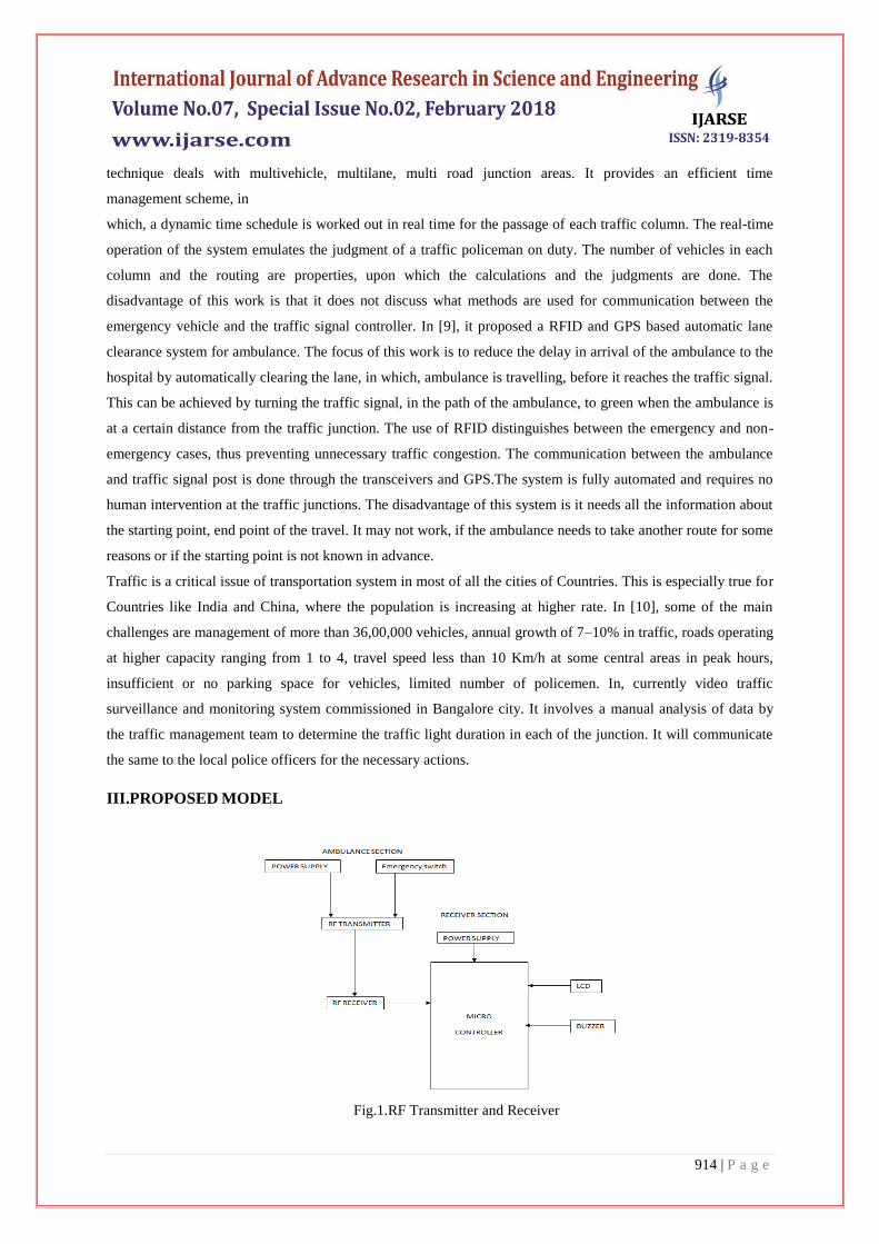
III.PROPOSED MODEL
Fig.1.RF Transmitter and Receiver
915 | P a g e
From the current problem section, it can be seen that, existing technologies are insufficient to handle the
problems of congestion control, emergency vehicle clearance, etc. To solve these problems, we propose to
implement our Intelligent Traffic Control System. It mainly consists of three parts. First part contains automatic
signal control system. The main scope of this project is to provide override facility for ambulance vehicles in
peak hours in traffic signal. Traditionally traffic signal timings are changed automatically to reduce the traffic
density at the junction. In the event of any emergency vehicles such as ambulance, fire brigades etc. requires top
priority to cross signals. Therefore, this system is enhanced by an RF transmitter and receiver facility that helps
to override the ambulance vehicle by flashing green signal in desired direction of such vehicles while blocking
the other lanes by flashing the red signal for some time.
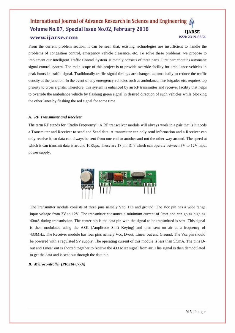
A. RF Transmitter and Receiver
The term RF stands for ―Radio Frequency‖. A RF transceiver module will always work in a pair that is it needs
a Transmitter and Receiver to send and Send data. A transmitter can only send information and a Receiver can
only receive it, so data can always be sent from one end to another and not the other way around. The speed at
which it can transmit data is around 10Kbps. These are 18 pin IC‘s which can operate between 3V to 12V input
power supply.
The Transmitter module consists of three pins namely Vcc, Din and ground. The Vcc pin has a wide range
input voltage from 3V to 12V. The transmitter consumes a minimum current of 9mA and can go as high as
40mA during transmission. The center pin is the data pin with the signal to be transmitted is sent. This signal
is then modulated using the ASK (Amplitude Shift Keying) and then sent on air at a frequency of
433MHz. The Receiver module has four pins namely Vcc, D-out, Linear out and Ground. The Vcc pin should
be powered with a regulated 5V supply. The operating current of this module is less than 5.5mA. The pins D-
out and Linear out is shorted together to receive the 433 MHz signal from air. This signal is then demodulated
to get the data and is sent out through the data pin.
B. Microcontroller (PIC16F877A)

916 | P a g e
Peripheral Interface Control (PIC) 16F series has a lot of advantages as compared to other series. It executes
each
Instruction in less than 200 nanoseconds. It has 40 pins and has 8K program memory and 368 byte data
memory. It is easy to store and send UINs. At the junction, it is easy to store large number of emergency
vehicles. Before switching to green, it should satisfy all the conditions. Simple interrupt option gives the
advantage like jump from one loop to another loop. It is easy to switch any time. It consumes less power and
operates by vehicle battery itself without any extra hardware.
C. Liquid Crystal Display (LCD)
LCD screen is an electronic display module and find a wide range of applications. A 16x2 LCD display is very
basic module and is very commonly used in various devices and circuits. These modules are preferred over
seven segments and other multi segment LEDs. The reasons being: LCDs are economical; easily programmable;
have no limitation of displaying special & even custom characters, animations and so on. A 16x2 LCD means it

917 | P a g e
can display 16 characters per line and there are 2 such lines. In this LCD each character is displayed in 5x7 pixel
matrix. This LCD has two registers, namely, Command and Data. The command register stores the command
instructions given to the LCD. A command is an instruction given to LCD to do a predefined task like
initializing it, clearing its screen, setting the cursor position, controlling display etc. The data register stores the
data to be displayed on the LCD. The data is the ASCII value of the character to be displayed on the LCD.
D. Piezoelectric Buzzer
A piezo buzzer is a sound producing device. The main working principle is based on the theory that,
whenever an electric potential is applied across a piezoelectric material, a pressure variation is generated. A
piezo buzzer consists of piezo crystals in between two conductors. When a potential difference is applied across
these crystals, they push one conductor and pull the other conductor by their internal property. The continuous
pull and push action generates a sharp sound wave. Piezo buzzers generate a loud & sharp sound. So, they are
typically used as an alarm circuits. Also they are used to make an alert of an event, signal or sensor input. A
special characteristic of piezo buzzer is, the sound pitch or level is not depended on the voltage level that is, it
works only in a specific voltage range.Typically, a piezo buzzer produce can generate a sound in the range of 2
to 4 kHz.
III.WORKING MODEL
In this model, there are mainly 3 modules are follows:
E. Emergency Vehicle Clearance System
In this module, there are 2 parts; first part which is RF transmitter is placed in the emergency vehicle.

918 | P a g e
A) B)
C) D)
919 | P a g e
E) F)
G)
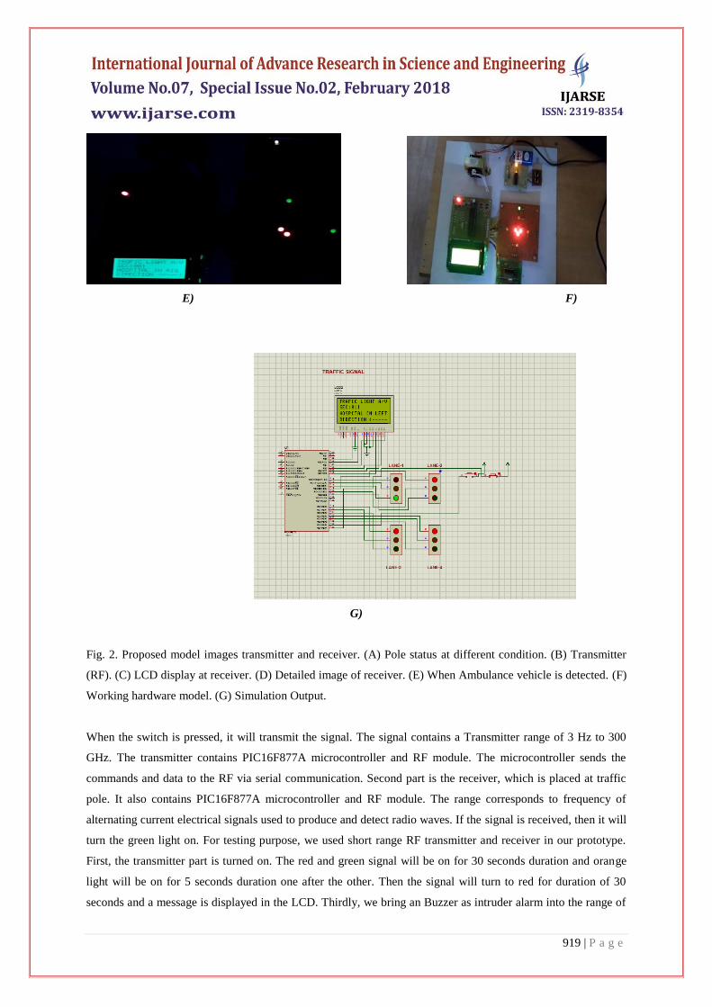
Fig. 2. Proposed model images transmitter and receiver. (A) Pole status at different condition. (B) Transmitter
(RF). (C) LCD display at receiver. (D) Detailed image of receiver. (E) When Ambulance vehicle is detected. (F)
Working hardware model. (G) Simulation Output.
When the switch is pressed, it will transmit the signal. The signal contains a Transmitter range of 3 Hz to 300
GHz. The transmitter contains PIC16F877A microcontroller and RF module. The microcontroller sends the
commands and data to the RF via serial communication. Second part is the receiver, which is placed at traffic
pole. It also contains PIC16F877A microcontroller and RF module. The range corresponds to frequency of
alternating current electrical signals used to produce and detect radio waves. If the signal is received, then it will
turn the green light on. For testing purpose, we used short range RF transmitter and receiver in our prototype.
First, the transmitter part is turned on. The red and green signal will be on for 30 seconds duration and orange
light will be on for 5 seconds duration one after the other. Then the signal will turn to red for duration of 30
seconds and a message is displayed in the LCD. Thirdly, we bring an Buzzer as intruder alarm into the range of
920 | P a g e
traffic signal, and then the green light duration will change to 30 seconds. Fourthly, we bring an emergency
vehicle carrying RF transmitter into the range of RF receiver, and then the traffic light will change to green till
the receiver receives the RF signal as shown in Fig. Figure 5 shows the images of different components and
highlighted features of the proposed work. The signal pole installed in junction. In the default condition, red and
green light will set for 10 seconds. The time period will be varied according to the traffic conditions and
emergency vehicle. Figure shows the transmitter part is placed in the ambulance. It transmits RF signal
continuously. Figure shows the LCD display status at different conditions (in that figure one is normal
conjunction image (traffic signal running as per the default time period) and another one is LCD display status,
when an ambulance coming near to junction. Figure 5.d shows the actual connections of different components
like RF, LCD, Buzzer, interfacing different microcontrollers. Figure shows the status updated at the time of
Ambulance vehicle. If ambulance vehicle is found, then it will immediately turn on green light in the signal. It
sends immediately a message to LCD display. Figure shows the working model of the proposed work.
F. Automatic signal control system
In this module, for experiment purpose, we have used Passive RF transmitter and RF receiver with frequency of
3 Hz to 300 GHz. RF transmitter, when vehicle comes in the range of the receiver, it will transmit to the traffic
signal. The microcontroller connected to the RF transmitter will produce the output in the form of audio and
video communication. The green light duration is set to 30 seconds, if count is between 5 and 9, the green light
duration is set to 20 seconds. If the count is less than 5, the green light duration is set to 10 seconds. The red
light duration will be for 10 seconds and orange light duration will be for 2 seconds.
IV.CONCLUSION AND ENHANCEMENT
With automatic traffic signal control based on the traffic density in the route, the manual effort on the part of the
traffic policeman is saved. As the entire system is automated it requires very less human intervention.
Emergency vehicles like ambulance, fire trucks, need to reach their destinations at the earliest. If they spend a
lot of time in traffic jams, precious lives of many people may be in danger. With emergency vehicle clearance, a
traffic signal turns to green as long as the emergency vehicle is waiting in the traffic junction. The signal turns to
RED, only after the emergency vehicle passes through. Further enhancement can be done to the prototype by
testing it with longer range RF Transmitters and Receivers. Currently, we have implemented system by
considering four road of the traffic junction. It can be improved by extending to all the roads in the multi-road
junction.
REFERENCES
[1] G. Varaprasad and R. S. D. Wahidabanu, ―Flexible routing algorithm for vehicular area networks,‖ in Proc.
IEEE Conf. Intell. Transp. Syst.Telecommun., Osaka, Japan, 2010, pp. 30–38.
[2] B. P. Gokulan and D. Srinivasan, ―Distributed geometric fuzzy multiagent urban traffic signal control,‖
IEEE Trans. Intell. Transp. Syst., vol. 11, no. 3, pp. 714–727, Sep. 2010.
921 | P a g e
[3] K. Sridharamurthy, A. P. Govinda, J. D. Gopal, and G. Varaprasad,―Violation detection method for
vehicular ad hoc networking,‖Security Commun. Netw, to be published.
[Online].Available:http://onlinelibrary.wiley.com/doi/10.1002/sec.427/abstract
[4] M. Abdoos, N. Mozayani, and A. L. C. Bazzan, ―Traffic light control in non-stationary environments based
on multi agent Q-learning,‖ in Proc.14th Int. IEEE Conf. Intell. Transp. Syst., Oct. 2011, pp. 580–1585.
[5] ZigBee Specifications, ZigBee Alliance IEEE Standard
802.15.4k2013,2014.[Online].Available:http://www.zigbee.org/Specifications.aspx
[6] Traffic Congestion in Bangalore—A Rising Concern.
[Online].Available:http://www.commonfloor.com/guide/traffic-congestion-in-bangalore-arising-concern-
27238.html accessed 2013.
[7] A. K. Mittal and D. Bhandari, ―A novel approach to implement green wave system and detection of stolen
vehicles,‖ in Proc. IEEE 3rd Int.Adv. Comput. Feb. 2013, pp. 1055–1059.
[8] S. Sharma, A. Pithora, G. Gupta, M. Goel, and M. Sinha, ―Traffic light priority control for emergency
vehicle using RFID,‖ Int. J. Innov. Eng.Technol, vol. 2, no. 2, pp. 363–366, 2013.
[9] R. Hegde, R. R. Sali, and M. S. Indira, ―RFID and GPS based automatic lane clearance system for
ambulance,‖ Int. J. Adv. Elect. Electron. Eng., vol. 2, no. 3, pp. 102–107, 2013.
[10] P. Sood. Bangalore Traffic Police-Preparing for the
Future.[Online].Available:http://www.intranse.in/its1/sites/default/files/D1-S2- accessed 2011.
[11] Traffic Management Centre. [Online]. Available:
http://www.bangaloretrafficpolice.gov.in/index.php?option=com_content&view=article&id=87&btp=87
accessed 2014.
[12] G. Varaprasad, ―High stable power aware multicast algorithm for mobile ad hoc networks,‖ IEEE Sensors
J., vol. 13, no. 5, pp. 1442–1446, May 2013.
[13] Traffic Solution. [Online].Available: http://phys.org/news/2013–05-physics-green-city-traffic-
smoothly.html, accessed 2013.