Molluscan assemblages on coral reefs and associated hard substrata in the northern Red Sea
Upload
univ-bpclermontCategory
view
2download
0
RESEARCH ARTICLE
Edifice and substrata deformation induced by intrusivecomplexes and gravitational loading in the Mullvolcano (Scotland)
Lucie Mathieu & Benjamin van Wyk de Vries
Received: 19 December 2007 /Accepted: 2 May 2009 /Published online: 28 May 2009# Springer-Verlag 2009
Abstract It is likely that the structure of a volcanic edificecan be significantly modified by deformation caused bylarge, shallow intrusions. Such deformation may interactwith that caused by volcano loading. We explore suchintrusion-related and loading-related deformation with fieldevidence and analogue models. To do this we have chosenthe eroded Palaeogene Mull volcano (Scotland) that had amajor edifice, has well exposed intrusions and significantdeformation. There are thin Mesozoic sedimentary rocksforming ductile layers below the volcano, but theirthickness is insufficient to allow the gravitational spreadingof the volcanic edifice, especially when considering that athick lava pile covers them. Thus intrusive push may havebeen the driving force for deformation. The Mull activitymigrated toward the northwest, forming three successiveintrusive complexes (Centres 1, 2 and 3). Our detailedfieldwork reveals that deformation due to these wasaccommodated on three levels; along thrust planes in lavasequences, along a décollement located in a thin clay-richsediment succession and in basement schists. A relativechronology has been established between different groupsof structures using dyke and sill cross-cutting relationships.Centre 1 is surrounded by a fold and thrust belt leading toradial expansion. In contrast, Centre 2 and 3 are connected
to thrusts located to the south and east, bounded by strike-slip faults, leading to expansion to the southeast. Themigration of centres and the directed sliding of the edificemay be related to the presence to the southeast of low-resistance Dalradian basement that failed significantlyduring growth of Centres 2 and 3. To study the observedrelationships we have carried out scaled analogue models.Models are made with fine powder intruded by a viscousmagma analogue. The models show an intimate relationshipbetween intrusion growth, uplift of the volcano andsubsequent flank sliding. The structures produced can becompared with Mull and suggest that the Centre 1 thrustbelt probably formed following edifice gravitational slidingas a consequence of the uplift associated with Centre 1formation. Centre 2 and 3 are responsible for the sectorsliding of the edifice flank toward the southeast as themagmatic complex became more asymmetric. The featuresobserved at Mull and in the models are similar to those seenon active volcanoes, such as Etna, providing a structuralframework for their deformation and evolution.
Keywords Mull . Scotland . Sub-volcano complex .
Volcanic cones . Cup-shaped intrusions .
Analogue experiments . Structural
Introduction
In the early 20th century the British Geologial Surveyproduced the first large-scale geological maps of the Scottishigneous provinces, including the Isle of Mull (Bailey et al.1924). During this initial survey, various types of igneousintrusions were recognized: ring dykes (circular intrusionsassociated with the formation of a caldera), cone sheets (highconcentrations of small scale conical intrusions, circular in
Bull Volcanol (2009) 71:1133–1148DOI 10.1007/s00445-009-0295-5
Editorial responsibility H. Delgado Granados
L. Mathieu (*)Volcanic and Magmatic Processes group,Trinity College Dublin,Museum Building, Dublin 2, Irelande-mail: [email protected]
B. VriesLaboratoire de Magmas et Volcans,Université Blaise Pascal,5 rue Kessler, 63038 Clermont-Ferrand, France

plan view and oriented toward a focal point at depth) anddyke swarms (high concentrations of vertical intrusions thatpossess similar orientations). Several other features, such aslava fields and igneous centres (former volcanoes or plutons)were also identified in western Scotland. The igneous centreof the Isle of Mull is a deeply eroded volcano that possessesmany of these classical features: a ring dyke (Loch Ba), threesuccessive intrusive complexes that are remnants of aprogressive migration of volcanic activity from the southeastto the northeast of the island, and a fold belt that surroundsthe first intrusive centre. These different structures wereidentified by Bailey et al. (1924). Subsequently, this workhas been modified and complemented by structural (Cheeney1962), petrological (Walker and Skelhorn 1966 ; Sparks1988), geochemical (Kerr et al. 1999) and geochronological(Chambers and Pringle 2001) studies.
The structural relationships in Mull remain poorlydocumented and the structural evolution of the volcano isunknown. Yet Mull is exceptional as it is a deeply erodedvolcanic centre that provides a rare view of the roof of avolcanic-magmatic system. Also it is accessible andabounds in good-quality outcrops. Reconstruction of theevolution of such a volcano can help to understand thestructural evolution and activity of present-day volcanoes.
The aim of this study is to provide a structural model ofthe deformed south-eastern sector. The fieldwork derivedreconstruction is complemented by analogue models. Theseinvolve the injection of an analogue liquid into a granularsubstratum overlain by a cone. With these we model (1) theshape of a sub-volcano complex (Mull’s Centres 1, 2, and3) and (2) the deformation caused in a volcanic cone by theemplacement of such intrusive complexes.
Geological setting
Mull is part of the North Atlantic Igneous Province, formedfollowing the coincidence of a hot spot beneath a thinnedcontinental crust, prior to the formation of the NorthAtlantic Ocean (Morgan 1971; Anderson and Natland2005). From 62 Ma to 58 Ma the magmatic activityproduced a thick basaltic lava succession, intrusive com-plexes and central volcanoes (Saunders et al. 1997) thatnow outcrop in western Scotland, north-eastern Ireland andGreenland. Mull is one of the central volcanoes, formedabout 58 Ma (Hamilton et al. 1998).
Mull volcano overlies thin (<200 m) Triassic to Cretaceoussedimentary cover, as well as Moine and Dalradian metamor-phic basement (Fig. 1). The Moine supergroup on Mull iscomposed of semi-pelite, psammite and the Dalradiansupergroup of grey schist, semi-pelite, and marble. Moinebasement, located in the north-western part of Mull, isseparated from the Dalradian by the northwest trending Great
Glen Fault, which has mainly been active during theCaledonian orogeny (Kennedy 1946). This continentalsinistral strike-slip fault formed at about 428–390 Ma inthe late stage of the Caldeonian orogeny (Stewart et al.1997). It is then affected by post-Caledonian reactivationwith a dextral sense (Roger et al. 1989). The contact betweenthe Moine and Lewisian Gneiss occurs at the Moine thrustjust off the west coast of Mull and the thrust is probably at afew kilometers depth below the igneous complex.
The Mull volcano formed above the Great Glen Fault(Fig. 1). The magma likely infiltrated the inactive fault zonewhile ascending toward the surface. After an initial stage ofuplift, the Mull lava field (tholeiitic basalts and hawaiites)grew in the Inner Hebrides Trough and Colonsay Mesozoic
Fig. 1 a Simplified geological map of the Isle of Mull showingregional faults, basement rocks, the Mull lava field and the Centre1 to 3intrusions; b The location of areas studied and place names mentionedin the text are included. The Java area extends from the Java Point toTorosay castle and includes the Craignure village. The Loch Spelve areais located between the loch Don and Spelve. The Croggan area includesCroggan village and extends to the Port na Muice Duibhe beach. TheLibidil is a transect between the Barachandroman house and the beachsouth of the Glen Libidil valley. The eastern shore of the Loch Buie hasbeen quickly visited (Loch Buie area). Field areas are located near thesea and the shore of each area is studied in great detail, especially for theJava, Loch Spelve and Croggan areas where most of the field campaignwas carried out; MLF stands for Mull Lava Field
1134 Bull Volcanol (2009) 71:1133–1148

sedimentary basins (Emeleus and Bell 2005). The lava pilewas probably over 2 km thick. Then, as the eruption intensityand magma supply decreased, the magma is thought to haveprogressively accumulated around a focal point, forming avolcanic edifice. The existence of this edifice was firstenvisaged by Judd (1878), with the model later supported byBailey et al. (1924) and Walker (1971). Based on the study ofamygdale minerals, Walker (1971) estimated that the top ofthe basaltic volcano was at least 2,200 m above the presentlyobserved lava pile. Considering the Mull lava field as beingpart of the volcanic edifice, he estimated that the slopeexceeded 2° to 3°. The three successive sub-volcanocomplexes of this edifice (Bailey et al. 1924) are aligned,from the oldest to the youngest (Centre 1 to 3), fromsoutheast to northwest (Fig. 1). Centre 1 is surrounded by abelt of deformation mapped as asymmetric, sometimesoverturned and steep folds by Bailey et al. (1924) andCheeney (1962). Some deformation may have occurredbefore the eruption of the first basalts (Cheeney 1962; Bailey1962; Rast et al. 1967) due to gravity sliding around theinitial dome of uplift (van Bemmelen 1937; Walker 1975).The folds later deformed the lava field, where they are cross-cut by early acid and basic intrusions (Bailey et al. 1924)indicating that they formed early in the Mull volcanoevolution.
The small scale igneous intrusions found are sills (concor-dant intrusions emplaced at the interface between lava flowsor sedimentary rocks), cone sheets (mainly located in thecentre of the island) and dykes (discordant sub-verticalintrusions). Most dykes are part of the Mull dyke swarm thattrends southeast (Fig. 1) and was emplaced throughout theMull magmatic activity. The dykes are numerous, thin andpossess variable orientations close to the intrusive com-plexes. However, they become sparse and wide severalkilometres to the southeast of the Mull volcano centre (Jollyand Sanderson 1995; Sloan 1971).
Field study data
Fieldwork was carried out in the eastern and southernpart of the island, around the villages of Craignure, LochDon, Croggan and Loch Buie (Fig. 1). The bulk ofobserved structures were found in the Mull lava pile.For this reason, conclusions presented here concern onlyvolcano-tectonic events that postdate the formation of thislava field that was emplaced 60.57±0.24 Ma to 58.35±0.19 Ma ago (Chambers and Pringle 2001). For conve-nience the field area is divided in several areas. The Javaarea extends from Craignure village to the Torosay castle.The Loch Spelve, Croggan, Libidil and Loch Buie areasare located around the lack, valley and village that give toeach its name. The extent of these areas is shown on
Fig. 1. A large amount of structures has been measured onthe field. A summary of the measurements made in eacharea is given in Table 1. The structures reported in Table 1are then described in more detail.
Lava flows, thrusts and contact between the lava fieldand the Mesozoic sedimentary cover
The basaltic lava flows are several meters to tens of metersthick with a massive core surrounded by vesicular zones. Thelower and upper limits of individual lava flows are commonlyhighlighted by an irregular surface fracture occasionallymarked by sedimentary rocks or by an 1–2 m thick sill. Beingof a similar composition and orientation to the lava flows, thesills are often difficult to distinguish. However, diagnostically,they contain few or no vesicles and usually possess welldeveloped cooling fractures that lavas commonly do not have..The interface between lava flows can rarely be a palaeosoiland their top is weathered in a few places. The contact is inisolated places occupied by sedimentary rocks. For example,in the Croggan area, several lenses of conglomerate are foundat the base of thin lava flow units. These sedimentary rockswere probably deposited by a network of small rivers thatformed between successive eruptions. These outcrops areamong the only evidence found of a significant gap in theactivity between successive eruptions. However, it should bekept in mind that our field area is not extensive and the timingof the activity responsible for the formation of the lava field isbeyond the scope of this paper.
Most lava flows dip toward the Mull intrusive Centres 1to 3 with an angle of 10° to 30°. Lava flows strike N-S andNE-SW in the Loch Spelve area, NE-SW in the Crogganarea and E-W to NW-SE in the Loch Buie area. A largenumber of thrusts (360 faults measured near the shore in theLoch Spelve and Croggan area) in the lava field arerecognised in the Loch Spelve, Croggan, Libidil and lochBuie areas. We show outcrop evidence for these in Fig. 2.Thrusts form striated planes (Fig. 2a) or fractures filled withstriated calcite veins. Some of these fractures, or faultplanes, are infiltrated by late sills 1 to 2 m thick. Faultsplanes are commonly underlain by a crush zone 10 to 5 cmthick (Fig. 2c, d). Most planes are parallel to lava flowcontacts with occasional ramps. However, in the LochSpelve area, thrust faults cross-cut the lava flow planes. Inthis area, thrusts possess two main orientations, 010°E and040°E (Fig. 3a), and are covered with striae oriented 090°Eand 120°E (Fig. 3b). The thrust fault planes strike 020°E to045°E with striae oriented 120–130°E (Fig. 3c); 060°E and115°E in the Croggan, Libidil and Loch Buie arearespectively. The faults dip 10° to 40° to the west or,rarely, toward the east, forming conjugate thrust faults.
The contact between the lava flow pile and Mesozoicsedimentary rocks is exposed on the shore east of the Loch
Bull Volcanol (2009) 71:1133–1148 1135

Tab
le1
Table
compilin
gkeyfielddata
such
asfaultstype
andorientationandthelitho
logies
observed
intheJava,LochSpelve,
Crogg
an,LibidilandLochBuieareas
Area
Java
LochSpelve
Crogg
anLibidil
LochBuie
Lith
olog
y.Moine
gneiss
.Dalradian
schiste
.Tertiary
lava
flow
s.Trias
andJurassic
sedimentary
rocks
.Tertiary
lava
flow
s.Trias
andJurassic
sedimentary
rocks
.Trias
andJurassic
sedimentary
rocks
.Tertiary
lava
flow
s.Tertiary
lava
flow
s.Tertiary
lava
flow
s
Lavaflow
orientation
none
010°Eand04
0°E,10–4
0NW
(or20
E)
030°–0
45°,20–4
5NW
~060
°E,20
NW
~050
°E,10–3
0NE
Sedim
entary
rock
orientation
.14
0°E,40–6
0NE
.03
0°E,35
NW
Non
e06
0°E,20–4
0NW
Non
e.00
0°E,20
EandW
Faults
.SSF
Thrust
Thrust
Thrust
Thrust
.Anticlin
e
Faultorientation
.14
5°Eand17
0°Ea
010°Eand04
0°E,25–3
5NW
(orSE)
020°Eto
045°E,05
–50N
W~0
60°E,20
NW
~110
–120
°E,10–3
0NE
.14
0°E(SSF)
Striatio
norientation
Non
e.09
0–110°Eb
120–
130°E
~150
°E,20
SE
~010
–020
°E,35
NE
.12
0–14
0°Ec
Orientatio
nof
main
horizontal
stress
.SSF:09
5°E
.09
0–110°E
120–
130°E
~150
°E~0
15°E
.Folds:05
5°Eand
090–
070°E
.12
0–14
0°E
Dyk
es.110°Eand14
0°Ed
.12
0–14
5°E
.Rando
min
faultzones
140°E
000–
020°Eand
070–09
0°E
.16
2°Eand14
5°Ee
.12
0°E,14
0°Eand
(040
–050
°E)
Tim
ing
SSFcross-cuttheanticlin
es01
0°Ebefore
040°Ethrust
140°Edy
kescross-cut
120°Edy
kes
Centre1gabb
rointrud
esthrust
Non
e
The
orientations
ofstructures
isameanof
measurementestablishedwith
RosediagramsandEqu
alarea
plotsandtheorientationof
themainho
rizontalstresses
arefrom
theanalysisof
fielddata.
Mostof
thedatafrom
theLibidilandLochBuieareasareshow
nwith
anaverageorientationdu
eto
thesm
allam
ount
ofdata(lessthan
20dataforeach
structure)
obtained
intheseareas.Indeed,
thefieldcampaignisfocalised
ontheJava,LochSpelveandCrogg
anareas.SSFmeans
strike-slip
fault
avertical
axialplaneof,respectiv
ely,
Java
andCraignu
reanticlin
esbfrom
northto
southforthrustsstriking
010°E
cfrom
eastto
westforthrustsstriking
040°E
daltereddy
kescontem
poraneou
sto
faultzone
efreshdy
keslocatedarou
ndfaultzonesor
that
cross-cuttheSSF
1136 Bull Volcanol (2009) 71:1133–1148
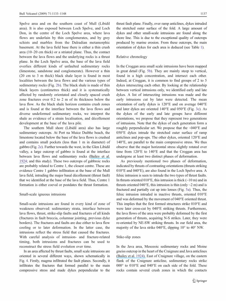
Spelve area and on the southern coast of Mull (Libidilarea). It is also exposed between Loch Spelve, and LochDon, in the centre of the Loch Spelve area, where lavaflows are underlain by thin conglomerates, and by greyschists and marbles from the Dalradian metamorphicbasement. At the lava field base there is either a thin crusharea (10–20 cm thick) or a striated plane. Thus, the contactbetween the lava flows and the underlying rocks is a thrustplane. In the Loch Spelve area, the base of the lava fieldoverlies different kinds of unfaulted sedimentary rocks(limestone, sandstone and conglomerate). However a thin(20 cm to 3 m thick) black shale layer is found in mostlocalities between the lava flows and the various types ofsedimentary rocks (Fig. 2b). The black shale is made of thinblack layers (centimetres thick) and it is systematicallyaffected by randomly orientated and closely spaced crushzone fractures over 0.2 to 2 m of its thickness below thelava flow. As the black shale horizon contains crush zonesand is found at the interface between the lava flows anddiverse undeformed sedimentary rocks, we interpret theshale as evidence of a strain localisation, and décollementdevelopment at the base of the lava pile.
The southern Mull shore (Libidil area) also has largesedimentary outcrops. At Port na Muice Duibhe beach, thelimestone located below the base of the lava flows is crushedand contains small pockets (less than 1 m in diameter) ofgabbro (Fig. 2e). Further towards the west, in the Glen Libidilvalley, a large outcrop of gabbro is found at the interfacebetween lava flows and sedimentary rocks (Bailey et al.1924; and this study). These two outcrops of gabbroic rocksare probably related to Centre 1, the closest centre. These areevidence Centre 1 gabbro infiltration at the base of the Mulllava field, intruding the major basal décollement (thrust fault)that we identified at the base of the lava field. Thus, Centre 1formation is either coeval or postdates the thrust formation.
Small-scale igneous intrusions
Small-scale intrusions are found in every kind of zone ofweakness observed: sedimentary strata, interface betweenlava flows, thrust, strike-slip faults and fractures of all kinds(fractures in fault breccia, columnar jointing, previous dykeborders). The fractures and faults are due either to lava flowcooling or to later deformation. In the latter case, theintrusions reflect the stress field that caused the fractures.With careful analysis of intrusion- and fracture-relatedtiming, both intrusions and fractures can be used toreconstruct the stress field evolution over time.
In an area affected by thrust faults, small scale intrusions areoriented in several different ways, shown schematically inFig. 4. Firstly, magma infiltrated the fault planes. Secondly, itinfiltrates the fractures that formed parallel to the maincompressive stress and made dykes perpendicular to the
thrust fault plane. Finally, over ramp anticlines, dykes intrudedthe stretched outer surface of the fold. A large amount ofdykes and other small-scale intrusions are found along theshore line. This is due to the exceptional quality of outcropsproduced by marine erosion. From these outcrops, the mainorientation of dykes for each area is deduced (see Table 1).
Relative chronology
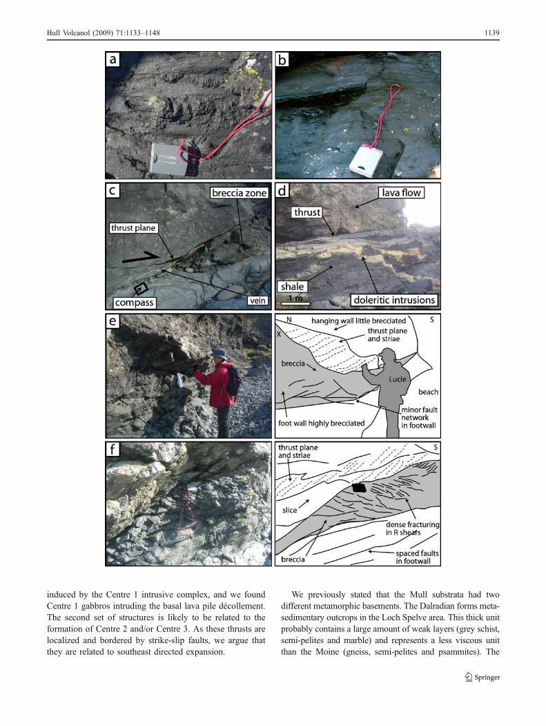
In the Croggan area small scale intrusions have been mappedin great detail (Fig. 5b). They are mainly steep to vertical,found in a high concentration, and intersect each other.Indeed, at Croggan, it is common to find groups of 2 to 5dykes intersecting each other. By looking at the relationshipbetween vertical intrusions only, we identified early and latedykes. A list of intersecting intrusions was made and theearly intrusions cut by later were detected. The meanorientation of early dykes is 120°E and on average 040°Eand later dykes are oriented 140°E and 050°E (Fig. 3c). Asthe dykes of the early and late groups have differentorientations, we propose that they represent two generationsof intrusions. Note that the dykes of each generation form aroughly perpendicular set. We propose that the ~040°E and050°E dykes intrude the stretched outer surface of rampanticlines and pop-ups. The other dykes, oriented 120°E and140°E, are parallel to the main compressive stress. We thusobserve that the major horizontal stress slightly rotated overtime from 120°E to 140°E and that the Croggan area hasundergone at least two distinct phases of deformation.
As previously mentioned two phases of deformation,indicated by thrusts of contrasting orientations (thrusts striking010°E and 040°E), are also found in the Loch Spelve area. Afelsic intrusion is seen to intrude the two types of thrust faults.In thrusts oriented 010°E, this intrusion is thick (~10 m) and inthrusts oriented 040°E, this intrusion is thin (only ~2 m) and isfractured and partially cut up into lenses (Fig. 5a). Thus, thefelsic intrusion intruded in inactive thrusts, oriented 010°Eand was deformed by the movement of 040°E oriented thrust.This implies that the first formed structures strike 010°E andwere later cross-cut by 040°E striking thrusts. Furthermore,the lava flows of the area were probably deformed by the firstgeneration of thrusts, acquiring N-S strikes. Later, they werere-oriented by NE-SW striking thrusts. In our field area, themajority of the lava strike 040°E, dipping 10° to 40° NW.
Stike-slip zones
In the Java area, Mesozoic sedimentary rocks and Moinegneiss outcrop in the heart of the Craignure and Java anticlines(Bailey et al. 1924). East of Craignure village, on the easternflank of the Craignure anticline, sedimentary rocks strike000° to 010°E and 040°E on each side of the fold. Theserocks contain several crush zones in which the contacts
Bull Volcanol (2009) 71:1133–1148 1137

between sandstones, conglomerates, limestones and Moinegneisses strike 140°E and dip more than 60° SW or NE orstrike 040°E, dipping at 40-80° to the NW or SE (Fig. 6a).The deformed areas contain many altered, geometricallycomplex, smooth bordered and crushed doleritic intrusionsoriented mostly 140°E and rarely 110°E (Fig. 6b, c). Theyalso contain centimetre thick sedimentary dykes and calcitetension gashes oriented 140°E that indicate a sinistral strike-slip sense of movement. We propose that sedimentary rocksare crushed and rotated due to 140°E orientated strike-slipfault movement. The doleritic intrusions infiltrate faultplanes (140°E) and tension gashes (110°E). We infer thatdykes acquired their altered and bulging morphology byinfiltrating an active fault zone and were crushed by furtherfault movements. Thus the igneous activity that producedthese dykes is coeval with the fault movements.
Sedimentary strata tilted by the Craignure and Javaanticline formation (Bailey et al. 1924) strike, respectivelyfor each fold, 160°E to 000°E and 140°E with dips of 10°to 30° to the east and the west. Subsequently, strike-slipfault movement locally rotated sedimentary strata from000°E–160°E to 140°E and modified their dips from 10°–30° to 40°–90°. During this deformation, the maximumprincipal stress was probably orientated about 100°E. Thebulk of outcrops visited around the Craignure village areaffected by strike-slip faults. The area affected by faults isat least 300 m wide and probably extends offshore.
The fault sense of motion is resolved from several fieldobservations: (1) the sinistral sense of motion of small-scaleveins parallel to the fault zone, (2) the bulk of sedimentarystrata strikes that range from 140°E to 180°E, indicating ananticlockwise rotation of these rocks by fault movement.Furthermore, the dykes oriented 110°E could either haveintruded tension gashes or could be former 140°E strikingintrusions rotated by fault movement. In either case, thebulk of observations indicate a sinistral sense of motion forthe strike-slip fault zone of the Java area (Fig. 6d). Theamount of displacement induced by this fault is notresolved from field observations.
Numerous smaller strike-slip fault zones (up to 2 m wide)are found in all areas visited. They are similar in morphologyto the Craignure-Java fault: they are characterised by crushedareas containing high concentrations of altered doleriticdykes that intrude and are cut by the fault planes. South ofCentre 1, these faults are radialy distributed around the mainintrusive centres.
Interpretation
OnMull, movements occur along thrusts which are facilitatedby weak décollement layers, whereas folds are rare. It is thuslikely that most of the folds mapped by Bailey et al. (1924) arein fact an association of tilted strata and thrust planes.
However, we continue to refer to the structures that we didnot visit during the field study as folds.
We are able to geometrically relate the two generations ofthrusts to distinct intrusive centres, suggesting a formative link(Fig. 7). This is probably confirmable by more detailedgeochemical and petrographic analysis of the intrusionsassociated with the deformation. The earliest structuresidentified are the following: thrusts striking 020°E–040°E(Croggan area), thrusts oriented 010°E (Loch Spelve area),the Craignure and Java anticlines and the folds mapped byBailey et al. (1924) located north and west from Centre 1(Fig. 7). These structures form a partial ring of deformationaround Centre 1. The latest structures identified in the fieldare: thrusts oriented 020°E–040°E (Croggan area), thrustsoriented 040°E (Loch Spelve area), sinistral strike-slip faultsof the Java area (Fig. 7). Thrusts are roughly concentric inthe south-eastern part of the island, where their orientationrotates, from east to west, from 010°E and 040°E (LochSpelve area) to 035°E (Croggan area) and 060°E to 115°E(Libidil and Loch Buie areas). The thrusts are bordered bysinistral strike-slip faults to the east (strike-slip faults of theJava area) and by vertical fractures to the west (Bailey et al.1924) that we suspect could be dextral strike-slip faults (thisarea is inaccessible and we were unable to check).
Thrusts concentric to the Centre 1 intrusive complex arelikely to be linked to its formation. Bailey et al. (1924)suggested that early deformation formed following the push
Fig. 2 Deformation features seen at outcrop continued; a shows astriated fault plane in the Croggan area. This fault is oriented 030°E,10NW. The outcrop is small, the fault plane appearing in the limitedarea where the hanging wall has been eroded. The fault plane islocated in the lava flows and is overlay by a limited crush zone (10 to15 cm thick). It is a smooth surface covered with lineations (striae)oriented 130°E, 10NW. It also presents several steps normal to thestriae. These steps indicate a reverse sense of movement alongthe fault; b Picture of the faulted contact between black shales of theMesozoic sedimentary cover and the base of the Mull lava field, LochSpelve area. The black shale is oriented 020°E, 40NW and is intrudedby four dykes and sills that also propagate in the overlying lava flows.The intrusions are oriented 020–040°E, 50–57NW (three sills 0.1 to0.5 m thick) and 160°E, 80SE (one dyke 0.3 m thick). c Thrustoriented 120°E, 30NE found below the Loch Buie raised beach, atpresent beach level (Loch Buie area). The thrust hanging wall is wellexposed with strong striae oriented 010–020°E, 35NE, and a foot wallbrecciated zone, below which more widely-spaced minor faults areseen; d Close-up image of the brecciated foot wall of a thrust oriented012°E, 30NW (Loch Spelve area), cut by multiple Riedel (R) shears.Well developed striaes are oriented 090°E, 30W; e Pocket of gabbrointruded into limestone oriented 070°E, 50NW near the base of thelava pile on the southern shore of Mull (Libidil area). The sedimentaryhorizons of the limestone are visible in most of the outcrop. Howeverin some areas around the gabbro the white and grey millimetre thickhorizons of the sedimentary rock are no longer visible, being lost incrush zones. The margins of the gabbro intrusive pockets contain afew macroscopic minerals and are white. These light colored marginsmay have form following a chemical reaction between the intrusivegabbro and its host rock
�
1138 Bull Volcanol (2009) 71:1133–1148
induced by the Centre 1 intrusive complex, and we foundCentre 1 gabbros intruding the basal lava pile décollement.The second set of structures is likely to be related to theformation of Centre 2 and/or Centre 3. As these thrusts arelocalized and bordered by strike-slip faults, we argue thatthey are related to southeast directed expansion.
We previously stated that the Mull substrata had twodifferent metamorphic basements. The Dalradian forms meta-sedimentary outcrops in the Loch Spelve area. This thick unitprobably contains a large amount of weak layers (grey schist,semi-pelites and marble) and represents a less viscous unitthan the Moine (gneiss, semi-pelites and psammites). The
Bull Volcanol (2009) 71:1133–1148 1139

contrast in lithology and competence may have causeddeformation to concentrate in the south-eastern part of Mull,conditioning the slump direction of the edifice.
Analogue modelling
Experimental device and materials used
Structures that form in and around a volcanic edifice duringthe emplacement of an intrusive complex have been investi-gated with analogue modelling. Models consist of theinjection of an analogue magma (Golden Syrup, supplied byTate and Lyle, London) into a granular material. Theexperimental set up is an adaptation of the initial models ofGalland et al. (2006) and Mathieu et al. (2008). The powderused is sieved ignimbrite with a grain size less than 250 μm,including a fine dust portion at around 1 micron that blockspores and stops infiltration of the magma analogue. Thepowder represents the Mull substrata (metamorphic base-ment and lava field) and volcano. The heterogeneouscomposition of the Mull basement (Dalradien, Moine gneissand other lithology) as well as the regional tectonic structure(Moine Thrust, Great Glenn Fault) are not modelled here. Allmodels represent a simplification of the reality. Here, it isproposed that while the inactive Great Glen Fault probablychannelized the rising magma and conditioned the locationof the Mull volcano, it had no further influence on themorphology of the shape of the Mull volcanic cone or on thedevelopment of its sub-volcanic complex. Weak layerscontained in the sedimentary cover (located between themetamorphic basement and the lava field) are modelled by aductile material (silicone). The experimental setup issketched in Fig. 8. The granular and ductile materials areplaced in a wood box, 40×40×40 cm in size. The size of thebox is chosen to fit into the freezer, and test experimentswere made to make sure that the box was large enough tohave limited edge effects. In fact wider models with no walls(just powder slopes) created the same structures. The GoldenSyrup reservoir is connected to the base of the wood box bya tube 2 cm in diameter (Fig. 8). This analogue magma
intrudes due to the pressure difference between the reservoirand the model. Surface deformation is recorded by time-lapse photography. At the end of each experiment, the modelis placed in a freezer for 12 h. The Golden Syrup solidifiesand the intrusion can be excavated and analyzed in detail.
An experimental device designed for Mull
Little is known about the Mull volcanic edifice. Based on thehydrothermal alteration limit (Bailey et al. 1924; Walker 1971),the volcanic cone diameter may roughly be estimated at25 km if we consider that the lava field is located below thevolcanic edifice as a separate unit as postulated by Walker(1971). The Mull magmatic rocks are mostly basic lava flows,intrusive centres, dykes, and cone sheets but a significantamount of acid rocks are also found in the younger intrusivecentres, and ring dykes. Even with the presence of differen-tiated rocks, there is no clear evidence as to the shape of thevolcanic edifice, and it may have had the geometry of a shieldor of a stratovolcano. We have thus tested several conegeometries, with a range of cone heights (Hc=2.5, 5 or 7 cm)and cone slopes (α=10° or 30°). We have tested several lavafield thicknesses (Hb=1, 2, 3 or 4 cm) as the initial pilethickness (before erosion) is uncertain. We have also usedanalogue metamorphic basement of varible thicknesses (Hh=2 to 10 cm). The ductile layer thickness (0.2 cm), the intrusionrate (4.7·10−8 m3 s−1) and the analogue magma liquidviscosity (50 Pa s) remain constant during the whole study(Table 2). Note that the injection of Golden syrup is doneunder a cone. We thus assume that the Mull volcano was
Fig. 3 a Equal area plot ofpoles of thrust planes measuredin the Loch Spelve area;b Rose diagrams showing striaemeasured on thrust planesin the Loch Spelve area;c striae measured on thrustplanes in the Croggan area
Fig. 4 Interpretative sketch of small-scale intrusions emplaced in anarea of thrust faulting
1140 Bull Volcanol (2009) 71:1133–1148
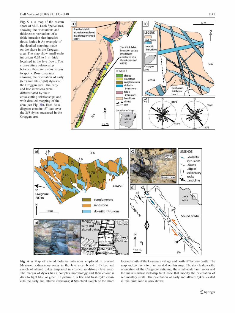
Fig. 6 a Map of altered doleritic intrusions emplaced in crushedMesozoic sedimentary rocks in the Java area; b and c Picture andsketch of altered dykes emplaced in crushed sandstone (Java area).The margin of dykes has a complex morphology and their colour isdark to light blue or green. In picture b, a late and fresh dyke cross-cuts the early and altered intrusions; d Structural sketch of the shore
located south of the Craignure village and north of Torosay castle. Themap and picture a to c are located on this map. The sketch shows theorientation of the Craignure anticline, the small-scale fault zones andthe main sinistral strik-slip fault zone that modify the orientation ofsedimentary strata. The orientation of early and altered dykes locatedin this fault zone is also shown
Fig. 5 a A map of the easternshore of Mull, Loch Spelve area,showing the orientations andthicknesses varitations of afelsic intrusion that intrudesthrust faults; b An example ofthe detailed mapping madeon the shore in the Crogganarea. The map show small-scaleintrusions 0.05 to 1 m thicklocalised in the lava flows. Thecross-cutting relationshipbetween these intrusions is easyto spot. c Rose diagramsshowing the orientation of early(left) and late (right) dykes ofthe Croggan area. The earlyand late intrusions weredifferentiated by theircross-cutting relationships andwith detailed mapping of thearea (see Fig. 5b). Each Rosediagram contains 57 data overthe 258 dykes measured in theCroggan area
Bull Volcanol (2009) 71:1133–1148 1141

already established at the time of the sub-volcano complexformation, and model a late stage of the evolution of thevolcano.
Three distinct and successive intrusive centres are found onMull. The magma migration may have occured alongweakness zones of the substrata. As a result, late magmacomplexes would have been emplaced below the flank of thecone rather than below its summit. This hypothesis ismodelled by offsetting the injection tube from the conesummit. The amount of offset is expressed by the dimension-
less Π-number defined as follows: ΠD=[(D*100)/Øc] with(D) being the horizontal distance between the cone tip andthe injection tube and (Øc) is the diameter of the cone.
Scaling
Table 2 summarizes the parameters used in our experimentsand the scaling values. The scaling used here is similar tothat employed in other analogue experimental work such asMerle and Vendeville (1994), Donnadieu and Merle (1998)
Fig. 7 Structural sketch of thesouthern part of the Mull Islandshowing the orientation andlocation of the thrusts, folds andstrike-slip faults measured onthe field. The geometricalrelationship of these faults tothe Mull intrusive Centres isrepresented by dashed lines. Thelocations of Centre 1 to 3 foci aswell as the geological map areafter Bailey et al. (1924). Thesimplified structural sketch is asummary if the early and late(bold line) structures formed inthe Mull lava flows. It shows abelt of deformation (thrust andfolds) around Centre 1 cross-cutby strike-slip faults and thrustsassociated with Centre 2 and/or3. The cross-section 1 and 2shows the geometry of Centre 1and 2, the intrusion of Centre 1in the Libidil area thrusts andthe relationship between thethrusts of the area and thebasement rocks
1142 Bull Volcanol (2009) 71:1133–1148

and Holohan et al. (2007). In our models 1 cm represents1 km in nature giving a geometric scaling of 10−5. Thestress ratio, calculated from density, gravity, and lengthscales is σ*=5·10−6, meaning that models are about 106
times weaker than natural examples, and that intrusivepressures and cohesion should be scaled accordingly. Toscale viscosity and time, we use the viscosity ratio (µ*) andthe stress ratio (σ*) in: t* = µ*/ σ*. The time ratio (t*) is10−7 (1 h is about 1,000 years), the viscosity ratio (μ*) is5·10−13. The natural viscosity is thus about 1013Pa s. Ouranalogue magma therefore corresponds to a high crystalcontent and partially solidified gabbroic magma body. Suchviscosities are several orders of magnitude lower than thoseassumed for granitic magma bodies (e.g. see discussion inHolohan et al. 2007). The scaling also allows us to modelductile substrata of 1016Pa s and an intrusive flux of 1 m3 s−1
(see Table 2).
Experimental results
The Golden Syrup injections take the shape of cup-shapedintrusions (Fig. 9). The initiation and development of cup-shaped intrusions is discussed in a previous article (Mathieuet al. 2008) and is not further developed here. Theseintrusions possess various aspect ratios and mostly developingfrom the box floor. However, when using greater substratumthicknesses, a dyke first develops before a cup-shapedintrusion initiates. Then, cup-shaped intrusions develop at amaximum depth of 13 cm (Hh + Hc) when using mediumsized cones (Hc=5 cm).
In most experiments, for cone slopes of 10° and 30°,extensional structures develop in the cone whilst the cup-shaped intrusion forms. In the early stage of intrusionformation, radial fractures form on the summit, then curvedand conjugated normal faults develop, forming a croissant-shaped rift in the cone (Fig. 10a). The largest part of thecone (comprising its summit) delimited by the rift is raised,tilted, and spreads as radial grabens form. For cones thatpossess an initial slope of 10°, this tilt results in the increaseof the cone slope and, for 30° cones, their flanks are rapidlyaffected by small collapses. Thrusts develop in thesubstrata, at the base of the tilted block. At the same time,strike-slip faults develop nearly parallel to the spreadingdirection and bound the normal and thrust faults. There isusually a dominant spreading direction that may be causedby model inhomogeneity.
Underneath the cone, the cup-shaped Golden syrupintrusion has a mean diameter of 15 cm (when Hc=5 cm,Fig. 9). In plan view, it is elongated in the rift direction. Incross section, the intrusion is also asymmetric: below thecroissant-shaped rift, the intrusion is steep (50°) and itsopposite side, located below the cone flank that spreads, isless developed and forms a gentler angle with the horizontal
(30°). Golden Syrup pierces the surface at one extremity ofthe rift.
In some experiments, a thrust belt develops in the substrataand radial grabens form in the cone. In experiment M2, forexample, there are four main grabens and numerous second-ary grabens (Fig. 10b). Underneath, the cup-shaped intrusionis circular in plan view. The development of such structuresis promoted by the following parameters: silicone layerplaced at shallow depth (Hb=1 cm), large cone (Hc=7 cm)and thin substratum (Hh=6 cm).
For subsequent experiments, the injection tube is shiftedrelative to the cone summit. Initially, we induced a slightshift: ΠD=10. In this case, the cup-shaped intrusionmorphology and the structures that develop in the coneare very similar to those described above: formation ofnormal and thrust faults delimited by strike-slip faults.Differences consist in the morphology of normal faults:formation of either two antithetic normal faults (straightrift) or of a single normal fault, both types of structuressurrounding or passing through the summit of the cone(Fig. 10c, d). Grabens may form in the block that spreadsand/or in the more stable part of the cone. The spreading isdirected in a direction containing the injection tube and thecone summit. The deformation affects the cone flank thatoverlies the tube. Underneath, the cup-shaped intrusion hasa mean diameter of 10 cm (when Hc=5 cm).
Finally, we move the injection tube significantly: ΠD=20. We distinguish two types of deformation. Sometimes ahorseshoe-shaped normal fault forms and bounds a smallpart of the cone that spreads (Fig. 10e). Underneath, thecup-shaped intrusion morphology is similar to previouslydescribed intrusions and it possesses a mean diameter of10 cm (when Hc=5 cm). For the second type ofdeformation, cone flanks are affected by thrusts rather thanby normal faults (Fig. 8f). The cup-shaped intrusion iscircular in plan view and asymmetric in cross-section: itssteepest and longest part grows toward the cone base and itsshortest part is located below the cone summit.
Fig. 8 Sketch of the experimental device representing the sand andsilicone layers poured in the wood box and the Golden syrup reservoirused to make the basal injection. HGS is the depth emplacement ofGolden syrup intrusions and H/L is their aspect ratio (see Table 2 for adescription of all parameters)
Bull Volcanol (2009) 71:1133–1148 1143
Several other parameters may modify the results. Forexample, when the ductile layer is placed at depth (Hb=3–4 cm), surface deformation is more widely distributed andthe intrusion is lens-shaped. The diameter of the cup-shaped
intrusion depends mainly of its depth of emplacement butalso on the depth of the silicone layer (Hb) and thethickness of the substrata (Hh).
Interpretation
In our models, cup-shaped intrusions form in the substrataand represent analogues of sub-volcano complexes. Most ofthe cup-shaped intrusions are elongated in plan view andasymmetric in cross-section. Such intrusions are responsi-ble for the cone flank lateral spreading. This mobile flank isbounded, in the cone, by normal faults (croissant-shapedrift, straight rift or normal fault), by thrusts in the substrataand by strike-slip faults. Grabens may develop, indicatingthat the cone undergoes radial extension.
As the cup-shaped intrusion grows, it pushes back adome of material above it. Early in its development thisintrusion becomes asymmetric with a steep cup side and aflatter cup side. This is probably due to small defects in thecone construction and an imperfectly centred injection tube.This is the case, for example, when the tube is shiftedslightly (ΠD=10). For this latter type of experiment,asymmetric intrusions develop systematically. This asym-metry forms by the faster growth of a steep part of the cup-shaped intrusion that creates normal faulting above it. Thisfaster growing arm intrudes the normal faults, becomingelongated in plan view.
As the intrusion becomes asymmetric, the dome locatedabove the intrusion also becomes asymmetric and eventu-ally one cone flank begins to slip on the ductile layer. Thissliding movement brings more load above the flatter part of
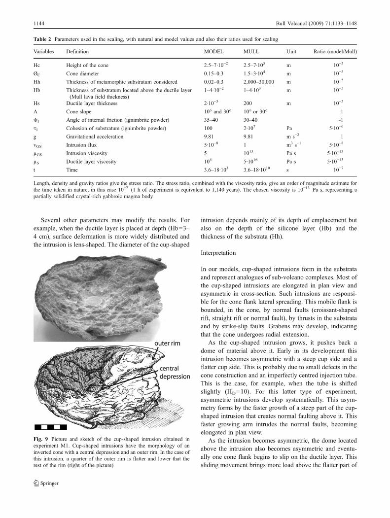
Fig. 9 Picture and sketch of the cup-shaped intrusion obtained inexperiment M1. Cup-shaped intrusions have the morphology of aninverted cone with a central depression and an outer rim. In the case ofthis intrusion, a quarter of the outer rim is flatter and lower that therest of the rim (right of the picture)
Table 2 Parameters used in the scaling, with natural and model values and also their ratios used for scaling
Variables Definition MODEL MULL Unit Ratio (model/Mull)
Hc Height of the cone 2.5–7·10−2 2.5–7·103 m 10−5
ØC Cone diameter 0.15–0.3 1.5–3·104 m 10−5
Hh Thickness of metamorphic substratum considered 0.02–0.3 2,000–30,000 m 10−5
Hb Thickness of substratum located above the ductile layer(Mull lava field thickness)
1–4·10−2 1–4·103 m 10−5
Hs Ductile layer thickness 2·10−3 200 m 10−5
Α Cone slope 10° and 30° 10° or 30° 1
ΦI Angle of internal friction (ignimbrite powder) 35–40 30–40 ~1
τI Cohesion of substratum (ignimbrite powder) 100 2·107 Pa 5·10−6
g Gravitational acceleration 9.81 9.81 m s−2 1
vGS Intrusion flux 5·10−8 1 m3 s−1 5·10−8
µGS Intrusion viscosity 5 1013 Pa s 5·10−13
µS Ductile layer viscosity 104 5·1016 Pa s 5·10−13
t Time 3.6–18·103 3.6–18·1010 s 10−7
Length, density and gravity ratios give the stress ratio. The stress ratio, combined with the viscosity ratio, give an order of magnitude estimate forthe time taken in nature, in this case 10−7 (1 h of experiment is equivalent to 1,140 years). The chosen viscosity is 10−13 Pa s, representing apartially solidified crystal-rich gabbroic magma body
1144 Bull Volcanol (2009) 71:1133–1148

Fig. 10 Pictures and sketches of the following experiments: a ExperimentM1 (Hc=5 cm, ΠD=0), the development of a large cup-shaped intrusionformed a croissant-shaped rift in the cone; b Experiment M2 (Hc=7 cm,ΠD=0), gravitational sliding of the cone induced by the growth of acircular cup-shaped intrusion; experiments M3 and M4 (Hc=5 cm, ΠD=10), formation of a straight rift c and of a normal fault d in the cone
following the formation of elongated cup-shaped intrusions; e ExperimentM5 (Hc=5 cm, ΠD=20), small sector deformation induced by anelongated cup-shaped intrusion; f Experiment M6 (Hc=5 cm, ΠD=20),small rounded cup-shaped intrusion induced compressional structures inthe cone
Bull Volcanol (2009) 71:1133–1148 1145

the intrusion, and this arm responds by developing slowlyas a sill-like body.
The asymmetry leads into an intrusion with a steep longarm on one side and gently-sloped short arm on the otherside (Fig. 11a, b). This observation has implications forsub-volcano complex migration. In later evolution of avolcano, magma may tend to accumulate at the steepest andshallowest part of the cup-shaped intrusion to form asecond intrusive complex. Thus, sub-volcano complexeswould migrate in the direction opposite to the cone flankspreading direction.
Smaller intrusions (diameter = 10 cm) are responsible forlocalized deformation (straight rift or single normal fault)whereas the larger intrusions (diameter = 15 cm) formlarger deformation patterns (croissant-shaped rift) responsi-ble for the spreading of more than half of the cone(Fig. 11a, b).
A pronounced shift of the injection tube (ΠD>20) resultseither in the spreading of a small part of the cone, forming ahorseshoe-shaped normal fault, or, secondly, in the forma-tion of compressive structures in the cone. The first type ofdeformation is similar to that described above and forms inthe same way: partial spreading of the cone induced by the
formation of a cup-shaped intrusion that is asymmetric andelongated in plan view (Fig. 11c). The second type ofdeformation is very different. In these experiments, theGolden Syrup injection is made between the summit andthe base of the cone. Thus, the intrusion tends to developfaster toward the cone base, where the overburden pressureis the smallest. The cup-shaped intrusion exerts a pressuredirected toward the cone top. This intrusion is far too smallto induce the spreading of the whole cone so deformation isdiverted, forming compressive structures (thrusts) on coneflanks, rather than at its base (Fig. 11c).
The experiments show that croissant-shaped rifts boundlarger sliding sectors than straight rift and single normalfaults do. Thus, the more the injection tube is offset fromthe cone summit, the smaller the cone flank area affected bysliding. The offset of the injection tube models themigration of magma along basement structures. We notethat the cone flank sliding direction is, in this case, similarto the sub-volcano complex migration direction.
We sometimes obtain cup-shaped intrusions circular inplan view when ΠD=0. Such intrusions domed the brittleand the ductile substrata above them after which coneflanks undergo a gravitational collapse along the domedductile layer (Fig. 11a). The whole cone spreads, resultingin the formation of radial grabens and of a thrust belt in thesubstratum (eg. experiment M2). If we interrupt the GoldenSyrup injection, this spreading stops. The observed struc-tures are similar to those that form during pure gravitationalspreading with no intrusion effects (e.g. Merle and Borgia1996). However in our models, the ductile layer is not thickenough to allow the gravitational spreading of the cone.Deformation is entirely controlled by the intrusion growthand occurs along the thin décollement layer.
Discussion and conclusions
The Mull Centre 1 has a round shape with a diameter of11×10 km and substrata outcrops in its middle (Bailey et al.1924). These outcrops are interpreted by previous work asbeing a sunken block related to caldera collapse (Baileyet al. 1924). However, the substrata are actually elevatedrelative to the outer levels, contrary to what would beexpected for caldera collapse. In view of this and the upliftseen in the modelling, we suggest that the substrata aremore likely to be a bulge surrounded by a cup-shapedintrusion. Furthermore, the analogue experiments indicate amechanism where uplift associated with the emplacementof Centre 1 could be responsible for the radial sliding of thevolcanic cone on the ductile substrata and hence theformation of the thrust and fold belt (Fig. 7). Centre 1gabbros are also found intimately associated with the earlythrusts, suggesting that some magma injections from the
Fig. 11 Sketches of experiments: plan view and cross-section of thevarious deformation types obtained with analogue models (see text forfurther explanation)
1146 Bull Volcanol (2009) 71:1133–1148

low angle arm of the cup might have occurred to form thethin inward dipping sills seen in the field.
Thrusts are recognized 2 km away from the Centre 1intrusion margin. Comparison with the models thus gives amaximum cone diameter of 28 km. However, deformationis not distributed in a homogenous way. Indeed, deforma-tion is more concentrated in the basalts located in the south-eastern part of the island, above the Dalradian basementthat is also itself significantly deformed. The Dalradianlithologies might have eventually triggered a localizedspreading of part of the cone flank toward the southeast.
The volcanic edifice has probably been affected by aninitial radial expansion, or sliding with a possible faster orgreater movement of its south-eastern flank. Due to thisasymmetry, the north-western part of the sub-volcaniccomplex would have been located at a shallower depth andthis could have promoted later magma accumulation aroundit. This can explain why the magmatic activity progressivelymigrated towards the northwest of the complex. This theoryseems difficult to test in the field as the north-western part ofCentre 1 is hidden by later intrusions (Centre 2 and 3) makingits exact geometry difficult to determine. This migration mightalso have occurred due to regional tectonics: the substrata maycontain a southeast-trending fault set related to extensioncoeval with the Mull dyke swarm. This hypothesis was testedexperimentally by offsetting the injection tube from the conesummit. This offset produced small sliding sectors in a plandirection containing the cone tip and the injection tube. Thus,if we infer that the Mull magma progressively migrated north-westward along weaknesses and faults zones in the substrata,it must be expected to observe north-westward directed cone-flank deformation. As this spreading occurs in the oppositedirection on Mull, this second hypothesis is unrealistic.
Centre 2 is the smallest of the Mull intrusive centres. It hasa circular outline; however, a large part of it is hidden by laterintrusions that make its geometry difficult to appreciate.Centre 3 (diameter = 11×8 km) is north-easterly elongatedand a small part of it is stretched toward the southeast. Centres2 and/or 3 are geometrically associatedwith the thrusts locatedin the south-eastern part of the island and delimited, at least tothe east, by strike-slip sinistral faults and, to the west, byvertical fractures (Bailey et al. 1924) that might be dextralstrike-slip faults (Fig. 7). These structures are similar to thoseobtained during analogue experiments, when the cone hasundergone a localized flank sliding. Centre 2- and 3- relateddeformation has not been differentiated in the field. Theformation of these centres might be responsible for one ormore successive sector slumps directed toward the southeast.In our experiments, spreading is progressive. In the naturalcase, the spreading might have been also progressive (slowslumping) and/or intermittent, being interrupted by instanta-neous sector collapses or rapid sliding periods and quiescentperiods (van Wyk de Vries and Francis 1997). Mull could
have thus undergone recurrent south-eastward directed sectorcollapses. Some of the ‘agglomerates’ identified in theanticlines (Bailey et al. 1924) could be such deposits andmerit re-examination.
A similar geometry of deformation is observed at Etna,where the volcanic substratum raises high underneath theedifice (Chester et al. 1985). Etna seems particularly similarwith the bounding Pernicana fault system being analogousto the Craignure-Java structure. The close association ofmovement on the Pernicana Fault and eruptions from theNortheast Rift of Etna is similar to the intimate intrusion —deformation relationships seen at Craignure.
Lateral escape and structural collapse is also known forother modern volcanoes : the Basse Terre volcanoes ofGuadeloupe — Lesser Antilles (Boudon et al. 1992) and LaReunion island volcanoes of Piton des Neiges and LaFournaise, for example (Oehler et al. 2004).
The Mull example and the analogue experiments thusprovide a model for the development and organisation ofmodern sub-volcanic intrusions, and of the deformationinduced in the modern volcanoes and their substrata. Largeamounts of uplift are likely to occur during major intrusiveevents, causing flanks to slide outwards, creating significantfaulting, flank fragmentation and collapse.
Acknowledgements The authors would like to thank the Mullinhabitants, especially G. and J. Kidd and the Corbett brothers, fortheir help and support during our fieldwork in Scotland. The authorsalso wish to address a special thank to Tate and Lyle for providing theGolden Syrup that has been invaluable in the lab and has helpeddiversify the French cuisine.
References
Anderson DL, Natland JH (2005) A brief history of the plumehypothesis and its competitors; concept and controversy. GeolSoc Am Special Paper 388:119–145
Bailey EB, Clough CT, Wright WB, Richey JE, Wilson GV (1924)Tertiary and post-tertiary geology of Mull, Loch Aline and Oban.Mem Geol Surv Great Brit 44:172–184
Bailey EB (1962) Early tertiary fold movements in Mull. Geol Mag99:478–479
Boudon G, Semet MP, Vincent PM (1992) Les éruptions à écroule-ment de flanc sur le volcan de la Grande Découverte (laSoufriére) de Guadeloupe: implications sur le risque volcanique.Bull Soc Géol Fr 163:159–167
Chambers LM, Pringle MS (2001) Age and duration of activity at the Isleof Mull tertiary igneous centre, Scotland, and confirmation of theexistence of subchrons during anomaly 26r. EPSL 193:333–345
Cheeney RF (1962) Early tertiary fold movements in Mull. Geol Mag99:227–232
Chester DK, Ducan AM, Guest JE, Kilburn CRJ (1985) Mount Etna,the anatomy of a volcano. University press, Cambridge
Donnadieu F, Merle O (1998) Experiments on the indentation processduring cryptodome intrusions: new insights into Mount St.Helens deformation. Geol 26(1):79–82
Bull Volcanol (2009) 71:1133–1148 1147

Emeleus CH, Bell BR (2005) British regional geology: the Palaeogenevolcanic districts of Scotland, 4th edn. British Geological Survey,Nottingham
Galland O, Cobbold PR, Hallot E, de Bremond d’Ars J, Delavaud G(2006) Use of vegetable oil and silica powder for scale modelling ofmagmatic intrusion in a deforming brittle crust. EPSL 243:786–804
Hamilton MA, Pearson DG, Thompson RN, Kelley SP, Emeleus CH(1998) Rapid eruption of Skye lavas inferred from precise U-Pband Ar-Ar dating of the Rum and Cuillin plutonic complexes.Nature 394:260–263
Holohan EP, van Wyk de Vries B, Troll VR (2007) Analogue modelsof caldera collapse in strike-slip tectonic regimes. doi: 10.1007/s00445-007-0166-x
Jolly RJH, Sanderson DJ (1995) Variation in the form and distributionof dykes in the Mull swarm, Scotland. J Struct Geol 17:1543–1557
Judd JW (1878) The secondary rocks of Scotland. Third paper. Thestrata of the Western Coast and islands. Quarterly J Geol SocLond 34:660–743
Kennedy WQ (1946) The Great Glen Fault. J Geol Soc Lond 102(1–4):41–76
Kerr AC, Kent RW, Thomson BA, Seedhouse JK, Donaldson CH(1999) Geochemical evolution of the tertiary Mull volcano,Western Scotland. J Petrol 40:873–908
Mathieu L, van Wyk de Vries B, Holohan EP, Troll VR (2008) Dykes,cups, saucers and sills: Analogue experiments on magmaintrusion into brittle rocks. EPSL 271(1–4):1–13
Merle O, Borgia A (1996) Scaled experiments of volcanic spreading.J Geophys Res 101(B6):13,805–13,817
Merle O, Vendeville B (1994) Experimental modeling of thin-skinnedshortening around magmatic intrusions. Bull Volc 57:33–43
Morgan WJ (1971) Convection plumes in the lower mantle. Nature230:42–43
Oehler JF, Labazuy P, Lénat JF (2004) Recurrence of major flanklandslides during the last 2-Ma-history of Reunion Island. BullVolcanol 66:585–598. doi:10.1007/s0044500403412R
Rast N, Diggens JN, Rast DE (1967) Triassic rocks of the Isle of Mull;their sedimentation, facies, structure, and relationship to theGreat Glen Fault and the Mull caldera. Proc Geol Soc Lond 164(5):299–304
Roger DA, Marshall JEA, Astin TR (1989) Devonian and latermovements on the Great Glen Fault system. J Geol Soc Lond 146(3):369–372
Saunders AD, Fitton JG, Kerr AC, Norry MJ, Kent RW (1997)The North Atlantic igneous province. In: Mahoney JJ, CoffinML (eds) Large Igneous Provinces. AGU Geophysical Mono-graph 100, American Geophysical Union, Washington DC,pp 45–93
Sloan T (1971) The structure of the Mull Tertiary dyke swarm. PhDThesis, University of London
Sparks RSJ (1988) Petrology of the Loch Ba ring dyke, Mull (NWScotland): an example of the extreme differentiation of tholeiiticmagmas. Contrib Mineral Petrol 100:446–461
Stewart M, Strachan RA, Holdsworth RE (1997) Direct field evidencefor sinistral displacements along the Great Glen Fault Zone: lateCaledonian reactivation of a regional basement structure? J GeolSoc Lond 154(1):135–139
Van Bemmelen RW (1937) The cause and mechanism of igneousintrusion: with some Scottish examples. Trans Geol Soc Glasg19:453–492
van Wyk de Vries B, Francis PW (1997) Catastrophic collapse atstratovolcanoes induced by gradual volcano spreading. Nature387:387–390
Walker GPL (1971) The distribution of amygdale minerals in Mulland Morven (western Scotland). In: Murty TVV, Rao SS (eds)Studies in Earth sciences: a volume in honour of William DixonWest. pp. 182–194
Walker GPL (1975) A new concept in the evolution of the Britishtertiary intrusive centers. J Geol Soc Lond 131:121–142
Walker GPL, Skelhorn RR (1966) Some associations of acid and basicintrusions. Earth Sci Rev 2:93–109
1148 Bull Volcanol (2009) 71:1133–1148
Copyright © 2022 FDOKUMEN