
E.CK00500-4 - Rotork
10
E.CK00500-4 Issue 4 Sheet 1/10 Edition: 11.18 Rotork Controls. All rights reserved. Subject to change without notice. Previous data sheets invalid with the issue of the latest data sheets. Due to production tolerance variation, the electrical values shown are averages compiled from Actuator production test data. Values are therefore provided for guidance only. Individual production tests are available on request (nominal load not included). Rotork Controls underwrite rated torque output only (specified tolerance -0/+10%) TITLE: CENTRONIK FUNCTION AND PROTECTION DETAILS MODELS: CENTRONIK UNIT Centork CKC and CKRC range actuators with Centronik controls have an assigned wiring diagram and terminal plan for the specific build of the subject actuator. These are incorporated into one document that details the electrical connections and terminal allocations within the unit. Each document has an assigned code that will be required for actuator commissioning support. Refer to E.CK00045. Centronik Control and Indication Specification The standard Centronik unit includes: - Local control with open/stop/close functionality - Local indication showing position, demand signal and torque values - Remote open/stop/close, ESD and interlock control - 4 configurable remote indication contacts - 1 Monitor relay to provide availability or fault status Power consumption for Centronik Module: Max. 40W. Local Control 2 Non-intrusive selectors are provided on the actuator’s electrical control cover: o Local/Stop/Remote selection, pad-lockable in each position o Open/Close control. Local control may be configured for maintained or inching operation. Control cover may be rotated in 90⁰ increments to suit actuator orientation. Local control is also possible using the optional Centork Actuator Setting Tool. The Setting Tool incorporates dedicated Open, Stop and Close buttons and will operate over a nominal distance of 10 meters from the display window. Local Indication The Centronik display has three main display functions: o Position: segments will show current actuator position. o Torque and position: segments will show current actuator position plus small segments will show torque. o Positioner: segments will show current actuator position plus small segments will show demand value. Remote control There are six control inputs for remote control: - Open, Close, Stop/Maintain - Emergency shut down (ESD) - Open interlock and Close interlock Control can be connected for maintained or inching (push to run) control, see schematics below. Remote control inputs are opto-isolated interfaces with a surge immunity of 2 kV. Standard control is positive switching (negative switching is available if specified). The remote control signals are defined as follows: - Customer fed control circuit supply within the ranges 20-60 VDC, 60-120 VAC - Actuator fed control circuit supply 24 VDC. (120 VAC available if specified) - Current draw from each control input is 5 mA at 24 VDC, 12 mA at 120 VAC - Minimum “ON” voltage: 16 V - Maximum “OFF” voltage: 8 V - Minimum signal duration: 300 ms - Maximum remote control cable capacitance: 2 μF core to core
-
Upload
khangminh22 -
Category
Documents
-
view
2 -
download
0
Transcript of E.CK00500-4 - Rotork
E.CK00500-4
Issue 4
Sheet 1/10 Edition: 11.18
Roto
rk C
ontr
ols.
All
right
s re
serv
ed. S
ubje
ct to
cha
nge
with
out n
otic
e. P
revi
ous
data
she
ets
inva
lid w
ith th
e is
sue
of th
e la
test
dat
a sh
eets
. Due
to p
rodu
ctio
n to
lera
nce
varia
tion,
the
elec
tric
al v
alue
s sh
own
are
aver
ages
com
pile
d fr
om
Actu
ator
pro
duct
ion
test
dat
a. V
alue
s ar
e th
eref
ore
prov
ided
for g
uida
nce
only
. Ind
ivid
ual p
rodu
ctio
n te
sts
are
avai
labl
e on
requ
est (
nom
inal
load
not
incl
uded
). Ro
tork
Con
trol
s un
derw
rite
rate
d to
rque
out
put o
nly
(spe
cifie
d to
lera
nce
-0/+
10%
)
TITLE: CENTRONIK FUNCTION AND PROTECTION DETAILS MODELS: CENTRONIK UNIT
Centork CKC and CKRC range actuators with Centronik controls have an assigned wiring diagram and terminal plan for the specific build of the subject actuator. These are incorporated into one document that details the electrical connections and terminal allocations within the unit. Each document has an assigned code that will be required for actuator commissioning support. Refer to E.CK00045.
Centronik Control and Indication Specification The standard Centronik unit includes:
- Local control with open/stop/close functionality - Local indication showing position, demand signal and torque values - Remote open/stop/close, ESD and interlock control - 4 configurable remote indication contacts - 1 Monitor relay to provide availability or fault status
Power consumption for Centronik Module: Max. 40W.
Local Control 2 Non-intrusive selectors are provided on the actuator’s electrical control cover:
o Local/Stop/Remote selection, pad-lockable in each position
o Open/Close control. Local control may be configured for maintained or inching operation.
Control cover may be rotated in 90⁰ increments to suit actuator orientation.
Local control is also possible using the optional Centork Actuator Setting Tool. The Setting Tool incorporates dedicated Open, Stop and Close buttons and will operate over a nominal distance of 10 meters from the display window.
Local Indication The Centronik display has three main display functions:
o Position: segments will show current actuator position.
o Torque and position: segments will show current actuator position plus small segments will show torque.
o Positioner: segments will show current actuator position plus small segments will show demand value.
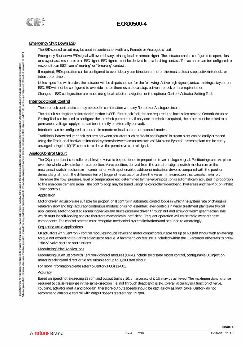
Remote control There are six control inputs for remote control:
- Open, Close, Stop/Maintain - Emergency shut down (ESD) - Open interlock and Close interlock
Control can be connected for maintained or inching (push to run) control, see schematics below.
Remote control inputs are opto-isolated interfaces with a surge immunity of 2 kV. Standard control is positive switching (negative switching is available if specified).
The remote control signals are defined as follows: - Customer fed control circuit supply within the ranges 20-60 VDC, 60-120 VAC - Actuator fed control circuit supply 24 VDC. (120 VAC available if specified) - Current draw from each control input is 5 mA at 24 VDC, 12 mA at 120 VAC - Minimum “ON” voltage: 16 V - Maximum “OFF” voltage: 8 V - Minimum signal duration: 300 ms - Maximum remote control cable capacitance: 2 μF core to core
E.CK00500-4
Issue 4
Sheet 2/10 Edition: 11.18
Roto
rk C
ontr
ols.
All
right
s re
serv
ed. S
ubje
ct to
cha
nge
with
out n
otic
e. P
revi
ous
data
she
ets
inva
lid w
ith th
e is
sue
of th
e la
test
dat
a sh
eets
. Due
to p
rodu
ctio
n to
lera
nce
varia
tion,
the
elec
tric
al v
alue
s sh
own
are
aver
ages
com
pile
d fr
om
Actu
ator
pro
duct
ion
test
dat
a. V
alue
s ar
e th
eref
ore
prov
ided
for g
uida
nce
only
. Ind
ivid
ual p
rodu
ctio
n te
sts
are
avai
labl
e on
requ
est (
nom
inal
load
not
incl
uded
). Ro
tork
Con
trol
s un
derw
rite
rate
d to
rque
out
put o
nly
(spe
cifie
d to
lera
nce
-0/+
10%
)
Emergency Shut Down ESD The ESD control circuit may be used in combination with any Remote or Analogue circuit.
Emergency Shut down ESD signal will override any existing local or remote signal. The actuator can be configured to open, close or stayput as a response to an ESD signal. ESD signals must be derived from a latching contact. The actuator can be configured to respond to an ESD from a “making” or “breaking” contact.
If required, ESD operation can be configured to override any combination of motor thermostat, local stop, active interlocks or interrupter timer.
Unless specified with order, the actuator will be dispatched set for the following: Active high signal (contact making), stayput on ESD. ESD will not be configured to override motor thermostat, local stop, active interlock or interrupter timer.
Changes in ESD configuration are made using local selector navigation or the optional Centork Actuator Setting Tool.
Interlock Circuit Control The Interlock control circuit may be used in combination with any Remote or Analogue circuit.
The default setting for the interlock function is OFF. If interlock facilities are required, the local selectors or a Centork Actuator Setting Tool can be used to configure the interlock parameters. If only one interlock is required, the other must be linked to a permanent voltage supply (this can be internally or externally derived).
Interlocks can be configured to operate in remote or local and remote control modes.
Traditional hardwired interlock systems between actuators such as “Main and Bypass” in steam plant can be easily arranged using the Traditional hardwired interlock systems between actuators such as “Main and Bypass” in steam plant can be easily arranged using the IQ “S” contacts to derive the permissive control signal.
Analog Control Circuit The CK proportional controller enables the valve to be positioned in proportion to an analogue signal. Positioning can take place over the whole valve stroke or a set portion. Valve position, derived from the actuators digital switch mechanism or the mechanical switch mechanism in combination with a pot enabled additional indication drive, is compared with the position demand signal input. The difference (error) triggers the actuator to drive the valve in the direction that cancels the error. Therefore the flow, pressure, level or temperature etc. determined by the valve’s position is automatically adjusted in proportion to the analogue demand signal. The control loop may be tuned using the controller’s deadband, hysteresis and the Motion Inhibit Timer controls.
Application
Motor-driven actuators are suitable for proportional control in automatic control loops in which the system rate of change is relatively slow and high accuracy continuous modulation is not essential; level controls in water treatment plants are typical applications. Motor operated regulating valves and sluice gates are driven through nut and screw or worm gear mechanisms which must be self-locking and are therefore mechanically inefficient. Frequent operation will cause rapid wear of these components. The control scheme must recognize mechanical system limitations and be tuned to accordingly.
Regulating Valve Applications
CK actuators with Centronik control modules include reversing motor contactors suitable for up to 60 starts/hour with an average torque not exceeding 33% of rated actuator torque. A hammer blow feature is included within the CK actuator drivetrain to break “sticky” valve seats or obstructions.
Modulating Valve Applications
Modulating CK actuators with Centronik control modules (CKRC) include solid state motor control, configurable DC injection motor breaking and direct drive are suitable for up to 1,200 starts/hour.
For more information please refer to Centork PUB111-001.
Accuracy
Based on speed not exceeding 29 rpm and output turns ≥ 10, an accuracy of ≤ 1% may be achieved. The maximum signal change required to cause response in the same direction (i.e. not through deadband) is 1%. Overall accuracy is a function of valve, coupling, actuator inertia and backlash, therefore outputs speeds should be kept as low as practicable. Centork do not recommend analogue control with output speeds greater than 29 rpm.

E.CK00500-4
Issue 4
Sheet 3/10 Edition: 11.18
Roto
rk C
ontr
ols.
All
right
s re
serv
ed. S
ubje
ct to
cha
nge
with
out n
otic
e. P
revi
ous
data
she
ets
inva
lid w
ith th
e is
sue
of th
e la
test
dat
a sh
eets
. Due
to p
rodu
ctio
n to
lera
nce
varia
tion,
the
elec
tric
al v
alue
s sh
own
are
aver
ages
com
pile
d fr
om
Actu
ator
pro
duct
ion
test
dat
a. V
alue
s ar
e th
eref
ore
prov
ided
for g
uida
nce
only
. Ind
ivid
ual p
rodu
ctio
n te
sts
are
avai
labl
e on
requ
est (
nom
inal
load
not
incl
uded
). Ro
tork
Con
trol
s un
derw
rite
rate
d to
rque
out
put o
nly
(spe
cifie
d to
lera
nce
-0/+
10%
)
Configuration Analogue Signal Types and Ranges
mA: 0-5, 0-10 and 0-20 (4-20); input impedance 220 Ω
Volts: 0-5, 0-10 and 0-20; input impedance 5.7 kΩ
Controller can be configured to close, open or move to the position set for low or high signal input. The analogue control signal can be inverted to suit a “high to close” control architecture.
Action on Loss of Signal
Stayput, move to high or low signal positions.
With live zero current control loops i.e. 4-20mA, at 50% of the set low signal (2mA) the controller invokes the set action.
NOTE: As the signal decays, movement toward the set low signal position may occur until it is determined as “lost”.
Tuning Deadband
Deadband range 0% - 25.5%
Used to allow for overrun or demand signal oscillation and so prevent “hunting” or unnecessary movement (movement without effecting a required control change).
For example, a 5% deadband will cause the motor to be de-energised once the actuator position is within 5% of the demand position. Subsequent inertia will then bring the final position nearer the demand positon.
Hysteresis
Hysteresis range 0 % - 25.5 % but must always be ≤ to the Deadband setting.
Hysteresis further refines the accuracy of the position controller.
The controller will run the actuator towards the demand position until the deadband position is reached and then continue by the valve of the hysteresis setting. The actuator will not restart unless it overshoots and runs outside the deadband or a change places the demand position out the deadband.
MIT
MIT range 0 – 255 seconds.
The Motion Inhibit Timer (MIT) may be set to prevent the actuator removing excessively or unnecessarily. Oscillating signals and/or response to small signal changes can effectively be filtered out. A delay is set (in seconds) as a period of inactivity after a response to a signal change. The actuator will not move until the MIT has elapsed and the demand signal changes sufficiently to move outside the deadband.
Interrupter Timer Where the operating time of the valve must be reduced to prevent hydraulic shock (“water hammer”) or prevent surges, the Interrupter Timer option can be included. Pulsed operation with independently adjustable “on” and “off” time periods in the range 2-100 seconds can be selected to operate over any portion of the closing and/or opening valve stroke. The Interrupter Timer is active for both local and remote control and can be configured to be bypassed under ESD operation if required.
Partial Stroke Function The actuator can be set to perform a partial stroke test upon a valid signal being applied to the Open Interlock. This allows for systems to be tested periodically without interruption, to verify valve movement.
The partial stroke function is enabled by selecting partial stroke in the interlock menu. Further partial stroke functions such as Start Limit, Position and Time can then be adjusted to suit the application. As the function uses the Open Interlock input, the interlock function cannot be used with partial stroking. For extra diagnostic coverage, there are three relay functions that can be used – Partial Stroke Active, Partial Stroke Error and Partial Stroke Pass. These can be configured to any of the Centronik relays, refer to Centork PUB111-005.
E.CK00500-4
Issue 4
Sheet 4/10 Edition: 11.18
Roto
rk C
ontr
ols.
All
right
s re
serv
ed. S
ubje
ct to
cha
nge
with
out n
otic
e. P
revi
ous
data
she
ets
inva
lid w
ith th
e is
sue
of th
e la
test
dat
a sh
eets
. Due
to p
rodu
ctio
n to
lera
nce
varia
tion,
the
elec
tric
al v
alue
s sh
own
are
aver
ages
com
pile
d fr
om
Actu
ator
pro
duct
ion
test
dat
a. V
alue
s ar
e th
eref
ore
prov
ided
for g
uida
nce
only
. Ind
ivid
ual p
rodu
ctio
n te
sts
are
avai
labl
e on
requ
est (
nom
inal
load
not
incl
uded
). Ro
tork
Con
trol
s un
derw
rite
rate
d to
rque
out
put o
nly
(spe
cifie
d to
lera
nce
-0/+
10%
)
Protection Features
The CK Range of actuators supplied with Centronik control modules include the following protection features:
Torque protection:
If the torque produced in operating the valve when closing or opening reaches that set for the active torque switch, the motor will be de-energized. The torque switches are independently configurable in the range 40 - 100% of rated torque. Local and remote indication of torque trip is provided.
Motor over temperature protection
CK range actuators include multiple thermostat protection devices embedded within the motor stator windings. The thermostats will trip and de-energize the motor if the temperature exceeds the designed rating. Local and remote indication of thermostat tripped is available. An active thermostat trip can be overridden during an ESD operation.
Automatic phase rotation correction
The actuator will always run in the correct direction regardless of the sequence of power supply connection.
Lost phase protection
If any one or more power supply phases are lost, the motor cannot be energized. Local and remote indication of lost phase is available.
Jammed valve protection
Should the actuator stall when attempting to unseat a valve stuck in its seat, the motor will be de-energized within 5 seconds, preventing damage. Local and remote indication of jammed valve is available.
Instantaneous reversal protection
The motor control logic introduces a delay in switching the motor as a response to instant reversal of control signals, preventing contact damage to the integral contactor. Over torque transients due to switching high inertia loads are prevented from causing a torque trip by the motor control logic.
ASTD Automatic Self-Test and Diagnosis
On power up the actuator automatically tests its vital operational circuits and memory devices to ensure correct operation. In the unlikely event of a device problem the Centronik module will diagnose the cause(s) and automatically present this information on the Centronik display. Electrical operation may be inhibited to prevent potential damage to the actuator and/or valve. The error should then be investigated and any necessary actions performed by maintenance personnel to resolve the issue. Local and remote indication of a fault status is available.
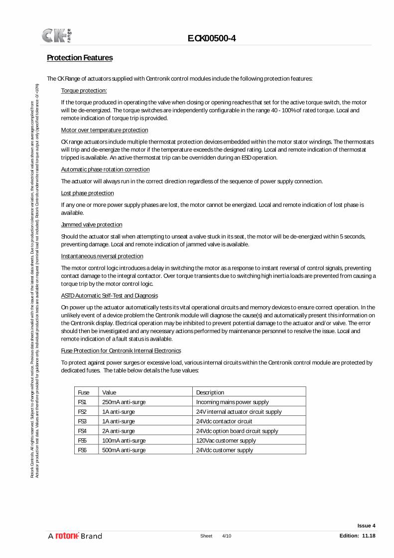
Fuse Protection for Centronik Internal Electronics
To protect against power surges or excessive load, various internal circuits within the Centronik control module are protected by dedicated fuses. The table below details the fuse values:
Fuse Value Description FS1 250mA anti-surge Incoming mains power supply
FS2 1A anti-surge 24V internal actuator circuit supply FS3 1A anti-surge 24Vdc contactor circuit
FS4 2A anti-surge 24Vdc option board circuit supply FS5 100mA anti-surge 120Vac customer supply FS6 500mA anti-surge 24Vdc customer supply

E.CK00500-4
Issue 4
Sheet 5/10 Edition: 11.18
Roto
rk C
ontr
ols.
All
right
s re
serv
ed. S
ubje
ct to
cha
nge
with
out n
otic
e. P
revi
ous
data
she
ets
inva
lid w
ith th
e is
sue
of th
e la
test
dat
a sh
eets
. Due
to p
rodu
ctio
n to
lera
nce
varia
tion,
the
elec
tric
al v
alue
s sh
own
are
aver
ages
com
pile
d fr
om
Actu
ator
pro
duct
ion
test
dat
a. V
alue
s ar
e th
eref
ore
prov
ided
for g
uida
nce
only
. Ind
ivid
ual p
rodu
ctio
n te
sts
are
avai
labl
e on
requ
est (
nom
inal
load
not
incl
uded
). Ro
tork
Con
trol
s un
derw
rite
rate
d to
rque
out
put o
nly
(spe
cifie
d to
lera
nce
-0/+
10%
)
Control Options
Hardwired Discrete Remote Control
The Centronik control module can facilitate six standard hardwired inputs for actuator control functions. These are galvanic isolated discrete inputs with the following functions: open, close, stop/maintain, ESD, open interlock and close interlock. Minimum pulse length is 300ms with minimum ON voltage of 16V (maximum OFF voltage of 8V). Each input can accommodate 20-60VDC, 60-120VAC. Current draw from each control input is 5mA at 24VDC, 12mA at 120VAC. Field wiring should have a maximum core to core capacitance of 2µF.
Open and close inputs are active high. The stop input is active low but has dual functionality. A high signal will cause pulsed open or close input signals to “maintain” until a limit position or torque stops the operation. A low signal will stop existing maintained operation and return remote hardwired control to “push-to-run” operation. Interlock inputs are active low and will prevent operation in the applicable direction unless a high signal is present. Both interlock inputs share a common connection with open, close and stop command inputs and must therefore use the same control voltage.
The ESD input can be active low or active high depending on configuration. This input has a separate common connection to accommodate independent emergency shutdown systems. The ESD action is fully configurable and can be set to override local stop, active interlocks, interrupter timer and a thermostat trip.
ISOLATES REMOTES
If additional remote inputs are required, the CK2 remote option board can be fitted inside the Centronik module. The CK2 remote may by 24VDC type or 115VAC type isolating board.
If the Centronik module utilises 24VDC type board, each input can accommodate 20-60VDC. Current draw from each control input is 5 mA at 24VDC. If the Centronik module utilises 115VAC type board, Each input can accommodate 60-120VAC. Current draw from each control input is 12 mA at 120VAC.
Note: Please contact the manufacturer, if in doubt of the CK2 remote optional type board used.
E.CK00500-4
Issue 4
Sheet 6/10 Edition: 11.18
Roto
rk C
ontr
ols.
All
right
s re
serv
ed. S
ubje
ct to
cha
nge
with
out n
otic
e. P
revi
ous
data
she
ets
inva
lid w
ith th
e is
sue
of th
e la
test
dat
a sh
eets
. Due
to p
rodu
ctio
n to
lera
nce
varia
tion,
the
elec
tric
al v
alue
s sh
own
are
aver
ages
com
pile
d fr
om
Actu
ator
pro
duct
ion
test
dat
a. V
alue
s ar
e th
eref
ore
prov
ided
for g
uida
nce
only
. Ind
ivid
ual p
rodu
ctio
n te
sts
are
avai
labl
e on
requ
est (
nom
inal
load
not
incl
uded
). Ro
tork
Con
trol
s un
derw
rite
rate
d to
rque
out
put o
nly
(spe
cifie
d to
lera
nce
-0/+
10%
)
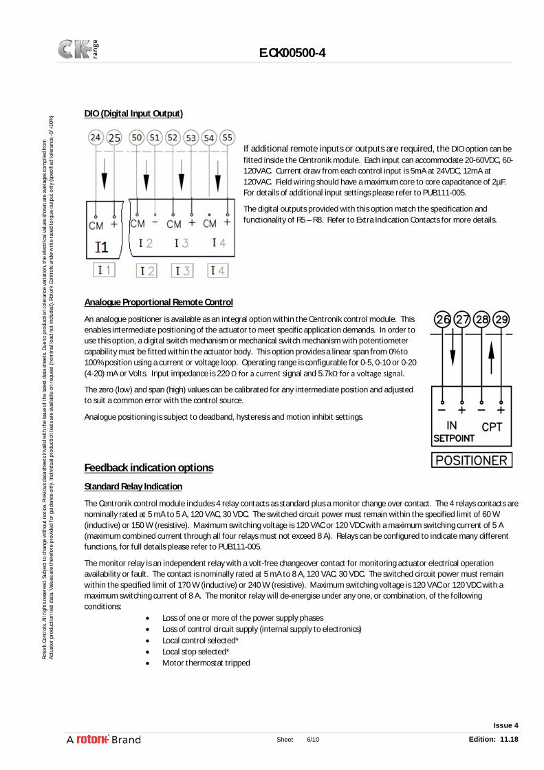
DIO (Digital Input Output)
If additional remote inputs or outputs are required, the DIO option can be fitted inside the Centronik module. Each input can accommodate 20-60VDC, 60-120VAC. Current draw from each control input is 5mA at 24VDC, 12mA at 120VAC. Field wiring should have a maximum core to core capacitance of 2µF. For details of additional input settings please refer to PUB111-005.
The digital outputs provided with this option match the specification and functionality of R5 – R8. Refer to Extra Indication Contacts for more details.
Analogue Proportional Remote Control
An analogue positioner is available as an integral option within the Centronik control module. This enables intermediate positioning of the actuator to meet specific application demands. In order to use this option, a digital switch mechanism or mechanical switch mechanism with potentiometer capability must be fitted within the actuator body. This option provides a linear span from 0% to 100% position using a current or voltage loop. Operating range is configurable for 0-5, 0-10 or 0-20 (4-20) mA or Volts. Input impedance is 220 Ω for a current signal and 5.7kΩ for a voltage signal.
The zero (low) and span (high) values can be calibrated for any intermediate position and adjusted to suit a common error with the control source.
Analogue positioning is subject to deadband, hysteresis and motion inhibit settings.
Feedback indication options
Standard Relay Indication
The Centronik control module includes 4 relay contacts as standard plus a monitor change over contact. The 4 relays contacts are nominally rated at 5 mA to 5 A, 120 VAC, 30 VDC. The switched circuit power must remain within the specified limit of 60 W (inductive) or 150 W (resistive). Maximum switching voltage is 120 VAC or 120 VDC with a maximum switching current of 5 A (maximum combined current through all four relays must not exceed 8 A). Relays can be configured to indicate many different functions, for full details please refer to PUB111-005.
The monitor relay is an independent relay with a volt-free changeover contact for monitoring actuator electrical operation availability or fault. The contact is nominally rated at 5 mA to 8 A, 120 VAC, 30 VDC. The switched circuit power must remain within the specified limit of 170 W (inductive) or 240 W (resistive). Maximum switching voltage is 120 VAC or 120 VDC with a maximum switching current of 8 A. The monitor relay will de-energise under any one, or combination, of the following conditions:
Loss of one or more of the power supply phases Loss of control circuit supply (internal supply to electronics) Local control selected* Local stop selected* Motor thermostat tripped
E.CK00500-4
Issue 4
Sheet 7/10 Edition: 11.18
Roto
rk C
ontr
ols.
All
right
s re
serv
ed. S
ubje
ct to
cha
nge
with
out n
otic
e. P
revi
ous
data
she
ets
inva
lid w
ith th
e is
sue
of th
e la
test
dat
a sh
eets
. Due
to p
rodu
ctio
n to
lera
nce
varia
tion,
the
elec
tric
al v
alue
s sh
own
are
aver
ages
com
pile
d fr
om
Actu
ator
pro
duct
ion
test
dat
a. V
alue
s ar
e th
eref
ore
prov
ided
for g
uida
nce
only
. Ind
ivid
ual p
rodu
ctio
n te
sts
are
avai
labl
e on
requ
est (
nom
inal
load
not
incl
uded
). Ro
tork
Con
trol
s un
derw
rite
rate
d to
rque
out
put o
nly
(spe
cifie
d to
lera
nce
-0/+
10%
)
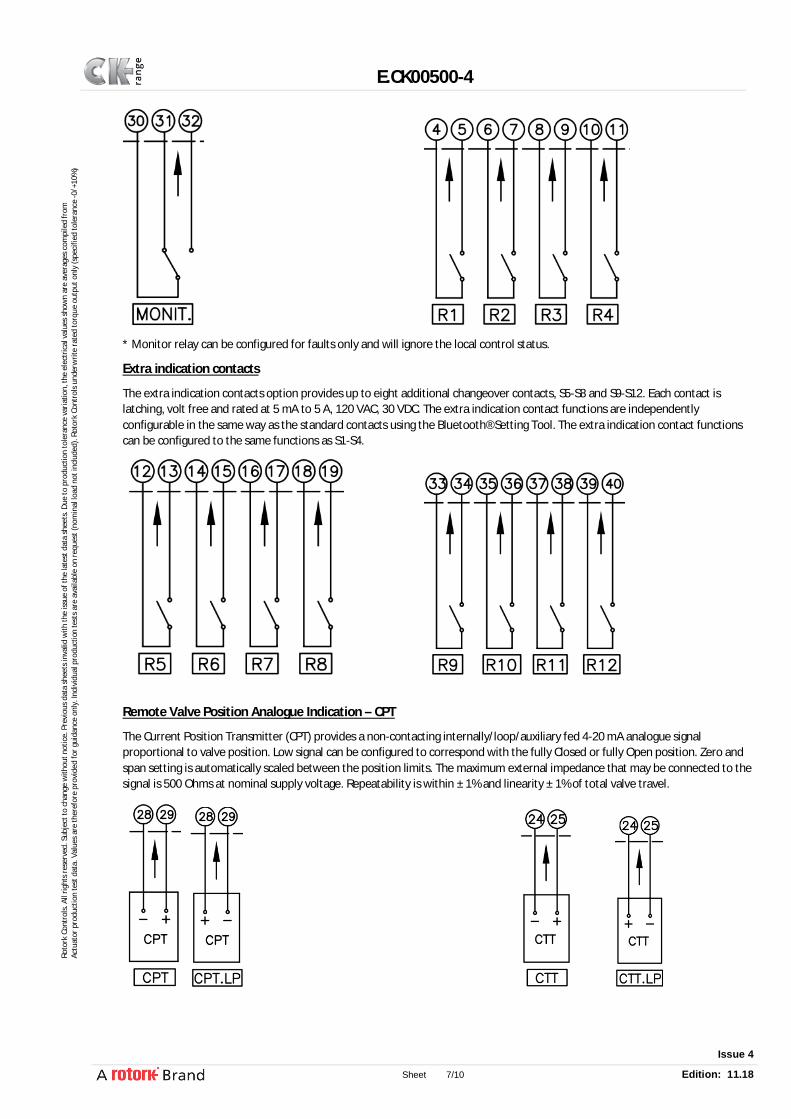
* Monitor relay can be configured for faults only and will ignore the local control status.
Extra indication contacts
The extra indication contacts option provides up to eight additional changeover contacts, S5-S8 and S9-S12. Each contact is latching, volt free and rated at 5 mA to 5 A, 120 VAC, 30 VDC. The extra indication contact functions are independently configurable in the same way as the standard contacts using the Bluetooth® Setting Tool. The extra indication contact functions can be configured to the same functions as S1-S4.
Remote Valve Position Analogue Indication – CPT
The Current Position Transmitter (CPT) provides a non-contacting internally/loop/auxiliary fed 4-20 mA analogue signal proportional to valve position. Low signal can be configured to correspond with the fully Closed or fully Open position. Zero and span setting is automatically scaled between the position limits. The maximum external impedance that may be connected to the signal is 500 Ohms at nominal supply voltage. Repeatability is within ± 1% and linearity ± 1% of total valve travel.
E.CK00500-4
Issue 4
Sheet 8/10 Edition: 11.18
Roto
rk C
ontr
ols.
All
right
s re
serv
ed. S
ubje
ct to
cha
nge
with
out n
otic
e. P
revi
ous
data
she
ets
inva
lid w
ith th
e is
sue
of th
e la
test
dat
a sh
eets
. Due
to p
rodu
ctio
n to
lera
nce
varia
tion,
the
elec
tric
al v
alue
s sh
own
are
aver
ages
com
pile
d fr
om
Actu
ator
pro
duct
ion
test
dat
a. V
alue
s ar
e th
eref
ore
prov
ided
for g
uida
nce
only
. Ind
ivid
ual p
rodu
ctio
n te
sts
are
avai
labl
e on
requ
est (
nom
inal
load
not
incl
uded
). Ro
tork
Con
trol
s un
derw
rite
rate
d to
rque
out
put o
nly
(spe
cifie
d to
lera
nce
-0/+
10%
)
Remote Valve Torque Analogue Indication – CTT
The Current Torque Transmitter (CTT) provides a non-contacting internally fed 4-20 mA analogue signal proportional to actuator output torque (0-120% of rated torque). When stationary the CTT output will continue to indicate the current torque.
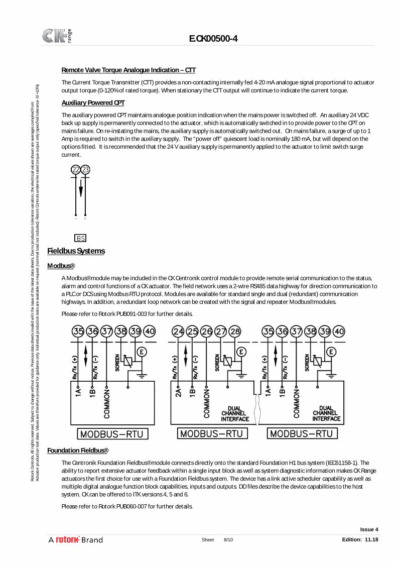
Auxiliary Powered CPT
The auxiliary powered CPT maintains analogue position indication when the mains power is switched off. An auxiliary 24 VDC back up supply is permanently connected to the actuator, which is automatically switched in to provide power to the CPT on mains failure. On re-instating the mains, the auxiliary supply is automatically switched out. On mains failure, a surge of up to 1 Amp is required to switch in the auxiliary supply. The “power off” quiescent load is nominally 180 mA, but will depend on the options fitted. It is recommended that the 24 V auxiliary supply is permanently applied to the actuator to limit switch surge current.
Fieldbus Systems
Modbus®
A Modbus® module may be included in the CK Centronik control module to provide remote serial communication to the status, alarm and control functions of a CK actuator. The field network uses a 2-wire RS485 data highway for direction communication to a PLC or DCS using Modbus RTU protocol. Modules are available for standard single and dual (redundant) communication highways. In addition, a redundant loop network can be created with the signal and repeater Modbus® modules.
Please refer to Rotork PUB091-003 for further details.
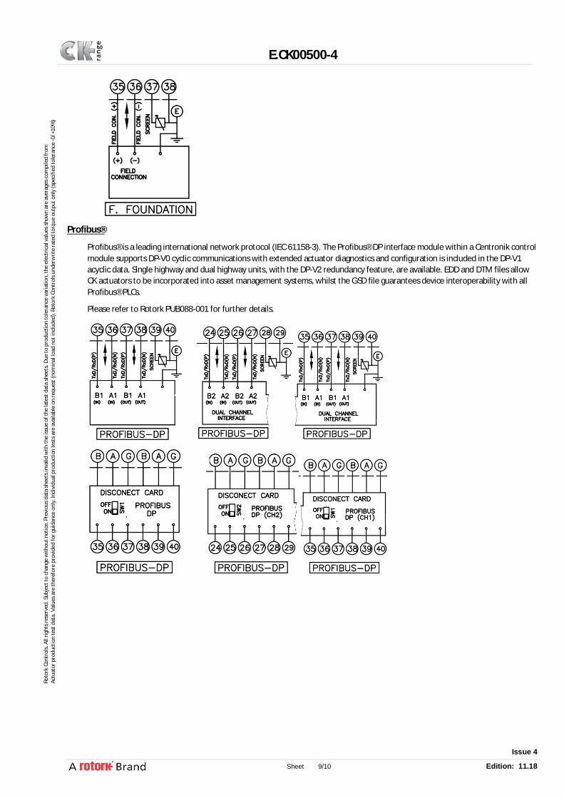
Foundation Fieldbus®
The Centronik Foundation Fieldbus® module connects directly onto the standard Foundation H1 bus system (IEC61158-1). The ability to report extensive actuator feedback within a single input block as well as system diagnostic information makes CK Range actuators the first choice for use with a Foundation Fieldbus system. The device has a link active scheduler capability as well as multiple digital analogue function block capabilities, inputs and outputs. DD files describe the device capabilities to the host system. CK can be offered to ITK versions 4, 5 and 6.
Please refer to Rotork PUB060-007 for further details.
E.CK00500-4
Issue 4
Sheet 9/10 Edition: 11.18
Roto
rk C
ontr
ols.
All
right
s re
serv
ed. S
ubje
ct to
cha
nge
with
out n
otic
e. P
revi
ous
data
she
ets
inva
lid w
ith th
e is
sue
of th
e la
test
dat
a sh
eets
. Due
to p
rodu
ctio
n to
lera
nce
varia
tion,
the
elec
tric
al v
alue
s sh
own
are
aver
ages
com
pile
d fr
om
Actu
ator
pro
duct
ion
test
dat
a. V
alue
s ar
e th
eref
ore
prov
ided
for g
uida
nce
only
. Ind
ivid
ual p
rodu
ctio
n te
sts
are
avai
labl
e on
requ
est (
nom
inal
load
not
incl
uded
). Ro
tork
Con
trol
s un
derw
rite
rate
d to
rque
out
put o
nly
(spe
cifie
d to
lera
nce
-0/+
10%
)
Profibus®
Profibus® is a leading international network protocol (IEC 61158-3). The Profibus® DP interface module within a Centronik control module supports DP-V0 cyclic communications with extended actuator diagnostics and configuration is included in the DP-V1 acyclic data. Single highway and dual highway units, with the DP-V2 redundancy feature, are available. EDD and DTM files allow CK actuators to be incorporated into asset management systems, whilst the GSD file guarantees device interoperability with all Profibus® PLCs.
Please refer to Rotork PUB088-001 for further details.

E.CK00500-4
Issue 4
Sheet 10/10 Edition: 11.18
Roto
rk C
ontr
ols.
All
right
s re
serv
ed. S
ubje
ct to
cha
nge
with
out n
otic
e. P
revi
ous
data
she
ets
inva
lid w
ith th
e is
sue
of th
e la
test
dat
a sh
eets
. Due
to p
rodu
ctio
n to
lera
nce
varia
tion,
the
elec
tric
al v
alue
s sh
own
are
aver
ages
com
pile
d fr
om
Actu
ator
pro
duct
ion
test
dat
a. V
alue
s ar
e th
eref
ore
prov
ided
for g
uida
nce
only
. Ind
ivid
ual p
rodu
ctio
n te
sts
are
avai
labl
e on
requ
est (
nom
inal
load
not
incl
uded
). Ro
tork
Con
trol
s un
derw
rite
rate
d to
rque
out
put o
nly
(spe
cifie
d to
lera
nce
-0/+
10%
)
HART®
HART (Highway Addressable Remote Transducer) is a process control communication protocol. The HART® signal consists of two parts, the analogue 4-20 mA current loop and a superimposed digital (variable frequency) signal. Traditionally the 4-20 mA loop is used for control and the superimposed digital signal for feedback, diagnostics and configuration. Along with the use of standard HART function codes, a DD file describes the device parameters which can be accessed by a host or handheld device. The majority of user configurable settings can be made over the HART protocol.
Please refer to Rotork PUB092-001 for further details.
Pakscan®
Pakscan™ is a 2-wire system for control and data transmission to and from actuators. This system was developed by Rotork with the primary objective of actuator control.
The CK Centronik control module can accommodate an internally mounted Pakscan field unit to connect the actuator to the field network. By arranging the field cable in a loop the system automatically provides a fault tolerant redundant path for the data signals. The communication distance may be up to 20km in length, without the need for repeaters, up to 240 actuators may be connected to the loop and a master station supervises the system. Communication from the master station to the host uses Modbus protocol over RS-232 and RS-485. System settings for the actuator are programmable through the Centronik display interface via the local selectors, Infra-red or optional Bluetooth®.
Please refer to Rotork PUB059-030 for further details.
DeviceNet™
DeviceNet is communications protocol which utilises the CAN bus network. Rotork's DeviceNet® module Electronic Data Sheet (EDS) file is used to set up the actuator parameters to allow the systems performance to be optimised. Status, alarms and control functions are available over the DeviceNet network.
Please refer to Rotork PUB090-001 for further details.