IS:1893-1984 lndian Standard CRITERIA FOR EARTHQUAKE RESISTANT DESIGN OF STRUCTURES
Upload
khangminh22Category
view
1download
0
www.ijcrt.org © 2020 IJCRT | Volume 8, Issue 6 June 2020 | ISSN: 2320-28820
IJCRT2006043 International Journal of Creative Research Thoughts (IJCRT) www.ijcrt.org 257
EARTHQUAKE RESISTANT ANALYSIS (RESPONSE SPECTRUM ANALYSIS METHOD) AND DESIGN OF G+2 BUNGALOW BY USING
SOFTWARE SAP 2000 1Pranay Sirsat and 2Bharati Changhode,
1M. Tech Student, 2Assistant Professor Civil Engineering Department,
G. H. Raisoni University, Amravati, MH, India Abstract: Seismic design techniques today enable structural engineers themselves to design buildings with different types of earthquake safety levels in line with the various demands of society. However, the design goal is basically limited to a relatively short period of time, i.e. to secure the service life of each building. Aspects of building sustainable and strong cities that recover quickly, including long-lived buildings, are not generally considered. Powerful earthquakes occur at regular intervals that are larger than individual buildings or people's lives. On the other hand, city life is clearly long-lived, just as seismic action is stronger than design action, and can only cause serious damage to a building designed for their life. Although multi-storey buildings with floors are in danger of collapsing due to natural earthquakes, their construction is still in a developing region like India. Vehicle parking area services are required to be provided at the ground level and the office does not need to be wary of such buildings from the engineering community. Due to the ease of high-speed computers, the use of software in civil engineering has greatly reduced the complexity of various aspects of project analysis and design. The aim of the project is to design and analysis a residential building by using the well-known software SAP2000.
KEYWORDS: SAP 2000, residential building, static load analysis, base shear, structural elements, response spectrum analysis
I. INTRODUCTION
"Basic needs" refers to those basic needs that obey as the foundation for survival. A regular list of immediate "basic needs" is food, shelter and clothing. Everyone has the basic human right to life, which is guaranteed access to a safe, secure, usable and affordable home free from forced evictions. Digital computers have taken the world by storm. Future society is certainly going to be technology driven. Almost everything is being computerised and digitalised. Software has become the order of the day. Amidst such a scenario, it is but natural that analysis and design work in any field of engineering is being carried out by using software.
Be that as manual calculations will always have their own importance software and programs have the uncanny knack of turning upside down. This is because the software is only good as the user and the results will always depend on accuracy of the input data.
The aim of the project is to design and analysis a residential building with the help of popular software SAP2000. For this purpose, a residential building with a 2BHK bungalow is considered.
A detailed planning and analysis is carried out for different loading combination including earthquake loading. Also 13 load combinations were analyzed and the worst load combination was detected and designed to the worst load combination using SAP 2000. We used SAP 2000 to design and analysis the structure and manual calculation for slab and staircase design.
II. RESPONSE SPECTRUM
In the response spectrum method of analysis, several modes of vibration were used in the frequency domain. The response of a multilevel structure is defined as a combination of different special modes i.e. corresponding to "harmonics" in a vibrating string. A computer program is used to determine the method of this special structure. For each mode, the response is recorded from the design response spectrum, based on the model mass and model frequency; They are then combined to estimate the overall response of the structure. According to the present study, the dimensions of the forces in all directions i.e. X, Y and Z were calculated and then the effect of the lateral forces on the building was analyzed. The design acceleration coefficient for different soil types and response spectrum graph obtained from the IS 1893:2016 (part 1) used in the present study is shown in the Fig. 1.

www.ijcrt.org © 2020 IJCRT | Volume 8, Issue 6 June 2020 | ISSN: 2320-28820
IJCRT2006043 International Journal of Creative Research Thoughts (IJCRT) www.ijcrt.org 258
Figure 2: Design Response Spectrum for different soil (5% damping)
III. LITERATURE REVIEW
1. V. Varalaxmi: The analysis and design of G+4 residential building at a Kukatpally, Hyderabad, India. This research study contains analysis & design of structural member like columns, beam, footing & slab using the software SAP2000.
2. Vijay N. Khose: The analysis and design of G+4 RC structure which is site located in earthquake zone IV. Analysis and 3D modelling of the structure is done by using SAP2000 Software. The study include step by step procedure of analysis and design of building structural elements with the help of SAP2000 software.
3. L. Kalurkar: The analysis and design of G+4 structure which is site located in seismic zone III using composite structure. Analysis and 3D modelling of the structure is done by using SAP2000 Software. In this study, response spectrum analysis method and and equvivalent static method of analysis used for both RCC and composite structure.
4. P. Jayachandran: The analysis and design of G+4 residential building at Salem, Tamilnadu, India. This research study contains analysis & design of structural member like columns, beam, footing & slab using the software SAP2000 and AutoCad.
IV. SAP2000 FEATURES
SAP 2000 software is principally useful for gravity design & analysis of any structure. For any smaller structure or portions of a bigger structure, this software is commonly used. SAP2000 is a good at conduct multifaceted geometry because it provide to operators many of various component types and a lots
of modification with considering to meshing choices. SAP2000 also be used for wind analysis and make extra comprehensible earthquake design procedures. Though, it will take
additional data post-processing to recover the required results for story shear, base shear, story drift etc. SAP2000 having absences about of the easiness that STAAD PRO & ETABS software has of discretizing the structure into
macroscopic elements.
V. OBJECTIVE
Analysis and Design of G+2 bungalow with the help of SAP2000 which contains following: 1. Making the building structural plan by selecting new model on SAP2000 2. Modelling of the structure 3. Application of Loading on the structure 4. Analyzing the structure and removing the structure that occurred 5. Designing the structure with the help of IS 450-2000
www.ijcrt.org © 2020 IJCRT | Volume 8, Issue 6 June 2020 | ISSN: 2320-28820
IJCRT2006043 International Journal of Creative Research Thoughts (IJCRT) www.ijcrt.org 259
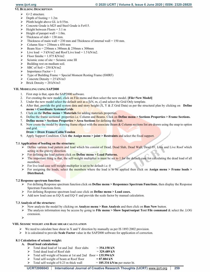
VI. BUILDING DESCRIPTION
G+2 structure. Depth of footing = 1.2m Plinth height above GL is 0.55m. Concrete Grade is M25 and Steel Grade is Fe415. Height between Floors = 3.1 m Height of parapet wall = 1.0m. Thickness of slab = 130 mm. Thickness of main wall = 230 mm and Thickness of internal wall = 150 mm. Column Size = 230mm x 450 mm Beam Size = 230mm x 380mm & 230mm x 300mm Live load = 3 kN/m2 and Roof Live load = 1.5 kN/m2. Floor finishe = 1.875 KN/m2 Seismic zone of site = Seismic zone III Building rest on medium soil. SBC of Soil = 250 KN/m2 Importance Factor = 1 Type of Building Frame = Special Moment Resting Frame (SMRF) Concrete Density = 25 kN/m3 Brick Density = 20 kN/m3
VII. MODELLING USING SAP2000
1. First step is that, open the SAP2000 software. 2. For creating the new model, click on File menu and then select the new model. [File>New Model] 3. Under the new model select the default unit as a [kN, m, c] and select the Grid Only template. 4. After that, provide the grid system data and story height (X, Y & Z Grid Data) as per the structural plan by clicking on Define
menu > Coordinate Systems/Grids 5. Click on the Define menu > Materials for adding materials properties. 6. Define the frame sectional properties i.e. Column and Beams. Click on Define menu > Sections Properties > Frame Sections. 7. Define menu > Sections Properties > Area Sections for defining the Slab. 8. Now create the model by drawing frame object with the associate Beam & Column sections list are drawn using the snap to option
and grid. Draw > Draw Frame/Cable/Tendon
9. Apply Support Condition. Click the Assign menu > joint > Restraints and select the fixed support.
7.1 Application of loading on the structure: Define various load pattern and load which bis consist of Dead, Dead Slab, Dead Wall, Dead FF, Live and Live Roof which
acting in the gravity direction. For defining the load pattern click on Define menu > Load Patterns. The important thing is that, the self-weight multiplier is must be set to 1 for the default case for calculating the dead load of all
members. For live load case self-weight multiplier is set to be default i.e. 0 For assigning the loads, select the members where the load is to be applied then click on Assign menu > Frame loads >
Distributed. 7.2 Response spectrum function:
For defining Response spectrum function click on Define menu > Respomnce Spectrum Functions, then display the Response Spectrum Functions form.
For defining Response spectrum load case click on Define menu > Load cases. Add new load case as EQ-X and EQ-Y and provide the scale factor by manual calculation.
7.3 Analysis of the structure:
Now analysis the model by clicking on Analyze menu > Run Analysis and then click on Run Now button. The analysis information may be access by going to File menu > Show Input/output Text File command & select the .LOG
extension.
VIII. SEISMIC WEIGHT AND BASE SHEAR CALCULATION
We need to calculate base shear in X and Y direction by manually as per IS 1893:2002 provision. It is calculated to provide Scale Factor value in the SAP2000 software for application of correction.
8.1 Calculation of seismic weight: A. Dead load calculation:
Total dead load of 1st and 2nd floor slabs = 354.158 kN Total dead load of Roof slab = 329.489 kN Total self-weight of beams at 1st and 2nd floor = 135.994 kN Total self-weight of beam at Roof floor = 87.804 kN Total self-weight of 0.23 m thick wall = 185.334 kN/m per meter ht.
www.ijcrt.org © 2020 IJCRT | Volume 8, Issue 6 June 2020 | ISSN: 2320-28820
IJCRT2006043 International Journal of Creative Research Thoughts (IJCRT) www.ijcrt.org 260
Total self-weight of 0.115 m thick wall = 40.078 kN/m per meter ht. Total self-weight of all column = 31.05 kN/m per meter height
B. Live load calculation:
Live load on Roof = 0 Total Live load on 1st and 2nd floor = 51.88 kN
C. Seismic weight calculation:
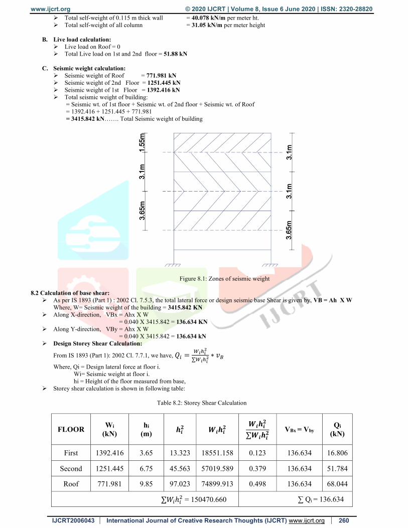
Seismic weight of Roof = 771.981 kN Seismic weight of 2nd Floor = 1251.445 kN Seismic weight of 1st Floor = 1392.416 kN Total seismic weight of building:
= Seismic wt. of 1st floor + Seismic wt. of 2nd floor + Seismic wt. of Roof = 1392.416 + 1251.445 + 771.981 = 3415.842 kN……. Total Seismic weight of building
Figure 8.1: Zones of seismic weight
8.2 Calculation of base shear: As per IS 1893 (Part 1) : 2002 Cl. 7.5.3, the total lateral force or design seismic base Shear is given by, VB = Ah X W
Where, W= Seismic weight of the building = 3415.842 KN Along X-direction, VBx = Ahx X W
= 0.040 X 3415.842 = 136.634 KN Along Y-direction, VBy = Ahx X W
= 0.040 X 3415.842 = 136.634 kN Design Storey Shear Calculation:
From IS 1893 (Part 1): 2002 Cl. 7.7.1, we have, 𝑄 =∑
∗ 𝑣
Where, Qi = Design lateral force at floor i. Wi= Seismic weight at floor i. hi = Height of the floor measured from base,
Storey shear calculation is shown in following table:
Table 8.2: Storey Shear Calculation
FLOOR Wi
(kN) hi
(m) 𝒉𝒊𝟐 𝑾𝒊𝒉𝒊
𝟐 𝑾𝒊𝒉𝒊
𝟐
∑𝑾𝒊𝒉𝒊𝟐 VBx = Vby
Qi
(kN)
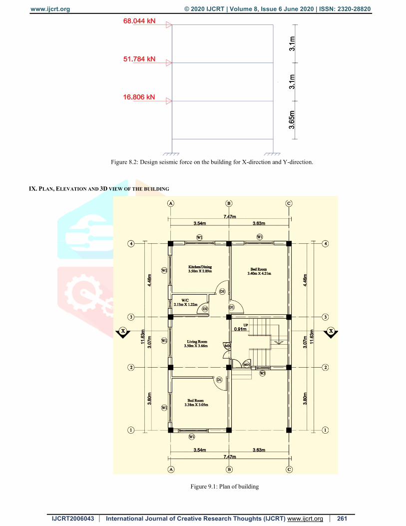
First 1392.416 3.65 13.323 18551.158 0.123 136.634 16.806
Second 1251.445 6.75 45.563 57019.589 0.379 136.634 51.784
Roof 771.981 9.85 97.023 74899.913 0.498 136.634 68.044
∑𝑊ℎ = 150470.660 ∑ Qi = 136.634
www.ijcrt.org © 2020 IJCRT | Volume 8, Issue 6 June 2020 | ISSN: 2320-28820
IJCRT2006043 International Journal of Creative Research Thoughts (IJCRT) www.ijcrt.org 261
Figure 8.2: Design seismic force on the building for X-direction and Y-direction.
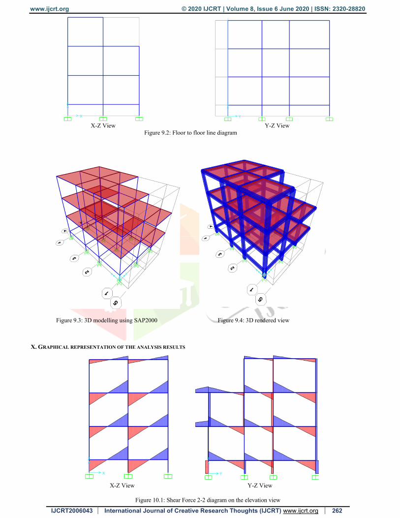
IX. PLAN, ELEVATION AND 3D VIEW OF THE BUILDING
Figure 9.1: Plan of building
www.ijcrt.org © 2020 IJCRT | Volume 8, Issue 6 June 2020 | ISSN: 2320-28820
IJCRT2006043 International Journal of Creative Research Thoughts (IJCRT) www.ijcrt.org 262
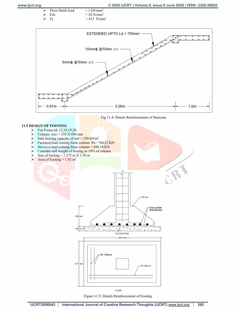
X-Z View Y-Z View Figure 9.2: Floor to floor line diagram
Figure 9.3: 3D modelling using SAP2000 Figure 9.4: 3D rendered view
X. GRAPHICAL REPRESENTATION OF THE ANALYSIS RESULTS
X-Z View Y-Z View
Figure 10.1: Shear Force 2-2 diagram on the elevation view

www.ijcrt.org © 2020 IJCRT | Volume 8, Issue 6 June 2020 | ISSN: 2320-28820
IJCRT2006043 International Journal of Creative Research Thoughts (IJCRT) www.ijcrt.org 263
X-Z VIEW Y-Z VIEW
Figure 10.2: Bending Moment 3-3 diagram on the elevation view
Fig. 10.3: Deformed shape of the building on elevation and 3D view
XI. DESIGN OF STRUCTURAL ELEMENTS
11.1 DESIGN OF BEAM
First Floor Beam (Frame Id: 69) Ast at support = 399 mm2 (Provide #2-16mm Ø) Ast at mid = 167 mm2 (Provide #2-12mm Ø) Ast at bottom = 236 mm2 (Provide #2-16mm Ø) Lateral ties 2L 8mm -150mm c/c
L- Section of Beam C/S of Beam
Figure 11.1: Details Reinforcement for Beam

www.ijcrt.org © 2020 IJCRT | Volume 8, Issue 6 June 2020 | ISSN: 2320-28820
IJCRT2006043 International Journal of Creative Research Thoughts (IJCRT) www.ijcrt.org 264
11.2 DESIGN OF COLUMN
Frame Id 30 Max Ast = 1310 mm2 Min Ast = 828 mm2 Lateral Ties 2L 8mm Ø – 250 mm C/C
C/S of Column
Figure 11.2: Details Reinforcement of Column
11.3 DESIGN OF SLAB Design of Two way slab as per IS 456-2000 Long Span = 4.21 m Short span = 3.40 m Slab thickness = 150 mm or 0.15 m Material properties: fck = 25 N/mm2 and fy = 415 N/mm2 Panel type = Two Adjacent Edges Discontinuous
L/S of Slab
Top View of Slab
Figure 11.3: Details Reinforcement of Slab 11.4 DESIGN OF STAIR CASE
The main aim of staircase is that safe and convenient going from one level to another level and also use for emergency purpose.
The geometry shape of staircase may be quite dissimilar which depends on following factors 1. Type of structure (Load bearing or Framed structure) 2. Space availability.
Design of first flight:
Going = 1.343m First Landing = 0.91m Second Landing = 1.0m Tread (T) = 275mm Rise (R) = 150nn Live load (LL) = 3 kN/m2
www.ijcrt.org © 2020 IJCRT | Volume 8, Issue 6 June 2020 | ISSN: 2320-28820
IJCRT2006043 International Journal of Creative Research Thoughts (IJCRT) www.ijcrt.org 265
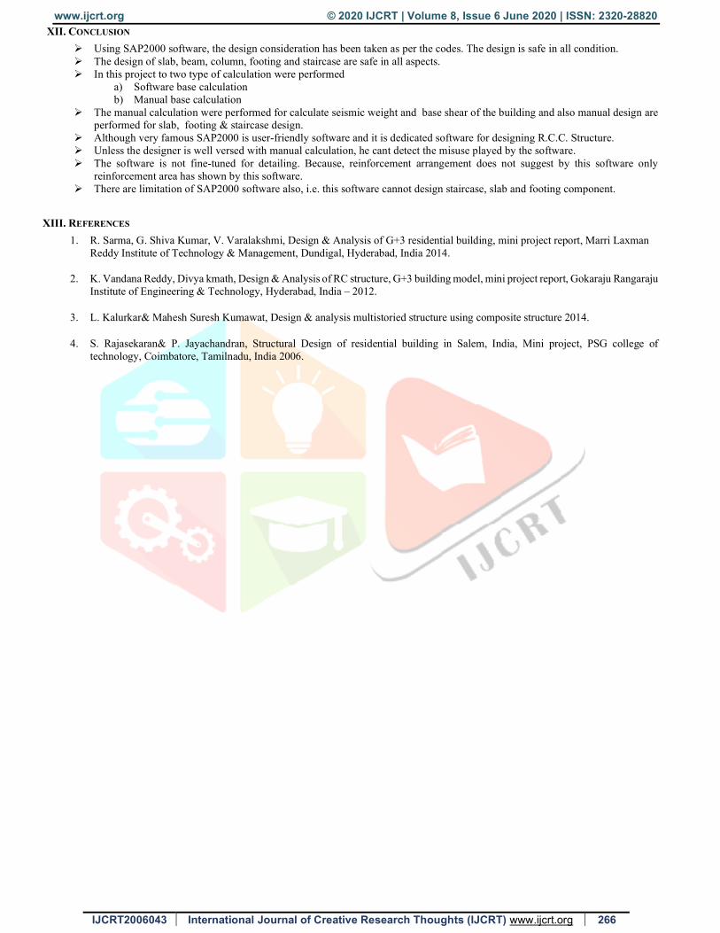
Floor finish load = 1 kN/mm2 Fck = 20 N/mm2 Fy = 415 N/mm2
Fig 11.4: Details Reinforcement of Staircase
11.5 DESIGN OF FOOTING
For Frame Id: 17,18,19,20. Column size = 230 X 450 mm Safe bearing capacity of soil = 250 kN/m2 Factored load coming from column Pu= 744.23 KN Servicve load coming from column = 496.14 KN Consider self weight of footing as 10% of column Size of footing = 1.275 m X 1.50 m Area of Footing = 1.92 m2
Figure 11.5: Details Reinforcement of Footing
www.ijcrt.org © 2020 IJCRT | Volume 8, Issue 6 June 2020 | ISSN: 2320-28820
IJCRT2006043 International Journal of Creative Research Thoughts (IJCRT) www.ijcrt.org 266
XII. CONCLUSION
Using SAP2000 software, the design consideration has been taken as per the codes. The design is safe in all condition. The design of slab, beam, column, footing and staircase are safe in all aspects. In this project to two type of calculation were performed
a) Software base calculation b) Manual base calculation
The manual calculation were performed for calculate seismic weight and base shear of the building and also manual design are performed for slab, footing & staircase design.
Although very famous SAP2000 is user-friendly software and it is dedicated software for designing R.C.C. Structure. Unless the designer is well versed with manual calculation, he cant detect the misuse played by the software. The software is not fine-tuned for detailing. Because, reinforcement arrangement does not suggest by this software only
reinforcement area has shown by this software. There are limitation of SAP2000 software also, i.e. this software cannot design staircase, slab and footing component.
XIII. REFERENCES
1. R. Sarma, G. Shiva Kumar, V. Varalakshmi, Design & Analysis of G+3 residential building, mini project report, Marri Laxman Reddy Institute of Technology & Management, Dundigal, Hyderabad, India 2014.
2. K. Vandana Reddy, Divya kmath, Design & Analysis of RC structure, G+3 building model, mini project report, Gokaraju Rangaraju Institute of Engineering & Technology, Hyderabad, India – 2012.
3. L. Kalurkar& Mahesh Suresh Kumawat, Design & analysis multistoried structure using composite structure 2014.
4. S. Rajasekaran& P. Jayachandran, Structural Design of residential building in Salem, India, Mini project, PSG college of technology, Coimbatore, Tamilnadu, India 2006.
Copyright © 2022 FDOKUMEN