E / F / G / K-Series - Service Manual
462
Service Manual SiBE121135 E / F / G / K-Series [Applied Models] Inverter Multi : Cooling Only Inverter Multi : Heat Pump
-
Upload
khangminh22 -
Category
Documents
-
view
4 -
download
0
Transcript of E / F / G / K-Series - Service Manual
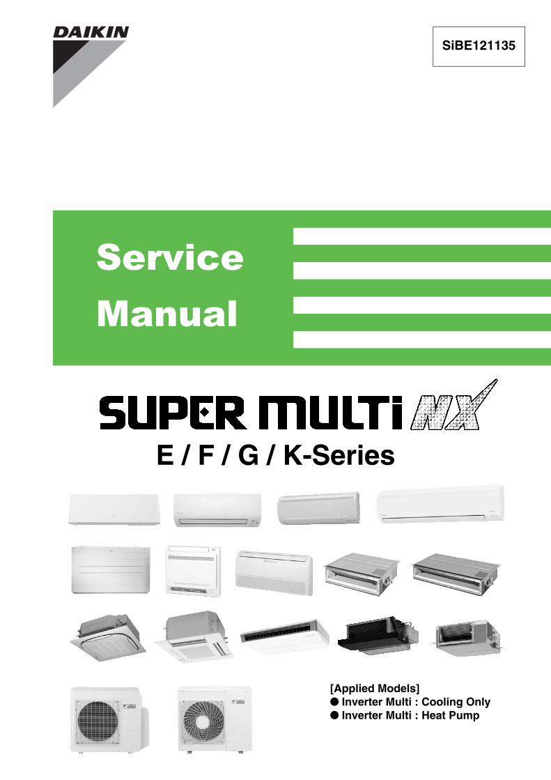
Service Manual
SiBE121135
E / F / G / K-Series
[Applied Models] Inverter Multi : Cooling Only Inverter Multi : Heat Pump
SiBE121135
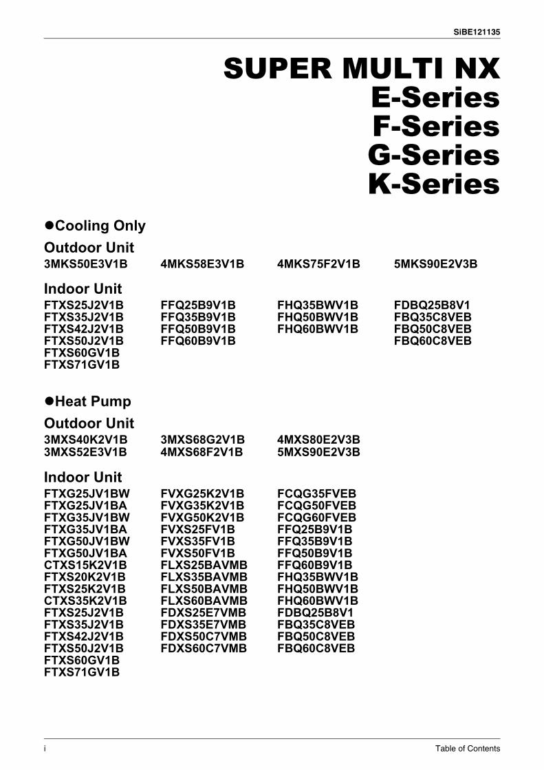
SUPER MULTI NXE-SeriesF-SeriesG-SeriesK-Series
Cooling OnlyOutdoor Unit3MKS50E3V1B 4MKS58E3V1B 4MKS75F2V1B 5MKS90E2V3B
Indoor UnitFTXS25J2V1B FFQ25B9V1B FHQ35BWV1B FDBQ25B8V1FTXS35J2V1B FFQ35B9V1B FHQ50BWV1B FBQ35C8VEBFTXS42J2V1B FFQ50B9V1B FHQ60BWV1B FBQ50C8VEBFTXS50J2V1B FFQ60B9V1B FBQ60C8VEBFTXS60GV1BFTXS71GV1B
Heat PumpOutdoor Unit3MXS40K2V1B 3MXS68G2V1B 4MXS80E2V3B3MXS52E3V1B 4MXS68F2V1B 5MXS90E2V3B
Indoor UnitFTXG25JV1BW FVXG25K2V1B FCQG35FVEBFTXG25JV1BA FVXG35K2V1B FCQG50FVEBFTXG35JV1BW FVXG50K2V1B FCQG60FVEBFTXG35JV1BA FVXS25FV1B FFQ25B9V1BFTXG50JV1BW FVXS35FV1B FFQ35B9V1BFTXG50JV1BA FVXS50FV1B FFQ50B9V1BCTXS15K2V1B FLXS25BAVMB FFQ60B9V1BFTXS20K2V1B FLXS35BAVMB FHQ35BWV1BFTXS25K2V1B FLXS50BAVMB FHQ50BWV1BCTXS35K2V1B FLXS60BAVMB FHQ60BWV1BFTXS25J2V1B FDXS25E7VMB FDBQ25B8V1FTXS35J2V1B FDXS35E7VMB FBQ35C8VEBFTXS42J2V1B FDXS50C7VMB FBQ50C8VEBFTXS50J2V1B FDXS60C7VMB FBQ60C8VEBFTXS60GV1BFTXS71GV1B
i Table of Contents
SiBE121135
1. Introduction ........................................................................................... vii1.1 Safety Cautions ...................................................................................... vii1.2 Used Icons .............................................................................................. xi
Part 1 List of Functions ................................................................11. Cooling Only............................................................................................2
1.1 Outdoor Unit .............................................................................................21.2 Indoor Unit................................................................................................3
2. Heat Pump ..............................................................................................62.1 Outdoor Unit .............................................................................................62.2 Indoor Unit................................................................................................7
Part 2 Specifications ..................................................................141. Cooling Only..........................................................................................15
1.1 Outdoor Unit ...........................................................................................151.2 Indoor Unit..............................................................................................17
2. Heat Pump ............................................................................................222.1 Outdoor Unit ...........................................................................................222.2 Indoor Unit..............................................................................................25
Part 3 Printed Circuit Board Connector Wiring Diagram ...........371. Outdoor Unit..........................................................................................382. Indoor Unit.............................................................................................41
2.1 FTXG25/35/50JV1BW(A) .......................................................................412.2 FTXS20/25K2V1B, CTXS15/35K2V1B ..................................................442.3 FTXS25/35/42/50J2V1B.........................................................................462.4 FTXS60/71GV1B....................................................................................492.5 FVXG25/35/50K2V1B ............................................................................522.6 FVXS25/35/50FV1B...............................................................................552.7 FLXS25/35/50/60BAVMB.......................................................................572.8 FDXS25/35E7VMB, FDXS50/60C7VMB................................................592.9 FCQG35/50/60FVEB..............................................................................612.10 FFQ25/35/50/60B9V1B..........................................................................642.11 FHQ35/50/60BWV1B .............................................................................662.12 FDBQ25B8V1.........................................................................................682.13 FBQ35/50/60C8VEB ..............................................................................70
3. Wired Remote Controller.......................................................................733.1 BRC1D528 .............................................................................................733.2 BRC1E52A7, BRC1E52B7.....................................................................74
Part 4 Function and Control........................................................751. Indoor Unit Control (RA Models) ...........................................................76
1.1 Temperature Control ..............................................................................761.2 Frequency Principle................................................................................761.3 Operation Starting Control......................................................................781.4 Airflow Direction Control.........................................................................791.5 Fan Speed Control for Indoor Unit .........................................................821.6 RADIANT Operation...............................................................................831.7 Program Dry Operation ..........................................................................85
Table of Contents ii
SiBE121135
1.8 Automatic Operation...............................................................................861.9 Thermostat Control.................................................................................871.10 NIGHT SET Mode ..................................................................................891.11 ECONO Operation .................................................................................901.12 HOME LEAVE Operation .......................................................................911.13 INTELLIGENT EYE Operation ...............................................................921.14 2-Area INTELLIGENT EYE Operation ...................................................931.15 Inverter POWERFUL Operation .............................................................951.16 Multi-Colored Indicator Lamp / TIMER Lamp .........................................951.17 Other Functions......................................................................................97
2. Indoor Unit Control (SA Models) ...........................................................992.1 Drain Pump Control................................................................................992.2 Thermostat Sensor in Remote Controller.............................................1012.3 Freeze Prevention Control ...................................................................1032.4 Hot Start Control (In Heating Operation Only)......................................104
3. Function of Thermistor ........................................................................1054. Control Specification ...........................................................................107
4.1 Mode Hierarchy ....................................................................................1074.2 Frequency Control................................................................................1084.3 Controls at Mode Changing / Start-up..................................................1114.4 Discharge Pipe Temperature Control...................................................1124.5 Input Current Control............................................................................1134.6 Freeze-up Protection Control ...............................................................1134.7 Heating Peak-cut Control .....................................................................1144.8 Outdoor Fan Control.............................................................................1154.9 Liquid Compression Protection Function..............................................1154.10 Defrost Control .....................................................................................1164.11 Low Hz High Pressure Limit .................................................................1174.12 Outdoor Electronic Expansion Valve Control .......................................1174.13 Malfunctions .........................................................................................122
Part 5 Operation Manual ...........................................................1241. System Configuration..........................................................................1252. RA Indoor Unit.....................................................................................126
2.1 FTXG, FTXS-K, CTXS, FVXG Series - ARC466A1, A2, A6 ................1262.2 FTXS-J, FTXS-G, FVXS Series - ARC452A1, A3................................1782.3 FLXS, FDXS Series - ARC433B67, B69 ..............................................218
3. SA Indoor Unit.....................................................................................2333.1 BRC1D528 ...........................................................................................233
Part 6 Service Diagnosis...........................................................2481. Troubleshooting with LED...................................................................250
1.1 Indoor Unit............................................................................................2501.2 Outdoor Unit .........................................................................................252
2. Problem Symptoms and Measures .....................................................2533. Service Check Function ......................................................................254
3.1 RA Indoor Unit - FTXG, FTXS, CTXS, FVXG, FVXS, FLXS, FDXS Series.........................................................................................254
3.2 SA Indoor Unit - FCQG, FFQ, FHQ, FDBQ, FBQ Series .....................263
4. Code Indication on Remote Controller ................................................267
iii Table of Contents
SiBE121135
4.1 RA Indoor Unit - FTXG, FTXS, CTXS, FVXG, FVXS, FLXS, FDXS Series.........................................................................................267
4.2 SA Indoor Unit - FCQG, FFQ, FHQ, FDBQ, FBQ Series .....................2674.3 Sub Codes for SA Indoor Unit ..............................................................2684.4 Outdoor Unit .........................................................................................269
5. Troubleshooting for RA Indoor Unit - FTXG, FTXS, CTXS, FVXG, FVXS, FLXS, FDXS Series ............................................................................2705.1 Indoor Unit PCB Abnormality ...............................................................2705.2 Freeze-up Protection Control or Heating Peak-cut Control ..................2725.3 Fan Motor or Related Abnormality .......................................................2745.4 Radiant Panel Temperature Rise, Indoor Electronic Expansion Valve
(Motor Operated Valve) Abnormality, Freeze-up Protection Control (FVXG Series Only)..............................................................................278
5.5 Thermistor or Related Abnormality (RA Indoor Unit)............................2805.6 Front Panel Open / Close Fault (FTXG Series Only) ...........................2815.7 Signal Transmission Error (between Indoor Unit and Outdoor Unit) ....2825.8 Unspecified Voltage (between Indoor Unit and Outdoor Unit) .............283
6. Troubleshooting for SA Indoor Unit - FCQG, FFQ, FHQ, FDBQ, FBQ Series..........................................................................................2846.1 Indoor Unit PCB Abnormality ...............................................................2846.2 Drain Water Level System Abnormality................................................2856.3 Fan Motor or Related Abnormality .......................................................2876.4 Swing Motor Lock (FHQ Series Only) ..................................................2896.5 Drain System Abnormality....................................................................2906.6 Thermistor or Related Abnormality (SA Indoor Unit) ............................2916.7 Remote Controller Thermistor Abnormality ..........................................2926.8 Signal Transmission Error
(between Indoor Unit and Remote Controller)......................................2936.9 Signal Transmission Error
(between MAIN Remote Controller and SUB Remote Controller)........2946.10 Field Setting Abnormality .....................................................................295
7. Troubleshooting for Outdoor Unit........................................................2967.1 Refrigerant Shortage ............................................................................2967.2 Low-voltage Detection or Over-voltage Detection................................2987.3 Signal Transmission Error (on Outdoor Unit PCB)...............................3007.4 Unspecified Voltage (between Indoor Unit and Outdoor Unit) /
Anti-icing Function in Other Rooms......................................................3017.5 Anti-icing Function................................................................................3027.6 Outdoor Unit PCB Abnormality.............................................................3047.7 OL Activation (Compressor Overload) .................................................3057.8 Compressor Lock .................................................................................3067.9 DC Fan Lock ........................................................................................3077.10 Input Overcurrent Detection .................................................................3087.11 Discharge Pipe Temperature Control...................................................3097.12 High Pressure Control in Cooling .........................................................3107.13 Compressor Sensor System Abnormality ............................................3117.14 Position Sensor Abnormality ................................................................3137.15 CT or Related Abnormality ...................................................................3157.16 Thermistor or Related Abnormality (Outdoor Unit) ...............................3177.17 Electrical Box Temperature Rise..........................................................3197.18 Radiation Fin Temperature Rise ..........................................................3217.19 Output Overcurrent Detection ..............................................................323
Table of Contents iv

SiBE121135
8. Check ..................................................................................................3258.1 Thermistor Resistance Check ..............................................................3258.2 Fan Motor Connector Check ................................................................3268.3 Hall IC Check .......................................................................................3278.4 Indoor Electronic Expansion Valve Coil Check ....................................3278.5 Power Supply Waveform Check...........................................................3288.6 Outdoor Electronic Expansion Valve Check.........................................3298.7 Four Way Valve Performance Check ...................................................3308.8 Inverter Unit Refrigerant System Check...............................................3308.9 “Inverter Checker” Check .....................................................................3318.10 Rotation Pulse Check on the Outdoor Unit PCB ..................................3328.11 Installation Condition Check.................................................................3338.12 Discharge Pressure Check...................................................................3338.13 Outdoor Fan System Check .................................................................3348.14 Capacitor Voltage Check......................................................................3348.15 Power Module Check ...........................................................................335
Part 7 Removal Procedure ........................................................3361. Outdoor Unit: 40-75 Class...................................................................337
1.1 Removal of Outer Panels .....................................................................3371.2 Removal of Electrical Box ....................................................................3411.3 Removal of PCBs .................................................................................3491.4 Removal of Outdoor Fan / Fan Motor...................................................3541.5 Removal of Sound Blankets .................................................................3561.6 Removal of Coils / Thermistors ............................................................3601.7 Removal of Distributor..........................................................................3631.8 Removal of Four Way Valve.................................................................3641.9 Removal of Compressor.......................................................................365
2. Outdoor Unit: 80/90 Class...................................................................3672.1 Removal of Outer Panels .....................................................................3672.2 Removal of Electrical Box ....................................................................3822.3 Removal of PCBs .................................................................................3882.4 Removal of Fan Motor..........................................................................3922.5 Removal of Coils / Thermistors ............................................................3932.6 Removal of Sound Blankets .................................................................3992.7 Removal of Compressor.......................................................................402
Part 8 Trial Operation and Field Settings.................................4031. Pump Down Operation........................................................................4042. Forced Operation ................................................................................4053. Wiring Error Check Function ...............................................................4064. Trial Operation ....................................................................................408
4.1 RA Indoor Unit - FTXG, FTXS, CTXS, FVXG, FVXS, FLXS, FDXS Series.........................................................................................408
4.2 SA Indoor Unit - FCQG, FFQ, FHQ, FDBQ, FBQ Series .....................410
5. Field Settings ......................................................................................4125.1 Outdoor Unit .........................................................................................4125.2 RA Indoor Unit - FTXG, FTXS, CTXS, FVXG, FVXS, FLXS,
FDXS Series.........................................................................................4155.3 SA Indoor Unit - FCQG, FFQ, FHQ, FDBQ, FBQ Series .....................419
v Table of Contents

SiBE121135
6. Application of Silicon Grease to a Power Transistor and a Diode Bridge .............................................................................423
Part 9 Appendix.........................................................................4241. Piping Diagrams..................................................................................425
1.1 Outdoor Unit .........................................................................................4251.2 Indoor Unit............................................................................................430
2. Wiring Diagrams..................................................................................4372.1 Outdoor Unit .........................................................................................4372.2 Indoor Unit............................................................................................442
Table of Contents vi
Introduction SiBE121135
1. Introduction1.1 Safety Cautions
Cautions and Warnings
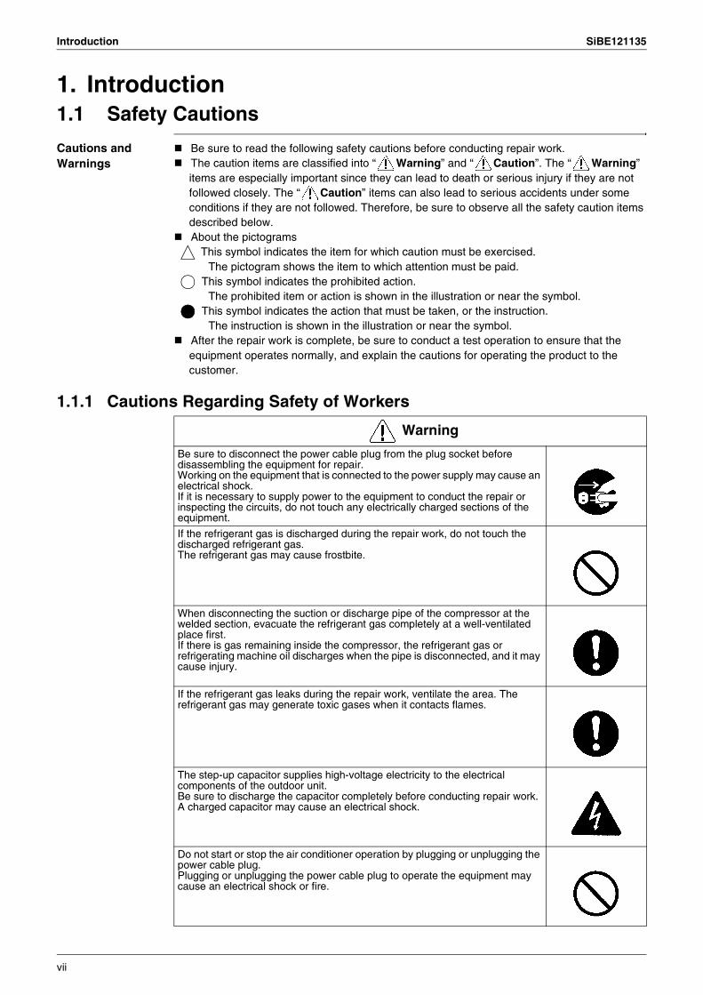
Be sure to read the following safety cautions before conducting repair work.The caution items are classified into “ Warning” and “ Caution”. The “ Warning” items are especially important since they can lead to death or serious injury if they are not followed closely. The “ Caution” items can also lead to serious accidents under some conditions if they are not followed. Therefore, be sure to observe all the safety caution items described below.About the pictograms
This symbol indicates the item for which caution must be exercised. The pictogram shows the item to which attention must be paid.
This symbol indicates the prohibited action. The prohibited item or action is shown in the illustration or near the symbol.
This symbol indicates the action that must be taken, or the instruction. The instruction is shown in the illustration or near the symbol.
After the repair work is complete, be sure to conduct a test operation to ensure that the equipment operates normally, and explain the cautions for operating the product to the customer.
1.1.1 Cautions Regarding Safety of Workers
Warning
Be sure to disconnect the power cable plug from the plug socket before disassembling the equipment for repair.Working on the equipment that is connected to the power supply may cause an electrical shock.If it is necessary to supply power to the equipment to conduct the repair or inspecting the circuits, do not touch any electrically charged sections of the equipment.
If the refrigerant gas is discharged during the repair work, do not touch the discharged refrigerant gas.The refrigerant gas may cause frostbite.
When disconnecting the suction or discharge pipe of the compressor at the welded section, evacuate the refrigerant gas completely at a well-ventilated place first.If there is gas remaining inside the compressor, the refrigerant gas or refrigerating machine oil discharges when the pipe is disconnected, and it may cause injury.
If the refrigerant gas leaks during the repair work, ventilate the area. The refrigerant gas may generate toxic gases when it contacts flames.
The step-up capacitor supplies high-voltage electricity to the electrical components of the outdoor unit.Be sure to discharge the capacitor completely before conducting repair work.A charged capacitor may cause an electrical shock.
Do not start or stop the air conditioner operation by plugging or unplugging the power cable plug.Plugging or unplugging the power cable plug to operate the equipment may cause an electrical shock or fire.
vii

SiBE121135 Introduction
Be sure to wear a safety helmet, gloves, and a safety belt when working at a high place (more than 2 m). Insufficient safety measures may cause a fall accident.
In case of R-410A refrigerant models, be sure to use pipes, flare nuts and tools for the exclusive use of the R-410A refrigerant.The use of materials for R-22 refrigerant models may cause a serious accident such as a damage of refrigerant cycle as well as an equipment failure.
Warning
Caution
Do not repair the electrical components with wet hands.Working on the equipment with wet hands may cause an electrical shock.
Do not clean the air conditioner by splashing water.Washing the unit with water may cause an electrical shock.
Be sure to provide the grounding when repairing the equipment in a humid or wet place, to avoid electrical shocks.
Be sure to turn off the power switch and unplug the power cable when cleaning the equipment.The internal fan rotates at a high speed, and may cause injury.
Be sure to conduct repair work with appropriate tools.The use of inappropriate tools may cause injury.
Be sure to check that the refrigerating cycle section has cooled down enough before conducting repair work.Working on the unit when the refrigerating cycle section is hot may cause burns.
Use the welder in a well-ventilated place.Using the welder in an enclosed room may cause oxygen deficiency.
viii

Introduction SiBE121135
1.1.2 Cautions Regarding Safety of Users
Warning
Be sure to use parts listed in the service parts list of the applicable model and appropriate tools to conduct repair work. Never attempt to modify the equipment.The use of inappropriate parts or tools may cause an electrical shock, excessive heat generation or fire.
If the power cable and lead wires have scratches or deteriorated, be sure to replace them.Damaged cable and wires may cause an electrical shock, excessive heat generation or fire.
Do not use a joined power cable or extension cable, or share the same power outlet with other electrical appliances, since it may cause an electrical shock, excessive heat generation or fire.
Be sure to use an exclusive power circuit for the equipment, and follow the local technical standards related to the electrical equipment, the internal wiring regulations, and the instruction manual for installation when conducting electrical work.Insufficient power circuit capacity and improper electrical work may cause an electrical shock or fire.
Be sure to use the specified cable for wiring between the indoor and outdoor units. Make the connections securely and route the cable properly so that there is no force pulling the cable at the connection terminals.Improper connections may cause excessive heat generation or fire.
When wiring between the indoor and outdoor units, make sure that the terminal cover does not lift off or dismount because of the cable.If the cover is not mounted properly, the terminal connection section may cause an electrical shock, excessive heat generation or fire.
Do not damage or modify the power cable.Damaged or modified power cable may cause an electrical shock or fire.Placing heavy items on the power cable, and heating or pulling the power cable may damage the cable.
Do not mix air or gas other than the specified refrigerant (R-410A / R-22) in the refrigerant system.If air enters the refrigerating system, an excessively high pressure results, causing equipment damage and injury.
If the refrigerant gas leaks, be sure to locate the leaking point and repair it before charging the refrigerant. After charging refrigerant, make sure that there is no refrigerant leak.If the leaking point cannot be located and the repair work must be stopped, be sure to perform pump-down and close the service valve, to prevent the refrigerant gas from leaking into the room. The refrigerant gas itself is harmless, but it may generate toxic gases when it contacts flames, such as fan and other heaters, stoves and ranges.
When relocating the equipment, make sure that the new installation site has sufficient strength to withstand the weight of the equipment.If the installation site does not have sufficient strength and if the installation work is not conducted securely, the equipment may fall and cause injury.
ix
SiBE121135 Introduction
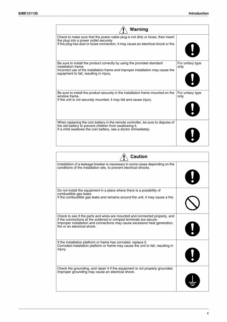
Check to make sure that the power cable plug is not dirty or loose, then insert the plug into a power outlet securely.If the plug has dust or loose connection, it may cause an electrical shock or fire.
Be sure to install the product correctly by using the provided standard installation frame.Incorrect use of the installation frame and improper installation may cause the equipment to fall, resulting in injury.
For unitary type only
Be sure to install the product securely in the installation frame mounted on the window frame.If the unit is not securely mounted, it may fall and cause injury.
For unitary type only
When replacing the coin battery in the remote controller, be sure to dispose of the old battery to prevent children from swallowing it.If a child swallows the coin battery, see a doctor immediately.
Warning
Caution
Installation of a leakage breaker is necessary in some cases depending on the conditions of the installation site, to prevent electrical shocks.
Do not install the equipment in a place where there is a possibility of combustible gas leaks.If the combustible gas leaks and remains around the unit, it may cause a fire.
Check to see if the parts and wires are mounted and connected properly, and if the connections at the soldered or crimped terminals are secure.Improper installation and connections may cause excessive heat generation, fire or an electrical shock.
If the installation platform or frame has corroded, replace it.Corroded installation platform or frame may cause the unit to fall, resulting in injury.
Check the grounding, and repair it if the equipment is not properly grounded.Improper grounding may cause an electrical shock.
x
Introduction SiBE121135
1.2 Used IconsIcons are used to attract the attention of the reader to specific information. The meaning of each icon is described in the table below:
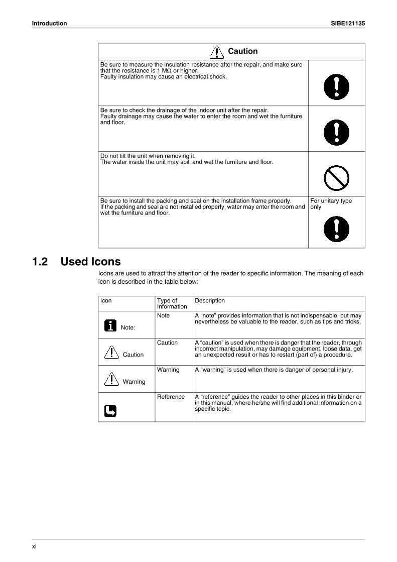
Be sure to measure the insulation resistance after the repair, and make sure that the resistance is 1 MΩ or higher.Faulty insulation may cause an electrical shock.
Be sure to check the drainage of the indoor unit after the repair.Faulty drainage may cause the water to enter the room and wet the furniture and floor.
Do not tilt the unit when removing it.The water inside the unit may spill and wet the furniture and floor.
Be sure to install the packing and seal on the installation frame properly.If the packing and seal are not installed properly, water may enter the room and wet the furniture and floor.
For unitary type only
Caution
Icon Type of Information
Description
Note:
Note A “note” provides information that is not indispensable, but may nevertheless be valuable to the reader, such as tips and tricks.
Caution
Caution A “caution” is used when there is danger that the reader, through incorrect manipulation, may damage equipment, loose data, get an unexpected result or has to restart (part of) a procedure.
Warning
Warning A “warning” is used when there is danger of personal injury.
Reference A “reference” guides the reader to other places in this binder or in this manual, where he/she will find additional information on a specific topic.
xi
SiBE121135
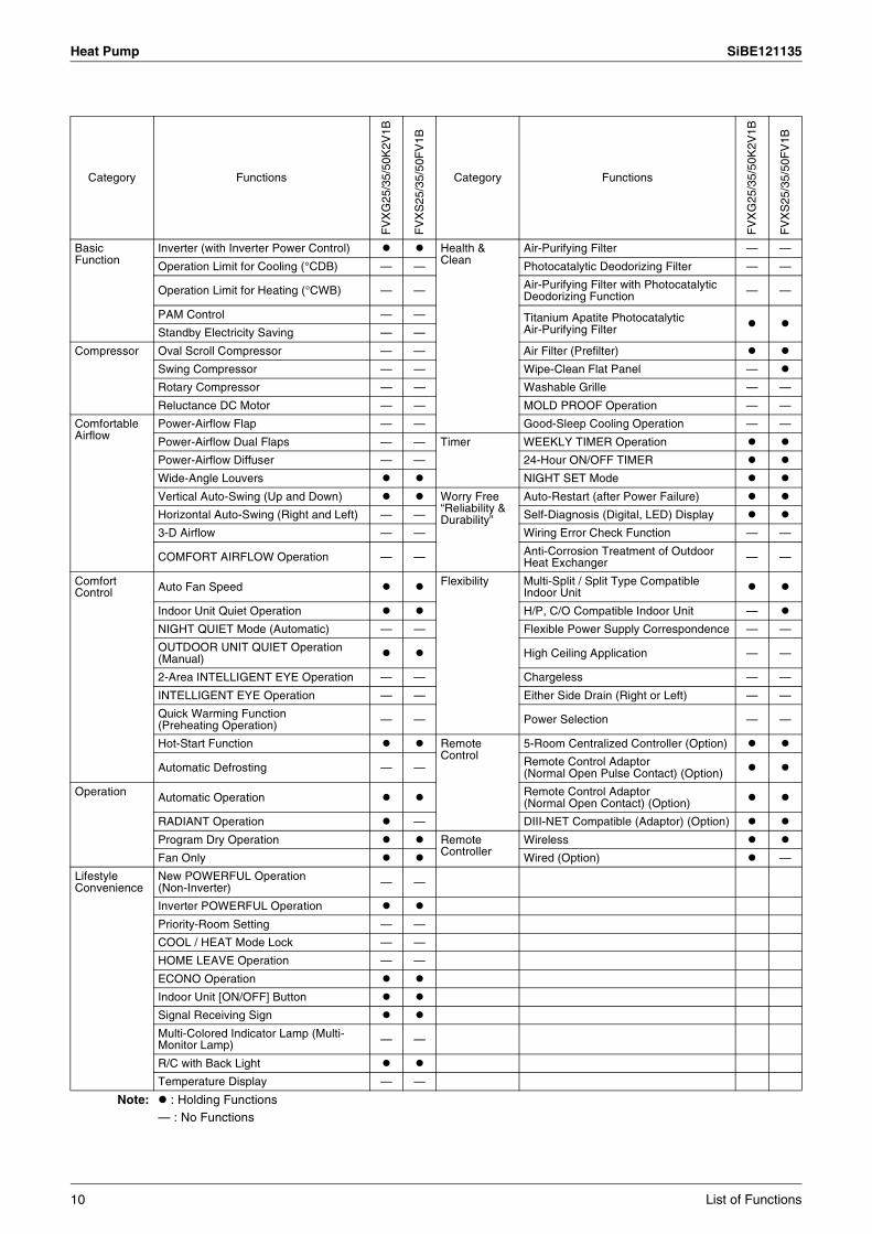
List of Functions 1
Part 1List of Functions
1. Cooling Only............................................................................................21.1 Outdoor Unit .............................................................................................21.2 Indoor Unit................................................................................................3
2. Heat Pump ..............................................................................................62.1 Outdoor Unit .............................................................................................62.2 Indoor Unit................................................................................................7
Cooling Only SiBE121135
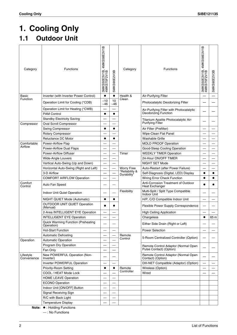
1. Cooling Only1.1 Outdoor Unit
Category Functions
3MK
S50
E3V
1B, 4
MK
S58
E3V
1B4M
KS
75F
2V1B
5MK
S90
E2V
3B
Category Functions
3MK
S50
E3V
1B, 4
MK
S58
E3V
1B4M
KS
75F
2V1B
5MK
S90
E2V
3B
Basic Function
Inverter (with Inverter Power Control) Health & Clean
Air-Purifying Filter — —
Operation Limit for Cooling (°CDB) –10~46
10~46 Photocatalytic Deodorizing Filter — —
Operation Limit for Heating (°CWB) — — Air-Purifying Filter with Photocatalytic Deodorizing Function — —
PAM Control
Standby Electricity Saving — — Titanium Apatite Photocatalytic Air-Purifying Filter — —
Compressor Oval Scroll Compressor — —
Swing Compressor Air Filter (Prefilter) — —
Rotary Compressor — — Wipe-Clean Flat Panel — —
Reluctance DC Motor Washable Grille — —
Comfortable Airflow
Power-Airflow Flap — — MOLD PROOF Operation — —
Power-Airflow Dual Flaps — — Good-Sleep Cooling Operation — —
Power-Airflow Diffuser — — Timer WEEKLY TIMER Operation — —
Wide-Angle Louvers — — 24-Hour ON/OFF TIMER — —
Vertical Auto-Swing (Up and Down) — — NIGHT SET Mode — —
Horizontal Auto-Swing (Right and Left) — — Worry Free “Reliability & Durability”
Auto-Restart (after Power Failure) — —
3-D Airflow — — Self-Diagnosis (Digital, LED) Display
COMFORT AIRFLOW Operation — — Wiring Error Check Function
Comfort Control Auto Fan Speed — — Anti-Corrosion Treatment of Outdoor
Heat Exchanger
Indoor Unit Quiet Operation — — Flexibility Multi-Split / Split Type Compatible Indoor Unit — —
NIGHT QUIET Mode (Automatic) H/P, C/O Compatible Indoor Unit — —
OUTDOOR UNIT QUIET Operation (Manual) Flexible Power Supply Correspondence — —
2-Area INTELLIGENT EYE Operation — — High Ceiling Application — —
INTELLIGENT EYE Operation — — Chargeless 65 m
Quick Warming Function (Preheating Operation) — — Either Side Drain (Right or Left) — —
Hot-Start Function — — Power Selection — —
Automatic Defrosting — — Remote Control 5-Room Centralized Controller (Option) — —
Operation Automatic Operation — —
Program Dry Operation — — Remote Control Adaptor (Normal Open Pulse Contact) (Option) — —
Fan Only — —
Lifestyle Convenience
New POWERFUL Operation (Non-Inverter) — — Remote Control Adaptor (Normal Open
Contact) (Option) — —
Inverter POWERFUL Operation — — DIII-NET Compatible (Adaptor) (Option) — —
Priority-Room Setting Remote Controller
Wireless (Option) — —
COOL / HEAT Mode Lock — — Wired — —
HOME LEAVE Operation — —
ECONO Operation — —
Indoor Unit [ON/OFF] Button — —
Signal Receiving Sign — —
R/C with Back Light — —
Temperature Display — —
Note: : Holding Functions— : No Functions
2 List of Functions
SiBE121135 Cooling Only
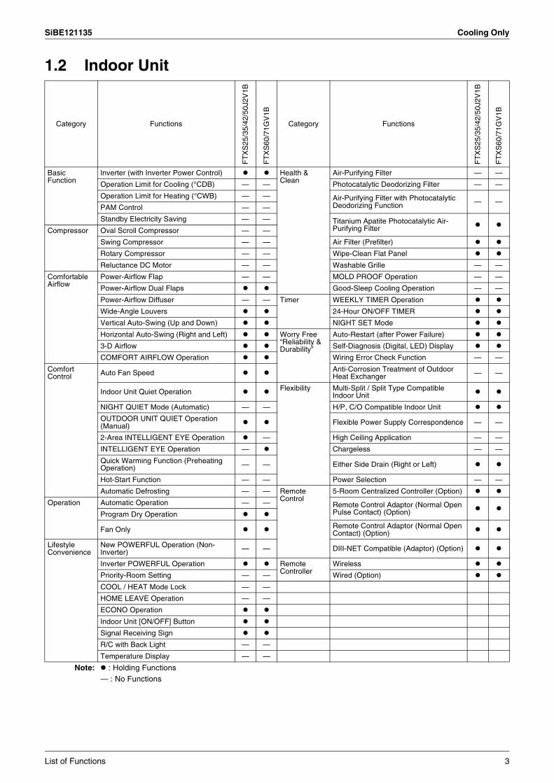
1.2 Indoor Unit
Category Functions
FT
XS
25/3
5/42
/50J
2V1B
FT
XS
60/7
1GV
1B
Category Functions
FT
XS
25/3
5/42
/50J
2V1B
FT
XS
60/7
1GV
1B
Basic Function
Inverter (with Inverter Power Control) Health & Clean
Air-Purifying Filter — —
Operation Limit for Cooling (°CDB) — — Photocatalytic Deodorizing Filter — —
Operation Limit for Heating (°CWB) — — Air-Purifying Filter with Photocatalytic Deodorizing Function — —
PAM Control — —
Standby Electricity Saving — — Titanium Apatite Photocatalytic Air-Purifying FilterCompressor Oval Scroll Compressor — —
Swing Compressor — — Air Filter (Prefilter)
Rotary Compressor — — Wipe-Clean Flat Panel
Reluctance DC Motor — — Washable Grille — —
Comfortable Airflow
Power-Airflow Flap — — MOLD PROOF Operation — —
Power-Airflow Dual Flaps Good-Sleep Cooling Operation — —
Power-Airflow Diffuser — — Timer WEEKLY TIMER Operation
Wide-Angle Louvers 24-Hour ON/OFF TIMER
Vertical Auto-Swing (Up and Down) NIGHT SET Mode
Horizontal Auto-Swing (Right and Left) Worry Free “Reliability & Durability”
Auto-Restart (after Power Failure)
3-D Airflow Self-Diagnosis (Digital, LED) Display
COMFORT AIRFLOW Operation Wiring Error Check Function — —
Comfort Control Auto Fan Speed Anti-Corrosion Treatment of Outdoor
Heat Exchanger — —
Indoor Unit Quiet Operation Flexibility Multi-Split / Split Type Compatible Indoor Unit
NIGHT QUIET Mode (Automatic) — — H/P, C/O Compatible Indoor Unit
OUTDOOR UNIT QUIET Operation (Manual) Flexible Power Supply Correspondence — —
2-Area INTELLIGENT EYE Operation — High Ceiling Application — —
INTELLIGENT EYE Operation — Chargeless — —
Quick Warming Function (Preheating Operation) — — Either Side Drain (Right or Left)
Hot-Start Function — — Power Selection — —
Automatic Defrosting — — Remote Control
5-Room Centralized Controller (Option)
Operation Automatic Operation — — Remote Control Adaptor (Normal Open Pulse Contact) (Option)Program Dry Operation
Fan Only Remote Control Adaptor (Normal Open Contact) (Option)
Lifestyle Convenience
New POWERFUL Operation (Non-Inverter) — — DIII-NET Compatible (Adaptor) (Option)
Inverter POWERFUL Operation Remote Controller
Wireless
Priority-Room Setting — — Wired (Option)
COOL / HEAT Mode Lock — —
HOME LEAVE Operation — —
ECONO Operation
Indoor Unit [ON/OFF] Button
Signal Receiving Sign
R/C with Back Light — —
Temperature Display — —
Note: : Holding Functions— : No Functions
List of Functions 3

Cooling Only SiBE121135
Category Functions
FF
Q25
/35/
50/6
0B9V
1B
Category Functions
FF
Q25
/35/
50/6
0B9V
1B
Basic Function
Inverter (with Inverter Power Control) Health & Clean
Air-Purifying Filter —
Operation Limit for Cooling (°CDB) — Photocatalytic Deodorizing Filter —
Operation Limit for Heating (°CWB) — Air-Purifying Filter with Photocatalytic Deodorizing Function —
PAM Control —
Standby Electricity Saving — Titanium Apatite Photocatalytic Air-Purifying Filter —
Compressor Oval Scroll Compressor —
Swing Compressor — Longlife Filter
Rotary Compressor — Wipe-Clean Flat Panel —
Reluctance DC Motor — Washable Grille
Comfortable Airflow
Power-Airflow Flap — Filter Cleaning Indicator
Power-Airflow Dual Flaps — Self-Cleaning Decoration Panel (Option) —
Power-Airflow Diffuser — MOLD PROOF Operation —
Wide-Angle Louvers — Good-Sleep Cooling Operation —
Vertical Auto-Swing (Up and Down) Timer Schedule Timer Operation 2
Horizontal Auto-Swing (Right and Left) — 72-Hour ON/OFF TIMER 1
3-D Airflow — NIGHT SET Mode —
COMFORT AIRFLOW Operation — Worry Free “Reliability & Durability”
Auto-Restart (after Power Failure)
Comfort Control
Auto Fan Speed — Self-Diagnosis (Digital, LED) Display
Indoor Unit Quiet Operation — Wiring Error Check Function —
NIGHT QUIET Mode (Automatic) — Anti-Corrosion Treatment of Outdoor Heat Exchanger —
OUTDOOR UNIT QUIET Operation (Manual) — Flexibility Multi-Split / Split Type Compatible Indoor Unit
2-Area INTELLIGENT EYE Operation — H/P, C/O Compatible Indoor Unit
INTELLIGENT EYE Operation — Flexible Power Supply Correspondence —
Quick Warming Function (Preheating Operation) — High Ceiling Application —
Hot-Start Function — Chargeless —
Automatic Defrosting — Either Side Drain (Right or Left) —
Operation Automatic Operation — Power Selection —
Program Dry Operation Remote Control
5-Room Centralized Controller (Option) —
Fan Only Remote Control Adaptor (Normal Open Pulse Contact) (Option) —
Lifestyle Convenience
New POWERFUL Operation (Non-Inverter) —
Inverter POWERFUL Operation — Remote Control Adaptor (Normal Open Contact) (Option) —
Priority-Room Setting — DIII-NET Compatible (Adaptor) (Option)
COOL / HEAT Mode Lock — Remote Controller
Wireless (Option)
HOME LEAVE Operation — Wired (Option)
ECONO Operation —
Indoor Unit [ON/OFF] Button 1
Signal Receiving Sign 1
Temperature Display —
Note: : Holding Functions— : No Functions
1:2:
with wireless remote controllerwith wired remote controller
4 List of Functions
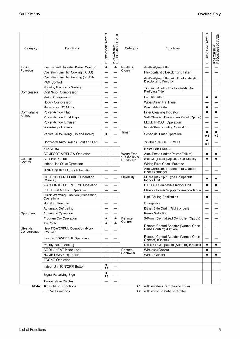
SiBE121135 Cooling Only
Category Functions
FH
Q35
/50/
60B
WV
1B
FD
BQ
25B
8V1
FB
Q35
/50/
60C
8VE
B
Category Functions
FH
Q35
/50/
60B
WV
1B
FD
BQ
25B
8V1
FB
Q35
/50/
60C
8VE
B
Basic Function
Inverter (with Inverter Power Control) Health & Clean
Air-Purifying Filter — —
Operation Limit for Cooling (°CDB) — — Photocatalytic Deodorizing Filter — —
Operation Limit for Heating (°CWB) — — Air-Purifying Filter with Photocatalytic Deodorizing Function — —
PAM Control — —
Standby Electricity Saving — — Titanium Apatite Photocatalytic Air-Purifying Filter — —
Compressor Oval Scroll Compressor — —
Swing Compressor — — Longlife Filter
Rotary Compressor — — Wipe-Clean Flat Panel — —
Reluctance DC Motor — — Washable Grille —
Comfortable Airflow
Power-Airflow Flap — — Filter Cleaning Indicator
Power-Airflow Dual Flaps — — Self-Cleaning Decoration Panel (Option) — —
Power-Airflow Diffuser — — MOLD PROOF Operation — —
Wide-Angle Louvers — — Good-Sleep Cooling Operation — —
Vertical Auto-Swing (Up and Down) — Timer Schedule Timer Operation 2 2
Horizontal Auto-Swing (Right and Left) — — 72-Hour ON/OFF TIMER 1 —
3-D Airflow — — NIGHT SET Mode — —
COMFORT AIRFLOW Operation — — Worry Free “Reliability & Durability”
Auto-Restart (after Power Failure)
Comfort Control
Auto Fan Speed — — Self-Diagnosis (Digital, LED) Display
Indoor Unit Quiet Operation — — Wiring Error Check Function — —
NIGHT QUIET Mode (Automatic) — — Anti-Corrosion Treatment of Outdoor Heat Exchanger — —
OUTDOOR UNIT QUIET Operation (Manual) — — Flexibility Multi-Split / Split Type Compatible
Indoor Unit
2-Area INTELLIGENT EYE Operation — — H/P, C/O Compatible Indoor Unit
INTELLIGENT EYE Operation — — Flexible Power Supply Correspondence — —
Quick Warming Function (Preheating Operation) — — High Ceiling Application —
Hot-Start Function — — Chargeless — —
Automatic Defrosting — — Either Side Drain (Right or Left) — —
Operation Automatic Operation — — Power Selection — —
Program Dry Operation Remote Control
5-Room Centralized Controller (Option) — —
Fan OnlyRemote Control Adaptor (Normal Open Pulse Contact) (Option) — —Lifestyle
ConvenienceNew POWERFUL Operation (Non-Inverter) — —
Inverter POWERFUL Operation — — Remote Control Adaptor (Normal Open Contact) (Option) — —
Priority-Room Setting — — DIII-NET Compatible (Adaptor) (Option)
COOL / HEAT Mode Lock — — Remote Controller
Wireless (Option) —
HOME LEAVE Operation — — Wired (Option)
ECONO Operation — —
Indoor Unit [ON/OFF] Button 1 —
Signal Receiving Sign 1 —
Temperature Display — —
Note: : Holding Functions— : No Functions
1:2:
with wireless remote controllerwith wired remote controller
List of Functions 5
Heat Pump SiBE121135
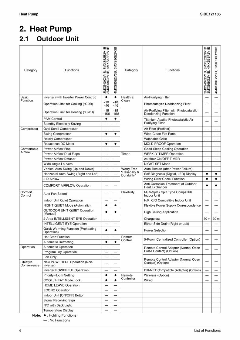
2. Heat Pump2.1 Outdoor Unit
Category Functions
3MX
S40
K2V
1B, 3
MX
S52
E3V
1B3M
XS
68G
2V1B
, 4M
XS
68F
2V1B
4MX
S80
E2V
3B, 5
MX
S90
E2V
3B
Category Functions
3MX
S40
K2V
1B, 3
MX
S52
E3V
1B3M
XS
68G
2V1B
, 4M
XS
68F
2V1B
4MX
S80
E2V
3B, 5
MX
S90
E2V
3B
Basic Function
Inverter (with Inverter Power Control) Health & Clean
Air-Purifying Filter — —
Operation Limit for Cooling (°CDB) –10 ~46
–10 ~46 Photocatalytic Deodorizing Filter — —
Operation Limit for Heating (°CWB) –15 ~15.5
–15 ~15.5
Air-Purifying Filter with Photocatalytic Deodorizing Function — —
PAM Control Titanium Apatite Photocatalytic Air-Purifying Filter — —
Standby Electricity Saving — —
Compressor Oval Scroll Compressor — — Air Filter (Prefilter) — —
Swing Compressor Wipe-Clean Flat Panel — —
Rotary Compressor — — Washable Grille — —
Reluctance DC Motor MOLD PROOF Operation — —
Comfortable Airflow
Power-Airflow Flap — — Good-Sleep Cooling Operation — —
Power-Airflow Dual Flaps — — Timer WEEKLY TIMER Operation — —
Power-Airflow Diffuser — — 24-Hour ON/OFF TIMER — —
Wide-Angle Louvers — — NIGHT SET Mode — —
Vertical Auto-Swing (Up and Down) — — Worry Free “Reliability & Durability”
Auto-Restart (after Power Failure) — —
Horizontal Auto-Swing (Right and Left) — — Self-Diagnosis (Digital, LED) Display
3-D Airflow — — Wiring Error Check Function
COMFORT AIRFLOW Operation — — Anti-Corrosion Treatment of Outdoor Heat Exchanger
Comfort Control Auto Fan Speed — — Flexibility Multi-Split / Split Type Compatible
Indoor Unit — —
Indoor Unit Quiet Operation — — H/P, C/O Compatible Indoor Unit — —
NIGHT QUIET Mode (Automatic) Flexible Power Supply Correspondence — —
OUTDOOR UNIT QUIET Operation (Manual) High Ceiling Application — —
2-Area INTELLIGENT EYE Operation — — Chargeless 30 m 30 m
INTELLIGENT EYE Operation — — Either Side Drain (Right or Left) — —
Quick Warming Function (Preheating Operation) Power Selection — —
Hot-Start Function — — Remote Control 5-Room Centralized Controller (Option) — —
Automatic Defrosting
Operation Automatic Operation — — Remote Control Adaptor (Normal Open Pulse Contact) (Option) — —
Program Dry Operation — —
Fan Only — —Remote Control Adaptor (Normal Open Contact) (Option) — —Lifestyle
ConvenienceNew POWERFUL Operation (Non-Inverter) — —
Inverter POWERFUL Operation — — DIII-NET Compatible (Adaptor) (Option) — —
Priority-Room Setting Remote Controller
Wireless (Option) — —
COOL / HEAT Mode Lock Wired — —
HOME LEAVE Operation — —
ECONO Operation — —
Indoor Unit [ON/OFF] Button — —
Signal Receiving Sign — —
R/C with Back Light — —
Temperature Display — —
Note: : Holding Functions— : No Functions
6 List of Functions

SiBE121135 Heat Pump
2.2 Indoor Unit
Category Functions
FT
XG
25/3
5/50
JV1B
W(A
)
Category Functions
FT
XG
25/3
5/50
JV1B
W(A
)
Basic Function
Inverter (with Inverter Power Control) Health & Clean
Air-Purifying Filter —
Operation Limit for Cooling (°CDB) — Photocatalytic Deodorizing Filter —
Operation Limit for Heating (°CWB) — Air-Purifying Filter with Photocatalytic Deodorizing Function —
PAM Control — Titanium Apatite Photocatalytic Air-Purifying FilterStandby Electricity Saving —
Compressor Oval Scroll Compressor — Air Filter (Prefilter)
Swing Compressor — Wipe-Clean Flat Panel
Rotary Compressor — Washable Grille —
Reluctance DC Motor — MOLD PROOF Operation —
Comfortable Airflow
Power-Airflow Flap — Good-Sleep Cooling Operation —
Power-Airflow Dual Flaps Timer WEEKLY TIMER Operation
Power-Airflow Diffuser — 24-Hour ON/OFF TIMER
Wide-Angle Louvers NIGHT SET Mode
Vertical Auto-Swing (Up and Down) Worry Free “Reliability & Durability”
Auto-Restart (after Power Failure)
Horizontal Auto-Swing (Right and Left) — Self-Diagnosis (Digital, LED) Display
3-D Airflow — Wiring Error Check Function —
COMFORT AIRFLOW Operation Anti-Corrosion Treatment of Outdoor Heat Exchanger —
Comfort Control
Auto Fan Speed
Indoor Unit Quiet Operation FlexibilityMulti-Split / Split Type Compatible Indoor Unit
NIGHT QUIET Mode (Automatic) —
OUTDOOR UNIT QUIET Operation (Manual) H/P, C/O Compatible Indoor Unit —
INTELLIGENT EYE Operation Flexible Power Supply Correspondence —
2-Area INTELLIGENT EYE Operation — High Ceiling Application —
Quick Warming Function (Preheating Operation) — Chargeless —
Hot-Start Function Either Side Drain (Right or Left)
Automatic Defrosting — Power Selection —
Operation Automatic Operation Remote Control 5-Room Centralized Controller (Option)
Program Dry Operation
Fan Only Remote Control Adaptor (Normal Open Pulse Contact) (Option)
Lifestyle Convenience New POWERFUL Operation (Non-Inverter) — Remote Control Adaptor (Normal Open
Contact) (Option)
Inverter POWERFUL Operation DIII-NET Compatible (Adaptor) (Option)
Priority-Room Setting — Remote Controller
Wireless
COOL / HEAT Mode Lock — Wired (Option)
HOME LEAVE Operation —
ECONO Operation
Indoor Unit [ON/OFF] Button
Signal Receiving Sign
Multi-Colored Indicator Lamp (Multi-Monitor Lamp)
R/C with Back Light
Temperature Display —
Note: : Holding Functions— : No Functions
List of Functions 7
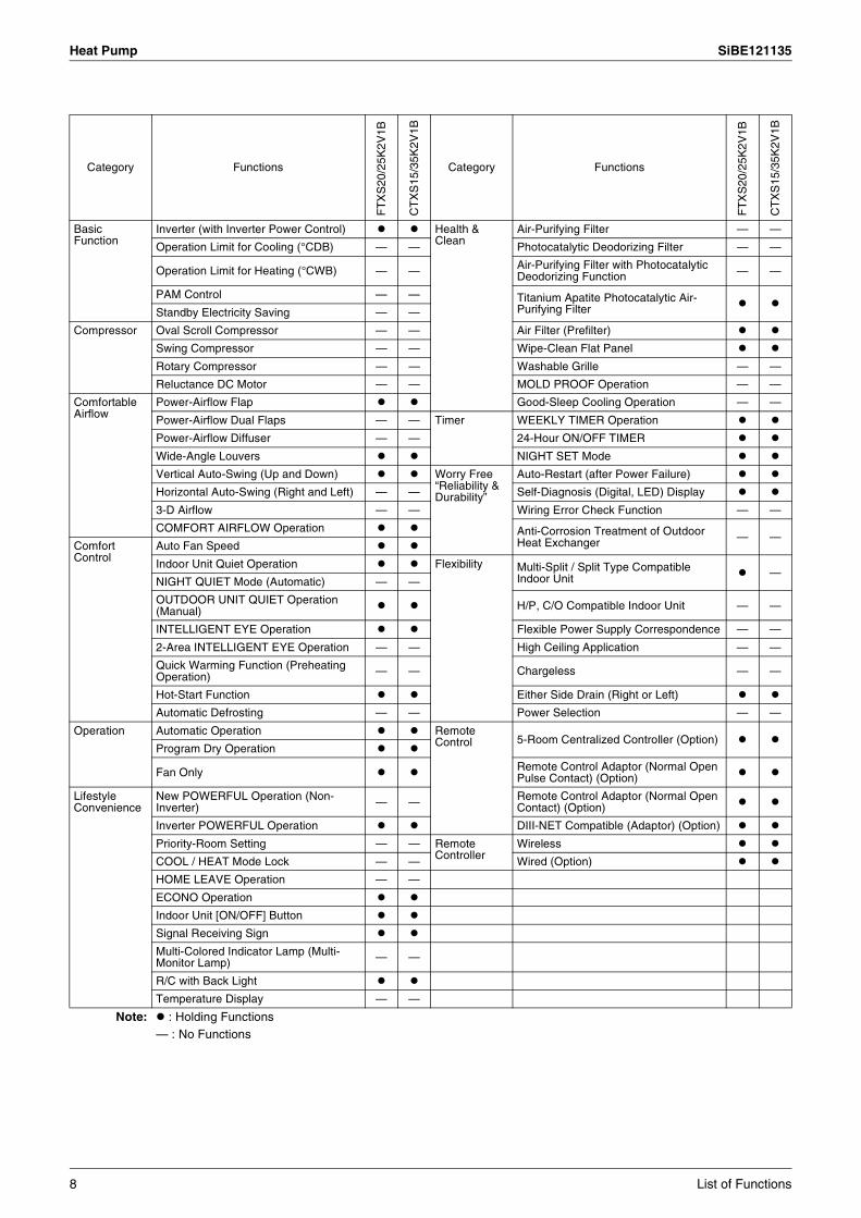
Heat Pump SiBE121135
Category Functions
FT
XS
20/2
5K2V
1B
CT
XS
15/3
5K2V
1B
Category Functions
FT
XS
20/2
5K2V
1B
CT
XS
15/3
5K2V
1B
Basic Function
Inverter (with Inverter Power Control) Health & Clean
Air-Purifying Filter — —
Operation Limit for Cooling (°CDB) — — Photocatalytic Deodorizing Filter — —
Operation Limit for Heating (°CWB) — — Air-Purifying Filter with Photocatalytic Deodorizing Function — —
PAM Control — — Titanium Apatite Photocatalytic Air-Purifying FilterStandby Electricity Saving — —
Compressor Oval Scroll Compressor — — Air Filter (Prefilter)
Swing Compressor — — Wipe-Clean Flat Panel
Rotary Compressor — — Washable Grille — —
Reluctance DC Motor — — MOLD PROOF Operation — —
Comfortable Airflow
Power-Airflow Flap Good-Sleep Cooling Operation — —
Power-Airflow Dual Flaps — — Timer WEEKLY TIMER Operation
Power-Airflow Diffuser — — 24-Hour ON/OFF TIMER
Wide-Angle Louvers NIGHT SET Mode
Vertical Auto-Swing (Up and Down) Worry Free “Reliability & Durability”
Auto-Restart (after Power Failure)
Horizontal Auto-Swing (Right and Left) — — Self-Diagnosis (Digital, LED) Display
3-D Airflow — — Wiring Error Check Function — —
COMFORT AIRFLOW Operation Anti-Corrosion Treatment of Outdoor Heat Exchanger — —
Comfort Control
Auto Fan Speed
Indoor Unit Quiet Operation Flexibility Multi-Split / Split Type Compatible Indoor Unit —
NIGHT QUIET Mode (Automatic) — —
OUTDOOR UNIT QUIET Operation (Manual) H/P, C/O Compatible Indoor Unit — —
INTELLIGENT EYE Operation Flexible Power Supply Correspondence — —
2-Area INTELLIGENT EYE Operation — — High Ceiling Application — —
Quick Warming Function (Preheating Operation) — — Chargeless — —
Hot-Start Function Either Side Drain (Right or Left)
Automatic Defrosting — — Power Selection — —
Operation Automatic Operation Remote Control 5-Room Centralized Controller (Option)
Program Dry Operation
Fan Only Remote Control Adaptor (Normal Open Pulse Contact) (Option)
Lifestyle Convenience
New POWERFUL Operation (Non-Inverter) — — Remote Control Adaptor (Normal Open
Contact) (Option)
Inverter POWERFUL Operation DIII-NET Compatible (Adaptor) (Option)
Priority-Room Setting — — Remote Controller
Wireless
COOL / HEAT Mode Lock — — Wired (Option)
HOME LEAVE Operation — —
ECONO Operation
Indoor Unit [ON/OFF] Button
Signal Receiving Sign
Multi-Colored Indicator Lamp (Multi-Monitor Lamp) — —
R/C with Back Light
Temperature Display — —
Note: : Holding Functions— : No Functions
8 List of Functions

SiBE121135 Heat Pump
Category Functions
FT
XS
25/3
5/42
/50J
2V1B
FT
XS
60/7
1GV
1B
Category Functions
FT
XS
25/3
5/42
/50J
2V1B
FT
XS
60/7
1GV
1B
Basic Function
Inverter (with Inverter Power Control) Health & Clean
Air-Purifying Filter — —
Operation Limit for Cooling (°CDB) — — Photocatalytic Deodorizing Filter — —
Operation Limit for Heating (°CWB) — — Air-Purifying Filter with Photocatalytic Deodorizing Function — —
PAM Control — — Titanium Apatite Photocatalytic Air-Purifying FilterStandby Electricity Saving — —
Compressor Oval Scroll Compressor — — Air Filter (Prefilter)
Swing Compressor — — Wipe-Clean Flat Panel
Rotary Compressor — — Washable Grille — —
Reluctance DC Motor — — MOLD PROOF Operation — —
Comfortable Airflow
Power-Airflow Flap — — Good-Sleep Cooling Operation — —
Power-Airflow Dual Flaps Timer WEEKLY TIMER Operation
Power-Airflow Diffuser — — 24-Hour ON/OFF TIMER
Wide-Angle Louvers NIGHT SET Mode
Vertical Auto-Swing (Up and Down) Worry Free “Reliability & Durability”
Auto-Restart (after Power Failure)
Horizontal Auto-Swing (Right and Left) Self-Diagnosis (Digital, LED) Display
3-D Airflow Wiring Error Check Function — —
COMFORT AIRFLOW Operation Anti-Corrosion Treatment of Outdoor Heat Exchanger — —
Comfort Control Auto Fan Speed Flexibility Multi-Split / Split Type Compatible
Indoor Unit
Indoor Unit Quiet Operation H/P, C/O Compatible Indoor Unit
NIGHT QUIET Mode (Automatic) — — Flexible Power Supply Correspondence — —
OUTDOOR UNIT QUIET Operation (Manual) High Ceiling Application — —
2-Area INTELLIGENT EYE Operation — Chargeless — —
INTELLIGENT EYE Operation — Either Side Drain (Right or Left)
Quick Warming Function (Preheating Operation) — — Power Selection — —
Hot-Start Function Remote Control 5-Room Centralized Controller (Option)
Automatic Defrosting — —
Operation Automatic Operation Remote Control Adaptor (Normal Open Pulse Contact) (Option)Program Dry Operation
Fan Only Remote Control Adaptor (Normal Open Contact) (Option)
Lifestyle Convenience
New POWERFUL Operation (Non-Inverter) — — DIII-NET Compatible (Adaptor) (Option)
Inverter POWERFUL Operation Remote Controller
Wireless
Priority-Room Setting — — Wired (Option)
COOL / HEAT Mode Lock — —
HOME LEAVE Operation — —
ECONO Operation
Indoor Unit [ON/OFF] Button
Signal Receiving Sign
Multi-Colored Indicator Lamp (Multi-Monitor Lamp) — —
R/C with Back Light — —
Temperature Display — —
Note: : Holding Functions— : No Functions
List of Functions 9
Heat Pump SiBE121135
Category Functions
FV
XG
25/3
5/50
K2V
1B
FV
XS
25/3
5/50
FV
1B
Category Functions
FV
XG
25/3
5/50
K2V
1B
FV
XS
25/3
5/50
FV
1B
Basic Function
Inverter (with Inverter Power Control) Health & Clean
Air-Purifying Filter — —
Operation Limit for Cooling (°CDB) — — Photocatalytic Deodorizing Filter — —
Operation Limit for Heating (°CWB) — — Air-Purifying Filter with Photocatalytic Deodorizing Function — —
PAM Control — — Titanium Apatite Photocatalytic Air-Purifying FilterStandby Electricity Saving — —
Compressor Oval Scroll Compressor — — Air Filter (Prefilter)
Swing Compressor — — Wipe-Clean Flat Panel —
Rotary Compressor — — Washable Grille — —
Reluctance DC Motor — — MOLD PROOF Operation — —
Comfortable Airflow
Power-Airflow Flap — — Good-Sleep Cooling Operation — —
Power-Airflow Dual Flaps — — Timer WEEKLY TIMER Operation
Power-Airflow Diffuser — — 24-Hour ON/OFF TIMER
Wide-Angle Louvers NIGHT SET Mode
Vertical Auto-Swing (Up and Down) Worry Free “Reliability & Durability”
Auto-Restart (after Power Failure)
Horizontal Auto-Swing (Right and Left) — — Self-Diagnosis (Digital, LED) Display
3-D Airflow — — Wiring Error Check Function — —
COMFORT AIRFLOW Operation — — Anti-Corrosion Treatment of Outdoor Heat Exchanger — —
Comfort Control Auto Fan Speed Flexibility Multi-Split / Split Type Compatible
Indoor Unit
Indoor Unit Quiet Operation H/P, C/O Compatible Indoor Unit —
NIGHT QUIET Mode (Automatic) — — Flexible Power Supply Correspondence — —
OUTDOOR UNIT QUIET Operation (Manual) High Ceiling Application — —
2-Area INTELLIGENT EYE Operation — — Chargeless — —
INTELLIGENT EYE Operation — — Either Side Drain (Right or Left) — —
Quick Warming Function (Preheating Operation) — — Power Selection — —
Hot-Start Function Remote Control
5-Room Centralized Controller (Option)
Automatic Defrosting — — Remote Control Adaptor (Normal Open Pulse Contact) (Option)
Operation Automatic Operation Remote Control Adaptor (Normal Open Contact) (Option)
RADIANT Operation — DIII-NET Compatible (Adaptor) (Option)
Program Dry Operation Remote Controller
Wireless
Fan Only Wired (Option) —
Lifestyle Convenience
New POWERFUL Operation (Non-Inverter) — —
Inverter POWERFUL Operation
Priority-Room Setting — —
COOL / HEAT Mode Lock — —
HOME LEAVE Operation — —
ECONO Operation
Indoor Unit [ON/OFF] Button
Signal Receiving Sign
Multi-Colored Indicator Lamp (Multi-Monitor Lamp) — —
R/C with Back Light
Temperature Display — —
Note: : Holding Functions— : No Functions
10 List of Functions
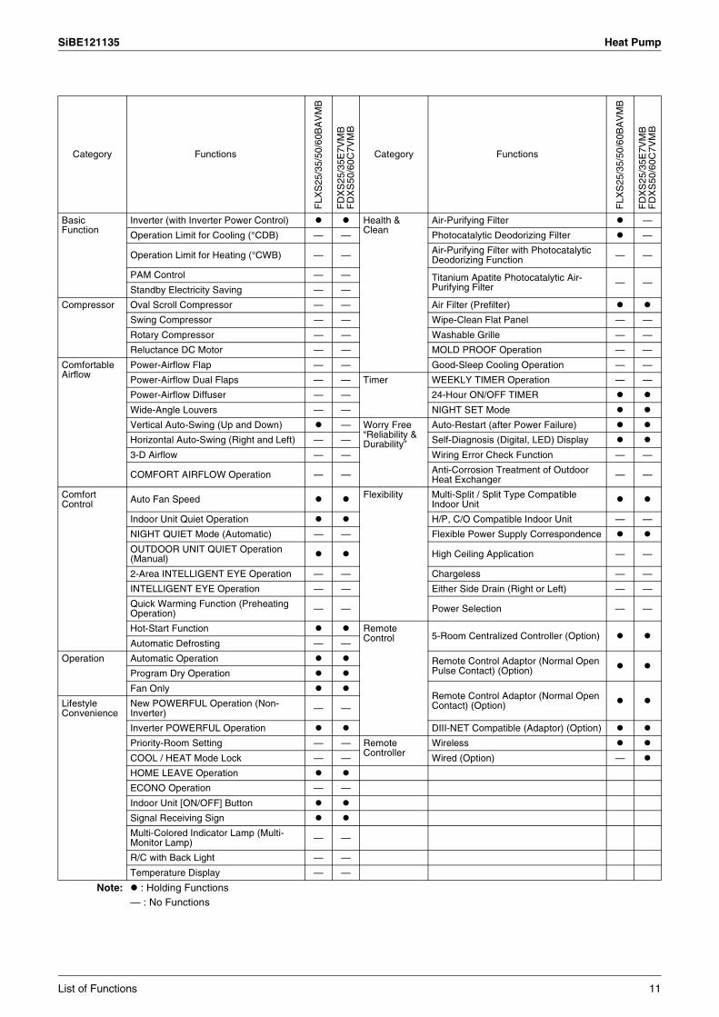
SiBE121135 Heat Pump
Category Functions
FLX
S25
/35/
50/6
0BA
VM
B
FD
XS
25/3
5E7V
MB
FD
XS
50/6
0C7V
MB
Category Functions
FLX
S25
/35/
50/6
0BA
VM
B
FD
XS
25/3
5E7V
MB
FD
XS
50/6
0C7V
MB
Basic Function
Inverter (with Inverter Power Control) Health & Clean
Air-Purifying Filter —
Operation Limit for Cooling (°CDB) — — Photocatalytic Deodorizing Filter —
Operation Limit for Heating (°CWB) — — Air-Purifying Filter with Photocatalytic Deodorizing Function — —
PAM Control — — Titanium Apatite Photocatalytic Air-Purifying Filter — —
Standby Electricity Saving — —
Compressor Oval Scroll Compressor — — Air Filter (Prefilter)
Swing Compressor — — Wipe-Clean Flat Panel — —
Rotary Compressor — — Washable Grille — —
Reluctance DC Motor — — MOLD PROOF Operation — —
Comfortable Airflow
Power-Airflow Flap — — Good-Sleep Cooling Operation — —
Power-Airflow Dual Flaps — — Timer WEEKLY TIMER Operation — —
Power-Airflow Diffuser — — 24-Hour ON/OFF TIMER
Wide-Angle Louvers — — NIGHT SET Mode
Vertical Auto-Swing (Up and Down) — Worry Free “Reliability & Durability”
Auto-Restart (after Power Failure)
Horizontal Auto-Swing (Right and Left) — — Self-Diagnosis (Digital, LED) Display
3-D Airflow — — Wiring Error Check Function — —
COMFORT AIRFLOW Operation — — Anti-Corrosion Treatment of Outdoor Heat Exchanger — —
Comfort Control Auto Fan Speed Flexibility Multi-Split / Split Type Compatible
Indoor Unit
Indoor Unit Quiet Operation H/P, C/O Compatible Indoor Unit — —
NIGHT QUIET Mode (Automatic) — — Flexible Power Supply Correspondence
OUTDOOR UNIT QUIET Operation (Manual) High Ceiling Application — —
2-Area INTELLIGENT EYE Operation — — Chargeless — —
INTELLIGENT EYE Operation — — Either Side Drain (Right or Left) — —
Quick Warming Function (Preheating Operation) — — Power Selection — —
Hot-Start Function Remote Control 5-Room Centralized Controller (Option)
Automatic Defrosting — —
Operation Automatic Operation Remote Control Adaptor (Normal Open Pulse Contact) (Option)Program Dry Operation
Fan OnlyRemote Control Adaptor (Normal Open Contact) (Option)Lifestyle
ConvenienceNew POWERFUL Operation (Non-Inverter) — —
Inverter POWERFUL Operation DIII-NET Compatible (Adaptor) (Option)
Priority-Room Setting — — Remote Controller
Wireless
COOL / HEAT Mode Lock — — Wired (Option) —
HOME LEAVE Operation
ECONO Operation — —
Indoor Unit [ON/OFF] Button
Signal Receiving Sign
Multi-Colored Indicator Lamp (Multi-Monitor Lamp) — —
R/C with Back Light — —
Temperature Display — —
Note: : Holding Functions— : No Functions
List of Functions 11
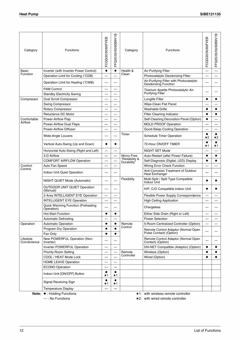
Heat Pump SiBE121135
Category Functions
FC
QG
35/5
0/60
FV
EB
FF
Q25
/35/
50/6
0B9V
1B
Category Functions
FC
QG
35/5
0/60
FV
EB
FF
Q25
/35/
50/6
0B9V
1B
Basic Function
Inverter (with Inverter Power Control) Health & Clean
Air-Purifying Filter — —
Operation Limit for Cooling (°CDB) — — Photocatalytic Deodorizing Filter — —
Operation Limit for Heating (°CWB) — — Air-Purifying Filter with Photocatalytic Deodorizing Function — —
PAM Control — — Titanium Apatite Photocatalytic Air-Purifying Filter — —
Standby Electricity Saving — —
Compressor Oval Scroll Compressor — — Longlife Filter
Swing Compressor — — Wipe-Clean Flat Panel — —
Rotary Compressor — — Washable Grille
Reluctance DC Motor — — Filter Cleaning Indicator
Comfortable Airflow
Power-Airflow Flap — — Self-Cleaning Decoration Panel (Option) —
Power-Airflow Dual Flaps — — MOLD PROOF Operation — —
Power-Airflow Diffuser — — Good-Sleep Cooling Operation — —
Wide-Angle Louvers — — Timer Schedule Timer Operation 2
2
Vertical Auto-Swing (Up and Down) 72-Hour ON/OFF TIMER 1
1
Horizontal Auto-Swing (Right and Left) — — NIGHT SET Mode — —
3-D Airflow — — Worry Free “Reliability & Durability”
Auto-Restart (after Power Failure)
COMFORT AIRFLOW Operation — — Self-Diagnosis (Digital, LED) Display
Comfort Control
Auto Fan Speed — — Wiring Error Check Function — —
Indoor Unit Quiet Operation — — Anti-Corrosion Treatment of Outdoor Heat Exchanger — —
NIGHT QUIET Mode (Automatic) — — Flexibility Multi-Split / Split Type Compatible Indoor Unit
OUTDOOR UNIT QUIET Operation (Manual) — — H/P, C/O Compatible Indoor Unit
2-Area INTELLIGENT EYE Operation — — Flexible Power Supply Correspondence — —
INTELLIGENT EYE Operation — — High Ceiling Application — —
Quick Warming Function (Preheating Operation) — — Chargeless — —
Hot-Start Function Either Side Drain (Right or Left) — —
Automatic Defrosting — — Power Selection — —
Operation Automatic Operation Remote Control
5-Room Centralized Controller (Option) — —
Program Dry Operation Remote Control Adaptor (Normal Open Pulse Contact) (Option) — —
Fan Only
Lifestyle Convenience
New POWERFUL Operation (Non-Inverter) — — Remote Control Adaptor (Normal Open
Contact) (Option) — —
Inverter POWERFUL Operation — — DIII-NET Compatible (Adaptor) (Option)
Priority-Room Setting — — Remote Controller
Wireless (Option)
COOL / HEAT Mode Lock — — Wired (Option)
HOME LEAVE Operation — —
ECONO Operation — —
Indoor Unit [ON/OFF] Button 1
1
Signal Receiving Sign 1
1
Temperature Display — —
Note: : Holding Functions— : No Functions
1:2:
with wireless remote controllerwith wired remote controller
12 List of Functions
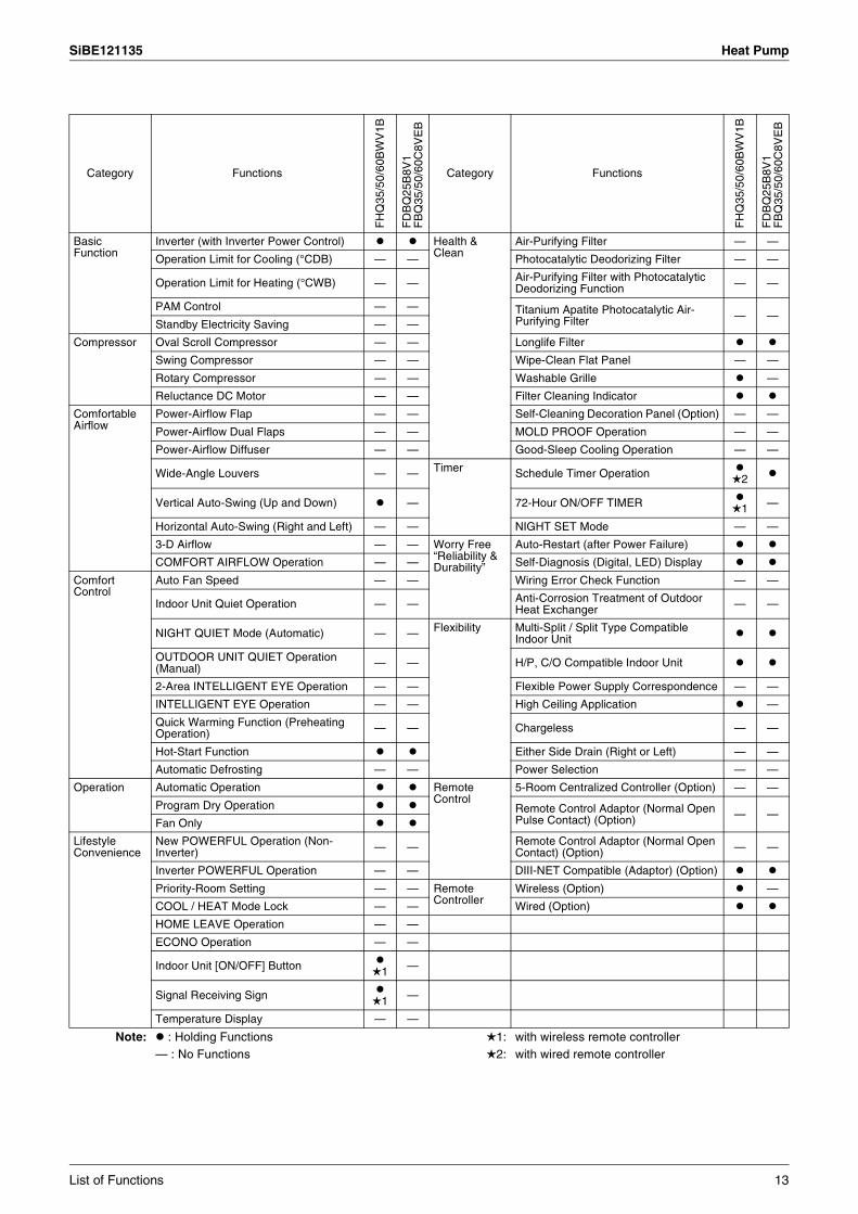
SiBE121135 Heat Pump
Category Functions
FH
Q35
/50/
60B
WV
1B
FD
BQ
25B
8V1
FB
Q35
/50/
60C
8VE
B
Category Functions
FH
Q35
/50/
60B
WV
1B
FD
BQ
25B
8V1
FB
Q35
/50/
60C
8VE
B
Basic Function
Inverter (with Inverter Power Control) Health & Clean
Air-Purifying Filter — —
Operation Limit for Cooling (°CDB) — — Photocatalytic Deodorizing Filter — —
Operation Limit for Heating (°CWB) — — Air-Purifying Filter with Photocatalytic Deodorizing Function — —
PAM Control — — Titanium Apatite Photocatalytic Air-Purifying Filter — —
Standby Electricity Saving — —
Compressor Oval Scroll Compressor — — Longlife Filter
Swing Compressor — — Wipe-Clean Flat Panel — —
Rotary Compressor — — Washable Grille —
Reluctance DC Motor — — Filter Cleaning Indicator
Comfortable Airflow
Power-Airflow Flap — — Self-Cleaning Decoration Panel (Option) — —
Power-Airflow Dual Flaps — — MOLD PROOF Operation — —
Power-Airflow Diffuser — — Good-Sleep Cooling Operation — —
Wide-Angle Louvers — — Timer Schedule Timer Operation 2
Vertical Auto-Swing (Up and Down) — 72-Hour ON/OFF TIMER 1 —
Horizontal Auto-Swing (Right and Left) — — NIGHT SET Mode — —
3-D Airflow — — Worry Free “Reliability & Durability”
Auto-Restart (after Power Failure)
COMFORT AIRFLOW Operation — — Self-Diagnosis (Digital, LED) Display
Comfort Control
Auto Fan Speed — — Wiring Error Check Function — —
Indoor Unit Quiet Operation — — Anti-Corrosion Treatment of Outdoor Heat Exchanger — —
NIGHT QUIET Mode (Automatic) — — Flexibility Multi-Split / Split Type Compatible Indoor Unit
OUTDOOR UNIT QUIET Operation (Manual) — — H/P, C/O Compatible Indoor Unit
2-Area INTELLIGENT EYE Operation — — Flexible Power Supply Correspondence — —
INTELLIGENT EYE Operation — — High Ceiling Application —
Quick Warming Function (Preheating Operation) — — Chargeless — —
Hot-Start Function Either Side Drain (Right or Left) — —
Automatic Defrosting — — Power Selection — —
Operation Automatic Operation Remote Control
5-Room Centralized Controller (Option) — —
Program Dry Operation Remote Control Adaptor (Normal Open Pulse Contact) (Option) — —
Fan Only
Lifestyle Convenience
New POWERFUL Operation (Non-Inverter) — — Remote Control Adaptor (Normal Open
Contact) (Option) — —
Inverter POWERFUL Operation — — DIII-NET Compatible (Adaptor) (Option)
Priority-Room Setting — — Remote Controller
Wireless (Option) —
COOL / HEAT Mode Lock — — Wired (Option)
HOME LEAVE Operation — —
ECONO Operation — —
Indoor Unit [ON/OFF] Button 1 —
Signal Receiving Sign 1 —
Temperature Display — —
Note: : Holding Functions— : No Functions
1:2:
with wireless remote controllerwith wired remote controller
List of Functions 13

SiBE121135
14 Specifications
Part 2Specifications
1. Cooling Only..........................................................................................151.1 Outdoor Unit ...........................................................................................151.2 Indoor Unit..............................................................................................17
2. Heat Pump ............................................................................................222.1 Outdoor Unit ...........................................................................................222.2 Indoor Unit..............................................................................................25
SiBE121135 Cooling Only
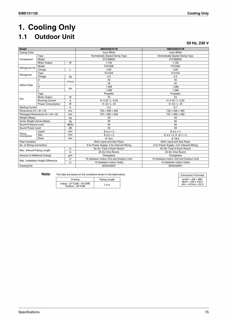
1. Cooling Only1.1 Outdoor Unit
50 Hz, 230 V
Note: The data are based on the conditions shown in the table below.
Model 3MKS50E3V1B 4MKS58E3V1BCasing Color Ivory White Ivory White
CompressorType Hermetically Sealed Swing Type Hermetically Sealed Swing TypeModel 2YC36BXD 2YC36BXDMotor Output W 1,100 1,100
Refrigerant OilModel FVC50K FVC50KCharge L 0.65 0.65
RefrigerantType R-410A R-410ACharge kg 2.0 2.0
Airflow Rate
Hm³/min
45 45L 45 45H
cfm1,589 1,589
L 1,589 1,589
Fan
Type Propeller PropellerMotor Output W 53 53Running Current A H: 0.33 / L: 0.33 H: 0.33 / L: 0.33Power Consumption W H: 43 / L: 43 H: 43 / L: 43
Starting Current A 5.3 6.7Dimensions (H × W × D) mm 735 × 936 × 300 735 × 936 × 300Packaged Dimensions (H × W × D) mm 797 × 992 × 390 797 × 992 × 390Weight (Mass) kg 49 49Gross Weight (Gross Mass) kg 56 56Sound Pressure Level dB(A) 46 46Sound Power Level dB 59 59
Piping Connection
Liquid mm φ 6.4 × 3 φ 6.4 × 4Gas mm φ 9.5 × 3 φ 9.5 × 2, φ 12.7 × 2Drain mm φ 18.0 φ 18.0
Heat Insulation Both Liquid and Gas Pipes Both Liquid and Gas PipesNo. of Wiring Connection 3 for Power Supply, 4 for Interunit Wiring 3 for Power Supply, 4 for Interunit Wiring
Max. Interunit Piping Lengthm 50 (for Total of Each Room) 50 (for Total of Each Room)m 25 (for One Room) 25 (for One Room)
Amount of Additional Charge g/m Chargeless Chargeless
Max. Installation Height Differencem 15 (between Indoor Unit and Outdoor Unit) 15 (between Indoor Unit and Outdoor Unit)m 15 (between Indoor Units) 15 (between Indoor Units)
Drawing No. 3D054330#1 3D054329#1
Conversion Formulae
kcal/h = kW × 860Btu/h = kW × 3412
cfm = m³/min × 35.3
Cooling Piping Length
Indoor ; 27°CDB / 19°CWB Outdoor ; 35°CDB 7.5 m
Specifications 15

Cooling Only SiBE121135
50 Hz, 230 V
Note: The data are based on the conditions shown in the table below.
Model 4MKS75F2V1B 5MKS90E2V3BCasing Color Ivory White Ivory White
CompressorType Hermetically Sealed Swing Type Hermetically Sealed Swing TypeModel 2YC45DXD 2YC63BXDMotor Output W 1,380 1,920
Refrigerant OilModel FVC50K FVC50KCharge L 0.65 0.75
RefrigerantType R-410A R-410ACharge kg 2.3 2.95
Airflow Rate
Hm³/min
52.7 54.5M 49.4 —L 43.5 46H
cfm1,861 1,924
M 1,744 —L 1,536 1,624
Fan
Type Propeller PropellerMotor Output W 53 66Running Current A H: 0.20 / M: 0.16 / L: 0.10 H: 0.97 / L: 0.69Power Consumption W H: 70 / M: 58 / L: 36 H: 86 / L: 55
Starting Current A 6.2 11.4Dimensions (H × W × D) mm 735 × 936 × 300 770 × 900 × 320Packaged Dimensions (H × W × D) mm 797 × 992 × 390 900 × 925 × 390Weight (Mass) kg 57 69Gross Weight (Gross Mass) kg 61 78Sound Pressure Level dB(A) 48 48Sound Power Level dB 61 62
Piping Connection
Liquid mm φ 6.4 × 4 φ 6.4 × 5Gas mm φ 9.5 × 2, φ 12.7 × 1, φ 15.9 × 1 φ 9.5 × 2, φ 12.7 × 1, φ 15.9 × 2Drain mm φ 18.0 φ 25.0
Heat Insulation Both Liquid and Gas Pipes Both Liquid and Gas PipesNo. of Wiring Connection 3 for Power Supply, 4 for Interunit Wiring 3 for Power Supply, 4 for Interunit Wiring
Max. Interunit Piping Lengthm 60 (for Total of Each Room) 75 (for Total of Each Room)m 25 (for One Room) 25 (for One Room)
Amount of Additional Charge g/m Chargeless 20 (65 m or more)
Max. Installation Height Differencem 15 (between Indoor Unit and Outdoor Unit) 15 (between Indoor Unit and Outdoor Unit)m 15 (between Indoor Units) 7.5 (between Indoor Units)
Drawing No. 3D056453 3D063120
Conversion Formulae
kcal/h = kW × 860Btu/h = kW × 3412
cfm = m³/min × 35.3
Cooling Piping Length
Indoor ; 27°CDB / 19°CWB Outdoor ; 35°CDB
5 m (4MKS75F2V1B)7.5 m (5MKS90E2V3B)
16 Specifications

SiBE121135 Cooling Only
1.2 Indoor Unit
Wall Mounted Type50 Hz, 220 - 230 - 240 V
Model FTXS25J2V1B FTXS35J2V1BRated Capacity 2.5 kW Class 3.5 kW ClassFront Panel Color White White
Airflow Rate
H
m³/min (cfm)
10.8 (381) 11.4 (403)M 7.9 (279) 8.7 (307)L 5.2 (184) 5.8 (205)SL 3.7 (131) 4.4 (155)
FanType Cross Flow Fan Cross Flow FanMotor Output W 23 23Speed Steps 5 Steps, Quiet, Auto 5 Steps, Quiet, Auto
Air Direction Control Right, Left, Horizontal, Downward Right, Left, Horizontal, DownwardAir Filter Removable / Washable / Mildew Proof Removable / Washable / Mildew ProofRunning Current (Rated) A 0.09 - 0.08 - 0.08 0.12 - 0.12 - 0.11Power Consumption (Rated) W 18 - 18 - 18 26 - 26 - 26Power Factor (Rated) % 90.9 - 97.8 - 93.8 98.5 - 94.2 - 98.5Temperature Control Microcomputer Control Microcomputer ControlDimensions (H × W × D) mm 295 × 800 × 215 295 × 800 × 215Packaged Dimensions (H × W × D) mm 289 × 870 × 366 289 × 870 × 366Weight (Mass) kg 9 10Gross Weight (Gross Mass) kg 13 14Sound Pressure Level
H / M / L / SL dB(A) 41 / 33 / 25 / 22 45 / 37 / 29 / 23
Sound Power Level dB 57 61Heat Insulation Both Liquid and Gas Pipes Both Liquid and Gas Pipes
Piping Connection
Liquid mm φ 6.4 φ 6.4Gas mm φ 9.5 φ 9.5Drain mm φ 18.0 φ 18.0
Drawing No. 3D070570A 3D070571A
Model FTXS42J2V1B FTXS50J2V1BRated Capacity 4.2 kW Class 5.0 kW ClassFront Panel Color White White
Airflow Rate
H
m³/min (cfm)
11.3 (399) 11.6 (410)M 9.0 (318) 9.2 (325)L 6.8 (240) 7.0 (247)SL 5.9 (208) 6.0 (212)
FanType Cross Flow Fan Cross Flow FanMotor Output W 23 23Speed Steps 5 Steps, Quiet, Auto 5 Steps, Quiet, Auto
Air Direction Control Right, Left, Horizontal, Downward Right, Left, Horizontal, DownwardAir Filter Removable / Washable / Mildew Proof Removable / Washable / Mildew ProofRunning Current (Rated) A 0.11 - 0.11 - 0.11 0.12 - 0.12 - 0.11Power Consumption (Rated) W 24 - 24 - 24 26 - 26 - 26Power Factor (Rated) % 99.2 - 94.9 - 90.9 98.5 - 94.2 - 98.5Temperature Control Microcomputer Control Microcomputer ControlDimensions (H × W × D) mm 295 × 800 × 215 295 × 800 × 215Packaged Dimensions (H × W × D) mm 289 × 870 × 366 289 × 870 × 366Weight (Mass) kg 10 10Gross Weight (Gross Mass) kg 14 14Sound Pressure Level
H / M / L / SL dB(A) 45 / 39 / 33 / 30 46 / 40 / 34 / 31
Sound Power Level dB 61 62Heat Insulation Both Liquid and Gas Pipes Both Liquid and Gas Pipes
Piping Connection
Liquid mm φ 6.4 φ 6.4Gas mm φ 9.5 φ 12.7Drain mm φ 18.0 φ 18.0
Drawing No. 3D070572A 3D070573A
Conversion Formulae
kcal/h = kW × 860Btu/h = kW × 3412
cfm = m³/min × 35.3
Specifications 17
Cooling Only SiBE121135
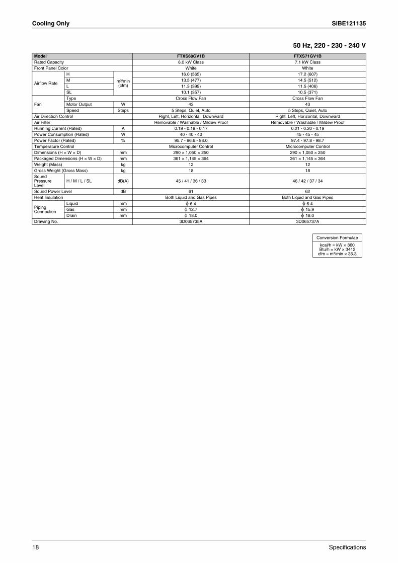
50 Hz, 220 - 230 - 240 V
Model FTXS60GV1B FTXS71GV1BRated Capacity 6.0 kW Class 7.1 kW ClassFront Panel Color White White
Airflow Rate
H
m³/min (cfm)
16.0 (565) 17.2 (607)M 13.5 (477) 14.5 (512)L 11.3 (399) 11.5 (406)SL 10.1 (357) 10.5 (371)
FanType Cross Flow Fan Cross Flow FanMotor Output W 43 43Speed Steps 5 Steps, Quiet, Auto 5 Steps, Quiet, Auto
Air Direction Control Right, Left, Horizontal, Downward Right, Left, Horizontal, DownwardAir Filter Removable / Washable / Mildew Proof Removable / Washable / Mildew ProofRunning Current (Rated) A 0.19 - 0.18 - 0.17 0.21 - 0.20 - 0.19Power Consumption (Rated) W 40 - 40 - 40 45 - 45 - 45Power Factor (Rated) % 95.7 - 96.6 - 98.0 97.4 - 97.8 - 98.7Temperature Control Microcomputer Control Microcomputer ControlDimensions (H × W × D) mm 290 × 1,050 × 250 290 × 1,050 × 250Packaged Dimensions (H × W × D) mm 361 × 1,145 × 364 361 × 1,145 × 364Weight (Mass) kg 12 12Gross Weight (Gross Mass) kg 18 18Sound Pressure Level
H / M / L / SL dB(A) 45 / 41 / 36 / 33 46 / 42 / 37 / 34
Sound Power Level dB 61 62Heat Insulation Both Liquid and Gas Pipes Both Liquid and Gas Pipes
Piping Connection
Liquid mm φ 6.4 φ 6.4Gas mm φ 12.7 φ 15.9Drain mm φ 18.0 φ 18.0
Drawing No. 3D065735A 3D065737A
Conversion Formulae
kcal/h = kW × 860Btu/h = kW × 3412
cfm = m³/min × 35.3
18 Specifications

SiBE121135 Cooling Only
Ceiling Mounted Cassette Type50 Hz, 230 V
( ) : dimension including control box
Model FFQ25B9V1B FFQ35B9V1BRated Capacity 2.5 kW Class 3.5 kW Class
Decoration Panel
Model BYFQ60B8W1 BYFQ60B8W1Color White WhiteDimensions (H × W × D) mm 55 × 700 × 700 55 × 700 × 700Weight (Mass) kg 2.7 2.7
Airflow RateH m³/min
(cfm)9.0 (318) 10.0 (353)
L 6.5 (230) 6.5 (230)
FanType Turbo Fan Turbo FanMotor Output W 55 55Speed Steps 2 Steps 2 Steps
Air Direction Control Horizontal, Downward Horizontal, DownwardRunning Current (Rated) A 0.37 0.40Power Consumption (Rated) W 73 84Power Factor (Rated) % 85.8 91.3Temperature Control Microcomputer Control Microcomputer ControlDimensions (H × W × D) mm 260 (286) × 575 × 575 260 (286) × 575 × 575Packaged Dimensions (H × W × D) mm 370 × 687 × 674 370 × 687 × 674Weight (Mass) kg 17.5 17.5Gross Weight (Gross Mass) kg 21 21Sound Pressure Level
H / L dB(A) 29.5 / 24.5 32.0 / 25.0
Sound Power Level dB 46.5 49.0Heat Insulation Both Liquid and Gas Pipes Both Liquid and Gas Pipes
Piping Connection
Liquid mm φ 6.4 φ 6.4Gas mm φ 9.5 φ 9.5Drain mm VP20 (O.D. φ 26 / I.D. φ 20) VP20 (O.D. φ 26 / I.D. φ 20)
Drawing No. 3D060406 3D060408
Model FFQ50B9V1B FFQ60B9V1BRated Capacity 5.0 kW Class 6.0 kW Class
Decoration Panel
Model BYFQ60B8W1 BYFQ60B8W1Color White WhiteDimensions (H × W × D) mm 55 × 700 × 700 55 × 700 × 700Weight (Mass) kg 2.7 2.7
Airflow RateH m³/min
(cfm)12.0 (424) 15.5 (530)
L 8.0 (283) 10.0 (353)
FanType Turbo Fan Turbo FanMotor Output W 55 55Speed Steps 2 Steps 2 Steps
Air Direction Control Horizontal, Downward Horizontal, DownwardRunning Current (Rated) A 0.49 0.61Power Consumption (Rated) W 97 120Power Factor (Rated) % 86.1 85.5Temperature Control Microcomputer Control Microcomputer ControlDimensions (H × W × D) mm 260 (286) × 575 × 575 260 (286) × 575 × 575Packaged Dimensions (H × W × D) mm 370 × 687 × 674 370 × 687 × 674Weight (Mass) kg 17.5 17.5Gross Weight (Gross Mass) kg 21 21Sound Pressure Level
H / L dB(A) 36.0 / 27.0 41.0 / 32.0
Sound Power Level dB 53.0 58.0Heat Insulation Both Liquid and Gas Pipes Both Liquid and Gas Pipes
Piping Connection
Liquid mm φ 6.4 φ 6.4Gas mm φ 12.7 φ 12.7Drain mm VP20 (O.D. φ 26 / I.D. φ 20) VP20 (O.D. φ 26 / I.D. φ 20)
Drawing No. 3D060410 3D040431
Conversion Formulae
kcal/h = kW × 860Btu/h = kW × 3412
cfm = m³/min × 35.3
Specifications 19
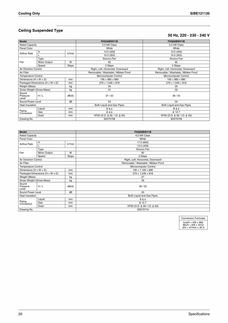
Cooling Only SiBE121135
Ceiling Suspended Type50 Hz, 220 - 230 - 240 V
Model FHQ35BWV1B FHQ50BWV1BRated Capacity 3.5 kW Class 5.0 kW ClassPanel Color White White
Airflow RateH
m³/min13.0 (459) 13.0 (459)
L 10.0 (353) 10.0 (353)
FanType Sirocco Fan Sirocco FanMotor Output W 62 62Speed Steps 2 Steps 2 Steps
Air Direction Control Right, Left, Horizontal, Downward Right, Left, Horizontal, DownwardAir Filter Removable / Washable / Mildew Proof Removable / Washable / Mildew ProofTemperature Control Microcomputer Control Microcomputer ControlDimensions (H × W × D) mm 195 × 960 × 680 195 × 960 × 680Packaged Dimensions (H × W × D) mm 279 × 1,046 × 818 279 × 1,046 × 818Weight (Mass) kg 24 25Gross Weight (Gross Mass) kg 31 32Sound Pressure Level
H / L dB(A) 37 / 32 38 / 33
Sound Power Level dB 53 54Heat Insulation Both Liquid and Gas Pipes Both Liquid and Gas Pipes
Piping Connection
Liquid mm φ 6.4 φ 6.4Gas mm φ 9.5 φ 12.7Drain mm VP20 (O.D. φ 26 / I.D. φ 20) VP20 (O.D. φ 26 / I.D. φ 20)
Drawing No. 3D075708 3D075709
Model FHQ60BWV1BRated Capacity 6.0 kW ClassPanel Color White
Airflow RateH
m³/min17.0 (600)
L 13.0 (459)
FanType Sirocco FanMotor Output W 62Speed Steps 2 Steps
Air Direction Control Right, Left, Horizontal, DownwardAir Filter Removable / Washable / Mildew ProofTemperature Control Microcomputer ControlDimensions (H × W × D) mm 195 × 1,160 × 680Packaged Dimensions (H × W × D) mm 279 × 1,246 × 818Weight (Mass) kg 27Gross Weight (Gross Mass) kg 35Sound Pressure Level
H / L dB(A) 39 / 33
Sound Power Level dB 55Heat Insulation Both Liquid and Gas Pipes
Piping Connection
Liquid mm φ 6.4Gas mm φ 12.7Drain mm VP20 (O.D. φ 26 / I.D. φ 20)
Drawing No. 3D075710
Conversion Formulae
kcal/h = kW × 860Btu/h = kW × 3412
cfm = m³/min × 35.3
20 Specifications
SiBE121135 Cooling Only
Ceiling Mounted Built-in Type50 Hz, 220 - 230 - 240 V /
50 Hz, 230 V 60 Hz, 220 VModel FDBQ25B8V1 FBQ35C8VEBRated Capacity 2.5 kW Class 3.5 kW Class
Decoration Panel
Model — BYBS45DJW1Color — WhiteDimensions (H × W × D) — 55 × 800 × 500Weight (Mass) kg — 3.5
Airflow RateH
m³/min6.5 16.0
L 5.2 11.0
FanType Sirocco Fan Sirocco FanMotor Output W 10 140Speed Steps 2 Steps 2 Steps
Air Filter Resin net with mold resistance Resin net with mold resistanceDimensions (H × W × D) mm 230 × 652 × 502 300 × 700 × 700Packaged Dimensions (H × W × D) mm 301 × 753 × 584 325 × 920 × 900Weight (Mass) kg 17 25Gross Weight (Gross Mass) kg 18 28Sound Pressure Level
H / L dB(A) 35 / 28 37 / 29
Sound Power Level H / L dB 55 / 49 63 / —
Heat Insulation — Both Liquid and Gas Pipes
Piping Connection
Liquid mm φ 6.35 φ 6.35 (Flare)Gas mm φ 9.52 φ 9.52 (Flare)Drain mm O.D. φ 27.2 VP25 (O.D. φ 32 / I.D. φ 25)
Model FBQ50C8VEB FBQ60C8VEBRated Capacity 5.0 kW Class 6.0 kW Class
Decoration Panel
Model BYBS45DJW1 BYBS71DJW1Color White WhiteDimensions (H × W × D) 55 × 800 × 500 55 × 1,100 × 500Weight (Mass) kg 3.5 4.5
Airflow RateH
m³/min16.0 18.0
L 11.0 15.0
FanType Sirocco Fan Sirocco FanMotor Output W 140 350Speed Steps 2 Steps 2 Steps
Air Filter Resin net with mold resistance Resin net with mold resistanceDimensions (H × W × D) mm 300 × 700 × 700 300 × 1,000 × 700Packaged Dimensions (H × W × D) mm 355 × 920 × 900 355 × 1,220 × 900Weight (Mass) kg 25 34Gross Weight (Gross Mass) kg 28 41Sound Pressure Level
H / L dB(A) 37 / 29 37 / 29
Sound Power Level H / L dB 63 / — 57 / —
Heat Insulation Both Liquid and Gas Pipes Both Liquid and Gas Pipes
Piping Connection
Liquid mm φ 6.35 (Flare) φ 6.35 (Flare)Gas mm φ 12.7 (Flare) φ 12.7 (Flare)Drain mm VP25 (O.D. φ 32 / I.D. φ 25) VP25 (O.D. φ 32 / I.D. φ 25)
Conversion Formulae
kcal/h = kW × 860Btu/h = kW × 3412
cfm = m³/min × 35.3
Specifications 21
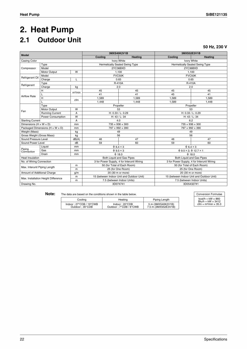
Heat Pump SiBE121135
2. Heat Pump2.1 Outdoor Unit
50 Hz, 230 V
Note: The data are based on the conditions shown in the table below.
Model3MXS40K2V1B 3MXS52E3V1B
Cooling Heating Cooling HeatingCasing Color Ivory White Ivory White
CompressorType Hermetically Sealed Swing Type Hermetically Sealed Swing TypeModel 2YC36BXD 2YC36BXDMotor Output W 1,100 1,100
Refrigerant OilModel FVC50K FVC50KCharge L 0.65 0.65
RefrigerantType R-410A R-410ACharge kg 2.0 2.0
Airflow Rate
Hm³/min
45 45 45 45L 41 41 45 41H
cfm1,589 1,589 1,589 1,589
L 1,448 1,448 1,589 1,448
Fan
Type Propeller PropellerMotor Output W 53 53Running Current A H: 0.33 / L: 0.29 H: 0.33 / L: 0.29Power Consumption W H: 43 / L: 34 H: 43 / L: 34
Starting Current A 4.0 6.2Dimensions (H × W × D) mm 735 × 936 × 300 735 × 936 × 300Packaged Dimensions (H × W × D) mm 797 × 992 × 390 797 × 992 × 390Weight (Mass) kg 49 49Gross Weight (Gross Mass) kg 56 56Sound Pressure Level dB(A) 46 47 46 47Sound Power Level dB 59 60 59 60
Piping Connection
Liquid mm φ 6.4 × 3 φ 6.4 × 3Gas mm φ 9.5 × 3 φ 9.5 × 2, φ 12.7 × 1Drain mm φ 18.0 φ 18.0
Heat Insulation Both Liquid and Gas Pipes Both Liquid and Gas PipesNo. of Wiring Connection 3 for Power Supply, 4 for Interunit Wiring 3 for Power Supply, 4 for Interunit Wiring
Max. Interunit Piping Lengthm 50 (for Total of Each Room) 50 (for Total of Each Room)m 25 (for One Room) 25 (for One Room)
Amount of Additional Charge g/m 20 (30 m or more) 20 (30 m or more)
Max. Installation Height Differencem 15 (between Indoor Unit and Outdoor Unit) 15 (between Indoor Unit and Outdoor Unit)m 7.5 (between Indoor Units) 7.5 (between Indoor Units)
Drawing No. 3D074741 3D054327#1
Conversion Formulae
kcal/h = kW × 860Btu/h = kW × 3412
cfm = m³/min × 35.3
Cooling Heating Piping Length
Indoor ; 27°CDB / 19°CWB Outdoor ; 35°CDB
Indoor ; 20°CDBOutdoor ; 7°CDB / 6°CWB
5 m (3MXS40K2V1B)7.5 m (3MXS52E3V1B)
22 Specifications
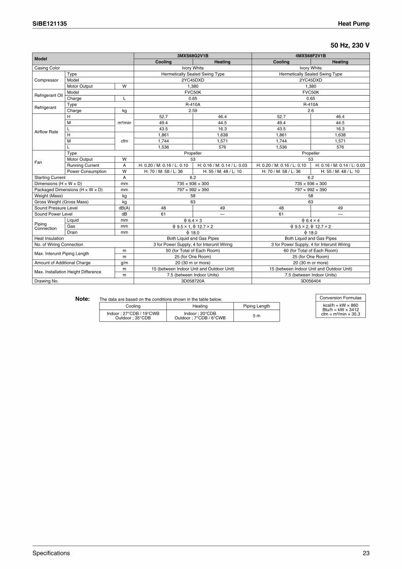
SiBE121135 Heat Pump
50 Hz, 230 V
Note: The data are based on the conditions shown in the table below.
Model3MXS68G2V1B 4MXS68F2V1B
Cooling Heating Cooling HeatingCasing Color Ivory White Ivory White
CompressorType Hermetically Sealed Swing Type Hermetically Sealed Swing TypeModel 2YC45DXD 2YC45DXDMotor Output W 1,380 1,380
Refrigerant OilModel FVC50K FVC50KCharge L 0.65 0.65
RefrigerantType R-410A R-410ACharge kg 2.59 2.6
Airflow Rate
Hm³/min
52.7 46.4 52.7 46.4M 49.4 44.5 49.4 44.5L 43.5 16.3 43.5 16.3H
cfm1,861 1,638 1,861 1,638
M 1,744 1,571 1,744 1,571L 1,536 576 1,536 576
Fan
Type Propeller PropellerMotor Output W 53 53Running Current A H: 0.20 / M: 0.16 / L: 0.10 H: 0.16 / M: 0.14 / L: 0.03 H: 0.20 / M: 0.16 / L: 0.10 H: 0.16 / M: 0.14 / L: 0.03Power Consumption W H: 70 / M: 58 / L: 36 H: 55 / M: 48 / L: 10 H: 70 / M: 58 / L: 36 H: 55 / M: 48 / L: 10
Starting Current A 6.2 6.2Dimensions (H × W × D) mm 735 × 936 × 300 735 × 936 × 300Packaged Dimensions (H × W × D) mm 797 × 992 × 390 797 × 992 × 390Weight (Mass) kg 58 58Gross Weight (Gross Mass) kg 63 63Sound Pressure Level dB(A) 48 49 48 49Sound Power Level dB 61 — 61 —
Piping Connection
Liquid mm φ 6.4 × 3 φ 6.4 × 4Gas mm φ 9.5 × 1, φ 12.7 × 2 φ 9.5 × 2, φ 12.7 × 2Drain mm φ 18.0 φ 18.0
Heat Insulation Both Liquid and Gas Pipes Both Liquid and Gas PipesNo. of Wiring Connection 3 for Power Supply, 4 for Interunit Wiring 3 for Power Supply, 4 for Interunit Wiring
Max. Interunit Piping Lengthm 50 (for Total of Each Room) 60 (for Total of Each Room)m 25 (for One Room) 25 (for One Room)
Amount of Additional Charge g/m 20 (30 m or more) 20 (30 m or more)
Max. Installation Height Differencem 15 (between Indoor Unit and Outdoor Unit) 15 (between Indoor Unit and Outdoor Unit)m 7.5 (between Indoor Units) 7.5 (between Indoor Units)
Drawing No. 3D058720A 3D056404
Conversion Formulae
kcal/h = kW × 860Btu/h = kW × 3412
cfm = m³/min × 35.3
Cooling Heating Piping Length
Indoor ; 27°CDB / 19°CWB Outdoor ; 35°CDB
Indoor ; 20°CDBOutdoor ; 7°CDB / 6°CWB 5 m
Specifications 23
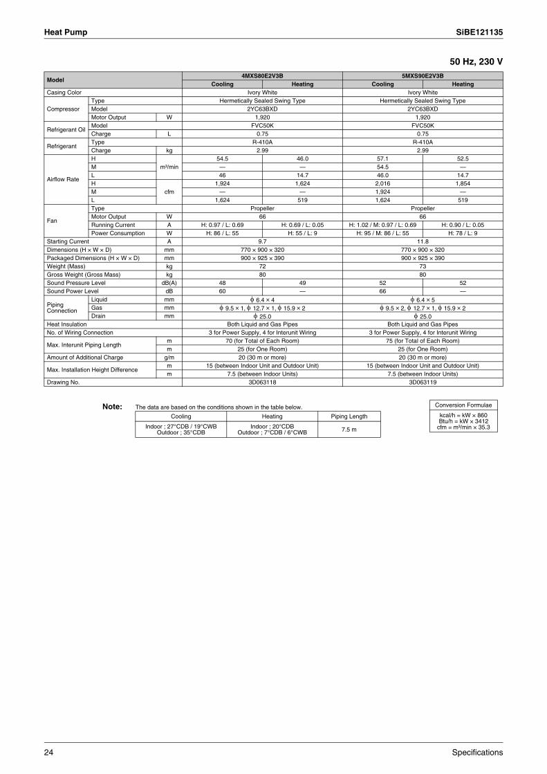
Heat Pump SiBE121135
50 Hz, 230 V
Note: The data are based on the conditions shown in the table below.
Model4MXS80E2V3B 5MXS90E2V3B
Cooling Heating Cooling HeatingCasing Color Ivory White Ivory White
CompressorType Hermetically Sealed Swing Type Hermetically Sealed Swing TypeModel 2YC63BXD 2YC63BXDMotor Output W 1,920 1,920
Refrigerant OilModel FVC50K FVC50KCharge L 0.75 0.75
RefrigerantType R-410A R-410ACharge kg 2.99 2.99
Airflow Rate
Hm³/min
54.5 46.0 57.1 52.5M — — 54.5 —L 46 14.7 46.0 14.7H
cfm1,924 1,624 2,016 1,854
M — — 1,924 —L 1,624 519 1,624 519
Fan
Type Propeller PropellerMotor Output W 66 66Running Current A H: 0.97 / L: 0.69 H: 0.69 / L: 0.05 H: 1.02 / M: 0.97 / L: 0.69 H: 0.90 / L: 0.05Power Consumption W H: 86 / L: 55 H: 55 / L: 9 H: 95 / M: 86 / L: 55 H: 78 / L: 9
Starting Current A 9.7 11.8Dimensions (H × W × D) mm 770 × 900 × 320 770 × 900 × 320Packaged Dimensions (H × W × D) mm 900 × 925 × 390 900 × 925 × 390Weight (Mass) kg 72 73Gross Weight (Gross Mass) kg 80 80Sound Pressure Level dB(A) 48 49 52 52Sound Power Level dB 60 — 66 —
Piping Connection
Liquid mm φ 6.4 × 4 φ 6.4 × 5Gas mm φ 9.5 × 1, φ 12.7 × 1, φ 15.9 × 2 φ 9.5 × 2, φ 12.7 × 1, φ 15.9 × 2Drain mm φ 25.0 φ 25.0
Heat Insulation Both Liquid and Gas Pipes Both Liquid and Gas PipesNo. of Wiring Connection 3 for Power Supply, 4 for Interunit Wiring 3 for Power Supply, 4 for Interunit Wiring
Max. Interunit Piping Lengthm 70 (for Total of Each Room) 75 (for Total of Each Room)m 25 (for One Room) 25 (for One Room)
Amount of Additional Charge g/m 20 (30 m or more) 20 (30 m or more)
Max. Installation Height Differencem 15 (between Indoor Unit and Outdoor Unit) 15 (between Indoor Unit and Outdoor Unit)m 7.5 (between Indoor Units) 7.5 (between Indoor Units)
Drawing No. 3D063118 3D063119
Conversion Formulae
kcal/h = kW × 860Btu/h = kW × 3412
cfm = m³/min × 35.3
Cooling Heating Piping Length
Indoor ; 27°CDB / 19°CWB Outdoor ; 35°CDB
Indoor ; 20°CDBOutdoor ; 7°CDB / 6°CWB 7.5 m
24 Specifications
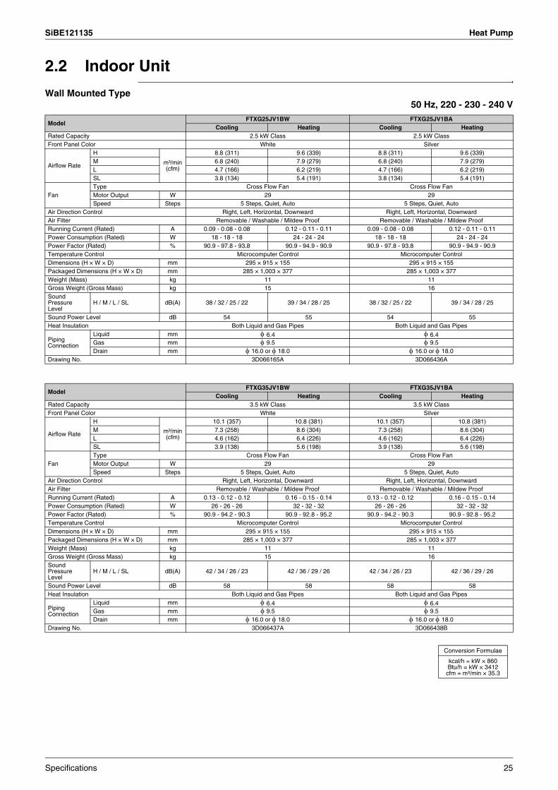
SiBE121135 Heat Pump
2.2 Indoor Unit
Wall Mounted Type50 Hz, 220 - 230 - 240 V
ModelFTXG25JV1BW FTXG25JV1BA
Cooling Heating Cooling HeatingRated Capacity 2.5 kW Class 2.5 kW ClassFront Panel Color White Silver
Airflow Rate
H
m³/min (cfm)
8.8 (311) 9.6 (339) 8.8 (311) 9.6 (339)M 6.8 (240) 7.9 (279) 6.8 (240) 7.9 (279)L 4.7 (166) 6.2 (219) 4.7 (166) 6.2 (219)SL 3.8 (134) 5.4 (191) 3.8 (134) 5.4 (191)
FanType Cross Flow Fan Cross Flow FanMotor Output W 29 29Speed Steps 5 Steps, Quiet, Auto 5 Steps, Quiet, Auto
Air Direction Control Right, Left, Horizontal, Downward Right, Left, Horizontal, DownwardAir Filter Removable / Washable / Mildew Proof Removable / Washable / Mildew ProofRunning Current (Rated) A 0.09 - 0.08 - 0.08 0.12 - 0.11 - 0.11 0.09 - 0.08 - 0.08 0.12 - 0.11 - 0.11Power Consumption (Rated) W 18 - 18 - 18 24 - 24 - 24 18 - 18 - 18 24 - 24 - 24Power Factor (Rated) % 90.9 - 97.8 - 93.8 90.9 - 94.9 - 90.9 90.9 - 97.8 - 93.8 90.9 - 94.9 - 90.9Temperature Control Microcomputer Control Microcomputer ControlDimensions (H × W × D) mm 295 × 915 × 155 295 × 915 × 155Packaged Dimensions (H × W × D) mm 285 × 1,003 × 377 285 × 1,003 × 377Weight (Mass) kg 11 11Gross Weight (Gross Mass) kg 15 16Sound Pressure Level
H / M / L / SL dB(A) 38 / 32 / 25 / 22 39 / 34 / 28 / 25 38 / 32 / 25 / 22 39 / 34 / 28 / 25
Sound Power Level dB 54 55 54 55Heat Insulation Both Liquid and Gas Pipes Both Liquid and Gas Pipes
Piping Connection
Liquid mm φ 6.4 φ 6.4Gas mm φ 9.5 φ 9.5Drain mm φ 16.0 or φ 18.0 φ 16.0 or φ 18.0
Drawing No. 3D066165A 3D066436A
ModelFTXG35JV1BW FTXG35JV1BA
Cooling Heating Cooling HeatingRated Capacity 3.5 kW Class 3.5 kW ClassFront Panel Color White Silver
Airflow Rate
H
m³/min (cfm)
10.1 (357) 10.8 (381) 10.1 (357) 10.8 (381)M 7.3 (258) 8.6 (304) 7.3 (258) 8.6 (304)L 4.6 (162) 6.4 (226) 4.6 (162) 6.4 (226)SL 3.9 (138) 5.6 (198) 3.9 (138) 5.6 (198)
FanType Cross Flow Fan Cross Flow FanMotor Output W 29 29Speed Steps 5 Steps, Quiet, Auto 5 Steps, Quiet, Auto
Air Direction Control Right, Left, Horizontal, Downward Right, Left, Horizontal, DownwardAir Filter Removable / Washable / Mildew Proof Removable / Washable / Mildew ProofRunning Current (Rated) A 0.13 - 0.12 - 0.12 0.16 - 0.15 - 0.14 0.13 - 0.12 - 0.12 0.16 - 0.15 - 0.14Power Consumption (Rated) W 26 - 26 - 26 32 - 32 - 32 26 - 26 - 26 32 - 32 - 32Power Factor (Rated) % 90.9 - 94.2 - 90.3 90.9 - 92.8 - 95.2 90.9 - 94.2 - 90.3 90.9 - 92.8 - 95.2Temperature Control Microcomputer Control Microcomputer ControlDimensions (H × W × D) mm 295 × 915 × 155 295 × 915 × 155Packaged Dimensions (H × W × D) mm 285 × 1,003 × 377 285 × 1,003 × 377Weight (Mass) kg 11 11Gross Weight (Gross Mass) kg 15 16Sound Pressure Level
H / M / L / SL dB(A) 42 / 34 / 26 / 23 42 / 36 / 29 / 26 42 / 34 / 26 / 23 42 / 36 / 29 / 26
Sound Power Level dB 58 58 58 58Heat Insulation Both Liquid and Gas Pipes Both Liquid and Gas Pipes
Piping Connection
Liquid mm φ 6.4 φ 6.4Gas mm φ 9.5 φ 9.5Drain mm φ 16.0 or φ 18.0 φ 16.0 or φ 18.0
Drawing No. 3D066437A 3D066438B
Conversion Formulae
kcal/h = kW × 860Btu/h = kW × 3412
cfm = m³/min × 35.3
Specifications 25
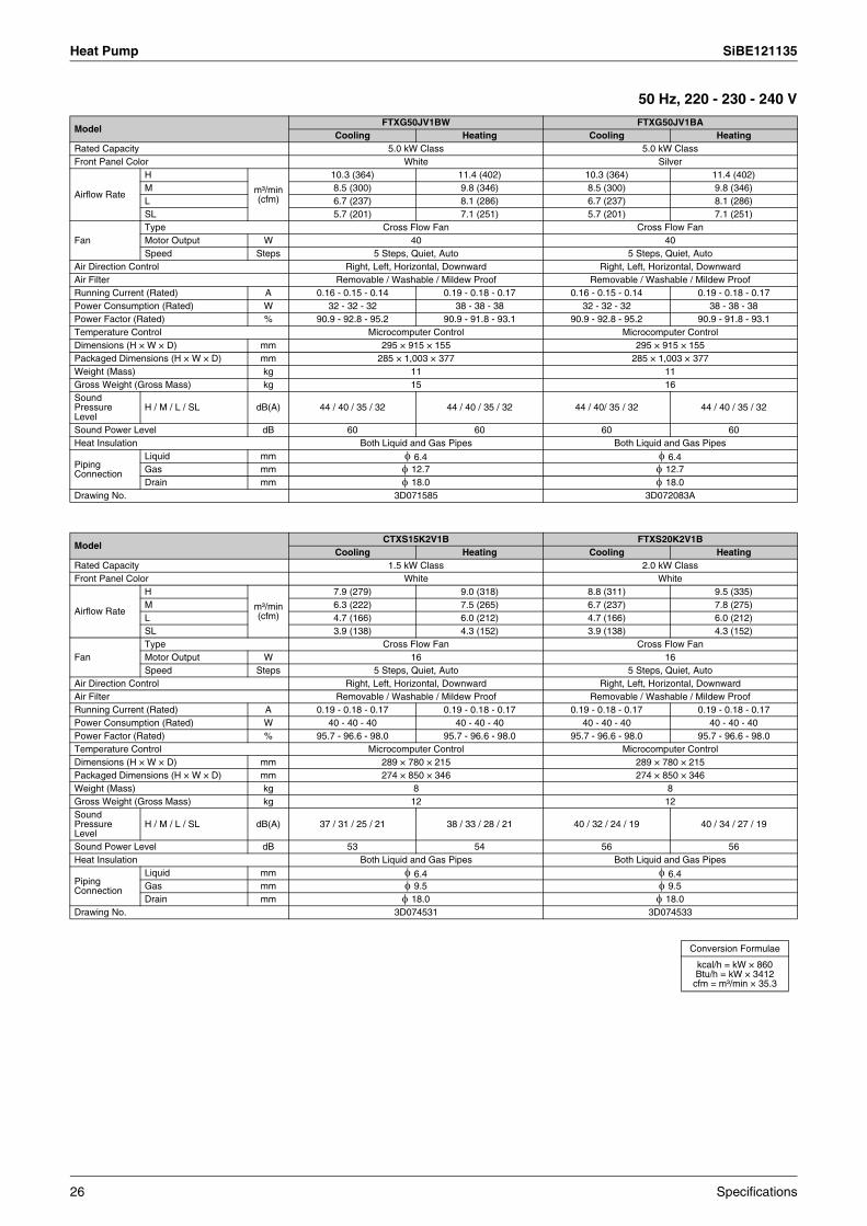
Heat Pump SiBE121135
50 Hz, 220 - 230 - 240 V
ModelFTXG50JV1BW FTXG50JV1BA
Cooling Heating Cooling HeatingRated Capacity 5.0 kW Class 5.0 kW ClassFront Panel Color White Silver
Airflow Rate
H
m³/min (cfm)
10.3 (364) 11.4 (402) 10.3 (364) 11.4 (402)M 8.5 (300) 9.8 (346) 8.5 (300) 9.8 (346)L 6.7 (237) 8.1 (286) 6.7 (237) 8.1 (286)SL 5.7 (201) 7.1 (251) 5.7 (201) 7.1 (251)
FanType Cross Flow Fan Cross Flow FanMotor Output W 40 40Speed Steps 5 Steps, Quiet, Auto 5 Steps, Quiet, Auto
Air Direction Control Right, Left, Horizontal, Downward Right, Left, Horizontal, DownwardAir Filter Removable / Washable / Mildew Proof Removable / Washable / Mildew ProofRunning Current (Rated) A 0.16 - 0.15 - 0.14 0.19 - 0.18 - 0.17 0.16 - 0.15 - 0.14 0.19 - 0.18 - 0.17Power Consumption (Rated) W 32 - 32 - 32 38 - 38 - 38 32 - 32 - 32 38 - 38 - 38Power Factor (Rated) % 90.9 - 92.8 - 95.2 90.9 - 91.8 - 93.1 90.9 - 92.8 - 95.2 90.9 - 91.8 - 93.1Temperature Control Microcomputer Control Microcomputer ControlDimensions (H × W × D) mm 295 × 915 × 155 295 × 915 × 155Packaged Dimensions (H × W × D) mm 285 × 1,003 × 377 285 × 1,003 × 377Weight (Mass) kg 11 11Gross Weight (Gross Mass) kg 15 16Sound Pressure Level
H / M / L / SL dB(A) 44 / 40 / 35 / 32 44 / 40 / 35 / 32 44 / 40/ 35 / 32 44 / 40 / 35 / 32
Sound Power Level dB 60 60 60 60Heat Insulation Both Liquid and Gas Pipes Both Liquid and Gas Pipes
Piping Connection
Liquid mm φ 6.4 φ 6.4Gas mm φ 12.7 φ 12.7Drain mm φ 18.0 φ 18.0
Drawing No. 3D071585 3D072083A
ModelCTXS15K2V1B FTXS20K2V1B
Cooling Heating Cooling HeatingRated Capacity 1.5 kW Class 2.0 kW ClassFront Panel Color White White
Airflow Rate
H
m³/min (cfm)
7.9 (279) 9.0 (318) 8.8 (311) 9.5 (335)M 6.3 (222) 7.5 (265) 6.7 (237) 7.8 (275)L 4.7 (166) 6.0 (212) 4.7 (166) 6.0 (212)SL 3.9 (138) 4.3 (152) 3.9 (138) 4.3 (152)
FanType Cross Flow Fan Cross Flow FanMotor Output W 16 16Speed Steps 5 Steps, Quiet, Auto 5 Steps, Quiet, Auto
Air Direction Control Right, Left, Horizontal, Downward Right, Left, Horizontal, DownwardAir Filter Removable / Washable / Mildew Proof Removable / Washable / Mildew ProofRunning Current (Rated) A 0.19 - 0.18 - 0.17 0.19 - 0.18 - 0.17 0.19 - 0.18 - 0.17 0.19 - 0.18 - 0.17Power Consumption (Rated) W 40 - 40 - 40 40 - 40 - 40 40 - 40 - 40 40 - 40 - 40Power Factor (Rated) % 95.7 - 96.6 - 98.0 95.7 - 96.6 - 98.0 95.7 - 96.6 - 98.0 95.7 - 96.6 - 98.0Temperature Control Microcomputer Control Microcomputer ControlDimensions (H × W × D) mm 289 × 780 × 215 289 × 780 × 215Packaged Dimensions (H × W × D) mm 274 × 850 × 346 274 × 850 × 346Weight (Mass) kg 8 8Gross Weight (Gross Mass) kg 12 12Sound Pressure Level
H / M / L / SL dB(A) 37 / 31 / 25 / 21 38 / 33 / 28 / 21 40 / 32 / 24 / 19 40 / 34 / 27 / 19
Sound Power Level dB 53 54 56 56Heat Insulation Both Liquid and Gas Pipes Both Liquid and Gas Pipes
Piping Connection
Liquid mm φ 6.4 φ 6.4Gas mm φ 9.5 φ 9.5Drain mm φ 18.0 φ 18.0
Drawing No. 3D074531 3D074533
Conversion Formulae
kcal/h = kW × 860Btu/h = kW × 3412
cfm = m³/min × 35.3
26 Specifications
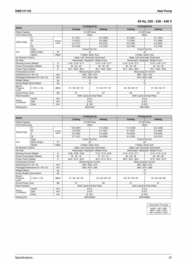
SiBE121135 Heat Pump
50 Hz, 220 - 230 - 240 V
ModelFTXS25K2V1B CTXS35K2V1B
Cooling Heating Cooling HeatingRated Capacity 2.5 kW Class 3.5 kW ClassFront Panel Color White White
Airflow Rate
H
m³/min (cfm)
9.1 (321) 10.0 (353) 9.2 (325) 10.1 (357)M 7.0 (247) 8.0 (282) 7.2 (254) 8.1 (286)L 5.0 (177) 6.0 (212) 5.2 (184) 6.3 (222)SL 3.9 (138) 4.3 (152) 3.9 (138) 4.3 (152)
FanType Cross Flow Fan Cross Flow FanMotor Output W 16 16Speed Steps 5 Steps, Quiet, Auto 5 Steps, Quiet, Auto
Air Direction Control Right, Left, Horizontal, Downward Right, Left, Horizontal, DownwardAir Filter Removable / Washable / Mildew Proof Removable / Washable / Mildew ProofRunning Current (Rated) A 0.19 - 0.18 - 0.17 0.19 - 0.18 - 0.17 0.19 - 0.18 - 0.17 0.19 - 0.18 - 0.17Power Consumption (Rated) W 40 - 40 - 40 40 - 40 - 40 40 - 40 - 40 40 - 40 - 40Power Factor (Rated) % 95.7 - 96.6 - 98.0 95.7 - 96.6 - 98.0 95.7 - 96.6 - 98.0 95.7 - 96.6 - 98.0Temperature Control Microcomputer Control Microcomputer ControlDimensions (H × W × D) mm 289 × 780 × 215 289 × 780 × 215Packaged Dimensions (H × W × D) mm 274 × 850 × 346 274 × 850 × 346Weight (Mass) kg 8 8Gross Weight (Gross Mass) kg 12 12Sound Pressure Level
H / M / L / SL dB(A) 41 / 33 / 25 / 19 41 / 34 / 27 / 19 42 / 35 / 28 / 21 41 / 36 / 30 / 21
Sound Power Level dB 57 57 58 57Heat Insulation Both Liquid and Gas Pipes Both Liquid and Gas Pipes
Piping Connection
Liquid mm φ 6.4 φ 6.4Gas mm φ 9.5 φ 9.5Drain mm φ 18.0 φ 18.0
Drawing No. 3D074534 3D074535
ModelFTXS25J2V1B FTXS35J2V1B
Cooling Heating Cooling HeatingRated Capacity 2.5 kW Class 3.5 kW ClassFront Panel Color White White
Airflow Rate
H
m³/min (cfm)
10.8 (381) 11.9 (420) 11.4 (403) 12.4 (438)M 7.9 (279) 9.1 (321) 8.7 (307) 9.5 (335)L 5.2 (184) 6.4 (226) 5.8 (205) 6.8 (240)SL 3.7 (131) 5.9 (208) 4.4 (155) 6.0 (212)
FanType Cross Flow Fan Cross Flow FanMotor Output W 23 23Speed Steps 5 Steps, Quiet, Auto 5 Steps, Quiet, Auto
Air Direction Control Right, Left, Horizontal, Downward Right, Left, Horizontal, DownwardAir Filter Removable / Washable / Mildew Proof Removable / Washable / Mildew ProofRunning Current (Rated) A 0.09 - 0.08 - 0.08 0.10 - 0.10 - 0.09 0.12 - 0.12 - 0.11 0.13 - 0.13 - 0.12Power Consumption (Rated) W 18 - 18 - 18 21 - 21 - 21 26 - 26 - 26 28 - 28 - 28Power Factor (Rated) % 90.9 - 97.8 - 93.8 95.5 - 91.3 - 97.2 98.5 - 94.2 - 98.5 97.9 - 93.6 - 97.2Temperature Control Microcomputer Control Microcomputer ControlDimensions (H × W × D) mm 295 × 800 × 215 295 × 800 × 215Packaged Dimensions (H × W × D) mm 289 × 870 × 366 289 × 870 × 366Weight (Mass) kg 9 10Gross Weight (Gross Mass) kg 13 14Sound Pressure Level
H / M / L / SL dB(A) 41 / 33 / 25 / 22 42 / 35 / 28 / 25 45 / 37 / 29 / 23 45 / 39 / 29 / 26
Sound Power Level dB 57 58 61 61Heat Insulation Both Liquid and Gas Pipes Both Liquid and Gas Pipes
Piping Connection
Liquid mm φ 6.4 φ 6.4Gas mm φ 9.5 φ 9.5Drain mm φ 18.0 φ 18.0
Drawing No. 3D070565A 3D070566A
Conversion Formulae
kcal/h = kW × 860Btu/h = kW × 3412
cfm = m³/min × 35.3
Specifications 27
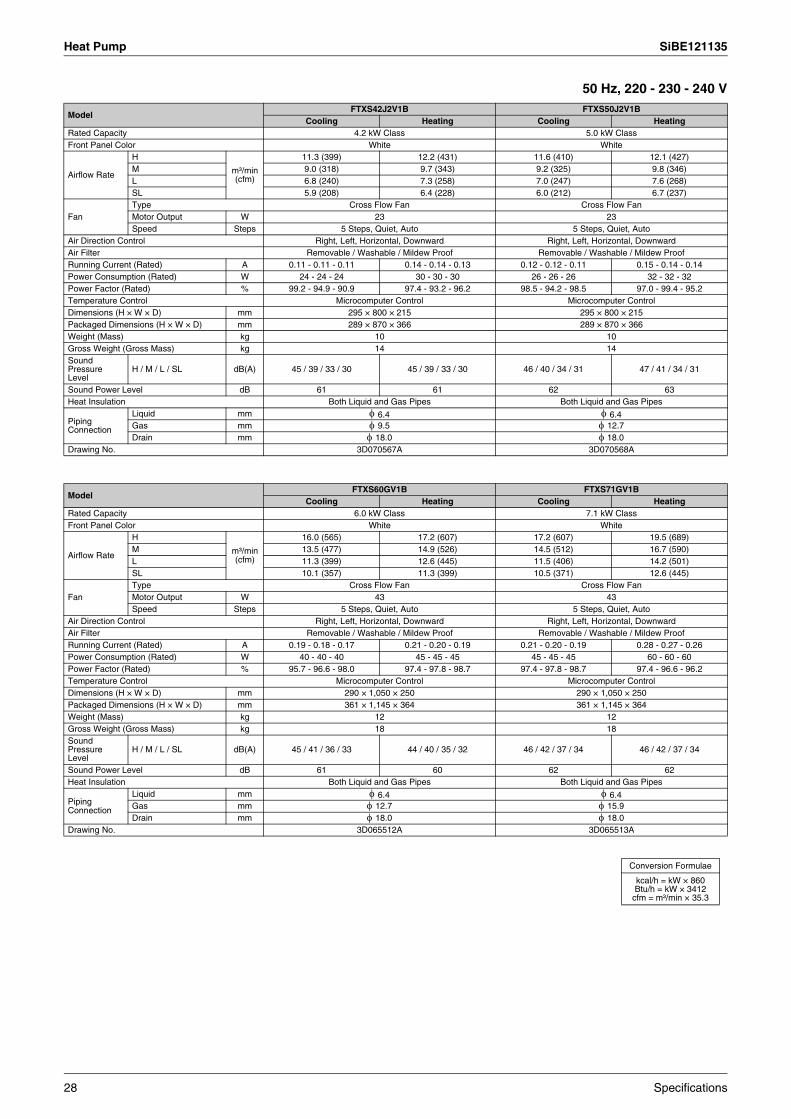
Heat Pump SiBE121135
50 Hz, 220 - 230 - 240 V
ModelFTXS42J2V1B FTXS50J2V1B
Cooling Heating Cooling HeatingRated Capacity 4.2 kW Class 5.0 kW ClassFront Panel Color White White
Airflow Rate
H
m³/min (cfm)
11.3 (399) 12.2 (431) 11.6 (410) 12.1 (427)M 9.0 (318) 9.7 (343) 9.2 (325) 9.8 (346)L 6.8 (240) 7.3 (258) 7.0 (247) 7.6 (268)SL 5.9 (208) 6.4 (228) 6.0 (212) 6.7 (237)
FanType Cross Flow Fan Cross Flow FanMotor Output W 23 23Speed Steps 5 Steps, Quiet, Auto 5 Steps, Quiet, Auto
Air Direction Control Right, Left, Horizontal, Downward Right, Left, Horizontal, DownwardAir Filter Removable / Washable / Mildew Proof Removable / Washable / Mildew ProofRunning Current (Rated) A 0.11 - 0.11 - 0.11 0.14 - 0.14 - 0.13 0.12 - 0.12 - 0.11 0.15 - 0.14 - 0.14Power Consumption (Rated) W 24 - 24 - 24 30 - 30 - 30 26 - 26 - 26 32 - 32 - 32Power Factor (Rated) % 99.2 - 94.9 - 90.9 97.4 - 93.2 - 96.2 98.5 - 94.2 - 98.5 97.0 - 99.4 - 95.2Temperature Control Microcomputer Control Microcomputer ControlDimensions (H × W × D) mm 295 × 800 × 215 295 × 800 × 215Packaged Dimensions (H × W × D) mm 289 × 870 × 366 289 × 870 × 366Weight (Mass) kg 10 10Gross Weight (Gross Mass) kg 14 14Sound Pressure Level
H / M / L / SL dB(A) 45 / 39 / 33 / 30 45 / 39 / 33 / 30 46 / 40 / 34 / 31 47 / 41 / 34 / 31
Sound Power Level dB 61 61 62 63Heat Insulation Both Liquid and Gas Pipes Both Liquid and Gas Pipes
Piping Connection
Liquid mm φ 6.4 φ 6.4Gas mm φ 9.5 φ 12.7Drain mm φ 18.0 φ 18.0
Drawing No. 3D070567A 3D070568A
ModelFTXS60GV1B FTXS71GV1B
Cooling Heating Cooling HeatingRated Capacity 6.0 kW Class 7.1 kW ClassFront Panel Color White White
Airflow Rate
H
m³/min (cfm)
16.0 (565) 17.2 (607) 17.2 (607) 19.5 (689)M 13.5 (477) 14.9 (526) 14.5 (512) 16.7 (590)L 11.3 (399) 12.6 (445) 11.5 (406) 14.2 (501)SL 10.1 (357) 11.3 (399) 10.5 (371) 12.6 (445)
FanType Cross Flow Fan Cross Flow FanMotor Output W 43 43Speed Steps 5 Steps, Quiet, Auto 5 Steps, Quiet, Auto
Air Direction Control Right, Left, Horizontal, Downward Right, Left, Horizontal, DownwardAir Filter Removable / Washable / Mildew Proof Removable / Washable / Mildew ProofRunning Current (Rated) A 0.19 - 0.18 - 0.17 0.21 - 0.20 - 0.19 0.21 - 0.20 - 0.19 0.28 - 0.27 - 0.26Power Consumption (Rated) W 40 - 40 - 40 45 - 45 - 45 45 - 45 - 45 60 - 60 - 60Power Factor (Rated) % 95.7 - 96.6 - 98.0 97.4 - 97.8 - 98.7 97.4 - 97.8 - 98.7 97.4 - 96.6 - 96.2Temperature Control Microcomputer Control Microcomputer ControlDimensions (H × W × D) mm 290 × 1,050 × 250 290 × 1,050 × 250Packaged Dimensions (H × W × D) mm 361 × 1,145 × 364 361 × 1,145 × 364Weight (Mass) kg 12 12Gross Weight (Gross Mass) kg 18 18Sound Pressure Level
H / M / L / SL dB(A) 45 / 41 / 36 / 33 44 / 40 / 35 / 32 46 / 42 / 37 / 34 46 / 42 / 37 / 34
Sound Power Level dB 61 60 62 62Heat Insulation Both Liquid and Gas Pipes Both Liquid and Gas Pipes
Piping Connection
Liquid mm φ 6.4 φ 6.4Gas mm φ 12.7 φ 15.9Drain mm φ 18.0 φ 18.0
Drawing No. 3D065512A 3D065513A
Conversion Formulae
kcal/h = kW × 860Btu/h = kW × 3412
cfm = m³/min × 35.3
28 Specifications

SiBE121135 Heat Pump
Floor Standing Type50 Hz, 220 - 230 - 240 V
ModelFVXG25K2V1B FVXG35K2V1B
Cooling Heating Cooling HeatingRated Capacity 2.5 kW Class 3.5 kW ClassFront Panel Color White White
Airflow Rate
H
m³/min (cfm)
8.9 (314) 9.9 (349) 9.1 (321) 10.2 (360)M 7.0 (247) 7.8 (275) 7.2 (254) 8.0 (282)L 5.3 (187) 5.7 (201) 5.3 (187) 5.8 (205)SL 4.5 (159) 4.7 (166) 4.5 (159) 5.0 (177)
FanType Cross Flow Fan Cross Flow FanMotor Output W 32 32Speed Steps 5 Steps, Quiet, Auto 5 Steps, Quiet, Auto
Air Direction Control Right, Left, Upward Right, Left, UpwardAir Filter Removable / Washable / Mildew Proof Removable / Washable / Mildew ProofRunning Current (Rated) A 0.10 - 0.09 - 0.09 0.11 - 0.11 - 0.10 0.11 - 0.10 - 0.10 0.12 - 0.12 - 0.11Power Consumption (Rated) W 19 - 19 - 19 22 - 22 - 22 21 - 21 - 21 24 - 24 - 24Power Factor (Rated) % 86.4 - 91.8 - 88.0 90.9 - 87.0 - 91.7 86.8 - 91.3 - 87.5 90.9 - 87.0 - 90.9Temperature Control Microcomputer Control Microcomputer ControlDimensions (H × W × D) mm 600 × 950 × 215 600 × 950 × 215Packaged Dimensions (H × W × D) mm 761 × 1,030 × 314 761 × 1,030 × 314Weight (Mass) kg 22 22Gross Weight (Gross Mass) kg 28 28Sound Pressure Level
H / M / L / SL dB(A) 38 / 32 / 26 / 23 39 / 32 / 26 / 22 39 / 33 / 27 / 24 40 / 33 / 27 / 23
Sound Power Level dB 54 55 55 56Heat Insulation Both Liquid and Gas Pipes Both Liquid and Gas Pipes
Piping Connection
Liquid mm φ 6.4 φ 6.4Gas mm φ 9.5 φ 9.5Drain mm φ 18.0 φ 18.0
Drawing No. 3D071592 3D071593
ModelFVXG50K2V1B
Cooling HeatingRated Capacity 5.0 kW ClassFront Panel Color White
Airflow Rate
H
m³/min (cfm)
10.6 (374) 12.2 (431)M 8.9 (314) 10.0 (353)L 7.3 (258) 7.8 (275)SL 6.0 (212) 6.8 (240)
FanType Cross Flow FanMotor Output W 32Speed Steps 5 Steps, Quiet, Auto
Air Direction Control Right, Left, UpwardAir Filter Removable / Washable / Mildew ProofRunning Current (Rated) A 0.17 - 0.16 - 0.15 0.18 - 0.17 - 0.17Power Consumption (Rated) W 32 - 32 - 32 35 - 35 - 35Power Factor (Rated) % 85.6 - 87.0 - 88.9 88.4 - 89.5 - 85.8Temperature Control Microcomputer ControlDimensions (H × W × D) mm 600 × 950 × 215Packaged Dimensions (H × W × D) mm 761 × 1,030 × 314Weight (Mass) kg 22Gross Weight (Gross Mass) kg 28Sound Pressure Level
H / M / L / SL dB(A) 44 / 40 / 36 / 32 46 / 40 / 34 / 30
Sound Power Level dB 56 58Heat Insulation Both Liquid and Gas Pipes
Piping Connection
Liquid mm φ 6.4Gas mm φ 12.7Drain mm φ 18.0
Drawing No. 3D071594
Conversion Formulae
kcal/h = kW × 860Btu/h = kW × 3412
cfm = m³/min × 35.3
Specifications 29
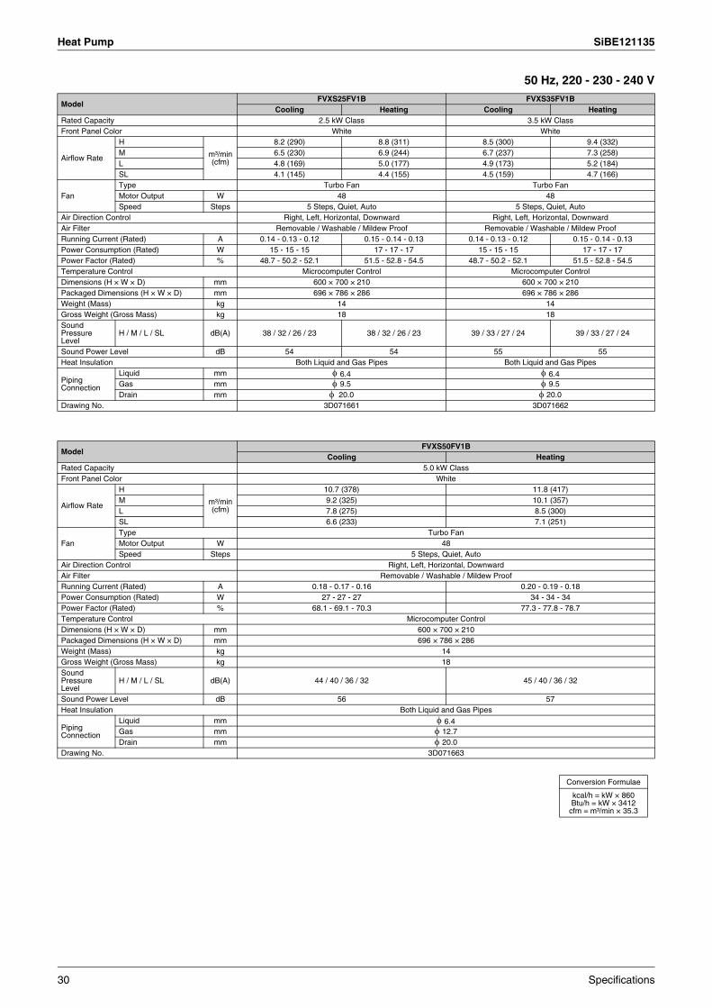
Heat Pump SiBE121135
50 Hz, 220 - 230 - 240 V
ModelFVXS25FV1B FVXS35FV1B
Cooling Heating Cooling HeatingRated Capacity 2.5 kW Class 3.5 kW ClassFront Panel Color White White
Airflow Rate
H
m³/min (cfm)
8.2 (290) 8.8 (311) 8.5 (300) 9.4 (332)M 6.5 (230) 6.9 (244) 6.7 (237) 7.3 (258)L 4.8 (169) 5.0 (177) 4.9 (173) 5.2 (184)SL 4.1 (145) 4.4 (155) 4.5 (159) 4.7 (166)
FanType Turbo Fan Turbo FanMotor Output W 48 48Speed Steps 5 Steps, Quiet, Auto 5 Steps, Quiet, Auto
Air Direction Control Right, Left, Horizontal, Downward Right, Left, Horizontal, DownwardAir Filter Removable / Washable / Mildew Proof Removable / Washable / Mildew ProofRunning Current (Rated) A 0.14 - 0.13 - 0.12 0.15 - 0.14 - 0.13 0.14 - 0.13 - 0.12 0.15 - 0.14 - 0.13Power Consumption (Rated) W 15 - 15 - 15 17 - 17 - 17 15 - 15 - 15 17 - 17 - 17Power Factor (Rated) % 48.7 - 50.2 - 52.1 51.5 - 52.8 - 54.5 48.7 - 50.2 - 52.1 51.5 - 52.8 - 54.5Temperature Control Microcomputer Control Microcomputer ControlDimensions (H × W × D) mm 600 × 700 × 210 600 × 700 × 210Packaged Dimensions (H × W × D) mm 696 × 786 × 286 696 × 786 × 286Weight (Mass) kg 14 14Gross Weight (Gross Mass) kg 18 18Sound Pressure Level
H / M / L / SL dB(A) 38 / 32 / 26 / 23 38 / 32 / 26 / 23 39 / 33 / 27 / 24 39 / 33 / 27 / 24
Sound Power Level dB 54 54 55 55Heat Insulation Both Liquid and Gas Pipes Both Liquid and Gas Pipes
Piping Connection
Liquid mm φ 6.4 φ 6.4Gas mm φ 9.5 φ 9.5Drain mm φ 20.0 φ 20.0
Drawing No. 3D071661 3D071662
ModelFVXS50FV1B
Cooling HeatingRated Capacity 5.0 kW ClassFront Panel Color White
Airflow Rate
H
m³/min (cfm)
10.7 (378) 11.8 (417)M 9.2 (325) 10.1 (357)L 7.8 (275) 8.5 (300)SL 6.6 (233) 7.1 (251)
FanType Turbo FanMotor Output W 48Speed Steps 5 Steps, Quiet, Auto
Air Direction Control Right, Left, Horizontal, DownwardAir Filter Removable / Washable / Mildew ProofRunning Current (Rated) A 0.18 - 0.17 - 0.16 0.20 - 0.19 - 0.18Power Consumption (Rated) W 27 - 27 - 27 34 - 34 - 34Power Factor (Rated) % 68.1 - 69.1 - 70.3 77.3 - 77.8 - 78.7Temperature Control Microcomputer ControlDimensions (H × W × D) mm 600 × 700 × 210Packaged Dimensions (H × W × D) mm 696 × 786 × 286Weight (Mass) kg 14Gross Weight (Gross Mass) kg 18Sound Pressure Level
H / M / L / SL dB(A) 44 / 40 / 36 / 32 45 / 40 / 36 / 32
Sound Power Level dB 56 57Heat Insulation Both Liquid and Gas Pipes
Piping Connection
Liquid mm φ 6.4Gas mm φ 12.7Drain mm φ 20.0
Drawing No. 3D071663
Conversion Formulae
kcal/h = kW × 860Btu/h = kW × 3412
cfm = m³/min × 35.3
30 Specifications
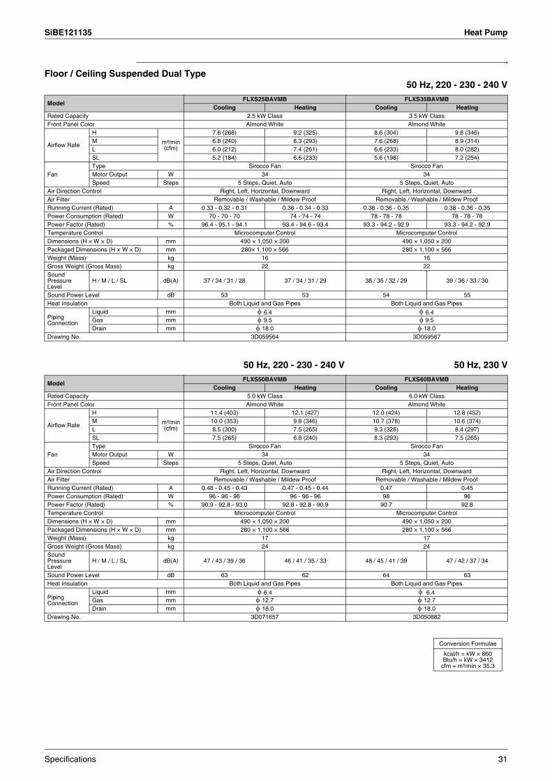
SiBE121135 Heat Pump
Floor / Ceiling Suspended Dual Type50 Hz, 220 - 230 - 240 V
50 Hz, 220 - 230 - 240 V 50 Hz, 230 V
ModelFLXS25BAVMB FLXS35BAVMB
Cooling Heating Cooling HeatingRated Capacity 2.5 kW Class 3.5 kW ClassFront Panel Color Almond White Almond White
Airflow Rate
H
m³/min (cfm)
7.6 (268) 9.2 (325) 8.6 (304) 9.8 (346)M 6.8 (240) 8.3 (293) 7.6 (268) 8.9 (314)L 6.0 (212) 7.4 (261) 6.6 (233) 8.0 (282)SL 5.2 (184) 6.6 (233) 5.6 (198) 7.2 (254)
FanType Sirocco Fan Sirocco FanMotor Output W 34 34Speed Steps 5 Steps, Quiet, Auto 5 Steps, Quiet, Auto
Air Direction Control Right, Left, Horizontal, Downward Right, Left, Horizontal, DownwardAir Filter Removable / Washable / Mildew Proof Removable / Washable / Mildew ProofRunning Current (Rated) A 0.33 - 0.32 - 0.31 0.36 - 0.34 - 0.33 0.38 - 0.36 - 0.35 0.38 - 0.36 - 0.35Power Consumption (Rated) W 70 - 70 - 70 74 - 74 - 74 78 - 78 - 78 78 - 78 - 78Power Factor (Rated) % 96.4 - 95.1 - 94.1 93.4 - 94.6 - 93.4 93.3 - 94.2 - 92.9 93.3 - 94.2 - 92.9Temperature Control Microcomputer Control Microcomputer ControlDimensions (H × W × D) mm 490 × 1,050 × 200 490 × 1,050 × 200Packaged Dimensions (H × W × D) mm 280× 1,100 × 566 280 × 1,100 × 566Weight (Mass) kg 16 16Gross Weight (Gross Mass) kg 22 22Sound Pressure Level
H / M / L / SL dB(A) 37 / 34 / 31 / 28 37 / 34 / 31 / 29 38 / 35 / 32 / 29 39 / 36 / 33 / 30
Sound Power Level dB 53 53 54 55Heat Insulation Both Liquid and Gas Pipes Both Liquid and Gas Pipes
Piping Connection
Liquid mm φ 6.4 φ 6.4Gas mm φ 9.5 φ 9.5Drain mm φ 18.0 φ 18.0
Drawing No. 3D059564 3D059567
ModelFLXS50BAVMB FLXS60BAVMB
Cooling Heating Cooling HeatingRated Capacity 5.0 kW Class 6.0 kW ClassFront Panel Color Almond White Almond White
Airflow Rate
H
m³/min (cfm)
11.4 (403) 12.1 (427) 12.0 (424) 12.8 (452)M 10.0 (353) 9.8 (346) 10.7 (378) 10.6 (374)L 8.5 (300) 7.5 (265) 9.3 (328) 8.4 (297)SL 7.5 (265) 6.8 (240) 8.3 (293) 7.5 (265)
FanType Sirocco Fan Sirocco FanMotor Output W 34 34Speed Steps 5 Steps, Quiet, Auto 5 Steps, Quiet, Auto
Air Direction Control Right, Left, Horizontal, Downward Right, Left, Horizontal, DownwardAir Filter Removable / Washable / Mildew Proof Removable / Washable / Mildew ProofRunning Current (Rated) A 0.48 - 0.45 - 0.43 0.47 - 0.45 - 0.44 0.47 0.45Power Consumption (Rated) W 96 - 96 - 96 96 - 96 - 96 98 96Power Factor (Rated) % 90.9 - 92.8 - 93.0 92.8 - 92.8 - 90.9 90.7 92.8Temperature Control Microcomputer Control Microcomputer ControlDimensions (H × W × D) mm 490 × 1,050 × 200 490 × 1,050 × 200Packaged Dimensions (H × W × D) mm 280 × 1,100 × 566 280 × 1,100 × 566Weight (Mass) kg 17 17Gross Weight (Gross Mass) kg 24 24Sound Pressure Level
H / M / L / SL dB(A) 47 / 43 / 39 / 36 46 / 41 / 35 / 33 48 / 45 / 41 / 39 47 / 42 / 37 / 34
Sound Power Level dB 63 62 64 63Heat Insulation Both Liquid and Gas Pipes Both Liquid and Gas Pipes
Piping Connection
Liquid mm φ 6.4 φ 6.4Gas mm φ 12.7 φ 12.7Drain mm φ 18.0 φ 18.0
Drawing No. 3D071657 3D050882
Conversion Formulae
kcal/h = kW × 860Btu/h = kW × 3412
cfm = m³/min × 35.3
Specifications 31
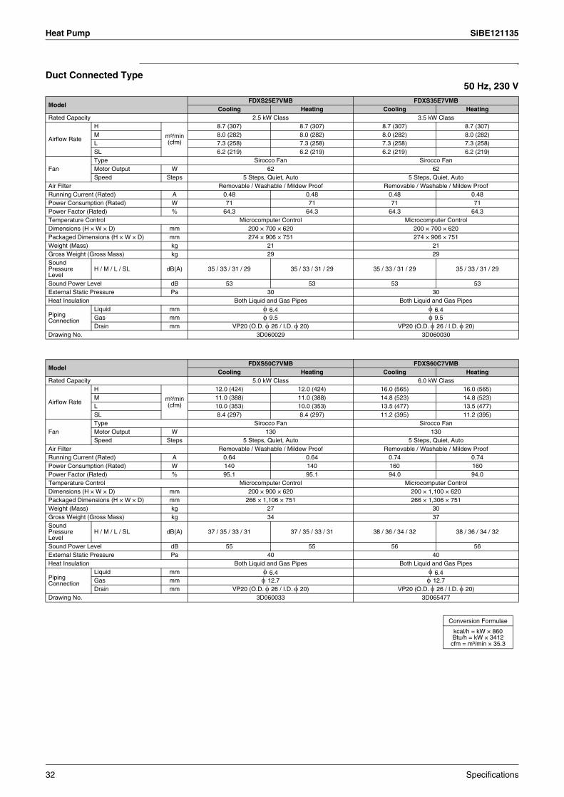
Heat Pump SiBE121135
Duct Connected Type50 Hz, 230 V
ModelFDXS25E7VMB FDXS35E7VMB
Cooling Heating Cooling HeatingRated Capacity 2.5 kW Class 3.5 kW Class
Airflow Rate
H
m³/min (cfm)
8.7 (307) 8.7 (307) 8.7 (307) 8.7 (307)M 8.0 (282) 8.0 (282) 8.0 (282) 8.0 (282)L 7.3 (258) 7.3 (258) 7.3 (258) 7.3 (258)SL 6.2 (219) 6.2 (219) 6.2 (219) 6.2 (219)
FanType Sirocco Fan Sirocco FanMotor Output W 62 62Speed Steps 5 Steps, Quiet, Auto 5 Steps, Quiet, Auto
Air Filter Removable / Washable / Mildew Proof Removable / Washable / Mildew ProofRunning Current (Rated) A 0.48 0.48 0.48 0.48Power Consumption (Rated) W 71 71 71 71Power Factor (Rated) % 64.3 64.3 64.3 64.3Temperature Control Microcomputer Control Microcomputer ControlDimensions (H × W × D) mm 200 × 700 × 620 200 × 700 × 620Packaged Dimensions (H × W × D) mm 274 × 906 × 751 274 × 906 × 751Weight (Mass) kg 21 21Gross Weight (Gross Mass) kg 29 29Sound Pressure Level
H / M / L / SL dB(A) 35 / 33 / 31 / 29 35 / 33 / 31 / 29 35 / 33 / 31 / 29 35 / 33 / 31 / 29
Sound Power Level dB 53 53 53 53External Static Pressure Pa 30 30Heat Insulation Both Liquid and Gas Pipes Both Liquid and Gas Pipes
Piping Connection
Liquid mm φ 6.4 φ 6.4Gas mm φ 9.5 φ 9.5Drain mm VP20 (O.D. φ 26 / I.D. φ 20) VP20 (O.D. φ 26 / I.D. φ 20)
Drawing No. 3D060029 3D060030
ModelFDXS50C7VMB FDXS60C7VMB
Cooling Heating Cooling HeatingRated Capacity 5.0 kW Class 6.0 kW Class
Airflow Rate
H
m³/min (cfm)
12.0 (424) 12.0 (424) 16.0 (565) 16.0 (565)M 11.0 (388) 11.0 (388) 14.8 (523) 14.8 (523)L 10.0 (353) 10.0 (353) 13.5 (477) 13.5 (477)SL 8.4 (297) 8.4 (297) 11.2 (395) 11.2 (395)
FanType Sirocco Fan Sirocco FanMotor Output W 130 130Speed Steps 5 Steps, Quiet, Auto 5 Steps, Quiet, Auto
Air Filter Removable / Washable / Mildew Proof Removable / Washable / Mildew ProofRunning Current (Rated) A 0.64 0.64 0.74 0.74Power Consumption (Rated) W 140 140 160 160Power Factor (Rated) % 95.1 95.1 94.0 94.0Temperature Control Microcomputer Control Microcomputer ControlDimensions (H × W × D) mm 200 × 900 × 620 200 × 1,100 × 620Packaged Dimensions (H × W × D) mm 266 × 1,106 × 751 266 × 1,306 × 751Weight (Mass) kg 27 30Gross Weight (Gross Mass) kg 34 37Sound Pressure Level
H / M / L / SL dB(A) 37 / 35 / 33 / 31 37 / 35 / 33 / 31 38 / 36 / 34 / 32 38 / 36 / 34 / 32
Sound Power Level dB 55 55 56 56External Static Pressure Pa 40 40Heat Insulation Both Liquid and Gas Pipes Both Liquid and Gas Pipes
Piping Connection
Liquid mm φ 6.4 φ 6.4Gas mm φ 12.7 φ 12.7Drain mm VP20 (O.D. φ 26 / I.D. φ 20) VP20 (O.D. φ 26 / I.D. φ 20)
Drawing No. 3D060033 3D065477
Conversion Formulae
kcal/h = kW × 860Btu/h = kW × 3412
cfm = m³/min × 35.3
32 Specifications

SiBE121135 Heat Pump
Ceiling Mounted Cassette Type50 Hz, 220 - 230 - 240 V
ModelFCQG35FVEB FCQG50FVEB
Cooling Heating Cooling HeatingRated Capacity 3.5 kW Class 5.0 kW Class
Decoration Panel
Model BYCQ140D7W1 / BYCQ140D7W1W / BYCQ140D7GW1 BYCQ140D7W1 / BYCQ140D7W1W / BYCQ140D7GW1Color Fresh White Fresh WhiteDimensions (H × W × D) mm 60 × 950 × 950 / 60 × 950 × 950 / 145 × 950 × 950 60 × 950 × 950 / 60 × 950 × 950 / 145 × 950 × 950Weight (Mass) kg 5.4 / 5.4 / 10.3 5.4 / 5.4 / 10.3Air Filter Resin net with mold resistance Resin net with mold resistance
Airflow RateH
m³/min12.5 12.5 12.6 12.6
M 10.6 10.6 10.7 10.7L 8.7 8.7 8.7 8.7
FanType Turbo Fan Turbo FanMotor Output W 48 48Speed Steps 3 Steps 3 Steps
Dimensions (H × W × D) mm 204 × 840 × 840 204 × 840 × 840Packaged Dimensions (H × W × D) mm 220 × 880 × 880 220 × 880 × 880Weight (Mass) kg 18 19Gross Weight (Gross Mass) kg 22 23Sound Pressure Level
H / M / L dB(A) 31 / 29 / 27 31 / 29 / 27
Sound Power Level H dB 49 49
Heat Insulation Foamed polystyrene / Foamed polyethylene Foamed polystyrene / Foamed polyethylene
Piping Connection
Liquid mm φ 6.35 (Flare) φ 6.35 (Flare)Gas mm φ 9.52 (Flare) φ 12.7 (Flare)Drain mm VP25 (O.D. φ 32 / I.D. φ 25) VP25 (O.D. φ 32 / I.D. φ 25)
Drawing No. 3D076994 3D076994
ModelFCQG60FVEB
Cooling HeatingRated Capacity 6.0 kW Class
Decoration Panel
Model BYCQ140D7W1 / BYCQ140D7W1W / BYCQ140D7GW1Color Fresh WhiteDimensions (H × W × D) mm 60 × 950 × 950 / 60 × 950 × 950 / 145 × 950 × 950Weight (Mass) kg 5.4 / 5.4 / 10.3Air Filter Resin net with mold resistance
Airflow RateH
m³/min13.6 13.6
M 11.2 11.2L 8.7 8.7
FanType Turbo FanMotor Output W 48Speed Steps 3 Steps
Dimensions (H × W × D) mm 204 × 840 × 840Packaged Dimensions (H × W × D) mm 220 × 880 × 880Weight (Mass) kg 19Gross Weight (Gross Mass) kg 23Sound Pressure Level
H / M / L dB(A) 33 / 31 / 28
Sound Power Level H dB 51
Heat Insulation Foamed polystyrene / Foamed polyethylene
Piping Connection
Liquid mm φ 6.35 (Flare)Gas mm φ 12.7 (Flare)Drain mm VP25 (O.D. φ 32 / I.D. φ 25)
Drawing No. 3D076994
Conversion Formulae
kcal/h = kW × 860Btu/h = kW × 3412
cfm = m³/min × 35.3
Specifications 33
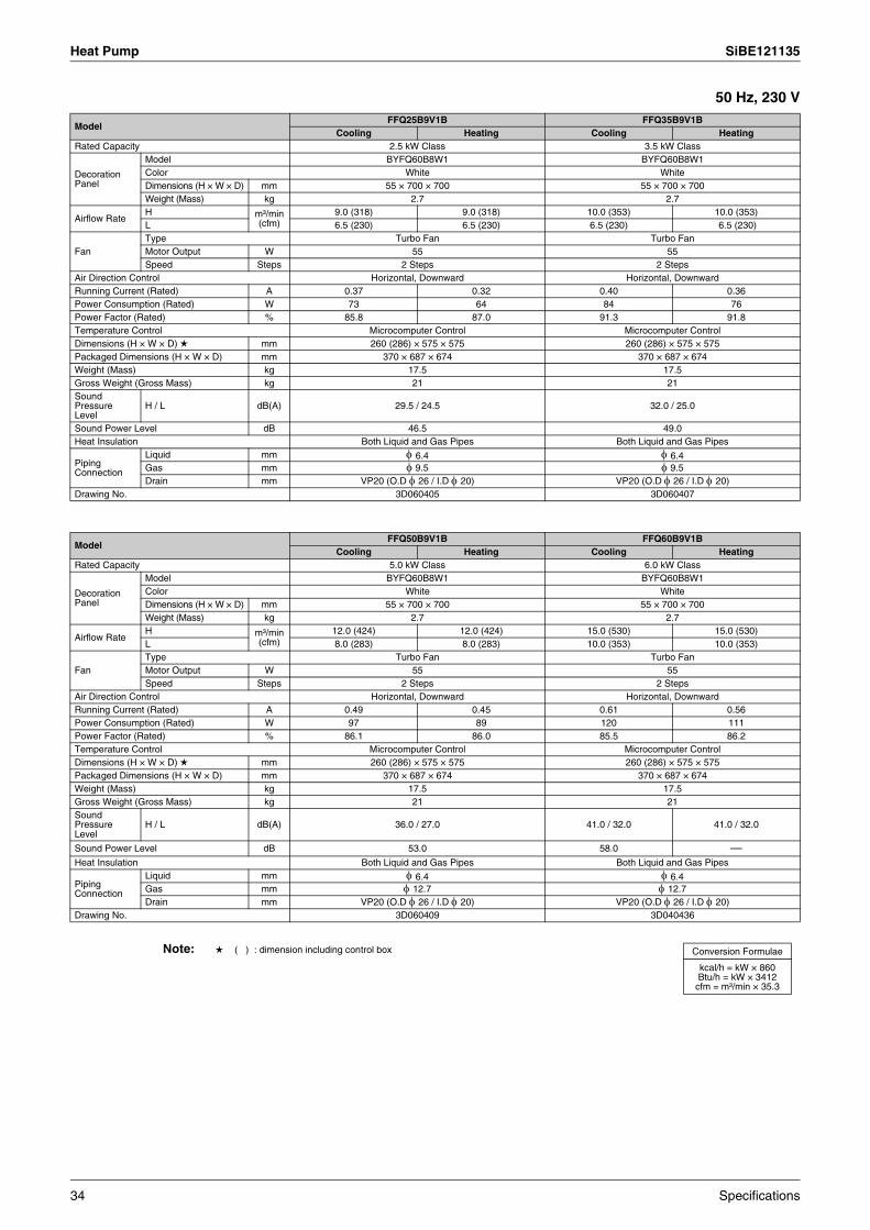
Heat Pump SiBE121135
50 Hz, 230 V
Note: ( ) : dimension including control box
ModelFFQ25B9V1B FFQ35B9V1B
Cooling Heating Cooling HeatingRated Capacity 2.5 kW Class 3.5 kW Class
Decoration Panel
Model BYFQ60B8W1 BYFQ60B8W1Color White WhiteDimensions (H × W × D) mm 55 × 700 × 700 55 × 700 × 700Weight (Mass) kg 2.7 2.7
Airflow RateH m³/min
(cfm)9.0 (318) 9.0 (318) 10.0 (353) 10.0 (353)
L 6.5 (230) 6.5 (230) 6.5 (230) 6.5 (230)
FanType Turbo Fan Turbo FanMotor Output W 55 55Speed Steps 2 Steps 2 Steps
Air Direction Control Horizontal, Downward Horizontal, DownwardRunning Current (Rated) A 0.37 0.32 0.40 0.36Power Consumption (Rated) W 73 64 84 76Power Factor (Rated) % 85.8 87.0 91.3 91.8Temperature Control Microcomputer Control Microcomputer ControlDimensions (H × W × D) mm 260 (286) × 575 × 575 260 (286) × 575 × 575Packaged Dimensions (H × W × D) mm 370 × 687 × 674 370 × 687 × 674Weight (Mass) kg 17.5 17.5Gross Weight (Gross Mass) kg 21 21Sound Pressure Level
H / L dB(A) 29.5 / 24.5 32.0 / 25.0
Sound Power Level dB 46.5 49.0Heat Insulation Both Liquid and Gas Pipes Both Liquid and Gas Pipes
Piping Connection
Liquid mm φ 6.4 φ 6.4Gas mm φ 9.5 φ 9.5Drain mm VP20 (O.D φ 26 / I.D φ 20) VP20 (O.D φ 26 / I.D φ 20)
Drawing No. 3D060405 3D060407
ModelFFQ50B9V1B FFQ60B9V1B
Cooling Heating Cooling HeatingRated Capacity 5.0 kW Class 6.0 kW Class
Decoration Panel
Model BYFQ60B8W1 BYFQ60B8W1Color White WhiteDimensions (H × W × D) mm 55 × 700 × 700 55 × 700 × 700Weight (Mass) kg 2.7 2.7
Airflow RateH m³/min
(cfm)12.0 (424) 12.0 (424) 15.0 (530) 15.0 (530)
L 8.0 (283) 8.0 (283) 10.0 (353) 10.0 (353)
FanType Turbo Fan Turbo FanMotor Output W 55 55Speed Steps 2 Steps 2 Steps
Air Direction Control Horizontal, Downward Horizontal, DownwardRunning Current (Rated) A 0.49 0.45 0.61 0.56Power Consumption (Rated) W 97 89 120 111Power Factor (Rated) % 86.1 86.0 85.5 86.2Temperature Control Microcomputer Control Microcomputer ControlDimensions (H × W × D) mm 260 (286) × 575 × 575 260 (286) × 575 × 575Packaged Dimensions (H × W × D) mm 370 × 687 × 674 370 × 687 × 674Weight (Mass) kg 17.5 17.5Gross Weight (Gross Mass) kg 21 21Sound Pressure Level
H / L dB(A) 36.0 / 27.0 41.0 / 32.0 41.0 / 32.0
Sound Power Level dB 53.0 58.0 —Heat Insulation Both Liquid and Gas Pipes Both Liquid and Gas Pipes
Piping Connection
Liquid mm φ 6.4 φ 6.4Gas mm φ 12.7 φ 12.7Drain mm VP20 (O.D φ 26 / I.D φ 20) VP20 (O.D φ 26 / I.D φ 20)
Drawing No. 3D060409 3D040436
Conversion Formulae
kcal/h = kW × 860Btu/h = kW × 3412
cfm = m³/min × 35.3
34 Specifications

SiBE121135 Heat Pump
Ceiling Suspended Type50 Hz, 220 - 230 - 240 V
ModelFHQ35BWV1B FHQ50BWV1B
Cooling Heating Cooling HeatingRated Capacity 3.5 kW Class 5.0 kW ClassPanel Color White White
Airflow RateH
m³/min13.0 (459) 13.0 (459) 13.0 (459) 13.0 (459)
L 10.0 (353) 10.0 (353) 10.0 (353) 10.0 (353)
FanType Sirocco Fan Sirocco FanMotor Output W 62 62Speed Steps 2 Steps 2 Steps
Air Direction Control Right, Left, Horizontal, Downward Right, Left, Horizontal, DownwardAir Filter Removable / Washable / Mildew Proof Removable / Washable / Mildew ProofTemperature Control Microcomputer Control Microcomputer ControlDimensions (H × W × D) mm 195 × 960 × 680 195 × 960 × 680Packaged Dimensions (H × W × D) mm 279 × 1,046 × 818 279 × 1,046 × 818Weight (Mass) kg 24 25Gross Weight (Gross Mass) kg 31 32Sound Pressure Level
H / L dB(A) 37 / 32 38 / 33
Sound Power Level dB 53 54Heat Insulation Both Liquid and Gas Pipes Both Liquid and Gas Pipes
Piping Connection
Liquid mm φ 6.4 φ 6.4Gas mm φ 9.5 φ 12.7Drain mm VP20 (O.D. φ 26 / I.D. φ 20) VP20 (O.D. φ 26 / I.D. φ 20)
Drawing No. 3D075705 3D075706
ModelFHQ60BWV1B
Cooling HeatingRated Capacity 6.0 kW ClassPanel Color White
Airflow RateH
m³/min17.0 (600) 16.0 (565)
L 13.0 (459) 13.0 (459)
FanType Sirocco FanMotor Output W 62Speed Steps 2 Steps
Air Direction Control Right, Left, Horizontal, DownwardAir Filter Removable / Washable / Mildew ProofTemperature Control Microcomputer ControlDimensions (H × W × D) mm 195 × 1,160 × 680Packaged Dimensions (H × W × D) mm 279 × 1,246 × 818Weight (Mass) kg 27Gross Weight (Gross Mass) kg 35Sound Pressure Level
H / L dB(A) 39 / 33
Sound Power Level dB 55Heat Insulation Both Liquid and Gas Pipes
Piping Connection
Liquid mm φ 6.4Gas mm φ 12.7Drain mm VP20 (O.D. φ 26 / I.D. φ 20)
Drawing No. 3D075707
Conversion Formulae
kcal/h = kW × 860Btu/h = kW × 3412
cfm = m³/min × 35.3
Specifications 35

Heat Pump SiBE121135
Ceiling Mounted Built-in Type50 Hz, 220 - 230 - 240 V /
50 Hz, 230 V 60 Hz, 220 V
ModelFDBQ25B8V1 FBQ35C8VEB
Cooling Heating Cooling HeatingRated Capacity 2.5 kW Class 3.5 kW Class
Decoration Panel
Model — BYBS45DJW1Color — WhiteDimensions (H × W × D) — 55 × 800 × 500Weight (Mass) kg — 3.5
Airflow RateH
m³/min6.5 6.95 16.0
L 5.2 5.2 11.0
FanType Sirocco Fan Sirocco FanMotor Output W 10 140Speed Steps 2 Steps 2 Steps
Air Filter Resin net with mold resistance Resin net with mold resistanceDimensions (H × W × D) mm 230 × 652 × 502 300 × 700 × 700Packaged Dimensions (H × W × D) mm 301 × 753 × 584 325 × 920 × 900Weight (Mass) kg 17 25Gross Weight (Gross Mass) kg 18 28Sound Pressure Level
H / L dB(A) 35 / 28 35 / 29 37 / 29
Sound Power Level H / L dB 55 / 49 63 / —
Heat Insulation — Both Liquid and Gas Pipes
Piping Connection
Liquid mm φ 6.35 φ 6.35 (Flare)Gas mm φ 9.52 φ 9.52 (Flare)Drain mm O.D. φ 27.2 VP25 (O.D. φ 32 / I.D. φ 25)
ModelFBQ50C8VEB FBQ60C8VEB
Cooling Heating Cooling HeatingRated Capacity 5.0 kW Class 6.0 kW Class
Decoration Panel
Model BYBS45DJW1 BYBS71DJW1Color White WhiteDimensions (H × W × D) 55 × 800 × 500 55 × 1,100 × 500Weight (Mass) kg 3.5 4.5
Airflow RateH
m³/min16.0 18.0
L 11.0 15.0
FanType Sirocco Fan Sirocco FanMotor Output W 140 350Speed Steps 2 Steps 2 Steps
Air Filter Resin net with mold resistance Resin net with mold resistanceDimensions (H × W × D) mm 300 × 700 × 700 300 × 1,000 × 700Packaged Dimensions (H × W × D) mm 355 × 920 × 920 355 × 1,220 × 900Weight (Mass) kg 25 34Gross Weight (Gross Mass) kg 28 41Sound Pressure Level
H / L dB(A) 37 / 29 37 / 29
Sound Power Level H / L dB 63 / — 57 / —
Heat Insulation Both Liquid and Gas Pipes Both Liquid and Gas Pipes
Piping Connection
Liquid mm φ 6.35 (Flare) φ 6.35 (Flare)Gas mm φ 12.7 (Flare) φ 12.7 (Flare)Drain mm VP25 (O.D. φ 32 / I.D. φ 25) VP25 (O.D. φ 32 / I.D. φ 25)
Conversion Formulae
kcal/h = kW × 860Btu/h = kW × 3412
cfm = m³/min × 35.3
36 Specifications
SiBE121135
Printed Circuit Board Connector Wiring Diagram 37
Part 3Printed Circuit Board
Connector Wiring Diagram
1. Outdoor Unit..........................................................................................382. Indoor Unit.............................................................................................41
2.1 FTXG25/35/50JV1BW(A) .......................................................................412.2 FTXS20/25K2V1B, CTXS15/35K2V1B ..................................................442.3 FTXS25/35/42/50J2V1B.........................................................................462.4 FTXS60/71GV1B....................................................................................492.5 FVXG25/35/50K2V1B ............................................................................522.6 FVXS25/35/50FV1B...............................................................................552.7 FLXS25/35/50/60BAVMB.......................................................................572.8 FDXS25/35E7VMB, FDXS50/60C7VMB................................................592.9 FCQG35/50/60FVEB..............................................................................612.10 FFQ25/35/50/60B9V1B..........................................................................642.11 FHQ35/50/60BWV1B .............................................................................662.12 FDBQ25B8V1.........................................................................................682.13 FBQ35/50/60C8VEB ..............................................................................70
3. Wired Remote Controller.......................................................................733.1 BRC1D528 .............................................................................................733.2 BRC1E52A7, BRC1E52B7.....................................................................74

Outdoor Unit SiBE121135
1. Outdoor UnitConnectors and Other Parts
PCB (1): Main PCB
PCB (2): Service Monitor PCB
1) S10 Connector for terminal board (indoor - outdoor transmission)
2) S15 Connector for COOL / HEAT mode lock
∗ Refer to page 413 for detail.
3) S20 (white) Connector for electronic expansion valve coil A port
4) S21 (red) Connector for electronic expansion valve coil B port
5) S22 (blue) Connector for electronic expansion valve coil C port
6) S23 (yellow) Connector for electronic expansion valve coil D port (for 4 and 5-room model)
7) S24 (green) Connector for electronic expansion valve coil E port (for 5-room model only)
8) S40 Connector for overload protector
9) S51, S101 Connector for service monitor PCB
10)S70 Connector for outdoor fan motor
11)S80 Connector for four way valve coil
12)S90 Connector for thermistors
(outdoor temperature, outdoor heat exchanger, discharge pipe temperature)
13)S92 Connector for gas pipe thermistors
14)S93 Connector for liquid pipe thermistors
15)AC1, AC2 Connector for terminal board (power supply)
16)HR1, HR2 Connector for reactor
17)E1, E2 Connector for earth
18)U, V, W Connector for compressor
19) FU1 Fuse (30 A, 250 V)
20)FU2, FU3 Fuse (3.15 A, 250 V)
21)V2, V3, V5 Varistor
V6, V11 (for 40 - 58 class)
V9, V100 (for 68 - 90 class)
1) S52, S102 Connector for main PCB
2) LED A LED for service monitor (green)
3) LED1 - LED4 LED for service monitor (red)
4) LED 5 LED for service monitor (red) (for 5-room model only)
5) SW1 Forced operation [ON/OFF] switch
∗ Refer to page 405 for detail.
6) SW2 Operation mode switch
∗ Refer to page 405 for detail.
7) SW3 Wiring error check switch
∗ Refer to page 406 for detail.
8) SW4 Priority room setting switch
∗ Refer to page 412 for detail.
9) SW5 NIGHT QUIET mode setting switch
∗ Refer to page 414 for detail.
38 Printed Circuit Board Connector Wiring Diagram
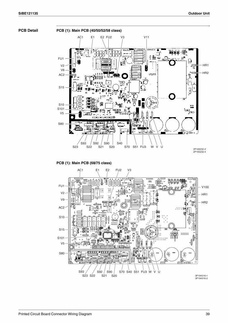
SiBE121135 Outdoor Unit
PCB Detail PCB (1): Main PCB (40/50/52/58 class)
PCB (1): Main PCB (68/75 class)
V3 V11AC1 FU2
HR1
HR2
FU32P165232-22P165232-4
S40S20 S70
S90S93 S92S23 S21S22 S51
S10
AC2
S15
S101V5
S80
V6V2
FU1
E1 E2
W V U
V3AC1 E1 E2 FU2
HR1
V100
HR2
FU33P194316-13P194316-2
S40S90S92S20S21S22
S70S23
S93 S51 W V U
S15
AC2
S101
S10
V5
S80
V9
V2
FU1
Printed Circuit Board Connector Wiring Diagram 39
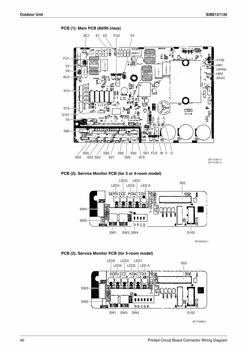
Outdoor Unit SiBE121135
PCB (1): Main PCB (80/90 class)
PCB (2): Service Monitor PCB (for 3 or 4-room model)
PCB (2): Service Monitor PCB (for 5-room model)
V3AC1 E1 E2 FU2
V100
FU3S40S20S21S22S23 S70
S90S92S93 S51 W V U
S15
AC2
S101
S10
V5
S80
V9
V2
S24
FU1
2P171491-12P171491-2
HR1(white)HR2(blue)
SW2
LED4LED3 LED1
LED2 LED AS52
S102SW4SW3SW1
SW5
3P165332-1
SW2
LED4LED3LED5 LED1
LED2 LED AS52
S102SW4SW3SW1
SW5
3P173588-1
40 Printed Circuit Board Connector Wiring Diagram

SiBE121135 Indoor Unit
2. Indoor Unit2.1 FTXG25/35/50JV1BW(A)
Connectors and Other Parts
[A1P]: Control PCB
[A2P]: Signal Receiver / Display PCB
[A3P]: INTELLIGENT EYE Sensor PCB
1) S21 Connector for centralized control (HA)
2) S25 Connector for INTELLIGENT EYE sensor PCB
3) S32 Indoor heat exchanger thermistor
4) S41 Connector for swing motors
5) S42 Connector for reduction motor (front panel mechanism) and limit switch
6) S46 Connector for signal receiver / display PCB
7) S200 Connector for fan motor
8) H1, H2, H3,FG
Connector for terminal board
9) JB Fan speed setting when compressor stops for thermostat OFF
JC Power failure recovery function (auto-restart)
∗ Refer to page 418 for detail.
10) LED A LED for service monitor (green)
11) F1U Fuse (3.15 A, 250 V)
12) V1 Varistor
1) S51 Connector for control PCB
2) S52 Connector for room temperature thermistor
3) S1W Forced cooling operation [ON/OFF] button
4) H1P LED for operation (multi-color)
5) H2P LED for INTELLIGENT EYE (green)
6) JA Address setting jumper
∗ Refer to page 415 for detail.
1) S36 Connector for control PCB
Printed Circuit Board Connector Wiring Diagram 41
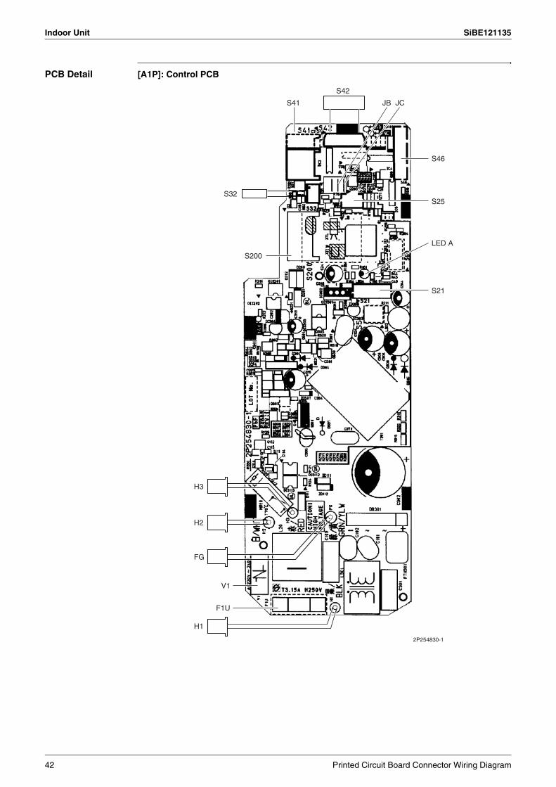
Indoor Unit SiBE121135
PCB Detail [A1P]: Control PCB
S42
S41
S32
JB JC
S200
H3
H2
FG
S46
S21
S25
LED A
V1
F1U
H1
2P254830-1
42 Printed Circuit Board Connector Wiring Diagram
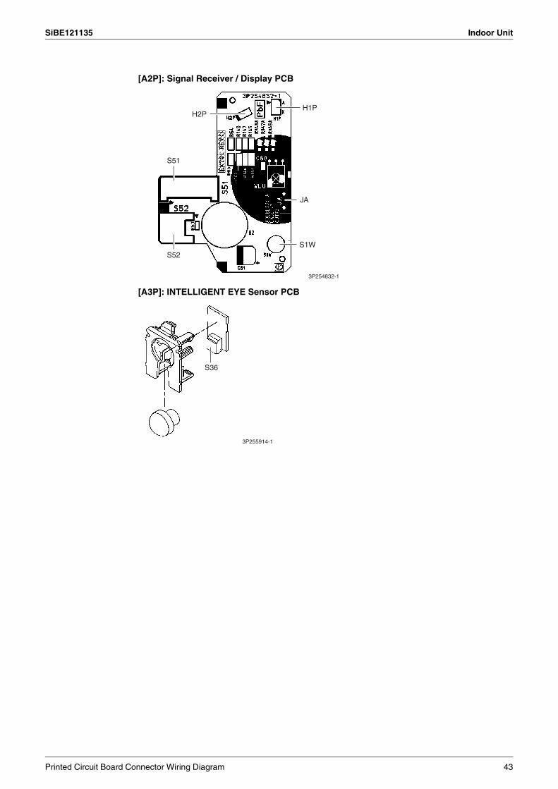
SiBE121135 Indoor Unit
[A3P]: INTELLIGENT EYE Sensor PCB
[A2P]: Signal Receiver / Display PCB
S52
S51
S1W
JA
H2PH1P
3P254832-1
S36
3P255914-1
Printed Circuit Board Connector Wiring Diagram 43
Indoor Unit SiBE121135
2.2 FTXS20/25K2V1B, CTXS15/35K2V1B
Connectors and Other Parts
PCB(1): Control PCB
PCB (2): Display PCB
PCB (3): INTELLIGENT EYE Sensor PCB
1) S6 Connector for swing motor (horizontal blade)
2) S25 Connector for INTELLIGENT EYE sensor PCB
3) S26 Connector for display PCB
4) S32 Connector for indoor heat exchanger thermistor
5) S200 Connector for fan motor
6) S403 Connector for adaptor PCB (option)
7) FG1, FG2 Connector for terminal board (frame ground)
8) H1, H2, H3 Connector for terminal board (indoor - outdoor transmission)
9) V1 Varistor
10)JA Address setting jumper
∗ Refer to page 415 for detail.
11)JB Fan speed setting when compressor stops for thermostat OFF
JC Power failure recovery function (auto-restart)
∗ Refer to page 418 for detail.
12)LED A LED for service monitor (green)
13)FU1 (F1U) Fuse (3.15 A, 250 V)
1) S27 Connector for control PCB
2) SW1 (S1W) Forced cooling operation [ON/OFF] button
3) LED1 (H1P) LED for operation (green)
4) LED2 (H2P) LED for timer (yellow)
5) LED3 (H3P) LED for INTELLIGENT EYE (green)
6) RTH1 (R1T) Room temperature thermistor
1) S36 Connector for control PCB
44 Printed Circuit Board Connector Wiring Diagram

SiBE121135 Indoor Unit
PCB Detail PCB(1): Control PCB
PCB(3): INTELLIGENT EYE Sensor PCB
PCB(2): Display PCB
FU1
FG1, FG2
LED A
S200
2P297453-1
S32S26 S6
JA JC JB
S25
S403
H2H3H1
V1
S27
SW1
(Solder side)
LED2LED3 LED1
RTH13P185701-3
S36
3P296737-1
Printed Circuit Board Connector Wiring Diagram 45
Indoor Unit SiBE121135
2.3 FTXS25/35/42/50J2V1B
Connectors and Other Parts
PCB (1): Control PCB
PCB (2): Signal Receiver PCB
PCB (3): Display PCB
PCB (4): INTELLIGENT EYE Sensor PCB
1) S1 Connector for DC fan motor
2) S21 Connector for centralized control (HA)
3) S25 Connector for INTELLIGENT EYE sensor PCB
4) S32 Indoor heat exchanger thermistor
5) S41 Connector for swing motors
6) S46 Connector for display PCB
7) S47 Connector for signal receiver PCB
8) H1, H2, H3,FG
Connector for terminal board
9) JA Address setting jumper∗ Refer to page 415 for detail.
10) JB Fan speed setting when compressor stops for thermostat OFF
JC Power failure recovery function (auto-restart)
∗ Refer to page 418 for detail.
11) LED A LED for service monitor (green)
12) FU1 (F1U) Fuse (3.15 A, 250 V)
13) V1 Varistor
1) S48 Connector for control PCB
1) S49 Connector for control PCB
2) SW1 Forced cooling operation [ON/OFF] button
3) LED1 (H1P) LED for operation (green)
4) LED2 (H2P) LED for timer (yellow)
5) LED3 (H3P) LED for INTELLIGENT EYE (green)
6) RTH1 (R1T) Room temperature thermistor
1) S26 Connector for control PCB
46 Printed Circuit Board Connector Wiring Diagram

SiBE121135 Indoor Unit
PCB Detail PCB (1): Control PCB
V1
FU1
S1
S41
S21
S47
JBJAJC
S46 S25
LED AS32
FG
H1
H2
H3
2P206687-1
Printed Circuit Board Connector Wiring Diagram 47

Indoor Unit SiBE121135
PCB (2): Signal Receiver PCB
PCB (3): Display PCB
PCB (4): INTELLIGENT EYE Sensor PCB
3P210728-1
S48
3P210728-1
RTH1
SW1
LED3
LED2
LED1
S49
3EB86013-1
S26
48 Printed Circuit Board Connector Wiring Diagram

SiBE121135 Indoor Unit
2.4 FTXS60/71GV1B
Connectors and Other Parts
PCB (1): Control PCB
PCB (2): Signal Receiver PCB
PCB (3): Display PCB
PCB (4): INTELLIGENT EYE Sensor PCB
1) S1 Connector for DC fan motor
2) S21 Connector for centralized control (HA)
3) S25 Connector for INTELLIGENT EYE sensor PCB
4) S32 Connector for indoor heat exchanger thermistor
5) S41 Connector for swing motors
6) S46 Connector for display PCB
7) S47 Connector for signal receiver PCB
8) H1, H2, H3,FG
Connector for terminal board
9) V1 Varistor
10)JA Address setting jumper
∗ Refer to page 415 for detail.
11) JB Fan speed setting when compressor stops for thermostat OFF
JC Power failure recovery function (auto-restart)
∗ Refer to page 418 for detail.
12)LED A LED for service monitor (green)
13)FU1 (F1U) Fuse (3.15 A, 250 V)
1) S48 Connector for control PCB
1) S49 Connector for control PCB
2) SW1 Forced cooling operation [ON/OFF] button
3) LED1 (H1P) LED for operation (green)
4) LED2 (H2P) LED for timer (yellow)
5) LED3 (H3P) LED for INTELLIGENT EYE (green)
6) RTH1 (R1T) Room temperature thermistor
1) S36 Connector for control PCB
Printed Circuit Board Connector Wiring Diagram 49
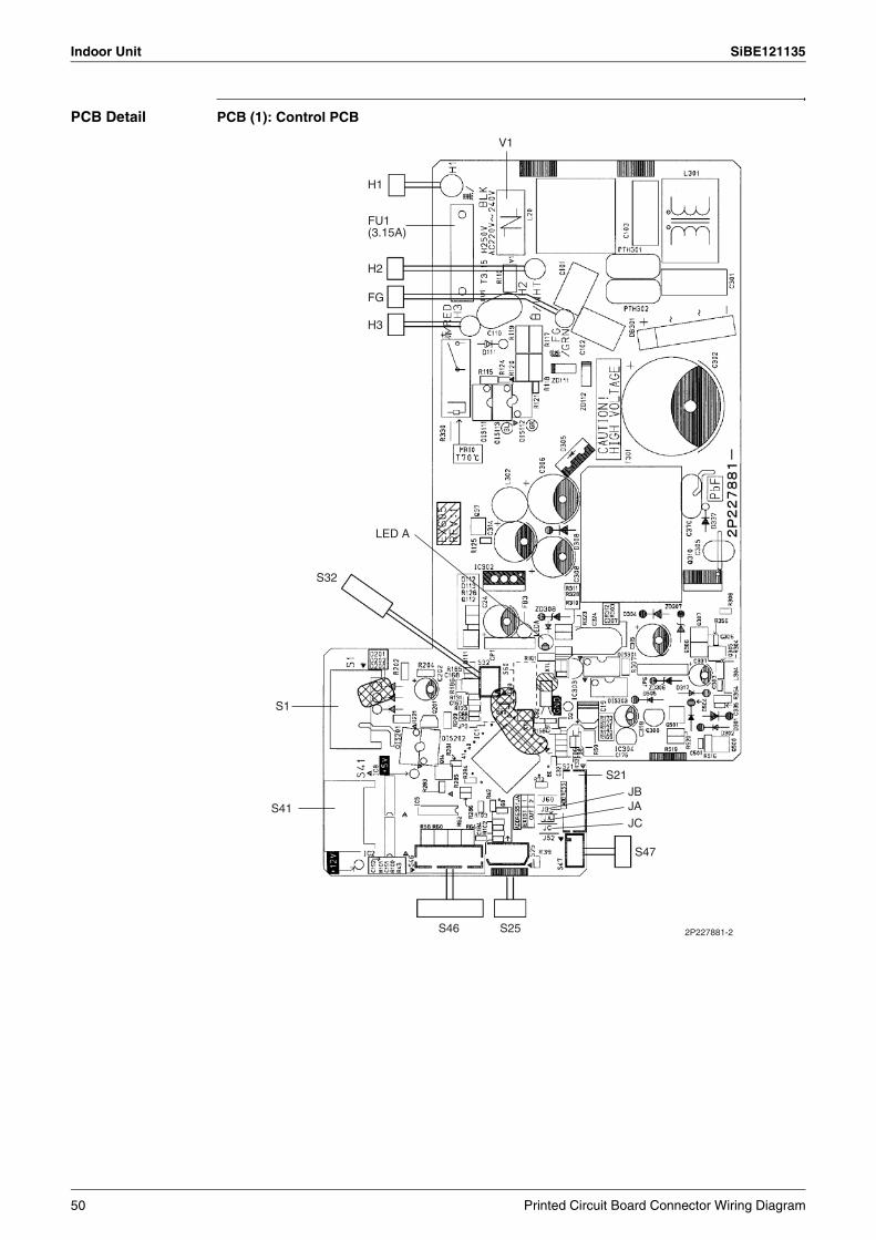
Indoor Unit SiBE121135
PCB Detail PCB (1): Control PCB
2P227881-2
V1
H1
H2
H3
LED A
S32
S1
S41
S46 S25
S47
S21JBJA
JC
FG
FU1(3.15A)
50 Printed Circuit Board Connector Wiring Diagram
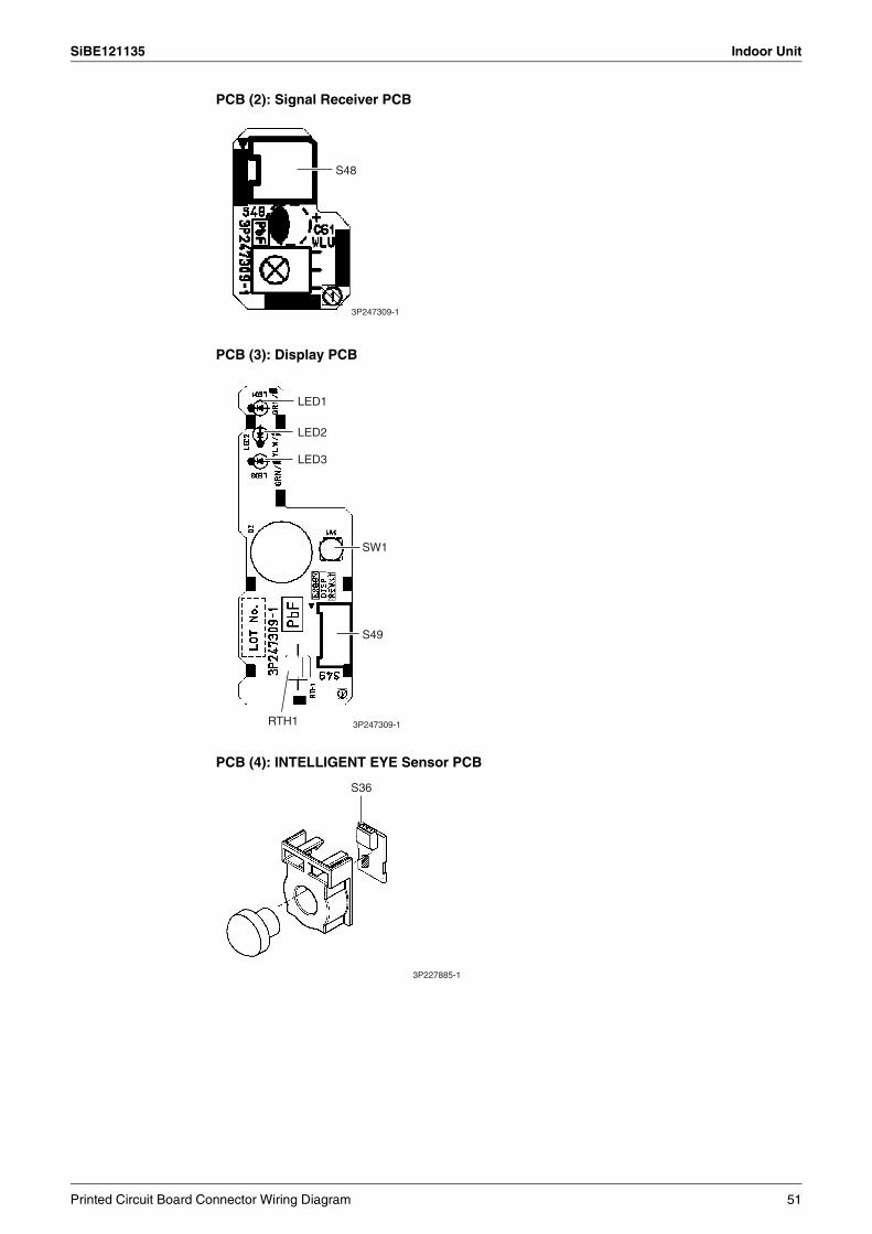
SiBE121135 Indoor Unit
PCB (2): Signal Receiver PCB
PCB (3): Display PCB
PCB (4): INTELLIGENT EYE Sensor PCB
S48
3P247309-1
LED1
LED2
LED3
SW1
S49
RTH1 3P247309-1
S36
3P227885-1
Printed Circuit Board Connector Wiring Diagram 51
Indoor Unit SiBE121135
2.5 FVXG25/35/50K2V1B
Connectors and Other Parts
PCB (1): Main PCB
PCB (2): Display PCB
PCB (3): Service PCB
1) S1 Connector for fan motor
2) S2 Connector for terminal board
3) S6 Connector for swing motor
4) S21 Connector for centralized control (HA)
5) S26 Connector for service PCB
6) S30 Connector for indoor electronic expansion valve coil (motor operated valve coil)
7) S32 Connector for indoor heat exchanger thermistor
8) S33 Connector for room temperature thermistor
9) S34 Connector for radiant panel thermistors
10)S46 Connector for display PCB
11)FG Connector for earth
12)V1 Varistor
13)JB Fan speed setting when compressor stops for thermostat OFF
JC Power failure recovery function∗ Refer to page 418 for detail.
14)F1U Fuse (3.15A, 250V)
15)LED A LED for service monitor (green)
1) S56 Connector for main PCB
2) S1W Forced cooling operation [ON/OFF] button
3) H1P LED for operation (green)
4) H2P LED for timer (yellow)
5) H3P LED for RADIANT operation (red)
1) S27 Connector for main PCB
2) S2W-1 Address setting switch∗ Refer to page 415 for detail.∗ Keep the other switches as factory setting (OFF).
52 Printed Circuit Board Connector Wiring Diagram

SiBE121135 Indoor Unit
PCB Detail PCB (1): Main PCB
S6
S30 S21
S32
S33
S34
S26
S46
FG
LED A
S1
V1
F1U
S2
JB
JC
2P273247-1
Printed Circuit Board Connector Wiring Diagram 53
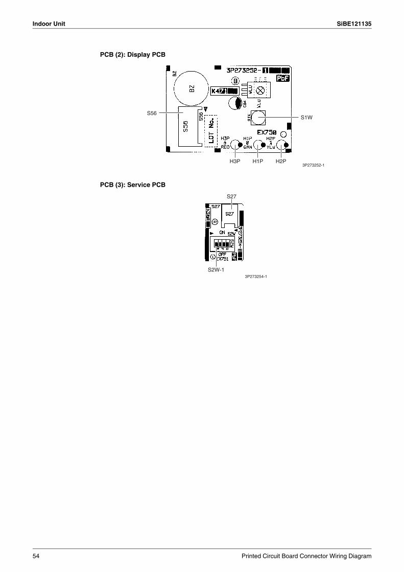
Indoor Unit SiBE121135
PCB (2): Display PCB
PCB (3): Service PCB
S56S1W
H3P H1P H2P3P273252-1
S2W-1
S27
3P273254-1
54 Printed Circuit Board Connector Wiring Diagram
SiBE121135 Indoor Unit
2.6 FVXS25/35/50FV1B
Connectors and Other Parts
PCB (1): Sensor PCB
PCB (2): Control PCB
PCB (3): Service PCB
PCB (4): Display PCB
1) S49 Connector for control PCB
2) RTH2 (R1T) Room temperature thermistor
1) S1 Connector for fan motor
2) S21 Connector for centralized control (HA)
3) S26 Connector for service PCB
4) S32 Indoor heat exchanger thermistor
5) S41 Connector for lower air outlet motor
6) S42 Connector for swing motor
7) S46 Connector for display PCB
8) S48 Connector for sensor PCB
9) H1, H2, H3 Connector for terminal board
10)E1 Terminal for earth
11)V1, V2 Varistor
12)JA Address setting jumper∗ Refer to page 415 for detail.
13)JB Fan speed setting when compressor stops for thermostat OFF
JC Power failure recovery function∗ Refer to page 418 for detail.
14) FU1 (F1U) Fuse (3.15A, 250V)
15) LED A LED for service monitor (green)
1) S27 Connector for control PCB
2) SW2-4 Switch for upward airflow limit setting∗ Refer to page 418 for detail.∗ Keep the other switches as factory setting.
3) SW4 (S4W) Switch for air outlet selection∗ Refer to page 185, 195 for detail.
1) S47 Connector for control PCB
2) SW1 (S1W) Forced cooling operation [ON/OFF] button
3) LED1 (H1P) LED for operation (green)
4) LED2 (H2P) LED for timer (yellow)
Printed Circuit Board Connector Wiring Diagram 55
Indoor Unit SiBE121135
PCB Detail PCB (1): Sensor PCB
PCB (2): Control PCB
PCB (3): Service PCB PCB (4): Display PCB
LED3 does not function.
S49
RTH2
3P191450-1
S1 LED A S21 S41 S42 S26
S46
S48
S32
JC
JA
JB
V1
V2
H1
FU1
2P191446-1
H2
H3
E1
S27
SW4
SW2-43P191448-1
S47SW1LED2
LED1
3P191447-1
56 Printed Circuit Board Connector Wiring Diagram
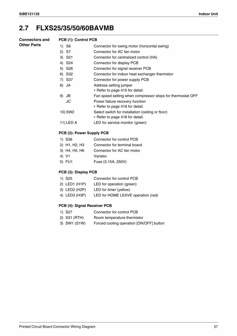
SiBE121135 Indoor Unit
2.7 FLXS25/35/50/60BAVMB
Connectors and Other Parts
PCB (1): Control PCB
PCB (2): Power Supply PCB
PCB (3): Display PCB
PCB (4): Signal Receiver PCB
1) S6 Connector for swing motor (horizontal swing)
2) S7 Connector for AC fan motor
3) S21 Connector for centralized control (HA)
4) S24 Connector for display PCB
5) S26 Connector for signal receiver PCB
6) S32 Connector for indoor heat exchanger thermistor
7) S37 Connector for power supply PCB
8) JA Address setting jumper∗ Refer to page 415 for detail.
9) JB Fan speed setting when compressor stops for thermostat OFF
JC Power failure recovery function∗ Refer to page 418 for detail.
10) SW2 Select switch for installation (ceiling or floor)∗ Refer to page 418 for detail.
11) LED A LED for service monitor (green)
1) S36 Connector for control PCB
2) H1, H2, H3 Connector for terminal board
3) H4, H5, H6 Connector for AC fan motor
4) V1 Varistor
5) FU1 Fuse (3.15A, 250V)
1) S25 Connector for control PCB
2) LED1 (H1P) LED for operation (green)
3) LED2 (H2P) LED for timer (yellow)
4) LED3 (H3P) LED for HOME LEAVE operation (red)
1) S27 Connector for control PCB
2) S31 (RTH) Room temperature thermistor
3) SW1 (S1W) Forced cooling operation [ON/OFF] button
Printed Circuit Board Connector Wiring Diagram 57
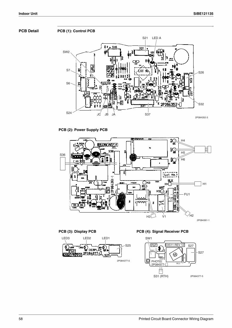
Indoor Unit SiBE121135
PCB Detail PCB (1): Control PCB
PCB (2): Power Supply PCB
PCB (3): Display PCB PCB (4): Signal Receiver PCB
SW2
S7
S6
S24 JC JB JA S37
S32
S26
S21 LED A
2P084352-3
S36
FU1
H2H3
H4
H5
H6
H1
V12P084361-1
LED3 LED2 LED1
S25
2P084377-5 PHOTO2P084377-
SW1
S31 (RTH)
PbF
SW1
IRTH
WLU
3
C1C2
C3
EX511 REV 12 S27
S27
2P084377-5
58 Printed Circuit Board Connector Wiring Diagram

SiBE121135 Indoor Unit
2.8 FDXS25/35E7VMB, FDXS50/60C7VMB
Connectors and Other Parts
PCB (1): Control PCB
PCB (2): Display PCB
1) S1 Connector for AC fan motor
2) S7 Connector for AC fan motor (Hall IC)
3) S21 Connector for centralized control (HA)
4) S26 Connector for display PCB
5) S32 Connector for indoor heat exchanger thermistor
6) H1, H2, H3 Connector for terminal board
7) GND Connector for terminal board (earth)
8) JA Address setting jumper∗ Refer to page 415 for detail.
9) JB Fan speed setting when compressor stops for thermostat OFF
JC Power failure recovery function (auto-restart)
Refer to page 418 for detail.
10) LED A LED for service monitor (green)
11) FU1 (F1U) Fuse (3.15A, 250V)
12) V1 (V1TR) Varistor
1) S1 Connector for control PCB
2) SW1 (S1W) Forced cooling operation [ON/OFF] button
3) LED1 (H1P) LED for HOME LEAVE operation (red)
4) LED2 (H2P) LED for timer (yellow)
5) LED3 (H3P) LED for operation (green)
6) RTH1 (R1T) Room temperature thermistor
Printed Circuit Board Connector Wiring Diagram 59
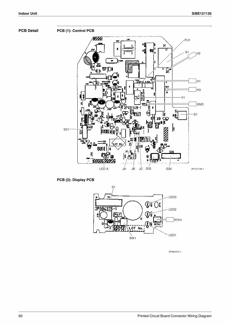
Indoor Unit SiBE121135
PCB Detail PCB (1): Control PCB
PCB (2): Display PCB
S1 H2
S7
S26S32JCJBJA
S21
2P131149-1LED A
FU1
H1
H3
V1
GND
S1
LED3
LED2
LED1SW1
2P084375-1
RTH1
60 Printed Circuit Board Connector Wiring Diagram
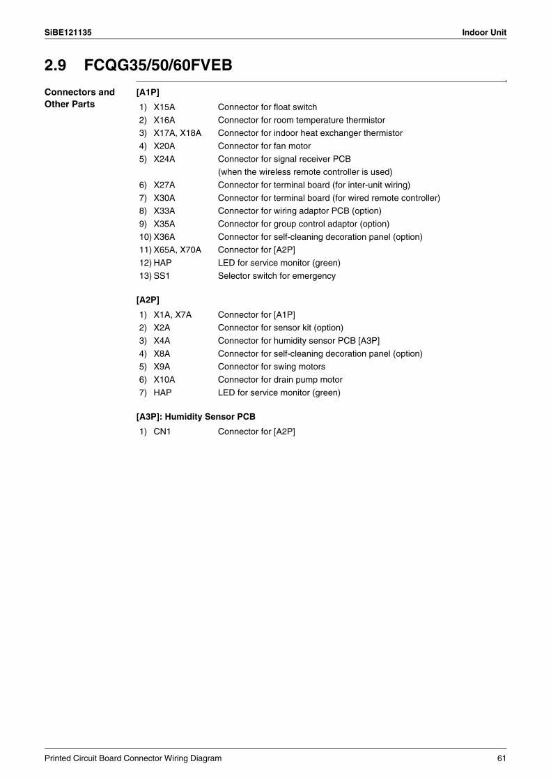
SiBE121135 Indoor Unit
2.9 FCQG35/50/60FVEB
Connectors and Other Parts
[A1P]
[A2P]
[A3P]: Humidity Sensor PCB
1) X15A Connector for float switch
2) X16A Connector for room temperature thermistor
3) X17A, X18A Connector for indoor heat exchanger thermistor
4) X20A Connector for fan motor
5) X24A Connector for signal receiver PCB
(when the wireless remote controller is used)
6) X27A Connector for terminal board (for inter-unit wiring)
7) X30A Connector for terminal board (for wired remote controller)
8) X33A Connector for wiring adaptor PCB (option)
9) X35A Connector for group control adaptor (option)
10) X36A Connector for self-cleaning decoration panel (option)
11) X65A, X70A Connector for [A2P]
12) HAP LED for service monitor (green)
13) SS1 Selector switch for emergency
1) X1A, X7A Connector for [A1P]
2) X2A Connector for sensor kit (option)
3) X4A Connector for humidity sensor PCB [A3P]
4) X8A Connector for self-cleaning decoration panel (option)
5) X9A Connector for swing motors
6) X10A Connector for drain pump motor
7) HAP LED for service monitor (green)
1) CN1 Connector for [A2P]
Printed Circuit Board Connector Wiring Diagram 61
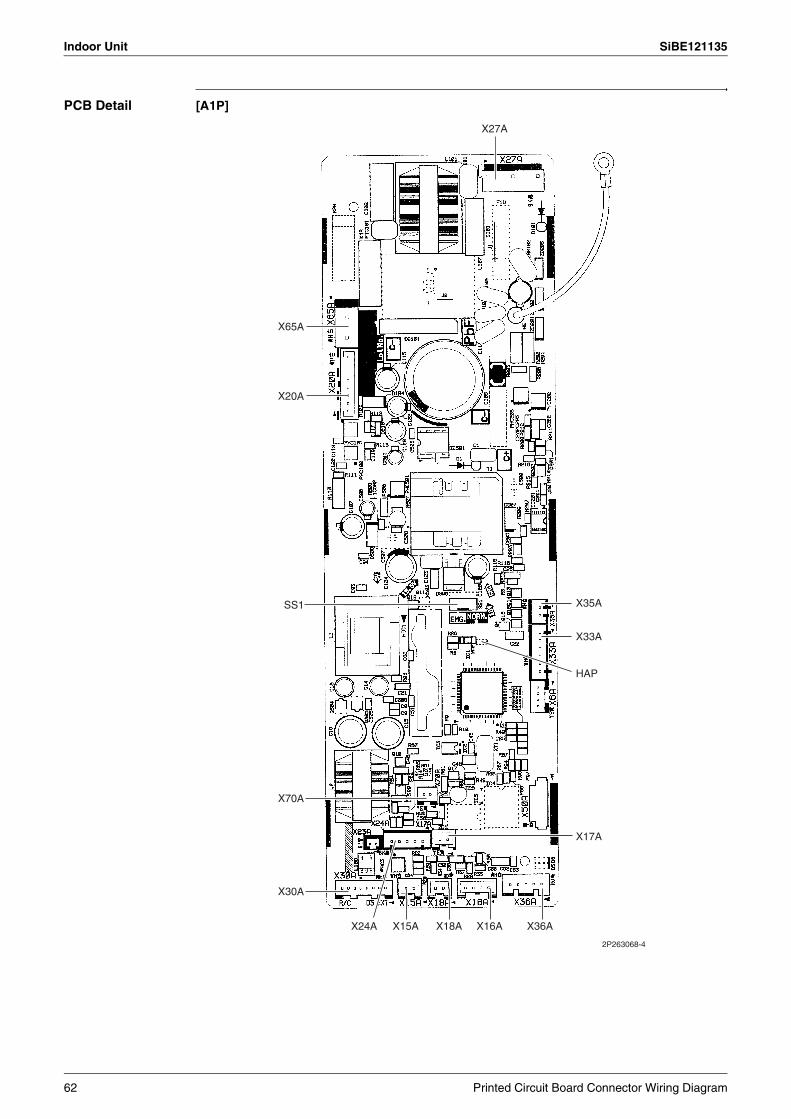
Indoor Unit SiBE121135
PCB Detail [A1P]
X27A
X65A
X20A
SS1
2P263068-4
X30A
X70A
X24A X15A X18A X16A X36A
X17A
HAP
X33A
X35A
62 Printed Circuit Board Connector Wiring Diagram
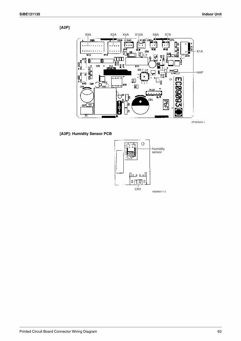
SiBE121135 Indoor Unit
[A2P]
[A3P]: Humidity Sensor PCB
X9A X2A X4A X10A X8A X7A
X1A
HAP
2P263045-1
Humidity sensor
CN14EB86011-3
Printed Circuit Board Connector Wiring Diagram 63

Indoor Unit SiBE121135
2.10 FFQ25/35/50/60B9V1B
Connectors and Other Parts
[A1P]: Control PCB
1) X5A Connector for terminal board (for wired remote controller)
2) X10A, X11A Connector for transformer
3) X15A Connector for float switch
4) X17A, X18A Connector for indoor heat exchanger thermistor
5) X19A Connector for room temperature thermistor
6) X20A Connector for fan motor
7) X24A Connector for signal receiver PCB
(when the wireless remote controller is used)
8) X25A Connector for drain pump motor
9) X27A Connector for terminal board (for inter-unit wiring)
10) X33A Connector for wiring adaptor PCB (option)
11) X35A Connector for group control adaptor (option)
12) X36A Connector for swing motor
13) X40A Connector for ON/OFF input from outside (option)
14) X60A, X61A Connector for interface adaptor (option)
15) HAP LED for service monitor (green)
16) SS1 Selector switch for emergency
64 Printed Circuit Board Connector Wiring Diagram
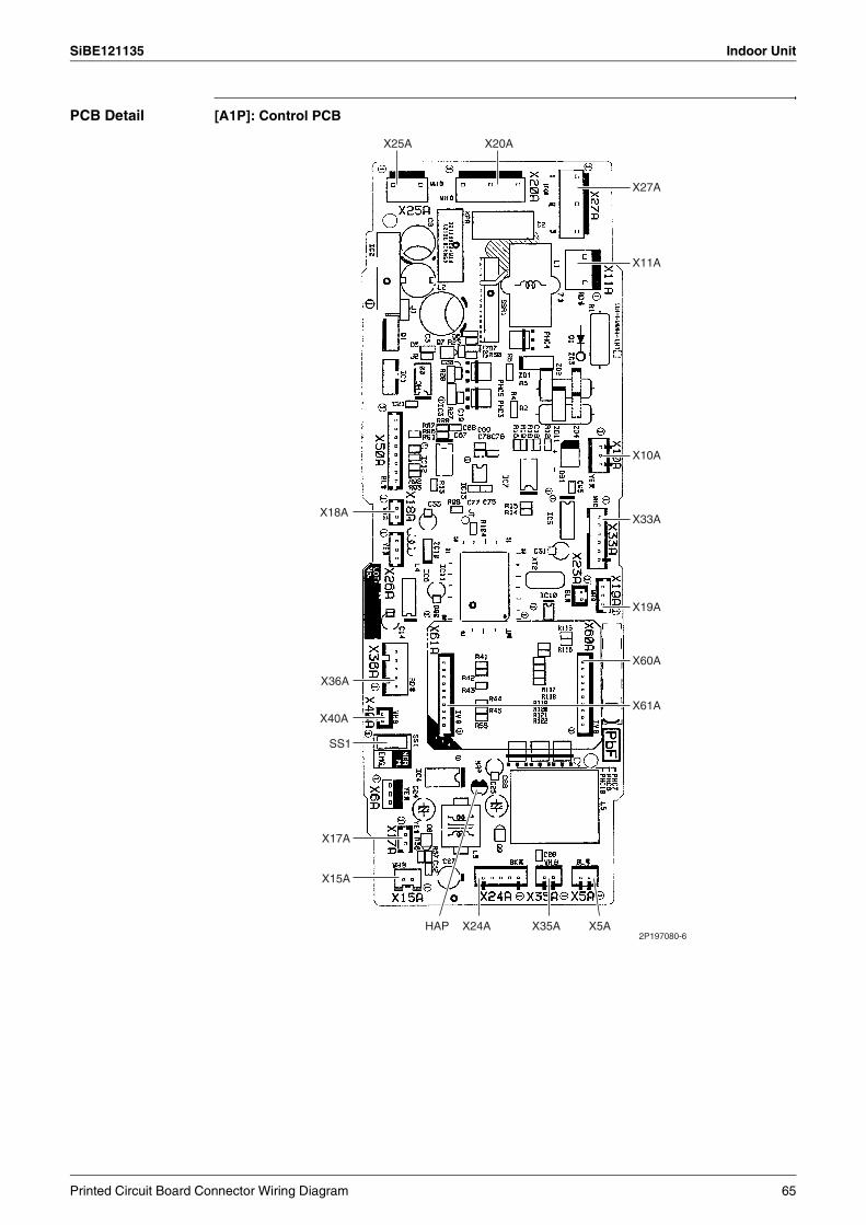
SiBE121135 Indoor Unit
PCB Detail [A1P]: Control PCB
X27A
X11A
X33A
X10A
X19A
X60A
X61A
X5AX35AX24AHAP
X15A
X17A
SS1
X40A
X36A
X18A
X25A X20A
2P197080-6
Printed Circuit Board Connector Wiring Diagram 65
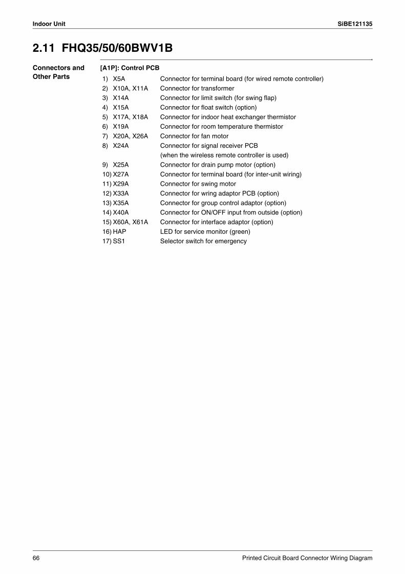
Indoor Unit SiBE121135
2.11 FHQ35/50/60BWV1B
Connectors and Other Parts
[A1P]: Control PCB
1) X5A Connector for terminal board (for wired remote controller)
2) X10A, X11A Connector for transformer
3) X14A Connector for limit switch (for swing flap)
4) X15A Connector for float switch (option)
5) X17A, X18A Connector for indoor heat exchanger thermistor
6) X19A Connector for room temperature thermistor
7) X20A, X26A Connector for fan motor
8) X24A Connector for signal receiver PCB
(when the wireless remote controller is used)
9) X25A Connector for drain pump motor (option)
10) X27A Connector for terminal board (for inter-unit wiring)
11) X29A Connector for swing motor
12) X33A Connector for wring adaptor PCB (option)
13) X35A Connector for group control adaptor (option)
14) X40A Connector for ON/OFF input from outside (option)
15) X60A, X61A Connector for interface adaptor (option)
16) HAP LED for service monitor (green)
17) SS1 Selector switch for emergency
66 Printed Circuit Board Connector Wiring Diagram
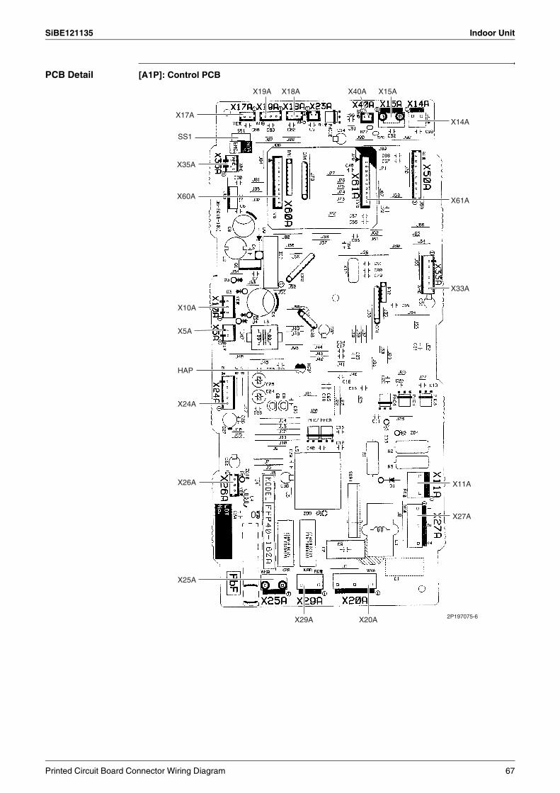
SiBE121135 Indoor Unit
PCB Detail [A1P]: Control PCB
2P197075-6
X19A X18A X40A X15A
X14A
X61A
X33A
X20A
X11A
X27A
X17A
X35A
X60A
X5A
X10A
HAP
X24A
X26A
X25A
X29A
SS1
Printed Circuit Board Connector Wiring Diagram 67
Indoor Unit SiBE121135
2.12 FDBQ25B8V1
Connectors and Other Parts
[A1P]: Control PCB
1) X5A Connector for terminal board (for wired remote controller)
2) X10A, X11A Connector for transformer
3) X17A Connector for indoor heat exchanger thermistor
4) X18A Connector for liquid pipe thermistor
5) X19A Connector for room temperature thermistor
6) X21A Connector for fan motor
7) X27A Connector for terminal board (for inter-unit wiring)
8) X33A Connector for wiring adaptor PCB (option)
9) X35A Connector for group control adaptor (option)
10) X40A Connector for ON/OFF input from outside (option)
11) X60A, X61A Connector for interface adaptor (option)
12) HAP LED for service monitor (green)
13) SS1 Selector switch for emergency
68 Printed Circuit Board Connector Wiring Diagram
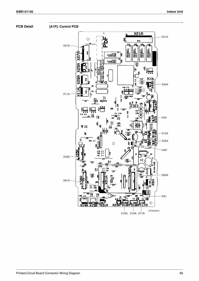
SiBE121135 Indoor Unit
PCB Detail [A1P]: Control PCB
X27A
X11A
X33A
X61A
X18A X19A X17A
X21A
X40A
X5A
X10A
X35A
X60A
SS1
HAP
2P095008-8
Printed Circuit Board Connector Wiring Diagram 69
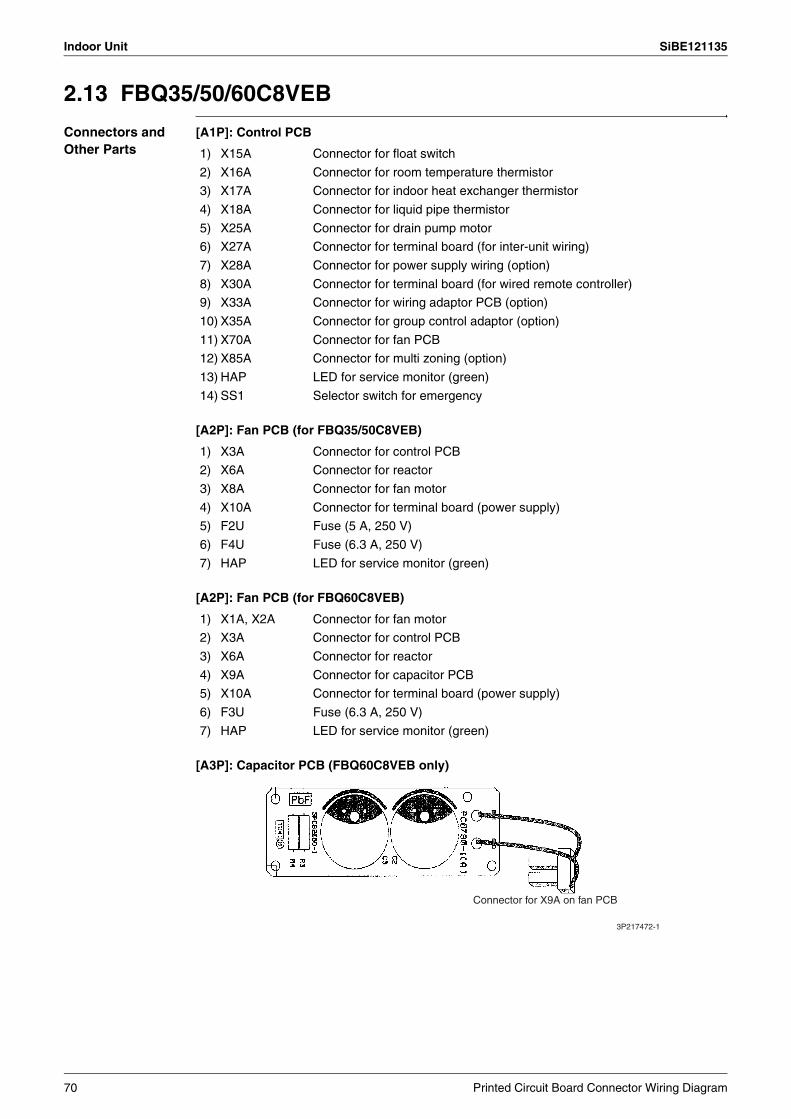
Indoor Unit SiBE121135
2.13 FBQ35/50/60C8VEB
Connectors and Other Parts
[A1P]: Control PCB
[A2P]: Fan PCB (for FBQ35/50C8VEB)
[A2P]: Fan PCB (for FBQ60C8VEB)
[A3P]: Capacitor PCB (FBQ60C8VEB only)
1) X15A Connector for float switch
2) X16A Connector for room temperature thermistor
3) X17A Connector for indoor heat exchanger thermistor
4) X18A Connector for liquid pipe thermistor
5) X25A Connector for drain pump motor
6) X27A Connector for terminal board (for inter-unit wiring)
7) X28A Connector for power supply wiring (option)
8) X30A Connector for terminal board (for wired remote controller)
9) X33A Connector for wiring adaptor PCB (option)
10) X35A Connector for group control adaptor (option)
11) X70A Connector for fan PCB
12) X85A Connector for multi zoning (option)
13) HAP LED for service monitor (green)
14) SS1 Selector switch for emergency
1) X3A Connector for control PCB
2) X6A Connector for reactor
3) X8A Connector for fan motor
4) X10A Connector for terminal board (power supply)
5) F2U Fuse (5 A, 250 V)
6) F4U Fuse (6.3 A, 250 V)
7) HAP LED for service monitor (green)
1) X1A, X2A Connector for fan motor
2) X3A Connector for control PCB
3) X6A Connector for reactor
4) X9A Connector for capacitor PCB
5) X10A Connector for terminal board (power supply)
6) F3U Fuse (6.3 A, 250 V)
7) HAP LED for service monitor (green)
Connector for X9A on fan PCB
3P217472-1
70 Printed Circuit Board Connector Wiring Diagram

SiBE121135 Indoor Unit
PCB Detail [A1P]: Control PCB
X17A
X70A
X85A
SS1
X18A X15A X30A
X16A
HAP
X33A
X35A
X27A X28A X25A 2P202878-7
Printed Circuit Board Connector Wiring Diagram 71
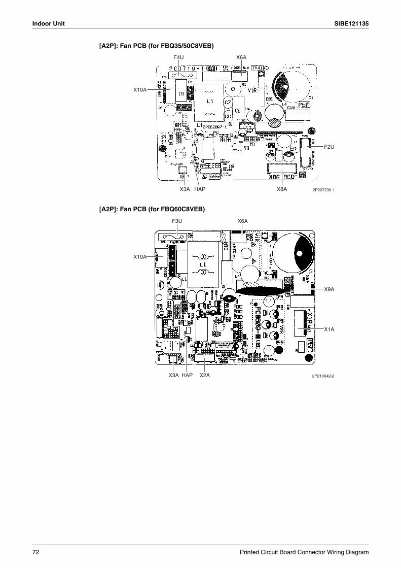
Indoor Unit SiBE121135
[A2P]: Fan PCB (for FBQ35/50C8VEB)
[A2P]: Fan PCB (for FBQ60C8VEB)
F4U
X10A
X3A X8A
F2U
HAP
X6A
2P207230-1
F3U X6A
X10A
X9A
X1A
X2AX3A HAP 2P210642-2
72 Printed Circuit Board Connector Wiring Diagram
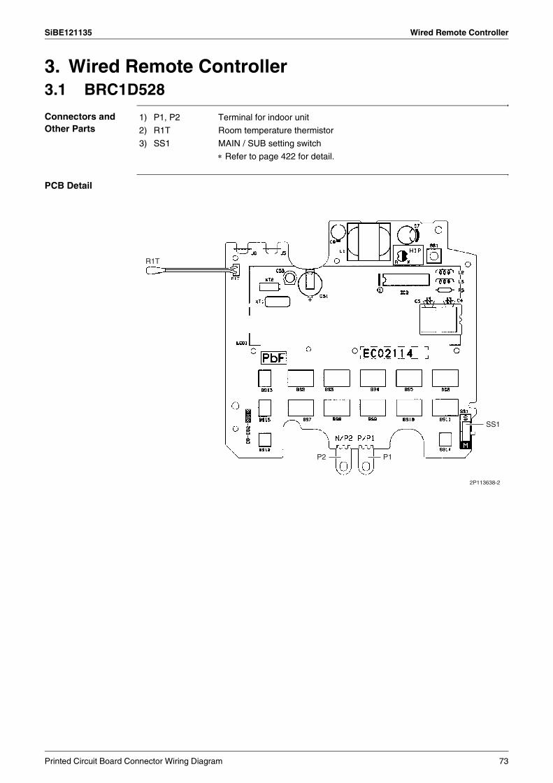
SiBE121135 Wired Remote Controller
3. Wired Remote Controller3.1 BRC1D528
Connectors and Other Parts
PCB Detail
1) P1, P2 Terminal for indoor unit
2) R1T Room temperature thermistor
3) SS1 MAIN / SUB setting switch
∗ Refer to page 422 for detail.
R1T
P2 P1
SS1
2P113638-2
Printed Circuit Board Connector Wiring Diagram 73
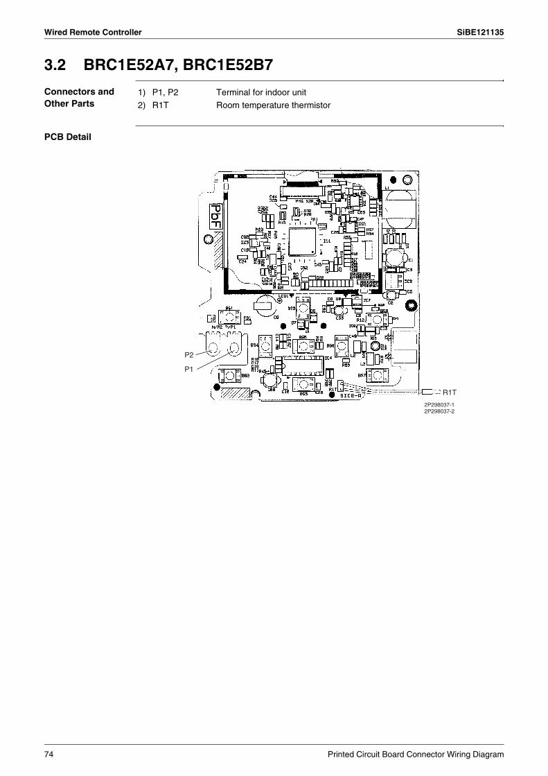
Wired Remote Controller SiBE121135
3.2 BRC1E52A7, BRC1E52B7
Connectors and Other Parts
PCB Detail
1) P1, P2 Terminal for indoor unit
2) R1T Room temperature thermistor
P2
P1
R1T
2P298037-12P298037-2
74 Printed Circuit Board Connector Wiring Diagram

SiBE121135
Function and Control 75
Part 4Function and Control
1. Indoor Unit Control (RA Models) ...........................................................761.1 Temperature Control ..............................................................................761.2 Frequency Principle................................................................................761.3 Operation Starting Control......................................................................781.4 Airflow Direction Control.........................................................................791.5 Fan Speed Control for Indoor Unit .........................................................821.6 RADIANT Operation...............................................................................831.7 Program Dry Operation ..........................................................................851.8 Automatic Operation...............................................................................861.9 Thermostat Control.................................................................................871.10 NIGHT SET Mode ..................................................................................891.11 ECONO Operation .................................................................................901.12 HOME LEAVE Operation .......................................................................911.13 INTELLIGENT EYE Operation ...............................................................921.14 2-Area INTELLIGENT EYE Operation ...................................................931.15 Inverter POWERFUL Operation .............................................................951.16 Multi-Colored Indicator Lamp / TIMER Lamp .........................................951.17 Other Functions......................................................................................97
2. Indoor Unit Control (SA Models) ...........................................................992.1 Drain Pump Control................................................................................992.2 Thermostat Sensor in Remote Controller.............................................1012.3 Freeze Prevention Control ...................................................................1032.4 Hot Start Control (In Heating Operation Only)......................................104
3. Function of Thermistor ........................................................................1054. Control Specification ...........................................................................107
4.1 Mode Hierarchy ....................................................................................1074.2 Frequency Control................................................................................1084.3 Controls at Mode Changing / Start-up..................................................1114.4 Discharge Pipe Temperature Control...................................................1124.5 Input Current Control............................................................................1134.6 Freeze-up Protection Control ...............................................................1134.7 Heating Peak-cut Control .....................................................................1144.8 Outdoor Fan Control.............................................................................1154.9 Liquid Compression Protection Function..............................................1154.10 Defrost Control .....................................................................................1164.11 Low Hz High Pressure Limit .................................................................1174.12 Outdoor Electronic Expansion Valve Control .......................................1174.13 Malfunctions .........................................................................................122
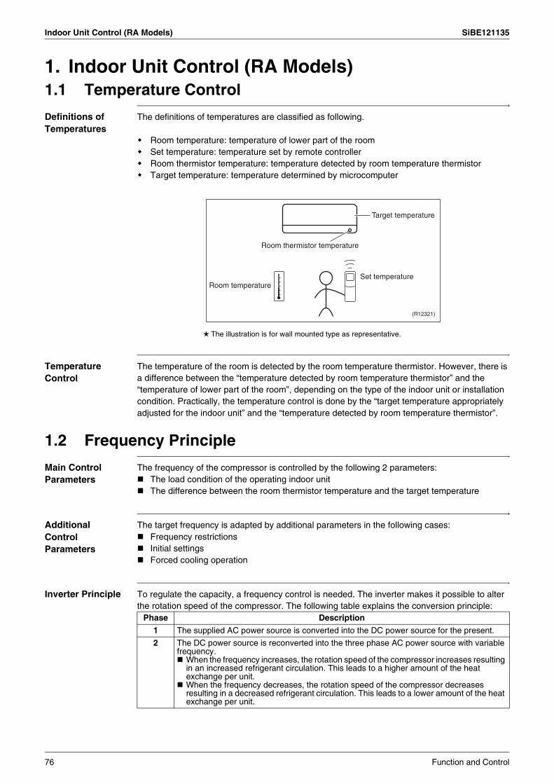
Indoor Unit Control (RA Models) SiBE121135
1. Indoor Unit Control (RA Models)1.1 Temperature Control
Definitions of Temperatures
The definitions of temperatures are classified as following.
Room temperature: temperature of lower part of the roomSet temperature: temperature set by remote controllerRoom thermistor temperature: temperature detected by room temperature thermistorTarget temperature: temperature determined by microcomputer
The illustration is for wall mounted type as representative.
Temperature Control
The temperature of the room is detected by the room temperature thermistor. However, there is a difference between the “temperature detected by room temperature thermistor” and the “temperature of lower part of the room”, depending on the type of the indoor unit or installation condition. Practically, the temperature control is done by the “target temperature appropriately adjusted for the indoor unit” and the “temperature detected by room temperature thermistor”.
1.2 Frequency Principle
Main Control Parameters
The frequency of the compressor is controlled by the following 2 parameters:The load condition of the operating indoor unitThe difference between the room thermistor temperature and the target temperature
Additional Control Parameters
The target frequency is adapted by additional parameters in the following cases:Frequency restrictionsInitial settingsForced cooling operation
Inverter Principle To regulate the capacity, a frequency control is needed. The inverter makes it possible to alter the rotation speed of the compressor. The following table explains the conversion principle:
Target temperature
Set temperatureRoom temperature
Room thermistor temperature
(R12321)
Phase Description
1 The supplied AC power source is converted into the DC power source for the present.
2 The DC power source is reconverted into the three phase AC power source with variable frequency.
When the frequency increases, the rotation speed of the compressor increases resulting in an increased refrigerant circulation. This leads to a higher amount of the heat exchange per unit.When the frequency decreases, the rotation speed of the compressor decreases resulting in a decreased refrigerant circulation. This leads to a lower amount of the heat exchange per unit.
76 Function and Control

SiBE121135 Indoor Unit Control (RA Models)
Drawing of Inverter
The following drawing shows a schematic view of the inverter principle:
Inverter Features The inverter provides the following features:The regulating capacity can be changed according to the changes in the outdoor temperature and cooling / heating load.Quick heating and quick coolingThe compressor rotational speed is increased when starting the heating (or cooling). This enables to reach the set temperature quickly.Even during extreme cold weather, high capacity is achieved. It is maintained even when the outdoor temperature is 2°C.Comfortable air conditioningA fine adjustment is integrated to keep the room temperature constant.Energy saving heating and coolingOnce the set temperature is reached, the energy saving operation enables to maintain the room temperature at low power.
Frequency Limits The following functions regulate the minimum and maximum frequency:
Forced Operation Refer to page 405 for detail.
Refrigerant circulation rate (high)
high f
low f
freq=variable
Refrigerant circulation rate (low)
high speed
low speed
(R2812)
Amount of heat exchanged air (large)
Amount of heat exchanged air (small)
freq= constant
capacity= variable
AC
po
wer
DC
po
wer
Amount of heat exchanged air (large)
Amount of heat exchanged air (small)
50 Hz60 Hz
Frequency Functions
Low Four way valve operation compensation. Refer to page 111.
High Compressor protection function. Refer to page 112.Discharge pipe temperature control. Refer to page 112.Input current control. Refer to page 113.Freeze-up protection control. Refer to page 113.Heating peak-cut control. Refer to page 114.Defrost control. Refer to page 116.
Function and Control 77
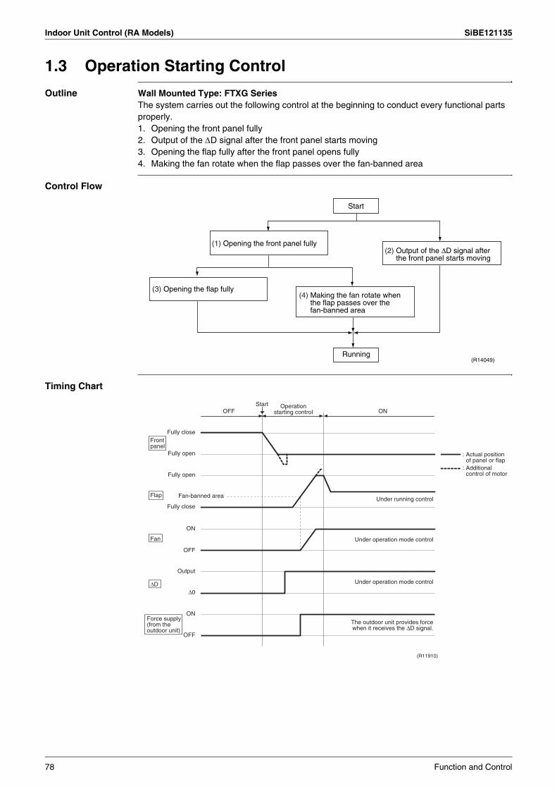
Indoor Unit Control (RA Models) SiBE121135
1.3 Operation Starting Control
Outline Wall Mounted Type: FTXG SeriesThe system carries out the following control at the beginning to conduct every functional parts properly.1. Opening the front panel fully2. Output of the ∆D signal after the front panel starts moving3. Opening the flap fully after the front panel opens fully4. Making the fan rotate when the flap passes over the fan-banned area
Control Flow
Timing Chart
(1) Opening the front panel fully
Start
Running
(2) Output of the ∆D signal after the front panel starts moving
(4) Making the fan rotate when the flap passes over the fan-banned area
(3) Opening the flap fully
(R14049)
Fully close
OFFStart
ON
FlapUnder running control
Under operation mode control
Under operation mode control
Fan
∆D
Fully open
Fully open
Fully close
ON
OFF
OFF
Output
ON
∆0
Fan-banned area
(R11910)
Front panel
Force supply (from the outdoor unit)
The outdoor unit provides force when it receives the ∆D signal.
Operation starting control
: Actual position of panel or flap
: Additional control of motor
78 Function and Control

SiBE121135 Indoor Unit Control (RA Models)
1.4 Airflow Direction Control
Power-Airflow Dual Flaps
The large flap sends a large volume of air downward to the floor. The flap provides an optimum control in cooling, dry, and heating operation.
<Cooling / Dry>During cooling or dry operation, the flap retracts into the indoor unit. Then, cool air can be blown far and distributed all over the room.
<Heating>During heating operation, the large flap directs airflow downward to spread the warm air to the entire room.
Wide-Angle Louvers
The louvers, made of elastic synthetic resin, provide a wide range of airflow that guarantees comfortable air distribution.
Auto-Swing The following table explains the auto-swing process for cooling, dry, heating, and fan:Wall Mounted Type
Floor Standing Type: FVXG SeriesThe swinging range of the flap is the same in any operation mode.
SeriesVertical Swing (up and down) Horizontal
Swing (right and left)Cooling / Dry Heating Fan
FTXG
(R11662) (R11664) (R11663)
—
FTXS-KCTXS-K
(R11256) (R11257) (R11256)
—
FTXS-J
(R12182) (R11402) (R14208) (R11404)
FTXS-G
(R2814) (R2815) (R2813) (R2816) (R2817)
10˚15˚
60˚ 65˚
20˚
70˚
25˚
75˚
5˚10˚
80˚75˚
5˚
45˚
15˚
45˚
5˚
45˚
15˚
50˚30˚
55˚30˚
70˚
30˚65˚
8˚
80˚
30˚65˚ 45˚45˚
10˚
40˚10˚40˚
5˚
35˚5˚
35˚
15˚
55˚15
55˚
5˚
55˚5
55˚
50˚ 50˚
25˚
45˚
(R14634)
Function and Control 79

Indoor Unit Control (RA Models) SiBE121135
Floor Standing Type: FVXS Series
Floor / Ceiling Suspended Dual Type
3-D Airflow Wall Mounted Type: FTXS-J/G SeriesAlternative repetition of vertical and horizontal swing motions enables uniform air-conditioning of the entire room. This function is effective for starting the air conditioner.
When the horizontal swing and vertical swing are both set to automatic operation, the airflow becomes 3-D airflow. The horizontal and vertical swing motion is altered and the airflow direction changes in the order shown in the following diagram.
(1): The vertical blades (louvers) move from the right to the left.(2): The horizontal blades (flaps) move downward.(3): The vertical blades (louvers) move from the left to the right.(4): The horizontal blades (flaps) move upward.
Vertical Swing (up and down)
Cooling / Dry Heating
Upward airflow limit
OFF
(R6831) (R6829)
Upward airflow limit
ON
(R6832) (R6830)
Vertical Swing (up and down)
Cooling / Dry / Fan Heating
Ceiling
(R2964) (R2963)
Floor
(R2967) (R2966)
25˚
90˚
40˚
90˚
20˚
90˚
90˚
20˚
40˚20˚ 95˚
65˚
40˚20˚
95˚
65˚
(R13554)
(1)(2)
(3) (4)
80 Function and Control
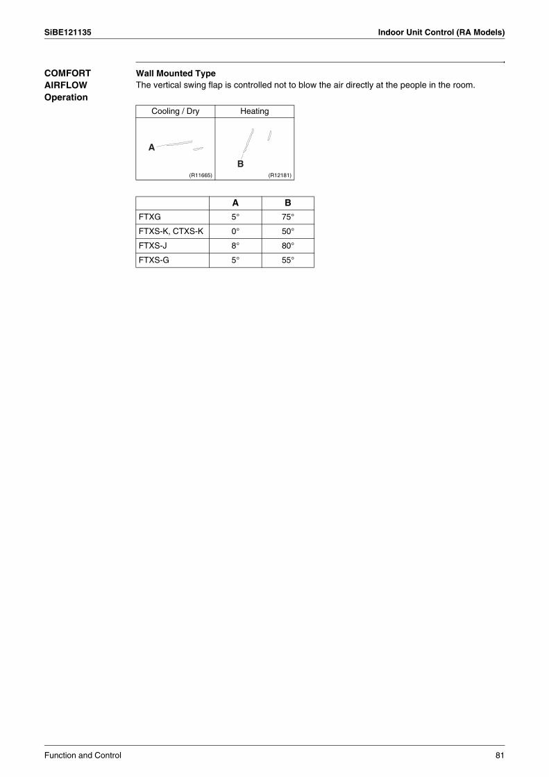
SiBE121135 Indoor Unit Control (RA Models)
COMFORT AIRFLOW Operation
Wall Mounted TypeThe vertical swing flap is controlled not to blow the air directly at the people in the room.
Cooling / Dry Heating
(R11665) (R12181)
A B
FTXG 5° 75°
FTXS-K, CTXS-K 0° 50°
FTXS-J 8° 80°
FTXS-G 5° 55°
A
B
Function and Control 81
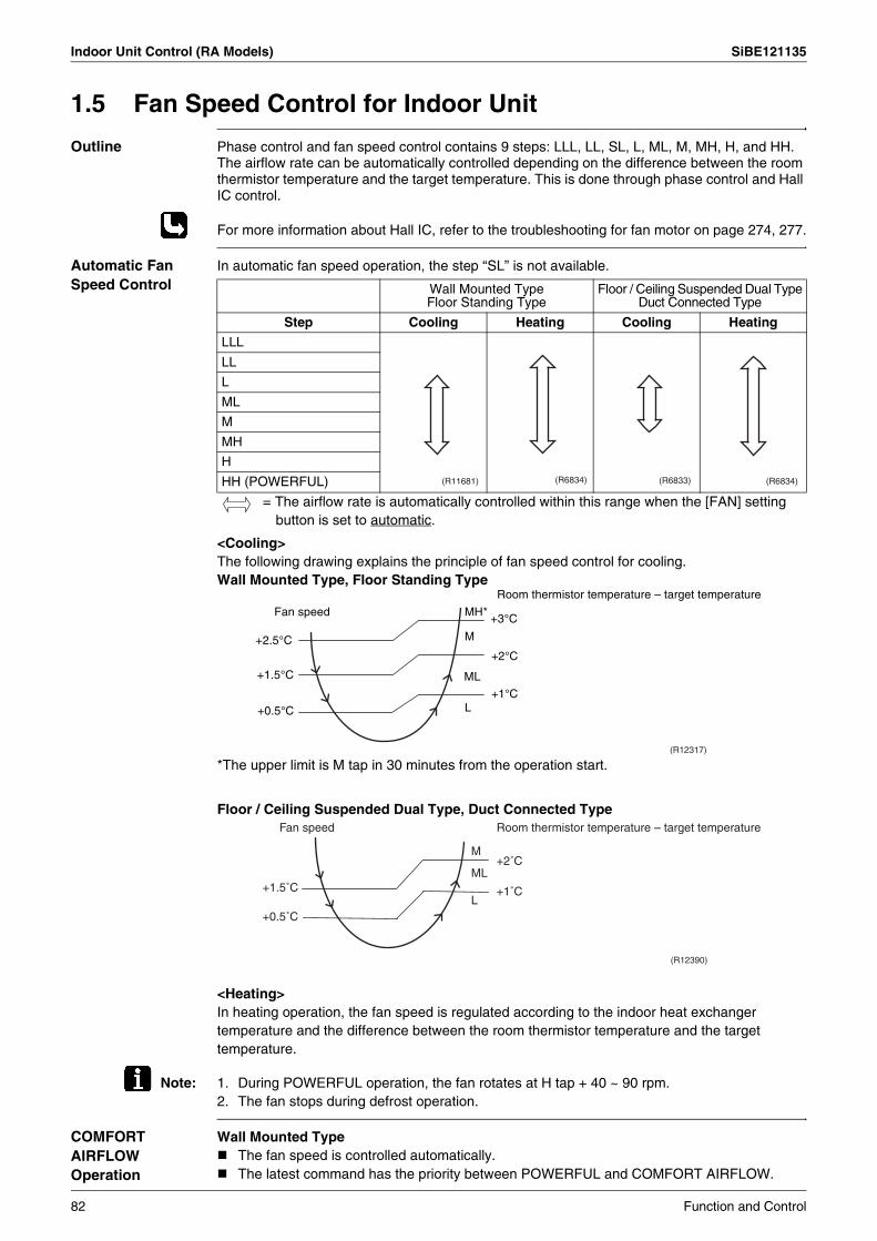
Indoor Unit Control (RA Models) SiBE121135
1.5 Fan Speed Control for Indoor Unit
Outline Phase control and fan speed control contains 9 steps: LLL, LL, SL, L, ML, M, MH, H, and HH.The airflow rate can be automatically controlled depending on the difference between the room thermistor temperature and the target temperature. This is done through phase control and Hall IC control.
For more information about Hall IC, refer to the troubleshooting for fan motor on page 274, 277.
Automatic Fan Speed Control
In automatic fan speed operation, the step “SL” is not available.
= The airflow rate is automatically controlled within this range when the [FAN] setting button is set to automatic.
<Cooling>The following drawing explains the principle of fan speed control for cooling.Wall Mounted Type, Floor Standing Type
*The upper limit is M tap in 30 minutes from the operation start.
Floor / Ceiling Suspended Dual Type, Duct Connected Type
<Heating>In heating operation, the fan speed is regulated according to the indoor heat exchanger temperature and the difference between the room thermistor temperature and the target temperature.
Note: 1. During POWERFUL operation, the fan rotates at H tap + 40 ~ 90 rpm.2. The fan stops during defrost operation.
COMFORT AIRFLOW Operation
Wall Mounted TypeThe fan speed is controlled automatically.The latest command has the priority between POWERFUL and COMFORT AIRFLOW.
Wall Mounted TypeFloor Standing Type
Floor / Ceiling Suspended Dual TypeDuct Connected Type
Step Cooling Heating Cooling Heating
LLL
LL
L
ML
M
MH
H
HH (POWERFUL) (R11681) (R6834) (R6833) (R6834)
(R12317)
Fan speed
+2.5°C
+1.5°C
+0.5°C
MH*
M
ML
L
+3°C
+2°C
+1°C
Room thermistor temperature – target temperature
Room thermistor temperature – target temperature
+1.5˚C
+0.5˚C
+2˚C
+1˚C
M
ML
L
Fan speed
(R12390)
82 Function and Control
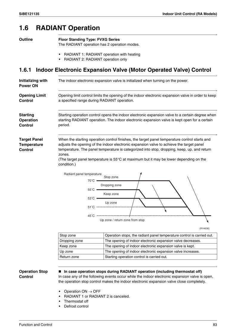
SiBE121135 Indoor Unit Control (RA Models)
1.6 RADIANT Operation
Outline Floor Standing Type: FVXG SeriesThe RADIANT operation has 2 operation modes.
RADIANT 1: RADIANT operation with heatingRADIANT 2: RADIANT operation only
1.6.1 Indoor Electronic Expansion Valve (Motor Operated Valve) Control
Initializing with Power ON
The indoor electronic expansion valve is initialized when turning on the power.
Opening Limit Control
Opening limit control limits the opening of the indoor electronic expansion valve in order to keep a specified range during RADIANT operation.
Starting Operation Control
Starting operation control opens the indoor electronic expansion valve to a certain degree when starting RADIANT operation. The indoor electronic expansion valve is kept open for a certain period.
Target Panel Temperature Control
When the starting operation control finishes, the target panel temperature control starts and adjusts the opening of the indoor electronic expansion valve to achieve the target panel temperature. The panel temperature is categorized into stop, dropping, keep, up, and return zones.(The target panel temperature is 55°C at maximum but it may be lower depending on the condition.)
Operation Stop Control
In case operation stops during RADIANT operation (including thermostat off)In case any of the following events occur while the indoor electronic expansion valve is open, the operation stop control makes the indoor electronic expansion valve close completely.
Operation ON → OFFRADIANT 1 or RADIANT 2 is canceled.Thermostat offDefrost control
Stop zone Operation stops, the radiant panel temperature control is carried out.
Dropping zone The opening of indoor electronic expansion valve decreases.
Keep zone The opening of indoor electronic expansion valve is kept.
Up zone The opening of indoor electronic expansion valve increases.
Return zone Starting operation control is carried out.
Radiant panel temperature
45˚CUp zone / return zone from stop
Up zone51˚C
Stop zone70˚C
Dropping zone55˚C
Keep zone53˚C
(R14636)
Function and Control 83

Indoor Unit Control (RA Models) SiBE121135
1.6.2 Indoor Unit Fan Control The movement of the indoor unit fan is different whether in RADIANT 1 or RADIANT 2.
1.6.3 RADIANT Operation and Optional Function Some optional function cannot be used with RADIANT 1 or RADIANT 2 at the same time.
RADIANT 1 starts.
Room temperature
Room temperature
Set temperature
Rotation speed of indoor unit fan
Note: The only difference between RADIANT 1 and RADIANT 2 is the movement of the indoor unit fan.In RADIANT 1, the rotation speed of the indoor unit fan is controlled depending on the difference between the set temperature and the room temperature. In RADIANT 2, the rotation speed of the indoor unit fan is constant.
(R14637)
Function RADIANT 1 RADIANT 2
POWERFUL operation available not available
ECONO operation not available not available
OUTDOOR UNIT QUIET operation not available not available
84 Function and Control
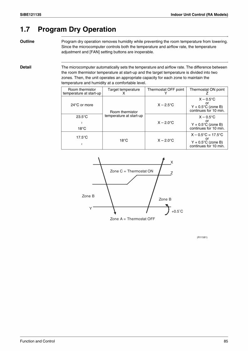
SiBE121135 Indoor Unit Control (RA Models)
1.7 Program Dry Operation
Outline Program dry operation removes humidity while preventing the room temperature from lowering.Since the microcomputer controls both the temperature and airflow rate, the temperature adjustment and [FAN] setting buttons are inoperable.
Detail The microcomputer automatically sets the temperature and airflow rate. The difference between the room thermistor temperature at start-up and the target temperature is divided into two zones. Then, the unit operates an appropriate capacity for each zone to maintain the temperature and humidity at a comfortable level.
Room thermistor temperature at start-up
Target temperatureX
Thermostat OFF pointY
Thermostat ON pointZ
24°C or more
Room thermistor temperature at start-up
X – 2.5°C
X – 0.5°Cor
Y + 0.5°C (zone B) continues for 10 min.
23.5°C
X – 2.0°C
X – 0.5°Cor
Y + 0.5°C (zone B) continues for 10 min.
~
18°C
18°C X – 2.0°C
X – 0.5°C = 17.5°Cor
Y + 0.5°C (zone B) continues for 10 min.
17.5°C
~
Z
X
Y
Zone BZone B
Zone A = Thermostat OFF
Zone C = Thermostat ON
+0.5˚C
(R11581)
Function and Control 85
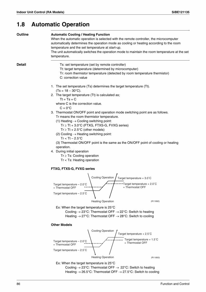
Indoor Unit Control (RA Models) SiBE121135
1.8 Automatic Operation
Outline Automatic Cooling / Heating FunctionWhen the automatic operation is selected with the remote controller, the microcomputer automatically determines the operation mode as cooling or heating according to the room temperature and the set temperature at start-up.The unit automatically switches the operation mode to maintain the room temperature at the set temperature.
Detail Ts: set temperature (set by remote controller)Tt: target temperature (determined by microcomputer)Tr: room thermistor temperature (detected by room temperature thermistor)C: correction value
1. The set temperature (Ts) determines the target temperature (Tt). (Ts = 18 ~ 30°C).
2. The target temperature (Tt) is calculated as; Tt = Ts + C
where C is the correction value.C = 0°C
3. Thermostat ON/OFF point and operation mode switching point are as follows.Tr means the room thermistor temperature.(1) Heating → Cooling switching point:
Tr ≥ Tt + 3.0°C (FTXG, FTXS-G, FVXG series)Tr ≥ Tt + 2.5°C (other models)
(2) Cooling → Heating switching point: Tr < Tt – 2.5°C
(3) Thermostat ON/OFF point is the same as the ON/OFF point of cooling or heating operation.
4. During initial operationTr ≥ Ts: Cooling operationTr < Ts: Heating operation
FTXG, FTXS-G, FVXG series
Ex: When the target temperature is 25°CCooling → 23°C: Thermostat OFF → 22°C: Switch to heatingHeating → 27°C: Thermostat OFF → 28°C: Switch to cooling
Other Models
Ex: When the target temperature is 25°CCooling → 23°C: Thermostat OFF → 22°C: Switch to heatingHeating → 26.5°C: Thermostat OFF → 27.5°C: Switch to cooling
Target temperature + 3.0˚C
Heating Operation
Target temperature – 2.5˚C
Cooling Operation
(R11892)
Target temperature – 2.0˚C = Thermostat OFF
Target temperature + 2.0˚C = Thermostat OFF
(R11893)
Target temperature + 2.5˚C
Heating Operation
Target temperature – 2.5˚C
Cooling Operation
Target temperature – 2.0˚C = Thermostat OFF
Target temperature + 1.5˚C = Thermostat OFF
86 Function and Control
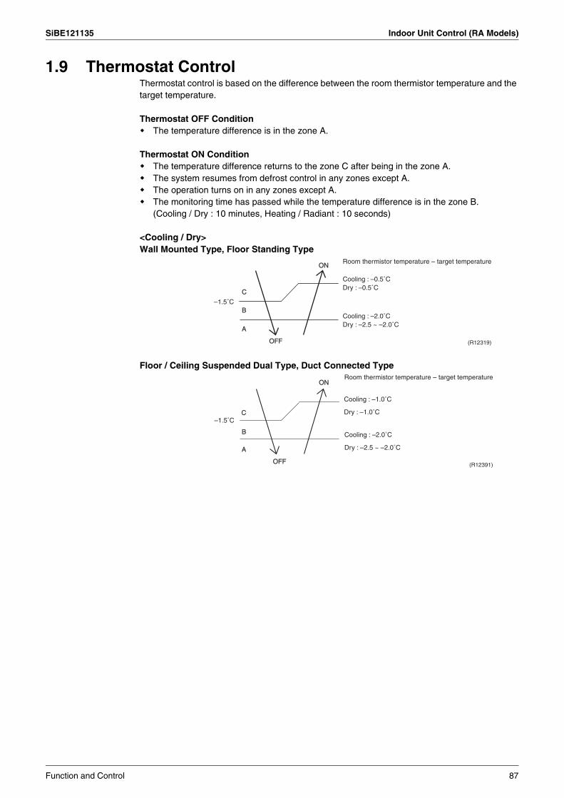
SiBE121135 Indoor Unit Control (RA Models)
1.9 Thermostat ControlThermostat control is based on the difference between the room thermistor temperature and the target temperature.
Thermostat OFF ConditionThe temperature difference is in the zone A.
Thermostat ON ConditionThe temperature difference returns to the zone C after being in the zone A.The system resumes from defrost control in any zones except A.The operation turns on in any zones except A.The monitoring time has passed while the temperature difference is in the zone B.(Cooling / Dry : 10 minutes, Heating / Radiant : 10 seconds)
<Cooling / Dry>Wall Mounted Type, Floor Standing Type
Floor / Ceiling Suspended Dual Type, Duct Connected Type
B
A
OFF
ON
C
Room thermistor temperature – target temperature
–1.5˚C
(R12319)
Cooling : –0.5˚C Dry : –0.5˚C
Cooling : –2.0˚C Dry : –2.5 ~ –2.0˚C
BB
AA
OFFOFF
ONON
CC
Room thermistor temperature – target temperature
–1.5˚C
(R12391)
Cooling : –2.0˚C
Dry : –2.5 ~ –2.0˚C
Cooling : –1.0˚C
Dry : –1.0˚C
Function and Control 87
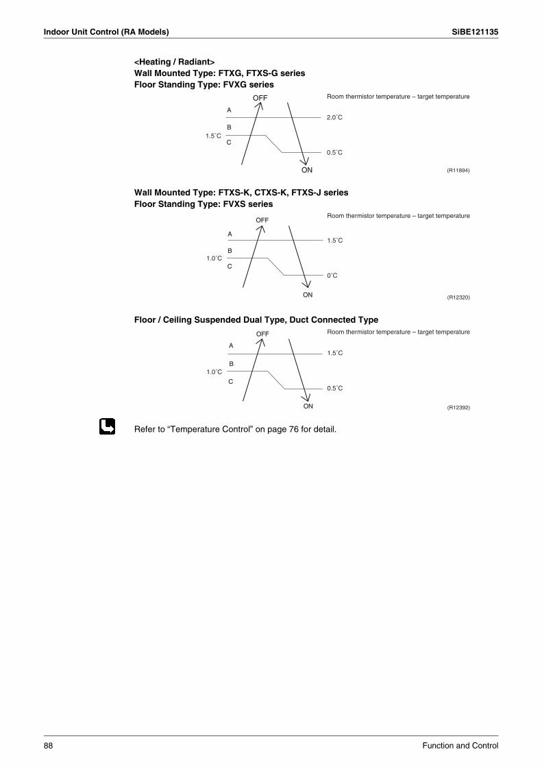
Indoor Unit Control (RA Models) SiBE121135
<Heating / Radiant>Wall Mounted Type: FTXG, FTXS-G seriesFloor Standing Type: FVXG series
Wall Mounted Type: FTXS-K, CTXS-K, FTXS-J seriesFloor Standing Type: FVXS series
Floor / Ceiling Suspended Dual Type, Duct Connected Type
Refer to “Temperature Control” on page 76 for detail.
OFF
ON
B
A
C1.5˚C
2.0˚C
0.5˚C
Room thermistor temperature – target temperature
(R11894)
B
A
OFF
ON
C
1.5˚C
1.0˚C
Room thermistor temperature – target temperature
0˚C
(R12320)
B
A
OFF
ON
C
1.5˚C
0.5˚C
1.0˚C
Room thermistor temperature – target temperature
(R12392)
88 Function and Control
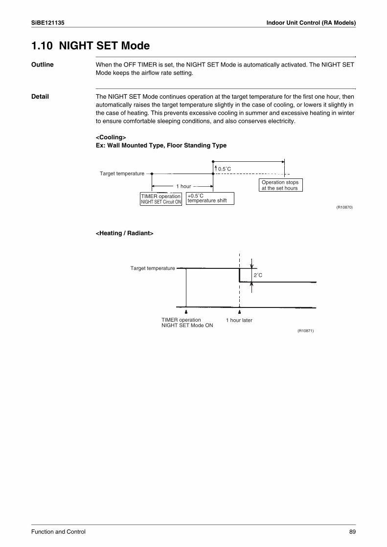
SiBE121135 Indoor Unit Control (RA Models)
1.10 NIGHT SET Mode
Outline When the OFF TIMER is set, the NIGHT SET Mode is automatically activated. The NIGHT SET Mode keeps the airflow rate setting.
Detail The NIGHT SET Mode continues operation at the target temperature for the first one hour, then automatically raises the target temperature slightly in the case of cooling, or lowers it slightly in the case of heating. This prevents excessive cooling in summer and excessive heating in winter to ensure comfortable sleeping conditions, and also conserves electricity.
<Cooling>Ex: Wall Mounted Type, Floor Standing Type
<Heating / Radiant>
(R10870)
TIMER operation NIGHT SET Circuit ON
Target temperature
+0.5˚C temperature shift
Operation stops at the set hours1 hour
0.5˚C
2˚C
(R10871)
Target temperature
1 hour laterTIMER operation NIGHT SET Mode ON
Function and Control 89
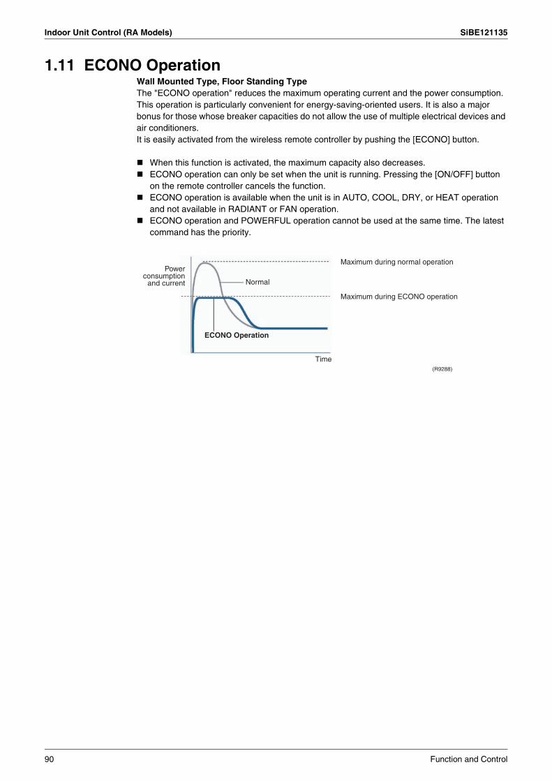
Indoor Unit Control (RA Models) SiBE121135
1.11 ECONO OperationWall Mounted Type, Floor Standing TypeThe "ECONO operation" reduces the maximum operating current and the power consumption.This operation is particularly convenient for energy-saving-oriented users. It is also a major bonus for those whose breaker capacities do not allow the use of multiple electrical devices and air conditioners.It is easily activated from the wireless remote controller by pushing the [ECONO] button.
When this function is activated, the maximum capacity also decreases.ECONO operation can only be set when the unit is running. Pressing the [ON/OFF] button on the remote controller cancels the function.ECONO operation is available when the unit is in AUTO, COOL, DRY, or HEAT operation and not available in RADIANT or FAN operation.ECONO operation and POWERFUL operation cannot be used at the same time. The latest command has the priority.
ECONO Operation
(R9288)
Normal
Maximum during normal operation
Maximum during ECONO operation
Time
Power consumption
and current
90 Function and Control

SiBE121135 Indoor Unit Control (RA Models)
1.12 HOME LEAVE Operation
Outline Floor / Ceiling Suspended Dual Type, Duct Connected TypeHOME LEAVE operation is a function that allows you to record your favorite set temperature and airflow rate. You can start your favorite operation mode simply by pressing the [HOME LEAVE] button on the remote controller.
Detail 1. Start of FunctionThe function starts when the [HOME LEAVE] button is pressed in cooling mode, heating mode (including POWERFUL operation), or while the operation is stopped. If this button is pressed in POWERFUL operation, the POWERFUL operation is canceled and this function becomes effective.
The [HOME LEAVE] button is ineffective in dry mode and fan mode.
2. Details of FunctionA mark representing HOME LEAVE is indicated on the display of the remote controller. The indoor unit is operated according to the set temperature and airflow rate for HOME LEAVE which were pre-set in the memory of the remote controller.The LED (red) of indoor unit representing HOME LEAVE lights up. (It goes out when the operation is stopped.)
3. End of FunctionThe function ends when the [HOME LEAVE] button is pressed again during HOME LEAVE operation or when the [POWERFUL] button is pressed.
Others The set temperature and airflow rate are memorized in the remote controller. When the remote controller is reset due to replacement of battery, it is necessary to set the temperature and airflow rate again for HOME LEAVE operation.
<Cooling>
HOME LEAVE operation
Start Stop (R1366)
Time
Set temp. Normal operation
“HOME LEAVE operation” set temp.
Normal operation
<Heating>
(R1367)
Time
Set temp.
“HOME LEAVE operation” set temp.
HOME LEAVE operation
Start Stop
Normal operation Normal operation
Function and Control 91

Indoor Unit Control (RA Models) SiBE121135
1.13 INTELLIGENT EYE Operation
Outline Wall Mounted Type: FTXG, FTXS-K, CTXS-K, FTXS-G SeriesThis function detects the existence of humans in the room with a human motion sensor (INTELLIGENT EYE) and reduces the capacity when there is nobody in the room in order to save electricity.
Detail 1. Detection method by INTELLIGENT EYE
The sensor detects human motion by receiving infrared rays and displays the pulse wave output.A microcomputer in an indoor unit carries out a sampling every 20 msec. and if it detects 10 cycles of the wave in 1 second in total (corresponding to 20 msec. × 10 = 200 msec.), it judges humans are in the room as the motion signal is ON.
2. The motions (for example: in cooling)
When the microcomputer does not have a signal from the sensor in 20 minutes, it judges that nobody is in the room and operates the unit at a temperature shifted from the target temperature. (Cooling / Dry : 1 ~ 2°C higher, Heating : 2°C lower, Auto : according to the operation mode at that time.)
In FAN operation, the fan speed is reduced by 60 rpm.
Others For dry operation, you cannot set the temperature with a remote controller, but the target temperature is shifted internally.
1 sec.sampling (20 msec.)
High
Low
ONOFF
Sensor output
(Human motion)
(R2821)
Human detection signal
If the sensor detects the outputs 10 times/sec. or more, it judges humans exist.
ONOFF
RESET.
20 min. 20 min.within 20 min.
ONOFF
ONOFF
Operation
OFF
Fan speed ( )
Set speed Set speed
Target temperature
(R15346)
Remote controller [INTELLIGENT EYE] button
Human detection signal
92 Function and Control

SiBE121135 Indoor Unit Control (RA Models)
1.14 2-Area INTELLIGENT EYE Operation
Outline Wall Mounted Type: FTXS-J SeriesThe following functions can be performed by a motion sensor (INTELLIGENT EYE).1. Reduction of the capacity when there is nobody in the room in order to save electricity
(energy saving operation)2. Dividing the room into plural areas and detecting existence of humans in each area.
Moving the airflow direction to the area with no human automatically to avoid direct airflow on humans.
Detail 1. Detection method of INTELLIGENT EYE
This sensor detects human motion by receiving infrared rays and displays the pulse wave output.The microcomputer in the indoor unit carries out a sampling every 20 msec. and if it detects 10 cycles of the wave in one second in total (corresponding to 20 msec.× 10 = 200 msec.), and when the ON signal continues 3 sec., it judges human is in the room as the motion signal is ON2-area INTELLIGENT EYE sensor is divided into 2 areas and detects humans in each area.
Image of 2-area INTELLIGENT EYE
1 secsampling (20 msec)
High
Low
ONOFF
Sensor output
(Human motion)
ONOFF
(R12757)
(Condition of 10 times or more output)
(Continue 3 sec.)
If the sensor detects the outputs 10 times/sec. or more, it judges humans exist.
If the detection signal (ON) continues 3 sec. or more, it judges humans exist.
Detection signal from the sensor
Human detection signal
Top view
(R12276)
Indoor unit
Wall
Area AArea B
· A microcomputer judges human existence by the sensor signal from each area A and B.
Function and Control 93

Indoor Unit Control (RA Models) SiBE121135
2. Motions (for example: in cooling)
When the microcomputer does not have a signal from the sensor in 20 minutes, it judges that nobody is in the room and operates the unit in temperature shifted from the target temperature. (Cooling / Dry : 2°C higher, Heating : 2°C lower, Auto : according to the operation mode at that time.)
In case of FAN operation, the fan speed reduces by 60 rpm.
3. Airflow direction in 2-area INTELLIGENT EYE operationDetection method: The opposite area of detected area is set as the target direction.
1. Detection signal ON in both area A and B: Shift the airflow direction to area B (left side)2. Detection signal ON in area A: Shift the airflow direction to area B (left side)3. Detection signal ON in area B: Shift the airflow direction to area A (right side)4. Detection signal OFF in both area A and B: No change
* When the detection signal is OFF for 20 minutes in both area A and B, the unit starts energy saving operation.
Others For dry operation, you cannot set the temperature with remote controller, but internally the target temperature is shifted.
ONOFF RESET.
(From area A or B)
20 min. 20 min.
ONOFF
ONOFF
Operation
OFFFan speed ( )
Set speed Set speed
Target temperature
(R15308)
Remote controller [INTELLIGENT EYE] button
ONOFF
INTELLIGENT EYE lamp
within 20 minutes
Human detection signal
Top view
Wall
Indoor unit
Area AArea B
Left Right
Human
(R3853)
94 Function and Control
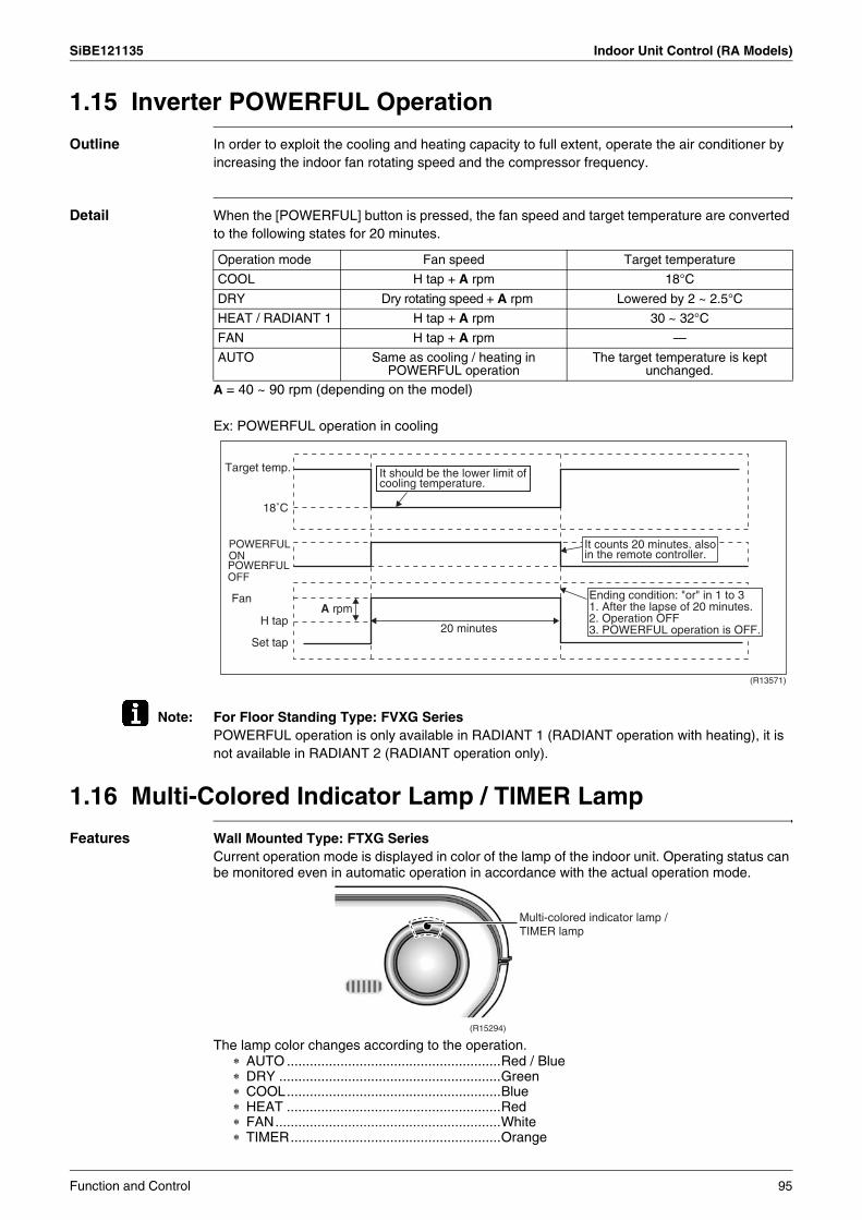
SiBE121135 Indoor Unit Control (RA Models)
1.15 Inverter POWERFUL Operation
Outline In order to exploit the cooling and heating capacity to full extent, operate the air conditioner by increasing the indoor fan rotating speed and the compressor frequency.
Detail When the [POWERFUL] button is pressed, the fan speed and target temperature are converted to the following states for 20 minutes.
A = 40 ~ 90 rpm (depending on the model)
Ex: POWERFUL operation in cooling
Note: For Floor Standing Type: FVXG SeriesPOWERFUL operation is only available in RADIANT 1 (RADIANT operation with heating), it is not available in RADIANT 2 (RADIANT operation only).
1.16 Multi-Colored Indicator Lamp / TIMER Lamp
Features Wall Mounted Type: FTXG SeriesCurrent operation mode is displayed in color of the lamp of the indoor unit. Operating status can be monitored even in automatic operation in accordance with the actual operation mode.
The lamp color changes according to the operation.∗ AUTO ........................................................Red / Blue∗ DRY ..........................................................Green∗ COOL........................................................Blue∗ HEAT ........................................................Red∗ FAN...........................................................White∗ TIMER.......................................................Orange
Operation mode Fan speed Target temperature
COOL H tap + A rpm 18°C
DRY Dry rotating speed + A rpm Lowered by 2 ~ 2.5°C
HEAT / RADIANT 1 H tap + A rpm 30 ~ 32°C
FAN H tap + A rpm —
AUTO Same as cooling / heating in POWERFUL operation
The target temperature is kept unchanged.
(R13571)
Target temp.
FanA rpm
18˚C
H tap
Set tap20 minutes
It should be the lower limit of cooling temperature.
It counts 20 minutes. also in the remote controller.
POWERFUL ONPOWERFUL OFF
Ending condition: "or" in 1 to 31. After the lapse of 20 minutes.2. Operation OFF3. POWERFUL operation is OFF.
(R15294)
Multi-colored indicator lamp / TIMER lamp
Function and Control 95
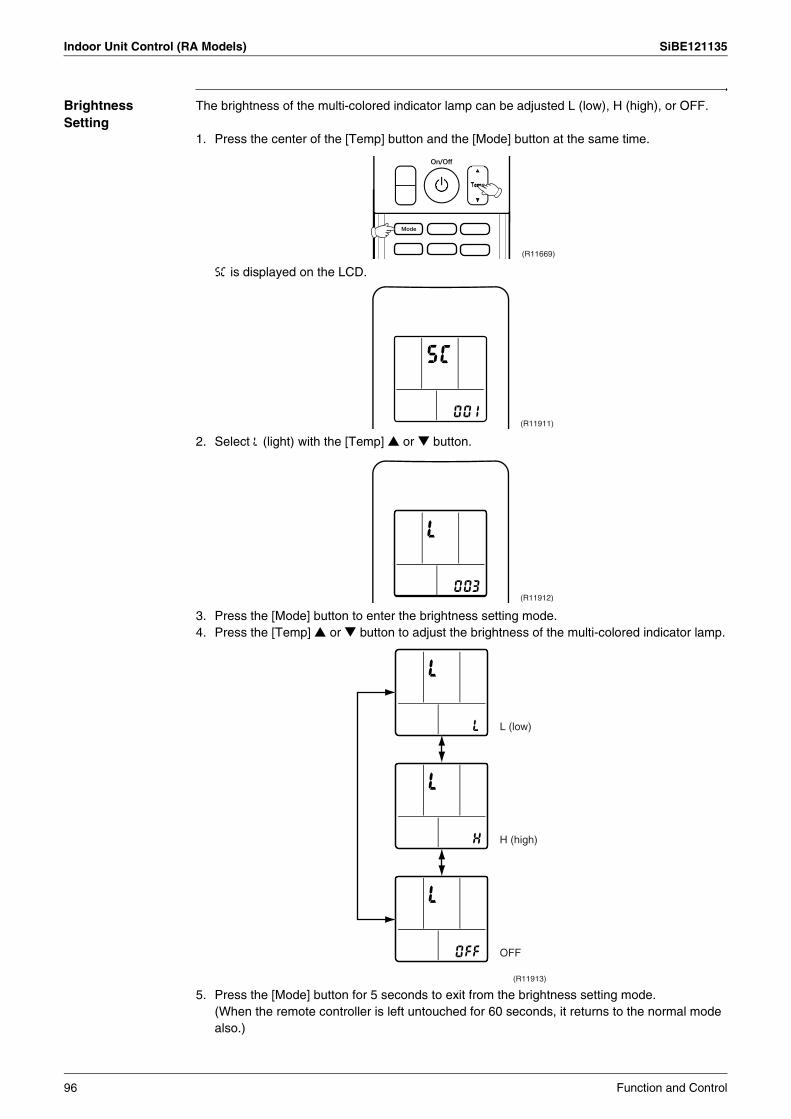
Indoor Unit Control (RA Models) SiBE121135
Brightness Setting
The brightness of the multi-colored indicator lamp can be adjusted L (low), H (high), or OFF.
1. Press the center of the [Temp] button and the [Mode] button at the same time.
5C is displayed on the LCD.
2. Select L (light) with the [Temp] or button.
3. Press the [Mode] button to enter the brightness setting mode.4. Press the [Temp] or button to adjust the brightness of the multi-colored indicator lamp.
5. Press the [Mode] button for 5 seconds to exit from the brightness setting mode.(When the remote controller is left untouched for 60 seconds, it returns to the normal mode also.)
(R11669)
(R11911)
(R11912)
L (low)
H (high)
OFF
(R11913)
96 Function and Control

SiBE121135 Indoor Unit Control (RA Models)
1.17 Other Functions1.17.1 Hot-Start Function
In order to prevent the cold air blast that normally comes when heating operation is started, the temperature of the indoor heat exchanger is detected, and the airflow is either stopped or made very weak thereby carrying out comfortable heating of the room.∗ The cold air blast is also prevented using similar control when the defrosting operation is started or when the thermostat is turned ON.
1.17.2 Signal Receiving SignWhen the indoor unit receives a signal from the remote controller, the unit emits a signal receiving sound.
1.17.3 Indoor Unit [ON/OFF] ButtonAn [ON/OFF] button is provided on the display of the unit.
Press the [ON/OFF] button once to start operation. Press once again to stop it.The [ON/OFF] button is useful when the remote controller is missing or the battery has run out.The operation mode refers to the following table.
In the case of multi system operation, there are times when the unit does not activate with the [ON/OFF] button.
Ex: Wall mounted type FTXS-J series
Note: When the [ON/OFF] button is pressed for 10 seconds or more, the forced operation is stopped.
1.17.4 Titanium Apatite Photocatalytic Air-Purifying FilterThis filter combines the Air-Purifying Filter and Titanium Apatite Photocatalytic Deodorizing Filter as a single highly effective filter. The filter traps microscopic particles, decomposes odors and even deactivates bacteria and viruses. It lasts for 3 years without replacement if washed about once every 6 months.
1.17.5 Photocatalytic Deodorizing FilterThe photocatalytic deodorizing filter powerfully decomposes odor of tobacco, pet, etc. The deodorizing power is regenerated simply by being exposed to the sunshine. It is recommended to dry the filter in the sun for about 6 hours (after vacuuming the filter) every 6 months.
1.17.6 Air-Purifying FilterThe air-purifying filter collects tobacco smoke, pollen, etc. with electrostatic agency.This filter includes a deodorizing active carbon filter that removes minute particles of odor.Replace the air-purifying filter every 3 months.
Operation mode Temperature setting Airflow rate
Cooling Only COOL 22°C Automatic
Heat Pump AUTO 25°C Automatic
(R8302)
[ON/OFF] button
Function and Control 97
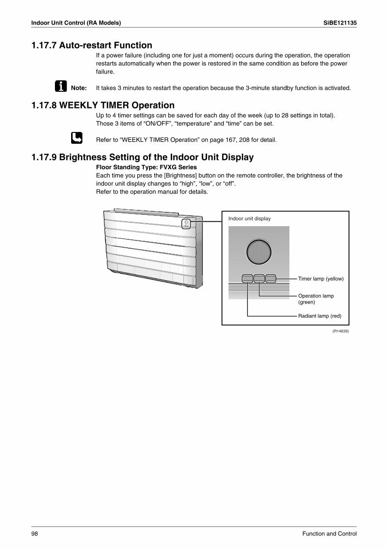
Indoor Unit Control (RA Models) SiBE121135
1.17.7 Auto-restart FunctionIf a power failure (including one for just a moment) occurs during the operation, the operation restarts automatically when the power is restored in the same condition as before the power failure.
Note: It takes 3 minutes to restart the operation because the 3-minute standby function is activated.
1.17.8 WEEKLY TIMER OperationUp to 4 timer settings can be saved for each day of the week (up to 28 settings in total). Those 3 items of “ON/OFF”, “temperature” and “time” can be set.
Refer to “WEEKLY TIMER Operation” on page 167, 208 for detail.
1.17.9 Brightness Setting of the Indoor Unit DisplayFloor Standing Type: FVXG SeriesEach time you press the [Brightness] button on the remote controller, the brightness of the indoor unit display changes to “high”, “low”, or “off”.Refer to the operation manual for details.
Timer lamp (yellow)
Radiant lamp (red)
Indoor unit display
(R14639)
Operation lamp (green)
98 Function and Control

SiBE121135 Indoor Unit Control (SA Models)
2. Indoor Unit Control (SA Models)2.1 Drain Pump Control2.1.1 When the Float Switch is Tripped While the Cooling Thermostat is
ON:
∗1. (Normal operation):The purpose of residual operation is to completely drain any moisture adhering to the fin of the indoor heat exchanger when the thermostat goes off during cooling operation. ∗2. (Malfunction residual):The remote controller displays A3 and the air conditioner comes to an abnormal stop in 5 minutes if the float switch is turned OFF while the cooling thermostat is ON.
2.1.2 When the Float Switch is Tripped While the Cooling Thermostat is OFF:
∗3. (Malfunction residual):The remote controller displays A3 and the air conditioner comes to an abnormal stop if the float switch is turned OFF and not turned ON again within 5 minutes while the cooling thermostat is OFF.
Float switch
The remote controller displays A3 and the indoor unit stops.
∗2) Malfunction residual∗1) Normal operation
5 min. 5 sec.5 min.
Drain pump
Thermostat(running)
(R16092)
ON
ON
OFF
OFF
ON
OFF
Float switch
Drain pump
Thermostat(running)
ON
ON
OFF
OFF
ON
OFF
The indoor unit enters malfunction treatment if the float switch is not reset within 5 minutes.
The remote controller displays A3 and the indoor unit stops.
∗3
5 sec. 5 sec.5 min.5 min.
(R16093)
Function and Control 99
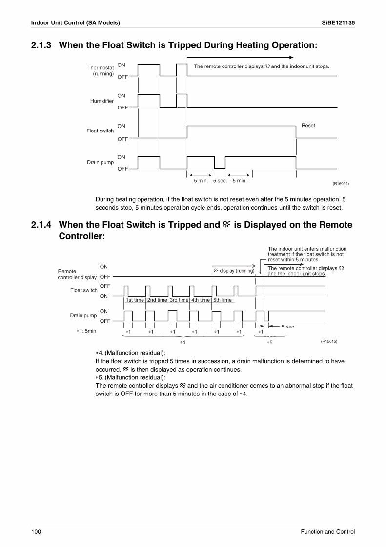
Indoor Unit Control (SA Models) SiBE121135
2.1.3 When the Float Switch is Tripped During Heating Operation:
During heating operation, if the float switch is not reset even after the 5 minutes operation, 5 seconds stop, 5 minutes operation cycle ends, operation continues until the switch is reset.
2.1.4 When the Float Switch is Tripped and AF is Displayed on the Remote Controller:
∗4. (Malfunction residual):If the float switch is tripped 5 times in succession, a drain malfunction is determined to have occurred. AF is then displayed as operation continues. ∗5. (Malfunction residual):The remote controller displays A3 and the air conditioner comes to an abnormal stop if the float switch is OFF for more than 5 minutes in the case of ∗4.
The remote controller displays A3 and the indoor unit stops.
Reset
Thermostat (running)
Humidifier
Float switch
Drain pump
ON
ON
ON
ON
OFF
OFF
OFF
OFF
(R16094)5 min. 5 min.5 sec.
The indoor unit enters malfunction treatment if the float switch is not reset within 5 minutes.
The remote controller displays A3 and the indoor unit stops.AF display (running)
5 sec.
∗5∗4
∗1 ∗1 ∗1 ∗1 ∗1 ∗1 ∗1
Drain pump
∗1: 5min
Float switch
Remote controller display
ON
ON
ON
OFF
OFF
OFF
4th time 5th time3rd time2nd time1st time
(R15615)
100 Function and Control
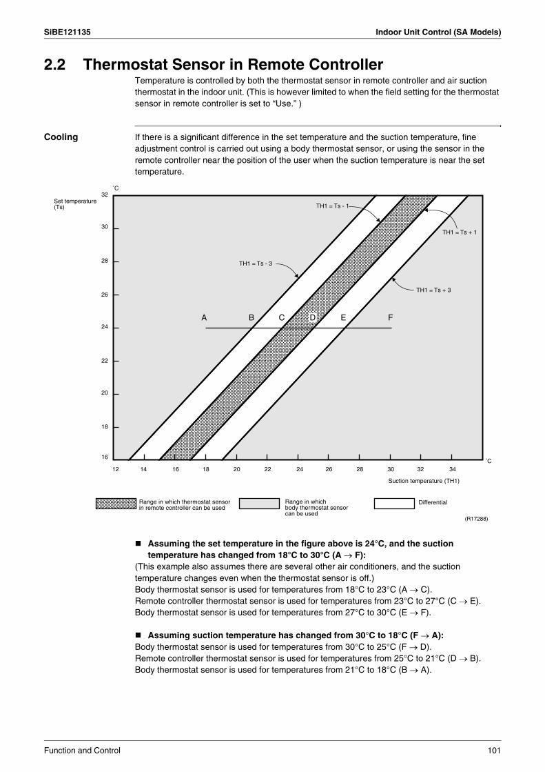
SiBE121135 Indoor Unit Control (SA Models)
2.2 Thermostat Sensor in Remote ControllerTemperature is controlled by both the thermostat sensor in remote controller and air suction thermostat in the indoor unit. (This is however limited to when the field setting for the thermostat sensor in remote controller is set to “Use.” )
Cooling If there is a significant difference in the set temperature and the suction temperature, fine adjustment control is carried out using a body thermostat sensor, or using the sensor in the remote controller near the position of the user when the suction temperature is near the set temperature.
Assuming the set temperature in the figure above is 24°C, and the suction temperature has changed from 18°C to 30°C (A → F):
(This example also assumes there are several other air conditioners, and the suction temperature changes even when the thermostat sensor is off.)Body thermostat sensor is used for temperatures from 18°C to 23°C (A → C).Remote controller thermostat sensor is used for temperatures from 23°C to 27°C (C → E).Body thermostat sensor is used for temperatures from 27°C to 30°C (E → F).
Assuming suction temperature has changed from 30°C to 18°C (F → A): Body thermostat sensor is used for temperatures from 30°C to 25°C (F → D).Remote controller thermostat sensor is used for temperatures from 25°C to 21°C (D → B).Body thermostat sensor is used for temperatures from 21°C to 18°C (B → A).
Set temperature (Ts)
32
30
28
26
24
22
20
18
16
˚C
˚C
TH1 = Ts - 1
TH1 = Ts + 1
TH1 = Ts + 3
TH1 = Ts - 3
A B C D E F
12 14 16 18 20 22 24 26 28 30 32 34
Range in which thermostat sensor in remote controller can be used
Range in which body thermostat sensor can be used
Suction temperature (TH1)
Differential
(R17288)
Function and Control 101
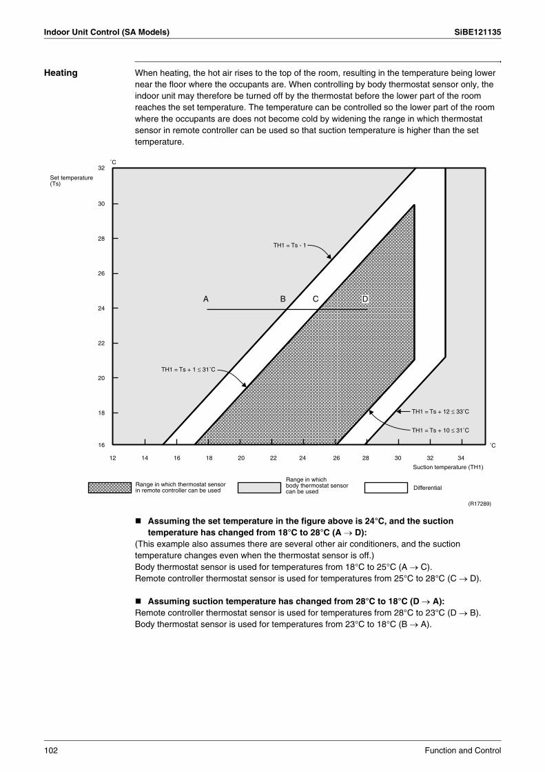
Indoor Unit Control (SA Models) SiBE121135
Heating When heating, the hot air rises to the top of the room, resulting in the temperature being lower near the floor where the occupants are. When controlling by body thermostat sensor only, the indoor unit may therefore be turned off by the thermostat before the lower part of the room reaches the set temperature. The temperature can be controlled so the lower part of the room where the occupants are does not become cold by widening the range in which thermostat sensor in remote controller can be used so that suction temperature is higher than the set temperature.
Assuming the set temperature in the figure above is 24°C, and the suction temperature has changed from 18°C to 28°C (A → D):
(This example also assumes there are several other air conditioners, and the suction temperature changes even when the thermostat sensor is off.)Body thermostat sensor is used for temperatures from 18°C to 25°C (A → C).Remote controller thermostat sensor is used for temperatures from 25°C to 28°C (C → D).
Assuming suction temperature has changed from 28°C to 18°C (D → A): Remote controller thermostat sensor is used for temperatures from 28°C to 23°C (D → B).Body thermostat sensor is used for temperatures from 23°C to 18°C (B → A).
Set temperature (Ts)
32
30
28
26
24
22
20
18
16
12 14 16 18 20 22 24 26 28 30 32 34
˚C
˚C
TH1 = Ts - 1
A B C D
TH1 = Ts + 1 ≤ 31˚C
TH1 = Ts + 12 ≤ 33˚C
TH1 = Ts + 10 ≤ 31˚C
Suction temperature (TH1)
Range in which thermostat sensor in remote controller can be used
Range in which body thermostat sensor can be used
Differential
(R17289)
102 Function and Control
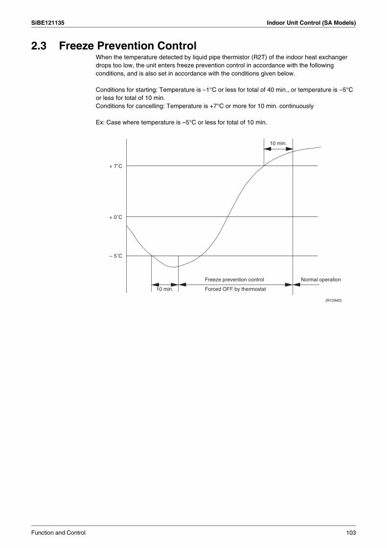
SiBE121135 Indoor Unit Control (SA Models)
2.3 Freeze Prevention ControlWhen the temperature detected by liquid pipe thermistor (R2T) of the indoor heat exchanger drops too low, the unit enters freeze prevention control in accordance with the following conditions, and is also set in accordance with the conditions given below.
Conditions for starting: Temperature is –1°C or less for total of 40 min., or temperature is –5°C or less for total of 10 min. Conditions for cancelling: Temperature is +7°C or more for 10 min. continuously
Ex: Case where temperature is –5°C or less for total of 10 min.
Freeze prevention control Normal operation
Forced OFF by thermostat10 min.
– 5˚C
+ 0˚C
+ 7˚C
10 min.
(R12940)
Function and Control 103
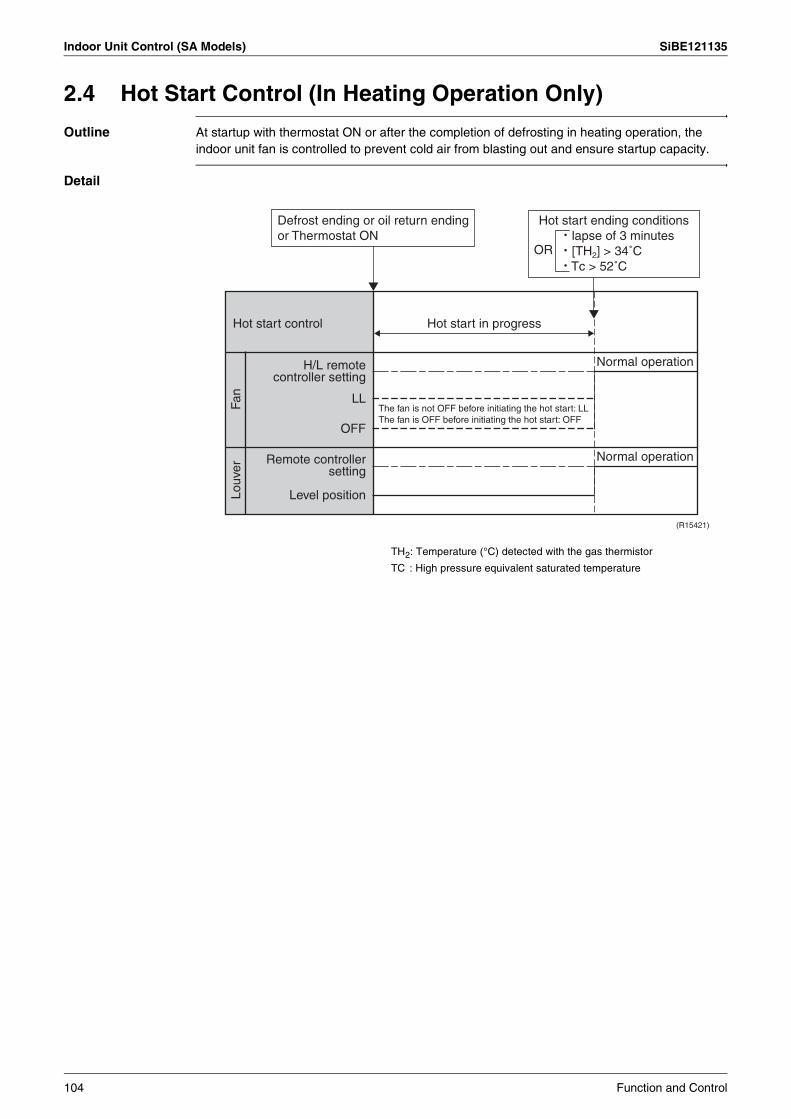
Indoor Unit Control (SA Models) SiBE121135
2.4 Hot Start Control (In Heating Operation Only)
Outline At startup with thermostat ON or after the completion of defrosting in heating operation, the indoor unit fan is controlled to prevent cold air from blasting out and ensure startup capacity.
Detail
TH2: Temperature (°C) detected with the gas thermistor
TC : High pressure equivalent saturated temperature
Defrost ending or oil return ending or Thermostat ON
The fan is not OFF before initiating the hot start: LLThe fan is OFF before initiating the hot start: OFF
Hot start control Hot start in progress
Normal operation
Normal operation
H/L remote controller setting
LL
OFF
Remote controller setting
Level position
Fan
Louv
erHot start ending conditions
· lapse of 3 minutes· [TH2] > 34˚C· Tc > 52˚C
OR
(R15421)
104 Function and Control
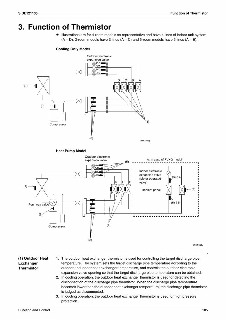
SiBE121135 Function of Thermistor
3. Function of ThermistorIllustrations are for 4-room models as representative and have 4 lines of indoor unit system (A ~ D). 3-room models have 3 lines (A ~ C) and 5-room models have 5 lines (A ~ E).
Cooling Only Model
Heat Pump Model
(1) Outdoor Heat Exchanger Thermistor
1. The outdoor heat exchanger thermistor is used for controlling the target discharge pipe temperature. The system sets the target discharge pipe temperature according to the outdoor and indoor heat exchanger temperature, and controls the outdoor electronic expansion valve opening so that the target discharge pipe temperature can be obtained.
2. In cooling operation, the outdoor heat exchanger thermistor is used for detecting the disconnection of the discharge pipe thermistor. When the discharge pipe temperature becomes lower than the outdoor heat exchanger temperature, the discharge pipe thermistor is judged as disconnected.
3. In cooling operation, the outdoor heat exchanger thermistor is used for high pressure protection.
EVCEVD
EVBEVA
Compressor
(1)
(2)
(3)
(4)
(R17248)
D C B A
Outdoor electronic expansion valve
Four way valve
Compressor
EVCEVD
EVBEVA
(1)
(2)
(3)
(4)
(5)
(R17159)
D C B
Radiant panel
A: In case of FVXG model
Indoor electronic expansion valve (Motor operated valve)
(4)
(6) φ 6
(6) φ 4
Outdoor electronic expansion valve
Function and Control 105
Function of Thermistor SiBE121135
(2) Discharge Pipe Thermistor
1. The discharge pipe thermistor is used for controlling discharge pipe temperature. If the discharge pipe temperature (used in place of the inner temperature of the compressor) rises abnormally, the operating frequency becomes lower or the operation halts.
2. The discharge pipe thermistor is used for detecting disconnection of the discharge pipe thermistor.
(3) Gas Pipe Thermistor
1. In cooling operation, the gas pipe thermistor is used for gas pipe isothermal control. The system controls outdoor electronic expansion valve opening so that the gas pipe temperature in each room becomes equal.
(4) Indoor Heat Exchanger Thermistor
1. The indoor heat exchanger thermistor is used for controlling the target discharge pipe temperature. The system sets the target discharge pipe temperature according to the outdoor and indoor heat exchanger temperature, and controls the outdoor electronic expansion valve opening so that the target discharge pipe temperature can be obtained.
2. In cooling operation, the indoor heat exchanger thermistor is used for freeze-up protection control. If the indoor heat exchanger temperature drops abnormally, the operating frequency becomes lower or the operation halts.
3. In cooling operation, the indoor heat exchanger thermistor is used for anti-icing function. If any of the following conditions are met in the room where operation halts, it is assumed as icing.The conditions are
Tc ≤ – 1° CTa – Tc ≥ 10° C
where Ta is the room temperature and Tc is the indoor heat exchanger temperature.4. In heating operation, the indoor heat exchanger thermistor is used for heating peak-cut
control. If the indoor heat exchanger temperature rises abnormally, the operating frequency becomes lower or the operation halts.
5. In heating operation, the indoor heat exchanger thermistor is used for detecting the disconnection of the discharge pipe thermistor. When the discharge pipe temperature becomes lower than the maximum indoor heat exchanger temperature, the discharge pipe thermistor is judged as disconnected.
6. When only one indoor unit is operating, the indoor heat exchanger thermistor is used for subcooling control. The actual subcool is calculated with the liquid pipe temperature and the indoor heat exchanger temperature. The system controls the outdoor electronic expansion valve openings to obtain the target subcool.
7. The indoor heat exchanger thermistor is used for wiring error check function. The refrigerant flows in order from the port A to detect the indoor heat exchanger temperature one by one, and then wiring and piping can be checked.
(5) Liquid Pipe Thermistor
1. When only one indoor unit is in heating, the liquid pipe thermistor is used for subcooling control. The actual subcool is calculated with the liquid pipe temperature and the maximum indoor heat exchanger temperature. The system controls the outdoor electronic expansion valve openings to obtain the target subcool.
2. In heating operation, the liquid pipe thermistor is used for liquid pipes isothermal control. The system controls the outdoor electronic expansion valve opening so that the liquid pipe temperatures in each room becomes equal.
(6) Radiant Panel Thermistors
1. The radiant panel thermistors are used for calculating radiant panel surface temperature. Due to structural and manufactural restrictions, the radiant panel surface temperature cannot be controlled directly with a thermistor. Thermistors are mounted on the radiant panel piping in order to calculate the radiant panel surface temperature.The indoor electronic expansion valve is controlled according to the radiant panel surface temperature.
2. The radiant panel thermistors are used for detecting malfunction of the indoor electronic expansion valve.
106 Function and Control
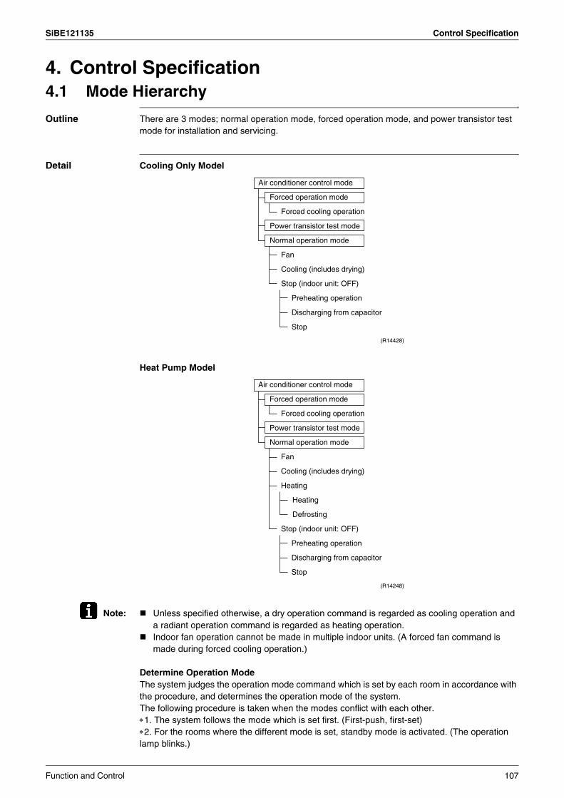
SiBE121135 Control Specification
4. Control Specification4.1 Mode Hierarchy
Outline There are 3 modes; normal operation mode, forced operation mode, and power transistor test mode for installation and servicing.
Detail Cooling Only Model
Heat Pump Model
Note: Unless specified otherwise, a dry operation command is regarded as cooling operation and a radiant operation command is regarded as heating operation.Indoor fan operation cannot be made in multiple indoor units. (A forced fan command is made during forced cooling operation.)
Determine Operation ModeThe system judges the operation mode command which is set by each room in accordance with the procedure, and determines the operation mode of the system. The following procedure is taken when the modes conflict with each other.∗1. The system follows the mode which is set first. (First-push, first-set)∗2. For the rooms where the different mode is set, standby mode is activated. (The operation lamp blinks.)
(R14428)
Air conditioner control mode
Forced operation mode
Forced cooling operation
Power transistor test mode
Normal operation mode
Fan
Cooling (includes drying)
Stop (indoor unit: OFF)
Preheating operation
Discharging from capacitor
Stop
Air conditioner control mode
Forced operation mode
Forced cooling operation
Power transistor test mode
Normal operation mode
Fan
Cooling (includes drying)
Heating
Heating
Defrosting
Stop (indoor unit: OFF)
Preheating operation
Discharging from capacitor
Stop
(R14248)
Function and Control 107

Control Specification SiBE121135
4.2 Frequency Control
Outline Frequency that corresponds to each room’s capacity is determined according to the difference between the target temperature and the temperature of each room. The function is explained as follows.1. How to determine frequency2. Frequency command from an indoor unit (Difference between a room thermistor
temperature and the target temperature)3. Frequency command from an indoor unit (The ranked capacity of the operating room)4. Frequency initial setting5. PI control
Detail How to Determine FrequencyThe compressor’s frequency is determined by taking the following steps.
For Cooling Only Model1. Determine command frequency
Command frequency is determined in the following order of priority.1. Forced cooling2. Indoor frequency command
2. Determine upper limit frequencyThe minimum value is set as the upper limit frequency among the frequency upper limits of the following functions: Compressor protection, input current, discharge pipe temperature, low Hz high pressure limit, freeze-up protection.
3. Determine lower limit frequencyThe maximum value is set as lower limit frequency among the frequency lower limits of the following functions: Draft prevention, pressure difference upkeep.
4. Determine prohibited frequencyThere is a certain prohibited frequency such as a power supply frequency.
Command frequency Limit frequency Skip control
Lower limit function Four way valve operating compensation (∗), etc.
Initial frequency PI control
Defrost control (∗)
Dropping function Input current control, etc.
Upper limit function Compressor protection function
Upper limit frequency FMAX
Lower limit frequency FMIN
Target frequency
(R16055)
When the shift of the frequency is less than zero (∆F<0) by PI control, the target frequency is used as the command frequency.
(∗): only for heat pump models
108 Function and Control

SiBE121135 Control Specification
For Heat Pump Model1. Determine command frequency
Command frequency is determined in the following order of priority.1. Limiting defrost control time2. Forced cooling / heating3. Indoor frequency command
2. Determine upper limit frequencyThe minimum value is set as upper limit frequency among the frequency upper limits of the following functions: Compressor protection, input current, discharge pipe temperature, low Hz high pressure limit, heating peak-cut, freeze-up protection, defrost.
3. Determine lower limit frequencyThe maximum value is set as the lower limit frequency among the frequency lower limits of the following functions: Four way valve operation compensation, draft prevention, pressure difference upkeep.
4. Determine prohibited frequencyThere is a certain prohibited frequency such as a power supply frequency.
Indoor Frequency Command (∆D signal)The difference between a room thermistor temperature and the target temperature is taken as the “∆D signal” and is used for frequency command.
Values depend on the type of indoor unit.∗Th OFF = Thermostat OFF
Indoor Unit Capacity (S value)The capacity of the indoor unit is a “S” value and is used for frequency command.
Frequency Initial Setting<Outline>When starting the compressor, or when conditions are varied due to the change of the operating room, the frequency must be initialized according to the total of a maximum ∆D value of each room and a total value of Q (ΣQ) of the operating room (the room in which the thermos is set to ON).Q value: Indoor unit output determined from indoor unit volume, airflow rate and other factors.
Temperature difference (°C)
∆D signal
Temperature difference (°C)
∆D signal
Temperature difference (°C)
∆D signal
Temperature difference (°C)
∆D signal
–2.0 ∗Th OFF
0 4 2.0 8 4.0 C
–1.5 1 0.5 5 2.5 9 4.5 D
–1.0 2 1.0 6 3.0 A 5.0 E
–0.5 3 1.5 7 3.5 B 5.5 F
Ex: Capacity S value Capacity S value
2.5 kW 25 5.0 kW 50
3.5 kW 35 6.0 kW 60
Function and Control 109
Control Specification SiBE121135
PI Control (Determine Frequency Up / Down by ∆D Signal)1. P control
A total of the ∆D value is calculated in each sampling time (20 seconds), and the frequency is adjusted according to its difference from the frequency previously calculated.
2. I controlIf the operating frequency is not change more than a certain fixed time, the frequency is adjusted according to the Σ∆D value.When the Σ∆D value is low, the frequency is lowered.When the Σ∆D value is high, the frequency is increased.
3. Limit of frequency increasing rangeWhen the difference between input current and input current dropping value is less than 1.5 A, the frequency increasing range must be limited.
4. Frequency management when other controls are functioningWhen each frequency is dropping; Frequency management is carried out only when the frequency drops.For limiting lower limit Frequency management is carried out only when the frequency rises.
5. Upper and lower limit of frequency by PI controlThe frequency upper and lower limits are set according to the total of S values. When the indoor unit quiet operation commands come from more than one room or when the outdoor unit quiet operation commands come from all the rooms, the upper limit frequency is lower than the usual setting.
110 Function and Control
SiBE121135 Control Specification
4.3 Controls at Mode Changing / Start-up4.3.1 Preheating Operation
Outline The inverter operation in open phase starts with the conditions of the preheating command from the outdoor unit.
Detail ON ConditionWhen the outdoor temperature is below 10.5°C, the inverter operation in open phase starts.
OFF ConditionWhen the outdoor temperature is higher than 12°C, the inverter operation in open phase stops.
4.3.2 Four Way Valve Switching
Outline In heating operation, current is conducted, and in cooling and defrosting operation, current is not conducted. In order to eliminate the switching sound, as the four way valve coil switches from ON to OFF when the heating is stopped, the OFF delay switch of the four way valve is carried out.
Detail OFF delay switch of four way valve: The four way valve coil is energized for 150 seconds after the operation is stopped.
4.3.3 Four Way Valve Operation Compensation
Outline At the beginning of the operation as the four way valve is switched, the pressure difference to activate the four way valve is acquired by having output frequency which is more than a certain fixed frequency, for a certain fixed time.
Detail Starting Conditions1. When starting the compressor for heating2. When the operation mode changes from the previous time3. When starting the compressor for defrosting4. When starting the compressor for the first time after resetting with the power ON.
The lower limit of frequency keeps A Hz for 70 seconds with any conditions 1 through 4 above.
4.3.4 3-Minute StandbyTurning on the compressor is prohibited for 3 minutes after turning off.(Except when defrosting.)
A (Hz)
40/50/52/58 class 48
68/75 class 40
80/90 class 28
Function and Control 111

Control Specification SiBE121135
4.3.5 Compressor Protection FunctionWhen turning the compressor from OFF to ON, the upper limit of frequency is set as follows. (The function is not used when defrosting.)
4.4 Discharge Pipe Temperature Control
Outline The discharge pipe temperature is used as the internal temperature of the compressor. If the discharge pipe temperature rises above a certain level, the upper limit of frequency is set to keep the discharge pipe temperature from rising further.
Detail
40/50/52/58 class 68/75/80/90 class
A (Hz) 55 55
B (Hz) 70 65
C (Hz) 85 80
D (seconds) 150 ~ 240 120
E (seconds) 180 200
F (seconds) 300 470
A
D E F
BC
(R13528)
(Hz) Frequency
(sec.) Time
Zone Control
Stop zone When the temperature reaches the stop zone, the compressor stops.
Dropping zone The upper limit of frequency decreases.
Keep zone The upper limit of frequency is kept.
Reset zone The upper limit of frequency is canceled.
68/75/80/90 class
120
111
109
107
107
40/50/52/58 class
110
103
102
100
95
A (˚C)
B (˚C)
C (˚C)
D (˚C)
E (˚C)
Reset zone
Stop zone
Dropping zone
Keep zone
(R14266)
A
C
D
E
B
Discharge pipe temperature
112 Function and Control
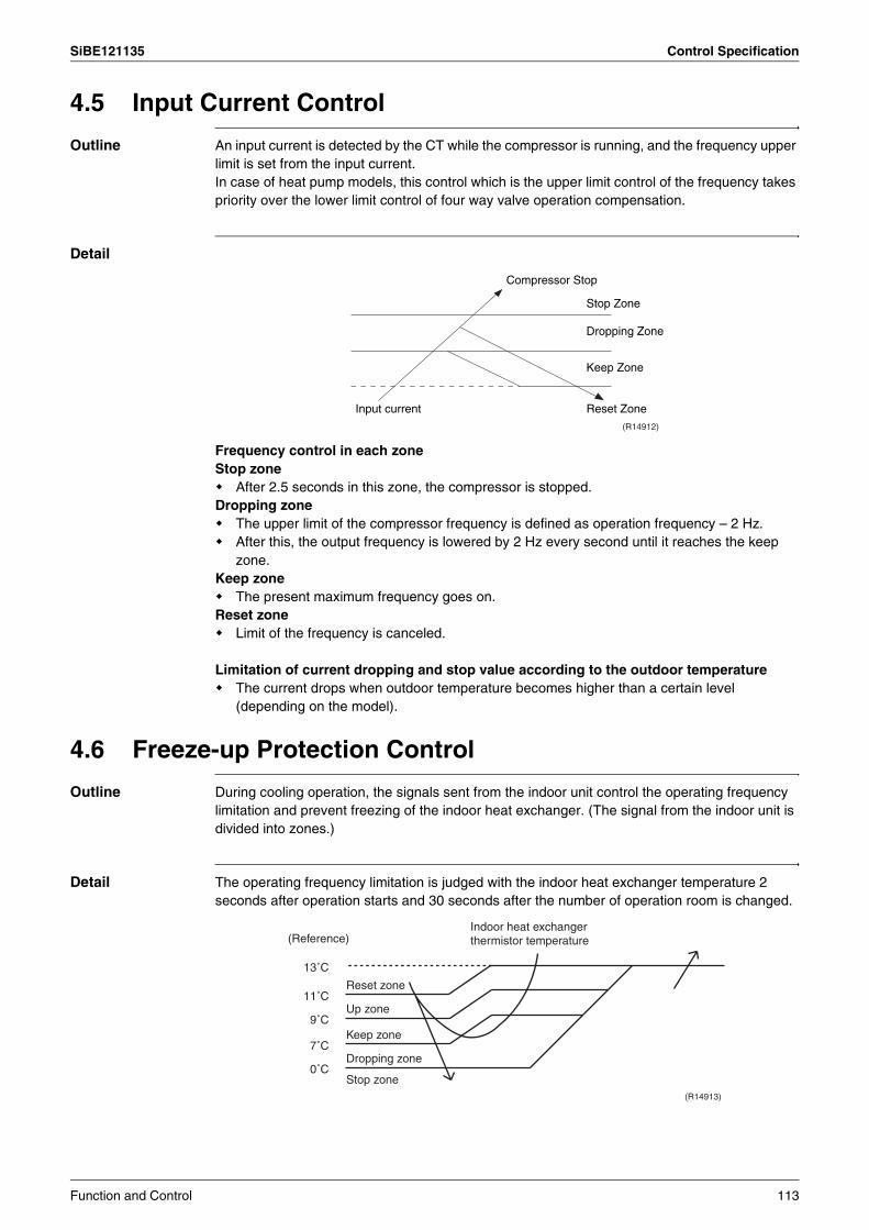
SiBE121135 Control Specification
4.5 Input Current Control
Outline An input current is detected by the CT while the compressor is running, and the frequency upper limit is set from the input current.In case of heat pump models, this control which is the upper limit control of the frequency takes priority over the lower limit control of four way valve operation compensation.
Detail
Frequency control in each zoneStop zone
After 2.5 seconds in this zone, the compressor is stopped.Dropping zone
The upper limit of the compressor frequency is defined as operation frequency – 2 Hz.After this, the output frequency is lowered by 2 Hz every second until it reaches the keep zone.
Keep zoneThe present maximum frequency goes on.
Reset zoneLimit of the frequency is canceled.
Limitation of current dropping and stop value according to the outdoor temperatureThe current drops when outdoor temperature becomes higher than a certain level (depending on the model).
4.6 Freeze-up Protection Control
Outline During cooling operation, the signals sent from the indoor unit control the operating frequency limitation and prevent freezing of the indoor heat exchanger. (The signal from the indoor unit is divided into zones.)
Detail The operating frequency limitation is judged with the indoor heat exchanger temperature 2 seconds after operation starts and 30 seconds after the number of operation room is changed.
Compressor Stop
Dropping Zone
Stop Zone
Keep Zone
Reset ZoneInput current
(R14912)
(R14913)
Reset zone
Up zone
Keep zone
Dropping zone
Stop zone0˚C
7˚C
9˚C
11˚C
13˚C
(Reference)Indoor heat exchanger thermistor temperature
Function and Control 113
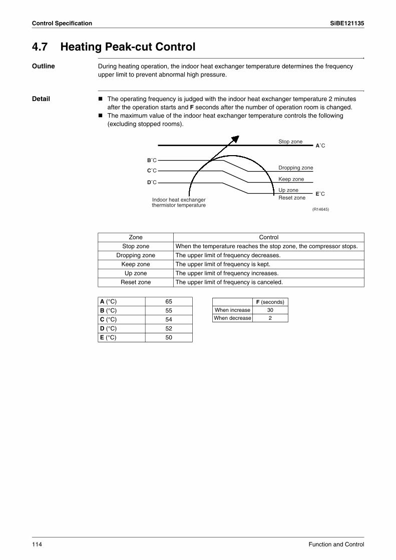
Control Specification SiBE121135
4.7 Heating Peak-cut Control
Outline During heating operation, the indoor heat exchanger temperature determines the frequency upper limit to prevent abnormal high pressure.
Detail The operating frequency is judged with the indoor heat exchanger temperature 2 minutes after the operation starts and F seconds after the number of operation room is changed.The maximum value of the indoor heat exchanger temperature controls the following (excluding stopped rooms).
Zone Control
Stop zone When the temperature reaches the stop zone, the compressor stops.
Dropping zone The upper limit of frequency decreases.
Keep zone The upper limit of frequency is kept.
Up zone The upper limit of frequency increases.
Reset zone The upper limit of frequency is canceled.
A (°C) 65
B (°C) 55
C (°C) 54
D (°C) 52
E (°C) 50
Indoor heat exchanger thermistor temperature
Stop zone
Dropping zone
Keep zone
Up zoneReset zone
(R14645)
D˚C
C˚C
B˚C
A˚C
E˚C
F (seconds)
30
2
When increase
When decrease
114 Function and Control
SiBE121135 Control Specification
4.8 Outdoor Fan Control1. Fan ON control to cool down the electrical boxThe outdoor fan is turned ON when the electrical box temperature is high while the compressor is OFF.
2. Fan OFF control during defrostingThe outdoor fan is turned OFF while defrosting.
3. Fan OFF delay when stoppedThe outdoor fan is turned OFF 60 seconds after the compressor stops.
4. Fan speed control for pressure difference upkeepThe rotation speed of the outdoor fan is controlled for keeping the pressure difference during cooling operation with low outdoor temperature.
When the pressure difference is low, the rotation speed of the outdoor fan is reduced.When the pressure difference is high, the rotation speed of the outdoor fan is controlled as well as normal operation.
5. Fan control when the number of heating room decreasesWhen the outdoor temperature is more than 10°C, the fan is turned off for 30 seconds.
6. Fan speed control during forced operationThe outdoor fan is controlled as well as normal operation during the forced operation.
7. Fan speed control during POWERFUL operationThe rotation speed of the outdoor fan is increased during the POWERFUL operation.
8. Fan speed control during indoor / outdoor unit quiet operationThe rotation speed of the outdoor fan is reduced by the command of the indoor / outdoor unit quiet operation.
9. Fan ON/OFF control when operation starts / stopsThe outdoor fan is turned ON when the operation starts. The outdoor fan is turned OFF when the operation stops.
4.9 Liquid Compression Protection Function
Outline In order to obtain the dependability of the compressor, the compressor is stopped according to the outdoor temperature and temperature of the outdoor heat exchanger.
Detail Operation stops depending on the outdoor temperatureThe compressor turns off under the conditions that the system is in cooling operation and outdoor temperature is below –12°C.
Function and Control 115

Control Specification SiBE121135
4.10 Defrost Control
Outline Defrosting is carried out by the cooling cycle (reverse cycle). The defrosting time or outdoor heat exchanger temperature must be more than a certain value to finish.
Detail Conditions for Starting DefrostThe starting conditions are determined with the outdoor temperature and the outdoor heat exchanger temperature.The system is in heating operation.The compressor operates for 6 minutes.More than 38 minutes of accumulated time pass after the start of the operation, or ending the previous defrosting.
Conditions for Canceling DefrostThe target heat exchanger temperature as the canceling condition is selected in the range of 4 ~ 12°C according to the outdoor temperature.
Frequency
Compressor
Four way valve
Fan
ON
OFF
ON
OFF
ON
OFF
0 Hz
A Hz
5 sec.
400 pulse350 pulse450 pulse
Initial opening
0 pulse
160 pulseInitial opening
PI control
5 sec.
60 sec.60 sec.
530 sec.
120 sec.
(R17160)
B Hz
40/50/52/58 class
62
80
68/75 class
54
82
80/90 class
39
62
A (Hz)
B (Hz)
Outdoor electronic expansion valve opening (operating room)
Outdoor electronic expansion valve opening (stop room)
116 Function and Control

SiBE121135 Control Specification
4.11 Low Hz High Pressure Limit
Outline The upper limit of high pressure in a low Hz zone is set. The upper limit of the indoor heat exchanger temperature is also set by the operating frequency. Zones are divided into three, reset zone, keep zone, and dropping zone, and the frequency control is carried out according to each zone.
Detail
Note: Dropping: The system stops 2 minutes after staying in the dropping zone.
4.12 Outdoor Electronic Expansion Valve Control
Outline The following items are included in the outdoor electronic expansion valve control.Outdoor electronic expansion valve is fully closed1. Outdoor electronic expansion valve is fully closed when turning on the power.2. Pressure equalizing controlRoom Distribution Control1. Gas pipe isothermal control2. SC (subcooling) control3. Liquid pipe temperature control (with all ports connected and all rooms being air-
conditioned)4. Liquid pipe temperature control for stopped rooms5. Dew prevention control for indoor rotorOpen Control1. Outdoor electronic expansion valve control when starting operation2. Outdoor electronic expansion valve control when the frequency changes3. Outdoor electronic expansion valve control for defrosting4. Outdoor electronic expansion valve control for oil recovery5. Outdoor electronic expansion valve control when a discharge pipe temperature is
abnormally high6. Outdoor electronic expansion valve control when the discharge pipe thermistor is
disconnected7. Outdoor electronic expansion valve control for indoor unit freeze-up protectionFeedback Control1. Target discharge pipe temperature control
40/50/52/58/68/75 class 80/90 class
A (°C) 60 57
B (°C) 59 56
C (°C) 56 53
A
B
CHighest indoor heat exchanger temperature among operating rooms
Reset zone
Dropping zone
Keep zone
(R14587)
Function and Control 117

Control Specification SiBE121135
Detail The followings are the examples of the outdoor electronic expansion valve control which function in each operation mode.
1: When all the indoor units are operating, “liquid pipe temperature control” is conducted.2 : “SC (subcooling) control” is conducted for the operating indoor units, when some of the units are not operating.3 : “Liquid pipe temperature control for stopped room” is conducted for the non-operating indoor units.
Fully closed when power is turned on
Open control when starting
(Control of target discharge pipe temperature)
Control when the operating room is changed
(Control of target discharge pipe temperature)
Pressure equalizing control
Open control when starting
(Control of target discharge pipe temperature)
Control when the operating room is changed
(Control of target discharge pipe temperature)
(Defrost control)
Pressure equalizing control
Open control when starting
Continue
Pressure equalizing control
Operation pattern
(R16007)
When power is turned on
Cooling, 1 room operation
Cooling, 2 rooms operation to Cooling, 4 rooms operation
Stop
Heating, 1 room operation
Heating, 2 rooms operation
Stop
Heating operation
Control of discharge pipe thermistor disconnection
Stop
—
—
—
—
—
—
—
—
—
—
—
—
—
—
—
—
—
—
—
—
—
—
—
—
—
—
—
—
—
—
—
—
—
—
—
—
—
—
—
—
—
—
—
—
—
—
—
—
—
—
—
—
—
—
—
—
—
—
—
—
—
—
—
—
—
—
—
—
—
—
—
—
2
—
2
—
—
—
2
—
—
—
—
—
—
—
—
1
—
1
—
—
—
1
—
—
—
—
—
—
—
—
3
—
3
—
—
—
3
—
Gas
pip
e is
othe
rmal
con
trol
SC
(su
bcoo
ling)
con
trol
Con
trol
whe
n th
e fr
eque
ncy
chan
ges
Con
trol
for
abno
rmal
ly h
igh
disc
harg
e pi
pe te
mpe
ratu
re
Oil
reco
very
con
trol
Indo
or fr
eeze
-up
prot
ectio
n co
ntro
l
Liqu
id p
ipe
tem
pera
ture
con
trol
Liqu
id p
ipe
tem
pera
ture
con
trol
for
non-
oper
atin
g un
its
Dew
pre
vent
ion
cont
rol f
or in
door
rot
or
: Holding Functions— : No Functions
118 Function and Control

SiBE121135 Control Specification
4.12.1 Fully Closing with Power onThe outdoor electronic expansion valve is initialized when the power is turned on. The opening position is set and the pressure equalization is developed.
4.12.2 Pressure Equalizing ControlWhen the compressor is stopped, the pressure equalizing control is activated. The outdoor electronic expansion valve opens, and develops the pressure equalization.
4.12.3 Opening Limit Control
Outline A maximum and minimum opening of the outdoor electronic expansion valve are limited.
Detail A maximum outdoor electronic expansion valve opening in the operating room: 450 pulsesA minimum outdoor electronic expansion valve opening in the operating room: 75 pulses
The outdoor electronic expansion valve is fully closed in the room where cooling is stopped and is opened at a fixed degree during defrosting.
4.12.4 Starting Operation Control / Changing Operation RoomThe outdoor electronic expansion valve opening is controlled when the operation starts, and prevents superheating or liquid compression.
4.12.5 Control when the Frequency ChangesWhen the target discharge pipe temperature control is active, if the target frequency is changed to a specified value in a certain time period, the target discharge pipe temperature control is canceled and the target opening of the outdoor electronic expansion valve is changed.
4.12.6 Oil Recovery Function
Outline The outdoor electronic expansion valve opening in the cooling stopped room is set as to open for a certain time at a specified interval so that the oil in the cooling stopped room may not be accumulated.
Detail During cooling operation, every 1 hour continuous operation, the outdoor electronic expansion valves in the operation stopped room is opened by 80 pulses for specified time.
4.12.7 High Discharge Pipe Temperature ControlWhen the compressor is operating, if the discharge pipe temperature exceeds a certain value, the outdoor electronic expansion valve opens and the refrigerant runs to the low pressure side.This procedure lowers the discharge pipe temperature.
Function and Control 119

Control Specification SiBE121135
4.12.8 Control for Disconnection of the Discharge Pipe Thermistor
Outline The disconnection of the discharge pipe thermistor is detected by comparing the discharge pipe temperature with the condensing temperature. If the discharge pipe thermistor is disconnected, the outdoor electronic expansion valve opens according to the outdoor temperature and the operation frequency, and operates for a specified time, and then stops.After 3 minutes, the operation restarts and checks if the discharge pipe thermistor is disconnected. If the discharge pipe thermistor is disconnected, the system stops after operating for a specified time.If the disconnection is detected repeatedly, the system is shut down. When the compressor runs for 60 minutes without any error, the error counter is reset.
Detail Detect DisconnectionWhen the starting control (660 ~ 810 seconds) finishes, the following adjustment is made.1. When the operation mode is cooling
When the following condition is fulfilled, the discharge pipe thermistor disconnection is ascertained.Discharge pipe temperature + 6°C < outdoor heat exchanger temperature
2. When the operation mode is heatingWhen the following condition is fulfilled, the discharge pipe thermistor disconnection is ascertained.Discharge pipe temperature + 6°C < highest indoor heat exchanger temperature
Adjustment when the thermistor is disconnectedWhen the disconnection is ascertained, the compressor continues operation for 9 minutes and then stops.If the compressor stops repeatedly, the system is shut down.
4.12.9 Gas Pipe Isothermal Control During CoolingWhen the units are operating in multiple rooms, the gas pipe temperature is detected and the outdoor electronic expansion valve opening is adjusted so that the temperature of the gas pipe in each room becomes equal.
When the gas pipe temperature > the average gas pipe temperature, → open the outdoor electronic expansion valve in that roomWhen the gas pipe temperature < the average gas pipe temperature, → close the outdoor electronic expansion valve in that room
The temperatures are monitored every 40 seconds.
4.12.10 SC (Subcooling) Control
Outline The liquid pipe temperature and the heat exchanger temperature are detected and the outdoor electronic expansion valve opening is compensated so that the SC of each room becomes the target SC.
When the actual SC is > target SC, open the outdoor electronic expansion valve of the room.When the actual SC is < target SC, close the outdoor electronic expansion valve of the room.
Detail Start ConditionsAfter finishing the starting control (660 ~ 810 seconds), (all) the outdoor electronic expansion valve(s) for the operating room is/are controlled.
Determine Outdoor Electronic Expansion Valve OpeningThe outdoor electronic expansion valve opening is adjusted so that the temperature difference between the maximum heat exchanger temperature of connected room and the liquid pipe temperature thermistor becomes constant.
120 Function and Control

SiBE121135 Control Specification
4.12.11Target Discharge Pipe Temperature ControlThe target discharge pipe temperature is obtained from the indoor and outdoor heat exchanger temperature, and the outdoor electronic expansion valve opening is adjusted so that the actual discharge pipe temperature becomes close to the target discharge pipe temperature. (Indirect SH (superheating) control using the discharge pipe temperature)
The outdoor electronic expansion valve opening and the target discharge pipe temperature are adjusted every 20 seconds. The target discharge pipe temperature is controlled by indoor heat exchanger temperature and outdoor heat exchanger temperature. The opening degree of the outdoor electronic expansion valve is controlled by the followings.
Target discharge pipe temperatureActual discharge pipe temperaturePrevious discharge pipe temperature
SC (Subcool)
SH (Superheat)
The target discharge pipe temperature is set as to become the aiming SH.
The inclination does not change depending on the operating condition.
(R14213)
Function and Control 121
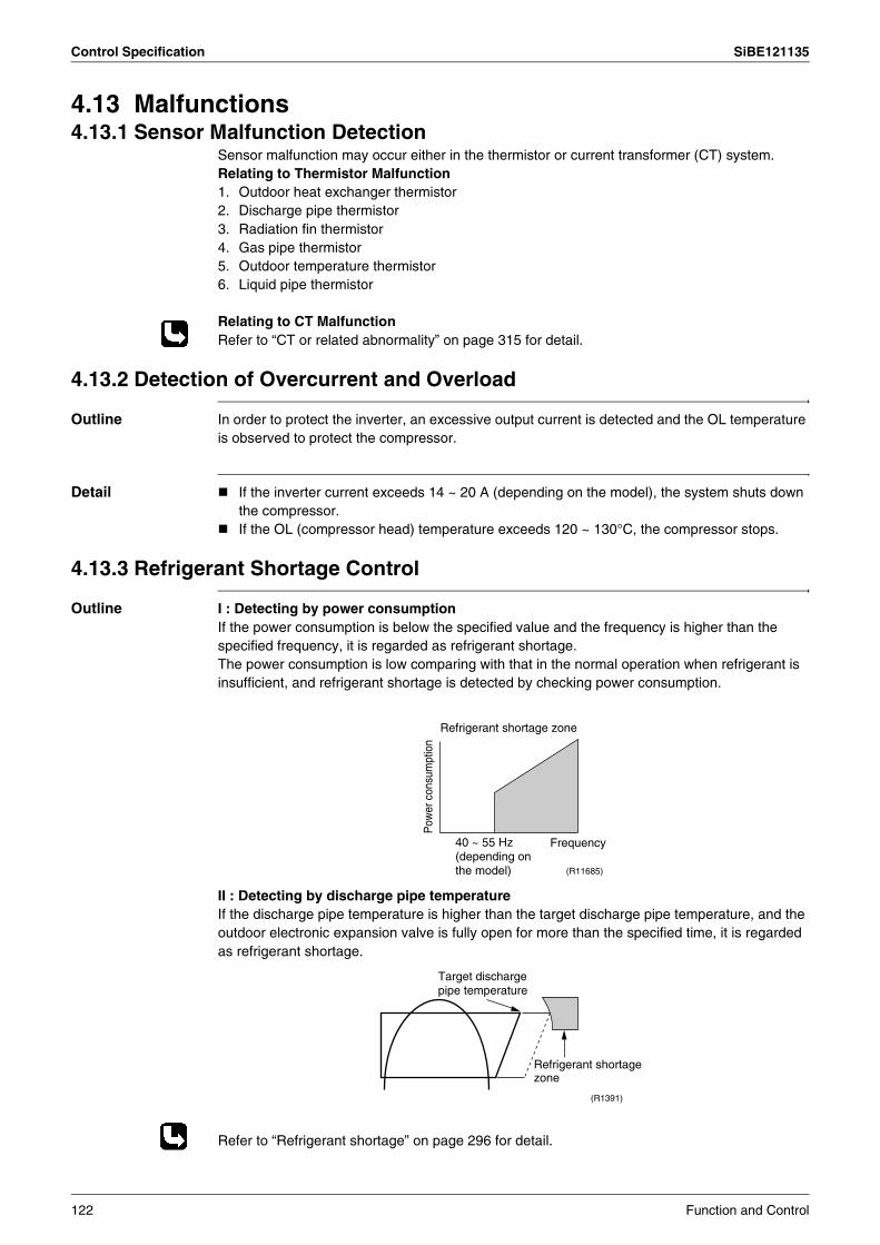
Control Specification SiBE121135
4.13 Malfunctions4.13.1 Sensor Malfunction Detection
Sensor malfunction may occur either in the thermistor or current transformer (CT) system.Relating to Thermistor Malfunction1. Outdoor heat exchanger thermistor2. Discharge pipe thermistor3. Radiation fin thermistor4. Gas pipe thermistor5. Outdoor temperature thermistor6. Liquid pipe thermistor
Relating to CT MalfunctionRefer to “CT or related abnormality” on page 315 for detail.
4.13.2 Detection of Overcurrent and Overload
Outline In order to protect the inverter, an excessive output current is detected and the OL temperature is observed to protect the compressor.
Detail If the inverter current exceeds 14 ~ 20 A (depending on the model), the system shuts down the compressor.If the OL (compressor head) temperature exceeds 120 ~ 130°C, the compressor stops.
4.13.3 Refrigerant Shortage Control
Outline I : Detecting by power consumptionIf the power consumption is below the specified value and the frequency is higher than the specified frequency, it is regarded as refrigerant shortage.The power consumption is low comparing with that in the normal operation when refrigerant is insufficient, and refrigerant shortage is detected by checking power consumption.
II : Detecting by discharge pipe temperatureIf the discharge pipe temperature is higher than the target discharge pipe temperature, and the outdoor electronic expansion valve is fully open for more than the specified time, it is regarded as refrigerant shortage.
Refer to “Refrigerant shortage” on page 296 for detail.
Frequency
Pow
er c
onsu
mpt
ion
Refrigerant shortage zone
(R11685)
40 ~ 55 Hz (depending on the model)
(R1391)
Refrigerant shortage zone
Target discharge pipe temperature
122 Function and Control

SiBE121135 Control Specification
4.13.4 Anti-icing FunctionDuring cooling, if the indoor heat exchanger temperature in the operation stopped room becomes below the specified temperature for the specified time, the outdoor electronic expansion valve is opened in the operation stopped room as specified, and the fully closed operation is carried out. After this, if freezing abnormality occurs more than specified time, the system shuts down as the system abnormality.
Function and Control 123
SiBE121135
124 Operation Manual
Part 5Operation Manual
1. System Configuration..........................................................................1252. RA Indoor Unit.....................................................................................126
2.1 FTXG, FTXS-K, CTXS, FVXG Series - ARC466A1, A2, A6 ................1262.2 FTXS-J, FTXS-G, FVXS Series - ARC452A1, A3................................1782.3 FLXS, FDXS Series - ARC433B67, B69 ..............................................218
3. SA Indoor Unit.....................................................................................2333.1 BRC1D528 ...........................................................................................233
SiBE121135 System Configuration
1. System ConfigurationAfter installation and trial operation of the room air conditioner are completed, the air conditioner should be handled and operated as described in the following pages. Every user should be informed on the correct method of operation and how to check if it can cool (or heat) well, and how to use it efficiently.
Providing instructions to the user can reduce requests for servicing by 80%. However proficient the installation and operating functions of the air conditioning system are, the customer may fault either the room air conditioner or its installation work when it is actually due to improper handling. The installation work and the handing-over of the unit can only be considered completed when its handling has been fully explained to the user without using technical terms, and while imparting full knowledge of the equipment.
Operation Manual 125
RA Indoor Unit SiBE121135
2. RA Indoor Unit2.1 FTXG, FTXS-K, CTXS, FVXG Series - ARC466A1, A2, A62.1.1 Manual Contents and Reference Page
1: Illustrations are for FTXS-K and CTXS-K series as representative.2: Illustrations are for FVXG series as representative.
Model SeriesWall Mounted Type Floor Standing Type
FTXG25-50JV1BW(A) FTXS20/25K2V1BCTXS15/35K2V1B FVXG25-50K2V1B
Read Before Operation
Names of Parts 127 131 135
Preparation before Operation 139 2 139 2 139
Operation
AUTO · DRY · COOL · HEAT · FAN Operation 141 143 145
RADIANT Operation — — 146
Temperature Setting — — 147
Adjusting the Airflow Direction and Rate 148 150 152
COMFORT AIRFLOW Operation 154 1 154 —
INTELLIGENT EYE Operation 155 1 155 —
POWERFUL Operation 157 1 157 158
OUTDOOR UNIT QUIET Operation 159 2 159 2 159
ECONO Operation 160 2 160 2 160
OFF TIMER Operation 161 162 163
ON TIMER Operation 164 165 166
WEEKLY TIMER Operation 167 2 167 2 167
Note for Multi System 173 173 173
Quick Reference 175 1 176 177
Drawing No. 3P255639-2A (Reference) 3P297033-1 3P276869-1
126 Operation Manual

SiBE121135 RA Indoor Unit
2.1.2 Name of Parts
FTXG25/35/50JV1BW(A)
Name of Parts
Indoor Unit
Air outlet
Louvers (vertical blades)
Orange
Blue
3 min.5 sec. 5 sec.
2 sec. 2 sec. 2 sec.Green
Blue
Red
White
Off
• Appearance of the indoor unit may differ.
Front panel
• The louvers are inside of the air outlet.
Flaps (horizontal blades)
Model name plate
Panel tab
• It detects the air temperature around the unit.
Room temperature sensor
• It detects the movements of people and automatically switches between normal operation and energy saving operation.
INTELLIGENT EYE sensor
Air inlet
INTELLIGENT EYE lamp (green)
Signal receiver and Indoor unit ON/OFF switch
• It receives signals from the remote controller.
• When the unit receives a signal, you will hear a beep sound.
Signal receiver
Sound type
beep-beep
beep
long beep
Indoor unit ON/OFF switch• Press this switch once to start operation.
Press once again to stop it.• The operation mode refer to the following table.
Temperature setting25˚C
Airflow rateAUTO
• This switch is useful when the remote controller is missing. Orange
Orange
Orange
Orange
Orange
TIMER lamp colourTIMER lamp colour : For COOL
TIMER lamp• When operation by timer has been set, the multi-monitor lamp
periodically changes to orange. After lighting orange for about 5 seconds, it returns to the colour of the operation mode.The multi-monitor lamp will turn orange on and off in cyclic manner while the air conditioner is not in operation.
Operation
AUTO
DRY
COOL
HEAT
FAN
TIMER
Multi-monitor lamp
Red/Blue
Green
Blue
Red
White
Orange
• The lamp colour changes according to the operation.
Multi-monitor lamp
Multi-monitor lamp and TIMER lamp
Display
ModeAUTO
Case
Operation start
Setting changed
Operation stop
DRY :
COOL :
HEAT :
FAN :
Stop :
Operation Manual 127
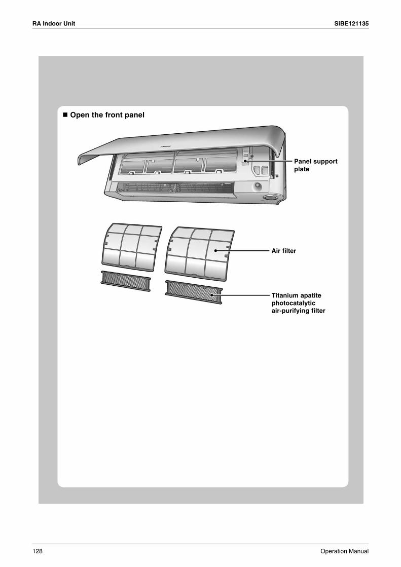
RA Indoor Unit SiBE121135
Open the front panel
Panel support plate
Air filter
Titanium apatite photocatalytic air-purifying filter
128 Operation Manual
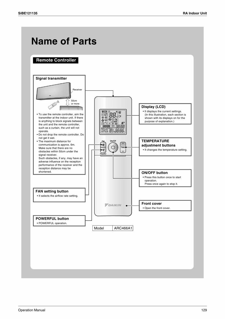
SiBE121135 RA Indoor Unit
Remote Controller
Name of Parts
Signal transmitter
Receiver
50cm or more
• To use the remote controller, aim the transmitter at the indoor unit. If there is anything to block signals between the unit and the remote controller, such as a curtain, the unit will not operate.
• Do not drop the remote controller. Do not get it wet.
• The maximum distance for communication is approx. 6m.Make sure that there are no obstacles within 50cm under the signal receiver.Such obstacles, if any, may have an adverse influence on the reception performance of the receiver and the reception distance may be shortened.
• It selects the airflow rate setting.
FAN setting button
• POWERFUL operation.
POWERFUL button
Model ARC466A1
• Open the front cover.
Front cover
• Press this button once to start operation.Press once again to stop it.
ON/OFF button
• It changes the temperature setting.
TEMPERATURE adjustment buttons
• It displays the current settings.(In this illustration, each section is shown with its displays on for the purpose of explanation.)
Display (LCD)
Operation Manual 129
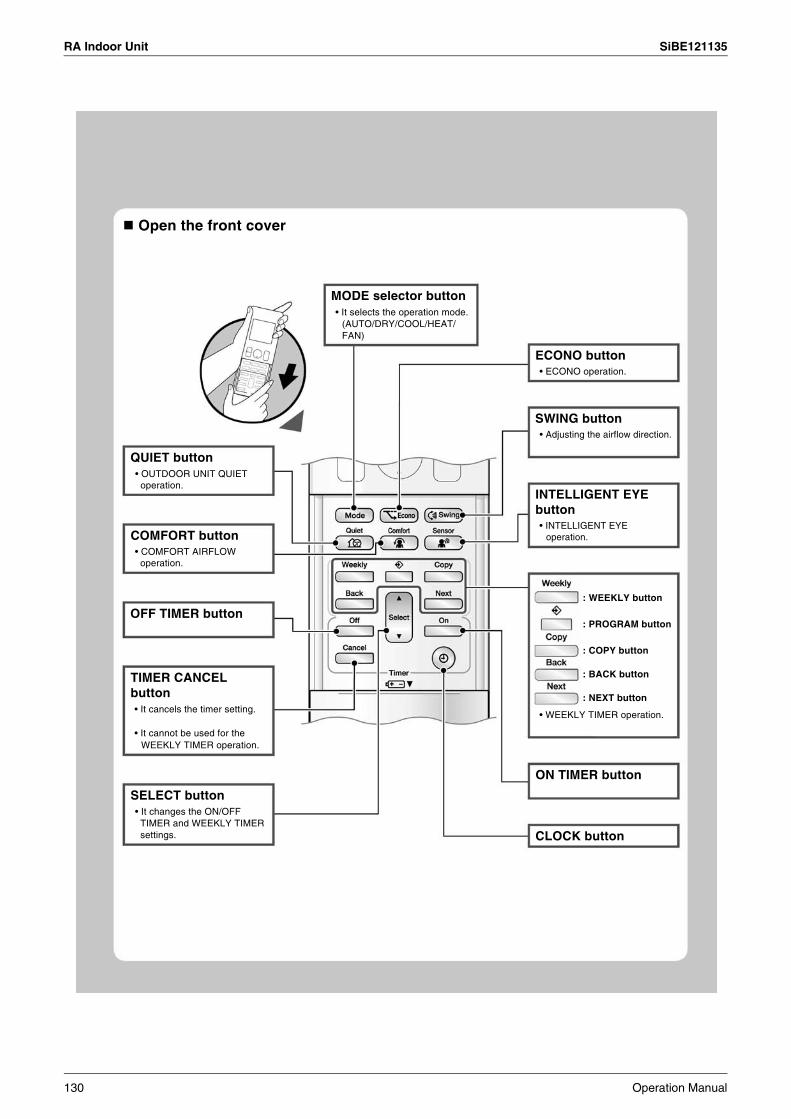
RA Indoor Unit SiBE121135
Open the front cover
• OUTDOOR UNIT QUIET operation.
QUIET button
• COMFORT AIRFLOW operation.
COMFORT button
OFF TIMER button
• It cancels the timer setting.
• It cannot be used for the WEEKLY TIMER operation.
TIMER CANCEL button
• It changes the ON/OFF TIMER and WEEKLY TIMER settings.
SELECT button
CLOCK button
ON TIMER button
• WEEKLY TIMER operation.
• INTELLIGENT EYE operation.
INTELLIGENT EYE button
• Adjusting the airflow direction.
SWING button
• ECONO operation.
ECONO button
• It selects the operation mode. (AUTO/DRY/COOL/HEAT/ FAN)
MODE selector button
: WEEKLY button
: PROGRAM button
: COPY button
: BACK button
: NEXT button
130 Operation Manual
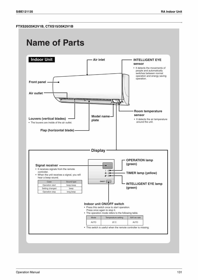
SiBE121135 RA Indoor Unit
FTXS20/25K2V1B, CTXS15/35K2V1B
Name of Parts
Indoor Unit Air inlet
Front panel
Air outlet
Louvers (vertical blades)• The louvers are inside of the air outlet.
Signal receiver• It receives signals from the remote
controller.• When the unit receives a signal, you will
hear a beep sound.
Indoor unit ON/OFF switch• Press this switch once to start operation.
Press once again to stop it.• The operation mode refers to the following table.
OPERATION lamp (green)
TIMER lamp (yellow)
INTELLIGENT EYE lamp (green)
• This switch is useful when the remote controller is missing.
Room temperature sensor• It detects the air temperature
around the unit.
INTELLIGENT EYE sensor• It detects the movements of
people and automatically switches between normal operation and energy saving operation.
Flap (horizontal blade)
Model name plate
Display
Case
Operation start
Setting changed
Operation stop
Sound type
beep-beep
beep
long beep
Mode
AUTO
Airfl ow rate
AUTO
Temperature setting
25˚C
Operation Manual 131

RA Indoor Unit SiBE121135
Open the front panel
Air filter
Titanium apatite photocatalytic air-purifying filter
132 Operation Manual
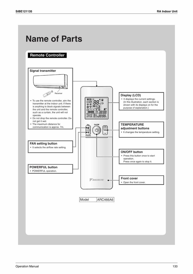
SiBE121135 RA Indoor Unit
Name of Parts
Remote Controller
Signal transmitter
FAN setting button
Display (LCD)
TEMPERATURE adjustment buttons
ON/OFF button
Front cover
POWERFUL button
Receiver
• To use the remote controller, aim the transmitter at the indoor unit. If there is anything to block signals between the unit and the remote controller, such as a curtain, the unit will not operate.
• Do not drop the remote controller. Do not get it wet.
• The maximum distance for communication is approx. 7m.
• It selects the airflow rate setting.
• POWERFUL operation.
• It displays the current settings.(In this illustration, each section is shown with its displays on for the purpose of explanation.)
• It changes the temperature setting.
• Press this button once to start operation.Press once again to stop it.
• Open the front cover.
Model ARC466A6
Operation Manual 133
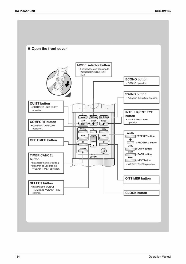
RA Indoor Unit SiBE121135
Open the front cover
QUIET button
COMFORT button
OFF TIMER button
SELECT button
TIMER CANCEL button
MODE selector button
ECONO button
SWING button
INTELLIGENT EYE button
ON TIMER button
CLOCK button
• OUTDOOR UNIT QUIET operation.
• COMFORT AIRFLOW operation.
• It cancels the timer setting.• It cannot be used for the
WEEKLY TIMER operation.
• It changes the ON/OFF TIMER and WEEKLY TIMER settings.
• It selects the operation mode.(AUTO/DRY/COOL/HEAT/ FAN)
• ECONO operation.
• Adjusting the airflow direction.
• INTELLIGENT EYE operation.
• WEEKLY TIMER operation.
: WEEKLY button
: PROGRAM button
: COPY button
: BACK button
: NEXT button
134 Operation Manual
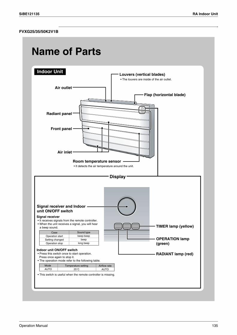
SiBE121135 RA Indoor Unit
FVXG25/35/50K2V1B
Name of Parts
Indoor Unit
Radiant panel
Front panel
Display
Air outlet
Louvers (vertical blades)• The louvers are inside of the air outlet.
Room temperature sensor• It detects the air temperature around the unit.
Flap (horizontal blade)
TIMER lamp (yellow)
RADIANT lamp (red)
Signal receiver
Sound typebeep-beep
beeplong beep
Indoor unit ON/OFF switch
• This switch is useful when the remote controller is missing.
Air inlet
ModeAUTO
Temperature setting25˚C
Airflow rateAUTO
CaseOperation start
Setting changedOperation stop
Signal receiver and Indoor unit ON/OFF switch
• It receives signals from the remote controller.• When the unit receives a signal, you will hear
a beep sound.
• Press this switch once to start operation. Press once again to stop it.• The operation mode refer to the following table.
OPERATION lamp (green)
Operation Manual 135

RA Indoor Unit SiBE121135
CAUTION
Open the front panel
Strings
Air filter (upper)
Front panel stopper
Air filter (lower)
• It is inside of air filter (lower).
• The surface of the radiant panel becomes very hot during RADIANT operation. Do not touch the panel of the main unit directly.After the operation is complete, do not remove or care and clean the panel until the surface temperature of the panel decreases.
Titanium apatite photocatalytic air-purifying filter
136 Operation Manual

SiBE121135 RA Indoor Unit
Name of Parts
Remote Controller
Signal transmitter
Receiver
Model ARC466A2
• To use the remote controller, aim the transmitter at the indoor unit. If there is anything to block signals between the unit and the remote controller, such as a curtain, the unit will not operate.
• Do not drop the remote controller. Do not get it wet.
• The maximum distance for communication is approximately 7m.
RADIANT switching button• RADIANT operation.
FAN setting button• It selects the airflow rate setting.
Front cover• Open the front cover.
ON/OFF button• Press this button once to start
operation. Press once again to stop it.
TEMPERATURE adjustment buttons• It changes the temperature setting.
Display (LCD)• It displays the current settings.
(In this illustration, each section is shown with its displays on for the purpose of explanation.)
Operation Manual 137
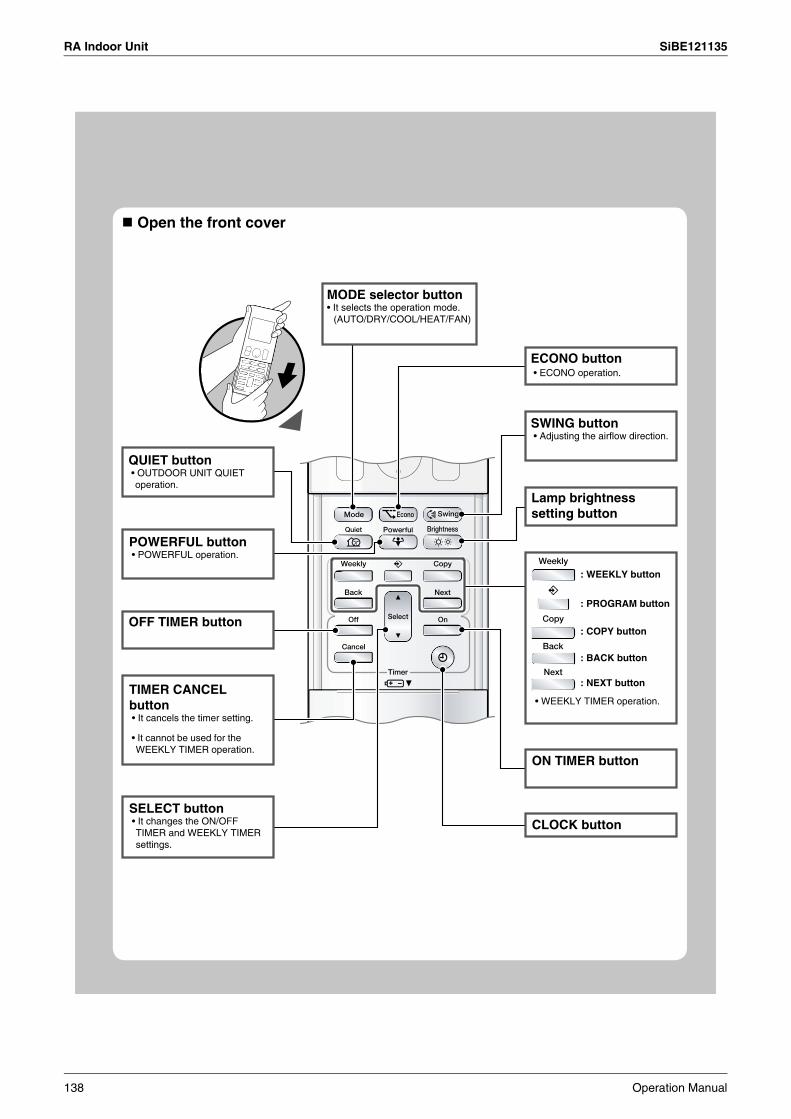
RA Indoor Unit SiBE121135
OFF TIMER button
ON TIMER button
CLOCK button
• WEEKLY TIMER operation.
Open the front cover
MODE selector button• It selects the operation mode.
(AUTO/DRY/COOL/HEAT/FAN)
QUIET button • OUTDOOR UNIT QUIET
operation.
POWERFUL button • POWERFUL operation.
TIMER CANCEL button • It cancels the timer setting.
• It cannot be used for the WEEKLY TIMER operation.
SELECT button • It changes the ON/OFF
TIMER and WEEKLY TIMER settings.
: WEEKLY button
: PROGRAM button
: COPY button
: BACK button
: NEXT button
Lamp brightness setting button
SWING button • Adjusting the airflow direction.
ECONO button • ECONO operation.
138 Operation Manual

SiBE121135 RA Indoor Unit
2.1.3 Preparation before Operation
+
2
3 1
Remote controller
Screws
Preparation before Operation
To set the batteries
To fix the remote controller holder on the wall
To set the luminance of the display• The luminance of the indoor unit display can be set.
Press .
Hi Low Off
NOTE
1. Choose a place from where the signals reach the unit.
2. Fix the holder to a wall, a pillar, or similar location with the screws procured locally
3. Place the remote controller in the remote controller holder.
1. Slide the front cover to take it off.
2. Set two dry batteries AAA.LR03 (alkaline).
3. Set the front cover as before.
Position and – correctly!
Remote controller holder
Notes on batteries• When replacing the batteries, use batteries of the same type, and replace both old batteries together.• When the system is not used for a long time, take the batteries out.• The batteries will last for approximately 1 year. If the remote controller display begins to fade and the degradation of reception performance
occurs within a year, however, replace both batteries with new, size AAA.LR03 (alkaline).• The attached batteries are provided for the initial use of the system.
The usable period of the batteries may be short depending on the manufactured date of the air conditioner.
Notes on remote controller• Never expose the remote controller to direct sunlight.• Dust on the signal transmitter or receiver will reduce the sensitivity. Wipe off dust with soft cloth. • Signal communication may be disabled if an electronic-starter-type fluorescent lamp (such as inverter-type lamps) is in the room. Consult the
shop if that is the case.• If the remote controller signals happen to operate another appliance, move that appliance to somewhere else, or consult the service shop.
Operation Manual 139
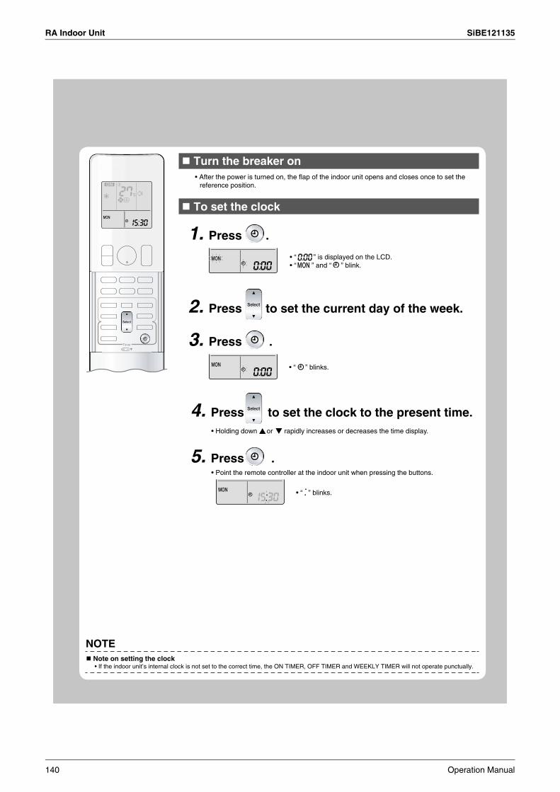
RA Indoor Unit SiBE121135
Turn the breaker on
To set the clock
1. Press .
2. Press to set the current day of the week.
3. Press .
• “ ” blinks.
4. Press to set the clock to the present time. • Holding down or rapidly increases or decreases the time display.
5. Press .• Point the remote controller at the indoor unit when pressing the buttons.
• “ ” blinks.
NOTE Note on setting the clock• If the indoor unit’s internal clock is not set to the correct time, the ON TIMER, OFF TIMER and WEEKLY TIMER will not operate punctually.
• After the power is turned on, the flap of the indoor unit opens and closes once to set the reference position.
• “ ” is displayed on the LCD.• “ ” and “ ” blink.
140 Operation Manual
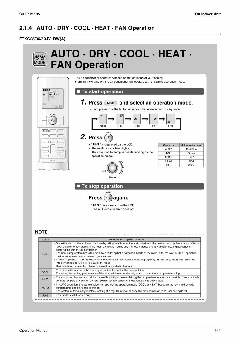
SiBE121135 RA Indoor Unit
2.1.4 AUTO · DRY · COOL · HEAT · FAN Operation
FTXG25/35/50JV1BW(A)
NOTE
Notes on each operation modeMODE
HEAT
COOL
DRY
AUTO
FAN
• Since this air conditioner heats the room by taking heat from outdoor air to indoors, the heating capacity becomes smaller in lower outdoor temperatures. If the heating effect is insufficient, it is recommended to use another heating appliance in combination with the air conditioner.
• The heat pump system heats the room by circulating hot air around all parts of the room. After the start of HEAT operation, it takes some time before the room gets warmer.
• In HEAT operation, frost may occur on the outdoor unit and lower the heating capacity. In that case, the system switches into defrosting operation to take away the frost.
• During defrosting operation, hot air does not flow out of indoor unit.
• This air conditioner cools the room by releasing the heat in the room outside.Therefore, the cooling performance of the air conditioner may be degraded if the outdoor temperature is high
• The computer chip works to rid the room of humidity while maintaining the temperature as much as possible. It automatically controls temperature and airflow rate, so manual adjustment of these functions is unavailable.
• In AUTO operation, the system selects an appropriate operation mode (COOL or HEAT) based on the room and outside temperatures and starts the operation.
• The system automatically reselects setting at a regular interval to bring the room temperature to user-setting level.
• This mode is valid for fan only.
To stop operation
Press again.• “ ” disappears from the LCD.• The multi-monitor lamp goes off.
Display
Operation
AUTO
DRY
COOL
HEAT
FAN
Multi-monitor lamp
Red/Blue
Green
Blue
Red
White
• “ ” is displayed on the LCD.• The multi-monitor lamp lights up.
The colour of the lamp varies depending on the operation mode.
2. Press .
AUTO · DRY · COOL · HEAT · FAN Operation
The air conditioner operates with the operation mode of your choice.From the next time on, the air conditioner will operate with the same operation mode.
To start operation
1. Press and select an operation mode.• Each pressing of the button advances the mode setting in sequence.
AUTO DRY COOL HEAT FAN
Operation Manual 141
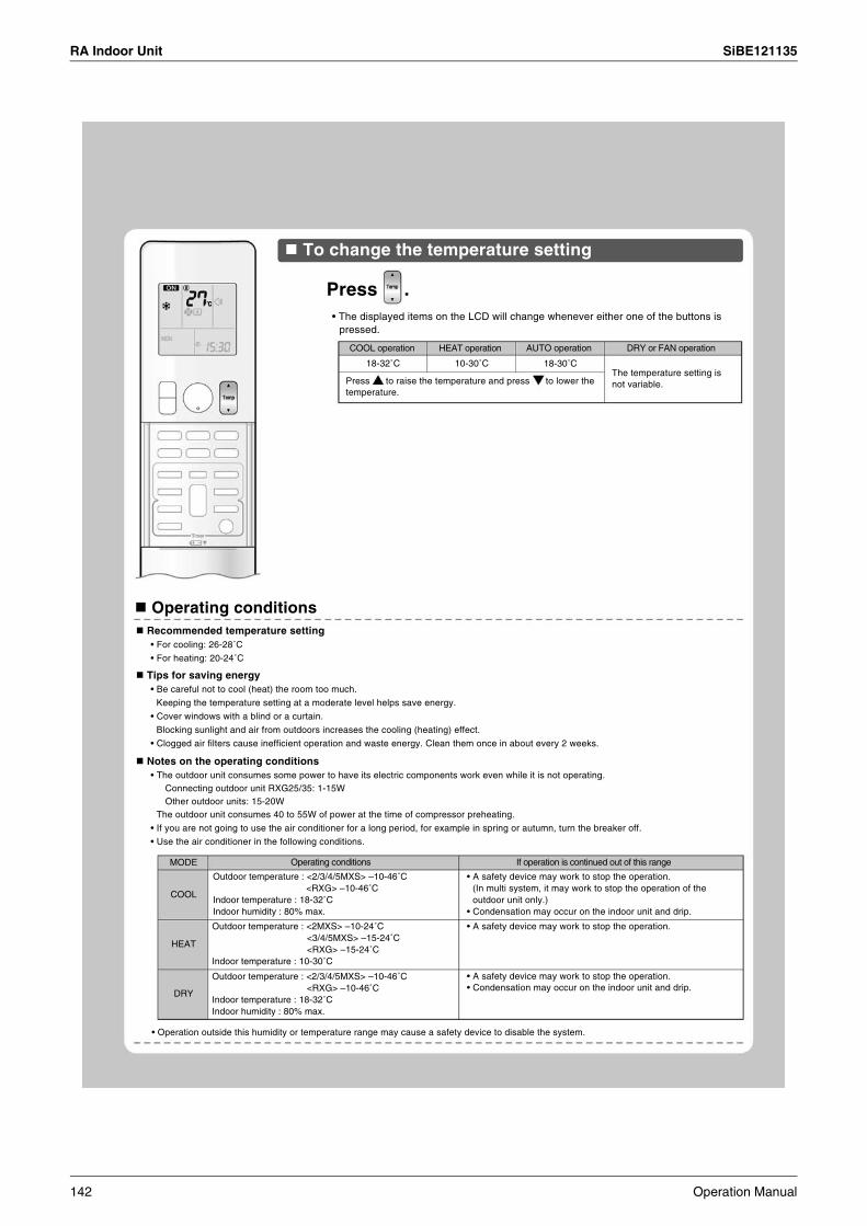
RA Indoor Unit SiBE121135
18-30˚C
To change the temperature setting
Press .• The displayed items on the LCD will change whenever either one of the buttons is
pressed.
COOL operation
18-32˚C
HEAT operation
10-30˚C
AUTO operation DRY or FAN operation
Press to raise the temperature and press to lower the temperature.
The temperature setting is not variable.
Operating conditions
• Operation outside this humidity or temperature range may cause a safety device to disable the system.
MODE
COOL
HEAT
DRY
Operating conditions
Outdoor temperature : <2/3/4/5MXS> –10-46˚C<RXG> –10-46˚C
Indoor temperature : 18-32˚CIndoor humidity : 80% max.
Outdoor temperature : <2MXS> –10-24˚C<3/4/5MXS> –15-24˚C<RXG> –15-24˚C
Indoor temperature : 10-30˚C
Outdoor temperature : <2/3/4/5MXS> –10-46˚C<RXG> –10-46˚C
Indoor temperature : 18-32˚CIndoor humidity : 80% max.
If operation is continued out of this range
• A safety device may work to stop the operation.(In multi system, it may work to stop the operation of the outdoor unit only.)
• Condensation may occur on the indoor unit and drip.
• A safety device may work to stop the operation.
• A safety device may work to stop the operation.• Condensation may occur on the indoor unit and drip.
Recommended temperature setting• For cooling: 26-28˚C
• For heating: 20-24˚C
Tips for saving energy• Be careful not to cool (heat) the room too much.
Keeping the temperature setting at a moderate level helps save energy.
• Cover windows with a blind or a curtain.
Blocking sunlight and air from outdoors increases the cooling (heating) effect.
• Clogged air filters cause inefficient operation and waste energy. Clean them once in about every 2 weeks.
Notes on the operating conditions• The outdoor unit consumes some power to have its electric components work even while it is not operating.
Connecting outdoor unit RXG25/35: 1-15WOther outdoor units: 15-20W
The outdoor unit consumes 40 to 55W of power at the time of compressor preheating.
• If you are not going to use the air conditioner for a long period, for example in spring or autumn, turn the breaker off.
• Use the air conditioner in the following conditions.
142 Operation Manual

SiBE121135 RA Indoor Unit
FTXS20/25K2V1B, CTXS15/35K2V1B
AUTO · DRY · COOL · HEAT · FAN Operation
The air conditioner operates with the operation mode of your choice.From the next time on, the air conditioner will operate with the same operation mode.
To start operation
To stop operation
1. Press and select an operation mode.• Each pressing of the button advances the mode setting in sequence.
AUTO
Display
DRY COOL HEAT FAN
2. Press .• “ ” is displayed on the LCD.• The OPERATION lamp lights green.
Press again.• “ ” disappears from the LCD.• The OPERATION lamp goes off.
MODE
HEAT
COOL
DRY
AUTO
FAN
Notes on each operation mode
• Since this air conditioner heats the room by taking heat from outdoor air to indoors, the heating capacity becomes smaller in lower outdoor temperatures. If the heating effect is insufficient, it is recommended to use another heating appliance in combination with the air conditioner.
• The heat pump system heats the room by circulating hot air around all parts of the room. After the start of HEAT operation, it takes some time before the room gets warmer.
• In HEAT operation, frost may occur on the outdoor unit and lower the heating capacity. In that case, the system switches into defrosting operation to take away the frost.
• During defrosting operation, hot air does not flow out of indoor unit.
• This air conditioner cools the room by releasing the heat in the room outside.Therefore, the cooling performance of the air conditioner may be degraded if the outdoor temperature is high
• The computer chip works to rid the room of humidity while maintaining the temperature as much as possible. It automatically controls temperature and airflow rate, so manual adjustment of these functions is unavailable.
• In AUTO operation, the system selects an appropriate operation mode (COOL or HEAT) based on the room and outside temperatures and starts the operation.
• The system automatically reselects setting at a regular interval to bring the room temperature to user-setting level.
• This mode is valid for fan only.
NOTE
Operation Manual 143

RA Indoor Unit SiBE121135
To change the temperature setting
Press .• The displayed items on the LCD will change whenever either one of the buttons is
pressed.
COOL operation
18-32˚C
HEAT operation
10-30˚C
AUTO operation
18-30˚C
DRY or FAN operation
Press to raise the temperature and press to lower the temperature.
The temperature setting is not variable.
Operating conditions Recommended temperature setting
• For cooling: 26-28˚C
• For heating: 20-24˚C
Tips for saving energy• Be careful not to cool (heat) the room too much.
Keeping the temperature setting at a moderate level helps save energy.
• Cover windows with a blind or a curtain.
Blocking sunlight and air from outdoors increases the cooling (heating) effect.• Clogged air filters cause inefficient operation and waste energy. Clean them once in about every 2 weeks.
Notes on the operating conditions• The outdoor unit consumes some power to have its electric components work even while it is not operating.
Connecting outdoor unit RXS20/25: 1-15WOther outdoor units: 15-20W
The outdoor unit consumes 40 to 55W of power at the time of compressor preheating.
• If you are not going to use the air conditioner for a long period, for example in spring or autumn, turn the breaker off.
• Use the air conditioner in the following conditions.
MODE
COOL
HEAT
DRY
Operating conditions If operation is continued out of this range
Outdoor temperature: <2MXS> 10-46˚C<3/4/5MXS> –10-46˚C<RXS> –10-46˚C
Indoor temperature: 18-32˚CIndoor humidity: 80% max.
Outdoor temperature: <2/3/4/5MXS> –15-24˚C<RXS> –15-24˚C
Indoor temperature: 10-30˚C
Outdoor temperature: <2MXS> 10-46˚C<3/4/5MXS> –10-46˚C<RXS> –10-46˚C
Indoor temperature: 18-32˚CIndoor humidity: 80% max.
• A safety device may work to stop the operation.(In multi system, it may work to stop the operation of the outdoor unit only.)
• Condensation may occur on the indoor unit and drip.
• A safety device may work to stop the operation.
• A safety device may work to stop the operation.• Condensation may occur on the indoor unit and drip.
• Operation outside this humidity or temperature range may cause a safety device to disable the system.
144 Operation Manual
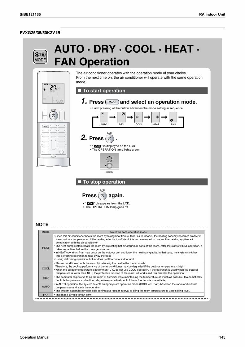
SiBE121135 RA Indoor Unit
FVXG25/35/50K2V1B
To start operation
• Each pressing of the button advances the mode setting in sequence.
AUTO DRY COOL HEAT FAN
2. Press .
Display
To stop operation
Press again.
NOTEMODE Notes on each operation mode
• This mode is valid for fan only.
1. Press and select an operation mode.
The air conditioner operates with the operation mode of your choice.From the next time on, the air conditioner will operate with the same operation mode.
AUTO · DRY · COOL · HEAT · FAN Operation
• “ ” is displayed on the LCD.• The OPERATION lamp lights green.
• “ ” disappears from the LCD.• The OPERATION lamp goes off.
HEAT
COOL
DRY
AUTO
FAN
• Since this air conditioner heats the room by taking heat from outdoor air to indoors, the heating capacity becomes smaller in lower outdoor temperatures. If the heating effect is insufficient, it is recommended to use another heating appliance in combination with the air conditioner.
• The heat pump system heats the room by circulating hot air around all parts of the room. After the start of HEAT operation, it takes some time before the room gets warmer.
• In HEAT operation, frost may occur on the outdoor unit and lower the heating capacity. In that case, the system switches into defrosting operation to take away the frost.
• During defrosting operation, hot air does not flow out of indoor unit.
• This air conditioner cools the room by releasing the heat in the room outside.Therefore, the cooling performance of the air conditioner may be degraded if the outdoor temperature is high.
• When the outdoor temperature is lower than 10˚C, do not use COOL operation. If the operation is used when the outdoor temperature is lower than 10˚C, the protective function of the main unit works and this disables the operation.
• The computer chip works to rid the room of humidity while maintaining the temperature as much as possible. It automatically controls temperature and airflow rate, so manual adjustment of these functions is unavailable.
• In AUTO operation, the system selects an appropriate operation mode (COOL or HEAT) based on the room and outside temperatures and starts the operation.
• The system automatically reselects setting at a regular interval to bring the room temperature to user-setting level.
Operation Manual 145

RA Indoor Unit SiBE121135
2.1.5 RADIANT Operation
RADIANT Operation
RADIANT1 RADIANT2
Display
Auto fan speed Gentle breeze
The RADIANT operation provides a comfortable environment with quiet and currentless heating operation in addition to the HEAT operation mode. The RADIANT operation has 2 operation modes.
To start RADIANT operation
1. Press and select an HEAT operation.• Each pressing of the button advances the mode setting in sequence.
AUTO DRY COOL HEAT FAN
• “ ” is displayed on the LCD.
2. Press and select a RADIANT operation.• “ ” is displayed on the LCD.• The RADIANT lamp lights red.• This button can be used only in the HEAT operation mode.• When the RADIANT operation starts, the temperature of the radiant panel increases.
HEAT
RADIANT operation with HEAT RADIANT operation
RADIANT1• Use this operation when the difference
between the set temperature and indoor temperature is large, or to warm up the room quickly.
RADIANT2• Use this operation to prioritize quiet and
currentless heating operation, or when the noise from RADIANT1 operation bothers you. The gentle breeze operation starts from the beginning.
CAUTION• During the RADIANT operation, the surface temperature of the panel will be about 55˚C at maximum.
Even after the RADIANT operation is finished, the surface temperature of the panel of the air conditioner stays hot for a while. Do not touch the air conditioner until the surface temperature of the panel decreases.Be careful that children do not touch the surface of the panel.
NOTENotes on RADIANT operation• If RADIANT2 operation does not warm up the room, use HEAT or RADIANT1 operation.• RADIANT1 can be used with POWERFUL operation. RADIANT2 cannot be used with the POWERFUL operation.• This operation may not warm up the room adequately depending on conditions such as an extremely low outside temperature and lack of
adequate performance.• The RADIANT operation uses the auto fan speed, so the airflow rate cannot be changed.• When the indoor units are connected using a multi system, please refer to “Selecting the operation mode” in note for multi system.
146 Operation Manual
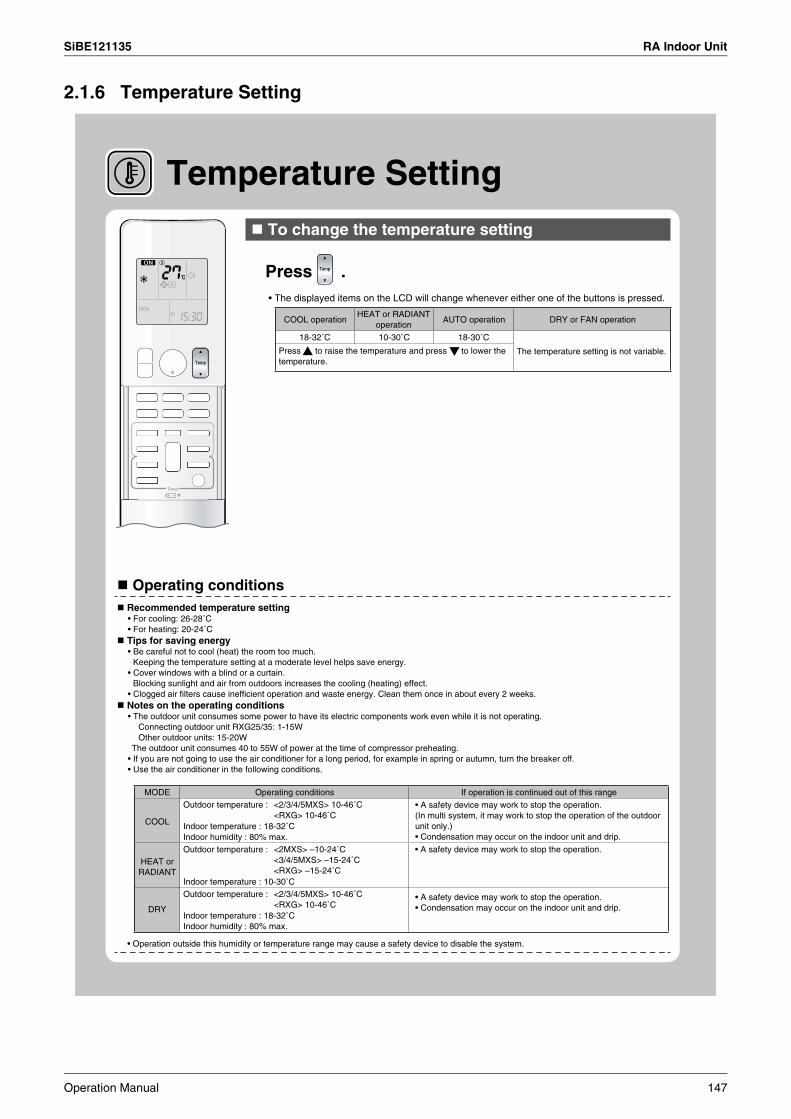
SiBE121135 RA Indoor Unit
2.1.6 Temperature Setting
Temperature Setting To change the temperature setting
Press .• The displayed items on the LCD will change whenever either one of the buttons is pressed.
COOL operation
18-32˚C 10-30˚C 18-30˚C
The temperature setting is not variable.
Operating conditions
MODE Operating conditions If operation is continued out of this rangeOutdoor temperature :
Indoor temperature : 18-32˚CIndoor humidity : 80% max.Outdoor temperature : <2MXS> –10-24˚C
<3/4/5MXS> –15-24˚C<RXG> –15-24˚C
Indoor temperature : 10-30˚C
• A safety device may work to stop the operation.
Outdoor temperature :
Indoor temperature : 18-32˚CIndoor humidity : 80% max.
• Operation outside this humidity or temperature range may cause a safety device to disable the system.
Press to raise the temperature and press to lower the temperature.
AUTO operation DRY or FAN operationHEAT or RADIANT
operation
• A safety device may work to stop the operation. (In multi system, it may work to stop the operation of the outdoor unit only.)• Condensation may occur on the indoor unit and drip.
• A safety device may work to stop the operation.• Condensation may occur on the indoor unit and drip.
<2/3/4/5MXS> 10-46˚C<RXG> 10-46˚C
<2/3/4/5MXS> 10-46˚C<RXG> 10-46˚C
Recommended temperature setting• For cooling: 26-28˚C• For heating: 20-24˚C
Tips for saving energy• Be careful not to cool (heat) the room too much.
Keeping the temperature setting at a moderate level helps save energy.• Cover windows with a blind or a curtain.
Blocking sunlight and air from outdoors increases the cooling (heating) effect.• Clogged air filters cause inefficient operation and waste energy. Clean them once in about every 2 weeks.
Notes on the operating conditions• The outdoor unit consumes some power to have its electric components work even while it is not operating.
Connecting outdoor unit RXG25/35: 1-15WOther outdoor units: 15-20W
The outdoor unit consumes 40 to 55W of power at the time of compressor preheating.• If you are not going to use the air conditioner for a long period, for example in spring or autumn, turn the breaker off.• Use the air conditioner in the following conditions.
COOL
HEAT or RADIANT
DRY
Operation Manual 147

RA Indoor Unit SiBE121135
2.1.7 Adjusting the Airflow Direction and Rate
FTXG25/35/50JV1BW(A)
Adjusting the Airflow Direction and Rate
You can adjust the airflow direction to increase your comfort.
To start auto swing
Upper and lower airflow direction
Press .• “ ” is displayed on the LCD.• The flaps (horizontal blades) will begin to swing.
To set the flaps at desired position• This function is effective while flaps are in auto swing mode.
Press when the flaps have reached the desired position.• “ ” disappears from the LCD.
To adjust the louvers at desired positionHold the knob and move the louvers.• You will find a knob on the left-side and the right-side
blades.• When the unit is installed in the corner of a room, the
direction of the louvers (vertical blades) should be facing away from the wall.If they face the wall, the wall will block off the wind, causing the cooling (or heating) efficiency to drop.
• If the flaps are in the way, press on the remote controller to move the flaps out of the way and then adjust the louvers.
148 Operation Manual

SiBE121135 RA Indoor Unit
Upper limit
Lower limit Stop operation Stop operation
Upper limit
Upper limit 5˚
10˚
60˚
20˚
70˚
75˚ 75˚
5˚
Lower limit Lower limit
To adjust the airflow rate setting
Press .
• Each pressing of advances the airflow rate setting in sequence.
Auto Indoor unit quiet Low Middle low
MiddleMiddle highHigh
• When the airflow is set to “ ”, indoor unit quiet operation will start and the noise from the unit will become quieter.
• In indoor unit quiet operation, the airflow rate is set to a weak level.• In DRY mode, the airflow rate setting is not variable.
• Always use a remote controller to adjust the angles of the flaps. If you attempt to move it forcibly with hand when it is swinging, the mechanism may be broken.
• Be careful when adjusting the louvers.Inside the air outlet, a fan is rotating at a high speed.
CAUTION
• At smaller airflow rates, the cooling (heating) effect is also smaller.
• If the air conditioner is operated in COOL or DRY operation with the flaps kept stopped in the downward direction, the flaps will automatically start operating in approximately an hour in order to prevent dew condensation.
Note on airflow rate setting
Stop operation
COMFORT AIRFLOW
COOL and DRY operation
COMFORT AIRFLOW
HEAT operation FAN operation
• The flaps swinging range depends on the operation. (See the figure.) Note on the angles of the flaps
NOTE
Operation Manual 149
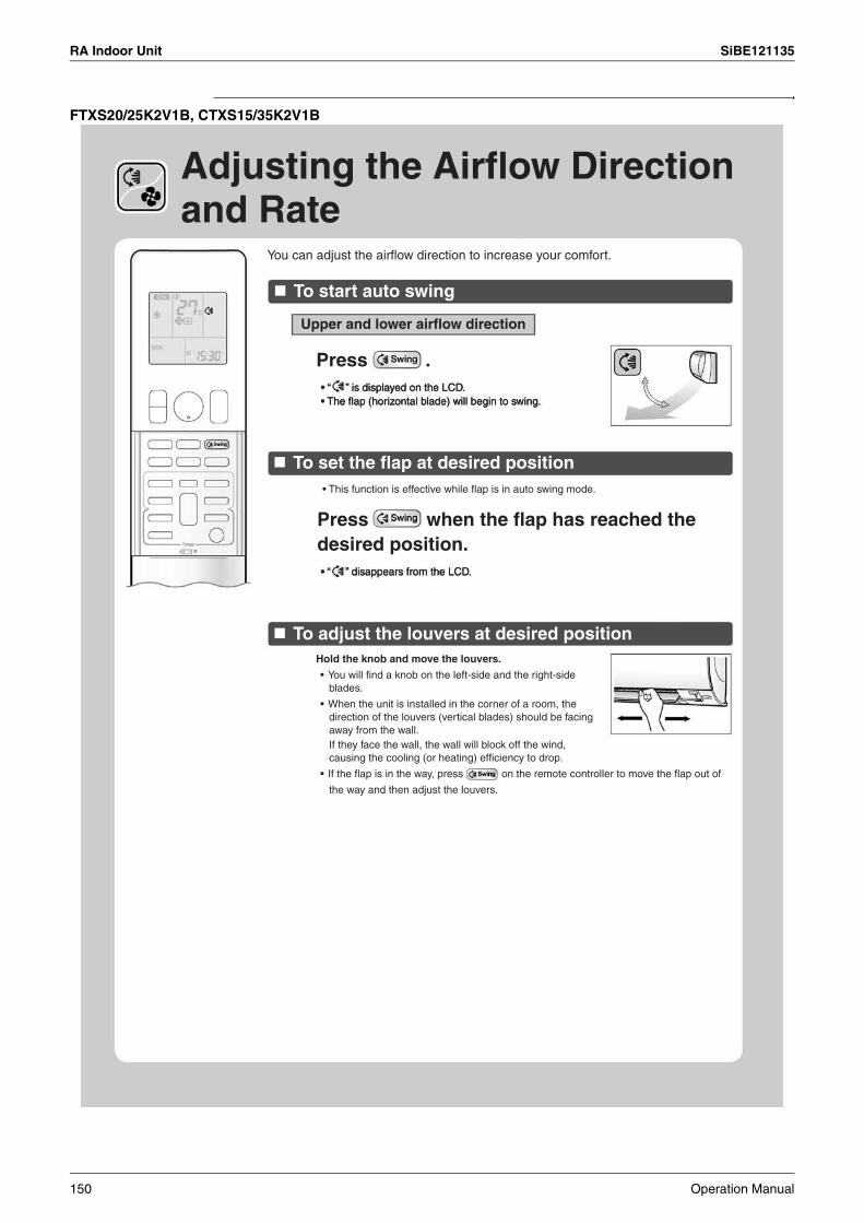
RA Indoor Unit SiBE121135
FTXS20/25K2V1B, CTXS15/35K2V1B
Adjusting the Airflow Direction and Rate
You can adjust the airflow direction to increase your comfort.
To start auto swing
To set the flap at desired position
To adjust the louvers at desired position
Upper and lower airflow direction
Press .
Press when the flap has reached the desired position.
• This function is effective while flap is in auto swing mode.
Hold the knob and move the louvers.
• You will find a knob on the left-side and the right-side blades.
• When the unit is installed in the corner of a room, the direction of the louvers (vertical blades) should be facing away from the wall.If they face the wall, the wall will block off the wind, causing the cooling (or heating) efficiency to drop.
• If the flap is in the way, press on the remote controller to move the flap out of
the way and then adjust the louvers.
• “ ” is displayed on the LCD.• The flap (horizontal blade) will begin to swing.
• “ ” disappears from the LCD.
150 Operation Manual

SiBE121135 RA Indoor Unit
To adjust the airflow rate setting
Press .
• Each pressing of advances the airflow rate setting in sequence.
Auto Indoor unit quiet Low Middle low
High Middle high Middle
• When the airflow is set to “ ”, indoor unit quiet operation will start and the noise from the unit will become quieter.
• In indoor unit quiet operation, the airflow rate is set to a weak level.• If the temperature does not reach the desired point in the indoor unit quiet operation,
change the airflow rate setting.• In DRY mode, the airflow rate setting is not variable.
• Always use a remote controller to adjust the angles of the flap. If you attempt to move the flap and louvers forcibly with hand when they are swinging, the mechanism may be broken.
• Be careful when adjusting the louvers.Inside the air outlet, a fan is rotating at a high speed.
• If the air conditioner is operated in COOL or DRY operation with the flap kept stopped in the downward direction, the flap will automatically start operating in approximately an hour in order to prevent dew condensation.
Note on airflow rate setting• At smaller airflow rates, the cooling (heating) effect is also smaller.
Notes on the angles of the flap• The flap swinging range depends on the operation. (See the figure.)
CAUTION
NOTE
COOL and DRY operation
HEAT operation FAN operation
Stop operation
COMFORT AIRFLOWUpper limit
Lower limit
Stop operation
COMFORT AIRFLOW
Upper limit
Lower limit
Stop operation
Upper limit
Lower limit
0˚5˚
45˚
0˚15˚
45˚50˚
0˚5˚
45˚
Operation Manual 151

RA Indoor Unit SiBE121135
FVXG25/35/50K2V1B
You can adjust the airflow direction to increase your comfort.
To start auto swing
Upper and lower airflow direction
Press .
To set the flap at desired position • This function is effective while flap is in auto swing mode.
• “ ” disappears from the LCD.
To adjust the louvers at desired position
Adjusting the Airflow Direction and Rate
• “ ” is displayed on the LCD. • The flap (horizontal blade) will begin to swing.
Press when the flap has reached the desired position.
Hold the knob and move the louvers.• You will find a knob on the left-side and the right-side blades.• When the unit is installed in the corner of a room, the direction
of the louvers (vertical blades) should be facing away from the wall.If they face the wall, the wall will block off the wind, causing the cooling (or heating) efficiency to drop.
• If the flap is in the way, press on the remote controller to move the flap out of the way and then adjust the louvers.
152 Operation Manual

SiBE121135 RA Indoor Unit
To adjust the airflow rate setting
Press .
Auto Indoor unit quiet Low Middle low
MiddleMiddle highHigh
NOTE Note on the angles of the flap• The flap swinging range is the same by all operation. (See the figure.)
Upper limit
Lower limit
Stop operation45˚
70˚
Note on airflow rate setting• At smaller airflow rates, the cooling (heating) effect is also smaller.
CAUTION
Adjusting the Airflow Direction and Rate
• Each pressing of advances the airflow rate setting in sequence.
• When the airflow is set to “ ”, indoor unit quiet operation will start and the noise from the unit will become quieter.
• In indoor unit quiet operation, the airflow rate is set to a weak level.• In DRY or RADIANT operation, the airflow rate setting is not variable.
• Always use a remote controller to adjust the angles of the flap. If you attempt to move it forcibly with hand when it is swinging, the mechanism may be broken.
• Be careful when adjusting the louvers.Inside the air outlet, a fan is rotating at a high speed.
Operation Manual 153

RA Indoor Unit SiBE121135
2.1.8 COMFORT AIRFLOW Operation
COMFORT AIRFLOW Operation
The flow of air will be in the upward direction while in COOL operation and in the downward direction while in HEAT operation, which will provide a comfortable wind that will not come in direct contact with people.
To start COMFORT AIRFLOW operation
To cancel COMFORT AIRFLOW operation
• “ ” is displayed on the LCD.• Airflow rate is set to Auto.
COOL/DRY: The flap will go up.HEAT: The flap will go down.
• The flaps will return to the memory position from before COMFORT AIRFLOW operation.
• “ ” disappears from the LCD.
Press .
Press again.
COOL operation HEAT operation
Notes on COMFORT AIRFLOW operation• The flap position will change, preventing air from blowing directly on the occupants of the room.
• POWERFUL operation and COMFORT AIRFLOW operation cannot be used at the same time.Priority is given to the function of whichever button is pressed last.
• The airflow rate will be set to Auto. If the upper and lower airflow direction is selected, the COMFORT AIRFLOW operation will be canceled.
NOTE
154 Operation Manual

SiBE121135 RA Indoor Unit
2.1.9 INTELLIGENT EYE Operation
INTELLIGENT EYE Operation
To start INTELLIGENT EYE operation
To cancel INTELLIGENT EYE operation
Press .
Press again.
“INTELLIGENT EYE” is the infrared sensor which detects the human movement. If nobody in the room for more than 20 minutes, the operation automatically changes to energy saving operation.
• “ ” is displayed on the LCD.• The INTELLIGENT EYE lamp lights green.
• “ ” disappears from the LCD.• The INTELLIGENT EYE lamp goes off.
Display
Operation Manual 155
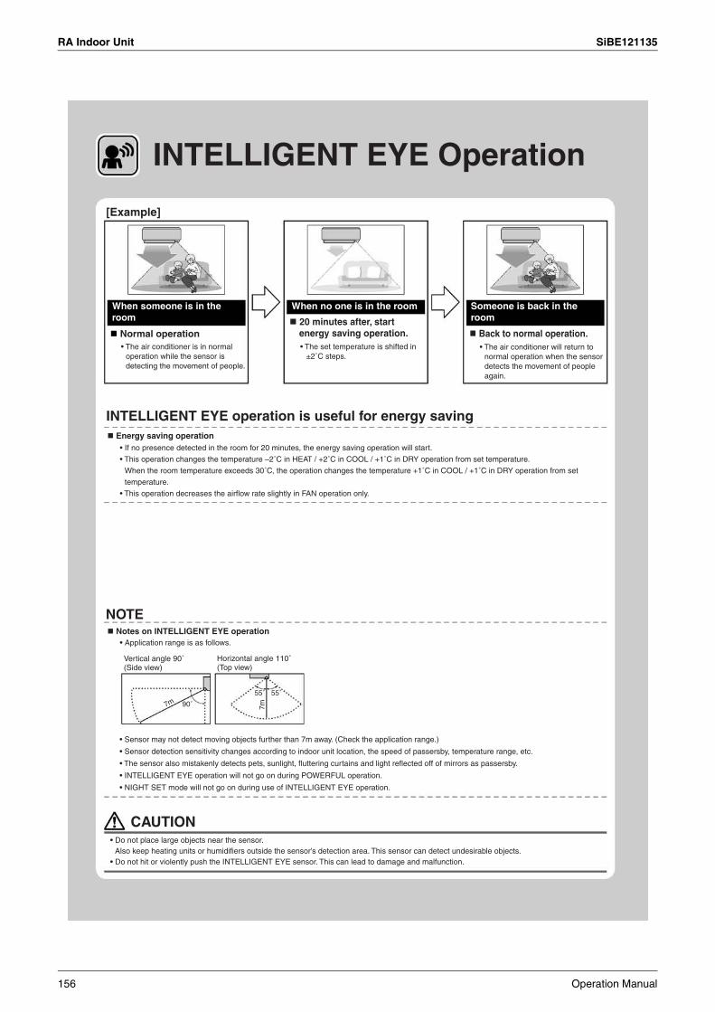
RA Indoor Unit SiBE121135
INTELLIGENT EYE Operation
90˚
55˚
7m
55˚
7m
[Example]
Normal operation
When no one is in the room
Back to normal operation.
When someone is in the room
Someone is back in the room
• The air conditioner is in normal operation while the sensor is detecting the movement of people.
20 minutes after, start energy saving operation.• The set temperature is shifted in
±2˚C steps.• The air conditioner will return to
normal operation when the sensor detects the movement of people again.
INTELLIGENT EYE operation is useful for energy saving
• If no presence detected in the room for 20 minutes, the energy saving operation will start.
• This operation changes the temperature –2˚C in HEAT / +2˚C in COOL / +1˚C in DRY operation from set temperature.
When the room temperature exceeds 30˚C, the operation changes the temperature +1˚C in COOL / +1˚C in DRY operation from set
temperature.
• This operation decreases the airflow rate slightly in FAN operation only.
NOTE Notes on INTELLIGENT EYE operation
Energy saving operation
• Application range is as follows.
Vertical angle 90˚ (Side view)
Horizontal angle 110˚ (Top view)
• Sensor may not detect moving objects further than 7m away. (Check the application range.)
• Sensor detection sensitivity changes according to indoor unit location, the speed of passersby, temperature range, etc.
• The sensor also mistakenly detects pets, sunlight, fluttering curtains and light reflected off of mirrors as passersby.
• INTELLIGENT EYE operation will not go on during POWERFUL operation.
• NIGHT SET mode will not go on during use of INTELLIGENT EYE operation.
CAUTION• Do not place large objects near the sensor.
Also keep heating units or humidifiers outside the sensor’s detection area. This sensor can detect undesirable objects.• Do not hit or violently push the INTELLIGENT EYE sensor. This can lead to damage and malfunction.
156 Operation Manual
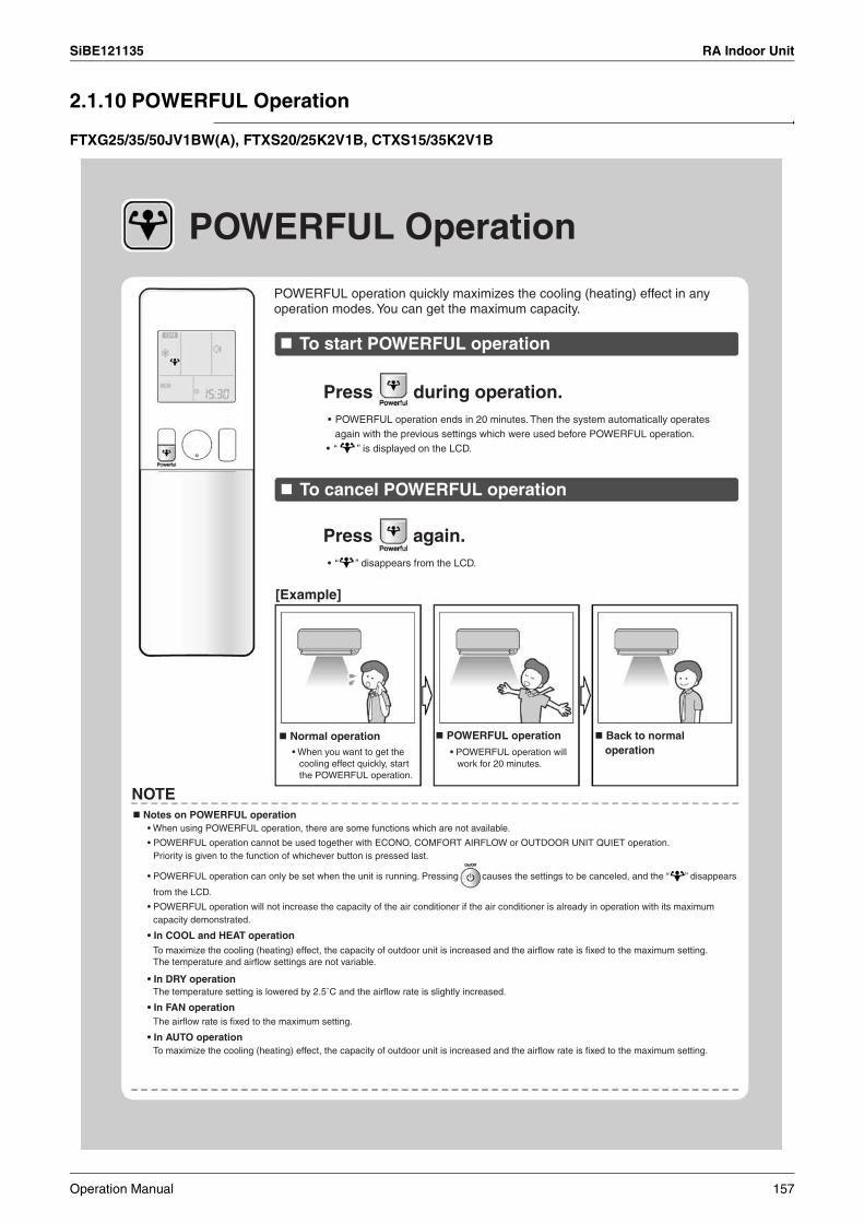
SiBE121135 RA Indoor Unit
2.1.10 POWERFUL Operation
FTXG25/35/50JV1BW(A), FTXS20/25K2V1B, CTXS15/35K2V1B
POWERFUL Operation
POWERFUL operation quickly maximizes the cooling (heating) effect in any operation modes. You can get the maximum capacity.
To start POWERFUL operation
To cancel POWERFUL operation
Press during operation.• POWERFUL operation ends in 20 minutes. Then the system automatically operates
again with the previous settings which were used before POWERFUL operation.• “ ” is displayed on the LCD.
Press again.• “ ” disappears from the LCD.
[Example]
Normal operation• When you want to get the
cooling effect quickly, start the POWERFUL operation.
POWERFUL operation• POWERFUL operation will
work for 20 minutes.
Back to normal operation
NOTE Notes on POWERFUL operation
• When using POWERFUL operation, there are some functions which are not available.
• POWERFUL operation cannot be used together with ECONO, COMFORT AIRFLOW or OUTDOOR UNIT QUIET operation.Priority is given to the function of whichever button is pressed last.
• POWERFUL operation can only be set when the unit is running. Pressing causes the settings to be canceled, and the “ ” disappears
from the LCD.
• POWERFUL operation will not increase the capacity of the air conditioner if the air conditioner is already in operation with its maximum capacity demonstrated.
• In COOL and HEAT operationTo maximize the cooling (heating) effect, the capacity of outdoor unit is increased and the airflow rate is fixed to the maximum setting.The temperature and airflow settings are not variable.
• In DRY operationThe temperature setting is lowered by 2.5˚C and the airflow rate is slightly increased.
• In FAN operationThe airflow rate is fixed to the maximum setting.
• In AUTO operationTo maximize the cooling (heating) effect, the capacity of outdoor unit is increased and the airflow rate is fixed to the maximum setting.
Operation Manual 157
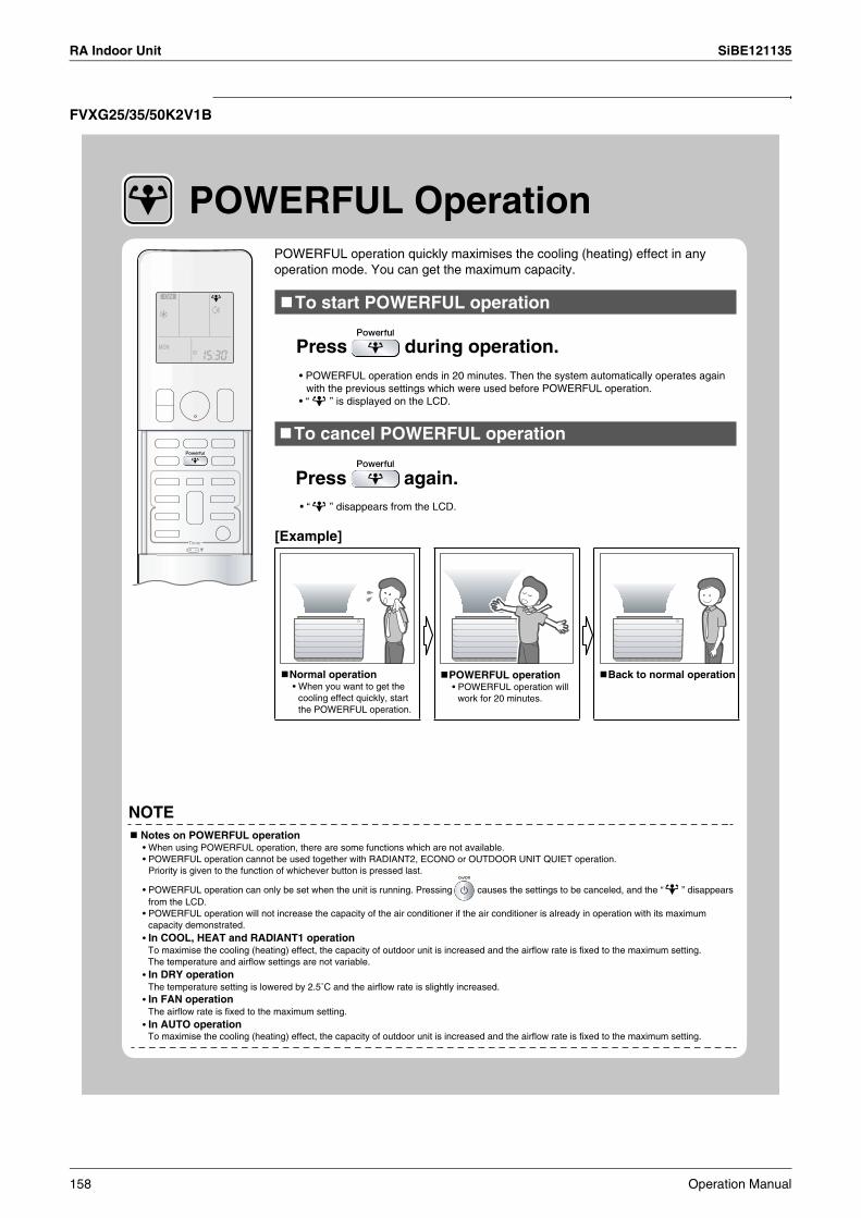
RA Indoor Unit SiBE121135
FVXG25/35/50K2V1B
[Example]
NOTE Notes on POWERFUL operation
POWERFUL OperationPOWERFUL operation quickly maximises the cooling (heating) effect in any operation mode. You can get the maximum capacity.
To start POWERFUL operation
Press during operation.• POWERFUL operation ends in 20 minutes. Then the system automatically operates again
with the previous settings which were used before POWERFUL operation.• “ ” is displayed on the LCD.
To cancel POWERFUL operation
Press again.• “ ” disappears from the LCD.
Normal operation• When you want to get the
cooling effect quickly, start the POWERFUL operation.
POWERFUL operation• POWERFUL operation will
work for 20 minutes.
Back to normal operation
• When using POWERFUL operation, there are some functions which are not available.• POWERFUL operation cannot be used together with RADIANT2, ECONO or OUTDOOR UNIT QUIET operation.
Priority is given to the function of whichever button is pressed last.
• POWERFUL operation can only be set when the unit is running. Pressing causes the settings to be canceled, and the “ ” disappears from the LCD.
• POWERFUL operation will not increase the capacity of the air conditioner if the air conditioner is already in operation with its maximum capacity demonstrated.
• In COOL, HEAT and RADIANT1 operationTo maximise the cooling (heating) effect, the capacity of outdoor unit is increased and the airflow rate is fixed to the maximum setting.The temperature and airflow settings are not variable.
• In DRY operationThe temperature setting is lowered by 2.5˚C and the airflow rate is slightly increased.
• In FAN operationThe airflow rate is fixed to the maximum setting.
• In AUTO operationTo maximise the cooling (heating) effect, the capacity of outdoor unit is increased and the airflow rate is fixed to the maximum setting.
158 Operation Manual
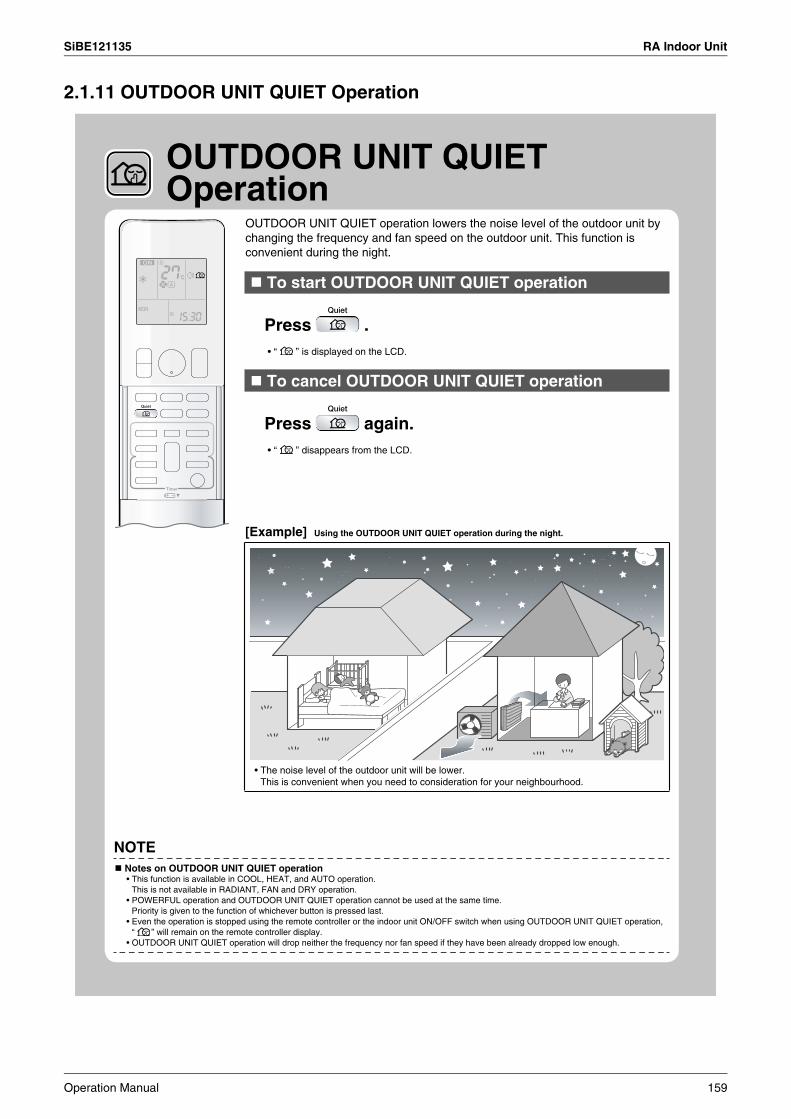
SiBE121135 RA Indoor Unit
2.1.11 OUTDOOR UNIT QUIET Operation
To start OUTDOOR UNIT QUIET operation
Press .• “ ” is displayed on the LCD.
To cancel OUTDOOR UNIT QUIET operation
Press again. • “ ” disappears from the LCD.
[Example] Using the OUTDOOR UNIT QUIET operation during the night.
NOTE Notes on OUTDOOR UNIT QUIET operation
OUTDOOR UNIT QUIET Operation
OUTDOOR UNIT QUIET operation lowers the noise level of the outdoor unit by changing the frequency and fan speed on the outdoor unit. This function is convenient during the night.
• The noise level of the outdoor unit will be lower.This is convenient when you need to consideration for your neighbourhood.
• This function is available in COOL, HEAT, and AUTO operation.This is not available in RADIANT, FAN and DRY operation.
• POWERFUL operation and OUTDOOR UNIT QUIET operation cannot be used at the same time.Priority is given to the function of whichever button is pressed last.
• Even the operation is stopped using the remote controller or the indoor unit ON/OFF switch when using OUTDOOR UNIT QUIET operation, “ ” will remain on the remote controller display.
• OUTDOOR UNIT QUIET operation will drop neither the frequency nor fan speed if they have been already dropped low enough.
Operation Manual 159

RA Indoor Unit SiBE121135
2.1.12 ECONO Operation
ECONO Operation
To start ECONO operation
Press during operation. • “ ” is displayed on the LCD.
To cancel ECONO operation
Press again.• “ ” disappears from the LCD.
[Example]Normal operation ECONO operation
TimeFrom start up until set temperature is reached
NOTE Notes on ECONO operation
ECONO operation is a function which enables efficient operation by limiting the maximum power consumption value.This function is useful for cases in which attention should be paid to ensure a circuit breaker will not trip when the product runs alongside other appliances.
• In case the air conditioner and other appliances which require high power consumption are used at same time, a circuit breaker may trip if the air conditioner operate with its maximum capacity.
• The maximum power consumption of the air conditioner is limited by using ECONO operation.The circuit breaker will hardly trip even if the air conditioner and other appliances are used at same time.
Running current and power consumption
Maximum during normal operation
Maximum during ECONO operation
ECONO operation
Normal operation
• This diagram is a representation for illustrative purposes only.The maximum running current and power consumption of the air conditioner in ECONO operation vary with the connecting outdoor unit.
• ECONO operation can only be set when the unit is running. Pressing causes the settings to be canceled, and the “ ” disappears from the LCD.
• ECONO operation is a function which enables efficient operation by limiting the power consumption of the outdoor unit (operating frequency).• ECONO operation functions in AUTO, COOL, DRY, and HEAT operation.
This is not available in RADIANT and FAN operation. • POWERFUL operation and ECONO operation cannot be used at the same time.
Priority is given to the function of whichever button is pressed last. • If the level of power consumption is already low, ECONO operation will not drop the power consumption.
160 Operation Manual
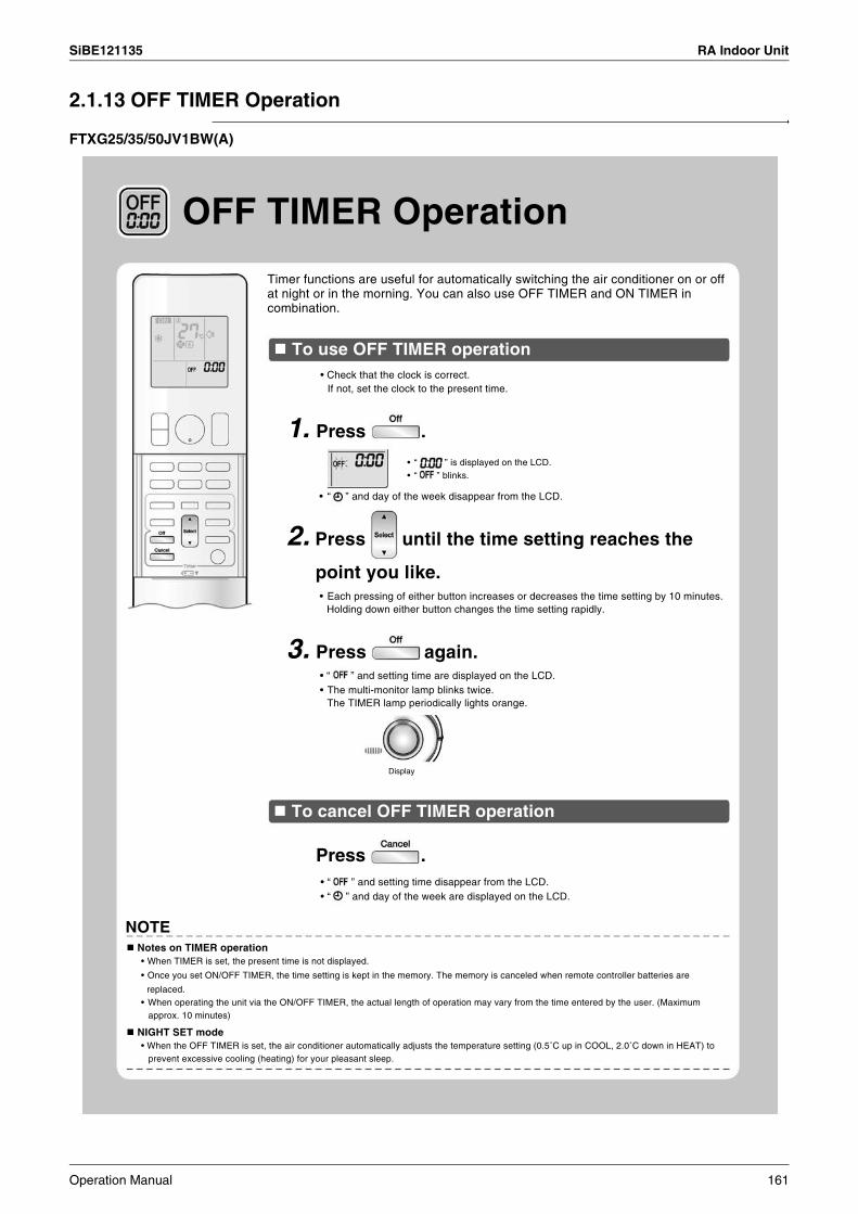
SiBE121135 RA Indoor Unit
2.1.13 OFF TIMER Operation
FTXG25/35/50JV1BW(A)
Display
OFF TIMER Operation
Timer functions are useful for automatically switching the air conditioner on or off at night or in the morning. You can also use OFF TIMER and ON TIMER in combination.
To use OFF TIMER operation• Check that the clock is correct.
If not, set the clock to the present time.
1. Press .
• “ ” and day of the week disappear from the LCD.
• “ ” is displayed on the LCD.• “ ” blinks.
2. Press until the time setting reaches the
point you like.• Each pressing of either button increases or decreases the time setting by 10 minutes.
Holding down either button changes the time setting rapidly.
3. Press again.• “ ” and setting time are displayed on the LCD.• The multi-monitor lamp blinks twice.
The TIMER lamp periodically lights orange.
To cancel OFF TIMER operation
• “ ” and setting time disappear from the LCD.• “ ” and day of the week are displayed on the LCD.
Press .
Notes on TIMER operation• When TIMER is set, the present time is not displayed.
• Once you set ON/OFF TIMER, the time setting is kept in the memory. The memory is canceled when remote controller batteries are
replaced.• When operating the unit via the ON/OFF TIMER, the actual length of operation may vary from the time entered by the user. (Maximum
approx. 10 minutes)
NIGHT SET mode• When the OFF TIMER is set, the air conditioner automatically adjusts the temperature setting (0.5˚C up in COOL, 2.0˚C down in HEAT) to
prevent excessive cooling (heating) for your pleasant sleep.
NOTE
Operation Manual 161
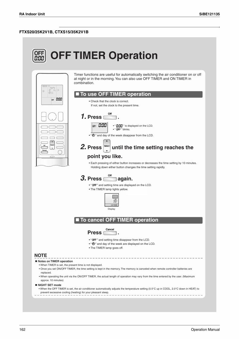
RA Indoor Unit SiBE121135
FTXS20/25K2V1B, CTXS15/35K2V1B
OFF TIMER Operation
Timer functions are useful for automatically switching the air conditioner on or off at night or in the morning. You can also use OFF TIMER and ON TIMER in combination.
To use OFF TIMER operation
To cancel OFF TIMER operation
• Check that the clock is correct.
If not, set the clock to the present time.
• Each pressing of either button increases or decreases the time setting by 10 minutes.
Holding down either button changes the time setting rapidly.
• “ ” and day of the week disappear from the LCD.
• “ ” and setting time are displayed on the LCD.
• The TIMER lamp lights yellow.
• “ ” and setting time disappear from the LCD.• “ ” and day of the week are displayed on the LCD.• The TIMER lamp goes off.
1. Press .
3. Press again.
Press .
2. Press until the time setting reaches the
point you like.
• “ ” is displayed on the LCD.• “ ” blinks.
Display
NOTE Notes on TIMER operation
• When TIMER is set, the present time is not displayed.
• Once you set ON/OFF TIMER, the time setting is kept in the memory. The memory is canceled when remote controller batteries are
replaced.
• When operating the unit via the ON/OFF TIMER, the actual length of operation may vary from the time entered by the user. (Maximum
approx. 10 minutes)
NIGHT SET mode• When the OFF TIMER is set, the air conditioner automatically adjusts the temperature setting (0.5°C up in COOL, 2.0°C down in HEAT) to
prevent excessive cooling (heating) for your pleasant sleep.
162 Operation Manual
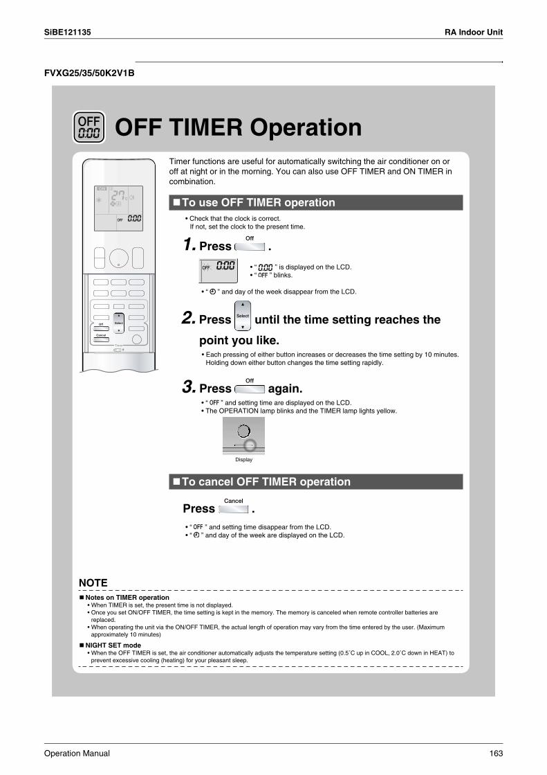
SiBE121135 RA Indoor Unit
FVXG25/35/50K2V1B
OFF TIMER Operation
Display
NOTE
Timer functions are useful for automatically switching the air conditioner on or off at night or in the morning. You can also use OFF TIMER and ON TIMER in combination.
To use OFF TIMER operation• Check that the clock is correct.
If not, set the clock to the present time.
1. Press .
• “ ” is displayed on the LCD.• “ ” blinks.
• “ ” and day of the week disappear from the LCD.
2. Press until the time setting reaches the
point you like.• Each pressing of either button increases or decreases the time setting by 10 minutes.
Holding down either button changes the time setting rapidly.
3. Press again.• “ ” and setting time are displayed on the LCD.• The OPERATION lamp blinks and the TIMER lamp lights yellow.
To cancel OFF TIMER operation
Press .• “ ” and setting time disappear from the LCD.• “ ” and day of the week are displayed on the LCD.
Notes on TIMER operation• When TIMER is set, the present time is not displayed.• Once you set ON/OFF TIMER, the time setting is kept in the memory. The memory is canceled when remote controller batteries are
replaced.• When operating the unit via the ON/OFF TIMER, the actual length of operation may vary from the time entered by the user. (Maximum
approximately 10 minutes)
NIGHT SET mode• When the OFF TIMER is set, the air conditioner automatically adjusts the temperature setting (0.5˚C up in COOL, 2.0˚C down in HEAT) to
prevent excessive cooling (heating) for your pleasant sleep.
Operation Manual 163
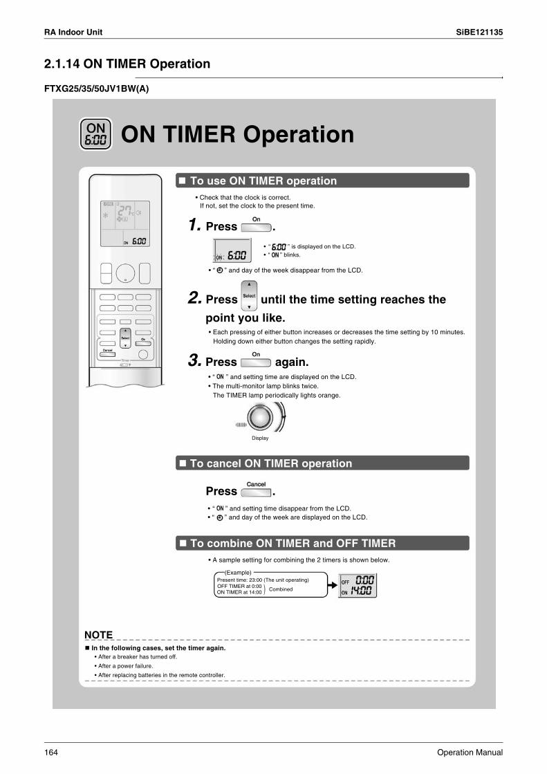
RA Indoor Unit SiBE121135
2.1.14 ON TIMER Operation
FTXG25/35/50JV1BW(A)
Display
(Example)Present time: 23:00 (The unit operating)
Combined
NOTE In the following cases, set the timer again.
ON TIMER Operation
To use ON TIMER operation• Check that the clock is correct.
If not, set the clock to the present time.
1. Press .
• “ ” is displayed on the LCD.• “ ” blinks.
• “ ” and day of the week disappear from the LCD.
2. Press until the time setting reaches the
point you like.• Each pressing of either button increases or decreases the time setting by 10 minutes.
Holding down either button changes the setting rapidly.
3. Press again.• “ ” and setting time are displayed on the LCD.• The multi-monitor lamp blinks twice.
The TIMER lamp periodically lights orange.
To cancel ON TIMER operation
Press .• “ ” and setting time disappear from the LCD.• “ ” and day of the week are displayed on the LCD.
To combine ON TIMER and OFF TIMER • A sample setting for combining the 2 timers is shown below.
OFF TIMER at 0:00ON TIMER at 14:00
• After a breaker has turned off.
• After a power failure.
• After replacing batteries in the remote controller.
)
164 Operation Manual
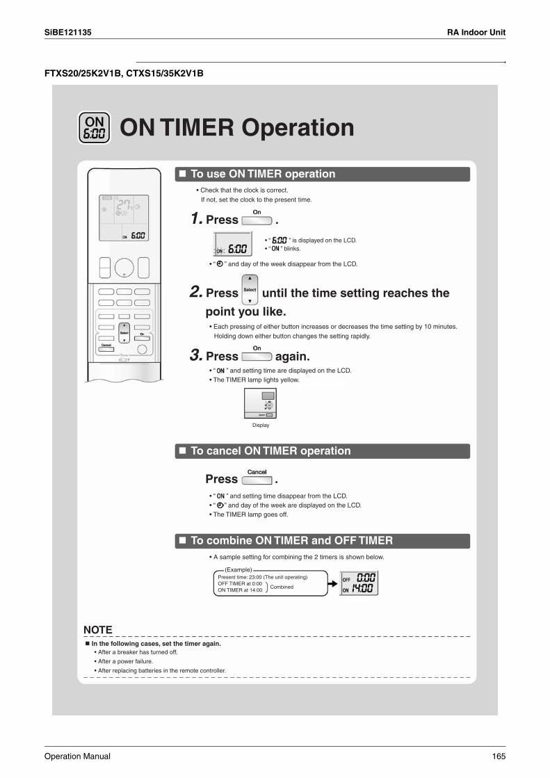
SiBE121135 RA Indoor Unit
FTXS20/25K2V1B, CTXS15/35K2V1B
ON TIMER Operation
To use ON TIMER operation
To cancel ON TIMER operation
To combine ON TIMER and OFF TIMER
• Check that the clock is correct.
If not, set the clock to the present time.
• Each pressing of either button increases or decreases the time setting by 10 minutes.
Holding down either button changes the setting rapidly.
• “ ” and day of the week disappear from the LCD.
• “ ” and setting time are displayed on the LCD.• The TIMER lamp lights yellow.
1. Press .
3. Press again.
2. Press until the time setting reaches the
point you like.
• “ ” is displayed on the LCD.• “ ” blinks.
• “ ” and setting time disappear from the LCD.• “ ” and day of the week are displayed on the LCD.• The TIMER lamp goes off.
• A sample setting for combining the 2 timers is shown below.
Press .
Display
(Example)Present time: 23:00 (The unit operating)OFF TIMER at 0:00ON TIMER at 14:00
Combined
NOTE In the following cases, set the timer again.
• After a breaker has turned off.
• After a power failure.
• After replacing batteries in the remote controller.
Operation Manual 165
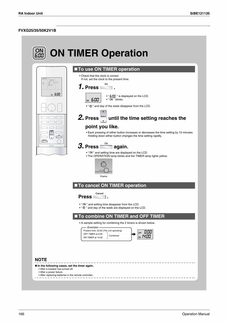
RA Indoor Unit SiBE121135
FVXG25/35/50K2V1B
ON TIMER Operation
Display
Present time: 23:00 (The unit operating)
Combined
(Example)
NOTE
To use ON TIMER operation• Check that the clock is correct.
If not, set the clock to the present time.
1. Press .
• “ ” is displayed on the LCD.• “ ” blinks.
• “ ” and day of the week disappear from the LCD.
2. Press until the time setting reaches the
point you like.• Each pressing of either button increases or decreases the time setting by 10 minutes.
Holding down either button changes the time setting rapidly.
3. Press again.• “ ” and setting time are displayed on the LCD.• The OPERATION lamp blinks and the TIMER lamp lights yellow.
To cancel ON TIMER operation
Press .• “ ” and setting time disappear from the LCD.• “ ” and day of the week are displayed on the LCD.
To combine ON TIMER and OFF TIMER• A sample setting for combining the 2 timers is shown below.
OFF TIMER at 0:00
ON TIMER at 14:00
In the following cases, set the timer again.• After a breaker has turned off.• After a power failure.• After replacing batteries in the remote controller.
166 Operation Manual

SiBE121135 RA Indoor Unit
2.1.15 WEEKLY TIMER Operation
[Example]
[Monday] Make timer settings up to programs 1-4.
6:00 8:30 17:30 22:00
25˚C 27˚C
ON ONOFF OFF
6:00 8:30 17:30 22:00
25˚C 27˚C
[Saturday] No timer settings
[Sunday] Make timer settings up to programs 1-4.
27˚C 27˚C25˚C
Program 1 Program 2 Program 3 Program 4
ON ONOFF OFF
WEEKLY TIMER OperationUp to 4 timer settings can be saved for each day of the week. It is convenient if the WEEKLY TIMER is set according to the family’s life style.
Using in these cases of WEEKLY TIMER
The same timer settings are made for the week from Monday through Friday while different timer settings are made for the weekend.
[Tuesday] to
[Friday]
Use the copy mode to make settings for Tuesday to Friday, because these settings are the same as those for Monday.
Program 1ON
Program 3ON
Program 2OFF
Program 4OFF
Program 1ON
Program 3ON
Program 2OFF
Program 4OFF
ON ONOFF OFF
8:00 10:00 21:0019:00
• Up to 4 reservations per day and 28 reservations per week can be set in the WEEKLY TIMER. The effective use of the copy mode ensures ease of making reservations.
• The use of ON-ON-ON-ON settings, for example, makes it possible to schedule operating mode and set temperature changes. Furthermore, by using OFF-OFF-OFF-OFF settings, only the turn off time of each day can be set. This will turn off the air conditioner automatically if the user forgets to turn it off.
Operation Manual 167

RA Indoor Unit SiBE121135
Setting mode
6:00 8:30 17:30 22:00
25˚C 27˚C[Monday]
Setting Displays
Day and number ON/OFF Time Temperature
ON TIMER OFF TIMER blank
To use WEEKLY TIMER operation
• Make sure the day of the week and time are set. If not, set the day of the week and time.
Program 1ON
Program 3ON
Program 2OFF
Program 4OFF
1. Press .• The day of the week and the reservation number of the current day will be displayed.• 1 to 4 settings can be made per day
2. Press to select the desired day of the week
and reservation number.
• Pressing changes the reservation number and the day of the week.
3. Press .• The day of the week and reservation number will be set.• “ ” and “ ” blink.
4. Press to select the desired mode.
• Pressing changes “ ” or “ ” setting in sequence.
Pressing alternates the following items appearing on the LCD in rotational sequence.
• In case the reservation has already been set, selecting “blank” deletes the reservation.
• Go to step 9 if “blank” is selected.
• To return to the day of the week and reservation number setting, press .
5. Press .• The ON/OFF TIMER mode will be set. • “ ” and the time blink.
168 Operation Manual

SiBE121135 RA Indoor Unit
Display
NOTE
WEEKLY TIMER Operation
6. Press to select the desired time.• The time can be set between 0:00 and 23:50 in 10 minute intervals.
• To return to the ON/OFF TIMER mode setting, press .
• Go to step 9 when setting the OFF TIMER.
7. Press .• The time will be set.• “ ” and the temperature blink.
8. Press to select the desired temperature.• The temperature can be set between 10˚C and 32˚C.
COOL or AUTO: The unit operates at 18˚C even if it is set at 10 to 17˚C.HEAT or AUTO: The unit operates at 30˚C even if it is set at 31 to 32˚C.
• To return to the time setting, press .• The set temperature is only displayed when the mode setting is on.
9. Press .• Be sure to direct the remote controller toward the indoor unit and check for a receiving tone and flashing the OPERATION lamp.
• The temperature is set while in ON TIMER operation, and the time is set while in OFF TIMER operation.
• The next reservation screen will appear.
• To continue further settings, repeat the procedure from step 4.• The TIMER lamp lights yellow.
10. Press to complete the setting.• “ ” is displayed on the LCD and WEEKLY TIMER operation is activated.• A reservation made once can be easily copied and the same settings used for another day of the week. Refer to copy mode.
Notes on WEEKLY TIMER operation• Do not forget to set the clock on the remote controller first.• The day of the week, ON/OFF TIMER mode, time and set temperature (only for ON TIMER mode) can be set with WEEKLY TIMER.
Other settings for ON TIMER are based on the settings just before the operation.• Both WEEKLY TIMER and ON/OFF TIMER operation cannot be used at the same time. The ON/OFF TIMER operation has priority if it is set
while WEEKLY TIMER is still active. The WEEKLY TIMER will go into standby state, and “ ” will disappear from the LCD. When ON/OFF TIMER is up, the WEEKLY TIMER will automatically become active.
• Shutting the breaker off, power failure, and other similar events will render operation of the indoor unit’s internal clock inaccurate. Reset the clock.
Operation Manual 169
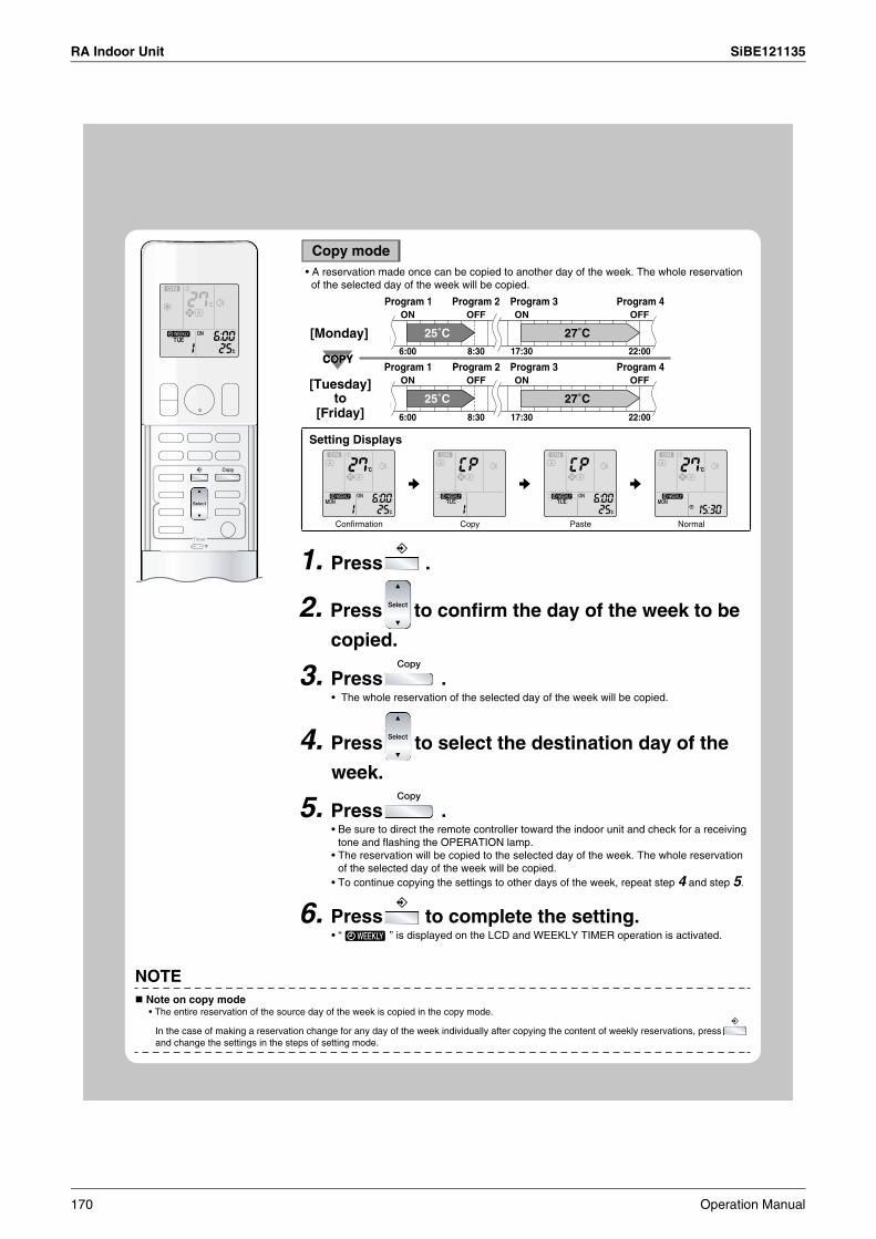
RA Indoor Unit SiBE121135
NOTE
Copy mode
6:00 8:30 17:30 22:00
25˚C 27˚C
6:00 8:30 17:30 22:00
25˚C 27˚C
COPYCOPY
Program 1 Program 2 Program 3 Program 4ON OFF ON OFF
[Monday]
Program 1 Program 2 Program 3 Program 4ON OFF ON OFF
Setting Displays
Confirmation Copy Paste Normal
3. Press .• The whole reservation of the selected day of the week will be copied.
5. Press .
6. Press to complete the setting.• “ ” is displayed on the LCD and WEEKLY TIMER operation is activated.
• A reservation made once can be copied to another day of the week. The whole reservation of the selected day of the week will be copied.
[Tuesday] to
[Friday]
2. Press to confirm the day of the week to be
copied.
4. Press to select the destination day of the
week.
• Be sure to direct the remote controller toward the indoor unit and check for a receiving tone and flashing the OPERATION lamp.
• The reservation will be copied to the selected day of the week. The whole reservation of the selected day of the week will be copied.
• To continue copying the settings to other days of the week, repeat step 4 and step 5.
• The entire reservation of the source day of the week is copied in the copy mode.
In the case of making a reservation change for any day of the week individually after copying the content of weekly reservations, press and change the settings in the steps of setting mode.
1. Press .
Note on copy mode
170 Operation Manual
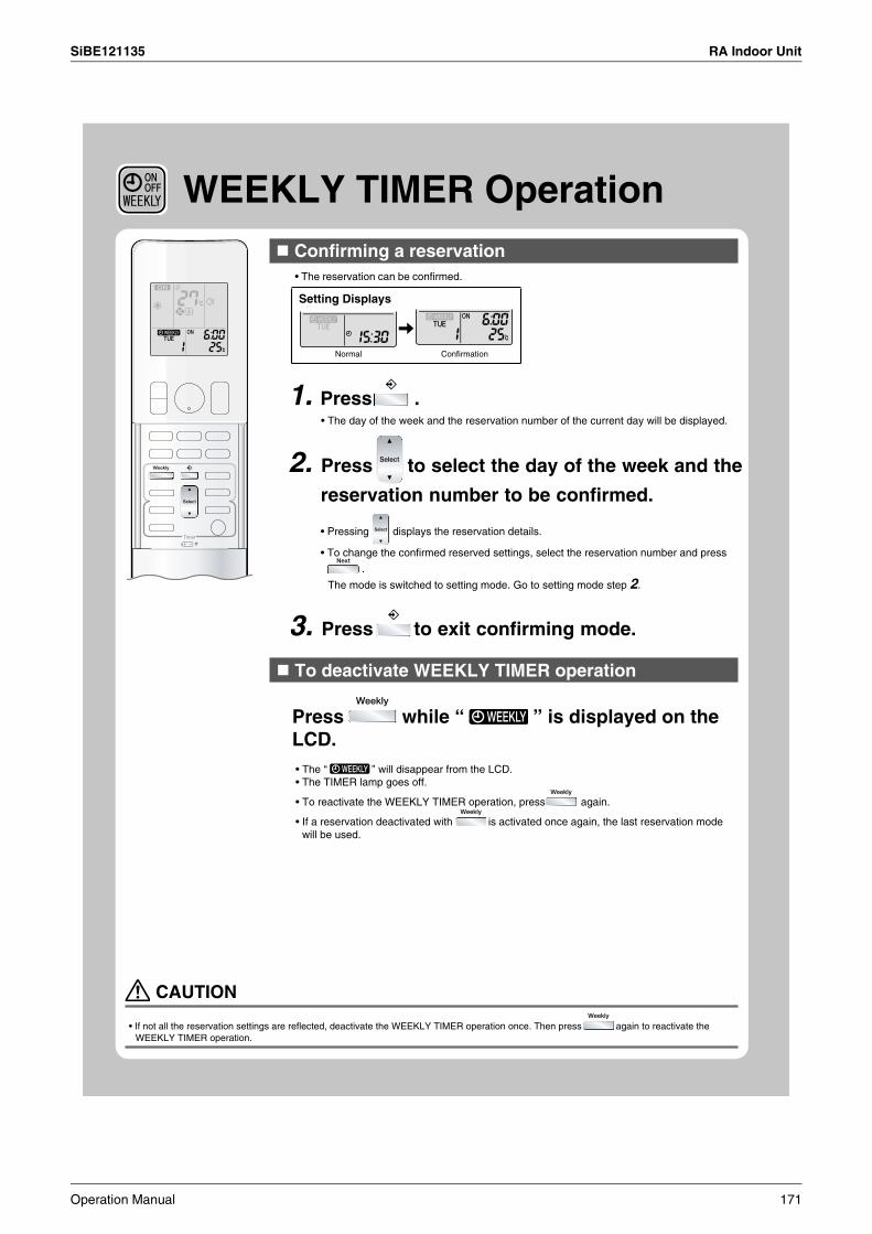
SiBE121135 RA Indoor Unit
WEEKLY TIMER Operation
To deactivate WEEKLY TIMER operation
Press while “ ” is displayed on the LCD.• The “ ” will disappear from the LCD.• The TIMER lamp goes off.
• To reactivate the WEEKLY TIMER operation, press again.
• If a reservation deactivated with is activated once again, the last reservation mode will be used.
3. Press to exit confirming mode.
Setting Displays
Normal
• The reservation can be confirmed.
Confirming a reservation
Confirmation
• The day of the week and the reservation number of the current day will be displayed.
1. Press .
2. Press to select the day of the week and the
reservation number to be confirmed.
• Pressing displays the reservation details.
• To change the confirmed reserved settings, select the reservation number and press
.
The mode is switched to setting mode. Go to setting mode step 2.
CAUTION
• If not all the reservation settings are reflected, deactivate the WEEKLY TIMER operation once. Then press again to reactivate the WEEKLY TIMER operation.
Operation Manual 171
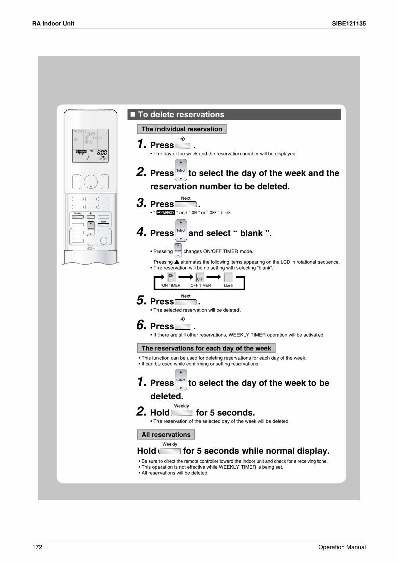
RA Indoor Unit SiBE121135
• The day of the week and the reservation number will be displayed.
3. Press .• “ ” and “ ON ” or “ OFF ” blink.
4. Press and select “ blank ”.
ON TIMER OFF TIMER blank
5. Press .
6. Press .
The reservations for each day of the week
2. Hold for 5 seconds.
2. Press to select the day of the week and the
reservation number to be deleted.
• Pressing changes ON/OFF TIMER mode.
Pressing alternates the following items appearing on the LCD in rotational sequence.• The reservation will be no setting with selecting “blank”.
• This function can be used for deleting reservations for each day of the week.• It can be used while confirming or setting reservations.
1. Press to select the day of the week to be
deleted.
• Be sure to direct the remote controller toward the indoor unit and check for a receiving tone.• This operation is not effective while WEEKLY TIMER is being set.• All reservations will be deleted.
• If there are still other reservations, WEEKLY TIMER operation will be activated.
• The selected reservation will be deleted.
To delete reservations
The individual reservation
1. Press .
• The reservation of the selected day of the week will be deleted.
All reservations
Hold for 5 seconds while normal display.
172 Operation Manual
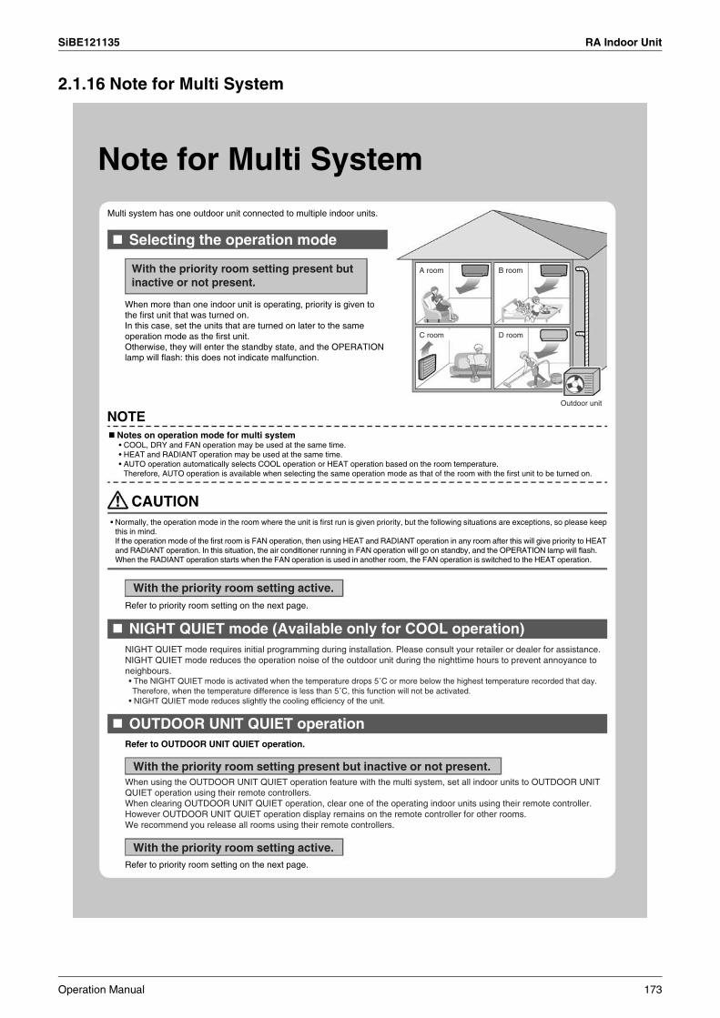
SiBE121135 RA Indoor Unit
2.1.16 Note for Multi System
Note for Multi SystemMulti system has one outdoor unit connected to multiple indoor units.
Selecting the operation mode
NIGHT QUIET mode (Available only for COOL operation)
OUTDOOR UNIT QUIET operation
When more than one indoor unit is operating, priority is given to the first unit that was turned on.In this case, set the units that are turned on later to the same operation mode as the first unit.Otherwise, they will enter the standby state, and the OPERATION lamp will flash: this does not indicate malfunction.
With the priority room setting present but inactive or not present.
A room B room
C room D room
Outdoor unit
NOTENotes on operation mode for multi system• COOL, DRY and FAN operation may be used at the same time.• HEAT and RADIANT operation may be used at the same time.• AUTO operation automatically selects COOL operation or HEAT operation based on the room temperature.
Therefore, AUTO operation is available when selecting the same operation mode as that of the room with the first unit to be turned on.
CAUTION• Normally, the operation mode in the room where the unit is first run is given priority, but the following situations are exceptions, so please keep
this in mind.If the operation mode of the first room is FAN operation, then using HEAT and RADIANT operation in any room after this will give priority to HEAT and RADIANT operation. In this situation, the air conditioner running in FAN operation will go on standby, and the OPERATION lamp will flash. When the RADIANT operation starts when the FAN operation is used in another room, the FAN operation is switched to the HEAT operation.
With the priority room setting active.
With the priority room setting present but inactive or not present.
With the priority room setting active.
Refer to priority room setting on the next page.
Refer to priority room setting on the next page.
Refer to OUTDOOR UNIT QUIET operation.
NIGHT QUIET mode requires initial programming during installation. Please consult your retailer or dealer for assistance.NIGHT QUIET mode reduces the operation noise of the outdoor unit during the nighttime hours to prevent annoyance to neighbours.• The NIGHT QUIET mode is activated when the temperature drops 5˚C or more below the highest temperature recorded that day. Therefore, when the temperature difference is less than 5˚C, this function will not be activated.
• NIGHT QUIET mode reduces slightly the cooling efficiency of the unit.
When using the OUTDOOR UNIT QUIET operation feature with the multi system, set all indoor units to OUTDOOR UNIT QUIET operation using their remote controllers.When clearing OUTDOOR UNIT QUIET operation, clear one of the operating indoor units using their remote controller.However OUTDOOR UNIT QUIET operation display remains on the remote controller for other rooms.We recommend you release all rooms using their remote controllers.
Operation Manual 173

RA Indoor Unit SiBE121135
COOL/HEAT mode lock
Priority room setting
The COOL/HEAT mode lock requires initial programming during installation. Please consult your authorised dealer for assistance. The COOL/HEAT mode lock sets the unit forcibly to either COOL or HEAT operation. This function is convenient when you wish to set all indoor units connected to the multi system to the same operation mode.During the COOL mode, the DRY operation can also be used. During the HEAT mode, the RADIANT operation can also be used.
The priority room setting requires initial programming during installation. Please consult your authorised dealer for assistance.The room designated as the priority room takes priority in the following situations.
NOTE• The COOL/HEAT mode lock cannot be activated together with the priority room setting.
• As the operation mode of the priority room takes precedence, the user can select a different operation mode from other rooms.
Operation mode priority
Priority when POWERFUL operation is used
Priority when using OUTDOOR UNIT QUIET operation
[Example]• Room A is the priority room in the examples.
When COOL operation is selected in room A while operating the following modes in room B, C and D:
[Example]• Room A is the priority room in the examples.
The indoor units in rooms A, B, C and D are all operating. If the unit in room A enters POWERFUL operation, operation capacity will be concentrated in room A. In such a case, the cooling (heating) efficiency of the units in room B, C and D may be slightly reduced.
[Example]• Room A is the priority room in the examples.
Just by setting the unit in room A to QUIET operation, the air conditioner starts OUTDOOR UNIT QUIET operation.You don’t have to set all the operated indoor units to QUIET operation.
Operation mode in room B, C and DCOOL or DRY or FANHEAT and RADIANT
AUTO
Status of room B, C and D when the unit in room A is in COOL operationCurrent operation mode maintainedThe unit enters standby mode. Operation resumes when the room A unit stops operating.If the unit is set to COOL operation, it continues. If the unit is set to HEAT operation, it enters standby mode. Operation resumes when the room A unit stops operating.
174 Operation Manual
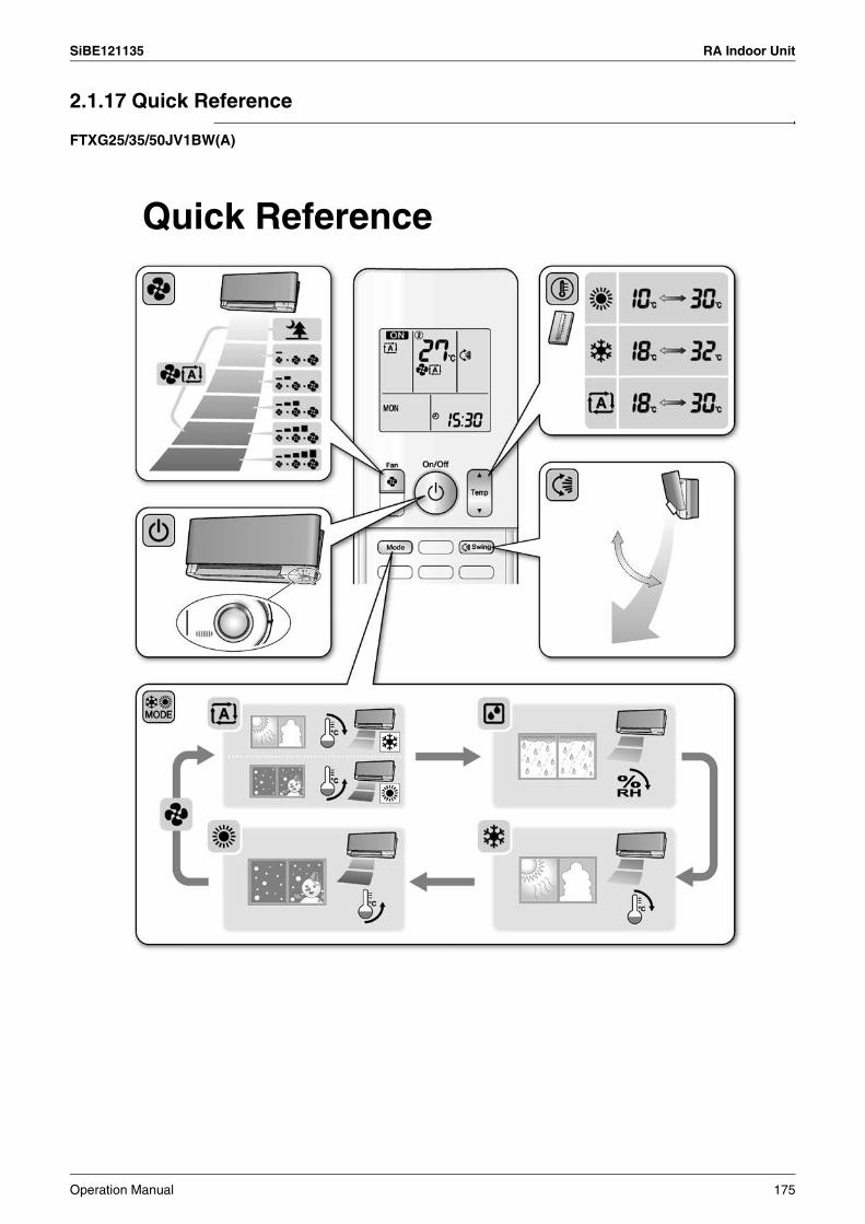
SiBE121135 RA Indoor Unit
2.1.17 Quick Reference
FTXG25/35/50JV1BW(A)
Quick Reference
Operation Manual 175

RA Indoor Unit SiBE121135
FTXS20/25K2V1B, CTXS15/35K2V1B
Quick Reference
176 Operation Manual
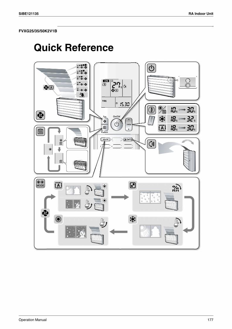
SiBE121135 RA Indoor Unit
FVXG25/35/50K2V1B
Quick Reference
Operation Manual 177

RA Indoor Unit SiBE121135
2.2 FTXS-J, FTXS-G, FVXS Series - ARC452A1, A32.2.1 Manual Contents and Reference Page
: The illustrations are for FTXS-J series as representative.
Model SeriesWall Mounted Type Floor Standing Type
FTXS25-50J2V1B FTXS60/71GV1B FVXS25-50FV1B
Read Before Operation
Names of Parts 179 182 185
Operation
AUTO · DRY · COOL · HEAT · FAN Operation 188 188 188
Adjusting the Airflow Direction 190 192 194
COMFORT AIRFLOW and INTELLIGENT EYE Operation 196 200 —
POWERFUL Operation 203 203 203
OUTDOOR UNIT QUIET Operation 204 204 204
ECONO Operation 205 205 205
OFF TIMER Operation 206 206 206
ON TIMER Operation 207 207 207
WEEKLY TIMER Operation 208 208 208
Note for Multi System 216 216 216
Drawing No. 3P266959-2A 3P248442-3 3P191290-1K
178 Operation Manual
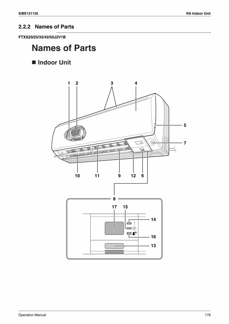
SiBE121135 RA Indoor Unit
2.2.2 Names of Parts
FTXS20/25/35/42/50J2V1B
17 15
14
16
13
1 3 4
5
7
91110
8
12 6
2
Names of Parts
Indoor Unit
Operation Manual 179

RA Indoor Unit SiBE121135
Model Mode
COOL
Indoor Unit
1. Air filter2. Titanium apatite photocatalytic
air-purifying filter:• These filters are attached to the inside of
the air filters.
3. Air inlet
4. Front panel
5. Panel tab
6. Room temperature sensor:• It senses the air temperature around the
unit.
7. INTELLIGENT EYE sensor
8. Display
9. Air outlet
10. Flaps (horizontal blades)
11. Louvers (vertical blades):• The louvers are inside of the air outlet.
12. Model name plate
13. Indoor unit ON/OFF switch:• Push this switch once to start operation.
Push once again to stop it.• The operation mode refers to the following
table.
COOLING ONLYHEAT PUMP
AUTO
Temperature setting
22˚C
25˚C
Airflow rate
AUTO
AUTO
• This switch is useful when the remote controller is missing.
14. OPERATION lamp (green)15. TIMER lamp (yellow)
16. INTELLIGENT EYE lamp (green)
17. Signal receiver:• It receives signals from the remote controller.• When the unit receives a signal, you will
hear a beep sound.• Operation start .......... beep-beep• Settings changed....... beep• Operation stop ........... long beep
180 Operation Manual

SiBE121135 RA Indoor Unit
Remote Controller 1
5
6
2
3
4
<ARC452A3>
78
13
141517
<Open the front cover>
109
11
12
1618
1. Signal transmitter:• It sends signals to the indoor unit.
2. Display:• It displays the current settings.
(In this illustration, each section is shown with its displays ON for the purpose of explanation.)
3. FAN setting button: • It selects the airflow rate setting.
4. POWERFUL button: POWERFUL operation
5. ON/OFF button:• Press this button once to start operation.
Press once again to stop it.
6. TEMPERATURE adjustment buttons:•It changes the temperature setting.
7. MODE selector button:• It selects the operation mode.
(AUTO/DRY/COOL/HEAT/FAN)
8. QUIET button: OUTDOOR UNIT QUIET operation
9. ECONO button: ECONO operation
10. SWING button:• Horizontal blades (flaps)
11. SWING button:• Vertical blades (louvers)
12. COMFORT/SENSOR button: • COMFORT AIRFLOW and INTELLIGENT
EYE operation
13. WEEKLY/PROGRAM/COPY/BACK/NEXT button: • WEEKLY TIMER operation
14. SELECT button: • It changes the ON/OFF TIMER and
WEEKLY TIMER settings.15. OFF TIMER button
16. ON TIMER button
17. TIMER CANCEL button:• It cancels the timer setting.• It cannot be used for the WEEKLY TIMER
operation.18. CLOCK button
Operation Manual 181

RA Indoor Unit SiBE121135
FTXS60/71GV1B
Names of Parts
Indoor Unit
17
16
13
1514
1 3 4 5
911 10
8
2
612 7
182 Operation Manual
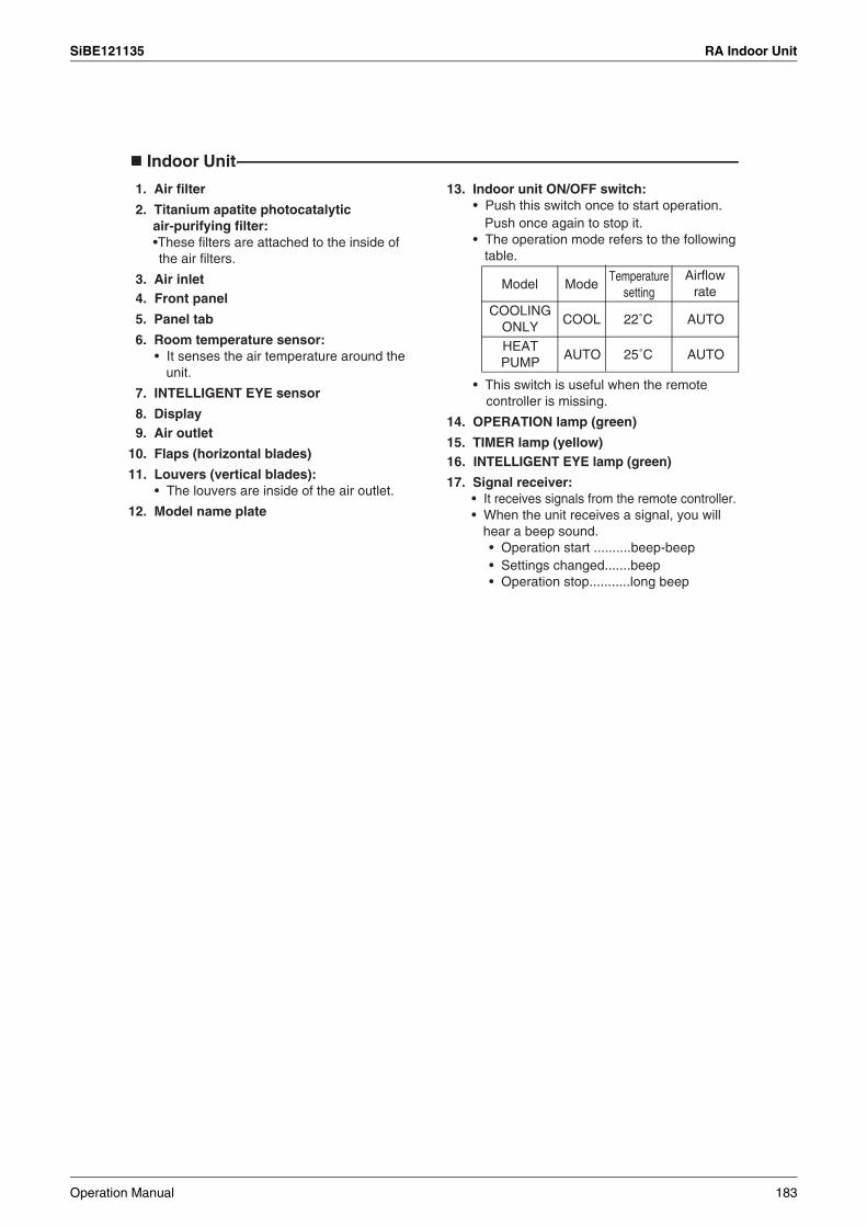
SiBE121135 RA Indoor Unit
Indoor Unit
Model Mode
COOL 22˚C AUTO
AUTO 25˚C AUTO
COOLING ONLYHEAT PUMP
Temperature setting
Airflow rate
1. Air filter
2. Titanium apatite photocatalytic air-purifying filter:•These filters are attached to the inside of the air filters.
3. Air inlet4. Front panel
5. Panel tab
6. Room temperature sensor:• It senses the air temperature around the
unit.
7. INTELLIGENT EYE sensor
8. Display9. Air outlet
10. Flaps (horizontal blades)
11. Louvers (vertical blades):• The louvers are inside of the air outlet.
12. Model name plate
13. Indoor unit ON/OFF switch:• Push this switch once to start operation.
Push once again to stop it.• The operation mode refers to the following
table.
• This switch is useful when the remote controller is missing.
14. OPERATION lamp (green)
15. TIMER lamp (yellow)16. INTELLIGENT EYE lamp (green)
17. Signal receiver:• It receives signals from the remote controller.• When the unit receives a signal, you will
hear a beep sound.• Operation start ..........beep-beep• Settings changed.......beep• Operation stop...........long beep
Operation Manual 183
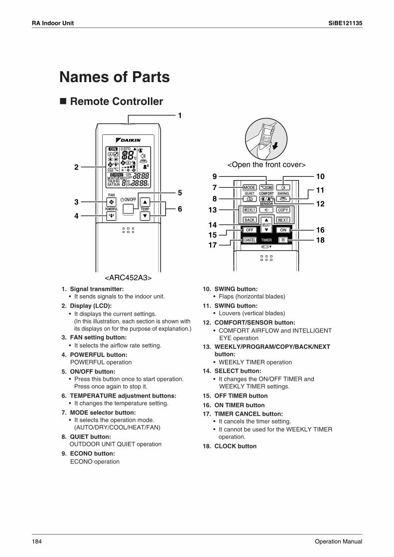
RA Indoor Unit SiBE121135
Names of Parts
Remote Controller1
5
6
2
3
4
<ARC452A3>
78
13
141517
<Open the front cover>
109
11
12
1618
1. Signal transmitter:• It sends signals to the indoor unit.
2. Display (LCD):• It displays the current settings.
(In this illustration, each section is shown with its displays on for the purpose of explanation.)
3. FAN setting button: • It selects the airflow rate setting.
4. POWERFUL button: POWERFUL operation
5. ON/OFF button:• Press this button once to start operation.
Press once again to stop it.
6. TEMPERATURE adjustment buttons:• It changes the temperature setting.
7. MODE selector button:• It selects the operation mode.
(AUTO/DRY/COOL/HEAT/FAN)
8. QUIET button: OUTDOOR UNIT QUIET operation
9. ECONO button: ECONO operation
10. SWING button:• Flaps (horizontal blades)
11. SWING button:• Louvers (vertical blades)
12. COMFORT/SENSOR button: • COMFORT AIRFLOW and INTELLIGENT
EYE operation13. WEEKLY/PROGRAM/COPY/BACK/NEXT
button: • WEEKLY TIMER operation
14. SELECT button: • It changes the ON/OFF TIMER and
WEEKLY TIMER settings.
15. OFF TIMER button
16. ON TIMER button17. TIMER CANCEL button:
• It cancels the timer setting. • It cannot be used for the WEEKLY TIMER
operation.
18. CLOCK button
184 Operation Manual
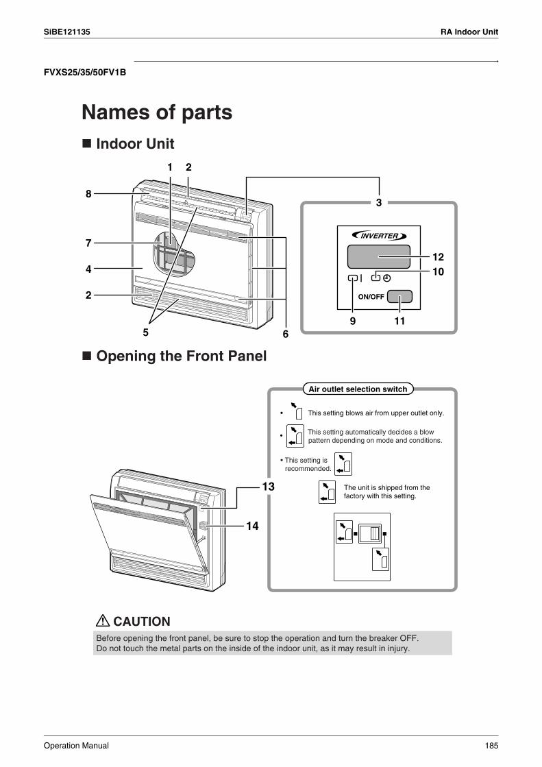
SiBE121135 RA Indoor Unit
FVXS25/35/50FV1B
Names of parts Indoor Unit
Opening the Front Panel
CAUTION
1 2
65
2
4
7
83
9
1210
11
13
14
Air outlet selection switch
• This setting is recommended.
The unit is shipped from the factory with this setting.
• This setting blows air from upper outlet only.
• This setting automatically decides a blow pattern depending on mode and conditions.
Before opening the front panel, be sure to stop the operation and turn the breaker OFF.Do not touch the metal parts on the inside of the indoor unit, as it may result in injury.
Operation Manual 185
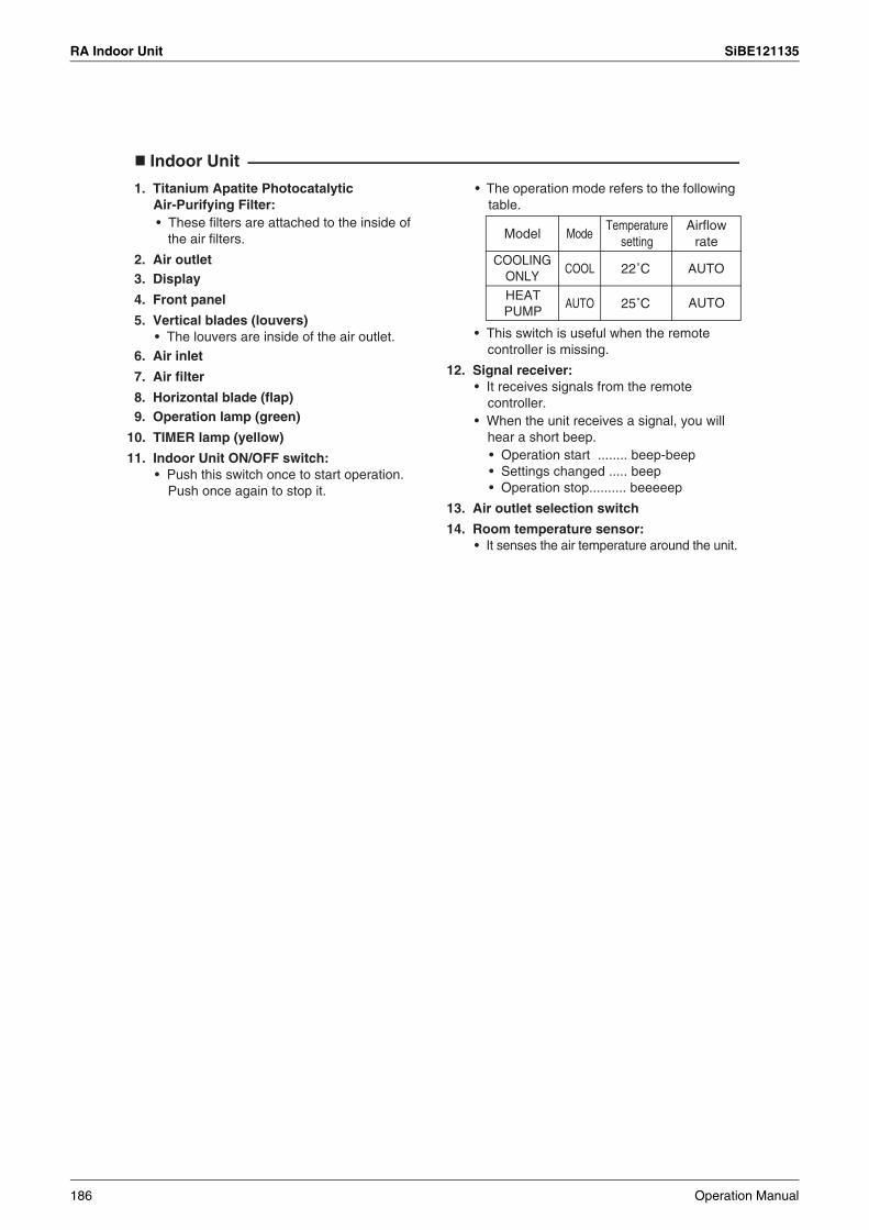
RA Indoor Unit SiBE121135
Indoor Unit
22˚C
25˚C
Model
COOLING ONLY
HEAT PUMP
Mode
COOL
AUTO
Temperature setting
Airflow rate
AUTO
AUTO
1. Titanium Apatite Photocatalytic Air-Purifying Filter:• These filters are attached to the inside of
the air filters.
2. Air outlet3. Display
4. Front panel
5. Vertical blades (louvers)• The louvers are inside of the air outlet.
6. Air inlet
7. Air filter
8. Horizontal blade (flap)9. Operation lamp (green)
10. TIMER lamp (yellow)
11. Indoor Unit ON/OFF switch:• Push this switch once to start operation.
Push once again to stop it.
• The operation mode refers to the following table.
• This switch is useful when the remote controller is missing.
12. Signal receiver:• It receives signals from the remote
controller.• When the unit receives a signal, you will
hear a short beep.• Operation start ........ beep-beep• Settings changed ..... beep• Operation stop.......... beeeeep
13. Air outlet selection switch
14. Room temperature sensor:• It senses the air temperature around the unit.
186 Operation Manual

SiBE121135 RA Indoor Unit
Remote Controller 1
5
6
2
3
4
<ARC452A1>
78
11
12
1315
<Open the lid>
910
1416
1. Signal transmitter:• It sends signals to the indoor unit.
2. Display:• It displays the current settings.
(In this illustration, each section is shown with all its displays ON for the purpose of explanation.)
3. FAN setting button: • It selects the airflow rate setting.
4. POWERFUL button: POWERFUL operation
5. ON/OFF button:• Press this button once to start operation.
Press once again to stop it.6. TEMPERATURE adjustment buttons:
• It changes the temperature setting.7. MODE selector button:
• It selects the operation mode. (AUTO/DRY/COOL/HEAT/FAN)
8. QUIET button: OUTDOOR UNIT QUIET operation
9. ECONO button: ECONO operation
10. SWING button:• Adjusting the Airflow Direction
11. WEEKLY/PROGRAM/COPY/BACK/NEXT button: WEEKLY TIMER operation
12. SELECT button: • It changes the ON/OFF TIMER and
WEEKLY TIMER settings.13. OFF TIMER button14. ON TIMER button15. TIMER CANCEL button:
• It cancels the timer setting.• It cannot be used for the WEEKLY TIMER operation.
16. CLOCK button
Operation Manual 187
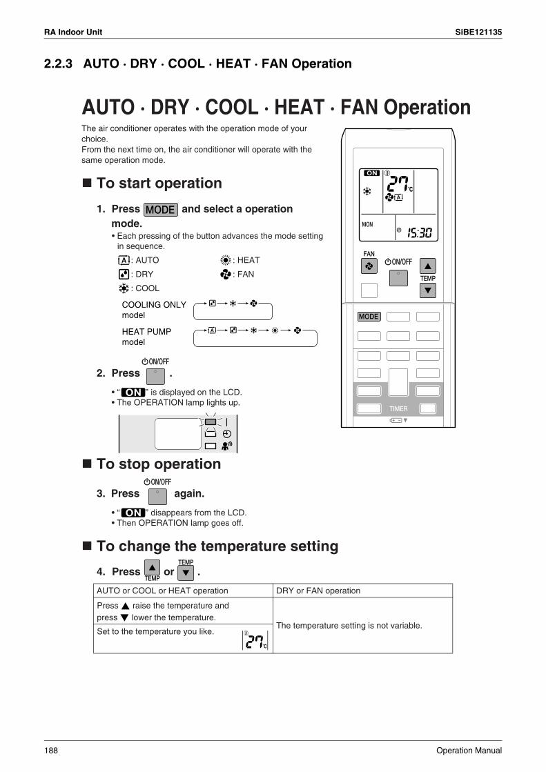
RA Indoor Unit SiBE121135
2.2.3 AUTO · DRY · COOL · HEAT · FAN Operation
1. Press and select a operation mode.
To start operation
2. Press .
To stop operation
3. Press again.
To change the temperature setting
4. Press or .
: AUTO : HEAT
: DRY : FAN
: COOL
AUTO or COOL or HEAT operation DRY or FAN operation
The temperature setting is not variable.
The air conditioner operates with the operation mode of your choice. From the next time on, the air conditioner will operate with the same operation mode.
• Each pressing of the button advances the mode setting in sequence.
COOLING ONLY model
HEAT PUMP model
AUTO · DRY · COOL · HEAT · FAN Operation
• “ ” is displayed on the LCD.• The OPERATION lamp lights up.
• “ ” disappears from the LCD.• Then OPERATION lamp goes off.
Press raise the temperature and press lower the temperature.
Set to the temperature you like.
188 Operation Manual
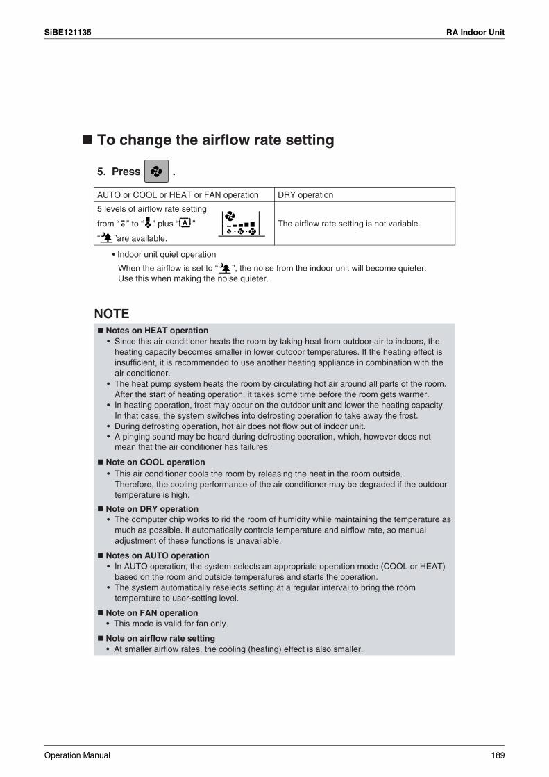
SiBE121135 RA Indoor Unit
5 levels of airflow rate setting
from “ ” to “ ” plus “ ”
“ ”are available.
To change the airflow rate setting
5. Press .
• Indoor unit quiet operation
NOTE
AUTO or COOL or HEAT or FAN operation DRY operation
The airflow rate setting is not variable.
Notes on HEAT operation
Note on COOL operation
Note on DRY operation
Notes on AUTO operation
Note on FAN operation• This mode is valid for fan only.
Note on airflow rate setting• At smaller airflow rates, the cooling (heating) effect is also smaller.
When the airflow is set to “ ”, the noise from the indoor unit will become quieter. Use this when making the noise quieter.
• Since this air conditioner heats the room by taking heat from outdoor air to indoors, the heating capacity becomes smaller in lower outdoor temperatures. If the heating effect is insufficient, it is recommended to use another heating appliance in combination with the air conditioner.
• The heat pump system heats the room by circulating hot air around all parts of the room. After the start of heating operation, it takes some time before the room gets warmer.
• In heating operation, frost may occur on the outdoor unit and lower the heating capacity. In that case, the system switches into defrosting operation to take away the frost.
• During defrosting operation, hot air does not flow out of indoor unit.• A pinging sound may be heard during defrosting operation, which, however does not
mean that the air conditioner has failures.
• This air conditioner cools the room by releasing the heat in the room outside.Therefore, the cooling performance of the air conditioner may be degraded if the outdoor temperature is high.
• The computer chip works to rid the room of humidity while maintaining the temperature as much as possible. It automatically controls temperature and airflow rate, so manual adjustment of these functions is unavailable.
• In AUTO operation, the system selects an appropriate operation mode (COOL or HEAT) based on the room and outside temperatures and starts the operation.
• The system automatically reselects setting at a regular interval to bring the room temperature to user-setting level.
Operation Manual 189

RA Indoor Unit SiBE121135
2.2.4 Adjusting the Airflow Direction
FTXS20/25/35/42/50J2V1B
Adjusting the Airflow DirectionYou can adjust the airflow direction to increase your comfort.
Press .
Press .
Press and .
Upper and lower airflow direction
The 3-D airflow direction
Upper/Lower Right/Left 3-D
Right and left airflow direction
To start auto swing
• “ ” is displayed on the LCD.• The louvers (vertical blades) will begin to swing.
• The following illustrations show respective airflow directions.
• “ ” and “ ” are displayed on the LCD.• The flaps and louvers move in turn.
• To cancel 3-D airflow, press either or again.
The flaps or louvers will stop moving.
• “ ” is displayed on the LCD.• The flaps (horizontal blades) will begin to swing.
190 Operation Manual
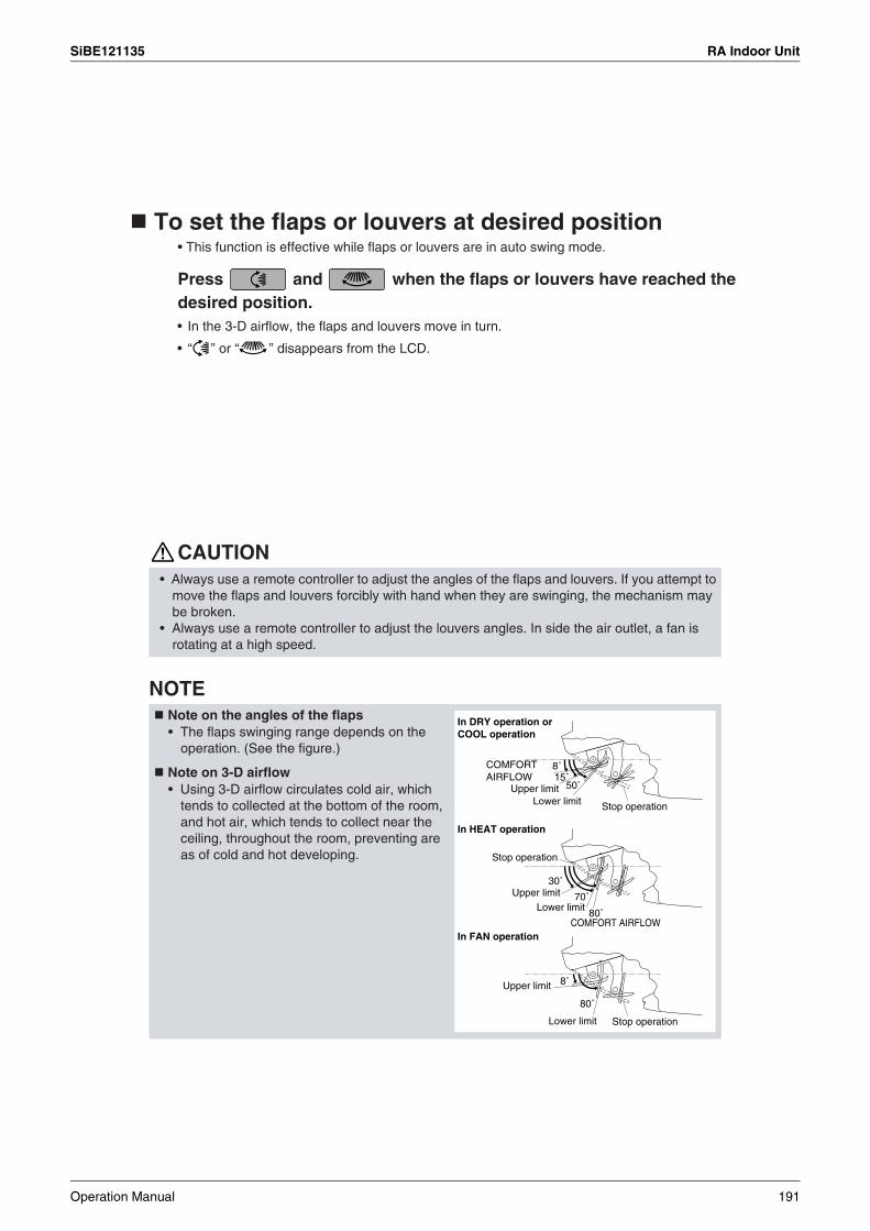
SiBE121135 RA Indoor Unit
To set the flaps or louvers at desired position • This function is effective while flaps or louvers are in auto swing mode.
CAUTION
NOTE Note on the angles of the flaps
Note on 3-D airflow
In HEAT operation
In FAN operation
Upper limitLower limit Stop operation
COMFORT AIRFLOW
Stop operation
Upper limitLower limit
Upper limit
Lower limit Stop operation
8˚15˚
50˚
80˚
30˚
70˚
8˚
80˚
Press and when the flaps or louvers have reached the desired position.
• Always use a remote controller to adjust the angles of the flaps and louvers. If you attempt to move the flaps and louvers forcibly with hand when they are swinging, the mechanism may be broken.
• Always use a remote controller to adjust the louvers angles. In side the air outlet, a fan is rotating at a high speed.
• The flaps swinging range depends on the operation. (See the figure.)
• Using 3-D airflow circulates cold air, which tends to collected at the bottom of the room, and hot air, which tends to collect near the ceiling, throughout the room, preventing are as of cold and hot developing.
In DRY operation or COOL operation
COMFORT AIRFLOW
• In the 3-D airflow, the flaps and louvers move in turn.
• “ ” or “ ” disappears from the LCD.
Operation Manual 191

RA Indoor Unit SiBE121135
FTXS60/71GV1B
Adjusting the Airflow DirectionYou can adjust the airflow direction to increase your comfort.
To start auto swing
Press .
Press .
Press and .
• The following illustrations show respective airflow directions.
Upper and lower airflow direction
Right and left airflow direction
The 3-D airflow direction
Upper/Lower Right/Left 3-D
• “ ” is displayed on the LCD.• The flaps (horizontal blades) will begin to swing.
• “ ” is displayed on the LCD.• The louvers (vertical blades) will begin to swing.
• “ ” and “ ” are displayed on the LCD.• The flaps and louvers move in turn.
• To cancel 3-D airflow, press either or again.The flaps or louvers will stop moving.
192 Operation Manual
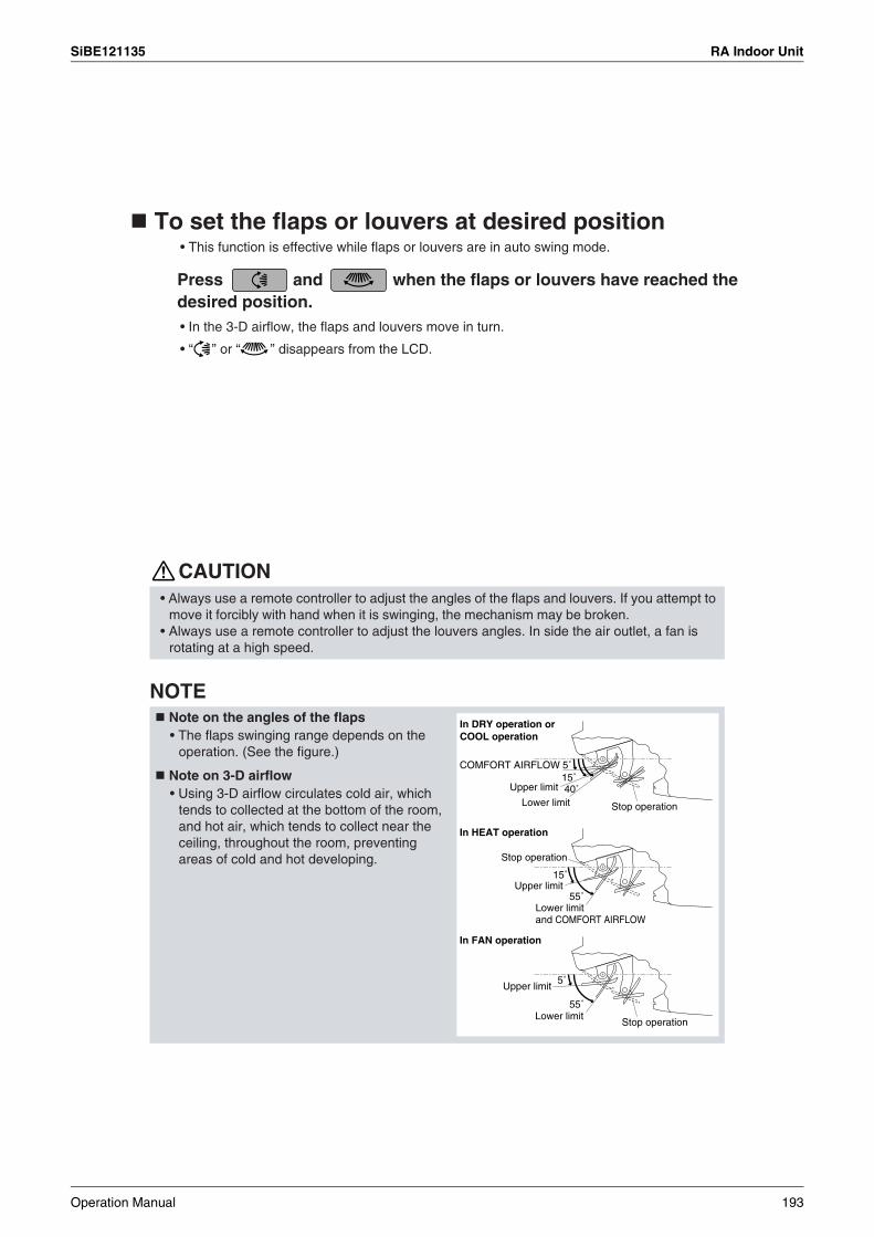
SiBE121135 RA Indoor Unit
CAUTION
NOTE
5˚
55˚
5˚15˚40˚
15˚
55˚
Upper limit
COMFORT AIRFLOW
Lower limit
Stop operation
Upper limit
Lower limit and COMFORT AIRFLOW
Upper limit
Lower limit
In HEAT operation
In FAN operation
Stop operation
Stop operation
In DRY operation or COOL operation
To set the flaps or louvers at desired position • This function is effective while flaps or louvers are in auto swing mode.
Press and when the flaps or louvers have reached the desired position.• In the 3-D airflow, the flaps and louvers move in turn.
• “ ” or “ ” disappears from the LCD.
• Always use a remote controller to adjust the angles of the flaps and louvers. If you attempt to move it forcibly with hand when it is swinging, the mechanism may be broken.
• Always use a remote controller to adjust the louvers angles. In side the air outlet, a fan is rotating at a high speed.
Note on the angles of the flaps • The flaps swinging range depends on the
operation. (See the figure.)
Note on 3-D airflow• Using 3-D airflow circulates cold air, which
tends to collected at the bottom of the room, and hot air, which tends to collect near the ceiling, throughout the room, preventing areas of cold and hot developing.
Operation Manual 193
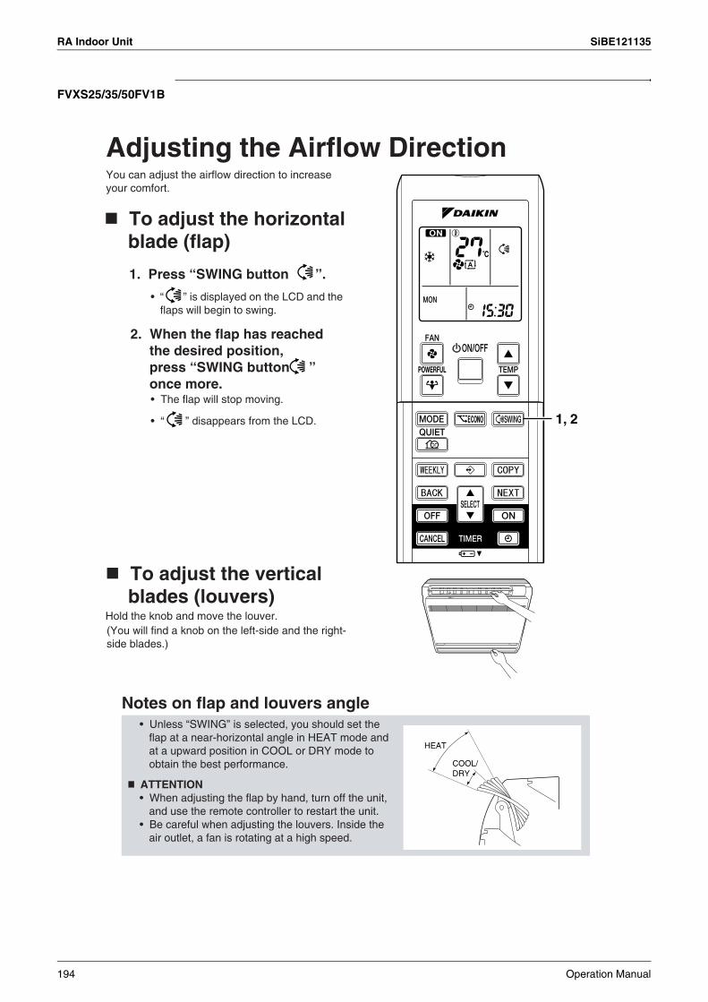
RA Indoor Unit SiBE121135
FVXS25/35/50FV1B
Adjusting the Airflow Direction
1, 2
HEAT
You can adjust the airflow direction to increase your comfort.
Notes on flap and louvers angle
COOL/DRY
To adjust the horizontal blade (flap)
1. Press “SWING button ”.
• “ ” is displayed on the LCD and the flaps will begin to swing.
2. When the flap has reached the desired position, press “SWING button ” once more.• The flap will stop moving.
• “ ” disappears from the LCD.
To adjust the vertical blades (louvers)
Hold the knob and move the louver.(You will find a knob on the left-side and the right-side blades.)
• Unless “SWING” is selected, you should set the flap at a near-horizontal angle in HEAT mode and at a upward position in COOL or DRY mode to obtain the best performance.
ATTENTION• When adjusting the flap by hand, turn off the unit,
and use the remote controller to restart the unit.• Be careful when adjusting the louvers. Inside the
air outlet, a fan is rotating at a high speed.
194 Operation Manual
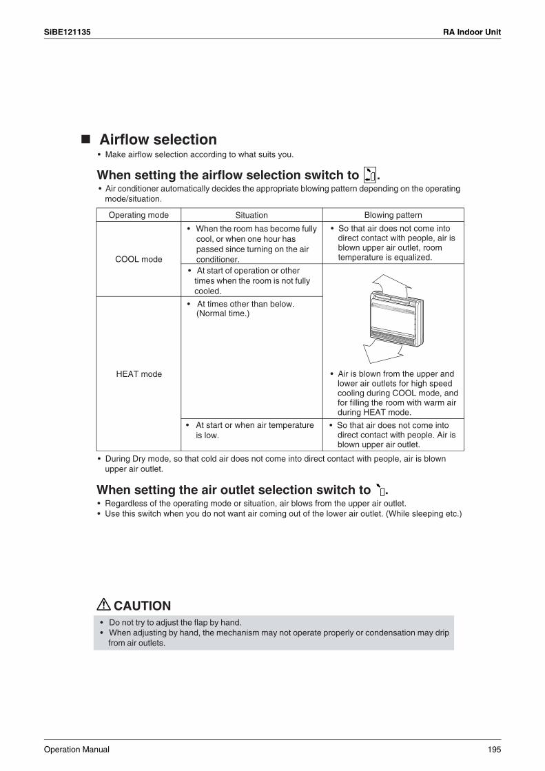
SiBE121135 RA Indoor Unit
Airflow
CAUTION
Operating mode Blowing pattern
COOL mode
HEAT mode
Situation
Airflow selection• Make airflow selection according to what suits you.
When setting the airflow selection switch to . • Air conditioner automatically decides the appropriate blowing pattern depending on the operating
mode/situation.
• When the room has become fully cool, or when one hour has passed since turning on the air conditioner.
• At start of operation or other times when the room is not fully cooled.
• At times other than below.(Normal time.)
• So that air does not come into direct contact with people, air is blown upper air outlet, room temperature is equalized.
• Air is blown from the upper and lower air outlets for high speed cooling during COOL mode, and for filling the room with warm air during HEAT mode.
• So that air does not come into direct contact with people. Air is blown upper air outlet.
• At start or when air temperature is low.
• During Dry mode, so that cold air does not come into direct contact with people, air is blown upper air outlet.
When setting the air outlet selection switch to . • Regardless of the operating mode or situation, air blows from the upper air outlet.• Use this switch when you do not want air coming out of the lower air outlet. (While sleeping etc.)
• Do not try to adjust the flap by hand.• When adjusting by hand, the mechanism may not operate properly or condensation may drip
from air outlets.
Operation Manual 195

RA Indoor Unit SiBE121135
2.2.5 COMFORT AIRFLOW and INTELLIGENT EYE Operation
FTXS20/25/35/42/50J2V1B
COMFORT AIRFLOW operation
INTELLIGENT EYE operation
A person is detected in area 1.
People are detected in both areas.
A person is detected in area 2.
No people are detected in the areas.
COOL operation HEAT operation
Area 1 Area 2
Area 1 Area 2
Area 1 Area 2
COMFORT AIRFLOW and INTELLIGENT EYE Operation
The flow of air will be in the upward direction while in COOL operation and in the downward direction while in HEAT operation, which will provide a comfortable wind that will not come in direct contact with people.
“INTELLIGENT EYE” is the infrared sensor which detects the human movement. If no one is in the room for more than 20 minutes, the operation automatically changes to energy saving operation.The INTELLIGENT EYE sensor according to the following situations.
Use the INTELLIGENT EYE Operation in combination with the COMFORT AIRFLOW Operation.
The air conditioner will go into energy-saving mode after 20 minutes.*The wind direction may differ from the illustrated direction depending on the actions and movements of the people in the areas.
196 Operation Manual

SiBE121135 RA Indoor Unit
To start operation
To cancel operation
Display Operation mode Explanation
COMFORT AIRFLOW
INTELLIGENT EYE
Blank No function –
blankNo SettingCombination
Press and select the desired mode.• Each time the is pressed a different setting
option is displayed on the LCD.
• By selecting “ ” from the following icons, the air conditioner will be in COMFORT AIRFLOW operation combined with INTELLIGENT EYE operation.
• When the flaps (horizontal blades) are swinging, the operating as above will stop movement of them.
• The INTELLIGENT EYE lamp lights up.• The lamp will be lit while human movements are
detected.
INTELLIGENT EYE
COMFORT AIRFLOW
Press and select “blank” on the LCD.
COMFORT AIRFLOW and INTELLIGENT EYE
The flaps will adjust the airflow direction upward while cooling, and adjust the airflow direction downward while heating.
The sensors will detect the movement of people in the sensing areas and the louvers will adjust the airflow direction to an area where people are not present. When there are no people in the sensing areas, the air conditioner will go into energy-saving mode.
The air conditioner will be in COMFORT AIRFLOW operation combined with INTELLIGENT EYE operation.
Operation Manual 197

RA Indoor Unit SiBE121135
NOTE Notes on COMFORT AIRFLOW operation
Notes on INTELLIGENT EYE operation
90˚
55˚
7m
55˚
7m
COMFORT AIRFLOW and INTELLIGENT EYE Operation
• The flap position will change, preventing air from blowing directly on the occupants of the room.
• POWERFUL operation and COMFORT AIRFLOW operation cannot be used at the same time.
• Priority is given to the function of whichever button is pressed last.• The airflow rate will be set to AUTO. If the upper and lower airflow direction is selected, the
COMFORT AIRFLOW operation will be canceled.
• Application range is as follows.
• While the air conditioner is in INTELLIGENT EYE operation, the louvers will adjust the airflow direction if there are people in the sensing areas of the INTELLIGENT EYE so that the leftward or rightward airflow will not be directed to the people. If no people are detected in either area 1 or 2 in 20 minutes, the air conditioner will go into energy-saving mode with the set temperature shifted by 2˚C. The air conditioner may go into energy-saving operation even if there are people in the areas.This may occur depending on the clothes the people are wearing if there are no movements of the people in the areas.
• The airflow direction from the louvers will be leftward if there are people in both areas 1 and 2 or if there is a person right in front of the sensors because the sensors on the both sides will detect the person.
• Due to the position of the sensor, people might be exposed to the airflow of the indoor unit if they are close to the front side of the indoor unit. If there are people close to the front side of the indoor unit or in both areas, it is recommended to use the COMFORT AIRFLOW and INTELLIGENT EYE functions simultaneously. When both of them are in use, the air conditioner will not direct the airflow towards the people.
• Sensor may not detect moving objects further than 7m away. (Check the application range) • Sensor detection sensitivity changes according to indoor unit location, the speed of
passersby, temperature range, etc.• The sensor also mistakenly detects pets, sunlight, fluttering curtains and light reflected off of
mirrors as passersby. • INTELLIGENT EYE operation will not go on during POWERFUL operation. • NIGHT SET mode will not go on during use of INTELLIGENT EYE operation.
Vertical angle 90˚ (Side view)
Horizontal angle 110˚ (Top view)
198 Operation Manual
SiBE121135 RA Indoor Unit
NOTE
INTELLIGENT EYE operation is useful for energy saving
CAUTION
Energy saving operation
Note on combination of COMFORT AIRFLOW operation and INTELLIGENT EYE operation
• The airflow rate will be set to AUTO. If the upper and lower airflow direction is selected, the COMFORT AIRFLOW operation will be canceled.Priority is given to the function of whichever button is pressed last.
• The air conditioner can go into operation with the COMFORT AIRFLOW and INTELLIGENT EYE functions combined. The flaps adjust the airflow direction upward (while in cooling operation) and downward (while in heating operation), during which the sensors of the INTELLIGENT EYE are working to detect the movement of people. When the sensors detect people, the louvers will direct the airflow in such way that it will not be blown directly on them. If there are no people, the air conditioner will go into energy-saving operation after 20 minutes.
• If no presence detected in the room for 20 minutes, the energy saving operation will start.• This operation changes the temperature –2˚C in HEAT / +2˚C in COOL / +2˚C in DRY
operation from set temperature. • This operation decreases the airflow rate slightly in FAN operation only.
• Do not place large objects near the sensor. Also keep heating units or humidifiers outside the sensor’s detection area. This sensor can detect undesirable objects.
• Do not hit or violently push the INTELLIGENT EYE sensor. This can lead to damage and malfunction.
Operation Manual 199
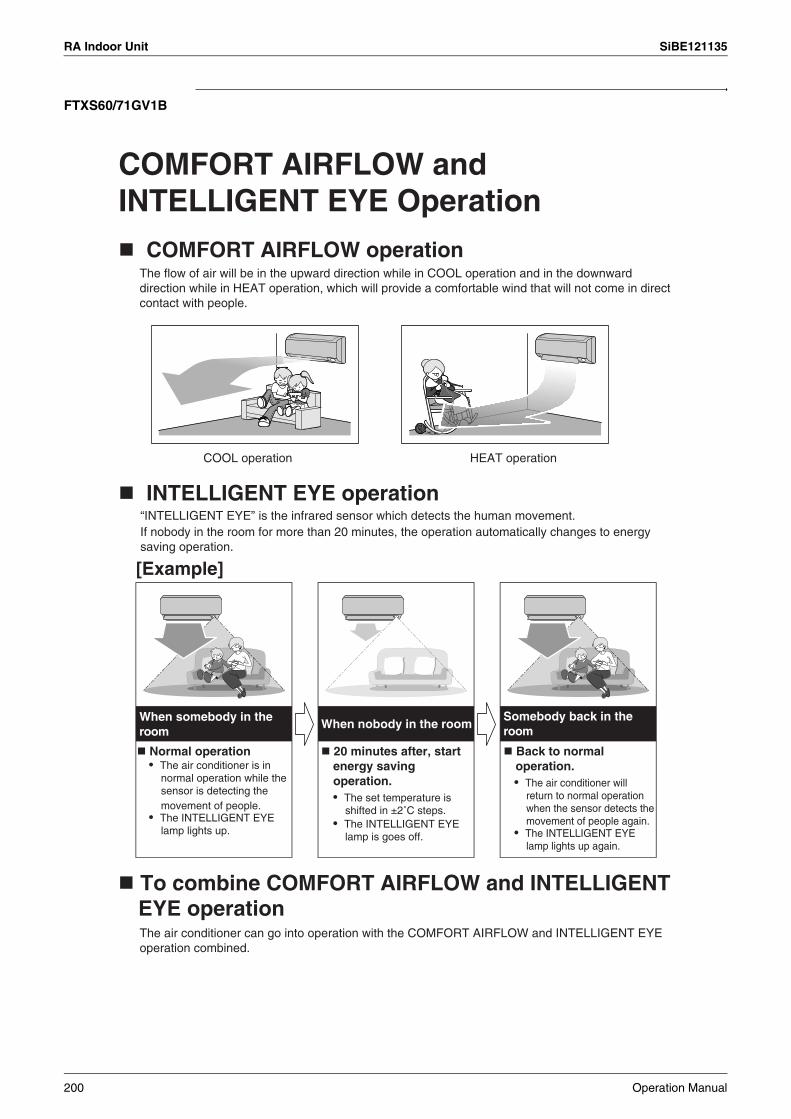
RA Indoor Unit SiBE121135
FTXS60/71GV1B
COMFORT AIRFLOW operation
INTELLIGENT EYE operation
[Example]
COOL operation HEAT operation
When nobody in the room
COMFORT AIRFLOW and INTELLIGENT EYE Operation
The flow of air will be in the upward direction while in COOL operation and in the downward direction while in HEAT operation, which will provide a comfortable wind that will not come in direct contact with people.
When somebody in the room
Somebody back in the room
“INTELLIGENT EYE” is the infrared sensor which detects the human movement.If nobody in the room for more than 20 minutes, the operation automatically changes to energy saving operation.
Normal operation• The air conditioner is in
normal operation while the sensor is detecting the movement of people.
• The INTELLIGENT EYE lamp lights up.
20 minutes after, start energy saving operation.• The set temperature is
shifted in ±2˚C steps.• The INTELLIGENT EYE
lamp is goes off.
Back to normal operation.• The air conditioner will
return to normal operation when the sensor detects the movement of people again.
• The INTELLIGENT EYE lamp lights up again.
To combine COMFORT AIRFLOW and INTELLIGENT EYE operationThe air conditioner can go into operation with the COMFORT AIRFLOW and INTELLIGENT EYE operation combined.
200 Operation Manual
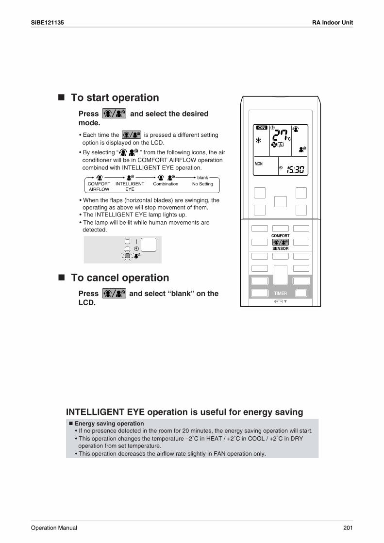
SiBE121135 RA Indoor Unit
To cancel operation
INTELLIGENT EYE operation is useful for energy saving
blankNo SettingCombinationCOMFORT
AIRFLOWINTELLIGENT
EYE
Press and select “blank” on the LCD.
To start operationPress and select the desired mode.
• Each time the is pressed a different setting option is displayed on the LCD.
• By selecting “ ” from the following icons, the air conditioner will be in COMFORT AIRFLOW operation combined with INTELLIGENT EYE operation.
• When the flaps (horizontal blades) are swinging, the operating as above will stop movement of them.
• The INTELLIGENT EYE lamp lights up.• The lamp will be lit while human movements are detected.
Energy saving operation• If no presence detected in the room for 20 minutes, the energy saving operation will start.• This operation changes the temperature –2˚C in HEAT / +2˚C in COOL / +2˚C in DRY operation from set temperature.
• This operation decreases the airflow rate slightly in FAN operation only.
Operation Manual 201
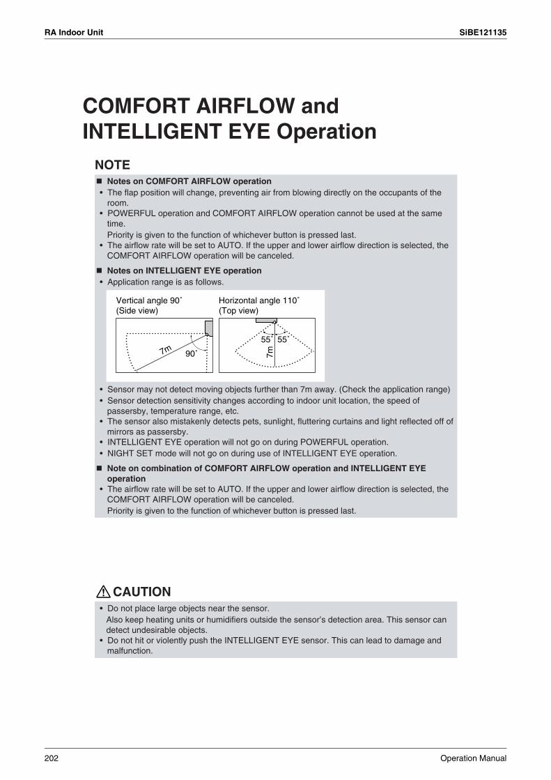
RA Indoor Unit SiBE121135
NOTE
CAUTION
90˚
55˚
7m
55˚
7m
Vertical angle 90˚(Side view)
Horizontal angle 110˚(Top view)
COMFORT AIRFLOW and INTELLIGENT EYE Operation
Notes on COMFORT AIRFLOW operation• The flap position will change, preventing air from blowing directly on the occupants of the
room.• POWERFUL operation and COMFORT AIRFLOW operation cannot be used at the same
time.Priority is given to the function of whichever button is pressed last.
• The airflow rate will be set to AUTO. If the upper and lower airflow direction is selected, the COMFORT AIRFLOW operation will be canceled.
Notes on INTELLIGENT EYE operation• Application range is as follows.
• Sensor may not detect moving objects further than 7m away. (Check the application range)• Sensor detection sensitivity changes according to indoor unit location, the speed of
passersby, temperature range, etc.• The sensor also mistakenly detects pets, sunlight, fluttering curtains and light reflected off of
mirrors as passersby.• INTELLIGENT EYE operation will not go on during POWERFUL operation.• NIGHT SET mode will not go on during use of INTELLIGENT EYE operation.
Note on combination of COMFORT AIRFLOW operation and INTELLIGENT EYE operation
• The airflow rate will be set to AUTO. If the upper and lower airflow direction is selected, the COMFORT AIRFLOW operation will be canceled.Priority is given to the function of whichever button is pressed last.
• Do not place large objects near the sensor.Also keep heating units or humidifiers outside the sensor’s detection area. This sensor can detect undesirable objects.
• Do not hit or violently push the INTELLIGENT EYE sensor. This can lead to damage and malfunction.
202 Operation Manual

SiBE121135 RA Indoor Unit
2.2.6 POWERFUL Operation
POWERFUL Operation
To start POWERFUL operation
1. Press .
To cancel POWERFUL operation
2. Press again.
NOTENotes on POWERFUL operation
POWERFUL operation quickly maximizes the cooling (heating) effect in any operation mode. You can get the maximum capacity.
• POWERFUL operation ends in 20 minutes. Then the system automatically operates again with the previous settings which were used before POWERFUL operation.
• “ ” is displayed on the LCD.
• “ ” disappears from the LCD.
• When using POWERFUL operation, there are some functions which are not available.• POWERFUL operation cannot be used together with ECONO, COMFORT AIRFLOW or OUTDOOR
UNIT QUIET operation. Priority is given to the function of whichever button is pressed last.• POWERFUL operation can only be set when the unit is running.• POWERFUL operation will not increase the capacity of the air conditioner if the air
conditioner is already in operation with its maximum capacity demonstrated.
• In COOL, HEAT and AUTO modeTo maximize the cooling (heating) effect, the capacity of outdoor unit is increased and the airflow rate is fixed to the maximum setting.The temperature and airflow settings are not variable.
• In DRY operationThe temperature setting is lowered by 2.5˚C and the airflow rate is slightly increased.
• In FAN operationThe airflow rate is fixed to the maximum setting.
Operation Manual 203
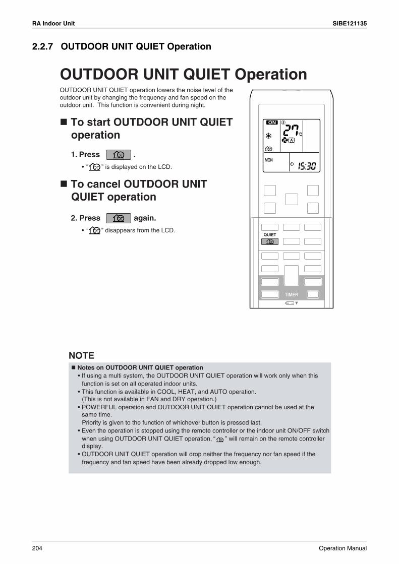
RA Indoor Unit SiBE121135
2.2.7 OUTDOOR UNIT QUIET Operation
OUTDOOR UNIT QUIET Operation
1. Press .
• “ ” is displayed on the LCD.
2. Press again.
• “ ” disappears from the LCD.
NOTE
OUTDOOR UNIT QUIET operation lowers the noise level of the outdoor unit by changing the frequency and fan speed on the outdoor unit. This function is convenient during night.
To start OUTDOOR UNIT QUIET operation
To cancel OUTDOOR UNIT QUIET operation
Notes on OUTDOOR UNIT QUIET operation• If using a multi system, the OUTDOOR UNIT QUIET operation will work only when this
function is set on all operated indoor units.• This function is available in COOL, HEAT, and AUTO operation.
(This is not available in FAN and DRY operation.)• POWERFUL operation and OUTDOOR UNIT QUIET operation cannot be used at the
same time.Priority is given to the function of whichever button is pressed last.
• Even the operation is stopped using the remote controller or the indoor unit ON/OFF switch when using OUTDOOR UNIT QUIET operation, “ ” will remain on the remote controller display.
• OUTDOOR UNIT QUIET operation will drop neither the frequency nor fan speed if the frequency and fan speed have been already dropped low enough.
204 Operation Manual
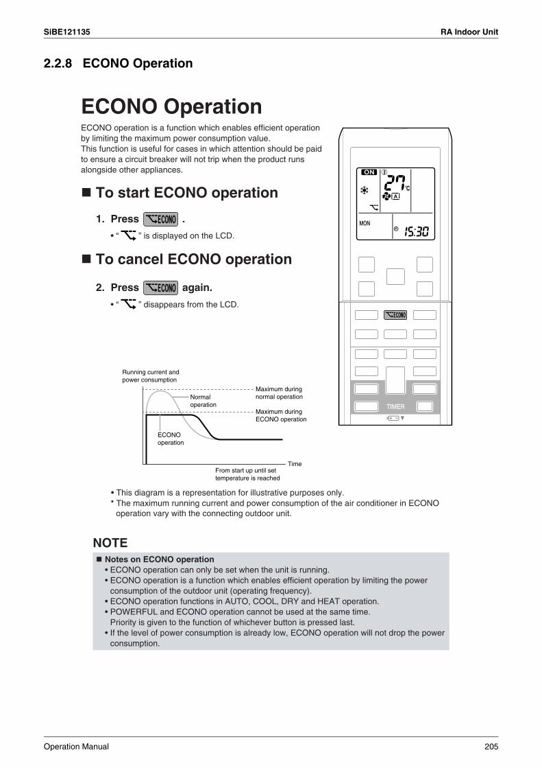
SiBE121135 RA Indoor Unit
2.2.8 ECONO Operation
ECONO Operation
To start ECONO operation
1. Press .
• “ ” is displayed on the LCD.
• “ ” disappears from the LCD.
To cancel ECONO operation
2. Press again.
• This diagram is a representation for illustrative purposes only.
NOTENotes on ECONO operation
Time
ECONO operation is a function which enables efficient operation by limiting the maximum power consumption value. This function is useful for cases in which attention should be paid to ensure a circuit breaker will not trip when the product runs alongside other appliances.
Running current and power consumption
Normal operation
Maximum during normal operation
Maximum during ECONO operation
ECONO operation
From start up until set temperature is reached
* The maximum running current and power consumption of the air conditioner in ECONO operation vary with the connecting outdoor unit.
• ECONO operation can only be set when the unit is running. • ECONO operation is a function which enables efficient operation by limiting the power
consumption of the outdoor unit (operating frequency).• ECONO operation functions in AUTO, COOL, DRY and HEAT operation. • POWERFUL and ECONO operation cannot be used at the same time.
Priority is given to the function of whichever button is pressed last. • If the level of power consumption is already low, ECONO operation will not drop the power
consumption.
Operation Manual 205
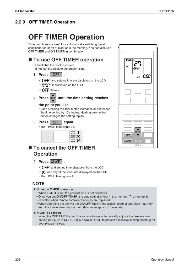
RA Indoor Unit SiBE121135
2.2.9 OFF TIMER Operation
OFF TIMER Operation
To use OFF TIMER operation
1. Press .
• “ ” and setting time are displayed on the LCD.
• “ ” is displayed on the LCD.
• “ ” blinks.
2.
3. Press again.• The TIMER lamp lights up.
4. Press .
• “ ” and setting time disappear from the LCD.
• “ ” and day of the week are displayed on the LCD.• The TIMER lamp goes off.
NOTENotes on TIMER operation
NIGHT SET mode
Timer functions are useful for automatically switching the air conditioner on or off at night or in the morning. You can also use OFF TIMER and ON TIMER in combination.
• Check that the clock is correct.If not, set the clock to the present time.
Press until the time setting reaches
the point you like.• Each pressing of either button increases or decreases
the time setting by 10 minutes. Holding down either button changes the setting rapidly.
To cancel the OFF TIMER Operation
• When TIMER is set, the present time is not displayed.• Once you set ON/OFF TIMER, the time setting is kept in the memory. The memory is
canceled when remote controller batteries are replaced.• When operating the unit via the ON/OFF TIMER, the actual length of operation may vary
from the time entered by the user. (Maximum approx. 10 minutes)
When the OFF TIMER is set, the air conditioner automatically adjusts the temperature setting (0.5˚C up in COOL, 2.0˚C down in HEAT) to prevent excessive cooling (heating) for your pleasant sleep.
206 Operation Manual
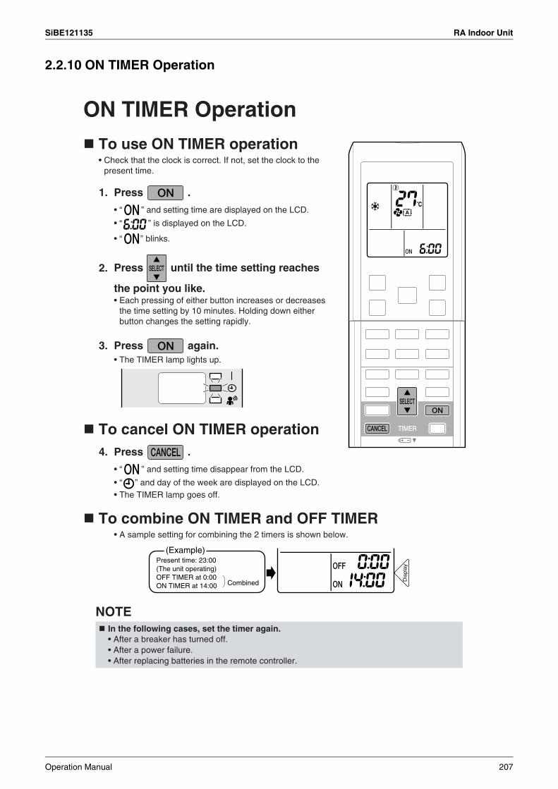
SiBE121135 RA Indoor Unit
2.2.10 ON TIMER Operation
ON TIMER Operation
To use ON TIMER operation
1. Press .
• “ ” and setting time are displayed on the LCD.
• “ ” is displayed on the LCD.
• “ ” blinks.
2.
3. Press again.• The TIMER lamp lights up.
To cancel ON TIMER operation4. Press .
• “ ” and setting time disappear from the LCD.
• “ ” and day of the week are displayed on the LCD.• The TIMER lamp goes off.
To combine ON TIMER and OFF TIMER• A sample setting for combining the 2 timers is shown below.
NOTEIn the following cases, set the timer again.
(Example)Present time: 23:00 (The unit operating)OFF TIMER at 0:00ON TIMER at 14:00 Combined D
ispl
ay
• Check that the clock is correct. If not, set the clock to the present time.
Press until the time setting reaches
the point you like.• Each pressing of either button increases or decreases
the time setting by 10 minutes. Holding down either button changes the setting rapidly.
• After a breaker has turned off.• After a power failure.• After replacing batteries in the remote controller.
Operation Manual 207

RA Indoor Unit SiBE121135
2.2.11 WEEKLY TIMER Operation
WEEKLY TIMER Operation
Using in these cases of WEEKLY TIMERAn example of WEEKLY TIMER settings is shown below.
6:00 8:30 17:30 22:00
25˚C 27˚C
6:00 8:30 17:30 22:00
25˚C 27˚C
8:00 10:00 19:00 21:00
27˚C 27˚C25˚C
Example:
Make timer settings up to programs 1-4.[Monday]
No timer settings[Saturday]
Make timer settings up to programs 1-4.[Sunday]
Program 1 Program 2 Program 3 Program 4ON OFF ON OFF
Program 1 Program 2 Program 3 Program 4ON OFF ON OFF
ON OFF OFF ONProgram 1 Program 2 Program 3 Program 4
ON
ON
ONOFF
Up to 4 timer settings can be saved for each day of the week. It is convenient if the WEEKLY TIMER is set according to the family’s life style.
[Tuesday] to
[Friday]
Use the copy mode to make settings for Tuesday to Friday, because these settings are the same as those for Monday.
• Up to 4 reservations per day and 28 reservations per week can be set in the WEEKLY TIMER. The effective use of the copy mode ensures ease of making reservations.
• The use of ON-ON-ON-ON settings, for example, makes it possible to schedule operating mode and set temperature changes. Furthermore, by using OFF-OFF-OFF-OFF settings, only the turn-off time of each day can be set. This will turn off the air conditioner automatically if the user forgets to turn it off.
OFF
The same timer settings are made for the week from Monday through Friday while different timer settings are made for the weekend.
ONOFFOFF
208 Operation Manual
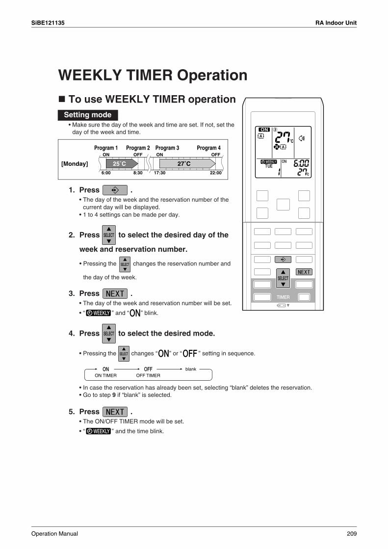
SiBE121135 RA Indoor Unit
WEEKLY TIMER Operation
To use WEEKLY TIMER operation
1. Press .
2.
3. Press .• The day of the week and reservation number will be set.
• “ ” and “ ” blink.
4. Press to select the desired mode.
• Pressing the changes “ ” or “ ” setting in sequence.
5. Press .• The ON/OFF TIMER mode will be set.
• “ ” and the time blink.
Setting mode
6:00 8:30 17:30 22:00
25˚C 27˚C
Program 1 Program 2 Program 3 Program 4ON OFF ON OFF
[Monday]
blankON TIMER OFF TIMER
• Make sure the day of the week and time are set. If not, set the day of the week and time.
• The day of the week and the reservation number of the current day will be displayed.
• 1 to 4 settings can be made per day.
Press to select the desired day of the
week and reservation number.
• Pressing the changes the reservation number and
the day of the week.
• In case the reservation has already been set, selecting “blank” deletes the reservation.• Go to step 9 if “blank” is selected.
Operation Manual 209
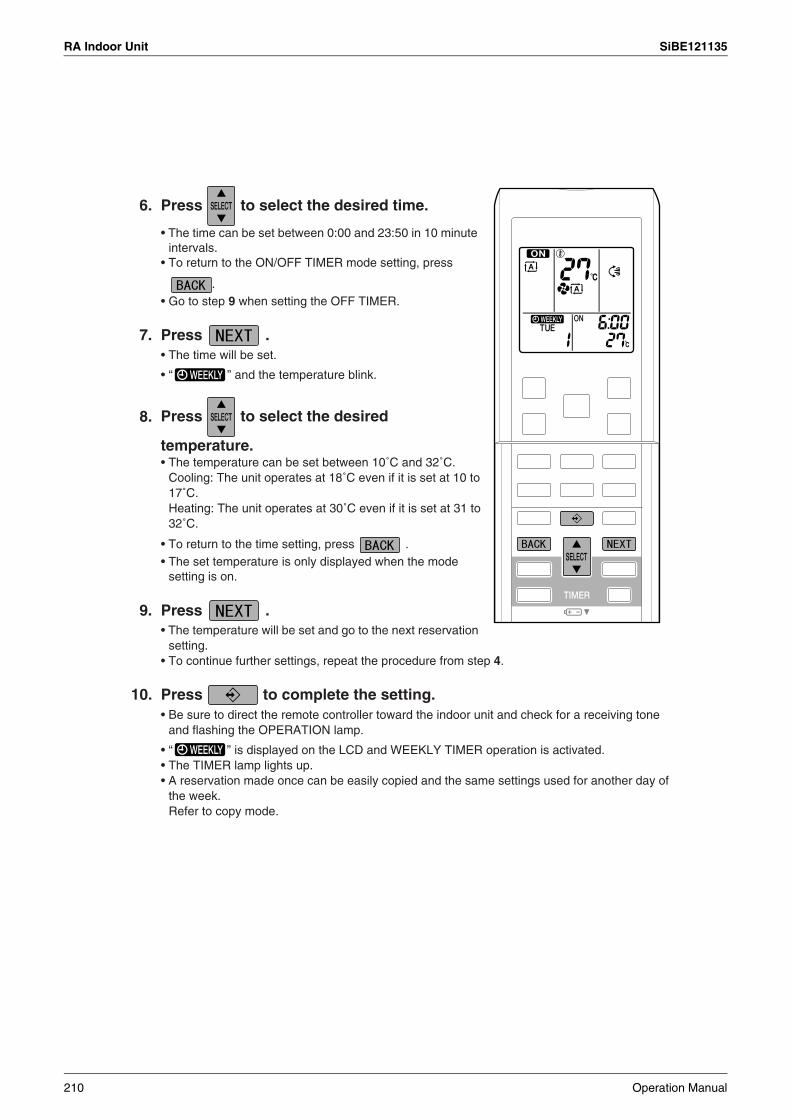
RA Indoor Unit SiBE121135
6. Press to select the desired time.
7. Press .• The time will be set.
• “ ” and the temperature blink.
8.
• To return to the time setting, press .
9. Press .
10. Press to complete the setting.
• The time can be set between 0:00 and 23:50 in 10 minute intervals.
• To return to the ON/OFF TIMER mode setting, press
.• Go to step 9 when setting the OFF TIMER.
Press to select the desired
temperature.• The temperature can be set between 10˚C and 32˚C.
Cooling: The unit operates at 18˚C even if it is set at 10 to 17˚C. Heating: The unit operates at 30˚C even if it is set at 31 to 32˚C.
• The set temperature is only displayed when the mode setting is on.
• The temperature will be set and go to the next reservation setting.
• To continue further settings, repeat the procedure from step 4.
• Be sure to direct the remote controller toward the indoor unit and check for a receiving tone and flashing the OPERATION lamp.
• “ ” is displayed on the LCD and WEEKLY TIMER operation is activated.• The TIMER lamp lights up. • A reservation made once can be easily copied and the same settings used for another day of
the week. Refer to copy mode.
210 Operation Manual

SiBE121135 RA Indoor Unit
WEEKLY TIMER Operation
NOTENotes on WEEKLY TIMER operation
Day and number ON/OFF Time Temperature
Setting Displays
• Do not forget to set the clock on the remote control first.• The day of the week, ON/OFF TIMER mode, time and set temperature (only for ON TIMER
mode) can be set with WEEKLY TIMER. Other settings for ON TIMER are based on the settings just before the operation.
• Both WEEKLY TIMER and ON/OFF TIMER operation cannot be used at the same time. The ON/OFF TIMER operation has priority if it is set while WEEKLY TIMER is still active.
The WEEKLY TIMER will go into standby state, and “ ” will disappear from the
LCD. When ON/OFF TIMER is up, the WEEKLY TIMER will automatically become active.
• Only the time and set temperature with the weekly timer are sent with the .
Set the weekly timer only after setting the operation mode, the fan strength, and the fan direction ahead of time.
• Shutting the breaker off, power failure, and other similar events will render operation of the indoor unit’s internal clock inaccurate. Reset the clock.
• The can be used only for the time and temperature settings.
It cannot be used to go back to the reservation number.
Operation Manual 211

RA Indoor Unit SiBE121135
1. Press .
2.
3. Press to activate copy mode.
4.
Copy mode
6:00 8:30 17:30 22:00
25˚C 27˚C
6:00 8:30 17:30 22:00
25˚C 27˚C
Program 1 Program 2 Program 3 Program 4ON OFF ON OFF
[Monday]
Program 1 Program 2 Program 3 Program 4ON OFF ON OFF
COPY
• A reservation made once can be copied another day of the week. The whole reservation of the selected day of the week will be copied.
[Tuesday] to [Friday]
Press to confirm the day of the week
to be copied.
• The whole reservation of the selected day of the week will be copied.
Press to select the destination day of
the week.
212 Operation Manual
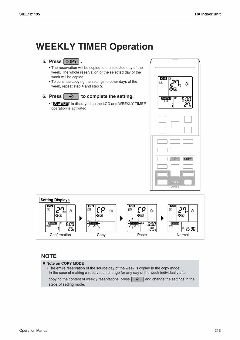
SiBE121135 RA Indoor Unit
WEEKLY TIMER Operation5. Press .
6. Press to complete the setting.
NOTENote on COPY MODE
Setting Displays
Confirmation Copy Paste Normal
• The reservation will be copied to the selected day of the week. The whole reservation of the selected day of the week will be copied.
• To continue copying the settings to other days of the week, repeat step 4 and step 5.
• “ ” is displayed on the LCD and WEEKLY TIMER operation is activated.
• The entire reservation of the source day of the week is copied in the copy mode. In the case of making a reservation change for any day of the week individually after
copying the content of weekly reservations, press and change the settings in the steps of setting mode.
Operation Manual 213

RA Indoor Unit SiBE121135
Confirming a reservation• The reservation can be confirmed.
1. Press .
2.
• Pressing the displays the reservation details.
3. Press to exit confirming mode.
To deactivate WEEKLY TIMER operation
4. Press while “ ” is displayed on the LCD.
• “ ” disappears from the LCD.• The TIMER lamp goes off.
• To reactivate the WEEKLY TIMER operation, press the again.
Setting Displays
Normal Confirmation
• The day of the week and the reservation number of current day will be displayed.
Press to select the day of the week and
the reservation number to be confirmed.
• To change the confirmed reserved settings, select the
reservation number and press . The mode is switched to setting mode. Go to setting mode step 4.
• “ ” is displayed on the LCD and WEEKLY TIMER operation is activated.
• The TIMER lamp lights up.
• If a reservation deactivated with is activated once again, the last reservation mode will be used.
214 Operation Manual
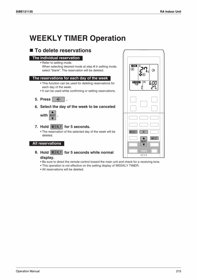
SiBE121135 RA Indoor Unit
WEEKLY TIMER Operation
To delete reservations
5. Press .
6.
7. Hold for 5 seconds.
8.
The individual reservation
The reservations for each day of the week
All reservations
• Refer to setting mode. When selecting desired mode at step 4 in setting mode, select “blank”. The reservation will be deleted.
• This function can be used for deleting reservations for each day of the week.
• It can be used while confirming or setting reservations.
Select the day of the week to be canceled
with .
• The reservation of the selected day of the week will be deleted.
Hold for 5 seconds while normal display. • Be sure to direct the remote control toward the main unit and check for a receiving tone.• This operation is not effective on the setting display of WEEKLY TIMER.• All reservations will be deleted.
Operation Manual 215
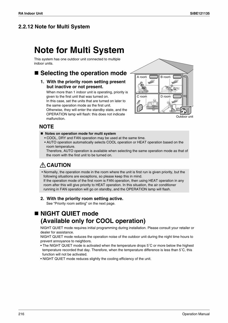
RA Indoor Unit SiBE121135
2.2.12 Note for Multi System
Note for Multi System
Selecting the operation mode
NIGHT QUIET mode(Available only for COOL operation)
NOTE
CAUTION
Notes on operation mode for multi system
A room B room
C room D room
Outdoor unit
This system has one outdoor unit connected to multipleindoor units.
1. With the priority room setting present but inactive or not present.When more than 1 indoor unit is operating, priority is given to the first unit that was turned on.In this case, set the units that are turned on later to the same operation mode as the first unit.Otherwise, they will enter the standby state, and the OPERATION lamp will flash: this does not indicate malfunction.
NIGHT QUIET mode requires initial programming during installation. Please consult your retailer or dealer for assistance.NIGHT QUIET mode reduces the operation noise of the outdoor unit during the night time hours to prevent annoyance to neighbors.• The NIGHT QUIET mode is activated when the temperature drops 5˚C or more below the highest temperature recorded that day. Therefore, when the temperature difference is less than 5˚C, this function will not be activated.
• NIGHT QUIET mode reduces slightly the cooling efficiency of the unit.
See “Priority room setting” on the next page.
• COOL, DRY and FAN operation may be used at the same time.• AUTO operation automatically selects COOL operation or HEAT operation based on the room temperature.Therefore, AUTO operation is available when selecting the same operation mode as that of the room with the first unit to be turned on.
• Normally, the operation mode in the room where the unit is first run is given priority, but the following situations are exceptions, so please keep this in mind.If the operation mode of the first room is FAN operation, then using HEAT operation in any room after this will give priority to HEAT operation. In this situation, the air conditioner running in FAN operation will go on standby, and the OPERATION lamp will flash.
2. With the priority room setting active.
216 Operation Manual

SiBE121135 RA Indoor Unit
Note for Multi System
See “Priority room setting”.
NOTE
As the operation mode of the priority room takes precedence, the user can select a different operation mode from other rooms.* Room A is the priority room in the examples.⟨Example⟩
When COOL operation is selected in room A while operating the following modes in room B, C and D:
* Room A is the priority room in the examples.⟨Example⟩
* Room A is the priority room in the examples.⟨Example⟩
• The COOL/HEAT mode lock cannot be activated together with the priority room setting.
Current operation mode maintained
HEAT
AUTO
OUTDOOR UNIT QUIET operation
Priority room setting
When using the OUTDOOR UNIT QUIET operation feature with the Multi system, set all indoor units to OUTDOOR UNIT QUIET operation using their remote controllers.When clearing OUTDOOR UNIT QUIET operation, clear one of the operating indoor units using their remote controller.However OUTDOOR UNIT QUIET operation display remains on the remote controller for other rooms.We recommend you release all rooms using their remote controllers.
1. With the priority room setting present but inactive or not present.
2. With the priority room setting active.
1. Operation mode priority.
2. Priority when POWERFUL operation is used.
3. Priority when using OUTDOOR UNIT QUIET operation.
COOL/HEAT mode lock(Available only for heat pump models)The COOL/HEAT mode lock requires initial programming during installation. Please consult your authorized dealer for assistance. The COOL/HEAT mode lock sets the unit forcibly to either COOL or HEAT operation. This function is convenient when you wish to set all indoor units connected to the multi system to the same operation mode.
The indoor units in rooms A, B, C and D are all operating. If the unit in room A enters POWERFUL operation, operation capacity will be concentrated in room A. In such a case, the cooling (heating) efficiency of the units in rooms B, C and D may be slightly reduced.
Just by setting the unit in room A to QUIET operation, the air conditioner starts OUTDOOR UNIT QUIET operation.You don’t have to set all the operated indoor units to QUIET operation.
The priority room setting requires initial programming during installation. Please consult your retailer or dealer for assistance.The room designated as the priority room takes priority in the following situations;
Operation mode in room B, C and D
COOL or DRY or FAN
Status of room B, C and D when the unit in room A is in COOL operation
The unit enters standby mode. Operation resumes when the room A unit stops operating.If the unit is set to COOL operation, it continues. If set to HEAT operation, it enters standby mode. Operation resumes when the room A unit stops operating.
Operation Manual 217

RA Indoor Unit SiBE121135
2.3 FLXS, FDXS Series - ARC433B67, B692.3.1 Manual Contents and Reference Page
: The illustrations are for FLXS series as representative.
Model SeriesFloor / Ceiling Suspended Dual Type Duct Connected Type
FLXS25-60BAVMB FDXS25/35E7VMBFDXS50/60C7VMB
Read Before Operation
Remote Controller 219 220
Operation
AUTO · DRY · COOL · HEAT · FAN Operation 221 221
Adjusting the Airflow Direction 223 —
POWERFUL Operation 225 225
OUTDOOR UNIT QUIET Operation 226 226
HOME LEAVE Operation 227 227
TIMER Operation 229 229
Note for Multi System 231 231
Drawing No. 3P194444-5C 3P196326-9C (Reference)
218 Operation Manual
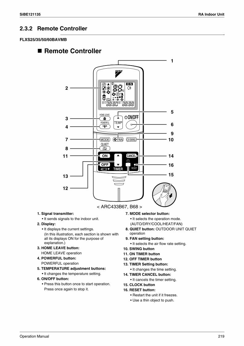
SiBE121135 RA Indoor Unit
2.3.2 Remote Controller
FLXS25/35/50/60BAVMB
1. Signal transmitter:• It sends signals to the indoor unit.
2. Display:• It displays the current settings.
(In this illustration, each section is shown with all its displays ON for the purpose of explanation.)
3. HOME LEAVE button:HOME LEAVE operation
4. POWERFUL button:POWERFUL operation
5. TEMPERATURE adjustment buttons:• It changes the temperature setting.
6. ON/OFF button:• Press this button once to start operation.
Press once again to stop it.
7. MODE selector button:• It selects the operation mode.(AUTO/DRY/COOL/HEAT/FAN)
8. QUIET button: OUTDOOR UNIT QUIET operation
9. FAN setting button:• It selects the air flow rate setting.
10. SWING button11. ON TIMER button12. OFF TIMER button13. TIMER Setting button:
• It changes the time setting.14. TIMER CANCEL button:
• It cancels the timer setting.15. CLOCK button16. RESET button:
• Restart the unit if it freezes.• Use a thin object to push.
14
16
15
1
2
5
6
910
11
13
12
3
4
7
8
Remote Controller
< ARC433B67, B68 >
Operation Manual 219
RA Indoor Unit SiBE121135
FDXS25/35E7VMB, FDXS50/60C7VMB
1. Signal transmitter:• It sends signals to the indoor unit.
2. Display:• It displays the current settings.
(In this illustration, each section is shown with all its displays ON for the purpose of explanation.)
3. HOME LEAVE button:HOME LEAVE operation
4. POWERFUL button:POWERFUL operation
5. TEMPERATURE adjustment buttons:• It changes the temperature setting.
6. ON/OFF button:• Press this button once to start operation.
Press once again to stop it.
7. MODE selector button:• It selects the operation mode.(AUTO/DRY/COOL/HEAT/FAN)
8. QUIET button: OUTDOOR UNIT QUIET operation
9. FAN setting button:• It selects the air flow rate setting.
10. ON TIMER button11. OFF TIMER button12. TIMER Setting button:
• It changes the time setting.13. TIMER CANCEL button:
• It cancels the timer setting.14. CLOCK button15. RESET button:
• Restart the unit if it freezes.• Use a thin object to push.
1
2
5
6
9
13
15
14
10
12
11
3
4
7
8
Remote Controller
< ARC433B69, B76 >
220 Operation Manual
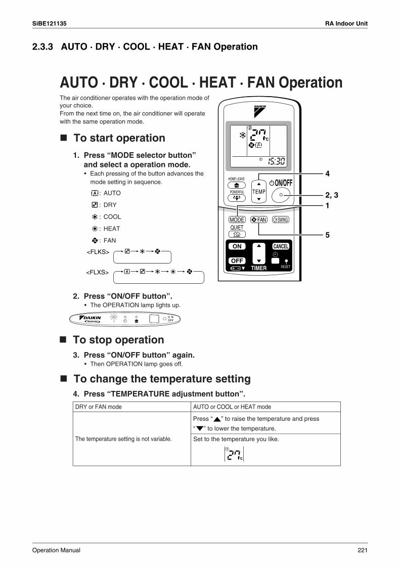
SiBE121135 RA Indoor Unit
2.3.3 AUTO · DRY · COOL · HEAT · FAN Operation
AUTO · DRY · COOL · HEAT · FAN Operation
: AUTO
: DRY
: COOL
: HEAT
: FAN
DRY or FAN mode AUTO or COOL or HEAT mode
The temperature setting is not variable. Set to the temperature you like.
VE
2, 31
4
5
<FLKS>
<FLXS>
C
The air conditioner operates with the operation mode of your choice.From the next time on, the air conditioner will operate with the same operation mode.
Press “ ” to raise the temperature and press
“ ” to lower the temperature.
To start operation
To stop operation
To change the temperature setting
1. Press “MODE selector button” and select a operation mode.• Each pressing of the button advances the
mode setting in sequence.
2. Press “ON/OFF button”.• The OPERATION lamp lights up.
3. Press “ON/OFF button” again.• Then OPERATION lamp goes off.
4. Press “TEMPERATURE adjustment button”.
Operation Manual 221

RA Indoor Unit SiBE121135
NOTE
DRY mode AUTO or COOL or HEAT or FAN mode
The air flow rate setting is not variable.
Five levels of air flow rate setting from “ ” to “ ”
plus “ ” “ ” are available.
To change the air flow rate setting
5. Press “FAN setting button”.
• Indoor unit quiet operation
When the air flow is set to “ ”, the noise from the indoor unit will become quieter. Use this when making the noise quieter.
The unit might lose capacity when the air flow rate is set to a weak level.
Note on HEAT operation• Since this air conditioner heats the room by taking heat from outdoor air to indoors, the
heating capacity becomes smaller in lower outdoor temperatures. If the heating effect is insufficient, it is recommended to use another heating appliance in combination with the air conditioner.
• The heat pump system heats the room by circulating hot air around all parts of the room. After the start of heating operation, it takes some time before the room gets warmer.• In heating operation, frost may occur on the outdoor unit and lower the heating capacity. In
that case, the system switches into defrosting operation to take away the frost.• During defrosting operation, hot air does not flow out of indoor unit.
Note on COOL operation• This air conditioner cools the room by blowing the hot air in the room outside, so if the
outside temperature is high, performance drops. Note on DRY operation• The computer chip works to rid the room of humidity while maintaining the temperature as
much as possible. It automatically controls temperature and fan strength, so manual adjustment of these functions is unavailable.
Note on AUTO operation• In AUTO operation, the system selects a temperature setting and an appropriate operation
mode (COOL or HEAT) based on the room temperature at the start of the operation.• The system automatically reselects setting at a regular interval to bring the room
temperature to user-setting level.• If you do not like AUTO operation, you can manually select the operation mode and setting
you like. Note on air flow rate setting
• At smaller air flow rates, the cooling (heating) effect is also smaller.
222 Operation Manual
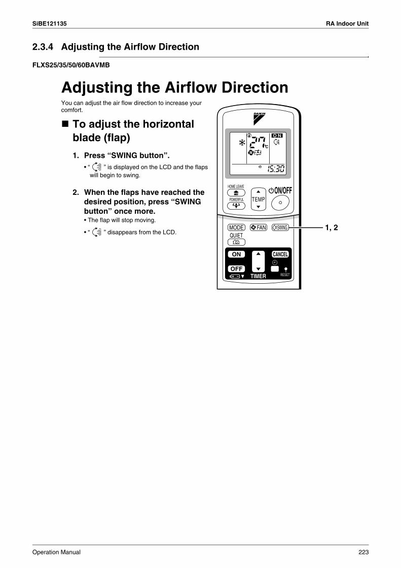
SiBE121135 RA Indoor Unit
2.3.4 Adjusting the Airflow Direction
FLXS25/35/50/60BAVMB
Adjusting the Airflow DirectionYou can adjust the air flow direction to increase your comfort.
To adjust the horizontal blade (flap)
1. Press “SWING button”.• “ ” is displayed on the LCD and the flaps
will begin to swing.
2. When the flaps have reached the desired position, press “SWING button” once more.• The flap will stop moving.
• “ ” disappears from the LCD.1, 2
Operation Manual 223
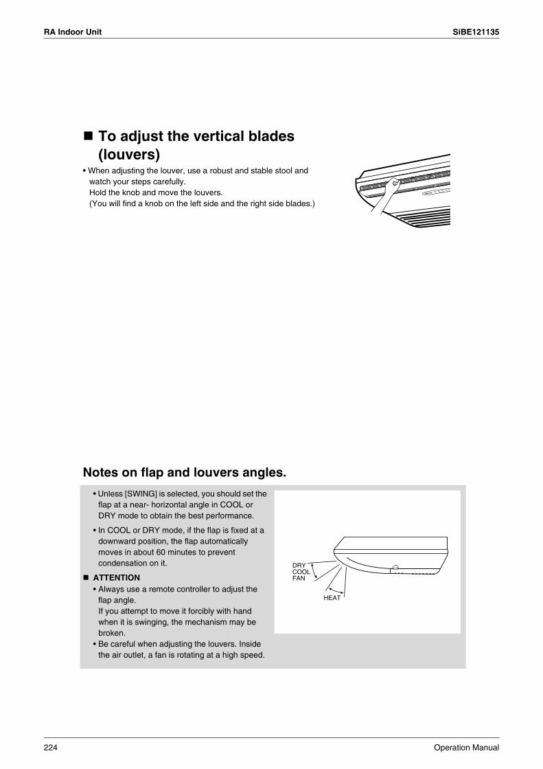
RA Indoor Unit SiBE121135
To adjust the vertical blades (louvers)
• When adjusting the louver, use a robust and stable stool and watch your steps carefully.Hold the knob and move the louvers.(You will find a knob on the left side and the right side blades.)
Notes on flap and louvers angles.
• Unless [SWING] is selected, you should set the flap at a near- horizontal angle in COOL or DRY mode to obtain the best performance.
• In COOL or DRY mode, if the flap is fixed at a downward position, the flap automatically moves in about 60 minutes to prevent condensation on it.
ATTENTION• Always use a remote controller to adjust the
flap angle.If you attempt to move it forcibly with hand when it is swinging, the mechanism may be broken.
• Be careful when adjusting the louvers. Inside the air outlet, a fan is rotating at a high speed.
DRY COOL FAN
HEAT
224 Operation Manual
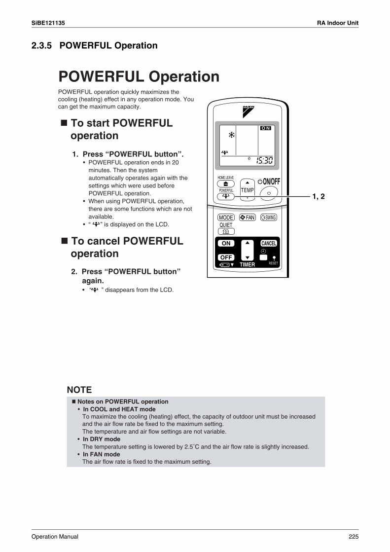
SiBE121135 RA Indoor Unit
2.3.5 POWERFUL Operation
POWERFUL Operation
NOTE
1, 2
POWERFUL operation quickly maximizes the cooling (heating) effect in any operation mode. You can get the maximum capacity.
To start POWERFUL operation
To cancel POWERFUL operation
1. Press “POWERFUL button”.• POWERFUL operation ends in 20
minutes. Then the system automatically operates again with the settings which were used before POWERFUL operation.
• When using POWERFUL operation, there are some functions which are not available.
• “ ” is displayed on the LCD.
2. Press “POWERFUL button” again.• “ ” disappears from the LCD.
Notes on POWERFUL operation• In COOL and HEAT mode
To maximize the cooling (heating) effect, the capacity of outdoor unit must be increased and the air flow rate be fixed to the maximum setting.The temperature and air flow settings are not variable.
• In DRY modeThe temperature setting is lowered by 2.5˚C and the air flow rate is slightly increased.
• In FAN modeThe air flow rate is fixed to the maximum setting.
Operation Manual 225
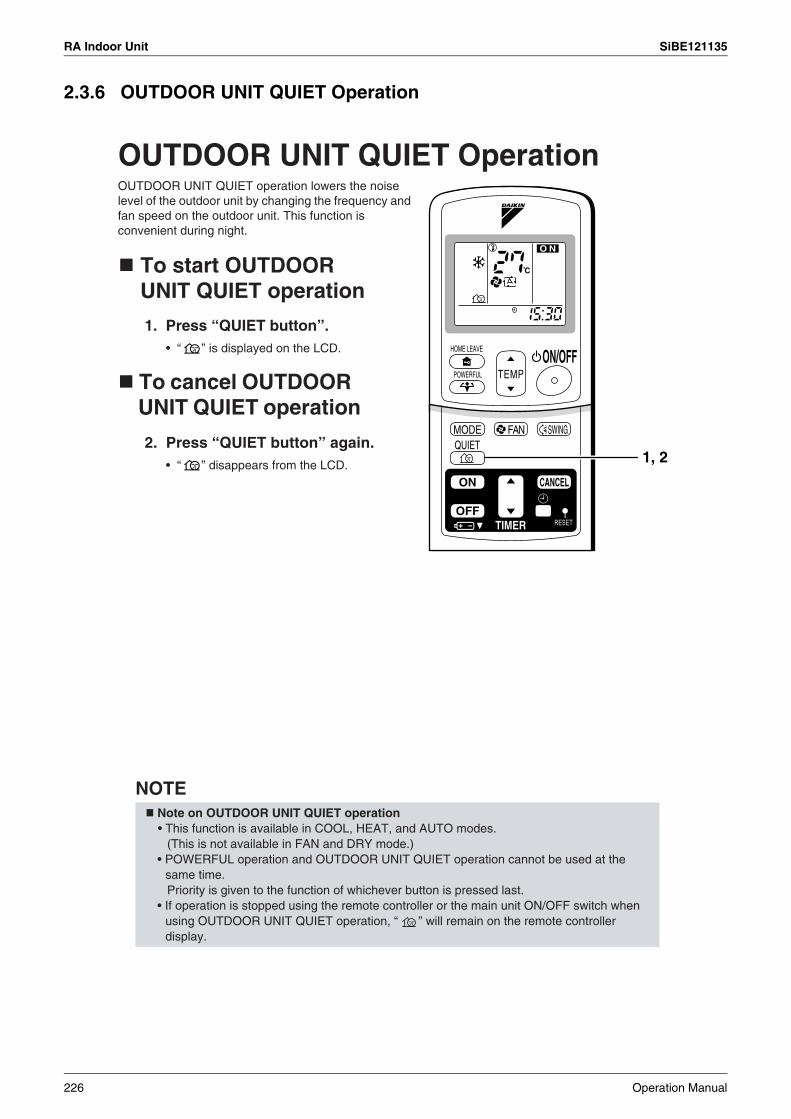
RA Indoor Unit SiBE121135
2.3.6 OUTDOOR UNIT QUIET Operation
OUTDOOR UNIT QUIET Operation
NOTE
C
1, 2
OUTDOOR UNIT QUIET operation lowers the noise level of the outdoor unit by changing the frequency and fan speed on the outdoor unit. This function is convenient during night.
To start OUTDOOR UNIT QUIET operation
To cancel OUTDOOR UNIT QUIET operation
1. Press “QUIET button”.• “ ” is displayed on the LCD.
2. Press “QUIET button” again.• “ ” disappears from the LCD.
Note on OUTDOOR UNIT QUIET operation• This function is available in COOL, HEAT, and AUTO modes.
(This is not available in FAN and DRY mode.)• POWERFUL operation and OUTDOOR UNIT QUIET operation cannot be used at the
same time. Priority is given to the function of whichever button is pressed last.
• If operation is stopped using the remote controller or the main unit ON/OFF switch when using OUTDOOR UNIT QUIET operation, “ ” will remain on the remote controller display.
226 Operation Manual

SiBE121135 RA Indoor Unit
2.3.7 HOME LEAVE Operation
HOME LEAVE Operation
Before using HOME LEAVE operation.
C
1, 2
Initial setting Selectable range
temperature Air flow rate temperature Air flow rate
Cooling 25°C “ ” 18-32°C 5 step, “ ” and “ ”
Heating 25°C “ ” 10-30°C 5 step, “ ” and “ ”
HOME LEAVE operation is a function which allows you to record your preferred temperature and air flow rate settings.
Home leave operation will run with these settings the next time you use the unit. To change the recorded information, repeat steps 1 – 3.
To start HOME LEAVE operation
To cancel HOME LEAVE operation
2. Press “HOME LEAVE button” again.• The HOME LEAVE lamp goes off.
1. Press “HOME LEAVE button” .• The HOME LEAVE lamp lights up.
To set the temperature and air flow rate for HOME LEAVE operationWhen using HOME LEAVE operation for the first time, please set the temperature and air flow rate for HOME LEAVE operation. Record your preferred temperature and air flow rate.
1. Press “HOME LEAVE button”. Make sure “ ” is displayed in the remote controller display.
2. Adjust the set temperature with “ ” or “ ” as you like.3. Adjust the air flow rate with “FAN” setting button as you like.
Operation Manual 227

RA Indoor Unit SiBE121135
1.Use as an energy-saving mode.
• Every day before you leave the house...
• Before bed...
2.Use as a favorite mode.
NOTE
Is there a set temperature and air flow rate which is most comfortable, a set temperature and air flow rate which you use the most? HOME LEAVE operation is a function that allows you to record your favorite set temperature and air flow rate. You can start your favorite operation mode simply by pressing the HOME LEAVE button on the remote controller. This function is convenient in the following situations.
Set the temperature 2-3˚C higher (cooling) or lower (heating) than normal. Setting the fan strength to the lowest setting allows the unit to be used in energy-saving mode. Also convenient for use while you are out or sleeping.
When you go out, push the “HOME LEAVE Operation” button, and the air conditioner will adjust capacity to reach the preset temperature for HOME LEAVE Operation.
When you return, you will be welcomed by a comfortably air conditioned room.
Push the “HOME LEAVE Operation” button again, and the air conditioner will adjust capacity to the set temperature for normal operation.
Set the unit to HOME LEAVE Operation before leaving the living room when going to bed.
The unit will maintain the temperature in the room at a comfortable level while you sleep.
When you enter the living room in the morning, the temperature will be just right. Disengaging HOME LEAVE Operation will return the temperature to that set for normal operation. Even the coldest winters will pose no problem!
Once you record the temperature and air flow rate settings you most often use, you can retrieve them by pressing HOME LEAVE button. You do not have to go through troublesome remote control operations.
What’s the HOME LEAVE operation?
Useful in these cases
• Once the temperature and air flow rate for HOME LEAVE operation are set, those settings will be used whenever HOME LEAVE operation is used in the future. To change these settings, please refer to the “Before using HOME LEAVE operation” section above.
• HOME LEAVE operation is only available in COOL and HEAT mode. Cannot be used in AUTO, DRY, and FAN mode.
• HOME LEAVE operation runs in accordance with the previous operation mode (COOL or HEAT) before using HOME LEAVE operation.
• HOME LEAVE operation and POWERFUL operation cannot be used at the same time. Last button that was pressed has priority.
• The operation mode cannot be changed while HOME LEAVE operation is being used.• When operation is shut off during HOME LEAVE operation, using the remote controller or
the indoor unit ON/OFF switch, “ ” will remain on the remote controller display.
228 Operation Manual
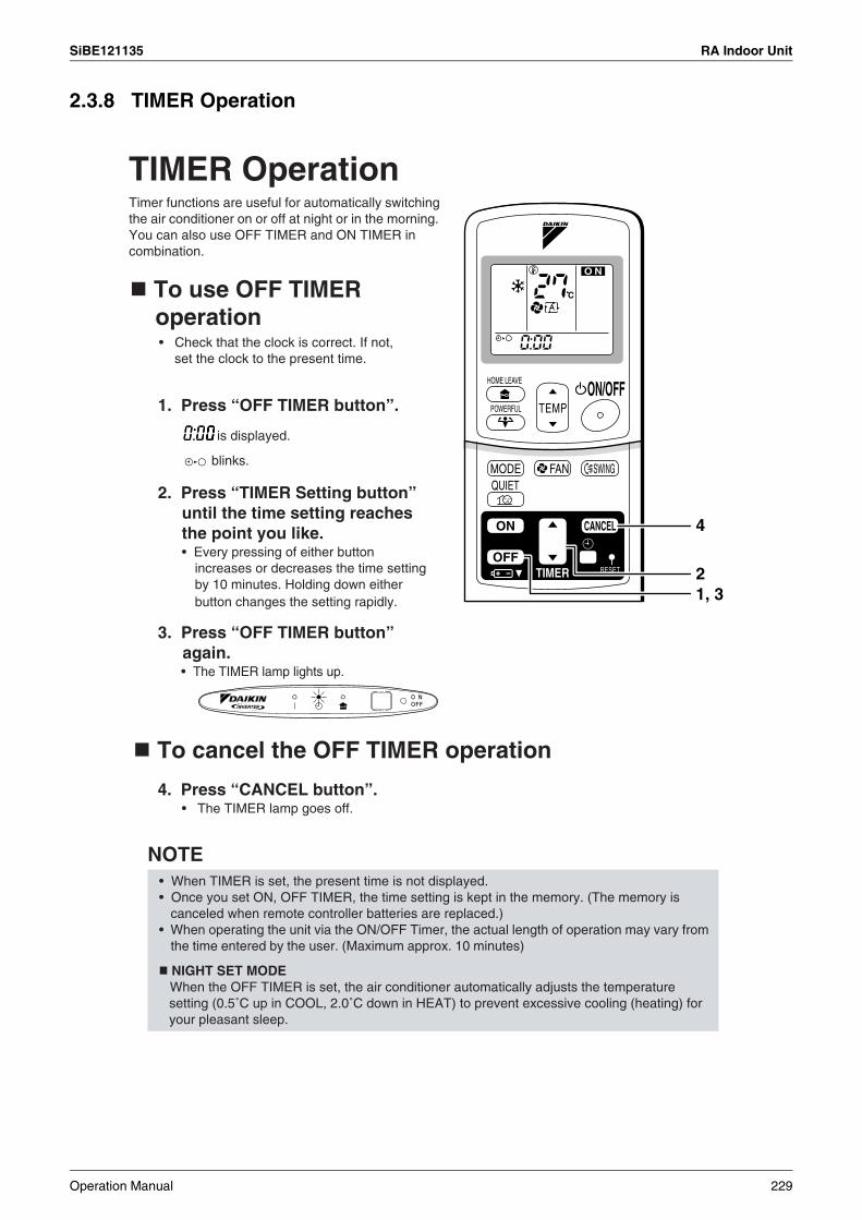
SiBE121135 RA Indoor Unit
2.3.8 TIMER Operation
TIMER Operation
NOTE
C
VE
O N
4
21, 3
Timer functions are useful for automatically switching the air conditioner on or off at night or in the morning.You can also use OFF TIMER and ON TIMER in combination.
To cancel the OFF TIMER operation
To use OFF TIMER operation• Check that the clock is correct. If not,
set the clock to the present time.
4. Press “CANCEL button”.• The TIMER lamp goes off.
1. Press “OFF TIMER button”.
is displayed.
blinks.
2. Press “TIMER Setting button” until the time setting reaches the point you like.• Every pressing of either button
increases or decreases the time setting by 10 minutes. Holding down either button changes the setting rapidly.
3. Press “OFF TIMER button” again.• The TIMER lamp lights up.
• When TIMER is set, the present time is not displayed.• Once you set ON, OFF TIMER, the time setting is kept in the memory. (The memory is
canceled when remote controller batteries are replaced.)• When operating the unit via the ON/OFF Timer, the actual length of operation may vary from
the time entered by the user. (Maximum approx. 10 minutes)
NIGHT SET MODEWhen the OFF TIMER is set, the air conditioner automatically adjusts the temperature setting (0.5˚C up in COOL, 2.0˚C down in HEAT) to prevent excessive cooling (heating) for your pleasant sleep.
Operation Manual 229
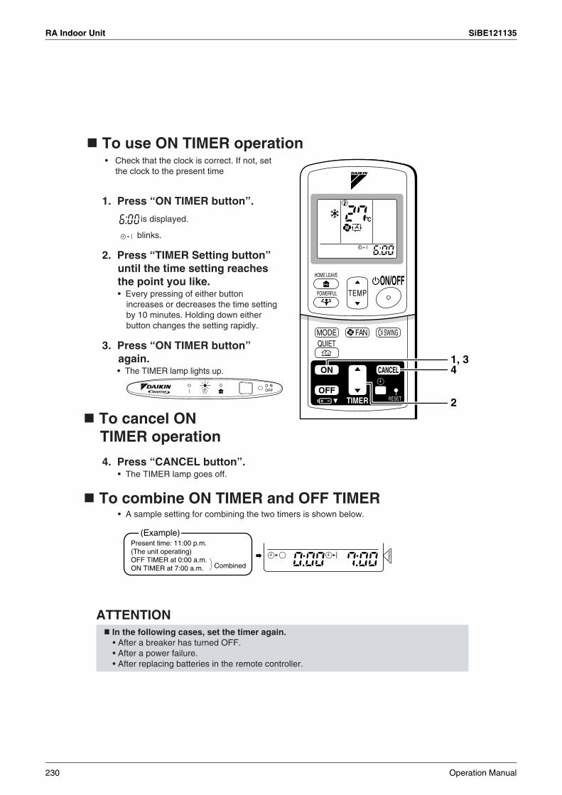
RA Indoor Unit SiBE121135
To combine ON TIMER and OFF TIMER• A sample setting for combining the two timers is shown below.
ATTENTION
C
TEMP
2
1, 34
(Example)
Combined
To cancel ON TIMER operation
To use ON TIMER operation• Check that the clock is correct. If not, set
the clock to the present time
1. Press “ON TIMER button”.
is displayed.
blinks.
2. Press “TIMER Setting button” until the time setting reaches the point you like.• Every pressing of either button
increases or decreases the time setting by 10 minutes. Holding down either button changes the setting rapidly.
3. Press “ON TIMER button” again.• The TIMER lamp lights up.
4. Press “CANCEL button”.• The TIMER lamp goes off.
Present time: 11:00 p.m. (The unit operating)OFF TIMER at 0:00 a.m.ON TIMER at 7:00 a.m.
In the following cases, set the timer again.• After a breaker has turned OFF.• After a power failure.• After replacing batteries in the remote controller.
230 Operation Manual

SiBE121135 RA Indoor Unit
2.3.9 Note for Multi System
Note for Multi System<< What is a “Multi System”? >>
This system has one outdoor unit connected to multiple indoor units.
Selecting the Operation Mode
(*1)
<CAUTION>
2. With the Priority Room Setting active.See “Priority Room Setting” on the next page.
NIGHT QUIET Mode (Available only for cooling operation)
OUTDOOR UNIT QUIET Operation1. With the Priority Room Setting present but inactive or not present.
2. With the Priority Room Setting active.See “Priority Room Setting” on the next page.
Cooling / Heating Mode Lock (Available only for heat pump models)
1. With the Priority Room Setting present but inactive or not present.
Outdoor unit
Living room
A room
B room
C roomWhen more than one indoor unit is operating, priority is
given to the first unit that was turned on. In this case, set the units that are turned on later to the same operation mode (*1) as the first unit.
Otherwise, they will enter the Standby Mode, and the operation lamp will flash; this does not indicate malfunction.
• COOL, DRY and FAN mode may be used at the same time.• AUTO mode automatically selects COOL mode or HEAT mode based on the room temperature.
Therefore, AUTO mode is available when selecting the same operation mode as that of the room with the first unit to be turned on.
Normally, the operation mode in the room where the unit is first run is given priority, but the following situations are exceptions, so please keep this in mind.If the operation mode of the first room is FAN Mode, then using Heating Mode in any room after this will give priority to heating. In this situation, the air conditioner running in FAN Mode will go on standby, and the operation lamp will flash.
NIGHT QUIET Mode requires initial programming during installation. Please consult your retailer or dealer for assistance.NIGHT QUIET Mode reduces the operation noise of the outdoor unit during the night time hours to prevent annoyance to neighbors.• The NIGHT QUIET Mode is activated when the temperature drops 5°C or more below the highest temperature
recorded that day. Therefore, when the temperature difference is less than 5°C, this function will not be activated.• NIGHT QUIET Mode reduces slightly the cooling efficiency of the unit.
When using the OUTDOOR UNIT QUIET operation feature with the Multi system, set all indoor units to OUTDOOR UNIT QUIET operation using their remote controllers.When clearing OUTDOOR UNIT QUIET operation, clear one of the operating indoor units using their remote controller.However OUTDOOR UNIT QUIET operation display remains on the remote controller for other rooms.We recommend you release all rooms using their remote controllers.
The Cooling / Heating Mode Lock requires initial programming during installation. Please consult your retailer or dealer for assistance. The Cooling / Heating Mode Lock sets the unit forcibly to either Cooling or Heating Mode. This functions convenient when you wish to set all indoor units connected to the Multi system to the same operation mode.
Operation Manual 231

RA Indoor Unit SiBE121135
Priority Room Setting
1. Operation Mode Priority.
<Example>
<Example>
<Example>
2. Priority when POWERFUL operation is used.
3. Priority when using OUTDOOR UNIT QUIET operation.
Operation mode in Room B, C and D Status of Room B, C and D when the unit in Room A is in COOL mode
COOL or DRY or FAN Current operation mode maintained
HEAT
AUTO
The Priority Room Setting requires initial programming during installation. Please consult your retailer or dealer for assistance.The room designated as the Priority Room takes priority in the following situations;
As the operation mode of the Priority Room takes precedence, the user can select a different operation mode from other rooms.
* Room A is the Priority Room in the examples.When COOL mode is selected in Room A while operating the following modes in Room B,C and D:
The unit enters Standby Mode. Operation resumes when the Room A unit stops operating.
If the unit is set to COOL mode, operation continues. If set to HEAT mode, it enters Standby Mode. Operation resumes when the Room A unit stops operating.
* Room A is the Priority Room in the examples.The indoor units in Rooms A,B,C and D are all operating. If the unit in Room A enters POWERFUL operation, operation capacity will be concentrated in Room A. In such a case, the cooling (heating) efficiency of the units in Rooms B,C and D may be slightly reduced.
* Room A is the Priority Room in the examples.Just by setting the unit in Room A to QUIET operation, the air conditioner starts OUTDOOR UNIT QUIET operation.You don’t have to set all the operated indoor units to QUIET operation.
232 Operation Manual

SiBE121135 SA Indoor Unit
3. SA Indoor Unit3.1 BRC1D528
1
1293
25
22
11
10
37
35
27
26
1214
17
34
24520 211816 13 15 19
323130
29
28
4
36
33
823 76
Operation Manual 233
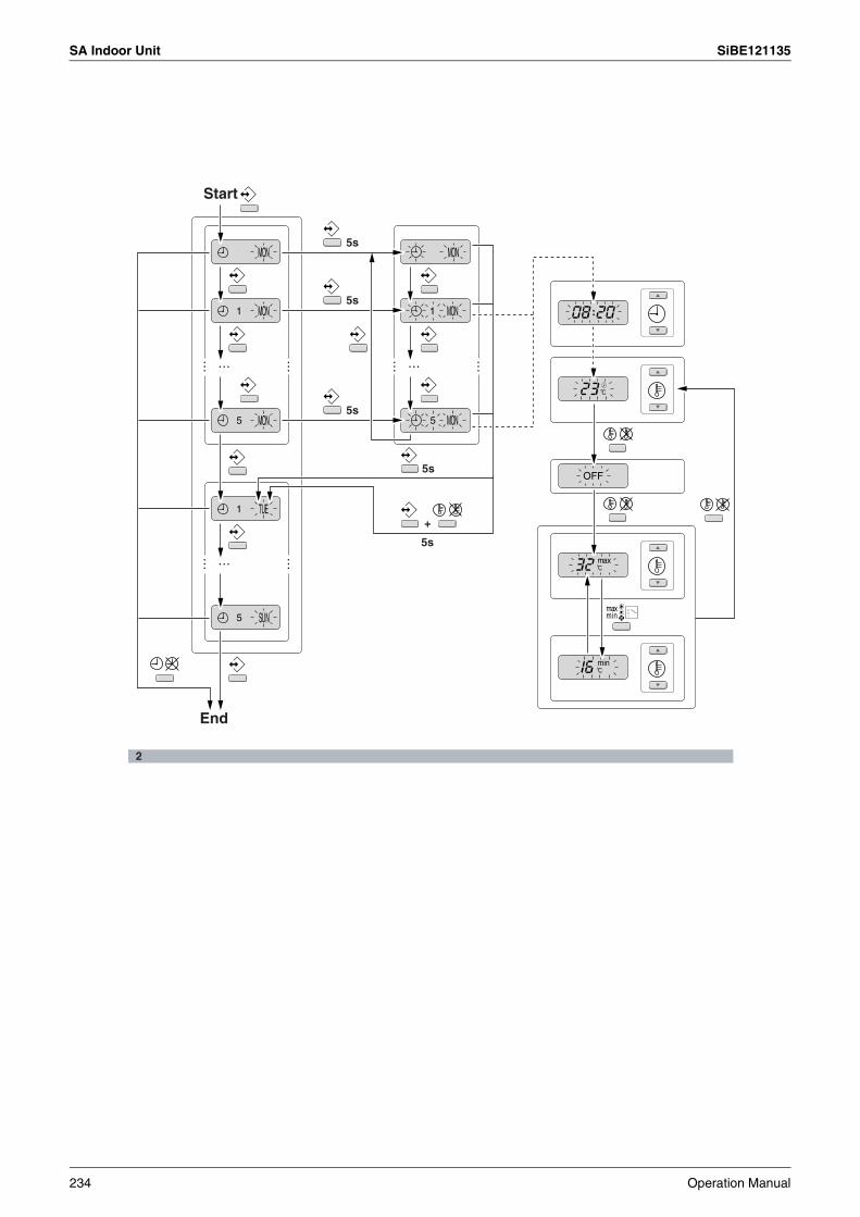
SA Indoor Unit SiBE121135
2
Start
5s
5s
5s
+
5s
5s
End
234 Operation Manual
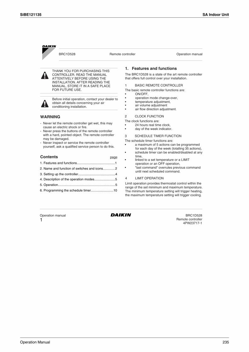
SiBE121135 SA Indoor Unit
Operation manual
1BRC1D528
Remote controller4PW23717-1
WARNING
Contents page
1. Features and functions
BRC1D528 Remote controller Operation manual
THANK YOU FOR PURCHASING THIS CONTROLLER. READ THE MANUAL ATTENTIVELY BEFORE USING THE INSTALLATION. AFTER READING THE MANUAL, STORE IT IN A SAFE PLACE FOR FUTURE USE.
Before initial operation, contact your dealer to obtain all details concerning your air conditioning installation.
The BRC1D528 is a state of the art remote controller that offers full control over your installation.
- Never let the remote controller get wet, this may cause an electric shock or fire.
- Never press the buttons of the remote controller with a hard, pointed object. The remote controller may be damaged.
- Never inspect or service the remote controller yourself, ask a qualified service person to do this.
1. Features and functions..........................................1
2. Name and function of switches and icons............. 2
3. Setting up the controller.........................................4
4. Description of the operation modes.......................5
5. Operation...............................................................5
6. Programming the schedule timer.........................10
1 BASIC REMOTE CONTROLLER
The basic remote controller functions are:• ON/OFF,• operation mode change-over,• temperature adjustment,• air volume adjustment• air flow direction adjustment.
2 CLOCK FUNCTION
The clock functions are:• 24 hours real time clock,• day of the week indicator.
3 SCHEDULE TIMER FUNCTION
The schedule timer functions are:• a maximum of 5 actions can be programmed
for each day of the week (totalling 35 actions),• schedule timer can be enabled/disabled at any
time,• linked to a set temperature or a LIMIT
operation or an OFF operation,• "last command" overrules previous command
until next scheduled command.
4 LIMIT OPERATION
Limit operation provides thermostat control within the range of the set minimum and maximum temperature.The minimum temperature setting will trigger heating, the maximum temperature setting will trigger cooling.
Operation Manual 235

SA Indoor Unit SiBE121135
BRC1D528Remote controller4PW23717-1
Operation manual
2
ON Leave home is enabled
FLASHING Leave home is active
OFF Leave home is disabled
The leave home function prevents the room temperature from dropping when the occupants are out for a longer period. If the room temperature drops below 10°C, heating is started automatically. As soon as 15°C is reached, the controller returns to its original status.
Three hierarchical permission levels can be set to limit the user action.
These icons indicate the current ventilation mode (HRV only) (AUTOMATIC, HEAT EXCHANGE, BYPASS).
The ventilation icon appears when the ventilation is adjusted with the ventilation amount button (HRV only). Simultaneously, the ventilation amount is indicated by the fan speed icon (see 22).
The day of the week indicator shows the current week day (or the set day when reading or programming the schedule timer).
5 LEAVE HOME
6 BUTTON PERMISSION LEVEL
2. Name and function of switches and icons (Refer to figure 1)
1 ON/OFF BUTTON
Press the ON/OFF button to start or stop the system.
2 OPERATION LAMP
The operation lamp lights up during operation or blinks if a malfunction occurs.
3 OPERATION MODE ICON
These icons indicate the current operation mode (FAN, DRY, AUTOMATIC, COOLING, HEATING).
4 VENTILATION MODE ICON
5 VENTILATION ICON11 CLOCK DISPLAY
The clock display indicates the current time (or the action time when reading or programming the schedule timer).
10 DAY OF THE WEEK INDICATOR
9 CHANGE-OVER UNDER CENTRALISED CONTROL ICON
This icon indicates that the change-over of the installation is under centralised control assigned to another indoor unit or optional cool/heat selector connected to the outdoor unit (= master remote controller).
8 EXTERNAL CONTROL ICON
This icon indicates that another controller with higher priority is controlling or disabling your installation.
7 LEAVE HOME ICON
The leave home icon shows the status of the leave home function.
6 AIR CLEANING ICON
This icon indicates that the air cleaning unit (option) is operational.
236 Operation Manual
SiBE121135 SA Indoor Unit
Operation manual
3BRC1D528
Remote controller4PW23717-1
is displayed whenever a non-installed option is addressed or a function is not available.
12 MAXTEMPERATURE IMUM SET
The maximum set temperature indicates the maximum set temperature when in limit operation.
13 MINIMUM SET TEMPERATURE
The minimum set temperature indicates the minimum set temperature when in limit operation.
14 SCHEDULE TIMER ICON
This icon indicates that the schedule timer is enabled.
15 ACTION ICONS
These icons indicate the actions for each day of the schedule timer.
16 OFF ICON
This icon indicates that the OFF action is selected when programming the schedule timer.
17 INSPECTION REQUIRED and
These icons indicate that inspection is required.Consult your installer.
18 SET TEMPERATURE DISPLAY
This indicates the current set temperature of the installation (not shown in LIMIT operation or in FAN or DRY mode).
19 SETTING
Not used, for service purposes only.
20 AIR FLOW DIRECTION ICON
This icon indicates the air flow direction (only for installations with motorised air flow ßaps).
21 NOT AVAILABLE
22 FAN SPEED ICON
This icon indicates the set fan speed.
23 DEFROST/HOTSTART MODE ICON
This icon indicates that the defrost/hotstart mode is active.
24 AIR FILTER CLEANING TIME ICON
This icon indicates the air filter must be cleaned.Refer to the manual of the indoor unit.
25 ELEMENT CLEANING TIME ICON
This icon indicates the element must be cleaned ( only).
26 VENTILATION MODE BUTTON
The ventilation mode button operates the ; refer to the manual for more details.
27 VENTILATION AMOUNT BUTTON
This button sets the ventilation amount; refer to the manual for more details.
28 INSPECTION/TEST OPERATION BUTTON
Not used, for service purposes only.
29 PROGRAMMING BUTTON
This button is a multi-purpose button.
Depending on the previous manipulations of the user, the programming button can have various functions.
Operation Manual 237

SA Indoor Unit SiBE121135
BRC1D528Remote controller4PW23717-1
Operation manual
4
1
These buttons are used to adjust the current setpoint or, when in programming mode, to adjust the programmed setpoint temperature (step = 1°C). Both buttons are also used to adjust the day of the week.
This button is a multi-purpose button. Depending on the previous manipulations of the user, it can have following functions:
Hold down the button for 5 seconds. The clock read-out and the day of week indicator will blink, both can now be adjusted.
Use the & buttons to adjust the clock. Each time pressing the time adjust button will in/decrease the time by 1 minute. Keeping the
or button pressed will in/decrease the time by 10 minutes.
Use the & buttons to adjust the day of the week. Each time pressing the or
buttons will display the next or previous day.
Press the button to confirm the current set time and day of the week.
If the controller, with blinking clock and day of week read-out, is left untouched for 5 minutes, the clock and day of the week will return to their previous settings; the clock setting function is no longer active.
30 SCHEDULE TIMER BUTTONThis button enables or disables the schedule timer.
31 TIME ADJUST BUTTON
These buttons are used to adjust the clock or, when in programming mode, to adjust the programmed action time. Both buttons have an auto-repeat function.
32 TEMPERATURE ADJUST BUTTONS
33 OPERATION CHANGE/MIN-MIX BUTTON
1 select the operation mode of the installation(FAN, DRY, AUTOMATIC, COOLING, HEATING)
2 toggle between minimum temperature and maximum temperature when in limit operation
34 SETPOINT/LIMIT BUTTON
This button toggles between setpoint, limit operation or (programming mode only).
35 FAN SPEED BUTTON
This button toggles between L (Low), H (High), HH (very High), (Automatic).
36 AIR FLOW DIRECTION ADJUST BUTTON
This button enables to adjust the air flow direction.
37 AIR FILTER CLEANING TIME ICON RESET BUTTON
This button is used to reset the air filter cleaning time icon.
3. Setting up the controllerAfter initial installation, the user can set the clock and day of the week.The controller is equipped with a schedule timer that enables the user to operate the installation automatically; setting the clock and day of the week is required to be able to use the schedule timer.
2 SETTING UP THE SCHEDULE TIMER
To set up the schedule timer, refer to chapter 6. "Programming the schedule timer" on page 10.
CLOCK SETTING FUNCTION
238 Operation Manual
SiBE121135 SA Indoor Unit
Operation manual
5BRC1D528
Remote controller4PW23717-1
Hot start (heat pump types only)
This prevents cold air from leaving the indoor unit.
Defrost (heat pump types only)
Manual operation
At the start of a heating operation, the indoor fan is stopped until a certain indoor heat exchanger temperature is reached and is displayed.
In heating operation, freezing of the outdoor heat exchanger may occur. If so, the heating capacity of the system lowers and the system goes into defrost operation. The indoor unit fan stops and is displayed. After maximum 10 minutes of defrost operation, the system returns to heating operation again.
Limit operation is an additional mode that enables to keep the room temperature within certain limits. The
& icons are displayed to confirm the activation of the limit operation.
In manual operation, the user decides about the settings of the installation. The last setting remains active until the user changes it.As the controller can be implemented for a wide variety of installations and features, it might occur that you select a function that is not available on your installation; if this is the case, the message will appear.
4. Description of the operation modes
1 FAN ONLY OPERATION
In this mode, air only circulates without heating or cooling.
2 DRY OPERATION
In this mode, the air humidity will be lowered with a minimal temperature decrease.
The temperature and fan speed are controlled automatically and cannot be controlled by the remote controller.Dry operation will not function if the room temperature is too low.
3 AUTOMATIC OPERATION
In this mode, the controller will automatically switch between heating and cooling as required by the setpoint or limit temperature.
4 COOLING OPERATION
In this mode, cooling will be activated as required by the setpoint or limit temperature.
5 HEATING OPERATION
In this mode, heating will be activated as required by the setpoint or limit temperature.
6 LIMIT OPERATION &
7 LEAVE HOME
LEAVE HOME is a feature that enables to keep the room temperature above 10°C when the occupants are out. This function will switch on heating if the installation is switched off.
5. Operation
Operation Manual 239

SA Indoor Unit SiBE121135
BRC1D528Remote controller4PW23717-1
Operation manual
6
3 AUTOMATIC OPERATION
User adjustable parameters:
Fan only operation
Dry operation
Automatic operation
Cooling operation
Heating operation
Use the button to select the desired operation mode.
Press the button to toggle between limit operation and the operations listed above.
In limit operation, use the button to select minimum and maximum temperature settings. Use the or buttons to adjust the minimum and maximum temperature settings.
• Setpoint temperature, use the & buttons,
• Fan speed, use the button,
• Air flow direction adjust, use the button,
• Ventilation mode, use the button,
• Ventilation amount, use the button.
4 COOLING OPERATION
User adjustable parameters:• Setpoint temperature, use the &
buttons,• Fan speed, use the button,• Air flow direction adjust, use the button,
• Ventilation mode, use the button,
• Ventilation amount, use the button.
5 HEATING OPERATIONUser adjustable parameters:• Setpoint temperature, use the &
buttons,• Fan speed, use the button,• Air flow direction adjust, use the button,• Ventilation mode, use the button,
• Ventilation amount, use the button.
6 LIMIT OPERATION
User adjustable parameters:• Fan speed, use the button,• Air flow direction adjust, use the button,
• Ventilation mode, use the button,
• Ventilation amount, use the button.
1 FAN ONLY OPERATIONUser adjustable parameters:
• Fan speed, use the button,
• Air flow direction adjust, use the button,
• Ventilation mode, use the button,
• Ventilation amount, use the button.
2 DRY OPERATION
User adjustable parameters:
• Air flow direction adjust, use the button,
• Ventilation mode, use the button,
• Ventilation amount, use the button.
240 Operation Manual
SiBE121135 SA Indoor Unit
Operation manual
7BRC1D528
Remote controller4PW23717-1
ADDITIONAL FEATURES OF THE CONTROLLER
Schedule timer operation
NOTE
NOTE
Press the and buttons simultaneously to enable the LEAVE HOME function.
KEEP IN MIND THAT THE BUTTON MUST BE OFF TO GUARANTEE TRIGGERING OF THE LEAVE HOME FUNCTION.
Use the button to adjust the air flow direction.Press the button to switch between fixed or variable air flow direction. Use the icon to determine the fixed air flow direction by pressing the button when the icon indicates the desired direction.
Even if fixed air flow direction is selected, variable air flow direction can be enabled automatically to preserve proper operation of your installation.
In schedule timer operation, the installation is also controlled by the schedule timer. The actions programmed in the schedule timer will be executed automatically.The schedule timer always executes the last command; this means the user can temporarily overrule the last executed programmed action. Refer to "Manual operation" on page 5. The next programmed action (in the schedule timer) will return control to the schedule timer.
Use the button to enable or disable the schedule timer.
The schedule timer overrules the button, only use the button to enable or disable the schedule timer. The schedule timer is enabled when the icon is visible. The button only overrules the schedule timer until the next programmed action.
The programmed schedule is time driven.Make sure that the clock and day of the week are set correctly. Refer to "CLOCK SETTING FUNCTION" on page 4.
Manually adjust the clock for summertime and wintertime. Refer to "CLOCK SETTING FUNCTION" on page 4.
A power failure exceeding 1 hour will reset the clock and the day of the week. Refer to "CLOCK SETTING FUNCTION" on page 4 to adjust the clock and the day of the week.
The actions programmed in the schedule timer will not be lost after a power failure; reprogramming the schedule timer is not required.
To set up the SCHEDULE TIMER refer to chapter 6. "Programming the schedule timer" on page 10.
1 LEAVE HOME
2 Adjusting the air flow direction
3 SCHEDULE TIMERAll features and operation and programming of the schedule timer are described below.
Operation Manual 241

SA Indoor Unit SiBE121135
BRC1D528Remote controller4PW23717-1
Operation manual
8
What can the schedule timer do?
The schedule timer can order 3 actions:
What will the schedule timer do?
OR
OR
What will the schedule timer NOT do?
Refer to figure 2.
The concept of the schedule timer is simple, straightforward though powerful.
The schedule timer can accept a maximum of 5 actions per day.
For each day of the week a maximum of 5 actions can be programmed, totalling a maximum of 35 programmed actions. The action that was programmed first for a certain day is action 1, the last programmed action for a day could be action 1 (in case only one action is programmed for that day) to 5.
It is of utmost importance to understand that the number assigned to the programmed action, DOES NOT DETERMINE WHEN the programmed action will be executed. Only the TIME, being a part of the data entered when programming the action, will determine when the programmed action will be executed.
• switch off the installation (the schedule timer remains enabled and reactivates the installation as programmed); the operation lamp will turn off,
• cool or heat, whichever is required to keep the room temperature within a specified range (limit operation); and are displayed.
The schedule timer will change the operation mode in LIMIT operation only.
To be able to verify the programmed actions, you can browse the programmed actions, see below.
Browsing the programmed actions in the schedule timer (read-out only)
Browsing the programmed actions of the schedule timer is a sequential process. Only 2 buttons are used to browse the entire schedule timer program.
The button is used to start browsing, to display the next programmed action or to exit browsing when displaying the last programmed action.
1 switch on the installation at a scheduled time, in combination with a setpoint (exact temperature control)
2 switch off the installation (end of control)
3 switch on the installation at a scheduled time, in limit operation
If enabled, the schedule timer will execute the programmed actions.
It will order the installation to:
• cool or heat, depending on the current operation, if applicable; the setpoint will be displayed,
The schedule timer will not:• control fan speed,• control air flow direction,• control ventilation mode,• control ventilation amount,• change the operation mode for a scheduled
setpoint.The parameters listed above can be set manually, without interfering with the schedule timer.
More sophisticated remote controllers are available.Consult your dealer for more information.
242 Operation Manual
SiBE121135 SA Indoor Unit
Operation manual
9BRC1D528
Remote controller4PW23717-1
NOTE
NOTE
NOTE
NOTE
The button is used to exit browsing at once (without having to scroll through all programmed actions).
Press the button to enter the browse mode, the icon appears, will blink.
Browsing always starts on Monday and ends on Sunday.
Check the icon. If at least 1 action is programmed for Monday, will appear.
The clock indicates the time when the programmed action is scheduled, either , or and
is being displayed.
The temperatures mentioned above are for clarifying purposes only, temperature values on your controller may vary.
If does not appear, it indicates that there are no programmed actions for Monday.Press the button again to go to the next day of the week. will blink, this indicates that the programmed actions for Tuesday are being browsed.
The process described above is now restarted.
If at least 1 action is programmed for Tuesday, will appear. The clock indicates the time when the programmed action will be enabled, either ,
or and is being displayed.
If does not appear, it indicates that there are no programmed actions for Tuesday.
Press the button to display the next programmed action. If a second action is programmed for Tuesday,
will still be blinking and will appear.
Assuming that 5 actions were programmed for Tuesday, a total of 5 presses will be required to display all programmed actions.
Continue pressing the button until the day of the week indicator displays the current day (not blinking), you have now quit browsing.
The number of times that the button will have to be pressed to quit browsing depends on the number of programmed actions in the schedule timer.
How do I interpret the programmed actionsTo be able to understand the behaviour of your installation when the schedule timer is enabled, it is important to look at all programmed actions for the current day and maybe the last programmed action of yesterday.If the first programmed action for today is not active yet, the current status of your installation depends, most probably but not necessarily, on the last programmed action from yesterday. Read the important note below.If the first programmed action for today is already active, the current status of your installation depends, most probably but not necessarily, on the parameters programmed in the first programmed action for today. Read the important note below.
To keep the operation of your installation simple, the schedule timer settings can easily be overruled by altering the current setting ("last command" overrules previous command until next scheduled command).
Conclusion: Although is displayed, somebody might have altered the settings. The next programmed action will overrule the altered settings and all settings return as programmed.
Operation Manual 243

SA Indoor Unit SiBE121135
BRC1D528Remote controller4PW23717-1
Operation manual
10
What do I have to program?
Getting started
NOTE
Programmed actions might overlap; due to the "last command overrules" logic, the last scheduled command will rule.
How do I interpret the readings on the display when the schedule timer is activeAs described above, the schedule timer settings, (and as a consequence the display readings) might be overruled temporarily by a manual intervention.If you want to be absolutely sure about the schedule timer settings for this very moment, you must browse the schedule timer programmed actions. Refer to "Browsing the programmed actions in the schedule timer" on page 8.
As the schedule timer is based on a week program (the same actions will be repeated every week) you will have to select the day of the week first.
Now you must choose an action:
1 switch on the installation at a scheduled time, in combination with a setpoint (exact temperature control)
2 switch off the installation (end of control)
3 switch on the installation at a scheduled time, in limit operation
Finally you must enter the time of the day when the action must be enabled.
If you program 2 or more actions on the same day and at the same time of the day, only the action with the highest action number (2 - 5) will be executed.
Programming the schedule timer is flexible (you can add, remove or alter programmed actions whenever required) and straightforward (programming steps are limited to a minimum).
Below are some tips and tricks to ensure successful programming of the schedule timer:
• familiarise yourself with the icons and the buttons, you will need them when programming,
• familiarise yourself with the browse function, you will need it to start programming. Refer to "Browsing the programmed actions in the schedule timer" on page 8,
• fill out the form at the end of this manual; note the time and the required action for each day (keep in mind that the number of actions is limited to 5 per day),
• take your time to enter all data accurately,• try to program the actions for each day in
logical sequence (start with action 1 for the first action and end with the highest number for the last action). This is not a requirement but it will make it much easier to interpret the program later,
• keep in mind that you can always alter, add or remove the programmed actions later.
6 . Programming the schedule timer
244 Operation Manual
SiBE121135 SA Indoor Unit
11BRC1D528
Remote controller4PW23717-1
Programming
NOTE When changing day during programming you will have to confirm "the last action".Each day can have 5 programmed actions (numbered 1 to 5) but for some reason you might want to delete one, several or all programmed actions.
To be able to delete programmed actions, you must select the last action that you want to keep, this can be 1 to 5 or no action ( is displayed and no action displayed).
All programmed actions with a number HIGHER than the selected one, or all programmed actions if no last action was selected will be deleted.
PROGRAMMING THE FIRST DAY OF THE WEEK
NOTE In the guidelines below it is assumed that you start programming the schedule timer actions on Monday and end with the schedule timer actions for Sunday.
If you prefer NOT to start on Monday, first browse to the desired day and then enter the PROGRAM mode.
In this particular case, no actions have been programmed before, all schedule timer actions are idle.• Browse to Monday by pressing the button.
The icon appears, will blink and one of the icons might be displayed but all other fields remain blank, indicating that no actions are programmed for Monday.
• Enter the program mode by holding down the button for 5 seconds, the icon will now blink too.
• Press the button to activate the first programmed action.
• A blinking is displayed indicating that the first programmed action for Monday is being programmed; The set temperature and clock display are blinking.
• Press the button to select either set
temperature, , or limit operation.• Enter the desired temperature using the
& buttons.
• Press the button to toggle between minimum set temperature and maximum set temperature in limit operation, the selected temperature will blink.
• Enter the time when the action must start using the & buttons (min. step = 10 minutes).
NOTE If, by accident, you pressed the button, you activated the next action; is displayed ( steady and blinking).Press the button repeatedly until a blinking is displayed. You can now continue adjusting the settings for the first schedule timer action.
Operation manual
1 THE SCHEDULE TIMER IS PROGRAMMED FOR THE FIRST TIME
Operation Manual 245
SA Indoor Unit SiBE121135
BRC1D528Remote controller4PW23717-1
12
If the action and the corresponding time are correct, you can proceed to the second schedule timer action.This is done by pressing the button, the data is saved and the next schedule timer action can be programmed.Programming the remaining schedule timer actions for the same day is similar.You can browse the schedule timer actions by pressing the button.
NOTE Don't worry if you add additional schedule timer actions by pressing the
button repeatedly, they can be deleted when finishing the current day.
When all data for the schedule timer actions for Monday are entered, you must confirm the programmed actions.Make sure the last schedule timer action you want to keep is selected (schedule timer actions with a higher number will be deleted).Now you must choose between 2 options:
The schedule timer action programmed for the current day are also valid for the next day: use the "confirm last action and copy actions to next day" function by pressing the and buttons simultaneously for 5 seconds.
The schedule timer action programmed for the current day are only valid for the selected day: use the "confirm last action and go to next day" function by pressing the button for 5 seconds.
Program mode is quit and depending on the choice made, the programmed actions are saved for Monday (and possibly Tuesday).
PROGRAMMING THE OTHER DAYS OF THE WEEK
Programming the other days of the week is identical to programming the first day of the week. is blinking to indicate the selected day, and are steady if actions were copied from Monday to Tuesday, only is displayed if no actions were copied from Monday to Tuesday.
2 I WANT TO EDIT PROGRAMMED ACTIONS Editing programmed actions is easy.
Make sure you are not in program mode ( not blinking); if required, press the button to quit program mode.
Browse to the programmed actions using the button, select the day and action you want to edit.
Press the button for 5 seconds; program mode is enabled, the icon and selected action are blinking. Edit the settings using the same buttons described above.Select the "last action" using the button and decide if you do or do not want to copy the programmed action(s) to the next day (pressing the
and buttons simultaneously or only the button for 5 seconds).
Operation manual
1 CONFIRM AND COPY TO NEXT DAY
2 CONFIRM ONLY
246 Operation Manual
SiBE121135 SA Indoor Unit
13BRC1D528
Remote controller4PW23717-1
Limit operation cannot be selected
Make sure you are not in program mode ( not blinking); if required, press to quit program mode.Browse to the programmed actions using the button, select the day you want to edit.
Press the button for 5 seconds; program mode is enabled, the icon and selected action are blinking.Select the "last action" you want to keep using the
button. All higher actions will be deleted.
Confirm the deletion by pressing the button for 5 seconds, OR confirm the deletion for the current and the next day too by pressing the and buttons simultaneously for 5 seconds.
NOTE In the case above, if for example the last action was 3, the programmed actions 4 and 5 will also be deleted (if they were present).
Quit programming or browsing.
Press the and buttons simultaneously for 5 seconds; the icon will invert and disappear to confirm deletion.
NOTE Only use clear tepid water to moisten the cloth.
Operation manual
The guidelines below might help to solve your problem. If you cannot remedy the problem, consult your installer.
No readings on the remote controller (display blank)Check if the mains power is still applied to your installation.
Only is displayed
This indicates that the installation has just been powered, please wait until disappears.
The schedule timer does work but the programmed actions are executed at the wrong time (e.g. 1 hour too late or too early)Check if the clock and the day of the week are set correctly, correct if necessary (refer to "CLOCK SETTING FUNCTION" on page 4).
I cannot enable the schedule timer (the icon blinks for 2 seconds and disappears)The schedule timer has not been programmed yet.First program the schedule timer (refer to "Programming the schedule timer" on page 10).
I cannot enable the schedule timer (the icon is displayed)The schedule timer can not be enabled when a centralised control is connected.
Limit operation is not available for cooling only installations.
3 I WANT TO DELETE ONE OR MORE PROGRAMMED ACTIONS
4 I WANT TO DELETE ALL PROGRAMMED ACTIONS AT ONCE
The remote controller does not need maintenance.
Remove dirt with a soft damp cloth.
7. Maintenance
8. Troubleshooting
4PW23717-1
Operation Manual 247
SiBE121135
Part 6Service Diagnosis
1. Troubleshooting with LED...................................................................2501.1 Indoor Unit............................................................................................2501.2 Outdoor Unit .........................................................................................252
2. Problem Symptoms and Measures .....................................................2533. Service Check Function ......................................................................254
3.1 RA Indoor Unit - FTXG, FTXS, CTXS, FVXG, FVXS, FLXS, FDXS Series.........................................................................................254
3.2 SA Indoor Unit - FCQG, FFQ, FHQ, FDBQ, FBQ Series .....................263
4. Code Indication on Remote Controller ................................................2674.1 RA Indoor Unit - FTXG, FTXS, CTXS, FVXG, FVXS, FLXS,
FDXS Series.........................................................................................2674.2 SA Indoor Unit - FCQG, FFQ, FHQ, FDBQ, FBQ Series .....................2674.3 Sub Codes for SA Indoor Unit ..............................................................2684.4 Outdoor Unit .........................................................................................269
5. Troubleshooting for RA Indoor Unit - FTXG, FTXS, CTXS, FVXG, FVXS, FLXS, FDXS Series ...........................................................................2705.1 Indoor Unit PCB Abnormality ...............................................................2705.2 Freeze-up Protection Control or Heating Peak-cut Control ..................2725.3 Fan Motor or Related Abnormality .......................................................2745.4 Radiant Panel Temperature Rise, Indoor Electronic Expansion Valve
(Motor Operated Valve) Abnormality, Freeze-up Protection Control (FVXG Series Only)..............................................................................278
5.5 Thermistor or Related Abnormality (RA Indoor Unit)............................2805.6 Front Panel Open / Close Fault (FTXG Series Only) ...........................2815.7 Signal Transmission Error (between Indoor Unit and Outdoor Unit) ....2825.8 Unspecified Voltage (between Indoor Unit and Outdoor Unit) .............283
6. Troubleshooting for SA Indoor Unit - FCQG, FFQ, FHQ, FDBQ, FBQ Series..........................................................................................2846.1 Indoor Unit PCB Abnormality ...............................................................2846.2 Drain Water Level System Abnormality................................................2856.3 Fan Motor or Related Abnormality .......................................................2876.4 Swing Motor Lock (FHQ Series Only) ..................................................2896.5 Drain System Abnormality....................................................................2906.6 Thermistor or Related Abnormality (SA Indoor Unit) ............................2916.7 Remote Controller Thermistor Abnormality ..........................................2926.8 Signal Transmission Error
(between Indoor Unit and Remote Controller)......................................2936.9 Signal Transmission Error
(between MAIN Remote Controller and SUB Remote Controller)........2946.10 Field Setting Abnormality .....................................................................295
7. Troubleshooting for Outdoor Unit........................................................2967.1 Refrigerant Shortage ............................................................................2967.2 Low-voltage Detection or Over-voltage Detection................................2987.3 Signal Transmission Error (on Outdoor Unit PCB)...............................300
248 Service Diagnosis

SiBE121135
7.4 Unspecified Voltage (between Indoor Unit and Outdoor Unit) / Anti-icing Function in Other Rooms......................................................301
7.5 Anti-icing Function................................................................................3027.6 Outdoor Unit PCB Abnormality.............................................................3047.7 OL Activation (Compressor Overload) .................................................3057.8 Compressor Lock .................................................................................3067.9 DC Fan Lock ........................................................................................3077.10 Input Overcurrent Detection .................................................................3087.11 Discharge Pipe Temperature Control...................................................3097.12 High Pressure Control in Cooling .........................................................3107.13 Compressor Sensor System Abnormality ............................................3117.14 Position Sensor Abnormality ................................................................3137.15 CT or Related Abnormality ...................................................................3157.16 Thermistor or Related Abnormality (Outdoor Unit) ...............................3177.17 Electrical Box Temperature Rise..........................................................3197.18 Radiation Fin Temperature Rise ..........................................................3217.19 Output Overcurrent Detection ..............................................................323
8. Check ..................................................................................................3258.1 Thermistor Resistance Check ..............................................................3258.2 Fan Motor Connector Check ................................................................3268.3 Hall IC Check .......................................................................................3278.4 Indoor Electronic Expansion Valve Coil Check ....................................3278.5 Power Supply Waveform Check...........................................................3288.6 Outdoor Electronic Expansion Valve Check.........................................3298.7 Four Way Valve Performance Check ...................................................3308.8 Inverter Unit Refrigerant System Check...............................................3308.9 “Inverter Checker” Check .....................................................................3318.10 Rotation Pulse Check on the Outdoor Unit PCB ..................................3328.11 Installation Condition Check.................................................................3338.12 Discharge Pressure Check...................................................................3338.13 Outdoor Fan System Check .................................................................3348.14 Capacitor Voltage Check......................................................................3348.15 Power Module Check ...........................................................................335
Service Diagnosis 249

Troubleshooting with LED SiBE121135
1. Troubleshooting with LED1.1 Indoor Unit
Operation Lamp The operation lamp blinks when any of the following errors is detected.1. When a protection device of the indoor or outdoor unit is activated, or when the thermistor
malfunctions.2. When a signal transmission error occurs between the indoor and outdoor units.In either case, conduct the diagnostic procedure described in the following pages.
Wall Mounted Type: FTXG Series Wall Mounted Type: FTXS-K, CTXS-K Series
Wall Mounted Type: FTXS-J Series Wall Mounted Type: FTXS-G Series
Floor Standing Type: FVXG Series
Operation lamp (multi-colored)
(R12750)
Operation lamp (green)
(R17161)
(R12187)
Operation lamp (green)
Operation lamp (green)
(R16008)
(R14646)
Operation lamp (green)
250 Service Diagnosis
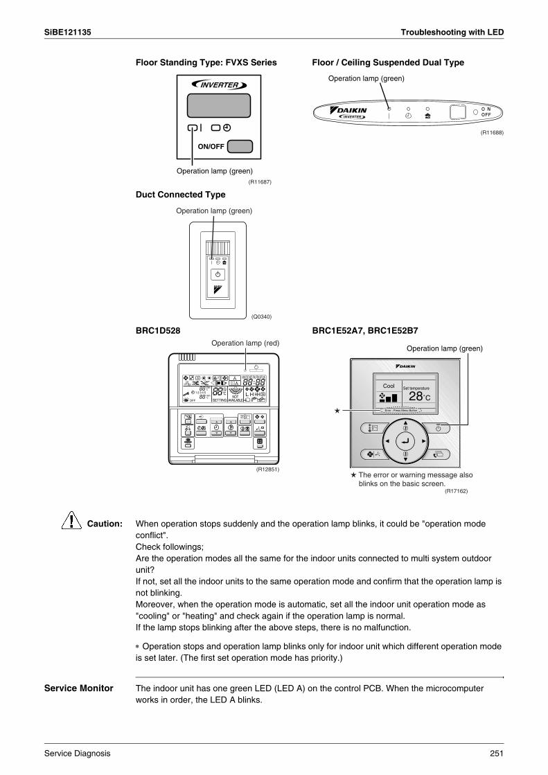
SiBE121135 Troubleshooting with LED
Caution: When operation stops suddenly and the operation lamp blinks, it could be "operation mode conflict".Check followings;Are the operation modes all the same for the indoor units connected to multi system outdoor unit?If not, set all the indoor units to the same operation mode and confirm that the operation lamp is not blinking.Moreover, when the operation mode is automatic, set all the indoor unit operation mode as "cooling" or "heating" and check again if the operation lamp is normal.If the lamp stops blinking after the above steps, there is no malfunction.
∗ Operation stops and operation lamp blinks only for indoor unit which different operation mode is set later. (The first set operation mode has priority.)
Service Monitor The indoor unit has one green LED (LED A) on the control PCB. When the microcomputer works in order, the LED A blinks.
Floor Standing Type: FVXS Series Floor / Ceiling Suspended Dual Type
Duct Connected Type
BRC1D528 BRC1E52A7, BRC1E52B7
(R11687)
Operation lamp (green)
Operation lamp (green)
(R11688)
Operation lamp (green)
(Q0340)
Operation lamp (red)
(R12851)
Operation lamp (green)
(R17162)
The error or warning message also blinks on the basic screen.
Service Diagnosis 251
Troubleshooting with LED SiBE121135
1.2 Outdoor UnitThe outdoor unit has one green LED (LED A) on the PCB. When the LED A blinks, the microcomputer works in order.
There are a green LED (LED A) and red LEDs on the outdoor unit PCB. The LED A indicates microcomputer operation condition. In normal condition, the LED A is blinking and the other LEDs are OFF.Even after the error is canceled and the unit operates in normal condition, the LED indication remains.
Service monitor PCB
3 or 4-room model 5-room model
LED ALED 1LED 2LED 3LED 4
LED 1LED 2LED 3LED 4LED 5
(R17270)
LED A
252 Service Diagnosis

SiBE121135 Problem Symptoms and Measures
2. Problem Symptoms and MeasuresProblem Symptom Check Item Details of Measure Reference
Page
None of the units operates. Check the power supply. Check if the rated voltage is supplied. —
Check the types of the indoor units. Check if the indoor unit type is compatible with the outdoor unit. —
Check the outdoor temperature. Heating operation cannot be used when the outdoor temperature is 20°C or higher, and cooling operation cannot be used when the outdoor temperature is below –10 ~ 10°C (depending on the model).
—
Diagnose with remote controller indication — 267
Check the remote controller addresses.
Check if address settings for the remote controller and indoor unit are correct. 415
Operation sometimes stops.
Check the power supply. A power failure of 2 to 10 cycles can stop air conditioner operation. (Operation lamp OFF) —
Check the outdoor temperature. Heating operation cannot be used when the outdoor temperature is 20°C or higher, and cooling operation cannot be used when the outdoor temperature is below –10 ~ 10°C (depending on the model).
—
Diagnose with remote controller indication. — 267
Some indoor units do not operate.
Check the type of the indoor units. Check if the indoor unit type is compatible with the outdoor unit. —
Diagnose with remote controller indication — 267
Units operate but do not cool, or do not heat.
Check for wiring and piping errors in the connection between the indoor and outdoor units.
Conduct the wiring/piping error check described on the product diagnosis nameplate. —
Check for thermistor detection errors. Check if the thermistor is mounted securely. —
Check for faulty operation of the outdoor electronic expansion valve.
Set all the units to cooling operation, and compare the temperatures of the liquid pipes to see if the each outdoor electronic expansion valve works.
—
Diagnose with remote controller indication. — 267
Diagnose by service port pressure and operating current.
Check for refrigerant shortage. 296
Large operating noise and vibrations
Check the output voltage of the power module. — 335
Check the power module. — —
Check the installation condition. Check if the required spaces for installation (specified in the installation manual) are provided.
—
Service Diagnosis 253
Service Check Function SiBE121135
3. Service Check Function3.1 RA Indoor Unit - FTXG, FTXS, CTXS, FVXG, FVXS, FLXS,
FDXS Series3.1.1 ARC466 Series Remote Controller
Check Method 1 1. When the timer cancel button is held down for 5 seconds, 00 is displayed on the temperature display screen.
2. Press the timer cancel button repeatedly until a long beep sounds.The code indication changes in the sequence shown below.
<ARC466A1, A6>
<ARC466A2>
Note: 1. A short beep and two consecutive beeps indicate non-corresponding codes.2. To return to the normal mode, hold the timer cancel button down for 5 seconds. When the
remote controller is left untouched for 60 seconds, it also returns to the normal mode.3. Not all the error codes are displayed. When you cannot find the error code, try the check
method 2. (→ Refer to page 255.)
No. Code No. Code No. Code1 00 13 C7 25 UA
2 U4 14 A3 26 UH
3 L5 15 H8 27 P4
4 E6 16 H9 28 L3
5 H6 17 C9 29 L4
6 H0 18 C4 30 H7
7 A6 19 C5 31 U2
8 E7 20 J3 32 EA
9 U0 21 J6 33 AH
10 F3 22 E5 34 FA
11 A5 23 A1 35 H1
12 F6 24 E1 36 P9
No. Code No. Code No. Code1 00 14 C7 27 UA
2 U4 15 A3 28 UH
3 L5 16 H8 29 P4
4 E6 17 H9 30 L3
5 H6 18 C9 31 L4
6 H0 19 C4 32 H7
7 A6 20 C5 33 U2
8 E7 21 CE 34 EA
9 U0 22 J3 35 AH
10 F3 23 J6 36 FA
11 A5 24 E5 37 H1
12 F6 25 A1 38 P9
13 A9 26 E1
(R14220)< ARC466 Series >
Timer cancel button
254 Service Diagnosis
SiBE121135 Service Check Function
Check Method 21. Press the center of the [Temp] button and the [Mode] button at the same time.
5C is displayed on the LCD.
2. Select 5C (service check) with the [Temp] or button.
3. Press the [Mode] button to enter the service check mode.
The left-side number blinks.
4. Press the [Temp] or button and change the number until you hear the two consecutive beeps or the long beep.
(R11669)
(R11821)
(R11672)
(R11670)
(R11671)
Service Diagnosis 255
Service Check Function SiBE121135
5. Diagnose by the sound.beep : The left-side number does not correspond with the error code.tow consecutive beeps : The left-side number corresponds with the error code but the
right-side number does not.long beep : Both the left-side and right-side numbers correspond with the error code.
The numbers indicated when you hear the long beep are the error code.Error codes and description → Refer to page 267.
6. Press the [Mode] button.
The right-side number blinks.
7. Press the [Temp] or button and change the number until you hear the long beep.
8. Diagnose by the sound.beep : The left-side number does not correspond with the error code.two consecutive beeps : The left-side number corresponds with the error code but the
right-side number does not.long beep : Both the left-side and right-side numbers correspond with the error code.
9. Determine the error code.The numbers indicated when you hear the long beep are the error code.Error codes and description → Refer to page 267.
10.Press the [Mode] button for 5 seconds to exit from the service check mode.(When the remote controller is left untouched for 60 seconds, it returns to the normal mode also.)
(R11672)
(R11673)
(R11671)
(R11672)
256 Service Diagnosis
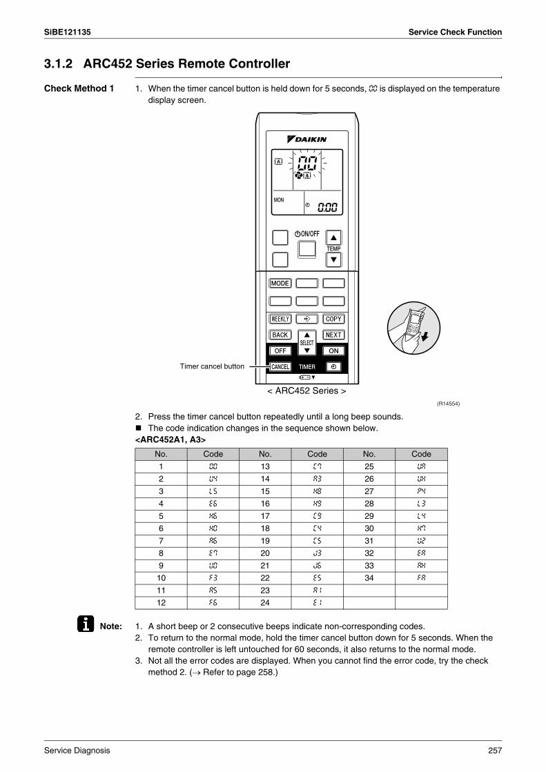
SiBE121135 Service Check Function
3.1.2 ARC452 Series Remote Controller
Check Method 1 1. When the timer cancel button is held down for 5 seconds, 00 is displayed on the temperature display screen.
2. Press the timer cancel button repeatedly until a long beep sounds.The code indication changes in the sequence shown below.
<ARC452A1, A3>
Note: 1. A short beep or 2 consecutive beeps indicate non-corresponding codes.2. To return to the normal mode, hold the timer cancel button down for 5 seconds. When the
remote controller is left untouched for 60 seconds, it also returns to the normal mode.3. Not all the error codes are displayed. When you cannot find the error code, try the check
method 2. (→ Refer to page 258.)
No. Code No. Code No. Code
1 00 13 C7 25 UA
2 U4 14 A3 26 UH
3 L5 15 H8 27 P4
4 E6 16 H9 28 L3
5 H6 17 C9 29 L4
6 H0 18 C4 30 H7
7 A6 19 C5 31 U2
8 E7 20 J3 32 EA
9 U0 21 J6 33 AH
10 F3 22 E5 34 FA
11 A5 23 A1
12 F6 24 E1
(R14554)
Timer cancel button
< ARC452 Series >
Service Diagnosis 257
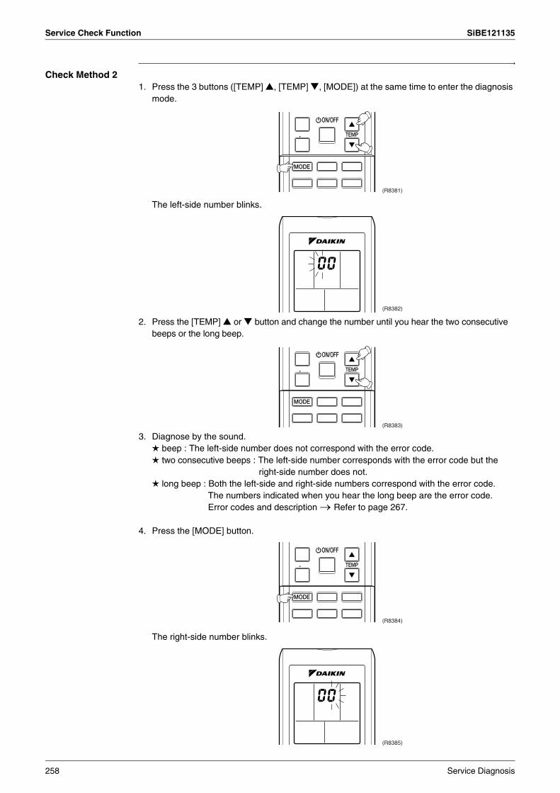
Service Check Function SiBE121135
Check Method 21. Press the 3 buttons ([TEMP] , [TEMP] , [MODE]) at the same time to enter the diagnosis
mode.
The left-side number blinks.
2. Press the [TEMP] or button and change the number until you hear the two consecutive beeps or the long beep.
3. Diagnose by the sound. beep : The left-side number does not correspond with the error code. two consecutive beeps : The left-side number corresponds with the error code but the
right-side number does not. long beep : Both the left-side and right-side numbers correspond with the error code.
The numbers indicated when you hear the long beep are the error code.Error codes and description → Refer to page 267.
4. Press the [MODE] button.
The right-side number blinks.
(R8381)
(R8382)
(R8383)
(R8384)
(R8385)
258 Service Diagnosis
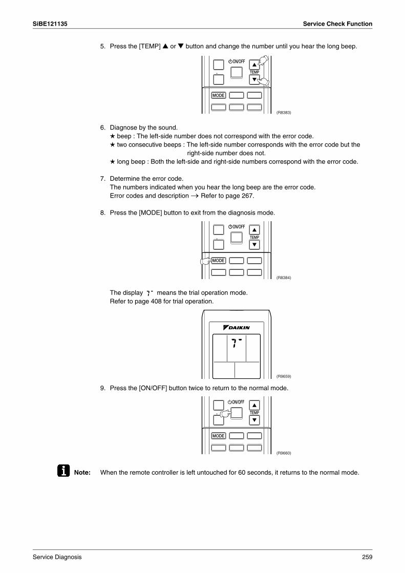
SiBE121135 Service Check Function
5. Press the [TEMP] or button and change the number until you hear the long beep.
6. Diagnose by the sound. beep : The left-side number does not correspond with the error code. two consecutive beeps : The left-side number corresponds with the error code but the
right-side number does not. long beep : Both the left-side and right-side numbers correspond with the error code.
7. Determine the error code.The numbers indicated when you hear the long beep are the error code.Error codes and description → Refer to page 267.
8. Press the [MODE] button to exit from the diagnosis mode.
The display means the trial operation mode.Refer to page 408 for trial operation.
9. Press the [ON/OFF] button twice to return to the normal mode.
Note: When the remote controller is left untouched for 60 seconds, it returns to the normal mode.
(R8383)
(R8384)
(R9659)
(R9660)
Service Diagnosis 259
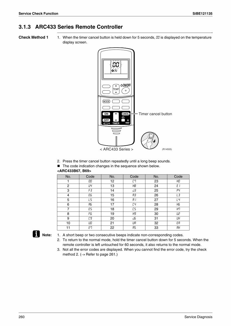
Service Check Function SiBE121135
3.1.3 ARC433 Series Remote Controller
Check Method 1 1. When the timer cancel button is held down for 5 seconds, 00 is displayed on the temperature display screen.
2. Press the timer cancel button repeatedly until a long beep sounds.The code indication changes in the sequence shown below.
<ARC433B67, B69>
Note: 1. A short beep or two consecutive beeps indicate non-corresponding codes.2. To return to the normal mode, hold the timer cancel button down for 5 seconds. When the
remote controller is left untouched for 60 seconds, it also returns to the normal mode.3. Not all the error codes are displayed. When you cannot find the error code, try the check
method 2. (→ Refer to page 261.)
Timer cancel button
(R14555)< ARC433 Series >
No. Code No. Code No. Code1 00 12 C7 23 H0
2 U4 13 H8 24 E1
3 F3 14 J3 25 P4
4 E6 15 A3 26 L3
5 L5 16 A1 27 L4
6 A6 17 C4 28 H6
7 E5 18 C5 29 H7
8 F6 19 H9 30 U2
9 C9 20 J6 31 UH
10 U0 21 UA 32 EA
11 E7 22 A5 33 AH
260 Service Diagnosis

SiBE121135 Service Check Function
Check Method 21. Press the center of the [TEMP] button and the [MODE] button at the same time to enter the
diagnosis mode.
The left-side number blinks.
2. Press the [TEMP] or button and change the number until you hear the two consecutive beeps or the long beep.
3. Diagnose by the sound. beep : The left-side number does not correspond with the error code. two consecutive beeps : The left-side number corresponds with the error code but the
right-side number does not. long beep : Both the left-side and right-side numbers correspond with the error code.
The numbers indicated when you hear the long beep are the error code.Error codes and description → Refer to page 267.
4. Press the [MODE] button.
The right-side number blinks.
(R4272)
(R14967)
(R4274)
(R4275)
(R14968)
Service Diagnosis 261
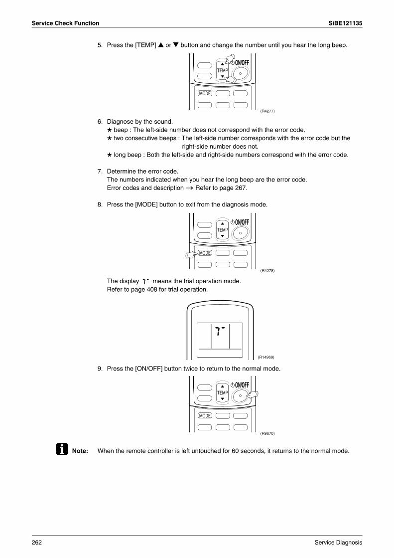
Service Check Function SiBE121135
5. Press the [TEMP] or button and change the number until you hear the long beep.
6. Diagnose by the sound. beep : The left-side number does not correspond with the error code. two consecutive beeps : The left-side number corresponds with the error code but the
right-side number does not. long beep : Both the left-side and right-side numbers correspond with the error code.
7. Determine the error code.The numbers indicated when you hear the long beep are the error code.Error codes and description → Refer to page 267.
8. Press the [MODE] button to exit from the diagnosis mode.
The display means the trial operation mode.Refer to page 408 for trial operation.
9. Press the [ON/OFF] button twice to return to the normal mode.
Note: When the remote controller is left untouched for 60 seconds, it returns to the normal mode.
(R4277)
(R4278)
(R14969)
(R9670)
262 Service Diagnosis
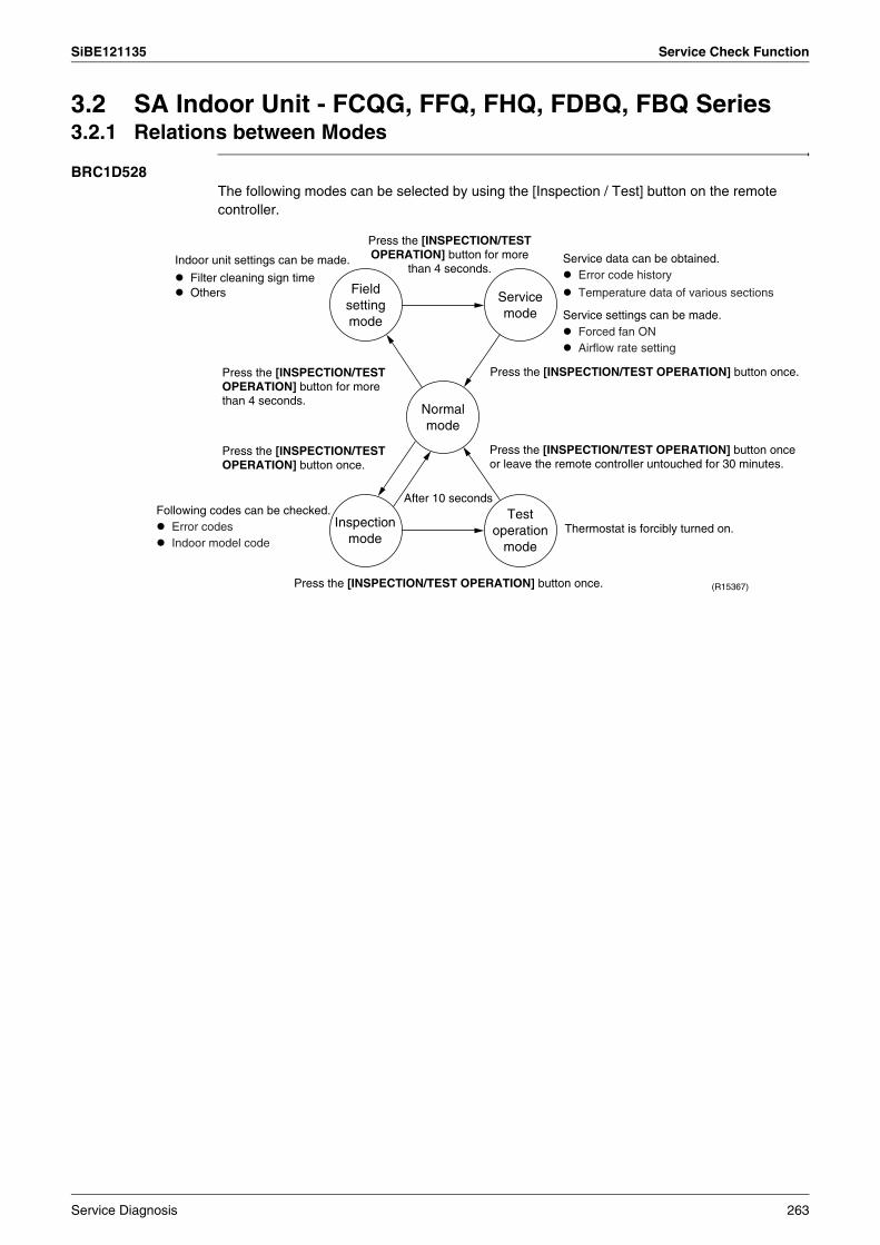
SiBE121135 Service Check Function
3.2 SA Indoor Unit - FCQG, FFQ, FHQ, FDBQ, FBQ Series3.2.1 Relations between Modes
BRC1D528The following modes can be selected by using the [Inspection / Test] button on the remote controller.
Press the [INSPECTION/TEST OPERATION] button once. (R15367)
Press the [INSPECTION/TEST OPERATION] button once.
After 10 seconds
Thermostat is forcibly turned on.
Press the [INSPECTION/TEST OPERATION] button for more
than 4 seconds.
Field setting mode
Service mode
Normal mode
Test operation
mode
Inspection mode
Press the [INSPECTION/TEST OPERATION] button once.
Press the [INSPECTION/TEST OPERATION] button for more than 4 seconds.
Press the [INSPECTION/TEST OPERATION] button once or leave the remote controller untouched for 30 minutes.
Indoor unit settings can be made.
Filter cleaning sign time Others
Following codes can be checked. Error codes Indoor model code
Service data can be obtained. Error code history
Temperature data of various sections
Service settings can be made. Forced fan ON Airflow rate setting
Service Diagnosis 263
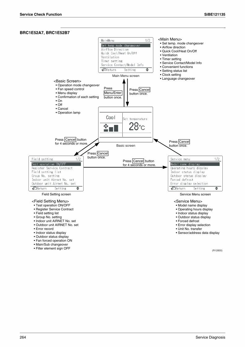
Service Check Function SiBE121135
BRC1E52A7, BRC1E52B7
Basic screen
Main Menu screen
Field Setting screen Service Menu screen
(R12855)
Press
button once.
Press button for 4 seconds or more.
Press button for 4 seconds or more.
Press button once.
Press button once.
Press button once.
<Main Menu>• Set temp. mode changeover• Airflow direction• Quick Cool/Heat On/Off• Ventilation• Timer setting• Service Contact/Model Info• Convenient functions• Setting status list• Clock setting• Language changeover
<Basic Screen>• Operation mode changeover• Fan speed control• Menu display• Confirmation of each setting• On• Off• Cancel• Operation lamp
<Field Setting Menu>• Test operation ON/OFF• Register Service Contract• Field setting list• Group No. setting• Indoor unit AIRNET No. set• Outdoor unit AIRNET No. set• Error record• Indoor status display• Outdoor status display• Fan forced operation ON• Main/Sub changeover• Filter element sign OFF
<Service Menu>• Model name display• Operating hours display• Indoor status display• Outdoor status display• Forced defrost• Error display selection• Unit No. transfer• Sensor/address data display
264 Service Diagnosis
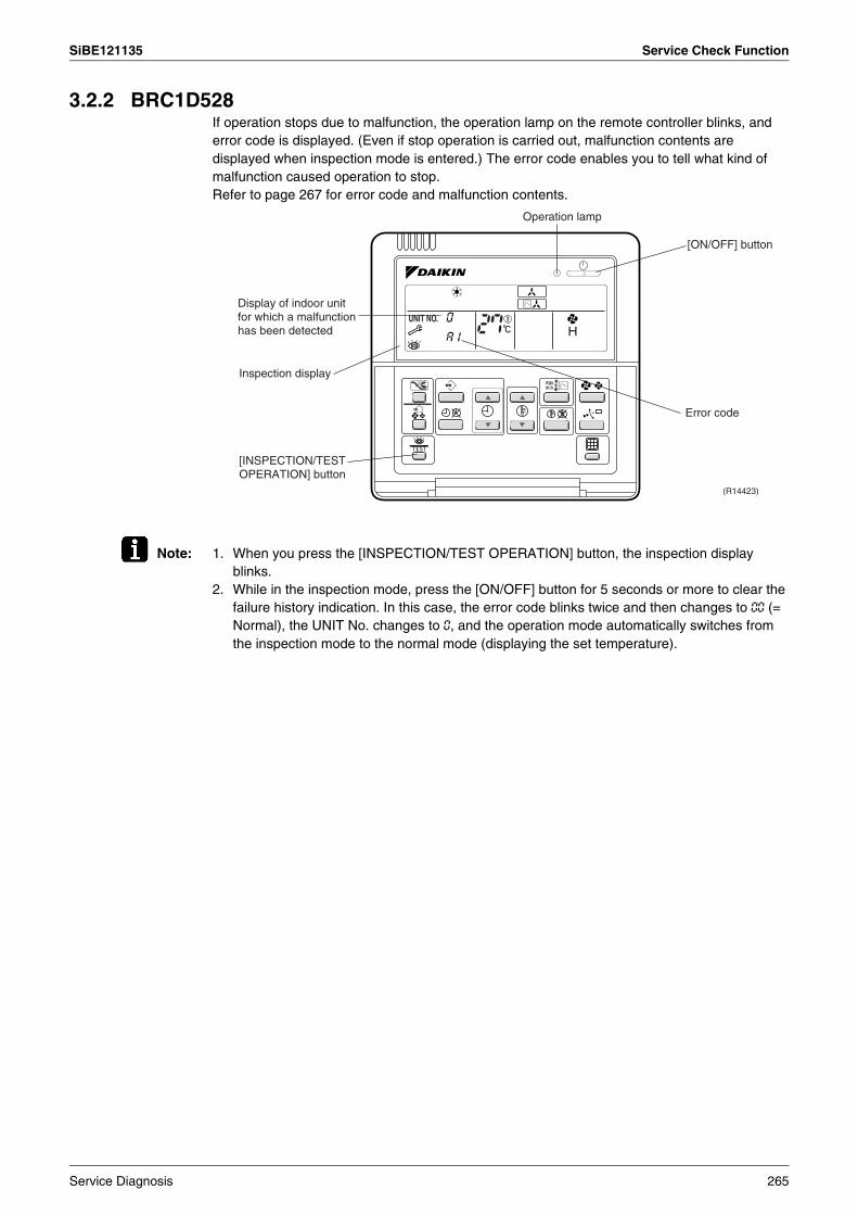
SiBE121135 Service Check Function
3.2.2 BRC1D528If operation stops due to malfunction, the operation lamp on the remote controller blinks, and error code is displayed. (Even if stop operation is carried out, malfunction contents are displayed when inspection mode is entered.) The error code enables you to tell what kind of malfunction caused operation to stop. Refer to page 267 for error code and malfunction contents.
Note: 1. When you press the [INSPECTION/TEST OPERATION] button, the inspection display blinks.
2. While in the inspection mode, press the [ON/OFF] button for 5 seconds or more to clear the failure history indication. In this case, the error code blinks twice and then changes to 00 (= Normal), the UNIT No. changes to 0, and the operation mode automatically switches from the inspection mode to the normal mode (displaying the set temperature).
Operation lamp
[ON/OFF] button
(R14423)
Inspection display
Display of indoor unit for which a malfunction has been detected
[INSPECTION/TEST OPERATION] button
Error code
Service Diagnosis 265

Service Check Function SiBE121135
3.2.3 BRC1E52A7, BRC1E52B7The following display appears on the screen when a error (or a warning) occurs during operation.Check the error code and take the corrective action specified for the particular model.
(1) Check if it is error or warning.
(2) Take corrective action.
Operation status Display
Abnormal shutdown
The system stops operating.
The operation lamp (green) starts to blink. The message "Error: Press Menu Button" appears and blinks at the bottom of the screen.
WarningThe system continues its operation.
The operation lamp (green) remains on. The message "Warning: Press Menu Button" appears and blinks at the bottom of the screen.
· Press the [Menu/Enter] button to check the error code.
· Take the corrective action specific to the model.
(R17163)
Screen
Operation lamp
[Menu/Enter] button
(R12858)
(R12857)
Error code
(R12859)
Applicable model names
266 Service Diagnosis
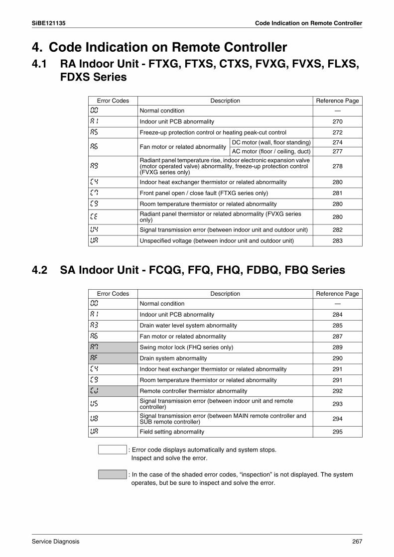
SiBE121135 Code Indication on Remote Controller
4. Code Indication on Remote Controller4.1 RA Indoor Unit - FTXG, FTXS, CTXS, FVXG, FVXS, FLXS,
FDXS Series
4.2 SA Indoor Unit - FCQG, FFQ, FHQ, FDBQ, FBQ Series
: Error code displays automatically and system stops.Inspect and solve the error.
: In the case of the shaded error codes, “inspection” is not displayed. The system operates, but be sure to inspect and solve the error.
Error Codes Description Reference Page
00 Normal condition —
A1 Indoor unit PCB abnormality 270
A5 Freeze-up protection control or heating peak-cut control 272
A6 Fan motor or related abnormalityDC motor (wall, floor standing) 274
AC motor (floor / ceiling, duct) 277
A9Radiant panel temperature rise, indoor electronic expansion valve (motor operated valve) abnormality, freeze-up protection control (FVXG series only)
278
C4 Indoor heat exchanger thermistor or related abnormality 280
C7 Front panel open / close fault (FTXG series only) 281
C9 Room temperature thermistor or related abnormality 280
CE Radiant panel thermistor or related abnormality (FVXG series only) 280
U4 Signal transmission error (between indoor unit and outdoor unit) 282
UA Unspecified voltage (between indoor unit and outdoor unit) 283
Error Codes Description Reference Page
00 Normal condition —
A1 Indoor unit PCB abnormality 284
A3 Drain water level system abnormality 285
A6 Fan motor or related abnormality 287
A7 Swing motor lock (FHQ series only) 289
AF Drain system abnormality 290
C4 Indoor heat exchanger thermistor or related abnormality 291
C9 Room temperature thermistor or related abnormality 291
CJ Remote controller thermistor abnormality 292
U5 Signal transmission error (between indoor unit and remote controller) 293
U8 Signal transmission error (between MAIN remote controller and SUB remote controller) 294
UA Field setting abnormality 295
Service Diagnosis 267

Code Indication on Remote Controller SiBE121135
4.3 Sub Codes for SA Indoor UnitIf an error code like the one shown below is displayed when the navigation remote controller (BRC1E52A7, BRC1E52B7) is in use, make a detailed diagnosis or a diagnosis of the relevant unit referring to the attached list.
Error codes Description Troubleshooting
A6 - 01 Fan motor locked A locked fan motor current has been detected.Turn the fan by hand to check for the connection of connectors.
A6 - 10 Fan overcurrent error A fan motor overcurrent has been detected.Check for the connection of the connector between the fan motor and the PCB. If the connection is normal, replace the fan motor. If this still cannot solve the error, replace the PCB.
A6 - 11 Fan position detection error An error in the detection of position of the fan motor. Check for the connection of the connector between the fan motor and the PCB. If the connection is normal, replace the fan motor. If this still cannot solve the error, replace the PCB.
AH - 03 Transmission error (between the self-cleaning decoration panel and the indoor unit)[when the self-cleaning decoration panel is mounted]
Check for the connection of the harness connector between the panel PCB and the indoor unit PCB.
AH - 04 Dust detection sensor error [when the self-cleaning decoration panel is mounted]
Check for the connections of the connector X12A on the panel PCB and the connectors X18A and X19A on the sensor PCBs.
AH - 05 Dust collection sign error[when the self-cleaning decoration panel is mounted]
Check for clogging with dust at the dust collection port as well as in the brush unit, S-shaped pipe, and dust box. Furthermore, check for any stains of the light receiving and emitting parts of the infrared unit.
AH - 06 Air filter rotation error[when the self-cleaning decoration panel is mounted]
Check for anything getting in the way of rotating the filter (e.g. the filter comes off or the drive gear is clogged with foreign matters).
AH - 07 Damper rotation error[when the self-cleaning decoration panel is mounted]
The damper does not rotate normally. Check for any foreign matters around the damper and for the operation of the gear and limit switch.
AH - 08 Filter self-cleaning operation error[when the self-cleaning decoration panel is mounted]
The unit has not yet completed the filter self-cleaning operation even after the lapse of specified period of time. Check for any external noise, etc.
AH - 09 Filter self-cleaning operation start disabled error [when the self-cleaning decoration panel is mounted]
The unit has been put into a state in which the filter self-cleaning operation is disabled. Check the unit for the operating conditions.
C6 - 01 Faulty combination of indoor unit PCB and fan PCB
A combination of indoor unit PCB and fan PCB is defective. Check whether the capacity setting adaptor is correct and the type of the fan PCB is correct.
268 Service Diagnosis
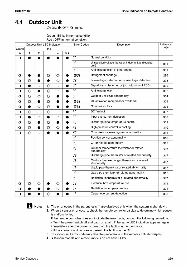
SiBE121135 Code Indication on Remote Controller
4.4 Outdoor Uniti: ON, h: OFF, j: Blinks
Green : Blinks in normal conditionRed : OFF in normal condition
Note: 1. The error codes in the parenthesis ( ) are displayed only when the system is shut down.2. When a sensor error occurs, check the remote controller display to determine which sensor
is malfunctioning.If the remote controller does not indicate the error code, conduct the following procedure.∗ Turn the power switch off and back on again. If the same LED indication appears again immediately after the power is turned on, the fault is in the thermistor.∗ If the above condition does not result, the fault is in the CT.
3. The indoor unit error code may take the precedence in the remote controller display.4. 3-room models and 4-room models do not have LED5.
Outdoor Unit LED Indication Error Codes Description Reference Page
Green Red
A 1 2 3 4 5
j h h h h h 00 Normal condition —
UA Unspecified voltage (between indoor unit and outdoor unit) 301
UH Anti-icing function in other rooms 301
j h h i i h (U0) Refrigerant shortage 296
j i h h i h U2 Low-voltage detection or over-voltage detection 298
j h i i i h U7 Signal transmission error (on outdoor unit PCB) 300
j i h i i h A5 Anti-icing function 302
j i i i h h E1 Outdoor unit PCB abnormality 304
j i h i h h (E5) OL activation (compressor overload) 305
j h i i h h (E6) Compressor lock 306
j i i i i h E7 DC fan lock 307
j h i h i h E8 Input overcurrent detection 308
j i h i h h F3 Discharge pipe temperature control 309
j i h i i h F6 High pressure control in cooling 310
j i i h h h H0 Compressor sensor system abnormality 311
H6 Position sensor abnormality 313
H8 CT or related abnormality 315
H9 Outdoor temperature thermistor or related abnormality 317
J3 Discharge pipe thermistor or related abnormality 317
J6 Outdoor heat exchanger thermistor or related abnormality 317
J8 Liquid pipe thermistor or related abnormality 317
J9 Gas pipe thermistor or related abnormality 317
P4 Radiation fin thermistor or related abnormality 317
j i i h i h L3 Electrical box temperature rise 319
j h h h i h L4 Radiation fin temperature rise 321
j h h i h h L5 Output overcurrent detection 323
Service Diagnosis 269
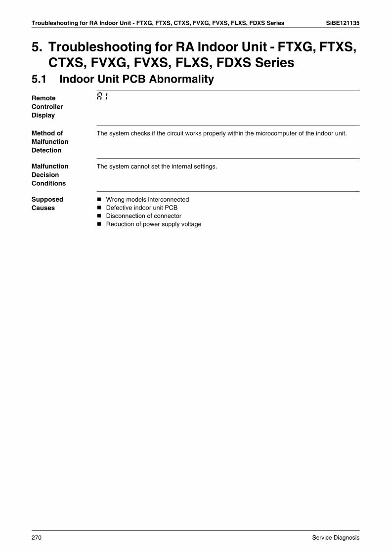
Troubleshooting for RA Indoor Unit - FTXG, FTXS, CTXS, FVXG, FVXS, FLXS, FDXS Series SiBE121135
5. Troubleshooting for RA Indoor Unit - FTXG, FTXS, CTXS, FVXG, FVXS, FLXS, FDXS Series
5.1 Indoor Unit PCB Abnormality
Remote Controller Display
A1
Method of Malfunction Detection
The system checks if the circuit works properly within the microcomputer of the indoor unit.
Malfunction Decision Conditions
The system cannot set the internal settings.
Supposed Causes
Wrong models interconnectedDefective indoor unit PCBDisconnection of connectorReduction of power supply voltage
270 Service Diagnosis
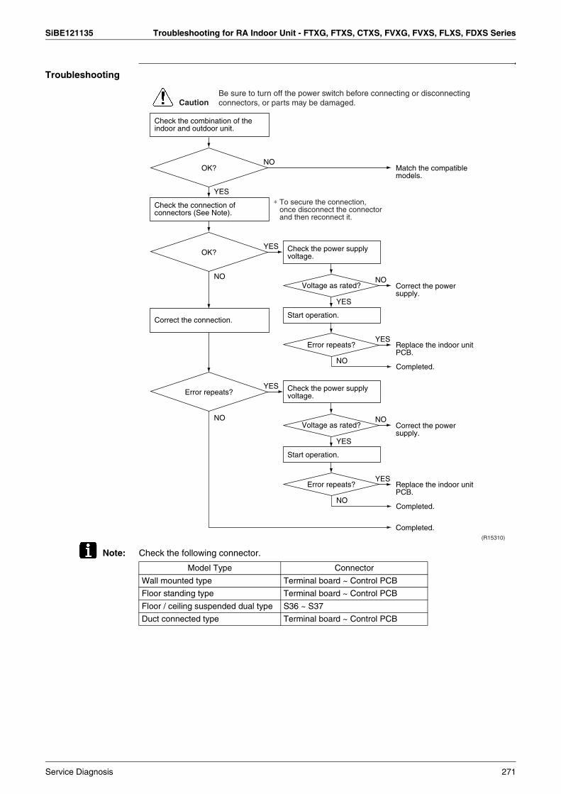
SiBE121135 Troubleshooting for RA Indoor Unit - FTXG, FTXS, CTXS, FVXG, FVXS, FLXS, FDXS Series
Troubleshooting
Note: Check the following connector.
Check the combination of the indoor and outdoor unit.
OK?
Check the connection of connectors (See Note).
Correct the connection.
OK? Check the power supply voltage.
Start operation.
Voltage as rated?
Error repeats?
Check the power supply voltage.
Start operation.
Voltage as rated?
Error repeats?
Error repeats?
YES
NO
NO
YES
NO
NO
YES
(R15310)
Caution
∗ To secure the connection, once disconnect the connector and then reconnect it.
YES
NO
YES
NO
YES
NO
YES
Match the compatible models.
Correct the power supply.
Replace the indoor unit PCB.
Completed.
Completed.
Correct the power supply.
Replace the indoor unit PCB.
Completed.
Be sure to turn off the power switch before connecting or disconnecting connectors, or parts may be damaged.
Model Type Connector
Wall mounted type Terminal board ~ Control PCB
Floor standing type Terminal board ~ Control PCB
Floor / ceiling suspended dual type S36 ~ S37
Duct connected type Terminal board ~ Control PCB
Service Diagnosis 271

Troubleshooting for RA Indoor Unit - FTXG, FTXS, CTXS, FVXG, FVXS, FLXS, FDXS Series SiBE121135
5.2 Freeze-up Protection Control or Heating Peak-cut Control
Remote Controller Display
A5
Method of Malfunction Detection
Freeze-up protection controlDuring cooling operation, the freeze-up protection control (operation halt) is activated according to the temperature detected by the indoor heat exchanger thermistor.Heating peak-cut controlDuring heating operation, the temperature detected by the indoor heat exchanger thermistor is used for the heating peak-cut control (operation halt, outdoor fan stop, etc.)
Malfunction Decision Conditions
Freeze-up protection controlDuring cooling operation, the indoor heat exchanger temperature is below 0°C.Heating peak-cut controlDuring heating operation, the indoor heat exchanger temperature is above 65°C.
Supposed Causes
Short-circuited airClogged air filter of the indoor unitDust accumulation on the indoor heat exchangerDefective indoor heat exchanger thermistorDefective indoor unit PCB
272 Service Diagnosis
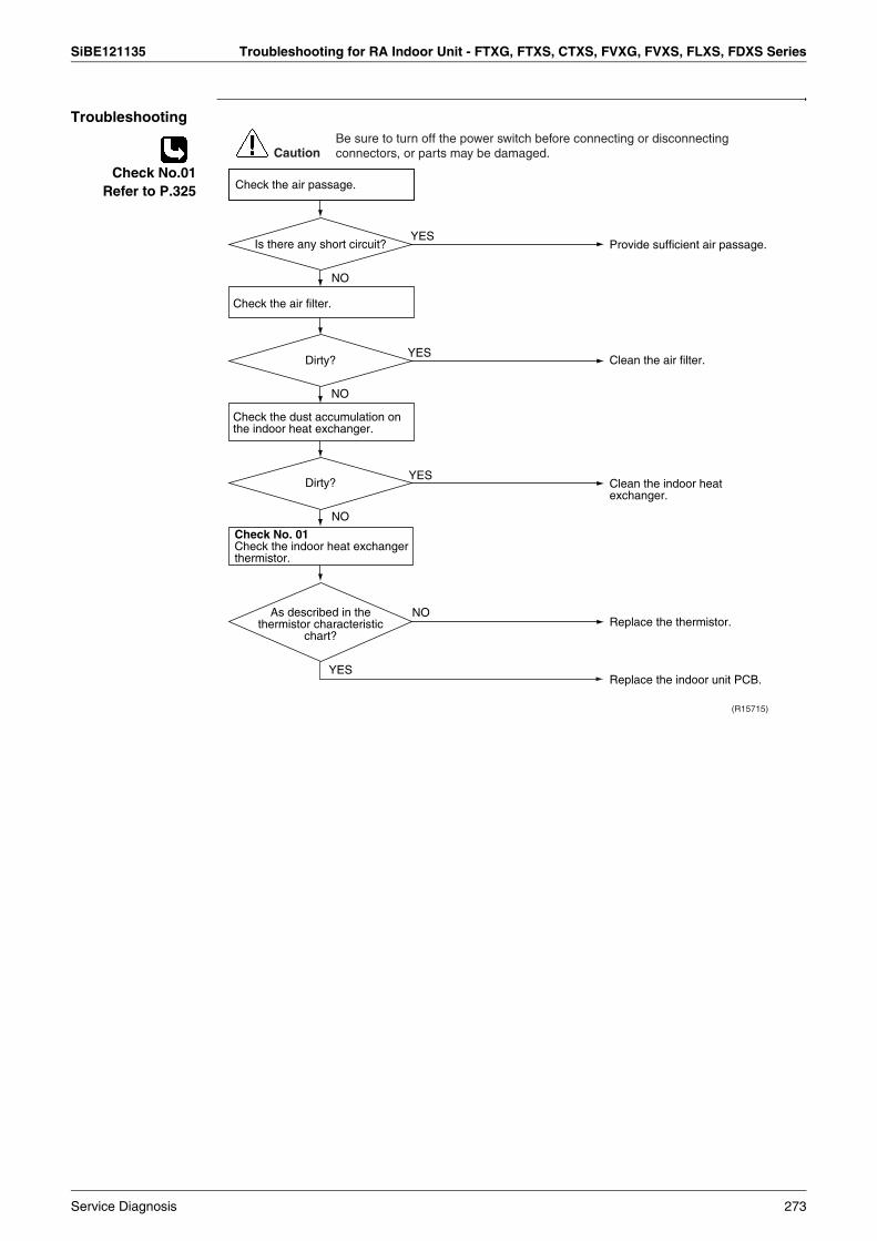
SiBE121135 Troubleshooting for RA Indoor Unit - FTXG, FTXS, CTXS, FVXG, FVXS, FLXS, FDXS Series
Troubleshooting
Check No.01Refer to P.325
NO
NO
NO
Check No. 06Check the indoor heat exchanger thermistor.
YES
YES
(R7131)
YES
YES
NO
Caution
Provide sufficient air passage.
Clean the air filter.
Clean the indoor heat exchanger.
Replace the indoor unit PCB.
Replace the thermistor.
Does it conform to the
thermistor characteristic chart?
Check the air filter.
Check the dust accumulation on the indoor heat exchanger.
Is there any short circuit?
Is it very dirty?
Is it very dirty?
Check the air passage.
Be sure to turn off the power switch before connecting or disconnecting connectors, or parts may be damaged.
NO
NO
NO
Check No. 01Check the indoor heat exchanger thermistor.
YES
YES
(R15715)
YES
YES
NO
Caution
Provide sufficient air passage.
Clean the air filter.
Clean the indoor heat exchanger.
Replace the indoor unit PCB.
Replace the thermistor.As described in the
thermistor characteristic chart?
Check the air filter.
Check the dust accumulation on the indoor heat exchanger.
Is there any short circuit?
Dirty?
Dirty?
Check the air passage.
Be sure to turn off the power switch before connecting or disconnecting connectors, or parts may be damaged.
Service Diagnosis 273
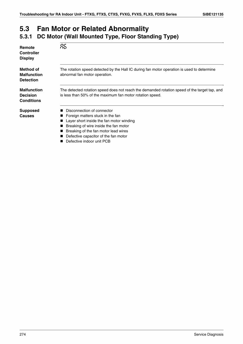
Troubleshooting for RA Indoor Unit - FTXG, FTXS, CTXS, FVXG, FVXS, FLXS, FDXS Series SiBE121135
5.3 Fan Motor or Related Abnormality5.3.1 DC Motor (Wall Mounted Type, Floor Standing Type)
Remote Controller Display
A6
Method of Malfunction Detection
The rotation speed detected by the Hall IC during fan motor operation is used to determine abnormal fan motor operation.
Malfunction Decision Conditions
The detected rotation speed does not reach the demanded rotation speed of the target tap, and is less than 50% of the maximum fan motor rotation speed.
Supposed Causes
Disconnection of connectorForeign matters stuck in the fanLayer short inside the fan motor windingBreaking of wire inside the fan motorBreaking of the fan motor lead wiresDefective capacitor of the fan motorDefective indoor unit PCB
274 Service Diagnosis
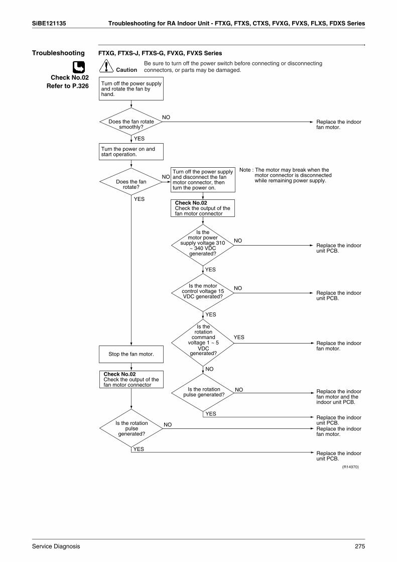
SiBE121135 Troubleshooting for RA Indoor Unit - FTXG, FTXS, CTXS, FVXG, FVXS, FLXS, FDXS Series
Troubleshooting FTXG, FTXS-J, FTXS-G, FVXG, FVXS Series
Check No.02Refer to P.326
Check No.02Check the output of the fan motor connector
YES
YES
NO
YES
YES
NO
NO
NO
Note : The motor may break when the motor connector is disconnected while remaining power supply.
Caution
Replace the indoor fan motor.
Replace the indoor unit PCB.
Replace the indoor unit PCB.
Be sure to turn off the power switch before connecting or disconnecting connectors, or parts may be damaged.
Check No.02Check the output of the fan motor connector
(R14970)
NO
YES
YES
NO
YES
NOReplace the indoor fan motor.
Replace the indoor unit PCB.
Replace the indoor unit PCB.
Replace the indoor fan motor.
Replace the indoor fan motor and the indoor unit PCB.
Turn off the power supply and rotate the fan by hand.
Does the fan rotate smoothly?
Turn the power on and start operation.
Does the fan rotate?
Stop the fan motor.
Is the rotation pulse
generated?
Is the rotation pulse generated?
Is the rotation
command voltage 1 ~ 5
VDC generated?
Is the motor control voltage 15 VDC generated?
Is the motor power
supply voltage 310 ~ 340 VDC generated?
Turn off the power supply and disconnect the fan motor connector, then turn the power on.
Service Diagnosis 275

Troubleshooting for RA Indoor Unit - FTXG, FTXS, CTXS, FVXG, FVXS, FLXS, FDXS Series SiBE121135
Troubleshooting FTXS-K, CTXS-K Series
Check No.03Refer to P.326
(R16048)
Turn off the power.(Unplug the power cable or turn the breaker OFF.)
CautionBe sure to turn off the power switch before connecting or disconnecting connectors, or parts may be damaged.
OK?NO
Check the connector for connection.
YES
YES
Foreign matters in or around the fan?
NO
Check No. 03Check the fan motor for breakdown or short circuit.
Resistance OK?
Turn the power on again.
Check No. 03Check the motor control voltage.
Is the motor control voltage 15 VDC
generated?
Check No. 03Check the indoor unit PCB for rotation pulse.
Is the rotation pulse generated?
NO
YES
YES
YES
NO
NO
∗ To secure the connection, once disconnect the connector and then reconnect it.
Correct the connection.
Remove the foreign matters.
Replace the indoor fan motor.
Replace the indoor unit PCB (1).
Replace the indoor fan motor.
Replace the indoor unit PCB (1).
Rotate the fan.
Fan rotates smoothly?
YES
NO Replace the indoor unit PCB (1).
Note: The motor may break when the motor connector is disconnected while remaining power supply.(Turn off the power supply before connecting the connector also.)
276 Service Diagnosis
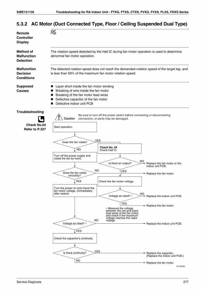
SiBE121135 Troubleshooting for RA Indoor Unit - FTXG, FTXS, CTXS, FVXG, FVXS, FLXS, FDXS Series
5.3.2 AC Motor (Duct Connected Type, Floor / Ceiling Suspended Dual Type)
Remote Controller Display
A6
Method of Malfunction Detection
The rotation speed detected by the Hall IC during fan motor operation is used to determine abnormal fan motor operation.
Malfunction Decision Conditions
The detected rotation speed does not reach the demanded rotation speed of the target tap, and is less than 50% of the maximum fan motor rotation speed.
Supposed Causes
Layer short inside the fan motor windingBreaking of wire inside the fan motorBreaking of the fan motor lead wiresDefective capacitor of the fan motorDefective indoor unit PCB
Troubleshooting
Check No.04Refer to P.327
NO
NO
NO
NO
NO
NO
YES
YES
YES
YES
YES
YES
(R16009)
Caution
Replace the fan motor or the indoor unit PCB.
Replace the fan motor.
Replace the indoor unit PCB.
Replace the capacitor. (Replace the indoor unit PCB.)
Replace the fan motor.
Replace the fan motor.
Replace the indoor unit PCB.
Be sure to turn off the power switch before connecting or disconnecting connectors, or parts may be damaged.
∗ Measure the voltage between the red and black lead wires of the fan motor, and check if the maximum voltage reaches the rated voltage.
Check No. 04Check Hall IC
Is there an output?
Check the fan motor voltage.
Voltage as rated? ∗
Start operation.
Does the fan rotate?
Turn off the power supply and rotate the fan by hand.
Does the fan rotate smoothly?
Turn the power on and check the fan motor voltage. (immediately after restart)
Voltage as rated? ∗
Check the capacitor's continuity.
Is there continuity?
Service Diagnosis 277

Troubleshooting for RA Indoor Unit - FTXG, FTXS, CTXS, FVXG, FVXS, FLXS, FDXS Series SiBE121135
5.4 Radiant Panel Temperature Rise, Indoor Electronic Expansion Valve (Motor Operated Valve) Abnormality, Freeze-up Protection Control (FVXG Series Only)
Remote Controller Display
A9
Method of Malfunction Detection
Radiant panel temperature riseDuring RADIANT operation, high temperature control (e.g., operation halt, indoor electronic expansion valve closure) is activated according to the temperature detected by the radiant panel thermistors.
Indoor electronic expansion valve abnormalityThe indoor electronic expansion valve is required to be fully closed during cooling, dry or heating operation. When the indoor electronic expansion valve is open due to malfunction, the refrigerant flows into the radiant panel and the radiant panel temperature rises or drops.The indoor electronic expansion valve is required to be open during RADIANT operation. When the indoor electronic expansion valve is closed due to malfunction, the refrigerant does not flow into the radiant panel and the radiant panel temperature does not rise.For multi systemThe indoor electronic expansion valve is required to be fully closed in the room where the system does not run. When the indoor electronic expansion valve is open due to malfunction and heating or RADIANT operation is conducted in the other room(s), the refrigerant flows into the radiant panel and the radiant panel temperature rises.
Freeze-up protection controlThe temperature detected by the radiant panel thermistors is used to prevent the indoor unit from freezing during cooling operation.
Malfunction Decision Conditions
Radiant panel temperature riseThe radiant panel surface temperature calculated by the radiant panel thermistors is above 70°C.
Indoor electronic expansion valve abnormalityDuring cooling or dry operation, the temperature detected by the radiant panel thermistor (φ 4) has dropped.During heating operation, the temperature detected by the radiant panel thermistor (φ 4) has risen.During RADIANT operation, the temperature detected by the radiant panel thermistor (φ 4) does not rise.For multi systemWhile the system does not run and heating or RADIANT operation is conducted in the other room(s), the temperature detected by the radiant panel thermistor (φ 4) has risen.
Freeze-up protection controlDuring cooling operation, the operation stops when the temperature detected by the radiant panel thermistor (φ 4) has dropped.
Supposed Causes
Clogged air filter of the indoor unitDust accumulation on the indoor heat exchangerShort-circuited airDefective radiant panel thermistor(s)Defective indoor heat exchanger thermistorDefective room temperature thermistorDefective indoor electronic expansion valve (or coil)
278 Service Diagnosis
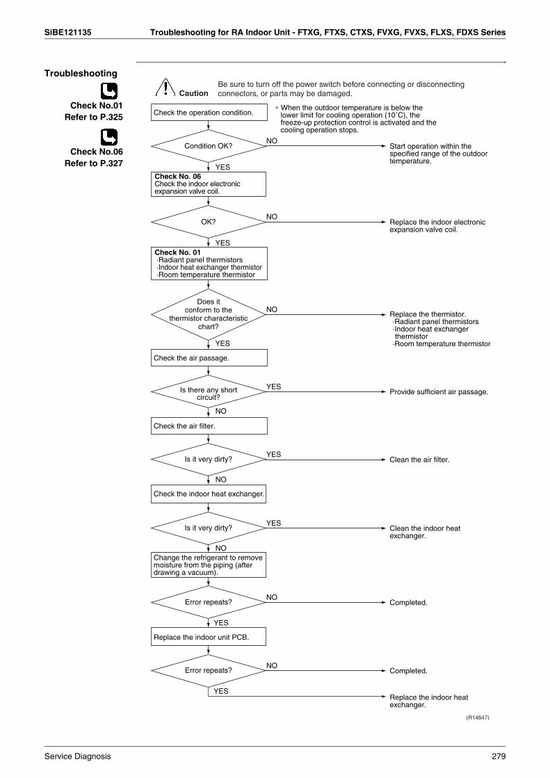
SiBE121135 Troubleshooting for RA Indoor Unit - FTXG, FTXS, CTXS, FVXG, FVXS, FLXS, FDXS Series
Troubleshooting
Check No.01Refer to P.325
Check No.06Refer to P.327
YES
YES
NO
NO
NO
NO
NO
(R14647)
YES
Caution
Replace the indoor electronic expansion valve coil.
Replace the thermistor.·Radiant panel thermistors·Indoor heat exchanger thermistor
·Room temperature thermistor
Provide sufficient air passage.
YES
Check No. 01·Radiant panel thermistors·Indoor heat exchanger thermistor·Room temperature thermistor
Check the air passage.
Check the operation condition.
Check the air filter.
OK?
Does it conform to the
thermistor characteristic chart?
Is there any short circuit?
YESClean the indoor heat exchanger.
Is it very dirty?
YESClean the air filter.Is it very dirty?
NOCompleted.Error repeats?
Be sure to turn off the power switch before connecting or disconnecting connectors, or parts may be damaged.
Check No. 06Check the indoor electronic expansion valve coil.
YES
NOStart operation within the specified range of the outdoor temperature.
Condition OK?
Check the indoor heat exchanger.
Replace the indoor unit PCB.
Change the refrigerant to remove moisture from the piping (after drawing a vacuum).
YES
NOCompleted.
Replace the indoor heat exchanger.
Error repeats?
∗ When the outdoor temperature is below the lower limit for cooling operation (10˚C), the freeze-up protection control is activated and the cooling operation stops.
Service Diagnosis 279
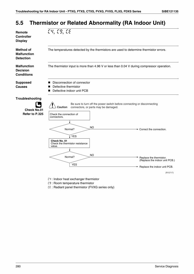
Troubleshooting for RA Indoor Unit - FTXG, FTXS, CTXS, FVXG, FVXS, FLXS, FDXS Series SiBE121135
5.5 Thermistor or Related Abnormality (RA Indoor Unit)
Remote Controller Display
C4, C9, CE
Method of Malfunction Detection
The temperatures detected by the thermistors are used to determine thermistor errors.
Malfunction Decision Conditions
The thermistor input is more than 4.96 V or less than 0.04 V during compressor operation.
Supposed Causes
Disconnection of connectorDefective thermistorDefective indoor unit PCB
Troubleshooting
Check No.01Refer to P.325
C4 : Indoor heat exchanger thermistorC9 : Room temperature thermistorCE : Radiant panel thermistor (FVXG series only)
YES
(R15717)
NO
YES
NO
Caution
Correct the connection.
Replace the thermistor. (Replace the indoor unit PCB.)
Replace the indoor unit PCB.
Be sure to turn off the power switch before connecting or disconnecting connectors, or parts may be damaged.
Check the connection of connectors.
Normal?
Check No. 01Check the thermistor resistance value.
Normal?
280 Service Diagnosis

SiBE121135 Troubleshooting for RA Indoor Unit - FTXG, FTXS, CTXS, FVXG, FVXS, FLXS, FDXS Series
5.6 Front Panel Open / Close Fault (FTXG Series Only)
Remote Controller Display
C7
Method of Malfunction Detection
Malfunction Decision Conditions
If the error repeats, the system is shut down.
SupposedCauses
Defective reduction motorMalfunction or deterioration of the front panel mechanismDefective limit switch
Troubleshooting
Note: You cannot operate the unit by the remote controller when the front panel mechanism breaks down.<To the dealers: temporary measure before repair>1. Turn off the power.2. Remove the front panel.3. Turn on the power.
(Wait until the initialization finishes.)4. Operate the unit by the indoor unit [ON/OFF] button.
YES
YES
YES
YES
NO
NO
NO
NO
Replace the harness and reduction motor.
Replace the assembly of the front panel mechanism.
Check the movement of the right and left separately by hand.
Replace the assembly of the front panel mechanism.
It is supposed such as deformation of the panel or stuffed dust.Find out the cause.
Replace the limit switch.
(R17249)
Caution
Does the front panel move?
Does the front panel mechanism
move?
Does the front panel open / close
fully?
Restart. Does the error code
reappear?
Restart and check the movement.
Remove the front panel and check the movement.
Be sure to turn off the power switch before connecting or disconnecting connectors, or parts may be damaged.
Service Diagnosis 281

Troubleshooting for RA Indoor Unit - FTXG, FTXS, CTXS, FVXG, FVXS, FLXS, FDXS Series SiBE121135
5.7 Signal Transmission Error (between Indoor Unit and Outdoor Unit)
Remote Controller Display
U4
Method of Malfunction Detection
The data received from the outdoor unit in indoor unit-outdoor unit signal transmission is checked whether it is normal.
Malfunction Decision Conditions
The data sent from the outdoor unit cannot be received normally, or the content of the data is abnormal.
Supposed Causes
Wiring errorBreaking of the connection wires between the indoor and outdoor units (wire No. 3)Defective outdoor unit PCBDefective indoor unit PCBDisturbed power supply waveform
Troubleshooting
Check No.11Refer to P.328
Check the voltage of the indoor unit-outdoor unit connection wires between No. 1 and No. 3, and between No. 2 and No. 3.
Check No.11Check the power supply waveform.
YES
YES
Replace the indoor unit PCB.
Locate the cause of the disturbance of the power supply waveform, and correct it.
NO
(R15782)
NO
YES
YES
NO
NO
Caution
Correct the indoor unit - outdoor unit connection wires.
Diagnose the outdoor unit PCB.
Replace the connection wires between the indoor unit and the outdoor unit.
Be sure to turn off the power switch before connecting or disconnecting connectors, or parts may be damaged.
Check the indoor unit - outdoor unit connection wires.
Is there any wiring error?
Properly insulated?
Check the LED A on the outdoor unit PCB.
Is LED A blinking?
Is there any disturbance?
282 Service Diagnosis

SiBE121135 Troubleshooting for RA Indoor Unit - FTXG, FTXS, CTXS, FVXG, FVXS, FLXS, FDXS Series
5.8 Unspecified Voltage (between Indoor Unit and Outdoor Unit)
Remote Controller Display
UA
Method of Malfunction Detection
The supply power is detected for its requirements (different from pair type and multi type) by the indoor / outdoor transmission signal.
Malfunction Decision Conditions
The pair type and multi type are interconnected.
Supposed Causes
Wrong models interconnectedWrong wiring of connecting wiresWrong indoor unit PCB or outdoor unit PCB mountedDefective indoor unit PCBDefective outdoor unit PCB
Troubleshooting
(R11707)
Caution
NO
YES
YES
YES
NO
NO
Check the code numbers (2P01234, for example) of the indoor and outdoor unit PCB with the Parts List.
Match the compatible models.
Change for the correct PCB.
Replace the indoor unit PCB (or the outdoor unit PCB).
Correct the connection.
Be sure to turn off the power switch before connecting or disconnecting connectors, or parts may be damaged.
Check the combination of the indoor and outdoor unit.
OK?
Are the connection wires
connected property?
Matched compatibly?
Service Diagnosis 283
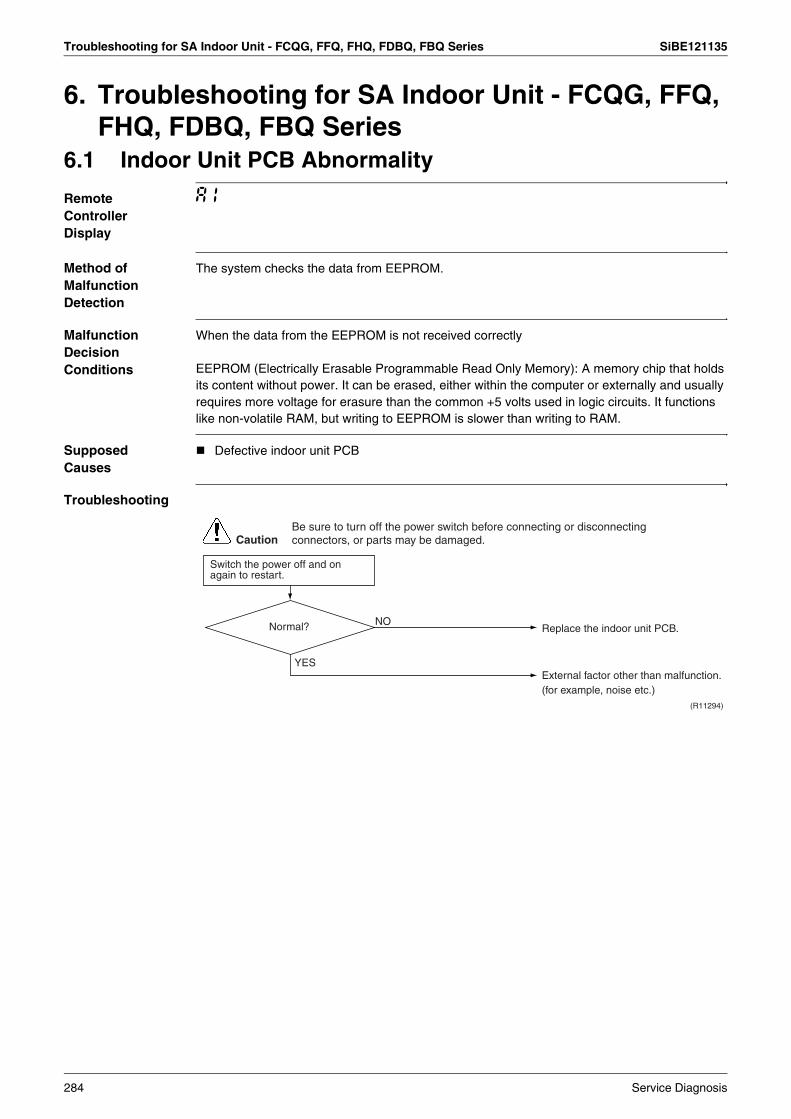
Troubleshooting for SA Indoor Unit - FCQG, FFQ, FHQ, FDBQ, FBQ Series SiBE121135
6. Troubleshooting for SA Indoor Unit - FCQG, FFQ, FHQ, FDBQ, FBQ Series
6.1 Indoor Unit PCB Abnormality
Remote Controller Display
A1
Method of Malfunction Detection
The system checks the data from EEPROM.
Malfunction Decision Conditions
When the data from the EEPROM is not received correctly
EEPROM (Electrically Erasable Programmable Read Only Memory): A memory chip that holds its content without power. It can be erased, either within the computer or externally and usually requires more voltage for erasure than the common +5 volts used in logic circuits. It functions like non-volatile RAM, but writing to EEPROM is slower than writing to RAM.
Supposed Causes
Defective indoor unit PCB
Troubleshooting
CautionBe sure to turn off the power switch before connecting or disconnecting connectors, or parts may be damaged.
Replace the indoor unit PCB.
(R11294)
Normal?
Switch the power off and on again to restart.
NO
YESExternal factor other than malfunction. (for example, noise etc.)
284 Service Diagnosis

SiBE121135 Troubleshooting for SA Indoor Unit - FCQG, FFQ, FHQ, FDBQ, FBQ Series
6.2 Drain Water Level System Abnormality
Remote Controller Display
A3
Method of Malfunction Detection
The float switch detects error.
Malfunction Decision Conditions
When the water level reaches its upper limit and when the float switch turns OFF
Supposed Causes
Defective drain pumpImproper drain piping workClogged drain pipingDefective float switchDefective indoor unit PCBDefective short circuit connector X15A on indoor unit PCB
Service Diagnosis 285

Troubleshooting for SA Indoor Unit - FCQG, FFQ, FHQ, FDBQ, FBQ Series SiBE121135
Troubleshooting
Note: If A3 is detected by the indoor unit PCB which is not mounted with X15A, the indoor unit PCB is defective.
CautionBe sure to turn off the power switch before connecting or disconnecting connectors, or parts may be damaged.
Connect the drain pump.
Replace the indoor unit PCB.
Replace the drain pump.
There is a drain system abnormality.
Connect the float switch.
Replace the float switch.
Replace the indoor unit PCB.
(R17250)
NO
YES
NO
YES
NO
Connect the short circuit connector.
NO
Connect the short circuit connector.
NO
YESYES
Replace the indoor unit PCB.
YES
NO
YES
Is the drain pump connected to the
indoor unit PCB?
Is the unit a ceiling suspended
type?
NO YES
NO
Is the drain water level abnormally high?
YES
YES
Is the float switch connected to X15A?
NO
Does the drain pump work after
restarting operation?
Set to "emergency" and
check the voltage of the connector for the drain
pump. 220 ~ 240 VAC?
YES
Remove the float switch from X15A, short circuit X15A, and restart operation.
NODoes A3 appear on the remote
controller display?
Is the short circuit connector
connected to X15A on the indoor unit
PCB?
Check the continuity of the short circuit
connector. Is there continuity?
Is the optional drain raising mechanism
connected?
286 Service Diagnosis
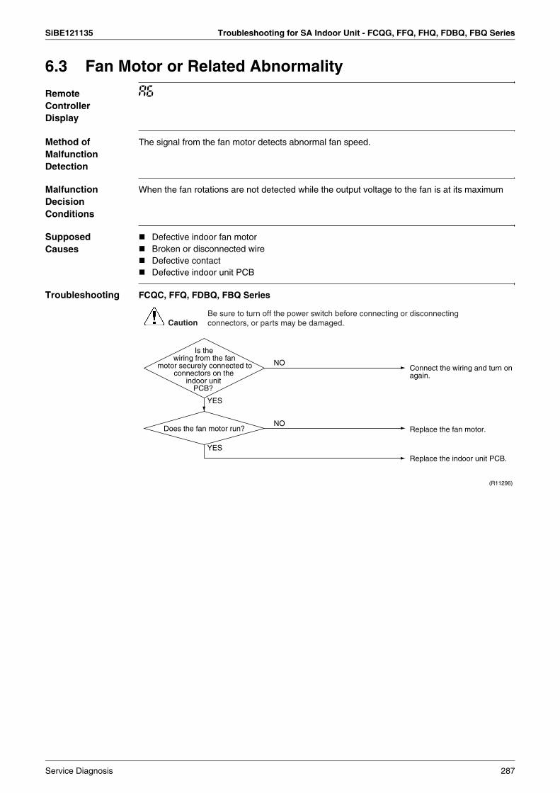
SiBE121135 Troubleshooting for SA Indoor Unit - FCQG, FFQ, FHQ, FDBQ, FBQ Series
6.3 Fan Motor or Related Abnormality
Remote Controller Display
A6
Method of Malfunction Detection
The signal from the fan motor detects abnormal fan speed.
Malfunction Decision Conditions
When the fan rotations are not detected while the output voltage to the fan is at its maximum
Supposed Causes
Defective indoor fan motorBroken or disconnected wireDefective contactDefective indoor unit PCB
Troubleshooting FCQC, FFQ, FDBQ, FBQ Series
CautionBe sure to turn off the power switch before connecting or disconnecting connectors, or parts may be damaged.
Connect the wiring and turn on again.
YES
YES
NO
NO
Replace the indoor unit PCB.
Replace the fan motor.
(R11296)
Does the fan motor run?
Is the wiring from the fan
motor securely connected to connectors on the
indoor unit PCB?
Service Diagnosis 287

Troubleshooting for SA Indoor Unit - FCQG, FFQ, FHQ, FDBQ, FBQ Series SiBE121135
Troubleshooting FHQ Series
Note: There is a possibility of open phase power supply, also check the power supply.
CautionBe sure to turn off the power switch before connecting or disconnecting connectors, or parts may be damaged.
Replace the indoor unit PCB.NO
(R12862)
About 12 VDC?
YES
Connect them correctly.
YES
NO
Check the connections of X20A and X26A.
Disconnect X26A and turn the power on.
Check the voltage between the pins 1 and 3 of X26A.
Check the indoor unit fan motor and motor wiring.
Are X20A or X26A or both properly
connected?
288 Service Diagnosis
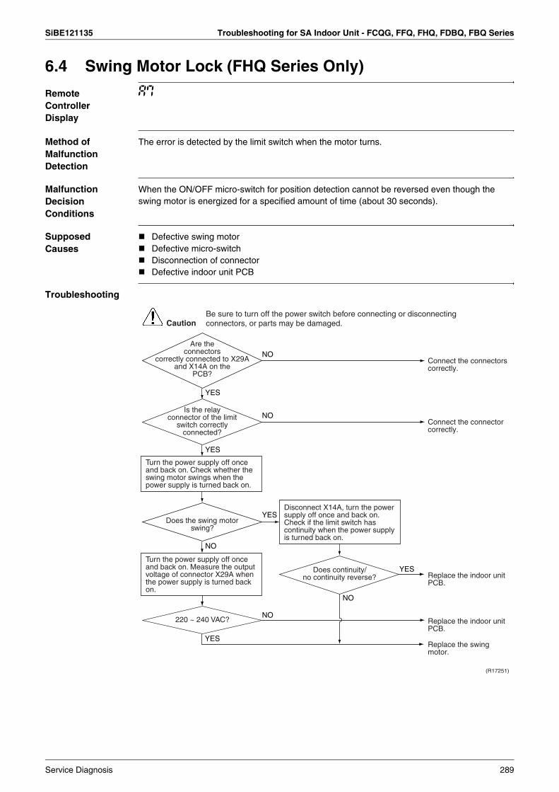
SiBE121135 Troubleshooting for SA Indoor Unit - FCQG, FFQ, FHQ, FDBQ, FBQ Series
6.4 Swing Motor Lock (FHQ Series Only)
Remote Controller Display
A7
Method of Malfunction Detection
The error is detected by the limit switch when the motor turns.
Malfunction Decision Conditions
When the ON/OFF micro-switch for position detection cannot be reversed even though the swing motor is energized for a specified amount of time (about 30 seconds).
Supposed Causes
Defective swing motorDefective micro-switchDisconnection of connectorDefective indoor unit PCB
Troubleshooting
CautionBe sure to turn off the power switch before connecting or disconnecting connectors, or parts may be damaged.
Connect the connectors correctly.
Replace the indoor unit PCB.
Replace the swing motor.
(R17251)
NO
Replace the indoor unit PCB.
YES
YES
NO
Connect the connector correctly.
NO
YES
Does the swing motor swing?
Are the connectors
correctly connected to X29A and X14A on the
PCB?
Is the relay connector of the limit
switch correctly connected?
YES
YES
Turn the power supply off once and back on. Check whether the swing motor swings when the power supply is turned back on.
Turn the power supply off once and back on. Measure the output voltage of connector X29A when the power supply is turned back on.
Disconnect X14A, turn the power supply off once and back on. Check if the limit switch has continuity when the power supply is turned back on.
NO
NO
220 ~ 240 VAC?
Does continuity/ no continuity reverse?
Service Diagnosis 289
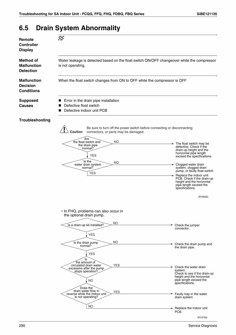
Troubleshooting for SA Indoor Unit - FCQG, FFQ, FHQ, FDBQ, FBQ Series SiBE121135
6.5 Drain System Abnormality
Remote Controller Display
AF
Method of Malfunction Detection
Water leakage is detected based on the float switch ON/OFF changeover while the compressor is not operating.
Malfunction Decision Conditions
When the float switch changes from ON to OFF while the compressor is OFF
Supposed Causes
Error in the drain pipe installationDefective float switchDefective indoor unit PCB
Troubleshooting
YES
YES
NO
NO
CautionBe sure to turn off the power switch before connecting or disconnecting connectors, or parts may be damaged.
The float switch may be defective. Check if the drain-up height and the horizontal pipe length exceed the specifications.
Clogged water drain system, clogged drain pump, or faulty float switchReplace the indoor unit PCB. Check if the drain-up height and the horizontal pipe length exceed the specifications.
(R16022)
Are the float switch and
the drain pipe normal?
Is the water drain system
normal?
NO
YES
YES
NO
NO
NO
YES
YES
Check the water drain system.Check to see if the drain-up height and the horizontal pipe length exceed the specifications.
Faulty trap in the water drain system
Replace the indoor unit PCB.
(R13752)
Check the jumper connector.
Check the drain pump and the drain pipe.
Is a drain-up kit installed?
Is the drain pump normal?
Is the amount of
circulated drain water excessive after the pump
stops operation?
Does the drain water flow in
reverse while the indoor unit is not operating?
∗ In FHQ, problems can also occur in the optional drain pump.
290 Service Diagnosis

SiBE121135 Troubleshooting for SA Indoor Unit - FCQG, FFQ, FHQ, FDBQ, FBQ Series
6.6 Thermistor or Related Abnormality (SA Indoor Unit)
Remote Controller Display
C4, C9
Method of Malfunction Detection
The temperatures detected by the thermistors determine thermistor errors.
Malfunction Decision Conditions
The thermistor input is more than 4.96 V or less than 0.04 V during compressor operation.
Supposed Causes
Disconnection of connectorDefective thermistorDefective indoor unit PCB
Troubleshooting If the cause of the problem is related to the thermistors, the thermistors should be checked prior to changing the indoor unit PCB.
To check the thermistors, proceed as follows:
C4 : Indoor heat exchanger thermistor (R2T, R3T)C9 : Room temperature thermistor (R1T)
Check No.01Refer to P.325
Step Action1 Disconnect the thermistor from the indoor unit PCB.
2 Read the temperature and the resistance value.
3 Check if the measured values correspond with the values in the table of thermistor resistance check.
YES
(R14406)
NO
Check No. 01Check the thermistor resistance value.
YES
NO
Caution
Correct the connection.
Replace the thermistor. (Replace the indoor unit PCB.)
Replace the indoor unit PCB.
Is it normal?
Is it normal?
Check the connection of connectors.
Be sure to turn off the power switch before connecting or disconnecting connectors, or parts may be damaged.
Service Diagnosis 291
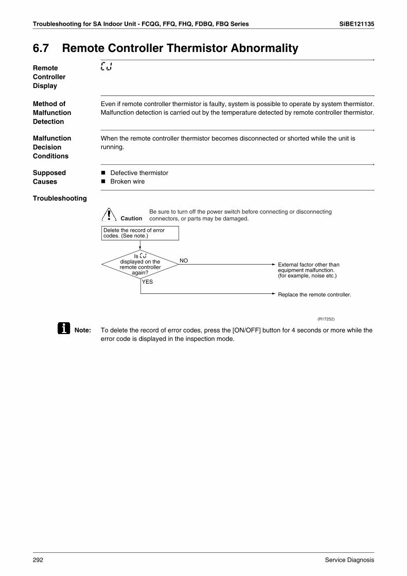
Troubleshooting for SA Indoor Unit - FCQG, FFQ, FHQ, FDBQ, FBQ Series SiBE121135
6.7 Remote Controller Thermistor Abnormality
Remote Controller Display
CJ
Method of Malfunction Detection
Even if remote controller thermistor is faulty, system is possible to operate by system thermistor.Malfunction detection is carried out by the temperature detected by remote controller thermistor.
Malfunction Decision Conditions
When the remote controller thermistor becomes disconnected or shorted while the unit is running.
Supposed Causes
Defective thermistorBroken wire
Troubleshooting
Note: To delete the record of error codes, press the [ON/OFF] button for 4 seconds or more while the error code is displayed in the inspection mode.
Replace the remote controller.
External factor other than equipment malfunction.(for example, noise etc.)
YES
NO
(R17252)
Is CJ displayed on the remote controller
again?
Delete the record of error codes. (See note.)
CautionBe sure to turn off the power switch before connecting or disconnecting connectors, or parts may be damaged.
292 Service Diagnosis
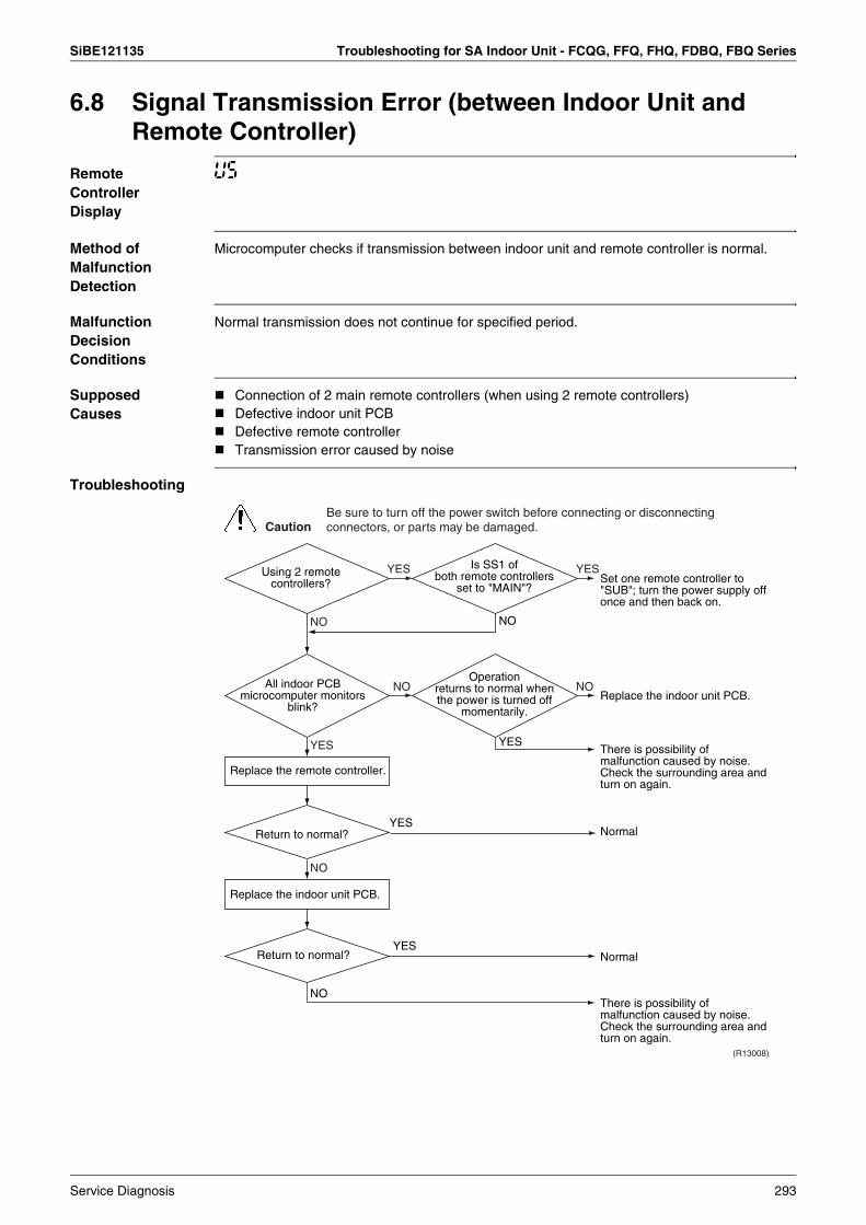
SiBE121135 Troubleshooting for SA Indoor Unit - FCQG, FFQ, FHQ, FDBQ, FBQ Series
6.8 Signal Transmission Error (between Indoor Unit and Remote Controller)
Remote Controller Display
U5
Method of Malfunction Detection
Microcomputer checks if transmission between indoor unit and remote controller is normal.
Malfunction Decision Conditions
Normal transmission does not continue for specified period.
Supposed Causes
Connection of 2 main remote controllers (when using 2 remote controllers)Defective indoor unit PCBDefective remote controllerTransmission error caused by noise
Troubleshooting
Normal
Normal
There is possibility of malfunction caused by noise. Check the surrounding area and turn on again.
Set one remote controller to "SUB"; turn the power supply off once and then back on.
Replace the indoor unit PCB.
There is possibility of malfunction caused by noise. Check the surrounding area and turn on again.
NO
YES
YES
Return to normal?
Return to normal?
NO
YES
YES YES
NO NO
NO
NO
YES
(R13008)
Using 2 remote controllers?
Is SS1 of both remote controllers
set to "MAIN"?
Operation returns to normal when the power is turned off
momentarily.
All indoor PCB microcomputer monitors
blink?
Replace the remote controller.
Replace the indoor unit PCB.
CautionBe sure to turn off the power switch before connecting or disconnecting connectors, or parts may be damaged.
Service Diagnosis 293

Troubleshooting for SA Indoor Unit - FCQG, FFQ, FHQ, FDBQ, FBQ Series SiBE121135
6.9 Signal Transmission Error (between MAIN Remote Controller and SUB Remote Controller)
Remote Controller Display
U8
Method of Malfunction Detection
In case of controlling with 2 remote controllers, check the system using micro-computer if signal transmission between indoor unit and remote controller (main and sub) is normal.
Malfunction Decision Conditions
Normal transmission does not continue for specified period.
Supposed Causes
Remote controller is set to “SUB” when using 1 remote controllerConnection of 2 sub remote controllers (when using 2 remote controllers)Defective remote controller PCB
Troubleshooting
Is SS1 of remote
controller PCB set to "SUB"?
Turn the power off and then back on. If a malfunction occurs, replace the remote controller PCB.
Set one remote controller to "MAIN"; turn the power supply off once and then back on.
Set SS1 to "MAIN"; turn the power supply off once and then back on.
YES
NO
YES
NO NO
YES
(R15321)
Using 2 remote controllers?
Is SS1 of both remote controllers
set to "SUB"?
CautionBe sure to turn off the power switch before connecting or disconnecting connectors, or parts may be damaged.
294 Service Diagnosis
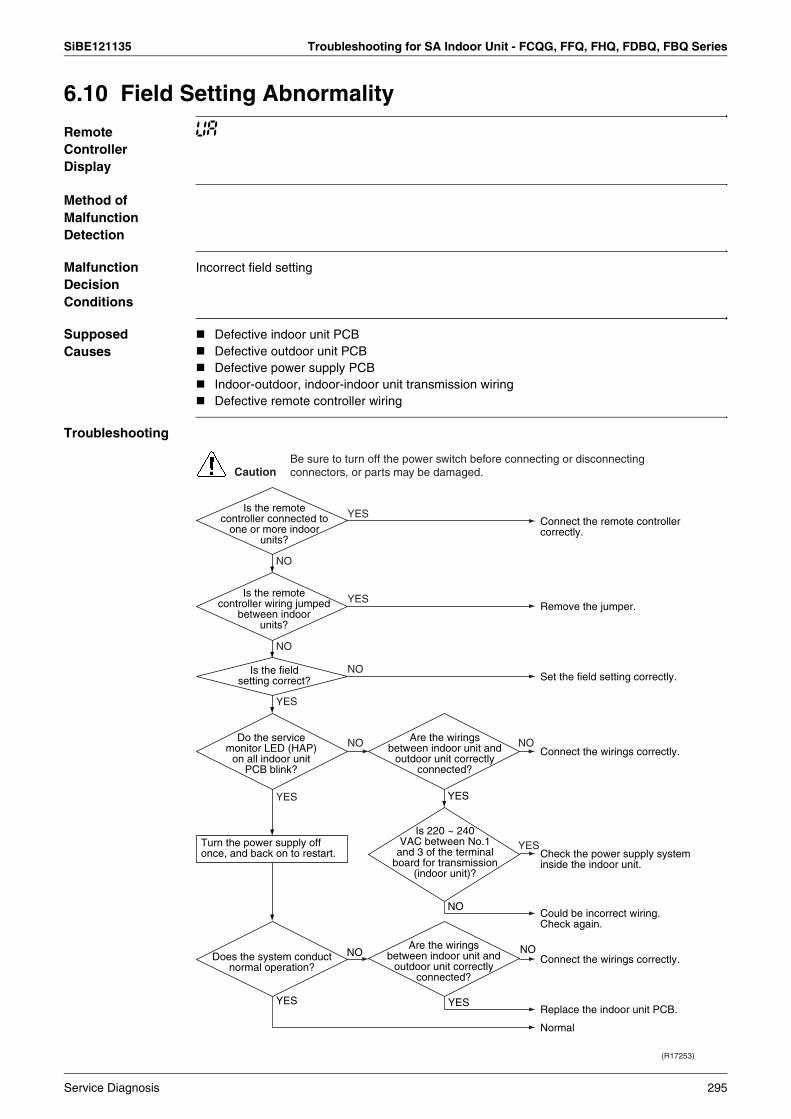
SiBE121135 Troubleshooting for SA Indoor Unit - FCQG, FFQ, FHQ, FDBQ, FBQ Series
6.10 Field Setting Abnormality
Remote Controller Display
UA
Method of Malfunction Detection
Malfunction Decision Conditions
Incorrect field setting
Supposed Causes
Defective indoor unit PCBDefective outdoor unit PCBDefective power supply PCBIndoor-outdoor, indoor-indoor unit transmission wiringDefective remote controller wiring
Troubleshooting
Connect the wirings correctly.
Replace the indoor unit PCB.
Normal
Connect the wirings correctly.
Check the power supply system inside the indoor unit.
Could be incorrect wiring.Check again.
YESYES
NONO
Connect the remote controller correctly.
YES
NO
NO
YES
Remove the jumper.
NO
YES
Set the field setting correctly.
YES
NO
NO NO
YES
YES
(R17253)
Is the remote controller connected to
one or more indoor units?
Is the remote controller wiring jumped
between indoor units?
Is the field setting correct?
Do the service monitor LED (HAP)
on all indoor unit PCB blink?
Are the wirings between indoor unit and
outdoor unit correctly connected?
Is 220 ~ 240 VAC between No.1
and 3 of the terminal board for transmission
(indoor unit)?
Does the system conduct normal operation?
Are the wirings between indoor unit and
outdoor unit correctly connected?
Turn the power supply off once, and back on to restart.
CautionBe sure to turn off the power switch before connecting or disconnecting connectors, or parts may be damaged.
Service Diagnosis 295
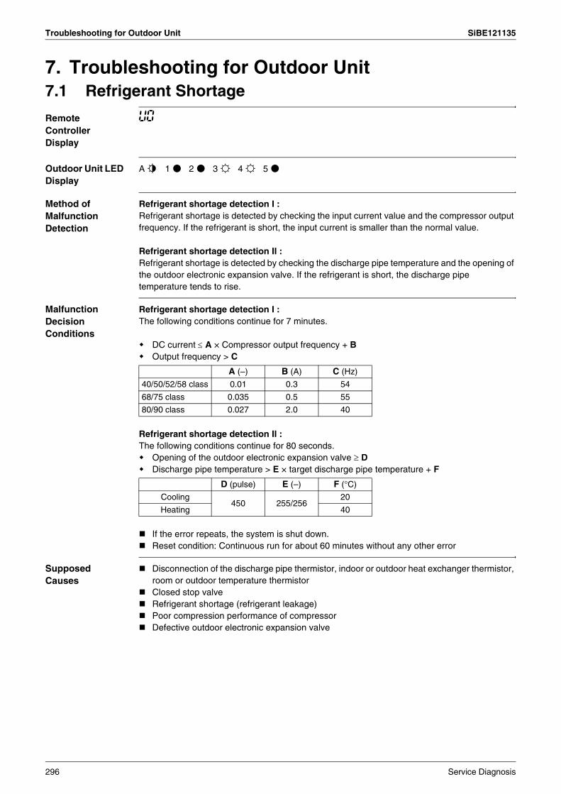
Troubleshooting for Outdoor Unit SiBE121135
7. Troubleshooting for Outdoor Unit7.1 Refrigerant Shortage
Remote Controller Display
U0
Outdoor Unit LED Display
A j 1 h 2 h 3 i 4 i 5 h
Method of Malfunction Detection
Refrigerant shortage detection I :Refrigerant shortage is detected by checking the input current value and the compressor output frequency. If the refrigerant is short, the input current is smaller than the normal value.
Refrigerant shortage detection II :Refrigerant shortage is detected by checking the discharge pipe temperature and the opening of the outdoor electronic expansion valve. If the refrigerant is short, the discharge pipe temperature tends to rise.
Malfunction Decision Conditions
Refrigerant shortage detection I : The following conditions continue for 7 minutes.
DC current ≤ A × Compressor output frequency + BOutput frequency > C
Refrigerant shortage detection II :The following conditions continue for 80 seconds.
Opening of the outdoor electronic expansion valve ≥ DDischarge pipe temperature > E × target discharge pipe temperature + F
If the error repeats, the system is shut down. Reset condition: Continuous run for about 60 minutes without any other error
Supposed Causes
Disconnection of the discharge pipe thermistor, indoor or outdoor heat exchanger thermistor, room or outdoor temperature thermistorClosed stop valveRefrigerant shortage (refrigerant leakage)Poor compression performance of compressorDefective outdoor electronic expansion valve
A (–) B (A) C (Hz)
40/50/52/58 class 0.01 0.3 54
68/75 class 0.035 0.5 55
80/90 class 0.027 2.0 40
D (pulse) E (–) F (°C)
Cooling450 255/256
20
Heating 40
296 Service Diagnosis
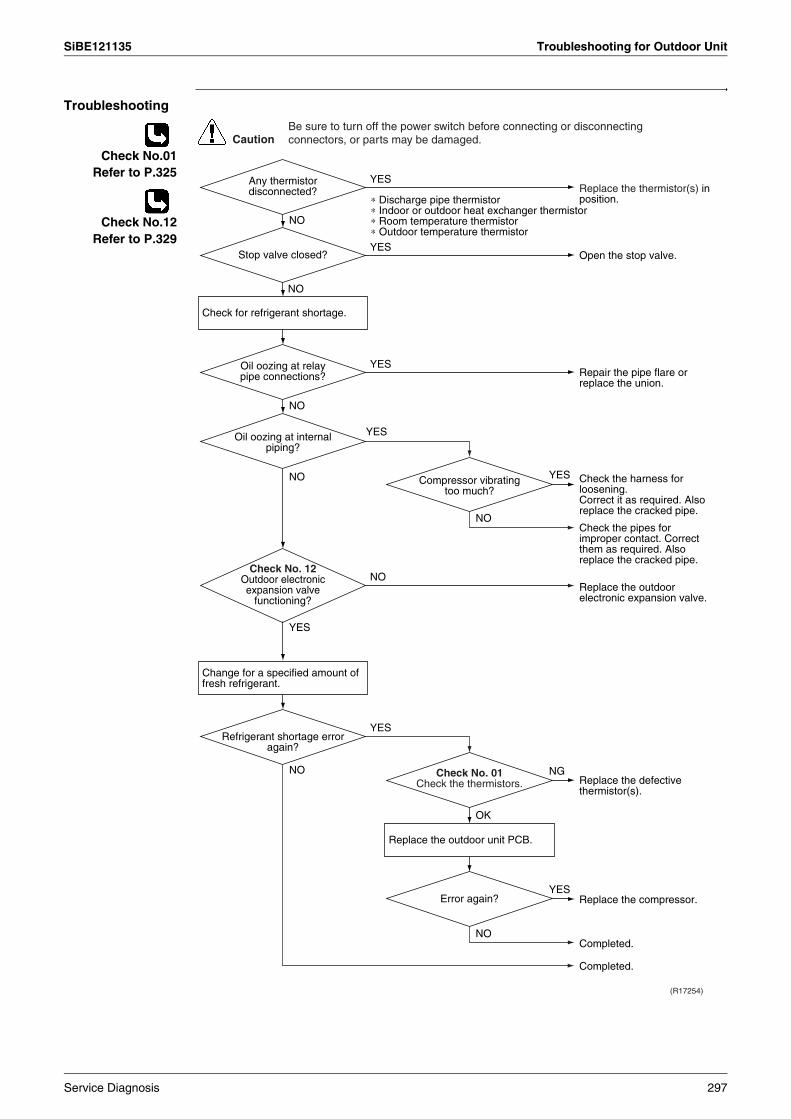
SiBE121135 Troubleshooting for Outdoor Unit
Troubleshooting
Check No.01Refer to P.325
Check No.12Refer to P.329
CautionBe sure to turn off the power switch before connecting or disconnecting connectors, or parts may be damaged.
(R17254)
YES
NG
NO
NO
YES
YES
YES
NO
YES
NO
NO
YES
NO
NO
YES
∗ Discharge pipe thermistor∗ Indoor or outdoor heat exchanger thermistor∗ Room temperature thermistor∗ Outdoor temperature thermistor
Check for refrigerant shortage.
Change for a specified amount of fresh refrigerant.
Check No. 12Outdoor electronic expansion valve
functioning?
Replace the thermistor(s) in position.
Open the stop valve.
Repair the pipe flare or replace the union.
Check the harness for loosening.Correct it as required. Also replace the cracked pipe.
Check the pipes for improper contact. Correct them as required. Also replace the cracked pipe.
Replace the outdoor electronic expansion valve.
Replace the defective thermistor(s).
Completed.
Refrigerant shortage error again?
Oil oozing at internal piping?
Stop valve closed?
Compressor vibrating too much?
Oil oozing at relay pipe connections?
Any thermistor disconnected?
Check No. 01Check the thermistors.
OK
NO
YES
Replace the outdoor unit PCB.
Replace the compressor.
Completed.
Error again?
Service Diagnosis 297
Troubleshooting for Outdoor Unit SiBE121135
7.2 Low-voltage Detection or Over-voltage Detection
Remote Controller Display
U2
Outdoor Unit LED Display
A j 1 i 2 h 3 h 4 i 5 h
Method of Malfunction Detection
Indoor Unit
The zero-cross detection of the power supply is evaluated by the indoor unit PCB.
Outdoor Unit
Low-voltage detection:An abnormal voltage drop is detected by the DC voltage detection circuit.
Over-voltage detection:An abnormal voltage rise is detected by the over-voltage detection circuit.
Malfunction Decision Conditions
Indoor Unit
There is no zero-cross detection in approximately 10 seconds.
Outdoor Unit
Low-voltage detection: The voltage detected by the DC voltage detection circuit is below 150 V for 0.1 second.If the error repeats, the system is shut down.Reset condition: Continuous run for about 60 minutes without any other error
Over-voltage detection:An over-voltage signal is fed from the over-voltage detection circuit to the microcomputer.The compressor stops if the error occurs, and restarts automatically after 3-minute standby.
Supposed Causes
Supply voltage is not as specified.Defective DC voltage detection circuitDefective over-voltage detection circuitDefective PAM control partDisconnection of compressor harnessNoiseMomentary fall of voltageMomentary power failureDefective indoor unit PCB
298 Service Diagnosis

SiBE121135 Troubleshooting for Outdoor Unit
Troubleshooting
Correct the power supply.
Replace the outdoor unit PCB.
Check for such factors for a long term.∗ Try to restart a few times.
(R17269)
CautionBe sure to turn off the power switch before connecting or disconnecting connectors, or parts may be damaged.
NO
NO
YES
NO
YES
YESReconnect the harness.
Check the power supply voltage.
Check the connection of the compressor harness.
Disturbance factors∗ Noise ∗ Power supply distortion
Repeat a few times.
(Precaution before turning on the power again) Make sure the power has been off for at least 30 seconds.
Replace the indoor unit PCB.
Turn on the power again. System
restarted?
Error again within 3 minutes
after turning on the power?
Loose or disconnected?
Voltage as rated?
YES
NO
Service Diagnosis 299
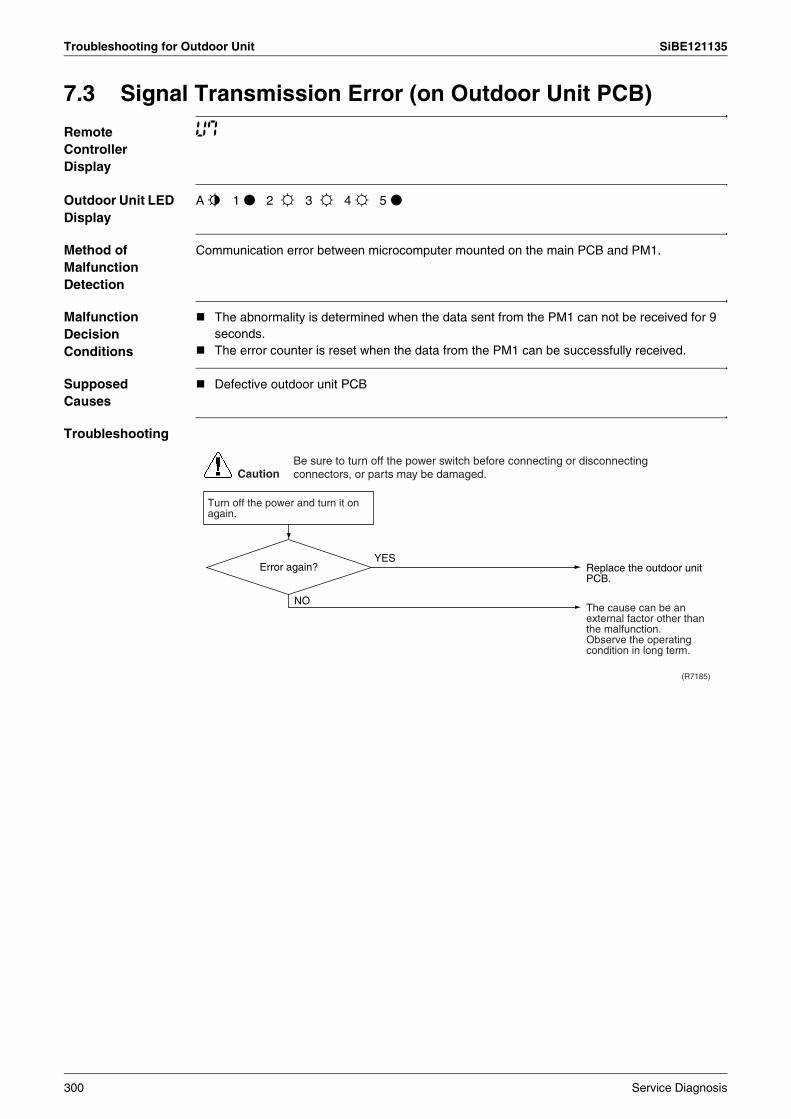
Troubleshooting for Outdoor Unit SiBE121135
7.3 Signal Transmission Error (on Outdoor Unit PCB)
Remote Controller Display
U7
Outdoor Unit LED Display
A j 1 h 2 i 3 i 4 i 5 h
Method of Malfunction Detection
Communication error between microcomputer mounted on the main PCB and PM1.
Malfunction Decision Conditions
The abnormality is determined when the data sent from the PM1 can not be received for 9 seconds. The error counter is reset when the data from the PM1 can be successfully received.
Supposed Causes
Defective outdoor unit PCB
Troubleshooting
(R7185)
Caution
NO
YES
Turn off the power and turn it on again.
Replace the outdoor unit PCB.
The cause can be an external factor other than the malfunction.Observe the operating condition in long term.
Be sure to turn off the power switch before connecting or disconnecting connectors, or parts may be damaged.
Error again?
300 Service Diagnosis
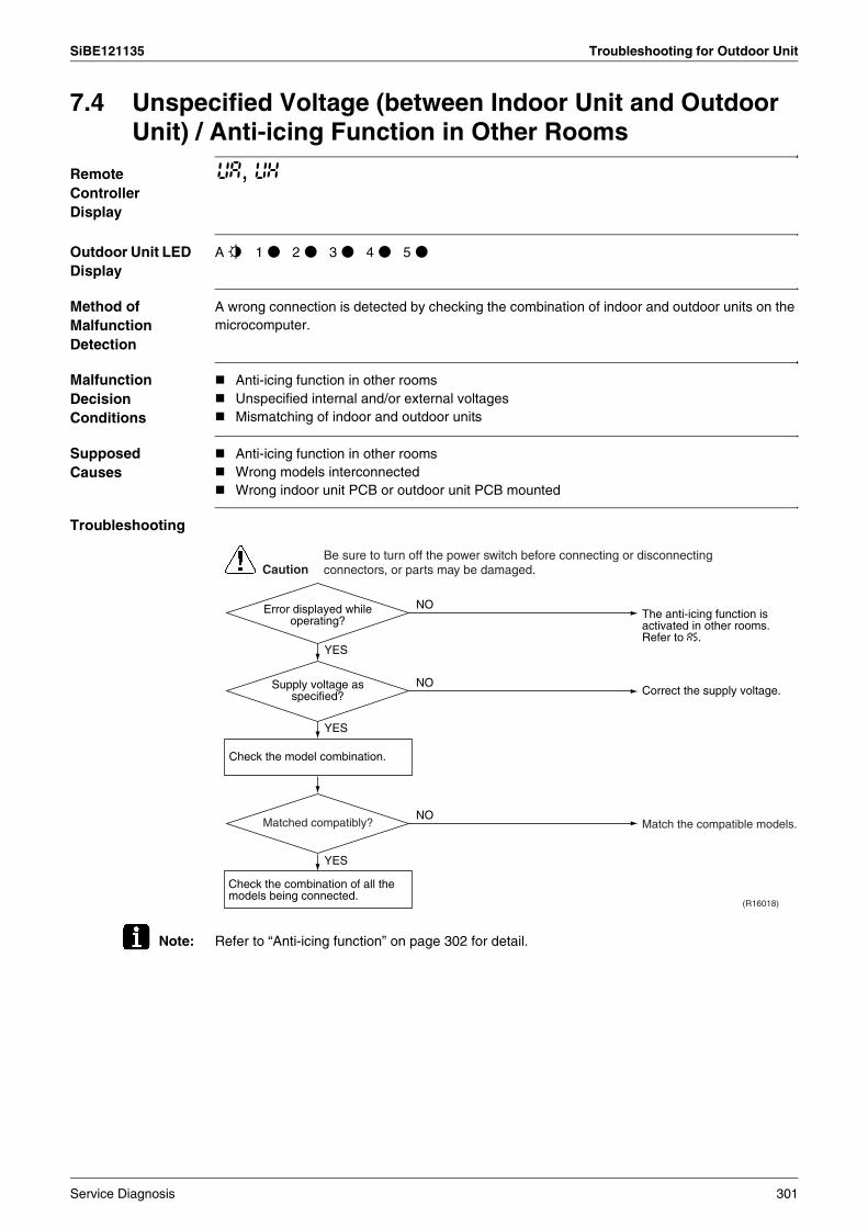
SiBE121135 Troubleshooting for Outdoor Unit
7.4 Unspecified Voltage (between Indoor Unit and Outdoor Unit) / Anti-icing Function in Other Rooms
Remote Controller Display
UA, UH
Outdoor Unit LED Display
A j 1 h 2 h 3 h 4 h 5 h
Method of Malfunction Detection
A wrong connection is detected by checking the combination of indoor and outdoor units on the microcomputer.
Malfunction Decision Conditions
Anti-icing function in other roomsUnspecified internal and/or external voltagesMismatching of indoor and outdoor units
Supposed Causes
Anti-icing function in other roomsWrong models interconnectedWrong indoor unit PCB or outdoor unit PCB mounted
Troubleshooting
Note: Refer to “Anti-icing function” on page 302 for detail.
(R16018)
Caution
NO
YES
NO
YES
NO
YES
Check the model combination.
Check the combination of all the models being connected.
The anti-icing function is activated in other rooms.Refer to A5.
Correct the supply voltage.
Match the compatible models.
Be sure to turn off the power switch before connecting or disconnecting connectors, or parts may be damaged.
Error displayed while operating?
Supply voltage as specified?
Matched compatibly?
Service Diagnosis 301
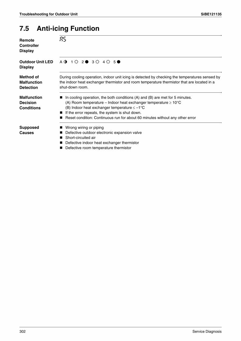
Troubleshooting for Outdoor Unit SiBE121135
7.5 Anti-icing Function
Remote Controller Display
A5
Outdoor Unit LED Display
A j 1 i 2 h 3 i 4 i 5 h
Method of Malfunction Detection
During cooling operation, indoor unit icing is detected by checking the temperatures sensed by the indoor heat exchanger thermistor and room temperature thermistor that are located in a shut-down room.
Malfunction Decision Conditions
In cooling operation, the both conditions (A) and (B) are met for 5 minutes.(A) Room temperature – Indoor heat exchanger temperature ≥ 10°C(B) Indoor heat exchanger temperature ≤ –1°CIf the error repeats, the system is shut down. Reset condition: Continuous run for about 60 minutes without any other error
Supposed Causes
Wrong wiring or pipingDefective outdoor electronic expansion valveShort-circuited airDefective indoor heat exchanger thermistorDefective room temperature thermistor
302 Service Diagnosis

SiBE121135 Troubleshooting for Outdoor Unit
Troubleshooting
Check No.01Refer to P.325
Check No.12Refer to P.329
(R17255)
Caution
YES
NO
NO
YES
YES
YES
YES
NO
NO
NO
Check No. 12Check the outdoor electronic expansion valve.
Check No. 01Check the outdoor heat exchanger thermistor.
Check No. 01Check the room temperature thermistor.
Activate the wiring error check function.
Replace the outdoor electronic expansion valve or coil.
Replace the outdoor heat exchanger thermistor.
Replace the room temperature thermistor.
Replace the room temperature thermistor or indoor heat exchanger thermistor.Do the vacuum drying.
Replace the indoor unit PCB and then start the wiring error check function.
Be sure to turn off the power switch before connecting or disconnecting connectors, or parts may be damaged.
Check the wiring and piping.
Wrong wiring or piping?
Functioning?
As described in the thermistor characteristic
chart?
As described in the thermistor characteristic
chart?
Change the refrigerant to remove moisture from the piping (after drawing a vacuum).
Error again?
Service Diagnosis 303
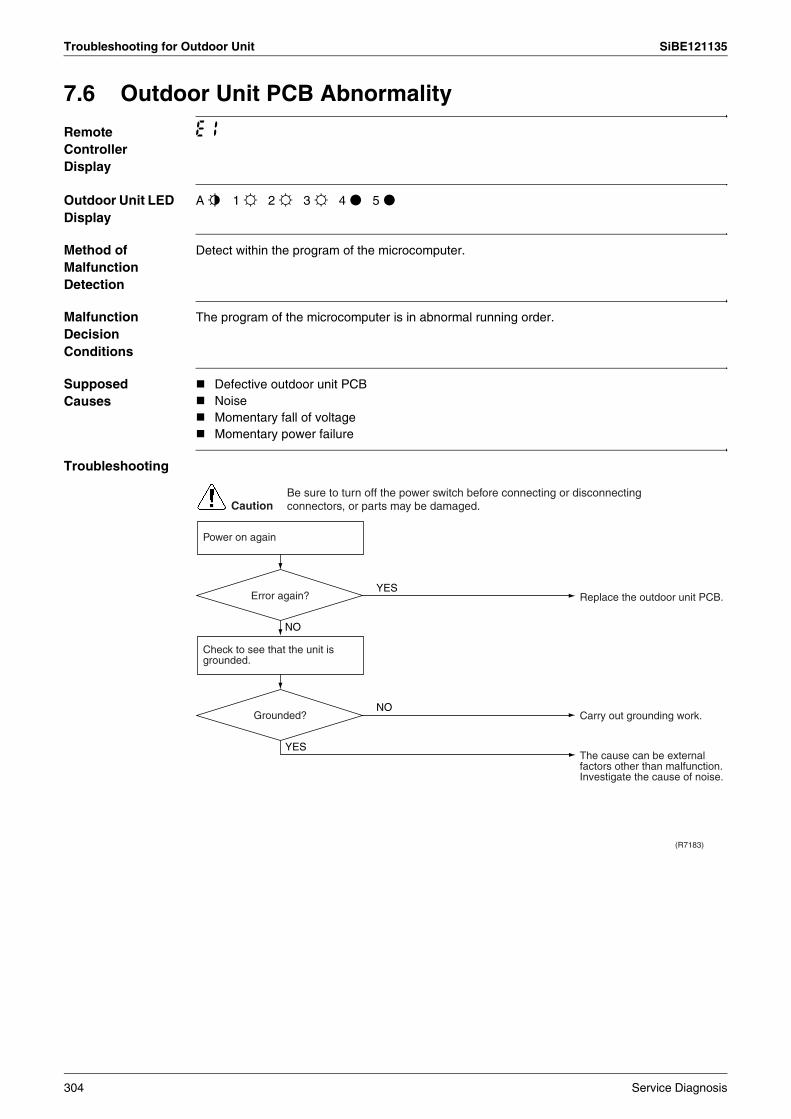
Troubleshooting for Outdoor Unit SiBE121135
7.6 Outdoor Unit PCB Abnormality
Remote Controller Display
E1
Outdoor Unit LED Display
A j 1 i 2 i 3 i 4 h 5 h
Method of Malfunction Detection
Detect within the program of the microcomputer.
Malfunction Decision Conditions
The program of the microcomputer is in abnormal running order.
Supposed Causes
Defective outdoor unit PCBNoiseMomentary fall of voltageMomentary power failure
Troubleshooting
(R7183)
CautionBe sure to turn off the power switch before connecting or disconnecting connectors, or parts may be damaged.
YES
NO
NO
YES
Replace the outdoor unit PCB.
Carry out grounding work.
The cause can be external factors other than malfunction.Investigate the cause of noise.
Power on again
Error again?
Check to see that the unit is grounded.
Grounded?
304 Service Diagnosis
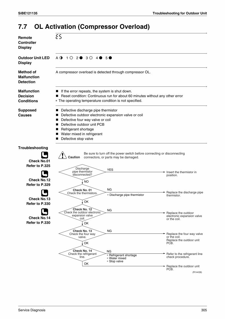
SiBE121135 Troubleshooting for Outdoor Unit
7.7 OL Activation (Compressor Overload)
Remote Controller Display
E5
Outdoor Unit LED Display
A j 1 i 2 h 3 i 4 h 5 h
Method of Malfunction Detection
A compressor overload is detected through compressor OL.
Malfunction Decision Conditions
If the error repeats, the system is shut down.Reset condition: Continuous run for about 60 minutes without any other error
∗ The operating temperature condition is not specified.
Supposed Causes
Defective discharge pipe thermistorDefective outdoor electronic expansion valve or coilDefective four way valve or coilDefective outdoor unit PCBRefrigerant shortageWater mixed in refrigerantDefective stop valve
Troubleshooting
Check No.01Refer to P.325
Check No.12Refer to P.329
Check No.13Refer to P.330
Check No.14Refer to P.330
(R14438)
Caution
YES
NG
∗ Discharge pipe thermistor
NO
OK
OK
NG
NG
OK
NG
OK
∗ Refrigerant shortage∗ Water mixed∗ Stop valve
Insert the thermistor in position.
Replace the discharge pipe thermistor.
Replace the outdoor electronic expansion valve or the coil.
Refer to the refrigerant line check procedure.
Replace the outdoor unit PCB.
Replace the four way valve or the coil.Replace the outdoor unit PCB.
Discharge pipe thermistor disconnected?
Check No. 01Check the thermistors.
Check No. 13Check the four way
valve.
Check No. 14Check the refrigerant
line.
Check No. 12Check the outdoor electronic
expansion valve coil.
Be sure to turn off the power switch before connecting or disconnecting connectors, or parts may be damaged.
Service Diagnosis 305

Troubleshooting for Outdoor Unit SiBE121135
7.8 Compressor Lock
Remote Controller Display
E6
Outdoor Unit LED Display
A j 1 h 2 i 3 i 4 h 5 h
Method of Malfunction Detection
A compressor lock is detected by checking the compressor running condition through the position detection circuit.
Malfunction Decision Conditions
Judging from the current waveform generated when high-frequency voltage is applied to the compressor.If the error repeats, the system is shut down.Reset condition: Continuous run for about 5 minutes without any other error
Supposed Causes
Compressor lockedCompressor harness disconnected
Troubleshooting
Check No.15Refer to P.331
Turn off the power. Disconnect the harnesses U, V, and W.
(R14439)
Caution
NO
YES
YES
NO
NO
YES
Check No.15Check with the inverter checker (∗).
Turn off the power and reconnect the harnesses. Turn on the power again and restart the system.
(Precaution before turning on the power again)Make sure the power has been off for at least 30 seconds.
Correct the power supply or replace the outdoor unit PCB.
∗ Inverter checker Part No.: 1225477
Replace the compressor.
Replace the compressor.
Check the outdoor electronic expansion valve coil.Replace it as required.
Normal?
Emergency stop without compressor
running?
System shut down after errors repeated
several times?
Be sure to turn off the power switch before connecting or disconnecting connectors, or parts may be damaged.
306 Service Diagnosis
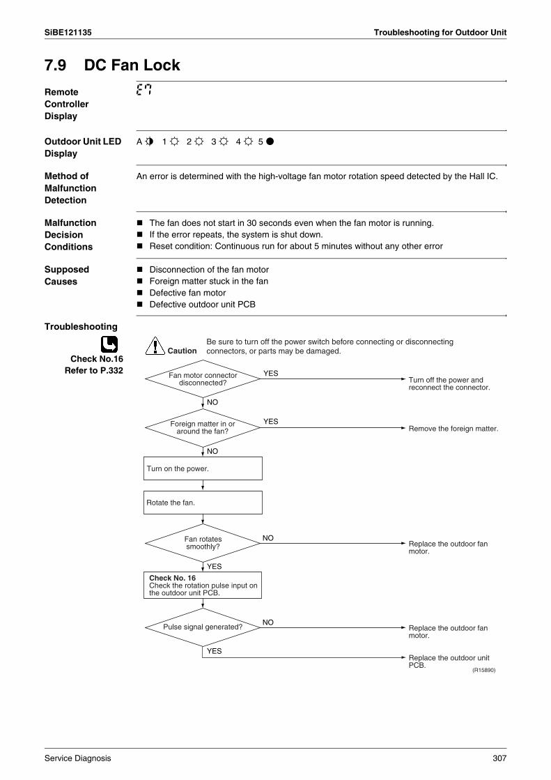
SiBE121135 Troubleshooting for Outdoor Unit
7.9 DC Fan Lock
Remote Controller Display
E7
Outdoor Unit LED Display
A j 1 i 2 i 3 i 4 i 5 h
Method of Malfunction Detection
An error is determined with the high-voltage fan motor rotation speed detected by the Hall IC.
Malfunction Decision Conditions
The fan does not start in 30 seconds even when the fan motor is running.If the error repeats, the system is shut down.Reset condition: Continuous run for about 5 minutes without any other error
Supposed Causes
Disconnection of the fan motorForeign matter stuck in the fanDefective fan motorDefective outdoor unit PCB
Troubleshooting
Check No.16Refer to P.332
(R15890)
Caution
YES
YES
NO
YES
NO
NO
YES
NO
Turn on the power.
Rotate the fan.
Check No. 16Check the rotation pulse input on the outdoor unit PCB.
Turn off the power and reconnect the connector.
Remove the foreign matter.
Replace the outdoor fan motor.
Replace the outdoor unit PCB.
Replace the outdoor fan motor.
Be sure to turn off the power switch before connecting or disconnecting connectors, or parts may be damaged.
Fan motor connector disconnected?
Foreign matter in or around the fan?
Fan rotates smoothly?
Pulse signal generated?
Service Diagnosis 307
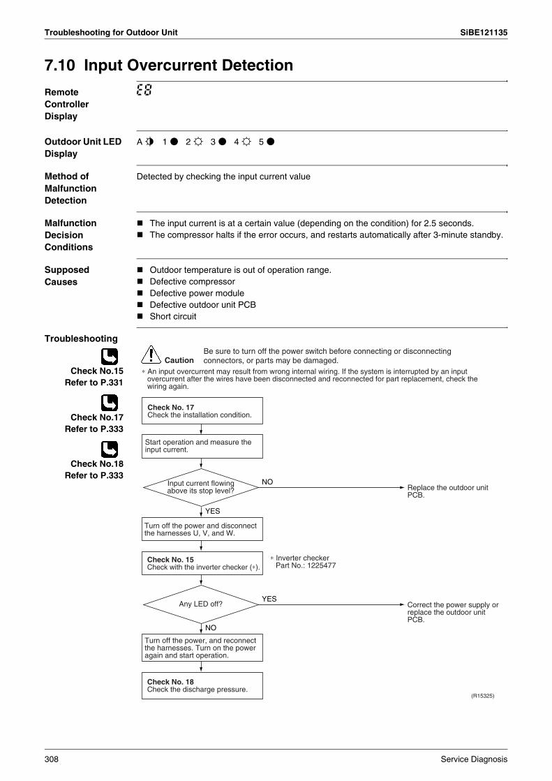
Troubleshooting for Outdoor Unit SiBE121135
7.10 Input Overcurrent Detection
Remote Controller Display
E8
Outdoor Unit LED Display
A j 1 h 2 i 3 h 4 i 5 h
Method of Malfunction Detection
Detected by checking the input current value
Malfunction Decision Conditions
The input current is at a certain value (depending on the condition) for 2.5 seconds.The compressor halts if the error occurs, and restarts automatically after 3-minute standby.
Supposed Causes
Outdoor temperature is out of operation range.Defective compressorDefective power moduleDefective outdoor unit PCBShort circuit
Troubleshooting
Check No.15Refer to P.331
Check No.17Refer to P.333
Check No.18Refer to P.333
CautionBe sure to turn off the power switch before connecting or disconnecting connectors, or parts may be damaged.
(R15325)
NO
YES
YES
NO
Check No. 17Check the installation condition.
Start operation and measure the input current.
Turn off the power and disconnect the harnesses U, V, and W.
Check No. 15Check with the inverter checker (∗).
Turn off the power, and reconnect the harnesses. Turn on the power again and start operation.
Check No. 18Check the discharge pressure.
Replace the outdoor unit PCB.
Correct the power supply or replace the outdoor unit PCB.
∗ Inverter checker Part No.: 1225477
Input current flowing above its stop level?
Any LED off?
∗ An input overcurrent may result from wrong internal wiring. If the system is interrupted by an input overcurrent after the wires have been disconnected and reconnected for part replacement, check the wiring again.
308 Service Diagnosis

SiBE121135 Troubleshooting for Outdoor Unit
7.11 Discharge Pipe Temperature Control
Remote Controller Display
F3
Outdoor Unit LED Display
A j 1 i 2 h 3 i 4 h 5 h
Method of Malfunction Detection
Detected by the discharge pipe thermistor
Malfunction Decision Conditions
If the temperature detected by the discharge pipe thermistor rises above A °C, the compressor stops. The error is cleared when the discharge pipe temperature is dropped below B °C.
If the error repeats, the system is shut down.Reset condition: Continuous run for about 60 minutes without any other error
Supposed Causes
Defective discharge pipe thermistor(Defective outdoor heat exchanger thermistor or outdoor temperature thermistor)Defective outdoor electronic expansion valve or coilRefrigerant shortageDefective four way valveWater mixed in refrigerantDefective stop valveDefective outdoor unit PCB
Troubleshooting
Check No.01Refer to P.325
Check No.12Refer to P.329
Check No.14Refer to P.330
A (°C) B (°C)
40/50/52/58 class 110 95
68/75/80/90 class 120 107
(R15286)
Caution
NG
OK
OK
OK
NG
NG
∗ Discharge pipe thermistor∗ Outdoor heat exchanger thermistor∗ Outdoor temperature thermistor
∗ Refrigerant shortage∗ Four way valve∗ Water mixed∗ Stop valve
Check No. 01Check the thermistors.
Check No. 14Check the refrigerant
line.
Check No. 12Check the outdoor electronic
expansion valve.
Replace the defective thermistor.
Replace the outdoor electronic expansion valve or the coil.
Refer to the refrigerant line check procedure.
Replace the outdoor unit PCB.
Be sure to turn off the power switch before connecting or disconnecting connectors, or parts may be damaged.
Service Diagnosis 309
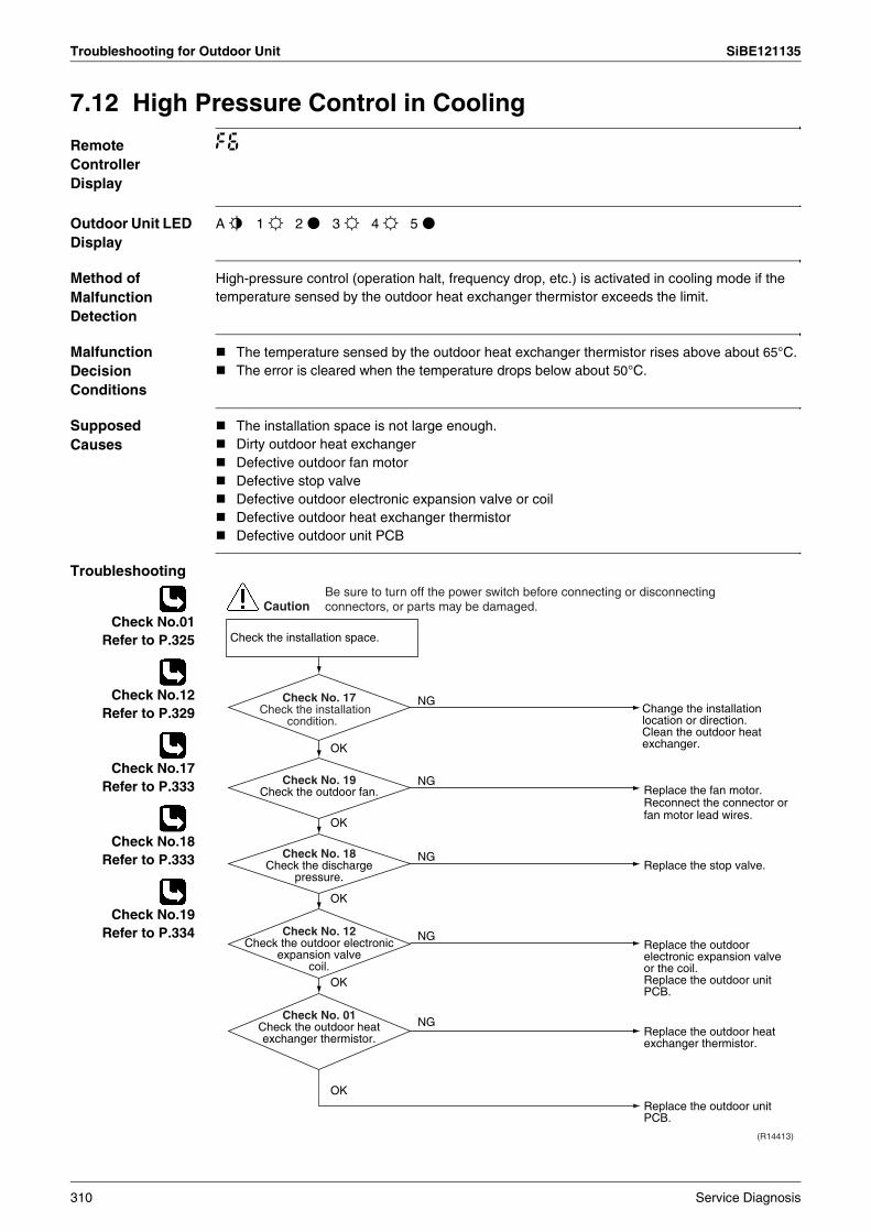
Troubleshooting for Outdoor Unit SiBE121135
7.12 High Pressure Control in Cooling
Remote Controller Display
F6
Outdoor Unit LED Display
A j 1 i 2 h 3 i 4 i 5 h
Method of Malfunction Detection
High-pressure control (operation halt, frequency drop, etc.) is activated in cooling mode if the temperature sensed by the outdoor heat exchanger thermistor exceeds the limit.
Malfunction Decision Conditions
The temperature sensed by the outdoor heat exchanger thermistor rises above about 65°C. The error is cleared when the temperature drops below about 50°C.
Supposed Causes
The installation space is not large enough.Dirty outdoor heat exchangerDefective outdoor fan motorDefective stop valveDefective outdoor electronic expansion valve or coilDefective outdoor heat exchanger thermistorDefective outdoor unit PCB
Troubleshooting
Check No.01Refer to P.325
Check No.12Refer to P.329
Check No.17Refer to P.333
Check No.18Refer to P.333
Check No.19Refer to P.334
(R14413)
Caution
Replace the fan motor.Reconnect the connector or fan motor lead wires.
Replace the stop valve.
Replace the outdoor heat exchanger thermistor.
Replace the outdoor unit PCB.
Replace the outdoor electronic expansion valve or the coil.Replace the outdoor unit PCB.
Change the installation location or direction.Clean the outdoor heat exchanger.
Check the installation space.
NG
OK
OK
NG
NG
OK
OK
OK
NG
NG
Check No. 19Check the outdoor fan.
Check No. 18Check the discharge
pressure.
Check No. 12Check the outdoor electronic
expansion valve coil.
Check No. 01Check the outdoor heat exchanger thermistor.
Check No. 17Check the installation
condition.
Be sure to turn off the power switch before connecting or disconnecting connectors, or parts may be damaged.
310 Service Diagnosis
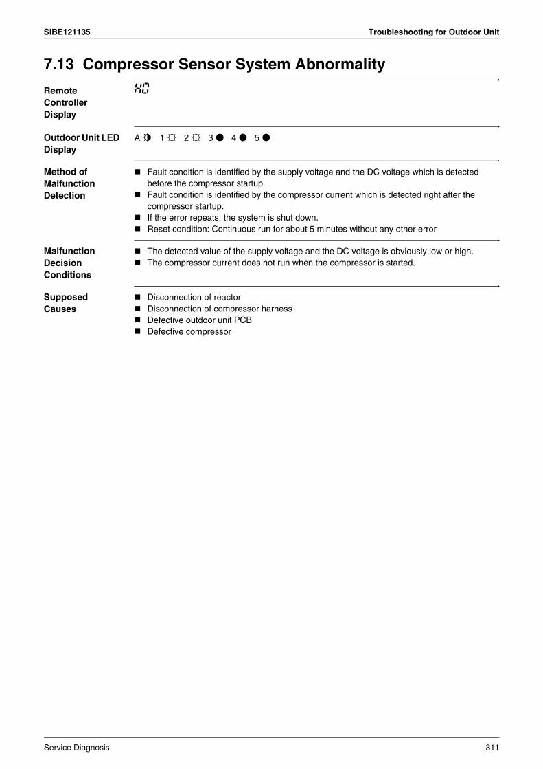
SiBE121135 Troubleshooting for Outdoor Unit
7.13 Compressor Sensor System Abnormality
Remote Controller Display
H0
Outdoor Unit LED Display
A j 1 i 2 i 3 h 4 h 5 h
Method of Malfunction Detection
Fault condition is identified by the supply voltage and the DC voltage which is detected before the compressor startup.Fault condition is identified by the compressor current which is detected right after the compressor startup.If the error repeats, the system is shut down.Reset condition: Continuous run for about 5 minutes without any other error
Malfunction Decision Conditions
The detected value of the supply voltage and the DC voltage is obviously low or high.The compressor current does not run when the compressor is started.
Supposed Causes
Disconnection of reactorDisconnection of compressor harnessDefective outdoor unit PCBDefective compressor
Service Diagnosis 311
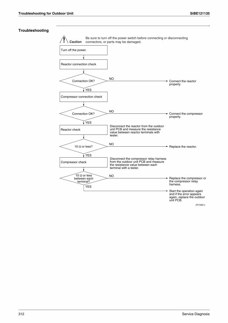
Troubleshooting for Outdoor Unit SiBE121135
Troubleshooting
Connect the reactor properly.
(R15891)
NO
YES
Connect the compressor properly.
NO
YES
Replace the reactor.NO
YES
Replace the compressor or the compressor relay harness.
Start the operation again and if the error appears again, replace the outdoor unit PCB.
NO
YES
Disconnect the reactor from the outdoor unit PCB and measure the resistance value between reactor terminals with tester.
Disconnect the compressor relay harness from the outdoor unit PCB and measure the resistance value between each terminal with a tester.
CautionBe sure to turn off the power switch before connecting or disconnecting connectors, or parts may be damaged.
Turn off the power.
Reactor connection check
Connection OK?
Compressor connection check
Connection OK?
Reactor check
10 Ω or less?
Compressor check
10 Ω or less between each
terminal?
312 Service Diagnosis

SiBE121135 Troubleshooting for Outdoor Unit
7.14 Position Sensor Abnormality
Remote Controller Display
H6
Outdoor Unit LED Display
A j 1 i 2 i 3 h 4 h 5 h
Method of Malfunction Detection
A compressor startup failure is detected by checking the compressor running condition through the position detection circuit.
Malfunction Decision Conditions
If the error repeats, the system is shut down.Reset condition: Continuous run for about 5 minutes without any other error
Supposed Causes
Disconnection of the compressor relay cableDefective compressorDefective outdoor unit PCBStart-up failure caused by the closed stop valveInput voltage is outside the specified range.
Service Diagnosis 313

Troubleshooting for Outdoor Unit SiBE121135
Troubleshooting
Check No.15Refer to P.331
Check No.18Refer to P.333
CautionBe sure to turn off the power switch before connecting or disconnecting connectors, or parts may be damaged.
NO
YES
Check the power supply voltage.
Check the connection.
Turn off the power.
Correct the power supply.Voltage as rated?
(R15892)
NO
NO
YES
NO
YES
YES
Check No.15Check with the inverter checker (∗).
Turn off the power. Disconnect the harnesses U, V, and W.
Turn on the power.Check the electrolytic capacitor voltage.
Electrical components or
compressor harnesses connected as
specified?
Replace the outdoor unit PCB.
Replace the compressor.
Correct the power supply or replace the outdoor unit PCB.
Reconnect the electrical components or compressor harnesses as specified.
∗ Inverter checker Part No.: 1225477
320 ± 50 VDC?
Any LED OFF?
NO
YES
Check No. 18Check the discharge pressure.
Replace the stop valve.OK?
314 Service Diagnosis
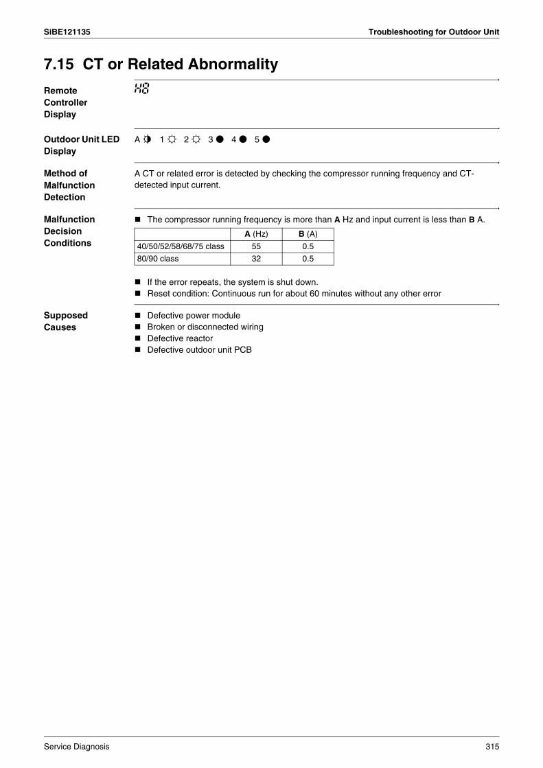
SiBE121135 Troubleshooting for Outdoor Unit
7.15 CT or Related Abnormality
Remote Controller Display
H8
Outdoor Unit LED Display
A j 1 i 2 i 3 h 4 h 5 h
Method of Malfunction Detection
A CT or related error is detected by checking the compressor running frequency and CT-detected input current.
Malfunction Decision Conditions
The compressor running frequency is more than A Hz and input current is less than B A.
If the error repeats, the system is shut down.Reset condition: Continuous run for about 60 minutes without any other error
Supposed Causes
Defective power moduleBroken or disconnected wiringDefective reactorDefective outdoor unit PCB
A (Hz) B (A)
40/50/52/58/68/75 class 55 0.5
80/90 class 32 0.5
Service Diagnosis 315
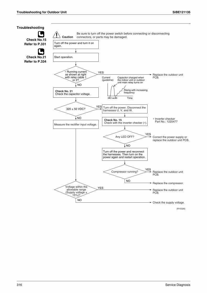
Troubleshooting for Outdoor Unit SiBE121135
Troubleshooting
Check No.15Refer to P.331
Check No.21Refer to P.334
(R15326)
Caution
YES
2 sec Time
NO
NO
YES
YES
NO
YES
NO
YES
NO
Current (guideline)
Turn off the power and turn it on again.
Start operation.
Check No. 21Check the capacitor voltage.
Measure the rectifier input voltage.
Turn off the power. Disconnect the harnesses U, V, and W.
Check No. 15Check with the inverter checker (∗).
Turn off the power and reconnect the harnesses. Then turn on the power again and restart operation.
Replace the outdoor unit PCB.
Replace the outdoor unit PCB.
Replace the outdoor unit PCB.
Check the supply voltage.
Replace the compressor.
Capacitor charged when the indoor unit or outdoor unit main relay turns on
Rising with increasing frequency
Correct the power supply or replace the outdoor unit PCB.
∗ Inverter checker Part No.: 1225477
Be sure to turn off the power switch before connecting or disconnecting connectors, or parts may be damaged.
∗ Running current as shown at right with relay cable 1
or 2?
320 ± 50 VDC?
Any LED OFF?
Compressor running?
Voltage within the allowable range
(Supply voltage ± 15%)?
316 Service Diagnosis

SiBE121135 Troubleshooting for Outdoor Unit
7.16 Thermistor or Related Abnormality (Outdoor Unit)
Remote Controller Display
H9, J3, J6, J8, J9, P4
Outdoor Unit LED Display
A j 1 i 2 i 3 h 4 h 5 h
Method of Malfunction Detection
This type of error is detected by checking the thermistor input voltage to the microcomputer.A thermistor error is detected by checking the temperature sensed by each thermistor.
Malfunction Decision Conditions
The thermistor input is above 4.96 V or below 0.04 V with the power on.J3 error is judged if the discharge pipe temperature is lower than the heat exchanger temperature.The system is shut down if all the units are judged as the J8 error.
Supposed Causes
Disconnection of the connector for the thermistorDefective thermistor corresponding to the error codeDefective heat exchanger thermistor in the case of J3 error (outdoor heat exchanger thermistor in cooling operation, or indoor heat exchanger thermistor in heating operation)Defective outdoor unit PCB
Troubleshooting In case of P4
Replace the outdoor unit PCB.
P4 : Radiation fin thermistor
CautionBe sure to turn off the power switch before connecting or disconnecting connectors, or parts may be damaged.
Service Diagnosis 317
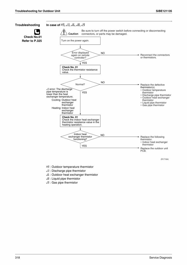
Troubleshooting for Outdoor Unit SiBE121135
Troubleshooting In case of H9, J3, J6, J8, J9
Check No.01Refer to P.325
H9 : Outdoor temperature thermistorJ3 : Discharge pipe thermistorJ6 : Outdoor heat exchanger thermistorJ8 : Liquid pipe thermistorJ9 : Gas pipe thermistor
(R17164)
Caution
NO
YES
YES
NO
NO
YES
Turn on the power again.
Normal?
Reconnect the connectors or thermistors.
J3 error: The discharge pipe temperature is lower than the heat exchanger temperature.
Replace the defective thermistor(s).∗ Outdoor temperature
thermistor∗ Discharge pipe thermistor∗ Outdoor heat exchanger
thermistor∗ Liquid pipe thermistor∗ Gas pipe thermistor
∗ Indoor heat exchanger thermistor
Cooling: Outdoor heat exchanger thermistor
Heating: Indoor heat exchanger thermistor
Replace the following thermistor.
Replace the outdoor unit PCB.
Error displayed again on remote
controller?
Indoor heat exchanger thermistor
functioning?
Check No. 01Check the thermistor resistance value.
Check No. 01Check the indoor heat exchanger thermistor resistance value in the heating operation.
Be sure to turn off the power switch before connecting or disconnecting connectors, or parts may be damaged.
318 Service Diagnosis
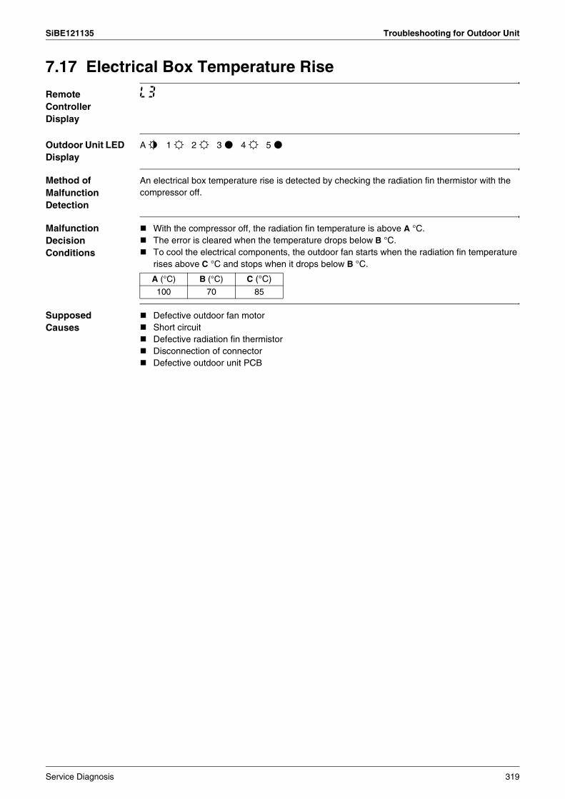
SiBE121135 Troubleshooting for Outdoor Unit
7.17 Electrical Box Temperature Rise
Remote Controller Display
L3
Outdoor Unit LED Display
A j 1 i 2 i 3 h 4 i 5 h
Method of Malfunction Detection
An electrical box temperature rise is detected by checking the radiation fin thermistor with the compressor off.
Malfunction Decision Conditions
With the compressor off, the radiation fin temperature is above A °C.The error is cleared when the temperature drops below B °C.To cool the electrical components, the outdoor fan starts when the radiation fin temperature rises above C °C and stops when it drops below B °C.
Supposed Causes
Defective outdoor fan motorShort circuitDefective radiation fin thermistorDisconnection of connectorDefective outdoor unit PCB
A (°C) B (°C) C (°C)100 70 85
Service Diagnosis 319
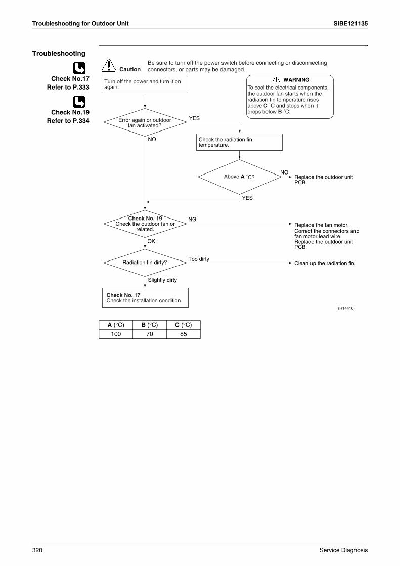
Troubleshooting for Outdoor Unit SiBE121135
Troubleshooting
Check No.17Refer to P.333
Check No.19Refer to P.334
Caution
WARNINGTo cool the electrical components, the outdoor fan starts when the radiation fin temperature rises above C ˚C and stops when it drops below B ˚C.
(R14416)
YES
NO
Slightly dirty
NG
Too dirty
OK
NO
YES
Turn off the power and turn it on again.
Check No. 17Check the installation condition.
Check the radiation fin temperature.
Replace the outdoor unit PCB.
Replace the fan motor.Correct the connectors and fan motor lead wire.Replace the outdoor unit PCB.
Clean up the radiation fin.
Be sure to turn off the power switch before connecting or disconnecting connectors, or parts may be damaged.
Error again or outdoor fan activated?
Check No. 19Check the outdoor fan or
related.
Radiation fin dirty?
Above A ˚C?
A (°C) B (°C) C (°C)
100 70 85
320 Service Diagnosis
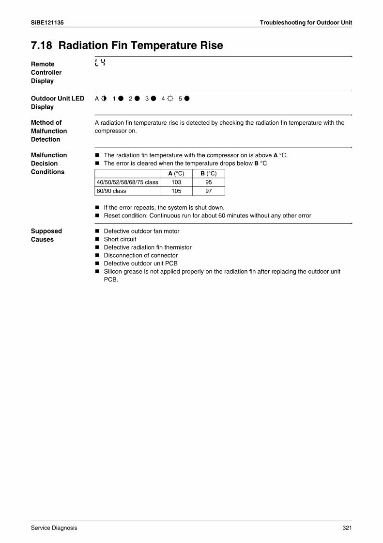
SiBE121135 Troubleshooting for Outdoor Unit
7.18 Radiation Fin Temperature Rise
Remote Controller Display
L4
Outdoor Unit LED Display
A j 1 h 2 h 3 h 4 i 5 h
Method of Malfunction Detection
A radiation fin temperature rise is detected by checking the radiation fin temperature with the compressor on.
Malfunction Decision Conditions
The radiation fin temperature with the compressor on is above A °C.The error is cleared when the temperature drops below B °C
If the error repeats, the system is shut down.Reset condition: Continuous run for about 60 minutes without any other error
Supposed Causes
Defective outdoor fan motorShort circuitDefective radiation fin thermistorDisconnection of connectorDefective outdoor unit PCBSilicon grease is not applied properly on the radiation fin after replacing the outdoor unit PCB.
A (°C) B (°C)
40/50/52/58/68/75 class 103 95
80/90 class 105 97
Service Diagnosis 321

Troubleshooting for Outdoor Unit SiBE121135
Troubleshooting
Check No.17Refer to P.333
Check No.19Refer to P.334
Note: Refer to “Application of silicon grease to a power transistor and a diode bridge” on page 423 for detail.
(R16053)
Caution
NO
Slightly dirty
NG
Too dirty
OK
NO
YES
Turn off the power and turn it on again to start the system.
Check the radiation fin temperature.
Check No. 17Check the installation condition.
NO
YESYES
Above A ˚C?
Radiation fin dirty?
Check No. 19Check the outdoor fan or
related.
Error displayed again? Has the PCB been replaced? Check if applied properly on
the radiation fin. If not, apply the silicon grease (∗). (See Note.)
∗ Silicon grease Part No.: 1172698
Replace the outdoor unit PCB.
Clean up the radiation fin.
Be sure to turn off the power switch before connecting or disconnecting connectors, or parts may be damaged.
Replace the outdoor fan motor.Correct the connectors and fan motor leads.Replace the outdoor unit PCB.
A (°C)
40/50/52/58/68/75 class 103
80/90 class 105
322 Service Diagnosis
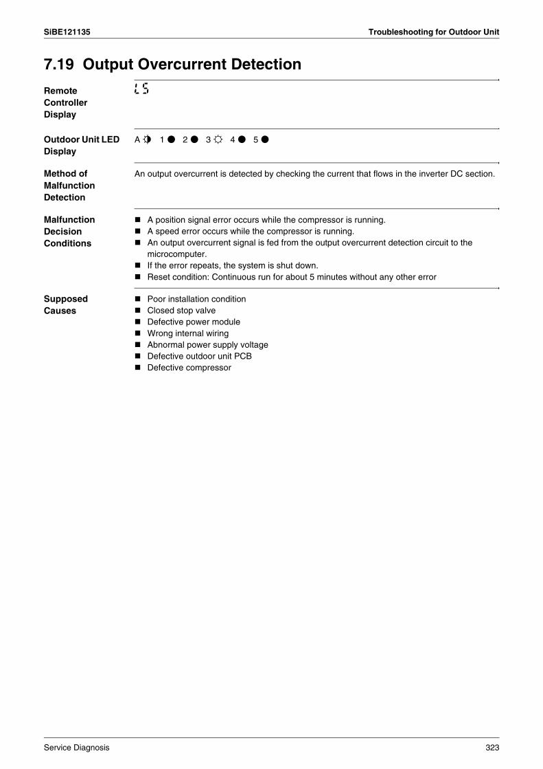
SiBE121135 Troubleshooting for Outdoor Unit
7.19 Output Overcurrent Detection
Remote Controller Display
L5
Outdoor Unit LED Display
A j 1 h 2 h 3 i 4 h 5 h
Method of Malfunction Detection
An output overcurrent is detected by checking the current that flows in the inverter DC section.
Malfunction Decision Conditions
A position signal error occurs while the compressor is running.A speed error occurs while the compressor is running.An output overcurrent signal is fed from the output overcurrent detection circuit to the microcomputer.If the error repeats, the system is shut down.Reset condition: Continuous run for about 5 minutes without any other error
Supposed Causes
Poor installation conditionClosed stop valveDefective power moduleWrong internal wiringAbnormal power supply voltageDefective outdoor unit PCBDefective compressor
Service Diagnosis 323

Troubleshooting for Outdoor Unit SiBE121135
Troubleshooting
Check No.15Refer to P.331
Check No.17Refer to P.333
Check No.18Refer to P.333
Check No.22Refer to P.335
(R16014)
Caution
NO
YES
NO
YES
NO
YES
YES
NO
NO
YES
YES
NO
Check No. 17Check the installation condition.
Turn off the power and turn it on again to start the system. See if the same error occurs.
Turn off the power and disconnect the harnesses U, V, and W.
Check No. 15Check with the inverter checker (∗).
Check No. 22Check the power module.
Turn off the power, and reconnect the harnesses. Turn on the power again and start operation.
Check the supply voltage.
Check No. 18Check the discharge pressure.
∗ An output overcurrent may result from wrong internal wiring. If the system is interrupted by an output overcurrent after the wires have been disconnected and reconnected for part replacement, check the wiring again.
Keep on using.
Check the connectors and other components.
Monitor the power supply voltage, discharge and suction pressures, and other factors for a long term.
Possible causes∗ Momentary fall of power supply
voltage∗ Compressor overload∗ Short circuit
Fully open the stop valve.
Correct the power supply.
Replace the compressor.
Correct the power supply or replace the outdoor unit PCB.
Replace the outdoor unit PCB.
∗ Inverter checker Part No.: 1225477
Be sure to turn off the power switch before connecting or disconnecting connectors, or parts may be damaged.
Stop valve fully open?
Error again?
Any LED off?
Normal?
Voltage as rated?
Short circuit or wire breakage between compressor's coil
phases?
324 Service Diagnosis
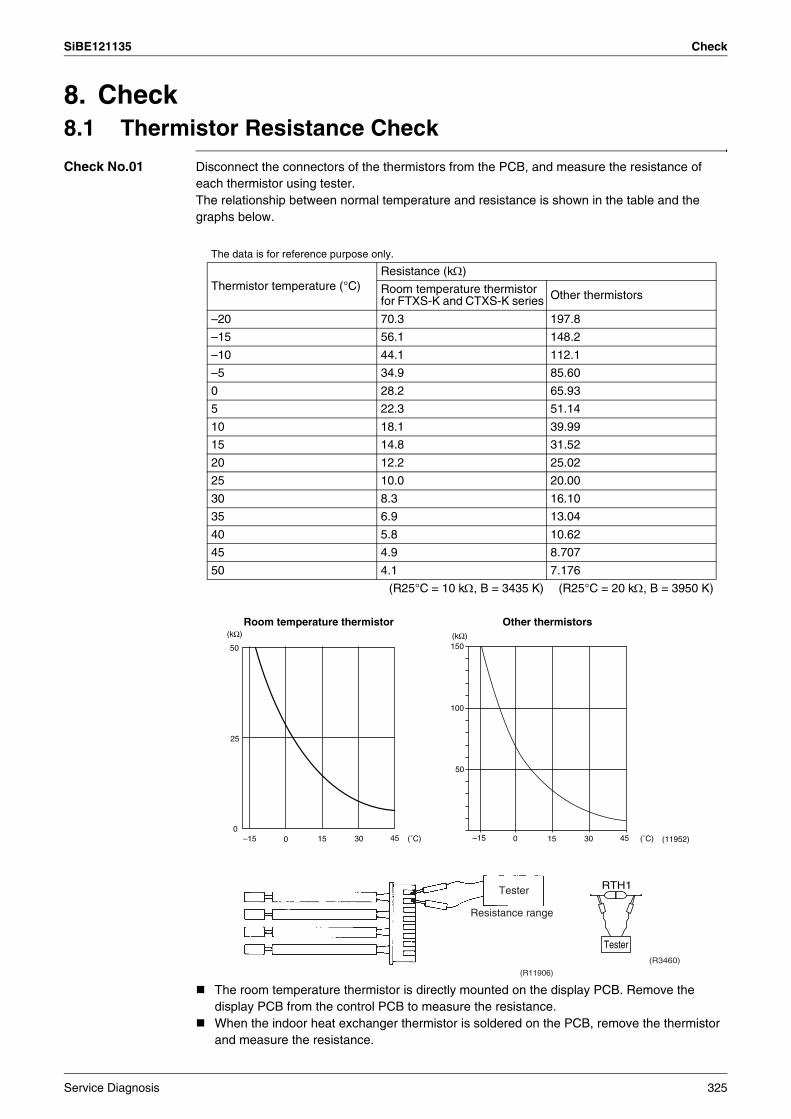
SiBE121135 Check
8. Check8.1 Thermistor Resistance Check
Check No.01 Disconnect the connectors of the thermistors from the PCB, and measure the resistance of each thermistor using tester.The relationship between normal temperature and resistance is shown in the table and the graphs below.
The room temperature thermistor is directly mounted on the display PCB. Remove the display PCB from the control PCB to measure the resistance.When the indoor heat exchanger thermistor is soldered on the PCB, remove the thermistor and measure the resistance.
The data is for reference purpose only.
Thermistor temperature (°C)Resistance (kΩ)
Room temperature thermistor for FTXS-K and CTXS-K series Other thermistors
–20 70.3 197.8
–15 56.1 148.2
–10 44.1 112.1
–5 34.9 85.60
0 28.2 65.93
5 22.3 51.14
10 18.1 39.99
15 14.8 31.52
20 12.2 25.02
25 10.0 20.00
30 8.3 16.10
35 6.9 13.04
40 5.8 10.62
45 4.9 8.707
50 4.1 7.176
(R25°C = 10 kΩ, B = 3435 K) (R25°C = 20 kΩ, B = 3950 K)
Room temperature thermistor
(˚C)
50
25
0–15 0 15 30 45
(kΩ)
(11952)
Other thermistors
(˚C)
(kΩ)
–15 0 15 30 45
150
100
50
Tester
Resistance range
(R11906)
RTH1
Tester(R3460)
Service Diagnosis 325
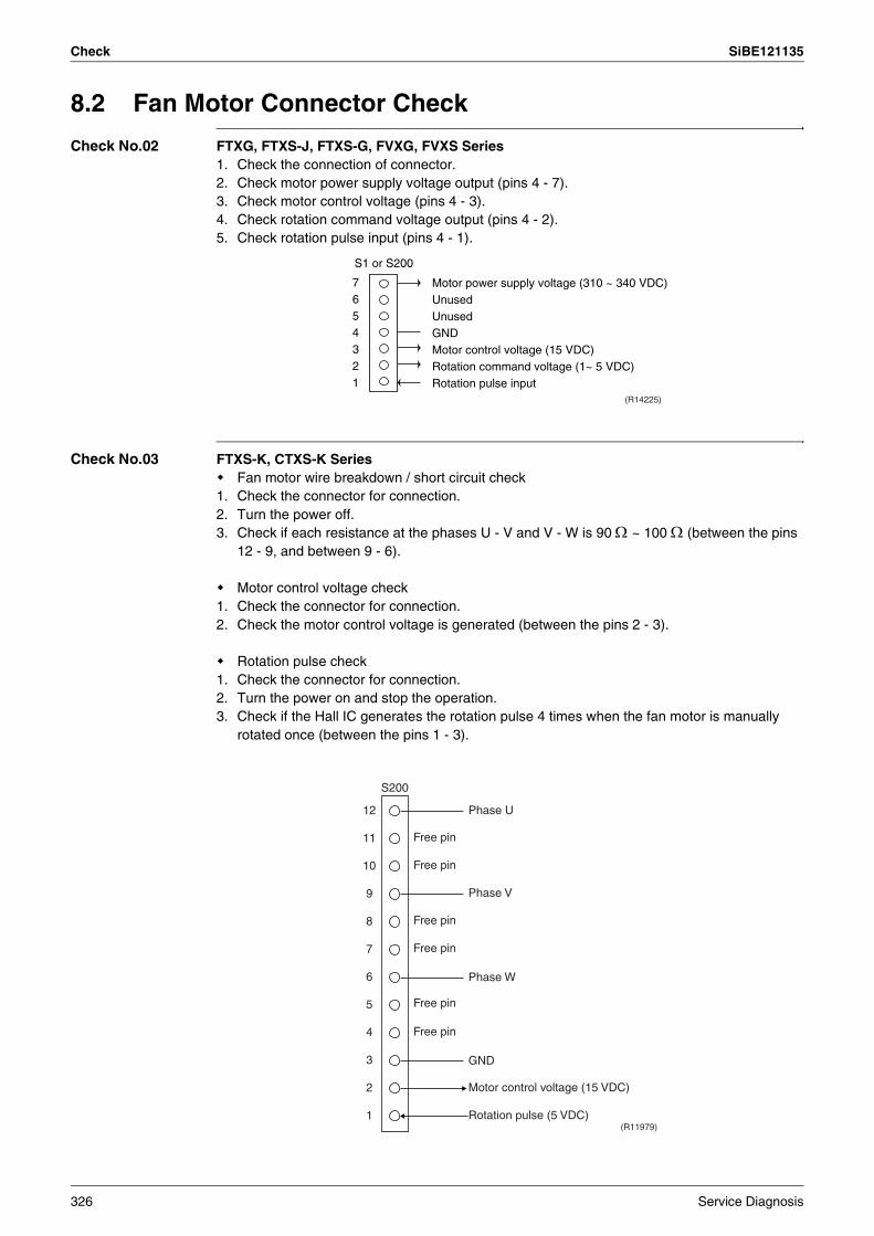
Check SiBE121135
8.2 Fan Motor Connector Check
Check No.02 FTXG, FTXS-J, FTXS-G, FVXG, FVXS Series1. Check the connection of connector.2. Check motor power supply voltage output (pins 4 - 7).3. Check motor control voltage (pins 4 - 3).4. Check rotation command voltage output (pins 4 - 2).5. Check rotation pulse input (pins 4 - 1).
Check No.03 FTXS-K, CTXS-K SeriesFan motor wire breakdown / short circuit check
1. Check the connector for connection.2. Turn the power off. 3. Check if each resistance at the phases U - V and V - W is 90 Ω ~ 100 Ω (between the pins
12 - 9, and between 9 - 6).
Motor control voltage check1. Check the connector for connection.2. Check the motor control voltage is generated (between the pins 2 - 3).
Rotation pulse check1. Check the connector for connection.2. Turn the power on and stop the operation. 3. Check if the Hall IC generates the rotation pulse 4 times when the fan motor is manually
rotated once (between the pins 1 - 3).
7654321
S1 or S200
(R14225)
Motor power supply voltage (310 ~ 340 VDC)UnusedUnusedGNDMotor control voltage (15 VDC)Rotation command voltage (1~ 5 VDC)Rotation pulse input
(R11979)
12
11
10
9
8
7
6
5
4
3
2
1
Phase U
Free pin
Free pin
Free pin
Free pin
Free pin
Free pin
Phase V
Phase W
GND
Motor control voltage (15 VDC)
Rotation pulse (5 VDC)
S200
326 Service Diagnosis

SiBE121135 Check
8.3 Hall IC Check
Check No.04 FLXS, FDXS Series1. Check the connector connection.2. With the power on, operation off, and the connector connected, check the following.
∗Output voltage of about 5 V between pins 1 and 3.∗Generation of 3 pulses between pins 2 and 3 when the fan motor is operating.
If NG in step 1 Defective PCB Replace the PCB.If NG in step 2 Defective Hall IC Replace the fan motor.If OK in both steps 1 and 2 Replace the PCB.
8.4 Indoor Electronic Expansion Valve Coil Check
Check No.06 Conduct the followings to check the indoor electronic expansion valve coil (EV).1. Check to see if the EV connector is correctly connected to the PCB.2. Turn the power off and on again, and check to see if the EV generate latching sound.3. If the EV does not generate latching sound in the above step 2, disconnect the connector
and check the continuity using a tester.4. Check the continuity between the pins 1 - 6, 2 - 6, 3 - 6, and 4 - 6. If there is no continuity
between the pins, the EV coil is faulty.
5. If the continuity is confirmed in the above step 3, the PCB is faulty.
Note: Please note that the latching sound varies depending on the valve type.
1 Gray (power supply)
Purple (signals)
Blue (grounding)
2
3
(R14211)
S7
Harness 5P
6P Connector(5)
Check
6-16-26-36-4
1 2 3 4 5 6(R15307)
S50 (relay connector)
Service Diagnosis 327

Check SiBE121135
8.5 Power Supply Waveform Check
Check No.11 Measure the power supply waveform between No. 1 and No. 2 on the terminal board, and check the waveform disturbance.
Check to see if the power supply waveform is a sine wave (Fig.1).Check to see if there is waveform disturbance near the zero cross (sections circled in Fig.2)
[Fig.1] [Fig.2]
(R1736)
(R1444)
328 Service Diagnosis

SiBE121135 Check
8.6 Outdoor Electronic Expansion Valve Check
Check No.12 Conduct the followings to check the outdoor electronic expansion valve (EV).1. Check to see if the EV connector is correctly inserted in the PCB. Match the EV unit number
and the connector number.2. Turn the power off and on again, and check to see if all the EVs generate latching sound.3. If any of the EVs does not generate latching sound in the above step 2, disconnect that
connector and check the continuity using a tester.Check the continuity between the pins 1 - 6 and 3 - 6, and between the pins 2 - 5 and 4 - 5. If there is no continuity between the pins, the EV coil is faulty.
4. If no EV generates latching sound in the above step 2, the outdoor unit PCB is faulty.5. If the continuity is confirmed in the above step 3, mount a good coil (which generated
latching sound) in the EV unit that did not generate latching sound, and check to see if that EV generates latching sound.∗If latching sound is generated, the outdoor unit PCB is faulty.∗If latching sound is not generated, the EV unit is faulty.
Note: Please note that the latching sound varies depending on the valve type.
If the system keeps operating with a defective outdoor electronic expansion valve, the following problem may occur.
Valve opening position
Possible problem Check method
Open Cooling:Flowing noise of refrigerant in the unit which is not in operationWater leakage at the unit which is not in operationOperation half due to anti-icing function
Reset power supply and conduct cooling operation unit by unit.
Heating:Flowing noise of refrigerant in the unit which is not in operationThe unit does not heat the room.
Close Cooling:The problem unit does not cool the room.Only the problem unit is in operation, the unit starts pump down.(The low pressure of the unit becomes vacuum.)Abnormal discharge pipe temperature
Reset power supply and conduct cooling operation unit by unit.
Heating:Refrigerant shortage due to stagnation of liquid refrigerant inside the faulty indoor unitThe unit does not heat the room.Abnormal discharge pipe temperature
Check the liquid pipe temperature of no-operation unit.
YES
(R16019)
NOThe EV is not defective.
Replace the EV of the room.
Almost the same as the outdoor temperature?
Check the low pressure.
(R16020)
YES
NO
Replace the EV of the room.
The EV is not defective.
Does the pressure become into vacuum
zone?
Service Diagnosis 329

Check SiBE121135
8.7 Four Way Valve Performance Check
Check No.13
8.8 Inverter Unit Refrigerant System Check
Check No.14
(R11903)
NO
YES
YES
NO
Turn off the power and turn it on again.
Start heating operation.∗ Four way valve coil
Cooling / Dry : No continuity Heating : Continuity
Replace the outdoor unit PCB.
Replace the four way valve coil.
Replace the four way valve.
Disconnect the four way valve coil from the connector and check the continuity.
S80 voltage at 220 - 240 VAC with compressor
on? (Fig. 1)
Four way valve coil resistance at 1000 ~ 2000 Ω?
(R11904)
(Fig. 1)
Voltage at S80
220 - 240 VAC
TimeCompressor ON
Refrigerant system check
Is the discharge pipe thermistor disconnected from
the holder?
Check for refrigerant leakage. See the section on refrigerant shortage detection.
(R15833)
YES
NO
Reconnect the thermistor.
Replace the refrigerant.
330 Service Diagnosis
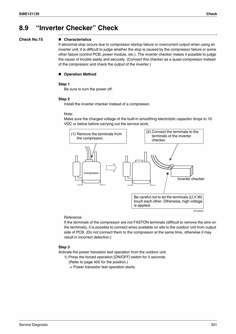
SiBE121135 Check
8.9 “Inverter Checker” Check
Check No.15 CharacteristicsIf abnormal stop occurs due to compressor startup failure or overcurrent output when using an inverter unit, it is difficult to judge whether the stop is caused by the compressor failure or some other failure (control PCB, power module, etc.). The inverter checker makes it possible to judge the cause of trouble easily and securely. (Connect this checker as a quasi-compressor instead of the compressor and check the output of the inverter.)
Operation Method
Step 1Be sure to turn the power off.
Step 2Install the inverter checker instead of a compressor.
Note:Make sure the charged voltage of the built-in smoothing electrolytic capacitor drops to 10 VDC or below before carrying out the service work.
Reference:If the terminals of the compressor are not FASTON terminals (difficult to remove the wire on the terminals), it is possible to connect wires available on site to the outdoor unit from output side of PCB. (Do not connect them to the compressor at the same time, otherwise it may result in incorrect detection.)
Step 3Activate the power transistor test operation from the outdoor unit.
1) Press the forced operation [ON/OFF] switch for 5 seconds.(Refer to page 405 for the position.)→ Power transistor test operation starts.
(R13940)
(1) Remove the terminals from the compressor.
(2) Connect the terminals to the terminals of the inverter checker.
Compressor
Inverter checker
Be careful not to let the terminals (U,V,W) touch each other. Otherwise, high voltage is applied.
Service Diagnosis 331
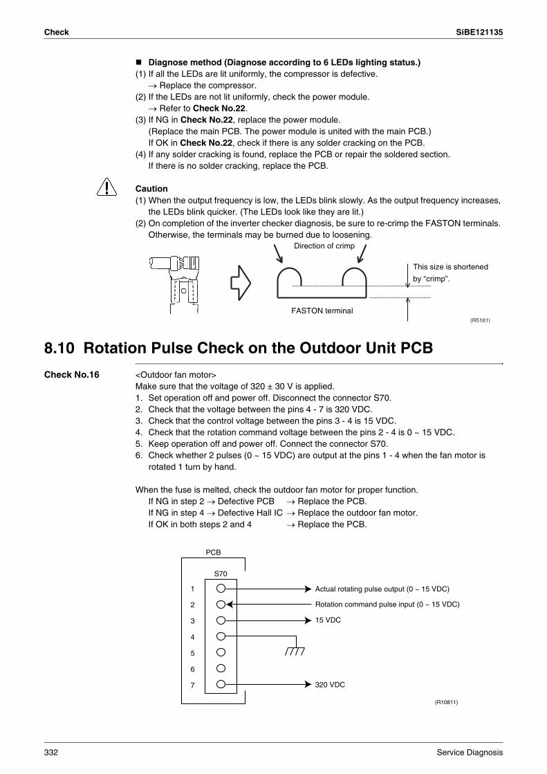
Check SiBE121135
Diagnose method (Diagnose according to 6 LEDs lighting status.)(1) If all the LEDs are lit uniformly, the compressor is defective.
→ Replace the compressor.(2) If the LEDs are not lit uniformly, check the power module.
→ Refer to Check No.22.(3) If NG in Check No.22, replace the power module.
(Replace the main PCB. The power module is united with the main PCB.)If OK in Check No.22, check if there is any solder cracking on the PCB.
(4) If any solder cracking is found, replace the PCB or repair the soldered section.If there is no solder cracking, replace the PCB.
Caution(1) When the output frequency is low, the LEDs blink slowly. As the output frequency increases,
the LEDs blink quicker. (The LEDs look like they are lit.)(2) On completion of the inverter checker diagnosis, be sure to re-crimp the FASTON terminals.
Otherwise, the terminals may be burned due to loosening.
8.10 Rotation Pulse Check on the Outdoor Unit PCB
Check No.16 <Outdoor fan motor>Make sure that the voltage of 320 ± 30 V is applied.1. Set operation off and power off. Disconnect the connector S70.2. Check that the voltage between the pins 4 - 7 is 320 VDC.3. Check that the control voltage between the pins 3 - 4 is 15 VDC.4. Check that the rotation command voltage between the pins 2 - 4 is 0 ~ 15 VDC.5. Keep operation off and power off. Connect the connector S70.6. Check whether 2 pulses (0 ~ 15 VDC) are output at the pins 1 - 4 when the fan motor is
rotated 1 turn by hand.
When the fuse is melted, check the outdoor fan motor for proper function.If NG in step 2 → Defective PCB → Replace the PCB.If NG in step 4 → Defective Hall IC → Replace the outdoor fan motor.If OK in both steps 2 and 4 → Replace the PCB.
(R5161)
Direction of crimp
FASTON terminal
This size is shortened
by “crimp”.
Actual rotating pulse output (0 ~ 15 VDC)
320 VDC
Rotation command pulse input (0 ~ 15 VDC)
15 VDC
(R10811)
S70
PCB
1
2
3
4
5
6
7
332 Service Diagnosis
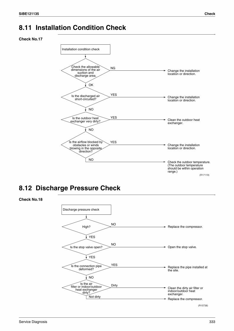
SiBE121135 Check
8.11 Installation Condition Check
Check No.17
8.12 Discharge Pressure Check
Check No.18
Installation condition check
OK
Check the allowable dimensions of the air
suction and discharge area.
Is the airflow blocked by obstacles or winds
blowing in the opposite direction?
(R17119)
NG
YES
YES
YES
Is the discharged air short-circuited?
NO
NO
NO
Is the outdoor heat exchanger very dirty?
Change the installation location or direction.
Change the installation location or direction.
Clean the outdoor heat exchanger.
Change the installation location or direction.
Check the outdoor temperature. (The outdoor temperature should be within operation range.)
(R15738)
Not dirty
YES
YES
Dirty
NO
NO
NO
YES
Is the air filter or indoor/outdoor
heat exchanger dirty?
Replace the compressor.
Open the stop valve.
Replace the pipe installed at the site.
Clean the dirty air filter or indoor/outdoor heat exchanger.
Replace the compressor.
Discharge pressure check
High?
Is the stop valve open?
Is the connection pipe deformed?
Service Diagnosis 333

Check SiBE121135
8.13 Outdoor Fan System Check
Check No.19
8.14 Capacitor Voltage Check
Check No.21 Before this check, be sure to check the main circuit for short circuit.With the circuit breaker still on, measure the voltage according to the drawing of the model in question. Be careful never to touch any live parts.
(R15128)
YES
YESNO
NO
Check the outdoor unit fan system.
Outdoor unit fan running?
Outdoor unit fan system functioning. Go to Check No. 16.
Reconnect the connector.Fan motor lead wire
connector disconnected?
(R12869)
Multimeter (DC. voltage range)
334 Service Diagnosis
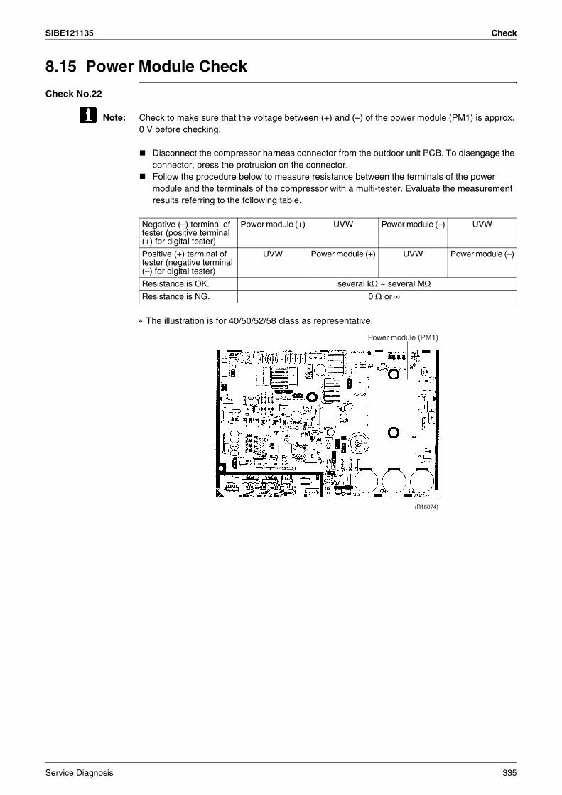
SiBE121135 Check
8.15 Power Module Check
Check No.22
Note: Check to make sure that the voltage between (+) and (–) of the power module (PM1) is approx. 0 V before checking.
Disconnect the compressor harness connector from the outdoor unit PCB. To disengage the connector, press the protrusion on the connector.Follow the procedure below to measure resistance between the terminals of the power module and the terminals of the compressor with a multi-tester. Evaluate the measurement results referring to the following table.
∗ The illustration is for 40/50/52/58 class as representative.
Negative (–) terminal of tester (positive terminal (+) for digital tester)
Power module (+) UVW Power module (–) UVW
Positive (+) terminal of tester (negative terminal (–) for digital tester)
UVW Power module (+) UVW Power module (–)
Resistance is OK. several kΩ ~ several MΩResistance is NG. 0 Ω or ∞
Power module (PM1)
(R16074)
Service Diagnosis 335
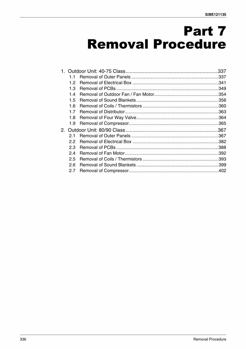
SiBE121135
336 Removal Procedure
Part 7Removal Procedure
1. Outdoor Unit: 40-75 Class...................................................................3371.1 Removal of Outer Panels .....................................................................3371.2 Removal of Electrical Box ....................................................................3411.3 Removal of PCBs .................................................................................3491.4 Removal of Outdoor Fan / Fan Motor...................................................3541.5 Removal of Sound Blankets .................................................................3561.6 Removal of Coils / Thermistors ............................................................3601.7 Removal of Distributor..........................................................................3631.8 Removal of Four Way Valve.................................................................3641.9 Removal of Compressor.......................................................................365
2. Outdoor Unit: 80/90 Class...................................................................3672.1 Removal of Outer Panels .....................................................................3672.2 Removal of Electrical Box ....................................................................3822.3 Removal of PCBs .................................................................................3882.4 Removal of Fan Motor..........................................................................3922.5 Removal of Coils / Thermistors ............................................................3932.6 Removal of Sound Blankets .................................................................3992.7 Removal of Compressor.......................................................................402

SiBE121135 Outdoor Unit: 40-75 Class
1. Outdoor Unit: 40-75 ClassNote: The illustrations are for heat pump models as representative.
1.1 Removal of Outer Panels
Procedure Warning Be sure to wait for 10 minutes or more after turning off all power supplies before disassembling work.
Step Procedure Points
1 Appearance features Take care not to cut your finger by the fins of the heat exchanger.
2 Remove the 4 screws (2 on both sides) of the top panel.
(R5494)
(R12898)
Top panel
(R12899)
Removal Procedure 337
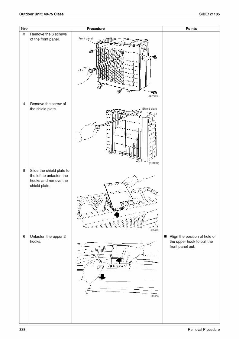
Outdoor Unit: 40-75 Class SiBE121135
3 Remove the 6 screws of the front panel.
4 Remove the screw of the shield plate.
5 Slide the shield plate to the left to unfasten the hooks and remove the shield plate.
6 Unfasten the upper 2 hooks.
Align the position of hole of the upper hook to pull the front panel out.
Step Procedure Points
Front panel
(R17165)
Shield plate
(R11204)
(R5499)
(R5500)
338 Removal Procedure
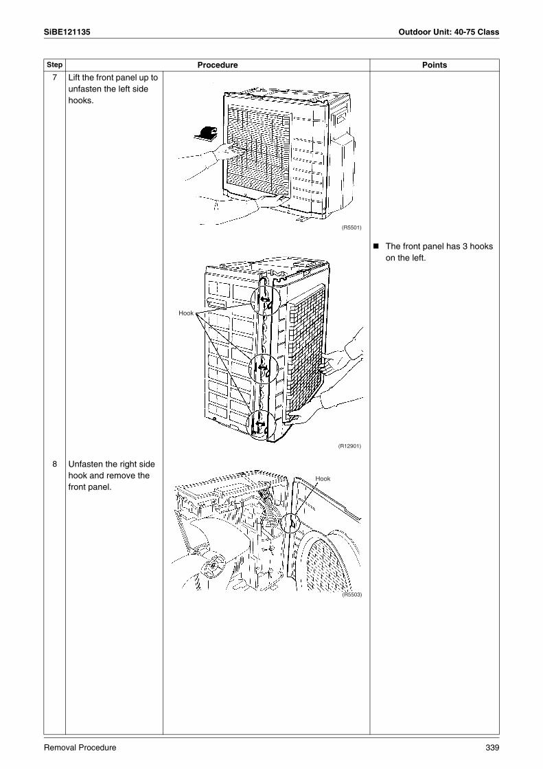
SiBE121135 Outdoor Unit: 40-75 Class
7 Lift the front panel up to unfasten the left side hooks.
The front panel has 3 hooks on the left.
8 Unfasten the right side hook and remove the front panel.
Step Procedure Points
(R5501)
Hook
(R12901)
(R5503)
Hook
Removal Procedure 339
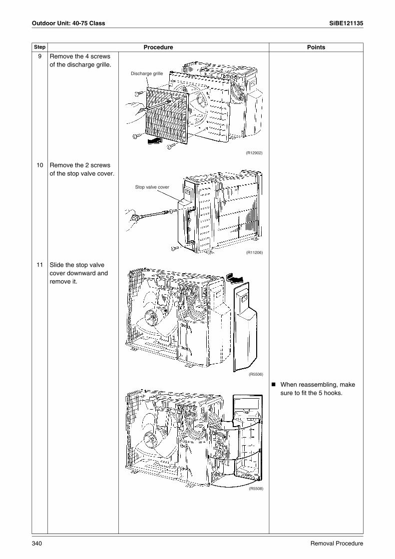
Outdoor Unit: 40-75 Class SiBE121135
9 Remove the 4 screws of the discharge grille.
10
11
Remove the 2 screws of the stop valve cover.
Slide the stop valve cover downward and remove it.
When reassembling, make sure to fit the 5 hooks.
Step Procedure Points
Discharge grille
(R12902)
(R11206)
Stop valve cover
(R5506)
(R5508)
340 Removal Procedure

SiBE121135 Outdoor Unit: 40-75 Class
1.2 Removal of Electrical Box
Procedure Warning Be sure to wait for 10 minutes or more after turning off all power supplies before disassembling work.
Step Procedure Points
1. Disconnect the harnesses.
The illustrations are for 3-room models as representative, 4-room models also have D port.
1 Layout of the connecting wires
The wires are fixed to the terminal board with screws.
Electrical box
Electronic expansion valve coil
Service port
A port
B port
C port
(R11175)
Liquid pipe
Liquid stop valveGas stop valve
Gas pipe
(R11176)
(R17256)Wiring fixture
C port
A port B port
Service monitor PCB
Terminal board
Earth wire
Removal Procedure 341
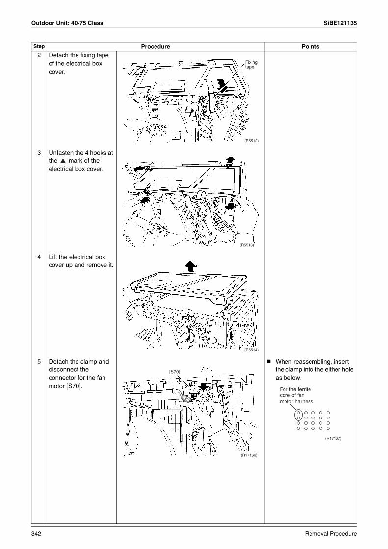
Outdoor Unit: 40-75 Class SiBE121135
2 Detach the fixing tape of the electrical box cover.
3 Unfasten the 4 hooks at the mark of the electrical box cover.
4 Lift the electrical box cover up and remove it.
5 Detach the clamp and disconnect the connector for the fan motor [S70].
When reassembling, insert the clamp into the either hole as below.
Step Procedure Points
(R5512)
Fixing tape
(R5513)
(R5514)
(R17166)
[S70]
For the ferrite core of fan motor harness
(R17167)
342 Removal Procedure
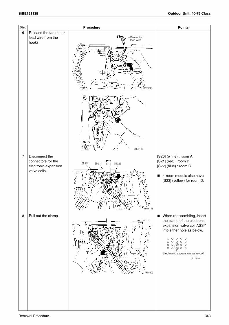
SiBE121135 Outdoor Unit: 40-75 Class
6 Release the fan motor lead wire from the hooks.
7 Disconnect the connectors for the electronic expansion valve coils.
[S20] (white) : room A[S21] (red) : room B[S22] (blue) : room C
4-room models also have [S23] (yellow) for room D.
8 Pull out the clamp. When reassembling, insert the clamp of the electronic expansion valve coil ASSY into either hole as below.
Step Procedure Points
Fan motor lead wire
(R17168)
(R5518)
(R5519)
[S20] [S21] [S22]
(R5520)
Electronic expansion valve coil
(R17170)
Removal Procedure 343
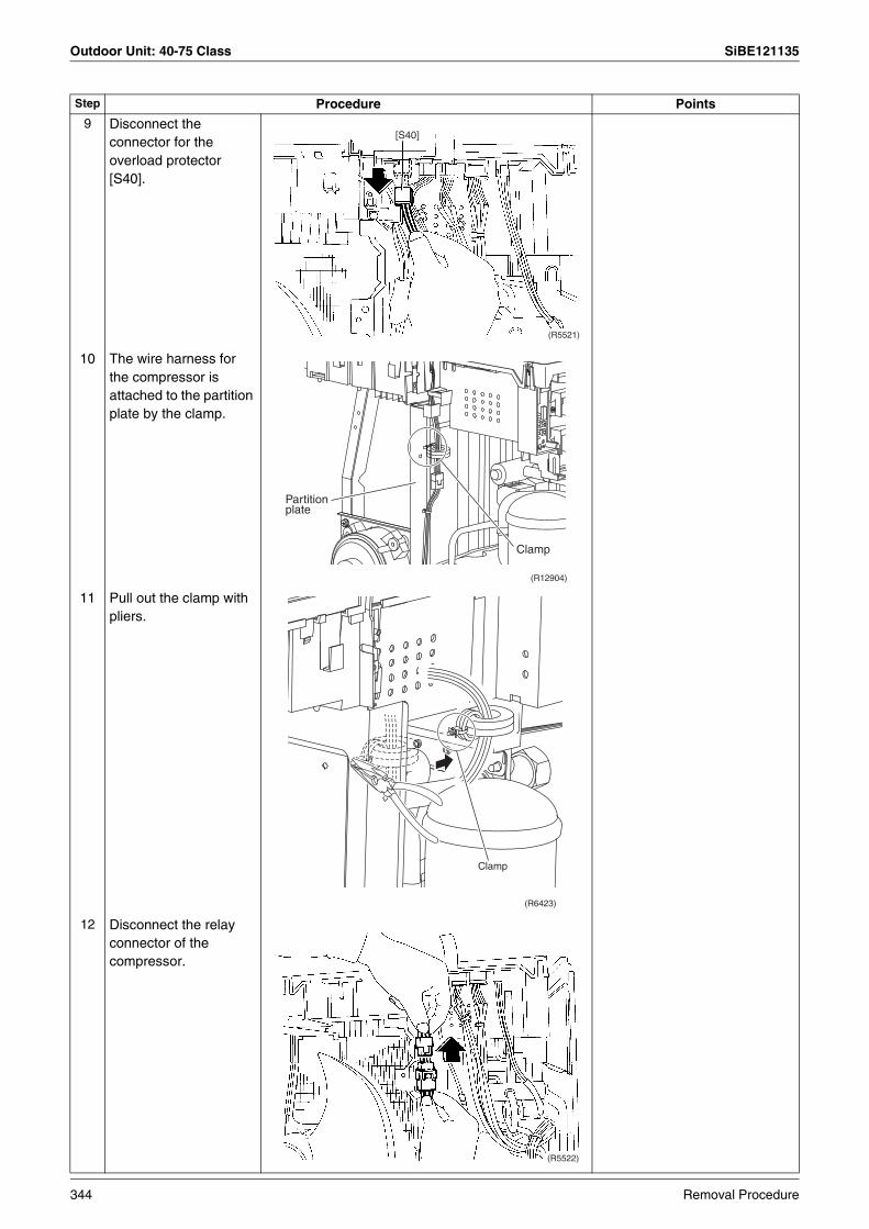
Outdoor Unit: 40-75 Class SiBE121135
9 Disconnect the connector for the overload protector [S40].
10 The wire harness for the compressor is attached to the partition plate by the clamp.
11 Pull out the clamp with pliers.
12 Disconnect the relay connector of the compressor.
Step Procedure Points
(R5521)
[S40]
Clamp
(R12904)
Partition plate
Clamp
(R6423)
(R5522)
344 Removal Procedure
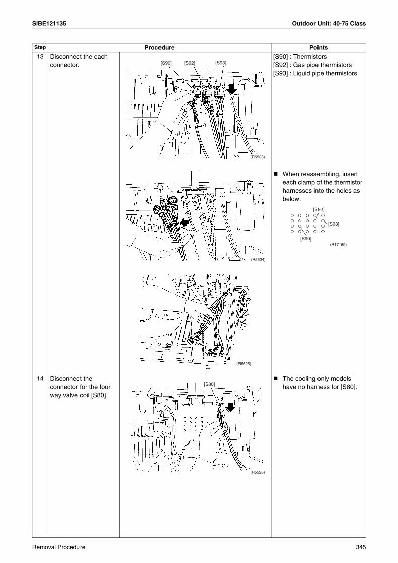
SiBE121135 Outdoor Unit: 40-75 Class
13 Disconnect the each connector.
[S90] : Thermistors [S92] : Gas pipe thermistors[S93] : Liquid pipe thermistors
When reassembling, insert each clamp of the thermistor harnesses into the holes as below.
14 Disconnect the connector for the four way valve coil [S80].
The cooling only models have no harness for [S80].
Step Procedure Points
(R5523)
[S90] [S92] [S93]
(R5524)
(R17169)[S90]
[S92]
[S93]
(R5525)
(R5526)
[S80]
Removal Procedure 345
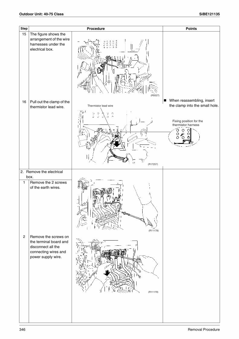
Outdoor Unit: 40-75 Class SiBE121135
15 The figure shows the arrangement of the wire harnesses under the electrical box.
16 Pull out the clamp of the thermistor lead wire.
2. Remove the electrical box.
1 Remove the 2 screws of the earth wires.
2 Remove the screws on the terminal board and disconnect all the connecting wires and power supply wire.
Step Procedure Points
(R5527)
Thermistor lead wire
(R17257)
Fixing position for the thermistor harness
When reassembling, insert the clamp into the small hole.
(R11178)
(R11179)
346 Removal Procedure
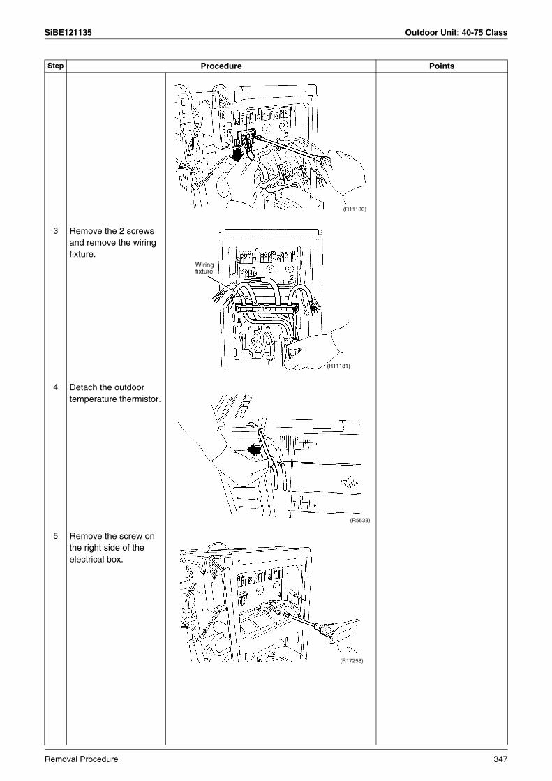
SiBE121135 Outdoor Unit: 40-75 Class
3 Remove the 2 screws and remove the wiring fixture.
4 Detach the outdoor temperature thermistor.
5 Remove the screw on the right side of the electrical box.
Step Procedure Points
(R11180)
(R11181)
Wiring fixture
(R5533)
(R17258)
Removal Procedure 347
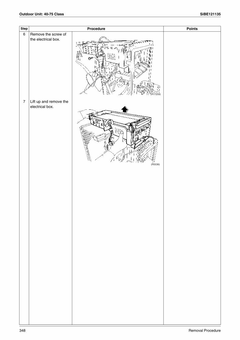
Outdoor Unit: 40-75 Class SiBE121135
6 Remove the screw of the electrical box.
7 Lift up and remove the electrical box.
Step Procedure Points
(R17259)
(R5536)
348 Removal Procedure

SiBE121135 Outdoor Unit: 40-75 Class
1.3 Removal of PCBs
Procedure Warning Be sure to wait for 10 minutes or more after turning off all power supplies before disassembling work.
Step Procedure Points
1. Remove the service monitor PCB.
1 External appearance
2 Remove the screw of the terminal board and open it.
3 Disconnect the connectors [S52] [S102] from the service monitor PCB.
Service monitor PCB Terminal board
(R5537)
(R5538)
(R5539)
(R5540)Service monitor PCB
[S102]
[S52]
Removal Procedure 349

Outdoor Unit: 40-75 Class SiBE121135
4 Unfasten the upper hook and pull the service monitor PCB upward to remove.
Refer to page 40 for detail.
2. Remove the main PCB.[AC1] [AC2] : for power supply[S10] : for transmission
1 Disconnect the connectors for the terminal board on the right side.
2 Disconnect the 2 connectors for the reactor on the left side.
3 Remove the 3 screws of the main PCB.
Step Procedure Points
(R5541)
(R5542)
[AC1] brown
[AC2] blue[S10]
(R5543)
(R5544)
[HR2]
[HR1]
Reactor
Main PCB
(R5545)
350 Removal Procedure
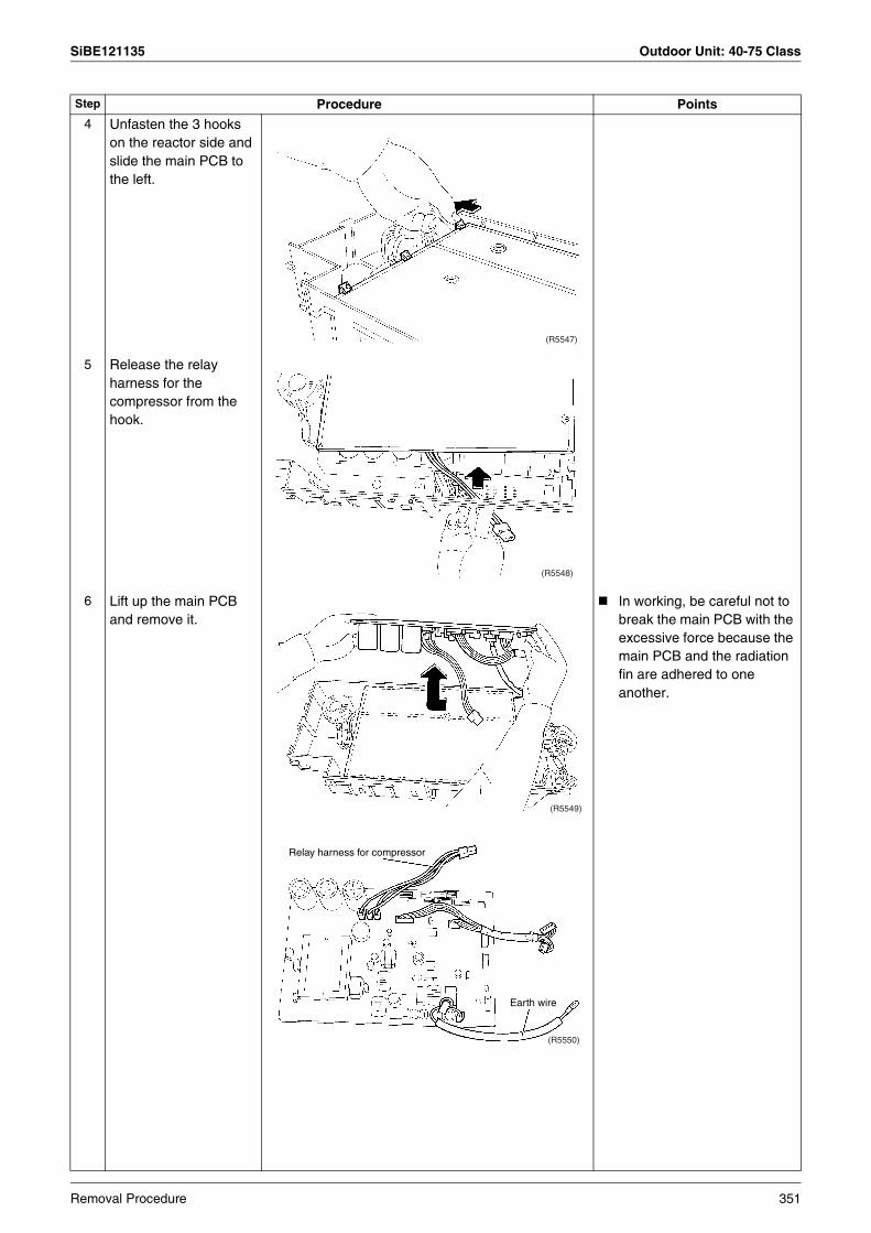
SiBE121135 Outdoor Unit: 40-75 Class
4 Unfasten the 3 hooks on the reactor side and slide the main PCB to the left.
5 Release the relay harness for the compressor from the hook.
6 Lift up the main PCB and remove it.
In working, be careful not to break the main PCB with the excessive force because the main PCB and the radiation fin are adhered to one another.
Step Procedure Points
(R5547)
(R5548)
(R5549)
(R5550)
Relay harness for compressor
Earth wire
Removal Procedure 351
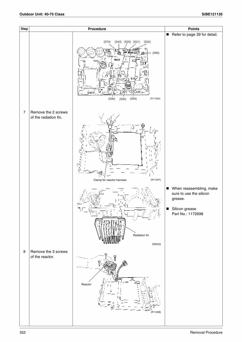
Outdoor Unit: 40-75 Class SiBE121135
Refer to page 39 for detail.
7 Remove the 2 screws of the radiation fin.
When reassembling, make sure to use the silicon grease.
Silicon greasePart No.: 1172698
8 Remove the 3 screws of the reactor.
Step Procedure Points
[S70] [S40] [S20] [S21] [S22]
[S80]
[S90] [S92] [S93] (R17260)
Clamp for reactor harness (R11207)
(R5553)
Radiation fin
Reactor
(R11208)
352 Removal Procedure
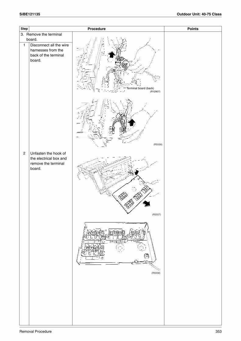
SiBE121135 Outdoor Unit: 40-75 Class
3. Remove the terminal board.
1 Disconnect all the wire harnesses from the back of the terminal board.
2 Unfasten the hook of the electrical box and remove the terminal board.
Step Procedure Points
(R12907)Terminal board (back)
(R5556)
(R5557)
(R5558)
Removal Procedure 353

Outdoor Unit: 40-75 Class SiBE121135
1.4 Removal of Outdoor Fan / Fan Motor
Procedure Warning Be sure to wait for 10 minutes or more after turning off all power supplies before disassembling work.
Step Procedure Points
1 Remove the 2 screws of the fan motor fixing plate.
PreparationRemove the outer panels and plates.Remove the electrical box.
2 Remove the fan motor fixing plate.
When reassembling, fit the lower hooks.
Nut size: M6
When reassembling, align the mark of the outdoor fan with the D-cut section of the motor shaft.
3 Remove the nut and remove the outdoor fan.
Fan motor fixing plate (R12908)
(R5561)
(R5564)
10 mm
(R12236)
Outdoor fan
(R12909)
(R14592)
Nut
D-cut
mark
354 Removal Procedure
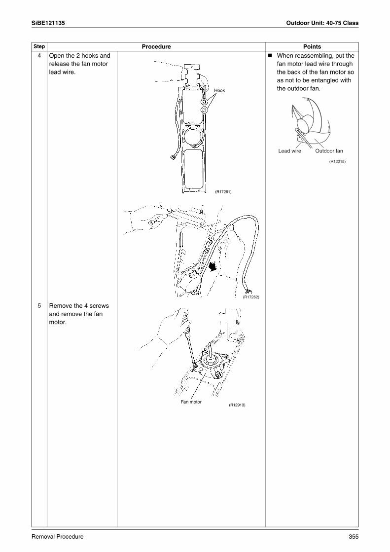
SiBE121135 Outdoor Unit: 40-75 Class
4 Open the 2 hooks and release the fan motor lead wire.
When reassembling, put the fan motor lead wire through the back of the fan motor so as not to be entangled with the outdoor fan.
5 Remove the 4 screws and remove the fan motor.
Step Procedure Points
Hook
(R17261)
(R17262)
Lead wire Outdoor fan
(R12215)
(R12913)Fan motor
Removal Procedure 355

Outdoor Unit: 40-75 Class SiBE121135
1.5 Removal of Sound Blankets
Procedure Warning Be sure to wait for 10 minutes or more after turning off all power supplies before disassembling work.
Step Procedure Points
1. Remove the right side panel.
PreparationRemove the outer panels and plates.
Remove the electrical box.
1 Remove the 3 screws of the right side panel.
2 Remove the 2 screws on the back.
3 Remove the protection rubber. There is a hook on the back.
(R12915)
Right side panel
(R5571)
Protection rubber
(R5572)
356 Removal Procedure
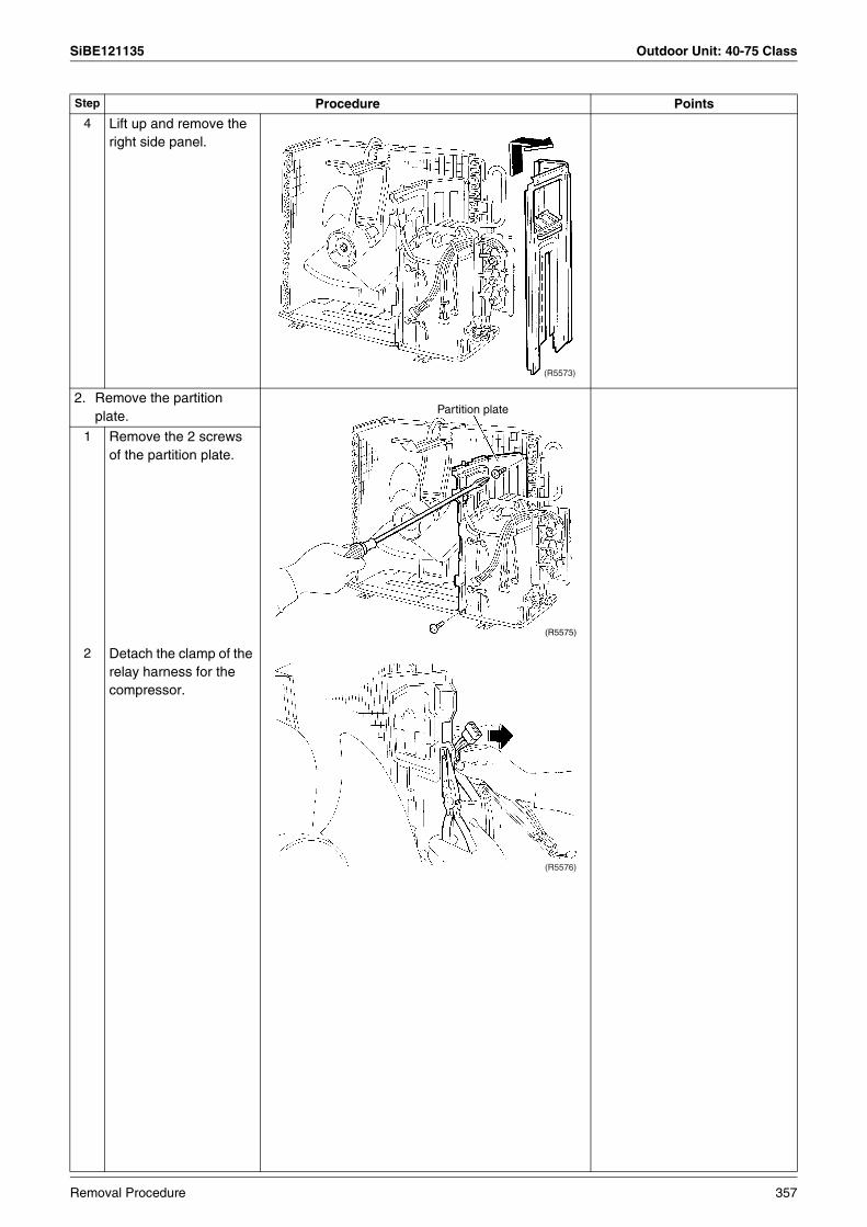
SiBE121135 Outdoor Unit: 40-75 Class
4 Lift up and remove the right side panel.
2. Remove the partition plate.
1 Remove the 2 screws of the partition plate.
2 Detach the clamp of the relay harness for the compressor.
Step Procedure Points
(R5573)
(R5575)
Partition plate
(R5576)
Removal Procedure 357

Outdoor Unit: 40-75 Class SiBE121135
3 Lift up and remove the partition plate.
When reassembling, make sure to fit the lower hook of the partition plate.
3. Remove the sound blankets.
Since the piping ports on the sound blanket are torn easily, remove the blanket carefully.The shape of the sound blankets differs depending on the model.
1 Remove the sound blanket (top upper).
2 Remove the sound blanket (top inner).
Step Procedure Points
(R5577)
(R5580)
Sound blanket (top upper) (R5579)
(R5582)Sound blanket (top inner)
358 Removal Procedure
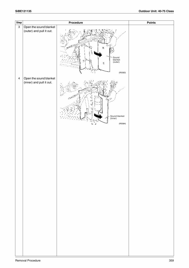
SiBE121135 Outdoor Unit: 40-75 Class
3 Open the sound blanket (outer) and pull it out.
4 Open the sound blanket (inner) and pull it out.
Step Procedure Points
Sound blanket (outer)
(R5583)
(R5584)
Sound blanket (inner)
Removal Procedure 359
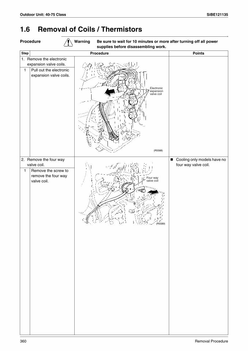
Outdoor Unit: 40-75 Class SiBE121135
1.6 Removal of Coils / Thermistors
Procedure Warning Be sure to wait for 10 minutes or more after turning off all power supplies before disassembling work.
Step Procedure Points
1. Remove the electronic expansion valve coils.
1 Pull out the electronic expansion valve coils.
2. Remove the four way valve coil.
Cooling only models have no four way valve coil.
1 Remove the screw to remove the four way valve coil.
Electronic expansion valve coil
(R5588)
(R5589)
Four way valve coil
360 Removal Procedure
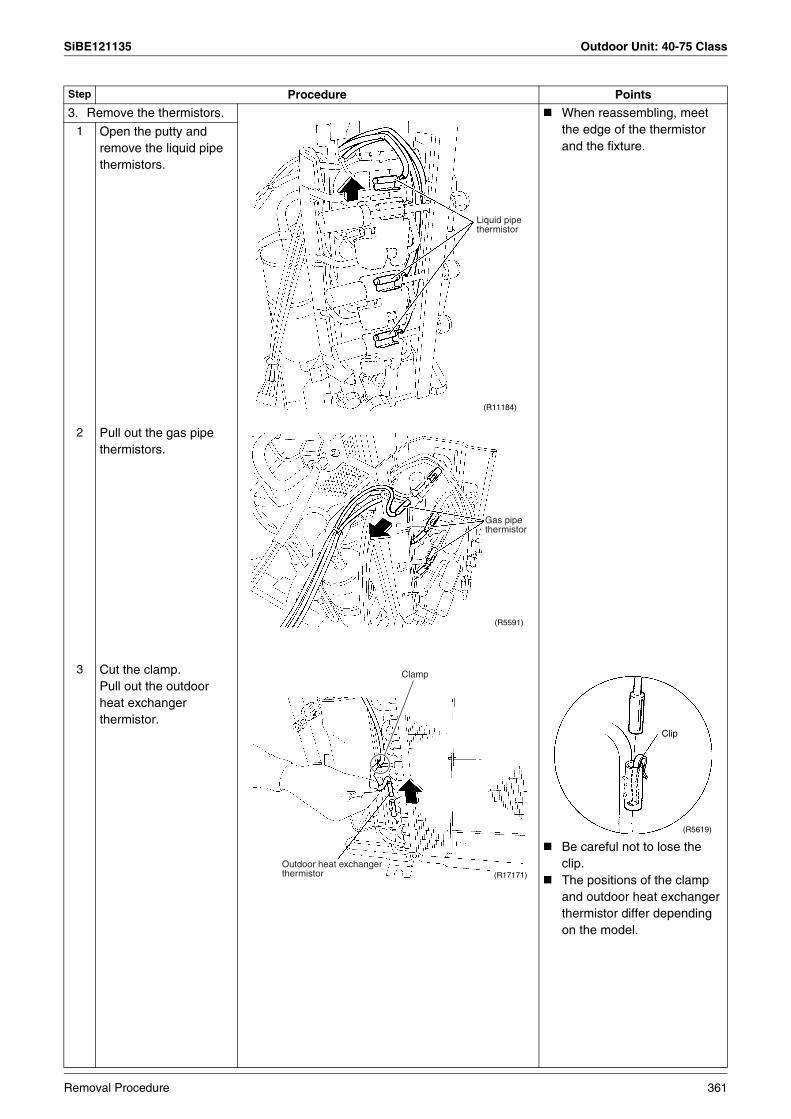
SiBE121135 Outdoor Unit: 40-75 Class
3. Remove the thermistors. When reassembling, meet the edge of the thermistor and the fixture.
1 Open the putty and remove the liquid pipe thermistors.
2 Pull out the gas pipe thermistors.
3 Cut the clamp.Pull out the outdoor heat exchanger thermistor.
Be careful not to lose the clip.The positions of the clamp and outdoor heat exchanger thermistor differ depending on the model.
Step Procedure Points
Liquid pipe thermistor
(R11184)
Gas pipe thermistor
(R5591)
Outdoor heat exchanger thermistor (R17171)
Clamp
Clip
(R5619)
Removal Procedure 361
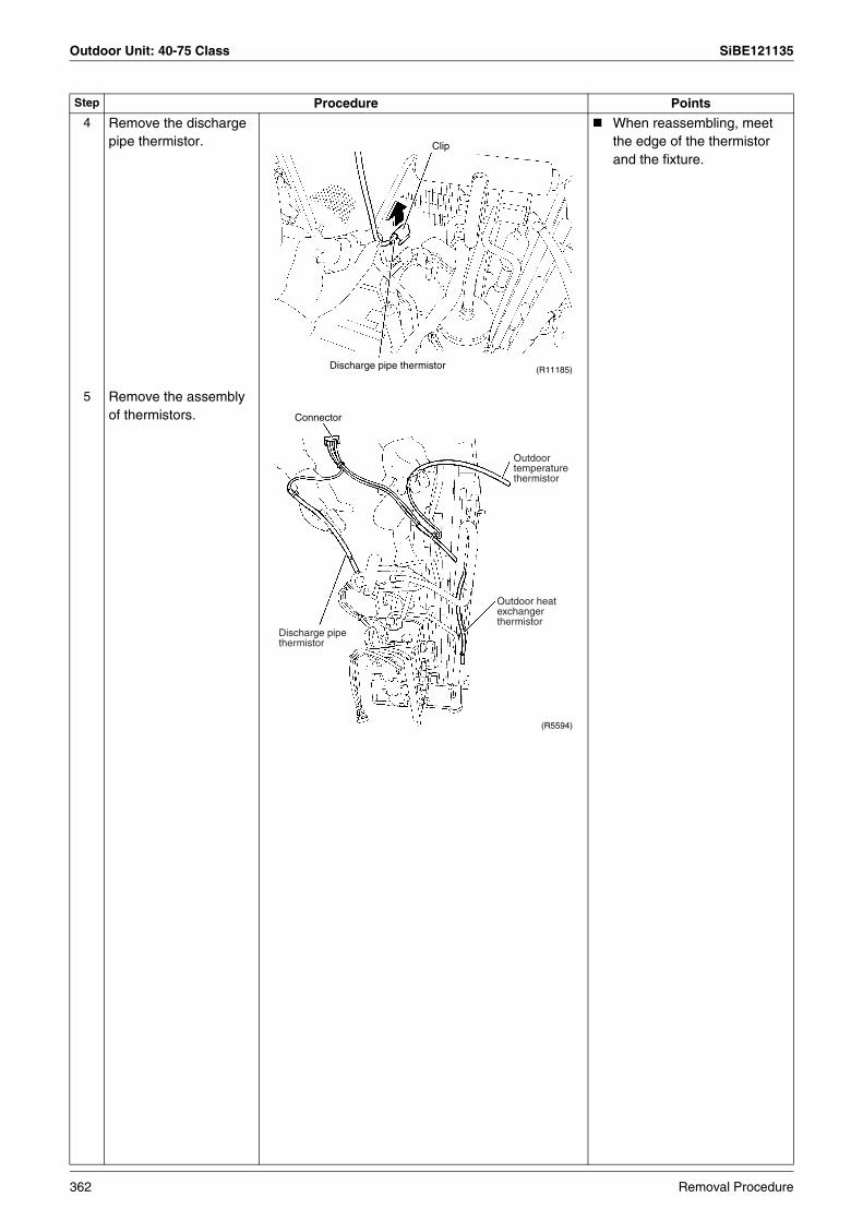
Outdoor Unit: 40-75 Class SiBE121135
4 Remove the discharge pipe thermistor.
When reassembling, meet the edge of the thermistor and the fixture.
5 Remove the assembly of thermistors.
Step Procedure Points
(R11185)Discharge pipe thermistor
Clip
Discharge pipe thermistor
Outdoor heat exchanger thermistor
Outdoor temperature thermistor
Connector
(R5594)
362 Removal Procedure

SiBE121135 Outdoor Unit: 40-75 Class
1.7 Removal of Distributor
Procedure Warning Be sure to wait for 10 minutes or more after turning off all power supplies before disassembling work.
Step Procedure Points
1 Remove the putty.Warning
Be careful not to get yourself burnt with the pipes and other parts that are heated by the gas brazing machine.
WarningIf the refrigerant gas leaks during work, ventilate the room. (If the refrigerant gas is exposed to flames, toxic gas may be generated.)
CautionFrom the viewpoint of global environment protection, do not discharge the refrigerant gas in the atmosphere. Make sure to collect all the refrigerant gas.
Cautions for restoration1. Restore the piping by non-
oxidation brazing. 2. It is required to prevent the
carbonization of the oil inside the four way valve and the deterioration of the gaskets affected by heat. (Keep below 120°C.) For the sake of this, wrap the four way valve with wet cloth and provide water so that the cloth does not dry.
In case of difficulty with gas brazing machine 1. Disconnect the brazed part
where is easy to disconnect and restore.
2. Cut pipes on the main unit with a tube cutter in order to make it easy to disconnect.
Before working, make sure that the refrigerant gas is empty in the circuit.Be sure to apply nitrogen replacement when heating up the brazed part.
2 Heat up and disconnect the brazed parts to remove the distributor.
Note:Do not use a metal saw for cutting pipes by all means because the sawdust comes into the circuit.
When withdrawing the pipes, be careful not to pinch them firmly with pliers. The pipes may get deformed.
Provide a protective sheet or a steel plate so that the brazing flame cannot influence peripheries.
(R5595)
Putty
Distributor
Brazed parts
(R17263)
Removal Procedure 363

Outdoor Unit: 40-75 Class SiBE121135
1.8 Removal of Four Way Valve
Procedure Warning Be sure to wait for 10 minutes or more after turning off all power supplies before disassembling work.
Step Procedure Points
Before working, make sure that the refrigerant gas is empty in the circuit.Be sure to apply nitrogen replacement when heating up the brazed part.
Cooling only models have no four way valve coil.
WarningBe careful not to get yourself burnt with the pipes and other parts that are heated by the gas brazing machine.
WarningIf the refrigerant gas leaks during work, ventilate the room. (If the refrigerant gas is exposed to flames, toxic gas may be generated.)
CautionFrom the viewpoint of global environment protection, do not discharge the refrigerant gas in the atmosphere. Make sure to collect all the refrigerant gas.
Cautions for restoration1. Restore the piping by non-
oxidation brazing. 2. It is required to prevent the
carbonization of the oil inside the four way valve and the deterioration of the gaskets affected by heat. (Keep below 120°C.) For the sake of this, wrap the four way valve with wet cloth and provide water so that the cloth does not dry.
In case of difficulty with gas brazing machine 1. Disconnect the brazed part
where is easy to disconnect and restore.
2. Cut pipes on the main unit with a tube cutter in order to make it easy to disconnect.
1 Remove the screw to remove the four way valve coil.
2 Heat up the 4 brazed part of the four way valve. First, disconnect the part (a).
3 Disconnect the part (b).
4 Disconnect the part (c) and (d) and remove the four way valve.
Note:Do not use a metal saw for cutting pipes by all means because the sawdust comes into the circuit.
When withdrawing the pipes, be careful not to pinch them firmly with pliers. The pipes may get deformed.
Provide a protective sheet or a steel plate so that the brazing flame cannot influence peripheries.
(R5589)
Four way valve coil
(R14067)
(a)
(R14068)
(b)
(R14069)
(c)
(d)
364 Removal Procedure

SiBE121135 Outdoor Unit: 40-75 Class
1.9 Removal of Compressor
Procedure Warning Be sure to wait for 10 minutes or more after turning off all power supplies before disassembling work.
Step Procedure Points
1 Remove the terminal cover.
2 Disconnect the compressor lead wires.
3 Detach the overload protector.
(R12914)
Terminal cover
V(yellow)
U(red)
W(blue) (R5602)
(R12916)
Overload protector
(R5604)
Removal Procedure 365

Outdoor Unit: 40-75 Class SiBE121135
WarningBe careful not to get yourself burnt with the pipes and other parts that are heated by the gas brazing machine.
WarningIf the refrigerant gas leaks during work, ventilate the room. (If the refrigerant gas is exposed to flames, toxic gas may be generated.)
WarningSince it may happen that the refrigerant oil in the compressor catches fire, prepare wet cloth so as to extinguish fire immediately.
CautionFrom the viewpoint of global environment protection, do not discharge the refrigerant gas in the atmosphere. Make sure to collect all the refrigerant gas.
Cautions for restoration1. Restore the piping by non-
oxidation brazing. 2. It is required to prevent the
carbonization of the oil inside the four way valve and the deterioration of the gaskets affected by heat. (Keep below 120°C.) For the sake of this, wrap the four way valve with wet cloth and provide water so that the cloth does not dry.
In case of difficulty with gas brazing machine 1. Disconnect the brazed part
where is easy to disconnect and restore.
2. Cut pipes on the main unit with a tube cutter in order to make it easy to disconnect.
4 Remove the putty.5 Remove the 2 nuts.
Before working, make sure that the refrigerant gas is empty in the circuit.Be sure to apply nitrogen replacement when heating up the brazed part.
6 Heat up the brazed part of the discharge side and disconnect the part (a).
7 Heat up the brazed part of the suction side and disconnect the part (b).
8 Remove the compressor.
Note:Do not use a metal saw for cutting pipes by all means because the sawdust comes into the circuit.
When withdrawing the pipes, be careful not to pinch them firmly with pliers. The pipes may get deformed.
Provide a protective sheet or a steel plate so that the brazing flame cannot influence peripheries.
Be careful so as not to burn the compressor terminals, the name plate, the heat exchanger fin.
Step Procedure Points
(R5605)
Nut (R17172)
Putty
(R14070)
(a)
(b)
Compressor (R12917)
366 Removal Procedure
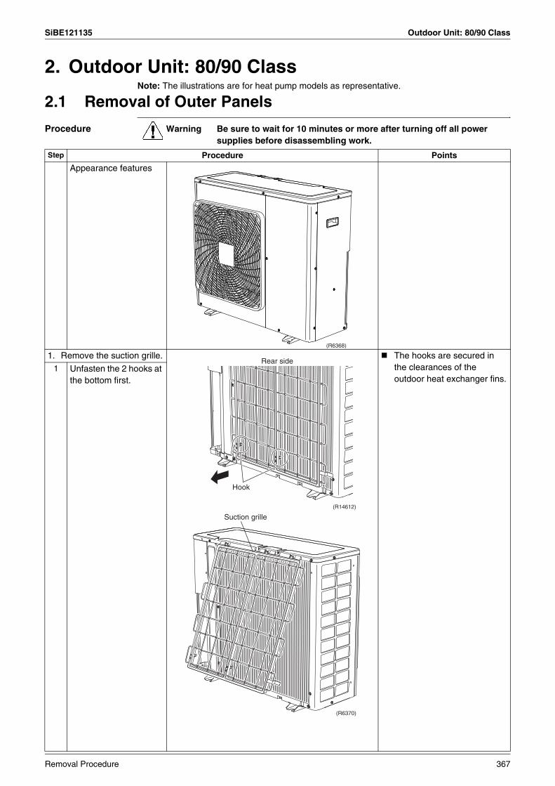
SiBE121135 Outdoor Unit: 80/90 Class
2. Outdoor Unit: 80/90 ClassNote: The illustrations are for heat pump models as representative.
2.1 Removal of Outer Panels
Procedure Warning Be sure to wait for 10 minutes or more after turning off all power supplies before disassembling work.
Step Procedure Points
Appearance features
1. Remove the suction grille. The hooks are secured in the clearances of the outdoor heat exchanger fins.
1 Unfasten the 2 hooks at the bottom first.
(R6368)
Hook
Rear side
(R14612)
Suction grille
(R6370)
Removal Procedure 367
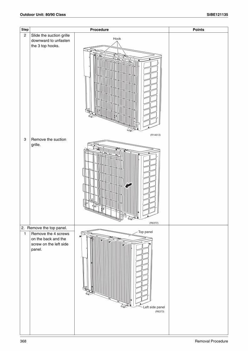
Outdoor Unit: 80/90 Class SiBE121135
2 Slide the suction grille downward to unfasten the 3 top hooks.
3 Remove the suction grille.
2. Remove the top panel.1 Remove the 4 screws
on the back and the screw on the left side panel.
Step Procedure Points
Hook
(R14613)
(R6372)
Top panel
Left side panel(R6373)
368 Removal Procedure
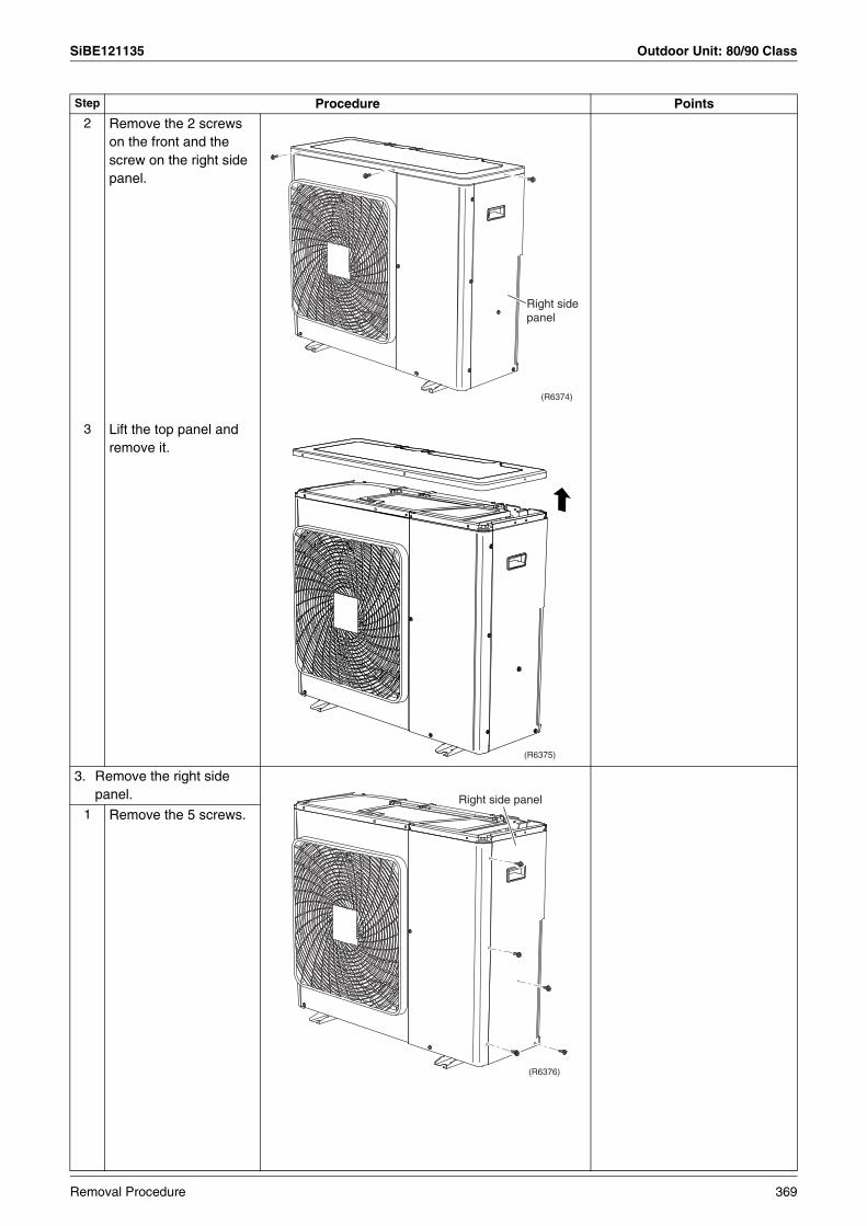
SiBE121135 Outdoor Unit: 80/90 Class
2 Remove the 2 screws on the front and the screw on the right side panel.
3 Lift the top panel and remove it.
3. Remove the right side panel.
1 Remove the 5 screws.
Step Procedure Points
(R6374)
Right side panel
(R6375)
(R6376)
Right side panel
Removal Procedure 369
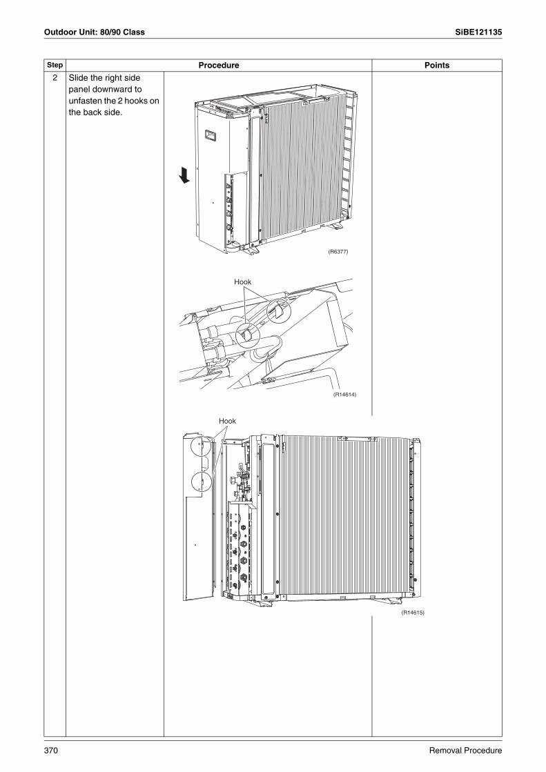
Outdoor Unit: 80/90 Class SiBE121135
2 Slide the right side panel downward to unfasten the 2 hooks on the back side.
Step Procedure Points
(R6377)
Hook
(R14614)
Hook
(R14615)
370 Removal Procedure

SiBE121135 Outdoor Unit: 80/90 Class
3 Remove the right side panel.
4. Remove the front panel (2). This screw is M5 × 16
1 Remove the 2 screws.
Step Procedure Points
(R10441)
(R10629)
Front Panel (2)
Front Panel (1)
Removal Procedure 371
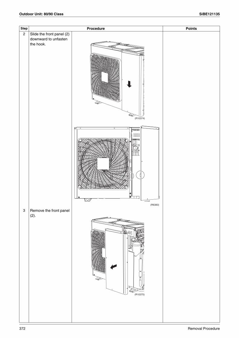
Outdoor Unit: 80/90 Class SiBE121135
2 Slide the front panel (2) downward to unfasten the hook.
3 Remove the front panel (2).
Step Procedure Points
(R10374)
(R6383)
(R10375)
372 Removal Procedure
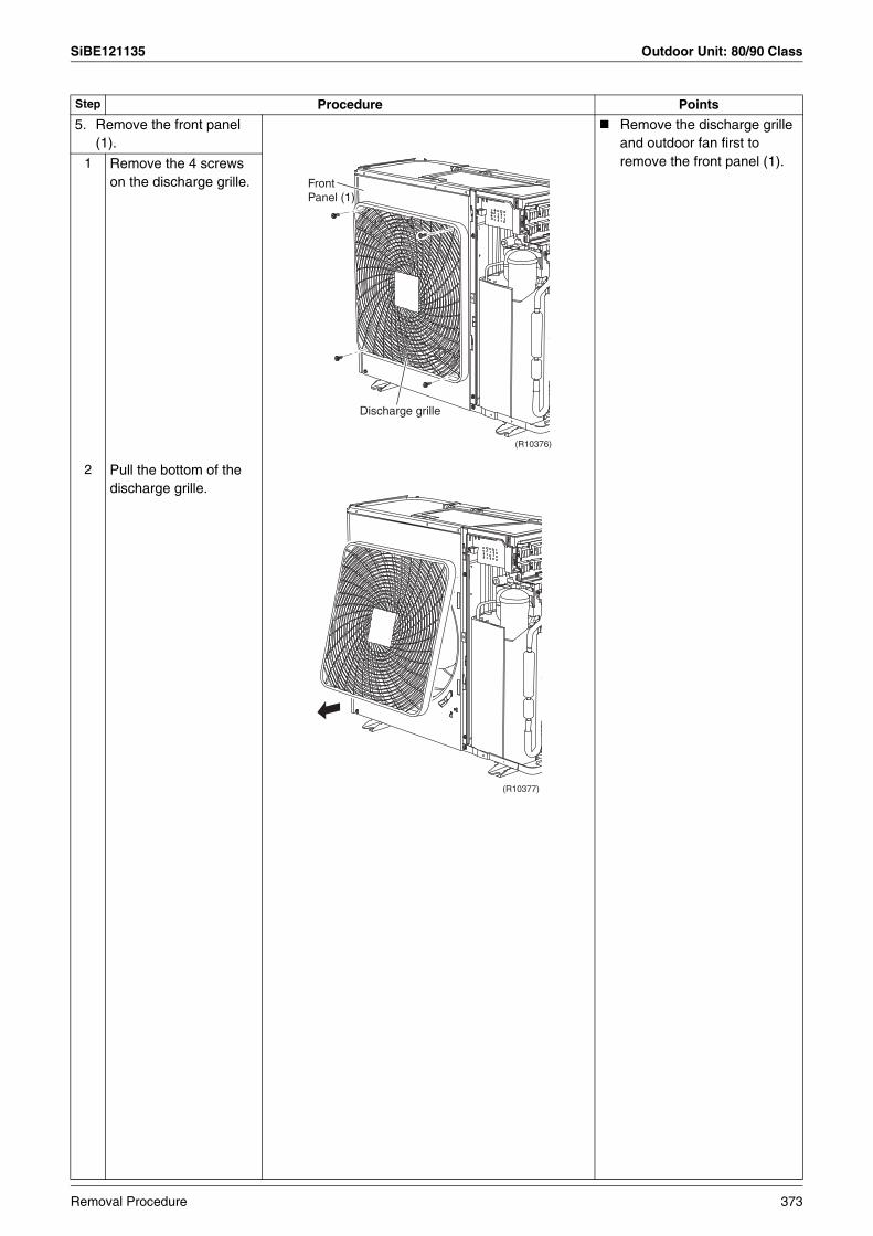
SiBE121135 Outdoor Unit: 80/90 Class
5. Remove the front panel (1).
Remove the discharge grille and outdoor fan first to remove the front panel (1).1 Remove the 4 screws
on the discharge grille.
2 Pull the bottom of the discharge grille.
Step Procedure Points
(R10376)
Front Panel (1)
Discharge grille
(R10377)
Removal Procedure 373
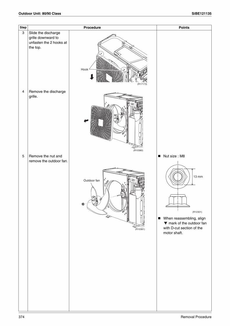
Outdoor Unit: 80/90 Class SiBE121135
3 Slide the discharge grille downward to unfasten the 2 hooks at the top.
4 Remove the discharge grille.
5 Remove the nut and remove the outdoor fan.
Nut size : M8
When reassembling, align mark of the outdoor fan
with D-cut section of the motor shaft.
Step Procedure Points
(R17173)
Hook
(R10380)
(R10381)
Outdoor fan13 mm
(R12301)
374 Removal Procedure
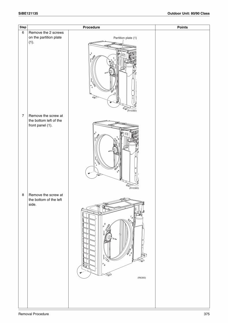
SiBE121135 Outdoor Unit: 80/90 Class
6 Remove the 2 screws on the partition plate (1).
7 Remove the screw at the bottom left of the front panel (1).
8 Remove the screw at the bottom of the left side.
Step Procedure Points
(R10382)
Partition plate (1)
(R10383)
(R6393)
Removal Procedure 375

Outdoor Unit: 80/90 Class SiBE121135
9 Remove the screw at the bottom of the back side.
10 The front panel (1) has a hook. Lift the front panel (1).
11 Remove the front panel (1).
Be sure to detach the front panel (1) carefully so as not to deform it.
Step Procedure Points
(R6394)
(R17174)
Hook
(R10385)
(R6396)
376 Removal Procedure
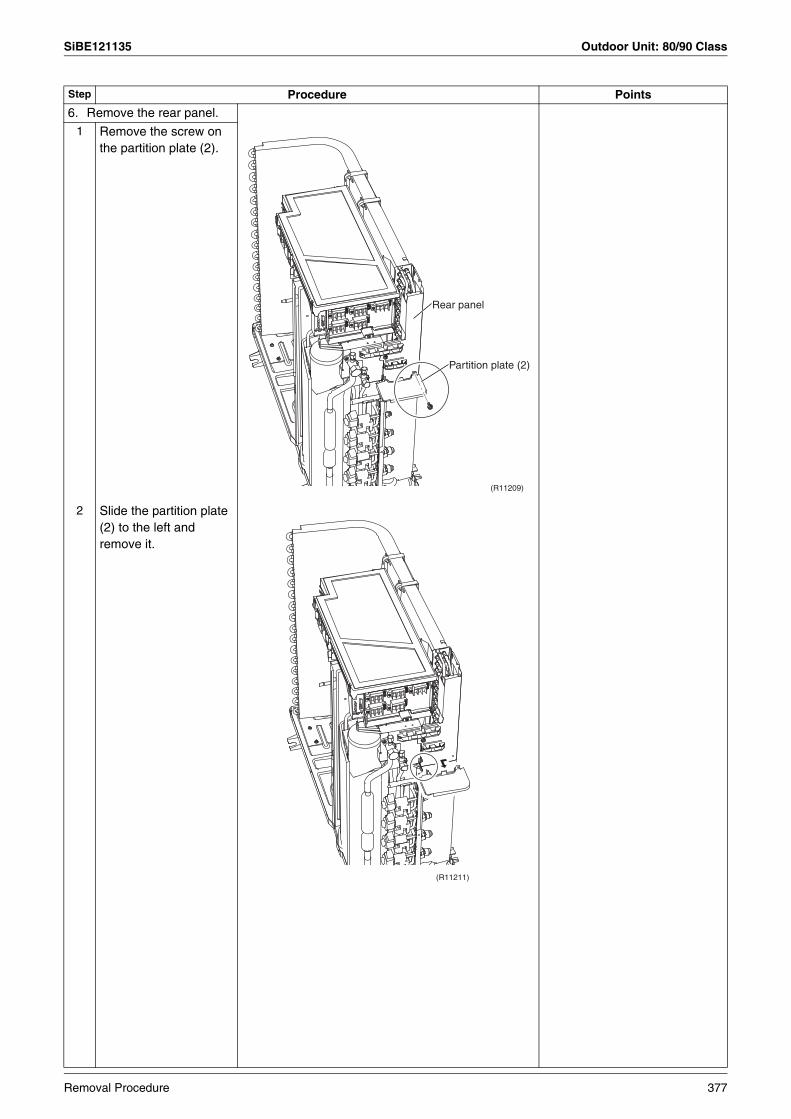
SiBE121135 Outdoor Unit: 80/90 Class
6. Remove the rear panel.1 Remove the screw on
the partition plate (2).
2 Slide the partition plate (2) to the left and remove it.
Step Procedure Points
(R11209)
Rear panel
Partition plate (2)
(R11211)
Removal Procedure 377
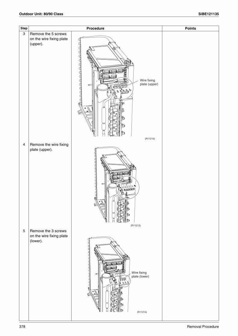
Outdoor Unit: 80/90 Class SiBE121135
3 Remove the 5 screws on the wire fixing plate (upper).
4 Remove the wire fixing plate (upper).
5 Remove the 3 screws on the wire fixing plate (lower).
Step Procedure Points
(R11210)
Wire fixing plate (upper)
(R11213)
(R11214)
Wire fixing plate (lower)
378 Removal Procedure

SiBE121135 Outdoor Unit: 80/90 Class
6 Remove the wire fixing plate (lower).
7 Pull out the holder of the outdoor temperature thermistor.
The holder is secured in the clearances of the outdoor heat exchanger fins.
8 Release the thermistor wire from the groove
Step Procedure Points
(R11215)
(R10388)Outdoor temperature thermistor
Groove
(R10389)
Removal Procedure 379

Outdoor Unit: 80/90 Class SiBE121135
9 Remove the 3 screws on the rear panel.
10 Remove the screw on the bottom frame.
11 Remove the screw on the stop valve mounting plate.
Step Procedure Points
(R10390)
(R10391)
(R10392)
Stop valve mounting plate
380 Removal Procedure
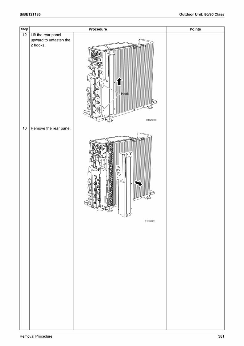
SiBE121135 Outdoor Unit: 80/90 Class
12 Lift the rear panel upward to unfasten the 2 hooks.
13 Remove the rear panel.
Step Procedure Points
HookHook
(R12918)
(R10394)
Removal Procedure 381
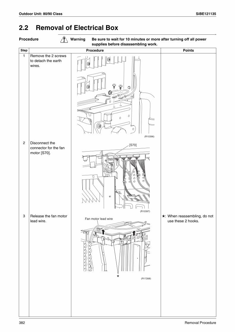
Outdoor Unit: 80/90 Class SiBE121135
2.2 Removal of Electrical Box
Procedure Warning Be sure to wait for 10 minutes or more after turning off all power supplies before disassembling work.
Step Procedure Points
1 Remove the 2 screws to detach the earth wires.
2 Disconnect the connector for the fan motor [S70].
3 Release the fan motor lead wire.
: When reassembling, do not use these 2 hooks.
(R10396)
[S70]
(R10397)
(R17268)
Fan motor lead wire
382 Removal Procedure

SiBE121135 Outdoor Unit: 80/90 Class
4 Disconnect the connector for the four way valve coil [S80].
Pull out the clamp.The cooling only model has no harness for [S80].
5 Disconnect the connectors for the electronic expansion valve coil.[S20] (white): room A[S21] (red): room B[S22] (blue): room C[S23] (yellow): room D
Pull out the clamp.5-room models also has [S24] (green) for room E.When reassembling, insert each clamp into the small hole.
6 Disconnect the connector for the liquid pipe thermistor [S93].
Pull out the clamp.
Step Procedure Points
[S80]
Clamp
(R11187)
A B C D
Clamp
(R11188)
For the electronic expansion valve coil
[S93]
(R17266)
Clamp
[S93]
(R10400)
Removal Procedure 383

Outdoor Unit: 80/90 Class SiBE121135
7 Disconnect the connector for the gas pipe thermistor [S92].
Pull out the clamp.When reassembling, insert the clamp into the small hole.
8 Disconnect the connector for the thermistors [S90].
Pull out the clamp.
When reassembling, insert the clamp of the thermistor ASSY into the hole as below.
9 The wire harness of the thermistor is hooked under the electrical box. Unhook it and pull out the clamp.
Step Procedure Points
[S92]
(R10537)
Clamp
[S92]
(R17267)
[S90]
Clamp
(R10538)
Thermistor ASSY(R17142)
Clamp
Hook
(R6420)
Fixing position for the thermistor harness
When reassembling, insert the clamp into the small hole.
384 Removal Procedure
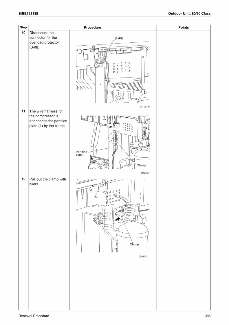
SiBE121135 Outdoor Unit: 80/90 Class
10 Disconnect the connector for the overload protector [S40].
11 The wire harness for the compressor is attached to the partition plate (1) by the clamp.
12 Pull out the clamp with pliers.
Step Procedure Points
[S40]
(R10539)
Clamp
(R12904)
Partition plate
Clamp
(R6423)
Removal Procedure 385
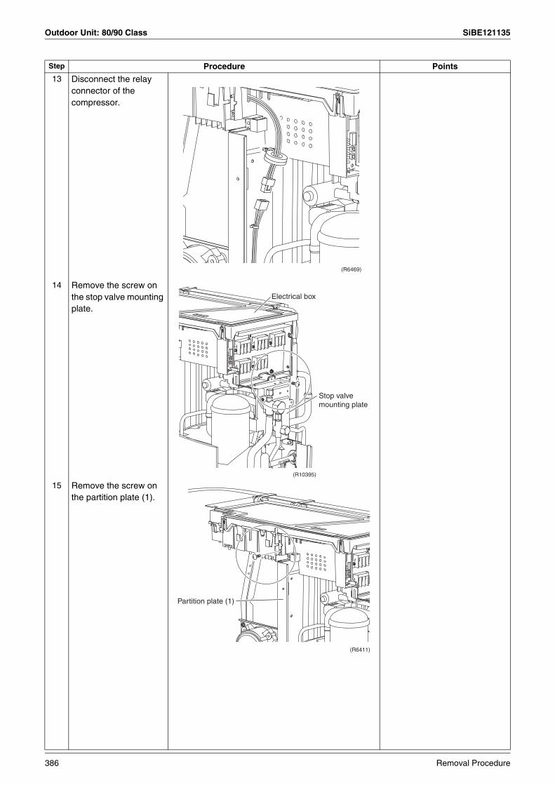
Outdoor Unit: 80/90 Class SiBE121135
13 Disconnect the relay connector of the compressor.
14 Remove the screw on the stop valve mounting plate.
15 Remove the screw on the partition plate (1).
Step Procedure Points
(R6469)
(R10395)
Electrical box
Stop valve mounting plate
(R6411)
Partition plate (1)
386 Removal Procedure
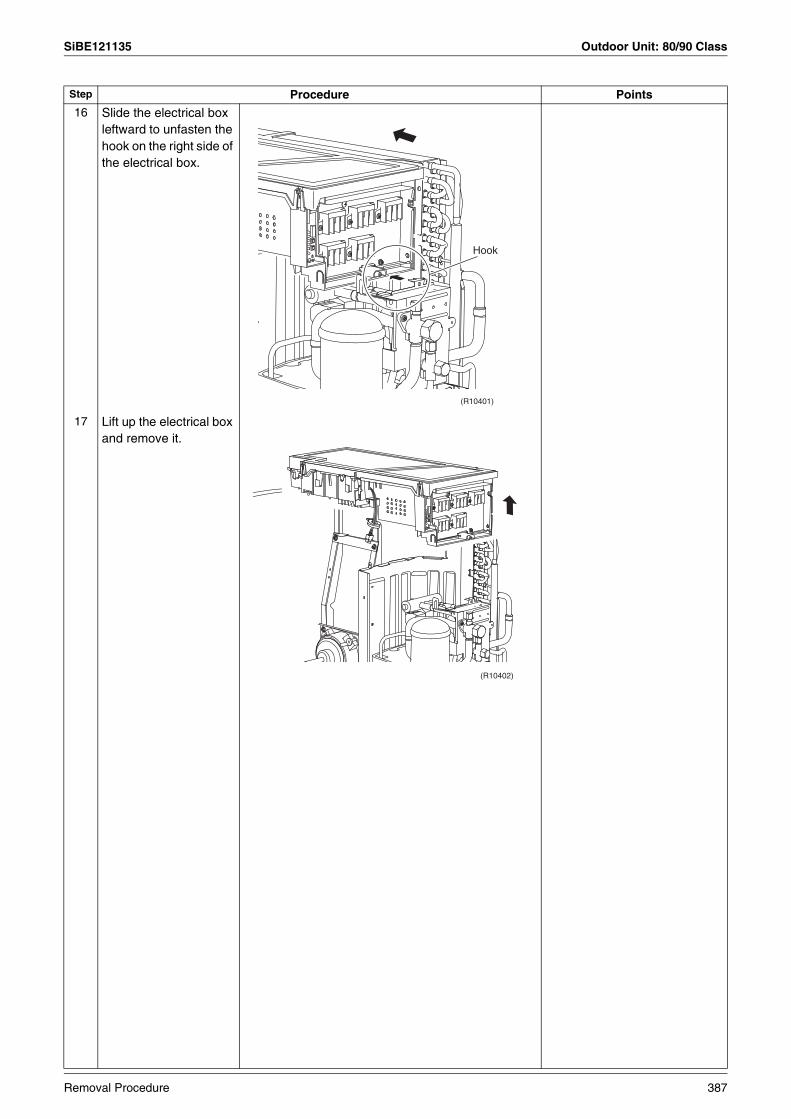
SiBE121135 Outdoor Unit: 80/90 Class
16 Slide the electrical box leftward to unfasten the hook on the right side of the electrical box.
17 Lift up the electrical box and remove it.
Step Procedure Points
(R10401)
Hook
(R10402)
Removal Procedure 387

Outdoor Unit: 80/90 Class SiBE121135
2.3 Removal of PCBs
Procedure Warning Be sure to wait for 10 minutes or more after turning off all power supplies before disassembling work.
Step Procedure Points
1. Remove the main PCB.1 Remove the cover of
the electrical box.Release the 4 hooks. The hooks are marked with .
2 Remove the 3 screws.
3 Unfasten the 4 hooks.
4 Lift up the main PCB.
Hook
Hook
(R14617)(R6427)
(R10404)
Main PCB
(R10405)
(R10406)
388 Removal Procedure
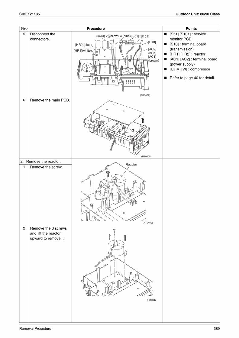
SiBE121135 Outdoor Unit: 80/90 Class
5 Disconnect the connectors.
[S51] [S101] : service monitor PCB[S10] : terminal board (transmission)[HR1] [HR2] : reactor[AC1] [AC2] : terminal board (power supply)[U] [V] [W] : compressor
Refer to page 40 for detail.
6 Remove the main PCB.
2. Remove the reactor.1 Remove the screw.
2 Remove the 3 screws and lift the reactor upward to remove it.
Step Procedure Points
(R10407)
[S10]
[S101][S51]W(blue)V(yellow)U(red)
[HR2](blue)
[HR1](white) [AC2] (blue)[AC1] (brown)
(R10408)
(R10409)
Reactor
(R6434)
Removal Procedure 389

Outdoor Unit: 80/90 Class SiBE121135
3. Remove the service monitor PCB.
1 Disconnect the connectors [S52] [S102] from the service monitor PCB.
2 Slightly lift the top hook to detach.
3 Unfasten the bottom hook and remove the service monitor PCB.
Refer to page 40 for detail.
Step Procedure Points
(R10410)
[S102]
[S52]
Service monitor PCB
(R6436)
(R6437)
390 Removal Procedure
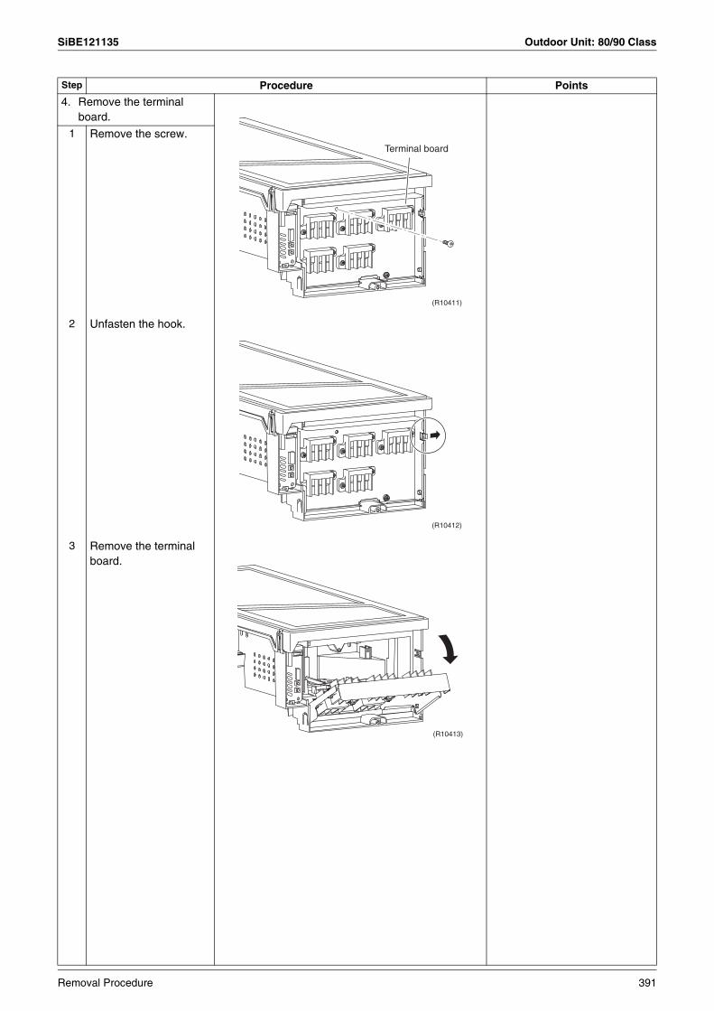
SiBE121135 Outdoor Unit: 80/90 Class
4. Remove the terminal board.
1 Remove the screw.
2 Unfasten the hook.
3 Remove the terminal board.
Step Procedure Points
(R10411)
Terminal board
(R10412)
(R10413)
Removal Procedure 391

Outdoor Unit: 80/90 Class SiBE121135
2.4 Removal of Fan Motor
Procedure Warning Be sure to wait for 10 minutes or more after turning off all power supplies before disassembling work.
Step Procedure Points
1
2
Remove the 2 lower screws of the fan motor.
Remove the 2 upper screws.
Be sure to remove the lower screws first. If the upper screws are removed first, the fan motor may tilt or fall because the center of its gravity is toward the front. It may cause injuries.
3 Remove the fan motor. When reassembling, be sure to place the wire harness lower.
(R10414)
(R6442)
2
1
(R10542)
Fan motor
(R6444)
Harness
392 Removal Procedure
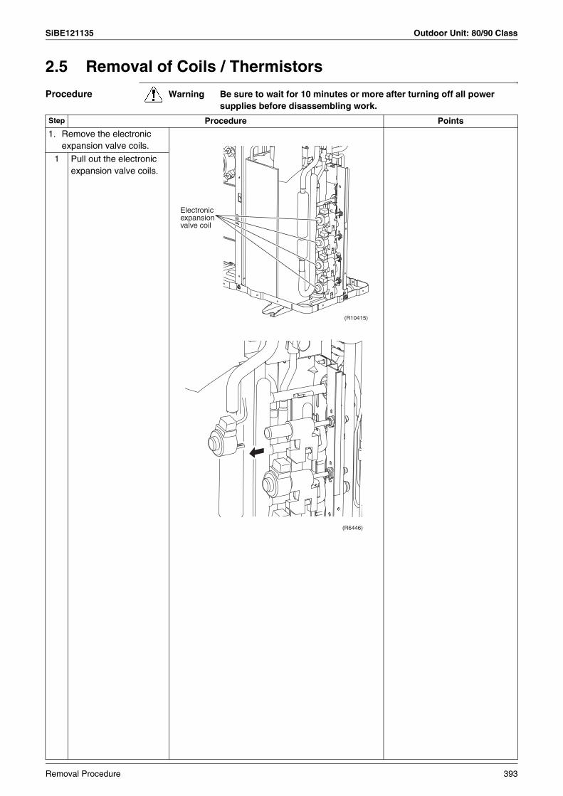
SiBE121135 Outdoor Unit: 80/90 Class
2.5 Removal of Coils / Thermistors
Procedure Warning Be sure to wait for 10 minutes or more after turning off all power supplies before disassembling work.
Step Procedure Points
1. Remove the electronic expansion valve coils.
1 Pull out the electronic expansion valve coils.
Electronic expansion valve coil
(R10415)
(R6446)
Removal Procedure 393
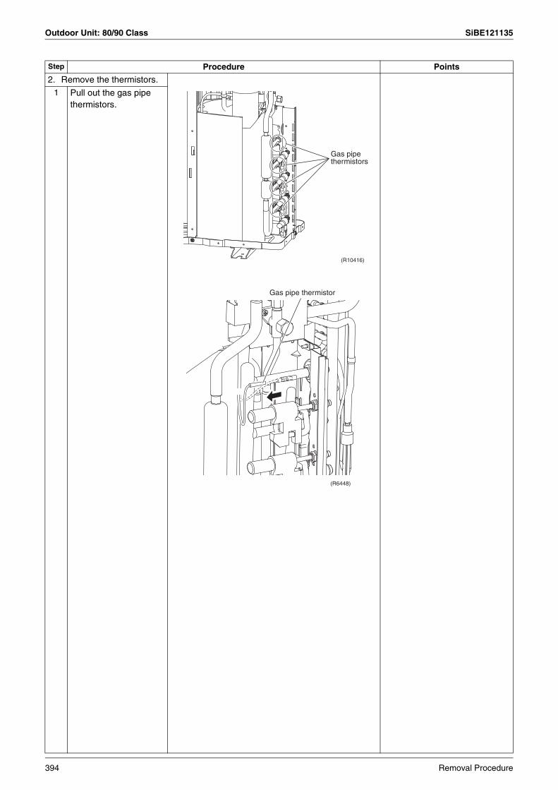
Outdoor Unit: 80/90 Class SiBE121135
2. Remove the thermistors.1 Pull out the gas pipe
thermistors.
Step Procedure Points
Gas pipe thermistors
(R10416)
(R6448)
Gas pipe thermistor
394 Removal Procedure
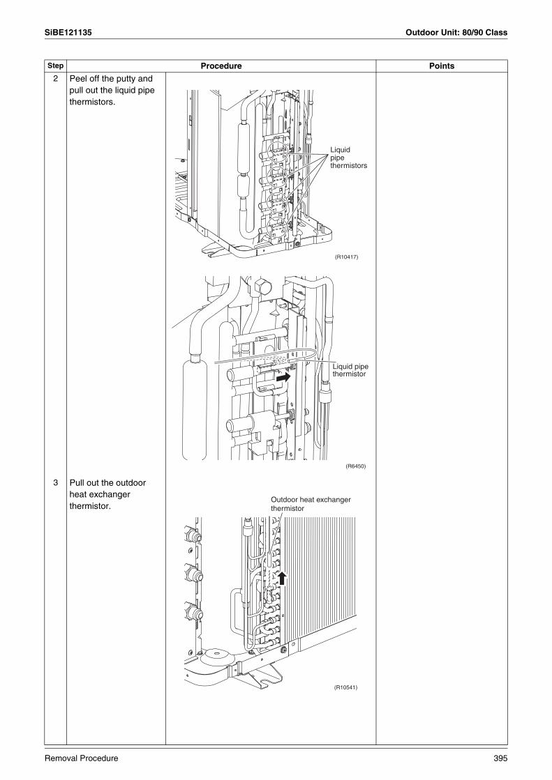
SiBE121135 Outdoor Unit: 80/90 Class
2 Peel off the putty and pull out the liquid pipe thermistors.
3 Pull out the outdoor heat exchanger thermistor.
Step Procedure Points
Liquid pipe thermistors
(R10417)
(R6450)
Liquid pipe thermistor
(R10541)
Outdoor heat exchanger thermistor
Removal Procedure 395

Outdoor Unit: 80/90 Class SiBE121135
4 Remove the clip from the outdoor heat exchanger thermistor.
Be careful not to lose the clip.
5 Slightly open the sound blanket (outer).
6 Remove the sound blanket (top upper).
Step Procedure Points
(R6452)
Clip
(R10418)Sound blanket (outer)
(R10419)
Sound blanket (top upper)
396 Removal Procedure
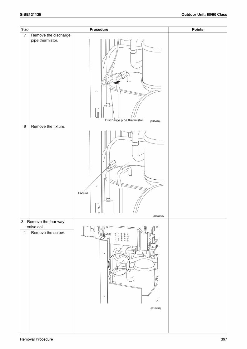
SiBE121135 Outdoor Unit: 80/90 Class
7 Remove the discharge pipe thermistor.
8 Remove the fixture.
3. Remove the four way valve coil.
1 Remove the screw.
Step Procedure Points
(R10420)Discharge pipe thermistor
(R10430)
Fixture
(R10431)
Removal Procedure 397
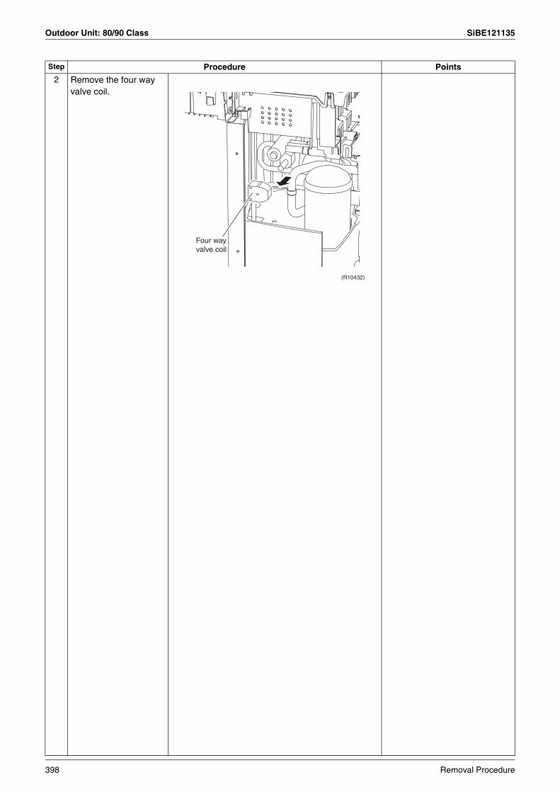
Outdoor Unit: 80/90 Class SiBE121135
2 Remove the four way valve coil.
Step Procedure Points
(R10432)
Four way valve coil
398 Removal Procedure

SiBE121135 Outdoor Unit: 80/90 Class
2.6 Removal of Sound Blankets
Procedure Warning Be sure to wait for 10 minutes or more after turning off all power supplies before disassembling work.
Step Procedure Points
1 Open the sound blanket (outer).
2 Remove the sound blanket (top upper).
The sound blanket is fragile. Carefully pass the blanket through the discharge pipe.
3 Remove the screw from the partition plate and push the plate to the left slightly for easy work.
(R10433)
Sound blanket (outer)
(R10434)
Sound blanket (top upper)
(R10435)
Partition plate
Removal Procedure 399

Outdoor Unit: 80/90 Class SiBE121135
4 Remove the sound blanket (outer).
The sound blanket is fragile.
5 Remove the sound blanket (top inner).
The sound blanket is fragile. Carefully pass the blanket through the discharge pipe.
6 Open the sound blanket (inner) and pass it through the part of the mufflers.
The sound blanket is fragile. Be careful of the notches of the compressor mount (3 locations).
Step Procedure Points
(R10436)Sound blanket (outer)
(R10437)Sound blanket (top inner)
(R10438)
Mufflers
Sound blanket (inner)
400 Removal Procedure
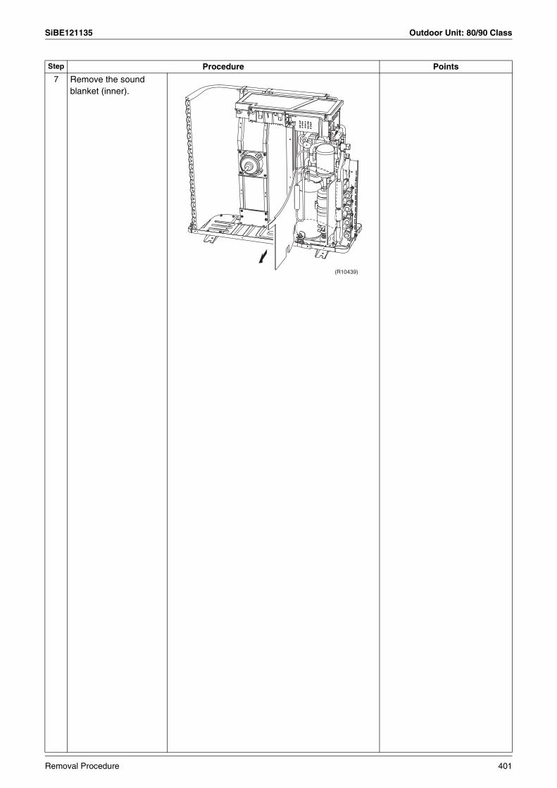
SiBE121135 Outdoor Unit: 80/90 Class
7 Remove the sound blanket (inner).
Step Procedure Points
(R10439)
Removal Procedure 401
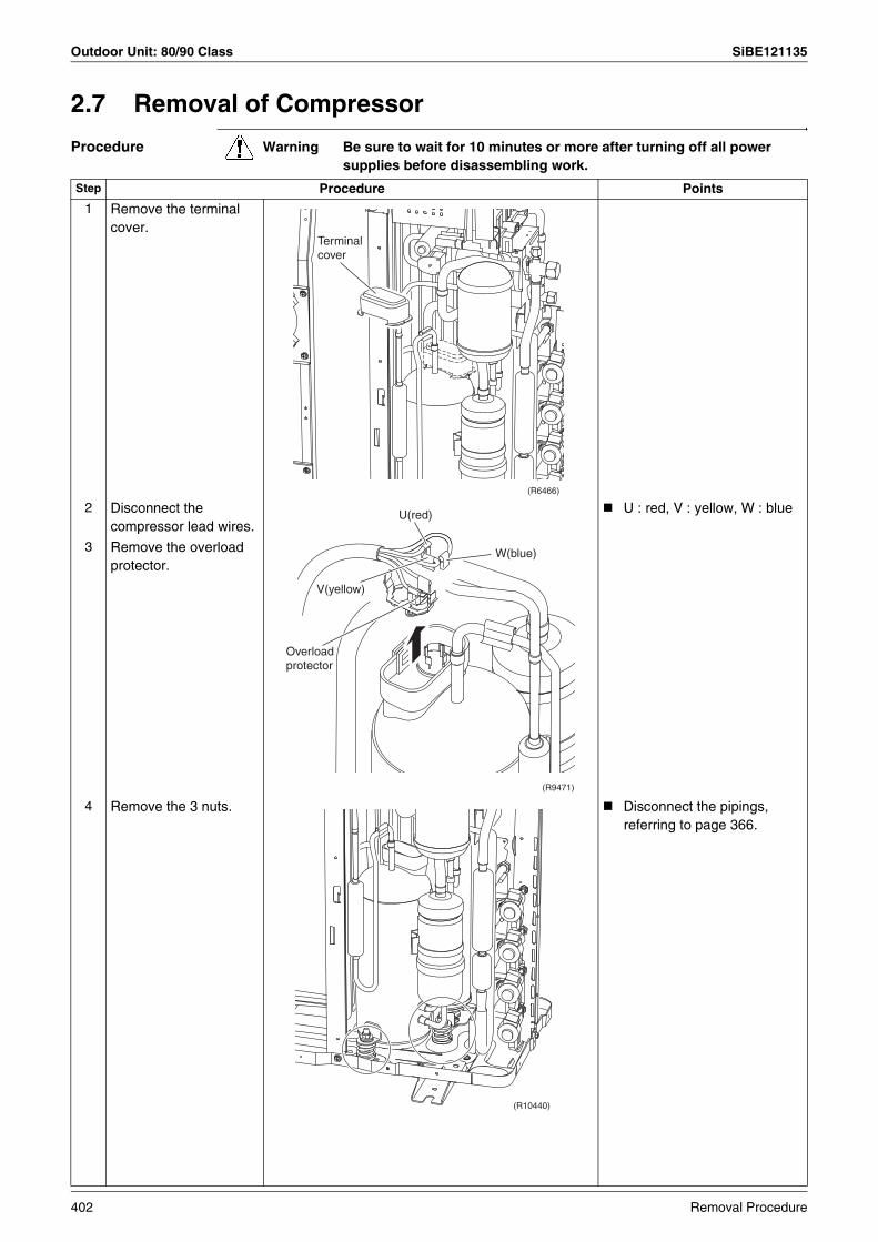
Outdoor Unit: 80/90 Class SiBE121135
2.7 Removal of Compressor
Procedure Warning Be sure to wait for 10 minutes or more after turning off all power supplies before disassembling work.
Step Procedure Points
1 Remove the terminal cover.
2 Disconnect the compressor lead wires.
U : red, V : yellow, W : blue
3 Remove the overload protector.
4 Remove the 3 nuts. Disconnect the pipings, referring to page 366.
(R6466)
Terminal cover
(R9471)
W(blue)
U(red)
Overload protector
V(yellow)
(R10440)
402 Removal Procedure

SiBE121135
Trial Operation and Field Settings 403
Part 8Trial Operation and
Field Settings
1. Pump Down Operation........................................................................4042. Forced Operation ................................................................................4053. Wiring Error Check Function ...............................................................4064. Trial Operation ....................................................................................408
4.1 RA Indoor Unit - FTXG, FTXS, CTXS, FVXG, FVXS, FLXS, FDXS Series.........................................................................................408
4.2 SA Indoor Unit - FCQG, FFQ, FHQ, FDBQ, FBQ Series .....................410
5. Field Settings ......................................................................................4125.1 Outdoor Unit .........................................................................................4125.2 RA Indoor Unit - FTXG, FTXS, CTXS, FVXG, FVXS, FLXS,
FDXS Series.........................................................................................4155.3 SA Indoor Unit - FCQG, FFQ, FHQ, FDBQ, FBQ Series .....................419
6. Application of Silicon Grease to a Power Transistor and a Diode Bridge .............................................................................423
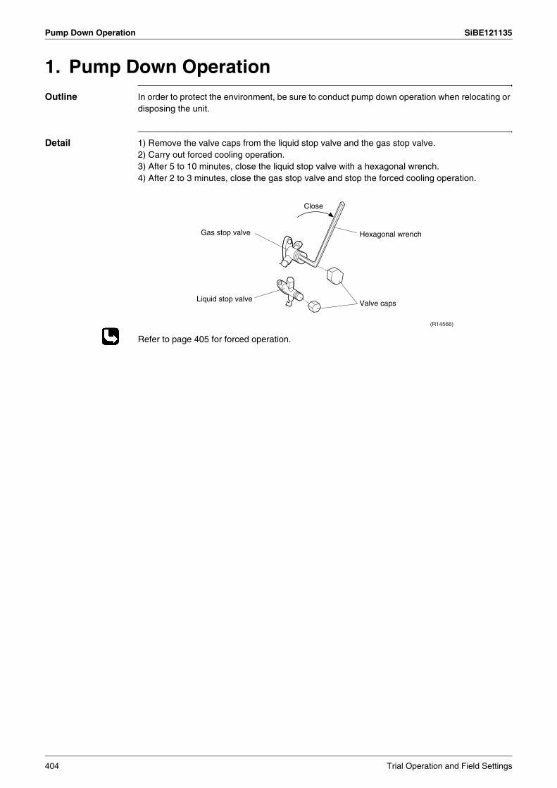
Pump Down Operation SiBE121135
1. Pump Down OperationOutline In order to protect the environment, be sure to conduct pump down operation when relocating or
disposing the unit.
Detail 1) Remove the valve caps from the liquid stop valve and the gas stop valve.2) Carry out forced cooling operation.3) After 5 to 10 minutes, close the liquid stop valve with a hexagonal wrench.4) After 2 to 3 minutes, close the gas stop valve and stop the forced cooling operation.
Refer to page 405 for forced operation.
Gas stop valve
Close
Liquid stop valveValve caps
Hexagonal wrench
(R14566)
404 Trial Operation and Field Settings
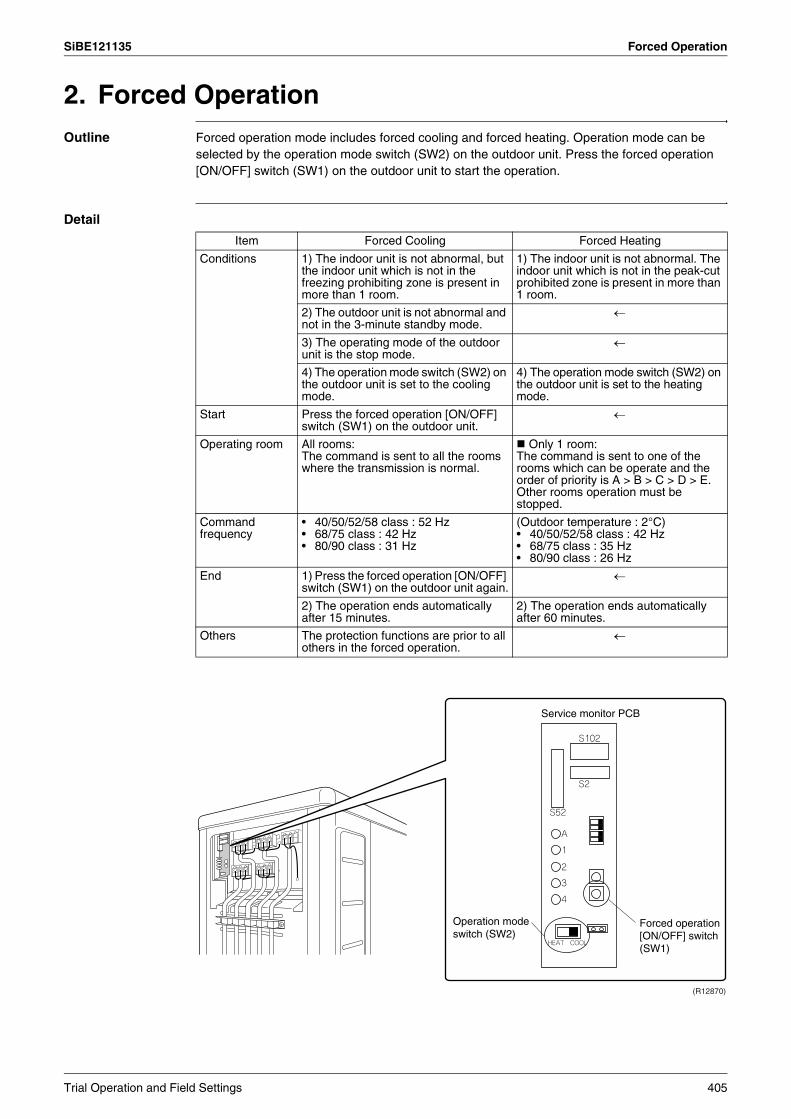
SiBE121135 Forced Operation
2. Forced OperationOutline Forced operation mode includes forced cooling and forced heating. Operation mode can be
selected by the operation mode switch (SW2) on the outdoor unit. Press the forced operation [ON/OFF] switch (SW1) on the outdoor unit to start the operation.
Detail
Item Forced Cooling Forced Heating
Conditions 1) The indoor unit is not abnormal, but the indoor unit which is not in the freezing prohibiting zone is present in more than 1 room.
1) The indoor unit is not abnormal. The indoor unit which is not in the peak-cut prohibited zone is present in more than 1 room.
2) The outdoor unit is not abnormal and not in the 3-minute standby mode.
←
3) The operating mode of the outdoor unit is the stop mode.
←
4) The operation mode switch (SW2) on the outdoor unit is set to the cooling mode.
4) The operation mode switch (SW2) on the outdoor unit is set to the heating mode.
Start Press the forced operation [ON/OFF] switch (SW1) on the outdoor unit.
←
Operating room All rooms:The command is sent to all the rooms where the transmission is normal.
Only 1 room:The command is sent to one of the rooms which can be operate and the order of priority is A > B > C > D > E. Other rooms operation must be stopped.
Command frequency
• 40/50/52/58 class : 52 Hz• 68/75 class : 42 Hz• 80/90 class : 31 Hz
(Outdoor temperature : 2°C)• 40/50/52/58 class : 42 Hz• 68/75 class : 35 Hz• 80/90 class : 26 Hz
End 1) Press the forced operation [ON/OFF] switch (SW1) on the outdoor unit again.
←
2) The operation ends automatically after 15 minutes.
2) The operation ends automatically after 60 minutes.
Others The protection functions are prior to all others in the forced operation.
←
Service monitor PCB
Operation mode switch (SW2)
Forced operation [ON/OFF] switch (SW1)
(R12870)
Trial Operation and Field Settings 405
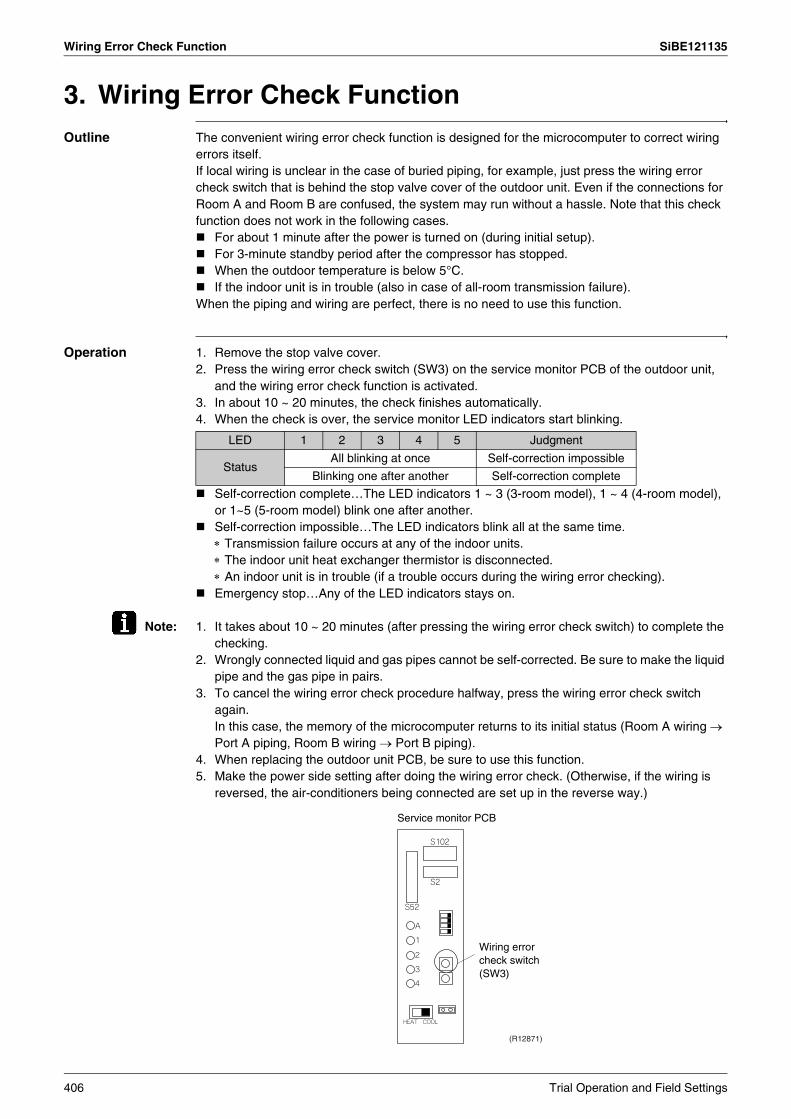
Wiring Error Check Function SiBE121135
3. Wiring Error Check FunctionOutline The convenient wiring error check function is designed for the microcomputer to correct wiring
errors itself.If local wiring is unclear in the case of buried piping, for example, just press the wiring error check switch that is behind the stop valve cover of the outdoor unit. Even if the connections for Room A and Room B are confused, the system may run without a hassle. Note that this check function does not work in the following cases.
For about 1 minute after the power is turned on (during initial setup).For 3-minute standby period after the compressor has stopped.When the outdoor temperature is below 5°C.If the indoor unit is in trouble (also in case of all-room transmission failure).
When the piping and wiring are perfect, there is no need to use this function.
Operation 1. Remove the stop valve cover.2. Press the wiring error check switch (SW3) on the service monitor PCB of the outdoor unit,
and the wiring error check function is activated.3. In about 10 ~ 20 minutes, the check finishes automatically.4. When the check is over, the service monitor LED indicators start blinking.
Self-correction complete…The LED indicators 1 ~ 3 (3-room model), 1 ~ 4 (4-room model), or 1~5 (5-room model) blink one after another.Self-correction impossible…The LED indicators blink all at the same time.∗ Transmission failure occurs at any of the indoor units.∗ The indoor unit heat exchanger thermistor is disconnected.∗ An indoor unit is in trouble (if a trouble occurs during the wiring error checking).Emergency stop…Any of the LED indicators stays on.
Note: 1. It takes about 10 ~ 20 minutes (after pressing the wiring error check switch) to complete the checking.
2. Wrongly connected liquid and gas pipes cannot be self-corrected. Be sure to make the liquid pipe and the gas pipe in pairs.
3. To cancel the wiring error check procedure halfway, press the wiring error check switch again.In this case, the memory of the microcomputer returns to its initial status (Room A wiring → Port A piping, Room B wiring → Port B piping).
4. When replacing the outdoor unit PCB, be sure to use this function.5. Make the power side setting after doing the wiring error check. (Otherwise, if the wiring is
reversed, the air-conditioners being connected are set up in the reverse way.)
LED 1 2 3 4 5 Judgment
StatusAll blinking at once Self-correction impossible
Blinking one after another Self-correction complete
Service monitor PCB
Wiring error check switch (SW3)
(R12871)
406 Trial Operation and Field Settings
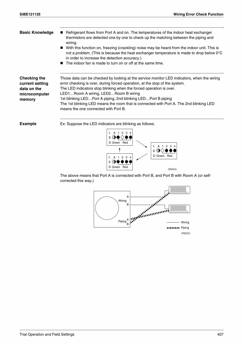
SiBE121135 Wiring Error Check Function
Basic Knowledge Refrigerant flows from Port A and on. The temperatures of the indoor heat exchanger thermistors are detected one by one to check up the matching between the piping and wiring.With this function on, freezing (crackling) noise may be heard from the indoor unit. This is not a problem. (This is because the heat exchanger temperature is made to drop below 0°C in order to increase the detection accuracy.)The indoor fan is made to turn on or off at the same time.
Checking the current setting data on the microcomputer memory
Those data can be checked by looking at the service monitor LED indicators, when the wiring error checking is over, during forced operation, at the stop of the system.The LED indicators stop blinking when the forced operation is over.LED1…Room A wiring, LED2…Room B wiring1st blinking LED…Port A piping, 2nd blinking LED…Port B pipingThe 1st blinking LED means the room that is connected with Port A. The 2nd blinking LED means the one connected with Port B.
Example Ex: Suppose the LED indicators are blinking as follows.
The above means that Port A is connected with Port B, and Port B with Room A (or self-corrected this way.)
A 1 2 3 4
Green Red
Green Red
Green Red
A 1 2 3 4
A 1 2 3 4
(R8252)
L
E
DL
E
DL
E
D
A
BWiring
PipingA
B
(R8253)
Wiring
Piping
Trial Operation and Field Settings 407
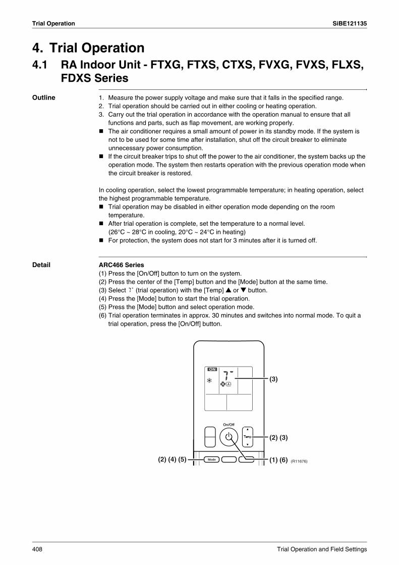
Trial Operation SiBE121135
4. Trial Operation4.1 RA Indoor Unit - FTXG, FTXS, CTXS, FVXG, FVXS, FLXS,
FDXS Series
Outline 1. Measure the power supply voltage and make sure that it falls in the specified range.2. Trial operation should be carried out in either cooling or heating operation.3. Carry out the trial operation in accordance with the operation manual to ensure that all
functions and parts, such as flap movement, are working properly.The air conditioner requires a small amount of power in its standby mode. If the system is not to be used for some time after installation, shut off the circuit breaker to eliminate unnecessary power consumption.If the circuit breaker trips to shut off the power to the air conditioner, the system backs up the operation mode. The system then restarts operation with the previous operation mode when the circuit breaker is restored.
In cooling operation, select the lowest programmable temperature; in heating operation, select the highest programmable temperature.
Trial operation may be disabled in either operation mode depending on the room temperature.After trial operation is complete, set the temperature to a normal level.(26°C ~ 28°C in cooling, 20°C ~ 24°C in heating)For protection, the system does not start for 3 minutes after it is turned off.
Detail ARC466 Series(1) Press the [On/Off] button to turn on the system.(2) Press the center of the [Temp] button and the [Mode] button at the same time.(3) Select T (trial operation) with the [Temp] or button.(4) Press the [Mode] button to start the trial operation.(5) Press the [Mode] button and select operation mode.(6) Trial operation terminates in approx. 30 minutes and switches into normal mode. To quit a
trial operation, press the [On/Off] button.
(R11676)(2) (4) (5) (1) (6)
(2) (3)
(3)
408 Trial Operation and Field Settings

SiBE121135 Trial Operation
ARC452 Series(1) Press the [ON/OFF] button to turn on the system.(2) Press the both of [TEMP] buttons and the [MODE] button at the same time.(3) Press the [MODE] button twice.
(T appears on the display to indicate that trial operation is selected.)(4) Press the [MODE] button and select the operation mode.(5) Trial operation terminates in approx. 30 minutes and switches into normal mode. To quit a
trial operation, press the [ON/OFF] button.
ARC433 Series(1) Press the [ON/OFF] button to turn on the system.(2) Press the center of the [TEMP] button and the [MODE] button at the same time.(3) Press the [MODE] button twice.
(T appears on the display to indicate that trial operation is selected.)(4) Press the [MODE] button and select the operation mode.(5) Trial operation terminates in approx. 30 minutes and switches into normal mode. To quit a
trial operation, press the [ON/OFF] button.
(R14594)
(2)
(2) (3) (4) (1) (5)
(2)
(3)
(2)
(1) (5)
(3)
(2) (3) (4) (R9663)
Trial Operation and Field Settings 409
Trial Operation SiBE121135
4.2 SA Indoor Unit - FCQG, FFQ, FHQ, FDBQ, FBQ Series4.2.1 Check points
To carry out test operation, check the followings:Check that the temperature setting of the remote controller is at the lowest level in cooling mode.Go through the following checklist:
4.2.2 Test operation
BRC1D528
Checkpoints Cautions or warnings
Are all units securely installed? Dangerous for turning over during stormPossible damage to pipe connections
Is the earth wire installed according to the applicable local standard?
Dangerous if electric leakage occurs.
Are all air inlets and outlets of the indoor and outdoor units unobstructed?
Poor coolingPoor heating
Does the drain flow out smoothly? Water leakage
Is piping adequately heat-insulated? Water leakage
Have the connections been checked for refrigerant leakage?
Poor coolingPoor heatingStop
Is the supply voltage conform to the specifications on the name plate?
Incorrect operation
Are the cable sizes as specified and according to local regulations?
Damage of cables
Are the remote controller signals received by the unit? No operation
Step Action1 Turn on the power supply more than 6 hours before test operation.
2 Open the gas stop valve.
3 Open the liquid stop valve.
4 Set to cooling operation with the remote controller and start operation by pressing [ON/OFF] button ( ).
5 Press the [INSPECTION/TEST OPERATION] button ( ) 4 times (2 times for wireless remote controller) and operate at test operation mode for 3 minutes.
6 Press the [AIRFLOW DIRECTION ADJUST] button ( ) to make sure the unit is in operation.
7 Press the [INSPECTION/TEST OPERATION] button ( ) and operate normally.
8 Confirm all the function of unit according to the operation manual.
9 If the decoration panel has not been installed, turn off the power after the test operation.
410 Trial Operation and Field Settings

SiBE121135 Trial Operation
BRC1E51A7
Step Action Remote controllerBefore test operation
1 Turn on the power supply more than 6 hours before test operation.
2 Open the gas stop valve.
3 Open the liquid stop valve.
How to activate test operation
4 Press and hold the [Cancel] button ( ) for 4 seconds to enter the Field setting menu.
5 Use the buttons to select Test operation ON/OFF and push the [Menu/Enter] button ( ).
6 Test operation is displayed on the bottom of the basic screen.
7 Push the [ON/OFF] button ( ) within 10 seconds to start the test operation.
How to check airflow direction
8 Push the [Menu/Enter] button ( ) to enter the Main Menu.
9 Use the buttons to select Airflow direction and push the [Menu/Enter] button( ).
10 Check that the airflow direction is actuated according to the setting and push the [Menu/Enter] button ( ) .
How to deactivate test operation
11 Press and hold the [Cancel] button ( ) for 4 seconds to enter the Field setting menu.
12 Use the buttons to select Test operation ON/OFF in the menu and push the [Menu/Enter] button ( ).
(R12872)
(R12873)
(R12874)
(R12875)
(R12876)
Trial Operation and Field Settings 411
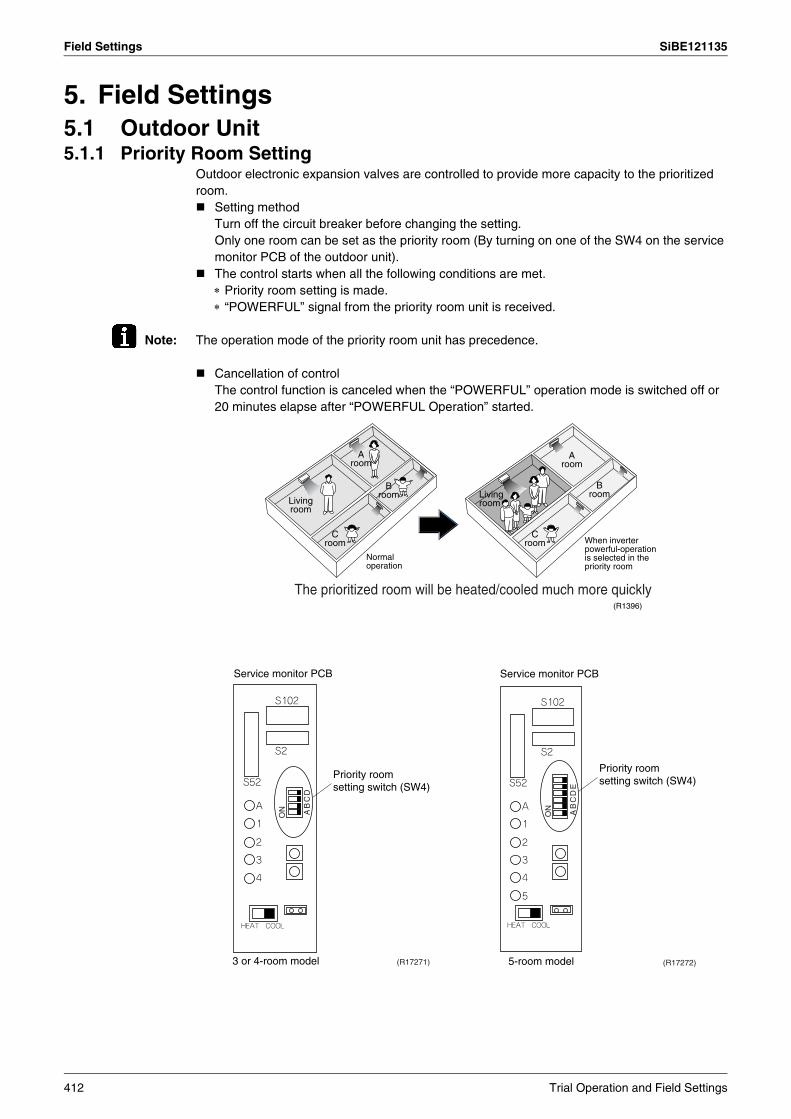
Field Settings SiBE121135
5. Field Settings5.1 Outdoor Unit5.1.1 Priority Room Setting
Outdoor electronic expansion valves are controlled to provide more capacity to the prioritized room.
Setting methodTurn off the circuit breaker before changing the setting.Only one room can be set as the priority room (By turning on one of the SW4 on the service monitor PCB of the outdoor unit).The control starts when all the following conditions are met.∗ Priority room setting is made.∗ “POWERFUL” signal from the priority room unit is received.
Note: The operation mode of the priority room unit has precedence.
Cancellation of controlThe control function is canceled when the “POWERFUL” operation mode is switched off or 20 minutes elapse after “POWERFUL Operation” started.
(R1396)
Living room
Living room
A room
A room
B room
B room
C room
C room
Normal operation
When inverter powerful-operation is selected in the priority room
The prioritized room will be heated/cooled much more quickly
Service monitor PCB
(R17271)
Priority room setting switch (SW4)
3 or 4-room model
Service monitor PCB
5-room model (R17272)
Priority room setting switch (SW4)
412 Trial Operation and Field Settings
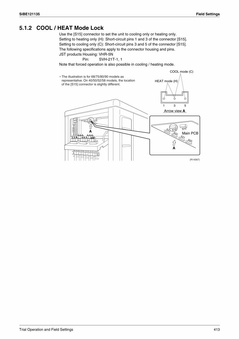
SiBE121135 Field Settings
5.1.2 COOL / HEAT Mode LockUse the [S15] connector to set the unit to cooling only or heating only.Setting to heating only (H): Short-circuit pins 1 and 3 of the connector [S15].Setting to cooling only (C): Short-circuit pins 3 and 5 of the connector [S15].The following specifications apply to the connector housing and pins.JST products Housing: VHR-5N
Pin: SVH-21T-1, 1Note that forced operation is also possible in cooling / heating mode.
COOL mode (C)
HEAT mode (H)
1 3 5
Arrow view A
Main PCB
(R14567)
A
A
∗ The illustration is for 68/75/80/90 models as representative. On 40/50/52/58 models, the location of the [S15] connector is slightly different.
Trial Operation and Field Settings 413

Field Settings SiBE121135
5.1.3 NIGHT QUIET ModeIf NIGHT QUIET mode is to be used, initial settings must be made when the unit is installed. Explain the function of NIGHT QUIET mode, as described below, to the customer, and confirm whether or not the customer wants to use NIGHT QUIET mode.NIGHT QUIET mode function reduces operating noise of the outdoor unit at nighttime. This function is useful if the customer is worried about the effects of the operating noise on the neighbors. However, if NIGHT QUIET mode is running, cooling capacity is reduced.
Procedure1. Remove the SW5 jumper switch on the service monitor PCB of the outdoor unit.
Once the settings are complete, reset the power.
2. Install the removed jumper switch as described below. This jumper switch is needed later to disable this setting.
5.1.4 ECONO-mode-proof Setting
Outline When installing in hotels, you can make ECONO mode ineffective on the outdoor unit.
Operation The ECONO mode can be switched over between "effective" and "ineffective" by pressing the forced operation [ON/OFF] switch (SW1) on the outdoor unit and wiring error check switch (SW3) on the outdoor unit at the same time and holding them for 5 seconds while the compressor is stopped. The LEDs are lit in turn for 15 seconds to show the ECONO mode status.The factory setting is "effective".
Service monitor PCB
(R10814)
NIGHT QUIET mode setting switch (SW5)
Jumper switch After removing
(R10813)
LED flashing order effective → ineffective ineffective → effective
3 or 4-room model 4 → 3 → 2 → 1 1 → 2 → 3 → 4
5-room model 5 → 4 → 3 → 2 → 1 1 → 2 → 3 → 4 → 5
414 Trial Operation and Field Settings
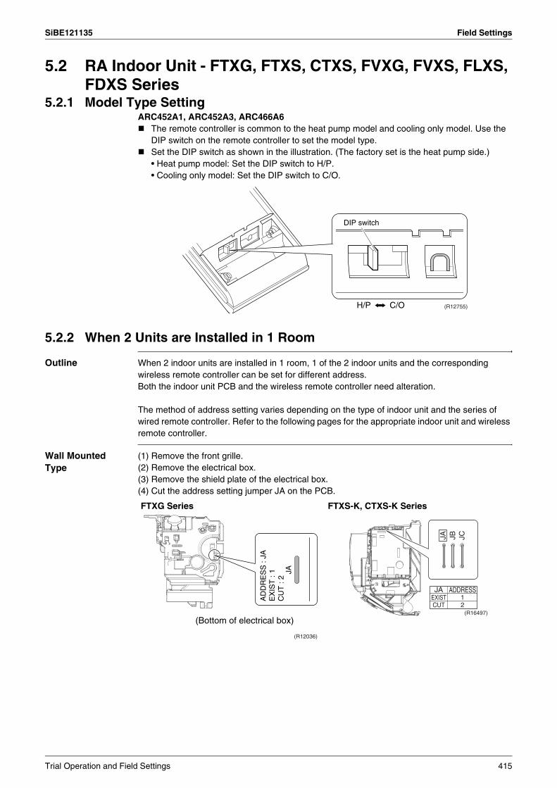
SiBE121135 Field Settings
5.2 RA Indoor Unit - FTXG, FTXS, CTXS, FVXG, FVXS, FLXS, FDXS Series
5.2.1 Model Type SettingARC452A1, ARC452A3, ARC466A6
The remote controller is common to the heat pump model and cooling only model. Use the DIP switch on the remote controller to set the model type.Set the DIP switch as shown in the illustration. (The factory set is the heat pump side.)• Heat pump model: Set the DIP switch to H/P.• Cooling only model: Set the DIP switch to C/O.
5.2.2 When 2 Units are Installed in 1 Room
Outline When 2 indoor units are installed in 1 room, 1 of the 2 indoor units and the corresponding wireless remote controller can be set for different address.Both the indoor unit PCB and the wireless remote controller need alteration.
The method of address setting varies depending on the type of indoor unit and the series of wired remote controller. Refer to the following pages for the appropriate indoor unit and wireless remote controller.
Wall Mounted Type
(1) Remove the front grille.(2) Remove the electrical box.(3) Remove the shield plate of the electrical box.(4) Cut the address setting jumper JA on the PCB.
H/P C/O
DIP switch
(R12755)
FTXG Series FTXS-K, CTXS-K Series
JA
(Bottom of electrical box)
(R12036)
AD
DR
ES
S :
JAE
XIS
T :
1C
UT
: 2
JA JB JC
ADDRESS12
JAEXISTCUT
(R16497)
Trial Operation and Field Settings 415
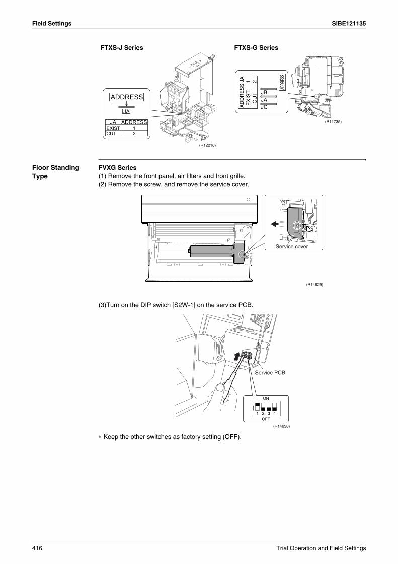
Field Settings SiBE121135
Floor Standing Type
FVXG Series(1) Remove the front panel, air filters and front grille.(2) Remove the screw, and remove the service cover.
(3)Turn on the DIP switch [S2W-1] on the service PCB.
∗ Keep the other switches as factory setting (OFF).
FTXS-J Series FTXS-G Series
ADDRESS
JA
(R12216)
JAEXISTCUT
ADDRESS12
ADDR
ESS
AD
DR
ES
S:J
A
(R11735)
JBJAJC
1 2E
XIS
TC
UT
Service cover
(R14629)
1 2 3 4OFF
ON
Service PCB
(R14630)
416 Trial Operation and Field Settings
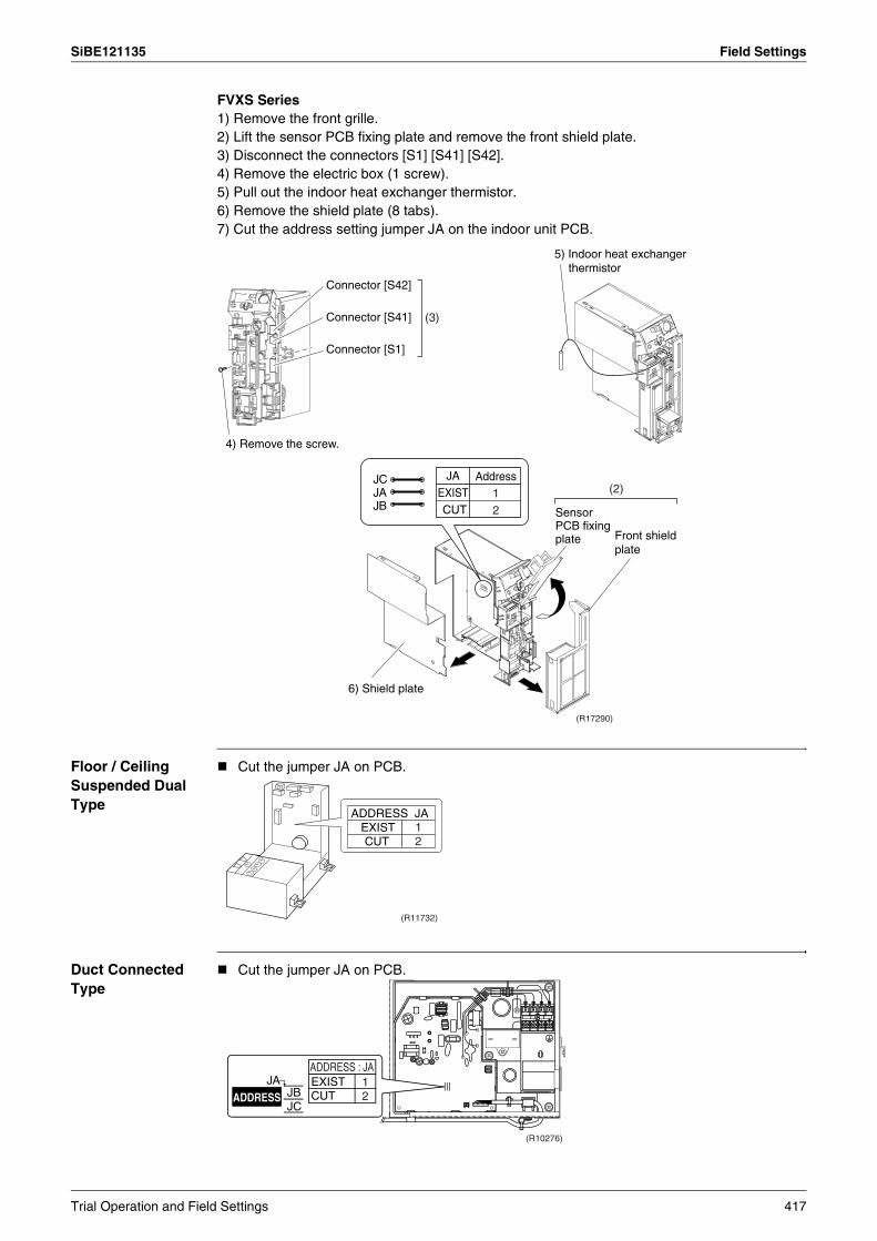
SiBE121135 Field Settings
FVXS Series1) Remove the front grille.2) Lift the sensor PCB fixing plate and remove the front shield plate.3) Disconnect the connectors [S1] [S41] [S42].4) Remove the electric box (1 screw).5) Pull out the indoor heat exchanger thermistor.6) Remove the shield plate (8 tabs).7) Cut the address setting jumper JA on the indoor unit PCB.
Floor / Ceiling Suspended Dual Type
Cut the jumper JA on PCB.
Duct Connected Type
Cut the jumper JA on PCB.
Connector [S42]
Connector [S41]
Connector [S1]
4) Remove the screw.
5) Indoor heat exchanger thermistor
(3)
6) Shield plate
(R17290)
Sensor PCB fixing plate
JCJAJB
JAEXISTCUT
Address12
(2)
Front shield plate
ADDRESS JA
(R11732)
EXISTCUT
12
1 2 3
ADDRESSJA
(R10276)
ADDRESS : JAEXISTCUT
12JB
JC
Trial Operation and Field Settings 417
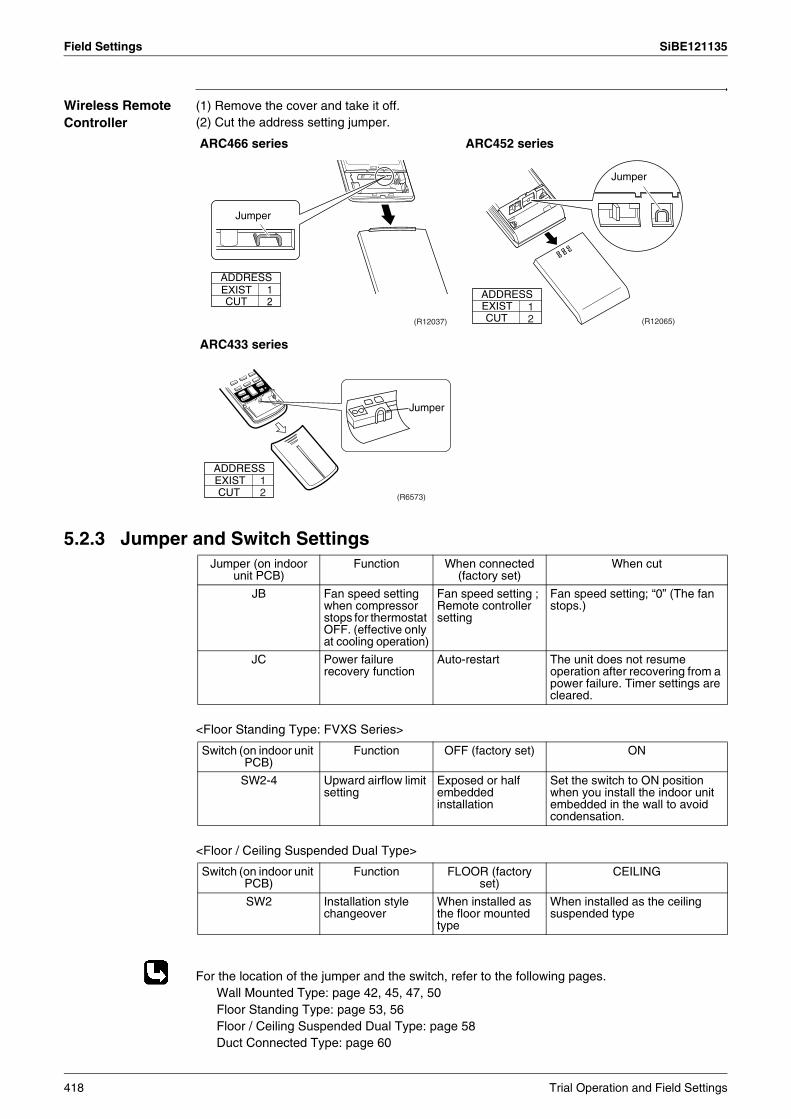
Field Settings SiBE121135
Wireless Remote Controller
(1) Remove the cover and take it off.(2) Cut the address setting jumper.
5.2.3 Jumper and Switch Settings
<Floor Standing Type: FVXS Series>
<Floor / Ceiling Suspended Dual Type>
For the location of the jumper and the switch, refer to the following pages.Wall Mounted Type: page 42, 45, 47, 50Floor Standing Type: page 53, 56Floor / Ceiling Suspended Dual Type: page 58Duct Connected Type: page 60
ARC466 series ARC452 series
ARC433 series
Jumper
(R12037)
ADDRESSEXIST 1CUT 2
Jumper
ADDRESS
(R12065)
EXISTCUT
12
Jumper
(R6573)
ADDRESSEXISTCUT
12
Jumper (on indoor unit PCB)
Function When connected (factory set)
When cut
JB Fan speed setting when compressor stops for thermostat OFF. (effective only at cooling operation)
Fan speed setting ; Remote controller setting
Fan speed setting; “0” (The fan stops.)
JC Power failure recovery function
Auto-restart The unit does not resume operation after recovering from a power failure. Timer settings are cleared.
Switch (on indoor unit PCB)
Function OFF (factory set) ON
SW2-4 Upward airflow limit setting
Exposed or half embedded installation
Set the switch to ON position when you install the indoor unit embedded in the wall to avoid condensation.
Switch (on indoor unit PCB)
Function FLOOR (factory set)
CEILING
SW2 Installation style changeover
When installed as the floor mounted type
When installed as the ceiling suspended type
418 Trial Operation and Field Settings
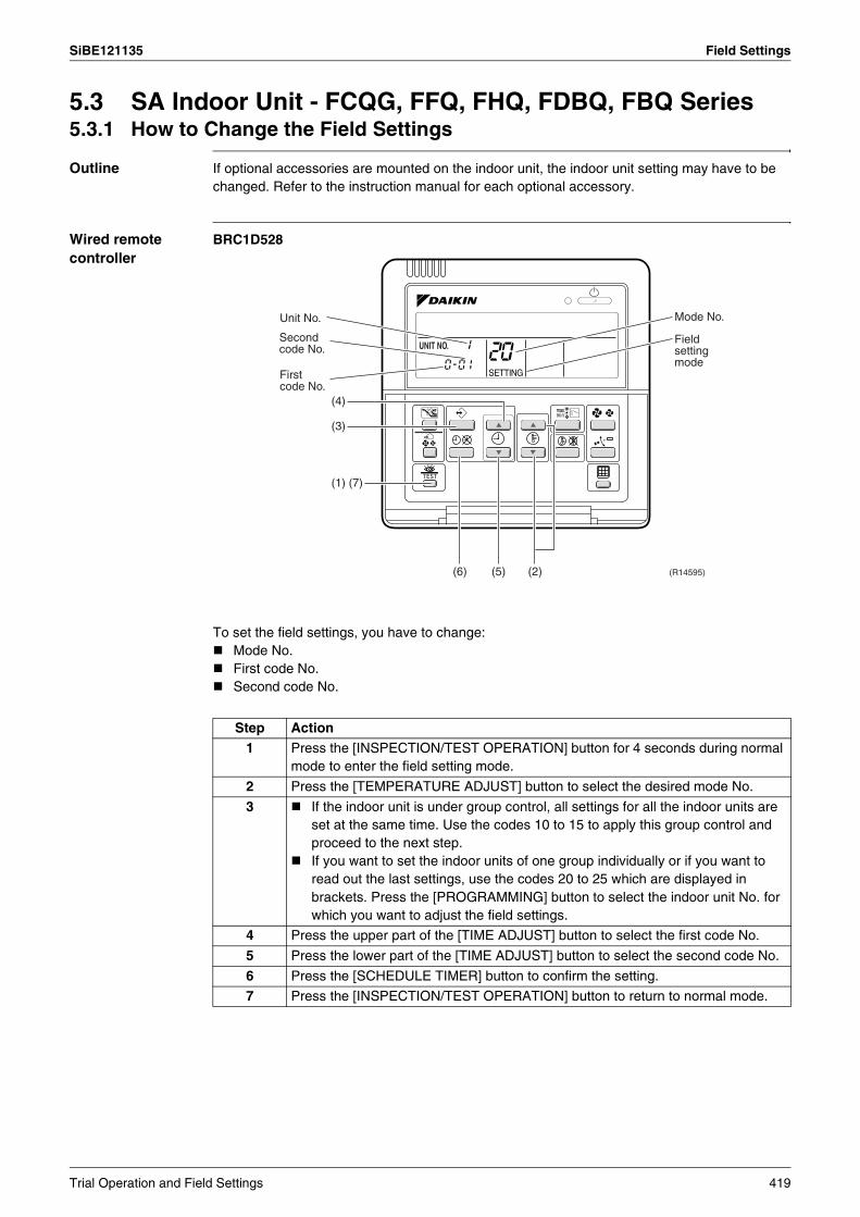
SiBE121135 Field Settings
5.3 SA Indoor Unit - FCQG, FFQ, FHQ, FDBQ, FBQ Series5.3.1 How to Change the Field Settings
Outline If optional accessories are mounted on the indoor unit, the indoor unit setting may have to be changed. Refer to the instruction manual for each optional accessory.
Wired remote controller
BRC1D528
To set the field settings, you have to change:Mode No.First code No.Second code No.
Step Action1 Press the [INSPECTION/TEST OPERATION] button for 4 seconds during normal
mode to enter the field setting mode.
2 Press the [TEMPERATURE ADJUST] button to select the desired mode No.
3 If the indoor unit is under group control, all settings for all the indoor units are set at the same time. Use the codes 10 to 15 to apply this group control and proceed to the next step.If you want to set the indoor units of one group individually or if you want to read out the last settings, use the codes 20 to 25 which are displayed in brackets. Press the [PROGRAMMING] button to select the indoor unit No. for which you want to adjust the field settings.
4 Press the upper part of the [TIME ADJUST] button to select the first code No.
5 Press the lower part of the [TIME ADJUST] button to select the second code No.
6 Press the [SCHEDULE TIMER] button to confirm the setting.
7 Press the [INSPECTION/TEST OPERATION] button to return to normal mode.
Mode No.Unit No.
(4)
(3)
(6) (5) (2)
(1) (7)
(R14595)
Second code No.
First code No.
Field setting mode0-01
Trial Operation and Field Settings 419
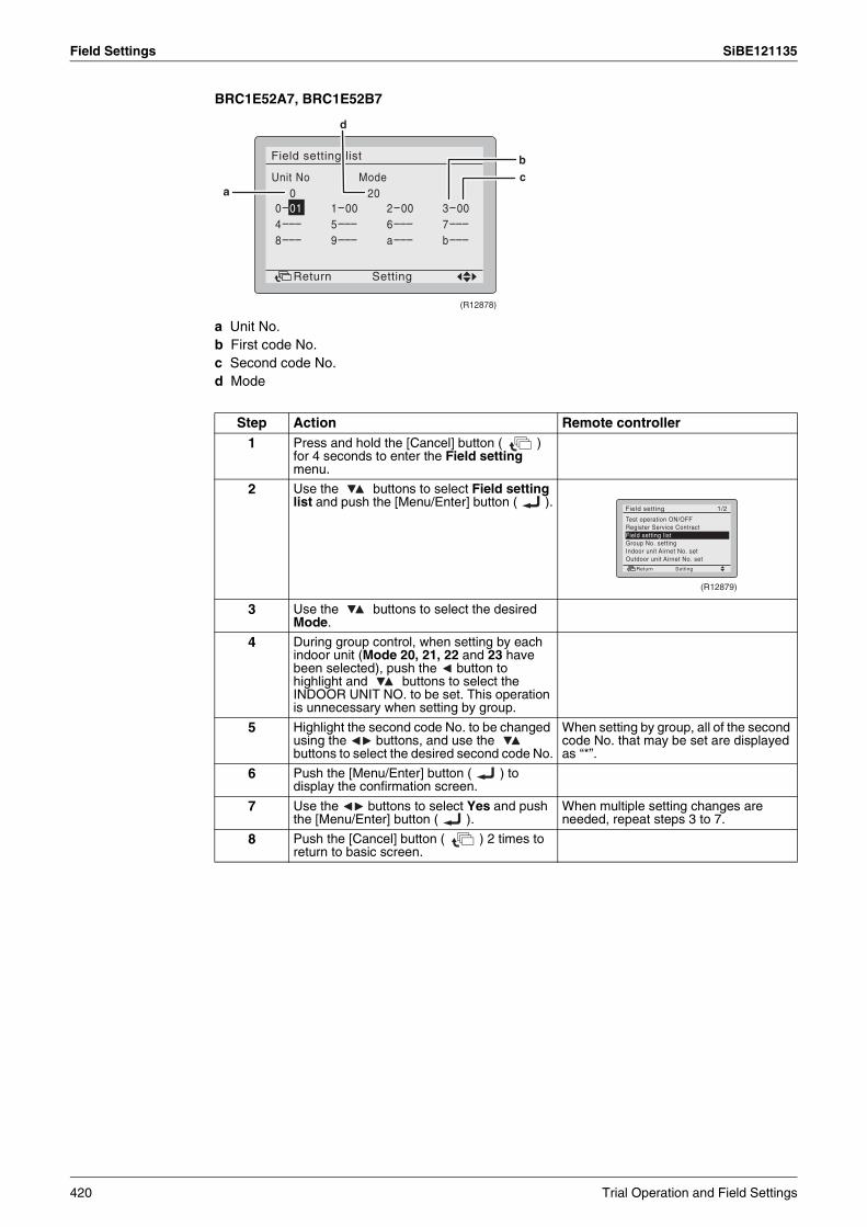
Field Settings SiBE121135
BRC1E52A7, BRC1E52B7
a Unit No.b First code No.c Second code No.d Mode
Step Action Remote controller1 Press and hold the [Cancel] button ( )
for 4 seconds to enter the Field setting menu.
2 Use the buttons to select Field setting list and push the [Menu/Enter] button ( ).
3 Use the buttons to select the desired Mode.
4 During group control, when setting by each indoor unit (Mode 20, 21, 22 and 23 have been selected), push the button to highlight and buttons to select the INDOOR UNIT NO. to be set. This operation is unnecessary when setting by group.
5 Highlight the second code No. to be changed using the buttons, and use the buttons to select the desired second code No.
When setting by group, all of the second code No. that may be set are displayed as “*”.
6 Push the [Menu/Enter] button ( ) to display the confirmation screen.
7 Use the buttons to select Yes and push the [Menu/Enter] button ( ).
When multiple setting changes are needed, repeat steps 3 to 7.
8 Push the [Cancel] button ( ) 2 times to return to basic screen.
a
bc
d
(R12878)
(R12879)
420 Trial Operation and Field Settings

SiBE121135 Field Settings
5.3.2 Overview of the Field Settings
: factory set
Note: 1. Any function that is not available on the indoor unit is not displayed.2.
Mode No.
First Code No.
Description of settingSecond Code No.
01 02 03 04
10 (20)
0 Filter cleaning sign interval
Ultra longlife filter
Ligh
t
Approx. 10,000 hrs.
Hea
vy Approx.
5,000 hrs.— —
Longlife filter Approx. 2,500 hrs.
Approx. 1,250 hrs.
1 Longlife filter type Longlife filter Ultra longlife filter — —
2 Remote controller thermistor Enabled Disabled — —3 Filter cleaning sign Display No display — —
11 (21)
0 Indoor unit number of simultaneous operation system Pair Twin Triple Double twin
1 Simultaneous operation system individual setting Unified setting Individual
setting — —
7 External static pressure settingAirflow
adjustment is OFF
Completion of airflow
adjustment
Start of airflow adjustment —
12 (22)
1 Forced ON/OFF function Forced OFF ON/OFF operation — —
2 Thermostat differential changeover (setting for when using remote sensor) 1°C 0.5°C — —
13 (23)
0 High air outlet velocity (for high ceiling applications) ≤ 2.7 m 2.7 ~ 3.0 m 3.0 ~ 3.5 m —
1Selection of airflow direction (setting for when a blocking pad kit has been installed)
4-way flow 3-way flow 2-way flow —
3Selection of airflow function (setting for when using a decoration panel for outlet)
Equipped Not equipped — —
4 Airflow direction range setting Upper Normal Lower —
6 External static pressure Refer to Note 2.
14 (24)
2 Dust collection sign interval Approx. 1,250 hrs.
Approx. 2,500 hrs.
Approx. 5,000 hrs. —
3 Filter replacement sign No display Approx. 32,000 hrs.
Approx. 48,000 hrs.
Approx. 72,000 hrs.
4 Panel indicator (green) ON/OFF
The indicator lights up during both air conditioning operation and filter auto-cleaning.
The indicator can light up only during filter auto-cleaning.
The indicator does not light up during both air conditioning operation and filter auto-cleaning.
—
8 Selection of the automatic control operation lock mode ON OFF — —
9 Dust amount setting Standard Heavy — —
15 (25) 3 Drain pump operation with humidifying Not equipped Equipped — —
: factory set
External static pressure (Pa)Mode No.
First code No.
Second code No.
FBQ35 class 50 class 60 class
13 (23) 6
03 30 30 3004 35 35 4005 40 40 5006 45 45 6007 50 50 7008 60 60 8009 70 70 9010 80 80 10011 90 90 —12 100 100 —
Trial Operation and Field Settings 421

Field Settings SiBE121135
5.3.3 MAIN / SUB Setting when Using 2 Wired Remote Controllers
Outline The MAIN / SUB setting is necessary when 1 indoor unit is controlled by 2 remote controllers. When you use 2 remote controllers (control panel and separate remote controller), set one to MAIN and the other to SUB.
Detail The remote controllers are factory set to MAIN, so you only have to change one remote controller from MAIN to SUB.
BRC1D528
BRC1E52A7, BRC1E52B7
Step Action1 Insert a flat screwdriver into the groove between the upper and lower part of the
remote controller, as shown in the illustration below. Gently pry off the upper part of the controller, working from the two possible positions.
2 Set the [MAIN / SUB changeover] switch on the PCB to “S”.
Step Action Remote controller
1 Put on the power for both remote controllers.
2 Determine which one is the sub/main remote controller.
3 When Error code: U5 - Connection under check Please wait for a moment is displayed on both remote controllers, push and hold the [Operation mode selector] button of the sub remote controller for 4 seconds.
4 The sub remote controller now displays Sub remote contrl.
Note) The main remote controller still displays Main remote contrl.
5 After a few seconds, the basic screen is displayed.
(R11738)
Upper part of the remote controller
Lower part of the remote controller
Set the switch to SUB.
(R11739)
The switch is set to MAIN (factory setting)
(R12880)
(R12881)
422 Trial Operation and Field Settings
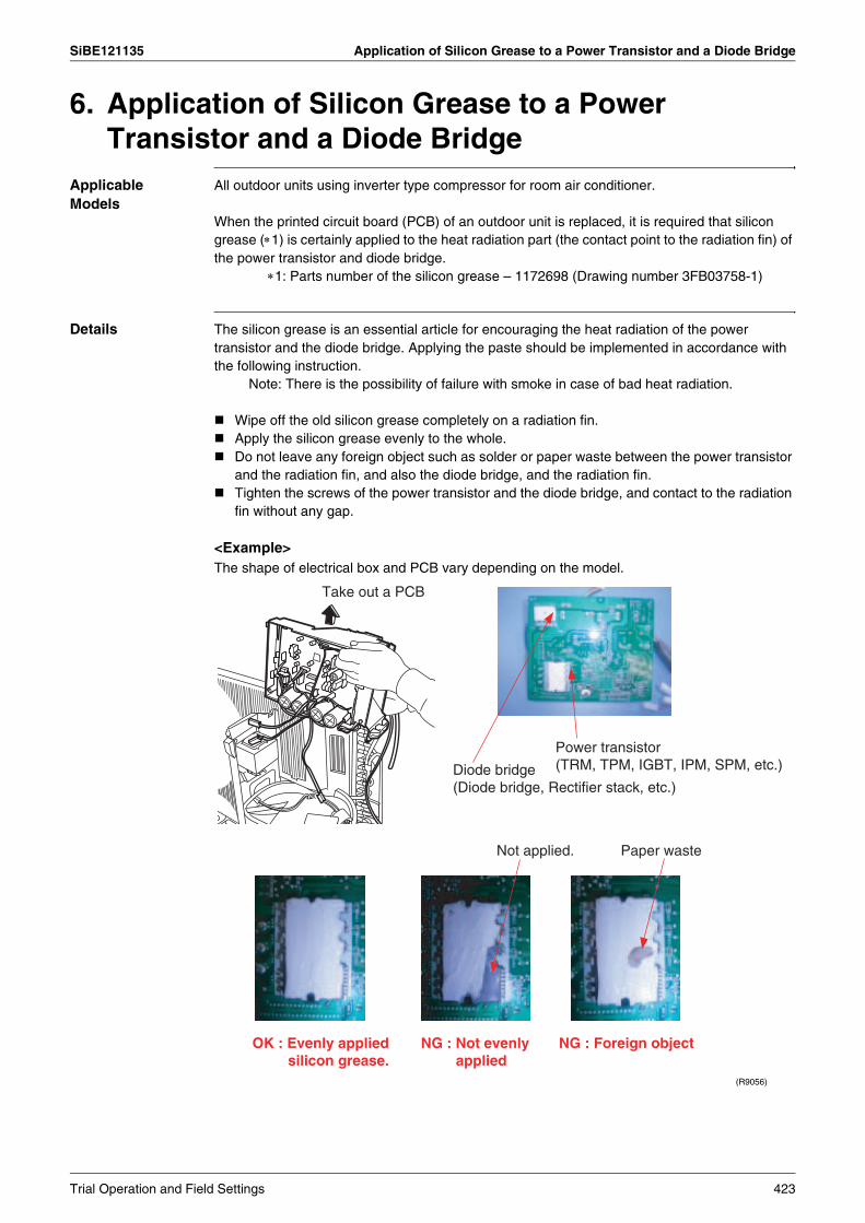
SiBE121135 Application of Silicon Grease to a Power Transistor and a Diode Bridge
6. Application of Silicon Grease to a Power Transistor and a Diode Bridge
Applicable Models
All outdoor units using inverter type compressor for room air conditioner.
When the printed circuit board (PCB) of an outdoor unit is replaced, it is required that silicon grease (∗1) is certainly applied to the heat radiation part (the contact point to the radiation fin) of the power transistor and diode bridge. ∗1: Parts number of the silicon grease – 1172698 (Drawing number 3FB03758-1)
Details The silicon grease is an essential article for encouraging the heat radiation of the power transistor and the diode bridge. Applying the paste should be implemented in accordance with the following instruction. Note: There is the possibility of failure with smoke in case of bad heat radiation.
Wipe off the old silicon grease completely on a radiation fin.Apply the silicon grease evenly to the whole.Do not leave any foreign object such as solder or paper waste between the power transistor and the radiation fin, and also the diode bridge, and the radiation fin.Tighten the screws of the power transistor and the diode bridge, and contact to the radiation fin without any gap.
<Example>The shape of electrical box and PCB vary depending on the model.
(R9056)
Take out a PCB
Not applied. Paper waste
NG : Foreign objectOK : Evenly applied silicon grease.
NG : Not evenly applied
Diode bridge (Diode bridge, Rectifier stack, etc.)
Power transistor (TRM, TPM, IGBT, IPM, SPM, etc.)
Trial Operation and Field Settings 423

SiBE121135
424 Appendix
Part 9Appendix
1. Piping Diagrams..................................................................................4251.1 Outdoor Unit .........................................................................................4251.2 Indoor Unit............................................................................................430
2. Wiring Diagrams..................................................................................4372.1 Outdoor Unit .........................................................................................4372.2 Indoor Unit............................................................................................442

SiBE121135 Piping Diagrams
1. Piping Diagrams1.1 Outdoor Unit1.1.1 Cooling Only
3MKS50E3V1B
4MKS58E3V1B
12.7
CuT
7.9CuT 12.7CuT
9.5CuT
6.4CuT
6.4CuT
6.4CuT
(
( )
)
ELECTRONIC EXPANSION VALVE
ELECTRONIC EXPANSION VALVE
ELECTRONIC EXPANSION VALVE
LIQUID PIPE THERMISTOR(DLA)
LIQUID PIPE THERMISTOR(DLB)
LIQUID PIPE THERMISTOR(DLC)
FIELD PIPING LIQUID SIDE
FIELD PIPING GAS SIDE
GAS LINE STOP VALVE
LIQUID LINE STOP VALVE
DISCHARGE PIPE THERMISTOR(DO)
HEAT EXCHANGER THERMISTOR(DE)
OUTDOOR TEMPERATURE THERMISTOR(DOA)
ROOM A (6.4 CuT)
ROOM B (6.4 CuT)
ROOM C (6.4 CuT)
ROOM A (9.5 CuT)
ROOM B (9.5 CuT)
ROOM C (9.5 CuT)
GAS PIPE THERMISTOR(DGA)
GAS PIPE THERMISTOR(DGB)
GAS PIPE THERMISTOR(DGC)
12.7CuT
12.7CuT
12.7CuT
OUTDOOR UNIT
HEADER
DC FAN MOTOR
PROPELLER FAN
MCAPILLARY TUBE
DISTRIBUTOR
HEAT EXCHANGER
HEADER
FILTER
FILTER
FILTER
FILTER
HEADER
MUFFLER
MUFFLER
ACCUMULATOR
MUFFLER
REFRIGERANT FLOW
COOLING COMPRESSOR
EVB
EVC
3D052056C
EVA
12.7
CuT
7.9CuT 12.7CuT
9.5CuT
6.4CuT
6.4CuT
6.4CuT
6.4CuT
12.7CuT
12.7CuT
12.7CuT
12.7CuT (
(
)
)
ELECTRONIC EXPANSION VALVE
ELECTRONIC EXPANSION VALVE
ELECTRONIC EXPANSION VALVE
ELECTRONIC EXPANSION VALVE
LIQUID PIPE THERMISTOR(DLA)
LIQUID PIPE THERMISTOR(DLB)
LIQUID PIPE THERMISTOR(DLC)
LIQUID PIPE THERMISTOR(DLD)
FIELD PIPING LIQUID SIDE
FIELD PIPING GAS SIDE
GAS LINE STOP VALVE
LIQUID LINE STOP VALVE
DISCHARGE PIPE THERMISTOR(DO)
HEAT EXCHANGER THERMISTOR(DE)
OUTDOOR TEMPERATURE THERMISTOR(DOA)
ROOM A (6.4 CuT)
ROOM B (6.4 CuT)
ROOM C (6.4 CuT)
ROOM D (6.4 CuT)
ROOM A (9.5 CuT)
ROOM B (9.5 CuT)
ROOM C (12.7 CuT)
ROOM D (12.7 CuT)
OUTDOOR UNIT
HEADER
DC FAN MOTOR
PROPELLER FAN
M
MUFFLER
REFRIGERANT FLOW
COOLING COMPRESSOR
MUFFLER
MUFFLER
ACCUMULATOR
HEADER
FILTER
DISTRIBUTORCAPILLARY TUBE
HEADER
HEAT EXCHANGER
EVA
EVB
EVC
EVD
FILTER
FILTER
FILTER
FILTER
GAS PIPE THERMISTOR(DGA)
GAS PIPE THERMISTOR(DGB)
GAS PIPE THERMISTOR(DGC)
GAS PIPE THERMISTOR(DGD)
3D052057B
Appendix 425
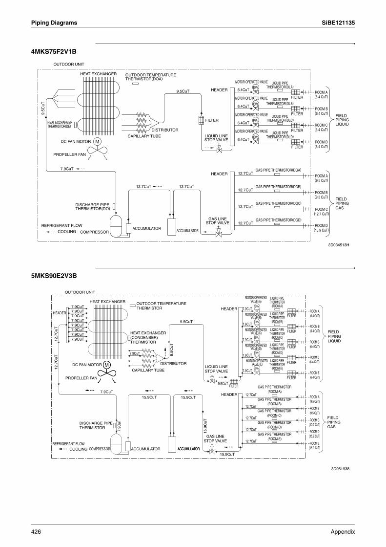
Piping Diagrams SiBE121135
4MKS75F2V1B
5MKS90E2V3B
9.5C
uT
7.9CuT
12.7CuT
9.5CuT
12.7CuT
6.4CuT
6.4CuT
6.4CuT
6.4CuT
12.7CuT
12.7CuT
12.7CuT
12.7CuT
LIQUID PIPE THERMISTOR(DLA)
LIQUID PIPE THERMISTOR(DLB)
LIQUID PIPE THERMISTOR(DLC)
LIQUID PIPE THERMISTOR(DLD)
FIELD PIPING LIQUID
FIELD PIPING GAS
GAS LINE STOP VALVE
LIQUID LINE STOP VALVE
DISCHARGE PIPE THERMISTOR(DO)
HEAT EXCHANGER THERMISTOR(DE)
OUTDOOR TEMPERATURE THERMISTOR(DOA)
ROOM A (6.4 CuT)
ROOM B (6.4 CuT)
ROOM C (6.4 CuT)
ROOM D (6.4 CuT)
ROOM A (9.5 CuT)
ROOM B (9.5 CuT)
ROOM C (12.7 CuT)
ROOM D (15.9 CuT)
HEAT EXCHANGER
DC FAN MOTOR M
PROPELLER FAN
REFRIGERANT FLOW
COOLING COMPRESSORACCUMULATOR ACCUMULATOR
HEADER
HEADER
FILTER
DISTRIBUTOR
CAPILLARY TUBE
MOTOR OPERATED VALVE
MOTOR OPERATED VALVE
MOTOR OPERATED VALVE
EVA
EVB
EVC
EVD
FILTER
FILTER
FILTER
FILTER
GAS PIPE THERMISTOR(DGA)
GAS PIPE THERMISTOR(DGB)
GAS PIPE THERMISTOR(DGC)
GAS PIPE THERMISTOR(DGD)
MOTOR OPERATED VALVE
3D034513H
OUTDOOR UNIT
12.7
CuT
12.7
CuT
7.9CuT7.9CuT
7.9CuT
7.9CuT
7.9CuT
7.9CuT
7.9CuT
7.9CuT
7.9CuT
7.9C
uT
7.9CuT
15.9CuT
9.5C
uT
9.5CuT
15.9CuT
15.9
CuT
9.5CuT
15.9CuT
7.9CuT
7.9CuT
7.9CuT
7.9CuT
7.9CuT
12.7CuT
12.7CuT
12.7CuT
12.7CuT
12.7CuT
OUTDOOR TEMPERATURE THERMISTOR
DISCHARGE PIPE THERMISTOR
GAS LINE STOP VALVE
LIQUID LINE STOP VALVE
LIQUID PIPE THERMISTOR
(ROOM-A)
LIQUID PIPE THERMISTOR
(ROOM-B)
LIQUID PIPE THERMISTOR
(ROOM-C)
LIQUID PIPE THERMISTOR
(ROOM-D)
LIQUID PIPE THERMISTOR
(ROOM-E)
MOTOR OPERATED VALVE (B)
MOTOR OPERATED VALVE (C)
MOTOR OPERATED VALVE (D)
MOTOR OPERATED VALVE (E)
MOTOR OPERATED VALVE (A)
FIELD PIPING LIQUID
FIELD PIPING GAS
ROOM A (6.4 CuT)
ROOM B (6.4 CuT)
ROOM C (6.4 CuT)
ROOM D (6.4 CuT)
ROOM E (6.4 CuT)
ROOM A (9.5 CuT)
ROOM B (9.5 CuT)
ROOM C (12.7 CuT)
ROOM D (15.9 CuT)
ROOM E (15.9 CuT)
HEAT EXCHANGER (CONDENSER) THERMISTOR
GAS PIPE THERMISTOR (ROOM-A)
GAS PIPE THERMISTOR (ROOM-B)
GAS PIPE THERMISTOR (ROOM-C)
GAS PIPE THERMISTOR (ROOM-D)
GAS PIPE THERMISTOR (ROOM-E)
OUTDOOR UNIT
HEAT EXCHANGER
HEADER
DC FAN MOTOR
PROPELLER FAN
M
REFRIGERANT FLOWCOOLING COMPRESSOR ACCUMULATOR
CAPILLARY TUBE
DISTRIBUTOR
HEADER
HEADER
FILTER
ACCUMULATORACCUMULATOR
EVA
EVB
EVC
EVD
EVE
FILTER
FILTER
FILTER
FILTER
FILTER
3D051938
426 Appendix

SiBE121135 Piping Diagrams
1.1.2 Heat Pump
3MXS40K2V1B
3MXS52E3V1B
( )
OUTDOOR UNIT
HEAT EXCHANGER
HEADER
HEADER9.5CuT6.4CuT
FILTER
6.4CuTFILTER FILTER
DISTRIBUTOREVC
EVB
EVA
6.4CuTCAPILLARY TUBEDC FAN MOTOR FILTERM
PROPELLER FAN
12.7CuT 12.7CuTHEADER
GAS PIPE THERMISTOR (DGA)12.7CuT
12.7
CuT
MUFFLER GAS PIPE THERMISTOR (DGB)MUFFLER12.7CuT
7.9C
uT
MUFFLERGAS PIPE THERMISTOR (DGC)
( )
12.7CuT
REFRIGERANT FLOWACCUMULATOR
COOLING COMPRESSORHEATING
HEAT EXCHANGER THERMISTOR (DE)
REVERSING SOLENOID VALVE
DISCHARGE PIPE THERMISTOR (DO)
GAS LINE STOP VALVE
LIQUID LINE STOP VALVE
OUTDOOR TEMPERATURE THERMISTOR (DOA)
ELECTRONIC EXPANSION VALVE
ELECTRONIC EXPANSION VALVE
ELECTRONIC EXPANSION VALVE
LIQUID PIPE THERMISTOR (DLA)
LIQUID PIPE THERMISTOR (DLB)
LIQUID PIPE THERMISTOR (DLC)
ROOM A (6.4 CuT)
ROOM B (6.4 CuT)
ROOM C (6.4 CuT)
ROOM A (9.5 CuT)
ROOM B (9.5 CuT)
ROOM C (9.5 CuT)
FIELD PIPING
FIELD PIPING
LIQUID SIDE
GAS SIDE
3D073394
REFRIGERANT FLOW
HEADER
OUTDOOR UNIT
COOLINGHEATING
12.7CuT
PROPELLER FAN
DC FAN MOTOR
HEAT EXCHANGER
COMPRESSOR
M
MUFFLER
7.9C
uT
CAPILLARY TUBE
ACCUMULATOR
12.7CuT
DISTRIBUTOR
12.7
CuT
9.5CuT
MUFFLER
MUFFLER
FILTER
HEADER
HEADER6.4CuT
6.4CuT
6.4CuT
12.7CuT
12.7CuT
12.7CuT
EVC
EVB
EVA
GAS PIPE THERMISTOR (DGC)
GAS PIPE THERMISTOR (DGB)
GAS PIPE THERMISTOR (DGA)
FILTER
FILTER
FILTER
(
( )
)HEAT EXCHANGER THERMISTOR (DE)
OUTDOOR TEMPERATURE THERMISTOR (DOA)
LIQUID LINE STOP VALVE
ELECTRONIC EXPANSION VALVE
ELECTRONIC EXPANSION VALVE
ELECTRONIC EXPANSION VALVE
LIQUID PIPE THERMISTOR (DLA)
LIQUID PIPE THERMISTOR (DLB)
LIQUID PIPE THERMISTOR (DLC)
ROOM A (6.4 CuT)
ROOM B (6.4 CuT)
ROOM C (6.4 CuT)
FIELD PIPINGLIQUID SIDE
FIELD PIPINGGAS SIDE
ROOM C (12.7 CuT)
ROOM B (9.5 CuT)
ROOM A (9.5 CuT)
GAS LINE STOP VALVE
DISCHARGE PIPE THERMISTOR (DO)
REVERSING SOLENOID VALVE
3D052055D
Appendix 427

Piping Diagrams SiBE121135
3MXS68G2V1B
4MXS68F2V1B
12.7CuT
12.7CuT
12.7CuT
12.7CuT
6.4CuT
12.7CuT
12.7CuT
12.7
CuT
12.7CuT
9.5CuT
6.4CuT
7.9C
uT6.4CuT
OUTDOOR TEMPERATURE THERMISTOR(DOA)
HEAT EXCHANGER THERMISTOR(DE)
REVERSING SOLENOID VALVE
DISCHARGE PIPE THERMISTOR(DO)
GAS LINE STOP VALVE
LIQUID LINE STOP VALVE
LIQUID PIPE THERMISTOR(DLA)
LIQUID PIPE THERMISTOR(DLB)
LIQUID PIPE THERMISTOR(DLC)
FIELD PIPING LIQUID
FIELD PIPING GAS
ROOM A (6.4 CuT)
ROOM B (6.4 CuT)
ROOM C (6.4 CuT)
ROOM A (9.5 CuT)
ROOM B (12.7 CuT)
ROOM C (12.7 CuT)
HEAT EXCHANGER
HEADER
DC FAN MOTOR
PROPELLER FAN
M
MUFFLER
REFRIGERANT FLOW
COOLINGHEATING
COMPRESSOR ACCUMULATOR ACCUMULATOR
CAPILLARY TUBE
DISTRIBUTOR
HEADER
FILTER
HEADERGAS PIPE THERMISTOR(DGA)
GAS PIPE THERMISTOR(DGB)
GAS PIPE THERMISTOR(DGC)
FILTER
FILTER
FILTER
MOTOR OPERATED VALVE
MOTOR OPERATED VALVE
MOTOR OPERATED VALVEEVC
EVB
EVA
3D058888
OUTDOOR UNIT
12.7CuT
9.5CuT
12.7CuT
6.4CuT
12.7CuT
12.7
CuT
12.7CuT
12.7CuT
12.7CuT
12.7CuT
6.4CuT
12.7CuT
6.4CuT
6.4CuT
7.9C
uT
OUTDOOR TEMPERATURE THERMISTOR(DOA)
HEAT EXCHANGER THERMISTOR(DE)
REVERSING SOLENOID VALVE
DISCHARGE PIPE THERMISTOR(DO)
GAS LINE STOP VALVE
LIQUID LINE STOP VALVE
LIQUID PIPE THERMISTOR(DLA)
LIQUID PIPE THERMISTOR(DLB)
LIQUID PIPE THERMISTOR(DLC)
LIQUID PIPE THERMISTOR(DLD)
FIELD PIPING LIQUID
FIELD PIPING GAS
ROOM A (6.4 CuT)
ROOM B (6.4 CuT)
ROOM C (6.4 CuT)
ROOM D (6.4 CuT)
ROOM A (9.5 CuT)
ROOM B (9.5 CuT)
ROOM C (12.7 CuT)
ROOM D (12.7 CuT)
HEADER
HEAT EXCHANGER
DC FAN MOTOR
PROPELLER FAN
M
MUFFLER
REFRIGERANT FLOW
COOLINGHEATING
COMPRESSORACCUMULATOR
CAPILLARY TUBEDISTRIBUTOR
HEADER
FILTER
HEADER
ACCUMULATOR
GAS PIPE THERMISTOR(DGD)
GAS PIPE THERMISTOR(DGC)
GAS PIPE THERMISTOR(DGB)
GAS PIPE THERMISTOR(DGA)
MOTOR OPERATED VALVE
MOTOR OPERATED VALVE
MOTOR OPERATED VALVE
MOTOR OPERATED VALVE
EVA
EVB
EVC
EVD
FILTER
FILTER
FILTER
FILTER
3D055041
OUTDOOR UNIT
428 Appendix
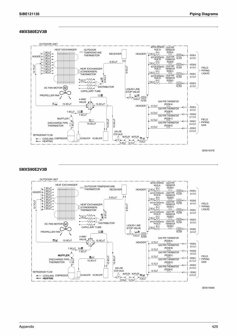
SiBE121135 Piping Diagrams
4MXS80E2V3B
5MXS90E2V3B
REFRIGERANT FLOW
HEADER
12.7
CuT
OUTDOOR UNIT
COOLINGHEATING
7.9CuT
7.9CuT
7.9CuT
7.9CuT
7.9CuT
7.9CuT
7.9CuT
7.9CuT
PROPELLER FAN
DC FAN MOTOR
COMPRESSOR
HEAT EXCHANGER
15.9CuT
MUFFLER
M
7.9CuT
7.9C
uT
ACCUMULATOR
7.9CuT
7.9CuT
CAPILLARY TUBE
15.9CuT
15.9CuT
DISTRIBUTOR
9.5C
uT
ACCUMULATOR
15.9
CuT
9.5CuT
RECEIVER
15.9
CuT
9.5C
uT
9.5CuT
HEADER
HEADER
FILTER
7.9CuT
7.9CuT
7.9CuT
7.9CuT
12.7CuT
12.7CuT
12.7CuT
12.7CuT
EVC
EVB
EVA
EVD
FILTER
FILTER
FILTER
FILTER
15.9CuT 12.7CuT 15.9CuT
MUFFLER MUFFLER
FIELD PIPING LIQUID
FIELD PIPING GAS
ROOM D (15.9 CuT)
ROOM C (15.9 CuT)
ROOM B (12.7 CuT)
ROOM A (9.5 CuT)
ROOM A (6.4 CuT)
ROOM B (6.4 CuT)
ROOM C (6.4 CuT)
ROOM D (6.4 CuT)
LIQUID PIPE THERMISTOR
(ROOM-D)
LIQUID PIPE THERMISTOR
(ROOM-C)
LIQUID PIPE THERMISTOR
(ROOM-B)
LIQUID PIPE THERMISTOR
(ROOM-A)
MOTOR OPERATED VALVE (A)
MOTOR OPERATED VALVE (B)
MOTOR OPERATED VALVE (C)
MOTOR OPERATED VALVE (D)
OUTDOOR TEMPERATURE THERMISTOR
HEAT EXCHANGER (CONDENSER) THERMISTOR
DISCHARGE PIPE THERMISTOR
GAS LINE STOP VALVE
GAS PIPE THERMISTOR (ROOM-A)
GAS PIPE THERMISTOR (ROOM-B)
GAS PIPE THERMISTOR (ROOM-C)
GAS PIPE THERMISTOR (ROOM-D)
4-WAY VALVE
LIQUID LINE STOP VALVE
3D051937E
12.7
CuT
HEATING
7.9CuT7.9CuT
7.9CuT
7.9CuT
7.9CuT7.9CuT
7.9CuT7.9CuT
15.9CuT
MUFFLER
7.9CuT
7.9C
uT
7.9CuT
7.9CuT
15.9CuT
15.9CuT
9.5C
uT15
.9C
uT
9.5CuT
15.9
CuT
9.5C
uT
9.5CuT FILTER
7.9CuT
7.9CuT
7.9CuT
7.9CuT
7.9CuT
12.7CuT
12.7CuT
12.7CuT
12.7CuT
12.7CuT
15.9CuT 12.7CuT 15.9CuT
OUTDOOR TEMPERATURE THERMISTOR
DISCHARGE PIPE THERMISTOR
GAS LINE STOP VALVE
LIQUID LINE STOP VALVE
MOTOR OPERATED VALVE (A)
MOTOR OPERATED VALVE (B)
MOTOR OPERATED VALVE (C)
MOTOR OPERATED VALVE (D)
MOTOR OPERATED VALVE (E)
LIQUID PIPE THERMISTOR
(ROOM-A)
LIQUID PIPE THERMISTOR
(ROOM-B)
LIQUID PIPE THERMISTOR
(ROOM-C)
LIQUID PIPE THERMISTOR
(ROOM-D)
LIQUID PIPE THERMISTOR
(ROOM-E)
FIELD PIPING LIQUID
FIELD PIPING GAS
HEAT EXCHANGER (CONDENSER) THERMISTOR
GAS PIPE THERMISTOR (ROOM-A)
GAS PIPE THERMISTOR (ROOM-B)
GAS PIPE THERMISTOR (ROOM-C)
GAS PIPE THERMISTOR (ROOM-D)
GAS PIPE THERMISTOR (ROOM-E)
ROOM A (6.4 CuT)
ROOM B (6.4 CuT)
ROOM C (6.4 CuT)
ROOM D (6.4 CuT)
ROOM E (6.4 CuT)
ROOM A (9.5 CuT)
ROOM B (9.5 CuT)
ROOM C (12.7 CuT)
ROOM D (15.9 CuT)
ROOM E (15.9 CuT)
HEAT EXCHANGER
HEADER
DC FAN MOTOR M
PROPELLER FAN
4-WAY VALVE
CAPILLARY TUBE
DISTRIBUTOR
RECEIVER HEADER
EVB
EVC
EVD
EVE
FILTER
FILTER
FILTER
FILTER
FILTER
HEADER
MUFFLER MUFFLERACCUMULATOR ACCUMULATORCOMPRESSOR
REFRIGERANT FLOW
COOLINGHEATING
MUFFLER
3D051936A
OUTDOOR UNIT
EVA
Appendix 429

Piping Diagrams SiBE121135
1.2 Indoor Unit1.2.1 Wall Mounted TypeFTXG25/35JV1BW(A) FTXG50JV1BW(A)
FTXS20/25K2V1B, CTXS15/35K2V1B FTXS25/35/42J2V1B
INDOOR UNIT
6.4CuT
HEAT EXCHANGER
CROSS FLOW FANFIELD PIPING6.4CuT M
FAN MOTORFIELD PIPING9.5CuT 9.5CuT
REFRIGERANT FLOWCOOLINGHEATING
THERMISTOR ON HEAT EXCH.
4D065855B
INDOOR UNIT
6.4CuT
HEAT EXCHANGER
CROSS FLOW FANFIELD PIPING6.4CuT M
FAN MOTORFIELD PIPING12.7CuT 9.5CuT
REFRIGERANT FLOWCOOLINGHEATING
THERMISTOR ON HEAT EXCH.
4D065856C
INDOOR UNIT
HEAT EXCHANGER7.0CuT
4.8CuT
7.0CuT
7.0C
uT
7.0CuT
CROSS FLOW FAN
M
9.5CuT
REFRIGERANT FLOWCOOLINGHEATING
FIELD PIPING(6.4CuT)
FIELD PIPING(9.5CuT)
FAN MOTOR
THERMISTOR ON HEAT EXCH.
4D058926N
CROSS FLOW FAN
9.5CuT
REFRIGERANT FLOW
FIELD PIPING
9.5CuT
6.4CuT
FIELD PIPING
M
COOLING
INDOOR UNIT
FAN MOTOR
HEAT EXCHANGER
6.4CuT
HEATING
THERMISTOR ON HEAT EXCH.
4D058897H
430 Appendix

SiBE121135 Piping Diagrams
FTXS50J2V1B FTXS60GV1B
FTXS71GV1B
CROSS FLOW FAN
COOLING
9.5CuT
6.4CuT
M
INDOOR UNIT
6.4CuT
REFRIGERANT FLOW
HEATING
FAN MOTORFIELD PIPING
HEAT EXCHANGER
FIELD PIPING
12.7CuT
THERMISTOR ON HEAT EXCH.
4D058898F
FIELD PIPING
FIELD PIPING(12.7CuT)
(6.4CuT)
CROSS FLOW FAN
FAN MOTOR
(7.9CuT)
INDOOR UNIT
(12.7CuT)
M
HEAT EXCHANGER
REFRIGERANT FLOWCOOLINGHEATING
THERMISTOR ON HEAT EXCH.
4D040081Y
(15.9CuT)
FIELD PIPING
FIELD PIPING
(6.4CuT)
CROSS FLOW FAN
FAN MOTOR
(7.9CuT)
INDOOR UNIT
(12.7CuT)
M
HEAT EXCHANGER
REFRIGERANT FLOW
COOLINGHEATING
THERMISTOR ON HEAT EXCH.
4D040082W
Appendix 431

Piping Diagrams SiBE121135
1.2.2 Floor Standing TypeFVXG25/35K2V1B FVXG50K2V1B
FVXS25/35FV1B FVXS50FV1B
INDOOR UNIT
MV RADIANT PANELTHERMISTOR 6.4CuTTHERMISTOR
HEAT EXCHANGER
6.4C
uT
6.4C
uT
CROSS FLOW FANFIELD PIPING
M6.4CuTFAN MOTOR
FIELD PIPING9.5CuT9.5CuT
REFRIGERANT FLOWCOOLINGHEATING
THERMISTOR ON HEAT EXCH.
4D071597
INDOOR UNIT
MV RADIANT PANELTHERMISTOR 6.4CuTTHERMISTOR
HEAT EXCHANGER
6.4C
uT
6.4C
uT
CROSS FLOW FANFIELD PIPING
M6.4CuTFAN MOTOR
FIELD PIPING9.5CuT12.7CuT
REFRIGERANT FLOWCOOLINGHEATING
THERMISTOR ON HEAT EXCH.
4D071598
THERMISTOR ON HEAT EXCH.
INDOOR UNIT
MUFFLER ASSY7.0CuT
6.4CuT
6.4CuT
6.4CuT
6.4CuT
(6.4CuT)
(9.5CuT)
FIELD PIPING
FIELD PIPING
TURBO FAN FAN MOTOR
9.5CuT
M
HEAT EXCHANGER
6.4C
uT
REFRIGERANT FLOW
COOLING
HEATING
4D056137B
FAN MOTOR
7.0CuT
TURBO FAN
6.4CuT
6.4CuT
6.4CuT
COOLING
M6.4CuT
6.4CuT
HEATING
HEAT EXCHANGER
6.4C
uT
6.4CuT
9.5CuT
REFRIGERANT FLOW
FIELD PIPING(6.4CuT)
FIELD PIPING(12.7CuT)
INDOOR UNIT
MUFFLER ASSY
THERMISTOR ON HEAT EXCH.
4D056138C
432 Appendix
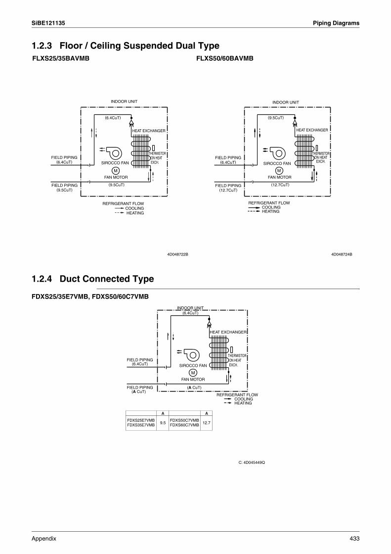
SiBE121135 Piping Diagrams
1.2.3 Floor / Ceiling Suspended Dual Type
1.2.4 Duct Connected Type
FDXS25/35E7VMB, FDXS50/60C7VMB
FLXS25/35BAVMB FLXS50/60BAVMB
(6.4CuT)
(9.5CuT)
THERMISTOR ON HEAT EXCH.
FIELD PIPING (6.4CuT)
FIELD PIPING (9.5CuT)
HEAT EXCHANGER
SIROCCO FAN
M
FAN MOTOR
REFRIGERANT FLOWCOOLINGHEATING
4D048722B
INDOOR UNIT
(9.5CuT)
(12.7CuT)
THERMISTOR ON HEAT
EXCH.FIELD PIPING
(6.4CuT)
FIELD PIPING (12.7CuT)
INDOOR UNIT
HEAT EXCHANGER
SIROCCO FAN
FAN MOTOR
REFRIGERANT FLOWCOOLINGHEATING
M
4D048724B
INDOOR UNIT(6.4CuT)
HEAT EXCHANGER
FIELD PIPING(6.4CuT) SIROCCO FAN
MFAN MOTOR
FIELD PIPING(A CuT)
REFRIGERANT FLOWCOOLINGHEATING
9.5
C: 4D045449Q
THERMISTOR ON HEAT EXCH.
(A CuT)
A
12.7
A
FDXS25E7VMBFDXS35E7VMB
FDXS50C7VMBFDXS60C7VMB
Appendix 433
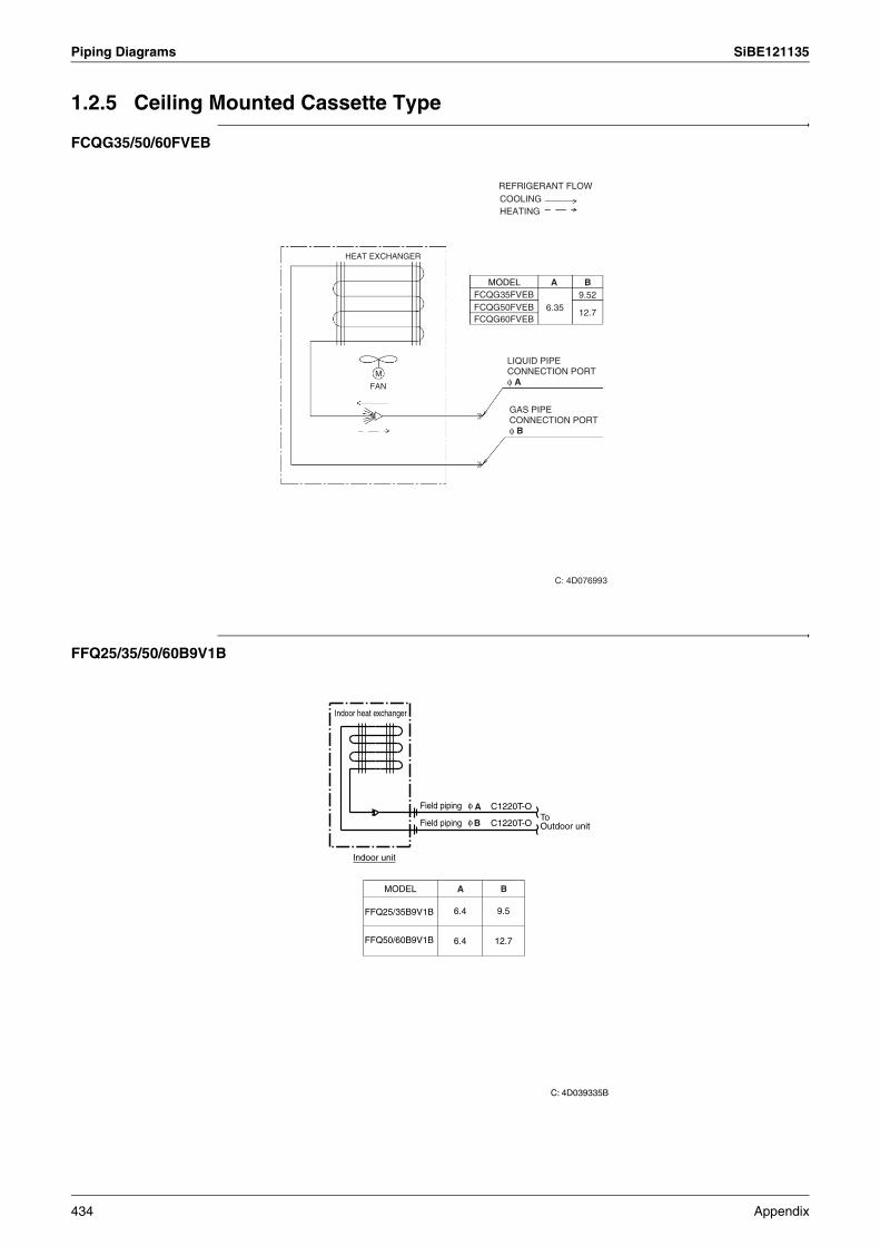
Piping Diagrams SiBE121135
1.2.5 Ceiling Mounted Cassette Type
FCQG35/50/60FVEB
FFQ25/35/50/60B9V1B
MODEL A B
REFRIGERANT FLOWCOOLINGHEATING
FCQG35FVEBFCQG50FVEBFCQG60FVEB
6.359.52
12.7
M
FAN
LIQUID PIPE CONNECTION PORT φ A
GAS PIPE CONNECTION PORT φ B
HEAT EXCHANGER
C: 4D076993
Indoor heat exchanger
Field piping φ C1220T-O
Field piping φ C1220T-O
Indoor unit
MODEL
6.4
6.4
9.5
12.7
FFQ25/35B9V1B
FFQ50/60B9V1B
To Outdoor unit
A
A B
B
C: 4D039335B
434 Appendix

SiBE121135 Piping Diagrams
1.2.6 Ceiling Suspended Type
FHQ35/50/60BWV1B
Field piping φ C1220T-O
Indoor heat exchanger
Field piping φ C1220T-O
Indoor unit
MODEL
6.4 9.5
6.4 12.7
FHQ35BWV1B
FHQ50, 60BWV1B
To Outdoor unit
A
A
B
B
C: 4D037995L
Appendix 435
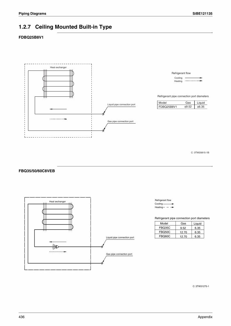
Piping Diagrams SiBE121135
1.2.7 Ceiling Mounted Built-in Type
FDBQ25B8V1
FBQ35/50/60C8VEB
C: 3TW20815-1B
ModelFDBQ25B8V1
Gasφ9.52
Liquidφ6.35
Refrigerant pipe connection port diameters
Refrigerant flow
CoolingHeating
Heat exchanger
Liquid pipe connection port
Gas pipe connection port
C: 3TW31275-1
FBQ35C
FBQ50C
FBQ60C
9.52
12.70
12.70
6.35
6.35
6.35
Refrigerant pipe connection port diameters
Model Gas Liquid
Liquid pipe connection port
Gas pipe connection port
Heat exchangerRefrigerant flow
Cooling
Heating
436 Appendix
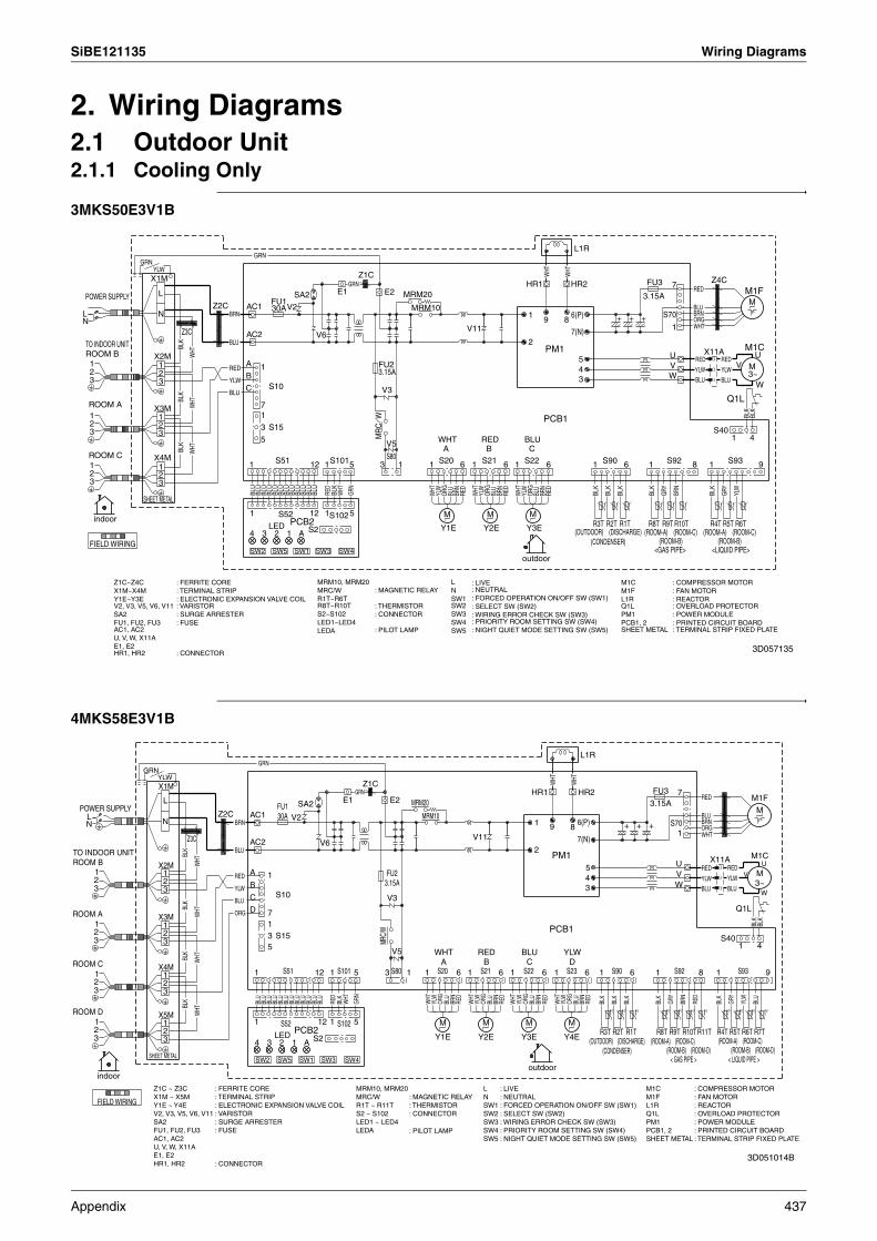
SiBE121135 Wiring Diagrams
2. Wiring Diagrams2.1 Outdoor Unit2.1.1 Cooling Only
3MKS50E3V1B
4MKS58E3V1B
indoor
FIELD WIRING
outdoor
V
YLW
WHT
R5T
WHT
E1
S51
S403
A
BLK
FU2
3
BLU
PM1
1
R8T
S22
N
YLW
C
YLW
BLK
V
Z4C
SW1
BLU
4
BLU
BLK
WHT
MR
CW
BLU
1
WHT
RED3
FU1
8
1
SA2
BLU
S93
BLK
R9T
1
BLU
Y1E
8
R3T
L1R
WHT
1
V5
2
CBLK
1 M
Q1L
S15
3
1
V6
ROOM C
BRN
YLW4
WHT
YLW
2
SHEET METAL
1
A
BRN
1
S21
BLU
X11A
PCB1
S10
ORG
M
3
SW3
S80
BRN
RED
RED
9
RED
S102
3.15A
7
RED
Y3E
ROOM A
YLW
BLU
5
BLU
X4M
PCB2
1
12R6T
X1M
Y2E
ORG
1
BLU
W
S90
ORG
BLU
7(N)
V2
4B
12
E2
RED
1
V11
ORG
BRN
GRN
Z3C
3
BLU
S20
L
U
(ROOM-B)(ROOM-A) (ROOM-C)
BLU
POWER SUPPLY
2
BLU
L
B BLU
GRN
M
3
FU3
6(P)
HR1
A
(ROOM-A) (ROOM-C)
30A1
V3
5
M1C
66
BLU
HR2
R4T
YLW
R10T
BLK
6
<GAS PIPE>
3.15ABL
U
SW4
6
2
R2T
3
S22
SW2
AC2
5 RED
R1T
BRN
LED
BLU
GRY
X3M 7
WHT
U
BRN
RED
WHT
1
M1F
3
1
12
MRM20
1
AC1
2
N
5
S101
3 BLU
1
BLK
Z2C
11
BLK
9
SW5
YLW
GRN
WHT
MRM10
3~
BLK
Z1C
S70
(ROOM-B)
GRN
X2M
1
BLK
W
2
WHT
<LIQUID PIPE>
M
1
BLK
BLU
WHT
RED
M
1
S52
S92
GRY
BLU
t˚ t˚ t˚ t˚ t˚ t˚ t˚ t˚ t˚
+ + +
(OUTDOOR) (DISCHARGE) (CONDENSER)
TO INDOOR UNIT ROOM B
Z1C~Z4CX1M~X4MY1E~Y3EV2, V3, V5, V6, V11SA2FU1, FU2, FU3AC1, AC2U, V, W, X11AE1, E2HR1, HR2
: FERRITE CORE: TERMINAL STRIP: ELECTRONIC EXPANSION VALVE COIL: VARISTOR: SURGE ARRESTER: FUSE
: CONNECTOR
MRM10, MRM20MRC/WR1T~R6TR8T~R10TS2~S102LED1~LED4LEDA
: MAGNETIC RELAY
: THERMISTOR: CONNECTOR
: PILOT LAMP
LNSW1SW2SW3SW4SW5
: LIVE: NEUTRAL: FORCED OPERATION ON/OFF SW (SW1): SELECT SW (SW2): WIRING ERROR CHECK SW (SW3): PRIORITY ROOM SETTING SW (SW4): NIGHT QUIET MODE SETTING SW (SW5)
M1CM1FL1RQ1LPM1PCB1, 2SHEET METAL
: COMPRESSOR MOTOR: FAN MOTOR: REACTOR: OVERLOAD PROTECTOR: POWER MODULE: PRINTED CIRCUIT BOARD: TERMINAL STRIP FIXED PLATE
3D057135
NL
POWER SUPPLY
ROOM D
ROOM C
ROOM A
3
3
3
3
2
2
2
2
1
1
1
1
FIELD WIRING
indoor
GRN
SHEET METAL
YLW
X5M
X4M
X3M
X2M
X1M
L
3
3
3
3
2
2
2
2
N
1
1
1
1
Z3C
BLK
BLK
BLK
BLK
WHT
WHT
WHT
WHT
Z2C
YLW
RED
ORG
BLU
BRN
BLU
A
B
C
D
AC2
AC1
1
4
1
SW2
GRN
BLU
BLU
71
53
1
3
BLU
S10
S15
BLU
SW5
LED
FU130A
S51
2
S52
BLU
BLU
1
BLU
PCB2
V2
BLU
SW1
BLU
SA2
A
BLU
BLU
12
S2
12
V6
BLU
SW3
1
1
RED
S102
S101
BLK
E1
SW4
WHT
5
5
GRN
GRN
Z1C
3
MRC/
W
FU23.15A
V3
E2
S80
V5
1
MRM20
MRM10
1
WHT
YLW
WHT
Y1E
S20
M
A
ORG
BLU
BRN
6
RED
1
WHT
V11
YLW
Y2E
RED
S21
M
B
ORG
BLU
BRN
6
RED
1
WHT
YLW
Y3E
BLU
S22
M
C
ORG
outdoor
BLU
2
1
HR1
BRN
6
RED
9
PCB1
PM1
WHT
1
WHT
YLW
Y4E
YLW
S23
M
8
D
ORG
WHT
BLU
7(N)
6(P)
HR2
L1R
BRN
345
6
RED
R3T
1
BLK
t°
R2T
S90
BLK
t°
+
R1T
BLK
6
t°
+ +
(ROOM-A) (ROOM-C)
3.15A
FU3
R8T
1
BLK
t°
R9T
GRY
S70
S92
WVU
t°
1
7
R10T
BRN
t°
R11T
RED
8
YLW
WHTORGBRN
RED
BLU
RED
BLU
t°
(ROOM-A) (ROOM-C)
X11A
R4T
1
BLK
S40
t°
YLW
BLU
RED
R5T
GRY
Q1L
S93
t°
1
R6T
V
YLW
t°
M1F
R7T
M1C
BLK
M
M3~
BLU
4
W
U
BLK
t°
9
(ROOM-B) (ROOM-D)< GAS PIPE >
(ROOM-B) (ROOM-D)< LIQUID PIPE >
TO INDOOR UNIT ROOM B
(OUTDOOR) (DISCHARGE) (CONDENSER)
Z1C ~ Z3CX1M ~ X5MY1E ~ Y4EV2, V3, V5, V6, V11SA2FU1, FU2, FU3AC1, AC2U, V, W, X11AE1, E2HR1, HR2
: FERRITE CORE: TERMINAL STRIP: ELECTRONIC EXPANSION VALVE COIL: VARISTOR: SURGE ARRESTER: FUSE
: CONNECTOR
MRM10, MRM20MRC/WR1T ~ R11TS2 ~ S102LED1 ~ LED4LEDA
: MAGNETIC RELAY: THERMISTOR: CONNECTOR
: PILOT LAMP
LNSW1SW2SW3SW4SW5
: LIVE: NEUTRAL: FORCED OPERATION ON/OFF SW (SW1): SELECT SW (SW2): WIRING ERROR CHECK SW (SW3): PRIORITY ROOM SETTING SW (SW4): NIGHT QUIET MODE SETTING SW (SW5)
M1CM1FL1RQ1LPM1PCB1, 2SHEET METAL
: COMPRESSOR MOTOR: FAN MOTOR: REACTOR: OVERLOAD PROTECTOR: POWER MODULE: PRINTED CIRCUIT BOARD: TERMINAL STRIP FIXED PLATE
3D051014B
Appendix 437

Wiring Diagrams SiBE121135
4MKS75F2V1B
5MKS90E2V3B
indoor outdoor
FIELD WIRING
1
3.15AB
A
YLW
S22
POWER SUPPLY
X4M
4W
HT
M1C
ROOM D BLU
RED
BLU
WHT
7
33~
YLW
1
W
1
ORG
BLU
7(N)
2
M1F
L1R
8
M
ORG
3
M
1 6
BRN
WHT
S93
5
AC2
L
YLW
1
REDFU2
D
V5
Z6C
2
2
12
7
1
WHT
SW5
1
WHT
Z3C
GRN
S70
BLU
N
SHEET METAL
6
WHT
1
1
1
RED
YLW
1
S2
MRM1030A
MRC/W
3
BLK
WHT
BLU
BRN
BLK
SW1
Y1E
SW2
BRN
3
RED BR
N
1
BLU
M
12
GRN
S52 5
BLK
U
BLK
GRN
GRY
1
S20
SW4
8
BLU
YLW
1
BLU
C
L
BLK
3.15A
FU3
3
Z2C
BRN
X1M
S23
1
S101
WHT
RED
1
M
PM1
YLW
AC1
PCB1
BLU
Z5C
6
BLU
YLW
LED M
RED
V
2
9
U
6
GRY
HR1
32
Z4C
Y3E
E1BL
K
1
X3M
Y4E
BLU
B
BLU
X11A
YLW
YLW
RED
ORG
ROOM A
BLU
YLW
BLK
WHT RED
1
5BL
U
MRM20
BLU
Y2E
V2
D
BLU
ORG
V9
BLU W
C
2
BLK
2
3
Z1C
BLU
S21
BLU
9
PCB2
ROOM C
E2
2
S15
RED
6
ORG
4
2
FU1 V100
1
1
BLK
5
3
3
A
V3
1
3
X5M
4 3
BLU
M
1
WHT
S102
6(P)
Q1L
ORG
WHT
2
WHTBL
K
N
BLU
1
1
BRN
V
3
A
X2M
WHT
BRN
1
S51
BLK
S90
SW3
S10
S80
GRN
RED
1 S92
RED
BLU
BLU
SA2
S40
HR2
BLK
t° t° t° t° t° t° t° t° t°t° t°
+ ++
(ROOM-B)
R9T
<GAS PIPE>
R8T R5TR2T R6TR3T
<LIQUID PIPE>
R10T R4TR1T R11T(ROOM-A) (ROOM-C)
R7T
(ROOM-D) (ROOM-B)(ROOM-A) (ROOM-C)
(ROOM-D)
TO INDOOR UNIT ROOM B
(OUTDOOR) (DISCHARGE) (CONDENSER)
Z1C~Z6CX1M~X5MY1E~Y4EV2, V3, V5, V9, V100SA2FU1, FU2, FU3AC1, AC2U, V, W, X11AE1, E2HR1, HR2
: FERRITE CORE: TERMINAL STRIP: ELECTRONIC EXPANSION VALVE COIL: VARISTOR: SURGE ARRESTER: FUSE
: CONNECTOR
MRM10, MRM20MRC/WR1T~R11TS2~S102LED1~LED4LEDA
: MAGNETIC RELAY: THERMISTOR: CONNECTOR
: PILOT LAMP
LNSW1SW2SW3SW4SW5
: LIVE: NEUTRAL: FORCED OPERATION ON/OFF SW (SW1): SELECT SW (SW2): WIRING ERROR CHECK SW (SW3): PRIORITY ROOM SETTING SW (SW4): NIGHT QUIET MODE SETTING SW (SW5)
M1CM1FL1RQ1LPM1PCB1, 2SHEET METAL
: COMPRESSOR MOTOR: FAN MOTOR: REACTOR: OVERLOAD PROTECTOR: POWER MODULE: PRINTED CIRCUIT BOARD: TERMINAL STRIP FIXED PLATE
3D055885
2TW27596-1A
ROOM C
ROOM A
ROOM
-A
ROOM
-B
ROOM
-C
ROOM
-D
ROOM
-E
ROOM
-A
ROOM
-B
ROOM
-C
ROOM
-D
ROOM
-E
CO
ND
EN
SE
R
DIS
CH
AR
GE
OU
TDO
OR
LIQ
UID
PIP
E
GA
S P
IPE
ROOM D
ROOM E
indoor outdoor
SHEETMETAL
TO INDOOR UNIT
ROOM B
Q1LPM1PCB1, 2SHEET METALF2UQ1DI
OVERLOAD PROTECTORPOWER MODULEPRINTED CIRCUIT BOARDTERMINAL STRIP FIXED PLATEFIELD FUSEFIELD EARTH LEAKAGE BREAKER (300mA)
1N ~50Hz230V
WHT : WHITEYLW : YELLOWORG : ORANGERED : REDGRN : GREENBLU : BLUEBRN : BROWNBLK : BLACKGRY : GREY
: FIELD WIRING: PROTECTIVE EARTH (SCREW)
: TERMINAL STRIP: TERMINAL: RELAY CONNECTOR: CONNECTOR: CONNECTION
L : LIVEN : NEUTRAL
Z1C~Z6CX1M~X6MY1E~Y5EV2, V3, V5V9, V100SA2FU1, FU2, FU3AC1, AC2U, V, W, X11AE1, E2HR1, HR2MRM10, MRM20MRC/W
FERRITE CORETERMINAL STRIPELECTRONIC EXPANSION VALVE COIL
VARISTOR
SURGE ARRESTERFUSE
CONNECTOR
MAGNETIC RELAY
R1T~R3TR4T~R8TR9T~R13TS2~S102LED1~LED5LEDASW1SW2SW3SW4SW5M1CM1FL1R
THERMISTOR
CONNECTOR
LIGHT EMITTING DIODE
FORCED OPERATION SW (SW1)OPERATION MODE SW (SW2)WIRING ERROR CHECK SW (SW3)PRIORITY ROOM SETTING SW (SW4)NIGHT QUIET MODE SETTING SW (SW5)COMPRESSOR MOTORFAN MOTORREACTOR
438 Appendix
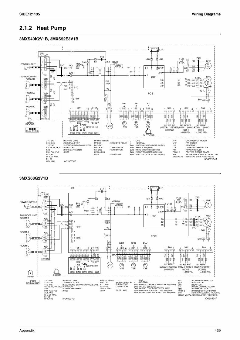
SiBE121135 Wiring Diagrams
2.1.2 Heat Pump
3MXS40K2V1B, 3MXS52E3V1B
3MXS68G2V1B
INDOOR
OUTDOOR
FIELD WIRINGSW2
BRN
ORG
MRC
BLU
BLU
HR2MRM20
BLU
1
S21
2
V5
<GAS PIPE>
BLK
WHT
6(P)
RED
YLW
PCB1
BRN
BRN
W
GRY
N
WHT
4
Q1LBL
K
V11
4
S52
U
BLK
POWER SUPPLY
BLU
(OUTDOOR)
S51
YLW
6
A
1S20
3
(CONDENSER)
BLU
R1T
1
2
1
RED
12
SW4
BLK
RED
X11A
ORG
2
1
3
3~
7
R3T
3
(ROOM-C)
V3
Z1C
X4M
9 8
A
5
M
S70
R10T
V6
(ROOM-C)
3
WHT
(ROOM-A)
BLU
9
BLU
SW3
(DISCHARGE)
BLU
1
SW5
BLU
ROOM C
YLW
Y2E
<LIQUID PIPE>
C
E1
B
GRN
BRN
BLK
S22
WHT
1
TO INDOOR UNIT
1
BLU
(ROOM-B)(ROOM-B)
S15
YLW
Z3C
BLK
2
YLW
S92
R5T
SA2
ROOM B U
1B
ORG1
1
WHT
1
E2
R4TM
2
S93
S102
RED
3.15A
7
M
GRN
5
W
M
1
M1F
BRN
BLU
2
FU2
WHT RED
S101
BLU
3
33
2
1S90
VRED
BLK
X3M
PCB2
S80
5
PM1
ROOM A
1
X1M
YLW
BLU
BLU
8
WHT
BLU
7(N)
R6T
N
12
BLU
Z4C
X2M
BLK
M
BLU3
R2T5
1
1
V2
BLU
GRN
BLU
3.15A
WHT
YLW
R8T(ROOM-A)
L1R
C
BLU
30A
BLU
BLK
LED
3
V
1 1
M1C
WHT
1
SW1
Y1EY1R
ORG
WHT
1
FU1
BRN
SHEET METAL
BLU
S10
3
HR1
GRN
L
6
BLK
GRY
S2
Z2C
RED
YLW
MRM10
S40
1
BLU
W
6
AC1
R9T2 A Y3E
4
BLK
AC2
WHT
RED
L
1
FU3
6
RED
t˚ t˚ t˚ t˚ t˚ t˚ t˚ t˚ t˚
+ + +
Z1C~Z4CX1M~X4MY1E Y3EV2, V3, V5, V6, V11SA2FU1, FU2, FU3AC1, AC2U, V, W, X11AE1, E2HR1, HR2
: FERRITE CORE: TERMINAL STRIP: ELECTRONIC EXPANSION VALVE COIL: VARISTOR: SURGE ARRESTER: FUSE
: CONNECTOR
MRM10, MRM20MRC/WR1T~R6TR8T~R10TS2~S102LED1~LED4LEDA
: MAGNETIC RELAY
: THERMISTOR: CONNECTOR
: PILOT LAMP
LNSW1SW2SW3SW4SW5
: LIVE: NEUTRAL: FORCED OPERATION ON/OFF SW (SW1): SELECT SW (SW2): WIRING ERROR CHECK SW (SW3): PRIORITY ROOM SETTING SW (SW4): NIGHT QUIET MODE SETTING SW (SW5)
M1CM1FL1RQ1LPM1PCB1, 2Y1RSHEET METAL
: COMPRESSOR MOTOR: FAN MOTOR: REACTOR: OVERLOAD PROTECTOR: POWER MODULE: PRINTED CIRCUIT BOARD: REVERSING SOLENOID VALVE COIL: TERMINAL STRIP FIXED PLATE
3D057134A
indooroutdoor
FIELD WIRING
Y3E
MV
RED
X4M
RED
WHT
1
WHT
V3
SA2
S102
WHT
2
M
12
V9
GRY
R6T
BLK
E2
GRN
SW2
ROOM C
BLU
1
7 (N)
2
+
BRN
Z6C
R1T
X2M
S2
BLK
2
BLU
7
Y1R
9
YLW
POWER SUPPLY
BRN
SW1
S92
BLU
ORG
S931
WHT
WHT
S10
BLK
FU1
YLW
GRY
5
3.15A
BLU
BLU
R4T12
6
BLU
(CONDENSER)
W
1
YLW
WHT
(ROOM-A)
MRM20
Y2E
RED
(ROOM-C)
1
L
Z3C
FU3
W
BRN
3
2
HR2
BLU
3
BLU
PM1
BLU
1
U
(ROOM-B)
Q1L
GRN
S20
Z2C
BRN
M
3
Z1C
YLW
3
S40
S80
5
BLUX11A
5
4
BLK
Z5C
YLW
1
V5
L
BLU
BLK
X3M
4
M1C
V2
WH
T
R2T
AC1
GRN
S70
WHT
(OUTDOOR)
HR1
MRM10
BLU
1
BRN
BLU
33
1
ORG
LED
FU2
BLK
RED
<LIQUID PIPE>
M1FRED
3.15A
2
WHT
ORG
SW3
3
t˚ t˚ t˚ t˚ t˚ t˚ t˚ t˚ t˚
<GAS PIPE>SW5
BRED
M
BLU
6
3
R5T
Z4C
(ROOM-A)
1
BLK
BRN
1
1
BLK
21
C
ROOM A
M
S90
1
BLU
BLK
91
R9T
1 V
R10T
2
BLU
4
1
BLU
AC2
6
3
BLU
1
(DISCHARGE)
S51
A
BLU
BLK
R8T
+
WHT
ORG
BLU
WHT
5
8
S52PCB2
L1R
S101
U
3
BLU
YLW
SW4
GRN
N
2
1C
R3T
N
1
BLU
BLK
PCB1
(ROOM-B)
+
(ROOM-C)
SHEET METAL
Y1E
BLU
S21
6 (P)
RED
1 MRC / W
6
YLW
3 ~
30A
B
RED
S15
E1
RED
7
X1M
1
S22
YLW
A
1
8A
V100
TO INDOOR UNIT ROOM B
Z1C~Z6CX1M~X5MY1E~Y4EV2, V3, V5, V9, V100SA2FU1, FU2, FU3AC1, AC2U, V, W, X11AE1, E2HR1, HR2
: FERRITE CORE: TERMINAL STRIP: ELECTRONIC EXPANSION VALVE COIL: VARISTOR: SURGE ARRESTER: FUSE
: CONNECTOR
MRM10, MRM20MRC / WR1T~R11TS2~S102LED1~LED4LEDA
: MAGNETIC RELAY: THERMISTOR: CONNECTOR
: PILOT LAMP
LNSW1SW2SW3SW4SW5
: LIVE: NEUTRAL: FORCED OPERATION ON/OFF SW (SW1): SELECT SW (SW2) : WIRING ERROR CHECK SW (SW3): PRIORITY ROOM SETTING SW (SW4): NIGHT QUIET MODE SETTING SW (SW5)
M1CM1FL1RQ1LPM1PCB1, 2Y1RSHEET METAL
: COMPRESSOR MOTOR: FAN MOTOR: REACTOR: OVERLOAD PROTECTOR: POWER MODULE: PRINTED CIRCUIT BOARD: REVERSING SOLENOID VALVE COIL: TERMINAL STRIP FIXED PLATE
3D058434A
Appendix 439

Wiring Diagrams SiBE121135
4MXS68F2V1B
4MXS80E2V3B
indooroutdoor
FIELD WIRING
9
BLK
BLU
1
N
BLU
S102
RED
S20
RED
4
WHT
3
WHT
BLK
Y1R
2
1 9
RED
A
AWHT
2(ROOM-B)
V
R9T
RED
SW3
LED
<GAS PIPE>
BLU
R8T R5T
S21
5
L
BLU
BLU
YLW
Z2C
WHT
BLU
1U
3
1
BLU
1
M1F
6(P)
BYLW
U
Z5C
BLK
23
1
S151
8
S70
3.15A
1
M
ROOM D
S92
WHT
1
ORG
ROOM C
3
MRM20
BLU
S2
8
3~
D
7(N)
BLU
S80
YLW
GRN
BLUBL
U
S90
V3
ORG GR
Y
C
AC2
PCB2
SW5
RED
2
GRY
1
12
2
L1R
SHEET METAL
YLW
BLU
6
V9
HR2
5W
HTM
6
D
GRN
BRN
YLW
RED BL
K
BLK
WHT BR
N
E1
BLU
2
BLU
BLK
RED
1
BLU
S22
BRN
POWER SUPPLY
1
V100
YLW
GRN
Y2E
2
BLK
BRN
RED
S101
1
YLW
Z3C
MRC/W
SW2
Q1L
1
X2M
R2T
S51B
GRN
2
BRN
6
PM1
2
1
M1C
YLW
X4M
L
3
SA2
N
(CONDENSER)4
BLK
1
BLU
WHT
E2
S10BLU
FU2 V
3
12
RED
BLU
S93
YLW
M
3
ORG
WHT
BLK
ORG
YLW
BRN
3
M
X1M
WHT
BLU
BLK
7
W
BLU
3
6
3
M
SW1
R6T
BLU
1
R3T
3
C
<LIQUID PIPE>
BLK
S40
1
V5
1 S23
M
BLK
R10T
1
W
FU3
V2
Z4C
Y1E
5
5
PCB1
30A
RED
X11A
A
Y4E
R4T
X5M
AC1
X3M
RED
7
3
R1T
BLU
ORG
1R11T
WHT
MRM10
(ROOM-A)Y3E
1
FU1
(OUTDOOR)
Z6C
ROOM A
1
1
R7T
3.15A
BLUBRN
6
WHT
S52
BLU
SW4
2
BLU
WHT
1
1
HR1
Z1C
4
ORG
+ + +
t° t° t° t° t° t° t° t° t°t° t°
(DISCHARGE) (ROOM-C)(ROOM-D) (ROOM-B)
(ROOM-A) (ROOM-C)(ROOM-D)
TO INDOOR UNIT ROOM B
Z1C~Z6CX1M~X5MY1E~Y4EV2, V3, V5, V9, V100SA2FU1, FU2, FU3AC1, AC2U, V, W, X11AE1, E2HR1, HR2
: FERRITE CORE: TERMINAL STRIP: ELECTRONIC EXPANSION VALVE COIL: VARISTOR: SURGE ARRESTER: FUSE
: CONNECTOR
MRM10, MRM20MRC/WR1T~R11TS2~S102LED1~LED4LEDA
: MAGNETIC RELAY: THERMISTOR: CONNECTOR
: PILOT LAMP
LNSW1SW2SW3SW4SW5
: LIVE: NEUTRAL: FORCED OPERATION ON/OFF SW (SW1): SELECT SW (SW2): WIRING ERROR CHECK SW (SW3): PRIORITY ROOM SETTING SW (SW4): NIGHT QUIET MODE SETTING SW (SW5)
M1CM1FL1RQ1LPM1PCB1, 2Y1RSHEET METAL
: COMPRESSOR MOTOR: FAN MOTOR: REACTOR: OVERLOAD PROTECTOR: POWER MODULE: PRINTED CIRCUIT BOARD: REVERSING SOLENOID VALVE COIL: TERMINAL STRIP FIXED PLATE
3D055495
2TW27576-1B
ROOM C
ROOM A
ROOM
-A
ROOM
-B
ROOM
-C
ROOM
-D
ROOM
-A
ROOM
-B
ROOM
-C
ROOM
-D
CO
ND
EN
SE
R
DIS
CH
AR
GE
OU
TDO
OR
LIQ
UID
PIP
E
GA
S P
IPE
ROOM D
indoor outdoor
SHEETMETAL
TO INDOOR UNIT
ROOM B
Q1LPM1PCB1, 2Y1RSHEET METALF2UQ1DI
OVERLOAD PROTECTORPOWER MODULEPRINTED CIRCUIT BOARDFOUR WAY VALVE COILTERMINAL STRIP FIXED PLATEFIELD FUSEFIELD EARTH LEAKAGE BREAKER (300mA)
1N ~50Hz230V
WHT : WHITEYLW : YELLOWORG : ORANGERED : REDGRN : GREENBLU : BLUEBRN : BROWNBLK : BLACKGRY : GREY
: FIELD WIRING: PROTECTIVE EARTH (SCREW)
: TERMINAL STRIP: TERMINAL: RELAY CONNECTOR: CONNECTOR: CONNECTION
L : LIVEN : NEUTRAL
Z1C~Z6CX1M~X5MY1E~Y4EV2, V3, V5V9, V100SA2FU1, FU2, FU3AC1, AC2U, V, W, X11AE1, E2HR1, HR2MRM10, MRM20MRC/W
FERRITE CORETERMINAL STRIPELECTRONIC EXPANSION VALVE COIL
VARISTOR
SURGE ARRESTERFUSE
CONNECTOR
MAGNETIC RELAY
R1T~R3TR4T~R7TR8T~R11TS2~S102LED1~LED4LEDASW1SW2SW3SW4SW5M1CM1FL1R
THERMISTOR
CONNECTOR
LIGHT EMITTING DIODE
FORCED OPERATION SW (SW1)OPERATION MODE SW (SW2)WIRING ERROR CHECK SW (SW3)PRIORITY ROOM SETTING SW (SW4)NIGHT QUIET MODE SETTING SW (SW5)COMPRESSOR MOTORFAN MOTORREACTOR
440 Appendix
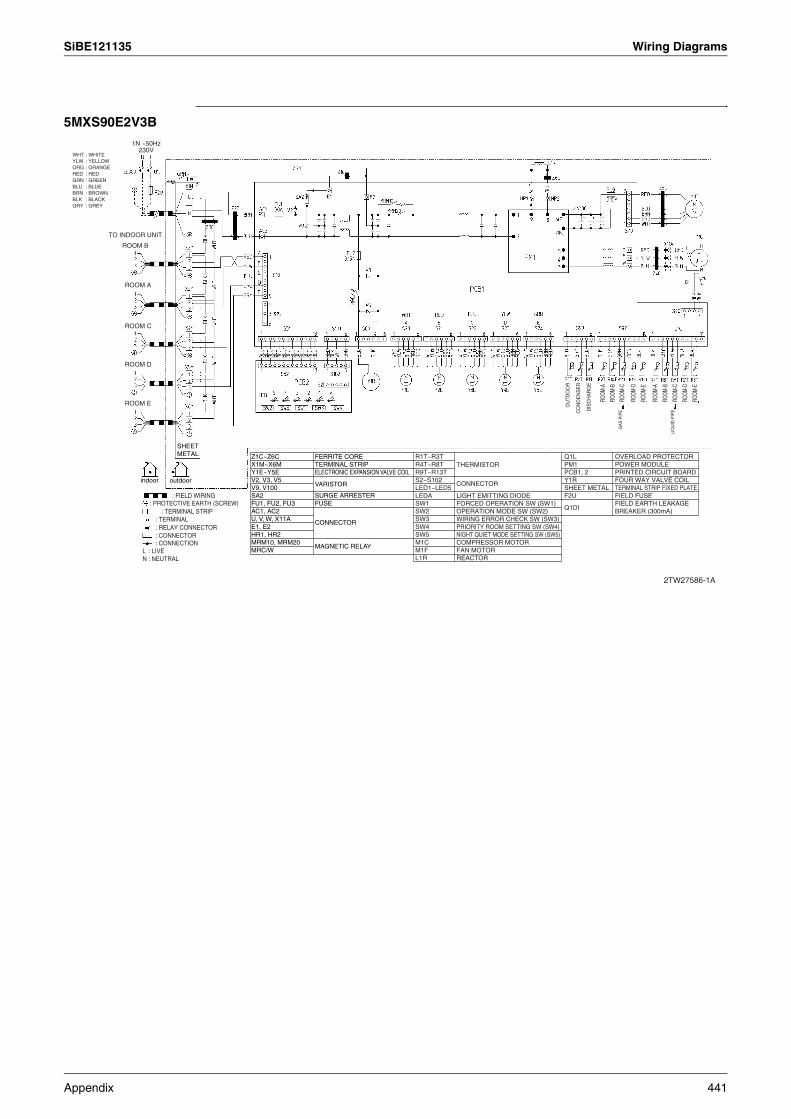
SiBE121135 Wiring Diagrams
5MXS90E2V3B
2TW27586-1A
ROOM C
ROOM A
ROOM
-A
ROOM
-B
ROOM
-C
ROOM
-D
ROOM
-E
ROOM
-A
ROOM
-B
ROOM
-C
ROOM
-D
ROOM
-E
CO
ND
EN
SE
R
DIS
CH
AR
GE
OU
TDO
OR
LIQ
UID
PIP
E
GA
S P
IPE
ROOM D
ROOM E
indoor outdoor
SHEETMETAL
TO INDOOR UNIT
ROOM B
Q1LPM1PCB1, 2Y1RSHEET METALF2U
Q1DI
OVERLOAD PROTECTORPOWER MODULEPRINTED CIRCUIT BOARDFOUR WAY VALVE COILTERMINAL STRIP FIXED PLATEFIELD FUSEFIELD EARTH LEAKAGE BREAKER (300mA)
1N ~50Hz230V
WHT : WHITEYLW : YELLOWORG : ORANGERED : REDGRN : GREENBLU : BLUEBRN : BROWNBLK : BLACKGRY : GREY
: FIELD WIRING: PROTECTIVE EARTH (SCREW)
: TERMINAL STRIP: TERMINAL: RELAY CONNECTOR: CONNECTOR: CONNECTION
L : LIVEN : NEUTRAL
Z1C~Z6CX1M~X6MY1E~Y5EV2, V3, V5V9, V100SA2FU1, FU2, FU3AC1, AC2U, V, W, X11AE1, E2HR1, HR2MRM10, MRM20MRC/W
FERRITE CORETERMINAL STRIPELECTRONIC EXPANSION VALVE COIL
VARISTOR
SURGE ARRESTERFUSE
CONNECTOR
MAGNETIC RELAY
R1T~R3TR4T~R8TR9T~R13TS2~S102LED1~LED5LEDASW1SW2SW3SW4SW5M1CM1FL1R
THERMISTOR
CONNECTOR
LIGHT EMITTING DIODEFORCED OPERATION SW (SW1)OPERATION MODE SW (SW2)WIRING ERROR CHECK SW (SW3)PRIORITY ROOM SETTING SW (SW4)NIGHT QUIET MODE SETTING SW (SW5)COMPRESSOR MOTORFAN MOTORREACTOR
Appendix 441
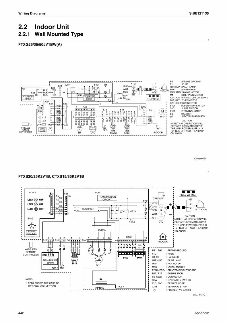
Wiring Diagrams SiBE121135
2.2 Indoor Unit2.2.1 Wall Mounted Type
FTXG25/35/50JV1BW(A)
FTXS20/25K2V1B, CTXS15/35K2V1B
X1M 1A1P F1U H1S21 2BLK 1S25 3.15A~ 32WHTA3P C102 V11 1BLK
H2OUTDOORRED 3MR10S36 HABLK GRN
/BLK3 3 YLWC101 H3GRN FIELD WIRING./YLWFG
A2PS51 S46t˚
S200BLK1 1 7 1S42R1T BLK 7S41S32 REDS52 BLK M1 2 3 102 85 9741 6BLK1 3 4BLK BLK
BLK
BLK
BLK
BLK
BLK
BLK
3 18 BLU M1FH1P BLK BRNBLK CAUTIONBLU
BLU
ORGPN
K
PN
K
BLK
BLK
RE
D
RE
D
H2P YLW
YLW
OR
G
OR
G
BLK 1 WHTBLK
BLK
BLK
BLK
BLK
BLK
BLK
BLKS1W 9 9t˚ MSWMSWBZ
M R2TINDOORS1CM1
WIRELESS REMOTE
CONTROLLER
INTELLIGENT EYE SENSOR
SIGNAL RECEIVER
TRANSMISSION CIRCUIT
M1S (MAIN)
M2S (SUB)
FGF1UH1P, H2PM1FM1S, M2SM1A1P~A3PR1T, R2TS25~S200S1WS1CX1MBZ
: FRAME GROUND: FUSE: PILOT LAMP: FAN MOTOR: SWING MOTOR: STEPPING MOTOR: PRINTED CIRCUIT BOARD: THERMISTOR: CONNECTOR: OPERATION SWITCH: LIMIT SWITCH: TERMINAL STRIP: BUZZER: PROTECTIVE EARTH
NOTE THAT OPERATION WILL RESTART AUTOMATICALLY IF THE MAIN POWER SUPPLY IS TURNED OFF AND THEN BACK ON AGAIN.
3D065507D
PCB 2 PCB 1S26S27S27S27 FIELD WIRING.BLK111 10
BLK GRN/YLWBLKH1PLED1 H1PLED1 H1PLED1
FG2BLKBLK 3H2PLED2 H2PLED2 H2PLED2 FG1BLK
2BLK RECTIFIER H3BLKH3PLED3 H3PLED3 H3PLED3 + 33 OUTDOOR–BLK 1MR10V1H21BLK101010 22H1
S1W 11
t° X1M
+–R1T
IPM200
1 1 113 2 5 10S4031 6 9 12S25 S32 S200S6 INDOOR
BLK
BLK
BLK
BLK
BLK
BLK
BLK
BLK
BLK
BLK
BLK
BLK
BLK
BLK
BLK
BLK
BLK
BLK
BLK
BLK
BLK
BLK
BLK
BLK
BLK
BLK
BLK
BLK
BLK
BLK
BLK
BLK
BLK
BLK
BLK
YLW
YLW
BLK
BLK
BLK
BLK
BLK
BLK
BLK
BLK
BLK
BLK
BLK
WHT
WHT
WHT
BLU
RED
BLU
RED
BLK
BLK
BLK
ORG
ORG
S36S36S36 4 14 14 14 116 16 16 16S601S601S601S601S602S602S602S602
MM
t° M1SM1SM1F
PCB 3 R2TR2T
NOTE) S21S21S21S21
PCB 4OPTIONOPTION
Z1C
N=3
GRN
GRN
RED
WHT
BLK
Z2CN=2
: FRAME GROUND: FUSE: HARNESS: PILOT LAMP: FAN MOTOR: SWING MOTOR: PRINTED CIRCUIT BOARD: THERMISTOR: CONNECTOR: OPERATION SWITCH: FERRITE CORE: TERMINAL STRIP: PROTECTIVE EARTH
FG1, FG2F1UH1~H3H1P~H3PM1FM1SPCB1~PCB4R1T, R2TS6~S602S1WZ1C, Z2CX1M
CAUTIONNOTE THAT OPERATION WILL RESTART AUTOMATICALLY IF THE MAIN POWER SUPPLY IS TURNED OFF AND THEN BACK ON AGAIN.
TRANSMISSION CIRCUIT
WIRELESS REMOTE
CONTROLLER
F1U 3.15A
INTELLIGENT EYE SENSOR
SIGNAL RECEIVER
1. PCB4 SHOWS THE CASE OF OPTIONAL CONNECTION.
3D073474C
442 Appendix
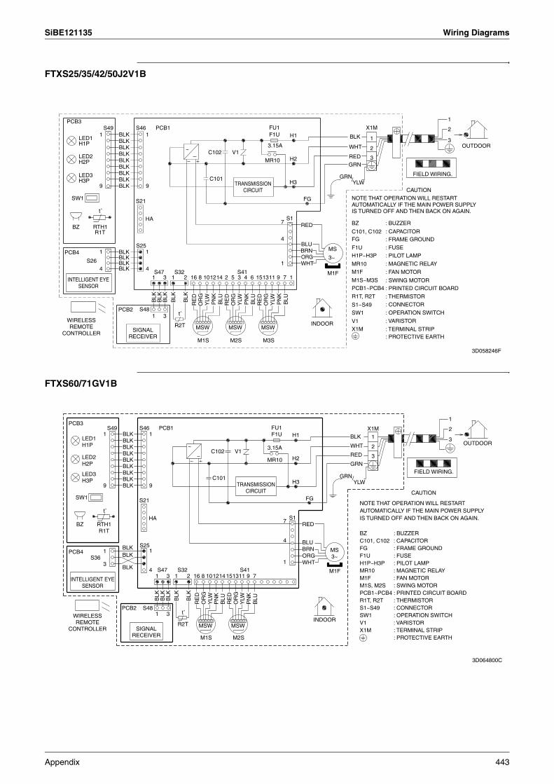
SiBE121135 Wiring Diagrams
FTXS25/35/42/50J2V1B
FTXS60/71GV1B
1
FU1 X1MPCB1PCB3
S46S49 2H1F1UBLK 11 BLK 1LED1 3BLK
3.15AH1PWHT~
OUTDOOR2BLKC102 V1BLKLED2 RED 3H2MR10BLK
GRNH2PBLK
FIELD WIRING.BLKLED3 GRNC101BLK /H3 YLWH3P9 9BLK
CAUTION
FGSW1 S21
t˚S1HA 7 REDRTH1BZ
R1T4
BLUS25MSBRNBLK1 1PCB4
ORGBLK 3~S26 BLK 1 WHT
S41S47 S324 4BLK
M1F16 4121 12143 131 102 735 96 118 15
BLK
BLK
BLK
BLK
BLK
PN
K
PN
K
PN
K
BLU
BLU
BLU
RE
D
RE
D
RE
D
OR
G
OR
G
OR
G
YLW
YLW
YLW
S48PCB2t˚1 3
INDOORR2T MSW MSWMSW
M2SM1S M3S
WIRELESS REMOTE
CONTROLLER
INTELLIGENT EYE SENSOR
SIGNAL RECEIVER
TRANSMISSION CIRCUIT
NOTE THAT OPERATION WILL RESTART AUTOMATICALLY IF THE MAIN POWER SUPPLY IS TURNED OFF AND THEN BACK ON AGAIN.
BZ
C101, C102FG
F1UH1P~H3P
MR10M1F
M1S~M3SPCB1~PCB4
R1T, R2T
S1~S49SW1
V1X1M
: BUZZER
: CAPACITOR: FRAME GROUND
: FUSE: PILOT LAMP
: MAGNETIC RELAY
: FAN MOTOR
: SWING MOTOR: PRINTED CIRCUIT BOARD
: THERMISTOR: CONNECTOR
: OPERATION SWITCH
: VARISTOR
: TERMINAL STRIP: PROTECTIVE EARTH
3D058246F
GRN/YLW
1
FU1F1U
X1MPCB1PCB3
S46S49 2H1BLK1 1 BLK 1LED1
H1P3BLK
3.15A WHT~ OUTDOOR2BLK
C102 V1BLKLED2H2P
RED 3H2MR10BLKGRNBLK
FIELD WIRING.BLKLED3H3P C101BLK H3
99 BLKCAUTION
FGSW1 S21
t˚S1HA 7 REDRTH1
R1TBZ
4 BLUS25BLK MS3~
BRN1 1PCB4 BLK ORGS361 WHT3
S41S47 S32BLK 4 M1F1 2 131 8 715143 16 111012 9
BLK
BLK
BLK
BLK
BLK
PN
K
PN
K
BLU
BLU
RE
D
RE
D
OR
G
OR
GY
LW
YLW
S48PCB2t˚1 3
INDOORR2T MSW MSW
M2SM1S
WIRELESS REMOTE
CONTROLLER
INTELLIGENT EYE SENSOR
SIGNAL RECEIVER
TRANSMISSION CIRCUIT
BZ : BUZZERC101, C102 : CAPACITORFG : FRAME GROUNDF1U : FUSEH1P~H3P : PILOT LAMPMR10 : MAGNETIC RELAYM1F : FAN MOTORM1S, M2S : SWING MOTORPCB1~PCB4 : PRINTED CIRCUIT BOARDR1T, R2T : THERMISTORS1~S49 : CONNECTORSW1 : OPERATION SWITCHV1 : VARISTORX1M : TERMINAL STRIP
: PROTECTIVE EARTH
NOTE THAT OPERATION WILL RESTART AUTOMATICALLY IF THE MAIN POWER SUPPLY IS TURNED OFF AND THEN BACK ON AGAIN.
3D064800C
Appendix 443

Wiring Diagrams SiBE121135
2.2.2 Floor Standing Type
FVXG25/35/50K2V1B
FVXS25/35/50FV1B
1S26S27 X1MS2F1UPCB1~ ~
PCB3 WHT V1 1 211 1BLKRECTIFIER 33.15AS2W(4) 2WHT3 3 outdoor
RED 3GRN3MR10 GRN/YLWS56 S46PCB2
1 1 C102 E3
S1W5
FG99H3PH2PH1P GRNC101 S10S1N=1 S30S50 BRN 77 REDWHT 1
YLWM ORG 4 4 MY1E BLU M1FBLUBRNORGHAS21RED 6WHT6 1 1S51 S6
S32 S35RED 1 BLK BLKORG 2 R2TM YLW 1M1S S34 S33BLK 11 34BLU 5
5Z1C BLK
R1TBRNYLW
indoor R3TR4T
SIGNAL RECEIVER
1 RED
1 BLU
TRANSMISSION CIRCUIT
WIRELESS REMOTE
CONTROLLER
FIELD WIRING.
→
CAUTIONNOTE THAT OPERATION WILL RESTART AUTOMATICALLY IF THE MAIN POWER SUPPLY IS TURNED OFF AND THEN BACK ON AGAIN.
t˚
t˚ t˚
t˚
S57BLK BLK
F1UH1P~H3PM1FM1SPCB1~PCB3R1T~R4T
: PROTECTIVE EARTH: FUSE: PILOT LAMP: FAN MOTOR: SWING MOTOR: PRINTED CIRCUIT BOARD: THERMISTOR
S1~S57S1WS2W(4)X1ME3Y1EZ1C
: CONNECTOR: OPERATION SWITCH: UPWARD AIR FLOW LIMIT SWITCH: TERMINAL STRIP: EARTH TERMINAL(HEAT EX.): ELECTRONIC EXPANSION VALVE COIL: FERRITE CORE 3D069838A
M
S1W
M
M
S2W(4) 321
3
X1M
21
E3
S26
BLU
S42
PCB4
S48
S41
M1S
3.15A
BRN
RED
1
RECTIFIERRED
LED2
WHT
V2
5
H2 GRNS4W
ORG
6
M2S
PNK
PCB3 V1
4
YLW
LED1
H3
S21
S1
BLU
SA1
S32
H1
S46
HA
S27
M1F
RED
PCB1
1
F1U
E4
E3
BLU
GRN/YLW
GRN
YLW
E1
1t°
PCB2
H1P
R1T
7
ORG
PNK
BLK
S47
t°
H2P
RED
S49
R2T
WHT
ORG
→~ ~
NOTE THAT OPERATION WILL RESTART AUTOMATICALLY IF THE MAIN POWER SUPPLY IS TURNED OFF AND THEN BACK ON AGAIN.
WIRELESS REMOTE
CONTROLLER
SIGNAL RECEIVER
indoor
TRANSMISSION CIRCUIT
FIELD WIRING.
outdoor
CAUTION
F1UH1P,H2PM1FM1SM2SPCB1~PCB4R1T,R2TS1~S49S1WS2W(4)S4WX1ME3E4
: PROTECTIVE EARTH: FUSE: PILOT LAMP: FAN MOTOR: SWING MOTOR: LOWER AIR OUTLET MOTOR: PRINTED CIRCUIT BOARD: THERMISTOR: CONNECTOR: OPERATION SWITCH: UPWARD AIR FLOW LIMIT SWITCH: AIR OUTLET SELECTION SWITCH: TERMINAL STRIP: EARTH TERMINAL(HEAT EX.): EARTH TERMINAL(SHIELD PLATE)
3D055953A
444 Appendix
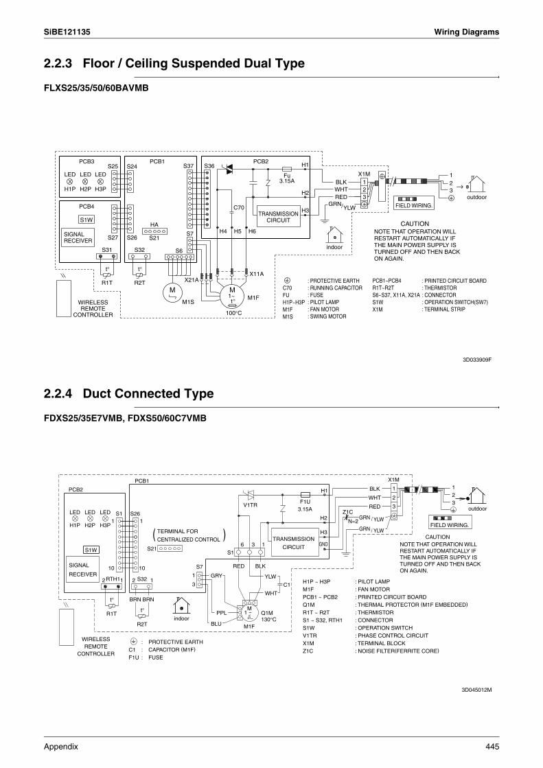
SiBE121135 Wiring Diagrams
2.2.3 Floor / Ceiling Suspended Dual Type
FLXS25/35/50/60BAVMB
2.2.4 Duct Connected Type
FDXS25/35E7VMB, FDXS50/60C7VMB
LED
H1P
PCB3
LED
H2P
PCB4
S1W
LED
H3P
R1T
S31
t°
S27
S25 S24
S26
S32
R2T
t°
PCB1
S21
HA
M
S6
M1S
S37
S7
X21A
S36
H4
100
1~M
t°
H5
C70
°C
M1F
H6
X11A
PCB2
3.15AFu
H2
H3
H1
GRN
WHTRED
BLK
/YLW
X1M
23
1
CAUTION
23
1
→
WIRELESS REMOTE
CONTROLLER
NOTE THAT OPERATION WILL RESTART AUTOMATICALLY IF THE MAIN POWER SUPPLY IS TURNED OFF AND THEN BACK ON AGAIN.
SIGNAL RECEIVER
TRANSMISSION CIRCUIT
FIELD WIRING.
outdoor
indoor
C70FUH1P~H3PM1FM1S
: PROTECTIVE EARTH: RUNNING CAPACITOR: FUSE: PILOT LAMP: FAN MOTOR: SWING MOTOR
PCB1~PCB4R1T~R2TS6~S37, X11A, X21AS1WX1M
: PRINTED CIRCUIT BOARD: THERMISTOR: CONNECTOR: OPERATION SWITCH(SW7): TERMINAL STRIP
3D033909F
PCB2
LED
H1P
LED
H2P
S1W
LED
H3P
2RTH1
R1T
t°
10
1S1
1
BRN
S26
2
PCB1
S32
R2T
t°
1
10
BRN
S21
1
(
indoor
3
1
S7
BLU
GRY
PPL
S1
)
RED
6
V1TR
1
M1F
~M
3
BLK
1
WHT
YLW
C1
3.15AF1U
GND
H2
H3
H1
Z1C
N=2GRN
GRN
WHT
/
/
BLK
RED
YLW
YLW
X1M
2
3
1
CAUTION
FIELD WIRING.
23
1
outdoor
WIRELESS REMOTE
CONTROLLERC1F1U
: PROTECTIVE EARTH: CAPACITOR (M1F)
: FUSE
Q1M130°C
H1P ~ H3PM1F PCB1 ~ PCB2 Q1MR1T ~ R2TS1 ~ S32, RTH1S1W V1TR X1M Z1C
: PILOT LAMP: FAN MOTOR: PRINTED CIRCUIT BOARD: THERMAL PROTECTOR (M1F EMBEDDED)
: THERMISTOR: CONNECTOR: OPERATION SWITCH: PHASE CONTROL CIRCUIT: TERMINAL BLOCK: NOISE FILTER(FERRITE CORE)
NOTE THAT OPERATION WILL RESTART AUTOMATICALLY IF THE MAIN POWER SUPPLY IS TURNED OFF AND THEN BACK ON AGAIN.
TRANSMISSION
CIRCUIT
TERMINAL FOR
CENTRALIZED CONTROL
SIGNAL
RECEIVER
3D045012M
Appendix 445

Wiring Diagrams SiBE121135
2.2.5 Ceiling Mounted Cassette Type
FCQG35/50/60FVEB
R2T R3T
NEX15AX18A X17A
SS1
HAP
HAP
X2AKCRKFR
PNKS1LGRN WHTYLWA1PX2MORGV1RF1U +C105
P2BLU1 BLK R1T+ P1
X1MT2T1F2F1P2P1Z1F BLK
A4P A5PSS1 H1P
H2P BS1X2A H3PSS2 H4P
X1A X1A2 WHT X24A-NOTE)3 RECEIVER/DISPLAY UNIT
3 REDX27A
X30APSGRN/YLW
TCRC A2PC21X1ARED MSW+X65A M4SWHTX33A PSX20A
X70A MSWZ1C X7A X9A M3SN=1WHTX3 X2X4 X1 REDBLUBRNORG X10A X4AX36A X8A
MSWWHT M2SX16AF1U KHuR MSM1FY2 X35A MSW M1SMSYC CN1M1P
F2UX1AA6P A7PR1T A3P
NOTES
X2M A3PX2M R1T X24AX36AX8AX2A
X1M A1PA2P X2M
X35AX33ACONTROL BOX
A1PA2PA3P
C21C105F1UHAP
M1FM1PM1S-M4SR1TR2T·R3TS1LSS1
V1RX1MX2MZ1C
Z1FPSRC
TC
R1T
INDOOR UNITPRINTED CIRCUIT BOARDPRINTED CIRCUIT BOARDPRINTED CIRCUIT BOARD(HUMIDITY SENSOR UNIT)CAPACITORCAPACITORFUSE (F, 5A, 250V)LIGHT EMITTING DIODE (SERVICE MONITOR GREEN)MOTOR (INDOOR FAN)MOTOR (DRAIN PUMP)MOTOR (SWING FLAP)THERMISTOR (AIR)THERMISTOR (COIL)FLOAT SWITCHSELECTOR SWITCH (EMERGENCY)DIODE BRIDGETERMINAL BLOCKTERMINAL BLOCKFERRITE CORE(NOISE FILTER)NOISE FILTERPOWER SUPPLY CIRCUITSIGNAL RECEIVER CIRCUITSIGNAL TRANSMISSION CIRCUIT
WIRED REMOTE CONTROLLERTHERMISTOR (AIR)
X2A
X8A
X24A
X33A
X35A
X36A
CONNECTOR FOR OPTIONAL PARTSCONNECTOR (SENSOR KIT)CONNECTOR (AUTO CLEAN PANEL)CONNECTOR (WIRELESS REMOTE CONTROLLER)CONNECTOR (ADAPTOR FOR WIRING)CONNECTOR (GROUP CONTROL ADAPTOR)CONNECTOR (AUTO CLEAN PANEL)
TO O
UTDO
OR
UNIT
IN CASE OF SIMULTANEOUS OPERATION SYSTEMINDOOR UNIT
(MASTER)INDOOR UNIT (SLAVE)
REMOTE CONTROLLER
SENSOR KIT (OPTIONAL ACCESSORY)
1 122
3 3
t˚ t˚
(NOTE 3)
(NOTE 3)
(NOTE 3)t˚
X2A (NOTE 3)
(NOTE 3)
WIRED REMOTE CONTROLLER (OPTIONAL ACCESSORY)
(NOTE 5)
INPUT FROM OUTSIDE (NOTE 9)CENTRAL REMOTE CONTROLLER (NOTE 2)
NORM. EMG.
INDOOR UNIT35~60 CLASS
TO OUTDOOR UNIT (NOTE 8)
H05VV-U4G2. 5 (NOTE 7)
FAN OPERATION
COMPRESSOR OPERATION
TERMINAL FOR OPERATION DISPLAY
ADAPTOR FOR WIRING (OPTIONAL ACCESSORY)
(NOTE 4)
A4PA5PBS1H1P
H2P
H3P
H4P
SS1SS2
F1UF2UKCRKFRKHuR
RECEIVER/DISPLAY UNIT (ATTACHED TO WIRELESS REMOTE CONTROLLER)
PRINTED CIRCUIT BOARDPRINTED CIRCUIT BOARDPUSH BUTTON (ON/OFF)LIGHT EMITTING DIODE (ON-RED)LIGHT EMITTING DIODE (TIMER-GREEN)LIGHT EMITTING DIODE (FILTER SIGN-RED)LIGHT EMITTING DIODE (DEFROST-ORANGE)SELECTOR SWITCH (MAIN/SUB)SELECTOR SWITCH (WIRELESS ADDRESS SET)
ADAPTOR FOR WIRING
FUSE ( B , 5A, 250V)
MAGNETIC RELAYMAGNETIC RELAYMAGNETIC RELAY (Hu)
1. : TERMINAL BLOCK , : CONNECTOR : FIELD WIRING2. IN CASE USING CENTRAL REMOTE CONTROLLER, CONNECT IT TO
THE UNIT IN ACCORDANCE WITH THE ATTACHED INSTALLATION MANUAL.
3. X2A, X8A, X33A, X35A, X36A ARE CONNECTED WHEN THE OPTIONAL ACCESSORIES ARE BEING USED. IN CASE OF USING AN AUTO CLEAN PANEL, SEE THE WIRING DIAGRAM OF IT.
4. CONNECT POWER OF ADAPTOR FOR WIRING TO TERMINAL BLOCK (X2M) OF INDOOR UNIT DIRECTLY.
5. IN CASE OF MAIN/SUB OVERCHANGE, SEE THE INSTALLATION MANUAL ATTACHED TO REMOTE CONTROLLER.
6. SYMBOLS SHOWS AS FOLLOWS : RED : RED BLK : BLACK WHT : WHITE YLW : YELLOW GRN : GREEN ORG : ORANGE BRN : BROWN PNK : PINK GRY : GRAY BLU : BLUE
7. SHOWS ONLY IN CASE OF PROTECTED PIPES. USE H07RN-F IN CASE OF NO PROTECTION.
8. FOR THE DETAIL, SEE WIRING DIAGRAM ATTACHED TO OUTDOOR UNIT.9. WHEN CONNECTING THE INPUT WIRES FROM OUTSIDE, FORCED OFF
OR ON/OFF CONTROL OPERATION CAN BE SELECTED BY THE REMOTE CONTROLLER. SEE INSTALLATION MANUAL FOR MORE DETAILS.
3D074344
446 Appendix
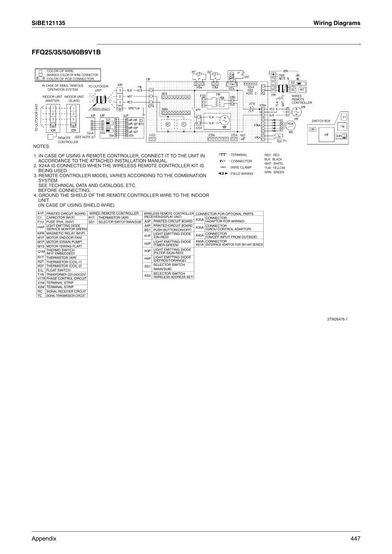
SiBE121135 Wiring Diagrams
FFQ25/35/50/60B9V1B
: COLOR OF WIRE.: (MARKED) COLOR OF WIRE CONNECTOR.: COLOR OF PCB CONNECTOR.
RED: REDBLK: BLACKWHT: WHITEYLW: YELLOWGRN: GREEN
: TERMINAL
: CONNECTOR
: WIRE CLAMP
: FIELD WIRING
NOTES:
1. IN CASE OF USING A REMOTE CONTROLLER, CONNECT IT TO THE UNIT IN ACCORDANCE TO THE ATTACHED INSTALLATION MANUAL.
2. X24A IS CONNECTED WHEN THE WIRELESS REMOTE CONTROLLER KIT IS BEING USED.
3. REMOTE CONTROLLER MODEL VARIES ACCORDING TO THE COMBINATION SYSTEM.SEE TECHNICAL DATA AND CATALOGS, ETC.BEFORE CONNECTING.
4. GROUND THE SHIELD OF THE REMOTE CONTROLLER WIRE TO THE INDOOR UNIT.(IN CASE OF USING SHIELD WIRE)
IN CASE OF SIMUL TANEOUS OPERATION SYSTEM
INDOOR UNIT (MASTER)
INDOOR UNIT (SLAVE)
TO O
UTD
OO
R U
NIT
REMOTE CONTROLLER
TO OUTDOOR UNIT
(SEE NOTE 3)
WIRED REMOTE CONTROLLER
SWITCH BOX
3TW26476-1
A1PC1F1U
HAP
KPRM1FM1PM1S
Q1M
R1TR2TR3TS1LT1RV1TRX1MX2MRCTC
PRINTED CIRCUIT BOARDCAPACITOR (M1F)FUSE (F5A, 250V)LIGHT EMITTING DIODE(SERVICE MONITOR GREEN)MAGNETIC RELAY (M1P)MOTOR (INDOOR FAN)MOTOR (DRAIN PUMP)MOTOR (SWING FLAP)THERMO SWITCH(M1F EMBEDDED)THERMISTOR (AIR)THERMISTOR (COIL-1)THERMISTOR (COIL-2)FLOAT SWITCHTRANSFORMER (220-240V/22V)PHASE CONTROL CIRCUITTERMINAL STRIPTERMINAL STRIPSIGNAL RECEIVER CIRCUITSIGNAL TRANSMISSION CIRCUIT
A3PA4PBS1
H1P
H2P
H3P
H4P
SS1
SS2
X33A
X35A
X40A
X60AX61A
PRINTED CIRCUIT BOARDPRINTED CIRCUIT BOARDPUSH BUTTON(ON/OFF)LIGHT EMITTING DIODE(ON-RED)
LIGHT EMITTING DIODE (TIMER-GREEN)
LIGHT EMITTING DIODE (FILTER SIGN-RED)LIGHT EMITTING DIODE(DEFROST-ORANGE)SELECTOR SWITCH (MAIN/SUB)
SELECTOR SWITCH(WIRELESS ADDRESS SET)
CONNECTOR(ADAPTOR FOR WIRING)
CONNECTOR(GROU CONTROL ADAPTOR)
CONNECTOR(ON/OFF INPUT FROM OUTSIDE)CONNECTOR(INTERFACE ADAPTOR FOR SKY-AIR SERIES)
WIRED REMOTE CONTROLLER WIRELESS REMOTE CONTROLLER (RECEIVER/DISPLAY UNIT)
CONNECTOR FOR OPTIONAL PARTSR1TSS1
THERMISTOR (AIR)SELECTOR SWITCH (MAIN/SUB)
Appendix 447
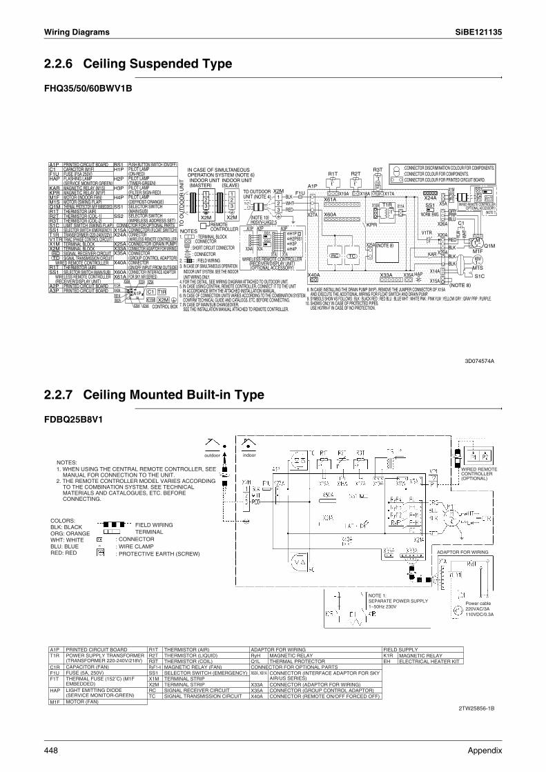
Wiring Diagrams SiBE121135
2.2.6 Ceiling Suspended Type
FHQ35/50/60BWV1B
2.2.7 Ceiling Mounted Built-in Type
FDBQ25B8V1
SS1F1U1 P2
R1TP123
R3TR2TR1T
t˚YLWt˚ t˚A1P WHT X1MX2M YLWX18A X17AX19A1 P2BLK X24A1 P1X61A2
X5AWHT2 T1RX10A SS13 X11ARED3 t˚ GRY (NOTE 7)NORM. EMG.X27A X60A PRPX2MX2M BLU
C1X26AKPRA2P A3PA1P
SS1 V1TRNOTES H1P WHT
YLWX20A
BS1 MH2P REDSS2 1 ~H3P X25A Q1MBLKX24A X2A H4P M1FX29AX1AX1A KARRC TC BLK MSW1~BLK
M1SX14A
HAPX35AX40A X33A S1CX15AX50A X33A X25A
(NOTE 8)X15AX40A T1RC1A1PX61A
X1M X2MX60AX35A X24A
A1PC1F1UHAP
KARKPRM1FM1SQ1MR1TR2TR3TS1CSS1T1RV1TRX1MX2M
RCTC
R1TSS1
A2PA3P
BS1H1P
H2P
H3P
H4P
SS1
SS2
X15AX24A
X25AX33AX35A
X40A
X60AX61A
PRINTED CIRCUIT BOARDCAPACITOR (M1F)FUSE (F5A 250V)FLASHING LAMP(SERVICE MONITOR GREEN)MAGNETIC RELAY (M1S)MAGNETIC RELAY (M1P)MOTOR (INDOOR FAN)MOTOR (SWING FLAP)THERMAL PROTECTOR (M1F EMBEDDED)THERMISTOR (AIR)THERMISTOR (COIL-1)THERMISTOR (COIL-2)LIMIT SWITCH (SWING FLAP)SELECTOR SWITCH (EMERGENCY)TRANSFORMER (220-240V/22V)TRIAC (PHASE CONTROL CIRCUIT)TERMINAL BLOCKTERMINAL BLOCKSIGNAL RECEIVER CIRCUITSIGNAL TRANSMISSION CIRCUIT
WIRED REMOTE CONTROLLERTHERMISTOR (AIR)SELECTOR SWITCH (MAIN/SUB)
WIRELESS REMOTE CONTROLLER(RECEIVER/DISPLAY UNIT)
PRINTED CIRCUIT BOARDPRINTED CIRCUIT BOARD
PUSH BUTTON SWITCH (ON/OFF)PILOT LAMP (ON-RED)PILOT LAMP (TIMER-GREEN)PILOT LAMP (FILTER SIGN-RED)PILOT LAMP(DEFROST-ORANGE)SELECTOR SWITCH (MAIN/SUB)SELECTOR SWITCH (WIRELESS ADDRESS SET)
CONNECTOR FOR OPTIONAL PARTSCONNECTOR (FLOAT SWITCH)CONNECTOR(WIRELESS REMOTE CONTROLLER)CONNECTOR (DRAIN PUMP)CONNECTOR (ADAPTOR FOR WIRING)CONNECTOR(GROUP CONTROL ADAPTOR)CONNECTOR(ON/OFF INPUT FROM OUTSIDE)CONNECTOR (INTERFACE ADAPTORFOR SKY AIR SERIES)
TO O
UT
DO
OR
UN
IT
IN CASE OF SIMULTANEOUS OPERATION SYSTEM (NOTE 6)INDOOR UNIT (MASTER)
INDOOR UNIT (SLAVE)
TO OUTDOOR UNIT (NOTE 4)
(NOTE 10)H05VV-U4G2.5REMOTE
CONTROLLER
8. IN CASE INSTALLING THE DRAIN PUMP (M1P), REMOVE THE JUMPER CONNECTOR OF X15A AND EXECUTE THE ADDITIONAL WIRING FOR FLOAT SWITCH AND DRAIN PUMP.
9. SYMBOLS SHOW AS FOLLOWS : BLK : BLACK RED : RED BLU : BLUE WHT : WHITE PNK : PINK YLW : YELLOW GRY : GRAY PRP : PURPLE.10. SHOWS ONLY IN CASE OF PROTECTED PIPES.
USE H07RN-F IN CASE OF NO PROTECTION.
1. : TERMINAL BLOCK: CONNECTOR
: SHORT CIRCUIT CONNECTOR: CONNECTOR
2. : FIELD WIRING3. IN CASE OF SIMULTANEOUS OPERATION
INDOOR UNIT SYSTEM, SEE THE INDOOR UNIT WIRING ONLY.
4. FOR THE DETAIL, SEE WIRING DIAGRAM ATTACHED TO OUTDOOR UNIT.5. IN CASE USING CENTRAL REMOTE CONTROLLER, CONNECT IT TO THE UNIT
IN ACCORDANCE WITH THE ATTACHED INSTALLATION MANUAL.6. IN CASE OF CONNECTION UNITS VARIES ACCORDING TO THE COMBINATION SYSTEM,
CONFIRM TECHNICAL GUIDE AND CATALOGS, ETC. BEFORE CONNECTING.7. IN CASE OF MAIN/SUB CHANGEOVER,
SEE THE INSTALLATION MANUAL ATTACHED TO REMOTE CONTROLLER.CONTROL BOX
WIRELESS REMOTE CONTROLLER (RECEIVER/DISPLAY UNIT) (OPTIONAL ACCESSORY)
:CONNECTOR DISCRIMINATION COLOUR FOR COMPONENTS.:CONNECTOR COLOUR FOR COMPONENTS.:CONNECTOR COLOUR FOR PRINTED CIRCUIT BOARD.
WIRED REMOTE CONTROLLER (OPTIONAL ACCESSORY)
(NOTE 8)
3D074574A
2TW25856-1B
indooroutdoor
ADAPTOR FOR WIRING
WIRED REMOTE CONTROLLER (OPTIONAL)
NOTES:1. WHEN USING THE CENTRAL REMOTE CONTROLLER, SEE
MANUAL FOR CONNECTION TO THE UNIT.2. THE REMOTE CONTROLLER MODEL VARIES ACCORDING
TO THE COMBINATION SYSTEM. SEE TECHNICAL MATERIALS AND CATALOGUES, ETC. BEFORE CONNECTING.
R1TR2TR3TRyF1-4SS1X1MX2MRCTC
THERMISTOR (AIR)THERMISTOR (LIQUID)THERMISTOR (COIL)MAGNETIC RELAY (FAN)SELECTOR SWITCH (EMERGENCY)TERMINAL STRIPTERMINAL STRIPSIGNAL RECEIVER CIRCUITSIGNAL TRANSMISSION CIRCUIT
Power cable220VAC/3A110VDC/0.3A
NOTE 1:SEPARATE POWER SUPPLY 1~50Hz 230V
COLORS:BLK: BLACKORG: ORANGEWHT: WHITEBLU: BLUERED: RED
FIELD WIRINGTERMINAL
: CONNECTOR: WIRE CLAMP: PROTECTIVE EARTH (SCREW)
A1PT1R
C1RF1UF1T
HAP
M1F
PRINTED CIRCUIT BOARDPOWER SUPPLY TRANSFORMER (TRANSFORMER 220-240V/218V)CAPACITOR (FAN)FUSE (5A, 250V)THERMAL FUSE (152˚C) (M1F EMBEDDED)LIGHT EMITTING DIODE (SERVICE MONITOR-GREEN)MOTOR (FAN)
FIELD SUPPLYK1REH
MAGNETIC RELAYELECTRICAL HEATER KIT
ADAPTOR FOR WIRINGRyHQ1LCONNECTOR FOR OPTIONAL PARTSX60A, X61A
X33AX35AX40A
MAGNETIC RELAYTHERMAL PROTECTOR
CONNECTOR (INTERFACE ADAPTOR FOR SKY AIR/US SERIES)CONNECTOR (ADAPTOR FOR WIRING)CONNECTOR (GROUP CONTROL ADAPTOR)CONNECTOR (REMOTE ON/OFF FORCED OFF)
448 Appendix
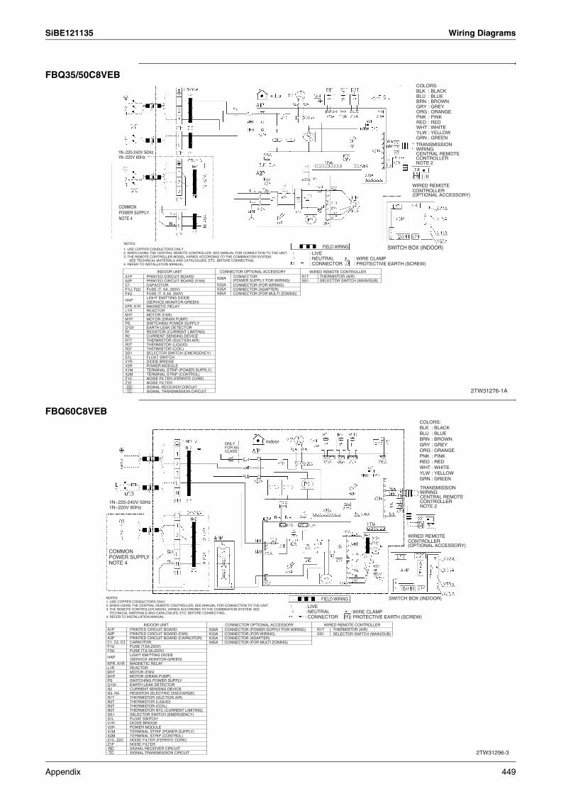
SiBE121135 Wiring Diagrams
FBQ35/50C8VEB
FBQ60C8VEB
2TW31276-1A
NOTES
1N~220-240V 50Hz1N~220V 60Hz
SWITCH BOX (INDOOR)
COLORS:
TRANSMISSION WIRINGCENTRAL REMOTE CONTROLLER NOTE 2
COMMON POWER SUPPLY NOTE 4
1. USE COPPER CONDUCTORS ONLY.2. WHEN USING THE CENTRAL REMOTE CONTROLLER, SEE MANUAL FOR CONNECTION TO THE UNIT.3. THE REMOTE CONTROLLER MODEL VARIES ACCORDING TO THE COMBINATION SYSTEM.
SEE TECHNICAL MATERIALS AND CATALOGUES, ETC. BEFORE CONNECTING.4. REFER TO INSTALLATION MANUAL.
BLKBLUBRNGRYORGPNKREDWHTYLWGRN
: BLACK: BLUE: BROWN: GREY: ORANGE: PINK: RED: WHITE: YELLOW: GREEN
WIRED REMOTE CONTROLLER(OPTIONAL ACCESSORY)
A1PA2PC1F1U, F2UF4U
HAP
KPR, K1RL1RM1FM1PPSQ1DIR1R2R1TR2TR3TSS1S1LV1RV2RX1MX2MZ1CZ1FRCTC
PRINTED CIRCUIT BOARDPRINTED CIRCUIT BOARD (FAN)CAPACITORFUSE (T, 5A, 250V)FUSE (T, 6.3A, 250V)LIGHT EMITTING DIODE (SERVICE MONITOR-GREEN)MAGNETIC RELAYREACTORMOTOR (FAN)MOTOR (DRAIN PUMP)SWITCHING POWER SUPPLYEARTH LEAK DETECTORRESISTOR (CURRENT LIMITING)CURRENT SENSING DEVICETHERMISTOR (SUCTION AIR)THERMISTOR (LIQUID)THERMISTOR (COIL)SELECTOR SWITCH (EMERGENCY)FLOAT SWITCHDIODE BRIDGEPOWER MODULETERMINAL STRIP (POWER SUPPLY)TERMINAL STRIP (CONTROL)NOISE FILTER (FERRITE CORE)NOISE FILTERSIGNAL RECEIVER CIRCUITSIGNAL TRANSMISSION CIRCUIT
X28A
X33AX35AX85A
CONNECTOR OPTIONAL ACCESSORYCONNECTOR(POWER SUPPLY FOR WIRING)CONNECTOR (FOR WIRING)CONNECTOR (ADAPTER)CONNECTOR (FOR MULTI ZONING)
FIELD WIRING: LIVE: NEUTRAL: CONNECTOR
: WIRE CLAMP: PROTECTIVE EARTH (SCREW)
INDOOR UNITR1TSS1
WIRED REMOTE CONTROLLERTHERMISTOR (AIR)SELECTOR SWITCH (MAIN/SUB)
SWITCH BOX (INDOOR)
INDOOR UNITA1PA2PA3PC1, C2, C3F1UF3U
HAP
KPR, K1RL1RM1FM1PPSQ1DIR2R3, R4R1TR2TR3TR5TSS1S1LV1RV2RX1MX2MZ1C, Z2CZ1F RC TC
CONNECTOR OPTIONAL ACCESSORYX28AX33AX35AX85A
CONNECTOR (POWER SUPPLY FOR WIRING)CONNECTOR (FOR WIRING)CONNECTOR (ADAPTER)CONNECTOR (FOR MULTI ZONING)
WIRED REMOTE CONTROLLERR1TSS1
THERMISTOR (AIR)SELECTOR SWITCH (MAIN/SUB)
PRINTED CIRCUIT BOARDPRINTED CIRCUIT BOARD (FAN)PRINTED CIRCUIT BOARD (CAPACITOR)CAPACITORFUSE (T,5A,250V)FUSE (T,6.3A,250V)LIGHT EMITTING DIODE(SERVICE MONITOR-GREEN)MAGNETIC RELAYREACTORMOTOR (FAN)MOTOR (DRAIN PUMP)SWITCHING POWER SUPPLYEARTH LEAK DETECTORCURRENT SENSING DEVICERESISTOR (ELECTRIC DISCHARGE)THERMISTOR (SUCTION AIR)THERMISTOR (LIQUID)THERMISTOR (COIL)THERMISTOR NTC (CURRENT LIMITING)SELECTOR SWITCH (EMERGENCY)FLOAT SWITCHDIODE BRIDGEPOWER MODULETERMINAL STRIP (POWER SUPPLY)TERMINAL STRIP (CONTROL)NOISE FILTER (FERRITE CORE)NOISE FILTERSIGNAL RECEIVER CIRCUITSIGNAL TRANSMISSION CIRCUIT
NOTES:1. USE COPPER CONDUCTORS ONLY.2. WHEN USING THE CENTRAL REMOTE CONTROLLER, SEE MANUAL FOR CONNECTION TO THE UNIT.3. THE REMOTE CONTROLLER MODEL VARIES ACCORDING TO THE COMBINATION SYSTEM. SEE
TECHNICAL MATERIALS AND CATALOGUES, ETC. BEFORE CONNECTING.4. REFER TO INSTALLATION MANUAL
: LIVE: NEUTRAL: CONNECTOR
: WIRE CLAMP: PROTECTIVE EARTH (SCREW)
2TW31296-3
1N~220-240V 50Hz1N~220V 60Hz
COMMON POWER SUPPLY NOTE 4
FIELD WIRING
TRANSMISSION WIRINGCENTRAL REMOTE CONTROLLER NOTE 2
WIRED REMOTE CONTROLLER(OPTIONAL ACCESSORY)
COLORS:BLKBLUBRNGRYORGPNKREDWHTYLWGRN
: BLACK: BLUE: BROWN: GREY: ORANGE: PINK: RED: WHITE: YELLOW: GREEN
ONLY FOR 60 CLASS
indoor
Appendix 449
Specifications, designs and other content appearing in this brochure are current as of March 2012 but subject to change without notice.SiBE121135
03/2012 AK.B
Warning Daikin products are manufactured for export to numerous countries throughout the world. Prior to purchase, please confirm with your local authorised importer, distributor and/or retailer whether this product conforms to the applicable standards, and is suitable for use, in the region where the product will be used. This statement does not purport to exclude, restrict or modify the application of any local legislation.
Ask a qualified installer or contractor to install this product. Do not try to install the product yourself. Improper installation can result in water or refrigerant leakage, electrical shock, fire or explosion.
Use only those parts and accessories supplied or specified by Daikin. Ask a qualified installer or contractor to install those parts and accessories. Use of unauthorised parts and accessories or improper installation of parts and accessories can result in water or refrigerant leakage, electrical shock, fire or explosion.
Read the User's Manual carefully before using this product. The User's Manual provides important safety instructions and warnings. Be sure to follow these instructions and warnings.
If you have any enquiries, please contact your local importer, distributor and/or retailer.
Head Office:Umeda Center Bldg., 2-4-12, Nakazaki-Nishi,Kita-ku, Osaka, 530-8323 Japan
Tokyo Office:JR Shinagawa East Bldg., 2-18-1, Konan,Minato-ku, Tokyo, 108-0075 Japan
http://www.daikin.com/global_ac/
All rights reservedc
Cautions on product corrosion1. Air conditioners should not be installed in areas where corrosive gases, such as acid gas or alkaline gas, are produced.2. If the outdoor unit is to be installed close to the sea shore, direct exposure to the sea breeze should be avoided. If you need to install
the outdoor unit close to the sea shore, contact your local distributor.
Dealer