E-business Implementation: A guide to web services, EAI, BPI ...
344
-
Upload
khangminh22 -
Category
Documents
-
view
1 -
download
0
Transcript of E-business Implementation: A guide to web services, EAI, BPI ...


E-business Implementation

This Page Intentionally Left Blank

E-business Implementation
A guide to web services, EAI, BPI, e-commerce, contentmanagement, portals, and supporting technologies
Dougal Watt MA, BA, BSc
OXFORD AMSTERDAM BOSTON LONDON NEW YORK PARISSAN DIEGO SAN FRANCISCO SINGAPORE SYDNEY TOKYO

E-business Implementation
Butterworth-HeinemannAn imprint of Elsevier ScienceLinacre House, Jordan Hill, Oxford OX2 8DP225 Wildwood Avenue, Woburn MA 01801-2041
First published 2002
Copyright © 2002, Dougal Watt. All rights [email protected]
The work of S J Sutherland as editor is acknowledged
The right of Dougal Watt to be identified as the author of this workhas been asserted in accordance with the Copyright, Designs andPatents Act 1988
No part of this publication may be reproduced in any material form (including photocopying or storing in any medium by electronic means and whetheror not transiently or incidentally to some other use of this publication) withoutthe written permission of the copyright holder except in accordance with theprovisions of the Copyright, Designs and Patents Act 1988 or under the terms ofa licence issued by the Copyright Licensing Agency Ltd, 90 Tottenham Court Road,London, England W1T 4LP. Applications for the copyright holder's written permission to reproduce any part of this publication should be addressed to the publisher
British Library Cataloguing in Publication DataA catalogue record for this book is available from the British Library
ISBN 0 7506 5751 0
The author gratefully acknowledges the use of Microsoft Corporation VisioTM for the creation of diagrams for this book, and the assistance of IBM and the Standish Group for their contribution of material for this book. All product and company names in this book are trademarked and subject to copyright by therespective companies.
Printed and bound in Great Britain
For information on all Butterworth-Heinemann publications visitour website at www.bh.com

Contents
Butterworth-Heinemann – Computer Weekly Professional Series ix
Overview xi
Part One – Project management phases 1
1 Structuring an e-business project 31.1 E-business project management 41.2 The project planning phase 71.3 The requirements gathering phase 141.4 The solution research phase 211.5 The high-level design phase 251.6 The detailed design phase 271.7 Build phase 291.8 Pilot phase 331.9 Implementation phase 351.10 Handover phase 361.11 Project documentation 36
2 Resourcing an e-business project 392.1 Selecting project staff 392.2 When to deploy project staff 442.3 Obtaining project staff 46
Part Two – E-business technology phases 49
3 The five phases of e-business adoption 51
4 Phase 1: Internet-based e-business publishing 554.1 Key technologies used 574.2 Types of publishing systems 594.3 Custom Internet and Intranet publishing systems 60
4.3.1 Key technologies used 624.3.2 High-level designs of Internet and Intranet systems 644.3.3 Benefits and limitations of Internet and Intranet 69
publishing solutions

Contents
4.3.4 Vendors of Internet and Intranet software 704.4 Portal systems 70
4.4.1 Key technologies used 724.4.2 High-level designs for portal systems 754.4.3 Benefits and limitations of portal solutions 814.4.4 Vendors of portal solutions 81
4.5 Content management systems 824.5.1 Key technologies 844.5.2 High-level designs of content management systems 884.5.3 Benefits and limitations of content management systems 924.5.4 Vendors of content management systems 93
5 Phase 2: Transacting with customers 945.1 Key technologies used 965.2 High-level designs for transactional e-business solutions 1015.3 Benefits and limitations of transactional e-business systems 1095.4 Vendors of transactional e-business systems 110
6 Phase 3: Internal enterprise application integration 1126.1 Key technologies used 1156.2 Point-to-Point point EAI solutions 1176.3 Middleware solutions 1196.4 Application server middleware solutions 120
6.4.1 High-level design of application server middleware solutions 1226.4.2 Benefits and limitations of application server middleware solutions 1246.4.3 Vendors of application server middleware solutions 124
6.5 Hub and spoke middleware solutions 1256.5.1 High-level design of hub and spoke middleware solutions 1306.5.2 Benefits and limitations of hub and spoke middleware solutions 1336.5.3 Vendors of hub and spoke middleware solutions 133
6.6 Message bus middleware solutions 1346.6.1 High level design of message bus middleware solutions 1366.6.2 Benefits and limitations of message bus middleware solutions 1396.6.3 Vendors of message bus middleware solutions 139
7 Phase 4: External integration 1407.1 Key technologies used 1437.2 Customized solutions 1457.3 Extended EAI solutions 148
7.3.1 Vendors of extended EAI solutions 150
vi

Contents
7.4 Supply chain management solutions 1517.4.1 Vendors of supply chain management solutions 153
7.5 Marketplace solutions 1537.5.1 Vendors of marketplace solutions 157
7.6 Business process integration solutions 1577.6.1 High-level designs of business process integration solutions 1657.6.2 Benefits and limitations of business process integration solutions 1687.6.3 Vendors of business process integration products 169
8 Phase 5: Dynamic e-business and web services 1708.1 Key technologies used 172
8.1.1 Process management and internal integration 1738.1.2 Business intelligence systems 1738.1.3 High-level design of internal and external BPI solution 1768.1.4 Benefits and limitations of dynamic e-business 1788.1.5 Vendors of dynamic e-business solutions 178
8.2 Web services 1798.2.1 Key technologies used 1818.2.2 Benefits and limitations of dynamic e-business using web services 1858.2.3 Vendors of web services solutions 186
Part Three – E-business supporting technologies 187
9 Critical technologies supporting e-business 189
10 E-business development technologies 19110.1 Key technologies used 19110.2 Java 19210.3 XML 19710.4 Microsoft .NET 208
11 Hardware platforms and operating systems 21111.1 Key technologies used 21211.2 Types of hardware platforms 21211.3 Hardware platform performance 21611.4 High-level designs of hardware platform architectures 220
12 Security 22712.1 Corporate information technology security policies 230
vii
Contents
12.2 Key technologies used 23212.3 Layered security systems 232
12.3.1 Network layer security 23412.3.2 Operating system layer security 23912.3.3 Data layer security 23912.3.4 Application layer security 24012.3.5 Access control mechanisms 24312.3.6 Security auditing and monitoring 246
12.4 High-level designs of security systems 24912.5 Vendors of security solutions 253
13 Networking systems 25513.1 Key technologies used 25613.2 The corporate IP address allocation scheme 25713.3 Network hardware 26013.4 High-level designs for networking systems 261
14 DNS 26914.1 Key technologies used 27014.2 High-level designs for corporate DNS systems 28214.3 Vendors of DNS systems 289
15 Open Source technologies 29115.1 Key technologies used 29215.2 History 29215.3 The Open Source development approach 29315.4 Open Source software projects 29415.5 Benefits and limitations of Open Source technologies 303
16 Summary and conclusion 305
References 307
Index 325
viii

Computer Weekly Professional Series
There are few professions which require as much continuous updating as that ofthe IS executive. Not only does the hardware and software scene changerelentlessly, but also ideas about the actual management of the IS function arebeing continuously modified, updated and changed. Thus keeping abreast ofwhat is going on is really a major task.
The Butterworth Heinemann – Computer Weekly Professional Series has beencreated to assist IS executives keep up to date with the management ideas andissues of which they need to be aware.
One of the key objectives of the series is to reduce the time it takes for leadingedge management ideas to move from the academic and consultingenvironments into the hands of the IT practitioner. Thus this series employsappropriate technology to speed up the publishing process. Where appropriatesome books are supported by CD-ROM or by additional information ortemplates located on the Web.
This series provides IT professionals with an opportunity to build up a bookcaseof easily accessible, but detailed information on the important issues that theyneed to be aware of to successfully perform their jobs.
Aspiring or already established authors are invited to get in touch with medirectly if they would like to be published in this series.
Dr Dan RemenyiSeries Editor

Computer Weekly Professional Series
Series EditorDan Remenyi, Visiting Professor, Trinity College Dublin
Advisory BoardFrank Bannister, Trinity College DublinRoss Bentley, Management Editor, Computer WeeklyEgon Berghout, Technical University of Delft, The NetherlandsAnn Brown, City University Business School, LondonRoger Clark, The Australian National UniversityReet Cronk, Harding University, Arkansas, USAArthur Money, Henley Management College, UKSue Nugus, MCIL, UKTerry White, BentleyWest, Johannesburg
Other titles in the SeriesIT investment – making a business caseThe effective measurement and management of IT costs and benefits Stop IT project failures through risk managementUnderstanding the InternetPrince 2: a practical handbookConsidering computer contracting?David Taylor’s Inside TrackA hacker’s guide to project managementCorporate politics for IT managers: how to get streetwiseSubnet design for efficient networksInformation warfare: corporate attack and defence in a digital worldDelivering IT and e-business valueReinventing the IT departmentThe project manager’s toolkit
x

Overview
Competition within the modern economy has dramatically increased in recentyears, as consumers and businesses demand greater choice. In order to survivein this new environment companies must increasingly deliver better customerservices and decrease time to market for new and existing products and services,as well as increase collaboration between their employees, partners and suppliersto provide additional efficiency and lower costs. Increasingly, companies aresatisfying these business requirements through the adoption of e-business technologies.
This adoption is driven by the increased awareness of the tremendous reachafforded by e-business technologies, and their ability to dramatically increasethe efficiency and productivity of existing business processes and systems.E-business technologies provide a single mechanism to reach businesses, consumers,and employees with products and services across local, national and internationalboundaries in real time and at very low cost.
E-business technologies also provide a powerful mechanism for organizationsto automate and simplify business processes used by their internal enterprisesystems, and to automate business processes used by external partners and suppliers,or to integrate disparate technology systems after mergers and acquisitions. Inaddition, e-business technologies are also being utilized for the outsourcing ofinefficient or non-core processes in order to gain competitive advantage andallow for greater information flow between trading partners to better respond tochanging market conditions.

Overview
However, in order to utilize these considerable benefits, companies must understand
how to implement e-business technology solutions appropriate to their organization
and market segment.
Successful e-business implementation begins with the creation of an appropriate
structure for running an e-business project. This structure must be designed to
ensure successful delivery for the eventual use of the e-business initiative, and
must be capable of delivering the desired business functionality in a timely
manner and within budget, while avoiding the high failure rates common to
many technology projects.
In addition, a critical element of all successful e-business implementations is
the selection of the correct e-business technology solution, which requires an
understanding of the e-business technologies and solutions available. These
technologies are comprised of one or more solution architectures from the five
phases of the e-business lifecycle. This lifecycle typically includes publishing
of corporate information through the Internet and Intranets, portals and content
management systems, transacting with customers and suppliers over the
Internet, integrating internal enterprise applications, integrating external systems
with partners and suppliers, and responding dynamically in real time to changing
levels of demand through dynamic e-business and web services.
Finally, successful e-business implementation also requires the services of a set
of common foundation technologies employed within all businesses and organizations
working over the Internet. These technologies include e-business development
languages, hardware platforms and their operating systems, security and networking
systems, the Internet Domain Name System, and Open Source technologies.
The resulting sets of project management, e-business technology and e-business
supporting technology phases, can be assembled into a corporate blueprint,
describing the technology and business phases each company can adopt as they
progress through the e-business lifecycle. This blueprint provides the core
elements of corporate e-business information technology required and is depicted
below in Figure 0.1: Blueprint for e-business technology and business adoption.
xii

Overview
Figure 0.1 Blueprint for e-business technology and business adoption
xiii
Publishing on the Internet
Transactional e-business systems
Internal Enterprise Application Integration-EAI
Application server EAI solutionsHub & Spoke EAI solutionsMessage Bus EAI solutions
External Integration
Dynamic E-business & Web Services
Real-time Business intelligenceBusiness Process IntegrationEnterprise Application IntegrationWeb services – SOAP, WSDL, UDDI
Sell & Buy side Transacting on the Internet
Custom solutionsSupply chain managementExtended EAIMarketplace solutionsBusiness process integration (BPI)
Internet & Intranet sitesPortalsContent Management
Projectplanning phase
Businessrequirements phase
Solutionresearch phase
Build phase
Pilot phase
Implementationphase
Handoverphase
Design phase
E-business DevelopmentJava XML .NET
Hardware platforms andOperating Systems
Security
DNS
Open SourceTechnologies
Networking systems
E-business SupportingTechnologies
Project ManagementPhases
E-business TechnologyPhases

Part One Project managementphases

This Page Intentionally Left Blank

Structuring an e-business project
When implementing an e-business project a number of processes and structuresare required to ensure the project is successful. These include determining thecorrect structure to guide the course of the project, selecting the appropriatetechnology to implement, having the correct support technology in place toensure the implementation will succeed, and choosing the right staff to carry outthe project.
Many projects fail because these four elements have not been set up andemployed correctly from the beginning. For example, the Standish Group conducteda survey of project failures with 365 organizations of all sizes across a widerange of major industry sectors. Focus groups and personal interviews were alsoconducted to provide a qualitative assessment of the survey.
Results of this survey showed that over 80 per cent of all projects suffered someform of failure. Only 16.2 per cent of surveyed projects were delivered withintime and budget, while 52.7 per cent of projects were delivered but ran overbudget, over time and had fewer features than were originally intended. Projectsthat were cancelled during their development formed 31.1 per cent of the sample.
Project failures included having to restart projects (94 per cent of all projects),cost overruns resulting in an average increase of 189 per cent of original cost,and time overruns, resulting in projects running an average of 222 per cent overoriginal time estimates. Of all companies surveyed, an average of 61 per centdelivered the features originally specified.
The survey found key reasons projects were delayed or failed completely
1

included lack of planning, low user input, incomplete or changing specificationof requirements, lack of resources and competent staff, incompetence with technology,unrealistic timeframes and unclear objectives.
A later survey conducted in 2000 by the Standish Group found that 28 per centof commercial projects were successfully delivered on time and budget with therequired functionality. Of the remainder, 49 per cent suffered from partial failureand 23 per cent complete failure. In the government sector 24 per cent of projectssucceeded while 50 per cent failed partially and 26 per cent failed completely.
The improvement in figures for project success between 1994 and 2001 wasattributed to smaller projects being conducted, which have a higher likelihoodof success.
Creating a successful e-business project therefore requires the project beplanned correctly from the outset, structured into discrete project steps withidentifiable and achievable goals, and the correct staff selected before the projectbegins.
The following sections discuss these issues, detailing the correct structure andprocess for conducting an e-business project, and the staff required for fulfillingthe project.
1.1 E-business project management
The key to running a successful e-business project is to provide sufficient structureand planning to ensure project success. Success is typically defined as the projectmeeting its business requirements without running over budget or over time.
Therefore, the project structure should include a set of critical elements thatgovern the lifecycle of the project and its resulting outcomes. These elementsfollow the project from its inception to completion, and include the initial projectplanning, the requirements phase, the solution research phase, the design phase,the build phase, the pilot phase, the implementation phase and the projecthandover phase. Each phase should be completed with a corresponding set ofdocuments that detail the information gathered in each phase, and the outputseach phase produced.
The initial project planning phase determines the broad outline of the project.
E-business Implementation
4

This is used to guide the initial project structure, including an outline of whatthe project is intended to deliver, and covers preliminary project planning issuessuch as potential technologies, budget, skills and timeframes.
The requirements phase extends the initial planning to determine the core set ofdeliverables the project should satisfy, which are in turn used to gauge projectsuccess. These cover all areas of business and technology relevant to the company,and are subject to analysis to prioritize the most relevant set of requirements todeliver with available resources.
The solution research phase is used to conduct detailed research into potentialtechnology solutions to fulfil the initial project planning and requirementsdeliverables. This is then analysed and a set of potential technology solutionsresearched, with the best solution being recommended to proceed into thedesign phase.
The design phase takes the recommended solution from the research phase tocreate a high-level conceptual design for the solution. Following best practice,this design is then audited internally and externally to prove its feasibility,before a detailed design is created to cover the chosen technology solution inmore detail, including application design, security systems, and the deploymentconfigurations.
The build phase uses the results of the design phase to create the intended solution.Blocks of functionality are coded, deployed and tested using a build processacross development, testing and production environments. The complete solutionis iteratively assembled using this process by creating and integrating successiveblocks of functionality until all chosen requirements are satisfied by the solution.
The pilot phase deploys an initial version of the completed solution for earlytesting by stakeholders (the members of staff or partners and suppliers whoeither sponsor a project or who are most affected by its implementation) andusers. This allows the project to tune the solution to better fit requirements andsatisfy deployment issues.
The implementation phase expands on the pilot phase to deploy the finalsolution across the business to all relevant business users. This requires thesolution be deployed in a production capacity, capable of supporting all usersand workloads, and the training and transition of users from old work practicesto the new solution.
The handover phase collates the output of all previous phases into a set of supportresources for operational and support staff. It also includes training of support
Structuring an e-business project
5

staff, and the creation of final project documentation.
This structured approach to designing and running a project is depicted inFigure 1.1.
Figure 1.1 Structured project planning
E-business Implementation
6
Project Handover
Project Execution
Initial Project Planning
Project planningphase
- Initial scope- Budgets- Staff skills- Timeframes
BusinessRequirements
TechnologyRequirements
AvailableTechnology
Project scopedocuments
Architecturedocuments
Testingdocuments
Supportdocuments
Technologytrends
Project
Initiation
document
RequirementsPhase
SolutionResearch Phase
HandoverPhase
Installation andconfigurationdocuments
ImplementationPhase
Pilot Phase
Build Phase
Design Phase

This structured process begins with the initial project planning and requirementsphases, and progresses through the main project execution phases until the completedproject handover phase, where the project is turned over to internal teams forongoing support. Each phase requires a set of inputs and produces a set ofdocumented outputs that are required for each successive project lifecyclephase. These well-documented outputs are a fundamental advantage to thisapproach, and are used for project support, future developments, and auditingpurposes.
The following sections discuss the elements of this structured approach to runninge-business projects in detail.
1.2 The project planning phase
Before a project begins it is essential to have a broad understanding of the issuesthe project will address, and how the project will fulfil these issues. These aredetailed in the project initiation document, which details the business problemsfacing the company, a broad overview of potential technology solutions, andestimates of the amount of time the project will take, what it will cost, and whatstaff will be required. These estimates are intended as a guide to assist in settingup the project, and are finalized in successive project phases.
An internal project manager and an internal or external e-business technicalarchitect typically conduct the initial project planning, with each team memberoccupying distinct roles. The project manager is responsible for managing andtracking the project to ensure each phase is being delivered successfully. Theytypically create preliminary budgets and project timeframes in collaborationwith the e-business technical architect. The e-business technical architect conductspreliminary research and assessments of the likely technologies necessary tosolve the business problem.
The initial project planning is critical to establishing a clearly understood contextfor the decision-making, through a focus on why there is a need for the e-businessproject. This involves getting the different stakeholders affected by project decisionsor involved in the decision-making process to understand and agree with theproblems that are to be addressed. This is critical for ‘buy-in’ to the project, sothat possible conflict between different stakeholders is prevented or minimized.
Structuring an e-business project
7

The core element of the initial project planning is the statement of the nature ofthe business problem confronting the company. This typically provides themotivation for the company to conduct the e-business project, and the extent to whichthe company resolves this problem determines the success of the project. It istherefore the focal point for understanding and determining intended technical solutions.
The statement of the business problems should include the nature of the business,the challenges facing it, and what business problems the technology is requiredto solve. It should also incorporate statements of the medium-term and long-termstrategic views of business and technology needs. This ensures that all proposedsolutions are aligned with medium-term and long-term plans, thus preventingselection of temporary solutions that will be discarded in future. The statementof the business problem should be expressed in a very simple and clear form, asshown in Figure 1.2.
Figure 1.2 Statement of business problem
E-business Implementation
8
Nature of Business
Company X is a financial services provider selling packaged pension, insurance andinvestment products to companies and direct to consumers.
Business Requirements
Company X’s operating costs are increasing.They wish to restructure their business touse technology more efficiently to save costs and communicate more effectively withtheir own staff and their customers.They want their technology solution to reflect this.
The current problemThe company has a website and an Intranet site, and want to automate these toincrease efficiency and create a cost-effective solution. They want to offer all theirproducts online for self-service to clients, in real time, and utilize existing systemswithin the business including back-end legacy mainframe applications and theirexternal suppliers of pension and investment products.
Alignment with medium-term strategyMove to complete automation throughout their business.Enable integration of financial,HR systems, call centres, and marketing systems to provide real-time knowledge of allparts of their business.
Alignment with long-term strategyThey want to be able to provide customers with a real-time customized financial productportfolio that can be changed at any time depending on their circumstances.

Defining the business problem at this stage is also critically important as it providesa baseline to assist in minimizing the risks that may arise from making incorrectdecisions during the course of the project. Frequent sources of risk includechanges in business issues arising during the project, which in turn invalidatesubsequent stages in the decision-making process, and potentially the technologysolution selected and deployed.
However, these risks can be mitigated if the business issues have been madeexplicit at the outset of the project. Any changes in business issues or otherrequirements during the project can then be compared to the original assumptions,and if they differ significantly, the project can be modified to accommodatethem without seriously jeopardizing the outcome.
Once the business problem has been stated, the e-business technical architectconducts preliminary research to provide prospective technology solutions andpreliminary budgets and timeframes. Typically, this requires the e-businesstechnical architect to research a range of appropriate design patterns andproducts from technologies commonly applied to specific business problems.These patterns typically include collections of technology architectures andproducts, design and development methodologies, and deployment factorsutilized in previous e-business projects.
Selection of a range of appropriate design patterns and products is complicateddue to the very large volume of technology information available, and thecomplexities and risks inherent in matching technology solutions to businessproblems. Therefore, this requires the e-business technical architect to havespecialist knowledge, experience and skills of e-business technology, a broadand detailed understanding of the technology industry as a whole, and theability to match technology solutions to business requirements.
The use of a formal research approach by the e-business technical architectprovides several benefits to the project. It offers the ability to shorten theresearch phase, as the design patterns and products provide a structure to guideresearch. As the design patterns utilize proven pre-existing successful technologystrategies, they lower the risk of making incorrect choices and allow the architectto reduce project timeframes. Finally, the use of such patterns shifts the solutionfocus away from individual point solutions reactively designed to solve asingle business problem, and permits the e-business solution to be synchronizedwith long-term strategic planning within an enterprise.
Structuring an e-business project
9

This preliminary research must also consider a number of factors that are in turnrelated to the statement of the business problem. For example, the statement ofbusiness problem listed above would influence the technical architect toresearch e-business design patterns capable of targeting multiple channels,including online and offline channels, and supporting CRM functionality. Theywould also research solutions capable of integrating with financial servicesback-end systems, typically legacy AS/400 or mainframe products, and productsthat can be used with their partners and suppliers. Their choices should also becapable of extension to web services in the future, allowing for alignment of thesolution to future medium-term and long-term strategic goals.
The factors affecting the preliminary decisions of the e-business technicalarchitect can be classified into business-specific factors, and general externalfactors related to industry, vendor and technology trends.
Business factors
Business factors are comprised of business issues specific to the company thatmay affect initial technology choices. These typically include areas such as thecompany industry sector, available budgets, current technologies in use, andavailable staff skills and timeframes.
Industry sector factors are unique to each industry segment a company is activewithin. For example, manufacturing or retail businesses frequently requirereal-time information regarding stock levels, while service specific businessesmay require a single complete view of all customer information for call centrestaff.
Budgets provide limits to the purchase and implementation costs of technologies.They also constrain other resources employed during the project phases, suchas skills and levels of staffing employed, and may also influence the availabilityof resources during later project stages, such as the duration and degree of testingin the build phase.
Initial project planning is also influenced by the technologies currently utilizedwithin the business, due to the large amount of investment a company mayalready have made in specific areas, and a desire to lower support and administrationcosts through the reuse of infrastructure. These technologies typically includehardware systems, operating systems, peripherals, and enterprise applications
E-business Implementation
10

such as business productivity, enterprise resource planning, and e-businesssystems.
The presence of existing technologies within the business is frequently viewedas an important business factor, and is often given greater weight than criticalfactors such as the performance or availability of the solution. Overemphasis ofthis factor may result in the technical architect selecting compatible technologieswith resulting tradeoffs, such as increased project timeframes, higher total projectcosts, and lower levels of reliability, scalability and availability in the finalsolution.
For example, a company may require a highly available e-business solution toensure customer satisfaction and maintain high customer retention rates.However, they may have standardized on a particular set of supportedtechnologies that are unreliable for e-business purposes. If the e-businesssystem must conform to these technology requirements, higher levels of systemdowntime may jeopardize customer satisfaction, resulting in lost business. Thismay in turn considerably outweigh the savings made from using common butunreliable infrastructure. Therefore, the requirement for the adoption of a morereliable technology should be preferred over selection of common systems.
The mixture of skills available within the company’s information technologydepartment may also help to determine what type of technology should beselected, as the department may already have made a significant investment inskills development in this area. For example, if an information technologydepartment has the majority of its development skills in one area, selecting thatdevelopment technology may be a business factor. However, in a similarmanner to the existing technologies within the business, levels of internal skillsshould not outweigh critical requirements such as the ability to create a suitablee-business solution.
Finally, the total time available for a given project will have a strong influenceon the initial project planning. Projects that must deliver functionality withinshort timeframes will influence decisions towards pre-packaged off-the-shelftechnologies capable of meeting business requirements with minimalcustomization. If a project is allocated long timeframes, decisions can includetechnologies requiring more custom development. However, long durationprojects of over 12 months are not recommended as they frequently lead to costand time overruns, and result in technological obsolescence.
Structuring an e-business project
11

External factors
External factors are issues outside the business that may influence the initialproject planning technology choices. These factors include existing relationshipswith technology vendors, technologies used by external partners and suppliers,trends within the information technology industry, and technology adoptiontrends within other business segments.
Frequently a company will have existing relationships with multiple technologyvendors. Selecting solutions from a vendor with whom the company has anexisting relationship and direct previous project experience can provide asignificant reduction in the risks of conducting a project, provided thisrelationship is close and beneficial to all parties. However, this factor must bebalanced against the need to select the vendor technology solution most appropriateto solving the business problem.
Integration of systems with external suppliers of products and services will alsoinfluence technology decisions. For example, if a supplier has a proprietaryenterprise application integration solution, potential integration technologychoices with that supplier may be restricted. Such relationships will also influencethe choice of other related technologies, such as security systems, to ensuresuch close integration will not compromise corporate systems and information.
However, selecting potential technology solutions that are tightly coupled tospecific suppliers may increase project risk. This occurs when the solutioncompromises other internal business factors that must be addressed in theproject, and inhibits support for and integration with additional suppliers andfuture technologies.
Technology industry trends frequently influence the selection of potentialtechnologies due to the expected lifecycle of a technology. If a technology isbecoming obsolete, it makes less sense to consider selecting it for a futureproject. If a technology is becoming more widespread, it may be sensible toutilize it if many vendors will support it. Similarly, technology selections areoften influenced by the trend towards adoption of packaged off-the-shelftechnology solutions rather than creating proprietary customized solutions.
Finally, trends adopted by competitors also influence preliminary technology
E-business Implementation
12

decision-making. For example, when many businesses in an industry sector
employ the same or similar technologies, companies frequently give these more
importance in making initial technology decisions. However, this strategy
should be avoided, as each technology should be assessed on its business
merits and degree of fit for the company and issues at hand. Alternatively,
analysis of how other companies employ technology can indicate the technologies
to avoid if there are widespread problems in that industry segment, or how to
correctly deploy such technologies to avoid common mistakes.
Following determination of the internal and external factors and their influenceon preliminary technology decisions, the e-business technical architect createsan overview of the technology solution proposed to address the businessproblem. This will typically include a broad overview of the technologyfunctionality required to satisfy the business problem, and the business andexternal factors. It will also typically include at least three potential solutionsfrom different vendors, and provide an indicative costing for each alternative.
For example, with the example depicted in Figure 1.2, the technical architect’soverview may include three proposed solutions for the creation of an internaland external e-business portal solution, integrated with a transactionale-business for customers and internal legacy and partner and supplier systems.These may include specific vendor products and indications of proposedcustomizations and content development required, and deployment scenarios.
The project initiation document is then created, including the statement of thebusiness problems, the proposed preliminary technology solutions, andestimated budgets, staff skills and project timeframes. This forms the firstoutput generated in the course of the project.
This document should be read and approved by the business and technicalstakeholders within the company, as it provides the context for the majordecisions within the project. It also provides a mechanism for initial agreementon how the project will be run and what it will deliver. Once this document hasbeen agreed with stakeholders, the project can move into the requirementsgathering phase.
Structuring an e-business project
13

1.3 The requirements gathering phase
The business issues introduced in the initial project planning phase provide ageneral context to the business problem that must be solved. This context mustbe extended during the requirements gathering phase to provide a more detaileddescription of all the business and technical issues the project must provide asolution for. These are in turn detailed within the project scope document,which forms the second project output.
During this phase, the project manager is responsible for overseeing the gatheringand analysis of the requirements. They must also ensure that appropriatebusiness analysts are hired, and ensure they work closely with the e-businesstechnical architect and business stakeholders. The business analysts are responsiblefor gathering and analysing the business and technical requirements frombusiness stakeholders and customers using one or more of the methodsdescribed below. They must also work closely with the e-business technicalarchitect to ensure the technical issues specific to the company and project areaddressed in full. The e-business technical architect is also responsible foranalysing these requirements before the subsequent research and design phases,which are used to create the high-level and detailed designs.
Project requirements are the detailed issues that combine to create the initialbusiness problem. These are typically composed of necessary business andtechnical conditions within the company, or problems experienced with specificbusiness processes by stakeholders. Each requirement imposes specificconstraints on the project solution, and must therefore be addressed by theproject to ensure project success.
For example, a stakeholder such as an investment manager may use a manualprocess to assist a customer in choosing an investment product. Customers maywish to have this process automated in a convenient online system, thus creatingthe requirement for automated product selection using an e-business system.
Detailed requirements are obtained from internal and external sources, includinginternal company divisions, and external customers and partners and suppliers,and are categorized into detailed business requirements and technicalrequirements, as shown in Figure 1.3.
E-business Implementation
14

Figure 1.3 Common sources of project requirements
Detailed business and technical requirements originate from the external andbusiness factors highlighted in the initial project planning phase. Once thesesources have been identified, their specific requirements are gathered using arange of mechanisms appropriate to the company and business in question.These may include structured questionnaires and interviews with stakeholders,internal reports, strategy documents, and analyst reports.
The methods used to gather requirements will depend on the size of the projectand the degree to which it will affect the business. Large and strategicallyimportant projects are typically driven from higher levels within the company,
Structuring an e-business project
15
External Factors
Business Factors
ITDepartment
Key
stakeholders
Board of
Directors
Partnerrequirements
Supplierrequirements
Customerrequirements
IndustryTrends
Other
departments
Project
Requirements

often at board level via the chief technology officer or chief information officer.Due to their strategic importance, such projects may require wide consultationwithin the company, and hence a formal and detailed requirements gatheringexercise. This may utilize mechanisms such as published board directives andstrategy reports, followed by interviews with stakeholders that are subsequentlyused to create detailed questionnaires. Such exercises often result in a verydetailed and focused set of requirements.
In contrast, small projects with limited budgets may require rapid and moreinformal requirements gathering exercises. This may include interviews withcritical stakeholders, and reference internally published reports and reports fromIT analysis firms to gauge ‘industry best practice’ as a mechanism to shorten therequirements gathering phase.
Structured questionnaires are frequently used to obtain requirements from largenumbers of company stakeholders, and typically solicit responses to items suchas lists of business objectives, problems with business processes, and proposedsolutions. Questionnaires are administered to all stakeholders across companybusiness units, then collated into common problems and desired solutions.Information technology departments should also be included in such questionnaires,as they are normally required to support the solution once it has beenimplemented and can also contribute relevant technology and business processissues.
Interviews with stakeholders provide a less structured mechanism to gatherrequirements compared to questionnaires. However, interviews frequentlyproduce very detailed sets of requirements that may be overlooked in questionnaires,such as revealing weaknesses in specific areas within business processes andtools. In addition, interviews with stakeholders may also be employed to createdetailed targeted questionnaires for use in widespread requirements gatheringthroughout the company.
Interviews and questionnaires should also include external stakeholders, such asrepresentative samples of customers and members of partner and suppliercompanies. Such stakeholders can provide feedback on end-user functionalityrequirements, and may contribute valuable high-level technical requirementssuch as desired levels of availability and performance for an e-business system.Requirements may also be gathered through internal reports and strategy documents,including high-level company strategy reports, and business unit documents
E-business Implementation
16

such as policy and procedure documents. These typically provide short-term,medium-term and long-term goals; objectives and strategies that the proposedsolution must satisfy, and may provide critical success factors and performanceindicators, such as business improvement targets.
Strategy-based requirements may also originate from the board of directors ofa company, which frequently establish broad goals such as ‘becoming ane-business leader’ in their industry field or ‘implementing a supplier tradingwebsite with partners’. Due to the pivotal and central place of technology withinmodern business, technology departments should be represented at board levelvia CIO or CTO members, and hence provide input into these strategies.
Additional sources of requirements gathering may include specialist analysisfirms such as Butler, Forrester or the Gartner Group. Such firms often releasereports from in-house analysts detailing the technical and business issues facingcompanies within specific business segments. These may provide valuableinput into the definition of both technical and business requirements.
In general, complex projects that will have a deep impact within the companywill require formal and widespread requirements gathering processes. Typically,such projects utilize custom developments to meet these requirements, andutilize formal requirements gathering and description methodologies such asthe use case method used in Object Oriented software design. Use cases detailthe set of actions and expected responses for each requirement, and areemployed for rapid prototyping and simplified development cycles. In contrast,less formal and simpler projects require less involved requirements gatheringprocesses, and typically express the resulting requirements in standarddocument templates.
Analyse requirements
Once the requirements have been gathered and documented, the projectmanager, business analysts and the e-business technical architect conduct arequirements analysis using a structured approach. This allows the requirementsto be prioritized according to importance to ensure the project can provide thegreatest degree of functionality within the available resources. It also providesa mechanism to clarify complex interactions between conflicting requirementsby simplifying the amount of detail gathered in the requirements gatheringphase.
Structuring an e-business project
17

Requirements are analysed through a process of ranking according to theirsignificance to the project, and the level of risk they represent to the project.Significance is typically determined by the extent each requirement influencesdecision-making, and thus how critical they are to the final solution.Requirements that strongly constrain a project but threaten project successshould be reassessed and modified or discarded if appropriate.
Requirements with high levels of significance frequently include projectdeadlines, requirement to reuse existing technologies, project budgets, andspecific aspects of functionality such as support for payment methods,transaction types or specific customer-driven requirements.
Requirements with lower levels of significance typically include utilizing productsfrom a preferred vendor or consultancy, or from in-house project resources suchas existing development and support staff with particular skills.
Ranking of requirements is also affected by less tangible factors. These includefactors such as industry trends, competitor trends and corporate preferences inspecific technology areas. Such factors should be accounted for whenprioritizing requirements, but they do not directly constrain decisions or carryhigh levels of risk to the project, and can therefore be allocated lowersignificance levels.
Sources of risk can be determined during the requirements gathering phasethrough interviews with stakeholders. Risk factors are typically expressed as thethreat of the project failing from not satisfying a given requirement, and thespecific elements that contribute to risk for that requirement. Formal riskmanagement processes should be incorporated throughout each stage of theproject to plan for risks that may arise, using a process of identifying andanalysing risks, determining methods to handle risks, and providing ongoingmonitoring of risks throughout the project. Risk management typically requiresmaintenance of a risk register by the project manager, in the form of a database,throughout the project lifecycle.
Once the significance and risk profile of each requirement have been classified,they are placed into an analysis matrix. This locates each requirement withinrows and columns corresponding to the source of the requirement (business orexternal), the description of the requirement, the significance of the requirement,the risk it represents to the project if it is not fulfilled, and details of factorscontributing to this risk.
E-business Implementation
18

An example of such a requirements matrix would typically include the elementsdepicted in Table 1.1.
Table 1.1 Requirements analysis matrix
The requirements analysis matrix is included as the final section of the projectscope document. It should incorporate enough detailed information to permitthe e-business technical architect to begin the design phase of the project.
An example scope document is depicted in Figure 1.4.
Structuring an e-business project
19
Source Requirement description Significance Risk Risk Issues
Business Must be delivered in 6 months 1 High Must beat competitor to marketMust integrate with partner X 1 High They supply some critical financial
productsBudget capped at $3 000 000 1 Medium Project very important therefore
budget can growIntegrate with internal CICS 1 High Core products sourcedfinancial system from this systemStrategic goal to adopt industry 1 Low Current trends support this form ofstandard technology to lower costs developmentAvailability 1 High Must be continually available to
service customer requestsScalability 1 High Must account for varying levels of
customer demandSecurity 1 High Must prevent compromise of
solution from internal and external sources
Corporate guideline to use Unix 2 Low Extensive in-house support and based solutions widespread industry support for
Unix productsCorporate hardware standard is for 2 Low As aboveSun SPARC systemsInternal skills in Unix, SPARC, and 2 Low Can outsource development andCOM technologies support skills or retrain staffIntegration with existing COM 3 Low Will not affect project launch datee-business system desirable
External Technology industry trends (list) 2 Low Industry standardizing on Javae-business technology
Current vendor relationships (list) 3 Low Can readily utilize other companiesCurrent supplier relationships (list) 3 Low Can readily utilize other companiesCompetitor trends (list) 4 Low Competitors utilizing similar
technology

Figure 1.4 Decision output: project scope document
E-business Implementation
20
Project Scope Document (title of document)
Table of Contents (list of all document headers)
IntroductionBriefly state the purpose of the document, and summarize the contents.
ObjectivesState what the document is intended to achieve, i.e. the need to resolve the business problems being faced.
Document HistoryAs this document will change over time, include version information in a table here with document author and the reasons formaking changes, e.g. adding a new section.
Related DocumentsIn a table, list any other documents that are referenced within this document. E.g. published reports used.
OverviewState the key issues facing the business, why these require a technology decision, and how this will solve the issues.
Business RequirementsDiscuss the source of the business requirements, how they were gathered, and discuss each requirement in logical groupings(e.g. business and external factors).
Technology RequirementsDiscuss the source of the technology requirements, how they were gathered, and discuss each requirement in logical groupings(e.g. internal and external factors).
Requirements AnalysisPlace each requirement into matrix of source, name, influence type, importance and risk. Include verbal summary of results ofthis analysis
Source Requirement description Significance Risk Risk Issues
Business Must be delivered in 6 months 1 High Must beat competitor to marketMust integrate with partner X 1 High They supply some critical financial
productsBudget capped at $3 000 000 1 Medium Project very important therefore
budget can growIntegrate with internal CICS 1 High Core products sourcedfinancial system from this systemStrategic goal to adopt industry 1 Low Current trends support this form ofstandard technology to lower costs developmentAvailability 1 High Must be continually available to
service customer requestsScalability 1 High Must account for varying levels of
customer demandSecurity 1 High Must prevent compromise of
solution from internal and external sources
Corporate guideline to use Unix 2 Low Extensive in-house support and based solutions widespread industry support for
Unix productsCorporate hardware standard is for 2 Low As aboveSun SPARC systemsInternal skills in Unix, SPARC, and 2 Low Can outsource development andCOM technologies support skills or retrain staffIntegration with existing COM 3 Low Will not affect project launch datee-business system desirable
External Technology industry trends (list) 2 Low Industry standardizing on Javae-business technology
Current vendor relationships (list) 3 Low Can readily utilize other companiesCurrent supplier relationships (list) 3 Low Can readily utilize other companiesCompetitor trends (list) 4 Low Competitors utilizing similar
technology
SummarySummarize the findings of the document.

1.4 The solution research phase
Once the business and technical requirements have been determined, the solutionresearch phase is conducted to produce a set of recommended technical solutionsto solve the project requirements. The preferred solution then forms the basis ofthe proposed high-level design.
The e-business technical architect conducts the solution research phase. Thisinvolves a process of selecting sources of information about proposed solutions,conducting research and compiling information on the technology products andtheir vendors using these sources, and evaluating the results of this researchagainst the initial scope and project requirements. This process is depicted inFigure 1.5.
Figure 1.5 Technology solution research process
Structuring an e-business project
21
Select
Information
Sources
Compare to
Requirements
and Scope
Close match
Insufficient
match
Research and
collate
product and
vendor
Information
More
informationrequired
Preliminary
solutions
Project
requirements
Project
scope
Create
High-level
Design

The e-business technical architect determines appropriate information sourcesfor research based on the three initial technology solution overviews created inthe project initiation phase. Typical sources for research include print andInternet magazines, print media such as trade publications in relevant areas,vendor websites, and market research reports.
Solution information is gathered and collated from these sources, including corefunctionality, product technologies and deployment options, and the productarchitecture. Analysis of this information by the e-business technical architectwill typically employ multiple analysis techniques gained within previousprojects. These include methods such as function point analysis comparingproduct functions to required functions from the requirements matrix andscope documents, analysis of vendor and industry analyst evaluations, assessmentof user reports, previous experience with products, and the vendor factors. If asolution does not provide sufficient functionality, additional information must begathered, or alternatively the solution must be discarded and a new solutionselected and researched.
The process of technology solution research and selection is one of the mostimportant decisions made during the project lifecycle, as it is crucial to projectsuccess to ensure the correct technologies are selected. E-business technologycontinually changes, and therefore selecting the wrong technology may result insystems that fail to work, or provide only a partial solution to business problems.
Technology selection should also account for existing corporate business andtechnology strategy, and other projects and technologies deployed within thecompany, to ensure that solutions can be integrated into other corporatesystems. Appropriate selection also minimizes ‘orphaned’ solutions wheretechnology is deployed that rapidly becomes obsolete and unsupported byvendors, resulting in lack of support and difficulty in obtaining product updates,and therefore increasing the operational cost to the business.
Following this process, the e-business technical architect should produce a finaldetailed recommendation for the proposed technology solution, and twoalternative recommendations. Each recommended solution should be rankedaccording to the extent to which they fit the project scope and requirements. Ifthe solution research phase cannot clearly distinguish between proposedalternatives, it is recommended that a small-scale proof of concept project beconducted using the recommended technology solutions to allow the e-businesstechnical architect to more accurately determine the most appropriate solution.
E-business Implementation
22

Vendor selection
The role of solution vendors is an important element in product research, selectionand resourcing for an e-business project. Vendor suitability for a project isdetermined by a set of factors, including suitability of products and servicesoffered by the vendor for the project requirements, the viability and history ofthe solution and vendor, the cost of their solution and ongoing support, and thevendor’s levels of customer service.
The suitability of vendor products and services to the business and technicalrequirements of the project is a key factor in ensuring project success.Selection of inappropriate vendor solutions is a common problem, andfrequently results in a solution incapable of supplying the required functionality,necessitating additional and unexpected custom work to fit the solution to theproject requirements. This also frequently results in increased costs andtime overruns for projects, and requires high levels of support for the incorrectsolution. It is therefore important to choose a suitable vendor and solution thatclosely matches project requirements, and has minimal need for customization.
Vendors should also be assessed to determine their ongoing viability over thefollowing years in order to provide continued support, bug fixes and newfeatures for current and outdated products. This ensures the solution cangenerate a reasonable return on investment before its replacement with newer,upgraded systems. Vendor viability typically includes the financial viability ofthe vendor, with a focus on selecting vendors and products with high or increasingmarket share to ensure their products will not be discontinued.
The viability of a solution can also be increased if vendors have widely availableand well-supported products. Such products are sold and supported by multipleindependent vendors, with consultants specializing in the product widely availablefrom vendors and independent contractors. In addition, training in such productsis typically readily available for internal staff. These factors allow companies toswitch vendors to find suitable service and support levels, which in turndecreases vendor lock-in and reduces the risks to the project.
The strategic viability of products and vendors should also be considered.Vendors should demonstrate a history of innovation in e-business, and articulatea clear strategic direction for their products, including adoption of emergingtechnologies and standards, and targeting of specific market segments withappropriate features. This direction should also be aligned with the companystrategic direction to ensure compatibility.
Structuring an e-business project
23

A vendor’s strategic vision should also remain consistent over time and focuson providing business value for customers. Vendors attempting to profit at theexpense of customers through frequent strategic shifts, licence changes, orforced product upgrades through incompatible product features should beavoided.
Once a product offering the required features has been selected from a viablevendor, the cost of solution should be determined. Typically, up-front purchasecosts represent only a small percentage of the total cost of the solution. It istherefore imperative to determine the complete lifecycle cost of the solutionfrom initial purchase to eventual replacement. Lifecycle costs include factorssuch as the ongoing cost of product maintenance, support and upgrades, securitycosts, training costs, and the usability of the solution, which affectsemployee productivity and customer satisfaction.
Reputable vendors should also be able to provide a detailed breakdown of theirsolution costs during early negotiations. This allows for price, performance andfeature comparisons between competing products. Vendors also frequentlyoffer discounts for start-up companies, the purchase of additional productsand services, global licensing of products across multiple business units in largecompanies, and for companies subscribing to development programmes.Therefore, when obtaining quotes from vendors, companies should capitalizeon such incentive programmes to ensure they obtain the best price for thechosen solution.
When evaluating vendors and vendor solutions, it is also recommended thattrial copies of products be obtained either during the initial negotiations with thevendors, or from website downloads. This allows a company to conduct tests offeatures and integration capabilities, and assists in the determination of costfactors such as security, support, and usability. Availability of trial copies mayalso indicate vendor confidence in their products, and a willingness to buildmarket share by seeding the market with product knowledge and skills.
Finally, the level of customer service provided by the vendor should also beconsidered during vendor selection. This includes factors such as providingprofessional service at all times, the sales experience for prospective customersmatching the level of their technical after-sales support, vendors returning callspromptly and providing sufficient information to assist in decision-making(including knowledgeable technical staff), and providing guaranteed deliverydates for products and services. Such dates are critical during project executionto ensure valuable staff members do not have to wait for vendors to deliverproject resources. Similarly, it is recommended that all dealings with vendors
E-business Implementation
24

be conducted with equivalent levels of professionalism from the company tofoster a good long-term working relationship.
1.5 The high-level design phase
Once the solution research phase has finalized a recommended technology solutionthe project progresses to the creation of the high-level design phase using theresults of this research. The high-level design provides a formal overview of thetechnical components of the solution necessary to meet the required businessand technical functionality specified in the requirements analysis.
The e-business technical architect is responsible for the creation of the high-leveldesign. This occurs through analysis of the recommended solution to produce aset of functional and operational design components satisfying the business andtechnical requirements of the project.
High-level functional design components consist of software solutions that willbe used to provide discrete groups of business functionality corresponding tostakeholder requirements. For example, a high-level functional design for atransactional e-business system may consist of a set of software componentsproviding data storage, catalogue management, transaction processing, paymentprocessing, interface management, and security. Each component is an independententity that offers services to other components, with the complete set of componentssatisfying the business and technical requirements.
The appropriate high-level functional components are determined through ananalysis of the project requirements, the interactions users will have with thee-business system and the features and systems offered in the proposedtechnology solution. Functional components may be provided through purchaseof packaged solutions, or development of the appropriate components.
The operational components of the high-level design describe the physicalaspects that govern how the functional design will be deployed, and are selectedduring the solution research phase. These typically include operating systemsand hardware servers, development tools, network and security systems, andperformance and availability levels. For example, the transactional e-businesssystem described above may require an operational design consisting of specifichardware servers, operating systems, and network and security devices assembledin a network configuration to provide high availability and performance.Typically, the operational servers are used to host the functional design
Structuring an e-business project
25

components.
Operational components are also determined from further analysis of technicaland business project requirements, and from the functional design, which mayindicate the need for additional systems.
Both operational and functional components may be simplified during thesolution research phase by selecting solutions supporting multiple operatingsystems and/or development languages. This removes potentially restrictivedependencies between design components, such as specific products selected toprovide functional components requiring specific operating systems. Removingsuch dependencies in turn allows the e-business technical architect more scopeto optimize the functional design to suit requirements, and the operationaldesign to support different deployment, performance and availability requirements.
Once analysis of the functional and operational design components is complete,they are included in the high-level design document. This document is intendedto provide an overview of the design for internal and external audit, and to guidethe subsequent creation of the detailed design and build phase.
The high-level design should therefore be written in a manner suitable for atechnical and non-technical audience, and provide sufficient detail to justifythe choice of design components while avoiding detailed discussions ofimplementation-specific issues such as detailed functionality or configurationand deployment information. Once complete, the high level design allows thee-business technical architect and project manager to finalize the projectbudgets and timeframes according to the chosen solutions and design.
The audit phase
Following completion of the high-level design phase, it is strongly recommendedthat the high-level design document be submitted to an external firm for analysis.This provides an independent audit for the design to ensure each requirementhas been met, and to minimize the risk of making incorrect decisions. Specialistanalysis firms such as the Butler Group or Gartner are recommended for thisfunction, or alternatively another external e-business technical architect.
In addition, an internal audit of the high-level design is also recommended togain stakeholder buy-in and ensure the proposed solution will be acceptable torelevant stakeholders. This internal audit also provides stakeholders with
E-business Implementation
26

necessary feedback from internal staff to ensure their business requirementswill be met.
1.6 The detailed design phase
Once the high-level design has been audited and approved, the detailed designcan be created by the e-business technical architect. This design provides adetailed set of specifications of the functional and operational components ofthe design, which are then used by developers, implementation staff and webdesigners to create and test the system during the build phase.
The detailed functional design provides an in-depth description of the functionalsoftware components (known as the software component model) providing thefunctionality specified in the requirements document. This includes descriptions ofthe software components, the interactions between components (whichcomponents use other components), their software interfaces (their expectedinputs and outputs), and descriptions of the externally observable behaviour ofthe components, typically described using ‘use cases’ and ‘collaborations’created from the requirements analysis. Use cases specify how an externalindividual or system would interact with the solution, for example how a userwould purchase a product from an e-business site. Collaborations specify theinteractions between components over time, and are used to express the dynamicbehaviour of the functional components. Each element of the detailed functionaldesign is typically expressed using the Unified Modelling Language (UML)system of notation, providing a common language for the project team.
Functional components are structured through analysis of the requiredfunctionality and selected software solutions. The e-business technical architectassigns specific units of functionality to discrete software components using arange of design principles. These include distributing functionality betweencomponents into distinct layers, including presentation user interfaces, businesslogic and data access, and internal and external integration systems. It alsorequires avoiding redundancy and duplication in components, the incorporationof legacy systems and other corporate applications, and consideration of operationalservice level requirements such as performance, security and availability.
This analysis should produce clean separation between the application businesslogic, presentation, event management, data access, and integration components.This separation in turn permits the different groups of project staff to work onseparate components in parallel during the course of the project, thus decreasing
Structuring an e-business project
27

the time taken to create the solution. In addition, it permits each component tobe modified separately from the others, allowing for rapid changes during thebuild phase such as the addition or alteration of solutions features. It should benoted that in addition to in-house development of functional components, muchof the required functionality may be purchased as packaged solutions andintegrated with custom project-specific code.
The detailed functional design components are also used to create test cases,which consist of specific sequences of steps and their related conditions used totest the expected behaviour of functional components. Creating test cases earlyin the build phase ensures that testing is closely aligned to the development ofthe solution, and allows for rapid and interactive modifications to systems tofulfil the specified requirements.
The detailed operational design consists of a set of components responsible forhow the system will be physically deployed, including specific products such ashardware servers, network devices, security devices, and the physical placementof these components within the company. These components are typicallyexpressed using network structure diagrams, depicting the location and connectionsbetween operational components, the functional components deployed acrossthese, and specific configuration documentation.
In addition, the operational design includes non-functional issues such as theperformance, availability, and security of the solution, support processes andprocedures for the ongoing operation of the solution, and internal and externaltechnology requirements such as preferred operating systems. These aspects ofthe design are typically expressed through service level agreements (SLAs), andsupport documents such as installation and configuration documents.
The detailed operational design must be synchronized with the functionaldesign to ensure the design is capable of satisfying the non-functional aspectsof the design, such as performance. This requires the e-business technical architectto analyse the flows of data within the solution according to user activity anddata source, the deployment configurations of packaged products, and thenon-functional operational requirements. This process should occur simultaneouslywith the functional design to ensure that operational design factors are built into the complete solution from the outset.
The detailed design must also specify project change control mechanisms.These include software code and document management products such as theOpen Source CVS, the Rational Clear Case product, or Microsoft Visual
E-business Implementation
28

Studio/SourceSafe. Such tools provide a central repository for all project code,and can enforce rigorous change control of functional component source codeto ensure the correct code is utilized and deployed during the build phase. Inaddition, change control procedures should also be specified for operationalsystems (such as server configurations), and project documentation. Thisprovides an audit trail for changes made during the project, and ensures thatarbitrary, unnecessary and potentially problematic changes are not enacted byproject or company staff.
The resulting detailed design provides a blueprint for the creation of thesolution in the build phase. However, it should include sufficient flexibility toallow for modifications during the build phase, such as restructuring the deploymentof functional components across operational systems for performance. It shouldalso support future enhancements as requirements evolve, such as the additionof new components or modifications to existing components.
1.7 Build phase
Once the detailed design has been approved, the build phase begins. This phaseinvolves creating a working solution to meet the project requirements, using thespecification supplied by the detailed design document.
During the build phase, the e-business technical architect ensures that thedevelopment and testing of a production-ready solution is managed andimplemented correctly according to the detailed design document. Thisincludes tracking technical milestones to ensure design components arecorrectly delivered on time, ensuring the performance, reliability and securityof the complete solution is maintained, and enforcing technical changemanagement to minimize errors during development.
Similarly, the project manager oversees the build phase as part of the ongoingmanagement of the project. This includes ensuring staffing, resourcing andclient issues are managed, that project milestones are met, and that project riskissues are addressed as they arise.
The build phase begins with implementation staff members skilled in the appropriatetechnologies and products installing the detailed operational components of thedesign into the development, testing and live production environments beforeapplication development commences. These include components such as webservers, application servers and packaged business logic products. It also
Structuring an e-business project
29

includes source code control servers used to store the software created by thedevelopment team in a central repository, and computers and tools used bymembers of the development teams to code the business logic, databases,integration, and presentation layer systems. In addition, network and securitysystems are installed across the design layers, and consist of network hardwaresuch as switches and routers, and security systems such as firewalls, intrusiondetection systems, and server hardening procedures.
The development, test and live environments, build phase tasks, and staffmembers responsible for these tasks are depicted in Figure 1.6.
Figure 1.6 Environments and processes used during the build phase
E-business Implementation
30
Staff members
Implementation
staff
Product specialists
Lead DeveloperApplication developers
Product specialists
Integration applicationdevelopers
Implementationstaff
Environments
Build Process
Install and configure
environments
Development environment Live environment
Detailed design
document
Development Test Deploy
Deploy live
solution
- Performance
testing
- User acceptance testing
Changes
Graphic designers
Usability expertWeb developers
Product specialists
Databasedevelopers
Testing team
Testing teamStakeholder testers
Createpresentation layer
Create businesslogic layer
Create databaselayer
Create integrationlayer
Testing of
components
- Unit testing
- Link testing
- Integration testing
- Early stakeholder feature testing
Stakeholder testers
Network andSecurity systems
E-business
Technical ArchitectProject Manager
Testing environment

Once the operational systems and environments have been installed, developmentof the detailed design commences. This includes parallel development of thefunctional components in presentation, business logic, data and integration layers,the testing of these components, and their deployment and tuning acrossoperational components.
The functional components developed in the presentation layer are located onweb servers, and consist of the web pages that customers see when they connectto the e-business site. Graphic designers create the appearance of this layerthrough the design of graphical images and the layout of page elements. Webdevelopers then code the site content into this design using technologies such asHTML, DHTML, JavaScript, JSP and ASP, through a range of tools such asMacromedia Dreamweaver and Microsoft Visual Studio. A usability expert isalso typically employed to work with the graphic designers and web developersto ensure the presentation layer is simple and easy to use for customers, thusensuring customer retention. Finally, the presentation layer should beconstructed to support all common Internet browsers running on Macintoshand PC platforms to ensure all customers can access the e-business site.
The functional components developed in the business logic layer are used toprocess customers’ requests and apply business-specific rules to appropriatedata to produce the required output. These components consist of software codecreated through custom development or packaged products, and are created byapplication developers according to the detailed functional design. Once created,components are deployed on application servers according to the operationaldesign. Typically, the business logic layer consists of either open solutionsbased on J2EE application server products such as WebSphere, iPlanet or BEAWebLogic, or proprietary systems based on C, C++ and COM/DCOM such asmany client-server ERP, CRM and financial products. In contrast to opensolutions, proprietary – systems typically require an additional integration layerto enable them for customer use over the Internet.
Creating transactional Internet-enabled business logic requires the use ofspecialist-packaged products or development of custom written code. It isrecommended that specialist products that fit requirements be adopted to ensurethe solution can be implemented within a short timeframe, thus not delaying theproject in the build phase. Additional functionality not included in suchproducts can then be created through customization. Alternatively, if theproject requirements cannot be satisfied through deployment of a packagedsolution, custom development should be undertaken in the build phase,
Structuring an e-business project
31

preferably using open solutions.
The building of the business logic layers requires a database layer for thestorage and retrieval of information, such as e-business catalogues andcustomer and order information. This database layer is located on dedicatedhardware servers, and consists of database software installed onto these serversand externally attached storage systems. The database layer is installed andconfigured by implementation staff members with knowledge of the databaseproduct selected in the detailed design. Once these have been installed, specialistdatabase developers work with the application developers to create the designof the database structures to be used by the business logic layer.
Additional systems may be required to participate in the e-business system,such as proprietary products or existing legacy systems. This is achievedthrough development of an integration layer during the build phase, accordingto the specifications of the detailed design document. The integration layer islocated on separate hardware servers, and consists of integration softwareproducts and integration code. This layer is built in parallel with the businesslogic layer by implementation staff knowledgeable in integration software andintegration application developers, and typically requires input from legacysystem and product support staff.
Development of design components within each layer is conducted with theparticipation of testing team members, who work closely with all teammembers to ensure test plans are written for each component as they are developed.Each test plan documents the component to be tested, the testing conditions inuse during the test, the expected input and output for each component, and theresults of each testing phase.
As each solution component is completed in the development environment, it ismigrated into the testing environment for unit testing to ensure it functionsaccording to the detailed design specifications. The test environment containsduplicated hardware, software, network and security systems from the developmentenvironment, and allows for testing to be isolated from development and thereforeconducted independently and in parallel.
Following successful completion of unit tests, components are link testedtogether with related components to ensure correct communication betweencomponents. Integration testing is then conducted on the completed set ofsolution components to determine that the solution satisfies the detailed design
E-business Implementation
32

requirements. Components are then migrated into the live environment forperformance testing to ensure the solution can meet expected levels of demand.This environment consists of the solution components that will be used once thesystem receives stakeholder approval. If a component fails any stage of thetesting process it is returned to the development environment for appropriatechanges then retested.
Once the components have passed integration and performance testing, useracceptance testing is conducted in the live environment with a representativegroup of stakeholders to ensure the solution meets their requirements. Once thisis successfully completed, the solution is signed off by stakeholders andbecomes ready for deployment into the pilot phase.
It is recommended that user testing by a small group of stakeholders also beconducted during development as this allows the solution to be tuned to moreclosely meet user requirements. It also allows the project to accommodate anyrequirements missed during the initial project phases or any subsequent changesin requirements. However, large-scale changes such as switching developmentmethodologies or dramatically altering component functionality, are notrecommended as they may seriously impact the successful delivery of the project.
Finally, during the build phase each team member contributes towards theproject documentation set. This includes the creation of the test plans and theirresults, creation of installation and configuration documents for the designcomponents, and a preliminary set of operational management documentsdetailing how to manage the complete solution. These documents are progressivelyamended until the handover phase as operational experience is gained with thesolution.
1.8 Pilot phase
Once the solution has been built and tested, and passed user acceptance, a pilotis conducted by a representative sample of end users who will utilize the solutionin their daily work.
The project manager, technical architect and testing staff assess the ongoingresults of this phase, and any modifications that may be required are submittedthrough the build phase processes to the appropriate staff members. The project
Structuring an e-business project
33

staff members also begin training internal support staff in the operation andmanagement of the new solution. This requires input from all project teammembers, and should be monitored by the project manager and e-business technicalarchitect.
At this stage in the project lifecycle, all functional requirements of the solutionshould have been delivered. However, solutions frequently require modificationsto ensure smooth deployment. These typically involve fixing minor bugsmissed during testing, or small changes to the solution to more closely fitrequirements. They may also include modifications due to operational issuessuch as performance, availability and scalability, which may require additionalwork before the system is put into full live production.
The pilot phase also provides a valuable opportunity to test the transition to thenew system for internal staff, and for integrating the new technology with existingsystems. Frequently new solutions are swapped in overnight with minimal or notraining for staff, with resulting confusion and loss of productivity. Deploymentof the solution in a limited pilot allows the business to determine how best toadapt staff work processes to the new system to ensure a smooth transition andto determine training requirements and prepare training materials. It alsoprovides a mechanism to determine how other business technology systemswill be affected by the transition to the new system, and allows time to adaptthese if required to ensure all technology related issues are solved beforeimplementation.
At this stage in the project lifecycle, major changes to functionality should beavoided, as these will require considerable additional work in new design andbuild phases, and typically result in considerable delays and greatly increasesthe chances that the project will not complete successfully.
Such changes can be avoided through management of stakeholder expectationsand by ensuring that the correct processes are used throughout the project. Thisincludes involving stakeholders in the initial project planning and requirementsgathering phases, by ensuring that the design and auditing phases are properlyconducted, and by involving stakeholders in early testing of the solution.Stakeholder management also requires creating awareness of the seriousrepercussions introduced by requesting major changes in the latter project phases,and by shifting requests for changes or additional functionality into subsequentprojects.
E-business Implementation
34

1.9 Implementation phase
The implementation phase follows successful deployment and use of thesolution in the pilot phase. This phase involves deployment of the solution into‘live’ production environments across the company to all appropriate end usersand other stakeholders. At this stage in the project lifecycle all requestedfunctionality should be addressed and the stakeholders should have signed offapproval for the solution.
Staff members required during the implementation phase typically includeinfrastructure, implementation and support staff to roll out and tune solutioncomponents, development and testing staff to provide additional developmentand testing services if required, and oversight by the e-business technicalarchitect and project manager. In addition, team members are required toupdate project documentation throughout the implementation phase.
The implementation phase occurs through a staged deployment of the e-businesssolution to groups of users, rather than to all users simultaneously. This ensuresa manageable transition to the new system without straining available resourcesand adversely affecting business continuity or affecting existing processes.
This staged deployment in turn requires a set of infrastructure and userdeployment processes. Infrastructure deployment processes allow for stageddeployment of additional or new hardware and software systems to end users ifrequired, such as new desktop computers and associated systems. Userdeployment processes are designed to maximize user productivity, and includegranting user access to the live production environment, and providing supportfor users during rollout of the solution, such as training users before changeoverto the new system, and providing ongoing assistance once users have migrated.
Finally, during the changeover period the new solution should be monitored foreach group of users as it is deployed. This ensures that issues occurring duringchangeover can be tracked and addressed before subsequent deployment of thesolution to additional user groups. This requires infrastructure, developmentand testing staff be available to optimize performance of the solution as itcomes under increased usage, and to correct minor bugs that may occur withinthe solution.
Structuring an e-business project
35

1.10 Handover phase
Once the solution has been successfully implemented, it is formally handedover to internal staff for ongoing maintenance and support. Project handoverinvolves a process of knowledge transfer, including knowledge of the technicaldesign and implementation, project outcomes, support processes and procedures,and the completed documentation set.
Project handover should include a fixed period of support from critical projectmembers with considerable project input, such as the e-business technicalarchitect and lead developer. This ensures the availability of critical projectresources for ongoing knowledge transfer back into the company, and assistancewith any technical issues that may arise following implementation.
The final element of project handover requires publishing the complete projectdocumentation set within the company. This provides a reference covering theproject history, technical decisions, and solution design, and the deploymentand support configurations for internal staff and stakeholders. All documentationand project source code should be supplied on CD-ROM and on the company’sIntranet site, allowing ready access for company support staff.
1.11 Project documentation
Following project handover and completion, documentation is required as aknowledge repository for the project, and for the developments of subsequentversions of the e-business system requested by users. In such cases, thedocumentation provides a detailed understanding of decisions that were made,and the manner in which technologies were implemented, to ensure they do notintroduce problems into stable live production systems.
Due to their role in designing and implementing the solution, the e-businesstechnical architect has overall responsibility for the creation and delivery ofproject technical documentation. Similarly, the non-technical project documentationis the responsibility of the project manager. Non-technical project documentationincludes documents concerned with the ongoing management of the completeproject by the project manager such as training plans, the project risk register,meeting minutes between project members and company staff, budgets, and theproject plan.
E-business Implementation
36

The completed documentation should include all outputs created during theproject lifecycle. These include the project initiation document, the scopedocument, the design documents, test plans and test results, installation andconfiguration documents, and support and training documents. It should alsoinclude the source code repository maintained throughout the project.
The project Iinitiation document introduces the reasons for beginning theproject, and suggests a proposed solution. These issues are covered through anintroduction to the project consisting of an overview of the business issuesfacing the company, and a general discussion of the high-level business andtechnical requirements for the project. The discussion of the proposed solutionshould cover project management and technical aspects, including the preliminaryproject plan, budget, an assessment of staff skills required for delivering theproposed technology solution, and a preliminary timeframe for the project.
The scope document provides the detailed context to why the project is requiredand what it should deliver. It expands on the overview of business issues facingthe company to include the detailed requirements of all project stakeholders,including internal stakeholders within the company and external users and partnerand supplier companies. Requirements are gathered from relevant company andcustomer sources, divided into business and technical requirements, andsummarized through a requirements analysis matrix. A risk management registeralso accompanies the scope document detailing the risk issues facing theproject and risk management plan to cope with these.
The high-level design document provides an overview of the proposed solution.It should incorporate the functional design components, which describe thegroups of features provided in the solution, and corresponding operationaldesign components, which describe products and technologies chosen to supplythese features. The vendors and product evaluation and selection criteriadetermined during the research phase may also form part of the high-leveldesign, or be included as a supporting document for complex projects with largenumbers of requirements to satisfy.
The detailed design documents describe the blueprint to build the solutionthrough detailed functional and operational design components. Detailedfunctional design elements include software components, their interactions andinterfaces, which are expressed using detailed UML use cases, data models, andcomponent class model diagrams. Detailed operational elements in this design
Structuring an e-business project
37

include descriptions of infrastructure systems such as hardware server systems,network systems, security systems, and specific deployment configurations,which are expressed using UML diagrams, network diagrams, and installation,configuration and operation documents for each operational system. Thedetailed design documents also describe the source code management tooldeployed in the project, and the change management processes used to maintainthe solution source code and project documents.
The test plan documents detail the testing procedures and tools used during thebuild phase. These include the test scripts used to test individual componentsagainst their intended design, test scripts for communication between componentsusing specified interfaces, and test scripts for the correct functioning of thecomplete solution against the design specifications and stakeholder requirements.Each test script also includes documented results of each phase of testing.
The installation and configuration documents allow staff members to recreatethe solution from its constituent functional and operational components. Theseinclude installation processes for operational components such as servers,network devices, development systems, security systems, and software. Theyalso include the subsequent configuration of these once they have beeninstalled, such as performance tuning, load balancing configuration and securityhardening, and the setting of run-time parameters.
Finally, the support documents should detail the operational management andsupport processes and tools required for the ongoing operation of the solution.These include software management systems, such as HP OpenView, and theirappropriate configuration, and daily operational processes such as diagnosisand problem resolution, content migration, or security checking processes.Support documents are created during the pilot phase by project staff, inconsultation with company support staff. Once the project enters theimplementation phase, support documents are refined to accommodateadditional support and management requirements discovered during thisphase.
E-business Implementation
38

Resourcing an e-business project
Successfully conducting an e-business project requires hundreds of decisions becorrectly made throughout each project phase. This in turn requires considerablespecialist input from staff members who must plan, design, test, build, integrateand implement the many complex technologies required during the project.Therefore, one of the most critical elements in the success of an e-businessproject is the quality and skill level of staff members involved.
However, correctly resourcing an e-business project is complicated due to anumber of factors, including the current skills shortages within the e-businessindustry, the rapid pace of change in the technology sector, and the complexityand variety of technologies involved. In addition, the cost of e-business projectresourcing is an important factor in the budget as it typically exceeds thehardware and software costs of the project.
Therefore, it is important to understand the types of staff required and theiraptitudes and abilities, when to deploy them, and how to source them in orderto obtain the correct number of skilled staff appropriate to the project whilemanaging costs and project risks.
2.1 Selecting project staff
Information technology staff can be classified into two general categories,including project staff, and operational staff. Project-based staff are dedicatedto the implementation of new technology systems, and are frequently sourcedfrom outside the company. In contrast, operational staff members are dedicatedto supporting and maintaining existing company business systems and
2

E-business Implementation
infrastructure, and are frequently sourced internally. Therefore, when conductingan e-business implementation project it is important to utilize specialist project-basedstaff who are experienced in new technologies to design and build the solution,and existing operational staff to support and maintain the final solution.
However, selecting the appropriate project and operational staff for each projectphase is complicated due to existing hiring and human resources practices,which often utilize stereotypical criteria to select staff members. Such criteriaare often not suitable for e-business staff members, who typically defy normalselection criteria.
For example, many of the most successful and influential people in theinformation technology industry have non-stereotypical backgrounds. BillGates co-founded Microsoft after dropping out of university, while ShawnFanning founded the ground-breaking Napster music sharing business at theage of 19. Bob Metcalfe was an academic who left the Xerox PARC researchcentre after creating Ethernet networking and founded the 3COM networkcompany, and Jerry Yang and David Filo founded Yahoo while still at university.
Therefore, staff selection necessitates analysing a candidate’s skill level withoutrecourse to traditional stereotypes such as age, qualifications, experience,appearance, cultural fit and length of time in projects to determine suitability.
Typically, skilled e-business staff can be distinguished by their tendency to createoptimal solutions by balancing risks and rewards to achieve the best possiblesolution for the task at hand. Such people typically demonstrate rapid deliveryof projects in short timeframes, have up-to-date skills, are able to make fast andaccurate decisions, and are able to learn new skills quickly. Frequently suchstaff members are also highly creative and dynamic, have strong problem-solvingability, and are able to create a fast and accurate solution from the businessproblem at hand. They are usually team players, as their motivation is derivedfrom improving their knowledge and skills, not from competing with their ownteam members.
In contrast, staff who have spent years delivering a single project with largeamounts of staff are typically indicative of a project that has run over time andbudget, and should be avoided. Such staff members frequently come from highlystructured environments within hierarchical organizations, with a focus ondelegation of responsibility through hierarchical management processes, ratherthan making the fast and complex decisions necessary in successful e-business projects.
40

Resourcing an e-business project
Therefore when making staffing decisions careful selection should be utilizedto ensure the staff selected are well suited to fast moving implementation projectsand have the broad skills necessary for successful e-business implementation.
When assembling an e-business project team, the most critical roles are typicallythe e-business technical architect, the project manager and the lead developer.Selecting these individuals requires an understanding of the aptitudes and abilitiesappropriate to each role.
The e-business technical architect
The e-business technical architect is the technical design authority for the projectand is responsible for the design, selection and management of the implementationof the solution according to their detailed design. As this input constitutes thecore of the project solution, the e-business technical architect is one of the mostimportant roles within the project team.
To ensure project success it is therefore important to hire the services of anexpert e-business technical architect with outstanding technical vision. Thisindividual should demonstrate an in-depth and expert knowledge of all aspectsof e-business solution selection, design and implementation including technologyproducts, platforms, security, applications, networking, infrastructure andintegration. They should also be able to evaluate these issues to achieve a solutionthat offers the best functionality and value for money for the company.
Therefore, the e-business technical architect should demonstrate a very technicaland hands-on approach. This requires they be capable of implementing the systemsthey design such as installing servers and coding software, rather than justdesigning systems on paper for others to implement. Typically, they will haveimplemented complex e-business projects across different parts of the e-businesslifecycle, and can work at a rapid pace to deliver projects in less than 12months, with teams of fewer than 20 staff.
The e-business technical architect must also demonstrate understanding of thebusiness issues facing a company, and the appropriate business uses fortechnology solutions. They should be used to having their designs externallyaudited, produce excellent documentation, have a passion for e-business andproject success, and be comfortable mentoring other team members. Theyshould also provide excellent references for past work.
41

E-business Implementation
As well as the skills listed above, an e-business technical architect should alsopossess a range of personal qualities to enable them to be highly effective intheir role. These include being able to achieve goals on time and in accordancewith their stated deliverables, being non-competitive and non-hierarchical,being able to admit mistakes, and being able to create a productive and honestculture. Other personal qualities include reliability, having excellent timemanagement skills, being honest and a good communicator, and being preparedto accept responsibility and put themselves on the line for their decisions.Finally, they should possess high energy levels, have high intelligence andproblem-solving ability, the ability to get on with others and work as part of ateam, as well as demonstrating strong leadership to technical staff.
The project manager
The project manager also has a critical position within an e-business project.This role focuses on the organization and delivery of the project, and typicallyincludes budget management responsibility for the project. The project managermust work closely with the technical architect and stakeholders from thecompany to ensure the project is on target for delivery.
To ensure project success the project manager must possess good technical abilityand broad knowledge of e-business technologies and platforms, including astrong understanding of e-business concepts and terminology. The more technicalthe project manager and the more passionate they are about e-business, thegreater the likelihood of project success.
The project manager must also understand project management techniques suitedto e-business gained through delivery of previous projects with fewer than 20staff within a 12-month period. They should also have experience with changemanagement and risk management within these projects, and understand how tocreate a project offering value for money. As they work closely with technicalstaff, it is also vital that the project manager has a strong understanding of howto fit technology to business requirements and understands the requirementsand motivations of technical people. They should therefore be able to follow theinstructions of the e-business technical architect to support and resource the
42

Resourcing an e-business project
technical staff in the course of their work. These skills should be supported withexcellent references for their previous work.
A project manager should also possess specific personal qualities related to theirposition. These include being able to achieve goals on time, delivering on theirstated intentions, and being reliable and punctual with excellent time managementskills. They should also be non-competitive, flexible, non-hierarchical, and bea good communicator who gets on well with others. The project manager shouldfoster an open non-blaming culture, and project honesty, leadership, and a focuson being a team player. They should therefore be able to admit mistakes and beprepared to put themselves on the line for their decisions. Finally, they shouldhave high intelligence and strong ability to solve problems as they occur, andhave a high energy level to drive the project to completion.
The lead developer
The lead developer is also a critical role in the e-business project. This role isresponsible for providing specific technical expertise during the build andsubsequent phases of the project, and for programming the solution designed bythe technical architect. They typically lead other development staff and workclosely with the technical architect.
To ensure project success, the lead developer should possess expert knowledgeof all aspects of programming in the relevant development languages selectedfor the project. They must also be very technical, hands on, and understandmultiple technology platforms and development technologies. Typically theywill have broad experience gained through working on multiple e-businessdevelopment projects, have worked in different industries, be used to workingwith fewer than 20 staff, and be accustomed to fast delivery of projects in under12 months. They should be capable of producing excellent documentation andadhering to source code and change control procedures, and be able todemonstrate a passion for e-business development. Finally, they should be ableto supply excellent references in support of their previous work.
A lead developer should also possess a range of relevant personal qualities,including being able to deliver work on time, delivering on what they say, and
43

E-business Implementation
being reliable and punctual with excellent time management. Other personalattributes include being honest and able to admit mistakes, being focused ontheir work, non-competitive, non-hierarchical and receptive to suggestions fromothers. The lead developer must be capable of working as part of a team, get onwell with others in a non-blame-centred culture, and mentor other developers.They should also be prepared to put themselves on the line for their work, and havehigh energy levels, high intelligence, and good all-round problem-solving ability.
2.2 When to deploy project staff
Resourcing appropriate staff for an e-business project requires correct planningand timing for when to hire project and operational staff. This issue is criticalto project success, as projects frequently run over time and budget throughdelays in hiring staff onto a project, hiring staff before they are required, or byhiring staff with inadequate skills during the project. In addition, hiring toomany staff onto a project may also negatively impact the project throughincreased management overhead and an increased risk of hiring inexperiencedor poor staff. This may also in turn increase pressure and conflict for expertskilled staff, who must monitor inexperienced staff to locate and rectify mistakesin their work.
E-business projects therefore benefit from smaller numbers of highly skilledstaff, frequently restricted to no more than 20 staff members at each stage.However, some projects may require additional staff numbers, such as largecontent-based projects requiring additional content developers, or large-scaleprojects with considerable custom development that require additional developers.Staffing numbers can be maintained at appropriate levels by avoiding duplicationof resources in the same role, especially duplication of the e-business technicalarchitect, project manager, and lead developer. Instead, productivity should beincreased by obtaining the best resource for each role, by avoiding hierarchyand political conflict in the project, and through the use of correct process anddue diligence throughout the project.
In addition, staff levels can be managed by employing specific staff membersonly when needed for specific project phases, and by reducing staff levels asphases complete. This is depicted in Table 2.1.
44
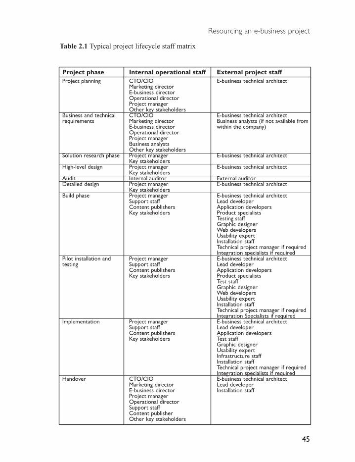
Resourcing an e-business project
Table 2.1 Typical project lifecycle staff matrix
Project phase Internal operational staff External project staffProject planning CTO/CIO E-business technical architect
Marketing directorE-business directorOperational directorProject managerOther key stakeholders
Business and technical CTO/CIO E-business technical architectrequirements Marketing director Business analysts (if not available from
E-business director within the company)Operational directorProject managerBusiness analystsOther key stakeholders
Solution research phase Project manager E-business technical architectKey stakeholders
High-level design Project manager E-business technical architectKey stakeholders
Audit Internal auditor External auditorDetailed design Project manager E-business technical architect
Key stakeholdersBuild phase Project manager E-business technical architect
Support staff Lead developerContent publishers Application developersKey stakeholders Product specialists
Testing staffGraphic designerWeb developersUsability expertInstallation staffTechnical project manager if requiredIntegration specialists if required
Pilot installation and Project manager E-business technical architecttesting Support staff Lead developer
Content publishers Application developersKey stakeholders Product specialists
Test staffGraphic designerWeb developersUsability expertInstallation staffTechnical project manager if requiredIntegration Specialists if required
Implementation Project manager E-business technical architectSupport staff Lead developerContent publishers Application developersKey stakeholders Test staff
Graphic designerUsability expertInfrastructure staffInstallation staffTechnical project manager if requiredIntegration specialists if required
Handover CTO/CIO E-business technical architect Marketing director Lead developerE-business director Installation staffProject managerOperational directorSupport staffContent publisherOther key stakeholders
45

E-business Implementation
As new staff members are deployed into each project phase, it is recommendedthat they be assessed to determine if they have the aptitudes and abilitiesrequired for their role and function within the project environment and team.This trial assessment period should cover one to two weeks, with each teammember required to deliver a set of outputs appropriate to their role. For example,the e-business technical architect should begin research and analysis ofsolutions early in the initial project planning phase, and produce preliminaryversions of technical documentation. Similarly, the project manager should startwork on the project plan, project scope and risk register as soon as they start.
In addition, trial assessment of outputs should include performance by staffmembers on tasks appropriate to their role, such as the installation andconfiguration of systems. If team members cannot perform such tasks, take along time to deliver such tasks, or avoid making decisions around such tasks,they may have insufficient skills to deliver their elements of the project. Thismay in turn compromise the project through poor decision-making, lengthenedtimeframes, and increased costs. If staff cannot deliver appropriate outcomes,they should be retrained or removed, and new staff recruited.
2.3 Obtaining project staff
Operational and project-based staff can be resourced from three sources, includinginternally within the company, from self-employed contractors, or from externalconsultancy firms. Alternatively, projects may assemble a composite team froma combination of these three sources.
Internal staff members are typically recruited from existing internal divisionswithin the company, often via human resources departments. Self-employedcontractors can be obtained via external agencies or through major online IT jobsites. In addition, a wide range of consultancies can be used to resource a projectthrough project outsourcing or by providing specific project member resources.
Consultancies are available in a broad range of sizes, including very largeinternational firms, medium-sized firms, small firms often operating at anational level, and micro consultancies with a handful of staff. Consultanciesfrequently work together on projects to mitigate industry skill shortages andreduce the costs of maintaining large amounts of project-based consultants whoneed to have specific expertise. However, when working with all consultancies,a range of strategies should be employed to maximize the value obtained toensure greater likelihood of successful project delivery.
46
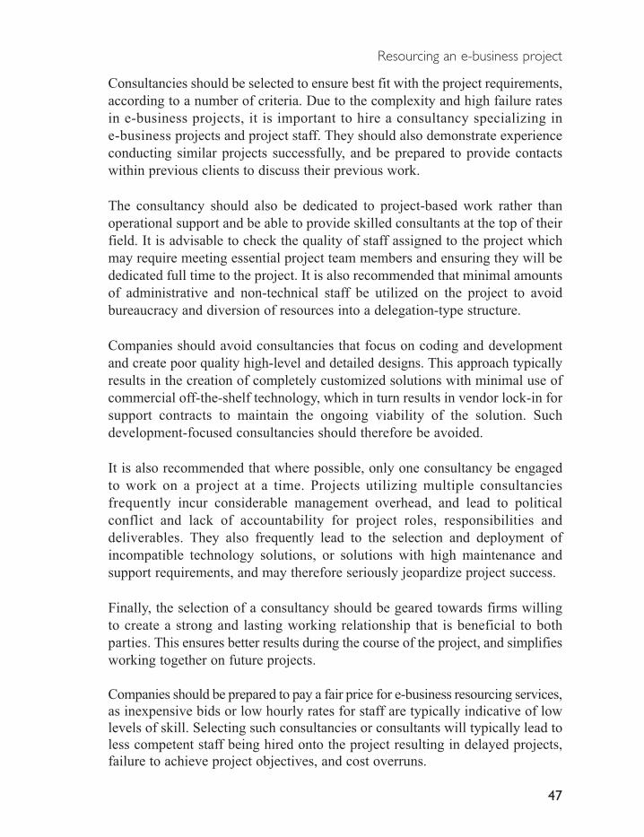
Consultancies should be selected to ensure best fit with the project requirements,according to a number of criteria. Due to the complexity and high failure ratesin e-business projects, it is important to hire a consultancy specializing ine-business projects and project staff. They should also demonstrate experienceconducting similar projects successfully, and be prepared to provide contactswithin previous clients to discuss their previous work.
The consultancy should also be dedicated to project-based work rather thanoperational support and be able to provide skilled consultants at the top of theirfield. It is advisable to check the quality of staff assigned to the project whichmay require meeting essential project team members and ensuring they will bededicated full time to the project. It is also recommended that minimal amountsof administrative and non-technical staff be utilized on the project to avoidbureaucracy and diversion of resources into a delegation-type structure.
Companies should avoid consultancies that focus on coding and developmentand create poor quality high-level and detailed designs. This approach typicallyresults in the creation of completely customized solutions with minimal use ofcommercial off-the-shelf technology, which in turn results in vendor lock-in forsupport contracts to maintain the ongoing viability of the solution. Suchdevelopment-focused consultancies should therefore be avoided.
It is also recommended that where possible, only one consultancy be engagedto work on a project at a time. Projects utilizing multiple consultanciesfrequently incur considerable management overhead, and lead to politicalconflict and lack of accountability for project roles, responsibilities anddeliverables. They also frequently lead to the selection and deployment ofincompatible technology solutions, or solutions with high maintenance andsupport requirements, and may therefore seriously jeopardize project success.
Finally, the selection of a consultancy should be geared towards firms willingto create a strong and lasting working relationship that is beneficial to bothparties. This ensures better results during the course of the project, and simplifiesworking together on future projects.
Companies should be prepared to pay a fair price for e-business resourcing services,as inexpensive bids or low hourly rates for staff are typically indicative of lowlevels of skill. Selecting such consultancies or consultants will typically lead toless competent staff being hired onto the project resulting in delayed projects,failure to achieve project objectives, and cost overruns.
Resourcing an e-business project
47

E-business Implementation
Once a consultancy has been selected, a detailed understanding of project deliverablesshould be created and agreed by both parties before contracts are signed. It isrecommended that a company hire a consultancy on a stage-by-stage basis, withthe consultancy committed to single phases at one time. Each stage should thenbe successfully completed before giving signed approval for successive stagesto ensure ongoing control over the project.
The agreement should also allow the company to maintain some control overthe technical direction of the project to manage their risk and exposure to theconsultancy. This may include conducting some preliminary technical workbefore engaging the consultancy, such as creating an audited design, to providea detailed specification of project deliverables. In addition, the company shouldprovide some project members who have an understanding of the business andtechnical requirements, such as their own project manager and e-business technicalarchitect. This allows the company to reduce project risk by monitoring theprogress of the consultancy and ensuring successful delivery against therequirements and design.
However, dividing project responsibility among in-house staff and a consultancyrequires a strong degree of collaboration between all parties to prevent the projectfrom failing due to political conflict. Therefore, special attention should be paidto the skill and personal attributes of such staff members involved in interactingwith the consultancy.
Once a consultancy has been selected, contracts should be drawn up and signedby both parties. These should be simple, short and in plain English to enable allproject staff to clearly understand the project terms and conditions. Penaltiesshould be included if the actions of the consultancy cause the project to run overtime and budget. However, contracts should be equitable for both parties to fostera beneficial working relationship. Payment should be made at the end of eachproject phase or set of deliverables, as this typically leads to better pricing fromthe consultancy.
Finally, the ongoing operation of the project requires regular meetings betweenthe consultancy and senior stakeholders and technical staff. These are typicallyweekly and cover ongoing administration, technical planning and management.However, attention in such meetings should not be solely dedicated to problemresolution, as this may foster a negative focus on the working relationshipbetween both parties.
48

Part Two E-business technologyphases

This Page Intentionally Left Blank

The five phases of e-business adoption
Successful e-business implementation requires a detailed understanding of thetechnology solutions appropriate to different business scenarios. This enablesan e-business technical architect to research and select appropriate e-businesssolutions and designs for an e-business initiative.
A recent study by IBM (Seeley, 2001) surveyed 21, 000 companies across theworld to determine the extent of their adoption of e-business technologies.Results from this survey showed that companies adopted common sets ofe-business solutions corresponding to a range of business scenarios.
The study classified e-business solutions into five phases, comprising ane-business lifecycle. This lifecycle follows a company’s progression fromadopting e-business technology to reach more customers in a more efficientmanner through to the final goal of optimizing all internal and external systemsand processes to respond in real time to the changing demands of customers(Seeley, 2001). This progression through the five phases of e-business adoptionis depicted in Figure 3.1.
3

Figure 3.1 The e-business lifecycle
The e-business lifecycle starts with Internet publishing, where the companygains a presence on the Internet through publication of marketing and corporatematerials, and uses internal Intranets to publish corporate information to staff.Internet publishing also includes the use of corporate portals to simplifypublishing and includes information from corporate applications, and the use ofcontent management systems to create and manage large volumes of rapidlychanging content for distribution to multiple channels. This phase allows acompany to realize new channels to communicate with customers and their owninternal staff, and achieve considerable savings from shifting the presentationand distribution of information from paper-based forms to Internet-based content.
As a company gains more experience and understanding of the benefits of
E-business Implementation
52
Publishing business informationon the Internet and Intranets
Transacting with Customersover the Internet
Integrating Internal Applications
with transactional E-business
systems
External Integration withPartners and Suppliers
Conducting Dynamic E-business
E-Business Phase Business Scenario
Reaching customers throughnew channels
Offering products and servicesthrough these new channels
Streamlining internal businessprocesses
Streamlining external businessprocesses
Real-time response tocustomer demand

e-business technologies to reach new channels, they progress to using thesechannels for transacting business directly with their customers. These transactionstypically take the form of providing existing and new products and services.
The transaction phase is then extended to the internal application integrationphase. This phase focuses on deploying Internet technology further into thebusiness to realize efficiency gains within existing internal processes. Disparatecorporate systems are integrated to automate transactional processes requiredfor online transactions, such as account settlement and invoicing. Integration isalso pursued to improve the speed and efficiency of internal processes to makethe company more efficient and productive, and hence more competitive.Internal integration is also used to integrate companies during corporateacquisitions and mergers.
The fourth phase focuses on integrating internal corporate systems with externalpartners and suppliers to achieve further efficiencies in areas such as orderprocessing, invoicing and fulfilment. This phase seeks to realize greatercorporate efficiencies and savings through refinements to internal processesand external interactions with partners and suppliers.
Ultimately, the company seeks to become completely responsive to customerdemand through the ability to conduct dynamic e-business. The aim of this fifthphase is to achieve a tight focus on the needs of the customer by synchronizingchanging customer demand with internal processes and external partner andsuppliers to better meet changing customer needs.
However, IBM discovered that over 80 per cent of the 21 000 companiessurveyed were still in the first two phases of e-business. In addition, EAIJournal (Editorial, 2001) reported the results of a survey by Hurwitz of 600enterprises, which found that only 10 per cent had integrated their mostmission-critical business processes, and 45 per cent had not started an integrationstrategy. The results from these surveys indicate there is still considerable scopefor the adoption of advanced e-business technologies within business.
The following sections discuss these five phases of e-business adoption. Eachsection introduces the set of interrelated issues required for implementinge-business at each stage of the e-business lifecycle. These issues include thebusiness background motivating adoption of each e-business phase, the benefits
The five phases of e-business adoption
53

of adopting each phase, the critical technologies comprising each phase and thefeatures and functions required when selecting products for each phase. Thediscussion of each phase also includes high-level designs pattens, the keybenefits and limitations of the technologies, and finally, common vendors offeringproducts suitable for deployment in e-business projects in each phase.
E-business Implementation
54

Phase 1: Internet-based e-business publishing
Internet-based publishing is the first phase of the e-business lifecycle. Thisphase involves a company providing corporate and marketing information tocustomers over the public Internet and through Intranets to their own staff onprivate internal corporate networks.
The benefits of Internet and Intranet-based e-business publishing includeproviding companies with a simple and inexpensive mechanism for informationdistribution to their target audience of customers, partners and suppliers, andinternal staff. In contrast to most traditional channels Internet and Intranete-business publishing has the ability to reach a widespread audience, and allowsinformation to be created and published online considerably quicker thantraditional means. It can also reach a much larger audience for less cost, and removesthe high cost of creation and distribution of paper-based publishing methods.
Content published online can be targeted to reach multiple audiences throughdifferent channels such as mobile phone or digital TV with minimal changes. Itcan also simultaneously reach audiences locally, nationally and internationally.Additional functionality can be added to published information to providebusiness benefits beyond traditional media, such as searchable telephone lists,or online training systems. Correcting and updating Internet-based publicationsis also quicker, simpler and much more affordable than traditional publishingmechanisms.
Internet and Intranet publishing can also be used to augment existing manualpublishing processes. For example, paper-based company reports are requiredby regulatory authorities to be sent to shareholders. Such documents can be
4

published on Intranets and Internet sites in addition to their printed form, thusreaching a much wider target audience. Additional financial statements orenvironmental compliance reports can also be made available to groups whowould not normally receive such information but who may have an interest init. This then assists a company in maintaining a public presence and brand.
For example, a company publishes large volumes of information to customersvia multiple channels, including mobile, email, an Internet site, print and digitalTV, on new products and services. Internal staff require access to this information,as well as staff-specific internal content such as product development plans,company newsletters, staff phone directories, and customer service informationfrom across the business. This information must be accessible from financialsystems, marketing systems, CRM systems, and e-business systems. Thispublishing process is depicted in Figure 4.1.
Figure 4.1 Internet-based e-business publishing
In the preceding example, the company utilizes a content management systemto provide customers with changing content across all channels. An internalportal system provides employees with this content from the content management
E-business Implementation
56
Content
ManagementSystem
Company StaffCustomers and Public
Internet Site Staff Portal
Mobile
Digital TV
Print media
Financial System
CRM System
Marketing System
E-business System
Company StaffBrochures
Office Documents
Reports

system, and customer and other business information from multiple internalsources. This provides customers with the content they require and staff withinformation required for their jobs from all areas of the business.
4.1 Key technologies used
In order to publish content online, companies require a solution capable ofcreating, managing, and delivering content in multiple formats to internal staffand externally to customers and suppliers.
Internet – and Intranet-based publishing involves assembling information fromdifferent sources, transforming it into Internet-ready content, transmitting it tousers, and displaying the content. This process is depicted in Figure 4.2.
Figure 4.2 Online publishing process
Each step in this process relies on a set of common, freely available standardsand technology components that define the Internet.
The Internet was initially developed in the 1960s to connect researchersbetween universities in the USA, with participation and sponsorship from theDefense Advanced Projects Research Agency (DARPA) now called ARPA.This early system consisted of multiple interconnected networks runningdifferent data transport protocols. As networks expanded and multiplied, acommon protocol was required to ensure all participants could communicateusing the systems available at that time, including email, shared files, andremote computing resources access systems. This led to the evolution of theTCP/IP networking standard, and its widespread adoption in the 1980s.
Defining the standards responsible for the fundamental infrastructure of theInternet occurs through submission of proposals to the Internet Engineering
Phase 1: Internet-based e-business publishing
57
ContentFormatting
ContentTransmission
ContentDisplay

Task Force, a non-profit body responsible for network and infrastructure standards onthe Internet. This group votes to accept new standards based on technical merit, withstandards published through freely available RFC (Request for Comment) documents.
Through this process, researchers gradually added additional services on top ofthe TCP/IP transport protocol, such as the World Wide Web system invented inthe early 1990s by Tim Berners-Lee at the CERN-institute in Switzerland. Thissystem described a simple mechanism for the transport and display of informationacross TCP/IP network, using the Hypertext Transport Protocol (HTTP).
The HTTP protocol was designed to transport ‘Hypertext’ documents, writtenin the HTML display language. HTML, derived from the high-end SGMLlanguage (Standard Generalized Mark-up Language) provided simple ‘tags’, orannotations within documents to describe how document content should bedisplayed. Special tags pointed to other related documents, creating aninterconnected ‘web’ of documents, hence the name World Wide Web. Theweb browser, a software application dedicated to rendering HTML content onscreen, then handled display of the document content. Transport of HTMLdocuments to web browsers utilised the services of simple web serverapplications, dedicated to serving pages via the HTTP protocol.
In contrast to other content display and transport systems, the HTML/Hypertextsystem was designed to be independent of underlying operating systems andplatforms, and accessible from any connected network. This resulted in asimple and affordable system for providing information, and led to the rapiduptake of Internet technologies by business following popularization of theNetscape Web browser by Netscape Communications Corporation in 1994.
HTML documents also offer the ability to include non-textual content withinthe document, such as images and sound. Common image formats include theGIF (Graphics Interchange Format) and JPEG (Joint Photographic Experts Group)formats. Common audio formats include MP3 (Motion Pictures Expert GroupAudio Layer 3), and video formats include the MPEG 2 and 4 (Motion PicturesExpert Group Layers 2 and 4) formats, AVI and Windows media, and AppleQuickTime formats.
Subsequent developments of content standards are overseen by the World WideWeb Consortium (W3C). In a similar process to that used by the IETF, thisgroup assesses and approves recommendations for new Internet content standards.Once approved, these new standards are made available to individuals orcompanies free of royalty payments. Vendors can then implement these standards
E-business Implementation
58

within their products, resulting in a broad base of compatible products frommany vendors. This results in increased competition within the industry and thedelivery of higher quality products. It also ensures consistency and compatibilitybetween competing products.
In addition to these standards and applications, Internet-based publishing relieson the content searching function provided by search engines. Search enginesallow users to locate content either in Intranet systems, on Internet sites. Thesearch engine locates and classifies the content, and creates a summarized indexof all content attributes such as date created, author, type of document, size andlocation, contents of document. Users enter search queries into the searchengine, which searches through the index for all occurrences of the search queryand returns the relevant page and its link.
4.2 Types of publishing systems
Three different technology solutions have evolved to provide online publishingfunctionality, with each solution targeting different publishing requirements.These include custom Internet and Intranet publishing systems, corporate portals,and enterprise content management systems. Each system is differentiated bythe mechanisms they employ to manage different forms of content, whichinclude static and dynamic application-based content. Static content typicallyincludes largely unchanging written content or images presented as a series ofpages. Dynamic application-based content consists of information sourced fromdata stored and maintained within enterprise applications.
Custom Internet and Intranet systems were the first online publishing systemsused. They systems are assembled from web servers, tools to create and manageHTML content, and manual processes required to publish content. Such systemsprovide simple functionality for creating, managing and displaying static content.Custom Internet and Intranet systems are generally suitable for businesses withsmall amounts of static page-based content that changes infrequently. Thesesolutions are generally unsuitable for the display of application-based content,as this requires considerable additional customisation to integrate with enterpriseapplications, and is more suited to a commercially available portal product.
Portal systems evolved to address some of the limitations of early customInternet and Intranet solutions, such as heavy reliance on error prone manualsite publishing processes. Portals automate these processes within a single product,and allow a company to efficiently aggregate and display large volumes of static
Phase 1: Internet-based e-business publishing
59

and application-based corporate information. This information is displayed toInternet and Intranet – users as customizable elements within a web browser interface.Portal systems are suitable for businesses where employees require Intranetaccess to large volumes of application-based corporate information, and largevolumes of static page-based information that undergoes a moderate degree ofchange. They are also suitable for Internet sites where customers require largeamounts of static page-based content and some application-based content witha moderate degree of change. If this content is undergoing rapid addition, deletionor modification, the portal system should be integrated with a dedicated enterprisecontent management system.
Enterprise content management systems address a different set of publishingrequirements, centred on storing and displaying huge volumes of rapidly changingcontent. These systems evolved from early document management systems thatwere designed to scan, store and manage documents, removing the need forpaper-based business processes. They were then extended to support multipledocument types and manage rapidly changing content within Intranets andInternet sites.
Content management systems are suitable for custom Intranets and Internetsites where employees and customers require access to large amounts of rapidlychanging of static page-based content, but no application-based content. Theyare also suitable for integration with portal systems to support large volumes ofrapidly changing static and application-based content. If large volumes oftransactional e-business or very high volumes of application-based content arerequired on an Internet site, integration is typically required with enterpriseapplication integration technologies.
4.3 Custom Internet and Intranet publishing systems
Internet sites are comprised of linked HTML pages of related content, such asdescriptions of a company’s products and services, and public companyinformation. Internet systems allow companies to reach their customers andsuppliers with relevant information in an affordable and simple manner. Theyalso provide a convenient central point for information distribution and management,allowing a company to maintain a consistent public image and brand.
In contrast, Intranet sites consist of a similar system, but with contentspecific to the needs of internal staff. Intranet sites are available to staff withinthe company over their internal private networks, and provide a centralized
E-business Implementation
60

source of corporate information.
Custom Internet and Intranet systems are designed to satisfy the onlinepublishing requirements of small – to medium-sized volumes of content, or forcompanies wishing to experiment with this medium on a small budget. Theyprovide a quick entry into e-business publishing and are very affordable andsimple to create with the skills required to create such systems and publishcontent readily available. Content can be published to either system dependingon the nature of the content and its intended audience. Typically companiesrestrict Intranet content to internal use only, while public content is for Internetuse.
For example, a company maintains an Internet site for customers and anIntranet site for staff. Content is authored using a number of tools, tested toensure it is correct and displays correctly, then published to the appropriateInternet or Intranet site. Users connect to either site and browse content byfollowing links, or alternatively by searching for content. This process isdepicted below in Figure 4.3.
Figure 4.3 Internet and Intranet publishing process
Phase 1: Internet-based e-business publishing
61
Content
Publishing
Intranet Site Internet Site
Internal Corporate Staff
Content
Creation
Content
Testing
C ustomers and public

In the preceding example, content is created from corporate information sourcessuch as internal reports, and authored into Internet formats and linked into aseries of content pages. The content is then tested to determine that it willdisplay properly, and published to the appropriate Internet or Intranet site.Internal staff can view either site, while customers and members of the publicare restricted to the Internet site.
4.3.1 Key technologies used
Custom Internet and Intranet sites utilize core Internet components includingweb servers designed to service HTTP requests for HTML content, webbrowsers for content display, and sets of tools to publish content in thedifferent Internet content formats, such as HTML editors to create and managepages. Sites should also include search engines to allow users to search forrelevant content.
What to look for in online publishing products
Online publishing products require support for a structured site creationprocess. This includes steps for the creation of site content, content testing, sitemanagement, and site publishing.
Creation of Internet and Intranet sites progresses from an initial site layouttemplate. The template details the major categories of content to be displayedon the site, and is structured as a hierarchical layer of pages grouped by topic.The home page, represents the first page on the site a visitor will encounter, andmust therefore display all the content areas in a simple and readily accessibleform. Often this page will include frequently changing topical content tomaintain user interest and encourage repeat viewing. Successive layers of thesite structure guide site visitors to different areas of content, with cross-links toother site areas. This allows users to browse content in an efficient and fastmanner.
It is recommended that a site usability expert should be employed to create thesite layout template and website content. This role involves guidingdevelopment of the site to ensure that content is manageable and easy to findfor users, and that customers have a positive experience when visiting the siteand are therefore more likely to return.
E-business Implementation
62
The site layout is populated with content using content creation tools. Theseinclude HTML editors, with the ability to create site pages, embed images inpages, and create links to audio and video content. Images, audio and videorequire initial formatting into the correct Internet standard formats using image,sound or video manipulation tools. This process also ensures that the files areoptimized so they load quickly into a user’s browser.
The HTML editor should include site management functionality, to facilitatemaintenance of the site layout. This tool maintains a database of the sitestructure, page content and assets (including images, audio and video files), andthe links between pages. If a page is moved within the site, the site managementsystem restructures each page to accommodate the change. This dramaticallyreduces the amount of manual changes required when alterations are made tothe site, and minimizes errors in content. Advanced products will also assist inmanaging the complete website production process, including providingteam-based collaboration and communication, and file management facilities.
Once all pages are complete, the site is published to an Intranet or Internet webserver using file transport systems such as the File Transfer Protocol (FTP) orWebDAV (Distributed Authoring and Versioning). Publishing to a web servermay be supported by additional functions such as site management engines, andintegrated search engines. In addition, delivery of video content may beprovided through specialist web servers supporting real-time delivery, orstreaming, of video and audio.
Web servers may also include support for scripting languages, which are usedto provide interactive functions in the sites. These typically include functionalitysuch as serving content in multiple languages to users from different countries.Site scripting systems also allow sites to be connected to database back-ends toprovide a simplified, structured mechanism to store site assets and content. Thisalso allows for simplification of the publishing process. As page links arecontained as references within the database, and not encoded within each page,changes to site structure do not require manual changes within each page.Common dynamic scripting languages include the simple PHP (Personal HomePage) system designed for websites, PERL (Practical Extraction and ReportingLanguage), a highly advanced scripting language ideally suited for processingtextual information, and the JSP (Java Server Pages) and ASP (Microsoft ActiveServer Pages) scripting systems.
Web servers can also be extended through the addition of software written tosupport web server-programming interfaces. These interfaces allow web servers
Phase 1: Internet-based e-business publishing
63
to provide additional automated functionality, such as online forms to solicitcustomer feedback. Common web server programming interfaces include theadvanced Java Servlet standard, or proprietary programming languages such asthe ISAPI (Internet Information Server Application Programming Interface)and NSAPI (Netscape Application Programming Interface) standards.
Internet and Intranet systems must also include management and administrationfunctions to enable the capture and reporting of site usage statistics. Thesetypically involve additional applications that read web sever log files andgenerate reports on the nature of user accesses to the sites. This information isinvaluable in determining the usage patterns of customers, and hence optimizea site to better suit their needs.
Finally, Internet and Intranet search engines, available as part of the web serveror as standalone servers, should provide the ability to search all content typeson the site, including HTML pages and downloadable content such as AdobePDF or Microsoft Word files.
4.3.2 High-level designs of Internet and Intranet systems
Designs for Internet and Intranet systems must provide availability andscalability to ensure continual content provision, and to support contentcreation and management processes.
Availability and scalability are provided using one – or two-tier web architectures.One-tier architectures feature deployments of single web servers, withreliability features such as RAID 5 storage systems to preserve operation of thesystem in event of disk failure, and error correcting memory to minimizesystem downtime resulting from memory failure. Scalability is provided by acombination of multi-threaded web servers and multi-processor server hardware.
Two-tier architectures extend the previous one-tier design to include a back-enddatabase for reliable and scalable storage and generation of site content.Additional availability and scalability features include the use of databaseclustering for higher performance and fail-over support.
The scalability and reliability of either architecture can be extended using networkload balancing of multiple web servers. This requires extension of contentpublishing to all servers simultaneously, with identical content stored on each server.
E-business Implementation
64

High-level designs must support the e-business content publishing process,from authoring to testing to deployment. Once site developers have authoredcontent, it is placed into a development environment, which is a copy of the liveInternet or Intranet system used for developing new content and features.
Content is previewed in the development environment to ensure it functionscorrectly, and then migrated to a staging environment. This environment isidentical to the development environment, but used by business staff responsiblefor the sites for viewing, testing and approving Internet and Intranet content.This enforces a change control process to ensure that only correctly functioningand approved content is made available to end users. It also allows for separatedevelopment of advanced functionality, such as online forms, to minimizepotential impacts on live systems.
Once content has been approved, it is migrated to the production environmentto become ‘live’. Users then access the production server to view the newcontent. Access to development and staging servers is prevented for casualusers to maintain the security of unapproved content.
Limited security can be enforced within the design using access control lists(ACLs) on the web server. These restrict user access to regulated content byprompting users for their username and password. Security of content in transitbetween a user and a web server can be assured using SSL technology toencrypt all communication.
All designs require an understanding of hardware, network and DNS designissues, and network, host and application layer security. For a detailed discussionof these issues, see part three.
The following designs depict online publishing systems for one-tier corporateInternet and Intranet sites, and two-tier database driven Internet and Intranetsites. Each design includes the ability to support extension through additionalfunctionality, including facilities such as automatic content migration, searchengines, and advanced dynamic content types such as online forms.
High-level design for one-tier Internet and Intranet publishing solution
A standard design for a combined corporate Internet and Intranet site is depictedin Figure 4.4. This design is suitable for small to medium sized staticpage-based content requirements, and is capable of supporting web server and
Phase 1: Internet-based e-business publishing
65

search engine software from different vendors.
This design incorporates development and test servers within the corporatenetwork, an internal Intranet server, and an Internet server within theDe Militarized Zone (DMZ) for secured public access. The DMZ restrictsexternal user access by allowing access to the production web server whiledenying access to internal corporate systems.
Content is created on development servers and migrated to staging servers fortesting. Once approved, content is migrated to the production Internet orIntranet web servers. Migration to the Internet site may require additionalnetwork ports opened on the firewall to allow one-way traffic between theInternal and DMZ networks from the staging to live servers.
An Internet search engine for indexing and searching the Internet site is locatedon the DMZ, with a similar Intranet search engine located on the internalcorporate network. A single staging search engine is required for stagingInternet and Intranet sites hosted on the corporate internal network. A developmentsearch engine is not required, as site developers rarely require this functionality.It is recommended that live web servers be deployed with live search engineson separate hardware, as search engine content indexing can seriously impactweb server performance.
All Intranet servers are located within the corporate network behind thefirewall. Although these servers are not exposed to the public Internet, theyshould be configured with standard high security features in the event that theyare shared with partners and suppliers through a private Extranet. In suchcircumstances, the servers participating in the Extranet should be placedwithin a separate DMZ network.
Note that development and staging servers can incorporate both the Intranet andInternet sites on the same hardware through a process known as multi-homing.Multi-homing is supported by all major Internet server software products, andallows for consolidation of sites and the elimination of redundant hardware.When deploying multi-homed sites, it is recommended that each site utilize thesame server IP address, to minimize waste of IP addresses. This also simplifiesDNS records and DNS management, and permits simple future migration ofsites to new server technologies.
The combined Internet and Intranet design is depicted in Figure 4.4.
E-business Implementation
66

Figure 4.4 High-level design for combined Internet and Intranet one-tier e-businesspublishing system
High level design for two-tier Internet and Intranet publishing solution
This design extends the one-tier Internet and Intranet design depicted above
Phase 1: Internet-based e-business publishing
67
DMZ (De Militarized Zone)
Internet
Firewall
DevelopmentIntranet/Web server
Staging search
Engine (Intranet andWeb)
ProductionIntranet server
Internal Network
Internal users
Internet users
ProductionIntranet Search engine
Staging Intranet/Webserver
Site developer Site developer
Productionweb server
ProductionWeb search server
Site developer Content approver

using a two-tier web architecture for Internet and Intranet sites. This designincludes an additional tier used to store site content within a database forretrieval in response to user requests.
As with the preceding designs, this configuration utilizes multi-homing tolocate development and staging Internet and Intranet sites on the same systems.In addition, development and staging environments consolidate the content databasewithin the same server to minimize unnecessary infrastructure, as they do nottypically experience high-performance demands compared to the live systems.
The two-tier Internet and Intranet design is depicted in Figure 4.5.
Figure 4.5 Dynamic Internet and Intranet online-publishing e-business system
E-business Implementation
68
DMZ (De Militarized Zone)
Internet
Firewall
DevelopmentIntranet/Web server
Staging search
Engine (Intranet andWeb)
IntranetWeb server
Internal Network
Internal users
Internet users
IntranetSearch engine
Staging Intranet/Webserver
Site developer Site developer
InternetWeb Server
Intranet Databaseserver
InternetDatabase server
InternetSearch Server
Site developer Content approver

4.3.3 Benefits and limitations of Internet and Intranet publishing solutions
Custom Internet and Intranet publishing systems offer affordable and simpletechnology to create and publish static content. They typically have minimalhardware and software requirements, and can be extended to support advancedfunctionality, such as search engines or online forms.
However, these systems suffer from a number of limitations such as lack ofcontrol over content, including lack of document versioning, automated authoringand approval workflow processes, and the ability to automatically convertdocuments into multiple publishing formats. Therefore, as the volume ofcontent, its rate of change, and site complexity increase, the manual sitecreation and maintenance processes create a bottleneck for publishing andmaintenance.
Using site management tools may alleviate some of this bottleneck, but as contentvolumes increase the costs and features of advanced software such as portalsystems and enterprise content management systems typically outweigh theselimitations. Portal and content management systems also dramatically reducethe number of errors in the content production process.
In addition, larger companies typically require that staff from several divisionspublish content online. Using custom Internet and Intranet systems limits theability to distribute this publishing function throughout the company, due to theneed for specialist online publishing skills. This function is normally held withina specialist-publishing unit with the required expertise, which can become abottleneck for large volumes of rapidly changing content.
Custom Internet and Intranet systems also frequently prove inadequate foraccessing and displaying application-based content. This typically requiresconsiderable customized development effort to extend Internet and Intranetsoftware, using proprietary web server development interfaces such as NSAPI,ISAPI or Apache modules. This approach results in ‘fragile’ systems that mustbe manually altered to compensate for changes to internal enterprise applications.In contrast, vendors typically maintain their portal products to remain currentwith enterprise application integration solutions and enterprise applicationssuch as CRM or ERP systems.
Phase 1: Internet-based e-business publishing
69

4.3.4 Vendors of Internet and Intranet software
Table 4.1 lists software products used in Internet and Intranet e-businesspublishing systems. It should be noted that due to the large number andcomplexity of vendors available, this list is not exhaustive and should be usedas a guide only before detailed product research is undertaken.
Table 4.1 Vendors of Internet and Intranet publishing products
Vendor Internet and Intranet publishing products
HTML editors Adobe GoLiveMacromedia Dreamweaver MXMicrosoft FrontPageImage editorsAdobe Photoshop, Photoshop ElementsCorel CorelDraw Graphics SuiteMacromedia FireworksOpen Source GIMP (GNU Image Manipulation Program)Site managementAdobe GoLiveMacromedia Dreamweaver MXBrowsersNetscape Netscape CommunicatorMicrosoft Internet ExplorerOmni Group OmniWebOpera OperaWeb serversApache Group Apache Web Server iPlanet iPlanet Enterprise ServerMicrosoft Internet Information Server (IIS) Search enginesAltaVista AltaVista Enterprise Search Autonomy AutonomyInktomi Inktomi Search EngineVerity Verity Search Engine
4.4 Portal systems
Portal systems are integrated online publishing solutions, which typically containmost of the functionality required for publishing static and application-based content
E-business Implementation
70

to Internet and Intranet sites. This functionality is often available through rapidout-of-box deployments.
Portal systems provide advanced integration and publishing functionality toamalgamate all sources of corporate information. This is then published ascustomized content accessed by users through web browsers, which the portalcan update in real time to staff members via an Intranet, or to customers andexternal partners and suppliers via the Internet or an Extranet. Portals aredesigned to support large amounts of both static and application-based contentpublished over an Intranet and large amounts of static content and moderateamounts of application content over the Internet. They can also manage moderateamounts of rapidly changing content, or can be integrated with contentmanagement systems for more demanding content requirements.
Portal systems provide considerable benefits within an organization for themanagement and distribution of information. Because they contain features toautomate the distribution of critical information throughout the enterprise,portal systems save users considerable time when locating and accessingcompany information. They provide a centralized, easily managed source ofconsistent corporate information and corporate identity for workers distributedacross different locations, and provide central access to corporate informationfor roaming/remote access users. They also reduce the costs for management ofknowledge and information within the company and for its partners andcustomers (Borck, 2000).
Portal systems also allow companies to save on software installation andsupport costs. Companies typically spend considerably amounts of timemanaging multiple interfaces into enterprise information sources on staffcomputers. These include separate database clients, email clients, filebrowsers, and mainframe clients (Bhatt and Fenner, 2001). Consolidatingaccess to these information sources into a browser reduces the need to installand support many potentially conflicting products, and reduces licensing costs.They are also increasingly being used to transfer work processes that formerlyrelied on paper-based information into the new Internet and Intranet systems(Mears, 2001c).
For example, a company uses a portal system to provide access to corporateemail, Internet and Intranet content, electronic employee message boards,business intelligence reports from corporate systems such as data warehouses,
Phase 1: Internet-based e-business publishing
71

CRM, and ERP systems, and give users the ability to publish Intranet contentfrom anywhere within the company. This process is depicted in Figure 4.6.
Figure 4.6 Corporate information access via a portal solution
In the preceding example, Internet and Intranet users access the portal andselect content areas of interest. The portal then assembles these into customizedpages using predefined templates, or alternatively users select how theinformation should display in their pages. Pages may include components ofstatic, page-based content such as quarterly reports published into the portal byinternal staff, and application-based content components, such as a queryinterface into a CRM system. The portal solution displays the static contentwithin the user’s browser, and retrieves the application content as requested,such as when a user requests customer details. Internet users are typically givenrestricted access to fewer application-based content items for security reasons.
4.4.1 Key technologies used
Borck (2000) classified portals into either consumer portals providing news,email, and search engines to Internet users, or enterprise portals providingpersonalized views of corporate data, collaboration systems, and access to
E-business Implementation
72
Corporate Staff
Teleworking Staff
Roaming Staff
Email System
Message Boards
Data Warehouse
ERP System
Staff publishedInformation
Internet Users
Portal System

corporate applications and processes.
Consumer portals are typically used to provide consumer-centric systems forInternet users (e.g. www.yahoo.com or www.hotmail.com) and are typically notused by companies, and thus not discussed in this book.
Enterprise portals are created with similar technologies to Internet and Intranetdesigns. Users interact with the portal via an HTML/DHTML web interfaceprovided by a web server. This server in turn communicates with the back-endportal server, which manages portal business logic functions, user and securityservices, content storage systems, and integration systems (Homan, Sanchezand Klima, 2001). Portals are typically created as two or three-tier Internetapplications, using either COM/DCOM technology, or Java J2EE technology toprovide application logic.
What to look for in a portal solution
Selecting an appropriate portal product is complicated by the rapid market-drivenchanges in vendor products, and the large number of portal product– vendors,currently more than 100 (Mears, 2001c). In addition, products are describedusing multiple classification systems (see Fitzgerald, 2001; Mears, 2001c;Upton, 2001). However, analysis of portal features indicates these differentcategorizations are merging as vendors adopt similar features to their competitors,and the portal marketplace matures.
Portal product selection requires careful understanding of product features andenterprise requirements. However, not all products are capable of supporting allenterprise class features. This may result in a company selecting multiple productsto meet the requirements of different company divisions. However, this is not arecommended strategy, as it results in isolated systems with pockets of dataserving specific users, and may result in problems integrating between thedifferent portal products.
Enterprise portal products typically provide seven components to provide acomprehensive set of portal services. These include integration services,personalization services, content management services, collaboration services,business intelligence features, administration and user management services, andsecurity systems.
Integration services allow the portal to integrate with existing corporate information
Phase 1: Internet-based e-business publishing
73

sources such as databases, existing websites, legacy mainframes, and ERPsystems. This integration is typically achieved through vendor-specificproprietary integration adapters, which connect the portal product to eachenterprise information source. However, such connector systems may lackintegration features required to retrieve information from applications distributedacross the company, necessitating standalone Enterprise Application Integrationsystems. Integration services should also provide single sign-on for all corporateapplications through the corporate directory services. This allows users to login to the portal, which uses their credentials to access permitted corporate systems.
Personalization services allow staff members to select and display the informationrelevant to themselves through customized home pages. Personalization servicesare typically made available through subscription and notification processes,which notify the user when a new or changed information resource has becomeavailable in the portal. Personalization services should be integrated with theportal security systems to ensure controlled access to application information.
Content management services allow the portal to integrate sources of content.This service is comprised of a set of technologies including directory services,search services, and content publishing features.
Directory services provide a directory server, such as LDAP, to store metadata,which is used to define the types and locations of information resources withinthe enterprise. This provides a centralized means to locate resources through astructured overview of the total enterprise resources, including diverseresources such as Internet and Intranet sites, legacy systems, ERP systems orCRM systems.
Search services build searchable indexes of content such as internal and externalwebsites. Employees subsequently conduct searches on these indexes to quicklylocate relevant information.
Publishing features allow users to enter and manage different forms ofinformation in the portal. Template driven publishing is the preferredmethod, incorporating predefined templates used to enter information. Thisreduces the publishing burden for non-technical users, and allows for efficientdistribution of the publishing functions throughout the enterprise. Templatesshould be created through included application development tools, along withgraphical utilities to integrate templates with appropriate data sources. Productsshould also include predefined business logic components for automatingcommon publishing tasks.
E-business Implementation
74

Collaboration services provide systems to increase employee productivity usingworkflow and interaction tools. These include email tracking and indexing,workplace communities for shared discussions and virtual meeting rooms, andtask lists.
Business intelligence services provide tools to analyse information held in thesystem, including accessing data warehouse, online analytical processing, anddata mining functions from existing corporate resources. This service is animportant aspect of portals, as it allows employees across a company access tovital analytical information.
Portal administration is best achieved through a web browser, and shouldintegrate with corporate directory servers. It should also support single-sign-on(SSO) allowing one-time entry of usernames and passwords to accessresources. This may be required for accessing the portal from different locations(e.g. Internet and Intranet), and for integration with other corporate systems, orwith partner/supplier systems.
User management services provide membership services for the creation andmanagement of users and their access rights in the portal. These are then usedby the security services, which provide the ability to regulate access based onthe user identity and type of information being accessed.
In addition to these seven components, it is also recommended that portalsolutions utilise or support J2EE-based application servers. This ensures thesolution can utilize the J2EE Java Connector Architecture and Java MessageService for direct integration with Enterprise Application Integration systemsfor higher performance, scalability, and reliability.
Support for J2EE application servers also permits companies to capitalize onmore rapid vendor development of the portal solution features. This occursthrough the vendor utilizing development productivity improvements offeredby Java, and by being able to rely on the underlying application serverreliability, scalability and availability facilities.
4.4.2 High-level designs for portal systems
Enterprise portal systems utilize two – or three-tier Internet application architectures.This allows portal solutions to incorporate availability and scalability features,and integrate with existing Internet and Intranet infrastructure systems.
Phase 1: Internet-based e-business publishing
75

Typically the first tier is responsible for delivering content to a user. Thispresentation layer can deploy content in multiple formats for different devicessuch as HTML for web browsers, WML for WAP phones, or SMS text messaging.
Typically the second tier houses the portal server business logic, whichutilizes the seven portal components discussed in the preceding section totransform static and application information into content for display via thepresentation layer. The user management and security functions are enhancedthrough integration with corporate directory servers, which store user informationand security attributes. Data processed by the portal server is stored in the thirdtier database system.
The portal server also includes application integration systems to interface toback-end corporate applications. These systems are typically integrated into thesecond, business logic tier, and employ custom-built integration adapters.Alternatively, products based on J2EE application servers utilize industrystandard integration technologies such as JMS and JCA to achieve integrationwith a wide range of enterprise applications and data sources.
Portal designs frequently require very high scalability and robustness, as theyare typically deployed as mission-critical business tools and therefore faceconsiderable performance demands. Scalability and robustness are achievedthrough the use of scalable clustered database back-ends for content storage,and network load balancing for very high scalability and availability of first tierweb servers. In addition, second tier portal servers may be clustered forredundancy and increased performance, or alternatively use J2EE applicationservers for transaction management, application integration, and clustering ofportal functions across multiple servers for very high scalability and availability.
These high-level designs allow for reconfiguration of the different layers tosupport the requirements of different portal products. For example, someproducts may be deployed using a one-tier architecture, with all functional unitsdeployed on one server. This architecture is recommended for development andstaging environments, as it reduces hardware and management requirements.However, this configuration does not provide enough scalability or reliabilityfor live production systems. Two-tier designs may also be used in someproducts, but are typically less scalable than three-tier designs. This designvariation evolved from early Internet architectures utilizing proprietary solutionsdirectly integrated with web server programming interfaces, and is currentlybeing superseded by modern three-tier architectures.
E-business Implementation
76

Portal designs also support provision of content to external partners and suppliersor to customers through private Extranet networks. This design variation utilizeshigh security connections between participant firewalls, with additionalauthentication systems to validate the identity of participants, and authorizationsystems to control access to subsets of the total portal information.
Similarly, portal content available to customers over the Internet incorporatessecurity systems to restrict access to critical portal content and components. Thisis achieved through network security systems, and access control within the portalproduct. Typically, products define a subset of total content available to Internetusers, and make this available through dedicated portal servers in the secureDMZ network.
The following designs provide two-tier and three-tier architectures for Portalproducts. Due to the considerable variety of products, these designs areoffered as a reference guide only.
High-level design for moderate usage two-tier portal solution
The two-tier portal design depicted in Figure 4.7 is intended for portals subjectto moderate to medium levels of usage. This design is intended to give access tocorporate content for internal employees via an Intranet, external partners andsuppliers via an Extranet, and select customers or roaming employees over theInternet.
Presentation and business logic functions are incorporated into the portal servers,with data storage provided by separate storage servers. The internal portal serveris for use by employees, and partners and suppliers connecting via a secureExtranet connection. A search server indexes all portal content and allows usersearching for relevant content.
The internal portal server connects to the portal integration server to retrieveinformation stored within the enterprise applications. Content authors andapprovers create and approve other content for display through the portal. Theyalso define and approve content suitable for publishing to customers over theInternet. The internal portal server then publishes this content to the Internet portalserver.
This design also offers integration between the portal and back-end corporateapplications such as ERP systems, financial systems, and CRM systems. If additional
Phase 1: Internet-based e-business publishing
77

integration is required, enterprise application integration systems can be incorporated.Security is provided through the DMZ network, firewall, and internal networkintrusion detection servers. These monitor all network traffic to detectsuspicious activity. Authentication of users and authorization of their access toinformation is provided through integration with the corporate directory serverusing the LDAP protocol.
This design also provides a customer internet portal through a first tier presentationserver in the DMZ. This server connects to the internal portal server to retrievecontent and utilise portal services. This allows the company to simultaneouslytarget internal staff, while providing external customers with an appropriatesubset of the total corporate. Additional security systems are required to restrictaccess to the internal portal server, including firewall control rules and intrusiondetection systems. A search server is also included in the DMZ, whichincorporates a subset of the internal search server indexes, allowing customersto search for relevant customer content. This design is depicted inFigure 4.7.
Figure 4.7 High-level design of two-tier portal solution
E-business Implementation
78
Internal Network
DMZ (De Militarized Zone)
Internet
Firewall
Internal users
Extranet to external
company
Portal Integrationserver
Internet PortalServer
Content
author
Content
approver
Internal Portalserver
Internet users
Enterprise ApplicationsPortal
Storage server
IntrusionDetection server
IntrusionDetection server
CorporateDirectory server
Portal Searchserver
Portal Searchserver

Variations on this design allow for higher availability and scalability. For example,if the portal is considered mission critical and downtime is not permitted,high-availability continual operation can be ensured through multiple clusteredportal and integration servers. This requires a network load-balancing design. Inaddition, the database server can be clustered using operating system/file systemclustering and a parallel database product.
High-level design for high usage three-tier portal solution
The three-tier portal design depicted in Figure 4.8 is intended for high usageportals with integration with many enterprise applications. It is also intended forcompanies intending to deploy multiple ‘virtual’ enterprise portals, consistingof several portals dedicated to different topics. Such virtual portals are typicallyhosted on the same hardware to minimize administration and expense.
This design builds on the two-tier design by separating presentation andapplication functions into the first and second layers, with storage functionsresiding in the third layer. Additional functions such as enterprise applicationintegration and security and user management server are also included, alongwith a separate access logging server, used to record and report on portal usage,for increased performance.
The third tier contains the data storage server. This tier provides storage forcontent managed by the portal solution, and is clustered on multi-processorservers for increased performance and scalability. In addition, multipledatabases can be deployed for different elements of the portal such as documentstorage and collaboration applications, allowing each database to be tuned fordifferent performance requirements. This tier also contains the portal-loggingserver to record accesses to portal content for management reporting.
Security and user configuration information is provided through the samemechanisms used in the two-tier design, including LDAP directory servers,firewalls, and intrusion detection servers.
This design also includes separate search engines with their own databases.These products are designed to search large volumes of information from multipleinternal and external sources, and thus require separate storage due to the
Phase 1: Internet-based e-business publishing
79

considerable size of the content indexes they generate. They also offer highscalability and reliability using multiple search and index servers.
Figure 4.8 High usage three-tier portal design
E-business Implementation
80
Security and user
profile servers
Internal Network
DMZ (De Militarized
Zone)
Internet
Firewall
Internal users
Extranet toexternal company
Portal Application
server
Portal storage servercluster
Content authors Content approvers
Internal PortalWeb server farm
Internet users
Enterprise Applications
Portal Applicationserver
Portal Application
serverEAI Hub server
Internet PortalServer farm
Intrusion
Detectionserver
SSL
Accelerator
Load
Balancer
IntrusionDetection server
Portal loggingserver
Portal Searchservers
LoadBalancer
Portal Searchservers

As with the design above, this architecture allows access to the portal for internalemployees via an Intranet, external partners and suppliers via an Extranet, andcustomers and employees over the Internet.
However, this design differs in the use of multiple first tier presentation serversutilizing network load balancing, and multiple clustered Portal business logicservers. This design also provides for highly scalable enterprise applicationintegration through the use of a central enterprise application integration (EAI)‘hub’, which acts as a routing and distribution centre for messages betweenapplications.
4.4.3 Benefits and limitations of portal solutions
Portals provide an ideal mechanism to centralize and manage employee accessto corporate information. They also provide a simple solution to distributee-business publishing throughout an enterprise and to provide automatedpublishing of content to Internet and Intranet sites.
However, portal solutions may be limited in their ability to integrate withenterprise applications. Portal integration modules are typically proprietary toportal vendors and may not suit all corporate integration requirements. Portalintegration systems are also typically designed primarily for simple informationretrieval from the enterprise applications and the portal, and may therefore lackhigh scalability and extensibility required for high-performance demandingenvironments. This in turn may result in restrictions to the amount of corporateinformation they can provide to users.
4.4.4 Vendors of portal solutions
Table 4.2 lists enterprise portal solutions and vendors. It should be noted thatdue to the large amounts of vendors and products available, this list is notexhaustive and should be used as a guide only before solution research isundertaken.
Phase 1: Internet-based e-business publishing
81

Table 4.2 Vendors of enterprise portal solutions
Vendor Enterprise portal solution
ATG ATG Enterprise PortalBEA WebLogic PortalBroadVision Enterprise PortalBrio Software Brio PortalEpicentric Epicentric Foundation ServerHummingbird Hummingbird PortalIBM WebSphere Portal and Enterprise Information PortalMicrosoft SharepointOpen Source Jahia and JetspeedOracle Oracle 9iAS PortalPlumtree Plumtree Corporate PortalPeopleSoft PeopleSoft Portal SolutionsSAP mySAP Enterprise PortalSybase Sybase Enterprise PortalSun Microsystems Sun ONE Portal ServerTibco ActivePortalViador E-Portal
4.5 Content management systems
Content management systems are designed to allow companies to create andmanage very large volumes of rapidly changing static content, and reformat itfor use across different channels such as Internet, Intranet, mobile, digital TVand print media.
Therefore, companies in industry segments where huge volumes of content aregenerated, such as media organizations and publishing companies producinglarge websites, frequently require content management systems. These alsoinclude companies with extensive information products, and specialist companies,such as aerospace or pharmaceutical companies, who create and consume hugequantities of structured information such as research studies or computer aideddesigns (CAD).
Such companies require systems to manage the thousands of items of rapidlychanging content they create (Doculabs, 2000). Content is typically created inmultiple formats, including company brochures, corporate reports, and online
E-business Implementation
82

media files such as video, audio and web pages. It is also typically convertedfrom original source formats into several target formats for distribution throughchannels such as television, print and the Internet. This in turn requires manymembers of staff to contribute to the creation and subsequent formatting of thiscontent, which necessitates sophisticated tools to manage the content as itmoves between workers.
These requirements typically exceed the ability of existing Internet, Intranet andportal systems to manage, due to the rapidly changing volume of content andthe sophistication of work practices needed to produce the finished content.From their roots in earlier dedicated document management products, contentmanagement products evolved to provide solutions capable of handling anycontent format.
Content management systems provide a number of advantages to companiesfaced with demanding content requirements. They allow content to be ‘repurposed’(reformatted) for simultaneous delivery to multiple channels such as CD-ROM,print, Internet, email, SMS and WAP. This in turn allows a company to targetcontent to different staff and customers for increased productivity of staff andincreased uptake of content by consumers. They also offer sophisticated‘workflow’ capabilities, where content is routed between multiple contributorssuch as authors and editors, thus providing a high degree of control over thecreation, management and distribution of content.
These abilities allow organizations to realize substantial benefits throughreductions in manual content creation and management practices.Time-consuming manual systems used to create, format, and display contentcan be made more efficient by increasing the degree of automation of each step.This results in improved employed productivity, reduced content creation andmanagement costs, and allows companies to offer more complex information-basedproducts and services. Such systems also allow targeting of content, allowingcustomers, staff and partners to locate and use relevant information in the formthey require without tying up staff in manual searches or content reformatting.
The total cost of ownership of corporate information assets is also loweredthrough content management tools due to the simplification of content creationand management across different online and offline channels. Using a singleContent Management solution rather than multiple manual systems for eachchannel results in lower infrastructure, administration and support costs, reductionsin staff training through standardization, and more consistent and error-free output.
Phase 1: Internet-based e-business publishing
83

These benefits can provide compelling savings. For example, the Giga group(Moore, 2001a) estimated that shifting content management from manualsystems to packaged content management systems could reduce maintenancecosts by one third and reduce labour costs in content authoring and design byhalf. They also estimated this could reduce operational web publishing costs byhalf, reduce the business risk of publishing erroneous or out-of-date content,and increase sales, revenues and profits.
For example, a media company uses a content management system to createand manage content for distribution to television, digital TV, multiple partnersInternet sites, mobile devices and print media. This process is depicted in Figure 4.9.
Figure 4.9 Managing content across multiple channels
In the preceding example, corporate information from multiple sources isentered into the content management system to produce relevant content fortarget markets. It is then repurposed into suitable display formats for a widerange of devices and channels, and delivered to consumers.
4.5.1 Key technologies
Content management systems are designed by vendors using either traditionalclient - server technologies, or modern Internet-based technologies. Traditional
E-business Implementation
84
Repurpose
Television
Digital TV
Syndicated
websites
Mobile devices
Print Media
Video footage
Audio tracks
Documents
Print media
News feeds
Staff editorial
ContentManagement
Intranet Sites

client - server products employ two-tier architectures with proprietary client andserver products that are highly dependent on each other, and dedicated to specificclient platforms. For example, many products utilize server applications writtenin the C++ language for Windows NT and Unix servers, with client tools writtenin C++ running on specific platforms such as Windows or Macintosh.
Recently, many vendors have adopted J2EE-based architectures for their products(Aberdeen Group, 2001). Such vendors have moved away from traditionalclient - server product approaches consisting of toolkits requiring considerablecustomization, towards scalable and extensible architectures supporting traditionalcontent management functions and Internet technologies such as personalization,catalogue management, and recommendation engines.
Many vendors have also decoupled their repositories from dependence onproprietary client tools and monolithic server systems, and added compliancewith Internet standards. This allows users to access the content stored in therepository from standard Internet browsers used on all client platforms. Thisevolution has in turn led to new generations of products featuringbrowser-based workflow, website and content management, and the ability tointegrate with a variety of third-party products.
What to look for in a content management system
Content management vendors initially targeted their products at the differentmarket segments they traditionally represented, including document managementproducts, e-business content management products, and web content managementproducts.
Document management products were designed for the management of largenumbers of corporate documents. These typically include FrameMakerdocuments for book publishing, corporate documents such as Microsoft OfficeWord and Excel, and print media publishing documents such as QuarkXPressfor Magazine production.
E-commerce content management products were created by vendors ofE-business products who added content management functions to enable theirsolutions to manage large catalogues and website content.
Web content management products were designed specifically for the management ofweb-based content for very large Internet and Intranet sites. Such products targetedsites requiring management of thousands of pages of rapidly changing content.
Phase 1: Internet-based e-business publishing
85

More recently, the shift by vendors to offer near complete compliance withInternet standards has led to consolidation around a common set of coretechnologies and features. This has resulted in products condensing into twomarket segments, including generalized content management products offeringcontent management features suitable for deployment in many situations, andintegrated e-business content management products offering e-businessapplications built on a content management infrastructure (Aberdeen Group,2001). These converged products now encompass the enterprise contentmanagement (ECM) field.
Content management products typically offer a common set of components tosupport the full content management lifecycle. This lifecycle follows content frominitial creation to consumption by end users, and includes phases for the creation,management and delivery of content. These stages are typically providedthrough four content management components. These include an end user – clientinterface, a content storage repository system for structured content storage, a filestore for maintaining unstructured documents and website content, and a contentmanagement server to provide the workflow and content management functions.
The client interface provides access for users into the system, allowing them toview content, upload content into the content management server after its creation,and perform administration functions. Interfaces include web browsers or traditionaldesktop client software. Use of browser-based systems typically offers theadvantages of minimizing training requirements, and reducing support costsincurred by installing and supporting proprietary desktop client software.
The user interface must support integration with common desktop tools used incontent creation and modification. These include Internet content creation toolssuch as HTML editors, traditional corporate document production tools such asMicrosoft Word, and traditional print media production tools such asQuarkXPress. It should be noted that not all products support integration withprint publishing applications.
The user interface must also provide support for all target content delivery formats,such as Java, HTML pages, JPEG and GIF images for Internet content, PDF forbusiness content, and QuarkXPress, InDesign, FileMaker or PDF for printdocuments. The product must also offer predefined templates for content creationby non-technical users, and allow such users to define and assemble their own templates.
Once created, content is uploaded into the content storage system. This componentincludes a file store for storage of unstructured items of content such as corporate
E-business Implementation
86

documents and images, typically as files in a traditional hierarchical file system.It also includes a database repository for the storage of structured content andinformation about content, known as metadata.
Metadata is used to identify, categorize and locate each item of content and linkrelated items together. Products should support metadata customization by usersto enable the product to fit the information structures within the organisation.This requires determination of the structure of its metadata by analysing whatmetadata is required for each type of content to be published. This classificationshould be extensible, and extend to all aspects of the business. Metadata mustthen be assigned to existing content before importing it into the contentmanagement system, with automated tools used for large volumes of content.Similarly, the system must support importing existing content into the repository,via automated tools for large volumes.
The repository should utilize industry standard relational database products, andsupport expiration and archiving of out-of-date content. Other features shouldinclude library functions such as document history, check in and out, documentprofiling and versioning to enable sophisticated management of content.Versioning is a critical element of the repository, as it allows for the creation ofmultiple versions of content, with rollback and roll-forward between versionsas content changes are made. Versioning should be at a granular element level,such as a single image, and at higher levels such as an entire page or website.Metadata tagging should be applied to content as it is imported into the repository,to classify the content for more accurate targeted searches.
The content management server is used to manage content throughout the contentlifecycle. This component provides business logic to support services requiredby users, including publishing of content, workflow and collaboration for usersworking on related content simultaneously, and system functions such asmanaging library services, database connectivity, and security. Automatedworkflow is a critical function of the content management server, as this facilitatescontent production. Workflow requires allocation of appropriate rights to users,thus defining user permissions to create and approve content as it movesthrough the content lifecycle. It also requires automated tools to route the contentbetween these users based on the nature of the content and its intended destination.
The content management server must also support the removal of expired contentto ensure published content is ‘fresh’. The system should support manual andautomated removal of old content or content that is no longer required, whichin turn requires tracking and auditing of content.
Phase 1: Internet-based e-business publishing
87

Content delivery requires content be physically deployed to end users electronically,or packaged into physical form for eventual shipment to users. The system musttherefore support all required forms of deployment, such as websites, FTP,email, or syndication to other websites, such as news providers. This requiresthe repository support storage of content in an XML format in multiplelanguages, to facilitate simple repurposing of content into multiple targetformats such as HTML for Internet browsers or WML for WAP phones. It alsoallows for targeting of content for different international markets. When contentis repurposed into Internet formats, the solution must support website managementfunctions such as checking page links, and delivery of real-time content.
In addition to the components discussed above, content management solutionsmust provide management systems to ensure their continued efficient operation.These include the ability to monitor the performance of the solution and ofcomponents such as data storage subsystems, or Internet sites. This allows forreal-time assessment of performance, and highlights any issues in the ongoingmanagement of the solution. Management functionality should also includelogging of the content management lifecycle functions, to provide analysis andbusiness reporting and direct assessment of the results of structural changes tocontent, such as alterations to a site affecting customer traffic.
4.5.2 High-level designs of content management systems
Content management solutions are designed around two-tier or three-tier applicationarchitectures. Typically, two-tier products utilize client - server systems withdedicated client interfaces and back-end content management server anddatabase server systems. The more common three-tier products typically utilizestandard three-tier Internet architectures with web server front ends, middle tierapplications and back-end data repositories.
As they may be deployed across large enterprises, content management solutionsmust provide sufficient scalability for the size of the company while allowingfor any expected growth. They must also be capable of integration with enterpriseresources such as databases and application servers, and should support industrystandard security management such as LDAP and single-sign-on mechanisms tointegrate with corporate security systems.
Scalability is typically provided through standard network load balancing offront-end web servers, and clustered content management servers and repositories.The most scalable products feature federated designs, which group content
E-business Implementation
88

management servers and repositories into distributed hierarchical structureswith central management. Such products typically also offer automated replicationof content between distributed repositories. This allows the solution to scaleacross organizational and geographical boundaries to support the largestorganizations.
Integration requirements are best met through industry standard Internet-basedtechnologies such as Enterprise Java Beans and J2EE-compliant applicationservers. These systems support integration with a wider range of corporateapplications than products based on proprietary architectures, while offeringvery high scalability and reliability. They also provide standardizedmechanisms for repurposing content via XML and conversion servers such asWAP gateways.
Application server-based products also permit vendors to reduce their developmenteffort by using the underlying services of the application server with littleadditional development effort. This in turn allows them to concentrate oncreating additional features in their products. This is reflected in the increasingintegration of additional functionality within content management products.Vendors now offer solutions with catalogue management features, content-basedcollaboration systems for portals or supply chains, mobile commerceapplications, and vertical industry products such as financial or pharmaceuticalindustry content management solutions. Such integrated products are worthconsideration for companies with little or no existing e-business infrastructure,or for companies requiring industry-specific solutions.
The following design provides a three-tier architecture for content managementsystems. This represents a reference design, illustrating the major deploymentconfigurations suitable for such products. Two-tier designs are not depicted dueto the predominance of three-tier architectures in modern content managementproducts.
High-level design for high usage three-tier content management solution
The three-tier content management solution depicted in Figure 4.10 is designedfor high levels of content creation, repurposing and consumption across multiplechannels and Internet and Intranet sites.
This design incorporates presentation web servers in the first tier providing contentto web browsers through Internet and Intranet sites. This tier also includes
Phase 1: Internet-based e-business publishing
89

specialist presentation servers used for content repurposing, such as mobilegateways for SMS (Simple Messaging Service) and WAP (WirelessApplication Protocol). In addition, a separate Intranet web server is provided toprovide the management interface for workflow definition, and to acceptcontent submissions from contributors.
The content management services, including workflow, collaboration, libraryservices, security and integration services, are provided on the second tier.These include application components developed in Java or languages such asC++ Microsoft COM components.
The second tier interacts with additional systems such as the third tier repositories,internal EAI deployments used to send content to other enterprise applications,and proprietary client desktop applications such as image scanning packagesor desktop publishing software. Integration is also required with contentarchiving systems, such as optical storage jukeboxes used in the long-termstorage of important content. Security is provided through integration of contentmanagement server systems with corporate directory servers such as NovellNetware or Microsoft Active Directory.
Additional security can be provided using an additional content repository andcontent management Server in a second internal DMZ network. The primarycontent management server on the corporate network populates relevantInternet content into this system through a one-way process. When Internetusers access the Internet site, the internal DMZ servers generate all content. Ascontent is not retrieved from the internal network systems, their security ispreserved.
The third tier incorporates the content management repository, used to storeand retrieve content. This layer includes structured relational databases, andunstructured storage systems such as file and print servers used for storage ofcorporate files in traditional client - server environments.
Availability and scalability features include network load balanced web serverfarms, and clustering of content management servers and repository servers.Additional availability is provided using federated servers, with additionalsystems distributed throughout the organization to support clusters of users atremote business units. Development and staging environments are not depictedin this design; however, these should be maintained as separate systems toenhance the stability of all live systems.
This design is depicted in Figure 4.10.
E-business Implementation
90
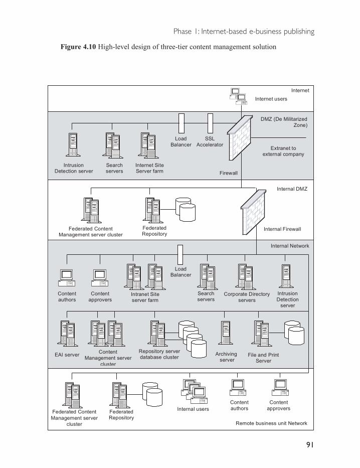
Figure 4.10 High-level design of three-tier content management solution
Phase 1: Internet-based e-business publishing
91
Corporate Directory
servers
Remote business unit Network
DMZ (De Militarized
Zone)
Internet
Firewall
Internal users
Extranet toexternal company
Content
authors
Content
approvers
Intranet Siteserver farm
Internet users
Repository serverdatabase clusterEAI server
Internet SiteServer farm
IntrusionDetection server
SSL
Accelerator
Load
Balancer
Intrusion
Detectionserver
File and PrintServer
Searchservers
Searchservers
LoadBalancer
Content
Management server
cluster
Archiving server
Federated Content
Management server
cluster
FederatedRepository
Federated ContentManagement server cluster
Internal DMZ
Internal Firewall
Content
authors
Content
approvers
Internal Network
FederatedRepository

4.5.3 Benefits and limitations of content management systems
Enterprise content management systems provide a very powerful solution fordemanding content requirements of modern businesses. They are ideally suitedfor the creation and management of large volumes of content in many formats,and for repurposing content to different channels. They also provide valuableservices to Internet and Intranet sites requiring large volumes of rapidlychanging content, and portal systems requiring more robust content managementservices.
In addition, some vendors are beginning to extend standard contentmanagement workflow systems with added process management and enterpriseapplication integration functionality using Java. This allows for much deeperintegration of the solution into the business and the inclusion of enterprise-scalecontent management across corporate business processes. Other developmentsinclude creation of specialist versions of content management solutions targetedat specific industry segments, providing considerable packaged functionalityand faster implementation timeframes. These developments ensure thatadoption of an Enterprise Content Management solution should positioncompanies well for future e-business efforts in subsequent phases.
However, some solutions suffer from a number of limitations that may restricttheir use to specific situations. Products utilizing proprietary client softwaremay offer limited support for some operating systems, such as Linux or theMacintosh. These clients also require ongoing maintenance and support frominternal staff, and their tight integration with the content management serverfrequently requires their complete replacement if the server product is updated.
In addition, some solutions are still oriented towards specific market segments,such as providing document-centric or web-centric solutions that may not beappropriate for all companies. Research is therefore required to ensure productsprovide the functionality required, as such solutions may lack some requiredfeatures or contain additional and unnecessary functionality.
Other limitations to enterprise content management solutions include the needfor considerable up-front planning before implementation. Corporate organizationalissues and processes must be determined before solutions are implemented.These typically include issues such as determination of corporate metadatapolicies (to ensure consistent descriptions for all corporate content), thoroughdefinition of import and conversion requirements to enter existing content into
E-business Implementation
92
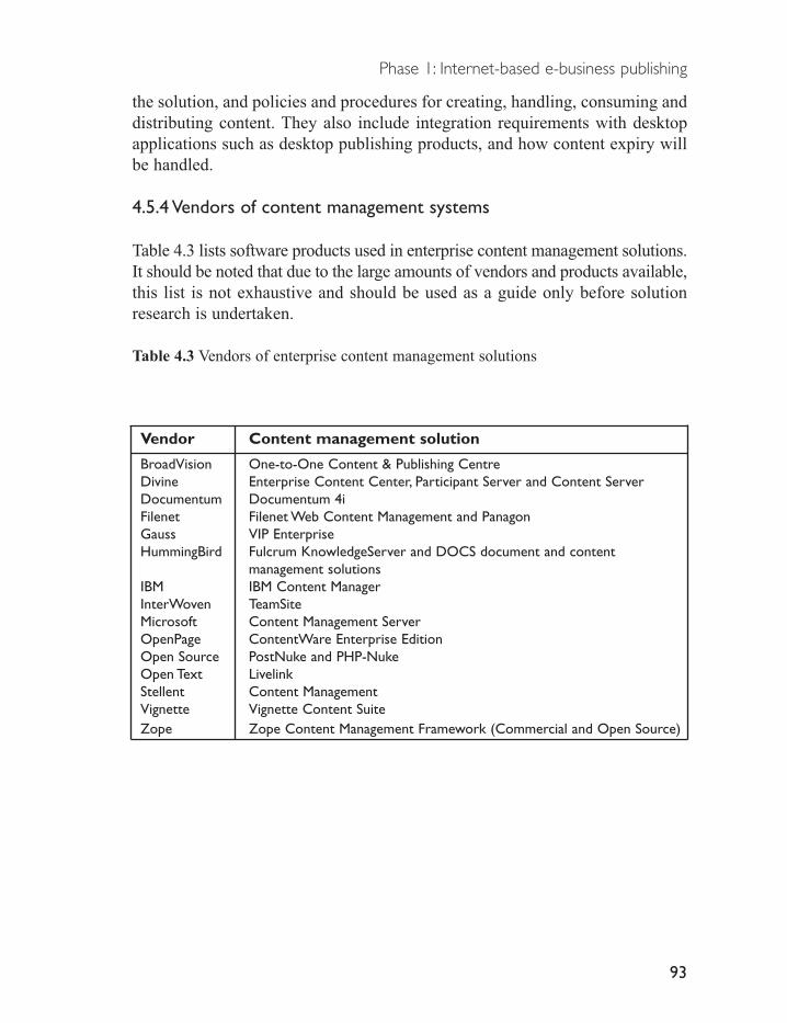
the solution, and policies and procedures for creating, handling, consuming anddistributing content. They also include integration requirements with desktopapplications such as desktop publishing products, and how content expiry willbe handled.
4.5.4 Vendors of content management systems
Table 4.3 lists software products used in enterprise content management solutions.It should be noted that due to the large amounts of vendors and products available,this list is not exhaustive and should be used as a guide only before solutionresearch is undertaken.
Table 4.3 Vendors of enterprise content management solutions
Vendor Content management solution
BroadVision One-to-One Content & Publishing CentreDivine Enterprise Content Center, Participant Server and Content ServerDocumentum Documentum 4iFilenet Filenet Web Content Management and PanagonGauss VIP EnterpriseHummingBird Fulcrum KnowledgeServer and DOCS document and content
management solutionsIBM IBM Content ManagerInterWoven TeamSiteMicrosoft Content Management ServerOpenPage ContentWare Enterprise EditionOpen Source PostNuke and PHP-NukeOpen Text LivelinkStellent Content ManagementVignette Vignette Content SuiteZope Zope Content Management Framework (Commercial and Open Source)
Phase 1: Internet-based e-business publishing
93

Phase 2:Transacting with customers
Transacting with customers is the second phase of the e-business lifecycle. Thisphase involves an organization offering products and services for sale to theircustomers over the Internet. These customers can include any entity the organizationconducts business with, including retail consumers in the traditionalbusiness-to-consumer (B2C) model, or with other businesses in thebusiness-to-business (B2B) model.
This phase represents an extension of the publishing model into commercecapabilities, as it allows customers to view content related to specific productsand services and then to conduct a transaction for these. It is also typicallyimplemented as an extension to online publishing.
Transacting with customers through e-business systems provides considerablebenefits to organizations, including decreased costs of sales, greaterresponsiveness to customers, greater product reach, and more accuratetargeting of sales to customers.
Transactional e-business decreases the cost of conducting business usingautomated systems. This reduces the need for routine processing carried out bystaff, such as order taking, order confirmation and order processing, and allowsinventory to be more efficiently managed. In addition, some transactionalsystems provide the opportunity to obtain reduced prices for supplies.
Responsiveness to customers is increased through the ability to react morequickly to changing customer demand, and by decreasing the time taken tobring products and services to market.
5

Customer reach is also increased by using the Internet as the mechanism toreach an almost unlimited number of potential customers anywhere in theworld, and at any time of the day.
Finally, the recent inclusion of content management and personalizationfeatures into vendor products has given rise to transactional e-businesssolutions offering more accurate real-time targeting of products and services tocustomers. Content management and personalization features allow companiesto run transactional sites with large volumes of content targeted to the specificneeds of individual customers. This in turn leads to increased acquisition andretention rates for customers, and greater customer loyalty. It also allowscompanies to increase revenues through facilities such as targeted cross-sell(selling similar products), up-sell (selling more expensive products), andprovision of targeted online marketing campaigns.
For example, a company uses a transactional e-business product to sell servicesand products online to business and consumer customers. A customer connectsto the corporate site to browse content, and follows links to select related productsand services for sale. When they choose products, the site recommends relatedproducts they may also wish to purchase. Once they have confirmed their order,the customer enters payment details and the order is confirmed. This process isdepicted in Figure 5.1.
Figure 5.1 Transactional e-business process
Phase 2:Transacting with customers
95
TransactionalE-business Application
Customerplaces order
Catalogue
Paymentprovider
Transactionmanagement
Personalization
Marketing
In the preceding example, the transactional e-business system contains severalfunctional modules to provide the required commerce features. These modulestrack the customer browsing behaviour to improve their transactionalexperience. Catalogue functionality is used to present static or dynamiccatalogues of products and services. This module is supported by thepersonalization and marketing modules, which provide product recommendationsthat would be of use to the customer. The transaction management modulecontrols the customers purchasing, and handles taking payment and processingthis through an external or internal payment provider system.
The preceding discussion details the sell-side transactional e-business model.However, transactional e-business also includes a buy-side. Buy-side e-businessis the process whereby a company engages in business-to-business transactionswith suppliers and trading partners. Buy-side transactions occur either throughmanual processes or automatically though software products. Manual processesrequire companies to adopt manual processes to purchase goods and services online,while automatic buy-side commerce requires integration of existing corporatesystems and processes with the systems of suppliers and trading partners.
5.1 Key technologies used
Transactional e-business solutions typically utilize one of three sets of technologies.These include proprietary systems based on scripting languages, products basedon the de facto industry standard Java technologies, or products based onMicrosoft technologies such as the COM/DCOM object standards, or theemerging .Net infrastructure.
Proprietary systems arose from early transactional e-business systems that weredesigned to provide simple e-commerce facilities (Fenner, Meister and Patel,2001). These early systems were typically written in a wide variety ofprogramming languages such as PERL or Microsoft ASP, and often lackedhighly reliable or scalable features and had few integration options with externalapplications.
More recently, most vendors have standardized their products around thede facto industry standard Java 2 Enterprise Edition (J2EE) technology.Vendors have adopted this platform to simplify their development efforts by
E-business Implementation
96

using the services provided by the underlying J2EE application servers. Thishas removed the need for vendors to develop reliability, scalability andavailability features in their products, and thus allowed them to concentratetheir development effort on incorporating additional product features such asintegrating transactions with content, personalizing the transactional process,and providing enterprise class integration systems.
Finally, a number of products have been developed using Microsoft objecttechnologies such as COM/DCOM, but it is expected that such products willmigrate to the emerging .Net application development platform as it replacesexisting Windows server programming interfaces.
What to look for in a transactional e-business solution
Transactional e-business systems were initially developed with broad sets offeatures to sell products and services to specific customer segments, includingbusiness-to-consumer (B2C) and business-to-business (B2B) markets.
However, many businesses now view their customers from the perspective oftheir interactions with the business across multiple channels such as Internet,email, telephone, and direct marketing. This view focuses on providingtransactional services to any customer through any channel, rather than thecustomer segment. In addition, many businesses transact with customers acrossboth the B2C and B2B customer segments, and therefore require products withfunctionality suitable for both.
Because of this customer driven demand, the e-business industry has nowfolded the business-to-consumer and business-to-business terms into thesell-side e-business model. This term shifts the focus of e-business fromcustomer segments to the process of selling products and services, which moreaccurately describes the aim of transactional e-business. Vendors are thereforeincreasingly incorporating broader functionality into their products to facilitatetransactional e-business simultaneously across all customer segments tomultiple channels.
However, although most vendors now describe their products in terms of thesell-side model, many products may still reflect their development history and
Phase 2:Transacting with customers
97

provide more features targeted to a specific customer segment. Consequently,many products are differentiated into ‘standard’ sell-side e-business offeringstargeting B2C and some B2B customers, and business-focused e-businessofferings incorporating additional B2B functionality on top of their standardproducts, such as contract negotiation or additional business-specific paymentoptions such as purchase orders.
Selecting a product with the greatest degree of required e-business functionalityis therefore critical in order to reduce the need to develop missing features, andto integrate different products from third-party vendors. It is thereforerecommended that a product be selected that is capable of targeting bothbusiness and consumer customer segments, as most businesses deal with bothsegments. In addition, many products and services are applicable across bothcustomer segments. This reduces the need to buy separate products to satisfy therequirements of both customer segments, which would result in greatercomplexity and operational cost.
All sell-side transactional e-business products should provide features supportingthe five core e-commerce processes common to all forms of sell-sidecommerce, including marketing, shopping, buying, fulfilment and customer service.
Marketing processes are used to present targeted products and services tocustomers to increase sales. This function is typically provided through productcatalogue systems, merchandising systems, and personalization systems.
Catalogue systems provide users with groups of related products and servicesfor purchase. This requires catalogue management features such as the abilityto offer personalized catalogues to specific customers, catalogues predefined byadministrators, multiple catalogues for different categories of customer, andintegration with external catalogue management products for large catalogues.
Merchandising systems offer pricing and discount functionality for catalogueitems. Multiple pricing and discount models should be supported, such as flatpricing for all customers, personalized pricing and discounts for specific usersor groups. Merchandising is also achieved through campaign systems, whichoffer product recommendations through personalization systems.
Personalization systems allow transactional e-business sites to tailor content to
E-business Implementation
98

the individual customer in an effort to increase sales. Personalization systemsinclude the ability to sell more products through cross-sell and up-sell capabilities.Cross-sell involves selling related items to customers, while up-sell involvesselling more expensive products in place of the customers’ choice.Personalization typically includes the additional ability to recommend substituteproducts in the event an item is out of stock.
Personalization systems should include the ability to analyse data fromcustomer interactions with the system in real time. These should includeexplicit sources, such as user filled forms, and implicit sources, such as the linksa user follows. Transactional content is then personalized using this informationthrough collaborative filtering mechanisms. These provide real-time productrecommendations based on observing similar behaviours in other customers,and via rules-based mechanisms using product-customer rules explicitlydefined by administrators. Information collected through these systems is alsofrequently used to drive further revenues through offering valued-customertargeted pricing, or through online advertising or direct mail/email marketingcampaigns.
Marketing systems should also include support for other countries throughinternationalization systems, including supporting multiple dates, currency andtaxation formats, and support for providing content in different languages.
Shopping processes allow customers to browse and search for products andservices. Browsing functionality is provided through catalogues, and searchesthrough included search engines. Search techniques should include plainlanguage queries, simple text queries, and complex methods such as Booleanlogic searching using words such as ‘and’, ‘or’ and ‘not’ to narrow searches.
Shopping is also increasingly being offered through alternative methods such asauctions, gift registries or collaboration, to provide customers with additionalshopping options. Auction functionality should target the business andconsumer segments through multiple auction models, such as open-cry, Dutchand sealed bid auctions. Open-cry auctions allow customers to see bids duringthe auction, in contrast to sealed bid auctions where only the seller seescustomer bids. Dutch auctions are similar to the open-cry method, but start athigher prices and work downward. Alternative shopping functions include giftregistries for purchasing for special events and collaboration or guided
Phase 2:Transacting with customers
99

shopping, with two users shopping simultaneously.
Buying processes allow customers to purchase products and services through avariety of mechanisms. This function is provided through a transactionmanagement system, which should offer payment processing in a variety offormats such as credit/debit cards and purchase orders for business customers.It should also offer functions such as saved orders and reorders, and includetaxation and shipping charge calculation using taxation and shipping methodsspecific to different regions and countries. Payment processing may be handledby internal systems, or via integration with external third-party systems.
Buying systems require integration with inventory systems to allow customersto determine if items are in stock before purchasing. This may be providedthrough interfaces to dedicated internal inventory systems, or included withinthe transactional e-business product.
The fulfilment process ensures that products are selected from warehouses,packed, and sent to customers. As these are manual processes, typically handledby third parties, fulfilment functionality should track the status of items whilein transit to provide improved customer service.
Customer service processes enable the e-business to manage customer enquiriesand customer orders. This typically involves updating and amending storedcustomer profile information such as passwords and addresses, manuallycreating and processing orders for customers, determining customer orderstatus, and processing goods returned by customers. It can also supportmanual amendments to customer orders such as allowing customer supportstaff to make price amendments to customer orders.
In addition to this core set of functions, products targeting business customersmay be required to support dedicated functionality appropriate to this marketsegment (see Varon, 2001).
Products often represent business customers on an ‘account’ basis, with eachaccount representing a single company. Each account will include a hierarchyof staff members who have permission to approve purchasing. Products shouldtherefore offer account-based pricing and catalogues, allowing for negotiateddiscount levels. Payment systems also incorporate account-based mechanisms
E-business Implementation
100

such as payment on account and invoice basis, cheque payments, and purchase orders.
Business specific functionality may also include support for negotiationprocesses through RFQ (Request for Quote) processes for requesting quotationsfrom other businesses, and RFI processes (Request for Information) for thesupply of information required to make a business decision. They may alsoinclude the ability to define and exchange contracts and negotiate terms andconditions for purchasing goods and services.
Finally, all transactional e-business solutions should provide simplifiedadministration and management interfaces for business users. They shouldoffer the ability to define business operational roles such as shop/storeadministrators and customer support staff, enter customer details, definepricing models and catalogues appropriate to customers, and manage customerservice functions. Products should also allow for the creation and managementof sales and marketing functions.
5.2 High-level designs for transactional e-business solutions
Designs of transactional e-business solutions must provide high availability andscalability to ensure continual operation of the e-business, and continuedperformance to handle fluctuating customer demand.
Customers may originate from any time zone or country, and they increasinglyexpect e-business systems will be continually available to service their needs.System downtime therefore results in lost business, and reduces repeatbusiness. Designs must therefore support high availability to ensure thesolution continues working in case of failure of one or more components.
Systems must also cope with unpredictable levels of demand for their services.Frequently, new e-business projects may experience very rapid increases indemand that they are unable to support, resulting in system overloads and crashes.Often this will require a complete redesign and build of the e-business system.It is therefore imperative that the system be capable scaling from an initialmodest load to support large increases in site traffic in the future.
Sufficient scalability and availability is typically provided using three-tier web
Phase 2:Transacting with customers
101

architectures. This architecture design separates operational systems forpresentation, business logic, and database systems, allowing each layer to bescaled according to demand, and incorporating multiple systems in case of failure.
Multiple presentation web servers are deployed using network-level server loadbalancing to distribute requests for web pages across multiple servers. Theseservers in turn communicate with the second tier e-business logic servers,which contain the business functionality of the solution such as marketing andbuying components. Logic servers then communicate with a third tier databaseserver cluster used to store configuration information and customer data.
Most transactional e-business systems based on object-oriented Java 2Enterprise Edition (J2EE) or COM/DCOM technology support this architecture(Fenner, Meister and Patel, 2001; Kramer, 2001a; Kramer, 2001b). Of these,Java is the most common technology in use in the majority of transactionale-business products as it typically provides the highest performance andavailability.
In contrast, proprietary products based on scripting languages utilize lowerperformance two-tier web architectures, as they cannot distribute applicationcomponents across multiple servers. These designs typically feature integratedfirst tier presentation and business logic systems, and separate second tierdatabase systems.
Other functions that form an important part of transactional e-businessarchitectures include providing high-security, integration capabilities, andextensibility of the solution.
Security is frequently neglected when designing e-business architectures,rendering systems vulnerable to attack and compromise. This has seriousimplications resulting from breaching data protection laws, and from theresulting loss of customer trust. Regulatory data protection requirements forsecurity vary between countries, with many countries requiring customer datato be stored and used with the highest possible security, and only for theoriginal purpose for which it was gathered. Preserving customer data securityis also critical to maintaining customer trust, and hence repeat business. Inaddition to data appropriation by hackers/crackers, companies must ensure thatdata is not sold to other companies for other purposes such as direct marketing.
E-business Implementation
102

Transactional e-business architectures therefore require a system of distributedsecurity to safeguard all stages of the customer’s interactions with the system.Industry best practice dictates deploying multiple firewalls for access control,intrusion detection for the detection and response to hacking/cracking incidents,server hardening to safeguard systems, and the use of encryption technology toprotect customer data.
Encryption of stored customer data can be handled by the e-businessapplication when it writes information into its database. If an unauthorizedentity gains access to the database they cannot then acquire customerinformation such as credit card numbers. Encryption is also required when acustomer purchases goods and services, to prevent unauthorized access tosensitive credit/debit card numbers in transit between the customer computerand e-business application. This dictates the use of Secure Sockets Technology(SSL), which is built in to all modern web servers. SSL technology sends adigital certificate from the web server to the customer’s browser, which thebrowser uses to encrypt the communication. Certificates are purchased from aCertificate Authority (CA) such as Verisign, by sending a certificate requestalong with details about the company. The certificate then issued will uniquelyidentify that site. All certificate requests should be made for 128-bit security,currently the strongest level of commercially available SSL security.
However, use of SSL technology may result in problems with performance.When a browser connects to an SSL enabled server, the server must carry outintensive calculations to generate the required level of encryption. This mayresult in dramatically decreased performance on that server if it is subject tolarge volumes of customer traffic. For sites expecting or experiencing highlevels of SSL traffic, it is recommended that SSL encryption and decryption beoffloaded onto dedicated SSL appliances. These appliances sit behind firewallsand in front of the web servers, and handle all encryption and decryption, thusrelieving the web and application servers of this processing.
Architectures must also support integration with a number of internal andexternal systems. Integration is frequently required with external systems frombanks and credit card vendors to facilitate final payment processing.Alternatively, internal financial systems may be used to settle business accountsthrough mechanisms such as payment on invoice. Integration may also berequired with external personalization system from third parties to utilize
Phase 2:Transacting with customers
103

customer demographic data. Alternatively, personalization systems mayinteract with existing corporate directories containing user information. This inturn requires secure communication systems, and securing of internal directoryservers using server hardening and firewalls.
More advanced integration may be required between the transactionale-business product and internal enterprise application integration systems, orbusiness process management systems. This allows the solution to incorporatefunctionality such as providing real-time inventory levels within productcatalogues.
Solutions developed using Java technology offer the greatest integration abilitywith such advanced systems, due to their support for integration standards suchas the Java Connector Architecture and Java Message Service. These allow theJ2EE application server to connect directly to many enterprise applications, oralternatively to integrate directly with many middleware and processmanagement products. In contrast, proprietary and COM/DCOM-based productsmay require additional customization to support integration with such systems.
Alternatively, transactional e-business architectures allow the core products tobe extended to support new features required to satisfy changing businessrequirements. For example, as an e-business experiences growth, additionalsystems such as content management systems may be required to enhance thee-business offering to customers. As many of the leading content managementproducts are written in Java, J2EE-based transactional e-business productsrepresent the most extensible systems capable of direct addition of suchproducts to the same hardware systems.
Adopting such a product also allows for extension of the architecture to supportemerging standards such as web services, which are currently supported byapplication server products. Such development is enhanced using the widevariety of Java development resources available. In contrast, many proprietaryscripting products require considerable customisation to integrate with webservices, while existing object-based COM/DCOM will typically requirerewriting using the Microsoft .Net system.
Finally, the architecture should include development and testing environmentsto support the creation and management of site content, and development of
E-business Implementation
104

Phase 2:Transacting with customers
105
additional site functionality. This should include change management featuresto manage the large amount of content, tools, and application code transactionale-business environments generate. More advanced products supportingadvanced features should include an integrated development environment and abroad range of tools to facilitate such developments.
High-level design of low to medium-level transaction volume e-businesssolution
The following design is intended for transactional e-business systemssupporting low to medium levels of transactions. Companies with undemandinge-business requirements, who often adopt proprietary scripting, often use suchsystems, or alternatively, low-end COM/DCOM-based products.
This design employs a two-tier architecture with combined business logic andpresentation functions in the first tier. The presentation functionality isprovided by a web server, with the business logic hosted on the same serverusing an application server for J2EE-based systems, an integrated scriptingengine for proprietary systems, or Microsoft COM transaction manager forCOM/DCOM systems. The second tier provides a database for storage ofproduct configuration data and customer profile data.
This design provides limited availability and scalability features by distributingcustomer requests to servers using network load balancing in the first tier.However, this technique will rapidly exhaust the performance of the second tierdatabase as the multiple, independent tier one systems contend for databaseresources. Availability for the database in the second tier is provided through afail-over cluster. In case of failure of a database, this transfers databasefunctionality to a parallel, standby database server with a copy of all data.
However, for systems using COM/DCOM or J2EE-based products, this designcan be expanded to the high-performance three-tier design. This requiresseparation of the first tier functions into two separate tiers for presentation andbusiness logic, and the addition of live database clustering.
Security systems are provided through the techniques discussed previously,with the addition of a secured Extranet network connecting the transactional

e-business system to the third-party payment provider.
Finally, a development environment is included to prototype new content andsystems for the live production site. This environment includes a reduced set ofall system components, typically on one server for simplicity.
This design is depicted in Figure 5.2.
Figure 5.2 High-level design for low - medium level transactional e-business solution
E-business Implementation
106
Internal Network
DMZ (De Militarized Zone)
Internet
Firewall
Customer servicerepresentatives
Extranet to third-partypayment processing company
Customers
Web and
e-businessservers
Fail-over databaseserver cluster
Intrusion detection
server
Development transactional e-business environment
DMZ (De Militarised Zone)
Load balancer

High-level design of medium to high-level transaction volumee-business solution
The following design is intended for transactional e-business systems supportingmedium to high levels of e-business transactions. Such systems are often used bycompanies with demanding e-business requirements such as multiple e-businesssites serving customers across several countries. Such systems are typicallydeployed using high-end COM/DCOM-based products, or Java-based products.
This design employs a more complex three-tier architecture. A web server farmconsisting of a set of web servers ‘hidden’ behind a network load-balancerprovides the presentation functionality. The second layer includes multiplecopies of core business logic components hosted across several servers.Requests from web servers are distributed to these components to balancecustomer demand. The third tier includes an active database cluster, whichdistributes a single database image across multiple servers and storagesystems for very high performance and availability. This design can therefore bescaled as customer demand increases, by adding additional systems within each tier.
Additional scalability and availability is provided through a load balancer cluster, withactive/active devices functioning in parallel, and multiple SSL accelerators to offloadencryption from the web and e-business servers. Additional servers forpersonalization and catalogue management are included within the DMZ tooff – load these resource-intensive functions from the business logic servers. Thecomplete product catalogue is maintained in a separate server within the corporatenetwork, and content published to the DMZ catalogue server to maintain security.
Integration can be provided through inclusion of Java Connector Architectureand Java Message Service components within the e-business application servercluster. In addition, content management systems can be integrated using thesetechnologies, or installed directly onto the cluster servers.
Security systems expand on those of the low – medium-level design through theaddition of a second internal intrusion detection server, and the inclusion ofdirectory servers. An LDAP server within the DMZ provides for centralizedmanagement of customer information. This is in turn synchronized with aninternal enterprise directory server to provide centralized management of allcorporate resources such as internal users and their computers and customer data.
Finally, an expanded development environment is included, offering developmentand staging systems. These allow for uninterrupted development cycles for new
Phase 2:Transacting with customers
107

content and systems and for independent testing of performance and approvalof content and systems ready for publication to the live production site.
This design is depicted in Figure 5.3.
Figure 5.3 High-level design for high-level transactional e-business solution
E-business Implementation
108
DMZ (De Militarized Zone)
Internet
Firewall
Customers
Web Server Farm
Extranet to third partypayment processing company
SSLaccelerator
Customer ServiceRepresentatives
Transactional e-businessapplication server cluster
e-business databaseserver cluster
Intrusion detection
server
Development
transactional e-businessenvironment
Internal Network
DMZ (De Militarized Zone)
Intrusion
detection server
Customer LDAP
directory server
Personalisation server Catalogue Server
E-business managementserver
Staging transactionale-business environment
Catalogue Server Enterprise
directory server
Loadbalancer

5.3 Benefits and limitations of transactional e-business systems
Modern transactional e-business systems contain rich sets of functionalityideally suited for a range of e-businesses. They typically include most of thefunctionality required for trading online for either purely Internet-onlybusinesses or traditional businesses wishing to establish an online presence.
Many products are now very flexible, and include store templates to enableusers to quickly create customized transactional sites with minimalprogramming knowledge. They also support consumer – and business-orientedfunctionality allowing the business to target both types of customer.
Higher-end products often include large numbers of components in the onepackage, such as integrated database and application servers, and sitedevelopment tool sets offering page construction utilities, site managementutilities, catalogue managers, and coding tools. The higher cost of such productsis frequently offset by the convenience and savings achieved through acquiringall the necessary tools from one vendor rather than purchasing potentiallyincompatible products from multiple vendors with lower-end products.
Some of the more limited e-business products based on COM/DCOM and proprietarytechnologies typically have a lower up-front cost compared to higher-endproducts, but may lack more advanced features, and therefore may not beapplicable to all business requirements. For example, they may lack templates,require additional customization and development before deployment, requirethe addition of third-party products such as taxation and payment engines, andmay require purchasing additional subsystems such as database servers.
Such products may therefore be suited to organizations wishing to experimentwith e-business or organizations with an existing commitment to thesetechnologies. However, such products may not be capable of deployment intoenterprise class scalability and availability configurations.
Products offer different levels of support for extension and integration to supportemerging technologies. Products based on J2EE technology offer the strongestexpansion and integration features of all transactional e-business products,followed by COM/DCOM products. Proprietary products typically offer verylimited facilities in these areas, and require extensive customization.
Most transactional e-business products include some content management
Phase 2:Transacting with customers
109

features, typically to provide support for functions such as catalogue creation,and management of product catalogues. However, additional content managementfunctionality such as management of media assets or business documentsrequired for RFI/RFQ processes is becoming increasingly important as contentassumes a greater role in business. Proprietary products may lack the ability tointegrate such functionality, and product selection should therefore consider theease of integration between transactional e-business systems and web ordocument management products.
They may also lack suitable integration facilities to support expansion as businessrequirements grow. Subsequent integration with additional third-party productssuch as content management systems or enterprise application integrationsystems may therefore require expensive and time-consuming customization.
If advanced content management features are required, a number of vendorsoffer content management systems based on the same core technology deployedin their e-business products. Some products also include direct integration withexternal content management products from leading vendors. Therefore, ifcontent management is a transactional e-business requirement, products fromthese vendors are recommended.
In addition, some vendors of Java-based products offer systems tailored tospecific market segments such as the travel industry, or specific business-orientedfunctionality such as support for purchase orders. If the intention is to targetsuch segments, it may be more appropriate to select products from vendors whooffer such products.
Finally, some transactional e-business products are not capable of hostingmultiple e-business sites, such as separate stores, on the same physicalhardware. Products should therefore be assessed to determine their ability tosupport multiple transactional e-business sites per server, and the associatedcost.
5.4 Vendors of transactional e-business systems
Table 5.1 lists vendors of transactional e-business systems. It should benoted that due to the large amounts of vendors and products available, this listis not exhaustive and should be used as a guide only before solution research isundertaken.
E-business Implementation
110

Table 5.1 Vendors of transactional e-business systems
Vendor Transational e-business systemActinic Actinic Catalogue and BusinessATG ATG Consumer Suite and Enterprise Commerce SuiteBlue Martini Blue Martini CommerceBroadVision BroadVision Business Commerce, Retail Commerce, and BillingIBM WebSphere Commerce Suite and IBM WebSphere Commerce Suite
Business EditionIntershop Enfinity and Intershop 4InterWorld Commerce ExchangeSun Microsystems Sun ONE BillerXpert, Market Maker, and BuyerXpertMicrosoft Commerce Server
Phase 2:Transacting with customers
111

Phase 3: Internal enterprise application integration
The third phase of e-business is internal enterprise application integration(EAI). This phase involves connecting internal enterprise applications such asfinancial, ERP, CRM, and manufacturing systems with each other and withtransactional e-business systems.
Enterprise application integration systems offer an excellent mechanism toincrease the corporate return on investment for existing internal enterpriseapplications. This is provided by integrating older applications with e-businesssystems, or through providing new products and services to customers byintegrating existing applications with minimal extra development effort. Theseapplications are typically deployed to customers as ‘self-service’ applications,and utilize EAI systems to integrate transactional e-business functionality withinternal application functionality to lower customer service costs and acquireadditional customers.
Examples of self-service applications include providing customers real-timeinformation on what products are available for immediate purchase, up-to-datepricing of products to let customers quickly find the best deal, and offeringcredit or loyalty cards. Consumers also increasingly demand self-serviceapplications across different industries such as online banking, insurance, sharetrading, travel and retail.
Companies frequently have older applications that are required for the runningof the business. EAI enables these systems to be reused via integration with
6

newer enterprise applications, without subjecting them to costly high riskrewriting. It also provides a rapid mechanism to integrate the internal enterprisesystems of new companies or divisions that have been acquired through mergersand acquisitions.
Internal enterprise application integration also allows companies to removetime-consuming and error-prone manual processes, such as re-entering ordersfrom transactional e-business systems into internal financial systems. Thisallows companies to provide new products and services to customers by wrappinga transactional e-business front-end onto existing internal applications, integratelegacy applications with new enterprise applications, and increase efficienciesin internal applications through greater use of automation.
EAI can also increase the speed with which products and services are deliveredto customers, allowing the company to respond to changing customer demandmore rapidly and therefore increasing sales. For example, implementing real-timeupdates of inventory levels from daily or weekly batch or manual processesallows customers to know that a product they purchase is immediately availablefor delivery, which is more likely to result in a purchase decision.
Another advantage of EAI is to increase the volume of transactions that can beperformed with no increase in staff effort, and remove unnecessary steps inorder processing. These in turn directly decrease business costs and increaseprofits. For example, many transactional e-business sites manually re-enterorders into internal applications. Directly integrating the existing back-endsystems into the transactional e-business front-end will result in dramaticincreases in efficiency.
Enterprise application integration therefore provides a powerful tool to increaseefficiencies, and gain and retain customers by increasing their satisfaction andhence loyalty. This in turn allows a company to respond to competitive pressuresmore effectively.
For example, a company may have a transactional e-business system that allowscustomers to order products from their site. Orders are processed manually bystaff members who enter payment details, and the type and quantity of productsordered into internal financial applications and manufacturing systems. Thismanual process contains considerable opportunity to create errors during data
Phase 3: Internal enterprise application integration
113

entry and is highly inefficient, as it requires staff be dedicated to performingsimple order processing tasks.
Using internal enterprise application integration (EAI), a customer’s orderinformation can be sent directly to the internal financial and manufacturing systemsto calculate and process the customer’s payment and begin the manufacture oftheir product. The manufacturing system can then automatically update thefinancial system with details of the product parts used during manufacture forreordering, as shown in Figure 6.1.
Figure 6.1 Order processing using enterprise application integration
Using EAI technologies, the company can also provide their customers withnew products and services, such as offering credit or loyalty cards onlinethrough integration of existing financial credit card approval systems with thetransactional e-business application. This enables the company to provideservices that are more efficient to their customers by simplifying their purchasingand finance requirements into one site, and results in labour cost savings. Thisprocess is depicted in Figure 6.2.
E-business Implementation
114
Transactional
E-businessApplication
ManufacturingApplication
Customerplaces order
Payment details Product details
Product reorder details
FinancialApplication

Figure 6.2 Offering additional products and services via enterprise application integration
6.1 Key technologies used
In order to integrate internal enterprise applications, companies require asolution that can interact with transactional e-business systems using Internetstandards, and with existing internal enterprise applications using the manyproprietary technologies contained in such applications.
Software vendors have therefore developed a range of technologies to integratethese systems. These solutions have evolved to cover a very wide range ofintegration functionality required between internal systems and transactionale-business applications. These include platform integration, data integration,
Phase 3: Internal enterprise application integration
115
TransactionalE-business Application
Financial Application
Mainframe CICS
ManufacturingApplication
Payment details Product details
CustomerAccounts
Credit card
approval
Application
OnlineOrdering
Online
Credit
card
Leasing/credit details
Customer
places order

component integration, and application integration solutions, as depicted inFigure 6.3.
Figure 6.3 Technology solutions used in enterprise application integration
Platform integration technologies are designed to integrate different types ofhardware, operating systems, and specific applications at a very low level. Thisis achieved through a range of technologies including simple messagingsystems, object request brokers (ORBs), and remote procedure calls (RPC’s).These products are either used for very simple integration between a fewspecific pieces of applications, or are used as components within moresophisticated integration solutions that require integration with specificproprietary technologies.
Data integration technologies are designed to operate directly on enterprise datastored in databases. These include dedicated database gateways via SQLcommands, or ETML (Extraction, Transforming, Moving and Loading) tools toextract data directly from underlying databases, thus bypassing the enterpriseapplications themselves. Both types of data integration product suffer somelimitations, including reliance on synchronous access to data which may not beappropriate in all integration scenarios, and requiring an understanding of theunderlying database schema and maps. Data integration solutions are often used
E-business Implementation
116
PlatformIntegration
Data Integration
ComponentIntegration
ApplicationIntegration
Depth of Integration into Business
IntegrationComplexity

to integrate legacy systems such as old mainframe applications. As thesesystems cannot easily or affordably be rewritten to use newer technologies, thisform of integration allows the application to be bypassed and its underlyingdatabase accessed directly.
Component integration technologies are collections of platform and dataintegration services housed within a centralized integration server. These productsoften feature connector-based architectures using messaging backbones. Incontrast to the previous integration solutions, component integration technologieswork at a higher level to remove some dependencies on underlying technologies.This can insulate the integration solution from potential changes in applications,or from complexities resulting from the introduction of new applications.
Application integration technologies are designed to provide near real-timeintegration through advanced data processing and routing functions layered ontop of the previous three categories of integration technologies. This is achievedthrough data transformation message brokers, rules-based data routing, andintegration with high-level proprietary application interfaces through packagedconnectors (Stokes, 2001). These features allow application integrationsolutions to rapidly integrate with existing enterprise applications withoutrequiring costly and time-consuming assembly of integration tools from multiplevendors, as required for the above solutions.
Four different categories of products have arisen to provide enterprise applicationintegration solutions, with each solution using a different combination of theseintegration technologies. These categories include point-to-point customizedsolutions, and three forms of ‘Middleware’ solutions.
6.2 Point-to-Point point EAI solutions
Due to a lack of packaged solutions, early enterprise application integrationinitiatives required the creation of proprietary ‘point-to-point’ architecturesbetween applications. To enable applications to communicate together, thesesolutions required customization of each integrated application using theplatform and data integration technologies discussed above. This resulted inapplications maintaining multiple connections to other integrated applications,as depicted in Figure 6.4.
Phase 3: Internal enterprise application integration
117

Figure 6.4 Point-to-point enterprise application integration
These customized solutions were designed to integrate critical packagedenterprise applications, such as ERP systems, with legacy systems or otherpackaged applications. The integration typically focused on low-level technicalaspects such as making applications understand other application-specific dataformats. This technical focus resulted in the creation of decentralizedapplication-to-application solutions, which lacked central management.
Such early integrations allowed companies to create highly customizedsolutions dedicated to the requirements of their internal applications. However,this architecture proved to be inadequate long-term solutions for enterpriseapplication integration, as it required very detailed knowledge of the proprietarytechnologies used in each application, to create links to other applications.Maintaining each application link therefore consumed considerable time anddevelopment resource, and resulted in the creation of ‘fragile’ solutions, whereminor changes in applications, or the addition of new applications, requiredexpensive and time-consuming rewriting of each integration link. In addition,failure in one application could cause the whole integration solution to ceasefunctioning due to their close coupling. This form of integration also createdsolutions that could not support more advanced functionality, and could not
E-business Implementation
118
Enterprise
Resource
PlanningApplication
Human
ResourcesApplication
FinanceApplication
Integration Code
Integration Code Integration Code
CRMApplication
Integration Code

scale well to support high levels of traffic between applications.
Because of the limitations of point-to-point integration efforts, modern integrationarchitectures are designed to employ mechanisms that are more sophisticatedfor enterprise application integration. These systems, called ‘middleware’ EAIsolutions, reduce the effort required to integrate applications, and create moremanageable and robust integration solutions with greater scalability andresponsiveness to changing corporate requirements.
6.3 Middleware solutions
The most common form of application integration solution are the Message-orientedmiddleware EAI products. These products manage and route allcommunications, in the form of messages, between applications through anintermediate software layer– the so-called middleware layer.
Each integrated application communicates with the middleware layer throughapplication-specific connectors (or adapters) installed into the Middlewareproduct. Adapters act as translation tools between the communication protocolsand messages issued by each application and the internal messaging systemused by the middleware product for its own internal communication. Thisprocess is depicted in Figure 6.5.
Figure 6.5 Functional components of message-oriented middleware integration solutions
Phase 3: Internal enterprise application integration
119
Middleware Product
FinancialEnterprise Application
Connector/Adapter
LegacyEnterprise Application
Transformationlogic
Transformationlogic
Businessrules
Intelligentrouting
Connector/Adapter
Key: Originating Messages Reply Messages

In the middleware integration solution depicted in Figure 6.5, a message is sentfrom a financial application to the Middleware product using a specific adapterthat understands the proprietary connection interfaces of the application. Thisensures that minimal changes are required to the application to enable it toparticipate in the integration. The connector then translates the applicationmessages into the message structure used within the middleware product. Thedifferent functional layers within the middleware product interpret the destinationof the message and apply predefined business rules and transformation logic torender the message into a format understood by the target legacy application.The response message is then sent to the specific legacy adapter, whichcommunicates using the specific legacy application integration interfaces.
Integration connectors/adapters provide the middleware solution with considerableflexibility and extensibility. When a new application is integrated, the appropriateconnector is ‘plugged in’ to the middleware layer, allowing the new applicationto participate in the complete integration solution. Development of the integrationsolution is also simplified using adapters. Developers typically have tounderstand only the middleware architecture and development systems, notmultiple detailed application-specific technologies, as the adapters handle suchissues. Such solutions can typically provide 70 to 80 per cent of the requiredintegration capabilities out-of-the-box, resulting in considerable time savingwhen integrating applications (Sanchez, Patel and Fenner, 2001a and b).
Message-oriented middleware integration products are categorized into threedifferent solution types based on the performance and scalability requirementsand design of the integration solution. These include application server middlewaredesigns, hub and spoke message-oriented middleware designs, and message busmessage-oriented middleware designs.
6.4 Application server middleware solutions
Application server middleware designs are generally suited for less demandingintegration initiatives with fewer applications and less message passingcompared to hub and spoke and message bus solutions. They are frequentlyused to provide enhanced customer services through integration betweentransactional e-business systems and internal applications such as financialsystems, customer databases or ERP systems.
These middleware solutions are a form of component integration, using J2EE-basedapplication servers as the central point of integration between enterprise ande-business applications. Communication with applications occurs via standard
E-business Implementation
120

packaged JCA (Java Connector Architecture) integration connectors that can bedeployed in any J2EE compliant application server, simplifying integrationdevelopment efforts and lowering integration risks. These provide access toenterprise applications such as relational databases, financial systems such asJD Edwards, customer relationship management (CRM) products such asSiebel, and enterprise resource planning (ERP) products such as SAP, or Baan.
For example, a transactional e-business application is deployed on a J2EE applicationserver. Using the appropriate Java Connector Architecture connectors it can bequickly integrated with financial and mainframe manufacturing applicationsto provide dynamic processing of payments and accounts, and automation oforder processing for product production. This process is depicted in Figure 6.6.
Figure 6.6 Enterprise integration using application server middleware solutions
In the middleware integration solution depicted in Figure 6.6, a customer connectsto a transactional e-business application to order a product. The applicationserver includes JCA integration adapters to connect to the back-end manufacturingand finance applications. The e-business application has been modified toinclude business logic to utilize some of the additional functionality of theseapplications. It issues queries through the JCA adapters to tap into the additionalcredit functionality within the finance application, and to understand andprocess its responses. This in turn allows the company to expose this functionalityfor authorizing and issuing credit to select customers.
Phase 3: Internal enterprise application integration
121
Application Server TransactionalE-business Application
Financial Application
ManufacturingApplication
Payment details Product details
CustomerAccounts
Credit cardApplication
Leasing details
JCAConnector
JCAConnector
Online
Creditapplication
OnlineOrdering
Customerplaces order

6.4.1 High-level design of application server middleware solutions
The transaction e-business application employs a standard n-tier applicationserver based design to facilitate simplified application development andindependent scaling of each tier.
The first tier receives requests from Internet or Intranet users through the webserver, then passes them to the second tier application server for processing bythe transactional e-business logic. This tier manages all business functions forcustomers, and includes integration code to access and return data from theenterprise applications. The second tier stores its configuration information andany transactional data in the database cluster in the third tier. This ensures theapplication server is not continually accessing the back-end data stores withinthe internal applications, thus maximizing performance by locating relevantdata closer to Internet customers.
Application server EAI designs include a number of additional componentsnecessary for integration and for reliable and scalable operation. Integration isprovided through Java Connector Architecture-based connectors. The e-businessapplication in the second tier accesses internal business applications on thefourth tier by sending messages from the e-business application via theseadapters, using the Java Message Service. They reformat the messages into aform understood by the native applications, which then respond appropriately.Integration is therefore controlled by the e-business application logic residingon the application server.
The operational design of this solution includes reliability, scalability andavailability features using multi-processor servers in all tiers. In addition, thetwo web servers in the first tier are arranged in a load balanced server farm foravailability and scalability, with one server available if the other fails. Thisconfiguration can be expanded with additional servers as more customers usethe system.
The transactional e-business application on the second tier is deployed in anapplication server cluster, with the e-business application software ‘cloned’ anddistributed across multiple servers. The web servers in the first tier distributeuser requests to these cloned applications, increasing the performance andavailability of the complete solution. The e-business application in turn storesconfiguration information and interim data from the enterprise applications in adatabase cluster in the third tier, providing continual availability and increasedperformance. It also stores customer specific data used to authenticate and
E-business Implementation
122

authorise customer access within an LDAP security server, which provides unifiedcustomer management and security. Critical information within this server isencrypted to provide high security.
Because this solution is accessing critical internal applications, the e-businessapplication is segregated and regulated from the internal applications andcorporate network by a firewall. All sensitive communication between eachlayer occurs via SSL certification to prevent interception by hackers/crackers.Other security mechanisms include encryption of sensitive financial andcustomer data in the application server database servers, and the use of multiplenetwork level security systems including firewalls and intrusion detection systems.
This design is depicted in Figure 6.7.
Figure 6.7 High-level application server EAI design
Phase 3: Internal enterprise application integration
123
Corporate Network
DMZ (De Militarized Zone)
Internet
FirewallWeb server farm
Internet users
E-business Application
Server cluster
Finance Server
Mainframe
CICS
Manufacturingsystem
Application Serverrepository cluster
LDAP Security
server
Intrusion Detection Server
Internal DMZ
DevelopmentEnvironment

6.4.2 Benefits and limitations of application server middleware solutions
Application server middleware integration solutions offer an affordable andeasily managed solution ideal for businesses requiring integration of enterpriseapplications.
Companies using this design will typically have a transactional e-businessapplication developed using J2EE Enterprise JavaBeans, and deployed on anapplication server such as BEA WebLogic, IBM WebSphere or Sun iPlanetApplication.
The use of a completely Java-based solution, including JavaBeans, JCA andJMS, removes unnecessary complexity and simplifies development around oneprogramming language. This ensures developers need only understand Java,resulting in quicker, more tightly controlled projects. The use of Java alsoallows the solution to be moved to application servers from other vendors,reducing vendor dependence and hence project risk, and ensures the solutioncan be readily modified in the future to include new internal applications.
Use of the JCA adapters also insulates the solution from changing integrationrequirements. If the integration solution requires a higher performanceMiddleware solution in the future, a product supporting this standard can be‘swapped in’ to take over the role of application server with minimal changesrequired in the e-business application.
However, this design may only be suited for small-scale integration initiativesdue to potential scalability and performance problems. Typically, applicationservers have not been designed to handle large numbers of integrated applicationsor provide high performance in integration functionality. In addition, the JCAadapter architecture currently lacks some functionality required for moredemanding integration requirements, such as asynchronous connections.
6.4.3 Vendors of application server middleware solutions
Table 6.1 lists vendors of J2EE Application Servers offering JCA adapterintegration functionality. It should be noted that due to the large amounts of
E-business Implementation
124

vendors and products available, this list is not exhaustive and should be used asa guide only before solution research is undertaken.
Table 6.1 Vendors of J2EE application servers
Vendor J2EE application server
ATG ATG DynamoBEA BEA WebLogic ServerHewlett Packard HP Application ServerIBM WebSphere Application ServerIona Orbix E2A Application ServerJonas Jonas Application Server (Open Source)Lutris Enterprise Application Server (Open Source)Orion Orion Application Server (Open Source)Oracle Oracle 9i Application ServerPramati Pramati ServerSun Microsystems Sun ONE Application ServerSybase EA Server
6.5 Hub and spoke middleware solutions
In contrast to application server designs, hub and spoke middleware solutionsuse a dedicated central Hub server connecting multiple ‘spoke’ applicationstogether. Integration occurs via messages passed through the hub, whichdetermines the appropriate message destination.
This design can provide businesses with an integration solution that can meetmore demanding integration requirements than the previous designs. It is capableof scaling from modest requirements to demanding integration between multipletransactional e-business and enterprise applications, with moderate to high levelsof messages passing.
Companies adopting this design will typically have several two – or three-tiertransactional e-business applications offering customer-focused services. Theseapplications may be written using many different Internet programminglanguages, and deployed on distributed stand-alone server systems or J2EEapplication servers. The solution will typically integrate these applications withseveral internal enterprise applications, such as financial, resource planning and
Phase 3: Internal enterprise application integration
125

legacy mainframe applications, and additionally provide integration betweeneach application.
For example, a customer accesses a transactional e-business application to purchasea product and arrange online credit. The order passes through the integrationhub, which in turn distributes the components of the order to the appropriateenterprise applications. When the manufacturing application needs to updatethe financial application with a request for new parts, it sends a message to thehub server as shown in Figure 6.8.
Figure 6.8 Enterprise integration using hub and spoke middleware solutions
In the middleware integration solution depicted in Figure 6.8, the transactionale-business application issues an order request to the integration hub. Thissystem in turn decomposes the order into constituent parts and sends them to
E-business Implementation
126
Application Server-based
TransactionalE-business ApplicationCustomer
places order
Financial Application
ManufacturingApplication
MiddlewareIntegration Hub Application
Payment details
Product details
CustomerAccounts
Credit CardApplication
Credit/payment details
ConnectorConnector
OnlineOrdering
OnlineCredit Card
Update financialfor parts reorder

the finance and manufacturing applications through the integration connectors.Inbound messages from the applications are received by the connectors andre-formatted into the EAI server internal message structure for processing,transformation and routing to their final destination. This in turn allows thetransactional e-business application to delegate some of these functions to thehub server so that it does not require detailed knowledge of the applications.
What to look for in a hub and spoke middleware solution
Hub and Spoke Middleware products should support a set of core architecturalcomponents to ensure the timely and accurate delivery of information betweenintegrated applications and transactional e-business systems. These includeperformance, security, integration, message transport, routing, reformatting,transformation, and administration components.
Products should provide an integrated development environment (IDE) fordevelopers to extend the functionality of the product and customize it to fit theirspecific integration requirements. Development tasks include creating newadapters for custom applications, tailoring routing and transformation rules tospecific requirements, or integrating the solution with corporate securitysystems to enhance the security of transactional e-business applications.
Performance and reliability should be provided through support formulti-processor and clustered servers, and distribution of transformation androuting engines across multiple servers. However, due to their centralizednature, some hub and spoke systems may not readily scale performance usingmultiple servers. Performance assessment should be provided through systemsmanagement and monitoring tools.
Critical components should be deployed in fault tolerant configurations toensure the solution continues to function if one component fails. Fault toleranceis achieved using redundant components to take over the work of failedcomponents. For example, if an adapter fails, the product should restart thefailed adapter or use an alternative adapter.
Security features should ensure application data is not sent to the wrong
Phase 3: Internal enterprise application integration
127

application or customer, and that customers cannot access applications forwhich they do not have access rights. This can be achieved through the use ofsecurity management infrastructures such as LDAP compliant directoryservices (e.g. Novell NDS, Microsoft Active Directory, IBM Secureway LDAPDirectory Server), single sign on systems, and public key encryptioninfrastructures for very high security.
A wide range of intelligent adapters should be included with the products toprovide immediate integration with packaged and custom-written internalenterprise applications. Adapters should offer performance monitoring, theability to restart dynamically when failure is detected, logging, and data encryption.Advanced adapters may also offer the ability to perform reformatting andtransformation of data within the adapter for highest performance.
Products should support multiple message transport functions to meet differentapplication integration requirements. Asynchronous transport should be availablefor transactional e-business applications, as this allows them to send data andcontinue processing user requests without waiting for acknowledgement.Synchronous transport is more suited for real-time/near real-time closelycoupled applications requiring transaction management, such as financialapplications, as this requires the product to wait for acknowledgement fromtarget applications. Synchronous transport is also used to emulatebatch-processing systems in legacy environments.
Message transport functions should utilize industry-standard messagecommunication protocols such as HTTP, the Java Messaging Service, orde facto standards such as the IBM MQSeries protocol. This simplifies theintegration effort by allowing it to use a wide range of compatible products.This in turn lowers the total lifetime cost of the integration solution, and reducesdependence on proprietary vendor products. It also allows for the creation of asolution based on products from several vendors to create the best solution.
Routing of messages between applications is handled by a message brokercomponent. This component uses rules to analyse message flows and re-routethem according to predefined or dynamic criteria. Common forms of routingthat should be supported include publish and subscribe, and request/reply routing.Publish and subscribe routing ‘publishes’ messages on certain topics from
E-business Implementation
128

applications, to which other applications then ‘subscribe’. This permitsapplications to issue messages without requiring direct connections or knowledgeof receiving applications, and offers high scalability and a more robust integrationsolution. Request/reply routing requires an application receive a responsebefore sending additional messages, and is used for closely coupled and real-timeintegration. Message brokers should also include the ability to reformat messagesource and destination information within the intelligent adapter, to relieve theworkload on the central hub.
Message transport and routing/broker functions should together provideguaranteed message delivery capability. This ensures reliable message deliveryand notification of message reception by the target application. If the messageis not delivered, the sending application is notified and then can act accordingly.Messages should also be warehoused in a database for later analysis, and topreserve message integrity in case of failure of the message broker.
Transformation functionality is required to change message content between thesource and destination applications. This allows the message broker to altermessages to an acceptable format for destination applications. As most applicationsunderstand data in a variety of incompatible formats, this feature ensures eachapplication can successfully process the received message. Transformationengines should support XML, the de facto industry standard mechanism fordata transformation, to ensure the product can support any application-specificdata format. All transformation rules should be stored in a scalable and reliablestorage repository to provide a centralized rule management mechanism.
Message transformation also requires transaction management to ensurealterations and updates to the messages execute successfully. This ensures dataintegrity is maintained between applications and the middleware product so thatcritical business transactions complete reliably. If a transaction cannot completesuccessfully, it is rolled back to ensure all messages are in a consistently knownstate. Transaction management also allows the product to execute a transactionand continue to process other messages. Once processing has completed it willthen be informed if the message processed successfully or failed.
Finally, administration functions require the product to offer a graphical interfaceto manage the application. This should include the ability to create rule definitions,
Phase 3: Internal enterprise application integration
129

define transformation logic and conduct systems management functions such astracking, logging, and notification of events. This allows the solution to determinethe status of message flows between the applications and the middleware, andto provide reporting and analysis.
6.5.1 High-level design of hub and spoke middleware solutions
The hub and spoke integration design is intended for integrating severaltransactional e-business applications with a number of enterprise applications.It is also suited to moderate to high levels of message passing between enterpriseapplications.
The hub and spoke e-business integration design contains a number ofoperational and functional differences to the application server integrationdesign to facilitate more demanding integration needs. Functional differencesinclude using the hub server to analyse and route messages from applications,in contrast to the use of the application server in the previous design. Thisdesign also includes more sophisticated integration logic within the hub, suchas message routing and transformation, providing higher performance andsimplifying the e-business applications, as they no longer require integrationcontrol logic.
This functional separation in turn allows for optimization of the operationaldesign components of the system. For example, integration hubs can be scaledindependently from the transactional e-business application server for optimalperformance. The hub server can also be placed closer to large groups ofapplications to reduce network latency times and therefore increase communicationspeeds.
Additional scalability can be implemented through deployment of hub andspoke ‘federated’ designs. This variation utilizes additional integration Hubservers configured as a hierarchy of integration servers, in a similar manner tothe DNS system. This allows integration tasks to be distributed between localand remote sites, off-loading remote integration tasks from the central hubcluster and increasing availability, scalability and reliability. This design isdepicted in Figure 6.9.
E-business Implementation
130

Figure 6.9 Federation of hub and spoke integration servers
In contrast to the application server design, additional security systems arerequired due to the integration with greater numbers of internal applications.These include additional intrusion detection systems within the internal network,and centralized security management via integration with corporate directoryservers such as Novell Netware NDS or Microsoft Active Directory, which aretypically present in companies deploying this design. The hub integrateswith directory servers via the LDAP protocol, providing simplified securitycontrol over access between enterprise applications and the e-business applications.As this directory server contains very sensitive internal information aboutemployees and corporate applications, a two-tier LDAP directory system is usedto prevent potential compromise of this information. The transactional e-businessapplications use a local LDAP security server containing information specific toexternal transactional customers. If it requires additional information, it checks theinternal directory server that then regulates access to this information. Any retrievedinformation is never cached in the e-business LDAP server to preserve security.
Additional operational systems are required to manage the complete solution.These include the management and reporting station to manage the completehub/spoke solution, and a development environment for design andproof-of-concept of changes and additions to the solution.
This design also includes the full set of features discussed in the section Whatto look for in a hub and spoke middleware solution. These include adapters tointegrate packaged and custom enterprise applications with e-business systemsand other enterprise applications, transaction management, security, multiple
Phase 3: Internal enterprise application integration
131
EnterpriseApplications
EnterpriseApplications
EnterpriseApplications
Local Hub
Integration Cluster
Remote Hub
Integration ClusterEnterprise
Applications

message transport, routing and transformation functions, and centralized administration.
The hub and spoke integration design is depicted in Figure 6.10.
Figure 6.10 Hub and spoke enterprise application integration design
E-business Implementation
132
Application Serverrepository cluster
Corporate Network
DMZ (De Militarized Zone)
Internet
FirewallWeb server farm
Internet users
E-business Application
Server cluster
Finance SAPServer
Mainframe CICS Manufacturing system
LDAP Security
server
Internal Firewall
Intrusion Detection Server
Internal DMZ
Development Environment
Hub Integration
Server Cluster
Other EnterpriseApplications
Enterprise Directory
Server (LDAP)
Management
Station
Intrusion Detection
Server
Hub Server
repository cluster
Load Balancer

6.5.2 Benefits and limitations of hub and spoke middleware solutions
Hub and spoke EAI solutions represent an ideal solution for the majority ofintegration needs. They offer simple administration of the integration solutionthrough their centralized design. Integration of additional applications is alsosimplified through the addition of appropriate adapters to ‘plug’ them into thehub, making them immediately available to other integrated applications. Theyalso provide a wide range of sophisticated integration features and performancesuitable for all but the most demanding integration initiatives.
However, for very large installations with many integrated applications or veryhigh levels of message traffic, the central hub can become a bottleneck and sufferfrom poor performance. The hub can also form a central point of failure if itbecomes unavailable, rendering the application integration solution non-functional.
Adopting federated and clustered solutions can alleviate some of these issues,but may result in increases in the management complexity of the solution. Thismay in turn suggest investigation of a message – bus solution to provide additionalperformance.
6.5.3 Vendors of hub and spoke middleware solutions
Table 6.2 lists vendors of hub and spoke-based middleware solutions. It should benoted that due to the large amounts of vendors and products available, this listis not exhaustive and should be used as a guide only before solution research isundertaken.
Table 6.2 Vendors of hub and spoke middelware solutions
Vendor Hub and spoke middleware solution
BEA WebLogic IntegrationIBM WebSphere MQSun Microsystems Sun ONE Integration Server EAI EditionPeregrine Business Integration Suite (also message bus design)WebMethods WebMethods Integration PlatformWRQ WRQ VerastreamOpen Source OpenAdapter;Tambora
Phase 3: Internal enterprise application integration
133

6.6 Message bus middleware solutions
Message bus middleware solutions integrate applications through a distributedand highly reliable message backbone or ‘bus’, in contrast to the centralintegration hub of the hub and spoke architecture which may provide a singlepoint of failure (Sanchez, Patel and Fenner, 2001).
The message bus design is intended for companies expecting very high levelsof message traffic between large numbers of internal enterprise applicationsdistributed across multiple geographical locations, and multiple transactionale-business applications creating very high levels of message traffic. This designis also intended for companies expecting strong growth in their integrationrequirements, as it can be scaled up to support the most demanding performancerequirements.
The integration bus is comprised of a highly distributed network of integrationcomponents, including distributed broker servers providing message datatransformation and routing, integration servers with integration adapters andmessage queues for sending and receiving messages between applications,monitoring tools, and distributed repositories containing configurationinformation and message data. Applications are integrated through integrationadapters and place messages onto message queues. The integration servers andbrokers then send these messages to their intended destination. Receivingapplications utilizes the same systems to receive messages from queues andprocess them according to their own internal systems and processes.
Each component in this design can be deployed in multiple configurations,depending on the requirements of the enterprise. Brokers and integrationservers can be deployed on the same server, or alternatively separated intoseparate systems. Message queue management can also be distributedthroughout the solution.
For example, a customer connects to a transactional e-business application topurchase a product. Manufacturing this product requires co-ordination betweenthe corporate financial application for payment processing, the manufacturingapplication, and the logistics system for product shipment to the customer. Thecompany supplying the product is spread across several offices in different partsof the country, and must integrate a wide range of internal applications,
E-business Implementation
134

necessitating a distributed message bus design. This process is depicted inFigure 6.11.
Figure 6.11 Enterprise integration using message bus middleware solutions
In the middleware integration solution depicted in Figure 6.11, the customerorder is sent into the message bus by the transactional e-business application.The message bus uses a system of broker and integration servers to route thismessage to the financial system, which responds confirming successfulpayment. The e-business application then sends order messages to the legacymanufacturing system, which requires the message to be reformatted and
Phase 3: Internal enterprise application integration
135
FinancialApplication
ManufacturingApplication
Message Queues
Customer
places order
Message Broker
Message Bus
Message Queues
Message
Queues
LogisticsApplication
Integration ServerContains Message
Queue Manager
Queue Adapter
JCA Adapter
Transactional
E-businessApplication
Queue Manager
Adapter
Integration ServerContains Message
Queue Manager
JCA Adapter

transformed into different legacy data structures. The message is thereforerouted through the message broker to transform it into the desired format. Oncethe customer’s order is ready, the manufacturing application informs thelogistics application that the order is ready for shipment to the customer viaanother message. This is routed to the message broker, which in turn communicateswith the logistics application using a JCA adapter residing in the messagebroker.
What to look for in a message bus middleware solution
In addition to the functions and components required in hub and spokeproducts, message bus solutions require additional functional and operationalcomponents due to their highly distributed design.
Message transformation rules stored in a repository must be available to allmessage bus broker servers to allow for distribution of message transformationfunctions to other servers. This allows for reductions in performance loads andbottlenecks on heavily used broker servers.
Products should also support distributed and remote management of allcomponents of the product. Remote management is required to allowintegration servers, message queues and broker servers to be managed atremote locations to satisfy local integration requirements. However, allcomponents of the solution should be capable of central administration toensure continued cohesive functioning of the solution.
6.6.1 High level design of message bus middleware solutions
The message bus integration design employs a set of highly configurable,
distributed components designed to offer very flexible deployments and very
high performance, as shown in Figure 6.12.
In contrast to the previous design, applications do not communicate with a
E-business Implementation
136

single central hub. Integration occurs via messages passed into queues, which
may be installed locally on servers or hosted on integration servers. Queues
communicate with nearby applications, and can access remote queues to
integrate with applications in different divisions. Some applications may not be
capable of running local message queues, and therefore integration is provided
through integration servers acting in a similar manner to hub and spoke designs.
If transformation and routing of messages is required, queues pass through
message brokers.
The operational design of message bus solutions includes distributed
integration servers and message broker servers spread across corporate
organizational and geographical boundaries. Therefore, additional systems are
deployed at sites requiring integration of many applications, or at geographically
remote sites.
Clustering of brokers and integration servers is also provided for reliability,
availability and scalability. As this design is highly distributed, repository
database clusters should support federation throughout the integration solution,
allowing distribution of required transformation and routing rules to remote
locations.
Security systems include additional intrusion detection monitoring systems, and
additional internal DMZ networks to support local and remote transactional
e-business applications. Due to the large number of integrated applications,
distributed LDAP directory servers are required to spread security information
throughout the enterprise, and provide for higher performance and increase
availability of security information. Secure message transport is also required
between local and remote message bus components to ensure protection of
sensitive data in transit.
Finally, additional management systems may be deployed at remote sites to
facilitate administration of local integration resources.
This design is depicted in Figure 6.12.
Phase 3: Internal enterprise application integration
137

Figure 6.12 Message bus enterprise application integration design
E-business Implementation
138
Corporate Network A
DMZ (De Militarized Zone)
Internet
FirewallWeb server farm
Internet users
E-business Application
Server cluster
Application Serverrepository cluster
LDAP Securityserver
Internal
Firewall
Mainframe CICS
Manufacturing system withQueue Manager
Intrusion Detection
Server
Internal DMZ
Finance Applications withQueue Managers
Enterprise Directory
Server (LDAP)
Management
Station
Intrusion
Detection Server
Broker
Server Cluster
Broker Serverrepository cluster
Queue Manager
Cluster with Adapters
Integration Cluster
Planning Applications
with Queue Client
Broker
Server Cluster
Integration
ClusterBroker Server
repository clusterERP Applications
Corporate Network B
Enterprise Applications
with Queue Client

6.6.2 Benefits and limitations of message bus middleware solutions
Message bus EAI middleware solutions provide the greatest scalability andhighest reliability of all enterprise application integration solutions. They aretherefore recommended for companies intending to integrate large numbers ofinternal applications with considerable volumes of message traffic.Alternatively, they are recommended for companies expecting large increasesin their integration requirements.
However, implementation and administration of this design can be morecomplicated than for hub and spoke designs as the number of interconnectedsystems and queues increases. Message bus EAI solutions also require moreinitial design and planning than hub and spoke or application server-basedsolutions, due to their potentially large numbers of components.
6.6.3 Vendors of message bus middleware solutions
Table 6.3 lists vendors of message bus middleware solutions and theirproducts. It should be noted that this list is not exhaustive and should be usedas a guide only before solution research is undertaken.
Table 6.3 Vendors of message bus middleware solutions
Vendor Message bus middleware solution
BEA WebLogic IntegrationIBM WebSphere MQ and WebSphere IntegrationPeregrine Business Integration Suite (also hub and spoke design)SeeBeyond Business Integration SuiteTibco ActiveEnterpriseVitria Technology BusinessWare Integration PlatformWebMethods WebMethods Integration PlatformWRQ WRQ Verastream
Phase 3: Internal enterprise application integration
139

Phase 4: External integration
The fourth phase of e-business is external enterprise application integration,also known as business-to-business integration (B2B integration). This phaseinvolves connecting internally integrated enterprise applications to theenterprise applications of external supplier and partner companies, in contrastto the internal focus of the EAI phase.
External enterprise application integration provides considerable benefits.These include real-time knowledge of product availability, real-time logisticsfor customer shipping status, increased efficiency through automation ofexisting manual processes when working with suppliers, and reducing time tomarket for new products and services.
Other benefits to external integration include improving communicationbetween companies through the sharing of information and outsourcing parts ofthe business to highly valued partners, which enables all parties to function asan extended trading network with resulting economies of scale and specialization.This in turn supports gaining rapid competitive advantage, building closerpartnerships with customers, partners and suppliers across all areas of business,reducing the business cost for procurement and production of goods, andreducing inventory levels. Finally, external integration also allows segregatedbusiness units to work together to integrate their processes with externalpartners and suppliers, and consolidate redundant processes, resulting in moreefficiency and effectiveness and increased revenue and decreased businesscosts.
For example, a company sells products to customers online through an internally
7

integrated transactional e-business system. If a product is in stock, the integratedinternal applications determine if the item is available and an expected shipmenttime, and send these to the customer.
However, if the item is not in stock and requires parts or services from asupplier, the company systems determine the products and services required tofulfil the order, and request these from external partner and suppliers. Thesupplier systems determine the availability and shipment dates of the requiredproducts or services, and then informs the company manufacturing system. Thisinformation is then fed back to the customer, giving improved service andguaranteed availability. This process is depicted in Figure 7.1.
Figure 7.1 Order fulfilment process using EAI and external integration
The transactional e-business application requests item availability from themanufacturing application. If this item is not in stock, the manufacturing system
Phase 4: External integration
141
Transactional
E-businessApplication
ManufacturingApplication
Payment details Product details
Product reorder details
Customer
places order
Supplier
FulfilmentApplications
Supplier
ProductResupply
Company
New
availability
and fulfilmenttimes
Requests for product
Supplier order fulfilment details
FinancialApplication

sends a request for additional products to the financial application. Thisapplication then sends a request for new products to the external suppliersystems, which respond with a quantity, price and logistics fulfilment schedule.The financial application updates the e-business application with thisinformation, and the customer confirms the order and makes a payment. Thefinancial application then approves the product resupply request from thesupplier, and makes a payment if required. It then updates the manufacturingsystems with the expected delivery time for the product. Once the item is instock, it can be processed and shipped to the customer.
External enterprise application integration is used across the supply anddemand chain areas of the business. The supply chain is the set of systemsresponsible for bringing a product to market, and includes internal andoutsourced manufacturing, transportation, warehousing, procurement, anddistribution. Typically procurement processes for goods and services are veryinefficient, and involve manual effort from staff or alternatively use technologywith minimal automation that may be prone to error, such as emailing or faxingorders to suppliers. Automation of procurement from external partners andsuppliers can therefore achieve considerable productivity improvementsand savings in staff time and business costs, and reduces the cost of the goodsbeing procured.
Fulfilment of goods and services from external suppliers requires them to builda product, then use logistics companies to transport the finished goods frommanufacturers to customers. Automation of fulfilment can provide real-timeinformation on the current location and estimated delivery time for products.This can be used to provide customers with exact times for product delivery,and allows companies to optimize production schedules to reduce inventorylevels, resulting in considerable savings.
The demand chain areas of the business involves processing sales orders fromcustomers, taking direct payments or payment on account, and shipment offinished goods. Some of these areas may be outsourced to external partnersor suppliers, such as using a payment provider for account settlement, andproduct shipping through logistics companies. Automation of these stepsthrough external partner and supplier integration can therefore provideincreased efficiencies, reduce errors in existing manual processing, and reduceprocessing times for customer orders. This improves customer service andsatisfaction, and can increase customer loyalty and hence customer retention.
E-business Implementation
142

7.1 Key technologies used
External integration with partners and suppliers requires technology systemsthat can extend existing business processes used within the company toexternal partner and suppliers.
Business processes consist of a discrete set of steps that must be carried out toachieve a business outcome, such as producing products or services. Each stepin a business process involves manipulating and moving information or physicalgoods. Typical business processes used in external integration initiatives coversupply and demand factors in a business, such as determining productavailability and order status, processing payments, determining shipment timesfor goods and services, and transporting orders to customers.
For example, a supply chain replenishment process between company andsupplier may include the following steps, as depicted in Figure 7.2.
Figure 7.2 Supply chain processing through an external supplier
The initial order is specified by the company and then sent to their supplier. Thesupplier processes the order to determine if they can fulfil it. They then build a
Phase 4: External integration
143
SupplierCompany
ORDER A
Request supply
of product X,
quantity Y,expected price Z
Process Order A
Inventory levels?
Manufacture time?Shipping time?
ORDER A Response
Quantity available = Y
Time for delivery = WTotal cost = V
Analyse response
– financial factors
– quantity factors– time to market
Place OrderFulfil Order

response including the product quantities they can produce, their estimated timefor delivery, and the total cost of the order. This is sent back to the company,who then analyse it to determine if the quantity of goods will be sufficient, andwhether it will arrive in time and at the right cost. If these criteria are metsatisfactorily, they will confirm and place the order.
With increased use of outsourcing, business processes are typically sharedamong multiple participants, such as a number of suppliers and logisticspartners responsible for the delivery of finished goods. This extended processsharing is depicted in Figure 7.3.
Figure 7.3 Extended business process sharing
This diagram depicts a company using the services of three suppliers to createfinished goods for customers. This requires co-ordination of the businessprocesses shared between each supplier and the company. It also requiresparticipation of a logistics supplier for the delivery of products from the threesuppliers to the company, then delivery of the finished goods from thecompany to the customer.
Sharing processes with external suppliers and partners is complicated by the
E-business Implementation
144
Company
LogisticsCompany
Customer
Supplier B
Supplier C
Supplier A

different technologies commonly used by each company. Such integration’s aretypically faced with either a wide range of diverse technologies used in loosenetworks of partners and suppliers (often small to medium sized companies).Alternatively, they may utilize tightly linked networks of suppliers with highdegrees of integration between each company’s processes and technologies.This form of integration is typically used for tightly integrated companies, suchas subsidiaries of large conglomerates. Such companies typically have veryhomogeneous integration architectures with little variation in technology. Manycompanies will be faced with both extremes, as they are integrated withmultiple suppliers.
Five forms of external integration solutions have evolved to share businessprocesses between companies and their external partners and suppliers. Thesesolutions can be categorized into customized solutions, supply chain solutions,extended EAI solutions, marketplace solutions, and business processintegration (BPI) solutions. For most companies that are committed to usinge-business for competitive advantage, business process integration solutionswill be the best long-term solution. However, companies frequently utilize morethan one of these integration solutions, as they may be involved in multipletrading relationships with different partners and suppliers and thus need tointegrate with different systems.
7.2 Customized solutions
Before modern external integration solutions were developed, proprietaryexternal integration solutions were often created to connect companyapplications to external partner and supplier systems. These solutions weredeveloped in-house through customization of packaged software, or by writingcompletely new applications from scratch.
As each integration participant wrote different and incompatible software, thisintegration strategy relied on all trading partners agreeing on the data that theywould use to encode the business transaction information they needed toexchange. Data exchange systems included custom HTML or text documentssent via automated FTP or email mechanisms, or Electronic Data Interchange(EDI) messages transmitted over closed proprietary networks. These includeincompatible national and industry standards, such as ANSI X12 in NorthAmerica and TRADACOMS in the United Kingdom and the internationalEDIFACT standard (Electronic Data Interchange for Administration,
Phase 4: External integration
145

Commerce and Transport). More recently, these solutions have begun usingproprietary XML document formats to encode transaction information.
Data sent between participants was typically then integrated into internalapplications via manual systems such as reading emails or files and manuallyre-entering data, or via automated systems such as low-level EAI data andplatform integration technologies. This process is depicted in Figure 7.4.
Figure 7.4 External integration using proprietary solutions
In this example, Company A has created a highly customized proprietary integrationsolution to cover very diverse integration requirements. This tool sends productorders to Supplier A via FTP using a proprietary text format agreed between thetwo companies. Supplier A receives these files at their FTP server, where theyare read by staff members and manually input into existing internal applications.Supplier B has a proprietary integration solution written using MicrosoftDCOM objects. This solution receives an object-level call from Company A,which passes the required information using a proprietary data format. SupplierB’s software then uses ODBC to directly access the underlying databases ofinternal enterprise applications to enter the information received.
E-business Implementation
146
Supplier A
Company A
Proprietary
Integrationsolution
FTPServer
ftp
proprietarytext format
http/https
proprietary
COM+ dataformat
InternalApplications
Manualdata entry
Supplier B
Custom
COM+software
EAI
Data
store
InternalApplications

However, such proprietary solutions suffer from a considerable number of problemsthat render them generally unsuitable as external integration solutions. Becausethey are customized in-house, a company adopting such a solution requires designand development teams, and will thus have to manage potentially large-scale andtime-consuming projects. The high levels of customization within such productsalso render them inflexible and unable to adapt to changes in technology andbusiness processes. For example, if the technology used within internal andpartner and supplier systems changes or a new partner is added, the solution willhave to be rewritten. In addition, changes in the common data standards adoptedwill typically require substantial modifications to the systems of each participant.
Problems also arise from the need to develop proprietary common data standards toexchange information, which must be agreed by each integration participant.However, this is not always possible as one or more participants may be using anexisting data standard that they refuse to change. This frequently results in the lowestcommon denominator data standard being employed, with resulting loss of potentiallyvaluable trading information. Using EDI as the common data standard also suffersfrom a number of problems, as EDI standards are considered to be inflexible andthus only suitable for limited transactions (Varon, 2001), and frequentlyfocused on direct material procurements and transportation of goods (Scala,2001). EDI is also a costly and slow system to implement (Varon, 2001), relieson proprietary networks to connect trading partners, and lacks additionalfunctionality beyond that offered in paper documents (Verbeck and Madda, 2001).
Customized external integration solutions may also use similar data andtransport-level technologies to more advanced business process integrationsolutions, to exchange compatible information between companies. However,as customized solutions lack support for managing integration standards as partof a business process, any changes in data formats or shared business processeswill require changes in the customized solution to accommodate these changes.
In addition, the reliance on exchange of common data to determine businessprocess transactions does not address the issue of how to properly manage suchinteractions. Business process interactions require advanced functionality suchas managing errors during data exchanges and compensating for errors throughother processes, and determining how often data should be exchanged underdifferent conditions.
Proprietary integration systems do provide some advantages, as they do notrequire complex integration infrastructure such as middleware brokers.
Phase 4: External integration
147

Therefore, such solutions may be appropriate to situations where tradingrelationships exist between a small number of companies with stable businessmodels. Such companies will change their business processes infrequently, andseldom need to integrate new partners and suppliers. A cost-benefit analysesshould be conducted to determine the value of adopting such a custom solution,compared to choosing a more open and flexible business process integrationsystem from a well-known and stable vendor.
7.3 Extended EAI solutions
External integration using extended EAI allows companies to integrate with theenterprise applications of external partners and suppliers, using their existingEAI infrastructure.
This form of external integration uses the integration functionality includedwith an EAI product to connect to external partner and supplier applicationinfrastructure, as depicted in Figure 7.5.
Figure 7.5 External integration using extended EAI products
E-business Implementation
148
Transactional
E-businessApplication
FinancialApplication
Paymentdetails
Product details
Product reorder details
Customer
places orderSupplier
Product
Resupply
Company
New availability and
fulfilment times
Requests for product
Supplier order fulfilment details
Order details
ManufacturingApplication
Messagerouter
Supplier
FulfilmentApplications

Figure 7.5 depicts a company routing internal messages between applicationsand a transactional e-business system via a message router, which consists of anEAI Middleware broker product. The message router breaks down the initialcustomer order into pieces destined for relevant internal applications. Productorder details are sent to the manufacturing application, which responds with anout-of-stock message.
The router processes this message and sends a request to the external supplierrequesting supply of additional product. This application responds withconfirmation of quantity, delivery time and price. The router sends the responseto the financial application, which then gives tentative approval to the order.The router then informs the client of the expected delivery time, and the clientpays for their order, with payment details routed to the financial application forprocessing. Once the order payment is approved, the router responds to thesupplier with confirmation to proceed with the new order, and sends confirmationthat the order is being processed to the customer.
This form of external integration can be achieved through the EAI integrationtechnologies discussed in the preceding chapter, such as JMS/JCA messagingand adapter technologies, or alternatively low-level direct access to applicationdatabases or software components.
High-level designs for extended EAI integration initiatives typically resembleinternal enterprise application integration, and include modifications to firewallsystems to establish virtual private networks (VPN) between partner andsupplier company firewalls to secure messages travelling between participants.External integration with partner and supplier applications then becomes anextension of existing systems. Hub and spoke designs would therefore includeexternal applications as another ‘spoke’, and message bus designs would deployadditional message queue definitions or queue brokers at the remote supplier site.
Extended EAI initiatives provide a means to reuse existing EAI infrastructure,potentially generating a higher return on investment. It also provides companieswith current EAI systems a well-understood methodology for external integration.
However, such products may suffer a number of limitations that restrict theirusefulness for external integration. They typically lack the ability to connect to
Phase 4: External integration
149

external systems in a non-intrusive manner, thus requiring changes to be madeto these external systems before integration can occur. Thus, changes in internalor shared business processes may require modification of the extended EAIsolution, preventing rapid change necessary within the business.
In addition, external integration using such technology may not include all thefunctionality required to manage shared business processes, such as allowingfor manual steps within processes, or manual intervention when errors occur(Hildreth, 2000). They are also frequently unable to handle the long durationrequired for many outsourced business processes.
These limitations also frequently lead to companies with strong, dominantrelationships with suppliers mandating a common middleware infrastructurebefore participation in an external integration (Olsen, 2000). This results in apotentially inflexible integration solution that is incapable of extension tocompanies not using that product, thus excluding them from participating in theintegration and restricting the companies’ choice of partners and suppliers.
7.3.1 Vendors of extended EAI solutions
Table 7.1 lists vendors of extended EAI external integration solutions and theirproducts. It should be noted that this list is not exhaustive and should be usedas a guide only before solution research is undertaken.
Table 7.1 Vendors of extended EAI solutions
Vendor Extended EAI solutionBEA Systems BEA eLink Integration Server; BEA WebLogic IntegrationIBM IBM MQ/MQSI, CrossWorldsNeon NEON e-Biz IntegratorPeregrine Business Integration SuiteSeeBeyond E-Business Integration SuiteSun Microsystems iPlanet Integration Server, EAI EditionTibco ActiveEnterpriseVitria Technology BusinessWareWebMethods WebMethods EnterpriseWRQ WRQ VerastreamOpen Source OpenAdapter;Tambora
E-business Implementation
150

7.4 Supply chain management solutions
Supply chain management solutions are typically dedicated applications usedto manage all aspects of the company’s supply chain with external partnersand suppliers, such as product planning and forecasting, product designcollaboration with suppliers, outsourced manufacturing, and outsourcedlogistics management.
This form of external integration manages the company’s supply chain throughthe functionality included in the supply chain management product, connectingto similar products within the external partner and supplier companies as depictedin Figure 7.6.
Figure 7.6 External integration using supply chain management products
Phase 4: External integration
151
Customer
places order
Transactional
E-businessApplication
FinancialApplication
Supply Chain
ManagementApplication
Payment details Product details
Product reorder
details
Supply Chain
ManagementApplication
Supplier
Request
Product
Fulfilment
details
ProductResupply
Company
New
availability
and fulfilmenttimes
ManufacturingApplication

Figure 7.6 depicts a customer placing an order through a transactionale-business application. Product order details are received by the manufacturingapplication, which checks with the supply chain management application todetermine stock availability. If the product is out of stock, this application willquery the same application at the supplier to determine when new products canbe supplied. Some financial functions may reside in the supply chain application,such as product costing and pricing, allowing it to approve orders automatically.It then responds to the manufacturing application with expected delivery timesfor the product, which is forwarded to the transactional e-business application.The customer approves the order, and their payment is processed and approvedby the financial system. The product resupply is then approved by the supplychain management application.
Typical high-level designs for supply chain management external integrationsolutions resemble existing hub and spoke and message bus eai designs, withthe addition of the supply chain management product as an additional integratedapplication. In a similar manner to the extended EAI external integrationsolution, a virtual private network is required to secure communicationsbetween participants.
Supply chain management solutions can provide a number of benefits tocompanies. These include very rigorous control over inventory and productionlevels, resulting in business cost savings and the ability to optimize theircomplete supply chain for increased automation and efficiency. They may alsobenefit from additional product features such as demand forecasting, allowingfor prediction of customer demand and adjustment of production levels, anddesign collaboration to work on new product releases with suppliers.
However, supply chain management solutions have similar problems to thosefaced by the extended EAI solutions discussed above. Typically all participantsmust use the same solution and integrate it with their existing internal systems.This results in increased expense for participants, as they may require severaldifferent integration solutions for different customers.
In addition, not all participants will require all the functionality of such broadproducts, resulting in unnecessary expenditure. They may also find their owninternal business processes are not catered for by such packaged applications.This may in turn force them to change their processes to suit the software.Finally, such products may lack the flexibility to change with ongoing changesin business processes within companies.
E-business Implementation
152

7.4.1 Vendors of supply chain management solutions
Table 7.2 lists vendors of supply chain management solutions for use in externalintegration initiatives with partners and suppliers. It should be noted that this listis not exhaustive and should be used as a guide only before solution research isundertaken.
Table 7.2 Vendors of supply chain management solutions
Vendor Supply chain management solutionAriba Ariba Enterprise Sourcing and Spend ManagementCommerce One Commerce One SuiteClarus eProcurementFreeMarkets FullSource and QuickSourceFrictionless Commerce Frictionless Sourcing and Enterprise SourcingInfoRay InfoRayi2 Technologies i2Manugistics Manugistics Supply Chain ManagementSageTree SageTree Supply Chain Performance SuiteMoai CompleteSourceOracle Oracle Supply Chain Intelligence/E-business SuitePeopleSoft PeopleSoft Supply Chain ManagementSAP mySAP Supply Chain ManagementSAS SAS Supplier Relationship ManagementSeeCommerce SeeChainSyncra systems Syncra XtViewlocity TradeSync
7.5 Marketplace solutions
Marketplace solutions (also known as net markets or exchanges) are designed tooffer companies access to potentially hundreds of external suppliers and customers.
This model differs significantly from other forms of external integration,through centralized management of external suppliers through the MarketplaceBroker. Brokers can also provide a range of added value services within themarketplace by managing and executing core business processes amongparticipants, such as catalogue and pricing information, order management,transactions between participants, and shipping co-ordination.
For example, a company may wholesale certain products to customers. They requireaccess to a wide variety of suppliers simultaneously to provide the best possible price
Phase 4: External integration
153
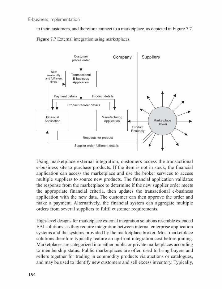
to their customers, and therefore connect to a marketplace, as depicted in Figure 7.7.
Figure 7.7 External integration using marketplaces
Using marketplace external integration, customers access the transactionale-business site to purchase products. If the item is not in stock, the financialapplication can access the marketplace and use the broker services to accessmultiple suppliers to source new products. The financial application validatesthe response from the marketplace to determine if the new supplier order meetsthe appropriate financial criteria, then updates the transactional e-businessapplication with the new data. The customer can then approve the order andmake a payment. Alternatively, the financial system can aggregate multipleorders from several suppliers to fulfil customer requirements.
High-level designs for marketplace external integration solutions resemble extendedEAI solutions, as they require integration between internal enterprise applicationsystems and the systems provided by the marketplace broker. Most marketplacesolutions therefore typically feature an up-front integration cost before joining.Marketplaces are categorized into either public or private marketplaces accordingto membership status. Public marketplaces are often used to bring buyers andsellers together for trading in commodity products via auctions or catalogues,and may be used to identify new customers and sell excess inventory. Typically,
E-business Implementation
154
Transactional
E-businessApplication
ManufacturingApplication
Payment details Product details
Product reorder details
Customer
places orderSuppliers
ProductResupply
Company
New
availability
and fulfilmenttimes
Requests for product
Supplier order fulfilment details
MarketplaceBroker
FinancialApplication

independent investors or industry consortia own public marketplaces, whichfunction as independent companies.
Individual companies often set up private marketplaces to transact with theirexisting customers, partners and suppliers, as this provides for a closer, morestreamlined working relationship. They also offer participants greater securitywhen trading sensitive information between participants, such as sales forecasts,and allow centralized control of supplier contracts.
Marketplaces are differentiated into four categories according to the specificindustry segments they support, and the features they offer companies, includingfunctional enablers, generic supplies, commodity products, and verticalmarketplaces (Bolino and Conti, 2001; Frick and Hyrne, 2001). These fourcategories are depicted in Table 7.3.
Table 7.3 Common types of marketplaces
Type Functional enablers Generic supplies Commodity products Vertical
Services Provides low cost Reduction in cost of Provides marketplace Performs complex services that are transactions for low for commodity products processes ineasily outsourced value, highly standardized with ‘market’ pricing vertical industries
products in most industriesthat can be easily compared
Current Most recent, smallest Fastest growing but most Many commodity Hardest to create status fragmented sector product marketplaces and least amount
exist for most products of progress
Possible Will be transformed Will consolidate into two Each commodity area will Unknownfuture into service companies or three dominant companies have one dominant companystatus
Examples Hire.com Staples.com E-steel TransoraPeopleSupport MRO.com PlasticsNet Neoforma
FinancialSettlement Grainger Chemdex
The functionality offered within these marketplace categories includes providingmarket information, facilitating trading relationships, supporting transactions,and providing integration (Tapellini, 2000). Market information is offered by allmarketplaces, and includes providing information to participants in the marketplacein such areas as industry directories, databases of products, industry relatedarticles, and discussion forums.
Facilitation is the ability of the exchange to match buyers to supplier productand service offerings through different mechanisms including product postings,request for proposals (RFPs), request for quotes (RFQs), auctions, and negotiation
Phase 4: External integration
155
systems. Settlement of the resulting transaction may take place offline outsidethe marketplace via each company’s current arrangements.
Marketplaces with support for transactions offer buyers and sellers the ability tocomplete the financial transaction online within the marketplace. This requiresconnections to external banks and to the internal financial systems of both participants.
Integration builds on the other areas of functionality, and offers participants theability to share their data, business documents, and related business processesusing systems supplied by the marketplace vendor.
Marketplaces provide an ideal opportunity to obtain access to a very wide range ofcustomers and suppliers for diverse goods and services. They may offer compellingcost savings for many business transactions, with estimates of transaction costsavings range from $US 25 to $US 150 per transaction (Brox, 2001; Harrelson,2001; Mehra, 2001). In addition, marketplaces present an opportunity for somecompanies to experiment with affordable external integration and businessprocess automation without requiring sophisticated integration infrastructure.
However, this business model is currently undergoing considerable upheaval.Hundreds of online marketplaces have been launched in the past several years,with many vendors competing in each of the different industry segments available,such as forestry, automotive, and electronics manufacture. Some estimatesreport between 600 and 800 different marketplaces competing for customers.
Due to this intense competition, few marketplaces have been successful in obtainingmembers who will trade online. Suppliers are sceptical of the viability of marketplacebusiness models, with high participation charges, limited levels of integration andautomation offered by many marketplaces, and lack of custom cataloguesrestricting the amount of value-added information participants can publish.Other participant concerns include lack of sophistication in critical functions such asdelivery times, quality of products and services, inventory levels and time to market.
Due to these problems, and the considerable competition among vendors in allindustry segments, many commentators expect considerable consolidation willoccur among marketplaces, with many public marketplaces ceasing trading resultingin consolidation in each vertical market segment to one or two primarymarketplace vendors. It is also expected that in order to survive, manymarketplaces will integrate with other marketplaces to provide additional services,and alter their business models to include fee-paying value-added services. Thiswill in turn offer participants the greatest potential for sales to other businesses,
E-business Implementation
156

and more opportunities for integration.
7.5.1 Vendors of marketplace solutions
Table 7.4 lists vendors of marketplace solutions for use in external integrationinitiatives with partners and suppliers. It should be noted that this list is notexhaustive and should be used as a guide only before solution research isundertaken.
Table 7.4 Vendors of marketplace solutions
Vendor Solution
Ariba Ariba Supplier NetworkBroadVision MarketMakerCommerce One Commerce One.netClarus Clarus Sourcingi2 Technologies Network ServicesMoai LiveExchangeSAP mySAP Exchanges
7.6 Business process integration solutions
Business Process Integration solutions are currently the most sophisticatedexternal integration solutions available, and are becoming the predominant methodto achieve external integration with partners and suppliers through their abilityto optimize business processes to increase efficiencies and lower business costs.Business process integration (BPI) solutions achieve internal and externalintegration using a business-oriented approach, in contrast to the technicalapplication-centric approach of other forms of external integration. This allowsbusiness users to rapidly create the integration solution without requiringprogramming knowledge or have a detailed understanding of internal andexternal applications and systems.
They are also designed to manage integrated internal enterprise applicationsand the external systems of partners and suppliers as elements of businessprocesses used to run the company. This contrasts with the EAI approach ofconnecting applications together. However, BPI solutions also include all theapplication integration advantages of enterprise application integration systems.
Phase 4: External integration
157

Business process integration solutions are also typically highly responsive tochanges in internal and shared external business processes, such as changes tomanufacturing schedules and techniques, and can support short and long durationbusiness transactions, such as purchasing commodity products from suppliersor managing negotiations. They can also support demanding integration withvery large highly distributed corporate business structures and very highmessageloads between integrating companies, and can include human interactionsand intervention within managed business processes.
A typical customer order process utilizing a business process integration solutionis depicted in Figure 7.8.
Figure 7.8 External integration using business process integration
E-business Implementation
158
Transactional
E-businessApplication
Customer
places order
Supplier
Logistics
Systems
Supplier
Product resupply
Company
Requests for
product
Business Process
Integrator
Order details
Check
product
availability
Supply Chain
Replenish
process
Logisticsprocess
Supplier
Fulfilment
Applications
Make payment
Productship date
Order details
Supplier
FinancialApplication
CheckFinancial

In Figure 7.8, a customer connects to a transactional e-business application topurchase a product. The business process integrator processes this request byanalysing the request to determine what processes to use. As this is atransactional order, it runs it through the order process. Product availability ischecked first, and because the item is out of stock, it triggers the supply chainreplenish process. This process requests additional product from a supplier, whothen responds with order quantity, expected delivery date, and price. This is fed tothe financial process for checking, and when approved, payment is made to thesupplier and approval given to make the new product. The ship date is fed to thelogistics process, which estimates the delivery date for the customer. The orderprocess then notifies the customer of the expected delivery date, and they confirmtheir purchase, which is processed and confirmed by the financial process.
What to look for in a process integration solution
External integration through business process integration solutions requires thesolution provide a set of services consisting of process modelling, integration,monitoring and optimization (McDaniel, 2001), as depicted in Figure 7.9.
Figure 7.9 Process management services
Process modelling is used to design internal and external shared businessprocesses. These are then integrated by connecting corporate resources into theprocess integration solution, including internal staff, partners and customers,
Phase 4: External integration
159
Processmodelling
Processmonitoring
Employees Customers Partners Applications
Processintegration
Databases
Process optimization

data sources, and internal enterprise applications. Process monitoring is thenused to track the execution of process, and process optimization used to refineprocesses to increase corporate business efficiency and remove redundancy andwaste.
Process management services are provided through a set of process managementtools and their supporting connection mechanisms and data formats. Thesecomponents are designed to isolate the process integration solution fromdependencies on underlying technologies and data within the participatingcompanies. This isolation in turn creates a flexible solution that can adapt to ongoingbusiness change both within the business and between partners and suppliers.
These components of an external business process integration solution aredepicted in Figure 7.10.
Figure 7.10 Functional components of a business process integration solution
The following section discusses the different process management tools,connection mechanisms and data formats required in an external integrationusing business process integration solutions.
E-business Implementation
160
Data Storage Layer
Internal
Users
Application 1
Process Management Services
Application 2
External Supplier
using process
management tool
External Supplierusing EAI tool
External Supplier
using customized
tool
External SupplierUsing Marketplace
Process Management Tools
GUI Application Integration
Data Format Standard
Data Transport Standard
SupplierCompany

Process management tools
Process management tools provide the means to create and manage companybusiness processes and data, including internal processes within the business,and processes shared across public and private networks with partners andsuppliers.
Process management products include a set of tools to manage manual andautomated business processes and data, including internal processes within thebusiness, and processes shared across public and private networks with partnersand suppliers. These tools typically include graphical process modelling tools,a development toolset, a process execution engine, a rules engine, an analysistool set, administration and management tools, and a storage repository.
Graphical process modelling tools should define and modify the corporate businessprocesses. They should be capable of generating integration code and includeEAI features to interface with internal and external applications, such asintegration adapters, brokers and messaging infrastructures. They should alsooffer visual GUI (Graphical User Interface) modelling of process flows foremployees to manually action process work items and check process status, andthe ability to modify processes as they are running.
Process modelling defines how information will flow through the differentstages of each business process, with the physical integration implementationcreated from this. This approach is in contrast to EAI, which focuses onbuilding a physical integration framework between applications. The modellingtool should support nested process models, where processes can be composedof subprocesses. This allows the solution to more closely model real-worldbusiness processes. This support should also include the ability to modify, add,remove, and manually invoke subprocesses within the currently running processmodel, with changes automatically incorporated into the running process.
The process engine (also known as the workflow engine or process broker)executes the processes defined with the modelling tool, manages the state ofinformation flowing through each stage of the processes, and communicateswith external process engines or integrated systems. The process engine shouldallow execution of multiple simultaneous processes, and support transactioncontrol of processes where subprocesses must complete together successfully,or otherwise fail without affecting the state of the running process. It should
Phase 4: External integration
161

also be capable of rapidly managing process exceptions, which are events thatare not part of the process model. This permits the process engine to correctthese events through another manual or automated step or process.
Modelling and process engine tools must support manual and automatedsteps within all processes. This is a critical feature, as most business processrequires some human input when making high-level decisions, such asnegotiation, or when an error occurs. It should also allow for manualchanges to running processes. To accommodate manual intervention,processes should be accessible to users via web browsers, which also allowsexternal suppliers with minimal automated systems to participate in theintegration.
The development toolset is used to define the business processes’ control rules.It also provides the mechanisms and tools to integrated processes withenterprise applications and resources such as databases.
A rules engine is used to evaluate executing processes against a set of businessrules defined by the development tool. It modifies running processes accordingto these rules, and permits the setting of process exception criteria andresponses.
The analysis tool is used to model the process flow and ensure it is valid beforedeployment. This tool uses business metrics stored in the repository todetermine if the processes can be optimized by identifying bottlenecks,redundancies, waste, and inefficiencies in running processes.
Administration and management tools are used to re-route process flows andmonitor the overall solution as a collection of integrated processes. They canalso start, stop, suspend or resume the operation of processes. Managementfunctionality should provide real-time process monitoring and reporting. Thisallows an organization to better react to changes in market conditions andimprove efficiencies through monitoring and modifying processes, endingfaulty processes, and optimizing existing processes. Monitoring can alsoprovide a means to quantify service level agreements with trading partners,customer service levels, and guarantees made to partners.
The repository is used to store process data objects for use by the other tools.These include definitions of business processes, business rules, integrity
E-business Implementation
162

constraints to control process execution, definitions of security objects andsystems, policy definitions, and business metric definitions for performanceanalysis.
Connection mechanisms
Connection mechanisms are the systems required for communication betweenall participants of the external integration. These mechanisms include networktransport technologies and data formats. Network transport technologiesare used to send and receive information reliably across networks. Dataformats are used to specify the form and meaning of the data being exchangedbetween companies so that all participants can understand the exchangedinformation.
Network and data transport technologies must support a variety of systems toensure maximum ease of integration. Due to its pervasive use in business, lowcost, and open design, the Internet is most commonly used as the network leveltransport mechanism for external integration.
Products should support standard Internet transport protocols including TCP/IP,HTTP, and various email standards. TCP/IP is the fundamental data transportprotocol of the Internet. The HTTP (HyperText Transport Protocol) protocolruns on top of TCP/IP to transmit hypertext data such as HTML and XML.Email transport via the SMTP (Simple Mail Transport Protocol), POP/POP3(Post Office Protocol) and IMAP (Internet Message Access Protocol) protocolsprovide an asynchronous mechanism for simple message transport, but lacksreliability features such as assured delivery.
In addition, products should also support older legacy transport standardssuch as value added networks used for EDI, asynchronous session protocols(e.g. X.Modem, Y.Modem and ANSI Clear) and synchronous session protocols(e.g. 3780 Remote Job Entry).
To integrate with a wide range of external suppliers, products should supportmultiple standards, as combinations of these standards are often used by anumber of vertical segment industry groups who have defined specifications fordata exchange between member companies. These include the AutomotiveIndustry Action Group (AIAG) Advance Network Exchange standard using
Phase 4: External integration
163
TCP/IP, HTTPS and IPSEC, the Gas industry sending transactions via HTTPencrypted with the PGP (Pretty Good Privacy) standard, and the RosettaNetconsortium using XML and the HTTPS protocol.
Products should also provide security of transport systems to preventinterception and compromise of sensitive corporate data. This is providedthrough the IPSEC protocol for encryption of IP packets over TCP, the HTTPS(HTTP Secure) protocol for encrypting hypertext data in transit, or the S/MIME(Secure MIME) standard for secure email transport.
Data integration formats
Data integration formats are used to describe common business processes anddata used by each integration partner. These formats are routed and deliveredbetween company and suppliers using the transport level technologiesdescribed above.
XML is the preferred data standard for data integration across most industries,and represents a very low risk solution for common data integration dueto its unique properties. XML is a very simple, open, and extensibletechnology, providing a very low cost and easy to implement mechanismto describe the format and meaning of data. This has resulted in manyindustry consortia defining common business processes and data structuresusing freely available XML specifications. XML is also extensible, allowingcompanies to customize XML document standards for their own requirementsand thus integrate with a very wide range of suppliers across differentindustries.
XML also offers several advantages over legacy EDI data formats previouslyused for limited external integration. EDI implementations suffer fromlimitations in the types of information they can convey between integrationparticipants, and cannot easily be integrated with modern e-businessdevelopment technologies such as Java and COM. In contrast, XML enableslower cost, rapid implementation with the ability to define any form of data orbusiness process. However, due to the prevalence of legacy EDI solutions inmany companies, it is expected that use of EDI and proprietary data formatswill continue. Hence, an external process integration product must supportmultiple XML data formats as well as legacy EDI formats.
E-business Implementation
164

It is expected that the use of EDI will decline within business, as differentindustry segments agree and adopt common industry and global XMLstandards, and increasingly use Internet technologies for their integrationinitiatives. It is also expected that many companies will eventually replace theiruse of EDI with the XML-EDI standard, an emerging XML standard based onEDI and allowing connections to legacy EDI infrastructures.
7.6.1 High-level designs of business process integration solutions
The following section presents a generic design for process level integration ofinternal enterprise applications with external partner and supplier systems.This design supports direct sharing of business processes with externalcompanies using similar process management systems, and indirect sharingof process-related data with companies via multiple data format standards.
This design is also intended to integrate internal enterprise applications withina company-wide business process framework to provide increased automationand optimization of corporate business processes.
Companies adopting this design will typically have several transactionale-business systems and a potentially wide range of internal applications. Thesemay include applications located within a single geographical area, ranging upto large numbers of enterprise applications distributed across multiple regionsand companies. They may be written using a very wide range of technologies,and be used in many internal and external business processes. They will alsotypically need to integrate with the systems of external partners and suppliers tosupport outsourced business processes.
Internal and external integration is achieved through the integration technologyof the BPI product, including middleware brokers, intelligent adapters, andintegration standards such as JMS. It should be noted that this design is alsocapable of integrating additional EAI systems within the process managementsolution in the event that companies acquire additional businesses with theirown EAI solutions.
This design includes additional functional and operational components,compared to previous integration designs. The functional architectureemphasizes control of applications through the process management functions
Phase 4: External integration
165

discussed above, including process modelling and analysis, process andbusiness rules management and execution, and process repository. Thesefunctions initiate and control the data flow between applications as part ofconnected processes, in contrast to EAI solutions where applications initiatedata flows.
Operational differences in this design include additional server nodes requiredto support the process management tools, and different availability, scalability,security, and manageability features.
Because the business process solution is controlling all corporate businessprocesses, high scalability and reliability are required. To cope withpotentially large numbers of external partners, applications, messages, andconcurrently executing processes, cluster processing is used to distributethese functions across servers, with fail-over to redundant systems forincreased availability. Vertical scalability is also achieved using multiprocessorservers.
Similar security mechanisms to previous designs are deployed, includingencryption of sensitive data, secure data transport technologies such as HTTPS,SSL and IPSEC, and intrusion detection systems. Centralized securitymanagement is provided through corporate LDAP directory servers. Becausethe process management tools share only data with external parties and do notpermit them to execute potentially insecure application code, the use of localLDAP servers for higher security is not required.
However, as the process management server cluster communicates withexternal parties through the firewall, it must be isolated into an internal DMZnetwork for additional security. To facilitate scalability in the design, anadditional internal process management server cluster has been added to theinternal corporate network.
It should be noted that other configurations of the process management tools arealso permitted. For example, simplified deployments could be created forsmaller sized companies through placement of the rules engine on the businessprocess management server, and use of a shared repository server between theanalysis server, rules engine and business process management server.
The external Business Process Integration design is depicted in Figure 7.11.
E-business Implementation
166
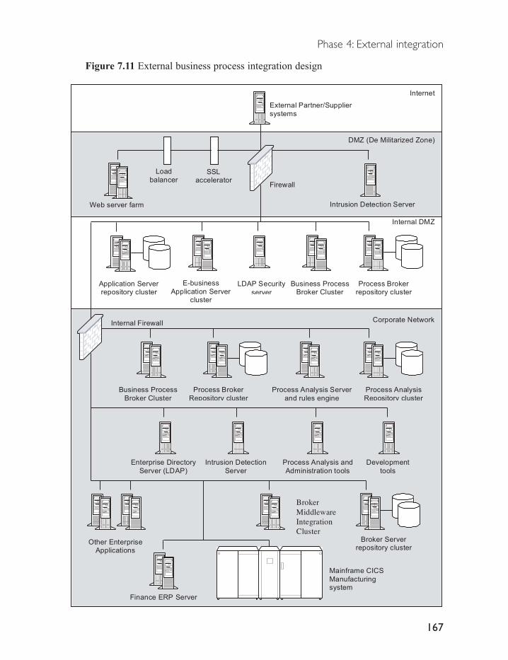
Figure 7.11 External business process integration design
Phase 4: External integration
167
Application Serverrepository cluster
Corporate Network
DMZ (De Militarized Zone)
Internet
Firewall
Web server farm
External Partner/Supplier
systems
E-business
Application Servercluster
Finance ERP Server
Mainframe CICS
Manufacturingsystem
LDAP Security
server
Internal Firewall
Intrusion Detection Server
Internal DMZ
BrokerMiddlewareIntegrationCluster
Other EnterpriseApplications
Enterprise Directory
Server (LDAP)
Intrusion Detection
Server
Broker Serverrepository cluster
Business ProcessBroker Cluster
Process Analysis Server
and rules engine
Process Brokerrepository cluster
Business Process
Broker Cluster
Process Broker
Repository cluster
Process Analysis and
Administration tools
Development
tools
Process Analysis
Repository cluster
Load
balancerSSL
accelerator

7.6.2 Benefits and limitations of business process integration solutions
Business process integration solutions provide considerable advantages tobusinesses by optimizing existing business processes to produce increasedcorporate efficiency. Efficiencies are achieved through reductions in the timetaken to execute business processes, or through elimination of wasteful processes.
External integration is also considerably simplified using BPI solutions. Theseallow for very flexible integration initiatives that can be controlled by businessusers. Solutions typically allow additional enterprise applications to be rapidlyincorporated into integration solution with minimal or no effect on othersystems, or alternatively the swapping of existing applications for differentversions or products. Multiple different external suppliers can also be rapidlyintegrated in the integration initiative.
However, current business process integration solutions have some limitationsthat currently restrict their usefulness, including immature standards and somelimited integration functionality.
Although XML represents an ideal mechanism to exchange structured processesand data between companies, current XML standards in many industries haveyet to be agreed or are in an early and immature form. For example, there iscurrently no globally accepted XML structure to describe business processes,although several are in progress. These issues restrict the usefulness of XMLstandards for sharing business processes and data, and have resulted in aslowing of the adoption of XML data exchange by businesses (Hildreth, 2001).
In addition, some products may provide limited internal application integrationfacilities, restricting their ability to share processes with external suppliers.Such products may require additional integration services provided throughEAI technologies, typically with enterprise application integration middlewaredeployed to integrate internal applications and data with the processmanagement product deployed on top of this for process management andexternal integration.
Finally, current business process integration products are an immature softwarecategory, with resulting weaknesses in some products. These are typicallymanifest in the areas of process modelling capabilities, support for processtesting and debugging, inconsistent support for handling exceptions or errorsduring process execution, and poor support for compensating transactions, used
E-business Implementation
168

to help processes complete when a part of a process fails. Product selectionshould therefore pay particular attention to these issues.
7.6.3 Vendors of business process integration products
Table 7.5 lists vendors and products used in business process integration initiatives.It should be noted that this list is not exhaustive and should be used as a guideonly before solution research is undertaken.
Table 7.5 Vendors of business process integration solutions
Vendor BPI Solution
Actional Actional Control BrokerAttunity Attunity BPIBEA WebLogic IntegrationBowstreet FactoryFileNET BrightspireFuegotech Inc. Fuego4Hewlett Packard Process ManagerIBM WebSphere MQ & MQ Workflow, IBM CrossworldsInsession Technologies WorkPointIona Orbix E2A Web Services Integration PlatformIPNet EBizness CollaborateMercator Process IntegratorPeregrine Business Integration SuiteSeeBeyond Business Integration SuiteSterling IntegratorSun Microsystems Sun ONE Integration Server, B2B EditionSybase BPI SuiteTibco ActiveEnterpriseVitria BusinessWareWebMethods WebMethods Integration PlatformWRQ WRQ Verastream
Phase 4: External integration
169

Phase 5: Dynamic e-business and web services
The fifth phase of e-business is dynamic e-business, which is used to integrateall internal and external corporate resources into a dynamic system. This levelof integration allows a company to gain a real-time understanding of all areasof their business for purposes such as financial reporting or inventory management.
Dynamic e-business utilizes business process integration, with processmanagement occurring in real time. This provides up-to-the-minute informationon all aspects of the business both externally with customers and suppliers, andinternally for staff and applications. Business managers can then use thisinformation for dynamic business planning to respond to changing customerdemands. This real-time view can extend across complete business to encompassareas such as financial performance, customer demand, staffing levels,manufacturing resources, inventory levels, and the status of suppliers.
Real-time analysis of the complete business can result in considerable savingsthrough productivity improvements from optimization of all internal and externalprocess, and reductions in resource wastage. It can also lead to dramaticallyincreased responsiveness to customer demand, which in turn increases profitsthrough improved customer loyalty and retention.
For example, a company seeks to increase productivity, decrease waste, andimprove competitiveness in its industry segment through a corporate businessprocess integration initiative. Using a real-time BPI solution, existing businessprocesses for human resources, sales and marketing, manufacturing, distributionand financial reporting and management are mapped and encoded into thesolution. Enterprise applications, databases, and roles and responsibilities for
8

staff members are connected to the solution, along with external partner andsupplier companies that contribute to many of the corporate processes.
Integration at this level therefore provides the company with detailedmanagement of product inventory, real-time sales data, and dynamic assessmentof the financial performance of the company. By understanding process flowsacross the company and its suppliers, business managers readily determineways to optimise existing processes to increase efficiency. They also gainreal-time assessment of the relative performance of external suppliers, whichcan be used to re-negotiate contracts to include performance penalties andincentives for production savings or reduced production times.
This example is depicted in Figure 8.1.
Figure 8.1 Dynamic e-business using BPI products
In this example, the corporate transactional e-business application is connectedto a real-time BPI product. Product orders trigger processes to check inventory
Phase 5: Dynamic e-business and web services
171
SuppliersShared
Processes
Company
Customer
places order
Product orders
Sales
Supplier A
Supplier B
Supplier C
Supplier DMarketing
Product resupply
Real time financial reporting
Real time inventory & sales
Hire new staff
Finance
HumanResources
Transactional
E-businessApplication
ManufacturingBPI
Logistics

levels, and if these are low, to reorder new product from suppliers. Otherprocesses check customer payments through financial applications to verifypayment. Once received, production is started through the manufacturingapplications. Large orders may require additional staff to meet requiredproduction levels, which is checked against the human resources applications.If additional staff members are required, these query external suppliers to see ifqualified production staff members are available.
Sales and marketing applications are also involved in the process to matchdemand to marketing and sales initiatives. If these are proving successful staffare notified, allowing them to plan campaign extensions or new initiatives.Finally, the financial systems monitor all transactions in real time to providedynamic financial reporting on the state of the company.
8.1 Key technologies used
Dynamic real-time business integration of internal and external businessprocesses requires three sets of integrated technology components. Theseinclude real-time process integration systems for external partners and suppliersand internal systems, internal integration of applications and resources, andbusiness intelligence systems for real-time processing of business informationand customer demand and supply patterns.
The functional components of real-time internal and external integrationsolutions are depicted in Figure 8.2.
Figure 8.2 Functional components of a real-time business process integration solution
E-business Implementation
172
Company
Process Management
Internal Integration
Customer
demand
InternalApplications
InternalStaff
InternalData Stores
Suppliers
and
PartnersBusiness Intelligence

8.1.1 Process management and internal integration
Within the internal and external integration solution, the real-time process managementfunction is provided by business process integration systems. Products offeringBPI features must support real-time management of running processes, shareand manage processes with external partners and suppliers, and integrate with allinternal corporate resources. These include all sources of internal companyinformation, such as internal human resources, CRM, ERP, and transactionale-business applications. They also include corporate data stores, and staff members whomake manual contributions to business processes. The real-time BPI solution mayalso be required to integrate with existing EAI implementations within a company.
8.1.2 Business intelligence systems
In addition to the BPI and internal integration components, an internal and externalintegration solution must provide business intelligence systems for the real-timeanalysis of business activity across all integrated corporate and externalresources. These systems analyse information flows within the integrated internaland external processes, and produce dynamic reports of sales and financialinformation. This analysis in turn allows a company to meet changing customerdemand by modifying internal processes and shared external processes in real-time.It also provides a company with an up-to-the-minute understanding of its business.
Business intelligence systems typically provide analysis by building a dynamicmodel of customer behaviour in order to understand customer demand. Thismodel is then matched to business supply functions required to meet customerdemand, such as product supply, product design, or marketing and sales, acrossall company product and service offerings, as depicted in Figure 8.3.
Figure 8.3 Business intelligence modelling
Phase 5: Dynamic e-business and web services
173
Supply/DemandBusiness Model
Customer
demand
factors
Business
supply
factors
Business
IntelligenceModelling

Customer demand is assessed by analysing information from all customerchannels, such as shops, transactional e-business sites, catalogue and mail orderinitiatives, and direct sales. Data sources for these channels include transactionale-business logging and analysis systems, online publishing systems, CRM systems,and traditional data mining technologies used on recorded customer data.
Further customer data may be gathered via collaborative systems, such as emailsystems or online chat rooms. This data can provide valuable qualitative data tocompare to the customer data analysis, allowing companies to better understandcustomer motivations or even determine up-and-coming trends to target.
As the customer data is gathered, the business intelligence system builds adynamic model focusing on factors affecting demand for products and services.These typically include factors such as location, price, promotions, seasonal andweather effects, industry specific data, and market forecasts.
The business intelligence solution may also employ demand modellingfunctionality to build the model. This aims to predict the effect of changes incustomer demand on the business, using customer data and factors such asseasonal trends or historical patterns. This allows the company to potentiallyavoid incorrect inventory levels, such as having low inventory in times of highdemand or high inventory in times of low demand.
Supply factors are also included in to the business intelligence model. Theseinclude internal company and external partner and supplier factors such ascurrent state of inventory levels, shipping times to customers, and lead times onnew products and existing stock.
The model built by the business intelligence system then attempts to achieveefficiencies in production and logistics processes through a customer-centricview of the products and services the company needs to meet customer demand.In contrast, supply chain management solutions may focus on managing andoptimizing supply chains from a less efficient planning perspective rather thanbeing driven by customer demand (Langabeer, 2001).
Business intelligence systems typically consist of three functional units, includingan integration hub, data warehouse and analysis system (White, 2001).Information is first gathered via an event-driven hub system, which receivesinformation and places it into a data warehouse system. The analysis engine isthen used to create and provide access to analyses from the data stored in thewarehouse system. Finally, a decision engine is used to initiate actions based onthe results of analyses of the data. These can either be through automated processes,
E-business Implementation
174

or via manual triggering by staff. This process is depicted in Figure 8.4.
Figure 8.4 Functional components of a business intelligence system
The BPI process engine usually fulfils the role of the integration hub, oralternatively an EAI messaging middleware solution managed by the processengine. All sources of demand and supply data used in the model are capturedthrough this hub and fed directly into the data warehouse for storage and analysis.
The data warehouse provides storage for all demand and supply data receivedthrough the BPI process engine. It may also include predefined businessanalysis functions to calculate data summaries or important performancemetrics for the business.
The analysis engine provides real-time analysis of supply and demand byprocessing data received by the data warehouse. Analysis may be initiated byanalysis rules that evaluate the data as it is received through the integration hub.Alternatively, the analysis engine can periodically trigger the business analysis
Phase 5: Dynamic e-business and web services
175
Business Intelligence Analysis and Reporting Functions
Recommendations
and automatedactions
Business Processes Integration Solution
Transactional
e-businessapplication
Enterpriseapplications
Process management system (integration hub)
Corporate DataStores
AnalysisEngine
DataWarehouse
DecisionEngine
analyse
data
Business
activity reports
Gather andtransform data
ManualProcesses
BusinessMetrics

functions within the data warehouse to summarize and analyse businessintelligence data. Once the data warehouse has processed the data, analysis reportscan then be provided to business users via web-based front ends, such as portal systems.
The decision engine provides business processes and rules to determine whatactions to take based on the analysis of the data. Decision engine functionalityis sometimes embed in existing enterprise applications such as transactionale-business systems through rules-based marketing engines, or within applicationserver personalization engines. However, for many business scenarios thisfunction should reside in the process management layer, and be handled by theprocess rules engine. This allows different applications and services within thecompany to respond to business events in real time by calling on the services ofthe rules engine, without requiring separate engines in each application.
Business intelligence analysis and decision-making are guided by a set ofbusiness metrics that are specific to each company. Business metrics includeindustry-standard best practice, required performance factors unique to eachcompany, and the functions such as quality, item and production cost, marketshare, real-time business performance, and customer satisfaction (Jain and Jain,2001). Business metrics are used to guide both internal business processes andprocesses shared with partners and suppliers.
Once analysis of customer data is conducted against business metrics, it can becompared to current internal and shared processes across each e-business channel.This then allows companies to analyse and then comprehend the impact e-businesscollaboration will have on their own business, identify channel conflicts andinconsistencies, optimize collaborative processes that span multiple channels,and determine the costs of different channels.
8.1.3 High-level design of internal and external BPI solution
The following section presents a generic design for a corporate internal andexternal business process integration system between internal systems andexternal partners and suppliers. This design resembles the high-level businessprocess integration systems design, but includes systems to provide the businessintelligence functions discussed above. These include a data warehouse whichreceives information from the process management broker, a business intelligenceanalysis engine which creates the analysis model from data stored in the datawarehouse, and the process rules engine, which provides business rules to acton the analysis model. These systems are depicted in Figure 8.5.
E-business Implementation
176
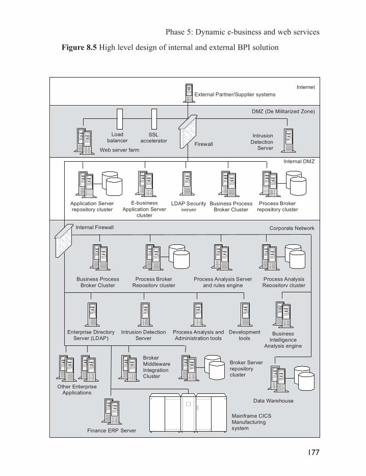
Figure 8.5 High level design of internal and external BPI solution
Phase 5: Dynamic e-business and web services
177
Application Serverrepository cluster
Corporate Network
DMZ (De Militarized Zone)
Internet
FirewallWeb server farm
External Partner/Supplier systems
E-business
Application Servercluster
Finance ERP Server
Mainframe CICS
Manufacturingsystem
LDAP Security
server
Internal Firewall
Intrusion
DetectionServer
Internal DMZ
Broker
Middleware
IntegrationCluster
Other EnterpriseApplications
Enterprise Directory
Server (LDAP)
Intrusion Detection
Server
Broker Server
repositorycluster
Business ProcessBroker Cluster
Process Analysis Server
and rules engine
Process Brokerrepository cluster
Business Process
Broker Cluster
Process Broker
Repository cluster
Process Analysis and
Administration tools
Development
tools
Process Analysis
Repository cluster
Load
balancerSSL
accelerator
Business
IntelligenceAnalysis engine
Data Warehouse

8.1.4 Benefits and limitations of dynamic e-business
Dynamic e-businesses provide companies with the ability to have real-timeknowledge of the state of their business. This includes areas such as financialstatus, sales performance, and staffing levels. In addition, it provides a means forthe company to respond to customer demand in real time to increase retention and sales.It also provides a means to optimize business processes to achieve efficienciesin production, inventory, and measure the efficiency of outsourced supplier processes.
Dynamic e-business represents a logical progression from external integrationsystems using business process integration solutions. Therefore, extending suchsystems to encompass dynamic e-business represents a low risk solution and anincremental change to existing infrastructure.
However, creating dynamic e-businesses is complicated due to the lack ofoff-the-shelf products. Such initiatives require some custom development,including construction of a data warehouse and integration with a businessintelligence analysis engine.
It should be noted that some companies adopt alternative real-time systems,such as demand planning tools or supply chain management solutions.However, currently many demand planning tools lack sufficient flexible to meetthe demands of dynamic e-business as they cannot integrate supply and demandareas of the business, and lack sufficient analysis capability and the expertautomation required to automate decision making (Langabeer, 2001).
In addition, while some supply chain management solutions are starting to offerelements of functionality to model customer demand and supply chain planning,they are currently problematic for use in dynamic e-business implementations.These solutions are typically proprietary to individual vendors, and hence areunlikely to operate with products from another vendor. They may also be tooinflexible for the diverse business requirements of many e-businesses.
8.1.5 Vendors of dynamic e-business solutions
Table 8.1 lists vendors of business intelligence solutions required for integrationwith business process integration solutions. It should be noted that this list is notexhaustive and should be used as a guide only before solution research isundertaken.
E-business Implementation
178

Table 8.1 Vendors of business intelligence solutions
Vendor Business intelligence solution
Brio Metrics Builder and IntelligenceBusinessObjects SA Business Objects Intelligence and AnalyticsCognos Inc Cognos Series 7Crystal Decisions Crystal AnalysisHNC Critical ActionHyperion Solutions Corp Essbase XTD and Business Performance ManagementIBM DB2 Warehouse ManagerInformatica Corp PowerCenter, PowerMart and ApplicationsInformation Builders WebFOCUSMicrosoft SQL Server OLAPMicroStrategy MicroStrategyOutlookSoft EAPOracle Business Intelligence ApplicationsSAP mySAP Business IntelligenceSAS SAS Business Intelligence and Analytic IntelligenceSiebel Siebel AnalyticsSybase Industry Warehouse StudioTeradata Teradata WarehouseViador E-Business IntelligenceVisual Insights eBizinsights
8.2 Web services
Dynamic e-business can also utilize the developing web services standards toautomatically locate and outsource business processes in real time to supportrapidly changing customer and business demands.
This real-time outsourcing contrasts with traditional external integration withsuppliers that require an existing relationship before trading can commence.Establishing this relationship would typically take weeks or months, andinvolve considerable manual effort by company staff to locate suppliers thenunderstand their business and negotiate outsourcing terms and conditions.
Dynamic outsourcing of e-business processes relies on web services technology,which is currently being developed by leading software vendors. It is thereforeonly available in limited form at present.
Phase 5: Dynamic e-business and web services
179

Dynamic outsourcing of e-business processes provides a company with anothermechanism to satisfy customer demand, gain loyalty and increase customerretention by being able to immediately satisfy customers requirements. It alsooffers companies complete flexibility to outsource any business processes theydo not have in-house, allowing them to rapidly optimize external processes forefficiency, levels of service, and operational business cost savings.
For example, a company receives a request for a customized product from acustomer. Their current systems are unable to fulfil this order, as itwould require considerable re-configuration of their production lines.However, this customer represents a valued account that the company wishes toretain.
Using automated web services technology, the company manufacturing andprocess integration systems create a product order incorporating the customizedproduct specifications. They then query external directories to determinesuppliers that may be capable of fulfilling the order. Once a sufficientnumber of suppliers have been located, the corporate systems issue thecustom order to the external suppliers. They then receive automated responsesfrom a number of suppliers containing contractual terms and conditions,expected delivery times, costs, and quality guarantees. The company busi-ness process integration systems then determine the optimum supplier andplace the order.
This integration scenario would typically require transactional e-business systemswith the ability to create custom product catalogues, or include customercollaboration systems such as online submissions to allow the customer tospecify their custom product. Once their order is received, the internal processsolution queries the internal manufacturing applications and finds this ordercannot be created in-house. It then uses a business process and associated rulesto determine if custom orders are worthwhile. This process queries the corporatefinancial applications to determine the customer spending patterns, thendetermines if they are a valued customer. The process then queries a webservices directory to locate potential suppliers, and receives a list in return. Itthen queries each supplier with the custom order, and sends the responses to theprocess rules engine to evaluate the best match. Once this is determined, itissues approval to the supplier to manufacture the product, and makes theappropriate payment through the internal financial applications.
This process is depicted in Figure 8.6.
E-business Implementation
180

Figure 8.6 Automated integration of new partners and suppliers through web services
Companies in this phase of the e-business lifecycle therefore utilise dynamic webservices e-business technology as their competitive edge to direct resources into creatingnew customer channels, increasing market share, and reducing the time taken tocreate and introduce new products and services (Schmidt, 2000; Seeley, 2001).
8.2.1 Key technologies used
Dynamic outsourcing of e-business relies on the emerging web servicestechnology to provide rapid location and utilization of external supplier businessprocesses. Web services arose from the desire of a number of informationtechnology vendors to create an affordable services-based architecture for softwaredevelopment. The service based approach to software emphasizes the ability tosell software over networks, reducing the need for businesses and individualsto purchase, install and integrate separate software products.
Phase 5: Dynamic e-business and web services
181
Transactional
E-businessApplication
Customer
requestscustom order
Locatesuppliers
Business Process Integrator
Ship date
Order details
Supplier list
Contract andOrder response
Sendorder
Approve
orderresponse
Make payment
Check
product
availability
Check
Customer
status
Build
Custom
order
Web Services
Financial
Processes
Web ServicesDirectory
Supplier

This architecture in turn required a mechanism to allow for the integration ofany technology in a rapid and very affordable manner. XML was chosen asthis mechanism, due to its rapid adoption within business, and the abilityof XML documents to be read by humans and automated software.
Web services technology consists of a simple set of XML based standards usedto access and employ software developed by external parties. These includefacilities for lookup services and discover their role, description of the requestedinputs and resulting outputs generated by the web service, transport for messagingbetween services, the environment to develop and deploy a service within, andevent notification to notify changes in the environment of the service.
Lookup, discovery and description processes utilize the facilities provided byproducts adhering to the UDDI (Universal Description, Discovery andIntegration) specification. This describes businesses and the web services theyoffer using XML descriptions within public UDDI registry services.
Through a UDDI registry a company can discover services offered by anothercompany, define how they can interact over the Internet, and share this informationthrough the registry (Karpinski, 2001; www.uddi.org). The services offered throughthe UDDI registry are described via the Web Services Description Language(WSDL), which describes the XML messages the software uses as input and output.
Entries are classified within a UDDI directory as White Pages, Yellow Pages, orGreen Pages. White Pages contain addresses, contact information, and knowninformation about the company. Yellow Pages contain industrial categorizationsusing standard classification taxonomies, and Green Pages contain technicalinformation about the services offered by each business, including referenceand interface information about each service.
The Simple Object Access Protocol (SOAP) is used to provide XML-basedmessaging to connect application components together over the Internet. SOAPallows the exchange of structured information independently from the underlyingsystems or applications, and uses XML to encode messages.
Microsoft, IBM, and Dave Winer of UserLand Software Inc. initially proposedthe SOAP standard. It is currently maintained by the World Wide WebConsortium, and consists of the SOAP envelope, which defines the frameworkfor expressing what is contained within a message, who should handle it, andwhether it is optional or mandatory (see http://www.w3.org/TR/SOAP). Theencoding rules specify a serialization mechanism used to exchange application
E-business Implementation
182

defined data. Finally, the SOAP RPC representation defines the convention usedto represent remote procedure calls to other applications and their responses.
Application development using web services therefore emphasizes the creationof software as an interconnected set of software components, wrapped inWSDL, which provide discrete elements of the complete application functionality.Applications are then assembled from collections of components as required byissuing SOAP messages to UDDI directories. Because these components aresmall, they can be delivered over the Internet or corporate networks asrequired by users. Examples of application components may include functionssuch as credit card verification, mortgage approval, or travel reservation.
This approach is depicted in Figure 8.7. This diagram depicts an enterpriseapplication assembled by a Business Process Integration tool using the SOAPprotocol over HTTP. Application functions are typically provided by accessingcomponents from external suppliers, which may be developed using a widerange of programming languages, including J2EE, COM and DCOM.
Figure 8.7 XML based web services model of applications
Components can be developed using any programming language, ‘wrapped’ inweb services, and published to directories to become available online. Oncewrapped, components exposed as web services can be used in more than oneapplication simultaneously, and can incorporate processes and componentsencoded in remote web services for local use, and can be created on any platformusing any object model.
Phase 5: Dynamic e-business and web services
183
Corporate Enterprise
Application
SOAP over HTTP
Business
ProcessIntegration Tool
Component
A(J2EE)
Component
B(J2EE)
Component
C(J2EE)
Component
D(J2EE)
Component
E(DCOM)
External Supplier Components

Business process integration using web services components is depicted belowin Figure 8.8.
Figure 8.8 Process integration via web services
In this example, a supplier publishes their offered application and processfunctionality to a public UDDI registry. Company A urgently requires anadditional process from an external supplier to help them meet demand for anew service that they have just launched. They issue a SOAP messagerequesting the new process to the UDDI directory, which responds listingProcess B offered by Supplier A; both parties then directly integrate theirprocesses via SOAP messages.
This model shifts process integration efforts to a service-based design. Incontrast to more complicated technology-centric external integration initiatives,this service model focuses on finding and using publicly available businessservices from any vendor, allowing for very flexible real-time acquisition anduse of business processes as required (Gisolfi, 2001).
E-business Implementation
184
Supplier
SOAP reply messagewith process B
SOAP messagewith query for process
Integration ofProcess B
WSDL wrapper
Application B
WSDL wrapper
Process B
SOAP gateway
Company
WSDL wrapper
Application A
WSDL wrapper
Process A
SOAP gateway
UDDI Directory Service

8.2.2 Benefits and limitations of dynamic e-business using web services
Web services is an ideal set of technologies to develop and utilize applicationswithin a business process integration framework. Processes and subprocessescan be encoded into web services software components using developmentlanguages such as Java, then published over the Internet to business partners,suppliers and customers on an ad-hoc basis as they are required (Colan, 2001).If internal or external processes change, the web services components used toexecute the processes can be readily reconfigured to support this change, oralternatively additional external processes from suppliers and partners can beincorporated. This model is forecast by the Butler Group to become thepredominant method of application development within five years (Jennings, 2001).
Web services also provide a means to preserve existing investment in informationtechnology infrastructures. For example, existing e-business applications can be wrappedin web services and redeployed as a set of transactional e-business components, suchas shopping carts for retail e-commerce. These can then be reused in differentInternet initiatives requiring similar functionality, such as multiple corporatetransactional sites, or sold as service to other companies requiring similar functionality.
In addition, as web services are being adopted by most software vendors and opensource projects, the risk of developing software projects using web serviceswill be considerably reduced due to the widespread availability of compatibletools and applications, and broad exposure of developers to this technology.
Web services are therefore an ideal tool for the creation of e-business applicationsacross the five e-business phases discussed above. These include publishing online,transactional e-business applications, integration of applications within theenterprise, and integration initiatives with external partner and supplier systems.Web services also provide an ideal tool for the creation of a completely dynamice-business enterprise able to respond to all customer requirements in real time.
However, web services suffer from a number of problems that preclude theirwidespread adoption at present. These include greater consumption of networkbandwidth, lack of security mechanisms, and lack of support for complex transactions.
Web services consume greater bandwidth compared to other integrationtechnologies, due to their use of ‘verbose’ XML text documents used by theSOAP protocol and enclosed WSDL content (Vaughn-Nichols, 2002).
Web services also currently lack required security measures. SOAP messages aresent as human readable clear text, with no security yet implemented within the SOAPspecification. This necessitates securing SOAP messages via encryption, secure
Phase 5: Dynamic e-business and web services
185

sockets layer transport, or virtual private networks between parties exchangingSOAP messages. However, more advanced security systems such as theKerberos standard are required for authentication and authorization of webservices components (Schwartz, 2002). In addition, the ability to dynamicallylocate and use software components exposes companies to security managementissues, such as how to determine if the integrated components can be trusted.
In addition, the SOAP protocol cannot support complex features required forbusiness transactions (Borck, 2001b; Sullivan, Scannell and Schwartz, 2002;Woods, 2002). These limitations include lack of support within WSDLspecification for how web services can be used, and no means to provide forcontractual agreements on the use of services such as trade-level agreements,support for interactions among multiple parties, and quality of service reliability.
Web services also lack agreed standards for describing shared business processesthat are required for complex integration with partners and supplier systems.Currently three initiatives are under development to address this limitation.These include the WSFL (Web Services Flow Language) from IBM, theebXML initiative from the OASIS group, and the OAGIS (Open ApplicationsGroup Interface Specifications) initiative.
8.2.3 Vendors of web services solutions
Table 8.2 lists vendors of web services products. It should be noted that this listis not exhaustive and should be used as a guide only before solution research isundertaken.
Table 8.2 Vendors of web services solutions
Vendor Web services solution
BEA WebLogic Enterprise Platform and WebLogic WorkshopBorland jBuilderBowstreet WebFactoryIBM WebSphere products and Eclipse development toolsIONA E2A Web Services Integration PlatformMicrosoft Microsoft .Net initiative;Visual Studio .Net development toolsOpen Source Eclipse development tools, XML development tools such as Xerces,
SAX,Tomcat and CocconOracle JDeveloper development toolsSun Microsystems Java 2 Enterprise Edition; Forte Development tools; Sun ONE initiative,
Java Web Services packSybase Web Services IntegratorWebMethods WebMethods Integration Platform
E-business Implementation
186

Part Three E-business supporting technologies

This Page Intentionally Left Blank

Critical technologies supporting e-business
Successful implementation of e-business systems relies on the deployment andcorrect configuration of a set of critical underlying technologies. Thesetechnologies provide core foundation services utilized by all e-businesssystems and by existing corporate systems such as email and groupwareservers, file and print servers, and legacy applications.
The e-business supporting technologies are deployed as a series of layers rangingfrom simple networking systems to complex e-business development languages,as depicted in Figure 9.1.
Figure 9.1 Dependence of e-business systems on core supporting technologies
9
SecurityLayer
Hardware and Operating System Layer
Network Layer
Addressing Layer
Development Languages, Open Source
Application Layer – E-business Systems
Phase 1: Websites, Intranets, Portals, Content Management
Phase 2: Transactional e-business
Phase 3: Internal EAI
Phase 4: External B2B IntegrationPhase 5: Dynamic E-business

Each layer of core supporting technology relies on the services provided by thepreceding layer. Technologies selected in lower layers therefore influence thesubsequent choices available for deployment in successive higher levels.
The addressing and network layers are used to facilitate communicate betweenhigher level systems and end users. The addressing layer translates communicationrequests from the application layer into a form that can be understood and routedby the network layer. The network layer takes translated requests and directsthem to the user or other application system originating the request.
Hardware and operating system layers provide the operational deploymentplatform for all e-business systems. Selection of the correct hardware platformis critical to ensuring the appropriate levels of availability, scalability andreliability of the final e-business solution, and influences ongoing support andmaintenance costs to the business.
The combination of these two layers in turn influences the choice of programminglanguage and ancillary open source software components used to create thefinal form of the application layer. These have a strong influence on the viability,costs and strategic technology direction of the company, and hence of thefunctional design of the systems deployed across the five e-business phases.
Security systems are deployed to maintain the security of the complete solution.These are a fundamental element of the complete e-business solution, andenclose each preceding layer as well as the final e-business system.
Deployment of e-business systems using this layered structure permits higher-levelsystems such as e-business applications to be designed and deployedindependently of the lower-level systems, such as the addressing and networkinglayers.
In order to deploy these systems, a company must understand and deploy twocritical enabling technologies that are required to support the functioning of allInternet-based technologies. These include the Domain Name System (DNS)and TCP/IP-based networking. This dependence on DNS and TCP/IP is createdbecause these two technologies are an essential foundation for the basicfunctioning of the Internet, and are used by all Internet-based systems. Theseinclude corporate Internet and Intranet systems, and advanced systems such asapplication server-based e-business, CRM and ERP systems.
E-business Implementation
190

E-business development technologies
E-business initiatives typically require some degree of customized development,either of commercial packaged applications, or of systems written in-house, inan attempt to achieve the desired levels of functionality.
Simple customizations typically require modifications to templates or small-scalechanges to e-business application logic. For example, many packagedtransactional e-business systems may require modification of store templatefiles by page designers, usability experts and developers to provide a fully functionalbranded e-business presence. Alternatively, more complex customizations maybe required, such as recoding application functionality within an externalintegration package to support specific industry specific data formats, oralternatively the creation of a custom integration adapter.
As such customization is an integral part of e-business, it is critical to the successof e-business projects to have an understanding of the development languagesand technologies involved.
10.1 Key technologies used
Java and XML are the technologies most commonly used in the majority ofenterprise class e-business developments, with the Microsoft .Net environmentincreasing in importance. Each technology is comprised of a set of componentscritical to successful e-business implementations, and to maintainingcompatibility with emerging technologies such as web services.
10

E-business Implementation
10.2 Java
Java was designed by programmers within Sun Microsystems in the early 1990sto address many of the drawbacks of contemporary development languages,such as poor memory management, proprietary platform-specificimplementations of technologies, and unnecessary complexity.
Originally conceived as a platform for networked consumer electronics, Javarapidly rose to prominence after incorporation into the Netscape Navigator webbrowser. Following this success, Java was retargeted at Internet-baseddevelopment initiatives.
Java is now one of the most widely used programming languages for e-business,both for custom and packaged software development. For example, the CutterConsortium reported in 2000 that more than 50 per cent of companies wereusing Java with another 12 per cent intending to use Java (Cutter Consortium,2000). By late 2001 the momentum behind Java had increased to the pointwhere more than three quarters of IT executives surveyed were prepared toadopt Java to develop emerging web services-based enterprise applications(Berger, 2001).
Sun Microsystems owns the Java language, and is responsible for ongoingdevelopment of the various Java standards through the Java CommunityProcess. This process allows the participation of companies and individuals inthe ongoing definition of Java standards, and was begun in response to calls forSun to cede control of Java to standards bodies.
Java is divided into a set of technology blocks, offering specific sets of featuresrequired within different industry segments. The most recent version of these isthe Java 2 standard. This standard incorporates the Java 2 Micro Edition (J2ME)for very small computing devices such as mobile phones, the Java 2 StandardEdition (J2SE) for client side desktop computing, and the Java 2 EnterpriseEdition (J2EE), for enterprise-class scalable and reliable applications.
Java 2 Enterprise Edition provides many features to increase programmerproductivity. These include programming interfaces for transaction managementand security, and distributed programming suitable for the development ofenterprise applications. It also separates design, development and deploymentroles such as application developer, application deployer, application assembler
192

and application server administrator.
The J2EE standard is composed of subsets of technology designed for e-businessinitiatives. Common J2EE technologies used in the five e-business phasesinclude the Java Messaging Service, for integration projects connecting Javae-business applications and message-oriented middleware, and the JavaConnector Architecture, used to create adapters to connect applications to aJava integration solution. Other standards include the emerging Java XMLservice architecture used to provide web services from Java components, andthe Java portal integration standards, used in portal-based applications toprovide standards-based integration with enterprise resources.
J2EE application servers
The development of the Java 2 Enterprise Edition (J2EE) standard for enterpriseclass computing has led to considerable industry support, including the rapiddevelopment of the application server product category.
These products provide highly reliable and scalable platforms to run applicationswritten to comply with the J2EE industry standard. Their high degree of J2EEcompliance allows J2EE software to run on application servers from differentvendors. This in turn lowers the cost of ownership for companies and reducesthe risk of being locked into technology from a single vendor. Therefore, if anapplication server vendor ceases business or does not provide sufficientfunctionality or performance, J2EE applications can be moved to a newapplication server from another vendor.
Application servers further benefit e-business development by bundling enterprisefunctionality into their core products, which developers can then use in theirapplications without additional effort. These include services such as transactionsupport for greater reliability, in-built security services, integral back-enddatabase connection pooling for greater performance, enterprise applicationintegration facilities, component and application level integration, and scalableclustering technologies.
Application vendors have in turn adopted the J2EE standard to increase thereach of their applications across multiple hardware and operating systemplatforms. For example, developing a portal solution using Java allows a vendorto sell the same product to customers with existing deployments of Windows,
E-business development technologies
193

Unix and OS/390 servers, without creating multiple platform-specific versions.In addition, the ability to leverage the underlying application server functionsallows vendors to concentrate development resource on adding additionalfeatures to their products, resulting in increased competition.
Application servers also form the foundation for advanced developmentsystems designed to allow non-programmers to create enterprise-class J2EE-basedapplications. Such systems incorporate visual design environments, allowingbusiness users to create and customize corporate business logic for deploymentwithin J2EE application servers. Examples include AltoWeb ApplicationPlatform, BEA Cajun, Bowstreet Web Factory, Versata Logic Suite, andWakesoft Architecture Server.
Java Message Service
The Java Message Service (JMS) was designed to address problemsexperienced when integrating enterprise applications using message-orientedmiddleware solutions.
Current message-oriented middleware vendor products utilize differentmessaging systems, in turn restricting application integration initiatives tospecific products from each vendor. Integration with another vendor EAIsystem, or the removal and replacement of an existing EAI product, is thereforecomplicated due to this dependence on vendor-specific technology.
The JMS standard was designed to address these limitations by providing astandard means for Java programs to create, send, receive and read messagesfrom messaging systems. JMS provides developers with a standards-basedmechanism to send, receive and read messages between their Java-basedapplications and vendor Middleware products, incorporating advancedmessaging facilities such as asynchronous messaging.
This has in turn led to many vendors supporting JMS within their differentmessage-oriented middleware products to ensure compatibility. It has alsoincreased developer productivity and reduced the timeframes for integrationinitiatives, as developers are no longer required to understand the underlyingprogramming technologies behind different vendor middleware products. Thisin turn lowers the total cost for implementing integration projects for businesses,and provides more choices of middleware products for integration.
E-business Implementation
194

Java Connector Architecture
The Java Connector Architecture (JCA) was designed to address the differencesbetween different vendor implementations of application integration adapters,used to integrate enterprise applications through middleware solutions.
The JCA standard specifies a programming interface for Java applications tocreate and access application integration adapters. This allows integrationprojects to standardize on JCA for communicating between enterprise applicationsand Java-based software.
Currently, major EAI product vendors are shifting from their proprietaryconnector architectures to widespread adoption of the JCA standard. This willallow any JCA adapter to be ‘plugged in’ to JCA compatible integrationmiddleware, resulting in the commoditization of the integration adaptermarketplace and reduced costs. It should also lead to increases in integrationproject productivity, as developers will no longer be required to learn multiple,incompatible adapter integration methods for each project. This will in turn leadto reductions in integration project costs, reduced project delivery timeframes,and access to a wider pool of developers able to work across products frommultiple vendors.
Java APIs for XML
The Java APIs for XML (JAX) provides a standard mechanism for Javaapplications to process XML documents.
The JAX API allows a Java application to represent and describe text asgenerated XML files for consumption by other software. The JAX interfacesalso offer the ability to issue asynchronous and synchronous XML messagesbetween applications, and the ability to publish available services to externalregistries, such as UDDI registries, and to consult such registries to findservices.
These facilities allow Java applications to access and utilize web services fromany source, which have been written using any development language. Theyalso allow Java software to publish business logic components as web servicesfor integration and use by other internal enterprise applications, and theapplications of partner and supplier companies in dynamic e-business initiatives.
E-business development technologies
195

Java web services for remote portals and the Java portlet API
Two recent Java standards, the Java portlet and web services for remote portalsAPIs, have emerged in an effort to standardize and simplify the integrationbetween portal servers and back-end application resources.
The Java portlet API defines a standard programming interface for writing‘portlets’, the small-scale integration applications used for application aggregationfunctionality within portals. Portlets written to the Java Portlet standard canthen be integrated into any portal product supporting this API, resulting inreduced development effort and making available a wider range of portlets forall portal product vendors.
The web services for remote portals API is designed to allow interoperabilitybetween portal products and any web services designed for visual display withinportals. This allows compliant portal products to integrate internal or externalcontent and applications published as web services.
Benefits and limitations of Java
The widespread adoption of Java has resulted from the extensive, well-developedset of Java programming interfaces that offer enterprise class functionalityrequired in e-business projects. Developers are able to utilize this pre-existingfunctionality without the effort required in comparable languages lacking suchfeatures, resulting in enhanced productivity and reduced project implementationtimes.
In addition, adoption has been accelerated through utilisation of the reliability,availability and scalability services provided by the J2EE specification andcompliant application servers.
Due to the widespread industry support for Java, developers have access to ahuge range of Java tools and programming aids, and managers have access to a verybroad base of available Java developers for projects. Such factors combine toensure that Java-based projects are typically more productive and lower costthan those conducted with competing technologies.
However, the complexity of Java creates a steep initial learning curve for developers,who must learn the many application programming interfaces before becomingproductive.
E-business Implementation
196

In addition, acceptance of additions and alterations to the Java standard throughthe Java Community Process can take considerable time. This in turn slows theadoption rate of emerging technologies such as web services.
10.3 XML
XML is a standards-based mechanism used to describe information in textualform. XML is becoming increasingly important due to its ability to supportapplication and business process integration, without requiring alterations toexisting applications, and its ability to repurpose one source of information intomultiple target formats.
XML was first published as a standard in February 1998, and evolved from theearlier and more complex Standard Generalized Markup Language (SGML).SGML, first developed in 1969 and published as the international ISO standardISO 8879 in 1986, was designed to separate document content from the form inwhich the document was presented. SGML is therefore frequently used in thecreation of technical documents as it offers the ability to perform intelligentsearches and queries for document content.
The less sophisticated HTML standard was also derived from SGML. However,in contrast to SGML, HTML encodes the presentation format into the dataitself, with the data containing no inherent meaning.
HTML grew in popularity as it provided an open standard for the presentationof human-readable information across the Internet. However, although suited tohuman-readable information display, HTML lacks support for encoding meaninginto data and has thus proved problematic for the automated exchange of businessinformation between applications.
XML evolved to fill the gap between the complexity of SGML and simplicityof HTML, and to provide a facility to publish data to web browsersindependently of participating systems.
The W3C XML Working Group, with the participation of many individuals andmajor companies, developed the XML specification, with the first versionreleased in 1998.
Subsequently, XML was conceived as an ideal mechanism to exchange
E-business development technologies
197

information between applications to address integration requirements.Numerous XML-based standards have therefore evolved to fulfil a diverserange of business uses across industry segments, typically focused around internalEAI integration and external integration between companies across industrysectors.
Key technologies
XML is comprised of a set of components for the encoding of documentcontent, for interpreting the meaning of a document, and for transformingdocuments for reading by other applications.
Encoding data: the structure of xml documents
XML documents encode data using entities known as elements and attributes ofthese elements. Elements are comprised of data enclosed within a tag structure.These tags superficially resemble HTML documents in their use of the < >characters. However, in contrast to HTML, XML tags encode meaningfulsemantic information and metadata, not simply presentation information.
This difference can be illustrated by comparing a purchase order encoded inHTML with the equivalent encoded in XML. The HTML purchase orderincludes the purchase order date, number, and authorization as depicted in Table10.1.
Table 10.1 HTML purchase order
HTML code Browser display
<P><B>Purchase Order</B></P> Purchase Order<P>nbsp;</P><P>Date:</P> Date:<P>08/01/2002</P> 08/01/2002<P>nbsp;</P><P>PO Number:</P> PO Number:<P>1287332</P> 1287332<P>nbsp;</P><P>Name:</P> Name:<P>John Smith</P> John Smith
E-business Implementation
198

Within this HTML code, the purchase order has no intrinsic meaning. It is onlyrecognizable as a purchase order once a browser has rendered it. Each HTMLtag is designed to specify only rendering information for display purposes, suchas the <B> </B> tags specifying bold text.
In contrast, encoding of the purchase order in XML provides meaning for thedata through the enclosing tags, as depicted in Figure 10.1
Figure 10.1 XML Purchase purchase order
<ORDER:PODATE> 08/01/2002</ORDER:PODATE><ORDER:PONUMBER>1287332 </ORDER:PONUMBER><ORDER:AUTHORITY>John Smith</ORDER:PONUMBER>
This XML document includes both the purchase order data, and metadata in theform of the PODATE, PONUMBER and AUTHORITY elements. The meaningof each element is contained separately from the data within the enclosing tags.If this purchase order forms part of an information exchange in an EAIintegration scenario, middleware brokers would reformat the tags to render thisdata readable for a target application without altering the underlying data.
For example, another software component may not recognize the<ORDER:AUTHORITY></ORDER:AUTHORITY> tag structure, insteadusing <ORDER:APPROVER></ORDER:APPROVER>. A middlewaretransformation engine would read the first set of tags and alter them to resemblethe second set, without loss of data or meaning.
Interpreting XML documents: DTDs, schema and stylesheets
In order for different systems to read and interpret XML documents, theyrequire a mechanism to interpret the syntax of the documents they receive andhence to understand the document elements.
This functionality is provided through a dedicated software system known as anXML parser. A parser reads an XML document and checks it for consistent
E-business development technologies
199

structure against a document type definition (DTD) or XML Schema.
A DTD is used to define the structure of tags within the document, and to validatethe document structure when it is read using checks based on the permissibledocument elements. These include types of data, structural aspects of the documentsuch as repeating elements, and any mandatory and optional elements. Thelocation of the DTD is described within the document header, or alternativelymay be included within the document itself.
However, problems exist when using DTD to validate and understand XMLdocuments. The use of a DTD is not compulsory for all XML documents, andthey do not use XML syntax. These factors complicate parsing of XMLdocuments. In addition, DTDs lack some crucial abilities to constrain anddescribe aspects of data.
XML Schema evolved to address the problems experienced using DTDs.Schemas are shared vocabularies that define the structure, content and semanticsof XML documents. Schemas offer the advantages of including more capabilitiesthan DTDs for richer document content. They offer more power for checkingand validating XML documents through their ability to specify more in-depthdefinitions of the types of data held within the document.
Schema also provide the ability to specify relationships between elements andattributes of a document, including meaning, date type, elements, attributes,values, and usage and document component interrelationship (Editorial,IT-Director.com, 2001). For example, a DTD may specify that a purchaseorder contains a date, while a schema can specify the valid values of that date.Finally, schemas are extensible through their open content model, permittingcustom schema creation from standard parts.
Although schemas provide more functionality than DTDs for parsing andinterpreting XML documents, the widespread use of XML DTDs is likely toensure their co-existence for some time.
Transforming XML documents
Transformation of XML documents is provided through the eXtensibleStylesheet Language Transformation (XSLT) system. XSLT provides the abilityto transform XML documents and the schemas used to describe the document
E-business Implementation
200

and its content, and are written in XML.
XSLT offers the ability to provide a standards-based mechanism to alter anXML document between source and destination applications within an integrationsolution. They can also alter the document to fit a final target presentationformat, such as rendering a document into Wireless Mark-up Language for amobile device, or HTML for a web browser.
The transformation abilities of XSLT allow it to be used in a variety of integrationscenarios. It permits flexible transformations between source and destinationapplications through application of a style sheet to multiple documents, oralternatively multiple style sheets to a single document.
E-business and XML
Using DTDs, schema and XSLT permits the use of XML as a powerful meansto automate the exchange and processing of business data between differente-business systems.
Using an integration engine incorporating an XSLT parser, different softwaresystems can issue messages in XML format to the integration engine for parsingand transformation into XML formats understood by target applications, asdepicted in Figbure 10.2.
Figure 10.2 XML-based e-business integration
E-business development technologies
201
application 1
Data stored in
database in
proprietary
format
XML Integration and
Transformation
Engine
E-business
application 2
Industry-specific
XML formats
Data stored in
database in
proprietaryformat
XML
messages
XML
messages

This process relies on common industry-specific data dictionaries to be used tomediate between the applications being integrated, which are discussed below.
Common XML standards
Due to the widespread adoption of XML and considerable industry momentumbehind the use of XML for integration, vertical industry consortia began creatingspecific XML data structures for use in integration between their respectiveindustries. For example, industries such as finance, banking, insurance, andhealthcare began developing specialized XML dialects to describe the meaningof their business data; in order to facilitate standards-based informationexchange between trading partners.
The initial lack of agreement on these standards led to multiple consortiadeveloping competing standards in parallel, such as cXML from Ariba andxCBL from CommerceOne for transactional e-business data exchange. Thisproliferation of early XML standards in turn led to companies being required tolearn multiple incompatible XML data structures.
For example, currently there are more than 400 such XML standards in use orin development, considerably complicating integration initiatives and requiringsupport for many different standards.
It is expected that the considerable diversity of XML standards will evolve tosupport core underlying XML infrastructure services (known as the W3C XMLProtocol Stack) for the transport of XML documents, such as the SOAPtransport standard. In addition to these services, industry specific add-ons willevolve to utilize these services.
The following section lists some of the common XML standards currently indevelopment and deployment in the e-business industry. These standards are ofparticular use for transactional e-business, and internal and external integrationinitiatives.
RosettaNet
RosettaNet, created in 1998, is a consortium of companies in the informationtechnology, semiconductor manufacturing and electronic components industries.
E-business Implementation
202

This consortium is defining a set of cohesive standards and practices forprocesses involving automation of the supply chain between manufacturers,distributors, and resellers across these industries. The objective of RosettaNet isto gain competitive advantages through lowering operational expenses andaccelerating the pace of e-business.
In contrast to many initiatives focused on data driven information exchange,RosettaNet uses business process modelling to define common e-businessprocesses. These include trading processes such as inventory, pricing, salesmanagement, order handling, product configuration and shipping. Also includedin these definitions are partners and product specifications.
RosettaNet is comprised of a set of components making the RosettaNetImplementation Framework, which is the specification of how trading messageswill be constructed and exchanged between business partners. It includes partnerinterface processes (PIP), used to describe business process message flow andprocess interaction, and data dictionaries, defining a common data languageincluding technical properties for describing product information, and businessproperties for describing information about catalogues, business entities andbusiness transactions.
Technology components within RosettaNet include X12 EDI, the PKCS 7digital signature specification, HTTP and SSL. In addition, XML is used as themechanism to facilitate data exchange as part of the PIP business processes.
ebXML
ebXML (electronic business XML) is defined by the OASIS (the Organizationfor the Advancement of Structured Information Standards) group. OASIS havebeen working with the United Nations Centre for Trade Facilitation andElectronic Business (UN/CEFACT) since 1999 to define a global specificationfor XML-based e-business interoperability, known as ebXML.
This initiative seeks to lower trading entry barriers for e-business through thecreation of a global, inclusive e-business standard suitable for all sizes ofbusiness. It is also designed to unify many emerging XML specifications, andextends traditional integration technologies including EDI.
Currently ebXML has industry support from diverse companies such as IBM,
E-business development technologies
203

Sun Microsystems, Cisco Systems, Ariba, CommerceOne, and the RosettaNetconsortium, although it has not yet been adopted as a formal web services standard.
ebXML is comprised of profiles, agreements, and core components, which areused to build standardized document exchange mechanisms via XML. Itincludes support for emerging XML-based web services standards such as theSOAP protocol, with extensions including attachments for messaging transport,and can utilize the UDDI service registry to locate other ebXML services.
In addition, ebXML offers extended functionality beyond that offered within theUDDI specification. This includes key data standards for building partnershipsand transactions, with roles, relationships and responsibilities during transactions.It also includes support for security, quality of service agreements, and businessprocess modelling, allowing transaction scenarios to incorporate advancedfunctionality such as routing between services, sequencing and transactionalnon-repudiation for added security and reliability.
Process functions included within the standard include the ability to definecollaboration protocol profiles (CPPs), which describe the processes of abusiness, and collaborative protocol agreements (CPAs), which standardizetechnical and business issues with trading partners. Using these standards, theCPP describes business processes, their interfaces, protocols for collaboration,and quality of service levels, with the CPA used to agree run-time parametersfor their execution.
It is recommended that companies investigate the use of ebXML in their futuretrading and integration initiatives due to the strong industry support amongvendors for the standard, support for emerging web services standards, andglobal reach. However, ebXML still requires additional work on the corecomponents responsible for industry data-type translations such as EDI to XML.
tpaML
The tpaML is the Trading Partner Agreement Markup Language. This standarddefines and implements electronic contracts between trading parties. The corecomponent of tpaML is the Trading Partner Agreement (TPA). This componentdefines how different trading partners interact together, and includes information,which the trading partners must agree on to enable communication betweentheir business processes and applications.
E-business Implementation
204

BizTalk
In contrast to the process-based use of XML in RosettaNet, the BizTalk projectfrom Microsoft focuses on the use of XML in direct information exchanges.BizTalk provides a mechanism to integrate different XML schema to integrateenterprise applications and business processes for trading partners, exchangesor internal systems (Hildreth, 2001).
BizTalk consists of guidelines for the publishing of schemas in XML and theuse of XML messages for application integration. In a similar manner to theOASIS ebXML standard, BizTalk emphasizes reuse of internal infrastructuresand their adaptation through XML.
BizTalk supports its own XML standard, the BizTalk Framework, whichconsists of a set of BizTags specifying how XML documents are handled. Thisframework is implemented through the BizTalk server middleware broker.BizTalk also supports ‘accelerators’ or sets of development tools and parsers forpopular XML formats, including RosettaNet, HIPAA for healthcare, FIX,SWIFT, and the EDI ANSI X12 and EDIFACT formats.
Integration through BizTalk focuses on translating different application datastructures and meanings, the creation of a common XML message format, anda standard infrastructure for integration. Application integration requiresparticipating applications create BizTalk compatible messages, which aretransformed, formatted and routed by the BizTalk server.
The BizTalk.org site serves as a repository for tools supporting this framework,including publicly available schemas, and business process tools.
HIPAA
HIPAA specifies a set of standards for the exchange of healthcare information.This standard will become mandatory within the US in October 2002 forhealthcare providers and hospitals.
Financial standards
Several different financial XML standards exist, including SWIFT (Society for
E-business development technologies
205

Worldwide Interbank Financial Telecommunication) for banking datainterchange, FIX (Financial Information eXchange) for financial data, IFX(Interactive Financial Exchange) for financial transactions
OAGIS
The Open Applications Group Interface Specifications has defined a set ofXML specifications and standards to ensure interoperability for enterpriseapplications, and between companies. This specification includes templatesdescribing document specifications, and definitions of business transactions andbusiness processes for several e-business scenarios.
BPML
The Business Process Modelling Language is used to describe businessprocesses, defined by the Business Process Management Initiative.
XML and EDI
The Electronic Data Interchange (EDI) system utilizes different technology toXML. Initially EDI arose from attempts within vertical industries to definedifferent standards for the exchange of data within supply chains. Subsequentdevelopment of EDI technology gave rise to common EDI document standardssuch as EDIFACT, ANSI X12 or TRADCOMS, supporting automateddocument exchange.
Integration via these EDI standards therefore required companies map theirbusiness documents, such as purchase orders, invoices or shipping notices, intothe EDI document standards. Once these mappings were generated, specialistEDI-aware software automated the exchange process.
However, although EDI-based integration provides a common and maturestandard, it suffers a number of limitations that typically render it unsuitable forongoing development and use as an integration technology. These include thehigh levels of technical skill and cost required for managing EDI implementations,inflexibility in standards, and reliance on proprietary networks for the transportof EDI documents between participants.
E-business Implementation
206

It is likely that XML will eventually supplant EDI completely, subsuming EDIsyntax within XML schema; however, XML still requires the ability to defineprocesses, generate service level guarantees, and provide security andtransactional efficiency (Borck, 2001).
Benefits and limitations of XML
XML represents an ideal mechanism to simplify different integration scenariosdue to its ability to separate data content from final presentation format, verybroad industry support, and inclusion in leading products from multiple vendors.
For example, stock reordering is dramatically simplified for a retail business ifboth parties use a single XML standard for retail transactions. Such a standardwould include a common description of the product and the stock reorderingprocess. External integration between these two parties would then consist ofsending XML messages and receiving appropriate replies.
However, several problems exist with the use of XML for data exchange andintegration. Integration requires agreement on the semantic meaning of businessobjects, such as what constitutes a stock item or business process such as ordering. Mostindustries already have multiple definitions for common business objects using differentproduct specifications and descriptions, and different internal and external processes.
This diversity in industry sector semantics is reflected in the multiplication ofdifferent XML standards proposed for different industries, suggesting that theadoption of common XML business standards will be a complicated process.
In addition, integration products do not all support the same XML dictionaries.Some products utilize different XML specifications or specific vocabularieswithin specifications, which may then require human intervention to translateXML documents between companies. The addition of this step thereforeremoves the advantages of automated integration via XML.
Finally, although there is considerable interest in and promotion of XMLstandards for internal and external integration, XML does not form a completeEAI and B2B external integration solution by itself. Direct integration usingXML document exchange requires participating applications support the creation,output and interpretation of XML documents. However, few enterprise applicationscurrently support XML standards for integration.
E-business development technologies
207

It is expected that the adoption of XML-based technologies by enterpriseapplications over time will simplify integration initiatives from the adoption ofcommon XML standards.
However, XML-based integration will still require mechanisms to transport,parse and reformat XML documents between applications and companies. Thisin turn requires the services of the message-oriented middleware and processintegration technologies currently utilized in current integration initiatives. Thishas in turn led to the continued evolution of integration brokers and middlewaresolutions, with most products now incorporating XML-based documentprocessing. Such products offer the ability to integrate non-XML compliantapplications, while also providing routing and transformation services for XMLmessages between compliant systems and external companies.
10.4 Microsoft .NET
Microsoft .Net is a new initiative from Microsoft intended to replace theexisting Microsoft development technologies such as Visual Basic, and theCOM/COM+ object architectures.
Faced with the competitive success of Sun, IBM and Linux in enterprisecomputing (Yager, 2002), Microsoft designed .Net to provide an equivalententerprise-class distributed networked environment, with similar features to thesuccessful J2EE enterprise Java standard.
Although containing many similar features, the .Net initiative features twomajor differences to the J2EE standard, including support for multiplelanguages, with 25 languages currently available for coding .Net applications,and a single focus on the Windows platform. Unlike Java, which permits thesame application to run on different operating systems, .Net is intended primarilyas a Microsoft-only technology. However, Corel and Microsoft are currentlyporting the .Net project to the FreeBSD operating system, and the open sourceMono project is currently porting .Net to Linux.
Key technologies
.Net provides a full set of object-oriented features, including services,programming languages, and libraries. In a similar manner to the Java
E-business Implementation
208
technology components, these features are intended to increase programmerproductivity by providing a broad set of functionality suited to the creation ofnetworked Internet-aware applications.
.Net consists of four core technologies, including the Common LanguageRuntime, the .Net Class library, unifying components ASP.Net and WindowsForms, and Visual Studio.Net.
The Common Language Runtime is broadly similar to a J2EE-based applicationserver, and provides advanced services including memory management, threadexecution and management, configuration management, error handling,component lifetime management, and security services to all .Net applications,irrespective of the language they are developed with. All code is compiled intothe Microsoft Intermediate Language (MSIL) for execution on the CommonLanguage Runtime engine.
The .Net Class Library provides programming classes and objects for use in.Net applications. These are available to all languages, allowing a consistentand simple approach to using system provided services.
The ASP.Net and Windows Forms components provide web-based applicationsand ‘traditional’ Windows style applications, based on underlying .Net services.These compare to Java JSP/Servlet and client-side Java application front-ends.
Also part of the .Net initiative is a set of additional products based on mixedlegacy COM/COM+ and .Net applications. These include the BizTalk2000/2002 integration products, Microsoft Commerce 2000/2002 Server forsell-side commerce, and SQL Server 2000/2002. Although not directly part ofthe .Net technologies, these products provide components recommended byMicrosoft for the creation and maintenance of .Net-based products and services.
Benefits and limitations of Microsoft .Net
Microsoft .Net provides much needed stability and reliability toWindows-based development, and simplifies development using manyMicrosoft technologies (Yager, 2002). For example, although still in beta,pre-production release, .Net is proving to be relatively stable and reliable. It alsooffers integral support for current web services standards, and the .Netdevelopment tool set provides for simple creation of web services code for
E-business development technologies
209

.Net projects.
However, a number of limitations exist with the .Net initiative. CurrentWindows-based developers will require extensive retraining in the new .Nettechnologies to utilize the improvements it offers. In addition, core .Net serversrequired to support many .Net services have yet to be released from Microsoft,holding back implementation of this technology (English, 2001).
Due to its newness and unproven reliability, availability and scalability,implementation of projects using .Net represents some business risk. Therefore,many commentators believe .Net will obtain no more than 35 per cent of theenterprise software development marketplace from Java, centred around smallercompanies due to this immaturity, lack of production level stability, and lack ofcross-platform flexibility (Arnott, 2001). In addition, a recent informal marketsurvey of IT executives by the Giga Information Group suggested that morethan three quarters of executives surveyed viewed J2EE server software as themost effective platform to create web services (Berger, 2001).
However, .Net represents a solid upgrade path for companies with existinginvestments in Microsoft COM/COM+-based Internet and Intranet projects. Itis therefore recommended that companies intending to create Windows-basede-business initiatives evaluate the emerging .Net technologies with a viewtowards eventual migration of current projects.
E-business Implementation
210

Hardware platforms and operating systems
The hardware platform selected for an e-business project provides thefundamental underlying operational infrastructure supporting an e-businesssystem. Hardware platforms are used to run e-business software, and arecomprised of servers and their associated operating systems, and ancillary supportsystems such as hard disk storage, memory systems, and clustering systems.
E-business hardware platforms are frequently chosen using a minimal set ofsimple criteria, such as an existing relationship with a vendor or compatibilitywith existing infrastructure. They are also frequently selected by defaultthrough the selection of an application or development technology supported bya specific operating system.
However, selection based on such criteria may often result in the creation of asolution that is unable to support the current or future needs of the e-business.It is therefore critical to the success of an e-business implementation to conductan informed hardware platform selection to suit project requirements.
Hardware platform selection should include a focus on the ability of the platformto achieve appropriate levels of performance. This allows the e-business solutionto scale performance to meet increased user and system demand.
Minimal downtime is also a critical element of hardware platform selection.Lack of system availability may result in the customer dissatisfaction, andhence the loss of customers who may turn elsewhere for products and services.In addition, the failure of a critical system, such as a broker in an EAI system,can result in considerable lost revenue if the business is unable to continue functioning.
11

11.1 Key technologies used
E-business hardware platforms consist of different categories of hardware, theirassociated operating systems, and the reliability, availability and scalabilityfeatures (RAS) they provide. In addition, hardware platforms are distinguishedby their degree of support for e-business technologies and applications.
11.2 Types of hardware platforms
The information technology industry is divided into four major hardwareplatforms, with each platform providing different features that govern theirsuitability for e-business. These platforms include Unix servers from multiplevendors, two enterprise-class IBM platforms, and the Intel server platform.
Each platform was developed to meet the requirements of different industrysectors, and has since evolved to share many common features. However, thisinitial platform differentiation strongly influences their current feature sets, andhence their suitability for e-business.
The Unix operating system and hardware originated in the 1970s academic andscientific computing environments, and focused on the creation of powerfulmulti-user systems supporting portable applications that could be readilymoved among different Unix platforms. Most of the early Internet systems andstandards were developed on Unix systems.
Modern Unix systems offer modular and highly stable operating systems, andare available in different versions from a range of vendors. Currently threeprimary vendors are responsible for the majority of sales of Unix systems,including the Solaris operating system running on SPARC hardware from Sun,the HP-UX operating system running on PA-RISC hardware from HewlettPackard, and the AIX operating system running on the pSeries hardware fromIBM. These Unix versions feature highly efficient utilization of their hardwareplatform to provide very high levels of performance. They are also available ina very broad range of solutions from low-end desktop and small-companysolutions competitive with Intel servers, to high-level mainframe alternatives.These Unix systems provide an ideal foundation for e-business solutions, asthey provide high performance, native support for all Internet technologies andhave a very broad portfolio of available e-business and enterprise applications.
E-business Implementation
212

The two enterprise-class IBM platforms include the iSeries and the zSeries. TheiSeries servers (formerly known as the AS/400) and associated OS/400 operatingsystem originated in the 1980s from IBM. These systems offered companies ina diverse range of industries a reliable and secure computing platform, capableof running many enterprise-class manufacturing and business applications. TheiSeries includes many advanced concepts such as a virtualized operating systemsimilar to a Java virtual machine, and single system storage with no distinctionbetween memory and disk storage. It also offers highly scalable levels ofperformance, and high levels of reliability. Although initially constrained bytheir use of proprietary technologies, iSeries systems have recently adoptedmany standard e-business technologies, such as Java, LDAP and J2EE applicationservers, rendering them suitable for integration into e-business initiatives.
The zSeries servers (formerly known as OS/390) and zOS operating systemevolved from earlier mainframe enterprise computing platforms within IBM.These systems are designed to provide very high performance, reliability,availability and security for demanding back-end functions in many criticalindustries, such as banking, billing, insurance, and finance. They also offersupport for thousands of simultaneous users. Currently the zSeries provides thehighest level of availability of any computing platform, and has begun adoptingstandards-based technologies suited to e-business in a similar manner to theiSeries.
The Intel server platform, running Microsoft Windows or the Open SourceLinux operating systems, evolved from the early IBM PC design of 1981, andstill shares many aspects of this architecture. Although offering the advantageof low cost commodity components shared throughout the PC industry, thisplatform typically lacks high-end architectural features found in the otherplatforms, restricting their availability and scalability. All e-business technologiesare available on Intel servers, making them ideal platforms suitable for low tomid-range e-business initiatives.
What to look for in a hardware platform
Selection of an appropriate hardware platform and operating system for ane-business initiative requires an understanding of how well these platformssupport the project’s operational and functional requirements.
Operational requirements are comprised of the physical factors specific to
Hardware platforms and operating systems
213

implementing a particular e-business solution. These include factors such as thelevels of reliability, scalability and availability of the proposed solution, andinclude the ongoing maintenance and support requirements they incur withinthe business.
Operational decisions on hardware platforms are frequently made based on twodecision criteria, including existing corporate support policies and corporatepurchasing policies. Pre-existing internal support resources often dictatepurchasing specific hardware solutions with compatible support requirementsin an effort to minimize investment in new support resources. Corporatepurchasing policies may also dictate the vendor and type of hardware platformin an effort to lower costs and create well-known ‘standard’ environments.
However, reliability, availability and scalability should be the primary basis forhardware platform decisions, as these directly influence the ongoing businessvalue of the e-business initiative. Customers demand reliable and continuallyavailable, high performance e-business systems to service their needs. If anunstable technology platform is purchased to satisfy support or purchasingrequirements, considerable downtime may result, with a corresponding loss ofcustomers. This will in turn negate any perceived savings to the business fromadoption of a ‘standard’ corporate platform.
Reliability is measured by the length of time the hardware solution can continueto function without suffering failure. This is typically measured in terms of the‘mean time between failure’ (MTBF) statistic for different system componentssuch as hard disks or power supplies. Thus, a hard disk with an MTBF of50 000 hours would be considered a less reliable solution than a disk offeringan MTBF of 100 000 hours. The more components a solution has, and the shortertheir MTBF, the less reliable the total solution will be. High reliability is desiredas this ensures the solution can perform useful work for a longer period beforerequiring replacement parts.
Availability is defined as the ability of the complete hardware solution tocontinue functioning in the event that one or more of its components fail.Availability can be achieved through several mechanisms, depending on thenumber of servers involved. Availability within a single server is typicallyachieved by using multiple redundant components operating simultaneously.Low-end single server hardware solutions often provide availability forcommon system components, such as RAID (redundant array of inexpensivedisks) solutions for hard disk storage, grouped network adapters to support failure
E-business Implementation
214

of a single adapter, multiple power supplies, and error checking memory.
Additional availability can be achieved through high-end mainframe classtechniques such as dynamic hardware reconfiguration, which supports theability to detect failing components and remove them from operation withoutaffecting running systems. Other availability solutions include the ability topartition servers into multiple virtual servers, allowing resources and runningapplications to be moved between partitions for maintenance and upgrading ofserver components.
Availability can also be provided using multiple servers in a clusteredconfiguration. This form of availability distributes applications acrossadditional servers, either in an active/passive ‘hot standby’ configuration witha standby server ready to take over from a failed server, or alternatively in anactive/active configuration with additional active servers participating insimultaneous workload management. Thus, failure of one server will notcompromise the total e-business solution. Clustered availability is dependent onthe type of network hardware deployed and the level of cluster support offeredby the hardware, operating system and applications.
Scalability is the degree to which the hardware solution can increase performance,using horizontal or vertical techniques. Vertical scalability requires thehardware and associated operating system utilize additional resources within asingle server, such as memory, internal bus bandwidth, and multiple processorsin symmetric multi-processor (SMP) designs.
Horizontal scalability can also utilize clustering to improve performance, withmultiple servers grouped into a single cluster image. Clustering can be providedthrough operating system facilities, or via modern e-business applicationsclustered across multiple servers using application server software. However,the performance and management of horizontal scalability is often problematicdue to poor operating system or application support, or due to limited hardwaresupport for multiple cluster members.
Manageability and support of the platform will also influence hardware choices.Multiple servers are typically more complex to manage than single servers.Therefore, consolidating multiple e-business functions within a single serverprovides a more manageable system than distributing that function across manyservers. This requires a hardware and operating system platform to support highperformance and availability, and the ability to dynamically allocate system
Hardware platforms and operating systems
215

resources to different computing tasks. Such sophisticated features typicallythen require fewer, more highly trained support resources.
11.3 Hardware platform performance
The different hardware platforms can be classified into low-end solutions,mid-range solutions, and high-end solutions, depending on their support for theoperational requirements of reliability, availability and scalability within ane-business initiative. This categorization is depicted in Figure 11.1.
Figure 11.1 Hardware platform suitability
Low-end solutions are suited to e-business initiatives requiring low levels offunctionality. Such solutions typically require less complex application logic,low to moderate levels of performance, and are typically not critical to thefunctioning of a business and may therefore require low to moderate levels ofavailability. Examples of such initiatives include simple Internet and Intranetonline publishing sites and low or moderately utilized portals and contentmanagement systems.
Mid-range solutions are suited to e-business initiatives with moderate to highlevels of functionality and more complex application logic. Such initiatives are
E-business Implementation
216
High-endMid-rangeLow-end
PC Servers – Windows and Linux
Unix Servers - Sun, HP, IBM
iSeries Servers
zSeries Servers
Linux Clusters

typically more demanding and critical to the functioning of the business, andtherefore require moderate to high levels of performance and availability.Examples of such initiatives include transactional e-business systems, internaland external integration solutions, high-use portals, high-use content managementsolutions, and enterprise applications such as ERP and CRM systems.
High-end solutions are suited to traditional back-end processing functions withinsectors such as manufacturing and finance, which generate very large volumesof information and may have thousands of simultaneous users. These solutionsare often used to provide added functionality to front-end e-business systems,such as additional business logic processing functions for finance products, orto provide access to legacy data. Such solutions typically require very high levelsof performance and availability, and are critical to the functioning of a business.
Low to mid-range solutions
The Intel server hardware platform is typically employed in low to mid-rangesolutions for workgroup computing within companies and provides simplee-business functionality such as Internet-based publishing. Intel server hardwareis commonly offered with the Windows operating system and can also run withthe Linux operating system.
Although the Intel server platform utilizes symmetric multi-processor (SMP)systems for vertical scalability, Windows is currently limited to supporting amaximum of 32 processors through a special version of Windows, the WindowsDatacentre Server edition. Datacentre Server is only available forMicrosoft-certified customized hardware solutions direct from select vendors,and provides proprietary extensions to Windows 2000 to support additionalsystem memory beyond the standard Windows 4 GB limit. These proprietaryextensions may in turn require software developers recode and retest theirapplications to ensure compatibility.
Other versions of Windows provide support for more limited levels of scalability,suited to low-end and mid-range solutions. Windows 2000 Server supports upto 4GB of memory and four processors, with Windows 2000 Advanced Serversupporting up to 8 GB of memory and eight processors.
Horizontal scalability and availability through Windows-based clustering is
Hardware platforms and operating systems
217

also limited to low-end to mid-range solutions. Currently, Windows supportsclustering of two servers with Windows Advanced Server and four servers withWindows Datacentre Server. These solutions offer services for clusteringnetwork connections, DCOM application components and fail-over support forcritical applications in case of server failure. Currently Windows Intel Serverslack high-end availability features found in Unix, iSeries and zSeries systemssuch as dynamic reconfiguration and dynamic pathing.
This limited support for scalability, availability and reliability features restrictsthe use of Windows to workgroup-based computing tasks, such as file and printsharing, and e-business application and database tasks where a moderate degreeof system downtime is permissible.
The open-source Linux operating system is also available for Intel server hardware.The Unix-like design of Linux allows it to offer many of the advantages of Unixoperating systems, including high levels of reliability and scalability. For example,Linux-based systems support vertical scalability with up to 32 processor SMPsystems through the version 2.4-release kernel.
Linux systems also offer horizontal scalability through a number of cluster solutionssupporting a broad range of SMP servers. They also offer advanced super-computerclustering solutions such as the ‘Beowolf’ cluster system, supporting theconnection of hundreds of servers into a single system image for extremelyhigh levels of performance suited for supercomputing-class applications.
The sophistication of Linux-based servers and the growing availability of largenumbers of enterprise and e-business applications have led to growing acceptanceof Linux within companies and their deployment for e-business implementations.For example, Linux shipments have come to represent more than 27 per cent ofall servers sold during 2000 (Connolly, 2001), with various versions of Unixtaking almost 14 per cent. The widespread uptake of Linux within business hasalso resulted in greater availability of support staff with experience of Unix-typesystems.
Mid to high-end solutions
The three major Unix server platforms, Sun SPARC running the Sun Solarisoperating system, IBM pSeries running the AIX operating system and
E-business Implementation
218

Hewlett-Packard PA-RISC systems running the HP-UX operating system, providean ideal solution for mid to high-end e-business solutions. These platforms offerhigh levels of reliability as well as supporting scalable deployment of applicationsacross hardware systems ranging from affordable personal desktop systems tomainframe-class enterprise systems without requiring different applicationversions.
Vertical scalability for Unix systems is typically higher than other hardwareplatforms, with the largest systems supporting up to 256 processors in a singlesystem. Due to its long development history, Unix operating systems are alsomore efficient at utilizing such high performance multi-processor systems,when compared to Windows– and Linux-based systems.
Horizontal scalability of Unix systems is provided through advanced clustersolutions. These typically provide a number of advantages compared toWindows – and Linux-based systems, including support for a wide range ofoff-the-shelf cluster-aware applications, increased cluster scalability, and theability to consolidate cluster resources into a single virtual server for simplifiedmanageability.
Unix-based systems provide additional scalability through support for 64-bitoperating systems and hardware architectures, which allow for computation onvery large quantities of information. For example, Sun Solaris and SPARCservers currently support up to a half-terabyte of system memory. Sixty-four-bitarchitectures also allow Unix hardware and operating system platforms to supportvery large storage volumes for applications such as large databases, comparedto 32-bit systems.
Sun Solaris and the SPARC hardware architecture were the first major Unixvendor systems to offer 64-bit support in 1995, and all major versions of Unixnow provide 64-bit hardware and operating systems. They also provide transparentconcurrent support for older 32-bit software.
In addition to support for scalability through SMP designs, clustering and highlevels of reliability, Unix systems offer mainframe-class management featuressuch as multiple system partitions and dynamic resource management. Systempartitioning allows a single SMP Unix server to host multiple copies of anoperating system and applications, saving hardware and management costscompared to multiple separate servers. This server consolidation in turn simplifies
Hardware platforms and operating systems
219

administration, support and management. Dynamic resource managementenables Unix servers to respond to changes in hardware configuration in realtime without affecting currently operating applications. For example, if a systemcomponent such as system memory or processors fails during operation, theserver continues to function.
The ability of Unix systems to provide very high levels of reliability, availability,and scalability, a broad range of hardware options, and the availability of thousandsof enterprise and e-business applications render them ideal for all forms ofe-business. These include workgroup functions and enterprise class e-businessapplications such as portals, content management, database servers, transactionale-business, CRM, ERP, and EAI.
High-end solutions
The zSeries (OS/390) and iSeries (AS/400) platforms provide very high levelsof reliability, scalability and availability for mid-range to very high-ende-business applications. Scalability in these platforms is provided throughmulti-processor hardware, with support for up to 32 processors and additionaldedicated hardware to off-load common tasks from these processors.Support is provided for 64-bit hardware and operating systems, and for similarlevels of clustering to other IBM systems. In addition, the zSeries isspecifically designed for multi-user application processing, providingaccess for thousands of concurrent users to applications on a single zSeriessystem.
The recent adoption of Internet technologies such as Java has allowed theiSeries and zSeries platforms to provide additional e-business functionality.However, the expense of these systems and the limited levels of third-partyexperience in deploying e-business systems into such environments restricttheir widespread use within e-business. This has typically led to the use ofiSeries and zSeries systems being deployed as mission-critical back-endproviders of data and enterprise and legacy applications, integrated with Unix,Windows or Linux e-business systems using technologies such as EAI.
11.4 High-level designs of hardware platform architectures
Due to the different levels of reliability, availability, scalability and manageability
E-business Implementation
220

provided by the different hardware platforms, each platform can be utilized toperform different services within common e-business architectures.
Due to their low cost and widespread availability, Windows – and Linux-basedsystems are frequently utilized in e-business web server farms in the presentationtier. Linux systems are typically recommended when availability and reliabilityare critical elements of the e-business solution. Alternatively, if highavailability considerations are less important, Windows-based solutions areoften utilized.
Business logic and back-end storage tiers typically utilize highly available Unixsystems to provide high levels of performance and availability, and support fora very broad range of applications. Alternatively, Linux – or Windows-basedsystems can be utilized when high performance and availability are of lowerimportance.
An additional integration tier may access iSeries and zSeries systems to providevery high performance business logic and data storage from enterprise applications.
Two-tier e-business architectures
E-business solutions utilizing a two-tier e-business architecture employ hardwareand software systems deployed across two layers. This design provides for lowto moderate performance and availability, and has lower management requirementscompared to the three-tier architecture.
Within this design, the first-tier utilises a combined presentation and businesslogic layer. The second-tier data storage layer incorporates database storageservers and their attached storage devices. This design may be extended usingadditional business logic located in the second tier as high performance databasestored procedures.
Typically, this design utilizes different classes of hardware platform distributedacross these two tiers. The first tier may include a smaller number of moderateperformance web and application servers, with the second tier employing asmall number of high performance database servers.
The two-tier e-business architecture is depicted in Figure 11.2.
Hardware platforms and operating systems
221

Figure 11.2 Two-tier e-business architecture
Within this architecture, additional scalability can be achieved through theinclusion of additional load-balanced servers in the first tier, and databaseclustering in the second tier. Parallel database products offering active/activecluster configurations (where all servers are active), such as Oracle 9i or IBMDB2, allow for higher performance compared to active/passive cluster solutions(where one or more standby servers are employed). Both tiers should supportthe expansion of servers to accommodate more processors, memory and storage.
Management requirements for this architecture can be minimized by deployinga smaller number of higher performance servers, thus simplifying administration.In addition, having fewer web servers in the first tier allows simpler mechanismsto synchronize content between these servers.
Typical deployments of this architecture utilize hardware platforms with varyinglevels of availability and performance, as depicted in Table 11.1.
E-business Implementation
222
Tier 2 – Data storage
Tier 1 – Presentation and E-business Logic
Internet
Firewall
Internet users
SSLaccelerator
Loadbalancer
Storage server
cluster
E-business web and Application Servers

Table 11.1 Common hardware platform solutions for two-tier e-business architectures
Medium availability High availabilityMedium performance High performance
Tier 1 Linux Windows (load balanced)Windows Linux
UnixTier 2 Linux Unix
Windows iSeriesUnix zSeries
Three-tier and n-tier e-business architectures
Three-tier e-business architectures offer a number of advantages over two-tierarchitectures. The separation of presentation, business logic and data functionalityinto separate tiers in this architecture reduces dependencies between layers andsimplifies the programming model of the solution. Changes in one layertherefore minimize changes in other layers, increasing system reliabilityand maintainability. In addition, servers within the individual tiers can bescaled separately from other tiers, allowing a more efficient use of hardware.
Typically, this design utilizes multiple low to medium performance web servers in thefirst-tier presentation layer. Specialist small and inexpensive servers are employedin this role, providing functionality dedicated to single tasks such as web page serving,mail serving, or DNS serving. Most Unix and Intel server vendors provide suchappliance servers, with some vendors increasingly offering servers based on emergingserver Blade technology, featuring multiple highly compact servers within a singlechassis.
The second-tier business logic layer employs multiple medium or high performanceservers to manage the performance demands of e-business transaction processing.E-business applications are typically clustered across these servers through theworkload-management services provided by technologies such as DCOM, orJava application server products. This permits the deployment of applicationsinto high availability and high performance configurations.
The third-tier data layer incorporates one or more high performance databaseserver clusters, based on the requirements of the e-business application. Forexample, an application may require a separate management database and separateapplication content database. In addition, multiple applications may be
Hardware platforms and operating systems
223

deployed on the second tier, requiring separately scaled back-end databases.N-tier architectures extend three-tier architectures to include additional serviceson four or more tiers. These may include other e-business systems such asportals, publishing systems, or internal and external integration systems interfacingto enterprise applications and partner and supplier systems. Many of the functionsin this tier are typically provided by iSeries and zSeries systems. These systemsprovide access to enterprise applications and data stores through enterpriseapplication integration with e-business systems and other internal applications.
Typical three tier and n-tier architectures are depicted in Figure 11.3.
Figure 11.3 Three and n-tier e-business architectures
E-business Implementation
224
Tier 1 - Presentation
Internet
Firewall
E-business Web Server farm
Internet users
Tier 2 – E-businessLogic
SSLaccelerator
Loadbalancer
Storage servercluster
Storage servercluster
E-businessApplication Server
E-businessApplication Server
E-businessApplication Server
E-businessApplication Server
Tier 3 – Data storage
Tier 4 – Enterprise Applications
zSeries Mainframe systemiSeries systemEnterprise CRM
Server
Enterprise PortalServer

Typical deployments of this architecture utilize hardware platforms as depictedin Table 11.2.
Table 11.2 Hardware products suitable for three and n-tier architectures
Medium availability High availabilityMedium performance High performance
Tier 1 Linux Windows (load balanced)Windows LinuxUnix Unix
Tier 2 Linux LinuxWindows UnixUnix
Tier 3 Linux UnixWindows iSeriesUnix
Tier n Linux UnixWindows iSeriesUnix zSeriesiSerieszSeries
Consolidated tiers
In addition to 2-n-tier architectures, recent developments in Unix and zSeries operatingsystems have led to vendors promoting ‘server consolidation’ strategies. Theseconsolidation strategies utilize operating system partitioning, where multiple virtualservers are created within a single hardware server. This allows the solution to consolidatemultiple discrete servers into a single large physical server, as depicted in Figure 11.4.
Figure 11.4 Consolidated virtual servers
Hardware platforms and operating systems
225
Consolidation Server
Server 1 Server 2 Server 3
Server 4 Server 5 Server 6
Server 7 Server 8 Server 8

Server consolidation represents an efficient strategy for many companies toreduce the proliferation of e-business servers running enterprise e-businessapplications such as DNS serving, portal and content management, EAI, andenterprise functions such as CRM and ERP.
However, adopting this strategy requires reliable and high-speed internal networkscapable of deploying centralized applications to internal users. It also requiresvery reliable, high performance hardware and operating system solutions.
Currently a range of vendors offers consolidation solutions. For example, inFebruary 2002 IBM released a new class of zSeries mainframe servers exclusivelydedicated to hosting multiple copies of the Linux operating system. This allowsa single zSeries server to run hundreds of concurrent Linux servers, withconsiderable reductions in management and support of the complete solutionwhen compared to managing discrete servers. Sun Microsystems also offer asimilar partitioning strategy for high-end and mid-range SPARC servers, allowingthe creation of 18 separate partitions per server, each running a discrete copy ofthe Solaris operating system. Similarly, Hewlett-Packard also offer partitioningwithin their Unix servers.
However, although ideal for internal application consolidation, this model ofhardware deployment leads to increased levels of risk when centralizing publicInternet-facing e-business applications into one server. For example, compromiseof a publicly accessible Linux partition within a consolidated server couldpotentially lead to compromise of all partitioned resources. In contrast,compromise of separate servers hosted within a DMZ network would notdirectly compromise other DMZ or internal systems.
E-business Implementation
226

Security
Security is a critical aspect of all e-business initiatives due to the need toobserve regulatory requirements on the use of personal information, the need tomaintain the trust of customers, and the need to ensure the continued, secureand reliable operation of all corporate systems.
Regulatory requirements for security differ between countries, but will typicallyinclude three core principles governing the storage and handling of customerdata. First, companies must use customer information only for the purposes forwhich it was gathered. For example, this requirement stipulates that customerdata should not be on-sold to external companies without user permission, andthat all customer identifiers be removed if it is to be used for testing purposesoutside the company. It also dictates that mechanisms be put in place toregulate access to data to approved individuals.
Second, customer information must be stored within a secured environment toprevent it being compromised and put to unintended use. For example,customer data must not be stored in a manner that will allow it to be read byunauthorizsed users, such as an online bank allowing access to a customer’saccount details by other customers. This dictates that all customer data be storedin a secure manner, and be accessible only by its owner or by authorizedpersonnel within the company.
The third requirement is that customer data should only be stored for as long asrequired for the operation of the business. Examples of this requirement includetelecommunications companies storing lists of phone numbers of calls made bycustomers to generate billing information. This dictates companies maintain
12

mechanisms to securely store, manage and dispose of customer information.
In addition to regulatory requirements for the secure use of information,maintaining security of customer information is vital to retaining customer trust.High profile security breaches have resulted in reduced uptake of online e-businessesinitiatives due to the fear by customers that their information is not being treated ina secure manner. In addition to the issue of trust, security breaches also expose a companyto the threat of legal action from customers for the mishandling of their information.
Finally, security is critical to ensuring the continued, efficient operation of corporatecomputing resources. Weak security typically leads to company security beingbreached, resulting in expensive investigative and remedial repair efforts. Securitybreaches also have the potential for intruders to utilize company resources tolaunch attacks on other systems within and outside a company, therefore usingthese resources for unintended and potentially illegal destructive purposes.
For example, a company may provide a transactional e-business system foronline financial services to its customers. Weak security may result in compromiseof this system, and the release of critical personal information such as billingdetails, credit card numbers, and account numbers, as depicted in Figure 12.1.
Figure 12.1 Customer data compromise through security breaches
E-business Implementation
228
Transactional
e-business
system
Customer A
Record A
Records A,B,C,..
CustomerRecords
Name Address Credit Card No.
A 145 yy… xxxx-xxxx-xxxx-xxxx
B 145 yy… xxxx-xxxx-xxxx-xxxx
C 145 yy… xxxx-xxxx-xxxx-xxxx
D 145 yy… xxxx-xxxx-xxxx-xxxx
E 145 yy… xxxx-xxxx-xxxx-xxxx
F 145 yy… xxxx-xxxx-xxxx-xxxx
G 145 yy… xxxx-xxxx-xxxx-xxxx
H 145 yy… xxxx-xxxx-xxxx-xxxx
I 145 yy… xxxx-xxxx-xxxx-xxxx
CompanyInternet
Security Hole
Sale or use of
compromisedinformation
Cracker

Security breaches can be categorized into three common forms of securityincident. These include unauthorized compromise of secure informationthrough the release or modification of information such as customer and corporatedata, modifying such corporate resources without permission, stealingcorporate computing resources, and denying service from corporate resources.
Unauthorized compromise of customer and corporate data is one of the mostserious categories of security incident, and involves the theft or modification ofcustomer and corporate data. Typical high profile thefts of customer informationinclude stealing credit card and banking details, and the more recent trendtowards ‘identity theft’. This involves an attacker stealing enough informationabout an individual to impersonate them. This then allows the attacker to usethis information for personal financial gain, or psychological gratificationthrough online and offline stalking. Unauthorized modification of secure informationinvolves an attacker intentionally changing corporate or customer data such aschanging a credit history for personal gain, or changing corporate informationin an attempt to damage a company.
Stealing corporate resources involves an attacker compromising internal systemswithin a company and using them for their own aims. Examples of this form ofcompromise may include launching attacks on other systems within the company,launching attacks on systems outside the company, or using computingresourcse for the attacker’s own purposes, such as storing stolen software ordata.
Denial-of-service of corporate resources occurs when an attacker commandeerscorporate systems to prevent them being used. Denial-of-service may involvean attacker overwhelming corporate systems with huge volumes of networktraffic, or through propagation of viruses within corporate systems. Distributeddenial-of-service attacks are another variation on denial-of-service attacks, andutilize automated software agents to attack resources from multiple externalsystems. Typically, the originator of these attacks cannot be easily traced due totheir use of other compromised systems to launch their attacks.
Although considerable publicity is given to external attacks on systems by‘hackers’ or ‘crackers’, the majority of security breaches of the three typesdiscussed above originate from internal users within the business. Therefore, itis imperative to deploy secure systems within the business to ensure employeescannot compromise corporate resources, in addition to securing businesssystems from external attack.
Security
229

12.1 Corporate information technology security policies
Corporate security policies form the foundation of how an enterprise conductsbusiness in a secure manner. Security policies are designed to ensure that allcorporate activity is assessed against this policy, in order to identify securityweaknesses within the business and respond accordingly.
The most widely accepted security policy standard is BS 7799 (versions 1 and 2)from the British Standards Institute. Version 2 of this standard has recently beenincorporated as the ISO standard ISO 17799, guaranteeing worldwide acceptance.
ISO 17799 details a set of security assurance controls created and maintainedby management within an organization. It identifies ten detailed security controlsdesigned to ensure the implementation of a successful information securityinitiative. These include business continuity planning, system access control,system development and maintenance practices, physical and environmentalsecurity, compliance, personnel security, security organization, computer andnetwork management, asset classification and control, and a documentedsecurity policy.
Business continuity planning is designed to minimize interruptions to ongoingbusiness and processes that may result from major failures or disasters. Thisranges from the provision of standard availability and reliability features withininfrastructure and systems, to sophisticated disaster recovery facilities such asduplicate data centres.
System access control is designed to provide controlled access to information.It governs the prevention of unauthorized access to information systems,ensures network systems are protected, prevents unauthorized access tocomputer systems and detects such access, and ensures security is appliedacross mobile and remote working facilities.
System development and maintenance practices are designed to ensure securityis built into corporate information technology systems. This ensures systems aredeveloped and maintained to prevent loss, modification or misuse of data, andprotect the confidentiality, authenticity and integrity of information. It alsorequires all projects and support be conducted securely to maintain the securityof application system software and data.
Physical and environmental security is designed to prevent unauthorized access,
E-business Implementation
230

damage and interference to business premises and information, to prevent theloss, damage or compromise of corporate assets and resulting interruptions tobusiness, and to prevent the theft or compromise of corporate systems.
Compliance measures are designed to ensure all relevant laws, contracts andsecurity requirements are complied with. This ensures systems comply withorganizational security policies and standards, and maximizes the effectivenessof and minimizes the interference with the systems audit process.
Personnel security is designed to ensure risks from human error, theft, fraud andresource misuse are minimized. Users must be made aware of security threats,and trained to support the corporate security policy in their work. They mustalso minimize damage resulting from security incidents and learn from thesewhen they occur.
Security organization is designed to create structures to manage informationsecurity within the company, to maintain security of information processingfacilities and assets accessed by third parties, and to maintain security ofinformation when the information processing has been outsourced to externalorganizations.
Computer and network management is designed to ensure that facilities operatesecurely and correctly. The risk of failures within systems should be minimized,and all software and information protected. The integrity and availability ofinformation processing and communication must be maintained, information innetworks safeguarded, and supporting infrastructure protected. Interruptions tobusiness and the loss, modification or misuse of information exchangedbetween organizations must also be prevented.
Asset classification and control is designed to maintain the protection ofcorporate assets and to ensure that they have appropriate levels of protection.This typically requires deployment and use of asset management systems,policies, and procedures for asset maintenance.
Finally, a documented corporate security policy forms the basis of all securitywithin the organization, and provides management direction and support toensure consistent company-wide information security.
Once an organization has adopted an information security policy such as ISO17799, it is imperative that ongoing compliance with the system is assessed ona periodic basis. This should include a minimum of yearly audits to ensure
Security
231

compliance with the policy, and more frequent tests of corporate securitysystems, depending on the degree to which corporate infrastructure andapplication systems change.
12.2 Key technologies used
Security systems must be capable of coping with a wide range of requirements,including exposure to security threats from deployment of internal and externale-business systems and integration with external partners and suppliers, and theincreasing levels of attacks on corporate systems.
Security technologies must now protect internal resources from internal andexternal attack while providing controlled access to critical resources. Theymust also cope with the dramatic increase in automated software viruses andworms, such as Code Red and Nimda, and denial of service attacks. In addition,corporate security must keep abreast of the constantly changing nature andvolume of attacks being employed.
These requirements dictate that security systems be designed using a series ofoverlapping technologies to secure all corporate systems. Security is thereforetypically provided through layered security systems and access control systems.
Layered security systems are comprised of overlapping sets of securitytechnologies designed to provide security services to all corporate systems. Asmultiple overlapping technologies are deployed, the compromise of an individuallayer does not result in total compromise of the complete e-business solution.The layered security model also utilizes the services of corporate access controlsystems to restrict all activities crossing security system boundaries.
Access control systems are security technologies that regulate access to corporateresources based on predefined criteria. These may include the origin of aconnection and request, the type of request, and the identity of the requestor.These systems provide detailed and fine-grained control over access to valuablecorporate resources.
12.3 Layered security systems
Many of the security implementation goals of ISO 17799 can be achieved
E-business Implementation
232

through the adoption of layered security systems. Layered security systems aredesigned to ensure that the compromise of individual security layers does notresult in the complete loss of corporate security, as additional layers remainintact and continue to secure corporate resources.
Layered security systems typically employ four distinct layers and associatedaccess control and auditing and monitoring mechanisms. These include thenetwork layer, operating system layer, data layer and application layer, as depictedin Figure 12.2.
Figure 12.2 The layered security system
Each layer is governed by the constraints of the corporate security policy toensure continued compliance with security directives. Each layer must alsoincorporate access control systems and audit and monitoring systems to providecontrolled access to resources and ensure any suspicious activity that maycompromise security is notified to the appropriate authorities.
This system can be configured to support deployment of additional componentsto compensate for weaknesses in components within individual layers. Forexample, if an application has been deployed with known security weaknesses,additional security systems within other layers, such as input-checking proxy
Security
233
Corporate Security Policy
Network Layer Security
Operating System Layer Security
Data Layer Security
Application Layer Security
Access
Control
Audit and
Monitor

servers in the network layer, can be interposed in front of the application toisolate it from potential threats.
The layered security system also permits extension of different layers intoexternal partner and supplier systems connecting to the enterprise. For example,before permitting such external connections, additional network and applicationlevel security mechanisms can be mandated for the external party, such as theaddition of firewalls, screening routers, and use of digital certificates. A corporatesecurity policy should therefore specify that the layered security model beextended to all third parties wishing to establish connections into a business.
12.3.1 Network layer security
The first layer of the layered security system is provided by security systemswithin the network infrastructure layer. Mechanisms within this layer regulateconnectivity between the outside world and internal systems according to thesecurity policy.
Network layer security is governed by the networking hardware, includingscreening routers and firewall devices. These devices allow the network torespond to network traffic in an appropriate manner by identifying the sourceand intended destination of requests for corporate resources, and permit or denythe requests.
Screening routers
The first point of network security is provided through the deployment ofscreening routers. Routers control network traffic flows between internalcorporate networks and the Internet, and within the corporate network betweennetwork segments with different address schemes.
Screening routers employ access-control filtering lists to monitor the source anddestination IP addresses, and the content of the network traffic. This restrictsaccess to users across network boundaries by ensuring connections originatefrom the appropriate network. It is also designed to prevent so-called trustedsystems forgery attacks, where an external user impersonates an internal systemin an attempt to utilize incorrectly configured internal resources.
Users originating from external networks with internal addresses are blocked,
E-business Implementation
234
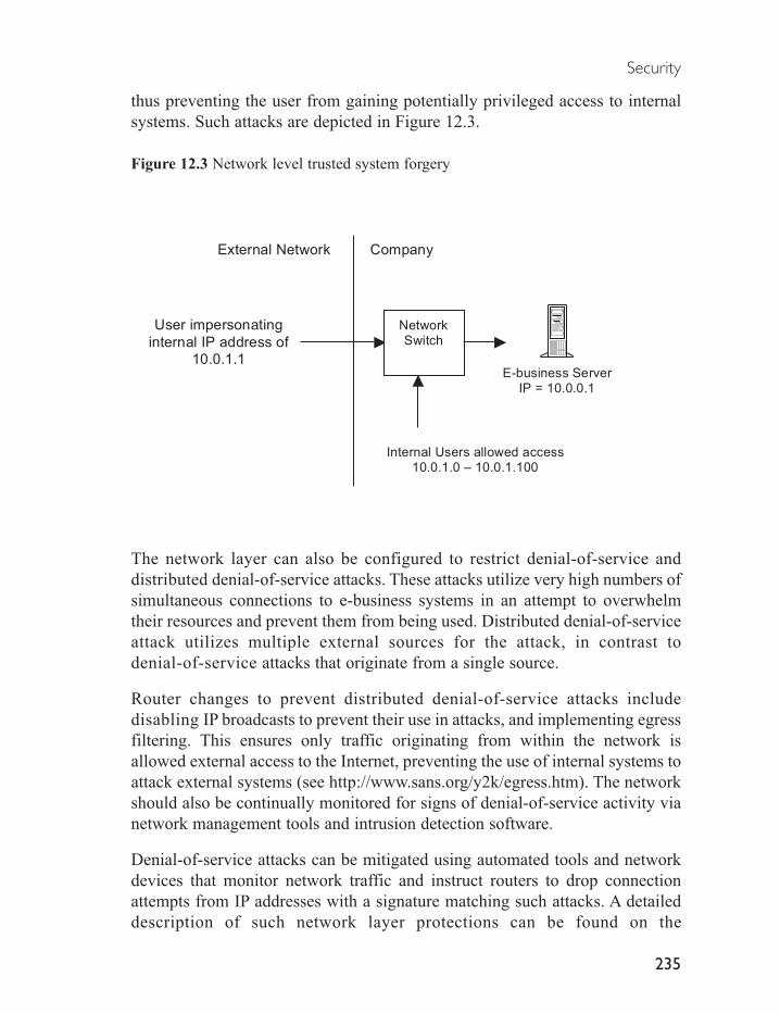
thus preventing the user from gaining potentially privileged access to internalsystems. Such attacks are depicted in Figure 12.3.
Figure 12.3 Network level trusted system forgery
The network layer can also be configured to restrict denial-of-service anddistributed denial-of-service attacks. These attacks utilize very high numbers ofsimultaneous connections to e-business systems in an attempt to overwhelmtheir resources and prevent them from being used. Distributed denial-of-serviceattack utilizes multiple external sources for the attack, in contrast todenial-of-service attacks that originate from a single source.
Router changes to prevent distributed denial-of-service attacks includedisabling IP broadcasts to prevent their use in attacks, and implementing egressfiltering. This ensures only traffic originating from within the network isallowed external access to the Internet, preventing the use of internal systems toattack external systems (see http://www.sans.org/y2k/egress.htm). The networkshould also be continually monitored for signs of denial-of-service activity vianetwork management tools and intrusion detection software.
Denial-of-service attacks can be mitigated using automated tools and networkdevices that monitor network traffic and instruct routers to drop connectionattempts from IP addresses with a signature matching such attacks. A detaileddescription of such network layer protections can be found on the
Security
235
E-business ServerIP = 10.0.0.1
User impersonating
internal IP address of
10.0.1.1
CompanyExternal Network
Internal Users allowed access10.0.1.0 – 10.0.1.100
NetworkSwitch

www.securityfocus.com and www.sans.org security sites.
Firewalls
Firewalls inspect all network traffic according to predefined rules, and permitor deny connections to e-business resources based on these rules. Connectionattempts that fail this inspection are then rejected. This allows firewalls beinterposed between internal and external networks to control access to network,data, and application layer resources.
For example, firewalls are typically deployed between corporate e-businessnetworks and the Internet and allow standard HTTP and HTTPS traffic to ane-commerce server. Insecure protocols, such as telnet or ftp, are then deniedbetween internal and all external networks to preserve security.
Firewalls allow for filtering of traffic to potentially insecure internal systemsand services, and can therefore be used to stop a wide variety of attacks targetingcommonly used and insecure network services, or services that may reveal toomuch internal information to intruders, such as DNS zone transfers.
Firewalls should therefore be configured to deny connection attempts to commonnetwork services. These typically include the time service (37/tcp and 37/udp),TFTP (69/udp), finger (79/tcp), NNTP (119/tcp), NTP (123/tcp), LPD(515/tcp), syslog (514/udp), SNMP (161/tcp and 161/udp, 162/tcp and162/udp), BGP (179/tcp), and SOCKS (1080/tcp).
Potentially ‘revealing’ network traffic that should be blocked includes incomingecho request ICMP traffic and outgoing echo replies, time exceeded, anddestination unreachable messages except for packet too big messages. All UDPpackets sent to non-required UDP ports should be blocked, and all traffic arrivingfrom external networks with private address space addresses (RFC 1918)should also be dropped.
Insecure network services should be blocked by the firewall, as these may haveexploitable security holes. These typically include login services such as telnet(23/tcp), SSH (22/tcp), FTP (21/tcp), NetBIOS (139/tcp), rlogin (512/tcpthrough 514/tcp); RPC and NFS services, NFS (2049/tcp and 2049/udp), andlockd (4045/tcp and 4045/udp). Windows specific network systems are alsoaffected, including NetBIOS in Windows NT and 2000 (tcp and udp 135,
E-business Implementation
236

137/UDP, 138/UDP, and 139/tcp, and Windows 2000 445/tcp and udp). XWindows traffic should be blocked (6000/tcp to 6255/tcp), and DNS namingservices (53/udp) restricted to all machines which are not DNS servers, withDNS zone transfers (53/tcp) disallowed except to external secondary DNSservers.
Other e-business-related services that should be restricted include LightweightDirectory Access Protocol (LDAP) directory services (389/tcp and 389/udp),email services to all systems that are not external mail relays, including SMTP(25/tcp), POP (109/tcp and 110/tcp), and IMAP (143/tcp). Web traffic to publicweb servers should be allowed but denied to all other servers including HTTP(80/tcp) and SSL (443/tcp) traffic.
Firewalls constitute a mission critical element of a company’s network andsecurity infrastructure, and should therefore be subject to strict change control.The firewall rule sets should not be changed on an ad-hoc basis before goingthrough change control procedures to ensure business continuity.
In addition, firewalls should be deployed in a high availability configuration toprovide guaranteed availability. This can be provided through the deploymentof firewalls in a dual redundant firewall cluster configuration, incorporating twofirewalls running in parallel, with each cluster member sharing network trafficinformation. Failure of a single firewall will therefore not compromise thescreening of network traffic as the remaining cluster members will continue tooperate.
Firewall clusters should be deployed in an active/active mode, with each clustermember participating in simultaneous traffic filtering. This provides twice theperformance of a single firewall or of an active/passive standby clusterconfiguration, which utilizes a passive standby firewall ready to take over fromthe failed active firewall. In addition, a high availability deployment configurationshould be utilized to eliminate all points of failure within the cluster.
Additional corporate security can be achieved through deployment of firewallson desktop and laptop computers used by roaming and remote users. Thisprovides protection for mobile computers or home workers when outside thecompany, in the event that an individual attempts to compromise such systemsto obtain access to corporate data.
Remote firewall products should include the ability to be managed remotely
Security
237

through a firewall policy defined by a central management station. This shouldpermit propagation of the policy to all remote computers, and the ability to manageapplications on the remote computers to prevent leakage of unintended information.
In addition, it is recommended that roaming and roving users be issued withvirtual private network software. This permits such users to establish a secureencrypted connection to their office when they need to access office resourcessuch as file servers. This encrypted connection prevents outsiders from decipheringtheir communications and potentially gaining access to critical information.
Although frequently deployed as the primary defence mechanism for companysecurity, firewalls cannot protect networks and systems against many modernattack methods, such as email viruses or application level vulnerabilities.Such firewall-transparent attacks exploit known and newly discovered flaws inapplications, and are not picked up by firewalls as they employfirewall-approved channels to gain access to systems such as HTTP webtraffic or legitimate inbound email traffic. Therefore, additional security layersare required to protect affected systems.
DMZ networks
Additional security is provided by the creation of secured de militarized zone(DMZ) networks. A DMZ is a separate network connected to a corporatefirewall used to host systems requiring external communication such as ane-business server or email gateway.
DMZ network designs are required due to the inability to fully trust e-businessinfrastructure with external access to insecure networks, such as the Internet.These systems will be in contact with unknown and untrusted users, who maycompromise the e-business infrastructure. The DMZ therefore restricts theopportunity for such compromised servers to be used to compromise otherinternal systems.
Wireless network security
Although increasingly popular, wireless networks based on the new 802.11bstandard currently have considerable security holes in the WEP security proto-col employed to secure the connection.
E-business Implementation
238

It is therefore not recommended that such devices be attached to corporatenetworks, as these may result in attackers gaining complete access to internalcorporate networks, and potentially compromising internal systems. Oncewireless security standards improve, all wireless network access points shouldemploy advanced encryption systems to secure network traffic.
12.3.2 Operating system layer security
The second layer in the layered security system is the operating system layer,which consists of a secure deployment of a server and its associated operatingsystem. This requires the ‘hardening’ of all servers within the organization,which removes known security holes in the operating system thus preventingthese being used to compromise the system.
Hardening occurs before a server is first connected to a network and beforeapplication software is installed. It requires that a server operating system beinstalled with a minimal set of critical components and utilities to reduce thelikelihood of installing non-essential components with potential securityweaknesses.
Vendor operating system security patches should then be installed to bring thesystem up to date with all known security holes. Patches should be scanned forviruses then provided on removable media such as CD-ROM for installation onthe server. This ensures the server is not connected to a network and potentiallycompromised until hardening is complete. Application software can then beinstalled following security patching.
As new security holes are discovered in operating systems almost daily, it isrecommended that security patching of previously hardened production serversbe conducted on a periodic basis. This minimizes the risk of compromise to liveservers arising from new security holes discovered since the server waspatched. To minimize potential disruption to live systems, it is recommendedthat new security patches be tested on development servers prior to deploymenton hardened live production servers.
12.3.3 Data layer security
The third layer in the layered security system is the data layer security, which
Security
239

consists of the secure storage of data within databases and secure networks, andthe secure transmission of critical corporate data between networked systems.
Encryption mechanisms utilize software algorithms to scramble human-readabledata into an unreadable form. Encryption is employed to protect sensitiveinformation stored in externally accessible areas, such as credit card informationstored within a transactional e-business server in a DMZ network. This ensuresthat in the case of the server being compromised, the information is unreadable.
Encryption is also used to secure data in transit over insecure networks, such asthe Internet. This is typically provided through the Secure Sockets Layer (SSL)data transport technology. SSL employs an encryption module within thee-business infrastructure, typically on web servers, which is used to encryptcommunication with a user’s browser. This ensures data in transit between theuser and the e-business system cannot be intercepted.
Data layer security is also provided by the deployment of database serversbehind additional firewalls within DMZ networks. This provides an added layerof security in the event that preceding security layers are compromised.
12.3.4 Application layer security
The fourth layer of the layered security system is the application layer security.This layer consists of the creation, deployment and maintenance of applications usingsecurity best practices to minimize the potential for the creation of security holes.
This layer is critically important to e-business security, as the majority ofsecurity breaches now occur within applications behind firewalls. Theseexploits utilize flaws in poorly configured or poorly written applications to sendinvalid input designed to exploit known or suspected weaknesses in theapplication. This typically results in an intruder gaining control over the serverhosting the application, and either changing corporate content such as defacinga public website, or using the server to stage attacks on other systems.
Creation of secure applications requires correct security procedures be designedinto all applications. This typically requires the design of applications to checkinput such as validating user input to prevent the sending of information capableof compromising the application, and designing the application to respectoperating system security settings. It also requires periodic security audits bydevelopers during the development of the application to ensure security
E-business Implementation
240

weaknesses are caught before applications are deployed into live environments.
Secure application development can also be enhanced using developmentlanguages such as Enterprise Java and Microsoft C++ for .Net. These languagesenforce strict controls on application code, preventing many security issuesfrom arising within applications, such as memory buffer overruns.
Application deployment requires applications be installed and configured onservers using operating system accounts with minimal privileges. In addition,deployment of packaged applications requires installation of vendor-suppliedsecurity patches to address known security issues.
Deployed applications can be further secured using operating system securitymechanisms such as Windows Security Policies for Microsoft Windowssystems, or through high security Unix policy-control systems, such as TrustedSolaris. These systems enforce strict controls on the server resources eachapplication is permitted to access, thus ensuring attackers cannot use flaws in oneapplication to compromise other applications or the underlying operating system.
DNS security
Corporate DNS systems form a critical application within all e-businessinitiatives, and necessitate special security measures to ensure continued nameresolution service.
Deploying DNS servers typically opens a company to two potentially serioussecurity risks, including the ‘hijacking’ of DNS information, and compromiseof publicly accessible DNS servers.
Compromises of publicly accessible DNS servers occur through insecureconfiguration of operating systems, and through flaws in DNS software.Hackers/crackers utilize these security weaknesses to compromise the server.Once compromised, a DNS server can be used to launch subsequent attacks oninternal systems, or used to stage attacks on other external systems.
To prevent compromises of DNS servers, the operating system should beconfigured in a secure manner. In addition, for very high security configurationsDNS server software should be deployed on Unix systems in a chroot environment,where access is restricted to a virtual ‘sandbox’, protecting the underlyingoperating system in case of compromise of the DNS software. This deploymentcan be found in the BIND v9 Administrator Reference Manual for a discussion
Security
241

of this option.
Hijacking of DNS information occurs through a hacker/cracker gaining accessto DNS information and altering it to point to other resources. This constitutesa form of denial-of-service attack, as it denies access to corporate resources forinternal and external users. This may result in lost business and considerabletime spent rectifying the hijacking. Hijacking of DNS systems typically occursif a cracker is able to exploit flaws in DNS server configuration, such asallowing dynamic updates from untrusted sources, to redirect DNS requests toanother DNS server.
Hijacking of DNS systems can be mitigated through the deployment ofsplit-level DNS designs to reduce the availability of critical DNS informationof use to a cracker. Split-level DNS partitions a corporate name space into publicand private sections, hiding sensitive internal DNS information from externalusers. A subset of public DNS information is then provided to external usersthrough separate, externally visible DNS servers within the DMZ network, andchanges to the DNS server configuration files (see the section ‘DNS serverconfiguration’), as depicted in Figure 12.4.
Figure 12.4 Split-level DNS
E-business Implementation
242
Company.com
E-business server
Mail relay serverWeb server
Company.com
DMZ systems:
E-business server
Mail server
Web server
Email servers:
Email1
Email2
Internal systems:
File/print server
Email servers
Database server
User request
for public
DNSinformation
Internet DMZ DNS Server Internal DNS Server
Internal user request for
internal DNS information

Provision of email delivery from the Internet to internal email systems alsorequires the use of split-level DNS to provide DNS security. Email is typicallydelivered to a central email relay server on the DMZ network, and then routedto different internal email delivery servers. If the public DMZ DNS serverscontained entries for these internal email servers, this sensitive informationcould potentially be exposed to untrusted external individuals.
Additional security precautions for DNS systems include restricting zone transfers,to prevent the widespread release of important information, as it may be used insubsequent attacks, and to deploy access control lists. In addition, dynamicupdating of DNS information should not be permitted for critical systems usingstatic addresses, such as e-business servers. All dynamic updates should besecured with digital certificate signing of all update requests, and externalaccess should be disallowed for updates to records.
Access control lists (ACLs) are used to regulate access to specific DNS records,allowing for fine-grained control over the security of records. Typical optionsinclude the ability to restrict access to individual records based on the networkof the originating request, or even specific IP addresses. This feature is criticalfor supporting split-level DNS configurations utilized in high security DNS andDMZ designs. Support for ACLs should also include the ability to restrict zonetransfers, which are used to update zone files held by secondary DNS servers.
12.3.5 Access control mechanisms
In addition to the four layers described above, all security systems shouldimplement industry standard directory-service mechanisms for access control.Access control is the process of validating the identity of users against a directoryservice before granting them access to regulated resources. This reducessecurity risks by ensuring only approved users can utilize corporate e-businessresources.
The current standard for user directory services for e-business systems is theLightweight Directory Access Protocol (LDAP). LDAP directory systems storeuser credentials in a high performance server, and accept and respond tostandard LDAP queries issued by e-business applications. This provides acompany with a centralized, standards-based user authentication system.Corporate e-business applications can then query this system to determine theidentity of users requesting connections to resources. Approved users are granted
Security
243
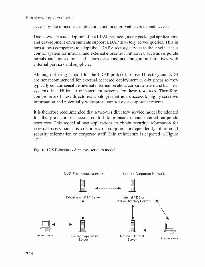
access by the e-business application, and unapproved users denied access.
Due to widespread adoption of the LDAP protocol, many packaged applicationsand development environments support LDAP directory server queries. This inturn allows companies to adopt the LDAP directory service as the single accesscontrol system for internal and external e-business initiatives, such as corporateportals and transactional e-business systems, and integration initiatives withexternal partners and suppliers.
Although offering support for the LDAP protocol, Active Directory and NDSare not recommended for external accessed deployment in e-business as theytypically contain sensitive internal information about corporate users and businesssystems, in addition to management systems for these resources. Therefore,compromise of these directories would give intruders access to highly sensitiveinformation and potentially widespread control over corporate systems.
It is therefore recommended that a two-tier directory service model be adoptedfor the provision of access control to e-business and internal corporateresources. This model allows applications to obtain security information forexternal users, such as customers or suppliers, independently of internalsecurity information on corporate staff. This architecture is depicted in Figure12.5.
Figure 12.5 E-business directory services model
E-business Implementation
244
DMZ E-business Network Internal Corporate Network
E-business LDAP Server Internal NDS orActive Directory Server
External usersInternal users
Internal File/PrintServer
E-business ApplicationServer

In this model, an internal user attempts to access a document stored within a file andprint server. When they first log on to their computer the NDS or Active DirectoryServer validates their credentials and returns them a security token appropriateto their level of access. They are then free to access the desired resource, beingvalidated using this token each time they access other resources. In contrast, anexternal user connects to the e-business application in the DMZ network. Whenthey connect to the secured resource the application queries them for theirsecurity credentials, then validates these against the user database held in theLDAP server. Access to resources appropriate to their privileges is then granted.
In addition to providing access control to external users, this model can also beextended to provide access control for partners and suppliers in externalintegration initiatives. For example, integration of a business process integrationbroker system with an LDAP directory server would provide a centralizedrepository of user information allowing the broker to regulate external supplieraccess to internal corporate systems participating in the integration initiative.
Finally, this model may also be deployed to enhance other security layers.Network-level firewall security can utilize LDAP directory services to validatethe identity of corporate users accessing internal networks and resources viavirtual private network connections while roaming outside the company. Datalevel security can also be enhanced through LDAP. Database servers can beconfigured to query LDAP directory servers to obtain user credentials beforegranting controlled access to secure data.
Public key infrastructures
A public key infrastructure (PKI) provides a highly secure form of access controlthrough the issuing of digital certificates to participating users, which containencrypted information unique to each user. This allows the PKI system tovalidate user identity with a very high level of certainty.
The security provided by a PKI system exceeds that of other user authenticationand verification schemes, and is typically utilized in situations where it is criticalto validate identity with a high degree of certainty. For example, PKI may bedeployed to provide secure access to a valued trading partner in a dynamice-business initiative, and ensure the correct entity is accessing business-criticalinternal systems such as enterprise resource planning applications.
The PKI architecture consists of three core components designed to control the issue,
Security
245

management and destruction of digital certificates. These components includethe certificate authority (CA) for creating and digitally signing certificates, theregistration authority (RA) for issuing certificates requested by users (to besigned by the CA), and the validation authority (VA) for verification of certificatespresented by users. The VA also revokes certificates if they are no longer valid.
A certificate authority is considered the ‘root authority’ for a company, which is thesingle originating source of authority for the creation and signing of certificates within thecorporate PKI system. The CAis typically maintained within a highly secured environment,and delegates the right to issue individual certificates to the registration authority.
The registration authority receives requests for digital certificates from usersand applications, and then grants or denies these according to specific policiesdeployed within the server. Registration authority policies may also include theoption of manual intervention for a staff member to perform identity checks onthe user requesting the certificate, such as checks on credit criminal records.
The registration authority can issue digital certificates to a user’s browser or viaemail software to customers and suppliers, permitting the use of highly secureemail and Internet access to e-business applications. When these userssubsequently send email, or connect to secured web pages, the certificate theypresent guarantees their identity and thus validates their email as originatingfrom them or permits them access to secured web pages or resources.
The validation authority is responsible for verifying a certificate presented by auser or application. In the event that the CA has revoked the certificate, the VAwill reject it. Expiry of a certificate can occur via a manual process, or auto-matically, for example by specifying a total lifetime for the certificate.
Although providing the highest security for authentication and authorization ofcustomers, partners and suppliers connecting to corporate e-business systems,PKI implementations suffer from a number of problems. These include high expense,poor support for client systems, and lack of interoperability between different PKIvendors. This typically restricts PKI implementations to specific vertical uses, suchas integration between well-established trading partners or providing secure documentaudit trails within regulated industries such as the pharmaceutical industry.
12.3.6 Security auditing and monitoring
Corporate security systems must also implement continual auditing of all systemsto determine if they remain secure. Security auditing is an ongoing process, and
E-business Implementation
246

involves deployment and use of intrusion detection, server auditing, andmonitoring systems across the four security layers.
Typically, intrusion detection systems consist of servers and network sensorsrunning software providing network and host-level protection. Network protectionconsists of a server listening to network traffic for activity that matches knownpatterns representing a security threat. In the event that a threat is detected theintrusion detection system notifies the appropriate staff member via email orpager, and may block the suspicious activity. Host-level protection incorporatessoftware agents installed onto servers to monitor attempts to modify andcompromise the server.
However, the detection of attacks using network and host-level intrusion detectionproducts is currently limited due to their tendency to frequently report securitythreats that do not exist. Such ‘false positives’ may consume considerableresources as staff attempt to respond to each perceived threat. This can bepartially alleviated through deployment and extensive tuning of multiple intrusiondetection systems, permitting cross-correlation of false positives. In addition,many intrusion detection tools are frequently overwhelmed by large volumes ofnetwork traffic, and suffer from poor reporting and management features.
The design of network and host-level intrusion detection products also oftenrenders them unable to respond to newly emerged threats. Such products typicallyincorporate a database of security threats, and respond by matching networktraffic to these ‘signatures’. Therefore, vendors must continually update theirproducts as new security threats are discovered, which lag the latest attacks.This in turn requires companies dedicate resources to tracking the latest securitythreats on a daily basis to respond accordingly to preserve corporate security.
Emerging forms of intrusion detection systems are now addressing theselimitations, through mechanisms such as anomaly detection and security eventaggregation and correlation tools. Anomaly detection tools construct a baselineof network behaviour, and compare current activity to this baseline to determineif an attack is in progress. However, this system depends on having a predictableand well-understood network, which may not be possible. Security eventaggregation tools rely on real-time data and log analysis correlated to networklevel events to determine the status of network and resource accesses.
Static auditing employs tools either installed on each server or running across anetwork, to periodically scan all servers for newly discovered operating systemsecurity holes. Such products run tests based on an internal database of all
Security
247

known security holes. If a security hole is detected, the operating systemvendor can be contacted to supply the required security patch.
A variation on static auditing utilizes software such as the Tripwire product toensure that the operating system of each server is maintained in a known state.Following installation and hardening of the server operating system andapplication software, the static auditing tool is run on the server, producing abaseline configuration that can be compared to later runs to determine if theserver has been modified. Signature files generated by such tools should besecurely stored off-site, and periodically compared to the actual configurationof the server. This ensures that if an intruder has altered the operating system tocompromise the server, their changes can be detected.
Security monitoring requires security staff analyse log files output by thesystems within each security layer to determine if users of applications haveviolated corporate security policies. This requires monitoring of firewall logs,application access control logs, and intrusion detection and auditing systemlogs. In addition, all security policies and procedures should be continuallyreassessing to cope with changes within the business.
Monitoring also requires attention to vendor security notifications andsubscription to online security notification sites, to ensure awareness of currentsecurity threats. For example, the Security Focus website (www.securityfocus.com)provides an online database of current and past security exploits, with theoption to subscribe to regular security alert updates. The SANS website(www.sans.org) also provides a list of the top 20 security vulnerabilities, basedon the most commonly reported security exploits.
In the event that a security threat is discovered, responses should follow the policiesand procedures detailed in the security policy. Typically, responses to securityalerts will follow six phases, including Preparation, Identification, Containment,Eradication, Recovery and Follow-up, and these should be documented in thecorporate security policy. In addition, companies may provide an emergency actionchecklist for staff, with a simple set of steps to follow in case of security alerts.
Such checklists typically suggest noting the nature of an attack then notifyingthe correct staff members, using alternative and non-compromised communicationmethods such as telephone or fax. The problem should then be containedthrough steps such as disconnecting affected systems from the network, and theaffected systems backed-up. The cause of the problem should be removed ifpossible, such as a removing viruses or Trojans, and affected systems restoredto bring the business back up as soon as possible.
E-business Implementation
248

12.4 High-level designs of security systems
Two sets of high-level designs for e-business security systems are depicted inFigure 12.6, covering secure DMZ network design issues, and a comprehensivedesign featuring the systems and services offered within the layered securitysystem.
High-level design for secure dmz networks
High-level designs of secure DMZ e-business networks provide securednetworks for e-business systems separated from the Internet and corporate networksby firewalls and screening routers.
A typical secured DMZ network design is depicted in Figure 12.6.
Figure 12.6 DMZ network design
Security
249
Internal Corporate Network
Internet
Content Managementserver
Internal users
ERP server
Secondary DNS serverPrimary DNS serverPortal server
Content Repositoryserver
Firewall
Internet users
User requests to DMZ resources permitted
Attempted internal access blocked at DMZ boundary
DMZ NetworkScreening router

In this design, the screening router and firewall restrict user requests originatingfrom the Internet, and ensure they are only granted access to the e-businessservers located within the DMZ network. Servers on the DMZ are in turnphysically separated from other servers and users on the internal corporate network.All user requests to critical internal resources are blocked at the DMZ networkboundary.
Corporate networks frequently deploy more than one DMZ in order to provideenhanced security for critical internal systems, as depicted in Figure 12.7.
Figure 12.7 Additional DMZ network configuration
E-business Implementation
250
Internal e-businessserver
Secure Databaseserver Internal DMZ Network
Internal Corporate Network
Internet
Content Managementserver
Internal users
ERP server
Secondary DNS serverPrimary DNS serverPortal server
Content Repositoryserver
Firewall
Internet users
User requests to DMZ resources permitted
Attempted internal access blocked at DMZ boundary
DMZ NetworkScreening router

In this configuration, an additional internal DMZ network has been created tohost a secure e-business server and database used for internal purposes. As theinformation on these systems is highly sensitive, these servers are isolated frominternal access from unauthorized users.
Additional DMZ networks are also frequently required for connections to externalpartner and supplier networks for purposes such as external e-business systemsintegration initiatives.
Although partners and suppliers are frequently trusted entities, and may havelong-term trading relationships, it is often not possible to ensure complete securitywith such external parties. For example, it may not be possible to conduct acomplete audit of the partner and supplier security systems to determine levelsof potential security risk. These risks may include having unprotected externalconnections, insecure connections to other unknown third parties, or havingbeen breached by hackers/crackers and potential compromises such as Trojansoftware installed without the knowledge of the partner or supplier.
It is therefore necessary to minimize the risk associated with connecting to partnersand suppliers by restricting the possible access they have to internal corporatesystems, as depicted in Figure 12.8.
Figure 12.8 External partner and supplier DMZ
Security
251
Internal Network
Internet
Internal users
ERP server
Integration server
Supplier DMZ NetworkCompany DMZ Network
Integration server
Firewall
Screening router
Secure Database server
Internal users
Internal Network
Internet customers
Shared DMZ
ExtranetNetwork

In this example, an integration server located in the DMZ network of asupplier connects to the integration server located within the company’s DMZ.Both servers are connected through a common shared DMZ Extranet networkdedicated to secured, private connections for partner and supplier companies.
Comprehensive high-level security design
Comprehensive high-level security designs should employ the full range oflayered security systems described above. These include the use of secured DMZnetwork zones, deployment of network access control devices betweennetworks, deployment of network monitoring devices at strategic points, useof access control mechanisms, use of hardened servers, and data andapplication-level security systems.
The following high-level security design depicts a transactional e-businesssystem consisting of an e-business web server farm in a secured DMZ with anSSL accelerator and load-balancing switch.
Additional DMZ networks are provided for VPN connections to external thirdparties, an internal DMZ for e-business application and LDAP directoryservers, a database server DMZ for secure data storage, and a corporate PKIDMZ for secured control of a Certificate Authority.
Additional security features include the use of multiple intrusion detectionservers and network sensors, a split-level DNS system, a two-tier directoryservice design with an internal corporate directory server and an internal DMZLDAP server, a split-level DNS system, and hardening of all servers.
An internal PKI system is also deployed to supply certificates used by theLDAP server, application server and firewalls to authenticate and authorizeexternal trading partners and suppliers connected across the VPN connection.
The use of these combined security features is depicted in Figure 12.9.
E-business Implementation
252

Figure 12.9 High-level design of security systems
12.5 Vendors of security solutions
Table 12.1 lists vendors of products used in enterprise security systems. It shouldbe noted that this list is not exhaustive and should be used as a guide only before
Security
253
Internal Network
DMZ (De Militarized Zone)
Internet
Firewall
E-business WebServer farm
E-business ApplicationServer A
Internet users
E-business ApplicationServer B
Internal NDS or ActiveDirectory Server
E-business LDAPServer
Certificate
Authority
Internal ValidationAuthority Server
Internal RegistrationAuthority Server
Intrusion Detection
Server
Intrusion DetectionSensor
Internal DMZ
PKI CA DMZ
Corporate File
and PrintServer
External partners
and suppliers
Intrusion
DetectionSensor
Primary and SecondaryInternal DNS Servers
Primary and Secondary
DMZ DNS Servers
Intrusion
DetectionSensor Internal users
Storage servercluster
Database DMZ

solution research is undertaken.
Table12.1 Vendors of security solutions
Vendor Security solution
Security PoliciesISO ISO17799Denial-of-serviceRadware Fireproof 2.2 with SynApps softwareTop Layer Networks AppSwitch & AppSafeMazu Networks TrafficMaster EnforcerCorporate firewallsCisco PIX range (e.g. PIX 535)CheckPoint Firewall 1 and CheckPoint NGEagle Systems RaptorLucent Technologies VPN Firewall BrickNetScreen Technologies NetScreen-1000Nokia IP 51-740 rangeNortel Contivity 600 and Optivity NCSSonicWall SonicWall Pro-VXWatchguard Technologies Firebox 1000Roaming/roving firewallsInfoExpress CyberArmor SuiteSygate Technologies Secure Enterprise and Management ServerHost intrusion detection systemsSymantec Corporation Intruder AlertInternet Security Systems (ISS) RealSecureCyberSafe Corporations CentraxNetwork intrusion detection systemsCisco Systems Secure IDSInternet Security Systems BlackICEEnterasys Networks DragonOpen Source SNORTStatic monitoring and assessment toolsTripwire TripWireOpen Source Nessus Security ScannerOpen Source WhiskerOpen Source SnortInternet Security Systems Real Secure
E-business Implementation
254
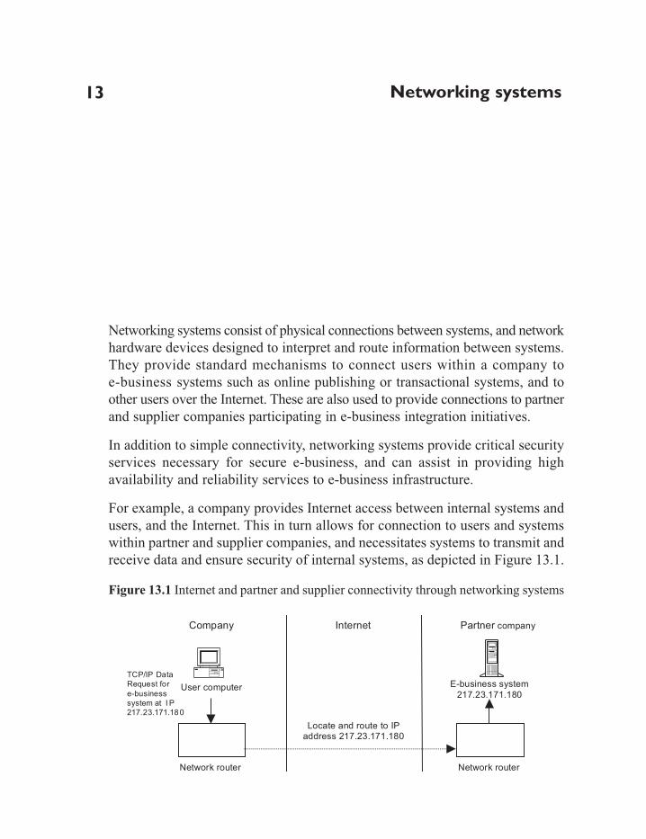
Networking systems
Networking systems consist of physical connections between systems, and networkhardware devices designed to interpret and route information between systems.They provide standard mechanisms to connect users within a company toe-business systems such as online publishing or transactional systems, and toother users over the Internet. These are also used to provide connections to partnerand supplier companies participating in e-business integration initiatives.
In addition to simple connectivity, networking systems provide critical securityservices necessary for secure e-business, and can assist in providing highavailability and reliability services to e-business infrastructure.
For example, a company provides Internet access between internal systems andusers, and the Internet. This in turn allows for connection to users and systemswithin partner and supplier companies, and necessitates systems to transmit andreceive data and ensure security of internal systems, as depicted in Figure 13.1.
Figure 13.1 Internet and partner and supplier connectivity through networking systems
13
E-business system
217.23.171.180
Company Partner companyInternet
Network router
User computer
TCP/IP Data
Request for
e-business
system at I P
217.23.171.180
Network router
Locate and route to IPaddress 217.23.171.180

In this example, a user sends a request for a resource located on an e-businesssystem in a partner company with the IP address of 217.23.171.180. The request isconveyed to the company router, a device dedicated to sending such requests to thecorrect destination. The router forwards the request across the Internet to nearbyrouters that are physically closer to the destination. Eventually the information is atthe partner company router, which then forwards the request to the e-business system.
13.1 Key technologies used
The Network layer utilizes three core technologies to transport data, includingtransport protocols to encode and transport data, addressing schemes built usingthese protocols for identification of systems, and specialist hardware devices toroute data between source and destination addresses.
The information technology industry has standardized around the TCP/IP protocolto provide data transport functionality for networking systems. TCP/IP providesfor reliable delivery of data across Intranets and the public Internet, and utilizesthe IP protocol to assign unique addresses to each connecting system.
Each networked system is identified through a unique IP address and subnetmask. These are allocated by an external Internet connectivity provider, andboth IP address and subnet mask consist of a group of four numbers between 0and 255 separated by full stops, such as 198.45.78.3. The IP address is used toidentify servers and clients across the Internet, while the subnet mask is used toidentify the network the server or client is located on.
To further simplify routing, networks are divided into classes according to thesubnet mask. These classes include Class A, B and C, with the subnet mask in turndetermining the number of available IP addresses within the block. The Class Aaddress block is denoted by a subnet mask of 255.0.0.0 and permits 126 networkswith 16, 777, 214 addresses. The Class B address block is denoted by a subnetmask of 255.255.0.0 and permits 16, 383 networks of 65, 534 addresses. A ClassC address block is denoted by a subnet mask of 255.255.255.0 and permits 2, 097,150 networks of 255 addresses. Example addresses are depicted in Table 13.1.
Table 13.1 IP address classes
Class IP address Subnet mask
A 10.10.34.5 255.0.0.0B 157.23.70.200 255.255.0.0C 217.23.171.80 255.255.255.0
E-business Implementation
256

However, as the total number of available IP addresses is constrained, IPaddresses are often allocated in blocks smaller than the Class C group with subnetmasks such as 255.255.255.240. This ensures wastage of IP addresses isminimized by only giving companies the addresses they need.
13.2 The corporate IP address allocation scheme
IP addresses are issued to networked systems through Dynamic HostConfiguration Protocol (DHCP) servers, or manually by modifying operatingsystem network properties. However, before allocating addresses companiesmust determine how their address space will be used for different corporatesystems, users and office locations.
An IP address allocation scheme is designed to allow a company to efficiently allocatethe finite number of addresses they have been issued between resources, users andlocations. This allows a company to conserve available IP addresses and ensure thatsystems are allocated unique addresses to prevent network address conflicts.
A corporate IP Address Allocation Scheme consists of static and dynamicaddresses. Static addresses are used for commonly accessed resources such asservers and printers, which will typically not change location. Dynamicaddresses are used for transient systems, such as desktop client systems andnotebooks, which do not typically provide networked services to other systemsor users such as serving web pages.
Dynamic addresses are allocated to conserve addresses and simplify IP addressmanagement. For example, desktop systems are constantly being added andremoved within companies as employees shift department or building, movejobs, or are absent on business. If such systems used fixed addresses, a companywould incur a considerable management overhead tracking addresses in use andallocating unused addresses to other systems.
An allocation scheme can use either public Class A, B or C addresses, or the privateaddresses, known as the RFC 1918 private address scheme. This scheme, a specialform of Class A address, was designed for use within companies and is thereforenot routed across the Internet. IP addresses within the private address space runfrom 10.0.0.0 to 10.255.255.255, providing 16, 777, 214 available addresses.
Although recommended for internal use, the RFC 1918 private address space isnot routed across the Internet, and therefore cannot be used for systems directly
Networking systems
257

accessible from the Internet, such as e-business servers.
Use of private addresses on such public systems therefore requires a companyto deploy either network address translation, to ‘translate’ internal addressesinto public addresses (typically via a firewall or router), or use separate privateinternal and public DMZ networks, as depicted in Figure 13.2.
Figure 13.2 Public and private address schemes
In this example, a Class C IP address has been allocated to the DMZ e-businesssystem. Alternatively, a large organization such as a university or globalcorporation may utilize a Class B address for this system.
An allocation scheme based on the RFC 1918 private address space allows forthe creation of a very large and flexible scheme by providing a single network(10.x.x.x) consisting of 16, 777, 214 (256*256*256 minus 2 reserved addresses)possible addresses, ranging from 10.0.0.1 to 10.255.255.254.
The flexibility of this scheme arises from the ability to partition this range
E-business Implementation
258
External E-business systemIP = 217.23.45.161
Internal UsersIP = 10.10.0.1 – 10.10.255.255
Internal E-business systemIP = 10.0.20.10
Internal Private Network
Class A RFC 1918 scheme
Publicly accessible DMZ Network
Class C public address
Public Internet

according to the requirements of the company. Using a different subnet maskallows for the creation of more networks with fewer addresses per network. Forexample, using a Class B subnet mask of 255.255.0.0 divides the RFC 1918space into 256 different networks each containing 65, 534 addresses. Similarly, aClass C subnet mask of 255.255.255.0 allows for 65, 536 networks consisting of254 hosts in each network. This division of addresses is depicted in Table 13.2.
Table 13.2 Possible class B and C subnet masks
Item Class B subnet Class C subnet
IP address 10.x.0.0 10.x.x.0Networks available 10.1.0.0– 10.255.0.0 10.0.1.0– 10.255.0.0Hosts available per network 10.1.0.1– 10.1.255.254 10.0.1.1– 10.0.1.254Note: X denotes an arbitrary number from 0 to 255.
Creating an IP address allocation scheme requires determination of the numberof fixed and dynamic resources and their distribution across physical locationssuch as buildings, floors, or cities. The number of physical locations will determinethe number of networks, and the required numbers of addresses determined bythe number of resources in each location.
For example, Table 13.3 depicts a medium sized company with four divisionsspread across four physical locations, with different numbers of static anddynamic resources in each area.
Table 13.3 IP allocation example of company resources
Division Marketing Sales Manufacturing Head officeDynamic resourcesNumber of users 20 100 3000 200Total 20 100 3000 200Static resourcesNumber of servers 1 5 30 10Number of printers 2 2 10 5Other systems 1 2 20 1Total 4 9 60 16
In this example, the company has four locations with between 20 and 3000 dynamicresources, and between 4 and 60 static resources. Possible address allocation
Networking systems
259

schemes include a Class C scheme, with 254 hosts per network and 65, 536networks, or a Class B scheme with 65, 534 hosts per network and 256 networks.
The 3000 dynamic resources in the manufacturing office exceed the limits of a singleClass C network of 255 devices. Selection of a Class B scheme allows for theallocation of 65, 534 possible addresses, sufficient to meet the current numberof users and any foreseeable future growth. If additional branches or divisions withinexisting offices are created, a further 252 networks are available for growth.
Once the allocation scheme address class has been determined, available addressesmust be allocated between dynamic and static hosts. This ensures that addressesreserved for static hosts will not be issued to dynamic hosts via DHCP servers.
In this example, each Class B address has 65, 534 available addresses, of which60 static addresses and 3000 dynamic addresses are required in the manufacturingplant. Allocating 1024 fixed addresses (4*256) would permit substantial futuregrowth in fixed addresses for this network while still preserving more than64, 000 addresses for growth in dynamic hosts.
The allocation scheme would therefore resemble that depicted in Table 13.4.
Table 13.4 Example IP addresses allocation scheme
Division Static range Dynamic
Marketing 10.0.0.1-10.0.3.255 10.0.4.0-10.0.255.255Sales 10.10.0.1-10.10.3.255 10.10.4.0-10.10.255.255Manufacturing 10.20.0.1-10.10.3.255 10.20.4.0-10.20.255.255Head office 10.30.0.1-10.10.3.255 10.30.4.0-10.30.255.255
13.3 Network hardware
Specialized hardware devices are used to route TCP/IP data, or packets,between source and destination systems. The most common devices includerouters, switches and hubs.
Routers consist of intelligent devices used to connect networks of systems withdifferent addresses together. Routers utilize sophisticated algorithms to determinethe optimal path for TCP/IP packets to reach their destination based on knowledgeof the addresses in use within adjacent connected networks.
E-business Implementation
260

Switches are used internally within corporate networks to transfer packets pointto point between local systems at very high speed through dedicated channels.In contrast, hubs employ a shared local connection between multiple systems.This may result in congestion due to the shared nature of all connections.
Other network devices include firewall systems and DMZ networks to providenetwork security, and specialist e-business devices such as load balancers andSSL accelerators to provide enhanced e-business facilities.
Firewalls provide a mechanism to tightly regulate the flow of information within acompany, while DMZ networks are subnetworks separated from main corporatenetworks for the purposes of isolating systems exposed to external contact. This ensuresthat compromises to such systems do not result in direct access to critical internal resources.
Load balancers are used to aggregate multiple servers into a single virtual server bydistributing requests to a ‘virtual’address to multiple back-end servers. This allowsa group of servers to provide increased levels of performance and availability, asfailure of one or more servers will not affect the total functioning of the solution.
SSL accelerators are utilized to increase the performance of SSL encryption anddecryption for sites with high volumes of secured traffic.
13.4 High-level designs for networking systems
Companies employing e-business systems typically require specialist networkdesigns to ensure the security and high scalability and availability of theire-business applications. These designs are discussed below.
SSL accelerated networks
Specialist network devices are frequently deployed to enhance the performanceof e-business security systems. For example, network devices can be used toincrease the speed of secure services running over the network, such as SSLencryption for communications between users and e-business servers.
Such network devices are known as hardware SSL accelerators. These devicesoff-load processing of SSL connection encryption and decryption frome-business web servers. SSL accelerators use custom designed hardwareoptimized for SSL calculations and offer performance several orders ofmagnitude faster than web server processes SSL. This in turn frees the webserver hardware for more efficient processing of user requests.
Networking systems
261

Hardware SSL accelerators are available as network devices (sometimesincorporated into switches) or as hardware accelerator cards added to servers.Network switches provide an excellent mechanism suitable for offloading SSLprocessing from multiple servers. However, network switch-based SSLaccelerators render the decrypted traffic visible within internal DMZ network,and thus subject potentially sensitive information to interception if the internalnetwork has been compromised. In contrast, hardware accelerator cards withinservers can provide additional performance, as well as offering greater security,as all decrypted information is retained within the server.
When utilizing hardware SSL accelerators, the resulting network infrastructuremay resemble that depicted in Figure 13.3.
Figure 13.3 Hardware SSL accelerated network design
E-business Implementation
262
DMZ (De Militarized Zone)
Internet
Firewall
E-business ApplicationServers
Internet users
Load balancing switches
Web Server Cluster
SSL accelerator
Internal Network
Web Server Cluster
Screening router
Storage server cluster

High availability network design
Network systems provide business critical connectivity to e-business applications.Failure of individual components within the network can therefore render thee-business infrastructure unable to serve customers or internal users and systems.It is therefore recommended that a corporate e-business network be configuredto support continual availability for e-business systems.
Standard techniques for e-business network high availability focus on theelimination of all single points of failure. These can occur through failures incabling, failure of network devices such as switches and routers, failure ofnetwork cards within servers, and failure of complete servers.
The diagram depicted in Figure 13.4 depicts a design with no single points of failure.
Figure 13.4 High-availability e-business infrastructure design
Networking systems
263
Load-balancing switches (active/active)
Redundant routers and dual Internet feeds
DMZ (DeMilitarised Zone) Firewall cluster (active/active)
Storage server clusterE-business Application
Server Cluster
Load balancing switches (active/active)
Web Server Cluster
Load balancing switches (active/active)
Load balancing switches(active/active)
Internet
Internal Network

Using this design, single points of failure are eliminated using multiple redundantsystems within each network layer. The network connections into the infrastructureare deployed in a redundant configuration using two routers and a second connectionto the Internet. Each router has two connections into the telecommunicationsprovider to allow for failure of a cable. If either router fails, the remaining routerreconfigures the network routes through its connections to provide continualavailability of connectivity.
The routers are in turn connected to an active/active load-balancing switch cluster,which is connected to the firewall cluster. Each router and firewall has twoconnections to each active/active switch. Thus, if a cable or network port failson one switch, the connection to the other switch will continue to function. Bothswitches are linked together, and in the event that a switch fails, the remainingswitch will still function and continue to switch the traffic of the failed switch.
Behind the firewalls are a set of load-balancing switches designed to directnetwork requests to an array of web servers, called a server farm or web cluster.These switches also function in active/active mode to eliminate failures asdiscussed above. This configuration provides higher performance by balancingtraffic among the web cluster member servers, preventing the failure of anindividual server from affecting the complete e-business service. In addition,cross-connecting systems in this manner eliminate failures of network cards,cabling, switches, firewalls, and network ports.
Load-balancing switches are also known as content switches. They representthe web-farm as a single IP address, and intercept requests from users to thisaddress to direct them to the available servers. They perform periodic diagnosticson the servers to determine if they are still available, and how heavily loadedthey are, and then dynamically redirect traffic to the most appropriate server.
Content switches should support fail-over via serial connection, for nearlyinstantaneous recovery from failure, or network-level fail-over, using thenetwork to detect failure of the redundant switch. Network-level fail-over isslower, but allows the switches to be used in global load-balancing configurations.Switches should also offer fail-over support for user connections, so thatconnection information is not lost as the backup switch assumes control.
It should be noted that the functions provided by switches positioned on eachside of the firewall can be amalgamated into one layer using VLAN technology(virtual LANs). This feature allows each switch to segment traffic into two ormore virtual LANs, providing multiple virtual switches in one physical device.
E-business Implementation
264

Behind the web server farm layer, another two active/active switches provideconnectivity to two or more e-business application servers, which arethemselves connected by active/active switches to the database cluster at theback-end. Similarly, if VLAN capable switches are used, this additional switchinglayer can be amalgamated into one set of devices. Load-balancing switches maynot be required in these layers if the application servers are configured as a singlecluster image. This feature, present in many J2EE application serverimplementations, deploys Java components across multiple application servers.Requests to these components are dynamically load balanced by applicationserver code, removing the need for front-end load-balancing switches.
The database cluster in the back-end utilizes database and operating systemclustering to present the multiple cluster servers as a single system image withvery high availability. Additional storage options such as storage area networks(SANs) should be investigated for very high levels of storage.
Global load balancing
Although eliminating points of failure within the e-business infrastructure inFigure 13.4, this design retains the geographical location of the infrastructure asa single point of failure. Loss of connectivity at that location through acatastrophic event such as bomb damage, or accidents such as the severing ofa major telecommunications cable, can render e-business sites unavailable forprolonged periods.
Full uptime requires the deployment of global load balancing configurations.These designs use an additional copy of the e-business infrastructure, physicallylocated at a different site, often in another country. If one site fails, the site atthe other location will continue to function, preserving e-business continuity.
Global server load-balancing configurations can also be deployed across countries forenhanced performance. Using this option, an e-business site may be duplicatedat datacentres in the US and the UK. Connections to the site from Europe wouldbe routed to the UK site, and requests from the Pacific Rim and Americas wouldbe routed to the US site. Load balancing in this fashion ensures that e-businessresources are located closer to users within broad geographical areas, ensuringconnections do not have to pass through congested long-distance Internet links.
This design utilizes intelligent content-aware switches, known as Layer 4 – 7switches, to achieve global load balancing. Redundant switches located at each
Networking systems
265

infrastructure location are configured to act as primary and secondary DNSservers for their e-business sites.
As each switch receives user requests for the IP address of an e-commerceresource, the switch determines their original location by reading their IPaddress and comparing it to global IP address allocations. If the address is closerto that set of infrastructure it will return the local IP address for the resource.However, if the request originated closer to the other set of infrastructure, theswitch will respond with the remote site IP address, thus diverting the user tothe closer resources. Each site monitors the other so that if one becomesunavailable, the opposite site will handle all requests.
High-level remote access designs
Remote access to corporate resources as well as the Internet may be required forusers who work from home, or alternatively for users who travel with theircomputer. This presents additional security issues with corporate networkdesigns, which must be addressed in order to ensure security for e-business systems.
Remote access technologies use dial-up access to networked modems locatedwithin the corporate network, virtual private networks over the Internet, ordedicated private networks supplied by third-party providers such astelecommunications providers. These forms of connections are typically restrictedto authenticated users via firewall technology or access control systems such asSecure ID, which require users to present an electronic token to authenticatebefore being given access.
When designing networks for remote access, similar principles for connectionsto external partner and supplier networks must be used, as it is not always possibleto guarantee the integrity and security of such remote connections.
Therefore, it is recommended that connections to these remote workers besecured via virtual private network (VPN) technology. A VPN encryptscommunications between parties to ensure the security of information in transit,and can utilize hardware or software VPN solutions.
Software VPN solutions utilize encryption and decryption services providedthrough an application deployed on a server. This typically takes the form offirewall-based software VPNs, for simplified management. Software VPN
E-business Implementation
266

solutions are typically deployed for small numbers of remote users, as theseprovide a low cost entry into VPN technology.
In contrast, hardware VPNs may be used in place of software solutions for largenumbers of remote users, as many simultaneous connections can overwhelmsoftware VPNs. These solutions utilize dedicated network devices to processencryption and decryption of network traffic to remote users. Hardware VPNsolutions are typically placed within a separately managed DMZ network foradded security.
It is also recommended that the VPN products adopted should be compliantwith the IPSEC standard. This standard is designed to ensure interoperabilitybetween different vendor VPN products, and is currently undergoing advanceddevelopment to include more sophisticated authentication systems to validatethe identity of VPN participants.
Alternatively, managed VPN solutions from telecommunications providers canprovide cost-effective VPN solutions. As these utilize the services of a thirdparty, connections to the provider network should be regulated through a DMZnetwork for added security.
All forms of remote access solutions should employ user authentication systemssuch as Secure ID tokens, RADIUS username and password authentication, andadvanced systems such as PKI-based authentication. These allow a company tovalidate the identity of the user connecting through the remote access entry point.
High-level designs for external hosting/co-location
As an alternative to internal deployment of e-business infrastructure, externalhosting, or co-location, within third-party facilities is often utilized.
Co-location offers advantages such as full-time monitoring and management ofinfrastructure provided as a complete managed service. This typically includesin-house security teams, very high availability network infrastructure providingguaranteed network uptime, and physical security control of hosted systems. Inaddition, such arrangements can frequently provide considerably more availablebandwidth to the hosted infrastructure that many companies could afford themselves.
Hosting providers should be selected based on their ability to provide a full
Networking systems
267

range of hosting services. These include physical security and networkmanagement services provided through a 24 by 7 dedicated network managementteam. Physical security services are typically comprised of protection from fire,bomb damage, and earthquakes in the hosting building, with video and physicalsecurity of the hosting premises to ensure only authorized personnel are permittedaccess.
Network management services typically include highly available and redundantinternal and external network connections to multiple bandwidth providers.Connections to providers should include major international telecommunicationscarriers, and utilize multiple connections into peering facilities.
Peering facilities provide network entry points for multiple carriers to exchangeprivate connections with each other. This permits traffic to flow efficientlybetween network providers without their having to use public Internet connections.For example, if a user on Network A sends data to Network B and they have apeering arrangement it will be directly transmitted between the two privatenetworks without using the public Internet. This in turn allows such companiesto provide more bandwidth between the Internet and their own networks for useby their customers.
High-level designs for hosted e-business systems require full access betweenexisting corporate networks and the equipment located within the hostingprovider premises. This should be provided through VPN connections betweenfirewalls to encrypt traffic in transit between the two networks.
To ensure network traffic will route correctly between these two locations, theIP address allocation scheme at the remote site should be compatible with thecorporate scheme. It is recommended that the RFC 1918 private addressingscheme be used as this allows for simplified removal and resiting of equipmentin the event that another co-location provider is required. In contrast, utilizingaddresses supplied by the hosting provider binds the e-business infrastructure tothat provider. This in turn complicates resiting of equipment due to the necessityfor reassigning IP addresses to all servers and their dependent application serviceswhen moving equipment.
E-business Implementation
268

DNS
The Domain Name System (DNS) is the industry-standard technology used tolocate e-business systems over the Internet or within corporate Intranets. DNSemploys specialist servers to translate human-readable requests for e-businessresources into computer-readable IP address for routing to their destination by thenetwork layer. Correct implementation of the DNS system is therefore required tosuccessfully deploy and utilize all e-business systems.
DNS functions in a transparent manner, with users and systems requiring nounderstanding of the mechanisms and operation of the system. This allows accessto resources irrespective of the underlying network or resource location. For example,a user within a company in Los Angeles can access Intranet and e-business serverslocated in their UK office without knowing their location.
DNS is a core component of the Internet, and is therefore required for all businessesto utilize Internet and Intranet systems. It provides a very robust design capable ofscaling to accommodate huge numbers of users and servers through distributionof multiple copies of DNS information among different locations.
The process of locating and accessing of resources through DNS is known as NameResolution. Name Resolution translates the names of e-business resources such asthe website address http://www.company.com/ into IP addresses such as145.45.34.2, which are used by network hardware to communicate with theresource. The process of name resolution is depicted in Figure 14.1.
14

Figure 14.1 DNS name resolution process
In the example depicted in Figure 14.1, a user clicks a link to the websitewww.company.com in their web browser. This sends a request to their computerto locate this resource, which their computer does not know the location for. Ittherefore sends a request to the corporate DNS server for the resource. The DNSserver in turn looks up the IP address that corresponds to this request, andreturns it to the user’s computer. This computer now has the correct destinationIP address and issues network packets with this address, and the request for thehomepage at www.company.com, to be routed to the destination server. Thedestination server reads the originating IP address of the user’s computer andresponds with the requested web page, allowing the user to view the homepageat http://www.company.com/index.html.
14.1 Key technologies used
The DNS system locates names for e-business resource and their correspondingIP addresses as elements within a structured tree. This tree structure is in turnphysically deployed within DNS servers distributed in a global federatedarchitecture consisting of multiple redundant DNS systems.
E-business Implementation
270
DNS ServerIP = 10.10.100.1
Client
web
browser
Target web server
www.company.comIP = 145.45.34.2
Client PC
IP = 10.10.4.1
http://www.company.com/
company.com 145.45.34.2
returned page
index.html
request pageindex.html

The tree structure consists of a root, top-level domains, subdomains, and zones,as depicted in Figure 14.2.
Figure 14.2 Functional view of DNS tree structure
In the example in Figure 14.2, Company owns the ‘company.com’ domainname, which lists six publicly accessible e-business servers. The domain nameof each of these resources is therefore the total collection of all subdomains,top-level domain and root, such as ‘www.ebusiness.company.com.’ for thecompany.com web server.
All e-business resources are therefore located within a hierarchy of names builtbeneath the root level. These include top-level domains, corresponding to countriessuch as .uk. or .nz., and organizational entities such as .com. (company), .org.(organization), or .biz. (business); subdomains, corresponding to names ownedby entities such as businesses; and zones, containing the DNS records ofindividual e-business servers and websites. This structure allows extension ofnames through the addition of multiple subdomains and corresponding zonefiles for companies with many e-business resources. All DNS records are stored astext files within servers running software dedicated to servicing DNS requests.
DNS
271
ns.company.com. 145.34.2.2
www.company.com. 145.34.2.3
extranet.company.com. 145.34.2.4
shop.company.com. 145.34.2.5
sap1.company.com. 145.34.2.6
sap2.company.com. 145.34.2.7
.
uk. com. nz. fr. de.
DNS Root
Top-level domains
aaa.de.bbb.fr.Subdomains ccc.fr.company.com.
DNS Zone

DNS requests are propagated through this hierarchical tree structure until thecorrect server is reached, starting with the ‘root’ of the tree structure designatedby a full stop ‘.’ and maintained on 13 root servers. For example, a query forwww.company.com is received by a root DNS server and passed to a servermanaging the ‘com.’ top-level domain. This server in turn forwards the query tothe ‘company.com’ server, which then responds with the IP address forwww.company.com.
The complete DNS name space, corresponding to all domain names and IPaddresses, is therefore distributed among top-level and subdomain DNSservers, with each server managing a sub-branch of the total name space. Thisdistributed design provides considerable redundancy, ensuring that failure ofone or more DNS servers will not impact the ability of the total system to serviceDNS requests. For example, if the ‘com.’ servers fail, other branches of thename space continue functioning.
Multiple primary and secondary DNS servers are also deployed for each toplevel and subdomain, providing additional redundancy. Secondary DNS serversare designed to support the primary servers by replicating their information.This provides redundant backup copies of zones in case of failure of a primaryDNS server, and allows secondary servers to service DNS requests.
Secondary DNS servers can also distribute the name space within a company,so that local clients query local secondary DNS server. This reduces the load on theprimary server. It also provides for a more robust configuration in case of serverfailure, as clients can be configured to still know of the existence of the primary.
What to look for in a DNS system
Successful e-business implementations require the design and deployment of acorporate-wide DNS system. Such systems are comprised of a corporate DNSname space, e-business resource zone files, and correctly configured DNSservers deployed using an appropriate design.
The corporate DNS name space
A corporate DNS name space is comprised of a hierarchical structure ofdomains and subdomains corresponding to the distribution, logical function and
E-business Implementation
272

name of company e-business resources. Typically, this structure is created usingorganizational naming according to the business group owning the resources,functional naming describing the functions provided by the e-businessresources, or geographical naming using the geographical location of theresources.
Organizational naming utilizes the names of different business groups to createthe name space. This in turn binds resource names directly to the companyorganizational structure. For example, an organizational structure may includedomains for ‘sales.company.com.’ and ‘marketing.company.com.’, correspondingto sales and marketing departments.
However, this strategy is sensitive to changes in corporate organizational structure,which may require resources to be renamed as the company evolves. This inturn results in downtime while each resource is reconfigured to support the newname space.
In contrast, geographical naming is typically subject to fewer changes than theorganizational naming strategy, as companies typically relocate less frequentlythan they reorganize. For example, a geographical structure may includedomains for ‘uk.company.com.’ and ‘fr.company.com.’ corresponding to officesin the UK and France. However, this strategy typically requires users to understandthe geographical distribution of company resources to specify resource URLs,and may not reflect the intended function of resources.
Functional naming utilizes the intended purpose of the resources, such asIntranet servers or e-business servers, to create the name space. For example,this structure may include domains for ‘ebusiness.company.com.’ and‘portal.company.com.’ corresponding to e-business servers.
The functional naming strategy is suited for small to medium sized companieswith few organizational or geographic structures and limited numbers of e-businessresources. It provides simplicity for the addition of resources, and does notrequire alteration when the corporate organizational structure changes.However, with multiple similar resources, such as two portal servers, it maylead to the creation of a potentially confusing name space.
Finally, a hybrid naming strategy utilizes geographical or organizationalcategories, such as country code, and functional names for resources. Forexample, this structure could include two e-business servers named according
DNS
273

to their function (e-business) and geographical location within UK and NZoffices, as depicted in Figure 14.3.
Figure 14.3 Hybrid name space strategy
This strategy allows resources to be distributed and administered by regional ororganizational local business units, and provides unique names for similarresources. If sufficiently broad naming categories are used, it can insulate thename space from broad changes in corporate organizational and geographicalstructures.
Once the naming strategy has been determined it should be formalized as apublished corporate standard, and made available to users with administrativerights to the corporate DNS system. Procedures should also be enacted toenforce these naming conventions to prevent this standard from being modified.
Corporate zone files
Zone files are text files used to store DNS names and associated IP addresses.DNS servers then service DNS requests by reading the contents of zone filesinto memory, comparing these to the received requests, and responding with theappropriate IP address.
Zone files are created by assigning domain names to resources using the corporateDNS naming strategy, and then assigning them IP addresses in accordance with
E-business Implementation
274
company.com
uk.company.com nz.company.com
Corporate root:
Subdomains:
ebusiness.uk.company.com. ebusiness.nz.company.com.Resource names:

the corporate IP address allocation strategy.
For example, company.com utilizes a hybrid corporate naming strategy withgeographical and functional naming. They create a domain corresponding totheir branch offices, ‘us.company.com.’ and host an e-business Internet server,an Extranet proxy server, a transactional e-business server, and two ERPservers. A zone file is then created to contain entries for each resource and IPaddress, as depicted in Figure 14.4.
Figure 14.4 Forward mapping zone file – ebusiness.uk.company.com
This file is used by the company.com DNS server to provide IP addresses inresponse to DNS name queries, and is known as a forward mapping zone file.
Within the zone file, the header describes the start of authority (SOA), declaringthis server as the authority permitted to serve this zone for the company.comsubdomain. It also contains configuration parameters for the length of time theDNS information will remain valid. The body of the zone file contains the nameand address of the DNS server for this domain (ns.uk.company.com), and a listof the names of each server (the canonical name) and their IP addresses.
Software occasionally queries DNS servers for the domain name of a resource
DNS
275
company.com. IN SOA ns.company.com mail.company.com (
1 ; serial
86400 ; Refresh after 1 day
3600 ; Retry after 1 hour
604800 ; Expire after 1 week
86400 ); Minimum TTL of 1 day
; The following is the DNS Name Server for Company serving the company.com subdomain
company.com. IN NS ns.company.com.
; The following are addresses for Company server canonical names
localhost.uk.company.com. IN A 127.0.0.1
ns.uk.company.com. IN A 172.34.2.2
www. company.com. IN A 172.34.2.3
extranet.company.com. IN A 172.34.2.4
shop.company.com. IN A 172.34.2.5
erp1.company.com. IN A 172.34.2.6
erp2.company.com. IN A 172.34.2.7

based on a supplied IP address, in the reverse process to normal DNS queries.This requires the addition of an inverse (or reverse) mapping zone file, with asimilar structure to the forward mapping zone file.
Inverse mapping zone files include similar structures to the forward mappingfiles, and name resources using reversed IP addresses for each resource, asdepicted in Figure 14.5.
Figure 14.5 Inverse mapping zone file – db.172.34.2
Distributing DNS within a company
Companies with many resources distributed across multiple locations frequentlydeploy additional DNS servers to those locations to provide local DNS facilities.This allows for high local performance and reduces dependency on centralizedcorporate DNS resources.
The DNS system provides a facility, known as delegation, to distribute thecorporate name space throughout the company. Delegation is also used withinDNS servers on the Internet to distribute the global name space throughout theworld.
Delegation requires additional entries in zone files to point to the new DNS
E-business Implementation
276
2.34.172.in-addr.arpa. IN SOA ns.company.com mail.company.com (
1 ; serial
86400 ; Refresh after 1 day
3600 ; Retry after 1 hour
604800; Expire after 1 week
86400 ); Minimum TTL of 1 day
; The following is the DNS Name Server for Company
2.34.145.in-addr.arpa. IN NS ns.company.com.
; The following are addresses for Company server canonical names
2.2.34.172.in-addr.arpa. IN PTR nscompany.com.
3.2.34.172.in-addr.arpa. IN PTR www.company.com.
4.2.34.172.in-addr.arpa. IN PTR extranet.company.com.
5.2.34.172.in-addr.arpa. IN PTR shop.company.com.
6.2.34.172.in-addr.arpa. IN PTR erp1.company.com.
7.2.34.172.in-addr.arpa. IN PTR erp2.company.com.

servers managing delegated domains. For example, company.com expands toinclude a UK division, who wish to manage their own DNS server. They intendto manage e-business systems providing email transport, a transactional e-businesssite, and an external integration server for supply chain management.
This requires the addition of the subdomain ‘uk.company.com.’ and the delegationof authority to manage all UK DNS resources within this domain to the newserver, as depicted in Figure 14.6.
Figure 14.6 DNS name space delegation
The delegated domain requires a new zone file stored in the UK DNS server,containing records for the e-business servers within the UK office, including theforward and reverse mappings for each resource. Zone files in the parent‘company.com’ zone file are modified with the addition of ‘Glue Records’ topoint to the new DNS servers for all requests to the new UK domain. Theserecords provide the IP address for the London DNS server, and are depicted inFigure 14.7.
DNS
277
Corporate Name Space
Primary DNS Server
company.com.
Primary DNS Server
uk.ompany.com
Primary DNS Serverus.company.com
ns.company.com.
www.company.com.
extranet.company.com.
shop.company.com.
erp1.company.com.
erp2.company.com.
mail.uk.company.com.
smtp.uk.company.com.
shop.uk.company.com.supply1.uk.company.com.

Figure 14.7 Delegating zones – forward mapping zone file
In Figure 14.7 the glue records are depicted in italic text, and point to the primaryDNS server ‘dns.london.uk.company.com’ and the secondary server‘dns2.london.uk.company.com.’Similarly, changes are required in the inverse-mappingzone file of the company.com DNS server to direct requests for domain names to theUK DNS server.
The existing db.172.34.2 zone file is therefore modified with entries pointing tothe DNS servers managing the new London network on the 172.34.10.0 subnet,as depicted in Figure 14.8.
Figure 14.8 Delegating zones – inverse mapping zone file
E-business Implementation
278
company.com. IN SOA ns.company.com mail.company.com (
1 ; serial
86400 ; Refresh after 1 day
3600 ; Retry after 1 hour
604800 ; Expire after 1 week
86400 ); Minimum TTL of 1 day
; The following is the DNS Name Server for Company serving the company.com sub-domain
company.com. IN NS ns.company.com.
uk.company.com IN NS dns.uk.company.com
IN NS dns2.uk.company.com
; The following are addresses for Company server canonical names
localhost.uk.company.com. IN A 127.0.0.1
ns.uk.company.com. IN A 172.34.2.2
www.uk.company.com. IN A 172.34.2.3
extranet.uk.company.com. IN A 172.34.2.4
shop.uk.company.com. IN A 172.34.2.5
erp1.uk.company.com. IN A 172.34.2.6
erp2.uk.company.com. IN A 172.34.2.7
dns.uk.company.com. IN A 172.34.10.10dns2.uk.company.com. IN A 172.34.10.11
34.172.in-addr.arpa. IN SOA ns.company.com mail.company.com (
1 ; serial
86400 ; Refresh after 1 day
3600 ; Retry after 1 hour
604800; Expire after 1 week
86400 ); Minimum TTL of 1 day
; The following are the DNS Name Servers for company.com and london.company.com
2.34.172.in-addr.arpa. IN NS ns.company.com.
10.34.172.in-addr.arpa. IN NS dns.company.com.
10.34.172.in-addr.arpa. IN NS dns2. company.com.

The inverse mapping zone file does not require glue records, as the new DNSservers are not part of this zone because they are located on different networks(i.e. the ‘company.com’ DNS server is in the db.172.34.10 zone and the new‘uk.company.com’ DNS server is in the db.172.34.2 zone).
DNS server configuration
Once the corporate name space and zone files have been created, DNS serversmust be configured to begin servicing DNS requests. DNS servers typicallyprovide considerable configuration flexibility, supporting many options tocontrol server behaviour. All solutions should support a minimum set ofoptions, including control of the type of DNS server, creation of access controllists for regulation of zone updates, and support for split-level DNS.
DNS servers can be configured to service DNS requests in a number of roles.Servers can act as primary (master) authority for serving local zones, or provideredundancy through acting as a secondary (slave) authority for other zones. Inaddition, servers can act as a forwarder to channel DNS requests from local siteswith minimal DNS requirements to central primary and secondary servers. For greatestflexibility, a DNS server should be able to act as all three types simultaneously.
Special configuration changes are also required to support split-level DNSsystems for security and email transport, including modifications to the DMZDNS server configurations. Typically, internal DNS servers are primary DNSservers and contain complete sets of records for all internal domains and theirassociated subdomains. To protect sensitive information, these internalservers are configured to disallow queries to these domains from externalnetworks, including the DMZ.
In contrast, the DMZ DNS servers are configured to serve a public version of thecompany domain containing the externally accessible resources such as e-businesssites. To preserve security these servers do not contain entries for the completeinternal domain structure. This ensures DMZ DNS servers are able to serve namerequests for the public DMZ resources, without exposing internal DNS information.
This configuration is also used to support email delivery into a company byremoving internal email server DNS entries from public view. Configurationchanges include the use of a single DNS MX (mail exchanger) record entry forthe email relay server. The email relay server is configured to query the internalDNS servers for the IP address of internal email delivery servers. The internal DNS
DNS
279

servers are in turn configured to accept these requests and respond with the correctinternal addresses. This ensures internal addresses are not stored within the DMZ.
For example, if the relay server receives an email addressed to [email protected] must locate the internal email server responsible for delivering this email tothe user. However, the DMZ DNS servers contain entries only for public‘company.com’ servers, and do not hold information on the ‘uk.company.com’subdomain required for delivery to user1. The DMZ DNS servers include anentry in the ‘company.com’ zone file for a ‘wildcard MX record’ to direct allincoming email to the DMZ email relay server, as depicted in Figure 14.9.
Figure 14.9 Wildcard MX email DNS record
* IN MX 10 mail.company.com.
The internal DNS server configuration file requires modification to allowrequests from this relay server for names of other email servers, as depicted inFigure 14.10.
Figure 14.10 Split-level DNS server configuration file, internal primary DNS server
E-business Implementation
280
acl internals { 172.34.0.0/24; }; // The internal 172.34.0.0 class C networkacl externals { DMZ-ips-go-here;}; // The DMZ network IP addressesacl relay {email relay server DMZ IP;}; // IP of email relay serveroptions {
forward only;forwarders { DMZ-ips-go-here; }; // forward to external servers for any other zonesallow-transfer { none; }; // don’t transfer zone allow-transfer (no one)allow-query { internals; externals; relay}; // restrict query access to internal and external ACLsallow-recursion { internals; }; // restrict recursion – no iterative queries
};zone "company.com" { // primary (master) for the company.com zone
type master;file "m/company.com"; // location of zone fileforwarders { }; // no forwarders, normal iterative name resolutionallow-query { internals; externals; }; // allow queries from internal and external ACLsallow-transfer { internals; }; // only transfer zone information to internal DNS servers
};zone "uk.compay.com" { // primary (master) for the uk.company.com zone
type master;file "m/uk.company.com"; // location of zone fileforwarders { }; // no forwarders, normal iterative name resolutionallow-query { internals; }; // allow queries only from internal ACLsallow-transfer { internals; }; // allow zone transfers to internal DNS servers
};zone “mail.company.com” { // primary (master) for internal mail.company.com zone
type master;file “m/mail.company.com”; // location of zone fileforwarders {}; // no forwarders usedallow-query { internals; relay; }; // allow queries from internal and relay ACLsallow-transfer { internals; }; // allow zone transders to internal DNS servers
};

The configuration file from the primary internal server defines three access controllists for internal and DMZ networks, and the email relay server. It is configuredto act as the primary (master) for the DMZ ‘company.com’, internal‘uk.company.com’ zones, and internal email server zone, ‘mail.company.com’.Queries to the sensitive internal ‘uk.company.com’ zone are restricted to internalnetworks only, while queries to ‘mail.company.com’ are restricted to the internaland relay access control lists. The company.com zone contains the DNSinformation from systems within the DMZ, and can be queried from the internaland DMZ networks.
The DMZ primary DNS server is also configured with access control listsspecifying internal and DMZ networks, and is defined as primary for thecompany.com and ebusiness.company.com zones, as depicted in Figure 14.11.
Figure 14.11 Split-level DNS server configuration file, primary DMZ DNS server
In contrast to the internal DNS server, this server has limited DNS entries in thecompany.com and ebusiness.company.com zone files, specifying systems withinthe DMZ network. In order to direct inbound email into the internal network fordelivery, the DMZ DNS servers are also configured to use the internal primaryDNS server for queries they cannot answer. This requires an entry in theresolv.conf files on the DMZ DNS servers to point to the IP address of the internalDNS servers when searching the company.com domains.
This configuration now allows internal users to access secure DNS information
DNS
281
acl internals { 172.16.0.0/24; };acl externals { DMZ-ips-go-here; };options {
allow-transfer { none; }; // sample allow-transfer (no one)allow-query { internals; externals; }; // restrict query accessallow-recursion { internals; externals; }; // restrict recursion
};zone "company.com" { // Primary (master) for the company.com zone
type master;file "m/company.com"; // location of the zone fileallow-query { any; }; // queries can originate from anywhereallow-transfer { internals; externals; }; // zone transfer only to internal or external ACLs
};zone "ebusiness.company.com" { // Primary (master) for the ebusiness.company.comzone
type master;file "m/ebusiness.company.com"; // location of the zone fileallow-query { any; }; // queries can originate from anywhereallow-transfer { internals; externals; } // zone transfer only to internal or external ACLs
};

for internal resources, which are in turn hidden from external users. The DMZDNS servers can now serve a limited set of information for the public resourceson the DMZ, and also forward all inbound email into the internal network withoutthemselves having to have the names and IP addresses of the internal emailservers. In addition, internal users also gain access to the Internet, with all DNSrequests for external resources forwarded to the DMZ DNS servers.
This configuration can also provide external name resolution for companiesusing the private addressing scheme on their internal networks. Use of theprivate IP address scheme restricts the ability of a company to resolve externalDNS names, as private addresses are not routable across the Internet and thereforedo not permit resolution of public Internet names and addresses. Internal DNSservers within a private address space network should therefore be configuredto forward all DNS requests for external resources to the split-level DNSservers within the DMZ. These servers accept internal queries and attempt toresolve these using public DNS servers on the Internet.
For a detailed discussion of DNS server configuration options, consult theBIND Administrator Reference Manual.
14.2 High-level designs for corporate DNS systems
Organizations typically have highly variable requirements for DNS, includingsupport for internal and external name resolution, queries to public e-businesssystems within DMZ networks, and protection of sensitive internal DNS information.
Corporate DNS systems must therefore provide DNS resolution for all usersand systems within corporate Intranets and wide area networks, and be capableof resolving public DNS names through external connections such as Extranetsor the Internet.
Designs must also accommodate the distribution of users and corporate e-businessresources across multiple physical sites, including cities and countries, and providesecure name resolution for systems contained within secure DMZ networks.
In addition, DNS designs must provide high availability to ensure continuedname resolution in case of network outages, and high scalability and availability tocope with demanding levels of queries. They must also allow for flexible deploymentof DNS servers to support the different corporate naming space strategies.
E-business Implementation
282
Two designs are depicted in Figures 14.12 and 14.13, suitable for typicalcompanies and companies with highly distributed networks of offices. Due tothe considerable variability in corporate DNS requirements, these designs areintended as reference points for the creation of complete DNS systems. Detailedevaluation of corporate DNS requirements should be conducted to determineserver placement and performance levels, zone structures, and numbers ofprimary and secondary servers required.
High-level design of a standard corporate DNS system
The standard corporate DNS design is intended for companies with severaloffices located within the same city. These companies typically have internalresources, such as enterprise applications and internal e-business systems, andexternally accessible e-business systems, such as a public Internet portalpresence or transactional e-business systems.
Such companies typically have private local area networks connecting officesin the same city. They also typically experience moderate levels of DNS trafficacross these networks, and may have moderate to high levels of traffic to theirexternal e-business sites.
These requirements dictate a DNS design for serving DNS to allow for locationof these public e-business resources and for the provision of name resolution forinternal resources across all internal networks.
This design features a simple topology with split-level DNS servers dividedbetween DMZ and internal networks. Both networks include primary andsecondary DNS servers for redundancy.
Additional availability and scalability features are provided using secondaryDNS servers, ensuring continuous name resolution in case of failure of theprimary servers or failure of network connectivity between offices. SecondaryDNS may also be added within the main network to scale the performance ofthe DNS solution as request traffic grows.
This design is also extensible to the distributed corporate DNS design throughthe addition of primary and secondary DNS servers within remote branches. Italso supports delegation of the corporate name space to local business units.
DNS
283

This design is depicted in Figure 14.12
Figure 14.12 Standard corporate DNS design
E-business Implementation
284
Main Internal Network
DMZ (De Militarized Zone)
Internet
Content Managementserver
Internal usersERP server
Secondary DNSserver
Primary DNSserver
Portal server
Content Repositoryserver
Firewall
Secondary DNSserver
Primary DNSserver
E-business server
Internet users
Public DNS
Private DNS
Email relay server
Secondary DNSserver Portal server
Office NetworkDatabase server ERP server
Internal users
EAI Server

High-level design of a distributed corporate DNS system
The distributed corporate DNS design is intended for companies with multipleoffices located across different geographical locations. These companies typicallyhave large numbers of internal resources, such as enterprise applications andinternal e-business systems, and multiple externally accessible e-business systems,such as transactional e-business systems and external integration systems.
Such companies typically have large numbers of internal local area networksconnecting offices in the same city, and a wide variety of connections to multipleremote office networks, including virtual private networks and distributed widearea networks. Large groups of users are frequently spread across these differentlocations, and require access to local e-business resources and enterpriseapplications, in addition to company-wide common resources. This often generateshigh volumes of DNS traffic across these networks, in addition to high levels ofDNS requests to external e-business sites from internal and external users.
These requirements dictate a highly distributed DNS design allow for provisionof local DNS to large groups of local users, and to allow for local administration ofDNS systems. It also requires provision of name resolution for internal resourcesacross all company networks, and provision of external and internal locationDNS names for public e-business resources distributed across multiple locations.
Due to the highly distributed nature of such companies, and the large numbersof systems and users, this design requires considerable extra redundancy toensure continuous reliable operation. It therefore has a more complex topologywith multiple primary DNS servers located at large concentrations of local systemsand users, and multiple additional secondary DNS servers near large populationsof users and remote networks to increase performance for local DNS queries.
Availability is assured using primary DNS servers configured as high availabilitysystems, through server clustering or provision of hot-standby primary servers.Additional availability is provided through the deployment of the secondaryDNS servers at remote network locations.
This design also supports a more complex corporate name space designed toaccommodate the widely distributed e-business resources. This requiresdistribution of subdomains to local primary DNS servers.
This design is depicted in Figure 14.13.
DNS
285

Figure 14.13 Distributed corporate DNS design
E-business Implementation
286
Other branches
Internal users
Branch Office
Virtual Private Network
Secondary DNS server
Branch servers Internal users
Large Branch Office
Primary DNS server
Branch servers
Main Internal Network
DMZ (De Militarized Zone)
Internet
Content Managementserver
Internal users ERP server
Secondary DNSserver
Primary DNSserver
Portal server
Content Repositoryserver
Firewall
Secondary DNSserver
Primary DNSServer cluster
E-business server
Internet users
Email relay server
Servers

This design can be further extended to provide additional redundancy bydeploying remote delegated primary DNS servers at the end of WAN links toalso act as secondary servers for their parent domain. Thus, a remote DNSserver configured as primary for ‘uk.company.com’ can also act as secondaryfor the US ‘company.com’ primary DNS server. Therefore, if the primary USDNS server fails, the remote users will still be able to access IP addresses forthe remote US systems.
It should be noted that deployment into very large global networks requiresadditional design amendments, including multiple primary and secondaryservers at each country. In addition, high levels of delegation of the companyname space should be employed to partition the corporate name spaceaccording to the company organizational and geographical structures.Similarly, multiple secondary DNS servers should also be located across WANlinks for smaller regional sites.
High-level design for Internet connectivity
Companies may have branches without connections to corporate networks, suchas remote offices. Alternatively, a company may choose to deploy publice-business servers at a co-located site through an internet service provider(ISP), or instead deploy e-business systems internally for company staff.
The DNS system provides a configuration, known as the DNS forwarderdesign, to allow such companies access to the Internet for internal users. Theforwarder design utilizes internal DNS servers configured to act as primary andsecondary servers for internal domains, with the additional option to forward allrequests for unknown resources to DNS servers on the public Internet.
This design requires the firewall to support stateful packet inspection to denyexternal DNS requests from entering the internal network, as this may allow forcompromise of the internal DNS servers. In addition, internal DNS serversshould be configured to disallow queries from, and zone transfers to, externalsources.
This design is depicted in Figure 14.14.
DNS
287

Figure 14.14 DNS forwarder design amendment
DNS systems migration
Many companies experience unplanned organic growth in their DNSinfrastructure. This typically results in missconfigured DNS systems includingthe creation of complex and confusing name spaces, lack of consolidation ofDNS resources such as widely spread servers and subdomains, incorrect zonefile configuration and delegation of subdomains, and lack of redundancy inDNS systems.
It is therefore recommended that periodic audit of corporate DNS systems isconducted to determine the state of the DNS system. Such audits should also beconducted for companies planning to merge.
If an audit determines deficiencies within the DNS infrastructure, it isrecommended that a migration plan be created to ensure compliance with thedesigns detailed above. A migration plan should incorporate the following stages:
E-business Implementation
288
Internal Network
Internet
Content Managementserver
Internal usersERP server
Secondary DNSserver
Primary DNSserver
Portal server
Content Repositoryserver
Firewall
Internet users

1. Select an appropriate DNS design for the size and type of company, includinga corporate name space and DNS architecture.
2. Select a DNS software provider from the list detailed in Table 14.10.
3. Determine the current DNS design and distribution of resources, includingthe location and configurations of all servers, the location and numbers of userswithin the company, and the network addressing scheme.
4. Determine the alterations required to these resources based on the expectedfinal design.
5. Deploy new servers with appropriate domains, subdomains, zone files, andserver configurations, populated with appropriate records for existing and newsystems.
6. Pilot the new DNS design.
7. Switch to the new design by altering the DHCP configurations of clientcomputers. These should include entries for the IP addresses of the new DNSservers in addition to old servers. This allows for parallel functioning of the twosets of DNS infrastructure.
8. Tune the new design to resolve any roll-out issues, and progressively removelegacy subdomains.
During the migration phase, disruption to resources can be minimized by usingCNAME record types, to redirect requests for old resource names to newnames.
14.3 Vendors of DNS systems
The industry-standard DNS software is known as BIND, the Berkeley InternetName Daemon, with version 9.1.3 released in July 2001. BIND is availablefrom http://www.isc.org/products/BIND.
Table 14.1 lists vendors of DNS software that utilize the BIND source code.
DNS
289

Note that this list is not exhaustive.
Table 14.1 Vendors of BIND compliant DNS systems
Vendor BIND compliant DNS system
Bluecat Networks The Adonis ServerCheck Point Software Technologies Meta IPFBL Inc. DNS ProLen Conrad BIND 8 for NT 4 and Win 2000Lucent Technologies QIP Enterprise 5.0Network TeleSystems Shadow IPNortel Networks NetID 4.2Software.com BindNT Threshold Networks EDGE IP
E-business Implementation
290

Open Source technologies
Open Source technology is a recent development in software development practicesemphasizing the ongoing collaborative development of solutions, and the freeavailability of these solutions.
The traditional software development model focuses on the creation of softwarefor profit. Development under this model creates periodic releases of new orimproved products with enhanced features. Further development is financedfrom the sale or lease of the software to endusers, and support contracts,consulting and project implementation work.
In contrast to the for-profit model of software development, Open Sourcetechnology offers an alternative approach to software design, development anduse that produces very low cost and/or free software. Utilizing standards-basedInternet technology, Open Source products offer high levels of standardscompliance, and strong support for e-business technologies. These attributesmake Open Source technologies ideal elements in the implementation ofe-business projects in companies of any size.
The degree of use of Open Source software within companies is difficult toassess, due to its free availability and lack of deployment restrictions. However,a number of indicators point to considerable uptake of Open Source softwarewithin the information technology industry. Research indicates that there maybe up to 27 million users of Open Source software (Open Source Initiative,2001). Statistics on server shipments reveal the open source operating systemLinux held more than 27 per cent of the total market for server operatingsystems sold during 2000 (Connolly, 2001). The Netcraft survey of Internet
15

sites reports that the Open Source Apache web server runs more than 50per cent of all Internet web sites, and much of the primary infrastructure of theInternet utilizes Open Source software, such as email and ftp servers.
In addition, a number of reports have noted that the uptake of Open Sourcesoftware has accelerated in recent years, due to increased charges from softwarevendors and a desire to have more control over technology solutions throughaccess to source code. For example, InfoWorld reported a survey of chieftechnology officers, which revealed that around half of the survey participantsused Open Source application development tools and application servers(Yager, 2001b). Nearly all participants reported savings in time and money fromusing Open Source tools.
15.1 Key technologies used
Open Source software is available across all software technology categories inuse within the information technology industry. These include developmentlanguages and tools such as Java, C, C++ and Integrated DevelopmentEnvironments, productivity applications such as spreadsheets and databases,e-business applications such as content management systems and transactionalapplications, and enterprise-class software such as CRM systems.
15.2 History
Much of the early impetus and inspiration for Open Source software grew fromthe Free Software initiative, which originated in 1984 (Stallman, 2001). As areaction to the restrictive licensing of early software, Richard Stallman soughtto develop a compatible version of Unix known as GNU Unix (GNU denotes arecursive acronym, ‘GNUs Not Unix’). GNU Unix included free softwareapplications commonly distributed with operating systems of the time, includingcompilers, interpreters, text editors, and mail transport and reader programs.
The core tenets of this movement, encapsulated in the GNU Public Licence,focused on freedom for users. This included the freedom to run a program forany intended purpose, to have the right to modify a program to suit individualneeds and hence to have the right to the source code of the program. It alsoincluding the freedom to redistribute copies of the software for free or for a fee,and to distribute a modified version of the software to allow the community of
E-business Implementation
292

other users to benefit from improvements (Stallman, 2001).
As the GNU project progressed, it progressively replaced commercial Unixsoftware components with Free Software versions, leaving only the operatingsystem kernel. Although the Mach micro-kernel was initially selected as thekernel for GNU, work on adapting it to suit GNU was not completed when theLinux kernel was released in 1991. This kernel was adopted in 1992, resultingin the GNU/Linux combination, now frequently referred to simply as ‘Linux’.
The subsequent success of the Linux kernel, and the widespread andwell-reported collaboration to improve it, inspired the development of theOpen Source initiative. This group focused on many of the same goals as theFree Software initiative, including providing freely available alternatives tocommercial software but emphasized a more business-focused approach.
15.3 The Open Source development approach
The Open Source approach to software development emphasizes the freeavailability of software source code. As developers are permitted to modify thiscode, other developers are encouraged to participate in making improvementsand customize the code for their own needs.
Development of Open Source projects proceeds in an iterative manner, withmultiple contributors working on different sections of each project. Peer reviewof ongoing changes is actively encouraged among project participants duringthe evolution of the project.
As a project progresses, changes are incorporated into periodic releases orbuilds of the project. Builds are classified as either development builds, whichare works in progress, or release builds, which are judged by project participantsto be in a state ready for release.
The source code for each project is maintained on public Internet source codecontrol servers. This permits open participation in the development effort byany interested party. Completed and development versions of code are thenavailable for users to freely download from these sites.
As an alternative to the free download of Open Source software, companiesmay offer low cost packaged implementations of Open Source products, such
Open Source technologies
293

as the Linux operating system. These packaged implementations typicallyinclude extra options such as free support or periodic updates.
In order to be classified as Open Source, a software product must conform tothe Open Source licence terms. This requires a software product be offered freefrom licensing fees, even if it is included as part of a for-sale software distribution.All products must contain the source code in addition to the complete compiledsoftware, and any software derived from this code must be distributed using thesame terms as the licence of the original software product. It also permits thedistribution of source code with subsequent update patches, and forbids thelicence to discriminate against any individual, group, or field of endeavour. Thelicence must also not be made dependent on the product being part of a specificsoftware distribution, and it must not place any restrictions on other softwarethat may be distributed with the Open Source software.
15.4 Open Source software projects
There are currently a large number of Open Source software projects targetingmost areas of software functionality. For example, the SourceForge OpenSource development portal currently hosts 31, 690 separate software projects,with 326, 408 registered users either participating in project development oractively utilizsing their resources.
Typically, projects encompass broad areas of software functionality ideallysuited to e-business initiatives. These include Internet site utilities such as theAFP NewsML news feed for websites, Internet infrastructure software such asApache, and e-business development languages such as PERL and XML.
In addition, many Open Source projects are designed for deployment in a widerange of corporate settings. For example, Open Source projects providesoftware such as standard office productivity applications, including spreadsheetsand databases, and enterprise-class applications such as financial, CRM andERP systems.
Open Source operating systems
Open Source operating systems are ideally suited as core elements within ane-business initiative, due to their native inclusion of key Internet technologies
E-business Implementation
294

and ability to host a wide range of e-business software.
Open Source operating systems are available in three major variations, includingmultiple versions of the GNU/Linux operating system, the FreeBSD operatingsystem, and partial Open Source operating systems versions such as the Mac OSX/Darwin operating system. Each variation is characterized by a similar designapproach first introduced in the Unix operating system, featuring a privilegedkernel layer mediating controlling hardware resources and non-privileged operatingsystem utilities and user applications, as depicted in Figure 15.1.
Figure 15.1 Open Source operating system design
The Linux operating system kernel forms the core of most open source operatingsystems. Finnish student Linus Torvalds developed the Linux kernel in 1991 atthe Helsinki University because of his dissatisfaction with the then current PCcompatible operating systems. Torvalds therefore wrote his own kernel andassociated components, but realized that he needed assistance to create a com-plete operating system.
Torvalds announced his project on USENET newsgroups, and receivedimmediate feedback and suggestions for improvements. Following onlineplacement of the source code for Linux, amendments began to arrive fromcontributors around the world in an early example of the Open Sourcedevelopment approach. Later releases of Linux source code under the GNUPublic Licence (GPL) and the adoption of the Free Software Foundation GNU
Open Source technologies
295
Hardware
Kernel
Operating System Utilities
User Applications

software library gave rise to a complete functional Unix clone adhering to theprinciples of the Free Software movement.
Multiple Linux variations, or distributions, are now available from vendors,providing support for different hardware architectures including Intel PC,IBM/Apple PowerPC, MIPS, SPARC, and Compaq/Digital Alpha. Thesevendors typically sell distributions for minimal cost typically in the region of$US 30 – 50, and permit free downloads of their software and installation oftheir distributions across an unlimited number of servers. These companies alsogain revenue through the sale of consulting and support services.
Each Linux distribution is differentiated through offering combinations of GNUand other software. These typically include variations in applications such asfax software, Open Source productivity applications, additional bundled for-profitapplications such as databases, and different management interfaces designed tomake Linux more accessible to less technically minded individuals.
Linux has received considerable support from well-established for-profitcompanies such as IBM, Apple, and SGI. These organizations have embracedLinux as a means to sell more hardware, software and consulting services, andhave begun porting much of their commercial software to Linux. In addition,they have sponsored development of Linux and other Open Source initiatives,such as the sponsorship by SGI of the SAMBA networking system, andcontributed their own proprietary source code to Open Source developmentefforts, such as journaling file systems and cluster software.
Another common Open Source operating system is the FreeBSD project, theOpen Source version of Berkeley Software Distribution Unix. FreeBSD arosefrom projects at the University of California in Berkeley in the 1970s to createa licence-free clone of Unix. Four variations of BSD have since beendeveloped, including NetBSD supporting multiple platforms, OpenBSD offeringvery high security through a detailed operating system code audit, FreeBSD, anopen community project with many contributors and the most popular variationof BSD, and BSD/OS, a commercial version of FreeBSD.
Due to their long development history, the BSD operating systems provide higherlevels of proven reliability when compared to Linux systems. In addition, OpenBSDprovides very high levels of security through an intensive security auditing process.
Finally, attempts in the past six years by Apple Computer to modernize the
E-business Implementation
296

Macintosh operating system resulted in the purchase of the NextStep operatingsystem, another variation of BSD Unix. Subsequent development of NextStepby Apple led to the creation of the Mac OS X operating system. This systemrepresents an amalgamation of technology from NextStep, GNU and BSDUnix, the Mach micro-kernel and a full copy of the legacy Macintosh OS 9operating system for existing Macintosh software.
To gain the advantages of participation in the development efforts of the OpenSource community, Apple has released many of the core components of OS Xas the Open Source Darwin project. Formerly proprietary Apple technologiesare also being released as Open Source projects, such as the QuickTime streamingserver providing live streaming of multimedia content over the Internet.
The Darwin initiative offers developers and users major components of OS Xas an Open Source project, including the Mach micro-kernel, device drivers andBSD layers. However, it omits some proprietary components such as the Aquauser interface. With the addition of an X Windows server to provide a userinterface, Darwin users can utilize these components to create fully functionalUnix compatible servers running on Macintosh hardware.
File and print sharing
Linux-based operating systems are suitable for direct integration anddeployment within corporate desktop and server computing environmentsthrough their very high performance for file and print sharing functions. Thesefunctions are provided through the SAMBA and NetaTalk packages, whichprovide compatible implementations of proprietary Microsoft SMB and AppleAppleTalk networking systems. These packages transparently support all versionsof Windows and Macintosh client systems.
SAMBA and NetaTalk typically provide comparable performance to the nativefile and print services available from Microsoft and Apple. They also offeradvanced functionality such as Windows Primary and Secondary DomainController ability within Windows networks, allowing them to be utilized asWindows-based Domain Controller servers.
Deployment of SAMBA and NetaTalk allows companies to adopt highperformance and reliable alternatives to existing vendor file and print serviceswithout requiring client and server software licensing. In addition, the modular
Open Source technologies
297

nature of these solutions provides greater stability and reliability for file and print servers.
Deployment of these packages on very high performance hardware such aszSeries Linux mainframes or large-scale SMP Unix servers also allows forprovision of file and print services to very large numbers of users.
Open Source office productivity software
A number of Open Source office productivity solutions have been created,offering features comparable to those found in the Microsoft Office product.
These products typically offer the most frequently used features of MicrosoftOffice, while maintaining file compatibility with the Office document formats.In addition, they can frequently be compiled to run on multiple platforms suchas Intel, PowerPC and MIPS Linux, and often do not incur licensing costs.
Examples of these products include OpenOffice (the open Source version ofStarOffice) from Sun Microsystems (www.sun.com), AnyWare Desktop fromVitaSource (), and the AbiWord word processor (www.abiword.org). OpenSource spreadsheets include the Gnumeric spreadsheet (www.gnome.org/gnumeric/),and the SIAG (Scheme in A Grid) project (http://siag.nu/).
Open Source databases
Databases are an important element of e-business systems. Several highperformance Open Source database projects have created products suited toe-business systems, as well as typical corporate data-centric applications.
These products offer many of the features of enterprise-class commercialproducts including standard ANSI SQL command syntax, online backup,transaction management and clustering support.
The most advanced Open Source databases include Postgres SQL and MySQL.Postgres SQL is now available as a commercially supported product from anumber of vendors, including Red Hat Incorporated.
Open Source e-business software
A considerable quantity of Open Source products suitable for deployment within
E-business Implementation
298

e-business initiatives has been developed. In addition, a number of high profilecommercial vendors have ported their e-business products to Open Sourceoperating systems such as Linux.
These products include core Internet infrastructure functions, with manyproducts currently utilized throughout the Internet. Other products provideenterprise-class e-business development systems such as application servers, Javasolutions, development environments, and the emerging Microsoft .Net initiative.
Web servers
The Apache web server is a core element within the Internet infrastructure, andprovides high levels of reliability and performance for serving static anddynamic web content. Apache is the most frequently used Internet web serverproduct, currently responsible for running 56.5 per cent of all public Webservers as of December 2001 (source: www.netcraft.com).
Commercial web servers typically support a limited number of operating systems,and utilise proprietary programming models to provide advanced functionalitysuch as dynamic web sites. In contrast, the Apache web server has been portedto all major and minor operating systems, and supports multiple e-businessprogramming models including scripting languages such as Microsoft ASP,PERL and PHP, and Java Servlet support via the Tomcat project. This flexibilityensures e-business systems developed using Apache provide high levels offunctionality and adaptability to changing e-business technology.
Apache has also been adopted as the preferred web server for the IBMWebSphere application server. This extends the reach of Apache into missioncritical enterprise class e-business software offering high levels of reliabilityand performance. In addition, Apache offers very high performance comparableto commercial web servers for dynamic and static content serving.
Email servers
Open Source email software initiatives include projects for email transport,designed to transport and deliver email between source and destination email servers,and email client projects, designed for the storage and display of messages to users.Email transport products include the Sendmail email server, currently used totransport more than 60 per cent of all Internet email, and the secure Qmail
Open Source technologies
299

alternative, designed in response to security weaknesses in the Sendmailproduct, providing a highly secure email server for DMZ environments.
Email client storage and display products include standard GNU products such asPine and Elm, and the Evolution email management software from Ximian. Thisproduct provides an email client with similar levels of functionality to the MicrosoftOutlook product, including calendar, scheduling and email management functions.
Typically, these products provide high performance and reliability, and are suitedfor deployments covering DMZ email relay to highly distributed, highperformance mail routing and delivery across large distributed organizations.
DNS servers
The Berkeley Internet Naming Daemon (BIND) is the most commonly usedsoftware for providing DNS name resolution. BIND is currently maintained bythe Internet Software Consortium, and is available for all computing platforms.BIND is regularly updated with new features and bug fixes, and is included inall Open Source operating systems.
BIND-based DNS servers are recommended for all e-business initiatives,including e-business systems within DMZ networks, internal networks, andwithin Internet service providers. BIND provides very high performance,proven reliability, and is available for all major platforms.
Linux and Unix-based BIND DNS servers are typically recommended for DNSsystems, due to their highly reliable operation and support for highly securedeployment on hardened operating systems within Chroot environments.
Open Source application servers
Open Source application servers offer very low cost, scalable solutions forhosting e-business applications based on the Java J2EE platform technology.
Common application server projects include the Enhydra server from LutrisTechnologies (www.enhydra.org), the JBoss project, and the Tomcat servlet engine.Enhydra provides support for the Java J2EE standard, XML services, andincludes excellent support for wireless functionality and multiplecountry/language-based localization. However, Enhydra lacks some reliabilityfeatures such as persistent session state management and transaction control.
E-business Implementation
300

Similarly, the JBoss project (www.jboss.org) provides a J2EE compliant OpenSource application server with support for the J2EE standard, includingServlets, JSP pages, and Enterprise JavaBeans, and emerging Java specificationssuch as the Java Management Extensions.
The Tomcat servlet engine provides an open source Java servlet and JSP enginefor the Apache web server. This addition to Apache provides for high performanceJava-based extensions to the core Apache server for the creation of dynamicweb and Intranet sites.
In addition to Open Source application servers, the commercial IBMWebSphere application server is now available for multiple Linux distributions,including RedHat Linux, Suse Linux, and TurboLinux.
CRM and ERP solutions
Open Source projects are increasingly targeting commercial grade systems suchas ERP and CRM. These include the Linux Enterprise Accounting system(http://www.linux-kontor.de/), and the Kontor ERP system, focused on thecreation of a Linux alternative to the SAP R/3 system. The QtTudo ERP project(http://www.bemme.de/index2.html) is designing an Open Source EnterpriseResource Planning product. The Relata project (http://www.relata.com/) isdesigning a web based customer relationship management system.
Finally, the Compiere project (http://www.compiere.org/) is creating an OpenSource ERP and CRM system for small to medium sized enterprises using Javatechnologies. This solution is intended for small to medium sized businesseswith revenue between $US 2 and 200 million, and covers customer management,supply chain and accounting functions.
Content management and portal systems
Open Source web content management and portal projects include thePostNuke and PHP-Nuke (http://www.postnuke.com; http://www.phpnuke.org)products, the Java-based Jahia Corporate Portal and Content ManagementSystem, and the Java-based Jetspeed portal system.
The PostNuke and PHP-Nuke projects provide a web-based portal system writtenin the PHP language, with the mySQL database back end. Features includethreaded discussion groups, user polling, private messaging, downloads, and
Open Source technologies
301

linking. They also provide add-on software components with additional featuressuch as chat, event calendars, and bulletin board forums. See alsohttp://www.nukeforums.com and http://www.nukesupport.com.
The Jahia project (http://www.jahia.org) provides a J2EE-based corporate portalsystem with integral content management and web-based publishing features.Additional features include security and profile management, template-drivencontent creation, and an aggregation engine to integrate legacy enterpriseapplications and data sources, cross-platform support through J2EE compliance,and integration with Macromedia Dreamweaver for template authoring.
The Jetspeed project has created a Java servlet-based portal environment. Thisincludes support for template-driven portal creation, WAP support, syndicationof portal content to other portals and websites, and integration with contentpublication systems such as Cocoon, WebMacro and Velocity. Jetspeed is availablefrom http://www.jakarta.apache.org/jetspeed.
Development environments
A considerable number of e-business Open Source development tool projectshave been created, offering a number of advantages including low cost accessto a very broad community of developers, continual releases of new featuresand products, and rapid response to bugs.
Development projects include sophisticated Open Source integrated developmentenvironments (IDEs), such as the Kdevelop IDE and the new Eclipse projectfrom IBM. Eclipse is designed to provide an Open Source tool frameworksupporting a wide range of development languages and target platforms. IBMintends to enhance Eclipse with leading edge e-business tools such as businessprocess integration modelling components obtained through its acquisition ofCrossWorlds in 2001.
Commercial Linux development is also catered for through the Borland KylixEnterprise product. Kylix offers a similar development system to the Delphienvironment for Windows, but targets software development on the Linux platform.It also includes the ability to generate software supporting the emerging webservices standards for dynamic e-business.
Development using popular e-business scripting languages, such as the PHP,Perl, Python or TCL/Tk, is also greatly simplified using Open Sourcetechnologies. Such projects can utilize the vast numbers of existing modules created
E-business Implementation
302

by other programmers to solve specific problems, or alternatively alter the languagesource code to produce the desired results. Open Source development also allowsprojects to be targeted to other platforms, such as Windows and Solaris, orembedded systems.
In addition, the Microsoft .Net runtime is being ported to the FreeBSDenvironment by Corel corporation, and another Open Source initiative (theMono project available at http://www.mono.com) is creating a free version ofthe core .Net components to run under Linux systems.
Support and licensing for Open Source products
Support for Open Source software is available through online websites or newsgroups, which frequently offer comprehensive and in-depth levels of support.Open Source developers are frequently available to directly answer supportqueries regarding their products. In addition, in-house support within companiesis also increasingly being addressed through the increasing availability ofsupport staff who have gained exposure to Open Source technologies fromuniversity or commercial settings.
In addition, a number of commercial companies reselling Open Source solutionsalso provide consulting and support services for products such as the Enhydraapplication server, available from Lutris. This ensures companies are able toretain well-defined external accountability for support and product fixes forOpen Source e-business solutions.
Finally, the retention of Open Source source code in-house allows companies toaddress licensing and accountability issues with Open Source products. Thisensures companies can maintain ongoing control over the products they deploy,with the additional ability to hire contractors to modify the code in the eventthat in-house programmers leave.
15.5 Benefits and limitations of Open Source technologies
The Open Source software development approach typically offers a number ofadvantages when compared to for-profit development, including rapid developmentof product features, and frequent fixes for bugs and security flaws. It also typicallyproduces stable products, which are available at low or free cost.
Open Source technologies
303

Open Source software is typically developed more rapidly than traditionalsoftware due to the ability of all participants to freely access and modify codewithout restrictions. This ensures that large numbers of developers can participatein each project. For example, when security issues are discovered with OpenSource products, developers will often modify the product to fix the securityhole within hours or days, in contrast to for-profit software vendors who maytake months to amend security flaws in their products.
The large numbers of participants in Open Source projects also ensures OpenSource software code is scrutinized by more developers, resulting in fewer securityflaws. The peer review process used in Open Source development also encouragesselection of the best code by project participants, producing more stable andbug-free products. Similarly, Open Source operating systems allow users access tofrequent bug fixes and security patches, often only days after a threat has been identified.
Open Source operating systems also offer advantages such as very low costs forcommon distributions, the ability to purchase one copy of the operating systemfor deployment across multiple servers, and the wide availability of OpenSource software. In addition, Open Source operating systems support anincreasing range of commercial for-profit software products for Linux-basedservers, including databases such as Oracle and Informix, ERP products such asSAP, and application servers such as IBM WebSphere. Therefore, deploymentof Linux servers allows companies to capitalize on freely available OpenSource software in addition to commercial products.
In addition, Open Source operating systems provide an affordable, reliable andscalable platform for the deployment of e-business functions such as databaseservers, e-commerce servers, and core Internet functions such as email, DNSand web-site serving.
However, deployment of Open Source products may be restricted due to a numberof limitations. Open Source products may lack advanced enterprise-class featuresrequired for many e-business initiatives, such as specific business functions forparticular industries, and may lack maturity in areas such as user interfaces,installation and configuration mechanisms, and product usability. They mayalso require considerable customization in-house to tune the solutions tocorporate business requirements, and subsequent integration of other productsto provide necessary features. Finally, the levels of support for many OpenSource products may not be sufficient for enterprise e-business initiativeswithin companies.
E-business Implementation
304
Summary and conclusion
Successful implementation of e-business solution architectures and supportingtechnologies gives rise to the creation of a company-wide corporate e-businesssolution.
This provides an affordable mechanism to reach businesses, consumers, andemployees with products and services, improve customer service, decrease thetime to market for products and services, and increase collaboration betweenemployees and partners and suppliers. It also allows companies to automate andincrease the efficiency and productivity of corporate business processes, toautomate business processes shared with external partners and suppliers, and tooutsource inefficient or non-core business processes to gain competitiveadvantage and dynamically respond to changing market conditions.
Figure 16.1 provides a summary that describes the e-business technologies thata company can adopt to support advanced e-business initiatives with customers,partners, suppliers, and internal enterprise systems.
16

Figure 16.1 Corporate e-business architecture
E-business Implementation
306
Security Systems
Company
Corporate networks, DNS, hardware and operating systems, programming languages, Open Source
Process Management
Internal EAI-based Integration
BusinessApplications
InternalStaff
InternalData stores
Business Intelligence
Transactional
E-businessInternet
sitesCorporate
Portal
ContentManagement
Customers
Intranetsites
WebServices
Partners andSuppliers

References
Chapter 1 Structuring an e-business project
Astels, D., Miller, G. and Novak, M. (2002). A Practical Guide to eXtremeProgramming. Prentice-Hall.
Baird, S. (2002). XP: A Project Manager’s Primer. InformitIt.com, March 22.
Bennekum, A. van (2002). A Human Being is not Equivalent to a Tool: Workingwith the Dynamic Systems Development Method. Informit.com, March 22.
Cockburn, A. (1997). Surviving Object-Oriented Projects. Addison-Wesley.
Johnston, M. (2001). A Methodology for E-business? Informit.com, February 9.
Palmer, S. R. and Felsing, J. M. (2002). A Practical Guide to Feature-DrivenDevelopment. Prentice-Hall.
Spitzer, T. (2001). Balancing Act. Reduce project development time by effectivelycapturing and managing requirements. Intelligent Enterprise, March 27.
The Standish Group (2001). The CHAOS Report (1994).
Youngs, R., Redmond-Pyle, D., Spaas, P. and Kahan, E. (1999). A standard forarchitecture description. IBM Systems Journal 38 (1).

Chapter 2 Resourcing an e-business project
Spitzer, T. (2001). Balancing Act. Reduce project development time byeffectively capturing and managing requirements. Intelligent Enterprise,March 27.
Chapter 3 The five phases of e-business adoption
Editorial (2001). BPM Deployments Still Immature. EAI Journal, December 11.
Gartner Group (2001). CIO Hotline: E-business is driving a new IT architecture.Tech Republic, June 8.
Seeley, R. (2001). IBM WebSphere Rises to Meet the Challenges of DynamicE-business. The Business Integrator Journal, Winter.
Chapter 4 Phase 1: Internet-based e-business publishing
Custom Internet and Intranet publishing systems
Cox, K. (2001). A Web Development Studio in One Package.WebTechniques.com, May.
Editorial (2001). Top 100 Products of 2001: Software. ZNNet.com, October 5.
Jefferson, S. (2000). Automated Web site maintenance made easy. InfoWorld,November 17.
O’Reilly, D. (2001). FrontPage 2002 Gets Down to Business. PCWorld.com,July.
Segal, N. (2001). Macromedia Dreamweaver 4. WebDeveloper.com, April 3.
Reference sites:
http://www.webreview.comhttp://www.webtechniques.comhttp://builder.cnet.com
E-business Implementation
308

Portal systems
Bhatt, A. and Fenner, J. (2001). A Portal Odyssey. Network Computing, July 23.
Borck, J.. R. (2000). Beyond the hype, what will an EIP do for you?. InfoWorld,July 7.
Choksy, C., Sanchez, E. and Homan, D. (2001). Evaluating Portal Servers.eDoc (www.edocmagazine.com), September/October.
Fitzgerald, P. (2001). Tie it together and open it up with Enterprise InformationPortals. Intranet Design Magazine.
Homan, D., Sanche, E. and Klima, C. (2001). Building a Portal? Vive LaDifference. Information Week, November 5.
Mears, J. (2001a). Epicentric provides framework for multiple portals. NetworkWorld, October 16.
Mears, J. (2001b). IBM focuses portal effort. Network World, October 10.
Mears, J. (2001c). The New Enterprise Portal. Network World, September 24.
Mercy, J.-S. (2001). A Better Understanding of the EIP Market. Owendo(www.owendo.com), October 3.
Meta Group. (2001). Evaluation of Hummingbird Enterprise Information Portal.
Upton, M. (2001). Race for Portal Pre-eminence. IDC, June 28.
Content management systems
Aberdeen Group. (2001). Content Management: At the Center of e-Business:An Executive White Paper, July 2001.
Doculabs (2000). Enterprise Content Management: A Functional Assessment of4i eBusiness Platform.
Gilbert, M., Drakos, N. and Latham, L. (2001). The Web Content Management
References
309

Magic Quadrant for 2001. Gartner Research Notes, August 28.
Heck, M. (2000a). Document Management fuels e-Business. InfoWorld, August 4.
Heck, M. (2000b). Eliminate Web Publishing Bottlenecks. InfoWorld, August 4.
Meta Group. (2001). Evaluation of: TeamSite. SPEX.
Moore, C. (2001a). Justifying IT Investments: Web Content Management. GigaInformation Group, May 16.
Moore, C. (2001b). Vendor Viability is a Key Strength for Interwoven. GigaInformation Group, June 11.
Pyles, M. (2001). The Three Steps to Content Management. TransformMagazine, January.
Sanborn, S. (2001). Content Management Moves Ahead. InfoWorld, February 16.
Shegda, K. and Weintraub, A. (2000). Documentum Inc Documentum 4ieBusiness Edition, Gartner DataPro, December.
Verma, G., Campbell, J., Turocy, P. and Andrews, L. (2001). Product Review:Content-Management Solutions. VAR Business, August 24.
West, K., Huff, R. and Turocy, P. (2000). Managing Content on the Web.Network Computing, October 30.
Chapter 5 Phase 2:Transacting with customers
Bettini, W. L. (2001). Microsoft Commerce Server 2000. PC Magazine, May 4.
Carr, D. (2001). Open Market Shifts Focus to Content Management. InternetWorld, March 12.
Connolly, P. J. (2001). BizTalk automates B-to-B. InfoWorld, June 15.
Cox, B. (2001). IBM Offers Digital Media Solution. Internet News, August 1.
Desai, G., Sanchez, E. and Fenner, J. (2001). Internet Infrastructure: App
E-business Implementation
310

Servers meet E-commerce. Information Week, February 26.
Fenner, J., Meister, F. and Patel, J. (2001). Evolution of E-commerce. VARBusiness, June 11.
Fingar, P. (2001). Don’t Just Transact – Collaborate. CIO Magazine, June 1.
Huff, R. and Fenner, J. (2001). E-commerce platforms take command of content.Transform Magazine, February.
IT Director. (2000). eBusiness for Traditional Companies – the Role ofEnterprise Application Integration. March 5.
Kramer, M. I. (2001a). Blue Martini 4: How Blue Martini’s Sell-SideE-Commerce Server Offering Stacks Up. Patricia Seybold Group, June.
Kramer, M. I. (2001b). Confident Commerce: IBM WebSphere CommerceSuite Version 5.1. Patricia Seybold Group, January.
Meister, F., Fenner, J. and Patel, J. (2000). E-commerce Platforms Mature. VARBusiness, October 23.
Schultz, K. (2001). Click to WebSphere. Internet Week, April 16.
Stackpole, B. (2001). E-Commerce: E-commerce & Extranets Product of theYear 2000. Earthweb IT Management (INT Media Group), February 14..
Simmons, C. L. (2000). .InterWorld Commerce Exchange. Gartner DataProReport (cited on ZDNet), August 24.
Tillett, L. S. (2001). Open Market, IBM Team For Content/E-commerceOffering. Internet Week, August 1.
Varon, E. (2001). The ABC’s of B2B. CIO Magazine, August 20.
Chapter 6 Phase 3: Internal enterprise application integration
Barlas, D. (2001). EAI In The Spotlight. Line 56, November 5.
Britton, C. (2001). Classifying Middleware. EAI Journal, Winter.
References
311

Courtney, P. E. (1999a). Seamless, End-to-End Application Integration WithBEA eLink. EAI Journal, July/August.
Courtney, P. E. (1999b). Business Process Integration from CrossWorldsSoftware. EAI Journal, May/June.
Courtney, P. E. (2000a). Control Brokers from Actional. EAI Journal,July/August.
Courtney, P. E. (2000b). Active Software’s ActiveWorks Business ExchangeServer. EAI Journal, June.
Courtney, Philip. E. (2000c). The iWave Solution – From NEON Systems.Delivering a Strategic Approach to e-Business Integration. EAI Journal,October.
Courtney, P. E. (2000d). NEON’s e-Biz Integrator. Easing e-Business PainsThrough Integration. EAI Journal, January.
Eck, J. R. (2000). Combining E-Commerce and EAI. EAI Journal, January 1.
Fenner, J. and Sanchez, E. (2001). EAI Users Go With The Flow. InformationWeek, March 26.
Gold-Bernstein, B. (1999). EAI Market Segmentation. EAI Journal.
Gonsalves, A. (2001). Value of EAI Grows As Integration Needs Expand.Information Week, May 28.
Hansen, M., and Mamorski, P. (2001). Java Connector Architecture: The Futureof EAI? EAI Journal, May 15.
Hisham, A. (2001) Understanding Integration Strategies. EAI Journal,November 27.
Korzeniowski, P. (2000). EAI Tools Tie Business to Business. EAI Journal.
Linthicum, D. S. (2000). Application Servers and EAI. EAI Journal, July 1.
Linthicum, D. S. (2001). B2B Application Integration. e-Business-Enable yourEnterprise. Addison-Wesley.
E-business Implementation
312

Longo, J. R. (2001). The ABC’s of Enterprise Application Integration. EAIJournal, May 28.
Lublinsky, Boris. (2001). Achieving the Ultimate EAI Implementation. Part 2:Message-Level Integration. EAI Journal, February 1.
Lublinsky, B. and Farrell, M. Jr. (2001). .Enterprise Architecture and J2EE. EAIJournal, November.
Lutz, J. C. (2001). EAI Architecture Patterns. EAI Journal, March.
McGoveran, D. (1999). Architected Simplicity. EAI Journal.
Mann, J. E. (2001). Attunity. Transforming Legacy Applications to Support theServices Paradigm. Particia Seybold Group, June 7.
Moore, C. (2000). IBM’s MQSeries Workflow Ecilipses FlowMark. GigaInformation Group, February 29.
Open Systems Advisers Inc. (2001). CrossRoads A List Awards 2001: PeregrineSystems B2B (Extricity). January.
Sanchez, E., Beery, D. and Shehab, J. (2002). Review: EAI Systems Bring ITTogether. Network Computing, January 21.
Sanchez, E, Patel, K. and Fenner, J. (2001a). Integration Powered. InformationWeek, May 28.
Sanchez, E., Patel, K. and Fenner, J. (2001b). Integration Platforms ForE-Business. Information Week, June 4.
Sloser, S. E. (2001). Actional X - From Actional. Creating Direct Integratione-Commerce and Back-End ERP Applications. EAI Journal, February 20.
Stokes, N. (2001). EAI and Beyond: A Multi-Level Flow Model. EAI Journal,May 14.
Technology Trends (2001). iPlanet’s New Web and Application Server FamilyEnables Web Services from Top to Bottom. D.H. Brown Associates Inc.,March 5.
References
313

Chapter 7 Phase 4: External integration
Barrett, A. (2000). Making the B2B Connection: Why, and How, Companies areLinking to Their Customers and Suppliers. Editorial, www.ebizq.net, June 26.
Bolino, G. and Conti, E. (2001). B2B: Making Value Choices.www.ebizq.net,August 6.
Boughton, N. W. (2001). E-Business Messaging. EAI Journal, June.
Brox, N. (2001). The ROI of B2B Networks. Editorial, www.ebizq.net, 25 June.
Courtney, P. E. (2000). Sterling Commerce’s e-Business Process Integration.EAI Journal, June.
Courtney, P. E. (2001a). First Impression: FuegoBPM 4.0 – From Fuegotech,Inc. EAI and B2Bi Without the Middleware Plumbing. EAI Journal, August.
Courtney, P. E. (2001b). First Impression: WorkPoint - from InsessionTechnologies. AppServer Independent BPM. EAI Journal, December.
Covill, R. (2001). The Future of e-Markets. Editorial, www.ebizq.net,September.
Cronin, C. (2001). Five Success Factors for Private Exchanges. BusinessAdvisor Magazine, August 1.
Editorial (2000). e-Business Integration Drives EAI: An Interview withAberdeen’s Tom Dwyer. EAI Journal, July/August.
Frick, J. and Hyrne, C. (2001). Net Markets: Beyond The Basics.www.ebizq.net, March 5.
Gartner Group (2001). B2B Technologies and Initiatives Start Making Sense.Tech Republic, July 2.
Harrelson, W. B. (2001). B2B Trading Exchanges: Giving Suppliers andBuyers What They Really Want. Canopy International.
Helm, R. (1999). Extending EAI Beyond the Enterprise. EAI Journal.
E-business Implementation
314

Hildreth, S. (2000). The Marriage of EAI and BPM: A Conversation withGartner’s David McCoy. Editorial, www.ebizq.net, October.
Hildreth, S. (2001). BizTalk Talks Up Vertical Standards. Editorial,www.ebizq.net, June 11.
Jenkins, J. (2001). Customers Force Supply Chain Vendors to Change Gears.Analyst Corner, CXO Media, November 28.
Jennings, T. (2001). Application Deployment and Integration. Research Paper.Bowstreet Business Web Factory. Butler Group, August.
Jenz, D. E. (2001). Productivity Drives BPMS Acceptance. www.ebizq.net, July23.
Korzeniowski, P. (2000). EAI Tools Tie Business to Business. EAI Journal,2000.
Lawton, G. (2001). Achieving B2B Business Process Integration.www.ebizq.net, April 10.
Linthicum, D. S. (2000). Enterprise Evolution: Where EAI Meets B2B. AneBiz Q & A with SAGA software CTO David Linthicum. www.ebizq.net, May.
Linthicum, D. S. (2001). B2B Application Integration. e-Business-Enable yourEnterprise. Addison-Wesley.
Linthicum, D. S. (2001). Solve the Integration Puzzle: Choose the RightArchitecture. e-Business Advisor, October/November.
McDaniel, T. (2001). Ten Pillars of Business Process Management. EAIJournal, November.
McGoveran, D. (1999). Architected Simplicity. EAI Journal.
McGoveran, D. (2001). B2B Success Secrets, Part 1. EAI Journal, September.
Mann, J. E. (2001). Attunity: Transforming Legacy Applications to Support theServices Paradigm. Patricia Seybold Group Customer.com, June 7.
References
315

Mehra, P. (2001). Exchanges in the New Economy: Transforming The World OfWork. www.ebizq.net, July 23.
Morgenthal, J. P. (2000). B2B Integration: Marketplaces Vs. Point-to-Point.EAI Journal.
Nagaraj, N. S., Thonse, Srinivas., and Balasubramanian, S. (2001). BusinessProcess Management: An Emerging Trend. SETLabs, Infosys Technologies Ltd.
Olsen, G.(2000). An Overview of B2B Integration. EAI Journal, May.
Sawhney, M. and Zabin, J. (2001). A Brave New B-Web World. The BowstreetBusiness Web Factory. Delphi Group, August.
Scala, S. (2000). Don’t Send an A2A Broker to Do a B2B Integrator’s Job!.Editorial, www.ebizq.net, July 24.
Scala, S. (2001). Business-to-Business Integration: Participating in supply-chaininitiatives and business exchanges. www.ebizq.net, March 26.
Schmidt, J. (2000). Enabling Next-Generation Enterprises. EAI Journal,July/August.
Schulte, R. (2001). Understanding the Convergence of B2B and InternalApplication Integration: Questions and Answers. Gartner Inc., April 12.
Smith, D. (2001). Gartner’s Internet Strategies Research Note C-14-7199, 8November.
Smith, M. (2000). The Visible Supply Chain. IntelligentEnterprise.com,October 20.
Smith, M. (2001). Business-Critical Prism. IntelligentEnterprise.com, October 4.
Tapellini, D. (2000). Negotiating B2B Exchanges: A Quick Tour ThroughOnline Marketplaces. www.ebizq.net, September.
Ulrich, W. (2001). Critical Success Factors in a Business Process Initiative.www.ebizq.net, December 17.
Varon, E. (2001). The ABC’s of B2B. CIO Magazine, August 20.
E-business Implementation
316

Verbeck, M. and Madda, T. Business to Business eCommerce Solutions. EpochPartners, www.ebizq.net, July 2.
Yee, A. (2000a). Demystifying Business Process Integration. www.ebizq.net,July 24.
Yee, Andre. (2000b). Order Out of Chaos: Understanding B2B IntegrationPatterns. Editorial, www.ebizq.net, September.
Chapter 8 Phase 5: Dynamic e-business and web services
Borck, J. R. (2001a). Say goodbye to EDI. InfoWorld, October 19.
Borck, J. R. (2001b). Solving the Web services puzzle. InfoWorld, September 14.
Borck, J. R. (2001c). Supply-chain success. InfoWorld, April 20.
Bos, B. (2001). XML in 10 points. W3C Communications Team, November 13.
Colan, M. (2001). Dynamic e-business: Using Web services to transform business.IBM, IBM E-business, June.
Derome, J. (2001). Collaborative Commerce as the Ultimate Business Model. ,www.ebizq.net, May 21.
Durchslad, S., Donato, C. and Hagel, J. III. (2001). Web Services: Enabling theCollaborative Enterprise. White Paper, Grand Central, July 1.
Ferguson, R. B. (2001). B2B Leaders Turn to Collaboration. eWeek.com,November 19.
Gilpin, M. (2000). XML: Standardising Data in Motion. Giga InformationGroup.
Gisolfi, D. (2001). Web services architect: Part 1. Introduction to dynamice-business. IBM developerworks.com, April.
Harreld, H. (2001). Collaboration in supply chain management providesbenefits. InfoWorld, April 20.
References
317

Jain, P. and Jain, A. (2001). The Competitive Advantage of Net Markets.www.ebizq.net, March 19.
Jennings, T. (2001). Application Deployment and Integration. Research Paper.Bowstreet Business Web Factory. Butler Group, August.
Karpinski, R. (2001). Inside UDDI. Internet Week, June 7.
Langabeer, J. (2001). Automating the Demand Chain. Editorial, www.ebizq.net,November 5.
Sanborn, S. and Moore, C. (2001). Collaboration comes together. InfoWorld,December 7.
Schwartz, E. (2002). Secure Web services a moving target. InfoWorld, January 17.
Schmidt, J. (2000). Enabling Next-Generation Enterprises. EAI Journal,July/August.
Seeley, R. (2001). IBM WebSphere Rises to Meet the Challenges of DynamicE-business. The Business Integrator Journal, Winter.
Sullivan, T. and Scannell, E. (2002). Enterprises seek Web services platformunity. InfoWorld, January 11.
Sullivan, T., Scannell, E., and Schwartz, E. (2002). Second standards phaseemerges. InfoWorld, January 10.
Uddi.org. (2001). UDDI Executive White Paper. November 14.
Udell, J. (2002). Web Services. InfoWorld, January 3.
Vaughn-Nichols, S. (2002). Fat protocols slow Web services. eWeek.com,January 7.
White, C. (2001). Analytics on Demand: The Zero Latency Enterprise.Intelligent Enterprise.com, October 4.
Woods, D. (2002). Web services: A skeptic’s journey. InfoWorld, January 14.
Worthen, B. (2001). Collaborative Computing. CIO Magazine, October 15.
E-business Implementation
318

Chapter 10 E-business development technologies
Java
Berger, M. (2002). Survey: Java breezes by .Net for Web services. NetworkWorld, December 21.
Cutter Consortium. (2000). More Than Half Of Companies Using Java. CutterConsortium, April 18.
Desai, G., Sanchez, E., and Fenner, J. (2001). Web Application Servers Comeof Age. Network Computing, July 23..
Pawlan, M. (2001). Introduction to the J2EE Platform. Java DeveloperConnection, March 23..
Schaeck, T. and Hepper, S. (2002). Portal Standards. TheServerSide.com,February.
XML
Apicella, M. (2002). Side by side in perfect harmony? InfoWorld, February 22.
Borck, J. R. (2001). Building a better b-to-b marketplace. InfoWorld, September 14.
Boucher, R. (2002). XML needs more cohesion. IT Week, January 21.
Connolly, D. and Thompson, H. (2000). XML Schema. www.w3.org, April.
Editorial (2001). B2B and the standards issue. IT-Director.com, February 8.
Hildreth, S. (2001). BizTalk Talks Up Vertical Standards. Editorial, ebizQ.net,June 11.
Linthicum, D. S. (2001). B2B Application Integration. e-Business-Enable yourEnterprise. Addison-Wesley.
Smith, D., Correia, J., Pring, B. and Plummer, D. (2001). Gartner’s InternetStrategies Research Note M-13-3593, April 9.
References
319

Yager, T. (2002). The future of application integration. InfoWorld, February 22.
Reference sites
The XML & EDI Group - http://www.xmledi.comXML.COM - http://www.xml.comThe World Wide Web Consortium - http://www.w3c.orgThe RosettaNet consortium - http://www.rosettanet.orgThe BizTalk homepage - http://www.biztalk.orgThe OASIS group - http://www.oasis-open.orgOASIS &United Nations/CEFACT - http://www.ebxml.orgGeneral XML reference - http://www.xml.orgExcellent comprehensive source of XML links - http://www.w3.org/XML/
Microsoft .Net
Ahmed, E. (2001). Introducing the .NET Framework and Jscript .NET.EarthWeb Developer.com, December 6.
Arnott, S. (2001). .Net battles against tough J2EE rival. Network News, vnu.net,September 26.
Berger, M. (2001). Survey: Java breezes by .Net for Web services. IDG NewsService, December 21.
English, A. (2001). Microsoft .Net strategy pushes the Web applicationdevelopment envelope. Network World, November 5.
Yager, T. (2002). Microsoft .Net and C#. InfoWorld, January 3, 2002.
Chapter 11 Hardware platforms and operating systems
Anderson, R., Lee, M. and Chapin, S. J. (2000). Unraveling the Mysteries ofClustering. Network Computing, October 2.
Berger, M. (2002). Is Microsoft .Net coming to a platform near you?Itworld.com, January 10.
E-business Implementation
320

Connolly, P. J. (2001). The penguin swoops into the OS fray. InfoWorld,November 2.
Gray, D. F. (2001). Intel or Unix? Server Customers Face a Tough Choice.ITworld.com, December 11.
Lawson, S. (2001). IBM packages Linux clusters for e-commerce. Itworld.com,November 13.
Microsoft (2001). Introducing Windows Advanced Server, Limited Edition.http://www.microsoft.com/windows2000/64bit/, August 7.
Moore, F. (1999). Scalability and server selection. Horison InformationStrategies.
Saltzer, J. and Schroeder, M. (1975). The Protection of Information inComputing Systems. Proceedings of the IEEE, 63(9), September.
Shipley, G. and Novak, K. (2000). The Linux Challenge. Network Computing,June 26.
Vance, A. (2002). Pall cast on HP Itanium leadership claims:, InfoWorld,January 4.
Yager, T. (2001). Inside Intel’s Itanium. InfoWorld, June 22.
Chapter 12 Security
Article. (2001). The BS 7799 Security Standard: What is It?. C & A SecuritySystems Ltd.
Brooke, P. (2001a). DDOS: Internet Weapons of Mass Destruction. NetworkComputing, January 8.
Brooke, P. (2001b). Opening Your E-Business Perimeter. Network Computing,January 8.
Brown, K. (2000). Programming Windows Security. Addison Wesley, June 30.
References
321

Costello, S. (2001). Survey reveals one in nine IIS servers could be taken overby hackers. InfoWorld, November 2.
DeMaria, M. J. (2001). No Desktop is an island. Network Computing,November 12.
Eirich, B. and Shipley, G. (2001). Cisco Cures the Chicago Blues. NetworkComputing, November 12.
Forristal, J. (2001). Fireproofing Against DoS Attacks. December 10.
Fratto, M. (2001a). Defense Mechanisms. Network Computing, November 12.
Fratto, M. (2001b). The Survivors Guide to 2002. Network Computing,December 17.
Garfinkel, S. and Spafford, G. (1996). Practical UNIX & Internet Security, 2nd
Edition. O’Reilly.
Messmer, E. (2001). Intrusion Alert. Gigabit-speed intrusion detection systemsmiss attacks on faster nets. Network World, December 3.
Mueller, P. and Shipley, G. (2001). To Catch a Thief. Network Computing,August 20.
Rapoza, J. (2002). Microsoft Still Suffers Insecurity Complex. eWeek, January 7.
Stacey, T. (2000). Toward Standardisation of Information Security: DS 7799.Sans Institute, September 22.
Shipley, G. (2000). Watching the Watcher: Intrusion Detection. NetworkComputing, November 12.
Viega, J. and McGraw, G. (2001). Building Secure Software: How to AvoidSecurity Problems the Right Way. Addison Wesley, September.
Wheeler, D. A. (2002). Secure Programming for Linux and Unix HOWTO.http://www.dwheeler.com/secure-programs/
Yocom, B., Brown, K. and DerVeer, D. (2001). Review: Intrusion-detection
E-business Implementation
322

products grow up. Network World, October 8.
Reference sites
http://www.sans.orghttp://www.securityfocus.com
Chapter 13 Networking systems
Andress, M. (2001). VPN’s proving vital to corporate nets. InfoWorld,November 16.
Dunetz, B. (2001). Virtual Private Networks. Network World, September 3.
Galvin, P. B. (2000). Reliability without the cluster. Sunworld.com, March 24.
MacVittie, L. (2000). E-Commerce Security Gets a Boost. NetworkCommunications, September 17.
MacVittie, L. (2001a). Content Switches. Network Communications, September 17.
MacVittie, L. (2001b). Scaling Your E-Business. Network Communications,February 5.
MacVittie, L. (2001c). Web Server Director Comes Out on Top of the Pile.Network Communications, February 5.
Chapter 14 DNS
BIND Administrator Reference Manual - brief treatment of some DNS designissues, good for BIND configuration file reference.
DNS and BIND: Help for System Administrators (O’Reilly).
Reference sites
http://www.dns.net/dnsrd/http://www.isc.org/bind.html
References
323

Chapter 15 Open Source technologies
Baltazar, H. and Dyck, T. (2001). Tux: Built for speed. eWeek, June 18.
Borck, J. R. (2001). Taking the open road to Web Services. InfoWorld,November 29.
Connolly, P. J. (2001). The penguin swoops into the OS fray. InfoWorld,November 2.
Dyck, T. (2001). Apache 2.0 scales to Windows. eWeek, April 15
Hasan, R. (2000). History of Linux. http://ragib.hypermart.net/linux/,November 4.
Kegel, D. (2001). NT vs. Linux Server Benchmark Comparisons.http://www.kegel.com/nt-linux-benchmarks.html, July 31.
Open Source Initiative (2001). www.opensource.org, November 28.
Rapoza, J. (2001). Open-source portal radiates power. eWeek, September 13.
Scannell, E. and Sullivan, T. (2001). IBM connects its software layers.InfoWorld, December 14.
Schenk, (2001). Linux: Its history and current distributions. http://ww.develop-er.ibm.com/library/articles/schenk1.html, April 25.
Shipley, G. and Novak, K. (2000). The Linux Challenge. Network Computing,June 26.
Source Forge, www.sourceforge.net.
Stallman, R. (2001). The GNU Project. http://www.gnu.org/gnu/thegnuproject.html
Yager, T. (2001a). Developing in the open. InfoWorld, August 24.
Yager, T. (2001b). Open source takes hold. InfoWorld, August 24.
Yager, T. (2001c). BSD’s strength lies in devilish details. InfoWorld, November 2
E-business Implementation
324

Access control, 77, 103, 230, 232, 233, 243 – 245,248, 252, 266
Access control lists (ACLs), 65, 243, 279, 281Active Directory, 90, 128, 131, 244, 245Active Server Pages (ASP), 31, 63, 96, 299Addressing layer, 190AIX, 212, 218Analysis firms, 16, 17, 26Apache, 69, 70, 292, 294, 299, 301Apple Quicktime, 58Application assembler, 192Application deployer, 192Application developer(s), 31, 32, 45, 192Application integration, 12, 53, 60, 69, 76,
116, 117, 119, 120, 128, 133, 157, 168,194, 205
Application layer security, 65, 240Application server(s), 29, 31, 75, 76, 88, 89,
97, 103 – 105, 107, 109, 121 – 125, 130,131, 139, 176, 190, 193, 194, 196, 209,213, 215, 223, 252, 265, 292, 299 – 301,303, 304
Application server EAI, 122, 123Archiving, 87, 90ASP.Net, 209Auction, 99, 154, 155
Audit, 26, 29, 45, 231, 233, 240, 246, 251,288, 296
Authentication, 77, 78, 186, 243, 245, 246,267
AVI, 58
Back-end, 10, 63, 64, 73, 76, 77, 88, 113, 121,122, 193, 196, 213, 217, 220, 221, 224,261, 265
Beowolf clusters, 218BIND DNS, 241, 282, 289, 290, 300Biztalk, 111, 205, 209BPML, 206Browser, 31, 58, 60, 62, 63, 70 – 72, 75, 76,
85, 86, 88, 89, 103, 162, 192, 197 – 199,201, 240, 246, 270
BS 7799 see ISO 17799Build phase, 4, 5, 10, 26 – 34, 38, 48Business analysis, 175Business analyst, 14, 17, 45Business intelligence, 71, 73, 75, 172 – 176,
178, 179Business logic, 27, 29 – 32, 73, 74, 76, 77, 81,
87, 102, 105, 107, 121, 122, 194, 195, 217,221, 223
Business logic layer, 31, 32, 221, 223
Index

Business Process Integration (BPI), 145, 147,148, 157 – 160, 165, 168 – 173, 175 – 178,180, 183 – 185, 197, 245, 302
Business requirements, 4, 9, 11, 14, 17, 19,27, 42, 104, 105, 107, 109, 110, 178, 304
Business rules, 120, 162, 166, 176Business-to-business (B2B), 94, 96 – 98, 140,
169, 207Business-to-consumer (B2C), 94, 97, 98Buying systems, 100
Catalogue management, 25, 85, 89, 98, 107Catalogue systems, 98Certificate Authority (CA), 103, 246, 252Change control, 28, 29, 43, 65, 237Client – server, 31, 84, 85, 88, 90, 297Clustering, 76, 79, 81, 88, 90, 102, 105, 107,
122, 127, 130, 133, 137, 166, 193, 211,215, 217 – 220, 222, 223, 237, 264, 265,285, 296, 298
Collaboration, 7, 48, 63, 72, 73, 75, 79, 87, 89,90, 99, 151, 152, 176, 180, 293, 305
Collaboration protocol profiles (CPPs), 204Collaborations, 27Collaborative protocol agreements (CPAs),
204Co-location hosting, 267, 268COM/DCOM, 31, 73, 90, 96, 97, 102, 104,
105, 107, 109, 146, 164, 183, 208 – 210,218, 223
Component integration, 116, 117, 120Configuration, 5, 25, 26, 28, 29, 33, 36 – 38,
46, 79, 102, 105, 109, 122, 127, 134, 166,189, 203, 209, 215, 220, 222, 223, 237, 241– 243, 248, 250, 251, 264, 265, 272, 275,279, 280 – 282, 287 – 289, 304
Connectivity, 87, 234, 255, 256, 263 – 265,283, 287
Consolidated tiers, 225Consultancy, 18, 46 – 48Content management, 52, 56, 59, 60, 69, 71,
73, 74, 82 – 93, 95, 104, 107, 109, 110,216, 217, 220, 225, 292, 301, 302
Corporate DNS name space, 242, 276, 279,283, 285, 287, 289
Cracker(s), 102, 123, 229, 241, 242, 251CRM, 10, 31, 56, 69, 72, 74, 77, 112, 121,
173, 174, 190, 217, 220, 225, 292, 294, 301
Cross-sell, 95, 99
Data integration, 115 – 117, 164Data layer security, 239, 240Data protection, 102Data storage, 25, 77, 79, 88, 221, 252Data warehouse, 71, 75, 174 – 176, 178Database clustering, 64, 105, 222Database(s), 18, 30, 32, 63 – 65, 68, 71, 74,
76, 79, 87, 88, 90, 102, 103, 105, 107, 109,116, 117, 120 – 123, 129, 137, 146, 149,155, 162, 170, 193, 218 – 224, 240, 245,247, 248, 251, 252, 265, 292, 294, 296,298, 301, 304
Demand chain, 142Demand modelling, 174Denial-of-service, 229, 235, 242, 254Detailed design, 5, 14, 26 – 29, 31, 32, 37, 38,
41, 45, 47Development languages, 26, 43, 185, 189,
191, 192, 241, 292, 294, 302DHCP, 257, 260, 289Dial-up access, 266Digital certificate, 103, 234, 243, 245, 246Directory servers, 75, 76, 78, 79, 90, 104, 107,
128, 131, 137, 166, 244, 245, 252DMZ, 66, 77, 78, 90, 107, 137, 166, 226, 238,
240, 242, 243, 245, 249 – 252, 258, 261,262, 267, 279, 280 – 283, 300
DNS, 65, 66, 130, 190, 223, 225, 237, 241 – 243,252, 269, 270 – 272, 274 – 290, 300
DNS delegation, 276, 277, 283, 287, 288DNS forwarder design, 287, 288DNS root, 271, 272DNS root server, 272DNS security, 241, 243DNS subdomains, 271, 272, 275, 277, 279,
280, 285, 288, 289DNS systems migration, 288DNS zone, 236, 237, 243, 271, 272, 274 – 281,
283, 288, 289DNS zone transfers, 236, 237, 243, 288Document management, 28, 60, 83, 85, 110Document type definition (DTD), 199 – 201Documentation, 6, 28, 29, 33, 35, 36, 37, 41,
43, 46Dynamic content, 65Dynamic e-business, 53, 170, 171, 178, 179,
E-business Implementation
326

185, 195, 245, 302Dynamic IP addresses, 257, 260
ebXML, 186, 203, 204, 205E-commerce, 85, 96, 98, 185, 236, 266, 304EDI, 145, 147, 163 – 165, 203 – 207EDI ANSI X12, 205, 206EDIFACT, 145, 205, 206Email, 56, 57, 71, 72, 75, 83, 88, 97, 99, 142,
145, 146, 163, 164, 174, 189, 237, 238,243, 246, 247, 277, 279 – 282, 292, 299,300, 304
Encryption, 103, 107, 123, 128, 164, 166, 185,238, 240, 261, 266, 267
Enterprise Application Integration (EAI), 81,90, 112 – 114, 117, 119, 127, 133, 140, 141,146, 148, 149, 157, 161, 165, 166, 168,173, 175, 194, 195, 198, 199, 207, 211,220, 225
Enterprise applications, 10, 59, 69, 76, 77, 79,81, 90, 104, 112, 113, 115 – 118, 121, 122,124 – 126, 128, 130, 131, 134, 140, 146,148, 157, 160, 162, 165, 168, 170, 176,192, 194, 195, 205 – 207, 212, 217, 221,224, 283, 285, 302
ERP, 31, 69, 72, 74, 77, 112, 118, 120, 121,173, 190, 217, 220, 225, 275, 294, 301, 304
ETML, 116Exchanges, 153, 155, 157Extended EAI, 145, 148 – 150, 152, 154External hosting, 267External integration, 27, 140 – 143, 145 – 154,
156 – 160, 163 – 165, 168, 172, 173, 178,179, 184, 191, 198, 202, 207, 217, 224,245, 277, 285
Extranet, 66, 71, 77, 81, 105, 252, 275, 282
Federated designs, 88, 90, 130, 133, 270File and print, 90, 189, 218, 245, 297, 298File transfer protocol (FTP), 63, 88, 145, 146,
236, 292Firewall(s), 30, 66, 77 – 79, 103, 104, 123,
149, 166, 234, 236 – 238, 240, 245, 248 –250, 252, 254, 258, 261, 264, 266, 268, 288
First-tier see One-tier architectureFIX, 205, 206FreeBSD, 208, 295, 296, 303Fulfilment, 53, 98, 100, 141, 142
Functional components, 25 – 29, 31Functional design, 25 – 28, 31, 37, 190
Global load balancing, 265Groupware, 189
Hacker see CrackerHandover, 4, 5, 7, 33, 36, 45Hard disk storage, 211, 214Hardening, 30, 38, 103, 104, 239, 248, 252Hardware, 10, 25, 28, 30, 32, 35, 38, 39, 64 – 66,
69, 76, 79, 104, 110, 116, 190, 193, 211 – 223,225, 226, 255, 256, 260 – 262, 266, 267,269, 295 – 298
High-level design, 21, 25 – 27, 37, 45, 54, 65,67, 75 – 77, 79, 88, 89, 91, 101, 105 – 108,122, 130, 149, 152, 154, 165, 176, 220,249, 253, 261, 267, 268, 282, 283, 285, 287
HIPAA, 205Horizontal scalability, 215, 217 – 219HP-UX, 212, 219HTML, 31, 58 – 60, 62 – 64, 70, 73, 76, 86,
88, 145, 163, 197, 198, 199, 201HTML editor, 62, 63, 70, 86HTTP, 58, 62, 128, 163, 164, 183, 203, 236,
237, 238HTTPS, 164, 166, 236Hub and spoke EAI, 120, 125 – 127, 130 – 134,
136, 137, 139, 149, 152Hubs, 260
IFX, 206IMAP, 163, 237Implementation phase, 4, 5, 35, 38Intel server, 212, 213, 217, 218, 223Internet technologies, 53, 58, 85, 165, 212,
220, 291, 294Intranet, 36, 52, 55 – 57, 59 – 75, 77, 81 – 83,
85, 89, 90, 92, 122, 190, 210, 216, 256,269, 273, 282, 301
Intrusion detection, 30, 78, 79, 103, 107, 123,131, 137, 166, 235, 247, 248, 252, 254
Inventory, 94, 100, 104, 113, 140, 142, 152,154, 156, 170, 171, 174, 178, 203
IP address, 66, 234, 235, 243, 256 – 260, 264,266, 268 – 270, 272, 274 – 277, 279, 281,282, 287, 289
IP address scheme, 257, 258 – 260, 268, 275
Index
327

IPSEC, 164, 166, 267ISO 17799, 230 – 232ISP, 287
Java, 63, 64, 73, 75, 86, 90, 92, 96, 102, 104,107, 110, 124, 164, 185, 191 – 197, 208 – 210,213, 220, 223, 265, 292, 299, 301, 302
Java 2 Enterprise Edition (J2EE), 31, 73, 75,76, 85, 89, 96, 102, 104, 105, 109, 120,121, 124, 125, 183, 186, 192 – 194, 196,208 – 210, 213, 265, 300 – 302
Java 2 Micro Edition (J2ME), 192Java 2 Standard Edition (J2SE), 192Java APIs for XML (JAX), 195Java Community Process, 192, 197Java Connector Architecture (JCA), 75, 76,
104, 107, 121, 122, 124, 136, 149, 193 – 195Java Message Service (JMS), 75, 76, 104,
107, 122, 124, 128, 149, 165, 193, 194Java portlet API, 196Java web services for remote portals, 196Javabeans, 89, 124, 301
LDAP, 74, 78, 79, 88, 107, 123, 128, 131, 137,166, 213, 237, 243 – 245, 252
Lead developer, 36, 41, 43 – 45Legacy, 10, 13, 27, 32, 74, 113, 117, 118, 120,
126, 128, 135, 136, 163 – 165, 189, 209,217, 220, 289, 297, 302
Linux, 92, 208, 213, 217 – 221, 223, 225, 226,291, 293 – 304
Load balancers, 261Load-balancing, 79, 252, 264, 265
Macintosh, 31, 85, 92, 297Mainframe, 10, 71, 74, 117, 121, 126, 212,
213, 215, 219, 226, 298Marketing systems, 56, 99Marketplace, 145, 153 – 157Merchandising systems, 98Message broker, 117, 128, 129, 136, 137Message bus EAI, 120, 133 – 139, 149, 152Metadata, 74, 87, 92, 198, 199Microsoft .Net, 96, 97, 104, 186, 191, 208 – 210,
241, 299, 303Microsoft .Net class library, 209Microsoft .Net common language runtime, 209Microsoft .Net Windows forms, 209
Middleware, 104, 117, 119 – 121, 124, 129,130, 135, 147, 149, 150, 165, 168, 175, 193– 195, 199, 205, 208
Mean time between failure (MTBF), 214Multi-homing, 66, 68
NDS, 128, 131, 244, 245Net markets, 153Network(s), 25, 28, 30, 32, 38, 40, 41, 55, 57,
58, 60, 64 – 66, 76 – 79, 81, 88, 90, 102,105, 107, 123, 130, 131, 134, 137, 140,145, 147, 161, 163, 166, 181, 183, 185,186, 189, 190, 192, 206, 208, 209, 214,215, 218, 225, 226, 229 – 231, 233 – 240,242, 243, 245, 247 – 252, 254 – 264, 266 – 270,278, 279, 281 – 283, 285, 287 – 289, 296,297, 300
Network layer security, 234Novell Netware, 90, 131N-tier architecture, 122, 223 – 225
OAGIS, 186, 206OASIS, 186, 203, 205Object Oriented, 17, 102, 208Object request brokers (ORBs), 116One-tier architecture, 64, 65, 67, 76, 78, 81,
89, 102, 105, 122, 221 – 223Open source, 28, 70, 82, 93, 125, 133, 150,
185, 190, 208, 213, 218, 254, 291 – 304Operating system, 10, 25, 26, 28, 58, 79, 92,
116, 190, 193, 208, 211 – 213, 215, 217 – 220,225, 226, 233, 239, 240, 241, 247, 248,257, 265, 291 – 297, 299, 300, 304
Operating system security, 239 – 241, 247Operational design, 25, 26, 28, 31, 37, 122,
130, 137Outsourcing, 46, 140, 144, 179 – 181
Packets, 164, 236, 260, 270PA-RISC, 212, 219Performance testing, 33PERL, 63, 96, 294, 299, 302Personalization, 73, 74, 85, 95, 96, 98, 99,
103, 104, 107, 176PHP, 63, 93, 299, 301, 302Pilot, 4, 5, 33 – 35, 38, 45, 289PKI, 245, 246, 252, 267Platform integration, 115, 116, 146
E-business Implementation
328

Point-to-Point EAI, 117 – 119POP/POP3, 163, 237Portal, 13, 52, 56, 59 – 83, 89, 92, 176, 179,
193, 196, 216, 217, 220, 224, 225, 273,283, 294, 301, 302
Presentation layer, 30, 31, 76, 223Primary DNS server, 272, 278 – 281, 285, 287Process broker, 161Process engine, 161, 162, 175Process management, 92, 104, 159 – 161, 165,
166, 168, 170, 173, 176, 206Process modelling, 159, 161, 166, 168, 203,
204Project manager, 7, 14, 17, 18, 26, 29, 33 – 36,
41 – 46, 48Project planning, 4 – 8, 10 – 12, 14, 15, 34, 45,
46Project staff, 27, 34, 38, 39, 44 – 48Proxy server, 233, 234 275Publishing, 36, 52, 55, 56, 57, 59 – 65, 67 – 69,
70, 71, 74, 77, 81, 82, 84 – 86, 87, 90, 93,94, 174, 185, 205, 216, 217, 224, 255, 302
RAID, 64, 214Registration Authority (RA), 246Reliability, Availability and Scalability
(RAS), 11, 25 – 27, 34, 64, 75, 76, 79, 90,97, 101, 105, 107, 109, 122, 130, 137, 190,196, 210, 212 – 218, 220, 221, 223, 230,237, 255, 261, 263, 265, 267, 282, 283, 285
Remote access, 71, 266, 267Remote firewall, 237Remote procedure calls (RPCs), 116, 183, 236Repository, 29, 30, 36, 37, 85 – 88, 90, 129,
136, 137, 161, 162, 166, 205, 245Requirements gathering, 13, 14, 16, 17, 18, 34RFC 1918 private IP address scheme, 236,
257 – 259, 268, 282Risk management, 18, 37, 42RosettaNet, 164, 202 – 205Router, 30, 149, 234, 235, 249, 250, 256, 258,
260, 263, 264Rules engine, 161, 162, 166, 176, 180
S/MIME, 164SAP, 82, 121, 153, 157, 179, 301, 304Scope, 14, 19 – 22, 26, 37, 46, 53Screening routers, 234, 249, 250
Scripting, 63, 96, 102, 104, 105, 299, 302Search engine, 59, 62 – 66, 69, 70, 72, 79, 99Second-tier see Two-tier architectureSecondary DNS server, 237, 243, 266, 272,
283, 285, 287Secure Sockets Layer (SSL), 65, 103, 123,
166, 203, 237, 240, 261, 262Security, 5, 12, 19, 24, 25, 27 – 30, 32, 38, 41,
65, 66, 72 – 79, 87, 88, 90, 102, 103, 105,107, 123, 127, 128, 131, 137, 155, 163,164, 166, 185, 186, 190, 192, 193, 204,207, 209, 213, 227 – 234, 236 – 241, 243 – 255,261, 262, 266 – 268, 279, 296, 300, 302 – 304
Server consolidation see Consolidated tiersSGML, 58, 197Shopping, 98, 99, 100, 185Single-sign-on (SSO), 75, 88, 128SMS, 76, 83, 90SOAP, 182 – 186, 202, 204Solaris, 212, 218, 219, 226, 241, 303Solution research, 5, 21, 22, 25, 26, 45, 81, 93,
110, 125, 133, 139, 150, 153, 157, 169,178, 186, 254
Split-level DNS, 242, 243, 252, 279 – 283SSL accelerators, 107, 252, 261, 262Stakeholders, 5, 7, 13 – 16, 18, 25, 26, 33 – 38,
42, 45, 48Static auditing, 247, 248Static IP addresses, 243, 257, 260Storage area networks (SANs), 265Storage servers, 77, 79, 221Streaming media, 63, 297Subnet mask, 256, 257, 259Supply chain, 89, 142, 143, 145, 151 – 153,
159, 174, 178, 203, 206, 277, 301SWIFT, 205Switches, 23, 30, 252, 260, 262 – 266
TCP/IP, 57, 58, 163, 164, 190, 256, 260Technical architect, 7, 9, 10, 11, 13, 14, 17,
19, 21, 22, 25 – 29, 33 – 36, 41 – 46, 48, 51Test cases, 28Testing, 5, 10, 24, 27 – 35, 37 – 39, 45, 61, 62,
65, 66, 104, 108, 168, 227, 232, 239Three-tier architecture, 73, 75 – 77, 79, 80, 88 – 91,
101, 102, 105, 107, 122, 125, 221, 223, 224Top-level DNS domains, 271, 272tpaML, 204
Index
329

TRADCOMS, 206Transaction management, 76, 96, 100, 128,
129, 131, 192, 298Transactional e-business, 13, 25, 60, 94 – 98,
100 – 115, 120 – 122, 124 – 128, 130, 131,134, 135, 137, 141, 149, 152, 154, 159,165, 171, 173, 174, 176, 180, 185, 191,202, 217, 220, 228, 240, 244, 252, 275,277, 283, 285
Transformation logic, 120, 130Two-tier architecture, 64, 65, 67, 68, 76, 77 – 79,
85, 88 – 90, 102, 105, 122, 131, 221 – 224,244, 252
UDDI, 182, 183, 184, 195, 204Unified Modelling Language (UML), 27, 37,
38Unix, 85, 194, 212, 218 – 221, 223, 225, 226,
241, 292, 293, 295 – 298, 300Up-sell, 95, 99Usability expert, 31, 45, 62, 191Use cases, 17, 27, 37
Validation Authority (VA), 246Vendor, 10, 12, 13, 18, 19, 21 – 24, 37, 47, 54,
58, 59, 66, 69, 70, 73 – 75, 81, 82, 84, 85,86, 89, 92, 93, 95 – 98, 103, 109 – 111, 115,117, 124, 125, 128, 133, 139, 148, 150,153, 156, 157, 169, 178, 179, 181, 184 – 186,193 – 196, 204, 207, 211, 212, 214, 217,219, 223, 225, 226, 239, 241, 246 – 248,253, 254, 267, 289, 290, 292, 296 – 299, 304
Vendor selection, 23, 24Versioning, 69, 87Vertical scalability, 166, 215, 217 – 219Virtual server, 215, 219, 225, 261Viruses, 229, 232, 238, 239, 248Visual Studio.Net, 186, 209VLAN, 264, 265VPN, 149, 252, 254, 266 – 268
W3C, 58, 197W3C XML Protocol Stack, 202WAN, 287WAP, 76, 83, 88 – 90, 302Web servers, 29, 31, 58, 59, 62 – 66, 69, 70,
73, 76, 88 – 90, 102, 103, 105, 107, 122,221 – 223, 237, 240, 252, 261, 264, 265,
271, 292, 299, 301Web services, 10, 104, 170, 179 – 186, 191 – 193,
195 – 197, 204, 209, 210, 302Webdav, 63Website, 17, 22, 24, 62, 63, 74, 82, 85 – 88,
240, 248, 269 – 271, 294, 302, 303Windows, 85, 97, 193, 208 – 210, 213, 217 – 221,
223, 225, 236, 237, 241, 297, 302, 303Windows Advanced Server, 217, 218Windows Datacentre Server, 217, 218Windows media, 58Wireless network security, 238WML, 76, 88Workflow, 69, 75, 83, 85 – 87, 90, 92, 161World Wide Web, 58WSDL, 182, 183, 185, 186WSFL, 186
XML, 88, 89, 129, 146, 163 – 165, 168, 182,183, 185, 191, 193, 195, 197 – 208, 294,300
XML Schema, 200, 205, 207XML-EDI, 165XSLT, 200, 201
E-business Implementation
330