
dynamic behaviour of composite leaf spring - European ...
16
European Journal of Material Science Vol.6, No.1, pp.27-42, December 2019 Published by ECRTD-UK Print ISSN: ISSN 2055-6551(Print), Online ISSN: ISSN 2055-656X(Online) 27 DYNAMIC BEHAVIOUR OF COMPOSITE LEAF SPRING S.K.Vignesh E.Sangeeth Kumar M.Tech (Automobile) Final Year, Hindustan Institute of Technology and Science, Padur Assistance Professor (Department Of Automobile), Hindustan Institute of Technology and Science, Padur ABSTRACT: This work is carried out to describe dynamic behaviour of composite parabolic leaf spring made up of fibre reinforced polymer. As the composite material has high strength to weight ratio, good corrosion resistance, it saves weight and increase performance. The paper deals with the dynamic behaviour of GFRP leaf springs. The dimensions of an existing steel EN45 parabolic leaf spring of a TATA ACE light commercial vehicle are taken as a reference model. The problems identified as wearing and failure during cornering and braking in heavy load condition. GFRP/EPOXY was used as fibre and resin material, POLYURETHANE for bushing material. The manufacturing was done by hand lay-up and mechanical property was tested and compared with existing material. This model will provide a much improvised ride to the vehicle by the reduction on interleaf friction. The CAD modelling of parabolic leaf spring has been done in SOLIDWORKS and for analysis the model is imported in ANSYS workbench. The finite element analysis of the composite component has been carried out by initially discrediting the model into a finite number of elements and nodes and then applying the necessary boundary condition KEYWORDS : dynamic behavior, less weight, high fuel efficiency INTRODUCTION Leaf springs are used in suspension system to absorb shock and load in vehicle. It carries lateral loads, brake torque, driving torque along the shock absorbing. Due to shear amount of the metal layered together, leaf springs gives a large support between the wheels, axles and the vehicle chassis. Leaf spring will take vertical loads being applied to them due to their tight-knit structure. Vertical loading is also distributed throughout the length of the leaf spring through a small spring and damper, which can create a concentrated force too large for the suspension to handle. Leaf springs is used to vehicle damping due to the friction between each plate of steel which made the response time after a vertical flex in the suspension much quicker. Weight reduction can be done by the replacement of material, and different manufacturing processes. This will give the vehicle with more fuel efficiency and improved riding qualities. For reduction of weight in automobiles we need to the reduction of un-sprung weight of automobile. The component whose weight is not transmitted to the suspension spring are called the un-sprung component of the automobile. This includes wheel assembly, axles, and part of the weight of suspension spring and shock absorbers. The leaf spring accounts for 10-20% of the un-sprung weight.
-
Upload
khangminh22 -
Category
Documents
-
view
0 -
download
0
Transcript of dynamic behaviour of composite leaf spring - European ...
European Journal of Material Science
Vol.6, No.1, pp.27-42, December 2019
Published by ECRTD-UK
Print ISSN: ISSN 2055-6551(Print), Online ISSN: ISSN 2055-656X(Online)
27
DYNAMIC BEHAVIOUR OF COMPOSITE LEAF SPRING
S.K.Vignesh E.Sangeeth Kumar
M.Tech (Automobile) Final Year, Hindustan Institute of Technology and Science, Padur
Assistance Professor (Department Of Automobile), Hindustan Institute of Technology and Science, Padur
ABSTRACT: This work is carried out to describe dynamic behaviour of composite
parabolic leaf spring made up of fibre reinforced polymer. As the composite material has
high strength to weight ratio, good corrosion resistance, it saves weight and increase
performance. The paper deals with the dynamic behaviour of GFRP leaf springs. The
dimensions of an existing steel EN45 parabolic leaf spring of a TATA ACE light commercial
vehicle are taken as a reference model. The problems identified as wearing and failure
during cornering and braking in heavy load condition. GFRP/EPOXY was used as fibre and
resin material, POLYURETHANE for bushing material. The manufacturing was done by
hand lay-up and mechanical property was tested and compared with existing material. This
model will provide a much improvised ride to the vehicle by the reduction on interleaf
friction. The CAD modelling of parabolic leaf spring has been done in SOLIDWORKS and
for analysis the model is imported in ANSYS workbench. The finite element analysis of the
composite component has been carried out by initially discrediting the model into a finite
number of elements and nodes and then applying the necessary boundary condition
KEYWORDS : dynamic behavior, less weight, high fuel efficiency
INTRODUCTION Leaf springs are used in suspension system to absorb shock and load in vehicle. It carries lateral
loads, brake torque, driving torque along the shock absorbing. Due to shear amount of the metal
layered together, leaf springs gives a large support between the wheels, axles and the vehicle
chassis. Leaf spring will take vertical loads being applied to them due to their tight-knit structure. Vertical
loading is also distributed throughout the length of the leaf spring through a small spring and
damper, which can create a concentrated force too large for the suspension to handle. Leaf
springs is used to vehicle damping due to the friction between each plate of steel which made the
response time after a vertical flex in the suspension much quicker. Weight reduction can be done
by the replacement of material, and different manufacturing processes.
This will give the vehicle with more fuel efficiency and improved riding qualities. For reduction
of weight in automobiles we need to the reduction of un-sprung weight of automobile. The
component whose weight is not transmitted to the suspension spring are called the un-sprung
component of the automobile. This includes wheel assembly, axles, and part of the weight of
suspension spring and shock absorbers. The leaf spring accounts for 10-20% of the un-sprung
weight.
European Journal of Material Science
Vol.6, No.1, pp.27-42, December 2019
Published by ECRTD-UK
Print ISSN: ISSN 2055-6551(Print), Online ISSN: ISSN 2055-656X(Online)
28
The composite materials made it possible to reduce the weight of un-sprung mass without any
reduction of the load carrying capacity. Composites has high elastic strain energy storage
capacity and high strength-to-weight ratio compared with those of steel. FRP springs also have
excellent fatigue resistance and durability.
Moreover the composite leaf spring has lower stresses compared to steel spring. All these will
result in fuel saving and better performance of the vehicle.
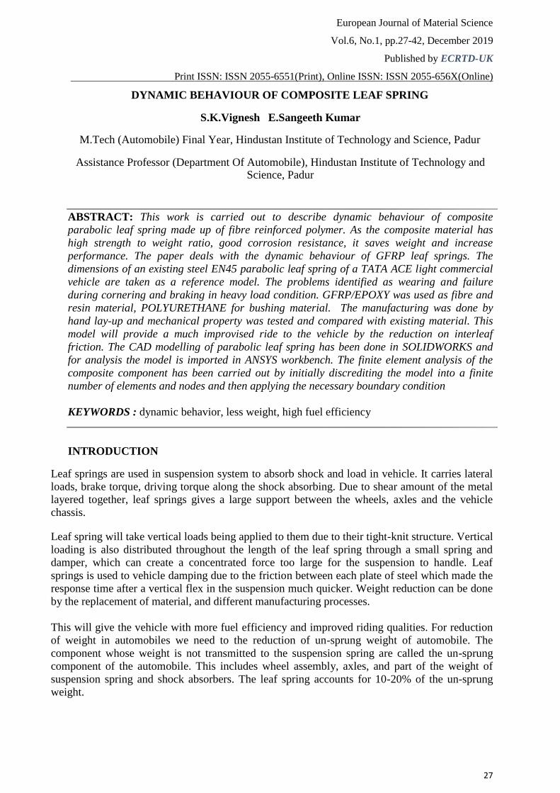
Fig 1.1 Multi leaf spring
MATERIALS AND METHOD 3.1 COMPOSITE MATERIALS
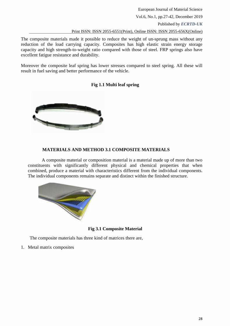
A composite material or composition material is a material made up of more than two
constituents with significantly different physical and chemical properties that when
combined, produce a material with characteristics different from the individual components.
The individual components remains separate and distinct within the finished structure.
Fig 3.1 Composite Material
The composite materials has three kind of matrices there are, 1. Metal matrix composites
European Journal of Material Science
Vol.6, No.1, pp.27-42, December 2019
Published by ECRTD-UK
Print ISSN: ISSN 2055-6551(Print), Online ISSN: ISSN 2055-656X(Online)
29
2. Ceramic matrix composites In which are composite matrices contains oxides, carbides, nitrides of metals.
Examples are granite stones, lime stones, cements, clay based materials, oxides, carbides. 3. Polymer matric composites
Polymer matrix involves the union of small molecules to form molecules having
higher molecular weight. Examples, plastics, Adhesives, natural fibres, artificial fibres,
coating resins.
FIBRES Fibre is a string used as a component of composite materials, or matted into sheets to make
products such as paper or felt. Fibres are often used in the manufacture of other materials. The
strongest engineering materials are generally made as fibres, for example carbon fibre and glass
fibre.
Synthetic fibres can often be produced very cheaply and in large amounts compared to
natural fibres, but in natural fibres the jute has much tensile strength and flexural than other
fibres. And for clothing natural fibres can give some benefits, such as comfort, over their
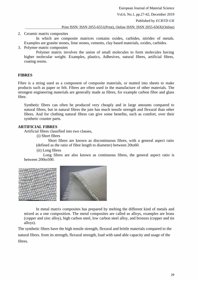
synthetic counter parts. ARTIFICIAL FIBRES
Artificial fibres classified into two classes, (i) Short fibres
Short fibres are known as discontinuous fibres, with a general aspect ratio
(defined as the ratio of fibre length to diameter) between 20to60. (ii) Long fibres
Long fibres are also known as continuous fibres, the general aspect ratio is between 200to500.
In metal matrix composites has prepared by melting the different kind of metals and
mixed as a one composition. The metal composites are called as alloys, examples are brass
(copper and zinc alloy), high carbon steel, low carbon steel alloy, and bronzes (copper and tin
alloys).
The synthetic fibres have the high tensile strength, flexural and brittle materials compared to the
natural fibres. from its strength, flexural strength, load with sand able capacity and usage of the
fibres.
European Journal of Material Science
Vol.6, No.1, pp.27-42, December 2019
Published by ECRTD-UK
Print ISSN: ISSN 2055-6551(Print), Online ISSN: ISSN 2055-656X(Online)
30
Glass-fibre reinforced polymer (woven Roving glass fibre)
Glass-fibre reinforced plastic, or GFRP is a fibre reinforced polymer made of a plastic
matrix reinforced by fine fibres of glass. Fibreglass is a lightweight, extremely strong, and
robust material.Although strength properties are somewhat lower than carbon fibre and it is
less stiff, the material is typically far less brittle.Glass Fibre Reinforced Polymers (GFRPs)
is a fibre reinforced polymer made of a plastic matrix reinforced by fine fibres of glass.
Fibre glass is a lightweight, strong, and robust material used in different industries due to
their excellent properties. Although strength properties are somewhat lower than carbon
fibre and it is less stiff, the material is typically far less brittle, and the raw materials are
much less expensive.
Table 3.1 Mechanical property of S GLASS PROPERTY VALUES UNIT Young’s modulus 93000 Mpa Tensile strength 4800 Mpa Poisson ratio 0.23 - Elastic limit 4085 Mpa
RESIN
A resin is a basic binding material consisting of long chain organic polymer, whichundergoes polymerization reaction during moulding. The resins has two types there are thermosetting resins, thermoplastic resins. The resin we chose as Araldite LY556 is an epoxy resin. The layers of fibres are fabricated by adding the required amount of epoxy resin. In making of the fibre composite materials the resin is playing a major role in this process, the various kinds of the resins are available in the shops. The key data for the epoxy LY556 resin taken and listed below from reference [5].
Table 3.2 PROPERTIES OF EPOXY LY556 Sl.no Araldite LY 556 Properties
1. Aspect (visual) clear, pale
yellow liquid
2. Colour (Gardner, ISO <2
4630)
3. Epoxy content (ISO 5.30 - 5.45
3000) [eq/kg]
4. Viscosity at 25 °C 10000 –12000
(ISO 9371B) [mPas]
5. Density at 25 °C (ISO 1.15 - 1.20
1675) [g/cm3]
6. Flash point (ISO 2719) > 200 [°C]
7. Storage temperature 2 - 40 [°C]
European Journal of Material Science
Vol.6, No.1, pp.27-42, December 2019
Published by ECRTD-UK
Print ISSN: ISSN 2055-6551(Print), Online ISSN: ISSN 2055-656X(Online)
31
Anhydride-cured, low-viscosity standard matrix system with extremely long pot life. The
reactivity of the system is adjustable by variation of the accelerator content. The system is
easy to process, has good fibre impregnation properties and exhibits excellent mechanical,
dynamic and thermal properties. It has an excellent chemical resistance especially to acids
at temperatures up to 80 °C. The epoxy resins are applicable for high performance
composite parts.
For the glass fibre the epoxy LY556 resin is suitable resin compared to other resins it has
the better performance than the other resins and less cost. The thermosetting resin epoxy
LY556 is used for the composite specimen coating, the resin cannot remould and it cannot
be reheat. The resin contains the cross links c=c covalent bond links and formed in the
condensation polymerisation process. Araldite LY 556 which has crystallized and looks
cloudy can be restored to its original state by heating to 60 - 80 °C.
EN45 STEEL
Steel is an alloy of iron and carbon and other elements. EN45 Steel is used commonly to
make leaf spring. Iron is the base metal of steel. Composition of EN45 Steel is 0.5-0.6%
Carbon,0.7-1.1% of Manganese,1.5-2% of Silicon. It is the interaction of the allotropes of
iron with the alloying elements, primarily carbon, that gives steel and cast iron their range of
unique properties.
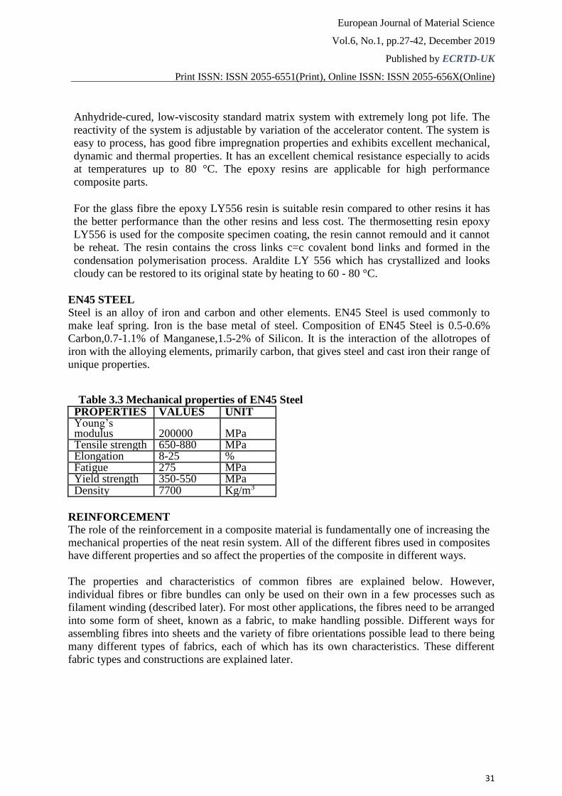
Table 3.3 Mechanical properties of EN45 Steel PROPERTIES VALUES UNIT Young’s modulus 200000 MPa Tensile strength 650-880 MPa Elongation 8-25 % Fatigue 275 MPa Yield strength 350-550 MPa Density 7700 Kg/m3
REINFORCEMENT
The role of the reinforcement in a composite material is fundamentally one of increasing the
mechanical properties of the neat resin system. All of the different fibres used in composites have different properties and so affect the properties of the composite in different ways.
The properties and characteristics of common fibres are explained below. However,
individual fibres or fibre bundles can only be used on their own in a few processes such as
filament winding (described later). For most other applications, the fibres need to be arranged
into some form of sheet, known as a fabric, to make handling possible. Different ways for
assembling fibres into sheets and the variety of fibre orientations possible lead to there being
many different types of fabrics, each of which has its own characteristics. These different
fabric types and constructions are explained later.
European Journal of Material Science
Vol.6, No.1, pp.27-42, December 2019
Published by ECRTD-UK
Print ISSN: ISSN 2055-6551(Print), Online ISSN: ISSN 2055-656X(Online)
32
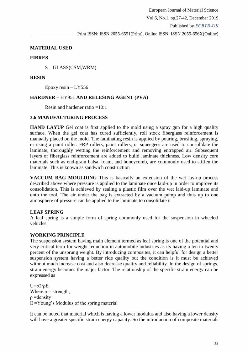
MATERIAL USED FIBRES
S – GLASS(CSM,WRM) RESIN
Epoxy resin – LY556 HARDNER – HY951 AND RELESING AGENT (PVA)
Resin and hardener ratio =10:1 3.6 MANUFACTURING PROCESS HAND LAYUP Gel coat is first applied to the mold using a spray gun for a high quality
surface. When the gel coat has cured sufficiently, roll stock fiberglass reinforcement is
manually placed on the mold. The laminating resin is applied by pouring, brushing, spraying,
or using a paint roller. FRP rollers, paint rollers, or squeegees are used to consolidate the
laminate, thoroughly wetting the reinforcement and removing entrapped air. Subsequent
layers of fiberglass reinforcement are added to build laminate thickness. Low density core
materials such as end-grain balsa, foam, and honeycomb, are commonly used to stiffen the
laminate. This is known as sandwich construction VACCUM BAG MOULDING This is basically an extension of the wet lay-up process
described above where pressure is applied to the laminate once laid-up in order to improve its
consolidation. This is achieved by sealing a plastic film over the wet laid-up laminate and
onto the tool. The air under the bag is extracted by a vacuum pump and thus up to one
atmosphere of pressure can be applied to the laminate to consolidate it
LEAF SPRING A leaf spring is a simple form of spring commonly used for the suspension in wheeled vehicles.
WORKING PRINCIPLE The suspension system having main element termed as leaf spring is one of the potential and
very critical term for weight reduction in automobile industries as its having a ten to twenty
percent of the unsprung weight. By introducing composites, it can helpful for design a better
suspension system having a better ride quality but the condition is it must be achieved
without much increase cost and also decrease quality and reliability. In the design of springs,
strain energy becomes the major factor. The relationship of the specific strain energy can be
expressed as U=σ2/ρE Where σ = strength, ρ =density E =Young’s Modulus of the spring material It can be noted that material which is having a lower modulus and also having a lower density
will have a greater specific strain energy capacity. So the introduction of composite materials
European Journal of Material Science
Vol.6, No.1, pp.27-42, December 2019
Published by ECRTD-UK
Print ISSN: ISSN 2055-6551(Print), Online ISSN: ISSN 2055-656X(Online)
33
can made it possible to reduce the weight of the leaf spring without any reduction into the
load carrying capacity and stiffness. A Composite mainly is any materials that have been physically assembled to form one single
bulk without physical blending to foam a homogeneous material. The resulting material
would still have components identifiable as the constituent of the different materials. One of
the advantages of composite is that two or more materials could be combined to take
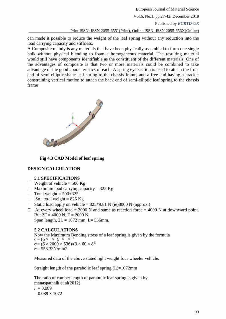
advantage of the good characteristics of each. A spring eye section is used to attach the front
end of semi-elliptic shape leaf spring to the chassis frame, and a free end having a bracket
constraining vertical motion to attach the back end of semi-elliptic leaf spring to the chassis
frame
Fig 4.3 CAD Model of leaf spring
DESIGN CALCULATION
5.1 SPECIFICATIONS
Weight of vehicle = 500 Kg
Maximum load carrying capacity = 325 Kg
Total weight = 500+325 So , total weight = 825 Kg Static load apply on vehicle = 825*9.81 N (ie)8000 N (approx.) At every wheel load = 2000 N and same as reaction force = 4000 N at downward point.
But 2F = 4000 N, F = 2000 N Span length, 2L = 1072 mm, L= 536mm.
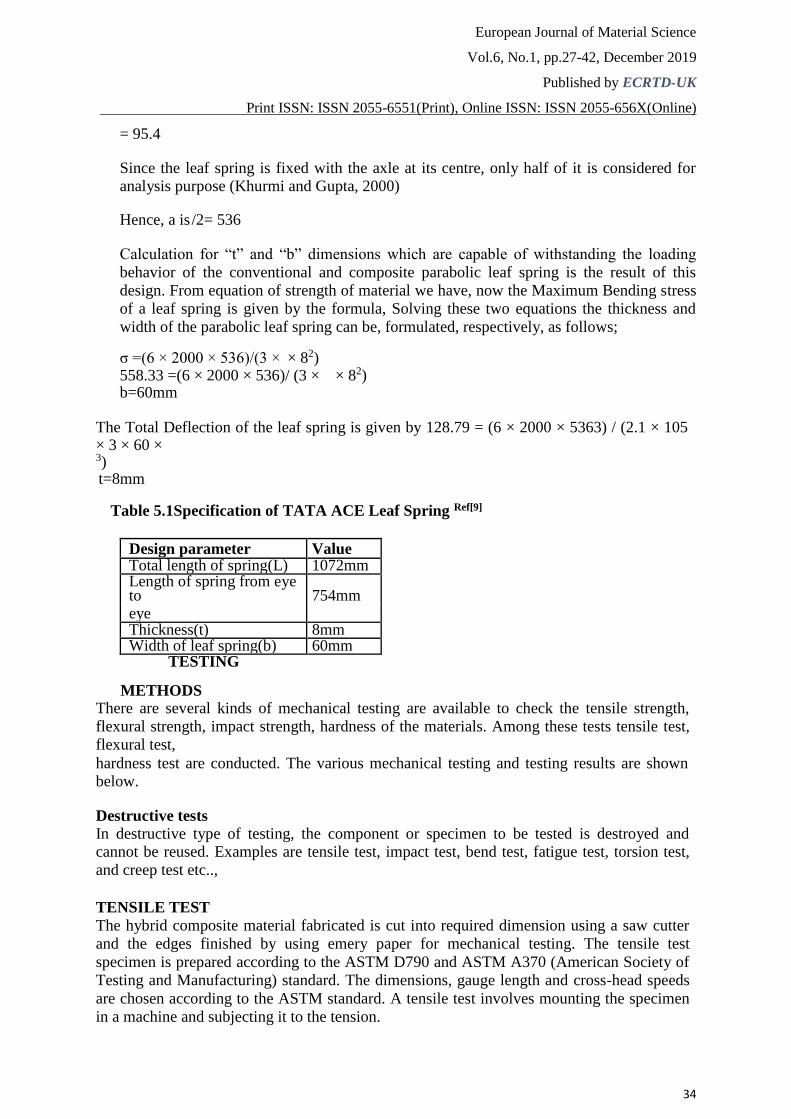
5.2 CALCULATIONS Now the Maximum Bending stress of a leaf spring is given by the formula σ = (6 × × )/ × × 2 σ = (6 × 2000 × 536)/(3 × 60 × 82) σ = 558.33N/mm2
Measured data of the above stated light weight four wheeler vehicle.
Straight length of the parabolic leaf spring (L)=1072mm
The ratio of camber length of parabolic leaf spring is given by manaspatnaik et al(2012) / = 0.089 = 0.089 × 1072
European Journal of Material Science
Vol.6, No.1, pp.27-42, December 2019
Published by ECRTD-UK
Print ISSN: ISSN 2055-6551(Print), Online ISSN: ISSN 2055-656X(Online)
34
= 95.4
Since the leaf spring is fixed with the axle at its centre, only half of it is considered for analysis purpose (Khurmi and Gupta, 2000)
Hence, a is /2= 536
Calculation for “t” and “b” dimensions which are capable of withstanding the loading
behavior of the conventional and composite parabolic leaf spring is the result of this
design. From equation of strength of material we have, now the Maximum Bending stress
of a leaf spring is given by the formula, Solving these two equations the thickness and
width of the parabolic leaf spring can be, formulated, respectively, as follows;
σ =(6 × 2000 × 536)/(3 × × 82) 558.33 =(6 × 2000 × 536)/ (3 × × 82) b=60mm
The Total Deflection of the leaf spring is given by 128.79 = (6 × 2000 × 5363) / (2.1 × 105 × 3 × 60 × 3) t=8mm
Table 5.1Specification of TATA ACE Leaf Spring Ref[9]
Design parameter Value Total length of spring(L) 1072mm Length of spring from eye to 754mm eye Thickness(t) 8mm Width of leaf spring(b) 60mm
TESTING METHODS
There are several kinds of mechanical testing are available to check the tensile strength,
flexural strength, impact strength, hardness of the materials. Among these tests tensile test,
flexural test, hardness test are conducted. The various mechanical testing and testing results are shown below. Destructive tests
In destructive type of testing, the component or specimen to be tested is destroyed and cannot be reused. Examples are tensile test, impact test, bend test, fatigue test, torsion test,
and creep test etc..,
TENSILE TEST
The hybrid composite material fabricated is cut into required dimension using a saw cutter
and the edges finished by using emery paper for mechanical testing. The tensile test
specimen is prepared according to the ASTM D790 and ASTM A370 (American Society of
Testing and Manufacturing) standard. The dimensions, gauge length and cross-head speeds
are chosen according to the ASTM standard. A tensile test involves mounting the specimen
in a machine and subjecting it to the tension.
European Journal of Material Science
Vol.6, No.1, pp.27-42, December 2019
Published by ECRTD-UK
Print ISSN: ISSN 2055-6551(Print), Online ISSN: ISSN 2055-656X(Online)
35
The testing process involves placing the test specimen in the testing machine and applying
tension to it until it fractures. The tensile force is recorded as a function of the increase in
gauge length. During the application of tension, the elongation of the gauge section is
recorded against the applied force.
FLEXURAL TEST
Flexural test is one of the mechanical test for to know the flexural strength and flexural
deflections of the material. The flexural specimens are prepared as per the ASTM standards.
The four test piece samples are fitted in the flexural test machine. The flexural load is
applied slowly on the composite specimens. The test is conducted until the test piece is
broke. The 3-point flexure test is the most common flexural test for composite materials.
Specimen deflection is measured by the
crosshead position. Test results include flexural strength of the materials.
The testing process involves placing the test specimen in the universal testing machine and applying force to it until it fractures and breaks. HARDNESS TEST Hardness implies the ability of a material to resist deformation. There is a wide variety of
hardness assessment procedures available, including static indentation, scratch, rebound,
damping, cutting, abrasion and erosion tests. Recently, nano indentation techniques have also
been used for the investigation of hardness of composites. Hardness is a routinely measured
mechanical characteristic that is sensitive to structural parameters as well as to mechanical
behaviour. A classical method used to measure hardness is the static indentation test, which
involves forcing a hard tool of known geometry into the sample body. The hardness of the sample is then defined as the ratio of the applied force to the size of the
resulting indentation. TESTING PROCEDURE: The material to be tested is held on the anvil of the machine. The test piece is raised by
turning the hand wheel, till it just touches the indenter. A minor load of 10 kg is applied to
seat the specimen. Then the dial indicator is set at zero. Now the major load (60 kg for R-
scale is applied to the indenter to produce a deeper indentation. After the indicating pointer
has come to rest, the major load is removed. With the major load is removed, on the
appropriate scale of the dial.
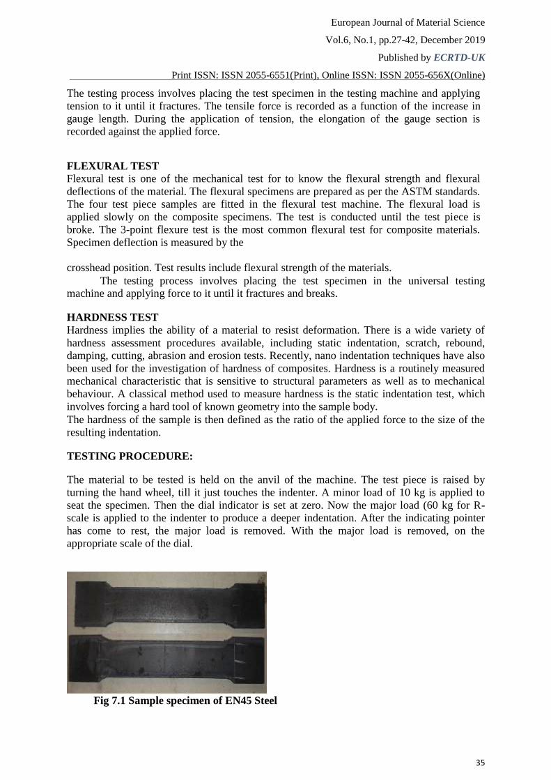
Fig 7.1 Sample specimen of EN45 Steel
European Journal of Material Science
Vol.6, No.1, pp.27-42, December 2019
Published by ECRTD-UK
Print ISSN: ISSN 2055-6551(Print), Online ISSN: ISSN 2055-656X(Online)
36
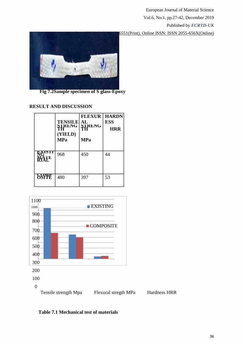
Fig 7.2Sample specimen of S glass-Epoxy RESULT AND DISCUSSION
TENSILE
FLEXUR
AL
HARDN
ESS
STRENGTH
STRENGTH HRR
(YIELD)
MPa MPa
EXISTING 968 450 44 MATERIAL
COMPOSITE 480 397 53
1100
1000 EXISTING
900
800 COMPOSITE
700
600
500
400
300
200
100
0 Tensile strength Mpa Flexural stregth MPa Hardness HRR
Table 7.1 Mechanical test of materials
European Journal of Material Science
Vol.6, No.1, pp.27-42, December 2019
Published by ECRTD-UK
Print ISSN: ISSN 2055-6551(Print), Online ISSN: ISSN 2055-656X(Online)
37
DISPLACEMENT TEST The composite leaf spring is placed in the UTM machine and gradually given the load
in terms of 100,250,500,1000,1500 N and the displacement for the corresponding load
is noted and compared with existing material.
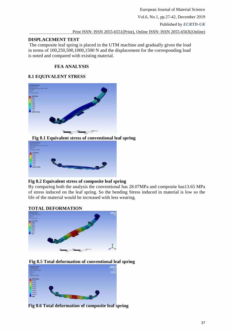
FEA ANALYSIS 8.1 EQUIVALENT STRESS
Fig 8.1 Equivalent stress of conventional leaf spring
Fig 8.2 Equivalent stress of composite leaf spring By comparing both the analysis the conventional has 28.07MPa and composite has13.65 MPa
of stress induced on the leaf spring. So the bending Stress induced in material is low so the
life of the material would be increased with less wearing.
TOTAL DEFORMATION
Fig 8.5 Total deformation of conventional leaf spring
Fig 8.6 Total deformation of composite leaf spring
European Journal of Material Science
Vol.6, No.1, pp.27-42, December 2019
Published by ECRTD-UK
Print ISSN: ISSN 2055-6551(Print), Online ISSN: ISSN 2055-656X(Online)
38
By comparing both the analysis the conventional has 0.101 mm deflection and composite
material has 0.042mm of deflection with the same loading condition. So it is clear that the strength will be increased in composite for the better fatigue life
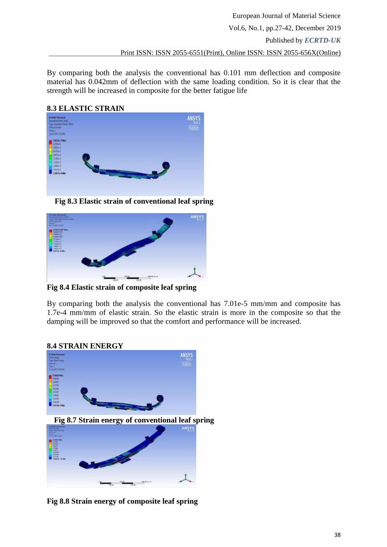
8.3 ELASTIC STRAIN
Fig 8.3 Elastic strain of conventional leaf spring
Fig 8.4 Elastic strain of composite leaf spring By comparing both the analysis the conventional has 7.01e-5 mm/mm and composite has
1.7e-4 mm/mm of elastic strain. So the elastic strain is more in the composite so that the
damping will be improved so that the comfort and performance will be increased.
8.4 STRAIN ENERGY
Fig 8.7 Strain energy of conventional leaf spring Fig 8.8 Strain energy of composite leaf spring
European Journal of Material Science
Vol.6, No.1, pp.27-42, December 2019
Published by ECRTD-UK
Print ISSN: ISSN 2055-6551(Print), Online ISSN: ISSN 2055-656X(Online)
39
By comparing both the analysis the conventional has 0.566 mJ and composite material has
2.45 mJ of strain energy. Hence I shows that composite is much tougher than conventional
steel. So it able to withstand heavy loading without change in performance of the vehicle.
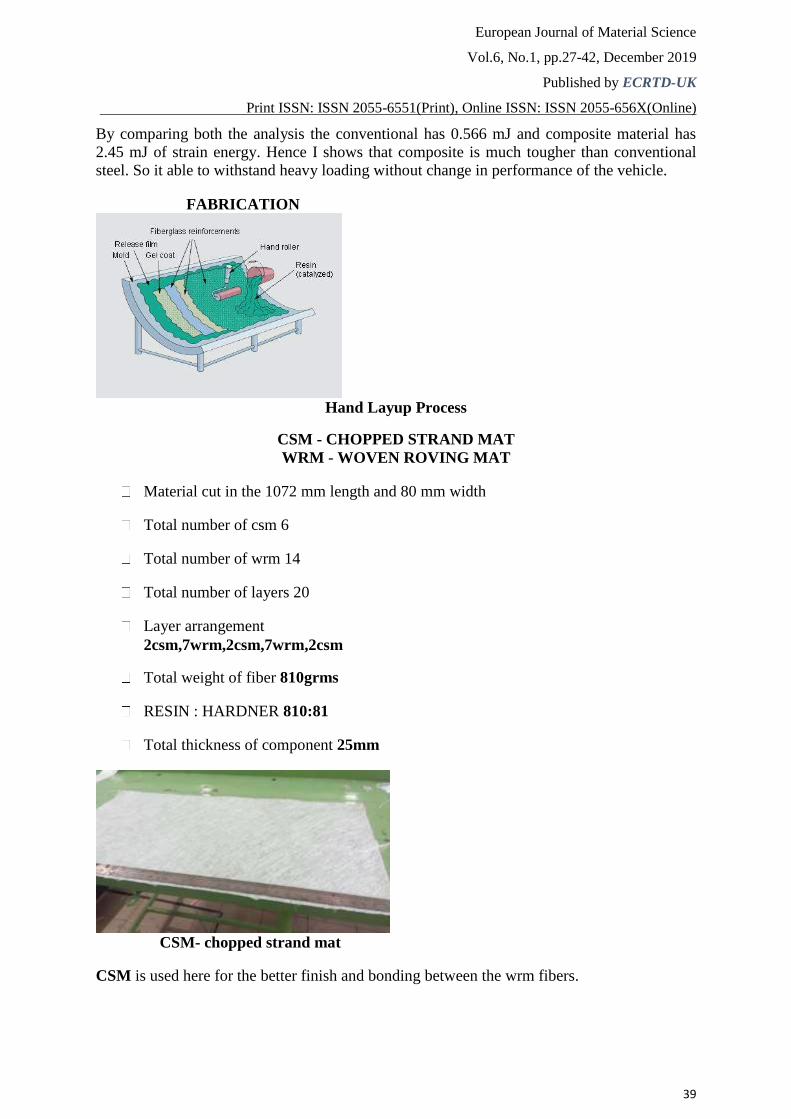
FABRICATION
Hand Layup Process
CSM - CHOPPED STRAND MAT
WRM - WOVEN ROVING MAT
Material cut in the 1072 mm length and 80 mm width
Total number of csm 6
Total number of wrm 14
Total number of layers 20
Layer arrangement 2csm,7wrm,2csm,7wrm,2csm
Total weight of fiber 810grms
RESIN : HARDNER 810:81
Total thickness of component 25mm
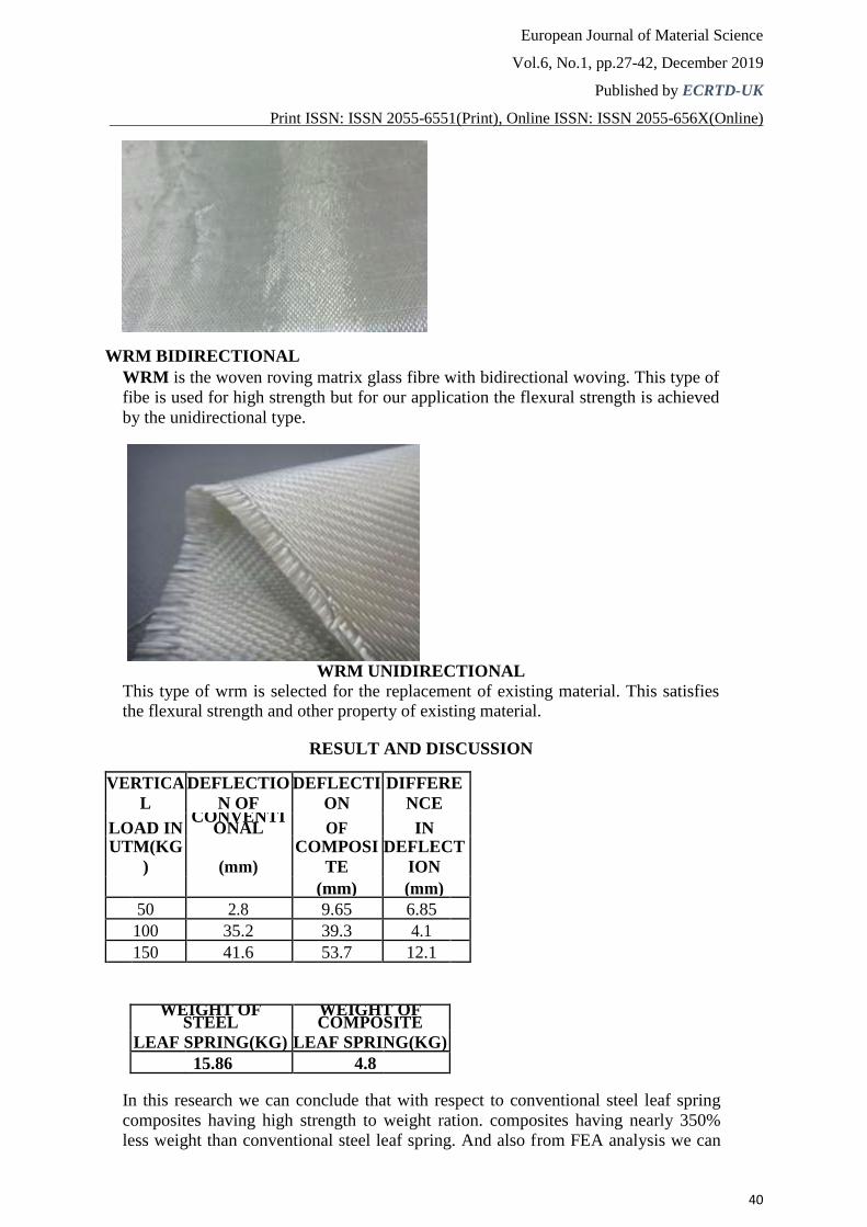
CSM- chopped strand mat CSM is used here for the better finish and bonding between the wrm fibers.
European Journal of Material Science
Vol.6, No.1, pp.27-42, December 2019
Published by ECRTD-UK
Print ISSN: ISSN 2055-6551(Print), Online ISSN: ISSN 2055-656X(Online)
40
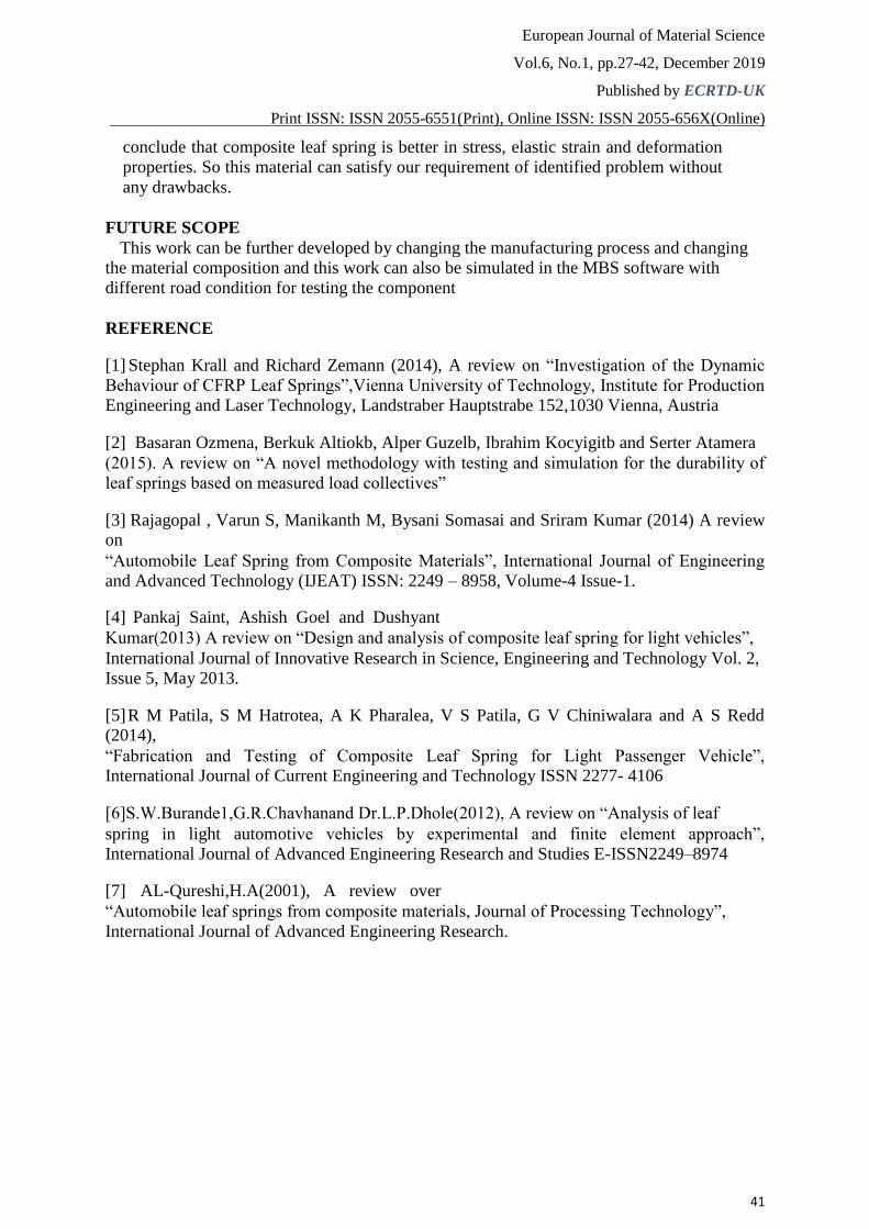
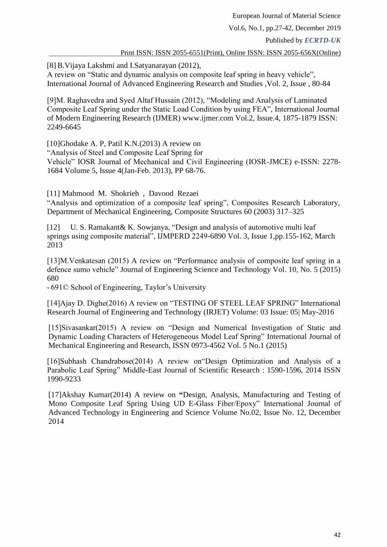
WRM BIDIRECTIONAL WRM is the woven roving matrix glass fibre with bidirectional woving. This type of
fibe is used for high strength but for our application the flexural strength is achieved
by the unidirectional type.
WRM UNIDIRECTIONAL This type of wrm is selected for the replacement of existing material. This satisfies the flexural strength and other property of existing material.
RESULT AND DISCUSSION
VERTICA
L
DEFLECTIO
N OF
DEFLECTI
ON
DIFFERE
NCE
LOAD IN CONVENTI
ONAL OF IN UTM(KG
) (mm)
COMPOSI
TE
DEFLECT
ION
(mm) (mm)
50 2.8 9.65 6.85
100 35.2 39.3 4.1
150 41.6 53.7 12.1
WEIGHT OF
STEEL WEIGHT OF COMPOSITE
LEAF SPRING(KG) LEAF SPRING(KG)
15.86 4.8
In this research we can conclude that with respect to conventional steel leaf spring
composites having high strength to weight ration. composites having nearly 350%
less weight than conventional steel leaf spring. And also from FEA analysis we can
European Journal of Material Science
Vol.6, No.1, pp.27-42, December 2019
Published by ECRTD-UK
Print ISSN: ISSN 2055-6551(Print), Online ISSN: ISSN 2055-656X(Online)
41
conclude that composite leaf spring is better in stress, elastic strain and deformation
properties. So this material can satisfy our requirement of identified problem without
any drawbacks.
FUTURE SCOPE This work can be further developed by changing the manufacturing process and changing
the material composition and this work can also be simulated in the MBS software with
different road condition for testing the component
REFERENCE [1] Stephan Krall and Richard Zemann (2014), A review on “Investigation of the Dynamic
Behaviour of CFRP Leaf Springs”,Vienna University of Technology, Institute for Production
Engineering and Laser Technology, Landstraber Hauptstrabe 152,1030 Vienna, Austria [2] Basaran Ozmena, Berkuk Altiokb, Alper Guzelb, Ibrahim Kocyigitb and Serter Atamera (2015). A review on “A novel methodology with testing and simulation for the durability of
leaf springs based on measured load collectives” [3] Rajagopal , Varun S, Manikanth M, Bysani Somasai and Sriram Kumar (2014) A review on “Automobile Leaf Spring from Composite Materials”, International Journal of Engineering
and Advanced Technology (IJEAT) ISSN: 2249 – 8958, Volume-4 Issue-1. [4] Pankaj Saint, Ashish Goel and Dushyant Kumar(2013) A review on “Design and analysis of composite leaf spring for light vehicles”, International Journal of Innovative Research in Science, Engineering and Technology Vol. 2,
Issue 5, May 2013. [5] R M Patila, S M Hatrotea, A K Pharalea, V S Patila, G V Chiniwalara and A S Redd (2014), “Fabrication and Testing of Composite Leaf Spring for Light Passenger Vehicle”, International Journal of Current Engineering and Technology ISSN 2277- 4106 [6]S.W.Burande1,G.R.Chavhanand Dr.L.P.Dhole(2012), A review on “Analysis of leaf spring in light automotive vehicles by experimental and finite element approach”,
International Journal of Advanced Engineering Research and Studies E-ISSN2249–8974 [7] AL-Qureshi,H.A(2001), A review over “Automobile leaf springs from composite materials, Journal of Processing Technology”, International Journal of Advanced Engineering Research.
European Journal of Material Science
Vol.6, No.1, pp.27-42, December 2019
Published by ECRTD-UK
Print ISSN: ISSN 2055-6551(Print), Online ISSN: ISSN 2055-656X(Online)
42
[8] B.Vijaya Lakshmi and I.Satyanarayan (2012), A review on “Static and dynamic analysis on composite leaf spring in heavy vehicle”, International Journal of Advanced Engineering Research and Studies ,Vol. 2, Issue , 80-84 [9]M. Raghavedra and Syed Altaf Hussain (2012), “Modeling and Analysis of Laminated
Composite Leaf Spring under the Static Load Condition by using FEA”, International Journal
of Modern Engineering Research (IJMER) www.ijmer.com Vol.2, Issue.4, 1875-1879 ISSN:
2249-6645 [10] Ghodake A. P, Patil K.N.(2013) A review on
“Analysis of Steel and Composite Leaf Spring for Vehicle” IOSR Journal of Mechanical and Civil Engineering (IOSR-JMCE) e-ISSN: 2278-1684 Volume 5, Issue 4(Jan-Feb. 2013), PP 68-76. [11] Mahmood M. Shokrieh , Davood Rezaei “Analysis and optimization of a composite leaf spring”, Composites Research Laboratory,
Department of Mechanical Engineering, Composite Structures 60 (2003) 317–325 [12] U. S. Ramakant& K. Sowjanya, “Design and analysis of automotive multi leaf
springs using composite material”, IJMPERD 2249-6890 Vol. 3, Issue 1,pp.155-162, March
2013 [13]M.Venkatesan (2015) A review on “Performance analysis of composite leaf spring in a defence sumo vehicle” Journal of Engineering Science and Technology Vol. 10, No. 5 (2015) 680 - 691© School of Engineering, Taylor’s University [14]Ajay D. Dighe(2016) A review on “TESTING OF STEEL LEAF SPRING” International
Research Journal of Engineering and Technology (IRJET) Volume: 03 Issue: 05| May-2016 [15]Sivasankar(2015) A review on “Design and Numerical Investigation of Static and
Dynamic Loading Characters of Heterogeneous Model Leaf Spring” International Journal of
Mechanical Engineering and Research, ISSN 0973-4562 Vol. 5 No.1 (2015) [16]Subhash Chandrabose(2014) A review on“Design Optimization and Analysis of a
Parabolic Leaf Spring” Middle-East Journal of Scientific Research : 1590-1596, 2014 ISSN
1990-9233 [17]Akshay Kumar(2014) A review on “Design, Analysis, Manufacturing and Testing of
Mono Composite Leaf Spring Using UD E-Glass Fiber/Epoxy” International Journal of
Advanced Technology in Engineering and Science Volume No.02, Issue No. 12, December
2014