
Duty cycle learning algorithm (DCLA) for IEEE 802.15.4 beacon-enabled wireless sensor networks
16
Duty cycle learning algorithm (DCLA) for IEEE 802.15.4 beacon-enabled wireless sensor networks Rodolfo de Paz Alberola ⇑ , Dirk Pesch Nimbus Centre for Embedded Systems Research, Cork Institute of Technology, Rossa Avenue, Cork, Ireland article info Article history: Received 10 March 2011 Received in revised form 14 May 2011 Accepted 18 June 2011 Available online 7 July 2011 Keywords: Wireless sensor networks (WSNs) IEEE 802.15.4 Duty cycle Energy efficiency Machine learning Reinforcement learning abstract The current specification of the IEEE 802.15.4 standard for beacon-enabled wireless sensor networks does not define how the fraction of the time that wireless nodes are active, known as the duty cycle, needs to be configured in order to achieve the optimal network performance in all traffic conditions. The work presented here proposes a duty cycle learn- ing algorithm (DCLA) that adapts the duty cycle during run time without the need of human intervention in order to minimise power consumption while balancing probability of successful data delivery and delay constraints of the application. Running on coordinator devices, DCLA collects network statistics during each active duration to estimate the incoming traffic. Then, at each beacon interval uses the reinforcement learning (RL) frame- work as the method for learning the best duty cycle. Our approach eliminates the necessity for manually (re-)configuring the nodes duty cycle for the specific requirements of each network deployment. This presents the advantage of greatly reducing the time and cost of the wireless sensor network deployment, operation and management phases. DCLA has low memory and processing requirements making it suitable for typical wireless sen- sor platforms. Simulations show that DCLA achieves the best overall performance for either constant and event-based traffic when compared with existing IEEE 802.15.4 duty cycle adaptation schemes. Ó 2011 Elsevier B.V. All rights reserved. 1. Introduction Wireless sensor network (WSN) nodes are usually bat- tery operated and, in many deployments, replacing or recharging their batteries is costly or even infeasible. Con- sequently, low power operation is considered a primary requirement for WSN communication protocols. Specifi- cally, the idle listening problem must be solved as it has been identified as one of the major sources of energy wast- age [1]. This occurs when the nodes are unaware of when data traffic is generated by other nodes and their trans- ceiver continuously stays in the receiving mode even when there is no data traffic for them. The IEEE 802.15.4 standard [2], which is currently the most widely adopted MAC protocol, defines several type of nodes that take different roles during the operational phase of the system. Full function devices (FFD), also called beacon enabled devices, can operate either as Personal Area Network Coordinators (PANc), Cluster Heads (CLH) or routers. On the other hand, reduced function devices (RFD) also called non beacon devices can only operate as end devices. FFDs can generate, receive and/or forward data frames whereas RFD have reduced functionalities only using its radio to receive control information and send col- lected data. End devices may therefore be asleep unless they have data to transmit or receive control commands. This work considers that FFDs are battery powered and act as the Cluster Head forming a star of end devices col- lecting data around it. In this scenario, as the FFDs cannot predict when other sensor nodes are going to send their 1570-8705/$ - see front matter Ó 2011 Elsevier B.V. All rights reserved. doi:10.1016/j.adhoc.2011.06.006 ⇑ Corresponding author. E-mail addresses: [email protected] (R. de Paz Alberola), dirk.- [email protected] (D. Pesch). Ad Hoc Networks 10 (2012) 664–679 Contents lists available at ScienceDirect Ad Hoc Networks journal homepage: www.elsevier.com/locate/adhoc
Transcript of Duty cycle learning algorithm (DCLA) for IEEE 802.15.4 beacon-enabled wireless sensor networks

Ad Hoc Networks 10 (2012) 664–679
Contents lists available at ScienceDirect
Ad Hoc Networks
journal homepage: www.elsevier .com/locate /adhoc
Duty cycle learning algorithm (DCLA) for IEEE 802.15.4beacon-enabled wireless sensor networks
Rodolfo de Paz Alberola ⇑, Dirk PeschNimbus Centre for Embedded Systems Research, Cork Institute of Technology, Rossa Avenue, Cork, Ireland
a r t i c l e i n f o
Article history:Received 10 March 2011Received in revised form 14 May 2011Accepted 18 June 2011Available online 7 July 2011
Keywords:Wireless sensor networks (WSNs)IEEE 802.15.4Duty cycleEnergy efficiencyMachine learningReinforcement learning
1570-8705/$ - see front matter � 2011 Elsevier B.Vdoi:10.1016/j.adhoc.2011.06.006
⇑ Corresponding author.E-mail addresses: [email protected] (R. de
[email protected] (D. Pesch).
a b s t r a c t
The current specification of the IEEE 802.15.4 standard for beacon-enabled wireless sensornetworks does not define how the fraction of the time that wireless nodes are active,known as the duty cycle, needs to be configured in order to achieve the optimal networkperformance in all traffic conditions. The work presented here proposes a duty cycle learn-ing algorithm (DCLA) that adapts the duty cycle during run time without the need ofhuman intervention in order to minimise power consumption while balancing probabilityof successful data delivery and delay constraints of the application. Running on coordinatordevices, DCLA collects network statistics during each active duration to estimate theincoming traffic. Then, at each beacon interval uses the reinforcement learning (RL) frame-work as the method for learning the best duty cycle. Our approach eliminates the necessityfor manually (re-)configuring the nodes duty cycle for the specific requirements of eachnetwork deployment. This presents the advantage of greatly reducing the time and costof the wireless sensor network deployment, operation and management phases. DCLAhas low memory and processing requirements making it suitable for typical wireless sen-sor platforms. Simulations show that DCLA achieves the best overall performance for eitherconstant and event-based traffic when compared with existing IEEE 802.15.4 duty cycleadaptation schemes.
� 2011 Elsevier B.V. All rights reserved.
1. Introduction
Wireless sensor network (WSN) nodes are usually bat-tery operated and, in many deployments, replacing orrecharging their batteries is costly or even infeasible. Con-sequently, low power operation is considered a primaryrequirement for WSN communication protocols. Specifi-cally, the idle listening problem must be solved as it hasbeen identified as one of the major sources of energy wast-age [1]. This occurs when the nodes are unaware of whendata traffic is generated by other nodes and their trans-ceiver continuously stays in the receiving mode even whenthere is no data traffic for them.
. All rights reserved.
Paz Alberola), dirk.-
The IEEE 802.15.4 standard [2], which is currently themost widely adopted MAC protocol, defines several typeof nodes that take different roles during the operationalphase of the system. Full function devices (FFD), also calledbeacon enabled devices, can operate either as PersonalArea Network Coordinators (PANc), Cluster Heads (CLH)or routers. On the other hand, reduced function devices(RFD) also called non beacon devices can only operate asend devices. FFDs can generate, receive and/or forwarddata frames whereas RFD have reduced functionalities onlyusing its radio to receive control information and send col-lected data. End devices may therefore be asleep unlessthey have data to transmit or receive control commands.This work considers that FFDs are battery powered andact as the Cluster Head forming a star of end devices col-lecting data around it. In this scenario, as the FFDs cannotpredict when other sensor nodes are going to send their

R. de Paz Alberola, D. Pesch / Ad Hoc Networks 10 (2012) 664–679 665
data to them, they need to be always awake to receive allthe information collected, which rapidly depletes their bat-teries. To overcome this problem, the standard specifica-tion defines the beacon enabled mode. This modesupports the transmission of beacon frames from coordina-tor to end devices allowing node synchronization. Synchro-nization allows all devices to sleep between coordinatedtransmissions which contributes to reduce idle listening,resulting in prolonged network lifetimes.
The beacon mode employs the superframe structure de-picted in Fig. 1. Its format is established by the coordinatorand is defined by two parameters, the beacon interval (BI),which determines the time between two consecutive bea-con frames, and the superframe duration (SD), whichdetermines the nodes’ active period in the BI. The super-frame duration is composed of a contention access period(CAP) in which all devices use a slotted CSMA/CA protocolto gain access and compete for time slots, followed by acontention free period (CFP) for low latency applicationswhich is divided into guaranteed time slots (GTSs). In orderto reduce energy consumption, the coordinator may intro-duce an inactive period by choosing BI > SD. The inactiveperiod defines a time period during which all devices, coor-dinator included, go into a sleep mode. BI and SD are deter-mined by two parameters, the beacon order (BO) and thesuperframe order (SO), respectively, as per Eq. (1) whereaBaseSuperframeDuration = 15.36 ms (assuming 250 kbpsin the 2.4 GHz frequency band) denotes the minimumduration of the superframe, corresponding to SO = 0.
BI¼aBaseSuperframeDuration �2BO
SD¼aBaseSuperframeDuration �2SO
)for 06SO6BO614:
ð1Þ
Although the beacon-mode was developed with limitedpower supply availability in mind by allowing the intro-duction of sleep periods, it does not specify how the dura-tion of active and sleep periods can be adapted based onthe traffic generated by end devices. Setting the duty cycleis however a major requirement in order to achieve a goodbalance among network reliability and power consump-tion. Thus, the physical implementation of this MAC proto-col requires additional power management considerationsthat are not defined in the standard. Specifically, the coor-dinator needs to control the duty cycle (DC), defined as thefraction of the time nodes are active, in order to provideenergy efficiency. This time can be computed as the ratio
Fig. 1. The superframe structure of the IE
between the superframe duration and the beacon intervalthat can be related to BO and SO as per the followingequation:
DC ¼ SDBI¼ 2SO�BO: ð2Þ
The smaller the duty cycle the lower is the energy con-sumption. However, due to the inherent resource constric-tions of sensor nodes, a small duty cycle can cause bufferoverflows and delays. On the other hand, although a highduty cycle enables end devices to transmit a higher num-ber of data frames and decrease delay it may also increasethe time the coordinator spends in idle listening. Conse-quently, duty cycle adaptation is necessary to enhancethe performance of IEEE 802.15.4 beacon-enabled net-works and it is therefore the main objective of this work.
A number of reports in the literature present work aim-ing at adjusting the duty cycle to the traffic load using theIEEE 802.15.4 beacon-enabled MAC. However, as discussedin Section 2, these works have limitations when applyingthem to diverse event-based, periodic or spatial traffic dis-tributions. We therefore propose in this paper a duty cyclelearning adaptation algorithm (DCLA) for IEEE 802.15.4beacon-enabled networks that overcomes theirlimitations.
2. Related research efforts
Several approaches have been developed for the IEEE802.15.4 standard towards adjusting node’s duty cycle tothe traffic changes using the beacon-enabled MAC. Theearliest work on 802.15.4 duty cycle adaptation is knownas the Beacon Order Adaptation Algorithm (BOAA) [3].For the traffic estimation, BOAA uses the number of mes-sages received from the end devices in order to estimatethe network offered load. The authors propose to storethe number of received messages from all devices duringa number of beacon intervals in a buffer matrix. The pro-posed buffer matrix presents the advantage of giving somememory to the algorithm. This matrix however is not scal-able for large networks as the number of rows increaseswith the number of end devices in the topology.
Alternatively, Jeon et. al. employ in their duty cycle algo-rithm (DCA) [4] additional information such as transmitqueue occupation and end-to-end delay to select the dutycycle. In order to gather these statistics from end devices,they modify the reserved frame control field present in theMAC frame header so that no extra overhead is incurred.The queue occupation is computed as the average of a queue
EE 802.15.4 beacon-enabled mode.

666 R. de Paz Alberola, D. Pesch / Ad Hoc Networks 10 (2012) 664–679
indicator embedded in all frames during the active period.This however results in under estimations of the numberof transmission requests as the queue occupation in enddevices decreases along with the active duration.
Barbieri et al. propose an alternative way to adapt theduty cycle to the traffic load referred to as AMPE [5]. Thealgorithm assumes that the time the channel is busy corre-sponds to the superframe occupation and that this is pro-portional to the load factor. They then suggest employingthe PLME-CCA request primitive provided by the 802.15.4standard to determine the amount of time the channel isbusy during the active duration. Although CCA measure-ments provide more accurate information on the super-frame occupation than estimations. They require thesensor node to invoke repeatedly the primitive duringthe superframe duration, as each CCA lasts only eight sym-bols, which results in much computational expenditure.
Similar to our work, other researchers have also em-ployed reinforcement learning (RL) with the main goal offinding the optimal duty cycle. In this line of work, Liuand Elhanany designed in [6] a scheme to adjust the sleepschedules of the SMAC protocol [1] in a WSN setting. Theproposed scheme, called RL-MAC, employs the number offrames queued for transmitting as the state and the re-served active time as the action generated. This howeverrepresents a large number of state–action pairs which re-quires high memory resources that are not available inconstrained sensor nodes. Recently, a similar strategy hasbeen also used for adapting the superframe duration inIEEE802.15.4 networks [7]. In this case, the state is chosenas the number of packets available at the end devicesqueues at the end of each beacon interval whereas the ac-tions are the possible SO values. Both learning approachespresent slow convergence for non-stationary scenarios dueto the selection of a large state–action space as the larger isthe number of possible actions the longer it takes to learnthe optimal. In addition, in steady traffic situations, thesesolutions are not optimal as their �-greedy explorationstrategy prevents them from staying at the optimum eventhough the traffic is constant. This is due to the fact thatthey use a fixed � parameter that translates into randomactions (duty cycles) being chosen from time to time.
Most duty cycle adaptations [3,5,7] have been designedfor applications where the amount of traffic can be easilypredicted and it is possible to change the appropriate val-ues of BO and SO well in advance. Therefore, they do notcope well with instantaneous traffic bursts because theytake some time to estimate the traffic and adjust the dutycycle. To deal with this problem, several algorithms thatdynamically extend the active period based on the traffichandled by end devices have been proposed. Authors in[8] propose the extension of the CAP based on a busy tonesent by devices at the end of the standard CAP. The busytone is only sent if the device has failed to transmit all itsdata frames. In [9], the CAP extension is done based onthe type of traffic that is waiting in the queue of end de-vices. Specifically, the CAP is extended if there is somereal-time data in the transmit queue of any device at theend of the CAP. These extensions are however not compli-ant with the standard as they propose to have the exten-sion immediately after the CAP thus modifying the
superframe structure. In addition, they are not envisagedto be proportional to the amount of traffic waiting to betransmitted which can lead to idle listening. Finally, theyare not as flexible as duty cycle adaptations because theystill work on fixed active and beacon interval durations.
Although previous works exist on adaptive duty cyclingfor sensor nodes that run the IEEE 802.15.4 MAC, they havedeficits. Firstly, for simplicity purposes, they fix the dutycycle by either fixing SO = 0 and adapting BO [3] or fixingBO to a maximum value and adapting SO [4,5,7]. Neverthe-less, the strategy of fixing SO and adapting BO increases theprobability of losing synchronisation. On the other hand,fixing BO may however result in unnecessary delays andbeacon overheads as well as a reduced range of duty cyclevalues due to the restriction SO 6 BO. In addition, somesolutions do not consider queueing statistics [5] or onlyconsider the statistics received from one device to makethe duty cycle selection [3] which can lead to frame dropsand/or increased idle listening. On the other hand, mostduty cycle adaptations are not well suited for event-basedtraffic and CAP extensions are not compliant with the stan-dard. Considering this, we propose the duty cycle learningalgorithm (DCLA). The algorithm is formulated as a multi-armed bandit problem where the agent objective is to min-imise idle listening and buffer overflows. DCLA is able toadapt to a wider range of traffic settings as it adjusts itspolicy for selecting the duty cycle according to the feed-back information provided by the network. Unlike theother approaches, the MAC parameters (BO, SO) are se-lected trying to find a compromise among beacon over-head and queuing delay. Moreover, the algorithm iscompliant with the IEEE 802.15.4 standard and requireslow RAM storage making it suitable for typical wirelesssensor platforms.
3. Duty cycle learning algorithm (DCLA)
The design of the proposed algorithm is explained inthis section. We first discuss the traffic estimation usedby FFD devices to set their duty cycle. Secondly, we intro-duce the Q-learning methodology used to design the algo-rithm. Thirdly, we formulate the proposed DCLA algorithmand the actions, reward and policy functions employed bythe learning agent to find the duty cycle. We conclude thesection describing the algorithm used for the selection ofthe beacon and superframe order values.
3.1. Traffic estimation
This work considers that FFDs are battery powered andact as the coordinator of a star topology to which end de-vices send their collected data. Thus, we assume that FFDsact as receivers and aim to adapt the duty cycle to the traf-fic generated by end devices. For the duty cycle adaptation,each FFD estimates the incoming traffic by computing idlelistening, packet accumulation and delay in end devices’transmitting queues. The idle listening IL is computed bya coordinator as per Eq. (3) and it represents the amountof time the coordinator is in receive mode without actuallyhaving any transmission from the senders (end devices).

Fig. 2. Types of collision depending on its timing characteristics.
R. de Paz Alberola, D. Pesch / Ad Hoc Networks 10 (2012) 664–679 667
The term 1.0 represents the theoretical maximum utiliza-tion from which the actual superframe utilization SFu issubtracted.
IL ¼ 1:0� SFu: ð3Þ
The superframe utilization, see Eq. (4), is the ratio be-tween the time that end devices occupy the superframeand the total time available for data communication. Thetotal time available for data communication is obtainedas the superframe duration SD minus the time spent bythe coordinator for the beacon transmission Tb. The timeused by the coordinator to transmit a beacon is calculatedby summing up the 802.15.4 MAC and physical overhead(30 symbols) plus the beacon payload. On the other hand,the numerator is comprised of the sum of two terms asshown by the Eq. (4). The first term Tc is the time that de-vices occupy the medium due to frame collisions whereasthe second term Tr is the time used for data reception. Byincluding an estimation of the time used by collidedframes we avoid the situation of over estimating the idlelistening when the probability of collision is high.
SFu ¼Tc þ Tr
SD� Tb¼ Tsðc þ rÞ
SD� Tb6 1; ð4Þ
Tr and Tc are estimated by collecting the number of re-ceived (r) and collided (c) frames during the active periodand using the time spent by the sender to transmit eachdata frame Ts. To estimate the number of frames c thathave collided, after each transmission failure the senderestimates if a collision occurred and sends a collision indi-cator in the following transmission attempt. This indicatoris included in the reserved bit of the physical header de-fined by the standard so that we do not incur extra over-head. End devices may detect if a collision has occurredin different ways depending on their timing characteris-tics1. There are, in particular, three different types of colli-sions as shown in Fig. 2. In the type 1 (C1), the sendernode under consideration (A in Fig. 2) ends its transmissionfirst while other node’s transmission still continues. In thetype 2 (C2), sender A finishes its transmission after the col-lision happens. Finally, in the type 3 (C3) both nodes endtransmitting at the same time. To detect C1s and C2s, it ispossible for A or B to listen to the channel to detect otherstransmission if they are in the range of each other. Thus,the sender considers that a collision occurred if when listen-ing to the channel after transmission, it detects a busy chan-nel and no acknowledgement frame is received2. On the
1 We do not claim to be able to detect all collisions but have a goodestimate that aids estimating the utilization of the superframe.
2 Indirect collisions type 1, 2 that occur due to hidden nodes that cannothear each others transmissions cannot be detected by transmitters A, B butby the receiver as a collision type 3.
other hand, to detect C3s, the receiver perceives an increaseon the received energy over its CCA threshold but it does notsynchronise with the start frame delimiter.
The time Ts used by end devices to transmit each dataframe sent in the CAP has to be estimated to obtain thesuperframe utilisation in time units. Ts is calculated asthe time that devices spend for clear channel assessment,data transmission, inter-frame spacing and ack reception.This is mathematically expressed in formula (5), wherethe time for clear assignment TCCA is two backoff slots(40 symbols); the time to transmit the data frame TDATA
is the standard 802.15.4 MAC and physical headers (38symbols) plus the payload length; the inter-frame spac-ing TIFS is the sum of the turnaround time (12 symbols)plus the time to find the next backoff boundary (up to20 symbols); and the TACK is the time to receive theframe from coordinator (equal to 22 symbols). This timeestimation does not consider the time the node is inbackoff because during this time the radio is in idlemode and others are free to use the superframe totransmit.
Ts ¼ TCCA þ TDATA þ T IFS þ TACK: ð5Þ
The delay and occupation in end devices’ transmittingqueues, which are the other two factors considered byDCLA to adapt the duty cycle, are also estimated by thecoordinator. These values represent the delay and thepacket accumulation at the queue caused by the last dutycycle selection and they let the coordinator know if timingand reliability application requirements are being met bythe duty cycle adaptation method. Let n be the numberof end devices associated to this particular coordinator,each end device i embeds the queue occupation (oi) anddelay (di) in each data frame sent. To avoid introducingany extra overhead, this information is embedded usingthe 3 reserved bits of the frame control field as depictedin Fig. 3. Two bits are used by each sender to indicate 4 dif-ferent levels of queue occupancy oi whereas the queuingdelay di is divided into 2 levels. With this information,the coordinator may estimate the queue occupation Oand delay D indicators. The occupation indicator O, as ex-pressed in Eq. (6), is equal to one if any of the deviceshas reached or overpassed the maximum number offrames that can be stored in its queue. Otherwise, it isequal to the average queuing occupation of first messagereceived in the CAP representing the accumulation of pack-ets during the inactive period, that is the time at which theoccupation is the highest. The resulting indicator O ismapped onto 4 bits giving 16 levels of precision and savedonto memory. This mapping saves RAM storage and avoidsminimal fluctuations of the value. On the other hand, thedelay bit di sent by each end device i indicates whether
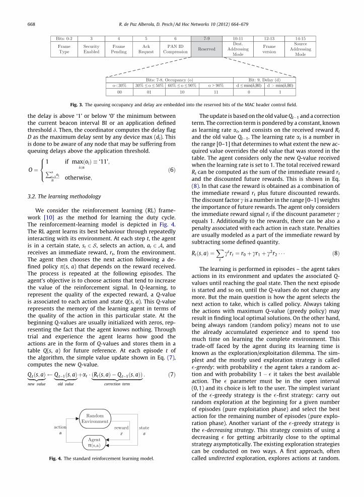
Fig. 3. The queuing occupancy and delay are embedded into the reserved bits of the MAC header control field.
668 R. de Paz Alberola, D. Pesch / Ad Hoc Networks 10 (2012) 664–679
the delay is above ‘1’ or below ‘0’ the minimum betweenthe current beacon interval BI or an application definedthreshold d. Then, the coordinator computes the delay flagD as the maximum delay sent by any device max (di). Thisis done to be aware of any node that may be suffering fromqueuing delays above the application threshold.
O ¼1 if maxðoiÞ
i2n� ‘11’;Pn
i¼1oi
n otherwise;
8><>: ð6Þ
3.2. The learning methodology
We consider the reinforcement learning (RL) frame-work [10] as the method for learning the duty cycle.The reinforcement-learning model is depicted in Fig. 4.The RL agent learns its best behaviour through repeatedlyinteracting with its environment. At each step t, the agentis in a certain state, st 2 S, selects an action, at 2 A, andreceives an immediate reward, rt, from the environment.The agent then chooses the next action following a de-fined policy p(s, a) that depends on the reward received.The process is repeated at the following episodes. Theagent’s objective is to choose actions that tend to increasethe value of the reinforcement signal. In Q-learning, torepresent the quality of the expected reward, a Q-valueis associated to each action and state Q(s, a). This Q-valuerepresents the memory of the learning agent in terms ofthe quality of the action in this particular state. At thebeginning Q-values are usually initialized with zeros, rep-resenting the fact that the agent knows nothing. Throughtrial and experience the agent learns how good theactions are in the form of Q-values and stores them in atable Q(s, a) for future reference. At each episode t ofthe algorithm, the simple value update shown in Eq. (7),computes the new Q-value.
Q tðs; aÞ|fflfflfflffl{zfflfflfflffl}new value
Q t�1ðs; aÞ|fflfflfflfflfflffl{zfflfflfflfflfflffl}old value
þat � ðRtðs; aÞ � Q t�1ðs; aÞÞ|fflfflfflfflfflfflfflfflfflfflfflfflfflfflfflfflfflffl{zfflfflfflfflfflfflfflfflfflfflfflfflfflfflfflfflfflffl}correction term
: ð7Þ
Fig. 4. The standard reinforcement learning model.
The update is based on the old value Qt�1 and a correctionterm. The correction term is pondered by a constant, knownas learning rate at, and consists on the received reward Rt
and the old value Qt�1. The learning rate at is a number inthe range [0–1] that determines to what extent the new ac-quired value overrides the old value that was stored in thetable. The agent considers only the new Q-value receivedwhen the learning rate is set to 1. The total received rewardRt can be computed as the sum of the immediate reward rt
and the discounted future rewards. This is shown in Eq.(8). In that case the reward is obtained as a combination ofthe immediate reward rt plus future discounted rewards.The discount factor c is a number in the range [0–1] weightsthe importance of future rewards. The agent only considersthe immediate reward signal rt if the discount parameter cequals 1. Additionally to the rewards, there can be also apenalty associated with each action in each state. Penaltiesare usually modeled as a part of the immediate reward bysubtracting some defined quantity.
Rtðs; aÞ ¼X
t
ctrt ¼ r0 þ cr1 þ c2r2 � � � ð8Þ
The learning is performed in episodes – the agent takesactions in its environment and updates the associated Q-values until reaching the goal state. Then the next episodeis started and so on, until the Q-values do not change anymore. But the main question is how the agent selects thenext action to take, which is called policy. Always takingthe actions with maximum Q-value (greedy policy) mayresult in finding local optimal solutions. On the other hand,being always random (random policy) means not to usethe already accumulated experience and to spend toomuch time on learning the complete environment. Thistrade-off faced by the agent during its learning time isknown as the exploration/exploitation dilemma. The sim-plest and the mostly used exploration strategy is called�-greedy: with probability � the agent takes a random ac-tion and with probability 1 � � it takes the best availableaction. The � parameter must be in the open interval(0,1) and its choice is left to the user. The simplest variantof the �-greedy strategy is the �-first strategy: carry outrandom exploration at the beginning for a given numberof episodes (pure exploitation phase) and select the bestaction for the remaining number of episodes (pure explo-ration phase). Another variant of the �-greedy strategy isthe �-decreasing strategy. This strategy consists of using adecreasing � for getting arbitrarily close to the optimalstrategy asymptotically. The existing exploration strategiescan be conducted on two ways. A first approach, oftencalled undirected exploration, explores actions at random.

R. de Paz Alberola, D. Pesch / Ad Hoc Networks 10 (2012) 664–679 669
The second way, referred to as directed exploration, usesdomain-specific knowledge for guiding exploration. Direc-ted exploration usually provides better results in terms oflearning time and cost.
One of the main limitations of RL is the slowness in con-vergence. The Q-learning convergence depends on theproblem itself and the agent definition: on the complexityof the action-state space, on the reward function and onthe exploration strategy used. Several methods that in-volve the incorporation of prior knowledge or bias intoRL have been proposed to speed up RL (see [11] and there-in). Using the inspirational work from ML researchers forspeeding up the learning, this work uses Q-learning tosolve the duty cycle adaptation problem as a non-station-ary multi-armed bandit problem [12]. In this problem thediscount parameter is set to zero so only immediate re-wards are considered. Not considering future rewards al-lows the agent to adapt faster to instantaneous changesin the environment. Considering the multi-armed banditalso reduces the state space to one variable whereas thenumber of actions that equals the number of levers thatcan be pulled off. Decreasing the complexity of the ac-tion-state space increases the speed of convergence innon-stationary environments and makes the algorithmmore suitable for the typical memory constrained micro-controllers found in WSN. In order to deal with the diffi-culty of detecting changes in the environment like in theevent-based scenario, the exploration and exploitationrates are continuously adjusted according to the rewardsobtained. The exploration is stopped after receiving a num-ber of neutral reward signals and re-started again whenthe reward varies. Also, the learning is adapted to the vari-ations in the reward signal so the learning speed is in-creased when there is uncertainty about theenvironment. The next section describes in detail the pro-posed duty cycle learning algorithm.
3.3. The DCLA algorithm
The DCLA algorithm is implemented as a software com-ponent compliant with IEEE 802.15.4 networks that config-ures the duty cycle during run time, without the need forhuman intervention, and with the aim of providing energyefficiency while fulfilling application requirements. Thealgorithm is proposed to be run by a coordinator that shalldetermine the optimal duty cycle without any prior knowl-edge of the environment by employing the RL techniqueknown as Q-learning. The RL agent is defined to have onlyone state and can take one of many actions similar to amulti-armed bandit problem. In our agent, each of the le-vers are the possible energy saving levels that the nodecan take which are defined as the difference between BOand SO values. Each action a 2 A that can be taken by theagent is related to the duty cycle as per the followingequation.
DC ¼ 2SO�BO ¼ 2�a ) a ¼ BO� SO 0 6 a 6 14: ð9Þ
Thus, each action a is proportional to the sleeping time,representing the level of energy the sensor is saving, whichis inversely proportional to the activity of the node (duty
cycle). A high value means that the duty cycle is low andthe node is thus saving batteries. Alternatively, a low valueimplies that the battery will be rapidly depleted. When theDCLA agent moves to a new action, its corresponding dutycycle can be calculated using Eq. (9) whereas BO, SO valuescan be selected following the beacon order and superframeorder algorithm described in Section 3.4.
The rule for exploring and selecting actions in DCLAaims to find an optimal balance between exploring andexploiting. If the environment is found to be static, thealgorithm exploits the best actions in its Q-table asthe training progresses. When the environment changes,the algorithm explores new actions according to therewards obtained. Therefore, DCLA controls the explora-tion/exploitation ratio by biasing the policy with the infor-mation obtained from the rewards in order to achieve fastconvergence in stationary conditions while being capableto adapt to changing environments. We explain in thefollowing the different steps taken by DCLA as per thepseudo-code shown in Algorithm 1:
1. Initialise variables. At the beginning of the algorithm theQ-values are initialised to their maximum value (nullvalue). This ensures that every action is visited duringthe preliminary exploration phase. The learning rate isalso set to its maximum amax = 1 due to the uncertaintyabout the environment. This selection speeds up thelearning process by maximising the immediate reward.Usually a lower learning rate is needed since otherwisethe Q-values will oscillate. However, since the devicestarts being awake all the time a = BO � SO = 0, whichis the worst case in terms of idle listening, the rewardvalues are guaranteed to increase and not oscillate thusavoiding delay in learning. Therefore, at the start the Q-learning equation becomes Qt(a) = rt(a) directly updat-ing the Q-value with the reward. The exploration rateis also set to its maximum �max = 0.1 which means thatwe select a random action with 10% probability. Thisgives the algorithm some randomness in its initialexploration as the learner has not been trained yet todirectly select the best action. The episode counter t isalso initialised at the start of the algorithm. The timebetween two successive episodes depends on the bea-con order that is decided by the coordinator.
2. Update reward. The coordinator updates the reward rt ateach beacon interval by using the feedback receivedfrom the senders during the last active duration. Thereward function, see Eq. (10), is formulated as the com-bination of penalty (negative) values that indicate theperformance of the last duty cycle selection. The bestreward is a value of zero (no penalties) as it would indi-cate that there is no idle listening and transmit queuesare not overflowing.
rtðaÞ ¼�1 if O > Omax;
�IL otherwise:
�ð10Þ
Specifically, the reward is based on a threshold compar-ison among the queue occupation indicator O and athreshold value Omax. If the occupation is above theupper threshold Omax, the reward signal is negative

670 R. de Paz Alberola, D. Pesch / Ad Hoc Networks 10 (2012) 664–679
and equal to the the maximum penalty of �1. Thismeans that the greater Omax is set the more chancesend devices have to drop packets and thus the loweris the reward obtained. The selection of this thresholdvalue represents how sensitive the application is toframe losses. Simulations suggested to set this valueto 0.8 in our tests. Other values for this parameter canbe set however depending on the reliability require-ment of the application. If the occupation is below thethreshold, the reinforcement signal is defined as a neg-ative value equal to the amount of idle listening. Thus,the idle listening acts as a penalty since the higher itis the lower is the reward that we get from the environ-ment. The maximum reward of zero (no penalties) isonly reached if the idle listening is zero and the occupa-tion indicator O indicates that there are not frame dropsin the transmitter queues. This represents our objectiveof achieving the best trade-off between bandwidthutilization and energy consumption.
3. Update Q-value. The quality of the action is updatedafter obtaining the reinforcement signal from theenvironment. To update the value Qt of the actionselected in t, the agent uses the immediate rewardsignal rt received from the environment, the learningrate at, and the value Qt�1 of the action in the lastepisode.
4. Initial exploration. During the initial episodes, the algo-rithm explores all the actions in the set by selectingthem in a deterministic manner following an increas-ing round-robin strategy. The device starts selectingthe minimum action value, which gives the highestduty cycle, and it increases the action selected eachepisode until reaching the maximum action value thatcorresponds to minimum duty cycle. Compared torandom exploration strategies, using initially theround-robin exploration ensures that all actions havebeen tried and thus the Q-table has been completelyfilled.
5. Random strategy. Once all the actions have beenselected, we select, if the reward is not minimum, with�t probability the next action following the randomstrategy p1(a) shown in Eq. (11). This strategy consistsof randomly exploring actions with higher duty cyclethan the current selection if the last statistic indicatesthat the reward has increased. Otherwise, if the rewardremains constant or it has decreased, it randomlyexplores actions with lower or equal duty cycle. Inaddition, the exploration rate is dynamically adaptedat each episode of the algorithm according to therewards received during the greedy selection of actionvalues.
p1ðaÞ ¼randðaÞ
a<at�1
if rt > rt�1;
randðaÞaPat�1
otherwise:
8><>: ð11Þ
6. Round-robin strategy. With a probability 1 � �t, the coor-dinator first assesses if the reward signal is minimal. Thismay occur, if the traffic has suddenly changed and sensornodes are either having frame overflows (O > Omax) or thecoordinator is always in idle listening (IL = 1). In that
case, the algorithm explores following a round-robinstrategy from the last optimal action. This strategy isused because it works well with the small size of ouraction set. The strategy, as expressed in Eq. (12),decreases the action value (increasing the coordinator’sduty cycle) if the nodes have maximum queue occupa-tion and the action value is not already minimum(at�1 > 0). The duty cycle increase is repeated each epi-sode until the reward increases again indicating adecrease on the traffic. Alternatively, if the coordinatoris at maximum idle listening (IL = 1) and the action valueis not already maximum (at�1 < jAj), it obtains the nextaction decreasing its duty cycle. In both cases, the learn-ing rate is increased by �s = �max/10, to learn faster thenew action-value quality that allows adapting to theenvironment.
p2ðaÞ ¼at�1 � 1 if O > Omax;
at�1 þ 1 otherwise:
�ð12Þ
7. Greedy strategy. If neither the random or round-robinexploration strategies are activated, the algorithmexploits the action with the best Q-value by usingthe greedy strategy p3(a) as shown in Eq. (13). Whenthe reward signal obtained is higher than in the lastepisode, that is the traffic has increased, the greedystrategy selects the action with the best Q-valueamong the subset of actions with lower action value,or in other words higher duty cycle, than the oneselected in the last episode. In the case of severalactions in the selected subset having the same Q-value, the action with the lowest duty cycle (highestaction value) is selected. This means that we selectthe best action with the lowest duty cycle becausethe traffic has increased since the last step of the algo-rithm. Alternatively, it selects the best Q-value amongthe subset of higher actions if the reward is equal orlower than the one received in the last episode. Again,for similar Q-values in the set of actions, the actionwith lowest duty cycle is selected. Therefore, in stableconditions, the minimum duty cycle is preferred. Oncethe action at is selected, the learning and explorationrates are increased, by as and �s values respectively,if the new action value is different from the last epi-sode. The step value as equals amax/10. The increaseon these rates is done to speed up the learning andto ensure that all actions are being explored whenthe environment is changing. If however the newaction equals the last action selected, the learningand exploration rate are decreased to avoid oscilla-tions in the selection of optimal action.
p3ðaÞ ¼min
DCargmax
a<at�1
QðaÞ if rt > rt�1:
minDC
argmaxaPat�1
QðaÞ otherwise:
8><>: ð13Þ
8. Select DC. After the action value is selected, the Algo-rithm 2 is called to select the BO and SO standardparameters that will determine the duty cycle. Thisselection is based on the delay experienced by thedata frames as explained during the next section.The parameter values BO and SO are embedded in

R. de Paz Alberola, D. Pesch / Ad Hoc
the beacon frame that is broadcast to end devices inorder to synchronise. The DCLA algorithm is not trig-gered again until the next BI at which it is repeatedfrom step 2.
Algorithm 1. Duty cycle learning algorithm
1: function DCLA (IL,O,D)2: � �max,a amax,a 0,Q(a) 03: for t = 0 to end do4: t t + 15: if O > Omax then6: rt = �17: else8: rt = �IL9: end if10: Qt(a) Qt�1(a) + at [rt(a) � Qt�1(a)]11: if t < jAj then12: at at�1 + 113: els if �t > rand() and rt > �1 then14: at p1(a) . Random strategy15: else16: if (O > Omax and at�1 > 0) or (IL = 1 and
at�1 < jAj) then17: at p2(a) . Round-robin18: at min (amax,at + as)19: else20: at p3(a) . Greedy strategy21: if at = at�1 then22: at max (amin,at � as)23: �t max (�min,�t � �s)24: else25: a min (amax,at + as)26: � min (�max,�t + �s)27: end if28: end if29: end if30: DC = BOandSOSelection (at,D)31: sendBeacon (BO, SO)32: end for33: end function
Algorithm 2. Beacon Order and Superframe Order
Selection1: function BOANDSOSELECTION (at,D)Initialise BO0 ¼maxð4; jAj ! ðBI� SDÞ < dÞ
2: if t > jAj and �min = 0 then3: if E(O) < Omax and D < d then4: jAj minð14; jAj þ 1Þ5: end if6: els if O > Omax and �min = 0 then7: jAj maxðBO0; jAj � 1Þ8: else9: jAj BO0
10: end if11: BO jAj12: SO max (0,BO � at)13: return DC = 2SO�BO
14: end function
3.4. The beacon order and superframe order selection
Immediately after the DCLA agent has decided the nextaction to take, the beacon order BO and superframe orderSO need to be selected. The simplest way to do this is tofix one of both parameters and select the other one accord-ing to Eq. (9). This is usually done by fixing SO to a low va-lue and adapting BO or fixing BO to a high value andadapting SO. Adapting BO every BI has the drawback ofincreasing the probability of synchronisation loss. This oc-curs when a device does not receive the beacon that carriesthe new BO value. Then, the node is not able to synchroniseat the start of the next superframe meaning that the devicemay likely lose subsequent beacons until reaching theaMaxBeaconLost value that triggers the orphan scan. Duringthe orphan scan the device has to stay in receive mode un-til receiving a beacon frame to resynchronise. This repre-sents a waste of energy for the node and thus a source ofenergy inefficiency. Moreover, in this type of approaches,the SO value is then generally fixed to a low value (e.g.SO = 0). This increases the number of collisions that occurdue to deferred uplink transmissions as has been reportedin [13]. On the other hand, always fixing BO has also sev-eral flaws. If it is fixed to a high value, the convergence rateof the algorithm is decreased making the adaptation diffi-cult to network changes. Furthermore, delays and framedropping can be proportionally increased because a highBO value leads to longer sleep times between beacons.Alternatively, if BO is fixed to a low value the range of pos-sible duty cycles is decreased due to the restrictionSO 6 BO and nodes may suffer of unnecessary beacon over-heads since beacons are more frequent.
We propose Algorithm 2 for the selection of BO and SOvalues. During the initial exploration phase ðt 6 jAjÞ, thealgorithm initialises the beacon order to the cardinality ofthe action set. The cardinality jAj represents the size of theaction space and it is used for the selection of BO and SO val-ues. The cardinality value is initialised to the maximum va-lue among the application delay and BO P 4 requirement.Specifically, the delay requirement is that the BO shall en-sure that the delay incurred during queuing, given by themaximum sleeping time (BI � SD), meets the delay require-ment d. For instance, for an application requirement d = 2 sthe cardinality is initially set to 7. The other requirementindicates that the BO should be higher than 4 so we minimisedeferences and beacon overhead. Assuming that the super-frame duration is able to cope with the traffic, this imposesa minimum delay of 240 ms for the application. The super-frame order is then selected according to Eq. (9). Thus, theSO only equals zero when there is low contention (minimumduty cycle) so we minimise the collisions due to deferringtransmissions. We then priorise adapting the superframe or-der over the beacon order to minimise beacon losses thatmay lead to desynchronise devices.
After this initial exploration phase, the range of possibleaction values and thus the BO is changed according to thetraffic statistics and stability of the algorithm. The range ofpossible values is increased if statistics and stability condi-tions are met. The stability condition ensures that we donot reduce the adaptation rate when the environment isunpredictable. We therefore only allow the increase of
Networks 10 (2012) 664–679 671

672 R. de Paz Alberola, D. Pesch / Ad Hoc Networks 10 (2012) 664–679
BO if the exploration rate is zero which means that thealgorithm has converged to an action-value. The statisticalconditions are that the expected queue occupation E(O) islower than Omax and the delay D is lower than the applica-tion delay requirement. The expected occupation is equalto the current occupation due to the binary exponential in-crease of the BO parameter (E(O) = O + O/2). The delay iscalculated from the delay flag sent in the MAC header (asexplained in Section 3.1). This condition ensures that thedelay is never greater than required by the application.
The action space is reduced if the occupation is higherthan the maximum but the algorithm has not startedexploration. This is done to avoid increasing packet drops.Finally, any time the exploration has started again due touncertainties about the incoming traffic pattern, the BO isset to its initial value. This is done so the frequency ofadaptation of the algorithm is not decreased while theagent is learning. This beacon order and superframe orderselection allows to maximise energy efficiency withoutincreasing delay or packet drop as results will show later.
3 ppm: parts per million, i.e. 10�6
4. Evaluation
This section presents an evaluation of the proposedduty cycle learning algorithm. The performance metricsused for comparison and simulator models are explainedfirst. Afterwards, the DCLA algorithm is evaluated in anumber of steps. Firstly the speed of convergence andmemory requirements of the algorithm are analysed. Sec-ondly, the operation of the different duty cycle adaptationapproaches for IEEE 802.15.4 its compared to DCLA forboth periodic and event-based scenarios. The most impor-tant performance metrics used in the evaluation are ex-plained as follows:
� Network offered load (NOL). The network offered load isthe amount of data generated by all the wireless sensornodes in the network at a particular time, measured inbits per second (bit/s or bps).� Energy efficiency (Eeff). It is defined as the total success-
fully transmitted and/or received information bits perJoule of energy spent by the sensor node. This indicatoris important due to the energy constrained nature ofwireless sensor nodes.� End-to-end delay (D). It is the average delay experienced
by the sensor data from its generation at the sender’sapplication layer to the end of its reception at the recei-ver. This value is measured in seconds.� Probability of success (PS). This indicator is obtained as
the goodput divided by the offered load at the applica-tion layer. It reflects the degree of reliability achievedby the wireless sensor network protocol for applicationgenerated data. A data frame sent can be dropped at thesender prior to be correctly received due to the follow-ing reasons: (i) the data frame cannot be inserted intothe transmit queue because it is already full; (ii) thenode fails more than macMaxCSMABackoffs times toacquire the channel; (iii) the node succeeds at acquiringthe channel but the data transfer attempt fails morethan macMaxFrameRetries times.
4.1. Simulation environment
The DCLA algorithm was designed and tested withinthe OPNET network simulator [14]. This simulator waschosen over other WSN simulators because of its accuracy,practical graphical user interface and low overhead. Wespecifically employed the Open-ZB simulation model[15] as the basis for our protocol development to whichwe added several features that we needed for our protocoldevelopment.
We consider in our traffic model some essential ele-ments of typical wireless sensing applications. The modelaims to simulate environmental monitoring and targettracking. Monitoring applications are usually based onconstant periodical reports. Periodical reports are gener-ated in the simulator through a constant bit rate (CBR) dis-tribution. Each data frame has a header size equal to 104bits (according to the standard specifications) and a pay-load of 300 bits. This choice of payload is just an exampleof a small frame size as typically used in WSN applications.On the other hand, same sensors may also be used for tar-get tracking. The traffic model for the target tracking appli-cation is based on the curve fitting that Wang and Zhangcarried out in [16] following the ON/OFF model. In thisevent-based traffic model, each ON interval correspondsto a time span when the target appears within the sensingrange and each OFF interval represents a time span whenthe target is out of the sensing range. The length of theON and OFF intervals is modelled following a generalizedPareto distribution with short finite tails. The distributionof the traffic rate within the ON period follows a truncatednormal distribution, with a mean equal to 0.5 s and a stan-dard deviation of 0.01 s.
In order to analyse the time-critical parts of a protocolstack such as energy efficient synchronization protocols, arealistic model of the nodes hardware (HW) clock is re-quired. The local time provided by the HW clock of a sen-sor node as a function c(t) of the real-time t. The HW timeis usually the value of a counter that counts intervals of anideally fixed length. The clock drift q(t) is defined as thedeviation of the clock rate at which the counter is actuallyincremented by the oscillator and the ideal rate 1: q(t) =(dc(t)/dt) � 1. An ideal clock would therefore have driftq � 0. But we consider that, due to changes in tempera-ture and supply voltage, the clock drift fluctuates overtime. We simulate these clock variations in our modelby randomly generating drift values qk. These values aregenerated within a range of drift values in which the clockdrift and its variations over time are bounded. A reason-able range in standard sensor nodes is [10,100] ppm3.Thus, the HW clock time at a time instant k is computedin our simulator as:
ckðtÞ ¼ t þ qk where q 2 ½10;100� ppm; ð14ÞOperations in the communication protocol that requiretime synchronization such as the reception of a beaconmust account for this time drift. Therefore, end devicesare woken up every beacon interval a time t > qk prior

R. de Paz Alberola, D. Pesch / Ad Hoc Networks 10 (2012) 664–679 673
the beacon reception in order to avoid the lost ofsynchronization.
In addition, to be able to assess the average powerconsumption of each node, we characterize the instanta-neous power consumption of the transceiver when oper-ating in and switching between states. The energyconsumed by the microcontroller, sensors and other elec-tronics is not considered as the proposed algorithm doesnot have any effect on them. We consider the well knownTI CC2420 [17] radio chip for our battery model. Thetransceiver supports five states as shown in Fig. 5. Duringthe off state, the chip is completely deactivated as thevoltage regulator is off. In the shutdown state, the voltageregulator is on but the clock oscillator is switched off sothe chip is just waiting for a start-up strobe. In idle state,the clock is turned on and the chip can receive commands(for example, to turn on the radio circuitry) but stillcannot receive any frame. Finally, transmit and receiveare employed for transmitting and receiving framesrespectively and are the most power consuming states.Transient energies for switching from one mode to an-other are also taken into account as they could signifi-cantly impact on the total energy consumption whenoperating at low duty cycle [18]. Hence, it is importantto precisely characterize the transition time and energybetween the transceiver states when modelling theenergy expenditure. Steady state power, transient timeand energy measurement are therefore obtained fromradio chip data sheets. Then, the state transition energyEt is computed by multiplying the transition time bythe power in the arrival state as follows:
Et ¼ tt � Im � Vs where m ¼ target power mode: ð15Þ
Fig. 5. Steady state power, energy and transient times for the CC2420battery model.
This is a worst-case assumption. One may note from thefigure that the idle state power is much higher than thepower in shutdown and off states. To achieve low powerconsumption, the transceiver must enter the shutdownstate when no action is required. The total energy Ec con-sumed by the radio chip is calculated employing the fol-lowing linear state model:
Ec ¼ Vs �X½Im � ðtm þ ttÞ� where m ¼ tx; rx; id; sp; ð16Þ
where Vs is the supply voltage, Im the current draw for thepossible energy modes (transmit, receive, idle, sleep), tm isthe time spent in each mode and tt the transition time forswitching to that energy mode.
Finally, the default wireless physical channel modelavailable in OPNET uses a free space propagation model.To create a more realistic channel, we have modified themodel so that the wireless channel considers the pathlosspower law and the fading due to the movement of peopleor obstacles in the radio path. The chosen fading model[19] considers that rapid and frequent transitions betweenline of sight (LOS) and non line of sight (NLOS) occur in typ-ical node locations due to movement of obstacles in theradio path such as people. The fading in this model is de-fined as a combination of a coherent part represented bya Rice distribution and a diffuse part arising from multi-path NLOS components which are represented by a mix-ture of Lognormal and Rayleigh distributions. We use alookup table as described in [20] in order to obtain theappropriate statistics and time co-relational properties ofthe fading distributions.
4.2. Analysis
We analyse during this section the proposed duty cyclelearning algorithm. Firstly, we study the convergence ofthe algorithm. Secondly, we evaluate the memory and pro-cessing requirements of DCLA compared to the other state-of-the-art approaches. Thirdly, we show the impact of theWSN statistics on the reward formulation. We finalise thesection analysing the algorithm used for the Beacon andSuperframe Order selection.
4.2.1. Speed of convergenceWe analyse the speed of convergence of the proposed
algorithm by studying the time DCLA spends to stabilise.In our scenario, convergence means that firstly, the proto-col is stable and the Q-values do not change any more, andsecondly and more importantly, that the optimal duty cy-cle has been identified. The original Q-learning algorithmwas shown to converge after an infinite number of steps[21], however our algorithm needs to converge after a fi-nite and fairly low number of steps or the network perfor-mance could be degraded. The time to converge can beobtained by counting the number of episodes needed be-fore the agent selects consecutively the same action sothe exploration rate becomes zero. In a network with nend devices and a central coordinator, the Q-learning algo-rithm starts with maximum learning rate and a determin-istic exploration strategy that chooses the duty cycles in around-robin manner. With a = 1 the feedback obtained at

Fig. 6. SRAM requirement for the duty cycle adaptation algorithms formicaZ platform.
674 R. de Paz Alberola, D. Pesch / Ad Hoc Networks 10 (2012) 664–679
any action is used for direct replacement of the old Q-va-lue. Thus, in order to learn the Q-values at any duty cycle,we need jAj þ 1 steps. After this time, the coordinator usesan �-decreasing strategy in which it decreases theexploration rate by �t any time the same action is greedilyselected. Then, the number of action selection steps t thatthe algorithm need in order to converge is t P jAjþ1þ �max=�min which is equal to 25 in the worst casescenario ðjAj ¼ 14Þ. In addition, the coordinator has to firstwait in order to associate with all nodes to start receivingtheir traffic and stabilize the Q-values. In the worstcase it has to wait for all the nodes to start prior stabilizingthe Q-values. In the simulations this time was set to10 s.
This is the minimum number of steps needed by theprotocol to converge. After convergence, exploration canbe stopped and the algorithm can proceed in a greedymanner, as the best duty cycle has been identified andhas the best Q-value among all available. Although this isnot a real traffic scenario in WSNs – real networks usuallyfollow event driven or longer periodic traffic patterns, itgives us an idea about the convergence of the algorithm.Also, the above proof is built under the assumption of per-fect communication. However, in the real world wirelesscommunication is seldom perfect. Packet losses are usualand have to be considered. However, assuming some prob-ability pm for delivering the first message and thus the buf-fer occupancy values is enough to maintain theconvergence of the algorithm. The convergence will takelonger, but the correctness is not violated if the probabilitypm is non-zero.
The above analysis is given for the first phase of the pro-tocol with deterministic round-robin strategy. However,after that phase, the exploration may be started againdue to fading or variations in the incoming traffic. Thus,the exact time to converge is hard to compute because ofthe non-deterministic nature of the environment.
4.2.2. Memory and processing requirementsOne of the crucial factors on the design of an algorithm
for embedded sensor systems is the consideration of itsmemory and processing requirements. DCLA has been de-signed to have low memory requirements by for instancelimiting the state–action space needed by the reinforce-ment learning agent. We consider for the evaluation ofthe proposed algorithm the micaZ platform from the micafamily of sensor nodes [22]. The micaZ uses the ATme-ga128 processor which has 128 KB of flash (ROM) and4 KB of SRAM. The ROM is used for the program code andinitial values of global variables for which 128 KB is usuallyenough memory. On the other hand, the SRAM is used forstoring the global variables and is usually a limitationwhen running applications. Furthermore, this processordoes not have a floating point unit so all the arithmeticcomputation is done in software rather than hardware.This makes the computation of each floating point opera-tion expensive in terms of processor cycles. We thus sug-gest to implement the proposed algorithm using fixedpoint operations instead of floating point. Therefore, inte-ger variables are used to represent the fractional valuesof the algorithm with a fixed precision behind the decimal
point. This allows much faster execution than floatingpoint operations. For this, global variables were roundedto their minimum required amount of fractional precision.
Fig. 6 shows the SRAM requirement for the differentalgorithms. The most memory consuming component ofDCLA are the Q-values. The coordinator node requires tostore the quality of all the available actions in order torun effectively. The Q-value of every action is limited to aprecision of 8 bits. Mapping the values into several levelsnot only reduces the memory requirements but also re-duces the probability of oscillating around optimal duty-cycles. The maximum number of actions is equal to 14which is the maximum difference among the beacon andsuperframe order values. This represents a total storagespace requirement of 112 bits for the Q-table. In addition,the learning algorithm needs to store the learning andexploration rates as it may vary from one episode to thenext depending on the rewards received. These rates aremapped onto a maximum of 10 different levels and there-fore stored as 4 bit variables. Finally, in addition to the Q-values, the reward obtained during the last episode isstored in a 8 bit variable to compute the variance of thetraffic.
Apart from the learning agent parameters, the algo-rithm employs the initial and current cardinality of theset jAj for use in the BO and SO selection algorithm. Thesetwo variables are stored in 3 bits each. Also, WSN statisticssuch as idle listening (4 bits), delay (1 bit) and queue occu-pation (4 bits) are used. This gives a total memory require-ment of 143 bits which represents less than 3% of availableSRAM on the micaZ platform. This proves the suitability ofthe algorithm for embedded WSNs. On the other hand, theprocessing requirements for DCLA include updating the Q-value and selecting the duty cycle. The update of a Q-valueis itself an atomic operation: given the old Q-value and thereward, it calculates the new one. Its complexity is thusminimal. Selecting the duty cycle requires in the worstcase scenario to loop through all available values to com-pare them in terms of their rewards and is thus boundedby the maximum number of actions.
The DCA and AMPE approaches require less memorythan DCLA. The DCA algorithm, apart from the SO and BOvalues, only needs to store the previous SO, and the latestqueuing statistics received by any node in a three bits ma-trix. Alternatively, its highest processing requirements arethe computation of two log2 operations in order to esti-mate the SO value. AMPE has also low memory require-ments as it only has to store the number of messagesreceived during the previous interval to determine if it
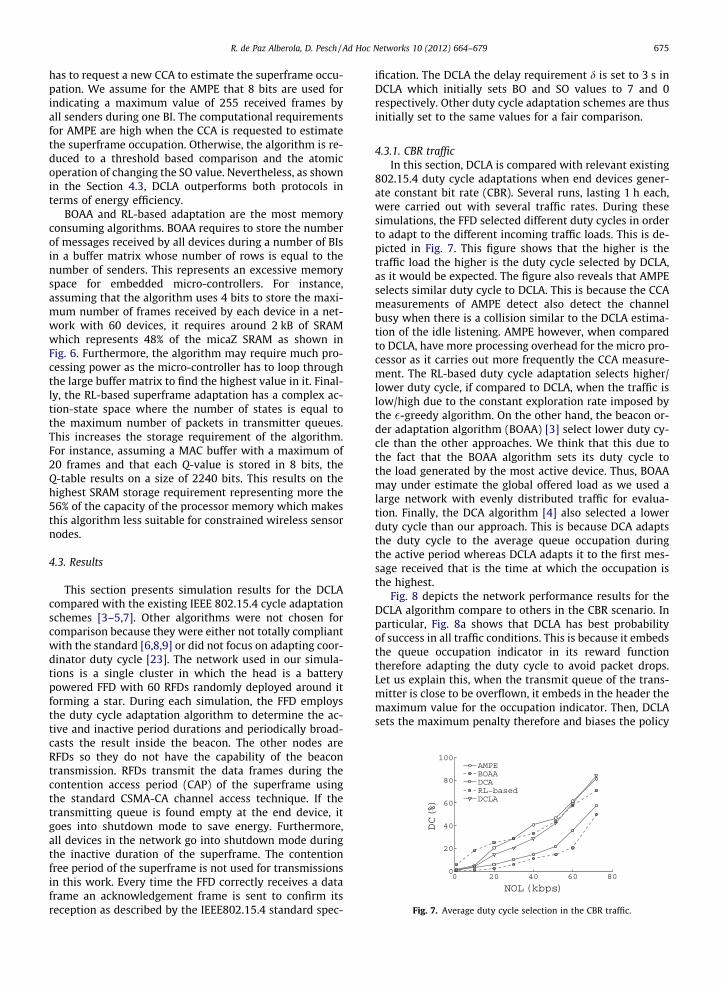
Fig. 7. Average duty cycle selection in the CBR traffic.
R. de Paz Alberola, D. Pesch / Ad Hoc Networks 10 (2012) 664–679 675
has to request a new CCA to estimate the superframe occu-pation. We assume for the AMPE that 8 bits are used forindicating a maximum value of 255 received frames byall senders during one BI. The computational requirementsfor AMPE are high when the CCA is requested to estimatethe superframe occupation. Otherwise, the algorithm is re-duced to a threshold based comparison and the atomicoperation of changing the SO value. Nevertheless, as shownin the Section 4.3, DCLA outperforms both protocols interms of energy efficiency.
BOAA and RL-based adaptation are the most memoryconsuming algorithms. BOAA requires to store the numberof messages received by all devices during a number of BIsin a buffer matrix whose number of rows is equal to thenumber of senders. This represents an excessive memoryspace for embedded micro-controllers. For instance,assuming that the algorithm uses 4 bits to store the maxi-mum number of frames received by each device in a net-work with 60 devices, it requires around 2 kB of SRAMwhich represents 48% of the micaZ SRAM as shown inFig. 6. Furthermore, the algorithm may require much pro-cessing power as the micro-controller has to loop throughthe large buffer matrix to find the highest value in it. Final-ly, the RL-based superframe adaptation has a complex ac-tion-state space where the number of states is equal tothe maximum number of packets in transmitter queues.This increases the storage requirement of the algorithm.For instance, assuming a MAC buffer with a maximum of20 frames and that each Q-value is stored in 8 bits, theQ-table results on a size of 2240 bits. This results on thehighest SRAM storage requirement representing more the56% of the capacity of the processor memory which makesthis algorithm less suitable for constrained wireless sensornodes.
4.3. Results
This section presents simulation results for the DCLAcompared with the existing IEEE 802.15.4 cycle adaptationschemes [3–5,7]. Other algorithms were not chosen forcomparison because they were either not totally compliantwith the standard [6,8,9] or did not focus on adapting coor-dinator duty cycle [23]. The network used in our simula-tions is a single cluster in which the head is a batterypowered FFD with 60 RFDs randomly deployed around itforming a star. During each simulation, the FFD employsthe duty cycle adaptation algorithm to determine the ac-tive and inactive period durations and periodically broad-casts the result inside the beacon. The other nodes areRFDs so they do not have the capability of the beacontransmission. RFDs transmit the data frames during thecontention access period (CAP) of the superframe usingthe standard CSMA-CA channel access technique. If thetransmitting queue is found empty at the end device, itgoes into shutdown mode to save energy. Furthermore,all devices in the network go into shutdown mode duringthe inactive duration of the superframe. The contentionfree period of the superframe is not used for transmissionsin this work. Every time the FFD correctly receives a dataframe an acknowledgement frame is sent to confirm itsreception as described by the IEEE802.15.4 standard spec-
ification. The DCLA the delay requirement d is set to 3 s inDCLA which initially sets BO and SO values to 7 and 0respectively. Other duty cycle adaptation schemes are thusinitially set to the same values for a fair comparison.
4.3.1. CBR trafficIn this section, DCLA is compared with relevant existing
802.15.4 duty cycle adaptations when end devices gener-ate constant bit rate (CBR). Several runs, lasting 1 h each,were carried out with several traffic rates. During thesesimulations, the FFD selected different duty cycles in orderto adapt to the different incoming traffic loads. This is de-picted in Fig. 7. This figure shows that the higher is thetraffic load the higher is the duty cycle selected by DCLA,as it would be expected. The figure also reveals that AMPEselects similar duty cycle to DCLA. This is because the CCAmeasurements of AMPE detect also detect the channelbusy when there is a collision similar to the DCLA estima-tion of the idle listening. AMPE however, when comparedto DCLA, have more processing overhead for the micro pro-cessor as it carries out more frequently the CCA measure-ment. The RL-based duty cycle adaptation selects higher/lower duty cycle, if compared to DCLA, when the traffic islow/high due to the constant exploration rate imposed bythe �-greedy algorithm. On the other hand, the beacon or-der adaptation algorithm (BOAA) [3] select lower duty cy-cle than the other approaches. We think that this due tothe fact that the BOAA algorithm sets its duty cycle tothe load generated by the most active device. Thus, BOAAmay under estimate the global offered load as we used alarge network with evenly distributed traffic for evalua-tion. Finally, the DCA algorithm [4] also selected a lowerduty cycle than our approach. This is because DCA adaptsthe duty cycle to the average queue occupation duringthe active period whereas DCLA adapts it to the first mes-sage received that is the time at which the occupation isthe highest.
Fig. 8 depicts the network performance results for theDCLA algorithm compare to others in the CBR scenario. Inparticular, Fig. 8a shows that DCLA has best probabilityof success in all traffic conditions. This is because it embedsthe queue occupation indicator in its reward functiontherefore adapting the duty cycle to avoid packet drops.Let us explain this, when the transmit queue of the trans-mitter is close to be overflown, it embeds in the header themaximum value for the occupation indicator. Then, DCLAsets the maximum penalty therefore and biases the policy

Fig. 8. Results for the scenario with CBR traffic.
676 R. de Paz Alberola, D. Pesch / Ad Hoc Networks 10 (2012) 664–679
to select and action with higher duty cycle. Furthermore,DCLA idle listening estimation takes into account the colli-sions so increases the duty cycle when there is high con-tention. This results in less number of collisions andframes dropped in the transmit queues (higher PS).
On the other hand, Fig. 8b depicts the average end-to-end delay. All duty cycle adaptation algorithms increasetheir delay when the network offered load is lower. Thisis because they select longer inactive periods which meansdata frames need to wait longer before being dispatchedfrom the transmit queue. It is also shown in this figure thatDCLA meets the delay requirement of 3s. This is because, asexplained in Section 3.4, the selection of the MAC parame-ters (BO, SO) limits the maximum inactive period to the de-lay requirement. In the other algorithms, the delay is lowerfor the duty cycle adaptations that take into account thequeuing delay (DCA, RL-based) compared to those that donot (AMPE, BOAA). This parameter must therefore be pres-ent in the adaptation when working with delay demandingapplications.
Finally, Fig. 8c and Fig. 8d show the average energy effi-ciency results for reduced and full function devices respec-tively. DCLA has best energy efficiency for RFDs. This isbecause the duty cycle considers queue occupation andnumber of collisions at the device. Therefore, the more bitsare delivered and the lower energy is spent by RFDs inretransmissions compared to other approaches. Moreover,the BO and SO selection algorithm in DCLA reduces, whenpossible, the RFDs energy expenditure due to beacon over-head as it increases the beacon interval when delay andqueue occupation are found below the application require-ments. On the other hand, the energy efficiency at the FFDfor DCLA also outperforms the other approaches proving
that the learning algorithm meets its objecting of selectingthe duty cycle that minimises the idle listening of thedevice.
4.3.2. Event-based trafficThis section evaluates DCLA with regard to an scenario
with event-based traffic. For the event-based data genera-tion, we take the example of target tracking applications.When the target to track enters into the area, the eventis detected by the nodes close to the target and they startgenerating data following the ON/OFF model explained inSection 4.1. Besides the event-based data, the sensorsnodes generate periodic data for monitoring purposes. Inthis scenario the 60 nodes send data frames every 1 swhich still allows the FFD to stay in sleep mode duringapproximately 90% of the time before any event has beendetected.
In a first test, the target enters into the area after 500 sand only six nodes in the network are able to detect theevent. After this time, the event-based data generation fol-lows the fitted Pareto distribution described in Section 4.1.The instantaneous duty cycle selection that DCLA selectsover the time is depicted in Fig. 9. As it can be seen, DCLAstarts with round-robin strategy to select different duty cy-cles and continues with an decreasing �-greedy strategyuntil achieving a stable action. Then, when the trafficchanges, the DCLA protocol increases the learning rateand uses directed round-robin exploration to select thenew duty cycle. As depicted in the figure, this is a muchfaster and precise approach to find the new duty cyclecompared with the traditional �-strategy used by authorsin [6,7]. In the �-greedy strategy there is a fixed explorationand learning rate. The fixed exploration means that the

Fig. 9. DCLA instantaneous duty cycle selection for event-based traffic.
Fig. 10. Results for event-based traffic when varying the number of sensors detecting the event.
R. de Paz Alberola, D. Pesch / Ad Hoc Networks 10 (2012) 664–679 677
algorithm explores other actions with a fixed probability(0.1 in this test). In addition, this exploration is undirectedwhich means that actions to explore are chosen at random.The DCLA algorithm however, decreases the explorationrate after the same action has been chosen a number ofconsecutive episodes and chooses the next action accord-ing to the traffic variations, that is, the exploration is direc-ted towards higher or lower duty cycles depending on theincrease or decrease of the load. Also, the learning rate isadapted in DCLA to the traffic which allows faster adapta-tion to the traffic burst.
During a second test, the number sensor nodes in thenetwork that detect the event is varied from 0 to 40. Forthe FFD that runs the duty cycle adaptation protocol, thisresults in different sizes of the incoming traffic burst.Fig. 10 shows the performance of the DCLA algorithm forthis test compared to other duty cycle strategies. The prob-ability of success decreases in all approaches when thenumber of sensors detecting the event increases. This is be-cause more data frames are being generated during thesame ON period length which results in higher packetdrops. DCLA however minimises this effect when com-pared to other approaches and shows better adaptationto the traffic burst. This is because the directed round-ro-bin exploration allows the algorithm to quickly find thebest duty cycle during the traffic burst and therefore losea lower number of data frames. Specifically, DCLA presents
around a 20% gain over the RL-based superframe adapta-tion. This is because DCLA direcly searches for an upperor lower duty cycle when there is an increase or decreaseof the traffic, it adapts the exploration rate to the changesand has a far less complex action-state space to explore. Italso improves compared to AMPE as this algorithm de-creases almost linearly to the increase of sensor nodesdetecting the event. The reason for this is that the FFD onlytriggers the CCA if the number of frames is doubled whenthe traffic burst occurs. The superframe occupation is how-ever usually set higher than 0.5 before the event and there-fore there is not enough space to cope with such increase.Therefore, AMPE does not usually detect the increase untilthe next updating period resulting in packet drops andlower PS. On the other hand, BOAA does not decrease fromthe pure CBR case its PS as it bases its adaptation on themost active device. Then, as the number of frames sentby the device that detects the event increases compare tothe others, the FFD running BOAA increases the activeduration.
Fig. 10b shows the energy efficiency for this test. Wecan see that DCLA is more energy efficient than the restof duty cycle adaptations. Specifically, DCLA energy effi-ciency ranges from 750 to 920 Kb/J. However, the otheradaptations present energy efficiencies approximately20% lower. This means that the proposed algorithm is ableto deliver 20% more data or,in other words, it is able to

Fig. 11. Results for event-based traffic when varying ON period length.
678 R. de Paz Alberola, D. Pesch / Ad Hoc Networks 10 (2012) 664–679
increase the network lifespan by 20% when compared toother duty cycle adaptations. The reason behind this gainis that DCLA adapts the duty cycle faster to the increaseand traffic decrease and remembers the best duty cycle se-lected during the burst thanks to the stored table of Qvalues.
Finally, to investigate the influence of the burst timelength on the duty cycle adaptation, a third test is carriedout, the goal of this test is to simulate events lasting differ-ent periods of time (for example detecting a person thatjust passes by or that remains for short while standing atthe same position). For this, the ON timer length is variedfrom 0 s to 35 s. The number of sensors detecting the eventis also fixed and equal to 6. The results for the FFD energyefficiency and probability of success are shown in Fig. 11aand Fig. 11b respectively. The probability of success in allalgorithms decreases when some events exist on the net-work compared to the pure CBR case. This is mainly be-cause the event is sometimes detected by the sensorwhile the radio is in shutdown state (inactive period). Inthat case, the FFD does not receive the statistics aboutthe traffic increase until the next active period whichmay cause queue overflows. However, the proposed DCLAalgorithm presents better PS than the other duty cycleadaptations as it quickly detects the variation on the re-ward thus adapting its policy selection of the duty cycle.Furthermore, when the traffic burst is longer, the DCLAalgorithm has more time to converge during the first burst(reach � = 0) duration and find its best higher duty cycle.Afterwards, it will use this knowledge during the consecu-tive traffic bursts to greedily select the higher duty cyclethat has the highest Q-value. All other algorithms do nothave this learning mechanism and they have to learn thenew duty cycle every time a new event is detected. Thissignificantly decreases their probability of success andenergy efficiency.
Although DCA presents lower probability of successthan other algorithms due to its underestimation on theduty cycle selection, it adapts better than other algorithmsto fast fluctuations of the traffic. This is because it directlycomputes in every BI the next duty cycle according to thenumber of expected packets. Other algorithms however,like AMPE and BOAA, only adapt the duty cycle in a stag-gered manner which slows the duty cycle adaptation. Thisresults in lower probability of success and energy effi-ciency during the ON period. The effect is nevertheless
reduced for longer ON period durations as they are ableto reach a high duty cycle before the traffic burst finishes.Furthermore, AMPE presents a higher packet losses withhigher ON period lengths because it does not detect thestart of the event until the timer for performing CCA isreached. This timer is fixed to minimise micro-controllerprocessing overhead unless the number of received framesis doubled or halved during one BI. However, we discov-ered in this test that when the superframe utilizationwas high before detecting the event, the increase in thenumber of data frames received did not doubled butcaused overflows at transmit queues. Alternatively, theBOAA algorithm suffers a lower decrease on the probabilityof success from the stationary case because the number offrames sent by the most active device is increased duringthe traffic burst above the threshold. Finally, the RL-basedsuperframe adaptation shows lower efficiency and proba-bility of success than DCLA since it explores actions at ran-dom independently of the fluctuation of the traffic. Thismeans that these algorithms may trigger the explorationof lower duty cycles even though the traffic has increaseddue to an event detection.
5. Conclusion
This paper proposes a duty cycle learning algorithm(DCLA) for minimising IEEE802.15.4 based wireless sensornodes power consumption while balancing probability ofsuccessful data delivery and delay requirements of theapplication. The algorithm does not require any modifica-tions to the IEEE 802.15.4 standard. The adaptive algorithmis formulated as a multi-armed bandit problem where theagents objective is to minimise idle listening and bufferoverflows. The actions are defined as the sleep schedulesof the protocol and the exploration and exploitation poli-cies are continuously adjusted according to the feedbackinformation provided by the network. Moreover, the MACparameters (BO, SO) are selected such as to find a compro-mise between beacon overhead and queuing delay.
The proposed adaptive algorithm is easily implement-able by collecting the statistics that aid estimating the traf-fic, updating the quality of the actions and selecting thenext duty cycle according to the most convenient policy.We analysed the memory requirements of the algorithmand numerical results show that it is suitable for the hard-

R. de Paz Alberola, D. Pesch / Ad Hoc Networks 10 (2012) 664–679 679
ware constraints of typical sensor nodes. We investigatedthe performance of our algorithm under both stationaryand transient conditions. Simulation results showed thatthe proposed scheme is more energy efficient and ensuresa longer network lifetime when compared to existing ap-proaches. Future research will focus on the practical imple-mentation of DCLA on sensor nodes based on the open-source IEEE 802.15.4 MAC implementation for TinyOS 2.1[24]. In addition, we plan to extend our study to multi-hop topologies by employing our distributed beaconscheduling techniques [25].
Acknowledgement
The authors acknowledge the support of Science Foun-dation Ireland (SFI) under the Grant 06-SRC-I1091 in fund-ing work reported in this paper.
References
[1] J. Polastre, J. Hill, D. Culler, Versatile low power media access forwireless sensor networks, in: Proceedings of the 2nd InternationalConference on Embedded Networked Sensor Systems, SenSys ’04,ACM, New York, NY, USA, 2004, pp. 95–107.
[2] IEEE, Standard for Information Technology – Telecommunicationsand Information Exchange Between Systems – Local andMetropolitan Area Networks– Specific Requirements Part 15.4:Wireless Medium Access Control (MAC) and Physical Layer (PHY)Specifications for Low-Rate Wireless Personal Area Networks(WPANs), 2006.
[3] M. Neugebauer, J. Plonnigs, K. Kabitzsch, A new beacon orderadaptation algorithm for IEEE 802.15.4 networks, in: Proceedingsof the Second European Workshop on Wireless Sensor Networks,2005, pp. 302–311.
[4] J. Jeon, L. Jong Wook, H. Jae Yeao, K. Wook Hyun, DCA: Duty CycleAdaptation Algorithm for IEEE 802.15.4 Beacon-Enabled Networks,in: Proceedings of the IEEE 65th Vehicular Technology Conference,2007, pp. 110–113.
[5] A. Barbieri, F. Chiti, R. Fantacci, Proposal of an Adaptive MAC Protocolfor Efficient IEEE 802.15.4 Low Power Communications, in:Proceedings of the 49th Global Telecommunications Conference,2006, pp. 1–5.
[6] Z. Liu, I. Elhanany, RL-MAC: a reinforcement learning based MACprotocol for wireless sensor networks, International Journal ofSensor Networks 1 (2006) 117–124.
[7] J. Mao, F. Xiang, H. Lai, RL-based superframe order adaptationalgorithm for IEEE 802.15.4 networks, in: Chinese Control andDecision Conference, 2009, pp. 4708–4711.
[8] L. Jongwook, H. Jae Yeol, J. Jeon, K. Dong Sung, K. Wook Hyun, ECAP:A Bursty Traffic Adaptation Algorithm for IEEE 802.15.4 Beacon-Enabled Networks, in: Proceedings of the IEEE 65th VehicularTechnology Conference, 2007, pp. 203–207.
[9] L. Jae Han, J. Byung Tae, Dynamic Duty Cycle Adaptation to Real-Time Data in IEEE 802.15.4 Based WSN, in: Proceedings of the 5thIEEE Consumer Communications and Networking Conference, 2008,pp. 353–357.
[10] R.S. Sutton, A.G. Barto, Reinforcement Learning: an Introduction,Artificial Intelligence, The MIT Press, Massachusetts, 1998.
[11] Y. Achbany, F. Fouss, L. Yen, A. Pirotte, M. Saerens, Tuning continualexploration in reinforcement learning: an optimality property of theBoltzmann strategy, Neurocomputing 71 (2008) 2507–2520.
[12] D.E. Koulouriotis, A. Xanthopoulos, Reinforcement learning andevolutionary algorithms for non-stationary multi-armed banditproblems, Applied Mathematics and Computation 196 (2008) 913–922.
[13] J. Misic, S. Shafi, V.B. Misic, Avoiding the Bottlenecks in the MACLayer in 802.15.4 Low Rate WPAN, in: Proc. 11th Int Parallel andDistributed Systems Conf., vol. 2, pp. 363–367.
[14] O.T. Inc., Opnet Modeler v.15.0, 2009.[15] P. Jurcik, A. Koubaa, IEEE 802.15.4 OPNET Simulation Model Version
2.1, 2009.[16] Q. Wang, T. Zhang, Source traffic modeling in wireless sensor
networks for target tracking, in: Proceedings of the 5th ACMsymposium on Performance Evaluation of Wireless Ad hoc, Sensor,and Ubiquitous Networks, ACM, Vancouver, British Columbia,Canada, 2008, pp. 96–100.
[17] T. Instruments, CC2420: Single-Chip 2.4 GHz IEEE 802.15.4Compliant and ZigBee Ready RF Transceiver, Technical Report,Texas Instruments, 2007.
[18] J. Na, S. Lim, C.-K. Kim, Dual wake-up low power listening for dutycycled wireless sensor networks, EURASIP Journal on WirelessCommunications and Networking (2008) 1–12.
[19] M. Klepal, R. Mathur, A. McGibney, D. Pesch, Influence of peopleshadowing on optimal deployment of WLAN access points, in:Proceedings of the 60th IEEE Vehicular Technology Conference, vol.6, 2004, pp. 4516–4520.
[20] R.J. Punnoose, P.V. Nikitin, D.D. Stancil, Efficient simulation of Riceanfading within a packet simulator, in: Proceedings of the 52nd IEEEVehicular Technology Conference, vol. 2, 2000, pp. 764–767.
[21] C. Watkins, Learning from Delayed Rewards, Ph.D. Thesis, King’sCollege, 1989.
[22] J.L. Hill, D.E. Culler, Mica: a wireless platform for deeply embeddednetworks, IEEE Micro 22 (2002) 12–24.
[23] B. Gao, C. He, An individual beacon order adaptation algorithm forIEEE 802.15.4 networks, in: Proceedings of the 11th IEEE SingaporeInternational Conference on Communication Systems, 2008, pp. 12–16.
[24] J.-H. Hauer, TKN15.4: An IEEE 802.15.4 MAC Implementation forTinyOS 2, TKN Technical Report Series TKN-08-003,Telecommunication Networks Group, Technical University Berlin,2009.
[25] B.C. Villaverde, R. De Paz Alberola, S. Rea, D. Pesch, ExperimentalEvaluation of Beacon Scheduling Mechanisms for Multihop IEEE802.15.4 Wireless Sensor Networks, in: Fourth InternationalConference on Sensor Technologies and Applications(SENSORCOMM), 2010, pp. 226–231.
Rodolfo de Paz Alberola received his M.Eng.degree in Telecommunications Engineeringfrom Miguel Hernandez University, Spain. Hewas a visiting scholar at the Radio AccessTechnology (RATE) section of the Departmentof Electronics System in Aalborg University,Denmark, during 2006–2007. Rodolfo is cur-rently pursuing his PhD degree in the NimbusCentre for Embedded Systems Research at theCork Institute of Technology, Ireland. Hiscurrent research interest focuses on themodelling and analysis of wireless embedded
systems and communication protocols.
Dirk Pesch is Director of the Nimbus Centrefor Embedded Systems Research at CorkInstitute of Technology. Prior to joining CIT in1999, he was a research fellow at StrathclydeUniversity, Glasgow, Scotland and with Nokiain Germany and the UK. Dirk received degreesfrom RWTH Aachen University, Germany andStrathclyde University, both in Electrical &Electronic Engineering. Dirk’s research focu-ses on analysis/design of algorithms and pro-tocols for heterogeneous wireless/mobilenetworks, methods/tools for WLAN design,
and development of wireless network and service management. Dirk hasover 100 publications in his area of expertise and is active in internationalconference organisation.