DUCTILITY PERFORMANCE OF WALL-SLAB JOINT IN INDUSTRIALIZED BUILDING SYSTEM (IBS) SUBJECTED TO...
13
ESTEEM Academic Journal Vol. 8, No. 1, June 2012, 15-27 p-ISSN 1675-7939; e-ISSN 2289-4934 © 2012 Universiti Teknologi MARA (Pulau Pinang) 15 DUCTILITY PERFORMANCE OF WALL-SLAB JOINT IN INDUSTRIALIZED BUILDING SYSTEM (IBS) SUBJECTED TO LATERAL REVERSIBLE CYCLIC LOADING Mohd Ashaari bin Masrom 1 , Nor Hayati binti Abdul Hamid 2 and Mohd Azrizal Fauzi 3 1,2,3 Faculty of Civil Engineering, Universiti Teknologi MARA (UiTM) Malaysia, 13500 Permatang Pauh, Penang, Malaysia 1 [email protected] ABSTRACT Connections between floor slab and shear walls constitute an essential link in the lateral load-resisting mechanism of slab-wall of reinforced concrete building. The ductility performance of wall-slab joint influences the pattern and distribution of lateral forces among the vertical elements of a structure. This study presents the results of an experimental investigation on the ductility performance of wall-slab connection which is designed in accordance to BS 8110. The experiment work includes full-scale test of wall-slab connection under reversible lateral cyclic loading. This study focuses on ductility performance of wall-slab connection under reversible cyclic loading. The hysteresis loops was developed based on experiment data to determine the ductility of wall-slab joint under reversible cyclic loading. The theoretical background was formulated to validate the result of experiment. There was a good agreement between them. Therefore, the ductility of the joint was determined and designed accordingly. The results indicate that the wall-slab connection was governed by brittle failure modes in reinforced concrete. This is due to low ductility which resulted in the inability of the connection to absorb energy efficiently and therefore further undergoes inelastic deformation. In fact, the brittle failure modes did not allow the energy dissipation and lead to sudden failure without warning to the structures as experienced by the Reinforced Concrete (RC) buildings during earthquakes. Keywords: energy dissipation; ductility; inelastic deformation; brittle failure; hysteresis loops; lateral cyclic loading 1. INTRODUCTION Currently, the construction industry in Malaysia is shifting from conventional method towards the modular system which is known as Industrialized Building System (IBS). IBS is the construction system where most of the structural elements such as beams, columns, walls, slabs and staircases are prepared in the factories/plants and assembled at site within a short period of time. Precast structural elements are transported to site for erection using lorries, cranes and heavy machineries. Tunnel form system is one type of Industrialized Building
Transcript of DUCTILITY PERFORMANCE OF WALL-SLAB JOINT IN INDUSTRIALIZED BUILDING SYSTEM (IBS) SUBJECTED TO...
ESTEEM Academic Journal Vol. 8, No. 1, June 2012, 15-27
p-ISSN 1675-7939; e-ISSN 2289-4934 © 2012 Universiti Teknologi MARA (Pulau Pinang)
15
DUCTILITY PERFORMANCE OF WALL-SLAB JOINT IN INDUSTRIALIZED BUILDING SYSTEM (IBS)
SUBJECTED TO LATERAL REVERSIBLE CYCLIC LOADING
Mohd Ashaari bin Masrom1, Nor Hayati binti Abdul Hamid2 and Mohd Azrizal Fauzi3
1,2,3Faculty of Civil Engineering, Universiti Teknologi MARA (UiTM) Malaysia, 13500 Permatang Pauh, Penang, Malaysia
ABSTRACT
Connections between floor slab and shear walls constitute an essential link in the lateral load-resisting mechanism of slab-wall of reinforced concrete building. The ductility performance of wall-slab joint influences the pattern and distribution of lateral forces among the vertical elements of a structure. This study presents the results of an experimental investigation on the ductility performance of wall-slab connection which is designed in accordance to BS 8110. The experiment work includes full-scale test of wall-slab connection under reversible lateral cyclic loading. This study focuses on ductility performance of wall-slab connection under reversible cyclic loading. The hysteresis loops was developed based on experiment data to determine the ductility of wall-slab joint under reversible cyclic loading. The theoretical background was formulated to validate the result of experiment. There was a good agreement between them. Therefore, the ductility of the joint was determined and designed accordingly. The results indicate that the wall-slab connection was governed by brittle failure modes in reinforced concrete. This is due to low ductility which resulted in the inability of the connection to absorb energy efficiently and therefore further undergoes inelastic deformation. In fact, the brittle failure modes did not allow the energy dissipation and lead to sudden failure without warning to the structures as experienced by the Reinforced Concrete (RC) buildings during earthquakes.
Keywords: energy dissipation; ductility; inelastic deformation; brittle failure; hysteresis loops; lateral cyclic loading
1. INTRODUCTION
Currently, the construction industry in Malaysia is shifting from conventional method towards the modular system which is known as Industrialized Building System (IBS). IBS is the construction system where most of the structural elements such as beams, columns, walls, slabs and staircases are prepared in the factories/plants and assembled at site within a short period of time. Precast structural elements are transported to site for erection using lorries, cranes and heavy machineries. Tunnel form system is one type of Industrialized Building
ESTEEM Academic Journal Vol. 8, No. 1, June 2012, 15-27
p-ISSN 1675-7939; e-ISSN 2289-4934 © 2012 Universiti Teknologi MARA (Pulau Pinang)
16
System widely used in construction of precast reinforced concrete buildings. This system has been implemented in the construction of houses and condominiums either in seismic or non-seismic regions. This technique uses wet concrete at site and pours into two half-tunnel forms steel mould to make load bearing wall and floor slab, simultaneously. It becomes more popular as compared to conventional method in erecting medium to high-rise RC buildings. One of the major issues addresses in the designing of high-rise RC building is to determine the capacity of RC structures subjected to lateral force consists of wind and earthquake loads. However, wind load is not a major problem in Malaysia because it is too small as compared to earthquake load. Many codes of practice were developed to accommodate wind load factor in determining the structural integrity and stability of the RC buildings. Meanwhile, seismic load always impairs the building structure and causes holocaust to buildings either partial or full collapse. A lot of past earthquakes events in Sumatra caused tremor to the people who live in high-rise RC buildings in Malaysia. It was reported that many Malaysians especially those who stay in high-rise buildings felt the swaying of the buildings during these earthquakes. It was discovered through building inspections about 30 percent out of 65 buildings in Kuala Lumpur, Putrajaya, and Klang are very vulnerable to earthquake. The main reason is that these RC buildings were designed in accordance to the British Standard (BS 8110) where there is no provision for earthquake loading. The initial work and analysis of tunnel form building was conducted by Balkaya and Kalkan (2003). Yuksel and Kalkan (2007) later carried out experiment work using tunnel form building by testing its under quasi-static cyclic lateral loadings. They discovered the wall-slab interface suffered severe damages after the testing. In the RC building, the crucial zone in determining the stability of the building is the seismic performance of joint in beam-column, wall-foundation, wall-slab and slab-beam (Paulay & Priestey, 1992). The reinforced concrete joints should have sufficient strength to resist the induced stresses and sufficient stiffness to control undue deformations. Large deformations of joints result in significant increase in the inter-storey displacement. Basics seismic design requirements for RC buildings are to avoid any collapse of the structures under strong earthquake and to remain functional under low earthquake excitations (Gioncu & Mazzolani, 2002). There are three basic minimum parameters to be fulfilled in seismic design of RC buildings in medium and high seismic regions. The first parameter is the ductility of structures starting from elastic to inelastic behavior which can be measured in terms of displacement, strains and curvature. The amount of reinforcement bars in concrete is very important in determining the ductility of structures (Agarwal & Shrikhande, 2007). The second parameter is the stiffness of the structure which can be classified as brittle or flexible (Agarwal & Shrikhande, 2007). Brittle structure having greater stiffness proves to be less durable during earthquake while ductile structure performs well in earthquake. The brittle members need to be strong enough to withstand the lateral force. This force induced by yielding of the ductile members, allowing a suitable margin to give a high level of confidence that the brittle elements will not reach their failure loads (Booth & Key, 2006). Predominantly, RC buildings in Malaysia were designed without considering the seismic loading in RC buildings. Members in the structure should have adequate strength to carry the design loads safely. It should be pointed out that the designer should avoid brittle type of failure, by making a capacity design (Garcia & Sozen, 2004). The third parameter is the capability of the structures to absorb earthquake energy during ground motion. The construction materials such as concrete, steel and timber are capable to absorb earthquake energy up to 5% only (Jacobsen, 1930). However, structures with base isolation system or active/passive damper can absorb the energy up to 20% (Saiful, Jameel, & Jumaat, 2011). Most of civil engineers assume that earthquakes will not happen in Malaysia as compared
ESTEEM Academic Journal Vol. 8, No. 1, June 2012, 15-27
p-ISSN 1675-7939; e-ISSN 2289-4934 © 2012 Universiti Teknologi MARA (Pulau Pinang)
17
with to Indonesia which is located closely to the Pacific Ring of Fire. However, they cannot overlook this matter because Kuala Lumpur is located 450 km away from Sunda Plate. This plate is one of the most active plates in the world with the velocity movement of 70 mm/year. Furthermore, there are a few sleeping fault lines in West Malaysia such as Kuala Lumpur Fault, Bukit Tinggi Fault and Kenyir Fault which can cause very small magnitude of earthquake between 2.8 to 4.2 scale Richter. Therefore, the buildings in Malaysia are susceptible to damage and risk of collapse if bigger earthquake happens in the neighboring countries or in Malaysia. Due to that situation, the aim of this research is to perform wall-slab joint designed according to BS 8110 and tested under earthquake loading to give the real scenario of the overall behavior of reinforced concrete buildings during minor and major earthquake. Thus, this paper is focused on the ductility performance of wall-slab joint in IBS (industrialized building system) subjected to reversible lateral cyclic loading.
2. DESIGN OF WALL-SLAB CONNECTION
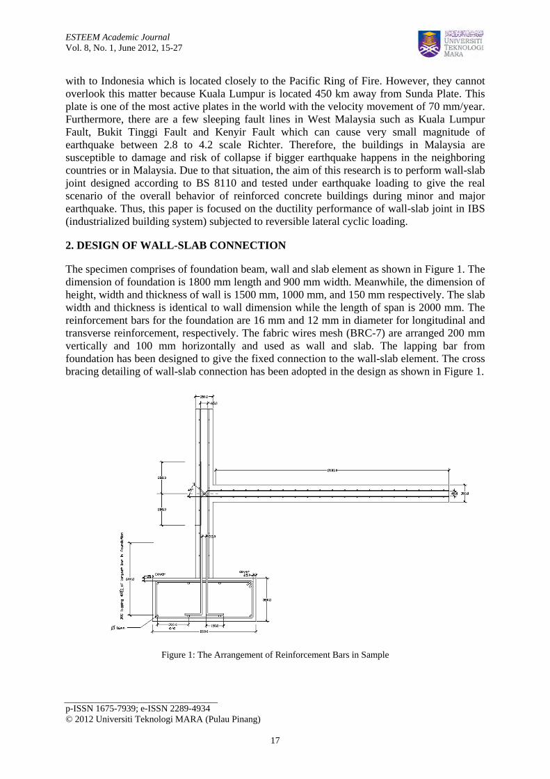
The specimen comprises of foundation beam, wall and slab element as shown in Figure 1. The dimension of foundation is 1800 mm length and 900 mm width. Meanwhile, the dimension of height, width and thickness of wall is 1500 mm, 1000 mm, and 150 mm respectively. The slab width and thickness is identical to wall dimension while the length of span is 2000 mm. The reinforcement bars for the foundation are 16 mm and 12 mm in diameter for longitudinal and transverse reinforcement, respectively. The fabric wires mesh (BRC-7) are arranged 200 mm vertically and 100 mm horizontally and used as wall and slab. The lapping bar from foundation has been designed to give the fixed connection to the wall-slab element. The cross bracing detailing of wall-slab connection has been adopted in the design as shown in Figure 1.
Figure 1: The Arrangement of Reinforcement Bars in Sample
ESTEEM Academic Journal Vol. 8, No. 1, June 2012, 15-27
p-ISSN 1675-7939; e-ISSN 2289-4934 © 2012 Universiti Teknologi MARA (Pulau Pinang)
18
3. THEORETICAL BACKGROUND OF WALL-SLAB JOINT
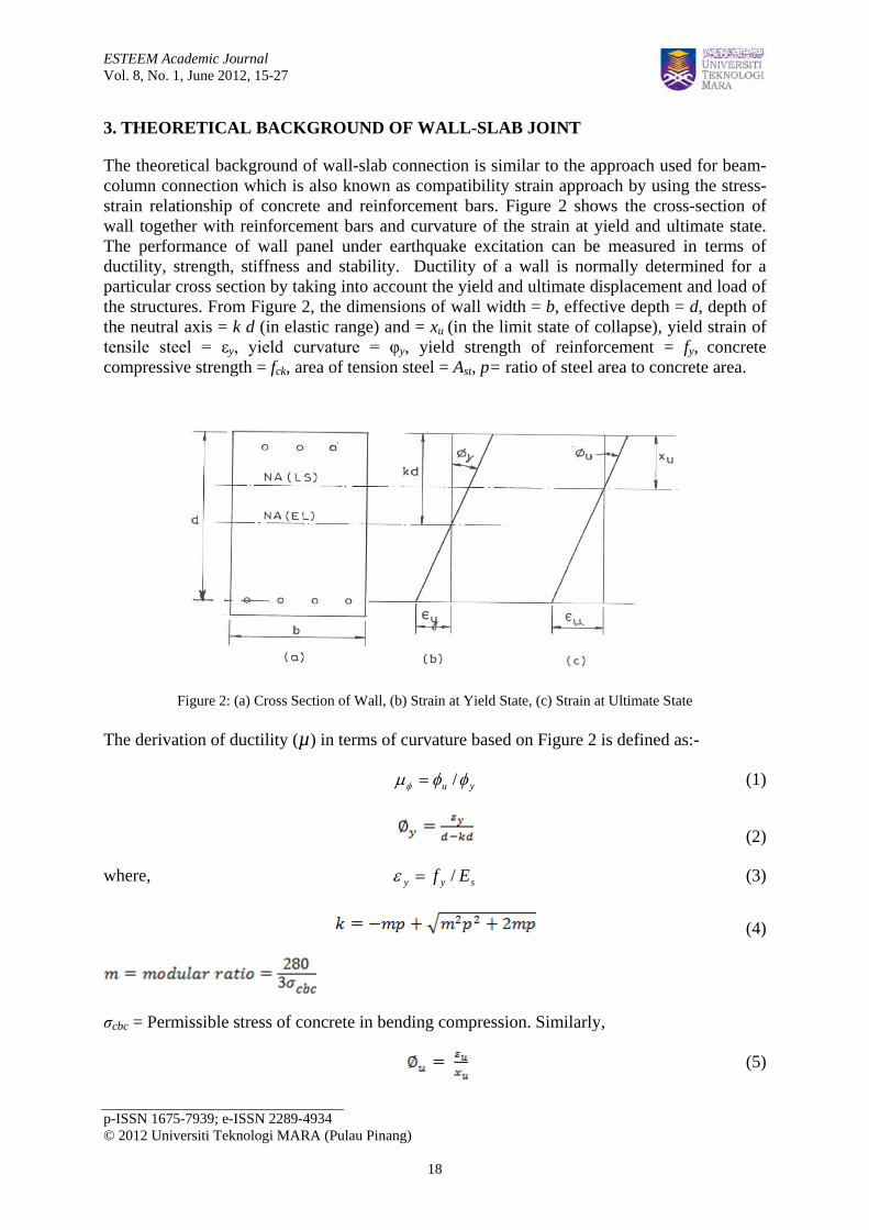
The theoretical background of wall-slab connection is similar to the approach used for beam-column connection which is also known as compatibility strain approach by using the stress-strain relationship of concrete and reinforcement bars. Figure 2 shows the cross-section of wall together with reinforcement bars and curvature of the strain at yield and ultimate state. The performance of wall panel under earthquake excitation can be measured in terms of ductility, strength, stiffness and stability. Ductility of a wall is normally determined for a particular cross section by taking into account the yield and ultimate displacement and load of the structures. From Figure 2, the dimensions of wall width = b, effective depth = d, depth of the neutral axis = k d (in elastic range) and = xu (in the limit state of collapse), yield strain of tensile steel = εy, yield curvature = φy, yield strength of reinforcement = fy, concrete compressive strength = fck, area of tension steel = Ast, p= ratio of steel area to concrete area.
Figure 2: (a) Cross Section of Wall, (b) Strain at Yield State, (c) Strain at Ultimate State
The derivation of ductility (µ) in terms of curvature based on Figure 2 is defined as:-
yu φφµφ /= (1)
(2)
where, syy Ef /=ε (3)
(4)
σcbc = Permissible stress of concrete in bending compression. Similarly,
(5)

ESTEEM Academic Journal Vol. 8, No. 1, June 2012, 15-27
p-ISSN 1675-7939; e-ISSN 2289-4934 © 2012 Universiti Teknologi MARA (Pulau Pinang)
19
where εu = ultimate strain of concrete = 0.0035
(6)
Substituting Equation 2 and 5 in Equation 1, we have ductility in terms of strain, effective depth of wall and neutral axis of the wall
(7)
(8)
The result of the experiment was validated by comparing it with calculated ductility resistance according to the analytical model equation.
4. CONSTRUCTION OF WALL-SLAB SPECIMEN CONNECTION
The subassemblage of wall-slab connection which comprises of foundation, shear wall and slab were constructed in Heavy Structural Laboratory, Faculty of Civil Engineering, Universiti Teknologi Mara, Shah Alam, Selangor. Initially, the foundation beam cage was prepared in the lab before the construction of the formwork. Eight holes with 30 mm diameter were made to cater for clamping foundation to strong floor. By providing the foundation beam, the wall-slab structure can be fixed to strong floor when imposed the lateral cyclic load. A formwork made from plywood was assembled in order to have a rectangular reinforced concrete foundation beam. Eight holes were drilled at the base of foundation formwork in order to place the steel pipes as shown in Figure 3. The high yield threaded bar will be placed throughout the pipes and fasten them using washers and nuts to fix the foundation beam to the strong floor. Reinforcement bars with caging is prepared for the foundation beam. The longitudinal bars with 16 mm diameter were adopted whilst 12 mm diameter have been used for the transverse reinforcement. Figure 3 shows the arrangement of the reinforcement in the foundation formwork. Figure 4 shows the fabric wire mesh (BRC-7) which had been cut according to the size of the slab and wall. Reinforcement bars of 12 mm diameter were used to connect wall and slab with the pattern of cross-bracing at the joints with 200 mm spacing between each other.
Figure 7 shows the steel mould which had been used as a formwork to obtain the intended shape of the specimen. The height of the steel mould to form wall is 1.6 m whilst the span length is 2.0 m to give a shape of flat slab. The breadth of steel mould is 1.0 m. The steel mould had been set-up on the foundation beam before casting of concrete was executed as shown in Figure 7. Then, BRC-7 was placed into the mould with some spacer blocks attached at certain places allowing for concrete cover for the specimen. The sides of mould for slab and both front and back mould faces for the wall were set-up and screwed into their position as shown in Figure 7. Then, the concrete mix was poured into the mould through the opening part in the mould as depicted in Figure 5. The concrete was smoothing to get an even surface as shown in Figure 6. The steel mould was taken off after the concrete hardened and achieved the compressive strength of 30 MPa. Figure 8 shows the finished product of wall-slab

ESTEEM Academic Journal Vol. 8, No. 1, June 2012, 15-27
p-ISSN 1675-7939; e-ISSN 2289-4934 © 2012 Universiti Teknologi MARA (Pulau Pinang)
20
connection seating on foundation beam. This specimen is ready for instrumentation and experimental set-up before commerce testing.
Figure 3: Preparation of Foundation Beam Figure 4: BRC Detailing of Wall-Slab
Figure 5: Pouring Concrete into Mould Figure 6: Smoothing the Concrete Surface
Figure 7: Set-Up of Mould on Foundation Beam Figure 8: Configuration of the Sample

ESTEEM Academic Journal Vol. 8, No. 1, June 2012, 15-27
p-ISSN 1675-7939; e-ISSN 2289-4934 © 2012 Universiti Teknologi MARA (Pulau Pinang)
21
5. INSTRUMENTATION AND EXPERIMENTAL SET-UP
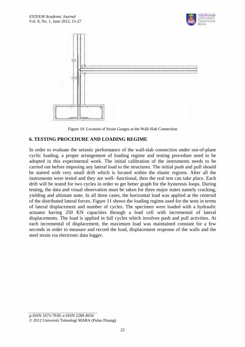
Figure 9 shows the systematic arrangement of linear potentiometers and double actuator. The load cell with capacity of 250 kN is connected to the double actuator and supported by the reaction frame. Double actuator will impose the lateral cyclic loading on the wall with control displacement while the head of load cell is connected to steel plate and clamped to the wall by screwed up the treaded bars snug tight. The RC wall became sandwiched by steel plate clamping to the double actuator head so that the wall can be pushed and pulled laterally during the experiment work without any gap between the steel plates. At the end of floor slab, two steel plates are attached to wall using high yield threaded rods. The slab is supported by UB steel section to ensure that the support is fixed and the wall is free to rotate in-plane. The foundation beam is clamped to strong floor by penetrating the high yield threaded bar through the holes located in foundation beam. A total number of ten (10) LVDT were installed on the sample in order to record the deflection consequential from the lateral cyclic load applied on the sample. Five (5) units of LVDT were placed along the height of wall while three units along the span of the slab as shown in Figure 9. One LVDT is placed vertically at the column and horizontally at the end of slab to detect any movement s in-plane and out-of-plane movement of the slab. Another two LVDT are located vertically on the foundation beam to detect any movement in both directions. Strain gauges were installed to read the change in strain of reinforcement due to alternate tension and compression stress during the experiment work. The strain gauges at reinforcement bar were installed prior to casting of sample. The exact and detailed arrangement of strain gauges on the reinforcement can be seen in Figure 10.
Figure 9: Experimental Set-Up
ESTEEM Academic Journal Vol. 8, No. 1, June 2012, 15-27
p-ISSN 1675-7939; e-ISSN 2289-4934 © 2012 Universiti Teknologi MARA (Pulau Pinang)
22
Figure 10: Location of Strain Gauges at the Wall-Slab Connection
6. TESTING PROCEDURE AND LOADING REGIME
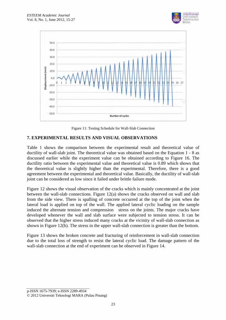
In order to evaluate the seismic performance of the wall-slab connection under out-of-plane cyclic loading, a proper arrangement of loading regime and testing procedure need to be adopted in this experimental work. The initial calibration of the instruments needs to be carried out before imposing any lateral load to the structures. The initial push and pull should be started with very small drift which is located within the elastic regions. After all the instruments were tested and they are well- functional, then the real test can take place. Each drift will be tested for two cycles in order to get better graph for the hysteresis loops. During testing, the data and visual observation must be taken for three major states namely cracking, yielding and ultimate state. In all three cases, the horizontal load was applied at the centroid of the distributed lateral forces. Figure 11 shows the loading regime used for the tests in terms of lateral displacement and number of cycles. The specimen were loaded with a hydraulic actuator having 250 KN capacities through a load cell with incremental of lateral displacements. The load is applied in full cycles which involves push and pull activities. At each incremental of displacement, the maximum load was maintained constant for a few seconds in order to measure and record the load, displacement response of the walls and the steel strain via electronic data logger.
ESTEEM Academic Journal Vol. 8, No. 1, June 2012, 15-27
p-ISSN 1675-7939; e-ISSN 2289-4934 © 2012 Universiti Teknologi MARA (Pulau Pinang)
23
Figure 11: Testing Schedule for Wall-Slab Connection
7. EXPERIMENTAL RESULTS AND VISUAL OBSERVATIONS
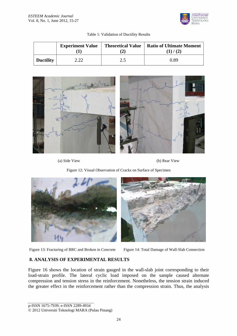
Table 1 shows the comparison between the experimental result and theoretical value of ductility of wall-slab joint. The theoretical value was obtained based on the Equation 1 - 8 as discussed earlier while the experiment value can be obtained according to Figure 16. The ductility ratio between the experimental value and theoretical value is 0.89 which shows that the theoretical value is slightly higher than the experimental. Therefore, there is a good agreement between the experimental and theoretical value. Basically, the ductility of wall-slab joint can be considered as low since it failed under brittle failure mode.
Figure 12 shows the visual observation of the cracks which is mainly concentrated at the joint between the wall-slab connections. Figure 12(a) shows the cracks observed on wall and slab from the side view. There is spalling of concrete occurred at the top of the joint when the lateral load is applied on top of the wall. The applied lateral cyclic loading on the sample induced the alternate tension and compression stress on the joints. The major cracks have developed whenever the wall and slab surface were subjected to tension stress. It can be observed that the higher stress induced many cracks at the vicinity of wall-slab connection as shown in Figure 12(b). The stress in the upper wall-slab connection is greater than the bottom.
Figure 13 shows the broken concrete and fracturing of reinforcement in wall-slab connection due to the total loss of strength to resist the lateral cyclic load. The damage pattern of the wall-slab connection at the end of experiment can be observed in Figure 14.
ESTEEM Academic Journal Vol. 8, No. 1, June 2012, 15-27
p-ISSN 1675-7939; e-ISSN 2289-4934 © 2012 Universiti Teknologi MARA (Pulau Pinang)
24
Table 1: Validation of Ductility Results
(a) Side View (b) Rear View
Figure 12: Visual Observation of Cracks on Surface of Specimen
Figure 13: Fracturing of BRC and Broken in Concrete Figure 14: Total Damage of Wall-Slab Connection
8. ANALYSIS OF EXPERIMENTAL RESULTS
Figure 16 shows the location of strain gauged in the wall-slab joint corresponding to their load-strain profile. The lateral cyclic load imposed on the sample caused alternate compression and tension stress in the reinforcement. Nonetheless, the tension strain induced the greater effect in the reinforcement rather than the compression strain. Thus, the analysis
Experiment Value (1)
Theoretical Value (2)
Ratio of Ultimate Moment (1) / (2)
Ductility 2.22 2.5 0.89
ESTEEM Academic Journal Vol. 8, No. 1, June 2012, 15-27
p-ISSN 1675-7939; e-ISSN 2289-4934 © 2012 Universiti Teknologi MARA (Pulau Pinang)
25
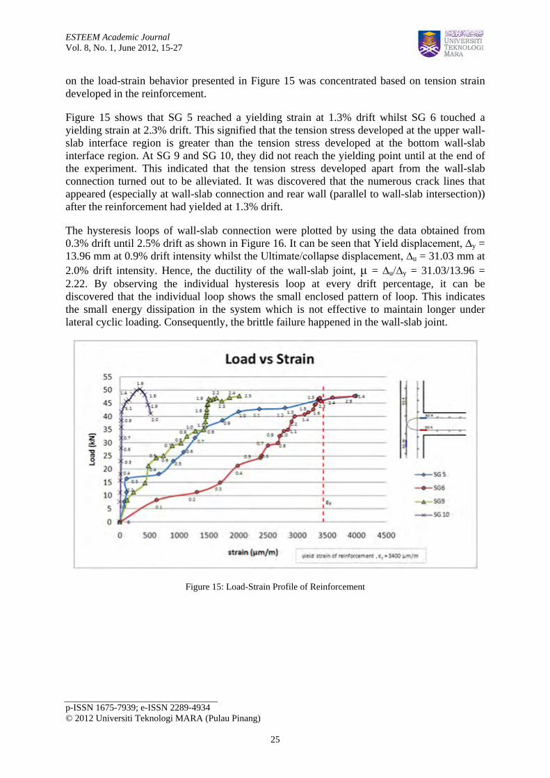
on the load-strain behavior presented in Figure 15 was concentrated based on tension strain developed in the reinforcement.
Figure 15 shows that SG 5 reached a yielding strain at 1.3% drift whilst SG 6 touched a yielding strain at 2.3% drift. This signified that the tension stress developed at the upper wall-slab interface region is greater than the tension stress developed at the bottom wall-slab interface region. At SG 9 and SG 10, they did not reach the yielding point until at the end of the experiment. This indicated that the tension stress developed apart from the wall-slab connection turned out to be alleviated. It was discovered that the numerous crack lines that appeared (especially at wall-slab connection and rear wall (parallel to wall-slab intersection)) after the reinforcement had yielded at 1.3% drift.
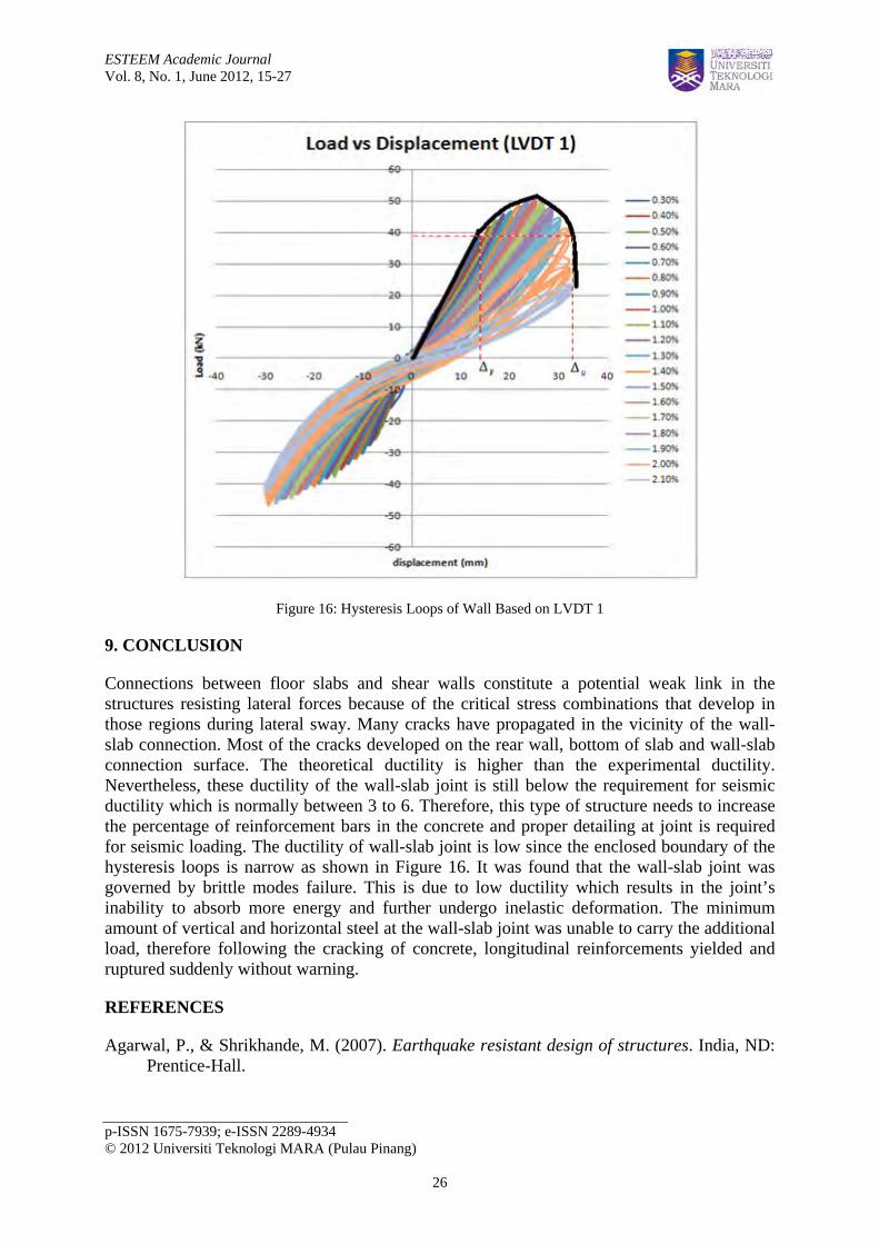
The hysteresis loops of wall-slab connection were plotted by using the data obtained from 0.3% drift until 2.5% drift as shown in Figure 16. It can be seen that Yield displacement, ∆y = 13.96 mm at 0.9% drift intensity whilst the Ultimate/collapse displacement, ∆u = 31.03 mm at 2.0% drift intensity. Hence, the ductility of the wall-slab joint, μ = ∆u/∆y = 31.03/13.96 = 2.22. By observing the individual hysteresis loop at every drift percentage, it can be discovered that the individual loop shows the small enclosed pattern of loop. This indicates the small energy dissipation in the system which is not effective to maintain longer under lateral cyclic loading. Consequently, the brittle failure happened in the wall-slab joint.
Figure 15: Load-Strain Profile of Reinforcement
ESTEEM Academic Journal Vol. 8, No. 1, June 2012, 15-27
p-ISSN 1675-7939; e-ISSN 2289-4934 © 2012 Universiti Teknologi MARA (Pulau Pinang)
26
Figure 16: Hysteresis Loops of Wall Based on LVDT 1
9. CONCLUSION
Connections between floor slabs and shear walls constitute a potential weak link in the structures resisting lateral forces because of the critical stress combinations that develop in those regions during lateral sway. Many cracks have propagated in the vicinity of the wall-slab connection. Most of the cracks developed on the rear wall, bottom of slab and wall-slab connection surface. The theoretical ductility is higher than the experimental ductility. Nevertheless, these ductility of the wall-slab joint is still below the requirement for seismic ductility which is normally between 3 to 6. Therefore, this type of structure needs to increase the percentage of reinforcement bars in the concrete and proper detailing at joint is required for seismic loading. The ductility of wall-slab joint is low since the enclosed boundary of the hysteresis loops is narrow as shown in Figure 16. It was found that the wall-slab joint was governed by brittle modes failure. This is due to low ductility which results in the joint’s inability to absorb more energy and further undergo inelastic deformation. The minimum amount of vertical and horizontal steel at the wall-slab joint was unable to carry the additional load, therefore following the cracking of concrete, longitudinal reinforcements yielded and ruptured suddenly without warning.
REFERENCES
Agarwal, P., & Shrikhande, M. (2007). Earthquake resistant design of structures. India, ND: Prentice-Hall.

ESTEEM Academic Journal Vol. 8, No. 1, June 2012, 15-27
p-ISSN 1675-7939; e-ISSN 2289-4934 © 2012 Universiti Teknologi MARA (Pulau Pinang)
27
Balkaya, C., & Kalkan, E. (2003). Nonlinear seismic response evaluation of tunnel form building structures. Computational Structural Journal, 81(2), 153-165.
Booth, E., & Key, D. (2006). Earthquake designs practice for buildings (2nd ed.). London: Thomas Telford Ltd.
Garcia, L. E., & Sozen, M. A. (2004). Earthquake resistant design of reinforced concrete buildings. New York: CRC Press.
Gioncu, V., & Mazzolani, F. M. (2002). Ductility of seismic resistant steel structures. New York: Spon Press.
Jacobsen, L. S. (1930). Steady forced vibrations as influenced by damping. Journal of ASME, 52(1), 169-181.
Paulay, T., & Priestey, M. J. N. (1992). Seismic design of reinforcement concrete and masonry buildings. New York: John Wiley & Sons.
Saiful, A. B. M., Jameel, M., & Jumaat, M. Z. (2011). Seismic isolation in buildings to be a practical reality: behavior of structure and installation technique. Journal of Engineering and Technology Research, 3(4), 99-117.
Yuksel, S. B., & Kalkan, E. (2007). Behavior of tunnel form buildings under quasi-static cyclic lateral loading. Journal of Structural Engineering and Mechanics, 27(1), 99-115.