DTM_Turbo_Kit_Instructions_05... - Rackcdn.com
57
-
Upload
khangminh22 -
Category
Documents
-
view
1 -
download
0
Transcript of DTM_Turbo_Kit_Instructions_05... - Rackcdn.com


2
Congratulations on the decision to take your R32 to the next level. We applaud your choice to go with HPA Motorsports’ DTM 7670 turbo system. Rest assured, your pur-chase comes with HPA’s long established reputation for quality and service. Please read over this detailed installation manual to familiarize what is involved in the installation process before you or your qualified technician start your build. Make sure special attention is paid to the before and after installation procedures. If you should encounter any difficulty during the process, please feel free to contact HPA for techni-cal support. We are here to help! The DTM 7670, as with all of HPA’s Turbo offering, is a culmination of over a decade of experience in tuning the narrow angle 3.2L 24V VR6. Your DTM 7670 is Built to be Driven, and will offer you a seamless driving experience with OEM integration, fitment and finish for many years of driving enjoyment. On behalf of the entire HPA Motorsport team, it is with great pleasure that I would like to thank you for choosing our DTM 7670 turbo system. I hope this will be the first step in a long standing relationship as we work together to maximize the performance of your vehicle and reach your tuning dreams. Our team is eager to hear your feedback and impressions of your reinvigorated R.

3
!!! HPA DTM 7670 Turbo Kit is restricted to run a maximum boost level of 7 psi. Any deviation of running higher boost levels or meth injection will require the customer to purchase a compression reduc-tion kit. Please contact the nearest HPA dealer or contact our sales department directly for further directions.
!!!HPA DTM 7670 TURBO KIT MUST RUN ONLY ON 91 PREMIUM OCTANGE GASOLINE
OR BETTER!!!
Please verify with the packing list included that all parts are present before starting the installation of the turbo kit.

4
DTM 7670 Series Turbo System – Pre Installation Procedure
Before getting started please make sure you take the steps outlined in the following pre-installation guide. This product is intended for use on healthy, well maintained engines. Installation on worn-out or damaged engines is not recommended and may result in failure of the engine as well as the turbo. * HPA Motorsports is not responsible for engine damage occurring as a result of pre-existing mechanical defi-ciencies, or caused by installer error. To ensure the health of your motor prior to installing your new turbo kit, it is important to perform the following procedures:
Scan the vehicle for faults Using a VW/Audi specific scan tool, run a fault check to detect for any trouble codes. Fix all Engine related faults before beginning turbo install. If you do not have access to a scan tool, please contact your HPA sales representative for infor-
mation on our VAD-Mobile and VAD-Pro series of hand held VW/Audi diagnostics suites.
Compression Check and Leak-Down test: to ensure the engine is in good working condition. Record the results of each cylinder for your reference. Ideal compression test results will be as follows:
Accepted Range: 145 to 190 psi (10 to 13 bar) Wear Limit: 110 psi (7.5 bar) – VW/Audi specifies this as the minimum acceptable com-
pression. However, this is NOT acceptable for use with our turbo system. Maximum difference between cylinders: 40 psi (3 bar)
Mass Air Flow Sensor: clean or replace as needed.
MAF should be cleaned every 10,000 miles. This will be even more important with the addition of your forced induction system. The new turbo will create more moisture and turbulence in the head which will eventually lead to oil deposits on your mass airflow sensor. If this happens it will throw off your fuel trims without setting a code which will lead to drivability problems and possibility of parts failure.
If the vehicle has over 30,000 miles; replace the mass air flow sensor.
Oxygen Sensors / Coil Packs / Spark Plugs: check and replace as needed. While on a test drive, use your VW/Audi scan tool to watch the O2 sensors and log the following
data: Go into engine address 01 Next go into read measuring blocks 08

5
Then finally watch block 001 values 3 and 4.
The desired result if for these values to stay pretty much the same. If the value is negative (–); the computer is taking out fuel. If the value is positive (+); the computer is adding fuel. A good check is to drive along and tip in the throttle. If both values react the same you’re in good shape. If one goes negative (–) and the
other goes positive (+) you likely have a problem with an O2 sensor, a coil, or a spark plug.
Repeat this test under full throttle.
Fuel Pressure and Residual Fuel Pressure: With gauge in-line on the engine fuel feed side, and engine running, the fuel pressure should be
around 60 psi (4 bar). Leave gauge attached, shut the ignition off and check the residual pressure. The pressure should stay above 2.0 bar for at least 10 minutes. If the pressure drops below 2.0
bar within this time you may have a problem with the check valve in the fuel pump.
Gaskets: During the turbo installation, it is highly recommend to replace the exhaust manifold gaskets, cata-
lytic converter gasket.
Coolant Temperature Sensor: It is also recommended while doing this installation to change the coolant temp sensor. They have
been known to fail and it will be easy to do now. Ask you local parts counter for the “green” one.
For ideal performance, install one that will open at a lower temperature.
Air Box and Air Filter: Your FT Series turbo system is to be used with the factory air box only. This turbo system is NOT
compatible with aftermarket air intake or cone-style housings. For best results, you may modify the bottom of your stock air box by enlarging the hole on the right
side. If not already equipped, install a high flow panel style (i.e.: K&N) air filter. The stock air filter will not
keep up to the volume of air the turbo will draw.
Compatibility of Other Modifications: If the mechanics of the vehicle have been modified in any way, please check with HPA Mo-
torsports prior to installing this product.

6
Remove front grill by removing locking tab. Split apart by a screwdriver and pull for-ward. Remove grille by pulling straight up.
Remove highlighted fender liner screws
Disconnect the IAT sensor and remove x2 10mm bumper nuts.

7
Once bumper is removed, you are left with the front radiator support. We will need to put this into the service position to gain access to removal of the intake manifold.
Before removing both radiator support bolts. You will need to install a long M8 bolt on the bottom on each side.
Remove top bumper bolts X3 Torx bolts

8
Remove the x2 10mm head bolts on the fenders
Pull front end radiator support into service position by installing long M8 bolts.
Disconnect hood latch cable Carefully use a flat head screwdriver to push retaining clip away.

9
Disconnect hood latch connector.
Disconnect both negative and positive battery cables. Remove battery by unscrewing bolt and removing retaining clip.
Remove complete airbox by unscrewing x2 bolts. Unplug the MAF sensor, and intake tract.

10
Drain coolant by first opening cap on ex-pansion tank. Pull off lower coolant hose connected to the coolant after run pump.
Pull off lower coolant hose retaining clip and remove coolant line and rest of cool-ant in radiator.
We can now start the removal of the in-take manifold

11
Unscrew both 10mm head bolts to re-move the dip stick and the vacuum canis-ter.
Start by removing the coil pack connec-tors. You may need a small 90 degree pick tool to get in the tight areas and disconnect the tabs. Carefully pull coil packs out of cylinder head.
To remove the oil dip stick you will need to remove the knock sensor connector. Simply push entire connector assembly off by using a forward motion.

12
Removing
With the ignition switched off, disconnect battery earth strap.
All cable ties which are opened or cut open when engine is removed must be replaced in the same po-sition when engine is installed.
Remove engine cover.
For engine codes AQP and AUE remove spark plug connectors and unclip ignition cables.
– For engine codes BDE, BFH, BJS and BML remove ignition coils with output stages for cylinders 1-6 using puller -T10095 – Remove intake hose between air mass meter - G70- and throttle valve module -J338 – Detach 6-pin connector from throttle valve module -J338--arrow-. – Detach earth connection on throttle valve control module -J338-. WARNING Steam may escape when expansion tank is opened. Wear eye protection and protective clothing to avoid eye injuries and scalding. Cover cap with cloth and open carefully. – Open and close expansion tank cap to release pressure in cooling system. – Detach coolant hoses from throttle valve control unit -J338- and seal hose ends. – Unscrew coolant and connecting hoses
PLEASE FOLLOW THE FACTORY SERVICE FOR REMOVAL OF THE INTAKE MANIFOLD, EXHAUST MANIFOLD, AND DOWNPIPE.

13
Now pull vacuum lines -arrows- off intake manifold. – Unbolt intake manifold supports on left and right of intake manifold. – Unscrew bolt -1- for rear intake manifold support. WARNING Fuel system is under pressure! Wear eye protection and protective clothing to avoid possible injury and skin contact. Before loosening hose connections, wrap a cloth around the connection. Then release pressure by carefully pulling hose off connection. – Detach supply line -1- (white marking) and return line -2- (blue marking) and collect any escaping fuel with cloth. Note
Press buttons on hose couplings to do this. – Seal lines so that fuel system is not contaminated by dirt. – Unclip fuel and vacuum lines from cylinder head cover. – Remove the two bolts on the side for the intake manifold support.

14
– Detach vacuum hose from combination valve. – Unclip pressure hose and all other lines from brackets on intake manifold and cylinder head cover. – Unscrew dipstick guide tube from intake manifold -1-. – Unclip secondary air inlet valve -2- and valve for intake manifold changeover -3- from vacuum reservoir. Note
The connectors for the valves can remain connected. – Detach vacuum hose from intake manifold change-over vacuum actuator. – Remove intake manifold securing bolts from cylinder head. – Remove intake manifold and place it on a suitable surface so that the vacuum unit will not be damaged. Note
Seal intake ports in intake manifold and in cylinder head with a clean clot

15
Assembly overview - intake manifold 1 - Intake manifold 2 - Closure
Only for engine codes BFH, BJS and BML 3 - 10 Nm
4 - Bearing cap For intake
manifold change-over Barrel 5 - Seal
Renew. 6 - 25 Nm
7 - Vacuum Connection 8 - To activated charcoal filter solenoid valve 1 - N80-
Activated charcoal filter system: 9 - To expansion tank
For coolant 10 - To vacuum Positioning Ele-ment
For exhaust flap valve 1 -N321- 11 - Connecting pipes 12 - Coolant pipe 13 - Vacuum connection
For crankcase ventilation. 14 - Vacuum connection
For exhaust flap valve 1 -N321- 15 - Vacuum connection
For activated charcoal filter system.

16
16 - Throttle valve module -J338- Gold-plated connector contacts Heated by coolant.
17 - Earth wire
Not for engine code BFH 18 - 10 Nm
19 - Vacuum actuator For intake manifold change-over.
20 - To intake manifold change-over valve -N156- 21 - Positioning lever
For change-over barrel. Check for secure seating.
22 - Change-over barrel 23 - Gasket
Note installation position. Renew if damaged.
24 - Vacuum reservoir
For intake manifold change-over. For secondary air system
25 - Dowel sleeve
To secure intake manifold. To locate seal.
26 - 15 Nm

17
Assembly overview - exhaust manifold, front exhaust pipe with dual catalytic converter and attachments 1 - Heat shield 2 - M6 - 10 Nm, M8 -25 Nm, M10 - 40Nm 3 - Gasket
Renew. 4 - Exhaust manifold 5 - Front exhaust pipe
To remove, remove front propshaft tube: 6 - Connector
Black, 6-pin. 7 - Lambda probe - G39-, 50 Nm 8 - Lambda probe 2 -G108-, 50 Nm
Grease only the threads with „G
052 112 A3“; „G 052 112 A3“ must not get into the slots on the probe body.
Remove and install with Lambda probe open ring spanner set -3337-. 9 - Connector
Brown, 6-pin. 10 - Connector
Brown, 4-pin. 11 - Dual catalytic converter
Behind pipe junction with stop for double clamp
Black, 4-pin.

18
12 - Connector Black, 4-pin.
13 - Lambda probe after catalytic converter -G130-, 50
Nm
Grease only the threads with „G 052 112 A3“; „G 052 112
A3“ must not get into the slots on the probe body.
Remove and install with Lambda probe open ring spanner set -3337-. 14 - To front silencer 15 - Lambda probe 2 after cata-lytic converter -G131-, 50 Nm
Grease only the threads with „G
052 112 A3“; „G 052 112 A3“ must not get into the slots on the probe body.
Remove and install with Lambda probe open ring spanner set -3337- . 16 - Cable guide
Bolted to subframe 17 - Washer

19
Remove the factory 4 Bar fuel pressure regulator and switch to the supplied HPA 3 Bar one. To remove the fuel pressure regulator, first remove the retaining clip. Twist the FPR and lift up. Clean the bore and make sure it is free of dirt and debris, lubricate the 3 Bar FPR oil rings and install.
Once the intake manifold is removed. This is what you will be left with. We are now going to remove the fuel rail, injec-tors and fuel pressure regulator.
Unclip and disconnect the factory fuel in-jector plugs. Remove the fuel injector harness covers by pushing it through the slots of the fuel rail. You may need a flat head screwdriver to aid in the process.

20
Pull the injector harness out of the way. At this time, you can go ahead and clean the injector bores and intake manifold ports. Q-tip and brake clean works great for re-moving dirt and gum.
Unscrew 4 bolts which hold the fuel rail on to the cylinder head. Once removed, you may need to give the fuel rail a pry to help removal assembly.

21
This is a good time to remove and replace the factory coolant temperature sensor, if you haven’t already done one. It is also a good idea to replace the exist-ing one with a brand new part if it has seen high mileage.
You will need to cut and solder on the new injector harness plug pig tails. Remove plastic cover from the injector harness. Remove tape from the injector harness. Do one plug at a time. Cut plug off the wiring harness leaving about ¾ of an inch. Solder new injector plug onto harness. Red with violet strip wire always goes on the right side. Make sure connections are good and leave the plugs in the right order. Tape harness back up. Reinstall plastic cover over harness.
Remove the old factory fuel injectors. Clean the injectors and make sure it is free of dirt and debris Install the new injectors, make sure to lubricate the injector o-rings to prevent tearing of the o-ring.

22
Finish the fuel rail assembly and fuel in-jectors by installing the fuel injector clips.
Install the fuel rail back onto the cylinder head. Reinstall the plastic covers. And you’re done for this part of the install.

23
Now route them up into the engine bay under the AC connections on the firewall. Now take the O2 sensors electrical con-nections and route them down to where you brought the harness.
Take care and attention to route the O2 sensor wires so no harm will come to them. Route straight back to the fire wall and then over to plugs. Use Cable ties to secure the wires
Rerouting front O2 sensors. This needs to be done because of the new location in the turbo exhaust mani-fold. Pull the front O2 sensor electrical plugs out of the loom. You will need to see at least two feet. Once this is done re tape the exposed wires.

24
Install the supplied M10 studs onto the exhaust manifold. . Double nut and tighten.
Locate the oil dump flanges. Install onto bottom of turbocharger with the supplied RTV silicone. Apply a thin coat of silicone and wipe off excess with a rag, make sure the drain port is open and free from silicone squeeze out.
Mate the turbo exhaust manifold to the turbo charger with the supplied M10 lock nuts. The finished turbo charger assembly should look exactly like the picture. Dou-ble check torque on all bolts and mark all bolts.

25
Turbo Coolant lines. Locate the front and rear turbo coolant lines, and also the coolant line adapters.
You will need to install the coolant line adapters into the turbo first. *Be sure to lubricate the o-ring before installing.
Rear Turbo Coolant line Install the rear turbo coolant line. This will Tee into the factory heater core inlet hose off the firewall.
REAR

26
Install the front turbo coolant line before snaking the 3/4” SS line through. This front coolant line will than bolt to the 3/4” stainless hard line.
The front braid water line will terminate on this end. Make sure the line is away from the en-gine block and a smooth kink free transi-tion.
FRONT
Install the 3/4 stainless coolant line on the back of the block BEFORE PUTTING ON THE TURBO ASSEMBLY! The coolant line is held on by x2 M6 socket head bolts. Remove and discard the factory bolts on the oil chain drive cover. Also at this point, you can set the downpipe in it’s location and leave it to the side.

27
The exit of the coolant reservoir bottle will merge onto the 3/4” coolant line. Slip on the hose, and install with the new supplied hose clamp.
Leave the outlet side of the 3/4” coolant line alone until the turbocharger assembly has been installed.

28
Exhaust Manifold Ports Make sure surface is clean and flat, and all studs are locked in Replace old gaskets with OEM gaskets
HPA Cast Turbo Exhaust Manifold *The turbo assembly should be in-stalled onto the turbo exhaust mani-fold before this step! Slip the turbo exhaust manifold on to the studs, use an M8 nut to hold the assem-bly in place while you gather the exhaust manifold clamps.
Exhaust Manifold Clamps Locate the exhaust manifold clamps and slip them over the studs.
TOP
BOTTOM

29
Exhaust Manifold Clamps Locate the 2 top exhaust manifold clamps with a 90 degree bend in it. The exhaust manifold clamps will only go on 1 way. Make sure they line up and push them on. It will be a tight fit
Exhaust Manifold Clamps Locate the 2 bottom exhaust manifold clamps. Just like the top clamps, the bottom ex-haust manifold clamps will only go on 1 way. Make sure they line up and push them on.
Copper Exhaust Manifold Nuts Locate the exhaust manifold copper nuts Once all the exhaust manifold clamps are all on, you can go ahead and tighten the manifold down with the supplied copper nuts. *It is recommended to tighten the ex-haust manifold from the inside out.

30
Locate the downpipe, and with the V-band clamp, center both halves before screwing down. You can find the proper orientation by in-stalling the other end onto the catalytic converter flange. Once everything is in, and in it’s proper location. Torque everything down.

31
Timing Chain Tensioner Locate the factory timing chain tensioner You will need to disassemble the ten-sioner in order to install the lengthened tensioner piston. To disassemble, simply relieve all the oil, use a rag to cover the tensioner Push down and let go
Timing Chain Tensioner Reinstall the retaining clip on the new longer tensioner Reinstall the spring and push down to complete the assembly
Reinstall the timing chain tensioner loosely with the oil feed adapter in be-tween.

32
You can now run the turbo oil feed to the top of the turbo Start all banjo bolts before tighten them down, make sure oil line is free from kinks and obstruction
Make sure the 90 degree portion of the oil feed line is pointed down towards the tur-bocharger. Do not torque this down until the steps followed.
Install the banjo and the x2 copper wash-ers. Install loosely. Before tightening , we need to double check clearances with the new 3/4 stainless hard pipe which runs directly be-hind the line. Once the proper clearance is achieved, we can torque down and double check our connections.

33
The installed turbo assembly should look like the picture, if there is any variations, please go through the steps above again. At this time, once the turbo charger as-sembly is installed. We can now work on the smaller sub assemblies.
Install the turbocharger heat shield with the supplied M6 bolts and washer. Once torqued, tap and wiggle the heat shield to make sure there is no rattles.
Locate the factory coolant hose out of the thermostat housing. This will merge onto the 3/4 stainless hard coolant line. Layout, mark and cut the coolant hose. It is important to use the supplied hose clamps.

34
Attach the rear turbocharger stainless braided coolant line to the inlet of the heater core. This line will merge into the factory plastic coolant tee. You may need to trim and cut the factory 5/16 coolant lines to achieve a smooth kink free orientation. Install with the supplied hose clamps.

35
Removing and installing oil sump Removing – Remove centre, left and right insulation trays: – Pull 3-pin connector off oil level and oil temperature sender -G266-. – Unbolt secondary air pump motor -V101- retainer from sump. - Drain engine oil. Observe environmental regulations for disposal. - Remove sump. – Loosen sump with light blows of a rubber headed hammer if necessary. – Remove sealant residue from cylinder block with a flat scraper. – Remove sealant residue on sump using a rotating brush, e.g. an electric drill with a plastic brush attachment (wear safety goggles). – Clean sealing surfaces; they must be free of oil and grease. Installing Note - The oil sump must be installed within 5 minutes of applying silicone sealing compound. – Cut off tube nozzle at forward marking (Ø of nozzle approx. 3 mm). – Apply silicone sealing compound, as shown, to

36
clean sealing surface on sump. Sealing compound bead must be: - 2…3 mm thick. - Run bead along inner side of bolt holes - arrows-. Note The sealant bead must not be thicker, other-wise excess sealing compound will enter the oil sump and may block the oil suction line strainer. – Apply silicone sealing compound bead as shown to the clean sealing surface of the sump. – Install sump immediately and tighten all sump bolts lightly. – Tighten oil sump bolts to 12 Nm. – Tighten bolts securing sump to gearbox to 45 Nm. Note Let sealing compound dry for approx. 30 min-utes after installing sump. Only then fill with engine oil. Further assembly is basically the reverse of the dismantling sequence.

37
Oil Pan You will need to drill 3 holes for the turbo oil return line flange
Turbo Oil Return Line Flange Locate the oil return line flange, loosely lay in where it needs to go, mark the cen-ter of the holes with a transfer punch
Oil Pan Center punch the marks Drill 5/16” holes for the 2 bolts Drill a 1/2” hole for the center of the flange

38
Oil Pan Apply a liberal amount of silicone onto the turbo oil return flange
Oil Pan Flange Insert the bolt and washer and tighten down evenly Remember to wipe the excess silicone off before it dries Torque M8 bolts.
Remember to tape off the flange so that dirt and debris doesn’t get inside the mo-tor. Install the oil pan per pages 35-36. **If you are upgrading to the HPA Race Grade Connecting Rod Bearings, this is a great time to install them while the oil pan is down

39
Turbo Oil Return Locate the turbo oil return line
Turbo Oil Return One end will go to the turbo assembly and the other end will go to the oil pan. Loosely lay turbo oil return in to double check orientation.
Oil Dump Line Bracket Locate the oil dump line bracket and hardware. The bracket will bolt onto a pre existing hole on the cylinder block.

40
Turbo Oil Return Once the oil return line is loosely fitted on both ends you can now go ahead and tighten both sides down Make sure the line is free from kinks and obstructions

41
Locate the new 5/16 coolant line. This coolant line will be the new path to the top of the coolant reservoir bottle. It will also have brackets which will attach to both sides of the intake manifold.
The 5/16 coolant line bolts directly in the factory heat shield location. Use the factory M8 bolts to attach to the cylinder head.
The 5/16 coolant line will use all factory coolant hoses. You will need to mark, and trim them to fit. Make sure all lines have a smooth transi-tions, free of kinks. Install hoses with the supplied hose clamps

42
The 5/16 coolant line will use all factory coolant hoses. You will need to mark, and trim them to fit. Make sure all lines have a smooth transi-tions, free of kinks. Install hoses with the supplied hose clamps.
Locate the throttle body electrical plug. On this harness you will see a 6 pin elec-trical connector that is for the throttle body. And a 2 pin electrical connector that is for the intake tract heater. You will not be needing the intake tract heater connector anymore. Move and zip tie it away from heat.

43
Coolant System Diagram
Cylinder Head
Coolant Reservoir
Turbo
Heater Core
Radiator
To Thermostat housing
Factory coolant line on engine side plate
Rear turbo coolant line (braided)
Front turbo coolant line (braided)
To bottom of coolant reser-
To top of coolant resevoir
Flow
Direction
Flow
Direction
BEFORE GOING ANY STEPS FURTHER, PLEASE DOUBLE CHECK ALL COOLANT CONNECTIONS AND FLOW PATH

44
We are now ready to modify and install the intake manifold heat shield, and in-take manifold itself.
The factory EVAP port closest to the throttle body will need to be cut off. This is done to accommodate the intake manifold heat shield. Make a straight cut and clean any burrs off.
Locate the intake manifold heat shield. Test fit heat shield on intake manifold. Once fitment is correct, clean and wipe down heat shield, making sure it’s free of grease and finger prints.

45
Install heat shield with the supplied course screws. Apply a small amount of silicone in the EVAP port that was just cut off.
Install the front O2 sensors. Make sure the O2 sensors are in it’s proper side location. Brown = Drivers side Black = Passenger side *This rule does not apply to new OEM O2’s
46
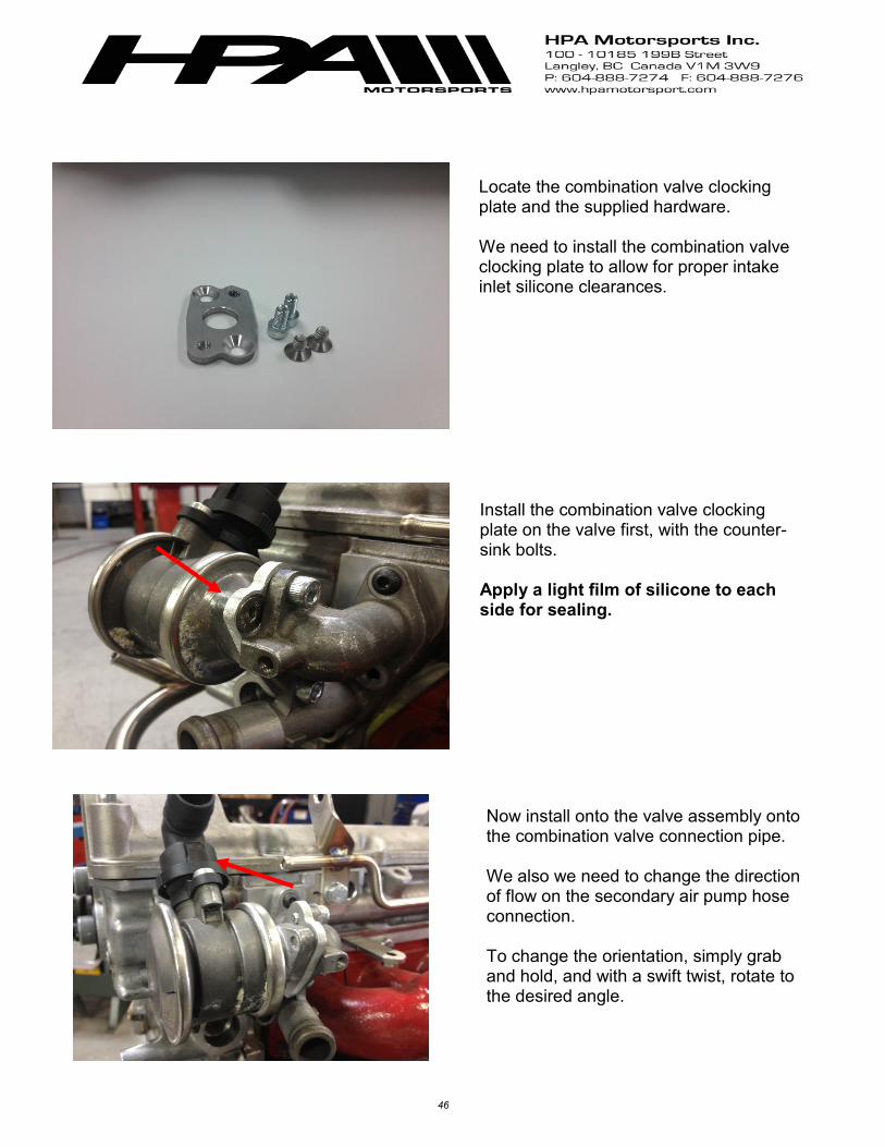
Locate the combination valve clocking plate and the supplied hardware. We need to install the combination valve clocking plate to allow for proper intake inlet silicone clearances.
Install the combination valve clocking plate on the valve first, with the counter-sink bolts. Apply a light film of silicone to each side for sealing.
Now install onto the valve assembly onto the combination valve connection pipe. We also we need to change the direction of flow on the secondary air pump hose connection. To change the orientation, simply grab and hold, and with a swift twist, rotate to the desired angle.

47
Install the intake manifold with the sup-plied NEW intake manifold gasket. Follow pages 12 – 16 for reassembly in-structions. Use the shorter M8 bolt supplied in this location.
Rotate the throttle body with the black part facing upwards, towards the roof. Plug in all electrical connections at this time.
Re install the factory line connections on the back of the intake manifold. All connections will be in the factory posi-tions. The only line we will need to modify is the EVAP line.
48
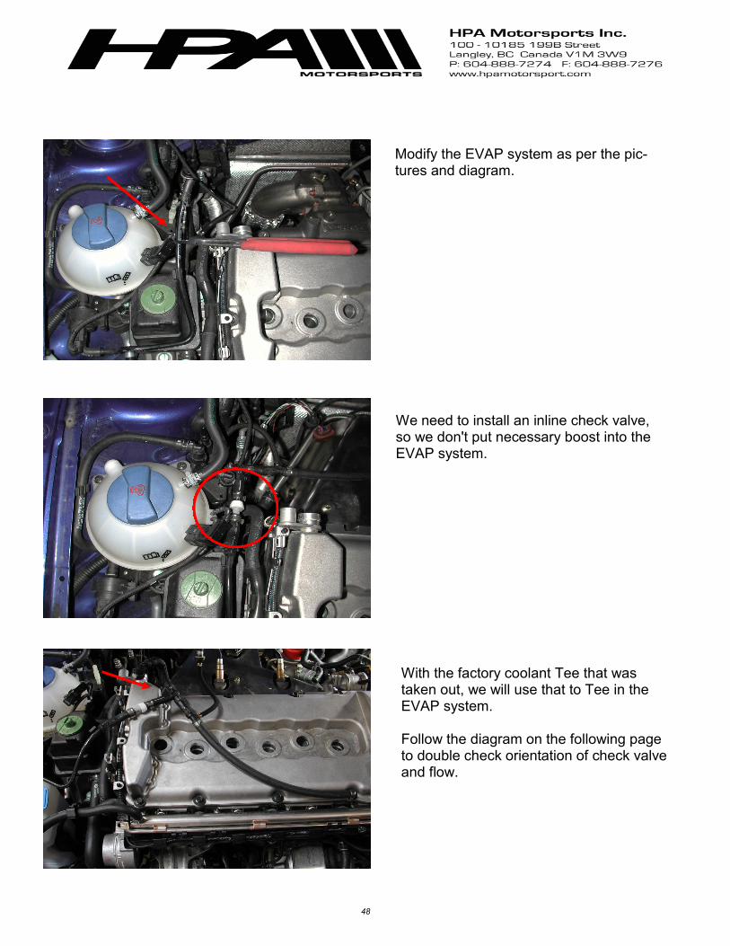
Modify the EVAP system as per the pic-tures and diagram.
We need to install an inline check valve, so we don't put necessary boost into the EVAP system.
With the factory coolant Tee that was taken out, we will use that to Tee in the EVAP system. Follow the diagram on the following page to double check orientation of check valve and flow.

49
EVAP Purge Valve
Vacuum and EVAP System
Intake Manifold
Canister
Check Valve Combi valve
Switch
T supplied in the kit
Check Valve
To Exhaust Bypass Diverter Valve
Combination Valve
Throttle Body
Vacuum sup-ply to fuel pressure regu-lator
To brake booster
To Green Leak Detection
To White EVAP
Check Valve
To intake manifold change over

50
The factory PCV pipe will need to be modified to fit the new turbo inlet silicone. Retain everything except for the corrugate line that runs to the intake tract. Cut this off with a sharp razor blade. And replace it with the 3/4 emissions hose provided.
We are now ready to install the coil packs and finish up the install. You may have a difficulty pushing the coil packs straight down. Twist the coil packs to the side to clear the intake manifold. You will hear a definitive sound once the coil pack is seated.
The finished engine bay should look iden-tical to the picture.
51
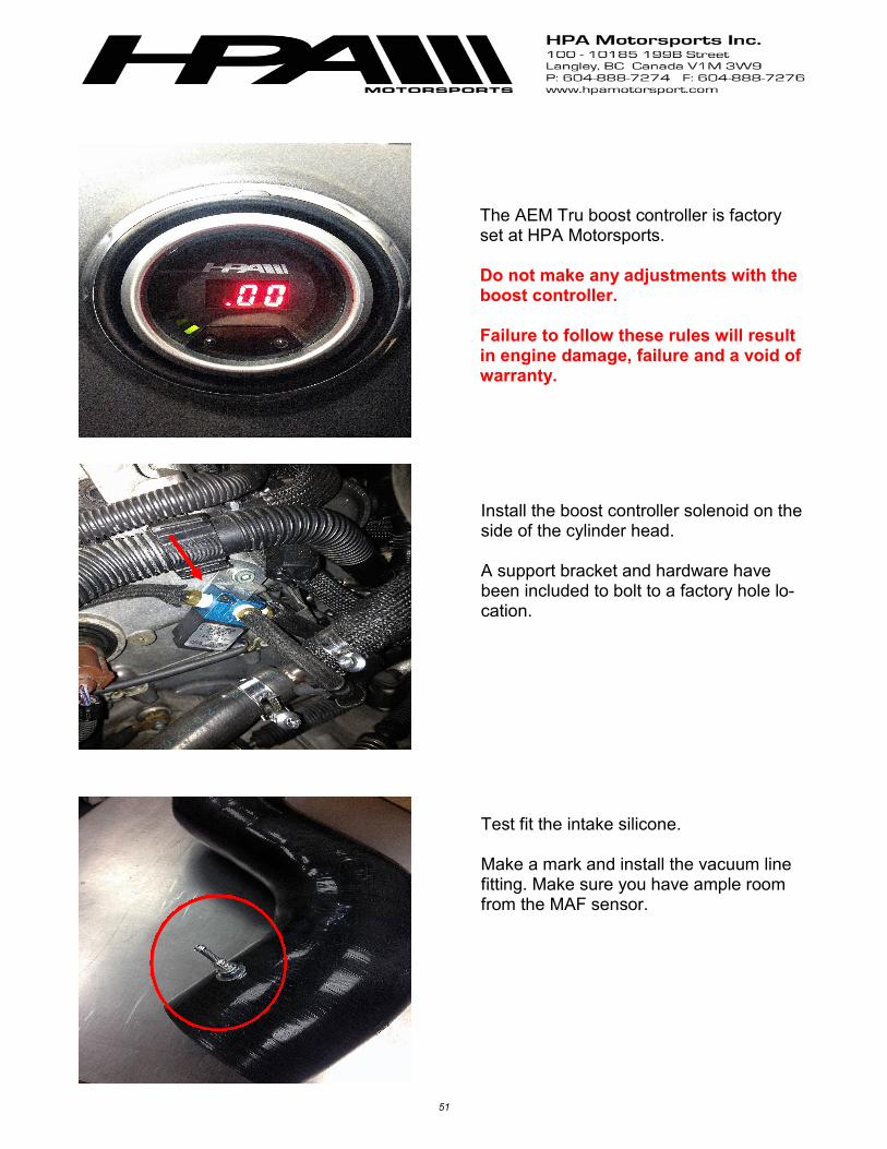
The AEM Tru boost controller is factory set at HPA Motorsports. Do not make any adjustments with the boost controller. Failure to follow these rules will result in engine damage, failure and a void of warranty.
Install the boost controller solenoid on the side of the cylinder head. A support bracket and hardware have been included to bolt to a factory hole lo-cation.
Test fit the intake silicone. Make a mark and install the vacuum line fitting. Make sure you have ample room from the MAF sensor.

52
Follow the diagrams below for wiring in the boost controller and hooking up the vacuum lines. Further instructions can be referred to the AEM factory manual supplied in the box.
You will only need to wire in the colors below, all other wires can be heat shrunk and taped away. You do not need them.
To air inlet intake vacuum line fitting

53
You may elect to trim the top cover to fit the new throttle body surround, or leave off to showcase the turbo system.
Installation is carried out in the reverse order. Airbox Battery Front radiator support Bumper, and fender lines Fluids Coolant - We only recommend using genuine factory VW coolant. Oil - We recommend Liqui– Moly 5w-40

54
HPA FIREUP PROCEDURE AND BREAK IN Before initial fire up confirm the following - Inspection of MAF, ignition coils, spark plugs, O2 sensors and fuel pump. All the above must be in great working condition. Replace any or all if necessary. - All engine fluids are double checked. - Battery is fully charged - All electrical connections are made - Pre bleed power steering if applicable - Connect to engine ECU and confirm communication. Clear any codes if neces- sary. If no communication contact HPA. - Cycle the key 3-4 times to build up fuel pressure. - Check for any fuel leaks. - Re charge ac system if needed

55
Initial Fire up -Go ahead and start car. -Once the engine is running inspect for any leaks. - While idling connect to ECU and check for codes. - If no codes are present let idle for 5 minutes. - During this time review your work. - If everything checks out increase idle to 2500 rpm and hold. - Continue to do this until you reach about 95 Celsius coolant temp. - Once again let car idle. - Now check to make sure your coolant fans turn on. The should come on around 100 Celsius/212 Fahrenheit - Connect scan tool to engine ECU and again check for codes. - Go to measuring block 001 and review values 3 and 4. These should be cycling between -10 and 10. If you see -25 or 25 you may have a problem with the 02 sensors. - Turn off car and once again inspect all work. - Check all fluid levels

56
Initial Test Drive and Break In Before leaving on test drive connect the following
1) AEM Boost controller 2) Fuel pressure gauge 3) VAD SCAN Tool It is highly recommended to do about 100 miles break in before getting into boost. This will allow you to confirm everything is working properly and to go over your work. Once this is done and you have inspected all your work, we need to check the follow-ing. 1) No engine codes present in the engine ECU. 2) Fuel pressure is sufficient. Cars must have at least 50 psi under acceleration. IF
YOU HAVE LESS THAN THIS INSPECT FUEL SYSTEM. Engine failure may re-sult otherwise.
3) With the scan tool plugged in, you will need to do a 3rd or 4th gear pull from 2500 rpm to redline.
Please log the following blocks MVB 001 values 3/4 is your O2 sensors referencing fuel trim. At WOT under maxi-mum heavy load you should never see this in the +05% or higher. If you see these values, you either have a fuel pump delivery issue, coil pack, or MAF issue. Please diagnose further. MVB 020/021 is your ignition timing. This will verify you are running a high enough octane. If you see a value of 8KW or more, you will need to run a higher octane or lower the boost. Once everything checks out, you are ready to go have some fun, and let her rip!
MVB Value #1 #2 #3 #4
001 RPM CTS 0 - -20% 0 - -20%
020 0 - 8 KW 0 - 8 KW 0 - 8 KW 0 - 8 KW
021 0 - 8 KW 0 - 8 KW