
Dredgers and Dredging Design Restraints
10
Dredgers and Dredging Design Restraints Ernesto FASANO 1 University of Naples “Federico II” Abstract. Dredging operations require deep maritime culture and experience, nowadays joined to a real environmental integrity. Moreover technological development gives new tools in dredging devices and general equipments, so that dredger evolution is improving and new design solutions are also expected in the near future. Taking into account new upgrades, available in the technical literature, this paper has the aim to analyze some design and operational restraints, both for dredgers hull and for the adopted dredging devices. Finally, a short overview of class rules for dredger ships will be outlined. Keywords. Dredgers, Dredging devices, Operational restraints 1. Introduction Generally, dredging means clearing seabed from any type of underwater laying soil, which might become an hazard for navigation. The ships used to this aim are dredgers, specifically designed and equipped to carry out mining, recovering and eventually for the carriage of the soil to the final destination. In the Navy dredging means to clear the sea from floating mines by means of minesweepers, characterized by a small, slender and non-magnetic hull. Year by year, the need for satisfying different sub marine demands has produced a deep variation of dredging purposes: Rearrangement of the sea bed by removing sediments and their repositioning in a different location, in the sea or ashore. This operation allows a safe navigation in shallow water channels or harbor areas and it is generally a routine necessity in waterways around the world because sedimentation – due to natural process of sand and silt washing downstream or human mistake – gradually fills them. Increasing depth in harbor areas ensures the safe transit of larger ships, improving, in this way, a nation commercial potential, vital for its economy Removal of contaminants, that is often necessary because sediments in and around cities and industrial areas are frequently contaminated with a variety of pollutants, dangerous for fish, wildlife and people Exhausting of diamond mines on earth has recently developed the exploitation of precious stones buried just under seafloor, particularly in the southern of Africa coasts. Diamond mining ships are equipped with a crawler that dredges sediments from seabed and sucks them onto the ship by a large pipe; once on board, the material is then crushed and sifted 1 Corresponding Author: Ernesto Fasano, University of Naples “Federico II”, [email protected]
-
Upload
khangminh22 -
Category
Documents
-
view
4 -
download
0
Transcript of Dredgers and Dredging Design Restraints
Dredgers and Dredging Design Restraints
Ernesto FASANO1
University of Naples “Federico II”
Abstract. Dredging operations require deep maritime culture and experience,
nowadays joined to a real environmental integrity. Moreover technological
development gives new tools in dredging devices and general equipments, so that dredger evolution is improving and new design solutions are also expected in the
near future. Taking into account new upgrades, available in the technical literature,
this paper has the aim to analyze some design and operational restraints, both for dredgers hull and for the adopted dredging devices. Finally, a short overview of
class rules for dredger ships will be outlined.
Keywords. Dredgers, Dredging devices, Operational restraints
1. Introduction
Generally, dredging means clearing seabed from any type of underwater laying soil,
which might become an hazard for navigation. The ships used to this aim are dredgers,
specifically designed and equipped to carry out mining, recovering and eventually for
the carriage of the soil to the final destination.
In the Navy dredging means to clear the sea from floating mines by means of
minesweepers, characterized by a small, slender and non-magnetic hull.
Year by year, the need for satisfying different sub marine demands has produced a
deep variation of dredging purposes:
Rearrangement of the sea bed by removing sediments and their
repositioning in a different location, in the sea or ashore. This operation
allows a safe navigation in shallow water channels or harbor areas and it
is generally a routine necessity in waterways around the world because
sedimentation – due to natural process of sand and silt washing
downstream or human mistake – gradually fills them.
Increasing depth in harbor areas ensures the safe transit of larger ships,
improving, in this way, a nation commercial potential, vital for its
economy
Removal of contaminants, that is often necessary because sediments in
and around cities and industrial areas are frequently contaminated with a
variety of pollutants, dangerous for fish, wildlife and people
Exhausting of diamond mines on earth has recently developed the
exploitation of precious stones buried just under seafloor, particularly in
the southern of Africa coasts. Diamond mining ships are equipped with a
crawler that dredges sediments from seabed and sucks them onto the ship
by a large pipe; once on board, the material is then crushed and sifted
1 Corresponding Author: Ernesto Fasano, University of Naples “Federico II”, [email protected]
until diamonds can be extracted, while leftover sediment is returned to the
sea.
Therefore, dredging operation and dredgers design is actually an interesting
technological topic that requires a deeper accuracy, in order to improve submarine jobs
and environmental safeguard.
2. Environmental restraints
Dredging operation and dredger design are strongly influenced by the seabed
characteristics, in particular by depth and soil nature. For instance, dredgers operating
in shallow water require peculiar ship dimensions; consequently statistical dimension
ratios are different to other ship types. Therefore, preliminary design must be carried
out on the basis of a very close type of ship, in order to determine the fundamental
elements of the proposed ship as beam, depth and draft.
Seabed soil natures can be very unlike: from sandy, to clayey or rocky; sometimes
they are also mixed. This aspect influences both the choice of dredging devices and the
whole equipment of dredgers. Moreover, soil nature also influences the production
capacity, defined as m3 per week or per hour. In fact, the soil type determines the
bucket filling degree. In case of soft and sticky soil the bucket is heaped, while in rocky
one – due to the shape of the boulders – only a part of the bucket is filled.
Since the efficiency coefficient is near to 1 for soft sandy soil, while it reduces
about 40% for rock, in the same working time the production capacity decreases
consequently. The attempt to optimize the production can lead to realize bigger
dredgers, but this also means a higher draft that opposes dredging operations in shallow
water.
These simple remarks allow to classify dredgers in two separate groups:
stationary dredgers – with or without propulsion – like grab or clamshell
dredgers, simply realized by a floating pontoon equipped with dredging
device. The ship hull can have a hold in which it stores dredged material,
otherwise barges transport the material to the final destination.
Dredger ships – self-propelled and big enough in order to guarantee the
whole dredging process: excavation, lifting, storing on board and
transporting of dredger material.
But, if the dredger main dimensions (starting from small ships up to 5000 t of
displacement, to the biggest ones more then 25.000 t) depend on seabed characteristics
(depth and soil nature), from weather and wave condition and from production
efficiency, the dredging device – mechanical or hydraulic - represents the basis
keystone of the whole design. More in detail, the difference between these two types is
in the way of excavating the soil:
o Mechanical digging by knives, teeth or cutting edges of dredging
equipment is applied to cohesive soil to realize the excavation, while
dredged materials can be raised both by clamshell or pump and pipe line.
The most common types are boom type clamshell dredgers with a boom
that can swing around a vertical axis. The capacity of a grab dredger is
expressed by grab volume, whose size varies between less than 1 m3 up to
200 m3.
o Hydraulic digging makes use of erosive working of water flow. For
instance, a water flow generated by a dredge pump is lead via suction
mouth over a seabed; this flow erodes the soil and forms a sand-water
mixture before it enters the suction pipe. In case of cohesive soil or rock,
it needs the crushing by means of specific cutting devices before lifting
dredge material.
Excavation, lifting and storing of dredged material on board or barge is a job carried
out by dredger and dredging equipments; while the soil unloading requires a more
accurate analysis, taking into account that the accumulation of sediments can cause the
following disadvantages:
o difficult navigation, if it takes place in the harbor proximity;
o alteration of submarine flowing, causing different sedimentation flow,
particularly serious in restricted areas;
o potential environment damage, if dredge material is unloaded in a
different location or if it contains dangerous pollutants
3. Operational restraints
All dredgers - except the trailing suction hopper ones - are stationary dredgers, which
means that they need a static positioning during dredging operation, in order to react to
any active and reverse force caused by the dredging device. This anchoring can be
realized by means conventional anchors and wires or by means of alternative systems
based on spud poles fixed on seabed.
But in the same time, dredger must be moved inside the working area, in order to
realize a regular and uniform excavation; to this aim the same anchoring systems can
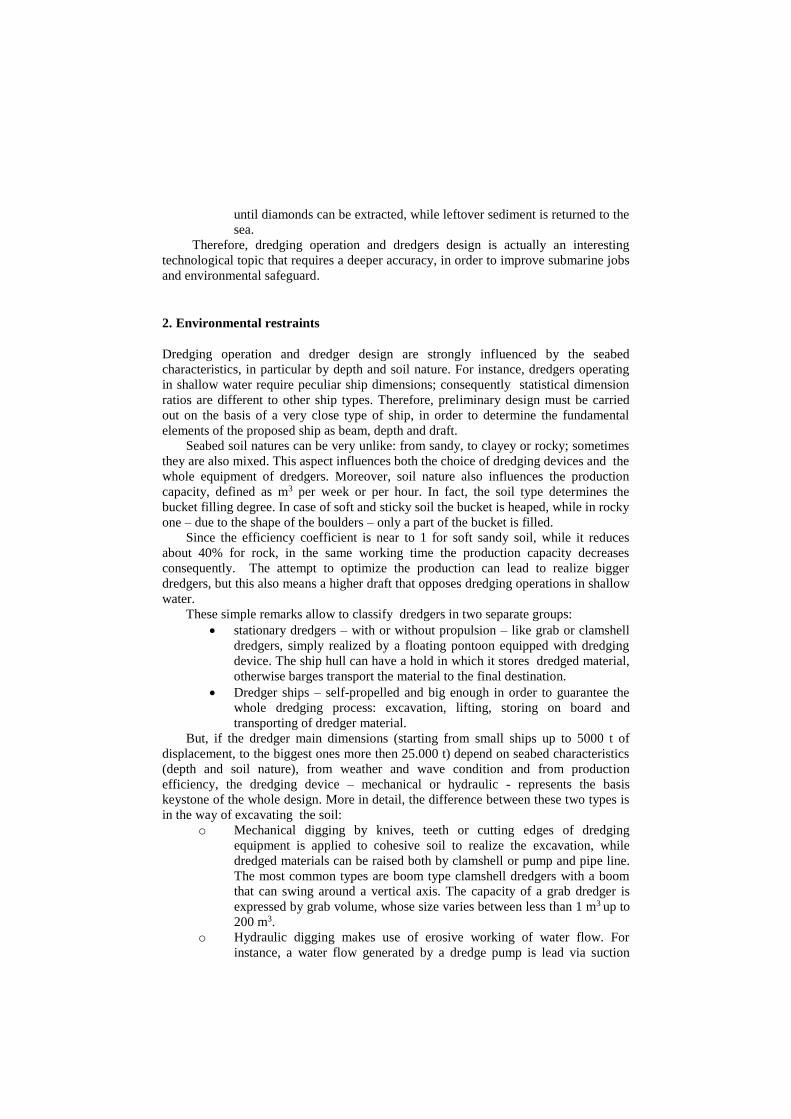
be used. In fact, when the dredger is properly anchored by anchors (both fore and aft –
fig. 1), the pontoon movement can be easily obtained releasing the aft wires and pulling
the fore wires.
Figure 1. Dredger anchoring
Otherwise, when the dredger is equipped with spud poles, the movement is done
by different spud operation, depending on number and location of poles. In this case,
the step of dredger is more accurate than executed by wires.
The method of anchoring, the positioning system and dredging device play an
important role in the pattern cut area and for the effectiveness of the dredger. For
bucket or hydraulic cutting dredger, the pontoon swings around the bow anchors,
whose radius depends on the bow wire length (up to 1 NM long); it means that with
such great lengths, measures must be taken to prevent the radius of the swing circle
from being reduced by the bow wire being dragged over the bottom. For instance, one
or more pontoons/floats/bow barges are positioned under the bow wire, in order to
ensure the optimum horizontal anchor force. The swinging of the dredger and the
provision of the excavation forces is mainly carried out by the side winches, whose
velocity depends on the type of soil and also on the step length and the height of the cut.
The stern winch controls the swing angle, while the stern anchor is used to obtain the
required tension in the bow wire.
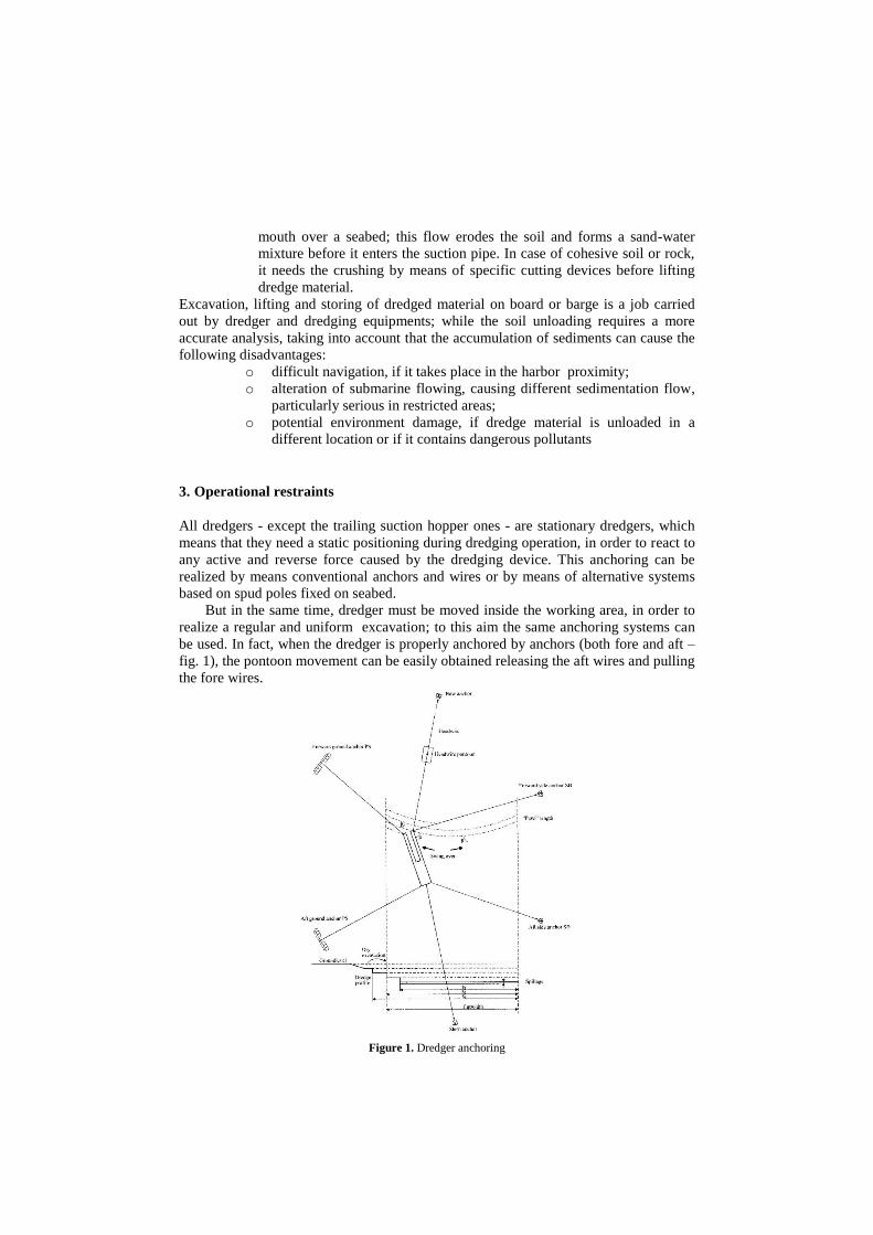
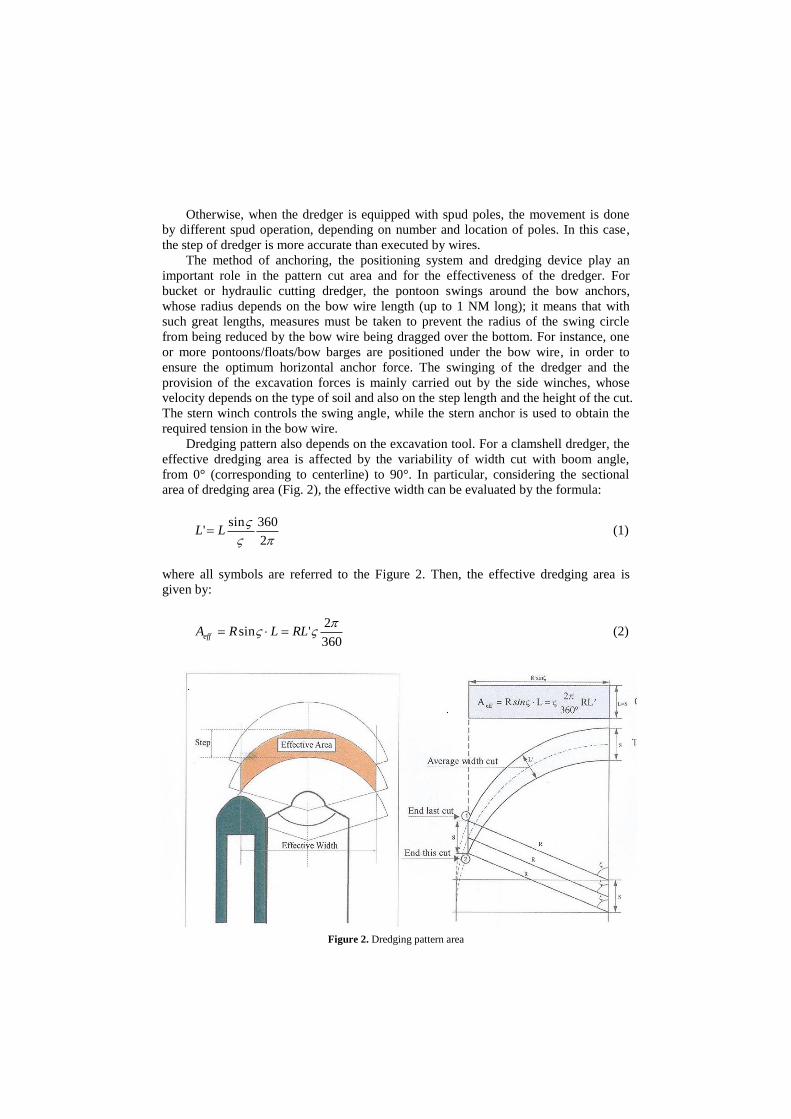
Dredging pattern also depends on the excavation tool. For a clamshell dredger, the
effective dredging area is affected by the variability of width cut with boom angle,
from 0° (corresponding to centerline) to 90°. In particular, considering the sectional
area of dredging area (Fig. 2), the effective width can be evaluated by the formula:
2
360sin' LL (1)
where all symbols are referred to the Figure 2. Then, the effective dredging area is
given by:
360
2'sin
RLLRAeff (2)
Figure 2. Dredging pattern area
When anchoring is obtained by spud poles, they can be located two on front side of
the pontoon and one at the aft side. They are vertically movable, so the movement of
the pontoon is ensured raising two poles (one front and one aft side) and swinging the
pontoon around the fixed pole. When the right position of the pontoon is reached, the
two poles can be fixed on seabed.
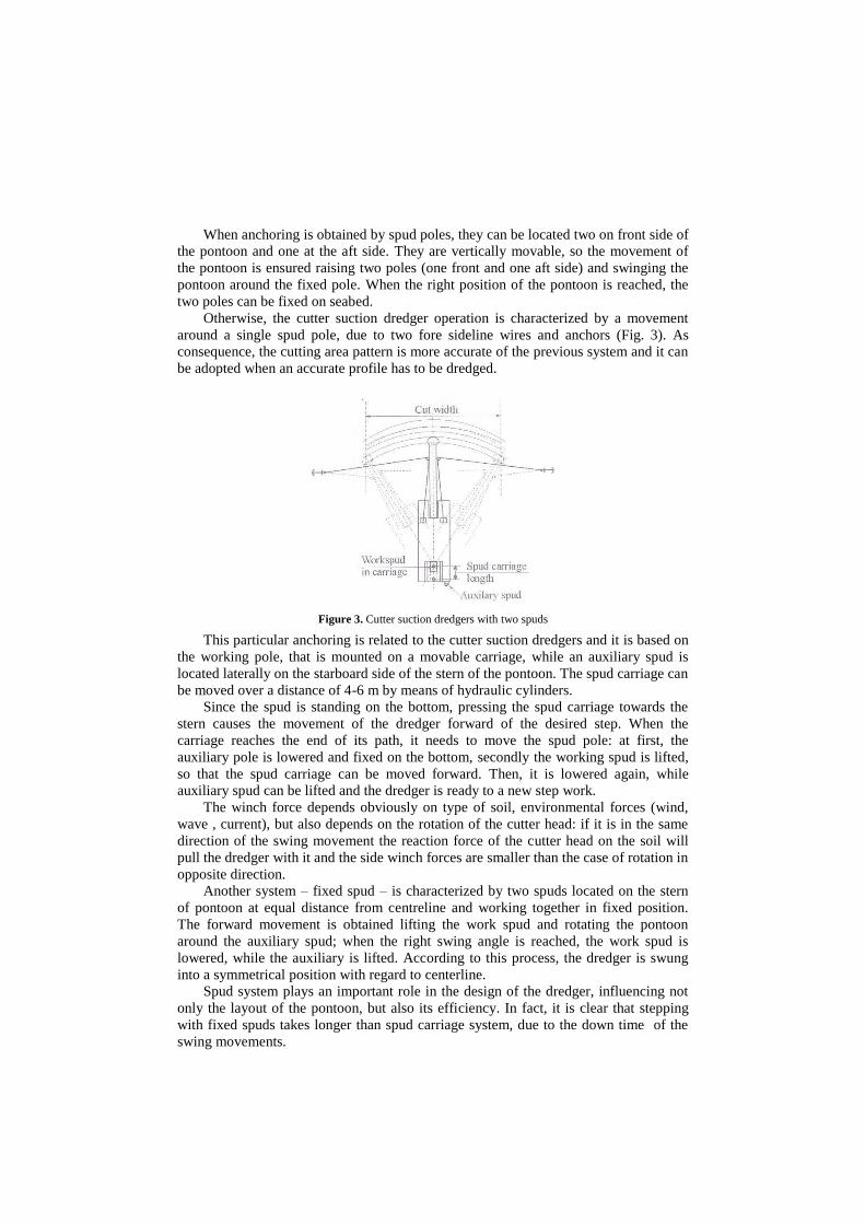
Otherwise, the cutter suction dredger operation is characterized by a movement
around a single spud pole, due to two fore sideline wires and anchors (Fig. 3). As
consequence, the cutting area pattern is more accurate of the previous system and it can
be adopted when an accurate profile has to be dredged.
Figure 3. Cutter suction dredgers with two spuds
This particular anchoring is related to the cutter suction dredgers and it is based on
the working pole, that is mounted on a movable carriage, while an auxiliary spud is
located laterally on the starboard side of the stern of the pontoon. The spud carriage can
be moved over a distance of 4-6 m by means of hydraulic cylinders.
Since the spud is standing on the bottom, pressing the spud carriage towards the
stern causes the movement of the dredger forward of the desired step. When the
carriage reaches the end of its path, it needs to move the spud pole: at first, the
auxiliary pole is lowered and fixed on the bottom, secondly the working spud is lifted,
so that the spud carriage can be moved forward. Then, it is lowered again, while
auxiliary spud can be lifted and the dredger is ready to a new step work.
The winch force depends obviously on type of soil, environmental forces (wind,
wave , current), but also depends on the rotation of the cutter head: if it is in the same
direction of the swing movement the reaction force of the cutter head on the soil will
pull the dredger with it and the side winch forces are smaller than the case of rotation in
opposite direction.
Another system – fixed spud – is characterized by two spuds located on the stern
of pontoon at equal distance from centreline and working together in fixed position.
The forward movement is obtained lifting the work spud and rotating the pontoon
around the auxiliary spud; when the right swing angle is reached, the work spud is
lowered, while the auxiliary is lifted. According to this process, the dredger is swung
into a symmetrical position with regard to centerline.
Spud system plays an important role in the design of the dredger, influencing not
only the layout of the pontoon, but also its efficiency. In fact, it is clear that stepping
with fixed spuds takes longer than spud carriage system, due to the down time of the
swing movements.
4. Dredging device restraints
Dredging device influences both dredger and its operations. For grab dredgers, the
dredging depth depends only on the length of the winch wire, even though the accuracy
decreases with depth.
In the same time, nature of soil influences the type of grab: in soft soil (sand and
gravel) light big grabs (clamshell) are used, while in more cohesive soils, heavy small
grabs (orange - cactus grab) are favorable. For these reasons, the efficiency of the grab
is expressed by paying load on total weight ratio.
Otherwise, when vessel is equipped with bucket like backhoe (or dipper) dredger,
dredging is influenced by length of stick and boom, while efficiency depends on bucket
size, that is related to crane power (actually, dredging operation is limited to about 30
m).
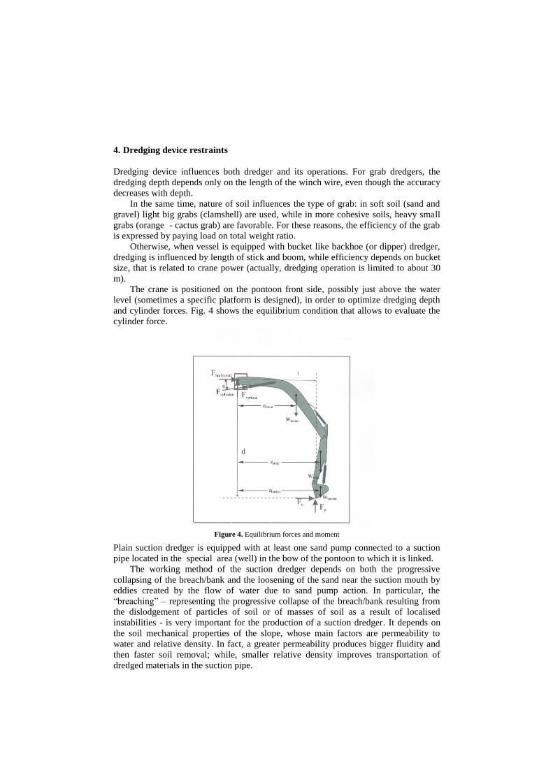
The crane is positioned on the pontoon front side, possibly just above the water
level (sometimes a specific platform is designed), in order to optimize dredging depth
and cylinder forces. Fig. 4 shows the equilibrium condition that allows to evaluate the
cylinder force.
Figure 4. Equilibrium forces and moment
Plain suction dredger is equipped with at least one sand pump connected to a suction
pipe located in the special area (well) in the bow of the pontoon to which it is linked.
The working method of the suction dredger depends on both the progressive
collapsing of the breach/bank and the loosening of the sand near the suction mouth by
eddies created by the flow of water due to sand pump action. In particular, the
“breaching” – representing the progressive collapse of the breach/bank resulting from
the dislodgement of particles of soil or of masses of soil as a result of localised
instabilities - is very important for the production of a suction dredger. It depends on
the soil mechanical properties of the slope, whose main factors are permeability to
water and relative density. In fact, a greater permeability produces bigger fluidity and
then faster soil removal; while, smaller relative density improves transportation of
dredged materials in the suction pipe.
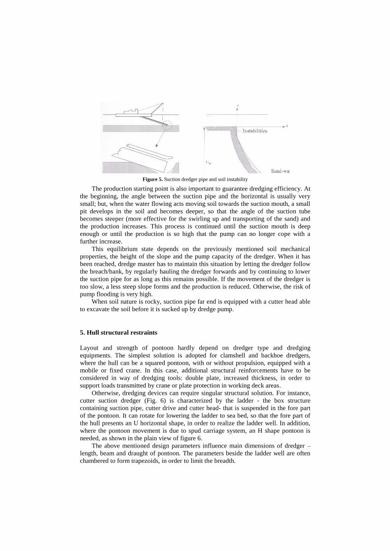
Figure 5. Suction dredger pipe and soil instability
The production starting point is also important to guarantee dredging efficiency. At
the beginning, the angle between the suction pipe and the horizontal is usually very
small; but, when the water flowing acts moving soil towards the suction mouth, a small
pit develops in the soil and becomes deeper, so that the angle of the suction tube
becomes steeper (more effective for the swirling up and transporting of the sand) and
the production increases. This process is continued until the suction mouth is deep
enough or until the production is so high that the pump can no longer cope with a
further increase.
This equilibrium state depends on the previously mentioned soil mechanical
properties, the height of the slope and the pump capacity of the dredger. When it has
been reached, dredge master has to maintain this situation by letting the dredger follow
the breach/bank, by regularly hauling the dredger forwards and by continuing to lower
the suction pipe for as long as this remains possible. If the movement of the dredger is
too slow, a less steep slope forms and the production is reduced. Otherwise, the risk of
pump flooding is very high.
When soil nature is rocky, suction pipe far end is equipped with a cutter head able
to excavate the soil before it is sucked up by dredge pump.
5. Hull structural restraints
Layout and strength of pontoon hardly depend on dredger type and dredging
equipments. The simplest solution is adopted for clamshell and backhoe dredgers,
where the hull can be a squared pontoon, with or without propulsion, equipped with a
mobile or fixed crane. In this case, additional structural reinforcements have to be
considered in way of dredging tools: double plate, increased thickness, in order to
support loads transmitted by crane or plate protection in working deck areas.
Otherwise, dredging devices can require singular structural solution. For instance,
cutter suction dredger (Fig. 6) is characterized by the ladder - the box structure
containing suction pipe, cutter drive and cutter head- that is suspended in the fore part
of the pontoon. It can rotate for lowering the ladder to sea bed, so that the fore part of
the hull presents an U horizontal shape, in order to realize the ladder well. In addition,
where the pontoon movement is due to spud carriage system, an H shape pontoon is
needed, as shown in the plain view of figure 6.
The above mentioned design parameters influence main dimensions of dredger –
length, beam and draught of pontoon. The parameters beside the ladder well are often
chambered to form trapezoids, in order to limit the breadth.

Figure 6. Cutter suction dredger with H shape pontoon
Adequate structural measures must be taken in order to support strength and forces.
For instance, in designing the hull, it must take into account that a part of the reaction
forces from dredging process is transferred to the work spud via the hull. For this
reason, the hull is composed by a single unit forming the main strengthen pontoon and
by two separate forward side pontoons. The bigger forces transmitted by ladder hinge
or spuds are mounted on the main pontoon.
The ladder gantry spans over the forward well is a particular frame construction,
able to support the vertical forces due to dredging operation and transferred to the
pontoon via the gantry. It also represents a torsional reinforcement in case of singular
wave loads.
U-shape pontoon is also adopted for bucket dredger to accommodate the ladder,
equipped with the chain of buckets. The well is rather long compared to that of the
cutter suction dredger, roughly 60% of the hull length, because it depends on ladder
length, relate to maximum depth operation.
For hopper dredger the production also depends on time required to discharge
dredged material; generally, the ship has to be able to discharge the load in a short time,
as completely as possible and for all types of soil.
Dredged material can be discharged in various ways, depending on the project
specification, but a very fast method is the dumping; it consists of depositing sediments
through valves or doors located in the bottom of the ship, opened hydraulically. As
enterprising solution, it can be considered a ship/barge that split totally in two halves
(Fig. 7) that can rotate around an horizontal axis; once the hold is opened, dredged
material can be deposited quickly at sea. Obviously, these pontoons require a trim and
stability verification for any load condition and appropriate structural analysis.
Figure 7. Split hopper dredger
6. Classification regulatory restraints
Part E chapter 13 of the rules for the Classification of ships by RINA (Italian Ship
Register) deals with the criteria adopted for dredging activity ships, as regards hull,
stability, machinery and dredging systems. In the follow, I have examined some rules
related to the specific dredger function and operation.
1. The pontoon intact stability must be evaluated considering the worst loading
condition during dredging, in order to produce the most severe combination of
inclining moment and initial metacentric height. For instance, the mass of
dredge material contained in the grab is to be considered equal to 1.6 of its
volume, namely rocky soil.
2. For dredgers with bottom doors or similar means at port and starboard side
rules consider as load condition the case of asymmetric discharging with
reduction of equilibrium angle, righting lever and range of stability.
3. Grounding is considered for some dredgers a normal operation, therefore the
bottom plating and related structures are to be properly dimensioned according
the following criteria:
Bottom shell plate has to be increased by 2.5 mm along the pontoon
full length; this thickness is sufficiently high if we consider that the
normal plate thickness is rather thin, due to reduced ship length,;
Pontoon having (B + D) > 21 m must be provided with a double
bottom between collision and fore bulkhead; this rule also represents
an appropriate measure to increase hull girder longitudinal strength
for dredgers having a central well to accommodate dredging device
4. If reinforcement is made by increasing the thickness, the section modulus may
be determined taking into account the extra thickness.
5. Double bottom structural lay out must be designed according to the following
criteria:
When the ship is transversely framed, floors are to be fitted at each
frame space and associated with inter-costal longitudinal girders, the
mean space of which is to be not greater than 2.1 m. Moreover, an
ordinary longitudinal stiffener is to be fitted at mid spacing
When the ship is longitudinally framed, the floor spacing may not
exceed the frame spaces and bottom girder spacing may not exceed
three longitudinal ordinary stiffener spaces.
6. A new equipment number formula (applicable to dredgers having normal ship
shape of the underwater part of the hull – otherwise, the EN is considered case
by case basis) is given together with a new table having a different range of
EN (35 < EN < 795), in order to assure the adequate equipment capacity for
anchors, chain cables and mooring lines for all pontoon dimensions.
Finally, more detailed criteria and additional requirements are then considered for
each specific dredger type and particularly split hopper dredgers and hopper units.
7. Conclusions
A series of general restraints for dredger design have been examined, showing the real
nature of these special ships.
Regulatory rules confirm the need to proof some aspects related to dredging
operations and devices that influence hull ship characteristics: stability and strength.
The descriptive approach allows to highlight the main problems related to dredging
operations and is sufficient to understand the complexity of the problems linked to
dredger design.
Nevertheless, it also seems inevitable that the modified demand for submarine
work and the development of technology innovations will open new and unexpected
frontiers in this marine culture field.
Note
Figures by [1]
References
[1] W.J. Vlasblom , Cutter suction dredgers, Lecture Notes, T.U. Delft, 2003.
[2] R.J. de Heer. Dredging and dredging equipment, IHE, T.U. Delft , 1989 [3] Rules for the Classification of Ships, Registro Italiano Navale, 2015