
Draft Guideline on Maintenance of Roa vuqla/kku vfHkdYi ,oa ...
40
Draft G Maintena Re Research Design an vuqla/kku vfHkd GOVERNMENT OF INDIA Hkkjr ljdkj MINISTRY OF RAILWAYS jsy ea=ky; Guideline on Construction & ance of Roads for Railway Premises eport No. RDSO/WKS/2018/1 March, 2018 Works Directorate dk;Z funs’kky; nd Standards Organization, Lucknow dYi ,oa ekud laxBu y[kuÅ & 2260 w – 226011 011
-
Upload
khangminh22 -
Category
Documents
-
view
4 -
download
0
Transcript of Draft Guideline on Maintenance of Roa vuqla/kku vfHkdYi ,oa ...

Draft Guideline on
Maintenance of Roads for Railway
Report
Research Design and Standards Organization, Lucknow vuqla/kku vfHkdYi ,oa ekud laxBu y[kuÅ
GOVERNMENT OF INDIA Hkkjr ljdkj
MINISTRY OF RAILWAYS
jsy ea=ky;
Draft Guideline on Construction &
Maintenance of Roads for Railway Premises
Report No. RDSO/WKS/2018/1 March, 2018
Works Directorate
dk;Z funs’kky;
Research Design and Standards Organization, Lucknow vuqla/kku vfHkdYi ,oa ekud laxBu y[kuÅ & 226011
Research Design and Standards Organization, Lucknow – 226011 & 226011

INDEX
S. No.
Description of items Page No.
1. Introduction 1 2. Construction of New Road 3
A. Bituminous Road 3 i) Surface Preparation & Leveling 5 ii) Water Bound Macadam & Wet Mix Macadam with Leveling &
Rolling 4
iii) Bituminous Surface 16 iv) Seal Coat or Filler 23
B. Concrete Road 24 i) Surface Preparation Leveling 24 ii) Water Bound Macadam & Wet Mix Macadam with Leveling &
Rolling 24
iii) Cement Concrete Surface 24 iv) Vacuum dewatering 29 v) Mechanical Toweling 29
3. Material IS Parameters 29 4. Construction Equipment involved 29 5. Material & Maintenance of Existing Road Work 31 6. Kerb and Channel Stones 35 7. Brick Edging 35 8. Speed Breaker 36 9. Road/Marking 36 10. Reflective Raised Pavement Markers (Cat eye) 37 11. Footpath 38

Page 1 of 38
Guideline on New Construction/Maintenance of Existi ng Roads in Colonies and Service Buildings
1. Introduction: There is a need to adopt uniform specifications in construction of roads in railway establishments. It is noticed that roads are constructed to a set standards & specifications for different categories of roads such as peripheral roads in colonies as well as heavy traffic areas like goods shed roads without exercising any technical thought.
There is an urgent need for standardizing of the specifications for construction of various categories of roads. Category of Roads for Railway Premises: There is no categorization of roads on the basis of uses by IRC (Indian road Congress). However, for Railway premises roads can be classified into following three groups:
Table-1 Group A Roads where heavy traffic (with frequent plying of buses and
loaded truck like approach roads to Goods sheds, Workshops etc.) is anticipated.
Group B Peripheral roads in bigger colonies, approaches to stations, circulating area etc.
Group C All roads in wayside stations, branches of arterial roads leading to smaller colonies or such similar types of non-important roads.
As per recommendation of subcommittee thickness of different category of roads shall be as under:-
Category of Roads
Sub-grade Sub base Course
Base Course
Surface Course
Finishing Course
A
If the existing soil consists of well compacted predominately incompressible coarse grained soil, then spread 25 mm thick layer of screening of nominal size 11.2 mm or coarse sand.
Two layers each of 100 mm thick WBM using 90 mm to 45 mm sizes aggregates
Two layers each of 75 mm thick WBM using 63 mm to 45 mm sizes or 53mm to 22.4mm aggregates will be laid over the sub-base course
50 mm thick (compacted thickness) Dense bituminous macadam (Asphaltic concrete) using hot mix plant and paver equipment with minimum bituminous content 5% (by weight of total
6-8 mm thick (compacted thickness) layer of seal coat using type ‘A’ stone chips of nominal size 6.7 mm (100% passing through

Page 2 of 38
If the existing soil consists of clayey sand on predominately fine grained soils of low compressibility, then a layer of minimum of 150mm thick moorum or equivalent granular material is to be laid.
mix) will be laid over base course after application of tack coat.
11.2 mm sieve & retained on 2.36 mm sieve). Normally, the quantity of stone chips would be 0.09 Cum per 10 sqm area.
B -do-
One layers of 100 mm thick WBM using 90 mm to 45 mm sizes aggregates
Two layers each of 75 mm thick WBM using 63 mm to 45 mm sizes or 53mm to 22.4mm aggregates will be laid over the sub-base course
40 mm thick bituminous macadam using hot mix plant and paver equipment with minimum bituminous content 3.5% (by weight of total mix) will be laid over base course after application of tack coat.
C -do-
One layers of 100 mm thick WBM using 90 mm to 45 mm sizes aggregates
Two layers each of 75 mm thick WBM using 63 mm to 45 mm sizes or 53mm to 22.4mm aggregates will be laid over the sub-base course
25 mm thick (compacted thickness) Premix carpet with hot bitumen using 13.2 and 11.2 mm stone chippings over base course after application of tack coat.

Page 3 of 38
However, the works under Category ‘C’ may be executed without paver & without hot mix plant material in exceptional cases where it is impractical to arrange the same for small wayside stations. In such cases, local heating & mixing of Bitumen & aggregates can be permitted by Engineer.
2. Steps of Construction of New Road:-
A. Bituminous Road:-
i) Surface Preparation & leveling:
Sub-grade Preparation :-The surface of the formation for width equal to that of the soling (or sub-base where provided) shall first be cut (where necessary) to a depth below the proposed finished level of the road, equal to the combined depth of sub-base (if provided), soling and wearing coat (due allowance being made for consolidation). It shall then be cleaned of all foreign substances. Any ruts or soft places that appear due to improper drainage conditions, traffic hauling or any other cause shall be corrected and the sub grade dressed off parallel to the finished profile. The same shall apply to preparation of sub-grade for new platform also.
The sub-grade shall then be consolidated with a road roller. Water shall be applied uniformly to the sub-grade one evening prior to rolling. Any low spots that develop in the sub-grade during rolling shall be brought to grade with the excavated approach earth and re-rolled. Rolling shall be done with a light road roller or sheep foot roller or any vibratory roller as approved by the Engineer. All soft and unsuitable materials and surplus earth shall be removed as directed by the Engineer and the area where it is disposed off shall be dressed. If the existing soil consists of well compacted predominately incompressible coarse grained soil, then spread 25 mm thick layer of screening of nominal size 11.2 mm or coarse sand. If the existing soil consists of clayey sand on predominately fine grained soils of low compressibility, then a layer of minimum of 150mm thick moorum or equivalent granular material is to be laid.
The sub-grade made up of natural soil has poor bearing capacity (less than11.0 tonnes per sqm), a sub-base consisting of dense granular material shall be provided. One /Two layers each of 100 mm thick WBM using 90 mm to 45 mm sizes aggregates shall be provided on the basis of type of road.

Page 4 of 38
If, the sub-grade or formation consists of black cotton soil or other soil subject to capillary action of water, a sub-base of moorum or coarse sand shall be provided below the base course consisting of stone or boulder soling. It will be watered and rolled lightly. It will be for a thickness of 150 mm (minimum), unless otherwise specified.
ii) Water Bound Macadam with Leveling & Rolling: This should be conforming to
IRC: 19.
Water Bound Macadam (WBM) shall consist of clean, crushed coarse aggregates mechanically interlocked by rolling, and voids thereof filled with screening and binding material with the assistance of water, laid on a prepared sub-grade, sub-base, base or existing pavement as the case may be. WBM may be used as a sub-base, base course or surfacing course depending upon category of road.
WBM should not be laid directly over a silty or clayey sub-grade. It is advisable to lay a suitable intervening granular layer.
Thickness: -Unless otherwise specified, the thickness of the wearing coat, if laid for the first time shall be 11.5 cm consolidated. For renewals it shall vary from 7.5 cm to 11.5 cm or as specified or as directed by Engineer. Camber: -The camber shall be 1 in 48 or as directed by the Engineer or otherwise specified.
Materials : Physical requirements of coarse aggregate shall be given as in Table 2 (IRC: 19):-
Table- 2 S.
No. Type of
Construction Test + Test Method Requirements
1. Sub-base Los Angeles Abrasion Value* or
IS 2386 (Part 4) Max. 50%
Aggregate Impact Value*
IS 2386 (Part 4) or IS 5640**
Max. 40%
2. Base course with bituminous surfacing
Los Angeles Abrasion Value* or
IS 2386 (Part 4) Max. 40%
Aggregate Impact Value*
IS 2386 (Part 4) or IS 5640**
Max. 30%
Flakiness Index*** IS 2386 (Part 1) Max. 20%
Page 5 of 38
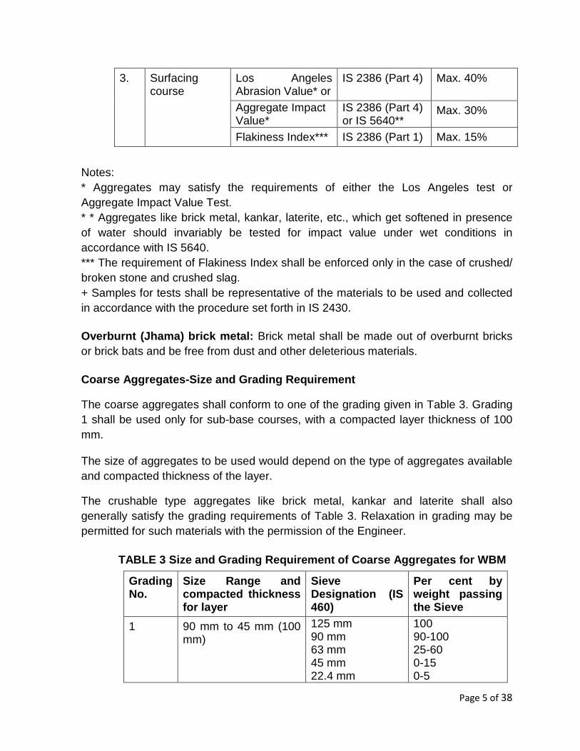
3. Surfacing course
Los Angeles Abrasion Value* or
IS 2386 (Part 4) Max. 40%
Aggregate Impact Value*
IS 2386 (Part 4) or IS 5640**
Max. 30%
Flakiness Index*** IS 2386 (Part 1) Max. 15%
Notes: * Aggregates may satisfy the requirements of either the Los Angeles test or Aggregate Impact Value Test. * * Aggregates like brick metal, kankar, laterite, etc., which get softened in presence of water should invariably be tested for impact value under wet conditions in accordance with IS 5640. *** The requirement of Flakiness Index shall be enforced only in the case of crushed/ broken stone and crushed slag. + Samples for tests shall be representative of the materials to be used and collected in accordance with the procedure set forth in IS 2430.
Overburnt (Jhama) brick metal: Brick metal shall be made out of overburnt bricks or brick bats and be free from dust and other deleterious materials.
Coarse Aggregates-Size and Grading Requirement
The coarse aggregates shall conform to one of the grading given in Table 3. Grading 1 shall be used only for sub-base courses, with a compacted layer thickness of 100 mm.
The size of aggregates to be used would depend on the type of aggregates available and compacted thickness of the layer.
The crushable type aggregates like brick metal, kankar and laterite shall also generally satisfy the grading requirements of Table 3. Relaxation in grading may be permitted for such materials with the permission of the Engineer.
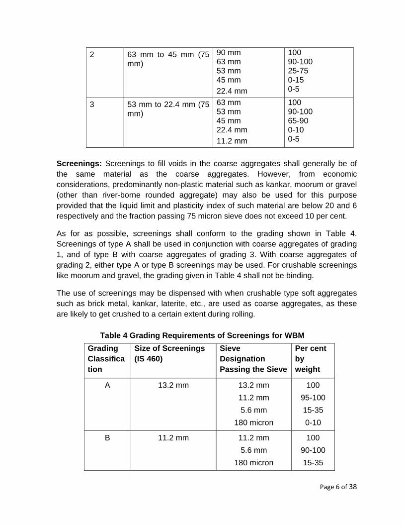
TABLE 3 Size and Grading Requirement of Coarse Aggr egates for WBM
Grading No.
Size Range and compacted thickness for layer
Sieve Designation (IS 460)
Per cent by weight passing the Sieve
1 90 mm to 45 mm (100 mm)
125 mm 90 mm 63 mm 45 mm 22.4 mm
100 90-100 25-60 0-15 0-5
Page 6 of 38
2 63 mm to 45 mm (75 mm)
90 mm 63 mm 53 mm 45 mm 22.4 mm
100 90-100 25-75 0-15 0-5
3 53 mm to 22.4 mm (75 mm)
63 mm 53 mm 45 mm 22.4 mm 11.2 mm
100 90-100 65-90 0-10 0-5
Screenings: Screenings to fill voids in the coarse aggregates shall generally be of the same material as the coarse aggregates. However, from economic considerations, predominantly non-plastic material such as kankar, moorum or gravel (other than river-borne rounded aggregate) may also be used for this purpose provided that the liquid limit and plasticity index of such material are below 20 and 6 respectively and the fraction passing 75 micron sieve does not exceed 10 per cent.
As for as possible, screenings shall conform to the grading shown in Table 4. Screenings of type A shall be used in conjunction with coarse aggregates of grading 1, and of type B with coarse aggregates of grading 3. With coarse aggregates of grading 2, either type A or type B screenings may be used. For crushable screenings like moorum and gravel, the grading given in Table 4 shall not be binding.
The use of screenings may be dispensed with when crushable type soft aggregates such as brick metal, kankar, laterite, etc., are used as coarse aggregates, as these are likely to get crushed to a certain extent during rolling.
Table 4 Grading Requirements of Screenings for WBM
Grading Classification
Size of Screenings (IS 460)
Sieve Designation Passing the Sieve
Per cent by weight
A
13.2 mm
13.2 mm
11.2 mm
5.6 mm
180 micron
100
95-100
15-35
0-10
B
11.2 mm 11.2 mm
5.6 mm
180 micron
100
90-100
15-35

Page 7 of 38
Binding Material: Binding material to be used for WBM as filler shall consist of a fine grained material passing 100 per cent through 425 micron sieve and possessing PI value of 4-8 when the WBM is used as a surfacing course and less than 6 when the WBM is adopted as a sub-base/base course with bituminous surfacing. If limestone formations are available nearby, limestone dust or kankar nodules may be used as binding material. Application of binding material may not be necessary, where the screenings consist of crushable type material like moorum or gravel. However, for WBM used as a surfacing course, where the PI of crushable type screenings is less than 4, application of a small quantity of binding material having PI of 4-6 would be required at the top. The quantity of screenings could be reduced correspondingly.
Quantities of Material: Table- 5 Approximate Quantities of Coarse Aggregate s and Screenings Required
for 100 mm compacted thickness of WBM Sub-base Cour se per 10 m2
Coarse Aggregates
Screenings
Stone Screening Crushable Type such as Moorum or Gravel
Classification
Size Range (mm)
Loose Qty (m 3)
Grading Classification & Size
Loose quantity (m 3)
Properties & Size
Loose Qty. (m 3)
Grading-1
90mm to 45mm
1.21 to 1.43 m3
Type A 13.2 mm
0.27 to 0.30 m3
LL<20, PI<6 Per cent passing 75 micron<10
0.30 to 0.32m3

Page 8 of 38
Table- 6 Approximate Quantities of Coarse Aggregate s and Screenings Required for 75 mm compacted thickness of WBM Base Course/Su rfacing Course per 10 m2
Coarse Aggregates
Screenings
Stone Screening Crushable Type
such as Moorum or Gravel
Classification
Size Range (mm)
Loose Qty (m3)
Grading
Classification & Size
Loose quantity or Properties & Size
Loose Qty. (m3)
WBM sub-base/base course (m3)
WBM surfacing course* (m3)
Grading-2
63mm to 45mm
0.91 to 1.07m3
Type A 13.2 mm
0.12 to 0.15
0.10 to 0.12
LL<20, PI<6 Per cent passing 75 micron<10
0.22 to 0.24 m3
- do - - do - - do- Type B 11.2 mm
0.20 to 0.22
0.16 to 0.18
- do - - do -
Grading-3
53mm to 22.4 mm
- do- - do - 0.18 to 0.21
0.14 to 0.17
- do - - do -
The quantity of binding material to be used for WBM will depend on the type of screenings and function of WBM. Generally, the quantity required for 75 mm compacted thickness of WBM will be 0.06-0.09 m3/10 m2 in the case of WBM sub-base/base course and 0.10-0.15 m3/10 m2 when the WBM is to function as a surfacing course. For 100 mm thickness, the quantity needed will be 0.08-0.10 m3/10 m2 for sub-base course.
The above mentioned quantities should be taken as a guide only, for estimation of quantities for construction etc.

Page 9 of 38
Construction Procedure:
Preparation of Foundation for Receiving WBM Layer
The sub-grade, sub-base or base to receive the WBM course shall be prepared to the required grade and camber and cleaned of all dust, dirt and other extraneous matter. Any ruts or soft yielding places that have appeared due to improper drainage, service under traffic or other reasons shall be corrected and rolled until firm.
Where the WBM is to be laid on an existing un-surfaced road, the surface shall be scarified and re-shaped to the required grade and camber as necessary. Weak places shall be strengthened, corrugations removed and depressions and potholes made good with suitable material before spreading the coarse aggregates for WBM.
As far as possible laying of WBM course over an existing bituminous surface should be avoided since it will cause problems of proper bond and internal drainage of the pavement at the interface of two courses. It is desirable to completely remove the existing thin surfacing of bituminous layer, where WBM is proposed to be laid over it. Where the intensity of rain is low and interface drainage facility is efficient, WBM can be laid over existing thin bituminous surfacing by cutting 50 mm x 50 mm (minimum) furrows at 1 metre intervals at 45 degrees to the centre line of the carriageway before proceeding with the laying of WBM. The direction and depth of furrows shall be such that they provide adequate bondage and also serve to drain water to the existing granular base course beneath the existing bituminous surface. In all cases, the foundation shall be kept well drained during the construction operations. Spreading of Coarse Aggregates: Coarse aggregates shall be spread uniformly and evenly upon the prepared base in required quantities from stockpiles along the side of the road or directly from vehicles. In no case shall these be dumped in heaps directly on the area where these are to be laid nor shall their hauling over a partly completed base be permitted. The aggregates shall be spread to proper profile by using templates placed across the road about 6 m apart. Where possible, approved mechanical devices shall be used to spread the aggregates uniformly so as to minimize the need for their manipulation by hand. The WBM Course shall be constructed in layers such that thickness of each compacted layer is not more than 100 mm for grading 1. The compacted thickness of layer shall be 75 mm for grading 2 and grading 3. Each layer shall be tested by depth

Page 10 of 38
blocks. No segregation of large or fine particles shall be allowed. The coarse aggregates as spread shall be of uniform gradation with no pockets of fine material. The coarse aggregates shall normally not be spread in lengths exceeding three days average work ahead of the rolling and bonding of the preceding section.
Rolling: After the laying of coarse aggregates, these shall be compacted to full width by rolling with either three wheel-power roller of 80 to 100 kN capacity or an equivalent vibratory roller. The rolling shall begin from edges with roller running forward and backward until the edges have been firmly compacted. The roller shall then progress gradually from edges to the centre, parallel to the centre line of the road and overlapping uniformly each preceding rear wheel track by one half width and shall continue until the entire area of the course has been rolled by the rear wheel. Rolling shall continue until the road metal is thoroughly keyed and the creeping of stone ahead of the roller is no longer visible. Slight sprinkling of water may be done, if required. On super elevated portions of the road, rolling shall commence from the lower edge and progress gradually towards the upper edge of the pavement. Rolling shall not be done when the sub-grade is soft or yielding or when it causes a wave-like motion in the base course or sub-grade. If irregularities develop during rolling, which exceed 12 mm when tested with a 3 m straight edge, the surface shall be loosened and aggregates added or removed as required before rolling again so as to achieve all uniform surfaces conforming to the desired cross section and grade. The surface shall also be checked transversely by template for camber, and any irregularities corrected in the manner described above. In no case shall the use of screenings to make up depressions be permitted. Material, which gets crushed excessively during compaction or become segregated shall be removed and replaced with suitable aggregates. Application of Screenings: After coarse aggregates have been rolled, screenings to fill interstices shall be applied gradually over the surface. Dry rolling shall be done when the screenings are being spread so that the jarring effect of roller causes them to settle into the voids of the coarse aggregate. The screenings shall not be dumped in piles but applied uniformly in successive thin layers either by the spreading motion of hand shovels, mechanical spreaders, or directly from trucks. Trucks plying over the base course to spread screenings shall be equipped with pneumatic tyres and operated such as not to disturb the coarse aggregates. The screenings shall be applied at a slow rate in three or more applications as necessary. This shall be accompanied by rolling and brooming. Either mechanical brooms/hand brooms or both may be used. In no case shall the screenings be applied so fast and thick as to form cakes or ridges on the surface making the filling

Page 11 of 38
of voids difficult or preventing the direct bearing of roller on the coarse aggregates. The spreading, rolling and brooming of screenings shall be taken up on sections, which can be completed within one day's operation. Sprinkling of Water and Grouting: After application of screenings, the surface shall be copiously sprinkled with water, swept and rolled. Hand brooms shall be used to sweep the wet screenings into the voids, and to distribute them evenly. The sprinkling, sweeping and rolling operations shall be continued and additional screenings applied, where necessary until the coarse aggregates are bonded and firmly set and a grout of screenings and water forms ahead of the wheels of the roller. Care shall be taken that the base or sub-grade does not get damaged due to addition of excessive quantities of water during the construction. Application of Binding Material: After the application of screenings as per binding material and Sprinkling of Water and Grouting, binding material where it is required to be used shall be applied at an uniform and slow rate in two or more successive thin layers. After each application of binding material, the surface shall be copiously sprinkled with water and the resulting slurry swept in with hand brooms/ mechanical brooms or both so as to fill the voids properly. This shall be followed by rolling with 80- 100 kN roller during which water shall be applied to the wheels to wash down the binding material that may get stuck to them. The spreading of binding material, sprinkling of water, sweeping with brooms and rolling shall continue until the slurry of binding material and water forms a wave ahead of the wheels of moving roller. Setting and Drying: After final compaction of the course, the layer shall be allowed to dry overnight. Next morning, hungry spots shall be filled with screenings or binding material, lightly sprinkled with water if necessary, and rolled. No traffic shall be allowed till the macadam sets. In the case of WBM base course to be provided with bituminous surfacing, the latter shall be laid only after the WBM course is completely dry and before allowing any traffic on it. Finished Surface: The surface unevenness of completed WBM course in longitudinal and transverse directions shall be within the limits. The longitudinal profile shall be checked with a 3-metre long straight edge at the middle of each traffic lane along a line parallel to the centre line of the road. The transverse profile shall be checked with a series of three camber templates at intervals of 10 m.

Page 12 of 38
Table- 7 Permissible Surface Unevenness for WBM Cou rses
S. No.
Size range of coarse
aggregates
Longitudinal profile measured with a 3 metre straight edge
Transverse Profile
Max. permissible
surface unevenness
Maximum no. of undulations
permitted in any 300 metre length,
exceeding
Max. Permissible variation from
specified profile under camber
template
12 mm 10 mm
1. 90-45 mm 15 mm 30 Nil 12
2. 63-45 mm and 53-22.4
mm
12 mm Nil 30 8mm
Rectification of Defective Construction: Where the surface irregularity of the WBM courses exceeds the tolerances specified above or where the course is otherwise defective due to sub-grade soil mixing with the aggregates, the layer to its full thickness shall be scarified over the affected area, reshaped with added material, or removed and replaced with fresh material as applicable, and re-compacted. The area treated in the aforesaid manner shall not be less than 10 m2.
The compacted water bound macadam course should be allowed to completely dry and set before the next pavement course is laid over it or opened to traffic in sections.
OR
Wet Mix Macadam with Leveling & Rolling: Wet Mix Macadam is a pavement layer wherein crushed graded aggregates and granular material, like, graded course sand arc mixed with water in mixing plant and rolled to a dense mass on a prepared surface. It has many advantages over the WBM construction. These include superior gradation of aggregate, faster rate of construction, higher standard of densification that can be achieved, less consumption of water and stricter standards of quality achievable. The specification can be adopted for sub-base and base courses. The work may be done in many layers. The thickness of an individual layer shall not be less than 75 mm and can be upto 200 mm provided suitable type of compacting equipment is used.(IRC:109:1997)
Materials: a) Aggregate: Physical requirements of coarse aggregates shall be crushed
stone/crushed gravel/shingle, not less than 90 per cent by weight of gravel/shingle pieces retained on 4.75 mm sieve and shall have at least two

Page 13 of 38
fractured faces. The aggregates shall conform to the physical requirements set forth in Table 8.
If the water absorption value of the coarse aggregates is greater than 2 per cent, soundness test shall be carried out on the material as per IS: 2386 (Part V).
Table 8 Physical Requirement of Coarse Aggregates f or Wet-Mix
-------------------------------------------------------------------------------------------------------
Test Test Method Requirements
1. *Los Angeles IS: 2386 40 per cent (Max.)
Abrasion value (Part-4)
Or
*Aggregate IS: 2386 30 per cent (Max.)
Impact value (Part-4) or
IS: 5640
2. **Combined Flakiness and IS: 2386 30 per cent (Max.) ***
Elongation (Part-1)
Indices (Total)
* Aggregates may satisfy requirements of either of the two tests. ** To determine the combined proportion of flaky and elongated particies, the flaky stone from a representative sample should first be separated out. Flakiness index is weight of flaky stone metal divided by weight of stone sample. Only the elongated particles shall be separated out from the remaining (Non-flaky) stone metal. Elongation index is weight of elongated particles divided by total non-flaky particles. The value of flakiness index and elongation index so found arc added up. *** Requirement of 30 per cent can be relaxed upto 35 percent (only) in cases where WMM is to be used as sub base.
Page 14 of 38
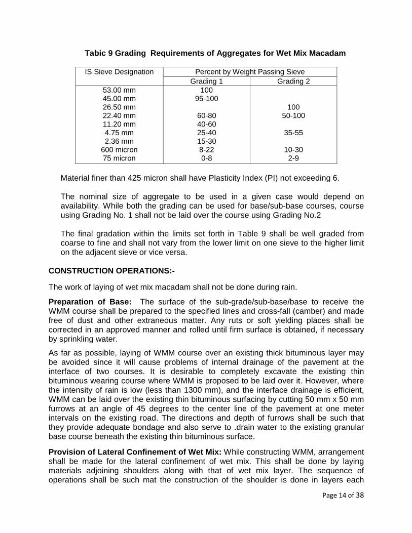
Tabic 9 Grading Requirements of Aggregates for Wet Mix Macadam
IS Sieve Designation Percent by Weight Passing Sieve Grading 1 Grading 2
53.00 mm 45.00 mm 26.50 mm 22.40 mm 11.20 mm 4.75 mm 2.36 mm
600 micron 75 micron
100 95-100
60-80 40-60 25-40 15-30 8-22 0-8
100 50-100
35-55
10-30 2-9
Material finer than 425 micron shall have Plasticity Index (PI) not exceeding 6. The nominal size of aggregate to be used in a given case would depend on availability. While both the grading can be used for base/sub-base courses, course using Grading No. 1 shall not be laid over the course using Grading No.2 The final gradation within the limits set forth in Table 9 shall be well graded from coarse to fine and shall not vary from the lower limit on one sieve to the higher limit on the adjacent sieve or vice versa.
CONSTRUCTION OPERATIONS:- The work of laying of wet mix macadam shall not be done during rain.
Preparation of Base: The surface of the sub-grade/sub-base/base to receive the WMM course shall be prepared to the specified lines and cross-fall (camber) and made free of dust and other extraneous matter. Any ruts or soft yielding places shall be corrected in an approved manner and rolled until firm surface is obtained, if necessary by sprinkling water.
As far as possible, laying of WMM course over an existing thick bituminous layer may be avoided since it will cause problems of internal drainage of the pavement at the interface of two courses. It is desirable to completely excavate the existing thin bituminous wearing course where WMM is proposed to be laid over it. However, where the intensity of rain is low (less than 1300 mm), and the interface drainage is efficient, WMM can be laid over the existing thin bituminous surfacing by cutting 50 mm x 50 mm furrows at an angle of 45 degrees to the center line of the pavement at one meter intervals on the existing road. The directions and depth of furrows shall be such that they provide adequate bondage and also serve to .drain water to the existing granular base course beneath the existing thin bituminous surface.
Provision of Lateral Confinement of Wet Mix: While constructing WMM, arrangement shall be made for the lateral confinement of wet mix. This shall be done by laying materials adjoining shoulders along with that of wet mix layer. The sequence of operations shall be such mat the construction of the shoulder is done in layers each

Page 15 of 38
matching the thickness of the adjoining pavement layer. Only after a layer of pavement and corresponding layers in shoulder have been laid and compacted, the construction of the next layer of pavement and shoulder shall be taken up. Preparation of Mix: WMM shall be prepared in an approved mixing plant of suitable capacity having provision for controlled addition of water and forced/positive mixing arrangement, like, pug mill or pan type mixer. For small quantity of wet mix work, mixing may be done in ordinary concrete mixers. Optimum moisture for mixing shall be determined in accordance with IS: 2720 (Part VIII), after replacing the aggregate fraction retained on 19 mm sieve with material of 4.75 to 19 mm size. However, the OMC and required number of passes to achieve the desired density may be determined at site during proof rolling, using the roller selected for compaction. While adding water, due allowance should be made for evaporation losses. However, at the time of compaction, water in the wet mix should not vary by more than ± 1 per cent. Spreading of Mix Immediately after mixing, the mixed material shall be transported to site and spread uniformly and evenly upon the prepared subgrade/sub-base/base in required quantities. Hauling of the mix over a freshly completed stretch is not permitted. The mix may be spread either by a paver finisher or motor grader or a combination of both. However, the use of paver finisher should be preferred to motor grader for spreading. For portions where mechanical means cannot be used, manual method of spreading can be adopted. The equipment used for spreading shall be capable of spreading the material uniformly all over the surface. Its blade shall have hydraulic controls suitable for initial adjustments and maintaining the same so as to achieve the specified slope and grade.
The paver finisher shall be self-propelled, having the following features:- i) Loading hoppers and suitable distributing mechanism ii) The screed shall have tamping and vibrating arrangement for imparting initial
compaction to the layer as it is spread without nitting or otherwise disturbing the surface profile.
iii) The paver shall be equipped with necessary control mechanism m so as to ensure that the unfinished surface is free from surface blemishes.
The surface of the layer as spread shall be carefully checked with templates and all high or low spots remedied by removing or adding wet mix material as may be required. The layer thickness may be checked by depth blocks during construction. No segregation of coarse or fine particles shall be allowed. The layer as spread shall be of uniform gradation and shall not have pockets of fine materials. Compaction: After the mix has been laid to the required thickness, grade and cross-fall/camber, the same shall be uniformly compacted to the full depth with a suitable roller. If the thickness of the single compacted layer does not exceed 100 mm, a smooth wheel roller of 80 to 100 kN weight may be used. For compacting single

Page 16 of 38
layer of higher thickness up to 200 mm, the compaction shall be done with the help of vibratory roller of minimum 80-100 KN static weight or equivalent capacity to achieve the desired density. The speed of roller shall not exceed 5km/hr.
After final compaction of the wet mix macadam course, the road shall be allowed to dry for 24 hours before overlaying with any bituminous layer.
iii) Bituminous Surface: Bituminous concrete shall be used as a wearing course and constructing a single layer of 25 mm/40 mm/50 mm thick bituminous concrete. Paver shall be used in all the above Bituminous Courses. Category C may be executed without paver and hot mix plant in exceptional case where it is impractical to arrange the same for small wayside stations. In such cases , local heating and mixing of bitumen & aggregate can be permitted.
Materials: Binder shall be as specified and shall confirm to table 10 and stone chippings shall confirm to grading as the table 11. Unless otherwise specified or directed by the Engineer-in-Charge.
Table 10 MAKES AND GRADES OF BITUMEN AND TAR IN GEN ERAL USE
Make Grade Temperature to which heated
Bharat Petroleum Hindustan Petroleum Bharat Petroleum Shalimar TAR Products Ltd., Bharat Petroleum Hindustan Petroleum Bharat Petroleum
Painting (Surface Dressing) (A) Hot Bitumen (i) Bharat Bitumen 80/100 (ii) Bharat Bitumen 60/70 (iii) Bharat cutback Bitumen 300/400 (iv) HP paving Asphalt 80/100
(B) Cold Bitumen (i) Bharat cutback Bitumen RC – 3 (ii) Cutback MC as per IS 4545
(C) TAR Road TAR Grade RT 2
For Premix Work
(A) Hot Bitumen (i) Bharat cutback Bitumen 300/400 (ii) HP paving Asphalt 80/100 (iii) Refinery modified CRMB conforming
to IRC:SP 53-1999 (B) Cold Bitumen
(i) Bharat cutback Bitumen RC-3
1600 --- 1750 C 1650 --- 1800 C 1550 --- 1700 C 1770 --- 1900 C Cold application (400 –650 C) Cold application 930 --- 1040 C 1500 --- 1650 C 1400 --- 1750 C Cold application (400 --- 650 C)

Page 17 of 38
Table -11
Stone Chipping
Nominal
Size Specification Quantity
Bitumen * Quantity
First Coat
13.2 mm 100 percent passing through IS: 22.4 mm square mesh and retained on IS: 11.2 mm square mesh
1.5 cum /100 qm.
1.8 kgm per sqm
Second Coat
11.2 mm 100 percent passing through 13.2 mm square mesh and retained on 5.6 mm square mesh
1.0 cum /100 qm.
1.1 kgm per sqm.
* (Preferably Maxsphalt 80/100 or stanvac paving asphalt 80/100 or equivalent. In extreme cold weather. Shelspra on stanvac paving asphalt with 3 to 6% socosele or any equivalent).
Table-12 Mixing, Laying and Rolling Temperatures fo r Bituminous Mixes (Degree Celsius)
Bitumen Viscosity
Grade
Bitumen Temperature
Aggregate Temperature
Mixed Material Temperature
Laying Temperature
Rolling Temperature
VG-40 160-170 160-175 160-170 150 Min. 100 Min. VG-30 150-165 150-170 150-165 140 Min. 90 Min. VG-20 145-165 145-170 145-165 135 Min. 85 Min. VG-10 140-160 140-165 140-160 130 Min. 80 Min.
Rolling must be completed before the mat cools to these minimum temperatures First Coat:
Preparation of Surface: Potholes or patches and ruts in the water bound macadam base or surface course, which is to be surface treated, shall be repaired by removal of all loose and defective material by cutting in rectangular patches and replacement with suitable material.
Prior to the application of the binder, all dust, dirt, caked mud, animal dung, loose and foreign material etc., shall be removed 30 cm on either side, beyond the full width to be

Page 18 of 38
treated, by means of mechanical sweepers and blowers, if available or otherwise with wire brushes, small picks, brooms etc. The material so removed shall be disposed off as directed by the Engineer-in-charge. For a water bound macadam surface, the interstices between the road metal shall be exposed upto a depth of about 10 mm by means of wire brushes. The surface shall then be brushed with soft brooms to remove all loose aggregate. Finally the traces of fine dust, which get accumulated while brushing, shall be thoroughly removed from the surface by blowing with gunny bags.
The prepared surface shall be closed to traffic and maintained fully clean till the binder is applied. Applying Binder (hot bitumen):
The binder shall be heated in a boiler to a temperature as specified in table 10 for the grade used and maintained at the temperature, the use of a thermometer being essential.
The binder shall be applied evenly to the clean dry surface by means of a pressure sprayer. The binder shall be applied longitudinally along the length of the road and never across it. The edges of the binder surface shall be defined by wire or a rope stretched in position.
Heating in cut out drums and pouring from perforated tins, cans and such other methods shall not be permitted, except in the case of petty works and repairs with the specific approval of the Engineer-in-Charge.
Excessive deposits of binder caused by stopping or starting of the sprayer or through leakage or any other reason shall be suitably corrected before the stone chippings are spread. Blinding or Spreading Stone Chippings: After the binder is applied and while it is still hot, stone chippings free from dust and in a dry and clean state shall be spread evenly over the surface. Spreading shall be done preferably by means of a mechanical gritter, otherwise manually with a twisting motion to avoid segregation which otherwise shall have to be removed by brushing the excess stone chippings over the surface into hungry spots to obtain a uniform surface, free from waviness, depressions and other irregularities. The surface shall be checked by means of a camber board laid across the road and a three metre straight edge laid parallel to the centre line of the road, and undulations if any shall be corrected by addition or removal of blindage till a surface free from undulation is obtained.
Page 19 of 38
If a uniform surface is assured at this stage the completed surface should be normally free from undulations and unevenness.
Consolidation of Blindage: After the application of the stone chippings and light brooming, the road surface shall be compacted by a power roller of 6 to 8 tonnes, starting at edges and working towards the centre (or to the outside edge in case of super elevated curve). Each pass of the roller shall uniformly overlap not less than one third of the track made in the preceding pass. The roller shall be worked or started and stopped without jerks and shall not be stopped or reversed each time at the same location to cause displacement of stone and other irregularities. Consolidation shall be considered complete when the stone chippings are firmly embedded. Generally five to six trips shall be made for thorough compaction of the surface or as may be specified by the Engineer-in-Charge.
Along kerbs, manholes and all places not accessible to the roller, compaction shall be secured by means of steel rammers or hand rollers.
Second Coat:
(a) Cleaning the road surface: The surface shall be examined and any loose material and foreign matter shall be removed by brooming or blowing off by fanning with gunny bags, care being taken not to loosen the blindage already set.
(b) Applying binder (hot Bitumen): The second coat of binder shall be applied immediately after the blinding has been set and the surface has been cleaned. The binder shall be applied at the specified rate in the manner specified for the first coat.
(c) Blinding or spreading stone chippings: After the second application of binder, the stone chippings shall be spread at the specified rate in the manner described.
(d) Consolidation of blindage: The specifications shall apply same as first coat. Further the prepared finished surface shall be protected from traffic for 24 hours or such period as may be specified by the Engineer-in-Charge.
Surface Finishing : The finished surface shall be uniform and conform to the lines, grades and typical cross-sections. Surface Dressing on New Surface with Hot Bitumen On e Coat This type of treatment shall consist of cleaning the existing water bound macadam, kankar or gravel surfaces, and applying one coat of hot bitumen on the prepared base, blinding it with stone chippings of 12.5 mm nominal size and consolidation with a road roller. This type of treatment is normally done for a road with light density rubber tyred traffic and roads for temporary construction. This treatment is also done on existing water bound macadam before applying the final surface treatment. In the latter case,

Page 20 of 38
after applying a coat of painting the road is thrown open to traffic till the road is consolidated. The final treatment is then given after making good the undulations etc. in the road surface. Preparation of Surface (Repairs and Cleaning) shall be same as first coat. Applying blinding, consolidation, surface finishing shall be same as first coat. Binder shall be applied at the rate of 2.25 kg per sqm and stone chippings of size 13.2 mm at 1.65 cum per 100 sqm unless otherwise specified.
Surface Dressing on New Surface with Bitumen Emulsi on – One Coat This treatment consists of cleaning the existing water bound macadam, kankar gravel or stabilized base and other black top surfaces, applying a coat of bitumen emulsion at atmospheric temperature, blinding it with stone chippings including consolidation with a road roller.
This type of treatment is normally applied under damp conditions and for minor repair works during rainy season for roads with medium density, rubber tyred traffic such as service roads. This treatment is also done on existing water bound macadam before applying the final surface treatment. In the latter case, the road is consolidated. The final treatment is then given after making good the undulations depressions etc, in the road surface.
Materials: Binder shall be as specified and shall conform to RS grade IS: 8887. Stone chipping of 13.2 mm size shall confirm to table 13. Unless otherwise specified of directed by the Engineer-in-Charge. 13.2 mm stone chippings shall be used @ 1.5 cum per 100 sqm area and bitumen @ 1.95 kg/sqm area. Materials required for surface dressing 10 sqm area using bitumen emulsion is mentioned in table 14.
Table- 13 SPECIFICATION FOR STONE CHIPPING FOR SURFACE DRESSING USING
BITUMEN-EMULSION
Sl. No.
Coat Size of Chippings
Specification
1 First Coat 13.2 mm Passing 22.4 mm sieve and retained on 11.2 mm sieve
2 Second Coat 6.7 mm Passing 9.5 sieve and retained on 2.36 mm sieve
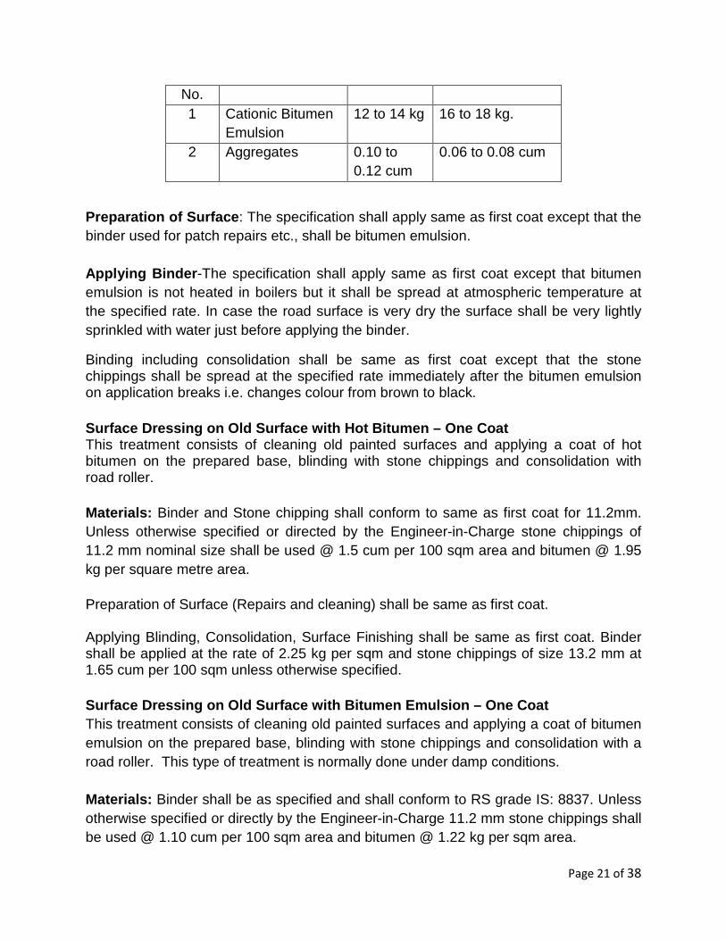
Table- 14
MATERIALS REQUIRED FOR SURFACE DRESSING 10 SQM AREA USING BITUMEN EMULSION
Sl. Materials First Coat Second Coat
Page 21 of 38
No. 1 Cationic Bitumen
Emulsion 12 to 14 kg 16 to 18 kg.
2 Aggregates 0.10 to 0.12 cum
0.06 to 0.08 cum
Preparation of Surface : The specification shall apply same as first coat except that the binder used for patch repairs etc., shall be bitumen emulsion. Applying Binder -The specification shall apply same as first coat except that bitumen emulsion is not heated in boilers but it shall be spread at atmospheric temperature at the specified rate. In case the road surface is very dry the surface shall be very lightly sprinkled with water just before applying the binder.
Binding including consolidation shall be same as first coat except that the stone chippings shall be spread at the specified rate immediately after the bitumen emulsion on application breaks i.e. changes colour from brown to black.
Surface Dressing on Old Surface with Hot Bitumen – One Coat This treatment consists of cleaning old painted surfaces and applying a coat of hot bitumen on the prepared base, blinding with stone chippings and consolidation with road roller. Materials: Binder and Stone chipping shall conform to same as first coat for 11.2mm. Unless otherwise specified or directed by the Engineer-in-Charge stone chippings of 11.2 mm nominal size shall be used @ 1.5 cum per 100 sqm area and bitumen @ 1.95 kg per square metre area. Preparation of Surface (Repairs and cleaning) shall be same as first coat. Applying Blinding, Consolidation, Surface Finishing shall be same as first coat. Binder shall be applied at the rate of 2.25 kg per sqm and stone chippings of size 13.2 mm at 1.65 cum per 100 sqm unless otherwise specified. Surface Dressing on Old Surface with Bitumen Emulsi on – One Coat This treatment consists of cleaning old painted surfaces and applying a coat of bitumen emulsion on the prepared base, blinding with stone chippings and consolidation with a road roller. This type of treatment is normally done under damp conditions. Materials: Binder shall be as specified and shall conform to RS grade IS: 8837. Unless otherwise specified or directly by the Engineer-in-Charge 11.2 mm stone chippings shall be used @ 1.10 cum per 100 sqm area and bitumen @ 1.22 kg per sqm area.

Page 22 of 38
Preparation of surface shall be same as first coat except that the binder used for patch repairs etc., shall be bitumen emulsion. Applying binder, bitumen emulsion, blinding or spreading it including consolidation of blindage etc., shall be same as first coat except for method of preparation of surface and 11.2 mm stone chippings shall be used @ 1.10 cum per 100 sqm area and bitumen @ 1.22 kg per sqm area.
Tack Coat of Hot Straight RUN Bitumen:
Materials: Bitumen: This shall be straight-run bitumen of penetration value 80/100 conforming to IS: 73 specifications. Rate of Application: The rate of application of binder which shall be as specified and shall depend on the surface on which the premix carpet is to be laid. Normally 0.40 kg/sqm on W.B.M surface and 0.25 kg/sqm on existing black topped surface.
Preparation of Surface :
• Cleaning: Prior to the application of bitumen, all vegetation, loose sealing compound, caked mud, animal dung, dust, dirt and foreign material shall be removed from the entire surface of the pavement and from existing dummy, construction and expansion joints (wherever existing) by means of mechanical sweepers and blowers, otherwise with steel wire brushes, small picks, brooms or other implements as approved by the Engineer-in-Charge. The material so removed shall be disposed off as directed by the Engineer-in-Charge.
Weather and seasonal limitations: The tack coat shall not be applied nor any bitumen work done during rainy weather or when the surface is damp or wet or when the atmospheric temperature in the shade is 16 deg. C or below. Application of Tack Coat:
Heating : Bitumen shall be heated in a boiler to a temperature of 165 deg. C to 175 deg. C and maintained at that temperature. Temperature shall be checked at regular intervals with the help of a thermometer.
Application of Bitumen: Hot bitumen shall be applied evenly to the clean, dry surface by means of a pressure sprayer at specified rate. Even and uniform distribution of bitumen shall be ensured. Bitumen shall be applied longitudinally along the length of pavement and never across it. Excessive deposits of bitumen
Page 23 of 38
caused by stopping or starting of the sprayer or through leakage or any other reason shall be suitably rectified
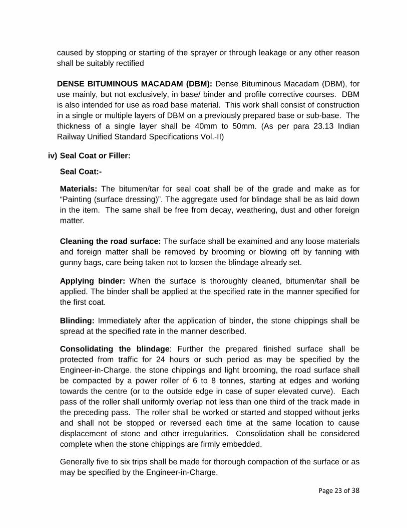
DENSE BITUMINOUS MACADAM (DBM): Dense Bituminous Macadam (DBM), for use mainly, but not exclusively, in base/ binder and profile corrective courses. DBM is also intended for use as road base material. This work shall consist of construction in a single or multiple layers of DBM on a previously prepared base or sub-base. The thickness of a single layer shall be 40mm to 50mm. (As per para 23.13 Indian Railway Unified Standard Specifications Vol.-II)
iv) Seal Coat or Filler:
Seal Coat:-
Materials: The bitumen/tar for seal coat shall be of the grade and make as for “Painting (surface dressing)”. The aggregate used for blindage shall be as laid down in the item. The same shall be free from decay, weathering, dust and other foreign matter.
Cleaning the road surface: The surface shall be examined and any loose materials and foreign matter shall be removed by brooming or blowing off by fanning with gunny bags, care being taken not to loosen the blindage already set.
Applying binder: When the surface is thoroughly cleaned, bitumen/tar shall be applied. The binder shall be applied at the specified rate in the manner specified for the first coat.
Blinding: Immediately after the application of binder, the stone chippings shall be spread at the specified rate in the manner described.
Consolidating the blindage : Further the prepared finished surface shall be protected from traffic for 24 hours or such period as may be specified by the Engineer-in-Charge. the stone chippings and light brooming, the road surface shall be compacted by a power roller of 6 to 8 tonnes, starting at edges and working towards the centre (or to the outside edge in case of super elevated curve). Each pass of the roller shall uniformly overlap not less than one third of the track made in the preceding pass. The roller shall be worked or started and stopped without jerks and shall not be stopped or reversed each time at the same location to cause displacement of stone and other irregularities. Consolidation shall be considered complete when the stone chippings are firmly embedded.
Generally five to six trips shall be made for thorough compaction of the surface or as may be specified by the Engineer-in-Charge.

Page 24 of 38
Along kerbs, manholes and all places not accessible to the roller, compaction shall be secured by means of steel rammers or hand rollers.
Seal coat with cold bitumen: Seal coat may also be applied with cold bitumen with the corresponding modifications in the process of applying the binder.
Filler:- The filler shall be consist of finely divided mineral matter such as stone dust, hydrated lime or cement approved by the Engineer-in-Charge. The filler shall be graded within the limits indicated in Table 15 (Unified Standard Specifications for Works & Materials-2010)
Table-15
Grading Requirement for Mineral Filler
IS Sieve (mm) Cumulative percent passing by weight of total aggregate
0.6 100
0.3 95-100
0.075 85-100
Fog Seal: Fog Seals are using polymer modified asphalt surface sealer (PASS). These seals find application to maintaining the quality of road ways there by extending its lifetime.
B. Concrete Road:-
i) Surface Preparation Leveling: same as bituminous concrete
ii) Water Bound Macadam OR Wet Mix Macadam with Lev eling & Rolling: same as bituminous concrete
iii) Cement Concrete Surface: All specification in concrete shall be applicable IS 456 except those given below:-
Grading of mixed aggregates : The grading of all ingredients (coarse and fine aggregates) to be used in the work shall be determined in the laboratory. The coarse and fine aggregates shall be mixed in suitable proportions so that the grading of the mixed aggregates shall be used.

Page 25 of 38
Placing of concrete: The concrete is to be transported without any delay from place of mixing to the position of laying and any concrete which in the opinion of the Engineer-in –Charge has remained in mixed state more than half an hour before reaching the place of laying is to be rejected and removed from site. In case of RMC, modified instructions shall be issued by the Chief Engineer.
With screed and internal vibrators, slabs of thickness not exceeding 15 cm shall be laid in one layer. Concrete for slabs of greater thickness will be laid in two layers. The second layer will be laid over the unfinished but thoroughly compacted first layer within the initial setting time of cement used in the concrete. Second layer shall also be compacted thoroughly after laying.
Finishing of concrete During compaction, any low or high spots shall be made up by adding or removing concrete. After longitudinal floating has been completed but while concrete is still plastic, the slab surface shall be tested for trueness with a 3 m straight edge. Any depressions or high spots showing departure from the true surface shall be immediately rectified. High spots shall be cut down and refinished. Depressions shall be enlarged to about 8 – 10 cm and filled up with fresh concrete, compacted and finished.
The straight edge testing the re-floating is to continue until the entire surface-
(a) is free from observable departure from the straight edge. (b) Conforms to the required levels and cross section, and (c) Shall conform to the specified surface when the concrete has hardened.
The foregoing work is to be carried out while the concrete is still plastic and workable.
Belting : Just before concrete becomes non-plastic, the surface shall be belted with a two ply canvas belt not less than 20 cm wide and at least 1 metre longer than the width of the slab. Hand belts shall have suitable handles to permit controlled uniform manipulation. The belt shall be operated with short strokes transverse to the centre line of the pavement and with rapid advance parallel to the centre line.
Brooming: After belting and as soon as the surplus water if any, has risen to the surface, the pavement shall be given a broom finish with an approved steel or fiber broom not less than 45 cm wide. The broom shall be pulled gently over the surface of the pavement from edge to edge. Adjacent strokes shall be slightly overlapped. Brooming shall be perpendicular to the centre line of the pavement and so executed that the corrugations formed shall be uniform in character and width and not more than 1.5 mm deep.
Brooming shall be completed before the concrete reaches such a stage that the surface is likely to be torn or unduly roughened by the operation. The broomed surface shall be free from porous or rough spots, irregularities, depressions, and small pockets such as

Page 26 of 38
may be caused by accidental disturbing of particles of coarse aggregates embodied near the surface. The brooming shall be of uniform pattern all through.
Edging : After belting/brooming has been completed but before the initial setting of concrete, the edges of the slab shall be carefully finished with an edger of 6 mm radius, and the pavement edges shall be left smooth and true to line.
Honey combing : The side forms shall not be removed until 12 hours or such longer period as the Engineer-in-Charge may decide after the laying of concrete. As soon as the side forms are removed, any minor honey combed area shall be filled with mortar composed of one part of cement and two parts of fine aggregate. Major honey combing areas or segregated concrete or other defective work or areas damaged by removal of the forms or concrete damaged by rain or due to any other reason whatsoever shall be considered as defective work and shall be removed and replaced. The total area of honeycombed surface shall not exceed 4 per cent of the area of the slab side. However, no individual honeycomb patch shall exceed 0.1 sqm. Engineer-in-Charge’s decision as to whether the concrete is defective or not shall be final and binding.
Surface Accuracy : After the concrete has sufficiently hardened for about 12 hours and not later than 24 hours, the surface shall be tested again for high spots. All high spots shall be marked and those exceeding 3 mm shall be ground down immediately. Care shall be taken to see that the grinding does not in any way damage the concrete surface.
The final surface finish is to be such that when tested with a profilograh/roughness indicator/or a 3 metre long straight edge or an equivalent mechanical unevenness indicator placed anywhere within the same or adjoining slab in any direction on the surface, there shall be no variation greater than 3 mm.
The surface irregularity exceeding 3 mm still remains despite grinding. The concrete shall be removed to its full depth. The area of concrete to be removed shall be complete slab between the nearest joints and where the defective slab is less than 4.5 metres from the expansion joint, the whole area upto the expansion joint shall be removed to the full depth. The concrete so removed shall not be reused in the work. Fresh concrete shall be laid in the manner already described in these specifications and shall again be subject to test for surface accuracy and other quality control measures. Nothing extra shall be paid for the same.
Every slab shall bear an impression not exceeding 3 mm in depth comprising the number allotted to the slab and the date on which it is laid. This impression shall be formed by the contractor when the concrete is green so as to leave permanent mark on setting.
Construction Joints : Construction joints shall be provided as per drawing and also at places where concreting is stopped due to unforeseen circumstances. The joints shall

Page 27 of 38
be straight and vertical through the full thickness of the slab. While concrete in adjacent bay is still green, flats of suitable size shall be drawn along the edge and a groove of size 10mm x 25 mm deep shall be neatly formed and finished. The edges of the groove shall be full nosed. After curing of concrete is complete, this groove shall be thoroughly cleaned of all sand dust and shall be perfectly dried and filled with hot poured sealing compound conforming to Grade B of IS: 1834. Before filling with sealing compound the faces of concrete of the joint shall be coated with Shalijet primer or equivalent to a depth of 25 mm at the rate of 2.6 litres per 10 square meters. Dummy Joints : The joints shall be 10 mm wide and shall extend vertically from the surface of the slab to be depth equal to 1/3rd of the thickness of the slab but not less than 4 cm in any case. The joint may be formed by depressing into the soft but compacted concrete, a high tensile M.S. or other approved Tee or flat bar of depth not less than required depth of the joint plus 25 mm. The bar used for forming the groove shall be coated with soft soap or other suitable lubricant to facilitate its removal when the steel Tee or flat is removed. Joints shall be neatly formed with proper tools and mortar material from the slab itself. No additional cement mortar (rich or otherwise) shall be used. Cutting or sawing by a saw mounted on a movable frame and driven mechanically shall also be permitted as a method for making the dummy joint. In this case the width may be reduced to 6 mm. Any other method for making joints can be followed with the prior approval of the Engineer-in-Charge. In all cases, except where cutting is done with saw, the joint edges shall be bullnosed. Care should be taken to see that the edges of the grooves are not damaged. The grooves shall be filled with hot poured sealing compound conforming to Grade B of IS: 1834. Prior to filling with sealing compound, the joints shall be cleaned by compressed air and primed with Shalijet primer or equivalent. All joints shall be sealed as soon as practicable after 28 days of placing of slabs. Joints shall be sealed flush with the adjacent pavement surface in summer and 3-4 mm below finished concrete surface in winter. The pavement shall be opened to traffic only after joint sealing over the entire pavement. To prevent tackiness or pickup under traffic, the exposed surfaces of the sealing compound shall be dusted with hydrated lime. In case of sudden rain or storm, the work can be concluded at the dummy joints but these will then be formed as construction joints. Before sealing of joints, it may be ensured that the groove extends fully across the bay between consecutive longitudinal joints, in the case of transverse joints. Any concrete or other foreign matter must be removed from the groove.

Page 28 of 38
Expansion Joint (With Non Extruding Filler Pad) in Concrete Pavements
Materials:
Pre moulded Joint Filler: It shall conform to IS: 1838 (Pt. I). The thickness shall be 20 mm and shall be of the maximum available standard length. Joint sealing compound: The joint sealing compound shall be fuel and heat resistant type complying to grade B of IS: 1834. It shall be capable of adhering to the concrete without cracking, spalling and disintegration. Primer: It shall be Shalijet or Expanjet primer or equivalent suitable primer. Bituminous emulsions shall not be used as primers. Construction Procedure : Expansion joints shall be provided as shown in the drawing and as per directions of Engineer-in-Charge. All joints shall be constructed true to line with their faces perpendicular to the surface of the pavement. The joint shall be 20 mm wide. The depth of the non-extruding filler paid shall be 25 mm less than the depth of the concrete slab.
Before the provision of expansion joint, the face of the already laid concrete slab shall be painted with primer at the rate of 2.6 liters per 10 square metres. The expansion pad shall be properly cut to shape and shall then be placed in position abutting the painted face of the already laid concrete slab. The adjacent slab shall then be concreted. The face of the pad against which the new concrete slab is to be laid shall also be painted with primer before laying the concrete, while concreting a neat groove 20 mm x 25 mm as per drawing shall be formed on top of the pad taking care that the edges are absolutely straight and that the groove so made does not get filled with any materials like concrete, mortar and other rubbish.
Before the curing process is started, the top of expansion joint shall be filled with bitumen sand mixture in order to ensure that no foreign material used in curing enters into the joint. This filling shall be removed before filling the joints with sealing compound.
For sealing the joints following operations shall be carried out:- (a) The joints are cleared of any foreign matter to the full depth upto the top of
expansion pad with steel spatula. (b) The joints are blown with compressed air. (c) Cleaning is done with Kerosene oil. (d) Priming is done with spray gun @ 2.6 liters per 10 sqm of the surface to be primed (e) The primer is allowed to dry completely before pouring the sealing compound.

Page 29 of 38
(f) The sealing compound grade ‘A’ is heated to the required temperature ranging between 155 deg. C to 165 deg. C or to the temperature range specified by the manufacturer. Over heating shall be avoided. Pouring shall be done from vessel with spout in such a manner that the material will not get spilled on the exposed surface of the concrete, any excess filler on the surface of the pavement shall be removed immediately and the pavement surface cleaned.
(g) The filling shall be worked in to the joints with hot flats to ensure escape of trapped air.
(h) The filling is then ironed with hot iron. It is recommended that while in summer the joints may be sealed flush with the adjacent pavement surface, in winter the sealing compound may be filled to a depth 3-4 mm below the surface.
(i) The edges of the joints are then cut and trimmed to ensure neat and straight-line finish.
(j) To prevent tackiness or pick up under traffic, the exposed surfaces of the sealing compound shall be dusted with hydrated lime.
iv) Vacuum Dewatering: Vacuum dewatering of all types & grade concrete by mechanical means including draining out the sucked excess water from concrete & then finishing the surface smooth with mechanical trowelling with suitable equipment etc. complete. The methodology to be adopted will be as per user manual of dewatering & trawling machine and as directed by Engineer.
v) Mechanical Toweling: Mechanical trowelling of concrete surface so as to obtain smooth shrinkage cracks free surface. Methodology to be adopted as per user manual of the equipment & as directed by Engineer – in – Charge.
3. Materials IS Parameters:
a) Water Bound Macadam confirming to IRC: 19-2005 b) Wet Mix Macadam confirming to IRC: 109-1997
For Bituminous Road- a) Bituminous Concrete Pavement confirming to IRC: 29-1998 b) Bituminous confirming to IS 73: 2013, 217
For Concrete Road- a) Cement Concrete confirming to IS 456: 2000 b) Sealing compound conforming to IS 1834
4. Construction Equipment Involved: a) Bull Dozer b) Tractor

Page 30 of 38
c) Motor Grader d) Shovel e) Clamshell f) Dumper g) Wet Mix Macadam Plant / Wet mix plant Soil Stabilizing Plant h) Wet mix Paver i) Truck j) Aggregate Spreader k) Roller l) Road cleaning Machine For Bituminous Road- a) Tar Boiler b) Bitumen Sprayer c) Aggregate Spreader d) Bitumen Aggregate Mixer e) Power Roller 5 Ton to 15 Ton Capacity.
Ready Mix Bituminous Concrete: a) Hot Mix Plant or Asphalt Drum Mix Plant b) Road cleaning Machine c) Bitumen Sprayer d) Asphalt Paver Machine e) Power Roller 5 Ton to 15 Ton Capacity.
For Concrete Road-
a) Batching & Mixing Plant b) Concrete Mixer Truck c) Concrete Paver d) Concrete Vibrator e) Power Roller 5 Ton to 15 Ton Capacity.
Ready Mix Cement Concrete: a) Batching & Mixing Plant b) Mixer truck c) Stationary truck bodies with or without agitators d) Buckets hauled by trucks e) Conveyor belts f) Hose or pipe line by pumping

Page 31 of 38
5. Material & Maintenance of Existing Road Work:
The Indian Roads Congress defines road maintenance as “routine work performed to upkeep pavement, shoulders and other facilities provided for road users, as nearly as possible in their constructed conditions under normal conditions of traffic and forces of nature”. Maintenance is “essential to get optimum service from the pavement structure during its life period.”
Maintenance is important because it:
� reduces the rate of deterioration, thereby safeguarding previous investments in construction and rehabilitation, � lowers the cost of operating vehicles on the road by providing a smooth running
surface, � improves safety of road users, � improves the reliability of the road allowing it to remain open for traffic on a
continuous basis and thus contributes to more reliable transport services, and � sustains social and economic benefits of improved road access.
Common routine maintenance activities :
� Remove debris from roadway and drains � Clear drains, allowing free passage of water � Clear culverts and other water crossings � Repair shoulders and side slopes � Patch potholes, seal cracks and repair edges of pavement � Cut grass and bush � Maintain road signage.
Table - 17 S.
No. Name of Item / Activity Frequency of operations
1.
Restoration of rain cuts and dressing of road side berms.
Once generally after rains or as and when required.
2. Making up of shoulders. As and when required 3. Maintenance of bituminous surface
road and/or gravel road and/or WBM road including filling potholes and patch repairs etc.
As and when required
4. Maintenance of road side catch drains.
Twice (in case of hill roads as and when required)
5. Maintenance of culverts and causeways.
Twice (in case of hill roads as and when required)
6. Maintenance of guardrails and parapet rails.
Maintenance as and when required. Repairing once a year.
Page 32 of 38
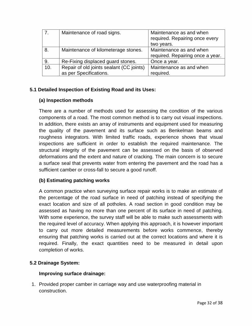
7. Maintenance of road signs. Maintenance as and when required. Repairing once every two years.
8. Maintenance of kilometerage stones. Maintenance as and when required. Repairing once a year.
9. Re-Fixing displaced guard stones. Once a year. 10. Repair of old joints sealant (CC joints)
as per Specifications. Maintenance as and when required.
5.1 Detailed Inspection of Existing Road and its Us es:
(a) Inspection methods
There are a number of methods used for assessing the condition of the various components of a road. The most common method is to carry out visual inspections. In addition, there exists an array of instruments and equipment used for measuring the quality of the pavement and its surface such as Benkelman beams and roughness integrators. With limited traffic roads, experience shows that visual inspections are sufficient in order to establish the required maintenance. The structural integrity of the pavement can be assessed on the basis of observed deformations and the extent and nature of cracking. The main concern is to secure a surface seal that prevents water from entering the pavement and the road has a sufficient camber or cross-fall to secure a good runoff.
(b) Estimating patching works
A common practice when surveying surface repair works is to make an estimate of the percentage of the road surface in need of patching instead of specifying the exact location and size of all potholes. A road section in good condition may be assessed as having no more than one percent of its surface in need of patching. With some experience, the survey staff will be able to make such assessments with the required level of accuracy. When applying this approach, it is however important to carry out more detailed measurements before works commence, thereby ensuring that patching works is carried out at the correct locations and where it is required. Finally, the exact quantities need to be measured in detail upon completion of works.
5.2 Drainage System:
Improving surface drainage:
1. Provided proper camber in carriage way and use waterproofing material in construction.

Page 33 of 38
2. Provided necessary side slope in shoulders. Early by pass water from road. 3. Provided maximum side slope in cutting & filling. Not erosion of soil. 4. Provided both side channel of road and provided proper longitudinal slope. 5. Water of high area passes opposite side through culvert or flow in river or gutter. 6. Area of Road’s construction level maximum 60 cm above from high flood level.
Maintaining proper slope & camber: Maintaining proper slope & camber in maintenance of existing roads for drainage.
Road marking & warning signs: Proper maintain road marking & warning sign for Smooth flow of traffic.
5.3 Bituminous Road:-
Premix Carpet with Bitumen Emulsion: This type of work is not ordinarily recommended but may be done in case of urgent repairs under damp conditions.
Materials: Binder shall be as specified and shall conform to RS grade IS: 8837. Grading of 11.2 mm stone chipping shall be as per given Table. Quantities of bitumen emulsion and stone chippings shall be as specified in below Table.
Table- 18
Stone Chipping
Nominal Size
Specification Quantity Bitumen * Quantity
First Coat
13.2 mm
100 percent passing through IS: 22.4 mm square mesh and retained on IS: 11.2 mm square mesh
1.5 cum /100 qm.
1.8 kgm per sqm
Second Coat
11.2 mm
100 percent passing through 13.2 mm square mesh and retained on 5.6 mm square mesh
1.0 cum /100 qm.
1.1 kgm per sqm.
Table- 19
BITUMEN EMULSION AND AGGREGATE FOR PREMIX CARPET Consolidated
thickness of premix Carpet
Bitumen Emulsion Stone Chippings For Carpet in cum of Chippings
Cum per 100 sqm
2 cm 96 2.4 (11.2 mm nominal size) 2.5 cm 96 3.0 (11.2 mm nominal size)

Page 34 of 38
5.3.1 Preparation of Base :
Preparation of Surface : Potholes or patches and ruts in the surface course, which is to be surface treated, shall be repaired by removal of all loose and defective material by cutting in rectangular patches and replacement with suitable material.
All pot holes, patches and ruts upto 2.5 cm shall be repaired and properly consolidated while those of depths greater than 2.5 cm shall be repaired with bitumen emulsion similar specifications as adopted originally.
Prior to the application of the binder, all dust, dirt, caked mud, animal dung, loose and foreign material etc., shall be removed 30 cm on either side, beyond the full width to be treated, by means of mechanical sweepers and blowers, if available or otherwise with wire brushes, small picks, brooms etc. The material so removed shall be disposed off as directed by the Engineer-in-charge.
The prepared surface shall be closed to traffic and maintained fully clean till the binder is applied.
Applying Binder - Bitumen emulsion is not heated in boilers but it shall be spread at atmospheric temperature at the specified rate. In case the road surface is very dry the surface shall be very lightly sprinkled with water just before applying the binder. The binder shall be applied evenly to the clean dry surface by means of a pressure sprayer at the rate specified. The binder shall be applied longitudinally along the length of the road and never across it. The edges of the binder surface shall be defined by wire or a rope stretched in position. Excessive deposits of binder caused by stopping or starting of the sprayer or through leakage or any other reason shall be suitably corrected before the stone chippings are spread. The rate of application of bitumen for tack coat shall be 0.75 kg per sqm on water bound macadam surface and 0.5 kg per sqm on black topped surface or as specified.
5.3.2 Construction Operations :
Blinding or Spreading Stone Chippings: After binder is applied and while it is still hot, stone chippings free from dust and in a dry and clean state shall be spread evenly over the surface at the rate specified above. Spreading shall be done preferably by means of a mechanical gritter, otherwise manually with a twisting motion to avoid segregation which otherwise shall have to be removed by brushing the excess stone chippings over the surface into hungry spots to obtain a uniform surface. The surface shall be checked by means of a camber board laid across the

Page 35 of 38
road and a three metre straight edge laid parallel to the centre line of the road, and undulations if any shall be corrected by addition or removal of blindage till a surface free from undulation is obtained. Consolidation of Blindage: The road surface shall be compacted by a power roller of 6 to 8 tonnes after 24 hours spreading the stone chippings and light brooming, , starting at edges and working towards the centre (or to the outside edge in case of super elevated curve). Each pass of the roller shall uniformly and compaction of the surface or as may be specified by the Engineer-in-Charge. The roller shall be worked or started and stopped without jerks. Along kerbs, manholes and all places not accessible to the roller, compaction shall be secured by means of steel rammers or hand rollers.
6. Kerb and Channel Stones:
Laying: Trenches shall first be made along the edge of the wearing course of the road to receive the kerb and the channel stones. The bed of the trenches shall be compacted manually with steel rammers to a firm and even surface and then the stones shall be set in cement mortar of specified proportion.
The kerb stones with top 20 cm wide shall be laid with their length running parallel to the road edge, true in line and gradient at a distance of 30 cm from the road edge to allow for the channel an shall project about 12.5 cm above the latter. The channel stories with top 30 cm wide shall be laid in position in camber with finished road surface and with sufficient slope towards the road gully chamber. The joints of kerb and channel stones shall be staggered and shall be not more than 10 mm thick. Wherever specified all joints shall be filled with mortar 1:6 (1 cement: 6 coarse sand) and pointed with mortar 1:2 (1 cement: 2 fine sand) which shall be cured for 7 days.
The necessary drainage openings of specified sizes shall be made through the kerb and foot path as per drawings or as directed by the Engineer for connecting to storm water drains.
Finishing: Berms and road edges shall be restored and all surplus earth including rubbish etc., disposed off as directed by the Engineer.
7. BRICK EDGING:
Edging: Trenches of specified width and depth shall first, be made along the edges of the wearing coarse of the road or pathway to receive the bricks. The bed of trenches shall be compacted to a firm and even surface and then the bricks shall be laid with its length at right angle or parallel to the side of the road pathway depending upon the width of edging as specified in the BOQ item or as indicated by

Page 36 of 38
Engineer. The bricks shall be abutting against the wearing course, true to line, gradient and in camber with the finished road surface at the edge.
Finishing: Berms and road edges shall be restored with excavated earth and consolidated by hand packing. All surplus earth including rubbish etc., shall be disposed off as directed by the Engineer-in-Charge.
8. Speed Breaker: Speed Breaker shall be as per RDSO Draft Guideline on the provision of Speed Breakers for Control of Vehicular speed on minor Roads based on IRC: 99-1988
9. Road/Markings: Road marking is carried out to define lane, speed breaker and turning of roads.
Materials Road markings shall be of ordinary road marking paint confirming to IS: 164, Hot Thermoplastic Compound confirming to ASTM D36/BS-3262-(Part I). Road marking paint of approved brand and manufacture shall be used.
Preparation of surface The surface shall be thoroughly cleaned and dusted. All the dirt, scales, oil and grease shall be thoroughly removed before painting is started. The prepared surface shall be inspected and approved by the Engineer-in-Charge before painting is commenced.
Application
• Before pouring into smaller containers for use, the paint shall be stirred thoroughly in its original container. During use also, it shall be continuously kept stirred.
• The painting shall be applied evenly and smoothly by means of crossing and laying off. The crossing and laying off consists of covering the area over with paint, brushing the surface hard for the first time over and then brushing alternately in opposite direction, two or three times and then finally brushing lightly in a direction at right angle to the same. In this process, no brush marks shall be left after the laying off is finished. The full process of crossing and laying off will constitute one coat.
• Each coat shall be allowed to dry out thoroughly before the next coat is applied.
• Earlier applied coat shall be cleaned off dust before the next coat is laid.

Page 37 of 38
• No hair marks from the brush or clogging of paint puddles shall be left on the work.
• The surface shall ordinarily not be painted until it has dried up completely. Trial patches of paint shall be laid at intervals to check if drying is satisfactory.
• The colour width and layout of road makings shall be in accordance with the Code of Practice for Road Markings with paints, IRC : 35, and as specified in the drawings or as directed by the Engineer-in-Charge
10. Reflective Raised Pavement Markers (Cat eye): Raised Pavement Markers made
of polycarbonate moulded body and reflective Panels with micro prismatic lens made out of Polycarbonate with abrasion resistant coating capable of providing total internal reflection of the light entering the lens face and conforming to ASTM D 4280 Type H. The length height and width of the body will not exceed 95mm and 105mm respectively. The lower surface of the RPM will be supported with two nylon shank, each of length not less 25mm. The area of each reflective surface will not be less than 15 sq. cm and the slope to the base shall be 35+/-5 degree. The marker shall support a load of minimum 18,000 Kg. Fixing will be without nails but by sing twin polymer shanks using bitumen adhesive on bitumen roads or without polymer shanks and epoxy resin based adhesive on CC Roads as per manufacturer’s including site clearance etc and complete as directed by the engineer.
Providing and fixing Cat’s Eye (Glow studs) heavy integral stem, reflective, aluminium die cast with elegant finish of size 100x100mm and 20mm high having a stem of 50mm (or 12mm dia. 90mm long) screwed and nailed to fix into the road surface or at the nosing of the central verge. The road studs should have reflectors fitted on one side of the studs (3Nos. 7 element or 1No. 29 element reflector) complete.
Cats Eye/Road Studs/Raised Pavement Marker

Page 38 of 38
11. Footpath: The width of sidewalks depends upon the expected pedestrian flow and shall be fixed subject to land availability, but shall not be less than 1.5 m on both sides. (IRC 84)
Open area, earthen shoulder on both side or finished with CC paving blocks. Berms shall be properly dressed to slope towards the side drains. In built-up areas, raised footpaths shall be provided on both sides. Footpath of minimum 1 .5 m width with kerb on either side (200 mm above road surface), drain pipes across at minimum 10 m intervals and finished with CC paving blocks. The raised footpath shall be depressed at suitable intervals to provide for convenient use of physically challenged persons.
There shall be no pedestrian crossings across the carriageway. Facility for crossing the carriageway by the pedestrians shall be provided through pedestrian underpasses/FOB. At-grade pedestrian crossings shall be provided for all intersections of cross roads with service roads or entry exit ramps. At-grade pedestrian crossings shall be controlled. Controlled form of crossing shall be achieved through provision of Zebra Crossings, whether at signalized intersection or pedestrian actuated signal.