(Draft) Cybersecurity Framework Manufacturing Profile Low ...
334
Withdrawn Draft Warning Notice The attached draft document has been withdrawn, and is provided solely for historical purposes. It has been superseded by the document identified below. Withdrawal Date September 30, 2019 Original Release Date May 28, 2019 Superseding Document Status Final Series/Number NIST Interagency or Internal Report (NISTIR) 8183A Volume 3 Title Cybersecurity Framework Manufacturing Profile Low Impact Level Example Implementations Guide: Volume 3 – Discrete-based Manufacturing System Use Case Publication Date September 2019 DOI https://doi.org/10.6028/NIST.IR.8183A-3 CSRC URL https://csrc.nist.gov/publications/detail/nistir/8183a/vol-3/final Additional Information
-
Upload
khangminh22 -
Category
Documents
-
view
2 -
download
0
Transcript of (Draft) Cybersecurity Framework Manufacturing Profile Low ...

Withdrawn Draft
Warning Notice
The attached draft document has been withdrawn, and is provided solely for historical purposes. It has been superseded by the document identified below.
Withdrawal Date September 30, 2019
Original Release Date May 28, 2019
Superseding Document
Status Final
Series/Number NIST Interagency or Internal Report (NISTIR) 8183A Volume 3
Title Cybersecurity Framework Manufacturing Profile Low Impact Level Example Implementations Guide: Volume 3 – Discrete-based Manufacturing System Use Case
Publication Date September 2019
DOI https://doi.org/10.6028/NIST.IR.8183A-3
CSRC URL https://csrc.nist.gov/publications/detail/nistir/8183a/vol-3/final
Additional Information

DRAFT NISTIR 8183A 1
Volume 3 2
3
Cybersecurity Framework Manufacturing Profile 4
Low Security Level Example 5
Implementations Guide: 6
Volume 3 – Discrete-based Manufacturing System Use Case 7
8
Keith Stouffer 9
Timothy Zimmerman 10
CheeYee Tang 11
Jeffrey Cichonski 12
Neeraj Shah 13
Wesley Downard 14
15
16
This publication is available free of charge from: 17
https://doi.org/10.6028/NIST.IR.8183A-3-draft 18
19
20

DRAFT NISTIR 8183A 21
Volume 3 22
23
Cybersecurity Framework Manufacturing Profile 24
Low Security Level Example 25
Implementations Guide: 26
Volume 3 – Discrete-based Manufacturing System Use Case 27
28
Keith Stouffer Neeraj Shah 29
Timothy Zimmerman Strativia, LLC 30
CheeYee Tang Largo, Maryland 31
Intelligent Systems Division 32
Engineering Laboratory 33
34
Jeffrey Cichonski Wesley Downard 35
Applied Cybersecurity Division G2, Inc. 36
Information Technology Laboratory Annapolis Junction, Maryland 37
38
39
40
This publication is available free of charge from: 41
https://doi.org/10.6028/NIST.IR.8183A-3-draft 42
43
May 2019 44
45 46
47 48
U.S. Department of Commerce 49 Wilbur L. Ross, Jr., Secretary 50
51 National Institute of Standards and Technology 52
Walter Copan, NIST Director and Under Secretary of Commerce for Standards and Technology 53

National Institute of Standards and Technology Internal Report 8183A, Volume 3 54 333 pages (May 2019) 55
56 This publication is available free of charge from: 57 https://doi.org/10.6028/NIST.IR.8183A-3-draft 58
Certain commercial entities, equipment, or materials may be identified in this document in order to describe an 59 experimental procedure or concept adequately. Such identification is not intended to imply recommendation or 60 endorsement by NIST, nor is it intended to imply that the entities, materials, or equipment are necessarily the best 61 available for the purpose. 62
There may be references in this publication to other publications currently under development by NIST in accordance 63 with its assigned statutory responsibilities. The information in this publication, including concepts and methodologies, 64 may be used by federal agencies even before the completion of such companion publications. Thus, until each 65 publication is completed, current requirements, guidelines, and procedures, where they exist, remain operative. For 66 planning and transition purposes, federal agencies may wish to closely follow the development of these new 67 publications by NIST. 68
Organizations are encouraged to review all draft publications during public comment periods and provide feedback to 69 NIST. Many NIST cybersecurity publications, other than the ones noted above, are available at 70 https://csrc.nist.gov/publications. 71
72
Public comment period: May 28, 2019 through July 8, 2019 73
National Institute of Standards and Technology 74 Attn: Applied Cybersecurity Division, Information Technology Laboratory 75
100 Bureau Drive (Mail Stop 2000) Gaithersburg, MD 20899-2000 76 Email: [email protected] 77
78 All comments are subject to release under the Freedom of Information Act (FOIA). 79
80

NISTIR 8183A VOL. 3 (DRAFT) CSF MFG PROFILE LOW SEC LVL EXAMPLE IG DISCRETE-BASED MFG SYSTEM USE CASE
ii
Abstract 81
This guide provides example proof-of-concept solutions demonstrating how open-source and 82
commercial off-the-shelf (COTS) products that are currently available today can be implemented 83
in discrete-based manufacturing environments to satisfy the requirements in the Cybersecurity 84
Framework (CSF) Manufacturing Profile [4] Low Security Level. The example proof-of-concept 85
solutions include measured network, device, and operational performance impacts observed 86
during the implementation. Depending on factors like size, sophistication, risk tolerance, and 87
threat landscape, manufacturers should make their own determinations about the breadth of the 88
proof-of-concept solutions they may voluntarily implement. The CSF Manufacturing Profile can 89
be used as a roadmap for managing cybersecurity risk for manufacturers and is aligned with 90
manufacturing sector goals and industry best practices. The Manufacturing Profile provides a 91
voluntary, risk-based approach for managing cybersecurity activities and cyber risk to 92
manufacturing systems. The Manufacturing Profile is meant to compliment but not replace 93
current cybersecurity standards and industry guidelines that the manufacturer is embracing. 94
95
Keywords 96
Computer security; Cybersecurity Framework (CSF); distributed control systems (DCS); 97
industrial control systems (ICS); information security; manufacturing; network security; 98
programmable logic controllers (PLC); risk management; security controls; supervisory control 99
and data acquisition (SCADA) systems. 100
Supplemental Content 101
Additional volumes of this publication include: 102
Draft NISTIR 8183A Volume 1, Cybersecurity Framework Manufacturing Profile Low 103
Security Level Example Implementations Guide: Volume 1 – General Implementation 104
Guidance. https://doi.org/10.6028/NIST.IR.8183A-1-draft 105
Draft NISTIR 8183A Volume 2, Cybersecurity Framework Manufacturing Profile Low 106
Security Level Example Implementations Guide: Volume 2 – Process-based 107
Manufacturing System Use Case. https://doi.org/10.6028/NIST.IR.8183A-2-draft 108

NISTIR 8183A VOL. 3 (DRAFT) CSF MFG PROFILE LOW SEC LVL EXAMPLE IG DISCRETE-BASED MFG SYSTEM USE CASE
iii
Acknowledgments 109
The authors gratefully acknowledge and appreciate the significant contributions from individuals 110
and organizations in the public and private sectors, whose thoughtful and constructive comments 111
improved the overall quality, thoroughness, and usefulness of this publication. A special 112
acknowledgement to the members of the ISA99, Industrial Automation and Control Systems 113
Security Committee and the Department of Homeland Security Industrial Control System Joint 114
Working Group (ICSJWG) for their exceptional contributions to this publication. 115
Note to Reviewers 116
This guide does not describe the solution, but a possible solution. This is a draft guide. We seek 117
feedback on its contents and welcome your input. Comments, suggestions, and success stories 118
will improve subsequent versions of this guide. Please contribute your thoughts to 119
[email protected]. 120
121

NISTIR 8183A VOL. 3 (DRAFT) CSF MFG PROFILE LOW SEC LVL EXAMPLE IG DISCRETE-BASED MFG SYSTEM USE CASE
iv
Call for Patent Claims 122
This public review includes a call for information on essential patent claims (claims whose use 123
would be required for compliance with the guidance or requirements in this Information 124
Technology Laboratory (ITL) draft publication). Such guidance and/or requirements may be 125
directly stated in this ITL Publication or by reference to another publication. This call also 126
includes disclosure, where known, of the existence of pending U.S. or foreign patent applications 127
relating to this ITL draft publication and of any relevant unexpired U.S. or foreign patents. 128
129
ITL may require from the patent holder, or a party authorized to make assurances on its behalf, 130
in written or electronic form, either: 131
132
a) assurance in the form of a general disclaimer to the effect that such party does not hold and 133
does not currently intend holding any essential patent claim(s); or 134
135
b) assurance that a license to such essential patent claim(s) will be made available to applicants 136
desiring to utilize the license for the purpose of complying with the guidance or requirements in 137
this ITL draft publication either: 138
139
i) under reasonable terms and conditions that are demonstrably free of any unfair 140
discrimination; or 141
142
ii) without compensation and under reasonable terms and conditions that are 143
demonstrably free of any unfair discrimination. 144
145
Such assurance shall indicate that the patent holder (or third party authorized to make assurances 146
on its behalf) will include in any documents transferring ownership of patents subject to the 147
assurance, provisions sufficient to ensure that the commitments in the assurance are binding on 148
the transferee, and that the transferee will similarly include appropriate provisions in the event of 149
future transfers with the goal of binding each successor-in-interest. 150
151
The assurance shall also indicate that it is intended to be binding on successors-in-interest 152
regardless of whether such provisions are included in the relevant transfer documents. 153
154
Such statements should be addressed to: [email protected] 155
156

NISTIR 8183A VOL. 3 (DRAFT) CSF MFG PROFILE LOW SEC LVL EXAMPLE IG DISCRETE-BASED MFG SYSTEM USE CASE
v
157
Table of Contents 158
Executive Summary .................................................................................................... vii 159
1. Introduction ............................................................................................................ 1 160
Purpose and Scope ........................................................................................ 1 161
Audience ......................................................................................................... 2 162
Document Structure ........................................................................................ 2 163
2. Discrete-based Manufacturing System Low Security Level Use Case .............. 3 164
Introduction ..................................................................................................... 3 165
Discrete-based Low Security Level Use Case ................................................ 3 166
3. Policy and Procedure Implementations ............................................................... 9 167
Security Program Document Example ............................................................ 9 168
Security Policy Document Example .............................................................. 21 169
Standard Operating Procedures Document Example ................................... 36 170
Risk Management Document Example ......................................................... 66 171
Incident Response Plan Document Example ................................................ 76 172
Incident Recovery Plan Document Example ................................................. 86 173
4. Technical Solution Implementations ................................................................ 102 174
Introduction ................................................................................................. 102 175
Open-AudIT ................................................................................................ 107 176
CSET .......................................................................................................... 123 177
GRASSMARLIN .......................................................................................... 130 178
Wireshark .................................................................................................... 140 179
Veeam Backup and Replication .................................................................. 146 180
TeamViewer ................................................................................................ 170 181
Microsoft Active Directory ........................................................................... 174 182
Symantec Endpoint Protection .................................................................... 190 183
Tenable Nessus .......................................................................................... 209 184
NamicSoft ................................................................................................... 221 185
GTB Inspector ............................................................................................. 237 186
Graylog ....................................................................................................... 256 187
DBAN .......................................................................................................... 268 188
Network Segmentation and Segregation .................................................... 272 189
Network Boundary Protection ..................................................................... 276 190
Managed Network Interfaces ...................................................................... 287 191
Time Synchronization ................................................................................. 296 192
System Use Monitoring ............................................................................... 301 193
Ports and Services Lockdown ..................................................................... 305 194
VeraCrypt .................................................................................................... 309 195
Media Protection ......................................................................................... 316 196
NISTIR 8183A VOL. 3 (DRAFT) CSF MFG PROFILE LOW SEC LVL EXAMPLE IG DISCRETE-BASED MFG SYSTEM USE CASE
vi
197
Appendix A - Acronyms and Abbreviations ........................................................... 319 198
Appendix B - Glossary .............................................................................................. 320 199
Appendix C - References .......................................................................................... 324 200
201
NISTIR 8183A VOL. 3 (DRAFT) CSF MFG PROFILE LOW SEC LVL EXAMPLE IG DISCRETE-BASED MFG SYSTEM USE CASE
vii
Executive Summary 202
This guide provides example proof-of-concept solutions demonstrating how open-source and 203
commercial off-the-shelf (COTS) products that are currently available today can be implemented 204
in discrete-based manufacturing environments to satisfy the requirements in the Cybersecurity 205
Framework (CSF) Manufacturing Profile [4] Low Security Level. The example proof-of-concept 206
solutions include measured network, device, and operational performance impacts observed 207
during the implementation. Depending on factors like size, sophistication, risk tolerance, and 208
threat landscape, manufacturers should make their own determinations about the breadth of the 209
proof-of-concept solutions they may voluntarily implement. 210
The CSF Manufacturing Profile can be used as a roadmap for managing cybersecurity risk for 211
manufacturers and is aligned with manufacturing sector goals and industry best practices. The 212
Manufacturing Profile provides a voluntary, risk-based approach for managing cybersecurity 213
activities and cyber risk to manufacturing systems. The Manufacturing Profile is meant to 214
compliment but not replace current cybersecurity standards and industry guidelines that the 215
manufacturer is embracing. 216
The CSF Manufacturing Profile focuses on desired cybersecurity outcomes and can be used as a 217
roadmap to identify opportunities for improving the current cybersecurity posture of the 218
manufacturing system. The Manufacturing Profile provides a prioritization of security activities 219
to meet specific business/mission goals. Relevant and actionable security practices that can be 220
implemented to support key business/mission goals are then identified. 221
While the proof-of-concept solutions in this guide used a suite of commercial products, this 222
guide does not endorse these particular products, nor does it guarantee compliance with any 223
regulatory initiatives. Your organization’s information security experts should identify the 224
products that will best integrate with your existing tools and manufacturing system 225
infrastructure. Your organization may voluntarily adopt these solutions or one that adheres to 226
these guidelines in whole, or you can use this guide as a starting point for tailoring and 227
implementing parts of a solution. This guide does not describe regulations or mandatory 228
practices, nor does it carry any statutory authority.229

NISTIR 8183A VOL. 3 (DRAFT) CSF MFG PROFILE LOW SEC LVL EXAMPLE IG DISCRETE-BASED MFG SYSTEM USE CASE
1
1. Introduction 230
The Executive Order 13636, “Improving Critical Infrastructure Cybersecurity,” [1] directed the 231
development of the voluntary Cybersecurity Framework that provides a prioritized, flexible, 232
repeatable, performance-based, and cost-effective approach to manage cybersecurity risk [1] for 233
those processes, information, and systems directly involved in the delivery of critical 234
infrastructure services. 235
The Cybersecurity Framework is a voluntary risk-based assemblage of industry standards and 236
best practices designed to help organizations manage cybersecurity risks [2]. The Framework, 237
created through collaboration between government and the private sector, uses a common 238
language to address and manage cybersecurity risk in a cost-effective way based on business 239
needs without imposing additional regulatory requirements. 240
To address the needs of manufactures, a Manufacturing Profile [4] of the Cybersecurity 241
Framework was developed, through collaboration between government and the private sector, to 242
be an actionable approach for implementing cybersecurity controls into a manufacturing system 243
and its environment. The Profile defines specific cybersecurity activities and outcomes for the 244
protection of the manufacturing system, its components, facility, and environment. Through use 245
of the Profile, the manufacturer can align cybersecurity activities with business requirements, 246
risk tolerances, and resources. The Profile provides a manufacturing sector-specific approach to 247
cybersecurity from standards, guidelines, and industry best practices. 248
Purpose and Scope 249
Many small and medium sized manufacturers have expressed that they are challenged in 250
implementing a standards-based cybersecurity program. This guide provides example proof-of-251
concept solutions demonstrating how open-source and commercial off-the-shelf (COTS) 252
products that are available today can be implemented in manufacturing environments to satisfy 253
the requirements in the Cybersecurity Framework (CSF) Manufacturing Profile Low Security 254
Level. Example proof-of-concept solutions with measured network, device, and operational 255
performance impacts for a process-based manufacturing environment (Volume 2) and a discrete-256
based manufacturing environment (Volume 3) are included in the guide. Depending on factors 257
like size, sophistication, risk tolerance, and threat landscape, manufacturers should make their 258
own determinations about the breadth of the proof-of-concept solutions they may voluntarily 259
implement. The CSF Manufacturing Profile can be used as a roadmap for managing 260
cybersecurity risk for manufacturers and is aligned with manufacturing sector goals and industry 261
best practices. The Manufacturing Profile provides a voluntary, risk-based approach for 262
managing cybersecurity activities and cyber risk to manufacturing systems. The Manufacturing 263
Profile is meant to enhance but not replace current cybersecurity standards and industry 264
guidelines that the manufacturer is embracing. 265
While the proof-of-concept solutions in this guide used a suite of commercial products, this 266
guide does not endorse these particular products, nor does it guarantee compliance with any 267
regulatory initiatives. Each organization’s information security experts should identify the 268
products that will best integrate with their existing tools and manufacturing system 269

NISTIR 8183A VOL. 3 (DRAFT) CSF MFG PROFILE LOW SEC LVL EXAMPLE IG DISCRETE-BASED MFG SYSTEM USE CASE
2
infrastructure. Organizations may voluntarily adopt these solutions or one that adheres to these 270
guidelines in whole, or can use this guide as a starting point for tailoring and implementing parts 271
of a solution. This guide does not describe regulations or mandatory practices, nor does it carry 272
any statutory authority. 273
This project is guided by the following assumptions: The solutions were developed in a lab 274
environment. The environment is based on a typical small manufacturer. The environment does 275
not reflect the complexity of a production environment. An organization can access the skills and 276
resources required to implement a manufacturing cybersecurity solution. 277
Audience 278
This document covers details specific to manufacturing systems. Readers of this document 279
should be acquainted with operational technology, general computer security concepts, and 280
communication protocols such as those used in networking. The intended audience is varied and 281
includes the following: 282
Control engineers, integrators, and architects who design or implement secure 283
manufacturing systems. 284
System administrators, engineers, and other information technology (IT) professionals 285
who administer, patch, or secure manufacturing systems. 286
Managers who are responsible for manufacturing systems. 287
Senior management who are trying to understand implications and consequences as they 288
justify and implement a manufacturing systems cybersecurity program to help mitigate 289
impacts to business functionality. 290
Researchers, academic institutions and analysts who are trying to understand the unique 291
security needs of manufacturing systems. 292
Document Structure 293
Volume 3 is divided into the following major sections: 294
Section 2 provides an overview of the discrete-based manufacturing system use case. 295
Section 3 provides the detailed policy and procedure documents developed for the 296
discrete-based manufacturing system use case. 297
Section 4 provides the detailed technical capability implementations and associated 298
performance measurements for the discrete-based manufacturing system use case. 299
Appendix A provides a list of acronyms and abbreviations used in this document. 300
Appendix B provides a glossary of terms used in this document. 301
Appendix C provides a list of references used in the development of this document. 302 303

NISTIR 8183A VOL. 3 (DRAFT) CSF MFG PROFILE LOW SEC LVL EXAMPLE IG DISCRETE-BASED MFG SYSTEM USE CASE
3
2. Discrete-based Manufacturing System Low Security Level Use Case 304
Introduction 305
This use case is a proof-of-concept solution demonstrating how open-source and commercial off-306
the-shelf (COTS) products that are currently available today can be implemented in a 307
manufacturing environment to satisfy the requirements in the CSF Manufacturing Profile Low 308
Security Level. Depending on factors like size, sophistication, risk tolerance, and threat 309
landscape, manufacturers should make their own determinations about the breadth of proof-of-310
concept solution they may voluntarily implement. 311
Discrete-based Low Security Level Use Case 312
The fictional company, Alpha Manufacturing (i.e., Alpha), is a small manufacturer that produces 313
common metal components for the automotive industry. These parts are typically subcontracted 314
to Alpha by larger manufacturers. The finished parts are then integrated into 315
larger subassemblies that perform non-safety related functions within a vehicle. 316
To meet increasing production demand, an automated workcell was contracted and purchased 317
from a manufacturing systems integrator. The first workcell was purchased to evaluate and 318
validate its operation, with the intent of purchasing more workcells to further increase 319
production. Two of the machining stations integrated into the workcell were existing at the 320
Alpha facility, while the other two stations were purchased by the integrator. The workcell 321
operates independently of all other shop operations, and is tended to by a single operator, who: 322
loads raw material, unloads finished parts, responds to alarm conditions, and validates the quality 323
of finished parts. 324
Facilities 325
Alpha operates a single small leased building less than 15,000 ft2 (1394 m2) in size. 326
Employees 327
Alpha has ten full-time employees, of which, six are machine operators. Alpha has no full-328
time control system engineers or IT personnel. Employees have no formal cybersecurity training. 329
Organizational Role Count
President 1
HR Manager 1
Bookkeeper 1

NISTIR 8183A VOL. 3 (DRAFT) CSF MFG PROFILE LOW SEC LVL EXAMPLE IG DISCRETE-BASED MFG SYSTEM USE CASE
4
Foreman/Supervisor 1
Machine Operators 6
Total 10
330
External Personnel 331
Some facility operations are outsourced to external entities. 332
Role
Information Technology (IT) Services
Operational Technology (OT) Services
Machine Tool Support, Service, and Repair
Janitorial Services
333
Supply Chain 334
Raw material suppliers are utilized on-demand. No formal relationships or direct-order 335
networking/online/cloud connections with any suppliers currently exist. Alpha is considered a 336
"tier two" supplier. Alpha sends completed parts to a tier one manufacturer. At the tier one 337
manufacturer’s facility, Alpha's parts are integrated into subassemblies that are subsequently 338
installed into a vehicle by the original equipment manufacturer (OEM). 339
Supporting Services 340
The only supporting service required by Alpha is electricity to power IT systems, manufacturing 341
machines, and lights. 342
Legal and Regulatory Requirements 343
Alpha does not have knowledge of any legal or regulatory requirements in regards to its 344
cybersecurity. However, as a tier two supplier, it is contractually obligated to follow all 345
standards, procedures, and guidance provided by the tier one manufacturer(s) and the OEM (e.g., 346

NISTIR 8183A VOL. 3 (DRAFT) CSF MFG PROFILE LOW SEC LVL EXAMPLE IG DISCRETE-BASED MFG SYSTEM USE CASE
5
ISO/TS 16949, ISO 9000). Alpha does not produce any components that fall within the 347
regulatory jurisdiction of 49 CFR Part 571: Federal Motor Vehicle Safety Standards. [5]. 348
Critical Infrastructure 349
The DHS Critical Manufacturing sector considers vehicle manufacturing (and its supply chain) a 350
core industry to be protected. However, Alpha is a tier two manufacturer that produces parts that 351
are not critical to vehicle safety and can easily be produced by other tier two job shops if Alpha 352
cannot meet its production demand. It is likely that the tier one manufacturer has already 353
implemented supply chain redundancy to enable continuity of production. 354
Alpha will not be able to produce if the primary metals critical manufacturing sector cannot 355
provide Alpha with the required raw materials. However, this sector is outside of the scope of 356
Alpha's implementation of the Manufacturing Profile. 357
Manufacturing Process 358
Parts are created in a sequential manufacturing process with four CNC machines within a 359
workcell. The CNC machines are tended to by two industrial robotic arms, which transfer parts 360
to each station until all of the machining processes are completed. Raw materials are loaded into 361
a queue by an operator. A supervisory PLC monitors the dynamic status of each machining 362
station and contains logic to disseminate jobs to the robots. Each robot executes its jobs 363
using preprogrammed scripts and waypoints. Finished parts are placed onto a conveyor by a 364
robot, subsequently dropping into either a finished parts bin, or a rejected parts bin. The bins are 365
emptied by operators once they are full. 366
The manufacturing process is as follows: 367
Systems 368
Most of the business functions are supported by general enterprise IT, and share information 369
with the OT (e.g., CNC machines). Typical IT software usage includes email and web browsing. 370
Any IT work is contracted out to local companies. 371
Critical Systems 372
The following systems are critical for proper operation of the workcell: 373
Engineering workstation 374
Supervisory PLC 375
HMI 376
Machining stations 377
Robot arms 378
Raw Material
Station 1:Cutting
Station 2: Turning
Station 3:Finishing
Station 4:Inspection

NISTIR 8183A VOL. 3 (DRAFT) CSF MFG PROFILE LOW SEC LVL EXAMPLE IG DISCRETE-BASED MFG SYSTEM USE CASE
6
Robot controllers 379
Robot driver 380
Networking equipment 381
Data 382
Data transferred over, or stored within, Alpha's network includes: 383
PLC code 384
Robot code 385
MODBUS TCP registers 386
Computer-aided Manufacturing (CAM) files (e.g., G code) 387
Workcell operating manuals and documentation 388
Electrical diagrams 389
Network diagrams 390
Computer-aided drafting (CAD) files 391
Part inspection measurements 392
Historical production data 393
NOTE: All data listed above are proprietary, trade secrets, and/or confidential. 394
Network 395
The manufacturing system network is connected to the corporate network through a dedicated 396
top-level router/firewall, and is organized into subnetworks and a DMZ. The network is managed 397
by the external IT contractor. The workcell has a dedicated router/firewall utilizing network 398
address translation (NAT) to help segment and isolate the workcell from the rest of the network. 399
The workcell itself is split into two subnets: the Supervisory LAN, and the Control LAN. 400
Most of the network traffic utilizes Ethernet and TCP/IP protocols, while the dedicated field-bus 401
level communications for the robots utilize the EtherCAT protocol. 402
Mission Objectives 403
The Manufacturing Profile describes five business/mission objectives common to the 404
manufacturing sector. The following sections describe what Alpha must protect, in regards to 405
their manufacturing process and assets, in order to meet each of the missions: 406
1. Maintain Personnel Safety 407
Safety PLC - The workcell has a safety-rated PLC to terminate operations when an 408
emergency condition is detected. Industry standard emergency stop buttons and light 409
curtains are used to protect operators from entering the work area while the workcell 410
is active. 411

NISTIR 8183A VOL. 3 (DRAFT) CSF MFG PROFILE LOW SEC LVL EXAMPLE IG DISCRETE-BASED MFG SYSTEM USE CASE
7
2. Maintain Environmental Safety 412
None - The workcell, and its underlying manufacturing process, do not use any raw 413
ingredients or produce any by-products that can compromise the environmental safety 414
mission. 415
416
3. Maintain Quality of Product 417
Machining Stations 1, 2, 3 - All manufacturing functions are performed by 418
sequential CNC machining stations (1, 2, and 3). Each station uses preprogrammed 419
operations (e.g., G code) to complete its required manufacturing process tasks. This 420
code, and all station functions, have direct control over the output product quality. 421
Inspection Station 4 - If product quality has been impacted outside of product quality 422
specifications, the inspection station will reject the part. Modification of the 423
specifications within the inspection station can allow out-of-spec parts to pass 424
inspection. 425
Robots - Tending of parts between the machines is handled by the two workcell 426
robots. This process requires accurate and repeatable placement of parts within the 427
machining station fixtures, which is performed through robot calibration and 428
preprogrammed waypoint coordinates. Parts that are not properly placed within 429
fixtures, or collide with the fixtures, may not meet product quality specifications. 430
Supervisory PLC - The supervisory PLC tracks each part as it goes through the 431
manufacturing process and commands the robots to transport each part between 432
machines in a sequential manner. If a robot executes a job out-of-order, a part may 433
bypass one of the machining stations, impacting product quality. 434
HMI - Through the HMI, operators can manipulate workcell operation parameters, 435
machining station programs, and inspection station acceptance parameters. 436
Modification of any of these parameters outside of expected bounds can impact 437
product quality. 438
Engineering Workstations - Privileged control and administrative functions of 439
workcell components is granted to engineers via the Engineering Workstation. 440
441
4. Maintain Production Goals 442
Machining Stations - The amount of time each machining station takes to perform its 443
manufacturing functions, and the frequency of alarm conditions, can impact 444
production goals. 445
Robots - The amount of time the robots require to transport the parts between 446
machining stations can impact the production goals. 447
Supervisory PLC - The amount of time it takes the PLC to disseminate jobs to the 448
robots, or communicate with the machining stations, can impact production goals. 449
HMI - Operators have direct control over the amount of parts produced in a batch via 450
the HMI. 451
Engineering Workstations - Numerous privileged functions available through the 452
engineering workstation can impact production goals. 453
Operator Workstations - Operators obtain production planning goals (e.g., product 454
type and quantity), machining station data files (e.g., G code) from network shares 455
and email systems. Inability to access these systems can impact production goals. 456

NISTIR 8183A VOL. 3 (DRAFT) CSF MFG PROFILE LOW SEC LVL EXAMPLE IG DISCRETE-BASED MFG SYSTEM USE CASE
8
Networking equipment - All coordination between workcell components occurs 457
through the installed network equipment. If this equipment degrades or ceases to 458
function, production goals will be impacted. 459
460
5. Protect Trade Secrets 461
Machining Stations - The operations performed by each machining station are a 462
protected trade secret of the company. 463
Network - The machining station data files (e.g., G code) are typically stored on 464
network shares, and must be protected. 465

NISTIR 8183A VOL. 3 (DRAFT) CSF MFG PROFILE LOW SEC LVL EXAMPLE IG DISCRETE-BASED MFG SYSTEM USE CASE
9
3. Policy and Procedure Implementations 466
This section includes example policy and procedure documents and statements that were 467
developed for the fictional company Alpha. An overview of these documents is discussed in 468
Section 5 of Volume 1. Each organization’s information security experts should identify the 469
policy and procedure documents and statements that will best integrate with their existing 470
cybersecurity program and manufacturing system infrastructure. 471
Security Program Document Example 472
Security Program 473
for 474
Alpha 475
476
477
478
Document Owner: Supervisor, Alpha
479
Version 480
481
Version Date Description Author
1.0 02-22-2018 Initial Draft Supervisor
2.0 04-21-2018 Major changes to the initial draft Supervisor
482
Approval 483
(By signing below, all Approvers agree to all terms and conditions outlined in this document.) 484
485
Approvers Role Signed Approval Date
President 4-22-2018
486
Purpose 487
The Information Security Program establishes guidelines and principles for initiating, 488
implementing, maintaining, and improving cybersecurity management for Alpha. 489
This program is designed to: 490
Ensure the security and confidentiality of employees and business information; 491

NISTIR 8183A VOL. 3 (DRAFT) CSF MFG PROFILE LOW SEC LVL EXAMPLE IG DISCRETE-BASED MFG SYSTEM USE CASE
10
Protect against any anticipated threats or hazards to the security or integrity of such 492
information; and 493
Protect against unauthorized access to or use of such information that could result in 494
substantial harm or inconvenience to Alpha, its partners, customers, or any member. 495
In addition, the Supervisor (Foreman) oversees the development, implementation, and 496
maintenance of the information security program 497
Who Should use this Document? 498
This document is intended to be used by the President, HR Manager, Shop Supervisor and any 499
other members as deemed appropriate by the Supervisor. It supports an agencies responsibility 500
for implementing an INFOSEC program. 501
Commitment from Management 502
Alpha’s leadership team is committed to the development of this Information Security 503
Program. It fully supports and owns the ultimate responsibility of this Security program. This 504
commitment involves allocating necessary funding to information security work and responding 505
without delay to new situations. The leadership team will participate in any information security 506
related event as organized. 507
Organization Overview 508
Role in the Industrial sector 509
Alpha produces common metal components for the automotive industry. These parts are 510
subcontracted to Alpha by larger manufacturers. The finished parts are then integrated into 511
larger subassemblies that perform non-safety related functions within a vehicle 512
Raw material suppliers are utilized on-demand, and supplier selection is determined in-stock 513
availability. No formal relationships or direct-order networking/online/cloud connections with 514
any suppliers currently exist. Alpha is considered a "tier two" supplier. Alpha sends completed 515
parts to a tier one manufacturer for integration into subassemblies that are subsequently installed 516
into a vehicle by the original equipment manufacturer (OEM). 517
Alpha will not be able to produce if the primary metals critical manufacturing sector cannot 518
provide Alpha with the required raw materials. However, this sector is outside of the scope of 519
Alpha's implementation of the Manufacturing Profile. 520
Mission Objectives: 521
The Manufacturing Profile describes five business/mission objectives (in order of 522
priority) common to the manufacturing sector. The following sections describe what Alpha must 523
protect, in regard to the manufacturing process and assets, in order to meet each of the missions. 524
NISTIR 8183A VOL. 3 (DRAFT) CSF MFG PROFILE LOW SEC LVL EXAMPLE IG DISCRETE-BASED MFG SYSTEM USE CASE
11
1. Maintain Personnel Safety 525
Safety PLC - The workcell has a safety-rated PLC to terminate operations when an 526
emergency condition is detected. Industry standard emergency stop buttons and light 527
curtains are used to protect operators from entering the work area while the workcell is 528
active. Each station has the ability to send emergency stop commands to the safety PLC. 529
2. Maintain Environmental Safety 530
None - The workcell, and its underlying manufacturing process, do not consume any raw 531
ingredients or produce any by-products that can compromise the environmental safety 532
mission. 533
3. Maintain Quality of Product 534
Machining Stations 1, 2, 3 - All manufacturing functions are performed by 535
sequential CNC machining stations (1, 2, and 3). Each station uses preprogrammed 536
operations (e.g., G code) to complete its required manufacturing process tasks. This code, 537
and all station functions, have direct control over the output product quality. 538
Inspection Station 4 - If product quality has been impacted (i.e., the product dimensions 539
do not meet the defined specifications), the inspection station will reject the part. 540
Misconfiguration or modification of specifications loaded into the inspection 541
station could allow out-of-spec parts to erroneously pass inspection. 542
Robots - Tending of parts between the machines is handled by the two workcell robots. 543
This process requires accurate and repeatable placement of parts within the machining 544
station fixtures, which is performed through proper robot calibration and the 545
programming of waypoint coordinates. Parts that are not properly placed within 546
fixtures, or collide with the fixtures, may not meet product quality specifications. 547
Supervisory PLC - The supervisory PLC tracks each part as it goes through the 548
manufacturing process and commands the robots to transport each part between machines 549
in a sequential manner. If a robot executes a job out-of-order, a part may bypass one of 550
the machining stations, impacting product quality, or damaging one of the downstream 551
stations. 552
HMI - Operators can manipulate workcell parameters, machining station programs, 553
and inspection station acceptance parameters through the HMI. Modification of any of 554
these parameters outside of expected bounds can impact product quality. 555
Engineering Workstations - Privileged control and administrative functions are granted to 556
authorized personnel via the Engineering Workstation. 557
4. Maintain Production Goals 558
Machining Stations - The amount of time each machining station takes to perform its 559
manufacturing functions, the frequency of alarm conditions, tooling wear/failure, and 560
machine component failure can impact production goals. 561

NISTIR 8183A VOL. 3 (DRAFT) CSF MFG PROFILE LOW SEC LVL EXAMPLE IG DISCRETE-BASED MFG SYSTEM USE CASE
12
Robots - The amount of time the robots require to transport the parts between machining 562
stations, robot faults, and robot wear/failure can impact the production goals. 563
Supervisory PLC - The amount of time it takes the PLC to disseminate jobs to the robots 564
or communicate with the machining stations, and PLC faults can impact production 565
goals. 566
HMI - Misconfiguration of the production settings on the HMI can impact production 567
goals. 568
Engineering Workstations - Numerous privileged functions available through the 569
engineering workstation can impact production goals. 570
Networking equipment - All coordination between workcell components occurs through 571
its network equipment. If this equipment experiences degraded performance or ceases to 572
function, production goals can be impacted. 573
5. Protect Trade Secrets 574
Machining Stations - The individual operations performed by each machining station, and 575
all supporting information the describes these operations, are protected trade secrets of 576
the company. 577
Network - The machining station data files (e.g., G code) are typically stored on network 578
shares, and must be protected 579
Role in the Supply chain: 580
Raw material suppliers are utilized on-demand, and supplier selection is determined in-stock 581
availability. No formal relationships or direct-order networking/online/cloud connections with 582
any suppliers currently exist. Alpha is considered a "tier two" supplier. Alpha sends completed 583
parts to a tier one manufacturer for integration into subassemblies that are subsequently installed 584
into a vehicle by the original equipment manufacturer (OEM). 585
Communication to Organization 586
All critical and operational aspects of the Manufacturing system, key resources should be 587
documented in network diagrams, manuals or other artifacts. The documentation will be 588
reviewed on a yearly basis by the Supervisor with assistance from the machine operators. 589
This information will be shared with all employees, contractors depending on their role in the 590
Company. 591
592
Critical Manufacturing System Components: 593
594
The following are a list of critical Manufacturing system components: 595
Engineering workstation 596
Supervisory PLC 597
HMI 598
Machining stations 599
Robot arms 600

NISTIR 8183A VOL. 3 (DRAFT) CSF MFG PROFILE LOW SEC LVL EXAMPLE IG DISCRETE-BASED MFG SYSTEM USE CASE
13
Robot controllers 601
Robot driver 602
Networking equipment 603
Supporting Services: 604
The only supporting service required by Alpha is electricity to power IT systems, manufacturing 605
machines, and lights. 606
607
Information Security Policy 608
The purpose of the Information Security Policy, which can be found in Section 3.2, is to provide 609
an overview of the policies, standards, procedures and Technical controls that make up Alpha’s 610
Information Security Program. This policy is developed and executed by the Supervisor, and 611
expectations are set for protecting Alpha’s IT and OT assets. 612
Applicable Laws and Regulations 613
Alpha does not have knowledge of any legal or regulatory requirements in regards to its 614
cybersecurity. However, as a tier two supplier, it is contractually obligated to follow all 615
standards, procedures, and guidance provided by the tier one manufacturer(s) and the OEM (e.g., 616
ISO/TS 16949, ISO 9000). Alpha does not produce any components that fall within the 617
regulatory jurisdiction of 49 CFR Part 571: Federal Motor Vehicle Safety Standards. 618
619
Security Organization and Governance 620
Information security is an inherent part of governance and consists of the leadership, 621
organizational structures and processes that safeguard Alpha’s information, its operations, its 622
market position, and its reputation. 623
The President is responsible for: 624
Reviewing and approving the written information security program and supporting 625
policies, at least annually. 626
Assigning the shop Supervisor responsibility for organization’s policies and procedures 627
for use of Alpha’s IT/OT assets, implementation, documentation and for meeting its 628
compliance obligations. 629
Overseeing efforts to develop, implement, and maintain an effective information security 630
program including regular review of reports from the Supervisor. 631
632
NISTIR 8183A VOL. 3 (DRAFT) CSF MFG PROFILE LOW SEC LVL EXAMPLE IG DISCRETE-BASED MFG SYSTEM USE CASE
14
The Supervisor is responsible for: 633
Serving as a Security Officer and as a Single point of contact for any physical or 634
cybersecurity related incident. 635
Implementing and maintaining Security Policy documents. 636
Overall security of all IT/OT assets, operations and remediating risks and vulnerabilities. 637
Acting as a liaison between plant operators, vendors and management on matters relating 638
to information security. 639
Reporting to the President about the status of the program, any security related 640
risks or incidents via reports. 641
All employees, contractors and vendors are responsible for ensuring the security, confidentiality, 642
and integrity of information by complying with all corporate policies and procedures. 643
Privacy of Personal Information 644
Employees should not assume any degree of privacy to information they create or store on 645
Alpha’s systems. Alpha is a private organization and any information stored on its information 646
systems may be subject to disclosure under state law. Alpha will disclose information about 647
individuals only to comply with applicable laws, regulations or valid legal requests. 648
Operational Security 649
Risk Management: 650
The Organization’s Risk Management Strategy can be found here in Section 3.4 Risk 651
Management Document. The Supervisor shall conduct yearly risk assessments to identify 652
potential internal and external risks to the security, confidentiality and integrity of Alpha. 653
Risk assessment involves evaluating risks and their likelihood along with selecting and 654
implementing controls to reduce risks to an acceptable level. Each risk assessment documents 655
major findings and risk mitigation recommendations. 656
All employees are encouraged to report any potential or existing risks to the Supervisor. Once 657
the Supervisor has identified or acknowledged the risks, the next course of action will be 658
determined (e.g., accept the risk, seek assistance from the IT Team, contact a vendor to 659
remediate the risk). Similarly, a vendor or contractor can also notify the Supervisor if they 660
identify any threats or risks to their equipment. A detailed description of risk notification 661
process can be found in Section 3.4 Risk Management Document. 662
663

NISTIR 8183A VOL. 3 (DRAFT) CSF MFG PROFILE LOW SEC LVL EXAMPLE IG DISCRETE-BASED MFG SYSTEM USE CASE
15
Physical Security: 664
The perimeter of the facility is fenced, and the main entrance has gate that is open during 665
business hours and locked after hours. There are two entrances to the main building. One is for 666
Employees only which is normally locked, employees need to swipe their personal 667
badges to enter the building. The other entrance located at the front lobby is open during normal 668
business hours. Guests and visitors are required to sign in with proper identification. Additional 669
details about Physical security requirements are mentioned in the Physical Security Section of 670
the Security Policy document. 671
Additionally, Personnel security is addressed through pre-employment screenings, adequate 672
position descriptions, terms of employment, and security education and training. 673
Access Control: 674
User access to IT and OT systems is based on the principle of least privilege depending on the 675
user’s role in the organization. Proper authorization and approval by the Supervisor is required 676
prior to granting access or operating any manufacturing system equipment. Sets of controls are in 677
place to restrict access through authentication methods and other technical means. Passwords are 678
managed through a formal process and secure log-on procedures. Sensitive systems are explicitly 679
identified and audited regularly. 680
Appropriate authentication controls are used for external connections and remote users. Physical 681
and logical access to critical infrastructure is controlled. Duties are separated to protect systems 682
and data. Access rights are audited at regular intervals 683
Security Awareness Training 684
Security awareness information is provided to new employees at the time of hire. Online 685
resources are provided to educate employees on best practices and the importance of reporting 686
security incidents. Additionally, the Supervisor will ensure the employee understands their role 687
and responsibilities in Alpha’s information security program. 688
Any information about potential or existing cyber threats to Alpha’s systems may be 689
exchanged routinely between the Supervisor and external vendors. Likewise, any news about 690
email scams, phishing attempts and other malicious actions are posted to inform users of possible 691
threats. 692
Training for Users and Managers 693
Employees must perform online computer-based training or classroom-based training per 694
management approval. Below is a list of training options. Trade organization subscriptions to 695
newsletters and magazines will offer more industry specific training classes. 696
697
698

NISTIR 8183A VOL. 3 (DRAFT) CSF MFG PROFILE LOW SEC LVL EXAMPLE IG DISCRETE-BASED MFG SYSTEM USE CASE
16
Computer Based Training 699
700
ICS-CERT VLP (Virtual Learning Portal) 701
https://ics-cert-training.inl.gov 702
DHS Recommended Training 703
https://www.dhs.gov/chemical-sector-training 704
SCADAhacker 705
https://scadahacker.com/training.html 706
In Person Training 707
Sans Industrial Control Systems Training 708
https://ics.sans.org/training/courses 709
710
Training for Privileged Users 711
Privileged Users in the Organizational Use case: 712
Foreman/Supervisor 713
This user has complete control of the manufacturing process within Alpha. 714
Responsibilities: 715
Any privileged user within manufacturing environment will have two accounts. A primary 716
account used for normal activities, and a privileged “administrator” account for performing 717
privileged functions. 718
719
o Primary accounts are used for normal daily operations. 720
o Primary accounts will have same rights as a standard Alpha user account (e.g., email 721
access, Internet access). 722
o Privileged accounts will have administrative privileges, and must only be used when 723
performing administrative functions within manufacturing system (e.g., system updates 724
of firmware or software, system reconfigurations, device restarts). 725
726
Privileged users will adhere to securely using Administrative account when performing 727
duties within manufacturing system. If a privilege account becomes compromised this could 728
have a damaging impact on the manufacturing process. 729
730

NISTIR 8183A VOL. 3 (DRAFT) CSF MFG PROFILE LOW SEC LVL EXAMPLE IG DISCRETE-BASED MFG SYSTEM USE CASE
17
Training: 731
Training for privileged users will include the training for regular users. Advance training will 732
be provided from industry trade group specializing in automation process, or other specialty 733
training organization focusing on manufacturing security for ICS environments. 734
735
Examples: 736
o International Society of Automation (ISA) https://www.isa.org 737
o SANS (Information Security Training) https://www.sans.org 738
Training for Third Party contractors 739
There are many different training options available. Training can be completed in person at a 740
training facility, or online in a virtual classroom environment. In person training at a facility 741
will have a cost associated and it not always appropriate depending on the level of training 742
required. Online training can also have a cost depending on the level required, but there are 743
also options that a free and provide a good understanding of the difference between a 744
traditional Information Technology (IT) environment and Operations Technology (OT) 745
environment. 746
Payed Training Options. 747
o https://www.sans.org/course/ics-scada-cyber-security-essentials (Offers hands on 748
training with experienced instructors). 749
Free Online Training Options. 750
o https://ics-cert-training.inl.gov/learn (Offers virtual classroom environment at no 751
cost). 752
753
Third Party Responsibilities and Requirements 754
Third party contactors and vendors are required to be aware of the sensitive information 755
within Alpha facility and the steps to ensure propriety information is kept secret. 756
Third party contactors and vendors will be re-evaluated yearly from the date of completion of 757
first security compliance check. During this re-certification all objectives listed in the 758
Security Awareness Training section above will be reviewed again to ensure security 759
compliance with original plan. 760
All Remote connections from third party providers will be conducted using a Desktop 761
sharing Program Connection. These remote connections will be monitored and audited. 762
All software and hardware tools used within Alpha’s network will be approved first before 763
service provider can proceed. 764
No data shall leave Alpha’s network without written approval from President. 765
Network accounts will be limited to only enabled when needed. Accounts used by service for 766
remote access will require approval before being allowed to connect during normal business 767

NISTIR 8183A VOL. 3 (DRAFT) CSF MFG PROFILE LOW SEC LVL EXAMPLE IG DISCRETE-BASED MFG SYSTEM USE CASE
18
hours. Refer to Remote Maintenance Approval process in the Security Policy document for 768
additional details. 769
Fire and Safety Regulations 770
Fire Protection Systems will compile with Local, State, and Federal laws. This is to include 771
Fire Protection Systems specially designed for manufacturing process. Fire Protection 772
System will place emphasis on human safety first and for most, before concern for 773
manufacturing system. Fire Protection Systems will be checked minimum once per year 774
unless shorter intervals are required from superseding regulations. 775
Only Industry approved Environmental Controls will be used within manufacturing systems, 776
to included compliance with all Local, State, Federal laws. Environmental Control will be 777
implemented to place human/community safety first before manufacturing systems. 778
Fire protection for a manufacturing environment should be designed to safeguard electrical 779
equipment. Fire Protection should be designed and implemented to protect human life first 780
and equipment second. Installed fire protection systems will be certified compliant with 781
existing/new environment by a licensed and accredited vendor. Check industry standards for 782
any required baselines. 783
784
Emergency Power 785
A short-term uninterruptible power supply (UPS) to facilitate both an orderly shutdown and 786
transition of the organization to a long-term alternate power in the event of a major power loss. 787
Incident Management 788
Alpha’s Incident Response and Recovery Plan describes the detection, analysis, containment, 789
eradication, recovery and review of security incidents. The process for responding to security 790
incident is designated in Incident Response Plan, while the procedures for incident recovery and 791
resilience requirements are defined in the Incident Recovery Plan. Security incidents are 792
managed by the Supervisor who ensures that security incidents are promptly reported, 793
investigated, documented and resolved in a manner that restores operation quickly and, if 794
required, maintains evidence for further disciplinary, legal, or law enforcement actions. The 795
Incident Response Plan and Recovery Plans are reviewed annually and updated as needed. 796
Lessons learned from cybersecurity events will be used to revise and improve device detection 797
ability while increasing protection for the organization and manufacturing system. 798
799
Information Sharing Plan 800
Information sharing with outside entities like trade organizations and local, state, and federal 801
agencies can help strengthen cybersecurity. Information sharing, especially when receiving 802
information from other outside entities, will improve Alpha’s situational awareness, and result in 803
a more secure manufacturing system. 804

NISTIR 8183A VOL. 3 (DRAFT) CSF MFG PROFILE LOW SEC LVL EXAMPLE IG DISCRETE-BASED MFG SYSTEM USE CASE
19
Trade Organizations: 805
Relationships will be established with trade organizations. These relationships will be used to 806
share information regarding cybersecurity incidents detected within the manufacturing facility. 807
Information shared with trade organizations regarding cybersecurity incidents must have all 808
proprietary information and trade secrets removed. This information will be listed as 809
unclassified. Information regarding a cybersecurity incident containing information relating to 810
proprietary, customer, or trade secret process will require a Non-Disclosure Agreement before 811
data is transmitted; this would be considered classified information requiring approval from 812
executive management before being sent. 813
Local Government: 814
Relationships with any local government organization whose purpose is to share cybersecurity 815
incident data should be established. 816
State Government: 817
Relationships with any state government organization whose purpose is to share cybersecurity 818
incident data should be established. Trade organizations should be able to provide contact 819
information for state government incident sharing organizations, if they exist. 820
Federal Government: 821
Relationships with federal government agencies whose purpose is to share cybersecurity incident 822
data should be established. Some federal government agencies are listed below. 823
824
DHS (CISA) Agency for reporting incidents of Phishing, Malware, Vulnerabilities. 825
https://www.us-cert.gov/report 826
DHS (NCCIC) Agency for reporting cybersecurity incidents relating to Industrial Control 827
Systems. 828
https://ics-cert.us-cert.gov/Report-Incident 829
830 Periodic Reevaluation of the Program 831
The Security Program document will be continuously updated to reflect changes made to 832
manufacturing system and to improve cybersecurity. Lessons learned will be incorporated to 833
help improve this document in the event a cybersecurity incident occurs. 834
The Supervisor shall reevaluate and update the Program from time to time as deemed 835
appropriate. The Supervisor shall base such reevaluation and modification on the following: 836
The results of the risk assessment and monitoring efforts; 837
Any material changes to the Alpha’s operations, business or infrastructure components. 838
Any cybersecurity incident. 839
NISTIR 8183A VOL. 3 (DRAFT) CSF MFG PROFILE LOW SEC LVL EXAMPLE IG DISCRETE-BASED MFG SYSTEM USE CASE
20
Any other circumstances that the Supervisor knows or is informed of by the President. 840
References 841
1. Implementing Effective Information Security Program by SANS Resources 842
https://www.sans.org/reading-room/whitepapers/hsoffice/designing-implementing-843
effective-information-security-program-protecting-data-assets-of-1398 844
2. InfoSec Program Plan by University of Tennessee Knoxville https://oit.utk.edu/wp-845
content/uploads/2015-11-11-utk-sec-prog-plan.pdf 846
3. GCADA Sample Information Security Procedure 847
http://www.gcada.org/pdf/Sample%20Information%20Security%20Procedure%20(safeg848
uard%20policy).pdf 849
4. IT Security Program by Old Dominion University 850
https://www.odu.edu/content/dam/odu/offices/occs/docs/odu-it-security-program.pdf 851
852
853

NISTIR 8183A VOL. 3 (DRAFT) CSF MFG PROFILE LOW SEC LVL EXAMPLE IG DISCRETE-BASED MFG SYSTEM USE CASE
21
Security Policy Document Example 854
Security Policy 855
for 856
Alpha 857
858
859
860
Document Owner: Supervisor, Alpha
861
Version 862
863
Version Date Description Author
1.0 02-22-2018 Initial Draft Supervisor
2.0 04-21-2018 Major changes to the initial draft Supervisor
864
Approval 865
(By signing below, all Approvers agree to all terms and conditions outlined in this document.) 866
867
Approvers Role Signed Approval Date
President 4-22-2018
868
Purpose 869
This Security Policy document defines the security requirements for the proper and secure use of 870
IT and OT services in the organization. The goal of the policies defined within is to protect the 871
organization and its users to the maximum extent possible against cybersecurity threats that 872
could jeopardize their integrity, privacy, reputation, and business outcomes. 873
Scope 874
Any employee, contractor, or individual with access to the organization’s systems or data. 875
Policy Maintenance 876
The Security Policy needs to be approved by the Supervisor in consultation with the President 877
before it can be made official to all employees of Alpha. Any updates to this document will need 878
to be preapproved by the Supervisor. 879

NISTIR 8183A VOL. 3 (DRAFT) CSF MFG PROFILE LOW SEC LVL EXAMPLE IG DISCRETE-BASED MFG SYSTEM USE CASE
22
This policy document will be reviewed by the Supervisor on an annual basis. The Supervisor will 880
notify all employees for any updates made to the policy. 881
Role-based Security Responsibilities 882
Security responsibilities vary depending on an individual’s role in the company. Each is defined 883
below. 884
Organizational Role Security Role Security Responsibilities
President Serve as Point of Escalation for any incidents.
Responsible for data breaches.
Comply with Alpha’s security policy
HR Manager Report any security risks to the Supervisor
Comply with Alpha’s security policy
Bookkeeper Report any security risks to the Supervisor
Comply with Alpha’s security policy
Foreman/
Supervisor
CISO/Security
Officer Responsible for overall security of all IT/OT
assets.
Responsible for remediating detected events
or vulnerabilities.
Implement and maintain Security Policy
documents.
Serve as a SPOC for any security related
incident and keeping upper management in
the loop.
Operators Help with the security requirements for their
specific area.
Often assume responsibility for intrusion
detection.
Report any security risks or events detected to
the Supervisor.
Comply with Alpha’s security policy
Assist in remediating vulnerabilities if asked
by Foreman.
885
886

NISTIR 8183A VOL. 3 (DRAFT) CSF MFG PROFILE LOW SEC LVL EXAMPLE IG DISCRETE-BASED MFG SYSTEM USE CASE
23
External Personnel 887
Role Security Responsibilities
IT / OT
Contractor Implement/Setup Tools and Technologies as requested by the
Foreman.
Report any security risks to the Supervisor
Assist in remediating vulnerabilities if required.
Comply with Alpha’s security policy
Machine
Vendor Assist in remediating vulnerabilities, upgrading software or hardware
as required.
Comply with Alpha’s security policy if called in.
Visitor Comply with Alpha’s security policy if called in.
888
Employee requirements 889
1. Employees must complete security awareness training and agree to uphold the acceptable 890
use policy. 891
2. Employees must immediately notify the Supervisor if an un-escorted or unauthorized 892
individual is found in the facility. 893
3. Employees must always use a secure password on all systems as per the password policy. 894
These credentials must be unique and must not be used on other external systems or 895
services. 896
4. Terminated employees must return all company records, in any format. 897
5. Employees must verify with the Supervisor that authorizations have been granted before 898
allowing external personnel to connect to the IT or OT network. 899
6. Employees must report any physical security incidents to the Supervisor. 900
7. Employees must understand and diligently follow the physical security requirements stated 901
in the next section. 902
903 Physical Security 904
1. Employees must always use and display physical identification (ID) provided by the 905
company. 906
2. IDs must be designed to enable the immediate visual distinction between employees, 907
external personnel, and visitors. 908
3. Sharing of IDs for any reason is strictly prohibited. 909
4. Employees must only access areas they are assigned. 910
5. A sign-in sheet will be maintained to record all Visitor visits. These log records will be 911
reviewed periodically by a designated Alpha employee. 912

NISTIR 8183A VOL. 3 (DRAFT) CSF MFG PROFILE LOW SEC LVL EXAMPLE IG DISCRETE-BASED MFG SYSTEM USE CASE
24
6. Any visitors, contractors and/or maintenance personnel must always be escorted by an 913
employee. 914
7. Unauthorized removal of any documentation, equipment, or media from is restricted, 915
unless authorized. Authorization can be obtained from the Supervisor. 916
8. All activities of visitors, contractors, and maintenance personnel will be subject to 917
monitoring while onsite. An employee from the IT team will be assigned to monitor all 918
computer activities if the visitor, contractor, or maintenance personnel is connected to 919
any company network. 920
9. A supervisor will conduct monthly security status monitoring of the company to check 921
for any physical security incidents. 922
923 Information Technology (IT) Assets 924
1. IT assets must only be used for the business activities they are assigned and authorized to 925
perform. 926
2. Every employee is responsible for the preservation and proper use of the IT assets they 927
have been assigned. 928
3. IT assets must not be left unduly exposed. 929
4. Desktops and laptops must be locked if left unattended. This policy should be 930
automatically enforced whenever possible. 931
5. IT assets must not be accessed by non-authorized individuals. Authorization can be 932
obtained from Supervisor. 933
6. Configuration changes are to be conducted through the change control process, 934
identifying risks and noteworthy implementation changes to security management. 935
7. All assets must be protected by authentication technologies (e.g., passwords). 936
8. Passwords must follow the password policy. 937
9. The Supervisor must be notified immediately after an asset is discovered to be lost or 938
stolen. 939
10. Use of personal devices to access IT resources is prohibited. 940
11. Storage of sensitive information on portable media is prohibited, unless authorized by the 941
Supervisor. 942
12. Any sensitive information stored on IT assets, or being transported on a portable device, 943
must be protected in such a way to deny unauthorized access, and must be encrypted in 944
line with industry best practices and any applicable laws or regulations. 945
946

NISTIR 8183A VOL. 3 (DRAFT) CSF MFG PROFILE LOW SEC LVL EXAMPLE IG DISCRETE-BASED MFG SYSTEM USE CASE
25
Operational Technology (OT) Assets 947
1. OT assets must not be used for operations they are not assigned or authorized to perform. 948
2. The Supervisor and Operators are responsible for the preservation and correct use of the 949
ICS assets they have been assigned. 950
3. Physical access to OT assets is forbidden for non-authorized personnel. Granting access 951
to the assets involved in the provision of a service must be authorized by Security 952
Officer. 953
4. All personnel interacting directly with OT assets must have proper training. 954
5. The Supervisor is responsible for all OT devices. Supervisor is solely responsible for 955
maintenance/configuration of the device they are assigned. No other personnel are 956
authorized to modify OT asset configurations, including any modification to interfacing 957
hardware or software. 958
6. Usage of security tools on the OT network must be approved by the Security Officer, and 959
all affected Operator must be notified. 960
7. Concept of least privilege must be followed when authorizing access to OT assets. 961
8. OT assets, such as PLCs, safety systems, etc., should have their keys in the “Run” 962
position at all times unless being actively programmed. 963
9. Accessing IT devices or internet use from the OT network, or OT assets, unless 964
authorized, is prohibited. 965
10. Use of personal devices to access OT resources is prohibited. 966
967
Description
Beckhoff Automation PLC Dell Servers (Linux)
Red Lion HMI Machining Stations
Wago Remote I/O Siemens RUGGEDCOM Network
Switches
KUKA Industrial Robots
OT Assets Inventory 968
969
Lifecycle Accountability of assets 970
1. Any IT or OT asset that needs to be decommissioned must be sanitized of all data, as per 971
the manufacturer guidelines. 972
2. In case of an employee termination, an IT asset such as desktop PC or laptop must be 973
reimaged prior to assigning it to a different employee. 974
975

NISTIR 8183A VOL. 3 (DRAFT) CSF MFG PROFILE LOW SEC LVL EXAMPLE IG DISCRETE-BASED MFG SYSTEM USE CASE
26
System Maintenance 976
1. Any maintenance tasks involving external resources such as Vendors, Contractors or 977
other non-employees must be pre- approved by the Supervisor. This can be coordinated 978
by filling out the Maintenance Order approval form. 979
2. It is the responsibility of Vendors, Contractors and/or Maintenance personnel with access 980
to resources that due care is ensured to properly secure their own resources. 981
3. It is Alpha’s responsibility that due care is ensured when using vendor devices on 982
networks. 983
4. All remote maintenance activities provided by a vendor will be controlled and monitored 984
to ensure no harmful or malicious activities occur. Detailed logging of the activity will be 985
performed by an Alpha employee using in-house tools. 986
5. All systems and/or technical controls must be verified upon the completion of 987
maintenance for any cybersecurity related impact. 988
6. All maintenance work details will be logged in a Maintenance Tracker Excel sheet. The 989
Supervisor will update all details of the work performed in the sheet. 990
991 Data 992
1. Access to sensitive data must be authorized by Supervisor. 993
2. Data should not be shared informally. When access to sensitive information is required, 994
personnel can request it from their supervisors and should take all necessary steps to 995
prevent unauthorized access. 996
3. You must immediately notify the Supervisor in the event a device containing sensitive 997
data is lost (e.g. mobiles, laptops, USB devices). 998
4. It is recommended personnel use encrypted portable media or secure protocols while 999
transferring data across systems. Supervisor can provide you with systems or devices that 1000
fit this purpose. You must not use other mechanisms to handle sensitive data. 1001
5. If you have been permitted to work remotely, extra precautions must be taken to ensure 1002
sensitive data is appropriately protected. 1003
6. Physical copies of data should be stored in a secure location where unauthorized 1004
personnel cannot access it. 1005
7. Personnel should ensure physical copies of sensitive data are not left unattended on a 1006
printer. 1007
8. Physical copies of sensitive data should be shredded or disposed in a secure manner. 1008
1009

NISTIR 8183A VOL. 3 (DRAFT) CSF MFG PROFILE LOW SEC LVL EXAMPLE IG DISCRETE-BASED MFG SYSTEM USE CASE
27
1010
Description Digital
Files
Physical
Copies Databases
PLC programs
Robot programs
CAM/G code
Operating manuals and
documentation
Electrical diagrams
Network diagrams
CAD Files
Inspection measurement files
Historical production data
Data types considered sensitive, proprietary, or containing trade secrets. 1011
1012
Credentials Management 1013
The purpose of this policy is to establish a standard for the creation of strong passwords, 1014
protection of those passwords, frequency of change and employee expectations. 1015
All staff, vendors, contractors or other stakeholders who use Alpha’s IT and OT systems should 1016
be given authenticated access to those systems by assigning individual credentials [username and 1017
password]. All access and restrictions to those access will be controlled by these credentials. 1018
The creation and removal of IT system accounts is managed via Microsoft Active Directory. In 1019
addition, The Supervisor will determine and authorize user access to IT or OT systems. 1020
Alpha reserves the right to suspend without notice access to any system or service. 1021
Password Policy for Active Directory Accounts 1022
1. All employee and system passwords must be at least 10 characters long and contain a 1023
combination of upper-case and lower-case letters, numbers, and special characters. 1024

NISTIR 8183A VOL. 3 (DRAFT) CSF MFG PROFILE LOW SEC LVL EXAMPLE IG DISCRETE-BASED MFG SYSTEM USE CASE
28
2. Passwords must be changed every 90 days and cannot match a password used within the 1025
past 12 months. 1026
3. Passwords must not be a dictionary name or proper name. 1027
4. Passwords must not be inserted into email messages or other forms of electronic 1028
communication. 1029
5. Employees must choose unique passwords for all company accounts and may not use a 1030
password that they are already using for a personal account. 1031
6. Whenever possible, use of multi-factor authentication is recommended. 1032
7. Default passwords, such as those preconfigured in newly-procured assets, must be 1033
changed before the asset is installed or connected to any organizational network. 1034
8. Sharing of passwords is forbidden. 1035
9. Passwords must not be revealed or exposed to public sight. 1036
10. Personnel must refrain from writing passwords down. 1037
11. Personnel must not use the “remember password” feature prevalent on many applications. 1038
1039 Privileged Accounts 1040
The following standards will be used for determining Privileged access to systems. 1041
Privileged Users 1042
Foreman/Supervisor 1043 o This user has complete control of the manufacturing process within Alpha. 1044
Responsibilities 1045
Any privileged user within manufacturing environment will have two accounts. A primary 1046
account used for normal activities, and a privileged “administrator” account for performing 1047
privileged functions. 1048
1049
o Primary accounts are used for normal daily operations. 1050
o Primary accounts will have same rights as a standard Alpha user account (e.g., email 1051
access, Internet access). 1052
o Privileged accounts will have administrative privileges, and must only be used when 1053
performing administrative functions within manufacturing system (e.g., system updates 1054
of firmware or software, system reconfigurations, device restarts). 1055
1056
Privileged users will adhere to securely using Administrative account when performing 1057
duties within manufacturing system. If a privilege account becomes compromised this could 1058
have a damaging impact on the manufacturing process. 1059
Antivirus 1060
1. Antivirus will be installed on all devices that are able to support this protections, and be 1061
configured to limit resources consumed as not to impact production within OT 1062
environment. 1063

NISTIR 8183A VOL. 3 (DRAFT) CSF MFG PROFILE LOW SEC LVL EXAMPLE IG DISCRETE-BASED MFG SYSTEM USE CASE
29
2. All devices within OT environment will be configured to receive daily update to include 1064
virus signatures. 1065
3. Installed antivirus will be configured to receive push updates from central management 1066
server, or others antivirus clients if supported. 1067
1068 Internet 1069
1. Internet access is provided for business purposes. 1070
2. Limited personal navigation is permitted from IT networks if no perceptible consumption 1071
of organizational system resources is observed, and the productivity of the work is not 1072
affected. 1073
3. Only authorized Internet access from the OT network is permitted. Authorized access can 1074
be obtained from Supervisor 1075
4. Inbound and outbound traffic must be regulated using firewalls in the perimeter. 1076
5. All Internal and External communications must be monitored and logged by in-house 1077
network security tools. Logs must be reviewed regularly by the plant operators and 1078
reported to the Supervisor. 1079
6. When accessing the Internet, users must behave in a way compatible with the prestige of 1080
the organization. 1081
1082 Continuous Monitoring 1083
1. Alpha will implement a Security Continuous Monitoring program. This will include 1084
performing comprehensive network monitoring using Commercial or Open source tools 1085
to detect attacks, attack indicators and unauthorized network connections. 1086
2. The Manufacturing system will be monitored for any cybersecurity attack indicators or 1087
IOC’s. 1088
3. All External boundary network communications will be monitored. 1089
4. All cybersecurity incidents must be logged in the Incident Response Management tool for 1090
documentation purposes. 1091
1092
5. All Local, State, and Federal detection activities applying to organization or 1093
manufacturing system will be followed in accordance within the law. Detection activities 1094
are to include any industry regulations, standards, policies, and other applicable 1095
requirements. 1096
6. Monitoring activity levels will be increased during periods of increased risk and/or any 1097
other factors as necessitated by the Alpha Management. 1098
7. All cybersecurity events detected will be communicated to the below list of defined 1099
personnel identified by the Supervisor. 1100
1101
Event Severity List of Personnel
Low (All Events) All Machine Operators
Medium Machine Operators, Supervisor

NISTIR 8183A VOL. 3 (DRAFT) CSF MFG PROFILE LOW SEC LVL EXAMPLE IG DISCRETE-BASED MFG SYSTEM USE CASE
30
High (Requiring Urgent
Attention)
Machine Operators, Supervisor
1102
8. Details of cybersecurity events will be shared with agencies such as ICS-CERT 1103
(https://ics-cert.us-cert.gov/). to help secure the organization, including helping secure 1104
the industry. Cyber + Infrastructure (CISA) is an agency of Department of Homeland 1105
Security which provides reporting capabilities for manufactures related to cybersecurity 1106
events. 1107
1108
External Service Provider Communications: 1109
1. All communications from External Service Providers to Alpha’s systems will be 1110
monitored to ensure work provided by service provider is done correctly, including 1111
following all cybersecurity best practices and complying with Alpha’s security policies. 1112
Monitoring will include designated employee to oversee all activities performed. 1113
2. Any Indicator of Compromise (IOC’s) detected while monitoring external service 1114
provider communications will be reported and escalated via appropriate communication 1115
channels. The Supervisor will reach out to the External service provider upon verifying 1116
the threat to discuss and seek an immediate remediation path accordingly. 1117
User Access Agreement 1118
Each employee provided with access to any Alpha resources, including Email and HR system, 1119
will be required to review and accept the terms of the User Access Agreement. 1120
As an employee of Alpha 1121
1. You may use Alpha’s IT, OT systems and networks to which you have been granted 1122
access for work related purposes only. Accounts and access are granted based on each 1123
individual’s roles and responsibilities. 1124
2. You should not expect any privacy on Alpha’s premises or when using Alpha’s property 1125
or networks either when onsite or accessing remotely 1126
3. You will act responsibly to maintain the security and integrity of the information systems 1127
that you use, to minimize the chance of any problems or security breaches for Alpha. 1128
4. You agree to co-operate with any audit by Alpha or our Contractors of your access to the 1129
System. 1130
5. You understand your responsibility for respecting other employee’s privacy and 1131
protecting the confidentiality of information to which you have access, and will comply 1132
with all privacy laws, codes and guidelines including, 1133
6. Internet access must not be used for activities that are not authorized under existing laws, 1134
regulations, or organization policies. 1135
7. Any company laptops assigned to you should only be used for the purpose of conducting 1136
Alpha’s business. You are expected to take due care while using laptops. 1137

NISTIR 8183A VOL. 3 (DRAFT) CSF MFG PROFILE LOW SEC LVL EXAMPLE IG DISCRETE-BASED MFG SYSTEM USE CASE
31
8. All laptops must be returned at the end of employment. 1138
9. You understand that Transmission or intentional receipt of any inappropriate material or 1139
material in violation of law or district policy is prohibited. This includes but is not limited 1140
to: copyrighted material; threatening or obscene material: material protected by trade 1141
secrets; the design or detailed information pertaining to explosive devices: criminal 1142
activities or terrorist acts; gambling; illegal solicitation; racism; inappropriate language. 1143
10. You shall be subject to disciplinary action up to and including termination for violating 1144
this agreement or misusing the internet. 1145
1146 Remote Access 1147
This policy applies to the users and devices that need access the organization’s internal resources 1148
from remote locations. The following rules are applicable for a one-time request 1149
1. Remote access for personnel requires pre-approval by the Security Officer 1150
(Supervisor). Please refer to the approval process for Maintenance to have the 1151
Maintenance Order Approval form approved by the Supervisor 1152
2. The Supervisor will determine list of authorized users for remote access. 1153
3. Remote access to sensitive or confidential information is not permitted on an unencrypted 1154
connection. Exception to this rule may only be authorized in cases where strictly 1155
required. 1156
4. For temporary remote access tasks, an approved desktop sharing program such as 1157
TeamViewer will be used. A temporary laptop (workstation) will be arranged with 1158
TeamViewer client installed on it. The laptop may have dual network connections, one 1159
for internet access and other from the manufacturing network to access the necessary 1160
systems. The remote connection will be disconnected upon completion of work. 1161
5. All remote connection activities will be monitored by an employee of Alpha. Monitoring 1162
will start and continue until remote session is no longer required, or work has been 1163
completed. Appointed individual will indicate when remote session is active and ensure 1164
manufacturing system environment has been returned to same state before remote 1165
connection was established 1166
6. Installation and use of remote access software (desktop sharing software) etc. on 1167
authorized devices must be approved by the Security officer. 1168
7. Any device used for remote access work must have Anti-virus installed along with up to 1169
date antivirus signatures. 1170 Usage Restrictions 1171
1. To avoid confusing official company business with personal communications, 1172
employees, contractors, and temporary staff with remote access privileges must never use 1173
non-company e-mail accounts (e.g. Hotmail, Yahoo, etc.) to conduct business. 1174
2. No employee is to use Internet access through company networks via remote connection 1175
for illegal transactions, harassment, competitor interests, or obscene behavior, in 1176
accordance with other existing employee policies. 1177
3. Where supported by features of the system, session timeouts are implemented after a 1178
period of no longer than 30 minutes of inactivity. Where not supported by features of the 1179
system, mitigating controls are implemented. 1180

NISTIR 8183A VOL. 3 (DRAFT) CSF MFG PROFILE LOW SEC LVL EXAMPLE IG DISCRETE-BASED MFG SYSTEM USE CASE
32
1181 Remote Maintenance Approval Process 1182
1183
1184

NISTIR 8183A VOL. 3 (DRAFT) CSF MFG PROFILE LOW SEC LVL EXAMPLE IG DISCRETE-BASED MFG SYSTEM USE CASE
33
Maintenance Approval Form 1185
1186
Maintenance Order Approval Form
Vendor Name
Vendor Address
Vendor Phone number
Does the Vendor provide support to Alpha
currently? YES NO
Does the Vendor system intended to be used
have an Anti-virus installed? YES NO
What items will be supported and/or worked
upon during this session?
PC / Laptops
Servers
Control System Devices
Any other IT/OT Device
Software
Details:
Will any software or program need to be
installed on Alpha's systems?
YES NO
Details (if YES):
Does this software require licensing to be
purchased? YES NO
Details of the task to be performed
Is this a recurring activity YES NO
Vendor Signature
Work Approved (To be filled by Alpha's
Supervisor) YES NO
Supervisor Signature
1187
Communicate Information to Organization 1188
1189
All critical and operational aspects of the Manufacturing system, key resources should be 1190
documented in network diagrams, manuals or other artifacts. The documentation will be 1191
reviewed on a yearly basis by the Supervisor. 1192
1193
This information will be shared with all employees, contractors depending on their role in the 1194
Company. 1195
1196

NISTIR 8183A VOL. 3 (DRAFT) CSF MFG PROFILE LOW SEC LVL EXAMPLE IG DISCRETE-BASED MFG SYSTEM USE CASE
34
Definitions and Acronyms 1197
Asset A device owned by the organization
AV Anti-virus
AV scanning The act of scanning a device for viruses
Change control process A systematic approach to managing all changes made to a
product or system. The purpose is to ensure that no
unnecessary changes are made, that all changes are
documented, that services are not unnecessarily disrupted
and that resources are used efficiently.
Device Electronic hardware (e.g., machine, computer, laptop,
phone, networking equipment)
Employee An individual directly employed by the organization
External personnel An individual who is not an employee (e.g., contractor,
visitor)
Human machine interface (HMI) Asset used by personnel to interface and interact with OT
(e.g., machines)
ID Physical identification (e.g., badge)
Industrial control system (ICS) Typically, the hardware and software used to control
processes, or operate machines and manufacturing
processes
Information technology (IT) Hardware devices such as computers, laptops, network
switches, firewalls etc.
Least privilege A user is only authorized to perform the functions
necessary to perform their job
Operating system Software that operates a device (e.g., Windows, Linux);
typically, the interface used by the user
Operational technology (OT) ICS and other devices (typically internetworked) used by
the manufacturing process
Personal device A device owned by an individual; not owned or controlled
by the organization

NISTIR 8183A VOL. 3 (DRAFT) CSF MFG PROFILE LOW SEC LVL EXAMPLE IG DISCRETE-BASED MFG SYSTEM USE CASE
35
Personnel All employees and external personnel, excluding visitors
Portable media USB flash drive, compact disc (CD), external hard drive,
laptop
Remote access technologies Software used to connect a device to the IT or OT network
via the Internet, usually performed by personnel located
off-site
Sensitive data Data containing proprietary information or trade secrets
pertaining to the operations of the organization; data that
could cause damage to the organization if obtained by an
attacker
Split tunneling Split tunneling allows a mobile user access public network
(e.g. Internet) and local LAN/WAN Corporate network at
the same using same or different network connections
User Individual using a device
Virus signature Data used by antivirus software to identify viruses
VPN Virtual private networking; see ‘remote access
technologies’.
Vulnerability scanning Software used to detect common or known vulnerabilities
on a device
1198
References 1199
1. Security Policies by SANS Resources https://www.sans.org/security-resources/policies 1200
2. Template for Security Policy by Project Management Docs 1201
http://www.projectmanagementdocs.com/template/Security-Policy.doc 1202
5. Data Security Policy by Sophos labs https://www.sophos.com/en-1203
us/medialibrary/PDFs/other/sophos-example-data-security-policies-na.pdf?la=en 1204

NISTIR 8183A VOL. 3 (DRAFT) CSF MFG PROFILE LOW SEC LVL EXAMPLE IG DISCRETE-BASED MFG SYSTEM USE CASE
36
Standard Operating Procedures Document Example 1205
Standard Operating Procedures 1206
for 1207
Alpha 1208
1209
1210
1211
Document Owner: Supervisor, Alpha
1212
Version 1213
1214
Version Date Description Author
1.0 02-22-2018 Initial Draft Supervisor
2.0 04-21-2018 Major changes to the initial draft Supervisor
1215
Approval 1216
(By signing below, all Approvers agree to all terms and conditions outlined in this document.) 1217
1218
Approvers Role Signed Approval Date
President 4-22-2018
1219
Introduction 1220
This document defines the procedural steps management and employees will follow ensuring 1221
consistence daily actives along with response to events occur within the manufacturing system 1222
for Alpha. Within this document contains content which should be referred to often ensuring all 1223
employees/individuals performing work within manufacturing system are not inadvertently 1224
compromising cybersecurity posture by not following Standard Operation Procedures (SOPs). 1225
Purpose 1226
To provide a consistent repeatable process that can be followed to perform tasks within 1227
manufacturing system. 1228

NISTIR 8183A VOL. 3 (DRAFT) CSF MFG PROFILE LOW SEC LVL EXAMPLE IG DISCRETE-BASED MFG SYSTEM USE CASE
37
Scope 1229
Management, employees, contractors, or individuals requiring access to manufacturing system 1230
for changes should be familiar with the contents included within this document. 1231
1232
IDENTIFY 1233
Asset Inventory 1234
Identifying assets within manufacturing system for Alpha is a vital first step in protecting 1235
organization from malicious activates that could result in disruption to production. Alpha uses 1236
multiple tools for asset inventory, some manual processes and other automated. Knowing the 1237
environment and what devices are installed allows the ability to detect devices not approved to 1238
be on the network which could be an indication of malicious activity. Keeping devices updated 1239
with the latest software patches ensure to mitigate potential weakness within manufacturing 1240
system. All patches will be carefully examined to determine if there is any performance impact 1241
effecting production within manufacturing system. 1242
Manual 1243
Devices not having ability to be automatically scanned will be added to excel spreadsheet and 1244
updated quarterly. Devices included in manual process would be PLC and machine stations, 1245
including any additional devices that are not able to be scanned automatically with a tool. All 1246
inventory will be conducted during manufacturing system planned down time and inventory will 1247
include hardware and software. 1248
Automated 1249
Devices with the ability to be scanned will be added to Alpha’s asset inventory tool and scanned 1250
quarterly. Scanning quarterly will ensure manufacturing process is not affected. All scanning 1251
should be performed when manufacturing system has been placed into a non-production mode 1252
(system down time). Alpha has chosen an asset inventory tool that has multiple version from 1253
open source to enterprise edition. Alpha has selected Enterprise edition since this version 1254
provides the ability to schedule scans, baseline systems for monitoring changes. For additional 1255
information and references see. 1256
Alpha inventory management tools will be configured for group access to ensure only 1257
individuals requiring access are allowed. This ensure that people within the organization only 1258
needing read accesses are not granted a higher level, which could lead to inadvertent changes to 1259
scanning tools configuration. See reference for how groups are created. 1260
Scans of manufacturing system will be conducted quarterly ensuring not to effect manufacturing 1261
process. Scans will audit software including license information, version, and configuration. 1262
Devices within the manufacturing systems will have software inventory audited and reviewed 1263
quarterly. Changes occurring to devices’ software before the next update will trigger a required 1264

NISTIR 8183A VOL. 3 (DRAFT) CSF MFG PROFILE LOW SEC LVL EXAMPLE IG DISCRETE-BASED MFG SYSTEM USE CASE
38
inventory to remain compliant. See reference for additional details for performing scanning 1265
within manufacturing system. 1266
Alpha will apply updates to asset inventory software as they become available. Updates are 1267
required to keep systems patched and free from known vulnerabilities while adding additional 1268
features. See reference for additional information. 1269
Network Baseline 1270
Network baseline is important as it provides the ability to detect malicious active occurring on 1271
manufacturing system network. Alpha will periodically perform baseline scans to identify any 1272
unusual traffic, which could be indication of malicious activity. All traffic observed during 1273
scanning should be reconciled to help create a securer network. See reference for network 1274
baseline performed. 1275
External Connections 1276
Using company provided network diagram tools all network connection for external 1277
communication will be mapped. Mapping will include all relevant information for connection 1278
service provided. Example of information required would be assigned IP address for device 1279
providing service, support phone number, customer number, person of contact, and support level 1280
agreement and hours. External providers will include cloud services. Network diagram will be 1281
updated quarterly. 1282
Baseline Configurations 1283
Baseline configurations was captured using two methods since some ICS devices don’t allow 1284
automated tool scanning; for these devices’ spreadsheet tracking is the preferred method. 1285
Devices lacking SSH, SNMP, WMI ability will require manual entry in spreadsheet. 1286
Steps used to perform automated scanning for Alpha. 1287
Baseline configurations Alpha implemented within Manufacturing systems helps to ensure 1288
inadvertent changes are detected before systems’ integrity has been compromised. 1289
Open-AudIT 1 has been chosen for Alpha due to scalable configuration depending on required 1290
needs. Instruction are listed for performing scanning. Once scanning has been performed changes 1291
with ICS devices are detectable by running reporting identifying new software changes. 1292
Manufacturing systems was scanned to get initial baseline. Steps performed are listed below. 1293
Once scan/s have been completed information was exported to CSV file for storage. See end of 1294
instructions for exported configuration. 1295
1296
1 Open-Audit: https://www.open-audit.org

NISTIR 8183A VOL. 3 (DRAFT) CSF MFG PROFILE LOW SEC LVL EXAMPLE IG DISCRETE-BASED MFG SYSTEM USE CASE
39
Open-AudIT Configuration steps within Collaborative Robotics System once system has 1297
been installed 1298
Initial Configuration: 1299
Login via web portal 1300
Navigate to Discovery Credentials Create Credentials1301
1302
Credentials can be assigned to any organization that has already been created. If you want 1303
credentials to only apply to specific organizational group, then select that from the 1304
appropriate drop-down during credential creation and select the desired group these 1305
credentials will apply to. 1306
Alpha’s environment consists of mainly Linux based machine, so SSH will be discussed 1307
for connection type. 1308
Now create a credential and select SSH for the type. Once completed click Submit 1309
button. 1310
Organization Groups Creation: 1311
Click on Manage Orgs Create Orgs 1312

NISTIR 8183A VOL. 3 (DRAFT) CSF MFG PROFILE LOW SEC LVL EXAMPLE IG DISCRETE-BASED MFG SYSTEM USE CASE
40
1313
Now enter Name: Description: and click submit at the bottom of the page to save. 1314
1315
If you have multiple machines / equipment in different locations you can make 1316
Organizational groups based on the business units, or related task. 1317
Configure Discovery Scan: 1318
Now click on Discover Discoveries Create Discoveries1319
1320
Enter a meaningful name for discover being created1321
1322
Next, enter the subnet that’ll be used for performing this scan. This scan is using 1323
192.168.0.0/23 Search online for additional 1324
subnetting information / calculators if you’d like to learn more. 1325
Network address: should already be defaulted to Open-AudIT installed location, if this 1326
is not true, click the drop-down arrow and select your installed location. 1327
Now, click on the advanced button to see more options. 1328
Once Advanced has been expanded you’ll have additional options to select if desired. 1329
These options are Org, Type, Devices Assigned to Org, and Devices Assigned to 1330

NISTIR 8183A VOL. 3 (DRAFT) CSF MFG PROFILE LOW SEC LVL EXAMPLE IG DISCRETE-BASED MFG SYSTEM USE CASE
41
Location. These options aren’t required but allow you to start placing found devices into 1331
different Organizational groups. 1332
Once all are selected click on Submit button to continue. 1333
Discoveries: 1334
Once the steps above have been completed clicking on Submit button you’ll be taken to 1335
a new webpage that’ll allow you to run discovery process created in the previous step. 1336
To start discovering devices click on green arrow button. If you need to verify details for 1337
this scan click on the button that looks like an eye: finally, if you need to delete this scan 1338
click on the trash can icon to the right. See screen shot for details.1339
1340
Once discovery has started you’ll be taken to a new page allowing you to view status or 1341
cancel if needed. 1342
Newly found devices are added to My Devices which is found on the home screen. 1343
Collaborative Robotics System CRS Baseline.zip 1344
Detailed baseline reports generated out of Open-AudIT can be obtained from CRS Baseline 1345
Reports 1346
Shown below is a sample export of the baseline data from one of the devices using Open Audit 1347
in the Robotics system. 1348
1349

NISTIR 8183A VOL. 3 (DRAFT) CSF MFG PROFILE LOW SEC LVL EXAMPLE IG DISCRETE-BASED MFG SYSTEM USE CASE
42
1350
List of services running: 1351
1352
List of patches/packages installed: 1353
1354

NISTIR 8183A VOL. 3 (DRAFT) CSF MFG PROFILE LOW SEC LVL EXAMPLE IG DISCRETE-BASED MFG SYSTEM USE CASE
43
Update Baseline after Modifications 1355
Manufacturing baseline will be reviewed quarterly and updated with any changes that have 1356
occurred since last review. During period between baseline updates any new equipment added, 1357
or configuration changes implemented will initiate a new baseline scan to be performed. 1358
GRASSMARLIN2 and Wireshark3 are the tools used for updating baseline after modification 1359
have occurred. Examples of changes within the manufacturing system would be updating 1360
software, license, system patches, firmware updates, new devices like PLCs’ or HMIs’ and other 1361
ICS components required for operations. 1362
Network Operations Baseline 1363
Network baseline will be created within manufacturing system to identify all crucial components 1364
required for production to operate. Tools used for this process are as listed, GRASSMARLIN 1365
and Wireshark. Each tool listed provides slightly different capabilities and detail. 1366
GRASSMARLIN generates a diagram for easy visualization, compare to Wireshark which 1367
provides data without diagrams. These tools provide the required network operations baseline 1368
required for manufacturing process. 1369
Priorities for Manufacturing Missions 1370
The priorities for manufacturing missions have been identified in the “Organization Overview” 1371
Section of the Security Program document. 1372
Critical Manufacturing system components and functions 1373
The critical manufacturing system components and functions have been identified in the 1374
Organization Overview Section of the Security Program document. 1375
1376
PROTECT 1377
Security 1378
Security within the organization including the manufacturing system will be followed at all time 1379
to reduce risk of cybersecurity incidents. Sections below contain multiple references to 1380
procedures used at Alpha for security manufacturing system. 1381
2 GRASSMARLIN: https://github.com/nsacyber/GRASSMARLIN
3 WireShark: https://github.com/nsacyber/GRASSMARLIN

NISTIR 8183A VOL. 3 (DRAFT) CSF MFG PROFILE LOW SEC LVL EXAMPLE IG DISCRETE-BASED MFG SYSTEM USE CASE
44
Training 1382
Training is a vital role for keeping the company safe for Cybersecurity threats. All employees, 1383
contractors and vendors should have completed required training before being allowed to work 1384
within manufacturing system. Awareness and Training for Third Party Contractors and Vendors 1385
should be reviewed and signed before being allowed to access manufacturing systems. 1386
Port Security 1387
Port security allows the ability to configure network ports to be associated with individual 1388
device’s Media Access Control (MAC) addresses. Enabling port security ensures only designated 1389
devices are allowed access, any device not already in the approved list will be denied access. 1390
Port Security along provides additional protection, when used with defense-in-depth strategies. 1391
See reference for steps required for setup within Alpha. 1392
Network Segmentation 1393
Alpha’s manufacturing network has been segmented to improve speed and security within the 1394
environment. Network segmentation provides ability to control traffic from each network, 1395
ensuring only allowed communication can pass between each network. See reference for steps 1396
used for Alpha. 1397
Task: Implement network segmentation. 1398
The Work Cell consists of the following network hardware. 1399
1400
Type Description
RuggedCom RX Firewall Boundary protection firewall, router
Siemens i800 Switch Layer-2 Switch for the Control Network
Netgear GS724T Switch Layer-2 Switch for the Supervisory Network
1401
Network segmentation was implemented using the RuggedCom firewall. The firewall has 1402
the following interfaces defined. There were two subnets created as listed in the below table. 1403
1404
Interface IP address of
Interface
Subnet Description
Ge-2-1 192.168.1.2 192.168.1.0/24 Control LAN Network
Ge-2-2 N/A N/A Mirror Port
Ge-3-1 192.168.0.2 192.168.0.0/24 Supervisory LAN Network
Ge-3-2 10.100.0.20 N/A Uplink to Cybersecurity LAN
1405
1406

NISTIR 8183A VOL. 3 (DRAFT) CSF MFG PROFILE LOW SEC LVL EXAMPLE IG DISCRETE-BASED MFG SYSTEM USE CASE
45
The Siemens i800 switch is connected to the Ge-2-1 interface of the RX1510 and used for the 1407
Control LAN network. Devices connected to this i800 switch such as the 4 Machining 1408
stations, Robot Driver server were assigned an IP address from the Control LAN subnet 1409
(192.168.1.0/24). 1410
1411
The Netgear switch is connected to the Ge-3-1 interface of RX1510 and used for the 1412
Supervisory LAN network. Devices connected to this switch such as the PLC, HMI, 1413
Engineering workstation were accordingly assigned an IP address from this Supervisory 1414
LAN subnet (192.168.0.0/24) 1415
Task: Identify and control connections. 1416 1417
From To Direction Controlled using
Connection Cybersecurity
LAN
Supervisory
LAN
Bi-directional NAT Configuration on the
Boundary Firewall (RuggedCom)
Connection Cybersecurity
LAN
Plant LAN Bi-directional NAT Configuration on the
Boundary Firewall (RuggedCom)
Connection Supervisory
LAN
Plant LAN Bi-directional ACL rules on the Boundary
Firewall (RuggedCom)
Connection Supervisory
and Plant
LAN
Internet One way Boundary Firewall (Cisco ASA)
in the Cybersecurity LAN
1418
Monitor Boundary Connections 1419
Network traffic will be monitored for external and internal communications using a firewall, or 1420
other type of device that allows for the ability to control connection traffic. Required network 1421
traffic leaving the manufacturing system will be allowed, all other traffic will be explicitly 1422
dropped. Traffic to manufacturing system will be limited to only those machines required for 1423
monitoring from corporate network to manufacturing system and machines won’t be allowed 1424
internet access. Device monitoring external/ internal connection/communications will forward all 1425
logging to internal Syslog server for archival purposes. 1426
External Boundary communications are monitored using Cisco ASA Firewall in the 1427
Cybersecurity LAN network. 1428
Internal Boundary communications are monitored using RuggedCom RX series Firewall in 1429
the Work Cell. 1430
Tool: Boundary Protection Device 1431

NISTIR 8183A VOL. 3 (DRAFT) CSF MFG PROFILE LOW SEC LVL EXAMPLE IG DISCRETE-BASED MFG SYSTEM USE CASE
46
The table below lists the boundary protection devices implemented 1432
Type Description
RuggedCom RX Firewall Firewall/Router for Work Cell
Cisco ASA Firewall Firewall/Router in the Cybersecurity LAN
1433
Boundary protection device configuration. 1434
Refer to section 4.16 Network Boundary Protection 1435
Actions with/without Authentication 1436
Shown below are a list of actions that can be performed with or without Authentication 1437
Authentication Required to Physically/Logically Interact with Device?
Engineering
Workstation
Supervisory
PLC
HMI Machining
Stations
Robot
Arms
Robot
Controllers
Robot
Driver
Process
Historian
Physical
Interaction
(All Users*)
Y N N N N N/A N/A Y
Logical/Net
work
Interaction
(All Users*)
Y Y Y Y Y Y Y Y
1438
1439
HMI User Actions Requiring Authentication
View
Workcell
Settings
Modify
Workcell
Settings
View
Station
Settings
Modify
Station
Settings
Reboot
Station
Silence/Clear
Alarms
Access
HMI
HTTP
Server
All
Users*
N N N N N N Y
1440
1441

NISTIR 8183A VOL. 3 (DRAFT) CSF MFG PROFILE LOW SEC LVL EXAMPLE IG DISCRETE-BASED MFG SYSTEM USE CASE
47
Engineering Workstation User Actions Requiring Authentication
Login to
Workstation
View/Modify
PLC Logic
View/Modify
HMI Logic
View/Modify
Robot Logic
View/Modify
Station Logic
Access
Engineering
Files
All
Other
Actions
All
Users*
Y Y Y Y Y Y Y
1442
Historian User Actions Requiring Authentication
View Historical
Data
Modify Historical
Data
Modify
Configuration
Login to Server
Desktop/CLI
All Users* Y Y Y Y
1443
1444
Robot Actions Requiring Authentication
Power On/Off Start/Stop
Driver
Start/Stop
Controllers
View/Modify
Logic
All Users* N Y Y Y
1445
1446
Machining Station Actions Requiring Authentication
Power
On/Off/Reboot
Reset View/Modify
Configuration
View/Modify
Logic
All Users* N N N Y
1447
1448
PLC Actions Requiring Authentication

NISTIR 8183A VOL. 3 (DRAFT) CSF MFG PROFILE LOW SEC LVL EXAMPLE IG DISCRETE-BASED MFG SYSTEM USE CASE
48
Power
On/Off
Reboot Process
Interaction
(Run/Stop/Reset)
Modify
Logic
Change Mode
(Run/Config)
All Users* N N N Y Y
1449
* Authentication for all users does not imply authorization has been granted to any specific user 1450
or role. 1451
Network Connections 1452
All network connection with manufacturing system will be documented to include port numbers 1453
and cables will be labeled indicating their designated purpose. 1454
Using company provided network diagram tools, all network connection for internal 1455
communication will be mapped. Mapping will include all relevant information for connection. 1456
Example of information required would be assigned IP address for device providing service and 1457
person of contact. Network diagram will be updated quarterly. 1458
All connection will be reviewed and authorized before being placed into production. 1459
Remote Maintenance 1460
Remote maintenance activities will be coordinated and approved before vendor access is 1461
allowed. All remote maintenance activities provided by a vendor will be controlled and 1462
monitored to ensure no harmful or malicious activities occur. Any vendors or contractors 1463
connecting to Alpha for remote maintenance will require approval before connecting. Requests 1464
will be documented to ensure proper audit trail for activity conducted within manufacturing 1465
system. See reference for detailed plan. 1466
System Maintenance 1467
Please see System Maintenance Section within Security Policy document. 1468
Change Control 1469
Changes to manufacturing system will be submitted to a change control process ensuring that all 1470
applicable parties are aware and agree on actions being performed. Management will have final 1471
approval since production could be affected by down time. 1472
Changes within the manufacturing systems will be scheduled during non-production hours as not 1473
to affect processing within manufacturing system. Changes will be reviewed and authorized 1474
before being implemented. Potential system performance issues from the potential change must 1475
be determined before the change is made. Once changes have been completed a review will be 1476
conducted ensuring same security level continues to be maintained after changes have been 1477
implemented. 1478

NISTIR 8183A VOL. 3 (DRAFT) CSF MFG PROFILE LOW SEC LVL EXAMPLE IG DISCRETE-BASED MFG SYSTEM USE CASE
49
1479
Responsible parties will evaluate security impact on change controls being performed within the 1480
manufacturing system environment. Change control reviewers will have final say for changes 1481
being implemented along with changes having an impact on security 1482
An Excel sheet will be used to document all change control items. 1483
1484

NISTIR 8183A VOL. 3 (DRAFT) CSF MFG PROFILE LOW SEC LVL EXAMPLE IG DISCRETE-BASED MFG SYSTEM USE CASE
50
Below is a list of items that need to be configuration controlled. 1485
1486
Device Name Item Type Details
POLARIS (Engineering
Workstation), MINTAKA
(Robot Driver), vController1,
vController2 (Robot Controllers)
Software
BIOS/Firmware patches, ROSS code, OS
Firewall rules (iptables) and any OS parameter
changes
Hardware Storage and Memory upgrade
PLC Software Firmware upgrade
HMI Software Firmware upgrade
RuggedCom Boundary Router Software Firmware upgrade, Firewall rules and any other
configuration change
Layer-2 Switches Software Firmware upgrade and any type of
configuration change
1487
Backup Procedures 1488
Servers, Workstations: 1489
Refer Section 4.6 Veeam Backup and Replication 1490
1491
Network Devices – Switches: 1492
1. Login to the Web UI of the device from the Engineer Workstation 1493
2. In the Web UI, browse to the Backup option, select the type of backup and click Download 1494
3.Ensure to manually save the configuration backup at a central secure location 1495
Network Devices – RuggedCom Router: 1496
1. Login to the Web UI of the device from the Engineer Workstation 1497
2.Click Admin >> Full-Configuration-Save >> Format- Cli >> Enter a File Name >> Perform 1498

NISTIR 8183A VOL. 3 (DRAFT) CSF MFG PROFILE LOW SEC LVL EXAMPLE IG DISCRETE-BASED MFG SYSTEM USE CASE
51
1499
3.Click on Tools >> Download >> Choose File Type – Configuration >> Click on the file to 1500
download 1501
1502
1503

NISTIR 8183A VOL. 3 (DRAFT) CSF MFG PROFILE LOW SEC LVL EXAMPLE IG DISCRETE-BASED MFG SYSTEM USE CASE
52
ICS Devices: 1504
Follow the Manufacturer’s product manual to perform a backup 1505
Ensure to manually save the configuration backup at a central secure location 1506
1507
Media Sanitization for Devices 1508
Assets / Device type
Method
used Details
Hard Drives on
servers,
workstations CLEAR
Tool: DBAN 4, Category: Software, Type: Open-Source
Instructions:
(1) Download and create a bootable media of DBAN
(2) Boot the server using the bootable media
(3) Follow the on-screen instructions to run the multiple
passes of data wipe.
(4) Once complete, verify if wipe was successful by booting
the server without the DBAN media
Beckhoff PLC CLEAR
The Beckhoff CX PLC contains an embedded Windows CE
loaded on a Micro SD card. As per the manufacturer, to
reset the CX back to factory settings, the best option would
be to reimage it.
(1) Obtain a copy of the base image of the Windows CE
prior to reimaging.
(2) Remove the MicroSD and load it in a card reader. Clear
the data on the SD card using the procedure
recommended in Section 2 above for SD cards.
(3) Load the base image on the SD card and plug it in back.
Red Lion HMI CLEAR
As per the manufacturer’s official documentation5
(1) When making selections in the system menu, you must
touch and hold your selection until it turns green.
(2) When system menu is display, touch and hold Database
Utilities. Then in the next window, touch and hold Clear
Database, then select yes. Then hit back, then hit
continue. You will get a page invalid database, which
4 https://dban.org/
5 http://www.redlion.net/sites/default/files/1299/6670/Crimson%203.0%20-
%20System%20Menu%20Tech%20Note.pdf

NISTIR 8183A VOL. 3 (DRAFT) CSF MFG PROFILE LOW SEC LVL EXAMPLE IG DISCRETE-BASED MFG SYSTEM USE CASE
53
means the database has been cleared off the unit.
RuggedCom L3
switches (Router)
CLEAR
and
PURGE
The below instructions are found in Siemens RuggedCom
Manual (ROX II v2.10 User Guide6)
Clear:
(1) Login to Web Admin console
(2) Navigate to admin and click restore-factory-defaults in
the menu
(3) Select “Delete Logs, Delete both partitions, Delete
saved configurations” and click on Perform.
Purge:
(1) Obtain a copy of the RUGGEDCOM ROX II firmware
currently installed on the device. For more information,
contact Siemens Customer Support.
(2) Log in to maintenance mode. For more information, refer
to the RUGGEDCOM ROX II v2.10 CLI User Guide.
(3) Delete the current boot password/passphrase by typing:
rox-delete-bootpwd --force
(4) Type exit and press Enter.
(5) Log in to RUGGEDCOM ROX II.
(6) Flash the RUGGEDCOM ROX II firmware obtained in
Step 1 to the inactive partition and reboot the device
(7) Repeat Step 5 and Step 6 to flash the RUGGEDCOM
ROX II firmware obtained in Step 1 to the other partition
and reboot the device.
(8) Shut down the device.
RuggedCom L2
switch CLEAR
The below instructions are found in Siemens RuggedCom
Manual (ROX v4.83 i8xx User Guide7)
Clear:
(1) Login to Web Admin console of the switch.
(2) Navigate to Diagnostics » Load Factory Defaults. The
Load Factory Defaults form appears.
(3) Select Default Choice = None from the dropdown. Hit
Apply.
6 https://www.plcsystems.ru/catalog/ruggedcom/doc/ROXII_RX1500_User-Guide_WebUI_EN.pdf
7 https://support.industry.siemens.com/cs/attachments/109737193/ROS_v4.3_i80x_User-Guide_EN.pdf?download=true

NISTIR 8183A VOL. 3 (DRAFT) CSF MFG PROFILE LOW SEC LVL EXAMPLE IG DISCRETE-BASED MFG SYSTEM USE CASE
54
Netgear L2 Switch CLEAR
The below instructions are found in Netgear GS724T
Manual8
Clear:
(1) Login to Web Admin console of the switch.
(2) Click on Maintenance Tab
(3) Click on Factory Default and hit Apply.
Wago Modular IO
Device CLEAR
1509
Priority Analysis 1510
Manufacturing system will be evaluated quarterly to identify devices importance. Devices 1511
importance will be used to provide a criticality report containing the minimum pieces of 1512
equipment required to continue production. 1513
1514
8 http://www.downloads.netgear.com/files/GDC/GS716TV2/GS716T_GS724T-SWA-
October2012.pdf?_ga=2.154219964.507023277.1517932216-1121248166.1517932216

NISTIR 8183A VOL. 3 (DRAFT) CSF MFG PROFILE LOW SEC LVL EXAMPLE IG DISCRETE-BASED MFG SYSTEM USE CASE
55
Vendor Requirements 1515
Service Level Agreements (SLA) will be outlined and discussed, along with the need 1516
for required notification when an employee transfers departments’, leaves the company, or is 1517
terminated that had direct network connectivity into Alpha network. An example SLA developed 1518
for Alpha is below. 1519
Service Level Agreement (SLA) 1520
for Vendor 1521
by 1522
Alpha 1523
Effective Date: 02-22-2019 1524
1525
1526
Document Owner:
1527
Version 1528
1529
Version Date Description Author
1.0 02-22-2019 Service Level Agreement
1530
Approval 1531
(By signing below, all Approvers agree to all terms and conditions outlined in this Agreement.) 1532
1533
Approvers Role Signed Approval Date
Alpha Customer 2-22-2019
Vendor Service
Provider
2-22-2019
1534 1535
Agreement Overview 1536 1537
This Agreement represents a Service Level Agreement (“SLA” or “Agreement”) between Alpha 1538
and Vendor (Service Provider) for the provisioning of IT/OT services required to support and 1539
sustain the Product or Service. 1540

NISTIR 8183A VOL. 3 (DRAFT) CSF MFG PROFILE LOW SEC LVL EXAMPLE IG DISCRETE-BASED MFG SYSTEM USE CASE
56
This Agreement remains valid until superseded by a revised agreement mutually endorsed by the 1541
stakeholders. 1542
This Agreement outlines the parameters of all IT/OT services covered as they are mutually 1543
understood by the primary stakeholders. This Agreement does not supersede current processes 1544
and procedures unless explicitly stated herein. 1545
1546
Goals and Objectives 1547 1548
The purpose of this Agreement is to ensure that the proper elements and commitments are in 1549
place to provide consistent IT/OT service support and delivery to Alpha by the Service 1550
Provider(s). 1551
The goal of this Agreement is to obtain mutual understanding for IT/OT services provision 1552
between the Service Provider and Alpha. 1553
1554
The objectives of this Agreement are to: 1555
Provide clear reference to service ownership, accountability, roles and/or responsibilities. 1556
Present a clear, concise and measurable description of service provision to the customer. 1557
Match perceptions of expected service provision with actual service support and delivery. 1558
1559
Stakeholders 1560
1561
The following Service Provider and Alpha will be used as the basis of the Agreement and represent 1562
the primary stakeholders associated with this SLA: 1563
IT Service Provider: Service Provider 1564
IT/OT Customer: Alpha 1565
Periodic Review 1566 1567
This Agreement is valid from the Effective Date outlined herein and is valid until further notice. 1568
This Agreement should be reviewed at a minimum once per fiscal year; however, in lieu of a 1569
review during any period specified, the current Agreement will remain in effect. 1570
The Business Relationship Manager (“Document Owner”) is responsible for facilitating regular 1571
reviews of this document. Contents of this document may be amended as required, provided 1572
mutual agreement is obtained from the primary stakeholders and communicated to all affected 1573
parties. The Document Owner will incorporate all subsequent revisions and obtain mutual 1574
agreements / approvals as required. 1575
1576

NISTIR 8183A VOL. 3 (DRAFT) CSF MFG PROFILE LOW SEC LVL EXAMPLE IG DISCRETE-BASED MFG SYSTEM USE CASE
57
Business Relationship Manager: Alpha (President) 1577
Review Period: Yearly (12 months) 1578
Previous Review Date: 02-22-2019 1579
Next Review Date: 02-22-2020 1580
1581
Service Agreement 1582 1583
The following detailed service parameters are the responsibility of the Service Provider in the 1584
ongoing support of this Agreement. 1585
1586
Service Scope 1587 1588
The following Services are covered by this Agreement: 1589
1590
Apply system updates to manufacturing environment per vendor’s recommendation 1591
Apply system updates to IT equipment when patches are released per vendor. 1592
Backup configure information for all IT/OT equipment within Alpha 1593
Ensure cybersecurity tools are operating correctly within the environment 1594
Provide liaison service between OT vendor and Alpha 1595
Product recommendation for new equipment being purchased and installed with Alpha’s 1596
manufacturing environment 1597
Manned telephone support 1598
Monitored email support 1599
Remote assistance using Remote Desktop and a Virtual Private Network where available 1600
Planned or Emergency Onsite assistance (extra costs apply) 1601
Monthly system health check 1602
1603
Customer Requirements 1604
1605 Alpha’s responsibilities and/or requirements in support of this Agreement include: 1606
Payment for all support costs at the agreed interval. 1607
Reasonable availability of customer representative(s) when resolving a service related 1608
incident or request. 1609
1610
Service Provider Requirements 1611 1612
Service Provider responsibilities and/or requirements in support of this Agreement include: 1613
1614
Meeting response times associated with service related incidents. 1615
Appropriate notification to Customer for all scheduled maintenance. 1616
1617

NISTIR 8183A VOL. 3 (DRAFT) CSF MFG PROFILE LOW SEC LVL EXAMPLE IG DISCRETE-BASED MFG SYSTEM USE CASE
58
Service Assumptions 1618
1619 Assumptions related to in-scope services and/or components include: 1620
Changes to services will be communicated and documented to all stakeholders. 1621
Service Management 1622
1623
Effective support of in-scope services is a result of maintaining consistent service levels. The 1624
following sections provide relevant details on service availability, monitoring of in-scope 1625
services and related components. 1626
Service Availability 1627 1628
Coverage parameters specific to the service(s) covered in this Agreement are as follows: 1629
Telephone support: 8:00 A.M. to 5:00 P.M. Monday – Friday 1630
Calls received out of office hours will be forwarded to a mobile phone and 1631
best efforts will be made to answer / action the call, however there will be a 1632
backup answer phone service 1633
Email support: Monitored 8:00 A.M. to 5:00 P.M. Monday – Friday 1634
Emails received outside of office hours will be collected, however no action 1635
can be guaranteed until the next working day 1636
Onsite assistance guaranteed within 72 hours during the business week 1637
1638
Service Requests 1639 1640
In support of services outlined in this Agreement, the Service Provider will respond to service 1641
related incidents and/or requests submitted by Alpha within the following time frames: 1642
0-8 hours (during business hours) for issues classified as High priority. 1643
Within 48 hours for issues classified as Medium priority. 1644
Within 5 working days for issues classified as Low priority. 1645
Remote assistance will be provided in-line with the above timescales dependent on the 1646
priority of the support request. 1647
1648
1649

NISTIR 8183A VOL. 3 (DRAFT) CSF MFG PROFILE LOW SEC LVL EXAMPLE IG DISCRETE-BASED MFG SYSTEM USE CASE
59
Personal Changes: 1650
When an individual user with remote access leaves service provider, is transferred, or is 1651
terminated the service provider will notify Alpha. If user had access to Alpha’s network, 1652
that access will be disabled, or deleted as soon as possible. System account passwords the 1653
service provider had will need to be changed to ensure user access into the network has 1654
been completely removed. 1655
1656
DETECT 1657
Event Logging 1658
Devices within manufacturing system shall be configured to send log data to central repository 1659
(Syslog Server) when supported. Logs sent from devices allow additional forensics analysis, 1660
which will be useful after a cybersecurity event. Alpha logs all devices event alerts to central log 1661
server for review and archive purpose. Recorded events help identify any malicious activity 1662
within the manufacturing systems. Logs will be checked periodically looking for abnormal alerts 1663
being generated from manufacturing system. See reference for additional information. 1664
Event Impacts 1665
Logged events will be examined to determine the impact if any against the manufacturing 1666
system. Events impacting manufacturing system will be reviewed to determine correlation with 1667
risk assessment outcomes. Once correlation has been completed action will be taken if required 1668
to increase cybersecurity posture to lessen future threats. 1669
Monitor 1670
All personnel within the manufacturing system will be required to sign-in upon entering ICS 1671
environment with date and time of entry, including when leaving work space. Any person found 1672
in violation of mandatory sign-in/sign-out sheet will be escorted out of the manufacturing 1673
environment. Individuals will be challenged to ensure they are employees or are being 1674
escorted around the environment. 1675
All network switches will be configured for port security, so unauthorized devices won’t be able 1676
to access manufacturing network without prior approval. 1677
Weekly wireless scans will be completed using a laptop within manufacturing system. Rouge or 1678
unknown wireless devices will be brought to management’s attention for additional review. 1679
Periodic hardware and software scans with be performed on devices within manufacturing 1680
system to detect any unauthorized hardware or software changes. 1681
Switch logs within manufacturing system will be checked regularly to ensure no rogue devices 1682
have attempted to connect. Output from switch logs will be compared against hardware 1683
inventory performed in. 1684

NISTIR 8183A VOL. 3 (DRAFT) CSF MFG PROFILE LOW SEC LVL EXAMPLE IG DISCRETE-BASED MFG SYSTEM USE CASE
60
Manufacturing system environment will be monitored for unauthorized personnel, connections, 1685
devices, access points, and software using multiple tools. Each tool provides a specify purpose 1686
and is designed to record and archive data. Syslog monitoring will be configured to captures all 1687
system generated logs and stored for archival/forensics purposes. Inventory management is used 1688
to detect rogue devices, include unauthorized software installations via scheduled scans within 1689
the manufacturing system. 1690
Forensics 1691
Syslog server will be used for collection of system logs. Logs can analysis to understand the 1692
attack target along with determining the method that was used during the attack against devices 1693
within manufacturing system. 1694
Ensure resources are maintained 1695
Systems performance and resources can have a drastic effect on manufacturing 1696
process. Individual in charge of manufacturing systems will be responsible for performing daily 1697
checks on all systems within the manufacturing system environment (OT). Checks will include, 1698
but not limited to physical observation of all operational components ensuring any warning 1699
lights or other area of concern are investigated further. System logs of 1700
all manufacturing devices will be checked at the beginning and end of every shift looking for 1701
any deviation from the normal baseline performance. 1702
Detect non-essential capabilities 1703
System scanning/auditing tool will be used to identify non-essential software applications 1704
installed on devices within manufacturing system. Software not required for operations will be 1705
removed and baseline configuration updated to reflect new configuration state. 1706
1707
RESPOND 1708
Fire Protection Systems 1709
Fire protection for a manufacturing environment should be designed to safeguard electrical 1710
equipment. Manufacturing systems requiring protection can be PLCs’, HMIs’, Robots, 1711
Machining equipment, computers and other required devices. Fire Protection should be designed 1712
and implemented to protect human life first and equipment second. Installed fire protection 1713
systems will be certified compliant with existing/new environment by a licensed and accredited 1714
vendor. Check industry standards for any required baselines. 1715
Emergency and Safety Systems 1716
Emergency and Safety Systems will compile with Local, State, and Federal laws. This is to 1717
include safety regulations for workers’ safety from Occupational Safety and Health 1718

NISTIR 8183A VOL. 3 (DRAFT) CSF MFG PROFILE LOW SEC LVL EXAMPLE IG DISCRETE-BASED MFG SYSTEM USE CASE
61
Administration (OSHA). Industry regulation for safety will be followed per guidance from 1719
regulating industry. 1720
Fire Protection Systems will compile with Local, State, and Federal laws. This is to include Fire 1721
Protection Systems specially designed for manufacturing process. Fire Protection System will 1722
place emphasis on human safety first and for most, before concern for manufacturing system. 1723
Fire Protection Systems will be checked minimum once per year unless shorter intervals are 1724
required from superseding regulations. 1725
Only Industry approved Environmental Controls will be used within manufacturing systems, to 1726
included compliance with all Local, State, Federal laws. Environmental Control will be 1727
implemented to place human/community safety first before manufacturing systems. 1728
Detected Events 1729
Detected cybersecurity event notification will be investigated to determine root cause and 1730
appropriate remediation steps will be taken to clear events returning the organization / 1731
manufacturing system to known good operating state. 1732
Vulnerability Management Process 1733
Vulnerability management is an essential component of any information security program and 1734
the process of vulnerability assessment is vital to effective vulnerability management 1735
Vulnerability Scanning and Management Tool 1736
Tenable- Nessus will be used to perform vulnerability scans. The Results report generated by 1737
Nessus at the completion of the scan, is then fed into NamicSoft which is a vulnerability 1738
management, parsing and reporting tool. 1739
NamicSoft can create customized reports and logically group results for a consistent workflow 1740
within the organization. The reports are reviewed by the foreman and then shared with the 1741
machine operators. 1742
Vulnerability Scan Targets 1743
All devices connected to both Control and Supervisory network segments are scanned. There is a 1744
policy and scan configured for scanning all network segments of Alpha. 1745
A new scan can be established, or an existing one changed, by submitting a request to the 1746
Foreman. 1747
Vulnerability Scan Frequency/Schedule 1748
Scans are performed by engaging the IT Contractor on an on-demand, per-request basis as 1749
needed. The Supervisor shall make provisions for an assessment once per month. Running 1750

NISTIR 8183A VOL. 3 (DRAFT) CSF MFG PROFILE LOW SEC LVL EXAMPLE IG DISCRETE-BASED MFG SYSTEM USE CASE
62
vulnerability scans using automated tools once per month will ensure continuous monitoring of 1751
the Manufacturing system is in place. 1752
All IT/OT device scans should be scheduled between the 1st and the 15th of each month. 1753
This accommodates critical patches released by vendors such as Microsoft. 1754
All device scans should be performed during hours appropriate to the business needs of the 1755
organization and to minimize disruption to normal operations 1756
Any new device discovered needs to be classified under its appropriate group. 1757
General Rules 1758
The Supervisor or machine operators will not make any temporary changes to information 1759
systems, for the sole purpose of "passing" an assessment. Vulnerabilities on information 1760
systems shall be mitigated and eliminated through proper analyses and repair methodologies. 1761
No devices connected to the network shall be specifically configured to block vulnerability 1762
scans from authorized scanning engines. 1763
Use caution when running vulnerability scans against OT Networks such as the Supervisory 1764
LAN and Control LAN Network. Scans should be scheduled off hours and during periods of 1765
maintenance. 1766
It is recommended to run authenticated scans from the vulnerability scanner. 1767
Vulnerability Reporting 1768
Upon completion of a vulnerability scan, the data is fed into NamicSoft out of which report is 1769
generated. A report will always be generated as proof that an assessment occurred. 1770
All IT/OT devices are organized into appropriate groups in NamicSoft as per the system they 1771
reside in. A device may belong to one or more systems. Reporting is done system wide so that 1772
the devices and vulnerabilities can more easily be distributed to the Supervisor and machine 1773
operators. Below is a table of type of reports that will be sent out. 1774
Status Reports Frequency Purpose
Host table with affected
vulnerabilities
Monthly Information is presented for each host.
Vulnerability Assessment
Report
Monthly Information is presented for both scanned
networks.
Host specific report Ad-hoc Information is presented for requested
host.
Mitigated vulnerabilities report Post remediation Upon re-scanning a host to check if
vulnerabilities have been mitigated or not
1775

NISTIR 8183A VOL. 3 (DRAFT) CSF MFG PROFILE LOW SEC LVL EXAMPLE IG DISCRETE-BASED MFG SYSTEM USE CASE
63
Remediation Management and Priorities 1776
All vulnerabilities discovered must be analyzed by the Supervisor and Control Engineers with 1777
assistance from IT/OT Contractor if needed to decide on the next course of action. 1778
All vulnerabilities discovered should be remediated. 1779
The below chart should be used for remediation timelines. 1780
Severity Description Remediation time
Critical Nessus uses Common Vulnerability Scoring
System (CVSS) for rating vulnerabilities. A
Critical vulnerability has a CVSS base score of
9.0 or 10.
15 days of discovery
High High-severity vulnerabilities have a CVSS score
between 7.0 and 8.9.
30 days of discovery
Medium Medium-severity vulnerabilities have a CVSS
score of 4.0 to 6.9 and can be mitigated within an
extended time frame.
45 days of discovery
Low Low-severity vulnerabilities are defined with a
CVSS score of 1.0 to 3.9. Not all low
vulnerabilities can be mitigated easily due to
applications and normal operating system
operations. These should be documented
180 days of discovery
Info Info level do not present security risk and are
listed for informational purposes only. It is
optional to remediate them.
Not required to remediate
1781
Exceptions Management 1782
Any exceptions to this policy, such as exemption from the vulnerability assessment process must 1783
be internally discussed and approved by the Foreman. 1784
Vulnerabilities may exist in operating systems, applications, web applications or OT devices. 1785
While every effort must be made to correct issues, some vulnerabilities cannot be remediated. 1786
Vendors may have appliances that are not patched, services may be exposed for proper 1787
application operations, and systems may still be commissioned that are considered end-of-life by 1788
the developer and manufacturer. In these cases, additional protections may be required to 1789
mitigate the vulnerability. Exceptions may also be made so that the vulnerabilities are not 1790
identified as items of risk to the system and organization. 1791

NISTIR 8183A VOL. 3 (DRAFT) CSF MFG PROFILE LOW SEC LVL EXAMPLE IG DISCRETE-BASED MFG SYSTEM USE CASE
64
False Positives identification may be documented through emails or the NamicSoft tool with the 1792
security staff. Acceptable Risk exceptions must be requested through the IT Team with an 1793
explanation containing: 1794
Mitigating controls – what changes, tools, or procedures have been implemented to 1795
minimize the risk. 1796
Risk acceptance explanation – details as to why this risk is not relevant to the company 1797
and systems. 1798
Risk analysis – if the vulnerability is indeed compromised, what risk and systems will be 1799
affected. 1800
Process Overview 1801
1802
RECOVER 1803
Recovery Plan 1804
Purpose and Objective: 1805 Alpha developed this incident recovery plan (IRP) to be used in the event of a significant 1806
disruption to the features listed in the table below. The goal of this plan is to outline the key 1807
recovery steps to be performed during and after a disruption working to return to normal 1808
operations as quickly as possible. 1809
1810
1811

NISTIR 8183A VOL. 3 (DRAFT) CSF MFG PROFILE LOW SEC LVL EXAMPLE IG DISCRETE-BASED MFG SYSTEM USE CASE
65
Scope: 1812 The scope of this IRP document addresses technical recovery only in the event of a significant 1813
disruption. The intent of the IRP is to be used in conjunction with the business continuity plan 1814
(BCP) Alpha developed. The IRP is a subset of the overall recovery process contained in 1815
the BCP. Plans for the recovery of people, infrastructure, and internal and external dependencies 1816
not directly relevant to the technical recovery outlined herein are included in the Business 1817
Continuity Plan and/or the Corporate Incident Response and Incident Management plans that 1818
Alpha has in place. 1819
1820
The specific objectives of this incident recovery plan are to: 1821
Establish a core group of leaders to assess the technical ramifications of a situation; 1822
Set technical priorities for the recovery team during the recovery period; 1823
Minimize the impact of the disruption to the impacted features and business groups; 1824
Stage restoration of operations back to full processing capabilities; 1825
Enable rollback operations once disruption has been resolved and determined appropriate 1826
by recovery team. 1827
1828
Within the recovery procedures there are significant dependencies between and supporting 1829
technical groups within and outside Alpha. This plan is designed to identify the steps that are 1830
expected to take to coordinate with other groups / vendors to enable their own recovery. This 1831
plan is not intended to outline all the steps or recovery procedures that other departments need to 1832
take in the event of a disruption, or in the recovery from a disruption. 1833
Incident Recovery Strategies: 1834
The overall IR strategy of Alpha is summarized in Section 3.6 Incident Recovery Plan. 1835

NISTIR 8183A VOL. 3 (DRAFT) CSF MFG PROFILE LOW SEC LVL EXAMPLE IG DISCRETE-BASED MFG SYSTEM USE CASE
66
Risk Management Document Example 1836
Risk Management Procedures 1837
for 1838
Alpha 1839
1840
1841
1842
Document Owner: Supervisor, Alpha
1843
Version 1844
1845
Version Date Description Author
1.0 02-22-2018 Initial Draft Supervisor
2.0 04-21-2018 Major changes to the initial draft Supervisor
1846
Approval 1847
(By signing below, all Approvers agree to all terms and conditions outlined in this document.) 1848
1849
Approvers Role Signed Approval Date
President 4-22-2018
1850
A risk is an event or condition that, if it occurs, could have a positive or negative effect on a 1851
project’s objectives. Risk Management is the process of identifying, assessing, responding to, 1852
monitoring, and reporting risks. This Risk Management Plan defines how risks associated with 1853
Alpha will be identified, analyzed, and managed. This document can be used by the Management 1854
to foresee risks, estimate impacts, and define responses to issues. 1855
Scope 1856
Any employee, contractor, or individual with access to the organization’s systems or data. 1857
1858

NISTIR 8183A VOL. 3 (DRAFT) CSF MFG PROFILE LOW SEC LVL EXAMPLE IG DISCRETE-BASED MFG SYSTEM USE CASE
67
Risk Management Process 1859
Process 1860
The overall process involves Identifying, Analysis, Categorizing, Reporting and Remediating. 1861
Risks will be identified as early as possible in the project to minimize their impact. The steps for 1862
accomplishing this are outlined in the following sections. 1863
Risk Identification 1864
Risk identification will involve the shop Supervisor, Machine operators, evaluation of 1865
environmental factors, organizational culture and the project management plan including the 1866
project scope. There are many different types of threats that can affect IT and OT infrastructure. 1867
These can include: 1868
Technical threats — disruption caused by technological advances or failures 1869
Structural threats — anything related to the building that houses your IT/OT 1870
infrastructure that could cause it to be harmed 1871
Financial threats — If the business loses funding or experiences another significant 1872
financial change 1873
Human threats — human error or loss of important individual 1874
Natural threats — weather and natural disasters such as earthquakes, tornadoes, and 1875
floods 1876
1877
A Risk Management Log will be generated and updated as needed, a sample of which is shown 1878
in the latter half of this document. 1879
Software tools such as CSET9 will be used to perform RISK Assessments. The reports generated 1880
will be discussed with the President. 1881
Additionally, the plant operators and Supervisor will subscribe to NVD, USCERT, ICS-CERT 1882
and ISACS alert feeds to keep up with the latest vulnerabilities. 1883
This is an iterative process. As the program progresses, more information will be gained 1884
about the program and the risk statement will be adjusted to reflect the current understanding. 1885
New risks will be identified as the project progresses through the life cycle. 1886
Risk Analysis 1887
All risks identified either manually or via CSET will be assessed to identify impact on 1888
operations. Qualification will be used to determine which risks are the top risks and which ones 1889
can be ignored. 1890
9 CSET: https://ics-cert.us-cert.gov/Assessments

NISTIR 8183A VOL. 3 (DRAFT) CSF MFG PROFILE LOW SEC LVL EXAMPLE IG DISCRETE-BASED MFG SYSTEM USE CASE
68
Qualitative Risk Analysis 1891
The probability and impact of occurrence for each identified risk will be assessed by the shop 1892
supervisor with input from the machine operators using the following approach: 1893
Probability 1894
High – Greater than <70%> probability of occurrence in a year 1895
Medium – Between <30%> and <70%> probability of occurrence in a year 1896
Low – Below <30%> probability of occurrence in a year 1897
1898
Impact 1899
High – Risk that has the potential to greatly impact project cost, project schedule or 1900
performance 1901
Medium – Risk that has the potential to slightly impact project cost, project schedule or 1902
performance 1903
Low – Risk that has relatively minor impact on cost, schedule or performance 1904
1905
Quantitative Risk Analysis 1906
This involves assigning a numeric value to the risk calculated as the product of probability of 1907
occurrence and impact score. Analysis of risk events that have been prioritized using the 1908
qualitative risk analysis process and their effect on project activities will be estimated, a 1909
numerical rating applied to each risk based on this analysis, and then documented in the risk 1910
management log. 1911
Risk Monitor and Control 1912
The Supervisor and IT/OT contractors will conduct yearly risk assessments which includes 1913
CSET assessments, vulnerability scans of the manufacturing system taking into account 1914
vulnerabilities and potential impact to the manufacturing operations. An identified risk can be 1915
bought to Supervisor’s attention either by Alpha’s employees or by external contractors. 1916
The IT Contractor will scan the IT and OT assets when called upon; with Nessus to monitor for 1917
any software-based risks. Nessus results will be fed into NamicSoft. Reports will be generated 1918
out of this tool and shared with the Supervisor. Any other type of risks like hardware based, 1919
physical, environmental will be identified and documented manually. 1920
All software-based vulnerabilities discovered using Nessus should be mitigated as per the 1921
Vulnerability Management Plan. 1922
If a software vulnerability has been remediated; a Nessus scan be re-run to see whether the 1923
situation has changed in a way that affects the manufacturing operations. For any corrective 1924
action has been taken, the risk management log will be updated. 1925

NISTIR 8183A VOL. 3 (DRAFT) CSF MFG PROFILE LOW SEC LVL EXAMPLE IG DISCRETE-BASED MFG SYSTEM USE CASE
69
Risk Notification Process 1926
1927
Risk Response / Remediation Strategy 1928
For each major risk, one of the following approaches will be selected to address it: 1929
Avoid – eliminate the threat by eliminating the cause 1930
Mitigate – Identify ways to reduce the probability or the impact of the risk 1931
Accept – Nothing will be done 1932
Transfer – Make another party responsible for the risk (buy insurance, outsourcing, etc.) 1933
1934
For each risk that will be mitigated, the Supervisor and operators will identify ways to prevent 1935
the risk from re-occurring or reduce its impact or probability of occurring. This may include 1936
Prototyping. 1937
Adding tasks to the project schedule 1938
Determining and allocating resources. 1939
1940
For each risk that needs to be “Accepted”, a document containing the list of accepted risks will 1941
be maintained by the Supervisor. 1942

NISTIR 8183A VOL. 3 (DRAFT) CSF MFG PROFILE LOW SEC LVL EXAMPLE IG DISCRETE-BASED MFG SYSTEM USE CASE
70
The Supervisor will reach out to an IT/OT Contractor for any risks and request remediation 1943
assistance. 1944
Risk Appetite 1945
Risk appetite - is the broad-based amount of risk an organization is willing to accept in pursuit of 1946
its mission/vision. [4] 1947
Risk Appetite scale [5]: 1948
High - the manufacturing system accepts disciplined risk taking because the organization 1949
has determined the potential benefits outweigh the potential risk. 1950
Moderate - the manufacturing system accepts some risk taking, assuming the 1951
organization has reviewed the potential benefits and potential risks. 1952
Low - the manufacturing system accepts minimal risk taking. 1953
None - the manufacturing system accepts no risk taking because the risk is intolerable. 1954
1955 Risk Tolerance 1956
Risk tolerance - is the acceptable level of variance in performance relative to the achievement of 1957
objectives. In setting risk tolerance levels, management considers the relative importance of the 1958
related objectives and aligns risk tolerance with risk appetite. [4] 1959
Risk tolerance scale [6]: 1960
Low - the level of risk will not considerably impact the ability of the manufacturing 1961
system to meet its mission objectives. 1962
Moderate - the level of risk may impact the ability of the manufacturing system to meet 1963
its mission objectives. 1964
High - the level of risk will significantly impact the ability of the manufacturing system 1965
to meet its mission objectives. 1966
1967 Risk Categories 1968
Risk Categories are used to classify a risk. This table represents a sample of potential categories 1969
that may be applied to each risk. 1970
Safety - the risk that human and/or environmental safety are compromised by an incident 1971
in the manufacturing system. 1972
Production - the risk that product quality and/or production goals are compromised by an 1973
incident in the manufacturing system. 1974
Trade Secrets - the risk that intellectual property and sensitive business data are 1975
compromised by an incident in the manufacturing system. 1976
1977

NISTIR 8183A VOL. 3 (DRAFT) CSF MFG PROFILE LOW SEC LVL EXAMPLE IG DISCRETE-BASED MFG SYSTEM USE CASE
71
Risk Category Risk Tolerance Risk
Appetite Mission Objectives
Safety Moderate Moderate
Maintain human safety
Maintain environmental
safety
Production Moderate High
Maintain quality of
product
Maintain production goals
Trade Secrets Moderate Moderate Maintain trade secrets
1978
Risk Reporting 1979
This table describes the frequency and format of how the Supervisor will document, analyze, 1980
communicate, and escalate outcomes of the risk management processes. 1981
Reporting Method Description Frequency
Risk Management log A document to report the results of risk
identification, analysis, and response
planning
Twice a year
CSET Report A document describing Risk assessment
results
Twice a year
NamicSoft report A document containing results of Nessus
vulnerability scans.
Manual/Post
vulnerability
assessment
1982
The Supervisor will share the results of risk assessments (either the Risk Management Log or 1983
CSET Report) with the appropriate stakeholders of Alpha and the President. 1984
1985
1986

NISTIR 8183A VOL. 3 (DRAFT) CSF MFG PROFILE LOW SEC LVL EXAMPLE IG DISCRETE-BASED MFG SYSTEM USE CASE
72
Sample Risk Management Log 1987
A Risk Log will be maintained by the Supervisor and Book keeper. These will be reviewed in the 1988
project team meetings. This log captures the results of a qualitative and quantitative risk analysis 1989
and the results of planning for response. 1990
Risk
Category
(Technical,
Management,
Contractual,
External)
Probability
(High / Likely to
occur =3,
Medium / May or
May not occur
=2, Low /
Unlikely =1)
Impact
(High = 3,
Medium =
2 , Low
=1)
Score
(Product
of
Probability
x Impact
1-3 Green
4-6 Yellow
7-9 - Red)
Risk Mitigation
Strategy (e.g.
Avoid, Transfer,
Mitigate or Accept
the risk)
Actions
required
Status
(Open,
closed, In
Progress)
Due Date
1991
Periodic Review 1992
This document will be reviewed and updated annually by the Supervisor in consultation with the 1993
machine operators. 1994
Annual reviews will be conducted determining component value within the manufacturing 1995
process being performed. Values will be used to determine required devices for continued 1996
manufacturing process and the effects if a cyber incident occurs against a device. 1997
Asset Criticality Matrix 1998
After a list of Alpha’s assets or systems of value requiring protection have been identified by the 1999
Hardware Inventory process, they will be assigned a value. Asset Value is the degree of impact 2000
that would be caused by the unavailability, malfunctioning or destruction of the asset. 2001
2002
2003

NISTIR 8183A VOL. 3 (DRAFT) CSF MFG PROFILE LOW SEC LVL EXAMPLE IG DISCRETE-BASED MFG SYSTEM USE CASE
73
Alpha will use the following scale to calculate Asset value. 2004
ASSET VALUE
Critical
10
High
7-9
Medium
3-6
Low
1-3
2005
Critical – Loss or damage of this asset would have grave / serious impact to the Operations of 2006
the Manufacturing system directly impacting production. This can result in total loss of primary 2007
services, core processes or functions. These assets are single point of failure. 2008
High - Loss or damage of this asset would have serious impact to the Operations of the 2009
Manufacturing system directly impacting production. This can result in major loss of primary 2010
services, core processes or functions. These assets can also be single point of failure. 2011
Medium - Loss or damage of this asset would have moderate impact to the Operations of the 2012
Manufacturing system or Production. This can result in some loss of primary services, core 2013
processes or functions. 2014
Low - Loss or damage of this asset would have minor to no impact on the Operations of the 2015
Manufacturing system or Production. This can result in little or no loss of primary services, core 2016
processes or functions. 2017
2018

NISTIR 8183A VOL. 3 (DRAFT) CSF MFG PROFILE LOW SEC LVL EXAMPLE IG DISCRETE-BASED MFG SYSTEM USE CASE
74
A list of assets belonging to Alpha with assigned value is presented below. 2019
2020
Asset Value Numeric Value
IT / Communication Systems High 8
OT / Field Devices – PLC,
HMI
Critical 10
OT / Machining Stations High 8
OT / Robots High 9
Electrical Systems Critical 10
Utility Systems Medium 6
Site Medium 6
2021
2022
Definitions and Acronyms 2023
IT Information Technology which includes devices such as
servers, laptops, workstations, switches and routers.
OT Operational Technology which includes Industrial
control system devices that are used by the
manufacturing process.
Vulnerability A weakness or a flaw in the system which an attacker
can exploit to gain access.
2024
References 2025
1. Risk Management plan – Maryland Department of Information Technology 2026
doit.maryland.gov/SDLC/Documents/Project%20Risk%20Managment%20Plan.doc 2027
2028
2. Sample Risk Management plan – State of North Dakota 2029
https://www.nd.gov/itd/sites/itd/files/legacy/services/pm/risk-management-plan-2030
sample.pdf 2031

NISTIR 8183A VOL. 3 (DRAFT) CSF MFG PROFILE LOW SEC LVL EXAMPLE IG DISCRETE-BASED MFG SYSTEM USE CASE
75
2032
3. Office of Management and Budget, “Management’s Responsibility for Enterprise Risk 2033
Management and Internal Control”, Office of Management and Budget, OMB Circular 2034
No. A-123, 2016. [Online]. Available: 2035
https://www.whitehouse.gov/sites/whitehouse.gov/files/omb/memoranda/2016/m-16-2036
17.pdf. 2037
2038
4. United States Agency for International Development, “U.S. Agency for International 2039
Development Risk Appetite Statement”, United States Agency for International 2040
Development, 2018. [Online]. Available: 2041
https://www.usaid.gov/sites/default/files/documents/1868/USAID_Risk-Appetite-2042
Statement_Jun2018.pdf. 2043
2044
5. Office of the Comptroller of the Currency, “Enterprise Risk Appetite Statement”, Office 2045
of the Comptroller of the Currency, 2016. [Online]. Available: 2046
https://www.occ.treas.gov/publications/publications-by-type/other-publications-2047
reports/risk-appetite-statement.pdf. 2048

NISTIR 8183A VOL. 3 (DRAFT) CSF MFG PROFILE LOW SEC LVL EXAMPLE IG DISCRETE-BASED MFG SYSTEM USE CASE
76
Incident Response Plan Document Example 2049
Incident Response Plan 2050
for 2051
Alpha 2052
2053
2054
2055
Document Owner: Supervisor, Alpha
2056
Version 2057
2058
Version Date Description Author
1.0 02-22-2018 Initial Draft Supervisor
2.0 04-21-2018 Major changes to the initial draft Supervisor
2059
Approval 2060
(By signing below, all Approvers agree to all terms and conditions outlined in this document.) 2061
2062
Approvers Role Signed Approval Date
President 4-22-2018
2063
Statement of Management commitment 2064
Alpha’s leadership team is committed to information security and appropriate incident response 2065
to accidental or deliberate incident within the company. Alpha has established the Incident 2066
Response Program to establish an actionable information security incident handling capability 2067
that includes preparation, detection, analysis, containment, recovery, and reporting for 2068
information security incidents. Alpha’s President oversees the Incident Response Program as a 2069
whole, supports and funds maintenance of the program and ensures that resources are 2070
appropriately maintained for preparedness. 2071
Purpose 2072
An incident can be defined as any event that, if unaddressed, may lead to a business interruption 2073
or loss. This document describes the plan for responding to information security incidents at 2074
Alpha Inc. It defines the roles and responsibilities of participants, characterization of incidents, 2075
relationships to other policies and procedures, and reporting requirements. The purpose of this 2076
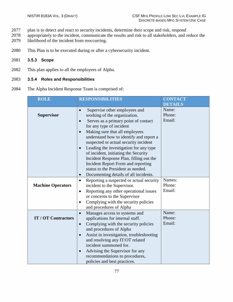
NISTIR 8183A VOL. 3 (DRAFT) CSF MFG PROFILE LOW SEC LVL EXAMPLE IG DISCRETE-BASED MFG SYSTEM USE CASE
77
plan is to detect and react to security incidents, determine their scope and risk, respond 2077
appropriately to the incident, communicate the results and risk to all stakeholders, and reduce the 2078
likelihood of the incident from reoccurring. 2079
This Plan is to be executed during or after a cybersecurity incident. 2080
Scope 2081
This plan applies to all the employees of Alpha. 2082
Roles and Responsibilities 2083
The Alpha Incident Response Team is comprised of: 2084
ROLE RESPONSIBILITIES CONTACT
DETAILS
Supervisor Supervise other employees and
working of the organization.
Serves as a primary point of contact
for any type of incident
Making sure that all employees
understand how to identify and report a
suspected or actual security incident
Leading the investigation for any type
of incident, initiating the Security
Incident Response Plan, filling out the
Incident Report Form and reporting
status to the President as needed.
Documenting details of all incidents.
Name:
Phone:
Email:
Machine Operators Reporting a suspected or actual security
incident to the Supervisor.
Reporting any other operational issues
or concerns to the Supervisor
Complying with the security policies
and procedures of Alpha
Names:
Phone:
Email:
IT / OT Contractors Manages access to systems and
applications for internal staff.
Complying with the security policies
and procedures of Alpha
Assist in investigation, troubleshooting
and resolving any IT/OT related
incident summoned for.
Advising the Supervisor for any
recommendations to procedures,
policies and best practices.
Name:
Phone:
Email:

NISTIR 8183A VOL. 3 (DRAFT) CSF MFG PROFILE LOW SEC LVL EXAMPLE IG DISCRETE-BASED MFG SYSTEM USE CASE
78
Categories of Incidents 2085
Alpha defines the following categories/types of incident for internal classification. These have 2086
been mentioned in the Incident Reporting Form as well. 2087
Intrusion 2088
Denial of Service 2089
Loss of Power 2090
Virus / Malware 2091
Social Engineering (Phishing, Phone, Email, etc.) 2092
Data Breach 2093
Hardware Stolen 2094
User account compromise 2095
System Misuse 2096
Technical Vulnerability 2097
2098 Severity Classification 2099
The Severity of an incident is determined based on the impact to the company and the urgency of 2100
restoration. 2101
SEVERITY DEFINITION
High All users of the company are affected
Work stoppage situation
The incident involves sensitive data breach.
The incident threatens Alpha’s operational goals
There is no viable workaround
Medium There is a viable workaround
Moderate to Low impact to the Operations.
Service interruption potentially affects specific
users and does not involve sensitive or personal
data breach.
Low No impact to operations.
Service interruption potentially affects only one
person and does not involve sensitive or
personal data breach.
2102
2103

NISTIR 8183A VOL. 3 (DRAFT) CSF MFG PROFILE LOW SEC LVL EXAMPLE IG DISCRETE-BASED MFG SYSTEM USE CASE
79
Restoration Priorities 2104
RESTORATION PRIORITIES DEFINITION
High Service Restoration must be completed
immediately, or significant loss of
revenue, reputation, or productivity will
occur.
Medium
Service Restoration must be completed
within two business days or there is a
potential for significant loss of revenue,
reputation or productivity.
Low Service Restoration can be delayed up to
three or more business days without loss
of revenue, reputation or productivity.
2105
Incident Alert Thresholds 2106
Manufacturing system alert thresholds will be configured as such to limit the number of false 2107
positives generated while working to capture valid data which could be an indication of 2108
cybersecurity incident. False-positives are classified as events indicating a problem, but further 2109
examination are not actual issues. Important, false-positives should always be treated as normal 2110
alerts requiring attention until determined otherwise. 2111
Incident Response Policy 2112
1. An incident upon detection or being reported needs to be thoroughly investigated as per the 2113
process defined under “Detection and Analysis” step of the IR process in the next section. 2114
The investigation may be performed by the Supervisor or by convening an IR Team. 2115
2. The incident needs to be classified as per the categories defined previously. 2116
3. Upon Investigation, the impact to the Manufacturing system must be determined. The IR 2117
Team may co-relate detected event information with Risk assessment outcomes to achieve 2118
perspective on the incident impact across the Organization. The incident will accordingly be 2119
assigned a Severity level and reported to the President. The Incident Report Template form 2120
should be used for this purpose. 2121

NISTIR 8183A VOL. 3 (DRAFT) CSF MFG PROFILE LOW SEC LVL EXAMPLE IG DISCRETE-BASED MFG SYSTEM USE CASE
80
4. During the “Detection and Analysis” step, detailed troubleshooting or forensic analysis 2122
should be performed to determine the root cause. This may be done using in place log 2123
management tools or commercial products such as Wireshark. 2124
5. Upon investigation, the incident must be mitigated as per the “Containment, Eradication and 2125
Recovery” step of the IR Process. 2126
6. The Supervisor upon consultation with the President. The Incident Report Template form 2127
should be used for this purpose. 2128
7. will communicate, co-ordinate and share incident response plan with Alpha’s stakeholders. 2129
8. The President will share information about any cybersecurity incidents and its mitigation 2130
with its designated sharing partners. 2131
9. The overall Incident Response program and plan will be revised or improved upon after 2132
every incident. Procedures must be updated regularly to address evolving threats such as 2133
APTs, Organizational changes, Manufacturing changes and/or after any problems discovered 2134
during implementation, execution or testing 2135
10. User awareness Training and Testing procedures will be updates after every incident. 2136
11. The Supervisor will communicate any changes or updates made to this policy. 2137
2138
Incident Plan Response Steps / Workflow 2139
The NIST Computer Security Incident Handling [1] Guide divides the incident response lifecycle 2140
into the following four steps: 2141
1. Preparation 2142
2. Detection and Analysis 2143
3. Containment, Eradication and Recovery 2144
4. Post-incident Activity 2145
2146

NISTIR 8183A VOL. 3 (DRAFT) CSF MFG PROFILE LOW SEC LVL EXAMPLE IG DISCRETE-BASED MFG SYSTEM USE CASE
81
Alpha’s IR process contains the following activities corresponding to each of the above steps: 2147
2148
Guidelines for Information Sharing 2149
Interactions with Law Enforcement 2150
All communications with external law enforcement authorities should be made after 2151
consulting with the President. 2152
The Supervisor will co-ordinate with the President to determine and share the minimum 2153
necessary information as required for incident response. 2154

NISTIR 8183A VOL. 3 (DRAFT) CSF MFG PROFILE LOW SEC LVL EXAMPLE IG DISCRETE-BASED MFG SYSTEM USE CASE
82
Communications Plan 2155
The President will share information about any cybersecurity incidents and its mitigation 2156
with its designated sharing partners. Refer to the Next section for additional details 2157
All public communications about an incident or incident response to external parties outside 2158
of Alpha are made in consultation with the President. 2159
The minimum information necessary to share for a particular incident is determined by the 2160
Supervisor in consultation with President or administrative authorities such as the 2161
bookkeeper. 2162
2163 Guidelines for Reporting to Stakeholders 2164
Overview: 2165
The Supervisor will compile all the details of incident(s) occurred in consultation with the 2166
IT/OT consultant. 2167
The Supervisor will share the details in the IR Report Template form with President. This 2168
will be used to determine level of severity, allowing the company to plan according. 2169
The Company’s leadership team consisting of President and HR Manager will make sure all 2170
facts have been gathered relating to the security incident before addressing any concerned 2171
with outside parties. 2172
The Company’s response needs to be consistent ensuring message being delivered will not 2173
need to be retracted or changed due to lack of clarity. 2174
Who will be responding: 2175
Depending on the severity of the security incident this role can be filled by President, or the 2176
Supervisor 2177
If the severity of a security incident requires additional resources, they should be contacted 2178
and brought in to help gather forensic information along with responding to inquiries. 2179
o Examples: 2180
Legal Counsel 2181
Forensic Investigator 2182
IT consultant (Work in conjunction with IT Manager) 2183
Security Consultant (Work in conjunction with IT Manager and Supervisors) 2184
Law Enforcement (Depends on severity) 2185
Notification: 2186
A Legal counsel will be contacted to oversee notification planning since the potential for 2187
legal actions against Alpha arising from security incident in question. 2188
If required, an outside Public Relations firm may be required depending on the severity level 2189
of the incident to help with crafting a response. 2190

NISTIR 8183A VOL. 3 (DRAFT) CSF MFG PROFILE LOW SEC LVL EXAMPLE IG DISCRETE-BASED MFG SYSTEM USE CASE
83
The President will both approve all communication being sent out regarding a security 2191
incident. 2192
Communications: 2193
The President will contact primary partners/vendors via phone call to inform them of the 2194
security incident. This should be done once all information has been gathered and a corporate 2195
response has been prepared. 2196
No voicemails will be left concerning the security incident in question. If recipient is 2197
unavailable schedule a follow up call. 2198
The Supervisor is the only Alpha employee authorized to call partners/vendors not already 2199
contacted by the President. 2200
Responses to partners/vendors should be scripted to ensure the delivered message is 2201
consistent, while ensuring only information regarding security incident are discussed. 2202
Email communication will be completed as a follow-up to a phone. 2203
Any email communications being sent will have additional proof reading completed by the 2204
President. 2205
Depending on the impact of security incident a Public Relation firm may be required to help 2206
with a response when providing communications via electronic or verbal. 2207
Media communication can ONLY be approved by President. 2208
2209
Restoring Trust: 2210
Alpha’s President or Supervisor with the advice consultants and Forensic experts will notify 2211
partners/vendors and customers with the steps being taken to restore and strength system 2212
security. 2213
The Supervisor will discuss with employees what caused security incident and what is being 2214
done to avoid a similar issue in the future. 2215
Once the security incident has been resolved and all fact are known Alpha leadership team 2216
will provide a full report which will be made publicly available containing facts relating to 2217
the security incident, along with the steps being taking to safe guard IT/OT infrastructure 2218
ensuring this and future events don’t happen again. 2219

NISTIR 8183A VOL. 3 (DRAFT) CSF MFG PROFILE LOW SEC LVL EXAMPLE IG DISCRETE-BASED MFG SYSTEM USE CASE
84
Incident Report Form Template 2220
2221

NISTIR 8183A VOL. 3 (DRAFT) CSF MFG PROFILE LOW SEC LVL EXAMPLE IG DISCRETE-BASED MFG SYSTEM USE CASE
85
Definitions and Acronyms 2222
President Head of the organization. Serves as an escalation point.
HR Manager An employee who deals with recruitment efforts and overall administration.
Incident An event that is not part of normal operations that disrupts operational
processes.
Supervisor An employee who supervises other employees and working of the
organization.
Vulnerability A weakness or flaw in the system which an attacker can exploit to gain access
to.
Vulnerability
Scan
The act of scanning a device or network for vulnerabilities
Machine
Operator
An employee who operates the manufacturing equipment and reports to
Supervisor.
IT/OT
Contractor
Non-employee(s) who are summoned on a need be basis for technical support
or maintenance tasks related to IT and OT equipment.
Stakeholders Business Owners, System Owners, Integrators, Vendors, Human Resources
Offices, Physical and Personnel Security Offices, Legal Departments,
Operations Personnel.
2223
References 2224
1. NIST Publication for handing Computer Security Incident 2225
https://nvlpubs.nist.gov/nistpubs/SpecialPublications/NIST.SP.800-61r2.pdf 2226
2227
2228
2229

NISTIR 8183A VOL. 3 (DRAFT) CSF MFG PROFILE LOW SEC LVL EXAMPLE IG DISCRETE-BASED MFG SYSTEM USE CASE
86
Incident Recovery Plan Document Example 2230
Incident Recovery Plan 2231
for 2232
Alpha 2233
2234
2235
2236
Document Owner: Supervisor, Alpha
2237
Version 2238
2239
Version Date Description Author
1.0 02-22-2018 Initial Draft Supervisor
2.0 04-21-2018 Major changes to the initial draft Supervisor
2240
Approval 2241
(By signing below, all Approvers agree to all terms and conditions outlined in this document.) 2242
2243
Approvers Role Signed Approval Date
President 4-22-2018
2244
Scope 2245
The scope and purpose of this document is to inventory all of infrastructure and capture 2246
information relevant to the Alpha’s ability to recover its IT/OT environment from a 2247
cybersecurity incident. It, in turn also aims to provide an effective and efficient recovery effort. 2248
Objectives 2249
This plan has been developed to accomplish the following objectives: 2250
1. Limit the magnitude of any loss by minimizing the duration of a critical application service 2251
interruption. 2252
2. Assess damage, repair the damage, and activate the repaired computer center. 2253
3. Manage the recovery operation in an organized and effective manner. 2254
4. Prepare technology personnel to respond effectively in an incident recovery situation. 2255

NISTIR 8183A VOL. 3 (DRAFT) CSF MFG PROFILE LOW SEC LVL EXAMPLE IG DISCRETE-BASED MFG SYSTEM USE CASE
87
Incident Response: 2256
This IR Plan is to be executed during or after a cybersecurity incident. 2257
The person discovering the incident must notify the Supervisor, who collectively assume 2258
responsibility for deciding which - if any - aspects of the IR plan should be implemented, and for 2259
establishing communication with employees, management, partners and customers 2260
RPO and RTO Targets 2261
Alpha defines the following SLA’s or Restoration times for operations recovery 2262
Type of Incident RTO
[2]
RPO [2] Restoration
Priority
Environmental Disasters such as
Fire, Flood.
72
hours
24 hours High
Recovery from Virus/Malware
attack
24
hours
24 hours High
Recovery from user account
compromise
24
hours
24 hours Medium
Recovery from Data Breach 48
hours
24 hours High
Hardware failure, System Parts
Replacement
48
hours
24 hours High
2263
Incident Recovery Team 2264
Alpha’s Incident Recovery (IR) Team will consists of the following individuals. 2265
ROLE RESPONSIBILITIES
Supervisor
Lead and oversee the entire DR process
Contact any Contractors/Vendors for assistance as
needed.
Making sure that all employees understand their roles
and responsibilities.
Update this document as per the Maintenance policy
Notify the President for any escalation issues.
President Assist the DR Lead (Supervisor) in their role as
required.

NISTIR 8183A VOL. 3 (DRAFT) CSF MFG PROFILE LOW SEC LVL EXAMPLE IG DISCRETE-BASED MFG SYSTEM USE CASE
88
Make any Business decisions that are out of scope for
the Supervisor.
Serve as point of escalation for any issues.
Machine Operators
Install, implement or assist in implementing any tools,
hardware software and systems as required
Escalate any issues related to recovery to the
Supervisor.
Complying with this plan.
IT / OT Contractors
Assist in Recovery, Troubleshooting and resolving any
IT/OT related incident summoned for
Advising the Supervisor for any recommendations to
procedures, policies and best practices.
Complying with this plan
2266
Contact Information 2267
Contact Information 2268
Name Title Contact Type Contact Information
Employee A ABC Work 555-555-5555 ext 2
Mobile
Alternate
Employee B ABC Work 555-555-5555 ext 3
Mobile
Alternate
Employee C ABC Work 555-555-5555 ext 4
Mobile
Alternate
2269
2270

NISTIR 8183A VOL. 3 (DRAFT) CSF MFG PROFILE LOW SEC LVL EXAMPLE IG DISCRETE-BASED MFG SYSTEM USE CASE
89
External Contacts 2271
Name Title Contact Type Contact Information
Power Company Work
Account # Mobile
Alternate
IT Contractor Work
Account # Mobile
Alternate
OT Contractor Work
Account # Mobile
Alternate
Network Provider Work
Account # Mobile
Alternate
Telecom Carrier Work
Account # Mobile
Alternate
Insurance Provider Work
Account # Mobile
Alternate
Hardware Provider Work
Account # Mobile
2272
2273

NISTIR 8183A VOL. 3 (DRAFT) CSF MFG PROFILE LOW SEC LVL EXAMPLE IG DISCRETE-BASED MFG SYSTEM USE CASE
90
Notification Calling Tree 2274
2275
2276
2277
2278
2279
2280
2281
2282
2283
Communications 2284
Notification 2285
The Supervisor in consultation Machine Operators will periodically update the President 2286
on the progress of Recovery Activities. 2287
A Legal Counsel may be hired to oversee notification planning since the potential for 2288
legal actions against Alpha arising from security incident in question. 2289
If required, an outside Public Relations firm may be required depending on the severity 2290
level of the incident to help with crafting a response. 2291
The President’s approval is required for work with any outside agency. 2292
Communications 2293
The President will contact primary partners/customers via phone call to inform them 2294
about Recovery activities. This should be done once all information has been gathered 2295
and a corporate response has been prepared. 2296
The Supervisor is the ONLY Alpha employee authorized to call partners/vendors not 2297
already contacted by the President. 2298
Responses to partners/vendors should be scripted to ensure the delivered message is 2299
consistent, while ensuring only information regarding security incident are discussed. 2300
Email communication will be completed as a follow-up to a phone. 2301
Any email communications being sent will have additional proof reading completed by 2302
the President. 2303
Depending on the impact of security incident a Public Relation firm may be required to 2304
help with a response when providing communications via electronic or verbal. 2305
Person
Identifying
Incident
Supervisor
President
Contractors /
Vendors
Customers
HR Manager

NISTIR 8183A VOL. 3 (DRAFT) CSF MFG PROFILE LOW SEC LVL EXAMPLE IG DISCRETE-BASED MFG SYSTEM USE CASE
91
Media communication can ONLY be approved by the President. 2306
Restoring Trust 2307
Alpha’s President or Supervisor with the advice consultants and Forensic experts will 2308
notify partners/vendors and customers with the steps being taken to restore and strength 2309
system security. 2310
The Supervisor will discuss with employees what caused security incident and what is 2311
being done to avoid a similar issue in the future. 2312
Once the security incident has been resolved and all fact are known, Alpha’s leadership 2313
team will provide a full report which will be made publicly available containing facts 2314
relating to the security incident, along with the steps being taking to safe guard IT/OT 2315
infrastructure ensuring this and future events don’t happen again. 2316
Plan Testing and Maintenance 2317
Maintenance 2318
The Incident Response Plan will be revised and updated after every recovery executed 2319
following a cybersecurity incident, Organizational changes, Manufacturing changes 2320
and/or after any problems discovered during implementation, execution or testing. 2321
The Supervisor will be responsible for updating the document in consultation with 2322
Machine Operators and other personnel as required. 2323
During Maintenance periods, any changes to the IR Team must be accounted for. 2324
2325
Testing 2326
Walkthroughs- IR Team members will verbally go through the specific steps as 2327
documented in the plan to confirm effectiveness, identify gaps or other weaknesses. The 2328
team should be familiar with procedures, equipment and operations. 2329
Simulations- An incident is simulated so that normal operations will not be interrupted. 2330
Hardware, software, personnel, communications, procedures, supplies and forms, 2331
documentation and utilities should be thoroughly tested in a simulation test. 2332
Full-Interruption Testing- IR Team members will perform a full-interruption test to 2333
activate a total IRP scenario. Caution must be exercised as this type of test disrupts 2334
normal operations. 2335
2336

NISTIR 8183A VOL. 3 (DRAFT) CSF MFG PROFILE LOW SEC LVL EXAMPLE IG DISCRETE-BASED MFG SYSTEM USE CASE
92
Hardware Information 2337
SYSTEM TYPE HARDWARE INFORMATION
IT Servers
Hostname: POLARIS System Model: Dell T5610
IP Address: 192.168.0.20
Location: Cabinet 101
Network: Control LAN
Type: Physical
Other: Eng. Workstation, Ubuntu
Linux 12.04
Hostname: MINTAKA System Model: Dell R420
IP Address: 192.168.1.105
Location: Cabinet 101
Network: Control LAN
Type: Physical
Other: Robot Driver, Ubuntu
Linux 14.04
Hostname: VController1 System Model: Hyper-V VM
IP Address: 192.168.1.103
Location: Robotics-VH Hyper-V
Type: Virtual
Network: Control LAN
Other: Robot Controller, Ubuntu
Linux 14.04
Hostname: VController2 System Model: Hyper-V VM
IP Address: 192.168.1.104
Location: Robotics-VH
Hyper-V Host
Type: Virtual
Network: Control LAN
Other: Robot Controller,
Ubuntu Linux 14.04
Hostname: Robotics-VH System Mode: Dell PE R420
Location: Cabinet 101
Type: Physical
Other: Windows Server 2012 R2,
Hyper-V Server
Network Devices Model: RuggedCom RX1510 Management IP: 10.100.2.
Location: Cabinet 101
Other: Boundary Router
Model: Netgear GS724T Management IP:
192.168.0.239
Location: Cabinet 101
Network: Supervisory Bus
LAN Switch
Model: Siemens i800 Management IP: 192.168.0.1
Location: Cabinet 101
Network: Control LAN Switch
OT Devices Model: Beckhoff CX9020 IP Address: 192.168.0.20
Location: Cabinet 101
Function: PLC
Model: Red Lion G310 IP Address: 192.168.0.98
Location: Cabinet 101
Function: HMI

NISTIR 8183A VOL. 3 (DRAFT) CSF MFG PROFILE LOW SEC LVL EXAMPLE IG DISCRETE-BASED MFG SYSTEM USE CASE
93
Model: Beagelbone Black IP Address: 192.168.1.101 - 104
Location: Work Cell
Function: Machining Stations
Quantity: 4
Model: Robots Manufacturer: KUKA
Location: Work Cell
Function: Robots
Quantity: 2
2338
Backup Strategy 2339
2340
SYSTEM TYPE BACKUP STRATEGY
IT Servers
POLARIS: System Image - Thrice Weekly using
Veeam, Directory Level Backup Monthly once
MINTAKA: System Image - Daily using Veeam
vController1: Full VM image Weekly once
vController2: Full VM image Weekly once
Application Code
Code is checked into a secure central network share.
Server hosting the network share is backed up using
Veeam
Network Devices
Boundary Router
Frequency:
Quarterly: Manual using Manufacturer instructions.
All configuration backup data will be saved to a
secured central network share.
RuggedCom RX1510:
1. Login to the RX1510 Web UI >> Click on
Admin >> Click on Full configuration backup
2. Enter a backup name, select backup format as cli
from the Drop-down menu > On the Trigger Action
form, click Perform.
3. The backup file will then be created and saved
locally at /admin/backup-files
4. [Optional]The above file can further be
downloaded via SFTP or copied over to a USB

NISTIR 8183A VOL. 3 (DRAFT) CSF MFG PROFILE LOW SEC LVL EXAMPLE IG DISCRETE-BASED MFG SYSTEM USE CASE
94
Drive. Click on Admin > Click Backup-Files in the
menu
5. In the Backup Files form, select “Config” under
File Type drop-down, enter a backup file name >
Under URL enter the path of USB Drive or SFTP
server’s network path > Click Perform.
6. Save the backup file to the central network
share/repository.
For more details, refer to RX1510 manual available
on Siemens website upon registration.
OT Devices Frequency:
Quarterly: Manual as per Manufacturer procedures.
Ensure backups are saved to a secure central
network share.
PLC:
1.Power off the embedded PC. Remove the
microSD card as per the steps mentioned in the
manual [3]
2.Copy the data from the microSD card to a central
secure location.
HMI:
1.Setup a link between the HMI and
PC(Workstation) using the RS-232 port or USB
port.
2.Download the database via the LINK Menu in the
HMI. Use either the Link-Send of Link-Update
commands. Link-Send will copy over the entire
database while Link-Update is for incremental
backups.
Detailed instructions can be found in the Crimson
3.1 Manual [4]

NISTIR 8183A VOL. 3 (DRAFT) CSF MFG PROFILE LOW SEC LVL EXAMPLE IG DISCRETE-BASED MFG SYSTEM USE CASE
95
Recovery Procedures 2341
The Incident Recovery plan will be executed following a cybersecurity incident. 2342
Any exceptions or issues during the Recovery process must be communicated to the 2343
Supervisor and/or President. 2344
Depending on the incident, and on the number and nature of the IT services affected, one or 2345
more of the following IR procedures may be activated by the IR team: 2346
2347
Type of Incident Plan of Action
Environment Disaster – Fire, Flooding
1. Identify root cause, co-ordinate initial
response
2. Remove damaged systems from the work
cell.
3. Evaluate damage
4. Review Insurance policies and reach out to
Insurance companies.
5. Procure new hardware systems as required.
Reach out to a Data recovery company for
data recovery from damaged hard drives.
Virus / Malware – IT / OT Systems
1. Disconnect the affected systems from the
network.
2. Reach out to the IT/OT Contractor for
assistance.
3. Perform a full manual Anti-virus scan on
the system
4. If the Anti-virus software cannot detect or
quarantine the infection, you may need to
reinstall or restore the entire Operating
System. Use Veeam to restore a full image
backup, if the system in question is an IT
system.
5. Upon reinstalling the operating system,
install all the appropriate patches to fix
known vulnerabilities.

NISTIR 8183A VOL. 3 (DRAFT) CSF MFG PROFILE LOW SEC LVL EXAMPLE IG DISCRETE-BASED MFG SYSTEM USE CASE
96
6. Depending on the nature of the virus
attack, change your original passwords as
these could have been compromised during
the infection.
Data Theft 1. Fulfill all legal obligations. Supervisor to
inform law enforcement and other customer
protection agencies notifying them of breach.
2. Immediately change system credentials,
account passwords to public websites (if
personal data is involved)
3.Monitor in-house security controls or tools
for any signs of new activity.
4. Identify and erase any new files or
programs that may have been installed as part
of this attack. Use system baselines for
reference.
5. Engage a Contractor or other professional
to conduct security audit.
Data Loss - IT Systems 1. Browse through the list of directory level
backups captured by Veeam for that host to
select the backup to restore data from.
2. Initiate a restore of the file or directory
from the affected system using Veeam. If the
system in question is a virtual machine,
restore the most recent full VM image as it is
using Veeam.
3. Verify the file, folders and their
permissions upon completion of the restore.
Hardware failure – IT Systems
1. Follow up with the vendor for getting the
hardware replaced.
2. Install and setup the new hardware as per
the original baseline configuration.

NISTIR 8183A VOL. 3 (DRAFT) CSF MFG PROFILE LOW SEC LVL EXAMPLE IG DISCRETE-BASED MFG SYSTEM USE CASE
97
3. Refer to File system table below to
configure any File system dependencies such
as NFS mount points.
4. Initiate a Restore operation from the most
recent backup using Veeam. The restore
procedure varies depending on if the system
is physical or virtual. For more details, refer
to the Veeam Backup guide.
5. Upon completion of restore, verify
connectivity and operations.
Hardware failure –Network Devices
1. Order a replacement from a vendor.
2. Setup and configure the new device as per
its original counterpart. For more details,
refer to the asset inventory database and/or
any supporting documentation to reference
the original baseline config such as Firewall
rules, ACLS, VLAN, etc.
3. Restore system configuration using
Manufacturer instructions from the secure
central repository.
4. Verify connectivity between devices. Run
operations to confirm.
Hardware failure / Configuration Restore-
OT Systems
1. Order a replacement from a vendor.
2. Setup the new device by assigning it the
original static IP address and restore the
configuration on it as per manufacturers
manual. Following are high level instructions
for a config restore
PLC:
1.Power off the device. Pull out the microSD
card from the PLC and load a previously
saved image on it using a card reader. Saved
images can be copied over from the central

NISTIR 8183A VOL. 3 (DRAFT) CSF MFG PROFILE LOW SEC LVL EXAMPLE IG DISCRETE-BASED MFG SYSTEM USE CASE
98
secure location or a new base image can also
be obtained from the manufacturer.
2.Insert the microSD card back into the PLC
and power on the device.
3. Test Connectivity and operations.
HMI:
1. Copy a working image to a USB stick and
plugin the USB in the HMI.
2. Access the “System menu” of the HMI.
For more details, please refer to
manufacturer’s manual.
3.Click on “Database Image Menu” >>
Load Image from Memory Card >> Yes
Machining stations:
1.Power off the device. Pull out the microSD
card from the beagle bone device and load a
previously saved image on it using a card
reader.
2.Insert the microSD card back into the
beagle bone and power on the device.
3. Test Connectivity and operations.
Robots:
1. Order a replacement from the vendor.
2. Install and connect new device in place of
the original.
3. Verify operations
2348

NISTIR 8183A VOL. 3 (DRAFT) CSF MFG PROFILE LOW SEC LVL EXAMPLE IG DISCRETE-BASED MFG SYSTEM USE CASE
99
File System Layouts 2349
System
Local
Hard
Drive
File System
layout Network Storage (NFS, SMB)
Dependencies/
Notes
POLARIS 2TB
Output of "df -
kh" N/A NFS Server
MINTAKA 500GB
Output of "df -
kh" N/A
vController1 50GB
Output of "df -
kh" polaris:/opt/catkin_ws/src/youbot
NFS client.
POLARIS
should be UP
before power
ON
vController2 50GB
Output of "df -
kh" polaris:/opt/catkin_ws/src/youbot
NFS client.
POLARIS
should be UP
before power
ON
2350
Restoration Priorities 2351
Should an incident occur and Alpha need to exercise this plan, this section will be referred to 2352
reference restoration priorities in bringing systems online. 2353
IT Systems 2354
Priority IT System Description
High LAN-AD Active Directory / DNS Server
High Veeam Veeam Backups Server
High MINTAKA Robot Driver
High vController1,
2
Robot Controllers
High POLARIS Engineering Workstation

NISTIR 8183A VOL. 3 (DRAFT) CSF MFG PROFILE LOW SEC LVL EXAMPLE IG DISCRETE-BASED MFG SYSTEM USE CASE
100
High Robotics-PI Local Historian Database
Medium PI-DMZ DMZ-Historian
Medium SymantecMgr Symantec Antivirus Manager SEPM
Low GTB
Inspector
DLP
Low Graylog Syslog server
Low Hive Incident Response Server
2355
Networking Equipment 2356
Priority Device
Info
Description
High Boundary
Router
Allen Bradley Router 8300
High Supervisory
LAN
Switch
Net gear GS724T
High Control
LAN
Switch
Siemens i800 Switch
2357
OT Systems 2358
Priority OT
System
Description
High PLC Beckhoff PLC
High HMI Red lion HMI
2359

NISTIR 8183A VOL. 3 (DRAFT) CSF MFG PROFILE LOW SEC LVL EXAMPLE IG DISCRETE-BASED MFG SYSTEM USE CASE
101
Definitions and Acronyms 2360
SLA Service Level Agreement
Recovery Time Objective (RTO) RTO defines the maximum amount of time that a
system resource can remain unavailable before there is
an unacceptable impact on other system resources,
supported mission/business processes, and the
Maximum Tolerable Downtime. [2]
Recovery Point Objective (RPO) The RPO represents the point in time, prior to a
disruption or system outage, to which mission/business
process data can be recovered (given the most recent
backup copy of the data) after an outage. [2]
2361
References 2362
1. SANS Guide for DR: https://www.sans.org/reading-room/whitepapers/recovery/disaster-2363
recovery-plan-strategies-processes-564 2364
2. NIST SP 800-34 Contingency planning guide for Federal Systems 2365
https://nvlpubs.nist.gov/nistpubs/legacy/sp/nistspecialpublication800-34r1.pdf 2366
3. Allen Bradley ControlLogix 5571 Manual 2367
https://literature.rockwellautomation.com/idc/groups/literature/documents/um/1756-2368
um001_-en-p.pdf 2369
2370

NISTIR 8183A VOL. 3 (DRAFT) CSF MFG PROFILE LOW SEC LVL EXAMPLE IG DISCRETE-BASED MFG SYSTEM USE CASE
102
4. Technical Solution Implementations 2371
Introduction 2372
This section includes proof-of-concept technical solution implementations developed for the 2373
fictional company Alpha. An overview of these technical solutions is discussed in Section 6 of 2374
Volume 1 and potential technical solutions are discussed in Section 7 of Volume 1. Each 2375
organization’s information security experts should identify the technical solutions that will best 2376
integrate with their existing cybersecurity program and manufacturing system infrastructure. 2377
All of the technical solutions were installed and configured within the Collaborative Robotics 2378
System (CRS) [6]. The manufacturing process was operated after each technical solution was 2379
implemented, producing 35 parts for each “experiment”. Technical solutions that had multiple 2380
modes of operation were tested for each mode that aligned with the requirements of the low 2381
security level and the applicability of the mode to the use case [7]. 2382
Three types of performance measurements were performed during the implementation: baseline 2383
measurements of the initial workcell performance, impact of individual technologies or 2384
configurations, and impact of the completed security level implementation. The process of 2385
sequentially implementing and measuring enabled the detection of performance-impacting 2386
interactions between the technical solutions. 2387
Security level baseline - Before any changes were made to the workcell, baseline 2388
measurements were captured. Since all experiments are meant to be comparative, a 2389
baseline reference of system performance must be obtained to determine if the 2390
manufacturing process or its sub-systems have been impacted after a technical solution is 2391
installed or reconfigured. 2392
Technology/configuration implementation impact - These measurements were 2393
performed after each technical solution was installed and configured to meet the security 2394
level requirements. Some technical solutions provided multiple modes of operation that 2395
met the security level requirements and had the potential to affect the manufacturing 2396
process differently. Measurements were performed for each unique configuration to 2397
compare its impact to the previous configurations. 2398
Security level implementation impact - These measurements were performed after all 2399
technical solutions have been installed and configured. These measurements are used to 2400
determine the total impact to the manufacturing process and compared with other security 2401
level implementation impact measurements to determine the relative performance impact 2402
between the security levels. The final technology implementation impact (if it not a 2403
multi-mode measurement) can also be used as the security level implementation impact. 2404
Before the security level baseline measurements were performed, the workcell manufacturing 2405
process was characterized by producing 1000 parts over ten experiments of 100 parts each, and 2406
the results analyzed. This characterization procedure (further described in [7]) validated that the 2407
process was in-control, stable, and random. 2408

NISTIR 8183A VOL. 3 (DRAFT) CSF MFG PROFILE LOW SEC LVL EXAMPLE IG DISCRETE-BASED MFG SYSTEM USE CASE
103
The primary key performance indicator (KPI) used to determine if the manufacturing process 2409
experienced a performance impact was “part production time” (KPI 2.1 in [6]), which measures 2410
the amount of time required for a part to travel through the manufacturing process. Numerous 2411
other performance measurements were captured on many of the CRS systems, and were 2412
subsequently used to produce the plots shown in the following sections, and to assist in 2413
determining the root cause of any realized performance impacts. 2414
Implementation Note – Due Diligence Implementing Technical Solutions 2415
It is important to note that the procedures used during this implementation (i.e., install a tool, 2416
then measure the impact) should not be used in a production system. Care must be taken before 2417
using any technical solutions, especially those that actively scan the manufacturing system ICS 2418
network and its devices; manufacturers should first conduct an assessment of how these tools 2419
work and what impact they might have on the connected control equipment [3]. Technology 2420
evaluations may include testing in similar, non-production control system environments to 2421
ensure that the tools do not adversely impact the production systems. Impact could be due to the 2422
nature of the information or the volume of network traffic. While this impact may be acceptable 2423
in IT systems, it may not be acceptable in a manufacturing system. In general, any operation that 2424
actively scans the manufacturing network should be scheduled to occur only during planned 2425
downtimes. [3] 2426
Implementation Note - Sensor Error and Adaptation of KPI 2427
After the Low baseline implementation was completed, an analysis of the KPI was performed. 2428
During this analysis, a small but consistent increase in the Station 4 allocation ratio was observed 2429
after each chronological experiment. The source of the increase was found to be occurring during 2430
the Station 4 “FINISHED” state, which is when the machining station has completed its 2431
manufacturing procedure and is waiting for the robot to remove the part. A plot showing the 2432
amount of time each station was in the “FINISHED” state across all experiments (compared to 2433
the baseline experiment CL001.1) was created (see Figure 4-1), which exhibited a high 2434
correlation to the part production time KPI measurements (see Figure 4-2). 2435
2436

NISTIR 8183A VOL. 3 (DRAFT) CSF MFG PROFILE LOW SEC LVL EXAMPLE IG DISCRETE-BASED MFG SYSTEM USE CASE
104
2437
Figure 4-1 - Bar plot showing the increasing Station 4 “FINISHED” state deviation from the baseline. The data 2438 from Station 1, 2, and 3 are also shown. The plotted values are the mean for all 35 parts in the experiment. 2439 The largest discrete deviation measured was around 1.55 sec. 2440
After further analytical review of the testbed measurements, the problem was isolated to a 2441
retroreflective proximity sensor located in the workcell on Station 4. The sensor specification 2442
defined a 20 mm sensing distance, but testing revealed the sensor intermittently reporting part 2443
presence after the part was removed upwards of 100 mm from the sensor. This effect was 2444
exacerbated by the motion of the robot, which keeps the part within the sensor field of view 2445
while removing the part from the station. Testing of the sensor response time revealed 2446
intermittent times upwards of 1.5 sec. when a part was removed from the station (the sensor 2447
specification reported a maximum switching frequency of 250 Hz, equivalent to a 0.004 sec. 2448
response time). The response time when a part was placed into the station was not affected. 2449
The faulty sensor data was reviewed to determine if it could be eliminated from the KPI 2450
measurements. Since the only measurements affected were when parts were removed from 2451
Station 4, an analysis was performed to determine the feasibility of changing the KPI definition 2452
to be measured using the arrival of a part at Station 4, instead of the departure of a part. This 2453
method proved to be feasible. All mentions of this KPI throughout the remainder of this 2454
document should be considered defined in this manner. A comparison of the “part production 2455
time” KPI for the original and modified definition is shown below in Figures Figure 4-2 and 2456
Figure 4-3. 2457

NISTIR 8183A VOL. 3 (DRAFT) CSF MFG PROFILE LOW SEC LVL EXAMPLE IG DISCRETE-BASED MFG SYSTEM USE CASE
105
2458
Figure 4-2 - Performance impact to the manufacturing process KPI “part production time” using the original 2459 definition, where the time is measured from the arrival of the part at Station 1 to the departure of the part 2460 from Station 4. Note the large increase and outliers for the last four experiments (CL010.2, CL011.2, CL012.1, 2461 and CL009.1). 2462
2463
Figure 4-3 - Performance impact to the manufacturing process KPI “part production time” using the updated 2464 definition, where the time is measured from the arrival of the part at Station 1 to the arrival of the part at 2465 Station 4. Note the improvement in stability compared to the original definition shown in Figure 4-2. 2466
Implementation Note - Availability of Measurement Data 2467
All the raw and processed measurement data captured from each experiment is freely available 2468
online as compressed ZIP files. Links to all of the data files are provided below, and directly 2469
referenced at the end of each implementation below. 2470
CL001.1-Baseline.zip 2471
CL001.2-BaselineUpdate.zip 2472
CL002.1-ActiveDir.zip 2473
CL003.1-Syslog.zip 2474
CL003.2-Syslog.zip 2475
CL004.1-HostBackups.zip 2476
OBSOLETE - DO NOT USE FOR
PERFORMANCE IMPACT ANALYSIS.

NISTIR 8183A VOL. 3 (DRAFT) CSF MFG PROFILE LOW SEC LVL EXAMPLE IG DISCRETE-BASED MFG SYSTEM USE CASE
106
CL004.2-FullImageBackup.zip ** 2477
CL004.3-DirectoryBackup.zip ** 2478
CL005.1-AntivirusRealTimeScan.zip 2479
CL005.2-AntivirusFullScan.zip 2480
CL006.1-NessusNetworkScan.zip 2481
CL006.2-NessusAuthenticatedScan.zip 2482
CL007.1-OpenAudITNetworkScan.zip 2483
CL007.2-OpenAudITAuthenticatedNetworkScan.zip 2484
CL008.1-LeastPrivilege.zip 2485
CL009.1-BoundaryFirewall.zip 2486
CL010.1-NetworkPhysicalConnections.zip 2487
CL010.2-NetworkMACFiltering.zip 2488
CL011.1-PatchesNetworkHardware.zip 2489
CL011.2-PatchesServersICSDevices.zip 2490
CL012.1-CiscoASA5506.zip 2491 2492
** - The network capture files provided for CL004.2 and CL004.3 (capture.pcap) have been 2493
modified to exclude all Veeam traffic recorded during the experiment, as the traffic contains 2494
sensitive testbed data in clear-text. To obtain access to these files, please contact the authors 2495
directly. 2496 2497

NISTIR 8183A VOL. 3 (DRAFT) CSF MFG PROFILE LOW SEC LVL EXAMPLE IG DISCRETE-BASED MFG SYSTEM USE CASE
107
Open-AudIT 2498
Technical Solution Overview 2499
Open-AudIT is an asset inventory tool providing scanning of hardware and software within the 2500
manufacturing environment. Open-AudIT scans are highly customizable to each environment, 2501
depending on the level required. 2502
Open-AudIT cost depends on the level of functionality desired for your environment. Editions 2503
offered by Open-AudIT vary from entry level community edition which is free, all the way up to 2504
enterprise edition. Enterprise was chosen since it contains the ability to setup schedule scanning, 2505
dashboards, and baselining of equipment. 2506
2507
Open-AudIT is a downloadable OVA which is easy to install. OVA install allows installation in 2508
a Hyper-Visor environment allowing for installation within an existing virtual environment 2509
without requiring purchasing additional hardware. Configure for initial discovery scans are 2510
straight forward and easy to configure and perform. 2511
Technical Capabilities Provided by Solution 2512
Open-AudIT provides components of the following Technical Capabilities described in Section 6 2513
of Volume 1: 2514
Hardware Inventory 2515
Software Inventory 2516
System Development Lifecycle Management 2517
Configuration Management 2518
Baseline Establishment (Enterprise Edition) 2519
Change Control 2520
2521 Subcategories Addressed by Implementing Solution 2522
ID.AM-1, ID.AM-2, ID.AM-3, ID.AM-4, PR.DS-3, PR.IP-1, PR.IP-2, PR.IP-3, PR.IP-4, 2523
PR.IP-6, PR.MA-1, DE.AE-1, DE.CM-7 2524
2525

NISTIR 8183A VOL. 3 (DRAFT) CSF MFG PROFILE LOW SEC LVL EXAMPLE IG DISCRETE-BASED MFG SYSTEM USE CASE
108
Architecture Map of Where Solution was Implemented 2526
2527

NISTIR 8183A VOL. 3 (DRAFT) CSF MFG PROFILE LOW SEC LVL EXAMPLE IG DISCRETE-BASED MFG SYSTEM USE CASE
109
Installation Instructions and Configurations 2528
Open-AudIT Setup Steps 2529 Prerequisites: 2530
Identify if physical hardware or virtual machine will be used 2531 Requirements from Opmantek who developed “Open-AudIT” indicate the specification required 2532 are low. Please see this link for exact details provided by the vendor link. 2533
Instruction: 2534 Download: 2535
1. Download and save Opmantek Virtual Appliance from Opmantek website.102536
2537 2. Once download has completed “.ova” file will need to be extracted to view the contents and 2538 move to the next step (any tool supporting extracting .ova and .gz can be used). 2539 3. Open the folder where the files were extracted too. There should be a total of four files. 2540 4. Next, extract the two files with extension (.vmdk.gz) since this file is still compressed. Once 2541 completed two files with the same extension (.vmdk) should now exist. 2542 5. Now two files just extracted need to be convert to “VHDX” format so we can run these disk in 2543 a Hyper-V environment. See this link for instruction and additional information useful for 2544 converting virtual drive format. 2545 6. Once both drives have been converted to “VHDX” format proceed to next section. 2546
Virtual Machine Setup: 2547 1. On the virtual server host open “Hyper-V Manager” and then right click on server 2548
name selecting New Virtual Machine 2549 2. Now type in the name you going to give this server. 2550
10 Opmantek Intelligent Network Management Software https://opmantek.com/

NISTIR 8183A VOL. 3 (DRAFT) CSF MFG PROFILE LOW SEC LVL EXAMPLE IG DISCRETE-BASED MFG SYSTEM USE CASE
110
3. Place a check in the box “Store the virtual machine in a different location” click next.2551
2552 4. The step above will place the configuration and hard drive files for the newly create Virtual 2553 Machine in D:\Hyper-V\NewServerBuild (See Screenshot) 2554 5. Leave Generation 1 selected and click Next. This machine doesn’t require additional features 2555 provided from Generation 2. 2556 6. Now assign how much memory your new machine will be given for use. For our environment we 2557 are using “2048” Click next to continue. 2558 7. Select the network this virtual machine will be using and click Next. 2559 8. Now select “Attach a virtual disk later” and click 2560
next. 2561 9. Now a screen appears displaying a configuration summary, click Finish to 2562
complete. 2563 10. Next, open Windows Explorer and navigate to the location of your newly created virtual 2564 machine and create a new folder labeled “Virtual Hard 2565
Disk” 2566 11. Now moves the hard drive files converted earlier to this new folder location just 2567
created. 2568 12. Open Hyper-V Manager and right click on Virtual Machine just created and select “Setting…”2569
2570 13. Memory should be configured for “2048” 2571

NISTIR 8183A VOL. 3 (DRAFT) CSF MFG PROFILE LOW SEC LVL EXAMPLE IG DISCRETE-BASED MFG SYSTEM USE CASE
111
14. Virtual Processor “2” 2572 15. Click on “IDE Controller 0” then click on “Add” button to attach a virtual hard. 2573 16. Click browse button and select the first virtual drive that was moved earlier, click 2574
apply. 2575 17. Now click on “IDE Controller 0” again and click “Add” button to attach a virtual hard. 2576 18. Click browse button and select the second virtual drive that was moved earlier, click 2577
apply. 2578 19. Now, select Network adapter and click the drop down and select “vswitch_TestBed_Lan” or 2579 what you have labeled your 2580
network. 2581 20. Click on Name and make sure to add some descriptive information that will allow other to easily 2582 see this information without having to login into machine. 2583 21. Select Integration Service and remove check from “Time Synchronization” Time will be 2584 sync using internal NTP server via DNS pointer. Click “Apply” and 2585
then “OK”. 2586 Configure Virtual Machine Networking: 2587
1. Open Hyper-V Manager and then right click on newly created machine and select start. 2588 2. Double click on machine being configured to open a Console window. 2589 3. Now type in “root” and then hit enter. Now type in Password provided from documentation. 2590 Once logged in make sure to change password from default. Additional information for default login 2591 credentials can be found here. 2592

NISTIR 8183A VOL. 3 (DRAFT) CSF MFG PROFILE LOW SEC LVL EXAMPLE IG DISCRETE-BASED MFG SYSTEM USE CASE
112
4. Now type this command without the quotes to copy a static configuration for 2593 networking. “cp ifcfg-eth0.static /etc/sysconfig/network-scripts/ifcfg-eth0” if prompted to 2594 overwrite file type “Yes” 2595 5. Now type this command without the quotes “sudo nano /etc/sysconfig/network-scripts/ifcfg-2596 eth0” 2597 6. Now use the arrow keys to change the highlighted fields to your desired network 2598
configuration. 2599 7. Once all fields have been updated use Ctrl + O “^O” to write the file and then Ctrl + X “^X” to 2600 exit. 2601
2602 2603 8. Now type “service network restart” This restarts networking services with the newly configured 2604 settings. 2605
Complete Additional Setup via Web Browser: 2606 1. Now with any web browser navigate to “IP Configured Earlier” example would 2607 be “10.100.0.177” 2608 2. If prompted to proceed to untrusted site, select “Yes”. This error is produced since SSL has not 2609 been configured and Open-AudIT redirects HTTP sessions over to HTTPS. 2610

NISTIR 8183A VOL. 3 (DRAFT) CSF MFG PROFILE LOW SEC LVL EXAMPLE IG DISCRETE-BASED MFG SYSTEM USE CASE
113
3. Once this page opens you’ll see lots of different options this tool provides. We’re using “Open-2611 AudIT Enterprise” This version allows for up to 20 nodes to be audited / monitored for 2612
free. 2613 4. You’ll now be prompted for login with username and password. This default information is 2614 provided above “username / password”. 2615 5. Once logged in we need to make some required changes to allow this produce to function in our 2616 environment. 2617 6. Click on “Admin LDAP Server Create LDAP Servers” This will allow integration with Active 2618 Directory using LDAP authentication for logging into this 2619
application. 2620

NISTIR 8183A VOL. 3 (DRAFT) CSF MFG PROFILE LOW SEC LVL EXAMPLE IG DISCRETE-BASED MFG SYSTEM USE CASE
114
7. Required setting for LDAP server connection. Screen shot provide for 2621 reference. 2622
2623 a. Name – TestConnection 2624 b. Description -- Documentation 2625 c. Domain – LAN.LAB 2626 d. Host – 10.100.0.17 2627 e. Use LDAP Roles -- Yes (Additional configuration is required in AD Groups. See section 2628 below in this document for additional steps. 2629 f. Base DN – “cn=user,dc=lan,DC=lab” 2630
8. Click “Submit” once all information has been entered. 2631 Active Directory Groups for LDAP Integration: 2632
1. Groups listed below are required for integration to work with Open-AudIT and Active Directory. 2633 a. Admin “open-audit_roles_admin” 2634 b. org_admin “open-audit_roles_org_admin” 2635 c. reporter “open-audit_roles_reporter” 2636 d. user “open-audit_roles_user” 2637

NISTIR 8183A VOL. 3 (DRAFT) CSF MFG PROFILE LOW SEC LVL EXAMPLE IG DISCRETE-BASED MFG SYSTEM USE CASE
115
e. Default Organization “open-audit_orgs_default_organisation” 2638 2. Create each group listed within quotes in your Active Directory. Each group should be created 2639 with Group Scope (Global) Group Type (Security) 2640 3. Once each group has been created and the appropriate users add you can now login with your 2641 Active Directory credentials. 2642
Discover Credentials and Discover Scans 2643 1. From the home screen click on Discover button Credentials Create 2644
Credentials. 2645 2. Now enter in the requested information. 2646
a. Name – Name of the Credentials being used. Example (SSH) 2647 b. Organization – Default Organization is selected. Pickup another if your configuring more 2648 the one organization. 2649 c. Description – Description of item being added. 2650 d. Type – Select which type of credentials will be used. (SNMP (v1 / v2), SNMP v3, SSH, 2651
SSH Key, or Windows) 2652 e. Credentials – enter the appropriate credentials for the select type from above. 2653 f. Click submit to save this entry. 2654
Discovered Scan: 2655 1. Click Discover button Discoveries Create 2656
Discoveries. 2657 2. Name – The name for this scan which should be unique. 2658 3. Subnet – The network discovery will be performed on. 2659 4. Click submit to save and return to main discovery screen. 2660 5. Main discovery screen allows you to start a scan at any time. Scans can also be configured to 2661 run on a schedule interval. 2662
2663 Useful information and links: 2664
1. Default password were not changed, so remember to change all default password before this is 2665 put into production. (THIS IS VERY IMPORTANT) 2666 2. Software Vendor webpage. https://opmantek.com 2667 3. Community forums. https://community.opmantek.com 2668

NISTIR 8183A VOL. 3 (DRAFT) CSF MFG PROFILE LOW SEC LVL EXAMPLE IG DISCRETE-BASED MFG SYSTEM USE CASE
116
4. Software is Open Source. Your able to use Professional Edition for up to 20 machines after that 2669 there is a cost which is relatively inexpensive. 2670 5. Comparison 2671 below. 2672
2673 2674
6. Ability to perform baseline scan on devices is provided by Enterprise edition. This could be very 2675 useful for determining changes over time. 2676
2677
2678

NISTIR 8183A VOL. 3 (DRAFT) CSF MFG PROFILE LOW SEC LVL EXAMPLE IG DISCRETE-BASED MFG SYSTEM USE CASE
117
Open-AudIT Configuration steps within CRS once system has been installed 2679
Initial Configuration: 2680
Login via web portal 2681
Navigate to Discovery Credentials Create Credentials2682
2683 Credentials can be assigned to any organization that has already been created. If you want 2684
credentials to only apply to specific organizational group, then select that from the 2685
appropriate drop-down during credential creation and select the desired group these 2686
credentials will apply to. 2687
The environment consists of mainly Linux machines, so SSH will be used for connection 2688
type. 2689
Now create a credential and select SSH for the type. Once completed click 2690
2691
Organization Groups Creation: 2692
Click on Manage Orgs Create Orgs 2693
2694

NISTIR 8183A VOL. 3 (DRAFT) CSF MFG PROFILE LOW SEC LVL EXAMPLE IG DISCRETE-BASED MFG SYSTEM USE CASE
118
Now enter Name: Description: and click submit at the bottom of the page to save. 2695
2696 If you have multiple machines / equipment in different locations you can make 2697
Organizational groups based on business units, or related task. 2698
Configure Discovery Scan: 2699
Now click on Discover Discoveries Create Discoveries2700
2701 Enter a meaningful name for discover being created2702
2703 Next, enter the subnet that’ll be used for performing this scan. This scan is using 2704
192.168.0.0/23 Search online for additional 2705
subnetting information / calculators if you’d like to learn more. 2706
Network address: should already be defaulted to Open-AudIT installed location, if this 2707
is not true, click the drop-down arrow and select your installed location. 2708
Now, click on the advanced button to see more options. 2709
Once Advanced has been expaned you’ll have additional options to select if desired. 2710
These options are Org, Type, Devices Assigned to Org, and Devices Assigned to 2711
Location. These options aren’t required, but allow you to place found devices into 2712
different Organzations groups. 2713
Once all selection have been made click on Submit button to continue. 2714
Discoveries: 2715
Once the steps above have been completed clicking on Submit button you’ll be taken to 2716
a new webpage that’ll allow you to run discovery process created in the previous step. 2717
To start discovering devices click on green arrow button. If you need to verify details for 2718
this scan click on the button that looks like an eye: finally, if you need to delete this scan 2719
click on the trash can icon to the right. See screen shot for details. 2720
2721

NISTIR 8183A VOL. 3 (DRAFT) CSF MFG PROFILE LOW SEC LVL EXAMPLE IG DISCRETE-BASED MFG SYSTEM USE CASE
119
Once discovery has started you’ll be taken to a new page allowing you to view status or 2722
cancel if needed. 2723
Newly found devices are added to My Devices which is found on the home screen. 2724
2725
Lesson Learned: 2726
Ensure default passwords are changed 2727
Use Secure LDAP (LDAPS) If unable to use LDAPS make sure account being used for syncing 2728
groups has least privilege rights. (Not an Administrator and not a Domain Administrator) 2729
When configuring SNMP make sure to use SNMP V3 if possible. 2730
Highlighted Performance Impacts 2731
Two performance measurement experiments were performed for the Open-AudIT tool while the 2732
manufacturing system was operational: 2733
1. CL007.1 - A discovery scan was performed. 2734
2. CL007.2 - A discovery scan with credentials was performed. 2735
4.2.6.1 Experiment CL007.1 2736
An Open-AudIT “discovery” scan without credentials (i.e., network scan) was performed on 2737
three IP address ranges in the CRS network: 2738
192.168.1.101 to 192.168.1.104 (CRS Control LAN), 2739
192.168.1.1 to 192.168.1.5 (CRS Control LAN), and 2740
192.168.0.1 to 192.168.0.239 (CRS Supervisory LAN). 2741
The Open-AudIT logs reported scanning was active for each IP address range for 1 second, 1 2742
second, and 7 minutes, respectively. Notes taken by the researchers while the experiment was 2743
underway reported that the tool was active from 308 seconds to around 700 seconds (experiment 2744
time). The network traffic captures show that the tool was actively communicating on the CRS 2745
network from 300 seconds to 358 seconds (experiment time), with a peak network throughput of 2746
around 150 kbps (see Figure 4-4). 2747
No components of the CRS showed any measurable performance impact from the discovery 2748
scans beyond the anticipated increase in network traffic. 2749

NISTIR 8183A VOL. 3 (DRAFT) CSF MFG PROFILE LOW SEC LVL EXAMPLE IG DISCRETE-BASED MFG SYSTEM USE CASE
120
2750
Figure 4-4 - Time series plot showing the rate of network traffic (in kilobits per second) transmitted and 2751 received by the Open-AudIT tool during the experiment time period, with the most prominent activity 2752 between 300 to 358 seconds. 2753
No performance impact to the manufacturing process was measured during the experiment. 2754
2755
Figure 4-5 - Bihistograms showing the part production time (left) and estimated mean production time using 2756 the bootstrap method (right) using the measurements from baseline CL001.2 and experiment CL007.1. 2757
4.2.6.2 Experiment CL007.2 2758
An Open-AudIT “discovery” scan with credentials (i.e., authenticated scan) was performed on 2759
three IP address ranges in the CRS network: 2760
192.168.1.101 to 192.168.1.104 (CRS Control LAN), 2761
192.168.1.1 to 192.168.1.5 (CRS Control LAN), and 2762
192.168.0.1 to 192.168.0.239 (CRS Supervisory LAN). 2763
Credentials were provided to Open-AudIT, which gave the tool access to the following CRS 2764
hosts: the engineering workstation (POLARIS), the robot driver (MINTAKA), the robot 2765
controllers (vController1, vController2), and the machining stations. The Open-AudIT logs 2766

NISTIR 8183A VOL. 3 (DRAFT) CSF MFG PROFILE LOW SEC LVL EXAMPLE IG DISCRETE-BASED MFG SYSTEM USE CASE
121
reported scanning was active for each IP address range for 5 minutes 17 seconds, 6 minutes 18 2767
seconds, and 7 minutes 24 seconds, respectively. Notes taken by the researchers while the 2768
experiment was underway reported that the tool was actively scanning from 293 seconds to 2769
around 750 seconds (experiment time). The network traffic captures show that the tool was 2770
actively communicating on the CRS network from 290 seconds to 681 seconds (experiment 2771
time), with a peak network throughput of around 300 kbps (see Figure 4-6). 2772
2773
Figure 4-6 - Time series plot showing the rate of network traffic (in kilobits per second) transmitted and 2774 received by the Open-AudIT tool during the experiment time period, with the most prominent activity 2775 between 290 to 380 seconds. 2776
Increased CPU utilization was observed on vController1 and vController2 between 340 to 420 2777
seconds experiment time. CPU utilization for vController1 increased to an approximate average 2778
of 36% with a peak of 46% during the scan period (see Figure 4-7). A constant increase of the 2779
average CPU utilization was also observed on vController1 for the entire experiment, from the 2780
baseline value of approximately 2% to 8%. The cause of this increase is unknown at the time of 2781
publishing. CPU utilization for vController2 increased to an approximate average of 32% with a 2782
peak of 58% during the scan period (see Figure 4-8). 2783

NISTIR 8183A VOL. 3 (DRAFT) CSF MFG PROFILE LOW SEC LVL EXAMPLE IG DISCRETE-BASED MFG SYSTEM USE CASE
122
2784
Figure 4-7 - Time series plots showing the CPU utilization ratio for vController1 during the experiment (left), 2785 and during the period of measured impact (right). 2786
2787
2788
Figure 4-8 - Time series plots showing the CPU utilization ratio for vController2 during the experiment (left), 2789 and during the period of measured impact (right). 2790

NISTIR 8183A VOL. 3 (DRAFT) CSF MFG PROFILE LOW SEC LVL EXAMPLE IG DISCRETE-BASED MFG SYSTEM USE CASE
123
A slight increase of the part production time mean and variance was observed during this 2791
experiment, but they are not statistically significant. 2792
2793
Figure 4-9 - Bihistograms showing the part production time (left) and estimated mean production time using 2794 the bootstrap method (right) using the measurements from baseline CL001.2 and experiment CL007.2. 2795
Link to Entire Performance Measurement Data Set 2796
CL007.1-OpenAudITNetworkScan.zip 2797
CL007.2-OpenAudITAuthenticatedNetworkScan.zip 2798
CSET 2799
Technical Solution Overview 2800
Cyber Security Evaluation Tool (CSET) is a tool provide by Department of Homeland Security 2801
for performing Cybersecurity evaluation against an organization. This evaluation is completely 2802
manual process of answering multiple questions to determine organizational security posture in 2803
regard to implemented current cybersecurity practices against current security status. This 2804
evaluation will help identify area within the organization that required more attention and 2805
resources. 2806
Technical Capabilities Provided by Solution 2807
CSET provides components of the following Technical Capabilities described in Section 6 of 2808
Volume 1: 2809
Network Architecture Documentation 2810
Risk Assessment 2811
Subcategories Addressed by Implementing Solution 2812
ID.RA-1 2813

NISTIR 8183A VOL. 3 (DRAFT) CSF MFG PROFILE LOW SEC LVL EXAMPLE IG DISCRETE-BASED MFG SYSTEM USE CASE
124
Architecture Map of Where Solution was Implemented 2814
2815

NISTIR 8183A VOL. 3 (DRAFT) CSF MFG PROFILE LOW SEC LVL EXAMPLE IG DISCRETE-BASED MFG SYSTEM USE CASE
125
Installation Instructions and Configurations 2816
CSET Installation and Configuration 2817
Download and Installation Instructions: Provided by DHS 2818
2819
Download CSET using the link at the bottom of this page or by clicking here. After clicking the 2820
link, you will be asked to identify yourself and will then be given the opportunity to download 2821
the file CSET_x.x.iso (where x.x represents the download version). 2822
The CSET download is in a file format known as “ISO.” This file is an “image” of the equivalent 2823
installation files included on the CSET CD. Because of this format, it is necessary to process the 2824
download using one of the following methods: 2825
1. Decompressing the File - Open the file using any one of the newer compression utility 2826
software programs. 2827
2. Mounting the File - this method loads the ISO file using utility software to make the file 2828
appear like a virtual drive with the original CD loaded. 2829
3. Burning the file to CD - this method uses CD-burn software and the ISO file to burn the 2830
files onto your own CD to create a physical disk identical to the CSET original. 2831
These methods require separate software utilities. There are a variety of both free and purchased 2832
utility programs available through the Internet that will work with the ISO file format. As DHS 2833
does not recommend any specific application or vendor, it will be necessary for you to find a 2834
product that provides the necessary functionality. Step by step instructions for each method are 2835
provided below: 2836
Decompressing the File 2837
1. CLICK the "Download CSET" link at the bottom of this page and complete the requested 2838
information to download the ISO file. 2839
2. SAVE the file to your hard drive of choice (i.e., your computer hard drive or USB drive) 2840
maintaining the file name and extension (.iso). 2841
3. OPEN the ISO file with a compression utility program and SAVE the files to your hard 2842
drive of choice maintaining the original names and file extensions. 2843
4. COMPLETE the Installing the CSET Program instructions below. 2844
Mounting the File 2845
1. CLICK the “Download CSET” link at the bottom of this page and complete the requested 2846
information to download the ISO file. 2847
2. SAVE the file to your hard drive of choice (i.e., your computer hard drive or USB drive) 2848
maintaining the file name and extension (.iso). 2849
3. RUN your ISO-specific utility program that is capable of mounting the file. COMPLETE 2850
the instructions within the utility software to create a virtual drive using the ISO file. If 2851

NISTIR 8183A VOL. 3 (DRAFT) CSF MFG PROFILE LOW SEC LVL EXAMPLE IG DISCRETE-BASED MFG SYSTEM USE CASE
126
you do not have an ISO utility application, you will need to find and install one before 2852
continuing with these instructions. 2853
4. COMPLETE the Installing the CSET Program instructions below. 2854
Burning the file to CD 2855
1. CLICK the "Download CSET" link at the bottom of this page and complete the requested 2856
information to download the ISO file. 2857
2. SAVE the file to the hard drive on your computer maintaining the filename and extension 2858
(.iso). 2859
3. INSERT a blank, writable CD into the computer’s CD drive. 2860
4. RUN your CD-burn utility program. COMPLETE the instructions on your utility 2861
program to burn the ISO image to your DVD. (If you do not have an application that can 2862
do this, then you will need to find and install one before continuing with these 2863
instructions.) 2864
5. COMPLETE the Installing CSET Program instructions below. 2865
Installing the CSET Program 2866
1. FIND the CSET_Setup.exe file in the folder, virtual drive, or CD containing the CSET 2867
files. 2868
2. DOUBLE-CLICK the CSET_Setup.exe file to execute. This will initiate the installer 2869
program. 2870
3. COMPLETE the instructions in the installation wizard to install the CSET program. 2871
4. READ the material within the ReadMe document for a summary explanation of how to 2872
use the tool. Help is also available through the User Guide, screen guidance text, 2873
and video tutorials. 2874
Video Tutorials 2875
A number of video tutorials are available to help you better understand how to use this tool. They 2876
are designed to play within YouTube, therefore, you must have an active internet connection to 2877
view them. You can access these videos by navigating to the CSET YouTube channel 2878
(https://www.youtube.com/c/CSETCyberSecurityEvaluationTool). 2879
To view close captioning in YouTube, click on the "cc" icon on the video window. 2880
System Requirements 2881
In order to execute CSET, the following minimum system hardware and software is required: 2882
Pentium dual core 2.2 GHz processor (Intel x86 compatible) 2883
CD-ROM drive if creating a physical CD 2884
5 GB free disk space 2885
3 GB of RAM 2886

NISTIR 8183A VOL. 3 (DRAFT) CSF MFG PROFILE LOW SEC LVL EXAMPLE IG DISCRETE-BASED MFG SYSTEM USE CASE
127
Microsoft Windows 7* or higher 2887
A Microsoft Office compatible (.docx) document reader is required to view reports in 2888
.docx format 2889
A Portable Document Format (PDF) reader such as Adobe Reader is required to view 2890
supporting documentation. The latest free version of Adobe Reader may be 2891
downloaded from http://get.adobe.com/reader/ 2892
Microsoft .NET Framework 4.6 Runtime (included in CSET installation) 2893
SQL Server 2012 Express LocalDB (included in CSET installation) 2894
NOTE: For all platforms, we recommend that you upgrade to the latest Windows Service Pack 2895
and install critical updates available from the Windows Update website to ensure the best 2896
compatibility and security. 2897
CSET Hash Values 2898
SHA-256: 2899
B7061B169E3461A298E58B99FADC9978D9F6CE22A0747669A538BDAF39C214ED 2900
MD5: 53f2f71eb6e3bb54471e75318eaa64ee 2901
SHA-1: f2b020e3a73db9b72ff85bd9b5e158449f6c003a 2902
To download CSET, select the following link: 2903
Download CSET 2904
If you are unable to download or install CSET from the link, you may request a copy be shipped. 2905
To request a copy, please send an email to: [email protected]. Please insert "CSET" in the subject 2906
line and include the following in your email request: 2907
Your name 2908
Organization name 2909
Complete street address (no P.O. boxes) 2910
Telephone number 2911
The error or installation issue you encountered when attempting the download 2912
2913
Running CSET for First time: 2914
1. Once install of CSET has been completed find the application just installed and double 2915
click to run. 2916
2. Once program has launched you will see the home screen. 2917
3. Click on File and select “New Assetment” 2918

NISTIR 8183A VOL. 3 (DRAFT) CSF MFG PROFILE LOW SEC LVL EXAMPLE IG DISCRETE-BASED MFG SYSTEM USE CASE
128
4. Now, click on Start Here button in the lower right corner of program. 2919
5. Next, enter all required information.2920
2921 6. Click continue to proceed. 2922
7. Now click on drop down menu and select the appropriate choices. Change any highlight 2923
options required. 2924
2925 8. Click continue to proceed. 2926
9. If you want to create a network diagram click the button, otherwise click “Continue”. 2927
10. Change Mode Selection to “Advanced” and “Cybersecurity Frame-based Approach” 2928
2929 11. Click continue. 2930
12. Click continue to use default profile or create a new profile. 2931
13. Click continue again. 2932
14. Now answer the questions as they appear. 2933
15. Complete all questions and generate a final report. 2934

NISTIR 8183A VOL. 3 (DRAFT) CSF MFG PROFILE LOW SEC LVL EXAMPLE IG DISCRETE-BASED MFG SYSTEM USE CASE
129
Lessons Learned: 2935
The tool is only as good as information entered. Make sure each answer is thought out 2936
before answering. 2937
Mark any answer for review as needed so there will be follow up. 2938
When completed your organization will receive a 0 to 100 score depending on readiness. 2939 2940
Highlighted Performance Impacts 2941
No performance measurement experiments were performed for CSET due to its typical 2942
installation location (i.e., external to the manufacturing system). 2943
Link to Entire Performance Measurement Data Set 2944
N/A 2945
2946

NISTIR 8183A VOL. 3 (DRAFT) CSF MFG PROFILE LOW SEC LVL EXAMPLE IG DISCRETE-BASED MFG SYSTEM USE CASE
130
GRASSMARLIN 2947
Technical Solution Overview 2948
GRASSMARLIN is an open source, passive network mapper dedicated to industrial networks 2949
and developed by the National Security Agency (NSA). GRASSMARLIN gives a snapshot of 2950
the industrial system including: 2951
Devices on the network 2952
Communications between these devices 2953
Metadata extracted from these communications 2954
Points to consider:11 2955
Passive IP network mapping tool 2956
Hardware agnostic portable Java based tool 2957
Can only see and map hosts where you are capturing data from. 2958
Technical Capabilities Provided by Solution 2959
GRASSMARLIN provides components of the following Technical Capabilities described in 2960
Section 6 of Volume 1: 2961
Network Architecture Documentation 2962
Baseline Establishment 2963
Map Data Flows 2964
2965
Subcategories Addressed by Implementing Solution 2966
ID.AM-3, ID.AM-4, PR.AC-5, PR.IP-1, PR.IP-3, PR.MA-1, DE.AE-1, DE.CM-7 2967
11 GRASSMARLIN Briefing Powerpoint 2017: https://github.com/nsacyber/GRASSMARLIN /blob/master/GRASSMARLIN
_Briefing_20170210.pptx

NISTIR 8183A VOL. 3 (DRAFT) CSF MFG PROFILE LOW SEC LVL EXAMPLE IG DISCRETE-BASED MFG SYSTEM USE CASE
131
Architecture Map of Where Solution was Implemented 2968
2969

NISTIR 8183A VOL. 3 (DRAFT) CSF MFG PROFILE LOW SEC LVL EXAMPLE IG DISCRETE-BASED MFG SYSTEM USE CASE
132
Installation Instructions and Configurations 2970
Details of the solution implemented: 2971
Name Version
GRASSMARLIN 3.2.1
2972
Setup 2973
GRASSMARLIN is supported on the following platforms12 2974
Microsoft Windows (64bit, 7 8 and 10) 2975
Fedora Linux 2976
Ubuntu (14.04 ,15.10) 2977
Kali Linux 2.0 2978
CentOS (6,7) 2979
Debian (8) 2980
2981
Download GRASSMARLIN from https://github.com/nsacyber/GRASSMARLIN/releases as 2982
per the OS version of your system. Upon download, run the installer. The installer will install 2983
additional programs such as Java and Wireshark during the setup. 2984
GRASSMARLIN can operate in a real time passive mode by sniffing the live traffic or by 2985
importing a recorded pcap file. Data in GRASSMARLIN is stored in a Session. The Session 2986
contains imported files and visual state information. 2987
GRASSMARLIN was installed on the Cybersecurity Scanning Laptop running Windows 10. 2988
Using the Software: 2989
A captured pcap file from the CRS system was imported in GRASSMARLIN to generate a 2990
network baseline. The pcap was captured by the running the tcpdump command on a Linux 2991
system which had a network connection from a Network aggregator device. This 2992
Aggregator was configured with mirror port connections in coming from the different 2993
network segments such as Supervisory LAN and Control LAN. 2994
2995
tcpdump -i <mirror-port interface> -w mypcap.pcap 2996
2997
For example: tcpdump -i eth1 -w /home/icssec/robotics.pcap 2998
Where eth1 is our mirror port connection 2999
3000
12 GRASSMARLIN User Guide: https://github.com/nsacyber/GRASSMARLIN

NISTIR 8183A VOL. 3 (DRAFT) CSF MFG PROFILE LOW SEC LVL EXAMPLE IG DISCRETE-BASED MFG SYSTEM USE CASE
133
To run GRASSMARLIN on a Windows or a Linux system with a Desktop, simply double 3001
click on the “GRASSMARLIN” shortcut or icon from the Programs Menu. To run it on a 3002
Linux system without a Desktop, type the command “GRASSMARLIN” or “sudo 3003
GRASSMARLIN” and the interface should load up. 3004
To Import a pcap in GRASSMARLIN, click on the Import icon in the toolbar (or select 3005
Import files from the File Menu) 3006
3007
Click on Add Files. Browse to the PCAP 3008
3009
The Pcap will now show up under Pending Imports. Select the file and click on “Import 3010
Selected”. Hit the Close button at the bottom of the page. The Import process can take 3011
several minutes to hours depending on the size of the pcap file. 3012

NISTIR 8183A VOL. 3 (DRAFT) CSF MFG PROFILE LOW SEC LVL EXAMPLE IG DISCRETE-BASED MFG SYSTEM USE CASE
134
3013
Once complete, the screen will display a Logical Graph of the network topology. 3014
3015
3016 3017
3018

NISTIR 8183A VOL. 3 (DRAFT) CSF MFG PROFILE LOW SEC LVL EXAMPLE IG DISCRETE-BASED MFG SYSTEM USE CASE
135
Take a moment to review the logical graph. Any public IP address will be highlighted with 3019
their respective Country’s flag. This can be useful in finding out information about any 3020
external IP’s that your network is communicating with. 3021
3022
Right-click on any external node IP address in question >> View Details for <IP address> 3023
3024
3025 3026
To Generate a list of all nodes in the Logical Graph, click on View (Top Menu) >> Logical 3027
Nodes Report. By default, only a single column (IP) is present, although additional columns 3028
can be added with any Property present in the set of Nodes. 3029
3030
To add a column, select the Property Name from the drop-down and click the Add button. 3031

NISTIR 8183A VOL. 3 (DRAFT) CSF MFG PROFILE LOW SEC LVL EXAMPLE IG DISCRETE-BASED MFG SYSTEM USE CASE
136
3032
3033
Click on View >> Logical Connections Report to view a summary of all connections 3034
captured by the pcap file. 3035
3036
3037 3038
To view all the logical communications for a specific host for capturing a baseline, Right-3039
click on a Node >> View Frames. This opens a new screen as shown below displaying all 3040
the different IP addresses including ports and protocol information that the selected node is 3041
communicating with. You may click further on “Export CSV” button to export this data to a 3042
csv file. 3043
3044

NISTIR 8183A VOL. 3 (DRAFT) CSF MFG PROFILE LOW SEC LVL EXAMPLE IG DISCRETE-BASED MFG SYSTEM USE CASE
137
Note: This process needs to be repeated on every host to capture a baseline of entire network. 3045
3046
3047 3048
Another interesting feature is Watch-Graphs. A Watch Graph is a subset of Logical graph, 3049
created for a particular node and shows all the different nodes connected to it. This can be 3050
generated using Watch-connections menu. Right-click a node >> select Watch 3051
Connections. This will generate a graph in a new window “Watch <IP address>” 3052
3053

NISTIR 8183A VOL. 3 (DRAFT) CSF MFG PROFILE LOW SEC LVL EXAMPLE IG DISCRETE-BASED MFG SYSTEM USE CASE
138
3054 3055
3056
3057
3058
3059
3060

NISTIR 8183A VOL. 3 (DRAFT) CSF MFG PROFILE LOW SEC LVL EXAMPLE IG DISCRETE-BASED MFG SYSTEM USE CASE
139
Highlighted Performance Impacts 3061
No performance measurement experiments were performed for the use of GRASSMARLIN due 3062
to its installation location and how it was used (i.e., the software performed offline analysis of 3063
PCAP files captured by other software). 3064
Link to Entire Performance Measurement Data Set 3065
N/A 3066
3067

NISTIR 8183A VOL. 3 (DRAFT) CSF MFG PROFILE LOW SEC LVL EXAMPLE IG DISCRETE-BASED MFG SYSTEM USE CASE
140
Wireshark 3068
Technical Solution Overview 3069
Wireshark is a free and open-source packet analyzer. It is user friendly, simple to implement, just 3070
need to ensure network connection plugged in is configured to display traffic correctly i.e. Port 3071
mirroring. 3072
3073 Technical Capabilities Provided by Solution 3074
Wireshark provides components of the following Technical Capabilities described in Section 6 3075
of Volume 1: 3076
Network Architecture Documentation 3077
Baseline Establishment 3078
Map Data Flows 3079
Forensics 3080
Subcategories Addressed by Implementing Solution 3081
ID.AM-3, ID.AM-4, PR.AC-5, PR.IP-1, PR.IP-3, PR.MA-1, DE.AE-1, DE.AE-2, 3082
DE.CM-7, RS.AN-3 3083
3084

NISTIR 8183A VOL. 3 (DRAFT) CSF MFG PROFILE LOW SEC LVL EXAMPLE IG DISCRETE-BASED MFG SYSTEM USE CASE
141
Architecture Map of Where Solution was Implemented 3085
3086

NISTIR 8183A VOL. 3 (DRAFT) CSF MFG PROFILE LOW SEC LVL EXAMPLE IG DISCRETE-BASED MFG SYSTEM USE CASE
142
Installation Instructions and Configurations 3087
Steps for installing Wireshark 3088
Download and Installation instructions: 3089
3090
1. Only download Wireshark from https://www.wireshark.org (Select 32bit or 64 bit) 3091
2. Once download has completed locate the executable just downloaded and double click to 3092
start install process. C:\Users\johndoe\Downloads\Wireshark-win64-3.0.1.exe 3093
3. If prompted for password enter administrator account on local machine. 3094
4. When first Screen appears click “NEXT” 3095
3096 5. Click “Agree” to continue. 3097
6. Leave default selected and click “Next” five times to continue install. (Make changes if 3098
all features aren’t required. This will be uncommon) 3099
7. When prompted for Npcap install click “I Agree” to continue. 3100
8. Leave default and click “Install”. 3101
9. Now click “Next and Finish” to start process. 3102
10. Click next and then select “Reboot Now” or “I want to manually reboot later” 3103
11. Click “Finish” to complete. 3104
3105
Running Wireshark and configure 3106
1. Click start button and find program labeled “Wireshark”. 3107
2. Once Wireshark is found right click on icon and select MoreRun as Administrator 3108
(Windows 10) Older operating system can just hold down “Shift + Right Click” menu 3109
will appear for run as, select administrator to continue. 3110
3. Wireshark requires administrative privileges to be fully functional, otherwise there will 3111
be undesired results. 3112

NISTIR 8183A VOL. 3 (DRAFT) CSF MFG PROFILE LOW SEC LVL EXAMPLE IG DISCRETE-BASED MFG SYSTEM USE CASE
143
4. Once Wireshark is running the initial interface will appear that the screen shot provided. 3113
3114 5. Select the interface to be monitored. 3115
Wireshark provide lots of information and can be hard to decipher https://www.wireshark.org 3116
provides documentation along with searches for additional command syntax. 3117
Capturing Network Baseline using Wireshark 3118
1. Launch Wireshark. Click Open to load a previously captured pcap file or run a “Start 3119
Capture” as explained in the previous section to record traffic. 3120
2. Upon loading the pcap or capturing live traffic; click on Statistics >> Conversations 3121
3. This will generate a window similar to the one below which will list all the different 3122
types of communications happening between all endpoints in your traffic. Click COPY 3123
>> as Csv to save this data as a Csv file for further analysis. 3124

NISTIR 8183A VOL. 3 (DRAFT) CSF MFG PROFILE LOW SEC LVL EXAMPLE IG DISCRETE-BASED MFG SYSTEM USE CASE
144
3125
4. To get a list of ports used, Click on Statistics >> IPv4 Statistics >> Destination and 3126
Ports. This will generate a list of ports used by all the IP addresses in the traffic. Click 3127
Copy, to copy the results to a word document or click Save as to save as a plain text file. 3128
Hit Close when done. 3129

NISTIR 8183A VOL. 3 (DRAFT) CSF MFG PROFILE LOW SEC LVL EXAMPLE IG DISCRETE-BASED MFG SYSTEM USE CASE
145
3130
3131
Highlighted Performance Impacts 3132
No performance measurement experiments were performed for the use of Wireshark due to its 3133
typical usage (i.e., the software performs passive capturing of network packets using existing 3134
mirror/SPAN ports or bump-in-the-wire network taps, and the software was installed a laptop 3135
that is attached to the network only during maintenance and engineering activities). 3136
Link to Entire Performance Measurement Data Set 3137
N/A 3138
3139

NISTIR 8183A VOL. 3 (DRAFT) CSF MFG PROFILE LOW SEC LVL EXAMPLE IG DISCRETE-BASED MFG SYSTEM USE CASE
146
Veeam Backup and Replication 3140
Technical Solution Overview 3141
Veeam Backup and Replication is a proprietary backup and incident recovery software 3142
developed by Veeam for virtual environments. It is built on VMware vSphere and Microsoft 3143
Hyper-V hypervisors. The software provides backup, restore and replication functionality for 3144
virtual machines. Veeam® Backup and Replication suite delivers availability for all workloads - 3145
virtual, physical, cloud (including VMware vSphere and Microsoft Hyper-V) -from a single 3146
management console. It provides fast, flexible and reliable recovery of your applications and 3147
data, and brings backup and replication together into a single software solution [1]. 3148
The Veeam Backup Free Edition lets you back up your VMs on the fly and provides you with 3149
flexible storage options, including file-based (NFS) primary storage, for easy archiving and 3150
quick recovery. Veeam also has products such as “Veeam agent for Windows” and “Veeam 3151
agent for Linux” for backing up physical Windows and Linux servers respectively. 3152
Points to consider: 3153
Free backup edition available for virtual and physical servers. 3154
Support for file level backups as well as system image type of backups. 3155
Backups can be run without having to shut down the system. This can be very critical in 3156
ICS/SCADA environments. 3157
Tech support available for Free edition users. 3158
Easy to setup and use. Lot of documentation available online to get started. 3159
3160
Technical Capabilities Provided by Solution 3161
Veeam Backup and Replication provides components of the following Technical Capabilities 3162
described in Section 6 of Volume 1: 3163
Data Backup 3164
Data Replication 3165
Subcategories Addressed by Implementing Solution 3166
PR.IP-4 3167

NISTIR 8183A VOL. 3 (DRAFT) CSF MFG PROFILE LOW SEC LVL EXAMPLE IG DISCRETE-BASED MFG SYSTEM USE CASE
147
Architecture Map of Where Solution was Implemented 3168
3169

NISTIR 8183A VOL. 3 (DRAFT) CSF MFG PROFILE LOW SEC LVL EXAMPLE IG DISCRETE-BASED MFG SYSTEM USE CASE
148
Installation Instructions and Configurations 3170
Setup 3171
The following products from Veeam were implemented 3172
3173
Name Purpose Version
Veeam Backup and
Replication
Veeam Backup Server and
Repository
9.5
Veeam Agent for Linux
(Free version)
For backup/recovery of
Physical Linux Systems in
Robotics Network
3.0.0.865
3174
A Windows 2012 R2 Virtual Machine was setup in the Cybersecurity LAN for installing 3175
Veeam Backup and Replication Server. Around 4TB of storage was allocated to this VM for 3176
backup storage. 3177
The Free Edition of Veeam Backup and Replication lets you manage virtual machine 3178
backups from the Central Veeam BandR Console. However, any physical servers configured 3179
for backup using the Veeam agent cannot be managed from the Central console in the Free 3180
edition. These need to be managed locally on the endpoint or client system itself. 3181
A NFS share folder was setup on the same 4TB drive for saving backups. This NFS directory 3182
would then be mounted on the Linux clients of the Robotics system. NFS Shares can be 3183
hosted on Windows 2012 by installing the Role/Feature “Server for NFS” under “File and 3184
iSCSI Services” as shown below 3185
3186

NISTIR 8183A VOL. 3 (DRAFT) CSF MFG PROFILE LOW SEC LVL EXAMPLE IG DISCRETE-BASED MFG SYSTEM USE CASE
149
3187 3188
3189 3190

NISTIR 8183A VOL. 3 (DRAFT) CSF MFG PROFILE LOW SEC LVL EXAMPLE IG DISCRETE-BASED MFG SYSTEM USE CASE
150
Next, a directory named linux-backups was created. The below two images shows the NFS 3191
share permissions configured on this directory. The IP address 10.100.0.20 is the NAT IP 3192
address of the traffic coming out of Robotics Systems. Ensure to not select “Allow Root 3193
access” for security reasons. 3194
Right-click on the Directory >> Select NFS-Sharing tab >> Manage NFS Sharing 3195
3196
3197 3198
3199 3200
3201

NISTIR 8183A VOL. 3 (DRAFT) CSF MFG PROFILE LOW SEC LVL EXAMPLE IG DISCRETE-BASED MFG SYSTEM USE CASE
151
Configuring Backups 3202
All Linux systems in Collaborative Robotics system were configured for Backup using 3203
Veeam Agent for Linux [2]. 3204
The Offline Mode of Agent installation was followed using the below instructions as the 3205
Linux systems did not have internet connectivity 3206
https://helpcenter.veeam.com/docs/agentforlinux/userguide/installation_offline.html?ver=30 3207
Network connectivity between the Linux clients and the Veeam server was verified using 3208
telnet for NFS ports. If using NFS to connect to Veeam server, ensure to test if the NFS 3209
mount folders can be accessed and written to from the Linux client. 3210
A backup or restore operation needs to be initiated from the client system. Once the agent is 3211
installed, run a sudo veeam command to launch the Veeam Control Panel utility. The initial 3212
screen will look as shown below. Accept the End User Agreement and click on Continue. 3213
Under Recovery ISO You can either select “Patch Veeam Recovery media ISO” and 3214
“Download and patch ISO” if the Linux system has internet connectivity else both of these 3215
options can be unchecked and proceed. The Veeam Recovery Media for Linux can also be 3216
downloaded manually from the Veeam website. 3217
3218
3219
3220 3221
3222
3223

NISTIR 8183A VOL. 3 (DRAFT) CSF MFG PROFILE LOW SEC LVL EXAMPLE IG DISCRETE-BASED MFG SYSTEM USE CASE
152
3224
Under License, just Click FINISH for Free Edition Mode 3225
3226
3227 3228
3229
Press “C” to Configure a new backup job. 3230
3231
3232 3233
Enter an appropriate Job name. Hit Next button 3234

NISTIR 8183A VOL. 3 (DRAFT) CSF MFG PROFILE LOW SEC LVL EXAMPLE IG DISCRETE-BASED MFG SYSTEM USE CASE
153
3235
3236
Next under “Backup Mode”, choose the type of backup to perform and hit Enter. For 3237
instance, to capture a full system image select Option #1 “Entire Machine” and hit Next. 3238
3239
3240 3241
Under Destination, select Option # 2 “Shared Folder” to enable saving backup to the NFS 3242
folder created earlier on the Veeam Storage server. The Option #1 “Local” can be used to 3243
save the backup to a directly connected external USB device. 3244

NISTIR 8183A VOL. 3 (DRAFT) CSF MFG PROFILE LOW SEC LVL EXAMPLE IG DISCRETE-BASED MFG SYSTEM USE CASE
154
3245
3246
3247
Select “NFS” and enter the network path of the NFS mount point that was setup earlier. For 3248
instance, the image below shows the NFS-target IP address and folder from our setup. 3249
3250
3251 3252

NISTIR 8183A VOL. 3 (DRAFT) CSF MFG PROFILE LOW SEC LVL EXAMPLE IG DISCRETE-BASED MFG SYSTEM USE CASE
155
Under Advanced, Enable the options as required. For security purposes, Enable the 3253
“Backup Encryption” 3254
3255
3256 3257
Under Schedule, you can either configure an automated job to run daily/weekly or uncheck 3258
“Run the job automatically” option to run a onetime manual backup. 3259
3260
3261 3262
Verify the settings on the Summary Screen and hit Next to kick off the job. Hit FINISH when 3263
done. 3264
Note: The free edition allows to schedule only one Backup job at a time. To change the 3265
backup mode, delete any existing job and re-run the configure wizard. 3266
Recovery: 3267

NISTIR 8183A VOL. 3 (DRAFT) CSF MFG PROFILE LOW SEC LVL EXAMPLE IG DISCRETE-BASED MFG SYSTEM USE CASE
156
A Restore operation is also initiated from the client and requires the Veeam Recovery Media 3268
to begin with. This media is available for download on the Veeam website 3269
Download the ISO and boot the server off it. The initial screen(s) will look like this: 3270
3271
3272 3273
3274
3275
If restoring from a Network drive (NFS or SMB), select the option “Configure Network” to 3276
first assign an IP address to the system. The Media supports both Static and DHCP method 3277

NISTIR 8183A VOL. 3 (DRAFT) CSF MFG PROFILE LOW SEC LVL EXAMPLE IG DISCRETE-BASED MFG SYSTEM USE CASE
157
for obtaining an IP address as shown below. Once done, Hit ESC to go Back. Click on 3278
“Restore Volumes” to proceed. 3279
3280
3281 3282
Click on Add Shared folder for restoring from a Network Share Drive using NFS/SMB as 3283
in our case. If restoring from an External USB drive, Click on Mount Local Drive. 3284
3285
3286 3287

NISTIR 8183A VOL. 3 (DRAFT) CSF MFG PROFILE LOW SEC LVL EXAMPLE IG DISCRETE-BASED MFG SYSTEM USE CASE
158
Configure the Network Path of the backup target as required. Below image shows the Path 3288
set to connect to Veeam backup server using NFS. 3289
3290
3291 3292
Next, assuming the client can connect to the Veeam server or the Backup location 3293
successfully the wizard will then auto populate Restore points based off the backup jobs 3294
saved previously. Select a Restore Point from the Right and Hit I for Import Backup 3295
For instance: 3296
3297
3298

NISTIR 8183A VOL. 3 (DRAFT) CSF MFG PROFILE LOW SEC LVL EXAMPLE IG DISCRETE-BASED MFG SYSTEM USE CASE
159
3299
The wizard will then display a comparison of the filesystem layout that’s currently on the 3300
Linux server versus to what it currently has on that Backup Restore point. Select the 3301
Appropriate volume/disk to Restore and hit Enter. This will confirm your selection 3302
3303
3304
Select the “Restore Whole Disk from” if restoring an Entire Volume / System Image or 3305
other options as shown in the list. 3306
Basically, you are telling the system to restore the image of /sda volume to the local /sda 3307
that’s currently only the system. 3308
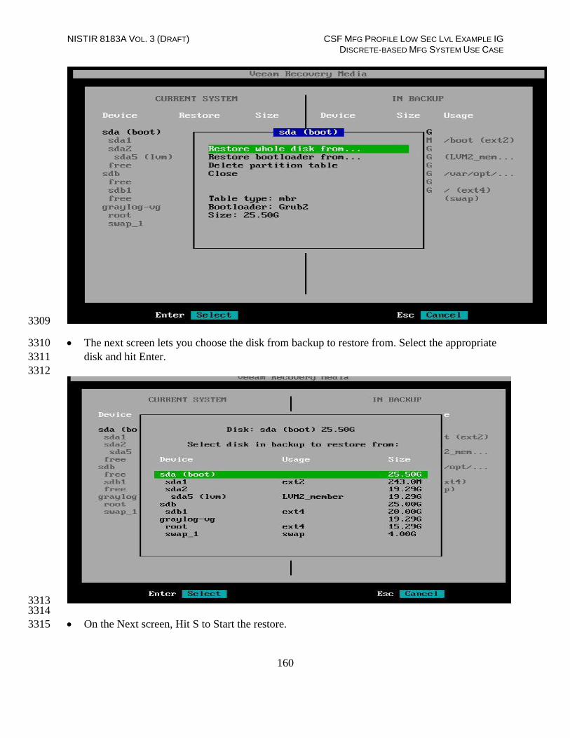
NISTIR 8183A VOL. 3 (DRAFT) CSF MFG PROFILE LOW SEC LVL EXAMPLE IG DISCRETE-BASED MFG SYSTEM USE CASE
160
3309
The next screen lets you choose the disk from backup to restore from. Select the appropriate 3310
disk and hit Enter. 3311
3312
3313 3314
On the Next screen, Hit S to Start the restore. 3315

NISTIR 8183A VOL. 3 (DRAFT) CSF MFG PROFILE LOW SEC LVL EXAMPLE IG DISCRETE-BASED MFG SYSTEM USE CASE
161
3316
3317
Next the Recovery Summary screen will confirm the filesystem changes. Hit Enter to start 3318
the Recovery 3319
The restore process will now run and show a success message once complete. Eject the 3320
Veeam Recovery Media once restore completes and Reboot the server. 3321
3322
3323

NISTIR 8183A VOL. 3 (DRAFT) CSF MFG PROFILE LOW SEC LVL EXAMPLE IG DISCRETE-BASED MFG SYSTEM USE CASE
162
Changing backup job type: 3324
The free version of Veeam allows for one type of backup job to be scheduled at a time. The 3325
below shown commands can be run to delete an existing backup job and recreate a new one. 3326
3327
3328
3329
Once deleted, run sudo veeam command to launch the Veeam Config Menu as shown 3330
below. Hit C for Configure to create a new job. 3331
3332
References: 3333
[1] Veeam Backup and Replication https://www.veeam.com/vm-backup-recovery-replication-3334
software.html 3335
[2] Veeam agent for Linux Free edition https://www.veeam.com/linux-backup-free.html 3336
Highlighted Performance Impacts 3337
Three performance measurement experiments were performed for the Veeam tool while the 3338
manufacturing system was operational: 3339
1. CL004.1 - Veeam agent is installed and running on predetermined CRS hosts. 3340
2. CL004.2 - A full image backup is performed on CRS hosts. 3341
3. CL004.3 - A directory backup (i.e., incremental backup) is performed on CRS hosts. 3342
sudo veeamconfig job list
sudo veeamconfig job delete - - name <job name>
sudo veeamconfig job delete - - id < id >

NISTIR 8183A VOL. 3 (DRAFT) CSF MFG PROFILE LOW SEC LVL EXAMPLE IG DISCRETE-BASED MFG SYSTEM USE CASE
163
4.6.6.1 Experiment CL004.1 3343
No performance impact to the manufacturing process was measured during the experiment. 3344
3345
Figure 4-10 - Bihistograms showing the part production time (left) and estimated mean production time using 3346 the bootstrap method (right) using the measurements from baseline CL001.1 and experiment CL004.1. 3347
4.6.6.2 Experiment CL004.2 3348
A full image of three CRS hosts was performed during the experiment: 3349
Engineering Workstation (POLARIS, on the CRS Network), 3350
Robot Controller vController1 (on the hypervisor over Management Network), and 3351
Robot Controller vController2 (on the hypervisor over Management Network). 3352
The imaging of POLARIS was performed from 210 sec. to 1023 sec. (experiment time), and all 3353
data was transferred over the CRS network. The vController1 and vController2 imaging was 3354
performed from 1050 sec. to 1710 sec. (experiment time) from the hypervisor, and all data was 3355
transferred over the Management network. The network traffic generated by the imaging of 3356
POLARIS is shown in Figure 4-11. 3357

NISTIR 8183A VOL. 3 (DRAFT) CSF MFG PROFILE LOW SEC LVL EXAMPLE IG DISCRETE-BASED MFG SYSTEM USE CASE
164
3358
Figure 4-11 - Time series plot showing the rate of network traffic (in megabits per second) transmitted and 3359 received by the Veeam tool during the CL004.2 experiment. Network traffic transmitted and received by the 3360 vControllers are not shown in this plot. 3361
Loss-of-view events were observed on the HMI multiple times during the experiment, as evident 3362
by the large inter-packet delay measurements between the HMI and Station 1 shown in Figure 3363
4-12. The longest loss-of-view event occurred over 130 sec. in length. Based on the large inter-3364
packet delay measurements, it is hypothesized that the loss-of-view events can also be classified 3365
as loss-of-control incidents, although this was not tested during the experiment. All the observed 3366
incidents occurred while the Veeam tool was imaging the POLARIS host. 3367
3368
Figure 4-12 - Stem plot displaying the inter-packet delays (greater than or equal to 1.10 seconds) of Modbus 3369 TCP traffic between the HMI and Station 1, as measured during the baseline CL001.2 and experiment 3370 CL004.2. Note the large inter-packet delays measured between experiment time 400 to 1000 sec., resulting in 3371 multiple HMI loss-of-view events of over 15 seconds, and the largest event over 130 seconds in length. 3372

NISTIR 8183A VOL. 3 (DRAFT) CSF MFG PROFILE LOW SEC LVL EXAMPLE IG DISCRETE-BASED MFG SYSTEM USE CASE
165
The loss-of-view events were likely caused by the large round-trip (RTT) times (shown in Figure 3373
4-13) observed between the HMI and Station 1 while the Veeam tool was imaging the POLARIS 3374
host, which were larger than the configured connection timeout value on the HMI (100 msec.). 3375
Measurements of the packet path delay (shown in Figure 4-14) show a similar increase, 3376
suggesting that one or more of the CRS network devices may have been overloaded while 3377
Veeam was active. 3378
3379
Figure 4-13 - Time-series plot showing the measured round-trip time of SYN and SYN-ACK packets sent 3380 between the HMI and Station 1 during the experiment. Large round-trip times (>350 msec.) occurred regularly 3381 from 400 seconds to 1000 seconds (experiment time). 3382
3383
Figure 4-14 - Time-series plots showing the measured packet path delay Modbus TCP packets sent from the 3384 HMI to Station 1 (left) and sent from Station 1 to the HMI (right) during the experiment. 3385

NISTIR 8183A VOL. 3 (DRAFT) CSF MFG PROFILE LOW SEC LVL EXAMPLE IG DISCRETE-BASED MFG SYSTEM USE CASE
166
An increase in the robot job actuation time was observed on Robot 1 for Job 102 (see Figure 3386
4-15). No other increases were observed for any of the other jobs. The two increases were 3387
measured while the Veeam tool was imaging the two vControllers. 3388
3389
Figure 4-15 - Time-series (left) and boxplot (right) showing the job actuation times for each job during the 3390 CL004.2 experiment. Note the two increased actuation times for job 102, which occurred while the Veeam 3391 tool was imaging the vControllers. 3392
A slight increase of the part production time variance was observed during this experiment, but it 3393
is not statistically significant. 3394
3395
Figure 4-16 - Bihistograms showing the part production time (left) and estimated mean production time using 3396 the bootstrap method (right) using the measurements from baseline CL001.1 and experiment CL004.2. 3397
4.6.6.3 Experiment CL004.3 3398
A directory backup of the /opt/ directory on the Engineering Workstation (POLARIS) host was 3399
performed for this experiment. The backup was performed from 347 sec. to 1052 sec. 3400
(experiment time), and all data was transferred over the CRS network. The network traffic 3401
generated by the backup is shown in Figure 4-17. 3402

NISTIR 8183A VOL. 3 (DRAFT) CSF MFG PROFILE LOW SEC LVL EXAMPLE IG DISCRETE-BASED MFG SYSTEM USE CASE
167
3403
Figure 4-17 - Time series plot showing the rate of network traffic (in megabits per second) transmitted and 3404 received by the Veeam tool during the CL004.3 experiment. 3405
Loss-of-view events with Station 3 and Station 4 were observed on the HMI multiple times 3406
during the experiment. Large inter-packet delay measurements between the HMI and Station 1 3407
are shown in Figure 4-18. The longest loss-of-view event occurred over 9 sec. in length. Based 3408
on the large inter-packet delay measurements, it is hypothesized that the loss-of-view events can 3409
also be classified as loss-of-control incidents, although this was not tested during the experiment. 3410
All the observed incidents occurred while the Veeam tool was actively backing up POLARIS. 3411
3412
Figure 4-18 - Stem plot showing the inter-packet delays (greater than or equal to 1.10 seconds) of Modbus 3413 TCP traffic between the HMI and Station 1, as measured during the baseline CL001.2 and experiment 3414 CL004.3. Note the large inter-packet delays measured between experiment time 370 to 700 sec., resulting in 3415 multiple HMI loss-of-view events of over 2 seconds, and the largest event over 9 seconds in length. 3416

NISTIR 8183A VOL. 3 (DRAFT) CSF MFG PROFILE LOW SEC LVL EXAMPLE IG DISCRETE-BASED MFG SYSTEM USE CASE
168
The loss-of-view events were likely caused by the large round-trip (RTT) times (shown in Figure 3417
4-19) observed between the HMI and Station 1 while the Veeam tool was active, which were 3418
larger than the configured connection timeout value on the HMI (100 msec.). Measurements of 3419
the packet path delay (shown in Figure 4-20) show a similar increase, suggesting that one or 3420
more of the CRS network devices may have been overloaded while Veeam was active. 3421
3422
Figure 4-19 - Time-series plot showing the measured round-trip time of SYN and SYN-ACK packets sent 3423 between the HMI and Station 1 during the experiment. 3424
3425
Figure 4-20 - Time-series plots showing the measured packet path delay Modbus TCP packets sent from the 3426 HMI to Station 1 (left) and sent from Station 1 to the HMI (right) during the experiment. Note the large path 3427 delay of over 600 msec. around 350 sec., followed by consistent delays of around 20 msec. until around 700 3428 sec. 3429
A slight increase of the part production time mean was observed during this experiment but it is 3430
not statistically significant. 3431

NISTIR 8183A VOL. 3 (DRAFT) CSF MFG PROFILE LOW SEC LVL EXAMPLE IG DISCRETE-BASED MFG SYSTEM USE CASE
169
3432
Figure 4-21 - Bihistograms showing the part production time (left) and estimated mean production time using 3433 the bootstrap method (right) using the measurements from baseline CL001.1 and experiment CL004.3. 3434
Link to Entire Performance Measurement Data Set 3435
CL004.1-HostBackups.zip 3436
CL004.2-FullImageBackup.zip 3437
CL004.3-DirectoryBackup.zip 3438

NISTIR 8183A VOL. 3 (DRAFT) CSF MFG PROFILE LOW SEC LVL EXAMPLE IG DISCRETE-BASED MFG SYSTEM USE CASE
170
TeamViewer 3439
Technical Solution Overview 3440
TeamViewer is a Remote Desktop sharing tool. TeamViewer provides Secure Remote Access 3441
and Support Solutions for Entrepreneurs, Small Businesses, and Large Enterprises. Some of its 3442
features include Cross Platform Support Access such as PC-PC, PC-Mobile, Mobile-Mobile, etc. 3443
Multi User Support Sessions and Remote Device Control [1] 3444
Technical Capabilities Provided by Solution 3445
TeamViewer provides components of the following Technical Capabilities described in Section 3446
6 of Volume 1: 3447
Secure Remote Access 3448
Secure Remote Access 3449
Subcategories Addressed by Implementing Solution 3450
PR.MA-2, PR.AC-5 3451

NISTIR 8183A VOL. 3 (DRAFT) CSF MFG PROFILE LOW SEC LVL EXAMPLE IG DISCRETE-BASED MFG SYSTEM USE CASE
171
Architecture Map of Where Solution was Implemented 3452
3453

NISTIR 8183A VOL. 3 (DRAFT) CSF MFG PROFILE LOW SEC LVL EXAMPLE IG DISCRETE-BASED MFG SYSTEM USE CASE
172
Installation Instructions and Configurations 3454
Setup for Robotics System: 3455
Secure Remote Access was setup for the CRS system using TeamViewer. The Cybersecurity 3456
scanning laptop was used a jump box for installing TeamViewer and connecting remotely to 3457
the Work Cell network within. 3458
3459
Configuration: 3460
3461
TeamViewer v14 was downloaded and installed on the Cybersecurity scanning laptop. The 3462
person connecting remotely needs to have Team viewer installed on their system too. 3463
3464
The scanning laptop had internet access via wireless and at the same time access to the Work 3465
cell network by connecting a physical Ethernet connection coming from the core switch. A 3466
Static IP was assigned to the system on the Ethernet interface. 3467
3468
The person connecting remotely needs to know your ID and password to punch in. Both of 3469
these are displayed on the TeamViewer panel itself. 3470
3471
3472 3473
3474
The remote person needs to enter your ID in the Partner ID box, select Remote Control and 3475
hit Connect button to initiate a session. Next, Enter the password as prompted. 3476

NISTIR 8183A VOL. 3 (DRAFT) CSF MFG PROFILE LOW SEC LVL EXAMPLE IG DISCRETE-BASED MFG SYSTEM USE CASE
173
Once the connection was established, the HMI Panel was accessed off a browser on the 3477
Cybersecurity Scanning laptop to perform maintenance on the HMI. 3478
3479
3480
3481
3482
Two factor authentication was configured by using the procedure mentioned here: 3483
https://community.teamviewer.com/t5/Knowledge-Base/Two-factor-authentication-3484
Activation-and-Deactivation/ta-p/66 3485
3486
References: 3487
3488
[1] Team Viewer: https://www.teamviewer.com 3489
3490
Highlighted Performance Impacts 3491
No performance measurement experiments were performed for the use of Team Viewer due to 3492
its intended usage (i.e., Team Viewer was installed on a laptop that is attached to the network 3493
only during maintenance and engineering activities). 3494
Link to Entire Performance Measurement Data Set 3495
N/A 3496

NISTIR 8183A VOL. 3 (DRAFT) CSF MFG PROFILE LOW SEC LVL EXAMPLE IG DISCRETE-BASED MFG SYSTEM USE CASE
174
Microsoft Active Directory 3497
Technical Solution Overview 3498
Active Directory (AD) is a directory service developed by Microsoft for Windows 3499
domain networks. A directory is a hierarchical structure that stores information about objects on 3500
the network. A directory service, such as Active Directory Domain Services (AD DS), provides 3501
the methods for storing directory data and making this data available to network users and 3502
administrators. For example, AD DS stores information about user accounts, such as names, 3503
passwords, phone numbers, and so on, and enables other authorized users on the same network to 3504
access this information. A server running Active Directory Domain Services (AD DS) is called 3505
a domain controller [1]. It authenticates and authorizes all users and computers in a Windows 3506
domain type network—assigning and enforcing security policies for all computers and installing 3507
or updating software. Active Directory uses Lightweight Directory Access Protocol (LDAP) 3508
versions 2 and 3, Microsoft's version of Kerberos and DNS.13 3509
Points to consider 3510
Cost of infrastructure can get high. 3511
Requires expertise to setup and maintain. Setup involves detailed planning. 3512
It is prone to being hacked. 3513
Technical Capabilities Provided by Solution 3514
Microsoft Active Directory provides components of the following Technical Capabilities 3515
described in Section 6 of Volume 1: 3516
Credential Management 3517
Authentication and Authorization 3518
Subcategories Addressed by Implementing Solution 3519
PR.AC-1, PR.MA-1, PR.MA-2, PR-PT-3, PR.PT-4, DE.CM-3 3520
3521
13 https://docs.microsoft.com/en-us/windows-server/identity/ad-ds/get-started/virtual-dc/active-directory-domain-services-
overview

NISTIR 8183A VOL. 3 (DRAFT) CSF MFG PROFILE LOW SEC LVL EXAMPLE IG DISCRETE-BASED MFG SYSTEM USE CASE
175
Architecture Map of Where Solution was Implemented 3522
3523

NISTIR 8183A VOL. 3 (DRAFT) CSF MFG PROFILE LOW SEC LVL EXAMPLE IG DISCRETE-BASED MFG SYSTEM USE CASE
176
Installation Instructions and Configurations 3524
Setup: 3525
The setup consists of two virtual machines running Active Directory services in the 3526
Cybersecurity LAN. The server “LAN-AD” is the Primary DC and DNS server while “LAN-3527
AD-02” one is the backup DC and DNS server. 3528
Details of the AD-servers 3529
Hostname IP address Roles Domain Name
LAN-AD 10.100.0.17 Active Directory, DNS, Network
Policy Server (Radius)
LAN.lab
LAN-
AD02
10.100.0.13 Active Directory, DNS, Network
Policy Server (Radius)
LAN.lab
3530
Installation: 3531
Below are high level instructions for installing Active Directory services (ADDS) on a 3532
Windows 2012 R2 server. 3533
It is recommended to have 2 servers running AD for redundancy. Ensure the servers are up to 3534
date with patches and have meaningful hostnames as per their role. Begin by configuring a 3535
static IP address on the network interface of your server. Since the server will also act as 3536
DNS server, for DNS server field you can use local host address 127.0.0.1 3537

NISTIR 8183A VOL. 3 (DRAFT) CSF MFG PROFILE LOW SEC LVL EXAMPLE IG DISCRETE-BASED MFG SYSTEM USE CASE
177
3538
Launch “Server Manager” and click on “Add Roles and Features” 3539
3540
3541 3542
Click “Next” at the first page 3543
3544
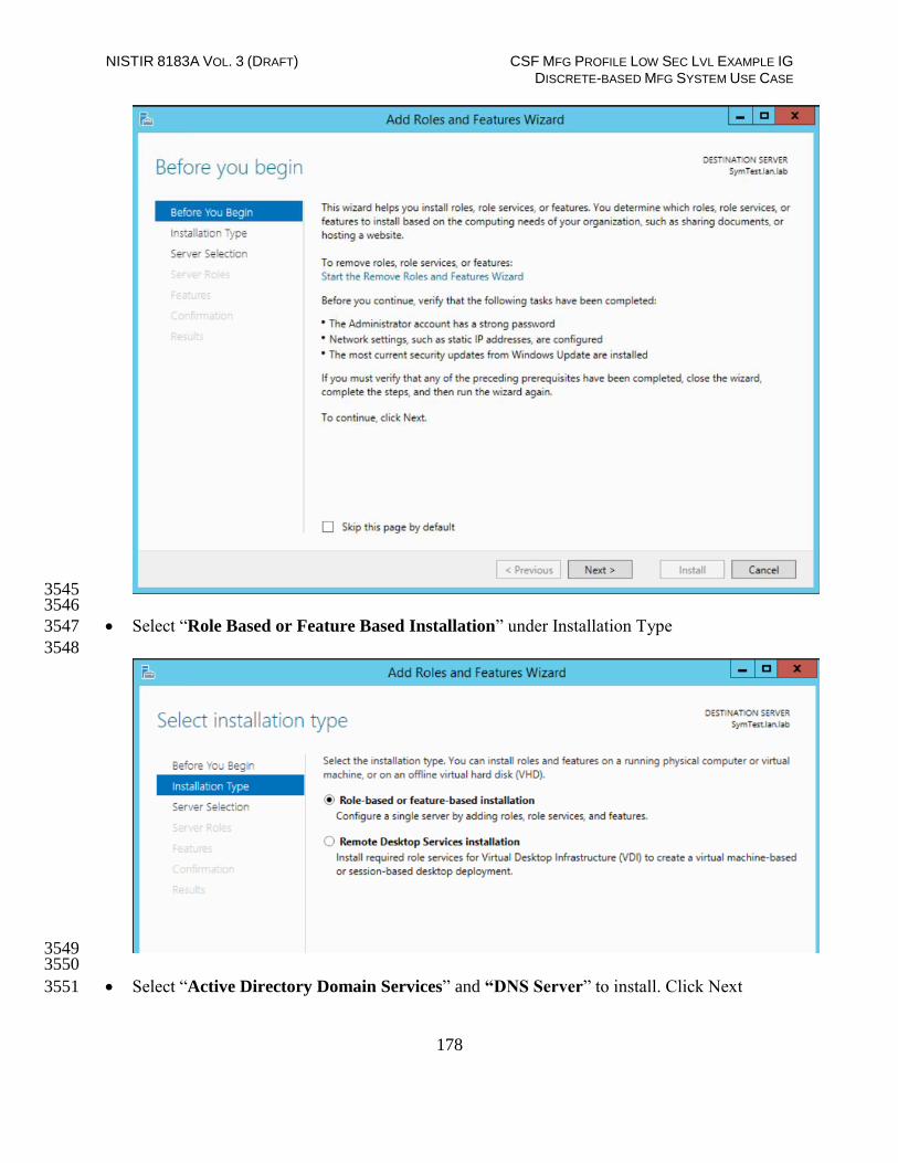
NISTIR 8183A VOL. 3 (DRAFT) CSF MFG PROFILE LOW SEC LVL EXAMPLE IG DISCRETE-BASED MFG SYSTEM USE CASE
178
3545 3546
Select “Role Based or Feature Based Installation” under Installation Type 3547
3548
3549 3550
Select “Active Directory Domain Services” and “DNS Server” to install. Click Next 3551
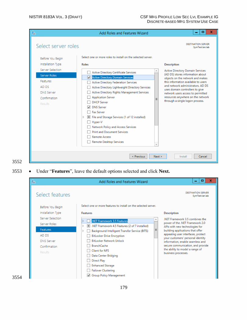
NISTIR 8183A VOL. 3 (DRAFT) CSF MFG PROFILE LOW SEC LVL EXAMPLE IG DISCRETE-BASED MFG SYSTEM USE CASE
179
3552
Under “Features”, leave the default options selected and click Next. 3553
3554

NISTIR 8183A VOL. 3 (DRAFT) CSF MFG PROFILE LOW SEC LVL EXAMPLE IG DISCRETE-BASED MFG SYSTEM USE CASE
180
On the “AD DS” page, click Next. Likewise, on the “DNS Server” page click Next as well. 3555
3556
Verify your settings on the “Confirmation” page. Click Install to proceed. 3557
3558

NISTIR 8183A VOL. 3 (DRAFT) CSF MFG PROFILE LOW SEC LVL EXAMPLE IG DISCRETE-BASED MFG SYSTEM USE CASE
181
The installation process will run and will show an “Installation succeeded” message upon 3559
completion. Hit Close button. 3560
3561
Launch “Server Manager” again and click on “Promote this server to a domain 3562
controller” 3563
3564
On the “Deployment Configuration” step, select “Add a new forest” as this would be a new 3565
domain controller in a new forest. Mention a Root Domain name as applicable to your 3566
environment. 3567

NISTIR 8183A VOL. 3 (DRAFT) CSF MFG PROFILE LOW SEC LVL EXAMPLE IG DISCRETE-BASED MFG SYSTEM USE CASE
182
3568
Set a Directory Services Restore Mode password in the next step. Click Next 3569
3570
Under “DNS Options” leave the default options selected. Click Next 3571

NISTIR 8183A VOL. 3 (DRAFT) CSF MFG PROFILE LOW SEC LVL EXAMPLE IG DISCRETE-BASED MFG SYSTEM USE CASE
183
3572
Under “Additional Options”, confirm the NETBIOS domain name. Click Next. 3573
3574
Under “Paths”, leave the default folder paths as it is. Click Next 3575
3576

NISTIR 8183A VOL. 3 (DRAFT) CSF MFG PROFILE LOW SEC LVL EXAMPLE IG DISCRETE-BASED MFG SYSTEM USE CASE
184
On the “Review Options” page, confirm all the settings and click Next. 3577
3578
On the “Prerequisites Check”, click Install to launch the installation process. 3579

NISTIR 8183A VOL. 3 (DRAFT) CSF MFG PROFILE LOW SEC LVL EXAMPLE IG DISCRETE-BASED MFG SYSTEM USE CASE
185
3580
The installation process will now run displaying the Progress bar. Upon completion, the 3581
server should auto reboot. 3582
3583
Upon reboot, login with domain administrator credentials. Open “Server Manager” and click 3584
on “Active Directory Users and Computers” under Tools to manage your AD. 3585

NISTIR 8183A VOL. 3 (DRAFT) CSF MFG PROFILE LOW SEC LVL EXAMPLE IG DISCRETE-BASED MFG SYSTEM USE CASE
186
3586
Configuration: 3587
All of the Linux systems from the Robotics System were joined to the AD domain lan.lab 3588
using Centrify Express [2]. The initial domain join process is a onetime task and involves a 3589
system restart. 3590
3591
The procedure to join Ubuntu Linux Systems to Active Directory domain using Centrify can 3592
be found in the section below “CentrifyDC Installation” 3593
3594
In addition, DNS records for each Linux host were manually created on the Active Directory 3595
server. 3596
3597
CentrifyDC Express Installation 3598
Pre-requisites: Connectivity between your Linux server and AD server. 3599
Ensure you can ping the AD Domain Controller from your Linux host. Configure the DNS 3600
settings on its network interface to point to the IP address of the AD server and set the search 3601
domain to whatever domain name you have created in your AD. Once done, you can verify the 3602
DNS-settings by checking the /etc/resolv.conf file of your Linux server. 3603
3604
The free Centrify Express (Centrifydc) package can be downloaded either from 3605
https://launchpad.net or https://www.centrify.com/express/linux/download/ . Ensure to select 3606
the correct OS version and CPU architecture that matches your Linux host. 3607
Upload the downloaded file to any Ubuntu Linux server which you want to join to AD. 3608
Run the command “dpkg -i <package_name> “to install it. It may prompt you to install 3609
some dependencies. Ensure the dependencies have been installed prior. 3610
3611

NISTIR 8183A VOL. 3 (DRAFT) CSF MFG PROFILE LOW SEC LVL EXAMPLE IG DISCRETE-BASED MFG SYSTEM USE CASE
187
3612 3613
Run the command “adlicense --express” to activate the free express mode. 3614
3615
3616 3617
Next run the “adjoin –workstation domain-name” command. This will prompt you to enter 3618
the Domain Administrator password. 3619
3620
3621 If the above step completes successfully, run “adinfo” command to verify the domain join 3622
status as follows 3623
3624
3625 3626
You can now login to your Linux host using your AD credentials. 3627

NISTIR 8183A VOL. 3 (DRAFT) CSF MFG PROFILE LOW SEC LVL EXAMPLE IG DISCRETE-BASED MFG SYSTEM USE CASE
188
o For example: ssh [email protected] 3628
o OR directly via Desktop as shown below: Domain-Name\Username 3629
3630
Enabling sudo for administrators 3631
To make an AD Domain Group a sudoer; edit the file /etc/sudoers file (using the 3632
command visudo) and add the following line: 3633
3634
%adgroup ALL=(ALL) ALL 3635
3636
Where, adgroup, is a group from your active directory. The group names from active 3637
directory are transformed into all lower case letters with underscores replacing spaces, so you 3638
can use %domain_admins for the Domain Admins group. 3639
3640
Highlighted Performance Impacts 3641
One performance measurement experiment was performed for the Active Directory service while 3642
the manufacturing system was operational: 3643
1. CL002.1 - The Active Directory service is installed and running on CRS hosts. 3644
4.8.6.1 Experiment CL002.1 3645
No performance impact to the manufacturing process was measured during the experiment. 3646

NISTIR 8183A VOL. 3 (DRAFT) CSF MFG PROFILE LOW SEC LVL EXAMPLE IG DISCRETE-BASED MFG SYSTEM USE CASE
189
3647
Figure 4-22 - Bihistograms showing the part production time (left) and estimated mean production time using 3648 the bootstrap method (right) using the measurements from baseline CL001.1 and experiment CL002.1. 3649
Link to Entire Performance Measurement Data Set 3650
CL002.1-ActiveDir.zip 3651

NISTIR 8183A VOL. 3 (DRAFT) CSF MFG PROFILE LOW SEC LVL EXAMPLE IG DISCRETE-BASED MFG SYSTEM USE CASE
190
Symantec Endpoint Protection 3652
Technical Solution Overview 3653
Symantec Endpoint Protection: 3654
Symantec Endpoint Protection (SEP) is a complete endpoint protection solution from Symantec. 3655
It delivers superior, multilayer protection to stop threats regardless of how they attack your 3656
endpoints. SEP integrates with existing security infrastructure to provide orchestrated responses 3657
to address threats quickly. Its lightweight SEP agent offers high performance without 3658
compromising end-user productivity. SEP also defends against ransomware and other emerging 3659
threats with multilayered protection that fuses signatureless technologies like advanced machine 3660
learning, behavior analysis and exploit prevention with proven protection capabilities like 3661
intrusion prevention, reputation analysis and more.14 3662
Points to Consider: 3663
Next Generation Antivirus / Endpoint protection solution to prevent against virus attacks and 3664
emerging cyber threats such as zero-day attacks, ransomware etc. 3665
OS Platform independent: The endpoint agents are supported on Windows and Linux. 3666
Comes with a lightweight agent and virus definition sets that require minimal network 3667
bandwidth. 3668
Diverse Feature set: Core capabilities include Antivirus, Host Firewall, Intrusion Prevention, 3669
Host Integrity, System lockdown, Application White listing and USB Device Control. 3670
Centralized Management: All endpoints, rule sets, policies can be centrally managed from 3671
the Symantec Endpoint Manager console. 3672
The Symantec Manager component is supported only on Windows OS. 3673
The Linux agent requires the OS kernel on Linux systems to be at a certain level for 3674
installation. In addition, the Linux agent is a 32-bit installer. If installing on a 64-bit Linux 3675
system, it requires certain 32-bit packages/libraries to be installed as a pre-requisite. This 3676
may conflict with some of the existing packages on the system. 3677
The endpoint agent on each system by default needs to communicate outbound with a range 3678
of public IP addresses for its Reputation analysis and Global Threat intelligence feature. It is 3679
recommended to allow this traffic from your firewall to leverage the advanced features of the 3680
product. 3681
Important: System reboot is required to complete the installation process on 3682
clients/endpoints. Plan ahead of time. 3683
14 Symantec Endpoint Protection: https://www.symantec.com/content/dam/symantec/docs/data-sheets/endpoint-protection-14-
en.pdf

NISTIR 8183A VOL. 3 (DRAFT) CSF MFG PROFILE LOW SEC LVL EXAMPLE IG DISCRETE-BASED MFG SYSTEM USE CASE
191
Technical Capabilities Provided by Solution 3684
Symantec Endpoint Protection provides components of the following Technical Capabilities 3685
described in Section 6 of Volume 1: 3686
Anti-virus/malware 3687
Subcategories Addressed by Implementing Solution 3688
PR.AC-1, DE.CM-3, DE.CM-4 3689

NISTIR 8183A VOL. 3 (DRAFT) CSF MFG PROFILE LOW SEC LVL EXAMPLE IG DISCRETE-BASED MFG SYSTEM USE CASE
192
Architecture Map of Where Solution was Implemented 3690
3691
Installation Instructions and Configurations 3692
Setup Overview: 3693

NISTIR 8183A VOL. 3 (DRAFT) CSF MFG PROFILE LOW SEC LVL EXAMPLE IG DISCRETE-BASED MFG SYSTEM USE CASE
193
Setup consists of a single Symantec Endpoint Protection Manager (SEPM) instance in the 3694
Cybersecurity LAN network. This central instance communicates with all the endpoint agents 3695
deployed on to the Process Control systems. Likewise, all endpoints report their status to the 3696
Manager server. The communication ports required to be opened are different for Windows 3697
clients as compared to Mac/Linux clients. Detailed list of firewall ports can be obtained from 3698
Symantec website. The SEP Manager server downloads its daily signature updates from the 3699
Symantec cloud servers, so this necessary traffic was allowed to pass thru the Manufacturing 3700
System Firewall. 3701
Details of the software used 3702
Product Name Version
Symantec Endpoint Protection Manager (SEPM) 14.2 Build 758
Symantec Endpoint agent for Linux (Client) 14.2.758.0000
3703
Installation of SEP Manager: 3704
SEPM is supported only on Windows server platforms. A Windows Server 2012 R2 virtual 3705
machine was setup in the Cybersecurity LAN to install the SEPM component. 3706
Upon purchase, there will be a license file emailed to you along with the link to download 3707
the install binaries. Download the zip bundle from the Symantec website. Extract the zip 3708
file which will be like the one below depending on whatever is the latest version available. 3709
o 3710 3711
Open the extracted folder and run the Setup.exe file. Mid-way during the setup, the install 3712
wizard will prompt to select a password for the admin user. Enter a strong password and hit 3713
Next. 3714
On the Backed Database selection page, there are two options - “Embedded” and “MS 3715
SQL Server”. Choose the Embedded database if you do not have a MS SQL Server. 3716
Follow the on-screen instructions and complete the installation wizard. Reboot the server 3717
once done. 3718
Launch the SEP Manager console and login with the admin user created earlier. 3719
3720

NISTIR 8183A VOL. 3 (DRAFT) CSF MFG PROFILE LOW SEC LVL EXAMPLE IG DISCRETE-BASED MFG SYSTEM USE CASE
194
3721 3722
Upon completing the installation of Symantec Endpoint Manager, the next steps are to 3723
activate the license, configuring client groups to group devices and installing the antivirus 3724
agent on each endpoint/client system. 3725
Link to Official Symantec Endpoint Protection v14 installation guides - 3726
https://support.symantec.com/en_US/article.DOC9449.html 3727
Ensure to open the necessary ports on the firewall for communication between the SEPM 3728
server and endpoints. A complete list of ports is available at 3729
https://support.symantec.com/en_US/article.HOWTO81103.html 3730
Custom Configuration of SEPM server 3731
3732
The following client groups were created to group devices from each of the systems. 3733
Upon installing the AV agent on the endpoints, the devices were moved to their 3734
respective groups. 3735
3736

NISTIR 8183A VOL. 3 (DRAFT) CSF MFG PROFILE LOW SEC LVL EXAMPLE IG DISCRETE-BASED MFG SYSTEM USE CASE
195
3737 3738
For integrating SEP Manager with AD/LDAP server, click on ADMIN >> Servers >> 3739
Local Site >> <Server Name> >> Edit Server Properties >> Directory servers. Click 3740
further on “ADD” button as shown below to configure domain details. Once done, logout 3741
and try logging in back with your AD credentials. 3742
3743

NISTIR 8183A VOL. 3 (DRAFT) CSF MFG PROFILE LOW SEC LVL EXAMPLE IG DISCRETE-BASED MFG SYSTEM USE CASE
196
3744 Similarly, Email server can be configured by clicking on the “Email Server” tab. 3745
Getting started with Endpoint installs 3746
High level steps: 3747
Create a deployment package specific for a client group 3748
Deploy the package from the SEPM server to the endpoint using Network Deployment 3749
options or manually copy over the package to the endpoint for installation. 3750
Restart the endpoint. Verify the device shows up in the SEPM console. 3751
Creating a deployment package: 3752
Login to the Symantec Manager console, click on CLIENTS >> <Group Name> where 3753
the device needs to be in >> Click on Install client under TASKS. For instance, to 3754
create a deployment package for the group “Process Control”, click on that group name 3755
followed by Install Client option. 3756
Select “New Package Deployment” if this is your first agent installation of that group. 3757
If you have already deployed the agent on other systems of this group, you can re-use the 3758
same package and skip this wizard completely. 3759

NISTIR 8183A VOL. 3 (DRAFT) CSF MFG PROFILE LOW SEC LVL EXAMPLE IG DISCRETE-BASED MFG SYSTEM USE CASE
197
3760 3761
3762
Click “Next” >> Choose the appropriate OS Platform as per the endpoint OS, from the 3763
dropdown list of Install Packages. You will notice the Group Name is already pre-3764
populated. This ensure the client will be placed directly in that group upon install. Under 3765
Content Options; Select “Include virus definitions in the client installation package” 3766
[optional]. Click Next. 3767

NISTIR 8183A VOL. 3 (DRAFT) CSF MFG PROFILE LOW SEC LVL EXAMPLE IG DISCRETE-BASED MFG SYSTEM USE CASE
198
3768
3769
On the next page, choosing the “Save Package” will create a local installer which needs to 3770
be copied over the target machine manually and the “Remote Push” will make the SEPM 3771
server perform a network deployment to the target machine(s). Choose your preferred option 3772
and hit Next. 3773

NISTIR 8183A VOL. 3 (DRAFT) CSF MFG PROFILE LOW SEC LVL EXAMPLE IG DISCRETE-BASED MFG SYSTEM USE CASE
199
3774
Installing the AV on Robotics Systems 3775
A new deployment package was created for the “Robotics” group with OS as Linux. This 3776
will create a .rpm package for Red Hat systems and .deb package for Debian based 3777
systems. The package with (.deb) extension was copied over manually to each Ubuntu 3778
Linux server in the Robotics system. 3779
3780 3781
3782

NISTIR 8183A VOL. 3 (DRAFT) CSF MFG PROFILE LOW SEC LVL EXAMPLE IG DISCRETE-BASED MFG SYSTEM USE CASE
200
Symantec AV on Linux requires the below 32-bit packages to be installed as a pre-3783
requisite15. A Full backup of all Linux systems in Robotics was taken prior to installing 3784
these. 3785
o libc6:i386 3786
o libx11-6:i386 3787
o libncurses5:i386 3788
o libstdc++6:i386 3789
3790
If installing it on a 64-bit server, ensure to enable/check if multi-architecture mode is 3791
enabled as follows, prior to installing those 32-bit libraries. For instance, on a Debian 3792
/Ubuntu system; run the following commands. 3793
- Verify if the system has 64-bit architecture by running 3794
3795
- If the output is something like the one shown below, it means you are okay 3796
3797
- Verify that you have multi-arch mode enabled by running the following command. 3798
Multi-architecture mode lets us install 32-bit packages on a 64-bit system. 3799
3800
- Run this command to enable multi-arch support: 3801
3802
This will allow us to install those 32-bit packages. 3803
15 https://support.symantec.com/en_US/article.TECH228118.html

NISTIR 8183A VOL. 3 (DRAFT) CSF MFG PROFILE LOW SEC LVL EXAMPLE IG DISCRETE-BASED MFG SYSTEM USE CASE
201
sudo apt-get install libc6:i386 libx11-6:i386 libncurses5:i386 libstdc++6:i386 3804
The zip file containing the .deb package was extracted on the Linux client. The following 3805
command was run to grant execute permissions to the “install.sh” file found in the 3806
extracted folder. 3807
3808
chmod u+x install.sh 3809
Next, the install.sh script was run as 3810
3811
sudo ./install.sh -i 3812
3813
Upon successful install, it showed an output like the one below 3814
3815
- 3816 3817
The client was rebooted, and its status was verified to be green ONLINE in the SEPM 3818
console. The process was repeated for all other Linux machines. 3819
Additional Configuration 3820
An “Exceptions” policy was created for excluding the /sys and /proc directories from 3821
scanning. Click on Policies >> Exceptions >> Default policy or create your own >> 3822
Exceptions >> Click Add to add folders to exclude from scanning. 3823
3824

NISTIR 8183A VOL. 3 (DRAFT) CSF MFG PROFILE LOW SEC LVL EXAMPLE IG DISCRETE-BASED MFG SYSTEM USE CASE
202
3825 3826
Symantec AV on each system by default blocks any port scan related traffic. If you have a 3827
vulnerability scanner or security tools in your environment, ensure those IP addresses are 3828
whitelisted in the SEPM console. The recommended way to do this is by creating a policy 3829
under Policies >> Intrusion Prevention >> Excluded Hosts and linking it to the appropriate 3830
client group. The image below shows our Nessus server and Open-AudIT servers were 3831
excluded to permit these hosts perform their respective scans. 3832
3833

NISTIR 8183A VOL. 3 (DRAFT) CSF MFG PROFILE LOW SEC LVL EXAMPLE IG DISCRETE-BASED MFG SYSTEM USE CASE
203
3834
3835
Lesson learned 3836
Installation on Linux systems: Have a proper backup of the Linux machine prior to installing 3837
the endpoint agent. The Linux agent being a 32bit binary requires some 32-bit packages to be 3838
installed as a pre-requisite.16 On 64bit Linux systems, this will install 32bit packages 3839
alongside their 64bit counterparts. This can cause issues/conflicts with some of existing 3840
packages such as python libraries especially if you are on older versions of Linux such as 3841
Ubuntu 12.04. 3842
On newer versions of Linux, ensure “Multiarch” mode is enabled to allow 32bit apps to 3843
install on 64bit systems.17 On our Ubuntu 12.04 servers, wherein we couldn’t get the agent to 3844
install due to these package conflicts, we ended up applying other compensating controls. 3845
3846
3847
16 https://support.symantec.com/en_US/article.TECH228118.html
17 https://wiki.debian.org/Multiarch/HOWTO

NISTIR 8183A VOL. 3 (DRAFT) CSF MFG PROFILE LOW SEC LVL EXAMPLE IG DISCRETE-BASED MFG SYSTEM USE CASE
204
Highlighted Performance Impacts 3848
Two performance measurement experiments were performed for the Symantec tool while the 3849
manufacturing system was operational: 3850
1. CL005.1 - Symantec agent is installed, and real-time scanning is enabled on CRS hosts. 3851
2. CL005.2 - A full system scan is performed on predetermined CRS hosts. 3852
4.9.6.1 Experiment CL005.1 3853
The Symantec agent was installed and real-time scanning enabled on following CRS hosts: the 3854
robot driver (MINTAKA), robot controller vController1, and robot controller vController2. 3855
CPU utilization increased from around 2% to 7% on vController1 during the experiment (see 3856
Figure 4-23). However, this CPU increase was not observed on vController2 (see Figure 4-24), 3857
which performs all of the same functions as vController1. At the time of publishing, it is 3858
unknown if this CPU increase on vController1 was caused by the Symantec agent. 3859
3860
Figure 4-23 - Time series plots showing the CPU utilization ratio for vController1 during the CL005.1 3861 experiment and CL001.2 baseline (left), and during the period of measured impact (right). 3862

NISTIR 8183A VOL. 3 (DRAFT) CSF MFG PROFILE LOW SEC LVL EXAMPLE IG DISCRETE-BASED MFG SYSTEM USE CASE
205
3863
Figure 4-24 - Time series plots showing the CPU utilization ratio for vController2 during the CL005.1 3864 experiment and CL001.2 baseline (left). 3865
A slight increase of the part production time mean was observed during this experiment, but is 3866
not statistically significant. 3867
3868
Figure 4-25 - Bihistograms showing the part production time (left) and estimated mean production time using 3869 the bootstrap method (right) using the measurements from baseline CL001.2 and experiment CL005.1. 3870
4.9.6.2 Experiment CL005.2 3871
A full system scan of the robot driver (MINTAKA), robot controller vController1, and robot 3872
controller vController2 were initiated at 106 sec., 140 sec., and 309 sec. experiment time, 3873
respectively. The tool did not report when the scanning ended, so it was not recorded. The host 3874
MINTAKA does not run a performance logger, so data from this host is not available. 3875

NISTIR 8183A VOL. 3 (DRAFT) CSF MFG PROFILE LOW SEC LVL EXAMPLE IG DISCRETE-BASED MFG SYSTEM USE CASE
206
The CPU utilization increased during the scan period on both vController1 and vController2. 3876
CPU utilization on vController1 (see Figure 4-26) increased from 7% to 29% while the scan was 3877
executing (from 140 sec. to 750 sec. experiment time), with a peak of 78%. CPU utilization on 3878
vController2 (see Figure 4-27) increased from 2% to 26% while the scan was executing (from 3879
300 sec. to 920 sec. experiment time), with a peak of 33%. 3880
3881
Figure 4-26 - Time series plots showing the CPU utilization ratio for vController1 during the CL005.2 3882 experiment and the CL001.2 baseline (left), and during the period of measured impact (right). 3883

NISTIR 8183A VOL. 3 (DRAFT) CSF MFG PROFILE LOW SEC LVL EXAMPLE IG DISCRETE-BASED MFG SYSTEM USE CASE
207
3884
Figure 4-27 - Time series plots showing the CPU utilization ratio for vController2 during the CL005.2 3885 experiment and the CL001.2 baseline (left), and during the period of measured impact (right). 3886
Network activity increased for a short time on both vController1 and vController2 while the scan 3887
was active, but the activity occurred at different times. Network activity on vController1 (see 3888
Figure 4-28) increased at the end of the scan (from 720 sec. to 750 sec. experiment time), while 3889
network activity on vController2 (see Figure 4-29) increased towards the beginning of the scan 3890
(from 335 sec. to 365 sec. experiment time). Sustained network bitrates over 2 Mbps for around 3891
30 seconds total were measured on both vControllers. 3892
3893
Figure 4-28 - Time series plots showing the quantity of network traffic received by vController1 during the 3894 experiment (left), and during the period of measured impact (right). The peak in traffic shown between 720 3895 sec. to 750 sec. occurred while the scan was active. 3896

NISTIR 8183A VOL. 3 (DRAFT) CSF MFG PROFILE LOW SEC LVL EXAMPLE IG DISCRETE-BASED MFG SYSTEM USE CASE
208
3897
Figure 4-29 - Time series plots showing the quantity of network traffic received by vController2 during the 3898 experiment (left), and during the period of measured impact (right). The peak in traffic shown between 330 3899 sec. to 365 sec. occurred while the scan was active. 3900
No performance impact to the manufacturing process was measured during the experiment. 3901
3902
Figure 4-30 - Bihistograms showing the part production time (left) and estimated mean production time using 3903 the bootstrap method (right) using the measurements from baseline CL001.2 and experiment CL005.2. 3904
3905
Link to Entire Performance Measurement Data Set 3906
CL005.1-AntivirusRealTimeScan.zip 3907
CL005.2-AntivirusFullScan.zip 3908

NISTIR 8183A VOL. 3 (DRAFT) CSF MFG PROFILE LOW SEC LVL EXAMPLE IG DISCRETE-BASED MFG SYSTEM USE CASE
209
Tenable Nessus 3909
Technical Solution Overview 3910
Nessus Professional is a vulnerability assessment software from Tenable. It features high-speed 3911
asset discovery, configuration auditing, target profiling, malware detection, sensitive data 3912
discovery and more. Nessus supports technologies such as scanning operating systems, network 3913
devices, next generation firewalls, hypervisors, databases, web servers and critical infrastructure 3914
for vulnerabilities, threats and compliance violations.18 It supports both authenticated and 3915
unauthenticated scans. 3916
Points to consider: 3917
Easy to setup, User friendly dashboard, fast scanning and can be configured to work in a 3918
distributed environment. 3919
Support for Industrial Protocols such as MODBUS, DNP3 etc. It has the necessary plugins to 3920
detect vulnerabilities on ICS/SCADA systems making it ideal to use in OT environments. 3921
Comes with a variety of Out-of-box policy and configuration templates. 3922
No limit on number of IPs or number of assessments you can run. 3923
Support for scanning devices behind a firewall. 3924
No integration available with LDAP or AD in the Professional edition. 3925
Multiple user accounts not supported for logging in to the Web UI. 3926
3927
Technical Capabilities Provided by Solution 3928
Tenable Nessus provides components of the following Technical Capabilities described in 3929
Section 6 of Volume 1: 3930
Vulnerability Scanning 3931
Vulnerability Management 3932
Subcategories Addressed by Implementing Solution 3933
ID.AM-3, ID.AM-4, ID.RA-1, DE.CM-4, DE.CM-8 3934
3935
18 Nessus Professional: http://info.tenable.com/rs/934-XQB-568/images/NessusPro__DS__EN_v8.pdf

NISTIR 8183A VOL. 3 (DRAFT) CSF MFG PROFILE LOW SEC LVL EXAMPLE IG DISCRETE-BASED MFG SYSTEM USE CASE
210
Architecture Map of Where Solution was Implemented 3936
3937

NISTIR 8183A VOL. 3 (DRAFT) CSF MFG PROFILE LOW SEC LVL EXAMPLE IG DISCRETE-BASED MFG SYSTEM USE CASE
211
Installation Instructions and Configurations 3938
Details of the solutions implemented: 3939
Name Version
Nessus Professional 7.2.0
3940
Setup Overview: 3941
The Robotics systems being behind a firewall (NAT) cannot be reached directly from the 3942
Cybersecurity LAN network. To work around this, a dedicated laptop was setup to assume 3943
the role of Nessus server and Nessus Professional 7.x was installed on it.19 This laptop would 3944
be used on-demand to perform scans. A temporary network connection from the Supervisory 3945
LAN would be arranged as required and the system was assigned a static IP address. 3946
3947
During the setup, the wizard will prompt for registration. The Registration process and 3948
updates can be configured either in online or offline mode. An online mode is suitable for 3949
environments where Nessus server is connected to the internet while an offline mode is for 3950
air-gapped environments. Detailed instructions for registering Nessus offline can be found in 3951
the product guide. Upon completion, Nessus can be accessed via 3952
https://<IP address of Nessus server>:8834 3953
3954
The Nessus server needs to have network connectivity from whichever networks or subnets 3955
that are intended to be scanned. In addition, if performing authenticated scans then 3956
appropriate firewall rules should be in place to allow SSH, WMI or SNMP traffic depending 3957
on the type of hosts. If performing unauthenticated scan, the firewall should be allowed for 3958
any-any communication between the Nessus server and target network. 3959
3960
Configuration for Robotics System: 3961
Ensure to allow firewall rules for Nessus scanning. Port 22 was allowed on our firewall 3962
between the Nessus system and Supervisory, Control LAN networks. 3963
3964
It is important to not change the IP address on the Nessus server once setup is done, as it 3965
causes errors. This is because Nessus installer records all network settings during the install 3966
process. Any hardware change made post install is not recognized by Nessus. 3967
3968
19Nessus Official Documentation: https://docs.tenable.com/nessus/Content/GettingStarted.htm

NISTIR 8183A VOL. 3 (DRAFT) CSF MFG PROFILE LOW SEC LVL EXAMPLE IG DISCRETE-BASED MFG SYSTEM USE CASE
212
A new policy was created specific to the assets in Robotics and linked to a scan job. The scan 3969
was scheduled to be On-Demand. The figure below shows the Policy configured Robotics 3970
System 3971
3972
3973 3974
The figure below shows the corresponding scan job settings which has the 3975
“Robotics_Enclave_II” policy assigned to it under Policy. 3976
3977
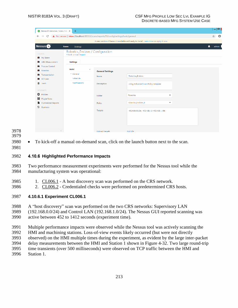
NISTIR 8183A VOL. 3 (DRAFT) CSF MFG PROFILE LOW SEC LVL EXAMPLE IG DISCRETE-BASED MFG SYSTEM USE CASE
213
3978 3979
To kick-off a manual on-demand scan, click on the launch button next to the scan. 3980
3981
Highlighted Performance Impacts 3982
Two performance measurement experiments were performed for the Nessus tool while the 3983
manufacturing system was operational: 3984
1. CL006.1 - A host discovery scan was performed on the CRS network. 3985
2. CL006.2 - Credentialed checks were performed on predetermined CRS hosts. 3986
4.10.6.1 Experiment CL006.1 3987
A “host discovery” scan was performed on the two CRS networks: Supervisory LAN 3988
(192.168.0.0/24) and Control LAN (192.168.1.0/24). The Nessus GUI reported scanning was 3989
active between 452 to 1412 seconds (experiment time). 3990
Multiple performance impacts were observed while the Nessus tool was actively scanning the 3991
HMI and machining stations. Loss-of-view events likely occurred (but were not directly 3992
observed) on the HMI multiple times during the experiment, as evident by the large inter-packet 3993
delay measurements between the HMI and Station 1 shown in Figure 4-32. Two large round-trip 3994
time transients (over 500 milliseconds) were observed on TCP traffic between the HMI and 3995
Station 1. 3996

NISTIR 8183A VOL. 3 (DRAFT) CSF MFG PROFILE LOW SEC LVL EXAMPLE IG DISCRETE-BASED MFG SYSTEM USE CASE
214
3997
Figure 4-31 - Time series plot showing the quantity of network traffic transmitted and received by the Nessus 3998 tool during the experiment time period 400 to 1200 seconds, with the most prominent activity between 700 to 3999 750 seconds and 875 to 1000 seconds. The Nessus GUI reported it was active between 450 to 1400 seconds 4000 experiment time. 4001
4002
4003
Figure 4-32 - Stem plot displaying the inter-packet delays (greater than or equal to 1.10 seconds) of Modbus 4004 TCP traffic between the HMI and Station 1, as measured during the baseline CL001.2 and experiment 4005 CL006.1. Note the large inter-packet delays between experiment time 600 to 800, resulting in HMI loss-of-view 4006 for over 5 seconds. 4007
Performance impacts to the supervisory PLC task execution time were observed while the 4008
Nessus tool was actively scanning. Relatively large fluctuations of the average task execution 4009
time and the maximum task execution time were observed from 800 to 1000 seconds experiment 4010

NISTIR 8183A VOL. 3 (DRAFT) CSF MFG PROFILE LOW SEC LVL EXAMPLE IG DISCRETE-BASED MFG SYSTEM USE CASE
215
time. The largest maximum task execution time was observed at 930 seconds with a value of 4011
2088 microseconds (a threefold increase above the average). Impacts to the measured inter-4012
packet delay between the PLC and Station 2 were also observed during this period. Further 4013
analysis revealed Nessus was actively scanning the machining stations while these PLC impacts 4014
were observed. It is hypothesized that the impacts were caused by interruptions to Modbus TCP 4015
communications between the supervisory PLC and the machining stations, likely due to 4016
increased resource utilization on the machining stations. 4017
4018
4019
Figure 4-33 - Plots showing the maximum PLC task execution time during the experiment (left) and during 4020 the period of measured impact (right). While the Nessus tool was active, the PLC experienced periods of 4021 fluctuating and increased task execution time. 4022
A slight increase of the part production time mean and variance were observed during this 4023
experiment, but they are not statistically significant. 4024
4025
Figure 4-34 - Bihistograms showing the part production time (left) and estimated mean production time using 4026 the bootstrap method (right) using the measurements from baseline CL001.2 and experiment CL006.1. 4027
4028
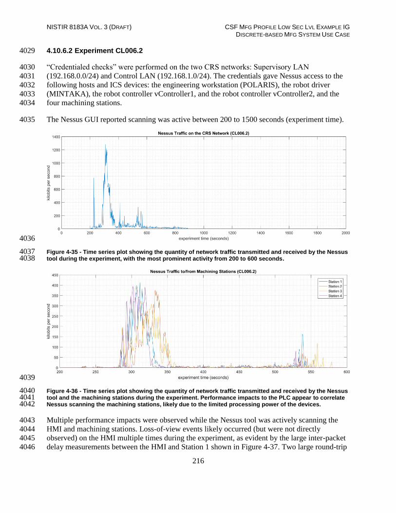
NISTIR 8183A VOL. 3 (DRAFT) CSF MFG PROFILE LOW SEC LVL EXAMPLE IG DISCRETE-BASED MFG SYSTEM USE CASE
216
4.10.6.2 Experiment CL006.2 4029
“Credentialed checks” were performed on the two CRS networks: Supervisory LAN 4030
(192.168.0.0/24) and Control LAN (192.168.1.0/24). The credentials gave Nessus access to the 4031
following hosts and ICS devices: the engineering workstation (POLARIS), the robot driver 4032
(MINTAKA), the robot controller vController1, and the robot controller vController2, and the 4033
four machining stations. 4034
The Nessus GUI reported scanning was active between 200 to 1500 seconds (experiment time). 4035
4036
Figure 4-35 - Time series plot showing the quantity of network traffic transmitted and received by the Nessus 4037 tool during the experiment, with the most prominent activity from 200 to 600 seconds. 4038
4039
Figure 4-36 - Time series plot showing the quantity of network traffic transmitted and received by the Nessus 4040 tool and the machining stations during the experiment. Performance impacts to the PLC appear to correlate 4041 Nessus scanning the machining stations, likely due to the limited processing power of the devices. 4042
Multiple performance impacts were observed while the Nessus tool was actively scanning the 4043
HMI and machining stations. Loss-of-view events likely occurred (but were not directly 4044
observed) on the HMI multiple times during the experiment, as evident by the large inter-packet 4045
delay measurements between the HMI and Station 1 shown in Figure 4-37. Two large round-trip 4046

NISTIR 8183A VOL. 3 (DRAFT) CSF MFG PROFILE LOW SEC LVL EXAMPLE IG DISCRETE-BASED MFG SYSTEM USE CASE
217
time transients (over 500 milliseconds) were observed on TCP traffic between the HMI and 4047
Station 1. 4048
4049
Figure 4-37 - Stem plot displaying the inter-packet delays (greater than or equal to 0.065 seconds) of Modbus 4050 TCP traffic between the PLC and Station 2, as measured during the baseline CL001.2 and experiment 4051 CL006.2. Note the large inter-packet delays between experiment time 250 to 600. 4052
Performance impacts to the supervisory PLC task execution time were observed while the 4053
Nessus tool was actively scanning. Relatively large fluctuations of the average task execution 4054
time and the maximum task execution time were observed from 250 to 600 seconds experiment 4055
time (see Figure 4-38). Impacts to the measured inter-packet delay between the PLC and Station 4056
2 were also observed during this period. Further analysis revealed Nessus was actively scanning 4057
the machining stations while these PLC impacts were observed. It is hypothesized that the 4058
impacts were caused by interruptions to Modbus TCP communications between the supervisory 4059
PLC and the machining stations, likely due to increased resource utilization on the machining 4060
stations. 4061

NISTIR 8183A VOL. 3 (DRAFT) CSF MFG PROFILE LOW SEC LVL EXAMPLE IG DISCRETE-BASED MFG SYSTEM USE CASE
218
4062
4063
Figure 4-38 - Plots showing the maximum (top) and average (bottom) PLC task execution time during the 4064 experiment (left) and during the period of measured impact (right). While the Nessus tool was active, the PLC 4065 experienced periods of fluctuating and increased task execution time. 4066
Since Nessus was configured to perform an authenticated scan, vController1 and vController2 4067
both hosts experienced increased utilization of resources (i.e., CPU, disk, memory). 4068

NISTIR 8183A VOL. 3 (DRAFT) CSF MFG PROFILE LOW SEC LVL EXAMPLE IG DISCRETE-BASED MFG SYSTEM USE CASE
219
4069
4070
Figure 4-39 - Time series plots showing the CPU utilization of vController1 and vController2 during the 4071 CL006.2 experiment. vController1 experienced intermittent periods of increased CPU utilization from 200 sec. 4072 to 450 sec., with a maximum of 68% utilization. vController2 experienced intermitted periods of increased 4073 CPU from 225 sec. to 560 sec., and a maximum of 80% utilization. 4074
A slight increase of the part production time variance was observed during this experiment, but it 4075
is not statistically significant. 4076
4077
4078

NISTIR 8183A VOL. 3 (DRAFT) CSF MFG PROFILE LOW SEC LVL EXAMPLE IG DISCRETE-BASED MFG SYSTEM USE CASE
220
4079
4080 Figure 4-40 - Bihistograms showing the part production time (left) and estimated mean production time using 4081 the bootstrap method (right) using the measurements from baseline CL001.2 and experiment CL006.2. 4082
4083
Link to Entire Performance Measurement Data Set 4084
CL006.1-NessusNetworkScan.zip 4085
CL006.2-NessusAuthenticatedScan.zip 4086

NISTIR 8183A VOL. 3 (DRAFT) CSF MFG PROFILE LOW SEC LVL EXAMPLE IG DISCRETE-BASED MFG SYSTEM USE CASE
221
NamicSoft 4087
Technical Solution Overview 4088
NamicSoft Scan Report Assistant, a parser and reporting tool for Nessus, Burp, Nexpose 4089
OpenVAS and NCATS.20 4090
Technical Capabilities Provided by Solution 4091
NamicSoft provides components of the following Technical Capabilities described in Section 6 4092
of Volume 1: 4093
Vulnerability Management 4094
Subcategories Addressed by Implementing Solution 4095
ID.RA-1, DE.CM-4, RS.MI-3 4096
20 Namicsoft https://www.namicsoft.com/

NISTIR 8183A VOL. 3 (DRAFT) CSF MFG PROFILE LOW SEC LVL EXAMPLE IG DISCRETE-BASED MFG SYSTEM USE CASE
222
Architecture Map of Where Solution was Implemented 4097
4098

NISTIR 8183A VOL. 3 (DRAFT) CSF MFG PROFILE LOW SEC LVL EXAMPLE IG DISCRETE-BASED MFG SYSTEM USE CASE
223
Installation Instructions and Configurations 4099
Details of the solutions implemented: 4100
Name Version
NamicSoft Scan Report
Assistant
3.5.0
4101
Setup: 4102
Download NamicSoft from https://www.namicsoft.com and run the installer on a Windows 4103
PC. NamicSoft is currently supported on 64-bit Windows with .Net Framework 4.5 installed 4104
The installation is tied to a user account. Any changes made by a user would not be visible to 4105
a different user logging in to the same system. 4106
If using for the first time, the installation will prompt for a license file. If a license is not 4107
entered, it runs in free mode. The free mode is limited to five hosts. 4108
NamicSoft was installed on the Scanning laptop used for Nessus scanning. 4109
Configuration for reporting Nessus scans: 4110
Export a Scan Report of Nessus format from the Nessus web interface. 4111
Launch NamicSoft Report Assistant. Click Import on left-side explorer, select Nessus 4112
Click on Choose button to import files 4113
4114

NISTIR 8183A VOL. 3 (DRAFT) CSF MFG PROFILE LOW SEC LVL EXAMPLE IG DISCRETE-BASED MFG SYSTEM USE CASE
224
4115
4116
4117
Browse to the Nessus scan report. Under Import Vulnerabilities with following 4118
vulnerabilities, Check / Un-check whichever severity of vulnerabilities you wish to be 4119
included in the report. Click Import 4120
The below image shows “Informational” type being excluded. When the Import finishes, the 4121
Status bar should display All files read 4122
4123

NISTIR 8183A VOL. 3 (DRAFT) CSF MFG PROFILE LOW SEC LVL EXAMPLE IG DISCRETE-BASED MFG SYSTEM USE CASE
225
4124
Upon completion of Import, go to Hosts page to view all the hosts level summary. Similarly, 4125
clicking on Vulnerabilities page shows all the vulnerabilities 4126
4127

NISTIR 8183A VOL. 3 (DRAFT) CSF MFG PROFILE LOW SEC LVL EXAMPLE IG DISCRETE-BASED MFG SYSTEM USE CASE
226
4128
4129
To mark a Vulnerability as Fixed, select the Vulnerability >> Right Click >> Fixed. 4130

NISTIR 8183A VOL. 3 (DRAFT) CSF MFG PROFILE LOW SEC LVL EXAMPLE IG DISCRETE-BASED MFG SYSTEM USE CASE
227
4131
4132 4133
Under Actions, click on Save Workspace. Ensure to Save your workspace after every 4134
change made. When running NamicSoft the next time, you can load this saved workspace 4135
file. 4136
4137
To generate a Report, click on Report. You can select one of the default reporting templates 4138
from the list or create a custom one. To use a default template, select one from the list >> 4139
Create Report. 4140
4141

NISTIR 8183A VOL. 3 (DRAFT) CSF MFG PROFILE LOW SEC LVL EXAMPLE IG DISCRETE-BASED MFG SYSTEM USE CASE
228
To view the Report, click Open Report. 4142
4143
To create a custom template, copy one of the template files located under C:\Program 4144
Files(x86)\NamicSoft Scan Report Assistant\templates and save it to a different folder. 4145
Open the copied file in MS Word to begin editing. The image below shows a customized 4146
template file created for CRS system. This report generates a summary of hosts and their 4147
respective vulnerabilities based on the Severity level. 4148
4149
4150

NISTIR 8183A VOL. 3 (DRAFT) CSF MFG PROFILE LOW SEC LVL EXAMPLE IG DISCRETE-BASED MFG SYSTEM USE CASE
229
4151
Detailed instructions for creating custom reports are available on the NamicSoft website 4152
under https://www.namicsoft.com/doc/content-controls/ 4153
Save your changes and give the file a suitable name. Copy this file back to the “Templates” 4154
directory. For instance, the below image shows our customized file – ICS LAB Host 4155
Summary copied back to the templates folder. 4156
4157
4158
Launch NamicSoft again. The custom report should now appear under the list. Select it and 4159
click on Create Report. 4160

NISTIR 8183A VOL. 3 (DRAFT) CSF MFG PROFILE LOW SEC LVL EXAMPLE IG DISCRETE-BASED MFG SYSTEM USE CASE
230
4161
The output should appear as per your changes. 4162
4163
4164

NISTIR 8183A VOL. 3 (DRAFT) CSF MFG PROFILE LOW SEC LVL EXAMPLE IG DISCRETE-BASED MFG SYSTEM USE CASE
231
To report on Vulnerabilities remediated based off the previous vulnerability scans, use the 4165
“Compare Workspaces” feature under Action Menu 4166
o Load Nessus result from your previous scan. Save as a workspace. 4167
o Clear the workspace in the GUI (or restart NamicSoft) 4168
o Load Nessus results from the latest scan 4169
o Open Actions --> Compare workspaces. Choose Compare with current workspace 4170
and point Workspace 2 to your workspace saved earlier. 4171
o Choose Excel output file (target) 4172
o Click "Compare Workspaces" 4173
4174
4175
Highlighted Performance Impacts 4176
Two performance measurement experiments were performed for the vulnerability management 4177
technical capability while the manufacturing system was operational: 4178
1. CL011.1 - Patches are installed on network hardware. 4179
2. CL011.2 - Patches are installed on servers and ICS devices (e.g., PLC). 4180
4181
4.11.6.1 Experiment CL011.1 4182
The firmware and operating systems for all three of the networking devices in the CRS (one 4183
router, two switches) were updated and patched to the most current versions. The firmware was 4184
updated while the CRS system was not operational. 4185
A slight increase of the part production time mean was observed during this experiment but is 4186
not statistically significant. 4187

NISTIR 8183A VOL. 3 (DRAFT) CSF MFG PROFILE LOW SEC LVL EXAMPLE IG DISCRETE-BASED MFG SYSTEM USE CASE
232
4188
Figure 4-41 - Bihistograms showing the part production time (left) and estimated mean production time using 4189 the bootstrap method (right) using the measurements from baseline CL001.1 and experiment CL011.1. 4190
4191
4.11.6.2 Experiment CL011.2 4192
The firmware and operating systems for each server (MINTAKA, POLARIS, vController1, and 4193
vController2) and each ICS device (HMI, PLC, and Engineering Laptop) were updated and 4194
patched to the most current versions. The firmware and operating systems were updated while 4195
the CRS system was not operational, and all of the devices were restarted after the updates 4196
completed. 4197
A decrease in the average inter-packet delay (IPD) was observed on the PLC Modbus TCP 4198
communications to Station 2. Further analysis revealed that the performance impact also showed 4199
a relatively unstable IPD, as compared to the baseline (see Figure 4-42). These new performance 4200
characteristics were consistent throughout the experiment. An increase in the average IPD was 4201
also observed on the Modbus TCP communications between Robot 2 and the PLC. Again, 4202
further analysis revealed that the performance impact showed a relatively unstable IPD, as 4203
compared to the baseline (see Figure 4-43). 4204

NISTIR 8183A VOL. 3 (DRAFT) CSF MFG PROFILE LOW SEC LVL EXAMPLE IG DISCRETE-BASED MFG SYSTEM USE CASE
233
4205
Figure 4-42 - Time series plot displaying the inter-packet delay of Modbus TCP traffic between the PLC and 4206 Station 2, as measured during the baseline CL001.2 and experiment CL011.2. Note the relatively constant 4207 baseline average delay of around 0.050 sec., while the experimental delay is decreased to an average of 0.042 4208 sec. with large deviations. 4209
4210
Figure 4-43 - Stem plot displaying the inter-packet delay of Modbus TCP traffic between Robot 2 and the PLC, 4211 as measured during the baseline CL001.2 and experiment CL011.2. Note the relatively constant baseline 4212 average delay of around 0.016 sec., while the experimental delay is increased to an average of 0.019 sec. and 4213 relatively unstable. 4214
A small increase in the average robot job actuation time was observed on Robot 1 for Job 103 4215
(see Figure 4-44). No other increases were observed for any of the other jobs. This added 4216
actuation time was also observed for all the experiments performed after CL011.2. 4217
4218

NISTIR 8183A VOL. 3 (DRAFT) CSF MFG PROFILE LOW SEC LVL EXAMPLE IG DISCRETE-BASED MFG SYSTEM USE CASE
234
4219
Figure 4-44 - Time-series (left) and boxplot (right) showing the job actuation times for Job 103 during the 4220 CL001.2 baseline and CL011.2 experiment. 4221
Performance impacts to the supervisory PLC task execution time were observed after the PLC 4222
operating system was updated. The task execution time increased from an average of around 330 4223
μsec. during the baseline to around 690 μsec., with the maximum task execution time now 4224
consistently exceeding 2000 μsec. (see Figure 4-45). 4225
CPU utilization on vController2 also increased from an average of around 2% during the 4226
baseline to an average of around 7% during the experiment (consistent with the increase 4227
vController1 had experienced in previous experiments). This CPU increase was observed for all 4228
the experiments performed after CL011.2 but was not consistent with vController1, which 4229
measured a consistent average of 2% CPU utilization for CL011.2 and all subsequent 4230
experiments. 4231
4232

NISTIR 8183A VOL. 3 (DRAFT) CSF MFG PROFILE LOW SEC LVL EXAMPLE IG DISCRETE-BASED MFG SYSTEM USE CASE
235
4233
4234
Figure 4-45 - Plots showing the maximum (top) and average (bottom) PLC task execution time during the 4235 experiment (left) and during the period of measured impact (right). The PLC task execution time 4236 characteristics changed considerably after patches were applied to the PLC and other ICS devices. 4237
4238
Figure 4-46 - Time series plots showing the CPU utilization ratio for vController2 during the CL011.2 4239 experiment and the CL001.2 baseline (left), and a detailed view of the same data (right). 4240

NISTIR 8183A VOL. 3 (DRAFT) CSF MFG PROFILE LOW SEC LVL EXAMPLE IG DISCRETE-BASED MFG SYSTEM USE CASE
236
A slight increase of the part production time mean was observed during this experiment, but it is 4241
not statistically significant. 4242
4243
Figure 4-47 - Bihistograms showing the part production time (left) and estimated mean production time using 4244 the bootstrap method (right) using the measurements from baseline CL001.2 and experiment CL011.2. 4245
Link to Entire Performance Measurement Data Set 4246
CL011.1-PatchesNetworkHardware.zip 4247
CL011.2-PatchesServersICSDevices.zip 4248

NISTIR 8183A VOL. 3 (DRAFT) CSF MFG PROFILE LOW SEC LVL EXAMPLE IG DISCRETE-BASED MFG SYSTEM USE CASE
237
GTB Inspector 4249
Technical Solution Overview 4250
GTB Inspector by GTB Technologies is a DLP solution that has been evaluated in our lab 4251
environment for low baseline manufacturing profile. GTB Inspector’s built in ability to detect, 4252
log, and block network traffic trying to leave premise. Inspector detects and blocks FTP, Email, 4253
HTTP, HTTPS (SSL/TLS), Finger Printed files, USB protection, and other configured 4254
exfiltration methods. GTB Inspector is the main component that analyzes all network traffic and 4255
depending on the configuration Bridge (In-Line), Monitoring (OOL), TAP, Transparent Proxy 4256
(TPROXY), and Load Balancing if required. GTB Central Console which is the device Inspector 4257
reports back to, so there is always a log of violation that occurred. Central Console allows for 4258
groups and escalation paths depending on the alerting required. 4259
GTB is configured within the corporate network. This option was chosen to ensure we could get 4260
the best protection for the entire environment. 4261
All DLP products have a high cost to implement, but GTB Technologies provides a product that 4262
can grow as your company does. 4263
Once installed and configured system requires little maintenance. 4264
Install time within the lab was approximately 16 hours for configuration, but for simple data 4265
capture setup took about an hour. 4266
Technical Capabilities Provided by Solution 4267
GTB Inspector provides components of the following Technical Capabilities described in 4268
Section 6 of Volume 1: 4269
Data Loss Prevention 4270
Subcategories Addressed by Implementing Solution 4271
PR.DS-5 4272

NISTIR 8183A VOL. 3 (DRAFT) CSF MFG PROFILE LOW SEC LVL EXAMPLE IG DISCRETE-BASED MFG SYSTEM USE CASE
238
Architecture Map of Where Solution was Implemented 4273
4274

NISTIR 8183A VOL. 3 (DRAFT) CSF MFG PROFILE LOW SEC LVL EXAMPLE IG DISCRETE-BASED MFG SYSTEM USE CASE
239
Installation Instructions and Configurations 4275
Steps for installing GTB Central Console and Inspector 4276
Both products are virtual machines and downloadable from https://gttb.com/downloads/ 4277
select desired product for download. 4278
Once downloaded extract each zip file to its own folder. 4279
Inside newly created folders there’ll be a “installation guide” along with the extracted 4280
files for each product. 4281
See attached PDF for current “system requirements” for each component being 4282
installed.GTB DLP Installation
Requirements for a GTB POC_2017_Aug.pdf 4283
Currently “GTB Inspector” network configuration is enabled in “Bridge [Inline]” 4284
mode. This diagram is within “installation guide” GTB Inspector DLP, installation 4285
methods. Displayed is Bridge [Inline] mode which monitors. 4286
4287
Hyper-V Install Configuration 4288
Create two virtual machines (See below for current specification of our environment) 4289
o GTB Inspector 4290
VHDX -- D:\Hyper-V\GTB InspectorVirtual Hard Disks\GTB Inspector.vhdx 4291
Memory – 16GB (16384MB) 4292
Processor – 4 CPU 4293
Network Adapter 4294
“vswitch_TestBed_LAN” Management Port 4295
o Management port IP is (10.100.0.175) 4296
“Eth2 for GTB Inspector” Connects to Monitor Port 1 on Tap 4297
Device 4298
“Eth3 for GTB Inspector” Connects to Monitor Port 2 on Tap 4299
Device 4300
o GTB Central Console 4301
VHDX -- D:\Hyper-V\GTB Central Console\Virtual Hard Disks\GTB Central Console.vhdx 4302

NISTIR 8183A VOL. 3 (DRAFT) CSF MFG PROFILE LOW SEC LVL EXAMPLE IG DISCRETE-BASED MFG SYSTEM USE CASE
240
Memory – 16GB (16384MB) 4303
Processor – 4 CPU 4304
Network Adapter 4305
“vswitch_TestBed_LAN” Management Port / Connection 4306
o Management Port / Connection IP is (10.100.0.176) 4307
Install Instructions for Each Virtual Machine and any additional configuration 4308
Inspector 4309
o See install guide for most updated instructions, or attachment below. Changes 4310
made within our environment are included below. 4311
o Each network connection was installed and rebooted to ensure they were assigned 4312
correct name / location, and if not, this command can be used to rename the 4313
network to reflect and needed changes. /usr/local/gtb/libexec/manage_nics -i ethX –o ethX 4314
(This syntax is included within installation guide) 4315
o IP Address (10.100.0.175) 4316
o Hostname = gtbinspector / gtpinspector.lan.lab 4317
o Created DNS A record for “gtbinspector” along with reverse lookup 4318
o Configured LDAP integration with Active Directory (10.100.0.17) 4319
o UPN is required for username 4320
o Configured email 4321
SMTP Server Hostname (postmark.nist.gov) 4322
Send email from ([email protected]) 4323
SMTP Server Port (25) 4324
o Check and ensure LAN and WAN interfaces are configured for eth2 (WAN) eth3 4325
(LAN) 4326
Configuration tab, Network, #-3 and #-4 4327
o GTB Inspector
Installation Guide.pdf 4328 Central Control 4329
o See install guide for most updated instructions or attachment below. Changes 4330
made within our environment are included below. 4331
o IP Address (10.100.0.176) 4332
o Hostname = gtbcc / gtbcc.lan.lab 4333
o Created DNS A record for “gtbcc” along with reverse lookup 4334
o Configured LDAP integration with Active Directory (10.100.0.17) 4335
o UPN is required for username 4336
o Configured email 4337
SMTP Server Hostname (postmark.nist.gov) 4338
Send email from ([email protected]) 4339
SMTP Server Port (25) 4340
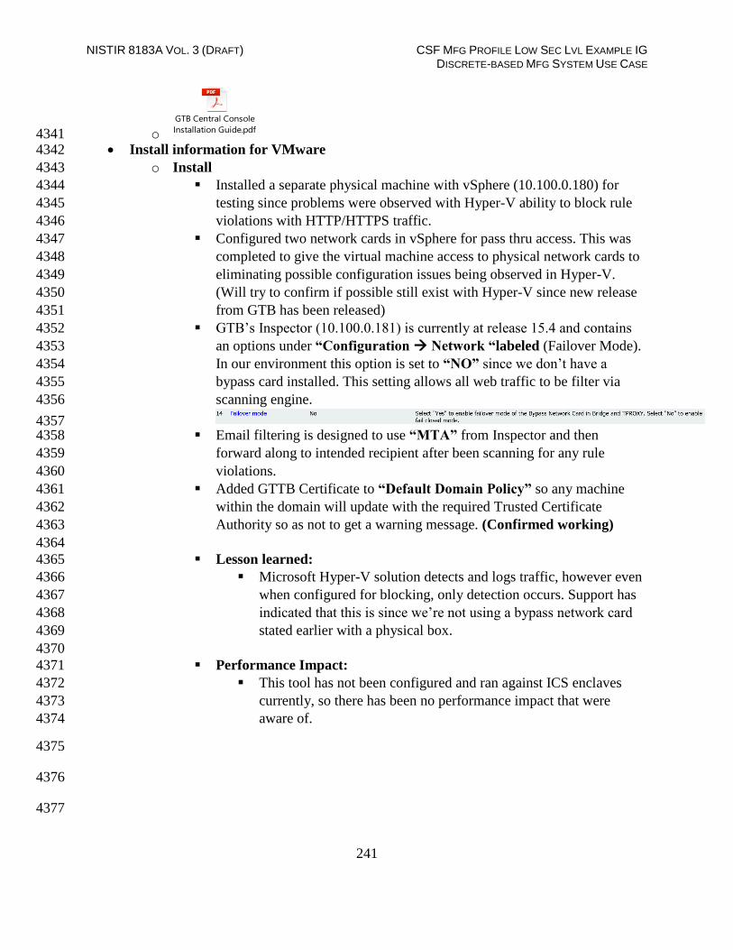
NISTIR 8183A VOL. 3 (DRAFT) CSF MFG PROFILE LOW SEC LVL EXAMPLE IG DISCRETE-BASED MFG SYSTEM USE CASE
241
o GTB Central Console
Installation Guide.pdf 4341 Install information for VMware 4342
o Install 4343
Installed a separate physical machine with vSphere (10.100.0.180) for 4344
testing since problems were observed with Hyper-V ability to block rule 4345
violations with HTTP/HTTPS traffic. 4346
Configured two network cards in vSphere for pass thru access. This was 4347
completed to give the virtual machine access to physical network cards to 4348
eliminating possible configuration issues being observed in Hyper-V. 4349
(Will try to confirm if possible still exist with Hyper-V since new release 4350
from GTB has been released) 4351
GTB’s Inspector (10.100.0.181) is currently at release 15.4 and contains 4352
an options under “Configuration Network “labeled (Failover Mode). 4353
In our environment this option is set to “NO” since we don’t have a 4354
bypass card installed. This setting allows all web traffic to be filter via 4355
scanning engine. 4356
4357 Email filtering is designed to use “MTA” from Inspector and then 4358
forward along to intended recipient after been scanning for any rule 4359
violations. 4360
Added GTTB Certificate to “Default Domain Policy” so any machine 4361
within the domain will update with the required Trusted Certificate 4362
Authority so as not to get a warning message. (Confirmed working) 4363
4364
Lesson learned: 4365
Microsoft Hyper-V solution detects and logs traffic, however even 4366
when configured for blocking, only detection occurs. Support has 4367
indicated that this is since we’re not using a bypass network card 4368
stated earlier with a physical box. 4369
4370
Performance Impact: 4371
This tool has not been configured and ran against ICS enclaves 4372
currently, so there has been no performance impact that were 4373
aware of. 4374
4375
4376
4377

NISTIR 8183A VOL. 3 (DRAFT) CSF MFG PROFILE LOW SEC LVL EXAMPLE IG DISCRETE-BASED MFG SYSTEM USE CASE
242
Specific configuration steps for GTB’s Inspector and Central Console 4378
within Testbed environment 4379
This document contains information for configuration within our environment. If scanning email 4380
for content violation, you’ll need to configure email clients to point SMTP to 10.100.0.175 4381
(Inspector - MTA) for email scanning. For additional configuration information please see 4382
vendors Administrator Guides which are included in download package from vendor. 4383
Inspector 4384
Generating and applying License: 4385
Generating 4386
o Click on middle top web page once logged into Inspector 4387
4388 You will now be directed to a page that allows you to download, email, or 4389
upload a license file. 4390
License files should be emailed to [email protected] . Support will reply 4391
with an updated file to be uploaded. 4392
When to generate a new license file 4393
o Anytime a network change effects the MAC (Media Access Control) address for 4394
Inspector you’ll need to generate a new license key an email [email protected]. 4395
Before emailing change the extension from “.dat” to “.txt”. Example: Inspector 4396
– “7-31-2018-sysinfo_inspector.dat to 7-31-2018-sysinfo_inspector.txt”. This 4397
change may be required if your email provider blocks “.dat” file extension 4398
o 4399
Configuration Setting 4400
o Login into GTB Inspector web page and click “Configuration” tab.4401
4402 o All setting are accessible via “Groups” located on left side of webpage. 4403
o Central Console = “gtbcc.lan.lab” 4404
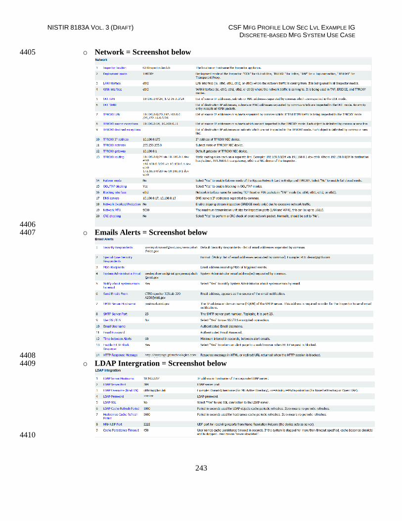
NISTIR 8183A VOL. 3 (DRAFT) CSF MFG PROFILE LOW SEC LVL EXAMPLE IG DISCRETE-BASED MFG SYSTEM USE CASE
243
o Network = Screenshot below 4405
4406 o Emails Alerts = Screenshot below 4407
4408 o LDAP Intergration = Screenshot below 4409
4410

NISTIR 8183A VOL. 3 (DRAFT) CSF MFG PROFILE LOW SEC LVL EXAMPLE IG DISCRETE-BASED MFG SYSTEM USE CASE
244
o Mail Transfer Agent = Screenshot below 4411
4412 o SIEM = Screenshot below 4413
4414

NISTIR 8183A VOL. 3 (DRAFT) CSF MFG PROFILE LOW SEC LVL EXAMPLE IG DISCRETE-BASED MFG SYSTEM USE CASE
245
o SSL Proxy = Screeshot below 4415
4416 Administration setting 4417
4418 o Licensing = Used for downloading and uploading license information. 4419
o Health Check = Ability to perform “Self-Test” to check Inspector install health. 4420
o Account Manager = Used to add new personal who will be administrating 4421
Inspector or responding to alerts for further investigation. 4422

NISTIR 8183A VOL. 3 (DRAFT) CSF MFG PROFILE LOW SEC LVL EXAMPLE IG DISCRETE-BASED MFG SYSTEM USE CASE
246
o System Time = Screenshot below4423
4424
Central Console 4425
Generating and applying License: 4426
Generating 4427
o Click on middle top web page once logged into Central Console 4428
4429 You will now be directed to a page that will allow you to download, email, 4430
or upload a license file. 4431
License files should be emailed to [email protected] . Support will reply 4432
with an updated file to be uploaded. 4433
When to generate a new license file 4434
o Anytime a network change effects the MAC (Media Access Control) address for 4435
Central Console you’ll need to generate a new license key and email it to 4436
[email protected]. Before emailing change the extension from “.dat” to “.txt”. 4437
Example: Central Console - 7-31-2018-sysinfo_cc.dat to 7-31-2018-4438
sysinfo_cc.txt. This change may be required if your email provider blocks “.dat” 4439
file extension 4440
o 4441
System settings 4442
o Click on “DLP Setup” tab 4443
o Network (Located under Categories) 4444
Enter required information. See below for screenshot 4445
4446 Click save to continue. 4447
o LDAP 4448
Enter information for screenshot below. This user has been created and 4449
only has Domain User right. Check for password in database. 4450
4451 User name = [email protected] 4452

NISTIR 8183A VOL. 3 (DRAFT) CSF MFG PROFILE LOW SEC LVL EXAMPLE IG DISCRETE-BASED MFG SYSTEM USE CASE
247
Password = check database 4453
LDAP Server = 10.100.0.17 4454
o Email and alerts 4455
Enter information from screenshot below4456
4457 Email Server = 10.100.0.175 4458
Email Originator = [email protected] 4459
Click save 4460
o Data and Time 4461
NTP Server = 10.100.0.15 (Click set time to sync) 4462
Time Zone = Eastern Time (US and Canada) (Click Apply to save) 4463
Click Save 4464
Other settings under DLP Setup System aren’t currently configured. These setting will be 4465
updated an included when these features are enabled. 4466
Lesson learned: If integrating with Active Directory using LDAP it’s recommended to use 4467
Secure LDAP to ensure user name and password are not sent in plaintext. 4468
4469
How ACL rules are created for use with GTB DLP Inspector. 4470
GTB DLP Inspector views data as it passes thru the device and responds based on 4471
configured rules. 4472
GTB Central Console is the portal were all policy rules and other settings are configured. 4473
ACL Rules: 4474
Login into to Central Console via web browser (E.g. 10.100.0.176). 4475
Now click on DLP-SetupNetwork DLP to access rules. 4476
4477 Now, look to the left of window under categories and select your Inspector installation. 4478

NISTIR 8183A VOL. 3 (DRAFT) CSF MFG PROFILE LOW SEC LVL EXAMPLE IG DISCRETE-BASED MFG SYSTEM USE CASE
248
4479 Once selected you will see on the right current ACL Rules being applied. 4480
Click Add button. 4481
A new window will appear titled “Add New ACL Rule” 4482
4483 Now type in a name for the new rule being created. 4484
Change Protocol to desire setting. This can be left to “ANY” which will look at all 4485
protocols passes thru the Inspector (This may cause a performance impact on you 4486
Inspector installation depending on the number of clients within your organization). 4487
Source: Choices are Any, IP Address, Hostname, Hostname (Custom), and 4488
Group (User/Computer). 4489
Destination: Choices are Any, IP Address, Hostname, Hostname (Custom), and 4490
Group (User/Computer). 4491
File type: Choices are None, All Files, Encrypted, and Extension. 4492
File Size: Choices are Any, and Not more than. 4493

NISTIR 8183A VOL. 3 (DRAFT) CSF MFG PROFILE LOW SEC LVL EXAMPLE IG DISCRETE-BASED MFG SYSTEM USE CASE
249
Comments: Give a description of the rule being applied then click Add button.4494
4495 Once Add has been clicked you’ll have an option to select a “Policy/Sets” to enforce. 4496
Default policies that are enforce are (Credit Card Number CCN and Social Security 4497
Numbers SSN). 4498
Next, select the action to be taken. There are four choices, Log, Block, S-Block, and 4499
Pass. 4500
Now select if you would like additional personal to be notification upon rule violations. 4501
Finally, place a check in File Capture if you want to retain a copy of the offending data. 4502
Click Save to complete. 4503
Last step is to click on Deploy all button. This sends newly created policy to Inspector. 4504
This button will have a red blinking box around it is indicating required action. 4505
4506
4507
Useful Information: 4508
Once a new rule has been created double click on that rule to adjust the ordering from top 4509
to bottom by click the UP or Down arrows towards the right. 4510
Remember rules work from Top Down, so think about ordering process. If unsure 4511
move the rule all the way to the top and then click Deploy all again. 4512
4513
4514
How to Fingerprint Files using GTB Security Manager for DLP Protection 4515

NISTIR 8183A VOL. 3 (DRAFT) CSF MFG PROFILE LOW SEC LVL EXAMPLE IG DISCRETE-BASED MFG SYSTEM USE CASE
250
Download: 4516
First download “GTB Security Manager” by clicking on Help tab within Central 4517
Console server web portal then select “GTB Security Manager” link to start download.4518
4519
4520 Select location to save file being downloaded. 4521
Double click to start install for “GTBSecurityManager_15.3.0.msi” from location 4522
where file was saved to (version number might be different than one listed above). 4523
Once first screen appears click on “Next” to continue. 4524
4525 Select Yes to License Aggreement and click “Next” to continue. 4526
4527

NISTIR 8183A VOL. 3 (DRAFT) CSF MFG PROFILE LOW SEC LVL EXAMPLE IG DISCRETE-BASED MFG SYSTEM USE CASE
251
Leave Destination Folder as default and Click “Next” 4528
4529 Click ”Install” to continue. 4530
4531
When prompted by User Access Control (UAC) enter administrator password to 4532
continue install. 4533
If prompted to close Open Applications, select either option. Reboot is required if second 4534
option is selected. 4535
Click “OK” to continue. 4536
Once install has completed click “Finish” to complete install. 4537
If prompted to reboot, select “Yes”. MAKE SURE TO SAVE ALL OPEN FILES 4538
BEFORE SELECTING “YES” 4539
4540 Once machine has completed rebooting open “GTB Security Manager” by right click 4541
and selecting “Run as administrator” 4542
When prompted enter administrator password for application to start. 4543

NISTIR 8183A VOL. 3 (DRAFT) CSF MFG PROFILE LOW SEC LVL EXAMPLE IG DISCRETE-BASED MFG SYSTEM USE CASE
252
Once “GTB Security Manager” has opened, click on setting button on menu bar. 4544
4545 Now enter the IP Address of where “Central Console” is installed. Login and password 4546
are already populated with default credentials from vendor. Both can be changed. See 4547
foot notes for additonal steps required to change Fingerprint Inspections login an 4548
password. 4549
Once IP Address has been enter click “OK” to save changes. 4550
Now, click on File from menu bar and select New New File Profile4551
4552 A new window will appear allowing the ability to select files to be added. Files can be 4553
copied to Local Machine, or accessed from a Network Share, Subversion 4554
Repositories, or SharePoint Respositories. 4555
Select the folder, or files that need fingerprinting. Once a folder is selected all files within 4556
selected folder will recive a check mark indicating which files will be fingerprinted. 4557
4558
Now click on floppy disk icon to save. 4559
Select location to save newly created profile. 4560

NISTIR 8183A VOL. 3 (DRAFT) CSF MFG PROFILE LOW SEC LVL EXAMPLE IG DISCRETE-BASED MFG SYSTEM USE CASE
253
Now the profile has been saved click the padlock icon to start fingerprinting process 4561
(Depending on the number of files being fingerprinted this can take a few minutes). 4562
To view the process see the Output screen that will display what files have been 4563
processed and there status. Once completed click Close4564
4565 Now look to the right side window for a tab labeled “Profiles” if this is missing click on 4566
“View” from menu bar and select “Profiles Window”. Click on Profile tab and a slide 4567
out appears show all the Profiles that can be monitored. 4568
Now select the Profile that was created earlier and right click, then select Start 4569
Monitoring. 4570
Once monitoring is enabled it’ll appears under “Currently Monitoring” under help. 4571
4572 Files that were included in fingerprinting profile will now have ACL rules applied from 4573
Network DLP section from Central Console. 4574
Login to Central Console and navigate to Account Manager Tab and click Refesh 4575
Polices. 4576
4577 You’ll see a message indicating Fingerprint polices successfully synchronized. 4578
4579
How to add policy to GTB Central Console for detecting fingerprinted files 4580
Login to Central Console 4581
Click on DLP Setup tab. 4582
Now select Policy Management tab. 4583
Now double click on Default to launch a new window. 4584
Click Add Policy. 4585
Click drop down and select File. 4586

NISTIR 8183A VOL. 3 (DRAFT) CSF MFG PROFILE LOW SEC LVL EXAMPLE IG DISCRETE-BASED MFG SYSTEM USE CASE
254
Now click save button for setting to be applied. 4587
All fingerprinted files from above steps will automatically be added to default Network DLP 4588
policy applied ACL. New Default values are “SSN, CCN, and File” 4589
4590
Additional Information for Fingerprinting: 4591
Recommended to configured GTB Security Manager to connect to IP address of DLP 4592
Inspector. 4593
Fingerprint only allows for one active Profile at a time. If another profile is set to Start 4594
Monitoring you’ll receive a warning asking if you’d like to disable the active profile. 4595
4596 o Recommendation would be to install GTB Security Manager on a machine that 4597
can be the central repositoiry for all fingerprinted files. Creating a large folder 4598
were the files can placed into for fingerprinting. Files don’t have to remain in 4599
saved location once the profile has been fingerprinted and uploaded to Central 4600
Console. Access to fingerprinted files is only required when changes are made to 4601
profile containing said files. 4602
Although only one profile is able to monitored at a time you are able to define multiple 4603
Polices within that profile. This is useful since when a fingerprint violation is triggered it 4604
will be tagged with the Defined Policy name, which allows for easier usability. 4605
Fingerprinted files follow ACL Rules: created within Central Console under DLP Setup 4606
Network DLP. Rules are processed in order from top to bottom. This means the first rule with a 4607
matching violation takes precedence over rules below. 4608
4609
Highlighted Performance Impacts 4610
No performance measurement experiments were performed for the installation of GTB into the 4611
CRS due to its location within the network topology. No workcell components involved with 4612
controlling the manufacturing process communicate across the boundary on a regular basis while 4613
the system is operational. 4614

NISTIR 8183A VOL. 3 (DRAFT) CSF MFG PROFILE LOW SEC LVL EXAMPLE IG DISCRETE-BASED MFG SYSTEM USE CASE
255
Link to Entire Performance Measurement Data Set 4615
N/A 4616
4617

NISTIR 8183A VOL. 3 (DRAFT) CSF MFG PROFILE LOW SEC LVL EXAMPLE IG DISCRETE-BASED MFG SYSTEM USE CASE
256
Graylog 4618
Technical Solution Overview 4619
Graylog is an open source log management tool. It can collect, parse and enrich logs, wire data, 4620
and event data from any data source. Graylog also provides centralized configuration 4621
management for 3rd party collectors such as beats, fluentd and nxlog. The processing pipelines 4622
allow for greater flexibility in routing, blacklisting, modifying and enriching messages in real-4623
time as they enter Graylog. It has a powerful search syntax to help query exactly what we are 4624
looking for. With Graylog one can even create dashboards to visualize metrics and observe 4625
trends in one central location.21 4626
Points to consider 4627
Open source product with good community support 4628
Easy to setup and customize. Support log collection from any OS platform. 4629
It is packaged for major Linux distributions, has a VM ready for use and Docker images are 4630
also available. 4631
The dashboard part, even if though well integrated and useful, lacks many features and 4632
visualizations contained in other elastic search tools such as Kibana (like aggregations). 4633
Technical Capabilities Provided by Solution 4634
Graylog provides components of the following Technical Capabilities described in Section 6 of 4635
Volume 1: 4636
Network Monitoring 4637
Event Logging 4638
Forensics 4639
Subcategories Addressed by Implementing Solution 4640
PR.DS-4, PR.PT-1, DE.AE-2, DE.AE-3, DE.CM-1, DE.CM-6, DE.DP-3, RS.AN-3 4641
21 Graylog Documentation http://docs.graylog.org/en/3.0/

NISTIR 8183A VOL. 3 (DRAFT) CSF MFG PROFILE LOW SEC LVL EXAMPLE IG DISCRETE-BASED MFG SYSTEM USE CASE
257
Architecture Map of Where Solution was Implemented 4642
4643

NISTIR 8183A VOL. 3 (DRAFT) CSF MFG PROFILE LOW SEC LVL EXAMPLE IG DISCRETE-BASED MFG SYSTEM USE CASE
258
Installation Instructions and Configurations 4644
Details of the solutions implemented: 4645
Name Version Daily volume of
logs
Server
Graylog Enterprise 2.4.6 < 5GB per day Ubuntu 14
4646
Setup: 4647
Download the installation package from the Graylog website (https://www.graylog.org/). 4648
Graylog can be installed on any flavor of Linux. In addition, Graylog also provides a 4649
preconfigured virtual machine for non-production environments. This virtual machine 4650
template (OVA) file was used in our environment. 4651
The OVA file was deployed on a Microsoft Hyper-V host server in our Cybersecurity LAN 4652
network. 4653
The Graylog server receives all syslog traffic by default on UDP port 514, accordingly UDP 4654
514 was permitted in the firewall rules. Additional ports are required to be allowed if 4655
utilizing other features of Graylog as described in the documentation. 4656
Upon deploying the OVA file, the virtual machine will default to a DHCP IP address. Login 4657
to the system to assign it a static IP address as per below shown instructions. 4658
4659
4660 4661
4662

NISTIR 8183A VOL. 3 (DRAFT) CSF MFG PROFILE LOW SEC LVL EXAMPLE IG DISCRETE-BASED MFG SYSTEM USE CASE
259
Login to the Web Interface using the default credentials and change the admin password. 4663
4664
Active Directory (AD)-integration is supported in Graylog. To configure, on the Top Menu 4665
Bar Click on System >> Authentication. On the Authentication Management page, click on 4666
LDAP / Active Directory and fill out the AD server details. Detailed instructions can be 4667
found in product documentation.22 4668
4669
o Note: Any AD domain user that’s added is assigned “Reader” access by default. This 4670
can be changed by configuring Group Mapping options in the same page. Change 4671
the Default User Role depending on your requirement. Adding permissions can be 4672
assigning by clicking on LDAP Group Mapping button on the same page 4673
4674
4675
Configuration: 4676
Syslog on Linux servers: 4677
22 Configuring External Authentication in Graylog
http://docs.graylog.org/en/2.3/pages/users_and_roles/external_auth.html?highlight=ldap

NISTIR 8183A VOL. 3 (DRAFT) CSF MFG PROFILE LOW SEC LVL EXAMPLE IG DISCRETE-BASED MFG SYSTEM USE CASE
260
The “rsyslog” package on Linux was leveraged to forward logs out of all Linux hosts in the 4678
Robotics system to the Graylog server. Rsyslog is by default present in all Linux 4679
distributions. Configure the /etc/rsyslog.conf file to enable forwarding the logs to the IP 4680
address of the Graylog server. Detailed instructions can be found here: 4681
https://marketplace.graylog.org/addons/a47beb3b-0bd9-4792-a56a-33b27b567856 4682
4683
Below is a snippet of a /etc/rsyslog.conf file from one of the Linux servers. Restart the 4684
rsyslog service once the rsyslog.conf file is modified. 4685
4686
4687 4688
You should now begin to receive syslog data in Graylog from this client. Login to the 4689
Graylog Web UI and search for the asset / server name in the dashboard to view these logs. 4690
The corresponding Linux device will also be listed under “Sources” page when its actively 4691
forwarding the data. 4692
Syslog on the Boundary Firewall (RuggedCom): 4693
Most of the firewall devices available today support syslog capabilities. This can be 4694
configured by either by setting it up from command line via SSH or from the Web Interface 4695
of the Firewall device. Ensure UDP 514 is allowed between the firewall and Graylog server. 4696
4697
Similarly, the RuggedCom boundary router/firewall device in Robotics system was 4698
configured to send syslog traffic to Graylog. Below screenshots reference the syslog setting 4699
on the RX1510 appliance where 10.100.0.14 is the IP address of our Graylog server. The log 4700
level was set to “Informational and above”. 4701
Detailed instructions can be found in the product manual.23 4702
23 http://www.plcsystems.ru/catalog/ruggedcom/doc/ROXII_RX1500_User-Guide_WebUI_EN.pdf

NISTIR 8183A VOL. 3 (DRAFT) CSF MFG PROFILE LOW SEC LVL EXAMPLE IG DISCRETE-BASED MFG SYSTEM USE CASE
261
4703
4704
4705
Syslog on the Network Switches: 4706
Both the network switches (Netgear and Siemens i800) were configured to log to the Graylog 4707
server. The below image shows Syslog server configuration on the Netgear SW pointing to 4708
the IP address of the Graylog server. 4709
4710
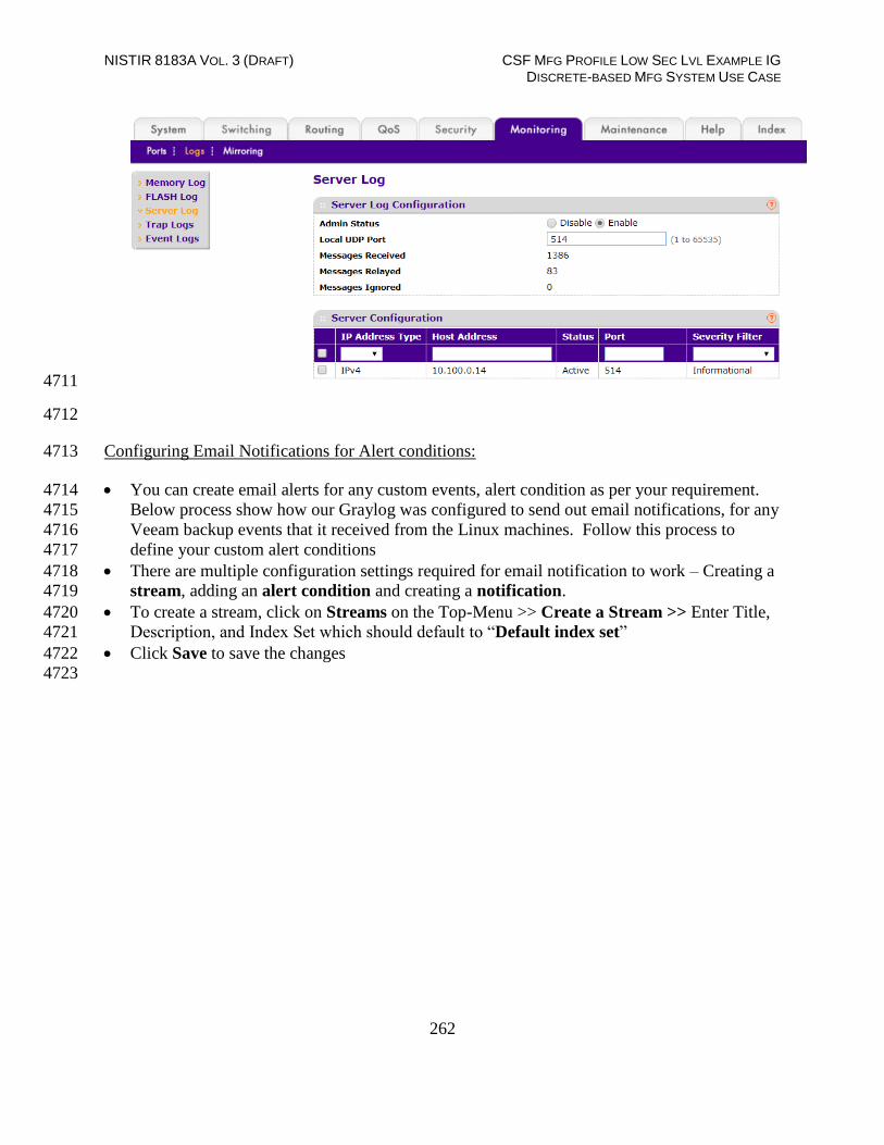
NISTIR 8183A VOL. 3 (DRAFT) CSF MFG PROFILE LOW SEC LVL EXAMPLE IG DISCRETE-BASED MFG SYSTEM USE CASE
262
4711
4712
Configuring Email Notifications for Alert conditions: 4713
You can create email alerts for any custom events, alert condition as per your requirement. 4714
Below process show how our Graylog was configured to send out email notifications, for any 4715
Veeam backup events that it received from the Linux machines. Follow this process to 4716
define your custom alert conditions 4717
There are multiple configuration settings required for email notification to work – Creating a 4718
stream, adding an alert condition and creating a notification. 4719
To create a stream, click on Streams on the Top-Menu >> Create a Stream >> Enter Title, 4720
Description, and Index Set which should default to “Default index set” 4721
Click Save to save the changes 4722
4723
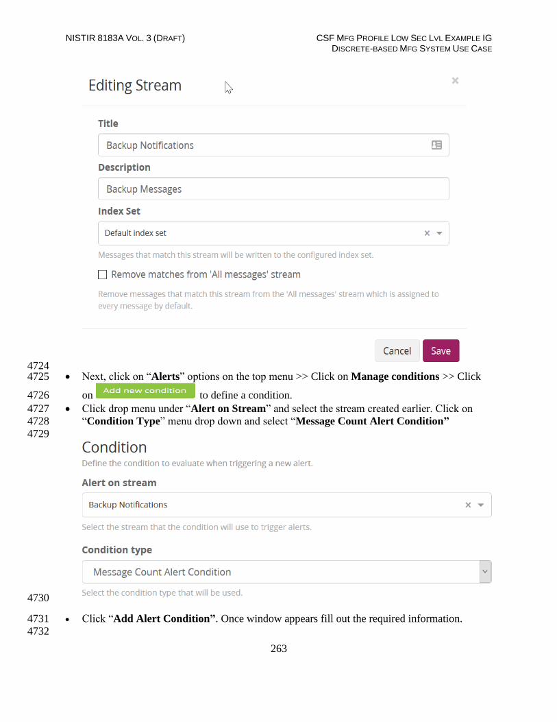
NISTIR 8183A VOL. 3 (DRAFT) CSF MFG PROFILE LOW SEC LVL EXAMPLE IG DISCRETE-BASED MFG SYSTEM USE CASE
263
4724 Next, click on “Alerts” options on the top menu >> Click on Manage conditions >> Click 4725
on to define a condition. 4726
Click drop menu under “Alert on Stream” and select the stream created earlier. Click on 4727
“Condition Type” menu drop down and select “Message Count Alert Condition” 4728
4729
4730
Click “Add Alert Condition”. Once window appears fill out the required information. 4731
4732

NISTIR 8183A VOL. 3 (DRAFT) CSF MFG PROFILE LOW SEC LVL EXAMPLE IG DISCRETE-BASED MFG SYSTEM USE CASE
264
4733
Click Save to complete (See below for example of current Message Count Alert Condition). 4734
4735
4736
4737
Now create a notification. 4738
o Click on “Manage notifications” blue button in upper right-hand corner. 4739
o Click green button for “Add new notification” 4740
o Under “Notify on Stream” select notification created earlier from drop down 4741
menu. 4742
o Under “Notification type” select “Email Alert Callback” from drop down 4743
menu. 4744
o Click “Add alert notification” button 4745
o Title: “Veeam Backup Alerts” 4746
NISTIR 8183A VOL. 3 (DRAFT) CSF MFG PROFILE LOW SEC LVL EXAMPLE IG DISCRETE-BASED MFG SYSTEM USE CASE
265
o Email Subject: “Successful Veeam Backup source: ${foreach backlog 4747
message}${message.source}${end}” without the quotes, see below for screen 4748
shot of current callback wording. 4749
o Sender: < sender address > 4750
o E-mail Body: “This can be adjusted as required” 4751 4752 Alert Description: ${check_result.resultDescription} 4753
Date: ${check_result.triggeredAt} 4754
Stream ID: ${stream.id} 4755
Stream title: ${stream.title} 4756
Stream description: ${stream.description} 4757
Alert Condition Title: ${alertCondition.title} 4758
4759
${if backlog}Last messages accounting for this alert: 4760
${foreach backlog message}${message} 4761
4762
${end}${else}<No backlog> 4763
${end} 4764
4765
o User Receivers: “Select a Graylog user if desired” 4766
o Email Receivers: “Enter email address for individuals receiving these 4767
alerts” 4768
o Click Save 4769
4770
Test new Streams / Alerts / Notifications to ensure they are configured correctly. 4771
4772
Highlighted Performance Impacts 4773
Two performance measurement experiments were performed for the Graylog tool while the 4774
manufacturing system was operational: 4775
1. CL003.1 - Syslog service was installed and running on CRS network hosts, and all 4776
generated syslog messages were forwarded from CRS hosts to Graylog server. 4777
2. CL003.2 - Syslog forwarding to Graylog was configured on CRS networking devices. 4778
4.13.6.1 Experiment CL003.1 4779
The rsyslog service was installed and configured on CRS hosts to forward all syslog messages to 4780
the Graylog server. A total of 13 syslog packets were transmitted during the experiment by the 4781
rsyslog service on all CRS hosts (see Figure 4-48). 4782

NISTIR 8183A VOL. 3 (DRAFT) CSF MFG PROFILE LOW SEC LVL EXAMPLE IG DISCRETE-BASED MFG SYSTEM USE CASE
266
4783
Figure 4-48 - Time series plot showing the rate of syslog network traffic (in packets per second) transmitted 4784 during the CL003.1 experiment. 4785
No performance impact to the manufacturing process was measured during the experiment. 4786
4787
Figure 4-49 - Bihistograms showing the part production time (left) and estimated mean production time using 4788 the bootstrap method (right) using the measurements from baseline CL001.1 and experiment CL003.1. 4789
4.13.6.2 Experiment CL003.2 4790
The rsyslog service was installed and configured on CRS networking devices to forward all 4791
syslog messages to the Graylog server. A total of 28 syslog packets were transmitted during the 4792
experiment by the rsyslog service from CRS hosts and networking devices (see Figure 4-50). 4793

NISTIR 8183A VOL. 3 (DRAFT) CSF MFG PROFILE LOW SEC LVL EXAMPLE IG DISCRETE-BASED MFG SYSTEM USE CASE
267
4794
Figure 4-50 - Time series plot showing the rate of syslog network traffic (in packets per second) transmitted 4795 during the CL003.2 experiment. 4796
No performance impact to the manufacturing process was measured during the experiment. 4797
4798
Figure 4-51 - Bihistograms showing the part production time (left) and estimated mean production time using 4799 the bootstrap method (right) using the measurements from baseline CL001.1 and experiment CL003.2. 4800
Link to Entire Performance Measurement Data Set 4801
CL003.1-Syslog.zip 4802
CL003.2-Syslog.zip 4803
4804

NISTIR 8183A VOL. 3 (DRAFT) CSF MFG PROFILE LOW SEC LVL EXAMPLE IG DISCRETE-BASED MFG SYSTEM USE CASE
268
DBAN 4805
Technical Solution Overview 4806
DBAN is a free open source data wiping utility allowing the ability to sanitize hard drives to 4807
ensure data is not left behind when drives are beginning decommissioned and prepared for 4808
removal from on premise. DBAN and other hard drive sanitization tools only work with spinning 4809
hard drives, SSD hard drives and other flash media refer to vendors for specific directions for 4810
sanitizing media before removing from company control. 4811
4812
Technical Capabilities Provided by Solution 4813
DBAN provides components of the following Technical Capabilities described in Section 6 of 4814
Volume 1: 4815
Media Sanitization 4816
Subcategories Addressed by Implementing Solution 4817
PR.DS-3, PR.IP-6 4818

NISTIR 8183A VOL. 3 (DRAFT) CSF MFG PROFILE LOW SEC LVL EXAMPLE IG DISCRETE-BASED MFG SYSTEM USE CASE
269
Architecture Map of Where Solution was Implemented 4819
4820

NISTIR 8183A VOL. 3 (DRAFT) CSF MFG PROFILE LOW SEC LVL EXAMPLE IG DISCRETE-BASED MFG SYSTEM USE CASE
270
4821
Installation Instructions and Configurations 4822
Instructions for installing DBAN and use 4823
Download: 4824 DBAN can be downloaded from https://dban.org 4825
Click download link which redirects the page and a pop will appear to start download 4826
process for ISO image file “dban-2.3.0_i586.iso”. 4827
Download ISO file and burn to CD/DVD, or USB drive using widely available ISO 4828
bootable utilities. 4829
4830
Instructions: 4831
1. Once ISO has been burned to bootable media go to device requiring sanitization. 4832
2. Power on machine and boot from USB or CD/DVD depending on the install option 4833
from earlier steps above. (Change Boot order in BIOS if no option for Boot 4834
Menu is available during machine power-up) 4835
3. Once machine has booted from media select desire option for media sanitization. 4836
4837 4. Select option to continue. Default sanitization mode is “short DoD 5520.22-M”, 4838
but this can be changed depending on the level your security program indicates. 4839
5. Follow menu options to start wiping process. 4840
6. Once wipe had completed you will see a screen like the image below. 4841

NISTIR 8183A VOL. 3 (DRAFT) CSF MFG PROFILE LOW SEC LVL EXAMPLE IG DISCRETE-BASED MFG SYSTEM USE CASE
271
4842
7. Once sanitization has completed, remove hard drive from device and label wiped 4843
ready for disposal. 4844
Lesson Learned and thing to know: 4845
Not all hard drives are able to be wiped clean using this sanitization method. Media that is either 4846
SSD or flash memory is written differently than spinning drives, so follow SSD/Flash media 4847
vendors’ recommendations for proper media sanitization for all non-spinning hard drives. 4848
Highlighted Performance Impacts 4849
No performance measurement experiments were performed for the use of DBAN due to its 4850
typical installation and usage location. 4851
Link to Entire Performance Measurement Data Set 4852
N/A 4853
4854

NISTIR 8183A VOL. 3 (DRAFT) CSF MFG PROFILE LOW SEC LVL EXAMPLE IG DISCRETE-BASED MFG SYSTEM USE CASE
272
Network Segmentation and Segregation 4855
Technical Solution Overview 4856
Network segmentation and segregation solutions enable a manufacturer to separate the 4857
manufacturing system network from other networks (e.g., corporate networks, guest networks), 4858
segment the internal manufacturing system network into smaller networks, and control the 4859
communication between specific hosts and services. 4860
Each Router’s native capabilities were leveraged to implemented network segmentation. 4861
Technical Capabilities Provided by Solution 4862
Network Segmentation and Segregation provides components of the following Technical 4863
Capabilities described in Section 6 of Volume 1: 4864
Network Segmentation and Segregation 4865
Subcategories Addressed by Implementing Solution 4866
PR.AC-5 4867

NISTIR 8183A VOL. 3 (DRAFT) CSF MFG PROFILE LOW SEC LVL EXAMPLE IG DISCRETE-BASED MFG SYSTEM USE CASE
273
Architecture Map of Where Solution was Implemented 4868
4869

NISTIR 8183A VOL. 3 (DRAFT) CSF MFG PROFILE LOW SEC LVL EXAMPLE IG DISCRETE-BASED MFG SYSTEM USE CASE
274
Installation Instructions and Configurations 4870
The following devices were involved in implementing Network Segmentation 4871
Device Details Location
Cisco-ASA 5512 NGFW, running Firepower Services
FTD 6.2.3
Manufacturing System
RuggedCom
RX1510
Firewall, Router Work cell
4872
Segmentation in the Cybersecurity LAN: 4873
Following is a list of interfaces created on the Boundary Router/Firewall – Cisco ASA of the 4874
Cybersecurity LAN network 4875
Interface IP
address
of
Interface
Subnet Description
GE 0/0 129.6.66.x 129.x.x.x/x Uplink to Corporate
GE 0/1 10.100.0.1 10.100.1.0/24 Cybersecurity LAN
GE 0/2 129.6.1.x 129.x.x.x/x VPN users
GE 0/3 10.100.2.1 10.100.2.0/24 Management LAN
GE 0/4 10.100.1.1 10.100.0.0/24 Manufacturing DMZ
LAN
4876
Segmentation in the Work Cell: 4877 4878
The Work Cell consists of the following network devices. 4879
4880
Type Description
RuggedCom RX Firewall Boundary protection firewall, router
Siemens i800 Switch Layer-2 Switch for the Control Network
Netgear GS724T Switch Layer-2 Switch for the Supervisory Network
4881

NISTIR 8183A VOL. 3 (DRAFT) CSF MFG PROFILE LOW SEC LVL EXAMPLE IG DISCRETE-BASED MFG SYSTEM USE CASE
275
Network segmentation was implemented using the RuggedCom firewall. The firewall has the 4882
following interfaces defined. There were two subnets created as listed in the below table. 4883
4884
Interface IP address of
Interface
Subnet Description
Ge-2-1 192.168.1.2 192.168.1.0/24 Control LAN Network
Ge-2-2 N/A N/A Mirror Port
Ge-3-1 192.168.0.2 192.168.0.0/24 Supervisory LAN Network
Ge-3-2 10.100.0.20 N/A Uplink to Cybersecurity LAN
4885
4886
The Siemens i800 switch is connected to the Ge-2-1 interface of the RX1510 and used for the 4887
Control LAN network. Devices connected to this i800 switch such as the 4 Machining 4888
stations, Robot Driver server were assigned an IP address from the Control LAN subnet 4889
(192.168.1.0/24). 4890
4891
The Netgear switch is connected to the Ge-3-1 interface of RX1510 and used for the 4892
Supervisory LAN network. Devices connected to this switch such as the PLC, HMI, 4893
Engineering workstation were accordingly assigned an IP address from this Supervisory 4894
LAN subnet (192.168.0.0/24) 4895
Highlighted Performance Impacts 4896
No performance measurement experiments were performed for network segmentation due to it 4897
being implemented on the CRS before the Manufacturing Profile implementation was initiated. 4898
Link to Entire Performance Measurement Data Set 4899
N/A 4900
4901

NISTIR 8183A VOL. 3 (DRAFT) CSF MFG PROFILE LOW SEC LVL EXAMPLE IG DISCRETE-BASED MFG SYSTEM USE CASE
276
Network Boundary Protection 4902
Technical Solution Overview 4903
Boundary Protection devices are implemented to monitor and control connections and 4904
communications at the external boundary and key internal boundaries within the organization. 4905
Boundary protection mechanisms include for example, Routers, Firewalls, Gateways, Data 4906
diodes separating system components into logically separate networks and sub networks. 4907
Technical Capabilities Provided by Solution 4908
Network Boundary Protection provides components of the following Technical Capabilities 4909
described in Section 6 of Volume 1: 4910
Network Boundary Protection 4911
Subcategories Addressed by Implementing Solution 4912
PR.AC-5, PR.PT-4, DE.CM-1 4913

NISTIR 8183A VOL. 3 (DRAFT) CSF MFG PROFILE LOW SEC LVL EXAMPLE IG DISCRETE-BASED MFG SYSTEM USE CASE
277
Architecture Map of Where Solution was Implemented 4914
4915

NISTIR 8183A VOL. 3 (DRAFT) CSF MFG PROFILE LOW SEC LVL EXAMPLE IG DISCRETE-BASED MFG SYSTEM USE CASE
278
Installation Instructions and Configurations 4916
Setup: 4917
The following devices were implemented for Boundary protection in the CRS System 4918
Device Details Location
Cisco-ASA 5512 NGFW, running Firepower Services FTD
6.2.3
Manufacturing System
RuggedCom RX1510 Firewall + Router running ROS 2.12.2 Work cell
GTB Inspector Data Loss Prevention (DLP) virtual
appliance
Cybersecurity LAN
4919
Configuration on Cisco-ASA: 4920
The following features, settings were enabled on the ASA firewall 4921
Network Segmentation 4922
ACL Rules 4923
NAT policy for Internet access 4924
Snort Inspection 4925
DMZ network 4926
Network Segmentation 4927
Separate network interfaces were configured for the different network segments as listed below 4928
Inside Interface (Network: 10.100.0.0/24) 4929
DMZ Interface (Network: 10.100.1.0/24) 4930
Outside Interface (Uplink to NIST Corporate for Internet) 4931
Management interface (out of scope) 4932
Access Control List (ACL) rules 4933
The following ACL rules were put in place on the ASA with a default Action to Block all 4934
traffic. 4935
4936
4937
4938

NISTIR 8183A VOL. 3 (DRAFT) CSF MFG PROFILE LOW SEC LVL EXAMPLE IG DISCRETE-BASED MFG SYSTEM USE CASE
279
4939
Source Source
Port Destination Dest Ports Protocol Action
10.100.0.0/24, Any DMZ network SSH,RDP,ICMP TCP Trust
DMZ Historian TCP_High
_Ports PCS-Historian 5450 TCP Trust
CRS-NAT
(10.100.0.20)
TCP_High
_Ports DMZ-Historian
5450, 5460,
5671, 5672 TCP Trust
DMZ Historian TCP_High
_Ports
CRS-NAT
(10.100.0.20) 5457, 5450 TCP Trust
DMZ Historian Any Active Directory
(10.100.0.17) 53 UDP Allow
Veeam Server Any Hyper-V Host servers,
Esxi Host Server
NETBIOS,
ICMP, HTTPS,
445,
TCP_High_port,
2500-5000,
6160-6163
TCP Trust
Hyper-V Host
Servers, Esxi
Host Server
Any Veeam Server ICMP, 2500-
5000
TCP Trust
inside_interface Any outside_interface Any Any Allow
DMZ Historian Any Symantec Server SMB (445),
HTTPS TCP Trust
Symantec
Server Any DMZ Historian
HTTP, HTTPS,
8014 TCP Trust
DMZ Historian Any Graylog Server 514 UDP Trust
4940
4941

NISTIR 8183A VOL. 3 (DRAFT) CSF MFG PROFILE LOW SEC LVL EXAMPLE IG DISCRETE-BASED MFG SYSTEM USE CASE
280
4942
NAT Policy 4943
A Dynamic NAT policy was configured to allow internet access. 4944
Type of NAT rule Auto NAT [1]
Source Interface inside
Destination Interface outside
Original sources 10.100.0.0/8
Translated Source Destination Interface IP
Options Translate DNS Replies that match this Rule: False
4945

NISTIR 8183A VOL. 3 (DRAFT) CSF MFG PROFILE LOW SEC LVL EXAMPLE IG DISCRETE-BASED MFG SYSTEM USE CASE
281
4946
Snort Inspection 4947
Snort Inspection was enabled on the following ACL rules 4948
Name of the
ACL
Intrusion Policy
Internet-
Access rule
Balanced connectivity and security
4949
4950
4951
4952
4953

NISTIR 8183A VOL. 3 (DRAFT) CSF MFG PROFILE LOW SEC LVL EXAMPLE IG DISCRETE-BASED MFG SYSTEM USE CASE
282
4954
DMZ Network 4955
A Separate interface was setup for the Manufacturing DMZ LAN Network for hosting the DMZ 4956
Historian server. 4957
4958
2. Configuration on RuggedCom Firewall: 4959
The following features, settings were enabled on this firewall 4960
Network Segmentation 4961
ACL Rules 4962
Masquerading (NAT) rules 4963
Network Segmentation 4964
Separate network interfaces were configured for the different network segments as listed below 4965
Supervisory LAN Interface (Network: 192.168.0.0/24) 4966
Control LAN Interface (Network: 192.168.1.1/24) 4967
LAN Interface (IP: 10.100.0.20, Uplink to Cybersecurity LAN) 4968
Access Control List (ACL) rules 4969
The following zones were created: 4970
WAN - Zone for internet-bound / uplink connections to Cybersecurity LAN. 4971
CTRL - Zone for the 192.168.1.0/24 subnet. 4972
SUPERVISORY - Zone for the 192.168.0.0/24 subnet. 4973
MGMT - Zone for the management interface traffic (out of scope) 4974
4975
The following firewall policies were created: 4976
Allow traffic between firewall and WAN. 4977

NISTIR 8183A VOL. 3 (DRAFT) CSF MFG PROFILE LOW SEC LVL EXAMPLE IG DISCRETE-BASED MFG SYSTEM USE CASE
283
Allow traffic between firewall and MGMT. 4978
Allow traffic between firewall and CTRL. 4979
Allow traffic between firewall and Supervisory. 4980
All other traffic is DROPPED. 4981
4982
The following firewall rules were created 4983
1) ALLOW: POLARIS:ANY -> 192.168.1.0/24,10.100.0.0/24:22 (TCP) 4984 2) ALLOW: vCONTROLLER1,vCONTROLLER2:ANY -> PLC:502 (TCP) 4985 3) ALLOW: STATION1,STATION2,STATION3,STATION4:ANY -> PLC,HMI:502 (TCP) 4986 4) ALLOW: STATION4:ANY -> PLC:502 (TCP) 4987 5) ALLOW: HISTORIAN:ANY -> STATION1,STATION2,STATION3,STATION4,PLC:502 (TCP) 4988 6) ALLOW: MINTAKA,vCONTROLLER1,vCONTROLLER2:ANY -> POLARIS:11311 (TCP) 4989 7) ALLOW: vCONTROLLER1,vCONTROLLER2:ANY -> POLARIS:115,2049 (TCP) 4990 8) ALLOW: vCONTROLLER1,vCONTROLLER2:ANY -> POLARIS:115,2049 (UDP) 4991 9) ALLOW: ANY:ANY -> ANY:ANY (ICMP) 4992 10) ALLOW: PLC,HMI:ANY -> STATION1,STATION2,STATION3,STATION4:502 (TCP) 4993 11) ALLOW: PLC:ANY -> vCONTROLLER1,vCONTROLLER2:502 (TCP) 4994 12) ALLOW: POLARIS:32678-65535 -> MINTAKA,vCONTROLLER1,vCONTROLLER2:32768-4995 65535 (TCP) 4996 13) ALLOW: POLARIS:ANY -> I800Switch-Management-UI:80,443 (TCP) 4997 14) ALLOW: NESSUS/OPEN-AUDIT:ANY -> 192.168.1.0/24:22 (TCP) 4998 15) ALLOW: VCONTROLLER1,VCONTROLLER2:32768-65535 -> POLARIS:32768:65535 (UDP) 4999 5000
5001
5002
5003

NISTIR 8183A VOL. 3 (DRAFT) CSF MFG PROFILE LOW SEC LVL EXAMPLE IG DISCRETE-BASED MFG SYSTEM USE CASE
284
5004
5005
5006
NAT Policy: 5007
Two Masquerading rules were created (one for each LAN segment) to NAT all traffic going 5008
outbound from the Work Cell to the Cybersecurity LAN network. Masquerading is a form of 5009
Dynamic NAT. Both hide a single subnetwork behind a single IP address 5010
5011
Rule # Outgoing Interface Source
Network
NAT IP address
1 Ge-3-2 (Uplink interface to Cybersecurity
LAN)
192.168.1.0/20 10.100.0.20
2 Ge-3-2 (Uplink interface to Cybersecurity
LAN)
192.168.0.0/20 10.100.0.20
5012
5013
3. Configuration on GTB Inspector: 5014
Refer to section 4.12.5 5015

NISTIR 8183A VOL. 3 (DRAFT) CSF MFG PROFILE LOW SEC LVL EXAMPLE IG DISCRETE-BASED MFG SYSTEM USE CASE
285
Highlighted Performance Impacts 5016
Two performance measurement experiments were performed for network boundary protection 5017
while the manufacturing system was operational: 5018
3. CL009.1 - Firewall rules and Access control list (ACL) rules are implemented at the CRS 5019
boundary router. 5020
4. CL012.1 - Firewall and ACL rules are implemented on an upgraded boundary router. 5021
These two experiments were performed chronologically after the experiment CL011.2 where the 5022
activities performed caused permanent performance impacts to the CRS (see Section 4.11.6.2). 5023
The performance impacts first observed during CL011.2 (and again measured as part of CL009.1 5024
and CL012.1) are not included in those sections. 5025
4.16.6.1 Experiment CL009.1 5026
Firewall rules and access control list (ACL) rules were implemented at the CRS boundary router. 5027
All authorized connections were verified to be allowed by the firewall before the manufacturing 5028
process was operational. 5029
A small increase in the average robot job actuation time was observed on Robot 2 for Job 203 5030
(see Figure 4-52). No other increases were observed for any of the other jobs. 5031
5032
Figure 4-52 - Time-series (left) and boxplot (right) showing the job actuation times for Job 203 during the 5033 CL001.2 baseline and CL009.1 experiment. 5034
A slight increase of the part production time mean was observed during this experiment but is 5035
not statistically significant. 5036
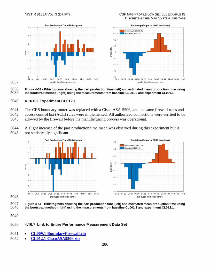
NISTIR 8183A VOL. 3 (DRAFT) CSF MFG PROFILE LOW SEC LVL EXAMPLE IG DISCRETE-BASED MFG SYSTEM USE CASE
286
5037
Figure 4-53 - Bihistograms showing the part production time (left) and estimated mean production time using 5038 the bootstrap method (right) using the measurements from baseline CL001.2 and experiment CL009.1. 5039
4.16.6.2 Experiment CL012.1 5040
The CRS boundary router was replaced with a Cisco ASA-5506, and the same firewall rules and 5041
access control list (ACL) rules were implemented. All authorized connections were verified to be 5042
allowed by the firewall before the manufacturing process was operational. 5043
A slight increase of the part production time mean was observed during this experiment but is 5044
not statistically significant. 5045
5046
Figure 4-54 - Bihistograms showing the part production time (left) and estimated mean production time using 5047 the bootstrap method (right) using the measurements from baseline CL001.2 and experiment CL012.1. 5048
5049
Link to Entire Performance Measurement Data Set 5050
CL009.1-BoundaryFirewall.zip 5051
CL012.1-CiscoASA5506.zip 5052

NISTIR 8183A VOL. 3 (DRAFT) CSF MFG PROFILE LOW SEC LVL EXAMPLE IG DISCRETE-BASED MFG SYSTEM USE CASE
287
Managed Network Interfaces 5053
Technical Solution Overview 5054
Managing network interfaces controls what network devices are plugged into switches within 5055
manufacturing system, along with physical labeling connections to help with system 5056
identification and classification. Required actions will be performed directly on the exterior of 5057
the switch. Switch port in use will be labeled logically within switch console itself, along with 5058
the corresponding network cable for easy identification. All cable should be labeled/identified at 5059
the switch and at the opposite end of the network cable. Switch Port Security should be 5060
configured to restrict access to only allowed preconfigured Media Access Control (MAC) 5061
addresses devices. 5062
Minimal cost for labeling. Effort of implement is high, but not difficult. The effort will be spent 5063
taking the required time to accurately identify cabling connections. 5064
Most switches have built in Port security. Since this technical control is built into switches there 5065
is no additional cost for implementation. Configuration for Port security is well documented and 5066
easily configured. 5067
Technical Capabilities Provided by Solution 5068
Managed Network Interfaces provides components of the following Technical Capabilities 5069
described in Section 6 of Volume 1: 5070
Managed Network Interfaces 5071
Subcategories Addressed by Implementing Solution 5072
PR.AC-5 5073

NISTIR 8183A VOL. 3 (DRAFT) CSF MFG PROFILE LOW SEC LVL EXAMPLE IG DISCRETE-BASED MFG SYSTEM USE CASE
288
Architecture Map of Where Solution was Implemented 5074
5075

NISTIR 8183A VOL. 3 (DRAFT) CSF MFG PROFILE LOW SEC LVL EXAMPLE IG DISCRETE-BASED MFG SYSTEM USE CASE
289
5076
Installation Instructions and Configurations 5077
Managing Network Interface Instructions 5078
Overview: 5079
Port labeling provides ability for others to understand and know what network devices belong 5080
where. Managing your switches with correct labeling and classification makes troubleshooting 5081
simpler along with improving cybersecurity. 5082
Labeling ports within switch: 5083
Switches within CRS: 5084
Siemens RuggedCom RX1510 (Router) 192.168.0.2 5085
Siemens RuggedCom i800 (Switch) 192.168.1.10 5086
Netgear GS724T (Switch) 192.168.0.239 5087
5088
Siemens RuggedCom RX1510 5089
Interface labels can’t be changed from defaults. 5090
Siemens RuggedCom i800 5091
Login to switch via web browser. https://192.168.1.10 5092
Click on Ethernet Ports-Configure Port Parameters. 5093
Click desired port number for renaming. 5094

NISTIR 8183A VOL. 3 (DRAFT) CSF MFG PROFILE LOW SEC LVL EXAMPLE IG DISCRETE-BASED MFG SYSTEM USE CASE
290
Type in Name to identify port and click apply. 5095
5096
Netgear 5097
Login to switch via web browser. https://192.168.0.239 5098
Click on Tab labeled “Switching”5099
5100 Select port that will be labeled. 5101
Enter Description. 5102
5103 Finally click apply button in lower right-hand corner. 5104
5105
Overview: 5106
Port security prevents unauthorized devices from being plugged into a network switch while 5107
trying to obtaining sensitive information, which could be used for mapping out network 5108
connections for possible data exfiltration. When an unauthorized device is plugged into a 5109
protected port a warning message is logged and sent to a syslog server if supported by switch 5110
vendor. 5111
5112

NISTIR 8183A VOL. 3 (DRAFT) CSF MFG PROFILE LOW SEC LVL EXAMPLE IG DISCRETE-BASED MFG SYSTEM USE CASE
291
Collaborative Robotics Enclave: 5113
This enclave contains three different switches/routers. 5114
o Siemens RuggedCom RX1510 (Can function as Router/Firewall/Switch) 5115
o Siemens RuggedCom i800 (Switch) 5116
o NETGEAR GS724Tv4 (Switch) 5117
RuggedCom RX 1510: Has multiple ports which are individual configurable depending on 5118
desired network topology. 5119
Ports LM1/1 and LM1/2 = disabled 5120
Ports LM2/1 (Switchport = False, port is configured for routing), LM2/2 (Switchport = 5121
True, port is configured for mirroring) 5122
Ports LM3/1 and LM3/2 (Switchport = False, ports are configured for routing) 5123
Ports LM4/1 and LM4/2 = disabled 5124
Only port security being applied to RuggedCom RX 1510 is LM1/1, LM4/1, LM4/2 5125
which are disabled. 5126
RuggedCom i800: Layer 2 switch that allows for all ports for switching or mirroring. 5127
Ports 1 to 7 are all configured for switching. 5128
Port 8 is configured for mirroring. 5129
NETGEAR GS724Tv4: Layer 2, Layer 2+ along with Layer 3 Lite features. All ports on this 5130
switch in our environment are configured for switching only. 5131
Ports 2, 4, 6, 8, 9, 10, 12, 14, 16, 17, 18, 20, 21, 22, 25, 26 are disabled (If any device is 5132
plugged into any of these ports there will be no link light). 5133
Ports 1, 3, 5, 7, 11, 13, 15, 19 are all enabled and labeled (Each port has Port Security 5134
enabled). 5135
Port 23 is used for management with no Port Security enabled (Used for accessing 5136
switch with any network device). 5137
Port 24 is mirror port connect to RA3. This port is configured for Probe. 5138
Port Security Configuration for NETGEAR and i800: 5139
NETGEAR: 5140
Port-Security
interface g1
dot1x port-control mac-based
description 'CTRL SYS LAN UPLINK'
Port Security
port-security max-dynamic 0
port-security max-static 3

NISTIR 8183A VOL. 3 (DRAFT) CSF MFG PROFILE LOW SEC LVL EXAMPLE IG DISCRETE-BASED MFG SYSTEM USE CASE
292
port-security mac-address
00:0C:29:CE:7F:94 1
port-security mac-address
94:B8:C5:0E:E1:01 1
port-security mac-address
94:B8:C5:0E:E1:9F 1
interface g3
dot1x port-control mac-based
description 'Beckhoff Automation GmbH'
port-security
port-security max-dynamic 0
port-security max-static 1
port-security mac-address
00:01:05:17:DB:08 1
interface g5
dot1x port-control mac-based
description 'Polaris (DELL)'
port-security
port-security max-dynamic 0
port-security max-static 1
port-security mac-address
F8:B1:56:BA:09:A8 1
interface g7
dot1x port-control mac-based
description 'PROBE1-A'
port-security
port-security max-dynamic 0
port-security max-static 1
port-security mac-address
00:05:E4:03:7C:3B 1
dot1x port-control mac-based
description 'Wago Kontakttechnik Gmbh'
port-security
port-security max-dynamic 0
port-security max-static 1
port-security mac-address
00:30:DE:00:C4:3C 1
interface g13
dot1x port-control mac-based
description 'Robotics Hyper-V / Open
AudIT'
port-security
port-security max-dynamic 0
port-security max-static 3

NISTIR 8183A VOL. 3 (DRAFT) CSF MFG PROFILE LOW SEC LVL EXAMPLE IG DISCRETE-BASED MFG SYSTEM USE CASE
293
port-security mac-address
00:15:5D:02:0A:07 1
port-security mac-address
00:15:5D:02:0A:0E 1
port-security mac-address
00:15:5D:02:0A:43 1
interface g15
dot1x port-control mac-based
description 'Laptop on CRS Desk'
port-security
port-security max-dynamic 0
port-security max-static 1
port-security mac-address
34:E6:D7:22:C3:ED 1
interface g19
dot1x port-control mac-based
description 'HyperV'
port-security
port-security max-dynamic 0
port-security max-static 3
port-security mac-address
00:10:18:B8:19:10 1
port-security mac-address
00:10:18:B8:19:11 1
port-security mac-address
00:15:5D:16:AC:07 1
5141
5142
i800: 5143
MAC Address
Attached
Machine VID Port Type CoS
00-15-5D-16-AC-02 vController1 1 6
Static
N/A
00-15-5D-16-AC-03 vController2 1 6
Static
N/A
94-B8-C5-0E-E1-9F Uplink 1 5
Static
N/A
A0-CE-C8-1F-BD-99 MINTAKA 1 7
Static
N/A
B0-D5-CC-F4-26-EC Station 4 1 4
Static
N/A

NISTIR 8183A VOL. 3 (DRAFT) CSF MFG PROFILE LOW SEC LVL EXAMPLE IG DISCRETE-BASED MFG SYSTEM USE CASE
294
B0-D5-CC-FA-70-C9 Station 1 1 1
Static
N/A
B0-D5-CC-FA-7A-43 Station 3 1 3
Static
N/A
B0-D5-CC-FE-6E-B1 Station 2 1 2
Static
N/A
C8-1F-66-C8-6A-ED MINTAKA 1 7
Static
N/A
C8-1F-66-CA-26-C0 Robotics VH 1 6
Static
N/A
C8-1F-66-CA-26-C2 Robotics VH 1 6
Static
N/A
5144
Highlighted Performance Impacts 5145
Two performance measurement experiments were performed for the Managed Network 5146
Interfaces technology implementation while the manufacturing system was operational: 5147
1. CL010.1 - Alerts are generated on new physical network connections (via syslog). 5148
2. CL010.2 - MAC address filtering is enabled and configured on CRS network devices, 5149
and unused physical network ports are disabled on CRS network devices. 5150
4.17.6.1 Experiment CL010.1 5151
No performance impact to the manufacturing process was measured during the experiment. 5152
5153
Figure 4-55 - Bihistograms showing the part production time (left) and estimated mean production time using 5154 the bootstrap method (right) using the measurements from baseline CL001.1 and experiment CL010.1. 5155

NISTIR 8183A VOL. 3 (DRAFT) CSF MFG PROFILE LOW SEC LVL EXAMPLE IG DISCRETE-BASED MFG SYSTEM USE CASE
295
4.17.6.2 Experiment CL010.2 5156
An increase in the robot job execution time was observed on Robot 1 for Job 103 (see Figure 5157
4-56), with two relatively large increases for parts 3 and 24. No other increases were observed 5158
for any of the other jobs. 5159
5160
Figure 4-56 - Time-series (left) and boxplot (right) showing the job execution times for Job 103 during the 5161 CL0010.2 experiment and CL001.2 baseline. 5162
A slight increase of the part production time mean was observed during this experiment but is 5163
not statistically significant. 5164
5165
Figure 4-57 - Bihistograms showing the part production time (left) and estimated mean production time using 5166 the bootstrap method (right) using the measurements from baseline CL001.1 and experiment CL010.2. 5167
Link to Entire Performance Measurement Data Set 5168
CL010.1-NetworkPhysicalConnections.zip 5169
CL010.2-NetworkMACFiltering.zip 5170

NISTIR 8183A VOL. 3 (DRAFT) CSF MFG PROFILE LOW SEC LVL EXAMPLE IG DISCRETE-BASED MFG SYSTEM USE CASE
296
Time Synchronization 5171
Technical Solution Overview 5172
Ability to have all devices sync from a reliable time source. Time synchronization is vital for 5173
system logins, event tracking and all other time sensitive events occurring with a manufacturing 5174
system. 5175
No additional cost since services are included. 5176
Ease of use simple 5177
Effort and time required = minimal 5178
Technical Capabilities Provided by Solution 5179
Time Synchronization provides components of the following Technical Capabilities described in 5180
Section 6 of Volume 1: 5181
Time Synchronization 5182
Subcategories Addressed by Implementing Solution 5183
PR.PT-1 5184

NISTIR 8183A VOL. 3 (DRAFT) CSF MFG PROFILE LOW SEC LVL EXAMPLE IG DISCRETE-BASED MFG SYSTEM USE CASE
297
Architecture Map of Where Solution was Implemented 5185
5186

NISTIR 8183A VOL. 3 (DRAFT) CSF MFG PROFILE LOW SEC LVL EXAMPLE IG DISCRETE-BASED MFG SYSTEM USE CASE
298
Installation Instructions and Configurations 5187
Collaborative Robotics System Time Synchronization 5188
5189
Computers: 5190
Linux Machines: Directions below work for all Linux machine within manufacturing system 5191
environment. 5192
Login to desired system using SSH client. 5193
Once logged on open a terminal window. 5194
Navigate to /etc 5195
open “ntp.conf” using text editor. (Make sure to type “sudo” before command for 5196
required write permissions) 5197
Edit the location for NTP Server setting. Save the file and exit.5198
5199
Now type this command to restart NTP “sudo service ntp restart “ 5200
Provide password for sudo when prompted. 5201
Type “ntpq -p” to verify ntp is getting time from correct source. 5202
5203
5204
Domain Controller: Is not providing time for this environment. 5205
Other Devices: 5206
Router: 5207
Siemens RuggedCom RX 1510: Device connects to Meinberg at 10.100.0.15 for time. 5208
Login into RuggedCom RX 1510 via web browser. https://192.168.1.2 5209
Click on “Edit Private” to put into configuration mode. 5210
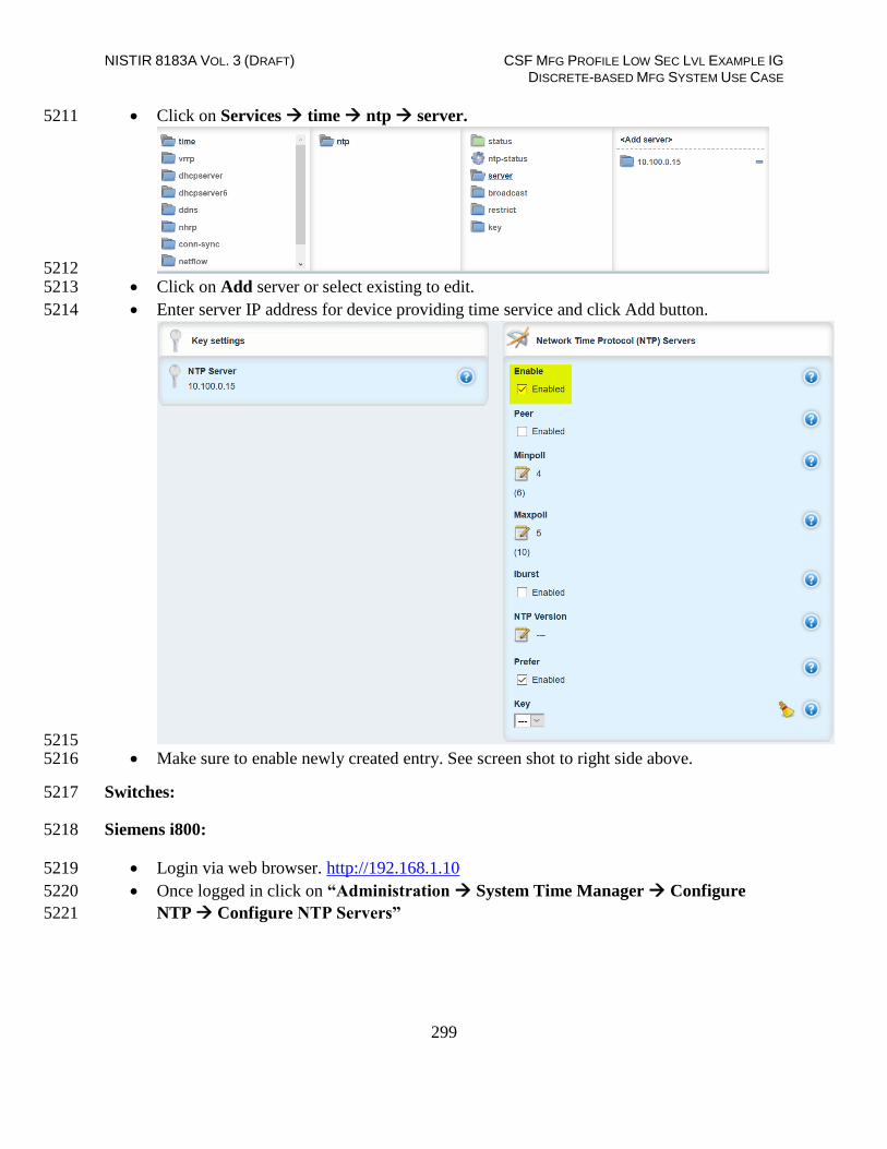
NISTIR 8183A VOL. 3 (DRAFT) CSF MFG PROFILE LOW SEC LVL EXAMPLE IG DISCRETE-BASED MFG SYSTEM USE CASE
299
Click on Services time ntp server. 5211
5212 Click on Add server or select existing to edit. 5213
Enter server IP address for device providing time service and click Add button. 5214
5215 Make sure to enable newly created entry. See screen shot to right side above. 5216
Switches: 5217
Siemens i800: 5218
Login via web browser. http://192.168.1.10 5219
Once logged in click on “Administration System Time Manager Configure 5220
NTP Configure NTP Servers” 5221

NISTIR 8183A VOL. 3 (DRAFT) CSF MFG PROFILE LOW SEC LVL EXAMPLE IG DISCRETE-BASED MFG SYSTEM USE CASE
300
Now Select primary or back and make the required changes. 5222
5223 Click Apply to save changes. 5224
Log out 5225
Netgear GS724T: 5226
Login via web browser portal. https://192.168.0.239 5227
Once logged in click on Time button. 5228
5229 Enter required information to configure NTP time on this switch. 5230
5231
Lesson Learned: The master time reference selected should be as close to your physical location 5232
as possible. This should reduce the Off Set. 5233
Highlighted Performance Impacts 5234
No performance measurement experiments were performed for time synchronization due to its 5235
installation in the system before the Manufacturing Profile implementation was initiated. 5236
Link to Entire Performance Measurement Data Set 5237
N/A 5238
5239

NISTIR 8183A VOL. 3 (DRAFT) CSF MFG PROFILE LOW SEC LVL EXAMPLE IG DISCRETE-BASED MFG SYSTEM USE CASE
301
System Use Monitoring 5240
Technical Solution Overview 5241
System use monitor is accomplished by multiple tools to protect manufacturing system 5242
environment from harmful actives using data loss protection, system hardening and syslog server 5243
for monitoring, store and auditing. Each tool provides a different level required to protect the 5244
manufacturing system. 5245
Implementation effort is moderate requiring understand of Linux systems, along with virtual 5246
machine experience. Time required to install and configure all components 20 to 30 hours 5247
depending on skill level. 5248
Technical Capabilities Provided by Solution 5249
System Use Monitoring was provided by GTB Inspector, Ports and Services Lockdown, and 5250
Graylog. 5251
Subcategories Addressed by Implementing Solution 5252
PR.AC-1, PR.DS-5, PR.MA-2, DE.CM-3 5253

NISTIR 8183A VOL. 3 (DRAFT) CSF MFG PROFILE LOW SEC LVL EXAMPLE IG DISCRETE-BASED MFG SYSTEM USE CASE
302
Architecture Map of Where Solution was Implemented 5254
DLP Solution:5255
5256

NISTIR 8183A VOL. 3 (DRAFT) CSF MFG PROFILE LOW SEC LVL EXAMPLE IG DISCRETE-BASED MFG SYSTEM USE CASE
303
Graylog Solution: 5257
5258
5259

NISTIR 8183A VOL. 3 (DRAFT) CSF MFG PROFILE LOW SEC LVL EXAMPLE IG DISCRETE-BASED MFG SYSTEM USE CASE
304
Installation Instructions and Configurations 5260
System use monitoring was implemented using a combination of tools such as GTB Inspector, 5261
Graylog and native Linux OS capabilities such as enabling rsyslog, hardening of permissions. 5262
GTB Inspector: See Section 4.12.5 for instructions. 5263
5264
Graylog: See Section 4.13.5 for instructions. 5265
Permissions on user home directories changed from 755 to 700 to protect data from authorized 5266
access using chmod. 5267
Highlighted Performance Impacts 5268
Due to the specific implementation of “System Use Monitoring” performed in the CRS, the 5269
performance impacts relating to this technical capability can be found in the following sections: 5270
GTB Inspector - Section 4.12.6 5271
Graylog - Section 4.13.6 5272
Link to Entire Performance Measurement Data Set 5273
N/A 5274
5275

NISTIR 8183A VOL. 3 (DRAFT) CSF MFG PROFILE LOW SEC LVL EXAMPLE IG DISCRETE-BASED MFG SYSTEM USE CASE
305
Ports and Services Lockdown 5276
Technical Solution Overview 5277
Ports and services lockdown solutions enable a manufacturer to discover and disable 5278
nonessential logical network ports and services. A logical port is a number assigned to a 5279
“logical” connection. Port numbers are assigned to a service, which is helpful to TCP/IP in 5280
identifying what ports it must send traffic to. Hackers use port scanners and vulnerability 5281
scanners to identify open ports on servers. By revealing which ports are open, the hacker can 5282
identify what kind of services are running and the type of system. Closing down unnecessary 5283
ports by uninstalling un-necessary programs considerably reduces the attack surface. These 5284
actions need to be performed manually. 5285
5286
Native OS capabilities, Open-AudIT and Nessus scanner were leveraged to inventory list of ports 5287
and applications currently running on each device of the plant. 5288
5289 Technical Capabilities Provided by Solution 5290
Ports and Services Lockdown provides components of the following Technical Capabilities 5291
described in Section 6 of Volume 1: 5292
5293
Ports and Services Lockdown 5294
Subcategories Addressed by Implementing Solution 5295
PR.IP-1, PR.PT-3 5296
5297
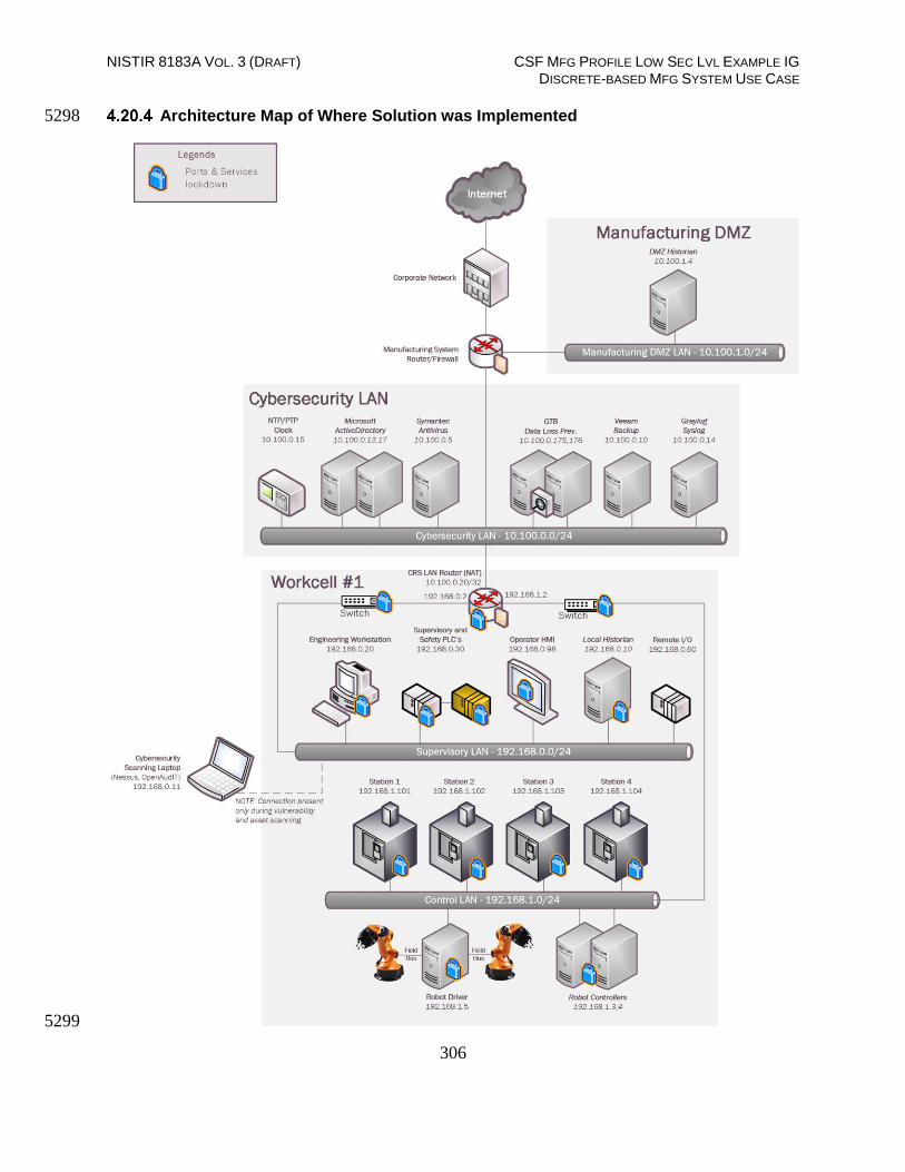
NISTIR 8183A VOL. 3 (DRAFT) CSF MFG PROFILE LOW SEC LVL EXAMPLE IG DISCRETE-BASED MFG SYSTEM USE CASE
306
Architecture Map of Where Solution was Implemented 5298
5299

NISTIR 8183A VOL. 3 (DRAFT) CSF MFG PROFILE LOW SEC LVL EXAMPLE IG DISCRETE-BASED MFG SYSTEM USE CASE
307
Installation Instructions and Configurations 5300
The following steps were performed 5301
On the Linux hosts: 5302
A software inventory of each Linux system was performed using Open-AudIT. The 5303
inventory reports were reviewed, and a list of unwanted packages were identified. This 5304
includes software that comes with the OS by default such as Remina, vino, Thunderbird etc. 5305
These programs were then uninstalled. 5306
Hardened /etc/exports file on the NFS-server to export nfs-shares to specific client IP 5307
addresses with Read only permissions 5308
Disabled the dnsmasq service and socket on machining stations, as they are not required for 5309
normal operations 5310
Disabled services such as mongodb, modem-manager from Robot Driver server and 5311
Engineering Workstation. 5312
Restricted SSH access to select users in the /etc/ssh/sshd_config file. 5313
5314
On the HMI: 5315
5316
Ports 21 161 which were detected as open by Open-AudIT were disabled. 5317
Modified the HMI program to disable the option to "restart" a machining station and to "clear 5318
the part counter" of a station if the station is NOT in the STOP mode. 5319
5320
1. On the PLC: 5321
5322
Ports 23, 80, 139, 443, 445, 5120, and 8080 were closed by disabling services. 5323
Services disabled: HTTP server, Telnet, web proxy, SMB, SNMP. This was performed by 5324
modifying Windows CE registry entries, as described on p.40 in the "Document about IPC 5325
Security" from Beckhoff. These actions required the PLC to be rebooted. 5326
Remaining open TCP ports: 21, 987. FTP is used by current work cell operations 5327
SMB and SNMP services were disabled. The SNMP service was disabled by modifying 5328
Windows CE registry entries. 5329
2. On the Network devices: 5330
5331
Changed the SNMP community string from the default public to something private. 5332
5333
5334
5335

NISTIR 8183A VOL. 3 (DRAFT) CSF MFG PROFILE LOW SEC LVL EXAMPLE IG DISCRETE-BASED MFG SYSTEM USE CASE
308
Highlighted Performance Impacts 5336
One performance measurement experiment was performed for the Ports and Services Lockdown 5337
technology implementation while the manufacturing system was operational: 5338
1. CL008.1 - The concept of least privilege is implemented on CRS hosts. 5339
4.20.6.1 Experiment CL008.1 5340
A slight increase of the part production time variance was observed during this experiment, but it 5341
is not statistically significant. 5342
5343
Figure 4-58 - Bihistograms showing the part production time (left) and estimated mean production time using 5344 the bootstrap method (right) using the measurements from baseline CL001.1 and experiment CL008.1 5345
Link to Entire Performance Measurement Data Set 5346
CL008.1-LeastPrivilege.zip 5347

NISTIR 8183A VOL. 3 (DRAFT) CSF MFG PROFILE LOW SEC LVL EXAMPLE IG DISCRETE-BASED MFG SYSTEM USE CASE
309
VeraCrypt 5348
Technical Solution Overview 5349
VeraCrypt is a free open source disk encryption software for Windows, Mac OSX and Linux24. 5350
VeraCrypt main features: 5351
Creates a virtual encrypted disk within a file and mounts it as a real disk. 5352
Encrypts an entire partition or storage device such as USB flash drive or hard drive. 5353
Encrypts a partition or drive where Windows is installed (pre-boot authentication). 5354
Encryption is automatic, real-time(on-the-fly) and transparent. 5355
Parallelization and pipelining allow data to be read and written as fast as if the drive was not 5356
encrypted. 5357
Encryption can be hardware-accelerated on modern processors. 5358
Technical Capabilities Provided by Solution 5359
VeraCrypt provides components of the following Technical Capabilities described in Section 6 5360
of Volume 1: 5361
Encryption 5362
Subcategories Addressed by Implementation 5363
PR.DS-5 5364
24 VeraCrypt: https://www.veracrypt.fr/en/Home.html

NISTIR 8183A VOL. 3 (DRAFT) CSF MFG PROFILE LOW SEC LVL EXAMPLE IG DISCRETE-BASED MFG SYSTEM USE CASE
310
Architecture Map of Where Solution was Implemented 5365
5366

NISTIR 8183A VOL. 3 (DRAFT) CSF MFG PROFILE LOW SEC LVL EXAMPLE IG DISCRETE-BASED MFG SYSTEM USE CASE
311
Installation Instructions and Configurations 5367
Details of the Program used 5368
Name Version Location
VeraCrypt 1.23 Work-Cell Supervisory LAN
5369
Setup Overview: 5370
VeraCrypt was installed on the Engineering Workstation (running Ubuntu Linux) to encrypt a 5371
directory containing confidential documents and code files. 5372
Installation: 5373
VeraCrypt can be downloaded from https://www.veracrypt.fr . Download the version specific 5374
to the Operating System of the Computer you intend to encrypt data on. 5375
To install VeraCrypt on Ubuntu, download the .tar.bz2 bundle and extract it on the Linux 5376
system. Once done, run the setup script (x86 or x64 version) using the following command: 5377
5378
sudo ./veracrypt-1.23-setup-gui-x64 (File name varies depending on the version used) 5379
5380
Once installed, launch it from the Unity Dash or your preferred application launcher. It is 5381
important to understand basics of volume-types that can be created using VeraCrypt. As per 5382
official documentation25, there are two types of VeraCrypt volumes: 5383
File-hosted (container) 5384
Partition/device-hosted (non-system) 5385
A VeraCrypt file-hosted volume is a normal file, which can reside on any type of storage 5386
device. It contains (hosts) a completely independent encrypted virtual disk device. 5387
5388
A VeraCrypt partition is a hard disk partition encrypted using VeraCrypt. You can also 5389
encrypt entire hard disks, USB hard disks, USB memory sticks, and other types of storage 5390
devices. 5391
The following procedure shows how to configure encrypted volumes of Container type 5392
using cli (command line). 5393
5394
25 https://www.veracrypt.fr/en/Documentation.html

NISTIR 8183A VOL. 3 (DRAFT) CSF MFG PROFILE LOW SEC LVL EXAMPLE IG DISCRETE-BASED MFG SYSTEM USE CASE
312
The first thing you need to do is create an encrypted volume where you will store all 5395
folders/files you’d like to protect. Run the following command(s) and follow the interactive 5396
menu 5397
sudo veracrypt -t -c 5398
5399
5400 5401
Select 1 for Normal (Standard) Volume. Next, you need to create a file for your encrypted 5402
volume. Enter the complete path of the mapper file and select a size. This file will act as the 5403
virtual container of your encrypted data so, plan the path and volume size accordingly. 5404
5405
5406 5407
Next, select an Encryption algorithm followed by Hashing algorithm from the list 5408
5409

NISTIR 8183A VOL. 3 (DRAFT) CSF MFG PROFILE LOW SEC LVL EXAMPLE IG DISCRETE-BASED MFG SYSTEM USE CASE
313
5410 5411
Select a Filesystem type depending on the OS of the computer. FAT works on all Operating 5412
systems. 5413
5414
Enter a password for the virtual container file. For the other options such as Enter PIM and 5415
Enter Keyfile path, hit Enter to leave them blank or configure one if required. Next the 5416
wizard will prompt you to type in 320 random characters. This helps to increase the 5417
cryptographic strength of the encryption keys. Punch in 320 characters randomly and the 5418
process should move forward. Next, the virtual container for our directory will be created and 5419
a success message will be shown once it’s completed. 5420
5421

NISTIR 8183A VOL. 3 (DRAFT) CSF MFG PROFILE LOW SEC LVL EXAMPLE IG DISCRETE-BASED MFG SYSTEM USE CASE
314
5422
Create a directory on which you would want to mount this virtual container on. In our 5423
example, a /encrypted directory was created to mount the container on. Next run the 5424
following command to mount 5425
5426
sudo veracrypt <path of the container mapper file> <directory to mount on> 5427
5428
Enter the password configured earlier and hit Enter for PIM and keyfile if left blank earlier. 5429
Choose NO for Protect hidden volume since there wasn’t any created. 5430
5431
5432
5433
If the above command completes successfully, you should have your directory mounted 5434
successfully. Run df -kh to verify the mount 5435
5436

NISTIR 8183A VOL. 3 (DRAFT) CSF MFG PROFILE LOW SEC LVL EXAMPLE IG DISCRETE-BASED MFG SYSTEM USE CASE
315
5437
5438
By default, other system users would only have Read access to this directory. To allow other 5439
users to write files, configure the permissions or owner as required. You can use this 5440
encrypted volume just like any other partition on your hard drive. Data saved in this directory 5441
is accessible only as long as the virtual container is mounted. 5442
An encrypted volume is just like a file and can be deleted. Ensure to take regular backups of 5443
the mapper file to avoid losing data incase if the volume gets deleted 5444
5445
In case of a system reboot, the directory would have to be mounted again using the 5446
commands shown earlier. Configuring “Auto-mount” and “Favorite volumes” options is 5447
outside of the scope of this document. 5448
5449
Highlighted Performance Impacts 5450
No performance measurement experiments were performed for VeraCrypt due to its 5451
implementation (i.e., it was used to encrypt data-at-rest; it does not encrypt data used to operate 5452
the manufacturing system). 5453
Link to Entire Performance Measurement Data Set 5454
N/A 5455
5456
5457

NISTIR 8183A VOL. 3 (DRAFT) CSF MFG PROFILE LOW SEC LVL EXAMPLE IG DISCRETE-BASED MFG SYSTEM USE CASE
316
Media Protection 5458
Technical Solution Overview 5459
Port locks provide a low-cost solution for protecting USB ports. Implementation and ease of use 5460
provide for quick install and easy removal. USB Port locks provide a simple yet effective 5461
solution to restrict USB use. Once USB Port lock has been inserted and engaged there is no way 5462
of removing lock device without damaging USB port unless key is used. Each USB Port lock can 5463
block up to two ports. These ports are the inserted port, and the port directly to either side 5464
depending on the blocking plate direction. USB Port Lock can be purchased with a collar that 5465
protects attached USB Mice and Keyboards from removal without prior approval. 5466
Technical Capabilities Provided by Solution 5467
Media Protection provides components of the following Technical Capabilities described in 5468
Section 6 of Volume 1: 5469
5470
Media Protection 5471
Subcategories Addressed by Implementation 5472
PR.PT-2 5473
5474

NISTIR 8183A VOL. 3 (DRAFT) CSF MFG PROFILE LOW SEC LVL EXAMPLE IG DISCRETE-BASED MFG SYSTEM USE CASE
317
Architecture Map of Where Solution was Implemented 5475
5476

NISTIR 8183A VOL. 3 (DRAFT) CSF MFG PROFILE LOW SEC LVL EXAMPLE IG DISCRETE-BASED MFG SYSTEM USE CASE
318
Installation Instructions and Configurations 5477
Product / Tools selected to be implemented in testbed: 5478
o Kensington USB Port Locks (Protects Linux Machines) 5479
o Symantec Endpoint Protection (USB Policy Enforcement - Protects Windows 5480
Machines) 5481
o Group Policy (GPO) Active Directory (Protects Windows Machines) 5482
Products Overview: 5483
o USB Port locks from Kensington provide an alternative for small manufactures 5484
that don’t have the resources or primarily run Linux machines within their 5485
environment to have a solution that protections from rogue USB devices being 5486
used without approval. 5487
Pros: Quick solution, Hardware only solution, inexpensive 5488
Cons: Feels like having to force device into USB Port first few times 5489
Insert USB Port lock then push locking button in to secure. Kensington provides inserts to block 5490
multiple ports including locks designed for securing USB Keyboards and Mice. 5491
Lessons learned: 5492
Patience is required when using this product so as not to inadvertently damage USB port 5493
Highlighted Performance Impacts 5494
No performance measurement experiments were performed for the USB port locks due to their 5495
implementation method (i.e., physically restricting access to USB ports). 5496
Link to Entire Performance Measurement Data Set 5497
N/A 5498

NISTIR 8183A VOL. 3 (DRAFT) CSF MFG PROFILE LOW SEC LVL EXAMPLE IG DISCRETE-BASED MFG SYSTEM USE CASE
319
Appendix A - Acronyms and Abbreviations 5499
Selected acronyms and abbreviations used in this document are defined below. 5500
CSF Cybersecurity Framework 5501
FIPS Federal Information Processing Standards 5502
HMI Human Machine Interface 5503
ICS Industrial Control System 5504
ICS-CERT Industrial Control Systems Cyber Emergency Response Team 5505
ISA The International Society of Automation 5506
IT Information Technology 5507
LAN Local Area Network 5508
NCCIC National Cybersecurity and Communications Integration Center 5509
NIST National Institute of Standards and Technology 5510
NVD National Vulnerability Database 5511
OT Operational Technology 5512
PLC Programmable Logic Controller 5513
US-CERT United States Computer Emergency Readiness Team 5514
VPN Virtual Private Network 5515

NISTIR 8183A VOL. 3 (DRAFT) CSF MFG PROFILE LOW SEC LVL EXAMPLE IG DISCRETE-BASED MFG SYSTEM USE CASE
320
Appendix B - Glossary 5516
Selected terms used in this document are defined below. 5517
Business/Mission Objectives - Broad expression of business goals. Specified target outcome 5518
for business operations. 5519
5520
Capacity Planning - Systematic determination of resource requirements for the 5521
projected output, over a specific period. [businessdictionary.com] 5522
5523 Category - The subdivision of a Function into groups of cybersecurity outcomes closely tied to 5524
programmatic needs and particular activities. 5525
5526
Critical Infrastructure - Essential services and related assets that underpin American society 5527
and serve as the backbone of the nation's economy, security, and health. [DHS] 5528
5529
Criticality Reviews - A determination of the ranking and priority of manufacturing system 5530
components, services, processes, and inputs in order to establish operational thresholds and 5531
recovery objectives. 5532
5533 Critical Services - The subset of mission essential services required to conduct manufacturing 5534
operations. Function or capability that is required to maintain health, safety, the environment and 5535
availability for the equipment under control. [62443] 5536
5537 Cyber Risk - Risk of financial loss, operational disruption, or damage, from the failure of the 5538
digital technologies employed for informational and/or operational functions introduced to a 5539
manufacturing system via electronic means from the unauthorized access, use, disclosure, 5540
disruption, modification, or destruction of the manufacturing system. 5541
5542
Cybersecurity - The process of protecting information by preventing, detecting, and responding 5543
to attacks. [CSF] 5544
5545
Defense-in-depth - The application of multiple countermeasures in a layered or stepwise manner 5546
to achieve security objectives. The methodology involves layering heterogeneous security 5547
technologies in the common attack vectors to ensure that attacks missed by one technology are 5548
caught by another. [62443 1-1] 5549
5550
Event - Any observable occurrence on a manufacturing system. Events can include 5551
cybersecurity changes that may have an impact on manufacturing operations (including mission, 5552
capabilities, or reputation). [CSF] 5553
5554 Firmware - Software program or set of instructions programmed on the flash ROM of a 5555
hardware device. It provides the necessary instructions for how the device communicates with 5556
the other computer hardware. [Techterms.com] 5557
5558

NISTIR 8183A VOL. 3 (DRAFT) CSF MFG PROFILE LOW SEC LVL EXAMPLE IG DISCRETE-BASED MFG SYSTEM USE CASE
321
Framework - The Cybersecurity Framework developed for defining protection of critical 5559
infrastructure. It provides a common language for understanding, managing, and expressing 5560
cybersecurity risk both internally and externally. Includes activities to achieve specific 5561
cybersecurity outcomes, and references examples of guidance to achieve those outcomes. 5562
5563
Function - Primary unit within the Cybersecurity Framework. Exhibits basic cybersecurity 5564
activities at their highest level. 5565
5566
Incident - An occurrence that actually or potentially jeopardizes the confidentiality, integrity, or 5567
availability of an information system or the information the system processes, stores, or transmits 5568
or that constitutes a violation or imminent threat of violation of security policies, security 5569
procedures, or acceptable use policies. [CSF] 5570
5571
Integrator - A value-added engineering organization that focuses on industrial control and 5572
information systems, manufacturing execution systems, and plant automation, that has 5573
application knowledge and technical expertise, and provides an integrated solution to an 5574
engineering problem. This solution includes final project engineering, documentation, 5575
procurement of hardware, development of custom software, installation, testing, and 5576
commissioning. [CSIA.com] 5577 5578 Manufacturing Operations - Activities concerning the facility operation, system processes, 5579
materials input/output, maintenance, supply and distribution, health, and safety, emergency 5580
response, human resources, security, information technology and other contributing measures to 5581
the manufacturing enterprise. 5582
5583 Network Access - any access across a network connection in lieu of local access (i.e., user being 5584
physically present at the device). 5585
5586
Operational technology - Hardware and software that detects or causes a change through the 5587
direct monitoring and/or control of physical devices, processes and events in the enterprise. 5588
[Gartner.com] 5589
5590
Programmable Logic Controller - A solid-state control system that has a user-programmable 5591
memory for storing instructions for the purpose of implementing specific functions such as I/O 5592
control, logic, timing, counting, three mode (PID) control, communication, arithmetic, and data 5593
and file processing. [800-82] 5594
5595
Profile - A representation of the outcomes that a particular system or organization has selected 5596
from the Framework Categories and Subcategories. [CSF] 5597
- Target Profile - the desired outcome or ‘to be’ state of cybersecurity implementation 5598
- Current Profile – the ‘as is’ state of system cybersecurity 5599
5600
Protocol - A set of rules (i.e., formats and procedures) to implement and control some type of 5601
association (e.g., communication) between systems. [800-82] 5602
5603

NISTIR 8183A VOL. 3 (DRAFT) CSF MFG PROFILE LOW SEC LVL EXAMPLE IG DISCRETE-BASED MFG SYSTEM USE CASE
322
Remote Access - Access by users (or information systems) communicating external to an 5604
information system security perimeter. Network access is any access across a network 5605
connection in lieu of local access (i.e., user being physically present at the device). [800-53] 5606
5607 Resilience Requirements - The business-driven availability and reliability characteristics for the 5608
manufacturing system that specify recovery tolerances from disruptions and major incidents. 5609
5610 Risk Assessment - The process of identifying risks to agency operations (including mission, 5611
functions, image, or reputation), agency assets, or individuals by determining the probability of 5612
occurrence, the resulting impact, and additional security controls that would mitigate this impact. 5613
Part of risk management, synonymous with risk analysis. Incorporates threat and vulnerability 5614
analyses. [800-82] 5615
5616
Risk Tolerance - The level of risk that the Manufacturer is willing to accept in pursuit of 5617
strategic goals and objectives. [800-53] 5618
5619
Router - A computer that is a gateway between two networks at OSI layer 3 and that relays and 5620
directs data packets through that inter-network. The most common form of router operates on IP 5621
packets. [800-82] 5622
5623
Security Control - The management, operational, and technical controls (i.e., safeguards or 5624
countermeasures) prescribed for a system to protect the confidentiality, integrity, and availability 5625
of the system, its components, processes, and data. [800-82] 5626
5627
Subcategory - The subdivision of a Category into specific outcomes of technical and/or 5628
management activities. Examples of Subcategories include “External information systems are 5629
catalogued,” “Data-at-rest is protected,” and “Notifications from detection systems are 5630
investigated.” [CSF] 5631
5632
Supporting Services - Providers of external system services to the manufacturer through a 5633
variety of consumer-producer relationships including but not limited to: joint ventures; business 5634
partnerships; outsourcing arrangements (i.e., through contracts, interagency agreements, lines of 5635
business arrangements); licensing agreements; and/or supply chain exchanges. Supporting 5636
services include, for example, Telecommunications, engineering services, power, water, 5637
software, tech support, and security. [800-53] 5638
5639 Switch - A device that channels incoming data from any of multiple input ports to the specific 5640
output port that will take the data toward its intended destination. [Whatis.com] 5641
5642
System Categorization - The characterization of a manufacturing system, its components, and 5643
operations, based on an assessment of the potential impact that a loss of availability, integrity, or 5644
confidentiality would have on organizational operations, organizational assets, or individuals. 5645
[FIPS 199] 5646

NISTIR 8183A VOL. 3 (DRAFT) CSF MFG PROFILE LOW SEC LVL EXAMPLE IG DISCRETE-BASED MFG SYSTEM USE CASE
323
Third-Party Relationships - relationships with external entities. External entities may include, 5647
for example, service providers, vendors, supply-side partners, demand-side partners, alliances, 5648
consortiums, and investors, and may include both contractual and non-contractual parties. 5649
[DHS] 5650
Third-party Providers - Service providers, integrators, vendors, telecommunications, and 5651
infrastructure support that are external to the organization that operates the manufacturing 5652
system. 5653
5654
Thresholds - Values used to establish concrete decision points and operational control limits to 5655
trigger management action and response escalation. 5656

NISTIR 8183A VOL. 3 (DRAFT) CSF MFG PROFILE LOW SEC LVL EXAMPLE IG DISCRETE-BASED MFG SYSTEM USE CASE
324
Appendix C - References 5657
5658
1. Executive Order no. 13636, Improving Critical Infrastructure Cybersecurity, DCPD-5659
201300091, February 12, 2013. https://www.govinfo.gov/app/details/FR-2013-02-5660
19/2013-03915 5661 5662
2. National Institute of Standards and Technology (2014) Framework for Improving Critical 5663
Infrastructure Cybersecurity, Version 1.0. (National Institute of Standards and 5664
Technology, Gaithersburg, MD), February 12, 2014. 5665
https://doi.org/10.6028/NIST.CSWP.02122014 5666
5667
3. Stouffer KA, Lightman S, Pillitteri VY, Abrams M, Hahn A (2015) Guide to Industrial 5668
Control Systems (ICS) Security. (National Institute of Standards and Technology, 5669
Gaithersburg, MD), NIST Special Publication (SP) 800-82, Rev. 2. 5670
https://doi.org/10.6028/NIST.SP.800-82r2 5671
5672
4. Stouffer K, Zimmerman T, Tang CY, Lubell J, Cichonski J, McCarthy J (2017) 5673
Cybersecurity Framework Manufacturing Profile. (National Institute of Standards and 5674
Technology, Gaithersburg, MD), NIST Internal Report (NISTIR) 8183, Includes updates 5675
as of May 20, 2019. https://doi.org/10.6028/NIST.IR.8183 5676 5677
5. Federal Motor Vehicle Safety Standards, 49 C.F.R § 571, 2011. 5678
5679
6. Zimmerman T (2017) Metrics and Key Performance Indicators for Robotic Cybersecurity 5680
Performance Analysis. (National Institute of Standards and Technology, Gaithersburg, 5681
MD), NIST Internal Report (NISTIR) 8177, Includes updates as of May 21, 2019. 5682
https://doi.org/10.6028/NIST.IR.8177 5683
5684
7. Zimmerman T (2019) Manufacturing Profile Implementation Methodology for a Robotic 5685
Workcell. (National Institute of Standards and Technology, Gaithersburg, MD), NIST 5686
Internal Report (NISTIR) 8227. https://doi.org/10.6028/NIST.IR.8227 5687