DP42746 - HDTV Solutions.com
29
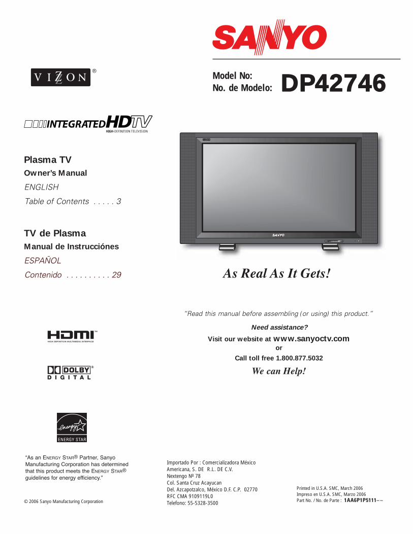
Plasma TV Owner’s Manual ENGLISH Table of Contents . . . . . 3 TV de Plasma Manual de Instrucciónes ESPAÑOL Contenido . . . . . . . . . . 29 DP42746 Printed in U.S.A. SMC, March 2006 Impreso en U.S.A. SMC, Marzo 2006 Part No. / No. de Parte : 1AA6P1P5111– – Model No: No. de Modelo: ENERGY STAR “As an ENERGY STAR ® Partner, Sanyo Manufacturing Corporation has determined that this product meets the ENERGY STAR ® guidelines for energy efficiency.” As Real As It Gets! “Read this manual before assembling (or using) this product.” Need assistance? Visit our website at www.sanyoctv.com or Call toll free 1.800.877.5032 We can Help! Importado Por : Comercializadora México Americana, S. DE R.L. DE C.V. Nextengo N o 78 Col. Santa Cruz Acayucan Del. Azcapotzalco, México D.F. C.P. 02770 RFC CMA 9109119L0 Telefono: 55-5328-3500 © 2006 Sanyo Manufacturing Corporation HIGH-DEFINITION TELEVISION ® ™
-
Upload
khangminh22 -
Category
Documents
-
view
0 -
download
0
Transcript of DP42746 - HDTV Solutions.com
Plasma TV
Owner’s Manual
ENGLISH
Table of Contents . . . . . 3
TV de Plasma
Manual de Instrucciónes
ESPAÑOL
Contenido . . . . . . . . . . 29
DDPP4422774466
Printed in U.S.A. SMC, March 2006Impreso en U.S.A. SMC, Marzo 2006Part No. / No. de Parte : 1AA6P1P5111– –
Model No:No. de Modelo:
ENERGY STAR
“As an ENERGY STAR® Partner, Sanyo Manufacturing Corporation has determinedthat this product meets the ENERGY STAR®guidelines for energy efficiency.”
As Real As It Gets!
“Read this manual before assembling (or using) this product.”
Need assistance?
Visit our website at www.sanyoctv.com or
Call toll free 1.800.877.5032
We can Help!
Importado Por : Comercializadora MéxicoAmericana, S. DE R.L. DE C.V.Nextengo No 78Col. Santa Cruz Acayucan Del. Azcapotzalco, México D.F. C.P. 02770RFC CMA 9109119L0 Telefono: 55-5328-3500© 2006 Sanyo Manufacturing Corporation
HIGH-DEFINITION TELEVISION
®
™

1. Read these instructions.
2. Keep these instructions.
3. Heed all warnings.
4. Follow all instructions.
5. Do not use this apparatus near water.
6. Clean only with dry cloth.
7. Do not block any ventilation openings. Install in accordance with the manufacturer’s instructions.
8. Do not install near any heat sources such as radia-tors, heat registers, stoves, or other apparatus(including amplifiers) that produce heat.
9. Do not defeat the safety purpose of the polarized orgrounding-type plug. A polarized plug has two bladeswith one wider than the other. A grounding-type plughas two blades and a third grounding prong. Thewide blade or the third prong are provided for yoursafety. If the provided plug does not fit fully into youroutlet, consult an electrician for replacement of theobsolete outlet.
10. Protect the power cord from being walked on orpinched particularly at plugs, convenience recepta-cles, and the point where they exit from theapparatus.
11. Only use attachments/accessories specified by themanufacturer.
12. Use only with the cart, stand, tripod,bracket, or table specified by the manu-facturer, or sold with the apparatus.When a cart is used, use caution whenmoving the cart/apparatus combinationto avoid injury from tip-over.
13. Unplug this apparatus during lightning storms orwhen unused for long periods of time.
14. Refer all servicing to qualified service personnel. Ser-vicing is required when the apparatus has beendamaged in any way, such as power-supply cord orplug is damaged, liquid has been spilled or objectshave fallen into the apparatus, the apparatus hasbeen exposed to rain or moisture, does not operatenormally, or has been dropped.
15. If an outside antenna is connected to the televisionequipment, be sure the antenna system is groundedso as to provide some protection against voltagesurges and built up static charges. In the U.S. Selec-tion 810-21 of the National Electrical Code providesinformation with respect to proper grounding of themast and supporting structure, grounding of the lead-in wire to an antenna discharge unit, size ofgrounding conductors, location of antenna dischargeunit, connection to grounding electrodes, andrequirements for the grounding electrodes.
EXAMPLE OF ANTENNA GROUNDING ACCORDING TO NATIONAL ELECTRICALCODE, ANSI/NFPA 70
16. An outside antenna system should not be located inthe vicinity of overhead power lines or other electricallight or power circuits, or where it can fall into suchpower lines or circuits. When installing an outsideantenna system, extreme care should be taken tokeep from touching such power lines or circuits ascontact with them might be fatal.
17. "Apparatus shall not be exposed to dripping orsplashing and no objects filled with liquids, such asvases, shall be placed on the apparatus."
WARNING: TO REDUCE THE RISK OF FIRE OR ELECTRIC SHOCK, DO NOT EXPOSE THIS
APPLIANCE TO RAIN OR MOISTURE.
IMPORTANT SAFETY INSTRUCTIONS
“Note to CATV system installer:This reminder is provided to call the CATV system installer’s attention toArticle 820-40 of the NEC that provides guidelines for proper groundingand, in particular, specifies that the cable ground shall be connected tothe grounding system of the building, as close to the point of cable entryas practical.”
NEC - NATIONAL ELECTRICAL CODE
ANTENNALEAD INWIRE
GROUNDING CONDUCTORS(NEC SECTION 810-21)
GROUND CLAMPS
ANTENNADISCHARGE UNIT(NEC SECTION 810-20)
GROUNDCLAMP
ELECTRICSERVICEEQUIPMENT
POWER SERVICE GROUNDINGELECTRODE SYSTEM(NEC ART 250, PART H)
2 Need help? Visit our Web site at www.sanyoctv.com or Call 1-800-877-5032
CAUTIONRISK OF ELECTRIC SHOCK DO NOT OPEN
CAUTION: TO REDUCE THE RISK OF ELECTRIC SHOCK, DO NOT REMOVE COVER (OR
BACK). NO USER-SERVICEABLE PARTS INSIDE. REFER SERVICING TO QUALIFIED
SERVICE PERSONNEL.
THIS SYMBOL INDICATES THAT DANGEROUS VOLTAGE CONSTITUT-ING A RISK OF ELECTRIC SHOCK IS PRESENT WITHIN THIS UNIT.
THIS SYMBOL INDICATES THAT THERE ARE IMPORTANT OPERATINGAND MAINTENANCE INSTRUCTIONS IN THE LITERATURE ACCOM-PANYING THIS UNIT.

CONTENTS
TO THE OWNER
Welcome to the World of SanyoThank you for purchasing this Sanyo Plasma High-Definitiontelevision. You made an excellent choice for Performance, Reliability, Features, Value, and Styling.
Important InformationBefore installing and operating this Plasma DTV, read thismanual thoroughly. This Plasma DTV provides many convenientfeatures and functions. Operating the Plasma DTV properly
enables you to manage those features and maintain it in goodcondition for many years to come. Improper operation mayresult in not only shortening the product-life, but may alsocause malfunctions or other serious problems.
If your Plasma DTV seems to operate improperly, read thismanual again, check operations and cable connections and trythe solutions in the “Helpful Hints” section, page 26 of thismanual. If the problem still persists, visit our website atwww.sanyoctv.com or call 1.800.877.5032. We Can Help!
Important Safety Instructions . . . . . . . . . . . . . . . . . . . . . . . 2To The Owner . . . . . . . . . . . . . . . . . . . . . . . . . . . . . . . . . . 3Contents . . . . . . . . . . . . . . . . . . . . . . . . . . . . . . . . . . . . . . 3Features . . . . . . . . . . . . . . . . . . . . . . . . . . . . . . . . . . . . . . 4Specifications . . . . . . . . . . . . . . . . . . . . . . . . . . . . . . . . . . 4Handling Precautions . . . . . . . . . . . . . . . . . . . . . . . . . . . . . 5Care and Cleaning . . . . . . . . . . . . . . . . . . . . . . . . . . . . . . . 5
Cleaning the Plasma DTV . . . . . . . . . . . . . . . . . . . . . . . . . . . . . . . . 5
Caring for the Plasma DTV . . . . . . . . . . . . . . . . . . . . . . . . . . . . . . . 5
Installation Precautions . . . . . . . . . . . . . . . . . . . . . . . . . . . 6Child Safety . . . . . . . . . . . . . . . . . . . . . . . . . . . . . . . . . . . . . . . . . . 6
Positioning Precautions . . . . . . . . . . . . . . . . . . . . . . . . . . . . . . . . . 6
Removing the Plasma Stand (Feet) (Optional) . . . . . . . . . . . . . . . . 6
First-Things-First (Required Initial Setup) . . . . . . . . . . . . . . . 7Initial Signal Connections . . . . . . . . . . . . . . . . . . . . . . . . . . . . . . . . 7
Digital RF Antenna Connection . . . . . . . . . . . . . . . . . . . . . . . . . . . 7
Analog RF Antenna Connection . . . . . . . . . . . . . . . . . . . . . . . . . . 7
Install Batteries . . . . . . . . . . . . . . . . . . . . . . . . . . . . . . . . . . . . . . . . 8
Connect AC Power Cord . . . . . . . . . . . . . . . . . . . . . . . . . . . . . . . . . 8
All Channel Search . . . . . . . . . . . . . . . . . . . . . . . . . . . . . . . . . . . . . . 8
Analog Antenna Signal Selection (Optional) . . . . . . . . . . . . . . . . . . 8
Top and Back Panels . . . . . . . . . . . . . . . . . . . . . . . . . . . . . 9Choose Your Connection . . . . . . . . . . . . . . . . . . . . . . . . . . 10Digital AV Connections
Connecting External Equipment to HDMI Input . . . . . . . . . . . . . . . 11
Connect STB or DVD with DVI Output to HDMI Input . . . . . . . . . . 12
Connecting Digital Audio Output to a Multi-Channel Receiver . . . . 12
Use the Component Jacks to Connect a DVD Player or Other Digital Equipment . . . . . . . . . . . . . . . . . . . . . . . . . . . . . . 13
Analog AV INPUT Connections Use the Video1 Jacks to Connect a VCR or other Analog Equipment . . . . . . . . . . . . . . . . . . . . . . . . . . . . . . 14
Connecting Analog Audio Output Jacks to Stereo Amplifier . . . . . 15
Typical Home Theater Connections . . . . . . . . . . . . . . . . . . 15
Using the Remote Control . . . . . . . . . . . . . . . . . . . . . . . . . 16
Precautions . . . . . . . . . . . . . . . . . . . . . . . . . . . . . . . . . . . . . . . . . . 16
Remote Control Keys . . . . . . . . . . . . . . . . . . . . . . . . . . . . . . 16 ~ 17
TV Adjustment and Setup . . . . . . . . . . . . . . . . . . . . . . . . . 18
Basic Menu Operation . . . . . . . . . . . . . . . . . . . . . . . . . . . . . . . . . . 18
Menu Navigation Map . . . . . . . . . . . . . . . . . . . . . . . . . . . . . . . . . . 18
Menu Options:
All Channel Search . . . . . . . . . . . . . . . . . . . . . . . . . . . . . . . . . . . . . 18
Digital Cable Search (Optional) . . . . . . . . . . . . . . . . . . . . . . . . . . . 19
Digital Add-on Search . . . . . . . . . . . . . . . . . . . . . . . . . . . . . . . . . . 19
Analog Antenna Signal Selection (Optional) . . . . . . . . . . . . . . . . . 20
Channel Scan Memory . . . . . . . . . . . . . . . . . . . . . . . . . . . . . . . . . 20
Digital Caption . . . . . . . . . . . . . . . . . . . . . . . . . . . . . . . . . . . . . . . . 21
Changing the Look of Digital Captions . . . . . . . . . . . . . . . . . . . 21
To View Captions . . . . . . . . . . . . . . . . . . . . . . . . . . . . . . . . . . . . 21
V-Guide (Parental Control) . . . . . . . . . . . . . . . . . . . . . . . . . . . . . . 22
To Block MPAA Movie or TV Program . . . . . . . . . . . . . . . . . . . . 22
To Setup V-Guide Ratings . . . . . . . . . . . . . . . . . . . . . . . . . . . . . 22
Temporarily Unblock MPAA Movie or TV Program . . . . . . . . . . 23
To Unblock All MPAA Movie or All TV Ratings . . . . . . . . . . . . . . 23
MPAA Movie Ratings (Age-Based) . . . . . . . . . . . . . . . . . . . . . . . 23
TV Ratings (Age/Content-Based) . . . . . . . . . . . . . . . . . . . . . . . . 23
Picture/Sound Adjustment . . . . . . . . . . . . . . . . . . . . . . . . . . . . . . 24
Menu Language . . . . . . . . . . . . . . . . . . . . . . . . . . . . . . . . . . . . . . . 24
Picture Rotation (Screen Saver) . . . . . . . . . . . . . . . . . . . . . . . . . . 25
White Pattern Setup (Panel Repair) . . . . . . . . . . . . . . . . . . . . . . . . 25
Helpful Hints (Problems/Solutions) . . . . . . . . . . . . . . . . . . 26
Mexico Guarantee . . . . . . . . . . . . . . . . . . . . . . . . . . . . . . 27
United States and Canada Warranty . . . . . . . . . . . . . . . . . . 28
3Need help? Visit our Web site at www.sanyoctv.com or Call 1-800-877-5032
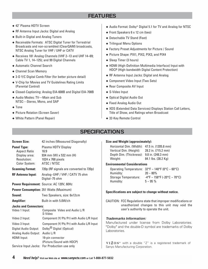
� 42" Plasma HDTV Screen
� RF Antenna Input Jacks: Digital and Analog
� Built-in Digital and Analog Tuners
� Receivable Formats: ATSC Digital Tuner for Terrestrial Broadcasts and non-scrambled (ClearQAM) broadcasts,NTSC Analog Tuner for VHF / UHF or CATV
� Receives 181 Analog Channels (VHF 2~13 and UHF 14~69;Cable TV 1, 14~125); and 99 Digital Channels
� Automatic Channel Search
� Channel Scan Memory
� 3-D Y/C Digital Comb Filter (for better picture detail)
� V-Chip for Movies and TV Guidelines Rating Limits (Parental Control)
� Closed-Captioning: Analog EIA-608B and Digital EIA-708B
� Audio Modes: TV—Main and SubNTSC—Stereo, Mono, and SAP
� Tone
� Picture Rotation (Screen Saver)
� White Pattern (Panel Repair)
� Audio Format: Dolby® Digital 5.1 for TV and Analog for NTSC
� Front Speakers 6 x 12 cm (two)
� Detachable TV Stand (Feet)
� Trilingual Menu Options
� Factory Preset Adjustments for Picture / Sound
� Picture Shape: PIX1, PIX2, PIX3, and PIX4
� Sleep Timer (3 hours)
� HDMI (High-Definition Multimedia Interface) Input withHDCP (High-bandwidth Digital Content Protection)
� RF Antenna Input Jacks: Digital and Analog
� Component Video Input (Two Sets)
� Rear Composite AV Input
� S-Video Input
� Optical Digital Audio Out
� Fixed Analog Audio Out
� XDS (Extended Data Services) Displays Station Call Letters,Title of Show, and Ratings when Broadcast
� 32-Key Remote Control
FEATURES
SPECIFICATIONS
Screen Size: 42 inches (Measured Diagonally)
Panel Type: Plasma HDTV DisplayAspect Ratio 16:9Display area: 934 mm (W) x 532 mm (H)Resolution: 1024 x 768 pixelsColor System: ATSC / NTSC
Scanning Format: 720p (RF signals are converted to 720p)
RF Antenna Input: Analog–UHF / VHF / CATV 75 ohm Digital–75 ohm
Power Requirement: Source: AC 120V, 60Hz
Power Consumption: 351 Watts (Maximum)
Sound: Two Speakers, size: 6x12cm
Amplifier: Built-in with 5.0W/ch
Jacks and Connectors:Video 1 Input: Composite Video and Audio L /R
S-VideoVideo 2 Input: Component (Y/ Pb/Pr) with Audio L/R Input
Video 3 Input: Component (Y/ Pb/Pr) with Audio L/R InputDigital Audio Output: Dolby® Digital (Optical) Analog Audio Output: Audio L /R HDMI Input: 19-pin connector
(Picture/Sound with HDCP)Service Input Jacks: For Production use only
Size and Weight (approximately):Horizontal Dim. (Width): 47.5 in. (1205.8 mm) Vertical Dim. (Height): 28.2 in. (715.2 mm)Depth Dim. (Thickness): 9.8 in. (248.3 mm)Weight: 84.1 lbs. (38.2 Kg)
Environmental ConsiderationsOperating Temperature: 32°F ~ 140°F (0°C ~ 60°C)Humidity: 20 ~ 80%Storage Temperature: -4°F ~ 158°F (-20°C ~ 70°C)Humidity: 5 ~ 95 %
Specifications are subject to change without notice.
CAUTION: FCC Regulations state that improper modifications orunauthorized changes to this unit may void theuser’s authority to operate the unit.
Trademarks Information:
Manufactured under license from Dolby Laboratories.“Dolby” and the double-D symbol are trademarks of DolbyLaboratories.
4 Need help? Visit our Web site at www.sanyoctv.com or Call 1-800-877-5032
with a double “Z” is a registered trademark ofSanyo Manufacturing Corporation.

HANDLING PRECAUTIONS
• Handle the Plasma DTV carefully when installing. DoNot Drop.
• Locate the set away from heat, excessive dust, anddirect sunlight.
NOTE: When the Plasma DTV is not used for a long periodof time, dark dots may be observed. This is a char-acteristic of the Plasma display. If this occurs, turnthe Plasma DTV On and leave it on about one hour.These dots will gradually disappear.
• Throughout the installation process, handling by morethan two people is recommended.
• When removing the feet, use a working space that islarger than the screen size. The work surface must beflat and covered with a soft cloth or blanket to protectthe screen surface.
• Before placing the Plasma DTV face down, make surethere are no objects under the screen. Leaving anyobject may cause damage on the screen surface.
AC IN 120VAC IN 120V
UHF/VHF/CATV
UHF/VHF/CATV
DIGITALDIGITAL
ANTENNA IN
ANTENNA IN
SERVICESERVICE
DIGITALDIGITAL
AUDIOAUDIO
OUTPUTOUTPUT
Hand Slots
CLEANING THE PLASMA DTV
The surface of the cabinet can be damaged if not properlymaintained. Many common household aerosol sprays,cleaning agents, solvents, and polishes will cause perma-nent damage to the fine surface.1. Unplug the power cord before cleaning the Plasma
DTV.
2. Gently wipe the screen and cabinet with dry soft
cloth.
The screen is likely to be damaged if it is not maintainedproperly. Do not use hard objects like a hard cloth orpaper. Do not use solvents or abrasives.
NOTES: Never spray liquids on thescreen.Do not use benzene, thinner, orany volatile substances to cleanthe Plasma DTV. These chemi-cals may damage the cabinetfinish.
CARING FOR THE PLASMA DTV
Do not bump or scratch the panel surface as this causesflaws on the surface of the screen.
Do not display a still image on the screen for a long time.Otherwise, an afterimage or “ghost” may appear on apart of the panel. To prevent this symptom, use the“Picture Rotation (Screen Saver) and White Pattern(panel repair)” function of the Plasma DTV. See page 25.
There may be some tiny black points and/or blight pointson the Plasma Display Panel. These points are normal.
AS
CARE AND CLEANING
5Need help? Visit our Web site at www.sanyoctv.com or Call 1-800-877-5032

INSTALLATION PRECAUTIONS
CHILD SAFETY
Sanyo is committed to making home entertainment safeand enjoyable. Always use an appropriate table or standwhen positioning your DTV. Use appropriate brackets,braces, or straps to anchor your furniture in place. Butnever screw anything directly to the television.
Do not place televisions on dressers, shelves, desks,carts, etc. where curious or excited children could pull,push, or otherwise cause the unit to fall and cause per-sonal injury.
Never place toys or other items on top of the DTV thatcould pique children’s curiosity causing them to climbabout the furniture.
Always use stands that are designed to support the sizeand combined weight of your television and other elec-tronic devices.
AS
POSITIONING PRECAUTIONS
• Place this Plasma DTV as indicated here. Failure to doso may result in a fire hazard. Allowing the properamount of space at the top, sides, and rear of thePlasma DTV cabinet is critical for proper air circulationand cooling of the unit. The dimensions shown hereindicate the minimum space required. If the PlasmaDTV is to be built into a compartment or similarlyenclosed, these minimum distances must bemaintained.
• Do not cover the ventilation slots on the Plasma DTV.Heat build-up can reduce the life of your Plasma DTV,and can also be dangerous.
• If the Plasma DTV is not to be used for an extendedperiod of time, unplug it from the power outlet.
AS
2.36”(6 cm)
4”(10 cm)
4”(10 cm)
4” (10 cm)
AC IN 120VAC IN 120VUHF/VHF/CATVUHF/VHF/CATVDIGITALDIGITAL
ANTENNA INANTENNA INSERVICESERVICE DIGITALDIGITAL
AUDIOAUDIOOUTPUTOUTPUT
REMOVING THE PLASMA STAND
(FEET) (OPTIONAL)
Remove two (2) screws from each foot bracket, thenslide the feet out of the brackets.
6 Need help? Visit our Web site at www.sanyoctv.com or Call 1-800-877-5032

This Plasma television will reproduce a crystal clear Digital picture and exceptional sound. The signal makes the difference!
1 INITIAL SIGNAL CONNECTIONS
Analog RF Antenna Connection
• Connect a Cable signal (with or without a cable box),Satellite Receiver, or RF antenna to the Analog RFinput.
The analog tuner in this Plasma DTV receives AnalogAntenna signals, Analog Cable signals, or the RF outputfrom a Satellite Receiver, VCR, or cable box.
UHF/VHF/CATVUHF/VHF/CATV
FROM ANT.
OUT TO TV
IN
OUT
CATV FRANCHISE NOTE: Cable companies, like publicutilities, are franchised by local government authori-ties. To receive cable programs, even with equipmentwhich is capable of receiving cable channels, the con-sumer must subscribe to the cable company’s service.
ANALOG CABLEANALOG RFANTENNA
ANALOG SATELLITE RECEIVER
VCR BACK
Digital (DTV) RF Antenna Connection
• Connect an RF Antenna to the Digital Antenna In terminal.
The digital tuner in this DTV receives HD signals from anantenna. Digital signals from a Set-top Box (STB) arereceived through the Component In jacks.
This DTV can receive ANY resolution being broadcast(HDTV, EDTV, or SDTV). However, ALL resolutions areconverted to 1080i for display.
DIGITALDIGITALANTENNA INANTENNA IN
DIGITALAUDIO
OUTPUT UHF/VHF/CATVUHF/VHF/CATV
DIGITAL RFANTENNA
PLASMA TV BACK
FIRST-THINGS-FIRST (Required Initial Setup)
FROM ANT.
OUT TO TV
IN
OUT
IN FROMSAT.
CATV IN
OUT TO TV S-VIDEO
CH3CH4
L- -RAUDIOVIDEO
L- -RAUDIOVIDEO
UHF/VHF/CATVUHF/VHF/CATV
FROM ANT.
OUT TO TV
IN
OUT
UHF/VHF/CATVUHF/VHF/CATV
ORVCR BACK VCR BACK
PLASMADTV BACK
OR
PLASMADTV BACK
PLASMADTV BACK
Notes: If you do not have a VCR, connect signal directly to the TV75 ohm terminal (UHF/VHF/CATV).
Don’t be fooled by the phrase “Available in High-
Definition.” The only resolution available with any of theseanalog connections, regardless of the original content, isstandard analog (SDTV).
DIGITAL ANTENNA INPUT
� DTV will select the correct Antenna mode for the type ofAnalog RF signal connected automatically.
� Use “Analog Antenna Signal” in the Setup menu to changethe Antenna Mode.
� If you move the DTV to a new location, press the RESET
key twice after connecting the signal and turning on theDTV.
7Need help? Visit our Web site at www.sanyoctv.com or Call 1-800-877-5032
(Continued on next page.)

When the television is powered on for the firsttime, it automatically checks for the presence ofan RF signal.
• Press the POWER key to turn on theDTV.
• Then press the CHANNEL UP
(CH � ) key to automaticallysearch for available channels:Digital (ATSC) and Analog (NTSC).
The All Channel Search contains two processes that areexecuted simultaneously for digital and analog channels.NOTES: Channel information found during All Channel Search is
stored in two Channel Scan Memory databases(Analog and Digital). After all channel search is com-pleted, the TV will tune to the lowest Digital channel orlowest Analog channel if no digital channels are found.
If the TV does not detect any digital or analog chan-nels, a message advising the viewer to check thecables and antenna connections will appear. In thiscase, you must press the CHANNEL UP key again torepeat the channel search process. If after twosearches the TV still fails to detect any channels, theTV will tune to analog channel 3.
If no analog or digital channels are found after the
second search, All Channel Search will default to off-air analog channels 2 through 69 and digital channelD3-1. Select analog channels using the remote controlkeypad. See page 16, item number 2.
4ALL CHANNEL SEARCH
IMPORTANT NOTE: Spent or dis-charged batteries must be recycled ordisposed of properly in compliancewith all applicable laws. For detailedinformation, contact your local CountySolid Waste Authority.
2INSTALL BATTERIES
• Install two “AAA” Batteries (not included) so that the“+” and “–” marks on the batteries match the “+”and “–” marks inside the Remote.
To review the remote control functions, go to pages 16 ~17.
NOTE: Use two “AAA” Alkaline batteries.
1
4 5 67 8
09
2 3
INPUT
INFO
RECALL
MENU
CAPTIONEXIT
VOL
ENTER
TUNER MUTE
SLEEP
1
4 5 67 8
09
2 3
INPUT
INFO
RECALL
MENU
CAPTIONEXIT
VOL
ENTER
TUNER MUTE
SLEEP
CH
POWER
3CONNECT AC POWER CORD
• Connect AC Power Cord (supplied) to the Plasma TVand electrical outlet as shown here.
The AC outlet must be near this equipment and must beeasily accessible.
To POWER CORD
CONNECTOR on backof Plasma TV.
To 120 V AC outlet.
5ANTENNA SIGNAL SELECTION(OPTIONAL)
To change the initialanalog tuning systemsetup (from antenna tocable or cable toantenna), use the on-screen menu. See“Analog Antenna Sig-nal” on page 20.
�
8 Need help? Visit our Web site at www.sanyoctv.com or Call 1-800-877-5032
FIRST-THINGS-FIRST (Required Initial Setup)
SKIP THE CHANNEL SEARCH PROCESS
Use this feature only if the DTV is used primarily forplaying video games, or watching videos, or if you receivelocal channels from a satellite receiver or cable system.
• Press the EXIT key to cancel the channel searchprocess.
• The DTV will be tuned to Analog Channel 3.
• Press the INPUT key (remote control) to selectAV signal source connected to: Video 1, Video 2,Video 3, or HDMI jacks.

TOP AND BACK PANELS
�
� � �
POWERCH VOL
Top Panel View (see items 8, 11, & 17 on page 17.)
Volume
– + keysChannel
� keys
Power key
BACK PANEL—BOTTOM VIEW (CENTER)
� HDMI (High Definition Multimedia Interface) Input,
PAGES 11 ~ 12—Connect digital video equipment tothis jack. It takes only one high bandwidth cable (notsupplied) to communicate between the video/audioequipment and this TV. This connection is compatiblewith DVI equipped devices. (Separate audio connec-tion and an adapter are required for DVI device.)
Digital Audio Output, PAGE 12—Use an OpticalAudio cable to connect Digital Audio Output to anadvanced stereo home theater system equipped withDolby® Digital 5.1.
� Digital Antenna Input, PAGE 7—Connect an RFantenna to this jack.
Service Jacks—For production use only
� Analog Antenna Input (UHF/VHF/CATV), PAGE
7—Connect an RF antenna or Analog cable system tothis jack.
� S-Video Input (VIDEO1), PAGE 14—To enhancevideo detail use the S-Video jacks instead of the Videojacks, if available on your external equipment. (S-Video connection will override connection to theVideo input jack [VIDEO1]).
� Analog Audio Out (L/R) Jacks, PAGE 15—Connectexternal audio equipment here.
� Audio/Video Input (VIDEO1), PAGE 14—Connectanalog video equipment here.
NOTE: S-Video connection overrides the (Video1)composite video connection.
� Component Video Input (VIDEO2), PAGE 13—Connect digital video equipment to the Y, Pb, Pr andAudio L/ R jacks. These jacks will automatically detectthe type of signal being received.
� Component Video Input (VIDEO3), PAGE 13—Connect digital video equipment to the Y, Pb, Pr andAudio L/R jacks. These jacks will automatically detectthe type of signal being received.
AC IN 120V—Connect power cord here. See page 8.
9Need help? Visit our Web site at www.sanyoctv.com or Call 1-800-877-5032
� �
� � 11
11

CHOOSE YOUR CONNECTION
Digital Signal Compatible External Cables Needed Go to
Connections Equipment (Not Supplied) Page
13
This Plasma DTV is designed to handle several differentconnections making it compatible with Digital and Analogdevices.
In order to receive the best performance from your DTV,choose your connection using this chart; then go to thespecified page for detailed instructions.
COMPONENT
(Y, Pb, Pr) IN
Will accept HDTV,EDTV, or SDTV Videocontent.
(Requires separateaudio connections.)
COMPONENTVIDEOCABLE[Green, Blue, and, Red connectors]
COMPOSITE VIDEO
OR
S-VIDEO IN
14
DIGITAL AUDIO
OUT
(Only available whenreceived as part of aDigital RF signal orHDMI signal.)
OPTICALDIGITALCABLE
12
ANALOG AUDIO
OUT JACKS 15
AUDIO CABLE[White and Red connectors]
S-VIDEO CABLE
Analog Signal Compatible External Cables Needed Go to
Connections Equipment (Not Supplied) Page
COMPOSITEVIDEO CABLE[Yellow, White, andRed connectors]
MULTI-CHANNEL RECEIVER
DVD PLAYER
VCR
STEREO AMPLIFIERSYSTEM
LEFT / RIGHT
ANALOG AUDIO IN
AUDIO CABLE[White and Red connectors]
Digital Set-Top Boxor DVD Player
HDMI
Will accept HDTV (High Bandwidth Video component)
Digital Set-Top Box orDVD Player
19 Pin HDMI 11 or
12
VIDEO GAME
VIDEO GAME
VIDEO GAME
10 Need help? Visit our Web site at www.sanyoctv.com or Call 1-800-877-5032

DIGITAL AV CONNECTIONS
This is the best option for picture and sound! Using the HDMI connection, which has high-definitioncontent protection, provides you with uncompressed digital video and audio, Dolby® Digital 5.1 orPCM sound. This connection requires only one cable. As Real As It Gets!
CONNECTING EXTERNAL EQUIPMENT TO HDMI
(INCLUDES HDCP COPY PROTECTION)
1
4 5 6
2 3
POWERINPUT
What you will need for connections:
19 Pin HDMI Digital Cable – 1
(Make sure you check the pin configuration of thecable plug-end*)
*Adapter may be required. Check with your localelectronics store.
REMOTE CONTROL
SET-TOP BOX (Can be a Digital Satellite Receiver,DVD PLAYER, or similar digital device.)
BACK VIEW OF DTV
To avoid problems with some brands of external equip-ment, follow this procedure when connecting cables andpowering on your equipment.
1 Switch off DTV and external equipment before con-necting cable. (Cable is not supplied.)
2 Connect the external equipment’s high bandwidthHDMI Output to the DTV’s HDMI Input.
3 The DTV must be turned on first, press POWER. Thenturn on your external equipment.
4 Press INPUT to select HDMI to view adigital program.
� If the television HDMI pin configuration is different fromthe pin configuration on your set-top box, you will need touse an Adapter.
� Press the INPUT key after connecting cables to access theAV Inputs. There is NO need to tune to a blank channel.
HDMI CABLE(Gently insertcable into TVHDMI Inputjack.)
4
2
3
11Need help? Visit our Web site at www.sanyoctv.com or Call 1-800-877-5032
SIGNAL CONVERSION CHARTINPUT SIGNAL(From external equipment)
OUTPUT SIGNAL(Display)
480i 720p480p 720p1080i 720p
BACK VIEWOF DTV2 3
SET-TOP BOX (Can be a Digital Satellite Receiver, DVDPLAYER, or similar digital device.)
What you will need for connections:
DVI to HDMI Cable – 1
Audio Cable – 1
1
4 5 6
2 3
POWERINPUT
REMOTE CONTROL
54
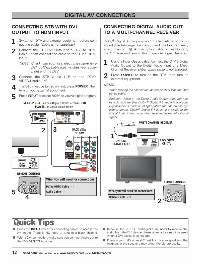
1 Switch off DTV and external equipment before con-necting cable. (Cable is not supplied.)
2 Connect the STB DVI Output to a “DVI to HDMICable;” then connect the cable to the DTV’s HDMIinput.
NOTE: Check with your local electronics store for aDVI to HDMI Cable that matches your equip-ment and the DTV.
3 Connect the STB Audio L / R to the DTV’s VIDEO3 Audio L / R.
4 The DTV must be turned on first, press POWER. Thenturn on your external equipment.
5 Press INPUT to select HDMI to view a digital program.
CONNECTING STB WITH DVI
OUTPUT TO HDMI INPUT
� Press the INPUT key after connecting cables to access theAV Inputs. There is NO need to tune to a blank channel.
� With a DVI connection, make sure you connect Audio out tothe TV’s VIDEO3 Audio In.
� Because the VIDEO3 audio jacks are used to receive theaudio from the DVI device, these video jacks cannot be usedwhen a DVI device is connected.
� Position your DTV at least 2 feet from stereo speakers. Themagnets in the speakers may affect the picture quality.
Dolby® Digital Audio provides 5.1 channels of surroundsound (five full-range channels [5] and one low-frequencyeffect channel [.1]). A fiber optics cable is used to carrythe 5.1 surround sound (for low-noise signal transfer).
BACK VIEWOF DTV
OPTICALDIGITAL CABLE
1 Using a Fiber Optics cable, connect the DTV’s DigitalAudio Output to the Digital Audio Input of a Multi-Channel Receiver. (Fiber optics cable is not supplied.)
2 Press POWER to turn on the DTV, then turn onexternal equipment.
NOTES:
When making the connection, do not pinch or kink the fiberoptics cable.
Red light visible at the Digital Audio Output does not nec-essarily indicate that Dolby ® Digital 5.1 audio is available.Digital audio is made up of light pulses that the human eyecannot detect. Dolby ® Digital 5.1 audio is available at theDigital Audio Output only when received as part of a Digitalsignal.
What you will need for connections:
Optical Cable – 1
MULTI-CHANNEL RECEIVER
1
1
4 5 6
2 3
POWERINPUT
REMOTE CONTROL
2
CONNECTING DIGITAL AUDIO OUT
TO A MULTI-CHANNEL RECEIVER
12 Need help? Visit our Web site at www.sanyoctv.com or Call 1-800-877-5032
DIGITAL AV CONNECTIONS

1 Connect DVD Player or similar digital equipment’sComponent Video Out to the DTV’s Video VIDEO3jacks.
2 Connect DVD Player or similar digital equipment’sAudio Out to the DTV’s VIDEO3 Audio jacks.
3 Press POWER to turn on the DTV, then turn on external equipment.
4 Press INPUT to select Video 3 to view the DVDprogram.
The Component Video jacks will accept HDTV, EDTV, orSDTV video content.
Switch off DTV and external equipment before connect-ing cables. (Cables are not supplied.) Follow these stepsto easily connect your STB or DVD Player to this DTV:
DVD PLAYER(or similar digitaldevice such as aDigital SatelliteReceiver.)
COMPONENT JACKS
1
What you will need for connections:
Component Video Cable – 1 Audio Cable – 1
� VIDEO2 and VIDEO3 jacks have identical functions. Com-patible video devices can be connected to either set ofjacks.
� Press the INPUT key after connecting the cables, to selectthe Video 2 or Video 3 input signal. There is NO need totune to a blank channel.
� “No Signal” will appear randomly on the screen when nosignal is detected at the VIDEO2 or VIDEO3 inputs.
2
1
4 5 6
2 3
POWERINPUT
REMOTE CONTROL
4 3
USING COMPONENT JACKS TO CONNECT A DVD PLAYER
OR OTHER DIGITAL EQUIPMENT
13Need help? Visit our Web site at www.sanyoctv.com or Call 1-800-877-5032
1
2
DTV BACK
SIGNAL CONVERSION CHARTINPUT SIGNAL(From external equipment)
OUTPUT SIGNAL(Display)
480i 720p480p 720p1080i 720p
ANALOG AV CONNECTIONS
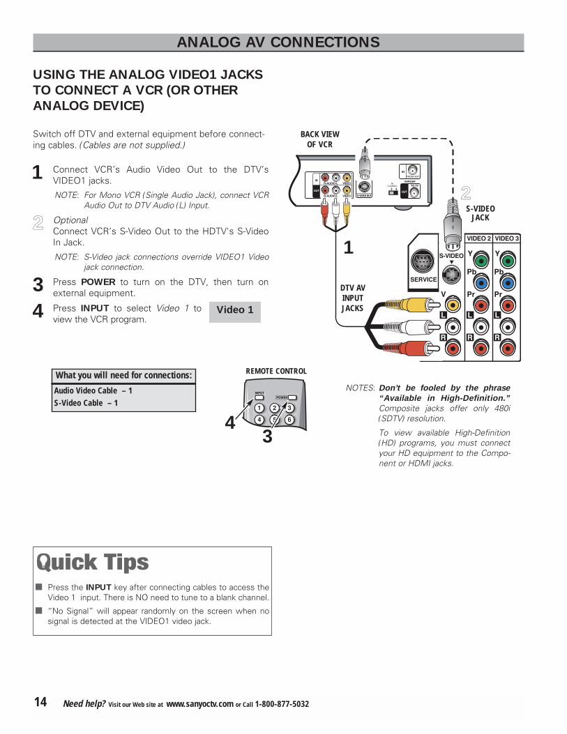
Switch off DTV and external equipment before connect-ing cables. (Cables are not supplied.)
BACK VIEWOF VCR
DTV AVINPUTJACKS
1 Connect VCR’s Audio Video Out to the DTV’s VIDEO1 jacks.
NOTE: For Mono VCR (Single Audio Jack), connect VCRAudio Out to DTV Audio (L) Input.
22 OptionalConnect VCR’s S-Video Out to the HDTV's S-VideoIn Jack.
NOTE: S-Video jack connections override VIDEO1 Videojack connection.
3 Press POWER to turn on the DTV, then turn onexternal equipment.
4 Press INPUT to select Video 1 toview the VCR program.
What you will need for connections:
Audio Video Cable – 1S-Video Cable – 1
S-VIDEOJACK
22
1
� Press the INPUT key after connecting cables to access theVideo 1 input. There is NO need to tune to a blank channel.
� “No Signal” will appear randomly on the screen when nosignal is detected at the VIDEO1 video jack.
1
4 5 6
2 3
POWERINPUT
REMOTE CONTROL
43
USING THE ANALOG VIDEO1 JACKS
TO CONNECT A VCR (OR OTHER
ANALOG DEVICE)
14 Need help? Visit our Web site at www.sanyoctv.com or Call 1-800-877-5032
Video 1
NOTES: Don’t be fooled by the phrase
“Available in High-Definition.”
Composite jacks offer only 480i(SDTV) resolution.
To view available High-Definition(HD) programs, you must connectyour HD equipment to the Compo-nent or HDMI jacks.

CONNECTING ANALOG AUDIO OUT JACKS TO A STEREO AMPLIFIER
STEREO AMPLIFIER
BACK VIEW OF DTV
1 Connect the DTV Audio Out (R/L) to the Stereo Amplifier In (R/L).
2 Press POWER to turn on the DTV, then turn on external equipment.
NOTE: Do not connect external speakers directly to the DTV.
11
4 5 6
2 3
POWERINPUT
REMOTE CONTROL
2
TYPICAL HOME THEATER CONNECTIONS
� Position your DTV at least 2 feet from stereo speakers. Themagnets in the speakers may affect the picture quality.
Switch off DTV and external equipment before connect-ing cables. (Cables are not supplied.)
15Need help? Visit our Web site at www.sanyoctv.com or Call 1-800-877-5032
USING THE REMOTE CONTROL
PRECAUTIONS
To ensure safe operation, please observe the follow-
ing precautions:
Use (2) AAA alkaline batteries, see page 8.
Replace both batteries at the same time. Do not use
a new battery with a used battery.
Risk of explosion, if battery is replaced by an incor-
rect type.
If batteries have leaked in the Remote Control Unit,
carefully wipe the case clean and load new batteries.
Do not expose the Remote Control Unit to moisture,
or heat.
REMOTE CONTROL KEYS
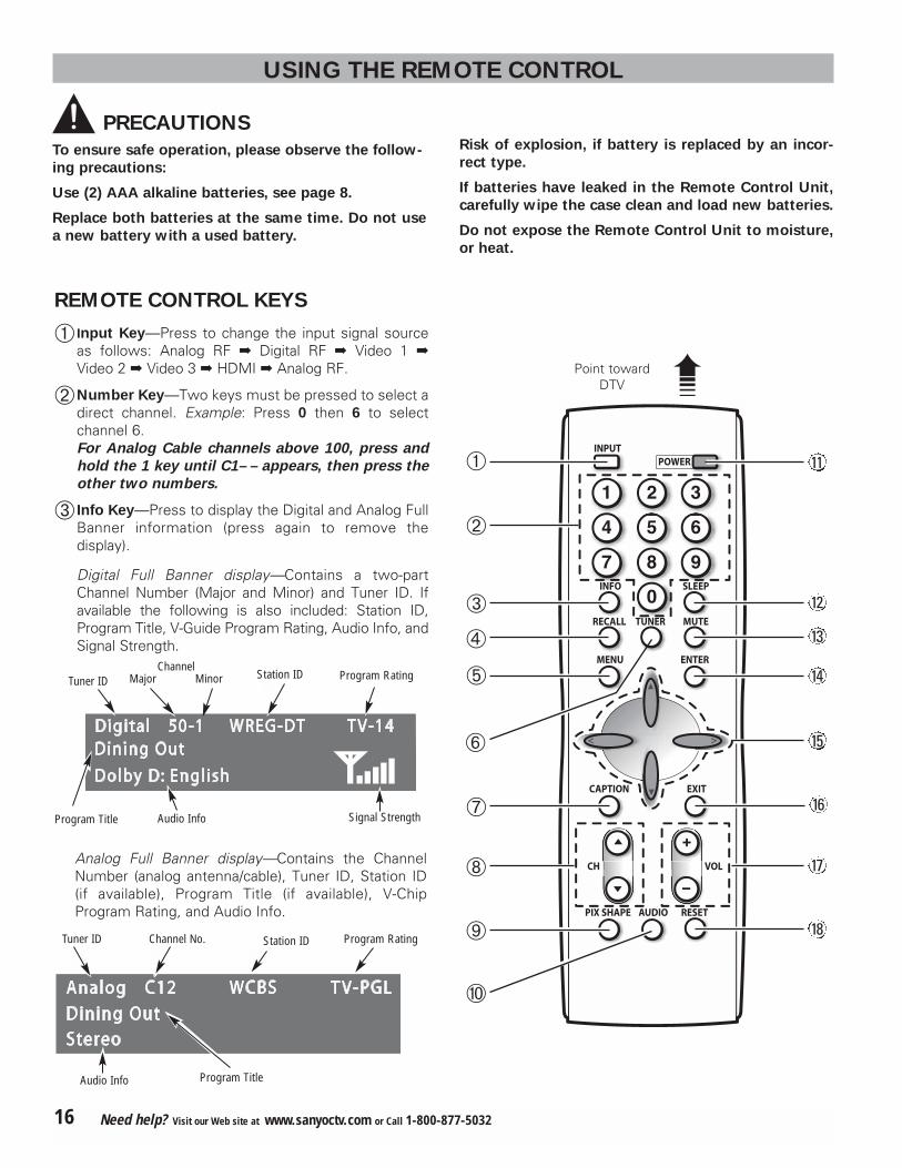
� Input Key—Press to change the input signal sourceas follows: Analog RF � Digital RF � Video 1 �
Video 2 � Video 3 � HDMI � Analog RF.
Number Key—Two keys must be pressed to select adirect channel. Example: Press 0 then 6 to selectchannel 6. For Analog Cable channels above 100, press and
hold the 1 key until C1– – appears, then press the
other two numbers.
� Info Key—Press to display the Digital and Analog FullBanner information (press again to remove thedisplay).
Digital Full Banner display—Contains a two-partChannel Number (Major and Minor) and Tuner ID. Ifavailable the following is also included: Station ID,Program Title, V-Guide Program Rating, Audio Info, andSignal Strength.
Analog Full Banner display—Contains the ChannelNumber (analog antenna/cable), Tuner ID, Station ID(if available), Program Title (if available), V-ChipProgram Rating, and Audio Info.
Program Title
Program Rating
Audio Info
Program RatingChannel No. Station ID
ChannelMajor Minor
Audio Info
Tuner ID
Tuner ID
Program Title
1
4 5 6
7 8
0
9
2 3
POWER INPUT
INFO
RECALL
MENU
CAPTION EXIT
VOL
RESET AUDIO PIX SHAPE
CH
ENTER
TUNER MUTE
SLEEP
�
12
13
14
11
�
16
15
17
18
�
�
�
�
�
�
�Point towardDTV
16 Need help? Visit our Web site at www.sanyoctv.com or Call 1-800-877-5032
Station ID
Signal Strength
Recall Key—Select the first channel you want towatch; then select another channel using theNUMBER keys. Press RECALL to switch easilybetween the channels.
NOTE: The RECALL key cannot toggle between a Digitalchannel and an Analog channel. See TUNER (#6)
key description.
�Menu key—Press this key to display the on-screenmenu.
�Tuner Key—Use this key to toggle from one tuningsystem to another, digital channels and analog channels.
NOTE: The TUNER key is inactive when an external inputis selected (Video 1, Video 2, Video 3, or HDMI).
�Caption Key—Press to select analog or digital cap-tioning. The Analog Caption modes are: CC1 ~ CC4,Quikcap, and OFF. The Digital Caption modes are:Digital CC1 ~ CC6, Quikcap, and OFF.
�Channel Scanning ((CH � ) Keys—Press � (up) (down) keys to tune to the next higher or lowerchannel in the Channel Scan Memory list. The scan-ning loop includes analog channels, digital channels,and all A V inputs.
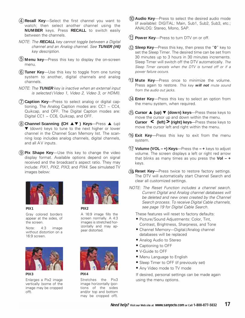
�Pix Shape Key—Use this key to change the videodisplay format. Available options depend on signalreceived and the broadcast’s aspect ratio. They mayinclude: PIX1, PIX2, PIX3, and PIX4. See simulated TVimages below:
�Audio Key—Press to select the desired audio mode(if available): DIGITAL: Main, Sub1, Sub2, Sub3, etc.;ANALOG: Stereo, Mono, SAP.
Power Key—Press to turn DTV on or off.
Sleep Key—Press this key, then press the “0” key toset the Sleep Timer. The desired time can be set from30 minutes up to 3 hours in 30 minutes increments.Sleep Timer will switch off the DTV automatically. TheSleep Timer cancels when the DTV is turned off or if apower failure occurs.
Mute Key—Press once to minimize the volume.Press again to restore. This key will not mute soundfrom the audio out jacks.
Enter Key—Press this key to select an option fromthe menu system, when required.
. Cursor � (up) (down) keys—Press these keys tomove the cursor up and down within the menu.Cursor << (left) >> (right) keys—Press these keys tomove the cursor left and right within the menu.
Exit Key—Press this key to exit from the menusystem.
Volume (VOL – +) Keys—Press the – + keys to adjustvolume. The screen displays a left or right red arrowthat blinks as many times as you press the Vol – +
keys.
Reset Key—Press twice to restore factory settings.The DTV will automatically start Channel Search andclear all customized settings.
NOTE: The Reset Function includes a channel search.Current Digital and Analog channel databases willbe deleted and new ones created by the ChannelSearch process. To receive Digital Cable channels,see page 19 for Digital Cable Search.
These features will reset to factory defaults:• Picture/Sound Adjustments: Color, Tint,
Contrast, Brightness, Sharpness, and Tone• Channel Memory—Digital /Analog channel
databases will be replaced• Analog Audio to Stereo• Captioning to OFF • V-Guide to OFF • Menu Language to English• Sleep Timer to OFF (if previously set)• Any Video mode to TV mode
If desired, personal settings can be made againusing the menu options.
11
PIX1
Gray colored bordersappear at the sides, ofthe screen.
Note: 4:3 imagewithout distortion on a16:9 screen.
PIX3
Enlarges a Pix2 imagevertically (some of theimage may be croppedoff).
12
13
14
16
15
17
18
PIX4
Stretches the Pix3image horizontally (por-tions of the sidesand/or top and bottommay be cropped off).
PIX2
A 16:9 image fills thescreen normally. A 4:3images is stretched hor-izontally and may ap-pear distorted.
17Need help? Visit our Web site at www.sanyoctv.com or Call 1-800-877-5032

DTV ADJUSTMENT AND SETUP
The on-screen menu system provides the viewer witheasy access to adjustments and settings. Just use theMENU, CURSOR, ENTER, and EXIT keys on the remotecontrol and follow the on-screen instructions. Generally,you will use the CURSOR � keys to select a menu itemand the CURSOR < > keys to make an adjustment. TheENTER key confirms a setting. Press the EXIT key toreturn to normal TV viewing.
IMPORTANT FACTS:
Some Menu options are specific to Digital and Analog signalsand will vary accordingly.
Also, some options are not available in combination. Unavail-able options will appear “grayed-out” in the menu. For example,Analog Antenna Signal is not available when tuned to a DigitalChannel.
MENU NAVIGATION MAP
MAIN SUB MENUS
BASIC MENU OPERATION
All Channel Search
Digital Cable Search
Digital Add-on Search
NoYesNoYesNoYes
Analog Antenna Signal CableVHF/UHF
Channel Scan Memory Delete?Add?
Digital Caption Font SizeFont Style
Background ColorForeground Color
Background OpacityForeground Opacity
Picture/Sound Auto Manual
Menu Language EnglishEspañol
Français
ColorTint
ContrastBrightnessSharpness
Tone
1 Press the MENU key to display the Main menu.
2 Use the CURSOR � keys to highlight (green) theAll Channel Search. Press ENTER.
3 Use the CURSOR key to select Yes. PressENTER.
Use All Channel Search to replace existing Digital andAnalog Channel databases, such as, if you move toanother city.
NOTES: During Channel Search, current Digital and Analogchannel databases are deleted and new ones created.To receive Digital Cable channels, if available, youmust perform a Digital Cable Search.
To add new digital channels to the existing database,use Digital Add-on Search, see page 19.
ALL CHANNEL SEARCH
MENU OPTIONS
�
Picture Rotation OffOn
White Pattern OffOn
18 Need help? Visit our Web site at www.sanyoctv.com or Call 1-800-877-5032
V-Guide OffOn Adjust

DIGITAL CABLE SEARCH (OPTIONAL)
This DTV can receive unscrambled (ClearQAM) digitalcable channels, when available. However, not all cablecompanies provide ClearQAM digital channels.
Searching for digital cable channels will take about 10minutes, please be patient.
1 Connect a Digital Cable signaldirectly to the DTV Digital AntennaIn Terminal.
2 Press the TUNER key to select the Digital Tuner.
3 Press the MENU key to display the Main menu.
4 Use the CURSOR � keys to highlight (green)Digital Cable Search. Press ENTER.
5 Use the CURSOR key to select Yes. PressENTER.
NOTE: After Channel Search is complete, the DTV will tune tothe lowest Digital Cable channel (or lowest Analogchannel if no Digital Cable channel is found).
DIGITALANTENNA IN
DIGITAL ADD-ON SEARCH
Use this feature to add new channels to the digitalantenna channel database. Also, use this feature to addchannels when broadcast towers are in multiple direc-tions from your location.
1 Press the TUNER key to select the Digital Tuner.
2 Press the MENU key to display the Main menu.
3 Use the CURSOR � keys to highlight (green)Digital Add-On Search. Press ENTER.
4 Use the CURSOR key to select Yes. PressENTER.
NOTES: Turn your Antenna and repeat these steps for eachdirection in which there are transmitting towers.
Go to www.antennaweb.org and type in your zipcode to obtain specific tower and antenna information.
�
NOTE: If the DTV is switched off by pressing thePOWER key or unplugging the AC duringDigital Add-On Search, all channel infor-mation detected before the power lossoccurred will be saved.
�
IMPORTANT FACT: This DTV maintains only one database ofdigital channels. Therefore, when you search for ClearQAMdigital cable channels, the database of antenna digital channelswill be deleted. You will only be able to receive those Clear-QAM channels your cable company provides.
Cable companies rearrange virtualchannels as programmingchanges, which may cause theprogram you are watching to moveto another channel. This message will appear on the screenbriefly to notify you of a change. You will have to relocate theprogram you were watching by scanning through the channels.
To restore the antenna digital channel database, reconnect theantenna and use the menu system to perform an All ChannelSearch.
Program changefrom cable company
�
�
19Need help? Visit our Web site at www.sanyoctv.com or Call 1-800-877-5032

�
ANALOG ANTENNA SIGNAL(OPTIONAL)
Use this feature to switch between analog off-air channels and analog cable channels.
1 Press the TUNER key to select analog channels.
2 Press the MENU key to display the Main menu.
3 Use the CURSOR � keys to highlight (green) theAnalog Antenna Signal. Press ENTER.
4 Use the CURSOR � keys to choose Cable orVHF/ UHF. Press ENTER.
5 Press the EXIT key to return to normal TV viewing.
To delete channels from the Channel Scan Memory
3 Use the CHANNEL (CH �) keys or numerical 0 ~ 9 keys to select desired channel. HINT: Press theTUNER key to switch between Digital and AnalogChannel Scan memories.
4 Press the ENTER key to delete the channel. Thedisplay will change to “deleted.”
NOTES
“Delete?” will ap-pear below thechannel number ifthe selected chan-nel is already in the Channel ScanMemory.
Use the numberkeys to tune toactive channels notin the ChannelScan Memory list.
To Add a channel to the Channel Scan Memory
3 Use the numerical 0 ~ 9 keys to select the desiredchannel number. “Add?” will appear below thechannel number.
4 Press the ENTER key to add the channel. The displaywill change to “Added.”
When you have fin-ished adding and/ordeleting channels,press the EXIT keyto return to normalTV viewing.
CHANNEL SCAN MEMORY
Channel Scan Memory is a list of active channels thatyou can scan through using the Channel Scan CH � (up)CH (down) keys. This list can be customized by delet-ing and/or adding channels.
1 Press the MENU key to display the Main menu.
2 Use the CURSOR � keys to highlight (green)Channel Scan Memory. Press ENTER.
� When a digital channel is deleted, all of that channel’s sub-channels are deleted as well.
� Only previously deleted digital channels can be added backto the Channel Scan Memory.
� If one digital sub-channel is added back to the Channel ScanMemory all of that channel’s sub-channels will be added back.
� If the last remaining digital channel is deleted, the entire previ-ous Channel Scan Memory list will be restored automatically.
� If the last remaining analog channel is deleted (cable or off-airchannel), ALL analog channels (cable or off-air) will berestored automatically, regardless of the previous AnalogChannel Scan Memory list.
20 Need help? Visit our Web site at www.sanyoctv.com or Call 1-800-877-5032

Closed-Captioning is hidden textual information transmit-ted along with the picture and sound. Turning CaptioningON causes the DTV to open these captions and superim-pose them on the screen. Because different types ofclosed-captions can be transmitted with the picture andsound, separate captioning modes are provided. The cap-tioning modes recognized by this model are: AnalogEIA-608B and Digital EIA-708B. Local broadcastersdecide which caption signals to transmit.
CHANGING THE LOOK OF DIGITAL CAPTIONS
This Font Size, Font Style, Background Color, ForegroundColor, Background Opacity, and Foreground Opacity ofDigital Captions can be changed.
NOTES: If Background Opacity is set to transparent, captionsmay be difficult to see.
Only true EIA 708B Digital Closed-Captions are affectedby all of these settings.
Analog captions generally will not respond to theseadjustments, however, upconverted analog captions mayrespond to some options.
1 Press the TUNER key to select the Digital Tuner.
2 Press the MENU key to display the Main menu.
3 Use the CURSOR � keys to highlight (green) theDigital Caption. Press ENTER.
4 Use the CURSOR � keys to highlight (green) anoption. Press ENTER.
5 Use the CURSOR � or < > keys to select thedesired effect.
6 When you have finished making adjustments, pressthe EXIT key to return to normal TV viewing.
TO VIEW CAPTIONS
1 Press the CAPTION key to select caption modes. Digital modes: Digital CC1 through Digital CC6,QuikCap, and Off.Analog modes : CC1 through CC4, QuikCap, and Off.
QUIKCAP OPERATION
QuikCap turns captioning on and off with the Mute func-tion. Press the MUTE key on the remote control to blockthe TV sound; the captions display automatically, if avail-able. Press the MUTE key again to restore the sound.Captions will disappear.
DIGITAL CAPTION
CC1CC1
Digital CC1Digital CC1
Analog Caption
Digital Caption
�
21Need help? Visit our Web site at www.sanyoctv.com or Call 1-800-877-5032

V-GUIDE (PARENTAL CONTROL)
NOTE: THIS FEATURE IS DESIGNED TO COMPLY WITH THE
UNITED STATES OF AMERICA’S FCC V-CHIP REGULATIONS.
THEREFORE, IT MAY NOT FUNCTION WITH BROADCASTS
THAT ORIGINATE IN OTHER COUNTRIES.
This Sanyo television is equipped with an electronic V-Chip to interpret MPAA (Motion Picture Association ofAmerica) and TV Parental Guidelines rating codes. Whenthese codes are detected, the DTV will automaticallydisplay or block the program, depending upon choices youmake when setting up the V-Guide system. Contentratings are represented by the initials: FV (fantasy violence), L (adult language), S (sexual situations), V (violence), and D (suggestive dialog). A rating icon willgenerally appear at the beginning of a program, see charton page 23.
This television can be set to block programs with contentyou deem as inappropriate for your children to view.
TO BLOCK MPAA OR TV PROGRAM
1 Press the MENU key to display the Main menu.
2 Use the CURSOR � keys to highlight (green) V-Guide. Press ENTER.
3 Use the CURSOR � keys to select ON. PressENTER.
TO SETUP V-GUIDE RATINGS
4 Use the CURSOR to select Adjust. Press ENTER.
5 Press CURSOR � and < > keys to select MPAA,TV Rating, or Content Ratings. (A green square willappear beside the selected item.)
6 Press the ENTER key to Block or Unblock selectedoption. A lock ( ) will appear beside the selectedrating option indicating it is blocked.
7 When you have finished making adjustments, pressthe EXIT key to return to normal TV viewing.
V-GUIDE RATINGS—AT-A-GLANCE
MPAA (Movie) RATING
BLOCKED RATINGS(Lock symbol)
Move Select Back ExitENTER MENU EXIT
Rating
cc Allow All Block All
TV-Y7TV-Y
TV-GTV-PGTV-14
MOVIE
PGPG13RNC17X TV-MA
TV FV D L S VG
TV RATING
� You can block portions of a TV rating by choosing one ormore of the Content ratings (D, L, S, & V). By blocking justthe L & S content ratings of TV-14, for example, TV-14rated programs with a D and/or V content rating could stillbe viewed.
� V-Guide limits on programming received via the Analogantenna input, Digital antenna input, Video 1 input, andany 480i signals received through the Component jackscan be controlled by this TV.
� V-Guide limits on digital programming received throughthe Component jacks are controlled by the external deviceconnected to those jacks (such as a DVD Player or DigitalSatellite Receiver). Refer to your external device’sowner’s manual for instructions on setting V-Guide limits.
� Networks and local stations may or may not include thecontent portion of the TV Parental Guidelines.
� The TV will automatically block ratings above or unblockratings below a selection. For example, if you block TVrating TV-PG, ratings TV-14 and TV-MA will be blockedautomatically; or if you block Movie rating PG-13, ratingsR, NC17, and X will be blocked automatically. BlockingTVY7 does not block higher ratings.
22 Need help? Visit our Web site at www.sanyoctv.com or Call 1-800-877-5032
CONTENT RATING

When codes are being transmitted and received, andV-Guide is set to ON, the V-Chip blocks programmingaccording to the settings you choose.
AS
Y7Y7TV
PGPGTV
1414TV
MAMATV
7
TO TEMPORARILY UNBLOCK MPAA
OR TV PROGRAM
1 Press the MENU key to display the Main menu.
2 Use the CURSOR � keys to highlight (green) V-Guide. Press ENTER.
3 Use the CURSOR � keys to select OFF. PressENTER.
This will temporarily set V-Guide to OFF. When V-Guide is reset to ON (follow steps 1~2), the DTV willautomatically revert to previously selected block ratings.
TO UNBLOCK ALL MPAA OR ALL TV RATING
1 Press the MENU key to display the Main menu.
2 Use the CURSOR � keys to highlight (green) V-Guide. Press ENTER.
3 Press ENTER to select Adjust.
4 Highlight the “Allow All” option using the CURSOR
�and < > keys, if needed. Press ENTER.
ALL CHILDREN—Program is designed to be appropriate forchildren ages 2-6.
DIRECTED TO OLDER CHILDREN—Program is designed forchildren 7 and above. Material may include mild fantasy violence (FV) or comedic violence.
GENERAL AUDIENCE—Program suitable for all ages. Containlittle or no violence, no strong language or sexual dialogue orsituations.
PARENTAL GUIDANCE SUGGESTED—Program containsmaterial that may be unsuitable for younger children. Material contains one or more for the following: moderateviolence (V), some sexual situations (S), infrequent coarselanguage (L), or some suggestive dialogue (D).
PARENTS STRONGLY CAUTIONED—Some material is unsuit-able for children under 14 years of age. Parents are stronglyurged to use caution against letting children under age 14watch unattended. Material contains intense violence (V),intense sexual situations (S), strong coarse language (L), orintensely suggestive dialogue (D).
MATURE AUDIENCE ONLY—Program is designed to beviewed by adults and therefore may be unsuitable for childrenunder 17 years of age.
TV RATINGS (AGE/CONTENT-BASED)
G GENERAL AUDIENCES—All ages admitted.
PG PARENTAL GUIDANCE SUGGESTED—Some material may notbe suitable for children.
PG-13 PARENTAL GUIDANCE CAUTIONED—Some material may beinappropriate for children under 13.
R RESTRICTED—Under 17 requires accompanying parent oradult guardian
NC-17 NO ONE 17 AND UNDER ADMITTED
MPAA MOVIE RATINGS (AGE-BASED)
23Need help? Visit our Web site at www.sanyoctv.com or Call 1-800-877-5032
24 Need help? Visit our Web site at www.sanyoctv.com or Call 1-800-877-5032
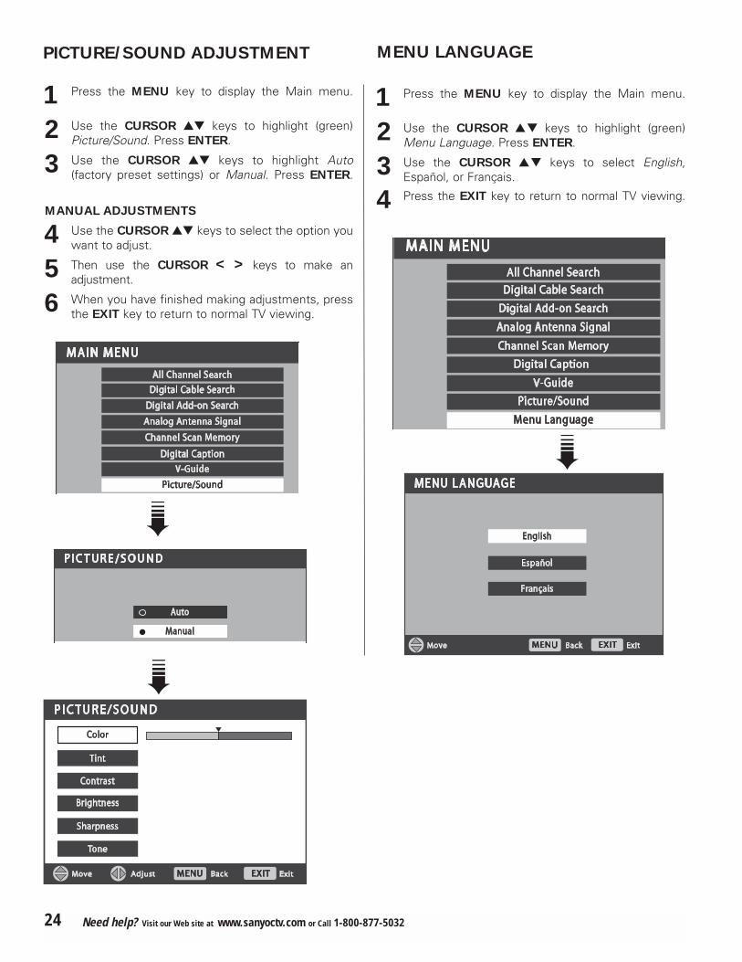
MENU LANGUAGE
1 Press the MENU key to display the Main menu.
2 Use the CURSOR � keys to highlight (green)Menu Language. Press ENTER.
3 Use the CURSOR � keys to select English,Español, or Français.
4 Press the EXIT key to return to normal TV viewing.
1 Press the MENU key to display the Main menu.
2 Use the CURSOR � keys to highlight (green)Picture/Sound. Press ENTER.
3 Use the CURSOR � keys to highlight Auto(factory preset settings) or Manual. Press ENTER.
MANUAL ADJUSTMENTS
4 Use the CURSOR � keys to select the option youwant to adjust.
5 Then use the CURSOR < > keys to make an adjustment.
6 When you have finished making adjustments, pressthe EXIT key to return to normal TV viewing.
�
PICTURE/SOUND ADJUSTMENT
�
�

25Need help? Visit our Web site at www.sanyoctv.com or Call 1-800-877-5032
PICTURE ROTATION (SCREEN
SAVER)
Displaying a still picture for a long time may cause an“afterimage” or “ghost” on the screen. To neutralize thissituation, a Picture Rotation function is provided.
1 Press the MENU key to display the Main menu.
2 Use the CURSOR � keys to highlight (green)Picture Rotation. Press ENTER.
3 Use the CURSOR key to select On. The PictureRotation changes the display position every 15minutes to avoid afterimage.
4When you have finished making adjustments, pressthe EXIT key to return to normal TV viewing.
WHITE PATTERN SETUP (PANEL
REPAIR)
Use this feature to repair the Plasma
screen.
If an afterimage occurs, use the White Pattern featureimmediately to repair the panel. The more severe theafterimage, the longer the curing process may take. It maybe impossible to repair all cases of afterimage burn.
The sooner you remove a still picture and activate WhitePattern, the more likely it is that the panel can be repaired.
NOTE: Afterimage (or image burn) is not covered underwarranty.
1 Press the MENU key to display the Main menu.
2 Use the CURSOR � keys to highlight (green)White Pattern. Press ENTER.
3 Use the CURSOR key to select On. The WhitePattern is activated instantly (screen will turn com-pletely white). The On time is set for 30 minutes.
NOTE: Pressing any key except VOLUME �, MUTE, andAUDIO will cancel the curing process and return the TVto normal viewing.
�
�

HELPFUL HINTS (PROBLEMS/SOLUTIONS)
Because of the Quality we build into our product,
very few problems are actual DTV defects. Most prob-lems only involve simple hookup or setup changes thatcan be solved by the customer. Please check the chart
below and try the solutions listed for your problem. If theproblem still persists, before returning your HDTV,
please visit our website at www.sanyoctv.com or callus toll free at 1.800.877.5032. We can Help!
Problem: Check these Conditions: Try these Solutions: Page No.
DTV turns off automatically
� The sleep timer may have been set. � Press POWER key. 17
No picture, sound(Digital Picture)
� Check antenna/external connections� May be station trouble, NO signal
broadcast.� MUTE function may be on.� The Plasma TV takes a few seconds to
display an image.
� Adjust antenna.� Try a different channel.� Press RESET key to restart channel
search.� Adjust Volume.
7, 17
No Captioning � Check if station is broadcasting aClosed-Caption signal.
� Select another channel.
� Press CAPTION key to select captioningmode. 17, 21
Cannot customizeCaption
� Digital Caption signal is not beingbroadcast.
� Press CAPTION key to select Analog captioning. 21
Cannot displaypicture on a fullscreen
� Check Aspect Ratio of broadcast. � Press PIX SHAPE key to change setting.17
Poor Picture/Sound(watching Analog)
� Check if program is in color.� Check antenna/external connections.� Color or Tint misadjusted.� May be station trouble.� May be MUTE function is on.
� Try a different channel.� Adjust antenna.� Press RESET key to restart channel
search.� Adjust Volume.
14, 15,
17, 24
“No Signal” messageappears on screen
� Check Audio/Video connections.� Check external equipment connections.� Check external equipment setting.� Check antenna connection.
� Press INPUT key.� Switch on external equipment.� Turn antenna, install signal booster.� Set external equipment output connec-
tions to match input connections.
11 ~ 15
Pixilation of Digitalimage
� Press INFO key and check signalstrength.
� Turn antenna, install signal booster.� Install outdoor Digital antenna. 7, 16
No DTV Stereo or SAP sound
� Check if station is broadcasting a trueMTS stereo signal or a SAP signal.
� Press AUDIO key.17
Cannot select or scansome channels
� Channel may be removed frommemory.
� Check antenna connections.� No digital signal being broadcast.� V-Guide is set to block programming.� Weak Signal
� Select CH. SCAN MEMORY and manuallyadd channels or start CH. (channel) search.
� Set V-Guide to “None” or press RESETkey to clear all settings and restartchannel search.
� Turn antenna, install signal booster.
17
22 ~ 23
7
No Cable channelsabove number 13
� Cable Channel Indicator C shouldappear next to channel number.
� Switch Analog Antenna Signal Selectionto Cable. 20
Remote Control will not work TV
� Check batteries.� Check if TV is plugged in.
� Replace batteries.� Aim remote control at front of TV.
8
16 ~ 17
Afterimages (ghosts)appear
� Do not display the same image onscreen for a long period of time. After-images or ghosts may appear on partsof the panel.
� Use the Picture Rotation Screen Saverfunction.
� Use the White Screen Feature to repairthe panel.
25
Cabinet makespopping sound
� This is a normal condition duringwarm-up and cool down of the plasticcabinet parts.
26 Need help? Visit our Web site at www.sanyoctv.com or Call 1-800-877-5032

IMPORTADOR:
COMERCIALIZADORA MEXICO
AMERICANA, S.DE R.L. DE C.V.
AV. NEXTENGO No 78
COL. SANTA CRUZ ACAYUCAN
DEL. AZCAPOTZALCO, MÉXICO, C.P. 02770
RFC: CMA9109119L0
GUARANTEE
THE APPARATUS THAT YOU HAVE ACQUIRED HAS A ONE YEAR GUARANTEE FOR MANUFACTURING DEFECTSAND A ONE YEAR SERVICE WARRANTY FROM THE DATE OF PURCHASE GRANTED BY:
COMERCIALIZADORA MEXICO-AMERICANA, S. DE R.L. DE C.V.
UNDER THE FOLLOWING CONDITIONS:
1. TO MAKE THE GUARANTEE EFFECTIVE, SIMPLY SHOW THIS POLICY FILLED OUT BY THE STORE OR SUPPLIER UNIT OR THIS SALES INVOICE, WITH THE APPARATUS IN ANY OF THE SERVICE CENTERS INDICATED ON THIS GUARANTEE.
2. IF THE FAULT IS ATTRIBUTED TO A MANUFACTURING DEFECT, THE APPARATUS WILL BE REPLACED ORYOUR MONEY REFUNDED. DURING THE 30 DAYS SUBSEQUENT TO THE PURCHASE THE GUARANTEEWILL BE VALID AT THE STORE WERE THE APPARATUS WAS PURCHASED, PRESENTING THE ABOVE DOCUMENTS.
3. REPAIR TIME WILL NEVER BE MORE THAN 30 DAYS. IF THIS TIME HAS ELAPSED, AND THE PRODUCT ISN’TREPAIRED, COMERCIALIZADORA MEXICO AMERICANA, S. DE R.L. DE C.V. WILL PROCEED TO EFFECTUATETHE EXCHANGE FOR AN EQUIVALENT APPARATUS OR THE RETURN OF THE BUYING-SALE COST RESPECTIVELY.
4. THIS GUARANTEE WILL COVER ITS TOTALITY OF PIECES, COMPONENTS AND SERVICE REPAIR OFPRODUCT, AND THE RESPECTIVE COST OF TRANSPORTATION.
THIS GUARANTEE WILL BE NULL AND VOID IN THE FOLLOWING CIRCUMSTANCES:
* WHEN PRODUCT HAS BEEN USED IN A DIFFERENT CONDITION THAN ITS NORMAL USE.
* WHEN PRODUCT HASN’T BEEN OPERATING CORRECTLY ACCORDING TO THE INSTRUCTIONS IN THISMANUAL.
* WHEN PRODUCT HAS BEEN CHANGED OR REPAIRED BY PERSONS NOT AUTHORIZED FROM THE MANUFACTURER, IMPORTER, OR MERCHANT RESPONSIBLE RESPECTIVE.
CENTRO DE SERVICIO Y LUGAR DONDE OBTENER PARTES, COMPONENTES, CONSUMIBLES Y ACCESORIOS:
SUCURSAL VALLEJO SUCURSAL MINERVAPoniente 126 No 288 B Silos No 135, Col. MinervaCol. Nueva Vallejo Deleg. IztapalapaMéxico, D.F. México, D.F. 09810Tels. 5567-5378 Tels. 5646-45515368-0105, 8589-8033 5646-4550
DESCRIPTION: ________________________________ BRAND: __________________ MODEL:________________________
CLIENT’S NAME: _______________________________________________________________________________
ADDRESS: _____________________________________________________________________________________
EXTERIOR NUMBER: _____________________________ INTERIOR NUMBER: __________________________
SUB DIVISION: ___________________________________ STATE/DELEGATION: ___________________________
TELEPHONE: _____________________________________________
STAMP, DATE AND SIGNATURE
OF
STORE
DESCRIPTION: Television
BRAND: SANYO
MODEL: DP42746
MEXICO GUARANTEE
TELEVISION SANYO DP42746
27Need help? Visit our Web site at www.sanyoctv.com or Call 1-800-877-5032

28 Need help? Visit our Web site at www.sanyoctv.com or Call 1-800-877-5032
ONE-YEAR LIMITED WARRANTY
THIS LIMITED WARRANTY IS VALID ONLY ON SANYO PLASMA TELEVISIONS PURCHASED AND USED INTHE UNITED STATES OF AMERICA, CANADA, AND PUERTO RICO, EXCLUDING THE UNITED STATES’OTHER TERRITORIES AND PROTECTORATES. THIS LIMITED WARRANTY APPLIES ONLY TO THE ORIGINALPURCHASER, AND DOES NOT APPLY TO PRODUCTS USED FOR INDUSTRIAL OR COMMERCIAL PURPOSES.
FOR ONE YEAR from the date of purchase, Sanyo Manufacturing Corporation will replace any defectivePlasma TV.
To insure proper warranty exchange, keep the original sales receipt for evidence of purchase. Return the
defective Plasma TV to the retailer along with the receipt and the included accessories, such as the remote
control. The defective Plasma TV will be exchanged for the same model, or a replacement model of equal
value, if necessary. Replacement model will be contingent on availability and at the sole discretion of
Sanyo Manufacturing Corporation.
THE FOREGOING WARRANTY IS EXCLUSIVE AND IN LIEU OF ALL OTHER WARRANTIES OFMERCHANTABILITY OR FITNESS FOR A PARTICULAR PURPOSE.
OBLIGATIONS
For one year from the date of purchase, Sanyo Manufacturing Corporation warrants this product to be freefrom defects in material and workmanship under normal use and conditions. Should replacement be nec-essary under this warranty for any reason due to manufacturing defect or malfunction during the first yearfrom date of original purchase, Sanyo Manufacturing Corporation will provide a new Plasma TV viaexchange at the retailer.
For customer assistance, whether during or out of the warranty period, call toll free 1-800-877-5032.
Weekdays 7:30 AM – 7:00 PM Central Time
Saturday 7:30 AM – 4:00 PM Central Time
This warranty expresses specific contractual rights; retail purchasers may have additional statutory rightswhich vary from state to state.
(EFFECTIVE: March 1, 2005)
For your protection in the event of theft or loss of this product, please fill in the information requested belowand KEEP IN A SAFE PLACE FOR YOUR OWN PERSONAL RECORDS.
Model No.______________________________ Date of Purchase _________________________
Serial No.______________________________ Purchase Price ___________________________
Where Purchased_________________________(Located on back of unit)
ASSanyo Manufacturing Corp.
3333 Sanyo Road, Forrest City, AR 72335
This symbol on the nameplate means the product is Listed by Under-writers’ Laboratories Inc. It is designed and manufactured to meet rigidU.L. safety standards against risk of fire, casualty and electrical hazards.
UNITED STATES AND CANADA WARRANTY

YX6-A 42-J3TZ GXBD [This manual printed with Soy Ink.]