
Document Details - Agrispread Australia
105
ASD-00015 V2.0 www.agrispread.com Information category: Unclassified Author / Owner: Paul McConn Page 1 of 105 Document Details Document Title: Fertiliser / Lime Spreader Operators Manual, (AS Range) Document Type: Operator / User Manual Ref No.: ASD-00015 Original instruction. All rights reserved. Reproduction of any part of this manual in any form without Agri- Spread’s express written permission is forbidden. The content of this manual is subject to change without prior notice.
-
Upload
khangminh22 -
Category
Documents
-
view
0 -
download
0
Transcript of Document Details - Agrispread Australia

ASD-00015 V2.0 www.agrispread.com
Information category: Unclassified
Author / Owner: Paul McConn
Page 1 of 105
Document Details
Document Title: Fertiliser / Lime Spreader Operators Manual, (AS Range)
Document Type: Operator / User Manual
Ref No.: ASD-00015
Original instruction. All rights reserved. Reproduction of any part of this manual in any form without Agri-
Spread’s express written permission is forbidden. The content of this manual is subject to change without
prior notice.
ASD-00015 V2.0 www.agrispread.com
Information category: Unclassified
Author / Owner: Paul McConn
Page 2 of 105
Version Control
Revision Date Author Comments/Status/Purpose
0.1 03/11/2018 Paul McConn Provisional Release
0.2 04/12/2018 Paul McConn Draft release for feedback.
0.3 11/12/2018 Paul McConn Minor updates.
1.0 13/12/2018 Paul McConn Initial Release
2.0 11/11/2020 Paul McConn Updated safety instructions.
Approvals
Department & Name Signature Date
Managing Director David Murphy 11/11/2020
ASD-00015 V2.0 www.agrispread.com
Information category: Unclassified
Author / Owner: Paul McConn
Page 3 of 105
Contents.
Contents. ........................................................................................................................................................... 3 1 Introduction. ................................................................................................................................................. 7
1.1 Preface ........................................................................................................................................ 7 1.2 Warranty. .................................................................................................................................... 7 1.3 Pre-delivery Inspection. .............................................................................................................. 7 1.4 EC Cert of Conformity. ................................................................................................................ 8 1.5 Ordering Spares. ......................................................................................................................... 9
2 Intended Use. ............................................................................................................................................ 10 3 Safety. ........................................................................................................................................................ 10
3.1 Safety Symbols. ........................................................................................................................ 10 3.2 Safety Overview. ....................................................................................................................... 10 3.3 Safety During Maintenance or Inspection. ................................................................................ 11 3.4 Safety During Loading. ............................................................................................................. 12 3.5 Safety While Towing. ................................................................................................................ 12 3.6 Safety During Machine Operation. ............................................................................................ 14 3.7 Safety Labels. ........................................................................................................................... 16
4 Product Technical Data & Specification. ................................................................................................... 18 5 Operating Instructions. .............................................................................................................................. 19
5.1 Machine Introduction................................................................................................................. 19 5.2 Pre-Operation Checklist, (General). ......................................................................................... 21 5.3 Parking/Hand Brake Operation, (General). .............................................................................. 22 5.4 Adjustment of Hitch Height, (General). ..................................................................................... 24 5.5 Connecting the Spreader to the Tractor, (General). ................................................................. 24 5.6 Tractor Drawbar & Machine Hitch Safety Chain Attachment, (General). ................................. 26 5.7 Disconnecting the Spreader from the Tractor, (General). ........................................................ 26 5.8 Rollover Cover/Tarp Operation. ................................................................................................ 27 5.9 Before Loading, (Hydraulic-Isobus System Only). .................................................................... 29 5.10 Loading the Spreader, (General). .......................................................................................... 31 5.11 Spreading Procedure, (General). .......................................................................................... 32 5.12 Setting Spinner Speeds & Rear Deflectors, (Land-Drive System Only)................................ 32 5.13 How to use Rate Charts, (Land-Drive System Only): ............................................................ 33 5.14 Setting the Application Rate, (Land-Drive System Only). ..................................................... 33 5.15 Tachometer, (Land-Drive System Only). ............................................................................... 36 5.16 Headland Operation, (Land-Drive System). .......................................................................... 36 5.17 Recommended Rear Deck Spinner Setups, (General). ........................................................ 37 5.18 Storage, (General). ................................................................................................................ 45
6 Service Intervals & General Maintenance. ................................................................................................ 47 6.1 Maintenance Safety. ................................................................................................................. 47 6.2 Maintenance Schedule. ............................................................................................................ 48 6.3 Cleaning General: ..................................................................................................................... 49 6.4 Brake/Hydraulic Hose Pass/Fail Inspection Criteria. ................................................................ 50 6.5 Greasing & Lubrication. ............................................................................................................ 51 6.6 Hydraulic System. ..................................................................................................................... 55 6.7 Belt Maintenance & Adjustment. ............................................................................................... 56 6.8 Inspecting the Spinner Tube Couplings for Wear. .................................................................... 58 6.9 Tyre Inflation & Wheel Nut Torque. .......................................................................................... 59 6.10 Hitch Maintenance. ................................................................................................................ 61 6.11 Axle Maintenance. ................................................................................................................. 63 6.12 Parking/Hand Brake Inspection & Maintenance. ................................................................... 66 6.13 Tandem Suspension Maintenance. ....................................................................................... 68
ASD-00015 V2.0 www.agrispread.com
Information category: Unclassified
Author / Owner: Paul McConn
Page 4 of 105
6.14 Chassis Jacking Points & Jacking Procedure. ...................................................................... 72 7 Clearing Blockages. ................................................................................................................................... 73
7.1 General. .................................................................................................................................... 73 7.2 A Blockage At The Rear Door of The Spreader. ...................................................................... 73 7.3 Spread Material Has “Bridged” In The Bin. ............................................................................... 73
8 Light Plug Wiring Diagrams. ...................................................................................................................... 74 8.1 7 Pin 12 Volt Plug – UK & Ireland. ............................................................................................ 74 8.2 7 Pin 24 Volt Plug – Australia & North America. ....................................................................... 74
9 End of Product Life. ................................................................................................................................... 75 10 Fastener Fixing Guidelines. ....................................................................................................................... 76
10.1 Fastener Torque Guidelines. ................................................................................................. 76 10.2 Cross Tightening Guidelines. ................................................................................................ 77
11 Tray Testing Guidelines. ............................................................................................................................ 78 11.1 Tray Test Method (13 Trays). ................................................................................................ 78 11.2 Tray Test (13 Tray), Bout Width Testing Form. ..................................................................... 80
12 Frequently Asked Questions, (FAQ). ........................................................................................................ 81 13 Rate Charts (Note: Rate Charts Are Only Applicable to Land-driven Gearbox). ...................................... 85
Figure 1, Product Serial Plate, PN:1000-1237. ................................................................................................. 9 Figure 2, Product serial plate location. .............................................................................................................. 9 Figure 3, Wheel chocks. .................................................................................................................................. 11 Figure 4, Spreader stability, rollover angle. ..................................................................................................... 14 Figure 5, Stickers / Decals / Serial Plates. ...................................................................................................... 16 Figure 6, Stickers / Decals / Serial Plates. ...................................................................................................... 17 Figure 7, Product Overview. ............................................................................................................................ 19 Figure 8, Product Overview. ............................................................................................................................ 19 Figure 9, Rear Deck Overview ........................................................................................................................ 20 Figure 10, Rear Deck Overview. ..................................................................................................................... 20 Figure 11, Parking/hand brake location. .......................................................................................................... 22 Figure 12, Wheel chock positioning. ................................................................................................................ 23 Figure 13, Hitch height adjustment. ................................................................................................................. 24 Figure 14, Move drawbar jack to transport position. ....................................................................................... 25 Figure 15, Drawbar shoe, transport position ................................................................................................... 25 Figure 16, Incorrect safety chain attachment .................................................................................................. 26 Figure 17, Correct safety chain attachment..................................................................................................... 26 Figure 18, Hydraulic hose holder. .................................................................................................................... 27 Figure 19, Drawbar jack in support position. ................................................................................................... 27 Figure 20, Drawbar shoe in support position ................................................................................................... 27 Figure 26, Rollover Cover/Tarp, (Open Position). ........................................................................................... 28 Figure 28, Crank Arm in open position. ........................................................................................................... 28 Figure 27, Crank arm in closed position. ......................................................................................................... 28 Figure 21, Agri-Spread Density Meter. ............................................................................................................ 31 Figure 22, Spinner Flow Control Valve. .......................................................................................................... 32 Figure 23, Land-drive gearbox, gear selection details. ................................................................................... 34 Figure 24, Land-drive gearbox, gear selection details. ................................................................................... 34 Figure 25, Feed plate adjustments. ................................................................................................................. 35 Figure 26, Agri-Spread Tachometer. ............................................................................................................... 36 Figure 27, Headland control operation. ........................................................................................................... 36 Figure 28, Rear Deck Region Overview .......................................................................................................... 37 Figure 29, Rear view of machine, standard disks & small centre V. ............................................................... 38
Table of Figures.
ASD-00015 V2.0 www.agrispread.com
Information category: Unclassified
Author / Owner: Paul McConn
Page 5 of 105
Figure 30, Rear view of machine, standard disks & large centre V................................................................. 38 Figure 31, Standard discs, note flight orientation. ........................................................................................... 39 Figure 32, Note alignment of CPA and CPB plates. ........................................................................................ 40 Figure 33, Cross bar assembly, (up position). ................................................................................................. 41 Figure 34, Cross bar assembly settings. ......................................................................................................... 41 Figure 35, 2-Vane Widespread General Setup. .............................................................................................. 42 Figure 36, 2-Vane Widespread Disk and Vane Orientation. ........................................................................... 43 Figure 37, 2-Vane Widespread Drop Point Adjustment. ................................................................................. 43 Figure 38, Check belt roller condition. ............................................................................................................. 45 Figure 39, Check motor coupling and side skirt condition. .............................................................................. 46 Figure 40, Door height indicator check. ........................................................................................................... 46 Figure 41, Hand brake handle drum. ............................................................................................................... 51 Figure 42, Belt bearing grease point locations. ............................................................................................... 52 Figure 43, Chassis drawbar grease point locations. ....................................................................................... 52 Figure 44, Spinner shaft grease point locations. ............................................................................................. 53 Figure 45, Floor gearbox maintenance. ........................................................................................................... 54 Figure 46, Land-drive gearbox lubrication. ...................................................................................................... 54 Figure 47, Hydraulic Filter Location. ................................................................................................................ 55 Figure 48, Belt Tensioning & Alignment. ......................................................................................................... 56 Figure 49, Belt Tensioner, Left Hand Side. ..................................................................................................... 56 Figure 50, Spinner tube coupling. .................................................................................................................... 58 Figure 51, Cross tightening sequence, circular bolting patterns. .................................................................... 60 Figure 54, Cross tightening sequence. ............................................................................................................ 61 Figure 52, Swivel hitch..................................................................................................................................... 61 Figure 53, Bull-pull hitch. ................................................................................................................................. 62 Figure 54, Bull-pull hitch, parts. ....................................................................................................................... 62 Figure 55, Hand brake handle drum. ............................................................................................................... 67 Figure 56, Single axle hand brake cable setup. .............................................................................................. 67 Figure 57, Tandem axle hand brake cable setup. ........................................................................................... 67 Figure 58, Tandem suspension components, (G-Type). ................................................................................. 68 Figure 59, Torque Arm Assembly, (G-Type). .................................................................................................. 69 Figure 60, Tightening torques for underslung suspension, (G-Type). ............................................................. 70 Figure 61, Suspension Cross Brace Assembly, (G-Type). .............................................................................. 70 Figure 62, Tightening axle U Bolts, (G-Type). ................................................................................................. 71 Figure 82, Single Axle Chassis Jacking Locations. ......................................................................................... 72 Figure 83, Tandem Axle Chassis Jacking Locations. ...................................................................................... 72 Figure 69, 7 Pin 12 Volt Plug Wiring Diagram. ................................................................................................ 74 Figure 70, 7 Pin 24 Volt Plug Wiring Diagram. ................................................................................................ 74 Figure 65, Cross tightening sequence, circular bolting patterns. .................................................................... 77 Figure 66, Cross tightening sequence, non-circular bolting patterns. ............................................................. 77 Figure 79, Test tray setup ................................................................................................................................ 78 Figure 68, Tray Test Results 1. ....................................................................................................................... 79 Figure 69, Tray Test Results 2. ....................................................................................................................... 79 Figure 70, 13 Tray Test Layout. ...................................................................................................................... 79
Table of Tables.
Table 1, Maximum spreader carrying capacity. ............................................................................................... 12 Table 2, Tractor horse power requirements. ................................................................................................... 12 Table 3, Maximum spreader towing speed...................................................................................................... 13 Table 4, Spreader vertical load on tractor hitch. .............................................................................................. 13 Table 5, Spreader stability, rollover angle. ...................................................................................................... 14
ASD-00015 V2.0 www.agrispread.com
Information category: Unclassified
Author / Owner: Paul McConn
Page 6 of 105
Table 6, Minimum oil flow and pressure requirements. ................................................................................... 15 Table 6, Product technical specification summary. ......................................................................................... 18 Table 8, Converting CWT/Acre or Lb. / Acre to Kg/Hectare. ........................................................................... 33 Table 9, Recommended settings, standard discs. .......................................................................................... 39 Table 9, 2-Vane Widespread Setup Summary. ............................................................................................... 44 Table 10, Maintenance / inspection summary. ................................................................................................ 48 Table 12, Grease / lubrication specification summary, (see section 6.2 also). ............................................... 51 Table 13, Maximum tyre inflation pressure...................................................................................................... 59 Table 14, Wheel nut torque. ............................................................................................................................ 60 Table 14, Wheel Stud Torque (G Type Axles) ................................................................................................ 60 Table 14, Hitch Fastener Torque Requirements. ............................................................................................ 61 Table 17, Spreader axle specification summary. ............................................................................................ 63 Table 16, Axle maintenance schedule. ............................................................................................................ 65 Table 17, Mechanical suspension maintenance schedule, (G-Type). ............................................................ 68 Table 20, Tandem suspension components, (G-Type). .................................................................................. 69 Table 21, 7 Pin 12 Volt Plug Wiring Diagram. ................................................................................................. 74 Table 22, 7 Pin 24 Volt Plug Wiring Diagram. ................................................................................................. 74 Table 21, Bolt torque guidelines. ..................................................................................................................... 76 Table 24, 13 Tray Test, Bin Width Measurement. ........................................................................................... 80
List of abbreviations:
- AS = Agri-Spread.
- TBC = To be confirmed.
- FAQ = Frequently asked questions.
- N/A = Not applicable.
- RDS = Rear discharge spreader.
- MS = Mild steel.
- ZP = Zinc plated.
- SS = Stainless steel.
- Kph = Kilometres per hour.
- Mph = Miles per hour.
- Gpm = Gallons per minute. Note: 1metric gallon = 4.546 litres.
- mT = Metric tonnes.
- BOM = Bill of materials.
- ASA = Automatic slack adjuster.
- SA = Slack adjuster.
- CWT = hundredweight, english imperial.
- Kg = kilogram.
- Lb = pounds.
- Hp = Horsepower
- VRT = Variable rate technology.
- VT = Virtual terminal.
Verbal forms:
- Shall = Indicates a mandatory requirement to be followed for fulfilment or compliance with the present standard. Deviations are not permitted unless formally and rigorously justified, and accepted by all relevant contracting parties.
- Should = Indicates a recommendation that a certain course of action is preferred or particularly suitable. Alternative courses of action are allowable under the standard where agreed between contracting parties but shall be justified and documented.
- May = Indicates a permission, or an option, which is permitted as part of conformance with the standard.
- Operator = Person in charge of the safe operation of the product and its working environment. - Machine = Fertiliser / lime spreader.
ASD-00015 V2.0 www.agrispread.com
Information category: Unclassified
Author / Owner: Paul McConn
Page 7 of 105
Document References:
- Warranty Documents. - Isobus Quick Start Guide. - Isobus Manual. - ASD-00013_Lime & Fertiliser Spreader Spare Parts Manual. - ASD-00011 Spreader Disk Setup Recommendations. - ASD-00001_Lime Spreader Spinner Assembly Refurb Instruction. - ASD-00025_Fert-Lime Spreader Axle Service Manual, (G-Type).
- ASD-00026_Fert-Lime Spreader Axle Service Manual, (A-Type).
1 Introduction.
1.1 Preface
We appreciate having you as a customer and wish
you many years of safe and satisfied use.
The purpose of this document is to provide
information to the customer to enable them to
- Safely operate the machine.
- Safely maintain the machine.
- Identify and procure spare parts when
required.
Agri-Spread reserves the right to modify the machinery and the technical data contained within this manual
without prior notice.
While every effort has been made in the production of this manual to ensure that the information contained
herein is full and correct, Agri-Spread assumes no responsibility for errors or omissions.
Further to this, Agri-Spread assumes no liability for any damages that may result from the use of the
information contained within this manual.
1.2 Warranty.
This Agri-Spread spreader carries a comprehensive one-year warranty against defects, providing that the
spreader has been operated correctly and has not exceeded its plated weight or speed rating.
- Do not modify the equipment in any way without prior authorisation. Unauthorised modifications will
invalidate the product warranty. Unauthorised modification may impair the function and/or safety and
could affect the life of the equipment.
- No warranty work is permitted without prior assessment and authorisation, with the spreader being
returned to the dealer for the work to be carried out.
- Only Agri-Spread authorised spares can be fitted without invalidating this warranty.
- If, in the unlikely event, you have a problem with the spreader, please contact your dealer in the first
instance.
For further detail refer to the owner warranty registration document presented to you the customer on
product handover from your local dealer.
1.3 Pre-delivery Inspection.
Refer to the owner warranty registration document presented to you the customer on product handover from
your local dealer.
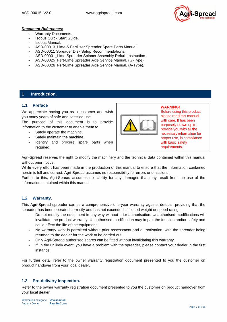
WARNING! Before using this product please read this manual with care. It has been purposely drawn up to provide you with all the necessary information for proper use, in compliance with basic safety requirements.

ASD-00015 V2.0 www.agrispread.com
Information category: Unclassified
Author / Owner: Paul McConn
Page 8 of 105
1.4 EC Cert of Conformity.
EC DECLARATION OF CONFORMITY
Manufacturer: AGRI-SPREAD INTERNATIONAL
Address: Running Gear Ltd, Coolnaha North, Ballyhaunis, Co. Mayo Ireland
Herewith declares that
Machine: AS35, AS55, AS65, AS85, AS100, AS120, AS130T, AS150T & AS170T
Described as: A range of trailed Fertiliser/ Lime Spreaders intended for use in the Agricultural Industry
Is in conformity with the provisions of the following EU directive(s):
- 2006/42/EC Machinery Directive. - 2014/30/EU EMC Directive.
And further declares that (clauses/pars of) the following European harmonised standards have been applied
And further declares that (clauses/pars of) the following European harmonised standards have been applied
- EN ISO 4254-1:2015 Agricultural machinery – Safety – Part 1: General Requirements. - EN ISO 4254-3:2018 Agricultural machinery – Safety – Part 8: Solid Fertilizer Distributors.
Signed: _______________________________ Name: David Murphy
Position: Managing Director
Place: Agri-Spread Ireland Date: (Date: 11 November 2020) The name and address of person authorized to compile the technical documentation. David Murphy, Managing Director Agri-Spread International
Running Gear Ltd, Coolnaha, Ballyhaunis, Co. Mayo Ireland

ASD-00015 V2.0 www.agrispread.com
Information category: Unclassified
Author / Owner: Paul McConn
Page 9 of 105
1.5 Ordering Spares.
Always state the machine model and year of manufacture when contacting your nearest dealer.
Refer to document “ASD-00013_Lime & Fertiliser Spreader Spare Parts Manual” for a detailed breakdown of
spare parts by location and part number.
1.5.1 How to Order.
If you need to contact your Agri-Spread dealer for information on servicing or spare parts, always provide the
product model and serial number along with the parts number required. Product information is located on the
product serial plate, refer to Figure 1 and Figure 2.
Part number details are contained in document “ASD-00013_Lime & Fertiliser Spreader Spare Parts
Manual”. We suggest that you record your machine details below:
- Model No: _________________________________________
- Serial No: _________________________________________
- Spinner Motor Size: _________________________________
- Hydraulic Valve No: _________________________________
- Wheel/Tyre Spec: ___________________________________
- Date of Purchase: ___________________________________
- Dealer Name: ______________________________________
- Dealer Telephone: __________________________________
1.5.2 Serial Plate Location.
Product information is located on the product serial plate, refer to Figure 1 and Figure 2.
To show that Agri-Spread products conform
to all the European rules, the CE-brand is
printed on the Agri-Spread serial plate.
Figure 1, Product Serial Plate, PN:1000-1237.
Figure 2, Product serial plate location.
Left
Right
Rear
Fro
nt
ASD-00015 V2.0 www.agrispread.com
Information category: Unclassified
Author / Owner: Paul McConn
Page 10 of 105
2 Intended Use.
The machine:
- has been designed for use in agricultural and municipal operation for spreading:
• Dry, granular, prilled and crystalline fertiliser (fert spreading kit)
• Lime, (lime spreading kit).
• Sand, (lime spreading kit).
• Grit and salt, (special spread kit).
• Poultry waste.
• Fibrophos.
- Is coupled to a tractor via
• Ball coupling.
• Pin coupling.
• Hitch hook.
- Is operated by a competent, trained person.
The intended use also includes:
- Compliance with all the instructions in this operating manual.
- Execution of inspection and maintenance work.
- Exclusive use of original Agri-Spread spare parts.
Uses other than those specified above are forbidden and shall be considered as improper. For any damage
resulting from improper use the operator bears the sole responsibility, Agri-Spread assumes no liability
whatsoever.
3 Safety.
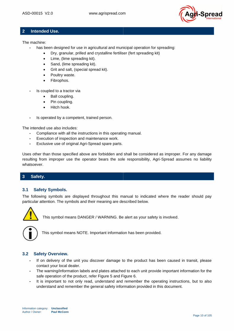
3.1 Safety Symbols.
The following symbols are displayed throughout this manual to indicated where the reader should pay
particular attention. The symbols and their meaning are described below.
This symbol means DANGER / WARNING. Be alert as your safety is involved.
This symbol means NOTE. Important information has been provided.
3.2 Safety Overview.
- If on delivery of the unit you discover damage to the product has been caused in transit, please
contact your local dealer.
- The warning/information labels and plates attached to each unit provide important information for the
safe operation of the product, refer Figure 5 and Figure 6.
- It is important to not only read, understand and remember the operating instructions, but to also
understand and remember the general safety information provided in this document.
ASD-00015 V2.0 www.agrispread.com
Information category: Unclassified
Author / Owner: Paul McConn
Page 11 of 105
- The operator must ensure that they and anyone else who is going to use maintain or work around
the product be familiar with the operating, maintenance and safety procedures / information
contained within this manual. This information should be reviewed at least once annually.
- Every effort has been made to provide you the customer with all the necessary information to safely
operate this product or undertake the instructions given within this document, however if you are
unsure of the clarity or substance of any statement or section please contact your local dealer,
before attempting to operate the product or carry out any work instruction.
- Observe all of your local health and safety, road safety and environmental regulations / legislation.
- When working with fertiliser / lime and aerosols/paints/oils/lubricants etc always be aware of the
specific safety considerations required. Please consult manufacturer material safety datasheets for
detailed instruction.
- Always wear appropriate protective safety gear during product operation and maintenance, including
but not limited to:
• Hearing protection.
• Respirator or filter mask.
• Hard hat.
• Protective footwear, slip resistant soles with steel toe caps.
• Protective goggles of face shield.
• Heavy gloves.
• Protective overalls or wet weather gear. Loose fitting clothing is not
permitted, as it may come trapped within moving parts.
Warning: Do not modify the equipment in any way without prior authorisation. Unauthorised
modifications will invalidate the product warranty. Unauthorised modification may impair the
function and/or safety and could affect the life of the equipment.
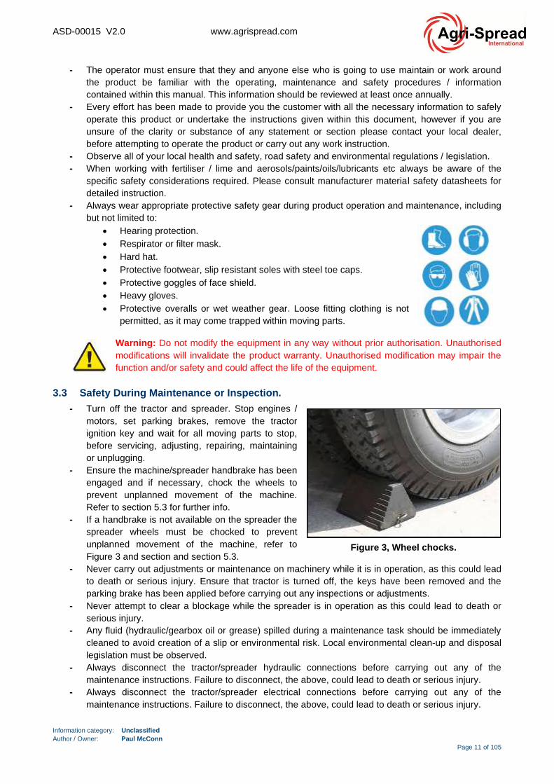
3.3 Safety During Maintenance or Inspection.
- Turn off the tractor and spreader. Stop engines /
motors, set parking brakes, remove the tractor
ignition key and wait for all moving parts to stop,
before servicing, adjusting, repairing, maintaining
or unplugging.
- Ensure the machine/spreader handbrake has been
engaged and if necessary, chock the wheels to
prevent unplanned movement of the machine.
Refer to section 5.3 for further info.
- If a handbrake is not available on the spreader the
spreader wheels must be chocked to prevent
unplanned movement of the machine, refer to
Figure 3 and section and section 5.3.
- Never carry out adjustments or maintenance on machinery while it is in operation, as this could lead
to death or serious injury. Ensure that tractor is turned off, the keys have been removed and the
parking brake has been applied before carrying out any inspections or adjustments.
- Never attempt to clear a blockage while the spreader is in operation as this could lead to death or
serious injury.
- Any fluid (hydraulic/gearbox oil or grease) spilled during a maintenance task should be immediately
cleaned to avoid creation of a slip or environmental risk. Local environmental clean-up and disposal
legislation must be observed.
- Always disconnect the tractor/spreader hydraulic connections before carrying out any of the
maintenance instructions. Failure to disconnect, the above, could lead to death or serious injury.
- Always disconnect the tractor/spreader electrical connections before carrying out any of the
maintenance instructions. Failure to disconnect, the above, could lead to death or serious injury.
Figure 3, Wheel chocks.
ASD-00015 V2.0 www.agrispread.com
Information category: Unclassified
Author / Owner: Paul McConn
Page 12 of 105
Warning: Use extreme care when working around the high-pressure hydraulic system. Make
sure all connections are tight and all components are in good repair. Wear hand and eye
protection when opening hydraulic brake / spinner circuits or searching for suspected leaks.
3.4 Safety During Loading.
- Lower the rear door prior to loading to safely retain the spread material.
Warning: Do not load the spreader unless it is connected to the tractor and the tractor
parking brake has been applied.
- All persons except for the operator should be at least 33ft (10m) away from spreader when loading
or when the engine is running.
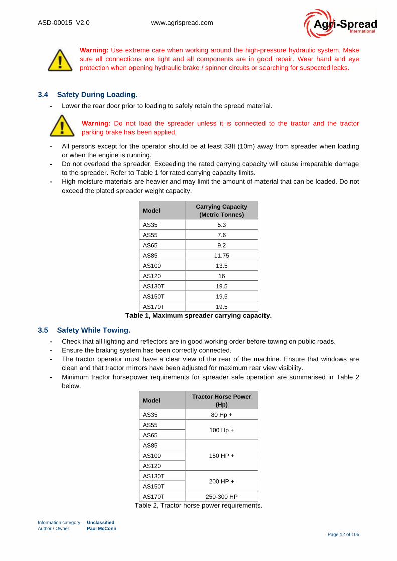
- Do not overload the spreader. Exceeding the rated carrying capacity will cause irreparable damage
to the spreader. Refer to Table 1 for rated carrying capacity limits.
- High moisture materials are heavier and may limit the amount of material that can be loaded. Do not
exceed the plated spreader weight capacity.
Model Carrying Capacity
(Metric Tonnes)
AS35 5.3
AS55 7.6
AS65 9.2
AS85 11.75
AS100 13.5
AS120 16
AS130T 19.5
AS150T 19.5
AS170T 19.5
Table 1, Maximum spreader carrying capacity.
3.5 Safety While Towing.
- Check that all lighting and reflectors are in good working order before towing on public roads.
- Ensure the braking system has been correctly connected.
- The tractor operator must have a clear view of the rear of the machine. Ensure that windows are
clean and that tractor mirrors have been adjusted for maximum rear view visibility.
- Minimum tractor horsepower requirements for spreader safe operation are summarised in Table 2
below.
Model Tractor Horse Power
(Hp)
AS35 80 Hp +
AS55 100 Hp +
AS65
AS85
150 HP + AS100
AS120
AS130T 200 HP +
AS150T
AS170T 250-300 HP
Table 2, Tractor horse power requirements.
ASD-00015 V2.0 www.agrispread.com
Information category: Unclassified
Author / Owner: Paul McConn
Page 13 of 105
Warning: Ensure local road safety regulations are adhered to at all times.
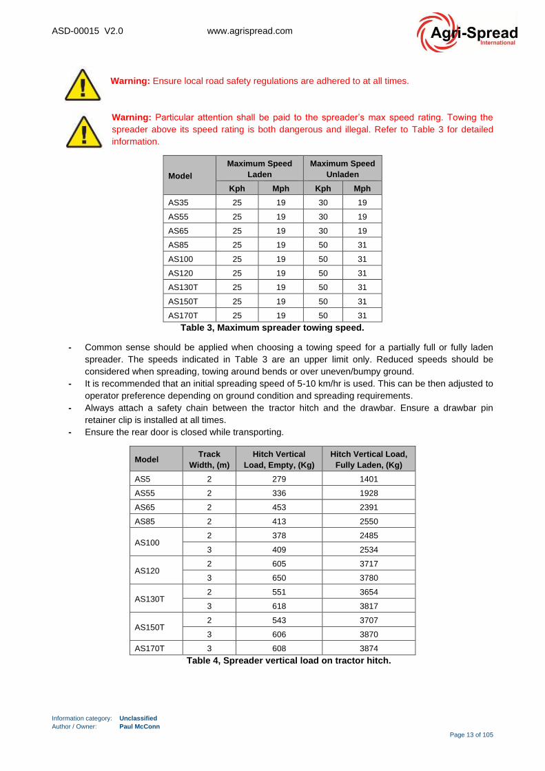
Warning: Particular attention shall be paid to the spreader’s max speed rating. Towing the
spreader above its speed rating is both dangerous and illegal. Refer to Table 3 for detailed
information.
Model
Maximum Speed
Laden
Maximum Speed
Unladen
Kph Mph Kph Mph
AS35 25 19 30 19
AS55 25 19 30 19
AS65 25 19 30 19
AS85 25 19 50 31
AS100 25 19 50 31
AS120 25 19 50 31
AS130T 25 19 50 31
AS150T 25 19 50 31
AS170T 25 19 50 31
Table 3, Maximum spreader towing speed.
- Common sense should be applied when choosing a towing speed for a partially full or fully laden
spreader. The speeds indicated in Table 3 are an upper limit only. Reduced speeds should be
considered when spreading, towing around bends or over uneven/bumpy ground.
- It is recommended that an initial spreading speed of 5-10 km/hr is used. This can be then adjusted to
operator preference depending on ground condition and spreading requirements.
- Always attach a safety chain between the tractor hitch and the drawbar. Ensure a drawbar pin
retainer clip is installed at all times.
- Ensure the rear door is closed while transporting.
Model Track
Width, (m)
Hitch Vertical
Load, Empty, (Kg)
Hitch Vertical Load,
Fully Laden, (Kg)
AS5 2 279 1401
AS55 2 336 1928
AS65 2 453 2391
AS85 2 413 2550
AS100 2 378 2485
3 409 2534
AS120 2 605 3717
3 650 3780
AS130T 2 551 3654
3 618 3817
AS150T 2 543 3707
3 606 3870
AS170T 3 608 3874
Table 4, Spreader vertical load on tractor hitch.
ASD-00015 V2.0 www.agrispread.com
Information category: Unclassified
Author / Owner: Paul McConn
Page 14 of 105
3.6 Safety During Machine Operation.
- Inspect and close all guards before starting the machine.
- Clear the area of people before starting the unit.
- Do not enter the machine while it is running.
- Never operate the machine without all safety guards in place and properly secured as this can result
in death or serious injury.
- Ensure the rear door is down before moving or transporting.
- Do not overload the spreader. Exceeding the rated carrying capacity will cause irreparable damage
to the spreader. Refer to Table 1 for rated carrying capacity limits.
- Do not overload the spreader. Exceeding the axle weight will cause irreparable damage to the
spreader.
- The driven floor should never be operated with the doors in closed position. This could cause
irreparable damage. On some fertilisers it should not be operated with less than 20 mm of gap as
packing will occur and the belt will jam. When spreading steel works slag, always operate the
machine in the low gear with the door open as wide as possible.
Warning: Beware that after the machine has been switched off, the spinner discs will continue
to rotate for approximately 10 seconds, keep all personnel clear during this rundown time.
- Never exceed the spreader’s speed rating as this could lead to death or serious injury.
- The operator must remain seated while the machine is working.
- All persons other than the operator should keep at least 328ft (100m) away from the spreading area.
The operator should ensure that the spreading area is clear of both bystanders and livestock before
spreading commences.
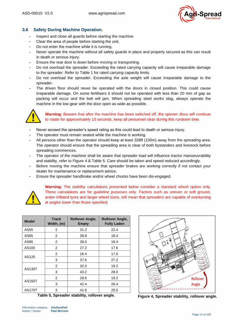
- The operator of the machine shall be aware that spreader load will influence tractor manoeuvrability
and stability, refer to Figure 4 & Table 5. Care should be taken and speed reduced accordingly.
- Before moving the machine ensure that spreader brakes are working correctly if not contact your
dealer for maintenance or replacement advice.
- Ensure the spreader handbrake and/or wheel chocks have been dis-engaged.
Warning: The stability calculations presented below consider a standard wheel option only.
These calculations are for guideline purposes only. Factors such as uneven or soft ground,
under-inflated tyres and larger wheel sizes, will mean that spreaders are capable of overturning
at angles lower than those specified.
Model Track
Width, (m)
Rollover Angle,
Empty
Rollover Angle,
Fully Laden
AS55 2 31.2 22.4
AS65 2 28.8 18.4
AS85 2 28.0 18.4
AS100 2 27.2 17.6
AS120 2 26.4 17.6
3 37.6 27.2
AS130T 2 32.0 19.2
3 43.2 28.0
AS150T 2 29.6 19.2
3 42.4 26.4
AS170T 3 41.6 25.6
Table 5, Spreader stability, rollover angle. Figure 4, Spreader stability, rollover angle.

ASD-00015 V2.0 www.agrispread.com
Information category: Unclassified
Author / Owner: Paul McConn
Page 15 of 105
Warning:
- Ensure the tractor spool valves have been placed in the float position, before turning off the
spreader. This requirement applies to both fixed pump and load sense setups.
- If the spreader is setup in “power beyond mode”, ensure that the spinners are set to the off
position on the computer before turning off the machine.
Operators must ensure that all hydraulic components are switched off at the spool valve before
switching off the tractor.
Use caution when turning on the tractor if set up in “power beyond mode”, as the spinners may be
set to on when the computer powers up.
Warning: Use extreme care when working around the high-pressure hydraulic system. Make
sure all connections are tight and all components are in good repair. Wear hand and eye
protection when opening hydraulic brake / spinner circuits or searching for suspected leaks.
Hydraulic Oil Flow & Pressure Requirements
Minimum Oil Flow (Land drive) 80 l/m 21gpm
Minimum Oil Flow (Hydraulic drive) 120 l/m 32gpm
Min Pressure 2500psi 172bar
Table 6, Minimum oil flow and pressure requirements.
ASD-00015 V2.0 www.agrispread.com
Information category: Unclassified
Author / Owner: Paul McConn
Page 16 of 105
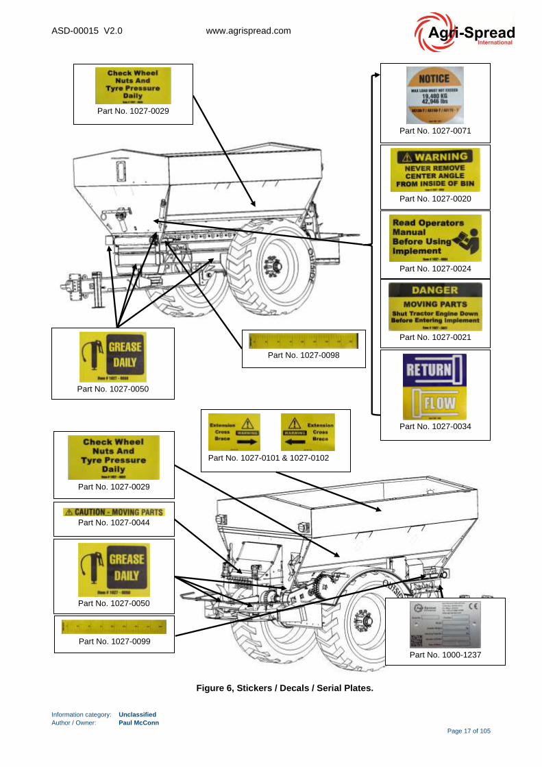
3.7 Safety Labels.
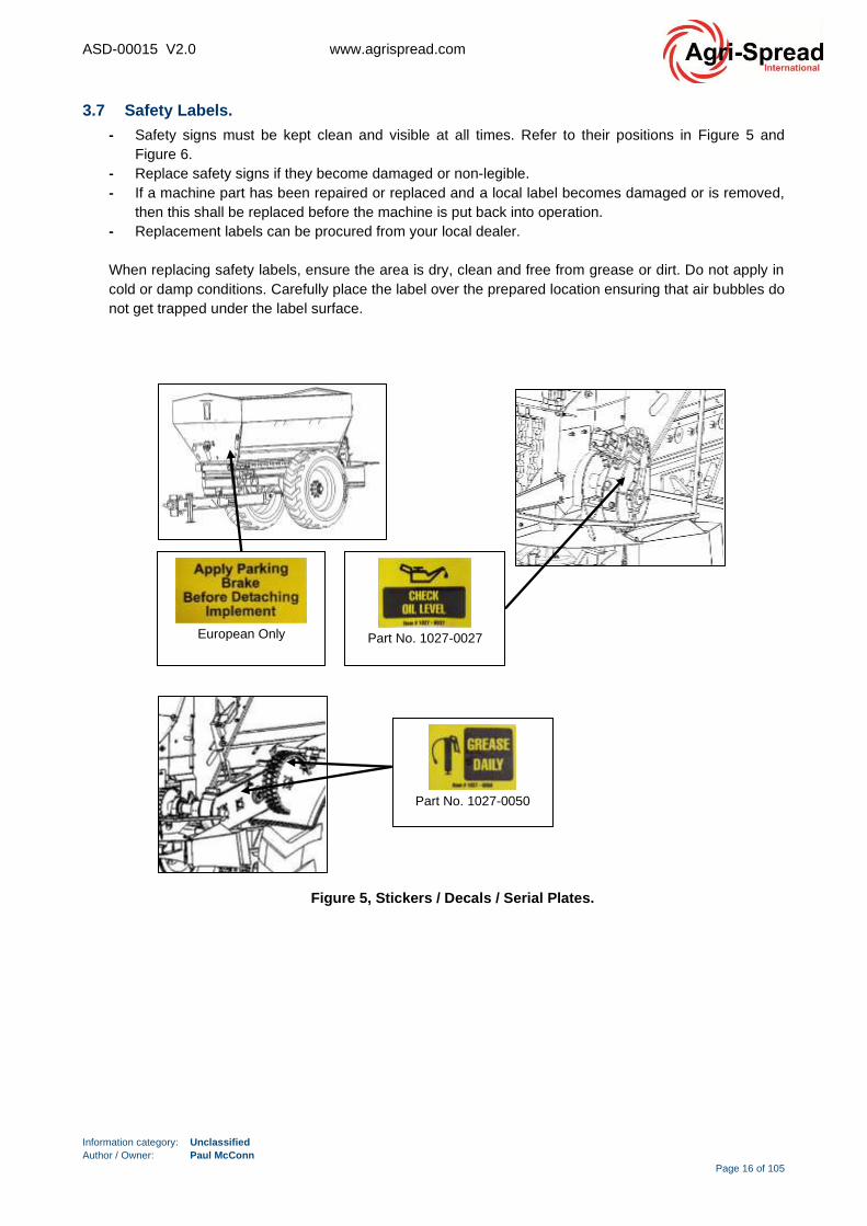
- Safety signs must be kept clean and visible at all times. Refer to their positions in Figure 5 and
Figure 6.
- Replace safety signs if they become damaged or non-legible.
- If a machine part has been repaired or replaced and a local label becomes damaged or is removed,
then this shall be replaced before the machine is put back into operation.
- Replacement labels can be procured from your local dealer.
When replacing safety labels, ensure the area is dry, clean and free from grease or dirt. Do not apply in
cold or damp conditions. Carefully place the label over the prepared location ensuring that air bubbles do
not get trapped under the label surface.
Part No. 1027-0050
European Only
Part No. 1027-0027
Figure 5, Stickers / Decals / Serial Plates.
ASD-00015 V2.0 www.agrispread.com
Information category: Unclassified
Author / Owner: Paul McConn
Page 17 of 105
Part No. 1027-0050
Part No. 1027-0071
Part No. 1027-0020
Part No. 1027-0024
Part No. 1027-0021
Part No. 1027-0034
Part No. 1027-0029
Part No. 1027-0098
Part No. 1027-0029
Part No. 1027-0050
Part No. 1027-0044
Part No. 1027-0099
Part No. 1000-1237
Part No. 1027-0101 & 1027-0102
Figure 6, Stickers / Decals / Serial Plates.

ASD-00015 V2.0 www.agrispread.com
Information category: Unclassified
Author / Owner: Paul McConn
Page 18 of 105
4 Product Technical Data & Specification.
All dimensions stated are in millimetres (unless stated otherwise) and are based on the standard model
specifications. Dimensions may alter if optional extras are fitted.
Table 7, Product technical specification summary.

ASD-00015 V2.0 www.agrispread.com
Information category: Unclassified
Author / Owner: Paul McConn
Page 19 of 105
5 Operating Instructions.
5.1 Machine Introduction.
The Agri-Spread range of the spreaders are capable of spreading a wide range of materials including lime,
fertiliser, fibrophos, sand, salt and poultry waste. Hydraulic control of the spinners and drop point adjustment
ensure accurate spreading up to 24 metres depending on the type of material. A range of models are
available from 3 to 20 metric tonne capacity depending of the requirements of the customer.
All Agri-Spread lime and fertiliser spreaders come complete with user-friendly test kits, allowing continuous
testing of spread patterns, ensuring an even spread and ultimately a more cost-effective solution.
Drawbar
Jack
Figure 7, Product Overview.
Access
Ladder
Grids
Front
Extension
Hood, (Option)
Drawbar
Hitch (Bolt
On)
Hose
Holder
Side
Extensions
(Option),
(Option)
Axle Wheel
Valve
Block
Rear
Extension
Hood, (Option)
Pedestrian
Guard
Mudguard
Viewing
Window
Figure 8, Product Overview.
Rear Deck
Region
Centre V
Conveyor
Spinners
ASD-00015 V2.0 www.agrispread.com
Information category: Unclassified
Author / Owner: Paul McConn
Page 20 of 105
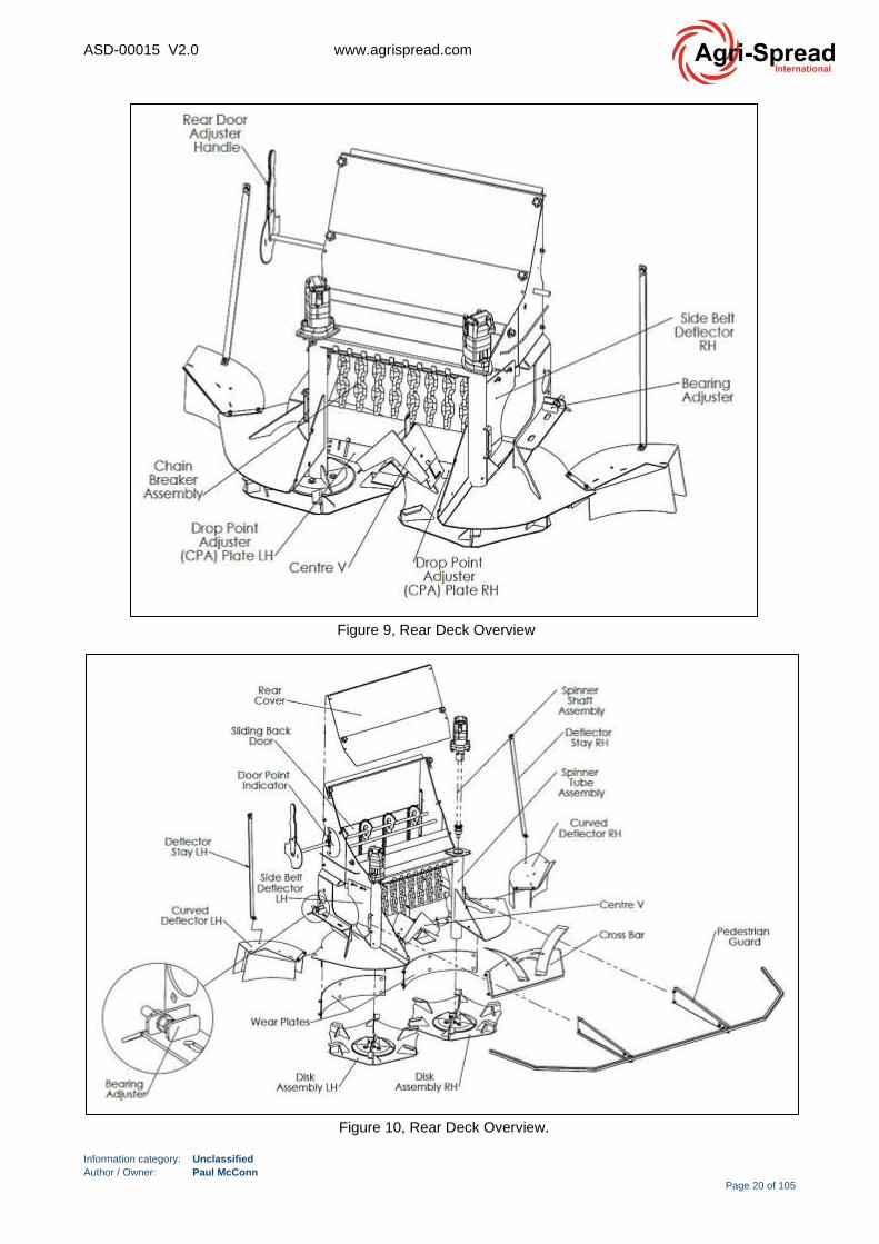
Figure 9, Rear Deck Overview
Figure 10, Rear Deck Overview.
ASD-00015 V2.0 www.agrispread.com
Information category: Unclassified
Author / Owner: Paul McConn
Page 21 of 105
5.2 Pre-Operation Checklist, (General).
Before operating this product for the first time and each time thereafter, the following steps should be
followed. This will ensure a safe and reliable working life.
(1) Inspect and lubricate the machine per the schedule outlined in the section 6.
(2) Check the floor and drive system can move freely.
(3) Check that the spinners and drive system move freely.
(4) Check all fasteners and hardware. Refer to section 10 for further detail.
(5) Check oil level in the gearboxes. Top up as required.
(6) Check for trapped material. Remove all trapped material before resuming work.
(7) Check tyre pressure. Inflate as required.
(8) Make sure that all guards and covers are in place, secured and functioning as designed.
(9) Check oil level in the tractor hydraulic reservoir. Top-up as required.
(10) Ensure that the machine is properly attached to the tractor using a drawbar pin with provisions for a
mechanical retainer. Make sure that a retainer is installed. Ensure the drawbar chain is installed.
(11) Depending on spec, the spreader may be equipped with optional hydraulic/air brakes. It is the
responsibility of the owner to connect the braking system to the tractor system or to a spool valve.
(12) Inspect all hydraulic lines, hoses, fittings and couplers for tightness. Tighten if there are leaks. Use
a clean cloth to wipe any accumulated dirt from the couplers before connecting to the tractor’s
hydraulic system.
Warning: Use extreme care when working around the high-pressure hydraulic system. Make
sure all connections are tight and all components are in good repair. Wear hand and eye
protection when opening hydraulic brake / spinner circuits or searching for suspected leaks.
5.2.1 Land-drive:
Minimum oil flow for a land drive spreader is 80 liters per minute (21 gpm).
A single pressure line is required for the spinner (1/2” male) and a single return line (3/4” female).
Pressure lines are color coded in Yellow and Return lines are color coded in Blue
5.2.2 Hydraulic Drive:
Minimum oil flow for a hydraulic drive spreader is 120 liters per minute (32 gpm).
There are two pressure lines required for the spinners and the floor (2 x 1/2” Male) and a single return line
(1” female).
• Female coupler installed at factory, to avoid plugging return into pressure port by mistake
• All fittings on the spreader have British Standard Parallel Pipe thread.
Warning: The return line must be fitted to the main free flow return line on the tractor. Failure do
to so will result in back pressure and may cause motor and or valve issues on the spreader
On tandem axle spreaders, there are two lines for the steering axle. One pressure line and one return line,
both ½”. Note the pressure line is only required to straighten axles for reversing or road use.
Warning: Ensure the steering axle is locked for road transport. Failure to do so can cause the
spreader to become unstable
All spreaders come equipped with hydraulic brakes as standard. This is a ½” female coupler.
5.2.3 Isobus Controller:
When running the spreader ECU through an Isobus controller, the tractor must have an ISO plug or an
adaptor that may have to be installed. Refer to your dealer for a list of compatible Isobus terminals.
ASD-00015 V2.0 www.agrispread.com
Information category: Unclassified
Author / Owner: Paul McConn
Page 22 of 105
The Isobus lead comes from the ECU on the side of the spreader and is fitted into either the tractor Isobus
plug or into an in-cab harness for a Topcon or similar display.
Notes for Isobus:
▪ When operating through an Isobus terminal in the tractor, for auto-shut off to work the display must
have this functionality and may require an unlock code.
▪ When operating through a Topcon display, the headland auto-shut off will operate using the
coverage maps on the Topcon.
▪ It is also possible to run the tractor auto guidance on the same Topcon unit, but this will require
installation from a local Topcon agent.
5.3 Parking/Hand Brake Operation, (General).
Agri-Spread spreaders may be supplied with or without a parking/hand brake. In the event a parking brake is
not supplied, wheel chocks should be used to safely secure the machine. The operation or installation of
both is described below.
Warning: The parking/hand brake alone should never be used to secure a laden or partially
laden spreader when disconnected from a tractor. If a laden or partially laden spreader is
disconnected from a tractor, wheel chocks shall be used in addition to the parking/hand brake, to
safely secure the spreader, refer to section 5.3.2 for further instruction.
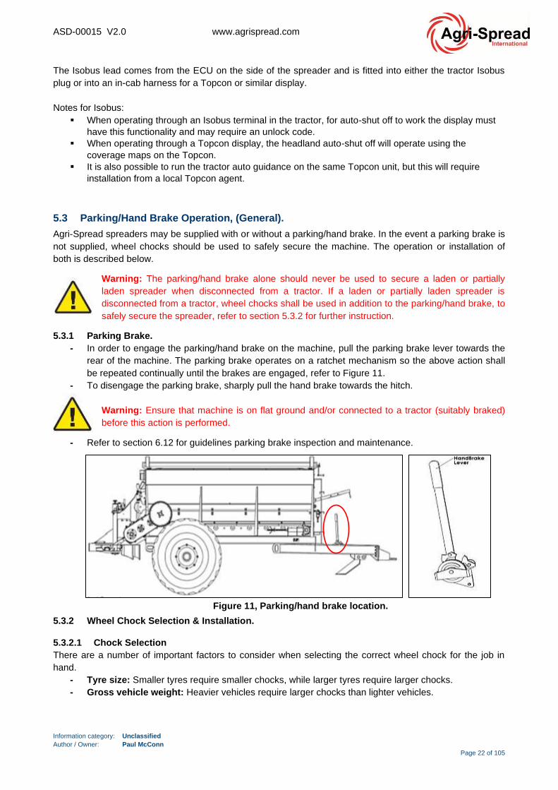
5.3.1 Parking Brake.
- In order to engage the parking/hand brake on the machine, pull the parking brake lever towards the
rear of the machine. The parking brake operates on a ratchet mechanism so the above action shall
be repeated continually until the brakes are engaged, refer to Figure 11.
- To disengage the parking brake, sharply pull the hand brake towards the hitch.
Warning: Ensure that machine is on flat ground and/or connected to a tractor (suitably braked)
before this action is performed.
- Refer to section 6.12 for guidelines parking brake inspection and maintenance.
5.3.2 Wheel Chock Selection & Installation.
5.3.2.1 Chock Selection
There are a number of important factors to consider when selecting the correct wheel chock for the job in
hand.
- Tyre size: Smaller tyres require smaller chocks, while larger tyres require larger chocks.
- Gross vehicle weight: Heavier vehicles require larger chocks than lighter vehicles.
Figure 11, Parking/hand brake location.

ASD-00015 V2.0 www.agrispread.com
Information category: Unclassified
Author / Owner: Paul McConn
Page 23 of 105
- Level or grade of the ground surface: Chocks need to be positioned in different ways depending
on if the ground is level or not. Ensuring that the chocking configuration is correct based on surface
grade is paramount for proper chocking.
- Radial Tyres vs. Bias-Ply Tyres: Radial tyres by design deflect more than bias-ply tyres. While this
flexibility allows the vehicle to move more smoothly, it also allows the tyre to wrap around the wheel
chock, which reduces the chocks effectiveness. To combat this, vehicles with radial tyres should be
chocked with wheel chocks that are larger than what the is typically recommended for that tyre size.
- Tyre pressure variance due to environment: It is important to monitor tyre pressure, especially in
harsh environments. Improperly inflated tyres can lead to chocking failures.
- Condition of the ground: Whether the ground is firm, soft, wet, dry, icy, or frozen is a key
determination in the type of chock to use. For frozen or icy terrain, choose a chock with a cleated
bottom. For severely wet or muddy terrain, multiple chocks may be necessary to ensure safe
chocking.
5.3.2.2 Chock Positioning.
When chocking a vehicle, always follow these rules to ensure maximum efficiency and safety.
1. Always ensure the chock is centred and squared with the tyre.
2. Position the chock snuggly against the tyre tread.
3. Always use wheel chocks in pairs.
4. Wheel chocks must be positioned downhill and below the vehicle’s centre of gravity.
5. On a downhill grade, position the chocks in front of the front wheels.
6. On an uphill grade, position the chocks behind the rear wheels.
7. On a level grade, position the chocks on the front and back of a single wheel.
Figure 12, Wheel chock positioning.
ASD-00015 V2.0 www.agrispread.com
Information category: Unclassified
Author / Owner: Paul McConn
Page 24 of 105
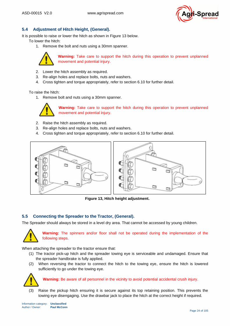
5.4 Adjustment of Hitch Height, (General).
It is possible to raise or lower the hitch as shown in Figure 13 below.
To lower the hitch:
1. Remove the bolt and nuts using a 30mm spanner.
Warning: Take care to support the hitch during this operation to prevent unplanned
movement and potential injury.
2. Lower the hitch assembly as required.
3. Re-align holes and replace bolts, nuts and washers.
4. Cross tighten and torque appropriately, refer to section 6.10 for further detail.
To raise the hitch:
1. Remove bolt and nuts using a 30mm spanner.
Warning: Take care to support the hitch during this operation to prevent unplanned
movement and potential injury.
2. Raise the hitch assembly as required.
3. Re-align holes and replace bolts, nuts and washers.
4. Cross tighten and torque appropriately, refer to section 6.10 for further detail.
5.5 Connecting the Spreader to the Tractor, (General).
The Spreader should always be stored in a level dry area. That cannot be accessed by young children.
Warning: The spinners and/or floor shall not be operated during the implementation of the
following steps.
When attaching the spreader to the tractor ensure that:
(1) The tractor pick-up hitch and the spreader towing eye is serviceable and undamaged. Ensure that
the spreader handbrake is fully applied.
(2) When reversing the tractor to connect the hitch to the towing eye, ensure the hitch is lowered
sufficiently to go under the towing eye.
Warning: Be aware of all personnel in the vicinity to avoid potential accidental crush injury.
(3) Raise the pickup hitch ensuring it is secure against its top retaining position. This prevents the
towing eye disengaging. Use the drawbar jack to place the hitch at the correct height if required.
Figure 13, Hitch height adjustment.
ASD-00015 V2.0 www.agrispread.com
Information category: Unclassified
Author / Owner: Paul McConn
Page 25 of 105
(4) Stop the tractor’s engine, set the park brake, remove the ignition key and wait for all moving parts
to stop.
(5) Install a safety chain between the tractor drawbar and machine hitch. Refer to section 5.6.
(6) If any safety guards and chains have been removed, refit them.
(7) Connect the large diameter return hose to the return line breakaway coupling on your tractor.
(8) Connect the small diameter pressure hose to the pressure line breakaway coupling on your tractor.
Warning: Use extreme care when working around the high-pressure hydraulic system.
Make sure all connections are tight and all components are in good repair. Wear hand
and eye protection when opening hydraulic brake / spinner circuits or searching for
suspected leaks.
(9) With the tractor at idle, engage your hydraulic spinners. The right-hand spinner should rotate anti-clockwise. The left-hand spinner should rotate clockwise.
Warning: If the spinners do not rotate or rotate in the wrong direction then the delivery and return hoses may be incorrectly assembled.
Warning: (Land-drive Only) Spinners can be over accelerated. Check Your Tachometer!! Max. for 675mm spinners = 1000 rpm, 575mm spinners = 1000 rpm. On any new set-up always shut the spinner flow control valve before start up and slowly open up with tractor at max RPM until maximum spinner speed has been achieved. Keep max. spinner speed within the above parameters.
(10) Connect and secure the multi-pin electrical plug to the tractor’s lighting socket. After connecting the
electrical circuit, ensure the lights are clean and operating properly.
(11) Lights should be checked before every use to
ensure there are functioning correctly and are
clearly visible.
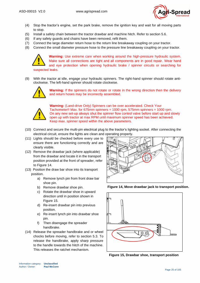
(12) Remove the drawbar jack (where applicable)
from the drawbar and locate it in the transport
position provided at the front of spreader, refer
to Figure 14.
(13) Position the draw bar shoe into its transport
position.
a) Remove lynch pin from front draw bar
shoe pin.
b) Remove drawbar shoe pin.
c) Rotate the drawbar shoe in upward
direction until in position shown in
Figure 15.
d) Re-insert drawbar pin into previous
position.
e) Re-insert lynch pin into drawbar shoe
pin.
f) Then disengage the spreader
handbrake.
(14) Release the spreader handbrake and or wheel
chocks before moving, refer to section 5.3. To
release the handbrake, apply sharp pressure
to the handle towards the hitch of the machine.
This releases the ratchet mechanism.
Figure 14, Move drawbar jack to transport position.
Figure 15, Drawbar shoe, transport position

ASD-00015 V2.0 www.agrispread.com
Information category: Unclassified
Author / Owner: Paul McConn
Page 26 of 105
5.6 Tractor Drawbar & Machine Hitch Safety Chain Attachment, (General).
The tractor drawbar & machine hitch safety chain acts as an additional coupling to the primary hitch coupling
on the spreader. This secondary coupling ensures that the spreader remains attached to the tractor if the
primary coupling fails or becomes detached. It prevents the spreaders drawbar from touching the ground,
damage to the tractor and provides some level of control.
A correct installation is illustrated in Figure 17. The chain is installed underneath the drawbar and connected
at the correct height on the tractor.
An incorrect installation is illustrated in Figure 16. The chain is too long and too high on the rear of the
tractor.
- The minimum strength of the chain must be equal to the gross weight of the spreader being drawn.
- Consult the vehicle manufacturer or chain supplier for advice on the type of chain you need.
- Safety chains must be securely attached to both the tractor’s hitch and the spreader drawbar.
- Safety chains must not be damaged, for example, worn from dragging on the ground, stretched or
kinked.
- The slack in the chain should only be enough to allow the spreader to turn.
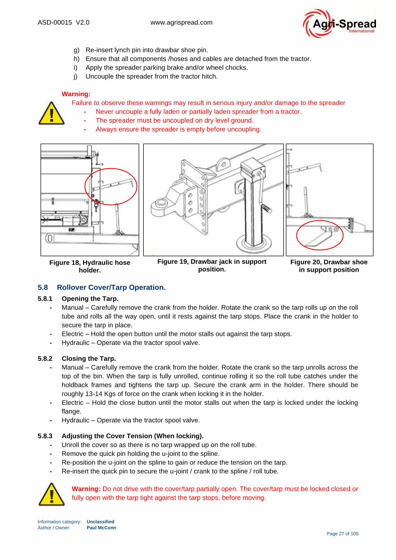
5.7 Disconnecting the Spreader from the Tractor, (General).
- To this dismount spreader from tractor, first ensure ground is firm and level where the machine will
be parked. Ensure that the machine is empty.
- Set the drawbar shoe/jack to its support position, refer to Figure 19 & Figure 20.
- Disconnection of the spreader from the tractor is the reverse of the previous procedure, with the
addition that the spreader’s hydraulic hoses should be fitted to the anchors provided on the
spreader, refer to Figure 18. This prevents damage to the hose fittings and contamination of the
hydraulic and brake systems.
- Remember to apply the handbrake and/or wheel chocks, refer to section 5.3. To apply the
handbrake, give the handle short pumps until resistance can be detected. This indicates that the
brake cable is becoming tight.
- Disconnection steps:
a) Ensure the tractor spool valves have been placed in the float position, before turning off the
spreader. This requirement applies to both fixed pump and load sense setups.
If the spreader is setup in “power beyond mode”, ensure that the spinners are set to the off
position on the computer before turning off the machine.
b) Stop the machine, engage the handbrake and/or wheel chocks.
c) Remove lynch pin from front draw bar shoe pin.
d) Remove drawbar shoe pin.
e) Rotate the drawbar shoe in a downward direction until in position shown Figure 20.
f) Re-insert drawbar pin into previous position.
Figure 17, Correct safety chain attachment Figure 16, Incorrect safety chain attachment
ASD-00015 V2.0 www.agrispread.com
Information category: Unclassified
Author / Owner: Paul McConn
Page 27 of 105
g) Re-insert lynch pin into drawbar shoe pin.
h) Ensure that all components /hoses and cables are detached from the tractor.
i) Apply the spreader parking brake and/or wheel chocks.
j) Uncouple the spreader from the tractor hitch.
Warning:
Failure to observe these warnings may result in serious injury and/or damage to the spreader
- Never uncouple a fully laden or partially laden spreader from a tractor.
- The spreader must be uncoupled on dry level ground.
- Always ensure the spreader is empty before uncoupling.
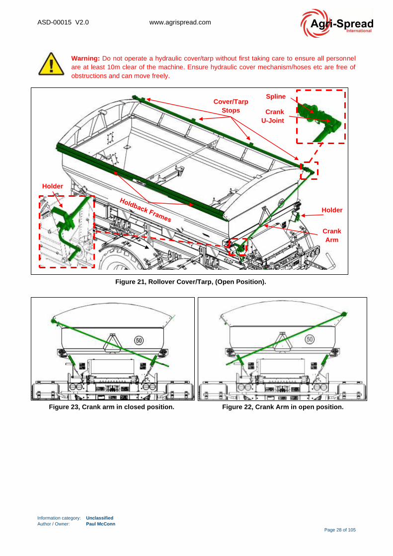
5.8 Rollover Cover/Tarp Operation.
5.8.1 Opening the Tarp.
- Manual – Carefully remove the crank from the holder. Rotate the crank so the tarp rolls up on the roll
tube and rolls all the way open, until it rests against the tarp stops. Place the crank in the holder to
secure the tarp in place.
- Electric – Hold the open button until the motor stalls out against the tarp stops.
- Hydraulic – Operate via the tractor spool valve.
5.8.2 Closing the Tarp.
- Manual – Carefully remove the crank from the holder. Rotate the crank so the tarp unrolls across the
top of the bin. When the tarp is fully unrolled, continue rolling it so the roll tube catches under the
holdback frames and tightens the tarp up. Secure the crank arm in the holder. There should be
roughly 13-14 Kgs of force on the crank when locking it in the holder.
- Electric – Hold the close button until the motor stalls out when the tarp is locked under the locking
flange.
- Hydraulic – Operate via the tractor spool valve.
5.8.3 Adjusting the Cover Tension (When locking).
- Unroll the cover so as there is no tarp wrapped up on the roll tube.
- Remove the quick pin holding the u-joint to the spline.
- Re-position the u-joint on the spline to gain or reduce the tension on the tarp.
- Re-insert the quick pin to secure the u-joint / crank to the spline / roll tube.
Warning: Do not drive with the cover/tarp partially open. The cover/tarp must be locked closed or
fully open with the tarp tight against the tarp stops, before moving.
Figure 18, Hydraulic hose holder.
Figure 20, Drawbar shoe in support position
Figure 19, Drawbar jack in support position.
ASD-00015 V2.0 www.agrispread.com
Information category: Unclassified
Author / Owner: Paul McConn
Page 28 of 105
Warning: Do not operate a hydraulic cover/tarp without first taking care to ensure all personnel
are at least 10m clear of the machine. Ensure hydraulic cover mechanism/hoses etc are free of
obstructions and can move freely.
Figure 21, Rollover Cover/Tarp, (Open Position).
Crank
Arm
Holder
Cover/Tarp
Stops Crank
U-Joint
Holder
Spline
Figure 22, Crank Arm in open position. Figure 23, Crank arm in closed position.

ASD-00015 V2.0 www.agrispread.com
Information category: Unclassified
Author / Owner: Paul McConn
Page 29 of 105
5.9 Before Loading, (Hydraulic-Isobus System Only).
Before loading the spreader review the following sections.
5.9.1 Isobus Control Setup:
- Consult the tractor terminal handbook to get the screen to display the virtual terminal screen, to
display the Agri-Spread Isobus screen.
- Reference the Isobus Quick Start Guide document for a summary of the essential setup and
operational control procedures for your spreader. A copy of this document is available from your
Agri-Spread dealer.
- Reference the Isobus manual for the load cell calibration procedure. This procedure should be
completed on an initial setup and repeated at the beginning of each spreading season or after a
major service interval. A copy of this document is available from your Agri-Spread dealer.
5.9.1.1 GPS Setup:
After the Isobus screen has been setup, ensure the screen is picking up the GPS forward speed. This can be
checked by driving forward and confirming the tractor speed matches that displayed on the Isobus screen.
The spinner control function and the floor control function need to be checked. Refer to the following
sections.
5.9.1.2 Checking Oil Flow.
- When running in fixed pump arrangement, engage both tractor spools and run the spinners up to
1000 rpm.
- When running in “power beyond” mode, once you turn the computer on and enter a spinner speed
and the spinners are set to on, they will operate without turning on any of the spools.
Warning: Ensure the spinners are free from obstruction and all personnel are safely clear of the
spreader.
Warning: Use caution when turning on the tractor if set up in “power beyond mode”, as the
spinners may be set to on when the computer powers up.
- Enter the product application rate, spread width, flow factor, driving speed and run the floor in
simulation mode, to ensure you have enough oil flow to operate the spreader at the desired rate and
speed.
- When the machine is spreading product, it will require more oil flow than in simulation mode as it is
now under pressure and oil flow reduces while spreading product.
5.9.1.3 Disk Setup:
Refer to the rear deck setup recommendations given in section 5.17.
5.9.1.4 Setting Door Height.
Agri-Spread recommended that the mobile application is used to define the door height needed for a material
and the spread requirements. A recommended range of door height openings are calculated based on
factors the operator sets, such as:
• Product density
• Spread width
• Target rate
• Spinner speed
• Tractor speed.
The mobile app allows the end user to pick specific door heights, but also to scroll a range of door heights
and clearly see what oil flow is required for each.
ASD-00015 V2.0 www.agrispread.com
Information category: Unclassified
Author / Owner: Paul McConn
Page 30 of 105
Note: Please refer to the Agri-Spread Mobile app for the recommended door heights for both
Land-drive spreaders and Hydraulic drive spreaders.
5.9.1.5 Setting Spinner Speed.
Agri-Spread recommended that the mobile application is used to define the spinner speed needed for a
material and the spread requirements. Spinner speed is the most important factor in achieving an accurate
spread pattern. The spinner speed is adjusted by entering the required speed into the Isobus terminal.
When approaching headlands, disengage the floor. Never disengage hydraulic flow to the spinners while
spreading.
Refer to the rear deck setup recommendations given in section 5.17.
5.9.1.6 Flow Factor.
Materials of the same density can have different flow characteristics. For example, take Hydro Extran and
Kemira Nitraprill. Both materials have the same density and the same door opening, however far more
Nitraprill will come out than Extran. This is due to the prill size and the ease with which the material will flow.
Compounds will not flow as readily as prills as they tend to be more angular in shape compared to the
spherical prills. Humidity and dampness can also affect the way a material flows as can the age of the
fertiliser.
Flow factor is a calibration number used to calculate target belt speed based on input factors such as:
• Density
• Spread width
• Target rate
• Spinner speed
• Driving speed
These are the variables used to determine the correct flow factor. The default flow factor is 1.0.
• Values > (greater than) 1.0 indicate a product that flows more quickly.
• Values < (less than) 1.0 indicate a product that flows less than normal.
Note: The gate height setting also effects the flow factor setting. Therefore, any given product will
have a different flow factor as gate height changes.
When working in dynamic mode, the flow factor inputted is the starting point for the belt speed.
Once the dynamic mode starts to change based on the readings taken while spreading, the flow factor
changes.
In static mode, the flow factor entered by the operator does not change through the load. The operator must
change the flow factor based on application rate checks or using the nudge feature*.
* Note: Reference the Isobus manual. A copy of this document is available from your Agri-Spread dealer.
5.9.2 Material Density.
Material density, usually expressed as relative density is a comparison of weight to volume. Imagine a table
tennis ball and a golf ball, they are of a similar size and volume but the weight of a golf ball is far greater.
This means that a golf ball is far denser than a table tennis ball. In spreading terms, this means that to
spread a similar weight of materials of differing densities the volume of material spread must change. To
spread accurately, you must know the density of the material you are spreading.

ASD-00015 V2.0 www.agrispread.com
Information category: Unclassified
Author / Owner: Paul McConn
Page 31 of 105
5.9.2.1 Agri-Spread Density Meters.
The Agri-Spread density metre is a quick and easy way to find out the density of fertiliser even on a load by
load basis. The Agri-spread density metre gives you a robust, light and simple solution to density
measurement that can be carried out in the cab.
Fill the Agri-spread density metre with the required product and level off the top, slide balance until float is in
the centre and read off top scale on slide arm.
5.9.3 Driving Inaccurately.
Although your Agri-spread unit may have a ground related conveyor belt, driving inaccuracies can affect your
rate per hectare. If your machine is set for a 12m bout width, any variation from this in your rows will be
reflected in the error of rate of application. i.e. If you drive at 10m instead of 12m the error in your rate will be
12/10 x 100 = 120% of your required rate per hectare. Likewise, if you drive at 14m instead of 12m the error
in your rate will be 12/14 x 100 = 86% of your required rate per hectare.
5.10 Loading the Spreader, (General).
- Park the spreader next to the loading area.
- Before loading check that the floor can move to the rear of the spinner discs are fully operational.
Warning: Remove of all personnel in the vicinity of the machine before operating the
spreader. All persons except for the operator should be at least 33ft (10m) away from
spreader when loading or when the engine is running.
- Ensure that the rear door of the spreader is fully closed.
Warning: Never attempt to load a spreader unless it is coupled to a tractor and the
tractor parking brake has been applied.
- Ensure that the fill material entering the spreader is free of foreign objects, otherwise damage may
result. Small objects such as stones can result in damage to the spinner vanes / flights and pose a
risk to personnel or animals near the spread region.
- The density and moisture content of the material will determine how much the spreader can be
loaded. Refer to the technical specifications section for max carrying capacity.
- High moisture materials are heavier and may limit the amount of material that can be loaded. Do not
exceed the plated spreader weight capacity.
1. Fill level with product 2. Balance on ring
3. Slide weight until
level is in centre
4. Read off top metric scale
for weight per cu. metre in
tonnes
Figure 24, Agri-Spread Density Meter.

ASD-00015 V2.0 www.agrispread.com
Information category: Unclassified
Author / Owner: Paul McConn
Page 32 of 105
Warning: Overloading a spreader can result in material loss on public roadways.
Consideration should be made when heaping loads if the machine is going to transit on
public roadways. Failure to do this could result in prosecution.
5.11 Spreading Procedure, (General).
After loading the spreader and transporting the load to the spreading site:
(1) Open the rear door to the required height, (safely, following all user safety instructions).
Use the online application rate calculator for land drive or hydraulic drive.
(2) Engage the spinners.
(3) Ensure the spinners have reached their operating speed, according to the tachometer or Isobus
screen.
(4) Engage the floor drive.
(5) Move forward.
Warning: All persons other than the operator should keep at least 328ft (100m) away from
spreading area. The operator should ensure that the spreading area is clear of both
bystanders and livestock before spreading commences.
5.12 Setting Spinner Speeds & Rear Deflectors, (Land-Drive System Only).
Spinner Speed is the most important factor in achieving an accurate spread pattern. The spinner speed is
adjusted by altering the control on the valve at the front of the machine, refer to Figure 25. Guideline spinner
speeds and machine setup recommendations for various different materials are given in section 5.17 and
Agri-Spread document ASD-00011 (available on request from your local dealer).
When setting spinner speeds ensure the engine of the tractor is running at the same RPM as it will normally
be operating in the field and make sure that the oil is warmed up to its normal operating temperature. Always
monitor the spinner speed by watching the tachometer when operating the spreader as an error of 50 RPM
on spinner speed will result in a deterioration of the spread pattern. If the spinner speed is too high, there will
be too much material behind the spreader. If the spinner speed is too slow there will be too little material
behind the spreader. It is sometimes necessary to alter the angle of the rear deflectors to lighten the spread behind the machine
and throw the material more into the centre of the pattern.
Warning: Never adjust the deflectors while the spinners are rotating.
Figure 25, Spinner Flow Control Valve.
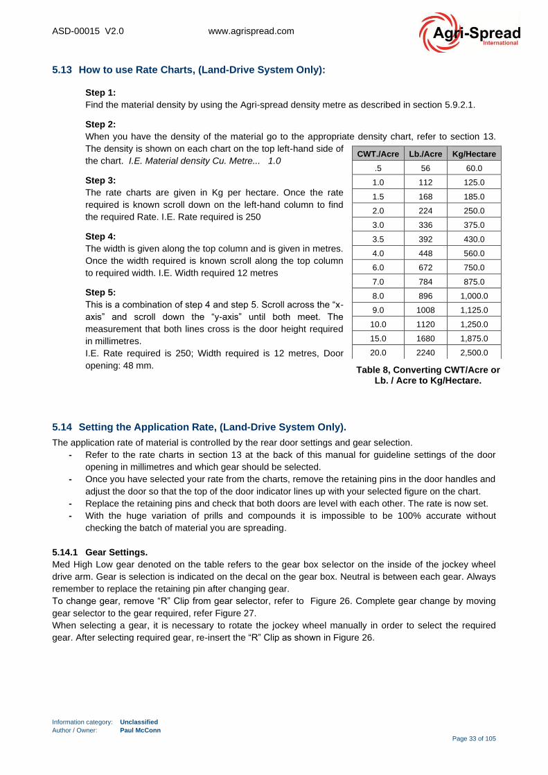
ASD-00015 V2.0 www.agrispread.com
Information category: Unclassified
Author / Owner: Paul McConn
Page 33 of 105
5.13 How to use Rate Charts, (Land-Drive System Only):
Step 1:
Find the material density by using the Agri-spread density metre as described in section 5.9.2.1.
Step 2:
When you have the density of the material go to the appropriate density chart, refer to section 13.
The density is shown on each chart on the top left-hand side of
the chart. I.E. Material density Cu. Metre... 1.0
Step 3:
The rate charts are given in Kg per hectare. Once the rate
required is known scroll down on the left-hand column to find
the required Rate. I.E. Rate required is 250
Step 4:
The width is given along the top column and is given in metres.
Once the width required is known scroll along the top column
to required width. I.E. Width required 12 metres
Step 5:
This is a combination of step 4 and step 5. Scroll across the “x-
axis” and scroll down the “y-axis” until both meet. The
measurement that both lines cross is the door height required
in millimetres.
I.E. Rate required is 250; Width required is 12 metres, Door
opening: 48 mm.
5.14 Setting the Application Rate, (Land-Drive System Only).
The application rate of material is controlled by the rear door settings and gear selection.
- Refer to the rate charts in section 13 at the back of this manual for guideline settings of the door
opening in millimetres and which gear should be selected.
- Once you have selected your rate from the charts, remove the retaining pins in the door handles and
adjust the door so that the top of the door indicator lines up with your selected figure on the chart.
- Replace the retaining pins and check that both doors are level with each other. The rate is now set.
- With the huge variation of prills and compounds it is impossible to be 100% accurate without
checking the batch of material you are spreading.
5.14.1 Gear Settings.
Med High Low gear denoted on the table refers to the gear box selector on the inside of the jockey wheel
drive arm. Gear is selection is indicated on the decal on the gear box. Neutral is between each gear. Always
remember to replace the retaining pin after changing gear.
To change gear, remove “R” Clip from gear selector, refer to Figure 26. Complete gear change by moving
gear selector to the gear required, refer Figure 27.
When selecting a gear, it is necessary to rotate the jockey wheel manually in order to select the required
gear. After selecting required gear, re-insert the “R” Clip as shown in Figure 26.
CWT./Acre Lb./Acre Kg/Hectare
.5 56 60.0
1.0 112 125.0
1.5 168 185.0
2.0 224 250.0
3.0 336 375.0
3.5 392 430.0
4.0 448 560.0
6.0 672 750.0
7.0 784 875.0
8.0 896 1,000.0
9.0 1008 1,125.0
10.0 1120 1,250.0
15.0 1680 1,875.0
20.0 2240 2,500.0
Table 8, Converting CWT/Acre or Lb. / Acre to Kg/Hectare.

ASD-00015 V2.0 www.agrispread.com
Information category: Unclassified
Author / Owner: Paul McConn
Page 34 of 105
Figure 26, Land-drive gearbox, gear selection details.
R-Pin
Gear
Selector
Figure 27, Land-drive gearbox, gear selection details.
Neutral Gear,
1 groove
visible
High Gear,
2 grooves
visible
Medium
Gear,
3 grooves
visible
Low Gear,
No grooves
visible
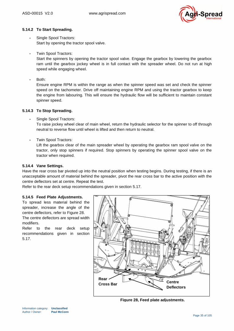
ASD-00015 V2.0 www.agrispread.com
Information category: Unclassified
Author / Owner: Paul McConn
Page 35 of 105
5.14.2 To Start Spreading.
- Single Spool Tractors:
Start by opening the tractor spool valve.
- Twin Spool Tractors:
Start the spinners by opening the tractor spool valve. Engage the gearbox by lowering the gearbox
ram until the gearbox jockey wheel is in full contact with the spreader wheel. Do not run at high
speed while engaging wheel.
- Both:
Ensure engine RPM is within the range as when the spinner speed was set and check the spinner
speed on the tachometer. Drive off maintaining engine RPM and using the tractor gearbox to keep
the engine from labouring. This will ensure the hydraulic flow will be sufficient to maintain constant
spinner speed.
5.14.3 To Stop Spreading.
- Single Spool Tractors:
To raise jockey wheel clear of main wheel, return the hydraulic selector for the spinner to off through
neutral to reverse flow until wheel is lifted and then return to neutral.
- Twin Spool Tractors:
Lift the gearbox clear of the main spreader wheel by operating the gearbox ram spool valve on the
tractor, only stop spinners if required. Stop spinners by operating the spinner spool valve on the
tractor when required.
5.14.4 Vane Settings.
Have the rear cross bar pivoted up into the neutral position when testing begins. During testing, if there is an
unacceptable amount of material behind the spreader, pivot the rear cross bar to the active position with the
centre deflectors set at centre. Repeat the test.
Refer to the rear deck setup recommendations given in section 5.17.
5.14.5 Feed Plate Adjustments.
To spread less material behind the
spreader, increase the angle of the
centre deflectors, refer to Figure 28.
The centre deflectors are spread width
modifiers.
Refer to the rear deck setup
recommendations given in section
5.17.
Centre
Deflectors
Rear
Cross Bar
Figure 28, Feed plate adjustments.

ASD-00015 V2.0 www.agrispread.com
Information category: Unclassified
Author / Owner: Paul McConn
Page 36 of 105
5.15 Tachometer, (Land-Drive System Only).
How do you tell what your spinners are doing? When do you know if they are going too fast or too slow,
before or after the farmer complains about the poor job done? To be certain you have the right speed use
the Agri-Spread tachometer.
This tachometer will give the speed of the spinners so that you can always know what they are doing.
Spinner speed will vary with load, oil temperature and engine revs.
- If the spread pattern is too heavy behind the spreader, the spinner speed is usually too high.
- If the spread pattern is too light, increase the spinner speed. To get the correct spread pattern the
spreader setup must be tray tested.
Kit descriptions are as follows:
1) Agri-spread Tachometer (spinner shaft already has sensor fitted).
2) Rev counter with magnet and sensor mount.
3) Plug kit for trailers or trucks with demountable bins.
5.16 Headland Operation, (Land-Drive System).
Spool valve is adjusted by turning black wheel as
described below:
- Fully clockwise: Both spinners are operating
at equal RPM
- Anti-clockwise: Reducers left hand spinner
speed.
To spread on headlands the left-hand spinner RPM
should be reduced by 20% in relation to your normal
spinner RPM.
Warning: Do not adjust headland control
while the machine is operating. Failure to
do so could result in death or serious
injury.
Wheel for
adjusting
Spinner RPM
Release nut to
adjust headland
spool valve.
Figure 30, Headland control operation.
Figure 29, Agri-Spread Tachometer.
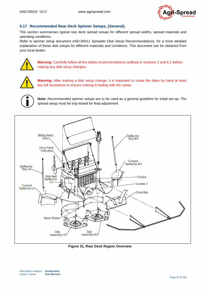
ASD-00015 V2.0 www.agrispread.com
Information category: Unclassified
Author / Owner: Paul McConn
Page 37 of 105
5.17 Recommended Rear Deck Spinner Setups, (General).
This section summarises typical rear deck spread setups for different spread widths, spread materials and
operating conditions.
Refer to spinner setup document ASD-00011 Spreader Disk Setup Recommendations, for a more detailed
explanation of these disk setups for different materials and conditions. This document can be obtained from
your local dealer.
Warning: Carefully follow all the safety recommendations outlined in sections 3 and 6.1 before
making any disk setup changes.
Warning: After making a disk setup change, it is important to rotate the disks by hand at least
two full revolutions to ensure nothing is fouling with the vanes.
Note: Recommended spinner setups are to be used as a general guideline for initial set-up. The
spread setup must be tray tested for final adjustment.
Figure 31, Rear Deck Region Overview
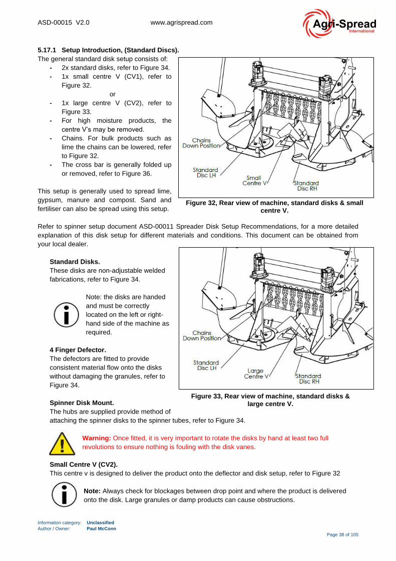
ASD-00015 V2.0 www.agrispread.com
Information category: Unclassified
Author / Owner: Paul McConn
Page 38 of 105
5.17.1 Setup Introduction, (Standard Discs).
The general standard disk setup consists of:
- 2x standard disks, refer to Figure 34.
- 1x small centre V (CV1), refer to
Figure 32.
or
- 1x large centre V (CV2), refer to
Figure 33.
- For high moisture products, the
centre V’s may be removed.
- Chains. For bulk products such as
lime the chains can be lowered, refer
to Figure 32.
- The cross bar is generally folded up
or removed, refer to Figure 36.
This setup is generally used to spread lime,
gypsum, manure and compost. Sand and
fertiliser can also be spread using this setup.
Refer to spinner setup document ASD-00011 Spreader Disk Setup Recommendations, for a more detailed
explanation of this disk setup for different materials and conditions. This document can be obtained from
your local dealer.
Standard Disks.
These disks are non-adjustable welded
fabrications, refer to Figure 34.
Note: the disks are handed
and must be correctly
located on the left or right-
hand side of the machine as
required.
4 Finger Defector.
The defectors are fitted to provide
consistent material flow onto the disks
without damaging the granules, refer to
Figure 34.
Spinner Disk Mount.
The hubs are supplied provide method of
attaching the spinner disks to the spinner tubes, refer to Figure 34.
Warning: Once fitted, it is very important to rotate the disks by hand at least two full
revolutions to ensure nothing is fouling with the disk vanes.
Small Centre V (CV2).
This centre v is designed to deliver the product onto the deflector and disk setup, refer to Figure 32
Note: Always check for blockages between drop point and where the product is delivered
onto the disk. Large granules or damp products can cause obstructions.
Figure 32, Rear view of machine, standard disks & small centre V.
Figure 33, Rear view of machine, standard disks & large centre V.

ASD-00015 V2.0 www.agrispread.com
Information category: Unclassified
Author / Owner: Paul McConn
Page 39 of 105
Large Centre V, (CV2).
This centre v is designed to deliver the product onto the deflector and disk setup. Refer to Figure 33.
Note: Always check for blockages between drop point and where the product is delivered onto
the disk. Large granules or damp products can cause obstructions.
The summary table below defines the recommended settings that apply to the type of material being spread
and the level of moisture present in the spread material.
Always ensure that the lime spreader CPA plates on the left- & right-hand side of the machine are aligned
horizontally with their respective centre V CPB plate set positions, refer to Figure 35. Suggested centre V
CPB plate settings where applicable are outlined in
Table 9.
Table 9, Recommended settings, standard discs.
Figure 34, Standard discs, note flight orientation.
Spread
Region
Right Hand
Disc
Left Hand
Disc
4 Finger
Deflector
Disk
Mount
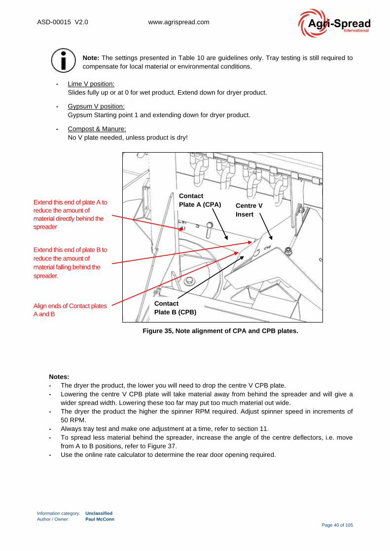
ASD-00015 V2.0 www.agrispread.com
Information category: Unclassified
Author / Owner: Paul McConn
Page 40 of 105
Note: The settings presented in Table 10 are guidelines only. Tray testing is still required to
compensate for local material or environmental conditions.
- Lime V position:
Slides fully up or at 0 for wet product. Extend down for dryer product.
- Gypsum V position:
Gypsum Starting point 1 and extending down for dryer product.
- Compost & Manure:
No V plate needed, unless product is dry!
Notes:
- The dryer the product, the lower you will need to drop the centre V CPB plate.
- Lowering the centre V CPB plate will take material away from behind the spreader and will give a
wider spread width. Lowering these too far may put too much material out wide.
- The dryer the product the higher the spinner RPM required. Adjust spinner speed in increments of
50 RPM.
- Always tray test and make one adjustment at a time, refer to section 11.
- To spread less material behind the spreader, increase the angle of the centre deflectors, i.e. move
from A to B positions, refer to Figure 37.
- Use the online rate calculator to determine the rear door opening required.
Figure 35, Note alignment of CPA and CPB plates.
Centre V
Insert
Contact
Plate A (CPA)
Contact
Plate B (CPB)
^
Extend this end of plate A to
reduce the amount of
material directly behind the
spreader
Extend this end of plate B to
reduce the amount of
material falling behind the
spreader.
Align ends of Contact plates
A and B
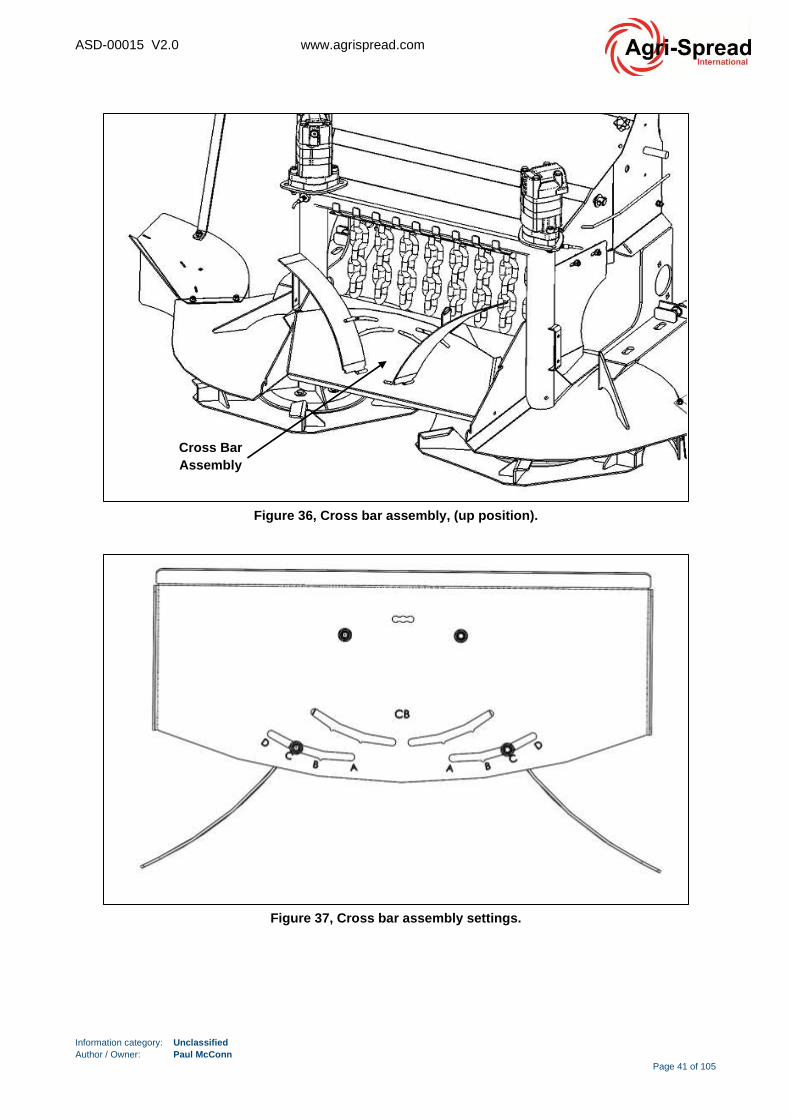
ASD-00015 V2.0 www.agrispread.com
Information category: Unclassified
Author / Owner: Paul McConn
Page 41 of 105
Figure 37, Cross bar assembly settings.
Figure 36, Cross bar assembly, (up position).
Cross Bar
Assembly

ASD-00015 V2.0 www.agrispread.com
Information category: Unclassified
Author / Owner: Paul McConn
Page 42 of 105
5.17.2 Setup Introduction, (2-Vane Widespread).
The general 2-vane widespread setup consists of:
- 2x 2-vane widespread disks and flights, refer to Figure 39.
- 1x large adjustable centre V (CV3), refer to Figure 38.
- The cross-bar assembly is folded up or removed, refer to Figure 36.
- Chains are folded up or removed.
This setup is generally used to spread fertilisers and similar granulated products.
Refer to spinner setup document ASD-00011 Spreader Disk Setup Recommendations, for a more detailed
explanation of this disk setup for different materials and conditions. This document can be obtained from
your local dealer.
Widespread Disks.
The disks provided are a two-vane disk. These are laser cut with engravings to give clearly marked
numbers for setting the vane position. Each disk is marked from -3 to +3 (-4 to +4 on older designs).
A general rule for vane position settings when testing is when spread pattern is heavy behind the
machine, increase the vane angle. For example, to increase the vane angle on the disk would be going
from -1 to -2. Negative disk setting numbers increase the distribution of product out wide. Refer to Figure
39.
Flights / Vanes.
The vanes provided in the kit are a fabricated vane made from hardened steel. When fitting the
widespread kits, ensure the extension hub is fitted to the disk. The rear deck centre divider often has to
be adjusted to ensure nothing is fouling. Refer to Figure 39.
Warning: Once fitted, it is very important to rotate the disks by hand at least two full revolutions
to ensure nothing is fouling with the vanes.
Large Adjustable Centre V, (CV3).
This centre v is designed to deliver the product onto the cones and 2-vane disk. There is an adjustable
guide plate that gives the operator more precision placement of fertiliser onto the disks, refer to Figure
38. Standard positions are outlined in Table 10.
Spinner Cones.
The cones are fitted to provide consistent flow onto the vanes without damaging the granules, refer to
Figure 39.
Figure 38, 2-Vane Widespread General Setup.
Right Hand Disc
Left Hand
Disc Adjustable
Centre V
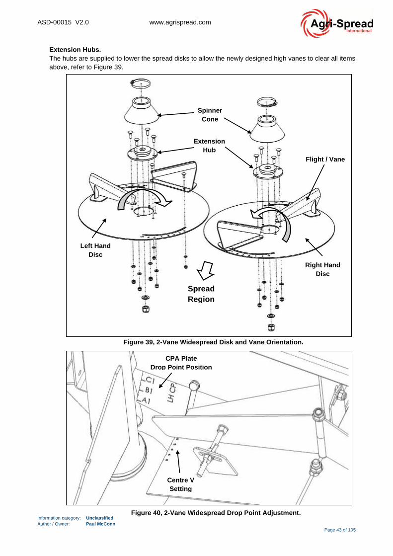
ASD-00015 V2.0 www.agrispread.com
Information category: Unclassified
Author / Owner: Paul McConn
Page 43 of 105
Extension Hubs.
The hubs are supplied to lower the spread disks to allow the newly designed high vanes to clear all items
above, refer to Figure 39.
Figure 39, 2-Vane Widespread Disk and Vane Orientation.
Spinner
Cone
Extension
Hub
Spread
Region
Right Hand
Disc
Left Hand
Disc
Flight / Vane
Figure 40, 2-Vane Widespread Drop Point Adjustment.
Centre V
Setting
CPA Plate
Drop Point Position
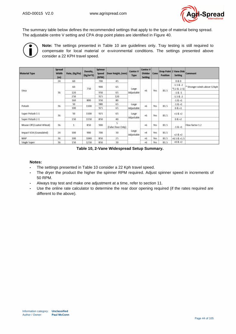
ASD-00015 V2.0 www.agrispread.com
Information category: Unclassified
Author / Owner: Paul McConn
Page 44 of 105
The summary table below defines the recommended settings that apply to the type of material being spread.
The adjustable centre V setting and CPA drop point plates are identified in Figure 40.
Note: The settings presented in Table 10 are guidelines only. Tray testing is still required to
compensate for local material or environmental conditions. The settings presented above
consider a 22 KPH travel speed.
Notes:
- The settings presented in Table 10 consider a 22 Kph travel speed.
- The dryer the product the higher the spinner RPM required. Adjust spinner speed in increments of
50 RPM.
- Always tray test and make one adjustment at a time, refer to section 11.
- Use the online rate calculator to determine the rear door opening required (if the rates required are
different to the above).
Left
Hand
Disc
Table 10, 2-Vane Widespread Setup Summary.
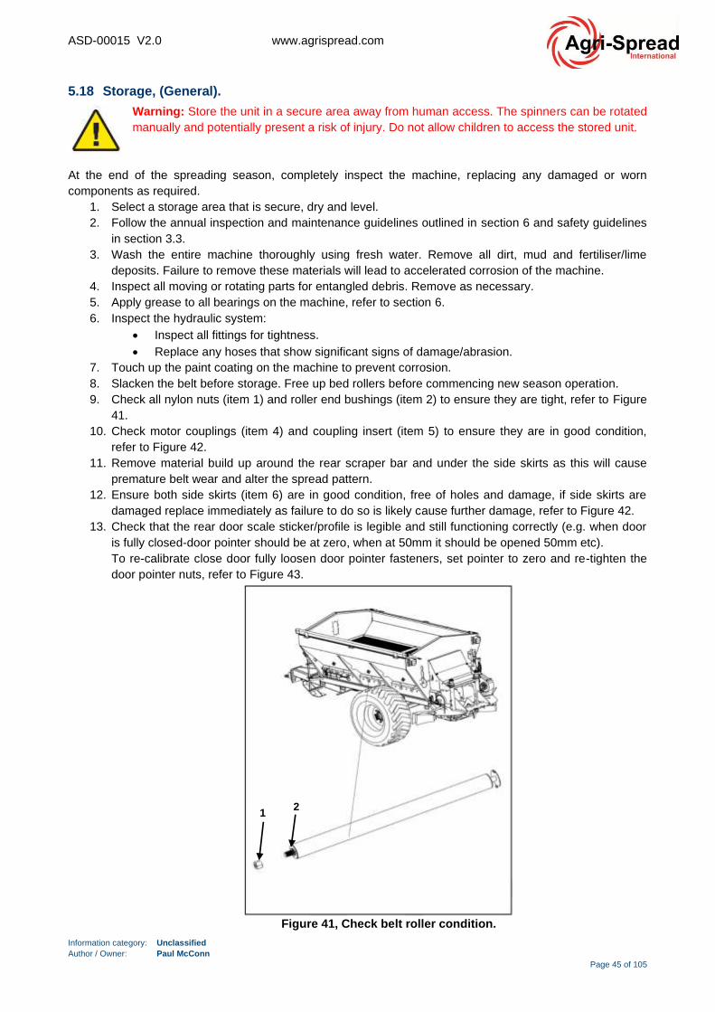
ASD-00015 V2.0 www.agrispread.com
Information category: Unclassified
Author / Owner: Paul McConn
Page 45 of 105
5.18 Storage, (General).
Warning: Store the unit in a secure area away from human access. The spinners can be rotated
manually and potentially present a risk of injury. Do not allow children to access the stored unit.
At the end of the spreading season, completely inspect the machine, replacing any damaged or worn
components as required.
1. Select a storage area that is secure, dry and level.
2. Follow the annual inspection and maintenance guidelines outlined in section 6 and safety guidelines
in section 3.3.
3. Wash the entire machine thoroughly using fresh water. Remove all dirt, mud and fertiliser/lime
deposits. Failure to remove these materials will lead to accelerated corrosion of the machine.
4. Inspect all moving or rotating parts for entangled debris. Remove as necessary.
5. Apply grease to all bearings on the machine, refer to section 6.
6. Inspect the hydraulic system:
• Inspect all fittings for tightness.
• Replace any hoses that show significant signs of damage/abrasion.
7. Touch up the paint coating on the machine to prevent corrosion.
8. Slacken the belt before storage. Free up bed rollers before commencing new season operation.
9. Check all nylon nuts (item 1) and roller end bushings (item 2) to ensure they are tight, refer to Figure
41.
10. Check motor couplings (item 4) and coupling insert (item 5) to ensure they are in good condition,
refer to Figure 42.
11. Remove material build up around the rear scraper bar and under the side skirts as this will cause
premature belt wear and alter the spread pattern.
12. Ensure both side skirts (item 6) are in good condition, free of holes and damage, if side skirts are
damaged replace immediately as failure to do so is likely cause further damage, refer to Figure 42.
13. Check that the rear door scale sticker/profile is legible and still functioning correctly (e.g. when door
is fully closed-door pointer should be at zero, when at 50mm it should be opened 50mm etc).
To re-calibrate close door fully loosen door pointer fasteners, set pointer to zero and re-tighten the
door pointer nuts, refer to Figure 43.
Figure 41, Check belt roller condition.
1
2

ASD-00015 V2.0 www.agrispread.com
Information category: Unclassified
Author / Owner: Paul McConn
Page 46 of 105
Figure 43, Door height indicator check.
Door
Pointer
Fasteners
Door Scale
Sticker/Profile
Figure 42, Check motor coupling and side skirt condition.
3
4
5
6

ASD-00015 V2.0 www.agrispread.com
Information category: Unclassified
Author / Owner: Paul McConn
Page 47 of 105
6 Service Intervals & General Maintenance.
6.1 Maintenance Safety.
The correct assembly and adjustment of all equipment is critical to the safe operation of this
product. Therefore, the procedures specified should only be carried out by competent personnel.
Warning: Routine or non-routine maintenance of components on this product should only be
carried out by competent/qualified personnel.
If you have any doubt about your ability to perform any of the procedures given in the following
section, we recommend the tasks be performed by a local service centre.
As a rule, stop the tractor engine prior to carrying out maintenance, servicing, cleaning or repair work.
Always remove the ignition key on the tractor and apply the spreader and tractor parking brakes.
Warning: The manufacturer will not be responsible for any damages or injuries caused by unauthorised repair, alterations or by mishandling of the product.
Regular maintenance is an essential part of operating any machinery and will keep your Agri-Spread
Spreader working at peak efficiency. The following paragraphs detail the minimum maintenance operations
required to keep the spreader operating safely and efficiently. Please ensure you have read and understood
the guidelines and warnings outlined in section 3.
It is recommended that records of this servicing are kept for future reference. Note: local
legislative regulations should always be followed.

ASD-00015 V2.0 www.agrispread.com
Information category: Unclassified
Author / Owner: Paul McConn
Page 48 of 105
6.2 Maintenance Schedule.
Table 11, Maintenance / inspection summary.

ASD-00015 V2.0 www.agrispread.com
Information category: Unclassified
Author / Owner: Paul McConn
Page 49 of 105
6.3 Cleaning General:
- Clean the machine thoroughly with water before carrying out repair work.
- Clean the machine thoroughly after use, with a pressure washer or regular water hose supply.
- Pay particular attention to the rear deck region and components involved in re-directing material
from the belt onto the disc and vanes.
- Take care when cleaning brake, air and hydraulic hoses.
- Avoid contacting hoses with benzene, benzole, petroleum or mineral oils.
- Grease the machine after cleaning with a pressure washer / steam cleaner.
- Observe local environmental requirements for the handling and removal of cleaning products.
- After the machine has dried, treat it with an anti-corrosive agent.
6.3.1 Cleaning with a pressure washer / steam jet.
Always observe the following points when using a pressure washer / steam jet for cleaning:
- Do not clean any electrical components.
- Do not clean any chromed components.
- Never aim the jet of the cleaning nozzle directly at lubrication points, bearings, rating plates,
warning signs, and stickers.
- Always maintain a minimum jet distance of 300 mm between the high-pressure cleaning or
steam jet cleaning nozzle and the machine.
- The set pressure of the high-pressure cleaner/steam jet must not exceed 120 bar.
- Comply with safety regulations when working with pressure washers.
6.3.2 Cleaning with a regular (low pressure) water hose.
- Pay particular attention to the rear deck region and components involved in re-directing material
from the belt onto the disc and vanes.
- Remove fertiliser deposits from the spreading discs and the spreading vanes.
- When the machine is dry, apply a coat of anti-rust compound. (Use only biodegradable
compounds).
- Clean the spreading discs very carefully and protect from corrosion.
6.3.3 Cleaning Centre-V/Hopper, Disc and Vanes:
- Clean the spreader both during and after use.
- Pay particular attention to the spreader centre-v/hopper and flights/vanes. Inspect and clean
these (if necessary), every time before refilling the bin.
- Cleaning is especially important when using fertilisers containing sulphur. Over time, sulphur
fertilisers are known to leave deposits on the spreader vanes which can create a build-up or
cause blockages which will lead to uneven spreading.
- Use a 'WD40' type product and a rag to clean vanes. Oil-based lubricants will dissolve sulphur
build-up quickly.

ASD-00015 V2.0 www.agrispread.com
Information category: Unclassified
Author / Owner: Paul McConn
Page 50 of 105
6.4 Brake/Hydraulic Hose Pass/Fail Inspection Criteria.
If any of these signs are present, replace the hose:
• Cracks: Try flexing the hose to expose cracks. No matter how small, shallow or random the crack,
the hose should be replaced.
• Blisters or bubbles: During operation the brake or hydraulic hoses should not change shape. If even
the smallest deformation is detected, replace the hose.
• Leaks or stains: Hoses should never leak. A leak is lost hydraulic pressure and an entry point for air
and moisture. Air in the fluid is bad because air is compressible. This reduces the effectiveness of a
hydraulic or brake circuit.
• Physical damage: Run your fingers along the length of the hose. A hydraulic/brake hose should be
free of any irregularities.
• Corrosion on the fittings: Most fittings are plated to prevent corrosion. If this plating wears away,
corrosion can occur at an accelerated rate.
• Corrosion on brackets and mounting hardware: Rust on the brackets can constrict and damage a
hose.
Warning: Spreader brake hose life varies with use. However natural rubber aging processes
also affect hose performance and reliability. Agri-Spread recommends replacing brake hoses
after 5 years of use, regardless of external physical condition. Contact your Agri-Spread dealer
for advice. Brake hose material ages over time and must be replaced to reduce the risk of brake
system failure.
Warning: Spreader hydraulic hose life varies with use. However natural rubber aging processes
also affect hose performance and reliability. Agri-Spread recommends replacing hydraulic hoses
after 7 years of use, regardless of external physical condition. Contact your Agri-Spread dealer
for advice. Hydraulic hose material ages over time and must be replaced to reduce the risk of
hydraulic system failure.
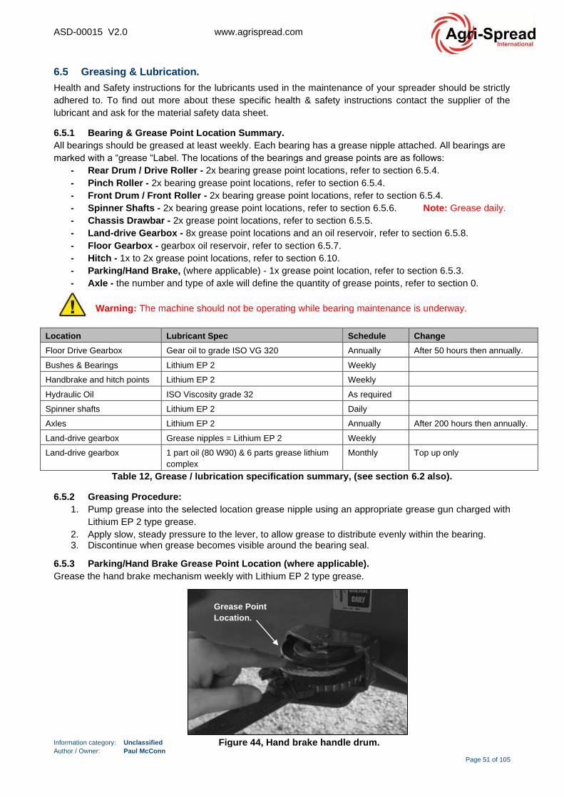
ASD-00015 V2.0 www.agrispread.com
Information category: Unclassified
Author / Owner: Paul McConn
Page 51 of 105
6.5 Greasing & Lubrication.
Health and Safety instructions for the lubricants used in the maintenance of your spreader should be strictly
adhered to. To find out more about these specific health & safety instructions contact the supplier of the
lubricant and ask for the material safety data sheet.
6.5.1 Bearing & Grease Point Location Summary.
All bearings should be greased at least weekly. Each bearing has a grease nipple attached. All bearings are
marked with a “grease “Label. The locations of the bearings and grease points are as follows:
- Rear Drum / Drive Roller - 2x bearing grease point locations, refer to section 6.5.4.
- Pinch Roller - 2x bearing grease point locations, refer to section 6.5.4.
- Front Drum / Front Roller - 2x bearing grease point locations, refer to section 6.5.4.
- Spinner Shafts - 2x bearing grease point locations, refer to section 6.5.6. Note: Grease daily.
- Chassis Drawbar - 2x grease point locations, refer to section 6.5.5.
- Land-drive Gearbox - 8x grease point locations and an oil reservoir, refer to section 6.5.8.
- Floor Gearbox - gearbox oil reservoir, refer to section 6.5.7.
- Hitch - 1x to 2x grease point locations, refer to section 6.10.
- Parking/Hand Brake, (where applicable) - 1x grease point location, refer to section 6.5.3.
- Axle - the number and type of axle will define the quantity of grease points, refer to section 0.
Warning: The machine should not be operating while bearing maintenance is underway.
Location Lubricant Spec Schedule Change
Floor Drive Gearbox Gear oil to grade ISO VG 320 Annually After 50 hours then annually.
Bushes & Bearings Lithium EP 2 Weekly
Handbrake and hitch points Lithium EP 2 Weekly
Hydraulic Oil ISO Viscosity grade 32 As required
Spinner shafts Lithium EP 2 Daily
Axles Lithium EP 2 Annually After 200 hours then annually.
Land-drive gearbox Grease nipples = Lithium EP 2 Weekly
Land-drive gearbox 1 part oil (80 W90) & 6 parts grease lithium
complex
Monthly Top up only
Table 12, Grease / lubrication specification summary, (see section 6.2 also).
6.5.2 Greasing Procedure:
1. Pump grease into the selected location grease nipple using an appropriate grease gun charged with
Lithium EP 2 type grease.
2. Apply slow, steady pressure to the lever, to allow grease to distribute evenly within the bearing. 3. Discontinue when grease becomes visible around the bearing seal.
6.5.3 Parking/Hand Brake Grease Point Location (where applicable).
Grease the hand brake mechanism weekly with Lithium EP 2 type grease.
Figure 44, Hand brake handle drum.
Grease Point
Location.
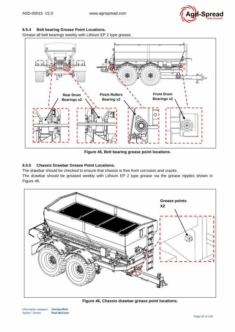
ASD-00015 V2.0 www.agrispread.com
Information category: Unclassified
Author / Owner: Paul McConn
Page 52 of 105
6.5.4 Belt bearing Grease Point Locations.
Grease all belt bearings weekly with Lithium EP 2 type grease.
6.5.5 Chassis Drawbar Grease Point Locations.
The drawbar should be checked to ensure that chassis is free from corrosion and cracks.
The drawbar should be greased weekly with Lithium EP 2 type grease via the grease nipples shown in
Figure 46.
Pinch Rollers
Bearing x2
Front Drum
Bearings x2
Figure 45, Belt bearing grease point locations.
Rear Drum
Bearings x2
Figure 46, Chassis drawbar grease point locations.
Grease points
X2

ASD-00015 V2.0 www.agrispread.com
Information category: Unclassified
Author / Owner: Paul McConn
Page 53 of 105
6.5.6 Spinner Shaft Grease Point Locations.
Each Spinner has a grease nipple for the purpose of lubrication. Spinners should be greased before each
use. Note: Grease daily with Lithium EP 2 type grease.
Figure 47, Spinner shaft grease point locations.
Grease points
X2
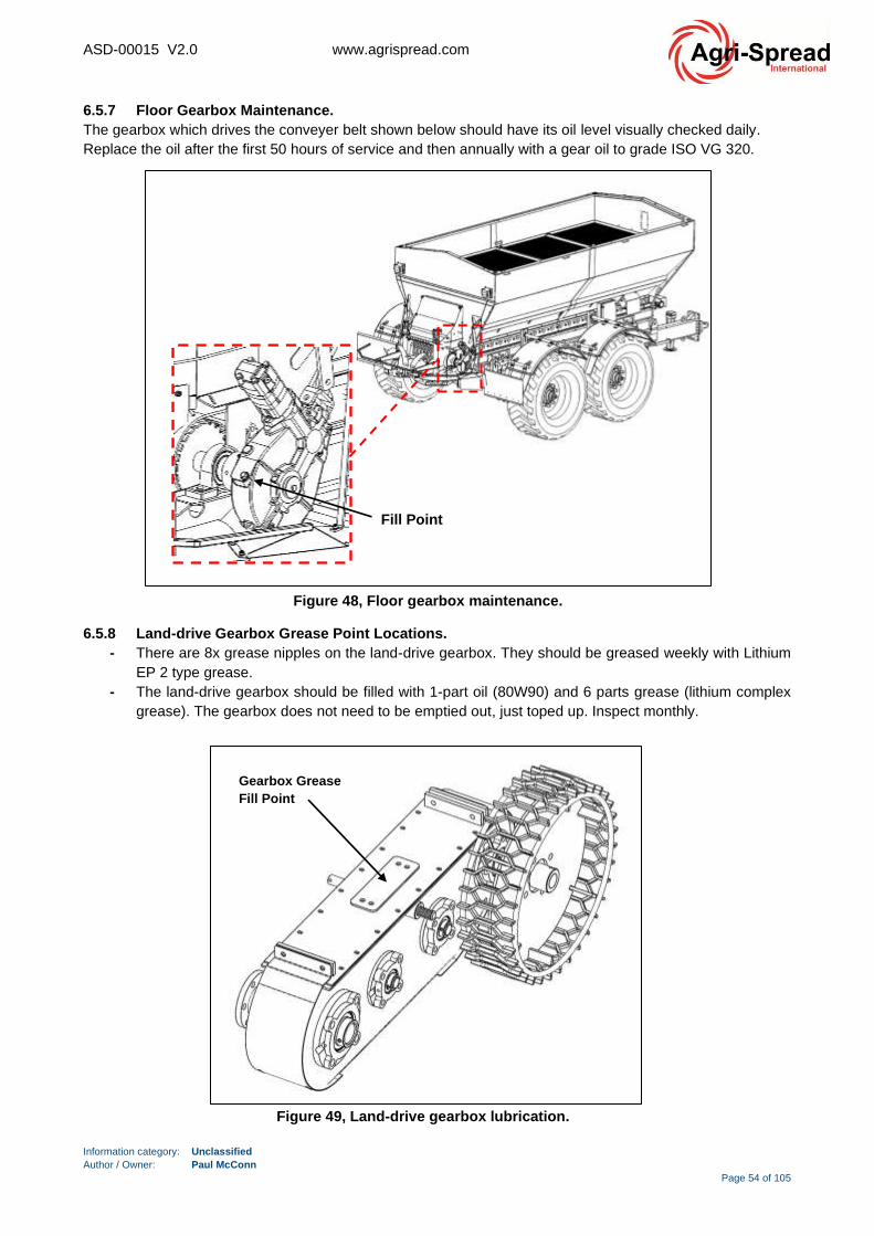
ASD-00015 V2.0 www.agrispread.com
Information category: Unclassified
Author / Owner: Paul McConn
Page 54 of 105
6.5.7 Floor Gearbox Maintenance.
The gearbox which drives the conveyer belt shown below should have its oil level visually checked daily.
Replace the oil after the first 50 hours of service and then annually with a gear oil to grade ISO VG 320.
6.5.8 Land-drive Gearbox Grease Point Locations.
- There are 8x grease nipples on the land-drive gearbox. They should be greased weekly with Lithium
EP 2 type grease.
- The land-drive gearbox should be filled with 1-part oil (80W90) and 6 parts grease (lithium complex
grease). The gearbox does not need to be emptied out, just toped up. Inspect monthly.
Fill Point
Figure 48, Floor gearbox maintenance.
Figure 49, Land-drive gearbox lubrication.
Gearbox Grease
Fill Point
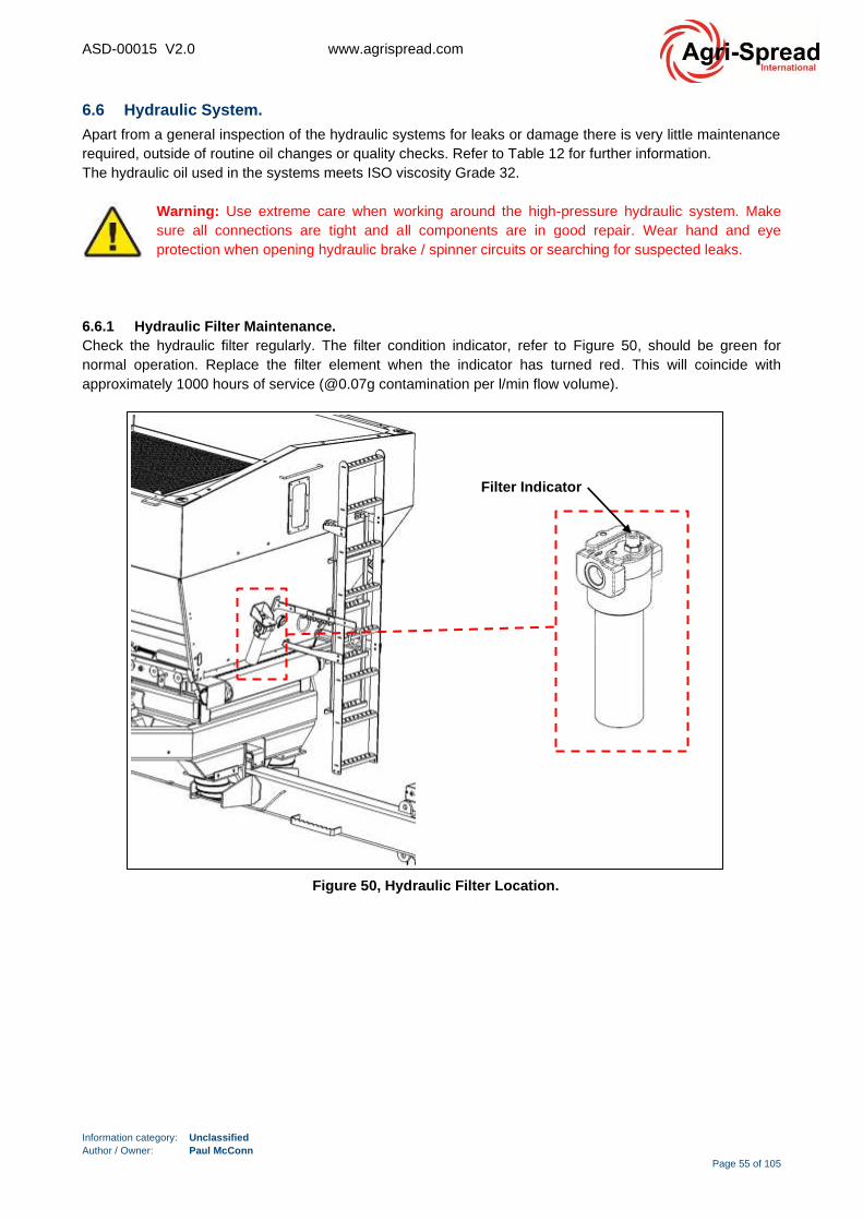
ASD-00015 V2.0 www.agrispread.com
Information category: Unclassified
Author / Owner: Paul McConn
Page 55 of 105
6.6 Hydraulic System.
Apart from a general inspection of the hydraulic systems for leaks or damage there is very little maintenance
required, outside of routine oil changes or quality checks. Refer to Table 12 for further information.
The hydraulic oil used in the systems meets ISO viscosity Grade 32.
Warning: Use extreme care when working around the high-pressure hydraulic system. Make
sure all connections are tight and all components are in good repair. Wear hand and eye
protection when opening hydraulic brake / spinner circuits or searching for suspected leaks.
6.6.1 Hydraulic Filter Maintenance.
Check the hydraulic filter regularly. The filter condition indicator, refer to Figure 50, should be green for
normal operation. Replace the filter element when the indicator has turned red. This will coincide with
approximately 1000 hours of service (@0.07g contamination per l/min flow volume).
Figure 50, Hydraulic Filter Location.
Filter Indicator
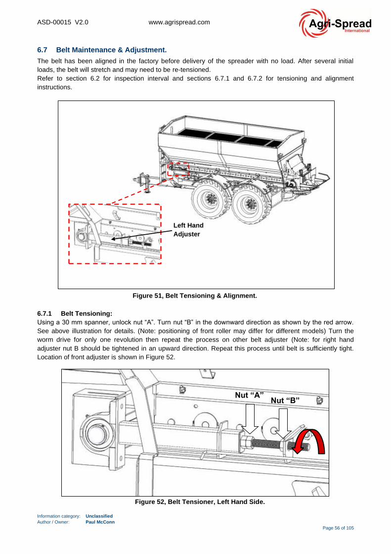
ASD-00015 V2.0 www.agrispread.com
Information category: Unclassified
Author / Owner: Paul McConn
Page 56 of 105
6.7 Belt Maintenance & Adjustment.
The belt has been aligned in the factory before delivery of the spreader with no load. After several initial
loads, the belt will stretch and may need to be re-tensioned.
Refer to section 6.2 for inspection interval and sections 6.7.1 and 6.7.2 for tensioning and alignment
instructions.
6.7.1 Belt Tensioning:
Using a 30 mm spanner, unlock nut “A”. Turn nut “B” in the downward direction as shown by the red arrow.
See above illustration for details. (Note: positioning of front roller may differ for different models) Turn the
worm drive for only one revolution then repeat the process on other belt adjuster (Note: for right hand
adjuster nut B should be tightened in an upward direction. Repeat this process until belt is sufficiently tight.
Location of front adjuster is shown in Figure 52.
Figure 51, Belt Tensioning & Alignment.
Left Hand
Adjuster
Figure 52, Belt Tensioner, Left Hand Side.
Nut “A” Nut “B”
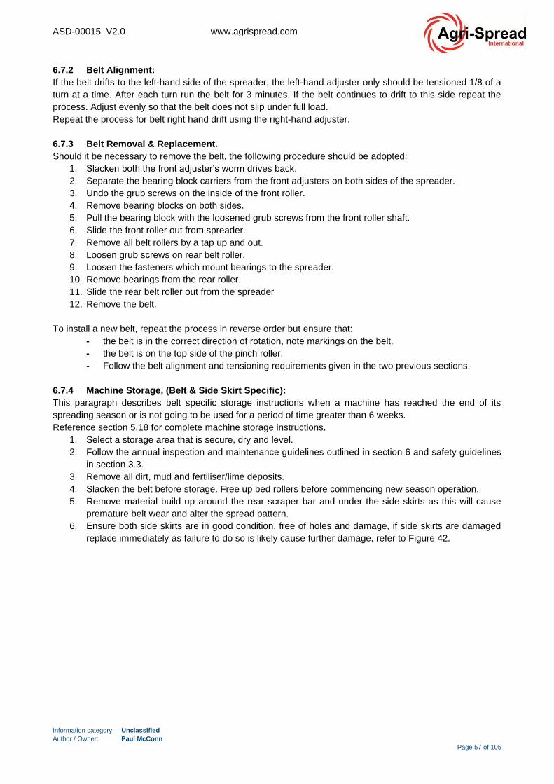
ASD-00015 V2.0 www.agrispread.com
Information category: Unclassified
Author / Owner: Paul McConn
Page 57 of 105
6.7.2 Belt Alignment:
If the belt drifts to the left-hand side of the spreader, the left-hand adjuster only should be tensioned 1/8 of a
turn at a time. After each turn run the belt for 3 minutes. If the belt continues to drift to this side repeat the
process. Adjust evenly so that the belt does not slip under full load.
Repeat the process for belt right hand drift using the right-hand adjuster.
6.7.3 Belt Removal & Replacement.
Should it be necessary to remove the belt, the following procedure should be adopted:
1. Slacken both the front adjuster’s worm drives back.
2. Separate the bearing block carriers from the front adjusters on both sides of the spreader.
3. Undo the grub screws on the inside of the front roller.
4. Remove bearing blocks on both sides.
5. Pull the bearing block with the loosened grub screws from the front roller shaft.
6. Slide the front roller out from spreader.
7. Remove all belt rollers by a tap up and out.
8. Loosen grub screws on rear belt roller.
9. Loosen the fasteners which mount bearings to the spreader.
10. Remove bearings from the rear roller.
11. Slide the rear belt roller out from the spreader
12. Remove the belt.
To install a new belt, repeat the process in reverse order but ensure that:
- the belt is in the correct direction of rotation, note markings on the belt.
- the belt is on the top side of the pinch roller.
- Follow the belt alignment and tensioning requirements given in the two previous sections.
6.7.4 Machine Storage, (Belt & Side Skirt Specific):
This paragraph describes belt specific storage instructions when a machine has reached the end of its
spreading season or is not going to be used for a period of time greater than 6 weeks.
Reference section 5.18 for complete machine storage instructions.
1. Select a storage area that is secure, dry and level.
2. Follow the annual inspection and maintenance guidelines outlined in section 6 and safety guidelines
in section 3.3.
3. Remove all dirt, mud and fertiliser/lime deposits.
4. Slacken the belt before storage. Free up bed rollers before commencing new season operation.
5. Remove material build up around the rear scraper bar and under the side skirts as this will cause
premature belt wear and alter the spread pattern.
6. Ensure both side skirts are in good condition, free of holes and damage, if side skirts are damaged
replace immediately as failure to do so is likely cause further damage, refer to Figure 42.
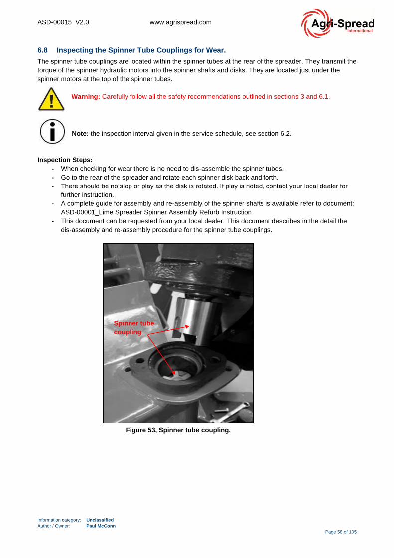
ASD-00015 V2.0 www.agrispread.com
Information category: Unclassified
Author / Owner: Paul McConn
Page 58 of 105
6.8 Inspecting the Spinner Tube Couplings for Wear.
The spinner tube couplings are located within the spinner tubes at the rear of the spreader. They transmit the
torque of the spinner hydraulic motors into the spinner shafts and disks. They are located just under the
spinner motors at the top of the spinner tubes.
Warning: Carefully follow all the safety recommendations outlined in sections 3 and 6.1.
Note: the inspection interval given in the service schedule, see section 6.2.
Inspection Steps:
- When checking for wear there is no need to dis-assemble the spinner tubes.
- Go to the rear of the spreader and rotate each spinner disk back and forth.
- There should be no slop or play as the disk is rotated. If play is noted, contact your local dealer for
further instruction.
- A complete guide for assembly and re-assembly of the spinner shafts is available refer to document:
ASD-00001_Lime Spreader Spinner Assembly Refurb Instruction.
- This document can be requested from your local dealer. This document describes in the detail the
dis-assembly and re-assembly procedure for the spinner tube couplings.
Figure 53, Spinner tube coupling.
Spinner tube
coupling
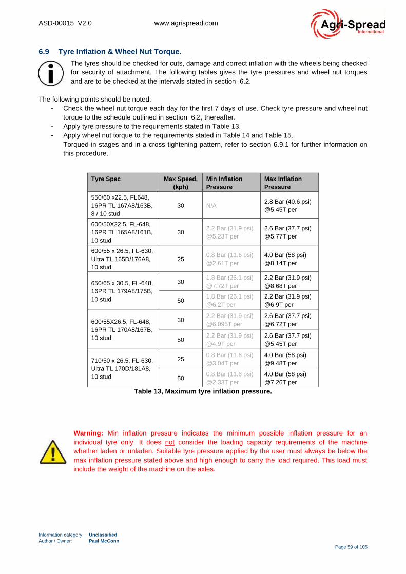
ASD-00015 V2.0 www.agrispread.com
Information category: Unclassified
Author / Owner: Paul McConn
Page 59 of 105
6.9 Tyre Inflation & Wheel Nut Torque.
The tyres should be checked for cuts, damage and correct inflation with the wheels being checked
for security of attachment. The following tables gives the tyre pressures and wheel nut torques
and are to be checked at the intervals stated in section 6.2.
The following points should be noted:
- Check the wheel nut torque each day for the first 7 days of use. Check tyre pressure and wheel nut
torque to the schedule outlined in section 6.2, thereafter.
- Apply tyre pressure to the requirements stated in Table 13.
- Apply wheel nut torque to the requirements stated in Table 14 and Table 15.
Torqued in stages and in a cross-tightening pattern, refer to section 6.9.1 for further information on
this procedure.
Tyre Spec Max Speed,
(kph)
Min Inflation
Pressure
Max Inflation
Pressure
550/60 x22.5, FL648,
16PR TL 167A8/163B,
8 / 10 stud
30 N/A 2.8 Bar (40.6 psi)
@5.45T per
600/50X22.5, FL-648,
16PR TL 165A8/161B,
10 stud
30 2.2 Bar (31.9 psi)
@5.23T per
2.6 Bar (37.7 psi)
@5.77T per
600/55 x 26.5, FL-630,
Ultra TL 165D/176A8,
10 stud
25 0.8 Bar (11.6 psi)
@2.61T per
4.0 Bar (58 psi)
@8.14T per
650/65 x 30.5, FL-648,
16PR TL 179A8/175B,
10 stud
30 1.8 Bar (26.1 psi)
@7.72T per
2.2 Bar (31.9 psi)
@8.68T per
50 1.8 Bar (26.1 psi)
@6.2T per
2.2 Bar (31.9 psi)
@6.9T per
600/55X26.5, FL-648,
16PR TL 170A8/167B,
10 stud
30 2.2 Bar (31.9 psi)
@6.095T per
2.6 Bar (37.7 psi)
@6.72T per
50 2.2 Bar (31.9 psi)
@4.9T per
2.6 Bar (37.7 psi)
@5.45T per
710/50 x 26.5, FL-630,
Ultra TL 170D/181A8,
10 stud
25 0.8 Bar (11.6 psi)
@3.04T per
4.0 Bar (58 psi)
@9.48T per
50 0.8 Bar (11.6 psi)
@2.33T per
4.0 Bar (58 psi)
@7.26T per
Table 13, Maximum tyre inflation pressure.
Warning: Min inflation pressure indicates the minimum possible inflation pressure for an
individual tyre only. It does not consider the loading capacity requirements of the machine
whether laden or unladen. Suitable tyre pressure applied by the user must always be below the
max inflation pressure stated above and high enough to carry the load required. This load must
include the weight of the machine on the axles.
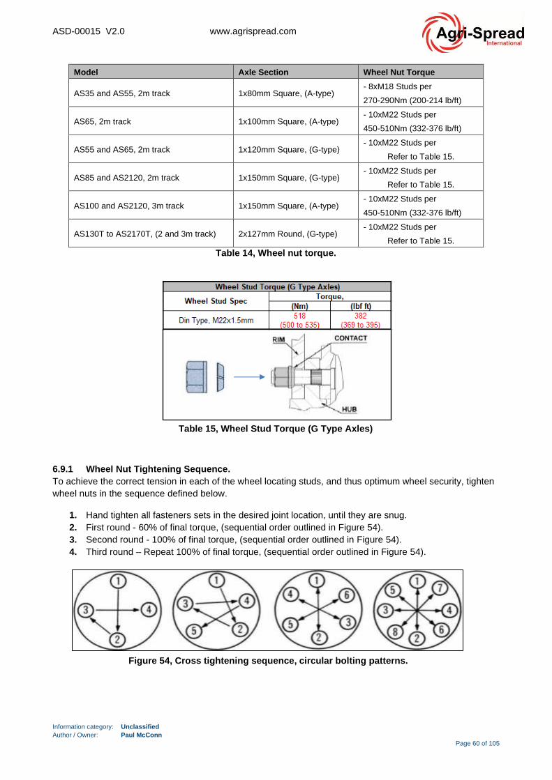
ASD-00015 V2.0 www.agrispread.com
Information category: Unclassified
Author / Owner: Paul McConn
Page 60 of 105
Model Axle Section Wheel Nut Torque
AS35 and AS55, 2m track 1x80mm Square, (A-type) - 8xM18 Studs per
270-290Nm (200-214 lb/ft)
AS65, 2m track 1x100mm Square, (A-type) - 10xM22 Studs per
450-510Nm (332-376 lb/ft)
AS55 and AS65, 2m track 1x120mm Square, (G-type) - 10xM22 Studs per
Refer to Table 15.
AS85 and AS2120, 2m track 1x150mm Square, (G-type) - 10xM22 Studs per
Refer to Table 15.
AS100 and AS2120, 3m track 1x150mm Square, (A-type) - 10xM22 Studs per
450-510Nm (332-376 lb/ft)
AS130T to AS2170T, (2 and 3m track) 2x127mm Round, (G-type) - 10xM22 Studs per
Refer to Table 15.
Table 14, Wheel nut torque.
6.9.1 Wheel Nut Tightening Sequence.
To achieve the correct tension in each of the wheel locating studs, and thus optimum wheel security, tighten
wheel nuts in the sequence defined below.
1. Hand tighten all fasteners sets in the desired joint location, until they are snug.
2. First round - 60% of final torque, (sequential order outlined in Figure 54).
3. Second round - 100% of final torque, (sequential order outlined in Figure 54).
4. Third round – Repeat 100% of final torque, (sequential order outlined in Figure 54).
Table 15, Wheel Stud Torque (G Type Axles)
Figure 54, Cross tightening sequence, circular bolting patterns.

ASD-00015 V2.0 www.agrispread.com
Information category: Unclassified
Author / Owner: Paul McConn
Page 61 of 105
6.10 Hitch Maintenance.
- Apply hitch fastener torque to the requirements stated in Table 16.
The grade of fastener can be determined from the head of the bolt. It will have an “8.8, “10.9 or
“12.9” stamp. This bolt strength information is used to determine the correct torque value to be
applied.
- To achieve the correct tension in each of the hitch fasteners, tighten in the sequence defined below:
1. Hand tighten all fasteners sets in the desired joint location, until they are snug.
1. First round - 60% of final torque, (sequential order outlined in Figure 55).
2. Second round - 100% of final torque, (sequential order outlined in Figure 55).
3. Third round – Repeat 100% of final torque, (sequential order outlined in Figure 55).
6.10.1 Swivel Hitch.
The hitch should be inspected regularly to ensure that all nuts and bolts are tight. The hitch should be free
from corrosion and cracks.
- The hitch should be greased weekly via the grease nipple shown in Figure 56.
- The swivel hitch should be rotated by hand to ensure an even film of grease is distributed around the
joint. The hitch should be able to rotate freely through 360⁰.
6.10.2 Bull Pull Hitch.
The hitch should be inspected regularly to ensure that all nuts and bolts are tight. The hitch should be free
from corrosion and cracks.
- The hitch ball and socket have a greasing requirement. Grease both nipples weekly, Refer to Figure
57 for location.
A high-quality grease with moly works best. High pressure grease (suitable or heavy excavating
machinery pins/bushings) can be used in extreme operating conditions.
Figure 56, Swivel hitch.
Figure 55, Cross tightening sequence. Table 16, Hitch Fastener Torque Requirements.

ASD-00015 V2.0 www.agrispread.com
Information category: Unclassified
Author / Owner: Paul McConn
Page 62 of 105
- This bull pull hitch accepts 1-1/2” and 2” draw pins on Cat 4 hitches. Make sure the correct size
insert is matched to the draw pin size. It may be changed by removing the spiral snap ring from the
stub shaft and switching stub shafts to match the pin size.
- Be sure the bull pull lettering always remains on the top side.
Figure 58, Bull-pull hitch, parts. Figure 57, Bull-pull hitch.
Grease Point
Locations

ASD-00015 V2.0 www.agrispread.com
Information category: Unclassified
Author / Owner: Paul McConn
Page 63 of 105
6.11 Axle Maintenance.
There are a number of different axle types used on the Agri-Spread spreader range. Refer to Table 17 for an
overview of the different types.
Note: There are two different axle groupings and each have a unique letter identifier. This letter
is important when identifying the correct axle maintenance manual document. All G-type axles
have a “G” designation in the axle type column in Table 17. All A-type axles have a “A”
designation in the axle type column.
Axle maintenance documents:
- ASD-00025_Fert-Lime Spreader Axle Service Manual, (G-Type).
- ASD-00026_Fert-Lime Spreader Axle Service Manual, (A-Type).
Machine specifications may vary and different axle specifications can be supplied. Contact your local Agri-
Spread dealer if you are unsure of the axle type on your machine.
Model Axle
Type/Code Beam Type/Size Qty
Track
Width,
(mm)
Brake
size,
(mm)
Wheel Stud Config
AS35 A1 80mm Square 1 2000 350x60 8 stud 275mm PCD, M18
AS55 A1 80mm Square 1 2000 350x60 8 stud 275mm PCD, M18
AS65 G1 120mm Square 1 1976 406x120 10 stud 335mm PCD, M22
AS85 G2 150mm Square 1 2000 420x180 10 stud 335mm PCD, M22
AS100, 2m G2 150mm Square 1 2000 420x180 10 stud 335mm PCD, M22
AS100, 3m A3 150mm Square 1 3000 420x180 10 stud 335mm PCD, M22
AS120, 2m G2 150mm Square 1 2000 420x180 10 stud 335mm PCD, M22
AS120, 3m A3 150mm Square 1 3000 420x180 10 stud 335mm PCD, M22
AS130T, 2m G3 127mm Round 2 2021 420x180 10 stud 335mm PCD, M22
AS130T, 3m G3 127mm Round 2 3000 420x180 10 stud 335mm PCD, M22
AS150T, 2m G3 127mm Round 2 2021 420x180 10 stud 335mm PCD, M22
AS150T, 3m G3 127mm Round 2 3000 420x180 10 stud 335mm PCD, M22
AS170T, 2m G3 127mm Round 2 2021 420x180 10 stud 335mm PCD, M22
AS170T, 3m G3 127mm Round 2 3000 420x180 10 stud 335mm PCD, M22
Table 17, Spreader axle specification summary.
Service intervals depend on operating conditions and are best decided by the operator, the following
guidelines are noted as maximum recommended intervals and should be reduced accordingly under extreme
conditions. It is recommended that records of this servicing are kept for future reference. Note: local
legislative regulations should always be followed.
The service requirements given below are a basic summary of the axle service requirements.
Detailed maintenance instructions can be obtained from your Agri-Spread dealer. Simply quote
the axle type/code from Table 17 and ask your dealer to confirm the axle specification. They will
supply a detailed axle maintenance guide that matches the correct axle specification.
ASD-00015 V2.0 www.agrispread.com
Information category: Unclassified
Author / Owner: Paul McConn
Page 64 of 105
6.11.1 Axle Service Schedule, (All G-Type Axles).
Service intervals depend on operating conditions and are best decided by the operators
fleet engineer, having considered the following guide lines for axles used for agricultural applications. It is
recommended that records of this servicing are kept for future reference.
Note: local legislative regulations should always be followed.
On Initial Receipt.
• Check all nuts, etc. for recommended torque.
• Check all wheel nuts daily for first week, due to seating effects.
Weekly.
• Check wheel nut torque every 7 days or 1000 km, whichever is sooner.
First 200 hours or 300km, whichever is sooner.
• Check hubs for end-float, due to seating effects.
• Lubricate all grease points, using Lithium soap-based EP2 grease.
First 300 hours or 5000km, whichever is sooner.
• Check hubs for end-float, due to seating effects. Reset adjustment nut if necessary.
• Lubricate all grease points, using Lithium soap-based EP2 grease.
• Check wear pattern of brake linings, if not satisfactory, make correct adjustment.
Every 500 hours or annually, whichever is sooner.
• Lubricate all grease points, using Lithium soap-based EP2 grease.
• Check wear pattern of brake linings, if not satisfactory, make correct adjustment.
• Check hubs for bearing end-float. Adjust as necessary. Reset adjustment nut if necessary.
• Lubricate slack adjusters.
• Check brake linings for wear.
Every 1500 hours or 3 years, whichever is sooner.
• All 500 hour / annual checks.
• Remove hubs.
• Check brake linings for wear.
• Check anchor pins for sticking (remove and re-grease if necessary),
• Check camshafts for sticking.
• Completely clean out grease from hub. Re-pack, using fresh grease.
• Check grease seals for signs of wear, replace if necessary.
• Re-set bearing adjustment nuts to give bearing end-float.

ASD-00015 V2.0 www.agrispread.com
Information category: Unclassified
Author / Owner: Paul McConn
Page 65 of 105
6.11.2 Axle Service Schedule, (All A-Type Axles).
Table 18, Axle maintenance schedule.
ASD-00015 V2.0 www.agrispread.com
Information category: Unclassified
Author / Owner: Paul McConn
Page 66 of 105
6.12 Parking/Hand Brake Inspection & Maintenance.
Warning: Carefully follow all the safety recommendations outlined in sections 3 and 6.1.
Note if the parking/hand bake mechanism is being inspected and maintained a secondary
brake/chocking method must be applied to the machine for safety. Refer to section 5.3.2 for
guidelines.
Note: the parking/hand-brake inspection intervals given in the service schedule, see section 6.2.
6.12.1 Parking/Hand Brake Inspection:
- Inspect the parking/hand brake ratchet mechanism for signs of damage and/or corrosion. Inspect the
brake cable, brake cable clamps for signs of damage and or corrosion. Replace if necessary.
- During service if the machine show signs of movement after the parking/hand brake has been
engaged then the parking/hand brake needs to be inspected/adjusted.
- There are two suggested method of parking/handbrake function inspection:
Option A:
- While coupled to a tractor, stop the spreader on an incline.
1. Apply the tractor parking brake.
2. The tractor should be able to safely hold the spreader in position. Do not proceed if this is
not the case.
3. Apply the spreader parking brake.
4. Momentarily release the tractor parking, note any movement and then re-apply the tractor
handbrake.
5. If moment is observed then the parking brake needs to be inspected/adjusted.
- Option B:
While coupled to a tractor, stop the spreader on a level surface.
1. With the parking brake applied, gently crawl the spreader forward a few inches using the
tractor.
2. Observe if the wheels of the spreader turn/rotate during this movement.
3. If the wheels rotate with the parking brake applied then the parking brake needs to be
inspected/adjusted.
6.12.2 Parking/Hand Brake Maintenance/Adjustment:
Warning: Ensure that machine is on flat ground and/or connected to a tractor (suitably braked)
before any maintenance is performed. Wheel chocks shall be used to safely secure the spreader,
refer to section 5.3.2 for further instruction.
1. Inspect the parking/hand brake assembly for signs of damage and/or corrosion. Inspect the
brake cable, brake cable clamps for signs of damage and or corrosion. Replace parts if
necessary.
2. Pull the parking brake lever towards the rear of the machine and observe if the hand brake
ratchet mechanism is functioning correctly.
3. Ensure that when the handbrake is in the released position that the wire rope wraps around
the drum of the handbrake handle at least one revolution. Refer to Figure 59.
4. If after inspection the handbrake has been deemed to require adjustment, it is suggested
that any adjustment in brake cable length is made at the cable clamp locations indicated in
Figure 60 and Figure 61.
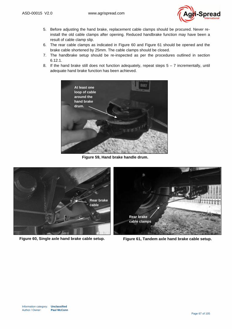
ASD-00015 V2.0 www.agrispread.com
Information category: Unclassified
Author / Owner: Paul McConn
Page 67 of 105
5. Before adjusting the hand brake, replacement cable clamps should be procured. Never re-
install the old cable clamps after opening. Reduced handbrake function may have been a
result of cable clamp slip.
6. The rear cable clamps as indicated in Figure 60 and Figure 61 should be opened and the
brake cable shortened by 25mm. The cable clamps should be closed.
7. The handbrake setup should be re-inspected as per the procedures outlined in section
6.12.1.
8. If the hand brake still does not function adequately, repeat steps 5 – 7 incrementally, until
adequate hand brake function has been achieved.
Figure 60, Single axle hand brake cable setup.
Rear brake
cable
Figure 61, Tandem axle hand brake cable setup.
Rear brake
cable clamps
Figure 59, Hand brake handle drum.
At least one
loop of cable
around the
hand brake
drum.
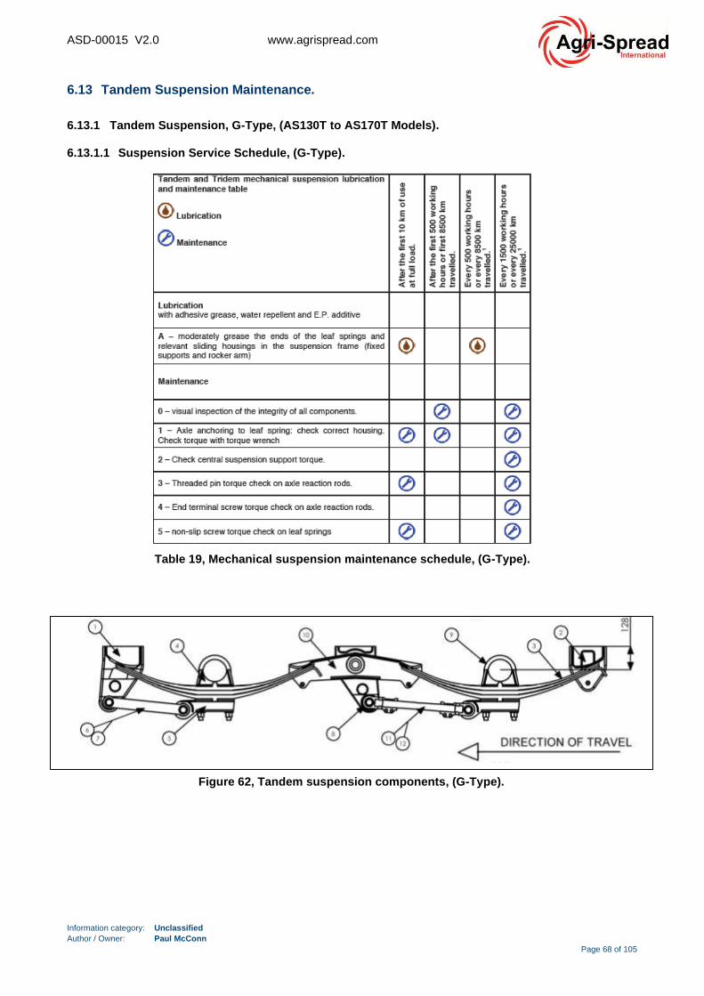
ASD-00015 V2.0 www.agrispread.com
Information category: Unclassified
Author / Owner: Paul McConn
Page 68 of 105
6.13 Tandem Suspension Maintenance.
6.13.1 Tandem Suspension, G-Type, (AS130T to AS170T Models).
6.13.1.1 Suspension Service Schedule, (G-Type).
Figure 62, Tandem suspension components, (G-Type).
Table 19, Mechanical suspension maintenance schedule, (G-Type).
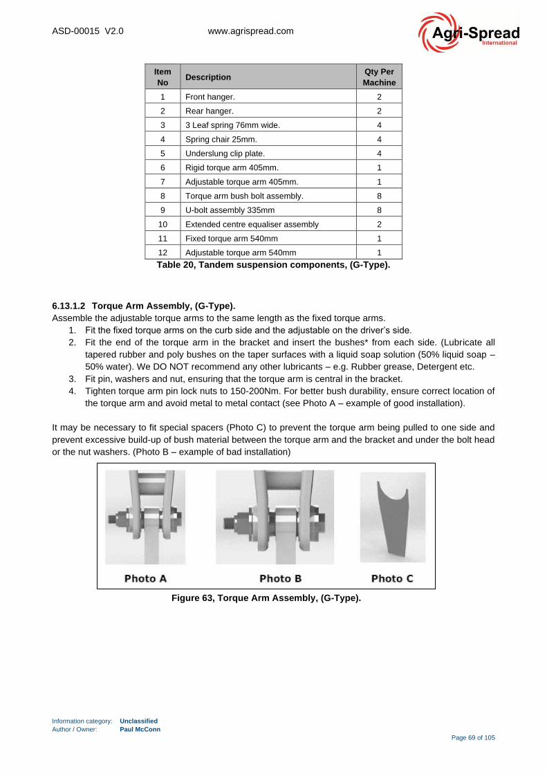
ASD-00015 V2.0 www.agrispread.com
Information category: Unclassified
Author / Owner: Paul McConn
Page 69 of 105
Item
No Description
Qty Per
Machine
1 Front hanger. 2
2 Rear hanger. 2
3 3 Leaf spring 76mm wide. 4
4 Spring chair 25mm. 4
5 Underslung clip plate. 4
6 Rigid torque arm 405mm. 1
7 Adjustable torque arm 405mm. 1
8 Torque arm bush bolt assembly. 8
9 U-bolt assembly 335mm 8
10 Extended centre equaliser assembly 2
11 Fixed torque arm 540mm 1
12 Adjustable torque arm 540mm 1
Table 20, Tandem suspension components, (G-Type).
6.13.1.2 Torque Arm Assembly, (G-Type).
Assemble the adjustable torque arms to the same length as the fixed torque arms.
1. Fit the fixed torque arms on the curb side and the adjustable on the driver’s side.
2. Fit the end of the torque arm in the bracket and insert the bushes* from each side. (Lubricate all
tapered rubber and poly bushes on the taper surfaces with a liquid soap solution (50% liquid soap –
50% water). We DO NOT recommend any other lubricants – e.g. Rubber grease, Detergent etc.
3. Fit pin, washers and nut, ensuring that the torque arm is central in the bracket.
4. Tighten torque arm pin lock nuts to 150-200Nm. For better bush durability, ensure correct location of
the torque arm and avoid metal to metal contact (see Photo A – example of good installation).
It may be necessary to fit special spacers (Photo C) to prevent the torque arm being pulled to one side and
prevent excessive build-up of bush material between the torque arm and the bracket and under the bolt head
or the nut washers. (Photo B – example of bad installation)
Figure 63, Torque Arm Assembly, (G-Type).
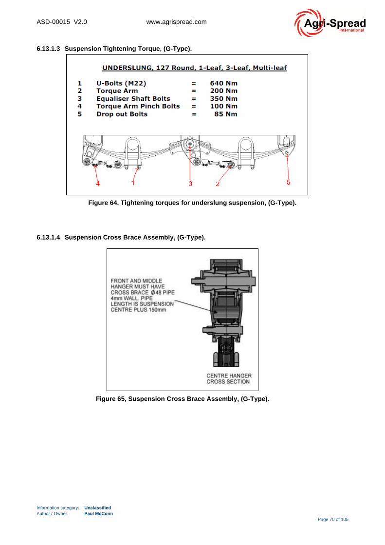
ASD-00015 V2.0 www.agrispread.com
Information category: Unclassified
Author / Owner: Paul McConn
Page 70 of 105
6.13.1.3 Suspension Tightening Torque, (G-Type).
6.13.1.4 Suspension Cross Brace Assembly, (G-Type).
Figure 64, Tightening torques for underslung suspension, (G-Type).
Figure 65, Suspension Cross Brace Assembly, (G-Type).
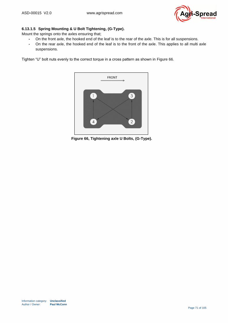
ASD-00015 V2.0 www.agrispread.com
Information category: Unclassified
Author / Owner: Paul McConn
Page 71 of 105
6.13.1.5 Spring Mounting & U Bolt Tightening, (G-Type).
Mount the springs onto the axles ensuring that;
- On the front axle, the hooked end of the leaf is to the rear of the axle. This is for all suspensions.
- On the rear axle, the hooked end of the leaf is to the front of the axle. This applies to all multi axle
suspensions.
Tighten “U” bolt nuts evenly to the correct torque in a cross pattern as shown in Figure 66.
Figure 66, Tightening axle U Bolts, (G-Type).
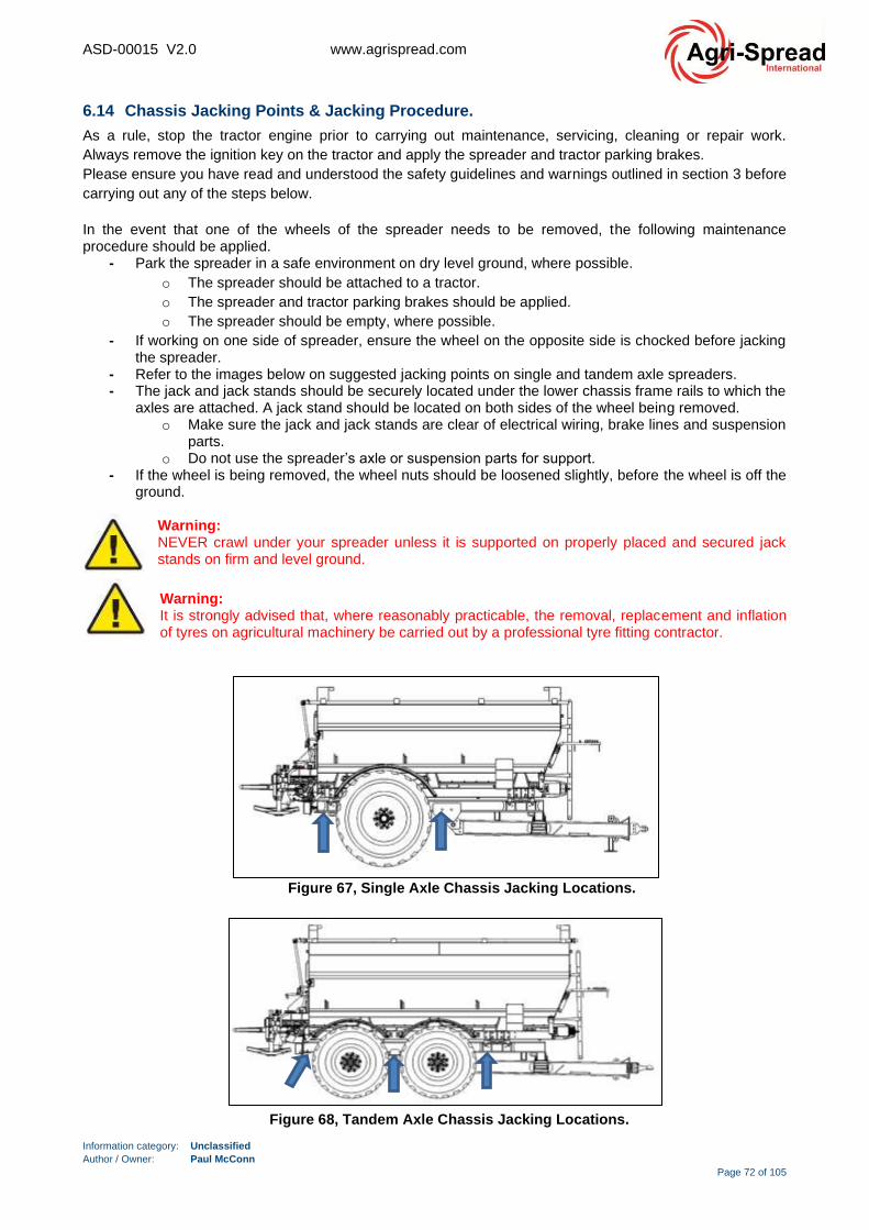
ASD-00015 V2.0 www.agrispread.com
Information category: Unclassified
Author / Owner: Paul McConn
Page 72 of 105
6.14 Chassis Jacking Points & Jacking Procedure.
As a rule, stop the tractor engine prior to carrying out maintenance, servicing, cleaning or repair work.
Always remove the ignition key on the tractor and apply the spreader and tractor parking brakes.
Please ensure you have read and understood the safety guidelines and warnings outlined in section 3 before
carrying out any of the steps below.
In the event that one of the wheels of the spreader needs to be removed, the following maintenance procedure should be applied.
- Park the spreader in a safe environment on dry level ground, where possible.
o The spreader should be attached to a tractor.
o The spreader and tractor parking brakes should be applied.
o The spreader should be empty, where possible.
- If working on one side of spreader, ensure the wheel on the opposite side is chocked before jacking the spreader.
- Refer to the images below on suggested jacking points on single and tandem axle spreaders. - The jack and jack stands should be securely located under the lower chassis frame rails to which the
axles are attached. A jack stand should be located on both sides of the wheel being removed. o Make sure the jack and jack stands are clear of electrical wiring, brake lines and suspension
parts. o Do not use the spreader’s axle or suspension parts for support.
- If the wheel is being removed, the wheel nuts should be loosened slightly, before the wheel is off the ground.
Warning: NEVER crawl under your spreader unless it is supported on properly placed and secured jack stands on firm and level ground.
Warning: It is strongly advised that, where reasonably practicable, the removal, replacement and inflation of tyres on agricultural machinery be carried out by a professional tyre fitting contractor.
Figure 67, Single Axle Chassis Jacking Locations.
Figure 68, Tandem Axle Chassis Jacking Locations.
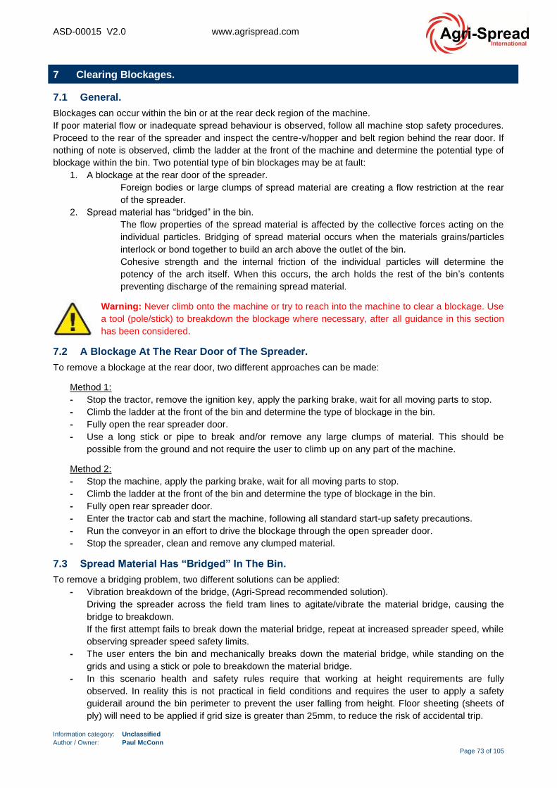
ASD-00015 V2.0 www.agrispread.com
Information category: Unclassified
Author / Owner: Paul McConn
Page 73 of 105
7 Clearing Blockages.
7.1 General.
Blockages can occur within the bin or at the rear deck region of the machine.
If poor material flow or inadequate spread behaviour is observed, follow all machine stop safety procedures.
Proceed to the rear of the spreader and inspect the centre-v/hopper and belt region behind the rear door. If
nothing of note is observed, climb the ladder at the front of the machine and determine the potential type of
blockage within the bin. Two potential type of bin blockages may be at fault:
1. A blockage at the rear door of the spreader.
Foreign bodies or large clumps of spread material are creating a flow restriction at the rear
of the spreader.
2. Spread material has “bridged” in the bin.
The flow properties of the spread material is affected by the collective forces acting on the
individual particles. Bridging of spread material occurs when the materials grains/particles
interlock or bond together to build an arch above the outlet of the bin.
Cohesive strength and the internal friction of the individual particles will determine the
potency of the arch itself. When this occurs, the arch holds the rest of the bin’s contents
preventing discharge of the remaining spread material.
Warning: Never climb onto the machine or try to reach into the machine to clear a blockage. Use
a tool (pole/stick) to breakdown the blockage where necessary, after all guidance in this section
has been considered.
7.2 A Blockage At The Rear Door of The Spreader.
To remove a blockage at the rear door, two different approaches can be made:
Method 1:
- Stop the tractor, remove the ignition key, apply the parking brake, wait for all moving parts to stop.
- Climb the ladder at the front of the bin and determine the type of blockage in the bin.
- Fully open the rear spreader door.
- Use a long stick or pipe to break and/or remove any large clumps of material. This should be
possible from the ground and not require the user to climb up on any part of the machine.
Method 2:
- Stop the machine, apply the parking brake, wait for all moving parts to stop.
- Climb the ladder at the front of the bin and determine the type of blockage in the bin.
- Fully open rear spreader door.
- Enter the tractor cab and start the machine, following all standard start-up safety precautions.
- Run the conveyor in an effort to drive the blockage through the open spreader door.
- Stop the spreader, clean and remove any clumped material.
7.3 Spread Material Has “Bridged” In The Bin.
To remove a bridging problem, two different solutions can be applied:
- Vibration breakdown of the bridge, (Agri-Spread recommended solution).
Driving the spreader across the field tram lines to agitate/vibrate the material bridge, causing the
bridge to breakdown.
If the first attempt fails to break down the material bridge, repeat at increased spreader speed, while
observing spreader speed safety limits.
- The user enters the bin and mechanically breaks down the material bridge, while standing on the
grids and using a stick or pole to breakdown the material bridge.
- In this scenario health and safety rules require that working at height requirements are fully
observed. In reality this is not practical in field conditions and requires the user to apply a safety
guiderail around the bin perimeter to prevent the user falling from height. Floor sheeting (sheets of
ply) will need to be applied if grid size is greater than 25mm, to reduce the risk of accidental trip.
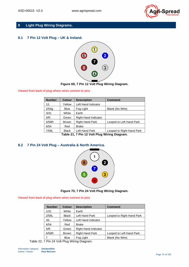
ASD-00015 V2.0 www.agrispread.com
Information category: Unclassified
Author / Owner: Paul McConn
Page 74 of 105
8 Light Plug Wiring Diagrams.
8.1 7 Pin 12 Volt Plug – UK & Ireland.
Figure 69, 7 Pin 12 Volt Plug Wiring Diagram.
Viewed from back of plug where wires connect to pins
Number Colour Description Comment
1/L Yellow Left Hand Indicator
2/54g Blue Fog Light Blank (No Wire)
3/31 White Earth
4/R Green Right Hand Indicator
5/58R Brown Right Hand Park Looped to Left Hand Park
6/54 Red Brake
7/58L Black Left Hand Park Looped to Right Hand Park
Table 21, 7 Pin 12 Volt Plug Wiring Diagram.
8.2 7 Pin 24 Volt Plug – Australia & North America.
Figure 70, 7 Pin 24 Volt Plug Wiring Diagram.
Viewed from back of plug where wires connect to pins
Number Colour Description Comment
1/31 White Earth
2/58L Black Left Hand Park Looped to Right Hand Park
3/L Yellow Left Hand Indicator
4/54 Red Brake
5/R Green Right Hand Indicator
6/58R Brown Right Hand Park Looped to Left Hand Park
7 Blue Fog Light Blank (No Wire)
Table 22, 7 Pin 24 Volt Plug Wiring Diagram.

ASD-00015 V2.0 www.agrispread.com
Information category: Unclassified
Author / Owner: Paul McConn
Page 75 of 105
9 End of Product Life.
Agri-Spread spreaders are constructed from a number of different materials. These materials are largely
recyclable locally and with a little research the requirement for landfill disposal of parts can be minimised.
- Mild Steel & Stainless Steel Materials:
The bin/hopper and chassis/drawbar are fabricated from a mixture of mild steel and stainless steel
materials. These materials have a value and are recyclable and can be sent to a local steel recycler
for processing.
• Chassis = Mild steel.
• Drawbar = Mild steel.
• Bin Hopper = Mild steel and stainless steel.
- Gearbox Oil, Hydraulic Oil & Grease:
Gearboxes and hydraulic hoses should be carefully dis-assembled and drained of waste oil
materials.
These materials should be safely collected and disposed of at local waste oil facilities. A cost may be
associated with disposal of these materials.
The emptied gearboxes can be sent to a local steel recycler for processing.
- Hydraulic Hoses:
Before attempting to recycle
• Drain:
• Rinse: the hoses to remove oil and dirt residues. Waste water runoff needs to consider local
environmental legislation requirements for containment, collection and disposal.
• Remove the metallic fittings at the ends of the hoses.
• Bundle: Tie hoses together to make transport easier and to keep it as compact as possible.
The typical hydraulic hose is usually made of rubber or plastic, which should make recycling a
simple task. However, steel components frequently line hoses to make a longer lasting, more
durable product.
Unfortunately, while such reinforcements are vital to the functionality of hoses in various
applications, they also make recycling more difficult. While hoses that are metal-free or have very
little metal inside them can be crumbled to create modified-asphalt surfaces, rubber hoses that are
lined with significant amounts of steel are slightly more complicated.
If both local and national recycling centres are unable to aid in recycling hoses, there are some
recycling companies that use hoses to make fuel blends, all it takes is a bit more research to locate
them.
- Rubbers:
The conveyor belts, side and centre skirt rubbers and tyres are constructed of rubber materials.
These rubbers are recyclable and can be sent to local/national facilities to be shredded, granulated
or milled, for the production of saleable recycled products.
- Electrical Wiring.
Old cable can be salvaged and recycled to produce many useful materials.
- Plastics:
• PVC Type Material:
Agri-Spread conveyor rollers are manufactured from a combination of stainless/mild steels
and PVC plastics. The metal parts of these rollers are recyclable. The plastic PVC material
is more complicated. In mechanical recycling, because no chemical reaction is involved, the
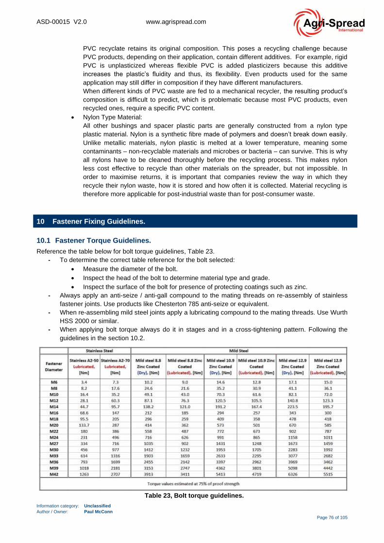
ASD-00015 V2.0 www.agrispread.com
Information category: Unclassified
Author / Owner: Paul McConn
Page 76 of 105
PVC recyclate retains its original composition. This poses a recycling challenge because
PVC products, depending on their application, contain different additives. For example, rigid
PVC is unplasticized whereas flexible PVC is added plasticizers because this additive
increases the plastic’s fluidity and thus, its flexibility. Even products used for the same
application may still differ in composition if they have different manufacturers.
When different kinds of PVC waste are fed to a mechanical recycler, the resulting product’s
composition is difficult to predict, which is problematic because most PVC products, even
recycled ones, require a specific PVC content.
• Nylon Type Material:
All other bushings and spacer plastic parts are generally constructed from a nylon type
plastic material. Nylon is a synthetic fibre made of polymers and doesn’t break down easily.
Unlike metallic materials, nylon plastic is melted at a lower temperature, meaning some
contaminants – non-recyclable materials and microbes or bacteria – can survive. This is why
all nylons have to be cleaned thoroughly before the recycling process. This makes nylon
less cost effective to recycle than other materials on the spreader, but not impossible. In
order to maximise returns, it is important that companies review the way in which they
recycle their nylon waste, how it is stored and how often it is collected. Material recycling is
therefore more applicable for post-industrial waste than for post-consumer waste.
10 Fastener Fixing Guidelines.
10.1 Fastener Torque Guidelines.
Reference the table below for bolt torque guidelines, Table 23.
- To determine the correct table reference for the bolt selected:
• Measure the diameter of the bolt.
• Inspect the head of the bolt to determine material type and grade.
• Inspect the surface of the bolt for presence of protecting coatings such as zinc.
- Always apply an anti-seize / anti-gall compound to the mating threads on re-assembly of stainless
fastener joints. Use products like Chesterton 785 anti-seize or equivalent.
- When re-assembling mild steel joints apply a lubricating compound to the mating threads. Use Wurth
HSS 2000 or similar.
- When applying bolt torque always do it in stages and in a cross-tightening pattern. Following the
guidelines in the section 10.2.
Table 23, Bolt torque guidelines.

ASD-00015 V2.0 www.agrispread.com
Information category: Unclassified
Author / Owner: Paul McConn
Page 77 of 105
10.2 Cross Tightening Guidelines.
The final torque value required can be determined from Table 23.
Note: Torque values outlined in this section do not apply to wheel nut fasteners.
Steps
5. Hand tighten all fasteners sets in the desired joint location, until they are snug.
6. First round - 60% of final torque, (sequential order outlined in Figure 71 or Figure 72).
7. Second round - 100% of final torque, (sequential order outlined in Figure 71 or Figure 72).
8. Third round – Repeat 100% of final torque, (sequential order outlined in Figure 71 or Figure 72).
Figure 71, Cross tightening sequence, circular bolting patterns.
Figure 72, Cross tightening sequence, non-circular bolting patterns.
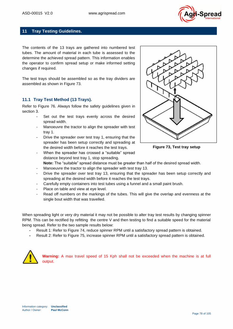
ASD-00015 V2.0 www.agrispread.com
Information category: Unclassified
Author / Owner: Paul McConn
Page 78 of 105
11 Tray Testing Guidelines.
The contents of the 13 trays are gathered into numbered test
tubes. The amount of material in each tube is assessed to the
determine the achieved spread pattern. This information enables
the operator to confirm spread setup or make informed setting
changes if required.
The test trays should be assembled so as the tray dividers are
assembled as shown in Figure 73.
11.1 Tray Test Method (13 Trays).
Refer to Figure 76. Always follow the safety guidelines given in
section 3.
- Set out the test trays evenly across the desired
spread width.
- Manoeuvre the tractor to align the spreader with test
tray 1.
- Drive the spreader over test tray 1, ensuring that the
spreader has been setup correctly and spreading at
the desired width before it reaches the test trays.
- When the spreader has crossed a “suitable” spread
distance beyond test tray 1, stop spreading.
Note: The “suitable” spread distance must be greater than half of the desired spread width.
- Manoeuvre the tractor to align the spreader with test tray 13.
- Drive the spreader over test tray 13, ensuring that the spreader has been setup correctly and
spreading at the desired width before it reaches the test trays.
- Carefully empty containers into test tubes using a funnel and a small paint brush.
- Place on table and view at eye level.
- Read off numbers on the markings of the tubes. This will give the overlap and evenness at the
single bout width that was travelled.
When spreading light or very dry material it may not be possible to alter tray test results by changing spinner
RPM. This can be rectified by refitting the centre V and then testing to find a suitable speed for the material
being spread. Refer to the two sample results below:
- Result 1: Refer to Figure 74, reduce spinner RPM until a satisfactory spread pattern is obtained.
- Result 2: Refer to Figure 75, increase spinner RPM until a satisfactory spread pattern is obtained.
Warning: A max travel speed of 15 Kph shall not be exceeded when the machine is at full
output.
Figure 73, Test tray setup
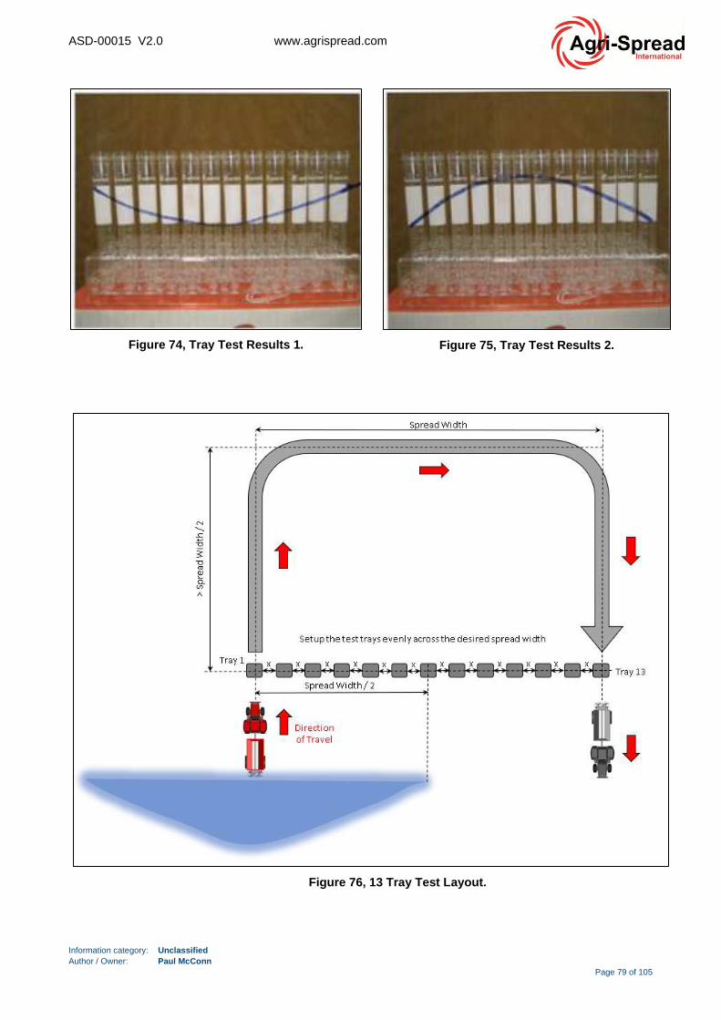
ASD-00015 V2.0 www.agrispread.com
Information category: Unclassified
Author / Owner: Paul McConn
Page 79 of 105
Figure 76, 13 Tray Test Layout.
Figure 74, Tray Test Results 1. Figure 75, Tray Test Results 2.

ASD-00015 V2.0 www.agrispread.com
Information category: Unclassified
Author / Owner: Paul McConn
Page 80 of 105
11.2 Tray Test (13 Tray), Bout Width Testing Form.
Test Number……………………………………………….… Date…………………………………………………
Test Material………………………………………………….. Spreader Identification...……………………….…
Spinner Size ………………………………..………………… Spinner Speed……………………………..………
Bout Width ……………………………………………………. Rate ..…………………...…………………………
Number of Runs …………………………………………….. . Direction Spread: Up & down / Round & Round
Width/Measurement of Bins
Tray Number Left Centre Right
Tray 1
Tray 2
Tray 3
Tray 4
Tray 5
Tray 7
Tray 8
Tray 9
Tray 10
Tray 11
Tray 12
Tray 13
Table 24, 13 Tray Test, Bin Width Measurement.
ASD-00015 V2.0 www.agrispread.com
Information category: Unclassified
Author / Owner: Paul McConn
Page 81 of 105
12 Frequently Asked Questions, (FAQ).
How wide can we spread?
- Agri-Spread can spread good quality fertiliser up to 36m (120 feet) with the correct settings.
- Lime can be spread from 10 to 15 meters depending on quality and moisture content. Most lime is
spread at 12 meters.
Can we spread small seed or granular herbicide?
- Small oilseeds, grass and cereals can be spread evenly. However, spread width will be limited.
Granular herbicides aren’t ideal for spreading. Agri-Spread will be testing the practice, but great
results aren’t expected. Possibly 30 to 40 feet.
Can we spread manure?
- Yes, but only dry manure with moisture content no higher than 30-35%.
Why are there two pressure lines?
- Having two pressure lines reduces overheating problems, which has been more of an issue in
warmer climates and tractors with limited cooling ability.
- Once a machine is set up in load sense (Power beyond) there is only one pressure and one return
line required.
What do I have to know about the return line? Why is the coupler different?
- Given we are running both the conveyor and spinner motors hydraulically, there is a high volume of
return oil going back to the hydraulic pump. It is essential that the return line plumbs directly into the
‘Power-Beyond return port’. If the return line is plumbed into the standard return port, as people
usually expect, oil will not return to the pump quickly enough. The ‘Power-Beyond’ return port
provides shorter route back to the pump.
- The coupler (1” female) is different only because some operators were mixing it up with the pressure
lines. Our dealers and customers can feel free to use whichever coupler is convenient. (if changing
couplers, keep in mind that all fittings use British thread…
Why do all the fittings use British thread (BSPP)?
- This is the standard thread in Europe. We may change our manufacturing process as our North
American market grows.
- Thread adaptors are easy to use and convert British thread to ‘National Pipe Thread: BSPP to NPT.
Can it handle variable rate applications? How is spread pattern affected by large rate changes?
- Yes, VRT (Variable Rate Technology) applications are very common with Agri-Spread spreaders.
- VRT maps can be uploaded into whatever software you are running on your tractor Isobus through
to your VT (Virtual terminal).
- The variable drive conveyor will handle rate changes, on the go. It will also handle groundspeed
changes, on the go.
- Spread pattern should not be affected greatly, even by large changes in application rate. However,
it’s important to tray test the spread pattern at low rates and high rates.
What is the difference between ‘Border Control’ and Headland Auto-Shutoff? Are they the same as
Section Control?
- Border Control is a standard option on Agri-Spread machines; it is the ability to slow down either the
left-hand or right-hand spinner, as the spreader runs over headlands, to control the spread width on
the outside lap.
- Note; this feature does not alter/vary the application rate, and should not be confused with Section
Control.
ASD-00015 V2.0 www.agrispread.com
Information category: Unclassified
Author / Owner: Paul McConn
Page 82 of 105
- Headland Auto-Shutoff is a feature that nearly all of Agri-Spread machines use. It shuts off the floor
when covering areas that have already been spread on. Essentially it is ‘single section’ section
control.
- Full section control is available on all the AS2-SC section control models, where a twin belt system
delivers product to both the left- and right-hand spinner at the required rate, in turn the spinners then
speed up or slow down as required to achieve the correct spread width.
Do I need to calibrate my scale, speed sensor or hydraulic valves?
- Loadcell calibration is highly recommended at least once per season.
• Ideally use a known weight of at least 600 kg. (suitcase weights are ideal)
▪ For highest accuracy, use the largest ‘known weight’ possible when calibrating.
• If necessary, a smaller calibration weight can be used.
- Speed sensor calibrations are rarely required; Use GPS for speed readings instead of speed sensor.
- If the hydraulic valves are causing problems, contact your local dealer.
What is the flow factor? Why does it vary for different products?
- Flow factor is a calibration number used to calculate target belt speed, and thus accurate application
rate.
- The default flow factor is 1.0. Values > 1.0 indicate a product flows more quickly. Values < 1.0
indicate a lower flowrate product.
- Different products have different flow characteristics. Note that gate-height also affects flow factor.
Therefore, any given product will have a different flow factor as gate-height changes.
- Flow factor can be set manually, or by performing a nudge calibration. Flow factor is only used when
operating the spreader in static.
How do I know where to set my gate-height?
- Refer to the Rate Calculator within our Mobile App
- A recommended range for gate height openings will be calculated based on factors you’ve input:
density, spread width, target rate, spinner speed and forward driving speed.
- Select the height range per your tractor’s hydraulic capacity and ideal door height for the product
being spread.
How low a rate can it apply? What’s the highest application rate possible?
- Rates as low as 2 lbs/acre are possible. The ‘Feathers False Door’ option; This attaches to the
existing door to allow for a very narrow door opening, while still achieving high rate accuracy
- Rates as high as 5000 lbs/acre are possible. Travel speed may be limited.
Do we need a power-beyond hydraulics setup on our tractor?
- No, power-beyond isn’t a required setup to operate your Agri-Spread.
- However, it is recommended for ideal hydraulic flow. It eliminates the need to ever adjust your
hydraulic remote pressures for ideal performance of your spreader’s conveyor belt and spinner
motors.
What would be the minimum tractor horsepower needed? How big does my hydraulic pump need to
be?
- For the largest model spreader (AS170) we recommend 300+ horsepower tractor. Using a tractor in
the 250Hp range is certainly possible, but you may be restricted on ground speed.
- 32 GPM (gallons per minute) is required.
How much does wind affect spread patterns? How much wind is too much?...
- Less than most people think… But wind will still affect the pattern, more when conditions are gusty.
ASD-00015 V2.0 www.agrispread.com
Information category: Unclassified
Author / Owner: Paul McConn
Page 83 of 105
- Ideally, you’ll want to travel ‘across’ the wind, so that the swaths will shift back and forth. Travelling
parallel to wind direction will result in a narrower spread width when into the wind, and a widened
spread width when travelling downwind.
- A common practice is to increase spinner speed when wind speeds increase. Keep this in mind
when pan-testing.
- It’s important to re-calibrate when conditions change, and to track changes in wind speed. Agri-
Spread now provides a handheld wind-gauge (anemometer) in our new spinner disk kits (36m kit or
BioSul disk kit).
Is a spreader a good choice on hilly fields?
- Hilly terrain presents challenges regardless of application method.
- In extreme slope situations, spread patterns will be affected somewhat.
- Agri-Spread offers a Hillside Divider insert to ensure more even distribution of product coming off the
conveyer belt. This hillside divider will be standard on 2017 spreaders and available for retrofit on
older Agri-Spread models.
- When possible, avoid traveling along ridge-tops or along valleys bottoms.
How late in the crop stage can I spread?
- Consult your agronomist or crop advisor.
- More timely nutrient application is a common trend, and spinner spreaders and granular fertiliser
products are more commonly becoming part of those practices.
- Narrower tire options are available, for ‘in-row’ or ‘in-crop’ applications.
How much granule pulverisation can I get away with?
- Very dependent on the type of product and the timeliness of application
- Pulverisation is not a concern with certain products; consult your agronomist.
- In general, wider spreads and greater efficiencies are seen with higher spinner speeds; this may
lead to an unacceptable amount of dusting/pulverisation
What is the ideal belt speed? What happens if my gate is set too high?
- The Agri-Spread conveyor belt is designed to work within a very wide range of belt speeds.
- Extremely slow belt speed may result in some belt stagger or inconsistent application rates. This
may be caused by opening the gate far higher than recommended; the resulting target belt speed
may be too low, resulting in poor performance.
- If target belt speed is too high (possibly due to door opening being too tight) hydraulic oil flow may
become a limiting factor; the pump may not be able to keep up to the high flow demand (loss of
spinner RPM will be the first observation, increase oil flow or open the door height to fix the problem)
How do I know if I have enough oil flow? How do I fine tune oil flow on my tractor’s hydraulic
remotes? What are the green bar graphs on the software?
- In short, if either the belt or the spinner motors aren’t charging up to target speed quickly, it’s likely to
be due to a lack of oil flow.
- If spinner speeds or belt speed is erratic (bouncing between low and high speeds), it’s likely a case
of too much oil flow.
- The green bar graphs on the main run page of the spreader software are indicators of the valve
positions (bar graph in top-left corner below groundspeed indicates belt valve position. Bar graph
beneath spinner speed indicates spinner motor valve position). Full bar graph indicates the valve is
fully open.
- If either valve is fully open, oil flow should be increased to rectify the situation.
- Hydraulic pressures can typically be set from the tractor cab, either with a digital setting in the
display, or analog dials on the armrest. Make sure you’re adjusting the remote pressure
corresponding to the same hydraulic remote being used.

ASD-00015 V2.0 www.agrispread.com
Information category: Unclassified
Author / Owner: Paul McConn
Page 84 of 105
- A common practice is to set target spinner speed to 1000 rpm, while parked and without the
conveyor belt running. Increase hydraulic remote pressure until spinner speed bumps above 1000
rpm (target speed). Then decrease hydraulic pressure by 10%. Assuming the spinner speed still
holds at 1000rpm, you’ll likely be in the proper pressure range to then go spread.
Belt encoder; does it need regular tightening?
- We have a known issue, albeit rare, where certain belt encoders have become loose, or not been
tightened properly during pre-delivery inspection. This can result in the controller reading an
inaccurate belt speed.
- Check your encoder to ensure it is properly tightened, using an allen key.
NOTE: when properly tightened, the encoder is meant to feel loose. Rotational play is acceptable, as
the encoder is retained by a rubber strap. However, there should be no axial play. The shaft should
not move in and out of the belt roller.
What are the large chains hanging above the end of the conveyor belt?
- These chains are designed to break apart bulky product, such as BioSul.
- When spreading regular granular fertiliser, we recommend these chains are hung in the ‘up’ position,
as they may cause uneven flow of product off the belt, onto the spinner disks.
Can I use a foot pedal as a master ON/OFF switch?
- Agri-Spread offer a foot pedal which will turn the conveyer belt on and off. Certain operators have
requested this, despite the ‘Auto-shutoff’ feature. This allows the operator to quickly turn off the belt
for quick turns, unforeseen obstacles and in case of emergency.
- Contact your dealer or Agri-Spread for more info.
Why aren’t my two spinner speeds matching?
- This issue is occasionally caused by incorrect oil flow.
- It may be an issue with the border control solenoid; unplug the solenoid from the left-hand spinner
motor; observe if spinners are still showing uneven speeds.
The controller is set to read the speed sensor on the right-hand spinner motor. A common
troubleshooting procedure is to swap the Deutsch plugs (located at the rear-right side of the
spreader bin. This will then swap the speed sensors and may rectify the issue.

ASD-00015 V2.0 www.agrispread.com
Information category: Unclassified
Author / Owner: Paul McConn
Page 85 of 105
13 Rate Charts (Note: Rate Charts Are Only Applicable to Land-driven Gearbox).
Lo
w G
ear

ASD-00015 V2.0 www.agrispread.com
Information category: Unclassified
Author / Owner: Paul McConn
Page 86 of 105
Lo
w G
ear

ASD-00015 V2.0 www.agrispread.com
Information category: Unclassified
Author / Owner: Paul McConn
Page 87 of 105
Lo
w G
ear

ASD-00015 V2.0 www.agrispread.com
Information category: Unclassified
Author / Owner: Paul McConn
Page 88 of 105
Lo
w G
ear

ASD-00015 V2.0 www.agrispread.com
Information category: Unclassified
Author / Owner: Paul McConn
Page 89 of 105
Lo
w G
ear

ASD-00015 V2.0 www.agrispread.com
Information category: Unclassified
Author / Owner: Paul McConn
Page 90 of 105
Lo
w G
ear

ASD-00015 V2.0 www.agrispread.com
Information category: Unclassified
Author / Owner: Paul McConn
Page 91 of 105
Lo
w G
ear

ASD-00015 V2.0 www.agrispread.com
Information category: Unclassified
Author / Owner: Paul McConn
Page 92 of 105
Med
ium
Ge
ar

ASD-00015 V2.0 www.agrispread.com
Information category: Unclassified
Author / Owner: Paul McConn
Page 93 of 105
Med
ium
Ge
ar

ASD-00015 V2.0 www.agrispread.com
Information category: Unclassified
Author / Owner: Paul McConn
Page 94 of 105
Med
ium
Ge
ar

ASD-00015 V2.0 www.agrispread.com
Information category: Unclassified
Author / Owner: Paul McConn
Page 95 of 105
Med
ium
Ge
ar

ASD-00015 V2.0 www.agrispread.com
Information category: Unclassified
Author / Owner: Paul McConn
Page 96 of 105
Med
ium
Ge
ar

ASD-00015 V2.0 www.agrispread.com
Information category: Unclassified
Author / Owner: Paul McConn
Page 97 of 105
Med
ium
Ge
ar

ASD-00015 V2.0 www.agrispread.com
Information category: Unclassified
Author / Owner: Paul McConn
Page 98 of 105
Hig
h G
ear

ASD-00015 V2.0 www.agrispread.com
Information category: Unclassified
Author / Owner: Paul McConn
Page 99 of 105
Hig
h G
ear

ASD-00015 V2.0 www.agrispread.com
Information category: Unclassified
Author / Owner: Paul McConn
Page 100 of 105
Hig
h G
ear

ASD-00015 V2.0 www.agrispread.com
Information category: Unclassified
Author / Owner: Paul McConn
Page 101 of 105
Hig
h G
ear

ASD-00015 V2.0 www.agrispread.com
Information category: Unclassified
Author / Owner: Paul McConn
Page 102 of 105
Hig
h G
ear

ASD-00015 V2.0 www.agrispread.com
Information category: Unclassified
Author / Owner: Paul McConn
Page 103 of 105
Hig
h G
ear

ASD-00015 V2.0 www.agrispread.com
Information category: Unclassified
Author / Owner: Paul McConn
Page 104 of 105
Hig
h G
ear

ASD-00015 V2.0 www.agrispread.com
Information category: Unclassified
Author / Owner: Paul McConn
Page 105 of 105
Agri-Spread International,
Running Gear Limited,
Coolnaha North,
Ballyhaunis,
Co. Mayo,
Ireland
Phone: 00353 (0)949631808
Email: [email protected]
Dales Agri Sales Agency,
Canbuci,
Allendale,
Hexham,
NE47 9PY,
United Kingdom
Phone: 0044 1434 683626
Email: [email protected]
Waringa Distribution,
56 Edward Road,
Geraldton WA 6530,
Australia,
Phone: 0061 8 99607164
Email: [email protected]