DiGiT Numbering System - Anthem Screen Printing
8
DiGiT Numbering System Assembly and Operating Manual This manual contains the following documents: Page 2 Introduction / Component ID / Attachment Installation 3 Site & Detent Rail Installation **IMPORTANT** 4 Site Rail and Number Alignment Overview 5 Alignment Instructions & Tips 6 Operating Instructions & Adjustments Alignment Guide Vastex International, Inc. 7 Emery St Bethlehem, Pa. 18015 USA Phone# 610 625-2702 Fax# 610 625-2775 Web Site www.vastex.com Vastex E-mail assistance Purchasing & Product Info: [email protected] Electrical Support: [email protected] Tech Support, Mechanical Setup, and Operation [email protected] Screen Printing Issues & Support: [email protected] Models: V2NS-8 & V2NS-12 Doc # 01-19-001
-
Upload
khangminh22 -
Category
Documents
-
view
3 -
download
0
Transcript of DiGiT Numbering System - Anthem Screen Printing

DiGiT Numbering System
Assembly and Operating Manual
This manual contains the following documents:
Page 2 Introduction / Component ID / Attachment Installation
3 Site & Detent Rail Installation **IMPORTANT**
4 Site Rail and Number Alignment Overview
5 Alignment Instructions & Tips
6 Operating Instructions & Adjustments
Alignment Guide
Vastex International, Inc. 7 Emery StBethlehem, Pa. 18015 USA Phone# 610 625-2702 Fax# 610 625-2775 Web Site www.vastex.com
Vastex E-mail assistance Purchasing & Product Info: [email protected] Electrical Support: [email protected] Tech Support, Mechanical Setup, and Operation [email protected] Screen Printing Issues & Support: [email protected]
Models: V2NS-8 & V2NS-12
Doc # 01-19-001

Roller Assembly
Component ID
Attachment Installation
The DiGiT was designed and built as light as possible, while still maintaining great strength and durability. This attachment will clamp into any rear clamp manual press. The print head must be able to support a minimum of 25 lbs for the 8” attachment and 30 lbs for the 12” attachment. It must also be strong enough to hold the screen level when slid to the end printing positions. Additional springs or shocks may be required for your press to hold this attachment. Vastex is not responsible for damages incurred while trying to retrofit our DiGiT to your press. A Vastex V-2000 press only needs a double gas spring instead of the standard single gas spring to hold up the DiGiT. V-1000 owners must upgrade to (optional) HD head. There are different Site and Detent Rails for all sizes of numbers. The same Site and Detent rails are used for either screen of the same height numbers. Detent Rails are marked at the factory with the number height. The Site Rails are labeled from the factory as shown on page 3 of this manual.
Set of 4” Detent and Site Rails
Set of 6” Detent and Site Rails
Set of 8” Detent and Site Rails
Parts included in each attachment box.
Introduction
Main Slide Assembly Screen Holder Assembly
V-2000 Recommended Gas Spring setting: Hinge
Print Head
Numbering Attachment being installed
Note Be sure the Roller Assembly is centered and as far back in the clamps as possible. Install the Roller Assembly parallel to the rear clamps.
-V2NS-8 pictured below -V2NS-12 has a longer Screen Holder Assembly, and two additional pairs of Site and Detent Rails.
1) Lower the print head 2) Slide the pallet at least 5” away from the clamps.
(shown on right) 3) Place the Main Slide Assembly into the screen
clamp. Be sure it is centered, then tighten the rear clamps.
4) Install lift springs to support the extra weight. V-2000 owners: Install included double gas spring as shown below. 5) Install second assembly and verify there is no
inter-ference between the two assemblies. 6) Set the off contact to 3/8”
5” (12.7cm)

Site Rail Installation
1) Loosen the three phillips head screws circled in the picture below. 2) Slide the Site Rail under the screw heads and tighten. Be sure to install the correct Site and Detent Rails to match the screen you will be using.
Detent Rail Installation
Site Rail
Note
The Site and Detent Rails can be in-stalled while the numbering attachment is on the press. This is shown off the press for instructional purposes only.
(The picture above shows the correct orientation of an installed Detent Rail.)
Detent Rail
3) Site Rails should be labeled from the factory as shown below.
3 31 13 L R 1 11 11 5 15 51 4 41 14 2 21 12 L R L R L R L R
8 81 18 L R 6 61 16 0 10 01 9 91 19 7 71 17 L R L R L R L R
1-5
6-0
Target
The Site Rail is a visual aid for selecting the desired print location of the numbers.
The Detent Rail controls the location of the number. Five positions are available for each number. This is a very important step.
The grooves in the Detent Rail engage into a Roller Bearing, locking the screen into position.
1) Loosen the three philips head screws on the Detent Rail. (shown below)(V2NS-12 has 5 screws to install Detent Rail. 2) Slide the Detent Rail onto the bottom of the Numbering Attachment and tighten them down well. See photo (bottom right) for visual reference. Be sure to install the correct Site and Detent Rails to match the screen you will be using.
Roller Bearing
Important! Detent rails must be installed as shown below. Be sure grooves in rail lock into the roller bearing!

3 31 13 L R
34 (A B)
51 12
(B) (A) (C) (D) (E) (F)
Site Rail and Number Alignment Overview
Selected # printed on center of shirt. ex: 3
Selected # printed to the left side of a #1. ex: 31
Selected # printed on left chest. ex: 32
Selected # printed to the right side of a #1. ex: 13
Selected # printed on right chest. ex: 23
3 31 13 L R L R L R L R L R
(C D) (E F)
1 11 11 5 15 51 4 41 14 2 21 12
Example prints with their Site Rail locations for printing
# 5 # 4 # 3 # 2 # 1
(Letters shown on shirts are for Site Rail references only.)
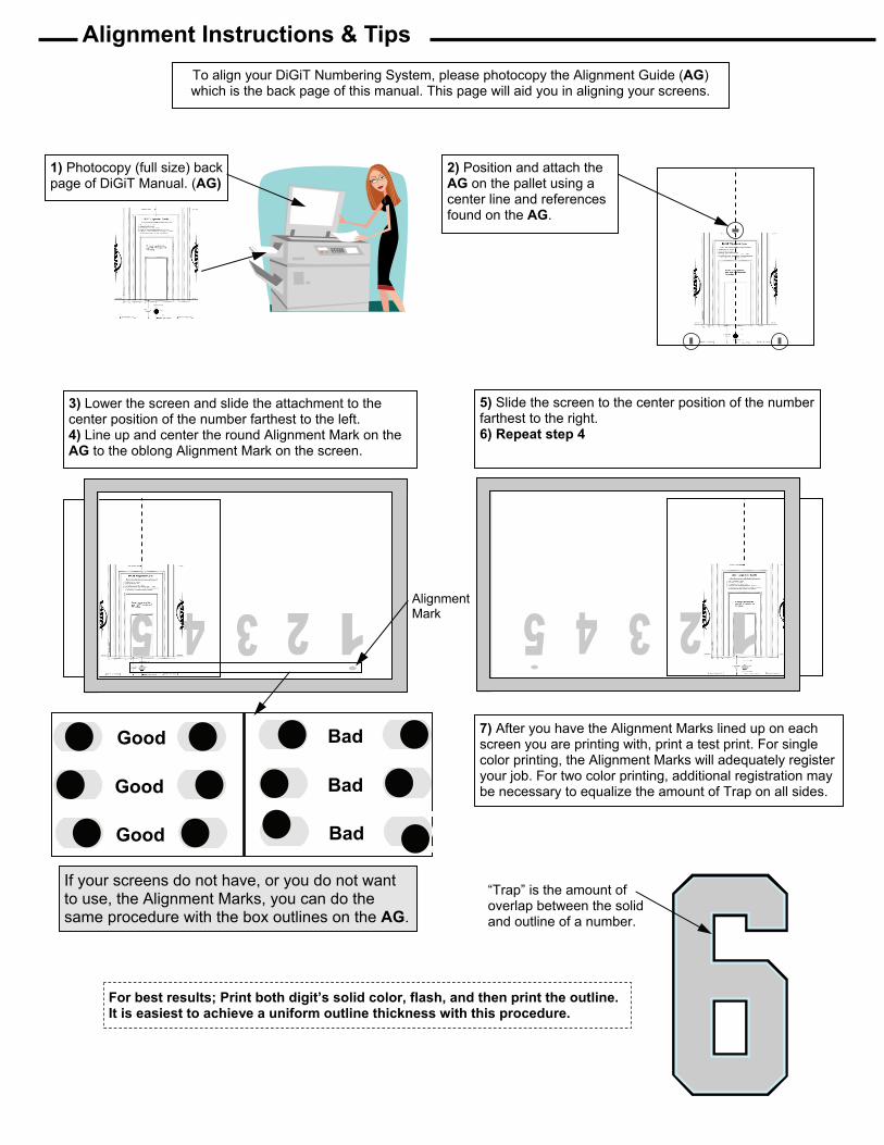
Alignment Instructions & Tips
2) Position and attach the AG on the pallet using a center line and references found on the AG.
To align your DiGiT Numbering System, please photocopy the Alignment Guide (AG) which is the back page of this manual. This page will aid you in aligning your screens.
1) Photocopy (full size) back page of DiGiT Manual. (AG)
If your screens do not have, or you do not want to use, the Alignment Marks, you can do the same procedure with the box outlines on the AG.
3) Lower the screen and slide the attachment to the center position of the number farthest to the left. 4) Line up and center the round Alignment Mark on the AG to the oblong Alignment Mark on the screen.
Alignment Mark
5) Slide the screen to the center position of the number farthest to the right. 6) Repeat step 4
7) After you have the Alignment Marks lined up on each screen you are printing with, print a test print. For single color printing, the Alignment Marks will adequately register your job. For two color printing, additional registration may be necessary to equalize the amount of Trap on all sides.
“Trap” is the amount of overlap between the solid and outline of a number.
Good
Good
Bad
Bad
Good Bad
For best results; Print both digit’s solid color, flash, and then print the outline. It is easiest to achieve a uniform outline thickness with this procedure.

Operating Instructions 1) Install the DiGiT numbering attachments. 2) Install required Site and Detent Rails. 3) Clamp in and locate screen. 4) Be sure your screen is leveled in both directions. Set off con-
tact to 3/8” to ensure the screen locks fully into the Detent Rail. 5) Install (optional) Vastex Squeegee Rest onto screen. 6) Ink the screens with athletic ink. For athletic numbering tips,
see document (01-08-028) found at Vastex.com or contact Vastex Sales department.
7) Use squeegees cut to proper width. See chart for sizes. 8) Tilt the screen slightly to slide to the required number. Print
position and sliding position are shown below.
Adjustments (Optional) Vastex Squeegee Rest
Print position (shown above)
Sliding position (shown above)
The spacing between the rollers, in the Roller As-sembly, have been preset at the factory. It may be necessary to make a slight adjustment to the roller spacing as the rollers wear. If the screen does not maintain level when the screen is slid to the end posi-tions, the rollers may need to be adjusted. With the print head lowered, center the Screen Holder Assem-bly in the Roller Assembly. While holding down firmly on the print head, lift up and down on the Screen Holder Assembly. There should be no notice-able vertical movement between the rollers and the Screen Holder Assembly. If movement is noticed, use two 7/16 wrenches to tighten the adjustment bolt. Tighten no more than 1/8 turn at a time. Recheck for vertical movement. Do NOT over tighten!! Adjust both sets of rollers. If the rollers are adjusted too tight it will be difficult to slide the Screen Holder Assembly.
9) Each number has five printing positions. (Pg 3) Align the Site Rail to the Target for the desired printing location. When the screen is in the print position, the detent will engage into the roller bearing. A properly set off contact is required for this to function correctly.
10) For printing two color numbers, rotate the pallet under the flash then proceed with the outline or drop shadow.
11) To raise the print head, center the screen and gently lift. 12) Do not lean on number screens. Damage to the mechanism
can occur and off contact will suffer.
Adjustment Bolt
2-0 1 ½” 1 1 ¼” 2-0 2 ¾” 1 2” 2-0 3 ¾” 1 2 ¾”
Recommended Squeegee width
2”
4”
6”
Check here for vertical movement.
Screen Holder Assembly
2-0 5” 1 3 ½” 2-0 5 ¾” 1 3 ¾”
8”
10”
12” 2-0 7” 1 4 ¼”


TOP OF # TOP OF #
Be sure to copy/print this page with NO margins and NO scaling.
2” from edge of paper
6” 8” 4”
Center of Pallet 11/19/15
Follow these steps for each attachment being used 1) Mark a center line on pallet. 2) Center this sheet on pallet. 3) Set height from front edge of pallet. 4) Line up the Alignment Marks when centered on #s 1, 5, 6 & 0 5) No bulls -eyes on your number screen? Simply use guide lines on this template to center and align your numbers.
½”
1”
1.5” FRONT OF PALLET FRONT OF PALLET Center of Pallet
10” 12”
DiGiT Alignment Guide N
umbe
r Out
line
Alignment Mark