Diffraction of an obliquely incident plane wave by the discontinuity of a two part thin dielectric...
10
lnr. 1. Engng Sci. Vol. 27, No. 6, pp. 701-710, 1989 0020-7225/89 $3.00 + 0.00 Printed in Great Britain. All rights reserved Copyright 0 1989 Pergamon Press plc DIFFRACTION OF AN OBLIQUELY INCIDENT PLANE WAVE BY THE DISCONTINUITY OF A TWO PART THIN DIELECTRIC PLANE ALINUR BUYUKAKSOY’, GGKI-IAN UZGGREN* and A. HAMIT SERBEST3 1 Faculty of Electrical and Electronics Engineering, Technical University of Istanbul, 80626 Maslak, Istanbul, Turkey ’ Department of Electrical Engineering, Yildiz University, Istanbul, Turkey 3 Department of Electrical and Electronics Engineering, Cukurova University, Balcali, 01330 Adana, Turkey (Communicated by H. DEMIRAY) Ah&act-The problem of diffraction of an obliquely incident plane wave by the discontinuity occuring in the permittivity of a thin dielectric layer is investigated. The structure is simulated by a set of boundary conditions involving the normal components of the field and their normal derivatives. The related boundary value problem is then reduced to three scalar Wiener-Hopf equations and solved by standard techniques. Some numerical results are presented in the case of normal incidence. 1. INTRODUCTION The diffraction of electromagnetic waves by a two-part surface is an important topic in diffraction theory, because it constitutes a canonical problem for analyzing the scattering caused by an abrupt change in the material properties of a surface. The diffraction by a two part impedance plane and by the discontinuity formed by resistive and impedance half-planes have been treated by several authors [l-4]. As a part of this subject we consider in the present paper the diffraction of an obliquely incident plane wave by the discontinuity occuring on a plane composed by two parts with different dielectric permittivities. A non-magnetic thin dielectric slab is generally simulated by an infinitesimally thin resistive sheet supporting an electric current proportional to the common value of the tangential electric field at its surface [5]. Recently, it has been shown that the inclusion of a “modified conductive sheet” in addition to the resistive one provides a better simulation at oblique incidence when the incident electric vector has a component normal to the layer [6]. For a thin planar slab consisting of a homogeneous non-magnetic dielectric with thickness c and relative complex permittivity E, the boundary conditions are as follows: nX{nX[E+E-]}=-2RnX[H+-H-1 (14 nX{nX[H++H-]}=2R*nX[E+-E-]++-$E++E-] 0) Here R and R* stand for R= ‘ii? R*= iYE kt(E - 1) ’ kt(E - 1) with Z and Y being the intrinsic impedance and admittance of the surrounding medium, respectively. The (+) and (-) superscript to the value of the field on the upper and lower faces of the sheet whereas n denotes the unit normal vector directed outward from the upper surface. Note that in the case of normal incidence for H-polarization the boundary conditions in (la, b) reduce to those previously given by Leppington [7]. The problem of diffraction by a two-part dielectric plane at skew incidence will be considered by expressing the boundary conditions in (la, b) in terms of normal components of the field and their normal derivatives. This will enable us to reduce the mixed boundary-value problem into three scalar Wiener-Hopf equations which can be solved by standard techniques. 701
-
Upload
independent -
Category
Documents
-
view
2 -
download
0
Transcript of Diffraction of an obliquely incident plane wave by the discontinuity of a two part thin dielectric...
lnr. 1. Engng Sci. Vol. 27, No. 6, pp. 701-710, 1989 0020-7225/89 $3.00 + 0.00 Printed in Great Britain. All rights reserved Copyright 0 1989 Pergamon Press plc
DIFFRACTION OF AN OBLIQUELY INCIDENT PLANE WAVE BY THE DISCONTINUITY OF A TWO PART
THIN DIELECTRIC PLANE
ALINUR BUYUKAKSOY’, GGKI-IAN UZGGREN* and A. HAMIT SERBEST3
1 Faculty of Electrical and Electronics Engineering, Technical University of Istanbul, 80626 Maslak, Istanbul, Turkey
’ Department of Electrical Engineering, Yildiz University, Istanbul, Turkey 3 Department of Electrical and Electronics Engineering, Cukurova University, Balcali, 01330 Adana,
Turkey
(Communicated by H. DEMIRAY)
Ah&act-The problem of diffraction of an obliquely incident plane wave by the discontinuity occuring in the permittivity of a thin dielectric layer is investigated. The structure is simulated by a set of boundary conditions involving the normal components of the field and their normal derivatives. The related boundary value problem is then reduced to three scalar Wiener-Hopf equations and solved by standard techniques. Some numerical results are presented in the case of normal incidence.
1. INTRODUCTION
The diffraction of electromagnetic waves by a two-part surface is an important topic in diffraction theory, because it constitutes a canonical problem for analyzing the scattering caused by an abrupt change in the material properties of a surface. The diffraction by a two part impedance plane and by the discontinuity formed by resistive and impedance half-planes have been treated by several authors [l-4]. As a part of this subject we consider in the present paper the diffraction of an obliquely incident plane wave by the discontinuity occuring on a plane composed by two parts with different dielectric permittivities.
A non-magnetic thin dielectric slab is generally simulated by an infinitesimally thin resistive sheet supporting an electric current proportional to the common value of the tangential electric field at its surface [5]. Recently, it has been shown that the inclusion of a “modified conductive sheet” in addition to the resistive one provides a better simulation at oblique incidence when the incident electric vector has a component normal to the layer [6].
For a thin planar slab consisting of a homogeneous non-magnetic dielectric with thickness c and relative complex permittivity E, the boundary conditions are as follows:
nX{nX[E+E-]}=-2RnX[H+-H-1 (14
nX{nX[H++H-]}=2R*nX[E+-E-]++-$E++E-] 0)
Here R and R* stand for
R= ‘ii? R*= iYE
kt(E - 1) ’ kt(E - 1)
with Z and Y being the intrinsic impedance and admittance of the surrounding medium, respectively. The (+) and (-) superscript to the value of the field on the upper and lower faces of the sheet whereas n denotes the unit normal vector directed outward from the upper surface. Note that in the case of normal incidence for H-polarization the boundary conditions in (la, b) reduce to those previously given by Leppington [7].
The problem of diffraction by a two-part dielectric plane at skew incidence will be considered by expressing the boundary conditions in (la, b) in terms of normal components of the field and their normal derivatives. This will enable us to reduce the mixed boundary-value problem into three scalar Wiener-Hopf equations which can be solved by standard techniques.
701

702 A. B~Yi_kAKSOY et al.
2. FORMULATION OF THE PROBLEM
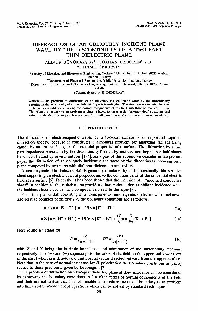
Let a two-part dielectric plane located at y = 0 in a Cartesian coordinate system Oxyz, be illuminated by a plane wave, with time dependence exp(-iwt) whose normal components are given by
L2;l=I~l exp{ -ik sin @,(x cos & + y sin #*) + ikz cos 13,) (2)
The dielectric constants of the plane are denoted by Q and s2, where the subscripts 1 and 2 refer to the right (x > 0) and left (x < 0) sides of the junction, respectively (Fig. 1). These parts are characterized by the boundary conditions (la, b). The problem consists then of finding explicit expression of the scattered field.
The boundary conditions in (la, b) which is a vector one relating the tangential components at the surface are reduced to the following scalar con~tions written in terms of the field components normal to the layer located at y = 0:
LYE+ aE- y +---L + ikql,2[Ec - E;] = 0 X$0 3Y 8Y
(l+~~)[~:+E;]+(~~~/ik)[~-~]=O XSO C+b)
Hz-H;=0 X E (-a, 03) (3c)
IH:+H;]+(s,.iik)[~-~-]=O XZO
where we have put
2Ri Vj”=:y’ +2+; j=l,2 W
Since the boundary ~nditions are independent of the z-coordinate, it follows that the entire field must have the same z dependence as the incident field. In particular
E,,(x, y, z) = E,(x, y)exp(ikz ~0s G), HJx, y, z) = HY(x, y)exp(ikz cos 0,)
and we shall henceforth omit the z-dependent factor. For the normal components of the scattered electric and magnetic fields, say E; and H$,
Fig. 1. The geometry of the diffraction problem,
Diffraction of an obliquely incident plane wave
which satisfy the Helmholtz equation
one can assume the following integral representation
A+(v)exp{iX(v)y - ivx} dv + e;(x, y), Y’O
A_(v)exp{-iX(v)y - ivx} dv + e$(x, y), Y<O
703
(4)
(54
ZH;= ’ 1 I B+(v)exp{iX(v)y - ivx} dv + h;(x, y) Y’O
I
0) B_(v)exp{-iX(v)y - ivx} dv + h:(x, y) Y<O
f
with
x(v)=G=T K = k sin 8,, (5c)
Here the square-root function x(v) is defined in the v-plane cut as indicated in Fig. 2 such that at the origin one has x(O) = K. The integration line C is a straight-line parallel to the real v-axis lying in the strip Im(K cos &) < Im(v) < Im(K) (see Fig. 2). In (5a, b) ei, ei, hi and hf denote the normal components of the electric and magnetic fields that would be observed as reflected and transmitted waves when the dielectric layer has the permittivity ci, j = 1, 2, namely:
a e;(x, y) = -
sin e0 sin f#JO - qj + qf sin f& sin $J~ + sin2 e. sin2 & - 1
1
_.
2 sin e. sin & + 7)i $ sin e. sin f#~~ - sin2 e. sin2 & + 1 e I+C“S ~o-Y~~'t'Cd (ha)
a ej(x,y)=--
2
sin e. sin & - T)j _ vi* sin e. sin f#~~ + sin2 e. sin’ & - 1 e_ix(X cos *o+y sin ho)
sin e. sin & + T/j r$ sin e. sin e0 - sin’ e. sin2 & + 1 1 (6b)
and
hi’(x, y ) = -b 1
1 + ?)j sin e. sin Go e-ir(x cm @o-y sin @JO)
h,!(x, y) = b 7)j sin e. sin &
1 + Qj sin e. sin & e-i~(~ ~0s &+y sin f&)
(74
(7b)
They are explicitly inserted in the expressions of the scattered field for the sake of analytical convenience.
By substituting (2) and (5a, b) into (3a, d) and then inverting the resulting integral equations
Imu
FP k _____---__- ----- ----------_
-K /’ Fig. 2. The branch-cuts in the complex-v plane.
704
one obtains:
A. BiiYijKAKSOY et al.
i[A+(v) -A_(v)][qlk +X(Y)] = q:(v) - a;(,, + ii;, ;;;);““” ‘O 0 v KCOS $0)
@a) 0
W+(y) - A-(~)lir~& + x(v)] = w:(v)
[A+(v)+A_(v)][$+~~~+cos’e,}
@b)
= -q&l) -a (q: - $)sin Bo(l - sin’ f30 sin’ eo)sin c#~
ni (qz* sin O. sin @o + 1 - sin’ O. sin2 f#~~)( v - K cos eo) (gc)
[A+(v)+A-(v)]& 7j;$+OS2e,)= -g(v) (84
B+(v) = B_(v) (9
[B+(v) + B_(v)][ 1+ rI1 +)I = a’(v) +b (71~ - rll)sin e. sin Go
ni (1 + n2 sin e. sin Go)(v - K cos Go) (gf)
[B+(v) + z?_(v)][ 1+ n23 = Q)“(v) @g)
Here r&(v), @‘( ) v and t+!~f;,~(v), Q)“(v) are regular functions of v in the half-planes Imv<ImK and Imv>ImKcos$O, respectively. The elimination of A,(v) and B,(v) between (ga, g) yields the following Wiener-Hopf equations written in the strip Im K cos Go < Imv<ImK:
K&v ( 1
p(v) “; = q{(v) + a K sin #Oh - %)
K -,v ( >
n ( q2 + Sin 8,) Sin f&)( V - K COS c&O) Pa)
rll
@xv)
WV:> v)
M(rC, v) = ?/I,:(v) + fi
(q: - r&sin2 eo(i - sin2 e. sin2 eo)sin Go
Jri (7: Sin $0 Sin ~$0 i- 1 - Sin2 eO Sin2 &)(V - K COS $0) (9b)
K(712, V) (71~ - v&in e. Sin e.
K(qr, v) W(v) = @l(v) + 6
xi (1 + r/2 sin e. sin $o)(v - K cos #o) (9c)
Here we have put
K(Vjt v) = 1
Vj+klX(v)
j=l,2 (10)
M(r$, v) = 2 1
$ + 77;~(~)ik + ~0~2 e.
(114
with

Diffraction of an obliquely incident plane wave
3. SOLUTION OF THE WIENER-HOPF EQUATIQNS
705
By applying the standard Wiener-Hopf procedure f8], the solution of (9a-c) can be obtained as follows:
K ('?I - ‘@in $0 K’(l/r),> K COS $0) 1
3d r/2 + sin 80 Sin $0 K1(1/7f2, K COS $0) ’ V - K COS $0 -q(Y)]
- $)sin eo(l - sin2 60 sin’ #o)sin #O . kf’(q:, i( cos $0)
(7$ sin o. sin @o + 1 - sin28o sin2 Cpo) Mf(V2*, K cos $0)
1
Y-KCOS& - J%(v)]
WI
Wb)
In the above expressions K”(K’) and M”(M’) are the split functions regular and free of zeros in the half-plane Im v < Im K cos cibo (Im v < Im K), resulting from the Wiener-Hopf factor~ation of (10) and (lla), respectively. Note that when we let v-m in their respective regions of analycity, one has
KU’+/, v) = O(1)
provided that t,r # 0, ~0. Explicit expressions for Ku,’ (and consequently for Mu,‘) can be obtained in terms of tabulated ~ali~hinetz functions [9].
The functions PI(v), P2(v) and P,(v) appearing in (12a-c) are entire functions resulting from the application of the Liouville Theorem in the Wiener-Hopf analysis. By taking into account the edge conditions and the behaviour of the split functions for IvI-+ 60, one finds that P1 and P3 are constants whereas P2(v) is a linear function of v in the form P2(v) = mv + II, with m and )z being constants. In order to determine them one has to consider the tangential component of the scattered field [lo, 111. From Maxwell’s equations one has
E, = k2 cos ~,ZZ-I, + - ?T 3.x ay y’
ik[Z(a/&)Hy + cos B,(d/ay)E,].
By assuming for E”, and E”, an integral representation similar to (5a) with spectral coefficients C+(v), C-(v) and D+(v), D-4 v , respectively, and using (13a) and (13b) one obtains )
C,(v) = [k2 cos BOB+(v) f v~(v)A~(v)]I(v2 + k2 cos 0,) (14a)
Z&(v) = [vkB+(v) T kx(v)cos &,A*(v)],(v” + k2 cos2 @,) (14b) In the subsequent Fourier inversion of the integrals related to tangential field components, the poles occuring at the zeros of (v2 + k2 cos2 0,) may be captured. It is obvious that the residues at these poles must be zero because they give rise to surface waves which grow exponentially as x--+ fm, and consequently violate the radiation condition. This requirement enables one to determine PI, P2(v) and P3 as follows:
cos eo(q2 -t sin e, sin Cpo) kl’(% 3 1y” cm $0) q2 a (1 - sin’ e. sin’ (bo)(l + r/2 sin &, sin 4po) K’( n2, K cos @o)
x f%/rl2, KCOS$o)
K1(l/?fl, K Cos @o) - se4yl - Y+
sin 8, cos cpo + cos e. tg(yi - y2)
k( 1 - sin2 e. sin2 #Jo) @a)
PZ(V) = - V+KCOS~o
k2(1 - sin’ 6, sin2 eo) Wb)
706 A. BijYijKAKSOY ef al.
cos &(l + rj2 sin 13~ sin f##‘( rj2, K cos &J
(1 - sin2 &sin2 &)(n2 + sin OO sin &,)K’(nl, K cos @,)
x K’(llq1, K cos @o) sin e,cos &- cos e0 tg(y, - y2)
K’Wrl2, k ~0s $0) sech - y2) -
k(1 - sin2 8, sin2 &J (15c)
We should note that the consideration of the tangential components of the scattered magnetic field leads to the same results.
The constants Yj (j = 1, 2) appearing in the above expressions are defined as
C'Y'= 6 K”(Q ik cos 0,)
>
(16)
For selected real n, a graph of y(&,, n) as a function of &, is given in [9].
4. ANALYSIS OF THE FIELD
Since I/J’;,~ and Cp” are now completely determined, the spectral amplitudes A+(v) and B,(v) can be obtained from (8b, d) and (8e, g). After substituting them into (5a) and (5b) and evaluating the resulting integrals by the saddle-point technique one obtains the following results for the total fields, say E,’ and Hr:
Ec+E$++e; o<tp<Jd-$0
E;= El+Et++e; Jd-&J<Cp<n
Ez_ + e: --36-C@-Jr+&) (17)
E$_ + e: -n+Cp”<ql<O
and H;+ H;+h; O<@<n-$0
H;= H;+ H,d+h; Jc-~~<@<Jr
H;+h; --3d<$<-Jr++0 (18)
H,d+h; -Jc+fp~<#<o
Here E$ and Hi are given by (2) whereas e;, ej and hJ, hf are defined through (6a, b) and (7a, b), respectively. The normal components of the diffracted electric and magnetic fields are obtained as
E ;+=[aU*+bV+]$$ yS0
H; = [au* + bV*] = 6
with
(194
Wb)
u,(eO, f& 9) = $ sin CpO sin OO sin C$ 1+Lsin8,sin&
r/2 >( 1 + t sin eO sin #
>
K’ ( ) (
1
> 1 X
+os$q, K’ ~,Kcos@ sin2 e. cos & + sin BO cos e. tan ( y1 - y2) _
K’ 1
-, KCOS+ >
1 - sin2 e,sin2 & cos & + cos @
r/2
Diffraction of an obliquely incident plane wave 707
+W
(q: - $)(l - sin2 8a sin2 +a)
2 sin f& sin & + 1 - sin’ tIO sin’ &)(n2* sin 8a sin $ + 1 - sin’ BO sin2 @)
M’(r):, K COS #o)M’($, K COS $‘) . sin2 eO(cOs f& - cos #) 1
xA4’(7$, K cos &JM’(?& K cos f#)) 1 - sin2 eO sin2 & - cos 4 + cos & 1 (204 we,, eo9 9) = *& $&
(7jr - 7j2)sin2 eO cos eO sin & sin ip sec(y, - y2)
( i sin e. sin $ + 1
> (1 + rj2 sin e. sin @o)(l - sin2 e. sin2 f$o)
X
K’h, K cos On)K’($ , K cos f#g
K’(rl2, K cos &)I$;, k cos $)
W’b)
1 u*(eo, 409 +) =g G
( rj2 - q ,)sin2 e. sin @o cos e. sin 4
1 - sin2 e. sin2 Go
K’ (
X
;, K COS $0 >
K’(ql, K COS #) sech - y2)
K’(k, Kcos&)K’(q2, KCOS$) ($2+sin60sin~o)(~+sinB,sin4)
WC)
v*(e,, #09 44 = f (n2 - qr)sin e. sin Go sin I$ K’(rl,, K cos $o)K’(n,, K cos 4)
2~r (I+ q2 sin e. sin $o)(l + 7j2 sin e. sin $) K’(q2, K cos &)K’(7j2, K cos G)
i
1 X
_ sin2 e. cos @o - sin e. cos e. tan(y, - y2)
cos f$o + cos @ 1 - sin2 e. sin2 @o I (20d)
The tangential components of the diffracted electric field can easily be obtained as
Ed _ cos fjO[aU* + bV*] T sin2 e. cos @ sin $[a& + bV*l eirp xi - 1 - sin’ e. sin2 @ 6
yzo (21a)
Ed Zf
= _ sin e. cos q+U* + bV*] f sin e. cos eO[a, + bV,] eiKp
1 - sin2 e. sin2 fp 6 yzo (21b)
Similarly, the tangential components of the scattered magnetic field can be found as follows
H;,= - *sin2 e. sin f$ cos @[au* + bV*] + cos e,[au+ f bV,] eiKP
1 - sin2 e. sin2 C$ 6 (22a)
Hd zf
= _ fsin e. c0s e. sin +[uU* + bV*] - cm @[au* + bl/,l eirp
1 - sin2 e. sin2 @ 6 (22b)
In the case of normal incidence (13, = x/2) and for H-polarization, the above results reduce to
H:,=u e ikp e id4 sin Go sin @ +;I
-i&G w (cos #o + cos f#) l+isinf$2 l+lsin@
>( r/2 > ES 27:6-G
708 A. BfimKAKSOY et al.
X
Kl(;, k cm g4,) K'(; , k cos c#) (77: - v:)cos $0 cm @
K’ $, k cos $0 > - Cd sin 4% + ax* &I)($ sin $ + COS* $J)
1 x M%I:, k ~0s $o)M*(rl:, k cos 9)
M’(rl:, k ~0s @o)M’(d, k cos $) (23)
Since ZHi(O) = -(l/cos &,)a, the diffraction coefficient related obtained as
to two-part dielectric plane is
in’4
D%@oP @) =
sin & sin @
k cos q& + cos 9
i
*\7]1-121 --
( l+$sin$o l+lsin#
>( 72 >
;, k cos r$ (7: - r/aces 9 cos 40
;, k cos $ - (r/2* sin e. + cos* @o)( 71: sin 9 + cos* q5)
X M’(rl:, k ~0s tio)M’(rl:, k cos $) M’(q:, k ~0s @o)M’(r/;, k cos $) (24)
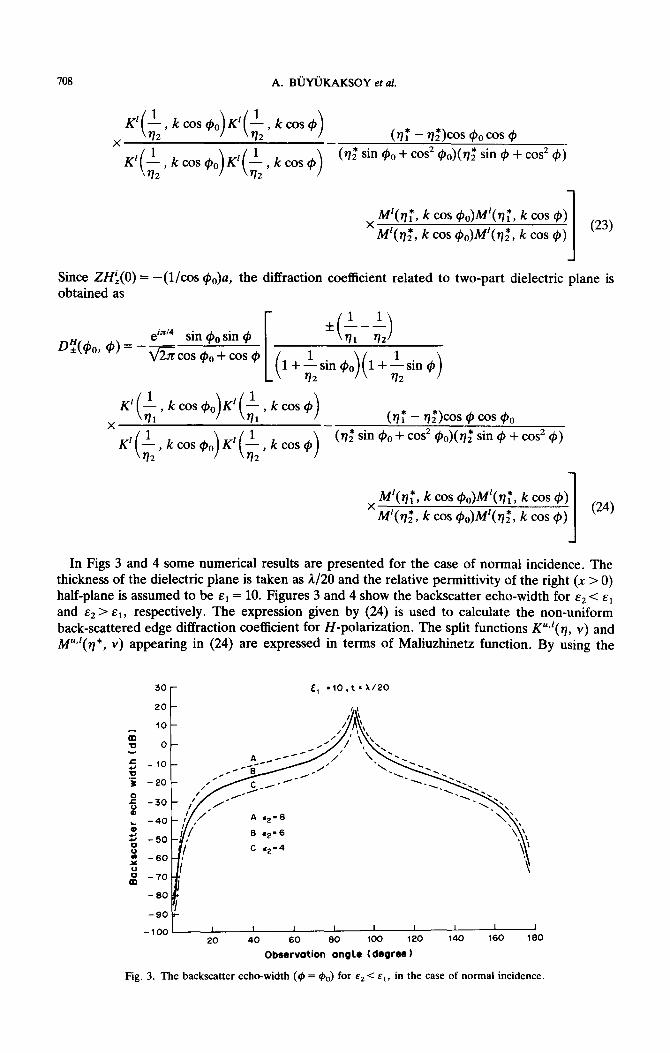
In Figs 3 and 4 some numerical results are presented for the case of normal incidence. The thickness of the dielectric plane is taken as A/20 and the relative permittivity of the right (X > 0) half-plane is assumed to be s1 = 10. Figures 3 and 4 show the backscatter echo-width for s2 < c1 and s2> sl, respectively. The expression given by (24) is used to calculate the non-uniform back-scattered edge diffraction coefficient for H-polarization. The split functions K”“(v, Y) and iWl(q*, Y) appearing in (24) are expressed in terms of Maliuzhinetz function. By using the
30 r
6 =iO,t=X/i?O
20 -
m
-100 1 I 1 I I I I I I
20 40 60 60 100 120 140 160 160
Observation angle (degree 1
Fig. 3. The backscatter echo-width ($I = &,) f or e2 < Ed, in the case of normal incidence.
Diffraction of an obliquely incident plane wave 709
t - 40 =:
:: -50
a 0 _ 60
lz - 70
- 80
-90 :
-100 I I I I I I I I I 0 20 40 60 60 100 120 140 160 160
Observation angle (degree)
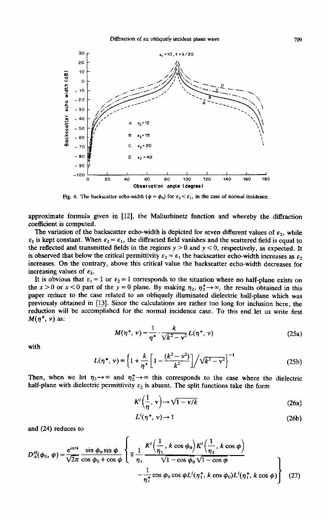
Fig. 4. The backscatter echo-width (4 = #o) for -s2 < E,, in the case of normal incidence.
approximate formula given in [12], the Maliuzhinetz function and whereby the diffraction coefficient is computed.
The variation of the backscatter echo-width is depicted for seven different values of .Q, while st is kept constant. When s2 = sl, the diffracted field vanishes and the scattered field is equal to the reflected and transmitted fields in the regions y > 0 and y < 0, respectively, as expected. It
is observed that below the critical permittivity &2 = el the backscatter echo-width increases as c2 increases. On the contrary, above this critical value the backscatter echo-width decreases for increasing values of s2.
It is obvious that cl = 1 or c2 = 1 corresponds to the situation where no half-plane exists on the x > 0 or x < 0 part of the y = 0 plane. By making n2, ~2 303, the results obtained in this paper reduce to the case related to an obliquely illuminated dielectric half-plane which was previously obtained in [13]. Since the calculations are rather too long for inclusion here, the reduction will be accomplished for the normal incidence case. To this end let us write first
N(q*, v) as:
qq*, v)=‘* k
q* qgL@?*J y) CW
with
L(?j*, v) = { 1+ $ [ 1 - ‘“‘s”‘]/~zq-’ Wb)
Then, when we let VZ-* M and r]2*-+ ~0 this corresponds to the case where the dielectric half-plane with dielectric permittivity Ed is absent. The split functions take the form
and (24) reduces to
K’ ;, v ---q/m ( >
L’(q*, Y)-+ 1
(264
(26bI
kcos &, k cos c$
Vl-cos$,ql-cos$
--&OS ~POCOS W’(q:, k cos ~o)L*~~~, k cos r@) (27)
710 A. BUYUKAKSOY et al.
which is nothing but the diffraction coefficient related to a thin dielectric half-plane previously obtained in [14]. This agreement can be considered as a verification of the analysis made in this
paper.
Acknowledgemenf-The authors are indebted to Professor Dr Mithat Idemen of the Technical University of Istanbul, Turkey, for his valuable suggestions and comments.
REFERENCES
[I] A. F. KAY, Scattering of a surface wave by a discontinuity in reactance. IRE Tram Antennas Propagation AP-7, 22-31 (1959).
[2] R. TIBERIO and G. PELOSI, High-frequency scattering from the edges of imepdance discontinuity on a flat plane. IEEE Tram. Anteed Propagation AP-3X (No. 4), 590-S% (July 1983).
[3] P. H. PATHAK and R. G. ROJAS, A UTD analysis of the EM diffraction by an impedance di~ontinuity in a planar surface. J. Wave,M$erial Interaction 1 (No. 11, 16-33 (Januarv 1986).
[4] G. UZGGREN, A. BUYUKAKSOY and A. H. SERBEST, Diffraction coefficient related to a discontinuity formed by impedance and resistive half-planes. IEEE Proc.-H, Microwaves, Antennas Propagation. 136 (No. l), 19-23 (1989).
[S] R. F. HARRINGTON and J. R. MAUTZ, An impedance sheet approximation for thin dielectric shells. IEEE Tram. Antennas Propuguiion AP-25, 531-534 (1975).
[6] T. B. A. SENIOR and J. L. VOLAKIS, Sheet simulation of a thin dielectric layer. Radio Sci. 22 (No, 7), 1261-1272 (December 1987).
[7] F. G. LEPPINGTON, Travelhng waves in a delectric slab with an abrupt change in thickness. Proc. R. Sot., London, Ser. A 386, 443-W (1983).
[8] B. NOBLE, Method1 Based on the Wiener-Hopf Technique. Pergamon Press, Oxford (1958). [9] T. B. A. SENIOR, Half-plane edge diffraction. Radio Sci. 10, 645-650 (1975).
[lo] T. B. A. SENIOR, Diffraction tensors for imperfectly conducting edges. Radio Sci. 10 (No. lo), 911-919 (1975). [ll] 0. M. BUCCI and G. FRANCESCHETH, Electromagnetic scattering by a half-plane with different face
impedances. Radio Sci. 11 (No. l), 49-59 (1976). 1121 J. L. VOLAKIS and T. B. A. SENIOR, Simple expressions for a function occuring in diffraction theory, IEEE
Trans. Antennas Propagation APz33 (No. 6), 678-680 (1985). [13] A. BUYUKAKSOY, E. ERDOGAN and A. H. SERBEST, Diffraction of an obliquely incident plane wave by a
thin dielectric half-plane. Bull. Tech. Univ. Istanbul. 41 (No. 4), 655-664 (1988). [14] J. L. VOLAKIS and T. B. A. SENIOR, Diffraction by a thin dielectric half-plane. IEEE Trans. Antennas
Propagation AP-35, (No. 12), 1483-1487 (1987).
(Received 24 October 1988)


![4.1.1] plane waves](https://static.fdokumen.com/doc/165x107/6322513728c445989105b845/411-plane-waves.jpg)