Developmental flight testing of a digital terrain system for the ...
12
Developmental Flight Testing of a Digital Terrain System for the USAF F-16 Capt Glenn Coleman Michael Seelos Capt Sean McAllum Project Manager 805-277-1 105 Project Engineer 805-277-2741 Project Pilot R05-277-1825 ~. ~ .~~ -. . ~.-- ~~~ [email protected] MichaelSeelos @ edwards.af.mil [email protected] 416” Test Squadron, 412” Test Wing, US. Air Force Flight Test Center, Edwards AFB, CA 93524 “Abstract - The United States Air Force decided to integrate a Digital Terrain System into all F-16s to reduce the number of controlled flight into terrain mishaps. Through the use of a digital map of the earth used in conjunction with the F-16’s own inertial navigation system and radar altimeter, the DTS provides the F-16 with an all-attitude, complete-envelope, ground and obstacle collision avoidance system with passive terrain following and bomb ranging capabilities. The F-16 Combined Test Force at Edwards A m , CA recently completed the second and final phase of the DTS development program. This flight test program spanned two years and flew over 150 test sorties. The system was shown to considerably reduce the pilot’s worHoad and increase situation awareness, especially at night, in low visibility conditions and low-level, high workload environments. In addition, it provided valuable ground and obstacle collision avoidance wamings that should decrease any further F-16 mishaps. -”I Summary In response to several mishaps, the US. Air Force (USAF) decided to improve ground proximity warnings by integrating a Digital Terrain System (DTS) into all F-16s. Since DTS was an “off-the-shelf’ purchase, this integration effort was considered a low cost way to reduce controlled flight into terrain mishaps, especially when compared with the real costs of such accidents. The origins of this DTS came from a program known as TERPROMm developed by the British Aerospace Corporation, and was subsequently tailored for the F-16 by Lockheed Matin Tactical Aircraft Systems (LMTAS) and the USAF. This paper will detail DTS, the developmental flight test program, test program results, and lessons learned. Currently, detailed data analysis is just beginning and this paper will address only preliminary results of the second and final phase of this developmental flight test program. It is anticipated a more detailed technical analysis will be available at this paper’s presentation. 1. 2. 3. 4. 5. 6. I. TABLE OF CONTENTS INTRODUCTION BACKGROUND SYSTEM DESCRIPTION TEST PLANS I EXECUTION RESULTS AND CONCLUSIONS ACKNOWLEDGMENTS SUMMARY AND LESSONS LEARNED 1. INTRODUCTION The Digital Terrain System (DTS), a commercial off the shelf system, was integrated into all F-16s to reduce the number of controlled flight into terrain mishaps. This integration effort was considered low cost when compared with the human and material cost of such accidents. The Phase 2 DTS Development Flight Test Program was recently flight tested by the F-16 Combined Test Force at the Air Force Flight Test Center, Edwards AFB, California. Phase 2 DTS consisted of improvements to the five DTS functions: terrain referenced navigation (TRN), predictive ground collision avoidance system (PGCAS), database terrain cueing (DBTC), obstacle warning and cueing (OWE), and passive ranging (PR). The primary function of the TRN was to provide accurate registration of the aircraft within the terrain database to the other four functions. PGCAS provided visual and aural warnings for the pilot to recover the aircraft and avoid the terrain. DBTC provided guidance similar to a terrain following system, using a digital tenain map to generate a cue in the Heads-Up Display (HUD). By following this cue, a pilot could fly at a preset terrain clearance height. Warnings for avoidance of man-made obstacles were provided by OW/C. Passive Ranging provided target elevation, derived from the digital database, for both visual and pre-planned bombing computations. I ‘‘US. Government work not protected by U.S copyright.” 99
-
Upload
khangminh22 -
Category
Documents
-
view
1 -
download
0
Transcript of Developmental flight testing of a digital terrain system for the ...
Developmental Flight Testing of a Digital Terrain System for the USAF F-16
Capt Glenn Coleman Michael Seelos Capt Sean McAllum Project Manager
805-277-1 105 Project Engineer
805-277-2741 Project Pilot
R05-277-1825 ~. ~ .~~ -. . ~.-- ~~~
Glenn.Coleman @edwards.af.mil MichaelSeelos @ edwards.af.mil [email protected]
416” Test Squadron, 412” Test Wing, US. Air Force Flight Test Center, Edwards AFB, CA 93524
“Abstract - The United States Air Force decided to integrate a Digital Terrain System into all F-16s to reduce the number of controlled flight into terrain mishaps. Through the use of a digital map of the earth used in conjunction with the F-16’s own inertial navigation system and radar altimeter, the DTS provides the F-16 with an all-attitude, complete-envelope, ground and obstacle collision avoidance system with passive terrain following and bomb ranging capabilities.
The F-16 Combined Test Force at Edwards A m , CA recently completed the second and final phase of the DTS development program. This flight test program spanned two years and flew over 150 test sorties. The system was shown to considerably reduce the pilot’s worHoad and increase situation awareness, especially at night, in low visibility conditions and low-level, high workload environments. In addition, it provided valuable ground and obstacle collision avoidance wamings that should decrease any further F-16 mishaps. -”I
Summary
In response to several mishaps, the US. Air Force (USAF) decided to improve ground proximity warnings by integrating a Digital Terrain System (DTS) into all F-16s. Since DTS was an “off-the-shelf’ purchase, this integration effort was considered a low cost way to reduce controlled flight into terrain mishaps, especially when compared with the real costs of such accidents. The origins of this DTS came from a program known as TERPROMm developed by the British Aerospace Corporation, and was subsequently tailored for the F-16 by Lockheed Matin Tactical Aircraft Systems (LMTAS) and the USAF. This paper will detail DTS, the developmental flight test program, test program results, and lessons learned. Currently, detailed data analysis is just beginning and this paper will address only preliminary results of the second and final phase of this developmental flight test program. It is anticipated a
more detailed technical analysis will be available at this paper’s presentation.
1. 2. 3. 4. 5. 6. I.
TABLE OF CONTENTS
INTRODUCTION BACKGROUND SYSTEM DESCRIPTION TEST PLANS I EXECUTION RESULTS AND CONCLUSIONS
ACKNOWLEDGMENTS SUMMARY AND LESSONS LEARNED
1. INTRODUCTION
The Digital Terrain System (DTS), a commercial off the shelf system, was integrated into all F-16s to reduce the number of controlled flight into terrain mishaps. This integration effort was considered low cost when compared with the human and material cost of such accidents.
The Phase 2 DTS Development Flight Test Program was recently flight tested by the F-16 Combined Test Force at the Air Force Flight Test Center, Edwards AFB, California. Phase 2 DTS consisted of improvements to the five DTS functions: terrain referenced navigation (TRN), predictive ground collision avoidance system (PGCAS), database terrain cueing (DBTC), obstacle warning and cueing (OWE), and passive ranging (PR). The primary function of the TRN was to provide accurate registration of the aircraft within the terrain database to the other four functions. PGCAS provided visual and aural warnings for the pilot to recover the aircraft and avoid the terrain. DBTC provided guidance similar to a terrain following system, using a digital tenain map to generate a cue in the Heads-Up Display (HUD). By following this cue, a pilot could fly at a preset terrain clearance height. Warnings for avoidance of man-made obstacles were provided by OW/C. Passive Ranging provided target elevation, derived from the digital database, for both visual and pre-planned bombing computations.
I ‘‘US. Government work not protected by U.S copyright.”
99
2. BACKGROUND
General
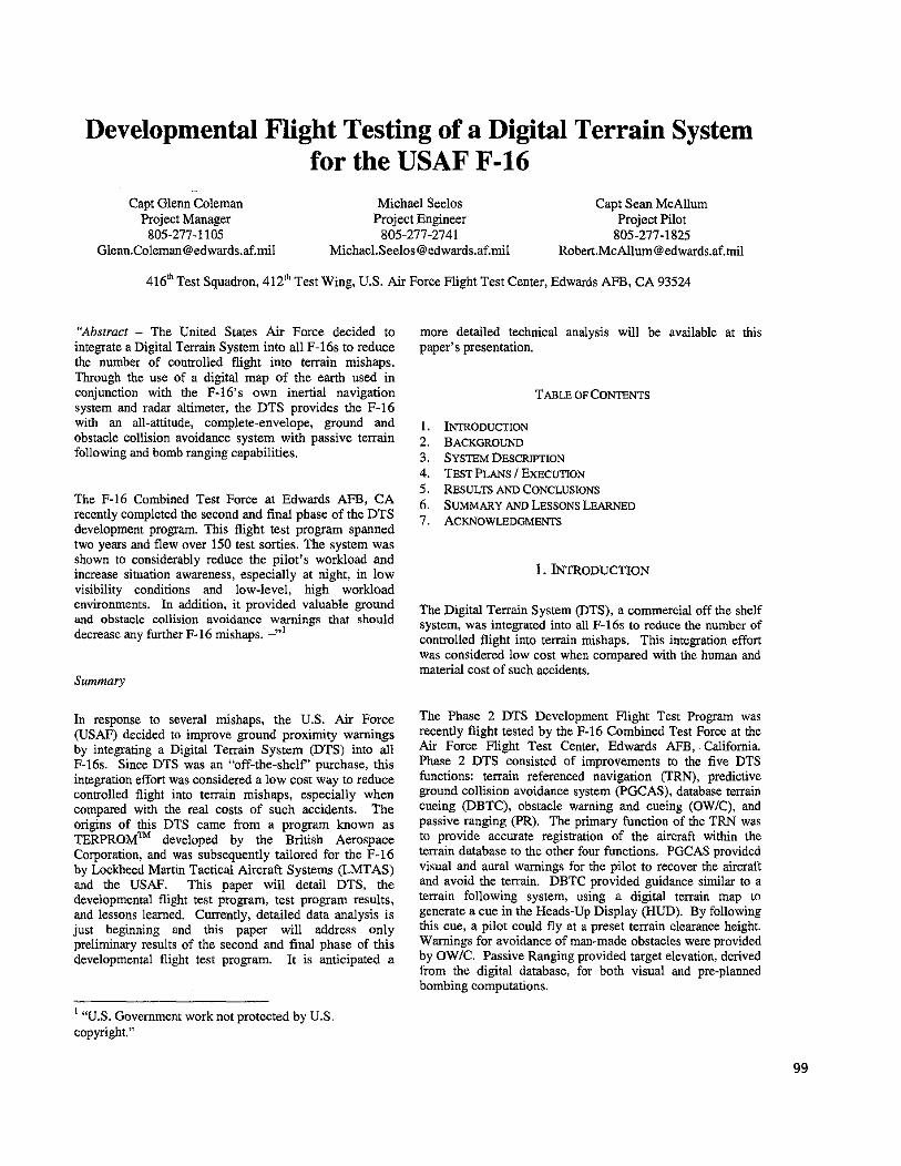
The Digital Terrain System was designed to provide the F-16 aircraft with improved safety and weapon delivery performance. The implementation of DTS for the general avionics computer (GAC) and modular mission computer (MMC) consisted of development and integration, and was divided into two phases. Phase 1 testing consisted of the development of the DTS data transfer camidge (DTSDTC) hardware, and the associated operating software, the DTS Application Software (DTSAS). In addition the DTS was successfully integrated with the F- 16 pre-Block 50T4 avionics baseline software during DTS Phase 1 testing. Fairchild Defense and British Aerospace Systems and Equipment (BASE) performed the design and development of the DTSDTC and the DTSAS, respectively. Lockheed Martin Tactical Aircraft Systems designed and integrated the F-16 subsystems and software interface with the DTSAS. The USAF purchased the license to the DTSAS from BASE and contracted LMTAS to develop it specifically for the F-16. The Phase 1 DTS fed into a variety of F-16 software updates, or operational flight programs (OFPs). These included Block 50 Tape 4, Block 40 Tape 5, and USAF Block 50 MMC MI. The DTS Phase 2 development consisted of improvements to the DTSAS by LMTAS. Phase 2 was intended to improve all DTS functions and to provide a basis for future growth. The DTS roadmap for both the development and integration into the production blocks is shown in Figure 1. Phase 2 development was planned to be integrated into USAF Block 50 Tape 5, Block 40 Tape 6, and M2+ software update programs.
Figure 1 DTS Roadmap
Chronology
The Phase 2 DTS Development Flight Test Program consisted of two major tape releases, although each tape consisted of multiple flight test OFPs. The initial evaluations of the DTS functions were performed in Tape 1 between April and October of 1997 for a total of 78 sorties and 115.9 flight hours. Flight test began with the evaluation of the basic DTS navigation function, TRN, and integration with the F-16 Master Navigation Filter (MNF) to establish confidence that the system was performing correctly before proceeding to the other DTS functions.
In Phase 2 Tape 2, final performance tunings to the DTS functions were implemented, and two new run matrices were added for the PGCAS and PR functions. Phase 2 Tape 2 was conducted from 9 Oct 97 to 5 Aug 98 for a total of 88 sorties and 143.1 flight hours. Tape 2 began with two daytime integrated systems evaluation (BE) sorties to assess overall system operation. Flight-testing then proceeded to the other DTS functions and concluded with the evaluation of DTS with Night Vision Goggles (NVGs) in 4 night ISE sorties by both developmental and operational test pilots to determine the military utility of the DTS.
In this development program, flight test was the final means for developing the design implementation (i.e. “fly, develop, fly” concept). Flight simulations were used extensively to arrive at a configuration that would he finalized in flight test. Flight test was required to capture the real world environment factors such as atmospheric effects, pilot workload, actual aircraft feedback and controls, etc that could not be duplicated in simulation. Improvements and performance tuning of the DTS functions were made using flight test OFPs and parameter allocation files. Fourteen OFP updates across four subsystems and 13 OFP sets were required to flight test and evaluate the Phase 2 DTS. The majority of the OFP updates were for improvements to the DTSAS.
3. SYSTEM DESCRIPTION
The F-16C aircraft was a single-engine, single-seat multi-role tactical fighter with full air-to-air and air-to-surface combat capabilities. The F-16D aircraft was a two-seat (tandem) version intended to perform a secondary role as a trainer. Numerous F-16 test aircraft were used during the project, all with digital flight control systems, and equipped with either Pratt & Whitney PW-220 or General Electric C3E-129 engines. Each of the test aircraft were extensively instrumented to provide capability for telemetry and onboard recording of pulse code modulation data, selected multiplex bus parameters, pilot voice transmissions, and onboard recording of all MIL-STD-1553 multiplex bus traffic. Additional instrumentation included three videotape recorders for post flight analysis of both the HUD and multifunction display (MFD) information.
100
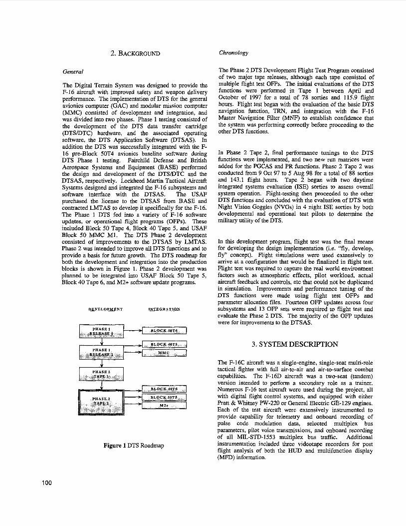
The Digital Terrain System consisted of both hardware and software components. The improved DTS data transfer camidge @TS/DTC) built by Fairchild Industries (Figure 2) was the only new hardware required to host the DTS in the F-16. It was a form, fit, function replacement for the standard F-16 DTC. The DTSDTC differed from a standard DTC in that it added 72 MB of flash mass memory for storing the terrain database and vertical ohsmction data (VOD), the .DTSAS, and a new microprocessor to drive the DTS functions. The software which provided the DTS functions was the DTSAS. It was hosted in the DTSDTC and provided DTS outputs to the F-16 core avionics computers through the data transfer unit @TU) onboard the aircraft. The core avionics computers then provided the appropriate pilot controls and displays commanded by the various DTS functions.
Figure 2 Digital Terrain System I Data Transfer Cartridge @TSDTC)
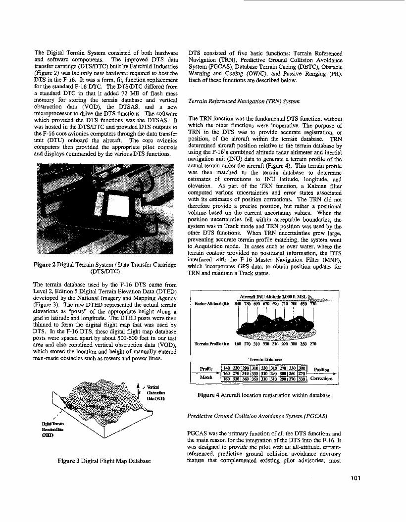
The terrain database used by the F-16 DTS came from Level 2, Edition 5 Digital Terrain Elevation Data @TED) developed by the National Imagery and Mapping Agency (Figure 3). The raw DTED represented the actual terrain elevations as “posts” of the appropriate height along a grid in latitude and longitude. The DTED posts were then thinned to form the digital flight map that was used by DTS. In the F-16 DTS, these digital flight map database posts were spaced apart by about 500-600 feet in our test area and also contained vertical obstruction data (VOD), which stored the location and height of manually entered man-made obstacles such as towers and power lines.
..
Figure 3 Digital Flight Map Database
DTS consisted of five hasic functions: Terrain Referenced Navigation (TRN), Predictive Ground Collision Avoidance System (PGCAS), Database Terrain Cueing (DBTC), Obstacle Warning and Cueing (OWE), and Passive Ranging (PR). Each of these functions are described below.
Terrain Referenced Navigation (TRN) System
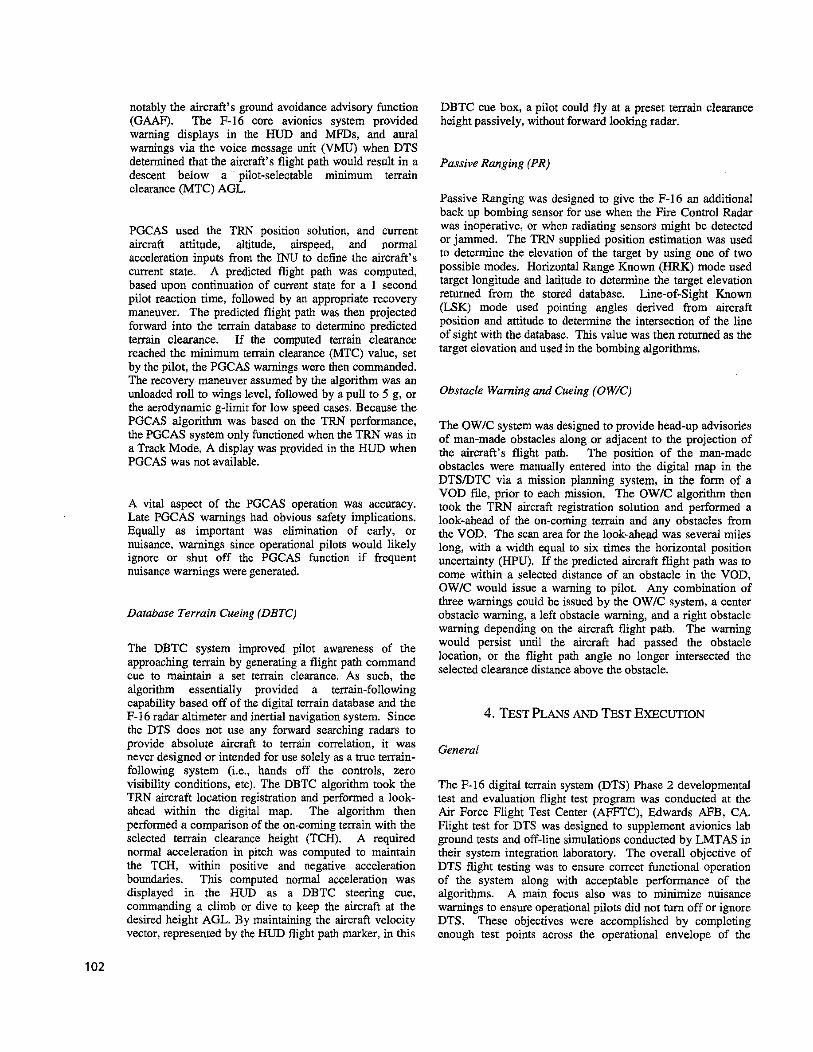
The TRN function was the fundamental DTS function, without which the other functions were inoperative. The purpose of TRN in the DTS was to provide accurate registration, or position, of the aircraft within the terrain database. TRN determined aircraft position relative to the terrain database by using the F-16‘s combined altitude radar altimeter and inertial navigation unit ( I N ) data to generate a terrain profile of the actual terrain under the aircraft (Figure 4). This terrain profile was then matched to the terrain database to determine estimates of corrections to INU latitude, longitude, and elevation. As part of the TRN function, a Kalman filter computed various uncertainties and error states associated with its estimates of position corrections. The TRN did not therefore provide a precise position, but rather a positional volume based on the current uncertainty values. When the position uncertainties fell within acceptable boundaries, the system was in Track mode and TRN position was used by the other DTS functions. When TRN uncertainties grew large, preventing accurate terrain profile matching, the system went to Acquisition mode. In cues such as over water, where the terrain contour provided no positional information, the DTS interfaced with the F-16 Master Navigation Filter (MNF), which incorporates GPS data, to obtain position updates for TRN and maintain a Track status.
Figure 4 Aircraft location registration within database
Predictive Ground Collision Avoidance System (PGCAS)
PGCAS was the primary function of all the DTS functions and the main reason for the integration of the DTS into the F-16. It was designed to provide the pilot with an all-attitude, temin- referenced, predictive ground collision avoidance advisory feature that complemented existing pilot advisories; most
101
notably the aircraft's ground avoidance advisory function (GAAF). The F-16 core avionics system provided warning displays in the HUD and MFDs, and aural warnings via the voice message unit (VMU) when DTS determined that the aircraft's flight path would result in a descent below a pilot-selectable minimum terrain clearance (MTC) AGL.
PGCAS used the TRN position solution, and current aircraft attitude, altitude, airspeed, and normal acceleration inputs from the INU to define the aircraft's current state. A predicted flight path was computed, based upon continuation of current state for a 1 second pilot reaction time, followed by an appropriate recovery maneuver. The predicted flight path was then projected forward into the terrain database to determine predicted terrain clearance. If the computed terrain clearance reached the minimum terrain clearance (MTC) value, set by the pilot, the PGCAS warnings were then commanded. The recovery maneuver assumed by the algorithm was an unloaded roll to wings level, followed by a pull to 5 g, or the aerodynamic g-limit for low speed cases. Because the PGCAS algorithm was based on the TRN performance, the PGCAS system only functioned when the TRN was in a Track Mode, A display was provided in the HUD when PGCAS was not available.
A vital aspect of the PGCAS operation was accuracy. Late PGCAS warnings had obvious safety implications. Equally as important was elimination of early, or nuisance, warnings since operational pilots would likely ignore or shut off the PGCAS function if frequent nuisance warnings were generated.
Darabase Terrain Cueing (DBTC)
The DBTC system improved pilot awareness of the approaching terrain by generating a flight path command cue to maintain a set terrain clearance. As such, the algorithm essentially provided a terrain-following capability based off of the digital terrain database and the F-16 radar altimeter and inertial navigation system. Since the DTS does not use any forward searching radars to provide absolute aircraft to terrain correlation, it was never designed or intended for use solely as a true terrain- following system (i.e., hands off the controls, zero visibility conditions, etc). The DBTC algorithm took the TRN aircraft location registration and performed a look- ahead within the digital map. The algorithm then performed a comparison of the on-coming terrain with the selected terrain clearance height (TCH). A required normal acceleration in pitch was computed to maintain the TCH, within positive and negative acceleration boundaries. This computed normal acceleration was displayed in the HUD as a DBTC steering cue, commanding a climb or dive to keep the aircraft at the desired height AGL. By maintaining the aircraft velocity vector, represented by the HUD flight path marker, in this
DBTC cue box, a pilot could fly at a preset terrain clearance height passively, without forward looking radar.
Passive Ranging (PR)
Passive Ranging was designed to give the F-16 an additional back up bombing sensor for use when the Fire Control Radar was inoperative, or when radiating sensors might be detected or jammed. The TRN supplied position estimation was used to determine the elevation of the target by using one of two possible modes. Horizontal Range Known (HRK) mode used target longitude and latitude to determine the target elevation returned from the stored database. Line-of-Sight Known (LSK) mode used pointing angles derived from aircraft position and attitude to determine the intersection of the line of sight with the database. This value was then returned as the target elevation and used in the bombing algorithms.
Obstacle Warning and Cueing (OW/C)
The OWIC system was designed to provide head-up advisories of man-made obstacles along or adjacent to the projection of the aircraft's flight path. The position of the man-made obstacles were manually entered into the digital map in the DTSDTC via a mission planning system, in the form of a VOD file, prior to each mission. The OW/C algorithm then took the TRN aircraft registration solution and performed a look-ahead of the ou-coming terrain and any obstacles from the VOD. The scan area for the look-ahead was several miles long, with a width equal to six times the horizontal position uncertainty (HPU). If the predicted aircraft fight path was to come within a selected distance of an obstacle in the VOD, OWIC would issue a warning to pilot. Any combination of three warnings could be issued by the O W E system, a center obstacle warning, a left obstacle warning, and a right obstacle warning depending on the aircraft flight path. The warning would persist until the aircraft had passed the obstacle location, or the flight path angle no longer intersected the selected clearance distance above the obstacle.
4. B S T PLANS AND TEST EXECUTION
General
The F-16 digital terrain system (DTS) Phase 2 developmental test and evaluation flight test program was conducted at the Air Force Flight Test Center (AFFIC), Edwards AFB, CA. Flight test for DTS was designed to supplement avionics lab ground tests and off-line simulations conducted by LMTAS in their system integration laboratory. The overall objective of DTS flight testing was to ensure correct functional operation of the system along with acceptable performance of the algorithms. A main focus also was to minimize nuisance warnings to ensure operational pilots did not turn off or ignore DTS. These objectives were accomplished by completing enough test points across the operational envelope of the
102
aircraft to establish basic DTS performance parameters The test approach over level terrain consisted of performing for each DTS function. certain diving maneuvers at a predefined altitude and at
specific values of airspeed, dive angle, bank angle and normal acceleration such that a PGCAS warning would he issued. These flight conditions were maintained until either the PGCAS warning was issued, or until the aircraft went below a
Terrain Referenced Navigation
predetermined safety altitude, where the test point was aborted, ~ f t ~ ~ the pilot received the ground proximity warning (m pull-up,,) a recove- maneuver was initiated. The ‘hnrnnriate” recovery
The objective of Terrain Referenced Navigation testing was to evaluate the accuracy of TRN’s estimate of aircraft position within the digital map and uncertainty Of that
and aural --, ~~~~ ,~~~~~ ~~ ~~ ~ ~ ‘ ‘ ~ ~ . ~ ..... ~ ~...
position estimate. The algorithms were initially maneuver was defined to be unloading of the aircraft, roll to unchanged from the Phase 1 TRN implementation, So the wings level, and then pull to 5 g or to the g-limit, whichever
of Phase was on integration Of the TRN was less. Testing was started with less dynamic runs function with the Master Navigation Filter of the F-16. completed before the high dynamic runs to establish
Test scenarios included flights over water, water-to-land transitions, new threshold values for position uncertainties, flight with and without Global Positioning System (GPS) inputs to the MNF, and flight over varying types of terrain. TRN was also inherently checked when testing other DTS functions, since the other algorithms were inoperative when TRN was not in Track mode. The actual results provided by TFW were simply compared to the truth data derived from test range assets to determine TRN accuracy.
Predictive Ground Collision Avoidance System
The objectives of the PGCAS test and evaluation program were:
1) Verify PGCAS cautions and warnings (Aural, Break Xs) operate correctly for given flight condition.
2) Evaluate the timing and effectiveness of PGCAS aural and visual cues.
3) Evaluate PGCAS performance over level terrain, non-level terrain, with asymmemc stores configurations, and turn rate limit performance.
PGCAS testing was performed over Level and Non-Level terrain using both air-to-air and air-to-ground F-16 configurations, including asymmetric loadings. The PGCAS portion of the testing consisted of 33 flights and approximately 65 flight test hours. For all PGCAS tests, the TRN status was required to be in Track mode, as no PGCAS warnings could be issued when the DTS was in Acquisition. Minimum terrain clearance (MTC) values were set by the pilot and were used as “ground clearance buffers” for each test run. The range of available values for the MTC safety margin was 50 - 9999 ft above ground level (AGL). For purposes of PGCAS testing, level terrain was defined as terrain with less than 50 feet of elevation change over one nautical mile. Non-level terrain was defined as terrain that had more than 50 feet of elevation change per nautical mile.
confidence in the algorithm implementation and performance. The test approach for PGCAS asymmemc testing was the same as that used for symmetric testing with the exception of the addition of actual weapon deliveries performed between PGCAS test points to achieve the desired level of asymmetry on the aircraft for that particular test condition.
The test approach over non-level terrain also consisted of flying specified values of airspeed, bank angle and normal acceleration. However instead of performing descending maneuvers towards the ground, the pilot flew at approximately constant altitude towards actual terrain features or imaginary obstacles entered into the DTED database. The recovery maneuver and test point build up was the same as that used for the level terrain testing.
PGCAS turn rate limit performance was done over non-level terrain by flying at approximately constant altimde and a specified turn rate towards a simulated ridgeline built into the DTED database. Upon receiving the PGCAS warnings, the pilot recovered by rolling out of the turn and pulling upwards until the obstacle was cleared. These mns were then repeated with incrementally increased turn rates to determine if the look into turn capability of the function could be achieved.
Database Terrain Cueing
The objectives of the DBTC system test were to demonstrate and evaluate the DBTC functional capability and mechanization. Specifically, the test program was designed to:
1) Verify proper operation and mechanization of DBTC functions (i.e. cautionslwarnings, steering cue).
2) Evaluate wings-level and turning-flight DBTC performance over varied terrain and man-made obstacles at different velocities, TCHs, and stores configurations.
3) Evaluate the DBTC and PGCAS interoperability and determine a recommended TCWMTC coupling relationship.
4) Evaluate frequency of PGCAS nuisance ground proximity warnings and anticipatory cues during DBTC flights.
103
Objective 2 was originally intended to be met using four different terrain types, nine different airspeeds, five different Terrain Clearance Heights (TCH), three different store configurations and during turning flight. All of the different airspeeds, TCHs, and store configurations were tested as was turning flight, but with different versions of the DBTC algorithm as improvements were made during the course of the flight test program. Because only the final version of the DBTC algorithm (Version 5) was released to the F-16 integration programs, only the final version was evaluated in this report. The testing done with Version 5 was done using only three different airspeeds, two terrain types, two store configurations, and one TCH. Version 5 was not tested during turning flight. The differences between the previous versions and the final version were considered minimal and a full repeat of the DBTC test program was not required. Therefore, a complete look at DBTC performance using several different terrain types, airspeeds, TCHs, and store configurations during turning flight is not discussed in this paper.
A “build-up” approach was used to test the DBTC capability. Confidence was initially established in the primary performance measurement sensor, the combined altitude radar altimeter (CARA). Functional checks were performed to ensure that the DBTC function was mechanized properly and then DBTC performance was evaluated over a wide range of terrain types and aircraft velocities using two aircraft stores configurations. Terrain type varied from the flat, dry lakebeds at Edwards AFB to the rugged Sierra Nevada mountain range. A “build-up” test approach was also used within each test category. In general, runs were performed at higher Terrain Clearance Heights before lower, over level terrain before rough, at medium, high, then low velocity, and at lighter store configurations before heavier.
A limited evaluation of aircraft handling qualities during high-gain DBTC tracking was accomplished to address fixes for Pilot Induced Oscillation (PIO) susceptibility discovered in Phase 1. The test approach had three elements. First, a system characterization was accomplished which involved a high gain tracking task, and used a build-up to the predicted worst case conditions (airspeed, terrain type, and INS type). The intent was to identify the DBTC worst-case operations mode (airspeed, terrain type, and control input). Testing was a build down in terrain clearance height and build up in airspeed. Second, a limited Cooper-Harper handling qualities evaluation was accomplished which allowed the system to be compared to previous DBTC mechanization’s (LANTIRN manual TF was used as a secondary comparison source because of similarity in system function). Last, DBTC performance evaluation was done by flying multiple DBTC test points over varied terrain types, at different velocities, initial altitude, TCH, and aircraft store loading conditions. Two aircraft store configurations were used over all terrain types, one very light (Category I), and the other very heavy (Category 111)
to evaluate the handling qualities of the aircraft with each of these different loadings since the flight control logic of the aircraft varies for each category.
The existing DBTC and ISE test runs were utilized to evaluate possible PGCAS MTC and DBTC TCH coupling mechanizations. The intent was to arrive at a MTClTCH coupling relationship that ensured adequate safety while minimizing nuisance warnings when both functions were used concurrently. The final recommended implementation was based on test pilot comments of the operational utility of the various combinations tested.
Obstacle Warning and Cueing
The overall objective of the OW/C testing was to evaluate if OW/C warnings operated correctly for given flight conditions for both single and multiple obstacles and to verify the proper mechanization of OWIC. Specifically, the test program looked to:
1) Evaluate if OW/C warnings (Obstacle Left, Center, and Right Cues) operated correctly for given flight conditions for both single and multiple obstacles.
2) Verify the mechanization (time and distance to an obstacle) of the OWIC warnings were as expected for the given flight conditions.
Flights were conducted against both real and false obstacles that were entered into the VOD prior to flight. Test runs were flown against single and multiple vertical obstacles and horizontal obstacle fields at varying altitudes, approach angles, approach offsets, and airspeeds. The warnings produced by the OWIC were then compared to the hue aircraft and obstacle location, obtained with test range assets.
Passive Ranging
The overall test objective of the PR portion was to measure and evaluate PR performance for both HRK and LSK using both Actual and Simulated Weapon Deliveries. Specific objectives consisted of the following:
1) Verify proper operation of displays (warning messages) for symbol placement and correctness.
2) Evaluate the effects of GPS Automatic Altitude Calibrations (Auto ACALS), DTS AUTO ACALS, and GPS Off on HRK and LSK. Evaluate HRK and LSK performance over varying levels of terrain roughness (level. moderate, and rough), varying flight dynamic conditions (dive angle, airspeed), and varying weapon delivery modes.
4) Determine the recommended coupling of PR mode for use with each F-16 air-to-ground weapon delivery mode.
3)
104
The Passive Ranging test approach consisted of performing both simulated weapon deliveries (SWDs) and actual weapon deliveries (AWDs) with either PR submode (LSK or HRK) selected as the ranging source. DTS Auto ACALS, GPS Auto ACALs and GPS Off were selected variably during the SWDs to determine the impact of system configuration on PR performance. For AWDs, the system configuration was manual ACALS using the radar altimeter and GPS-On, while utilizing the Dive Toss (DTOS) bombing mode for the deliveries. The actual weapon deliveries used Mk-82, Mk-84 and BDU- 33 bombs while SWDs simulated only Mk-82 bombs. Simulated weapon deliveries were accomplished and analyzed prior to determining the test matrix for actual weapon deliveries. This test approach helped reduce cost by identifying up front the best submode for PR with SWDs, and then using the more costly AWDs for performance characterization.
The overall integrated system evaluation (ISE) test objectives were to evaluate the integrated DTS system performance in operationally representative scenarios. This was to include operational evaluation of predictive ground collision avoidance system (PGCAS) warnings, database terrain cueing (DBTC) steering cue usability, obstacle warningheing (OW/C) advisories, and passive ranging (PR) weapon deliveries. A major focus was to ensure that the system only provided valid and appropriate warnings and to ensure the operational pilot would not turn the system off or become conditioned to ignore these warnings. The specific objectives were to:
1) Evaluate the military utility of the DTS functions (TRN, PGCAS, DBTC, OW/C and PR) while flying day and night low level navigation, air-to-ground attacks, threat reactions, intercepts, and unusual attitudes (day only).
2) Evaluate the pilot-vehicle interface (PVI) mechanization of DTS functions (TRN, PGCAS, DBTC, OWE, and PR), including degraded sensor modes (is., radar altimeter standby or GPS off).
Daytime ISE mission events included tactical intercepts, low-level navigation, air-to-ground attacks, threat reactions, combat descents, OWIC evaluations, and unusual attitude recoveries. The TRN track capability was also exercised with the RALT in standby and GPS off, forcing the system to accept position fixes during low level navigation.
Air-to-ground attacks included both actual weapon deliveries using passive ranging and BDU-33s, and simulated deliveries using general purpose bombs and AGM-65 Maverick missiles. Dedicated obstacle evaluations against simulated and real obstacles were flown to fully exercise OW/C in level and turning flight.
Both vertical (towers) and horizontal (powerlines) obstacle data were loaded in the digital flight maps to evaluate OW/C performance and PVI feedback.
Unusual attitude recovery evaluations were flown in two-seat aircraft, where the back seat safety observer flew the aircraft into an unusual attitude. Upon hearing the PGCAS voice warnings, the pilot would then recover as appropriate. These evaluations were used for evaluating the ability of PGCAS to alert and aid the pilot when a potential controlled flight into terrain (CFIT), or in this case simulated terrain, was imminent.
The night ISE mission events were flown during single-ship and two-ship missions with night vision goggles (NVGs). These missions included one-on-one tactical intercepts, low- level navigation, air-to-ground attacks, and both air-to-air and air-to-ground threat reactions. Low level navigation was also flown with GPS off to evaluate TRN tracking performance. The significant enhancement evaluated during the night sorties was the incorporation of the horizon stabilized DBTC cue, and its impact or cantxihution (if any) to situation awareness (SA) and military utility.
5 . RESULTS AND CONCLUSIONS
General
Overall, the DTS increased safety of flight, while also reducing pilot workload during certain mission elements. The predictive ground collision avoidance system (PGCAS) and obstacle warninglcueing (OW/C) functions of DTS demonstrated the potential to minimize both controlled flight into terrain (CFIT) and flight into man-made obstacles. Database terrain cueing (DBTC) provided combat descent enhancements and improved situation awareness regarding aircraft height above terrain during night and low visibility, low altitude missions. The passive ranging (PR) function, using the horizontal range known (HRK) mode, provided a viable alternative to barometric (BARO) bombing during passive attacks (no radar emitting), or when the radar and/or laser ranging was not available (i.e., broken systems or while in a jamming environment).
The Phase 2 DTS provided many improvements over Phase 1 by reducing nuisance warnings, improving TRN tracking performance, and providing additional enhancements such as horizontal obstacle warning capabilities. However, there were several areas that warrant improvement. The following are the most significant areas that could benefit from further development (in order of significance):
DTS terrain referenced navigation (TRN) track performance during medium and high altitude events and over flat terrain or water. DBTC-commanded flight below the desired terrain clearance height (TCH) during low altitude flight.
105
3) The presentation of the DBTC terrain awareness cue and its similarity to the LANTIRN manual terrain following box.
4) PGCAS nuisance warnings during low level flight in rough terrain.
5) The accuracy of OW/C multiple obstacle warnings.
other functions give useless guidance but possibly put the pilot and the aircraft in a potentially hazardous situation. Any future development work on DTS should focus on improving the TRN accuracy.
Predictive Ground Collision Avoidance System
Terrain Referenced Navigation
The TRN’s overall performance was satisfactory in providing a basic aircraft to terrain correlation position for the use with the other DTS vertical guidance functions, based on the assumed operation of the system as a terrain awareness aid and not as a precision navigation function. Transitions from Track to Acquisition mode, where the TRN algorithm determines it is lost and requires a system fix or MNF update, were reduced significantly from Phase 1 but still occurred. These transitions were seen mainly during or immediately following dynamic maneuvering and high altitude flight. Over water performance indicated a strong reliance on GPS to stay in Track mode. The automatic altitude calibration (Anto ACAL) feature of DTS also was able to provide accurate vertical position without GPS assistance.
Several problems were encountered with the MNF integration. When a GPS runoff problem occurred due to a previously known GPS receiver problem, the MNF became corrupted but the TRN continued to accept updates from the corrupted MNF, thus producing large TRN errors. Currently, the MNF is forced to always accept GPS updates and this version of TRN was forced to accept MNF updates. However, the aircraft was not totally lost, as the INS does not accept fixes from the MNF. Another problem was the susceptibility to radar altimeter lock-ups when below 5000 ft AGL, which were difficult for the pilot to notice. With a locked-up radar altimeter, TRN was unable to detect the surrounding terrain height for inclusion into the aircraft location registration routine, which significantly reduced location registration accuracy.
A special set of demonstration flights using a version of TRN where GPS velocities were input directly into TRN instead of through the MNF producei promising results. The position uncertainty was reduceu producing a more accurate look ahead scan area which resulted in more accurate guidance and warnings in the other DTS functions. This direct input also improved high altitude performance where radar altimeter data was not available.
PGCAS tests over level and non-level terrain and in both symmetric and asymmemc configurations indicated that the PGCAS performed adequately. No turn-rate limitations were identified for various turn rates and PGCAS demonstrated sufficient ground-protection warnings to proceed to operational program integration.
The Pilot Vehicle Interface (PVI) for PGCAS was also evaluated. The order of the PCGAS cues was as follows; a Break-X was displayed on the multi-function display (MFD), accompanied simultaneously by an audible “Altitude, Altitude”. If the flight path was not altered, a Break-X would display on the €IUD 1.1 seconds later, accompanied by an audible ‘‘Pull-up, Pull-up” waming. The HUD Break-X was an excellent aid for getting the pilot’s attention when looking in the HUD and the VMU was effective when the pilot was looking elsewhere. The pilot consistently noticed and responded to the €IUD Break-X. The PGCAS MFD cues were excellent for getting the pilot to look up and out of the cockpit.
PGCAS warnings resulted in aircraft recovery at or above the pilot specified minimum terrain clearance (MTC) in over 85% of the test points (symmemc and asymmemc). Of the test points that resulted in recoveries below the MTC, over half were 50 or more feet below the MTC. Because the PGCAS MTC could not be set lower than 50 feet, recoveries greater than 50 feet below the MTC were examined in detail. Each of these points were examined in detail and the low recoveries were determined to be the result of a “non-standard” recovery procedure. The required recovery procedure allowed for a pilot reaction time up to 1 second, then time to unload the aircraft to 1 g, a roll to wings level at the maximum roll rate, and a pull to Sflimiter in approximately two seconds. Recovery below the MTC in each of the points identified was attributed to a recovery procedure with insufficient Gs pulled, or a slow g onset rate. Recoveries well above the MTC (>2500 ft) were also examined, and several of the test points were determined to have recovered well above the MTC. In each case the test point involved a high sink rate and pilot reaction time was much less than the one second allotted by the PGCAS algorithm. In both cases the recoveries below and above the MTC could be attributed to improper recovery procedure or quicker than anticipated pilot reaction.
Overall, this aspect of DTS testing proved most valuable The turn rate limitation evaluations determined that at the turn by exposing the susceptibility of TRN to other aircraft rates tested, PGCAS provided adequate warning to allow the system (GPS, MNF, and radar altimeter) errors or pilot to recover the aircraft away from the obstacle. Based on failures. It also demonstrated the importance of an the hun rates tested, no hnn rate limitations were found. accurate TRN solution to the overall functionality of Further analyses of these evaluations was being conducted. DTS. Without a good TRN solution not only will the
106
Overall, the PGCAS demonstrated sufficient and adequate ground protection warnings were provided, while also minimizing the number of undue nuisance warnings, to proceed to operational program integration.
Database Terrain Cueing
In general, the performance of the Database Terrain Cueing function was satisfactory, but further PVI enhancements were required before integration into any operational unit occurs. The DBTC provided added information about upcoming terrain, therefore increasing situational awareness. This was especially useful during low-level flight in reduced-visibility conditions (weather, light conditions). During Phase 1 DTS testing, the DBTC steering cue exhibited a significant amount of jitter on the HUD and was difficult to track. Improvements were made in Phase 2 that resulted in a more stable steering cue and made it possible to track the cue using only moderate gains. However, not all cue jitter and discrete jumps could be eliminated. In addition, airspeed, type of tracking gain used, turbulence, and terrain-type were all factors contributing to the possibility of a pilot-induced oscillation (PIO) while attempting to closely track the DBTC cue.
Although the DBTC steering cue increased situation awareness during certain mission elements, it also had the potential to decrease situation awareness in some other scenarios based on the current pilot-vehicle interface implementation. Trying to follow the DBTC steering cue closely focused the pilot’s attention on the center of the HUD and detracted from his ability to perform any other tasks. Since the cue was box-shaped, there was a tendency to try to keep the flight path marker inside the box, which required increased attention and consequently reduced situation awareness. In addition, the DBTC steering cue was identical to the LANTIFW manual Terrain Following (TF) box. There were concerns that the DBTC system, which includes no automatic fly-up protection, could be mistaken for the LANTIRN manual TF mode, which does offer automatic fly-up protection by an operational pilot exposed to both systems. The suggestion was made to change the symbol for the DBTC steering cue to two inward facing chevrons, so a pilot would not get confused as to which system was being used. Changing the symbol would also reduce the degradation of situation awareness caused by the DBTC box’s eye-catching nature.
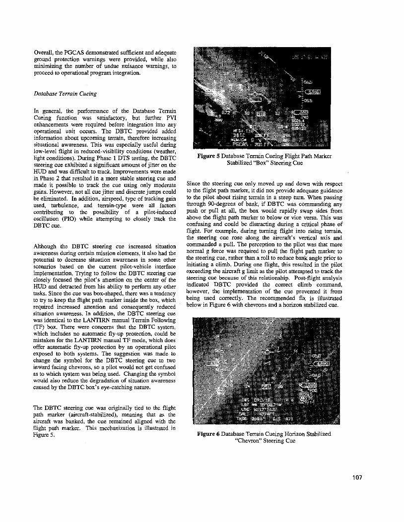
The DBTC steering cue was originally tied to the flight path marker (aircraft-stabilized), meaning that as the aircraft was banked, the cue remained aligned with the flight path marker. This mechanization is illustrated in Figure 5.
Figure 5 Database Terrain Cueing Flight Path Marker Stabilized “Box” Steering Cue
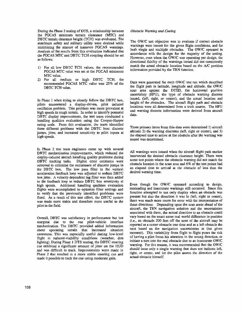
Since the steering cue only moved up and down with respect to the flight path marker, it did not provide adequate guidance to the pilot about rising terrain in a steep turn. When passing through 90-degrees of bank, if DBTC was commanding any push or pull at all, the box would rapidly swap sides from above the flight path marker to below or vice versa. This was confusing and could be distracting during a critical phase of flight. For example, during turning flight into rising terrain, the steering cue rose along the aircraft’s vertical axis and commanded a pull. The perception to the pilot was that more normal g force was required to pull the flight path marker to the steering cue, rather than a roll to reduce bank angle prior to initiating a climb. During one flight, this resulted in the pilot exceeding the aircraft g limit as the pilot attempted to track the steering cue because of this relationship. Post-flight analysis indicated DBTC provided the correct climb command, however, the implementation of the cue prevented it from being used correctly. The recommended fix is illustrated below in Figure 6 with chevrons and a horizon stabilized cue.
Figure 6 Database Terrain Cueing Horizon Stabilized “Chevron” Steering Cue
107
During the Phase 2 testing of DTS, a relationship between the PGCAS minimum terrain clearance (MTC) and DBTC terrain clearance height (TCH) was evaluated. The maximum safety and military utility were desired while minimizing the amount of nuisance PGCAS warnings. Analysis of the results from this evaluation indicated that the PGCAS MTC and DBTC TCH coupling should be set as follows:
1) For all low DBTC TCH values, the recommended PGCAS MTC value was set at the PGCAS minimum MTC value.
2) For all medium or high DBTC TCH, the recommended PGCAS MTC value was 25% of the DBTC TCH value.
In Phase 1 when trying to closely follow the DBTC box, pilots encountered a display-driven, pilot induced oscillation problem. This problem was more prevalent at high speeds in rough terrain. In order to identify potential DBTC display improvements, the test team conducted a handling qualities evaluation using the Cooper-Harper rating scale. From this evaluation, the team identified three different problems with the DBTC box: discrete jumps, jitter, and increased sensitivity to pilot inputs at high speeds.
In Phase 2 test team engineers came up with several DBTC mechanization improvements, which reduced the display-induced aircraft handling quality problems during DBTC tracking tasks. Digital error estimates were removed to minimize the occurrence of discrete jumps in the DBTC box. The low pass filter in the vemcal acceleration feedback loop was adjusted to reduce DBTC box jitter. A velocity dependent lag filter was then added to the feedback loop to reduce DBTC box sensitivity at high speeds. Additional handling qualities evaluation flights were accomplished to optimize filter settings and to verify that the previously identified problems were fixed. As a result of this test effort, the DBTC system was made more stable and therefore more useful to the pilot in the field.
Overall, DBTC was satisfactory in performance but but marginal due to the cue pilot-vehicle interface mechanization. The DBTC provided added information about upcoming terrain that increased situation awareness. This was especially useful during low-level flight in reduced-visibility conditions (weather, dim lighting). During Phase 1 DTS testing, the DBTC steering cue exhibited a significant amount of jitter on the HUD and was difficult to track. Improvements were made in Phase 2 that resulted in a more stable steering cue and made it possible to track the cue using moderate gain.
Obstacle Warning and Cueing
The OWIC test objective was to evaluate if correct obstacle warnings were issued for the given flight conditions, and for both single and multiple obstacles. The OWIC operated in accordance with the design for the majority of the testing. However, even when the OWIC was operating per design, the directional fidelity of the warnings issued did not consistently match the actual obstacle location based on the A/C position information provided by the TRN function.
Data were generated for each OWIC test run which described the flight path in latitude, longitude and altitude, the OWIC scan area against the DTED, the horizontal position uncertainty ("U), the type of obstacle warning discrete issued, (left, right, or center), and the actual location and height of the obstacles. The aircraft flight path and obstacle locations were all determined from a truth source. The HPU and warning discrete information were derived from aircraft data.
Three primary items from this data were determined 1) aircraft altitude 2) the warning discretes (left, right or center), and 3) the elapsed time to arrive at the obstacle after the warning was issued was determined.
All warnings were issued when the aireraft flight path marker intersected the desired obstacle clearance height. There were some test points where the obstacle warning did not match the obstacle location in the scan area and 6% of the test points had an elapsed time to arrival at the obstacle of less than the desired waming time.
Even though the OWIC operated according to design, misleading and inaccurate warnings still occurred. Since this function attempted to not only display when an obstacle was present but also the direction it was in (left, right or center), there was much more room for error with the interpretation of these directions. Depending upon the scan areas ahead of the aircraft, the TRN navigation solution and the uncertainties associated with them, the actual direction to an obstacle could vary based on the exact same real world difference in position (i.e., an obstacle 200 feet off the nose of the aircraft may be reported as a center obstacle one time and as a left obstacle the next based on the navigation uncertainties at that given moment). This variability from flight to flight poses the risk of having a pilot focus his attention in the wrong direction, or initiate a turn into the real obstacle due to an inaccurate OWlC warning. For this reason, it was recommended that the OWIC should issue only a single warning that does not indicate left, right, or center, and let the pilot assess the direction of the actual obstacle himself.
108
Passive Ranging of this, HRK was recommended over LSK based on its usability to the pilot.
The overall objective of the Passive Ranging (PR) testing was to evaluate the performance of the two PR Modes, Line of Sight Known (LSK) and Horizontal Range Known (HRK), while using different weapon delivery techniques over various terrain types. PR provided an alternative to active sensors, which might not be available or tactically desired.
The data indicated that within HRK and LSK, there were no significant differences in stability performance as a function of the different F-16 altitude calibration modes or with or without GPS inputs via the master navigation filter. Also the target elevation error performance showed no significant difference between LSK and HRK. However, the HUD display indicated that HRK targeting symbology was much more stable than LSK, therefore it was recommended for use with all of the F-16 air-to-ground weapon delivery modes over LSK.
HRK and LSK performance over varying levels of terrain roughness (level, moderate, and rough), varying flight dynamic conditions (dive angle and airspeed), and using different weapon delivery modes (Continuously Computed Impact Point (CCIP), Continuously Computed Release Point (CCRP), and Dive Toss (DTOS)) were evaluated using the same stability and target elevation error techniques. The stability and target elevation error performance for both the HRK and LSK ranging sources as a function of terrain roughness, dive angle, airspeed and delivery mode were also evaluated. The target elevation error performance indicated that within HRK and LSK, level terrain was preferred over both moderate and rough, level deliveries were preferred over dive deliveries, there was no correlation between target elevation error and airspeed, and CCRP was preferred over CCIP. Because no actual weapon deliveries using DTOS were flown with HRK, no conclusive results regarding DTOS and Passive Ranging could be made at this time.
The stability performance indicated that within HRK and LSK there were no significant differences in stability performance as a function of terrain roughness, dive angle, and airspeed or delivery mode. When comparing HRK and LSK performance, the data indicated that the target elevation error performance showed no significant difference between LSK and HRK. However, as was the case in the previous example, the stability analysis again indicated that HRK was more stable then LSK. Because
6. SUMMARY AND LESSONS LEARNED
Overall the system provides increased situational awareness for the pilot with added mission safety producing a more effective weapon in combat. Although there were areas warranting improvement, the system was deemed effective and ready for integration into F-16 operational aircraft. The recommendations from this development program should be implemented before DTS is deployed to the field significantly increasing its combat utility.
The lessons the test team learned (or re-learned) throughout the conduct of the program were as follows:
1) The value of well-equipped and well-rehearsed control room personnel not only ensured complete mission safety but also increased test program efficiency. This was particularly evident in PGCAS testing, as there were numerous parameters with tight tolerances for each test point. Control room personnel were able to review aircraft parameters immediately without having to wait for aircraft data reduction. This enahled real-time feedback to the pilot for test points that required re- attempts due to being off of parameters.
2 ) As with any “fly-develop-fly” program, an accurate tool for tracking which software version was flown on which mission became essential. This program had numerous software updates across the five DTS functions and the database used to track OFP configurations became indispensable for configuration control.
3) There were a few flights where DTS performance was very poor due to TRN being completely lost and staying that way. The first reaction was to blame DTS and request the contractor fix the problem. Further analysis showed that DTS was working correctly, but the information it was provided from other aircraft systems were in error. Examples such as the GPS runoff and radar altimeter lock-ups caused extremely poor DTS performance. This highlighted the vulnerability of the system under test in a systems integration effort.
4) PGCAS required a significant number of unusual attitude test points with numerous critical parameters for the pilot to hold. Early pilot and test team training for these types of maneuvers (including simulation training), flight test techniques, test point set-up conitions, and contzol room procedures made for more effective test sorties during the program. Without this up-front familiarization, the test program would have gone much slower and thus incurred increased cost.
109
7. ACKNOWLEDGMENTS
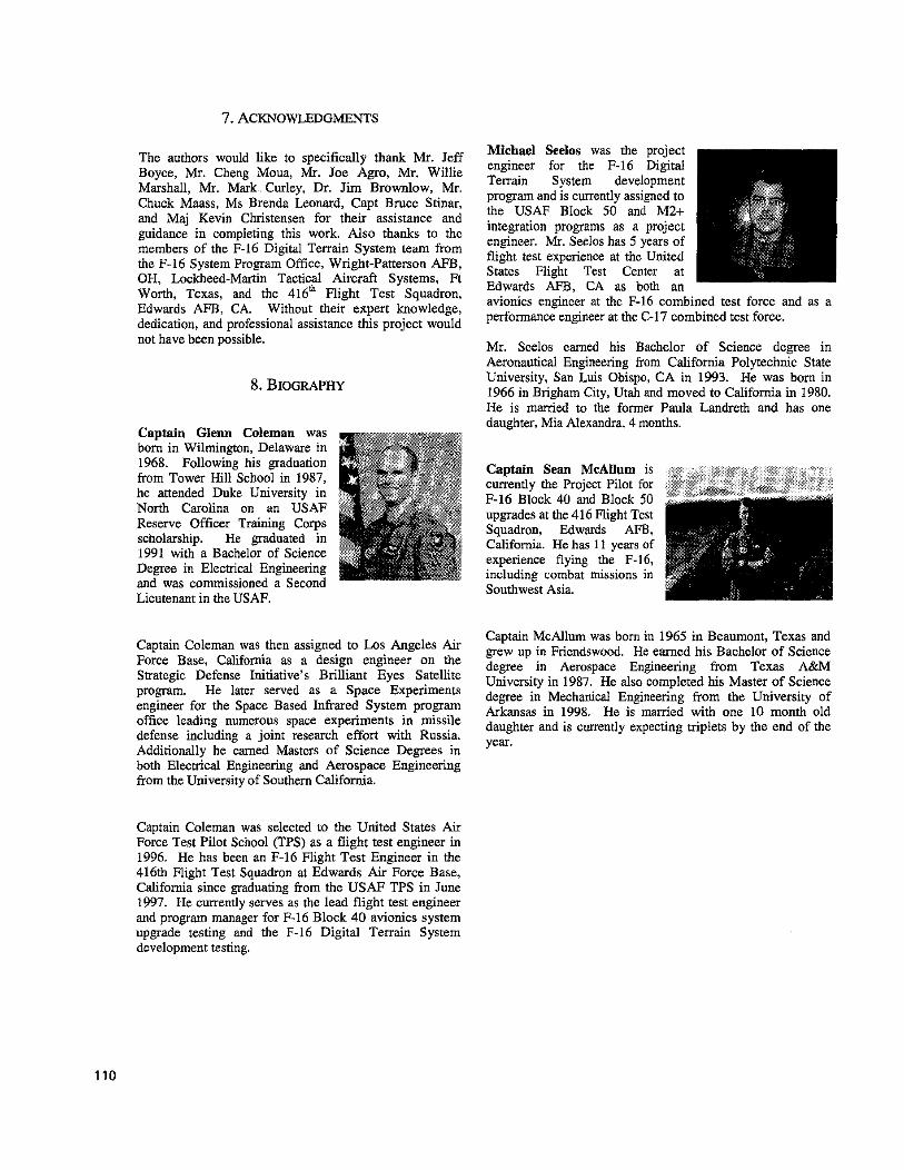
Michael Seelos was the project The authors would like to specifically thank Mr. Jeff engineer for the F-16 Digital Boyce, Mr. Cheng Moua, Mr. Joe Agro, Mr. Willie Terrain System development Marshall, Mr. Mark Curley, Dr. Jim Brownlow, Mr. program and is currently assigned Chuck Maass, Ms Brenda Leonard, Capt Bruce Stinar, the USAF Block 5o and M2+ and Maj Kevin Christensen for their assistance and integration programs as a project guidance in completing this work. Also thanks to the engineer. Mr. Seelos has 5 years of members of the F-16 Digital Terrain System team from flight test experience at the United the F-16 System Program Office, Wright-Patterson AFB, States Flight Center at OH, Lockheed-Martin Tactical Aircraft Systems, Ft Edwards AFB, CA as both an
avionics engineer at the F-16 combined test force and as a Edwards AFB’ CA’ Without their howledge’ performance engineer at the C-17 combined test force. dedication, and professional assistance this project would
Texas’ and the 416’b might Test
not have been possible.
8. BIOGRAPHY
Mr. Seelos earned his Bachelor of Science degree in Aeronautical Engineering from California Polytechnic State University, San Luis Obispo, CA in 1993. He was horn in 1966 in Brieham Citv, Utah and moved to California in 1980.
Captain Glenn Coleman was born in Wilmington, Delaware in 1968. Following his graduation from Tower Hill School in 1987, he attended Duke University in North Carolina on an USAF Reserve Officer Training Corps scholarship. He graduated in 1991 with a Bachelor of Science Degree in Electrical Engineering and was commissioned a Second Lieutenant in the WAF.
He is rnanied to &e former Paula Landreth and has one daughter, Mia Alexandra, 4 months.
Captain Sean MeAUum is currently the Project Pilot for F-16 Block 40 and Block 50 upgrades at the 416 Flight Test Squadron, Edwards AFB, California. He has 11 years of experience flying the F-16, including combat missions in Southwest Asia.
Captain McAllum was born in 1965 in Beaumont, Texas and grew up in Friendswood. He earned his Bachelor of Science degree in Aerospace Engineering from Texas A&M University in 1987, He also completed his Master of Science
Captain ‘Oleman was then assigned to Los Air Force Base, California as a design engineer on the Strategic Defense Initiative’s Brilliant Eyes Satellite program. He later served as a Space Experiments engineer for the Space Based Infrared System program degree in Mechanical Engineering from the university of
Arkansas in 1998. H~ is m-ed with one month old office leading space experiments in missile daughter and is currently expecting triplets by the end of the defense including a joint research effort with Russia. Additionally he earned Masters of Science Degrees in both Elecmcal Engineering and Aerospace Engineering from the University of Southern California.
year,
Captain Coleman was selected to the United States Air Force Test Pilot School (TPS) as a flight test engineer in 1996. He has been an F-16 Flight Test Engineer in the 416th Flight Test Squadron at Edwards Air Force Base, California since graduating from the USAF TPS in June 1997. He currently serves as the lead flight test engineer and program manager for F-16 Block 40 avionics system upgrade testing and the F-16 Digital Terrain System development testing.
110