Robust Estimation of Camera Motion Using Optical Flow Models
Upload
khangminh22Category
view
2download
0
Development of Robust Control Schemes
with New Estimation Algorithms for Shunt
Active Power Filter
Rakhee Panigrahi
Department of Electrical Engineering
National Institute of Technology Rourkela
2015

Development of Robust Control Schemes
with New Estimation Algorithms for Shunt
Active Power Filter
Thesis submitted in partial fulfillment
of the requirement for the degree of
Doctor of Philosophy in
Electrical Engineering by
Rakhee Panigrahi
(Roll No:510EE111)
Under the Guidance of
Prof. Bidyadhar Subudhi
Prof. Prafulla Chandra Panda
Department of Electrical Engineering
National Institute of Technology Rourkela
2015

Department of Electrical Engineering
National Institute of Technology Rourkela
C E R T I F I C A T E
This is to certify that the thesis entitled “Development of Robust Control
Schemes with New Estimation Algorithms for Shunt Active Power
Filter,” submitted by Rakhee Panigrahi to the National Institute of
Technology, Rourkela for the award of Doctor of Philosophy in Electrical
Engineering, is a record of bonafide research work carried out by her in the
Department of Electrical Engineering, under our supervision. We believe that this
thesis fulfills part of the requirements for the award of degree of Doctor of
Philosophy. The results embodied in the thesis have not been submitted for the
award of any other degree elsewhere.
Professor Prafulla Chandra Panda Department of Electrical Engineering,
Ex-Prof., National Institute of Technology,
Rourkela
Professor Bidyadhar Subudhi Department of Electrical Engineering,
National Institute of Technology,
Rourkela

Dedicated To
My Family Members

Acknowledgement
At the outset I express my sincere and heartfelt gratitude to my supervisors, Prof. B.
Subudhi and Prof. P. C. Panda, who have acted constantly as my philosopher and guide in
this Herculean job of thesis preparation and compilation. But for their spontaneous help
and co-operation this thesis could not have seen the light of the day.
I am grateful to Director, Prof. S. K. Sarangi and Prof. A. K. Panda, Head of Electrical
Engineering Department, NIT, Rourkela, for their kind support and concern regarding my
academic requirements.
I would also like to thank the Doctoral Scrutiny Committee members, Prof. D. Patra,
Prof. K.B. Mohanty, Prof. S. K. Patra and Prof. D. P. Mohapatra, for their helpful and
stimulating comments and suggestions in the final stages of this thesis.
I thank all my friends for their unstinted help and co-operation.
I must acknowledge the academic infrastructure of NIT, Rourkela for offering me a
soothing and active environment for pursuing my research freely and independently.
Last but not the least, I would like to record my warmest feelings of thanks to all my
family members and particularly to my husband and my daughter ‗Ritwika‘ who have
endured a lot by tolerating my negligence of them during my research.
Rakhee Panigrahi
Abstract
The widespread use of power electronics in industrial, commercial and even residential
electrical equipments causes deterioration of the quality of the electric power supply with
distortion of the supply voltage. This has led to the development of more stringent
requirements regarding harmonic current generation, as are found in standards such as
IEEE-519. Power Quality is generally meant to measure of an ideal power supply system.
Shunt active power filter (SAPF) is a viable solution for Power Quality enhancement, in
order to comply with the standard recommendations. The dynamic performance of SAPF
is mainly dependent on how quickly and how accurately the harmonic components are
extracted from the load current. Therefore, a fast and accurate estimation algorithm for
the detection of reference current signal along with an effective current control technique
is needed in order for a SAPF to perform the harmonic elimination successfully. Several
control strategies of SAPF have been proposed and implemented. But, still there is a lot
of scope on designing new estimation algorithms to achieve fast and accurate generation
of reference current signal in SAPF. Further, there is a need of development of efficient
robust control algorithms that can be robust in face parametric uncertainties in the power
system yielding improvement in power quality more effectively in terms of tracking error
reduction and efficient current harmonics mitigation.
The work described in the thesis involves development of a number of new current
control techniques along with new reference current generation schemes in SAPF. Two
current control techniques namely a hysteresis current control (HCC) and sliding mode
control (SMC) implemented with a new reference current generation scheme are
proposed. This reference generation approach involves a Proportional Integral (PI)
controller loop and exploits the estimation of the in phase fundamental components of
distorted point of common coupling (PCC) voltages by using Kalman Filter (KF)
algorithm. The KF-HCC based SAPF is found to be very simple in realization and
performs well even under grid perturbations. But the slow convergence rate of KF leads
towards an ineffective reference generation and hence harmonics cancellation is not
perfect. Therefore, a SMC based SAPF is implemented with a faster reference scheme
based on the proposed Robust Extended Complex Kalman Filter (RECKF) algorithm and
the efficacy of this RECKF-SMC is compared with other variants of Kalman Filter such
as KF, Extended Kalman Filter (EKF) and Extended Complex Kalman Filter (ECKF)
ii
employing simulations as well as real-time simulations using an Opal-RT Real-Time
digital Simulator. The RECKF-SMC based SAPF is found to be more effective as
compared to the KF-HCC, KF-SMC, EKF-SMC and ECKF-SMC.
Subsequently, predictive control techniques namely Dead Beat Control (DBC) and
Model Predictive Control (MPC) are proposed in SAPF along with an improved reference
current generation scheme based on the proposed RECKF. This reference scheme is
devoid of PI controller loop and can self-regulate the dc-link voltage. Both RECKF-DBC
and RECKF-MPC approaches use a model of the SAPF system to predict its future
behavior and select the most appropriate control action based on an optimality criterion.
However, RECKF-DBC is more sensitive to load uncertainties. Also, a better
compensation performance of RECKF-MPC is observed from the simulation as well as
real-time simulation results. Moreover, to study the efficacy of this RECKF-MPC over
PI-MPC, a comparative assessment has been performed using both steady state as well as
transient state conditions. From the simulation and real-time simulation results, it is
observed that the proposed RECKF-MPC outperforms PI-MPC. The thesis also proposed
an optimal Linear Quadratic Regulator (LQR) with an advanced reference current
generation strategy based on RECKF. This RECKF-LQR based SAPF has better tracking
and disturbance rejection capability and hence RECKF-LQR is found to be more efficient
as compared to RECKF-SMC, RECKF-DBC and RECKF-MPC approaches.
Subsequently, two robust control approaches namely Linear Quadratic Gaussian
(LQG) servo control and H∞ control are proposed in SAPF with highly improved
reference generation schemes based on RECKF. These control strategies are designed
with the purpose of achieving stability, high disturbance rejection and high level of
harmonics cancellation. From simulation results, they are not only found to be robust
against different load parameters, but also satisfactory THD results have been achieved in
SAPF. A prototype experimental set up has been developed in the Laboratory with a
dSPACE-1104 computing platform to verify their robustness. From both the simulation
and experimentation, it is observed that the proposed RECKF-H∞ control approach to
design a SAPF is found to be more robust as compared to the RECKF-LQG servo control
approach in face parametric uncertainties due to load perturbations yielding improvement
in power quality in terms of tracking error reduction and efficient current harmonics
mitigation. Further, there is no involvement of any voltage sensor in this realization of
RECKF-H∞ based SAPF resulting a more reliable and inexpensive SAPF system.

iii
Therefore, superiority of proposed RECKF-H∞ is proved amongst all the proposed control
strategies of SAPF.

Contents
Contents
List of Abbreviations ix
List of Figures xi
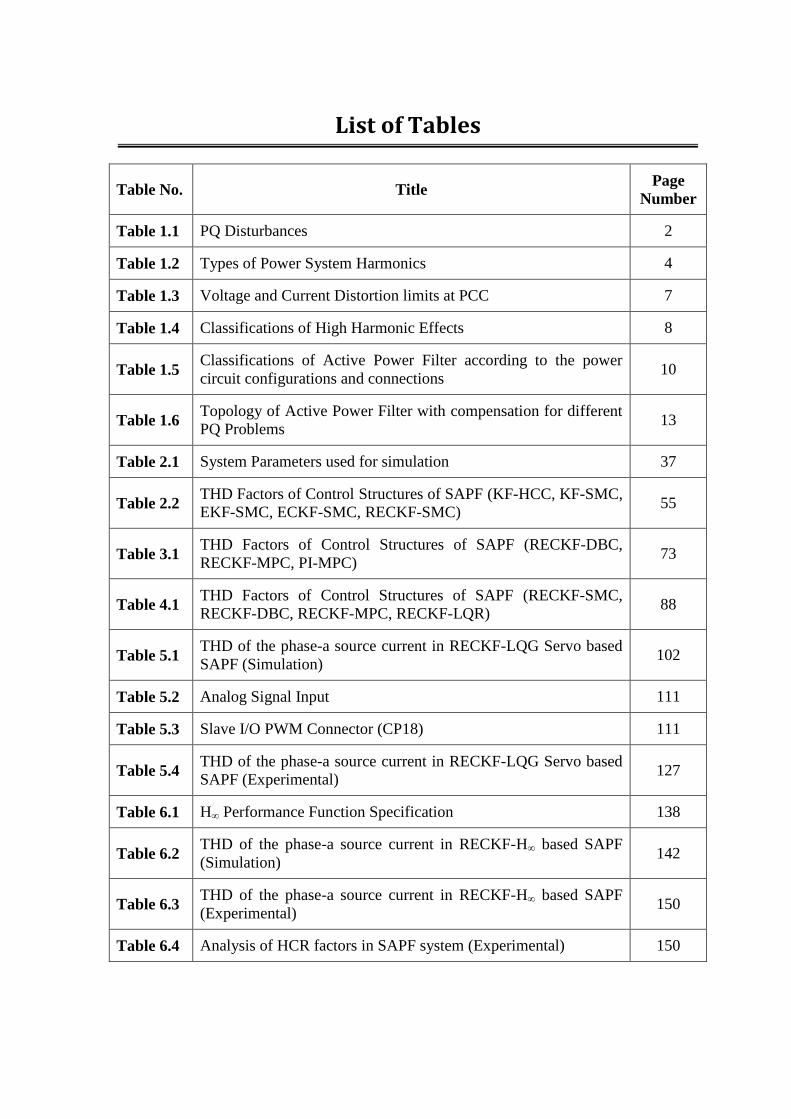
List of Tables xv
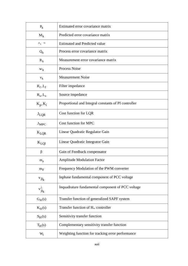
List of Symbols xvi
1 Introduction 1
1.1 Background 1
1.1.1 Power Quality 1
1.1.2 Sources of Harmonics 3
1.1.3 Classification of Active Power Filters 9
1.2 Literature Review on Shunt Active Power Filter 14
1.2.1 Remarks from Literature Review 22
1.3 Motivation of the Thesis 23
1.4 Objective of the Thesis 24
1.5 Thesis Organization 25
2 HCC and SMC with a New Reference Current Generation Strategy in SAPF 29
2.1 Introduction 29
2.2 Chapter Objectives 30
2.3 Proposed KF-HCC based SAPF 30
2.3.1 Description of Proposed KF-HCC based SAPF System 30
2.3.2 Proposed Reference Current Generation 32
2.3.3 Hysteresis current control (HCC) 34
2.3.4 Design of Power circuit of SAPF 35
2.3.5 Results and Discussions 37
2.3.5.1 Simulation Results 38
vi
2.3.5.2 Real-Time Simulation Results 38
2.3.5.3 Remarks on KF-HCC based SAPF 42
2.4 Proposed RECKF-SMC based SAPF 44
2.4.1 Description of Proposed RECKF-SMC based SAPF System 44
2.4.2 Proposed Reference Current Generation 45
2.4.3 Sliding Mode Control (SMC) 48
2.4.4 Results and Discussions 50
2.4.4.1 Simulation Results 50
2.4.4.2 Real-Time Simulation Results 53
2.4.4.3 Remarks on RECKF-SMC based SAPF 53
2.5 Chapter Summary 56
3 RECKF and Model Predictive based SAPF 57
3.1 Introduction 57
3.2 Chapter Objectives 59
3.3 Proposed RECKF-DBC based SAPF 59
3.3.1 Description of Proposed RECKF-DBC based SAPF System 59
3.3.2 Proposed Reference Current Generation 61
3.3.3 Dead Beat Control (DBC) 61
3.3.4 Results and Discussions 62
3.3.4.1 Simulation Results 62
3.3.4.2 Real-Time Simulation Results 63
3.3.4.3 Remarks on RECKF-DBC based SAPF 65
3.4 Proposed RECKF-MPC based SAPF 65
3.4.1 Description of Proposed RECKF-MPC based SAPF System 65
3.4.2 Model Predictive Control (MPC) 66
3.4.3 Results and Discussions 68
vii
3.4.3.1 Simulation Results 68
3.4.3.2 Real-Time Simulation Results 71
3.4.3.3 Remarks on RECKF-MPC based SAPF 73
3.5 Chapter Summary 73
4 RECKF and LQR based SAPF 75
4.1 Introduction 75
4.2 Chapter Objectives 76
4.3 Proposed RECKF-LQR based SAPF 77
4.3.1 Description of Proposed RECKF-LQR based SAPF System 77
4.3.2 Development of SAPF 77
4.3.3 Linear Quadratic Regulator (LQR) 81
4.3.4 Estimation of PCC State Variables 83
4.3.5 Generation of Reference Current 84
4.3.6 Results and Discussions 84
4.3.6.1 Simulation Results 84
4.3.6.2 Real-Time Simulation Results 85
4.4 Chapter Summary 88
5 RECFK and LQG Servo based SAPF 89
5.1 Introduction 89
5.2 Chapter Objectives 91
5.3 Proposed RECKF-LQG Servo based SAPF 91
5.3.1 Description of Proposed RECKF-LQG Servo based SAPF System 91
5.3.2 Proposed Reference Current Generation 93
5.3.3 Proposed LQG Servo Current Controller 94
5.4 Simulation Results and Discussions 98
5.5 Experimental Implementation 104
viii
5.6 Experimental Results and Discussions 121
5.7 Chapter Summary 127
6 RECFK and H∞ Control based SAPF 129
6.1 Introduction 129
6.2 Chapter Objectives 130
6.3 Proposed RECKF-H∞ based SAPF 130
6.4 Design of the H∞ Controller 131
6.4.1 Weighting function selection for Tracking error performance 133
6.4.2 Weighting function selection for Control effort 134
6.4.3 Weighting function selection for Robust performance 136
6.5 Proposed Reference Current Generation 136
6.6 Simulation Results and Discussions 138
6.7 Experimental Results and Discussions 143
6.8 Chapter Summary 151
7 Conclusion and Suggestions For Future Work 153
7.1 Overall Conclusion 153
7.2 Contributions of the Thesis 156
7.3 Suggestions for Future Work 158
References 161
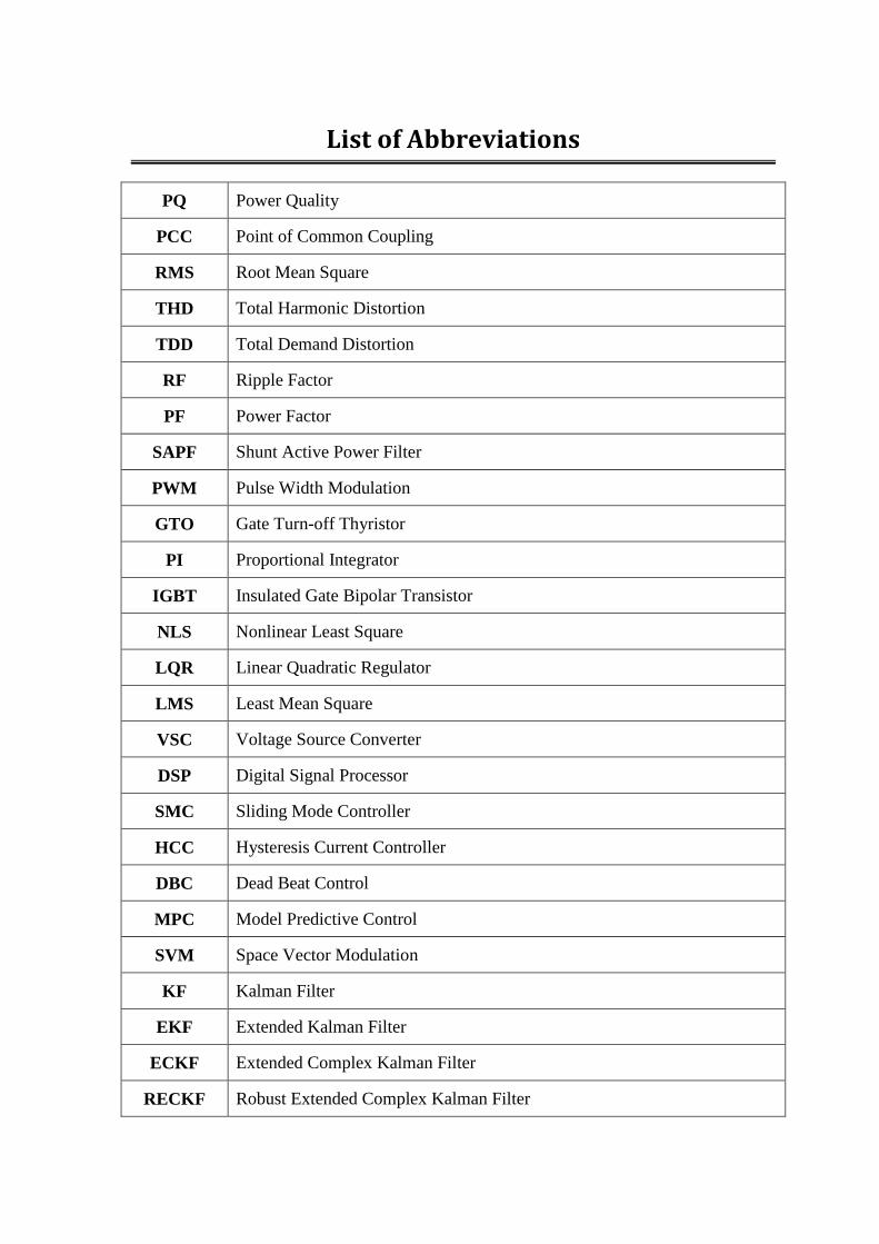
List of Abbreviations
PQ Power Quality
PCC Point of Common Coupling
RMS Root Mean Square
THD Total Harmonic Distortion
TDD Total Demand Distortion
RF Ripple Factor
PF Power Factor
SAPF Shunt Active Power Filter
PWM Pulse Width Modulation
GTO Gate Turn-off Thyristor
PI Proportional Integrator
IGBT Insulated Gate Bipolar Transistor
NLS Nonlinear Least Square
LQR Linear Quadratic Regulator
LMS Least Mean Square
VSC Voltage Source Converter
DSP Digital Signal Processor
SMC Sliding Mode Controller
HCC Hysteresis Current Controller
DBC Dead Beat Control
MPC Model Predictive Control
SVM Space Vector Modulation
KF Kalman Filter
EKF Extended Kalman Filter
ECKF Extended Complex Kalman Filter
RECKF Robust Extended Complex Kalman Filter
x
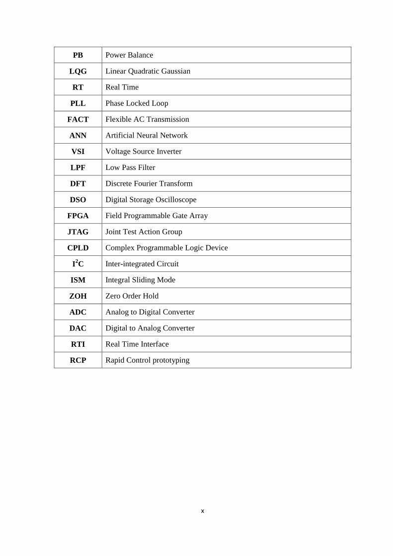
PB Power Balance
LQG Linear Quadratic Gaussian
RT Real Time
PLL Phase Locked Loop
FACT Flexible AC Transmission
ANN Artificial Neural Network
VSI Voltage Source Inverter
LPF Low Pass Filter
DFT Discrete Fourier Transform
DSO Digital Storage Oscilloscope
FPGA Field Programmable Gate Array
JTAG Joint Test Action Group
CPLD Complex Programmable Logic Device
I2C Inter-integrated Circuit
ISM Integral Sliding Mode
ZOH Zero Order Hold
ADC Analog to Digital Converter
DAC Digital to Analog Converter
RTI Real Time Interface
RCP Rapid Control prototyping
List of Figures
Figure No. Title Page
Number
Figure 1.1 Harmonics distortion at PCC 3
Figure 1.2 Sources of Harmonics 4
Figure 1.3 Generalized block diagram for active power filters 9
Figure 1.4 Principle of Shunt Active Filter 12
CHAPTER - 2
Figure 2.1 Proposed KF-HCC based SAPF 31
Figure 2.2 HCC Method, (a) Block Diagram of HCC, (b) Switching Pattern
of HCC
34
Figure 2.3 Vector Diagram representing reactive power flow 36
Figure 2.4 Response of KF-HCC based SAPF using MATLAB, (a) PCC
voltage with its in phase fundamental, (b) Capacitor voltage, (c)
Load current, (d) Compensating current, (e) Source current, (f)
THD of load current, (g) THD of source current
39
Figure 2.5 Opal-RT Platform, (a) Set-up for Opal-RT Lab, (b) OP5142 layout
and connectors
41
Figure 2.6 Response of KF-HCC based SAPF using Opal-RT, (a) Capacitor
voltage, (b) Load current, (c) Compensating current, (d) Source
current, (e) THD before and after compensation
42
Figure 2.7 Proposed RECKF-SMC based SAPF 44
Figure 2.8 Equivalent circuit for a single-phase of voltage source inverter 49
Figure 2.9 Response of SAPF using KF-SMC, EKF-SMC, ECKF-SMC and
RECKF-SMC based control structure in MATLAB, (a) PCC
voltage with its in phase fundamental, (b) Capacitor voltage, (c)
Compensating current, (d) Source current, (e) THD of source
current
52
Figure 2.10 Response of SAPF using KF-SMC, EKF-SMC, ECKF-SMC and
RECKF-SMC based control structure in Opal-RT, (a)
Compensating current, (b) Capacitor voltage, (c) Source current,
(d) THD before and after compensation
54
CHAPTER - 3
Figure 3.1 Proposed RECKF-DBC based SAPF, (a) Block Diagram of
Proposed RECKF- DBC based SAPF, (b) Schematic of VSI power
circuit
60
xii
Figure 3.2 DBC Method, (a) DBC with PWM block diagram, (b) Illustration
of DBC Operation
61
Figure 3.3 Response of RECKF-DBC based SAPF using MATLAB, (a)
Source voltage, (b) Compensating current, (c) Capacitor voltage,
(d) Source and Source reference current, (e) THD of source
current
63
Figure 3.4 Response of RECKF-DBC based SAPF using Opal-RT, (a)
Compensating current, (b) Capacitor voltage, (c) Source and
Source reference current, (d) Source voltage and source current
after compensation, (e) THD before and after compensation
64
Figure 3.5 Structure of MPC for SAPF 66
Figure 3.6 Voltage Space Vector Diagram 67
Figure 3.7 Steady State Response of RECKF-MPC based SAPF using
MATLAB, (a) Compensating current, (b) Capacitor voltage, (c)
Source and Source reference current, (e) THD of source current
69
Figure 3.8 Transient State Response of RECKF-MPC and PI-MPC based
SAPF using MATLAB, (a) Load current, (b) Compensating
current, (c) Capacitor voltage, (d) Source current, (e) THD of
source current in steady state, (f) THD of source current in
transient state
70
Figure 3.9 Transient State Response of RECKF-MPC and PI-MPC based
SAPF using Opal-RT, (a) Load current, (b) Capacitor voltage, (c)
Compensating current, (d) Source voltage and source current, (e)
THD of source current in steady and transient state
72
CHAPTER - 4
Figure 4.1 Proposed RECKF-LQR based SAPF, (a) Block Diagram of
Proposed RECKF- LQR based SAPF, (b) Proposed Reference
Current Generation
78
Figure 4.2 Structure of LQR for SAPF 82
Figure 4.3 Identification of in phase and in quadrature fundamental voltages
at PCC
83
Figure 4.4 Response of RECKF-LQR based SAPF using MATLAB, (a) In
phase and in quadrature fundamental components of PCC voltage,
(b) Capacitor voltage, (c) Reference and actual compensating
current, (d) Source current, (e) THD of source current
86
Figure 4.5 Response of RECKF-LQR based SAPF using Opal-RT, (a)
Reference and actual compensating current, (b) Capacitor voltage,
(c) Source voltage and source current after compensation, (d) THD
before and after compensation
87
CHAPTER - 5
xiii
Figure 5.1 Basic Structure of LQG Servo Controller 91
Figure 5.2 Proposed RECKF- LQG Servo based SAPF, (a) Block Diagram of
Proposed RECKF- LQG Servo based SAPF, (b) Proposed
Reference Current Generation
92
Figure 5.3 Proposed LQG Servo Current Controller Strategy 94
Figure 5.4 Response of RECKF-LQG Servo based SAPF in Case-1 using
MATLAB 100
Figure 5.5 Response of RECKF-LQG Servo based SAPF in Case-2 using
MATLAB
101
Figure 5.6 Compensation Effect of RECKF-LQG Servo based SAPF using
MATLAB,
(i) Case-1, (ii) Case-2, (a) Load current spectrum, (b) Source
current spectrum
102
Figure 5.7 Response of Tracking Error Signal 103
Figure 5.8 Control and Power Circuit of SAPF 104
Figure 5.9 Experimental Setup 105
Figure 5.10 DS1104 R&D Controller Board 108
Figure 5.11 Features of the DS1104 R&D Controller Board 108
Figure 5.12 CLP1104 Connector/LED Panel 111
Figure 5.13 Three-phase IGBT based inverter 112
Figure 5.14 Three-phase Auto-Transformer condition 113
Figure 5.15 Schematic Diagram of Voltage Sensor 114
Figure 5.16 Schematic Diagram of Current Sensor 114
Figure 5.17 Schematic Diagram of Signal conditioning Circuit 116
Figure 5.18 Nonlinear Load, (a) Three-phase diode bridge rectifier, (b)
Resistive Load, (c) Inductor 117
Figure 5.19 Filter Inductor 117
Figure 5.20 Blanking Circuit, (a) Schematic circuit diagram, (b) Monostable
multivibrator circuit connection diagram, (c) Timing diagram 119
Figure 5.21 Opto-Coupler Circuit 120
Figure 5.22 DC regulated power supply 121
Figure 5.23 Waveforms of three phase load currents in Case-1 122
Figure 5.24 Waveforms of three phase compensating currents in Case-1 123
Figure 5.25 Waveforms showing phase-a quantities in Case-1 123
Figure 5.26 Waveforms of three phase source currents in Case-1 124
xiv
Figure 5.27 Harmonic spectra of (a) phase-a load current, (b) phase-a source
current of proposed RECKF-LQG Servo based SAPF in Case-1 124
Figure 5.28 Waveforms of three phase load currents in Case-2 125
Figure 5.29 Waveforms showing phase-a quantities in Case-2 125
Figure 5.30 Waveforms of three phase source currents in Case-2 126
Figure 5.31 Harmonics spectra of (a) phase-a load current, (b) phase-a source
current of proposed RECKF-LQG Servo based SAPF in case-2 126
CHAPTER - 6
Figure 6.1 Proposed RECKF-H∞ based SAPF system 131
Figure 6.2 H∞ control configuration with weighting functions 132
Figure 6.3 Waveforms for (a) Performance weight 1/W1 and desired HS , (b)
Control weight 1/W2 and desired H HK S , and (c) Complementary
weight 1/W3 and desired HT
135
Figure 6.4 Bode plots of the original and reduced controllers 139
Figure 6.5 Response of RECKF-H∞ based SAPF in Case-1 using MATLAB 140
Figure 6.6 Response of RECKF-H∞ based SAPF in Case-2 using MATLAB 141
Figure 6.7 Compensation Effect of RECKF- H∞ based SAPF using
MATLAB,
(i) Case-1, (ii) Case-2, (a) Load current spectrum, (b) Source
current spectrum
142
Figure 6.8 Control and Power circuit of SAPF Model 143
Figure 6.9 Experimental test case 1: Source reference current waveforms 145
Figure 6.10 Experimental test case 1: Waveforms of compensation by SAPF 145
Figure 6.11 Experimental test case 1: Waveforms showing phase-a quantities 146
Figure 6.12 Experimental test case 1: three phase source current waveforms 146
Figure 6.13 Experimental test case 1: Harmonic spectra of (a) phase-a load
current, (b) phase-a source current
147
Figure 6.14 Experimental test case 2: Source reference current waveforms 147
Figure 6.15 Experimental test case 2: Waveforms of compensation by SAPF 148
Figure 6.16 Experimental test case 2: Waveforms showing phase-a quantities 148
Figure 6.17 Experimental test case 2: three phase source current waveforms 149
Figure 6.18 Experimental test case 2: Harmonic spectra of (a) phase-a load
current, (b) phase-a source current
149
List of Tables
Table No. Title Page
Number
Table 1.1 PQ Disturbances 2
Table 1.2 Types of Power System Harmonics 4
Table 1.3 Voltage and Current Distortion limits at PCC 7
Table 1.4 Classifications of High Harmonic Effects 8
Table 1.5 Classifications of Active Power Filter according to the power
circuit configurations and connections 10
Table 1.6 Topology of Active Power Filter with compensation for different
PQ Problems 13
Table 2.1 System Parameters used for simulation 37
Table 2.2 THD Factors of Control Structures of SAPF (KF-HCC, KF-SMC,
EKF-SMC, ECKF-SMC, RECKF-SMC) 55
Table 3.1 THD Factors of Control Structures of SAPF (RECKF-DBC,
RECKF-MPC, PI-MPC) 73
Table 4.1 THD Factors of Control Structures of SAPF (RECKF-SMC,
RECKF-DBC, RECKF-MPC, RECKF-LQR) 88
Table 5.1 THD of the phase-a source current in RECKF-LQG Servo based
SAPF (Simulation) 102
Table 5.2 Analog Signal Input 111
Table 5.3 Slave I/O PWM Connector (CP18) 111
Table 5.4 THD of the phase-a source current in RECKF-LQG Servo based
SAPF (Experimental) 127
Table 6.1 H∞ Performance Function Specification 138
Table 6.2 THD of the phase-a source current in RECKF-H∞ based SAPF
(Simulation) 142
Table 6.3 THD of the phase-a source current in RECKF-H∞ based SAPF
(Experimental) 150
Table 6.4 Analysis of HCR factors in SAPF system (Experimental) 150

xvi
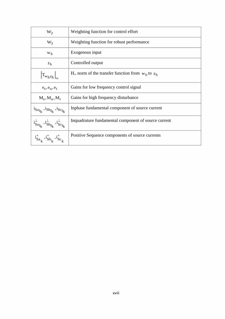
List of Symbols
*Sabc Sabci , i Source and source reference Current
*Fabc Fabci , i Compensating and reference Compensating Current
a b cv , v , v PCC voltages
fa fb fcv , v , v Inverter voltages
1 1 1a ,f ,
Fundamental amplitude, frequency and phase angle
a b cS ,S ,S
Switching states
ppi , i Real and imaginary part of the predicted source current
* *i , i Real and imaginary part of the future reference source current
S
Space vector of switching States
slidingS
Sliding surface
sv
Source voltage
*dcv
Reference DC capacitor voltage
equ
Equivalent switching function
sT
Sampling time
swf
Switching frequency
sf Sampling frequency
smi Peak value of source reference current
Labci
Load Current
Angular Frequency
k State transistion matrix
kH Observation matrix
kK Kalman gain
xvii
kP Estimated error covariance matrix
kM
Predicted error covariance matrix
, Estimated and Predicted value
kQ Process error covariance matrix
kR Measurement error covariance matrix
kw Process Noise
kv Measurement Noise
f fR ,L Filter impedance
s sR ,L Source impedance
p iK ,K Proportional and Integral constants of PI controller
LQRJ Cost function for LQR
MPCJ Cost function for MPC
LQRK Linear Quadratic Regulator Gain
LQIK
Linear Quadratic Integrator Gain
Gain of Feedback compensator
am
Amplitude Modulation Factor
Fm
Frequency Modulation of the PWM converter
j1kv Inphase fundamental component of PCC voltage
j1kv
Inquadrature fundamental component of PCC voltage
HG (s) Transfer function of generalized SAPF system
HK (s) Transfer function of H∞ controller
HS (s)
Sensitivity transfer function
HT (s)
Complementary sensitivity transfer function
1W Weighting function for tracking error performance
xviii
2W Weighting function for control effort
3W Weighting function for robust performance
hw
Exogenous input
hz
Controlled output
w zh hT
H∞ norm of the transfer function from hw to hz
s u te ,e ,e Gains for low frequency control signal
s u tM ,M ,M Gains for high frequency disturbance
Sa Sb Sc1 1 1k k ki , i , i Inphase fundamental component of source current
Sa Sb Sc1 1 1k k ki , i , i
Inquadrature fundamental component of source current
Sa Sb Sck k k
i , i , i
Positive Sequence components of source currents
CHAPTER 1
Introduction
1.1 Background
1.1.1 Power Quality
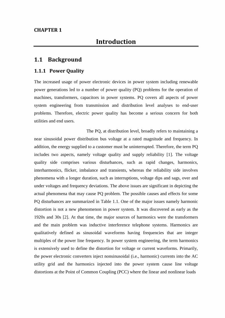
The increased usage of power electronic devices in power system including renewable
power generations led to a number of power quality (PQ) problems for the operation of
machines, transformers, capacitors in power systems. PQ covers all aspects of power
system engineering from transmission and distribution level analyses to end-user
problems. Therefore, electric power quality has become a serious concern for both
utilities and end users.
The PQ, at distribution level, broadly refers to maintaining a
near sinusoidal power distribution bus voltage at a rated magnitude and frequency. In
addition, the energy supplied to a customer must be uninterrupted. Therefore, the term PQ
includes two aspects, namely voltage quality and supply reliability [1]. The voltage
quality side comprises various disturbances, such as rapid changes, harmonics,
interharmonics, flicker, imbalance and transients, whereas the reliability side involves
phenomena with a longer duration, such as interruptions, voltage dips and sags, over and
under voltages and frequency deviations. The above issues are significant in depicting the
actual phenomena that may cause PQ problem. The possible causes and effects for some
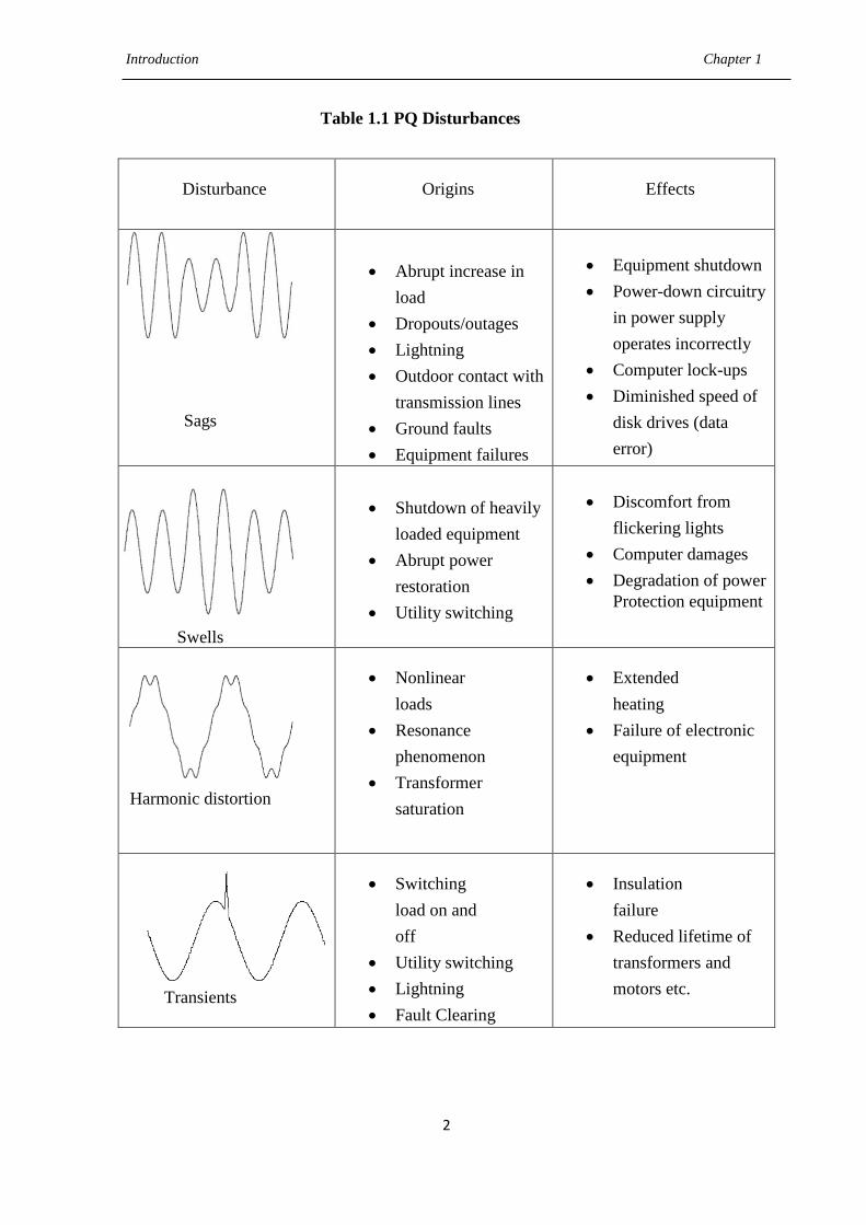
PQ disturbances are summarized in Table 1.1. One of the major issues namely harmonic
distortion is not a new phenomenon in power system. It was discovered as early as the
1920s and 30s [2]. At that time, the major sources of harmonics were the transformers
and the main problem was inductive interference telephone systems. Harmonics are
qualitatively defined as sinusoidal waveforms having frequencies that are integer
multiples of the power line frequency. In power system engineering, the term harmonics
is extensively used to define the distortion for voltage or current waveforms. Primarily,
the power electronic converters inject nonsinusoidal (i.e., harmonic) currents into the AC
utility grid and the harmonics injected into the power system cause line voltage
distortions at the Point of Common Coupling (PCC) where the linear and nonlinear loads
Introduction Chapter 1
2
Table 1.1 PQ Disturbances
Disturbance Origins Effects
Sags
Abrupt increase in
load
Dropouts/outages
Lightning
Outdoor contact with
transmission lines
Ground faults
Equipment failures
Equipment shutdown
Power-down circuitry
in power supply
operates incorrectly
Computer lock-ups
Diminished speed of
disk drives (data
error)
Swells
Shutdown of heavily
loaded equipment
Abrupt power
restoration
Utility switching
Discomfort from
flickering lights
Computer damages
Degradation of power
Protection equipment
Harmonic distortion
Nonlinear
loads
Resonance
phenomenon
Transformer
saturation
Extended
heating
Failure of electronic
equipment
Transients
Switching
load on and
off
Utility switching
Lightning
Fault Clearing
Insulation
failure
Reduced lifetime of
transformers and
motors etc.

Introduction Chapter 1
3
Figure 1.1: Harmonics distortion at PCC
are connected, as displayed in Fig. 1.1. As a consequence, harmonic distortion can have
detrimental influences on electrical distribution systems. Identifying the problems
associated with sources and impacts of harmonics as well as the methods to decrease the
harmonic will increase the overall efficiency of the distribution system.
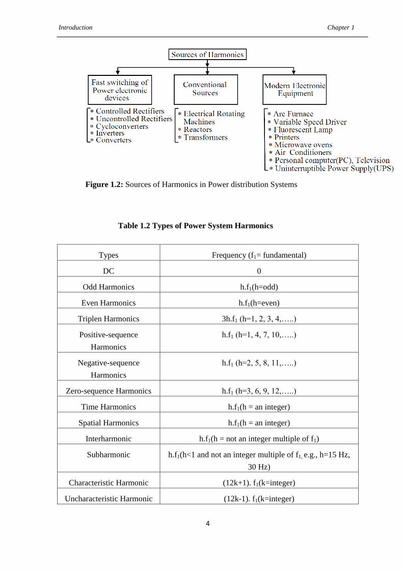
1.1.2 Sources of Harmonics
Fig. 1.2 shows the different sources of harmonics in power distribution system. The
different sources of harmonics [3] namely from three major areas are listed below.
Fast switching of power electronic devices
The conventional sources such as electrical rotating machines and Transformers
The modern electronic equipments
1.1.2.1 Types of Power System Harmonics
Different types of harmonics in power system are enlisted in Table 1.2.
1.1.2.2 Harmonics Measurement
Some definitions and formulations for harmonics measurement are described below:
Form factor (FF): It is a ratio between the Root Mean Square (RMS) value and the
average value of a periodic waveform and is defined as
Introduction Chapter 1
4
Figure 1.2: Sources of Harmonics in Power distribution Systems
Table 1.2 Types of Power System Harmonics
Types Frequency (f1= fundamental)
DC 0
Odd Harmonics h.f1(h=odd)
Even Harmonics h.f1(h=even)
Triplen Harmonics 3h.f1 (h=1, 2, 3, 4,…..)
Positive-sequence
Harmonics
h.f1 (h=1, 4, 7, 10,…..)
Negative-sequence
Harmonics
h.f1 (h=2, 5, 8, 11,…..)
Zero-sequence Harmonics h.f1 (h=3, 6, 9, 12,…..)
Time Harmonics h.f1(h = an integer)
Spatial Harmonics h.f1(h = an integer)
Interharmonic h.f1(h = not an integer multiple of f1)
Subharmonic h.f1(h<1 and not an integer multiple of f1, e.g., h=15 Hz,
30 Hz)
Characteristic Harmonic (12k+1). f1(k=integer)
Uncharacteristic Harmonic (12k-1). f1(k=integer)

Introduction Chapter 1
5
rms
avg
IFF
I (1.1)
where rmsI and avgI are the RMS value and average value respectively.
Ripple Factor (RF): It is a measure of ripple content of the waveform and is defined as
ac
dc
IRF
I (1.2)
where acI and dcI are the alternating current (ac) and direct current (dc) respectively and
acI is given by
2 2ac rms dcI I I
Total Harmonic Distortion (THD): It is a measure of effective value of the harmonic
components in a distorted waveform, which is defined as the RMS of the harmonics
expressed as a percentage of the fundamental component.
(h) 2
h 2
(1)
(I )
THDI
(1.3)
where (1)I and
(h)I are the fundamental and harmonic components of the waveform.
Total Demand Distortion (TDD): This is similar to THD except that the distortion is
expressed as a percentage of some rated or maximum value, rather than as a percentage of
the fundamental current.
(h) 2
h 2
rated
(I )
TDDI
(1.4)
where ratedI is the rated value of the current.
Displacement and True Power Factor (PF): Displacement power factor is the cosine of
the angle between the fundamental voltage and current waveforms. But the presence of
harmonics introduces additional phase shift between the voltage and the current. True

Introduction Chapter 1
6
power factor is calculated as the total active power used in a circuit (including harmonics)
and the total apparent power (including harmonics) supplied from the source.
PTrue PF
S (1.5)
P and Q are the total active power and total apparent power respectively, where
2 2S P Q and Q is the reactive power.
1.1.2.3 Standard of Harmonics
The foremost purposes for setting guidelines, recommendations and standards in power
systems with nonsinusoidal voltages or currents are to keep disturbances to user
equipment within permissible limits, to provide uniform terminology and test procedures
for power quality problems and to provide a common source on which a wide range of
engineering is referenced. There are many standards and related documents
[4][5][6][7][8] that deal with PQ issues. The mostly adopted standard is Institute of
Electrical and Electronics Engineering (IEEE) 519-1992 standard.
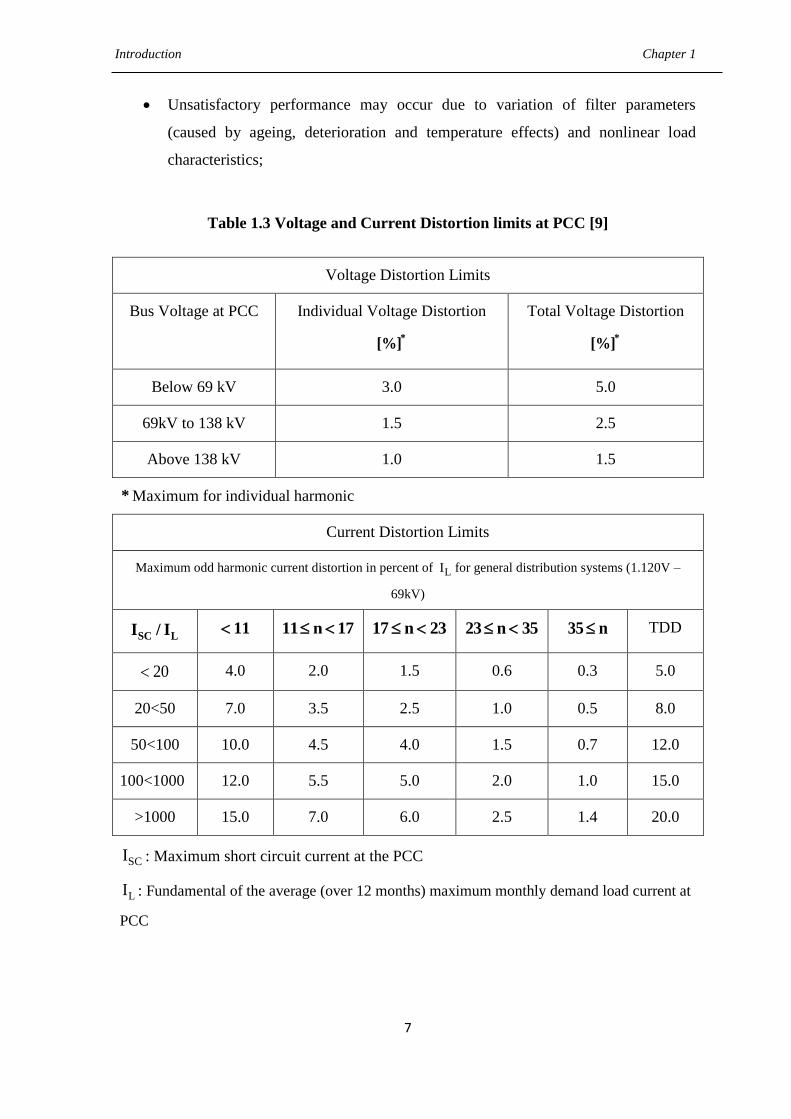
1.1.2.3.1 IEEE 519-1992
This standard sets limits for harmonic voltage and currents at the PCC as shown in Table
1.3. It places concern on large commercial and industrial consumers.
1.1.2.3.2 Harmonic Effects
Harmonics (voltage or current) negatively affect a power system in several fronts. The
classification of the effects of high harmonics [9][10][11] are summarized in Table 1.4.
1.1.2.3.3 Harmonics Reduction Techniques
The traditional techniques to eliminate the harmonic currents include: electrical
equipment over dimensioning, three-phase transformer special connections to eliminate
the third and its proportional harmonics and the connection of passive filters (PFs), but
they have the following disadvantages:
Fixed compensation or harmonic mitigation; large size and possible resonance
with the supply system impedance at fundamental or other harmonic frequencies;
Compensation is limited to a few orders of harmonics;
Introduction Chapter 1
7
Unsatisfactory performance may occur due to variation of filter parameters
(caused by ageing, deterioration and temperature effects) and nonlinear load
characteristics;
Table 1.3 Voltage and Current Distortion limits at PCC [9]
Voltage Distortion Limits
Bus Voltage at PCC Individual Voltage Distortion
*[%]
Total Voltage Distortion
*[%]
Below 69 kV 3.0 5.0
69kV to 138 kV 1.5 2.5
Above 138 kV 1.0 1.5
* Maximum for individual harmonic
Current Distortion Limits
Maximum odd harmonic current distortion in percent of LI for general distribution systems (1.120V –
69kV)
SC LI / I 11 11 n 17 17 n 23 23 n 35 35 n TDD
20 4.0 2.0 1.5 0.6 0.3 5.0
20<50 7.0 3.5 2.5 1.0 0.5 8.0
50<100 10.0 4.5 4.0 1.5 0.7 12.0
100<1000 12.0 5.5 5.0 2.0 1.0 15.0
>1000 15.0 7.0 6.0 2.5 1.4 20.0
SCI : Maximum short circuit current at the PCC
LI : Fundamental of the average (over 12 months) maximum monthly demand load current at
PCC

Introduction Chapter 1
8
Table 1.4 Classifications of High Harmonic Effects
Classification
Criterion
Type of Effect Comment
Duration
Very Short
Term Effects
These effects are linked with a failure, malfunction or
defective state of apparatus exposed to high harmonics,
such as control and instrumentation equipment,
electronic equipment and IT equipment etc.
Long Term
Effects
Primarily of thermal nature. The thermal effect
(producing accelerated ageing of insulation or rarely
damage to equipment) is a function of many variables,
of which the most significant are the values and order
of harmonics.
Physical
Nature of the
distorted
quantity
Current
Effects
Related to the instantaneous or time-averaged current
value (overheating of electric machines, capacitor
fuses blowing, increased losses in transmission lines,
unwanted operation of relays etc.). Harmonics in
power supply systems are the major cause of
temperature rise in the equipment and shortening of in-
service time. This effect reaches extremely high values
under conditions of resonant amplification of harmonic
currents.
Voltage
Effects
Associated with the peak, average or RMS value of
distorted voltage
The technical evolution in rated power and switching speed of electronic devices,
allows now-a-days the application of the active power filters (APFs) [12][13][14] and
they have many other advantages over traditional methods for harmonic compensation
such as
Adaptation with respect to the variation of the loads;
Possibility of selective harmonics compensation;
Limitations in the compensation power;
Possibility of reactive power compensation;
Introduction Chapter 1
9
1.1.3 Classification of Active Power Filters
A large number of APF circuit configurations have been proposed in the literature
[15][16] to facilitate the compensation of harmonics in power systems. To classify these,
it is desirable first to characterize the whole process of active filtering into its main
building blocks.
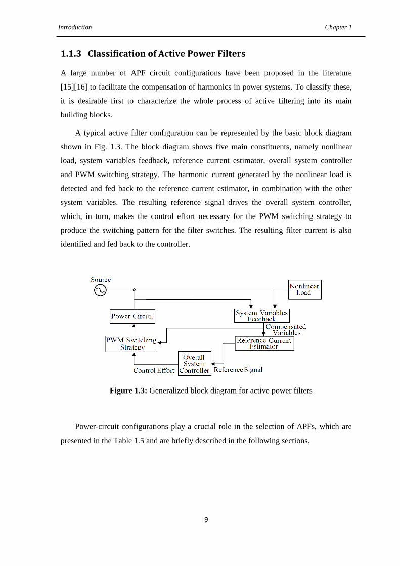
A typical active filter configuration can be represented by the basic block diagram
shown in Fig. 1.3. The block diagram shows five main constituents, namely nonlinear
load, system variables feedback, reference current estimator, overall system controller
and PWM switching strategy. The harmonic current generated by the nonlinear load is
detected and fed back to the reference current estimator, in combination with the other
system variables. The resulting reference signal drives the overall system controller,
which, in turn, makes the control effort necessary for the PWM switching strategy to
produce the switching pattern for the filter switches. The resulting filter current is also
identified and fed back to the controller.
Figure 1.3: Generalized block diagram for active power filters
Power-circuit configurations play a crucial role in the selection of APFs, which are
presented in the Table 1.5 and are briefly described in the following sections.
Introduction Chapter 1
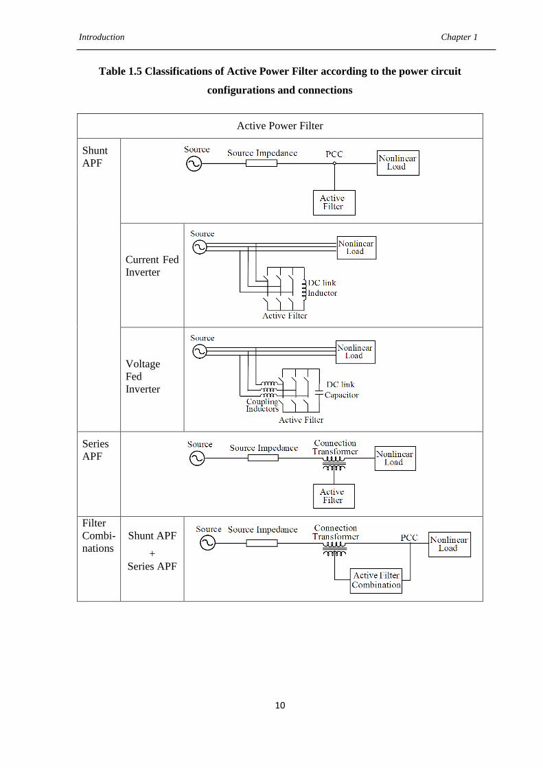
10
Table 1.5 Classifications of Active Power Filter according to the power circuit
configurations and connections
Active Power Filter
Shunt
APF
Current Fed
Inverter
Voltage
Fed
Inverter
Series
APF
Filter
Combi-
nations
Shunt APF
+
Series APF
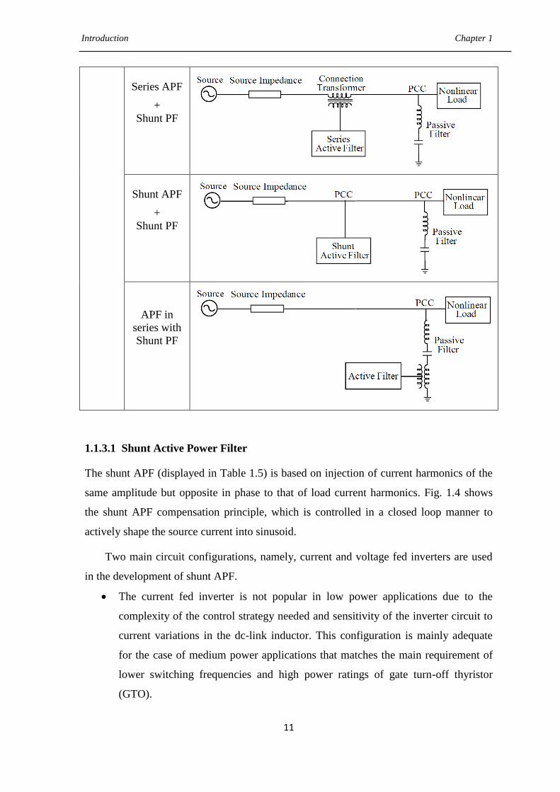
Introduction Chapter 1
11
Series APF
+
Shunt PF
Shunt APF
+
Shunt PF
APF in
series with
Shunt PF
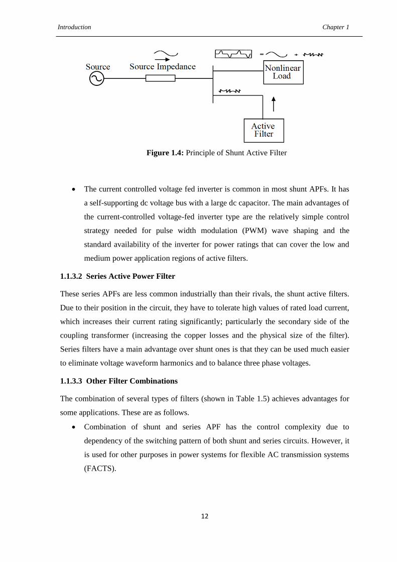
1.1.3.1 Shunt Active Power Filter
The shunt APF (displayed in Table 1.5) is based on injection of current harmonics of the
same amplitude but opposite in phase to that of load current harmonics. Fig. 1.4 shows
the shunt APF compensation principle, which is controlled in a closed loop manner to
actively shape the source current into sinusoid.
Two main circuit configurations, namely, current and voltage fed inverters are used
in the development of shunt APF.
The current fed inverter is not popular in low power applications due to the
complexity of the control strategy needed and sensitivity of the inverter circuit to
current variations in the dc-link inductor. This configuration is mainly adequate
for the case of medium power applications that matches the main requirement of
lower switching frequencies and high power ratings of gate turn-off thyristor
(GTO).
Introduction Chapter 1
12
Figure 1.4: Principle of Shunt Active Filter
The current controlled voltage fed inverter is common in most shunt APFs. It has
a self-supporting dc voltage bus with a large dc capacitor. The main advantages of
the current-controlled voltage-fed inverter type are the relatively simple control
strategy needed for pulse width modulation (PWM) wave shaping and the
standard availability of the inverter for power ratings that can cover the low and
medium power application regions of active filters.
1.1.3.2 Series Active Power Filter
These series APFs are less common industrially than their rivals, the shunt active filters.
Due to their position in the circuit, they have to tolerate high values of rated load current,
which increases their current rating significantly; particularly the secondary side of the
coupling transformer (increasing the copper losses and the physical size of the filter).
Series filters have a main advantage over shunt ones is that they can be used much easier
to eliminate voltage waveform harmonics and to balance three phase voltages.
1.1.3.3 Other Filter Combinations
The combination of several types of filters (shown in Table 1.5) achieves advantages for
some applications. These are as follows.
Combination of shunt and series APF has the control complexity due to
dependency of the switching pattern of both shunt and series circuits. However, it
is used for other purposes in power systems for flexible AC transmission systems
(FACTS).
Introduction Chapter 1
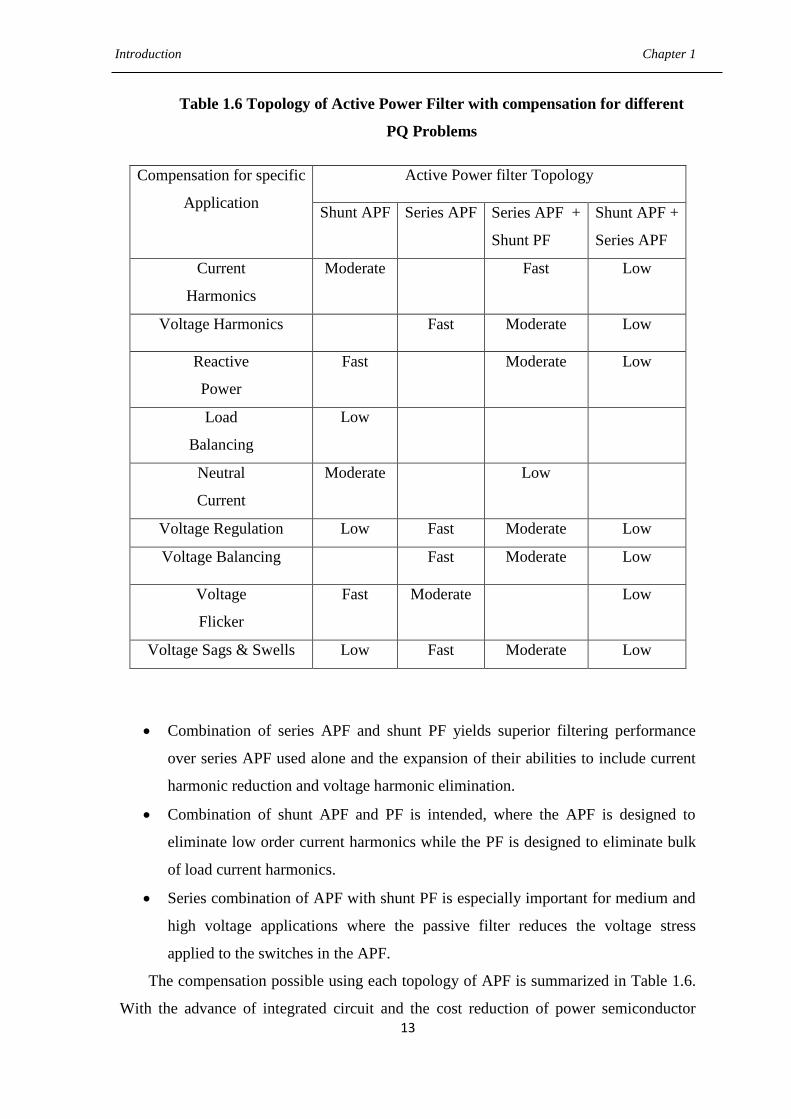
13
Table 1.6 Topology of Active Power Filter with compensation for different
PQ Problems
Compensation for specific
Application
Active Power filter Topology
Shunt APF Series APF Series APF +
Shunt PF
Shunt APF +
Series APF
Current
Harmonics
Moderate Fast Low
Voltage Harmonics Fast Moderate Low
Reactive
Power
Fast Moderate Low
Load
Balancing
Low
Neutral
Current
Moderate Low
Voltage Regulation Low Fast Moderate Low
Voltage Balancing Fast Moderate Low
Voltage
Flicker
Fast Moderate Low
Voltage Sags & Swells Low Fast Moderate Low
Combination of series APF and shunt PF yields superior filtering performance
over series APF used alone and the expansion of their abilities to include current
harmonic reduction and voltage harmonic elimination.
Combination of shunt APF and PF is intended, where the APF is designed to
eliminate low order current harmonics while the PF is designed to eliminate bulk
of load current harmonics.
Series combination of APF with shunt PF is especially important for medium and
high voltage applications where the passive filter reduces the voltage stress
applied to the switches in the APF.
The compensation possible using each topology of APF is summarized in Table 1.6.
With the advance of integrated circuit and the cost reduction of power semiconductor
Introduction Chapter 1
14
devices, APFs are expected to be extensively used in common industrial or residential
applications. A typical series APF, which functions in the cascade power path requires
higher rated current and voltage devices and hence produces significant switching losses.
Furthermore, the combinations of APFs provide an expensive and complicated filter
system for the power distribution system. So far, the shunt type is much preferred and
practical one as observed from Table 1.6. In this thesis, the shunt active power filter
(SAPF) configuration is chosen.
1.2 Literature Review on Shunt Active Power Filter
To obtain efficient active filter performance, it is important to choose both a proper
current reference and an adequate current control strategy. As far as control is concerned,
two loops can be identified. The first one is used to calculate the current reference
injected by the filter and the second one should guarantee that the filter follows that
reference adequately. Several control strategies have been reported in literature for
improving performance of SAPF and these are briefly reviewed below.
Instantaneous p-q method has been proposed in [17] for performance improvement of
SAPF under unbalanced supply voltage condition, however performance under balanced
and sinusoidal conditions is satisfactory. A hysteresis-band PWM current controller is
employed for generation of switching pulses and proportional integrator (PI) controller
supervises the dc capacitor voltages. The resulting source currents are found to be
sinusoidal, but voltage regulation performance is not satisfactory. A simple modification
is proposed in [18] to develop a generalized p-q theory in active power filtering under the
condition of distorted supply condition. Addition of phase locked loop (PLL) with p-q
approach helps in eliminating the adverse effect of the distorted supply voltage. The
reference current signal is generated with help of direct and indirect current control
technique and hysteresis current controller is used as a PWM generator. The SAPF
system maintains a self-supporting DC bus voltage and it functions as a reactive power
and harmonic compensator. The source current THD is reduced from 27.2 to 3.4% under
a distorted supply voltage with a THD of 16.2%.
Yuan and Merk [19] reported a PI current controller using stationary-frame
generalized integrators for current control of APFs. Instantaneous p-q theory is used for
reference current generation and the sequence filter based on the positive sequence ideal
Introduction Chapter 1
15
integrator resolves the problems of the p-q theory under distorted or unbalanced PCC
voltage conditions. Extensive test results from a 10-kW prototype are demonstrated and
the utility current is observed to be sinusoidal under both balanced and unbalanced
loading conditions.
Synchronous - reference frame (SRF) method is proposed in [20] along with three
independent two-level hysteresis comparators operating on a 3-leg VSC. Reference
currents are derived directly from the load currents without considering the source
voltages. Experimental results from a 2-kVA IGBT prototype showing the transient and
steady-state system performance are presented, where the proposed method allows the
operation of the SAPF in a large frequency range covering both 50 Hz and 60 Hz three-
phase distribution systems and presents better harmonic compensation performance as
compared to p-q based SAPF.
A new digital reference current estimation method for control of SAPF using a
Kalman Filter (KF) is presented by Moreno [21]. Its capability of prediction avoids the
effects of computational lags derived from the digital signal processing. The
characteristics of the proposed technique are: the harmonic current compensation in a
global or a selective way and the fast dynamical response. The dead beat current (DBC)
control loop takes into account the SAPF model and ensures the correspondence of the
injected current and its reference estimated by KF. Its immunity to harmonic distortion of
the line voltage waveform has been confirmed for common levels of voltage THD (4.7%)
and higher levels (11.4%) than those now present in the power system. Chudamani [22]
has proposed nonlinear least square (NLS) based algorithm for reference current
generation and hysteresis controller for generation of switching pulses in SAPF. The
fundamental frequency of the grid is estimated by using NLS and the estimated frequency
is then used in the signal model to compute the harmonic magnitudes resulting in
reference compensation signals. The THD of the source current is found to be 4.6% in
this proposed control strategy and also it performs well under sudden load changes as
well as change in the wave shape of the load. A new control scheme based on KF and
linear quadratic regulator (LQR) is proposed in [23] to improve the performance of SAPF
under the effects of measurement noise, load currents and grid voltage transients. KF
algorithm generates references for harmonics, unbalance and displacement power factor
compensation and can also be responsible for LQR implementation. With increase of line
impedance i.e., 0 mH, 2.8 mH and 5.8 mH, the THD of the proposed SAPF is found to be
Introduction Chapter 1
16
6.37%, 5.78% and 4.85% respectively showing good tracking behavior even under high
line impedance. Extensive tests and experimental results are presented in order to verify
the performance of SAPF.
A fuzzy logic controller for a three level SAPF based on p–q theory to identify
reference currents have been implemented in [24]. Fuzzy logic control algorithm is
proposed for harmonic current and inverter dc voltage regulation to improve the
performance of the SAPF. The proposed SAPF has produced a sinusoidal supply current
of low harmonic distortion of 0.9% and is in phase with the line voltage as obtained from
simulation results. Particle swarm optimization approach [25] and Takagi-Sugeno Fuzzy
(TS-fuzzy) [26] have been developed to improve the performance of active power filter.
Tey and Chu [27] proposed artificial neural network (ANN) technique to design
SAPF system. ANN algorithm computes harmonic contents and reactive power for the
nonlinear load and these two signals are used as the reference signal for the hysteresis
control of a three phase IGBT based VSI. The application of ANN makes extraction of
harmonics faster resulting in faster adaptation of active filter to any variation in the
operating conditions and it also has the capability to regulate the dc capacitor voltage.
Referring simulation results, the THDs of the source current are found to be 2.14%,
2.00% and 2.25% for high-to-low, low-to-high and unbalanced nonlinear load current
conditions respectively. An algorithm based on load conductance estimation using neural
network (NN) is implemented on a three phase shunt compensation for mitigation of PQ
problems such as load balancing, reactive power compensation, harmonics elimination
and neutral current compensation in a four wire distribution system [28]. Its structure is
reflected as Kohonen learning or Kohonen feature maps and is used for extraction of
fundamental component of load currents in terms of conductance and susceptance, which
finally helps in the source reference current estimation. This algorithm is found suitable
for the conditions where the periodicity of loads is not fixed or load currents are
frequently changing. It is based on the strong basic circuit theory compared to other
traditional NN algorithms. The reference supply currents and sensed supply currents are
compared and their current errors are amplified through PI current controllers. The output
of PI current controller is fed to the PWM current controller to generate the gating pulses
of IGBTs of the VSC. From experimental verification, THDs of the supply current and
load current are observed to be 3.8% and 39.6%. In [29], SAPF is controlled using an
adaptive-linear-element (Adaline) based current estimator to maintain sinusoidal and
Introduction Chapter 1
17
unity power factor source currents. Three phase load currents are sensed and using least
mean square (LMS) algorithm based Adaline, online calculation of weights are multiplied
by the unit vector templates, which give the fundamental frequency real component of
load currents. PI controller is used for maintaining dc bus voltage constant and the
switching of VSC is performed using hysteresis based PWM indirect current control
technique, which controls the source currents to follow the derived reference source
currents. Moreover, a THD of as low as 2.5% is achieved in SAPF system. An adaline-
based phase-locking scheme has been proposed in [30] to control three-phase SAPF. The
proposed ANN-based synchronization scheme is done in two steps: 1) frequency
estimation by modified NLS and 2) phase locking using adaline. Prefiltering of the supply
voltage prior to the frequency estimation is suggested as it improves the estimation
capability, regardless of the harmonic order present in the supply voltage and then
reference current signal is generated utilizing synchronous unit templates. The hardware
experimental results under different supply and load conditions are provided. In all cases,
the source current THDs are achieved below 4% while maintaining unity-power-factor
operation. In [31], Shyu proposed model reference adaptive control (MRAC) design for
SAPF to improve line power factor and to reduce the line current harmonics. The MRAC
approach improves many failures of the fixed gain PI controller, such as undesirable
undershoots and overshoots at the transient and nonrobustness when changing loads. The
proposed MRAC adaptive law is designed using Lyapunov‘s stability theory and
Barbalat‘s lemma that guarantees asymptotic output tracking. Furthermore, a prototype
system was built to show effectiveness and to verify the performance of the system. An
integration of predictive and adaptive ANN-based controller for SAPF has been presented
in [32] to improve the convergence and reduce the computational requirement. The
predictive algorithm is derived from an ANN based PI controller used to regulate the dc-
link voltage in the SAPF. This is followed by an adaline based THD minimization
technique. Adaline is trained by conjugate gradient method to minimize THD. The system
is extensively simulated and experimental prototype is produced in laboratory using
dSPACE1104. The THDs for both the simulation and experimental results remain less
than 5%.
An adaptive control strategy for SAPF for compensation of harmonic distortion,
reactive power, and unbalanced load is proposed in [33]. In the proposed study, the
amplitude of SAPF reference currents is generated by the dc-link voltage controller,

Introduction Chapter 1
18
based on the active power balance of system. The current controller is implemented by an
adaptive pole-placement control strategy integrated to a variable structure control scheme
(VS-APPC) in which it introduced the internal model principle (IMP) of reference
currents for achieving the zero steady-state tracking error. The main feature of this
controller in comparison to the conventional resonance-based schemes is that VS-APPC
controller gains are determined based on adaptive laws, which employs sliding-mode
techniques. This hybrid structure leads to a robust adaptive control strategy with a good
dynamic performance. After the use of compensation scheme, the harmonic distortion is
reduced from 29% to 3.5%. Singh and Arya [34] proposed an adaptive theory-based
improved linear sinusoidal tracer (ILST) control algorithm for three phase shunt
compensation. The ILST control algorithm is used for the extraction of fundamental load
currents and their active and reactive power components. These components are used for
the estimation of reference source currents. These reference source currents and sensed
source currents are compared for respective phases and each phase current error is
amplified using PI current regulators and their outputs are compared with a triangular
carrier signal of 10 kHz to generate the gating signals for IGBT switches of VSC. The
phase ‗a‘ source current and load current are observed to be 4.7% and 25.8% respectively.
Also an adaptive filter is implemented for shunt compensation in three-phase distorted
voltage ac mains [35].The proposed filter is based on adaptive synchronous extraction,
which helps in estimation of reference supply currents. The main features of this control
approach are high convergence speed and robustness with respect to input frequency and
internal parameter variations and less sensitivity to voltage pollutions. The PWM current
controller is employed for minimization of error between reference and actual source
currents. The dc-link voltage of the APF has been also regulated to a desired value under
time-varying load conditions. The compensation result for this proposed control strategy
is analyzed to be 4.4% THD in the source current. Also, the power factor on the supply
side is improved to near unity (0.99). A leaky LMS adaptive filter [36] is implemented in
a shunt connected compensating device for the extraction of reference supply currents
with a self-supporting dc bus. These extracted reference supply currents are used for the
generation of switching pulses of VSC. An advantage of this adaptive filter algorithm is
that it has improved dynamic response and fast convergence due to decreasing spread
input eigenvalues. The value of the leaky factor should be higher to reduce the eigen
spread for the simultaneously improved dynamic response. Based on the simulation and
Introduction Chapter 1
19
implementation results, the proposed control system was able to shape the supply currents
toward the sinusoidal and balanced at unit power factor.
In [37], a three phase shunt connected custom power device known as Distribution
Static Compensator (DSTATCOM) is designed with back propagation (BP) algorithm for
reference current generation and PWM current control technique for switching pulses
generation. In this BP algorithm, the training of weights has three stages. It includes the
feedforward of the input signal training, calculation and BP of the error signals and
upgrading of training weights. In the training process, it is slow due to more number of
learning steps, but after the training of weights, this algorithm produces very fast trained
output response. Extensive tests are performed utilizing proposed control strategy of APF.
The THDs of the phase ‗a‘ source current and load current are observed to be 2.99% and
24.94% respectively specifying harmonic distortions of the source current within the
IEEE-519 standard limit. Also a composite observer-based control algorithm along with
PWM current control technique is implemented for three phase shunt compensation
device [38]. This algorithm extracts load fundamental current components of polluted
load current and these components of load currents are used for estimation of reference
source currents. The advantages of this algorithm are that it is less sensitive with supply
frequency variation, low distortion in the extracted signal without leakage of harmonics.
The proposed control structure has been given a satisfactory performance according to
IEEE-519–1992 guidelines. The dc bus voltage has also been regulated to desired level.
Rahmani and Mendalek [39] presented a nonlinear control technique for SAPF
system. PI control law is derived through linearization of the inherently nonlinear SAPF
model, so that tasks of the current control dynamics and dc capacitor voltage dynamics
become decoupled. This decoupling allows controlling the SAPF output currents and dc
bus voltage independently of each other and hence generates a delay. The computational
control delay compensation method is proposed, which extracts the SAPF reference
currents from nonlinear load currents by using SRF method in first step and then,
reference currents are modified. SAPF performance is evaluated in real time using
dSPACE1104 controller board. The THD of the current generated by nonlinear load is
observed to be 25.8%, whereas the compensated supply current has a THD of 2.62%.
Jorge [40] proposes a current controller based on the reduced order generalized integrator
(ROGI) to control SAPF and this controller doesn‘t require accurate current references,
nor the current references that must be updated quickly in presence of load transients or
Introduction Chapter 1
20
grid voltage transients. The low computational burden of the whole control makes it ideal
for its implementation in low-cost digital signal processor (DSP).
A single-step noniterative optimized control algorithm has been proposed in [41] for
a three phase three wires SAPF to achieve an optimum performance between power
factor and THD. The proposed optimized approach is simple to implement and does not
require complex iterative optimization techniques such as Newton–Raphson and
sequential quadratic programming to determine the conductance factors. It is shown
mathematically that only three conductance factors (one for the fundamental harmonic
and two other for odd and even harmonics) are sufficient to determine the desired
reference source currents. These reference source currents are compared with the actual
measured currents using the hysteresis current controller which determine the switching
signals for the VSI.The performance of the proposed control strategy is validated by a
real-time HIL experimental prototype and the compensation THD result is analyzed to be
1.7%. Trinh [42] proposes an advanced control strategy to enhance performance of SAPF.
This scheme is implemented by using only supply current without detecting the load
current and filter current. Hence this scheme comprises of only two loops. The outer
voltage control loop is maintained by PI controller to generate the reference current and
the inner current control loop is designed with PI and vector-PI controller to regulate the
supply current. Experimental results demonstrate that the proposed control strategy
achieves good performances under ideal sinusoidal as well as distorted supply conditions.
The THD of the supply current is reduced to less than 2% for all cases. In [43], a novel
source current detection control scheme is proposed in SAPF to generate reference
current signal with power balance (PB) method. This PB method has good dc voltage
regulation and has excellent stable filtering performance as compared to current source
(CS) based method. A vector resonant controller is proposed, with which the SAPF
performs as an equivalent multiband rejection filter that series between nonlinear loads
and the grid source, blocking selected harmonics components from the load side flowing
into the source side. The proposed SAPF is simple in structure and is needless of a
harmonic extraction algorithm. In this SAPF system, THD of the source current is
dropped from 28% to 2.9%. Lenwari [44] investigates an optimization procedure based
on genetic algorithms (GA), which can automatically design a high-performance
resonant-type current controller for SAPF application and SRF method is employed for
generation of reference compensation signal. Even in the presence of power system
Introduction Chapter 1
21
impedance variations , the SAPF can precisely regulate the 5th, 7th, 11th, and 13th
harmonic currents by utilizing fitness function in GA, which is defined to be a
compromise between speed of response, stability and robustness to supply impedance
variations. The performance of the system is good; the THD of the supply current is
reduced from 26.81% to 4.49%.
A robust control strategy is implemented in [45] to regulate the dc-link voltage by
combining a standard PI controller and sliding mode controller (SMC), which helps in
generation of reference current in SAPF. The SMC scheme continuously determines the
gains of the PI controller based on the control loop error and its derivative. The chattering
due to the SMC scheme is reduced by a transition rule that fixes the controller gains when
steady state condition is reached. The phase currents of the power grid are indirectly
regulated by double sequence controllers (DSC), where the internal model principle
(IMP) is employed to avoid reference frame transformation. The proposed control
strategy ensures zero steady-state error and after the compensation implemented by the
SAPF, the THD obtained is 3.6%. Matas [46] proposed feedback linearization theory to
SAPF system, where active filter is linearized by means of a nonlinear transformation of
the system model, deduced from the application of Tellegen‘s theorem to the system.
SMC is proposed to impose a desired dynamic behaviour on the system, giving
robustness and insensitivity to parameter variations. Outer voltage controller loop is based
on PI controller and also helps in reference current generation. The proposed SAPF
ensures proper tracking of the reference signals and THD of the compensated source
current is analysed to be 3.3%.
Odavic and Biagini [47] proposed an improved predictive current controller for
SAPF. This algorithm is based on the conventional DBC method and introduces a
modified approach to compensate for delays incurred through digital implementation of
the control, by predicting a system behaviour one and two sample instants in advance
with respect to the measurement instant. A polynomial type extrapolation predictor is
considered to predict the SAPF reference currents and space vector modulation (SVM)
scheme is employed for switching pulses generation in IGBT inverter. Compared to
conventional DBC, the proposed SAPF is more suitable for practical implementations
where measurement noise is very likely to appear. The THD of load current is reduced
from 27% to 3.7%. The SAPF implemented with a four-leg VSI using a predictive control
scheme is presented in [48]. This predictive algorithm is realized in three steps; current
Introduction Chapter 1
22
reference generator, prediction model and cost function optimization. A SRF based
current reference generator scheme is used to obtain the current reference signals and
presents a fast and accurate signal tracking capability. The experimental results present
that the THD of the line current is dropped from 27.09% to 4.54%. A new approach for
harmonic distortion minimization in distributed power system has been proposed in [49] .
1.2.1 Remarks from Literature Review on SAPF
From the above discussions, the following remarks can be reported.
Control strategies based on p-q method and conventional HCC technique are
easier to realize in SAPF with higher accuracy and fast response. These
approaches perform satisfactorily under balanced sinusoidal supply condition, but
their performances deteriorate in unbalanced condition. However, variable
switching frequency is one of the drawbacks related with HCC technique.
SRF-HCC approach to improve SAPF performance is satisfied under unbalanced
as well as distorted supply conditions and as a result, current harmonics can be
effectively reduced in this approach as compared to p-q-HCC.
SAPF performance employing reference current estimation using KF, NLS
method is found to be effective under grid perturbations such as grid voltage
transients and measurement noise.
SAPF based on soft computing approaches such as fuzzy, ANN is very sensitive
to system uncertainty and external disturbances.
The source reference generation along with PWM current control realization in
SAPF is the most established in the literature [36][37][38]. The extracted
fundamental component of polluted load current helps in reference generation and
PI controller is used for maintenance of dc-link voltage.
Adaptive control based SAPF system improves many failures of fixed-gain PI
controller in transient conditions of the load and makes THD less than 5%.
PI-SMC based SAPF has main advantages including fast dynamic response,
strong robustness of perturbation parameter and easier realization over other linear
control methods. Moreover, a proper tracking of reference signal is achieved in
SAPF.
Predictive current control techniques employed in SAPF can handle multivariable
characteristics as well as simplify the treatment of dead time compensation.
Introduction Chapter 1
23
However this approach requires a high amount of calculations compared to a
classic control based SAPF.
SAPF with proper reference current generation as well as strong robust current
controller approach is essential to reduce the THD of source current to a large
extent.
1.3 Motivation of the Thesis
The motivations of the thesis are as follows.
The information from the grid is used at different levels of the control system of a
grid-connected converter. The internal reference signal generated by the control
algorithm of a grid-connected power converter should be brought into line with a
particular grid variable, usually the fundamental component of the grid voltage.
This has motivated to generate the reference current signal in SAPF based upon
the knowledge of fundamental component of the grid voltage such that a
synchronization of the source current with the supply voltage can be achieved.
Thus, an accurate estimation of this fundamental component is intended.
Both linear and nonlinear Kalman filter (KF) [50][51][52][53][54] approaches
have gained extensive attention as they accurately estimate the amplitude, phase
and frequency of a signal buried under noise and harmonics. Further, most of the
existing estimation approaches [55][56][57][58][59][60] have not considered the
grid perturbations such as voltage distortion, measurement noise and harmonics.
Hence in view of addressing these aforesaid issues (harmonics, voltage distortion,
noise), a new estimation algorithm has to be developed, which can provide better
improved estimations independent of all grid perturbations in SAPF with fast
convergence.
The dynamic performance of SAPF is mainly dependent upon the behavior of its
current controller technique. From literature review, it is found that Predictive
control concepts are intuitive and easy to understand, and can also be applied to a
variety of systems. Constraints and nonlinearities can be easily included. Further,
these types of controllers require a high amount of calculations compared to a
classic control scheme; which is made possible through fast microprocessors
available today. Therefore, new predictive control techniques need to be

Introduction Chapter 1
24
developed in SAPF, which offer the potential for achieving fastest transient
response, more precise current control and full compatibility with digital control
platforms.
It is not possible to supply quality power to special equipments such as converters
with AC drives, distributed control system, programmable logic control (PLC)
through conventional control schemes employed in SAPF. This results in
malfunctioning of the above type of equipment, which demands pure power at all
moments with fast changing disturbances occurring in power system. Hence, a
fast and robust control action is necessary to deliver pure and distortion less power
to above equipments considering all perturbations taken into account. Moreover,
power line uncertainties such as unexpected failure of power system components,
random variation of load, high disturbance conditions and sensor nonlinearities
are the most challenging problems that might affect the dynamic performance of
SAPF. Further, parameters of SAPF may vary owing to component aging, thermal
drift and saturation effects caused by the operating environment. In view of
aforementioned issues, it is necessary to design robust controllers that not only
provide good disturbance rejection and robustness against uncertainties in the
system dynamics, but also to achieve efficient current harmonics compensation
through the SAPF.
1.4 Objectives of the Thesis
To propose a robust estimation technique for estimation of fundamental amplitude
and frequency in view of achieving accuracy and fast convergence considering all
possible perturbations such as voltage distortion, measurement noise and
harmonics.
To develop a new reference current generation scheme that can self-regulate the
dc-link voltage.
To propose new current control techniques for improving the dynamic
performance of SAPF system.
To propose robust control technique such that it should provide robustness against
parametric variations of load, reduce the current tracking error to zero, cancel the
current harmonics effectively and achieve unity power factor in SAPF system.
Introduction Chapter 1
25
To develop a prototype experimental set up for verifying the robustness of the
proposed robust control techniques in SAPF system.
1.5 Thesis Organization
The thesis consists of seven chapters that are organized as follows.
Chapter 1 provides an extensive review on SAPF based upon different reference
current generation approaches as well as current controller techniques. Remarks on the
review on different control strategies of SAPF are presented along with the discussion of
their merits and demerits. Further, they are evaluated with respect to their benefits,
drawbacks and appliances.
Chapter 2 proposed two current control techniques called HCC and SMC realized
with a new reference current generation scheme for SAPF system. This reference
generation scheme involves with exterior PI controller loop and the in phase fundamental
components of distorted PCC voltages necessitated for this reference generation are
estimated using the KF based algorithm. KF-HCC based SAPF performs under
consideration of grid perturbations, but harmonics cancellation is not so fast and perfect
owing to slower convergence rate of KF. Hence, the other controller called SMC is
employed with a faster reference scheme based on proposed Robust Extended Complex
Kalman Filter (RECKF). A new weighted exponential function is embedded into RECKF
to estimate a fast and distortion less reference signal considering grid perturbations such
as voltage distortion and measurement noise. The effectiveness of this proposed RECKF-
SMC is assessed with other variants of KF such as KF, Extended Kalman Filter (EKF)
and Extended Complex Kalman Filter (ECKF) using simulation results obtained from
Matlab/Simulink and real-time simulation results obtained from Opal-RT. KF-SMC
performs better than KF-HCC, but RECKF-SMC is analyzed to be more effective in
harmonics cancellation as compared to KF-SMC, EKF-SMC and ECKF-SMC based
control strategies in SAPF.
Chapter 3 proposed two predictive current control techniques called Dead beat
control (DBC) and Model predictive control (MPC) with a new and improved reference
generation scheme. The reference generation is comprised of two components: 1)
estimation of in phase fundamental component of PCC voltage in p.u. value, and 2)
estimation of fundamental amplitude of load current. The main advantage of this

Introduction Chapter 1
26
reference scheme is the avoidance of PI controller loop to eliminate relatively large
overshoots and undershoots associated with it, which may interrupt the stable operation of
the inverter in protecting the switching devices. Further proposed RECKF is found to be
excellent among KF, EKF and ECKF as investigated in Chapter 2. As a result, in this
Chapter RECKF has been employed in reference generation scheme. Realization using
proposed RECKF-DBC scheme is very simple and it needs a modulator to provide gate
drive signals to IGBT inverter. In DBC, the optimal actuation is the one that makes the
error equal to zero in the next sampling instant, whereas a more flexible criterion is
employed in MPC, expressed as a cost function to be minimized. There is no need of any
modulators and the gate drive signals are generated directly by this MPC scheme.
RECKF-MPC performs better as compared to RECKF-DBC. Furthermore, to examine the
efficiency of this proposed RECKF-MPC over PI-MPC, a comparative study has been
done applying both steady state and transient state conditions.
Chapter 4 proposed an optimal Linear Quadratic Regulator (LQR) with a new
reference current generation method in SAPF. LQR is chosen here due to its well-known
features of tracking and disturbance rejection capability. A realistic representation of the
SAPF system is achieved in LQR by using a resonant model of the PCC voltages instead
of considering it as a disturbance. For LQR designing, the state space variables related to
the PCC voltages, are accurately estimated using proposed RECKF based algorithm.
Furthermore, stabilization of capacitor voltage is improved with a new reference
generation scheme based on RECKF, adding an error between fundamental amplitudes of
source and load current. Consequently, harmonics cancellation effect is more in case of
RECKF-LQR approach. Thus, RECKF-LQR is analyzed to be more effective as
compared to RECKF-SMC, RECKF-DBC and RECKF-MPC employing simulation as
well as real-time simulation results.
Chapter 5 proposed a robust technique called Linear Quadratic Gaussian (LQG)
Servo controller with higher disturbance rejection capability, which permits all
perturbations such as PCC disturbances, parametric variations of load and tracking error
variations so that compensation capability of the overall SAPF system can be enhanced
(i.e., THD much less than 3%) with less consumption of time. From simulation results,
LQG servo controller is not only analyzed to be robust against different load parameters,
but also a satisfactory THD result has been achieved in SAPF. This has motivated to
develop a prototype experimental set up in our Laboratory using dSPACE DS1104 R & D
Introduction Chapter 1
27
controller board for verifying the robustness of LQG servo controller. Finally, it is found
that the experimental results are in close agreement with the simulation results.
Chapter 6 proposed H∞ controller with a mixed sensitivity approach with the
purpose of achieving stability, high disturbance rejection and high level of harmonics
cancellation. This mix sensitivity approach involves with the robustness performance,
control effort performance as well as error tracking performance of SAPF system by
selecting appropriate weighting functions. Further, a new current reference scheme is
proposed in this Chapter, which deals with the measurement of source current only
making whole SAPF a more reliable and cost efficient system. The effectiveness of the
proposed RECKF-H∞ based SAPF model is validated pursuing simulation and
experimental studies. From the both simulation and experimental results, it is observed
that the proposed RECKF-H∞ control approach to design a SAPF is found to be more
robust as compared to RECKF-LQG servo control approach in face parametric
uncertainties due to load perturbations yielding improvement in power quality more
effectively in terms of tracking error reduction, efficient current harmonics mitigation as
well as reactive power compensation. Comparing with compensation performances of
RECKF-SMC, RECKF-DBC, RECKF-MPC, RECKF-LQR and RECKF-LQG servo
based SAPF; it is observed that overall performance of this robust RECKF-H∞ is more.
Chapter 7 describes the concluding explanations and suggestions for some future
research problems as extensions of the work described in the thesis.

CHAPTER 2
Hysteresis and Sliding Mode Controller with a New
Reference Current Generation Strategy in SAPF
2.1 Introduction
Usually a signal can be constructed by using the estimation of its frequency, amplitude,
and phase. This idea can be extended to identify the fundamental component from a
distorted power system signal, which generates a reference signal for a SAPF. To obtain a
high-quality estimate of this component is of particular interest. Most of the proposed
methods to identify the fundamental component of voltage or current are based on the
low-pass filter (LPF) method, conventional unit vector based method, discrete Fourier
transform (DFT) method, and positive sequence calculation method. In the LPF method
[61], the filter introduces a phase shift in the output, which requires a lead compensator to
compensate this phase shift. Any change in the fundamental frequency introduces an error
in the compensation network and causes a residual fundamental component to be added to
the reference currents. This causes active power flow through the SAPF even under
steady-state conditions. In the conventional unit vector method [29], the steady-state
performance under balanced and sinusoidal conditions is satisfactory, but it produces
inaccurate reference currents when the supply voltage contains distortions, resulting in
incomplete harmonics compensation. In the DFT method [62], the estimation accuracy is
inaccurate because of spectral leakage. This happens because grid frequency does not
remain constant. In [63], the reference current is calculated by two steps: the first is
related to the calculation of the positive-sequence component of unbalanced supply
voltage and the second is deriving a simple fundamental extraction filter to extract the
fundamental frequency component from the distorted positive-sequence voltage, hence
increases computation time. Here additional measurement noise at the point of common
coupling (PCC) does not seem to be taken into consideration in reference current
generation. Once the current references have been determined with consideration of all
grid perturbations such as voltage distortion and measurement noise, the SAPF must be
able to track accurately such references with a suitable controller even in sudden slope
variations of the reference.
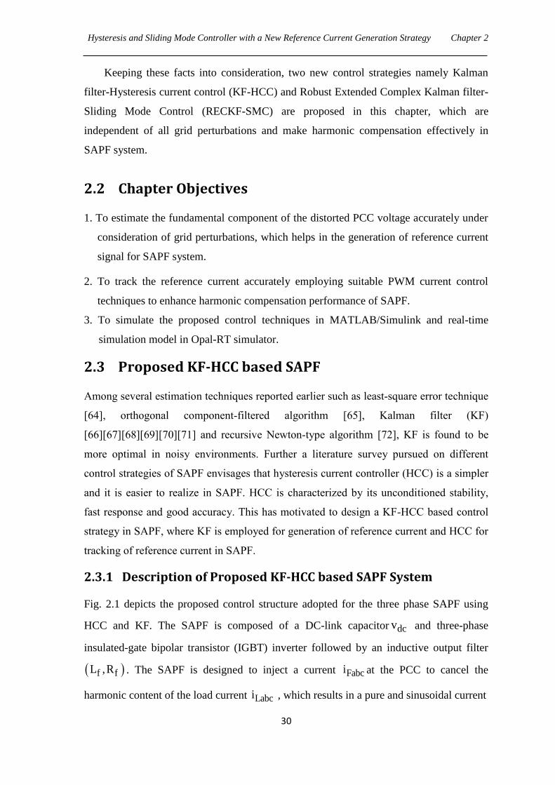
Hysteresis and Sliding Mode Controller with a New Reference Current Generation Strategy Chapter 2
30
Keeping these facts into consideration, two new control strategies namely Kalman
filter-Hysteresis current control (KF-HCC) and Robust Extended Complex Kalman filter-
Sliding Mode Control (RECKF-SMC) are proposed in this chapter, which are
independent of all grid perturbations and make harmonic compensation effectively in
SAPF system.
2.2 Chapter Objectives
1. To estimate the fundamental component of the distorted PCC voltage accurately under
consideration of grid perturbations, which helps in the generation of reference current
signal for SAPF system.
2. To track the reference current accurately employing suitable PWM current control
techniques to enhance harmonic compensation performance of SAPF.
3. To simulate the proposed control techniques in MATLAB/Simulink and real-time
simulation model in Opal-RT simulator.
2.3 Proposed KF-HCC based SAPF
Among several estimation techniques reported earlier such as least-square error technique
[64], orthogonal component-filtered algorithm [65], Kalman filter (KF)
[66][67][68][69][70][71] and recursive Newton-type algorithm [72], KF is found to be
more optimal in noisy environments. Further a literature survey pursued on different
control strategies of SAPF envisages that hysteresis current controller (HCC) is a simpler
and it is easier to realize in SAPF. HCC is characterized by its unconditioned stability,
fast response and good accuracy. This has motivated to design a KF-HCC based control
strategy in SAPF, where KF is employed for generation of reference current and HCC for
tracking of reference current in SAPF.
2.3.1 Description of Proposed KF-HCC based SAPF System
Fig. 2.1 depicts the proposed control structure adopted for the three phase SAPF using
HCC and KF. The SAPF is composed of a DC-link capacitor dcv and three-phase
insulated-gate bipolar transistor (IGBT) inverter followed by an inductive output filter
f fL ,R . The SAPF is designed to inject a current Fabci at the PCC to cancel the
harmonic content of the load current Labci , which results in a pure and sinusoidal current
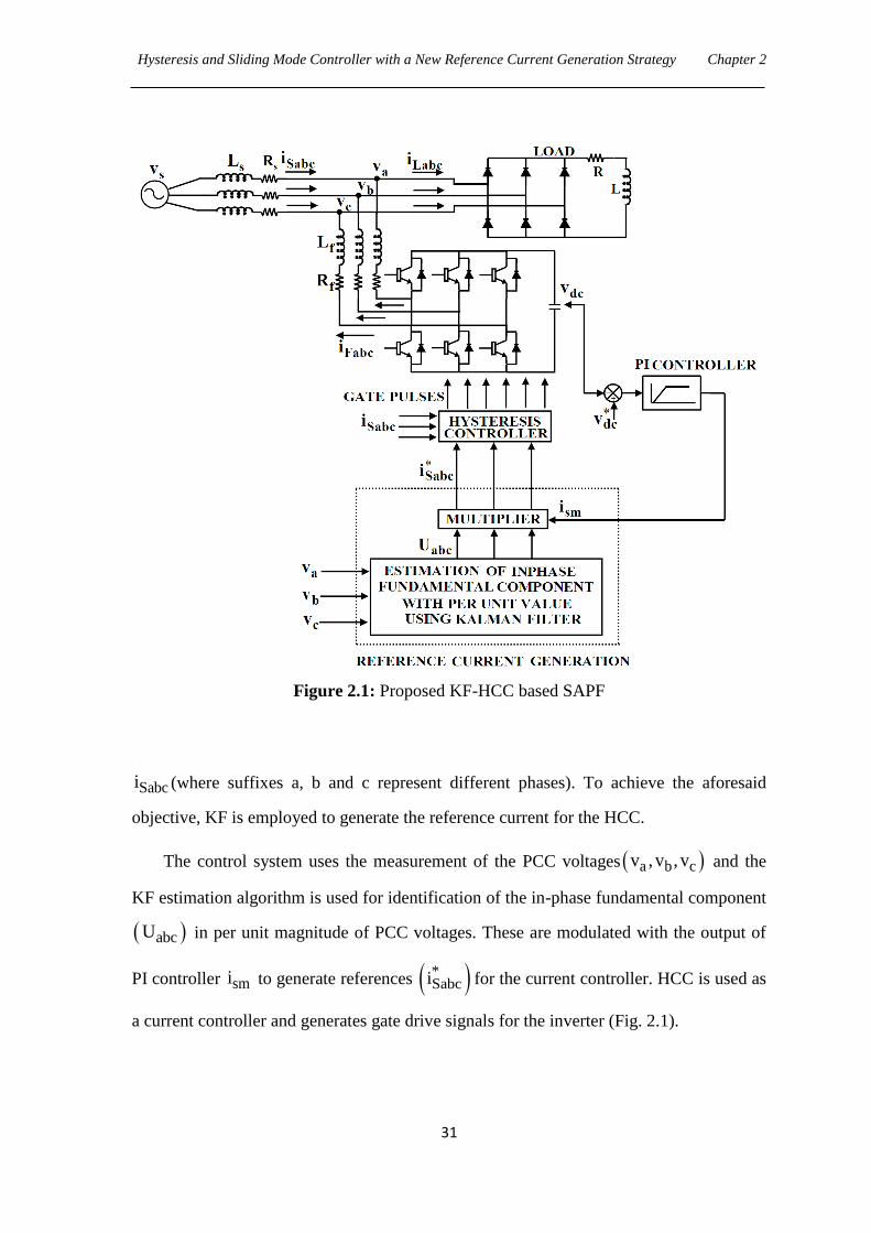
Hysteresis and Sliding Mode Controller with a New Reference Current Generation Strategy Chapter 2
31
Figure 2.1: Proposed KF-HCC based SAPF
Sabci (where suffixes a, b and c represent different phases). To achieve the aforesaid
objective, KF is employed to generate the reference current for the HCC.
The control system uses the measurement of the PCC voltages a b cv , v , v and the
KF estimation algorithm is used for identification of the in-phase fundamental component
abcU in per unit magnitude of PCC voltages. These are modulated with the output of
PI controller smi to generate references *Sabci for the current controller. HCC is used as
a current controller and generates gate drive signals for the inverter (Fig. 2.1).
Hysteresis and Sliding Mode Controller with a New Reference Current Generation Strategy Chapter 2
32
2.3.2 Proposed Reference Current Generation
Usually the performance of the SAPF depends upon the accuracy of the reference signal
generator and for source reference generation, identification of the in phase fundamental
component is the most critical item in determining SAPF behavior. The expression for
source reference signal is given by
*Sabc sm abci i U (2.1)
The estimation of the in phase fundamental component of PCC voltages using KF
algorithm is presented below.
2.3.2.1 Signal Model and Formulation of KF Algorithm
A linear signal kz of single sinusoid is represented by
k 1 1 s 1z a sin k T , k=1,....,N (2.2a)
N denotes an integer.
1 12 f (2.2b)
In eq (2.2a), sT is the sampling time, parameters 1a and 1f are the fundamental
amplitude and frequency respectively with initial phase 1 . The signal k 1z can be
expressed as
k 1 k kk 1 1 1 1 s 2 1 sz x x cos k T x sin k T (2.3)
Further,
k 1 k k2 1 1 s 2 1 sx x sin(k T ) x cos(k T ) (2.4)
wherek2x is known as the in quadrature component and is orthogonal to
k1x and they are
represented by
k1 1 1 s 1x a sin(k T ) (2.5a)
k2 1 1 s 1x a cos(k T ) (2.5b)
Hysteresis and Sliding Mode Controller with a New Reference Current Generation Strategy Chapter 2
33
To model amplitude or phase variations in the signal, a perturbation vector
T
1 2 k in the system states is considered. The state space representation of the signal
then becomes
k 1 k k kx x w (2.6)
k k k ky H x v (2.7)
where kw and kv are the process and measurement noises respectively. k and kH are
denoted as transition matrix and observation matrix respectively.
1 s 1 sk
1 s 1 s
cos( T ) sin( T )
sin( T ) cos( T )
(2.8)
kH [1 0] (2.9)
Denoting the estimate of k 1x as k 1kx , the sequential recursive computation steps
for fundamental component identification are given as follows.
k 1k k k k 1 k k k k k 1ˆ ˆ ˆx x K (y H x ) (2.10)
1
T Tk k k k 1 k k k k 1 k kK P H H P H R
(2.11)
T Tk 1k k k k 1 k k k k k 1 k kP P K H P Q (2.12)
Tk 1k k 1 k 1k k 1 k 1kˆ ˆP E(x x )(x x ) (2.13)
In eq (2.10), the innovation vector k k k k 1ˆy H x is used to refine the priori estimate
k k 1x and kK is the Kalman gain. In eq (2.11), it is intended to find the value of kK that
minimises the individual terms along the major diagonal of error covariance matrix kP
because these terms represent the estimation error variances for the elements of the state
vector being estimated. Eq (2.12) is a general expression for the updated error covariance
matrix for any gain kK , where k 1kP and k k 1P represent a posteriori and a priori error
covariance matrices respectively. kQ and kR are the process and measurement error
covariance matrix respectively.
Tk k kQ Ew w (2.14)
Tk k kR Ev v (2.15)
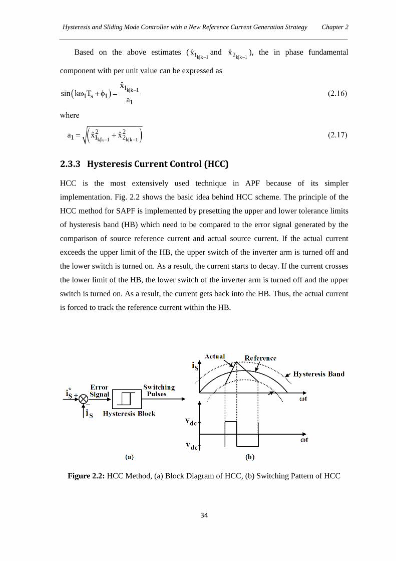
Hysteresis and Sliding Mode Controller with a New Reference Current Generation Strategy Chapter 2
34
Based on the above estimates (k k 11x
and k k 12x
), the in phase fundamental
component with per unit value can be expressed as
k k 11
1 s 11
xsin k T
a
(2.16)
where
k k 1 k k 1
2 21 1 2ˆ ˆa x x
(2.17)
2.3.3 Hysteresis Current Control (HCC)
HCC is the most extensively used technique in APF because of its simpler
implementation. Fig. 2.2 shows the basic idea behind HCC scheme. The principle of the
HCC method for SAPF is implemented by presetting the upper and lower tolerance limits
of hysteresis band (HB) which need to be compared to the error signal generated by the
comparison of source reference current and actual source current. If the actual current
exceeds the upper limit of the HB, the upper switch of the inverter arm is turned off and
the lower switch is turned on. As a result, the current starts to decay. If the current crosses
the lower limit of the HB, the lower switch of the inverter arm is turned off and the upper
switch is turned on. As a result, the current gets back into the HB. Thus, the actual current
is forced to track the reference current within the HB.
Figure 2.2: HCC Method, (a) Block Diagram of HCC, (b) Switching Pattern of HCC

Hysteresis and Sliding Mode Controller with a New Reference Current Generation Strategy Chapter 2
35
The actual currents Sa Sb Sci , i , i and reference currents * * *Sa Sb Sci , i , i are compared
within the HB and the current controller decides the switching pattern of the devices in
SAPF. The switching logic is formulated as follows:
if *
Sa Sai (i HB) , then upper switch is OFF and lower switch is ON in leg ‗a‘ of the
SAPF;
if *
Sa Sai (i HB) , then upper switch is ON and lower switch is OFF in leg ‗a‘ of the
SAPF;
Similarly, the switches in the legs ‗b‘ and ‗c‘ are activated.
A proper design of power circuit of SAPF is essential for implementation and hence
a design procedure for parameters of SAPF is prescribed in the next Section.
2.3.4 Design of Power circuit of SAPF
The design of the power circuit includes three main parameters;
1. Selection of filter inductor, fL
2. Selection of DC side capacitor, C
3. Selection of reference DC bus voltage, *dcv
2.3.4.1 Selection of fL and *dcv
The design of these components is based on the following assumptions:
1. The AC source voltage is sinusoidal.
2. The AC side line current distortion is assumed to be 5% [34] for designing fL .
But when distortion is more than 5%, there would be an increase of interruption in
injecting compensating current.
3. There is fixed capability of reactive power compensation of the active filter.
4. The PWM converter is assumed to operate in the linear modulation mode (i.e.,
a0 m 1 ), where am is the amplitude modulation factor.
As per the compensation principle, the active filter corrects the current F1i to
compensate the reactive power of the load. If the active filter compensates all the
fundamental reactive power of the load, S1i will be in phase and F1i should be orthogonal
to sv as shown in Fig. 2.3, where one stands for the fundamental component.
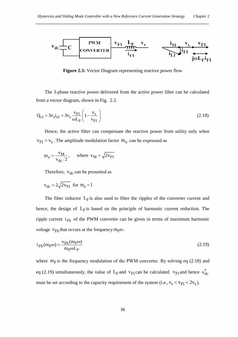
Hysteresis and Sliding Mode Controller with a New Reference Current Generation Strategy Chapter 2
36
Figure 2.3: Vector Diagram representing reactive power flow
The 3-phase reactive power delivered from the active power filter can be calculated
from a vector diagram, shown in Fig. 2.3.
sF1c1 s s1 s
F F1
vvQ 3v i 3v 1
L v
(2.18)
Hence, the active filter can compensate the reactive power from utility only when
F1 sv v . The amplitude modulation factor am can be expressed as
Ma
dc
vm
v 2 , where M F1v 2v
Therefore, dcv can be presented as
dc F1v 2 2v for am 1
The filter inductor FL is also used to filter the ripples of the converter current and
hence, the design of FL is based on the principle of harmonic current reduction. The
ripple current Fhi of the PWM converter can be given in terms of maximum harmonic
voltage Fhv that occurs at the frequency Fm .
Fh FFh F
F F
v (m )i (m )
m L
(2.19)
where Fm is the frequency modulation of the PWM converter. By solving eq (2.18) and
eq (2.19) simultaneously, the value of FL and F1v can be calculated. F1v and hence *dcv
must be set according to the capacity requirement of the system (i.e., s F1 sv v 2v ).
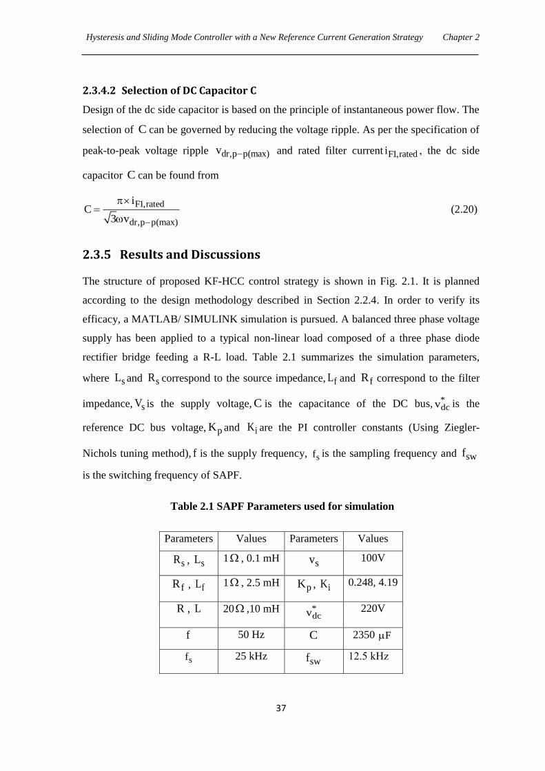
Hysteresis and Sliding Mode Controller with a New Reference Current Generation Strategy Chapter 2
37
2.3.4.2 Selection of DC Capacitor C
Design of the dc side capacitor is based on the principle of instantaneous power flow. The
selection of C can be governed by reducing the voltage ripple. As per the specification of
peak-to-peak voltage ripple dr,p p(max)v and rated filter current F1,ratedi , the dc side
capacitor C can be found from
F1,rated
dr,p p(max)
iC
3 v
(2.20)
2.3.5 Results and Discussions
The structure of proposed KF-HCC control strategy is shown in Fig. 2.1. It is planned
according to the design methodology described in Section 2.2.4. In order to verify its
efficacy, a MATLAB/ SIMULINK simulation is pursued. A balanced three phase voltage
supply has been applied to a typical non-linear load composed of a three phase diode
rectifier bridge feeding a R-L load. Table 2.1 summarizes the simulation parameters,
where sL and sR correspond to the source impedance, fL and fR correspond to the filter
impedance, sV is the supply voltage, C is the capacitance of the DC bus, *dcv is the
reference DC bus voltage, pK and iK are the PI controller constants (Using Ziegler-
Nichols tuning method), f is the supply frequency, sf is the sampling frequency and swf
is the switching frequency of SAPF.
Table 2.1 SAPF Parameters used for simulation
Parameters Values Parameters Values
sR , sL 1 , 0.1 mH sv 100V
fR , fL 1 , 2.5 mH pK , iK 0.248, 4.19
R , L 20 ,10 mH *dcv 220V
f 50 Hz C 2350 F
sf 25 kHz swf 12.5 kHz
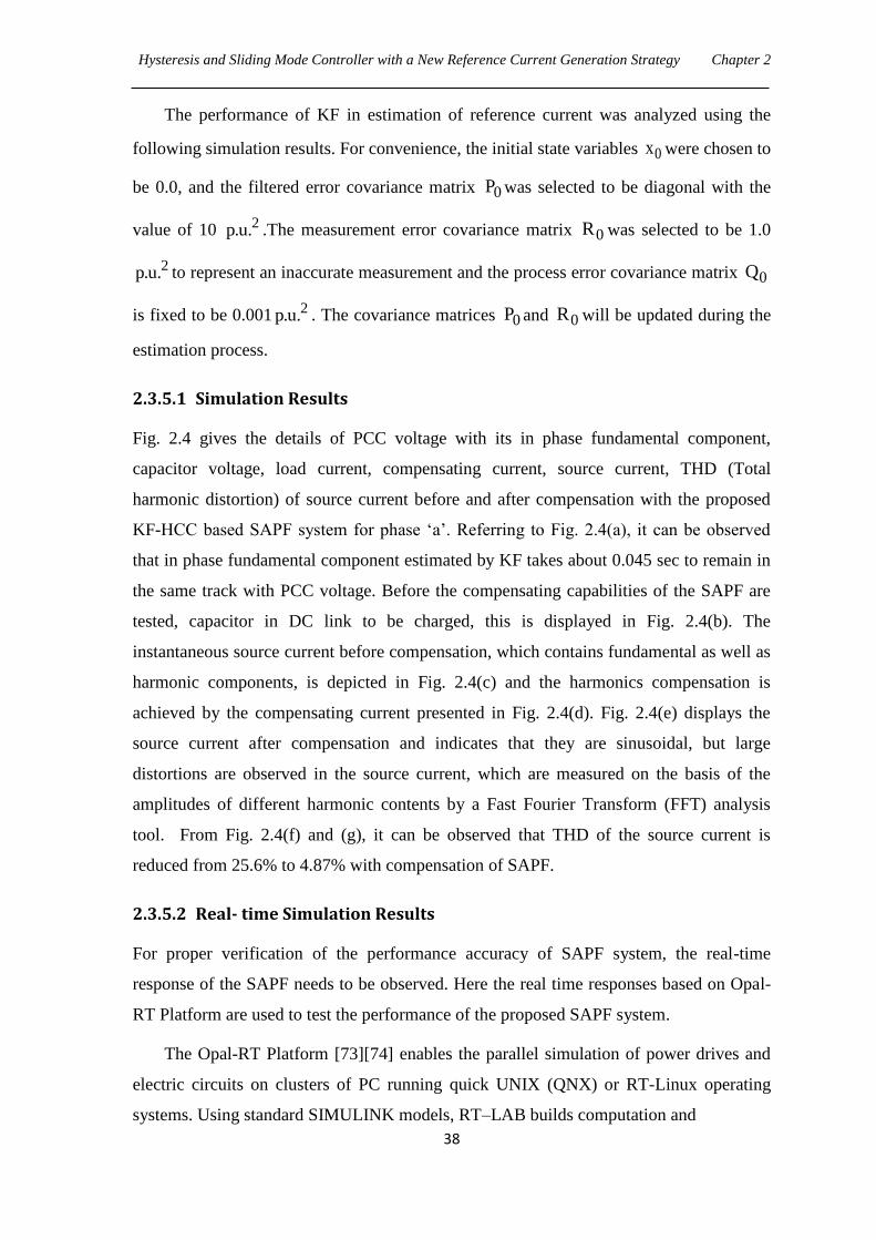
Hysteresis and Sliding Mode Controller with a New Reference Current Generation Strategy Chapter 2
38
The performance of KF in estimation of reference current was analyzed using the
following simulation results. For convenience, the initial state variables 0x were chosen to
be 0.0, and the filtered error covariance matrix 0P was selected to be diagonal with the
value of 10 2p.u. .The measurement error covariance matrix 0R was selected to be 1.0
2p.u. to represent an inaccurate measurement and the process error covariance matrix 0Q
is fixed to be 0.001 2p.u. . The covariance matrices 0P and 0R will be updated during the
estimation process.
2.3.5.1 Simulation Results
Fig. 2.4 gives the details of PCC voltage with its in phase fundamental component,
capacitor voltage, load current, compensating current, source current, THD (Total
harmonic distortion) of source current before and after compensation with the proposed
KF-HCC based SAPF system for phase ‗a‘. Referring to Fig. 2.4(a), it can be observed
that in phase fundamental component estimated by KF takes about 0.045 sec to remain in
the same track with PCC voltage. Before the compensating capabilities of the SAPF are
tested, capacitor in DC link to be charged, this is displayed in Fig. 2.4(b). The
instantaneous source current before compensation, which contains fundamental as well as
harmonic components, is depicted in Fig. 2.4(c) and the harmonics compensation is
achieved by the compensating current presented in Fig. 2.4(d). Fig. 2.4(e) displays the
source current after compensation and indicates that they are sinusoidal, but large
distortions are observed in the source current, which are measured on the basis of the
amplitudes of different harmonic contents by a Fast Fourier Transform (FFT) analysis
tool. From Fig. 2.4(f) and (g), it can be observed that THD of the source current is
reduced from 25.6% to 4.87% with compensation of SAPF.
2.3.5.2 Real- time Simulation Results
For proper verification of the performance accuracy of SAPF system, the real-time
response of the SAPF needs to be observed. Here the real time responses based on Opal-
RT Platform are used to test the performance of the proposed SAPF system.
The Opal-RT Platform [73][74] enables the parallel simulation of power drives and
electric circuits on clusters of PC running quick UNIX (QNX) or RT-Linux operating
systems. Using standard SIMULINK models, RT–LAB builds computation and
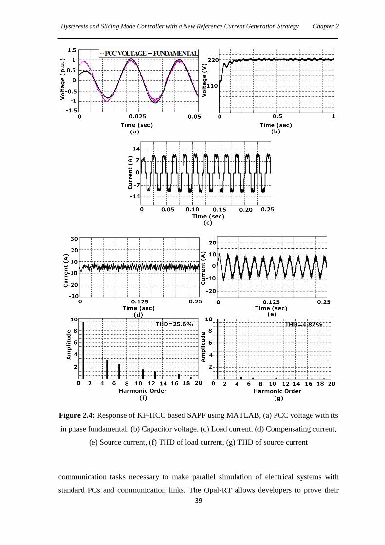
Hysteresis and Sliding Mode Controller with a New Reference Current Generation Strategy Chapter 2
39
Figure 2.4: Response of KF-HCC based SAPF using MATLAB, (a) PCC voltage with its
in phase fundamental, (b) Capacitor voltage, (c) Load current, (d) Compensating current,
(e) Source current, (f) THD of load current, (g) THD of source current
communication tasks necessary to make parallel simulation of electrical systems with
standard PCs and communication links. The Opal-RT allows developers to prove their
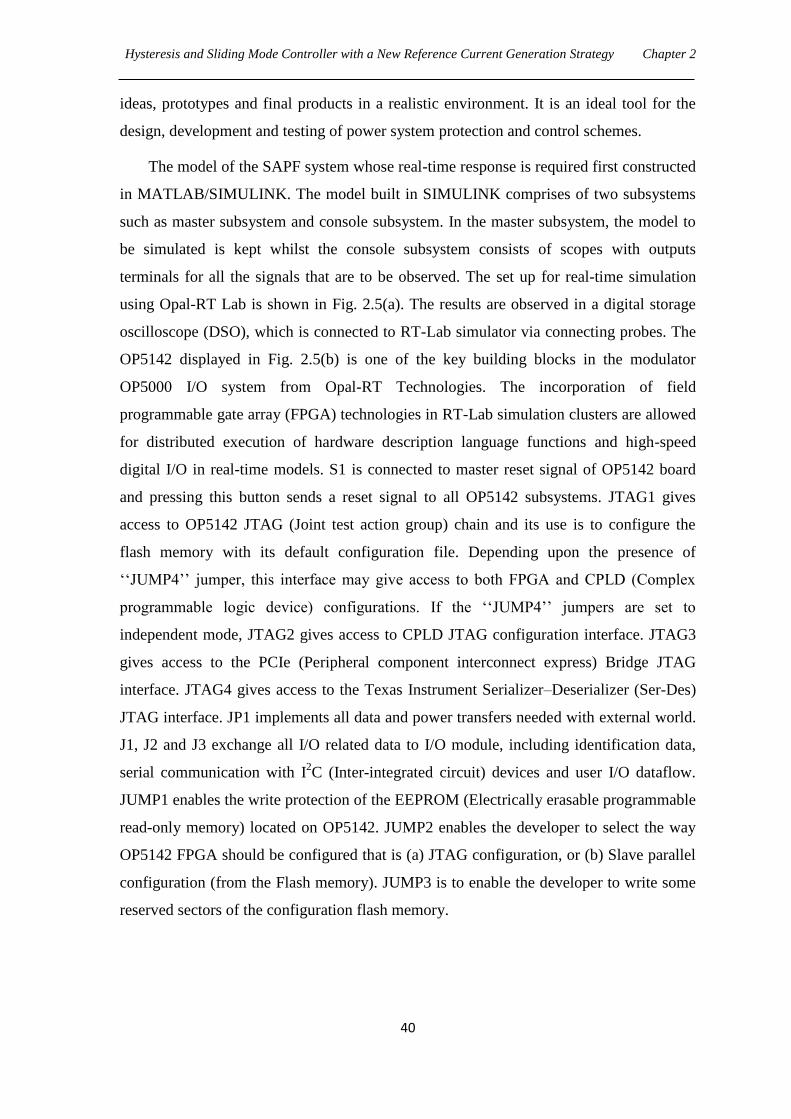
Hysteresis and Sliding Mode Controller with a New Reference Current Generation Strategy Chapter 2
40
ideas, prototypes and final products in a realistic environment. It is an ideal tool for the
design, development and testing of power system protection and control schemes.
The model of the SAPF system whose real-time response is required first constructed
in MATLAB/SIMULINK. The model built in SIMULINK comprises of two subsystems
such as master subsystem and console subsystem. In the master subsystem, the model to
be simulated is kept whilst the console subsystem consists of scopes with outputs
terminals for all the signals that are to be observed. The set up for real-time simulation
using Opal-RT Lab is shown in Fig. 2.5(a). The results are observed in a digital storage
oscilloscope (DSO), which is connected to RT-Lab simulator via connecting probes. The
OP5142 displayed in Fig. 2.5(b) is one of the key building blocks in the modulator
OP5000 I/O system from Opal-RT Technologies. The incorporation of field
programmable gate array (FPGA) technologies in RT-Lab simulation clusters are allowed
for distributed execution of hardware description language functions and high-speed
digital I/O in real-time models. S1 is connected to master reset signal of OP5142 board
and pressing this button sends a reset signal to all OP5142 subsystems. JTAG1 gives
access to OP5142 JTAG (Joint test action group) chain and its use is to configure the
flash memory with its default configuration file. Depending upon the presence of
‗‗JUMP4‘‘ jumper, this interface may give access to both FPGA and CPLD (Complex
programmable logic device) configurations. If the ‗‗JUMP4‘‘ jumpers are set to
independent mode, JTAG2 gives access to CPLD JTAG configuration interface. JTAG3
gives access to the PCIe (Peripheral component interconnect express) Bridge JTAG
interface. JTAG4 gives access to the Texas Instrument Serializer–Deserializer (Ser-Des)
JTAG interface. JP1 implements all data and power transfers needed with external world.
J1, J2 and J3 exchange all I/O related data to I/O module, including identification data,
serial communication with I2C (Inter-integrated circuit) devices and user I/O dataflow.
JUMP1 enables the write protection of the EEPROM (Electrically erasable programmable
read-only memory) located on OP5142. JUMP2 enables the developer to select the way
OP5142 FPGA should be configured that is (a) JTAG configuration, or (b) Slave parallel
configuration (from the Flash memory). JUMP3 is to enable the developer to write some
reserved sectors of the configuration flash memory.
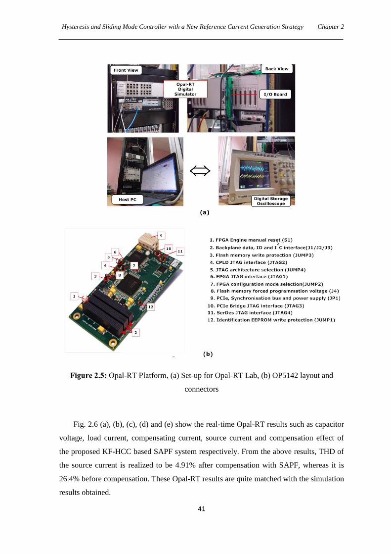
Hysteresis and Sliding Mode Controller with a New Reference Current Generation Strategy Chapter 2
41
Figure 2.5: Opal-RT Platform, (a) Set-up for Opal-RT Lab, (b) OP5142 layout and
connectors
Fig. 2.6 (a), (b), (c), (d) and (e) show the real-time Opal-RT results such as capacitor
voltage, load current, compensating current, source current and compensation effect of
the proposed KF-HCC based SAPF system respectively. From the above results, THD of
the source current is realized to be 4.91% after compensation with SAPF, whereas it is
26.4% before compensation. These Opal-RT results are quite matched with the simulation
results obtained.
Hysteresis and Sliding Mode Controller with a New Reference Current Generation Strategy Chapter 2
42
Figure 2.6: Response of KF-HCC based SAPF using Opal-RT, (a) Capacitor voltage,
(b) Load current, (c) Compensating current, (d) Source current, (e) THD before and after
compensation
2.3.5.3 Remarks on the Proposed KF-HCC based SAPF Method
Advantages:
The main advantage of HCC method is the simplicity in calculus.
KF acts as an important role in generation of reference signal, where it perfectly
estimates the in phase fundamental component of PCC voltage with all grid
perturbations taken into account.
Disadvantages:
Reference current generation is not so effective due to slower convergence rate of KF.
Therefore, KF-HCC based SAPF method is not able to mitigate harmonics perfectly. The
THD value for the source current is found to be 4.87% as verified by the simulation
results (Fig. 2.3), which value is quite closer to the boundary of IEEE-519 standard.
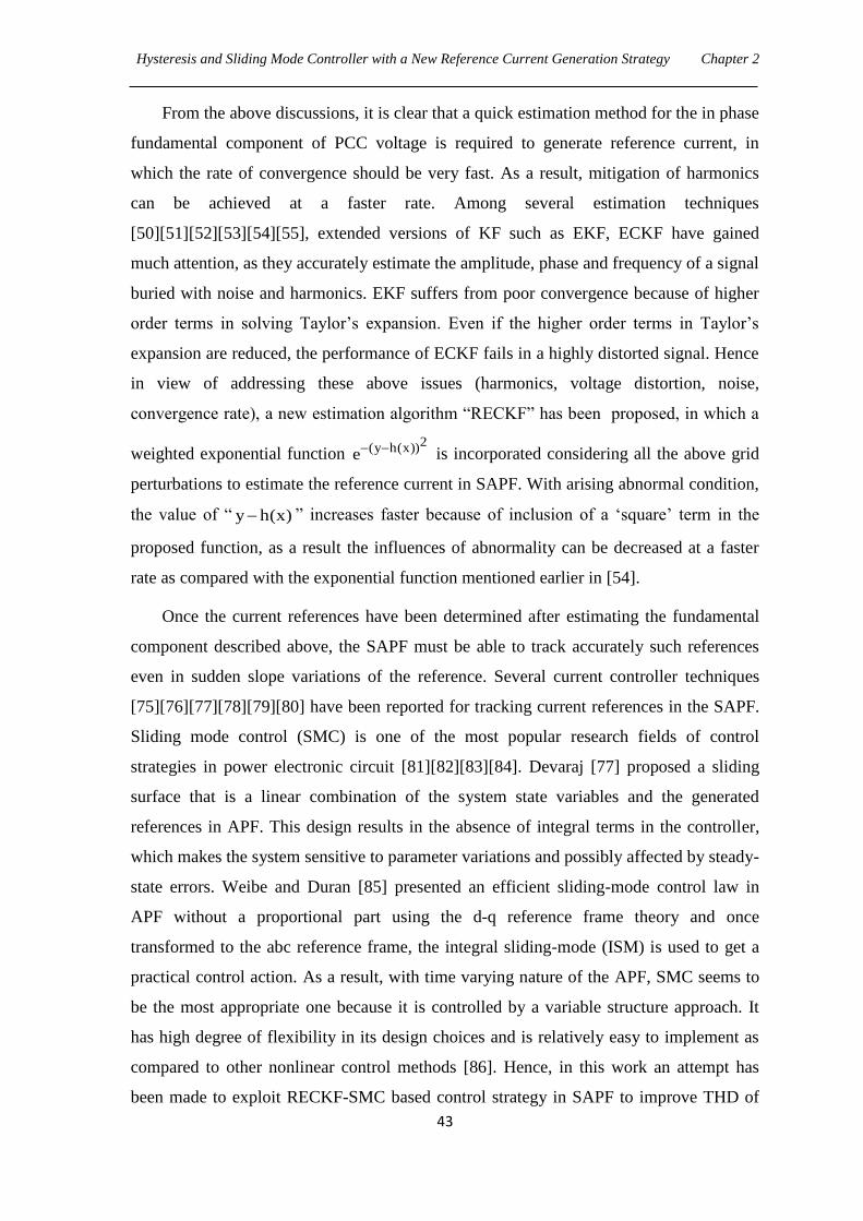
Hysteresis and Sliding Mode Controller with a New Reference Current Generation Strategy Chapter 2
43
From the above discussions, it is clear that a quick estimation method for the in phase
fundamental component of PCC voltage is required to generate reference current, in
which the rate of convergence should be very fast. As a result, mitigation of harmonics
can be achieved at a faster rate. Among several estimation techniques
[50][51][52][53][54][55], extended versions of KF such as EKF, ECKF have gained
much attention, as they accurately estimate the amplitude, phase and frequency of a signal
buried with noise and harmonics. EKF suffers from poor convergence because of higher
order terms in solving Taylor‘s expansion. Even if the higher order terms in Taylor‘s
expansion are reduced, the performance of ECKF fails in a highly distorted signal. Hence
in view of addressing these above issues (harmonics, voltage distortion, noise,
convergence rate), a new estimation algorithm ―RECKF‖ has been proposed, in which a
weighted exponential function
2(y h(x))e is incorporated considering all the above grid
perturbations to estimate the reference current in SAPF. With arising abnormal condition,
the value of ― y h(x) ‖ increases faster because of inclusion of a ‗square‘ term in the
proposed function, as a result the influences of abnormality can be decreased at a faster
rate as compared with the exponential function mentioned earlier in [54].
Once the current references have been determined after estimating the fundamental
component described above, the SAPF must be able to track accurately such references
even in sudden slope variations of the reference. Several current controller techniques
[75][76][77][78][79][80] have been reported for tracking current references in the SAPF.
Sliding mode control (SMC) is one of the most popular research fields of control
strategies in power electronic circuit [81][82][83][84]. Devaraj [77] proposed a sliding
surface that is a linear combination of the system state variables and the generated
references in APF. This design results in the absence of integral terms in the controller,
which makes the system sensitive to parameter variations and possibly affected by steady-
state errors. Weibe and Duran [85] presented an efficient sliding-mode control law in
APF without a proportional part using the d-q reference frame theory and once
transformed to the abc reference frame, the integral sliding-mode (ISM) is used to get a
practical control action. As a result, with time varying nature of the APF, SMC seems to
be the most appropriate one because it is controlled by a variable structure approach. It
has high degree of flexibility in its design choices and is relatively easy to implement as
compared to other nonlinear control methods [86]. Hence, in this work an attempt has
been made to exploit RECKF-SMC based control strategy in SAPF to improve THD of
Hysteresis and Sliding Mode Controller with a New Reference Current Generation Strategy Chapter 2
44
the source current and the development of this proposed strategy is discussed in the
following section.
2.4 Proposed RECKF-SMC based SAPF
Based on the discussions in the above section, the estimation accuracy of the proposed
RECKF is more effective and hence can be employed for generation of reference current
in SAPF. Further, sliding mode controller (SMC) technique is characterized by
guaranteed stability, fast dynamic response and strong robustness against parameter
uncertainties. Such properties make SMC suitable for applications in SAPF system,
accounting for their wide utilization in industrial applications, e.g. electrical drivers,
automotive control, furnace control, etc.
2.4.1 Description of Proposed RECKF-SMC based SAPF System
The control structure for proposed RECKF-SMC based SAPF system is developed by
replacing HCC by SMC technique for generation of gate drive signals for IGBT inverter
and KF by proposed RECKF for estimating in phase fundamental component of PCC
voltage in Fig. 2.1, whereas the objective of this SAPF system is same as described for
KF-HCC in Section 2.2.1. Hence a reduced block diagram for proposed RECKF-SMC
based SAPF system is depicted in Fig. 2.7.
Figure 2.7: Proposed RECKF-SMC based SAPF
Hysteresis and Sliding Mode Controller with a New Reference Current Generation Strategy Chapter 2
45
2.4.2 Proposed Reference Current Generation
The expression for reference signal is same as derived for KF-HCC in eq (2.1). In order to
verify the estimation accuracy of the proposed RECKF based reference current
generation, a comparative evaluation has to be performed using four variants of Kalman
filtering algorithms (KF, EKF, ECKF and Proposed RECKF).Therefore the formulations
for the above four Kalman algorithms are presented below. However, formulation for KF
algorithm has already been described in Section 2.2.2.1.
2.4.2.1 Signal Model and Formulation of EKF Algorithm
As per simplicity in formulation, the signal in eq (2.2a) can be replaced by
k 1 1 s 1z a cos(k T ) (2.21)
It is noted that the three consecutive samples of this single sinusoid will satisfy the
following relationship
k 1 s k 1 k 2z 2cos T z z 0 (2.22)
The state space vector is given by
T
k 1 s k 1 k 2x 2cos T z z (2.23)
k 1 1 s k
1 0 0
x 0 2cos T 1 x
0 1 0
(2.24)
The measurement equation can be expressed as
k 1 s k ky [0 2cos T 1]x v (2.25)
The nonlinear state space equations can be represented as
k 1 kx f (x ) (2.26)
k k ky g(x ) v (2.27)
where
Tk 1 s 1 s k 1 k 2 k 1f (x ) [2cos T 2cos T .x x x ] (2.28)
k 1 s k 1 k 2g(x ) 2cos T .x x (2.29)
Hysteresis and Sliding Mode Controller with a New Reference Current Generation Strategy Chapter 2
46
Linearizing the above system and applying EKF theory to first order system, a
nonlinear recursive filter for estimating a single sinusoid is given as follows:
k k k k 1 k k k k 1ˆ ˆ ˆx x K (y g(x )) (2.30)
k 1k k kˆ ˆx f (x ) (2.31)
k k 1
1T T
k k k 1 k k k kK P H . H P H R
(2.32)
k k k k 1 k k k k 1P P K H P (2.33)
Tk k 1 k k k kP F P F (2.34)
where
k k
kk 2 1
k
1 0 0ˆf (x )
ˆ ˆF x x 1x
0 1 0
and k k
kk 2 1
k
ˆg(x )ˆ ˆH x x 1
x
To find in phase fundamental component 1 1 s 1a sin(k T ) as per eq (2.5a), we have to
make 90 degree phase shift of the estimated signal kz . Then per unit representation of in
phase fundamental component is same as prescribed in KF algorithm.
2.4.2.2 Signal Model and Formulation of ECKF Algorithm
The signal in eq (2.2a) can be represented in complex form as
1 s 1 1 s 1j(k T + ) -j(k T + )k 1 1z ( 0.5i) a e (0.5i) a e
(2.35)
The complex type state variable kx can be given as
1 sk
i T1x e
(2.36)
1 s 1k
j(k T )2 1x a e
(2.37)
1 s 1k
j(k T )3 1x a e
(2.38)
The nonlinear state space equations can be represented as
k k 1x f (x ) (2.39)
k k ky g(x ) v (2.40)
Hysteresis and Sliding Mode Controller with a New Reference Current Generation Strategy Chapter 2
47
where
(k 1)
(k 1) (k 1)(k 1)
(k 1)
T
3
k 1 1 1 21
xf (x ) x x x
x
(2.41)
The recursion process of the ECKF for estimating the signal parameters of sinusoid
waves is given below.
k k 1ˆx f (x ) (2.42)
Tk k k 1 k kM F P F Q (2.43)
k k k k k kx x K (y H x ) (2.44)
1T T
k k k k k k kK M H H M H R
(2.45)
k k k kP M (I K H ) (2.46)
where the symbols and stand for the predicted and estimated values respectively,
kM and kP represent the predicted and estimated error covariance respectively. The
values of kF and kH are given here.
(k 1) (k 1)
(k 1) (k 1)(k 1)
k 1k 2 1
k 12
3 11
1 0 0ˆf (x )
ˆ ˆF x x 0x
ˆ ˆ ˆx x 0 1 x
(2.47)
kk
k
(g(x ))H 0 0.5i 0.5i
x
(2.48)
The parameters of frequency kf , amplitude ka and phase angle k can be expressed as
k k1 1s
1ˆ ˆf Im (ln(x ))2 T
(2.49)
k k1 2ˆ ˆa x (2.50)
k
k
k k
21 k
2 1
xˆ Im ln
ˆ ˆx (x )
(2.51)
Hysteresis and Sliding Mode Controller with a New Reference Current Generation Strategy Chapter 2
48
Using the above parametersk1f ,
k1a andk1 , the in phase fundamental component can be
identified and its per unit value can be expressed as
k k k
k k
k
1 1 s 1
1 s 11
ˆ ˆa sin 2 f Tˆ ˆsin 2 f T
a
(2.52)
2.4.2.3 Signal Model and Formulation of Proposed RECKF Algorithm
The signal model and filter formulations in proposed RECKF are same as in ECKF. The
only difference is in the measurement error covariance ― kR ‖, which is the inverse of the
weighting kW , i.e.
1k kR W (2.53)
2k k k(y H x )
k k 1W W e
(2.54)
where the exponential term 2
k k k(y H x )e is the proposed robust exponential function and
the variable kR is replaced in eq (2.41).When any grid disturbances occur at the PCC, the
innovation vector k k k(y H x ) increases faster due to the inclusion of a ‗square term‘ in
the proposed exponential function. Consequently, the value of proposed robust
exponential function decreases faster and finally a fast reduction of weighting and
mitigation of error can be achieved.
2.4.3 Sliding Mode Control (SMC)
A single phase circuit of voltage source inverter is considered here in the design of an
active power filter. Fig. 2.8 presents the equivalent circuit for a single phase voltage
source inverter used for development of SMC law. If a switching function u is defined
such that u 1 when either 1S or 1D is conducting and u 1 when either 2S
or 2D is
conducting, then the inductor current is given by
xF sxn dc
F F
di v vu
dt L 2L (2.55)
where x denotes the phase, sxnv represents the phase to neutral voltage.
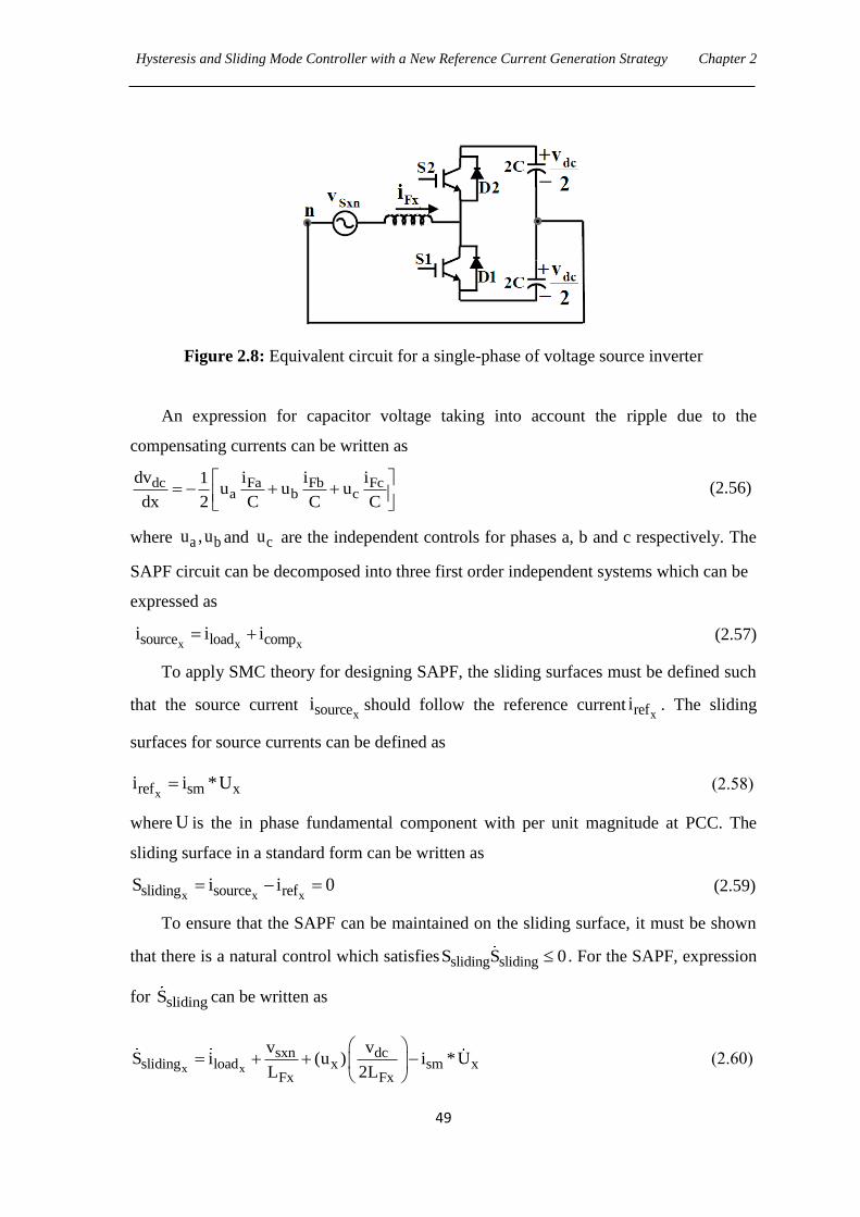
Hysteresis and Sliding Mode Controller with a New Reference Current Generation Strategy Chapter 2
49
Figure 2.8: Equivalent circuit for a single-phase of voltage source inverter
An expression for capacitor voltage taking into account the ripple due to the
compensating currents can be written as
dc Fa Fb Fca b c
dv i i i1u u u
dx 2 C C C
(2.56)
where a bu ,u and cu are the independent controls for phases a, b and c respectively. The
SAPF circuit can be decomposed into three first order independent systems which can be
expressed as
x x xsource load compi i i (2.57)
To apply SMC theory for designing SAPF, the sliding surfaces must be defined such
that the source current xsourcei should follow the reference current
xrefi . The sliding
surfaces for source currents can be defined as
xref sm xi i *U (2.58)
where U is the in phase fundamental component with per unit magnitude at PCC. The
sliding surface in a standard form can be written as
x x xsliding source refS i i 0 (2.59)
To ensure that the SAPF can be maintained on the sliding surface, it must be shown
that there is a natural control which satisfies sliding slidingS S 0 . For the SAPF, expression
for slidingS can be written as
x x
sxn dcsliding load x sm x
Fx Fx
v vS i (u ) i *U
L 2L
(2.60)
Hysteresis and Sliding Mode Controller with a New Reference Current Generation Strategy Chapter 2
50
The equivalent control xequ can be found out by equating eq (2.60) to zero and the
natural control limits of the circuit arexeq1 u 1 . The discontinuous control law can
be written as follows.
If slidingS 0 then u 1
If slidingS 0 then u 1 (2.61)
For generating switching pulses, this control law can be applied to the SAPF.
2.4.4 Results and Discussions
Four control strategies namely KF-SMC, EKF-SMC, ECKF-SMC, and RECKF-SMC
based SAPF were implemented and analyzed using the following simulation and Opal RT
results.
2.4.4.1 Simulation Results
Fig. 2.9 depicts the simulation results for SAPF using KF-SMC, EKF-SMC, ECKF-SMC,
and RECKF-SMC based control structure. The PCC voltage at phase a and its in phase
fundamental component estimated with the help of above four Kalman algorithms is
displayed in Fig. 2.9(a). It can be seen from Fig. 2.9(a) that in phase fundamental
estimated by KF takes 0.005 sec to follow PCC voltage. But in case of EKF, the
fundamental is initially not in phase with PCC, and it suffers a delay of 0.05 sec.
However, the fundamental components are exactly matched with the PCC voltage in case
of both ECKF and RECKF. The capacitor voltage waveforms presented in Fig. 2.9(b) are
compared on the basis of above four filter algorithms. Generally, the harmonic
compensating performance will be spoiled when large fluctuations of the voltage occur
across the DC capacitor. As can be seen in Fig. 2.9(b), the fluctuation is more in the EKF-
SMC as compared to the other three. Further comparison among the KF-SMC, ECKF-
SMC and RECKF-SMC shows that the RECKF-SMC based SAPF system enables
suppression of the voltage fluctuations across DC capacitor and is quickly set at around
220V indicating good harmonic compensating performance.
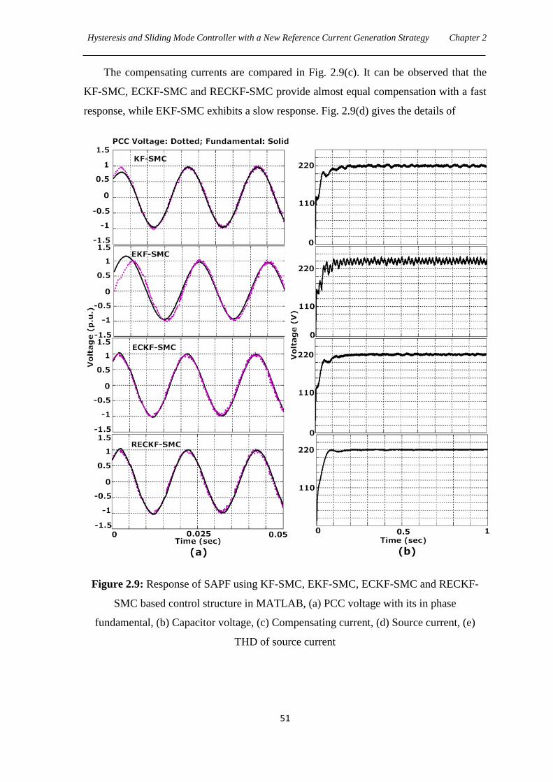
Hysteresis and Sliding Mode Controller with a New Reference Current Generation Strategy Chapter 2
51
The compensating currents are compared in Fig. 2.9(c). It can be observed that the
KF-SMC, ECKF-SMC and RECKF-SMC provide almost equal compensation with a fast
response, while EKF-SMC exhibits a slow response. Fig. 2.9(d) gives the details of
Figure 2.9: Response of SAPF using KF-SMC, EKF-SMC, ECKF-SMC and RECKF-
SMC based control structure in MATLAB, (a) PCC voltage with its in phase
fundamental, (b) Capacitor voltage, (c) Compensating current, (d) Source current, (e)
THD of source current
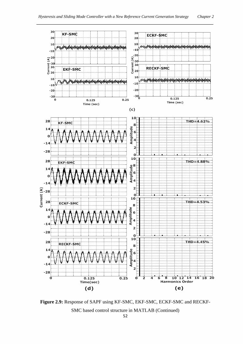
Hysteresis and Sliding Mode Controller with a New Reference Current Generation Strategy Chapter 2
52
Figure 2.9: Response of SAPF using KF-SMC, EKF-SMC, ECKF-SMC and RECKF-
SMC based control structure in MATLAB (Continued)
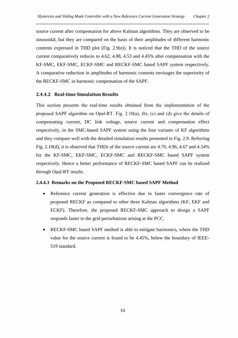
Hysteresis and Sliding Mode Controller with a New Reference Current Generation Strategy Chapter 2
53
source current after compensation for above Kalman algorithms. They are observed to be
sinusoidal, but they are compared on the basis of their amplitudes of different harmonic
contents expressed in THD plot (Fig. 2.9(e)). It is noticed that the THD of the source
current comparatively reduces to 4.62, 4.88, 4.53 and 4.45% after compensation with the
KF-SMC, EKF-SMC, ECKF-SMC and RECKF-SMC based SAPF system respectively.
A comparative reduction in amplitudes of harmonic contents envisages the superiority of
the RECKF-SMC in harmonic compensation of the SAPF.
2.4.4.2 Real-time Simulation Results
This section presents the real-time results obtained from the implementation of the
proposed SAPF algorithm on Opal-RT. Fig. 2.10(a), (b), (c) and (d) give the details of
compensating current, DC link voltage, source current and compensation effect
respectively, in the SMC-based SAPF system using the four variants of KF algorithms
and they compare well with the detailed simulation results presented in Fig. 2.9. Referring
Fig. 2.10(d), it is observed that THDs of the source current are 4.70, 4.96, 4.67 and 4.54%
for the KF-SMC, EKF-SMC, ECKF-SMC and RECKF-SMC based SAPF system
respectively. Hence a better performance of RECKF-SMC based SAPF can be realized
through Opal-RT results.
2.4.4.3 Remarks on the Proposed RECKF-SMC based SAPF Method
Reference current generation is effective due to faster convergence rate of
proposed RECKF as compared to other three Kalman algorithms (KF, EKF and
ECKF). Therefore, the proposed RECKF-SMC approach to design a SAPF
responds faster to the grid perturbations arising at the PCC.
RECKF-SMC based SAPF method is able to mitigate harmonics, where the THD
value for the source current is found to be 4.45%, below the boundary of IEEE-
519 standard.
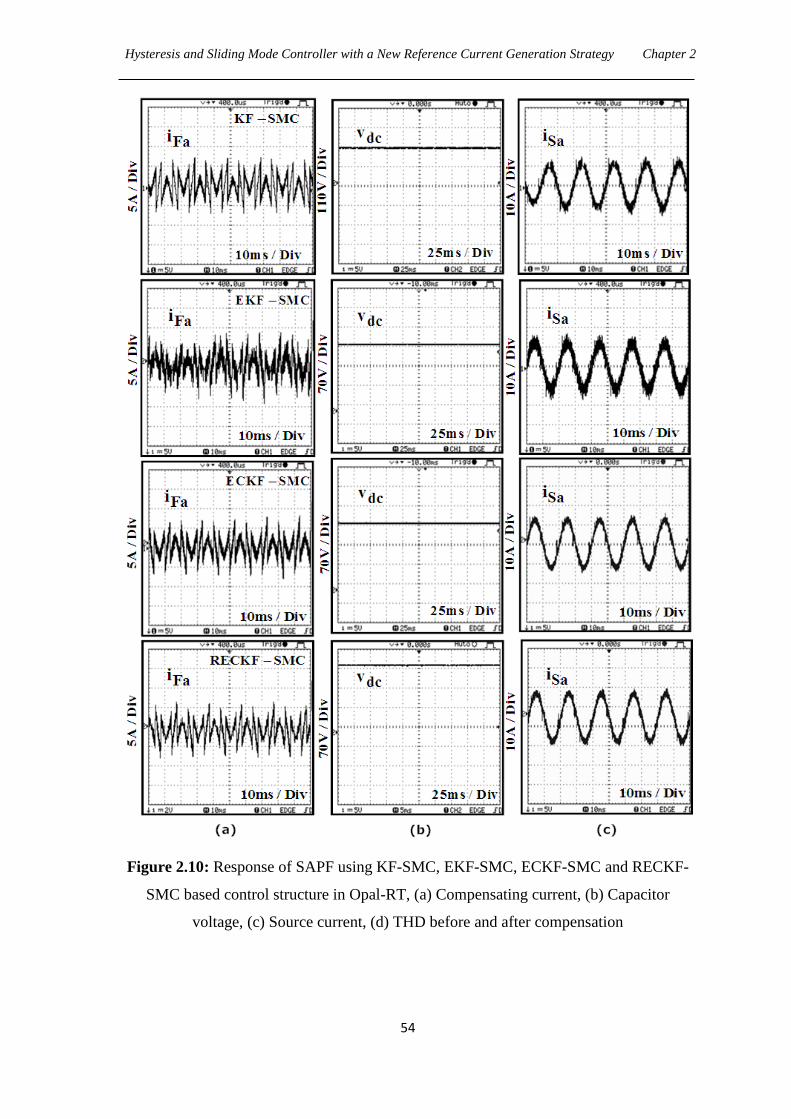
Hysteresis and Sliding Mode Controller with a New Reference Current Generation Strategy Chapter 2
54
Figure 2.10: Response of SAPF using KF-SMC, EKF-SMC, ECKF-SMC and RECKF-
SMC based control structure in Opal-RT, (a) Compensating current, (b) Capacitor
voltage, (c) Source current, (d) THD before and after compensation
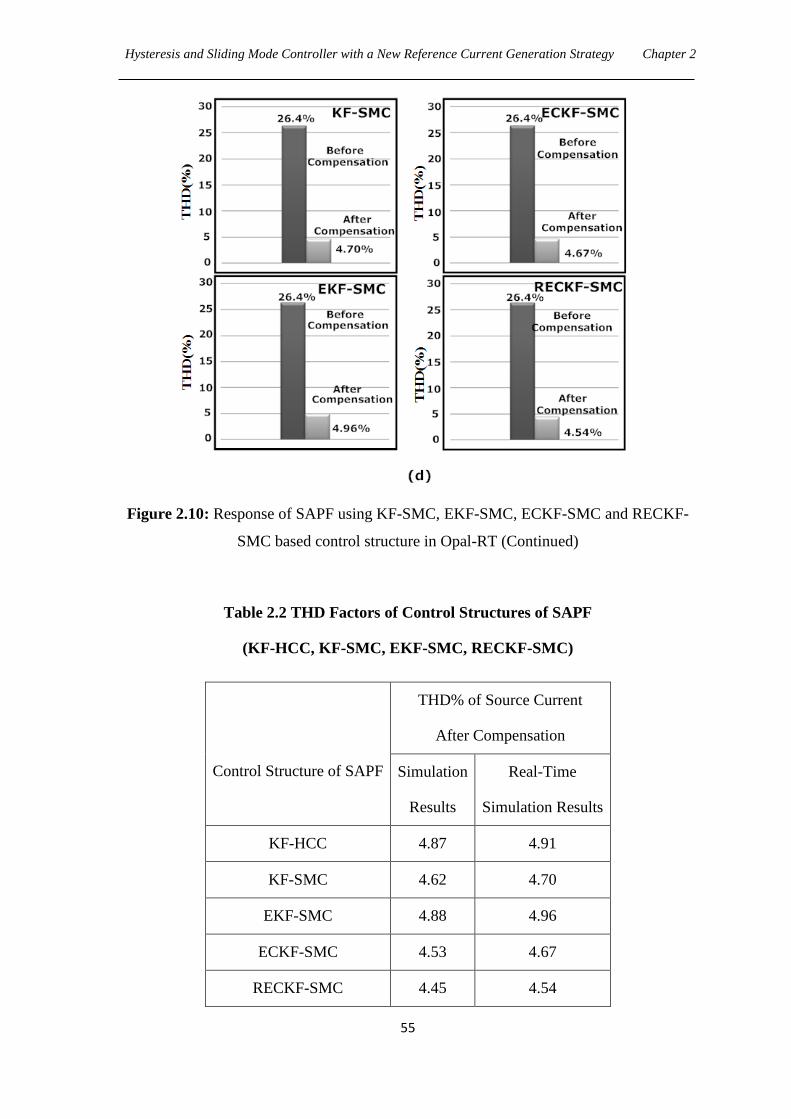
Hysteresis and Sliding Mode Controller with a New Reference Current Generation Strategy Chapter 2
55
Figure 2.10: Response of SAPF using KF-SMC, EKF-SMC, ECKF-SMC and RECKF-
SMC based control structure in Opal-RT (Continued)
Table 2.2 THD Factors of Control Structures of SAPF
(KF-HCC, KF-SMC, EKF-SMC, RECKF-SMC)
Control Structure of SAPF
THD% of Source Current
After Compensation
Simulation
Results
Real-Time
Simulation Results
KF-HCC 4.87 4.91
KF-SMC 4.62 4.70
EKF-SMC 4.88 4.96
ECKF-SMC 4.53 4.67
RECKF-SMC 4.45 4.54
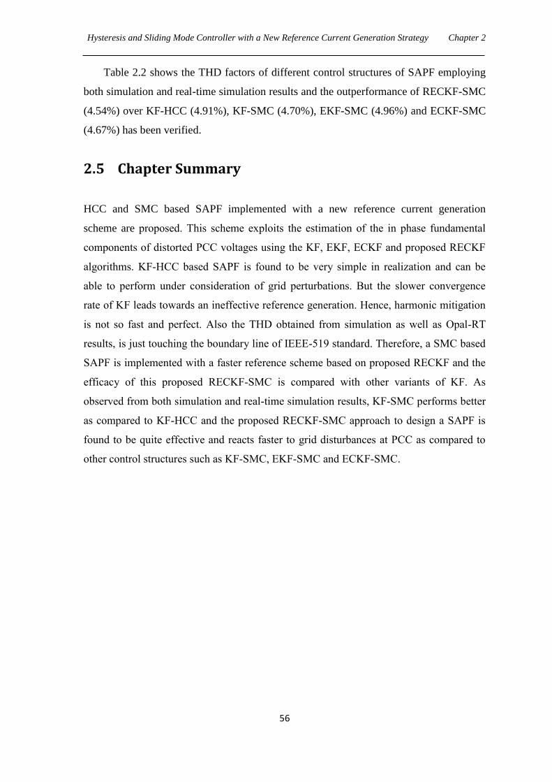
Hysteresis and Sliding Mode Controller with a New Reference Current Generation Strategy Chapter 2
56
Table 2.2 shows the THD factors of different control structures of SAPF employing
both simulation and real-time simulation results and the outperformance of RECKF-SMC
(4.54%) over KF-HCC (4.91%), KF-SMC (4.70%), EKF-SMC (4.96%) and ECKF-SMC
(4.67%) has been verified.
2.5 Chapter Summary
HCC and SMC based SAPF implemented with a new reference current generation
scheme are proposed. This scheme exploits the estimation of the in phase fundamental
components of distorted PCC voltages using the KF, EKF, ECKF and proposed RECKF
algorithms. KF-HCC based SAPF is found to be very simple in realization and can be
able to perform under consideration of grid perturbations. But the slower convergence
rate of KF leads towards an ineffective reference generation. Hence, harmonic mitigation
is not so fast and perfect. Also the THD obtained from simulation as well as Opal-RT
results, is just touching the boundary line of IEEE-519 standard. Therefore, a SMC based
SAPF is implemented with a faster reference scheme based on proposed RECKF and the
efficacy of this proposed RECKF-SMC is compared with other variants of KF. As
observed from both simulation and real-time simulation results, KF-SMC performs better
as compared to KF-HCC and the proposed RECKF-SMC approach to design a SAPF is
found to be quite effective and reacts faster to grid disturbances at PCC as compared to
other control structures such as KF-SMC, EKF-SMC and ECKF-SMC.
CHAPTER 3
Robust Extended Complex Kalman Filter and
Model Predictive based SAPF
3.1 Introduction
Chapter 2 discusses the harmonics compensation performance of HCC and SMC based
SAPF together with reference generation scheme through different variants of KF
algorithms such as KF, EKF, ECKF and RECKF. The harmonics compensation
performances of these control strategies are very poor as THD obtained (i.e., 4.91%,
4.70%, 4.96%, 4.67% and 4.54%) are very close to 5%. In order to obtain accurate
current harmonics compensation, predictive current control techniques with improved
reference generation scheme are proposed in this chapter. The motivation for developing
these predictive controllers has emerged because of obvious advantages of digital control
techniques [87][88][89][90][91][92][93][94][95] over the analog ones. The proposed
predictive current controller comprises of a deadbeat controller (DBC) and model
predictive controller (MPC) in designing a SAPF. Since implementation of a predictive
current control requires a fast and accurate reference current estimator, the proposed
RECKF algorithm is more effective owing to its fastest convergence rate as observed in
Chapter 2 and hence it can be employed for the reference generation scheme.
In order to regulate dc bus voltage, a PI controller is needed in the external loop
using conventional unit vector approach [29]. Fryze theory [96] necessitates a
measurement of both load current and source voltage for reference generation without PI
controller loop. However, more computations are involved in this approach for
calculating reference source current. In the operation of the SAPF system, the ac mains
supplies real power needed to the load and meets some losses e.g. switching losses of
devices, losses in the reactor and dielectric losses of dc capacitor. Therefore, the proposed
reference source currents that are used to decide the switching of the SAPF have two
parts: one is the real fundamental-frequency component of the load current, which is
estimated using the proposed RECKF and another component, which corresponds to the
losses in the SAPF, is also estimated using the proposed RECKF. The advantage of this
method is the simpler computations and avoiding tuning and thus less number of voltage
Robust Extended Complex Kalman Filter and Model Predictive based SAPF Chapter 3
58
sensors are necessary to obtain the reference current. This proposed approach is chosen to
eliminate large overshoots and undershoots associated with conventional PI control,
causing unstable operation of the inverter in protecting the switching devices.
Furthermore, recent applications need faster response, minimum power dissipation and
robustness, which are not achieved by using the PI controller. It is expected that by using
the proposed reference generation the above demerits of PI control can be resolved and
the dc-link capacitor voltage can be kept constant at the set point.
With the evolution of powerful, fast and inexpensive microcomputers, research is
progressing faster on designing and subsequent real-time implementation of predictive
controller for several systems including power electronic systems. In predictive control, a
model of the system is used to predict its future behavior and the most appropriate control
action based on an optimality criterion is generated. Dead Beat Control (DBC) is a
popular predictive controller applied to power converters. DBC can eliminate the classic
linear controller by using a predictive model of the system. This model is used to
calculate the required reference voltage in order to reach the desired reference value for a
certain variable (usually the current). The predicted reference voltage is later generated by
the converter via a modulation stage. Malesani [88] considered a control strategy
combining dead-beat control of inverter currents and space vector modulation in SAPF. A
generalized discrete-time state-space representation of the controlled converter and its
load is presented and this reveals the stability margins of the deadbeat algorithm in the
case of a conventional load model and line voltage estimation technique, giving the
possibility of predicting the occurrence of oscillations in the current loop by mapping the
closed loop SAPF's eigenvalues. In [89] an improved deadbeat current control scheme
with a novel adaptive self-tuning load model for a three phase PWM VSI was introduced.
First, an improved deadbeat current controller with delay compensation has been
developed for a fully digital platform with a relatively small control period (150 µs). The
compensation method forces the delay elements, which are caused by voltage calculation,
PWM and synchronous frame rotation, to be equivalently placed outside the closed-loop
control system. Hence, their effect on the closed-loop stability is eliminated and the
current controller can be designed with high-bandwidth characteristics. A robust deadbeat
current control technique [90] is derived based on the average current tracking scheme in
hybrid APF, where the grid current feedback and load current feed forward strategies are
used to achieve precise current tracking and fast dynamic response.
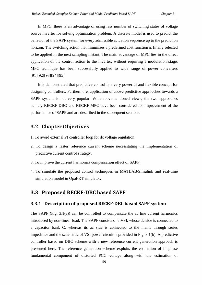
Robust Extended Complex Kalman Filter and Model Predictive based SAPF Chapter 3
59
In MPC, there is an advantage of using less number of switching states of voltage
source inverter for solving optimization problem. A discrete model is used to predict the
behavior of the SAPF system for every admissible actuation sequence up to the prediction
horizon. The switching action that minimizes a predefined cost function is finally selected
to be applied in the next sampling instant. The main advantage of MPC lies in the direct
application of the control action to the inverter, without requiring a modulation stage.
MPC technique has been successfully applied to wide range of power converters
[91][92][93][94][95].
It is demonstrated that predictive control is a very powerful and flexible concept for
designing controllers. Furthermore, application of above predictive approaches towards a
SAPF system is not very popular. With abovementioned views, the two approaches
namely RECKF-DBC and RECKF-MPC have been considered for improvement of the
performance of SAPF and are described in the subsequent sections.
3.2 Chapter Objectives
1. To avoid external PI controller loop for dc voltage regulation.
2. To design a faster reference current scheme necessitating the implementation of
predictive current control strategy.
3. To improve the current harmonics compensation effect of SAPF.
4. To simulate the proposed control techniques in MATLAB/Simulink and real-time
simulation model in Opal-RT simulator.
3.3 Proposed RECKF-DBC based SAPF
3.3.1 Description of proposed RECKF-DBC based SAPF system
The SAPF (Fig. 3.1(a)) can be controlled to compensate the ac line current harmonics
introduced by non-linear load. The SAPF consists of a VSI, whose dc side is connected to
a capacitor bank C, whereas its ac side is connected to the mains through series
impedance and the schematic of VSI power circuit is provided in Fig. 3.1(b). A predictive
controller based on DBC scheme with a new reference current generation approach is
presented here. The reference generation scheme exploits the estimation of in phase
fundamental component of distorted PCC voltage along with the estimation of
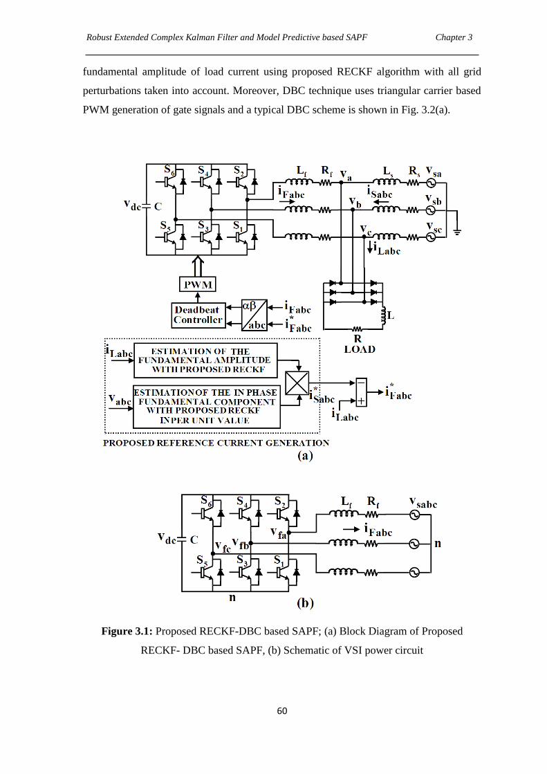
Robust Extended Complex Kalman Filter and Model Predictive based SAPF Chapter 3
60
fundamental amplitude of load current using proposed RECKF algorithm with all grid
perturbations taken into account. Moreover, DBC technique uses triangular carrier based
PWM generation of gate signals and a typical DBC scheme is shown in Fig. 3.2(a).
Figure 3.1: Proposed RECKF-DBC based SAPF; (a) Block Diagram of Proposed
RECKF- DBC based SAPF, (b) Schematic of VSI power circuit
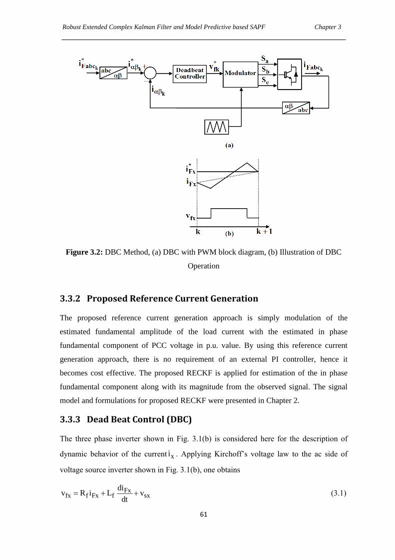
Robust Extended Complex Kalman Filter and Model Predictive based SAPF Chapter 3
61
Figure 3.2: DBC Method, (a) DBC with PWM block diagram, (b) Illustration of DBC
Operation
3.3.2 Proposed Reference Current Generation
The proposed reference current generation approach is simply modulation of the
estimated fundamental amplitude of the load current with the estimated in phase
fundamental component of PCC voltage in p.u. value. By using this reference current
generation approach, there is no requirement of an external PI controller, hence it
becomes cost effective. The proposed RECKF is applied for estimation of the in phase
fundamental component along with its magnitude from the observed signal. The signal
model and formulations for proposed RECKF were presented in Chapter 2.
3.3.3 Dead Beat Control (DBC)
The three phase inverter shown in Fig. 3.1(b) is considered here for the description of
dynamic behavior of the current xi . Applying Kirchoff‟s voltage law to the ac side of
voltage source inverter shown in Fig. 3.1(b), one obtains
Fxfx f Fx f sx
div R i L v
dt (3.1)

Robust Extended Complex Kalman Filter and Model Predictive based SAPF Chapter 3
62
where x represents the phases a, b, c and fv is the voltage generated by inverter. The
source EMF is denoted by sv .
The following discrete time equation can be obtained from eq. (3.1) for a sampling time
sT , under the assumption that the variables are constant between sampling instants.
Fx Fx fx sx1
i (k 1) i (k) v (k) v (k)
(3.2)
where T R /Ls f fe
and
T R /Ls f ff1/ R (1 e )
Based on the discrete-time model (eq. (3.2)), the reference voltage vector can be obtained
as follows,
*fx Fx Fx sx
1v (k) (i (k 1) i (k)) v (k)
(3.3)
Reference voltage *fxv is applied to VSI using a modulator. The basic operating principle
of DBC technique is shown in Fig. 3.2(b). Here, the current Fxi at time k is different to
the reference current Fxi . This error is used for calculation of the reference voltage*fxv ,
which is applied at time k. Ideally, at time (k+1), the current Fxi becomes equal to the
reference current Fxi .
3.3.4 Results and Discussions
3.3.4.1 Simulation Results
The performance of the proposed RECKF-DBC control strategy shown in Fig. 3.1(a) has
been verified using MATLAB/SIMULINK and the simulation results are shown in Fig.
3.3. A supply voltage is 100V peak to peak as shown (Fig. 3.3(a)). The tracking
performance of the proposed SAPF system is depicted in Fig. 3.3(b), where the
compensating current is able to track the reference current. The behavior of capacitor
voltage is presented in Fig. 3.3 (c) and the capacitor voltage takes about 0.2 sec to attain a
reference point of 220V. As observed from Fig. 3.3 (d), the source current is found to be
sinusoidal. Moreover, the THD of the source current after compensation is obtained to be
4.26%, as shown in Fig. 3.3(e).
Robust Extended Complex Kalman Filter and Model Predictive based SAPF Chapter 3
63
Figure 3.3: Response of RECKF-DBC based SAPF using MATLAB, (a) Source voltage,
(b) Compensating and Reference Compensating current, (c) Capacitor voltage, (d) Source
current, (e) THD of source current
3.3.4.2 Real-time Simulation Results
The real-time results obtained from the implementation of the proposed SAPF algorithm
on Opal-RT are presented in this section. Fig.3.4 shows the real-time results displaying
capacitor voltage, tracking of compensating and reference compensating currents, source
voltage and source current after compensation, and the THD effects with the proposed
RECKF-DBC based SAPF system respectively. It is observed from Fig. 3.4 that the
response for capacitor voltage and reference tracking are the same as obtained from
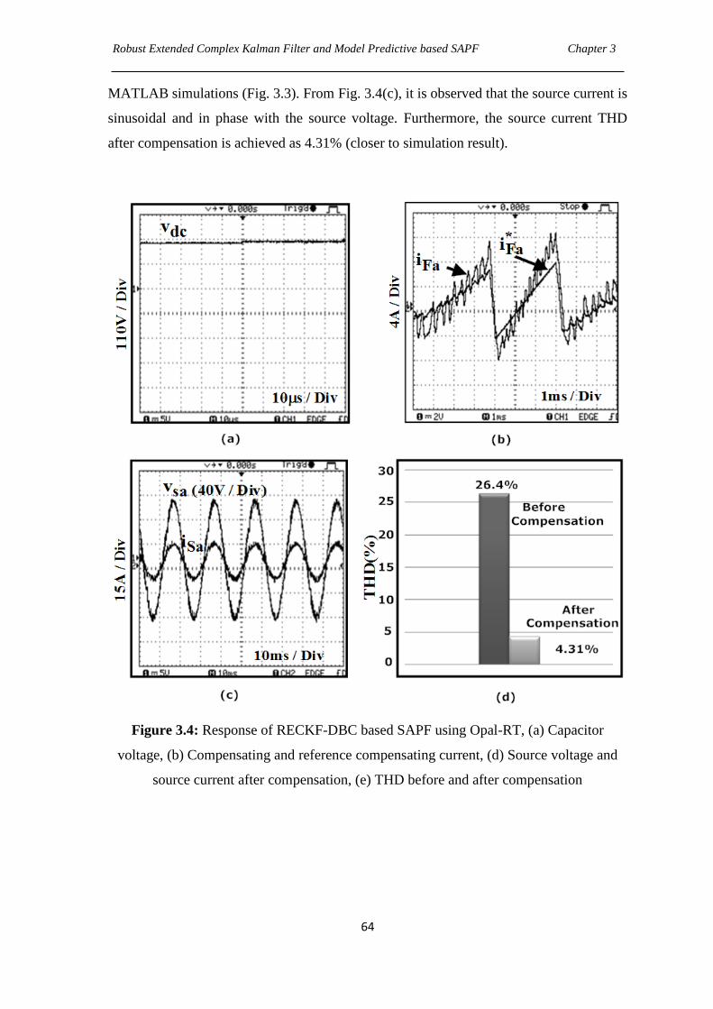
Robust Extended Complex Kalman Filter and Model Predictive based SAPF Chapter 3
64
MATLAB simulations (Fig. 3.3). From Fig. 3.4(c), it is observed that the source current is
sinusoidal and in phase with the source voltage. Furthermore, the source current THD
after compensation is achieved as 4.31% (closer to simulation result).
Figure 3.4: Response of RECKF-DBC based SAPF using Opal-RT, (a) Capacitor
voltage, (b) Compensating and reference compensating current, (d) Source voltage and
source current after compensation, (e) THD before and after compensation
Robust Extended Complex Kalman Filter and Model Predictive based SAPF Chapter 3
65
3.3.4.3 Remarks on the Performance exhibited by the Proposed RECKF-DBC
based SAPF
Advantages:
Implementation using proposed RECKF-DBC scheme is very simple.
Using DBC technique, it is possible to avoid the cascaded structure, which is
typically used in the linear control scheme, ensuring a very fast transient response.
This proposed SAPF system has full compatibility with digital control platforms.
Disadvantages:
DBC scheme needs a modulator to provide gate drive signals to IGBT inverter.
Irrespective of fixed switching frequency, DBC method is incapable of achieving
a satisfactory performance level and distortions are present in the source current
after compensation (i.e., THD%=4.26).
Nonlinearities of the system can be included in the model, avoiding the need of
linearizing the model for a given operating point and improving the operation of the
system for all conditions. It is also possible to include restrictions to some variables when
designing the controller. These advantages can be easily implemented in an advanced
predictive scheme known as MPC, but it is very difficult to implement in DBC scheme.
In DBC, the optimal actuation is the one that makes the error equal to zero in the next
sampling instant, whereas a more flexible criterion is used in MPC, expressed as a cost
function to be minimized. Internal current control loops and modulators are not needed
and the gate drive signals are generated directly by this MPC scheme.
Hence, there is a scope of improvement of the proposed RECKF-DBC based SAPF
system by designing an advanced predictive control scheme based on MPC and the
design of the proposed RECKF-MPC based SAPF is presented in next section.
3.4 Proposed RECKF-MPC based SAPF
3.4.1 Description of proposed RECKF-MPC based SAPF system
The control structure for the proposed RECKF-MPC is similar as mentioned in Fig. 3.1(a)
except that the current controller is replaced by MPC without any PWM scheme. The
reference generation approach with RECKF is same as prescribed in Section 3.2.2.
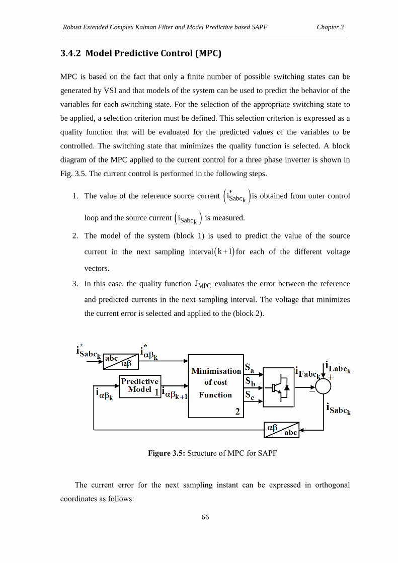
Robust Extended Complex Kalman Filter and Model Predictive based SAPF Chapter 3
66
3.4.2 Model Predictive Control (MPC)
MPC is based on the fact that only a finite number of possible switching states can be
generated by VSI and that models of the system can be used to predict the behavior of the
variables for each switching state. For the selection of the appropriate switching state to
be applied, a selection criterion must be defined. This selection criterion is expressed as a
quality function that will be evaluated for the predicted values of the variables to be
controlled. The switching state that minimizes the quality function is selected. A block
diagram of the MPC applied to the current control for a three phase inverter is shown in
Fig. 3.5. The current control is performed in the following steps.
1. The value of the reference source current *Sabck
i is obtained from outer control
loop and the source current Sabcki is measured.
2. The model of the system (block 1) is used to predict the value of the source
current in the next sampling interval k 1 for each of the different voltage
vectors.
3. In this case, the quality function MPCJ evaluates the error between the reference
and predicted currents in the next sampling interval. The voltage that minimizes
the current error is selected and applied to the (block 2).
Figure 3.5: Structure of MPC for SAPF
The current error for the next sampling instant can be expressed in orthogonal
coordinates as follows:
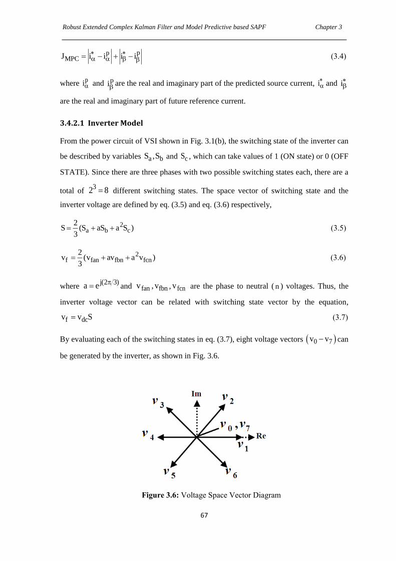
Robust Extended Complex Kalman Filter and Model Predictive based SAPF Chapter 3
67
ppMPCJ i i i i
(3.4)
where pi and p
i are the real and imaginary part of the predicted source current, i and i
are the real and imaginary part of future reference current.
3.4.2.1 Inverter Model
From the power circuit of VSI shown in Fig. 3.1(b), the switching state of the inverter can
be described by variables a bS ,S and cS , which can take values of 1 (ON state) or 0 (OFF
STATE). Since there are three phases with two possible switching states each, there are a
total of 32 8 different switching states. The space vector of switching state and the
inverter voltage are defined by eq. (3.5) and eq. (3.6) respectively,
2a b c
2S (S aS a S )
3 (3.5)
2f fan fbn fcn
2v (v av a v )
3 (3.6)
where j(2 3)a e and fan fbnv , v , fcnv are the phase to neutral ( n ) voltages. Thus, the
inverter voltage vector can be related with switching state vector by the equation,
f dcv v S (3.7)
By evaluating each of the switching states in eq. (3.7), eight voltage vectors 0 7v v can
be generated by the inverter, as shown in Fig. 3.6.
Figure 3.6: Voltage Space Vector Diagram
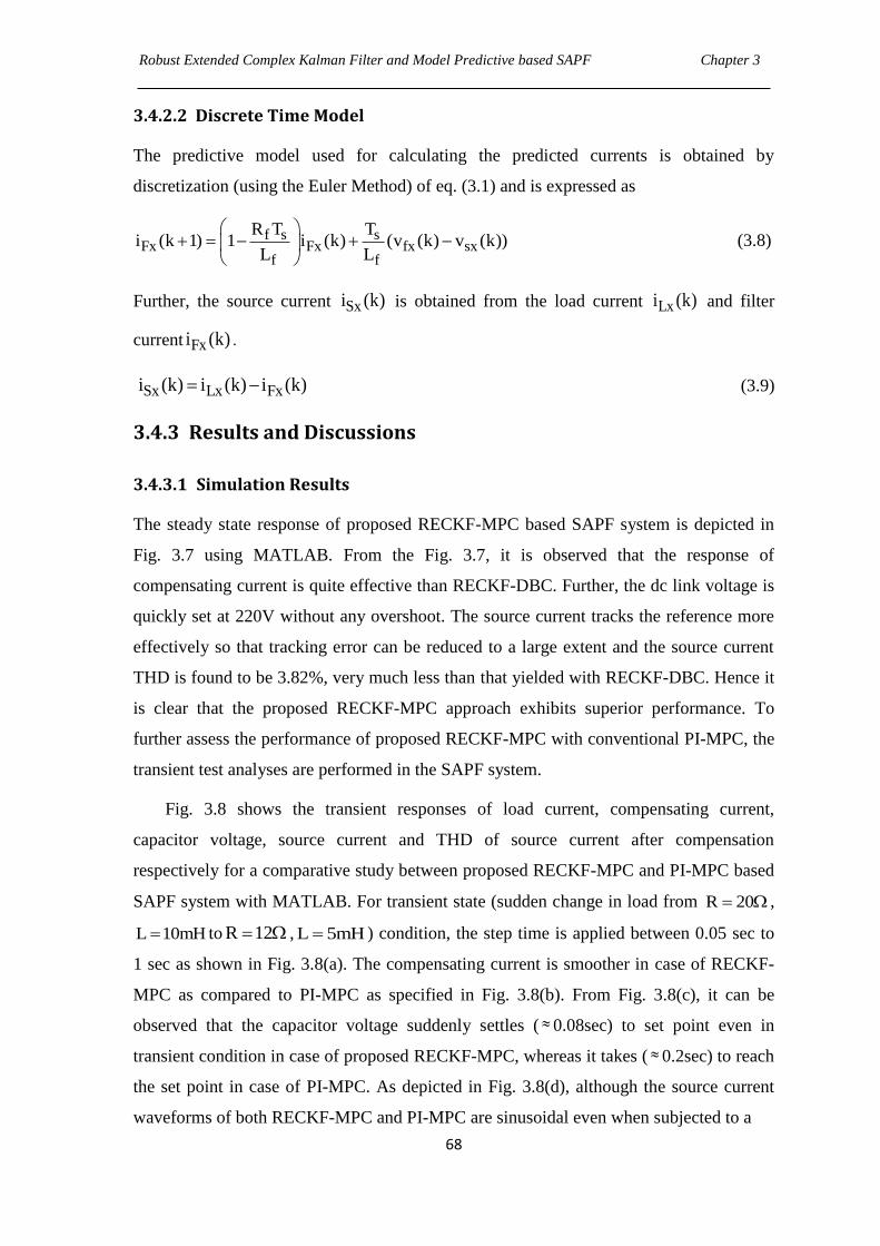
Robust Extended Complex Kalman Filter and Model Predictive based SAPF Chapter 3
68
3.4.2.2 Discrete Time Model
The predictive model used for calculating the predicted currents is obtained by
discretization (using the Euler Method) of eq. (3.1) and is expressed as
f s sFx Fx fx sx
f f
R T Ti (k 1) 1 i (k) (v (k) v (k))
L L
(3.8)
Further, the source current Sxi (k) is obtained from the load current Lxi (k) and filter
current Fxi (k) .
Sx Lx Fxi (k) i (k) i (k) (3.9)
3.4.3 Results and Discussions
3.4.3.1 Simulation Results
The steady state response of proposed RECKF-MPC based SAPF system is depicted in
Fig. 3.7 using MATLAB. From the Fig. 3.7, it is observed that the response of
compensating current is quite effective than RECKF-DBC. Further, the dc link voltage is
quickly set at 220V without any overshoot. The source current tracks the reference more
effectively so that tracking error can be reduced to a large extent and the source current
THD is found to be 3.82%, very much less than that yielded with RECKF-DBC. Hence it
is clear that the proposed RECKF-MPC approach exhibits superior performance. To
further assess the performance of proposed RECKF-MPC with conventional PI-MPC, the
transient test analyses are performed in the SAPF system.
Fig. 3.8 shows the transient responses of load current, compensating current,
capacitor voltage, source current and THD of source current after compensation
respectively for a comparative study between proposed RECKF-MPC and PI-MPC based
SAPF system with MATLAB. For transient state (sudden change in load from R 20 ,
L 10mH to R 12 , L 5mH ) condition, the step time is applied between 0.05 sec to
1 sec as shown in Fig. 3.8(a). The compensating current is smoother in case of RECKF-
MPC as compared to PI-MPC as specified in Fig. 3.8(b). From Fig. 3.8(c), it can be
observed that the capacitor voltage suddenly settles ( 0.08sec) to set point even in
transient condition in case of proposed RECKF-MPC, whereas it takes ( 0.2sec) to reach
the set point in case of PI-MPC. As depicted in Fig. 3.8(d), although the source current
waveforms of both RECKF-MPC and PI-MPC are sinusoidal even when subjected to a
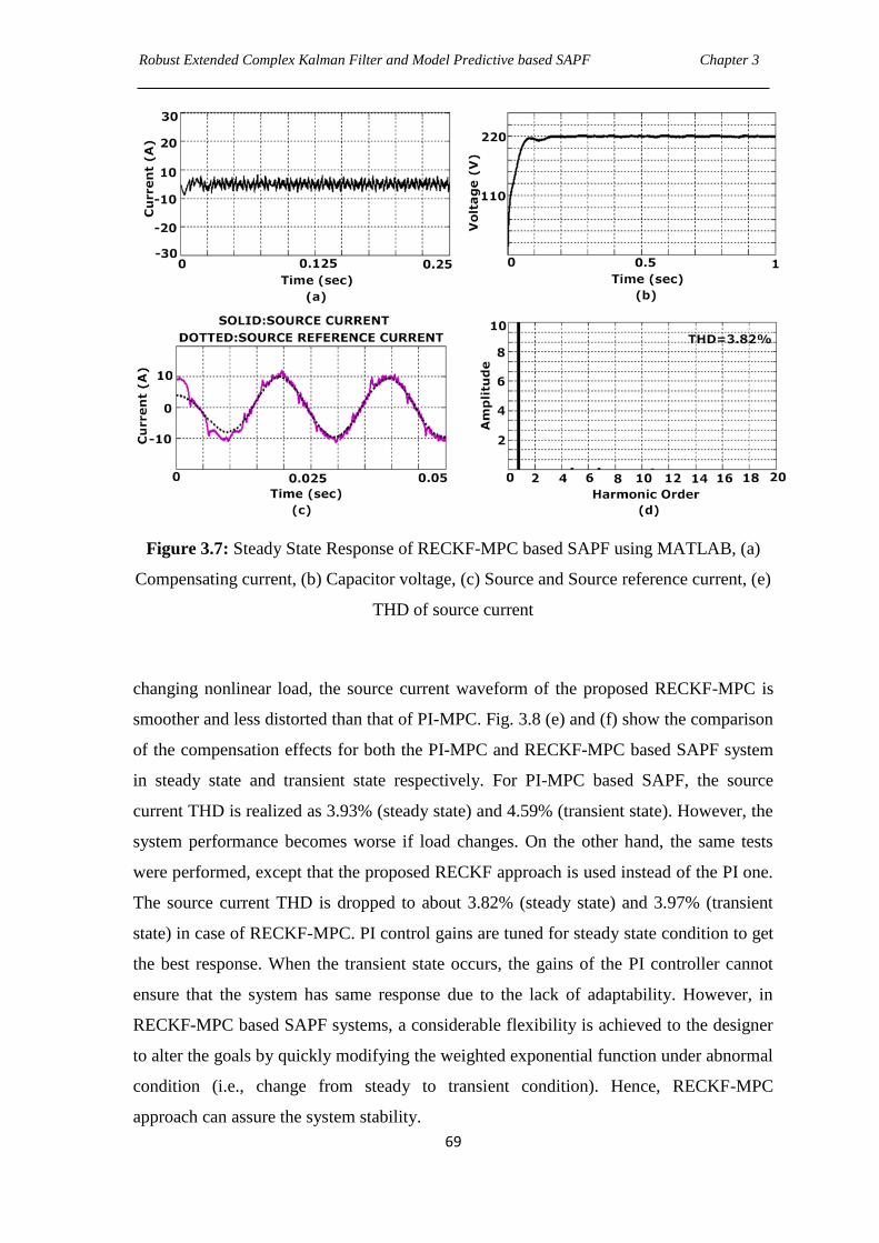
Robust Extended Complex Kalman Filter and Model Predictive based SAPF Chapter 3
69
Figure 3.7: Steady State Response of RECKF-MPC based SAPF using MATLAB, (a)
Compensating current, (b) Capacitor voltage, (c) Source and Source reference current, (e)
THD of source current
changing nonlinear load, the source current waveform of the proposed RECKF-MPC is
smoother and less distorted than that of PI-MPC. Fig. 3.8 (e) and (f) show the comparison
of the compensation effects for both the PI-MPC and RECKF-MPC based SAPF system
in steady state and transient state respectively. For PI-MPC based SAPF, the source
current THD is realized as 3.93% (steady state) and 4.59% (transient state). However, the
system performance becomes worse if load changes. On the other hand, the same tests
were performed, except that the proposed RECKF approach is used instead of the PI one.
The source current THD is dropped to about 3.82% (steady state) and 3.97% (transient
state) in case of RECKF-MPC. PI control gains are tuned for steady state condition to get
the best response. When the transient state occurs, the gains of the PI controller cannot
ensure that the system has same response due to the lack of adaptability. However, in
RECKF-MPC based SAPF systems, a considerable flexibility is achieved to the designer
to alter the goals by quickly modifying the weighted exponential function under abnormal
condition (i.e., change from steady to transient condition). Hence, RECKF-MPC
approach can assure the system stability.
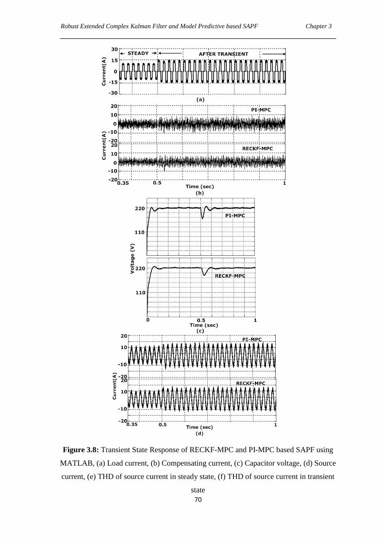
Robust Extended Complex Kalman Filter and Model Predictive based SAPF Chapter 3
70
Figure 3.8: Transient State Response of RECKF-MPC and PI-MPC based SAPF using
MATLAB, (a) Load current, (b) Compensating current, (c) Capacitor voltage, (d) Source
current, (e) THD of source current in steady state, (f) THD of source current in transient
state
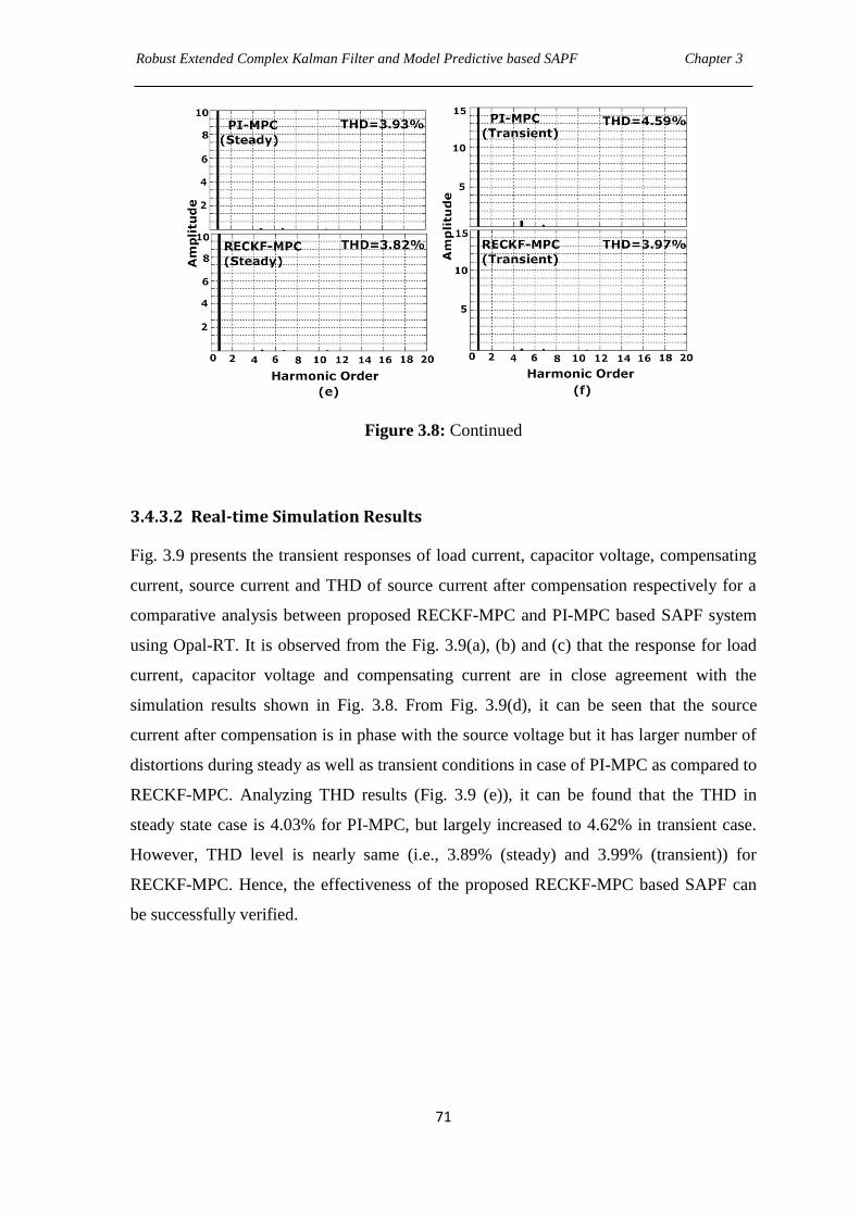
Robust Extended Complex Kalman Filter and Model Predictive based SAPF Chapter 3
71
Figure 3.8: Continued
3.4.3.2 Real-time Simulation Results
Fig. 3.9 presents the transient responses of load current, capacitor voltage, compensating
current, source current and THD of source current after compensation respectively for a
comparative analysis between proposed RECKF-MPC and PI-MPC based SAPF system
using Opal-RT. It is observed from the Fig. 3.9(a), (b) and (c) that the response for load
current, capacitor voltage and compensating current are in close agreement with the
simulation results shown in Fig. 3.8. From Fig. 3.9(d), it can be seen that the source
current after compensation is in phase with the source voltage but it has larger number of
distortions during steady as well as transient conditions in case of PI-MPC as compared to
RECKF-MPC. Analyzing THD results (Fig. 3.9 (e)), it can be found that the THD in
steady state case is 4.03% for PI-MPC, but largely increased to 4.62% in transient case.
However, THD level is nearly same (i.e., 3.89% (steady) and 3.99% (transient)) for
RECKF-MPC. Hence, the effectiveness of the proposed RECKF-MPC based SAPF can
be successfully verified.
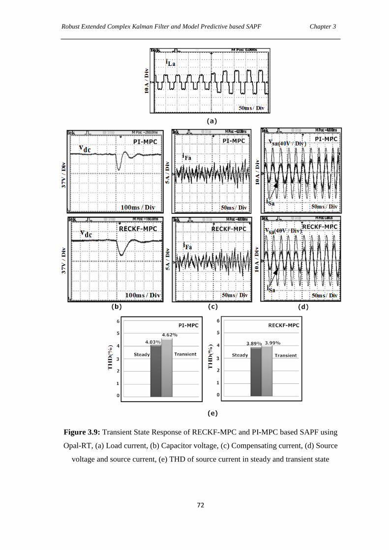
Robust Extended Complex Kalman Filter and Model Predictive based SAPF Chapter 3
72
Figure 3.9: Transient State Response of RECKF-MPC and PI-MPC based SAPF using
Opal-RT, (a) Load current, (b) Capacitor voltage, (c) Compensating current, (d) Source
voltage and source current, (e) THD of source current in steady and transient state

Robust Extended Complex Kalman Filter and Model Predictive based SAPF Chapter 3
73
3.4.3.3 Remarks on the Proposed RECKF-MPC based SAPF Method
It is not necessary to include any type of modulator in MPC approach.
RECKF-MPC based SAPF method is able to mitigate harmonics successfully both
in steady state and transient state conditions. It can overcome the difficulties
encountered with the fixed-gain PI controller, such as flexibility and robustness
over stabilization of capacitor voltage when changing loads.
Table 3.1 shows the superiority of RECKF-MPC both in steady state and transient
state conditions, when a comparative investigation has been performed on the basis of
THD factors employing simulation and real-time simulation results.
Table 3.1 THD Factor of Control Structures of SAPF
(RECKF-DBC, RECKF-MPC, PI-MPC)
Cases
Control Structure of SAPF
THD% of Source Current
After Compensation
Simulation
Results
Real-Time
Simulation Results
RECKF-DBC 4.26 4.31
Steady State RECKF-MPC 3.82 3.89
PI-MPC 3.93 4.03
Transient State RECKF-MPC 3.97 3.99
PI-MPC 4.59 4.62
3.5 Chapter Summary
A RECKF-DBC and RECKF-MPC based SAPF are proposed in this chapter. These two
approaches have been developed with less number of voltage sensors and resolve the

Robust Extended Complex Kalman Filter and Model Predictive based SAPF Chapter 3
74
difficulty of gain tuning of PI controller. In the first proposed RECKF-DBC method,
harmonics cancellation is not perfect (THD is above 4%) in spite of having fixed
switching frequency in SAPF. Therefore, a MPC based SAPF is implemented with the
main advantage of direct application of switching pulses to the IGBT inverter, without
necessitating a modulation stage. Moreover, to study the efficacy of this proposed
RECKF-MPC over PI-MPC, a comparative assessment has been performed using both
steady state as well as transient state conditions. From the simulation and real-time
simulation results, it is observed that the proposed RECKF-MPC outperforms over PI-
MPC and exhibits an excellent control approach to SAPF design in steady as well as
transient condition which improves PQ more effectively in terms of efficient harmonics
mitigation.
CHAPTER 4
Robust Extended Complex Kalman Filter and Linear
Quadratic Regulator based SAPF
4.1 Introduction
This chapter proposed LQR controller approach that is developed using the estimation
techniques based on proposed RECKF for SAPF system. Chapter 3 presented predictive
current controllers such as DBC and MPC with a new reference generation scheme based
on RECKF avoiding the need of a PI controller in the external loop. DC voltage
regulation is found to be better in case of RECKF-MPC as compared to PI-MPC from a
comparative study in steady state as well as transient state conditions in SAPF system.
Large settling time in dc voltage leads to poor tracking performance of RECKF-MPC
controlled SAPF and thus compensation of current harmonics is not effective. Moreover,
MPC is very sensitive to model mismatch and noise. It is quite sluggish in rejecting large
drifting grid disturbances. Hence, a suitable control strategy needs to be developed in
SAPF to improve tracking performance as well as grid disturbance rejection capability.
The LQR based on the optimal control [97][98][99][100] of three-phase ac–dc
converters with unity power factor was applied for sinusoidal current PWM rectifiers and
the neutral point clamped PWM rectifier in [101] and [102]. An optimal servo-controller
was also applied in [103] to the current inner loop of the SAPF in the cascade strategy
where an outer loop used a simple PI regulator for the dc bus voltage.
In this Chapter, the LQR is designed for SAPF due to its obvious advantage for
controlling multi-input–multi-output systems such as the SAPF in addition to insensitivity
to small parameter variations [104].Taking advantage of the LQR robustness [105], it is
used for the signal model describing the SAPF dynamics to keep the power factor at PCC
close to unity. Using this approach, it becomes easier to find the optimal gains of the
controller with the acceptable tracking of the SAPF‟s current components for the entire
operating range. The advantage of LQR over other controllers such as DBC, SMC, and
HCC is that by minimizing a performance index as a function of u (control effort) and
states, one can reduce the control effort needed or the energy of some state variable can
Robust Extended Complex Kalman Filter and Linear Quadratic Regulator based SAPF Chapter 4
76
be reduced. Moreover, if the SAPF is accurately modeled, the LQR may be considered a
robust controller, minimizing satisfactorily the considered states.
It may be noted that in order to achieve a superior compensation of harmonics beside
the controller, the reference current generation should be made appropriately [106]. For
implementation of LQR, generation of reference compensating current is essential.
Hence, harmonic contents of the load current should be identified in SAPF. It can be
determined by (a) directly determining each of the parameters of the harmonic
components, or (b) indirectly subtracting the fundamental component from the load
current. The indirect method is commonly used in view of ease in its implementation.
However, if the fundamental component is not estimated accurately, then the active filter
may source or sink the active power. Several methods have been reported in literature
[17][18][27][61][62] for the extraction of harmonic components such as LPF method, pq
method, dq method, ANN approach and DFT approach. In this Chapter, an approach
based on RECKF is described for estimating the in phase fundamental of PCC as well as
peak value of source current. It is shown that by using this approach, capacitor voltage
stabilization is improved with lessening settling time.
This Chapter focuses on the minimizing the effects of the PCC voltage by
considering it as a part of the SAPF model and designing LQR with the help of RECKF
based estimation approach.
4.2 Chapter Objectives
1. To improve current tracking and disturbance rejection capability of SAPF system
considering dynamic information of distorted voltage signal at the PCC.
2. To design an improved reference current scheme without necessitating PI controller
loop.
3. To self-regulate dc-link voltage.
4. To improve the current harmonics compensation capability of SAPF.
5. To simulate the proposed control structure in MATLAB/Simulink and real-time
simulation model in Opal-RT simulator.
Robust Extended Complex Kalman Filter and Linear Quadratic Regulator based SAPF Chapter 4
77
4.3 Proposed RECKF-LQR based SAPF
4.3.1 Description of proposed RECKF-LQR based SAPF system
The SAPF shown in Fig. 4.1(a) is controlled by the proposed RECKF and LQR method.
RECKF is employed for estimation of in phase and in quadrature components of PCC
voltages abcv and these are used to estimate the PCC voltages and their derivatives. Also,
the fundamental amplitudes of load current as well as source current are estimated by
RECKF, which are utilized for generation of reference current. Then the LQR is designed
along with the information of the above state space variables and gate pulses are given to
the IGBT inverter through triangular carrier based PWM method.
4.3.2 Development of SAPF
4.3.2.1 Mathematical Model of SAPF
The SAPF model in the dq frame according to [107] can be expressed by eq (4.1) and
(4.2), where PCC voltage is considered as a disturbance. Fdqi , dqu and dqv denote the
dq frame model for filter current Fabci , switching function abcu and PCC voltage abcv
respectively.
Fdq Fdq dq dqi Ai Bu Ev (4.1)
dq Fdqy Ci (4.2)
where
dcf
f f
f dc
f f
f
f
vR0
L LA , B= ,
R v0
L L
10
L 1 0E , C=
1 0 10
L
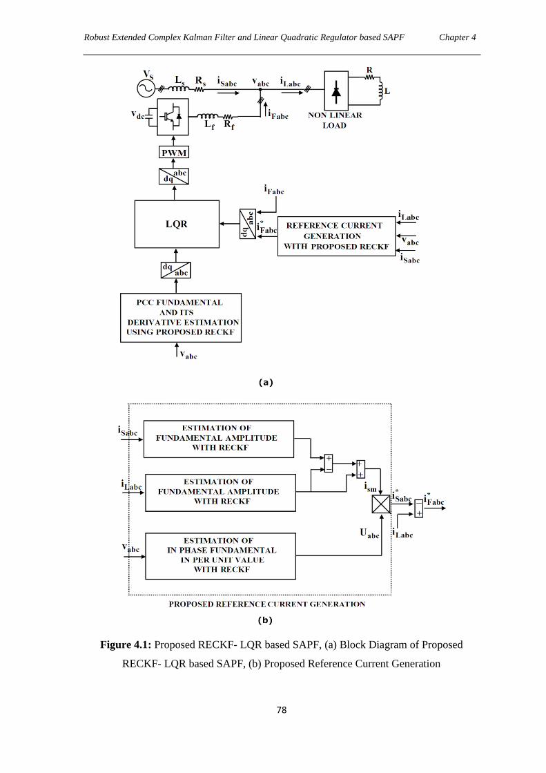
Robust Extended Complex Kalman Filter and Linear Quadratic Regulator based SAPF Chapter 4
78
Figure 4.1: Proposed RECKF- LQR based SAPF, (a) Block Diagram of Proposed
RECKF- LQR based SAPF, (b) Proposed Reference Current Generation

Robust Extended Complex Kalman Filter and Linear Quadratic Regulator based SAPF Chapter 4
79
In this Chapter PCC voltage dynamics are included in the model. Considering the PCC
voltages as sinusoidal, balanced and each phase is delayed by radians, the following
equations can be written to describe the SAPF system.
a
b
c
v Vsin( t)
v Vsin( t )
v Vsin( t )
(4.3)
where V is the magnitude of the voltage, 2 f is the angular frequency of the grid and
2
3
rad. The first derivatives of these waveforms are shown in eq (4.4).
a
b
c
dvV cos( t)
dt
dvV cos( t )
dt
dvV cos( t )
dt
(4.4)
The second derivatives of eq (4.3) are obtained as follows.
22a
2
22b
2
22c
2
d vV sin( t)
dt
d vV sin( t )
dt
d vV sin( t )
dt
(4.5)
From eq (4.3), eq (4.4) and eq (4.5), it is verified that
22abc
abc2
d vV v
dt , thus the
complete model that represents the behavior of the voltages at PCC in the „abc‟ frame is
given in eq (4.6).
a a
b b
c c2
a a
2b b
2c c
0 0 0 1 0 0v v
0 0 0 0 1 0v v
0 0 0 0 0 1v v
0 0 0 0 0v v
v v0 0 0 0 0
v v0 0 0 0 0
(4.6)
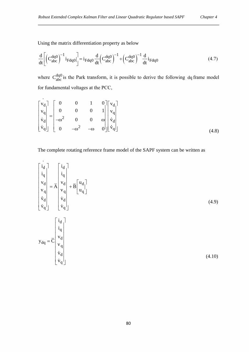
Robust Extended Complex Kalman Filter and Linear Quadratic Regulator based SAPF Chapter 4
80
Using the matrix differentiation property as below
1 1 1
dq0 dq0 dq0Fdq0 Fdq0 Fdq0abc abc abc
d d dC i i C C i
dt dt dt
(4.7)
where dq0
abcC is the Park transform, it is possible to derive the following dq frame model
for fundamental voltages at the PCC,
d d
q q
2d d
2q q
0 0 1 0v v
0 0 0 1v v
v 0 0 v
v v0 0
(4.8)
The complete rotating reference frame model of the SAPF system can be written as
d d
q q
d d d
q q q
d d
q q
i i
i i
v v uA B
v v u
v v
v v
(4.9)
d
q
ddq
q
d
q
i
i
vy C
v
v
v
(4.10)
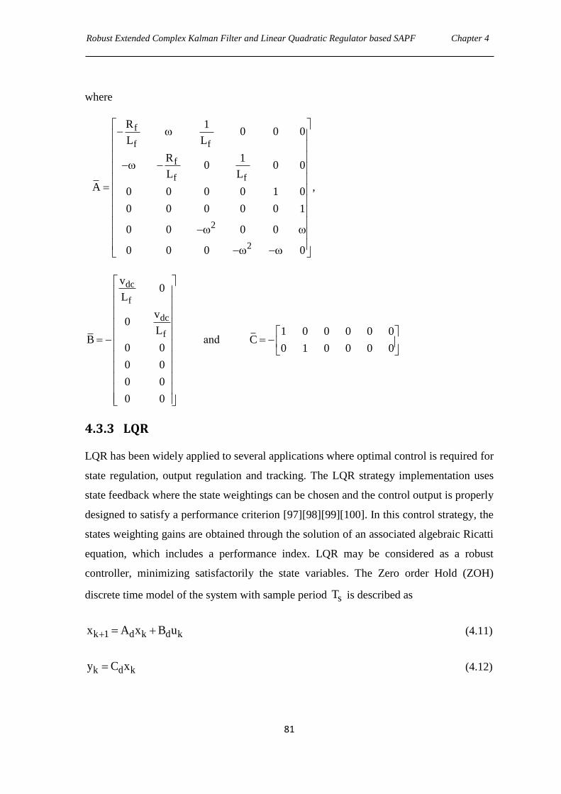
Robust Extended Complex Kalman Filter and Linear Quadratic Regulator based SAPF Chapter 4
81
where
f
f f
f
f f
2
2
R 10 0 0
L L
R 10 0 0
L LA ,0 0 0 0 1 0
0 0 0 0 0 1
0 0 0 0
0 0 0 0
dc
f
dc
f
v0
L
v0
LB
0 0
0 0
0 0
0 0
and 1 0 0 0 0 0
C0 1 0 0 0 0
4.3.3 LQR
LQR has been widely applied to several applications where optimal control is required for
state regulation, output regulation and tracking. The LQR strategy implementation uses
state feedback where the state weightings can be chosen and the control output is properly
designed to satisfy a performance criterion [97][98][99][100]. In this control strategy, the
states weighting gains are obtained through the solution of an associated algebraic Ricatti
equation, which includes a performance index. LQR may be considered as a robust
controller, minimizing satisfactorily the state variables. The Zero order Hold (ZOH)
discrete time model of the system with sample period sT is described as
k 1 d k d kx A x B u (4.11)
k d ky C x (4.12)
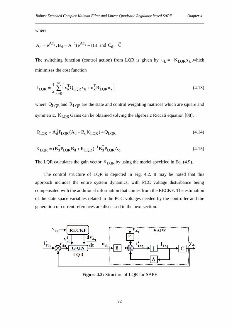
Robust Extended Complex Kalman Filter and Linear Quadratic Regulator based SAPF Chapter 4
82
where
s sAT AT1d dA e ,B A (e 1)B and dC C
The switching function (control action) from LQR is given by k LQR ku K x ,which
minimises the cost function
T TLQR k LQR k k LQR k
k 0
1J x Q x u R u
2
(4.13)
where LQRQ and LQRR are the state and control weighting matrices which are square and
symmetric. LQRK Gains can be obtained solving the algebraic Riccati equation [88].
TLQR d LQR d d LQR LQRP A P (A B K ) Q (4.14)
T 1 TLQR d LQR d LQR d LQR dK (B P B R ) B P A (4.15)
The LQR calculates the gain vector LQRK by using the model specified in Eq. (4.9).
The control structure of LQR is depicted in Fig. 4.2. It may be noted that this
approach includes the entire system dynamics, with PCC voltage disturbance being
compensated with the additional information that comes from the RECKF. The estimation
of the state space variables related to the PCC voltages needed by the controller and the
generation of current references are discussed in the next section.
Figure 4.2: Structure of LQR for SAPF
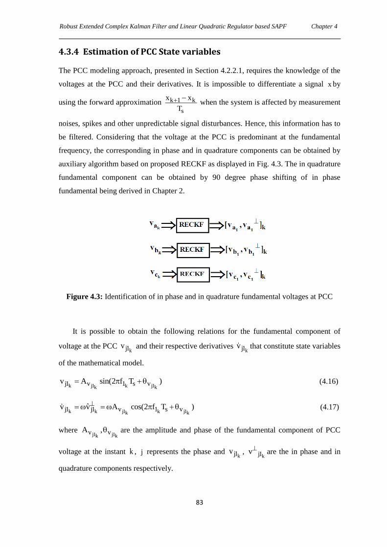
Robust Extended Complex Kalman Filter and Linear Quadratic Regulator based SAPF Chapter 4
83
4.3.4 Estimation of PCC State variables
The PCC modeling approach, presented in Section 4.2.2.1, requires the knowledge of the
voltages at the PCC and their derivatives. It is impossible to differentiate a signal x by
using the forward approximation k 1 k
s
x x
T
when the system is affected by measurement
noises, spikes and other unpredictable signal disturbances. Hence, this information has to
be filtered. Considering that the voltage at the PCC is predominant at the fundamental
frequency, the corresponding in phase and in quadrature components can be obtained by
auxiliary algorithm based on proposed RECKF as displayed in Fig. 4.3. The in quadrature
fundamental component can be obtained by 90 degree phase shifting of in phase
fundamental being derived in Chapter 2.
Figure 4.3: Identification of in phase and in quadrature fundamental voltages at PCC
It is possible to obtain the following relations for the fundamental component of
voltage at the PCC kj1v and their respective derivatives
kj1v that constitute state variables
of the mathematical model.
k j1 k j1k kj1 v 1 s vv A sin(2 f T ) (4.16)
k k j1 k j1k kj1 j1 v 1 s vˆv v A cos(2 f T ) (4.17)
where j1 j1k k
v vA , are the amplitude and phase of the fundamental component of PCC
voltage at the instant k , j represents the phase and kj1v ,
kj1v are the in phase and in
quadrature components respectively.
Robust Extended Complex Kalman Filter and Linear Quadratic Regulator based SAPF Chapter 4
84
4.3.5 Generation of Reference current
The proposed reference current scheme (Fig. 4.1(b)) is the modification of reference
scheme developed in Chapter 3 by including an error value originated from the difference
between the estimated fundamental amplitudes of source current and load current. The
estimation technique is based upon proposed RECKF algorithm and the formulations for
fundamental amplitudes have already been described in Chapter 2. This error value is
further added to the fundamental amplitude of load current to give a desired peak value of
source current smi , which enhances the reference tracking capability of dc link voltage
without involving any PI controller loop. The implementation of source reference currents
*Sabci are already prescribed in Chapter 2. Finally, for implementation of the LQR, the
reference compensating currents *Fabci can be found out by using the following equation.
* *Fabc Labc Sabci i i (4.18)
4.3.6 Results and Discussions
4.3.6.1 Simulation Results
In order to evaluate the harmonic compensation performance of the proposed RECKF-
LQR method, the SAPF system shown in Fig. 4.1 is implemented using
MATLAB/Simulink. For the implementation of the LQR, the built-in ‗lqrd‘ function of
MATLAB is used. The selection of LQRQ and LQRR matrices in LQR design is based on
the performance specifications and a certain amount of trial and error [108] is required
with an interactive computer simulation before arriving at satisfactory design results.
Since the matrices LQRQ and LQRR are symmetric, there are six distinct elements in
LQRQ and two distinct elements in LQRR need to be selected. The matrices LQRQ and
LQRR should be positive definite. The value of the elements in LQRQ and LQRR are
related to their contribution to the cost function LQRJ .
Robust Extended Complex Kalman Filter and Linear Quadratic Regulator based SAPF Chapter 4
85
LQR LQR
3700 0 0 0 0 0
0 4970 0 0 0 0
0 0 0 0 0 0 1 0Q , R
0 0 0 0 0 0 0 1
0 0 0 0 0 0
0 0 0 0 0 0
(4.19)
Fig. 4.4 shows the behavior of proposed RECKF-LQR approach considering phase
‗a‘. The response of a RECKF estimator, when extracting in phase and in quadrature
fundamental components of PCC voltage, is depicted in Fig. 4.4(a). It is shown in Fig.
4.4(a) that estimation results are quite matched with the actual ones indicating a good
performance of RECKF. The dc voltage stabilization capacity of proposed RECKF-LQR
based SAPF system is presented in Fig. 4.4(b). It is realized from Fig. 4.4(b) that there is
no overshoot present in the waveform and a settling time of 0.1sec is required to set at the
reference voltage resulting a good voltage regulation performance of RECKF-LQR
approach. The current output of SAPF is superimposed with its respective reference and
is shown in Fig. 4.4(b). It is inferred that the filter injected current harmonics track their
references with high level of accuracy.
Fig. 4.4(c) represents the current quality obtained with proposed RECKF-LQR after
compensation with SAPF. As can be seen, the source current is sinusoidal and balanced.
The spectrum analysis of source current depicted in Fig. 4.4(d) indicates that the THD of
the source current is reduced to 3.4% after compensation. Hence, the effectiveness of
proposed RECKF-LQR can be realized.
4.3.6.2 Real-time Simulation Results
Real-time simulated results of proposed SAPF system are shown in Fig. 4.5 (a), (b), (c)
and (d) respectively. From Fig. 4.5(a), it is found that compensating current is able to
track the reference perfectly by means of reducing the tracking error. Capacitor voltage is
found to be set at 220V as depicted in Fig. 4.5(b). Both source voltage and source current
waveforms are presented in Fig. 4.5(c) to analyze the performance of proposed RECKF-
LQR. It is observed from Fig. 4.5(c) that the source current is in phase with source
voltage with power factor close to unity. The compensating effect of proposed SAPF is
analyzed in Fig. 4.5(d) and it is found that the THD of source current is reduced from
26.4% to 3.46%., very close to simulation result (i.e., 25.9% to 3.41%). Hence, all the
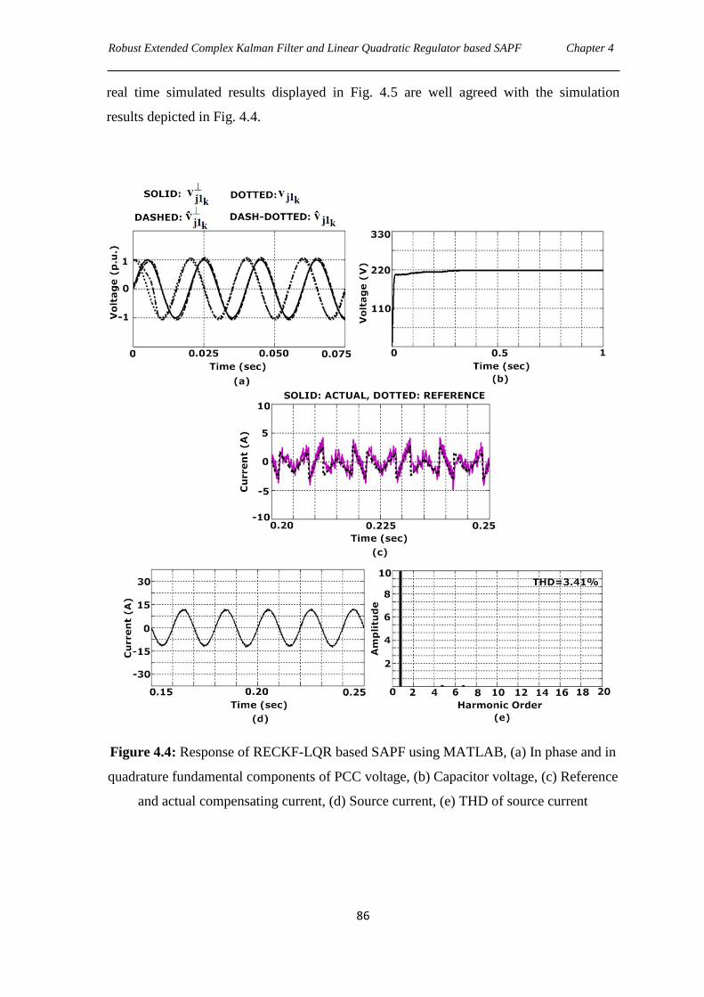
Robust Extended Complex Kalman Filter and Linear Quadratic Regulator based SAPF Chapter 4
86
real time simulated results displayed in Fig. 4.5 are well agreed with the simulation
results depicted in Fig. 4.4.
Figure 4.4: Response of RECKF-LQR based SAPF using MATLAB, (a) In phase and in
quadrature fundamental components of PCC voltage, (b) Capacitor voltage, (c) Reference
and actual compensating current, (d) Source current, (e) THD of source current
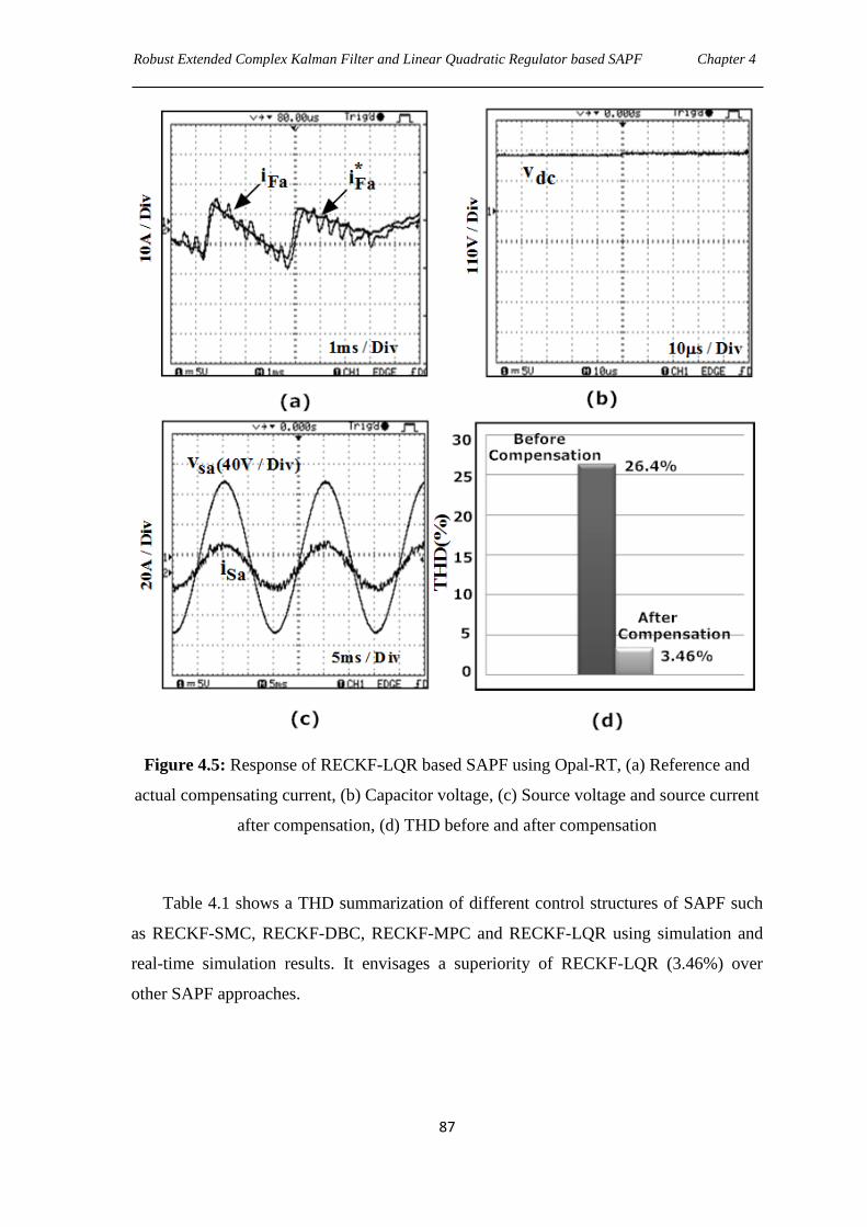
Robust Extended Complex Kalman Filter and Linear Quadratic Regulator based SAPF Chapter 4
87
Figure 4.5: Response of RECKF-LQR based SAPF using Opal-RT, (a) Reference and
actual compensating current, (b) Capacitor voltage, (c) Source voltage and source current
after compensation, (d) THD before and after compensation
Table 4.1 shows a THD summarization of different control structures of SAPF such
as RECKF-SMC, RECKF-DBC, RECKF-MPC and RECKF-LQR using simulation and
real-time simulation results. It envisages a superiority of RECKF-LQR (3.46%) over
other SAPF approaches.
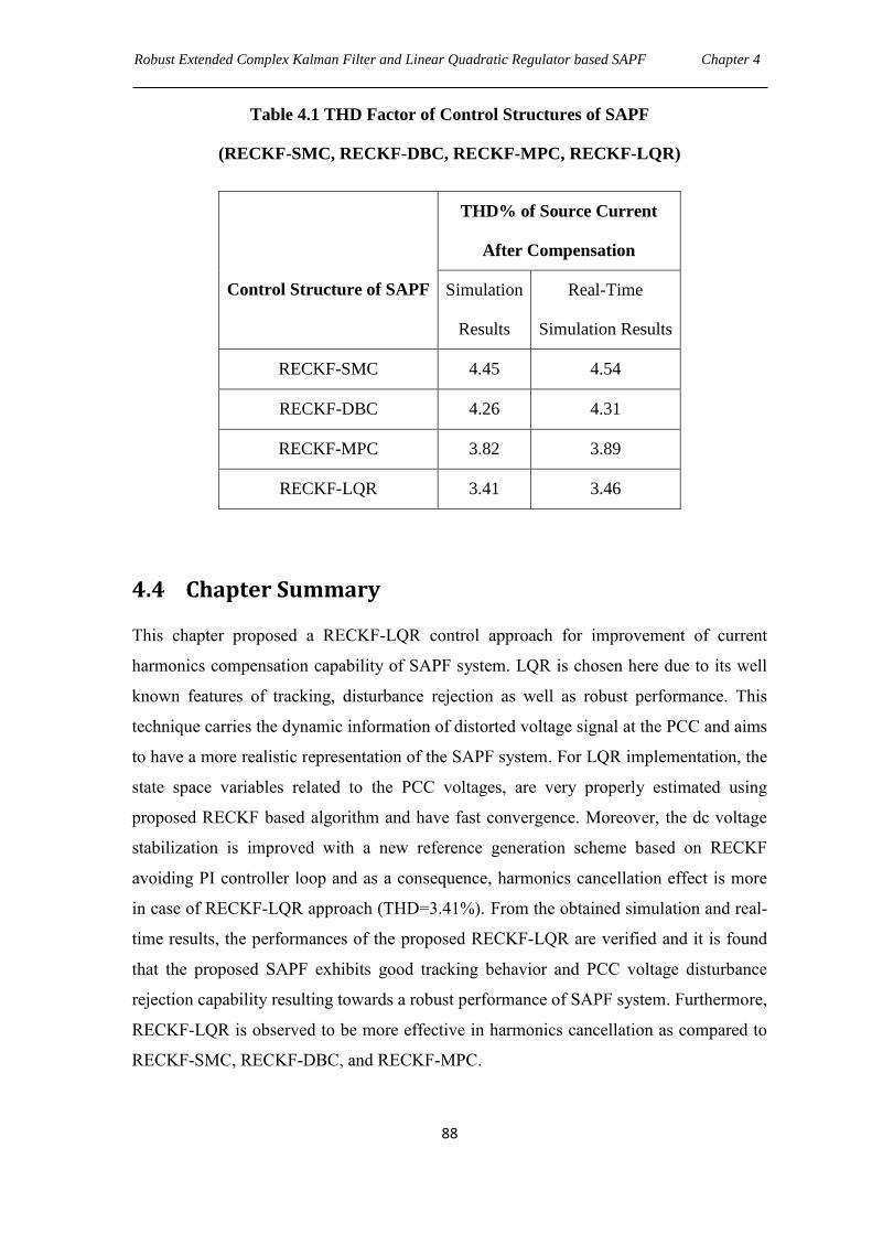
Robust Extended Complex Kalman Filter and Linear Quadratic Regulator based SAPF Chapter 4
88
Table 4.1 THD Factor of Control Structures of SAPF
(RECKF-SMC, RECKF-DBC, RECKF-MPC, RECKF-LQR)
Control Structure of SAPF
THD% of Source Current
After Compensation
Simulation
Results
Real-Time
Simulation Results
RECKF-SMC 4.45 4.54
RECKF-DBC 4.26 4.31
RECKF-MPC 3.82 3.89
RECKF-LQR 3.41 3.46
4.4 Chapter Summary
This chapter proposed a RECKF-LQR control approach for improvement of current
harmonics compensation capability of SAPF system. LQR is chosen here due to its well
known features of tracking, disturbance rejection as well as robust performance. This
technique carries the dynamic information of distorted voltage signal at the PCC and aims
to have a more realistic representation of the SAPF system. For LQR implementation, the
state space variables related to the PCC voltages, are very properly estimated using
proposed RECKF based algorithm and have fast convergence. Moreover, the dc voltage
stabilization is improved with a new reference generation scheme based on RECKF
avoiding PI controller loop and as a consequence, harmonics cancellation effect is more
in case of RECKF-LQR approach (THD=3.41%). From the obtained simulation and real-
time results, the performances of the proposed RECKF-LQR are verified and it is found
that the proposed SAPF exhibits good tracking behavior and PCC voltage disturbance
rejection capability resulting towards a robust performance of SAPF system. Furthermore,
RECKF-LQR is observed to be more effective in harmonics cancellation as compared to
RECKF-SMC, RECKF-DBC, and RECKF-MPC.
CHAPTER 5
Robust Extended Complex Kalman Filter and
Linear Quadratic Gaussian Servo Controller
based SAPF
5.1 Introduction
This chapter proposes a Linear Quadratic Gaussian (LQG) servo controller for the current
control of SAPF. It has been discussed in Chapter 2, 3, and 4 that RECKF is the most
appropriate for estimation approach because of its fastest convergence. Further, reference
current generation schemes employed in the above Chapters consider both voltage and
current measurements and to achieve the dc-link capacitor voltage steady after a time
delay of 0.15sec. Hence, in this chapter, voltage regulation of dc-link capacitor is further
improved by employing a new and faster reference generation scheme based on RECKF,
which can be achieved by only current measurements indicating a cost effective
approach. Although, LQR approach developed in Chapter 4 provides robustness and
disturbance rejection, but complete cancellation of load current harmonics was not
obtained i.e. THD of the source current is 3.41%. Hence, in this Chapter, it is intended to
develop effective robust technique such that higher disturbance rejection can be achieved.
Various control schemes have been applied in SAPF [109][110][111] under both
balanced and unbalanced loading conditions. However, these control strategies have not
considered some important aspects, such as variations in the SAPF parameters, including
load impedance and grid perturbations. Due to parametric uncertainties present in the
load, the problem of compensating the SAPF becomes more complicated which adversely
effects towards its satisfactory operation.
A linear quadratic control combined with an integral control has been employed to
control a three phase three wire SAPF to achieve unity power factor at PCC of a highly
distorted and unbalanced load currents [107]. This control uses the full state vector
available for feedback, but this is unrealistic as there is always a measurement noise. LQR
with KF was proposed in [23] supported LQR and KF was proposed considering
measurement noise, load currents and grid voltage transients. However, PCC voltage has
not been considered as a disturbance in the SAPF model. LQR law is based on the
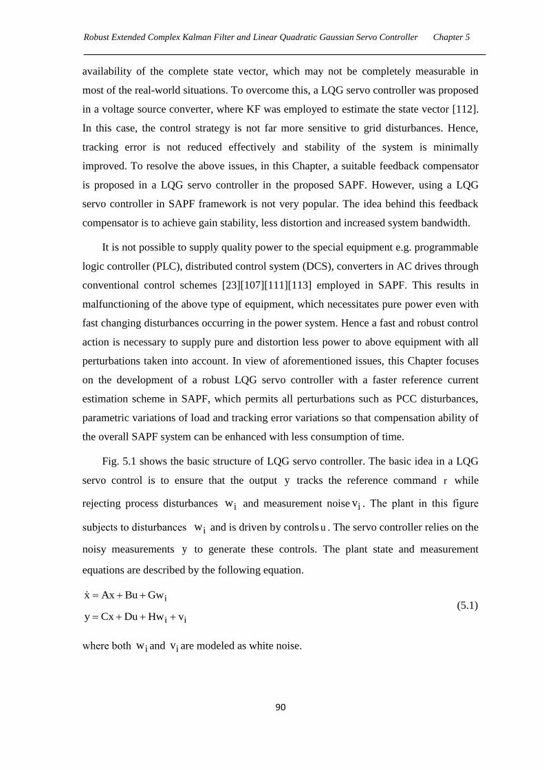
Robust Extended Complex Kalman Filter and Linear Quadratic Gaussian Servo Controller Chapter 5
90
availability of the complete state vector, which may not be completely measurable in
most of the real-world situations. To overcome this, a LQG servo controller was proposed
in a voltage source converter, where KF was employed to estimate the state vector [112].
In this case, the control strategy is not far more sensitive to grid disturbances. Hence,
tracking error is not reduced effectively and stability of the system is minimally
improved. To resolve the above issues, in this Chapter, a suitable feedback compensator
is proposed in a LQG servo controller in the proposed SAPF. However, using a LQG
servo controller in SAPF framework is not very popular. The idea behind this feedback
compensator is to achieve gain stability, less distortion and increased system bandwidth.
It is not possible to supply quality power to the special equipment e.g. programmable
logic controller (PLC), distributed control system (DCS), converters in AC drives through
conventional control schemes [23][107][111][113] employed in SAPF. This results in
malfunctioning of the above type of equipment, which necessitates pure power even with
fast changing disturbances occurring in the power system. Hence a fast and robust control
action is necessary to supply pure and distortion less power to above equipment with all
perturbations taken into account. In view of aforementioned issues, this Chapter focuses
on the development of a robust LQG servo controller with a faster reference current
estimation scheme in SAPF, which permits all perturbations such as PCC disturbances,
parametric variations of load and tracking error variations so that compensation ability of
the overall SAPF system can be enhanced with less consumption of time.
Fig. 5.1 shows the basic structure of LQG servo controller. The basic idea in a LQG
servo control is to ensure that the output y tracks the reference command r while
rejecting process disturbances iw and measurement noise iv . The plant in this figure
subjects to disturbances iw and is driven by controls u . The servo controller relies on the
noisy measurements y to generate these controls. The plant state and measurement
equations are described by the following equation.
i
i i
x Ax Bu Gw
y Cx Du Hw v
(5.1)
where both iw and iv are modeled as white noise.
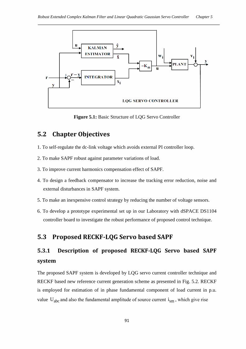
Robust Extended Complex Kalman Filter and Linear Quadratic Gaussian Servo Controller Chapter 5
91
Figure 5.1: Basic Structure of LQG Servo Controller
5.2 Chapter Objectives
1. To self-regulate the dc-link voltage which avoids external PI controller loop.
2. To make SAPF robust against parameter variations of load.
3. To improve current harmonics compensation effect of SAPF.
4. To design a feedback compensator to increase the tracking error reduction, noise and
external disturbances in SAPF system.
5. To make an inexpensive control strategy by reducing the number of voltage sensors.
6. To develop a prototype experimental set up in our Laboratory with dSPACE DS1104
controller board to investigate the robust performance of proposed control technique.
5.3 Proposed RECKF-LQG Servo based SAPF
5.3.1 Description of proposed RECKF-LQG Servo based SAPF
system
The proposed SAPF system is developed by LQG servo current controller technique and
RECKF based new reference current generation scheme as presented in Fig. 5.2. RECKF
is employed for estimation of in phase fundamental component of load current in p.u.
value abcU and also the fundamental amplitude of source current smi , which give rise

Robust Extended Complex Kalman Filter and Linear Quadratic Gaussian Servo Controller Chapter 5
92
Figure 5.2: Proposed RECKF- LQG Servo based SAPF, (a) Block Diagram of Proposed
RECKF- LQG Servo based SAPF, (b) Proposed Reference Current Generation
to source reference current *Sabci . Further subtraction of this source reference *
Sabci from
load current Labci provides reference compensating current *Fabci , which supports the
implementation of LQG servo current controller. The whole SAPF is implemented in dq-
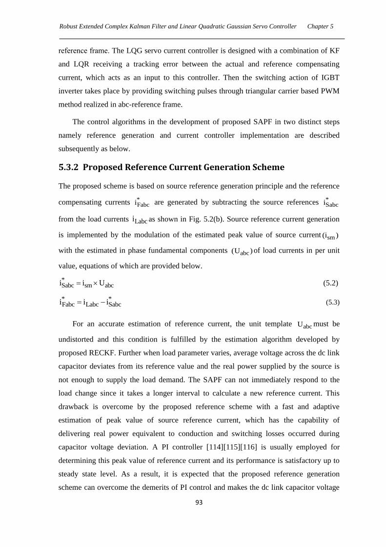
Robust Extended Complex Kalman Filter and Linear Quadratic Gaussian Servo Controller Chapter 5
93
reference frame. The LQG servo current controller is designed with a combination of KF
and LQR receiving a tracking error between the actual and reference compensating
current, which acts as an input to this controller. Then the switching action of IGBT
inverter takes place by providing switching pulses through triangular carrier based PWM
method realized in abc-reference frame.
The control algorithms in the development of proposed SAPF in two distinct steps
namely reference generation and current controller implementation are described
subsequently as below.
5.3.2 Proposed Reference Current Generation Scheme
The proposed scheme is based on source reference generation principle and the reference
compensating currents *Fabci are generated by subtracting the source references *
Sabci
from the load currents Labci as shown in Fig. 5.2(b). Source reference current generation
is implemented by the modulation of the estimated peak value of source current sm(i )
with the estimated in phase fundamental components abc(U ) of load currents in per unit
value, equations of which are provided below.
*Sabc sm abci i U (5.2)
* *Fabc Labc Sabci i i (5.3)
For an accurate estimation of reference current, the unit template abcU must be
undistorted and this condition is fulfilled by the estimation algorithm developed by
proposed RECKF. Further when load parameter varies, average voltage across the dc link
capacitor deviates from its reference value and the real power supplied by the source is
not enough to supply the load demand. The SAPF can not immediately respond to the
load change since it takes a longer interval to calculate a new reference current. This
drawback is overcome by the proposed reference scheme with a fast and adaptive
estimation of peak value of source reference current, which has the capability of
delivering real power equivalent to conduction and switching losses occurred during
capacitor voltage deviation. A PI controller [114][115][116] is usually employed for
determining this peak value of reference current and its performance is satisfactory up to
steady state level. As a result, it is expected that the proposed reference generation
scheme can overcome the demerits of PI control and makes the dc link capacitor voltage
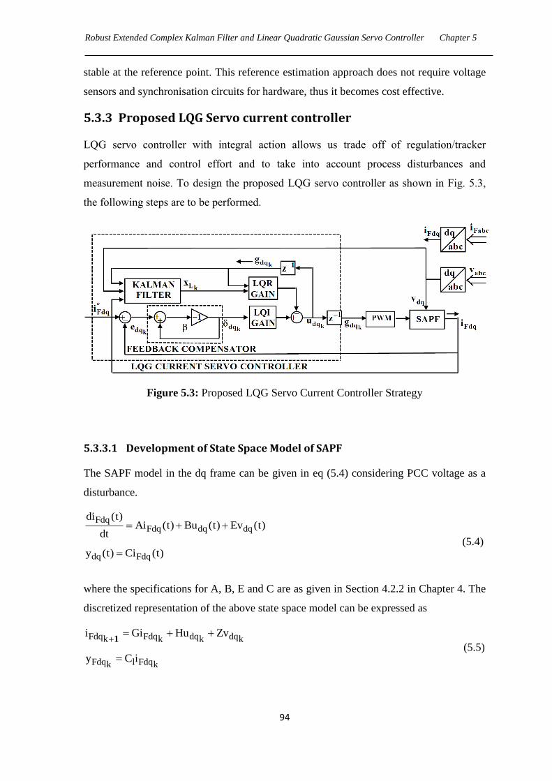
Robust Extended Complex Kalman Filter and Linear Quadratic Gaussian Servo Controller Chapter 5
94
stable at the reference point. This reference estimation approach does not require voltage
sensors and synchronisation circuits for hardware, thus it becomes cost effective.
5.3.3 Proposed LQG Servo current controller
LQG servo controller with integral action allows us trade off of regulation/tracker
performance and control effort and to take into account process disturbances and
measurement noise. To design the proposed LQG servo controller as shown in Fig. 5.3,
the following steps are to be performed.
Figure 5.3: Proposed LQG Servo Current Controller Strategy
5.3.3.1 Development of State Space Model of SAPF
The SAPF model in the dq frame can be given in eq (5.4) considering PCC voltage as a
disturbance.
FdqFdq dq dq
dq Fdq
di (t)Ai (t) Bu (t) Ev (t)
dt
y (t) Ci (t)
(5.4)
where the specifications for A, B, E and C are as given in Section 4.2.2 in Chapter 4. The
discretized representation of the above state space model can be expressed as
Fdq Fdq dq dqk k k k
Fdq l Fdqk k
i Gi Hu Zv
y C i
1
(5.5)
Robust Extended Complex Kalman Filter and Linear Quadratic Gaussian Servo Controller Chapter 5
95
where
ATst Ts
ATs
ATs
l
G e L (sI A)
H A e I B
Z A e I E
C C
1 1
1
1
(5.6)
5.3.3.2 Construction of Optimal State Feedback Gain
For a full state feedback control design, LQR design seeks to minimize the total transfer
of energy from system input to output. The associated Riccati equation solution provides
the optimal state feedback controller ( LQRmK ) that can minimize the cost function of the
closed loop system given below.
T TLQRm LQRm dq LQRm dqdq dqk kk k
k 0
1J x Q x u R u
2
(5.7)
where
dq Fd Fq dq d qk kx i i ,u u u (5.8)
and LQRmQ is a positive semi definite matrix (state weighting matrix) and LQRmR is a
positive definite matrix (control weighting matrix). The entries of matrices LQRmQ and
LQRmR are chosen such that fastest dynamic response in SAPF system can be achieved.
The gain LQRmK can be obtained by solving the algebraic Riccati equation.
TLQRm LQRm LQRm LQRmP G P (G HK ) Q (5.9)
which gives
T 1 TLQRm LQRm LQRm LQRmK (H P H R ) H P G (5.10)
5.3.3.3 Construction of Kalman State Estimator
For linear systems contaminated with additive noise, KF is found to be an optimum
estimator [117][118][119]. In this paper, we need Kalman state estimator for LQG servo
Robust Extended Complex Kalman Filter and Linear Quadratic Gaussian Servo Controller Chapter 5
96
control because we cannot implement LQ optimal state feedback without full state
measurement.
The model given in eq (5.5) can be rewritten as
dq dq Fdq ik k k k
dq dq ik k k
x Gx Su w
y Cx v
1
(5.11)
where the PCC voltage acts as an input to the estimator. ikw and ik
v are modeled as
white noise and the associated noise covariance matrices are given by
T Ti n, i n i ik kk k
E(w w ) Q E(v v ) R (5.12)
and
S H Z ,T
Fdq dq dqk k ku g v
(5.13)
where
dq dqk k 1g u
(5.14)
One inherent computational delay is considered within the switch input to the SAPF
system due to finite computation time. Here PCC voltage acts as an input to the estimator
and its inclusion allows KF to correctly estimate the state values even if it is not
controlled.
5.3.3.4 Formulation of Proposed LQG Servo Controller
The proposed LQG servo controller (Fig. 5.3) ensures that the filter output current of
SAPF ( Fdqi ) tracks the reference command (*
Fdqi ) while rejecting process disturbances
iw and measurement noise iv . The servo controller is the combination of optimal
Kalman estimator and optimal state feedback controller and both designs are solved
separately, based on the ―separation principle‖. The estimator design has already been
specified above.
The state space equations of the feedback controller LQR can be specified along with
the consideration of computational delay (eq (5.14)) and PCC voltage as a disturbance.
From eq (5.5), it can be written as
Robust Extended Complex Kalman Filter and Linear Quadratic Gaussian Servo Controller Chapter 5
97
L L L L dqk 1 k k
k L Lk
x A x B u
y C x
(5.15)
where
FdqkT
L Fd Fq d q Lk k k k k
dqk
TL L l
i G H
x i i g g , A ,
g 0 0
01 0 0 0
B 0 0 1 1 ,C C 00 1 0 0
I
(5.16)
The following equations describe servo control laws.
dq LQI dq LQRm dqk k ku K K x (5.17)
dq dqk ke (5.18)
*dq Fdq Fdqk k k
e i i (5.19)
where dqk is the output of the proposed feedback compensator and dqk
e is the tracking
error of the SAPF system. is the gain of feedback compensator and the corresponding
gain value is determined as 1
2
. LQIK and LQRmK are the linear quadratic integrator
and linear quadratic regulator gains of the proposed LQG servo controller respectively
and the values of above gains can be achieved from the solutions of the state space model
of LQG Servo controller. Finally the extended state space model of the proposed LQG
servo controller equations is given below:
servo servo servo servo dqk 1 k kx A x B u
(5.20)
k servo servoky C x (5.21)
dq m servok ku K x (5.22)
Robust Extended Complex Kalman Filter and Linear Quadratic Gaussian Servo Controller Chapter 5
98
where
T
servo Fd Fq d q d qk k k k k k kx i i g g
(5.23)
L L
servo servo
L L L L
A 0 B
A , B
C A 1 C B
(5.24)
servo L m LQRm LQIC C 0 , K K K (5.25)
5.4 Simulation Results and Discussions
A simulation model for the three phase SAPF (Fig. 5.2) with the same parameters shown
in Table 2.1 in Chapter 2 has been developed using MATLAB/Simulink. A triangular
carrier based PWM method is employed for driving three phase IGBT inverter. The
objective is to verify the robustness of the proposed control scheme under parametric
variations of load. The proposed LQG servo controller algorithm was implemented using
MATLAB-Function “lqgtrack” in an Embedded MATLAB-Function block that allows
simulation of a discrete model.
For the LQR design, weighting matrices LQRmQ and LQRmR are used considering
the conventional model of eq (5.5) expanded to include different elements inside the state
vector eq (5.23). These values are set to guarantee satisfactory response. These values are
first generated through simulation analysis of responses obtained using sim power system
in MATLAB/ Simulink. In order to optimize the behavior of chosen output variables, the
methodology to set the values of eq (5.26), is based on output indexes i.e., the maximum
value for control law, voltage at capacitors, current at inductors, among others.
Correlation among state variables is disregarded.
LQRm LQRm
0.0031 0 0 0 0 0
0 0.0035 0 0 0 0
0 0 0 0 0 0 1 0Q , R
0 0 0 0 0 0 0 1
0 0 0 0 0.91 0
0 0 0 0 0 0.93
(5.26)
Robust Extended Complex Kalman Filter and Linear Quadratic Gaussian Servo Controller Chapter 5
99
For Kalman filter design, zero mean white measurement noise is considered. The
covariance of measurement noise is set to 2
n R 200A and arises from the covariance
used in the generation of the measurement noise in the simulations. The covariance of the
process noise is set to2
n 22Q 0.05 I A . In fact in practice, both matrices n Q and n R
can be identified by using whitening techniques as presented in [71].
The simulation results obtained with the proposed RECKF-LQG servo based SAPF
are shown in Fig. 5.4 ,5.5 and 5.6 considering two cases of parameter uncertainties of the
load (Case-1: Load impedances are at 100% (Base case); Case-2: Load impedances are
increased by 100%). Fig. 5.4 presents the steady state performance of SAPF when the
load impedances are kept at base value (100%). The supply voltage, load current,
compensating current, source current and the capacitor voltage are shown for three phases
in top to bottom order. The compensated source current is found to be in phase with the
source voltage.
Similar results are found for Case-2 as seen in the respective graphs shown in Fig.
5.5. The robustness of LQG servo controller for the SAPF is analyzed here. The THD of
the source current for phase „a‟ in both cases when LQG servo controller is used are
shown in Fig. 5.6. In Case-1, the source current THD is reduced from 25.6% to 2.23%.
When load impedance is increased by 100%, the THD is reduced from 21.9% to 1.98%
and also the harmonics compensation ratio (HCR) is differed by only 0.33% as
summarized in Table 5.1. However, THDs of the source current are extremely far behind
the permissible limit of 5%. As a result, this proposed SAPF model is unaffected by the
parametric variations of the load. This shows the robustness of proposed RECKF-LQG
servo controller based SAPF under parametric variations of the load. The HCR factor is
calculated as follows:
THD% After CompensationHCR 100%
THD% Before Compensation
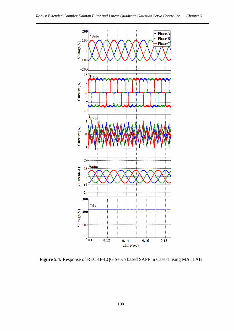
Robust Extended Complex Kalman Filter and Linear Quadratic Gaussian Servo Controller Chapter 5
100
Figure 5.4: Response of RECKF-LQG Servo based SAPF in Case-1 using MATLAB
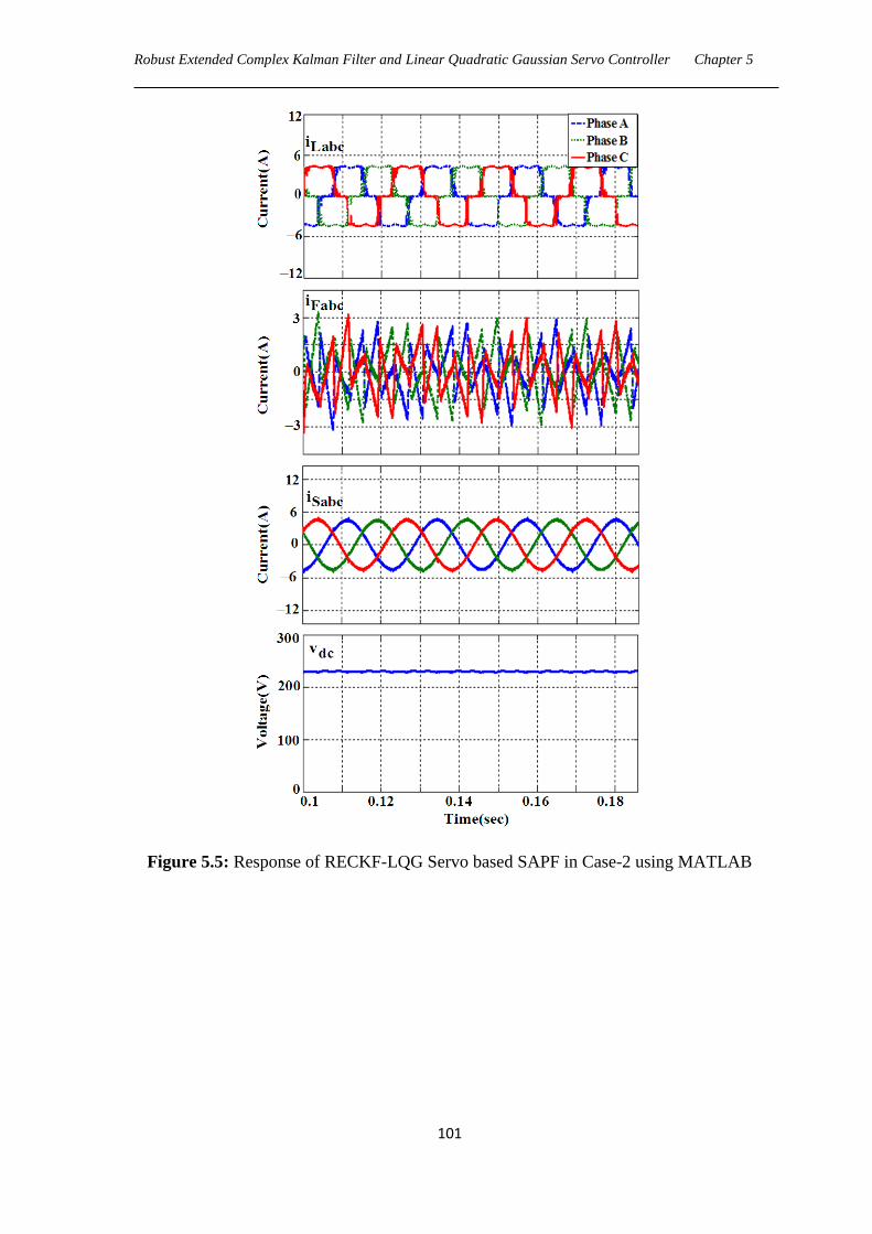
Robust Extended Complex Kalman Filter and Linear Quadratic Gaussian Servo Controller Chapter 5
101
Figure 5.5: Response of RECKF-LQG Servo based SAPF in Case-2 using MATLAB
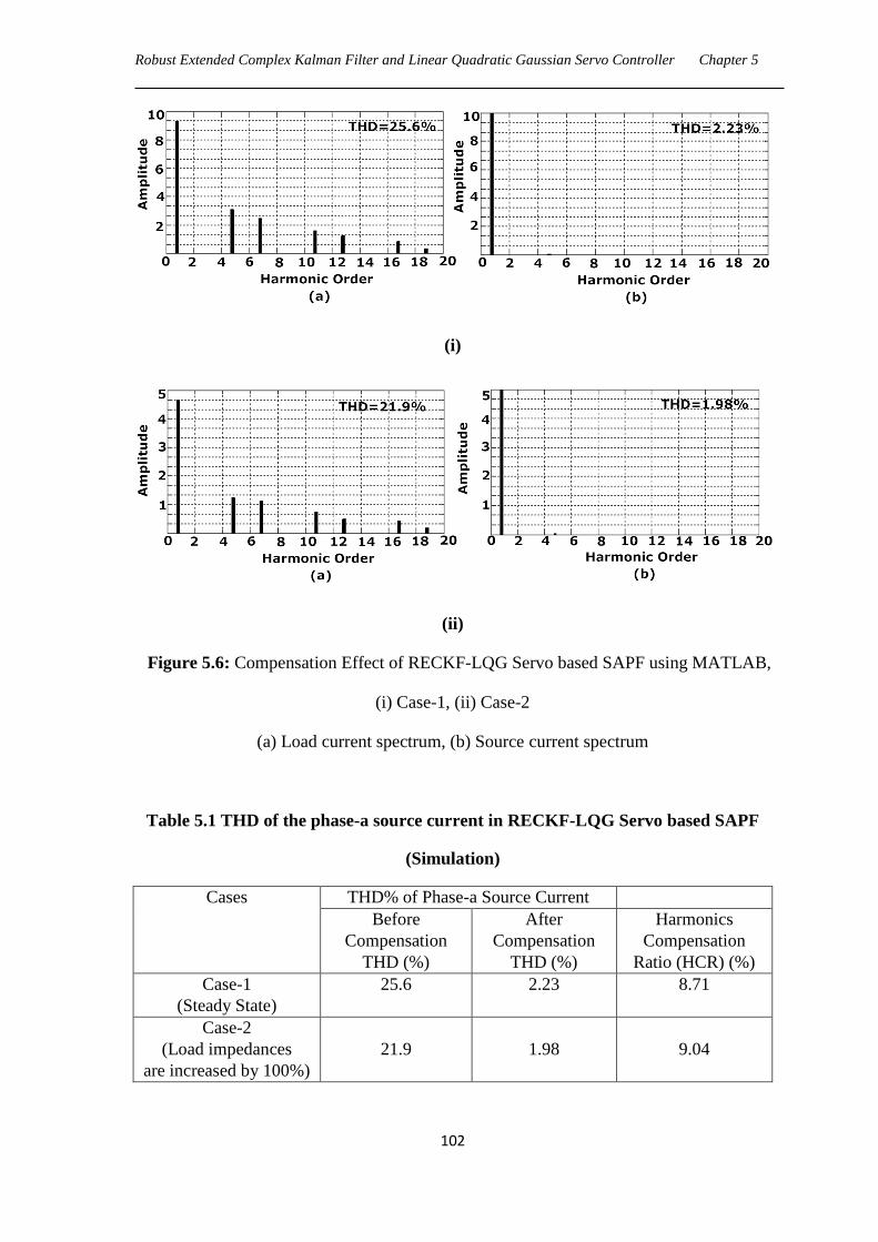
Robust Extended Complex Kalman Filter and Linear Quadratic Gaussian Servo Controller Chapter 5
102
(i)
(ii)
Figure 5.6: Compensation Effect of RECKF-LQG Servo based SAPF using MATLAB,
(i) Case-1, (ii) Case-2
(a) Load current spectrum, (b) Source current spectrum
Table 5.1 THD of the phase-a source current in RECKF-LQG Servo based SAPF
(Simulation)
Cases THD% of Phase-a Source Current
Before
Compensation
THD (%)
After
Compensation
THD (%)
Harmonics
Compensation
Ratio (HCR) (%)
Case-1
(Steady State)
25.6 2.23 8.71
Case-2
(Load impedances
are increased by 100%)
21.9
1.98
9.04
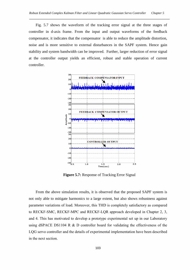
Robust Extended Complex Kalman Filter and Linear Quadratic Gaussian Servo Controller Chapter 5
103
Fig. 5.7 shows the waveform of the tracking error signal at the three stages of
controller in d-axis frame. From the input and output waveforms of the feedback
compensator, it indicates that the compensator is able to reduce the amplitude distortion,
noise and is more sensitive to external disturbances in the SAPF system. Hence gain
stability and system bandwidth can be improved. Further, larger reduction of error signal
at the controller output yields an efficient, robust and stable operation of current
controller.
Figure 5.7: Response of Tracking Error Signal
From the above simulation results, it is observed that the proposed SAPF system is
not only able to mitigate harmonics to a large extent, but also shows robustness against
parameter variations of load. Moreover, this THD is completely satisfactory as compared
to RECKF-SMC, RECKF-MPC and RECKF-LQR approach developed in Chapter 2, 3,
and 4. This has motivated to develop a prototype experimental set up in our Laboratory
using dSPACE DS1104 R & D controller board for validating the effectiveness of the
LQG servo controller and the details of experimental implementation have been described
in the next section.
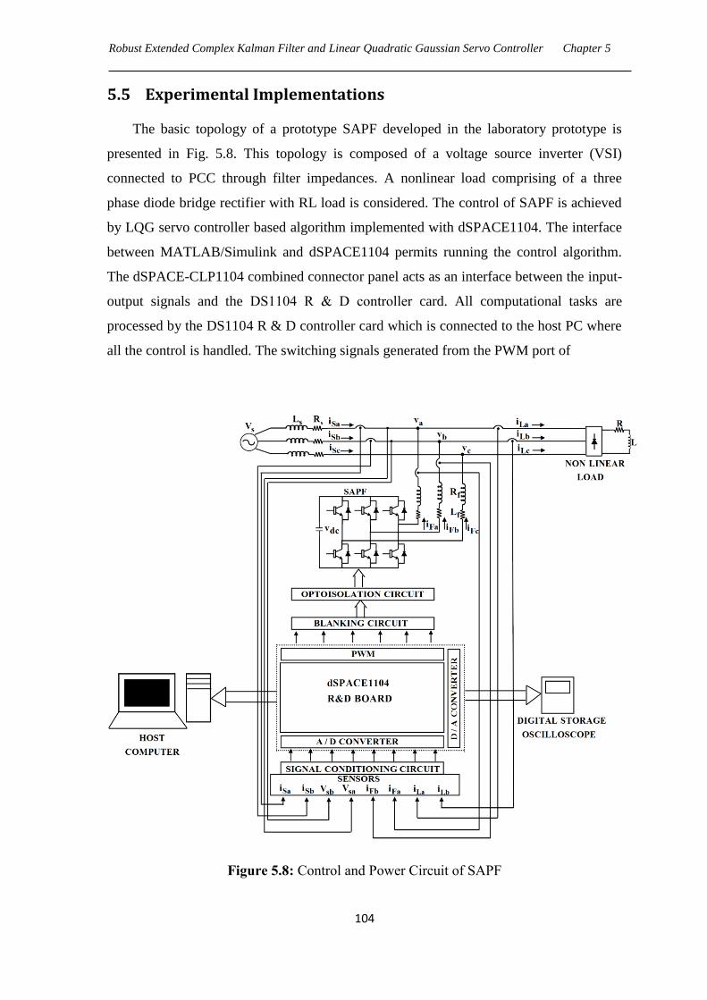
Robust Extended Complex Kalman Filter and Linear Quadratic Gaussian Servo Controller Chapter 5
104
5.5 Experimental Implementations
The basic topology of a prototype SAPF developed in the laboratory prototype is
presented in Fig. 5.8. This topology is composed of a voltage source inverter (VSI)
connected to PCC through filter impedances. A nonlinear load comprising of a three
phase diode bridge rectifier with RL load is considered. The control of SAPF is achieved
by LQG servo controller based algorithm implemented with dSPACE1104. The interface
between MATLAB/Simulink and dSPACE1104 permits running the control algorithm.
The dSPACE-CLP1104 combined connector panel acts as an interface between the input-
output signals and the DS1104 R & D controller card. All computational tasks are
processed by the DS1104 R & D controller card which is connected to the host PC where
all the control is handled. The switching signals generated from the PWM port of
Figure 5.8: Control and Power Circuit of SAPF
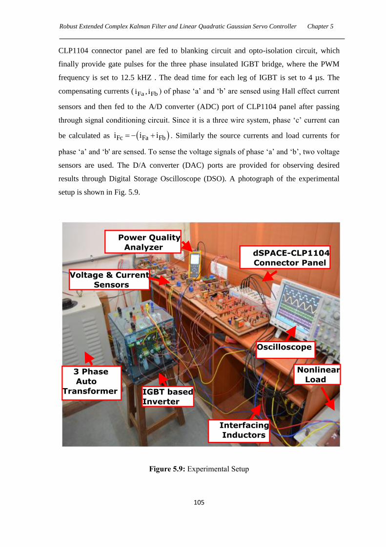
Robust Extended Complex Kalman Filter and Linear Quadratic Gaussian Servo Controller Chapter 5
105
CLP1104 connector panel are fed to blanking circuit and opto-isolation circuit, which
finally provide gate pulses for the three phase insulated IGBT bridge, where the PWM
frequency is set to 12.5 kHZ . The dead time for each leg of IGBT is set to 4 µs. The
compensating currents ( Fa Fbi , i ) of phase ‗a‘ and ‗b‘ are sensed using Hall effect current
sensors and then fed to the A/D converter (ADC) port of CLP1104 panel after passing
through signal conditioning circuit. Since it is a three wire system, phase ‗c‘ current can
be calculated as Fc Fa Fbi i i . Similarly the source currents and load currents for
phase ‗a‘ and ‗b' are sensed. To sense the voltage signals of phase ‗a‘ and ‗b‘, two voltage
sensors are used. The D/A converter (DAC) ports are provided for observing desired
results through Digital Storage Oscilloscope (DSO). A photograph of the experimental
setup is shown in Fig. 5.9.
Figure 5.9: Experimental Setup
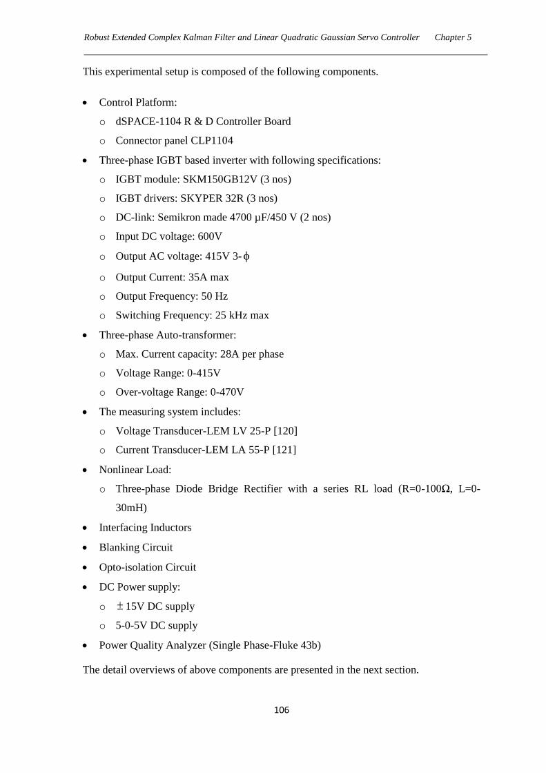
Robust Extended Complex Kalman Filter and Linear Quadratic Gaussian Servo Controller Chapter 5
106
This experimental setup is composed of the following components.
Control Platform:
o dSPACE-1104 R & D Controller Board
o Connector panel CLP1104
Three-phase IGBT based inverter with following specifications:
o IGBT module: SKM150GB12V (3 nos)
o IGBT drivers: SKYPER 32R (3 nos)
o DC-link: Semikron made 4700 µF/450 V (2 nos)
o Input DC voltage: 600V
o Output AC voltage: 415V 3-
o Output Current: 35A max
o Output Frequency: 50 Hz
o Switching Frequency: 25 kHz max
Three-phase Auto-transformer:
o Max. Current capacity: 28A per phase
o Voltage Range: 0-415V
o Over-voltage Range: 0-470V
The measuring system includes:
o Voltage Transducer-LEM LV 25-P [120]
o Current Transducer-LEM LA 55-P [121]
Nonlinear Load:
o Three-phase Diode Bridge Rectifier with a series RL load (R=0-100Ω, L=0-
30mH)
Interfacing Inductors
Blanking Circuit
Opto-isolation Circuit
DC Power supply:
o 15V DC supply
o 5-0-5V DC supply
Power Quality Analyzer (Single Phase-Fluke 43b)
The detail overviews of above components are presented in the next section.

Robust Extended Complex Kalman Filter and Linear Quadratic Gaussian Servo Controller Chapter 5
107
5.5.1 dSPACE Control Platform
DSPACER provides complete solutions for electronic control unit (ECU) software
development. It is a powerful development tool for dedicated services in the field of
function prototyping, target implementation, and ECU testing. Real time control systems
can be built using dSPACE and the control logic can be implemented. The dSPACE
works on Matlab/Simulink platform which is a common engineering software and easy to
understand. Another feature of the dSPACE is the Control desk which allows the
graphical user interface. Through the control desk the user can observe the response of
the system. Real-time Interface (RTI) is the link between dSPACE‘s real-time systems
and the development software MATLAB/Simulink from the Math Works. It extends
Real-Time Workshop (C-code generation) for the seamless and automatic implementation
of our Simulink Models on the dSPACE Real-time Hardware. This allows us to
concentrate fully on the actual design process and to carry out fast design iterations.
To implement a real-time control loop using dSPACE and MATLAB we need
following items.
1. dSPACE DS1104 R&D Controller Board
2. Connector Panel CLP1104
5.5.1.1 dSPACE DS1104 R&D Controller Board
The DS1104 R&D Controller Board is a standard board that can be plugged into a PCI
slot of a PC shown in Fig. 5.10. The DS1104 is specifically designed for the development
of high-speed multivariable digital controllers and real-time simulations in various fields.
It is a complete real-time control system based on a 603 Power PC floating-point
processor running at 250 MHz. For advanced I/O purposes, the board includes a slave-
DSP subsystem based on the TMS320F240 DSP microcontroller. For purposes of rapid
control prototyping (RCP), specific interface connectors and connector panels described
below provide easy access to all input and output signals of the board. Thus, the DS1104
R&D Controller Board is the ideal hardware for the dSPACE Prototype development
system for cost-sensitive RCP applications. It executes all computational and control
tasks for the shunt connected converter.
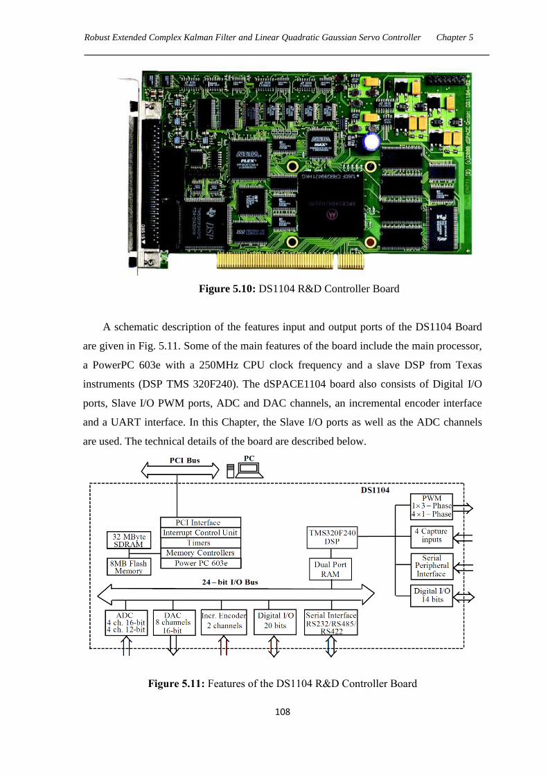
Robust Extended Complex Kalman Filter and Linear Quadratic Gaussian Servo Controller Chapter 5
108
Figure 5.10: DS1104 R&D Controller Board
A schematic description of the features input and output ports of the DS1104 Board
are given in Fig. 5.11. Some of the main features of the board include the main processor,
a PowerPC 603e with a 250MHz CPU clock frequency and a slave DSP from Texas
instruments (DSP TMS 320F240). The dSPACE1104 board also consists of Digital I/O
ports, Slave I/O PWM ports, ADC and DAC channels, an incremental encoder interface
and a UART interface. In this Chapter, the Slave I/O ports as well as the ADC channels
are used. The technical details of the board are described below.
Figure 5.11: Features of the DS1104 R&D Controller Board

Robust Extended Complex Kalman Filter and Linear Quadratic Gaussian Servo Controller Chapter 5
109
Technical Details:
Main Processor
MPC8240, PowerPC 603e core, 250 MHz
32 kByte internal cache
Timers
1 sample rate timer, 32-bit downcounter
4 general purpose timers, 32 bit
64-bit time base for time measurement
Memory
32 MByte synchronous DRAM (SDRAM)
8 MByte boot flash for applications
Interrupt Control Unit
Interrupts by timers, serial interface, slave
DSP, incremental encoders, ADC, host PC
and 4 external inputs
PWM synchronous interrupts
Analog Input
4 ADC inputs, 16 bit, multiplexed
± 10 V input voltage range
2 μs sampling time
80 dB signal-to-noise ratio
4 ADC channels, 12 bit
± 10 V input voltage range
800 ns sampling time
> 65 dB signal-to-noise ratio
Analog Output
8 channels, 16 bit, 10 μs max. settling time
± 10 V output voltage range
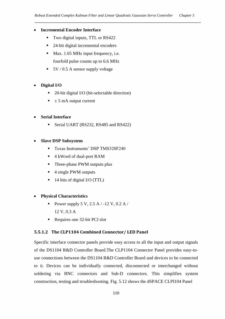
Robust Extended Complex Kalman Filter and Linear Quadratic Gaussian Servo Controller Chapter 5
110
Incremental Encoder Interface
Two digital inputs, TTL or RS422
24-bit digital incremental encoders
Max. 1.65 MHz input frequency, i.e.
fourfold pulse counts up to 6.6 MHz
5V / 0.5 A sensor supply voltage
Digital I/O
20-bit digital I/O (bit-selectable direction)
± 5 mA output current
Serial Interface
Serial UART (RS232, RS485 and RS422)
Slave DSP Subsystem
Texas Instruments‘ DSP TMS320F240
4 kWord of dual-port RAM
Three-phase PWM outputs plus
4 single PWM outputs
14 bits of digital I/O (TTL)
Physical Characteristics
Power supply 5 V, 2.5 A / -12 V, 0.2 A /
12 V, 0.3 A
Requires one 32-bit PCI slot
5.5.1.2 The CLP1104 Combined Connector/ LED Panel
Specific interface connector panels provide easy access to all the input and output signals
of the DS1104 R&D Controller Board.The CLP1104 Connector Panel provides easy-to-
use connections between the DS1104 R&D Controller Board and devices to be connected
to it. Devices can be individually connected, disconnected or interchanged without
soldering via BNC connectors and Sub-D connectors. This simplifies system
construction, testing and troubleshooting. Fig. 5.12 shows the dSPACE CLPI104 Panel
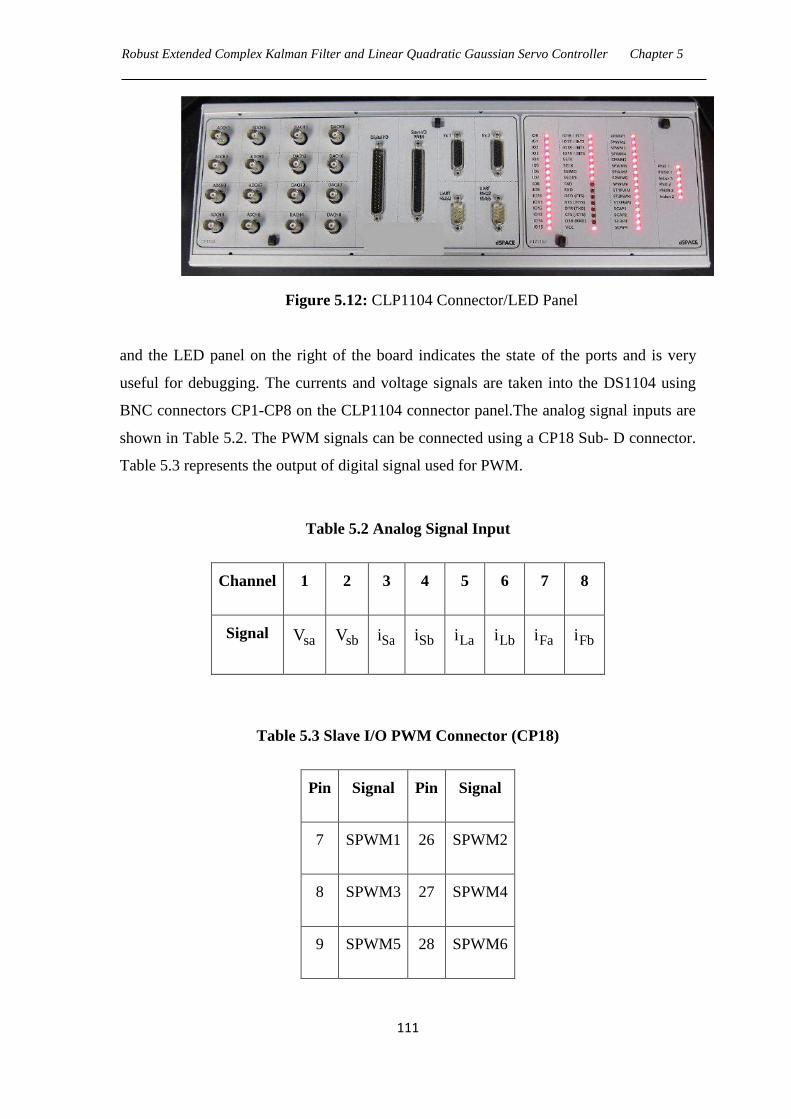
Robust Extended Complex Kalman Filter and Linear Quadratic Gaussian Servo Controller Chapter 5
111
Figure 5.12: CLP1104 Connector/LED Panel
and the LED panel on the right of the board indicates the state of the ports and is very
useful for debugging. The currents and voltage signals are taken into the DS1104 using
BNC connectors CP1-CP8 on the CLP1104 connector panel.The analog signal inputs are
shown in Table 5.2. The PWM signals can be connected using a CP18 Sub- D connector.
Table 5.3 represents the output of digital signal used for PWM.
Table 5.2 Analog Signal Input
Channel 1 2 3 4 5 6 7 8
Signal saV sbV Sai Sbi Lai Lbi Fai Fbi
Table 5.3 Slave I/O PWM Connector (CP18)
Pin Signal Pin Signal
7 SPWM1 26 SPWM2
8 SPWM3 27 SPWM4
9 SPWM5 28 SPWM6
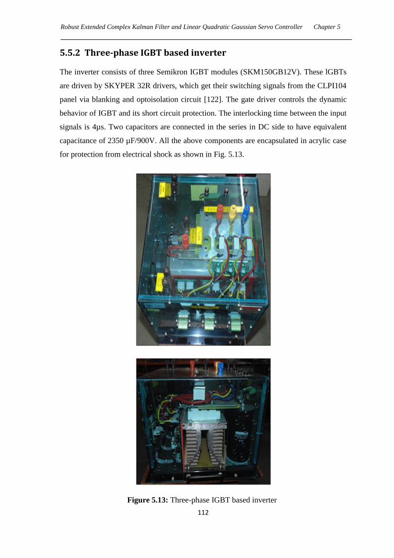
Robust Extended Complex Kalman Filter and Linear Quadratic Gaussian Servo Controller Chapter 5
112
5.5.2 Three-phase IGBT based inverter
The inverter consists of three Semikron IGBT modules (SKM150GB12V). These lGBTs
are driven by SKYPER 32R drivers, which get their switching signals from the CLPI104
panel via blanking and optoisolation circuit [122]. The gate driver controls the dynamic
behavior of IGBT and its short circuit protection. The interlocking time between the input
signals is 4µs. Two capacitors are connected in the series in DC side to have equivalent
capacitance of 2350 µF/900V. All the above components are encapsulated in acrylic case
for protection from electrical shock as shown in Fig. 5.13.
Figure 5.13: Three-phase IGBT based inverter
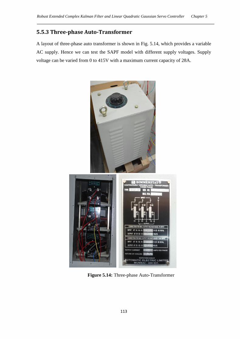
Robust Extended Complex Kalman Filter and Linear Quadratic Gaussian Servo Controller Chapter 5
113
5.5.3 Three-phase Auto-Transformer
A layout of three-phase auto transformer is shown in Fig. 5.14, which provides a variable
AC supply. Hence we can test the SAPF model with different supply voltages. Supply
voltage can be varied from 0 to 415V with a maximum current capacity of 28A.
Figure 5.14: Three-phase Auto-Transformer
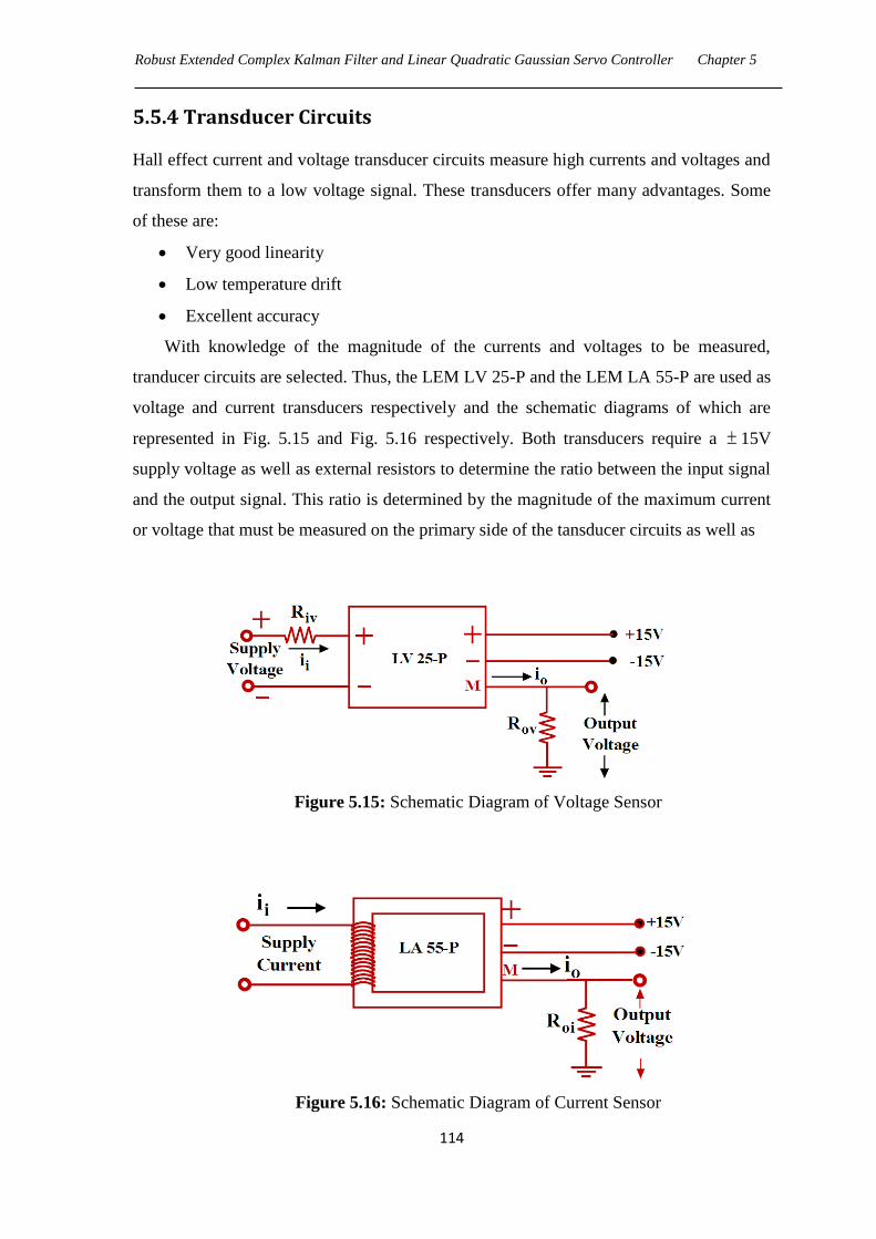
Robust Extended Complex Kalman Filter and Linear Quadratic Gaussian Servo Controller Chapter 5
114
5.5.4 Transducer Circuits
Hall effect current and voltage transducer circuits measure high currents and voltages and
transform them to a low voltage signal. These transducers offer many advantages. Some
of these are:
Very good linearity
Low temperature drift
Excellent accuracy
With knowledge of the magnitude of the currents and voltages to be measured,
tranducer circuits are selected. Thus, the LEM LV 25-P and the LEM LA 55-P are used as
voltage and current transducers respectively and the schematic diagrams of which are
represented in Fig. 5.15 and Fig. 5.16 respectively. Both transducers require a 15V
supply voltage as well as external resistors to determine the ratio between the input signal
and the output signal. This ratio is determined by the magnitude of the maximum current
or voltage that must be measured on the primary side of the tansducer circuits as well as
Figure 5.15: Schematic Diagram of Voltage Sensor
Figure 5.16: Schematic Diagram of Current Sensor

Robust Extended Complex Kalman Filter and Linear Quadratic Gaussian Servo Controller Chapter 5
115
by the magnitude of the desired output voltages on the secondary side. The transducer
circuits provide isolation between the power network and the signal level circuits. The
output signals must be restricted to 10V, which is the maximum allowable voltage of
the ADC of the DS 1104 Controller board.
5.5.4.1 Design of Voltage Transducer Circuit
In the experimental set up, the supply voltage is scaled down from 100V to the 10V
range. Referring the data sheet of the transducer [120], the input resistance ivR is chosen
so as to fall the output resistance ovR in the range of 100-350Ω.
The input current ii can be obtained from iv 100V and ivR 15k .
ii 3
iv
v 100i 6.67mA
R 15 10
(5.27)
With conversion ratio of 2500:1000 for transducer, the output current is calculated as
o i2500
i i 6.67 2.5 16.67mA1000
(5.28)
The output resistance is chosen to be 300 Ω so that transducer output voltage lies in
the range of 10V and hence the transducer output voltage becomes,
Output voltage= 3ov oR i 300 16.67 10 5V (5.29)
5.5.4.2 Design of Current Transducer Circuit
A current of 10A in the power network is converted to 10V. The number of primary
turns ( pN ) is chosen such that the output resistance falls in the range of 50-160 Ω as
specified in the datasheet of transducer [121].
With conversion ratio of 1:1000, pN 5 and ii 10A , the output current can be
computed as
o p i1 5 10
i N i 0.05A1000 1000
(5.30)
The output resistance is chosen to be 100 Ω so that transducer output voltage lies in
the range of 10V and hence the transducer output voltage becomes,
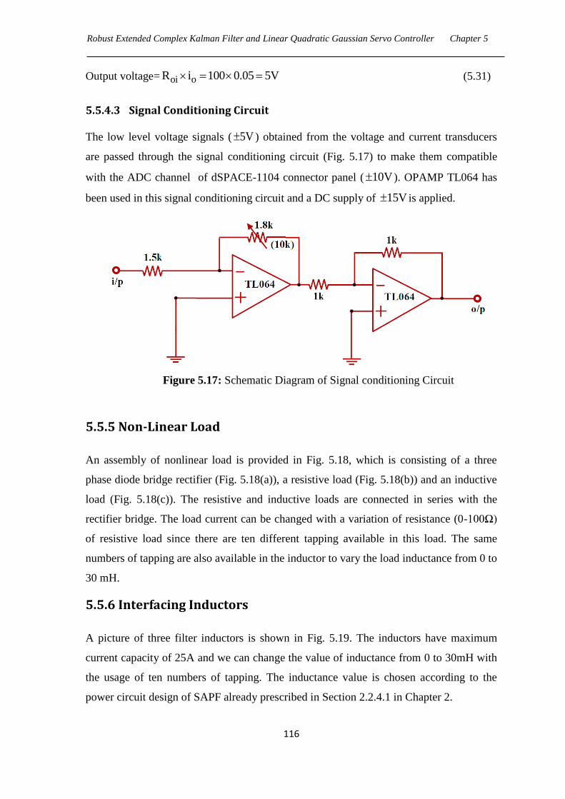
Robust Extended Complex Kalman Filter and Linear Quadratic Gaussian Servo Controller Chapter 5
116
Output voltage= oi oR i 100 0.05 5V (5.31)
5.5.4.3 Signal Conditioning Circuit
The low level voltage signals ( 5V ) obtained from the voltage and current transducers
are passed through the signal conditioning circuit (Fig. 5.17) to make them compatible
with the ADC channel of dSPACE-1104 connector panel ( 10V ). OPAMP TL064 has
been used in this signal conditioning circuit and a DC supply of 15V is applied.
Figure 5.17: Schematic Diagram of Signal conditioning Circuit
5.5.5 Non-Linear Load
An assembly of nonlinear load is provided in Fig. 5.18, which is consisting of a three
phase diode bridge rectifier (Fig. 5.18(a)), a resistive load (Fig. 5.18(b)) and an inductive
load (Fig. 5.18(c)). The resistive and inductive loads are connected in series with the
rectifier bridge. The load current can be changed with a variation of resistance (0-100Ω)
of resistive load since there are ten different tapping available in this load. The same
numbers of tapping are also available in the inductor to vary the load inductance from 0 to
30 mH.
5.5.6 Interfacing Inductors
A picture of three filter inductors is shown in Fig. 5.19. The inductors have maximum
current capacity of 25A and we can change the value of inductance from 0 to 30mH with
the usage of ten numbers of tapping. The inductance value is chosen according to the
power circuit design of SAPF already prescribed in Section 2.2.4.1 in Chapter 2.
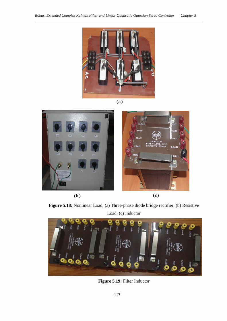
Robust Extended Complex Kalman Filter and Linear Quadratic Gaussian Servo Controller Chapter 5
117
Figure 5.18: Nonlinear Load, (a) Three-phase diode bridge rectifier, (b) Resistive
Load, (c) Inductor
Figure 5.19: Filter Inductor
(a )
(b ) (c )
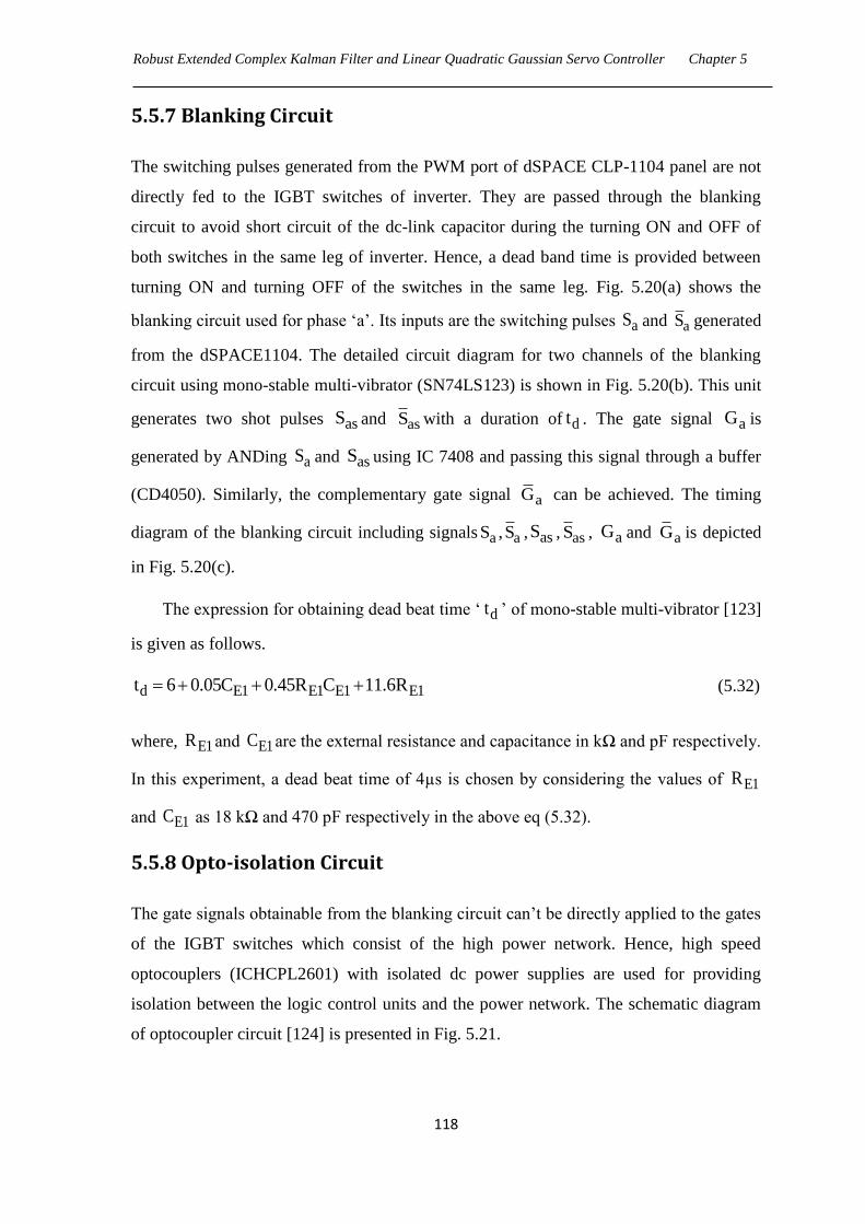
Robust Extended Complex Kalman Filter and Linear Quadratic Gaussian Servo Controller Chapter 5
118
5.5.7 Blanking Circuit
The switching pulses generated from the PWM port of dSPACE CLP-1104 panel are not
directly fed to the IGBT switches of inverter. They are passed through the blanking
circuit to avoid short circuit of the dc-link capacitor during the turning ON and OFF of
both switches in the same leg of inverter. Hence, a dead band time is provided between
turning ON and turning OFF of the switches in the same leg. Fig. 5.20(a) shows the
blanking circuit used for phase ‗a‘. Its inputs are the switching pulses aS and aS generated
from the dSPACE1104. The detailed circuit diagram for two channels of the blanking
circuit using mono-stable multi-vibrator (SN74LS123) is shown in Fig. 5.20(b). This unit
generates two shot pulses asS and asS with a duration of dt . The gate signal aG is
generated by ANDing aS and asS using IC 7408 and passing this signal through a buffer
(CD4050). Similarly, the complementary gate signal aG can be achieved. The timing
diagram of the blanking circuit including signals a aS ,S , asS , asS , aG and aG is depicted
in Fig. 5.20(c).
The expression for obtaining dead beat time ‗ dt ‘ of mono-stable multi-vibrator [123]
is given as follows.
d E1 E1 E1 E1t 6 0.05C 0.45R C 11.6R (5.32)
where, E1R and E1C are the external resistance and capacitance in kΩ and pF respectively.
In this experiment, a dead beat time of 4µs is chosen by considering the values of E1R
and E1C as 18 kΩ and 470 pF respectively in the above eq (5.32).
5.5.8 Opto-isolation Circuit
The gate signals obtainable from the blanking circuit can‘t be directly applied to the gates
of the IGBT switches which consist of the high power network. Hence, high speed
optocouplers (ICHCPL2601) with isolated dc power supplies are used for providing
isolation between the logic control units and the power network. The schematic diagram
of optocoupler circuit [124] is presented in Fig. 5.21.
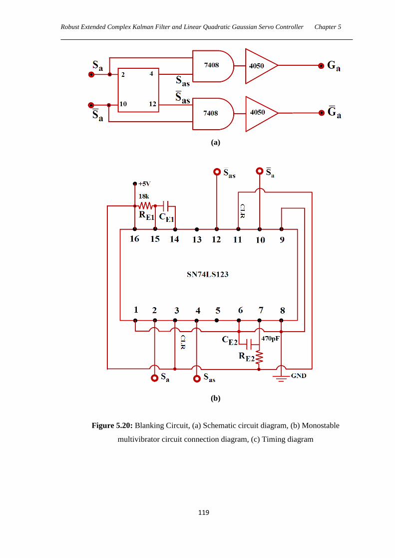
Robust Extended Complex Kalman Filter and Linear Quadratic Gaussian Servo Controller Chapter 5
119
(a)
(b)
Figure 5.20: Blanking Circuit, (a) Schematic circuit diagram, (b) Monostable
multivibrator circuit connection diagram, (c) Timing diagram
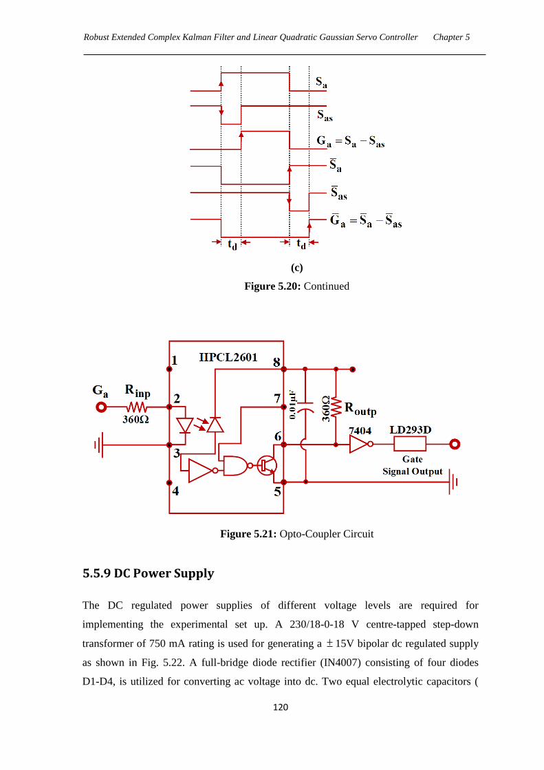
Robust Extended Complex Kalman Filter and Linear Quadratic Gaussian Servo Controller Chapter 5
120
(c)
Figure 5.20: Continued
Figure 5.21: Opto-Coupler Circuit
5.5.9 DC Power Supply
The DC regulated power supplies of different voltage levels are required for
implementing the experimental set up. A 230/18-0-18 V centre-tapped step-down
transformer of 750 mA rating is used for generating a 15V bipolar dc regulated supply
as shown in Fig. 5.22. A full-bridge diode rectifier (IN4007) consisting of four diodes
D1-D4, is utilized for converting ac voltage into dc. Two equal electrolytic capacitors (
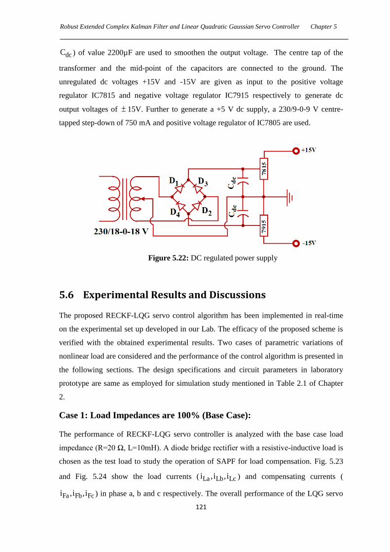
Robust Extended Complex Kalman Filter and Linear Quadratic Gaussian Servo Controller Chapter 5
121
dcC ) of value 2200µF are used to smoothen the output voltage. The centre tap of the
transformer and the mid-point of the capacitors are connected to the ground. The
unregulated dc voltages +15V and -15V are given as input to the positive voltage
regulator IC7815 and negative voltage regulator IC7915 respectively to generate dc
output voltages of 15V. Further to generate a +5 V dc supply, a 230/9-0-9 V centre-
tapped step-down of 750 mA and positive voltage regulator of IC7805 are used.
Figure 5.22: DC regulated power supply
5.6 Experimental Results and Discussions
The proposed RECKF-LQG servo control algorithm has been implemented in real-time
on the experimental set up developed in our Lab. The efficacy of the proposed scheme is
verified with the obtained experimental results. Two cases of parametric variations of
nonlinear load are considered and the performance of the control algorithm is presented in
the following sections. The design specifications and circuit parameters in laboratory
prototype are same as employed for simulation study mentioned in Table 2.1 of Chapter
2.
Case 1: Load Impedances are 100% (Base Case):
The performance of RECKF-LQG servo controller is analyzed with the base case load
impedance (R=20 Ω, L=10mH). A diode bridge rectifier with a resistive-inductive load is
chosen as the test load to study the operation of SAPF for load compensation. Fig. 5.23
and Fig. 5.24 show the load currents ( La Lb Lci ,i ,i ) and compensating currents (
Fa Fb Fci ,i ,i ) in phase a, b and c respectively. The overall performance of the LQG servo
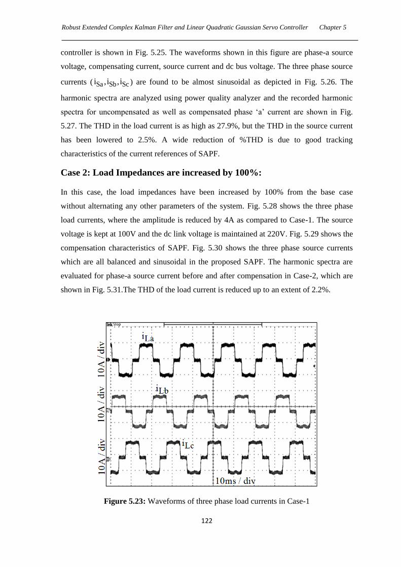
Robust Extended Complex Kalman Filter and Linear Quadratic Gaussian Servo Controller Chapter 5
122
controller is shown in Fig. 5.25. The waveforms shown in this figure are phase-a source
voltage, compensating current, source current and dc bus voltage. The three phase source
currents ( Sa Sb Sci ,i ,i ) are found to be almost sinusoidal as depicted in Fig. 5.26. The
harmonic spectra are analyzed using power quality analyzer and the recorded harmonic
spectra for uncompensated as well as compensated phase ‗a‘ current are shown in Fig.
5.27. The THD in the load current is as high as 27.9%, but the THD in the source current
has been lowered to 2.5%. A wide reduction of %THD is due to good tracking
characteristics of the current references of SAPF.
Case 2: Load Impedances are increased by 100%:
In this case, the load impedances have been increased by 100% from the base case
without alternating any other parameters of the system. Fig. 5.28 shows the three phase
load currents, where the amplitude is reduced by 4A as compared to Case-1. The source
voltage is kept at 100V and the dc link voltage is maintained at 220V. Fig. 5.29 shows the
compensation characteristics of SAPF. Fig. 5.30 shows the three phase source currents
which are all balanced and sinusoidal in the proposed SAPF. The harmonic spectra are
evaluated for phase-a source current before and after compensation in Case-2, which are
shown in Fig. 5.31.The THD of the load current is reduced up to an extent of 2.2%.
Figure 5.23: Waveforms of three phase load currents in Case-1
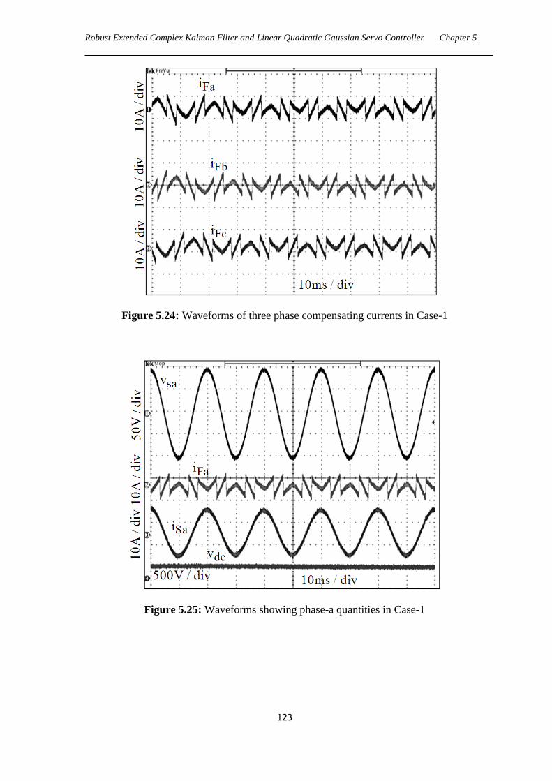
Robust Extended Complex Kalman Filter and Linear Quadratic Gaussian Servo Controller Chapter 5
123
Figure 5.24: Waveforms of three phase compensating currents in Case-1
Figure 5.25: Waveforms showing phase-a quantities in Case-1
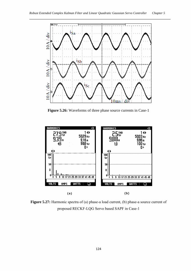
Robust Extended Complex Kalman Filter and Linear Quadratic Gaussian Servo Controller Chapter 5
124
Figure 5.26: Waveforms of three phase source currents in Case-1
Figure 5.27: Harmonic spectra of (a) phase-a load current, (b) phase-a source current of
proposed RECKF-LQG Servo based SAPF in Case-1
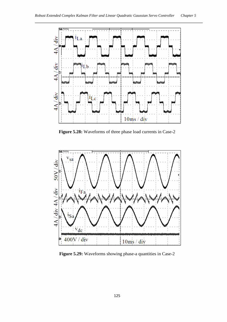
Robust Extended Complex Kalman Filter and Linear Quadratic Gaussian Servo Controller Chapter 5
125
Figure 5.28: Waveforms of three phase load currents in Case-2
Figure 5.29: Waveforms showing phase-a quantities in Case-2
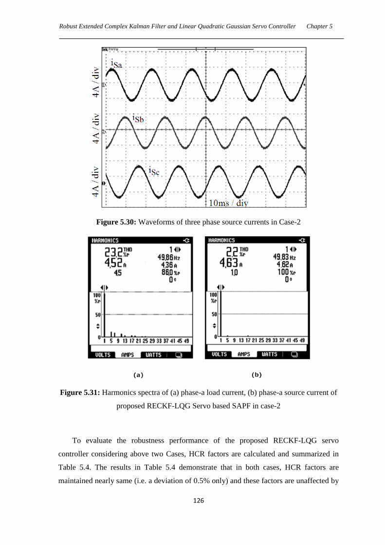
Robust Extended Complex Kalman Filter and Linear Quadratic Gaussian Servo Controller Chapter 5
126
Figure 5.30: Waveforms of three phase source currents in Case-2
Figure 5.31: Harmonics spectra of (a) phase-a load current, (b) phase-a source current of
proposed RECKF-LQG Servo based SAPF in case-2
To evaluate the robustness performance of the proposed RECKF-LQG servo
controller considering above two Cases, HCR factors are calculated and summarized in
Table 5.4. The results in Table 5.4 demonstrate that in both cases, HCR factors are
maintained nearly same (i.e. a deviation of 0.5% only) and these factors are unaffected by
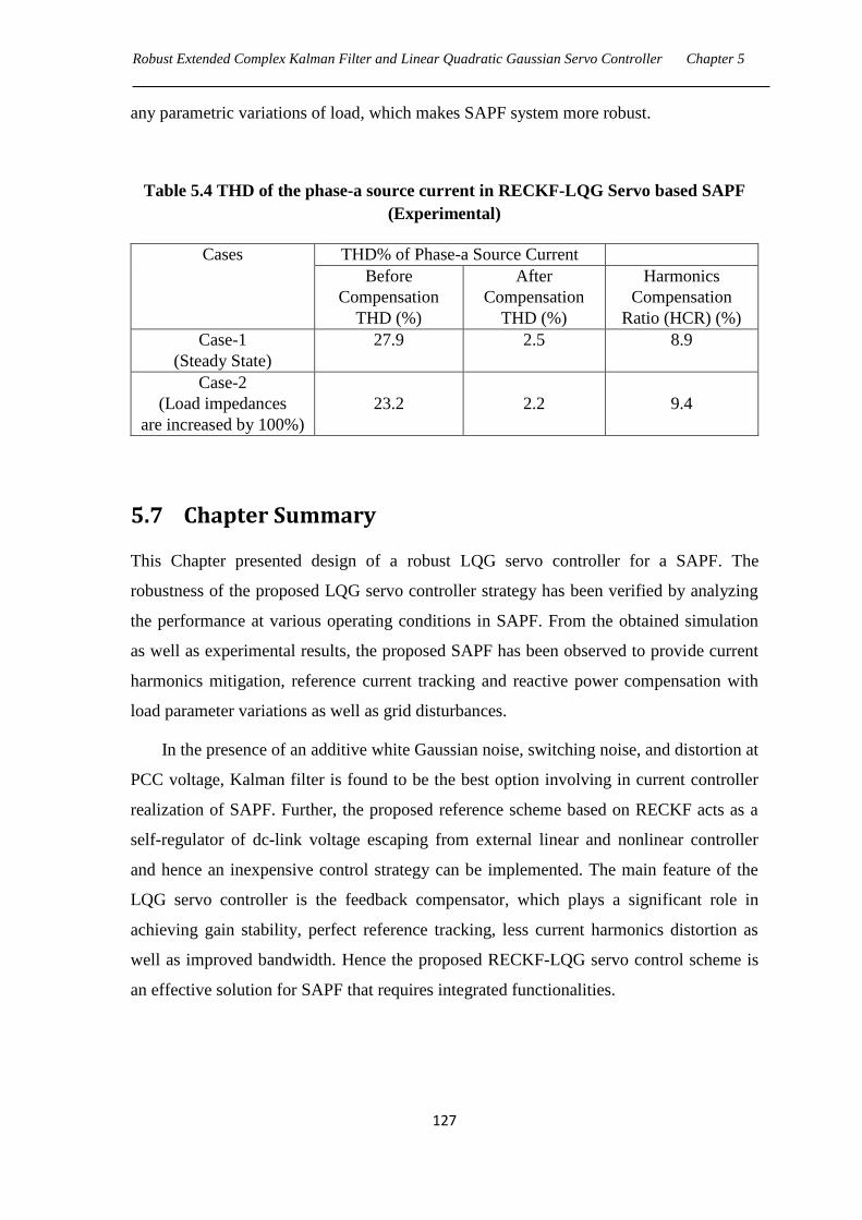
Robust Extended Complex Kalman Filter and Linear Quadratic Gaussian Servo Controller Chapter 5
127
any parametric variations of load, which makes SAPF system more robust.
Table 5.4 THD of the phase-a source current in RECKF-LQG Servo based SAPF
(Experimental)
Cases THD% of Phase-a Source Current
Before
Compensation
THD (%)
After
Compensation
THD (%)
Harmonics
Compensation
Ratio (HCR) (%)
Case-1
(Steady State)
27.9 2.5 8.9
Case-2
(Load impedances
are increased by 100%)
23.2
2.2
9.4
5.7 Chapter Summary
This Chapter presented design of a robust LQG servo controller for a SAPF. The
robustness of the proposed LQG servo controller strategy has been verified by analyzing
the performance at various operating conditions in SAPF. From the obtained simulation
as well as experimental results, the proposed SAPF has been observed to provide current
harmonics mitigation, reference current tracking and reactive power compensation with
load parameter variations as well as grid disturbances.
In the presence of an additive white Gaussian noise, switching noise, and distortion at
PCC voltage, Kalman filter is found to be the best option involving in current controller
realization of SAPF. Further, the proposed reference scheme based on RECKF acts as a
self-regulator of dc-link voltage escaping from external linear and nonlinear controller
and hence an inexpensive control strategy can be implemented. The main feature of the
LQG servo controller is the feedback compensator, which plays a significant role in
achieving gain stability, perfect reference tracking, less current harmonics distortion as
well as improved bandwidth. Hence the proposed RECKF-LQG servo control scheme is
an effective solution for SAPF that requires integrated functionalities.

CHAPTER 6
Robust Extended Complex Kalman Filter and H∞
Control based SAPF
6.1 Introduction
This Chapter proposes a robust H∞ control scheme in the current control loop for a three
phase SAPF system. With the purpose of achieving high stability and high disturbance
rejection, a mixed sensitivity approach has been employed in the synthesis of this H∞
controller. Further, the reference generation scheme employed in the Chapter 5 considers
current measurements (both load and source current) to achieve a cost effective SAPF
system. Hence, a new current reference scheme is proposed in this Chapter, which
concerns with the measurement of source current only in order to achieve a more reliable
and cost efficient SAPF.
The proposed reference scheme is based upon a fast and adaptive estimation of peak
and fundamental of source reference current, which has the capability of delivering real
power equivalent to conduction and switching losses occurred during capacitor voltage
deviation. Robust extended complex Kalman filter is employed here for fast estimation of
positive sequence from the fundamental component of supply current, which leads to
generate source reference because negative and zero sequence components can degrade
the harmonics compensation efficiency of SAPF. It is demanded that proposed reference
generation scheme not only overcomes the problems of PI controller, but also self-
regulates the dc-link voltage with sensing supply current only.
In recent years, power line uncertainties such as random variation of load,
unexpected failure of power system components, high disturbance environment and
involved sensor nonlinearities are the most challenging issues that might affect the
dynamic performance of SAPF. Moreover parameters of SAPF may vary due to
component aging, thermal drift and saturation effects caused by the operating
environment. Hence it is essential to design robust controllers that provide good
disturbance rejection and robustness against uncertainties in the system dynamics.
Furthermore, application of robust control scheme is not very popular in distribution of
power system and is limited to medium voltage level DVR [125][126], where H∞

Robust Extended Complex Kalman Filter and H∞ Control based SAPF Chapter 6
130
controller is employed for the purpose of voltage control only. However, H∞ control of
SAPF has not been actively investigated for the purpose of harmonics and reactive power
compensation so far. In view of addressing all the aforementioned issues, an H∞ robust
controller is proposed, designed and investigated in this Chapter for mitigating current
harmonics as well as reactive power to achieve unity power factor in SAPF. H∞ controller
is synthesized using mixed sensitivity approach for achieving stability and high
disturbance rejection in SAPF.
6.2 Chapter Objectives
1. To make reference generation scheme simple, reliable and self dc-link voltage
regulating.
2. To achieve stability and disturbance rejection in SAPF.
3. To show a high degree of robustness against parametric variations of the load.
4. To improve the PQ more effectively in terms of tracking error minimization and
efficient current harmonics compensation.
5. To make a cost-effective SAPF system.
6. To validate the robustness of proposed control system with experimental set up under
different parameters of load.
6.3 Proposed RECKF-H∞ based SAPF
The proposed control scheme for the SAPF is summarized in Fig. 6.1. The control system
consists of a current loop including H∞ controller so that the current injected FabcI into
the grid could track the reference current *FabcI .The transformation from abc to dq frame
has been performed for current controller implementation. The output of the current
controller is then transformed to the abc frame and subsequently passed to the pulse width
modulation (PWM) generator to give switching pulses to IGBT based inverter.
The whole system is designed to inject current into the line such as to compensate the
harmonic content of the load current. The compensation must be accomplished
considering model uncertainty, parameter variations of load, and several disturbances on
the grid which may affect the dynamic behavior of SAPF. Under this scenario, this
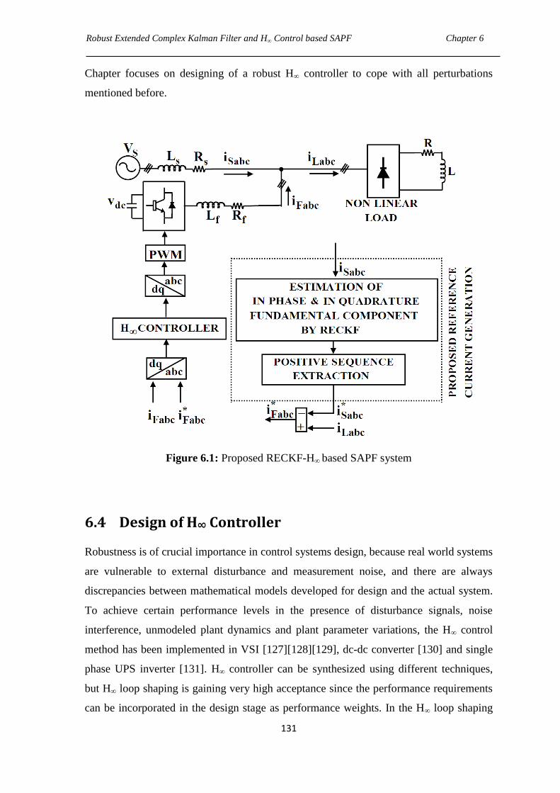
Robust Extended Complex Kalman Filter and H∞ Control based SAPF Chapter 6
131
Chapter focuses on designing of a robust H∞ controller to cope with all perturbations
mentioned before.
Figure 6.1: Proposed RECKF-H∞ based SAPF system
6.4 Design of H∞ Controller
Robustness is of crucial importance in control systems design, because real world systems
are vulnerable to external disturbance and measurement noise, and there are always
discrepancies between mathematical models developed for design and the actual system.
To achieve certain performance levels in the presence of disturbance signals, noise
interference, unmodeled plant dynamics and plant parameter variations, the H∞ control
method has been implemented in VSI [127][128][129], dc-dc converter [130] and single
phase UPS inverter [131]. H∞ controller can be synthesized using different techniques,
but H∞ loop shaping is gaining very high acceptance since the performance requirements
can be incorporated in the design stage as performance weights. In the H∞ loop shaping
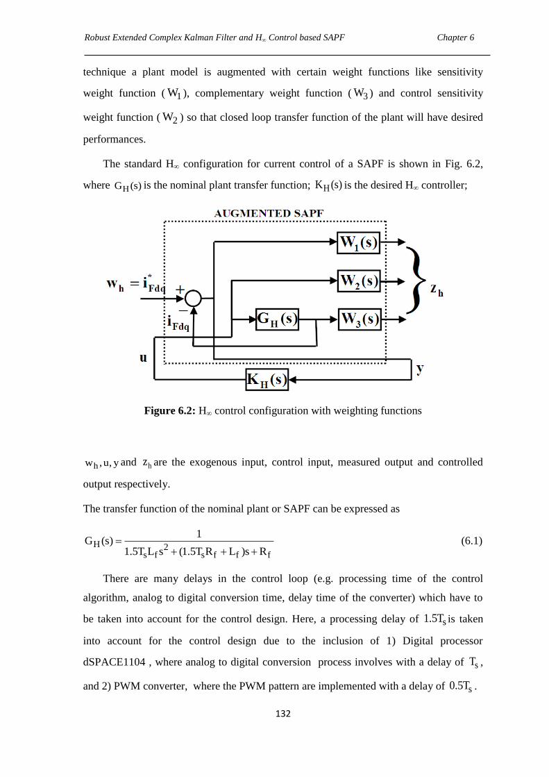
Robust Extended Complex Kalman Filter and H∞ Control based SAPF Chapter 6
132
technique a plant model is augmented with certain weight functions like sensitivity
weight function ( 1W ), complementary weight function ( 3W ) and control sensitivity
weight function ( 2W ) so that closed loop transfer function of the plant will have desired
performances.
The standard H∞ configuration for current control of a SAPF is shown in Fig. 6.2,
where HG (s) is the nominal plant transfer function; HK (s) is the desired H∞ controller;
Figure 6.2: H∞ control configuration with weighting functions
hw ,u, y and hz are the exogenous input, control input, measured output and controlled
output respectively.
The transfer function of the nominal plant or SAPF can be expressed as
H 2s f s f f f
1G (s)
1.5T L s (1.5T R L )s R
(6.1)
There are many delays in the control loop (e.g. processing time of the control
algorithm, analog to digital conversion time, delay time of the converter) which have to
be taken into account for the control design. Here, a processing delay of s1.5T is taken
into account for the control design due to the inclusion of 1) Digital processor
dSPACE1104 , where analog to digital conversion process involves with a delay of sT ,
and 2) PWM converter, where the PWM pattern are implemented with a delay of s0.5T .
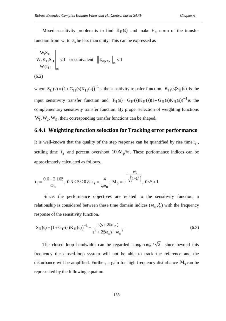
Robust Extended Complex Kalman Filter and H∞ Control based SAPF Chapter 6
133
Mixed sensitivity problem is to find HK (s) and make H∞ norm of the transfer
function from hw to hz be less than unity. This can be expressed as
1 H
2 H H
3 H
W S
W K S 1
W T
or equivalent w zh hT 1
(6.2)
where 1
H H HS (s) 1 G (s)K (s)
is the sensitivity transfer function, H HK (s)S (s) is the
input sensitivity transfer function and 1
H H H H HT (s) G (s)K (s)(1 G (s)K (s)) is the
complementary sensitivity transfer function. By proper selection of weighting functions
1 2 3W , W , W , their corresponding transfer functions can be shaped.
6.4.1 Weighting function selection for Tracking error performance
It is well-known that the quality of the step response can be quantified by rise time rt ,
settling time st and percent overshoot p100M % . These performance indices can be
approximately calculated as follows.
21
r s pn n
0.6 2.16 4t , 0.3 0.8; t ; M e , 0< 1
Since, the performance objectives are related to the sensitivity function, a
relationship is considered between these time domain indices ( n , ) with the frequency
response of the sensitivity function.
1 n
H H H 2 2n n
s(s 2 )S (s) 1 G (s)K (s)
s 2 s
(6.3)
The closed loop bandwidth can be regarded as b n / 2 , since beyond this
frequency the closed-loop system will not be able to track the reference and the
disturbance will be amplified. Further, a gain for high frequency disturbance sM can be
represented by the following equation.
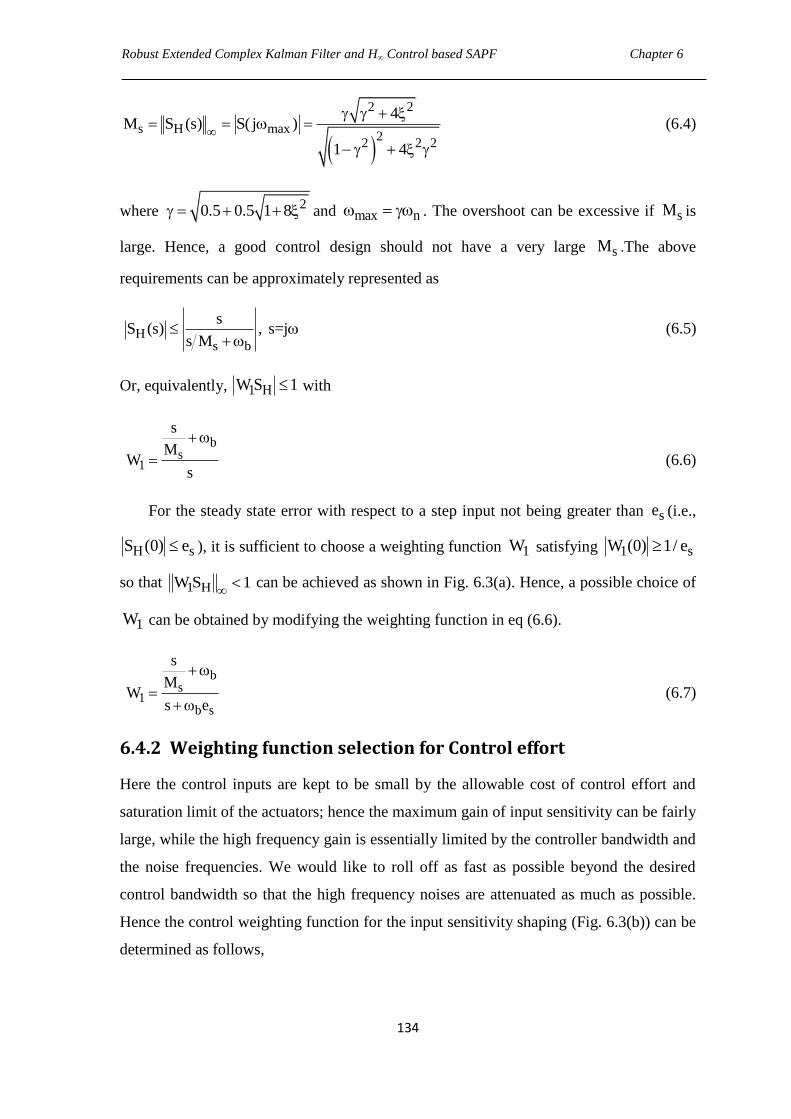
Robust Extended Complex Kalman Filter and H∞ Control based SAPF Chapter 6
134
2 2
s H max2
2 2 2
4M S (s) S( j )
1 4
(6.4)
where 20.5 0.5 1 8 and max n . The overshoot can be excessive if sM is
large. Hence, a good control design should not have a very large sM .The above
requirements can be approximately represented as
Hs b
sS (s) , s=j
s M
(6.5)
Or, equivalently, 1 HW S 1 with
bs
1
s
MW
s
(6.6)
For the steady state error with respect to a step input not being greater than se (i.e.,
H sS (0) e ), it is sufficient to choose a weighting function 1W satisfying 1 sW (0) 1/ e
so that 1 HW S 1 can be achieved as shown in Fig. 6.3(a). Hence, a possible choice of
1W can be obtained by modifying the weighting function in eq (6.6).
bs
1b s
s
MW
s e
(6.7)
6.4.2 Weighting function selection for Control effort
Here the control inputs are kept to be small by the allowable cost of control effort and
saturation limit of the actuators; hence the maximum gain of input sensitivity can be fairly
large, while the high frequency gain is essentially limited by the controller bandwidth and
the noise frequencies. We would like to roll off as fast as possible beyond the desired
control bandwidth so that the high frequency noises are attenuated as much as possible.
Hence the control weighting function for the input sensitivity shaping (Fig. 6.3(b)) can be
determined as follows,
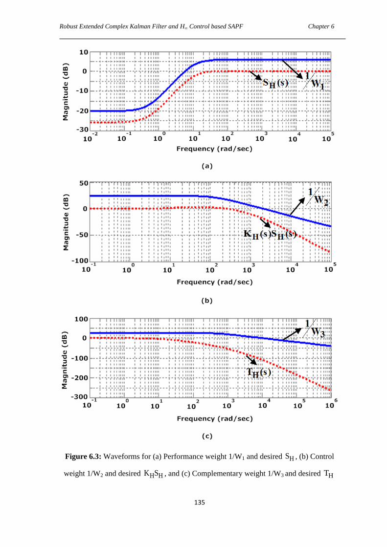
Robust Extended Complex Kalman Filter and H∞ Control based SAPF Chapter 6
135
Figure 6.3: Waveforms for (a) Performance weight 1/W1 and desired HS , (b) Control
weight 1/W2 and desired H HK S , and (c) Complementary weight 1/W3 and desired HT
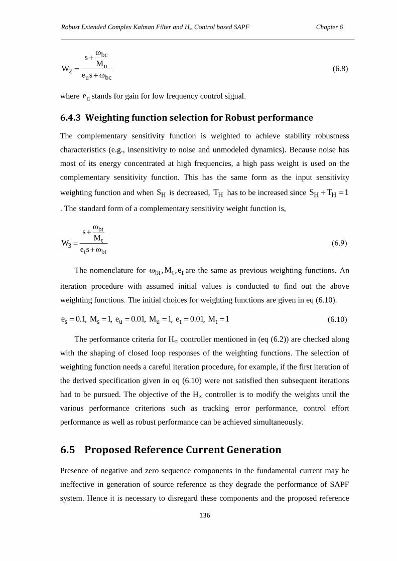
Robust Extended Complex Kalman Filter and H∞ Control based SAPF Chapter 6
136
bc
u2
u bc
sM
We s
(6.8)
where ue stands for gain for low frequency control signal.
6.4.3 Weighting function selection for Robust performance
The complementary sensitivity function is weighted to achieve stability robustness
characteristics (e.g., insensitivity to noise and unmodeled dynamics). Because noise has
most of its energy concentrated at high frequencies, a high pass weight is used on the
complementary sensitivity function. This has the same form as the input sensitivity
weighting function and when HS is decreased, HT has to be increased since H HS T 1
. The standard form of a complementary sensitivity weight function is,
bt
t3
t bt
sM
We s
(6.9)
The nomenclature for bt t t,M ,e are the same as previous weighting functions. An
iteration procedure with assumed initial values is conducted to find out the above
weighting functions. The initial choices for weighting functions are given in eq (6.10).
s s u u t te 0.1, M 1, e 0.01, M 1, e 0.01, M 1 (6.10)
The performance criteria for H∞ controller mentioned in (eq (6.2)) are checked along
with the shaping of closed loop responses of the weighting functions. The selection of
weighting function needs a careful iteration procedure, for example, if the first iteration of
the derived specification given in eq (6.10) were not satisfied then subsequent iterations
had to be pursued. The objective of the H∞ controller is to modify the weights until the
various performance criterions such as tracking error performance, control effort
performance as well as robust performance can be achieved simultaneously.
6.5 Proposed Reference Current Generation
Presence of negative and zero sequence components in the fundamental current may be
ineffective in generation of source reference as they degrade the performance of SAPF
system. Hence it is necessary to disregard these components and the proposed reference
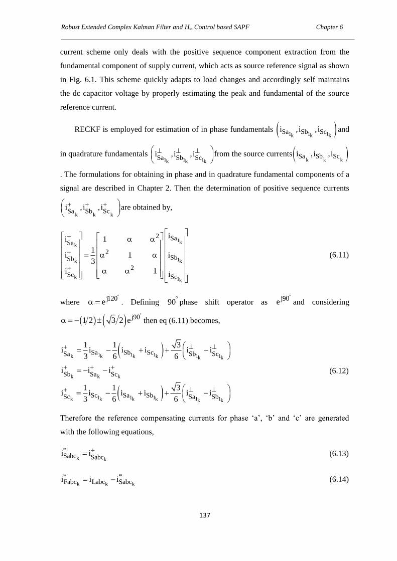
Robust Extended Complex Kalman Filter and H∞ Control based SAPF Chapter 6
137
current scheme only deals with the positive sequence component extraction from the
fundamental component of supply current, which acts as source reference signal as shown
in Fig. 6.1. This scheme quickly adapts to load changes and accordingly self maintains
the dc capacitor voltage by properly estimating the peak and fundamental of the source
reference current.
RECKF is employed for estimation of in phase fundamentals 1 1 1k k kSa Sb Sci , i , i and
in quadrature fundamentals 1 1 1k k k
Sa Sb Sci , i , i
from the source currents k k k
Sa Sb Sci , i , i
. The formulations for obtaining in phase and in quadrature fundamental components of a
signal are described in Chapter 2. Then the determination of positive sequence currents
k k kSa Sb Sc
i , i , i
are obtained by,
1kk
1k k
k 1k
2 SaSa
2SbSb
2Sc Sc
ii 1
1i 1 i
3
i 1 i
(6.11)
where j120e
. Defining 90phase shift operator as j90e
and considering
j901 2 3 2 e
then eq (6.11) becomes,
1 1 1k 1 1k k k k k
k k k
1 1 1k 1 1k k k k k
Sa Sb ScSa Sb Sc
Sb Sa Sc
Sc Sa SbSc Sa Sb
1 1 3i i i i i i
3 6 6
i i i
1 1 3i i i i i i
3 6 6
(6.12)
Therefore the reference compensating currents for phase ‗a‘, ‗b‘ and ‗c‘ are generated
with the following equations,
k k
*Sabc Sabc
i i (6.13)
k k k
* *Fabc Labc Sabci i i (6.14)

Robust Extended Complex Kalman Filter and H∞ Control based SAPF Chapter 6
138
6.6 Simulation Results and Discussions
A simulation model for the three phase SAPF (Fig. 6.1) has been developed using
MATLAB/Simulink. After several iterations, the necessary weighting functions are
defined with all parameters specified in Table 6.1. The typical plots for HS , H HK S and
HT with their corresponding inverse weighting functions are shown in Fig. 6.3 and from
the figure, it is clear that a proper shaping of the sensitivity functions is achieved as
described in Section 6.3. Using the MATLAB „hinfsyn‟ algorithm, the H∞ controller that
nearly minimizes the H∞ norm of the transfer function from hw to hz is obtained as
4 5 3 14 2
18 19
H 5 9 4 13 3 16 2
18 18
(0.0003296s 9.889 10 s 6.593 10 s ...
... 9.422 10 s 6.279 10 )K s
(s 1 10 s 1.642 10 s 3.101 10 s ...
... 6.964 10 s 3.479 10 )
(6.15)
Using the balanced truncation method (modred function in MATLAB), the resulting
reduced controller is given by the following eq (6.16).
H1.306s 9.043
K ss 0.501
(6.16)
Table 6.1 H∞ Performance Function Specification
Weighting Functions Specifications
1W b 5 rad / s sM =1.9946 1se =1 10
2W 3bc 2 10 rad / s uM =16 2
ue =1 10
3W 3bt 3 10 rad / s tM =18 2
te =1 10
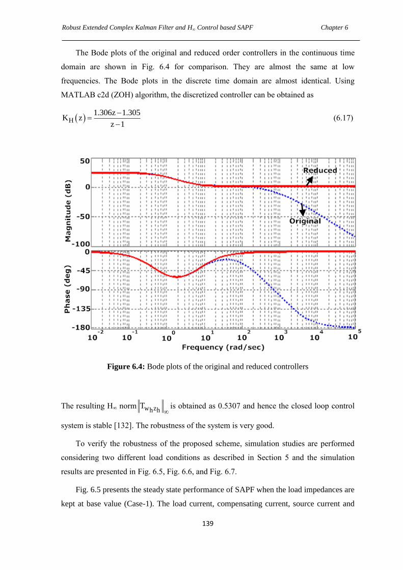
Robust Extended Complex Kalman Filter and H∞ Control based SAPF Chapter 6
139
The Bode plots of the original and reduced order controllers in the continuous time
domain are shown in Fig. 6.4 for comparison. They are almost the same at low
frequencies. The Bode plots in the discrete time domain are almost identical. Using
MATLAB c2d (ZOH) algorithm, the discretized controller can be obtained as
H1.306z 1.305
K zz 1
(6.17)
Figure 6.4: Bode plots of the original and reduced controllers
The resulting H∞ norm w zh hT
is obtained as 0.5307 and hence the closed loop control
system is stable [132]. The robustness of the system is very good.
To verify the robustness of the proposed scheme, simulation studies are performed
considering two different load conditions as described in Section 5 and the simulation
results are presented in Fig. 6.5, Fig. 6.6, and Fig. 6.7.
Fig. 6.5 presents the steady state performance of SAPF when the load impedances are
kept at base value (Case-1). The load current, compensating current, source current and
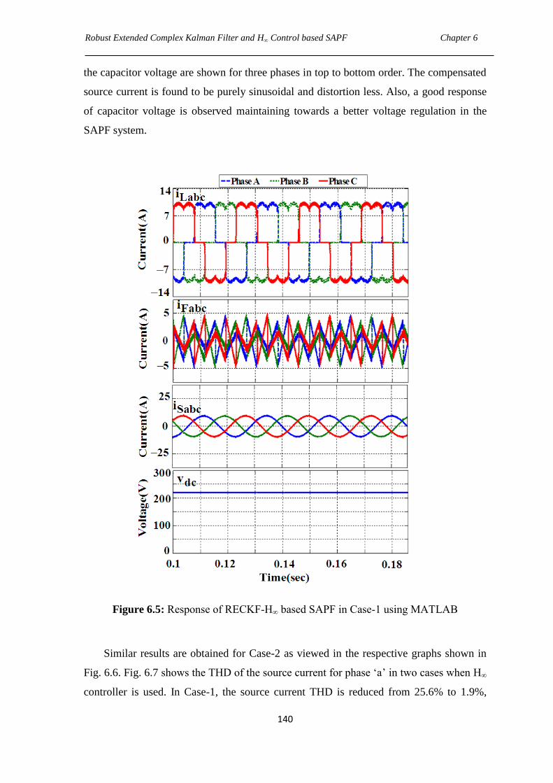
Robust Extended Complex Kalman Filter and H∞ Control based SAPF Chapter 6
140
the capacitor voltage are shown for three phases in top to bottom order. The compensated
source current is found to be purely sinusoidal and distortion less. Also, a good response
of capacitor voltage is observed maintaining towards a better voltage regulation in the
SAPF system.
Figure 6.5: Response of RECKF-H∞ based SAPF in Case-1 using MATLAB
Similar results are obtained for Case-2 as viewed in the respective graphs shown in
Fig. 6.6. Fig. 6.7 shows the THD of the source current for phase ‗a‘ in two cases when H∞
controller is used. In Case-1, the source current THD is reduced from 25.6% to 1.9%,
Robust Extended Complex Kalman Filter and H∞ Control based SAPF Chapter 6
141
whereas it is decreased to 1.67% when load impedance is increased by 100%. Hence,
THDs of the source current are sufficiently small and far away from the permissible limit
of 5%, indicating a complete and perfect harmonics cancellation in SAPF system. Here,
the robustness of H∞ controller for the SAPF is examined on the basis of harmonics
compensation ratio.
Figure 6.6: Response of RECKF-H∞ based SAPF in Case-2 using MATLAB
Table 6.2 demonstrates that when load impedance is increased by 100%, the
harmonics compensation ratio (HCR) is differed by only 0.20% (i.e., Case-1: 7.42% and
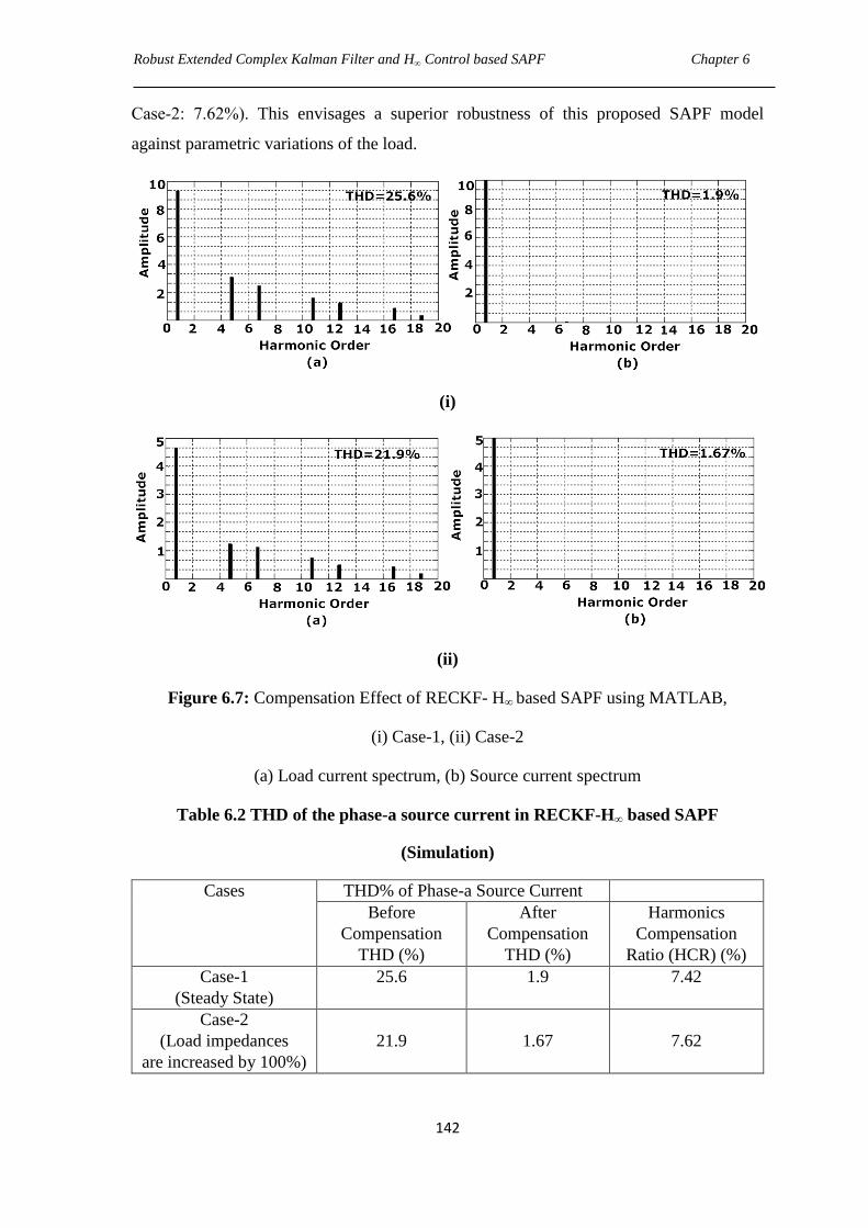
Robust Extended Complex Kalman Filter and H∞ Control based SAPF Chapter 6
142
Case-2: 7.62%). This envisages a superior robustness of this proposed SAPF model
against parametric variations of the load.
(i)
(ii)
Figure 6.7: Compensation Effect of RECKF- H∞ based SAPF using MATLAB,
(i) Case-1, (ii) Case-2
(a) Load current spectrum, (b) Source current spectrum
Table 6.2 THD of the phase-a source current in RECKF-H∞ based SAPF
(Simulation)
Cases THD% of Phase-a Source Current
Before
Compensation
THD (%)
After
Compensation
THD (%)
Harmonics
Compensation
Ratio (HCR) (%)
Case-1
(Steady State)
25.6 1.9 7.42
Case-2
(Load impedances
are increased by 100%)
21.9
1.67
7.62
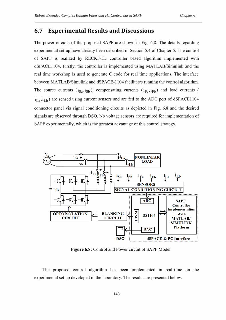
Robust Extended Complex Kalman Filter and H∞ Control based SAPF Chapter 6
143
6.7 Experimental Results and Discussions
The power circuits of the proposed SAPF are shown in Fig. 6.8. The details regarding
experimental set up have already been described in Section 5.4 of Chapter 5. The control
of SAPF is realized by RECKF-H∞ controller based algorithm implemented with
dSPACE1104. Firstly, the controller is implemented using MATLAB/Simulink and the
real time workshop is used to generate C code for real time applications. The interface
between MATLAB/Simulink and dSPACE-1104 facilitates running the control algorithm.
The source currents ( Sa Sbi , i ), compensating currents ( Fa Fbi , i ) and load currents (
La Lbi , i ) are sensed using current sensors and are fed to the ADC port of dSPACE1104
connector panel via signal conditioning circuits as depicted in Fig. 6.8 and the desired
signals are observed through DSO. No voltage sensors are required for implementation of
SAPF experimentally, which is the greatest advantage of this control strategy.
Figure 6.8: Control and Power circuit of SAPF Model
The proposed control algorithm has been implemented in real-time on the
experimental set up developed in the laboratory. The results are presented below.
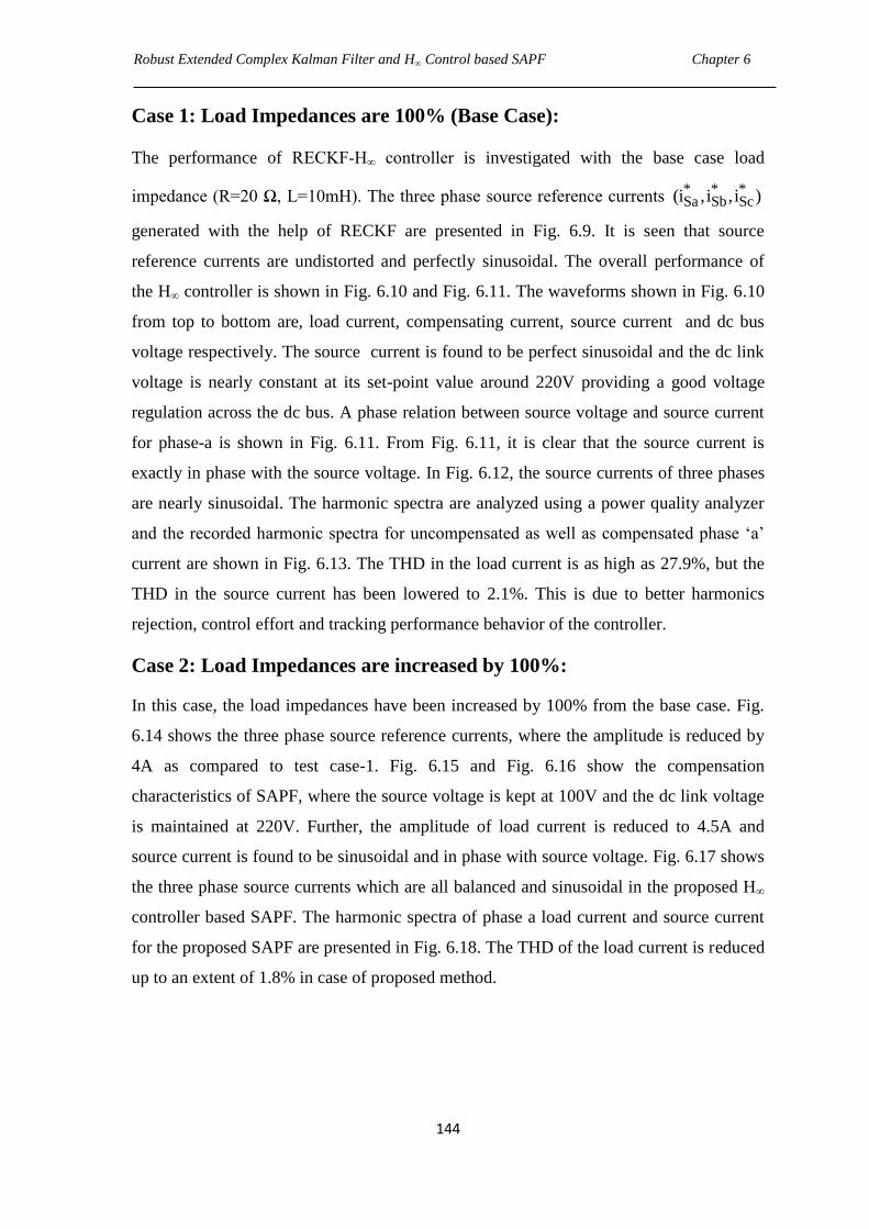
Robust Extended Complex Kalman Filter and H∞ Control based SAPF Chapter 6
144
Case 1: Load Impedances are 100% (Base Case):
The performance of RECKF-H∞ controller is investigated with the base case load
impedance (R=20 Ω, L=10mH). The three phase source reference currents * * *Sa Sb Sc(i ,i , i )
generated with the help of RECKF are presented in Fig. 6.9. It is seen that source
reference currents are undistorted and perfectly sinusoidal. The overall performance of
the H∞ controller is shown in Fig. 6.10 and Fig. 6.11. The waveforms shown in Fig. 6.10
from top to bottom are, load current, compensating current, source current and dc bus
voltage respectively. The source current is found to be perfect sinusoidal and the dc link
voltage is nearly constant at its set-point value around 220V providing a good voltage
regulation across the dc bus. A phase relation between source voltage and source current
for phase-a is shown in Fig. 6.11. From Fig. 6.11, it is clear that the source current is
exactly in phase with the source voltage. In Fig. 6.12, the source currents of three phases
are nearly sinusoidal. The harmonic spectra are analyzed using a power quality analyzer
and the recorded harmonic spectra for uncompensated as well as compensated phase ‗a‘
current are shown in Fig. 6.13. The THD in the load current is as high as 27.9%, but the
THD in the source current has been lowered to 2.1%. This is due to better harmonics
rejection, control effort and tracking performance behavior of the controller.
Case 2: Load Impedances are increased by 100%:
In this case, the load impedances have been increased by 100% from the base case. Fig.
6.14 shows the three phase source reference currents, where the amplitude is reduced by
4A as compared to test case-1. Fig. 6.15 and Fig. 6.16 show the compensation
characteristics of SAPF, where the source voltage is kept at 100V and the dc link voltage
is maintained at 220V. Further, the amplitude of load current is reduced to 4.5A and
source current is found to be sinusoidal and in phase with source voltage. Fig. 6.17 shows
the three phase source currents which are all balanced and sinusoidal in the proposed H∞
controller based SAPF. The harmonic spectra of phase a load current and source current
for the proposed SAPF are presented in Fig. 6.18. The THD of the load current is reduced
up to an extent of 1.8% in case of proposed method.
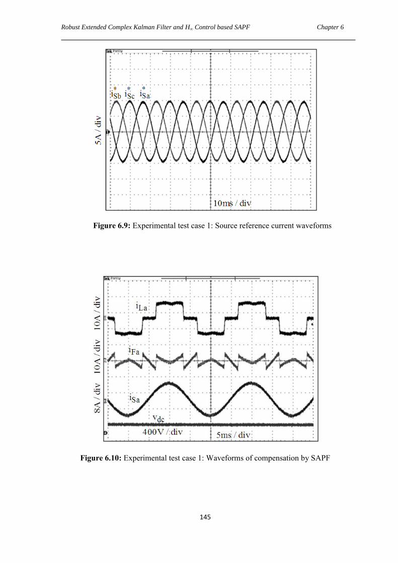
Robust Extended Complex Kalman Filter and H∞ Control based SAPF Chapter 6
145
Figure 6.9: Experimental test case 1: Source reference current waveforms
Figure 6.10: Experimental test case 1: Waveforms of compensation by SAPF
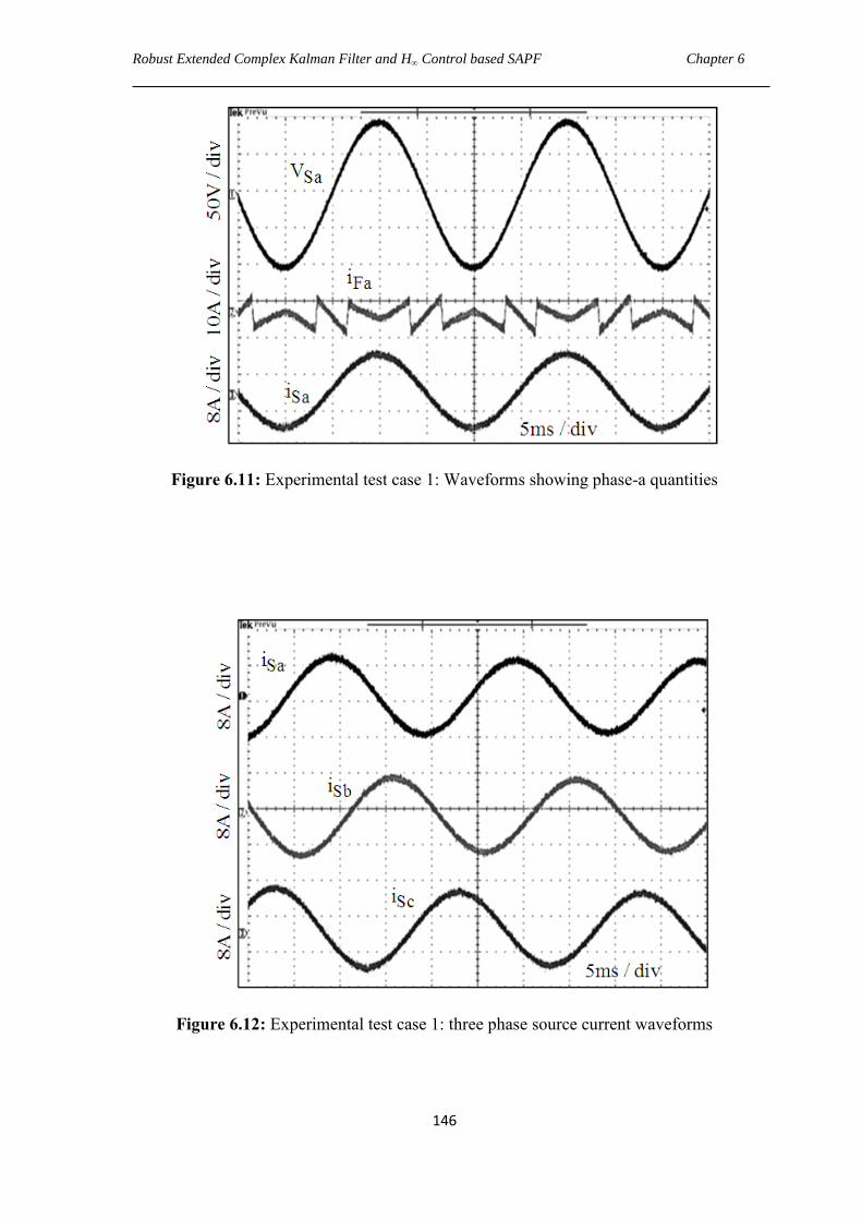
Robust Extended Complex Kalman Filter and H∞ Control based SAPF Chapter 6
146
Figure 6.11: Experimental test case 1: Waveforms showing phase-a quantities
Figure 6.12: Experimental test case 1: three phase source current waveforms
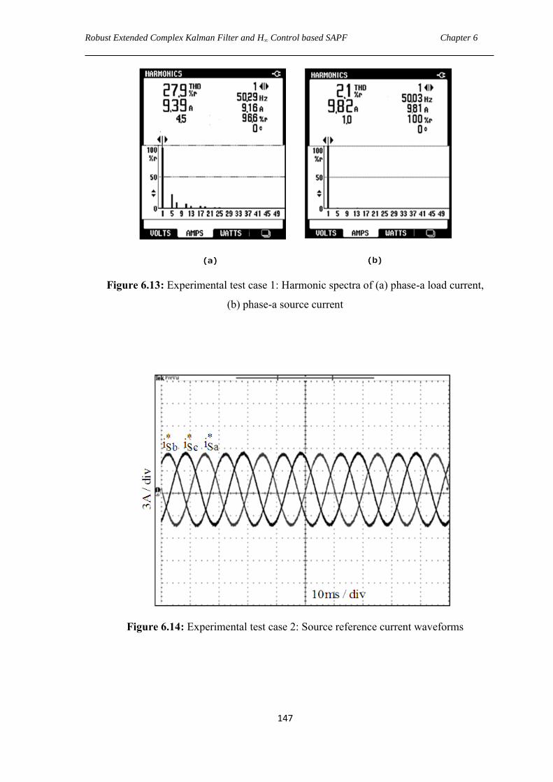
Robust Extended Complex Kalman Filter and H∞ Control based SAPF Chapter 6
147
Figure 6.13: Experimental test case 1: Harmonic spectra of (a) phase-a load current,
(b) phase-a source current
Figure 6.14: Experimental test case 2: Source reference current waveforms
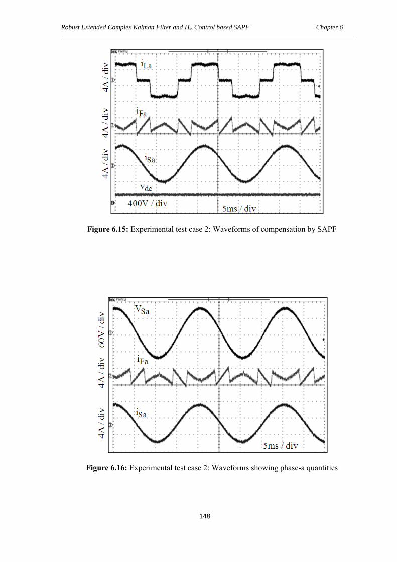
Robust Extended Complex Kalman Filter and H∞ Control based SAPF Chapter 6
148
Figure 6.15: Experimental test case 2: Waveforms of compensation by SAPF
Figure 6.16: Experimental test case 2: Waveforms showing phase-a quantities
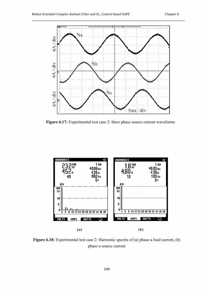
Robust Extended Complex Kalman Filter and H∞ Control based SAPF Chapter 6
149
Figure 6.17: Experimental test case 2: three phase source current waveforms
Figure 6.18: Experimental test case 2: Harmonic spectra of (a) phase-a load current, (b)
phase-a source current
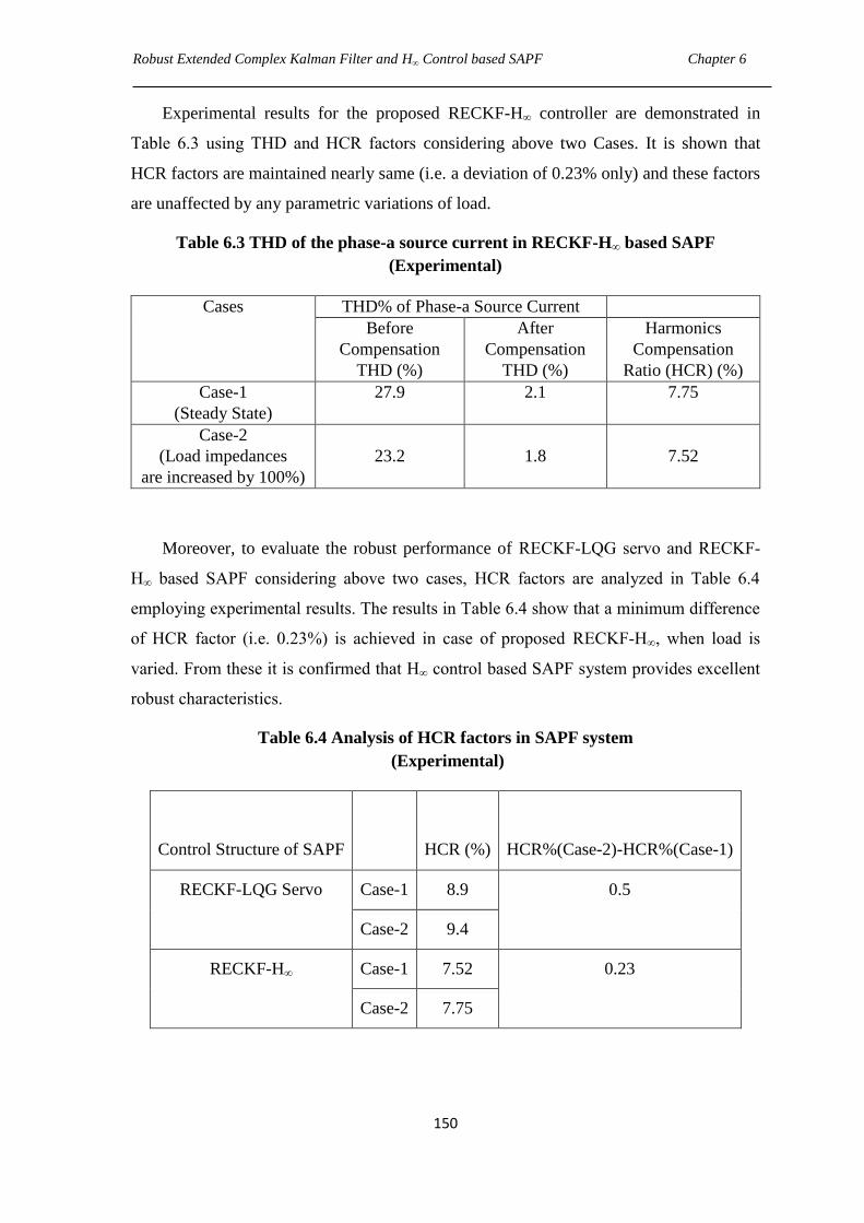
Robust Extended Complex Kalman Filter and H∞ Control based SAPF Chapter 6
150
Experimental results for the proposed RECKF-H∞ controller are demonstrated in
Table 6.3 using THD and HCR factors considering above two Cases. It is shown that
HCR factors are maintained nearly same (i.e. a deviation of 0.23% only) and these factors
are unaffected by any parametric variations of load.
Table 6.3 THD of the phase-a source current in RECKF-H∞ based SAPF
(Experimental)
Cases THD% of Phase-a Source Current
Before
Compensation
THD (%)
After
Compensation
THD (%)
Harmonics
Compensation
Ratio (HCR) (%)
Case-1
(Steady State)
27.9 2.1 7.75
Case-2
(Load impedances
are increased by 100%)
23.2
1.8
7.52
Moreover, to evaluate the robust performance of RECKF-LQG servo and RECKF-
H∞ based SAPF considering above two cases, HCR factors are analyzed in Table 6.4
employing experimental results. The results in Table 6.4 show that a minimum difference
of HCR factor (i.e. 0.23%) is achieved in case of proposed RECKF-H∞, when load is
varied. From these it is confirmed that H∞ control based SAPF system provides excellent
robust characteristics.
Table 6.4 Analysis of HCR factors in SAPF system
(Experimental)
Control Structure of SAPF
HCR (%)
HCR%(Case-2)-HCR%(Case-1)
RECKF-LQG Servo Case-1 8.9 0.5
Case-2 9.4
RECKF-H∞ Case-1 7.52 0.23
Case-2 7.75
Robust Extended Complex Kalman Filter and H∞ Control based SAPF Chapter 6
151
6.8 Chapter Summary
In this Chapter, a H∞ controller with a new reference current estimation scheme based on
RECKF has been developed for a SAPF. This reference generation scheme is simple,
reliable and self-regulator of dc-link voltage, which does not necessitate PI controller
loop. A mixed sensitivity approach is adopted in the synthesis of H∞ controller for
achieving stability and high disturbance rejection in SAPF. A proper selection of
weighting functions has been performed to specify the robustness, control effort
performance and error tracking performance of SAPF. Finally, the designed control
scheme is tested on an experimental prototype SAPF model, where the controller
performs extreme well at a particular load condition (base case), but a high degree of
robustness of the proposed controller is also verified through its performance for the
SAPF even under different load condition with changing load impedances.
Generally power line uncertainties such as fluctuation of load, variation of system
parameter, sudden failure of power system components and sensor nonlinearities degrade
the reliability and efficiency of the SAPF system. Moreover, grid perturbations such as
harmonics, measurement noise, and distorted voltage are responsible for power quality
deterioration. Hence, the objective of designing a robust control strategy in SAPF is
achieved by accommodating all the possible perturbations occurring in the power system.
From the experimental results, it is also observed that the proposed control approach to
design a SAPF is found to be robust in face parametric uncertainties due to load
perturbations yielding improvement in power quality more effectively in terms of
tracking error reduction, efficient current harmonics mitigation as well as reactive power
compensation. Moreover, the proposed SAPF system is less expensive since it uses only
current sensors and has very good filtering performance with the reduced hardware.
Finally, the superiority of proposed RECKF- H∞ based SAPF is verified through a
comparative assessment with RECKF- LQG Servo based SAPF employing simulation
and experimental results.

CHAPTER 7
Conclusion and Suggestions for future work
In this chapter, the conclusions of overall thesis are presented and some suggestions for
future work are also proposed.
7.1 Overall Conclusion
The thesis has described development of new current controller techniques together with
new reference current estimation schemes for performance enhancement of Shunt Active
Power Filter (SAPF). Firstly, a Robust Extended Complex Kalman Filter (RECKF)
estimation algorithm is employed which provides fast convergence under highly
abnormal conditions such as PCC voltage distortion, harmonics and measurement noise.
A number of controllers such as Hysteresis Current Controller (HCC), Sliding Mode
Controller (SMC), Dead Beat Controller (DBC), Model Predictive Controller (MPC),
Linear Quadratic Regulator (LQR), Linear Quadratic Gaussian (LQG) Servo Controller
and H-infinity (H∞) Controller are employed in SAPF for achieving tracking error
minimization, which in turn provides cancellation of current harmonics in power system.
This thesis presents an extensive review on different control strategies in SAPF with
emphasis on their merits and demerits, and evaluate with respect to their benefits,
drawbacks and appliances.
HCC realized with a new reference current generation scheme are proposed for
SAPF system in Chapter 2. This reference generation scheme involves a PI controller in
the external loop. Further, the in phase fundamental components of distorted PCC
voltages necessitated for this reference generation are estimated using the KF based
algorithm. KF-HCC based SAPF performs under consideration of grid perturbations, but
harmonics cancellation is not so fast owing to slower convergence rate of KF.
Hence, a robust controller SMC is employed with a faster reference scheme based on
proposed RECKF. A new weighted exponential function is embedded into RECKF for
fast estimation of a reference signal considering grid perturbations such as voltage
distortion and measurement noise. The effectiveness of this RECKF-SMC is evaluated
Conclusion and suggestions for future works Chapter 7
154
with other variants of KF such as KF, EKF and ECKF with the results obtained from
MATLAB/Simulink simulations as well as real-time simulation results obtained from
Opal-RT. KF-SMC performs better than KF-HCC, but RECKF-SMC is analyzed to be
more efficient in harmonics cancellation as compared to KF-SMC, EKF-SMC and ECKF-
SMC based control strategies in SAPF.
With the growth of powerful and fast computing facilities with expensive computing
platforms such as microprocessors, FPGA, recently increasing attention has been given to
predictive control. Hence, predictive current control techniques called Dead beat control
(DBC) and Model predictive control (MPC) with improved reference generation scheme
are focused in Chapter 3. The reference generation is comprised of two components,
namely estimation of in phase fundamental component of PCC voltage in p.u. value and
estimation of fundamental amplitude of load current. The advantage of this reference
scheme is that the need of a PI controller loop can be avoided to eliminate relatively large
overshoots and undershoots associated with it, which may interrupt the stable operation of
the inverter in protecting the switching devices. Further proposed RECKF is found to be
excellent among KF, EKF and ECKF as investigated in Chapter 2. As a result, RECKF
has been employed in reference generation scheme in Chapter 3.
Proposed RECKF-DBC scheme is very simple and it needs a modulator to provide
gate drive signals to IGBT inverter. In DBC, the optimal actuation is the one that makes
the error equal to zero in the next sampling instant, whereas a more flexible criterion is
employed in MPC, expressed as a cost function to be minimized. There is no need of any
modulators and the gate drive signals are generated directly by this MPC scheme. In the
first proposed RECKF-DBC method, harmonics cancellation is not perfect (THD is above
4%) in spite of having kept the switching frequency of 12.5 kHz fixed in the SAPF. But,
the second proposed RECKF-MPC method performs better as compared to RECKF-
DBC. Furthermore, to examine the efficiency of this proposed RECKF-MPC over PI-
MPC, a comparative study has been done applying both steady state and transient state
conditions. It is observed from the simulation and real-time simulation results that the
proposed RECKF-MPC based SAPF outperforms over PI-MPC in steady as well as
transient condition.
Subsequently, this thesis presented development of an optimal Linear Quadratic
Regulator (LQR) with a new reference current generation method in SAPF in Chapter 4
for further improvement of harmonics mitigation since MPC is very sensitive to model
Conclusion and suggestions for future works Chapter 7
155
mismatch and noise. LQR is chosen because it provides good tracking and disturbance
rejection capability. For LQR designing, the state space variables related to the PCC
voltages, are accurately estimated using proposed RECKF based algorithm. Furthermore,
stabilization of capacitor voltage is improved with a new reference generation scheme
based on RECKF, adding an error between fundamental amplitudes of source and load
current. Consequently, harmonics cancellation effect is more in case of RECKF-LQR
approach. Thus, RECKF-LQR is found to be more effective as compared to RECKF-
SMC, RECKF-DBC and RECKF-MPC which are evidenced from both the obtained
simulation as well as real-time simulation results.
Reference generation schemes employed in the Chapter 2, 3, and 4 consider both
voltage and current measurements and make the dc-link capacitor voltage steady after
some time delay. Hence, in Chapter-5, voltage regulation of dc-link capacitor is further
improved by employing a new and faster reference generation scheme based on RECKF,
which involves with only current measurements representing a cost effective approach. In
spite of robustness and disturbance rejection capability of LQR approach, it is not
successful in complete cancellation of current harmonics since the THD of the source
current is found to be far more than 3%. Hence, a more robust technique called Linear
Quadratic Gaussian (LQG) Servo controller with higher disturbance rejection capability
has been developed in Chapter 5, which permits all perturbations such as PCC
disturbances, parametric variations of load and tracking error variations so that
compensation capability of the overall SAPF system can be enhanced (i.e., THD much
less than 3%) with less consumption of time. From simulation results, LQG servo
controller is not only analyzed to be robust against different load parameters, but also a
satisfactory THD result has been achieved in SAPF. This has motivated to develop a
prototype experimental set up in our Laboratory using dSPACE DS1104 R & D controller
board for verifying the robustness of LQG servo controller. Finally, the experimental
results agree with the simulation results.
Although RECKF-LQG servo based SAPF exhibits good robustness against
parameter variations of load and also harmonics mitigation is superior than that of
RECKF-LQR, RECKF-MPC and RECKF-SMC, but the stability of RECKF-LQG servo
control cannot be guaranteed under high disturbance environment. In view of achieving
stability, high disturbance rejection and high level of harmonics cancellation
performance, H∞ controller with a mixed sensitivity approach has been developed for
Conclusion and suggestions for future works Chapter 7
156
SAPF in the Chapter 6. This mix sensitivity approach involves with the robustness
performance, control effort performance as well as error tracking performance of SAPF
system by selecting appropriate weighting functions. Further, a new current reference
scheme is proposed in this Chapter, which deals with the measurement of source current
only ensuring whole SAPF a more reliable and a cost efficient system. This method does
not require voltage sensor in realization of RECKF-H∞ based SAPF. The effectiveness of
the proposed RECKF-H∞ based SAPF model is validated through both simulation and
experimental studies. From the both simulation and experimental results, it is observed
that the proposed RECKF-H∞ control approach to design a SAPF is found to be more
robust as compared to RECKF-LQG servo control approach in face parametric
uncertainties due to load perturbations yielding improvement in power quality more
effectively in terms of tracking error reduction and efficient current harmonics mitigation
(i.e., just touches the line of THD 2%). Moreover, the proposed RECKF-H∞ control based
SAPF system yields the least THD i.e., 1.9% as compared to RECKF-SMC, RECKF-
DBC, RECKF-MPC, RECKF-LQR and RECKF-LQG servo approaches employing both
the simulation and real-time results.
7.2 Contributions of the Thesis
The contributions of the Thesis are as follows.
A RECKF approach with an exponential robust term embedded for reference
current estimation of SAPF system is proposed in Chapter 2, which handles all
grid perturbations to estimate the reference signal quickly. Further, the current
controller in the proposed SAPF has been designed using sliding mode approach
because it is controlled by a variable structure approach with time varying nature
of SAPF. [ ―A Robust Extended Complex Kalman filter and Sliding mode control based shunt
active power filter,” Electric Power Components and Systems (Taylor & Francis), vol. 42, no. 5,
pp. 520-532, 2014.]
Predictive current control techniques called DBC and MPC are proposed in
Chapter 3. DBC eliminates the classic linear controller by using a predictive
model of the system. Another advanced predictive control called MPC takes
advantage of the limited number of switching states of voltage source inverter for
solving optimization problem and the main advantage of MPC lies in the direct
Conclusion and suggestions for future works Chapter 7
157
application of the control action to the inverter, without necessitating a modulation
stage. Also a new and faster reference current estimation based on RECKF is
proposed in this Chapter because predictive control techniques require an
immediate and accurate response of reference current. This proposed reference
scheme is based on estimation of fundamental amplitude of load current and also
in phase fundamental component of PCC voltage; hence it is completely devoid of
exterior PI controller loop and self-regulator of dc capacitor voltage. [Model
Predictive Based Shunt Active Power Filter with a New Reference Current Estimation Strategy,”
IET Power Electronics, vol. 8, no. 2, pp. 221–233, 2015.]
An optimal control technique called LQR is proposed in Chapter 4. LQR deals
with state regulation, output regulation, and tracking. This approach includes the
whole SAPF system dynamics, with PCC voltage disturbance being compensated
with the aid of information that comes from RECKF algorithm. Further, a new
reference current scheme based on RECKF is proposed here by adding an error
between the fundamental amplitudes of load and source current in the reference
scheme proposed in Chapter 3 and this facilitates better regulation of dc-link
voltage.
A Robust LQG Servo controller is proposed in Chapter 5. A feedback
compensator is proposed in this LQG servo controller to achieve gain stability,
less distortion and increased bandwidth. Voltage regulation of dc-link capacitor is
improved by proposing a new and faster reference generation scheme based on
RECKF, which comprises only current measurements i.e., fundamental amplitude
estimation of source current and in phase fundamental component estimation of
load current.
A Robust H∞ controller design is proposed for SAPF in Chapter 6. This H∞
controller is synthesized using mixed sensitivity approach for realizing stability
and high disturbance rejection in SAPF system. Moreover, in this Chapter, the
proposed reference current scheme based on RECKF that uses sensing of the
supply current only is making a more reliable and cost-effective SAPF system.
Conclusion and suggestions for future works Chapter 7
158
7.3 Suggestions for Future Work
Control Strategies for Unified Power Quality Conditioner (UPQC)
This thesis work is based upon shunt APF system, which attempts to solve PQ
problems such as current harmonics through different control strategies. Since the
modern distribution system demands a better quality of voltage being supplied and
current drawn, integration of both shunt APF and series APF, i.e. UPQC [133] has
great scope in actual practical implementation. Hence, an immediate extension of
the thesis work is to apply above control strategies for UPQC.
Estimation Techniques
Estimation of amplitude and frequency problems can also be extended to different
versions such as Unscented Kalman filter (UKF) [134], Particle filter [135], and
H∞ filter [136]. These can be applied with further comparative analysis of the
methods presented in the thesis.
Robust Adaptive Control Design
The performance of robust control strategies such as LQG servo controller, H∞
controller may not be satisfactory when severe model uncertainties are present in
the SAPF system. Hence, robust performance of SAPF can be enhanced by
employing adaptive LQG or adaptive H∞ controller with suitable adaptive control
laws [137] such that it can counteract the effects of the severe disturbances and
thereby achieves PQ improvement.
THESIS DISSEMINATION
Journal Papers
1. R. Panigrahi, B. Subudhi, and P. C. Panda, “A Robust LQG Servo Control
Strategy of Shunt Active Power Filter for Power Quality Enhancement,” IEEE
Transactions on Power Electronics, vol. 31, no. 4, pp. 2860-2869, 2016.
2. R. Panigrahi, B. Subudhi, and P. C. Panda, “Model Predictive Based Shunt Active
Power Filter with a New Reference Current Estimation Strategy,” IET Power
Electronics, vol. 8, no. 2, pp. 221–233, 2015.
3. R. Panigrahi, P. C. Panda, and B. Subudhi, “A Robust Extended Complex Kalman
filter and Sliding mode control based shunt active power filter,” Electric Power
Components and Systems (Taylor & Francis), vol. 42, no. 5, pp. 520-532, 2014.
4. R. Panigrahi, B. Subudhi, and P. C. Panda, “A Comparative Assessment of
Hysteresis and Dead Beat Controllers for Performances of Three Phase Shunt
Active Power Filtering,” Journal of Power Technologies, vol. 94, no. 4, pp. 286-
295, 2014.
5. R. Panigrahi, B. Subudhi, and P. C. Panda, “Performance Enhancement of Shunt
Active Power Filter using a Robust H∞ Control Strategy,” IEEE Transactions on
Power Electronics (Revision in Progress).
6. R. Panigrahi, B. Subudhi, and P. C. Panda, “New Control Strategy of Shunt
Active Power Filter Based on Robust Extended Complex Kalman Filter,”
International Journal of Electrical Power and Energy Systems (Elsevier) (Revision
in Progress).

THESIS DISSEMINATION
160
Conference Papers
1. R. Panigrahi, P. C. Panda, and B. Subudhi, “Comparison of performances of
hysteresis and dead beat controllers in active power filtering”, IEEE 3rd
International Conference on Sustainable Energy Technologies (ICSET),
Kathmandu, Nepal, 24-27 September, 2012.
2. R. Panigrahi, P. C. Panda, and B. Subudhi, “Discrete Kalman filter applied in
reference current estimation for control of single phase shunt active power filter”,
National Power System Conference (NPSC), Varanasi, 12-14 December, 2012.
3. R. Panigrahi, P. C. Panda, and B. Subudhi, “New strategy for generation of
reference current in active power filters with distortion in line voltage”, IEEE 7th
International Conference on Industrial and Information Systems (ICIIS), Chennai,
6-9 August, 2012.
4. R. Panigrahi, P. C. Panda, B. Subudhi, and S. Swain, “Model Predictive Control
of Shunt Active Power Filter with Kalman Filter based reference signal
generation”, 5th International Conference on Computer Applications in Electrical
Engineering-Recent Advances (CERA), Roorkee, 3-5 October, 2013.
5. R. Panigrahi, P. C. Panda, and B. Subudhi, “ Investigation on active power filter
using Kalman filter based LQR modeling approach”, International conference on
Electronics Engineering and Image Processing (ICEEIT), Bangkok, Thailand, 1-2
April, 2014.
References
[1] J. D. Gomez, P. N. Enjeti and B. Woo, "Effect of voltage sags on adjustable-speed
drives: a critical evaluation and an approach to improve performance," IEEE
Transactions on Industry Application, vol. 35, no. 6, pp. 1440–1449, 1999.
[2] P. S. Harmonics, IEEE Working Group on Power System Harmonics, "Power
System Harmonics: An Overview," IEEE Transactions on Power Apparatus and
Systems, vol. PAS-102, no. 8, pp. 2455-2460, 1983.
[3] Mohd Izhar Bin A Bakar, "Active power filter with automatic control circuit for
neutral current harmonic minimization technique," Ph.D thesis, University of
Science, Malaysia, June 2007.
[4] G. T. Heydt, "Electric power quality: a tutorial introduction," IEEE Transactions
on computer applications in power, vol. 11, no. 1, pp. 15-19, 1998.
[5] I. Hunter, "Power quality issues-a distribution company perspective," Power
Engineering Journal, vol. 15, no. 2, pp. 75-80, 2001.
[6] J. Stones and A. Collinson, "Power Quality," Power Engineering Journal, vol.
15, no. 2, pp. 58-64, 2001.
[7] E. Muljadi and H. E. McKenna, "Power quality issues in a hybrid power system,"
IEEE Transactions on industry applications, vol. 38, no. 3, pp. 803-809, 2002.
[8] M. S. M. Cichowlas, "PWM Rectifier with Active filtering," Ph.D Thesis, Warsaw
University of Technology, Poland, 2004.
[9] J. Arrillaga and N. R. Watson, Power system harmonics, second edition, New
Zealand: John Wiley & Sons, 2003.
[10] J. S. Thorp, A. G. Phadke and K. J. Karimi, "Real-Time Voltage Phasor
Measurements for Static-State Estimation," IEEE Transactions on Power
Apparatus and Systems, vol. PAS-104, no. 11, pp. 3099-3106, 1985.
[11] P. Verdelho and G. D. Marques, "An active power filter and unbalanced current
compensator," IEEE Transactions on Industrial Electronics, vol. 44, no. 3, pp.
321-328, 1997.
[12] A. M. Al-Zamil and D. A. Torrey, "A passive series, active shunt filter for high
power applications," IEEE Transactions on Power Electronics, vol. 16, no. 1, pp.
101-109, 2001.
[13] J. L. Hurng and W. C. Jinn, "A novel active power filter for harmonic
suppression," IEEE Transactions on Power Delivery, vol. 20, no. 2, pp. 1507-
1513, 2005.
References
162
[14] S. Rahmani and A. Hamadi, "A Combination of Shunt Hybrid Power Filter and
Thyristor-Controlled Reactor for Power Quality," IEEE Transactions on Power
Delivery, vol. 61, no. 5, pp. 2152-2164, 2014.
[15] A. F. Zobaa, "Optimal multiobjective design of hybrid active power filters
considering a distorted environment," IEEE Transactions on Industrial
Electronics, vol. 61, no. 1, pp. 107-114, 2014.
[16] W. C. Jinn and J. L. Hurng, "Novel Circuit Topology for Three-Phase Active
Power Filter," IEEE Transactions on Power Delivery, vol. 22, no. 1, pp. 444-449,
2007.
[17] M. Aredes, J. Hafner and K. Heuma, "Three-Phase Four-Wire Shunt Active Filter
Control Strategies," IEEE Transactions on Power Electronics, vol. 12, no. 2, pp.
311-318, 1997.
[18] V. Khadkikar, A. Chandra and B. N. Singh, "Generalised single phase p-q theory
for active power filtering: simulation and DSP-based experimental investigation,"
IET Power Electronics, vol. 2, no. 1, pp. 67-78, 2008.
[19] X. Yuan, W. Merk and H. Stemmler, "Stationary-frame generalized integrators for
current control of active power filters with zero steady state error for current
harmonics of concern under unbalanced and distorted operating conditions," IEEE
Transactions on Industry Applications, vol. 38, no. 2, pp. 523-532, 2002.
[20] V. Soares, P. Verdelho and G. D. Marques, "An Instantaneous Active and
Reactive Current Component Method for Active Filters," IEEE Transactions on
Power Electronics, vol. 15, no. 4, pp. 660-669, 2000.
[21] V. M. Moreno, A. P. Lopez and R. D. Garcias, , ―Reference Current Estimation
Under Distorted Line Voltage for Control of Shunt Active Power Filters‖, IEEE
Transactions on Power Electronics, vol. 19, no. 4, pp. 988-994, 2004.
[22] R. Chudamani, K. Vasudevan and C. S. Ramalingam, " Non-linear least-squares-
based harmonic estimation algorithm for a shunt active power filter," IET Power
Electronics, vol. 2, no. 2, pp.134-146, 2009.
[23] J. M. Kanieski, R. Cardoso and H. A. Grundling , ―Kalman filter based control
system for power quality conditioning devices‖, IEEE Transactions on Industrial
Electronics, vol. 60, no. 11, pp. 5214 - 5227, 2013.
[24] S. Saad and L. Zellouma, " Fuzzy logic controller for three-level shunt active filter
compensating harmonics and reactive power," Electric Power Systems Research,
vol. 79, no. 10, pp. 1337-1341, 2009.
[25] R. N. Ray, D. Chatterjee, S. K. Goswami, ―Harmonics elimination in a multilevel
inverter using the particle swarm optimization technique‖, IET Power Electronics,
vol. 2, no. 6, pp. 646-652, 2009.

References
163
[26] C. N. Bhende, S. Mishra, S. K. Jain, ―TS-fuzzy-controlled active power filter for
load compensation‖, IEEE Transactions on Power Delivery, vol. 21, no. 3, pp.
1459-1465, 2006.
[27] L. H. Tey, P. L. So and Y. C. Chu, ―Improvement of power quality using adaptive
shunt active filter‖, IEEE Transactions on Power Delivery, vol. 20, no. 2, pp.
1558-1568, 2005.
[28] S. R. Arya and B. Singh, ―Neural Network Based Conductance Estimation
Control Algorithm for Shunt Compensation‖, IEEE Transactions on Industrial
Informatics, vol. 10, no. 1, pp. 569-576, 2014.
[29] B. Singh and J. Solanki, ―An implementation of an adaptive control algorithm for
a three phase shunt active power filter‖, IEEE Transactions on Industrial
Electronics, vol. 56, no. 8, pp. 2811-2820, 2009.
[30] P. Kanjiya and V. Khadkikar, ―Artificial-Neural-Network-Based Phase-Locking
Scheme for Active Power Filters‖, IEEE Transactions on Industrial Electronics,
vol. 61, no. 8, pp. 3857 - 3866, 2014.
[31] K. K. Shyu, M. J. Yang, Y. M. Chen and Y. F. Lin, ―Model reference adaptive
control design for a shunt active power filter system‖, IEEE Transactions on
Industrial Electronics, vol. 55, no. 1, pp. 97-106, 2008.
[32] A. Bhattacharya and C. Chakraborty, ―A shunt active power filter with enhanced
performance using ANN based predictive and adaptive controllers‖, IEEE
Transactions on Industrial Electronics, vol. 58, no. 2, pp. 421-428, 2011.
[33] R. L. A. Ribeiro, C. C. Azevedo and R. M. Sousa, ―A Robust Adaptive Control
Strategy of Active Power Filters for Power-Factor Correction, Harmonic
Compensation, and Balancing of Nonlinear Loads‖, IEEE Transactions on Power
Electronics, vol. 27, no. 2, pp. 718-730, 2012.
[34] B. Singh and S. R. Arya, ―Adaptive Theory-Based Improved Linear Sinusoidal
Tracer Control Algorithm for DSTATCOM‖, IEEE Transactions on Power
Electronics, vol. 28, no. 8, pp. 3768-3778, 2013.
[35] B. Singh, S. R. Arya, A. Chandra and K. A. Haddad, ―Implementation of Adaptive
Filter in Distribution Static Compensator‖, IEEE Transactions on Industry
Applications, vol. 50, no. 5, pp. 3026-3033, 2014.
[36] S. R. Arya and B. Singh, ―Performance of DSTATCOM using Leaky LMS
Control Algorithm‖, IEEE journal of Emerging and selected topics in Power
Electronics, vol. 1, no. 2, pp. 104-113, 2013.
[37] B. Singh and S. R. Arya, ―Back-propagation control algorithm for power quality
improvement using DSTATCOM‖, IEEE Transactions on Industrial Electronics,
vol. 61, no. 3, pp. 1204-1212, 2014.
References
164
[38] B. Singh and S. R. Arya, ―Composite observer-based control algorithm for
distribution static compensator in four-wire supply system‖, IET Power
electronics, vol. 6, no. 2, pp. 251–260, 2013.
[39] S. Rahmani, N. Mendalek and K. Haddad, ―Experimental design of a nonlinear
control technique for three phase shunt active power filter‖, IEEE Transactions on
Industrial Electronics, vol. 57, no. 10, pp. 3364-3375, 2010.
[40] S. G. Jorge, C. A. Busada and J. Solsona, ―Reduced order generalized integrator-
based current controller applied to shunt active power filters‖, IET Power
Electronics, vol. 7, no. 5, pp. 1083-1091, 2014.
[41] P. Kanjiya, V. Khadkikar and H. H. Zeineldin, ―A noniterative optimized
algorithm for shunt active power filter under distorted and unbalanced supply
voltages‖, IEEE Transactions on Industrial Electronics, vol. 60, no. 12, pp. 5376
– 5390, 2013.
[42] Q. N. Trinh and H. H. Lee, ―An advanced current control strategy for three-phase
shunt active power filters‖, IEEE Transactions on Industrial Electronics, vol. 60,
no. 12, pp. 5400-5410, 2013.
[43] H. Yi, F. Zhuo and Y. Zhang, ―A source current detected shunt active power filter
control scheme based on vector resonant controller‖, IEEE Transactions on
Industry Applications, vol. 50, no. 3, pp. 1953-1965, 2014.
[44] W. Lenwari, M. Sumner and P. Zanchetta, ―The use of genetic algorithms for the
design of resonant compensators for active filters‖, IEEE Transactions on
Industrial Electronics, vol. 56, no. 8, pp. 2852-2861, 2009.
[45] R. L. A. Ribeiro, T. O. A. Rocha and R. M. Sousa, ―A Robust DC-Link Voltage
Control Strategy to Enhance the Performance of Shunt Active Power Filters
Without Harmonic Detection Schemes‖, IEEE Transactions on Industrial
Electronics, vol. 62, no. 2, pp. 803-813, 2015.
[46] J. Matas, L. G. Vicuna, J. Miret and J. M. Guerrero, ―Feedback Linearization of a
Single-Phase Active Power Filter via Sliding Mode Control‖, IEEE Transactions
on Power Electronics, vol. 23, no. 1, pp. 116-125, 2008.
[47] M. Odavic, V. Biagini and P. Zanchetta, ―One-sample-period-ahead predictive
current control for high performance active shunt power filters‖, IET Power
Electronics, vol. 4, no. 4, pp. 414-423, 2011.
[48] P. Acuna, L. Moran and M. Rivera, ―Improved active power filter performance for
renewable power generation systems‖, IEEE Transactions on Power Electronics,
vol. 29, no. 2, pp. 687-694, 2014.
[49] A. F. Zobaa, S. Aleem, ―A new approach for harmonic distortion minimization in
power systems supplying nonlinear loads‖, IEEE Transactions on Industrial
Informatics, vol. 10, no. 2, pp. 1401-1412, 2014.
References
165
[50] R. Aghazadeh, H. Lesani and M. S. Pasand, ―New technique for frequency and
amplitude estimation of power system signals‖, IEE Proceedings. Generation,
Transmission and Distribution, vol. 152, no. 3, pp. 435-440, 2005.
[51] R. A. Zadeh, A. Ghosh and G. Ledwich, ―Combination of Kalman Filter and
Least-Error Square Techniques in Power System‖, IEEE Transactions on Power
Delivery, vol. 25, no. 4, pp. 2868- 2880, 2010.
[52] A. Routray, A. K. Padhan and K. P. Rao, ―Novel Kalman Filter for Frequency
Estimation of Distorted Signals in Power Systems‖, IEEE Transactions on
Instrumentation and Measurement, vol. 51, no. 3, pp. 469- 479, 2002.
[53] P. K. Dash, R. K. Jena, G. Panda and A. Routray, ―An Extended Complex Kalman
Filter for Frequency Measurement of Distorted Signals‖, IEEE Transactions on
Instrumentation and Measurement, vol. 49, no. 4, pp. 746- 753, 2000.
[54] C. H. Huang, C. H. Lee and K. J. Shih, ―Frequency Estimation of Distorted Power
System Signals Using a Robust Algorithm‖, IEEE Transactions on Power
Delivery, vol. 23, no. 1, pp. 41- 50, 2008.
[55] M. Mojiri, D. Yazdani and A. Bakhshai, ―Robust Adaptive Frequency Estimation
of Three-Phase Power Systems‖, IEEE Transactions on Instrumentation and
Measurement, vol. 59, no.7, pp. 1793-1802, 2010.
[56] E. Lavopa, P. Zanchetta and M. Sumner, ―Real-Time Estimation of Fundamental
Frequency and Harmonics for Active Shunt Power Filters in Aircraft Electrical
Systems‖, IEEE Transactions on Industrial Electronics, vol. 56, no. 8, pp. 2875-
2884, 2009.
[57] R. Chudamani, K. Vasudevan and C. S. Ramalingam, ―Real-Time Estimation of
Power System Frequency Using Nonlinear Least Squares‖, IEEE Transactions on
Power Delivery, vol. 24, no. 3, pp. 1021- 1028, 2009.
[58] D. P. Marcetic, J. J. Tomic and M. D. Kusljevic, ―Unbalanced three-phase
distribution system frequency estimation using least mean squares method and
positive voltage sequence‖, IET Science, Measurement and Technology, vol. 8,
no. 1, pp. 30- 38, 2014.
[59] M. D. Kusljevic, J. J. Tomi and L. D. Jovanovic, ―Frequency Estimation of Three-
Phase Power System Using Weighted-Least-Square Algorithm and Adaptive FIR
Filtering‖, IEEE Transactions on Instrumentation and Measurement, vol. 59, no.
2, pp. 322-329, 2010.
[60] B. Subudhi, P. K. Ray and S. Ghosh, ―Variable leaky least mean-square
algorithm-based power system frequency estimation‖, IET Science, Measurement
and Technology, vol. 6, no. 4, pp. 288-297, 2012.
[61] L. A. Moran, J. W. Dixon and R. R. Wallace, ―A three-phase active power filter
operating with fixed switching frequency for reactive and current harmonic
References
166
compensation,‖ IEEE Transactions on Industrial Electronics, vol. 42, no. 4, pp.
402–408, 1995.
[62] T. Lobos and J. Rezmer, ―Real-time determination of power system frequency,‖
IEEE Transactions on Power Delivery, vol. 46, no. 4, pp. 877-881, 1997.
[63] N. Gupta, S. P. Singh and R. C. Bansal, ―A digital signal processor based
performance evaluation of three-phase four wire shunt active filter for harmonic
elimination, reactive power compensation and balancing of non-linear loads under
non-ideal mains voltages,‖ Electric Power Component and Systems, vol. 40, no.
10, pp. 1119–1148, 2012.
[64] A. K. Pradhan, A. Routray and A. Basak, ―Power system frequency estimation
using least mean square technique,‖ IEEE Transactions on Power Delivery, vol.
20, no. 3, pp. 1812–1816, 2005.
[65] T. S. Sidhu and M. S. Sachdev, ―An iterative technique for fast and accurate
measurement of power system frequency,‖ IEEE Transactions on Power Delivery,
vol. 13, no. 1, pp. 109–115, 1998.
[66] G. G. Rigatos, ―A derivative free Kalman filtering approach to state estimation
based control of nonlinear systems,‖ IEEE Transactions on Industrial Electronics,
vol. 59, no. 10, pp. 3987–3997, 2012.
[67] P. K. Ray and B. Subudhi, ―Ensemble Kalman filtering algorithm applied to
power system harmonics estimation,‖ IEEE Transactions on Instrumentation and
Measurement, vol. 61, no. 12, pp. 3216–3224, 2012.
[68] J. Barros and E. Perez, ―Automatic Detection and Analysis of Voltage Events in
Power Systems,‖ IEEE Transactions on Instrumentation and Measurement, vol.
55, no. 5, pp. 1487 - 1493, 2006.
[69] R. A. Wiltshire, G. Ledwich and P. Oshea, ―A Kalman Filtering Approach to
Rapidly Detecting Modal Changes in Power Systems,‖ IEEE Transactions on
Power System, vol. 22, no. 4, pp. 1698 - 1706 , 2007.
[70] Z. Jinghe, G. Welch and G. Bishop, ―A Two-Stage Kalman Filter Approach for
Robust and Real-Time Power System State Estimation,‖ IEEE Transactions on
Sustainable Energy, vol. 5, no. 2, pp. 629 – 636, 2014.
[71] R. K. Mehra, ―On the identification of variances and adaptive Kalman filtering‖,
IEEE Transactions on Automatic Control, vol. AC-15, no. 2, pp. 175-184, 1970.
[72] V. V. Terzija, N. B. Djuric and B. D. Kovacevic, ―Voltage phasor and local
system frequency estimation using Newton type algorithm,‖ IEEE Transactions
on Power Delivery, vol. 9, no. 3, pp. 1368–1374, 1994.
[73] P. Xiao and K. A. Corzine, ―Seven-level shunt active power filter for high-power
drive systems,‖ IEEE Transactions on Power Electronics, vol. 24, no. 1, pp. 6–13,
2009.
References
167
[74] RT-Lab Professional. Available at http://www.opal-rt.com/product/rtlab-
Professional
[75] M. A. Rahman, T. S. Radwan, A. M. Osheiba and A. Lashine, ―Analysis of
current controllers for voltage-source inverter,‖ IEEE Transactions on Industrial
Electronics, vol. 44, no. 4, pp. 477-485, 1997.
[76] S. Buso, L. Malesani and P. Mattavelli, ―Comparison of current control techniques
for active filter applications,‖ IEEE Transactions on Industrial Electronics, vol.
45, no. 5, pp. 722–729, 1998.
[77] S. Saetieo, R. Devaraj and D. A. Torrey, ―The design and implementation of a
three phase active power filter based on sliding mode control,‖ IEEE Transactions
on Industry Applications, vol. 31, no. 5, pp. 993–1000, 1995.
[78] B. Singh, K. Haddad and A. Chandra, ―Active power filter with sliding mode
control,‖ IEE Proceedings Generation, Transmission and Distribution, vol. 144,
no. 6, pp. 564 - 568, 1997.
[79] K. M. Tsang, W. L. Chan and X. Tang, ―Multi-level shunt active power filter
using modular cascade H-bridge and delay firing,‖ Electric Power Components
and Systems, vol. 41, no. 6, pp. 605–618, 2013.
[80] R. D. Patidar and S. P. Singh, ―Digital signal processor based shunt active filter
controller for customer-generated harmonics and reactive power compensation,‖
Electric Power Components and Systems, vol. 38, no. 8, pp. 937–959, 2010.
[81] D. Casini, M. Marchesoni and L. Puglisi, ―Sliding Mode Multilevel Control for
Improved Performances in Power Conditioning Systems,‖ IEEE Transactions on
Power Electronics, vol. 10, no. 4, pp. 453 - 463, 1995.
[82] A. Sabanovic, ―Variable Structure Systems with Sliding Modes in Motion
Control—A Survey,‖ IEEE Transactions on Industrial Informatics, vol. 7, no. 2,
pp. 212 - 223, 2011.
[83] M. P. Kazmierkowski, R. Krishnan and F. Blaabjerg, ―Control in Power
Electronics‖. Academic Press, San Diego, CA, 2002.
[84] N. Mohan, T. M. Undeland and W. P. Robbins, ―Power Electronics: Converters,
Applications and Design,‖ 3rd ed., Hoboken, NJ: John Wiley & Sons, 2003.
[85] E. Wiebe, J. L. Duran and P. R. Acosta, ―Integral sliding mode active filter
control for harmonic distortion compensation,‖ Electric Power Components and
Systems, vol. 39, no. 9, pp. 833–849, 2011.
[86] A. Luo, Z. Shuai, W. Zhu, R. Fan and C. Tu, ―Development of Hybrid Active
Power Filter Based on the Adaptive Fuzzy Dividing Frequency-Control Method,‖
IEEE Transactions on Power Delivery, vol. 24, no. 1, pp. 424-432, 2009.
References
168
[87] P. Cortes, M. P. Kazmierkowski and R. M. Kennel, ―Predictive Control in Power
Electronics and Drives,‖ IEEE Transactions on Industrial Electronics, vol. 55, no.
12, pp. 4312–4324, 2008.
[88] S. Buso, L. Malesani, P. Mattavelli and R. Veronese, ―Design and Fully Digital
Control of Parallel Active Filters for Thyristor Rectifiers to comply with IEC-
1000-3-2 Standards ,‖ IEEE Transactions on Industry Applications, vol. 34, no. 3,
pp. 508 - 517, 1998.
[89] Y. A. R. I. Mohamed and E. F. Saadany, ―An Improved Deadbeat Current Control
Scheme With a Novel Adaptive Self-Tuning Load Model for a Three-Phase PWM
Voltage-Source Inverter,‖ IEEE Transactions on Industrial Electronics, vol. 54,
no. 2, pp. 747 - 759, 2007.
[90] Y. Han, L. Xu, M. M. Khan and C. Chen, ―Robust Deadbeat Control Scheme for a
Hybrid APF With Resetting Filter and ADALINE-Based Harmonic Estimation
Algorithm,‖ IEEE Transactions on Industrial Electronics, vol. 58, no. 9, pp. 3893
- 3904, 2011.
[91] P. Cortes, G. Ortiz, J. I. Yuz and J. Rodríguez, ―Model Predictive Control of an
Inverter With Output LC Filter for UPS Applications,‖ IEEE Transactions on
Industrial Electronics, vol. 56, no. 6, pp. 1875 - 1883, 2009.
[92] S. Kouro, P. Cortes, R. Vargas, U. Ammann and J. Rodríguez, ―Model Predictive
Control—A Simple and Powerful Method to Control Power Converters,‖ IEEE
Transactions on Industrial Electronics, vol. 56, no. 6, pp. 1826-1838, 2009.
[93] J. Rodriguez, M. P. Kazmierkowski, J. R. Espinoza and P. Zanchetta, ―State of the
Art of Finite Control Set Model Predictive Control in Power Electronics,‖ IEEE
Transactions on Industrial Informatics, vol. 9, no. 2, pp. 1003 - 1016, 2013.
[94] V. Yaramasu, M. Rivera, B. Wu and J. Rodriguez, ―Model Predictive Current
Control of Two-Level Four-Leg Inverters-Part I: Concept, Algorithm, and
Simulation Analysis,‖ IEEE Transactions on Power Electronics, vol. 28, no. 7,
pp. 3459-3468, 2013.
[95] M. Rivera, V. Yaramasu, J. Rodriguez and B. Wu, ―Model Predictive Current
Control of Two-Level Four-Leg Inverters-Part II: Experimental Implementation
and Validation,‖ IEEE Transactions on Power Electronics, vol. 28, no. 7, pp.
3469-3478, 2013.
[96] J. F. Petit, G. Robles and H. Amaris, ―Current reference control for shunt active
power filters under non sinusoidal voltage conditions,‖ IEEE Transactions on
Power Delivery, vol. 22, no. 4, pp. 2254-2261, 2007.
[97] C. L. Phillips and H. T. Nagle, Digital Control System analysis and Design,
Prentice-Hall, 1995.
[98] B. D. O. Anderson and J. B. Moore, Optimal Control, Prentice Hall, Englewood
Cliffs, New Jersy, 1989.
References
169
[99] M. Athans, P. Falb, Optimal Control: An Introduction to the Theory and Its
Applications, McGraw Hill Book Company, New York, NY, 1966.
[100] F. L. Lewis, Optimal Control, John Wiley & Sons, New York, NY, 1986.
[101] S. Fukuda, ―LQ control of sinusoidal current PWM rectifiers,‖ IEE Proceedings
on Electric Power Applications, vol. 114, no. 2, pp. 95–100, 1999.
[102] S. Fukuda, Y. Matsumoto, and A. Sagawa, ―Optimal-regulator-based control of
NPC boost rectifiers for unity power factor and reduced neutral point- potential
variations,‖ IEEE Transactions on Industrial Electronics, vol. 46, no. 3, pp. 527–
534, 1999.
[103] K. Izumi, M. Tsuji, E. Yamada and J. Oyama, ―Active power filter with optimal
servo controller,‖ in 23rd IEEE International Conference on Industrial
Electronics, Control and Instrumentation (IEEE-IECON), 1999, pp. 816–821.
[104] R. Grino and R. Costa-Castello, "Digital repetitive plug-in controller for odd-
harmonic periodic references and disturbances," Automatica, vol. 41, no. 1, pp.
153–157, 2005.
[105] S. Alepuz, J. S. B. Monge and J. Bordonau, ―Interfacing renewable energy sources
to the utility grid using a three-level inverter,‖ IEEE Transactions on Industrial
Electronics, vol. 53, no. 5, pp. 1504–1511, 2006.
[106] T. Thomas and K. Haddad, "Design and performance of active power filters,"
IEEE Industry Applications Magazine, vol. 4, no. 5, pp. 38–46, 1998.
[107] B. Kedjar and K. Haddad, ―DSP-based implementation of an LQR with integral
action for a three-phase three-wire shunt active power filter,‖ IEEE Transactions
on Industrial Electronics, vol. 56, no. 8, pp. 2821-2828, 2009.
[108] A. Ghosh, R. Krishnan and B. Subudhi, ―Robust PID Compensation of an
Inverted Cart-Pendulum System: An Experimental Study,‖ IET Control Theory &
Applications, vol. 6, no. 8, pp. 1145-1152, 2012.
[109] M. I. M. Montero, E.R. Cadaval and F.B. Gonzalez, ―Comparison of Control
Strategies for Shunt Active Power Filters in Three-Phase Four-Wire Systems,‖
IEEE Transactions on Power Electronics, vol. 22, no. 1, pp. 229 - 236, 2007.
[110] L. B. G. Campanhol, S. A. O. Silva and A. Goedtel, ―Application of shunt active
power filter for harmonic reduction and reactive power compensation,‖ IET
Power Electronics, vol. 7, no. 11, pp. 2825-2836, 2014.
[111] C. C. Che and Y. Y. Hsu, ―A novel approach to the design of a shunt active filter
for an unbalanced three-phase four-wire system under non sinusoidal conditions,‖
IEEE Transactions on Power Delivery, vol. 15, no. 4, pp. 1258 - 1264 , 2000.
References
170
[112] F. Huerta, D. Pizarro, S. Cobreces, F. J. Rodriguez, C. Giron and A. Rodriguez,
―LQG Servo Controller for the Current Control of LCL Grid-Connected Voltage-
Source Converters,‖ IEEE Transactions on Industrial Electronics, vol. 59, no. 11,
pp. 4272-4284, 2012.
[113] K. H. Kwan, P. L. So and Y. C. Chu, ―An output regulation-based unified power
quality conditioner with Kalman filters,‖ IEEE Transactions on Industrial
Electronics, vol. 59, no. 11, pp. 4248-4262, 2012.
[114] L. Wu, F. Zhuo, P. Zhang, H. Li and Z. Wang, ―Study on the Influence of Supply-
Voltage Fluctuation on Shunt Active Power Filter,‖ IEEE Transactions on Power
Delivery, vol. 22, no. 3, pp. 1743 - 1749 , 2007.
[115] S. K. Jain, P. Agrawal and H. O. Gupta, ―Fuzzy logic controlled shunt active
power filter for power quality improvement,‖ IEE Proceedings on Electric Power
Applications, vol. 149, no. 5, pp. 317-328, 2002.
[116] Z. Zeng, J. Yang and N. Yu, ―Research on PI and repetitive control strategy for
Shunt Active Power Filter with LCL-filter,‖ in 7th IEEE International Conference
on Power Electronics and Motion Control (IEEE-IPEMC), 2012, pp. 2833 - 2837.
[117] V. G. Kinhal, P. Agarwal and H. O. Gupta, ―A Kalman Filtering Approach to
Rapidly Detecting Modal Changes in Power Systems,‖ IEEE Transactions on
Power System, vol. 22, no. 4, pp. 1698 - 1706 , 2007.
[118] A. A. Girgis and W. L. Peterson, ―Adaptive estimation of power system
frequency deviation and its rate of change for calculating sudden power system
overloads,‖ IEEE Transactions on Power Delivery, vol. 5, no. 2, pp. 585 - 594,
1990.
[119] G. Fusco and M. Russo, ―Self-tuning regulator design for nodal voltage
waveform control in electrical power systems,‖ IEEE Transactions on Control
Systems Technology, vol. 11, no. 2, pp. 258 - 266, 2003.
[120] LEM, \Voltage Transducer LV 25-P," Datasheet.
[121] LEM, \Current Transducer LA 55-P," Datasheet.
[122] M. K. Mishra, K. Karthikeyan, G. Vincent and S. Sasitharan, ―A DSP based
integrated hardware set up for a DSTATCOM; Design, development and
implementation issues,‖ IETE Journal of Research, vol. 56, no. 1, pp. 11-21,
2010.
[123] Motorola Semiconductor Datasheet: SN74LS123, Motorola Semiconductor
Products Inc., Phoenix, AZ, 1989.
[124] Fairchild Datasheet: HCPL 2601, Fairchild semiconductor Corporation, USA,
2001.
References
171
[125] Y. W. Li, D. M. Vilathgamuwa and F. Blaabjerg, ―A robust control scheme for
medium voltage level DVR implementation,‖ IEEE Transactions on Industrial
Electronics, vol. 54, no. 4, pp. 2249-2260, 2007.
[126] Y. W. Li, F. Blaabjerg and D. M. Vilathgamuwa, ―Design and comparison of high
performance stationary frame controllers for DVR implementation,‖ IEEE
Transactions on Power Electronics, vol. 22, no. 2, pp. 602-612, 2007.
[127] K. H. Kwan, Y. C. Chu and P. L. So, ―Model based H∞ control of a unified power
quality conditioner,‖ IEEE Transactions on Industrial Electronics, vol. 56, no. 7,
pp. 2493-2504, 2009.
[128] T. Hornik, and Q. C. Zhong, ―A current control strategy for voltage source
inverters in microgrids based on H∞ and repetitive control,‖ IEEE Transactions on
Power Electronics, vol. 26, no. 3, pp. 943-952, 2011.
[129] G. Weiss, Q. C. Zhong, T. C. Green and J. Liang, ―H∞ Repetitive Control of DC-
AC Converters in Microgrids,‖ IEEE Transactions on Power Electronics, vol. 19,
no. 1, pp. 219-230, 2004.
[130] R. Naim, G. Weiss, and S. Ben-Yaakov, ―H∞ control applied to boost power
converters,‖ IEEE Transactions on Power Electronics, vol. 12, no. 4, pp. 677-683,
1997.
[131] T. S. Lee, S. J. Chiang, and J. M. Chang, ―H∞ loop shaping controller designs for
the single phase UPS inverters,‖ IEEE Transactions on Power Electronics, vol.
16, no. 4, pp. 473-481, 2001.
[132] K. Zhou and J. C. Doyle, Essentials of Robust control, Prentice Hall; 1st edition,
Louisiana, 1997.
[133] V. Khadkikar, ―Enhancing Electric Power Quality Using UPQC: A
Comprehensive Overview,‖ IEEE Transactions on Power Electronics, vol. 27, no.
5, pp. 2284-2297, 2012.
[134] L. Chang, B. Hu, A. Li and F. Qin, ―Unscented type Kalman filter: limitation and
combination,‖ IET Signal Processing, vol. 7, no. 1, pp. 167–176, 2013.
[135] S. Saha and F. Gustafsson, ―Particle Filtering With Dependent Noise Processes,‖
IET Signal Processing, vol. 60, no. 9, pp. 4497 - 4508, 2012.
[136] L. Ping, J. Lam and S. Zhan, ―H∞ Positive Filtering for Positive Linear Discrete-
Time Systems: An Augmentation Approach,‖ IEEE Transactions on Automatic
Control, vol. 55, no. 10, pp. 2337 - 2342, 2010.
[137] G. Cheng and P. Shuangxia, ―Nonlinear Adaptive Robust Control of Single-Rod
Electro-Hydraulic Actuator with Unknown Nonlinear Parameters,‖ IEEE
Transactions on Control Systems Technology, vol. 16, no. 3, pp. 434 - 445, 2008.


Rakhee Panigrahi
Date of Birth: 7th
August, 1980
Email: [email protected]
Qualification
Ph.D. (Continuing)
NIT Rourkela
Mtech (Power Electronics and Drives)
NIT Rourkela [First Division]
B.E (Electrical Engineering)
U. C. E, Burla, Sambalpur University [First Division]
+2 (Science)
Council of Higher Secondary Education, Odisha [First Division]
10th
Board of Secondary Education, Odisha [First Division]
Publications
04 Journal Papers
05 Conference Papers
Permanent Address
Beheramal Chowk
At/Po/Dist: Jharsuguda-768203, Odisha, India


Copyright © 2022 FDOKUMEN