Development of Recommended Practices and Guidance ...
15
North Sea Flow Measurement Workshop 18 th - 21 st October 2005 Development of Recommended Practices and Guidance Documents for Upstream Oil and Gas Flow Measurement Eivind Dahl, Christian Michelsen Research AS Lex Scheers, Shell Frank Ting, Chevron Chip Letton, Letton-Hall Group 1 INTRODUCTION Commercial multiphase and wet gas flow meters have come a long way in their accuracy, reliability, and versatility since their introduction fifteen years ago. Furthermore, considerable experience has been gained in how to select, test, verify, implement, maintain and use these devices in various applications. Particularly in applications that are located offshore, either subsea or topside, the use of multiphase or wet gas flow meters in some cases may be the only practical method of individual phase flow rate measurement. While the maturity and acceptance of the techniques and products has steadily improved during this period, they are sufficiently different from the traditional methods of measurement that their introduction and acceptance has at times been slow. Even experienced personnel who might use them must learn not just the distinctly new technology, but also a whole new set of concepts and terminology describing the complexities of multiphase fluid flow dynamics, and the technologies used to measure the individual flow rates. Within the major oil and gas production companies this problem has been addressed by developing courses, manuals, seminars, and other training materials. All this will bring the measurement engineers and other staff, who should have an interest in the production data, up to date with regard to how the meters work, what are their flow measurement uncertainties and limitations, what vendor companies can offer, what advantages and disadvantages are provided by each, and so on. Nowadays, as perhaps never before, producing companies and governments worldwide are working in partnership together in the production of hydrocarbons, leading to more complex infrastructures and to questions on ownership of the various oil and gas streams. In those applications which are most likely to make use of multiphase or wet gas flow meters, it is rare that a single entity is the sole owner and completely responsible for measurement. Consequently it is not sufficient that multiphase flow measurement be well understood inside one company, but that throughout the industry this understanding is the norm rather than the exception. The most common method for developing this kind of understanding through the industry is by the creation of documentation that discusses at length the various issues that must be confronted. Typically this has been done through the publication of white papers, technical reports, recommended practices, and standards. There are numerous reasons why it is important that documents such as these be written and periodically updated. The ultimate reason is obviously is to reduce the capital and operational expenditure in the oil and gas projects; in support of this, the following three reasons seem particularly noteworthy: 339
-
Upload
khangminh22 -
Category
Documents
-
view
1 -
download
0
Transcript of Development of Recommended Practices and Guidance ...
North Sea Flow Measurement Workshop
18th
- 21st October 2005
Development of Recommended Practices and Guidance Documents for
Upstream Oil and Gas Flow Measurement
Eivind Dahl, Christian Michelsen Research AS
Lex Scheers, Shell
Frank Ting, Chevron
Chip Letton, Letton-Hall Group
1 INTRODUCTION
Commercial multiphase and wet gas flow meters have come a long way in their accuracy,
reliability, and versatility since their introduction fifteen years ago. Furthermore, considerable
experience has been gained in how to select, test, verify, implement, maintain and use these devices
in various applications. Particularly in applications that are located offshore, either subsea or
topside, the use of multiphase or wet gas flow meters in some cases may be the only practical
method of individual phase flow rate measurement.
While the maturity and acceptance of the techniques and products has steadily improved during this
period, they are sufficiently different from the traditional methods of measurement that their
introduction and acceptance has at times been slow. Even experienced personnel who might use
them must learn not just the distinctly new technology, but also a whole new set of concepts and
terminology describing the complexities of multiphase fluid flow dynamics, and the technologies
used to measure the individual flow rates.
Within the major oil and gas production companies this problem has been addressed by developing
courses, manuals, seminars, and other training materials. All this will bring the measurement
engineers and other staff, who should have an interest in the production data, up to date with regard
to how the meters work, what are their flow measurement uncertainties and limitations, what
vendor companies can offer, what advantages and disadvantages are provided by each, and so on.
Nowadays, as perhaps never before, producing companies and governments worldwide are working
in partnership together in the production of hydrocarbons, leading to more complex infrastructures
and to questions on ownership of the various oil and gas streams. In those applications which are
most likely to make use of multiphase or wet gas flow meters, it is rare that a single entity is the
sole owner and completely responsible for measurement. Consequently it is not sufficient that
multiphase flow measurement be well understood inside one company, but that throughout the
industry this understanding is the norm rather than the exception.
The most common method for developing this kind of understanding through the industry is by the
creation of documentation that discusses at length the various issues that must be confronted.
Typically this has been done through the publication of white papers, technical reports,
recommended practices, and standards.
There are numerous reasons why it is important that documents such as these be written and
periodically updated. The ultimate reason is obviously is to reduce the capital and operational
expenditure in the oil and gas projects; in support of this, the following three reasons seem
particularly noteworthy:
339
1. Knowledge Distribution. The technology and practice of multiphase and wet gas flow
measurement is admittedly arcane. As discussed above, not many staff involved in
production measurement have any depth of understanding of multiphase flow metering,
even in large production companies.
2. Common Language and Understanding. As the meters become commonplace in large
projects in which there are many partners, it is important for all parties to “speak the same
language”. Not only will the documentation foster this objective, but actual participation by
potential partners in its creation will do likewise.
3. Meet the Needs of Governing Regulatory Authorities. Since regulators often have
enormous portfolios of projects for which they are responsible, any means through which
their oversight responsibilities can be simplified is a welcome addition. In these complex
measurement problems, such documentation can provide them some relief.
Three organizations that historically have been active in developing such documentation are the
American Petroleum Institute (API), the International Organization for Standardization (ISO), and
the Norwegian Society for Oil and Gas Measurement (NFOGM). Within API, ISO, and NFOGM
attempts have been made to create awareness of this new measurement technology, and to provide
guidance and steering on how to make its application a success.
Each organization's goals have been somewhat different from those of the others. However, in
recent times the groups responsible for creating new documentation on multiphase and wet gas
flow measurement have worked quite closely with one another. The purpose has been to remove, as
much as possible, any ambiguity or confusion among users of the documents, and thereby to
enhance the likelihood of success of all three in their respective domains.
However, in the course of working together on such similar documents, two questions continue to
arise. The first is why these documents take so long to develop once the need is recognized. The
second is why the industry needs three documents rather than only one. More will be said on this
second topic later.
2 WHERE WE ARE IN THE WORLD OF MULTIPHASE FLOW MEASUREMENT
The adoption of multiphase and wet gas meters, though at times seeming to be almost painfully
slow, has in very recent times achieved a more rapid rate of introduction. While in part due to
greater familiarity among users, it is also true that new applications requiring measurement have
left the user with no realistic alternative.
Here we consider the current state of multiphase and wet gas flow metering, review the various
technologies used in the devices, and discuss how and where standards, recommended practices,
and other similar documents can be applied in this domain.
2.1 Current State of Multiphase and Wet Gas Flow Metering.
The applications for which multiphase flow measurement was initially considered trustworthy
could be broadly classed as Well Testing, Well Surveillance, or Well Management. While this is
still an area where the meters find application, in recent times they have begun to see service in
those applications where ownership and royalties are involved, i.e. allocation. While it is quite
unlikely that meters will ever be used for the ultimate in fiscal measurement, i.e. custody transfer of
hydrocarbons, they will likely become commonplace on many allocation applications.
Early meters were often installed on land – perhaps so the vendors could access them if needed.
Now multiphase meters are used extensively offshore, and not simply topside but in what is termed
ultra-deepwater. Meters have been operational in water depths ranging up to 2300 meters for
340
almost three years now, and others are scheduled for installation in depths approaching 3000 meters
as early as 2007.
A next logical step in the evolution of multiphase flow meters, after topside and subsea, will be the
development of downhole multiphase flow meters. With the multi-lateral wells being drilled today,
it is desirable to measure oil, water and gas flow rates before they are commingled in the well bore.
Although use can be made of existing multiphase flow measurement technology, the challenge is
clearly in designing equipment for high pressure (up to 1000 bar) and high temperature (150-200
°C) applications. Of these two, the high temperature challenge is probably the more difficult to
overcome as it requires electronics and sensors to work reliably at those elevated temperatures.
An early use of multiphase meters was in the replacement of mobile test separators by oilfield
service companies. They recognized early on that it was far easier to transport a multiphase flow
meter from one well site to another than a large separator and all its associated equipment.
In the earliest days of multiphase measurement the only means of test and verification of meters
was at the facilities built by each manufacturer. Now there are well-recognized, third-party
reference loops available for multiphase and wet-gas flow in the US, the UK, Norway, and China.
2.2 Diversity of Technologies Used.
In the measurement of multiphase flow, one obvious characteristic of the technology is the fact that
there is no standard way of measuring flow. Unlike the case with some single-phase methodologies
(e.g. orifice meters), the sensor technology and multiphase flow models used to come up with oil,
gas, and water flow rates vary widely. Some of the more important sensors and technologies used
are:
• Electromagnetic – Dielectric, Conductivity
• Nuclear Gamma Ray – Densitometry, Spectroscopy
• Pressure/Differential Pressure – Mass Flow, Density
• Acoustic/Ultrasound – Flow Rate, Gas-Liquid Separation
• Separation – Measurement Simplification
• Tomography – Flow Rates, Flow Regimes, Geometry
2.3 What Can be Standardized, and What Cannot.
Due to the diversity in measurement technologies used here, it is impossible to write standards for the
physical designs of the meters themselves. However, the meters have common measurement objectives
in spite of their differences, and there are certain key aspects of multiphase flow measurement, which
clearly lend themselves to standardization. Some of these are:
• Meter Specification. There are numerous items that can be standardized with regard to
meter specification: A few of these are:
! Weight of complete meter package.
! Physical dimensions of complete meter package.
! Available pressure ratings.
! Communications protocols and data rates available.
! Minimum/maximum flow rates at available sizes.
! Uncertainty of flow rates and composition.
341

• Testing/Presentation of Test Results. One of the most badly needed areas for
standardization is in the area of determination of uncertainty through testing, and in the
presentation of those results. Not only have there been instances in which common practice
in our industry has been at odds with accepted practice in most other endeavors – for
example in the use of a 90% confidence interval – but the use of confusing or misleading
methods of presenting test results is commonplace. For users to make informed buying
decisions, there need to be accepted methods of estimating and displaying uncertainty of
measurement – i.e., standards.
• Maintenance/Operation/Verification. Many aspects of these activities can lend
themselves to standardization. An example is the recommended schedule for verification of
meters, along with a template for all the information that must be collected in routine
verification activities. Although individual meters will have their own particular verification
activities, there should be certain kinds of information that can be “standardized”.
3 STANDARDIZATION BODIES
Although standards-making groups have been active since the time of the Industrial Revolution,
and flow measurement standards were issued periodically throughout most of the 20th
Century, it
has only been in the last 15 years that a serious attempt has been made to document
recommendations and practices for multiphase and wet gas flow metering.
Of the three groups that stepped in to fill this void, two – API and ISO – are commonly associated
with such activities throughout the oilfield and elsewhere. The third represented here, the
Norwegian Society for Oil and Gas Measurement, stepped up because it was needed, because the
expertise existed in Norway to do the job, and because no one else seemed ready to take on the
task. Thus the first “how-to” document on multiphase flow measurement was the 1995 NFOGM
Handbook of Multiphase Metering.
3.1 Norwegian Society for Oil and Gas Measurement (NFOGM)
The Norwegian Society for Oil and Gas Measurement (NFOGM)1 is an independent society for
personnel engaged in measurement of oil and gas in the Norwegian oil and gas business. In the
technical area the Society's activities include flow measurement, sampling and online quality
measurement in processing and transportation facilities. The Society’s work is to a large extent
based on voluntary work by experienced personnel in oil companies, the manufacturer industry and
authorities. As one of its activities, NFOGM initiate and support projects for example to produce
handbooks and development of E-learning courses. The work is to a large extent based on
voluntary work by experienced personnel in the oil companies, the manufacturers, and governing
regulatory authorities.
In cooperation with manufacturers and end users, the first edition of the Handbook of Multiphase
Metering was published by NFOGM in 1995 to provide a common basis for the classification of
applications and multiphase flow meters, as well as guidance and recommendations for the
implementation of such meters. Since then the development and use of multiphase flow meters has
increased significantly, and in 2003 NFOGM and the Norwegian Society of Chartered Technical
and Scientific Professionals (Tekna) therefore decided to start the work to revise this handbook.
An international workgroup was established to carry out this work, with participants from Shell GS
International, TOTAL, Norsk Hydro, BP Norway, ConocoPhillips, Framo/Schlumberger, Roxar
and CMR. Other than CMR, who were contracted to coordinate the work, the participants
1 http://www.nfogm.no
342
contributed on a voluntary basis with sponsorship from their employer, bringing broad and varied
skills and experience from oil and gas flow measurement.
The new revision of the handbook was published in March 2005 [Ref. 1], and NFOGM is now also
developing an E-learning course in multiphase flow measurement based on the handbook. This new
course will add to the already available E-learning course on fiscal flow metering.
3.2 International Organization for Standardization (ISO)
The International Organization for Standardization is the world's largest developer of standards,
with more than 15,000 International Standards published. The name ISO is an acronym that comes
from the Greek word “isos” which means equal. By using ISO as the name for the organization it
would also become independent of the language, as it would have been abbreviated by IOS
(International Organization for Standardization) in English and OIS in French (Organisation
Internationale de Standardisation). Therefore, whatever the country, whatever the language, the
short form of the organization's name is always ISO.
ISO is a non-governmental organization and is a network of national standards institutes of 150
countries, on the basis of one member per country2. The Central Secretariat has a coordinating role
and is based in Geneva, Switzerland. Some examples of national standardization bodies that are a
member are: BSI for the United Kingdom, AFNOR for France, DIN for Germany, NEN for the
Netherlands, GOST for the Russian Federation and ANSI for the USA.
ISO standards are developed according to strict rules intended to make the process both transparent
and fair. Most of the standard development work is done in Technical Committees (TC’s) with
experts from the industry, research institutes, government authorities, consumer bodies, etc.
Depending on the diversity of subjects, TC’s may be further split into Sub-Committees (SC’s) and
Working Groups (WG’s). Each published International Standard has followed an extensive route
through the ISO organization, which can be summarized as follows:
• Starting with a new work item proposal
• Building expert consensus, leading to a Committee Draft (CD)
• Consensus building in TC/SC expert environment, leading to a Draft International Standard
(DIS)
• Enquiry on DIS, here all ISO members are entitled to comment and vote, resulting in a
Final Draft International Standard (FDIS)
• Formal voting on FDIS
• Publication of International Standard (IS)
ISO TC1933, entitled “Natural Gas”, was established in 1989 to develop International Standards for
natural gas and natural gas substitutes (gaseous fuels). It covers the supply chain from production
to delivery to end-users across national boundaries. These standards include terminology, quality
specifications, methods of measurement, sampling, analyses, calculations and testing. A total of 55
International Standards have been published so far under TC193 responsibility. TC193 was mainly
“downstream” oriented, i.e. toward the gas transportation and distribution business. However with
the liberalization of the gas markets and the more complex infrastructure of oil and gas production
and gathering systems, the group’s standardization activities have moved further into the
“upstream” world. Hence, within TC193 SC3, entitled “Upstream Area”, was established with the
2 http://www.iso.org/iso/en/aboutiso/introduction/index.html3 http://www.iso.ch/iso/en/stdsdevelopment/tc/tclist/TechnicalCommitteeDetailPage.TechnicalCommitteeDetail?COMMID=4437
343

aim to look into this new area. A first WG (WG1) in this SC was established in 2002 to look into
the metering and allocation methodology for gas and condensate fields (Section 4.9).
3.3 American Petroleum Institute
The American Petroleum Institute (API)4 is a trade association representing America’s oil and
natural gas industry with more than 400 member companies. API draws on the experience and
expertise of its members and staff to support the oil and natural gas industry, engaging in federal
and state legislative and regulatory advocacy. It also provides industry forums to develop
consensus policies. In addition and of particular interest here, API provides opportunity for
development of standards, recommended practices, and other similar kinds of documentation.
Finally, it encourages technical cooperation among peers to improve the industry’s competitiveness
through program sponsorship.
API has four primary standards committees, each serving the oil and gas industry in a specific area
of interest. Within one of these, the API Executive Committee on Drilling and Production
Operations, a special interest group called the Upstream Allocation Task Group (UATG) is found.
UATG develops industry recommended practices in flow measurement and allocation, especially
those needed to meet the rapidly changing technical and regulatory needs of those deepwater
developments where conventional separation processes are not applicable. These recommended
practices help to ensure that production from remote subsea fields with different ownership, and
perhaps different royalty rates, is accurately measured and properly allocated back to the operators.
Current API flow measurement standards do not fully address many measurement and allocation
applications in the upstream environment. Two such recommended practices have been developed
in the past four years, the most recent of which is RP 86, described below.
3.4 Recent Developments of API, ISO, and NFOGM Documentation
Each of the three groups has recently developed a document to help users who require assistance
with navigating the difficulties of multiphase or wet gas measurement or allocation. Although each
activity was initiated independently from the others, those working on the three were aware of the
existence of the other activities. Close relationships between personnel working on each led to a
high level of cooperation between the groups, more of which will be discussed in Section 3.5.
As mentioned in Section 3.1, the 2005 revision of what over time has become familiarly known as
the “Norwegian Handbook” is a particularly noteworthy event. Because Norwegian oil and gas
producers and manufacturers were in the forefront of developing and using multiphase and wet gas
flow meters, it was perhaps natural that they would take a leadership role. During the past ten
years, in the absence of other documentation, the NFOGM Handbook was often used as a de facto
standard for this form of measurement. The new version was made available for use in the second
quarter of 2005 [Ref. 1].
The ISO TC 193 WG 1 document took a somewhat different approach from the other two. While it
addresses many of the issues in flow measurement, its primary emphasis is on the allocation of
hydrocarbons under various situations. Because of the many different methodologies that were
already available in the area of gas and condensate allocation, for the purposes of ISO it was
decided that a Technical Report (TR) would be the best first approach. This WG has now delivered
a draft TR called “Allocation of Gas and Condensate in the Upstream Area” [Ref. 2]. Currently this
draft TR is in circulation for comments through the central ISO secretariat. A TR is often used for
subjects that are still too complicated for an International Standard; through a draft TR an inventory
of best practices is presented, and a level of awareness is created. A similar well-known example in
4 http://api-ep.api.org/publications
344
gas metering is the recently developed TR on Ultrasonic Flow Meters that will now be followed by
an International Standard.
The API Upstream Allocation Task Group (UATG) was tasked with developing a recommended
practice that addressed the kinds of issues a user would be faced with no matter how he chose to
measure a well stream. As such, the resulting document, called API RP 86 [Ref. 3], deals with the
points to consider in separator-based measurement as well as various forms of multiphase flow
measurement. Besides the various kinds of routine topics, special emphasis is placed on uncertainty
in multiphase measurement and how it should be described, specified, and displayed.
Instructions for obtaining both electronic and print copies of each of the three documents are found
in the Appendix.
3.5 Cooperation Among the Groups
It is well known that the community of those engaged in multiphase flow measurement is not large,
and that many of those who are seriously engaged in this area know one another. Consequently, as
each of the groups listed above began planning the development of documentation in their
respective organizations, it was natural that they should discuss how they might work together.
Although there was never a formal arrangement created for cooperation among the groups, the fact
is that an informal affiliation has existed during the period of the creation of the documents. Some
examples of the cooperation were:
• Lex Scheers and Eivind Dahl attended numerous API UATG meetings, e.g. vendor
meetings at 2003 NSFMW. This even dates back to the period of development of API RP
85.
• Lex Scheers (chair of ISO TC193) participated in NFOGM development.
• Roy Meyer of API UATG participated in ISO TR development.
• API RP 86 adopted NFOGM handbook descriptions to explain multiphase flow regimes,
almost without modification.
• API and NFOGM concurrently adopted common uncertainty presentation graphics and
methodology. NFOGM developed and made available to the industry an Excel tool for
creating these uncertainty plots.
• API UATG was given access to NFOGM handbook development area, including drafts of
new version, invited to comment on and use as necessary.
• API RP 86 adopted a number of definitions from the NFOGM Handbook. In all but one
instance, common terminology was agreed between the groups.
4 TOPICS COVERED IN THE DOCUMENTS
Although the three documents have a number of similarities – and in some cases are virtually
identical – they were developed independently for somewhat different purposes. In discussing
content here, some of the subjects are found in two or three of the reports (e.g., Terms and
Definitions), while other topics are highlighted more in one of the documents than in the other two
(e.g. Allocation).
4.1 Terms and Definitions
All three reports dedicate considerable space to defining the terms that are used in both the
document and in practice. Of course, the specific terms defined in each document reflect the
particular emphasis of that work. For example, the ISO report has a special section called
“Allocation System Terms” in which the vocabulary peculiar to allocation is presented.
345
As was mentioned in Section 3.5, there is a significant duplication of terms and definitions among
the documents, particularly between RP 86 and the NFOGM Handbook. This was of course by
design, and hopefully will prevent confusion among interested users.
The only significant exception to the harmonization of Terms and Definitions was in the use of the
word calibration. The ISO definition [Ref. 6] of the term calibration, also used in the NFOGM
Handbook, is fundamentally different from its definition in API RP 86, Measurement of Multiphase
Flow, since API RP 86 uses definitions consistent with the API Manual of Petroleum Measurement
Standards (MPMS) [Ref. 4]. According to the MPMS, the term calibration prescribes an
adjustment to the meter should it be found out of range, whereas the ISO definition does not permit
such an adjustment. ISO identifies adjustment as a separate activity, not part of a calibration. The
ISO definition of calibration is similar to that defined in the API RP 86 as verification.
4.2 Tutorials
4.2.1 Multiphase Flow Regimes
For those who are not familiar with the nature of multiphase flow, one of its most difficult concepts
to grasp is the variety of ways that the fluids travel through the pipe. Unlike the case of single-
phase flow, multiphase flow through a pipe can be quite chaotic and unrepeatable.
One of the strong points of the 1995 NFOGM Handbook was its clear explanation of the various
flow regimes found in both horizontal and vertical flow, complete with figures showing how the
liquid and gas distribution might appear in the pipe. This section has been updated with improved
verbiage and figures in the latest release of the Handbook.
Rather than re-write something, which had already been done very well, API asked for and was
granted permission to use the NFOGM material on this subject in RP 86. This was accomplished
with only a few minor revisions.
4.2.2 Metering Principles
Both the NFOGM Handbook and RP 86 discuss the principles involved in measuring multiphase
flow rates. This includes descriptions of the sensors used for various purposes, as well as the ways
the sensors are combined – at times with a partial separation system – to achieve the desired results.
4.3 Metering Philosophy and Applications
Multiphase flow measurement technology may be an attractive alternative for a number of
applications since it enables measurement of unprocessed well streams very close to the well.
However the technology is complex and has its limitations. Care must therefore be exercised when
planning installations that include one or more MPFMs. Chapter 5 in the NFOGM Handbook and
chapter 6 in API RP 86 cover the general and overall reasoning for selection, installation and
operation of multiphase flow metering systems for a wide range of applications.
A number of different MPFMs are available on the market, employing a great diversity of
measurement principles and solutions. Some MPFMs work better in certain applications than
others, and hence a careful comparison and selection process is required to work out the optimal
MPFM installation for each specific application. Amongst other things one must:
• Ensure that the selected MPFM is capable of continuously measuring the representative
phases and volumes within the required uncertainties, taking into account that the well
stream flow rates vary over the lifetime of the well (see 4.2.2).
• Most MPFMs on the market need some kind of a priori information about the properties of
the fluids being measured, and since no standard method for multiphase fluid sampling is
yet available, alternative ways to gather this fluid information must be addressed when
planning an MPFM installation.
346
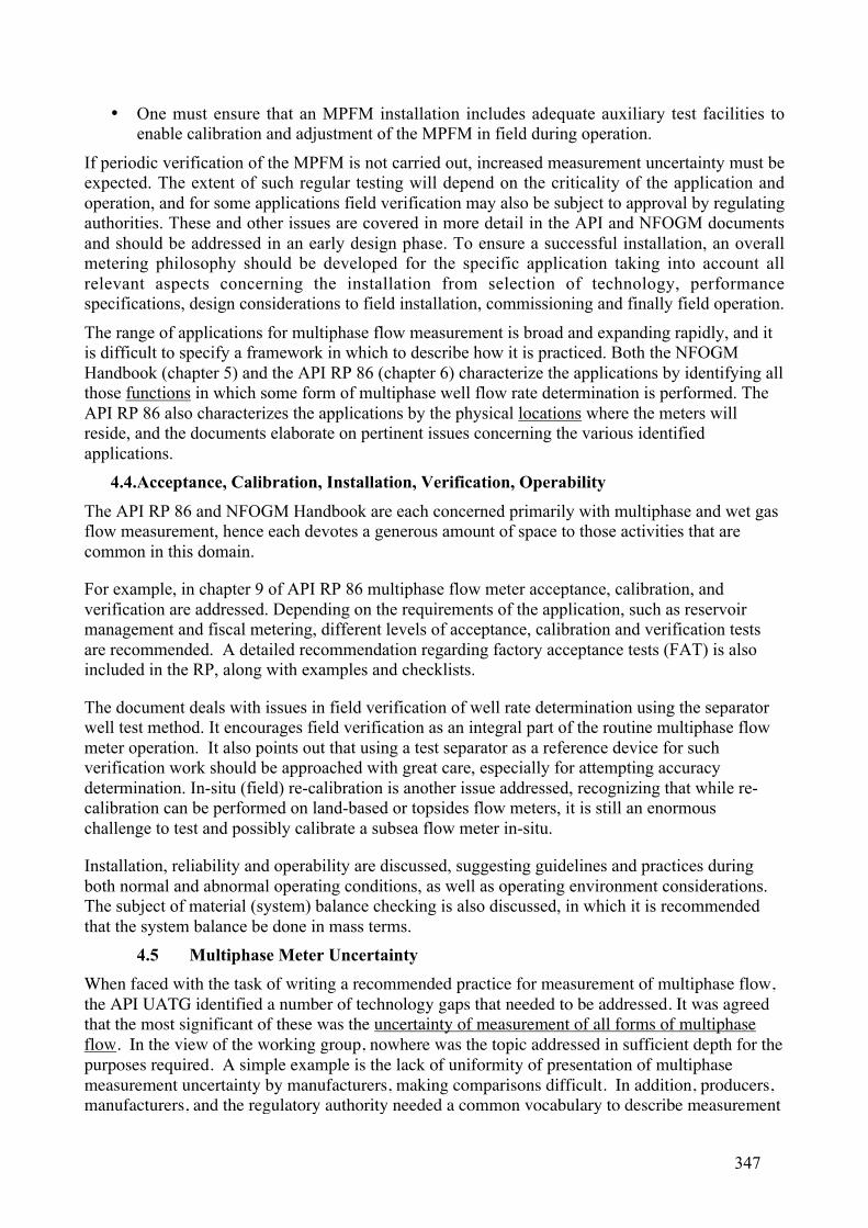
• One must ensure that an MPFM installation includes adequate auxiliary test facilities to
enable calibration and adjustment of the MPFM in field during operation.
If periodic verification of the MPFM is not carried out, increased measurement uncertainty must be
expected. The extent of such regular testing will depend on the criticality of the application and
operation, and for some applications field verification may also be subject to approval by regulating
authorities. These and other issues are covered in more detail in the API and NFOGM documents
and should be addressed in an early design phase. To ensure a successful installation, an overall
metering philosophy should be developed for the specific application taking into account all
relevant aspects concerning the installation from selection of technology, performance
specifications, design considerations to field installation, commissioning and finally field operation.
The range of applications for multiphase flow measurement is broad and expanding rapidly, and it
is difficult to specify a framework in which to describe how it is practiced. Both the NFOGM
Handbook (chapter 5) and the API RP 86 (chapter 6) characterize the applications by identifying all
those functions in which some form of multiphase well flow rate determination is performed. The
API RP 86 also characterizes the applications by the physical locations where the meters will
reside, and the documents elaborate on pertinent issues concerning the various identified
applications.
4.4. Acceptance, Calibration, Installation, Verification, Operability
The API RP 86 and NFOGM Handbook are each concerned primarily with multiphase and wet gas
flow measurement, hence each devotes a generous amount of space to those activities that are
common in this domain.
For example, in chapter 9 of API RP 86 multiphase flow meter acceptance, calibration, and
verification are addressed. Depending on the requirements of the application, such as reservoir
management and fiscal metering, different levels of acceptance, calibration and verification tests
are recommended. A detailed recommendation regarding factory acceptance tests (FAT) is also
included in the RP, along with examples and checklists.
The document deals with issues in field verification of well rate determination using the separator
well test method. It encourages field verification as an integral part of the routine multiphase flow
meter operation. It also points out that using a test separator as a reference device for such
verification work should be approached with great care, especially for attempting accuracy
determination. In-situ (field) re-calibration is another issue addressed, recognizing that while re-
calibration can be performed on land-based or topsides flow meters, it is still an enormous
challenge to test and possibly calibrate a subsea flow meter in-situ.
Installation, reliability and operability are discussed, suggesting guidelines and practices during
both normal and abnormal operating conditions, as well as operating environment considerations.
The subject of material (system) balance checking is also discussed, in which it is recommended
that the system balance be done in mass terms.
4.5 Multiphase Meter Uncertainty
When faced with the task of writing a recommended practice for measurement of multiphase flow,
the API UATG identified a number of technology gaps that needed to be addressed. It was agreed
that the most significant of these was the uncertainty of measurement of all forms of multiphase
flow. In the view of the working group, nowhere was the topic addressed in sufficient depth for the
purposes required. A simple example is the lack of uniformity of presentation of multiphase
measurement uncertainty by manufacturers, making comparisons difficult. In addition, producers,
manufacturers, and the regulatory authority needed a common vocabulary to describe measurement
347

uncertainty in the estimation of oil, gas, and water flow rates for allocation calculations. In a break
with today’s commonly used practice, the working group recommended expressing multiphase
metering uncertainty at a confidence level of 95% (two-standard-deviations), rather than at 90%.
Also recommended were three levels for uncertainty determination and presentation:
• Level 1: Primary and Secondary Devices – the uncertainties of all instrument sensor
readings, such as pressure, temperature, density, radiation detector counts, capacitance, and
conductivity should be made available to the user.
• Level 2: Observed Conditions - the uncertainties of flow rates (both mass and volumetric)
of gas, oil, and water at meter flowing conditions, plus GVF and WLR are presented at this
level. It is possible to develop the flow rate uncertainties from those of the sensors
combined with a multiphase flow model or equations. However, the higher uncertainty of
using a flow model and equations are not ordinarily accounted for. It is common to use
reference flow loop tests to determine the flow rate uncertainty at the flow loop conditions.
• Level 3: Reference Conditions – the uncertainties of flow rates of gas, oil, and water at
reference conditions are presented at this level. The reference flow rates are calculated
using uncertainties at Level 2 conditions in conjunction with a PVT model. Thus, the
uncertainties of the PVT model, sampling, and analysis must be combined with the
uncertainty at observed flow rate conditions to derive the overall uncertainty at the
reference conditions. The reference flow rates are typically used for the allocation process.
Other flow rate uncertainty topics covered are uncertainty changes during field life, presentation of
results (as in 4.2.2 below), calibrations, influence factors, sensitivity, and verification.
4.6 Display of Multiphase Meter Uncertainty
Currently, many different ways are used to present the outcome of a MPFM evaluation program.
Often the liquid flow rate or gas flow rate as measured by the MPFM is plotted against the
reference liquid or gas flow rate as measured by the test loop, however, there is no information in
these plots on the actual two-phase conditions, and in particular which flow regime was present. A
second and better way is to plot the deviations in liquid and gas flow rates and the deviation in
watercut against the GVF. A third way of presentation often seen is the use of the composition map
and contour plots. Deviations in liquid flow rate, oil flow rate, and watercut are given as function of
both the watercut and the GVF. Again, the performance as a function of GVF and watercut
becomes visible, but there is no information on the flow rate dependency in these plots. A fourth
way recently proposed [Ref. 5] is to use both the two-phase flow map and the composition map,
and to plot both the reference (test loop) measurement and the MPFM measurement together (see
Figure 4.1 for an example). The direction of the lines indicates whether deviations are in the liquid
flow rate (vertical lines) or in the gas flow rates (horizontal lines). The length of the line indicates
the magnitude of the deviation. A logarithmic flow map has the advantage that vectors of the same
relative deviation are the same length, regardless of position in the plot. This is contrary to flow
maps with a linear scale, where a vector of 10% relative deviation in the low flow rates shows up
much smaller than a 10% deviation at high flow rates.
A significant consideration is that deviations in MPFM’s readings / results are often systematic
because of inaccuracies in the flow models used or differences between configured and actual basic
fluid parameters. These systematic errors appear as vectors between reference and MPFM
measurement points, with consistent direction of the vector. Hence, the relative position between
the reference point and measurement points indicates the presence of systematic deviations. As can
be seen in the example shown in Figure 4.1, there is greater deviation is in the gas flow rates than
in the liquid flow rates. The same set of test points can also be plotted in the composition map. The
deviation in watercut and GVF is plotted, and the largest deviations are easily identified. The length
348

of the vectors between reference and MPFM measurement points again indicates an absolute
deviation between the reference and MPFM measurements, this time in composition. Also clearly
visible are the higher deviations at the higher GVF’s, and the transition zone between oil-
continuous and water-continuous emulsions.
Figure 4.1. Two-phase flow map and composition map with production envelope, MPFM
operating envelope, and test results
At present there is no standard method to present the overall uncertainties of multi-phase flow
meters, with a variety of different methods being used in practice, making it difficult to compare
the performance of different multiphase flow meters. In general MPFM uncertainties are quoted in
relative uncertainties for gas and liquid flowrate, and absolute uncertainties for the watercut or
WLR fraction measurements. All three will be a function of the GVF and/or WLR. With this
combination, also the relative uncertainties in the oil and water flow rates are dependent on the
actual watercut level, and need assessment by the user.
Figure 4.2. Example of cumulative deviation plots for liquid flow rates, gas flow rates and
watercut.
Cumulative deviation plots are a convenient way to compare the performance of different MPFM’s.
In Figure 4.2 the deviation between the MPFM measurement and the reference measurement is
plotted along the x-axis and the y-axis represents the percentage of test points that fulfill a certain
349
deviation criteria. This example shows that 70% of all the test points exhibit relative deviations in
liquid flow rate that are smaller than 10%. In addition, 80% of all the test points show absolute
deviations in watercut that are smaller than 10%. Finally, this MPFM performs poorly for gas, as
only some 10% of the test points fulfill a 10% deviation criterion. If the operating envelope is
specified with various GVF ranges, it is recommended that one construct cumulative deviation
plots for each GVF range.
4.7 Site Design Considerations
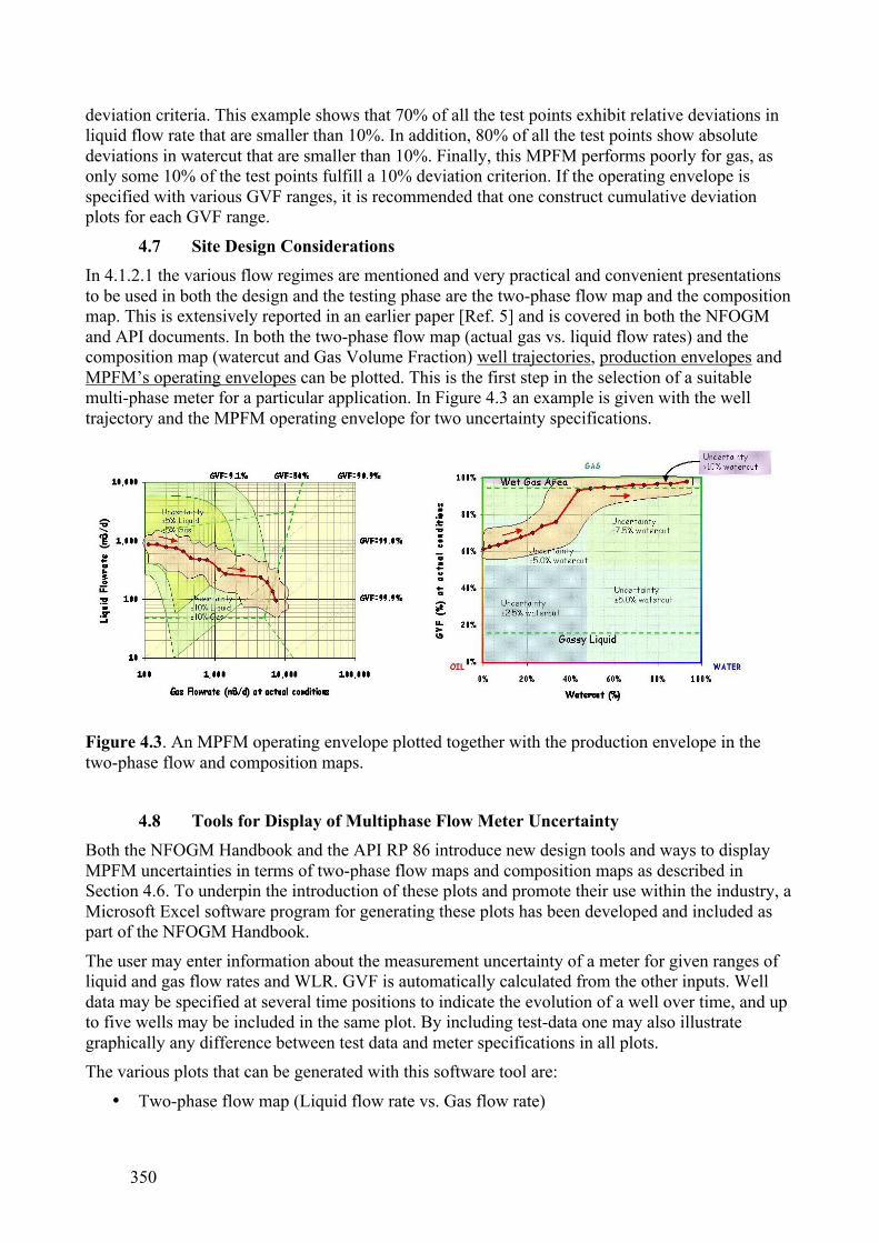
In 4.1.2.1 the various flow regimes are mentioned and very practical and convenient presentations
to be used in both the design and the testing phase are the two-phase flow map and the composition
map. This is extensively reported in an earlier paper [Ref. 5] and is covered in both the NFOGM
and API documents. In both the two-phase flow map (actual gas vs. liquid flow rates) and the
composition map (watercut and Gas Volume Fraction) well trajectories, production envelopes and
MPFM’s operating envelopes can be plotted. This is the first step in the selection of a suitable
multi-phase meter for a particular application. In Figure 4.3 an example is given with the well
trajectory and the MPFM operating envelope for two uncertainty specifications.
Figure 4.3. An MPFM operating envelope plotted together with the production envelope in the
two-phase flow and composition maps.
4.8 Tools for Display of Multiphase Flow Meter Uncertainty
Both the NFOGM Handbook and the API RP 86 introduce new design tools and ways to display
MPFM uncertainties in terms of two-phase flow maps and composition maps as described in
Section 4.6. To underpin the introduction of these plots and promote their use within the industry, a
Microsoft Excel software program for generating these plots has been developed and included as
part of the NFOGM Handbook.
The user may enter information about the measurement uncertainty of a meter for given ranges of
liquid and gas flow rates and WLR. GVF is automatically calculated from the other inputs. Well
data may be specified at several time positions to indicate the evolution of a well over time, and up
to five wells may be included in the same plot. By including test-data one may also illustrate
graphically any difference between test data and meter specifications in all plots.
The various plots that can be generated with this software tool are:
• Two-phase flow map (Liquid flow rate vs. Gas flow rate)
350
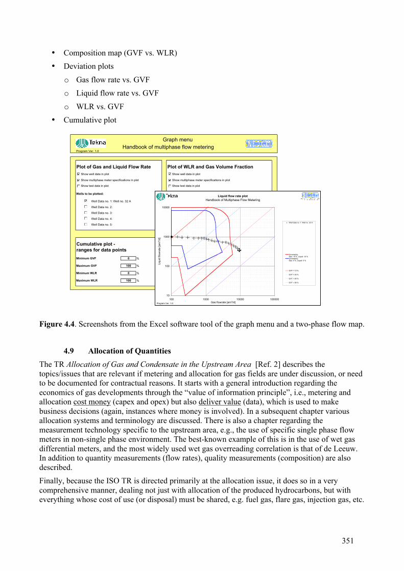
• Composition map (GVF vs. WLR)
• Deviation plots
o Gas flow rate vs. GVF
o Liquid flow rate vs. GVF
o WLR vs. GVF
• Cumulative plot
Figure 4.4. Screenshots from the Excel software tool of the graph menu and a two-phase flow map.
4.9 Allocation of Quantities
The TR Allocation of Gas and Condensate in the Upstream Area [Ref. 2] describes the
topics/issues that are relevant if metering and allocation for gas fields are under discussion, or need
to be documented for contractual reasons. It starts with a general introduction regarding the
economics of gas developments through the “value of information principle”, i.e., metering and
allocation cost money (capex and opex) but also deliver value (data), which is used to make
business decisions (again, instances where money is involved). In a subsequent chapter various
allocation systems and terminology are discussed. There is also a chapter regarding the
measurement technology specific to the upstream area, e.g., the use of specific single phase flow
meters in non-single phase environment. The best-known example of this is in the use of wet gas
differential meters, and the most widely used wet gas overreading correlation is that of de Leeuw.
In addition to quantity measurements (flow rates), quality measurements (composition) are also
described.
Finally, because the ISO TR is directed primarily at the allocation issue, it does so in a very
comprehensive manner, dealing not just with allocation of the produced hydrocarbons, but with
everything whose cost of use (or disposal) must be shared, e.g. fuel gas, flare gas, injection gas, etc.
Program Ver. 1.0
Plot of Gas and Liquid Flow Rate Plot of WLR and Gas Volume Fraction
Wells to be plotted: Wells to be plotted:
Well Data no. 1: Well no. 32 A Well Data no. 1: Well no. 32 A
Well Data no. 2: Well Data no. 2:
Well Data no. 3: Well Data no. 3:
Well Data no. 4: Well Data no. 4:
Well Data no. 5: Well Data no. 5:
Cumulative plot -
ranges for data points
Minimum GVF 0 %
Maximum GVF 100 %
Minimum WLR 0 %
Maximum WLR 100 %
Show well data in plot
Show multiphase meter specifications in plot
Show test data in plot
Show well data in plot
Show multiphase meter specifications in plot
Show test data in plot
Handbook of multiphase flow metering
Graph menu
10
100
1000
10000
100 1000 10000 100000Gas flowrate [am?/d]
Liq
uid
flo
wra
te [
am
?/d
]
Well Data no. 1: Well no. 32 A
Uncertainty: Gas: 10 %, Liquid: 10 %Uncertainty: Gas: 5 %, Liquid: 5 %
GVF = 10 %
GVF = 50 %
GVF = 90 %
GVF = 99 %
Liquid flow rate plot
Handbook of Multiphase Flow Metering
Program Ver. 1.0
351
5 CONCLUSIONS. WHAT’S NEXT? THE CHALLENGE.
As first stated in the Introduction, improvements in multiphase flow meters during the last 15 years
have resulted in their increased usage in upstream oil and gas applications, especially in difficult
offshore locations both topside and deep subsea. To address user needs for information and
standardization in the area, documentation has recently been created under the auspices of the
NFOGM, API, and ISO.
Our intent here was to familiarize potential users with the three new documents, which should be
helpful in a number of respects, e.g., (a) distribution of best knowledge and operational practices on
the subject, (b) provision of a common language for discussing multiphase flow, and (c) accounting
for the requirements of governing regulatory authorities.
At this stage of completion of NFOGM, API, and ISO reports, a natural question arises as to what
the future holds for another round of flow measurement documentation. Candidate areas include:
• In Situ Verification of Multiphase Flow Meters
• Wet Gas Flow Measurement
• Flare Gas Meters
• Virtual Metering
• Composition and Phase Behavior Issues In Measurement
• Flow Measurement Uncertainty
Addressing certain of these is already being proposed in several possible venues, among which are
(1) the DeepStar Consortium, (2) a JIP for investigating total system (meter + flowline + separator)
uncertainty organized by a group at Tulsa University, and (3) a program for development of drilling
and production capabilities in ultradeep water to be sponsored by the US Department of Energy.
The creation of the three documents discussed in this paper demonstrates the benefits that strong
international cooperation can achieve in producing standardization documents, ensuring their true
global input and acceptance. On the other hand, it should also be questioned why two or more
documents are required, which are the result of much duplication of effort. For example, although
there are differences between API RP86 and the NFOGM Handbook, they do not differ much in
content. Cost saving is often mentioned as a benefit of standardization, and here cost savings can be
achieved by combined standards. In the oil and natural gas industry there are numerous examples,
particularly in the area of materials, equipment and offshore structures, where API and ISO (TC67)
share some 30 co-branded standards, i.e. the standards carry both the ISO and API trademarks.
The authors feel most strongly that there is no reason to repeat this in the future, and that a single
document that can be adopted by all the groups be created for a given subject. If it requires that one
group take the lead and that the others adopt what has been done by the leader, then this should be
acceptable, if the needs of the follower groups have been adequately expressed and accounted for
in the final document.
Thus, for potential new standardization activities in our area of flow measurement such as those
mentioned above, we recommend the following:
• Do It Once,
• Do It Right,
• Do It Internationally
352
This will lead to a true international standard. In today’s World where the need for speed and
efficiency dominates, there is no good reason for developing these documents as we have done in
the past.
6 REFERENCES
1. Norwegian Society for Oil and Gas Measurement – Handbook of Multiphase
Flow Metering, March 2005, ISBN-82-91341-89-3.
2. International Organization for Standardization - Allocation of Gas and
Condensate in the Upstream Area, [TR in process of publication].
3. American Petroleum Institute Recommended Practice RP 86 - Recommended
Practice for Measurement of Multiphase Flow, August 2005.
4. American Petroleum Institute (API), Manual of Petroleum Measurement
Standards (MPMS).
5. Scheers, A.M., Use of the Two-Phase Flow Map and the Composition Map
in Multiphase Flow Meter Applications. South East Asia Hydrocarbon Flow
Measurement Workshop, Kuala Lumpur, March 2005.
6. International Organization for Standardization, International Vocabulary of
Basic and General Terms in Metrology, 2003, ISBN 92-67-01075-1.
7 ACKNOWLEDGEMENTS
The authors would like to gratefully acknowledge those groups that sponsored the work reported
here.
For sponsoring development of the new NFOGM Handbook, thanks are due the Norwegian Society
for Oil and Gas Measurement (NFOGM) and the Norwegian Society of Chartered Technical and
Scientific Professionals (Tekna).
The new API Recommended Practice 86 was jointly sponsored by the American Petroleum
Institute and the US Minerals Management Service (MMS), to whom our appreciation is tendered.
Finally, we would like to thank those who worked as volunteers in developing each of the three
documents. We are especially grateful to their companies, which generously contributed their
valuable time to these efforts. Without the hard work of these volunteer contributors, none of what
has been described here would have been possible.
APPENDIX – HOW TO OBTAIN THE DOCUMENTS.
For copies of API RP 86:
Electronic copy: http://api-ep.api.org/publications
Hard copy: American Petroleum Institute
1220 L Street NW
Washington, DC, USA 20005-4070
353