Development of Nickel Based Superalloys for Advanced Turbine Engines
7
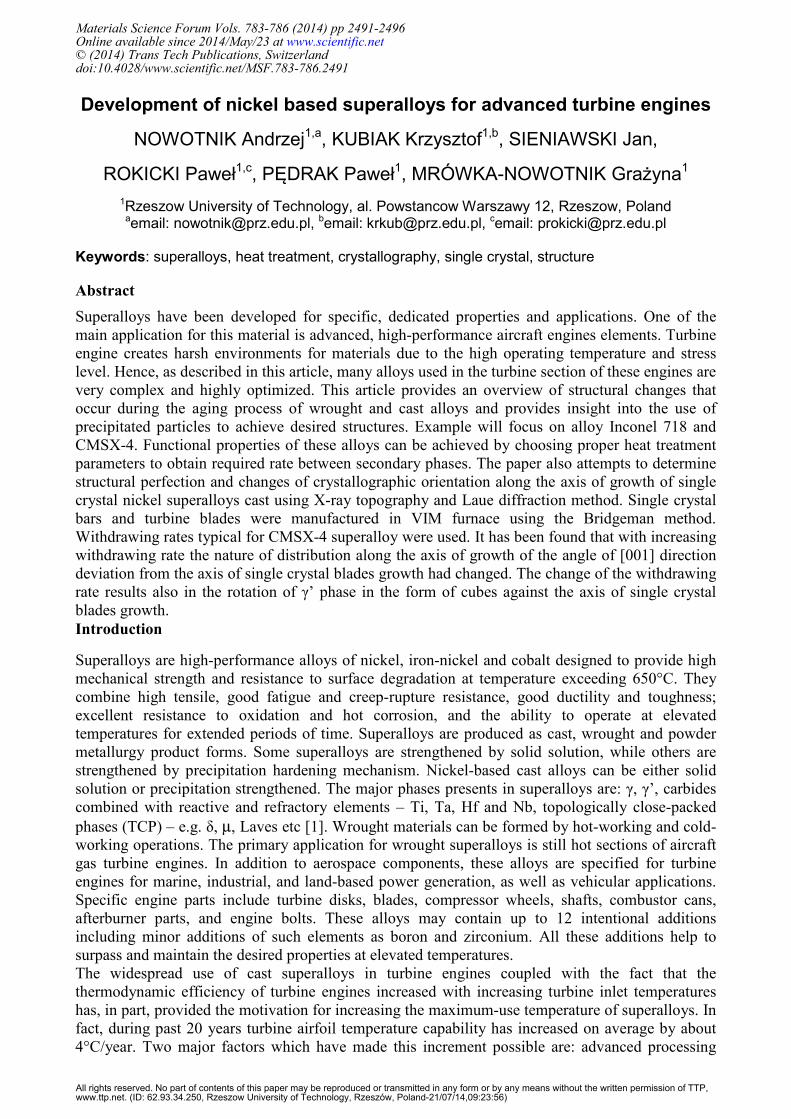
Development of nickel based superalloys for advanced turbine engines NOWOTNIK Andrzej 1,a , KUBIAK Krzysztof 1,b , SIENIAWSKI Jan, ROKICKI Paweł 1,c , PĘDRAK Paweł 1 , MRÓWKA-NOWOTNIK Grażyna 1 1 Rzeszow University of Technology, al. Powstancow Warszawy 12, Rzeszow, Poland a email: [email protected], b email: [email protected], c email: [email protected] Keywords: superalloys, heat treatment, crystallography, single crystal, structure Abstract Superalloys have been developed for specific, dedicated properties and applications. One of the main application for this material is advanced, high-performance aircraft engines elements. Turbine engine creates harsh environments for materials due to the high operating temperature and stress level. Hence, as described in this article, many alloys used in the turbine section of these engines are very complex and highly optimized. This article provides an overview of structural changes that occur during the aging process of wrought and cast alloys and provides insight into the use of precipitated particles to achieve desired structures. Example will focus on alloy Inconel 718 and CMSX-4. Functional properties of these alloys can be achieved by choosing proper heat treatment parameters to obtain required rate between secondary phases. The paper also attempts to determine structural perfection and changes of crystallographic orientation along the axis of growth of single crystal nickel superalloys cast using X-ray topography and Laue diffraction method. Single crystal bars and turbine blades were manufactured in VIM furnace using the Bridgeman method. Withdrawing rates typical for CMSX-4 superalloy were used. It has been found that with increasing withdrawing rate the nature of distribution along the axis of growth of the angle of [001] direction deviation from the axis of single crystal blades growth had changed. The change of the withdrawing rate results also in the rotation of γ’ phase in the form of cubes against the axis of single crystal blades growth. Introduction Superalloys are high-performance alloys of nickel, iron-nickel and cobalt designed to provide high mechanical strength and resistance to surface degradation at temperature exceeding 650°C. They combine high tensile, good fatigue and creep-rupture resistance, good ductility and toughness; excellent resistance to oxidation and hot corrosion, and the ability to operate at elevated temperatures for extended periods of time. Superalloys are produced as cast, wrought and powder metallurgy product forms. Some superalloys are strengthened by solid solution, while others are strengthened by precipitation hardening mechanism. Nickel-based cast alloys can be either solid solution or precipitation strengthened. The major phases presents in superalloys are: γ, γ’, carbides combined with reactive and refractory elements – Ti, Ta, Hf and Nb, topologically close-packed phases (TCP) – e.g. δ, μ, Laves etc [1]. Wrought materials can be formed by hot-working and cold- working operations. The primary application for wrought superalloys is still hot sections of aircraft gas turbine engines. In addition to aerospace components, these alloys are specified for turbine engines for marine, industrial, and land-based power generation, as well as vehicular applications. Specific engine parts include turbine disks, blades, compressor wheels, shafts, combustor cans, afterburner parts, and engine bolts. These alloys may contain up to 12 intentional additions including minor additions of such elements as boron and zirconium. All these additions help to surpass and maintain the desired properties at elevated temperatures. The widespread use of cast superalloys in turbine engines coupled with the fact that the thermodynamic efficiency of turbine engines increased with increasing turbine inlet temperatures has, in part, provided the motivation for increasing the maximum-use temperature of superalloys. In fact, during past 20 years turbine airfoil temperature capability has increased on average by about 4°C/year. Two major factors which have made this increment possible are: advanced processing Materials Science Forum Vols. 783-786 (2014) pp 2491-2496 Online available since 2014/May/23 at www.scientific.net © (2014) Trans Tech Publications, Switzerland doi:10.4028/www.scientific.net/MSF.783-786.2491 All rights reserved. No part of contents of this paper may be reproduced or transmitted in any form or by any means without the written permission of TTP, www.ttp.net. (ID: 62.93.34.250, Rzeszow University of Technology, Rzeszów, Poland-21/07/14,09:23:56)
Transcript of Development of Nickel Based Superalloys for Advanced Turbine Engines
Development of nickel based superalloys for advanced turbine engines
NOWOTNIK Andrzej1,a, KUBIAK Krzysztof1,b, SIENIAWSKI Jan,
ROKICKI Paweł1,c, PĘDRAK Paweł1, MRÓWKA-NOWOTNIK Grażyna1 1Rzeszow University of Technology, al. Powstancow Warszawy 12, Rzeszow, Poland
aemail: [email protected], bemail: [email protected], cemail: [email protected]
Keywords: superalloys, heat treatment, crystallography, single crystal, structure
Abstract
Superalloys have been developed for specific, dedicated properties and applications. One of the
main application for this material is advanced, high-performance aircraft engines elements. Turbine
engine creates harsh environments for materials due to the high operating temperature and stress
level. Hence, as described in this article, many alloys used in the turbine section of these engines are
very complex and highly optimized. This article provides an overview of structural changes that
occur during the aging process of wrought and cast alloys and provides insight into the use of
precipitated particles to achieve desired structures. Example will focus on alloy Inconel 718 and
CMSX-4. Functional properties of these alloys can be achieved by choosing proper heat treatment
parameters to obtain required rate between secondary phases. The paper also attempts to determine
structural perfection and changes of crystallographic orientation along the axis of growth of single
crystal nickel superalloys cast using X-ray topography and Laue diffraction method. Single crystal
bars and turbine blades were manufactured in VIM furnace using the Bridgeman method.
Withdrawing rates typical for CMSX-4 superalloy were used. It has been found that with increasing
withdrawing rate the nature of distribution along the axis of growth of the angle of [001] direction
deviation from the axis of single crystal blades growth had changed. The change of the withdrawing
rate results also in the rotation of γ’ phase in the form of cubes against the axis of single crystal
blades growth.
Introduction
Superalloys are high-performance alloys of nickel, iron-nickel and cobalt designed to provide high
mechanical strength and resistance to surface degradation at temperature exceeding 650°C. They
combine high tensile, good fatigue and creep-rupture resistance, good ductility and toughness;
excellent resistance to oxidation and hot corrosion, and the ability to operate at elevated
temperatures for extended periods of time. Superalloys are produced as cast, wrought and powder
metallurgy product forms. Some superalloys are strengthened by solid solution, while others are
strengthened by precipitation hardening mechanism. Nickel-based cast alloys can be either solid
solution or precipitation strengthened. The major phases presents in superalloys are: γ, γ’, carbides
combined with reactive and refractory elements – Ti, Ta, Hf and Nb, topologically close-packed
phases (TCP) – e.g. δ, µ, Laves etc [1]. Wrought materials can be formed by hot-working and cold-
working operations. The primary application for wrought superalloys is still hot sections of aircraft
gas turbine engines. In addition to aerospace components, these alloys are specified for turbine
engines for marine, industrial, and land-based power generation, as well as vehicular applications.
Specific engine parts include turbine disks, blades, compressor wheels, shafts, combustor cans,
afterburner parts, and engine bolts. These alloys may contain up to 12 intentional additions
including minor additions of such elements as boron and zirconium. All these additions help to
surpass and maintain the desired properties at elevated temperatures.
The widespread use of cast superalloys in turbine engines coupled with the fact that the
thermodynamic efficiency of turbine engines increased with increasing turbine inlet temperatures
has, in part, provided the motivation for increasing the maximum-use temperature of superalloys. In
fact, during past 20 years turbine airfoil temperature capability has increased on average by about
4°C/year. Two major factors which have made this increment possible are: advanced processing
Materials Science Forum Vols. 783-786 (2014) pp 2491-2496Online available since 2014/May/23 at www.scientific.net© (2014) Trans Tech Publications, Switzerlanddoi:10.4028/www.scientific.net/MSF.783-786.2491
All rights reserved. No part of contents of this paper may be reproduced or transmitted in any form or by any means without the written permission of TTP,www.ttp.net. (ID: 62.93.34.250, Rzeszow University of Technology, Rzeszów, Poland-21/07/14,09:23:56)
technologies enabling production of directionally solidified or single-crystal materials, alloy
development by addition elements (Re, W, Ta and W) enabling to go with temperature above the
limit. The exceptional properties of directionally solidified (DS) and single crystal (SC) alloys are
due to: the alignment or elimination of grain boundaries oriented transverse to loading direction, the
low modulus associated with the [100] directions enhances thermal mechanical fatigue resistance in
areas of constrained thermal expansion. SC properties depend on the crystallographic orientation of
the casts. Hence the assessment of SC cast quality is related to determination of their orientation
providing the basis information about its mechanical properties. It has been assumed that the value
of the angle denoted deviation between [001] direction and axis of the growth of single crystal
cannot exceed 15°. The higher value of this angle is the higher decrement in creep resistance is
observed [2,3].
Heat treatment of wrought Inconel 718 and cast CMSX-4 superalloys
Good mechanical properties of the Inconel 718 can be achieved by choosing proper heat treatment
parameters. It is important to produce proper distribution of precipitates of the hardening phase
characterized by uniform and suitable size. The precipitation hardening process consists of solution
annealing, quenching and aging. The temperature of solution annealing must be high enough to
dissolve alloying elements in the metal matrix, which during aging forms precipitates that harden
the nickel matrix. Samples of Inconel 718 were solution annealed at 1050°C followed by quenching
into water. Then, they were age hardened at temperature of: 700, 720, 740, 760 and 800°C.
CMSX-4® is an ultra-high strength, SC alloy developed by the Cannon Muskegon Co. This 2nd
generation Re-containing, nickel-base SC alloy is capable of higher peak temperature/stress
operation of at least 1163°C. Additionally it is capable to operate in long multiple cycles f.e. Solar®
Turbines report blade lives to overhaul of 25,000 - 30,000 hours in their 15,000 hp Mars 100
industrial gas turbine. The aim of presented work is to investigate heat treatment effect on
microstructure and properties of nickel-based single crystal superalloy CMSX-4®.
Heat treatment of CMSX-4 has been performed using a furnace in 10-5
mbar vacuum. Annealing
was performed in the temperature range of 1287°C to 1316°C for 19 hours. First step of aging was
carried out in 1140°C for 6 hours. Second step of aging in 871°C for 20 hours for stabilisation of
the microstructure. All the temperatures and times have been adjusted to compare with aircraft
industry norms and treated elements geometries. The effect of time and temperature on
microstructure of the superalloys was determined by analysis of changes in microstructure of the
examined alloys The microstructure was examined using standard optical and electron microscopy
techniques – SEM. SC casts were prepared in the Research and Development Laboratory for
Aerospace Materials of Rzeszow University of Technology using an ALD vacuum furnace.
Ceramic moulds made of Al2O3 were used. The alloy temperature during casting into the mould
amounted to 1550°C. Specimens for Laue method tests were cut out from single crystal blades
obtained at withdrawing rates of 1 and 4mm/min. Specimens were cut out parallel to the lower base
of the blade locking piece (fig. 1a). A series of five microsections for blade No. 1 (withdrawing rate
of 1 mm/min) was denoted in the order from the beginning of locking piece to the blade-end: 1.1,
1.2, 1.3, 1.4, 1.5. The denotations of blades No. 2, 3 and 4 microsections, at withdrawing rates 4
mm/min were similar. The microstructure was observed on transverse sections using light
microscope and SEM. Specimens’ surfaces were etched using Kalling’s reagent. Laue diffraction
patterns were obtained from polished surfaces of blades cross-sections. Basic parameters of
measurements: plate – specimen distance – 40 mm, exposure time – 8 h, molybdenum lamp, Kα
radiation, λ = 0.0709 nm. Laue patterns were registered on an AGFA Structurix D7 FW
photographic plate. The crystallographic orientation was determined based on the measurement of
two angles α and β. Angle α is the angle between single crystal growth axis Z and its
crystallographic direction [001]. An appropriate reference system should be taken to determine
angle β. It has been assumed that angle β is included between the projection of crystallographic
direction [100] on the surface of the studied microsection and the longer side of blade’s locking
piece. For the first and second microsection of blade with cross-sections C1 and C2 angle β is
included between the projection of direction [100] crystallographic axis onto the microsection
2492 THERMEC 2013
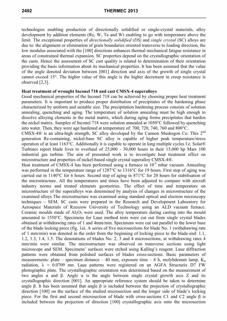
surface and the longer blade’s side. Microsections C3, C4 and C5 of the blade have irregular shape
and are situated above the blade’s locking piece Hence for correct determination of angle β it is
necessary to consider appropriate angular corrections M. Angular correction M is the angle between
the longer side of blade’s locking piece and the base line connecting on the transverse section the
edge of attack and the trailing edge of the blade. As during the Laue patterns recording
microsections C3, C4 and C5 were always set so that their base line A-B was horizontal, angle β
will be increased by angular corrections M3, M4 and M5. Because of that the actual angle β is
obtained deducting appropriate correction from the β value measured on the Laue pattern (fig. 1).
a
b
c
Fig. 1. Diagram of single crystal blades cutting: C1, C2, C3, C4, C5 – planes of microsections
made a). Arrows show the examined surfaces of transverse microsections. Schematic description of
angular corrections M to determine angle β – b) (view from the direction of arrows C1, C2, C3, C4
and C5, A-B – base line). c) diagram of crystallographic orientation determination: α – angle of
direction [001] deviation from single crystal’s growth axis Z, β – angle between direction [100]
projection on the examined microsections surface and the longer side (P-N) of blade’s locking piece
transverse section.
Results and discussion
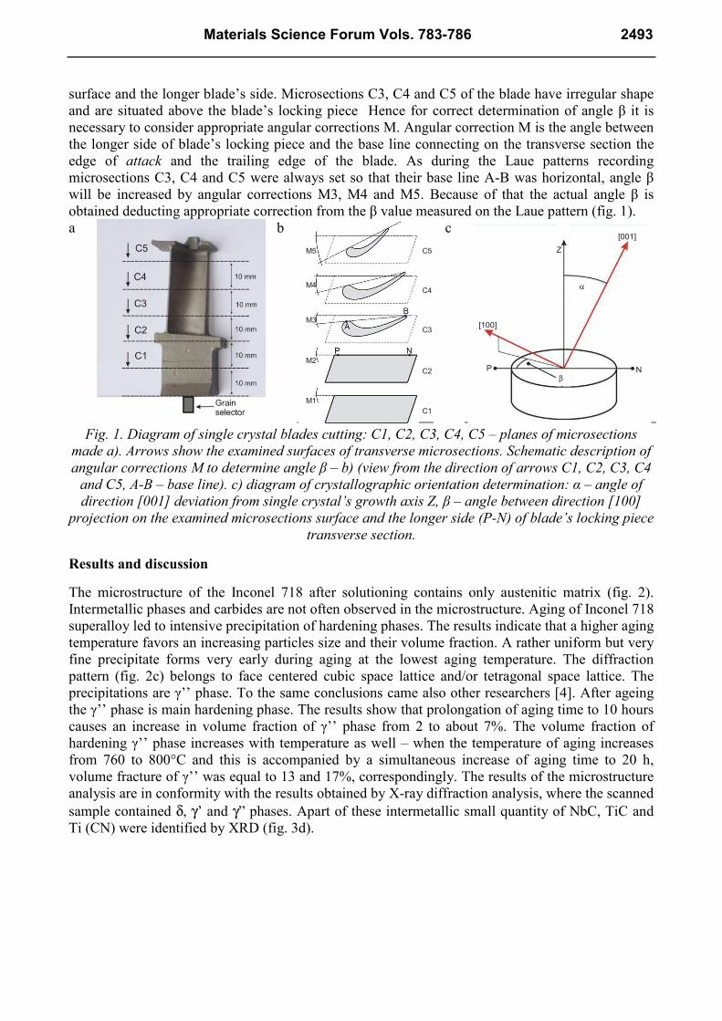
The microstructure of the Inconel 718 after solutioning contains only austenitic matrix (fig. 2).
Intermetallic phases and carbides are not often observed in the microstructure. Aging of Inconel 718
superalloy led to intensive precipitation of hardening phases. The results indicate that a higher aging
temperature favors an increasing particles size and their volume fraction. A rather uniform but very
fine precipitate forms very early during aging at the lowest aging temperature. The diffraction
pattern (fig. 2c) belongs to face centered cubic space lattice and/or tetragonal space lattice. The
precipitations are γ’’ phase. To the same conclusions came also other researchers [4]. After ageing
the γ’’ phase is main hardening phase. The results show that prolongation of aging time to 10 hours
causes an increase in volume fraction of γ’’ phase from 2 to about 7%. The volume fraction of
hardening γ’’ phase increases with temperature as well – when the temperature of aging increases
from 760 to 800°C and this is accompanied by a simultaneous increase of aging time to 20 h,
volume fracture of γ’’ was equal to 13 and 17%, correspondingly. The results of the microstructure
analysis are in conformity with the results obtained by X-ray diffraction analysis, where the scanned
sample contained δ, γ’ and γ” phases. Apart of these intermetallic small quantity of NbC, TiC and
Ti (CN) were identified by XRD (fig. 3d).
C5
C4
C3
C2
C1
M1
M2
M3
M4
M5
[001]
Z
P N
[100]
α
β
Materials Science Forum Vols. 783-786 2493
a)
b)
c)
Fig. 2. Microstructure of Inconel 718 alloy aged at: a) 740 for 20 h, b) 760/20 h, c) 800°C/20h.
a)
b)
c)
d)
Fig. 3. Inconel 718 alloy aged at 720°C for 10 h, a) γ’’ precipitates are visible, b) dark field, c)
corresponding [111] zone axis SAED diffraction pattern, d) X-ray diffraction of Inconel 718 aged
at 720 for 1, 4 and 10 h
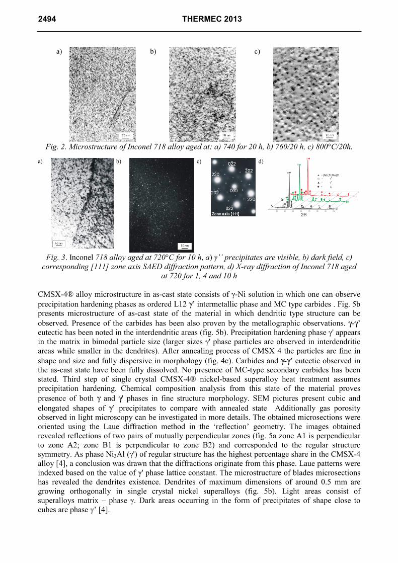
CMSX-4® alloy microstructure in as-cast state consists of γ-Ni solution in which one can observe
precipitation hardening phases as ordered L12 γ’ intermetallic phase and MC type carbides . Fig. 5b
presents microstructure of as-cast state of the material in which dendritic type structure can be
observed. Presence of the carbides has been also proven by the metallographic observations. γ-γ’
eutectic has been noted in the interdendritic areas (fig. 5b). Precipitation hardening phase γ' appears
in the matrix in bimodal particle size (larger sizes γ' phase particles are observed in interdendritic
areas while smaller in the dendrites). After annealing process of CMSX 4 the particles are fine in
shape and size and fully dispersive in morphology (fig. 4c). Carbides and γ-γ’ eutectic observed in
the as-cast state have been fully dissolved. No presence of MC-type secondary carbides has been
stated. Third step of single crystal CMSX-4® nickel-based superalloy heat treatment assumes
precipitation hardening. Chemical composition analysis from this state of the material proves
presence of both γ and γ' phases in fine structure morphology. SEM pictures present cubic and
elongated shapes of γ’ precipitates to compare with annealed state Additionally gas porosity
observed in light microscopy can be investigated in more details. The obtained microsections were
oriented using the Laue diffraction method in the ‘reflection’ geometry. The images obtained
revealed reflections of two pairs of mutually perpendicular zones (fig. 5a zone A1 is perpendicular
to zone A2; zone B1 is perpendicular to zone B2) and corresponded to the regular structure
symmetry. As phase Ni3Al (γ') of regular structure has the highest percentage share in the CMSX-4
alloy [4], a conclusion was drawn that the diffractions originate from this phase. Laue patterns were
indexed based on the value of γ' phase lattice constant. The microstructure of blades microsections
has revealed the dendrites existence. Dendrites of maximum dimensions of around 0.5 mm are
growing orthogonally in single crystal nickel superalloys (fig. 5b). Light areas consist of
superalloys matrix – phase γ. Dark areas occurring in the form of precipitates of shape close to
cubes are phase γ’ [4].
30 40 50 60 70 80 90 100a)
b)
c)
2Θ
(Nb,Ti,Mo)C-
-
--
2494 THERMEC 2013
a
b
c
Fig. 4. Single crystal CMSX-4 nickel-based superalloy structure details: a) as-cast state (LM), b)
as-cast state (SEM), c) annealed state (SEM)
a
b
Fig. 5. a) Diffraction pattern of CMSX4. Withdrawal rate of 2 mm/min, b) Microstructure of SC -
microsection of blade’s dovetail root. C-D arrow – axis of single crystal blade growth.
a
b
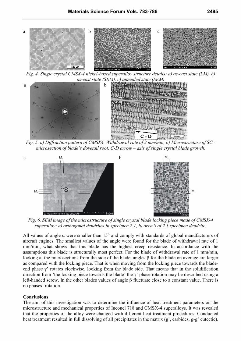
Fig. 6. SEM image of the microstructure of single crystal blade locking piece made of CMSX-4
superalloy: a) orthogonal dendrites in specimen 2.1, b) area S of 2.1 specimen dendrite.
All values of angle α were smaller than 15° and comply with standards of global manufacturers of
aircraft engines. The smallest values of the angle were found for the blade of withdrawal rate of 1
mm/min, what shows that this blade has the highest creep resistance. In accordance with the
assumptions this blade is structurally most perfect. For the blade of withdrawal rate of 1 mm/min,
looking at the microsections from the side of the blade, angles β for the blade on average are larger
as compared with the locking piece. That is when moving from the locking piece towards the blade-
end phase γ’ rotates clockwise, looking from the blade side. That means that in the solidification
direction from ‘the locking piece towards the blade’ the γ’ phase rotation may be described using a
left-handed screw. In the other blades values of angle β fluctuate close to a constant value. There is
no phases’ rotation.
Conclusions
The aim of this investigation was to determine the influence of heat treatment parameters on the
microstructure and mechanical properties of Inconel 718 and CMSX-4 superalloys. It was revealed
that the properties of the alloy were changed with different heat treatment procedures. Conducted
heat treatment resulted in full dissolving of all precipitates in the matrix (g’, carbides, g-g’ eutectic).
M2
M1M1
M2'
'
Materials Science Forum Vols. 783-786 2495
While precipitation hardening, rebuilding of fine structure occurred and the g’ precipitates
appeared. In case of Inconel 718 alloy, annealing process resulted in precipitation of g’’ phase. The
morphology and distribution of it was influenced by heat treatment parameters.
Concerning single crystal CMSX-4 alloy, angle α of direction [001] deviation from the axis of
single crystal blades growth depends on the rate of pulling-out from the heating area. For the rate of
1 mm/min the value of angle α on average is smaller than the values of angles obtained for blades of
pulling-out rates: 2mm/min, 3mm/min and 4mm/min. For the withdrawal rate of 1 and 2 mm/min
the values of angle α for the locking piece and blade substantially differ – they are nearly twice
larger in the blade than in the blade’s locking piece. Instead, for the withdrawal rate of 4 mm/min
there is an opposite effect. At the withdrawal rate of 3 mm/min the blades obtained have very close
α for the locking piece and blade, what proves a high degree of structure homogeneity. The
arrangement of dendrites in single crystals is strictly related to mutual position of γ and γ’ phases
boundaries – faces of γ’ phase cubes are approximately parallel to directions of dendrites’ arms.
This means that changes of angles α and β values (angle β describes the rotation of direction [100]
against the longer edge of the locking piece) along the blade axis are related to changes of
dendrites’ arms and γ and γ’ interphase boundaries arrangements. Angle α of direction [001]
deviation from the axis of single crystal blades growth depends on the withdrawal rate from the
heating area. For the rate of 1 mm/min the value of angle α on average is smaller than the values of
angles obtained for blades of withdrawal rates: 2, 3 and 4mm/min.
Acknowlegments
This work was supported by the National Science Center under grant no: No. N R15 0121 10.
References
[1] Supplement to The Minerals, Metals & Materials Society's site dedicated to the 9th International
Symposium on Superalloys, developed by Randy Bowman of NASA Lewis Research Center.
[2] Sieniawski J.: in: Assessment Criteria and Methods for Materials for Components of Aircraft
Turbine Engines, Rzeszów University of Technology Publishers, Rzeszów, 1995.
[3] Reed R.C.: in: The Superalloys, Fundamentals and Application, Cambridge University Press,
Cambridge, 2006.
[4] Betteridge W., Shaw S.W.S.: Mat. Sci. Techn., 3, 1987, 682.
2496 THERMEC 2013

THERMEC 2013 10.4028/www.scientific.net/MSF.783-786 Development of Nickel Based Superalloys for Advanced Turbine Engines 10.4028/www.scientific.net/MSF.783-786.2491