Development of a model to investigate the yaw behaviour of small horizontal axis wind turbines...
13
http://pia.sagepub.com/ Energy Engineers, Part A: Journal of Power and Proceedings of the Institution of Mechanical http://pia.sagepub.com/content/early/2011/11/06/0957650911421854 The online version of this article can be found at: DOI: 10.1177/0957650911421854 November 2011 published online 7 Proceedings of the Institution of Mechanical Engineers, Part A: Journal of Power and Energy M Narayana, G A Putrus, P S Leung, M Jovanovic and S McDonald Development of a model to investigate the yaw behaviour of small horizontal axis wind turbines Published by: http://www.sagepublications.com On behalf of: Institution of Mechanical Engineers be found at: can Proceedings of the Institution of Mechanical Engineers, Part A: Journal of Power and Energy Additional services and information for http://pia.sagepub.com/cgi/alerts Email Alerts: http://pia.sagepub.com/subscriptions Subscriptions: http://www.sagepub.com/journalsReprints.nav Reprints: http://www.sagepub.com/journalsPermissions.nav Permissions: What is This? - Nov 7, 2011 Proof >> at Univ of Northumbria on November 29, 2011 pia.sagepub.com Downloaded from
Transcript of Development of a model to investigate the yaw behaviour of small horizontal axis wind turbines...

http://pia.sagepub.com/EnergyEngineers, Part A: Journal of Power and
Proceedings of the Institution of Mechanical
http://pia.sagepub.com/content/early/2011/11/06/0957650911421854The online version of this article can be found at:
DOI: 10.1177/0957650911421854
November 2011 published online 7Proceedings of the Institution of Mechanical Engineers, Part A: Journal of Power and Energy
M Narayana, G A Putrus, P S Leung, M Jovanovic and S McDonaldDevelopment of a model to investigate the yaw behaviour of small horizontal axis wind turbines
Published by:
http://www.sagepublications.com
On behalf of:
Institution of Mechanical Engineers
be found at: canProceedings of the Institution of Mechanical Engineers, Part A: Journal of Power and EnergyAdditional services and information for
http://pia.sagepub.com/cgi/alertsEmail Alerts:
http://pia.sagepub.com/subscriptionsSubscriptions:
http://www.sagepub.com/journalsReprints.navReprints:
http://www.sagepub.com/journalsPermissions.navPermissions:
What is This?
- Nov 7, 2011Proof >>
at Univ of Northumbria on November 29, 2011pia.sagepub.comDownloaded from

Development of a model to investigate the yawbehaviour of small horizontal axis wind turbinesM Narayana1*, G A Putrus1, P S Leung1, M Jovanovic1, and S McDonald2
1School of Computing, Engineering and Information Sciences, Northumbria University, Newcastle upon Tyne, UK2Department of Electrical Technology, New and Renewable Energy Centre (NaREC), Blyth, UK
The manuscript was received on 29 January 2011 and was accepted after revision for publication on 9 August 2011.
DOI: 10.1177/0957650911421854
Abstract: Almost all small wind turbines have a tail vane to point the wind rotor into the winddirection. Various types of control mechanisms are used to protect the wind turbines from high-wind speeds. In this study, a generic model of a wind turbine is developed to investigate the yawoperation of small-scale horizontal axis wind turbines (HAWT) with a single tail vane. A tilt-upwind turbine is considered here as most of the other HAWT types can be simplified to a state ofthis model. In the tilted up wind turbines, the wind rotor is free to move around the horizontalaxis as well as the vertical one. When the wind speed exceeds the rated value, the wind rotor tiltsupwards, taking up a stable position with an inclination towards the direction of the wind, thuscontrolling the wind component responsible for power generation. This article describes thedevelopment of a mathematical model of small-scale HAWT using the D’Alembert’s principle toinvestigate the complex behaviour of the wind turbine under transient and steady-state oper-ating conditions. In this model, the blade element theory was adapted to predict the aerody-namic forces on the wind rotor at each rotor position. Combining the modified blade elementwith the momentum theories makes it possible to evaluate flow fields of induced velocitiesaround the wind rotor. Yaw movements are modelled by considering dynamic responses ofthe tail vane. Finally, simulation results are presented to illustrate the yaw behaviour of asmall wind turbine.
Keywords: D’Alembert’s principle, small-scale wind turbines, yaw behaviour
1 INTRODUCTION
The wind turbine must align itself in the direction of
the wind and has to adapt to any circumstances.
It also needs to protect itself from gusty winds
beyond the rated wind speed and this must happen
automatically. Larger wind turbines have computer-
driven control systems that operate servo-motors,
hydraulic motors, etc., to execute these functions.
Due to relatively limited investments in small wind
turbines, simple passive controls are needed wherever
possible. Passive yaw control mechanisms are being
commonly used in small wind turbines for both power
regulation and wind hunting. In this study, a mathe-
matical model was developed by considering a tilt-up
type small wind turbine built in with a single tail vane.
This system can be simplified to most of the other
horizontal axis wind turbine (HAWT) types built in
with single tail vanes. Figure 1 shows the kinetic
details of this system. Investigation of the kinetic
behaviour of tilt-up turbines is more complicated as
the wind rotor, the generator, and the counterweights
can be rotated freely around the pivot point in the
horizontal axis as well as around the vertical axis
(i.e. tower axis). The wind rotor is pivoted in a vertical
plane and it could be tilted upwards due to the wind
speed dependent thrust force of the wind rotor.
In this system, a counterbalancing weight or a
spring mechanism is required to produce the
*Corresponding author: School of Computing, Engineering and
Information Sciences, Northumbria University, Newcastle upon
Tyne, UK.
email: [email protected]
REVIEW ARTICLE 1
Proc. IMechE Vol. 000 Part A: J. Power and Energy
at Univ of Northumbria on November 29, 2011pia.sagepub.comDownloaded from

necessary restoring moment to hold the wind rotor in
the wind direction. At wind speeds above the rated
value, the wind rotor is tilted upward due to the resul-
tant torque of the thrust force of the wind rotor and
the restoring moment of counterbalancing weights
around the pivoted point. Normally in these systems,
a damper is used to control irregular vertical move-
ments [1]. This study intended to describe the devel-
opment of a mathematical model to investigate the
complex yaw behaviour of the small-scale wind
turbine.
2 MOMENTS DERIVED FROM D’ALEMBERT’SFORCES
Using the D’Alembert’s principle, a dynamic system
can be converted into a static system to be analysed
under static equilibrium conditions [2]. In this case,
for each and every point, forces of magnitude �mi.fi
are applied in the direction opposite to its accelera-
tion, where �mi is the mass and fi the acceleration at
the point i. D’Alembert’s forces on the wind rotor, the
generator, and the counterweight are shown in Fig. 1.
Orientations of the wind rotor and the tail vane are
illustrated in Fig. 2.
Momentums of D’Alembert’s forces on the wind
rotor, the generator, and the counterweight system
about ‘O’ can be expressed as follows (Fig. 1)
M0 ¼X
�R0 þ �ri
� �� �mi:
€�R0 þ€�ri
� �¼X
�mi�R0 þ �ri
� ��
€�R0 þ �R0 þ �ri
� �� €�ri
h i¼X
�mi�R0 �
€�R0 þ€�R0
X�miri|fflfflfflfflfflfflfflfflffl{zfflfflfflfflfflfflfflfflffl}
0
þ �R0 �X
�mi€�ri|fflfflfflfflfflfflfflfflfflfflffl{zfflfflfflfflfflfflfflfflfflfflffl}
0
þX
�mi �ri �€�ri
M0 ¼ m �R0 �€�R0 þ
dP _�ri � �mi �ri
� �h idt
ð1Þ
Now given that ð _� � _�, _�Þ, then _�R0 �_�ri. Velocity at
point ‘i’ ¼ _�R0 þ_�ri ¼ �Vi
; _�V��� ���
i� _�ri
��� ��� � _� �r1ij j
�ri ¼ �r0 þ �r1i
ThereforeX_�ri � �mi �ri ¼
X�mi �r0 þ �r1ið Þ � �Vi
¼ �r0
X�miVi|fflffl{zfflffl}
0
þX
�mi �r1i � Vi
thenX
�mi �r1i � �Vi ¼ �I _�
Therefore
M0 ¼ m �R0 �€�R0 þ
dð�I _�Þ
dtð2Þ
The wind rotor, the generator, the counterweight
system, and the tail vane are free to move about k
axis. Therefore, the D’Alembert’s momentum of the
wind rotor about the k axis
Mk ¼k component of m �R0�€�R0þ
dð�I _�Þ
dt
� �ð3Þ
Similarly, the wind rotor and the counterweight
system are free to move about the j0 axis, and the cor-
responding the D’Alembert’s momentum can be
expressed as
Mj 0 ¼ j0 component of m �R0�€�R0þ
dð�I _�Þ
dt
� ð4Þ
Solutions of Mk and Mj 0 are described in the
Appendix 2.
Fig. 2 Orientation of the wind rotor and the tail vane
Fig. 1 Configuration of tilt-up type small wind turbineand D’Alembert’s forces
2 M Narayana, G A Putrus, P S Leung, M Jovanovic, and S McDonald
Proc. IMechE Vol. 000 Part A: J. Power and Energy
at Univ of Northumbria on November 29, 2011pia.sagepub.comDownloaded from

3 AERODYNAMIC FORCES ON THE WIND
ROTOR
In this study, the blade element theory is used to
determine forces and momentums by assuming a
blade composed of a number of aerodynamically
independent cross-sections having the same charac-
teristics of a blade at a proper angle of attack [3]. The
overall flow pattern through the wind rotor is pre-
sented in Fig. 3. At the yawed position, the wind
rotor blade experiences a higher relative velocity on
the advancing side than on the retreating one.
Therefore, the blade loads and the generated power
fluctuate.
The flow expansion angle is varying throughout
the length of each blade element. Its value is zero at
the wind rotor hub and maximum at the blade tip.
The flow expansion angle at the tip of the wind
rotor blades is estimated by the average axial induc-
tion factors (K0) of the wind rotor in normal flow. At a
given angle between wind velocity and wind rotor axis
(’), the expansion angle at the tip "(R) is given as fol-
lows [4, 5]
"ðRÞ ¼1
3
1� K 0ð Þ
1þ K 0ð Þ
� cos ’ ð5Þ
Then, assuming that the variation of flow expansion
angle is equal from hub to tip, the flow expansion
angle at radius r of the wind rotor is
"ðrÞ ¼r
R�
1
3�
1� K 0ð Þ
1þ K 0ð Þ
� � cos ’ ð6Þ
The flow components at the wind rotor blade
are shown in Fig. 4. For a particular wind rotor
position (�), the axial wind speed relative to the
blade element at a distance r from the wind rotor
axis can be written as (Fig. 4)
VaðrÞ ¼Va1ðrÞ þ Va2ðrÞ½ �
2¼ð1þ kÞ
2� Va1ðrÞ ð7Þ
According to Fig. 4, for a particular wind rotor
position (�), the circumferential wind speed Vr(r) in
the wind rotor plane relative to the blade element
at a distance r from the wind rotor axis can be
expressed as
Vr ðrÞ ¼Vr1ðrÞ þ Vr2ðrÞ½ �
2¼ð1þ hÞ
2� Vr1ðrÞ ð8Þ
where Va2ðrÞ ¼ k � Va1ðrÞ and Vr2ðrÞ ¼ h � Vr1ðrÞ.
For a particular rotor position (�), axial and radial
relative flow components at the blade element (r) can
be expressed as
VaðrÞ ¼
�V1 � cos’� sin ’ � tan "ðrÞ � cos �ð Þ
� r �d’
dt� cos �
�
k þ 1
2
ð9Þ
Vr ðrÞ ¼ ! � r þ V1 � sin ’ � sin �ð Þ �h þ 1
2ð10Þ
’ ¼ cos�1 cos � � cos �ð Þ ð11Þ
Fig. 3 Overall flow pattern through the wind rotorFig. 4 Flow components at the blade element (r) for a
particular rotor position
Development of a model to investigate the yaw behaviour of small horizontal axis wind turbines 3
Proc. IMechE Vol. 000 Part A: J. Power and Energy
at Univ of Northumbria on November 29, 2011pia.sagepub.comDownloaded from
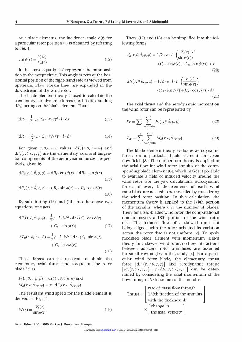
At r blade elements, the incidence angle �(r) for
a particular rotor position (�) is obtained by referring
to Fig. 4.
cot�ðrÞ ¼Vr ðrÞ
VaðrÞð12Þ
In the above equations, � represents the rotor posi-
tion in the swept circle. This angle is zero at the hor-
izontal position of the right-hand side as viewed from
upstream. Flow stream lines are expanded in the
downstream of the wind rotor.
The blade element theory is used to calculate the
elementary aerodynamic forces (i.e. lift dRl and drag
dRd) acting on the blade element. That is
dRl ¼1
2� � � Cl �W ðrÞ
2� l � dr ð13Þ
dRd ¼1
2� � � Cd �W ðrÞ
2� l � dr ð14Þ
For given r , �, _�, ’, _’ values, dFv r , �, _�, ’, _’� �
and
dFu r , �, _�, ’, _’� �
are the elementary axial and tangen-
tial components of the aerodynamic forces, respec-
tively, given by
dFv r , �, _�, ’, _’� �
¼ dRl � cos�ðrÞ þ dRd � sin �ðrÞ
ð15Þ
dFu r , �, _�, ’, _’� �
¼ dRl � sin�ðrÞ � dRd � cos�ðrÞ
ð16Þ
By substituting (13) and (14) into the above two
equations, one gets
dFvðr , �, _�, ’, _’Þ ¼1
2� � l �W 2 � dr � ðCl � cos�ðrÞ
þ Cd � sin �ðrÞÞ ð17Þ
dFuðr , �, _�, ’, _’Þ ¼1
2� � l �W 2 � dr � ðCl � sin�ðrÞ
þ Cd � cos�ðrÞÞ
ð18Þ
These forces can be resolved to obtain the
elementary axial thrust and torque on the rotor
blade ‘b’ as
Fb r , �, _�, ’, _’� �
¼ dFvðr , �, _�, ’, _’Þ and
Mb r , �, _�, ’, _’� �
¼ r � dFuðr , �, _�, ’, _’Þ
The resultant wind speed for the blade element is
derived as (Fig. 4)
W ðrÞ ¼VaðrÞ
sin�ðrÞð19Þ
Then, (17) and (18) can be simplified into the fol-
lowing forms
Fb r , �, _�, ’, _’� �
¼ 1=2 � � � l �VaðrÞ
sin�ðrÞ
� 2
� Cl � cos�ðrÞ þ Cd � sin�ðrÞð Þ � dr
ð20Þ
Mb r , �, _�,’, _’� �
¼ 1=2 � � � l � r �VaðrÞ
sin�ðrÞ
� 2
� ðCl � sin�ðrÞ þ Cd � cos�ðrÞÞ � dr
ð21Þ
The axial thrust and the aerodynamic moment on
the wind rotor can be represented by
FT ¼Xb
1
Xr¼R
r¼rðhubÞ
Fb r , �, _�, ’, ’� �
ð22Þ
TW ¼Xb
1
Xr¼R
r¼rðhubÞ
Mb r , �, _�, ’, _’� �
ð23Þ
The blade element theory evaluates aerodynamic
forces on a particular blade element for given
flow fields [3]. The momentum theory is applied to
the axial flow for wind rotor annulus of the corre-
sponding blade element [6], which makes it possible
to evaluate a field of induced velocity around the
wind rotor. For the yaw calculations, aerodynamic
forces of every blade elements of each wind
rotor blade are needed to be modelled by considering
the wind rotor position. In this calculation, the
momentum theory is applied to the 1/bth portion
of the annulus, where b is the number of blades.
Then, for a two-bladed wind rotor, the computational
domain covers a 180 portion of the wind rotor
disc. The induced flow of a skewed rotor not
being aligned with the rotor axis and its variation
across the rotor disc is not uniform [7]. To apply
modified blade element with momentum (BEM)
theory for a skewed wind rotor, no flow interactions
between adjacent rotor annuluses are assumed
for small yaw angles in this study [4]. For a parti-
cular wind rotor blade, the elementary thrust
force dFb r , �, _�, ’, _’� �� �
and aerodynamic torque
Mb r , �, _�, ’, _’� �
¼ r � dFuðr , �, _�, ’, _’Þ� �
can be deter-
mined by considering the axial momentum of the
flow through 1/bth fraction of the annulus
Thrust ¼
rate of mass flow through
1=bth fraction of the annulus
with the thickness dr
264
375
�change in
the axial velocity
�
4 M Narayana, G A Putrus, P S Leung, M Jovanovic, and S McDonald
Proc. IMechE Vol. 000 Part A: J. Power and Energy
at Univ of Northumbria on November 29, 2011pia.sagepub.comDownloaded from

Then, the axial thrust on 1/bth fraction of the annu-
lus at radius r is given by
Fb r ,�, _�,’, _’� �
¼�r
b�:dr V1� r �
d’
dt� cos’
�
�
V1 � cos’� sin’ � tan"r � cos�ð Þ
�r �d’
dt� cos�
24
35 � ð1�k2Þ
ð24Þ
The aerodynamic torque
¼
rate of mass flow through
1=bth fraction of the
annulus with the thickness dr
264
375
�
change in
the radial
velocity
264
375� r
Then, aerodynamic torque due to 1/bth fraction of
the annulus at radius r is given by
Mb r , �, _�, ’, _’� �
¼� � r2
b� �:dr V1 � r �
d’
dt� cos ’
�
� ! � r þ V1 � sin ’ sin �ð Þ � 1þ kð Þ � h � 1ð Þ
ð25Þ
There are six equations, i.e. (9), (12), (20), (21),
(24), and (25) and six unknowns, i.e. VaðrÞ,�ðrÞ,ð
Fb r , �, _�, ’, _’� �
, Mb r , �, _�, ’, _’� �
, k, and hÞ. Therefore,
aerodynamic forces on each blade element can be
determined for either value of �, ’ (� and �), d�=dt ,
and d’=dt , when the aerofoil data (Cl and Cd curve
with �r) are known.
The wind velocity components and the respective
aerodynamic forces (Fs sin , Fs cos , and FT ) are
Fig. 5 Wind velocity components and aerodynamic forces applied on the wind rotor
Development of a model to investigate the yaw behaviour of small horizontal axis wind turbines 5
Proc. IMechE Vol. 000 Part A: J. Power and Energy
at Univ of Northumbria on November 29, 2011pia.sagepub.comDownloaded from

shown in Fig. 5. Then, the side thrust force Fs
becomes
Fs ¼1
2� Cds � V
20 � � � As ð26Þ
where
V0 ¼ V1 �
ffiffiffiffiffiffiffiffiffiffiffiffiffiffiffiffiffiffiffiffiffiffiffiffiffiffiffiffiffiffiffiffiffiffiffiffiffiffiffiffiffiffiffiffiffifficos � � sin �ð Þ
2þ sin2 �
qð27Þ
For computational purposes, Fs is divided into two
components. Those components are Fs sin and
Fs cos in the wind rotor plane.
According to configuration of applied aerodynamic
forces on the wind rotor in Fig. 5, aerodynamic
moments on the wind rotor can be derived by con-
sidering equations (24), (25), and (26).
The aerodynamic moment of the wind rotor about
the k axis
MRk ¼Xb
1
Xr¼R
r¼rðhubÞ
rF r , �, _�,’, _’� �
� cos � � cos�
þTW � sin� þ x � sin � �ð Þ � Fs � cos
ð28Þ
and about the j 0 axis
MRj 0 ¼Xb
1
Xr¼R
r¼rðhubÞ
r � F r , �, _�, ’, _’� �
� sin �
þ x � cosð� �Þ � Fs � sin þ y � Ft
ð29Þ
To simplify the calculations in this study, the average
aerodynamic axial moment and thrust are deter-
mined by considering one rotation of the wind rotor
(as _� � _�, _�).
In tilt-up type small wind turbine systems, the wind
rotor part can be moved upward. Then kD _� can be
defined as the required damping component to
avoid irregular vertical movements of the wind rotor
part, consisting of the wind rotor, the generator, and
the counterweights. According to Fig. 5, the following
expression can be derived by considering the equilib-
rium of moments on the wind rotor part about the j 0
axis
kD _� þMj 0 ¼ MRj 0 þ X � sinð� �Þ �m � g ð30Þ
where kD is the damping factor for vertical
movements.
4 YAW MOTION OF THE WIND TURBINE
The contribution of wind rotor aerodynamics to
yaw dynamics is an extremely complex subject and
includes the effects of blade rigidity, horizontal and
vertical wind direction components, wind shear,
dynamic stall, and skewed wake effects [8]. In this
study, aerodynamic forces on the tail vanes were
calculated by considering the lift and drag forces by
lift and drag coefficients (Cl and Cd, respectively).
Relative wind speed to the tail vane and effective
angle of attack were considered here to determine
the dynamic forces on the tail vane. A velocity dia-
gram is shown in Fig. 6. It is assumed that lift and drag
coefficients for the tail vane can be approximated by
the standard ‘flat-plate equations’ [9].
The tail vane is some where in the downstream of
the wind rotor, so the change of the axial velocity
should be considered to evaluate the effective wind
velocity to the tail vane. The wind velocity at the
tail vane is greater than the downstream flow
value close to the wind rotor (V1 � k0), because it is in
combination with the normal wind flow; k 0 is the
average axial induction factor of the wind rotor,
which can be determined by the actuator disc theo-
rem [6]. In this study, suggested downstream axial
wind velocity at the tail vane is V1 � ð2k 0 � 1Þ for far
wake value [4].
Hence, the effected wind velocity to the tail vane is
U1 ¼ V1 � 2k 0 � 1ð Þ ð31Þ
By considering the velocity diagram in Fig. 6, one can
establish the following relationships
Vvt ¼
ffiffiffiffiffiffiffiffiffiffiffiffiffiffiffiffiffiffiffiffiffiffiffiffiffiffiffiffiffiffiffiffiffiffiffiffiffiffiffiffiffiffiffiffiffiffiffiffiffiffiffiffiffiffiffiffiffiffiffiffiffiffiffiffiffiffiffiffiffiffiffiffiU1 þ lv � _� � sin �ð Þ
2þ lv � _� � cos �ð Þ
2q
ð32Þ
Effective angle attack (�0) to the tail vane is:
�0 ¼ tan�1 U1 � sin �þ lv � _�ð Þ
U1 � cos �
� ð33Þ
The flat-plate equations are [9]: Clv ¼ K0 � sin �0� cos �0
and Cdv ¼ K0 � sin2��0; K0 is a constant. Here, it is
assumed that K0¼ 2 [10].
Then, lift and drag forces (Rlv and Rdv) on the wind
vane can be calculated as follows
Rlv ¼1
2�� �Clv �V
2vt �Av and Rdv ¼
1
2�� �Cdv �Vvt �Av
Fu ¼Rlv �cos�0 þRdv � sin�0, and
Fv ¼Rlv � sin�0 �Rdv �cos�0:
Fig. 6 Aerodynamic forces on the tail vane and windvelocity diagram for the tail vane
6 M Narayana, G A Putrus, P S Leung, M Jovanovic, and S McDonald
Proc. IMechE Vol. 000 Part A: J. Power and Energy
at Univ of Northumbria on November 29, 2011pia.sagepub.comDownloaded from

Substituting the solution for Clv, Cdv, Rlv, and Rdv in
the expression for Fu
Fu ¼1
2�K0 �V
2vt �� �Av � sin�0 � cos2 �0 þ sin3 �0
� �ð34Þ
Aerodynamic moment of tail vanes about the k
axis is
�lv �1
2K0 � V
2vt � � � Av � sin �0 � cos2 �0 þ sin3 �0
� �Then, the equation of the system angular motion is
of the form
Mkþ I1 � €��MRk ¼�lv �1
2�K0 �V
2vt �� �Av
� sin�0 �cos2�0 þsin3�0� � ð35Þ
where Mk is the D’Alambert’s moment of the
wind rotor about the k axis and MRk the wind rotor
aerodynamic moment of about the same axis.
For small � values, equation (33) can be approxi-
mated as
�0 ¼ �þlv � _�
U1ð36Þ
Using this approximation, (35) can now be simpli-
fied as
MRk þ I1 � €��Mk ¼ �lv �1
2� K0 � V
2vt � � � A � �
0 ð37Þ
The above equation is similar to an alternative form
used to represent the yaw dynamics as derived by
Kristensen [10] for the dynamic response of wind
vane. Therefore, Kristensen’s equation verifies the
derivation of yaw dynamics by ‘flat-plate equations’.
Under the yawed condition, the reduction of axial
velocity is induced by the wake skewness. There are
several models to analyse the skewed wake effects of
the wind rotor [11]. According to the actuator disc
theory [6], the skewed wake expansion is in direction
of the downwind blade for yawed flow condition.
Large wake angle ( �j j) will occur due to the significant
reduction of axial velocity at the wind rotor, as a result
of the large coefficient of thrust (Ct). The skew angle is
determined by the ratio between the inflow velocity
and edgewise component of the wind velocity.
Previous studies have shown that the wake skewed
angle is always slightly greater than the angle between
wind velocity and wind rotor axis ( ’�� ��5 �j j) [12]. To
evaluate the effects of wake skewness on the vane due
to the yawed and tilt-up wind rotor by flow analysis
methods is a complicated exercise. As yaw angles,
yaw rate, and thrust coefficient (Ct) variation are
small in this study, the skew angle can be assumed
to be equal to the yaw angle for all yaw positions. That
means, effect of the wake skewness on the tail vane is
neglected in this study. Therefore, it is assumed that
¼ 0. A schematic diagram of the yaw motion is
shown in Fig. 7.
5 DYNAMIC BEHAVIOUR OF THE WIND
TURBINE
Generated aerodynamic torque by the wind rotor
depends on the wind speed and the wind rotor speed.
Torque characteristics (Cm) of the wind rotor are deter-
mined by considering the geometrical parameters
(blade angles and chord lengths) and characteristics of
the wind rotor profiles [3].
If TW ðV1, _�Þ is the aerodynamic torque about the
wind rotor axis and TLð _�, electrical loadÞ the restoring
torque by the load (generator), which relies on the
rotational speed and electrical load, then
TW � TL ¼ �I�� �� � €� ð38Þ
Bearing in mind that Mk and MRk are given by (3)
and (28) and Mj 0 and MRj 0 by (4) and (29), from (24),
(29), and (38), it is clear that if V1, �, _�, �, _�, and _�
are known at a particular time instant (t0), then the
corresponding €�, €�, and €� parameters could be iden-
tified. After a very small time interval (�t), the values of
�, _�, �, _�, and _� could be determined by assuming
linear relationships within this interval. Under these
conditions, it is possible to apply an iterative method
Fig. 7 Schematic diagram of the yaw motion
Development of a model to investigate the yaw behaviour of small horizontal axis wind turbines 7
Proc. IMechE Vol. 000 Part A: J. Power and Energy
at Univ of Northumbria on November 29, 2011pia.sagepub.comDownloaded from

to investigate the variation of kinematics parameters
for a given initial known operating condition. In this
study, series of iterative calculations are used to
march the solutions.
6 SIMULATION STUDY
Realistic computer simulations are effective for
analysis and evaluation of system performance
and represent a necessary introductory step to
practical implementation or expensive field testing.
In this study, dynamic computer models for each
component of a small-scale wind energy conversion
system (SS-WECS) were developed in MATLAB/
SIMULINK. Minor factors such as dynamic defor-
mations of the wind rotor blades and consequence
of power transmission shaft are neglected in this
study. A small wind turbine system consists of a
wind rotor, a generator (normally a permanent
magnet generator), a yaw mechanism, a rectifier,
and a battery bank. In SS-WECSs, the wind rotor
and the generator are directly coupled to each
other. The wind rotor and the electrical generator
have different torque–speed characteristics and
these operate at the same rotational speed. Yaw
behaviour of the small wind turbine produced in
NERDC, Sri Lanka, was investigated using the
developed mathematical model. Specifications of
the NERDC small wind turbine are given in
Appendix 3. The MATLAB computer model was
used to simulate the system by applying 5 step
ramp of yaw error for 5 m/s wind speed.
Simulation results for different rotor speeds are
shown in Fig. 8. This shows that higher frequency
yaw oscillations with higher damping occur at low
rotational speeds. The sample time for this
simulation is set to 10 ms. The results show that at
low rotational speeds, the WECS with a yaw error
quickly reaches its zero yaw error position.
This means that for a step change of yaw error,
high yaw rates occur at low rotational speeds.
Therefore, the system quickly attains its stable con-
dition at low rotational speeds. In this study, simula-
tions are further elaborated for different wind speeds
and rotational speeds with varying parameters of
the tail vane such as area (Av) and momentum of iner-
tia (I1). Also, geometrical parameters of the tail vane
affect the dynamic response of the system. According
to the simulation results, the system incorporated
with larger tail vane area, higher tail boom length,
and lower moment of inertia of tail vane is more
stable. This study assists to optimize the configura-
tion of the wind turbine by taking into account
material usage and strength of material aspects of
the components.
For a complete SS-WECS model, the yaw mecha-
nism, the wind rotor, and the generator models need
to be combined together. A comprehensive SS-WECS
model developed in the MATLAB/SIMULINK envi-
ronment, which can be used to model dynamic sys-
tems and simulations, is presented in Fig. 9. In-built
permanent magnet synchronous machine and uni-
versal bridge rectifier blocks in Simpowersystems
tool box of the standard SIMULINK library were
utilized in this study [13]. The permanent magnet
synchronous machine block is based on a state-
space d–q model where the restoring torque is
derived by d and q generator currents [14]. Input
parameters of the model are d and q voltages and
aerodynamic torque (Ta). A conversion between
(d, q) and (a, b, c) coordinates can be done in a
usual manner using the well-known Park transforma-
tion [15]. Operations of a single-vane system for a
constant output DC voltage (40 V) were simulated
over a period of 8.3 h with measured time series
wind data of 1 s sample time at Blyth, UK. Figure 10
shows the yaw rate versus rotational speed and
wind speed. Inputs of the model are time series
wind data (speeds and directions) and outputs time
series data of rotational speeds, yaw errors, yaw rates,
and electrical power outputs. Results of this simula-
tion study have been experimentally verified by
the field test data generated at the University of
Newcastle, Australia [16].
The gyroscopic effect of wind rotor due to yaw
motion is denoted by the variations of D’Alembert’s
moments around j 0 axis (Mj). In tilt-up type small
wind turbines, these moments should be restored
by the counterweights to avoid unnecessary vertical
movements in yaw condition. According to the sim-
ulation, rapid vertical and horizontal movements
Time (s)
0 5 10 15 20 25 30 35 40 45 50 -3
-2
-1
0
1
2
3
Yaw
rate
(D
egre
e/s
)
Rotational speed = 20rad/s
Rotational speed = 30rad/s
Rotational speed = 40rad/s
Fig. 8 Dynamic yaw rate characteristicsof the system
8 M Narayana, G A Putrus, P S Leung, M Jovanovic, and S McDonald
Proc. IMechE Vol. 000 Part A: J. Power and Energy
at Univ of Northumbria on November 29, 2011pia.sagepub.comDownloaded from

take place at high yaw rates and high wind speeds as
Mj is being varied beyond the restoring limits of the
counterbalancing weights. This is the main drawback
of the tilt-up type control mechanism.
7 CONCLUSIONS
A comprehensive mathematical model to represent
the behaviour of small-scale wind turbines was devel-
oped and presented in this article. This model can be
used to optimize geometrical parameters of the wind
turbine system and mass of the counterweight in
order to obtain maximum power output from the
wind rotor in varying wind conditions. Yaw move-
ments were modelled by considering dynamic
responses of the wind vane and comparing this with
the alternative equation for the yaw dynamics. The
effective wind velocity at the tail vane was evaluated
by considering the axial velocity change in the
downstream of wind rotor.
In this analysis, the D’Alembert’s principle was
used to derive the governing equations of the
Fig. 9 SIMULINK wind turbine model
Fig. 10 Yaw rate versus rotational speed and wind speed
Development of a model to investigate the yaw behaviour of small horizontal axis wind turbines 9
Proc. IMechE Vol. 000 Part A: J. Power and Energy
at Univ of Northumbria on November 29, 2011pia.sagepub.comDownloaded from

system, including gyroscopic and centrifugal/
centripetal effects. The D’Alembert’s principle pro-
vides a method of analysing dynamic systems (at
any degree of complexity) with a very simple funda-
mental approach. The wind speed applies basic exter-
nal forces to the tilt-up type wind turbine.
Aerodynamic forces on the wind rotor and the tail
vane are determined separately. Here, the rotational
speed of the wind rotor ( _�) was assumed to be very
high compared with the other angular movements
( _� and _�) of the system. In this study, the modified
blade element and momentum theories are used to
estimate the aerodynamics forces on the wind rotor.
The combination of the modified blade element and
momentum theories makes it possible to evaluate a
field of induced velocities around the skewed wind
rotor. In axial flow simulations, the yaw calculations
are needed to model only the aerodynamics of a
single blade with the other blades experiencing the
same load and flow pattern 1/b revolutions later.
FUNDING
This research received no specific grant from any
funding agency in the public, commercial, or not-
for-profit sectors.
� Authors 2011
REFERENCES
1 Narayana, M. Gyroscopic effect of small scale tilt uphorizontal axis wind turbine. In World renewableenergy congress, Brighton, 1–7 July 2000, pp. 2312–2315.
2 Lanczos, C. The variational principles of mechanics,Vol. 12, edition 4, 1970 (Dover Publication, Mineola,New York).
3 Gourieres, D. L. Wind power plants theory and design,1982 (Pergamon Press, Oxford).
4 Ackerman, M. C. Yaw modelling of small wind tur-bines. J. Wind Engng Ind. Aerodyn., 1992, 39, 1–9.
5 Magnusson, M. Near-wake behaviour of windturbines. J. Wind Engng Ind. Aerodyn., 1999, 80,147–167.
6 Burton, T., Sharpe, D., Jenkins, N., and Bossanyi, E.Wind energy handbook, 2001 (John Wiley & Sons, Ltd,Chichester).
7 Coleman, R. P., Feingold, A. M., and Stempin, C. W.Evaluation of the induced velocity field of an idealizedhelicopter rotor, Langley Memorial AeronauticalLaboratory, Langley Field, 1945.
8 Vermeer, L. J., Sørensen, J. N., and Crespo, A. Windturbine wake aerodynamics. Prog. Aerosp. Sci., 2003,39, 467–510.
9 Anderson, J. D. Fundamentals of aerodynamics,edition 3, 2001 (McGraw-Hill Science, New York).
10 Kristensen, L. Cups, props and vanes. TechnicalReport Riso-R-766 (EN), Riso National Laboratory,Roskilde, 1994.
11 Xu, G. and Sankar, L. N. Effects of transition, turbu-lence and yaw on the performance of horizontalaxis wind turbines. In Proceedings of the 38thAerospace sciences meeting and exhibition, Reno,Nevada, 10–13 January 2000.
12 Haans, W., Sant, T., Kuik, G. V., and Bussel, G. V.Measurement and modelling of tip vortexpath in the wake of a HAWT under yawed flowconditions. In Proceedings of the 43rd AIAAaerospace sciences meeting and exhibition, Reno,Nevada, 10–13 January 2005.
13 MathWorks SimPowerSystemsTM reference, Hydro-Quebec and the MathWorks, Natick, Massachusetts,2010.
14 Grenier, D., Dessaint, L. A., Akhrif, O.,Bonnassieux, Y., and Le Pioufle, B. Experimentalnonlinear torque control of a permanent-magnetsynchronous motor using saliency. IEEE Trans. Ind.Electron., 1997, 44, 680–687.
15 Leonhard, W. Controls of electrical drives, edition 3,2001 (Springer, Berlin, Heidelberg, New York).
16 Wright, A. K. and Wood, D. H. Yaw rate, rotor speedand gyroscopic loads on a small horizontal axis windturbine. Wind Engng, 2007, 31, 197–209.
APPENDIX 1
Notation
As affected wind rotor area for the side thrust
Av area of tail vane
Cd drag coefficient for blade element
Cds drag coefficient for side thrust force of wind
rotor
Cdv drag coefficient for tail vane
Cl lift coefficient for blade element
Clv lift coefficient for tail vane
Cp power coefficient
Ct thrust coefficient
CG centre of gravity of wind rotor, generator,
and counterweights
CW counterweight
dr width of the blade element
Fs side thrust of wind rotor
h radial induction factor
I moment of inertia of wind rotor about wind
rotor axis
I1 moment of inertia of tail vane about the k
axis
k axial induction factor
K0 average axial induction factors
K0 constant for the ‘flat-plate’ equation
kD the damping factor for vertical movements
lv distance to the aerodynamic centre of the
tail vane from k axis
10 M Narayana, G A Putrus, P S Leung, M Jovanovic, and S McDonald
Proc. IMechE Vol. 000 Part A: J. Power and Energy
at Univ of Northumbria on November 29, 2011pia.sagepub.comDownloaded from

m mass of rotor, generator, and counterweight
r distance from the centre of the wind rotor
R radius of wind rotor
TG restoring momentum of generator
TW axial aerodynamic momentum on the wind
rotor
U1 effected wind velocity to the tail vane
V1 velocity of wind
Va(r) axial wind velocity at the rotor plane relative
to the blade element (r)
Va1(r) axial inflow wind velocity relative to the
blade element (r)
Va2(r) axial outflow wind velocity relative to the
blade element (r)
Vr(r) radial wind velocity at the rotor plane rela-
tive to the blade element (r)
Vr1(r) radial inflow wind velocity relative to the
blade element (r)
Vr2(r) radial outflow wind velocity relative to the
blade element (r)
W(r) wind velocity at the rotor plane in the plane
of blade element (r)
W1(r) inflow wind velocity in the plane of blade
element (r)
W2(r) outflow wind velocity in the plane of blade
element (r)
� yaw angle
angle between O–CG and k 0 axis (Fig. 2)
"(r) flow expansion angle at a distance r from the
rotor axis
� position angle of the wind rotor_� or ! angular velocity of the wind rotor
�0 tip-speed ratio
�(r) incidence angle for blade element (r)
’ angle between wind velocity and wind rotor
axis
� density of air
� wake angle
� angular velocity of the wake behind the
rotor in the rotor plane
APPENDIX 2
According to Fig. 2
�R ¼ a � sinð� �Þ � cos �i þ a � sinð� �Þ � sin�j
þ a � cosð� �Þk
a¼ R�� ��; �I¼ �I
�� ��: cos�:cos�:iþcos�:sin�:jþsin�:kh i
;
�I�I�� ��¼unit vector along the rotor axis:
Mk ¼ k component of m �R� €�Rþdð�I _�Þ
dt
� �
Mk
��� ��� ¼ �m
�a � sin � �ð Þ � cos �:A
� a � sin � �ð Þ sin �:B
� I�� �� €� � sin � þ _� � _� � cos �� �
M k ) D0Alembert0s momentum about the k axis:
Mj 0 ¼ j0 component of m �R� €�Rþdð�I _�Þ
dt
�
Mj 0
��� ��� ¼ sin ��
a � sin � �ð Þ � sin�
� €� � sin � �ð Þ � �2 � cos � �ð Þ� �� A:a � cos � �ð Þ
��m � cos �
�a: sin � �ð Þ
� cos�:a €� � sin � �ð Þ � �2 � cos � �ð Þ� �
� B:a � cos � �Þð��m þ C
Mj 0 ) D0Alembert0s momentum about the j 0 axis:
where
A¼d2 a � sin ��ð Þ � sin�½ �
dt 2¼ a½� €� �cos ��ð Þ
� sin�� _�2 � sin ��ð Þ � sin�� _� � _� �cos ��ð Þ
�cos�þ €� � sinð��Þ �cos�� _� � _� �cosð��Þ
�cos�� _�2 � sinð��Þ � sin��
B ¼d2 a � sin � �ð Þ � cos�½ �
dt 2
¼ a½� €� � cos � �ð Þ � cos�� _�2 � sin � �ð Þ
� cos�þ _� � _� � sin� � cos � �ð Þ � €� � sin � �ð Þ
� sin�þ _� � _� � cos � �ð Þ � sin�� _�2
� sin � �ð Þ � cos��
C ¼ � �I�� �� sin� �
€� � cos � � cos �
þ _� � _�ð� sin�Þ � cos �
þ _� � _� � ð� sin �Þ � cos �
264
375
þ �I�� �� cos� �
€� � cos � � sin�
þ _� � _� � ð� sin �Þ � sin�
þ _� � _� � cos � � cos �
264
375
APPENDIX 3
Wind rotor
Radius of wind rotor: 1.105 m
Blade profile: NACA4415
Number of blades: 2
Moment of inertia (I): 9.77 kg.m 2
Tail vane
Vane area (Av): 0.12 m2
Development of a model to investigate the yaw behaviour of small horizontal axis wind turbines 11
Proc. IMechE Vol. 000 Part A: J. Power and Energy
at Univ of Northumbria on November 29, 2011pia.sagepub.comDownloaded from

Distance to the centre of mass of the tail vane from k
axis (lv): 1.2 m
Moment of inertia around k 0 axis (I1): 7 kg.m2
Mass of wind rotor (M)¼ 25 kg, drag coefficient for
side thrust force of rotor (Cds)¼ 0.2, affected rotor
area for the side thrust (As)¼ 0.2 m2
Generator
Phase resistance (Rph): 1.25 �
Phase inductance (Lph): 0.003 075 H
Flux linkage by established by magnets: 0.10 692 V.s
Number of pole pairs (p): 6
12 M Narayana, G A Putrus, P S Leung, M Jovanovic, and S McDonald
Proc. IMechE Vol. 000 Part A: J. Power and Energy
at Univ of Northumbria on November 29, 2011pia.sagepub.comDownloaded from