Developing a Virtual Whiteboard for the VIEW Virtual Environment
28
Developing a Virtual Whiteboard for the VIEW Virtual Environment Rama Mangalagiri, Iyad Abu Doush, Ajay Gaddam, Jafar Al-Gharaibeh and Dr. Clinton Jeffery May 5, 2007 Abstract The virtual whiteboard is one of the facilities in the VIEW virtual environment. It is being developed using Java, Unicon and images from web cameras. This facility will help students use remote computers to see what is presented in the whiteboard at a real classroom. The virtual whiteboard will show the real images from the classroom whiteboard as textures in the VIEW virtual environment whiteboard.
Transcript of Developing a Virtual Whiteboard for the VIEW Virtual Environment
Developing a Virtual Whiteboard for the
VIEW Virtual Environment
Rama Mangalagiri, Iyad Abu Doush,
Ajay Gaddam, Jafar Al-Gharaibeh
and
Dr. Clinton Jeffery
May 5, 2007
Abstract
The virtual whiteboard is one of the facilities in the VIEW virtual environment. It is
being developed using Java, Unicon and images from web cameras. This facility will
help students use remote computers to see what is presented in the whiteboard at a
real classroom. The virtual whiteboard will show the real images from the classroom
whiteboard as textures in the VIEW virtual environment whiteboard.

2
1.0 Introduction
The virtual whiteboard is part of the VIEW virtual environment. Its purpose is to
show the real whiteboard content in a live class room as an image inside the VIEW
virtual environment. This virtual whiteboard can be used to send whatever the
instructor presents in the whiteboard during a class time into the VIEW virtual
environment. This virtual whiteboard can be viewed by the students at remote places
attending the class session.
This virtual whiteboard is one of several facilities and tools in the VIEW virtual
environment that enhance the distance learning experience. The system utilizes three
web cameras that are fixed inside an electronic class room (Science Hall 118b) in
New Mexico State University. The class room has also microphones that present the
voices inside the class room to the viewers.
The first step is to have these web cameras turned on during a class time. The time
and date of that class must be stored in the schedule file. The tool will start acquiring
the images from the web cameras once the system time and date matches the schedule
file. Then the tool will accept live images from a classroom and send these images to
the VIEW virtual environment.
The program will crop the image to the whiteboard boundary because the system will
use only the whiteboard portion of the image. These images are resized to power of
two (1024 x 512) in order to make the texture handling in the VIEW virtual
environment faster. During image retrieval the images - in a JPEG format - are
organized into respective folder with respect to the course number, date and time of
the course.
The program store all the images retrieved from the web cameras and then it use an
image difference algorithm to compare new images with their predecessors .If there is
a considerable difference between a previous image and the next image, then the new
image is saved. Otherwise, the new image is discarded to avoid redundancy and to
save disk space. Only images with considerable difference are sent to the VIEW
virtual environment. This will help in texturing the images with acceptable difference
3
and of course it will make the VIEW virtual environment more efficient when
rendering the virtual whiteboard because it will use only small set of the retrieved
images.
VIEW is a virtual environment which is built using the Unicon programming
language. VIEW is being developed in order to make the distance learning experience
for the user more interactive and to provide the user with different options for learning
(chat, voice, virtual whiteboard and collaborative IDE). The user navigates the virtual
environment using a humanoid avatar, and this avatar can be moved similar to the
first-person video games.
4
2.0 Requirement
The virtual whiteboard will show whatever the instructor is presenting in the actual
whiteboard in a classroom into the VIEW virtual environment. The virtual whiteboard
is written for some devices and software.
The requirements for the virtual whiteboard in VIEW are:
• Develop a virtual whiteboard in the VIEW virtual environment. It will provide
the whiteboard contents in an actual classroom into the virtual environment.
• The virtual whiteboard will help the students by viewing the contents of the
whiteboard inside the VIEW virtual environment.
VIEW virtual whiteboard hardware and software requirements are the
following:
• Web camera that has high resolution and deliver s images as JPEGs via HTTP.
New Mexico State University uses Toshiba IKLWB11A cameras..
• In order to make the camera work the user will need to download Java 2 SDK
1.4.2.
• Java Advanced Imaging (JAI)
http://java.sun.com/products/java-media/jai/downloads/download-1_1_2.html
• Java Media FrameWork(JMF)
http://java.sun.com/products/java-media/jmf/2.1.1/download.html
• A high speed internet.
• An accelerated graphics card in order for the VIEW virtual environment to
render fast enough.

5
3.0 Design
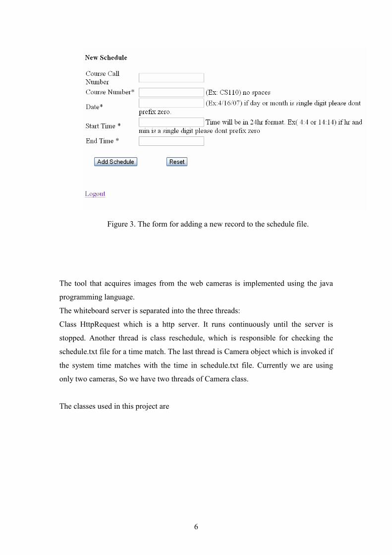
User interface for the scheduler
The user interface which allows us to modify the schedule.txt file from a
remote machine is written in PHP and HTML. The URL for this would be
http://www.cve.cs.nmsu.edu/~agaddam/login.php . The user will be verified
by entering the username and password. Once the user is authenticated s/he
can add a record to the schedule.txt file. This new record will be checked by
the program accordingly and once it is time is matched with the system time
the program will start acquiring images from the web camera.
Screenshots of the scheduler web interface
Figure 2. The whiteboard scheduler login screen
6
Figure 3. The form for adding a new record to the schedule file.
The tool that acquires images from the web cameras is implemented using the java
programming language.
The whiteboard server is separated into the three threads:
Class HttpRequest which is a http server. It runs continuously until the server is
stopped. Another thread is class reschedule, which is responsible for checking the
schedule.txt file for a time match. The last thread is Camera object which is invoked if
the system time matches with the time in schedule.txt file. Currently we are using
only two cameras, So we have two threads of Camera class.
The classes used in this project are

7
Figure 1. Whiteboard Class Diagram
3.1 Whiteboard:
This is the main class and is responsible for invoking and starting the server.
3.2 Readschedule:
This class continuously reads the schedule.txt file which contains the class
schedule. The schedule.txt file has the following format.
endtime starttime date courseno Coursecallno
2:15 1:12 9/21/06 CS571 10115
The Date format used is (mm/dd/yy). If the day or month is a single digit we
do not prefix zero. For example 7/12/07 is a valid date format but 07/12/07 is
not. Time must be in 24hr format. If hour or minutes is a single digit, we
should not prefix it with zero (Ex: 4:4 is valid but 04:04 is invalid).
The Readschedule class compares the course schedule time and date with the
current system time and date respectively. If there is a match, it invokes the
Camera. The Camera object is responsible for storing the images continuously
until the system time reaches the class endtime.
8
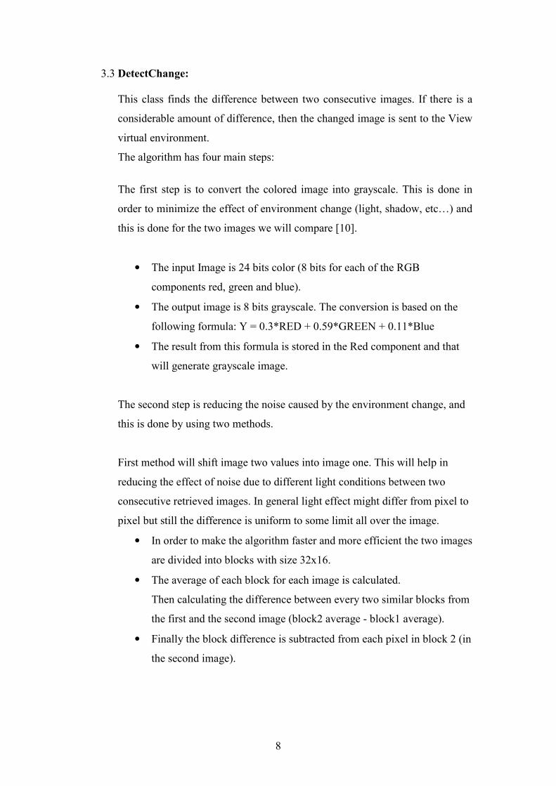
3.3 DetectChange:
This class finds the difference between two consecutive images. If there is a
considerable amount of difference, then the changed image is sent to the View
virtual environment.
The algorithm has four main steps:
The first step is to convert the colored image into grayscale. This is done in
order to minimize the effect of environment change (light, shadow, etc…) and
this is done for the two images we will compare [10].
• The input Image is 24 bits color (8 bits for each of the RGB
components red, green and blue).
• The output image is 8 bits grayscale. The conversion is based on the
following formula: Y = 0.3*RED + 0.59*GREEN + 0.11*Blue
• The result from this formula is stored in the Red component and that
will generate grayscale image.
The second step is reducing the noise caused by the environment change, and
this is done by using two methods.
First method will shift image two values into image one. This will help in
reducing the effect of noise due to different light conditions between two
consecutive retrieved images. In general light effect might differ from pixel to
pixel but still the difference is uniform to some limit all over the image.
• In order to make the algorithm faster and more efficient the two images
are divided into blocks with size 32x16.
• The average of each block for each image is calculated.
Then calculating the difference between every two similar blocks from
the first and the second image (block2 average - block1 average).
• Finally the block difference is subtracted from each pixel in block 2 (in
the second image).
9
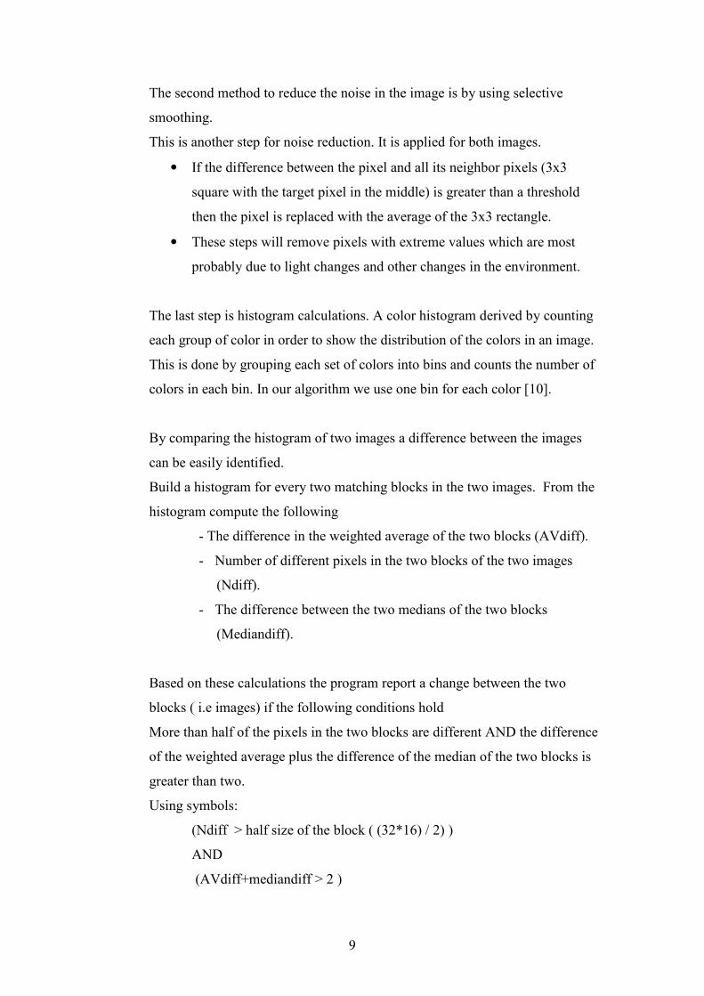
The second method to reduce the noise in the image is by using selective
smoothing.
This is another step for noise reduction. It is applied for both images.
• If the difference between the pixel and all its neighbor pixels (3x3
square with the target pixel in the middle) is greater than a threshold
then the pixel is replaced with the average of the 3x3 rectangle.
• These steps will remove pixels with extreme values which are most
probably due to light changes and other changes in the environment.
The last step is histogram calculations. A color histogram derived by counting
each group of color in order to show the distribution of the colors in an image.
This is done by grouping each set of colors into bins and counts the number of
colors in each bin. In our algorithm we use one bin for each color [10].
By comparing the histogram of two images a difference between the images
can be easily identified.
Build a histogram for every two matching blocks in the two images. From the
histogram compute the following
- The difference in the weighted average of the two blocks (AVdiff).
- Number of different pixels in the two blocks of the two images
(Ndiff).
- The difference between the two medians of the two blocks
(Mediandiff).
Based on these calculations the program report a change between the two
blocks ( i.e images) if the following conditions hold
More than half of the pixels in the two blocks are different AND the difference
of the weighted average plus the difference of the median of the two blocks is
greater than two.
Using symbols:
(Ndiff > half size of the block ( (32*16) / 2) )
AND
(AVdiff+mediandiff > 2 )
10
3.4 Camera:
This class is responsible for getting the images from the web cameras. The
images are stored in JPEG format. The directory hierarchy is set with respect
to the course number followed by date and the start time.
First the raw images are fetched in a directory hierarchy named as cam2 and
cam4 (here we are using only 2 cameras as our image source, if the number of
cameras is increasing, the number of directories should also be increased),
images from these directories are cropped and scaled to a perfect rectangle.
Then these images are copied to rectcam2 and rectcam4 directories
respectively.
Example of a directory hierarchy:
If course number is CS571 and date: 21st Sept 2006 and time is 13:15, then
images for this session is stored in cam2/CS571/9_21_06/13_15/ and cam4/
CS571/9_21_06/13_15/ respectively.
After rectification each image is again sent to the following directory
rectcam2/CS571/9_21_06/13_15 and rectcam4/CS571/9_21_06/13_15
directories respectively.
After applying the image difference algorithm the changed images are copied
to changecam2/CS571/9_21_06/13_15 and
changecam4/CS571/9_21_06/13_15 directories respectively.
The file names for the images are numeric starting with zero (0.jpeg) and each
time a new image retrieved the file name is incremented by one.
3.5 HttpRequest:
This class implements the web server. It will listen for the requests from the
client and sends the response accordingly. The client can send the request
using a standard web browser.
The client can make a request using the following URL:

11
http://cve.cs.nmsu.edu:4550//home/agaddam/rectcam2/current.html.
In the above URL rectcam2 is the home directory for the images and
current.html contains the path of the latest image. By using the path in the
current.html file, the client can get the latest image from the server.
3.6 RGBValues
This class stores the RGB values of a particular pixel of an image.

12
4.0 Implementation
Packages used in the implementation
Java advanced imaging
Java advanced imaging intends to meet the requirements of all of the different
imaging markets. JAI supports cross-platform, distributed imaging. The API is
object-oriented, device independent and powerful [1].
Java Media Framework
The Java Media Framework API allows developers to incorporate various media
types into Java applets and applications, and supports the capture, transmission,
playback and transcode of many types of audio and video. There's an
implementation written in 100% Pure Java, so the code can be ported onto any
supported Java platform [2].
Implementation in the View virtual environment
The images are sent to the VIEW virtual environment through HTTP protocol, where
the images are updated as textures on the virtual whiteboard and viewed by the
students in the virtual environment.
When there is a change between two consecutive images, the changed image is sent to
changimg2 and changeimg4 directories respectively. At the same time current2.html
and current4.html files are updated. These files contain the current image which is
detected by the algorithm as changed image. Using the current2.html and
current4.html files, the VIEW client fetches the images from the Whiteboard server.
If the VIEW client has no internet connection or the whiteboard server is down, then
"whiteboard is down" image is shown in the whiteboard.

13
Screenshots of the virtual whiteboard in VIEW virtual environment
Figure 4. Virtual whiteboard with "Whiteboard is down" message.

14
Figure 5. Virtual whiteboard with some text written on it.
Figure 6. Virtual whiteboard without any text written.

15
5.0 Evaluation Results
The following are image samples taken by the web camera and retrieved using the
whiteboard program.
The difference algorithm identifies that there is a considerable difference between the
following two images.
16
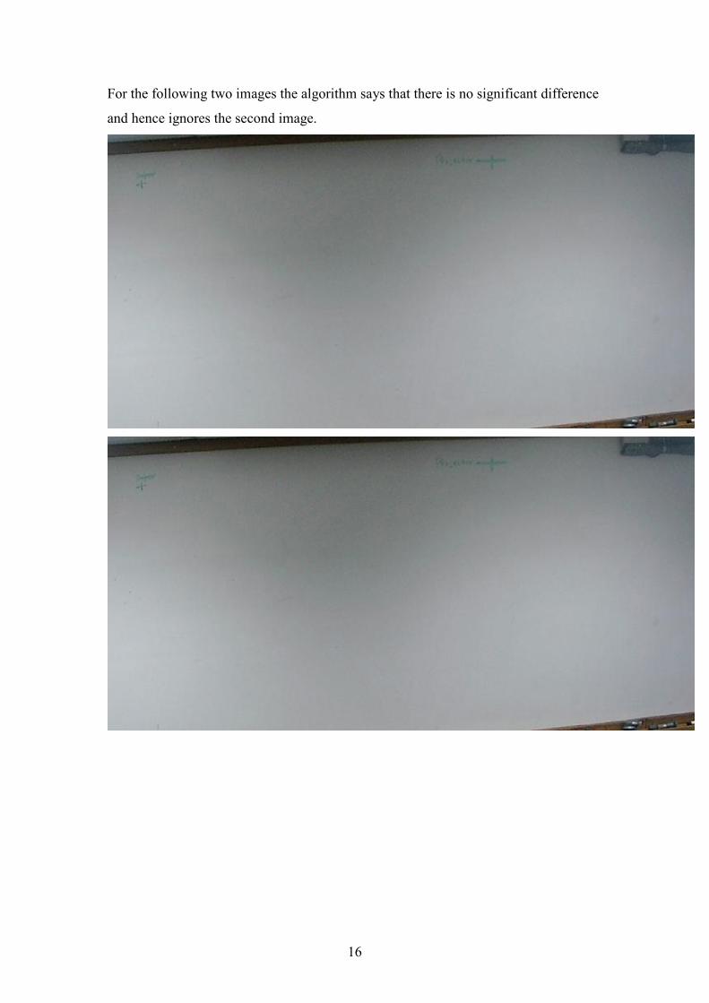
For the following two images the algorithm says that there is no significant difference
and hence ignores the second image.
17
The whiteboard server was tested on a computer science class in New Mexico State
university. The class is CS510 (Automata, Languages, Computability), and the tests
was taken on 4/29/07 with 15 minutes for each of the two conducted tests. The
purpose of the test is to check how much time it take the program to get the images,
process them using the difference algorithm and save them in the disk.
The test was conducted on the CVE machine with the following specifications:
Intel® Pentium® 4 CPU 3.00 GHz, Cache Size 1024Kb, Linux Swap memory 1024
MB, RAM 512 MB.
Test 1
This test was conducted in 4/29/07 and it started from 9:31 and end at 9:45. After the
end of the test the program retrieved 112 images from the web camera. But after using
the difference algorithm the numbers of images with considerable changes from the
112 images are 58 images.
The following table (Table.1) shows the image name and the time (in seconds) the
program takes to:
• Retrieve from the web camera.
• Check the difference between the new image and the previous image.
• Save the image on the disk.
Image Time(sec)
0.jpeg 3
1.jpeg 2
2.jpeg 2
3.jpeg 2
4.jpeg 2
5.jpeg 2
6.jpeg 2
7.jpeg 2
8.jpeg 2
9.jpeg 2
10.jpeg 2
11.jpeg 2
12.jpeg 1
13.jpeg 2
14.jpeg 1
15.jpeg 1
16.jpeg 1
17.jpeg 1
18.jpeg 2
18
19.jpeg 1
20.jpeg 2
21.jpeg 1
22.jpeg 1
23.jpeg 2
24.jpeg 1
25.jpeg 2
26.jpeg 1
27.jpeg 1
28.jpeg 2
29.jpeg 1
30.jpeg 1
31.jpeg 1
32.jpeg 1
33.jpeg 2
34.jpeg 2
35.jpeg 2
36.jpeg 1
37.jpeg 2
38.jpeg 2
39.jpeg 2
40.jpeg 2
41.jpeg 2
42.jpeg 2
43.jpeg 2
44.jpeg 2
45.jpeg 3
46.jpeg 2
47.jpeg 2
48.jpeg 2
49.jpeg 2
50.jpeg 1
51.jpeg 2
52.jpeg 1
53.jpeg 1
54.jpeg 2
55.jpeg 2
56.jpeg 2
57.jpeg 2
58.jpeg 2
59.jpeg 1
60.jpeg 1
61.jpeg 2
62.jpeg 1
63.jpeg 2
64.jpeg 2
65.jpeg 2
66.jpeg 2
67.jpeg 2
68.jpeg 2
69.jpeg 1
70.jpeg 1
71.jpeg 2
72.jpeg 1
73.jpeg 1
74.jpeg 2
75.jpeg 2
76.jpeg 2

19
77.jpeg 1
78.jpeg 2
79.jpeg 1
80.jpeg 1
81.jpeg 1
82.jpeg 1
83.jpeg 2
84.jpeg 1
85.jpeg 1
86.jpeg 1
87.jpeg 1
88.jpeg 2
89.jpeg 1
90.jpeg 1
91.jpeg 2
92.jpeg 2
93.jpeg 2
94.jpeg 1
95.jpeg 1
96.jpeg 2
97.jpeg 2
98.jpeg 2
99.jpeg 1
100.jpeg 2
101.jpeg 2
102.jpeg 2
103.jpeg 2
104.jpeg 2
105.jpeg 2
106.jpeg 2
107.jpeg 2
108.jpeg 2
109.jpeg 2
110.jpeg 1
111.jpeg 1
Table 1. Results from conducting test1.
20
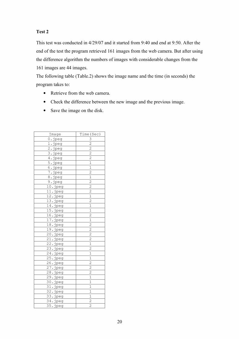
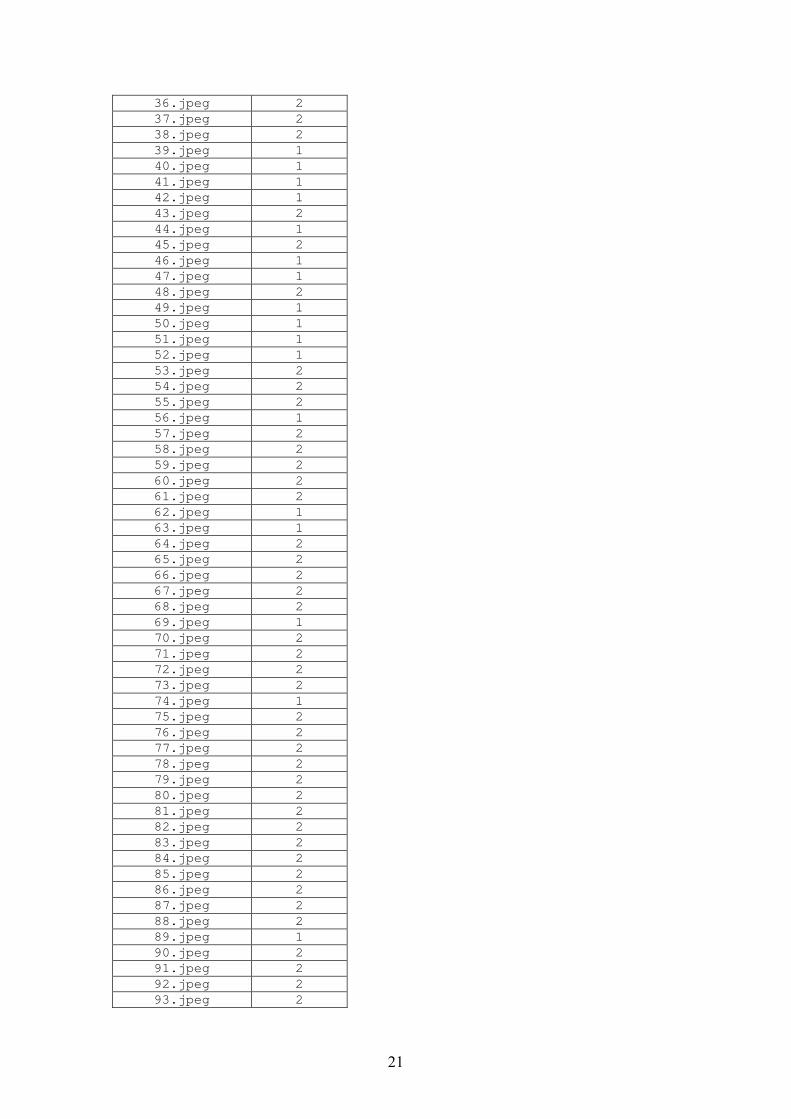
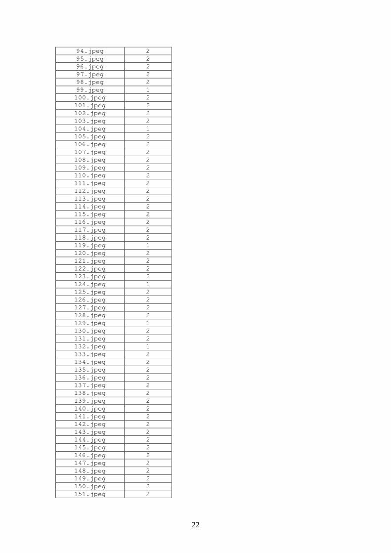
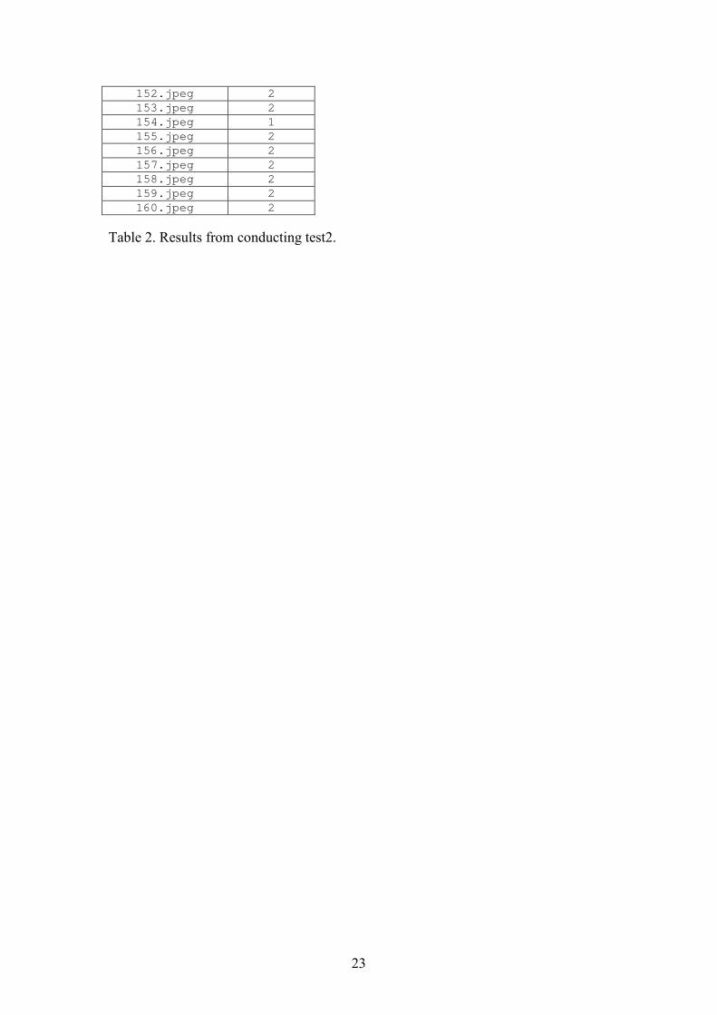
Test 2
This test was conducted in 4/29/07 and it started from 9:40 and end at 9:50. After the
end of the test the program retrieved 161 images from the web camera. But after using
the difference algorithm the numbers of images with considerable changes from the
161 images are 44 images.
The following table (Table.2) shows the image name and the time (in seconds) the
program takes to:
• Retrieve from the web camera.
• Check the difference between the new image and the previous image.
• Save the image on the disk.
Image Time(Sec)
0.jpeg 3
1.jpeg 2
2.jpeg 2
3.jpeg 2
4.jpeg 2
5.jpeg 1
6.jpeg 1
7.jpeg 2
8.jpeg 1
9.jpeg 2
10.jpeg 2
11.jpeg 2
12.jpeg 1
13.jpeg 2
14.jpeg 1
15.jpeg 1
16.jpeg 2
17.jpeg 1
18.jpeg 2
19.jpeg 2
20.jpeg 2
21.jpeg 2
22.jpeg 1
23.jpeg 2
24.jpeg 1
25.jpeg 1
26.jpeg 2
27.jpeg 2
28.jpeg 2
29.jpeg 1
30.jpeg 1
31.jpeg 1
32.jpeg 1
33.jpeg 1
34.jpeg 2
35.jpeg 2
21
36.jpeg 2
37.jpeg 2
38.jpeg 2
39.jpeg 1
40.jpeg 1
41.jpeg 1
42.jpeg 1
43.jpeg 2
44.jpeg 1
45.jpeg 2
46.jpeg 1
47.jpeg 1
48.jpeg 2
49.jpeg 1
50.jpeg 1
51.jpeg 1
52.jpeg 1
53.jpeg 2
54.jpeg 2
55.jpeg 2
56.jpeg 1
57.jpeg 2
58.jpeg 2
59.jpeg 2
60.jpeg 2
61.jpeg 2
62.jpeg 1
63.jpeg 1
64.jpeg 2
65.jpeg 2
66.jpeg 2
67.jpeg 2
68.jpeg 2
69.jpeg 1
70.jpeg 2
71.jpeg 2
72.jpeg 2
73.jpeg 2
74.jpeg 1
75.jpeg 2
76.jpeg 2
77.jpeg 2
78.jpeg 2
79.jpeg 2
80.jpeg 2
81.jpeg 2
82.jpeg 2
83.jpeg 2
84.jpeg 2
85.jpeg 2
86.jpeg 2
87.jpeg 2
88.jpeg 2
89.jpeg 1
90.jpeg 2
91.jpeg 2
92.jpeg 2
93.jpeg 2
22
94.jpeg 2
95.jpeg 2
96.jpeg 2
97.jpeg 2
98.jpeg 2
99.jpeg 1
100.jpeg 2
101.jpeg 2
102.jpeg 2
103.jpeg 2
104.jpeg 1
105.jpeg 2
106.jpeg 2
107.jpeg 2
108.jpeg 2
109.jpeg 2
110.jpeg 2
111.jpeg 2
112.jpeg 2
113.jpeg 2
114.jpeg 2
115.jpeg 2
116.jpeg 2
117.jpeg 2
118.jpeg 2
119.jpeg 1
120.jpeg 2
121.jpeg 2
122.jpeg 2
123.jpeg 2
124.jpeg 1
125.jpeg 2
126.jpeg 2
127.jpeg 2
128.jpeg 2
129.jpeg 1
130.jpeg 2
131.jpeg 2
132.jpeg 1
133.jpeg 2
134.jpeg 2
135.jpeg 2
136.jpeg 2
137.jpeg 2
138.jpeg 2
139.jpeg 2
140.jpeg 2
141.jpeg 2
142.jpeg 2
143.jpeg 2
144.jpeg 2
145.jpeg 2
146.jpeg 2
147.jpeg 2
148.jpeg 2
149.jpeg 2
150.jpeg 2
151.jpeg 2
23
152.jpeg 2
153.jpeg 2
154.jpeg 1
155.jpeg 2
156.jpeg 2
157.jpeg 2
158.jpeg 2
159.jpeg 2
160.jpeg 2
Table 2. Results from conducting test2.
24
6.0 Program Execution steps
First install the following packages and software:
• Java advanced imaging
• Java Media Framework
• JDK 1.4
In order to compile and execute the tool do the following commands:
javac Whiteboard.java -classpath jmf.jar
To run the tool we use the following command which also increases the heap
space for the java virtual machine
java -Xms64m -Xmx128m Whiteboard
To deploy this tool in any other server:
The user needs to change the following variables in whiteboard. java file:
• Root=”/home/agaddam/RaJava , This variable has multiple occurrences in
different classes so you need to change it accordingly.
• In the following PATH refers to the directory you intend to place the
program in your home directory (Ex:here my path would be
/home/agaddam/RaJava).
S2 ="/PATH/cam2/"+courseno+"/"+date+"/"+time+"/";
S5 ="/PATH/cam4/"+courseno+"/"+date+"/"+time+"/";
SSS2 ="/PATH/rectcam4/"+courseno+"/"+date+"/"+time+"/";
SS2="/PATH/rectcam2/"+courseno+"/"+date+"/"+time+"/";
Here courseno, date and time are system variables. rectcam4, rectcam2,
cam2 and cam4 are home directories for the cameras.
Also you have to change the following variables accordingly.
cam2dir="/PATH/cam2/"+courseno+"/"+date+"/"+time+"/";
cam4dir="/PATH/cam4/"+courseno+"/"+date+"/"+time+"/";
rectcam2dir="/PATH/rectcam2/"+courseno+"/"+date+"/"+time+"/";
rectcam4dir="/PATH/rectcam4/"+courseno+"/"+date+"/"+time+"/";
changeimg2="/PATH/changeimg2/"+courseno+"/"+date+"/"+time+"/";
changeimg4="/PATH/changeimg4/"+courseno+"/"+date+"/"+time+"/";
25
• Along with the above changes you also need to mention the URL for the
cameras. In our program we use the following URL’s for the Cameras.
The camera URLs are stored in the following variables
address = "http://cscam2.cs.nmsu.edu/__live.jpg?&&&";
address = "http://cscam4.cs.nmsu.edu/__live.jpg?&&&";
The variable address (mentioned above) is present in two places.
When the variable threadcontrol is 1 it is for cam2, so you have to mention
the url for cam2 here as address =
"http://cscam2.cs.nmsu.edu/__live.jpg?&&&"; (use the new web camera
address instead of this).
When the variable threadcontrol is 2 it is for cam4, so you have to mention
the url for cam4 here as address =
"http://cscam4.cs.nmsu.edu/__live.jpg?&&&"; (use the new web camera
address instead of this)
26
7.0 Related Work
The limitation of ordinary whiteboard is that it is not connected to a computer [9].
In the study [5] SimulNet is a framework developed in order to build interactive
collaborative distance learning application. This framework has several components
and services (e.g. video and audio conferencing, e-whiteboards, etc.) that can be used
by programmers to develop distance learning applications.
One of the components of SimulNet is the virtual electronic whiteboard. This
component can be included to exchange information drawn by the users. The users
who are in the whiteboard session can navigate through different whiteboard contents.
Also, this component can be used to present slides in the virtual whiteboard [5].
Another work [6] discuss the technologies (IP video, streaming video, and
collaboration tools) used in the classroom and compare between them.
A streaming video can be used to present different types of classroom materials. This
includes whiteboard, slide show, classroom lecture and demonstration using a
computer screen.
When using streaming video for educational purposes have some problems. For
example, some contents like text will not be clearly shown in the video. Also, in order
to get a good quality streaming it requires an internet with high speed [6].
In the work of Ovaska, Hietala, and Kangassalo an electronic whiteboard is used to
improve the team learning by a group of children's in kindergarten [7].
Virtual videography [8] is used with whiteboard and blackboard at a classroom in
order to present them to distance audience in different presentation styles after editing
their video. This work provides a video and photos for the lecture automatically.
To develop virtual videography several technologies are used to create different new
images from the source and this include signal processing, computer vision and image
synthesis.
27
To remove the instructor from the image or make him/her more transparent several
methods were used. Also, In order to specify instructor location in each frame
tracking is used.
In this work gesture recognition is used to specify what gestures the instructor
performing in the classroom[8].
This work presume that showing the instructor in the video is important and it provide
four different views of the video: Long shot, board medium shot, board closeup shot
and instructor closeup shot [8].
In order for the virtual videography to present a clear image of the whiteboard or
blackboard the scene of the taken shot has to be clear and it is taken in a classroom
that is well lighted [8].
28
References
1. Java advanced imaging http://java.sun.com/products/java-
media/jai/forDevelopers/jai1_0_1guide-unc/Introduction.doc.html
2. Java Media Framework http://java.sun.com/products/java-media/jmf/
3. Jeffery C., Mohamed S., Parlett R., Pereda R.: Unicon book “Programming
with Unicon". (1999-2003), published by the Free Software Foundation.
Available at <http://unicon.org/book/ub.pdf>
4. Bukka, S. Representing 3d objects in a virtual environment, February, 2006
Project Report for the final exam of Master of Science in Computer Science.
5. Anido-Rifón, L., M. Llamas-Nistal, and M.J. Fernández-Iglesias. A component
model for stardardized web-based education. in International World Wide
Web Conference 2001
6. Leonard, J., E. Riley, and E.M. Staman. Classroom and support innovation
using IP video and data collaboration techniques. in Conference On
Information Technology Education 2003
7. Ovaska, S., P. Hietala, and M. Kangassalo. Electronic whiteboard in
kindergarten: opportunities and requirements. in Interaction Design And
Children. 2003
8. Heck, R., M. Wallick, and M. Gleicher, Virtual videography. ACM
Transactions on Multimedia Computing, Communications, and Applications
(TOMCCAP), 2007 2(1).
9. Mynatt, E. (1999) . The writing on the wall . Proceedings ofHuman-Computer
Interaction - INTERACT '99. IOS Press, 1999, 196-204.
10. Gonzalez, R.C. and R.E. Woods, Digital Image Processing. Second ed. 2002:
Prentice-Hall.