
Developing a low-cost, heavy-duty reconnaissance robot for ...
103
1 DIVISION OF PRODUCT DEVELOPMENT | DEPARTMENT OF DESIGN SCIENCES FACULTY OF ENGINEERING LTH | LUND UNIVERSITY 2016 MASTER THESIS Björn Reiner and Marcus Svensson Mimer - Developing a low-cost, heavy-duty reconnaissance robot for use in Urban Search and Rescue operations
-
Upload
khangminh22 -
Category
Documents
-
view
0 -
download
0
Transcript of Developing a low-cost, heavy-duty reconnaissance robot for ...

1
DIVISION OF PRODUCT DEVELOPMENT | DEPARTMENT OF DESIGN SCIENCES FACULTY OF ENGINEERING LTH | LUND UNIVERSITY 2016
MASTER THESIS
Björn Reiner and Marcus Svensson
Mimer - Developing a
low-cost, heavy-duty
reconnaissance robot for
use in Urban Search and
Rescue operations

2
Mimer
Developing a
low-cost, heavy-duty reconnaissance robot for use in Urban Search
and Rescue operations
Björn Reiner and Marcs Svensson
3
Mimer
Developing a low-cost, heavy-duty reconnaissance robot for use in Urban Search and Rescue
operations
Copyright © 2016 Björn Reiner, Marcus Svensson
Published by
Department of Design Sciences
Faculty of Engineering LTH, Lund University
P.O. Box 118, SE-221 00 Lund, Sweden
Subject: Machine Design for Engineers (MMK820)
Division: Product Development
Supervisor: Olaf Diegel
Examiner: Giorgos Nikoleris

4
Abstract
Robots currently exist that are specifically designed for use in the wake of disasters to help rescue teams in
their work of locating and rescuing individuals trapped in confined spaces. However, they are prohibitively
expensive which limits their adoption and causes the operators to think twice before they're deploying a
robot with the risk of losing or damaging it.
This project details the first part of a multistage process to explore the field of rescue robotics with the aim
to produce an Unmanned Ground Vehicle robot to be used in Urban Search and Rescue missions. The main
purpose of it is to quickly gather critical data about the environment to help rescue personnel in their work.
The robot is specified to be cheap enough to allow it to be considered expendable and not impede its usage
in the field. It would also be designed to be rugged in order to survive the harsh operating environment with
drops from several meters and to be dust- and waterproof. It would be equipped with a camera for navigation
and a replaceable sensor module to allow it to switch sensors before being deployed. The project resulted
in the development of a proof-of-concept robot that can move with a camera and a slot in the chassis to
allow a sensor module to be implemented in the future. Additional suggestions for future developments to
complete a production version are described in the concluding chapter of the document along with proposed
project descriptions in the appendix section.
Keywords: robot, search and rescue, robust, sensors, simple

5
Sammanfattning
Det finns idag robotar som är särskilt anpassade för att användas av räddningsteam i följderna av katastrofer
som hjälpmedel i deras arbete att lokalisera och rädda människor instängda i trånga utrymmen. De är dock
mycket dyra vilket begränsar deras användande och gör att användarna tvekar innan de skickar in en robot
med risken att skada eller förlora den.
Detta projekt dokumenterar det första steget i en flerstegsprocess att utforska området för räddningsrobotar
med slutmålet att producera en obemannad markrobot för användning i urbana sök och räddningsaktioner.
Huvudmålet med roboten är att den ska snabbt kunna samla kritisk data om räddningsområdet för att hjälpa
räddningspersonalen i deras arbete. Roboten är specificerad att vara tillräckligt billig för att den ska kunna
anses förbrukningsbar och inte vara ett hinder för att den ska användas. Den ska även vara robust för att
kunna klara av den tuffa arbetsmiljön med fall från flera meter vara och vatten- och damm tålig. Den ska
utrustas med en kamera för navigering och en utbytbar sensormodul för att kunna byta utrustas med
lämpliga sensorer innan den skickas in. Projektet resulterade i tillverkningen av en s.k. proof-of-concept
robot som kan förflytta sig och som har en kamera och en plats i chassit för implementering av en
sensormodul. Ytterligare förslag på förbättringar och framtida utveckling beskrivs i det avslutande kapitlet
tillsammans med föreslagna projektbeskrivningar i avsnittet för bilagor.
Nyckelord: robot, search and rescue, robust, sensorer, enkel

6
Acknowledgments
The authors would like to thank Olaf Diegel and Giorgos Nikoleris for their valued input and guidance
during the course of the project. We also want to thank Jonny Nyman, Göran Larsson and all other staff at
the workshop in Ingvar Kamprad Designcentrum for helping us build the robot and find the tools we were
looking for. Finally, we thank Katarina-Elner Haglund for her advice regarding the injection-molding
characteristics of the robot.
Lund, August 2016
Björn Reiner and Marcus Svensson

7
Table of Contents 1 Motivate ..................................................................................................................................................... 1
Background ............................................................................................................................................... 1
1.1 Mission statement ............................................................................................................................... 2
2 Plan ............................................................................................................................................................ 3
2.1 Project setup ........................................................................................................................................ 3
2.2 Constraints and design specifications ................................................................................................. 4
2.3 Planning the execution of the project .................................................................................................. 6
3 Explore ....................................................................................................................................................... 8
3.1 Choosing the initial design .................................................................................................................. 8
3.2 Studying existing designs ................................................................................................................. 11
Recon Scout Throwbot® XT ..................................................................................................... 11
SCARAB robot .......................................................................................................................... 12
LittleBot Junior robot ................................................................................................................. 13
Sphero Ollie ............................................................................................................................... 13
3.3 Problem decomposition .................................................................................................................... 20
4 Develop .................................................................................................................................................... 22
4.1 Control .............................................................................................................................................. 22
Microcontroller .......................................................................................................................... 22
Communication .......................................................................................................................... 25
4.2 Power ................................................................................................................................................ 28
Internal battery ........................................................................................................................... 28
Charging port ............................................................................................................................. 29
4.3 Sensors .............................................................................................................................................. 31
Camera ....................................................................................................................................... 31
Gas & temperature ..................................................................................................................... 31
4.4 Locomotion ....................................................................................................................................... 32
Motors ........................................................................................................................................ 32
Wheels & suspension ................................................................................................................. 34
Drivetrain ................................................................................................................................... 51
4.5 Chassis .............................................................................................................................................. 53
Ingress protection ....................................................................................................................... 57
Impact resistance ........................................................................................................................ 59
Cost ............................................................................................................................................ 62
Component Mounting ................................................................................................................ 65
5 Present ...................................................................................................................................................... 69

8
6 Discuss ..................................................................................................................................................... 75
6.1 Future work ....................................................................................................................................... 75
Combine all separate circuit boards into one unit and develop sensor platform ................................. 76
Control ....................................................................................................................................... 76
Power ......................................................................................................................................... 77
Sensors ....................................................................................................................................... 77
Locomotion ................................................................................................................................ 78
Chassis ....................................................................................................................................... 79
References ................................................................................................................................................... 80
F.1 Mimer – development of integrated circuitry ................................................................................... 15
F.2 Mimer – development of testing environment .................................................................................. 15
F.3 Mimer – development of chassis & locomotion ............................................................................... 15
F.4 Mimer – development of Human-Machine Interface ....................................................................... 15

1
1 Motivate
Here the writers will introduce the reader to the reasons for pursuing this project and in what context its
results will be useful.
Background
Humans have a unique ability to reshape nature to our will and erect buildings and structures that are used
for accommodation, infrastructure or simply for visually appealing sculptures. It’s a process named
architecture that started thousands of years ago which has evolved to our present day and is now highly
efficient and advanced that has allowed us to build bigger, taller and stronger buildings and structures in
less time to suit our needs. However, these structures are not indestructible and can sometimes fail
unexpectedly and endanger human lives. These failures can be due to natural disasters, terrorist attacks or
faulty engineering and can create dangerous and inhospitable environments where humans are trapped and
require immediate help. Most notable examples are the attack on WTC in 2001, hurricane Katrina in 2005,
the earthquake in Haiti in 2010 and the tsunami wave in Japan in 2011 with the following failure of the
Fukushima nuclear plant. In those circumstances an Urban Search and Rescue team (USAR) is required
whose task is to locate and extract people trapped in these environments. They utilize many different
resources for these operations including custom tools, trained dogs and vehicles. Unmanned Aerial Vehicles
(UAVs), Unmanned Marine Vehicles (UMVs) and Unmanned Ground Vehicles (UGVs) specifically
designed to traverse and navigate these dangerous and hard to reach places have also been adopted in the
field. These robots are generally remotely controlled by a human operator with various degrees of autonomy
and are used to gather information about the surroundings. Fully autonomous UAVs exist and are generally
being used to gather topology data during rescue operations (Murphy, 2016). The cost of these robots vary
wildly but UAVs have dramatically dropped in price since the rapid sales growth of commercial models
such as the DJI Phantom and Parrot AR Drone. A UAV might be able to navigate and assist inside certain
collapsed structures but since they need to be airborne they require a large, unobstructed air corridor in
order to not hit and damage its delicate propeller blades. It also wouldn’t be able to investigate fires in
confined spaces due to the smoke that obfuscates the vision and high heat that would cause parts to melt
and cripple it. UGVs still maintain a higher cost primarily due to the low consumer interest in such models
and the increased complexity of traversing the terrain such as debris, rocks and crevices. It’s not atypical
for UGVs to cost 10 000 $ and upwards which is due to their technical complexity with many specialized
components and sensors which are produced in limited series. This high cost impedes their adoption and
use of USAR teams around the world.

2
1.1 Mission statement
This project is the first part of a multi-step effort with the goal to lower the barrier of entry for using UGVs
in Urban Search and Rescue operations. This paper will begin to explore this field and construct a proof-
of-concept to be used as a starting point for subsequent projects. The end goal of this multi-step process is
the development of a small, rugged and low-cost model that’s using readily available off-the-shelf
components to the greatest extent. The purpose of the robot is to be quick and easy to deploy in order to
rapidly gather initial critical data about the environment by using cameras and sensors. A key point with
the model is that the cost shall not be an impediment for its usage; if it gets stuck or destroyed then a new
unit would simply be deployed to replace it.

3
2 Plan
After specifying the mission of the project the plan for the actual execution of the project is presented. Here
the writers will describe how it will be carried out and what constraints are required in order to complete
the goals detailed in the mission statement within the allotted time- and budget constraints.
2.1 Project setup
This robot will be jointly created by two Mechanical Engineering students, Björn Reiner and Marcus
Svensson. Björn Reiner is majoring in product development and his responsibilities will include:
Physical design
Mechanical aspects of robot
CAD-drawing
while Marcus Svensson is majoring in mechatronics and will focus on:
Choosing and developing electrical components
Programming the robot
Wiring and assembling of electrical components
The writers will have access to a fully equipped workshop in the same building as where the project will
be developed. It includes a high-quality 3D-printer capable of printing parts in a nylon polymer material
which will be used for manufacturing the prototype. The parts will be modeled in the CAD-software Creo
Parametric 3.0 made by PTC since it’s the software the writers are most familiar with using. The budget
for the project is set to 5 000 SEK or 600 USD.

4
2.2 Constraints and design specifications
This project will construct a prototype for display-purposes and as a proof-of-concept that can be used for
further testing and exploration of the concept. It will not investigate or develop the production line for this
robot; instead it will give recommendations and suggestions for the further development of this product in
order to make it fully commercially viable.
Since this project will not create a production-model of the robot its characteristics will not be the same as
the final version. Therefore, some proposed tests and specifications of the final production model will be
adjusted or omitted for testing the prototype. For example, the chassis will be manufactured using a 3D-
printer and while it can have good mechanical characteristics it cannot fully simulate an injection-molded
part. The team will therefore adapt certain specifications and argue that with reasonable assumptions
regarding improvement potential of the final design the specifications can be fulfilled.
Ruggedness
The robot will be operating in hostile environments with many potential hazards. Therefore, it needs to be
able to handle abuse and foreign contaminants. The following specifications detail what the final robot
design is supposed to be able to handle:
Capable of being dropped from a height of 3 m without sustaining damage
An IP-classification of at least IP65 to prevent dust- and water particles from entering and
damaging the robot
Capable of being deployed into the field by throwing or with an air-cannon
Modularity
The main purpose of the robot is to gather critical data for the user and since cost is an important factor in
its design it’s not feasible for it to contain multiple sensors. Therefore, it’s better for the hardware to be
modular and allow different sensors to be inserted for specific scenarios. This project will develop a design
that has a slot available for the insertion of different sensors and will propose a project for implementing it
in the final version:
Modular design to allow each robot to easily be setup up with a single sensor type
(temperature, microphone, camera, gas, etc.)
Portability
The robot is meant to be small and lightweight enough to be carried by a single person to the desired location
and then deployed with the desired method.
Small enough to allow one person to carry it
Light enough to allow one person to carry it
Cost
A big focus of the project will be the cost of the robot in order to prevent it from becoming an impediment
for deploying it. It should be kept low enough that it can be considered expendable and used for “suicide
missions” in order to gather critical data. This is a goal and not a fixed number that must be achieved; it’s
a target that will guide the decisions regarding the components in the robot:
Production cost of less than 100 USD per robot

5
Terrain capability
The terrain will undoubtedly be varied and being able to overcome obstacles will be an important issue to
consider. A proper balance between size, longevity and weight needs to be achieved in order to maximize
its usefulness in the field:
Battery life of at least 60 min to have sufficient time to explore and possibly recover the robot
Capable of navigating over gravel and stones up to a size of 50 mm
Locomotion
The robot will most likely be out of sight and far away from the operator during operation. The likely
scenario of the robot going around corners or down crevices also emphasize tether-less operation along
with visual feedback about the surroundings.
Tether-less operation using an independent, intuitive remote control
Provide visual feedback about the surroundings
The proposed final specifications are summarized in Table 1 below with test methods for validation:
Table 1 final design specifications
Specification Goal Test Method
Ruggedness Survive 3 m drop Drop test
IP65 rating IP65 standard testing
Deploy by throwing or using air
cannon
Deployment test with manual throw
and air cannon
Modularity Replaceable sensor design Sensor switch test
Portability Small enough to allow one person
to carry it
Size measurement and carrying test
Light enough to allow one person to
carry it
Weight measurement and carrying
test
Cost Less than 100 $ Cost calculation
Terrain capability Climbing objects up to 50 mm Obstacle course
Minimum 60 min battery life Battery life calculation and runtime
test
Tether-less operation with at least 10
– 15 m signal range
Signal range tests
Visual feedback Video capture test

6
2.3 Planning the execution of the project
The project will be carried out using an adapted version of the Product Development process detailed in the
book Product Design and Development (Ulrich & Eppinger, 2012). This project will only include the tasks
and phases of the process that’s deemed useful for the development of this prototype and add others deemed
necessary. The original version divides the development of a new product in six distinct phases:
Planning
Concept Development
System-Level Design
Detail Design
Testing and Refinement
Production Ramp-Up
This generic version is more geared towards developing a commercial product and includes both the
engineering, marketing and production aspects. Since this project will not develop a production line the
Production Ramp-Up phase becomes obsolete and will be omitted from the process. The Testing and
Refinement and Detail Design phases include many tasks that involves the marketing and production of the
product and is deemed not relevant for this project and any tasks that involve any engineering work will
instead be included in the System-Level Design phase. Table 2 below shows the generic Product
Development Process with included phases and tasks highlighted in green and excluded in red.
Table 2 Generic Product Development Process
PlanningConcept Develop-
mentSystem-Level
DesignDetail Design
Testing and Refinement
Production Ramp-Up
Marketing
Articulate market
opportunity
Define market segments
Collect customer needs.
Identify competitive
products.
Develop plan for product
options and extended
product family.
Develop marketing plan Develop promotion and
launch materials
Facilitate field testing.
Place early production with
key customers
Design
Consider product platform
and architecture.
Assess new technologies
Investigate feasibility of
product concepts
Develop industrial design
Build and test experimental
prototypes
Develop product
architecture
Define major sub-systems
and interfaces.
Refine industrial design.
Preliminary component
engineering.
Define part geometry.
Choose materials.
Assign tolerances.
Complete industrial design
control documentation.
Test overall performance,
reliability and durability.
Obtain regulatory
approvals.
Assess environmental
impact.
Implement design changes.
Evaluate early production
output.
Manufacturing
Identify production
constraints.
Set supply chain strategy.
Estimate manufacturing
cost.
Assess production
feasibility.
Identify suppliers for key
components.
Perform make-buy
analysis.
Define final assembly
scheme.
Define piece-part
production processes.
Design tooling.
Define quality assurance
processes.
Begin procurement of long-
lead tooling.
Facilitate supplier ramp-up.
Refine fabrication and
assembly processes.
Train workforce.
Refine quality assurance
processes.
Begin full operation of
production system.
Other Functions
Research: demonstrate available
technologies.
Finance: Provide planning
goals.
General Management: allocate project resources.
Finance: Facilitate economic
analysis.
Legal: Investigate patent issues.
Finance: Facilitate make-buy
analysis.
Service: Identify service issues.
Sales: Develop sales plan.
General Management:
Conduct post project
review.

7
The emphasis in this Product Development Process will be on quickly iterating the design(s) in order to get
relevant feedback and data and adjusting them accordingly. On page 19 in the book Product Design and
Development (Ulrich & Eppinger, 2012) the authors list different variants on the process and one of them
is called Quick-Build Products. A different name for this is spiral product development process (see Figure
1) and focuses on rapidly generating several cycles of design-build-test that can be repeated many times.
Figure 1 Spiral Product Development

8
3 Explore
After determining the goal and setup of the project; the field of rescue robotics is explored in this section.
3.1 Choosing the initial design
Before this project could proceed any further a decision had to be made regarding the general shape of the
robot. Due to the team’s small size and the project’s short time span it wouldn’t be feasible to investigate
different alternatives. Initially a spherical design was proposed, similar to the toy robot Sphero (see Figure
2 below) with all components housed inside a plastic shell. The advantages would mainly be its innate dust-
and water resistance and compact design.
Figure 2 Sphero spherical toy robot

9
But the writers had concerns whether this shape would be the most appropriate one for the robot’s purpose.
Instead a cylindrical design with two wheels was suggested, similar to the Sphero Ollie pictured below in
Figure 3, and then compared to the spherical design.
Figure 3 Sphero Ollie two-wheeled cylinder toy robot
The big concerns regarding the sphere was its ability to traverse terrain, shock absorption capabilities and
the extra difficulties that would arise from integrating all components inside a spherical plastic shell. The
sphere’s propulsion system works by rotating wheels inside the sphere against the inside wall of the ball
which causes the center of mass to no longer be parallel with the center of the sphere which causes the ball
to roll. See Figure 4 below for an illustration.
10
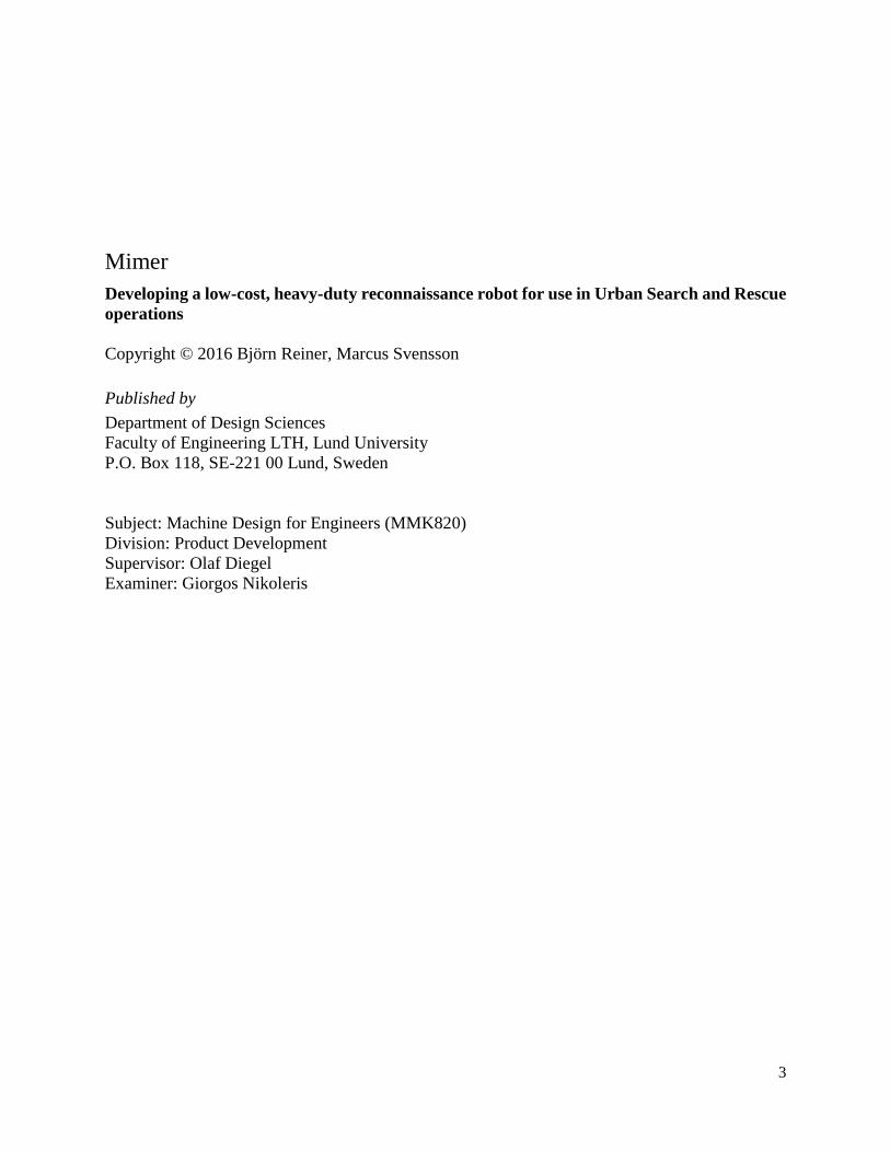
Figure 4 spherical propulsion system
This requires the components to be housed inside a sphere with a smooth inner surface which increases the
complexity and cost of the design. Since the wheels need to be the only parts in direct contact with the
plastic shell it causes the contact surface to be very small and increases the maximum amount of stress in
the design caused by high load impacts. In order to make this design shock-resistant some sort of suspension
is required which is difficult to implement in the restricted space inside the sphere. Using a cylinder design
with two wheels allows a suspension system and other parts to be placed outside the housing which enables
a wider variety of concept designs to be explored. Upon further discussions it was finally decided that a
cylindrical design with two wheels was more appropriate. Table 3 below lists the relative pros and cons of
the two designs that was used in the decision process:
Table 3 Relative pros and cons of sphere vs. two-wheeled cylinder
Sphere Two-wheeled cylinder
+
Water- & dust
resistance
Size
Speed
Shock resistance
Ability to traverse
obstacles
Reparability
-
Speed
Ability to traverse
obstacles
Shock resistance
Reparability
Water- & dust
resistance
Size

11
3.2 Studying existing designs
An external search was performed in order to get an overview of the current options on the market. The
search was conducted through various search engines on the web that scours web pages and published
literature. A number of variants with similar designs were found and the most relevant findings for this
project are presented below.
Figure 5 Recon Scout Rescue
Recon Scout Throwbot® XT
Pictured above in Figure 5, this robot’s manufacturer produces several different versions primarily intended
for task forces (Recon Robotics, 2016). This one is capable of being thrown and is aimed at being used in
Urban Search and Rescue operations in dangerous environments. Its body is made out of titanium, has an
infrared camera so it can see in the dark, can survive vertical drops from 9.1 m and has a rated runtime of
60 min. A standout feature are the wheels which are made of flexible urethane plastic and are circular with
protruding fins which supposedly increases its terrain capabilities. Another model with a similar wheel
design named Recon Scout XL is rated to climb obstacles over 10.2 cm. (Recon Robotics, 2016). The major
drawback with these models is price; one website retails them for around 7 500 - 13 000 $ (US Thermal
Optics, 2016) which is substantially more expensive than the target price for this projects’ design. It also
doesn’t have any sensors onboard for investigating the surroundings beyond providing visual information.
Even if a rescue organization could afford one of these models then they would most likely be hesitant to
deploy it if the chance of recovery is very small i.e. the time when it’s most needed.
12
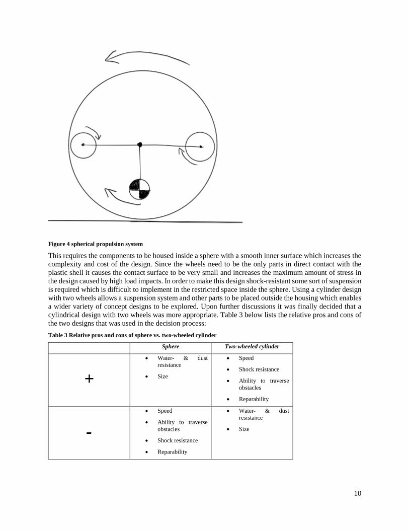
Figure 6 SCARAB robot and bent motor shaft
SCARAB robot
This robot was developed as a master thesis project by a student at the University of Cape Town in South
Africa (Mathew, 2015). It is also aimed at being used by rescue personnel in Urban Search and Rescue
operations. It has an estimated prototype cost of 287 $ (with final design expected to be less) and a
hypothetical but not tested drop height resistance of 3 m. The wheels are made of expanded polyethylene
foam called SPX200 with a density of 200 kg/m3 and have a cogwheel shape to provide additional traction.
One standout feature is a rear wing attached to the chassis which has several purposes; it’s used as a handle
to throw the robot, it acts as a stabilizer during flight and counteracts the torque produced by the motors.
The writers think the size and weight of the robot are a concern; the specified dimensions are 240 x 330 x
440 mm and weight is 2.4 kg. The increased size of the robot including the big fin means it can’t fit though
smaller openings and reduces its ability to navigate the terrain. The drivetrain is also shown to be less than
optimal; during one of the tests the robot tumbled to the ground which caused the motor shaft to be bent
(shown in Figure 6 above) and permanently damaging it.
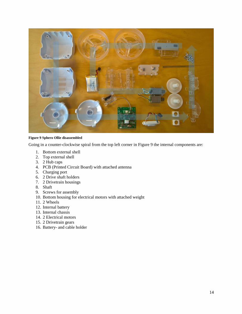
Figure 7 LittleBot Junior robot and its drivetrain bearings

13
LittleBot Junior robot
This robot was the result of a master thesis project by a student at the Victoria University of Wellington in
New Zeeland (McVay, 2014). The chassis is milled out of a solid block of aluminum and has two wheels
made out of 10 mm thick natural rubber. The drivetrain is a direct-drive and makes use of several radial
bearings to relieve stresses on the motor shaft caused by impacts and was drop tested from 2 m without
issues. The robot was also successfully tested for a waterproof IP55 rating. The estimated prototype cost
was 122 USD at the time of writing which is very close to this projects’ specified cost of 100 USD. The
size and weight is unknown but is presumably small since the diameter of the wheels in the picture is 80
mm. It features an interchangeable gas sensor that can be used for measuring humidity levels, temperature
and other contaminants when deployed. The big detractor is the terrain capability; the robot was tested on
various terrain and inclinations successfully but major hurdles like climbing a ledge was not tested. Since
the robot uses 6 V micro motors it’s not likely it can climb any larger obstacles and the wide, exposed
underside of the chassis means it’s more likely to get stuck in the terrain.
Figure 8 Sphero Ollie
Sphero Ollie
This robot is meant to be used as a toy and is not intended to be used in Urban Search and Rescue mission.
However, because of its general availability and low retail price of 100 USD it was chosen to be extensively
studied in order to get a good understanding of how robots of this configuration are built. The robot consists
of a plastic cylinder with two wheels that are larger than the body and extend inward around the chassis.
The device is controlled via a smartphone with Bluetooth and a proprietary app installed. It has a rated top
speed of 22 km/h and can survive drops from 1-1.5 m. All disassembled components of the robot are
displayed in Figure 9 below:
14
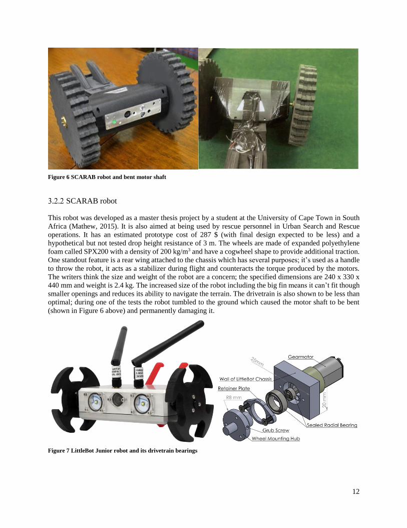
Figure 9 Sphero Ollie disassembled
Going in a counter-clockwise spiral from the top left corner in Figure 9 the internal components are:
1. Bottom external shell
2. Top external shell
3. 2 Hub caps
4. PCB (Printed Circuit Board) with attached antenna
5. Charging port
6. 2 Drive shaft holders
7. 2 Drivetrain housings
8. Shaft
9. Screws for assembly
10. Bottom housing for electrical motors with attached weight
11. 2 Wheels
12. Internal battery
13. Internal chassis
14. 2 Electrical motors
15. 2 Drivetrain gears
16. Battery- and cable holder

15
Figure 10 Assembled internals
3.2.4.1 Mechanics
As can be seen in Figure 10 the robot consists of a white external case to protect the internals from external
forces and contaminants which also to gives it an aesthetically pleasing look. The internals are mounted
onto an internal shell, see Figure 11, that provides structural integrity and makes it easy to remove the
assembled internals and service the components.

16
Figure 11 Internal chassis
Figure 12 below displays the drivetrain assembly which consists of two electrical motors, one for each
wheel, that are connected to plastic cog wheels displayed in Figure 13. One interesting part of the drivetrain
is the metal rod in Figure 14 which is free spinning and is used to give the drivetrain additional lateral
stiffness and impact resistance. Of note is also that there exists no dedicated suspension in the drivetrain.
Instead the flexibility of the materials and certain amount of play in the connections provides limited
suspension. The entire construction is made of polymer materials except the screws and a steel plate
mounted in the bottom (see Figure 15); presumably it’s used to lower the center of mass in order to
counteract the torque generated by the spinning wheels.

17
Figure 12 Assembled drivetrain
Figure 13 Drivetrain cogwheel components

18
Figure 14 Drivetrain rod
Figure 15 Bottom chassis and internal battery

19
Figure 16 PCB
3.2.4.2 Electronics
Looking at the electronics of ollie the first thing to notice is the custom PCB, Figure 16 above, containing
all the necessary electrical components and circuits for ollie to perform as intended. The PCB is powered
by the USB-port utilizing a 3.3V linear voltage regulator to generate a stable power rail from the battery to
all the digital systems. The USB-port can be used to program the ARM Cortex-M4 based microprocessor,
a unit with lots of computational power in order to manage the fast control of the DC motors, or as a
charging port enabled by presenting the connector with USB bus-power. Other components on the PCB
are:
A 6-axis inertial IMU measurement unit reporting the relative position of ollie to the processor Two full H-bridges, one for each motor, making it possible to change the direction of current
through the motor making it capable of running both clockwise and counter-clockwise A Cambridge Silicon Radio CSR1010 providing the BLE connectivity along with a special
designed 2.4GHz antenna soldered directly on the PCB
The construction of the robot is summarized in a block diagram in Figure 17 below:

20
Power
Control
Sensors Locomotion
Figure 17 Block diagram of Sphero Ollie
3.3 Problem decomposition
The proposed robot design has a number to specifications to fulfill and those specifications translate into
problems and sub-problems the writers need to address. To reiterate, the specifications of the robot are:
Terrain capability
o Climb objects up to 50 mm in height
o Tether-less operation
o Visual feedback
o Minimum 60 min battery life
Ruggedness
o Ingress protection of at least IP65
o Survive a drop of 3 m
o Survive deployment with an air cannon or by throwing
Modularity
o Interchangeable sensors
Portability
o Small enough to allow one person to carry it
o Light enough to allow one person to carry it
Cost
o Target cost of 100 USD
Microcontroller
Gyroscope Accelerometer
Internal battery
Charging port Electrical motor
Wheel
Bluetooth Low-Energy antenna
Bluetooth-connected Device (smartphone etc.)

21
These specifications have been translated into different areas of the robot that need to be investigated which
are shown in Figure 18 below. The details of their development are documented in the following chapter.
Figure 18 block diagram of robot
Two-wheeled
robot
Chassis
Ingress protection
Sensor modularity
Impact resistance
Locomotion
Wheels
Motors
Drivetrain
Suspension
PowerInternal battery
Charging port
Control
Communication
•Steering
•Video
Sensors
Gas
Temperature
Camera

22
4 Develop
This section covers the testing, selection and development of the different aspects of the robot that were
detailed in the specifications and the previous block diagram.
4.1 Control
Microcontroller
Microcontrollers are used in a wide variety of autonomous products and devices. The reduced size and cost
of it compared to a design using a separate processing unit, memory and input/output devices makes it a
small, economical and powerful device to utilize in a small robot. A study of different microcontrollers will
be conducted in order to determine which one should be used in the project.
4.1.1.1 Constraints
Below is a list of the criteria that were used in the study. Each microcontroller was evaluated against them
to determine which would best fit the goals of the master thesis. The given criteria states that the
microcontroller must:
Have at least 20 input/output (I/O) connections
Support Pulse Width Modulation (PWM) Have options for easy connection to other devices Have at least 256 kB long-term memory and 4kB short-term memory Have a clock speed of at least 10 MHz Be small enough to suit the development of a wieldy robot
In addition to the above criteria it would greatly benefit the programming and debugging of the chosen
microcontroller if it supports an Integrated Development Environment (IDE) known to the developers with
a vast and supportive community.
4.1.1.2 Method
Looking at the market of microcontrollers there's a large number of microcontrollers that could be used in
the development of a small robot; each with its own benefits and drawbacks. Below is a list of the six
microcontrollers that were selected for evaluation. They were chosen by considering what IDE they use,
the cost of the device with possible supplements and finally the available support from the developer or
community:
1. Genuino UNO
2. Genuino MEGA
3. Netduino 3
4. Raspberry PI
5. Intel Galileo
6. Beaglebone Black

23
The next step was to research the criteria discussed in chapter 3.1 and calculate the required memory, I/O
connections, clock speed etc. However, it’s hard to initially estimate for example the amount of memory
needed for storage or the amount of I/O connections required to connect all the needed sensors, motors,
modules etc. But by looking at the existing LittleBot and SCARAB projects some relevant parts and
estimations could be used to quantify the criteria listed in previous chapter.
4.1.1.3 Recommendation
In order to make the evaluation a bit more manageable the criteria were broken down into three categories:
I/O connections and PWM
Exterior device connections, size and IDE
Clock speed and memory
The result from each category were then compiled so that one of the microcontrollers could be selected for
the prototype.
4.1.1.4 I/O Connections and PWM
From the LittleBot and SCARAB projects it was determined that the microcontroller requires at least 20
I/O connections for various connections with components such as motors and sensors. There’s no real
drawback in having more than 20 besides having more connections equals more required space. The
connection between microcontroller and motors should be with I/Os that support PWM. PWM is a way for
digital I/O connections to control the output voltage to the motor and since the voltage controls the rotational
speed of the motor, PWM is essential for speed management. Finally, since all the sensors, modules and
other components for the project weren’t chosen yet the microcontroller should have support for both digital
and analog components. The only microcontroller among the selected that doesn’t have support for analog
I/O connections is the Raspberry PI. From this category it’s also determined that the Genuino UNO won’t
be recommended because it doesn’t have more than 14 I/O connections available.
4.1.1.5 Exterior device connections, size and IDE
All microcontrollers have some way to connect with other devices such as a computer or smartphone but
the method varies. The most common is a cable, often USB, which allows for a stable connection to upload
program and updates. Other options are Wi-Fi, Bluetooth or similar interfaces which are often used in
addition to the cable connection and provides a faster connection to the microcontroller during runtime.
The chosen microcontroller should be small enough to allow for the development of an agile robot. While
most microcontroller manufacturers aim to make their devices as small as possible; there are a few things
to consider when choosing one. First the amount of connections greatly impacts the size of the device and
should be close to the minimum amount of I/O connections required. Then the placement of I/O and other
connections needs to be considered, some connections might face in a direction that increase the overall
size of the microcontroller.
Most microcontrollers are developed to be used with a specific programming language and development
environment. While most devices support more than one IDE it’s often wise to use the IDE that the
microcontroller was developed for because the associated community probably use the “correct” IDE and
thus help with problems and examples would be easier to find. With this in mind the chosen microcontroller
should have support for, and preferably be developed for, an IDE known to the developers.
Both the Raspberry PI, Beaglebone Black and Netduino gets a slight advantage for being small while the
Intel Galileo gets a minus for being the biggest of the remaining devices. The Galileo also gets a slight
minus along with the Beaglebone for preferring programming in c and use of Simulink as the associated
development platform. The best here are the Netduino (C# and visual studio), Genuino Mega (Arduino IDE
with support for various languages and IDEs) and Raspberry PI (Python with support for various languages
and IDEs).

24
4.1.1.6 Memory and Clock Speed
There are a couple of things to consider when looking at memory. To begin with there are two types of
needed memory: long-term and short-term. The long-term is usually a flash memory located somewhere on
the microcontroller while the short-term is a fast RAM memory that's lost when the power source is
disconnected. The size of each memory is estimated by using a small test program to approximate the
required long-term or short-term memory (LittleBot). For a small robot with the purpose of collecting data
using tether-less movement the recommended memory sizes are 256 kB of long-term memory and 4 kB
short-term memory. The first thing to notice when looking at the remaining microcontrollers is that the
Raspberry doesn’t have any long-term, on-board memory but relies on an external memory source such as
an SD-card. Using an external storage unit could present a problem with data corruption i.e. the data not
being read because of bad connection or sudden disconnection of the memory card during runtime. And
considering that the robot should be heavy-duty the number of individual parts should be kept low in order
to reduce the risk of components becoming disconnected. Secondly the Raspberry, Beaglebone and Galileo
are over-dimensioned for the purpose of the robot. All three are equipped with memory more than ten times
the recommended size with clock speeds of more than twenty times the recommended. The Genuino Mega
is equipped with 256kB flash memory, 8kB SRAM and a 16 MHz clock which is close to the recommended
values; while the Netduino is located somewhere between the Genuino and the other three. The winner here
are the Genuino Mega 2560 board.
After considering all the findings and preferences from the developers regarding IDE and community, the
study recommends the Genuino Mega 2560 microcontroller for the development of the robot shown in
Figure 19 below.
Figure 19 Genuino Mega 2560
4.1.1.7 Genuino Mega 2560
The Genuino Mega 2560 board is supplied with 14.8 V by the battery pack discussed in the next chapter.
14.8 V is slightly higher than the recommended 7-12 V power supply but lies within the range of the
specified 6-20 V limit. The high input assures that the output always reaches the necessary 5 V output for
actuators, sensors and controllers connected to the Genuino board. The board is equipped with 54 digital
I/O (input/output) pins and 16 analog I/O pins. 15 of the digital I/O pins can be used as pulse width
modulating outputs to control the motors while the analog I/O pins receive control signals from the remote
control discussed later on. The program detailed below is stored in the Genuino Mega’s 256 kB on-board
flash memory and executed on a 16 MHz clock which yields sufficient speeds for the Genuino to operate
correctly.

25
4.1.1.8 Program
The microcontroller needs to be programmed for the robot to work as intended. The program creates the
interface for pin connections and provides the necessary logic calculations or interpretations to control the
robot. The program is written in a loop that executes every 200 ms. It begins by listening to four channels
for a command from the operator. When either of the channels detects a high signal, a switch-case
determines what should be done depending on the operators’ previous command. The switch-case keeps
track of the current state for each motor and responds to the command signal in the appropriate way
depending on the current state. The signal is then pushed to the H-bridge which creates the required current
flow for the desired movement. The program can be seen in appendix E.
Communication
4.1.2.1 Steering
The robot needs to have some way for the operator to control movement. For this purpose, a Radio
Frequency (RF) control system has been implemented. The control system consists of two parts; the first
one is a remote control equipped with two levers and an RF-transmitter while the other is a RF-receiver
mounted on the robot. Both the remote control and RF-receiver were directly taken from a toy robot named
Nikko Nano VaporizR that was purchased and taken apart; see Figure 20 below.
The toy robot presents a cheap off-the-shelf solution with sufficient transmission channels along with an
intuitive controller for independent motor control. The choice of using the already implemented solution
for control signal communication facilitate the work load compared to the amount of time it would take to
implement another protocol such as the XBee module from the LittleBot project. The chosen controller also
has the advantage of two independent levers for controlling each motor separately whereas other considered
toy robots employ one lever for speed and another for steering.
Figure 20 Nikko Nano VaporizR toy car and remote control
Remote control
The remote control shown above is equipped with two independent levers and an RF-transmitter unit.
Pushing the lever back and forth engages the circuit to set either a forward or backward signal high. Since

26
the levers are independent of each other a signal can be sent to drive one motor forward and the other motor
backward.
Transmitter
The transmitter is a SCT 2000 RF transmitter made by Silian company, the block diagram of the transmitter
can be seen in appendix D. The transmitter has a wide operating range of 27 – 49 MHz with a maximum
power output of 15 dBm. The transmitter has five binary signal channels that could be used to transfer
signals to a receiver mounted on the robot. For this project however, only four channels will be used. With
four channels and two motors each motor is controlled with two channels, one channel sends a forward
signal while the other sends a backward signal. Keeping the robot in place or breaking while the robot is
moving is achieved by not affecting either channel keeping both signals low.
Receiver
In order for the robot to receive and act on the transmitted signals; an SCR 2000 RF-receiving unit is
mounted on the robot. This unit is compatible with the SCT 2000 and can receive frequencies between 27
– 50 MHz. The unit has an operating range between 2.1 – 7.2 V and can be powered by the microcontrollers’
5 V power output. By connecting the receivers’ channels to the Genuino board the microcontroller can
interpret the signals and output the desired signals to the motor driver. The unit is shown in Figure 21 below
and the block diagram for the receiver can be seen in appendix D.
Figure 21 SCR 2000 receiver
4.1.2.2 Video
As the robot is a remote-controlled device developed to assist in Urban Search and Rescue operations; there
needs to be some sort of visual feedback to the operator. For this purpose, a camera has been mounted on
the robot with associated transmitting and receiving units.
In order for the operator to have constant knowledge of the robot’s location in the environment and to
mediate information about the environment, a camera with associated transmitter and receiver units has
been mounted on the robot to provide video feedback.
Transmitter
A TS351 8-channel transmitter, pictured in Figure 22 below, is mounted on the robot with the purpose of
transmitting the video signal. It measures 82 mm x 53 mm x 15 mm, weighs 65 g, draws 100 mA during

27
transmission and requires a 12 V DC power supply. The device is designed to transmit both audio and video
signals using the 5.8 GHz band and a 3 dB gain antenna. Comparing the signal range of the TS351
transmitter to the SCT 2000 transmitter; the TS351 has a line of sight range of up to 2 km making the
control unit the limiting factor to how far away the robot can travel.
Figure 22 TS351 video transmitter
Receiver
For the purpose of receiving and decoding the video signal a receiving unit with the model number RC805
has been chosen. The receiver unit draws 100 mA while receiving and requires a 12 V DC power supply to
function. It matches the TS351 transmitters’ 8 channels in the 5.8 GHz band and utilizes a 3 dB gain antenna
for receiving the signal. For testing and developing a functioning connection; the receiver has been
connected to a computer with VLC Media Player installed to show the video output. The conversion from
the composite video signal to a signal that can be interpreted by the computer is made by using an analog-
digital USB video adapter shown in Figure 23.
Figure 23 RC805 video receiver and accompanying analog-digital video adapter

28
4.2 Power
Internal battery
In order for the robot to operate tether-less it needs a mobile power supply with sufficient capacity to power
it for the specified 60 minutes. The robot consists of many different electrical components with various
power consumptions that need to be combined in order to determine the necessary battery capacity. To do
this, a worst-case scenario is initially calculated when estimating the total power consumption of the various
components and the values are listed in Table 4 below.
Table 4 power consumption
Device Voltage Current Power
Genuino Mega 2560 14.8 V 400 mA 5 920 mW
(2) Motors 14.8 V 9 000 mA 133 200 mW
H-Bridge 14.8 V 10 mA 148 mW
Camera 14.8 V 70 mA 1 036 mW
TS351 Transmitter 14.8 V 100 mA 1 480 mW
SCR2000 Receiver 5 V 60 mA 300 mW
Total - 3640 mA 142 084 mW
By far the largest power consumers are the motors with each being estimated to draw 4 500 mA of current
during continuous operation. However, this is a worst-case estimation in which the motors work at
maximum load during the entire operation. That amount of current will most likely be consumed during
very short periods of time when the robot needs to traverse obstacles, climb steep hills or when forcing the
motors to rotate from a stationary position. During standard operation the motors should run at low loads
consuming less than half the estimated current and thus reducing power consumption considerably.
Another big load is the Genuino Mega board consuming an estimated 400 mA. This is based on continuous
output on 20 I/O pins drawing 20 mA of current at any given time. Considering that some signals I/O
connections control two states of the same component, for example two binary inputs are utilized to signal
for forward or backward rotation for a motor. These shouldn't be logically pulled high at the same time
reducing the amount of I/O pins employed and power consumption at any given time.
The chosen power supply is a battery pack consisting of four Li-ion batteries, shown in Figure 24 below,
where each battery has a rated capacity of 6800 mAh and voltage of 3.7 V.

29
Figure 24 battery pack
The four batteries are connected in series to create a total voltage of 14.8 V which is enough to power all
of the connected components. The total power capacity is calculated by multiplying the supplied voltage
with the current capacity of the batteries;
𝑇𝑜𝑡𝑎𝑙 𝑏𝑎𝑡𝑡𝑒𝑟𝑦 𝑐𝑎𝑝𝑎𝑐𝑖𝑡𝑦 = 14.8 ∗ 6800 = 100 640 mWh
which equals about two-thirds of the required capacity in the worst-case scenario or a runtime of:
𝑅𝑢𝑛𝑡𝑖𝑚𝑒 𝑜𝑓 𝑟𝑜𝑏𝑜𝑡 =100640
142084≃ 42 min
However, as stated before the power consumption is based on a worst-case scenario and also the actual
capacity of the batteries may be less than the manufacturer has specified. Considering the low probability
of both motors being forced to operate at their maximum performance for long periods of time; it’s better
to assume a more varied scenario with long stretches of low loads coupled with short bursts of maximum
loads. A second estimation of the runtime is therefore conducted where the batteries have half the specified
capacity and the motors’ power draw is adjusted to be more realistic. Estimating that the robot will operate
at low loads with short bursts of maximum load; the approximate consumption of both motors goes down
from 9 000 mA to 2 000 mA. The new energy requirement for powering both motors during one hour then
becomes:
𝑇𝑜𝑡𝑎𝑙 𝑒𝑛𝑒𝑟𝑔𝑦 𝑐𝑜𝑛𝑠𝑢𝑚𝑝𝑡𝑖𝑜𝑛 𝑓𝑜𝑟 𝑏𝑜𝑡ℎ 𝑚𝑜𝑡𝑜𝑟𝑠 = 14.8 ∗ 2 000 = 29 600 mWh
making the total energy requirement for the robot 38 484 mWh. The provided amount of energy, calculated
with half the power capacity of the batteries, becomes:
𝑁𝑒𝑤 𝑡𝑜𝑡𝑎𝑙 𝑏𝑎𝑡𝑡𝑒𝑟𝑦 𝑐𝑎𝑝𝑎𝑐𝑖𝑡𝑦 = 14.8 ∗ 3 400 = 50 320 mWh
which is enough to power the robot for approximately:
𝑁𝑒𝑤 𝑟𝑢𝑛𝑡𝑖𝑚𝑒 𝑜𝑓 𝑟𝑜𝑏𝑜𝑡 =50 320
38 484≃ 78 min
Charging port
A common three-pole switch, see Figure 25 below, is employed on the robot’s back to act as an on/off
switch and charging port. To switch the robot on, the operator inserts a key that connects the batteries with
the rest of the robot. When the robot is finished with its work the operator simply disconnects the key and
the robot is switched off.

30
The robot is intended to be charged using a custom-made three-pin charging cable that attaches to the three-
pin connector on the robot. However, the battery is made by connecting four li-ion batteries in series making
the process of charging the battery tricky. For the charging process to be safe and to assure that each battery
is charged equally there’s need for some complementary circuits:
An overcharge protection circuit should be integrated along with a fuse to protect the battery from
overcharging and cut current if the temperature of the battery gets too high. A balancer should be integrated to assure that each battery is charged to the specified voltage
The development of such a charging circuit will be discussed as future work in chapter 6.
Figure 25 power switch

31
4.3 Sensors
Camera
The camera, pictured in Figure 26, is a Sony HeliStar 700TVL FPV camera module measuring 32 mm x
32 mm and weighs 13.5 g which makes it a small and light camera suitable for small robot projects. With
a sensitivity of 0.01 LUX/F1.2 and automatic exposure adjustments the camera provides acceptable images
even in darker environments. The video signal can be both PAL- and NTSC-encoded with a resolution of
1020 x 596 pixels for PAL and 1020 x 508 pixels for NTSC. The camera operates at 12 V DC with a
working current of 70 mA and can be powered by the internal power supply on the microcontroller.
An alternative to the chosen analog camera is to have a digital camera and data transmission system. The
data rate of such a video feed can be calculated by using the same formula as in the LittleBot project:
𝐷𝑎𝑡𝑎 𝑟𝑎𝑡𝑒 = 𝑐𝑜𝑙𝑜𝑟 𝑑𝑒𝑝𝑡ℎ ∗ 𝑣𝑒𝑟𝑡𝑖𝑐𝑎𝑙 𝑟𝑒𝑠𝑜𝑙𝑢𝑡𝑖𝑜𝑛 ∗ ℎ𝑜𝑟𝑖𝑧𝑜𝑛𝑡𝑎𝑙 𝑟𝑒𝑠𝑜𝑙𝑢𝑡𝑖𝑜𝑛 ∗ 𝑟𝑒𝑓𝑟𝑒𝑠ℎ 𝑟𝑎𝑡𝑒
Using a feed with 25 frames per second with 24-bit color depth and the same 1020 x 596 pixel resolution
as the chosen camera yields a raw data rate of:
𝐷𝑎𝑡𝑎 𝑟𝑎𝑡𝑒 = 24 ∗ 2010 ∗ 596 ∗ 25 = 364 752 000 bits/second
The calculated data rate could then be compressed using a standard such as H.264 to significantly reduce
the amount of data that needs to be transferred. However, to implement a solution capable of such data
compression along with the inherited delay optimizations and transmission would be overly expensive and
complex to be implemented in the current version of the robot design.
Figure 26 Sony HeliStar 700TVL FPV camera module
Gas & temperature
The purpose of the developed robot is to assist in Urban Search and Rescue operations by providing the
rescue team with information in the early stages of the operation. This could mean that the team sends in a
robot to determine if the area is safe to enter and if there are injured people in need of help. For this purpose,
the robot will need a tool to determine if there are potential hazards such as gas, smoke or extreme heat.
Considering the robot is intended to have such a low cost so it can be considered expendable; it should only
incorporate the necessary sensors to complete its task. It’s therefore desired to implement a module-based
32
system to allow switching between different sensors prior to deploying the robot for a specific scenario. A
suggested platform for the sensor will be detailed in the future work section further down.
4.4 Locomotion
Motors
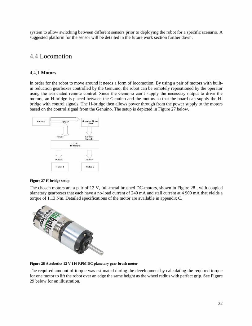
In order for the robot to move around it needs a form of locomotion. By using a pair of motors with built-
in reduction gearboxes controlled by the Genuino, the robot can be remotely repositioned by the operator
using the associated remote control. Since the Genuino can’t supply the necessary output to drive the
motors, an H-bridge is placed between the Genuino and the motors so that the board can supply the H-
bridge with control signals. The H-bridge then allows power through from the power supply to the motors
based on the control signal from the Genuino. The setup is depicted in Figure 27 below.
Figure 27 H-bridge setup
The chosen motors are a pair of 12 V, full-metal brushed DC-motors, shown in Figure 28 , with coupled
planetary gearboxes that each have a no-load current of 240 mA and stall current at 4 900 mA that yields a
torque of 1.13 Nm. Detailed specifications of the motor are available in appendix C.
Figure 28 Actobotics 12 V 116 RPM DC planetary gear brush motor
The required amount of torque was estimated during the development by calculating the required torque
for one motor to lift the robot over an edge the same height as the wheel radius with perfect grip. See Figure
29 below for an illustration.

33
Figure 29 torque calculation scenario
By multiplying the robots’ estimated mass with gravitational constant and wheel radius the required torque
could be estimated to:
𝑊ℎ𝑒𝑒𝑙 𝑟𝑎𝑑𝑖𝑢𝑠 𝑟 = 65 mm 𝐸𝑠𝑡𝑖𝑚𝑎𝑡𝑒𝑑 𝑤𝑒𝑖𝑔ℎ𝑡 𝑜𝑓 𝑟𝑜𝑏𝑜𝑡 𝑚 = 1.5 kg 𝑅𝑒𝑞𝑢𝑖𝑟𝑒𝑑 𝑡𝑜𝑟𝑞𝑢𝑒 = 𝑚𝑔𝑟 = 0.065 ∗ 9.81 ∗ 1.5 ≃ 0.96 Nm
An alternative is a brushless DC motor which is more precise and slightly more efficient but is more
expensive and have fewer stabilizing features. Other alternatives are stepper- and servomotors which are
slower than the DC motor and often needs extra circuits and programming to have full rotation.
The motor unit has a diameter of 22 mm, length of 73 mm and weighs 92 g with max rotational speed of
116 RPM. Multiplying the rotational speed with the wheel radius of 65 mm yields an estimated maximum
speed of:
116
60∗ 2𝜋 ∗
65
1000≃ 0.79 m/s
4.4.1.1 H-Bridge
In order to power the motors, a motor driver is required that is able to control both motors independently
and withstand strong peak currents. An STMicroelectronics L6205N dual full-bridge driver, shown in
Figure 30 below, can be used for this purpose by driving both motors independently with 2.8 A at 12 V
continuously and withstand up to 7.1 A of peak current. The bridge allows the driver to control the direction
of the current and thus control the direction for the rotations as well as break the motors by cutting the
current.

34
Figure 30 STMicroelectronics L6205 dual full-bridge driver
4.4.1.2 PCB
The H-bridge used to control the motors need a few external components to be able to work as intended.
For this purpose, a custom-built circuit board has been implemented. The PCB connects the H-bridge with
the required components as well as provide the camera and transmitter with power from the battery; see
Figure 31 below. The schematics of the PCB can be seen in appendix A. Two capacitors, C1 and C2, are
connected between the power pins, VSA and VSB, and ground to improve high frequency filtering on the
power supply. Cp, CBoot, D1, D2 and Rp creates a charge pump or bootstrap circuit. When the center of the
H-bridge goes low, the capacitor is charged to be used to drive the high-side MOSFET a few volts above
the supply voltage so as to switch it on.
Figure 31 custom-built PCB
Wheels & suspension
The wheels are an important component of the locomotion system that allows the robot to move to a new
position and should preferably enable it to traverse uneven and rough topology. Due to the added
complexity of developing a compact suspension system an idea came up to integrate it into the wheels
themselves in order to reduce the number of components and cost. The wheels should also have a larger
diameter than the chassis to always be the first part of the robot to hit the ground regardless of the
orientation. Similar wheel designs use airless tires with a structure that flexes when deformed which
provides a certain level of suspension; see Figure 32 below for examples.

35
Figure 32 airless tires
4.4.2.1 Designing wheel design concepts
A first concept design uses a pattern of fins where the thickness reduces radially from 5 mm to 2 mm in
order to flex and be rigid enough to not break from impact forces; see Figure 33 below.
Figure 33 Wheel concept design 1
In design 2, see Figure 34 below, the length of each fin is more than double from design 1 with the same
start- and end thickness. The increased length is believed to cause the wheels to be a lot more “springy”
and flexible which should also give a smoother ride and improve terrain capabilities.

36
Figure 34 Wheel concept design 2
Initial testing revealed that design 2 was too flexible and wouldn’t provide any suspension so a modified
version, concept design 3, with doubled fin thickness was made to test if it would improve; see Figure 35
below:

37
Figure 35 wheel concept design 3
Finally, Figure 36 shows a traditional wheel design for RC-cars purchased as a comparison. It consists of a
soft, threaded polymer tire filled with a foam polymer that’s glued onto a semi-rigid polymer rim. The foam
inserts combined with the soft tire is believed to provide ample suspension and the treads should help with
the terrain capability. They will be referred to as the monster wheels in the rest of the report.
Figure 36 RC monster truck wheels

38
Each design was then attached to a test platform with an accelerometer which was subjected to drop tests
in order to get a sense for what suspension they would provide. The test platform and results are presented
in the next chapter below.
4.4.2.2 Drop testing
In order to get a sense of how the designs perform in regards to their shock absorption; a simple drop test
platform was developed, see Figure 37 below. The purpose of this platform was to gather information about
the wheels’ shock absorption and compare them to each other in order to get a sense for their relative
performance.
Generally, there are two ways you can measure shock absorption/deformation and those are using
accelerometers on the unit to measure the G-forces involved or a high-speed camera to capture the
deformation caused by the impact. Since the purpose of this test was to get comparative data it wasn’t
necessary to construct a high-quality testing rig as long as it provides consistent data output. The built-in
accelerometer in a modern smartphone, here a Nokia X, were used to get the necessary data for comparison
and was mounted directly onto the drop test platform. An app named SensoDuino (SensoDuino - Google
Play Store, 2013) was used to collect the accelerometer data from the phone which records the sensor
outputs to a .txt file that can then be imported to Microsoft Excel for further analysis. The polling rate of
the sensor was set to the highest available resolution which was 100 milliseconds. The app identified the
built-in sensor as a Bosch BMA2X2 3-axis accelerometer. A search on the company’s website lists a
BMA222 3-axis sensor (Bosch, n.d.) that has configurable measurement ranges of ±2g, ±4g, ±8g and ±16g.
Preliminary testing revealed that the accelerometer in the phone is calibrated to measure forces ranging
from ±2g which meant the sensors were more sensitive than originally presumed and the drop height had
to be adjusted.
Figure 37 Drop test platform
The wheels attach to either side of an axis on the platform and with the SensoDuino app running the phone
is secured inside the platform by sliding it in between the axis and a plastic back plate and tightened with
two U-bolts with washers. The test platform is then leveled and elevated by hand with the phone positioned
below the axis to a specific height and then dropped against the floor.

39
A number of variables or so-called noise factors are involved in this testing system which need to be
identified and accounted for. The following ones were identified in no specific order:
Temperature
Humidity
Impact surface
Placement of cellphone in testing rig
Internal flexibility of testing rig
Orientation of wheels during impact
Orientation of testing platform during impact
Human interpretation of data
Variation in height during each drop
Polling rate of accelerometer sensor data
Accuracy of accelerometer sensor
Sensitivity of accelerometer sensor
Adjustment of values to 0
Both temperature and humidity were deemed insignificant since the tests were performed indoors where
the climate is regulated and sufficiently invariable. The impact surface is a plastic floor mat that is stiff
enough to not significantly influence the results and is the same impact surface in all drop tests. The
placement of the cellphone inside the test platform could affect the test results if it’s not properly aligned
and needs to be considered. It’s determined that as long as the center of the cellphone is below the axis in
Figure 37 within a margin of 1-3 mm then it won’t negatively affect the test results. The internal flexibility
of the test platform is determined not be a major concern since the phone is held firmly against the metal
axis with the assistance two U-bolts pushing the back plate against the back of the phone and causes it to
be in direct contact with the axis.
Because most of the wheel designs are not perfectly circular the way they’re oriented during the impact
will affect the shock absorption characteristics. In order to reduce this effect, the wheels will be rotated
randomly between each drop test which combined with a sufficient number of drop tests should alleviate
this issue. The interpretation of the data was addressed by performing the calculations several times at
different times to ensure their validity. Finally, the drop tests were performed 50 times in order to reduce
the significance of the other noise factors which further down in this chapter is shown to be a good sufficient
value.
After the drop tests were performed the data on the phone was transferred to a computer where they’re
imported into a spreadsheet in Microsoft Excel. The data from the sensors are reported in ms−2 and are
organized in such a fashion that each row contains the sensor readings from each axis for a specific time in
millisecond; see Table 5 below for an example:
Table 5 example of sensor output
Accelerometer 12 2.451663 7.201759 7.201759
Accelerometer 13 2.298434 6.742072 7.354988
Accelerometer 14 2.145205 6.742072 7.661446
Accelerometer 15 2.298434 6.282385 7.04853
Accelerometer 16 2.451663 6.129156 6.129156
Figure 38 below displays the three sensor readings at each timestamp of the acceleration with each
horizontal line indicating an increment of 5 ms-2. This image shows the typical output from a drop height
of 50 cm where each horizontal line indicates an increment of 5 ms−2. As can be seen all the sensors max
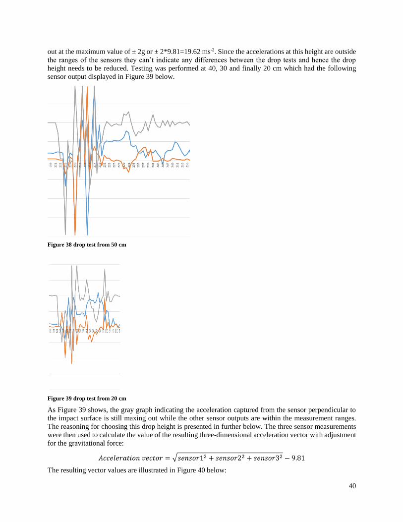
40
out at the maximum value of ± 2g or ± 2*9.81=19.62 ms-2. Since the accelerations at this height are outside
the ranges of the sensors they can’t indicate any differences between the drop tests and hence the drop
height needs to be reduced. Testing was performed at 40, 30 and finally 20 cm which had the following
sensor output displayed in Figure 39 below.
Figure 38 drop test from 50 cm
Figure 39 drop test from 20 cm
As Figure 39 shows, the gray graph indicating the acceleration captured from the sensor perpendicular to
the impact surface is still maxing out while the other sensor outputs are within the measurement ranges.
The reasoning for choosing this drop height is presented in further below. The three sensor measurements
were then used to calculate the value of the resulting three-dimensional acceleration vector with adjustment
for the gravitational force:
𝐴𝑐𝑐𝑒𝑙𝑒𝑟𝑎𝑡𝑖𝑜𝑛 𝑣𝑒𝑐𝑡𝑜𝑟 = √𝑠𝑒𝑛𝑠𝑜𝑟12 + 𝑠𝑒𝑛𝑠𝑜𝑟22 + 𝑠𝑒𝑛𝑠𝑜𝑟32 − 9.81
The resulting vector values are illustrated in Figure 40 below:

41
Figure 40 drop test from 20 cm – resulting vector values
Since the vector has been adjusted for the gravitational force it’s centered around the horizontal axis and
displays the positive and negative accelerations caused by the impact. The highest accelerations registered
at each drop test impact is then documented in a separate column which is used to calculate the average
value. The standard deviation σ and a confidence interval of 95 % is also calculated to ensure the validity
of the results. Different drop heights were tested and their corresponding numbers are presented in Table 6
below:
Table 6 drop height tests
Height Average max Std.dev. σ Conf.int (95%) # of max readings
10 cm 15.3648 5.834794337 ±1.617292757 101
15 cm 18.175625 4.796603358 ±1.356941983 166
20 cm 17.71884615 4.454068431 ±1.210607345 145
25 cm 18.62857143 4.49132588 ±1.257548138 198
The number of times each sensor was maxed out was also used to give an arbitrary, relative comparison of
how accurate the data is. As is shown in Table 6, the number of max readings increases between 10-15 cm
but then decreases slightly before rapidly increasing at 25 cm. The average maximum value follows the
same pattern but the values between 15-25 cm are within the confidence intervals so they can’t conclusively
be determined to be much different. Because the number of max readings seem to lower at 20 cm it’s
deemed the best compromise in order to get fairly accurate data. Another reason for not further lowering
the drop height was due to concerns regarding the impact velocity becoming too low to cause any
suspension to occur in the wheel designs. No vertical drop test was performed on design 3 because the
horizontal drop test value was so poor that it wouldn’t matter since the wheels need a good, general
suspension regardless of orientation.
The final test results of the different designs are shown in Table 7 below:
Table 7 drop test results
Wheel design Orientation Average max Std.dev. σ Conf.int (95%)
1 H 17.71884615 4.454068431 ±1.210607345
1 V 19.07910714 4.6588082 ±1.220194066

42
2 H 19.96957447 2.281413296 ±0.652233544
2 V 21.4954717 2.248912161 ±0.605456086
3 H 22.09981132 2.063682814 ±0.555588316
Monster wheels H 13.70481481 5.035976767 ±1.343182204
Monster wheels V 13.85298507 5.827245327 ±1.405851425
4.4.2.3 Drop test results discussion
As the results show, the monster wheels provided the best relative dampening performance in both
horizontal and vertical drops. Compared to the best and worst alternatives the difference varied between 23
% and 36 % in horizontal and 28 % to 37 % in vertical drop tests. As Table 8 shows with the average value
marked in yellow; none of the confidence intervals overlap and therefore the differences are statistically
significant.
Table 8 confidence intervals of drop tests
These results are contrary to the writers’ assumption that the custom-designed wheels would provide similar
or better dampening properties than a conventional wheel design. A suspicion was that the increased weight
of the monster wheels caused them to provide a smoother deceleration of the test platform compared to the
other designs. To test this, additional weights were added to the best custom design, design 1, to match the
weight of the monster wheels and then another round of drop test was performed. This test resulted in an
average max acceleration value of 17.76 ms−2 compared to 17.71 ms−2 from the previous test and a similar
confidence interval. This shows that the added weight could not explain the difference and was caused by
something else.
The most likely reason is believed to be the flexible polymer material they are made of which would absorb
the majority of the impact force. Since the polymer material is flexible the majority of the impact energy is
converted to general compression of the tire during impact. This combined with the increased surface area
of the wheels are likely explanations of the difference in performance. Conversely, the custom wheel
designs are made of a nylon polymer with small surface areas at the end of the fins. This material is a lot
stiffer where the majority of the impact energy is converted to local deflections of the fins instead.
0
5
10
15
20
25
Monster 1 2 3
Horizontal drop
tests
0
5
10
15
20
25
Monster 1 2
Vertical drop tests

43
It should be noted that these results are valid for these specific wheel designs and materials; they do not
exclude the possibility that an optimized version of designs 1 - 3 with a tweaked design and different
material could perform better than the conventional design. This research would require significant time-
and resource allocation that is deemed beyond the scope and restraints of this project and does not follow
the aim of the project which is to use standard components and tried-and-tested designs.
In conclusion, the best performing wheel design in these drop tests turned out to be the monster wheels.
4.4.2.4 Terrain capability test
Another important performance criteria of the wheels are their ability to traverse various types of terrain
and obstacles up to 50 mm in height.
The wheel designs will be mounted on a rudimentary test platform made of plywood and controlled by
circuitry on a breadboard; see Figure 41 below. The motors being used are 12 V DC motors with a maximum
non-load RPM of 148.6 and torque of 0.2167 Nm. Each motor weighs 110 g and are powered by two
standard 9 V batteries. Due to the motors being fed a lower voltage they will have slightly reduced
performance. Since the test platform’s center of mass coincides with the axis of rotation a protruding
plywood piece is necessary to prevent the platform from spinning around its axis.
Figure 41 Terrain capability test platform
Since the surface of the 3D-printed wheels was very smooth and slippery they were sprayed with liquid
rubber at the end of the fins in order to improve traction; see Figure 42 and Figure 43 below:

44
Figure 42 wheel design 1 coated with liquid rubber
Figure 43 all wheel designs coated with liquid rubber
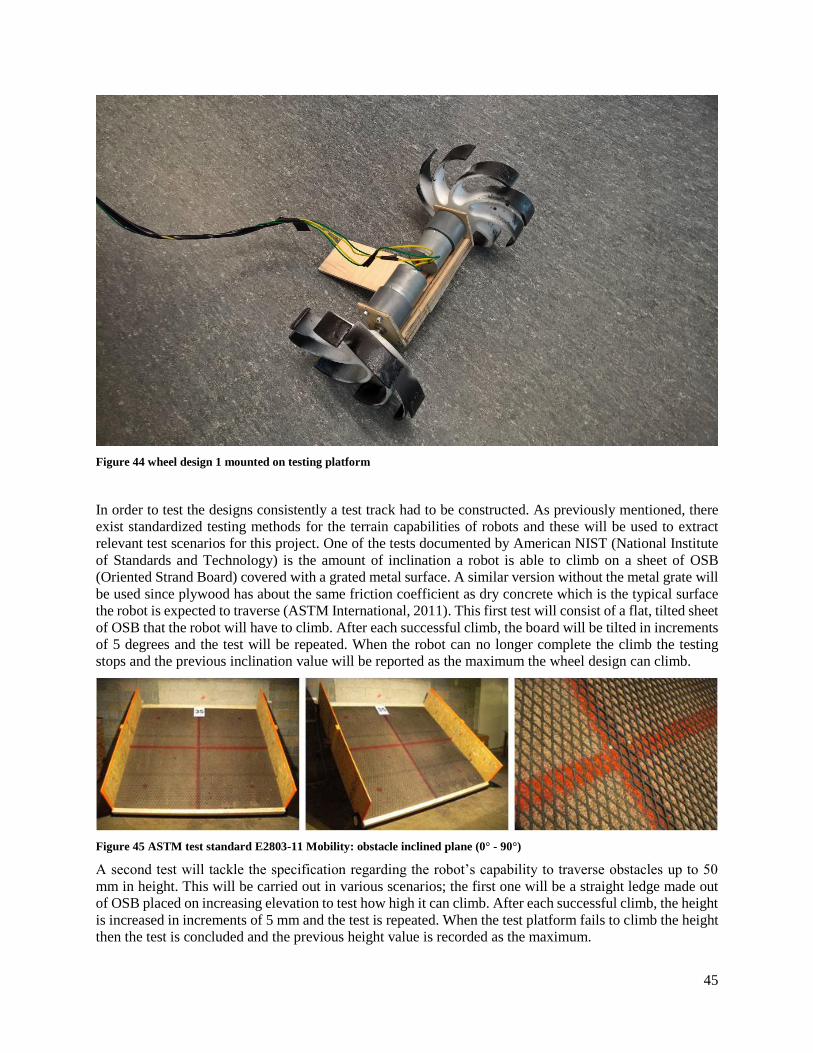
45
Figure 44 wheel design 1 mounted on testing platform
In order to test the designs consistently a test track had to be constructed. As previously mentioned, there
exist standardized testing methods for the terrain capabilities of robots and these will be used to extract
relevant test scenarios for this project. One of the tests documented by American NIST (National Institute
of Standards and Technology) is the amount of inclination a robot is able to climb on a sheet of OSB
(Oriented Strand Board) covered with a grated metal surface. A similar version without the metal grate will
be used since plywood has about the same friction coefficient as dry concrete which is the typical surface
the robot is expected to traverse (ASTM International, 2011). This first test will consist of a flat, tilted sheet
of OSB that the robot will have to climb. After each successful climb, the board will be tilted in increments
of 5 degrees and the test will be repeated. When the robot can no longer complete the climb the testing
stops and the previous inclination value will be reported as the maximum the wheel design can climb.
Figure 45 ASTM test standard E2803-11 Mobility: obstacle inclined plane (0° - 90°)
A second test will tackle the specification regarding the robot’s capability to traverse obstacles up to 50
mm in height. This will be carried out in various scenarios; the first one will be a straight ledge made out
of OSB placed on increasing elevation to test how high it can climb. After each successful climb, the height
is increased in increments of 5 mm and the test is repeated. When the test platform fails to climb the height
then the test is concluded and the previous height value is recorded as the maximum.

46
Figure 46 inclination test
Figure 47 climb height test
The climb height was tested using the same OSB used for the inclination test, see Figure 47 above. A
vertical wooden plank was later placed in the gap between the OSB and the floor to prevent the wheels
from moving in below the ledge and getting a better grip. Each test was deemed a success when the wheels
were able to climb the ledge and the horizontal distance from the axis of the wheels to the ledge was greater
than the wheel’s radius i.e. the robot had climbed past the ledge.

47
Both tests were repeated several times and the results are displayed in Table 9 below.
Table 9 Terrain capability test results
Design 1 Design 2 Design 3 Monster
Max incl. (degrees) 20 15 10 25
Max height (cm) 7 9 9 6
As the results show, there was not a clear winner of both tests. Instead, the monster wheels could climb the
highest inclination while designs 2 and 3 could climb the highest ledge. Design 1 has a good overall
performance in both categories while the monster wheels have the best inclination performance and worst
climbing performance. It should be noted that all of the wheel designs fulfill the minimum climbing height
specification for the robot so in that regard they all perform as required. The best general performer in both
tests was determined to be design 1.
Finally, some outdoor tests of both terrain capabilities were also performed to see if the results would differ
from the controlled tests. Three sites were spotted and deemed suitable for this task:
The first spot, pictured in Figure 48 below, is a sloped surface beneath a bridge that consists of dusty
concrete tiles with an inclination of around 20 degrees.
Figure 48 dusty concrete test
The results are shown in Table 10 below:
Table 10 dusty concrete test results
Wheel design Outcome
1 Fail

48
2 Fail
3 Fail
Monster Pass
As the results show, only the monster wheels were able to climb the slope; this is likely due to the increased
surface area of the tires being in direct contact with the ground at any point in time.
The second test involved small gravel (shown in Figure 49 below) on a small inclination of
approximately 15 degrees and the results are displayed in Table 11 below:
Figure 49 small gravel test
Table 11 small gravel test results
Wheel design Outcome
1 Pass
2 Pass
3 Pass
Monster Pass
As shown, all wheel designs pass the test though it’s noteworthy that the monster wheels performed
slightly worse than the other designs and took longer to move the same distance. This might be because
designs 1, 2 and 3 all have protruding fins which can act as shovels and dig into the small gravel which
provides increased traction.

49
Figure 50 big gravel test
The third and final outdoor test was performed beneath a bridge, shown in Figure 50 below, where there
was a slope covered in big gravel stones; approximately 3-5 cm in diameter. The inclination was estimated
to be around 20 degrees. This setting was believed to show the possible advantage of protruding fins which
can grasp objects and uneven surfaces for improved movement ability.
The results are listed in Table 12 below:
Table 12 big gravel test results
Wheel design Outcome
1 Pass
2 Pass
3 Pass
Monster Pass
As the results show, all wheel designs were able to climb the slope and visual observations during the test
revealed that there was no discernable difference between them in terms of climbing speed.
4.4.2.5 Terrain capability test discussion
The maximum inclination was not an initial specification for the robot but was deemed necessary since it
is tested by ASTM and is another aspect of terrain capability that can help determine the best performing
wheel in regards to their ability to overcome difficult terrain.
The first terrain capability tests showed that there was no clear winner; instead the custom designed had an
edge in climbing height and monster wheels in inclination. The overall winner of both categories was
determined to be design 1 while the second round of tests showed that there was no big difference in
performance when combining inclination and climb height testing in outdoor scenarios. What it did show
was that the monster wheels have a slight advantage in terms of traversing inclinations.

50
4.4.2.6 Choosing the final wheel design
In order to determine the best wheel design, the most important aspects need to be decided. The previous
tests compared the wheels’ performance in regards to:
Shock absorption
Climbing a slope
Climbing an obstacle
The shock absorption capability should be considered the most important since it determines how rugged
the robot is and its likelihood of surviving violent impacts. If the robot is damaged during deployment and
has impaired performance, then the other characteristics are likely impacted as well. Because of this and
the results from the tests that displayed superior suspension capabilities and good, general terrain
capabilities; the monster wheels are finally selected as the wheel design for the prototype. As mentioned
earlier; the test results don’t exclude the possibility for an optimized version of wheel designs 1-3 that
would perform better than the monster wheels. This would however be outside the scope of this project and
will be suggested as a future development project of the robot.
A concern regarding the wheel designs with fins is their force distribution during impact. Since they are
made up of separate fins that are connected at the center the impact forces are much more focused on local
points on the wheel compared to the monster wheels where the forces are more evenly distributed. This
increases the risk of fins experiencing local stress forces exceeding the materials’ capabilities and causing
them to break; see Figure 51 below for an illustration;
Figure 51 impact force distribution
Another concern is since the fin designs depend on local deflections for their suspension performance they
need to deflect a greater distance and therefore require a larger diameter than their circular counterpart in
order to obtain the same performance and prevent the chassis from hitting the ground. This would increase
the overall size of the robot and reduce its capability to navigate through tight-fitting spaces. Conversely,
in order to obtain the same terrain capability as designs 1-3 you need to increase the diameter of the monster
wheel which would have the same negative effect.
Since the suspension capabilities were determined the most important part of the wheel design then the
monster wheels naturally allow the size of the robot to be smaller with good suspension. The amount of
suspension required by the wheels to protect the payload in the chassis has not been determined which
needs to be addressed in future development projects.

51
Drivetrain
Special focus was put on the drivetrain to ensure
its rigidity and is shown as a cross-section in
Figure 52. The drivetrain consists of two
cogwheels for each motor with a gear ratio of 1:1
for transferring the power and protecting the motor
axis from getting bent during impact. The second
cogwheel (shown in red) in level with the wheel
axis is clamped together with an external piece
(shown in gray) and secured with a screw which
also provides additional internal rigidity. The red
and grey pieces are allowed to rotate freely by
using radial bearings (shown in white) which are
secured by both halves of the outer chassis. The
gray piece on the left side of the red cogwheel is a
metal rod which extends to the other side and is
used to distribute any axial impact forces evenly
between both sides of the drivetrain. The rod is
slightly smaller than the hole in the red piece and
therefore allows it to rotate freely; the only
movement it prevents is in the axial direction. This
design was inspired by the teardown of the Sphero
Ollie robot detailed in section 3.2.4 that uses the
same system. See Figure 53 below for a full cross-
section view of the drivetrain and rod. As can be
seen in the image; the rod is fixated in several spots
by fins on the main chassis and internal chassis
which will provide additional rigidity inside the
chassis.
Figure 52 impact resistance drivetrain cross-section
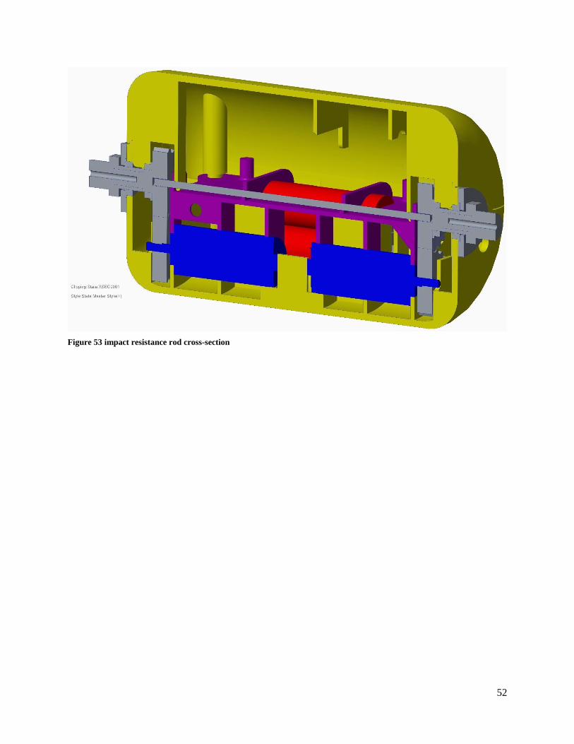
52
Figure 53 impact resistance rod cross-section

53
4.5 Chassis
The chosen design of the robot is a cylinder between two wheels as stated in section 3.1. A key aspect of
the robot is that the wheels will not only help it move but also provide impact protection. In order for them
to provide that protection and because there are countless ways the robot can land during deployment the
chassis should have an impact orientation invariant design. In other words, it can handle impacts from any
direction. Therefore, the cylinder is the best option in terms of impact resistance and space efficiency. This
also means there shouldn’t exist any protruding objects on the chassis that can be hit.
After several design revisions the following chassis design was chosen; see Figure 54 - Figure 60 below.
The main, outer chassis consists of two half-cylinders (shown in yellow) joined together with four screw
fasteners. The sensor is supposed to be mounted in the gray cylinder shown in Figure 55 and the camera
lens is protected by a transparent piece of plexiglass that’s secured with two screw fasteners. The internal
components are held together through the use of support ribs and screws in the half-cylinders and the two
internal chassis parts (shown in purple and red).
The various design considerations and solutions that went into the design will be explained in the next
sections.
Figure 54 chassis design exploded view

54
Figure 55 chassis design general view
Figure 56 chassis design general view transparent

55
Figure 57 chassis design front view transparent
Figure 58 chassis design rear view transparent

56
Figure 59 chassis design left view transparent
Figure 60 chassis design right view transparent

57
Ingress protection
One of the specifications for the robot was having an ingress protection of at least IP65 in order to increase
the ruggedness of it. This means the chassis needs to be dustproof and able to withstand waterjets from any
direction. The way this was solved was by creating an L-shaped lip on both halves of the chassis that
intersect when joined together. A small gap between the lips allows the insertion of a flexible sealing ring
to provide additional ingress protection, see Figure 61 below.
Figure 61 ingress protection lip cross-section
The camera lens is ingress protected by using a transparent piece of plexiglass, see Figure 62 for a general
outline. The camera lens is situated in the middle between the two mounting holes and will be ingress-
protected by placing a sealing ring outside the perimeter of the lens.
Figure 62 camera glass
The charging port is protected by a plastic screw cap and has a rated ingress protection of IP68 which
exceeds the specification for this robot; see Figure 63 below. It is mounted in the hole shown in Figure 64
and will provide good protection from external contaminants.

58
Figure 63 charging port
A slight bump was added on each side of the outer perimeter on the bottom cover where the wheel axis is
situated in order for the two halves and the sealing ring to encompass the entire chassis without any gaps;
see Figure 64 below.
Figure 64 bottom cover

59
Two oval plates on each side of the chassis with a hole in the middle for the wheel axes keep two radial
bearings secured which provide ingress protection; see Figure 65 below for a cross-section view of one
side.
Figure 65 ingress protection wheel axis cross-section
Impact resistance
The construction of the chassis has always had this specification in mind while designing it.
After some discussion a thickness of 3 mm for the chassis was deemed sufficient for providing enough
stability and impact resistance with 2 mm thick ribs added to increase the stiffness of the main chassis.
As stated before, the two halves are joined together with four screws as seen in Figure 64. The screw holes
are also used for providing additional stability of the internal components by being clamped together when
assembled; see Figure 66 below for a cross-section view and general view.

60
Figure 66 impact resistance screw holes
All internal components are secured either with screws onto internal chassis parts or by being clamped by
ribs with grooves for the parts which can be seen in Figure 64. Figure 67 and Figure 68 below shows cross-
section views of the motors and batteries being held together with ribs.

61
Figure 67 impact resistance ribs cross-section long
Figure 68 impact resistance ribs cross-section short

62
Cost
Since one of the main goals of the robot was to be low-cost in order to view it as an expendable resource in
the field; it was an important consideration during the design phase. The proposed future method of
manufacturing the chassis components is injection-molding due to its short cycle-time, suitability for large
production series and low material cost. When designing a product for injection-molding there are certain
design rules which need to be followed in order to keep the production time- and cost-efficient. Due to the
fact that the prototype will be 3D-printed and the projects’ limited time and resources it was decided that
not all design guidelines needed to be implemented in the printed chassis version and hence certain design
geometries might not be fully suitable for injection molding. The design guidelines were gathered from two
sources: the first one is a book written by a veteran of the plastic industry (Bruder, 2014) and the second
are recommendations from one of the major manufacturers of polymer materials (Dupont, 2000). The
design rules that were considered are the ones that are difficult to implement at a later stage in the design
such as ensuring the part can be extracted in one direction after being injection-molded. Other aspects such
as implementing corner radiuses, draughts and accounting for shrinkage of the material are deemed easier
to implement and are left as future work when a fully-optimized design for injection-molding would be
developed. Suggestions on how to prepare the design for injection-molding are included in chapter 5 further
below.
4.5.3.1 Design part to allow it to be ejected from mold
One of the first design rules is to ensure that the design can be ejected in one direction. The reason is because
of the way injection-molding works which is by using two halves with cavities that correspond to the design
of the object to be manufactured. The two halves are then joined together under high pressure and have a
funnel where molten polymer can enter the mold and become the designed part. After the material has
cooled down and become a solid the two halves are separated. The part is then removed from the mold by
using ejector pins that push the finished part away from the mold half it’s attached to.
Figure 69 injection molding process
Since the part needs to be ejected from the mold there can’t be any geometry that prevents it from being
removed. Examples of this are geometry that extends perpendicular to the ejection direction and walls that
extend inward and are conical. See Figure 70 below for an illustration.

63
Figure 70 injection molding wrong geometry
An example of this rule is the lower internal chassis in the robot shown in Figure 71 and Figure 72. It
consists of a flat, horizontal piece with vertical protruding fins used for supporting the surrounding
components. The two S-shaped pieces is where the camera module is mounted and since they are flexible
it allows the camera to be pushed inward when assembling the top cover. The S-shape will enable the part
to be ejected from a two-piece mold and eliminates the need for manufacturing a separate mounting piece
for the camera module.
Figure 71 lower internal chassis front view

64
Figure 72 lower internal chassis rear view
4.5.3.2 Uniform wall thickness
One of the rules is to keep the wall thickness consistent in order to avoid warping being caused by thinner
sections cooling down faster and introducing internal stress. See Figure 73 below for an illustration of the
problem. As stated before, the specified thickness of the outer chassis is 3 mm which is consistent
throughout the main chassis except for the supporting fins that are 2 mm and the lip along the outer
perimeter that is 1.5 mm thick. If the wall thickness can’t be consistent as is the case with the lip then the
transition should be gradual by using a chamfer, see Figure 73 below for an illustration. All other chassis
parts are designed with the uniform wall thickness of 2 mm.
Figure 73 wall thickness warping and transition

65
Component Mounting
The chassis is made up of four individual pieces that creates the external chassis and an internal support
structure to accommodate mounting of the electrical components. The support structure provides rigid
mounting spots for the components as well as clearance between the components.
4.5.4.1 Battery and Motors
There are a number of things to consider when determining where different components should be placed.
Heavy components, such as the motors and battery, should be placed in the lower parts of the chassis in
order to keep a low center of mass while some components, like the microcontroller, should be placed so
that necessary connections can be made. Other things to consider is the heat dissipation within the chassis
and making sure that heat can be dissipated.
In the lower region of the chassis is a custom made support structure for the batteries and motors. Figure
74 below depicts the placement of batteries, motors and power switch. The motors are located in the
lowest part of the robot, directly beneath where the wheel axis will be. On either side is a lidless box to
place the batteries in. Each box has enough space for two batteries placed on top of each other with a
metal plate in one end that connects them to each other. The two battery boxes are then connected using a
wire between the bottom two batteries.
Located in the back of the robot is the three-pin power switch. One of the pins is directly connected to the
battery’s positive terminal, the second creates a connection to the rest of the robot via a LED-light
indicator and the third pin is connected to common ground.
Figure 74 battery and motor placement in chassis
4.5.4.2 Microcontroller
The next component to be mounted is the microcontroller. As seen in Figure 75, the microcontroller is
mounted as far back as possible to allow space for the camera to be mounted in the front.
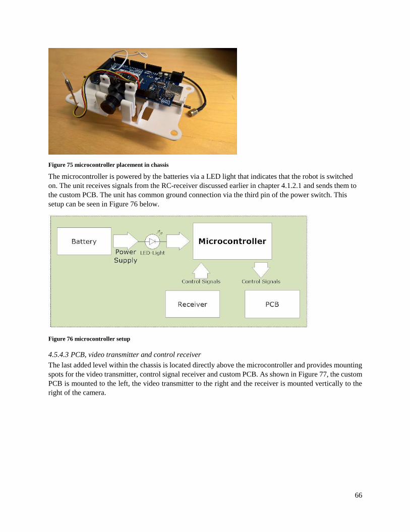
66
Figure 75 microcontroller placement in chassis
The microcontroller is powered by the batteries via a LED light that indicates that the robot is switched
on. The unit receives signals from the RC-receiver discussed earlier in chapter 4.1.2.1 and sends them to
the custom PCB. The unit has common ground connection via the third pin of the power switch. This
setup can be seen in Figure 76 below.
Figure 76 microcontroller setup
4.5.4.3 PCB, video transmitter and control receiver
The last added level within the chassis is located directly above the microcontroller and provides mounting
spots for the video transmitter, control signal receiver and custom PCB. As shown in Figure 77, the custom
PCB is mounted to the left, the video transmitter to the right and the receiver is mounted vertically to the
right of the camera.

67
Figure 77 PCB, video transmitter and control receiver placement in chassis
There are several components that need to be connected to the batteries for power. But having individual
long wires stretching out to each component would take up precious space and create a messy solution. For
this purpose, the PCB is equipped with power outputs so that components can be connected to the power
supply using short wires. Finally, the PCB is connected with the microcontroller in order to receive control
signals for the motors. The schematic can be seen in Figure 78 below.
Figure 78 PCB power and signal schematic
An overview of the connected units can be seen in Figure 79 below with complementary schematics of each
component attached in appendix D.

68
Figure 79 overview wire schematic of electrical components
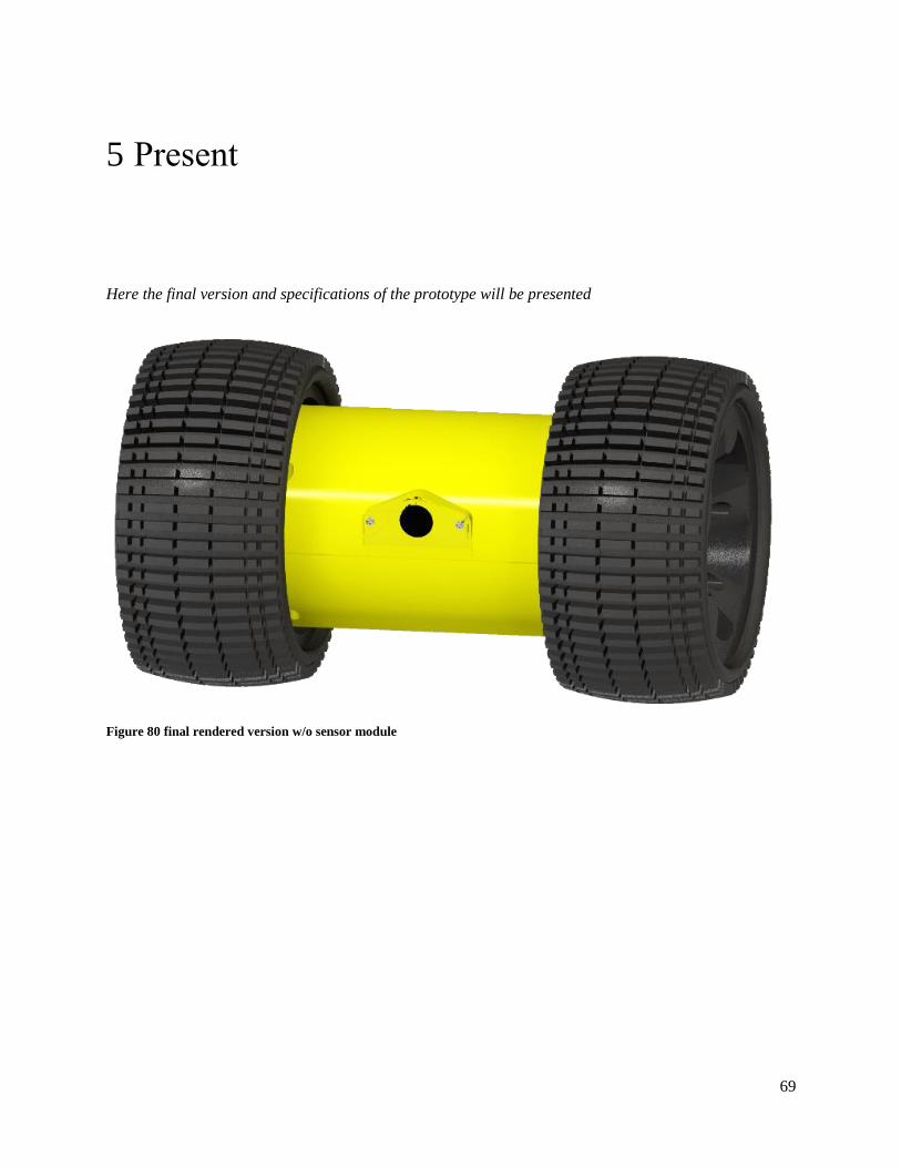
69
5 Present
Here the final version and specifications of the prototype will be presented
Figure 80 final rendered version w/o sensor module

70
Figure 81 General view of prototype w/o sensor module inserted
The prototype has the following specifications:
Table 13 prototype specifications
Dimensions (mm) 250 x 150 x 150
Weight (g) 1 580
Traveling speed (km/h) 2.84
Climbing height (mm) 60 mm
Slope inclination (deg) 20
Cost (SEK/USD) 4 139 / 495

71
Figure 82 front view of prototype
Figure 83 side view of prototype
Despite efforts to lower the center of mass on the prototype it turned out to be close to the axis or rotation
and would cause the robot to spin around its own axis. To prevent this, a protruding piece made out of a
foam polymer was mounted to counteract the torque as shown in Figure 84.

72
Figure 84 supporting fin

73
Figure 85 internal components mounted inside chassis

74
Figure 86 microcontroller and camera mounted inside chassis
Figure 87 bottom- and top half of chassis
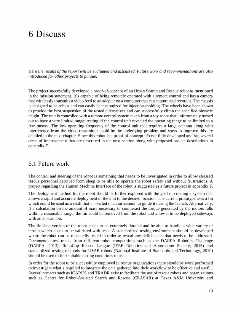
75
6 Discuss
Here the results of the report will be evaluated and discussed. Future work and recommendations are also
introduced for other projects to pursue.
The project successfully developed a proof-of-concept of an Urban Search and Rescue robot as mentioned
in the mission statement. It’s capable of being remotely operated with a remote control and has a camera
that wirelessly transmits a video feed to an adapter on a computer that can capture and record it. The chassis
is designed to be robust and can easily be customized for injection-molding. The wheels have been shown
to provide the best suspension of the tested alternatives and can successfully climb the specified obstacle
height. The unit is controlled with a remote control system taken from a toy robot that unfortunately turned
out to have a very limited range; testing of the control unit revealed the operating range to be limited to a
few meters. The low operating frequency of the control unit that requires a large antenna along with
interference from the video transmitter could be the underlying problem and ways to improve this are
detailed in the next chapter. Since this robot is a proof-of-concept it’s not fully developed and has several
areas of improvement that are described in the next section along with proposed project descriptions in
appendix F.
6.1 Future work
The control and steering of the robot is something that needs to be investigated in order to allow stressed
rescue personnel deprived from sleep to be able to operate the robot safely and without frustrations. A
project regarding the Human Machine Interface of the robot is suggested as a future project in appendix F.
The deployment method for the robot should be further explored with the goal of creating a system that
allows a rapid and accurate deployment of the unit to the desired location. The current prototype uses a fin
which could be used as a shaft that’s inserted in an air-cannon to guide it during the launch. Alternatively,
if a calculation on the amount of mass necessary to counteract the torque generated by the motors falls
within a reasonable range; the fin could be removed from the robot and allow it to be deployed sideways
with an air-cannon.
The finished version of the robot needs to be extremely durable and be able to handle a wide variety of
terrain which needs to be validated with tests. A standardized testing environment should be developed
where the robot can be repeatedly tested in order to reveal any deficiencies that needs to be addressed.
Documented test tracks from different robot competitions such as the DARPA Robotics Challenge
(DARPA, 2013), RoboCup Rescue League (IEEE Robotics and Automation Society, 2015) and
standardized testing methods for USAR-robots (National Institute of Standards and Technology, 2010)
should be used to find suitable testing conditions to use.
In order for the robot to be successfully employed in rescue organizations there should be work performed
to investigate what’s required to integrate the data gathered into their workflow to be effective and useful.
Several projects such as ICARUS and TRADR exist to facilitate the use of rescue robots and organizations
such as Center for Robot-Assisted Search and Rescue (CRASAR) at Texas A&M University and

76
International Search and Rescue Advisory Group (INSARAG) (ICARUS, 2016), (TRADR, 2016)
(CRASAR, 2016), (INSARAG, 2016).
Combine all separate circuit boards into one unit and develop sensor platform
The most important thing to develop is a custom PCB that incorporates all the electrical components into
one PCB. This would not only reduce the required space inside the robot allowing the robot to be
considerably smaller, but also reduces the complexity of the internal design by reducing the number of
independent components. Using a custom designed PCB also gives the developers the ability to choose the
most suitable connection points for other components such as motors and camera in order to further reduce
the size of the robot. Such a PCB should contain the following components:
Microcontroller H-Bridge Transmitter / Receiver Voltage regulator Charging circuit containing the necessary protection circuits Connection points for camera, motors, antenna and battery
This will most definitely cause major reductions in terms of required space inside the chassis and enable a
smaller and lighter unit to be developed.
Control
6.1.1.1 Steering
The current steering of the motors is a binary control unit meaning it only has two different states: full
forward or full reverse. For the robot to be effective in environments that require more fine movements it’s
desirable to be able to control the speed of each motor independently. Future development of the robot
should therefore incorporate a way for independent speed regulation of the motors with either analog or
digital data transfer protocols. One way of creating analog signals with different amplitude values is to
equip the levers on the hand control with potentiometers and thus regulate the voltage of the transferred
signal. The signal can then be interpreted by the processor on the robot in order to supply the appropriate
amount of current to the motors. Another way of doing it is to use levers with encoders on the hand control
to determine the desired speed and send a digital signal to the processor so that the desired current can be
supplied to the motors.
6.1.1.2 Communication
As stated in the discussion the chosen control system didn’t perform as well as expected. For the robot to
be used effectively during Urban Search and Rescue operations it’s essential for the operating range to be
long enough so that it doesn’t become an impediment for the robot to be employed. It should also employ
a frequency that has the ability to pervade walls in order to ensure constant connection to the robot. The
current control system needs to be replaced by a more reliable system using a higher frequency and with
longer range capabilities. Some controllers also allow the use of multiple robots operating on the same
frequency at the same time by employing technology such as digital spectrum modulation (DSM). The use
of multiple robots could help the rescue team locate injured people in need of help quicker. It’s also desired
that the new control system is a full duplex communication system to allow simultaneous transmission of
video feedback, control signals and sensor data in order to reduce the number of components in the robot.

77
Power
The battery powering the robot is intended to be charged using a custom-made three-pin charging cable that
attaches to the three-pin connector in the robot. In order for the batteries to be safely and equally charged
there’s need for development of a few internal protection circuits. Figure 88 below depicts a charging circuit
intended to charge two li-ion batteries with matching voltages.
Figure 88 charging circuit
The circuit has a potentiometer that allows the user to set the charging voltage to match the battery voltage.
As long as this voltage is set correctly the charger has built in overcharge protection.
Developing this charger circuit by adding a balancer to assure that each battery is charged equally and a
fuse to cut current if the temperature of the batteries goes too high and incorporating the design into the
robot provides the robot with a safe way to charge the robot between the missions.
Sensors
For the robot to be effectively used in Urban Search and Rescue operations it needs to have support for the
connection of a sensor. A modular design that makes it easy to switch between different sensor types in
order to equip the robot for various special missions therefore needs to be developed. By using a simple
connector terminal such as the one depicted in Figure 89 below the sensor can be easily be connected to the
robot.

78
Figure 89 connector terminal
The sensor module is then connected to the microcontroller as shown in Figure 90 below providing the
desired modular functionality.
Figure 90 sensor module connection to microcontroller
The finalized version of the robot will most likely often be used in environments with limited light. Regular
cameras will have trouble of capturing images in such environments making it desirable to equip the robot
with its own light source. A simple solution would be to equip the robot with normal or infrared LED lights
to illuminate the environment giving the operator a clear view of the surroundings. In the latter solution
with infrared LED lights an infrared camera should be replacing the current camera.
Locomotion
The writers believe more research into the wheel designs is required; the wheels on the Throwbot show that
a combination of a conventional wheel design and the fin design can achieve great mobility and suspension
performance. The current specification of climbing 50 mm obstacles is rather conservative and should be
improved in order to increase the robot’s terrain capabilities. Different materials should also be investigated
as a means of absorbing the impact forces and allow the wheels to deform instead of breaking.

79
The development of a smaller robot reduces the amount of torque required by the motors to drive the robot.
Replacing the current motors with smaller, cheaper motors more suited for mass production further reduces
weight and size of the robot as well as reducing the cost for mass production. Lower current and voltage
requirements also reduce the amount of power consumed allowing the use of a smaller battery. The current
H-bridge should also be replaced with a device that’s more suited for the lower amounts of required current
loads by the motors.
Chassis
After the space required by the new internal components has been determined; the chassis should be
redesigned to take advantage of the smaller footprint and enable a smaller robot to be constructed. It should
also be developed to allow it to be injection-molded by following the remaining design guidelines detailed
in the literature cited earlier. The suggested polymer material to be used is Polyoxymethylene (POM) or
also called Acetal due to its high strength, good heat resistance and high dimensional stability. The
injection-molded chassis is also recommended to be double-injected with the second pass constructing the
sealing ring directly onto the chassis piece.

80
References
(2013, December 3). Retrieved from SensoDuino - Google Play Store:
https://play.google.com/store/apps/details?id=com.techbitar.android.sensoduino
ASTM International. (2011, November). Retrieved from E2803 − 11 Standard Test Method for Evaluating
Emergency Response Robot Capabilities: Mobility: Confined Area Obstacles: Inclined Planes:
http://www.astm.org/Standards/E2803.htm
Bosch. (n.d.). Retrieved from BMA222E Digital, triaxial acceleration sensor: https://ae-
bst.resource.bosch.com/media/_tech/media/product_flyer/BST_BMA222E_FL000-
01_062013.pdf
Bruder, U. (2014). User's Guide to Plastic. Karlskrona: Bruder Consulting AB.
CRASAR. (2016). Center for Robot-Assisted Search and Rescue (CRASAR) at Texas A&M University.
Retrieved from http://crasar.org/
DARPA. (2013, December). DARPA. Retrieved from DARPA Robotics Challenge - Terrain Task:
http://archive.darpa.mil/roboticschallengetrialsarchive/node/160/index-
width=900&height=600.html
Dupont. (2000). General Design Principles for DuPont Engineering Polymers. Retrieved from Dupont:
http://www.dupont.com/content/dam/dupont/products-and-services/plastics-polymers-and-
resins/thermoplastics/documents/General%20Design%20Principles/General%20Design%20Princ
iples%20for%20Engineering%20Polymers.pdf
ICARUS. (2016). ICARUS - Unmanned Search and Rescue. Retrieved from http://www.fp7-icarus.eu/
IEEE Robotics and Automation Society. (2015, Maj 31). IEEE Robotics and Automation Society (IEEE-
RAS) Safety, Security and Rescue Robotics (SSRR) Summer School. Retrieved from
http://wiki.ssrrsummerschool.org/doku.php?id=rrl-rules-2015
INSARAG. (2016). INSARAG. Retrieved from http://www.insarag.org/
Mathew, T. J. (2015). SCARAB : development of a rugged, low cost, inspection-class robotic platform.
Cape Town: University of Cape Town.
McVay, J. (2014). LittleBot. Victoria University of Wellington.
Murphy, D. R. (2016). Missions, Choice of sUAS Platforms, and Manpower for Flying Floods: Lessons
learned from our deployment with Fort Bend County May 30-31, 2016. Retrieved from Center for
Robot-Assisted Search and Rescue: http://crasar.org/2016/06/04/missions-choice-of-suas-
platforms-and-manpower-for-flying-floods-lessons-learned-from-our-deployment-with-fort-bend-
county-may-30-31-2016/
National Institute of Standards and Technology. (2010, Oktober 5). NIST Engineering Laboratory -
Intelligent Systems Division. Retrieved from http://www.nist.gov/el/isd/test-methods.cfm
Recon Robotics. (2016). Retrieved from Recon Robotics: http://www.reconrobotics.com/
Recon Robotics. (2016). Recon Scout XL. Retrieved from
http://www.reconrobotics.com/products/Recon_Scout_XL.cfm

81
TRADR. (2016). TRADR project. Retrieved from http://www.tradr-project.eu/
Ulrich, K. T., & Eppinger, S. D. (2012). Product Design and Development, fifth edition. McGraw-Hill.
US Thermal Optics. (2016). Retrieved from Recon Scout ThrowBot:
http://usthermaloptics.com/shop/recon-scout-throwbot/

2
Appendix A project timeline and evaluation The project was initially scheduled to be carried out over the course of 16 weeks in total and the Gantt-
chart is displayed below in Figure A.1 and Figure A.2.
Figure A.2 project timeline

3
The project took longer than initially planned and can largely be attributed to the increased scope of the
wheel design phase, unexpected delays in delivery and problems and failures of components such as the H-
bridge and custom PCB. The bad components caused a lot of headache for the authors and took a long time
to troubleshoot in order to find the faulty hardware. The PCB was more difficult to develop than initially
presumed with bad connections that wouldn’t work which resulted in a lot of resoldering. The standard
components such as the motors and video transmitter system that were ordered also took a long time to
arrive and caused frustrating delays in the project. The project took a hiatus during the summer months and
work resumed again in the beginning of August. The authors learned from this project to order necessary
components as soon as possible in order to reduce the effect of delayed deliveries and to order several pieces
of critical components to prevent faulty hardware from causing delays.
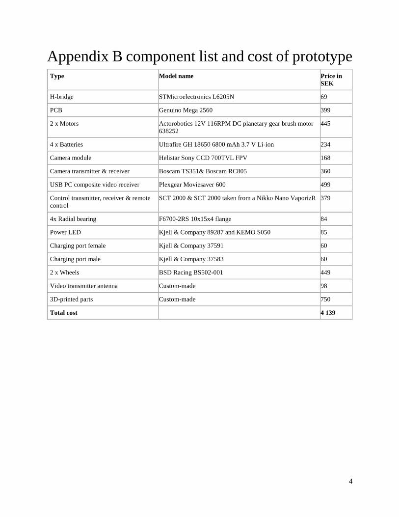
4
Appendix B component list and cost of prototype Type Model name Price in
SEK
H-bridge STMicroelectronics L6205N 69
PCB Genuino Mega 2560 399
2 x Motors Actorobotics 12V 116RPM DC planetary gear brush motor
638252 445
4 x Batteries Ultrafire GH 18650 6800 mAh 3.7 V Li-ion 234
Camera module Helistar Sony CCD 700TVL FPV 168
Camera transmitter & receiver Boscam TS351& Boscam RC805 360
USB PC composite video receiver Plexgear Moviesaver 600 499
Control transmitter, receiver & remote
control SCT 2000 & SCT 2000 taken from a Nikko Nano VaporizR 379
4x Radial bearing F6700-2RS 10x15x4 flange 84
Power LED Kjell & Company 89287 and KEMO S050 85
Charging port female Kjell & Company 37591 60
Charging port male Kjell & Company 37583 60
2 x Wheels BSD Racing BS502-001 449
Video transmitter antenna Custom-made 98
3D-printed parts Custom-made 750
Total cost 4 139

5
Appendix C detailed motor specifications

6
Appendix D circuit schematics
1. Mimer Complete Circuit
2. Microcontroller
3. Custom PCB

7
4. L6205 Dual Full-Bridge
5. Camera and Transmitter
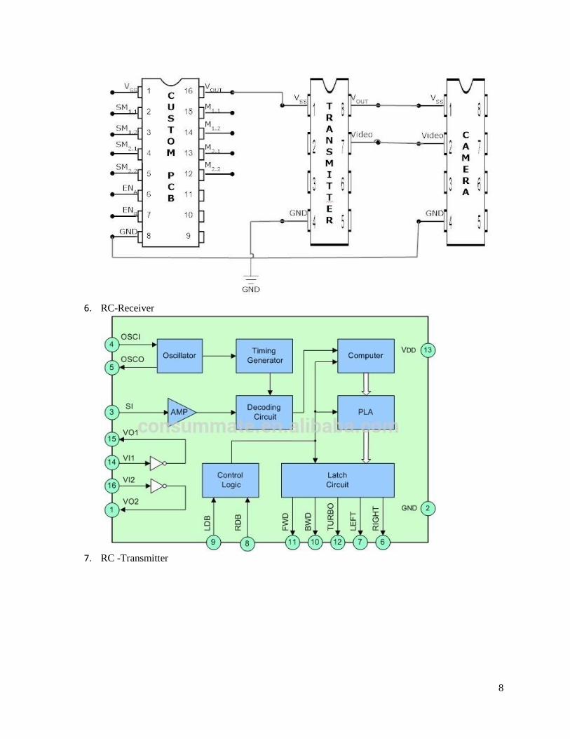
8
6. RC-Receiver
7. RC -Transmitter

9

10
Appendix E program
// Enable pins for motor 1 and 2
#define enableH 11
#define enableV 12
// Select motor connection pins
int motor_right[] = {52, 53};
int motor_left[] = {7, 8};
// Control signal variables
int rec1[] = {0, 0};
int rec2[] = {0, 0};
// Select receiver connection pins
int receiver_left[] = {A4, A3};
int receiver_right[] = {A0, A1};
// Variables to keep track of the current state of the motors
int modeR = 0;
int modeL = 0;
// Initiate and assign tasks to the selected pins
// Setup the program
void setup() {
// Motor Setup
int i;
for( i = 0; i < 2; i++){
pinMode(motor_left[i], OUTPUT);
pinMode(motor_right[i], OUTPUT);
}
// Receiver Setup
for( i = 0; i < 2; i++){

11
pinMode(receiver_left[i], INPUT);
pinMode(receiver_right[i], INPUT);
}
}
// The program to be executed over and over
void loop() {
// Enable write on the H-bridge
digitalWrite(enableH, HIGH);
digitalWrite(enableV, HIGH);
// Read inputs from controller
for( int i = 0; i < 2; i++){
rec1[i] = analogRead(receiver_right[i]);
}
for( int i = 0; i < 2; i++){
rec2[i] = analogRead(receiver_left[i]);
}
// Right motor control
switch(modeR) {
// Right motor idle
case 0:
// Right M Forward
if (rec1[0] > 1000){
digitalWrite(motor_right[0], HIGH);
digitalWrite(motor_right[1], LOW);
modeR = 1;
}
// Right M Backward
else if (rec1[1] > 1000){
digitalWrite(motor_right[0], LOW);
digitalWrite(motor_right[1], HIGH);

12
modeR = 2;
}
// Right M Stop
else{
digitalWrite(motor_right[0], LOW);
digitalWrite(motor_right[1], LOW);
modeR = 0;
}
break;
// Right motor forward
case 1:
// Right M Forward
if (rec1[0] > 1000){
digitalWrite(motor_right[0], HIGH);
digitalWrite(motor_right[1], LOW);
modeR = 1;
}
// Right M Stop
else{
digitalWrite(motor_right[0], LOW);
digitalWrite(motor_right[1], LOW);
modeR = 0;
}
break;
// Right motor backward
case 2:
// Right M Backward
if (rec1[1] > 1000){
digitalWrite(motor_right[0], LOW);
digitalWrite(motor_right[1], HIGH);
modeR = 2;
}
// Right M Stop

13
else{
digitalWrite(motor_right[0], LOW);
digitalWrite(motor_right[1], LOW);
modeR = 0;
}
break;
}
// Left motor
switch(modeL) {
// Left motor idle
case 0:
// Left M Forward
if (rec2[0] > 1000){
digitalWrite(motor_left[0], HIGH);
digitalWrite(motor_left[1], LOW);
modeL = 1;
}
// Left M Backward
else if (rec2[1] > 1000){
digitalWrite(motor_left[0], LOW);
digitalWrite(motor_left[1], HIGH);
modeL = 2;
}
// Left M Stop
else{
digitalWrite(motor_left[0], LOW);
digitalWrite(motor_left[1], LOW);
modeL = 0;
}
break;
// Left motor forward
case 1:
// Left M Forward

14
if (rec2[0] > 1000){
digitalWrite(motor_left[0], HIGH);
digitalWrite(motor_left[1], LOW);
modeL = 1;
}
// Left M Stop
else{
digitalWrite(motor_left[0], LOW);
digitalWrite(motor_left[1], LOW);
modeL = 0;
}
break;
// Left motor backward
case 2:
// Left M Backward
if (rec2[1] > 1000){
digitalWrite(motor_left[0], LOW);
digitalWrite(motor_left[1], HIGH);
modeL = 2;
}
// Left M Stop
else{
digitalWrite(motor_left[0], LOW);
digitalWrite(motor_left[1], LOW);
modeL = 0;
}
break;
}
// Small delay for stability
delay(200);
}

15
Appendix F suggested project descriptions
F.1 Mimer – development of integrated circuitry
The aim of this project is to redesign and integrate the internal components into one custom PCB in order
to reduce the size of the developed proof-of-concept robot. This project will evaluate existing components
and investigate alternatives in order to improve overall performance. A module for sensor mounting needs
to be developed to allow the robot to be equipped with a specific sensor suited for the current mission.
Further development of the control system is needed in order to provide speed regulation of the motors and
a charging circuit in order to assure safe and equal charging of the batteries.
F.2 Mimer – development of testing environment
The field of rescue robotics demands extreme robustness and maneuverability capabilities on the robots.
This project will investigate and develop a testing environment for the robot where it can be tested against
different difficult scenarios the robot could face while being deployed. Suggested areas to explore are terrain
capability testing, drop testing, visual tests, and heat tests. Existing facilities in the local area should be
explored to see if they could be used.
F.3 Mimer – development of chassis & locomotion
After having redesigned and integrated the internal components into one custom PCB; significant gains
could be made in the size and performance of the robot. This project’s aim should be to redesign the current
chassis and wheels to accommodate the new PCB-design and components and re-evaluate the existing
hardware to see if smaller and cheaper components could be utilized instead. The forces involved during
impact should be thoroughly investigated to make sure the design is not over dimensioned and can handle
the forces. The goal with the wheels will be to make sure they can provide the necessary shock resistance
and enable the robot to climb obstacles higher than 50 mm. The chassis should be designed to allow it to
be injection-molded and provide ample protection for the delicate components inside.
F.4 Mimer – development of Human-Machine Interface
The robot is aimed at being used by rescue personnel who will be under a great deal of pressure while
working. This project will focus on the user-friendliness and interface of the robot to ensure it can be
operated by a person who is sleep-deprived and stressed without complications.