
Design of LED grow light
43
Department Of Electronic and Information Engineering FYP final report draft Student Name & Student No.: DUAN Yujia 12144086d Supervisor: Dr. Y.M.LAI Program: 42079 Project Title: Design of LED Grow Light
-
Upload
independent -
Category
Documents
-
view
5 -
download
0
Transcript of Design of LED grow light

DepartmentOf
Electronic and Information Engineering
FYP final report draft
Student Name & Student No.: DUAN Yujia 12144086d
Supervisor: Dr. Y.M.LAI
Program: 42079
Project Title: Design of LED Grow Light

2.Abstract
LED Grow Light has been widely used in the cultivation and research of plants for a long time, it
provide the necessary light spectrum as sunlight supplement to plants. Now the LED grow lights
in market mostly have fixed light ratio and brightness. The function is single and can not be used
in various studies. In this project, an adjustable light color and brightness LED grow light which
is controled by PWM modulation has been designed for both large-scale and family, research and
cultivation use. A N-channel MosFET controller for constant current LED drivers is used to
driver and dimming the LED. Besides, in software part, the raspberry pi is used to design the
users interface and produce accordingly PWM output, and users can also achieve remote control
in their own computer with a router. The interface provide several recommended applications
settinng for specific plants, users can also design their own light ratio from totally 256*256*256
kinds of light combination. Users can also set time from the interface.
In this report, the theory and design procedure as well as the experimental result will be
presented both software part and hardware part. Further improvement advice is also provided for
later designer.
3. Introduction
3.1 Overview
Nowadays, grow light has already been widely used from large-scale to family cultivation. Grow
light is an artificial light source, designed to stimulate plant growth by emitting an
electromagnetic spectrum appropriate for photosynthesis to the situation which supplemental
light is required. The type of grow lights is variable, and LED grow light is the one we designed
in this project. Different from other kind of grow light, LED produce bright and long-lasting
lights which only emit specific wavelength that corresponding to the absorption peaks of a
plant’s typical photochemical process[1]. LED is also one of the most electronic efficiently light
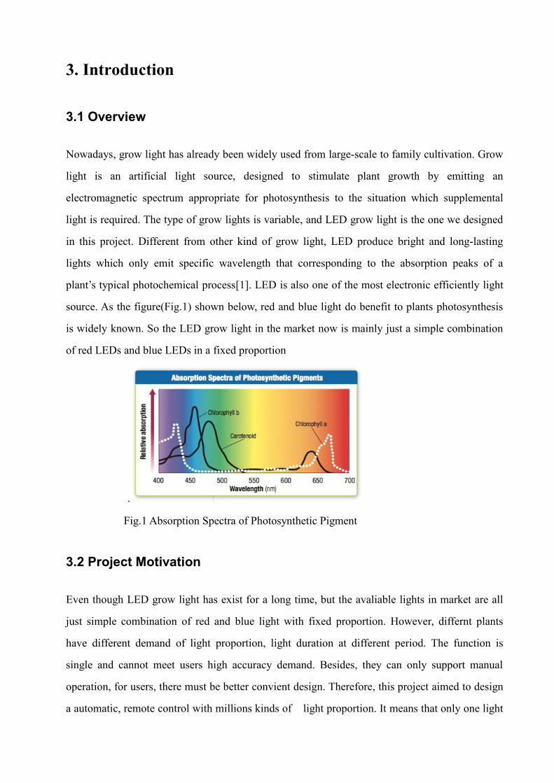
source. As the figure(Fig.1) shown below, red and blue light do benefit to plants photosynthesis
is widely known. So the LED grow light in the market now is mainly just a simple combination
of red LEDs and blue LEDs in a fixed proportion
.
Fig.1 Absorption Spectra of Photosynthetic Pigment
3.2 Project Motivation
Even though LED grow light has exist for a long time, but the avaliable lights in market are all
just simple combination of red and blue light with fixed proportion. However, differnt plants
have different demand of light proportion, light duration at different period. The function is
single and cannot meet users high accuracy demand. Besides, they can only support manual
operation, for users, there must be better convient design. Therefore, this project aimed to design
a automatic, remote control with millions kinds of light proportion. It means that only one light

can meet all plants requirment in all period, and users can control the light proportion, intensity
and time duration by computer in long distance.
3.3 Project Objective
The purpose of our project is to achieve the functions that mentioned in the last section.
Firstly, a high-power light will be designed. 3 series of LEDs which consist of 36 LEDs in total
will be the output, and the input voltage is 12V. So, a boost converter is needed in order to
achieve the basic circuit.
Secondly, each series of LEDs is one color. The project aim to produce variable colors by
combining red, green and blue LEDs in different proportion, so, the intensity of each color of
LEDs should be change when needed. The theory to change the LED intensity is pose different
output current to LEDs. There are several ways to achieve this goal, such as pulse width
modulation dimming and analog dimming[3]. In this project, we choose PWM dimming
application of LM3429 regulator.
Finally, a Raspberry Pi is used to produce PWM as well as achieve remote control for the light.
Raspberry Pi is an embedded development platform which can also be seen as a
cardcredit-card-sized single-board computer. Raspberry Pi type B has a Ethernet port which can
help achieve remote control of the light.

4. Background information
4.1 LM3429
LM3429 is a versatile high voltage N-channel MosFET controller for LED driver.[2] It has four
topologies: buck, boost, buck-boost and SEPIC. These four topologies is flexible and decide by
the input and output voltage. The input of input is ranging from 4.5V to 75V, makes LM3429 a
large family for applications. The graph below is the typical circuit of boost converter.
Fig.2 The typical boost application circuit
The flexibility of LM3429 is achieved by the control mode of it. LM3429 uses “Predictive
Off-time(PRO) control, which is a combination of peak current-mode control and a predictive
off-timer. When the current of the specific component reach the set value, this cycle will be
terminated immediately[2].” So, it use the inside PWM for converter use.
In this project, the most important part is the PWM dimming application of LM3429 which we
will discuss in next part. from PWM dimming, it also support analog dimming, over-voltage
protection, under-voltage lock-out, cycle-by-cycle limit and thermal shut down applications.

4.2 Pulse Width Modulation Dimming for LED
Pulse width modulation (PWM) (for driving LEDs) is used for luminance flux dimming. The
principle of PWM dimming is the boost converters turned ON and OFF by the high and low
level of PWM pulse[5]. In other words, the output current of boost converters of is constant but
not posed all the time. The duty cycle of hight level time is the ON time.
The number of bits of PWM levels is the criterion of color accuracy. In general, especially wider
dimming range, 12bit is the minimum requirement to ensure the stability of color[5]. In this
project, we use 256 levels PWM. Thus, 256*256*256 colors can be achieved.
In terms of frequency of boost converter, the PWM frequency must be set higher than the
frequencies that human’s eye can detect and much lower that converter frequency to avoid
flicker[5]. In this project, the boost converters are operated at more than 300KHz, so wen set
PWM frequency at around 300Hz.
4.3 RGB LED
For best combination of RGB colors, we choose multi-chip LEDs that provide high lumen and
multiple colors in a small package. This kind of LED reduce the distance between LED and give
excellent optical control and efficient color mixing.[6] The figure below is what we use in this
project--MC-E from CREE. For plant research, the characteristic of light is vitally important.
The table below shows the characteristics of the four colors.
Table. 1MC-E
characteristics
Color Dominant WavelengthRange
Base order codes codesMin. Luminous Flux@350mA*
ForwardVoltage
Min. Max. Group Flux(lm)Red 620nm 630nm
A5
30.6 2.2Vgreen 520nm 535nm 67.2 3.7VBlue 450nm 465nm 8.2 3.5VWhite 5700K 7000K 100 3.5V

Fig.3 CREE LED MC-E
Fig.4 The relationship between Forward Current and Luminous Flux
Fig.5 The relationship between Forward Voltage and Forward Current

Fig.6 The relationship between Junction Temperature and Relative Luminous Flux
The principle of changing intensity of LED is changing the forward current. According to the
chart, in 350mA, the intensity of the 3 kind of LEDs will reach 100% luminance. The PWM is
makes the forward current and relative luminance flux a linear relationship.
4.4 RGB values calculation
“The CIE RGB color space is one of many RGB color spaces, distinguished by a particular set of
monochromatic (single-wavelength) primary colors[7].” As the graph shows below, actually, the
CIE chromaticity diagram is not a plane figure, but a standard pyrometric cone. The three
corners of the red triangle is the specific wavelength RGB LED light, and all colors inside the
triangle can be achieved by combination the three colors light.
X, Y and Z are the three parameters of the CIE system. Since human’s eyes are sensitive to
difference of luminance much more than the variable of colors, Y is the luminance parameter.
The functions between of all three tristimulus X, Y and Z are:
ZYXXx
ZYXYy
yxZYX
Zz
-1
And the relationship between RGB CIE color space and XYZ space is:

BGR
BGR
bbbbbbbbb
bZYX
99.001.000.001063.081240.017697.0
20.031.049.0
17697.011
333231
232221
131211
21
The value of RGB is in the range from 0 to 255, adjust PWM output duty cycle form 0 to 100%
in the step of2561 the corresponding luminance will be produced.
Fig.7 CIE 1931 Chromaticity
4.5 Raspberry Pi
Raspberry Pi (RPI) is a kind of micro computer main board based on ARM. RPI use SD card as
RAM, and contains two USB ports and one Ethernet port which can connect to mouse, keyboard
and reticle. Users can use RPI directly in TV due to its analog signal TV-out port and HDMI high
definition port. RPI has its own operating system - Linux, users can play games, edit table as
well coding only connet to TV and keyboard. In this project, PWM output and remote control is
achieved by RPI.

Fig.8 Raspberry PI
Fig.9 Starting up interface of Raspbery PI
4.6 Python
Python is an object-oriented, interpreted programming language which invented by Guido van
Rossum in 1989. Python has clear and simple gramma, and the most prominent advantage of
Python is it has exceedingly rich class libraries which can help connect modules(especially C++)
build by other languages together. Apart from that, when codes need special modify, another
language can be used rather than python.
Fig.10 Logo of Python

4.7 Remote Control
Remote control is a technology that one computer(Remote) control another computer(Host) in
long distance, which mainly realized by remote control software.
The work pinciple of remote control software is: Remote control system usually has a client
program and a server program, client program is in the Remote and server program is in the Host.
At the begining, Remote send Host a signal to build a special remote serve, then Remote send
control instruction to Host through this serve. The program and applications in Host will be run.
Remote control instruction is a kind of Email with specific format. The receiver is
mailrouter#(modify by @)yourcompany#(modify by .)com. The format of specific instruction is
username=yourusername&password=yourpassword&command=commandname param1
param2 param3
Maxmium 3 instruction parameters can be send in a single instruction.
In this project, two kinds of remote control will be used. One is puTTY which based on
Windows and another is Vssh which based on Apple OS. PuTTY is a implementation of ssh
client. By using puTTY, Windows users can fully control any kinds of machine running *nix
operating system through ssh tunnel by sending shell commands and receiving shell outputs.
Vssh is s similar to puTTY in terms of function. These two software make the LED grow light
can be control by both computer and mobile devicec such as iPhone.
Fig.11 puTTY and vSSH

4.8. Light demand for several plants
Different plants need different, specific most appropraite light for growth. Artificial light source
is required to imitate nature light which the plant is the best adapted. If a plant do not get enough
light, it cannot be well growth regardless others conditions. For example, vegatable should be
cultivate in sufficient sunlight condition, as a result, in indoor farming of vegatable, high light
level is also required. However, foliage plants prefer living in low level light even full shade
condition such as Philodendron.
In addtion, many plants need both dark and light period which is called light period influence.
The best dark/light period defined by different breed of plants. For example, chrysanthemum
prefer longer night but China aster like long light period more. Whereas rose can growth best in
half light and half dark period mode.
In terms of lights color temperature, according to one manufacturer, plants prefer light levels 100
and 800 μmol m-2s-1.[4] The color temperature of lamps should be around 5800 K which
equals to 5800 to 46,000 lm/m2.[5]
According to the research did on variable plants, red and blue lights have most influence for
plants’ photosynthesis. But red and blue light have different effects. For vegatative growth, blue
LEDs are preferred, the wavelength is around 400nm. For fruits or flowers growth, high ratio of
red LEDs are preferred, the wavelength is very closed to 600nm to 640nm. In sunlight, the
proportion of red light to blue light is around 6.8:1.

5. Hardware design
5.1 Specification
According to the information of LEDs and regulator mentioned in last section, the input range of
LM3429 is from 4.5V to 75V, 12V is chosen as input voltage in terms of the common used
power supply. Output specifications are defined by the features of LEDs.
The following table illustrate the specification in this project:
Table.2 The Specification of the Circuit
Specification Color
Red Green Blue
Output current ( 0I ) 350mA 350mA 350mA
Output voltage ( OV ) 26.4V 44.4V 42V
Input voltage ( INI ) 12V 12V 12V
Output power ( OP ) 9.24W 15.54W 14.7W
5.2 Control Crcuit Designi
In this part, the skeleton of the entire circuit is introduced. The purpose of each part is also
described. The block diagram of the basic design of the product is:
Fig.13 The Circuit Design Flow Chart
There are two function of this circuit. The first function is achieve a boost converter. The second
function is using PWM driving to control the output current.
Control Circuitcontains LM3429
12 RGB LEDsOutput > 40V
15V InputPWM Input

According to the data sheet of LM3429, the circuit contains severals part. Apart from following
the function given by data sheet, the value of component should be easily found in the market.
Following the design steps:
(a) Duty Cycle
According to the circuit specification:
Duty Cycle:
INVV
VD0
0 63.8% (R)
INVV
VD0
0 74.7%(G)
INVV
VD0
0 73.7%(B)
(b) Switching Frequency
Rt and Ct decide the constant switching frequency(fsw). On the basis of the characteristic of
LM3429, the maximum switching frequency is 2MHz[2]. And the Ct capacitor is recommended
to be 1nF. As the result:
Fig.13 Circuit Diagram of RCT
(c) Average LED Current
The average current of LEDs are determined by a external resistor. The minimum suggested Icsh
is around 100uA, the minimum Vsns is suggested to be 50mV.[2] According to the formular (2)
to (6):
nFCT 1
z34725 KHCR
fTT
SW
KRRR TTT 72// 21
KRT 1201
KRT 1802

Fig. 14 Circuit Diagram of AVC part
HSP
SNSCSH R
VI (2)
CSH
HSPSNS R
RV 24.1 (3)
CSH
HSP
SNSSNS
SNSLED R
RR
VRVI
24.1 (4)
HSNHSP VV (5)
mAI LED 350 (6)
KVV HSNHSP 1
27.0SNSR
(d) Current Sense/Current Limit
LM3429 using peak current mode which is accomplished by a comparator. If the voltage of the
input sense(IS) exceeds 245mV, the on cycle is stopped, It means that the voltage on Rlim is
245mV[2]. According to the formula (7), the following result is got:
Fig.15 Circuit Diagram of Current Limit Part

LIMRmVI 245
LIM (7)
AI LIM 33.0
(e) PWM Dimming
The PWM dimming is achieved by the using nDIM port solely as a Vin input. The choose of this
project is using MosFET rather than the Schottky diode and connect the drain to the nDIM pin.
In case of no signal input situation, a pull down resistor is necessary between source and
ground(GND)[2]. The pull down resistor is set as 1Kohm, when there is no signal, it make sure
that the voltage on source is higher than drain. The PWM frequency should be high enough that
human’s eyes cannot detect and low enough to avoid flicker. The maximum frequency of PWM
is:
Fig. 16 Circuit Diagram of PWM Control Part
sV
HVmAV
LVItIN
OLEDpulse
62
6
21 10096.5
)15(10354.4435022
(8)
stT pulsepluse31030.1256
Hzf 766max
The maximum frequency human eyes can detect is 24Hz, as a result:
HzfHz 76624
I set the frequency as 300Hz.

5.3 Components
Since the RGB LED light could be out into widely used, in consideration of the cost and market
supply, the components are better to used widely in market. In view of the volume and
appearance, the board will be soldered with chip components mainly. SMT-0805 and SMT-1206
footprint are two of the most widely footprint which is used in resistor and capacitors. Hence, in
the circuit most resistors and capacitors are in these two footprint except input capacitor and
output capacitor. The table below are the components list:
Table.3 The Component used in the circuit
Components Value Footprint
Regulator LM3429 LM3429
Input Capacitor 100uF D-CAP100UF
Output Capacitor 220uF, 50V D-CAP220U6.8X7
Capacitors 47pF-4.7uF SMT-0805
Resistors 10ohm-511Kohm SMT-0805,SMT-1206
MOSFET IRF640B CON-TO-220AB
MOSFET AO3400 SOT-23-AO3415
Inductor SRR1210-390M SMT-CDRH127
Header HDR1X2
Header HDR1X3
5.4 PCB Circuit design
Altium Designer is the software which is used in this project to design schematic circuit
diagram and PCB board diagram. In PCB board design, the layout objective is to maximize noise

rejection and minimize Electro-Magnetic Interference of the circuit[2]. The following guidelines
are required to follow:
(a) The loop contains Cin, D1, Q1, Rlim should be kept as small as possible .
(b) The switch node which connect each components should be large and thick enough to
minimize parasitic inductance, and the wire should avoid right angle distribution.
(c) The loop contains RCT,COMP,CSH,IS,HSP and HSN pins should be kept as small as
possible.
(d) The LED arrays should be kept away from LM3429.
(e) The connection between components and ground should keep as short as possible to
minimize the voltage drop. When the frequency is very high, the voltage drop will be amplify
and effect the whole circuit a lot.
Fig. 17 The printed circuit board
5.5 Thermal management
The performance of LEDs are highly depend on the junction temperature, with the increasing of
junction temperature, the luminance flux of LED will decrease accordingly[3]. As a result, the
thermal management become vitally important. There are several aspects:
1. Thermal fin which LEDs paste on.

Fig. 18 Thermal fin of LEDs
2. Aluminum radiator shell
Fig. 19 Aluminum Radiator Shell
The whole produce will be put into this shell and the LEDs will paste by RTV on the top of
the shell for better thermal management.
Fig.20 The Thermal Design of LED grow light

6.Software Design
6.1 Users Interface Design
The users interface contains two part. Part 1 is full users defined setting mode which
conains a color plate, totally 256*256*256 colors can be choose. In addition, a timer which can
set each single series of LEDs exactly on the seconds is also included. Part 2 is users default
setting mode which is designed according to the specific features of different plants. 3 kinds of
light mode (Leaf and steam mode, Fruiting and Florescence mode and General mode) as well as
3 kinds of time mode (Long day mode, Long night mode and General mode), totally 3*3=9
modes for users to choose suitabel light for different kind of plants in different period. The
brightness also has 5 levels and users can set operation hours.
Fig.21 The users interface of LED Grow light
6.1.1 Color Plate
The color plate and RGB values of different value is invoke directly from the graphics library of
the operation system of PC. When users click one color point, corresponding RGB value of the
point will be produced.

Fig.22 The Color Plate of Users Interface
6.1.2 PWM prodece
General Purpose Input Output(GPIO) is used to produce the PWM. Program will call the
RPIO(GPIO control library) PWM library directly to produce the PWM by from RPIO import
PWM. The PWM is initialized through:
servo = PWM.Servo(0, 3000, 1)
servo.set_servo(23, 2999)
servo.set_servo(22,2999)
servo.set_servo(17, 2999)
These code means GPIO ports 23,22 and 17are used to produced withe the period of 3000us and
the increase step can be 1us.

The PWM duty cycle will change according to the value of RGB:
red = math.trunc(2999 - (2999 - adj_r) * (int(commands[0]) / 255.0))
green = math.trunc(2999 - (2999 - adj_g) * (int(commands[1]) / 255.0))
blue = math.trunc(2999 - (2999 - adj_b) * (int(commands[2]) /255.0))
Fig.23 GPIO ports of Raspberry PI
6.1.3 Default setting mode calculation
According to the background description in 4.8, 3 light modes and 3 time modes can be
combined to totally 9 modes for different plants in different period.
Light mode: Light modes are defined according to different RGB proportion
(1) General Mode: The red and blue proportion in natural sunlight is around R:B=6.8:1. The
general mode set R:B:G=7:1:1 so that the light is most similar to sunlight, which can be used in
any plants at any time.

(2) Fruiting and florescence mode: Higher proportion of red light is needed during flowering
period, R:B:G=8:1:0.
(3)
(4) Leaf and steam mode: In light of blue light helps the growth of leaf and steam. According to
one manufacturer, the blue light should be more, R:B:G=7:2:0.
Calculation of RGB value of different modes in different level:
Level 1 Level 2 Level 3 Level 4 Level 5
General Mode 49:7:7 98:14:14 147:21:21 196:28:28 256:36:36
Fruiting Mode 48:6:0 96:12:0 144:18:0 192:24:0 240:30:0
Leaf Mode 49:14:0 98:28:0 147:42:0 196:56:0 252:72:0
Time mode: Time mode is designed for plants’ different light/dark preference. The period is
defined as 1 hour. The three modes are defined by adjusting the light and dark duration in the one
hour.
(1) Long day mode: L(light):D(dark)=40min:20min
(2) Long night mode: L:D=10min:50min
(3) General mode: L:D=30min:30min
Fig.24 The default setting for specific plant growth situation

6.2 Communication description
1. The Raspberry Pi and PC communication throug a router, the router gives RPI an IP address.
The RPI is Host and the PC is Remote. The description of remote control is in the background
session
2. After RPI got its IP address, the server program in RPI start to run. Firstly, program will
initialize 3 PIN of GPIO port. Then, it will listen the virtual port 23333, waiting for data stream.
If instruction data stream received, server program will jump to corresponding logic and take
action. After the response, program will listen to the port and wait for new instruction.
3. The Client program only transfer the input from users to instruction data, and make sure that
PC and RPI communication communication correctly and instructions can be send to RPI.
4. There are two kinds of communication during the whole process.
(a) Connectivity test
It is a connectivity test between PC and RPI after target port and target are set. PC sends
“hello” to RPI, if RPI get it correctly, a “copy” will be replied. Then connection is correct when
PC get this string. The status in users interfave will change to connected, otherwise,
disconnected.
Fig.25 The schematic diagram of Connectivity Test between PC and RPI

(b) Instruction communication
In normal connection condition, PC sends RPI a 6 members array. For example,
[255,255,255,10,20,30], the first 3 elements are RGB value and the last 3 elements are lighting
time, the unit is second. Before it send to RPI, pickle, which is a library tranfer and rescue
specific data to binary bit stream, will transfer the array to a binary bit stream for easy data
tranmission in TCP socket.
5. After RPI judge the bit stream is not “hello”, pickle will rescue the array and control LEDs
according to this array. If the lighting time is 0, time delay will not be called; if the lighting time
is not 0, a new thread will start and delay corresponding time.
Fig.26 The schematic diagram of instruction communication between PC and RPI
6.3 Logical description
6.3.1 The logic in PC
Apart from connectivity test, there are two input logic.
(a) In user-defined setting, after users pick up a color and set a time, the 6 members array will
send to RPI after click start button as the connections description above.

(b) In default settings, RGB value is obtained according to the default value and levels. Time
control is run in the period of 1 hour, program pack the state as a 6 members array in unit of one
hour. Users’input value will become the loop number, eachi loop runs for 1 hour, at the begining
of each loop, the 6 members array will send to RPI again. If the time set is 0,the light will always
bright.
6.3.2 Users Interface Logic:
The functions of UI logical is to make sure the normal response of Users interface and do not
control RPI directly. For example, corresponding function should be band when click specific
button, and specific button will be unable depends on the conditions in checkbox.
6.4 Main functions description
6.4.1 Main function in PC:
def __init__(self) : Initialize the users interface and class variable.
def enable_default(self, event): A UI response function which related to the check box to make
sure the usability of functions in UI and reset some important variable.
def onChoose(self, event): A UI response function which related to choose color button to get
the RGB value input.
def set_default_color_value(self, event): A UI response function which related to silder to get
the RGB value input in the default setting condition.
def set_default_time_value(self, event): The function enable in default made and invoke after
start button is clicked to get the LED light duration hour.
def connect_to_target(self, event): A UI response function which related to connect button for
connectivity test.
def connect_to_target_without_button(self): A connectivity test function which used to check
connectioin status before the transmission of instruction.

def pack_tcp_message(self): Pack up the 6 members array to the binary bit stream which can be
transimit througn TCP.
def start_transmission(self, event): A UI response function which related to start button to start
bit stream transmission.
def timer_cycle(self):In default mode, when lighting time larger that one, a new thread will be
start to sent the 6 members array instructions once an hour and unable start button during this
time by this function.
6.4.2 Main Function in Raspberry Pi:
After initialize, a forever loop will start to listening the instruction from ports all the time.
def dim_timer(pin, time_to_live, servo): The function is invoke when LEDs turn off after
specific delay - time_to_live seconds.

7. Result and analysis
7.1 Boost converter test
Before the transistor is not added to the board, the circuit is a simple boost converter.
Fig.27 The LED driver without PWM dimming functionOutput Load Input Voltage Output VoltageRed 15V 26VGreen 15V 44VBlue 15V 42V
The input is 15V, the output voltage is change with different output load, proved that the circuitoperate correctly.
7.2 Raspberry PWM control
When the LED luminens flux set to 100%, theoretically, the duty cycle of PWM should be
0%. but in practical, the output current cannot be accurate 350mA only by adjust hardware. At
that time, the duty cycle which make the output 350mA will be the minimum value.
The 100% output flux(350mA) duty cycle of the 3 serials of light:

(1)
Fig.28 The minimum duty cycle of Red control PWM
(2)
Green:
Fig.29 The minimum duty cycle of Green control PWM
Color Red
Vp-p 1.169V
Duty Cycle 26.2%
Frequency 333.3Hz
Color Green
Vp-p 1.225V
Duty Cycle 31.1%
Frequency 333.3Hz
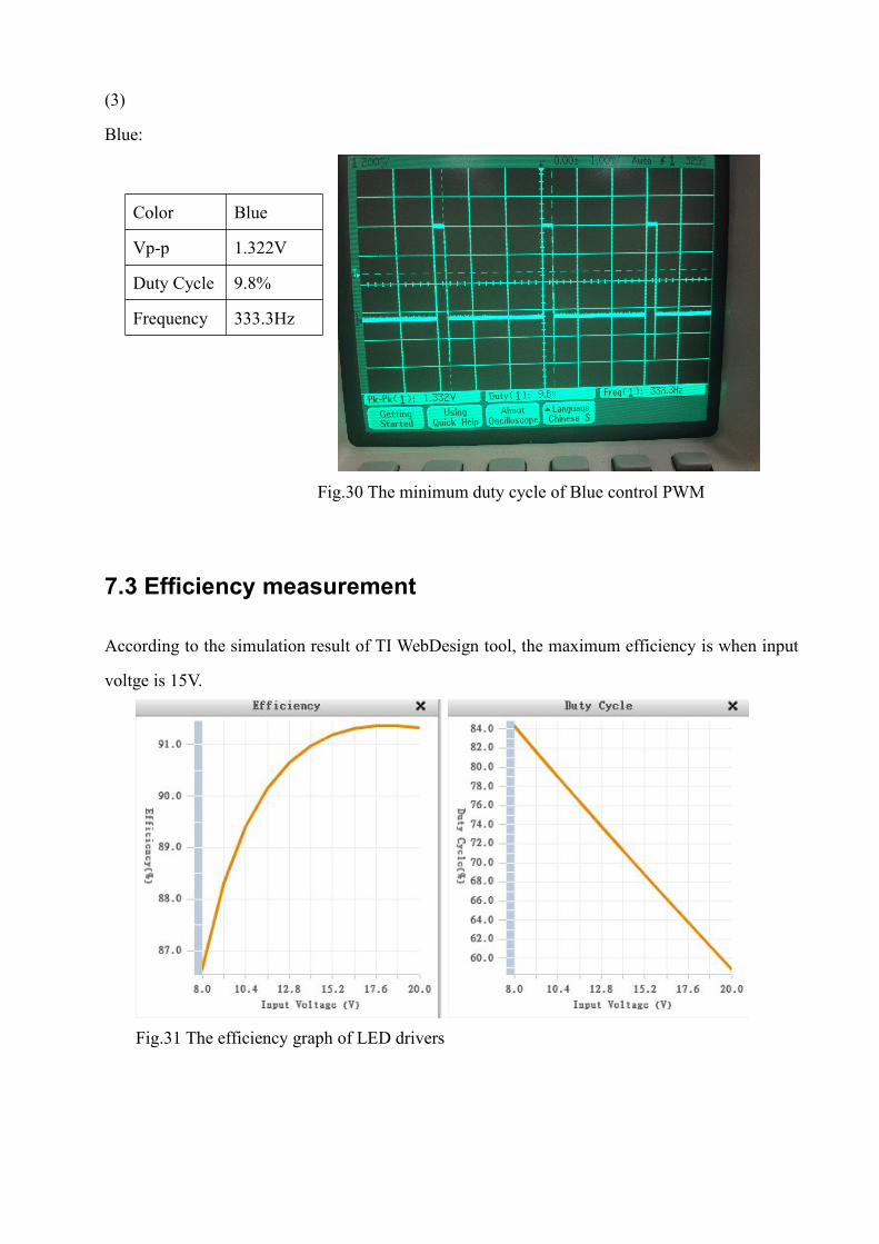
(3)
Blue:
Fig.30 The minimum duty cycle of Blue control PWM
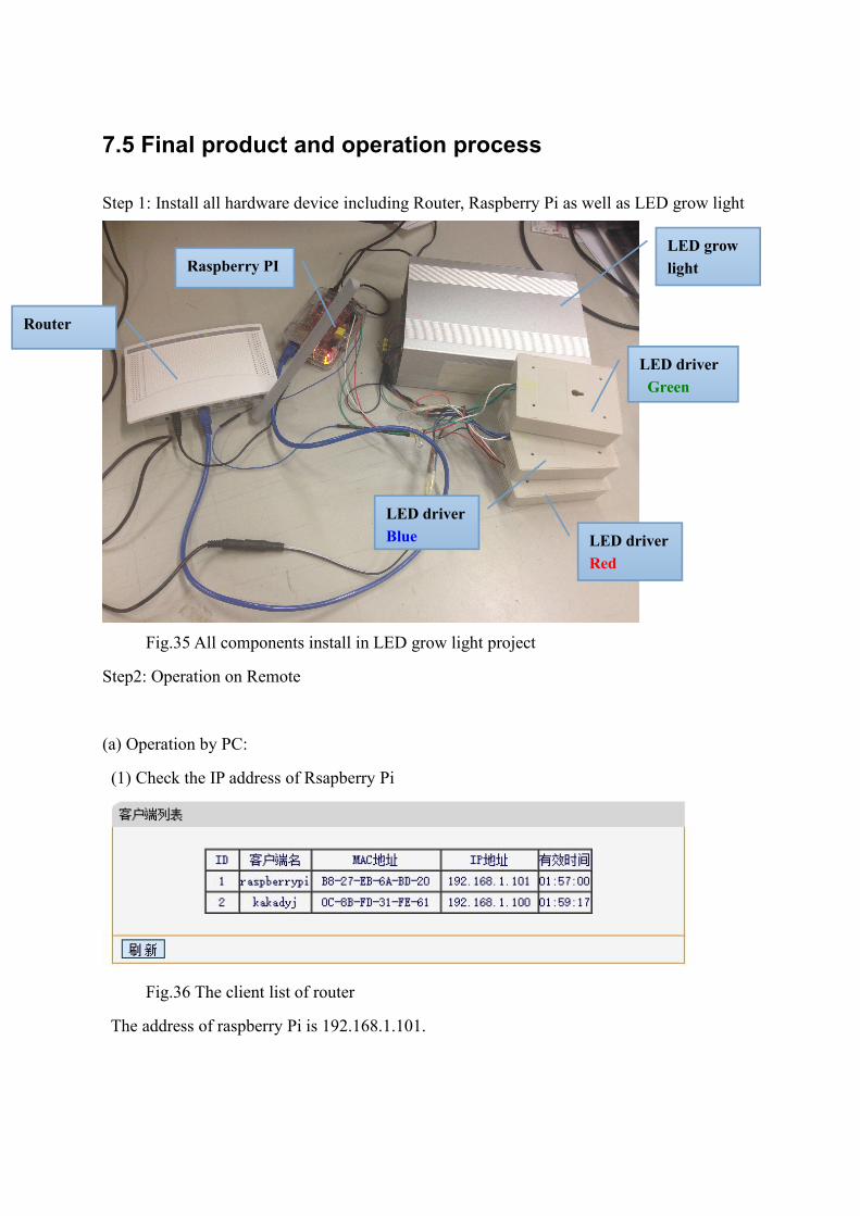
7.3 Efficiency measurement
According to the simulation result of TI WebDesign tool, the maximum efficiency is when input
voltge is 15V.
Fig.31 The efficiency graph of LED drivers
Color Blue
Vp-p 1.322V
Duty Cycle 9.8%
Frequency 333.3Hz

According to the chosen power supply:
Fig.31 The power supply used in this project
The input power is WAVPin 453115
The output power is:
WWWWmAVmAVmAVP 48.3924.1754.1524.9)350423504.443504.26(out
%884548.39
max W
W
7.4 Prblems and solutions
7.4.1 PWM input problem
At the begining, PWM in high level was supposed to be the IC open state, and boost
converter will operate. However, the situation is just negative as what I thought, the reason is:
Fig. 32 The input output relationship schematic diagram of AO3400
The pulse leve is inverted in Vout which means the open state of IC is in when Vin is low level.

7.4.2 Flicker problem
After all components connect together, the product works well at most time, however, the
flicker problem happend sometimes when there is no PWM input and the moment when Remote
close the server program in RPI through puTTY. And the limitation of power supply current
would also cause flicker problem.
(1) When there is no PWM poses, the LEDs will light even a small signal poses such as finger
touch.
Reason: In digital circuit, there cannot be any uncertainty work state. When there is no PWM
signal input, the MOSFET is in an uncertainty state. Human body even air have static electricity,
when human touch the PWM pin the LEDs will light up.
According to the characteristic of NMOS, when TGS VV , TV is the threshold voltage of
MOSFET, the 0DI ,the MOSFET will open.
Solution: A resistor is connect paralle between nDIM pin and Ground, that is, the default level of
G is high. The PWM input port is default closed when there is no signal poses.
Fig. 33 The schematic diagram of the solution of NMOS uncertainty state

Fig.34 The pin diagram of MOSFET AO3400
(2) At the moment when puTTY exit the control of server.py in RPI, the LEDs will flicker in an
unpredictable state.
Reason: When puTTY exit the server program of RPI, the pins of RPI will be reset. All pins will
have unpredictable state that we cannnot control by software. Therefore, this kind of problem is
out of control in a certain degree.
Solution: Users can standard operation procedure to control this problem. If users want to dark
the light for a while, just choose the black color or upplug the power supply of LEDs. If the
whole system need to be closed, upplug power supply of LEDs before cut the connection
between PC and RPI would be better.
(3) When adjusting the 100% output flux(350mA) PWM one color by one color, the light is well
performed. But if the white color is chosen, which means the 3 series LEDs’ current is 350mA,
the light will flicker.
Reason: At the begining, the three LED drivers’ input are connected together because they can
drive by same input current. However, the current will share betweent 3 series of light. When
they require 350mA current at the same time, the power supply cannot meet the requirement, the
light would flicker.
Solution: Change the power supply to a high current one or one power supply only drive one
LED driver. In this project, second solution is used initially and may try another solution later.
7.5 Final product and operation process
Step 1: Install all hardware device including Router, Raspberry Pi as well as LED grow light
Fig.35 All components install in LED grow light project
Step2: Operation on Remote
(a) Operation by PC:
(1) Check the IP address of Rsapberry Pi
Fig.36 The client list of router
The address of raspberry Pi is 192.168.1.101.
Router
Raspberry PI
LED driverGreen
LED driverBlue LED driver
Red
LED growlight

(2) Open the puTTY remote control software and input IP address of RPI
Fig.37 The users interface of puTTY
(3) Input username: root, keyword:123456 and input python server.py to start the server
program in Host:
Fig.38 The instruction table of puTTY
(4) Start led.py and choose one light output in the users interface.

Fig.39 LED grow light produce purple light
Fig.40 LED grow light produce white light
Fig.41 The output of default mode: General Mode

(6) Power off the RPI by putty
Fig.42 Rapberry poweroff reminder
When this dialog box popup, the RPI is powered off,users can turn off all devices.
(b) Operation by mobile device:
Apart from puTTY, in IOS devices, vssh is also a remote control program. The LED grow
light can be controlled directly by mobile phone, but users need to input codes to server program
on RPI.Input the initialize code mentioned in 6.1.2 to control the server program in RPI to
produce the corresponding PWM. However, iphone can only change one series of light at one
time by input one sentence of code.

Fig.43 The operation process of vssh LED control

8. Possible Future Improvement
8.1 LED spectrum measurement
In this project, a specfic type of LED has choosed and the ratio of different light is based on the
output power and the relative lumminance flux which provided by the data sheet, but the real
luminance value and how the heat effect influence the output have not measured accurat.
Therefore, in the future, for more accurate design, the output light spectrum can be measured by
using spectrograph.
8.2 Efficiency improvement
This LED light using 3 series of red, green and blue LED light to produce all intensity proportion
which controled by 3 PWM dimming boost converter. When the IC is unabled by PWM, actually
it is a waste of power. It can be improved that in one period, different time duration control
different color LEDs. Thus, only one board should be used and it saving much power and the
product can be more power efficiency.
8.3 Global control
When the LED grow light be used in a large scale or just use at home. A public network can be
applied, thus, users can control the light in all over the world wherever there provide network
connection.
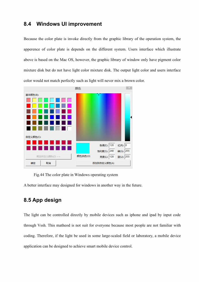
8.4 Windows UI improvement
Because the color plate is invoke directly from the graphic library of the operation system, the
apperence of color plate is depends on the different system. Users interface which illustrate
above is based on the Mac OS, however, the graphic library of window only have pigment color
mixture disk but do not have light color mixture disk. The output light color and users interface
color would not match perfectly such as light will never mix a brown color.
Fig.44 The color plate in Windows operating system
A better interface may designed for windows in another way in the future.
8.5 App design
The light can be controlled directly by mobile devices such as iphone and ipad by input code
through Vssh. This matheod is not suit for everyone because most people are not familiar with
coding. Therefore, if the light be used in some large-scaled field or laboratory, a mobile device
application can be designed to achieve smart mobile device control.

9. Conclusion
In this project, a design of a high power LED grow light is given from both hardware and
software aspect, which provide a new solution for indoor farming light design. The objective is
to design a LED light using red, blue and green LEDs which can produce all colors by
combining in different ratio.
Three N-channel MOSFET constant current LED controller - LM3429 is used to drive and
dimming the red, blue and green LED lighs respectively. Rsapberry PI, a computer like SCM
used for PWM produce and realized remote control by PC through the connect of a router.
Besides, a users interface which provide timer, totally 256*256*256 color ratio choices as well
as 9 default modes for all plants in different growth period.
During the design, many problems were met especially flicker problems. It was caused by the
uncertainty of MOSFET, unpredictable of GPIO pins state of Raspberry PI. The inapproprait
power supply would also caused ficker of light. In order to solve these problems, an resistor is
used to set the default state for MOSFET to keep it close without PWM signal and the one power
supply replaced by three .
The product achieved color change, time setting as well as the remote control with high
efficiency. In the future,this light can improve from both hardware and software, it can be
improve that using one converter to control 3 sreials LEDs. In addition, spectrum measurement
can be taken and feedback to MCU to get more accurate output. In software part, for better and
more covient control of the light, an application which used in mobile devices can be designed.
Global control can also be achieved by applying a public net IP address.

10.Appendix:
The schematic circuit of LED Grow Light:

The graph of PCB Board: