Design of Fasteners
75
Design of Fasteners
-
Upload
khangminh22 -
Category
Documents
-
view
5 -
download
0
Transcript of Design of Fasteners

Design of Fasteners

A) Design of Screw
Fasteners

Introduction • A screw thread is formed by cutting a
continuous helical groove on cylindrical surface.
• A continuous single helical groove is known as single threaded or single start.
• If second groove is cut into the space between the groove of first then it is double threaded or double start.
• Screw joint are formed by bolt and nut used for joining machine parts or for fastening, adjustment, assembly, inspection, replacement.

• Advantages –
1) These are convenient to assemble and disassemble.
2) Highly reliable in operation.
3) Screw joint are adopted in various operating conditions.
4) Screws are relatively cheap to produce due to standardization.
Disadvantages –
The main disadvantage of this joint is the stress concentration in the thread portion and strength is less than welded or riveted joint.

Types of Screw fastening Types of Screw
Fastening
1. Bolts
(i) Through Bolt
(ii) Tap Bolts
2. Cap Screw
3. Stud
4. Machine Screw
5. Set Screw

Types of Screw Fastening • Bolts - They are basically threaded fasteners
normally used with nuts.
• Screws - They engage either with a preformed or a self made internal threads.
• Studs -They are externally threaded headless fasteners. One end usually meets a tapped component and the other with a standard nut.
• Tapping screws -These are one piece fasteners which cut or form a mating thread when driven into a preformed hole. These allow rapid installation since nuts are not used.
• Set Screws -These are semi permanent fasteners which hold collars, pulleys, gears etc on a shaft. Different heads and point styles are available.

• Examples where screw joints are preferred
over welded joint.
1) Assembly of crank shaft and connecting rod.
2) In braking system of an automobile because
screw joints are convenient to assemble and
disassemble and relatively cheap to produce
due to standardization.

Advantages of V thread
1) V threads offers greater frictional resistance
of motion than square thread and are thus
better suited for fastening purpose.
2) These are stronger than square thread.
3) These are cheaper because of easy to cut by
die or on machine.
4) These are used to tighten the parts together in
bolts, nuts, stud and nut, tap bolts etc. because
they prevent the nut from slacking back due
to high frictional resistance.

Disadvantages
1) V threads are not suitable for power
transmission.
2) They have a component of force which acts
perpendicular to the axis causing bursting
action on the nut and increasing friction.

Forms of Threads


Terminology for Screw Threads

1. Major diameter (do)-
• It is the largest diameter of an external or
internal screw thread.
• The screw is specified by this diameter. It is also
known as outside or nominal diameter.
2. Minor diameter (dc)-
• It is the smallest diameter of an external or
internal screw thread.
• It is also known as core or root diameter.

3. Pitch diameter (dp) –
• It is the diameter of an imaginary cylinder, on a
cylindrical screw thread, the surface of which
would pass through the thread at such points as to
make equal the width of the thread and the width
of the spaces between the threads.
• It is also called an effective diameter.
4. Pitch (p) -
• It is the distance from a point on one thread to the
corresponding point on the next.
• This is measured in an axial direction between
corresponding points in the same axial plane.

5. Lead -
• It is the distance between two corresponding
points on the same helix.
• It may also be defined as the distance which a
screw thread advances axially in one rotation of
the nut.
• Lead is equal to the pitch in case of single start
threads, it is twice the pitch in double start, thrice
the pitch in triple start and so on.
6. Crest - It is the top surface of the thread.

7. Root - It is the bottom surface created by the two
adjacent flanks of the thread.
8. Depth of thread - It is the perpendicular
distance between the crest and root.
9. Flank - It is the surface joining the crest and
root.
10. Angle of thread - It is the angle included by
the flanks of the thread.
11. Slope - It is half the pitch of the thread.

Stresses in screw fastenings
• It is necessary to determine the
stresses in screw fastening due to
both static and dynamic loading in
order to determine their dimensions.
In order to design for static loading
both initial tightening and external
loadings need be known.

A) Initial tightening load
When a nut is tightened over a screw following
stresses are induced:
(a) Tensile stresses due to stretching of the bolt
(b) Torsional shear stress due to frictional
resistance at the threads.
(c) Shear stress across threads
(d) Compressive or crushing stress on the threads
(e) Bending stress if the surfaces under the bolt
head or nut are not perfectly normal to the bolt
axis.

a) Tensile Stress –
Since none of the above mentioned stresses
can be accurately determined bolts are usually
designed on the basis of direct tensile stress
with a large factor of safety.
boltsintensionInitialP
ddiameterCored
screwofpitchordiameterMeandWhere
dd
d
A
P
i
oc
c
oit
84.0
)2
(4
2840
2

b) Torsional shear stress -
Due to twisting moment, the bolt is subjected to
torsional shear stress.
torqueTwistingT
inertiaofmomentPolarIWhere
dT
d
Td
d
T
rI
T
l
G
rI
T
P
cs
c
c
c
s
P
s
s
P
3
33
16
16
2
32

roottheatthreadofwidthb
contactinthreadofNumbern
nouofdiameteralnod
bnd
P
isnutforstressshearaverageThe
bnd
P
isscrewforstressshearaverageThe
o
o
n
c
s
min
c) Shear stress across the threads -

d) Crushing stress on threads
The compression or crushing stress between the
thread of screw nut is given by
ndd
P
co
crc)( 22
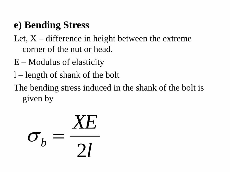
e) Bending Stress
Let, X – difference in height between the extreme
corner of the nut or head.
E – Modulus of elasticity
l – length of shank of the bolt
The bending stress induced in the shank of the bolt is
given by
l
XEb
2

2. Stresses due to external forces
a) Tensile stress –
co
c
t
c
c
t
dd
nd
P
thenboltsofnumbertheisnif
outfoundisd
d
P
84.0
4
4
2
2

b) Shear Stress in bolt –
nd
P
o
s
2
4
c) Combine tension and shear stress
]4[2
1
]4[2
1)(
22
max
22
max
t
ttt
stressshearMaximum
sresstensileprincipalMaximum

3. Stress due to combine forces
• The resultant load on the bolt is
boltofelsicitythetopartsconnectedofelasticityofRatioa
boltstheonloadExtrnalP
boltsoftighteningtoduetensionInitialP
a
akWhere
kPPP
Pa
aPP
i
i
i
2
2
2
)1
(
)1
(

Values of ‘K’

Bolts with Uniform strength • When a bolt is subjected to shock load. the In such
cases the bolt is designed to absorb impact load and
to resist the torque to prevent breakage of thread.
• In ordinary bolts, the effect of load concentration
on the weakest part of the bolt i.e. The c/s area of
the root of the thread.
• The stress in the threaded part will be more as
compared to the shank hence the maximum portion
of energy will be absorbed at the region of the
threaded part which may fracture the threaded
portion.


• If the diameter of shank of the bolt is turned to
the core diameter of the thread, then the shank
of the bolt will undergo a higher stress. This
means that shank will absorb large portion of
energy thus relieving the material at the
threaded portion.
• The bolt in this way become stronger and
lighter and it increases the impact load
carrying capacity. This gives us bolts of
uniform strength.

• Another method, an axial hole is drilled
through the head of the bolt as far as threaded
portion, such area of the shank become equal
to the root area of the thread.
threadofdiametercored
threadofdiameterouterd
holeofdiameterDwhere
ddD
ddD
c
o
co
co
,
)(
)(44
22
222

Design of bolted joint subjected to
Eccentric Loading
• There are many application of the bolted joints
which are subjected to eccentric loading such as
machine foundation bolt, wall brackets, pillar
crane, etc.
1) Parallel to the axis of bolts.
2) Perpendicular to the axis of bolts.
3) In the plane containing the bolts.

Eccentric load parallel to the axis of bolt

a) Each bolt is subjected to direct tensile load.
b) Due to load W the bracket tends to rotate
about edge A-A
Let w – load in a bolt per unit distance due to
turning effect of the bracket
boltsofNumbern
bracketonactingloadW
loadtensileDirectW
n
WW
td
td

• W1 & W2 – load on bolt at a distance L1 & L2
from tilting edge.
Load on each bolt at distance L1
W1 = w L1
Similarly, load on each bolt at distance L2
W2 = w L2
The moment of load W1 about tilting edge
2
111111 wLLwLLWM

• Similarly, the moment of load W2 about tilting
edge
)2(
,tan
)1(][2 2
2
2
121
2
222222
WLM
edgetiltingaboutLcedisaatWloadtheofmomentThe
wLwLMMM
edgetiltingaboutloadofmomentTotal
wLLwLLWM
Equating equation (1) and (2)

2
2
2
2
2
1
2222
2
2
2
2
2
1
2
2
2
1
2
2
2
1
4
][2
tan
tan
][2
][2
][2
c
tt
ttdtTotal
t
d
W
stresstensiletosubjectedbolttheAs
WWWW
boltsloadedheavilymostonloadTotal
LL
LLWwLWW
LcedisatbolteachonloadTensile
loadedheavilymostareLcedisatboltsThe
LL
WLw
LLw
wLwLWL

Eccentric Load Acting Perpendicular to the
Axis of Bolts
boltsofnumbern
LcedisaatactingloadWWhere
n
WW
boltsthebyshearedequallyare
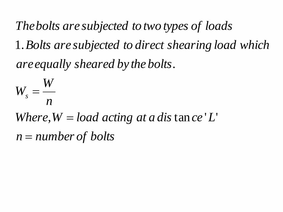
whichloadshearingdirecttosubjectedareBolts
loadsoftypestwotosubjectedareboltsThe
s
''tan,
.
.1

2. The eccentric load (W) will try to tilt the bracket
in clockwise direction about the tilting edge B-B.
Therefore maximum tensile load will be act on bolt
at position 3 and 4 which are at a greater distance
from the tilting edge.
Let, w = load in the bolt per unit distance due to
turning effect of the bracket.
Wt= Tensile load each bolt at a distance L1 from the
tilting edge B-B.

)3(2
,.
)2(
2
11
1
2
1111
11
LwM
henceLdistaatboltstwoAs
LwLWM
edgetiltingaboutloadthisofMoment
LwW
t
t

• Similarly Wt will be the tensile load each bolt at
a distance L2 from the tilting edge B-B.
)5(][2
22
)4(2
,.
2
2
2
1
2
2
2
1
21
2
22
2
2
2222
2
22
LLwM
LwLwM
MMM
isedgetiltingaboutmomentTotal
LwM
henceLdistaatareboltstwotheAs
LwLWM
edgetiltingaboutWloadtheofMoment
LwW
t
t
t

)7(][2
][2
..
4&3max
][2
][2
6&5
)6(
.
)(
2
2
2
1
22
22
2
2
1
22
2
2
2
2
1
2
2
2
1
LL
LLWW
LLL
LWLwW
edgetiltingfromLdistaatsituatedarewhich
boltainwillbeloadtensileimumThe
LL
LWw
LLwLW
equationEquating
LWM
isLdistaat
WloadtoduebracketofmomentThe
t
t

]4[2
1
)(
]4[2
1
)(
.
22
2
22
22
stse
se
sttte
te
WWW
WloadshearEquivalent
And
WWWW
WloadtensileEquivalent
loadshearaswellas
tensilecombiletosubjectedareboltstheAs

• By knowing the equivalent load, the core
diameter of the bolt is obtained.
2
4c
tet
d
W

Eccentric Load acting in the plane
containing the Bolts

• In this case, the bolts are subjected to two types
of load –
1. The Direct shear load (Wsd) –
Wsd = (W/n) ----- (a)
2. The secondary shear load (Ws2)
a) This secondary load is perpendicular to line
joining the centre of the bolt.
b) This secondary load is perpendicular to the
radial distance.


1
414
1
313
1
212
4
4
3
3
2
2
1
1
4321
4321
tan
..4,3,2,1,,,.
sec,,,
l
lWW
l
lWW
l
lWW
l
W
l
W
l
W
l
W
cedisradialtoalproportiondirectlyisforceAs
GCfromboltoflllldistaat
loadsshearondarytheareWWWW

• Sum of turning moment due to eccentric load and
internal resisting moment of the bolt must be
zero.
calculatedisWbequationFrom
blllll
W
ll
lWl
l
lWl
l
lWlW
lWlWlWlWeW
1
2
4
2
3
2
2
2
1
1
1
4
1
413
1
312
1
2111
44332211
''
)(][
)()()(

c
o
c
c
SR
ssdssdSR
dd
anddfind
d
WstressshearThen
loadshear
ondaryandprimarybetweenAngleWhere
WWWWW
loadsheartresultheCalculate
84.0
4
,
sec,
cos2
tan
2
22

Problems

B) Design of Welded
Joints

Welded Joints
• Welding is a process of joining
two similar metal by heating
with or without application of
pressure and filler materials.
• Welded joint can be used an
alternatively to riveted joint.
Advantages 1) The welded structure are usually lighter than
riveted structure because in welding, gussets and
other connecting component are not used.
2) Weld joint provide maximum efficiency which is
not possible by riveted joint.
3) Alteration and addition can be easily made in the
exiting structure.
4) It is smooth in appearance therefore looks
pleasing.
5) In welded connection, the tension member are
not weakened as in case of riveted joint.

6) A weld joint has greater strength often a
welded joint has the strength of the parent
metal itself.
7) Circular shape member are difficult to rivet
but they can easily welded.
8) The welding provide very rigid joints
9) Welding is possible at any point, any place.
10) Welding required less time than the riveting.

Disadvantages
1) Due to uneven heating and cooling during
fabrication, the members get distorted or
addition stresses may developed.
2) Highly skilled worker and supervision is
required.
3) Due to uneven contraction and expansion in
the frame, there is possibilities of cracks.
4) The inspection of weld is difficult than
riveted joint.

Types of welded joint
1) Lap Joint:
The Lap Joint is obtained by over lapping the
plates and then welding the edge of plates.
a) Single transverse
b) Double transverse
c) Parallel fillet joints.


2) Butt Joints:
The butt joint is obtained by welding the ends
and edge of the two plates which approximately
in the same plane.
The Butt Joint may
1. Square butt joint,
2. Single V-butt joint
3. Single U-butt joint,
4. Double V-butt joint, and
5. Double U-butt joint.


Basic Weld Symbols

Strength of Transverse Fillet Welded Joints


• In order to determine the strength of the fillet joint, it is
assumed that the section of fillet is a right angled
triangle ABC with hypotenuse AC making equal angles
with other two sides AB and BC.
• The enlarged view of the fillet is shown in Fig. 10.7.
• The length of each side is known as leg or size of the
weld and the perpendicular distance of the hypotenuse
from the intersection of legs (i.e. BD) is known as
throat thickness.
• The minimum area of the weld is obtained at the
throat BD, which is given by the product of the throat
thickness and length of weld.

)1(707.0
707.0
45sin
45
,
.
0
0
w
w
w
W
StweldofThickness
S
t
AB
BD
figureFrom
BCABAC
mminweldofLengthl
mminweldofThickness
weldofsizeorLegBCABS
mminthicknessThroatBDtLet
triangleisoscelesanglerightisABC

.
sin
707.0
707.0
)2(707.0
min
weldfillet
transversegleforequationThis
lSP
lS
P
throatofArea
P
forcetensiletodueisweldfilletoffailureThe
lSA
ltA
weldofLengththicknessThroatA
areaweldorthroattheofareaimumThe
tww
ww
t
t
ww
w

twW
ww
t
lSP
lS
P
A
P
weldfillettransversedoubleFor
707.02
707.022
During welding, the slag and blow holes are
occur, so the weld is weaker than plate,
therefore the weld is provided with some
reinforcement which may be taken as 10% of
the plate thickness.

Strength of Parallel Fillet Weld

sww
ww
s
s
lSP
lS
P
areaThroat
P
forceaxialtoduestressshear
isweldfillettheinindcedstressThe
707.02
707.02
2

Combine Transverse & Parallel
Fillet weld
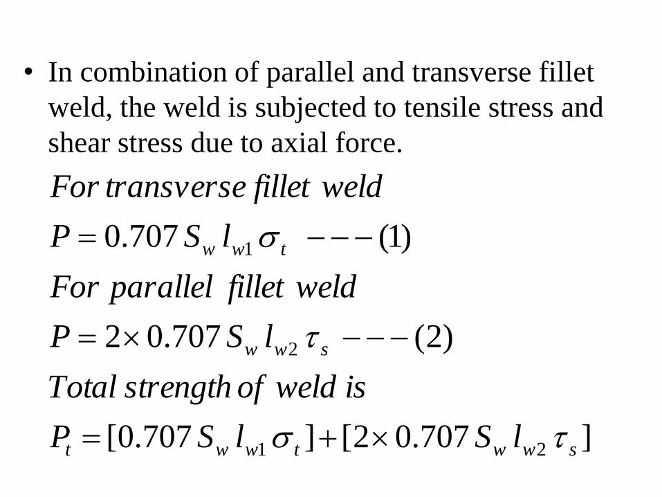
• In combination of parallel and transverse fillet
weld, the weld is subjected to tensile stress and
shear stress due to axial force.
]707.02[]707.0[
)2(707.02
)1(707.0
21
2
1
swwtwwt
sww
tww
lSlSP
isweldofstrengthTotal
lSP
weldfilletparallelFor
lSP
weldfillettransverseFor

• Note –
1. Stress concentration factor for transverse
fillet weld Under dynamic (fatigue)
loading = 1.5
2. Stress concentration factor for parallel
fillet weld Under dynamic (fatigue)
loading = 2.7

PROBLEMS