Design of an Audio Compressor with Digital Control
14
Received: 1 July 2020 Accepted: 20 Apr 2021 Available online: 28 May 2021 DOI: http://dx.doi.org/10.18180/tecciencia.2021.30.4 RE SEARCH AR TI CLE Engineering Design of an Audio Compressor with Digital Control Diseño de un Compresor de Audio con Control Digital Jonnathan Montenegro 1* 1 GRIAP-Grupo de Investigación en Acústica Aplicada, Ingeniería de Sonido, Universidad de San Buenaventura, Bogotá, Colombia. Correspondence Jonnathan Montenegro, San Buenaventura, Bogotá, Colombia. Email: [email protected] Copyright : Licencia de Creative Commons Reconocimiento-NoComercial 4.0 Interna. The publication of this journal is funded by Universidad ECCI, Bogotá-Colombia. Editors: Robert Paul Salazar Editorial assistant : Luz Adriana Suáres Suáres. How to cite: Jonnathan Montenegro, Design of an Audio Compressor with Digital Control, TECCIENCIA, Vol. 16, No. 30, 51-64, 2021 DOI:http://dx.doi.org/10.18180/tecciencia.2021.30.4 ABSTRACT Based on the concepts and insights of cybernetic theory and the applica- tions of applied electronic engineering and control, this article deals with the design of an analog compressor with digital control. The main purpose of the device is to control the basic parameters of a hardware using an applica- tion on a micro-controller. The advantage of that design is the possibility of store the dierent analog positions into a digital position of the memory of the micro-controller, in order to call these presets whenever its needed. Fur- ther possible applications include the virtual-remote monitoring of events where the interaction between artist and sound engineering is required. keywords: Analog compression, digital control, HW of audio, electronic micro-controllers. RESUMEN Este artículo trata acerca del diseño de un compresor análogo con control digital basado en los conceptos de teoría cibernética y las aplicaciones de ingeniería electrónica aplicada y control. El objetivo principal del dispositivo es controlar los parámetros básicos de un HW utilizando una aplicación en un microcontrolador. La ventaja de ese diseño es la posibilidad de almace- nar las diferentes posiciones análogas en una posición digital de la memoria del microcontrolador, con el n de realizar una llamada a estas congura- ciones siempre que sean necesario. Algunas posibles aplicaciones incluyen el monitoreo virtual-remoto de eventos donde la interacción entre el artista y la ingeniería de sonido se requiere. keywords: Compresión análoga, control digital, HW de audio, microcontro- ladores electrónicos. 1 | INTRODUCTION In sound engineering, compression is a phenomenon which can be approached from the physical mechanisms of the sound particles that experiment compression and rarefaction while propagating in the acoustic mechan- ical wave [1]; or, a phenomenon observed in audio coding technologies related to the perceptual procedures to minimize a le volume in order to facilitate transmission and storage purposes [2], as well as its evaluation [3]; or in the HW design, a device which limits the dynamic range of an audio signal [4]. * Equally contributing authors. TECCIENCIA ● VOL.16 ● NO.30 http://tecciencia.ecci.edu.co ISSN:1909-3667(print)|2422-3670(e) Universidad ECCI 51
-
Upload
khangminh22 -
Category
Documents
-
view
2 -
download
0
Transcript of Design of an Audio Compressor with Digital Control
Received: 1 July 2020 Accepted: 20 Apr 2021 Available online: 28 May 2021DOI: http://dx.doi.org/10.18180/tecciencia.2021.30.4
R E S E A RCH ART I C L EEng i nee r i n g
Design of an Audio Compressor with Digital ControlDiseño de un Compresor de Audio con Control DigitalJonnathan Montenegro1*1GRIAP-Grupo de Investigación en AcústicaAplicada, Ingeniería de Sonido, Universidadde San Buenaventura, Bogotá, Colombia.CorrespondenceJonnathan Montenegro, San Buenaventura,Bogotá, Colombia.Email: [email protected]
Copyright : Licencia de Creative CommonsReconocimiento-NoComercial 4.0 Interna.
The publication of this journal is funded byUniversidad ECCI, Bogotá-Colombia.Editors: Robert Paul SalazarEditorial assistant : Luz Adriana SuáresSuáres.
How to cite: Jonnathan Montenegro,Design of an Audio Compressor withDigital Control, TECCIENCIA, Vol. 16, No.30, 51-64, 2021DOI:http://dx.doi.org/10.18180/tecciencia.2021.30.4
ABSTRACTBased on the concepts and insights of cybernetic theory and the applica-tions of applied electronic engineering and control, this article deals with thedesign of an analog compressor with digital control. The main purpose ofthe device is to control the basic parameters of a hardware using an applica-tion on a micro-controller. The advantage of that design is the possibility ofstore the different analog positions into a digital position of the memory ofthe micro-controller, in order to call these presets whenever its needed. Fur-ther possible applications include the virtual-remote monitoring of eventswhere the interaction between artist and sound engineering is required.keywords: Analog compression, digital control, HW of audio, electronicmicro-controllers.RESUMENEste artículo trata acerca del diseño de un compresor análogo con controldigital basado en los conceptos de teoría cibernética y las aplicaciones deingeniería electrónica aplicada y control. El objetivo principal del dispositivoes controlar los parámetros básicos de un HW utilizando una aplicación enun microcontrolador. La ventaja de ese diseño es la posibilidad de almace-nar las diferentes posiciones análogas en una posición digital de la memoriadel microcontrolador, con el fin de realizar una llamada a estas configura-ciones siempre que sean necesario. Algunas posibles aplicaciones incluyenel monitoreo virtual-remoto de eventos donde la interacción entre el artistay la ingeniería de sonido se requiere.keywords: Compresión análoga, control digital, HW de audio, microcontro-ladores electrónicos.
1 | INTRODUCTIONIn sound engineering, compression is a phenomenon which can be approached from the physical mechanismsof the sound particles that experiment compression and rarefaction while propagating in the acoustic mechan-ical wave [1]; or, a phenomenon observed in audio coding technologies related to the perceptual proceduresto minimize a file volume in order to facilitate transmission and storage purposes [2], as well as its evaluation[3]; or in the HW design, a device which limits the dynamic range of an audio signal [4].*Equally contributing authors.
TECCIENCIA VOL.16 NO.30 http://tecciencia.ecci.edu.co ISSN:1909-3667(print)|2422-3670(e) Universidad ECCI 51
52 Jonnathan MontenegroTechnologies which have been implemented throughout the years include analogue processing as well asdigital schemes [5, 6, 7].This article proposes the design of an analog compressor with digital control [8]. Itsmain goal is to adjust the basic adjustment parameters of the device, through an application implemented on amicrocontroller. The advantage is the possibility of making different types of adjustments and as well to savethe analog positions of the controls in a memory with the possibility to call them afterwards when necessary[9].The dynamic audio signal compressor is a primary system in audio production processes [10]; it is an es-sential element in the electroacoustic chain that transmits the signal, it attenuates the dynamic range of thesignal, understood as the logarithmic relationship in decibels between the maximum and minimum signal level,preventing distortions or damage to the equipment that can be caused by saturations or damage. These phe-nomena are sometimes called “spikes” [11].Currently, compressors can be analogous, whose structure is made up of electronic elements, in otherwords, hardware. There are also digital ones which act through an algorithm. The main objective of thepresent work is to design a compressor, with the main parameters (such as threshold, ratio, and output gain)in each band controllable through MatLab programmed user interface [12]. This constant interface of buttonsindicated to each compression parameter, step indicators, so that the user interacts and processes the audioof his particular taste, in an intuitive manner. It should be noted that the digital control mentioned above doesnot affect the audio signal, it only acts on the specific compression parameters.The proposed digital control provides the following advantages: (i) it avoids the need to manually adjustanalog potentiometers, (ii) allows to save compression settings to a list to be easily and quickly activated onthe HW (analog circuit) with a single touch within the user interface. The implementation of the digitally com-pressor consists of two main development stages. The processes are executed independently. First, there isthe design of the analog compression circuit, that is the set of electronic components that process dynamicallythe audio signal. Secondly, a digital control system is implemented that must be compatible with the analogcircuit by means of integrated circuits and the user interface. In summary, the digital control system is capableof activating the analog compression circuit. Among the most relevant applications of dynamic range com-pression devices, hearing aids are currently the most prominent ones [13, 14], as well as Speech Processing[15].
2 | CIRCUIT DESIGN2.1 | HW implementationThe analog state of the compressor consists of three main control parameters (threshold, ratio and outputgain); for each band. These are controlled through a user interface programmed in MatLab. The interfaceconsists of buttons for each compression parameter, step indicators, so that the user can act and process theaudio as the like in an intuitive manner.
2.1.1 | Design of the circuit of dynamic processing of the signal (compressor)It was decided to use a feedforward topology for the design of this stage, and for the amplification stage, dueto its versatility, a VCA (Voltage Controlled Amplifier) will be implemented, after having analyzed the otheroptions, among which FET, optical, VariMu and digital types are at disposal. Fig. 3 shows the schematic forthe analog circuit of the compressor. The integrated circuit for the development of this stage is the THAT4301 (see Fig. 1), which has within its structure a VCA circuit, an RMS signal detector and three operationalamplifiers.TECCIENCIA VOL.16 NO.30 ISSN:1909-3667(print) | 2422-3670 (electronic) Universidad ECCI
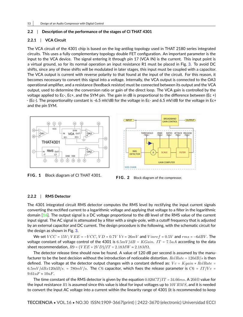
53 Design of an Audio Compressor with Digital Control2.2 | Description of the performance of the stages of CI THAT 43012.2.1 | VCA CircuitThe VCA circuit of the 4301 chip is based on the log-antilog topology used in THAT 2180 series integratedcircuits. This uses a fully complementary topology double FET configuration. An important parameter is theinput to the VCA device. The signal entering it through pin 17 (VCA IN) is the current. This input point isa virtual ground, so for its normal operation an input resistance R1 must be placed in Fig. 3. To avoid DCshifts, since any of these shifts will be modulated in later stages, this input must be coupled with a capacitor.The VCA output is current with reverse polarity to that found at the input of the circuit. For this reason, itbecomes necessary to convert this signal into a voltage. Internally, the VCA output is connected to the OA3operational amplifier, and a resistance (feedback resistor) must be connected between its output and the VCAoutput, used to determine the conversion ratio or gain of the direct loop. The VCA gain is controlled by thevoltage applied to Ec-, Ec+, and the SYM pin. The gain in dB is proportional to the difference between (Ec +)- (Ec-). The proportionality constant is -6.5 mV/dB for the voltage in Ec- and 6.5 mV/dB for the voltage in Ec+and the pin SYM.
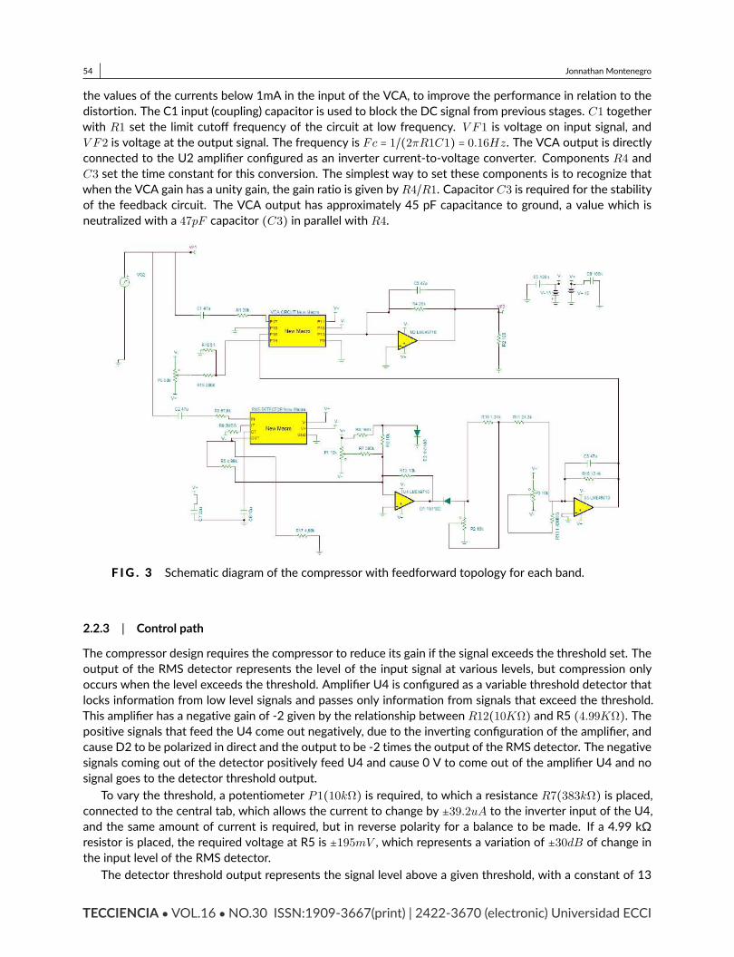
F IG . 1 Block diagram of CI THAT 4301. F IG . 2 Block diagram of the compressor.
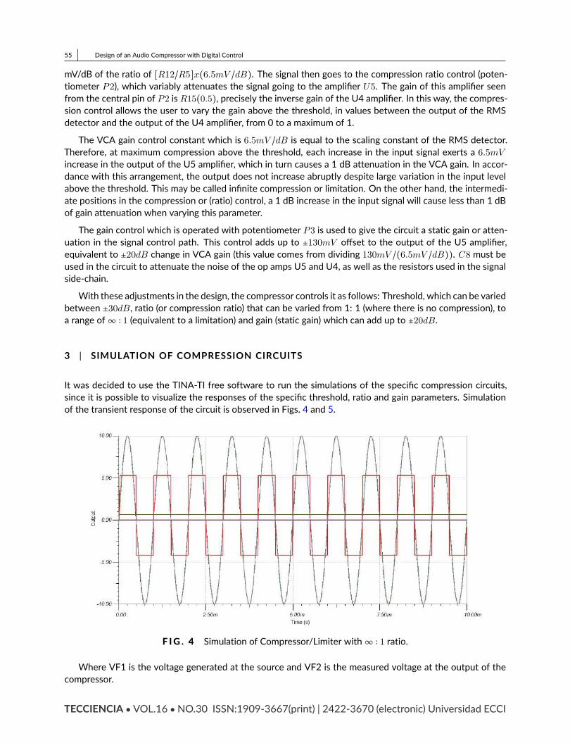
2.2.2 | RMS DetectorThe 4301 integrated circuit RMS detector computes the RMS level by rectifying the input current signalsconverting the rectified current to a logarithmic voltage and applying that voltage to a filter in the logarithmicdomain [16]. The output signal is a DC voltage proportional to the dB level of the RMS value of the currentinput signal. The AC signal is attenuated by a filter with a single-pole, with a cutoff frequency that is adjustedby an external capacitor and DC current. The design procedure is the following, with the schematic circuit forthe design as shown in Fig. 3.
We set V CC = 15V ; V EE = −V CC , V D = 0.7V V t = 26mV and V inref = 0.5V and rms = −6dBV . Thevoltage constant of voltage control of the 4301 is 6.5mV /dB = KGain. IT = 7.5uA according to the datasheet recommendation, R9 = (V EE + 2V D)/IT = 2.18MW ≈ 2.18MΩ.The detector release time should now be found. A value of 120 dB per second is assumed by the manu-facturer to be the best decision without the introduction of noticeable distortion. RelRate = 120dB/s is thendefined. The voltage at the detector output changes with a constant defined as: V c = Kgain ∗ RelRate =
6.5mV /dBx120dB/s. = 780mV /s. The C6 capacitor, which fixes the release parameter is C6 = IT /V c =9.61uF ≈ 10uF .
The time constant of the RMS detector is given by the equation 0.026CT /IT = 34.66ms. A 20kΩ value forthe input resistance R1 is assumed since this value is ideal for input voltages up to 10V RMS, and it is neededto convert the input AC voltage into a current within the linearity range of 4301 (it is recommended to keepTECCIENCIA VOL.16 NO.30 ISSN:1909-3667(print) | 2422-3670 (electronic) Universidad ECCI
54 Jonnathan Montenegrothe values of the currents below 1mA in the input of the VCA, to improve the performance in relation to thedistortion. The C1 input (coupling) capacitor is used to block the DC signal from previous stages. C1 togetherwith R1 set the limit cutoff frequency of the circuit at low frequency. V F1 is voltage on input signal, andV F2 is voltage at the output signal. The frequency is Fc = 1/(2πR1C1) = 0.16Hz. The VCA output is directlyconnected to the U2 amplifier configured as an inverter current-to-voltage converter. Components R4 andC3 set the time constant for this conversion. The simplest way to set these components is to recognize thatwhen the VCA gain has a unity gain, the gain ratio is given by R4/R1. Capacitor C3 is required for the stabilityof the feedback circuit. The VCA output has approximately 45 pF capacitance to ground, a value which isneutralized with a 47pF capacitor (C3) in parallel with R4.
F IG . 3 Schematic diagram of the compressor with feedforward topology for each band.
2.2.3 | Control pathThe compressor design requires the compressor to reduce its gain if the signal exceeds the threshold set. Theoutput of the RMS detector represents the level of the input signal at various levels, but compression onlyoccurs when the level exceeds the threshold. Amplifier U4 is configured as a variable threshold detector thatlocks information from low level signals and passes only information from signals that exceed the threshold.This amplifier has a negative gain of -2 given by the relationship between R12(10KΩ) and R5 (4.99KΩ). Thepositive signals that feed the U4 come out negatively, due to the inverting configuration of the amplifier, andcause D2 to be polarized in direct and the output to be -2 times the output of the RMS detector. The negativesignals coming out of the detector positively feed U4 and cause 0 V to come out of the amplifier U4 and nosignal goes to the detector threshold output.
To vary the threshold, a potentiometer P1(10kΩ) is required, to which a resistance R7(383kΩ) is placed,connected to the central tab, which allows the current to change by ±39.2uA to the inverter input of the U4,and the same amount of current is required, but in reverse polarity for a balance to be made. If a 4.99 kΩresistor is placed, the required voltage at R5 is ±195mV , which represents a variation of ±30dB of change inthe input level of the RMS detector.The detector threshold output represents the signal level above a given threshold, with a constant of 13
TECCIENCIA VOL.16 NO.30 ISSN:1909-3667(print) | 2422-3670 (electronic) Universidad ECCI
55 Design of an Audio Compressor with Digital ControlmV/dB of the ratio of [R12/R5]x(6.5mV /dB). The signal then goes to the compression ratio control (poten-tiometer P2), which variably attenuates the signal going to the amplifier U5. The gain of this amplifier seenfrom the central pin of P2 is R15(0.5), precisely the inverse gain of the U4 amplifier. In this way, the compres-sion control allows the user to vary the gain above the threshold, in values between the output of the RMSdetector and the output of the U4 amplifier, from 0 to a maximum of 1.
The VCA gain control constant which is 6.5mV /dB is equal to the scaling constant of the RMS detector.Therefore, at maximum compression above the threshold, each increase in the input signal exerts a 6.5mVincrease in the output of the U5 amplifier, which in turn causes a 1 dB attenuation in the VCA gain. In accor-dance with this arrangement, the output does not increase abruptly despite large variation in the input levelabove the threshold. This may be called infinite compression or limitation. On the other hand, the intermedi-ate positions in the compression or (ratio) control, a 1 dB increase in the input signal will cause less than 1 dBof gain attenuation when varying this parameter.The gain control which is operated with potentiometer P3 is used to give the circuit a static gain or atten-uation in the signal control path. This control adds up to ±130mV offset to the output of the U5 amplifier,equivalent to ±20dB change in VCA gain (this value comes from dividing 130mV /(6.5mV /dB)). C8 must beused in the circuit to attenuate the noise of the op amps U5 and U4, as well as the resistors used in the signalside-chain.With these adjustments in the design, the compressor controls it as follows: Threshold, which can be variedbetween ±30dB, ratio (or compression ratio) that can be varied from 1: 1 (where there is no compression), toa range of∞ ∶ 1 (equivalent to a limitation) and gain (static gain) which can add up to ±20dB.
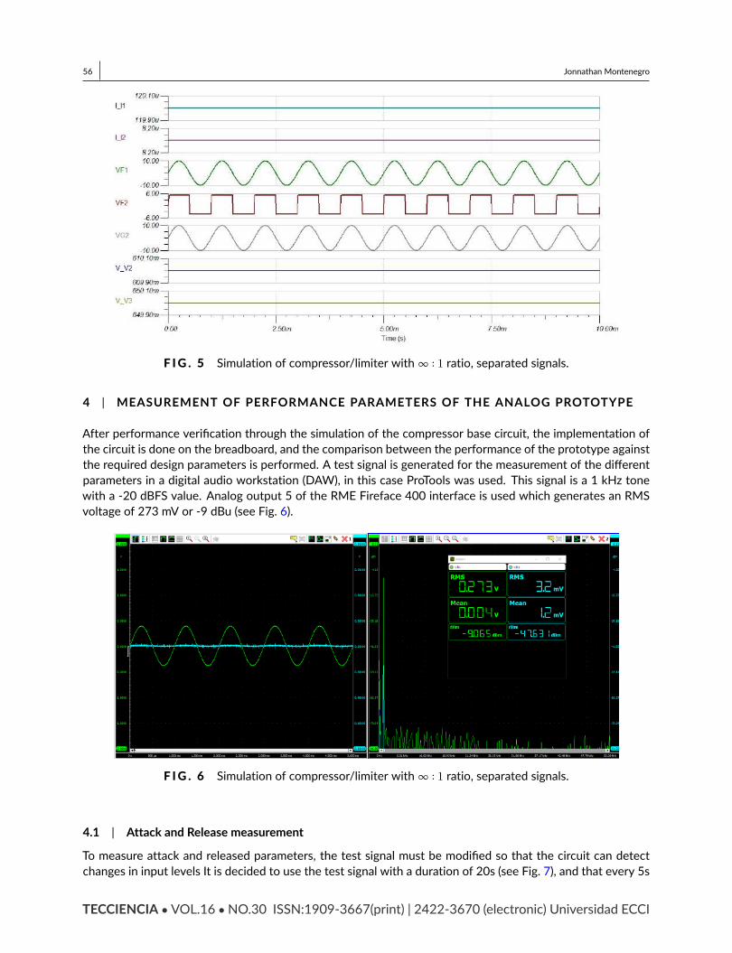
3 | SIMULATION OF COMPRESSION CIRCUITSIt was decided to use the TINA-TI free software to run the simulations of the specific compression circuits,since it is possible to visualize the responses of the specific threshold, ratio and gain parameters. Simulationof the transient response of the circuit is observed in Figs. 4 and 5.
F IG . 4 Simulation of Compressor/Limiter with∞ ∶ 1 ratio.Where VF1 is the voltage generated at the source and VF2 is the measured voltage at the output of thecompressor.
TECCIENCIA VOL.16 NO.30 ISSN:1909-3667(print) | 2422-3670 (electronic) Universidad ECCI
56 Jonnathan Montenegro
F IG . 5 Simulation of compressor/limiter with∞ ∶ 1 ratio, separated signals.4 | MEASUREMENT OF PERFORMANCE PARAMETERS OF THE ANALOG PROTOTYPEAfter performance verification through the simulation of the compressor base circuit, the implementation ofthe circuit is done on the breadboard, and the comparison between the performance of the prototype againstthe required design parameters is performed. A test signal is generated for the measurement of the differentparameters in a digital audio workstation (DAW), in this case ProTools was used. This signal is a 1 kHz tonewith a -20 dBFS value. Analog output 5 of the RME Fireface 400 interface is used which generates an RMSvoltage of 273 mV or -9 dBu (see Fig. 6).
F IG . 6 Simulation of compressor/limiter with∞ ∶ 1 ratio, separated signals.
4.1 | Attack and Release measurementTo measure attack and released parameters, the test signal must be modified so that the circuit can detectchanges in input levels It is decided to use the test signal with a duration of 20s (see Fig. 7), and that every 5sTECCIENCIA VOL.16 NO.30 ISSN:1909-3667(print) | 2422-3670 (electronic) Universidad ECCI
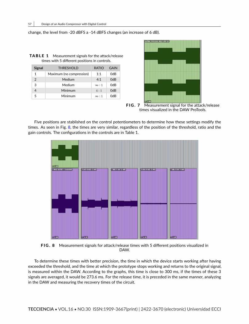
57 Design of an Audio Compressor with Digital Controlchange, the level from -20 dBFS a -14 dBFS changes (an increase of 6 dB).
TABLE 1 Measurement signals for the attack/releasetimes with 5 different positions in controls.Signal THRESHOLD RATIO GAIN1 Maximum (no compression) 1:1 0dB2 Medium 4:1 0dB3 Medium ∞ ∶ 1 0dB4 Minimum 4 ∶ 1 0dB5 Minimum ∞ ∶ 1 0dB
F IG . 7 Measurement signal for the attack/releasetimes visualized in the DAW ProTools.Five positions are stablished on the control potentiometers to determine how these settings modify thetimes. As seen in Fig. 8, the times are very similar, regardless of the position of the threshold, ratio and thegain controls. The configurations in the controls are in Table 1.
F IG . 8 Measurement signals for attack/release times with 5 different positions visualized inDAW.To determine these times with better precision, the time in which the device starts working after havingexceeded the threshold, and the time at which the prototype stops working and returns to the original signal,is measured within the DAW. According to the graphs, this time is close to 300 ms, if the times of these 3signals are averaged, it would be 273.6 ms. For the release time, it is preceded in the same manner, analyzingin the DAW and measuring the recovery times of the circuit.
TECCIENCIA VOL.16 NO.30 ISSN:1909-3667(print) | 2422-3670 (electronic) Universidad ECCI

58 Jonnathan Montenegro4.2 | Control measurement of compression relations (ratio)
To finish this parameter, a measurement of the levels is made in dBu of the input against the output of thedevice, by means of a digital oscilloscope, with the previously used test signal, which changes its gain valueevery 5s. The compressor controls are located in two different positions to output 2 ratio values for the Midpositions (equivalent to 4:1 according to design) and the max (equivalent to ∞ ∶ 1) respectively, and thesevalues are averaged to give an estimate of the device´s operation. Signals 2 and 4 in Table 1 are used to makethese measurements for a ratio of 4:1 and Signal 5 for a ratio of∞ ∶ 1.
F IG . 9 Measurement signal 2 with - 20 dBFS value.
F IG . 10 Measurement signal 2 with -14 dBFS value.In order to determine the ratio value, the dBu change in the input signal (green colour), with respect to theoutput signal (in blue colour) for the Figs. 9 and 10. Therefore,
• The change in dBu of the input signal = (9.075 - 3.048) = 6.027• The change in dBu of the output signal = (13.72 - 11.38) = 2.34• Ratio dB = dB in / dB out = 2.57TECCIENCIA VOL.16 NO.30 ISSN:1909-3667(print) | 2422-3670 (electronic) Universidad ECCI

59 Design of an Audio Compressor with Digital ControlFor the signal No. 4, same procedure is applied and the results are:
• The change in dBu of the input signal = (9.075 - 3.049) = 6.026• The change in dBu of the output signal = (30.62 – 29.37) = 1.25• Ratio dB = dB in / dB out = 4.82By averaging these two ratios, you have a value for theMid position of the prototype ratio control of 3.69:1,a value very close to that of design which is 4 ∶ 1. A similar procedure is performed to measure the ratio controlat its maximum value, which in theory yields a∞ ∶ 1, which is equivalent to the device behaving as a limiter.
F IG . 11 Measurement signal 2 with - 20 dBFS value.
F IG . 12 Measurement signal 2 with -14 dBFS value.From signal 5 (see Fig. 11 and 12), the values are obtained:
• Change in dBu of the input signal = (9.076 – 3.049) = 6.027• Change in dBu of the output signal = 37.85 – 38.11) = 0.26• Ratio dB = dB in / dB out = 23.18TECCIENCIA VOL.16 NO.30 ISSN:1909-3667(print) | 2422-3670 (electronic) Universidad ECCI
60 Jonnathan MontenegroFor the maximum position, the value approaches to the design. Due to the fact that it is established arelation of more than 10:1 in a compressor, then it behaves as a limiter.
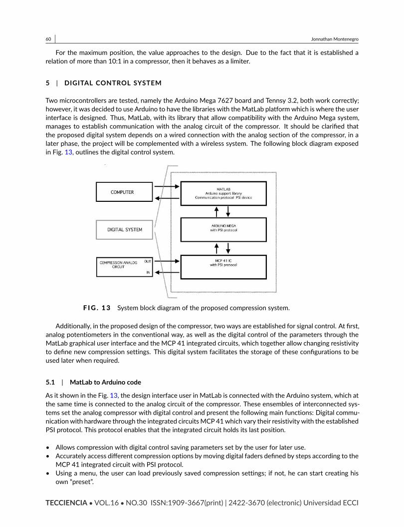
5 | DIGITAL CONTROL SYSTEMTwo microcontrollers are tested, namely the Arduino Mega 7627 board and Tennsy 3.2, both work correctly;however, it was decided to use Arduino to have the libraries with theMatLab platformwhich is where the userinterface is designed. Thus, MatLab, with its library that allow compatibility with the Arduino Mega system,manages to establish communication with the analog circuit of the compressor. It should be clarified thatthe proposed digital system depends on a wired connection with the analog section of the compressor, in alater phase, the project will be complemented with a wireless system. The following block diagram exposedin Fig. 13, outlines the digital control system.
F IG . 13 System block diagram of the proposed compression system.Additionally, in the proposed design of the compressor, two ways are established for signal control. At first,analog potentiometers in the conventional way, as well as the digital control of the parameters through theMatLab graphical user interface and the MCP 41 integrated circuits, which together allow changing resistivityto define new compression settings. This digital system facilitates the storage of these configurations to beused later when required.
5.1 | MatLab to Arduino codeAs it shown in the Fig. 13, the design interface user in MatLab is connected with the Arduino system, which atthe same time is connected to the analog circuit of the compressor. These ensembles of interconnected sys-tems set the analog compressor with digital control and present the following main functions: Digital commu-nicationwith hardware through the integrated circuitsMCP 41which vary their resistivity with the establishedPSI protocol. This protocol enables that the integrated circuit holds its last position.• Allows compression with digital control saving parameters set by the user for later use.• Accurately access different compression options by moving digital faders defined by steps according to theMCP 41 integrated circuit with PSI protocol.• Using a menu, the user can load previously saved compression settings; if not, he can start creating hisown “preset”.TECCIENCIA VOL.16 NO.30 ISSN:1909-3667(print) | 2422-3670 (electronic) Universidad ECCI
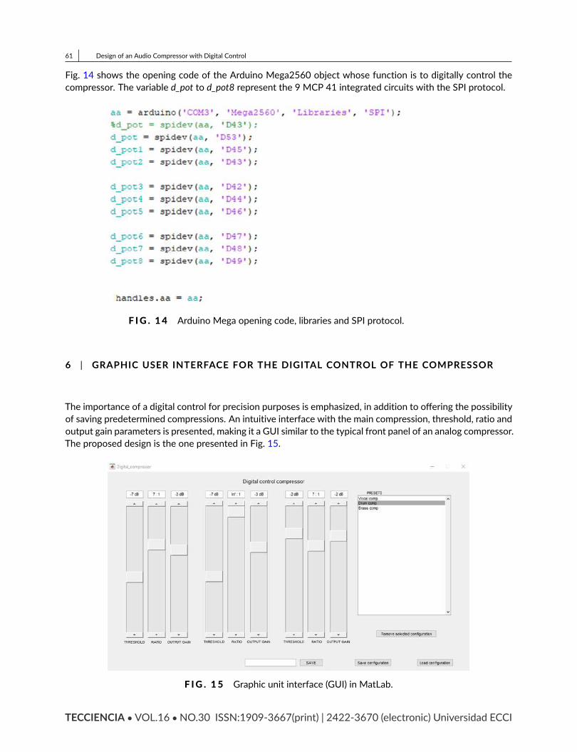
61 Design of an Audio Compressor with Digital ControlFig. 14 shows the opening code of the Arduino Mega2560 object whose function is to digitally control thecompressor. The variable d_pot to d_pot8 represent the 9 MCP 41 integrated circuits with the SPI protocol.
F IG . 14 Arduino Mega opening code, libraries and SPI protocol.
6 | GRAPHIC USER INTERFACE FOR THE DIGITAL CONTROL OF THE COMPRESSOR
The importance of a digital control for precision purposes is emphasized, in addition to offering the possibilityof saving predetermined compressions. An intuitive interface with the main compression, threshold, ratio andoutput gain parameters is presented, making it a GUI similar to the typical front panel of an analog compressor.The proposed design is the one presented in Fig. 15.
F IG . 15 Graphic unit interface (GUI) in MatLab.
TECCIENCIA VOL.16 NO.30 ISSN:1909-3667(print) | 2422-3670 (electronic) Universidad ECCI
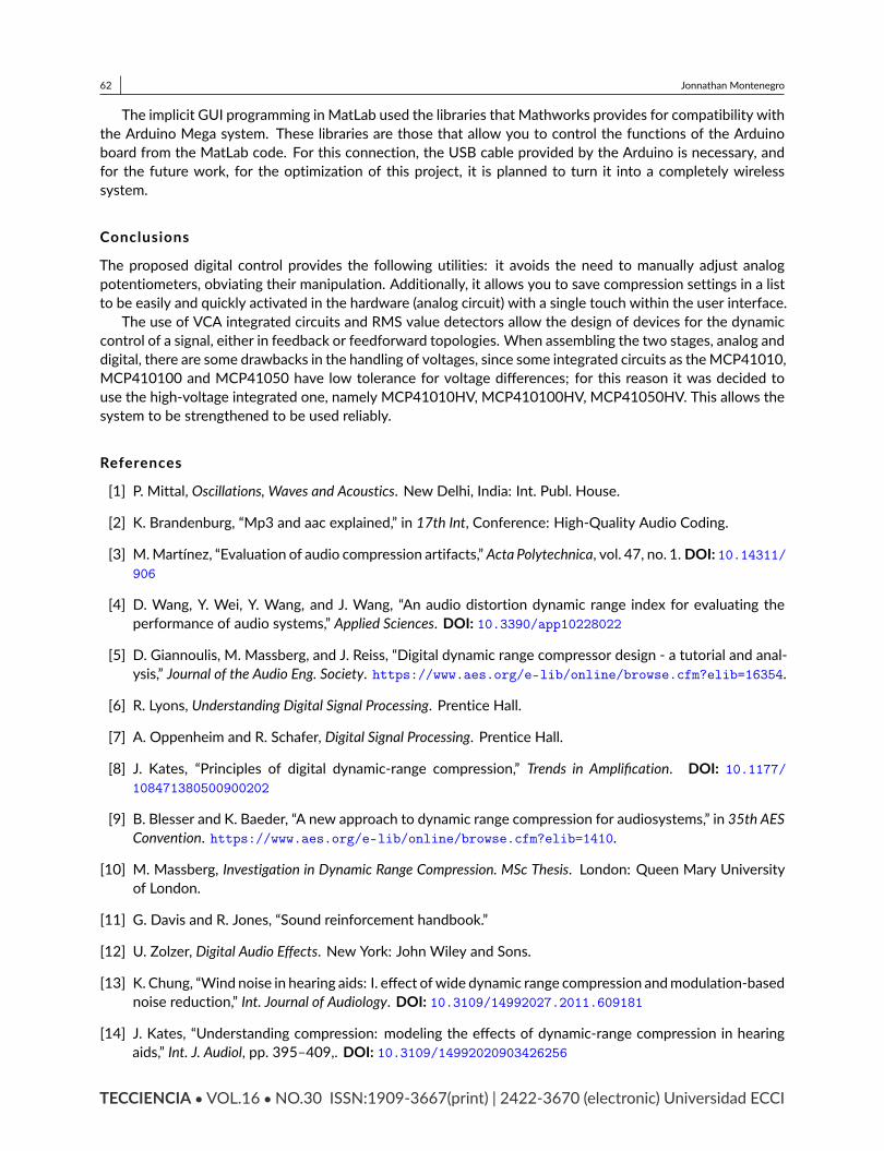
62 Jonnathan MontenegroThe implicit GUI programming in MatLab used the libraries that Mathworks provides for compatibility withthe Arduino Mega system. These libraries are those that allow you to control the functions of the Arduinoboard from the MatLab code. For this connection, the USB cable provided by the Arduino is necessary, andfor the future work, for the optimization of this project, it is planned to turn it into a completely wirelesssystem.
ConclusionsThe proposed digital control provides the following utilities: it avoids the need to manually adjust analogpotentiometers, obviating their manipulation. Additionally, it allows you to save compression settings in a listto be easily and quickly activated in the hardware (analog circuit) with a single touch within the user interface.The use of VCA integrated circuits and RMS value detectors allow the design of devices for the dynamiccontrol of a signal, either in feedback or feedforward topologies. When assembling the two stages, analog anddigital, there are some drawbacks in the handling of voltages, since some integrated circuits as theMCP41010,MCP410100 and MCP41050 have low tolerance for voltage differences; for this reason it was decided touse the high-voltage integrated one, namely MCP41010HV, MCP410100HV, MCP41050HV. This allows thesystem to be strengthened to be used reliably.References[1] P. Mittal, Oscillations, Waves and Acoustics. New Delhi, India: Int. Publ. House.[2] K. Brandenburg, “Mp3 and aac explained,” in 17th Int, Conference: High-Quality Audio Coding.[3] M.Martínez, “Evaluation of audio compression artifacts,” Acta Polytechnica, vol. 47, no. 1. DOI: 10.14311/
906
[4] D. Wang, Y. Wei, Y. Wang, and J. Wang, “An audio distortion dynamic range index for evaluating theperformance of audio systems,” Applied Sciences. DOI: 10.3390/app10228022[5] D. Giannoulis, M. Massberg, and J. Reiss, “Digital dynamic range compressor design - a tutorial and anal-ysis,” Journal of the Audio Eng. Society. https://www.aes.org/e-lib/online/browse.cfm?elib=16354.[6] R. Lyons, Understanding Digital Signal Processing. Prentice Hall.[7] A. Oppenheim and R. Schafer, Digital Signal Processing. Prentice Hall.[8] J. Kates, “Principles of digital dynamic-range compression,” Trends in Amplification. DOI: 10.1177/
108471380500900202
[9] B. Blesser and K. Baeder, “A new approach to dynamic range compression for audiosystems,” in 35th AESConvention. https://www.aes.org/e-lib/online/browse.cfm?elib=1410.
[10] M. Massberg, Investigation in Dynamic Range Compression. MSc Thesis. London: Queen Mary Universityof London.[11] G. Davis and R. Jones, “Sound reinforcement handbook.”[12] U. Zolzer, Digital Audio Effects. New York: John Wiley and Sons.[13] K. Chung, “Wind noise in hearing aids: I. effect ofwide dynamic range compression andmodulation-basednoise reduction,” Int. Journal of Audiology. DOI: 10.3109/14992027.2011.609181[14] J. Kates, “Understanding compression: modeling the effects of dynamic-range compression in hearingaids,” Int. J. Audiol, pp. 395–409,. DOI: 10.3109/14992020903426256TECCIENCIA VOL.16 NO.30 ISSN:1909-3667(print) | 2422-3670 (electronic) Universidad ECCI
63 Design of an Audio Compressor with Digital Control[15] P. Souza, “Effects of compression on speech acoustics, intelligibility, and sound quality,” Trends Amplif,pp. 131–165,. DOI: 10.1177/108471380200600402[16] J. Abel and D. Berners, “On peak-detection and rms feedback and feedforward compression,” in 115th of
the AES Convention.
TECCIENCIA VOL.16 NO.30 ISSN:1909-3667(print) | 2422-3670 (electronic) Universidad ECCI
64 Jonnathan Montenegro
TECCIENCIA VOL.16 NO.30 ISSN:1909-3667(print) | 2422-3670 (electronic) Universidad ECCI