Novel PID Tracking Controller for 2DOF Robotic Manipulator ...
Design of a Novel MRI Compatible Manipulator for Image Guided Prostate Interventions
8
306 IEEE TRANSACTIONS ON BIOMEDICAL ENGINEERING, VOL. 52, NO. 2, FEBRUARY 2005 Design of a Novel MRI Compatible Manipulator for Image Guided Prostate Interventions Axel Krieger, Robert C. Susil, Cynthia Ménard, Jonathan A. Coleman, Gabor Fichtinger, Member, IEEE, Ergin Atalar, and Louis L. Whitcomb*, Senior Member, IEEE Abstract—This paper reports a novel remotely actuated ma- nipulator for access to prostate tissue under magnetic resonance imaging guidance (APT-MRI) device, designed for use in a standard high-field MRI scanner. The device provides three-di- mensional MRI guided needle placement with millimeter accuracy under physician control. Procedures enabled by this device in- clude MRI guided needle biopsy, fiducial marker placements, and therapy delivery. Its compact size allows for use in both standard cylindrical and open configuration MRI scanners. Preliminary in vivo canine experiments and first clinical trials are reported. Index Terms—Biomedical imaging, cancer, magnetic resonance imaging, medical diagnosis, medical treatment. I. INTRODUCTION T HIS PAPER reports the development of a novel access to prostate tissue under magnetic resonance imaging guid- ance (APT-MRI) manipulator for MR prostate imaging and pre- cision MRI guided needle placements and reports the results of in vivo canine experiments and clinical trials. The manipulator operates inside the spatial confines and high magnetic field of a standard “closed” MR scanner. The principal objective for the manipulator is to provide precise image guided targeting of a needle for therapeutic procedures and biopsy of the prostate. The manipulator is equipped with active fiducial tracking to en- code the position of the needle path and is remotely actuated by the physician from outside the bore of the MR scanner. A tar- geting system displays MR images, including the needle path, and provides a graphical user interface for the physician. We Manuscript received December 22, 2003; revised June 6, 2004. This work was supported in part by the National Science Foundation (NSF) under Grant NSF ERC 9 731 478, in part by the US Army under Grant PC 10029, in part by the National Institutes of Health (NIH) under Grant RO1 HL57483, Grant RO1 HL61672, and Grant RO1 EB02963. Asterisk indicates corresponding author. A. Krieger is with the Department of Radiology and the Department of Me- chanical Engineering, The Johns Hopkins University, Baltimore, MD 21218 USA. R. C. Susil is with the Department of Biomedical Engineering, The Johns Hopkins University, Baltimore, MD 21218 USA. C. Ménard was with the Radiation Oncology Branch, NCI, NIH-DHHS, Fred- erick, MD 30325 USA. She is now with the Department of Radiation Oncology, Princess Margaret Hospital, Toronto, ON M5G 2M9, Canada. J. A. Coleman is with the Urologic Oncology Branch, NCI, NIH-DHHS, Frederick, MD 30325 USA. G. Fichtinger is with the Department of Radiology, The Johns Hopkins Uni- versity, Baltimore, MD 21218 USA. E. Atalar is with the Department of Radiology, The Johns Hopkins University Baltimore, MD 21218 USA, and also with the Department of Electrical and Electronics Engineering, Bilkent University, Ankara, 06533, Turkey. *L. L. Whitcomb is with the Department of Mechanical Engineering, 123 Latrobe Hall, 3400 N. Charles Street, The Johns Hopkins University, Baltimore, MD 21218 USA (e-mail: [email protected]). Digital Object Identifier 10.1109/TBME.2004.840497 have recently reported the use of a first generation prototype of this manipulator [4], [8], [13]. This paper focuses on the de- sign, materials and construction of a second generation device for clinical trials. The results of these clinical trials, mentioned briefly herein, are reported in [14]. This paper is organized as follows: The remainder of this sec- tion reviews background information about prostate diseases and treatments, compares imaging modalities for the prostate, and reviews previous work in this area. Section II reports the design of the manipulator. Section III reports the performance of the manipulator in in vivo canine studies and clinical trials. A. Background and Motivation Prostate cancer is the most common noncutaneous cancer in American men. In 2003, there will be an estimated 220 900 new cases of prostate cancer in the United States and 28 900 men will die of this disease [6]. There are two common screening methods for prostate cancer: the prostate-specific antigen test (PSA) and the digital rectal exam (DRE) [10]. The PSA concen- tration in the blood estimates the likelihood of prostate cancer, but is not conclusive. For the DRE, the physician determines whether the prostate gland is enlarged or whether abnormal nod- ules are present. When a PSA level is higher than normal or a DRE shows abnormal results, needle biopsy will normally be recommended to determine if a tumor exists and whether the tumor is benign or malignant. The current standard of care for verifying the existence of prostate cancer is transrectal ultrasound (TRUS) guided biopsy. Under ultrasound guidance, the physician places a biopsy needle through the wall of the rectum into the prostate gland. The needle removes a small cylinder of tissue, which is examined under the microscope to determine if cancer is present. Several biopsy samples are normally taken from dif- ferent areas of the prostate. Usually, 6–18 cores are removed (from upper, mid, and lower areas of the left and right sides) to obtain a representative sample of the gland and to determine how much of the gland is affected by the cancer. TRUS provides limited diagnostic accuracy and image reso- lution. In [17], the authors conclude that TRUS is not accurate for tumor localization and therefore precludes the precise identification and sampling of individual cancerous tumor sites. As a result, the sensitivity of TRUS biopsy is only between 60% and 85% [11], [16]. Magnetic Resonance Imaging (MRI) with an endorectal coil affords images with higher anatomical resolution and contrast than can be obtained using TRUS [17]. Although computed tomography (CT) X-Ray imaging is capable of high spatial resolution, MRI’s superior soft-tissue 0018-9294/$20.00 © 2005 IEEE
Transcript of Design of a Novel MRI Compatible Manipulator for Image Guided Prostate Interventions

306 IEEE TRANSACTIONS ON BIOMEDICAL ENGINEERING, VOL. 52, NO. 2, FEBRUARY 2005
Design of a Novel MRI Compatible Manipulator forImage Guided Prostate Interventions
Axel Krieger, Robert C. Susil, Cynthia Ménard, Jonathan A. Coleman, Gabor Fichtinger, Member, IEEE,Ergin Atalar, and Louis L. Whitcomb*, Senior Member, IEEE
Abstract—This paper reports a novel remotely actuated ma-nipulator for access to prostate tissue under magnetic resonanceimaging guidance (APT-MRI) device, designed for use in astandard high-field MRI scanner. The device provides three-di-mensional MRI guided needle placement with millimeter accuracyunder physician control. Procedures enabled by this device in-clude MRI guided needle biopsy, fiducial marker placements, andtherapy delivery. Its compact size allows for use in both standardcylindrical and open configuration MRI scanners. Preliminaryin vivo canine experiments and first clinical trials are reported.
Index Terms—Biomedical imaging, cancer, magnetic resonanceimaging, medical diagnosis, medical treatment.
I. INTRODUCTION
THIS PAPER reports the development of a novel access toprostate tissue under magnetic resonance imaging guid-
ance (APT-MRI) manipulator for MR prostate imaging and pre-cision MRI guided needle placements and reports the results ofin vivo canine experiments and clinical trials. The manipulatoroperates inside the spatial confines and high magnetic field of astandard “closed” MR scanner. The principal objective for themanipulator is to provide precise image guided targeting of aneedle for therapeutic procedures and biopsy of the prostate.The manipulator is equipped with active fiducial tracking to en-code the position of the needle path and is remotely actuated bythe physician from outside the bore of the MR scanner. A tar-geting system displays MR images, including the needle path,and provides a graphical user interface for the physician. We
Manuscript received December 22, 2003; revised June 6, 2004. This workwas supported in part by the National Science Foundation (NSF) under GrantNSF ERC 9 731 478, in part by the US Army under Grant PC 10029, in part bythe National Institutes of Health (NIH) under Grant RO1 HL57483, Grant RO1HL61672, and Grant RO1 EB02963. Asterisk indicates corresponding author.
A. Krieger is with the Department of Radiology and the Department of Me-chanical Engineering, The Johns Hopkins University, Baltimore, MD 21218USA.
R. C. Susil is with the Department of Biomedical Engineering, The JohnsHopkins University, Baltimore, MD 21218 USA.
C. Ménard was with the Radiation Oncology Branch, NCI, NIH-DHHS, Fred-erick, MD 30325 USA. She is now with the Department of Radiation Oncology,Princess Margaret Hospital, Toronto, ON M5G 2M9, Canada.
J. A. Coleman is with the Urologic Oncology Branch, NCI, NIH-DHHS,Frederick, MD 30325 USA.
G. Fichtinger is with the Department of Radiology, The Johns Hopkins Uni-versity, Baltimore, MD 21218 USA.
E. Atalar is with the Department of Radiology, The Johns Hopkins UniversityBaltimore, MD 21218 USA, and also with the Department of Electrical andElectronics Engineering, Bilkent University, Ankara, 06533, Turkey.
*L. L. Whitcomb is with the Department of Mechanical Engineering, 123Latrobe Hall, 3400 N. Charles Street, The Johns Hopkins University, Baltimore,MD 21218 USA (e-mail: [email protected]).
Digital Object Identifier 10.1109/TBME.2004.840497
have recently reported the use of a first generation prototype ofthis manipulator [4], [8], [13]. This paper focuses on the de-sign, materials and construction of a second generation devicefor clinical trials. The results of these clinical trials, mentionedbriefly herein, are reported in [14].
This paper is organized as follows: The remainder of this sec-tion reviews background information about prostate diseasesand treatments, compares imaging modalities for the prostate,and reviews previous work in this area. Section II reports thedesign of the manipulator. Section III reports the performanceof the manipulator in in vivo canine studies and clinical trials.
A. Background and Motivation
Prostate cancer is the most common noncutaneous cancer inAmerican men. In 2003, there will be an estimated 220 900 newcases of prostate cancer in the United States and 28 900 menwill die of this disease [6]. There are two common screeningmethods for prostate cancer: the prostate-specific antigen test(PSA) and the digital rectal exam (DRE) [10]. The PSA concen-tration in the blood estimates the likelihood of prostate cancer,but is not conclusive. For the DRE, the physician determineswhether the prostate gland is enlarged or whether abnormal nod-ules are present.
When a PSA level is higher than normal or a DRE showsabnormal results, needle biopsy will normally be recommendedto determine if a tumor exists and whether the tumor is benignor malignant. The current standard of care for verifying theexistence of prostate cancer is transrectal ultrasound (TRUS)guided biopsy. Under ultrasound guidance, the physician placesa biopsy needle through the wall of the rectum into the prostategland. The needle removes a small cylinder of tissue, whichis examined under the microscope to determine if cancer ispresent. Several biopsy samples are normally taken from dif-ferent areas of the prostate. Usually, 6–18 cores are removed(from upper, mid, and lower areas of the left and right sides)to obtain a representative sample of the gland and to determinehow much of the gland is affected by the cancer.
TRUS provides limited diagnostic accuracy and image reso-lution. In [17], the authors conclude that TRUS is not accuratefor tumor localization and therefore precludes the preciseidentification and sampling of individual cancerous tumor sites.As a result, the sensitivity of TRUS biopsy is only between60% and 85% [11], [16]. Magnetic Resonance Imaging (MRI)with an endorectal coil affords images with higher anatomicalresolution and contrast than can be obtained using TRUS[17]. Although computed tomography (CT) X-Ray imaging iscapable of high spatial resolution, MRI’s superior soft-tissue
0018-9294/$20.00 © 2005 IEEE

KRIEGER et al.: DESIGN OF A NOVEL MRI COMPATIBLE MANIPULATOR FOR IMAGE GUIDED PROSTATE INTERVENTIONS 307
Fig. 1. Picture of the manipulator showing the different components and theneedle tip, showing needle guide and sheath, positioning stage, insertion stage,flexible actuation shafts, and mount.
discrimination enables the identification of individual can-cerous lesions. MRI guided transperineal prostate biopsy hasbeen demonstrated inside an open MRI scanner [5]. While thetransrectal approach is generally well tolerated by patients, thetransperineal approach dictates a longer needle path, whichmay increase patient discomfort.
B. Previous Work in MRI Compatible Interventional Devices
Masamune and colleagues [9] report an in-MRI robot forstereotactic brain surgery for use with open MRI. In [7], Kaiserand colleagues report a 6 degrees of freedom (DOF) roboticsystem for breast biopsy for the use inside of a “closed” MRscanner. In [2], Chinzei and colleagues report a surgical assistrobot for use inside an open MRI scanner. This robot can be usedfor transperineal access to the prostate. In [1], Beyersdorff andcolleagues report a device for prostate biopsy inside a “closed”MR scanner utilizing passive fiducial tracking. In [15], Tajimaand colleagues report an MR compatible surgical manipulatorfor heart intervention designed for vertical magnetic field open-configuration MR imagers. In contrast to these approaches, wehave developed a remotely actuated manipulator that operatesinside a conventional high-field MRI scanner, which has highersignal-to-noise ratio (SNR) than most open configuration scan-ners and employs transrectal access to the prostate. This paperreports the first successful device combining MR imaging andtracking coils with a needle for the purpose of image guidedprostate intervention.
II. MANIPULATOR DESIGN
This section reports on the design of the manipulator. Place-ment schematic and the components of the manipulator are de-scribed. In addition, design, needles, encoding system and ma-terials for the manipulator are reported. Fig. 1 shows a photo ofthe manipulator. The manipulator consists of needle guide andrectal sheath, positioning stage, insertion stage, flexible shafts,and mount.
A. Device Operation
Fig. 2 shows a computer-aided design (CAD) drawing ofthe placement and operation of the robotic device. The deviceis comprised of a rectal sheath, which is placed adjacent tothe prostate in the rectum of the patient and a needle guide,containing a curved needle channel. The sheath is held sta-tionary during the procedure while the needle guide rotates andtranslates within the sheath. The needle exits the needle guide
Fig. 2. CAD drawing of needle guide and sheath with curved needle channel.The needle is guided inside the curved needle channel of the needle guide andadvanced through a window in the rectal sheath into the prostate.
Fig. 3. CAD drawing of needle guide and sheath with straight needle channel.A 20 needle channel for distal parts of the prostate and a 30 channel forproximal parts of the prostate.
through a window in the sheath at a 45 angle between axis ofthe guide and the needle for optimal coverage of the prostate.Rotation and translation of the needle guide and insertion ofthe needle are the three DOF necessary for the manipulator toplace the needle at a target within the prostate.
Some applications require a straight needle path (Fig. 3).Biopsy, for example, requires fast actuation of the biopsyneedle to reliably harvest good biopsy samples. Fast needleactuation is difficult to achieve with a curved channel due tofriction induced by the bending of the needle. A straight needlepath is therefore preferred for biopsies.
While the curved needle channel allows for unobstructed cov-erage of the prostate, even with high exit angles, the straightapproach is complicated by the constraint of avoiding obstruc-tion by tissue surrounding the proximal end of the needle guide.Therefore, the curved approach is preferable for most applica-tions. Two different needle guides with different needle chan-nels were designed to accommodate for various applications:1) a needle guide with curved needle channel for injections andfiducial marker placements, and 2) a needle guide with a straightneedle channel for biopsies. The sheath for the straight approachcontains two slots as windows: one on top for the entry of theneedle and one on the bottom for the exit. In straight needle ver-sion, the sheath rotates together with the needle guide. A keyinside the needle guide riding in the top slot provides the rota-tion of the sheath. For better coverage of the prostate, the needleguide for the straight approach contains two needle channels: Achannel with 30 exit angle for proximal parts of the prostateand a channel with 20 exit angle for the distal parts.

308 IEEE TRANSACTIONS ON BIOMEDICAL ENGINEERING, VOL. 52, NO. 2, FEBRUARY 2005
Fig. 4. Transparent CAD drawing of the positioning stage. Rotation of theactuation shaft for translation is converted into pure translation of the drive shaft.Rotation of the actuation shaft for rotation is converted into pure rotation of thedrive shaft.
B. Principal Mechanical Components
The positioning stage provides translation and rotation of theneedle guide. Fig. 4 shows a semi-transparent view of the posi-tioning stage. It consists of a drive shaft, which is concentricallyconnected to the needle guide. It contains a through-hole for theneedle to pass through the manipulator. Translation is providedthrough an actuation shaft rotating a nut over a gear reduction,as shown in Fig. 4. The threaded nut drives the shaft. A secondactuation shaft rotates a small gear, which engages an internalgear. The internal gear is held stationary by the housing. Uponrotation of the small gear, the entire inner assembly includingthe actuation shafts rotates. Two keys riding in two horizontalgrooves on the drive shaft and which are held by the inner as-sembly rotate the drive shaft. A spring washer provides enoughaxial load to prevent unintentional rotation of the drive shaft.The actuation shafts exit the housing via a radial slot on the leftside of the housing allowing for 140 degrees of rotation, withoutcompromising structural stability.
Two bidirectional, nonmagnetic phosphor bronze flexibleshafts (SS White Technologies, Piscataway, NJ) are attached tothe actuation shafts to provide remote actuation from outsidethe scanner bore. For protection the flex shafts are encased innylon tubing. The rectal sheath for the curved approach attachesto the positioning stage with a click-in mechanism, comprisedof a nylon ball and a flat spring mating with a spherical denton the right housing of the positioning stage. A similar click-inmechanism is used for attaching the sheath for the straightapproach. However, a circular groove is used instead of thespherical dent, to allow for rotation of the sheath. A medicalgrade heat shrink (Tyco Electronics Corporation, Menlo Park,CA) is fitted around the sheath and covers the window toprevent tissue from being trapped between window and needleguide.
The insertion depth is set by the insertion stage by increasingand decreasing the length of a tubular stop for the needle witha set screw mechanism. A scale is attached to the stop to man-ually set the length and thus the insertion depth of the needle.The insertion stage docks to the drive shaft of the positioning
Fig. 5. Signal to noise contours for 200- and 300-mm-wide imaging coil. Thegraphs show contours of measured SNR level of a cross section of the imagingcoil. XY units are in millimeters. The position of the coil is indicated by thearrows.
stage with a click in mechanism, similar to the one of the sheath.A tube is fitted inside the drive shaft to protect the drive shaftand the positioning mechanism from getting in contact with theneedle. This limits the number of parts requiring sterilizationto the sheath, the needle guide, and the insertion mechanism.The mount consists of a Drylin® T-slide and rail assembly (IgusInc., E. Providence, RI) for motion along the main axis of thescanner bore and an arm with two integrated ball joints (Man-frotto Trading, Milano, Italy) for adjusting horizontal and ver-tical position and orientation of the device.
C. MR Coils
The manipulator contains two types of MR coils: an imagingcoil and tracking coils for position encoding.
The imaging coil is looped around the window of the sheath,resting in a groove machined into the sheath. Two designideas were explored for the sheath containing the imagingcoil: with cylindrical cross section and a sheath with ellipticalcross section. An elliptical sheath would increase the width ofthe imaging coil, yielding higher SNR levels. The cylindricalsheath has the advantage of easier machinability and betterpatient comfort. To make a design choice, we compared theSNR level for an imaging coil on a flexible endorectal coil(MedRad Inc., Indianola, PA) with auto tuning capability ofa width of 300 mm, which is achievable with the ellipticaldesign to the SNR level for the cylindrical design with animaging width of 200 mm. Fig. 5 shows both SNR maps. Theincrease in SNR of the elliptical design was considered toosmall to justify higher machining costs and potential increaseof patient discomfort, leading to the decision to favor thecylindrical design.
Three tracking micro coils are placed into the manipulatorto encode the position of the needle channel. The method isexplained in Section II-E.
D. Nitinol Needles
For accurate targeting with the curved approach, the needleneeds to exit the channel of the needle guide along a straighttrajectory tangential to the arc at the point of exit. A higherexit angle allows for better coverage of the prostate. Higher exit
KRIEGER et al.: DESIGN OF A NOVEL MRI COMPATIBLE MANIPULATOR FOR IMAGE GUIDED PROSTATE INTERVENTIONS 309
angle for a given needle guide diameter requires higher cur-vature of the needle channel. Increasing the curvature of theneedle channel beyond a certain point, however, induces plasticdeformation (i.e., permanent bending) of the needle, resultingin arching of the needle and missing of the target. Our testsshowed that for 18 mm needle guide diameter an adequate exitangle could not be achieved using a standard 18 G (1.3 mm)or larger MRI compatible needle. 18 G Nitinol tube and wire(NDC Nitinol Devices & Components) with its super-elasticability was determined to provide enough yield strength to pre-vent it from plastically deforming at an exit angle of up to 45for an 18-mm-diameter needle guide. MRI Devices Daum pro-vided the grinding of the needle tips and assembly of the con-nectors and needles to our specifications for use with this newdesign.
E. 3-D Spatial Position Sensing
We explored three methods for encoding the device posi-tion in the MR scanner: Electro optic encoders, passive fiducialtracking and active fiducial tracking.
Electro-optical encoders reliably and accurately encode theposition of a robotic joint and were successfully implementedin the MRI environment by using optical connection for the de-velopment of a surgical assist robot [2]. However, they requireaccurate calibration between device coordinate system and MRIcoordinate system and suffer from inaccuracies caused by ma-terial deflection.
For passive fiducial tracking, fiducial markers composedof water doped with gadolinium-DTPA or other contrastagents are rigidly attached to the end-effector of the device.Gadolinium-DTPA is a commonly used contrast agent thatproduces large MR signal. Volumetric MR images are takenand after segmenting the marker position in the images thedevice position can be determined. This method providesposition of the end-effector in MRI coordinates, but in order toachieve good accuracy the images have to be of high qualitywhich takes a lot of time, preventing any real time tracking.Additionally, segmentation of the marker position from the restof the image is very time consuming.
Active fiducial tracking proved to be a fast and accurateencoding method [3]. This method utilizes three tracking microcoils rigidly embedded in the end-effector of the device, whichpick up their spatial position in the MRI scanner. A microcoil consists of a wire coil wrapped around a tube filled witha gadolinium-DTPA water solution. A cable connects theantenna coils to the imaging channels of the MRI scanner. Theposition of the center points of the gadolinium-DTPA tubes isdetermined by performing a series of twelve 1D projectionsalong different directions, using a frequency encoding gradient.A special MR pulse sequence to produce a series of projectionswas written. This yields an over-determined linear system forthe position of the points, which can be solved using a leastsquare algorithm. The registration sequence takes approxi-mately 50 ms allowing for real time tracking. Two trackingcoils are positioned along the axis of the needle guide, while thethird coil is placed off axis in the rotating part of the positioningstage, encoding the rotation of the needle guide, Fig. 6.
Fig. 6. Detailed picture of sheath, needle guide and positioning stage. Thepicture shows: the imaging coil, embedded in the rectal sheath, tracking coil 1and 2 built into the needle guide along the axis, and tracking coil 3, which isattached to the rotating part of the positioning stage.
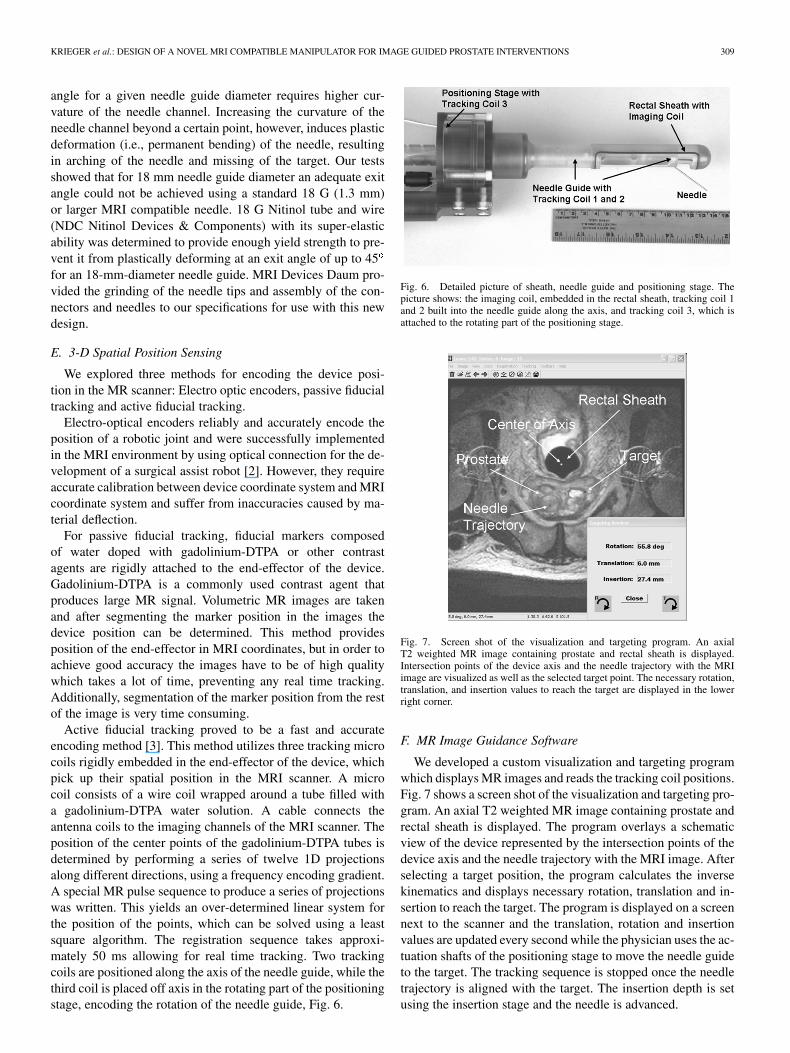
Fig. 7. Screen shot of the visualization and targeting program. An axialT2 weighted MR image containing prostate and rectal sheath is displayed.Intersection points of the device axis and the needle trajectory with the MRIimage are visualized as well as the selected target point. The necessary rotation,translation, and insertion values to reach the target are displayed in the lowerright corner.
F. MR Image Guidance Software
We developed a custom visualization and targeting programwhich displays MR images and reads the tracking coil positions.Fig. 7 shows a screen shot of the visualization and targeting pro-gram. An axial T2 weighted MR image containing prostate andrectal sheath is displayed. The program overlays a schematicview of the device represented by the intersection points of thedevice axis and the needle trajectory with the MRI image. Afterselecting a target position, the program calculates the inversekinematics and displays necessary rotation, translation and in-sertion to reach the target. The program is displayed on a screennext to the scanner and the translation, rotation and insertionvalues are updated every second while the physician uses the ac-tuation shafts of the positioning stage to move the needle guideto the target. The tracking sequence is stopped once the needletrajectory is aligned with the target. The insertion depth is setusing the insertion stage and the needle is advanced.

310 IEEE TRANSACTIONS ON BIOMEDICAL ENGINEERING, VOL. 52, NO. 2, FEBRUARY 2005
Fig. 8. Graph of tracking coil errors with aluminum ball joint, brass gear and phosphor bronze flex-shaft. The errors in mm are displayed over the displacementfrom the tracking coil in mm. The three lines indicate the position errors for coil 1, coil 2, and coil 3, respectively. Coil 1 is initially placed adjacent to the metalcomponent. Coil 2 and 3 are not influenced by the metal object.
Fig. 9. Angular and translational error distribution for active fiducial tracking. The graphs show histograms of angular and translational encoding error inmillimeters and degrees.
G. Materials
Due to the presence of a strong magnetic field inside of anMRI scanner, the use of any ferromagnetic materials is prohib-ited. Additionally, even nonmagnetic metals can create imagingartifact. These artifacts are caused by a disturbance of the mag-netic field due to difference in susceptibility of the metal andsurrounding objects. This disturbance also affects the readingsof the tracking coils in the vicinity of metals. The magnitudeof the disturbance is dependant on the size and on the materialof the metal. Very small nonmetallic metals create only a smalllocalized susceptibility artifact and can be neglected on MR im-ages and for tracking coil readings.
To avoid obstruction in anatomical images and introductionof errors in the coil readings, plastic materials are used to buildneedle guide and sheath, which are in closest vicinity to the fieldof view (FOV) of the anatomical MR images. Only very smallmetallic components are used to build these parts: Brass screwsfor fastening the needle guide to the drive shaft, the flat springfor the click in mechanism of the sheath, which is comprised ofphosphor bronze and a thin walled brass tubular liner (SpecialShapes Inc.) for the needle channel to protect the plastic frombeing marred with the needle. Functionality of the manipulator
could improve, if parts further away from the FOV may containmore metallic parts.
We developed a test methodology to determine the influenceof metallic components on tracking coil readings, which alsoindicates artifacts on MR images to determine the minimal dis-tance of installation of the components to the FOV and to thetracking coils. The position stage was used for stepped transla-tion of a needle guide containing three tracking coils. The posi-tion stage was set up to place one coil (coil 1) initially adjacentto the metal component and the other 2 coils (coil 2 and 3) outof the influenced region to provide undisturbed readings. Theneedle guide was translated away from the metal component andcoil errors over the distance to the component were recorded.
Fig. 8 shows the results of testing a phosphor bronze flex-ible shaft, a brass gear and an aluminum ball joint. The positionerror for a tracking coil placed in direct vicinity of the phosphorbronze flexible shaft did not measurably increase compared tothe tracking error distribution obtained without any metal partsin the vicinity shown in Fig. 9. This allows us in our designto place the flexible shafts right next to the positioning stage,which contains one of the tracking coils. The error introducedby placing a coil close to the aluminum ball joint significantly

KRIEGER et al.: DESIGN OF A NOVEL MRI COMPATIBLE MANIPULATOR FOR IMAGE GUIDED PROSTATE INTERVENTIONS 311
Fig. 10. MR images of the prostate. Panel A: Sagital T2 weighted MR image containing rectal sheath and prostate. Panel B: Axial T2 weighted MR imagecontaining prostate and rectal sheath with selected target. Panel C: Axial T1 weighted image after insertion of the needle, verifying accurate targeting, thus smalldisplacement between target point and the void created by the needle tip.
increased. However the error falls of rapidly to the level of thetracking error distribution without metal when the coil is furtherthan 10 mm away from the ball joint. Adding a safety margin of20 mm we placed the aluminum ball joint 30 mm away from thepositioning stage. The brass gears produced unacceptable errorsin the tracking coils and were replaced by plastic gears.
III. PERFORMANCE EVALUATION
All interventions were performed on a GE Signa Excite 1.5T MR scanner (GE Medical Systems). A protocol was devel-oped for MRI-guided gold fiducial marker placements on pa-tients with prostate cancer prior to treatment with external radi-ation beam therapy. Fiducial markers are used to adjust for dailyset-up changes to optimize targeting of external beam radiationtherapy [12]. The two primary goals of this study were to val-idate the needle targeting accuracy of the manipulator systemin clinical practice and to assess the effects of fiducial markerson the outcome of radiation therapy. Four markers were placedinto the prostate of each patient using the manipulator system.The target positions for the markers were selected to achievea diamond like pattern, with two markers placed to the left andright in the middle of the prostate (mid-gland), one marker in thelower part of the prostate (apex), and one marker in the upperpart of the prostate (base). After the markers were placed in theprostate, MRI images of the prostate were taken in the radia-tion treatment position without the transrectal device. These im-ages are co-registered to CT scans using the fiducial markers ascommon landmarks to aid in target delineation, and digitally re-constructed radiographs (DRRs) are compared to the treatmentportal x-rays taken prior to every radiation dose, to achieve op-timal beam coverage of the prostate gland. As of today, five pa-tients received implantation of markers. All 20 markers wereimplanted without complications. For each marker the physi-cian selected the desired marker position on T2 weighted axialand sagital MR images (Fig. 10). The manipulator was actu-ated to the target location and the physician inserted the needle.
After the needle was inserted, MR images were taken to con-firm that the location of needle tip was acceptable. The markerwas dropped and another MR image was taken after the needlewas extracted to visualize the marker position. Target location,needle tip location and center of marker location were recordedfor each marker placement to assess the targeting accuracy ofour system. The displacement errors for the needle and for themarker were determined on the MRI images as the distance ofthe needle tip and the center of the marker respectively to theplanned target location. The average in-plane displacement errorfor the needle tip of 20 needle placements was 1.3 mm with amaximum of 2.3 mm. In none of the 20 cases was the needletip more than one slice (3 mm) away from the slice containingthe target position. The average marker displacement error was4.8 mm with a maximum of 8.3 mm. The increased displace-ment errors for the marker compared to the needle tip wereconsidered to be caused by deformation of the prostate tissueduring insertion of the needle. After the marker is dropped andthe needle is extracted, the tissue around the marker relaxes andincreases the displacement error.
This section reports on the performance evaluation of themanipulator. First, the accuracy of the tracking method wastested. Subsequently, the manipulator was tested in in vivocanine studies and clinical trials.
A. In Vitro Tracking Accuracy Studies
An accuracy test with the proposed tracking method was per-formed, Fig. 9, using the positioning stage. Precise, steppedtranslations and rotations were performed and coil positionswere recorded after each step to calculate encoding errors. Stepsize was 1.27 mm for translation and 2 for rotation. The av-erage absolute error for translation was 0.19 mm with a standarddeviation of 0.25 mm. For rotation the average absolute errorwas 0.33 with a standard deviation of 0.42 . For a target that is30 mm away from the axis of rotation, a rotational error of 0.33yields a rotational displacement of 0.17 mm. The combinedmean displacement due to translational and rotational tracking

312 IEEE TRANSACTIONS ON BIOMEDICAL ENGINEERING, VOL. 52, NO. 2, FEBRUARY 2005
error is 0.26 mm. The measured bias for translation is mmand for rotation mm, yielding a distribution that is closeto zero mean. This data indicates that the desired millimeter ac-curacy for positioning of the manipulator can be achieved usingthis encoding method.
B. In Vivo Canine Accuracy Studies
A first-generation prototype of this manipulator was usedto demonstrate feasibility for different applications of prostateintervention and to assess the accuracy of needle placements.Needle placements, intraprostatic injections, and fiducialmarkers placements were performed in anesthetized canines,as reported in [13]. The usefulness of the manipulator for ac-curate needle placements, intraprostatic injections and fiducialmarkers placements was demonstrated. The maximum in-planeneedle displacement error for 4 needles was 2 mm. Becauseof a slice thickness of 3 mm for the MRI images it is moredifficult to exactly determine the error of the insertion depth. Inall cases, however, the needle tip was visible in the target slice.
C. In Vivo Clinical Accuracy Studies
In addition to the fiducial marker placements, four biopsy pro-cedures were performed with no adverse patient outcome. Theaverage in-plane displacement error for 20 biopsy needles was1.8 mm. Further clinical trials are in progress.
IV. CONCLUSION AND DISCUSSION
This paper reported the development of a novel APT-MRImanipulator for MR prostate imaging and precision MRI guidedneedle placements and reported the preliminary results of invivo canine experiments and clinical trials. Precise image guidedtargeting of a needle for intraprostatic marker placement andbiopsy was achieved.
Tissue deformation was considered to be the main reason fordisplacement errors. Reducing the tissue deformation, for ex-ample by increasing the insertion speed of the needle or fixatingthe prostate during insertion will be an objective for future work.Another objective will be to enable the use of the manipulatorin a 3 T system. The increased SNR of the 3 T system could im-prove the MR image quality and facilitate the use of functionalMRI, such as MR spectroscopy for better target selection.
ACKNOWLEDGMENT
The authors thank J. A. Derbyshire, Ph.D. and E. McVeigh,Ph.D. for help with the tracking coils; J. Polzin for assis-tance with gradient dewarping; Y. Oner, A. El-Sharkawy, andA. Yung for help with experiments and intrarectal imaging coildesign; P. Karmarkar for help with the nitinol needles; W. Krug,M. Franckowiak, and T. Shelly for machining; K. Ullman,P. Choyke, M.D. and P. Guion for help with clinical trials.
REFERENCES
[1] D. Beyersdorff, A. Winkel, P. Bretschneider, B. Hamm, S. Loening, andM. Taupitz, “Initial results of MRI-guided prostate biopsy using a biopsydevice in a closed MR imager at 1.5 T,” in Proc 88th Scientific Assemblyand Annu. Meeting Radiological Society of North America, Chicago, IL,2002, p. 629.
[2] K. Chinzei, N. Hata, F. Jolez, and R. Kikinis, “MR compatible surgicalrobot: System integration and preliminary feasibility study,” in MedicalImage Computing and Computer-Assisted Intervention 2000. Berlin,Germany: Springer Verlag, 2000, vol. 1935, pp. 921–930.
[3] C. L. Dumoulin, S. P. Souza, and R. D. Darrow, “Real-time positionmonitoring of invasive devices using magnetic resonance,” Magn.Reson. Med., vol. 29, no. 3, pp. 411–415, Mar. 1993.
[4] G. Fichtinger, A. Krieger, R. C. Susil, A. Tanacs, L. L. Whitcomb, andE. Atalar, “Transrectal prostate biopsy inside closed MRI scanner withremote actuation, under real-time image guidance,” in Lecture Notesin Computer Science, vol. 2488, Proceedings of the Fifth InternationalConference on Medical Image Computing and Computer-Assisted In-tervention, 2002, pp. 91–98.
[5] N. Hata, M. Jinzaki, D. Kacher, R. Cormak, D. Gering, A. Nabavi, S.G. Silverman, A. V. D’Amico, R. Kikinis, F. A. Jolesz, and C. M. C.Tempany, “MR imaging-guided prostate biopsy with surgical navigationsoftware: Device validation and feasibility,” Radiology, vol. 220, no. 1,pp. 263–268, Jul. 2001.
[6] A. Jemal, T. Murray, A. Samuels, A. Ghafoor, E. Ward, and M. J. Thun,“Cancer statistics, 2003,” CA Cancer J. Clin., vol. 53, no. 1, pp. 5–26,2003.
[7] W. Kaiser, H. Fischer, J. Vagner, and M. Selig, “Robotic system forbiopsy and therapy of breast lesions in a high-field whole-body mag-netic resonance tomography unit,” Investigat. Radiol., vol. 35, no. 8, pp.513–519, Aug. 2000.
[8] A. Krieger, R. C. Susil, A. Tanacs, G. Fichtinger, L. L. Whitcomb, and E.Atalar, “A MRI compatible device for MRI guided transrectal prostatebiopsy,” presented at the 10th Scientific Meeting Society of MagneticResonance Imaging in Medicine, Honolulu, HI, 2002, p. 338.
[9] K. Masamune, E. Kobayashi, Y. Masutani, M. Suzuki, T. Dohi, H. Iseki,and K. Takakura, “Development of an MRI-compatible needle insertionmanipulator for stereotactic neurosurgery,” J. Image-Guided Surg., vol.1, no. 4, pp. 242–248, Dec. 1995.
[10] J. Naitoh, R. L. Zeiner, and J. B. Dekernion, “Diagnosis and treatmentof prostate cancer,” Am. Fam. Physician, vol. 57, no. 7, pp. 1531–1539,1541–1512, 1545–1547, Apr. 1998.
[11] M. Norberg, L. Egevad, L. Holmberg, P. Sparen, B. Norlen, and C.Busch, “The sextant protocol for ultrasound-guided core biopsies of theprostate underestimates the presence of cancer,” Urology, vol. 50, no. 4,pp. 562–566, Oct. 1997.
[12] G. Pang, D. J. Beachey, P. F. O’Brian, and J. A. Rowlands, “Imagingof 1.0-mm-diameter radiopaque markers with megavoltage x-rays: Animproved online imaging system,” Int. J. Radiat. Oncol. Biol. Phys., vol.52, no. 2, pp. 532–537, Feb. 2002.
[13] R. C. Susil, A. Krieger, J. A. Derbyshire, A. Tanacs, L. L. Whitcomb,G. Fichtinger, and E. Atalar, “System for MR image-guided prostateinterventions: Canine study,” Radiology, vol. 228, no. 3, pp. 886–894,Sep. 2003.
[14] R. C. Susil, C. Menard, A. Krieger, J. Coleman, K. Camphausen, P.Choyke, G. Fichtinger, L. L. Whitcomb, C. N. Coleman, and E. Atalar,Transrectal prostate biopsy and fiducial marker placement in a standard1.5 T MRI scanner, 2004, submitted for publication.
[15] F. Tajima, K. Kishi, K. Nishizawa, K. Kan, H. Ishii, M. G. Fujie, T. Dohi,K.-I. Sudo, and S.-I. Takamoto, “A magnetic resonance compatible sur-gical manipulator: Part of a unified support system for the diagnosis andtreatment of heart disease,” Adv. Robot., vol. 17, no. 6, pp. 561–575, Sep.2003.
[16] M. K. Terris, “Sensitivity and specificity of sextant biopsies in the de-tection of prostate cancer: Preliminary report,” Urology, vol. 54, no. 3,pp. 486–489, Sep. 1999.
[17] K. K. Yu and H. Hricak, “Imaging prostate cancer,” Radiol. Clin. NorthAm., vol. 38, no. 1, pp. 59–85, Jan. 2000.
Axel Krieger received his B.S. and M.Sc. degrees inmechanical engineering from the University of Karl-sruhe, Karlsruhe, Germany, in 2001. He worked as aResearch Associate at the Department of Radiology,The Johns Hopkins University, Baltimore, MD,from 2001–2003. Currently he is working towardsthe Ph.D. degree in the Mechanical EngineeringDepartment at The Johns Hopkins University.
His research interest focuses on the develop-ment of MRI compatible devices for MRI-guidedinterventions.

KRIEGER et al.: DESIGN OF A NOVEL MRI COMPATIBLE MANIPULATOR FOR IMAGE GUIDED PROSTATE INTERVENTIONS 313
Robert C. Susil received the B.S. and Ph.D. degreesat The Johns Hopkins University in 1997 and 2003,respectively. He is currently working towards theM.D. degree at The Johns Hopkins University aspart of the NIH Medical Scientist Training Program.
His research has focused on developing techniquesand devices for performing MRI-guided minimallyinvasive procedures.
Cynthia Ménard received the M.D. degree from theUniversity of Calgary, Calgary, AB, Canada, in 1996and completed her residency in radiation oncology atthe University of Alberta, Edmonton, AB, Canada, in2001.
Until 2003 she was an ASTRO Translational Re-search Fellow in the Radiation Oncology Branch ofthe National Cancer Institute, NIH. She then held aStaff Clinician appointment and headed the Radia-tion Oncology Molecular Imaging Section in the Ra-diation Oncology Branch, NCI, where she pursued
research in the development, validation, and clinical application of novel MRimaging techniques to cancer radiotherapy. She is now appointed as a ClinicianScientist in the Radiation Medicine Program at Princess Margaret Hospital inToronto, ON, Canada.
Jonathan A. Coleman received the B.A. degreefrom Bard College, Annandale-on-Hudson, NY, in1989 and the M.D. degree (1996) and Residencytraining in urology (2002) at Cornell UniversityMedical College and Memorial Sloan KetteringCancer Center,New York.
He then entered the National Cancer Institute(NCI) as an A.F.U.D. sponsored fellow in UrologicOncology from 2002–2004. He currently holds anappointment as a senior clinical investigator andsurgeon at the NCI where he is active in ongoing
research and the surgical treatment of genitourinary malignancies includingprostate, bladder and kidney cancer. He has published in the field of ra-diographic imaging and tissue characterization using ultrasound as well ascontributing to chapters on urologic oncology in several texts. His currentresearch interests are in imaging and detection strategies for prostate cancer,developing molecular targeting therapies for bladder cancer and the use oflaparoscopic surgical approaches in the treatment of prostate and kidney cancer.
Gabor Fichtinger (M’04) received the B.S. andM.S. degrees in electrical engineering, and Ph.D.degree computer science from the Technical Univer-sity of Budapest, Budapest, Hungary, in 1986, 1988,and 1990, respectively.
He has balanced academic, industrial, and clinicalexperience in the development and clinical inaugura-tion of image-guided surgical interventional systems.His specialty is robot-assisted image-guided needle-placement procedures, primarily for cancer therapy.He is an Associate Research Professor of Computer
Science, Mechanical Engineering, and Radiology at The Johns Hopkins Uni-versity, Baltimore, MD. He is trained in therapeutic medical physics.
Mr. Fichtinger is a member of both AAPM and ASTRO.
Ergin Atalar received the B.S. degree from BogaziciUniversity, Istanbul, Turkey, in 1985; the M.S. de-gree from the the Middle East Technical University,Ankara, Turkey, in 1987; and the Ph.D. degree fromBilkent University, Ankara, Turkey in 1991, respec-tively.
Immediately after graduation, he joined The JohnsHopkins University, Baltimore, MD, as a Postdoc-toral Fellow where he is currently the Director of theCenter for Image Guided Intervetions and Professorof Radiology with joint appointments in the Depart-
ments of Electrical and Computer Engineering and Biomedical Engineering.He is also a Visiting Professor of Electrical and Electronics Engineering of theBilkent University. His main research areas are Magnetic Resonance Imaging(MRI)-guided vascular interventions and MRI-guided prostate interventions.
Louis L. Whitcomb (S’86–M’95–SM’02)receivedthe B.S. and Ph.D. degrees from Yale University,New Haven, CT, in 1984 and 1992, respectively.
From 1984 to 1986, he was an R&D Engineer withthe GMFanuc Robotics Corporation. From 1992 to1994, he was a Postdoctoral Fellow at the WoodsHole Oceanographic Institution and at the Universityof Tokyo. He holds numerous patents in the fieldof robotics. His research focuses on the design, dy-namics, and control of nonlinear dynamical systems.He is a Professor in the Department of Mechanical
Engineering, with joint appointment in the Department of Computer Science,at The Johns Hopkins University.