DESIGN CRITERIA FOR PUBLIC IMPROVEMENT PROJECTS
74
DESIGN CRITERIA FOR PUBLIC IMPROVEMENT PROJECTS Revised October 2016
-
Upload
khangminh22 -
Category
Documents
-
view
4 -
download
0
Transcript of DESIGN CRITERIA FOR PUBLIC IMPROVEMENT PROJECTS
DESIGN CRITERIA FOR PUBLIC IMPROVEMENT PROJECTS
Revised October 2016

i
TABLE OF CONTENTS DESIGN CRITERIA
Page
PROCEDURE FOR PUBLIC IMPROVEMENT PROJECT PLAN SUBMITTAL A. GENERAL...............................................DC/P-1 B. PUBLIC IMPROVEMENTS FUNDED BY PRIVATE DEVELOPERS......DC/P-1 C. PUBLIC IMPROVEMENTS FUNDED BY BENEFIT DISTRICT
AND/OR CITY AT LARGE..................................DC/P-3 GENERAL PLAN REQUIREMENTS FOR PUBLIC IMPROVEMENT PROJECTS A. GENERAL...............................................DC/1-1 B. REQUIRED NOTES........................................DC/1-1 C. APPROVAL BLOCK.......................................DC/1-10 D. PRIVATE IMPROVEMENTS.................................DC/1-10 DESIGN CRITERIA FOR SANITARY SEWERS AND APPURTENANCES A. DESIGN FACTORS........................................DC/2-1 B. SEWER DESIGN..........................................DC/2-1 C. MAXIMUM SIZE..........................................DC/2-2 D. MINIMUM SIZE..........................................DC/2-2 E. MATERIALS OF CONSTRUCTION.............................DC/2-2 F. MINIMUM SLOPE.........................................DC/2-2 G. INCREASING PIPE SIZE..................................DC/2-3 H. HIGH VELOCITY PROTECTION..............................DC/2-3 I. ALIGNMENT.............................................DC/2-4 J. MANHOLE CONSTRUCTION..................................DC/2-4 K. MANHOLES..............................................DC/2-4 L. SEWER CONSTRUCTION – GROUNDWATER BARRIERS.............DC/2-6 M. SEWER LOCATIONS.......................................DC/2-6 N. CLEANOUTS AND LAMPHOLES...............................DC/2-6 O. PROTECTION OF WATER SUPPLIES..........................DC/2-6 P. AERIAL CROSSINGS......................................DC/2-8 Q. UNSEWERED DWELLINGS...................................DC/2-8 R. MAXIMUM SLOPE.........................................DC/2-8 S. STUB LINES............................................DC/2-8 T. LIFT STATIONS.........................................DC/2-8 U. LOW PRESSURE SEWER SYSTEM............................DC/2-13 DESIGN CRITERIA FOR STREET IMPROVEMENTS A. GENERAL...............................................DC/3-1
ii
B. FUNCTIONAL CLASSIFICATION OF STREETS..................DC/3-1 C. STREET DESIGN STANDARDS...............................DC/3-5 D. RIGHT-OF-WAY GRADING..................................DC/3-6 E. TANGENT LENGTH........................................DC/3-6 F. OFF-CENTER STREET INTERSECTIONS.......................DC/3-6 G. CONNECTIONS TO EXISTING PAVEMENTS.....................DC/3-6 H. MINIMUM ANGLE OF INTERSECTION.........................DC/3-7 I. SIDEWALKS.............................................DC/3-7 J. STORM DRAINAGE........................................DC/3-7 K. CUL-DE-SACS...........................................DC/3-7 L. TEMPORARY TURN-AROUNDS................................DC/3-7 M. MONUMENT BOXES........................................DC/3-7 N. SIGHT DISTANCES.......................................DC/3-7 O. UNDERDRAIN............................................DC/3-9 P. PRIVATE STREETS......................................DC/3-10 Q. BICYCLE-PEDESTRIAN TRAIL SYSTEM......................DC/3-10 DESIGN CRITERIA FOR STORM DRAINAGE FACILITIES A. GENERAL...............................................DC/4-1 B. MINIMUM STANDARDS OF ANALYSIS.........................DC/4-1 C. ADDITIONAL REQUIREMENTS...............................DC/4-1 DESIGN CRITERIA FOR WATER LINE CONSTRUCTION A. GENERAL...............................................DC/5-1 B. LOCATION OF WATER MAINS AND APPURTENANCES.............DC/5-1 C. DEPTH.................................................DC/5-1 D. MATERIALS OF CONSTRUCTION.............................DC/5-1 E. FIRE HYDRANTS.........................................DC/5-2 F. LINE VALVES...........................................DC/5-2 G. CONNECTIONS TO EXISTING WATER MAINS...................DC/5-3 H. PROVISIONS FOR FUTURE EXTENSIONS OF WATER MAINS.......DC/5-3 I. THRUST BLOCKING.......................................DC/5-3 J. HIGHWAY AND RAILROAD CROSSINGS........................DC/5-4 K. STREET CROSSINGS......................................DC/5-4 L. BORINGS WITHOUT CASING PIPE...........................DC/5-4 M. FIRE FLOW REQUIREMENTS................................DC/5-4 N. END OF CUL-DE-SAC.....................................DC/5-5 O. PRIVATE FIRE LINES....................................DC/5-5 REQUIREMENTS FOR PUBLIC IMPROVEMENT PROJECT PLAN PREPARATION A. INTRODUCTION..........................................DC/6-1 B. GENERAL...............................................DC/6-1 C. TITLE SHEET...........................................DC/6-2
iii
D. GENERAL LAYOUT SHEET..................................DC/6-3 E. PLAN AND PROFILE SHEETS...............................DC/6-4 F. CROSS-SECTION SHEETS..................................DC/6-8 G. STANDARD AND SPECIAL DETAIL SHEETS....................DC/6-8 H. CONSTRUCTION RECORD DRAWINGS..........................DC/6-8 PRIVATE IMPROVEMENT DESIGN CRITERIA A. GENERAL...............................................DC/7-1 B. PARKING LOT CONSTRUCTION..............................DC/7-1 PRIVATE IMPROVEMENT PLAN PREPARATION A. INTRODUCTION..........................................DC/8-1 B. GENERAL...............................................DC/8-1 C. PARKING LOT PLANS.....................................DC/8-1 STREET LIGHTING CONSTRUCTION DESIGN CRITERIA A. GENERAL...............................................DC/9-1 B. DESIGN PROCESS........................................DC/9-1 C. DESIGN CONDITIONS.....................................DC/9-1 D. AREA CLASSIFICATION...................................DC/9-2 E. ROADWAY CLASSIFICATION................................DC/9-2 F. RECOMMENDED ROADWAY AVERAGE MAINTAINED
HORIZONTAL ILLUMINATION (IN FOOTCANDLES)..............DC/9-3 G. LUMINAIRE TYPE AND PLACEMENT..........................DC/9-3 H. CALCULATING AVERAGE ILLUMINANCE.......................DC/9-4 I. DETERMINATION OF MINIMUM ILLUMINANCE..................DC/9-4 J. UNIFORMITY RATIO......................................DC/9-5 K. CUTOFF................................................DC/9-5 L. ELECTRICAL SYSTEM.....................................DC/9-5
iv
LIST OF DESIGN AIDS DA 3-1 MINIMUM STOPPING SIGHT DISTANCE FOR CREST VERTICAL CURVE DA 3-2 MINIMUM STOPPING SIGHT DISTANCE FOR SAG VERTICAL CURVE DA 8-1 PARKING LOT DETAILS
DC/P-1
PROCEDURE FOR PUBLIC IMPROVEMENT PROJECT PLAN SUBMITTAL A. General. All developers and engineering consultants
submitting plans for public improvement projects to the City for review are required to follow the procedures outlined in this section. No public improvement projects may be constructed in the City of Spring Hill without prior approval of the City Engineer, Director of Public Works and the Planning Coordinator.
The majority of all public improvement projects are funded by either private developer, benefit district, or the City at large. The procedure to follow and the amount of time involved, in approving plans is dependent on the source of funding for the project.
B. Public Improvements Funded by Private Developers. Projects
funded by private developers do not ordinarily need City Council approval of final plans prior to construction. The plan review process for this type of project is as follows:
1. The first submittal should contain three (3) sets of plans, draft easements to include water, sanitary sewer, storm water, electric, phone, cable TV and street lighting, and a final plat showing all proposed easements being granted by the plat. This and all subsequent submittals are dated and recorded in the development checklist. Typically, each project will have three (3) separate sets of drawings: One set for sanitary sewers, one set for water lines, and one set for streets and storm sewers.
2. The normal time for review of the first submittal is ten (10) working days. In the case of abnormally large sets of plans (greater than twenty sheets) or of extremely complicated drawings, a longer time may be required for review.
3. The plans will be routed through the appropriate City departments and/or divisions to obtain a complete review of all facilities, which may be affected by the construction. They will also be reviewed to confirm conformance with City Standards and Design Criteria. In each review, comments and necessary revisions will
DC/P-2
be noted on the plans (first submittal check set). Subsequent to the review of the plans, the consulting engineer will be notified by telephone that the submittal is ready for return and may be picked up at the office of the City Engineer.
4. The consultant will be required to make all necessary corrections and/or revisions, as noted on the check set of plans or as noted in the comment letter from the City Engineer. Upon completion of the corrections and/or revisions the consultant will submit a new set of plans (second submittal check set) to the City Engineer along with a response letter indicating how all comments were addressed. Review time is approximately ten (10) working days. Revised sheets shall contain a revision block with identifying notations and date of revisions. Accompanying the second submittal should be the first submittal check set, the consultant’s response letter, and any necessary application forms such as Kansas Department of Health and Environment sewer extension permit, Kansas Department of Transportation permits, Department of Agriculture channel change permit, Notice of Intent for stormwater discharge (NOI), etc. All previous check sets must accompany each re-submittal. If the check sets and consultant’s response letter are not submitted with the revised plans, they shall be returned to the consultant without action until such time as they are included with the submittal
5. The third and any subsequent submittals shall contain all previous check sets and the mylar of the cover sheet for the City Engineer’s and Director of Public Works’ signatures. The City reserves the right to charge the designer for all costs incurred by the City for review and processing of the third and subsequent check sets if the third submittal is not approved as final. Three (3) sets of plans need to be submitted for water and sanitary sewer, along with three (3) extra cover sheets. Four (4) sets of plans must be submitted for the street and storm sewer plans.
.
6. Once a submittal is approved, the City Engineer and Director of Public Works will verify that all
DC/P-3
necessary state permits are obtained and all plats and easements are filed and recorded before signing the mylar cover sheet for the plans. This mylar cover sheet with the City Engineer’s and Director of Public Works’ signatures and date shall be utilized for all further cover sheets in bid documents sent out for proposals.
7. Public improvement plans and engineering reports are approved initially for one year after the date signed on the mylar cover sheet next to the City Engineer’s signature. After one year, the plans or report shall become null and void and must be re-submitted prior to approval of construction of that project. Such plans and/or reports shall be re-submitted to the City Engineer in accordance with the foregoing outlined procedure and requirements.
8. The design engineer shall send one set of plans to each of the private and public utility companies having territorial jurisdiction in the area of the improvement upon notification that the plans have been approved.
C. Public Improvements Funded by Benefit District and/or City
at Large. Projects funded by benefit district and/or City at large need City Council approval at various times during the plan approval process. Plan review as outlined in Section B above remains the same up to final approval of the City Engineer and Director of Public Works. Once the City Engineer and Director of Public Works have approved the plans, the following events occur which involve the City Council.
1. For approval of final plans by the City Council the Public Works Department must receive the final submittal fifteen (15) working days prior to a regularly scheduled City Council meeting. This allows five days to review and approve plans, two days to prepare a Council Transmittal Memorandum (CTM) and eight days for the City Administrator's office to review and approve the CTM and place it on the Council agenda.
DC/P-4
2. Once bids are received for a project, if they are in order, the design engineer will make a recommendation to the City for award of the bid. A CTM is then prepared by City staff for the City Council to approve the bid award. This information must be submitted ten (10) working days in advance of a regularly scheduled City Council meeting to allow two days to prepare the CTM and eight days for the City Administrator's office to review for the Council agenda.
3. Lastly, a pre-construction meeting shall be held prior to construction. A minimum of one week's notice shall be given to notify all parties involved, including utility companies, of the date, time and location of the meeting. Upon completion of the pre-construction meeting, a Notice to Proceed will be issued to the developer or the developer’s designated representative. The Notice to Proceed shall be approved by the City Engineer, Director of Public Works and Planning Coordinator. Construction on any public improvement project prior to issuance of the Notice to Proceed will be in violation of City Code.
END OF SECTION
DC/1-1
GENERAL PLAN REQUIREMENTS FOR PUBLIC IMPROVEMENT PROJECTS
A. GENERAL. All plans and reports submitted shall be prepared
by, or under the direction of, a professional engineer, licensed in the State of Kansas, and shall be reviewed by the City for compliance with the minimum design requirements as established in the Design Criteria Manual for Public Improvement Projects of the City of Spring Hill and with all other applicable City Codes and Standards.
Attention is directed to the design engineer that whenever extraordinary or unusual problems are encountered in conjunction with a proposed project, additional information and analysis beyond the minimum requirements of these Standards and criteria will be required.
The City of Spring Hill is not responsible for the accuracy and the adequacy of the design or dimensions and elevations as depicted on the plans (which shall be confirmed and correlated at the site of the work). The City of Spring Hill, through the approval of the plans and/or report, assumes no responsibility for the completeness and/or accuracy of the public improvement plan or report.
B. REQUIRED NOTES. The following general notes will be
required as a minimum on all plans submitted for public improvement projects. These notes are not meant to be all-inclusive, and in certain situations the use of additional notes may be required by the City Engineer or Director of Public Works.
WATER MAINS
1. Development plans are approved initially for one (1) year. After one year, if construction of the improvements has not begun, they automatically become void and must be updated and re-approved by the City Engineer and Director of Public Works before any construction will be permitted.
2. The City of Spring Hill plan review is only for general conformance with City of Spring Hill Design Criteria and the City Code. The City is not
DC/1-2
responsible for the accuracy and adequacy of the design, or dimensions and elevations that shall be confirmed and correlated at the job site. The City of Spring Hill, through approval of this document, assumes no responsibility other than that stated above for the completeness and/or accuracy of this document.
3. The contractor shall have one (1) signed copy of the plans (approved by the City of Spring Hill) with a state approval stamp on the title sheet and one (1) copy of the appropriate Design and Construction Standards and Specifications at the job site at all times.
4. Construction of the improvements shown or implied by this set of drawings shall not be initiated or any part thereof undertaken until the City Engineer or Director of Public Works are notified of such intent, and all required and properly executed bonds, contract agreements and permits are received and approved by the City Engineer, a pre-construction conference has been held and Notice to Proceed has been issued.
5. The City of Spring Hill Technical Specifications, latest edition, shall govern construction of this project.
6. All existing utilities indicated on the drawings are according to the best information available to the engineer; however, all utilities actually existing may not be shown. Utilities damaged through the negligence of the contractor to obtain the location of same shall be repaired or replaced by the contractor at his expense.
7. All backfill shall be tamped. Backfill within the right-of-way shall be to 95% compaction at optimum moisture.
8. All excavation beneath streets shall be backfilled with CA-5 rock to 4 feet back to curb.
9. Contractor shall not be allowed to work on Sundays. Holiday or Saturday work shall be as approved by the Director of Public Works.
DC/1-3
10. All water required for the construction of this project shall be purchased from the City Utilities Department through the use of a fire hydrant water meter. Meters can be obtained from the Public Works Department for a nominal deposit, refundable upon the return of the meter.
11. Relocation of any water line, sewer line or service line thereof required for the construction of this project shall be the responsibility of the contractor at his expense.
12. The proposed waterline improvements shown by this set of drawings have been designed to provide for the following fire flow requirements as determined by the South Johnson County Fire Chief GPM. (Note to be placed on development drawings that contain areas zoned for higher densities than R-2.)
13. As requested by the Kansas State Historical Society (KSHS), if construction work uncovers buried archeological materials, work in the area will cease and KSHS will be contacted.
14. The contractor shall provide at least one (1) chemically treated, portable toilet unit, for every 20 workmen on the job site (in no case shall less than one (1) unit be provided). The units shall remain on the site during all active phases of construction of the sanitary sewers. The contractor shall enforce the use of the facilities by all personnel at the site. The unit shall be obscured from the public view to the greatest extent possible.
15. All MJ fittings to have Type 304 stainless steel T-Bolts and Teflon coated nuts.
16. All valves to have stainless steel hardware.
17. Install #12 copper type TW stranded tracer wire with all water lines. Tracer wire shall surface at all valves on the outside of the PVC valve box.
18. Valve boxes will be 6-inch Class 200 PVC with cast iron tops. Pipe must fit over valve bonnet or a bell end/increaser will be used.
DC/1-4
19. T-posts shall be installed at each valve, 6 feet above finished grade.
20. All fire hydrants to have Type 304 stainless steel bolts below grade.
21. Inspection of the water line installation shall be the responsibility of the City Engineer. Any time the contractor is laying water line, the contractor will be required to provide prior notice to the City Engineer so as to allow scheduling of inspection.
SANITARY SEWERS
1. Development plans are approved initially for one (1) year. After one year, if construction of the improvements has not begun, they automatically become void and must be updated and re-approved by the City Engineer and Director of Public Works before any construction will be permitted.
2. The City of Spring Hill plan review is only for general conformance with City of Spring Hill Design Criteria and the City Code. The City is not responsible for the accuracy and adequacy of the design, or dimensions and elevations that shall be confirmed and correlated at the job site. The City of Spring Hill, through approval of this document, assumes no responsibility other than as stated above for the completeness and/or accuracy of this document.
3. The contractor shall have one (1) signed copy of the plans (approved by the City of Spring Hill) with a state approval stamp on the title sheet and one (1) copy of the appropriate Design and Construction Standards and Specifications at the job site at all times.
4. Construction of the improvements shown or implied by this set of drawings shall not be initiated or any part thereof undertaken until the City Engineer or Director of Public Works is notified of such intent and all required and properly executed bonds, contract agreements and permits are received and approved by
DC/1-5
the City Engineer, a pre-construction conference has been held and Notice to Proceed has been issued.
5. The City of Spring Hill Technical Specifications, latest edition, shall govern construction of this project.
6. All existing utilities indicated on the drawings are according to the best information available to the engineer; however, all utilities actually existing may not be shown. Utilities damaged through the negligence of the contractor to obtain the location of same shall be repaired or replaced by the contractor at his expense.
7. All backfill shall be tamped. Backfill within the right-of-way shall be 95% compaction of optimum moisture.
8. All excavation beneath existing and proposed streets shall be backfilled with CA-5 rock to 4 feet back of curb.
9. All stub lines shall be laid on 1.00% grade unless approved otherwise.
10. 1000° denotes Minimum Basement Floor Elevation.
11. All water required for the construction of this project shall be purchased from the City Public Works Department through the use of a fire hydrant water meter. Meters can be obtained from the Public Works Department for a nominal deposit, refundable upon the return of the meter.
12. Contractor shall not be allowed to work Sunday. Holiday or Saturday work shall be as approved by the Director of Public Works.
13. Relocation of any water line, sewer line, or service line thereof, required for the construction of this project shall be the responsibility of the contractor and shall be at his expense.
14. The contractor shall install and properly maintain a mechanical plug at all connection points with existing
DC/1-6
lines until such time that the new line is tested and approved.
15. To prevent damage to main sewer line, all blasting required for laterals (stub lines) shall be performed during blasting for the main line.
16. A pre-blast survey must be approved by the City Engineer or Public Works Director prior to the initiation of blasting operations.
17. As requested by the Kansas State Historical Society (KSHS), if construction work uncovers buried archeological materials, work in the area will cease and KSHS will be contacted. (This applies to all construction.)
18. For all manholes the developer will be required to install a minimum of one (1) green utility marker equal to Model CRM30, as manufactured by Carsonite International. The markers shall be a minimum of 6’-6” in length and shall be provided with the following identification:
CITY OF SPRING HILL, KANSAS SANITARY SEWER BEFORE DIGGING CALL 1-800-344-7233 (KANSAS ONE-CALL) AND
The marker shall be maintained by the developer until an occupancy permit is issued on the residence.
913-592-3317 (SPRING HILL PUBLIC WORKS)
19. The contractor shall provide at least one (1) chemically treated, portable toilet unit for every 20 workmen on the job site (in no case shall less than one (1) unit be provided). The units shall remain on the site during all active phases of construction of the sanitary sewers. The contractor shall enforce the use of the facilities by all personnel at the site. The unit shall be obscured from the public view to the greatest extent possible.
20. No spoil (any material) will be placed as to cover or block access to manholes or cleanouts.
DC/1-7
21. Inspection of the sanitary sewer line installation shall be the responsibility of the City Engineer. Any time the contractor is laying sanitary sewer line or setting manholes, the contractor will be required to provide prior notice to the City Engineer so as to allow scheduling of inspection.
STREETS AND STORM DRAINAGE
1. The City Engineer approves development plans and drainage reports initially for one (1) year. After one year, if construction of the improvements has not begun, they automatically become void and must be updated and re-approved before any construction will be permitted.
2. The City of Spring Hill plan review is only for general conformance with City of Spring Hill Design Criteria and the City Code. The City is not responsible for the accuracy and adequacy of the design, or dimensions and elevations, which shall be confirmed and correlated at the job site. The City of Spring Hill, through approval of this document, assumes no responsibility other than as stated above for the completeness and/or accuracy of this document.
3. The contractor shall have one (1) signed copy of the plans (approved by the City of Spring Hill) and one (1) copy of the appropriate Design and Construction Standards and Specifications at the job site at all times.
4. Construction of the improvements shown or implied by this set of drawings shall not be initiated or any part thereof undertaken until the City Engineer or Director of Public Works is notified of such intent, and all required and properly-executed bonds, contract agreements and permits are received and approved by the City Engineer, a pre-construction conference has been held and Notice to Proceed has been issued.
5. The City of Spring Hill Technical Specifications, latest edition, shall govern construction of this project.
DC/1-8
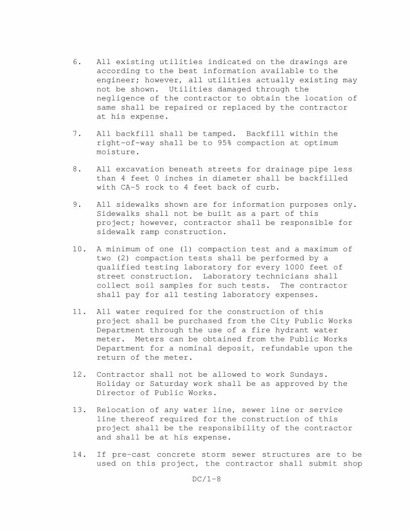
6. All existing utilities indicated on the drawings are according to the best information available to the engineer; however, all utilities actually existing may not be shown. Utilities damaged through the negligence of the contractor to obtain the location of same shall be repaired or replaced by the contractor at his expense.
7. All backfill shall be tamped. Backfill within the right-of-way shall be to 95% compaction at optimum moisture.
8. All excavation beneath streets for drainage pipe less than 4 feet 0 inches in diameter shall be backfilled with CA-5 rock to 4 feet back of curb.
9. All sidewalks shown are for information purposes only. Sidewalks shall not be built as a part of this project; however, contractor shall be responsible for sidewalk ramp construction.
10. A minimum of one (1) compaction test and a maximum of two (2) compaction tests shall be performed by a qualified testing laboratory for every 1000 feet of street construction. Laboratory technicians shall collect soil samples for such tests. The contractor shall pay for all testing laboratory expenses.
11. All water required for the construction of this project shall be purchased from the City Public Works Department through the use of a fire hydrant water meter. Meters can be obtained from the Public Works Department for a nominal deposit, refundable upon the return of the meter.
12. Contractor shall not be allowed to work Sundays. Holiday or Saturday work shall be as approved by the Director of Public Works.
13. Relocation of any water line, sewer line or service line thereof required for the construction of this project shall be the responsibility of the contractor and shall be at his expense.
14. If pre-cast concrete storm sewer structures are to be used on this project, the contractor shall submit shop
DC/1-9
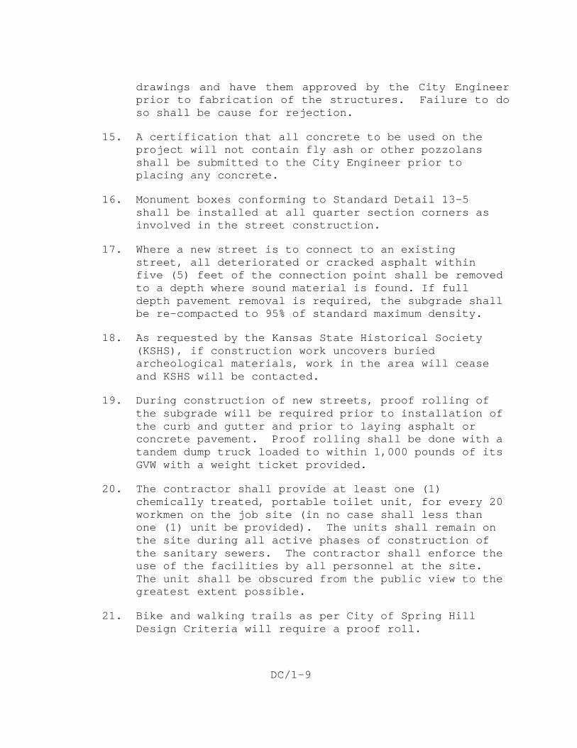
drawings and have them approved by the City Engineer prior to fabrication of the structures. Failure to do so shall be cause for rejection.
15. A certification that all concrete to be used on the project will not contain fly ash or other pozzolans shall be submitted to the City Engineer prior to placing any concrete.
16. Monument boxes conforming to Standard Detail 13-5 shall be installed at all quarter section corners as involved in the street construction.
17. Where a new street is to connect to an existing street, all deteriorated or cracked asphalt within five (5) feet of the connection point shall be removed to a depth where sound material is found. If full depth pavement removal is required, the subgrade shall be re-compacted to 95% of standard maximum density.
18. As requested by the Kansas State Historical Society (KSHS), if construction work uncovers buried archeological materials, work in the area will cease and KSHS will be contacted.
19. During construction of new streets, proof rolling of the subgrade will be required prior to installation of the curb and gutter and prior to laying asphalt or concrete pavement. Proof rolling shall be done with a tandem dump truck loaded to within 1,000 pounds of its GVW with a weight ticket provided.
20. The contractor shall provide at least one (1) chemically treated, portable toilet unit, for every 20 workmen on the job site (in no case shall less than one (1) unit be provided). The units shall remain on the site during all active phases of construction of the sanitary sewers. The contractor shall enforce the use of the facilities by all personnel at the site. The unit shall be obscured from the public view to the greatest extent possible.
21. Bike and walking trails as per City of Spring Hill Design Criteria will require a proof roll.
DC/1-10
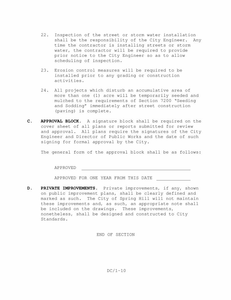
22. Inspection of the street or storm water installation shall be the responsibility of the City Engineer. Any time the contractor is installing streets or storm water, the contractor will be required to provide prior notice to the City Engineer so as to allow scheduling of inspection.
23. Erosion control measures will be required to be installed prior to any grading or construction activities.
24. All projects which disturb an accumulative area of more than one (1) acre will be temporarily seeded and mulched to the requirements of Section 7200 “Seeding and Sodding” immediately after street construction (paving) is complete.
C. APPROVAL BLOCK. A signature block shall be required on the
cover sheet of all plans or reports submitted for review and approval. All plans require the signatures of the City Engineer and Director of Public Works and the date of such signing for formal approval by the City.
The general form of the approval block shall be as follows: APPROVED APPROVED FOR ONE YEAR FROM THIS DATE D. PRIVATE IMPROVEMENTS. Private improvements, if any, shown
on public improvement plans, shall be clearly defined and marked as such. The City of Spring Hill will not maintain these improvements and, as such, an appropriate note shall be included on the drawings. These improvements, nonetheless, shall be designed and constructed to City Standards.
END OF SECTION
DC/2-1
DESIGN CRITERIA FOR SANITARY SEWERS AND APPURTENANCES
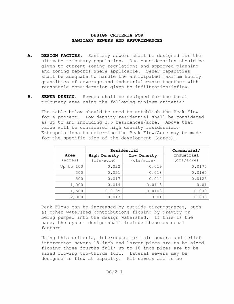
A. DESIGN FACTORS. Sanitary sewers shall be designed for the ultimate tributary population. Due consideration should be given to current zoning regulations and approved planning and zoning reports where applicable. Sewer capacities shall be adequate to handle the anticipated maximum hourly quantities of sewerage and industrial waste together with reasonable consideration given to infiltration/inflow.
B. SEWER DESIGN. Sewers shall be designed for the total tributary area using the following minimum criteria:
The table below should be used to establish the Peak Flow for a project. Low density residential shall be considered as up to and including 3.5 residences/acre. Above that value will be considered high density residential. Extrapolations to determine the Peak Flow/Acre may be made for the specific size of the development (acres).
Area
(acres)
Residential Commercial/ Industrial (cfs/acre)
High Density (cfs/acre)
Low Density (cfs/acre)
Up to 100 0.022 0.019 0.0175
200 0.021 0.018 0.0165
500 0.017 0.014 0.0125
1,000 0.014 0.0118 0.01
1,500 0.0135 0.0108 0.009
2,000 0.013 0.01 0.008
Peak Flows can be increased by outside circumstances, such as other watershed contributions flowing by gravity or being pumped into the design watershed. If this is the case, the system design shall include these external factors.
Using this criteria, interceptor or main sewers and relief interceptor sewers 18-inch and larger pipes are to be sized flowing three-fourths full; up to 18-inch pipes are to be sized flowing two-thirds full. Lateral sewers may be designed to flow at capacity. All sewers are to be
DC/2-2
designed for anticipated flows from a 50-year return interval storm. Design calculations shall be included on the general layout sheet of the project drawings.
C. MAXIMUM SIZE. The diameter of sewers proposed shall not exceed the diameter of the existing or proposed outlet, whichever is applicable.
D. MINIMUM SIZE. No public sewer shall be less than eight (8) inches in diameter. Stub-lines for service connections shall not be less than 6 inches in diameter.
E. MATERIALS OF CONSTRUCTION. Sanitary sewers shall be constructed of pipe material resistant to or protected from bacterial degradation, acid and alkaline solutions, normal sewer temperature variation, abrasion, and industrial wastes or other materials which may be transmitted by the collection system.
The following types of commercial pipe are approved for gravity sanitary sewer systems constructed in the City of Spring Hill:
PVC Pipe: See Standard Specifications Section 3000 for material and lining specifications.
Reinforced Concrete Pipe: See Standard Specifications Section 3000 for material and lining specifications.
Ductile Iron Pipe: See Standard Specifications Section 3000 for material and lining specifications.
The use of PVC pipe, ASTM D3034, shall be limited to residential or commercial areas as approved by the City Engineer and shall not be used for pipelines exceeding 21 inches in diameter, unless approved by the City Engineer or Director of Public Works. Concrete pipe shall be approved on a per project basis as recommended by the design engineer and approved by the City Engineer and Director of Public Works.
F. MINIMUM SLOPE. All sewers shall be designed to give mean velocities when flowing one-half full of not less than 2.0 feet per second.
DC/2-3
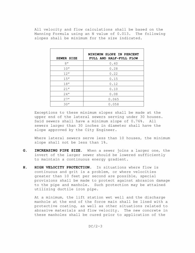
All velocity and flow calculations shall be based on the Manning Formula using an N value of 0.013. The following slopes shall be minimum for the size indicated.
SEWER SIZE
MINIMUM SLOPE IN PERCENT FULL AND HALF-FULL FLOW
8” 0.40
10” 0.28
12” 0.22
15” 0.15
18” 0.12
21” 0.10
24” 0.08
27” 0.065
30” 0.058
Exceptions to these minimum slopes shall be made at the upper end of the lateral sewers serving under 30 houses. Said sewers shall have a minimum slope of 0.76%. All sewers larger than 30 inches in diameter shall have the slope approved by the City Engineer.
Where lateral sewers serve less than 10 houses, the minimum slope shall not be less than 1%.
G. INCREASING PIPE SIZE. When a sewer joins a larger one, the invert of the larger sewer should be lowered sufficiently to maintain a continuous energy gradient.
H. HIGH VELOCITY PROTECTION. In situations where flow is continuous and grit is a problem, or where velocities greater than 10 feet per second are possible, special provisions shall be made to protect against abrasion damage to the pipe and manhole. Such protection may be attained utilizing ductile iron pipe.
At a minimum, the lift station wet well and the discharge manhole at the end of the force main shall be lined with a protective coating, as well as other situations related to abrasive materials and flow velocity. The new concrete in these manholes shall be cured prior to application of the
DC/2-4
protective coating (minimum of 28 days). The lining shall cover all interior surfaces from the bottom to the top, including the adjustment rings just under the cast iron ring and lid.
Approved manufacturers are:
Quadex Aluminaliner – Quadex, Inc.
SuperCoat - LaFarge Calcium Aluminates
405 Coating System - Raven Lining Systems, Inc.
PLS-650 Perpetu Wall Liner System - Protective Liner Systems
An acceptable mechanical liner system installed by the precast manhole manufacturer is T-Lock Lining by Ameron International Corporation. Installers of these materials must be trained and certified according to the manufacturer’s specifications. Installer certification shall be submitted to the City for review and approval prior to commencement of any work.
I. ALIGNMENT. All sewers shall be laid with straight alignment between manholes.
J. MANHOLE CONSTRUCTION. Manholes shall be installed at the end of each line; at all changes in grade, size, or alignment; at all intersections; and at a distance not greater than 400 feet for sewers 18 inches or less in diameter and not greater than 600 feet for larger sewers.
K. MANHOLES. The construction of all manholes shall conform to the details shown on Standard Details 31-1 through 31-4.
The minimum horizontal clear distance within the barrel of standard manholes should not be less than 4 feet. Manholes with connecting pipe diameters greater than 24 inches shall have a minimum inside clear dimension of 5 feet.
Drop manholes should be avoided as much as possible. However, an outside drop pipe shall be provided for a sewer entering a manhole at an elevation of 24 inches or more above the manhole invert. The outside drop pipe shall be protected against breaking or settling by the use of
DC/2-5
concrete encasement. When PVC pipe is used for the drop pipe, gravel may be substituted for the concrete encasement around the drop pipe and fittings. The drop pipe shall have the same nominal diameter as that of the incoming sewer.
Without utilizing drop manholes, the difference in elevation between the invert of any incoming sewer and the invert of the outgoing sewer should not exceed 24 inches except where required to match crowns. When a sewer joins a larger one, the crown of the smaller sewer shall not be lower than the crown of the larger one. The minimum drop through manholes shall be 0.2 foot for manholes with greater than 45° turns and 0.1 foot for straight-through trough and up to 45° turns.
Where manholes are to be built in close proximity to streets, the top of manhole elevation shall be set within the following limits:
Minimum Elevation 1/4" per foot rise above top back of curb
Maximum Elevation 1/2" per foot rise above top back of curb
All sanitary sewer manholes shall be provided with green utility markers equal to Model CRM30, as manufactured by Carsonite International. The markers shall be a minimum of 6’-6” in length and shall be provided with the following identification:
CITY OF SPRING HILL, KANSAS SANITARY SEWER BEFORE DIGGING CALL 1-800-344-7233 (KANSAS ONE-CALL) AND
The marker shall be maintained by the developer until an occupancy permit is issued on the residence.
913-592-3317 (SPRING HILL PUBLIC WORKS)
DC/2-6
All manholes on unplatted land shall have the tops set 6-inches above existing ground elevation or 1.0 feet above the 100-year flood elevation, whichever is greater.
Any variation from the above top of manhole criteria will require a letter of explanation to be submitted with the drawings and be subject to approval by the City Engineer.
L. SEWER CONSTRUCTION – GROUNDWATER BARRIERS. Continuity of embedment material shall be interrupted by low-permeability groundwater barriers to impede passage of water through the embedment. Groundwater barriers for sewer lines shall be compacted soil consisting of one 4-foot long, solid plug by the full width of the trench at approximately the half-way point between manholes where the distance between manholes exceeds 280 feet. The 4-foot soil plug shall extend the full depth of the trench to the bottom of the trench. Refer to Section 6017 for soil and compaction requirements of the barriers.
M. SEWER LOCATIONS. Sanitary sewers shall be located within street or alley rights-of-way unless topography dictates otherwise. When located in easements on private property, access shall be provided to all manholes. A manhole shall be provided at each street or alley crossing. End lines shall be extended to provide access from street or alley rights-of-way where possible. Imposed loading shall be considered in all locations. Not less than 8 feet of cover shall be provided over top of pipe in street and alley rights-of-way and 5 feet in all other areas.
N. CLEANOUTS AND LAMPHOLES. Cleanouts and lamp holes will not be permitted.
O. PROTECTION OF WATER SUPPLIES. There shall be no physical connection between a public or private potable water supply system and a sewer, or appurtenance thereto, which would permit the passage of any wastewater or polluted water into the potable water supply.
When potable water pipes and gravity sanitary sewers are laid parallel to each other, the horizontal distance between them shall be not less than 10 feet. The distance shall be measured from edge of pipe to edge of pipe. The
DC/2-7
laying of water pipes and sanitary sewers shall be in separate trenches with undisturbed earth between them. In cases where it is not practical to maintain a 10-foot separation, the City will consider proposals providing equivalent protection by other methods on a case-by-case basis. Equivalent protection may require sanitary sewer construction with concrete encasement using controlled low strength material (CLSM).
When a water pipe and a sanitary sewer cross, and the sewer is 2 feet or more (clear space) below the water pipe, no special requirements of limitations are provided herein. At all other crossings, the sanitary sewer is to be constructed of one of the following materials:
a. Ductile iron pipe conforming to ASTM A536 or ANSI/AWWA C151/A21.51 with minimum thickness Class 50, and gasketed, push-on or mechanical joints in conformance with ANSI/AWWA C 110/A21.10 or ANSI/AWWA C111/A21.11.
b. PVC pipe conforming to ASTM D3034 with ;minimum wall thickness of SDR35, ASTM F679, ASTM F789, or ASTM F794, with gasketed push-on joints in conformance with ASTM D3212.
c. Reinforced concrete pipe conforming to ASTM C76 with gasketed joints in conformance with ASTM C361 or ASTM C443.
Where a new water main is laid across or though an area where there is an existing sanitary sewer
Joints in the sewer pipe shall be located as far as practical from the intersected water main.
, which is not constructed of one of the above specified materials and is 2 feet or less below the water pipe, the existing sewer shall be encased in concrete (using CLSM as specified in Section 3013) with a minimum thickness 6 inches for a 10-foot distance on each side of the crossing or the crossed section of sewer replaced to meet the above specified construction requirements.
DC/2-8
P. AERIAL CROSSINGS. Adequate support shall be provided at all joints in pipes utilized for aerial crossings. All aerial crossings shall be approved by the City Engineer.
Q. UNSEWERED DWELLINGS. All existing addresses that will be provided access to the sewer that previously did not have sewer service available shall be identified. This identification shall include the approximate distance from the dwelling to the sewer.
R. MAXIMUM SLOPE. All sewers, which are designed to flow at 10 feet per second or greater, shall be reviewed by the City Engineer for approval or alternate design considerations.
S. STUB LINES. Stub lines for service laterals will not be permitted in manholes. Stub lines will be provided for all service lines as shown on Details 30-3 and 30-4
T. LIFT STATIONS. Acceptable lift stations are as follows:
1. Submersible Pump Lift Stations for all applications.
2. Before a lift station will be approved by the City, the City Engineer must receive and approve a Design Memorandum providing the following minimum required information:
a. Introduction.
b. Service Area and Land Use.
c. Design Flows.
1) Average daily flow.
2) Peak flows.
d. Site Design.
1) Map, exhibits.
2) Location from 100-year flood plain.
DC/2-9
3) Access (hard surface road with adequate sloping).
4) Fencing (protection/screening).
e. Hydraulic Design.
1) System curve(s).
a) Design point(s).
b) Static and total dynamic head.
c) System losses.
d) Hydraulic grade line of the pump and force main.
f. Pump Station.
1) Pump station’s design must provide firm pumping capacity to pump between a 10-year and 25-year storm event based on ultimate development with largest pump out of service. The overall capacity difference between the selected design pumping rate to the calculated flow from a 50-year storm event shall be maintained on-site.
2) Pump selection and components.
a) Type and model.
i) Submersible pumps manufactured by Flygt are the only acceptable pumps.
b) Pump curves.
c) Operating point(s).
d) Pump and motor efficiencies.
i) Maintain pump efficiency >60% over the design points.
DC/2-10
e) Variable frequency drive (depending on application and size of pumps).
3) Controls (Multitrode as standard).
a) Level controls with Multitrode as primary and backup.
b) HOA standard package.
4) Wet well sizing. Design pump start/stop per the following criteria.
a) Motors less than 30 HP – Less than 10 start/stops per hour.
b) Motors greater than 30 HP – Less than 6 start/stops per hour.
5) Emergency overflow storage.
a) Minimum of 2 hours storage for the development’s ultimate design flow is required.
6) Emergency bypass pumping.
a) Above-ground, 6-inch Bauer connections are standard.
7) Odor control.
a) As required, depending on flows and length of force main.
8) Hoist system.
a) As applicable.
9) Heating, ventilation, air-conditioning.
a) As needed, based on complexity of the building.
10) Electrical supply.
DC/2-11
a) Transfer switch for 3-phase generator.
b) Power feed from utility (3-phase).
c) Emergency disconnect (located outside pump station on post).
d) Utility power meter (located outside fenced area).
11) Monitoring system.
a) MicroComm system is required. The following summarizes minimum monitoring requirements.
i) Standard package alarms required.
ii) Power failure “built in.”
iii) High water (transducer is analog) backup system.
iv) Amp meter (analog).
v) Generator failure (digital).
vi) Communication “built in.”
vii) Pump failure (digital) – “Can have all combined to one alarm.”
viii) Excess pump starts “built in.”
ix) Flow monitoring (as applicable; flow meter rate “flow of day” analog).
x) Rain gauge (as required; in a pulse counter that is added when purchased.
xi) Seal failure (as required; digital) “Can have all combined to one alarm.”
DC/2-12
xii) Fuel (analog) “Can be digital if only want a low-level alarm.”
xiii) Temperature monitoring (motor temperature is digital; outside temperature is analog).
g. Force Main Design.
1) Class 200 ASTM D-2241 PVC is standard.
2) Velocities at average daily flow and peak flow.
a) Maximum velocity – 8 feet per second, unless otherwise approved.
b) Minimum velocity – 2.5 feet per second, unless otherwise approved.
3) Identify minimum and maximum pumping pressures.
4) Air release valves.
5) Control valves (as required).
a) Gear-operated plug valve.
h. Emergency Power.
1) Systems by Kohler, Caterpillar, Gnerac, Onan, or approved equal.
a) Sound attenuation.
2) Fuel requirements (minimum tank size to provide 24-hour supply).
a) Natural gas (preferred).
b) Propane.
c) Diesel.
DC/2-13
i. Safety.
1) Site lighting.
2) Concrete mounting pad for base mounting of davit arm.
a) The unit built by Unique Concepts, ltd., rated at 450 lbs.
b) Part number for base is 16190.
c) Available through American Riggers.
d) General information about the base dimensions and mounting requirements is available.
U. LOW PRESSURE SEWER SYSTEM. Low pressure sewer systems are not recommended. If a low pressure sewer system is necessary, the Design Engineer must submit plans and specifications along with a cost/benefit analysis prior to approval. All low pressure sewer systems must be approved by the City Engineer and Public Works Director.
END OF SECTION

DC/2-14
This page intentionally left blank.
DC/3-1
DESIGN CRITERIA FOR STREET IMPROVEMENTS
A. GENERAL. Proposed street improvements within the City
shall conform to the pattern as established in the Spring Hill Comprehensive Plan as adopted by the governing body of the City of Spring Hill. Regarding transportation, the major goal stated in the plan is to "provide a safe and efficient transportation system which facilitates the movement of people and goods within the City."
To this end, street improvements within the City of Spring Hill shall be designed to conform with all applicable codes, regulations, and ordinances as established by the City. Plans for said improvements shall be submitted to the City Engineer and Director of Public Works for approvals, and all plans shall include all information as may be required or described hereafter.
B. FUNCTIONAL CLASSIFICATION OF STREETS. In fulfilling the
goal of creating a "safe and efficient transportation system," the City must define geometric design standards for streets and highways, which would afford both adequate traffic mobility and suitable access to abutting property.
The Spring Hill Comprehensive Plan states that "the efficient movement of vehicles within any urban community is dependent on a balance between all types of street facilities..." Therefore, design standards must be defined by functional classification; i.e., expressways, major arterials, minor arterials, collectors, and local streets:
1. Arterial
a. Expressway or Freeway: Since its main purpose is to carry through traffic movement, expressways and freeways are properly classified as arterials. However, owing to their unique geometric and access design, they are more appropriately the function of federal or state control. High operating speeds and controlled or limited access (usually confined to above- or below-grade interchanges) arterial
DC/3-2
classifications. As a result, geometric design shall conform to those criteria defined by state or federal transportation agencies.
b. Major Arterial: A major arterial shall mean a street or highway that provides for rapid and efficient movement of large volumes of through traffic between sections of the City and across the urbanized area. It is not primarily intended to provide land access service. Therefore, the number of curb cuts on a planned major arterial shall be held to a minimum where they can be controlled and adequately protected.
In general, the major arterial has full or partial access control, but is not restricted to controlled access facilities. Major arterials can be four to six lanes wide, with or without medians, and commonly can be found on the mile section lines of the City. Signalized intersections along major arterials should be spaced far enough apart to permit efficient two-way progressive movement of traffic between intersections at the desirable off-peak and peak hour operating speeds.
c. Minor Arterial: As does the major arterial, a minor arterial provides for the through traffic movement between areas and across the City. However, the minor arterial provides direct access with the abutting property. As a result, the minor arterial accommodates trips of moderate length at a somewhat lower level of service and lower operating speeds than the major arterial. Also, traffic signal progression may be less systematic than on the major arterial.
The minor arterial interconnects residential, shopping, employment, and recreational activities at the community level. Although the minor arterial offers access to the abutting land uses, it does not penetrate identifiable neighborhoods. Furthermore, it is subject to required controls of entrances, exits and curb use.
DC/3-3
2. Collector Street: The collector street provides traffic circulation within residential areas. Land access is a secondary function of the collector. The collector distributes trips from the arterials to the local street network. Collectors penetrate but should not have direct continuity through residential areas.
Operating speeds should be 25 to 30 mph. Since speeds are slower and turning movements are anticipated, closer intersection/access spacing can be used than on arterials. Because land access is a secondary function of collectors, the number of lots fronting onto a collector should be held to a minimum in order to reduce the number of driveways, and thus, the number of friction points.
3. Service Street: The service street provides traffic circulation within commercial and industrial buildings and complexes from the arterial street system. Service streets should not have direct continuity with residential areas.
Operating speeds should be 25 to 30 mph. Since speeds are slower and turning movements are anticipated, closer intersection/access spacing can be used than on arterials.
Because service streets facilitate truck-related land uses, the special provisions associated with truck accessibility shall be considered within design. Wider turning radii and turning lanes shall be considered. Service streets shall not be utilized for backing or loading maneuvers. All such trucking maneuvers shall be handled on-site of the adjacent land uses.
4. Local Street: The major purpose of the local street is to provide direct traffic access to abutting land. Local streets can and do exist within residential, commercial, and industrial areas.
Traffic movement on local streets is incidental and involves traveling to or from a collector facility. Therefore, trip length on the local street is short,
DC/3-4
and as a result, both traffic volumes and operating speeds are usually low. Generally, through traffic is deliberately discouraged.
The development of a street system based on functional classes has numerous benefits, including the following:
1. The arterials can be designed to safely accommodate the high traffic volumes and high speeds.
2. Traffic control is simplified.
3. The pavement of designated streets can be designed to carry the high number of repetitions and heavy wheel loads. Other streets can be designed for a low number of repetitions and light wheel loads. Consequently, total maintenance costs are reduced.
4. Residential areas are not subject to through traffic, which makes them more desirable and safer places to live. Commercial office and retail land uses are concentrated in fewer but larger and better-designed developments. Strip development is reduced.
Implementation of Design Criteria based on functional class will help ensure that the traffic capacity and level of service is maintained. This, in turn, will help preserve the regional accessibility (market area) of private development and help stabilize land use patterns and property values. Thus, preservation of the levels of service on all functional classes of the City's street system is mutually advantageous to the public and private sectors.
Typical cross sections of these classifications are shown on Standard Details 13-1, 13-2, 13-2a, and 13-3.
DC/3-5
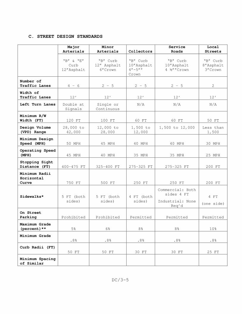
C. STREET DESIGN STANDARDS
Major Arterials
Minor Arterials
Collectors
Service Roads
Local Streets
“B” & “E”
Curb 12”Asphalt
“B” Curb
12” Asphalt 6”Crown
“B” Curb 10”Asphalt 4”-5”” Crown
“B” Curb 10”Asphalt 4 ½””Crown
“B” Curb 8”Asphalt 3”Crown
Number of Traffic Lanes
4 - 6
2 – 5
2 – 5
2 – 5
2
Width of Traffic Lanes
12’
12’
12’
12’
12’
Left Turn Lanes Double at Signals
Single or Continuous
N/A N/A N/A
Minimum R/W Width (FT)
120 FT
100 FT
60 FT
60 FT
50 FT
Design Volume (VPD) Range
28,000 to 42,000
12,000 to 28,000
1,500 to 12,000
1,500 to 12,000 Less than 1,500
Minimum Design Speed (MPH)
50 MPH
45 MPH
40 MPH
40 MPH
30 MPH
Operating Speed (MPH)
45 MPH
40 MPH
35 MPH
35 MPH
25 MPH
Stopping Sight Distance (FT)
400-475 FT
325-400 FT
275-325 FT
275-325 FT
200 FT
Minimum Radii Horizontal Curve
750 FT
500 FT
250 FT
250 FT
200 FT
Sidewalks*
5 FT (both sides)
5 FT (both sides)
4 FT (both sides)
Commercial: Both sides 4 FT
Industrial: None Req’d
4 FT
(one side)
On Street Parking
Prohibited
Prohibited
Permitted
Permitted
Permitted
Maximum Grade (percent)**
5%
6%
8%
8%
10%
Minimum Grade .8%
.8%
.8%
.8%
.8%
Curb Radii (FT) 50 FT
50 FT
30 FT
30 FT
25 FT
Minimum Spacing of Similar
DC/3-6
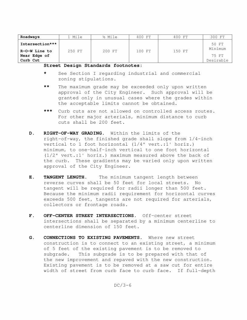
Roadways 1 Mile ½ Mile 400 FT 400 FT 300 FT
Intersection***
R-O-W Line to Near Edge of Curb Cut
250 FT
200 FT
100 FT
150 FT
50 FT Minimum
75 FT Desirable
Street Design Standards footnotes:
* See Section I regarding industrial and commercial zoning stipulations.
** The maximum grade may be exceeded only upon written approval of the City Engineer. Such approval will be granted only in unusual cases where the grades within the acceptable limits cannot be obtained.
*** Curb cuts are not allowed on controlled access routes. For other major arterials, minimum distance to curb cuts shall be 200 feet.
D. RIGHT-OF-WAY GRADING. Within the limits of the
right-of-way, the finished grade shall slope from 1/4-inch vertical to 1 foot horizontal (1/4" vert.:1' horiz.) minimum, to one-half-inch vertical to one foot horizontal (1/2" vert.:1' horiz.) maximum measured above the back of the curb. These gradients may be varied only upon written approval of the City Engineer.
E. TANGENT LENGTH. The minimum tangent length between
reverse curves shall be 50 feet for local streets. No tangent will be required for radii longer than 500 feet. Because the minimum radii requirement for horizontal curves exceeds 500 feet, tangents are not required for arterials, collectors or frontage roads.
F. OFF-CENTER STREET INTERSECTIONS. Off-center street
intersections shall be separated by a minimum centerline to centerline dimension of 150 feet.
G. CONNECTIONS TO EXISTING PAVEMENTS. Where new street
construction is to connect to an existing street, a minimum of 5 feet of the existing pavement is to be removed to subgrade. This subgrade is to be prepared with that of the new improvement and repaved with the new construction. Existing pavement is to be removed at a saw cut for entire width of street from curb face to curb face. If full-depth
DC/3-7
pavement removal is required, the subgrade shall be re-compacted to 95% of standard density.
H. MINIMUM ANGLE OF INTERSECTION. It is desirable for all
intersections to meet at approximately a 90° angle. Skewed intersections should be avoided and in no case should the angle be less than 75°.
I. SIDEWALKS. Sidewalk construction shall typically follow
the requirements in Standard Details 21-4 thru 21-8. J. STORM DRAINAGE. All storm drainage works constructed in
connection with street improvements shall be designed in accordance with APWA Section 5600.
K. CUL-DE-SACS. At locations where streets are to be
terminated and a vehicular connection between adjacent streets is not required, a cul-de-sac may be permitted. Such cul-de-sac shall be constructed with a minimum radius of 39 feet to the back of the curb.
L. TEMPORARY TURN-AROUNDS. At locations where streets are to
be temporarily terminated which will be extended at a later date, and said street extends beyond the intersection of an adjacent street more than five lots, a temporary cul-de-sac shall be constructed with a minimum radius of 35 feet. The temporary cul-de-sac shall be constructed of asphalt concrete with a minimum depth of 6 inches. Curb and gutter will not be required. The cul-de-sac shall be constructed within the limits of a permanent construction easement.
M. MONUMENT BOXES. Monument boxes conforming to Standard
Detail 13-5 shall be installed at all quarter section corners as an element of the street construction.
N. SIGHT DISTANCES.
1. Stopping Sight Distance--Sight distance is the length of roadway ahead visible to the driver. The minimum sight distance available on a roadway should be sufficiently long to enable a vehicle driving at or near the design speed to stop before reaching a stationary object in its path.
DC/3-8
Stopping sight distance represents the sum of the brake reaction distance and the braking distance. These distances are measured from the height of the driver's eye to the height of the object (3.5 feet and 0.5 feet above the road surface, respectively). Design controls for stopping sight distances vary slightly for crest vertical curves and sag vertical curves, and are dependent on the algebraic difference in the grades as well as the design speed. Design Aids 3-1 and 3-2 illustrate the minimum stopping sight distances to be used in design of roadways.
2. Intersection Sight Distance--Sight distances at intersections vary from stopping sight distance. The intersection sight distance should be sufficient to permit a vehicle on the minor leg of the intersection to cross the traveled way without requiring the approaching through traffic to slow down. To allow this, an area free of visual obstruction is required at every corner of an intersection. This area is known as the sight triangle.
An obstruction to vision shall be defined as an obstacle (i.e., a parked vehicle, a wall or commercial sign, bush or hedge, guardrail or fence, etc.) which forms a restriction to an assumed line of sight measured from the driver's eye height to a target some distance along the cross street.
Every effort shall be made to select intersection locations so that the maximum sight distance is possible. As an element of this, location of intersections shall always consider the grade changes along the adjacent street in terms of possible sight obstructions.
3. Sight triangle requirements vary based on the type of intersecting streets and are summarized in the following table. All measurements are taken from the point of intersection of the extended curb lines of each intersecting street. The values in the table are dependent on the travel speed of the vehicles on the intersecting street and on the typical vehicle which will approach the intersection. The standard assumed
DC/3-9
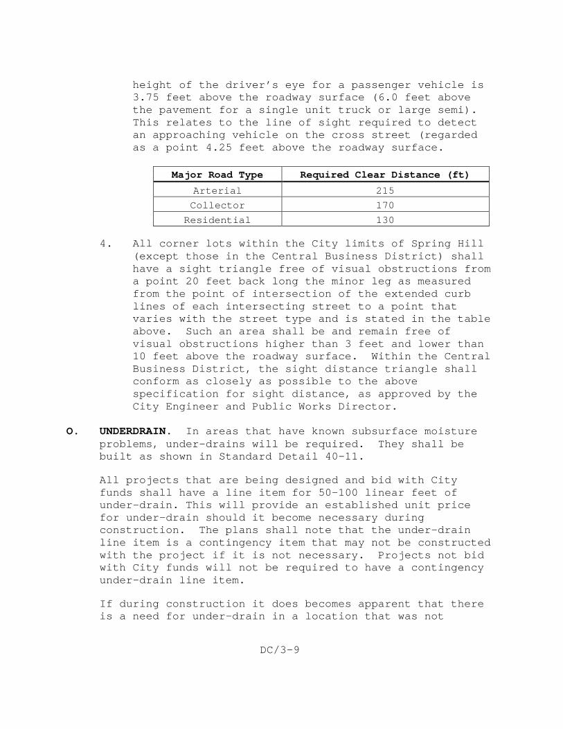
height of the driver’s eye for a passenger vehicle is 3.75 feet above the roadway surface (6.0 feet above the pavement for a single unit truck or large semi). This relates to the line of sight required to detect an approaching vehicle on the cross street (regarded as a point 4.25 feet above the roadway surface.
Major Road Type Required Clear Distance (ft)
Arterial 215
Collector 170
Residential 130
4. All corner lots within the City limits of Spring Hill (except those in the Central Business District) shall have a sight triangle free of visual obstructions from a point 20 feet back long the minor leg as measured from the point of intersection of the extended curb lines of each intersecting street to a point that varies with the street type and is stated in the table above. Such an area shall be and remain free of visual obstructions higher than 3 feet and lower than 10 feet above the roadway surface. Within the Central Business District, the sight distance triangle shall conform as closely as possible to the above specification for sight distance, as approved by the City Engineer and Public Works Director.
O. UNDERDRAIN. In areas that have known subsurface moisture
problems, under-drains will be required. They shall be built as shown in Standard Detail 40-11.
All projects that are being designed and bid with City funds shall have a line item for 50-100 linear feet of under-drain. This will provide an established unit price for under-drain should it become necessary during construction. The plans shall note that the under-drain line item is a contingency item that may not be constructed with the project if it is not necessary. Projects not bid with City funds will not be required to have a contingency under-drain line item.
If during construction it does becomes apparent that there is a need for under-drain in a location that was not
DC/3-10
previously designed for under-drain, the City Engineer can require that the consultant submit a revised plan including under-drains that will provide for subsurface drainage. The standard detail is a minimum. Upon approval of the City Engineer alternate details for increased capacity may be allowed.
P. PRIVATE STREETS. All streets and roadways within any
development, which are classified as “Private Streets”, shall conform to the Standards and specifications for public streets, as stipulated in the Technical Specifications and Design Criteria for Public Improvement Projects for the City of Spring Hill.
Q. BICYCLE-PEDESTRIAN TRAIL SYSTEM. Sidewalks constructed, as
part of this system shall be 8 feet in width. If they are to be located within street right-of-way, they shall be constructed with concrete 4 inches in depth with all of the joints saw cut instead of tooled. If they are to be located on City property but not within the street right-of-way, they may be constructed, at the City Engineer’s or Director of Public Works discretion, of asphalt 4 inches in depth with a 4-inch crushed rock (AB-3) base underneath. The base must be Proof Rolled and meet or exceed 95% compaction.
END OF SECTION
DC/4-1
DESIGN CRITERIA FOR STORM DRAINAGE FACILITIES
A. GENERAL. This section sets forth the minimum technical criteria
for the analysis and design of drainage systems in the City of Spring Hill. All development plans submitted for approval to the City of Spring Hill must be accompanied by an adequate storm drainage system analysis and design in accordance with the criteria as hereinafter described.
B. MINIMUM STANDARDS OF ANALYSIS. Unless otherwise approved by the
City Engineer, Section 5600, “Storm Drainage Systems and Facilities,” from the Standard Specifications and Design Criteria, Kansas City Metropolitan Chapter of the American Public Works Association, latest edition, shall be used for all storm drainage analysis and design.
C. ADDITIONAL REQUIREMENTS. The following requirements shall also
be incorporated into all storm drainage analysis and design:
1. The interior slopes of all wet bottom detention/retention basins shall be lined with rip rap from 2’ below the normal pool elevation to 2’ below the top of the berm.
2. All piping for detention/retention basins shall have rip rap at the inlets and outlets to protect against erosion.
3. During each phase of a development, consideration shall be given to the need for installation of a temporary sedimentation basin. The final decision on the need for this basin will be made by the City Engineer.
END OF SECTION

DC/4-2
This page intentionally left blank.
DC/5-1
DESIGN CRITERIA FOR WATER LINE CONSTRUCTION A. GENERAL. Proposed extensions of the water distribution system
shall, in general, follow the pattern of constructing 12-inch water lines along all section lines and 8-inch water lines along all half-section lines. Deviations from this general policy may be deemed necessary by the City Engineer should the provision of adequate service to prospective customers or fire protection needs, existing or anticipated, in the area to be served warrant said deviations.
Hydraulic calculations shall be submitted for review with all commercial and industrial plans. Upon request by the Engineer, hydraulic calculations shall be submitted for review with residential plans. Typically, these calculations shall be shown on a drawing sheet included in the plans, near the front of the drawing set.
All commercial and industrial water lines shall be designed with a minimum of two (2) feed lines (looped system). Dead end lines will not be allowed without approval from the City Engineer and Public Works Director.
No public water line shall be constructed less than 6 inches in diameter. Where water lines less than 6 inches exist, it may be required by the City to upgrade the pipe size to conform to the 6-inch minimum requirement.
B. LOCATION OF WATER MAINS AND APPURTENANCES. Proposed water mains
shall be so located within street right-of-way or a dedicated 10-foot water line easement to provide the least interference with the location of other utility lines. Street grades and elevations of proposed main shall be taken into consideration so that once constructed they will not require re-grading or relocation.
C. DEPTH. All water mains shall have a minimum cover of 42 inches.
Note
: Water main depths exceeding minimum cover should be avoided.
D. MATERIALS OF CONSTRUCTION. Ductile iron pipe or AWWA C900 Class 200 DR 14 PVC shall be used for all mains constructed in the City of Spring Hill.
DC/5-2
The ductile iron shall conform to ANSI A21-51; ASTM A536, Grade 60-42-10; AWWA C151. The minimum pressure class for ductile iron pipe shall be 350 for 3-inch to 12-inch, 250 for 14-inch to 20-inch and 200 for 24-inch, unless otherwise designated by the City Engineer. All water mains shall be polyethylene encased and shall conform to ASTM A674.
AWWA C900 PVC, conforming to ASTM D1784; PVC 12454-B, 12454-C or 12454-D; cast iron pipe OD; Pressure class and wall thickness as specified herein. Pressure Class 200 and wall thickness of DR 14.
E. FIRE HYDRANTS. Fire hydrants shall conform to AWWA C502, and
shall be, American Darling B-84-B, Kennedy K-81D or Mueller A-423.
Hydrants shall be traffic models with breakaway flanges and shall have one 4½-inch pump nozzle and two 2½-inch nozzles. All hydrants shall be furnished with auxiliary gate valves. All bolts below grade shall be Type 304 stainless steel.
Hydrants should be placed at or near street intersections, and at the end of permanent dead end lines (including cul-de-sacs), and at intermediate points when block lengths become long. Under no circumstances shall the spacing of fire hydrants exceed 500 feet in residential areas or 300 feet in commercial areas. Fire hydrant spacing in industrial areas shall be determined by the fire marshal. Fire hydrant installations shall conform to Standard Detail 50-2.
F. LINE VALVES. Gate valves shall be of the resilient-seated
configuration and shall conform to the applicable requirements of AWWA C509. All valves shall be supplied with Type 304 stainless steel bolts.
Resilient-seat gate valves shall be American-80 "CRS" or Mueller A-2370-20 or approved equal.
Gate valves shall be used in all water mains 12 inches in diameter and smaller.
Butterfly valves shall conform to AWWA C504 and shall be Kennedy 50C, American C-1508, Mueller "Line Seal III", or approved equal. Butterfly valves shall be used in mains larger than 12 inches in diameter or where otherwise approved by the City Engineer.
DC/5-3
Valves shall be placed in all straight runs of pipe at intervals not to exceed 800 feet. Where two lines intersect, a valve should be placed in each pipe on each side of the intersection. Valves should be so placed that any pipe line segment two (2) blocks long can be isolated from the general circulation without interrupting service in the rest of the system.
G. CONNECTIONS TO EXISTING WATER MAINS. Connections to existing
water mains shall be made in such a manner as to provide the least amount of interruption to water service. In the event closing of valves to make a connection will affect a customer who cannot be without service, provisions shall be made on the plans for a temporary service. Where possible, connections to existing mains shall be made using tapping sleeves and valves as approved in the Technical Specifications of the City of Spring Hill.
When connections are made to an existing system under normal conditions, the exposed pipe and fitting interiors shall be wetted with 500 mg/L chlorine solution before closure. In emergency situations, the exposed interiors of the pipe and fittings are to be swabbed with a 1% chlorine solution.
Wetting and/or swabbing are not considered effective methods of disinfection when there is a potential for significant contamination of the main; i.e., sewage is detected in the trench during repairs. Therefore, in this case, disinfection by normal methods shall be required; that is, flushing, chlorinating and testing as described in Section 5200.
H. PROVISIONS FOR FUTURE EXTENSIONS OF WATER MAINS. At the
termination of all water mains or at locations as specified by the City Engineer or Director of Public Works, a dead end assembly in accordance with Standard Detail 50-5 of the Technical Specifications of the City of Spring Hill shall be provided to allow for future water main extensions.
Fire hydrants shall be used at locations as required to provide for thorough flushing of all water mains in the project area. Water mains 8 inches and larger shall be provided with a fire hydrant for flushing, in accordance with Detail 50-3A.
I. THRUST BLOCKING. Reaction blocking of adequate size shall be
provided at all tees, elbows and bends to resist all resultant thrusts due to hydrostatic pressure.
DC/5-4
J. HIGHWAY AND RAILROAD CROSSINGS. All crossings of highways or railroads shall be made by boring or tunneling. Casing pipe shall be greater than or equal to the strength and integrity of the carrier pipe. This installation shall comply with all Federal, State and local regulations. The work shall be in conformity with all requirements and regulations and be under the control of the authority owning or having jurisdiction over and control of the right-of-way in each case.
K. STREET CROSSINGS. Open cutting of streets shall be allowed only
where permitted by the Director of Public Works. At locations where open cutting is not permitted, the crossing shall be made by boring or tunneling. Crossings made by boring or tunneling shall require a casing pipe, as described in Section 3017, unless otherwise approved by the City Engineer or Director of Public Works. All work and materials shall be in conformity with all requirements of the Technical Specifications of the City of Spring Hill. The diameter and length of the casing pipe to be used shall be as determined by the City Engineer. All casings shall be supplied with mechanical casing spacers.
All temporary surfacing shall consist of cold-mix asphalt as a minimum.
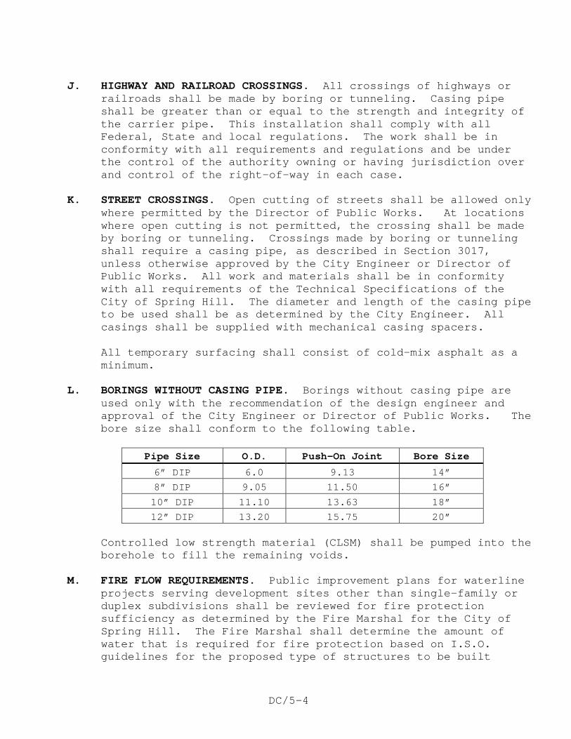
L. BORINGS WITHOUT CASING PIPE. Borings without casing pipe are
used only with the recommendation of the design engineer and approval of the City Engineer or Director of Public Works. The bore size shall conform to the following table.
Pipe Size O.D. Push-On Joint Bore Size
6” DIP 6.0 9.13 14”
8” DIP 9.05 11.50 16”
10” DIP 11.10 13.63 18”
12” DIP 13.20 15.75 20”
Controlled low strength material (CLSM) shall be pumped into the borehole to fill the remaining voids.
M. FIRE FLOW REQUIREMENTS. Public improvement plans for waterline
projects serving development sites other than single-family or duplex subdivisions shall be reviewed for fire protection sufficiency as determined by the Fire Marshal for the City of Spring Hill. The Fire Marshal shall determine the amount of water that is required for fire protection based on I.S.O. guidelines for the proposed type of structures to be built
DC/5-5
within the development. The design engineer shall obtain the flow requirement and then determine if the existing and proposed waterlines can provide this flow based on existing operating conditions. Calculations verifying that the required flows can be met shall accompany the drawings when submitted for approval.
N. END OF CUL-DE-SAC. All cul-de-sacs shall be designed in
conformance with Technical Specification 5030. O. PRIVATE FIRE LINES. All water lines and fire hydrants within a
development which are classified as “private fire lines” shall conform to the design and specifications of water mains, as stipulated in the Technical Specifications and Design Criteria for Public Improvement Projects for the City of Spring Hill.
1. Construction of all private water fire lines requires installation of an isolation valve and a backflow prevention device. If the point of connection of the private water fire line to the public water main is 75 feet or less, the backflow prevention device can be inside the building. If the distance of the point of connection of the private fire line to the water main is a greater distance than 75 feet, then the backflow prevention device must be located at the point of connection to the main. Variances from this policy must be approved by the City Engineer. Maintenance of the backflow prevention device and private water fire line shall be the responsibility of the property owner.
A private fire line shall be defined as a fire protection water main which only has connections to hydrants and/or building fire sprinklers.
A private fire line shall be defined as a fire protection water main which only has connection to fire hydrants and/or building fire sprinklers.
2. Public water service lines shall not be connected
3. Cross-connections between a private water line used for fire protection and a public “potable” water main or water service line
to private fire lines.
shall be prohibited
. Private water fire lines are for fire protection only and are considered non-potable.
END OF SECTION

DC/5-6
This page intentionally left blank.
DC/6-1
REQUIREMENTS FOR PUBLIC IMPROVEMENT PROJECT PLAN PREPARATION
A. INTRODUCTION. The following criteria is being established to
provide a uniform system of plan preparation that will aid the engineer in preparing plans for work within the City of Spring Hill. It is not intended that the criteria be an iron-clad set of rules that would restrict the engineer from utilizing imaginative design; however, all items as described below shall be shown on the plans in some manner.
B. GENERAL. All plans and specifications for public improvement
construction within either publicly-financed districts or privately-financed developments shall be prepared by a professional engineer licensed in the State of Kansas and submitted to the offices of the City Engineer and Director of Public Works for review. Subsequent to the review, the engineer will be notified of the approval of the plans as submitted, or of any necessary changes. (Refer to the section "Public Improvement Project Plan Submittal" for plan review procedures.)
Upon completion of the review and approval of the plans by the City Engineer and Director of Public Works, the following number of sets of plans (as approved) must be submitted for signing and distribution:
Sanitary Sewer and Water Projects.......3 sets (with 3 extra cover sheets)
All Other Improvement Projects..........4 sets
In addition, one set of approved plans shall be sent to each of the utility companies providing service in the proposed construction area.
The suggested plan sheet size is 22" x 36" or 24" x 36" with all sheets in a given set of plans being of the same size. Plan and profile shall be drawn on double or single plan and profile sheets to scales of 1 inch = 50 feet (horizontal) by 1 inch = 10 feet (vertical), unless otherwise approved by the City Engineer for special cases.
The plans shall consist of:
1. Title Sheet
2. General Layout Sheets
DC/6-2
3. Plan and Profile Sheets
4. Cross-Section Sheets (Street Improvement Plans only unless otherwise required by the City Engineer.)
5. Standard and Special Detail Sheets to include street lighting layout/plan with corresponding easements
Each sheet should contain a sheet number, including the individual sheet number and the total number of sheets, the engineer's seal, proper project identification and date.
Where feasible, storm sewer construction details shall be incorporated into street construction drawings and shall include a sediment and erosion control design/plan.
C. TITLE SHEET. The following items shall be included on the title
sheet.
1. Name of project
2. City project number
3. Index of sheets included in plans
4. A location map adequately showing project location in relation to major streets
5. A summary of plan quantities of principal items, such as:
a. Pipe sizes, number of manholes, etc. (sanitary sewers)
b. Length of curb and gutter, square yardage or tonnage of asphalt concrete pavement, etc. (streets)
c. Pipe sizes, number of inlets, etc. (storm sewers)
d. Pipe sizes and lengths, number of valves, etc. (water lines)
6. The project control benchmark shall be identified as to location and elevation; USGS datum. (Not required on water line plans.)
7. Name, address and telephone number of the consulting engineer and owner/developer.
DC/6-3
8. List containing name and telephone number of each utility company.
9. Zoning
10. City Engineer’s and Director of Public Works’ signature line
11. Signature and stamp of Professional Engineer registered in the State of Kansas
D. GENERAL LAYOUT SHEET. The following items shall be included on
the general layout sheet for all improvement projects.
1. A legend of symbols shall be shown which shall apply to all sheets.
2. North arrow and scale. Scale of the general layout map shall be 1 inch = 100 feet, unless otherwise approved.
3. Layout shall include names of subdivision, block designation, if any, lot designation, or proposed block and lots, all street names, and an accurate tie to at least one quarter section corner. An unplatted tract shall have an accurate tie to at least one quarter section corner.
4. Boundary line of project area.
5. A list of general notes to the contractor to include at least those notes indicated in the "Procedure For Public Improvement Project Plan Submittal" section of this manual.
6. Existing and final grading contours drawn at intervals not to exceed 2 feet in Johnson County and not to exceed 5 feet in Miami County. Intervals of less than 5 feet in Miami County may be required by the City Engineer, dependent on the character of the topography.
In addition, the following items shall be included on the general layout sheet for the particular type of improvement stated below.
7. Storm Drainage
a. Drainage calculation summary table containing the following information.
1) Pipe size and slope
DC/6-4
2) Pipe capacity
3) Velocity
4) Time of concentration
5) Runoff coefficient
6) Incremental tributary acreage
7) Accumulative acreage
8) Rainfall intensity
9) Rainfall runoff
b. A site-grading plan, including the following information.
1) Property lines identified as to existing or proposed lot and block number
2) Elevation and location of nearest benchmark (USGS datum)
3) Final grading spot elevations shown for all corners of each lot
4) 100-year flood plain line with elevation
5) Sediment and Erosion Control design/plan
8. Sanitary Sewer and Water Lines
a. Location of all existing (water or sewer) lines properly designated within or adjacent to the project area (list City project name and number).
b. Connection point or points to existing facilities (tied to a known point on existing facility) and the type of connection to be utilized.
c. Location of all proposed (water or sewer) lines and appurtenances with designation and sheet number on which they appear in plan and profile.
d. Pre-blast survey limits. E. PLAN AND PROFILE SHEETS. The following items shall be included
on the plan and profile sheets for all improvement projects.
1. North arrows and scale.
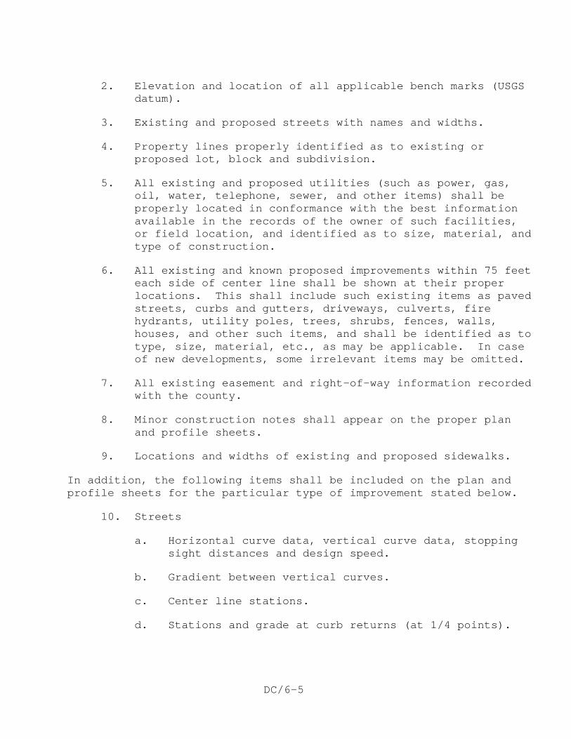
DC/6-5
2. Elevation and location of all applicable bench marks (USGS datum).
3. Existing and proposed streets with names and widths.
4. Property lines properly identified as to existing or proposed lot, block and subdivision.
5. All existing and proposed utilities (such as power, gas, oil, water, telephone, sewer, and other items) shall be properly located in conformance with the best information available in the records of the owner of such facilities, or field location, and identified as to size, material, and type of construction.
6. All existing and known proposed improvements within 75 feet each side of center line shall be shown at their proper locations. This shall include such existing items as paved streets, curbs and gutters, driveways, culverts, fire hydrants, utility poles, trees, shrubs, fences, walls, houses, and other such items, and shall be identified as to type, size, material, etc., as may be applicable. In case of new developments, some irrelevant items may be omitted.
7. All existing easement and right-of-way information recorded with the county.
8. Minor construction notes shall appear on the proper plan and profile sheets.
9. Locations and widths of existing and proposed sidewalks.
In addition, the following items shall be included on the plan and profile sheets for the particular type of improvement stated below.
10. Streets
a. Horizontal curve data, vertical curve data, stopping sight distances and design speed.
b. Gradient between vertical curves.
c. Center line stations.
d. Stations and grade at curb returns (at 1/4 points).
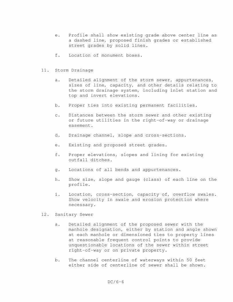
DC/6-6
e. Profile shall show existing grade above center line as a dashed line, proposed finish grades or established street grades by solid lines.
f. Location of monument boxes.
11. Storm Drainage
a. Detailed alignment of the storm sewer, appurtenances, sizes of line, capacity, and other details relating to the storm drainage system, including inlet station and top and invert elevations.
b. Proper ties into existing permanent facilities.
c. Distances between the storm sewer and other existing or future utilities in the right-of-way or drainage easement.
d. Drainage channel, slope and cross-sections.
e. Existing and proposed street grades.
f. Proper elevations, slopes and lining for existing outfall ditches.
g. Locations of all bends and appurtenances.
h. Show size, slope and gauge (class) of each line on the profile.
i. Location, cross-section, capacity of, overflow swales. Show velocity in swale and erosion protection where necessary.
12. Sanitary Sewer
a. Detailed alignment of the proposed sewer with the manhole designation, either by station and angle shown at each manhole or dimensioned ties to property lines at reasonable frequent control points to provide unquestionable locations of the sewer within street right-of-way or on private property.
b. The channel centerline of waterways within 50 feet either side of centerline of sewer shall be shown.
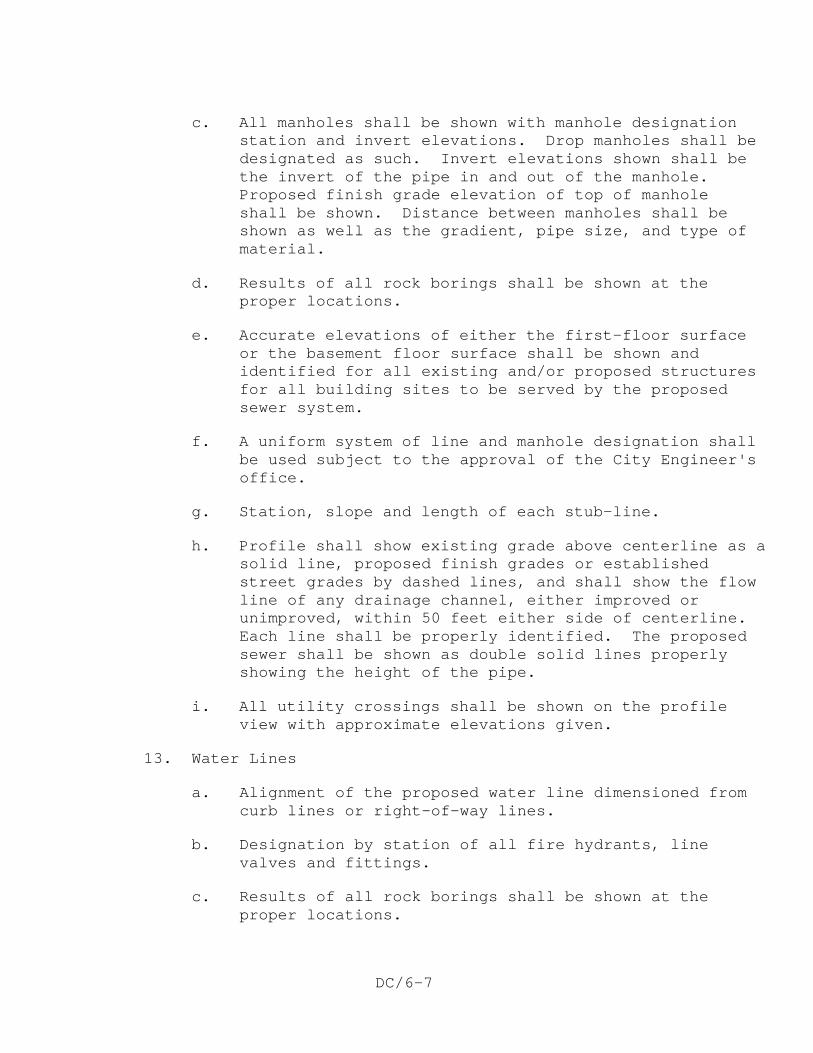
DC/6-7
c. All manholes shall be shown with manhole designation station and invert elevations. Drop manholes shall be designated as such. Invert elevations shown shall be the invert of the pipe in and out of the manhole. Proposed finish grade elevation of top of manhole shall be shown. Distance between manholes shall be shown as well as the gradient, pipe size, and type of material.
d. Results of all rock borings shall be shown at the proper locations.
e. Accurate elevations of either the first-floor surface or the basement floor surface shall be shown and identified for all existing and/or proposed structures for all building sites to be served by the proposed sewer system.
f. A uniform system of line and manhole designation shall be used subject to the approval of the City Engineer's office.
g. Station, slope and length of each stub-line.
h. Profile shall show existing grade above centerline as a solid line, proposed finish grades or established street grades by dashed lines, and shall show the flow line of any drainage channel, either improved or unimproved, within 50 feet either side of centerline. Each line shall be properly identified. The proposed sewer shall be shown as double solid lines properly showing the height of the pipe.
i. All utility crossings shall be shown on the profile view with approximate elevations given.
13. Water Lines
a. Alignment of the proposed water line dimensioned from curb lines or right-of-way lines.
b. Designation by station of all fire hydrants, line valves and fittings.
c. Results of all rock borings shall be shown at the proper locations.
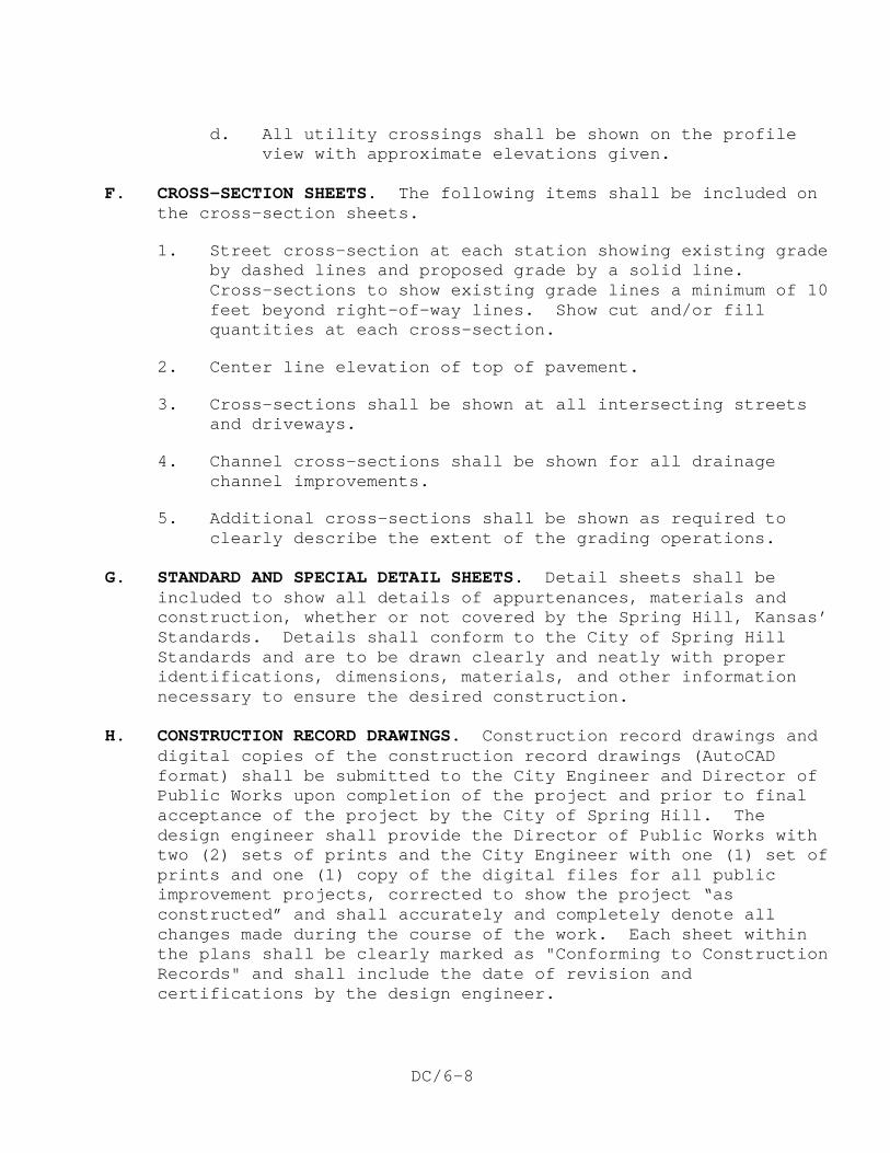
DC/6-8
d. All utility crossings shall be shown on the profile view with approximate elevations given.
F. CROSS-SECTION SHEETS. The following items shall be included on
the cross-section sheets.
1. Street cross-section at each station showing existing grade by dashed lines and proposed grade by a solid line. Cross-sections to show existing grade lines a minimum of 10 feet beyond right-of-way lines. Show cut and/or fill quantities at each cross-section.
2. Center line elevation of top of pavement.
3. Cross-sections shall be shown at all intersecting streets and driveways.
4. Channel cross-sections shall be shown for all drainage channel improvements.
5. Additional cross-sections shall be shown as required to clearly describe the extent of the grading operations.
G. STANDARD AND SPECIAL DETAIL SHEETS. Detail sheets shall be
included to show all details of appurtenances, materials and construction, whether or not covered by the Spring Hill, Kansas’ Standards. Details shall conform to the City of Spring Hill Standards and are to be drawn clearly and neatly with proper identifications, dimensions, materials, and other information necessary to ensure the desired construction.
H. CONSTRUCTION RECORD DRAWINGS. Construction record drawings and
digital copies of the construction record drawings (AutoCAD format) shall be submitted to the City Engineer and Director of Public Works upon completion of the project and prior to final acceptance of the project by the City of Spring Hill. The design engineer shall provide the Director of Public Works with two (2) sets of prints and the City Engineer with one (1) set of prints and one (1) copy of the digital files for all public improvement projects, corrected to show the project “as constructed” and shall accurately and completely denote all changes made during the course of the work. Each sheet within the plans shall be clearly marked as "Conforming to Construction Records" and shall include the date of revision and certifications by the design engineer.
DC/6-9
These record drawings will not require field surveys unless significant changes were made to the design during construction. Typically, the only record drawings that will require field surveying will be record grading plans. The record grading plans shall include record elevations for all property corners, including the front corners, and all curb notches.
END OF SECTION

DC/6-10
This page intentionally left blank.
DC/7-1
PRIVATE IMPROVEMENT DESIGN CRITERIA
A. GENERAL. Private improvement construction in the City of Spring
Hill shall in all respects be designed to conform to applicable codes, regulations and ordinances as established by the City of Spring Hill. Plans for private improvements being made in conjunction with building construction shall be submitted through the Code Enforcement Department. All street, roadway, driveway, and sidewalk construction, public or private, shall conform to the Technical Specifications and Design Criteria for public improvements as stipulated herein.
Private improvements that are not being constructed in conjunction with new building construction or an addition to an existing building shall submit plans to the City Engineer for review and approval. Improvements for water line, sanitary sewer line, storm sewer line and street construction shall conform to the Design Criteria of the City of Spring Hill and/or the applicable sections of the Uniform Building Code, latest edition.
B. PARKING LOT CONSTRUCTION. Parking lot construction shall
conform to the following Design Criteria and shall abide by all City of Spring Hill ordinances.
1. Materials for Construction. The following materials are
acceptable for parking lot construction in the City of Spring Hill:
a. Pavement. The pavement cross-section shall consist of full depth asphalt concrete (minimum of 4 inches); a combination of asphalt concrete surface (minimum of 2 inches) over a crushed rock base (minimum of 6 inches); or, portland cement concrete pavement (minimum of 5 inches) with 10 gauge welded wire mesh, on 6-inch centers each way, embedded 2 inches from the bottom surface of the slab.
b. Driveway Entrances and Curbing Within Public Right-of-Way. These items shall meet the requirements of Section 1400, 2000, and 2100 of the Technical Specifications of the City of Spring Hill. They will be constructed of Class II air-entrained concrete.
DC/7-2
c. Curbing. Parking lot curb shall be of 4000 psi air-entrained concrete.
2. Curb and Curb and Gutter. Concrete curbing shall be
provided along the perimeter of parking areas and along drives connecting parking areas with public streets. Curbing shall have a 6-inch vertical face above the surface of the pavement. Curbs shall be constructed as cast-in-place. In areas of the lot adjacent to proposed future expansion, asphalt concrete curb may be used if approved by the City Engineer. The proposed future expansion shall be shown on the plans.
All work within public right-of-way shall conform to applicable City of Spring Hill Standards. Driveway approaches shall be constructed with integral curb and gutter conforming to City of Spring Hill Type "B" curb and gutter. Transition to existing curb and gutter shall be made at saw joints in existing curb or at existing expansion joints. Construction and expansion joints, dimensions, elevations and surface finish shall match as closely as possible to that of existing adjacent curb and gutter. Expansion joints shall be placed where new curbing abuts existing curbing.
3. Drainage Facilities. All parking areas shall be provided
with adequate drainage facilities as approved by the City Engineer. Enclosed storm sewers shall be used to collect and convey drainage on, across and through public right-of-way. All effort will be made, within the limits of the existing topography, to prevent stormwater runoff from parking lots from exiting through driveway entrances. If the design engineer can justify the need for stormwater to exit through a drive entrance, the maximum flow of water allowed shall be governed by the Design Criteria for storm drainage facilities for the City of Spring Hill for gutter flow. If the flow is in excess of the gutter capacity then it must all be picked up by a curb inlet prior to entering public right-of-way.
Runoff calculations shall be in accordance with APWA Section 5600. All calculations shall be submitted to the City Engineer for review and approval. The City Engineer shall determine if stormwater detention will be required. Drainage structures located in the public right-of-way used and constructed as a portion of the storm drainage
DC/7-3
facilities for parking lots shall be in accordance with the Technical Specifications of the City of Spring Hill.
4. Driveway Entrances. All commercial driveway entrances
constructed within the public right-of-way shall be constructed of concrete with a minimum thickness of 7 inches (see detail in Section 2100). Each commercial or industrial property shall be allowed at least one driveway approach but may have more as long as the total maximum summation of the widths of all driveway approaches upon the property does not exceed 20% of the length of the real property that fronts the abutting City street. Should more than one driveway approach be desired, there shall not be less than 90 feet between the center lines of each driveway approach. In addition to the above, the following dimensions shall govern construction of driveway approaches:
a. Width of Driveway Approach
1) Commercial Driveway Approach - The width of commercial driveway approaches shall not exceed 35 feet or be less than 25 feet measured parallel to the center line of the street at the property lines for two-way driveway approaches; provided, however, that commercial property may be allowed to have a driveway approach not exceeding 52 feet, if said driveway approach does not exceed 20% of the length of the real property abutting the adjacent City street and a 4-foot raised median is placed within such driveway approach to divide the entrance and exit lane(s). The minimum width of a one-way driveway shall be 16 feet.
2) Industrial Driveway Approach. The width of industrial driveway approaches shall not exceed 65 feet or be less than 25 feet measured parallel to the centerline of the street at the property lines for two-way approaches; provided that the minimum width for a one-way driveway shall be 16 feet.
b. Corner of Adjacent Property Line Offset.
1) Commercial or Industrial Driveway Approaches. When commercial or industrial driveway approaches
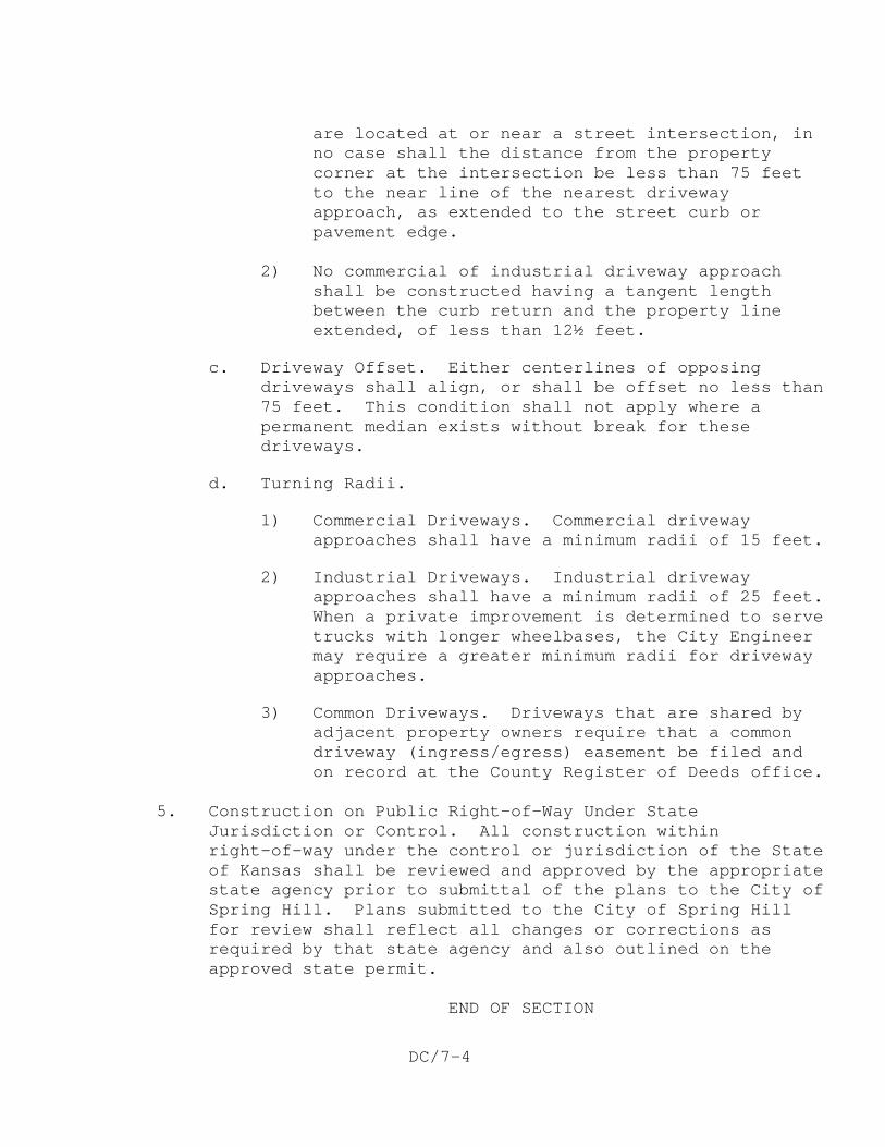
DC/7-4
are located at or near a street intersection, in no case shall the distance from the property corner at the intersection be less than 75 feet to the near line of the nearest driveway approach, as extended to the street curb or pavement edge.
2) No commercial of industrial driveway approach
shall be constructed having a tangent length between the curb return and the property line extended, of less than 12½ feet.
c. Driveway Offset. Either centerlines of opposing driveways shall align, or shall be offset no less than 75 feet. This condition shall not apply where a permanent median exists without break for these driveways.
d. Turning Radii.
1) Commercial Driveways. Commercial driveway approaches shall have a minimum radii of 15 feet.
2) Industrial Driveways. Industrial driveway approaches shall have a minimum radii of 25 feet. When a private improvement is determined to serve trucks with longer wheelbases, the City Engineer may require a greater minimum radii for driveway approaches.
3) Common Driveways. Driveways that are shared by adjacent property owners require that a common driveway (ingress/egress) easement be filed and on record at the County Register of Deeds office.
5. Construction on Public Right-of-Way Under State
Jurisdiction or Control. All construction within right-of-way under the control or jurisdiction of the State of Kansas shall be reviewed and approved by the appropriate state agency prior to submittal of the plans to the City of Spring Hill. Plans submitted to the City of Spring Hill for review shall reflect all changes or corrections as required by that state agency and also outlined on the approved state permit.
END OF SECTION
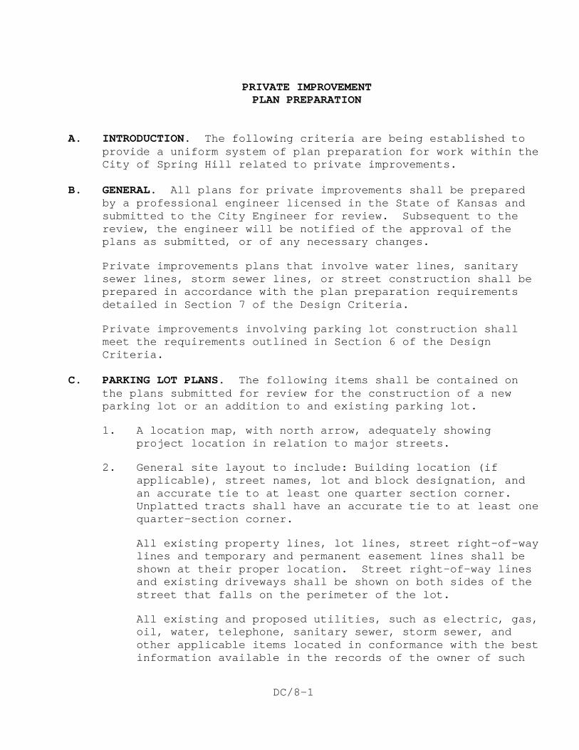
DC/8-1
PRIVATE IMPROVEMENT PLAN PREPARATION
A. INTRODUCTION. The following criteria are being established to
provide a uniform system of plan preparation for work within the City of Spring Hill related to private improvements.
B. GENERAL. All plans for private improvements shall be prepared
by a professional engineer licensed in the State of Kansas and submitted to the City Engineer for review. Subsequent to the review, the engineer will be notified of the approval of the plans as submitted, or of any necessary changes.
Private improvements plans that involve water lines, sanitary sewer lines, storm sewer lines, or street construction shall be prepared in accordance with the plan preparation requirements detailed in Section 7 of the Design Criteria.
Private improvements involving parking lot construction shall meet the requirements outlined in Section 6 of the Design Criteria.
C. PARKING LOT PLANS. The following items shall be contained on
the plans submitted for review for the construction of a new parking lot or an addition to and existing parking lot.
1. A location map, with north arrow, adequately showing project location in relation to major streets.
2. General site layout to include: Building location (if applicable), street names, lot and block designation, and an accurate tie to at least one quarter section corner. Unplatted tracts shall have an accurate tie to at least one quarter-section corner.
All existing property lines, lot lines, street right-of-way lines and temporary and permanent easement lines shall be shown at their proper location. Street right-of-way lines and existing driveways shall be shown on both sides of the street that falls on the perimeter of the lot.
All existing and proposed utilities, such as electric, gas, oil, water, telephone, sanitary sewer, storm sewer, and other applicable items located in conformance with the best information available in the records of the owner of such
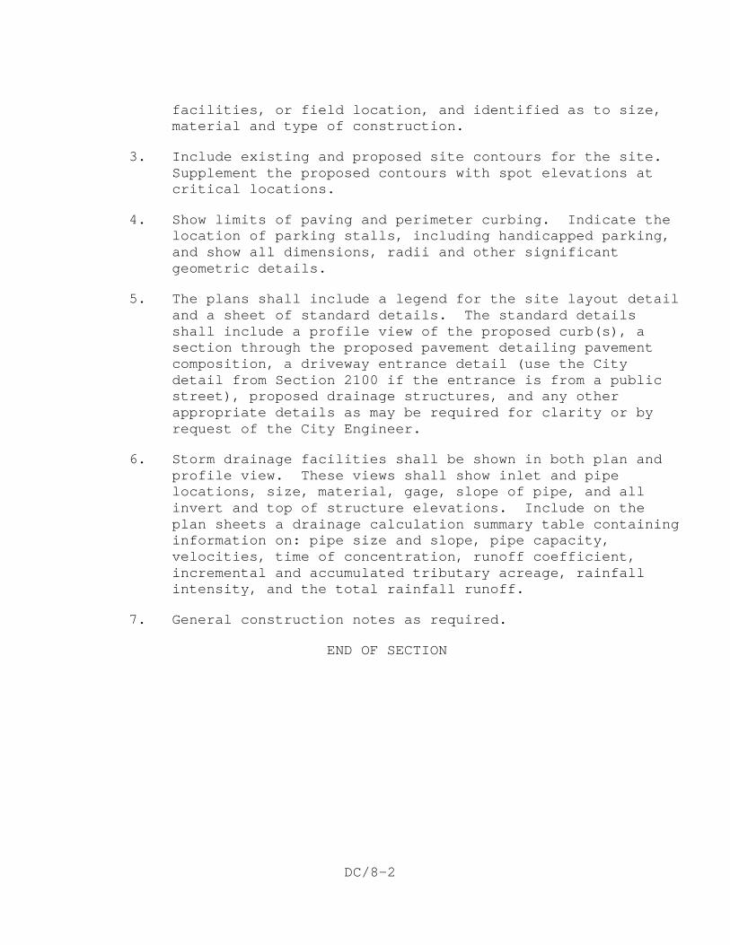
DC/8-2
facilities, or field location, and identified as to size, material and type of construction.
3. Include existing and proposed site contours for the site. Supplement the proposed contours with spot elevations at critical locations.
4. Show limits of paving and perimeter curbing. Indicate the location of parking stalls, including handicapped parking, and show all dimensions, radii and other significant geometric details.
5. The plans shall include a legend for the site layout detail and a sheet of standard details. The standard details shall include a profile view of the proposed curb(s), a section through the proposed pavement detailing pavement composition, a driveway entrance detail (use the City detail from Section 2100 if the entrance is from a public street), proposed drainage structures, and any other appropriate details as may be required for clarity or by request of the City Engineer.
6. Storm drainage facilities shall be shown in both plan and profile view. These views shall show inlet and pipe locations, size, material, gage, slope of pipe, and all invert and top of structure elevations. Include on the plan sheets a drainage calculation summary table containing information on: pipe size and slope, pipe capacity, velocities, time of concentration, runoff coefficient, incremental and accumulated tributary acreage, rainfall intensity, and the total rainfall runoff.
7. General construction notes as required.
END OF SECTION
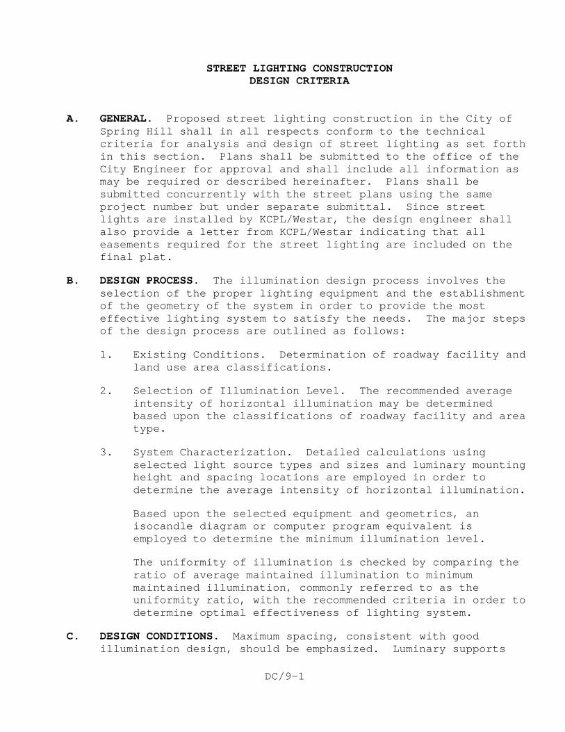
DC/9-1
STREET LIGHTING CONSTRUCTION DESIGN CRITERIA A. GENERAL. Proposed street lighting construction in the City of
Spring Hill shall in all respects conform to the technical criteria for analysis and design of street lighting as set forth in this section. Plans shall be submitted to the office of the City Engineer for approval and shall include all information as may be required or described hereinafter. Plans shall be submitted concurrently with the street plans using the same project number but under separate submittal. Since street lights are installed by KCPL/Westar, the design engineer shall also provide a letter from KCPL/Westar indicating that all easements required for the street lighting are included on the final plat.
B. DESIGN PROCESS. The illumination design process involves the selection of the proper lighting equipment and the establishment of the geometry of the system in order to provide the most effective lighting system to satisfy the needs. The major steps of the design process are outlined as follows:
1. Existing Conditions. Determination of roadway facility and land use area classifications.
2. Selection of Illumination Level. The recommended average intensity of horizontal illumination may be determined based upon the classifications of roadway facility and area type.
3. System Characterization. Detailed calculations using selected light source types and sizes and luminary mounting height and spacing locations are employed in order to determine the average intensity of horizontal illumination.
Based upon the selected equipment and geometrics, an isocandle diagram or computer program equivalent is employed to determine the minimum illumination level.
The uniformity of illumination is checked by comparing the ratio of average maintained illumination to minimum maintained illumination, commonly referred to as the uniformity ratio, with the recommended criteria in order to determine optimal effectiveness of lighting system.
C. DESIGN CONDITIONS. Maximum spacing, consistent with good illumination design, should be emphasized. Luminary supports
DC/9-2
are hazardous roadside objects and the total number should be minimized and/or strategically located behind sidewalks for safety considerations. Supports shall be set back as far as practical. In general, the pole setback distance from the face of the curb shall be 6 or more feet. In locations where the proper setback distance cannot be achieved, the use of breakaway pole bases is required.
Determination of light source size and type and luminary mounting height and spacing shall be based upon the required illuminance levels when the luminaries are at their lowest output. This condition occurs just prior to lamp replacement and luminary washing. Therefore, formulas calculating average illuminance shall include light loss factors relating to lamp lumen depreciation and luminaire dirt depreciation.
D. AREA CLASSIFICATION. The classification of urbanized areas
shall be generally defined as follows:
1. Commercial. That portion of a municipality in a business development where ordinarily there are large numbers of pedestrians during business hours. This definition applies to densely developed business areas outside, as well as within, the central part of a municipality. The area contains land use, which attracts a relatively heavy volume of nighttime vehicular and/or pedestrian traffic on a frequent basis.
2. Intermediate. That portion of a municipality often characterized by a moderately heavy nighttime pedestrian activity such as in blocks having libraries, community recreation centers, large apartment buildings or neighborhood retail stores.
3. Residential. A residential development, or a mixture of residential and commercial establishments, characterized by a few pedestrians at night. This definition includes areas with single-family homes, town houses, and/or small apartment buildings.
E. ROADWAY CLASSIFICATION. The classification of roadways shall be
generally defined as follows:
1. Freeway. A divided major roadway with full control of access and with no crossings at grade. This definition applies to toll as well as non-toll roads.
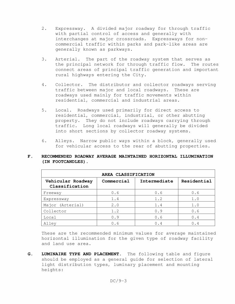
DC/9-3
2. Expressway. A divided major roadway for through traffic with partial control of access and generally with interchanges at major crossroads. Expressways for non-commercial traffic within parks and park-like areas are generally known as parkways.
3. Arterial. The part of the roadway system that serves as the principal network for through traffic flow. The routes connect areas of principal traffic generation and important rural highways entering the City.
4. Collector. The distributor and collector roadways serving traffic between major and local roadways. These are roadways used mainly for traffic movements within residential, commercial and industrial areas.
5. Local. Roadways used primarily for direct access to residential, commercial, industrial, or other abutting property. They do not include roadways carrying through traffic. Long local roadways will generally be divided into short sections by collector roadway systems.
6. Alleys. Narrow public ways within a block, generally used for vehicular access to the rear of abutting properties.
F. RECOMMENDED ROADWAY AVERAGE MAINTAINED HORIZONTAL ILLUMINATION
(IN FOOTCANDLES).
AREA CLASSIFICATION Vehicular Roadway Classification
Commercial Intermediate Residential
Freeway 0.6 0.6 0.6
Expressway 1.4 1.2 1.0
Major (Arterial) 2.0 1.4 1.0
Collector 1.2 0.9 0.6
Local 0.9 0.6 0.4
Alley 0.6 0.4 0.4
These are the recommended minimum values for average maintained horizontal illumination for the given type of roadway facility and land use area.
G. LUMINAIRE TYPE AND PLACEMENT. The following table and figure
should be employed as a general guide for selection of lateral light distribution types, luminary placement and mounting heights:
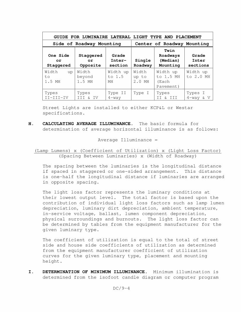
DC/9-4
GUIDE FOR LUMINAIRE LATERAL LIGHT TYPE AND PLACEMENT Side of Roadway Mounting Center of Roadway Mounting
One Side
or Staggered
Staggered
or Opposite
Grade Inter- section
Single Roadway
Twin Roadways (Median) Mounting
Grade Inter
sections Width up to 1.5 MH
Width beyond 1.5 MH
Width up to 1.5 MH
Width up to 2.0 MH
Width up to 1.5 MH (Each Pavement)
Width up to 2.0 MH
Types II-III-IV
Types III & IV
Type II 4-way
Type I Types II & III
Types I 4-way & V
Street Lights are installed to either KCP&L or Westar specifications.
H. CALCULATING AVERAGE ILLUMINANCE. The basic formula for
determination of average horizontal illuminance is as follows:
Average Illuminance =
(Spacing Between Luminaries) x (Width of Roadway) (Lamp Lumens) x (Coefficient of Utilization) x (Light Loss Factor)
The spacing between the luminaries is the longitudinal distance if spaced in staggered or one-sided arrangement. This distance is one-half the longitudinal distance if luminaries are arranged in opposite spacing.
The light loss factor represents the luminary conditions at their lowest output level. The total factor is based upon the contribution of individual light loss factors such as lamp lumen depreciation, luminary dirt depreciation, ambient temperature, in-service voltage, ballast, lumen component depreciation, physical surroundings and burnouts. The light loss factor can be determined by tables from the equipment manufacturer for the given luminary type.
The coefficient of utilization is equal to the total of street side and house side coefficients of utilization as determined from the equipment manufacturer coefficient of utilization curves for the given luminary type, placement and mounting height.
I. DETERMINATION OF MINIMUM ILLUMINANCE. Minimum illumination is
determined from the isofoot candle diagram or computer program
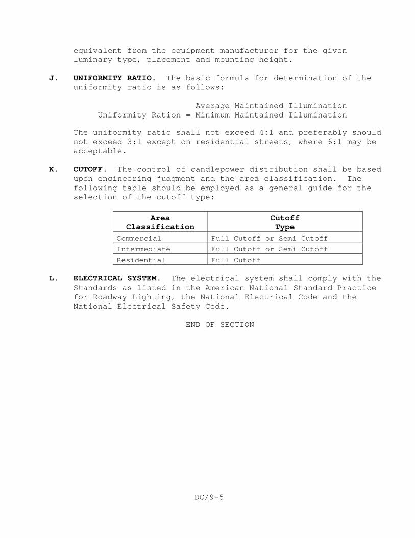
DC/9-5
equivalent from the equipment manufacturer for the given luminary type, placement and mounting height.
J. UNIFORMITY RATIO. The basic formula for determination of the
uniformity ratio is as follows: Uniformity Ration = Minimum Maintained Illumination
Average Maintained Illumination
The uniformity ratio shall not exceed 4:1 and preferably should not exceed 3:1 except on residential streets, where 6:1 may be acceptable.
K. CUTOFF. The control of candlepower distribution shall be based
upon engineering judgment and the area classification. The following table should be employed as a general guide for the selection of the cutoff type:
Area
Classification Cutoff Type
Commercial Full Cutoff or Semi Cutoff
Intermediate Full Cutoff or Semi Cutoff
Residential Full Cutoff L. ELECTRICAL SYSTEM. The electrical system shall comply with the
Standards as listed in the American National Standard Practice for Roadway Lighting, the National Electrical Code and the National Electrical Safety Code.
END OF SECTION

DC/9-6
This page intentionally left blank.