Design criteria for nuclear powered merchant ships. - CORE
294
DESIGN CRITERIA for NUCLEAR POWERED MERCHANT SHIPS by John M. Reade IV May 23, 1969
-
Upload
khangminh22 -
Category
Documents
-
view
2 -
download
0
Transcript of Design criteria for nuclear powered merchant ships. - CORE

DESIGN CRITERIA for
NUCLEAR POWERED MERCHANT SHIPS
by
John M. Reade IV
May 23, 1969

93940

^ V .
DUDLEY KNOX LIBRARYNAVAL POSTGRADUATE SCHnn.MONTEREY, CA 93943-5101
DESIGN CRITERIA FOR
NUCLEAR POWERED MERCHANT SHIPS
by
John Moore Reade IVII
B. S. , U. S. Naval Academy
(1965)
SUBMITTED in PARTIAL FULFILLMENT of the
REQUIREMENTS for the
DEGREE of NAVAL ENGINEER and the
DEGREE of MASTER of SCIENCE in NUCLEAR ENGINEERING
at the
MASSACHUSETTS INSTITUTE OF TECHNOLOGY
May I969


L-L^ ,
NAVAL i -
BUNTEF.:; R^^^pXLIBRARYNAVAL POSTGRADUATE SCHOOLMONTEREY, CA 93943-5101
Design Criteria for Nuclear Powered
Merchant Ships
by
John Moore Reade IV
Submitted to the Department of Naval Architecture and Marine Engineer-ing and the Department of Nuclear Engineering on May 23, 19&9 ' n partialfulfillment of the requirements for the degree of Naval Engineer and thedegree of Master of Science in Nuclear Engineering.
ABSTRACT
This study covers considerations of safety involved in the design ofa nuclear powered merchant ship. 27 design criteria are developed for the
protection of the public from a hazardous release of radioactivity in theevent of an accident in the nuclear plant. The question of protection is
considered in two interrelated ways; first, the protection of the surround-ing environment from radioactivity release by the containment system;second, the protection of the reactor primary, and containment systems fromdamage provided by ship structure.
In considering the overall safeguard:; cF the nuclear ship some pastdesigns have provided for an emergency propulsion system. However, nosuch general requirement is established in this study. !n designing andoperating the nuclear ship so as to ensure the safety of the public, thereis probably no peculiar danger for which emergency propulsive power wouldprovide protection. In considering the danger of containment system damagedue to water pressure during sinking, several alternative protections arediscussed. It is doubtful that flood valves would be satisfactory in pre-venting containment collapse due to the excessive valve areas necessary to
equalize the pressure. Instead, the design should place reliance on the
structural strength to keep the containment intact down to a safe depth,defined in terms of typical harbor depths.
Three aspects of nuclear ship structure are discussed; longitudinalstrength, collision protection, and grounding protection. Three approachesto collision protection can be considered; first, building side structurestrong enough to protect against any conceivable striking ship; second,segregating nuclear ships to remote ports away from population centers;third, providing side structure adequate to provide protection against a
large percentage of the conceivable striking ships and establishing harborspeed limits in ports where nuclear ships call. The last of these alter-natives is taken as being the most practical. The amount of protectionnecessary depends upon the speeds and displacements of the ships in theworld merchant fleet. In addition the bow structure of the striking shipis important in determining the amount of energy that will be absorbed byeach ship. The collision studies of V. U. Minorsky are used as a basis


for determining the necessary side structure. For the purpose of design a
passenger - cargo vessel should be assumed as a typical striking ship beingmore dangerous than the tanker due to a sharper bow angle which reduces theamount of bow structure that can absorb energy.
The basic premise of this study and the resulting criteria is that the
protection of the public from hazardous radioactivity must be provided by
systems and persons that are part of the ship system or organization; the
containment system on a nuclear ship must be self-reliant.
THESIS SUPERVISOR: Theos J. Thompson
TITLE: Professor of Nuclear Engineering
O


ACKNOWLEDGEMENTS
i would like to express my appreciation to several people whose
assistance helped in the preparation of this thesis. To Professor
T. J. Thompson for his supervision and suggestions, to Professor S. C.
Powell for his assistance as departmental reader, and to Miss Ruth
Richardson for helping to fashion the finished product - thank you.
4


TABLE OF CON TENTS
Abstract 2.
Acknowledgements •
4f
Table of Contents 5
List of Tables 6
List of Figures 7
Introduct ion
Part 1 - Longitudinal Strength
Part 2 - Collision Protection
Part 3 " Grounding Protection
Bibl iography
9Definitions /Q
Section A - Containment /£.
Part 1- Containment System Definition /$
Part 2 - Containment Capacity - internal Accidents V^>
Part 3 - Containment Access and Penetration ^*°
Part h - Containment Protection - External Accidents (0
Section B - Ship Structure S3
/a 3
/5f
Appendix 1/3©
/¥£
5


LIST OF TABLES
1. Percentage Fission Product Inventory Released from the Core ImmediatelyFollowing an Accident
2. Neutron Induced Activity Data
3. Characteristics of High Pressure Steel Containment Vessels
h. Nuclear Fission Energy
5. Summary of Metal -Water Reactions
6. Containment Energy-Yankee Reactor
7. Gamma Shield Materials
8. U. S. Salvage Association Collision Data
9. Summation of Area Coefficients
10. Values of Collision Probability for One Year
11. Values of Probability of Collision at or above Critical Speed
12. World Merchant Fleet (1963)


LIST OF FIGURES
1. Typical Dual Cycle Reactor Plant
2. Typical Direct Cycle Reactor Plant
3. Pressure Containment
k. Pressure Suppression
5. Pressure Transient Comparison
6. (Omitted)
7. Pressure Rel ief
8. Sectional Schematic of Ship Multiple Containment
9. SAVANNAH Pressure Transient
10. Containment pressure vs Volume with Primary System Mass as Parameter
11. Double Door Access
12. Simple Piping Penetration
13. Metallic Bellows Expansion for Piping Penetration
]k. Metallic Bellow Expansion with Protection Sleeve
15. N. S. SAVANNAH Electrical Penetrations
16. Air Venting Auxiliary Emergency Cooling
17. Air Cooling Auxiliary Emergency Cooling
18. Typical Weight-Bouyancy Distributions
19. Specific Machinery Weight versus Shaf thorsepower for Oil-fired Plant:
20. Variation of Plant Weight with Turbine Exhaust Pressure
21. Variation of Plant Weight with Steam Pressure
22. Variation of Steam Generator Weight with Coolant Temperature
23. Variation of Plant Weight with Coolant Pressure
2k. Midsectional View of SAVANNAH Collision Protection
25. Variation of Damage Length with Damage Location
26. Cumulative Frequency Distribution of Damage Location
7


27- Collision Resistance Factor versus Energy Absorbed
28. Cumulative Frequency Distribution of Striking Energy for VariousMerchant Fleets
29. Critical Speed versus Displacement, for SAVANNAH and OTTO HAHN
30. Rn versus Displacement for SAVANNAH and OTTO HAHNB
8


INTRODUCTION
At the present time, there is discussion concerning reasonable safety
standards for nuclear merchant ships. In the coming decade more and more
nuclear merchant ships will enter the sea lanes of international trade and
be entering the ports of host countries. In the past Atomic Energy Com-
mission review of the design and construction of domestic reactor plants
has been an important part of the assurance of safe operation. However,
in the case of foreign merchant ships this would not be possible. There-
fore, as part of the total effort to ensure the safety of ports and their
neighboring populations, it is important to establish certain criteria for
safe nuclear merchant ship design.
In developing criteria this study shall cover the necessary aspects of
the reactor plant containment system design and the design of adequate ship
structure. In both cases, the protection involves two interrelated defini-
tions; first, protection of the general public from a hazardous release of
radioactivity following an accident in the reactor plant; second, the pro-
tection of the reactor plant from structural damage due to collision, ground-
ing, ship motion, etc. Section A will concentrate on the first of these,
Section B, on the second.
The basic principle of many of the criteria that will be developed is
the necessity of containment system self-reliance. That is, the successful
operation of the containment system should be based on ship system operation,
not requiring external assistance such as tugs, salvage crews, or dock side
cooling water. Such external assistance may very well be available and can
be used. However, the containment should be basically a self-reliant system.


DEFINITIONS
1. Containment system - a system of enclosed spaces and auxiliary devicesdesigned to prevent the release of hazardous amounts of radioactivematerial to the environment in the event of accident by holding suchmaterial within the system boundaries.
2. Primary system - all components and pipes which contain or could con-tain reactor coolant which contacts the fuel during normal operation.
3- Normal operation - operation of the reactor and primary system in
accordance with design conditions.
k. Shut down - reactor subcritical with adequate coolant flow.
5. Assumed Accident Situation - a hypothetical accident(s) or mal funct ion (s)
in the nuclear power plant that is assumed by the containment systemdesigner as the basis for containment system design.
6. Reactor accident - any unintentional event which reduces the integrityof one or more of the radiation release barriers within the reactor(i.e., fuel jacket, reactor vessel) below the level allowed for in thenormal operations.
7- Minor 1 ine - line small enough so that a double-ended pipe break any-
where in the line would result in a rate of coolant loss small enoughso that the primary system could easily be kept full of an adequateamount of coolant at all times by readily and continuously availableemergency coolant supplies and existing injection methods.
8. Untenable condition - a condition of the containment system after an
accident in which the contained volume is radioactive, at a hightemperature, and/or at a high pressure (i.e., the containment cannot be
entered)
.
9. Internal accident - an abnormal operation, malfunction or failure of the
reactor or primary system resulting in the release of radioactivity and
nuclear, stored, and/or chemical energy to the. containment system.
10. External accident - any accident or hazardous situation brought aboutby forces, action, or failure of the surrounding ship system or environ-ment that could result in the failure of any part of containment system,
reactor, or primary system (e.g., collision, cargo fire...).
11. Accident energy density - the nuclear, stored, and chemical energy re-
leased - divided by - free volume of containment .
12. Re! iabi 1 i ty - the fraction of time a system or system component is
operating or capable of operation as designed. Unreliability is oneminus this fraction.
13. Divers i ty - the use of two or more different parameters as measures of
a change in or the presence of conditions for which control or emergencyaction could be necessary, (e.g., the use of containment pressure level
and activity level to determine the containment system closure).
\/o


\k. Redundancy - the use of two or more independent systems, the operationof any one of which will accomplish a particular system function.
15. Coinc idence - the requirement for two or more signals of an unsafe con-
dition (e.g., containment pressure rise) to all be received by a controlsystem before a response action is taken (e.g., containment closure).
16. Containment Desig n Pressure - the maximum internal pressure that thecontainment system is designed to withstand without structural failureor excessive leakage.
17. Containment Collap se Fressu re - the maximum differential pressure due
to external and internal sea water pressure that the containment systemis designed to withstand with no structural failure.
18. No- flood collapse depth - that depth at which the containment wouldcollapse in the absence of sea water flooding into the conta inment
.
//

Section A - CONTAINMENT
Introduct ion
The purpose of a containment systemfor a nuclear power plant is to pre-
vent the release of hazardous amounts of radioactivity or radioactive material
to the environment. In reference 1 the authors state that prevention of
accidents dangerous to public safety is the primary goal of reactor safety.
In the event of a release of radioactivity from the reactor plant, the
containment system must be designed, constructed, and operated to protect
the general public. Because the marine reactor plant is a mobile ocean-
going installation the term "general publ ic"warrants special attention.
Four groups that make up the nuclear ship's general public are:
(1) Passengers and crew not involved in reactor plant operation
(2) Passengers and crew on other ships in the vicinity (passing in
sea lanes or harbors, collision, emergency assistance....)
(3) Populations in the vicinity of the nuclear ship's line of travel(harbor entrance, channel, river, shoreline where the ship couldgo aground. . . .)
{h) Populations in the vicinity of the ship's dock site
In containment design (and all areas of reactor safety design) the various
situations that could effect any or all of these groups must be considered
in analyzing the effectiveness of the containment system.
Containment systems are designed to withstand the effects of an assumed
accident situation (or situations) (e.g., pressure rise) without a loss of
containment integrity (e.g., structural failure). Containment integrity is
measured in terms of the rate of leakage out of the containment. The con-
tainment design specifies a maximum permissible leakage rate that is usually
measured in terms of percent of containment volume to leak per day at a par-
ticular internal pressure. The maximum permissible leakage rate is determined
by doseage limitations and the assumed manner in which radioactivity is dis-
/Z


persed in the atmosphere.
In nuclear plant design, as in other fields of complex system design,
the engineer must consider the problems of system performance and system-
environment interaction under accident conditions. The term "assumed
accident situation", as defined, is not used to specify a new philosophy
for postulating reactor accidents. Several different approaches have been
utilized in arriving at an assumed accident situation; maximum credible
accident (N.S. SAVANNAH, OTTO HAHN) , and the probabilistic approach of
Farmer (REF-2) , to name two. It is not the purpose of this study to specify
the particular method to be used; this is a design function. The designer
must carefully develop an assumed accident situation or set of situations
as a logical starting point for containment system design.
There are peculiar aspects of the marine reactor containment problem
that warrant special design consideration. The merchant ship and the ocean,
coastal, or harbor environments provide beneficial and adverse conditions
not considered in land based plant design. The following list summarizes
these peculiarities affecting marine nuclear plant containment design that
should be considered.
Adverse Conditions
(1) Navigational accidents - such as grounding, collision, or striking.These could result in containment system damage, loss of ship con-
trol, loss of sea water supply for emergency cooling. There is a
particular hazard in coastal and harbor waters due to increasedship traffic and restricted water and the presence of the local
population. (These accidents will be discussed in detail in part 4)
(2) Fire or explosion - resulting in containment system damage.
(3) Ship motions - increasing structural loadings, and changingreactor coolant characteristics (movement of coolant free surface,void fraction, natural circulation). While the latter does not
directly concern the containment system, it could be the source of
a reactor accident.
/3


(*i) Volume and weight limitations - resulting in compact design.This necessitates smaller containment vessels than would be usedfor land based plants of equal power rating, increasing the con-tainment design pressure. Compact design also brings the con-tainment system closer to missile hazards, fire and explosionhazards, and passengers and crew.
(5) Sea water flooding - cold sea water creates problems of thermalstress, possible reactivity increase in the core (leading to an
accident). Also flooding causes a hydrostatic pressure on theoutside of the containment system. Uncontrolled flooding wouldresult in s inking; in shallow waters this could present a pro-
blem of radioactive release to the environment that could be
very difficult to control.
(6) Sea water corrosion - this includes corrosion of various structuralelements of the ship; hull, bilge, foundations for the containmentor other equipment, piping, and ventilation ducts.
Benef i c i a 1 I'. f f eg t s
(1) Mobility - enables the ship to avoid hazardous navigationalsituations (storms, ships, shoals, etc.),
(2) Ship structure - would provide protection for the containment sys-
tem and the reactor plant.
(3) Open sea and air space - for contamination release. This wouldonly be of signifigance when the ship is well out to sea. Thedeep ocean water would also act as a radiation shield in theevent of sinking, and a supply of emergency cooling water for the
reactor core and other plant components.
Section A, Containment, is divided into four parts. The first deals with
a definition of the containment system - what systems should be inside and
outside the containment - and a basic study of containment system concepts.
The second deals with the capacity of the containment in terms of internal
accidents. The third part is concerned with containment system accesses and
penetrations. The final part deals with protection of the containment system
from external accidents.
/f


] . Containment Sys tem Definition :
The definition of a containment system given in the list of definitions
is purposely general. No mention was made of what enclosed spaces or auxil-
iary devices should be considered. Furthermore, nothing was said concerning
what plant systems should be located internal or external to the containment.
V/ithout destroying the generality of the definition, this section shall
discuss these points and study some possible containment concepts.
Systems internal to the contai nment sys tem:
In containment of radioactivity two sources need to be considered:
(1) fission products and their subsequent decay products, and (2) neutron
induced activity of the reactor coolant; and solid or dissolved material in
the coolant.
Due to the high, unstable nuetron/proton ratios of fission products
negative beta emission is the primary mode of decay with half-lives ranging
from seconds to millions of years. A large proportion of the fission pro-
fucts are also gamma emitters with average energies of about 2 MEV. These
products are normally confined to the reactor fuel elements by cladding,
or sometimes are vented to prevent gaseous pressure buildup and neutron
absorption. The fission product inventory in the reactor depends upon the
core design and operating history. Some of the fission products of particular
interest are listed in table 1. The current AFC guides for inventory per-
centages released immediately from the core after an accident (e.g., cladding
failure, meltdown...) are quoted from reference *f. Those fission products
not in a gaseous form are usually assumed to be present in small diameter
particulate form (< 20 microns) (REF-31). Fifty percent of the halogens
that are released from the core are assumed to plate out on surfaces within
the containment; therefore, only 25% of the halogen inventory would be
available for leakage from t fie containment.
/5


TABLE 1
Percentage Fission Product inventory Released
from the Core Immediatel y following an Accident
Noble gas 100% (kyrpton, xenon)
Halogens 50% (bromide, iodine)
Volatile solids 50% (selenium, tellurium, cesium)
All others 1%
This table shows a difference from the release inventory used in evaluating
the effects of the N.S. SAVANNAH maximum credible accident. A figure of
one percent was used for all solids. However, SAVANNAH exhaust filtration
is adequate to handle the current AEC guide of TABLE 1 (REF -3, 5, 6).
The second source of radioactivity is neutron induced activity of the
reactor coolant or impurities in the coolant. The level of induced activity
depends upon the neutron capture cross sections of the elements in the coolant
Table 2 is reproduced from reference 7- It summarizes information on
16induced activity for water coolants. M would be of concern in radio-
activity release except for its low half-life of only 7-^ seconds. Of
particular concern are the coolant impurities such as sodium, potassium,
and corrosion products (crud) such as oxides of iron and aluminum. The
formation of crud is controlled by maintaining the coolant water slightly
alkaline (pH of 6.5 - 8.0 for SAVANNAH) by the addition of hydrogen or other
chemicals (morpholine for OTTO HAHN) . The radioactivity of the coolant is
usually of minor consequence during normal operation; this is also likely to
be the situation following an accident.
/6


TABLE 2
Neut ron Induced Activity DataEnergy
Activation Radio- of Gamma GammasTarget Isotopic Cross Section active Rays per Disinte-Nucl ide Per Cent (barns) Product Hal f- 1 i fe (Mev) grat ion
1699.8 2 x 10" 5 '"'
N16
7. if sec 6.1.3,7.10 0.76,0.06
70.039 5 x 10~ N
7k.\ sec Neutron 1 neutron
180.20^ 2 x 10
1929. h sec 1.6 0.7
Na23
100 0.53+ Na2
\k.S hr 2.75,1.33 1,1
K 6.8 1.15+ K42
\2.k hr 1.51 0,25
* Fast (n, p) cross sections averaged over fission spectrum,
+ 2200-rneters/sec cross sections
In addition to induced activity in the coolant the activity in the
coolant system could be increased due to a fuel element failure. Such fuel
element failure need not be considered a reactor accident necessitating
curtailment of reactor operation (REF-1). Some reactor and primary systems
(dual cycle) can tolerate a certain amount of fission products in the coolant
Nevertheless, such release increases the coolant radioactive hazard and
should be closely monitored. However, for direct cycle plants this is a
serious problem, as discussed later.
The preceding paragraphs have discussed the sources of radioactivity.
The significance of each of these sources to radioactivity release will
depend upon the type and size reactor and plant operating conditions. In
all cases studied the release of hazardous amounts of fission products was
considered. The importance of the coolant as a significant contributor of
radioactivity depends upon the type, amount, and density of the coolant;
the use of coolant filtration; and the operating policy with regard to
fission product leakage into the coolant. In any case the fission product
/7

release poses by far the greatest threat.
Such release may result from either a loss of the heat transfer medium
or an excessive power increase, or a combinat ion of the two. The following
list gives some of the possible causes of these two types of accidents:
A. Loss of heat transfer medium
1. rupture of a coolant line
2. loss of flow due to pump failure
3. inadequate flow in part of core due to bowing, swelling, or
movement of elements.
B. Excessive power increase
1. control rods withdrawn too rapidly
2. control rod malfunction or blowout
3. injection of cold water (negative temperature reactivity
coefficient)
k. coolant voiding or loss (positive void coefficient)
In the following discussion consideration will be given first to dual
cycle plants (PWR plants in particular) as shown in Figure 1 and then to
direct cycle plants such as that shown in Figure 2. For either cycle,
fission products are usually assumed to escape into the surrounding area
through either a rupture in the reactor coolant piping (most common assump-
tion) or by a rupture of the reactor vessel as was suggested in a letter of
I965 from the Advisory Committee on Reactor Safeguards to the Atomic Energy
Commission (REF-8) . In the first case, it is obvious that both the reactor
and the reactor coolant system must be within the containment system. For
the second case - reactor vessel rupture - it could be argued that since
it is assumed the coolant system piping has not ruptured only the reactor
vessel need be within the containment. However, such en assumption would
be open to serious question. Failure of coolant piping could occur as a
/&


Figure 1 - Typical Dual Cycle Reactor Plant
Key: 1
.
Reactor2. Steam generator
3. Primary coolant pressur izat ion systemk. Primary coolant purification system cooler
5. Primary coolant purification demineral izer
6. Turbine7. Condensor8. Feed water system
9. Containment system boundary10. Primary coolant line
n


4
Figure 2 - Typical Direct Cycle Reactor Plant
Key : 1
.
Reactor2. Turbine3. Condensork. Primary coolant purification system cooler
5. Primary coolant purification demineral izer
6. Generator7. Electric Motor8. Containment system boundary
9. Primary coolant line
20


secondary factor resulting from pressure increases caused by excessive heat
generation in the core. The Boxax I reactivity excursion tests of 195^
showed that extremely high water pressure could result from the rapid heat
transfer following core meltdown (REF-1). Therefore, it should not be
assumed that reactor vessel rupture precludes the possibility of reactor
coolant piping rupture. Even if the coolant system were to remain intact,
the fission products released into the coolant would still be a serious
radiation hazard.
For dual cycle plants the steam generators serve as a barrier to pre-
vent fission products in the coolant from spreading throughout the plant -
into turbines condensers, etc. As discussed above, the primary system,
including the coolant lines and circulating pumps should be enclosed within
the containment system, together with the reactor. However, some primary
system lines will be necessary outside the containment for coolant sampling,
coolant charge and discharge, and perhaps purification. !n addition, the
location of the primary pressur izat ion system with relation to the contain-
ment system must be considered. Attention here shall focus on the purifica-
tion and the pressur ization systems.
A coolant purification system is intended to control the concentration
of coolant impurities ("crud" in a water reactor) and remove the small
amounts of fission products that leak into the coolant. Coolant impurities
are sources of neutron induced activity and primary system corrosion. It
has been reasoned that since impurities would accumulate in a closed system
a purification system is necessary. However, recent experience in pressurized
water plant operation has indicated that continuous purification neither
significantly reduces the crud deposition on primary system surfaces nor
reduces the. formation of act iv stated corrosion products (REF~9) • The OTTO
HAHN purification system design was based on this experience. There the


purification system was designed to remove fission products from the water
prior to removal of the reactor vessel closure head and during reactor
startup. Whether or not a purification system is intended for continuous
use, it is a necessary part of the primary system,
A purification system typically consists of a cooling circuit and
demineral izers using a cat ion-an ion resin bed. The location oF this system
inside or outside of the containment would depend on several factors:
(1) pressure and temperature (thermodynamic energy) of coolant during
pur if icat ion.
(2) expected impurity and activity content of coolant.
(3) frequency of replacement or maintenance of the demineral izers.
(4) frequency of purification system operation.
N.S. SAVANNAH used a continuously operating system where the filtering
of the coolant was done outside the containment but within the secondary
shielding. Before the coolant left the containment it passed through pressure
reduction throttle valves to decrease pressure from 1750 psia to about
kO psia. The load on the demineral izers was increased from the primary loop
condition by the addition of secondary system water as make-up. The
demineral izer resin beds were designed for no less than a 50 day life (com-
pared to other marine reactor plants, this is short). Therefore, locating
the demineral izers outside the containment was a proper design for SAVANNAH.
However, it is possible, to locate the entire purification system within the
containment if the design is made more compact than the SAVANNAH installation.
This would be desirable if the system were to run continuously at high pres-
sure. The danger of coolant flashing to steam and the release of radio-
activity is decreased by placement of this system within the containment.
Furthermore, such internal placement would reduce the necessity of special
shielding structure. Use of reactor grade make up water instead of secondary
22.


water would lower the load on the system. This arrangement would employ only
heat exchange coolers and ion-exchanger demineral i zers.
The pressur izat ion of marine PV/R plants is usually accomplished by a
pressur izat ion system using electric heaters and water sprays. (The OTTO
HAHN, however, utilizes a self pressur izat ion concept in which saturated
steam in a space above the primary coolant maintains pressure on the coolant ,
(REF-10)) A pressur izat ion system serves several functions; maintaining
primary system pressure (about 2000 psia), limiting pressure fluctuations
during load change, and providing some pressure relief for the coolant.
The high pressures and temperatures of the coolant in the pressur izat ion
system are the same as in the coolant lines; consequently the pressuriza-
tion system should be included within the containment.
As mentioned previously, some primary lines must go outside the. con-
tainment. The rupture of such a line must be studied in terms of three
factors: coolant activity release, core melt down due to coolant loss
with poss ible fi ss ion product release through the break, and thermodynamic
energy release. if these lines were held to some maximum size the release
of radioactivity would not be uncontrolled and could be drawn out of the
affected compartment through ventilation filters (if the radioactivity in
the line were at a low level, as would be the case if no fuel element rup-
ture occurred). Also the coolant lost would not be enough to cause the core
to lose its heat transfer medium and core melt down would not result. By
cooling the coolant down before it leaves the containment, the thermodynamic
energy is reduced and the possibility of coolant flashing is prevented. Of
the three considerations core melt down would be the most hazardous due to
the great release of fission products and possible pressure increase in the
primary system as discussed earlier - resulting in a serious accident. The
definition of a "minor line" is built upon the premise of preventing core
Z'S


melt down due to coolant loss, and is used here to define the limitation on
primary lines that must pass outside the containment (i.e., coolant sampling,
charging and discharging, and purification).
Direct cycle plants have certain advantages in comparison with the
dual cycles. Greater thermal efficiencies can be obtained due to the
higher steam conditions that are possible; also, elimination of intermediate
heat exchangers reduces the plant size and weight. However, this elimination
of heat exchangers also presents a disadvantage in that fission products
in the coolant can spread throughout a larger portion of the engineering
plant. This necessitates the enclosure of most of the engineering plant
in the containment to prevent radioactivity release to the surrounding area.
Unlike land based plants, shipboard plants are compact and personnel must
work in close proximity to the plant equipment. This discussion will con-
sider two direct cycle concepts that enclose the propulsion system in the
containment; the use of turbine (gas or steam) drive with a shaft penetra-
ting the containment, and the use of turbo-electric drive with electrical
wiring penetrating the containment.
The enclosure of the turbine, condensors, and auxiliaries within the
containment presents problems of plant arrangement, accessibility, missile
hazards, and shaft penetration. The containment size for such a design
is limited by the need for water tight subdivision, requiring that compart-
ment lengths be small enough so that any two adjacent compartments can be
flooded without ship submergence (REF-28) . Therefore, the reactor and
propulsion system components would have to have a very compact, arrangement.
This creates problems of accessibility for maintenance and operation of
plant auxiliaries, such as ship service generators, potable water system.
and sanitary water system. The coolant activity level could be low enough
so as not to present a short term hazard to personnel working around the
Z'/


system components (REF-11). However, if fission products were to be re-
leased into the coolant (even in small amounts) a major part of the engi-
neering plant would be inaccessible, Such a plant design would also have
to be automated in order to reduce the frequency of containment access
(REF-12); marine plant experience with automated conventional steam plants
has shown that a certain amount of minor routine maintenance is still
required. Including turbines and feed water pumps within the containment
increases the missile hazard. This is discussed further in part k. The
problems involved with shafting penetration depend upon the diameter and
length of the shaft and the containment design pressure. Both axial and
radial shaft movement must be considered in order to provide a leak tight
shaft passage.
The use of turbo-generator electric drive eliminates the need for shaft-
ing penetrations, when the generator is inside the containment and the
electric drive motor is outside. Nevertheless, the same problems of com-
pact arrangement, accessibility, and missile hazard are still present.
This discussion has shown some of the' problems involved with direct cycle
operation, primarily the spread of fission products throughout the engineer-
ing plant in the event of fuel element leakage. The elimination of the
steam generator "barrier" and the requirement for primary system containment
present serious, though not insurrmountable, problems for direct cycle
designs.
Finally, in discussing those systems that must be included within the
containment for either dual or direct cycles, consideration should be given
to emergency cooling. Removal of fission product decay heat is necessary
to prevent core overheat or meltdown. Most marine systems use a two loop
arrangement with fresh water coolant for the core and a sea water secondary
loop. Auxiliary secondary loops are also re]u\re.d when the. sea water supply
2.5


is lost, as discussed in part h. In the event of a reactor accident the
emergency reactor coolant would become highly radioactive due to fission
product release from the core. This coolant should be held within the
containment for the same reasons given for the primary coolant system.
The preceding discussion has dealt with reactor plants generally.
Many of the arguments given for including the primary system within the
containment system could apply to land based as well as marine reactor
plants. It Is important now to focus attention on those additional aspects
of a ship and its environment that would also determine primary system
placement. First, the containment system offers some protection against
external accidents (see Part h) . The thermal stresses on primary system
piping from fire or flooding in machinery spaces could result in pipe
rupture. In sodium cooled systems the reaction of sodium and sea water or
air would be a hazard. The containment also offers come protection against
damage from explosion and failure of the ship's structure following a col-
lision or grounding. All of these hazards are considered in total ship
design; therefore, they must be considered in adapting nuclear power plants
to ship propulsion.
In addition to the protection from damage offered by containment, the
effects of a primary system rupture upon the ship surroundings must be
considered. In particular, an uncontained primary system rupture, releasing
thermodynamic energy and fission products to the engineering spaces would be
hazardous to operating personnel, and could cause damage to equipment and
ship structure (REF-24)
.
Cr i ter ia:
1. The containment system shall include the reactor, main primary
coolant lines, primary coolant pumps, primary coolant pressur izat ion
system, primary coolant purification system (except as noted in 2),
and the emergency reactor coolant loop.
26


2. Location of the primary coolant purification system outside thecontainment must be justified in terms of necessary access for
replacement and maintenance, expected impurity load and resultantpurification system size, and/or frequency of operation,
3. Primary system lines outside the containment system must be minor1 ines.
27


Systems external to t he containment :
There are three basic reasons why a particular system, device or space
should be located outside the containment system:
(1) availability or accessibility is necessary for plant control
and/or containment system operation
(2) hazardous as a potential source of an external accident
(3) space limitations
External accidents are considered in part k of this section. The present
discussion will focus on the first point listed, assuming no space limi-
tation.
The term availability is used here to mean the ability of a system to
function as designed under adverse conditions. Therefore, a system would
not be available if it became inoperable due to the effects of hostile
environment (high temperature, pressure, radioactivity) inside the contain-
ment. The second term, access ibi 1 i ty , is used here to mean the movement
of operating personnel to the vicinity of a given system. Therefore, if a
system were located within the hostile environment of the containment system,
it would not be accessible. In short, availability deals with the effect
of the hostile accident environment on systems; accessibility, with the
effect on personnel.
Some components of the reactor primary, and containment systems whose
operation is necessary after an accident are within the containment. These
include control and scram rods, soluable poison injection, instrumentation,
coolant pumps, emergency coolant system, ventilation system for containment
and surrounding spaces, some penetration and access closures, pressure
suppression sprays, containment relief valves, and containment system
cooling. They would be inaccessible following an accident situation,
however their design would be such as to withstand the effects of the accident
JZ&


For the purpose of the present discussion attention should be directed
toward the availability and accessibility of the control and power systems
for these components. Many of the automatic and manual control functions
of the containment system are centrally located (reactor control room).
It is important that they not be located within the containment system where
they would be inaccessible following an accident. As an example, lines
are provided on the Babcock-Wi Icox Advanced Marine Demonstration Reactor
(80 MV/t , PWR) (pressure suppression type containment system) for venting
the dry well and suppression chamber venting in order to purge the con-
tainment of contaminates. Careful monitoring and control of this flow
by operating personnel would be essential; and therefore, the necessary
control systems must be accessible.
The type of power for most of the components listed previously is
electrical. Provision is made for sufficient emergency electrical power
for these components (see part k) . It is common practice in merchant
ship design to locate the emergency power generators and switchboard
above the bulkhead deck and out of the machinery spaces (U. S. Coast
Guard Electrical Engineering Regulations) in order to reduce the chance
of emergency power loss due to flooding or machinery fires. This practice
is certainJy applicable to nuclear merchant ships and takes on the additional
importance of removing the power source from the containment where it
would be inaccessible and could suffer damage. Diesel or gas turbine
emergency generators (the usual design) require an air supply; and, there-
fore, they would be incompatible with the closed environment of the con-
tainment system. Therefore, for the reasons of removal from hazardous
areas and incompatibility, the power sources necessary for containment
system operation and reactor control should be placed outside the con-
ta inment
.
29


An additional system that should also be located outside the contain-
ment is the fi ref ighting system (except for those pieces of equipment and
fire main risers specifically needed for the containment). The cor|tainment
system design should not prevent access to or use of the fire fighting
system as a whole. Prevention of personnel and equipment movement fore
and aft, storage of equipment within the containment system, and inaccessi-
bility to fire main risers or pumps should be avoided.
In conclusion, the necessity of availability and/or accessibility
require that certain control and power components be located outside the
containment. The specific components will depend upon the particular
design; however, the following list gives some of those usually located
outside the containment (REF--5, 10, 13).
(1) emergency power' system
(2) hydraulic pumps for hydraulic control systems
(3) control room, including:
(a) reactor control
(b) instrumentation
(c) primary system controls
(d) main propulsion and auxiliary control
(e) radiation monitoring
(f) containment closure control
(k) manually operated back-up valves
(5) manual overrides
(6) fire fighting system
Cr i ter ia:
h. All systems, devices, and spaces necessary for successful contain-
ment system operation, or reactor or primary system safety shall
be operable with the containment in an untenable condition.
3o


All systems necessary for safe reactor, primary, or containment sys-
tem operation shall be controlled from points outside the contain-
ment. The power and emergency power for such systems shall be
located outside the containment.
3/


Containment Concepts
:
Various different concepts have been used or proposed for the pre-
vention of hazardous radioactivity release. Accidents resulting in the
need for containment system operation involve the release cf energy
(nuclear, stored, and chemical energy as discussed in part 2). Containment
integrity must not be violated by this energy release. The two energy
parameters of concern in exploring a containment concept are temperature
and pressure. The temperature effects the rneta lurgical properties and
thermal stresses of structural members; pressure effects the structural
stress levels and serves as the driving potential for containment leakage.
There may be two pressure peaks in the containment that occur following
an accident; the initial pressure riseusually due to the rapid release
of stored energy from the coolant, and a long term pressure rise due to
decay heat from fission products. If a means is not provided to reduce
this pressure, this second peak can be the highest. Containment concepts
must deal with both of these pressure peaks.
There are two basic approaches in the containment system concepts
discussed below. The first is what is commonly referred to as full con-
tainment in which the total energy and radioactivity release is held (and
possibly reduced) within the containment system boundaries. Concepts 1,
2, and 3 follow this approach. The second approach is sometimes called
confinement, where some of the energy and radioactivity is discharged to
the environment in order to reduce the necessary capacity of the contain-
ment structure. Concept h follows this approach.
Concept 1 - Pressure Containment
Pressure Containment is designed to withstand the full force of the
initial pressure rise (design pressure) and contain ail energy and material
32.


released by the accident. The long term pressure rise is held down by
sprays or containment wall coolers and absorption by surrounding structure.
It is built as a pressure vessel with a low allowable leakage rate
(usually 0.1o/o/day for land-based plant average; 1.0%/day OTTO HAHN, 1.5%/
day SAVANNAH) in accordance with applicable pressure vessel codes (ASME
Boiler and Pressure Vessel Code, Section 111, Nuclear Vessels for steel).
There are three important parameters in the design of a pressure contain-
ment; (1) pressure, (2) physical size, and (3) type of material.
Pressure Containment can be either high or low pressure; those
designed for pressures above 5 psig are termed high pressure containments
(REF-13). The significant difference is the size. In order to reduce the
design pressure for a particular energy release, the containment volume
can be increased. The low pressure concept was used in the Puerto Rican
BONUS plant design where virtually the entire engineering plant (reactor,
steam generators, turbines, condensers, electrical generators, and asso-
ciated auxiliaries) was included within a large, low pressure containment»
pressure vessel
.
53


Table 3 gives some characteristics of current high pressure steel contain-
ments (REF-13).
TABLE 3
Characteristics of High Pressure
Steel Containment Vessels
DESIGNPRESSURE (psig)
27.0
29.5
21.0
32.0
25.0
52.8
3'i. 5
66.0
186.0
208.0
Design pressures for high pressure, land-based containments average
about 25-50 psig. However, due to the more compact plant design, most ship-
board plants would have a higher design pressure. While ship plants have
lower power ratings than most land-based plants (and therefore require less
volume in the primary system), the containment volume decreases faster
(compact design) than the primary system volume (REF-3, 16, 10, 13).
This decrease in containment volume more than offsets the advantage
gained from lower power; consequently the containment design pressures
are usually higher for ship plants. Containment design pressures for
merchant ship plants have been quoted as high as 500 psig (REF-14).
3#
REACTOR TYPETHERMALPOWER (MW) SHAPE
FREE. VOLUME
ft3X10
3
Big Rock Point BWR 157 Sphere 922
Dresden BWR 626 Sphere 2880
Elk RiverBWR
Superheat 72.7 Cy
1
inder 287
Enrico Fermi Fast Breeder 200 Cyl inder 280
Indian Point PWR 585 Sphere 1800
Shippingport PWR"
231 Cyl inders ^73
Yankee PWR 5^2 Sphere 860
SM-1 PWR 10 Cyl inder 32.8
N.S. Savannah PWR 69 Cyl inder 32 .
3
Otto Hahn PWR 38 Cyl inder -

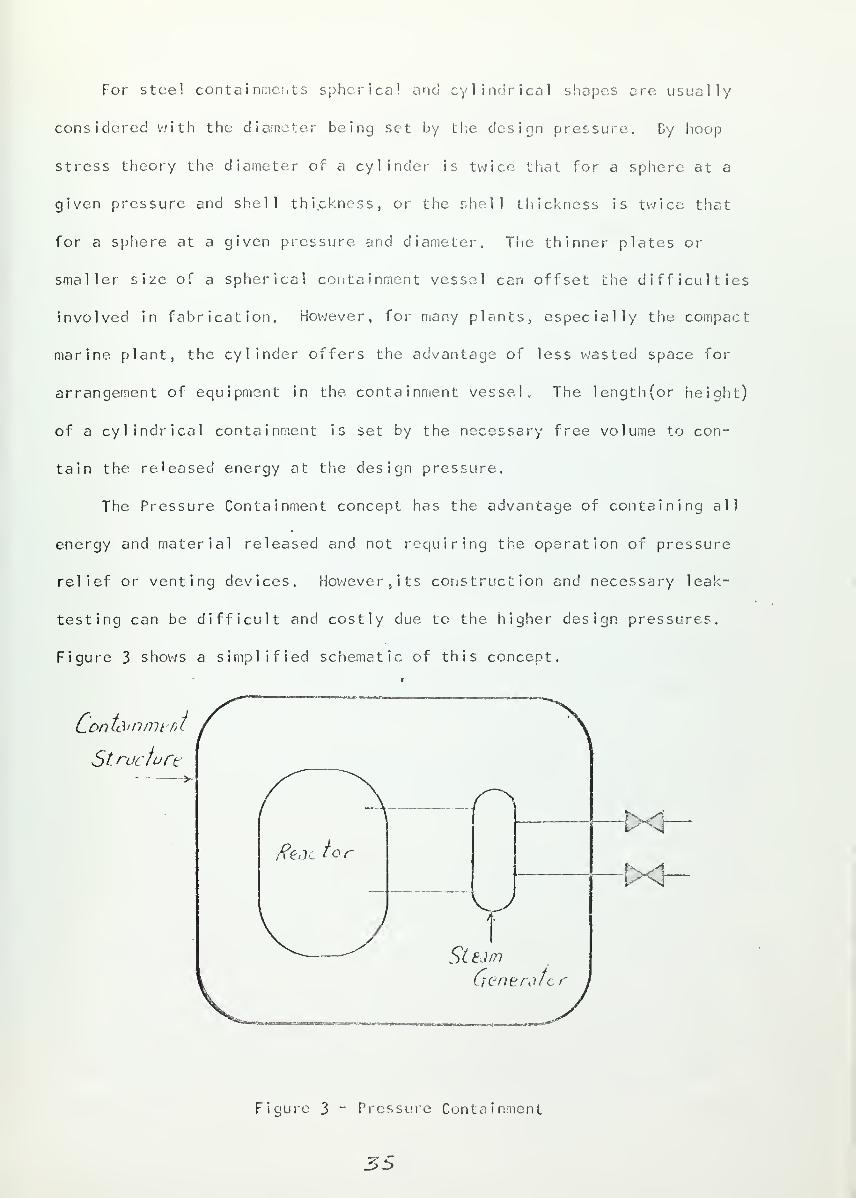
For steel containments spherical one! cylindrical shapes ore usually
considered with the diameter being set by the design pressure. By hoop
stress theory the diameter of a cylinder is twice that for a sphere at a
given pressure and shell thickness, or the shell thickness is twice that
for a sphere at a given pressure and diameter. The thinner plates or
smaller size of a spherical containment vessel can offset the difficulties
involved in fabrication. However, for many plants, especially the compact
marine plant, the cylinder offers the advantage of less wasted space for
arrangement of equipment in the containment vessel. The length(or height)
of a cylindrical containment is set by the necessary free volume to con-
tain the released energy at the design pressure.
The Pressure Containment concept has the advantage of containing all
energy and material released and not requiring the operation of pressure
relief or venting devices, however, its construction and necessary leak-
testing can be difficult and costly due to the higher design pressures.
Figure 3 shows a simplified schematic of this concept.
Contdmmt nt
Structurt
Figure 3 ~ Pressure Containment
35


Concept 2 - Pressure Suppression
Pressure Suppression is a containment concept based on absorbing a
large port of the energy released from an accident and thereby reducing
trie required free volume (or design pressure) of the containment. This
concept is of particular significance for water cooled reactors where the
largest portion of energy release is from the thermodynamic energy of the
coolant. The containment is divided into two regions. The first is a dry
well, holding the reactor, that is designed to withstand the peak accident
pressure. This pressure is rapidly reduced by energy absorption in the
second region, the suppression chamber. Escaping steam passes from the
dry well into the suppression chamber through vent pipes where it is
completely condensed in a pool of water. Most of the fission products
stay in the dry well; those that pass into the suppression chamber are
largely retained in the pool (REF- 1 5) ? reducing the amount of radioactive
material available for leakage.
In determining the design pressures for the dry well and suppression
chamber, the sequence of events following an accident can be divided into
three periods (REF- 15):
(1) dynamic effects - the shock wave preceding the steam-water inter-
face and the impact of the steam-water jet on the dry well wa 1
1
(<lsec).
(2) venting - mass flow from dry well to the suppression chamber pool.
( ~ 18 sec) This is the period of maximum dry wel 1 pressure.
(3) venting termination - the time of max suppression chamber pressure.
In tests for the Humboldt reactor design ( R E F ~ 15) a maximum dry well
pressure peak of 35 psig (for ~ 2 sec) was measured. The suppression chamber
pressure is due to the compression of the air (and some gaseous fission
products) transported from the dry well. For design purposes this transfer
36


is usually assumed to be 100%, but these same tests showed only a hS%
transfer and a maximum suppression chamber pressure of S psig. For the
Humboldt design pressures of ~)2 psig and 10 psig were used for the dry well
and suppression chamber, respectively, owing to limited experimental
information and operational experience.
Two means of pressure relief for the suppression chamber are usually
provided. First, air can be vented back to the dry well through pipes
with check valves to prevent reverse flow. Second, suppression chamber
vents can be opened to allow gaseous products to be passed through filters
to the atmosphere.
This concept, as used previously, has the disadvantage of placing part
of the primary system outside of the containment (in order to reduce con-
tainment volume) and relying on primary coolant pipe isolation to guarantee
containment integrity (Humboldt Bay, SM-1A, Bodega Bay). Having major
primary coolant lines penetrate the containment would present its use
for marine plants for reasons discussed previously. However, the Babcock-
Wilcox Advanced Marine Demonstration Reactor (the type used on OTTO HAHN)
uses a Pressure Suppression concept with an integrated reactor-steam genera-
tor. (AMDR dry well pressure - 100 psig, suppression chamber pressure - 50
psig.) Attention must be given to the effect of ship motion on the free
surface of the water in the suppression chamber. ADMR uses radial baffles
to ensure coverage of vent pipes by water during ship rolling and pitching.
Pressure Suppression has the advantage of smaller size (or lower design
pressure) than Pressure Containment, decreasing the fabrication difficulties
and cost. (REF-13) This decrease in size would be well suited to ship
designs where space is very limited (e.g., coastal freighters, weather
ships, light ships, etc.). Figure h gives a schematic illustration of
this concept.
5/


to Atm^ptareContainment Structure
filter
Suppression—>
Cbomber Stuam
FvtJ BackVent
Figure h - Pressure Suppression
Concept 3 " Subatmospher ic Containment (REF-18)
The concepts discussed up to this point operate at or above atmos-
pheric pressure. Any overpressure, in the containment following an acci-
dent would serve as a driving potential for fission product leakage over a
long period of time. If the containment system is designed to operate
before and after an accident at an underpressure, substantial leakage would
be prevented. Subatmospher ic Containment utilizes a heat removal system
(e.g., spray, cooler) to achieve and maintain a partical vacuum after an
accident. This reduces the energy content within the containment, allowing
either smaller volume or lower des ign pressure. This effect is similar to
%e


that for the Pressure Suppression concept except that the time required
for the pressure to fail off from the pea!; to within i psi of atmospheric
pressure is longer for Subatrnospher ic Containment. Tests on the Humboldt
Bay containment showed that for large ruptures (e.g., double-ended pipe
rupture) of a primary coolant line, the time for the dry well pressure
to fall off to atmospheric was about 30 seconds (REF-15). The time re-
quired for Subatrnospher ic Containment is about 1500 seconds, a factor of
difference of 50. However, Subatrnospher ic Containment has a definite
advantage in that its pressure falls off to an underpressure of about
-4 psig. Figure 5 shows representative pressure transient curves for
Pressure Containment and Subatrnospher ic Containment designs (equal design
pressure assumed). Prom this it can be seen that during the period of
pressure fall off the over pressure is less for the subatrnospher ic design,
giving a lower leakage driving potential. In this period up to about
1500 seconds most of the fission product release from the core usually
occurs.
3?


50
m 50
S to
<3
Desipn Pressure.
\< A t mosphcnc
StsLaLrrtosoAer/c ->\
-fO.10
l
10' ioz
/o l /o* <o*
Time from Start of Incident [^ ecJ
Figure 5 - Pressure Transient Comparison
This concept assumes a primary coolant accident and the operability
of a heat removal system. Its use on ship nuclear plants could reduce the
need for filtration of the air ventilated from the area surrounding the
containment, resulting in a space and cost savings. However, filtration
would still be required for reactor service and auxiliary areas such as
liquid waste storage, purification system space, spent fuel storage, and
gaseous waste system. An adequate means must be provided to prevent in~
leakage or to remove air that has leaked in in order to maintain the con-
tainment underpressure. As in Pressure Suppression and Pressure Relief
(Concept k) , this concept allows for a reduction in the required contain-
ment volume (or design pressure).
4o


Concept k - Pressure Relief
The Pressure Relief concept reduces the amount of energy and material
that must be contained by venting a portion of this directly, or through
fillers, to the atmosphere. The initial pressure surge due to a rupture of
the primary system (assumed accident, situation) is vented before fuel
failure causes fission product release. This vent could be a diaphram that
would burst, allowing coolant steam to escape. At a given point in time
the duct is sealed off so that the remaining energy and fission products
are contained. Such duct closure must be 100% reliable for successful
containment system operation. The vent duct(s) is large enough t o allow
a rapid transport of the mass with low pressure drop. The NPD-2 reactor
in Canada (82.5 NWt, pressure tube reactor) has one 9 by 12 foot duct 130
feet long; maximum pressure drop through this duct is k ps i (REF-13). The
reduction of the pressure peak allocs smaller, lower pressure ( -~ 5 psig)
containment structures. A spray system is installed in the containment to
prevent the long term pressure build up from fission product decay energy
or chemical reactions.
This concept is based on two principal assumptions:
(1) The fission product release would not occur immediately upon
rupture of the primary system, but would be delayed for some
reasonable amount of time, perhaps 10 minutes (RF.F-16).
(2) The radioactivity in the coolant (induced, fission products)
would be a negligible hazard (REF-13).
The first assumption is highly dependent upon the prediction of fission pro-
duct release from the particular core design being considered and the dif-
fusion of these products from the core into the surrounding containment
volume. It could be questioned on the ground that rapid depressur izat ion
of the primary coolant system could cause bursting of the fuel cladding due
to internal gas pressure, although every attempt is made to prevent this
4/


(REF- 17). The second assumption would be highly questionable for liquid
coolants if continuous coolant purification were not used (OTTO HAliN) .
Some fission products (e.g., Xe, Kr, I...) and radioactive corrosion pro-
ducts (e.g., Na, K..) have half-lives long enough to be of concern as a
radiation hazard to port and coastal populations if they were released in
the initial venting. If such activity were present, relief duct filtration
would be a necessity; this would increase the size of ducting in order to
keep the pressure drop low. A schematic of this concept Is given in figure 7
ReW
* In terno / Sprc )y
ST =*i
Ste^>y\ Generote/
ReactAor
Containment
Structure
V_7e-&sr Relief Closure
- Diaphrdm
tx-
Figure 7 " Pressure Relief
fZ


The possibility of passing the relief duct straight up through the
superstructure from the containment was studied in reference 16. The dosages
received as a function of distance from the ship were calculated to be below
the 25 rem whole body and 300 rem thyroid limits. The fission product con-
tent in the coolant was assumed to be the same for N.S. SAVANNAH (corresponding
to 363 kg exposed fuel). The vent duct cross sectional area was ^00
square feet. Low dosages require the coolant to be vented from the high
stack (65.5 ft. for SAVANNAH).
Multiple containment can be used to decrease the leakage rate.
Multiple barrier designs utilize two low leakage structures, the first
usually is of the high pressure containment type (Concept 1), the second
is a surrounding building, containment vessel, or ship structure in which
radioactive leakage from the pressure vessel is held and withdrawn through
filters to the atmosphere. The intermediate space is held at a particial
vacuum to decrease (or eliminate) leakage to the environment. This concept
was used on N.S. SAVANNAH and OTTO HAHN, It is particularly adaptable to
marine plants because of the ship structure. The space in which the con-
tainment is located (sometimes called the reactor compartment) can be built
with sufficient leak tightness so that a vacuum can be held. Tests on
SAVANNAH showed that with both exhaust fans operating (^000 cfm) a 3" in
H9
vacuum was maintained. It has been theoretically estimated that use of
multiple containment can reduce atmospheric contamination by a factor of
10-100 depending on the leak tight integrity of the second containment (REF-- 1 9) .
Venting can be designed to include a direct withdrawal of matter from
theprincipal containment. For ships the discharge of filtered effluent can
be up the stack or into the sea. Use of multiple containment for nuclear
merchant ships has the advantage of increased protection to the general
public with very little increase in cost. Figure 8 gives an illustration
of multiple containment for ships.
45


* to Atmosphere
w-v/V-
£> S('1
Filter
L
Reactor
Contain //lent
u. /3/oyVCf/"mn T
Lolli^'on
S^mer
Seconoor y
Lortti3/fi/iiept
Figure 8 - Sectional Schematic of Ship Multiple Containment
44


2 . Containment Ca pacity -I nterna] Accid ents
In the event of an internal accident energy and material would be
released into the free volume of the containment system. This would
cause a change in the temperature and pressure in the containment.
Temperature changes effect the material properties (e.g., fracture tough-
ness), thermal stress level, and heat transfer pioperties of the contain-
ment. Pressure changes effect the structural stress and leakage rate.
Part 1 of this section noted the need to design the conta inment to
withstand this increase in energy. This part will study the sources of
this energy and the factors determining the relative importance of each
source as a contribution to the total energy (and its rate of build up)
to be withstood by the containment system.
The energy released will come from three sources; nuclear energy,
stored energy, and chemical energy. Their relative, importance will depend
on several factors which will be discussed later. At this point it is
important to study each of these sources in greater detail.
Nuclear energy
The energy from nuclear fission appears in several different forms, as
outlined in table k (REF-20) . The heat generated from fission is about 1
megawatt-day per gram of fissioned material (U-233> 11-235, U-238, P-239)
.
The energy from the first group listed in table h is localized near the
place where fission occurs; the second is spread over a larger region.
4S


Source
Local ized:
Kinetic energy offission fragments
Beta particles fromfission products
TABLE h
Nucl ear F iss i_on Energy
Ener gy (MEV/f i ssio n )
_l nstantaneous Delayed
165 + 5
Total
7 + 1
Spread out:
Instantaneous gammaradiat ion
Gamma radiation fromfission products
Kinetic energy ofneutrons
5 + 1
5 + 0.5
-*-1
Total from fission(d i rect)
Neutrinos (no heat) 10
Capture gamma radiation(including fission productdecay) 5 + 2 1 + I
191 + 6
Total for heat generation 200
However, nuclear energy, as such, has little meaning when discussing the
causes and effects of an accident. its conversion into mechanical energy
is the important point. This conversion usually involves the vaporization
of some material, either core material or coolant, increasing the pressure
in the core (REF-1). The increase in pressure could damage or destroy the
reactor vessel, reactor core, or primary coolant system. Excessive nuclear
46


energy could also result in core meltdown.
Excessive nuclear energy in the reactor can be brought about in a
number of ways, such as reactivity excursion, loss of reactor control,
over-power operation, or loss of the heat transfer medium. Of these a
reactivity excursion is the most serious (REF-1). Reactivity excursions
involve a large reactor power increase due to the addition of an excessive
amount of reactivity to the nuclear chain reaction. Reactivity is defined
(for the purposes of this discussion) as the fraction of neutrons born
which are in excess of those required to hold the neutron population
constant. V/hen the reactor is critical the reactivity is zero. Reactivity
excursions make reactor control difficult or impossible and result in
very large and sudden energy release (REF-7) • Proper reactor core design
can make excursions practically impossible by utilizing negative reactivity
coefficients (void, temperature, Doppler) , burnable poison, and other means
of carefully controlling the reactivity inventory.
In addition to the nuclear energy within the core the designer must
consider the decay heat of fission products after they have escaped into the
containment volume. The percentages of reactor fission' product inventory
are assumed to escape from the core after an accident, as was mentioned in
the discussion of radioactivity of part 1.
Stored Energy :
Stored energy includes the latent and sensible thermodynamic energy of
reactor materials (e.g., fuel, cladding...), structural materials (e.g.,
piping, pumps, reactor pressure vessel, and the coolant. Graphite moderated
reactors also have a component of stored energy called Wigner energy." Of
*Wigner energy - energy stored in the graphite crystalline structure due to
neutron irradiation. This increases with neutron energy, radiation dose and
intensity, and decreases with irradiation temperature (REF-1, 15).
4l77


these, the thermodynamic energy of the coolant is the greatest, especially
for water cooled reactors.
For dual cycle reactors using heat transfer from the primary coolant
to generate steam in heat exchangers, there is the problem of determining
how much of the stored energy in the secondary system (if any) should be
included in the total containment energy. The answer to this problem
depends primarily upon these factors; first, the credibility of a steam
generator failure that would allow secondary fluid to enter the contain-
ment through the primary system, or the failure of a secondary pipe inside
the containment; second, the number of steam generators assumed to fail
in a given accident; and third, the location and reliability of secondary
system closure valves.
The problems involved in steam generator design and construction
(thermal expansion, corrosion rates, stress corrosion cracking high pressure)
are well understood (REF-21). Steam generator tubes for nuclear plants
are generally designed not to rupture from the normal pressure of either
fluid following the loss of the other (REF-1). however, it might be
possible for a high pressure peak caused by rapid core meltdown (BORAX- f)
to overstress the steam generator tubes; this would depend on many unknowns
and the process of transmitting such a pressure is not well understood
(REF-1). Therefore, a failure causing massive injection of secondary fluid
into the primary system is unlikely, but should be considered as a possibility.
If it is to be argued that one steam generator could fail (N.S. SAVANNAH),
then the same argument could be made for assuming all or several of the steam
generators fail, depending on the type of accident involved (e.g., displace-
ment of the reactor pressure vessel or primary system pipes). The decision
to assume only one steam generator is arbitrary and ignores the possibility
of mul t iple fa i lure.
48


It is common nuclear marine engineering practice to put at least
two quick action stop valves on main steam lines in addition to the
turbine throttling valve; one on each side of the bulkhead dividing the
boiler (reactor) room and the engine room. On ships with one main engine
where two main steam lines meet at the throttle valve (N.S. SAVANNAH),
these stop valves are up stream of the junction on each line.
Therefore, coolant stored energy should include the secondary
coolant of all steam generators up to the first isolation valve on each
steam line. This is conservative but the contribution to the total energy
is smal 1
.
Chemical energy
:
Reactor power plants use many materials that react chemically and
release chemical energy. The relative importance of the chemical energy
contribution depends upon the type of reactor used, the materials involved,
and the environmental conditions affecting chemical reaction kinetics
(surface area, temperature, and extent of reactant mixing). Only those
reactions whose energy or product release is great enough (and fast
enough) to make a significant contribution to the total energy need be
considered. The principal reactions are discussed below:
(1) Metal water - these are exoergic reactions giving off hydrogen,
which presents an explosion hazard. The reaction of cladding materia!
(zircaloy, aluminum, and stainless steel) with coolant water can occur
before and after core meltdown. For example, during the buildup of core
decay heat following a loss of coolant zirconium will begin to react with
water at a temperature of about 2000 F, adding heat to the fuel element
and significantly decreasing fuel melt time (REF-22)
.
StQ

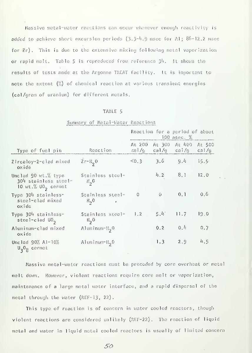
Massive metal-water reactions can occur whenever enough reactivity is
added to achieve short excursion periods (3. 3"^. 9 msec for Al ; 86-12.2 msec
for 2r) . This is due to the extensive mixing following metal vaporization
or rapid melt. Table 5 is reproduced from reference }h. It shows the
results of tests made at the Argonne TREAT facility. It is important to
note the extent (%) of chemical reaction at various transient energies
(cal/gram of uranium) for different metals.
TABLE 5
Summa ry of Metal -V/a t e r React ions
Reaction for a period of about100 msec, %
At 200 At 300 At 400 At 500
Type of fuel pin Reaction ca 1/g cal/g cal/g cal/g
Zircaloy-2-clad mixed Zr-H <0.3 3.6 S.k 15.5
oxide
Unclad 90 wt.% type Stainless steel- k .2 8.1 12.0
304 stainless steel- HO10 wt.% U0 cermet
Type 304 stainless- Stainless steel- 0.1 0.6
steel-clad mixed H o ,
oxide
Type 304 stainless- Stainless steel- 1.2 5.4' 11.7 19.0
steel-clad U02
H2
Aluminum-clad mixed Aluminum- if 0.2 0.4 0.7
oxide
Unclad 90% Al-10% Aluminum-H2
1.3 2.9 4.5
U_0^ cermet
Massive metal -water reactions must be preceded by core overheat or metal
melt down. However, violent reactions require core melt or vaporization,
maintenance of a large metal water interface, and a rapid dispersal of the
metal through the water (REF-13, 22).
This type of reaction is of concern in water cooled reactors, though
violent reactions are considered unlikely (REF--22) . The reaction of liquid
metal and water in liquid metal cooled reactors is usually of limited concern
So


in land based plants. However, for ship use this reaction increases in
importance due to possible containment sea water flooding.
(2) Oxidation - this includes graphite-air and sodium-air reactions. From
the former explosive quantities of carbon monoxide and hydrogen are re-
leased, but the reaction is negligible below about 750 F (REF~7) . The
latter is a strongly exoergic reaction (3900 BTU per pound of sodium
burned) and is a primary concern for sodium cooled reactor design, such
as the Enrico Fermi plant which based its containment design pressure
upon this energy source together with fission product decay heat (REF-35)
•
Sodium fires are usually prevented by filling the free volume of the con-
tainment with a gas such as nitrogen. The sodium-air reaction can occur
over a wide range of temperatures; and its reaction rate is virtually
independent of temperature and depends upon the rate of mixing of the
sodium and air.
(3) Organic coolant explosion (Organic-Air) - these reactions vary with
the coolant in question but usually occur below reactor operating tem-
peratures. In addition to the hazard from the coolant itself, there is
the danger of explosion of the products of radiation induced chemical
decomposition of the coolant, (hydrogen, propane, ethane, methane).
(k) Graphite-steam - this reaction is endoergic but generates hydrogen
and carbon monoxide which are explosive.
(5) Hydrogen-oxygen - hydrogen can be formed as the results of chemical
reactions or decomposition, as already noted; or from the radiolytic decom-
position of water. Hydrogen can react with oxygen in combustion or explosion.
In determining the total energy and its rate of increase the designer
must consider three points - (1) the relative importance of each source,
(2) the relative timing of energy release and absorption, and (3) the absorp-
57


tion of energy into surrounding structure and other material. This consi-
deration would involve several interacting factors, listed below:
(1) mass, temperature, and pressure of coolant
(2) type, location, and size of rupture in primary system
(3) mass, physical properties; and temperature of possible chemicalreactants
(k) probable percent completion of chemical reactions
(5) time, rate, and amount of any reactivity change, before and afteran accident (possibility of reactivity excursion)
(6) type, mass, and operating history of fuel
(7) rate of heat buildup in core
(8) physical and nuclear properties of core and structural material
(9) rate and amount of energy absorption within the containmentsystem due to heat transfer to structure, machinery, or anyother heat sinks in the containment system
(10) effects of ship motion (e.g., mixing)
(11) effects of containment flooding (sea water)
Table 6 (REF-13) outlines the assumed energ/ release, for the Yankee
reactor (5^0 MWt, PV/R) . Of particular interest here are the relative
amounts released from each source. This breakdown is typical of pressurized
water reactors.
TABLE 6
Containment Energy Yan kee Reactor
CommentsApproximate
Source Magnitude (BTU)
Nuclear 2 x 10⁷
Chemical 107
Decay heat 3 x 10⁷
Stored 108
Vaporization of 20% of core
Metal-water reaction of all Eircalioyand stainless steel in core
Integrated over one day shut down
Primary cool am:
$2.


A detailed energy analysis of the containment system design and the
assumed accident situation would result in a pressure transient curve for
the containment system. Figure S (REF-3) shows such a curve for N.S.
SAVANNAH (Pressure Containment). This analysis assumed the rapid release
of primary coolant ( ~ 20 sec) from a circumferential pipe rupture. While
a circumferential rupture would be unlikely, experimental studies have
shown this possibility on heavy piping (REF~37) • The stored thermodynamic
energy of the primary coolant made the largest and most sudden contribution
to containment energy. The fission product decay power was assumed to drop
to about 5% of reactor power (3MW) in the first second after pipe rupture
and fall off exponentially to about 1% in an hour (second peak). Fission
product release was assumed to be immediate, which is standard practice
(REF-8) . This is conservative, for zircalloy will probably burst from
internal pressure at about 2l60°F (stainless steel - 2^20°F) (REF-36)
.
An assumed zircalloy cladding - water reaction contributed about 5%
7( ~2.0 x 10 BTU) of the total containment energy.
In order to obtain a first estimate of containment design pressure
for primary r upture accidents, a simple model can be assumed. No credit
is given for heat transfer to the surroundings, and the instantaneous
release of coolant is assumed. The maximum pressure in the containment
is then easily computed from a coolant energy balance equation (zero
chance in internal energy). Figure 10 shows the results of such a simpli-
fied analysis for different coolant masses. This analysis gives a con-
servative est imate of design pressure, but is close enough (+ 5%) to serve
as a meaningful upper bound on the design pressure (REF-16).
However, a more careful analysis is necessary to determine the pressure
transient for the particular containment concept being considered. !n

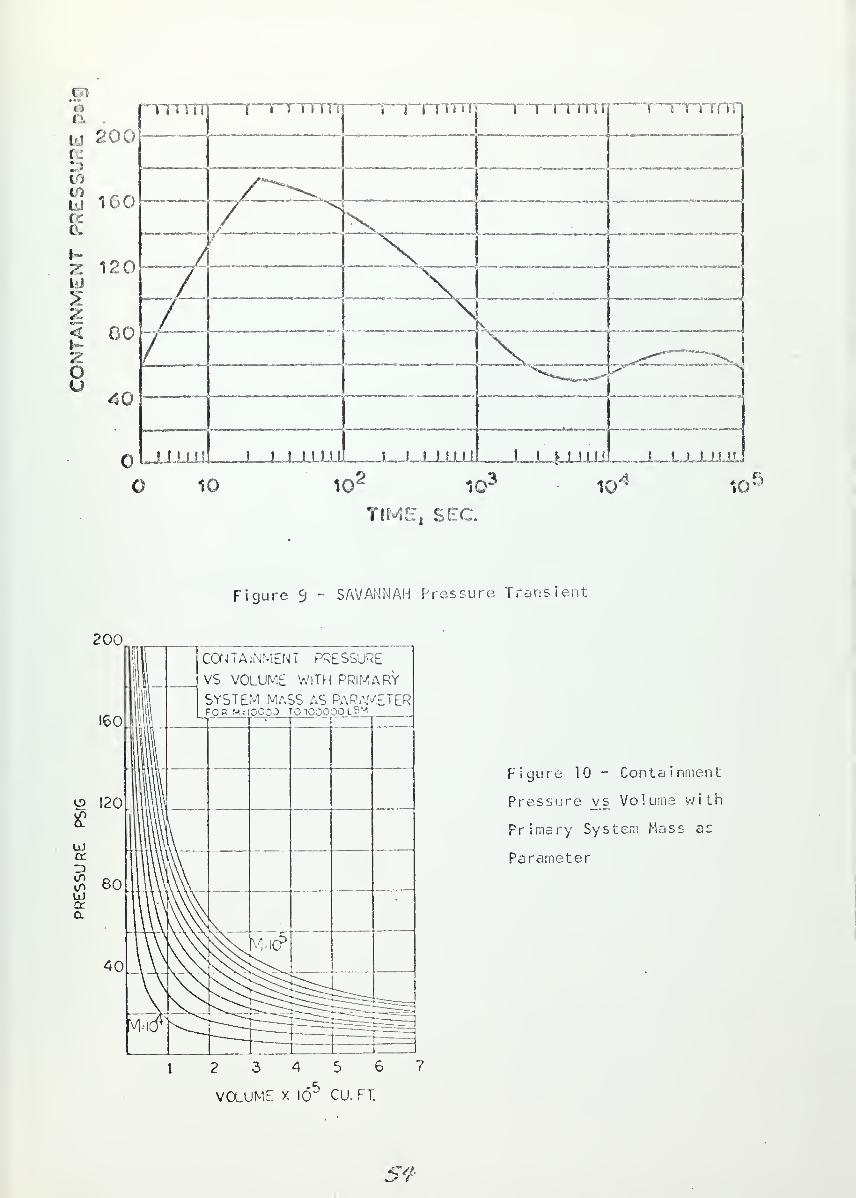
TIME, SEC.
Figure 5 - SAVANNAH Pressure Transient;
200
160
o 120
<X
$ 60UJa:a
40
CONTAINMENT PRESSURE
VS VOLUME WITH PRIMARY
SYSTEM MASS AS PARAMETERFOB M = 10000 TO 100000 L
B
y
Figure 10 - Containment
Pressure vs Volume with
Primary System Mass as
Parameter
VOLUME X 10 CU. FT.
SY


figure 9 a second pressure peak of about kO'% maximum pressure occurs due to
the decay heat. In some designs this second peak may exceed the first,
depending on the efficiency of decay heat removal, Therefore, the entire
pressure transient must be considered in containment system design.
Cr i ter ia
:
6. Containment system design pressure shall be determined from a
careful analysis of the release of nuclear, stored, and chemicalenergy fol'lcv.'ing an internal accident. Such an analysis shall
consider the relative contributions, energy absorption, and
time of release of each of these sources.
7. The containment system shall remain effective throughout the
entire pressure transient following an internal accident.
ss


3 Contai nment Acce s s and Penetrat [on
Containment design is complicated by the fact that the reactor and
primary systems within the. containment require electrical power, auxiliary
services, maintenance, and a means of removing the generated energy. This
requires the use of passages through the containment for pipes, wiring,
ventilation ducts, personnel, and equipment. The particular requirements
depend upon the type and size of the reactor and primary system. Part 3
shall study these passages and the problems they present in containment
des i gn.
Passages can be divided into two different groups; access for personnel
and equipment into the containment, and penetration for pipes> ventilation
ducts, and wiring. Both of these present three basic design problems:
(1) Structural strength problems due to stress concentrations,structural discontinuity, heat sources, and missiles releasedby an accident.
(2) Leakage around or through accesses and penetrations.
(3) Extension of the containment system boundary to include valves,vents, or doors. ,
Access :
Access passages include both the openings in the containment structure
that allow personnel and equipment to pass through the containment boundary
and the closures that seal these openings to maintain containment integrity
(REF-13). Entry into the containment may be necessary for maintenance, re-
fueling, or inspection under a variety of possible plant conditions, inclu-
ding normal operation, abnormal operation (e.g., decontamination following
an accident or coolant leakage), and shut down condition. The type of access
required will depend upon potential of hazardous radioactivity release under
these plant conditions. Access must be designed so that containment inte-
grity is always maintained when substantial amounts of radioactivity could
S6


be released to the containment .
Two types of accesses are used. Double door access, which assures
continuous containment integrity, is used when there is the possibility
of hazardous release, such as during normal operation, wnen the reactor
is shut down but the primary system is still pressurized (REF~3, 13),
or during decontamination. Single door access is used when there is
little or no possibility of hazardous release, such as during overhaul
or maintenance with the reactor shut down and the primary system de-
pressur ized.
Double door accesses are designed with interlocking doors on each
end of an air chamber. An example of such an access is shown in figure
11 (REF-13). This interlock design prevents both doors from being open
at the same time. Manual overrides are usually provided so that both
doors could be open when there is no potential of radioactivity release,
such as during overhaul. The interlock design presents the problem of
possibly entrapping someone inside the; containment by leaving the outer
door open. This can be prevented by either making the double door system
fully operable from either side or by providing an alarm to call attention
to persons outside the containment of the need to close the outer door.
Some studies have allowed for one double door access with single
doors serving for emergency use only. This is a contradiction with the
basic purpose of containment. The cause of such an emergency might very
well be an accident situation where containment integrity is of paramount
importance. Therefore, the same safety argument that dictates the use of
one double door access dictates their use on every other access intended
for use. when there is the potential of hazardous radioactivity release.
The design of double door accesses must consider the following points (in
S7


in
CD
oU<
oo
<D
-OZi
O
Q)1-.
D1
V- JZ J
P- «/>
Is<X 10
u.—
Z Q
3co
a:
OccUJ-xUJ
ozft
<o*
u' i- er >•« «* o
< -
«-j o
3-
58

addition to three basic design problems mentioned earlier):
(1) size for personnel and necessary equipment.
(2) direction of door opening - such as designing the door so that
the expected pressure differential would shut the door and seal
the gaskets.
(3) emergency air supply to the air chamber and filtration of air
in the chamber.
(4) elimination of dangerous material from the. chamber (e.g., batteries)
(5) emergency communication
(6) remote and multiple control of access doors and air supply
(7) manual overrides
Any access, whether double or single, would be subject to containment
pressure following an accident. Therefore, they should be designed to
withstand at least design pressure with no structural failure or leakage
in excess of the containment design limit For double door access this
applies when either door is open. The access is the largest opening in
the containment; therefore, the problems of stress concentrations duo to
structural discontinuity are greater than for other passages through the
containment. These are of added concern in ship design where, shock and
the structural working due to ship motions add to the stress levels at
points of discontinuity. Care should be taken to design accesses to
withstand these structural stresses.


Penetrat i ons :
As stated earlier, penetration design must consider structural
strength, leakage, and the extension of the containment system boundary.
This discussion will consider first, those penetrations for piping and
ventilation ducts; and second, electrical penetrations.
Of particular concern for ship containment penetrations are the
structural problems involved with thermal stress and structural movement.
Pipes (or ducts) with high temperature fluids provide a heat source
for any reactor plant; this problem is increased for ships due to the
more frequent load changes of propulsion plants which cause this heat
source to fluctuate. !n addition to these normal operation problems is
the increase of thermal stress resulting from cold sen water flooding,
though this is mitigated by the use of insulation. if the containment
system is to remain effective under such conditions, the penetration
design must consider these additional problems.
The leak tightness of a piping (or ducting) penetration is almost
always accomplished by welding the pipe (or duct) to the containment
structure. This makes the penetration an anchor point for the piping
as shown in figure 12 (REF-13). In cases where thermal expansion/
contraction or ship motions require that some relative movement between
the pipe (or duct) and the containment be allowed, more elaborate pene-
tration designs would be required. Figure 13 shows a metallic bellows
expansion joint of the type used on U.S. SAVANNAH main steam lines. These
joints cannot tolerate torsional strain; therefore, care must be taken to
prevent pipe rotation. Furthermore, the expansion bellows, as currently
designed, cannol withstand instantaneous high pressure build up as would
occur if a pipe ruptured in the area of the penetration. !f such a high
pressure, rupture is deemed possible the penetration design should include
60


£2a,
<6 ys& Hu s i.0
u a wCri W Ho &fc 2;z uU X* >
c:
c+J10s_
-Ma)
c<DCl.
CT)
C
D-
D_
<u
D.ECO
I
CM
Ol_
nen
6/


INSULATION
Figure 13 " Mela! lie Bellows Expansion for Piping Penetration
6£

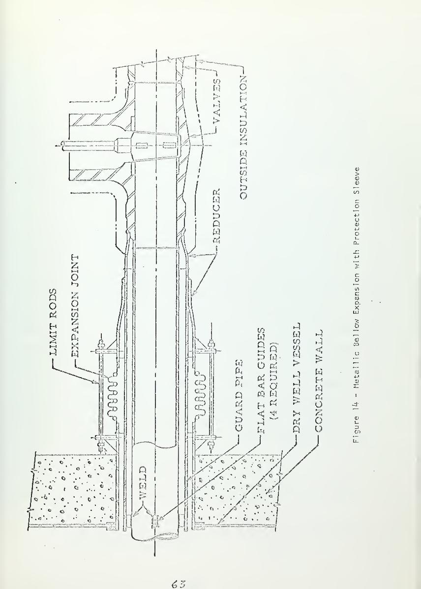
wo
ou
0)
>0)
to
Co•—
o<u<->
ol-
co
•—
c
D.XUJ
^ o
w J ,_
to JOJ <1W>
^
£•I w 03
. 1 H 4->
CD
I
-3"
J_
DCD
£5


protection against the rupture of the bellows. Figure i'f shows such a
design where a sleeve is provided between the pipe and the bellows (Hum-
boldt Bay primary steam line penetration). In all three figures mentioned
above, it should be noted that the space between the pipe and the contain-
ment wall empties into the containment volume. In summary, the penetration
design depends on; (1) temperature, and pressure of the fluid and possible
surrounding environment, (2) the expected structural movement due to ship
motion or shock loads, and (3) the size of the penetration.
In addition to the structural strength and leak tightness considera-
tions, the penetrating pipe (or duct) as an extension of the containment
boundary presents the problem of isolation. Some studies (REF-13) have
considered the possibility of eliminating isolation valves in piping that
leaves the containment and terminates at closed, leaktight equipment or
systems. This might prove satisfactory for land based plants; however,
for shipboard plants there are the additional considerations brought
about by external accidents, (discussed in part k) . in conventional ship
design these considerations necessitate that potentially hazardous piping
(e.g., steam lines, high pressure air lines, hydraulic iines, ventilation
ducts, etc.) be provided with isolation valves between system components
(U.S. Coost Guard Regulations, American Bureau of Shipping, U.S. Navy
General Specifications). This same reasoning must apply to containment
system design on nuclear ships as well. N.S. SAVANNAH and OTTO HAHN provide
isolation for all containment penetrations.
The number and type of isolation valves (or vents) and the required
closure speeds for those that are normally open depend on several factors
(REF-13):
(1) amount and type of radioactive material potentially available tc
the fluid being transmitted
<?


(2) the time dependency of the radioactivity entering the fluid andthe transport characteristics of the fluid
(3) presence of any solid barriers between the fluid and the sourcesof radioactivity (e.g., steam generator tube walls)
(k) consequences of failure of an isolation valve.
Isolation design should be evaluated in light of these factors for each of
the penetrations in a particular design. There are two general situations
for determining isolation criteria; those lines shut during normal opera-
tion, and those open (or occasionally open) during normal operation. For
the first group inspection can ascertain when the valve (or vent) is not
operating properly; however, there is the danger of accidental opening
during operation due to operator error. A locked valve (or vent) or the
use of multiple valves (or vents) may be necessary to prevent this danger.
The second group are of particular importance in containment design,
for the reliable operation of the closure under accident conditions
could be critical for successful containment systemoperat ion. Primary
coolant purification lines and main steam lines are included in this
group. While steam would not normally be radioactive, radioactivity is
potent i ally available,and the stored energy of the steam available for
injection into the containment must be limited (see part 2). The two
primary characteristics of the valves (or vents) on lines normally open
are automatic closure and multiplicity. To explore these two characteris-
tics, it is necessary to consider three principles of safety and control
systems; diversity, redundancy, and coincidence (REF-1).
The application of these principles to isolation design is intended
to adequately determine the presence of a hazardous condition, increase
the reliability of isolation closure in the event of a hazardous condition,
and reduce the frequency of unnecessary closures due to false control infor-
mation. The conditions necessary for closure of a valve (or vent) may
65


involve several factors and their time relation to one another (i.e.,
activity level, containment pressure, temperature and/or humidity).
The installation of automatic control on at least one of several mul-
tiple valves (or vents) has the advantage of fast closure time and the
ability to apply complex control logic rapidly and with little chance of
error. The use of multiple valves (or vents) in series is an application
of redundancy and allows manual control in case of automatic failure or
the need to override the automatic control system. One important point
concerning the application of the principle of redundancy to valves (and
vents) and their control system should be mentioned here. The increased
reliability of a system gained by redundancy is dependent upon the
independence of the redundant elements. If a system is designed with
several elements relying on the successful operation of a single common
element, much of the benefit of redundancy is lost. Therefore, multiple
valves (and vents) should not all rely on the same power source, control
system, or any other similar element for operation.
In locating closure devices in relation to the containment some of
the factors for consideration ere:
(a) Minimization of pipe area serving as containment boundary(b) Local thermal conditions(c) Local structural design in the penetration area
(d) Integration into automatic control system(e) Access for manual operation(f) Access for maintenance
On lines with two or more valves (or vents) at least one valve (or vent)
is usually placed within the containment, reducing the extension of trie con-
tainment boundary. The closure device (including the mechanical and electri'
cal components) together with the actual penetration serve as part of the
containment system and should, therefore be designed to withstand at least
the containment design pressure with no structural failure or leakage in
66>


excess of the maximum allowable containment leakage.
The second type of penetration for discussion is that made by electri-
cal wiring. There are usually a great number (l8 on N.S. SAVANNAH) of
these in a containment system. The most important design problem for
electrical penetrations is the prevention of leakage. Leakage can occur
in one of two ways ; through the cable, its insulation, or jacketing
material, or through the filler material placed around the cable.
References 1 and 13 discuss some of the many means for preventing Luis
leakage. All of these means have two points in common:
(1) use of cables with non-porous insulation that is tightly boundwith the conductor.
(2) provision of a penetration tube incorporating either a fillermaterial around the cable, fusion of the cable with a steelorifice, or gaskets.
Figure 15 shows the type of electrical penetration used on N.S. SAVANNAH.
It uses a nonseparable hermetic seal in which the metal conductor is
fused to the steel with glass. On each side of the fusion is a potting
compound. Each of these was tested and found to leak less than 9-4^ x 10
of the containment free volume per day at 100 psi differential pressure.
(REF-13)
Of particular concern in electrical penetration design is the effect
2on the sealing material of the i R heat generated from high voltage lines.
Excessive heat can cause melting, cracking, loss of bondage, decomposition
of the seal, or fire. Provision must be made for limiting this heat by
insulation or removal.
Due to the various types and uses of passages (access and penetration)
through the containment it is not possible to provide detailed criteria.
However, certain conclusions can be drawn and general criteria established.
£7


SEE ENLARGED VIEW BELOW
LOW-PRESSURE END HIGH-PRESSURE END
FUSED GLASS
POITING COMPOUND (BOTH ENDS)
SINGLE-PIECE PIPE
AND CENTER SECTION
-STRANDEDCONDUC TOR
7ZZZZ&
\ ^- SILVER SOLDER
^-SOLID CONDUCTOR
Figure 15 - N. S. SAVANNAH Electrical Penetrations
6B


Cr i ter ia
8. Double door access shall be used for any access into or out ofthe containment under plant conditions where there is the potentialof hazardous radioactivity release.
9. A means of isolation shall be provided for all piping and ductingpenetrations of the containment.
10. Those penetration closures that are shut during normal operationmust have provision made to prevent accidental opening.
11. Any penetration transmitting a fluid to which radioactivity is
potentially available in hazardous quantities shall have twoequally effective closures one of which will be automaticallyoperated. In no case will all closures on a particular pene-
tration rely on the same power source, control system, or any
other common element for successful operation.
12. Electrical penetration design shall provide adequate means of
heat dissipation for the penetration seal.
13. All containment passages, including accesses and penetrationsfor piping, ducting, and wiring, and their respective closuredevices shall be -designed to withstand at least the containmentdesign pressure with leakage rates less than those that wouldlead to a rate in excess of the permissible containment leakage
rate limit. Such design shall take into account the adverseeffects of heat sources, structural discontinuity, and material
released by an accident.
6?


k. Containment Protection - External Accidents
The discussion of the previous three parts has dealt with the pro-
Hems of defining and designing an adequate containment system for protection
from the consequences of internal accidents. Much of what has been said
applies to either the marine or the land based plant. However, in considering
those accidents that are brought about by the setting of the reactor' plant
the marine nuclear plant designer is faced with peculiar problems that are
not part of land based plant design. These external accidents are an
important part of the ship design problem and include:
(1
)
col 1 is ion
(2) grounding
(3) explosion(k) fire
(5) miss i les
(6) ship motion in waves
The major consequences of these accidents are divided into two
categories; (1) structural damage, and (2) an adverse change in normal
operating conditions. The first of these includes penetration of the
containment from collision or grounding, damage to equipment (e.g., pipes,
valves, containment, electrical distribution system, pumps, control
system, etc.) due to fire or missiles, bulkhead failure following a
cargo explosion, damage due to ship motions, and containment collapse
from external pressure following sinking. The adverse change in normal
operating conditions includes the loss of sea water for emergency core
and containment cooling following a grounding that leaves the ship high
and dry or clogs the sea water intakes, and the loss of power caused by
fire, flooding, or structural damage. The following discussion will treat
these consequences and study the steps that are either already required
(by regulatory or classification organizations) or should be required to
protect the nuclear plant generally and the containment system in parti-
cular.
70


Structura l Damage :
The protection of the containment from penetration due to collision
or grounding is covered in detail in the discussion of ship strength in
section B. There the protection is defined in terms of adequate ship
structure to absorb the energy involved and prevent damage to the con-
tainment. The primary concern in collision and grounding is the threat
of penetration; the shock levels are not high enough to cause damage,
being much lower than those predicted for ship motion in waves (REF-23)
.
In order to benefit from the protection provided by ship structure the
containment system must be located inboard of and above such structure.
Some shipboard containment proposals have used void spaces between the
containment pressure vessel and the hull as part of a multiple contain-
ment concept. The utilization of such spaces by the containment system
would be lost after a collision that opened the hull in way of the con-
tainment. Reliance on such spaces for successful containment system
operation would not be valid. An alternative means of multiple con-
tainment is the type used on SAVANNAH and OTTO HAHN where the intermediate
space was localized around the containment and is inboard of the collision
barrier. Such a design is protected from collision.
Another aspect of containment design that must be considered with
respect to hull damage is the use of double bottom voids as the suppression
chamber for a pressure suppression type containment (REF-lU). The
structural integrity of the suppression pool is essential for suppression
of the containment pressure peak and for the. controlled release of suppres-
sion chamber air to the atmosphere. Using double bottom voids for the
pressure suppression chamber also places a source of hazardous radioactivity
in a vulnerable position. Rupture of the bottom following a grounding could
lead to the uncontrolled release of radioactivity to the surrounding water
7/

or atmosphere. Since most groundings occur in harbor and channel waters
(near population centers), the danger involved might be excessive since
nearly all groundings involve some hull damage, the extent of which is
nearly impossible to predict.
In summary, the containment system must be located horizontally and
vertically so that a collision or grounding will not cause a failure of
successful containment system operation. Those portions of the ship
structure that are intended to absorb collision or grounding energy
through damage must not also be parts of the containment system.
Fire at sea is a particular danger due to the large quantities of
potentially dangerous material (e.g., lubricants, auxiliary fuels, cargo,
and some structural material) located in the relative small volume of a
ship. Fighting shipboard f i res is made difficult due to this same compact
design. Meat from shipboard fire can become very intense and cause
severe thermal stress in structural members, destruction of electrical
distribution systems, and possibly cause explosion (REF-24) . The chance
of equipment damage from fire can be reduced by removing potential hazards
wherever possible. Storage of flammable material in or around the con-
tainment should be avoided. Such fluids as lubricating oil and hydraulic
fluid should be used in self contained systems to preclude the chance of
fire spreading from the engine room to the containment system (or vice versa)
Fire resistant material should be used for insulation.
Missile hazards include high speed rotating machinery such as pumps,
generators, turbines, and motors, that could "explode" causing fragments
to fly about and damage equipment. The danger of missile penetration of
the containment can be reduced by locating such equipment away from the
containment. However, this is not always possible, for some rotating
machinery is necessary for reactor operation. Such equipment must be
7Z


designed to minimize the chance of "explosion". As mentioned earlier,
the location of turbines within the containment would increase the poten-
tial missile hazard.
The danger of cargo explosion (especially for tankers) must be
considered in any ship design, nuclear or conventional, and is, there-
fore, not a peculiarity of nuclear merchant ships. U.S. Coast Guard Rules
and Regulations for Tank Vessels require that the machinery spaces be
separated from tanks carrying flammable cargo liquids by cofferdams or
equivalent pump rooms, tanks, or air spaces. The strength of dividing
bulkheads is made high enough so that an explosion will rupture the top
or sides (above the water line) of the tank instead of the dividing bulk-
head. This provides venting area for the explosion pressure and reduces
the explosion pressure peak that must be withstood by the dividing bulk-
head. For the fluids carried by tankers (e.g., crude oil, gasoline, and
kerosene) an overpressure as high as 100 psi can result from an unvented
explosion (REF-25)
.
The forces on plant components due to ship motion in waves are greater
than the shock forces from collision or grounding; and, consequently, they
serve as the design limits for structural strength and component operability
A detailed prediction of the motion of ships in waves is not the purpose
of this study; it is covered extensively in the literature (REF-26, 2"/).
However, some of the important points are outlined here.
A floating ship has six degrees of freedom that are considered in
des ign :
Angular :
(1) pitch - about the transverse axis
(2.) roll - about the longitudinal axis
(3) yaw - about the vertical axis
75


L ineor :
(1) heave - along the vertical axis(2) sway - along the transverse axis
(3) surge - along the longitudinal axis
Vertical accelerations of pitch and heave (in addition to gravita-
tional acceleration) are usually considered together, and maximum
values are given by equation 1 (RF.F-28) :
Pitch and heave Acceleration = (0.3 H ± ) g (1)
L
where: Z - distance of component from amidshipsL = length of the ship at the design water line
Similarly, maximum transverse accelerations of sway and yaw are
considered together, equation 2:
Sway and Yaw Acceleration = (0.1 + O.k $) g (2)
L
To each of these is added (vector ily) the acceleration due to roll.
The maximum roll accelerations are computed on the basis of simple
harmonic motion which lead to slight overest imat ions (REF~2b) . The
roll acceleration has a centrifugal and a tangential component, as
given by equations 3 and k:
2 2Maximum Centrifugal Roll Accel. = (% ) 0. r (3)
W- A
2Maximum Tangential Roll Accel. = (4rc_ ) r (4)
Ttf2" A
where: Tef = period of roll (sec)
r = radial distance from axis of rotation (ft)0" = maximum roll angle (radians)
7¥


The centrifugal component is usually less than 5% of the accelera-
tion clue to gravity and is, therefore, neglected. For design pur-
poses the maximum roll angle is usually taken to be 30 , so thai the
contribution of roll to the vertical acceleration is 0.5 R-,.; and to
transverse acceleration, is 0.8S6R (R = tangential component at
30 ). The fore and aft acceleration is set at l.Og in reference 26;
calculations in reference 27 show this to be conservative (0.03g).
Maximum values of acceleration along the three axes are not
considered to occur simultaneously. instead separate calculations
are made for each. Applying these ship motion accelerations would
be simplified if the containment and other plant components acted as
single rigid masses. However, this is not the case. One of the most
difficult tasks is the choice of a model to represent system com-
ponents and their foundat ion(s) . Account must be taken of the inertia
and spring effects in any complex system with distributed mass sub-
jected to acceleration. In analyzing naval reactors models with over
20 lumped masses have been assumed (REF-2S) . The problems in ship
motion stress analysis are two-fold. First, each component (e.g..,
reactor pressure vessel, pumps, steam generators, containment system,
support foundations) must each be designed to withstand the loadings
from ship motion acceleration. Second, the differential motion be-
tween components must be considered. Plant components are inter-
connected by structural support and piping. Differential motion can
cause stress levels as much as three times those caused by ship motion
alone. For the reactor and the steam generators this problem is of
particular concern since they are connected by primary system piping
where fracture would be extremely dangerous. By placing all components
within the containment on a single structural foundation the degree of
75


differential movement can be reduced (RTF- 29)
„
In addition to the forces involved with ship motion there is
also the consideration of angles of roll and pitch and the maximum
angles of permanent list and trim. The nuclear plant must be
operable over a range of angles. The range of these angles depends
upon the particular plant component in question. References 28 and
30 specify that the nuclear plant should be capable of normal opera-
tion when subjected to the following angles:
(1) Roll - 30°
(2) Pitch - 10
(3) List - 15°
(*0 Trim -5
In the event that the ship should take on a permanent list or trim in
excess of 15 or 5 respectively, the reactor should be scramed and all
containment isolation closures should be shut. This should be by
automatic operation of special safety systems, with the possibility of
manual overrides.
There is a particular problem in nuclear merchant ship contain-
ment design concerned with the protection of the containment system
in the event of sinking. Due to the difficulties and hazards to per-
sonnel in salvaging the reactor plant with the containment system
flooded, it is highly desirable for the containment to remain dry if
the nuclear ship were to sink. Furthermore, damage to the reactor
and primary systems from high pressure must be prevented or minimized
following a sinking in a harbor, where there is danger to the sur-
rounding population. Such a sinking could result from collision vr
grounding, though the chance of this is small as discussed later.
For this discussion on a typical harbor depth of 150 feet has been
assumed, based on a study of several principal harbors oT the world
7G


(New York, Boston, New Orleans, San Francisco, Singapore, Tokyo,
Portsmouth, Antwerp, Hamburg, and Naples).
There are four alternative solutions to the problem of contain-
ment integrity following a sinking. Three of these involve the use
of flood valves that would allow the containment to flood, relieving
external differential pressure: the fourth alternative relies on the
containment structural strength alone to withstand the collapse
pressure with no containment flooding. Flooding the containment
would presumably prevent containment collapse and the resulting
reactor and primary system damage. However, as shown below the flood
valve areas necessary to provide the necessary sea water flow rate to
prevent collapse 'would be excessive. The size of valve area depends
upon the containment size, velocity of ship sinking, the depth of
valve opening, and trie collapse pressure of .the containment. Valve
areas greater than 10 square feet would probably be excessive, pre-
senting problems of stress at the containment structural discontinuities
The first of the four alternatives for study involves opening the
flood valves when the bottom cf the containment reaches the no~fleod
collapse depth. As the ship continues to sink past this depth, the
incoming sea water prevents the increase cf the differential pressure
above the collapse pressure. Appendix 1 shows that for various typical
containment designs the necessary valve areas are on the order of
250 ft. , which is excessive.
The second alternative, involves opening the flood valves when the
sinking ship is still on the surface, reducing the necessary valve area.
However, this method is rejected because it involves opening the con-
tainment system wh i 1 e the ship is still on the surface and exposed to
77

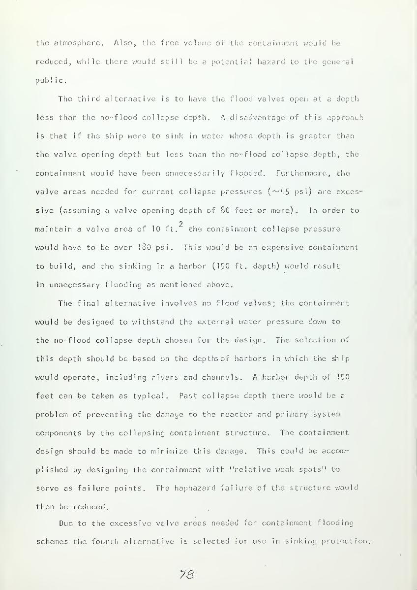
the atmosphere. Also, the free volume of the containment would be
reduced, while there would still be a potential hazard to the general
publ ic.
The third alternative is to have the flood valves open at a depth
less than the no-flood collapse depth. A disadvantage of this approach
is that if the ship were to sink in water whose depth is greater than
the valve opening depth but less than the no-flood collapse depth, the
containment would have been unnecessarily flooded. Furthermore, the
valve areas needed for current collapse pressures (~^5 psi) are exces-
sive (assuming a valve opening depth of 80 feet or more). In order to
2maintain a valve area of 10 ft. the containment collapse pressure
would have to be over 180 psi. This would be an expensive containment
to build, and the sinking in a harbor (150 ft. depth) would result
in unnecessary flooding as mentioned above.
The final alternative involves no flood valves; the containment
would be designed to withstand the external water pressure down to
the no-flood collapse depth chosen for the design. The selection of
this depth should be based on the depthsof harbors in which the ship
would operate, including rivers and channels. A harbor depth of 150
feet can be taken as typical. Past collapse depth there would be a
problem of preventing the damage to the reactor and primary system
components by the collapsing containment structure. The containment
design should be made to minimize this damage. This could be accom-
plished by designing the containment with "relative weak spots" to
serve as failure points. The haphazard failure of the structure would
then be reduced.
Due. to the excessive valve areas needed for containment flooding
schemes the fourth alternative is selected for use in sinking protection,
78


Adverse Change in Normal Operating Con d it ions
:
One of the possible consequences of grounding is the loss of the sea
water supply to heat exchangers, This could happen if the ship were
stranded high and dry or if mud, sand, or sea weed were scooped into the
sea water intakes. The iieat exchangers in a nuclear plant that arc of
particular concern here are those provided for emergency core cooling and
containment system cooling. The chance of clogging sea water intakes
can be greatly diminished by placing the intakes on the side cf the hull
instead of the bottom.. However, this does not solve the problem of
sea water loss by stranding; in fact, it is increased. Therefore, attention
here will focus on the problem of stranding and the necessary provisions
that must be made to ensure adequate emergency cooling. Two alternative
solutions are suggested. .In the first, the secondary loop of the heat
exchanger is supplied from a tank with either sea or fresh water. The
secondary coolant receives heat from the core coolant and vents steam to
the atmosphere at an above decks location, as shown in figure 16. This
approach has the advantage of not requiring a secondary coolant to air
heat exchanger. However, its use is limited by the storage capacity of
secondary water. Furthermore, the uncontrolled venting of steam to the
atmosphere would present a potential radioactivity hazard if the highly
radioactive emergency coolant were to leak into the secondary loop. The.
second alternative is to provide a secondary fresh water loop with an above
decks water to air heat exchanger. While increasing the weight and volume
requirements, imaginative design could reduce the useable deck area that
would be sacrificed to such a unit. Furthermore, emergency cooling could
be provided over a much longer period of time with such a unit. Figure 17
illustrates this second approach. Characteristic of both approaches is
the problem of circulation. Reliance on pumps to provide emergency cooling
7?


Dischak to Air.. 03fAcre
r o
,
/,'c.dc to
>
oto Sea
V
r Su/Y'7
f
•y-
Sf<j Waterbuao/v
Figure 16 - Air Venting Auxiliary Emergency Cooling
Reactorl
__EmcrgcncyCooltn
,
WW
I Y
:__. _
F/nerpc/icy
Air Coo/in p
Y
—f'Ukc up
Vn£>sc/iarge \'
to SeaSez Water$ cob fy
Figure 17 - Air Cooling Auxiliary Emergency Cooling
SO


is a contradiction of plant requirements for the type of marine accident
being considered here. A natural circulating heat removal system should
be used. Problems arise because of the hydrostatic head created by the
high point of heat rejection. This can be partially offset by using
gravity feed for the water supply tank.
It has not been the purpose, of the above discussion to advocate that
sea water not be used for emergency cooling when it is available; but,
instead, a back up system must be provided for the. case when the sea
water supply is interrupted. The basic idea behind both of the alter-
natives that were considered is the self reliance of the containment
system. Salvage crews would probably be available with sea water supply
pumps to aid the nuclear ship. Furthermore, the use of emergency cooling
may not be required during the entire period the ship is stranded, if at
all. Nevertheless, the designer must consider the pessimistic possibilities
and design a containment system that will operate successfully under ad-
verse conditions. Including systems or persons that are external to the
ship system or ship organization makes general assumptions of competence,
reliability, and availability that appear to be unwarrented for the pur-
pose of basic containment system definition and design.
The requirements for installed emergency power systems on conventional
merchant ships are outlined by various classification societies and the U. £,
Coast Guard Electrical Engineering Regulations. A summary of these re-
quirements follows:
(1) The system must be self conta ined , located away from and above
machinery spaces where it could be damaged by fire, flooding,
collision, or grounding. Diesels or gas turbines are the usual
prime mover.
(2) Capability of rapid cold start.
6/


(3) Continuit y of power supply is important. Storage batteriesfloating on the DC bus or on the DC side of an AC-DC motorgenerator set are common methods of ensuring continuity.
(*f) Operation compatible with ship motions and attitude.
(5) The emergen cy switchboard should be located near the emergencygeneration source. It should be possible to energize thisswitchboard from either the ship service or emergency systems.
(6) The emergency system should be capable of operation for 36 hours,
(7) The emergency load for conventional ships includes:
(a) lighting for passageways, lifeboat stations, emergencyequipment rooms, machinery spaces,
(b) radio and navigation equipment(c) navigation lights(d) alarm systems(e) fire fighting equipment(f) automatic water-tight door closing
(g) emergency interior communication circuits
These requirements would certainly be necessary for nuclear ships.
In addition, adequate emergency power must be provided for reactor control,
instrumentation, containment system automatic closure, and ventilation, and
to augment core and containment, cooling. SAVANNAH provided emergency power
for the following components in the reactor, primary, and containment sys-
tems :
(1) Two (of four) primary pumps at half speed.
(2) One (of two) containment cooling fan.
(3) One emergency primary circulating pump.
(^f) One (of two) emergency sea water pump.
(5) One (of two) emergency primary coolant make up pump.
(6) Two banks (of four) of pressurizer heaters.
(7) Reactor control and instrumentation.
(8) Coast Guard requirements listed above.
From this it can be estimated that approximately one half of the water and
air circulating capacity was included as part of the emergency load.
SAVANNAH had a 300 kw emergency load rating.
While the requirement for emergency cooling without external power
was discussed above, electrically powered cooling to supplement natural
circulation would be desirable for cooling of auxiliary equipment in addition
&Z.


to the core and containment. Furthermore, greater flexibility could be
attained, providing emergency cooling over a longer period of time (as
the decay heat falls off) and with greater operator control.
The continuity of emergency power - bringing and keeping it on the
line - is critical in a nuclear plant. Without provision for continuity,
approximately 20 to 30 seconds would pass before the emergency system
would be providing power. This may be unacceptable for safe reactor and
containment system operation. Scram rods are designed to shut the reactor
down and containment penetration closures are designed to shut in the event
of a control energy loss. Termination of plant operation might prove
detrimental to safe ship operation if ship service power is lost without
a coincidental release of radioactivity. Therefore," in the absence of
such an accident, continuous operation should be possible. Careful con-
sideration must be given to continuity of electrical power. in the. event
that emergency power is iost due to flooding, fire, extreme list, etc.,
the reactor must be automatically scram and all containment system isola-
tions closures must shut.,
It has been argued that power for the ship steering gear should be part
of the nuclear merchant ship's emergency load. The loss of ship directional
control could result in collision or grounding. U. S. Coast Guard Marine
Engineering Regulations specify the need for a primary steering control
station, a secondary station, and an auxiliary steering system(s). As long
as the auxiliary steering system operation does not depend on electrical
energy, there is no need for steering power to be part of the emergency
load. Sufficient protection would be provided by the auxiliary system.
While serious consideration should be made for including steering power in
the emergency load, this author does not believe that ii is necessary to
make this a definite requirement.
S3


In considering the. emergency power requirements there is the question of
whether there should be emergency propulsive power for the ship. While
this is not related directly to the operation of the containment system,
the SAVANNAH and OTTO HAHN included emergency propulsion as part of the
overall protection of the. general public and ship safety. The usual
arguments given for providing emergency propulsion for a nuclear ship arc:
(1) ability to take the ship back to port or to avoid collisionif main propulsion is lost on the open sea.
(2) ability to move the ship away from the dock and out to a "safe"anchorage".
(3) ability to avoid collision or grounding if main propulsion is
lost while manuevering in harbor or coastal waters.
However, other considerations are pertinent as discussed below:
(1) No provision for emergency power is required for- conventionally
powered merchant ships by regulation (U. S. Coast Guard Marine Engineer-
ing Regulations, American Bureau of Shipping, Lloyds Register of Shipping).
Therefore, in considering the necessity of such a requirement for nuclear
ships it must be shown that there would be a peculiar danger arising out
of a loss of main propulsion on the open seas, or that nuclear plants are
characteristically less reliable than conventional plants. As defined
in the discussion of collision protection, the open seas are considered
to be those areas greater than 100 miles from land (out of range of the
shore population assuming an uncontained release, of radioactivity). If
a loss of main propulsion in this area were somehow to result in an un-
contained radioactivity release, there would be no hazard to the public.
However, the chance of such a release being brought about by a loss of
power is very remote. There is no collision on record that was caused
by a loss of propulsion; but even if any such collision were to occur,
the collision barrier would provide adequate protection as described later.
St


Assuming no radioactivity release accident, it still might be desirable to
provide, a "take home" capacity if the nuclear plant were to be shut. down.
However, there is no reason to believe that the nuclear plant is more prone
to failure (less reliable) than the conventional plant. On the contrary,
at the present time it appears that nuclear reactors used on merchant ships
could be considered more reliable than oil-fired boilers. Operation of
the SAVANNAH showed high reactor reliability; during the demonstration
period (I96V-65) the reactor was available 99-8% of the scheduled sea-time,
during commercial operation ( 1 965-66) the availability was 100% (REF-16).
Therefore, no special emergency propulsion requirement is necessary for
merchant ships with regard to their operation on the open seas.
(2) Relying on the removal of the ship in the event of an accident at
dockside is a highly questionable concept. The time involved, the avail-
ability of personnel to man the plant after a radioactivity release, and
the peculiarities of each port all contribute unknowns which make such a
procedure a poor safeguard. Furthermore, to be able to move a ship from a
dock under all conditions of wind and current is sometimes difficult for
the main propulsion plant; it would be unreasonable to expect an emergency
plant with only 10 to 20% of the main system power to accomplish this
(REF~30) . if the ship were to be moved, tug assistance would almost always
be requi red,with or without emergency power. In many ports such removal
could actually prove detrimental to public safety due to the long rivers
or channels between the dock site and a "safe, anchorage" (e.g., Houston,
Antwerp, Baltimore, Quebec). Since the containment system must be designed
to provide complete protection to the public with the ship at the dock site,
and since tug assistance would be. necessary to move the ship with or with-
out emergency propulsion, no general requirement for nuclear ship emergency
propulsion can be justified based on removing the ship from the dock.
85

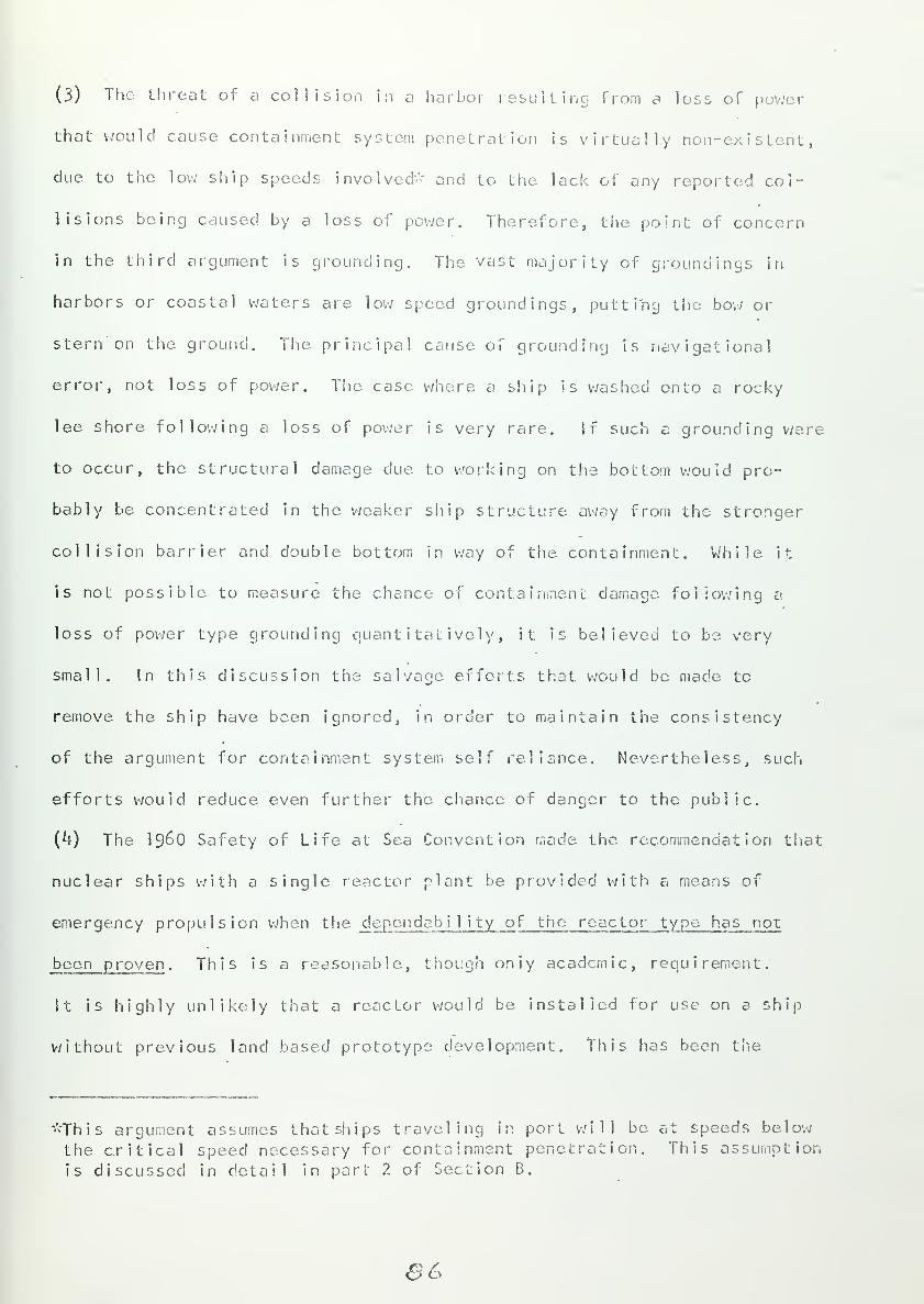
(3) The threat of a collision in a harbor resulting from a loss of power
that would cause containment system penetration is virtually non-existent,
due to the low ship speeds involved'- and to the lack of any reported col-
lisions being caused by a loss of power. Therefore, the point of concern
in the third argument is grounding. The vast majority of groundings in
harbors or coastal waters are low speed groundings, putting the bow or
stern on the ground. The principal cause, of grounding is navigational
error, not loss of power. The case where a ship is washed onto a rocky
lee shore following a loss of power is very rare. If such a grounding v/ere
to occur, the structural damage due to working on. the bottom would pro-
bably be concentrated in the weaker ship structure away from the stronger
collision barrier and double bottom in way of the containment. While it
is not possible to measure the chance of containment damage following a
loss of power type grounding quantitatively, it is believed to be very
small. In this discussion the salvage efforts that, would be made to
remove the ship have been ignored, in order to maintain the consistency
of the argument for containment system self reliance. Nevertheless, such
efforts would reduce even further the chance of danger to the public.
(A-) The i960 Safety of Life at Sea Convention made the recommendation that
nuclear ships with a single reactor plant be provided with a means of
emergency propulsion when the dependability of the reactor type has not
been proven. This is a reasonable, though only academic, requirement.
It is highly unlikely that a reactor would be installed for use on a ship
without previous land based prototype development. This has been the
"This argument assumes that ships traveling in port will be at speeds below
the critical speed necessary for containment penetration. This assumption
is discussed in detail in part 2 of Section B.
S6


practice for naval reactors. With the added problems of economic feasi-
bility for merchant designs, prototype development will be part of the
application of nuclear power to the merchant marine.
In conclusion, there are no grounds for a general requirement for
emergency propulsion for nuclear ships.
The following criteria are listed for protection against external
accidents:
Criteria:
\h. The containment system integrity must remain effective for anyship attitude. For angles of permanent list or trim in excessof 15° and 5° respectively, containment isolation closuresmust be designed to shut automatically, with provision madefor manual overrides.
15. The reactor and primary system steam generators must be mountedon a single integrated structural foundation to minimize indi-
vidual movement of components.
16. Those portions of ship structure intended to absorb collisionor grounding energy through damage must not also be necessaryfor successful containment system operation.
17. The containment structure must be designed to withstand 66.7psi external differential pressure before collapsing. Whenrupture occurs, damage to the reacr.or and primary system shouldbe minimized.
18. No flammable or explosive material shall be stored in the con-
tainment. All paint, lagging, insulation, or hydraulic fluidused in the containment system shall be fire resistant. Lubri-
cating oil and hydraulic systems used in the containment shall
be self contained.
19. An auxiliary emergency cooling system must be provided that is
not dependent upon sea water.
20. The emergency electrical load for nuclear ships is the same as
for conventional ships except additional provision is necessary
for reactor control, instrumentation, containment system auto-
matic closure and ventilation, and core and containment cooling.
87


Section B - SHIP STRUCTURE
I n trod net ion
This section will deal with the problems of ship structural design
that are peculiar to nuclear ships. The most outstanding feature of.
a
nuclear vessel is its vulnerability to certain external accidents as dis-
cussed in part k of section A. The containment system, itself, must be
designed with this vulnerability in mind. !n addition the ship structure
must provide protection against collision and grounding. Conventional
ship structure is inadequate for nuclear ships in this regard. Besides
the threat of external damage, the ship structure must be strong enough
to adequately support the engineering plant.
The discussion of section B is divided into three parts. The first
is concerned with the ship girder stress levels and longitudinal strength.
A study of the weight distribution cf a nuclear plant will be made.
The second part will develop the criteria necessary for structural protec-
tion from collision. This will be approached on the basis of a semi-
empirical probability analysis. The third part will discuss the structura'
problems related to grounding.
ee


a
1 • Long itud inal Stren gth
:
The determination of longitudinal strength is done on a relative
basis. Nominal stress levels are computed for the ship under consideration
nd compared with similarly computed nominal stress levels for past ships.
The detailed development of longitudinal ship strength is covered extensive-
ly in the literature (REF-26) ; an outline of the method Will be discussed
here. The effect of nuclear plants as compared with conventional oil-
fired plants ori ship structural stress levels is not clearcut or simple;
however, some of the trends will be considered. Finally, the components of
nuclear plant weight and the effects of plant operating parameters on these
weights will be discussed.
The basis for longitudinal strength analysis is the treatment of the
ship as a horizontal girder subjected to the vertical loads of weight: and
bouyancy. If the weight and bouyancy had identical distribution over the
ship's length the net vertical force at any point would be zero, and no
girder stress would result. However, this is not the case. The weight
distribution, in terms of tons per foot of length, will vary for different
ships. The location of cargo, machinery, fuel, stores, hull structure,
outfit, crew, passengers and any other wieght items along the length of
the ship will determine the distribution. Likewise, the bouyancy distri-
bution will vary as a function of the hull form and the wave shape that
is assumed.
The selection of a wave shape is dene to approximate storm conditions.
Data on actual ocean v/ave shapes is incomplete and the shapes involved are
not simple. For design purposes a "standard wave" is chosen having a
length equal to the ships length (L) . Different "standard wave" heights
are used. These include the 1/20, 1.1 y L, and 0.6 (L '
) wave heights.
When comparing nominal stress levels for generally similar ships, it is
B?


imperative that all ships in the comparison be based on the same "standard
wave' '
.
Three bouyancy distributions are studied; (a) still water, (b) with
wave crest at each end of the ship, and (c) with wave crest amidships.
Typical weight distribution and bouyancy distribution curves are shewn
in figure 18. The algebraic, sum of the weight arid bouyancy curves gives
the load curve. The integration of this curve along the ship : s length
gives the shear curve, showing the variation of vertical shear forces.
The integration of the shear curve gives the bending moment curve, showing
the variation of bending moment along the length of the ship. Ships with
negative bending moment are said to be in the sagging condition (bottom fibers
in tension). Ships with positive bending moment are in the hogging condi-
tion (top fibers in tension). The sagging condition reaches its maximum
when the wave crests are at each end of the ship; the hogging condition,
when the crest is amidships. Both the maximum sagging and maximum hogging
bending moments are calculated with their respective wave crest locations,
assuming the most adverse ship load condition, for each case. The greater
of these maxima is then used to set the nominal stress level, using equation 5
" =*f (5)
where o" = unit stress (tons per square inch) at the. extreme top or
bottom fibers of the hull girder
c = distance from the neutral axis of the cross section to theextreme member
M = bending moment at the cross section
I = moment of inertia of the section about the neutral axis
neutral axis = a line parallel to the base sine passing through the centerof gravity of the section.
?o


Co
3
u+JV)
>-o
>.
oCCS
i
.Ccn
oD.
I
oo
?/


For cargo ships and tankers with machinery spaces amidships the hogging
condition is usually critical (gives highest stress). This is dvc. to the
lower density of the machinery weight in relation to that of cargo. As the
machinery space length increases (with constant machinery weight), the
hogging stress increases. Likewise, as the machinery weight increases
(with constant length), the sagging stress increases, though not necessarily
above the hogging stress. With machinery spaces aft the sagging condition
is usually critical. For passenger ships with most loads located nearer
amidships the sagging condition tends to be critical, 'though this is offset
somewhat by the finer hull form that moves bouyancy toward tfie middle body.
It is common practice to assume the maximum bending moment to extend
over the midship portion of the ship (~0.k L) , and classification
societies require the maintenance of the midship scantlings over the entire
midship portion (P.EF-26) . The lowest value of sectional modulus (l/C)
in this region (usually in way of a hatch or deck opening) is then compared
with the minimum permissible value specified by regulat ion(e. g. , U. S. Coast
Guard Loan Line Regulations). However, this practice of maintaining mid-
ships scantlings would be unnecessarily conservative for a nuclear ship
with machinery spaces amidships, because the; midship structure, is a colli-
sion barrier of unusually heavy construction. Instead, the hull scant-
lings at either end of the collision barrier should be reduced to those
necessary to maintain sufficient sectional moduli, assuming the maximum
bending moment to extend over the midship portion. Such a longitudinal
reduction should be designed so as to maintain the continuity of longitudinal
strength and not introduce local stress risers.
Having outlined the method for obtaining nominal stress level and the
necessary sectional modulus, it is now important to compare the machinery
weights for nuclear and conventional plants. This is done in terms of the
?z


pounds (o\~ tons) of machinery per shaft horsepower. Tor the nuclear plant
machinery includes the reactor, reactor control and auxiliaries, primary
coolant system, steam generators, shielding containment, turbines, con-
densor, pumps, control, and auxiliaries. For conventional plants machinery
includes boilers, fuel feed system turbines, condensers, pumps, control and
auxiliaries. The great advantage oF nuclear propulsion is the virtually
unlimited cruising range at full speed. However, if this advantage is to
be realized the nuclear plant must be more reliable than its conventional
counterpart. The need for reliability is increased by the fact that a large
portion of the plant is inaccessible for routine preventative or corrective
maintenance. Increased plant reliability has usually brought about an
increase over the conventional plant in size and weight of certain com-
ponents (pumps, heat exchangers, piping, etc.) (REF-39) • in addition,
the steam conditions in marine nuclear plants to date have not been as
good as for high pressure conventional plants; however, improvements are
being made in this area (REF-11). Poorer steam conditions result in lower
thermal efficiency and increased weight, as discussed later.
The nuclear plant specific weight tends to be higher than the conventional
oil-fired plant. The variation of specific weight with shaft horsepower
is shown in figure 19 for conventional plants (REF-41). The point for the
SAVANNAH, 3^2 lbs./SHP is plotted for comparison. This point is believed
to be representative of PV/R plants though data is incomplete. The specific
weight for nuclear plants of any particular type will tend to decrease with
technological improvement and with increased power ratings (REF-39, ^0) .
A gas cooled, 50,000 SUP plant was proposed at one time for a super tanker
design with a specific weight of 500 lbs./SHP (REF-^tO) . A pressure tube
reactor proposal for a 20,000 SliP plant estimated a very optimistic specific
weight of 39 lb./SHP using turbo-electric drive and a direct cycle plant
93


cO 500
<D 400-
qP 2 oo
/oo
\
v«
J ______!_ I I 1 L_._L_L
Sa I/Aa/a/A//
J L L __j
10 50
S//PJOOO
Figure 19 - Specific Machinery V/eight versus Shafthorsepower for Oil
fired Plants
?tSL


with supercritical steam conditions (REF-12). These points ere not included
in figure 19 in that they represent conceptual not operational designs.
An important consideration has not been included - fuel weight for the
conventional plant. The quantity of fuel necessary is dependent upon the
specific fuel consumption rate (lbs. fuel/SHP-hr) and the time between
refuel ings. For the purpose of illustration a conventionally powered cargo
ship (^0.5 lb./SHP-hr) is assumed with power and speed equal to that
for the SAVANNAH (22,000 SUP, 20 knots). For a journey of 5,000 miles
(e.g., New York to the Mediterranean Sea) the specific machinery plus fuel
weight is 266.0 lb./SHP for the conventional ship, i.e., less than the
SAVANNAH. However, for a journey of 15,000 miles (e.g., San Francisco
to Sinapore) the specific weight is 625.0 lb./SHP, greater than the
SAVANNAH. Therefore, the weight advantage of a nuclear ship depends
upon the range being considered.
The weight of a nuclear plant, is made up of several components;
shielding, containment, reactor and primary systems, steam generators,
turbines, condensors, and auxiliaries. Of these, the shielding weight
makes the greatest contribution, about 20-50% of the plant weight, depending
on the plant type. For PWR plants the shielding weight is about 25% of
plant weight; for direct cycle plants this figure is about hS% (REF-12) due
to the additional shielding around propulsion components. There are five
factors that effect the shield weight (REF-39, **0) .
(1) Required radiation level outside shielding - Shielding decreases the
radiation level exponentially. At the reactor core the gamma intensity is
on the order of 10 times the allowable level; the neutron intensity is 10
times the allowable level for PV/R plants (3 rem per quarter or man's age
m inus eighteen times 1.25 rem per quarter, whichever is least (REF-58)).

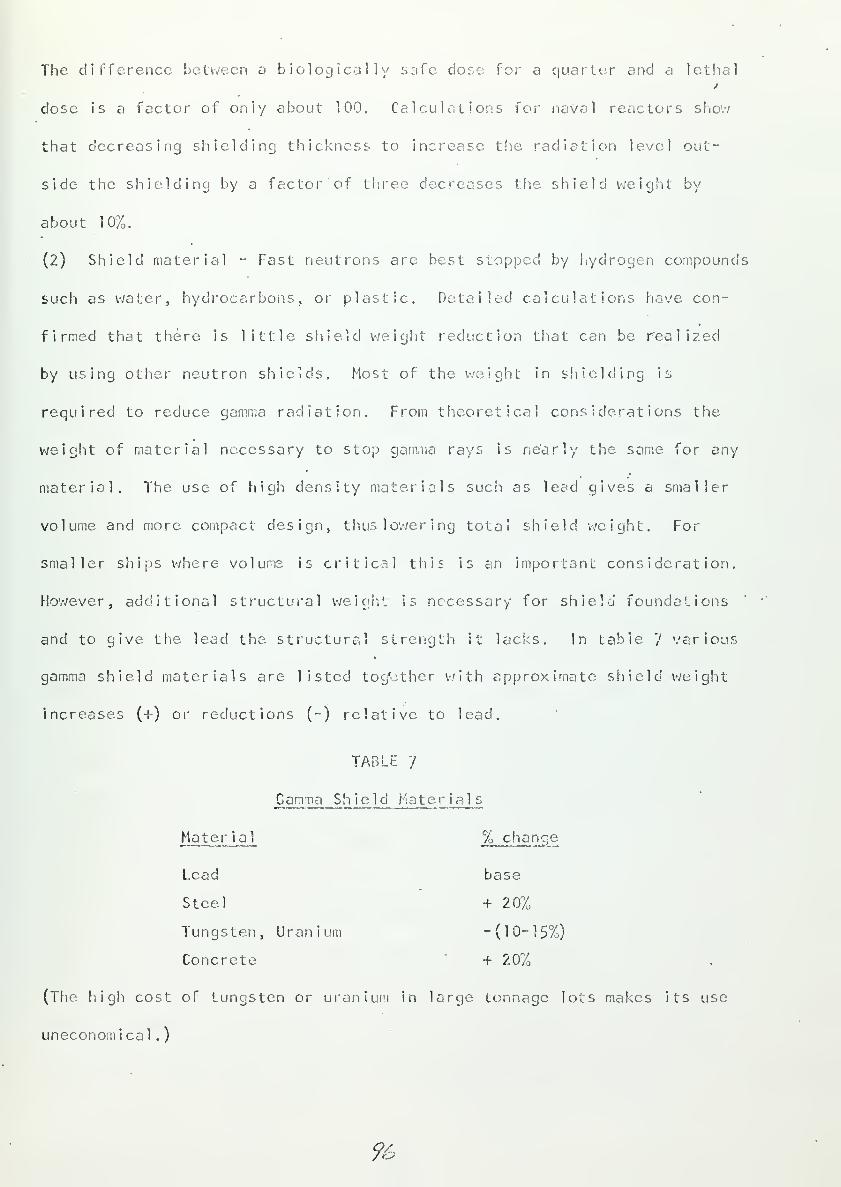
The difference between a biologically safe dose for a quarter and a lethal
dose is a factor of only about 100. Calculations for' naval reactors show
that decreasing shielding thickness to increase the radiation level out-
side the shielding by a factor of three decreases the shield weight by
about 10%.
(2) Shield material - Fast neutrons are best stopped by hydrogen compounds
such as water, hydrocarbons, or plastic. Detailed calculations have con-
firmed that there is little shield weight reduction that can be realized
by using other neutron shields. Most of the weight in shielding is
required to reduce gamma radiation. From theoretical considerations the
weigiit of material necessary to stop gamma rays is nearly the same for any
materiel. The use of high density materials such as lead gives a smaller
volume and more compact design, thus lowering total shield weight. For
smaller ships where volume is critical 1 1 i i s is an important consideration.
However, additional structural weight is necessary for shield foundations
and to give the lead the structural strength it lacks. In table '} various
gamma shield materials are listed together with approximate shield weight
increases (+) or reductions (-) relative to lead.
TABLE '/
JG amma Shield Mate r ials
Mater ial % change
Lead base
Steel + 207o
Tungsten, Uranium -(10-15%)
Concrete + 20%
(The high cost of tungsten or uranium in large tonnage lots makes its use
uneconomical.
)
9iv.


(3) Choice of moderator - This factor effects the size of the core. Trie
.greater the slowing power of the moderator, the smaller the ratio of
moderator to fuel weight. This decreases the pitch of the fuel elements,
decreasing core size. Three moderators are generally considered; graphite,
heavy water, and light water. Light water gives the most compact core for
a given power level. Smaller cores and mere compact plant designs require
less shielding weight due to the decrease in shield surface area. Even
though the neutron leakage from a small core may.be greater (requiring
a thicker shield), the decrease in surface area is the dominating effect.
(k) Reactor coolant - the coolant choice is important because of the in-
duced radioactivity. Naval reactor analyses show that the "ideal non-
radioactive coolant" results in a weight reduction of from 10% to 20% of
the total plant weight (compared to water), depending upon the type of
reactor chosen.
(5) Plant and ship arrangement - Some shield weight reduction car, be
obtained by arranging plant components (within the shielding) around the.
reactor in such a manner that they provide some shielding themselves.
Shield weight can also be reduced by placing tankage, storerooms, voids,
and other seldom occupied spaces around the reactor plant. Shield weight
is strongly effected by plant arrangement and volume. However, this must
be balanced against the needs of overall ship arrangement.
The shield design for a nuclear merchant ship will depend upon the par-
ticular ship des ign, includ i ng such factors as type and power of the reactor,
volume of machinery spaces, weight limitations, ship size and arrangement,
and plant operating conditions. Of course, shield weight is not the only
component of total plant weight that is effected by these factors.
97


The containment system weight for a marine reactor plant will depend
upon the containment concept used, the design pressure and the free volume,
of the containment. For SAVANNAH the containment weight accounted for about
2p% of the total plant weight. The containment and shield weight together
.appear to account for about 50% of the plant weight independent of the type
of plant (REF--3, 12, *;0) . Another weight involved with nuclear plants
is not actually a component of plant weight - the collision barrier.
The collision barrier will add about 20% to the hull weight in way of the
containment. The overall hull weight will be increased by about 5% 3
depending on the barrier length.
The total weight of the plant will be effected by the plant operating
conditions. This discussion will pertain mostly to PWR plants, and the
experience gained in naval plant design (REF-39) • However, it can be seen
that certain trends would pertain to any merchant plant design.
(1) Turbine exhaust pressure (or temperature) - An increase in turbine
exhaust pressure reduces the size and weight of the condensor and turbine.
However, this increase in pressure also reduces the thermal efficiency,
necessitating an increase in the weight and size of the reactor, steam
generators, and coolant pumps. Such size changes also involve shield and
containment weight increases. The net effect is to increase plant weight
with increasing turbine exhaust pressure, as shown in figure 20.
(2) Steam temperature - Increasing the steam temperature increases thermal
efficiency which reduces the size and weight of plant components. However,
past a certain point this will be offset by the increase in steam generator
and shield weight. As the steam temperature is raised, the AT across the
steam generator tubes from coolant to steam decreases. This increases the
necessary heat transfer surface, area. The steam generator' size is very
98


sensitive to changes in the AT. Figure 21 shows the net effect of steam
pressure variation.
(3) Coolant temperature - Within any given plant large changes in coolant
temperature with various plant load conditions increase the thermal stress
problems in the reactor and primary systems. This causes increases in the
size and weight of components in order to provide adequate strength, For
PV.'R plants the pressurizer size is effected by the amount of coolant
temperature change, due to the need for larger units for greater coolant
surges. In addition to the changes in coolant temperature within a given
primary loop, there is the consideration of the variation of average
coolant temperature from plant to plant. For any dual cycle steam
generating system the maximum steam pressure is set by the no load con-
dition. This pressure is'equal to the saturation pressure at the average
coolant temperature and can be two or more times the full load steam
pressure. It is this no load pressure that must be used to design steam
generators, steam pipes, valves, and feed system equipment. The higher
the average coolant temperature, the higher the no load steam pressure
and the greater the weight involved. Offsetting this at lower temperatures
is the increased AT across the steam generator tubes, decreasing steam
generator weight. The net effect of various average coolant temperatures
on steam generator weight is shown in figure 22.
(*f) Coolant flow rate - There is no general trend for plant weight varia-
tion with coolant flow rate. Nevertheless, two of the factors effected by
the flow rate are coolant temperature and coolant activity level.
(5) Coolant pressure - For PV/R plants the coolant pressure sets the maximum
coolant temperature and, hence, the. temperature, pressure and thermal effi-
ciency of the steam cycle. Thermal efficiency increases with coolant
pressure, tending to make plant weight reductions mentioned before. However,
9?


m
3
i-
^
/(Ml
<
015
& 10
Elhtust Pressure , Incites rl
t
1.3-
0.1
ZOO too
Steam P
—i—
~
hoc
re $ sure
—j
—
6oo—j~
• 1030
(?><*)
Figure 20 - Variation of Plant
Weight with Turbine Exhaust Pressure
Figure 21 - Variation of Piant
Weight with Steam Pressure
•50
V)
c*»
25-
10-
15-
ID
^ OS-W Bate +10 v30
Average Coolant Temeeraturt [l °J
f.3
> II-
1.0
OSei
—i
—
0.1
I
04 o.i 0.B 1.0
Coolant Pressure
—i
—
1.1 ;.i
Figure 22 - Variation of Steam
Generator Weight with Coolant
Temperature
Figure 2 3 " Variation of Plant
Weight with Coolant Pressure
JOO


high pressure also creates the need for heavier reactor and primary system
components and an increase in containment weight. About 15% of the plant
weight is directly dependent on primary system pressure and would be re-
duced by a pressure reduction. The remaining 85% includes shielding
which would usually be increased by a pressure reduction. Detailed
studies for naval reactor designs have shown that most weight reduction
due to coolant pressure decrease is from the removal of equipment or
material which contributed shielding due to their arrangement around the
reactor. Such removal must be compensated for by additional shielding
in a less favorable (more weight) location. The overall effect is a
slight increase in weight with increasing pressure, as shown in figure 23.
The effect of machinery (and fuel) weight on longitudinal strength
depends upon its distribution. For a nuclear ship this weight is all
concentrated in the engineering spaces, while fuei weight for conventional
ships can be spread over a greater length. Nevertheless, a large portion
of the fuel weight i s st i 1 1 in close priximity to the engineering spaces
in order to limit the necessary fuel transfer pumps and lines. The greater
weight concentration for nuclear plants is offset to a certain degree by
the increased length of nuclear engineering spaces (e.g., SAVANNAH, OTTO HAHN)
The net effect for ships of large cruising range ( ~ 10,000 miles or more)
will probably be a decrease in the machinery (plus fuel) tons per foot in
the engineering spaces for nuclear ships. The effect of this on the
maximum bending moment will depend upon the location of the engineering
spaces and the relative density of the cargo and other weight items. It
is believed that any increase in bending moment in a nuclear ship will not
be drastic and will be offset by the greater sectional modulus in way of the
col 1 i s ion barr ter
.
/Of


In conclusion, the following criteria for longitudinal strength of
nuclear ships are stated:
Cr i ter ia:
21. The minimum value of sectional modulus over the midship portionof a nuclear ship must be greater than or equal to the minimumpermissible value specified by the. U. S. Coast Guard Load LineRegulat ions.
22. For nuclear ship with engineering spaces amidships, the scantlingsof the collision barrier need not be maintained over the entiremid-ship portion (except as required by Criteria 2k), but may be •
reduced on either end of the barrier to values consistent withthe minimum sectional modulus criterion stated above.
23. Reduction of scantlings forward and aft of the collision barriermust be designed so as to maintain the continuity of longitudinalstrength.
/02-


2 • Col lision Protection
Collision protection is of particular concern in harbor waters near
population centers. Though the following discussion deals with the opera-
tion of nuclear ships in all waters, it is valuable as an introduction to
consider three approaches to collision protection in harbor waters.
First, the nuclear ship side structure could be built strong enough so
that, presumably, a striking ship at any speed could not penetrate the
containment. Second, harbor speeds could be limited in ports served by
nuclear ships and adequate side structure could be provided so that the
containment would not be penetrated,, Third, segregate the nuclear ships
to special port facilities away from population centers and away from
conventional harbor and approach areas. This study is based on the second
of these approaches. The 'first is impractical due to the extremely heavy
and rigid side structure that would result. The third might prove
economically impractical both in terms of the initial capital investment
and the discouragement of business.
Damage to the containment following a collision can occur as a resuli;
of penetration by the striking ship bow or penetration by transverse
structural members of the strucl< ship that are pushed ahead of the striking
ship. The first of these is the subject of the discussion that follows and
the basis for determining the probability or damage to the containment fol-
lowing collision. The second type of damage cannot be ignored, however.
Due to the relatively thin (~0,75 inches) plate thicknesses usee! for
transverse bulkheads 'the danger from these is small. However, bulkhead
stiffeners could be expected to offer more resistance to distortion and be
pushed into the containment. Protection can be provided against this
"lancing effect" by placing heavy longitudinal structure adjacent to the
containment. This longitudinal structure will be referred to as the collision
/03


(6 SUIT
\\
« !-.
0.75 "ft
;
£ft±ggl.ft? <gQ.Tg»..
I wom 0*. W-O *»U
"N
•G>.2.£U" f£
o.c/zy Ft
? ^0.©7?'&
0.-74-" ft
0.74-" £
Figure 2k - Midsect ional View of SAVANNAH Collision Protectior
/0#


mat. It may be made from a variety of materials; high strength steel,
steel-wood combined structure. ., .The SAVANNAH used a design incorporating
a heavy longitudinal bulkhead outboard of a two foot thick laminated
steel and redwood structure. Figure 2k shows the midsection of SAVANNAH.
Note the collision mat and the structure between the mat and the side of
the ship.
The containment system must be protected from penetration b-/ the
striking ship. To determine what protection is necessary for a nuclear
vessel, a study is made of the probability of a collision occuring in which
the containment vessel is penetrated. Such a study is logically divided
into five points (REF-3)
ty of a collision occuring
ty the nuclear ship is the struck vessel, given (A)
P(A) - the probabi
1
P(B) - the probabi
1
P(C) - the probabi
1
ty that the nuclear vessel is struck in way of the
containment, given (A) and (B)
P(D) - the probability that the striking vessel is capable of pene-trating to the containment, given (A), (B) , and (C)
P(E) - the probability that the striking vessel is actually operatingat sufficient speed at the time of collision to penetrate the
containment vessel, given (A), (B), (C) , and (D)
.
This discussion shall treat each of these in a manner similiar to that used
in reference 3. Certain improvements will be discussed and current statis-
tical data will be incorporated. The ship side structure that is designed
to prevent collision penetration of the containment is referred to as the
collision barrier. This includes all transverse and deck structural members
outboard of the collision mat,
P(A) • P.CH:
P(A) and P(E) are considered together 'due to the lack of sufficient
statistical data to treat P(f) separately. It is necessary to treat the
/OS


product of these two probabilities for three possible types of nuclear
vessels (passenger-cargo, general cargo, and tanker) for three opera-
tional areas (harbor, harbor, approach, open sea). Each of these areas is
defined below:
(1) harbor - the sheltered port, characterized by heavy traffic andrelatively low ship speeds. This is assumed to extend out to
the principal sea mark. This would be Boston Light Ship for
Boston Harbor and Ambrose Light Ship for New York Harbor.Operation in. this area will almost always be with a pilot.
(2) harbor approach - the area extending from the principal seamark out to a distance of 100 miles. For SAVANNAH this dis-tance was based on the assumed minimum safe distance for thegeneral population for an uncontained release of radioactivityunder inversion atmospheric conditions. It is also the approxi-mate distance at which most of the sea lanes merge as they nearland, and is characterized by high traffic density and full
speed. The 100 mile distance is believed to be conservative.Coast Guard collision investigations indicate that 32% of ali
collisions occur .within 2.5 miles cf shore. Also the 30 dayintegrated plume center! ine dose of whole body gamma radia-
tion for an uncontained SAVANNAH type radioactivity releaseis 22 rem at 25 miles and 16 rem at 50 miles (25 rem maximumallowable). Due to the probable increase in marine reactorpower ratings and the envelope of merging sea lanes, the 100
mile extent is used in this study.
(3) open sea - ocean areas greater than 100 miles from land. Full
speed and light traffic density are characteristic. Very fewcollisions occur in this area.
It should, of course, be realized that these are general definitions based
on the characteristic world shipping lanes as a whole.
The probability P(A) • P(E) is defined by equation 6:
P(A) • P(E) = I- (1- P )
n(6)
where:
p = probability of collision at speed greater than criticalspeed in one year.
n - design life of the nuclear ship; number cf years.
critical speed = the speed necessary for a particular shipto penetrate the containment of the nuclear ship. Thisis discussed later in Greater detail.
/o&


Collision percentages for each nuclear ship type are calculated separately
for each of the three areas. Each of these ship-area percentages is then
weighted by factors that express the. probability of operation of a striking
vessel at greater than critical speed, B , and the percentage of the nuclear
ship's life spent in a particular area, /. Therefore,
p = ph Bh Th + pa b aYa + PS Bs Ts (7)
for each ship type.
Table 8 is reproduced from reference 3. It shows the percentage of
collisions (?\\, Pa, Ps) r° r the three types of vessels. While this data
was taken in the mid-fifties, it is still an accurate indication of col-
lision percentages (REF-43) .
TABLE 8
SUMMARY OF COLLISION DATA
(U. S. Salvage Association)
PASSENGER SHIPS
Number in sampleNumber of vessels in collision
in harborsin approachesat sea
Number in sampleNumber of vessels in collision
in harborsin approachesat sea
1953 1954 1955 19.56, Average
49 64 61 62 59.0
2 4 1.50
TANKERS
427 4073^7 360 385.3
11
5
1
5
2
46
7
7
6.755.090.25
CARGO SHIPS
Number in sample 1112 1028 ll4g 1181 1117-5Number of vessels in collision
3n harbors 14 3 12 11 10.00
in approaches 11 7 8 12 9-50at sea 10 0.25
/07


As stated in the discussion of the operating areas, the approach area
and the open sea are characterized by full speed, and hence B A and B S are
both equal to unity. Var iousqoerat ing conditions prevail in harbors, Pas-
senger ships proceed at low speed (<10 knots) and would, therefore, usually
be below their critical speeds. Cargo vessels and tankers do not reduce
speed as much, but their critical speeds are usually very close to their
design speed so that a small reduction would drop the speed below the
critical value. V/hile it is true that a value of zero for B H is generally
accurate, nevertheless public safety in harbor areas would require that
appropriate speed limits be set and enforced by port authorities to ensure
ships speeds are low enough to preclude the danger of a penetrating colli-
sion. Assuming such limits would be in effect, H is taken as zero for all
ship types in this study.
Table 9 lists the valuesof B and )* for each ship type. The deter-
mination of T is based on values of the "use factor", defining the time
spent underway. The time spent in approaches will vary with different
trade routes, but is taken to be 10% based on a study of several trade
routes for American flag vessels (REF-3) . The percentage of time in the
harbor is one minus the "use factor". This percentage will probably decrease
over the next decade due to more automated loading and unloading techniques.
However, such techniques are now used for only a small percentage of the
total merchant fleet.
/os


table: 9
Summation of Area Coefficients
B H -
Ship Type
Passenger - cargoTankerGeneral cargo
8A=I BS = 1
Th Ta„ 'Vs
.25
.15
.35
.10
.10
.10
.65
• 75M
Based on the data cf tables 8 and 9 the following values of collision pro-
bability for one year (p) were calculated from equation /, and listed in
table 10.
TABLE 10
Values of Collision Probability for One Year
Ship Type
Passenger - cargoTankerGeneral cargo
Harbor Approach
.0025*1
.00130
.000852
Sea
.000^9
.000099
.00254
.00174
.000941
/Of


From table 10 several conclusions can be made. In all cases the pro-
bability in the approach is the highest. The probability oT a passenger-
cargo nuclear ship being in a collision is the greatest This is probably
due to the higher speeds involved, cutting down reaction time as the two
ships approach.
To arrive at a value of P(A) • P(F.) it is necessary to assume a value
for the life of the ship (n) . This will have been done for the economic
study of the. ship design proposal, Values of n usually range from about
20 to 30 years; 25 years is a representative figure for the purpose of
illustration. Table 11 lists the values of P(A) - P(E) for various ship
types, assuming n = 25.
TABLE 1
1
Values of Probability of Collision at or above Critical Speed
(n - 25)
Ship Type. £ __P{AL_i_P(El_.
Passenger - cargo .0025^ . 06 1 82
Tanker .0017** .0^280
General cargo .0G0$4l .02332
The value of P(A) - P(E) to use in design depends on the type of ship
being built. It may be necessary to make more detailed calculations of this
probability based on the actual trade routes and ports of call to be used
during the life of the particular ship.
P[Bl:
There are no grounds on which to substantiate a claim that the nuclear
ship would be more likely to be the struck vessel than the striking vessel
(or vice versa). Therefore, the value of P(B) is set at 0.5.
Pi£l:
The term "in way of the containment" refers, for the purpose of this dis-
cussion, to a length on the side of the nuclear ship equal to the length of
//O

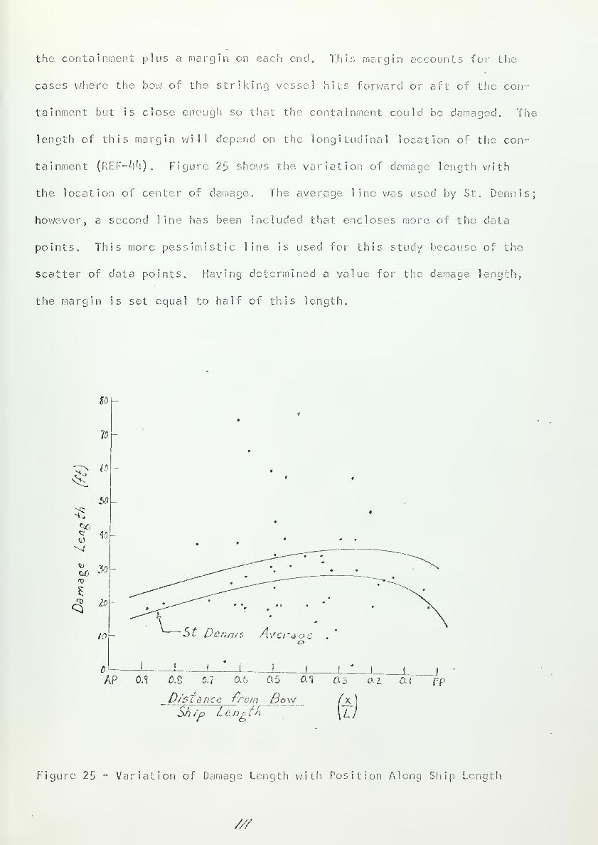
the containment plus a margin en each end. This margin accounts for the
cases where the bow of the striking vessel hits forward or aft of the con-
tainment but is close enough so that the containment could be damaged. The
length of this margin will depend on the longitudinal location of the con-
tainment (REF-V-0 . Figure 25 shows the variation of damage length with
the location of center of damage. The average line was used by St. Dennis;
however, a second line has been included that encloses more of the data
points. This more pessimistic line is used for this study because of the
scatter of data points. Having determined a value for the damage length..
the margin is set equal to hair of this length.
80
V
w
50
* "if)
GO *fv
^ 2D
10 St Denn/s Avcraoe
AP 0.1 0.6 0.1
0/stance
O.'o 0.5 OSx G3 o.L 0.1
from SowShip Le. np ff>
Jf-'P
Figure 25 - Variation of Damage Length with Position Along Ship Length
///


St. Dennis also studied the. distribution of damage location along
the ship's length. His study confirms the validity of the distribution
used in the SAVANNAH study. This distribution is shown in figure 26.
/\p n o.* 0.6
Loc&lion of' Co II/sion on
03i
FP
Lenp th
Figure 26 - Cumulative Frequency Distribution of Damage Location
Having determined the length in way of the containment that is of concern
(the "target area"), the probability of a collision in this length is equal to:
P(C) = P (a) - p(b) (3)
//2


where: a = the fraction of total ship length from the bow to theafter end of the "target area".
b -- the fraction of length from the bow to the forward endof the "target area".
As an illustration, assume the center of the containment is exactly
amidships and has a length of 50 feet. Assume the ships length to be 600
feet. From figure 25 the damage length (using the top curve) is about
35 feet for this region. Therefore, any collision in the space 85 feet
long, centered at the ship's midsection, would be of concern (from
x/L = Ji2S to .572). The probability that the collision actually occurs
in this region is equal to:
P(C) = p (.572) - p (.429) = .20
This method is believed to be more accurate than that used in
reference 3 for SAVANNAH. There a damage length of 100 Feet was chosen
corresponding to the beam of an assumed striking vessel. The damage '•
lengths reported by St. Dennis are lower than this. By taking a damage
length equal to the beam, the striking ship is essentially assumed to
have penetrated from one side of the ship to the other.' This type of
collision for a ship with strong side structure would be virtually impossible.
P(D):
The basis for determining the depth of penetration of the striking ves-
sel into the struck vessel is a study of the. kinetic energies involved in
collision and the structural characteristics of the respective ships. A
collision of two ships is almost entirely inelastic. The initial kinetic
energy of the ships is partially absorbed in the crushing, twisting, tearing,
shearing, buckling, and bending of structural members of the ships. The
forces involved are well above the elastic limit of the materials and only
1.5% of the absorbed energy is absorbed in elastic deformation (REF-23)
.
/A


The kinetic energy that is not absorbed in structural damage appears as
kinetic energy of the two ships (and a mass of entrained water) as they'
move together after the collision. The important item in collision barrier
design is the determination of the depth of penetration of the striking
vessel. As stated above this depends upon two factors; the kinetic energy
of the ships prior to collision (particularly that of the striking ship),
and the structure of the bow of the striking ship and the side of the
struck ship.
V. U. Minorsky has developed a method for determining the absorbed
energy and the depth of penetration in a collision (REF~^5) . This method
is commonly used for design analysis (SAVANNAH, OTTO HAHN, GLACIER, LENIN).
Equation 9 gives the kinetic energy lost (absorbed in ship structure) (E^)
as a function of the striking ship displacement (long tons) and speed (knots)
It is derived from an inelastic collision energy balance.
F-IAAA _ AjlIr! (ton knots*} (q)A " l.^AA +A B 2
where:
^A = struck ship displacement&B = striking ship displacementV B = striking ship speed
This equation is based on five assumptions:
(1) collision is inelastic
(2) ships are locked together after collision and free to move together
(3) angle of encounter is 90°(A) the struck ship i s at rest
(5) A A is increased by k0% to account for entrained water
The first assumption is valid in that the ship structures are crushed
by the forces of impact and the ships do not "bounce". This is verified
by the very low shock levels involved in collision. Coast Guard, American
Bureau of Shipping and Lloyd's Register inspections show shock levels of
// /


about one-tenth of those experienced from ship motion in waves (REF-23) .
The same inspections also confirm the validity of the second assumption.
The choice of a 90 angle of encounter is based on the fact that this is
the most severe collision. While the energy of a collision with a forward
angle of encounter involves more energy (higher relative velocity), the
distance of penetration necessary to reach the containment is greater, off-
setting the increase in energy (REF-^5) . Furthermore, a study of Coast
Guard reports shows that k0% of the collisions occur with angles of en-
counter from 80 to 100 degrees. The fourth assumption is valid because
of the 90 angle of encounter. Only those structural members whese prin-
cipal dimensions are in the direction of penetration absorb substantial
amounts of energy (REF-^) . Of primary interest in the energy balance are
those components of energy normal to the center line of the struck ship.
The assumption of the struck ship being at rest gives conservative results.
The choice of k(f/ for the amount of entrained water was verified by
experimental model tests at the Institute of Naval Construction in Italy
(REF-23). It has also been shown that small variations of this percentage
do not have an appreciable effect on the energy balance (REF-45)
.
Equation 9 gives the lost energy but says nothing of the structural
damage necessary to absorb this energy. For this purpose Minorsky developed
the resistance factor as a measure of the volume of structural material
involved in collision energy absorption. The structural members included
are those with their principal dimensions in the direction of the lire of
impact, including:
(1) decks, flats, and double bottom in the two ships.
(2) transverse bulkheads inthe struck ship.
(3) Longitudinal bulkheads in. the striking ship.
(^1) The component of the shi 1 o" the striking ship in the directionof the col 1 i s ion
,
//s


Ry is defined in equation 10:
RT ^E pN Li! tN + 1.33l>n Ln tn (ft.
2in) (10)
where:
P^j ; I_n = depth and length of penetration of the Nth member of thestriking vessel
tw
= thickness of the Nth member of striking vessel
Pn ,L , tn= same as above for struck vessel
The factor of 1.33 is used to account for the increase in L by the forward
motion of the struck vessel. This value was determined from a study of
Coast Guard collision reports for struck ship speeds from 10 to 16 knots.
Having defined Ry, Minorsky studied 26 collisions in order to corre-
late the amount of energy absorbed with the computed value of Ry. Figure
27 shows the results of this study. There was found to be a very good
correlation especially in the higher energy region. The low energy region
shows a scatter of points due to the greater ability of the ships to apply
backing power to prevent or reduce the effects of collision. Extrapolation
6 ?to an energy level very much higher than 1.8 x 10 ton knots is not con-
sidered valid. The straight line correlation is represented by equation
(11):
EA = 414.5 Rj + 121,900 ton knots2
(11)
In computing Ry no credit was given for the energy absorption by the
side shell and longitudinal bulkheads of the struck ship. However, for a
nuclear ship the presence of the special collision mat structure would con-
tribute to the resistance to penetration. Due to the lack of experimental
information on the energy absorption qualities of these structures, it is
not possible to assign them a resistance factor. Nevertheless, credit can
be given by assuming the initial speed of the striking vessel to be effective-
ly reduced. This will be discussed in more detail later.
//6

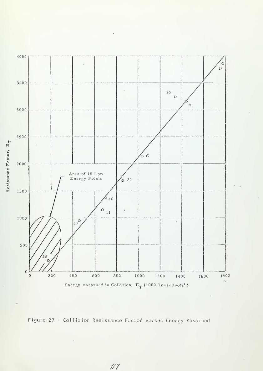
4000 r
3500
3000
2500
o«-»
u
hvucfl!
en
2000
p; i5oo
1000
500
Area of 18 LowEnergy Points
Figure 27 - Collision Resistance Factor versus Energy Absorbed
200 400 600 800 1000 1200 MOO 1600 1800
Energy Absorbed in Collision, ET (1000 Tons -Knots 2)
///


At this point in the discussion the emphasis is shifted iron: deter-
mining the depth of penetration for a given ship structure, to deter-
mining the ship structure necessary to limit the number of ships in the
total world merchant fleet that can possibly penetrate to the containment.
For the purpose of this discussion several terms should be explained:
(1) Striking energy (Es) - the kinetic energy of any ship computedfrom its design speed and full load displacement.
(2) Critical Energy (Ec) (or critical speed, V'bc)'" that value of
kinetic energy necessary for a particular striking ship to
penetrate a certain critical depth (to the containment) into a
particular struck ship. This is a function of the kineticenergy involved arid the ships' structural characteristics.
(3) Absorbed energy (or lost energy) (E^) - that kinetic energyabsorbed in damaging the ship structures. This is given by
equations 9 and 11, and shown in figure 2'/ as a function of Ry.
(h) Barrier energy (En) - that kinetic energy absorbed in damagingthe ships' structure up to the containment (or some otherarbitrarily chosen point outboard of the containment). !f
En ^_ E/\ no containment penetration occurs.
(5) Ra " the resistance factor of the struck vessel based on an
assumed depth of penetration (this includes the 1.35 factor).
(6) Rg - the resistance factor of the striking vessel based on
the same depth of penetration.
Figure 28 is reproduced from reference 3. A random check of Lloyds
Register of Shipping for I968 seems to indicate its continued validity.
This graph shows the cumulative frequency distribution of the striking
energy (Es) for the total world merchant fleet, tanker fleet, and passenger-
cargo fleet. From figure 28 it can be seen that the passenger-cargo ships
have a higher average striking energy than do the tankers. Lloyds was also
consulted for the sizes cf these three fleets. These figures represent
the ocean going fleets, eliminating service and utility craft, and are
1 is ted in table 12.
//S


6 7 8
Striking Kinetic Energy, Tons -Knots 2 x 10
Figure 28 - Cumulative Frequency Distribution of
Striking Energy for Various Merchant Fleets
//?


TABLE 12
World Merchant Fleet ( 1 968)
Ship Type Approximate Number Percent
Total 40,000 100.0Passenger - Cargo 2,520 6.3Tanker 3,025 7.6General Cargo 3^,600 86.1
In the collision study done for SAVANNAH a curve was developed for
critical speed versus displacement for passenger - cargo ships and tankers.
This curve was based on typical bow structures for different ships and
A = 17,000 tons, RA = 1632 ft.2
in. for the SAVANNAH. This curve is
represented by the dark lines on figure 29. The curve for tankers in-
creases for displacements greater than about 35>000 tons due to the in-
creasing thickness of shell plating and the greater bluntness of the bows
which have the effect of spreading the damage in the struck ship over
wider areas fore and aft (larger Ln) . However, in the design study for
OTTO HAHN (REF-^7) , a second tanker curve was proposed based on tv/o factors
First, the thicker bow shell plating actually experiences less damage
than previously credited; second, in the last ten years large tankers have
increasingly been built with large, relatively rigid bulbous bows. For a
tanker trimmed down by the stern this could serve as a "battering ram".
Consequently, the lower tanker curve now applies, represented by the
dashed line. The general cargo fleet is not considered due to their re-
latively low values of Es. Figure 29 also shows the result of a collision
test. Scale models of 0FT0 HAHN end BREMEN (passenger-cargo) were brought
into collision; the impact velocity was equivalent to a true speed of 11.6
knots (Ab = 29,500 tons). The collision barrier was effective in prevent-
ing containment penetration.
/ZO


?0 40 60 80 100 120
DISPLACEMFNT OF RAMMING SHIP140 160 • 10
J
L0NGT0N5
Figure 29 - Critical Speed versus Displacement, for SAVANNAH and OTTO HAHN
/Zf


I
'
i
s
Ǥ
o00
fc
<3
re<DC
Ot=occo
<
<><to
J-
o
+-»
ca)
E<u
ofO
Q-
i-
>
COen
o
CD
/22


The information in figure 29 can also be presentee! as a plot of
typical Rq values versus displacement for the two groups of ships. This
is done in figure 30. It is important to note that the values in figures
29 and 30 are valid only for the SAVANNAH or ships of approximately equal
displacement and equivalent side structure. Rearranging equation 9:
V B =ea (i.**A a + A b) '
\A A a Ab (12)
Setting E n = E^ and substituting equaLion 11 in 12 gives the equation
for critical speed, Vgr; :
V BC[ V|Z+- 5 ( ra + R B ) + 112, 900] [1AAa_+A_b1
Ua Aa~Ab]'
1/2
(13)
Substituting the SAVANNAH values into equation 13 and rearranging
RB -Ab (23,800)A~B + 23,800 829
0*0
Figure 30 is the plot of equation 1^!. It should be noted that for all dis-
placements the Rq value for a passenger - cargo ship is less than or equal
to that for a tanker. This is due to the smaller bow angles of passenger -•
cargo vessels which result in sharper entrance angles and delay the effect
of longitudinal bulkheads of the striking vessel, V/hile the absolute values
in figures 29 and 30 apply only to SAVANNAH (or similar ships), the rela-
tive variation is the same for other ships of conventional ship construction
In particular, the relative difference between the tanker and the passenger
cargo curves will remain the same. This is an important point and will be
considered again later in the discussion.
Having developed the distribution of Es for the world fleet (figure 28)
and the variation of R[> with displacement for the two ship types of concern
Ac 5

(figure 30), we are ready to consider a method for arriving at an appro-
priate value of R^. The depth of penetration does not depend solely cm
Es; if it did the problem would be simple. Rather, it depends on the
striking energy and the value of Rf for the two ships. Ideally, what is
needed is a cumulative frequency distribution of the number of ships in
the world with Ec > Es as a function of R&. The development of such a
plot would be a tremendous task ?n.d not worthy of the necessary time.
As an alternative the following method is suggested.
(1) From figure 28 choose a value of Es corresponding to a largepercentage of the total world fleet. For the purpose of
generality this percentage is represented here by 2.
(2) Choose, a "typical ship ?! of this striking energy as the strikingship. (The choice of this typical ship will be discussed in
detail later.)
(3) Use. the values of full load displacement and design speed of thetypical ship to compute E/\ from equation 3. This sets the amountof energy that must be absorbed in the collision barrier, i.e.,
set Eq equal to E^.
(h) Assume a maximum al lowable depth of penetration. This will be
up to some point outboard of the containment. Lloyds Registerof Shipping Classification Rules for nuclear ships sets this at
20% of the beam. This depth is used to determine the Pn and P^
values in computing R^ and R^.
(5) Compute the Rg value for the typical ship based on the P^j valuesfrom the assumed penetration depth. For the SAVANNAH this couldbe taken from figure 30.
(6) From figure 28 obtain a value of Ry by entering with the valueof En obtained in step 3.
(7) Calculate the necessary value of Ra (Ra ~ Rf " Rb) • This valueis then used in determining the scantlings of the side structurein way of the containment.
The accuracy of this method depends upon two points; first, the validity
of using the striking energy distribution as a means of eliminating ships
rather than a critical energy distribution described earlier as the ideal
case; second, the proper choice of a typical striking ship.
/2t


With the first point, the possible danger of using the striking energy
curve is that having chosen a value of striking energy, the energy lost is
still dependent upon the displacement of the striking ship (denominator of
equation 9). Also, a ship with the chosen Es (or even lower) could still
penetrate the barrier if its bow structure were not sufficient to absorb
enough energy (low R3) . Eoth of these dangers are reduced by the choice
of an appropriate typical striking ship. The spesds of ocean going ships
do not vary appreciably with displacement. Tankers average from about 15
to 17 knots; and passenger - cargo ships, from about 18-26 knots. By
choosing a typical value of ship speed at si ightly' over the average the
displacement would be less than average (for a given Es) . This would
have the effect of overestimating the value of E/*,, leading to a -conservative
design.
The second point is the most critical. The designer must exercise
care in choosing the typical ship; this choice involves two points:
(1) Should the typical ship be a tanker or a passenger - cargo vessel?
(2) Choice of the speed and displacement of the type chosen.
The second factor has already been mentioned. In choosing either a tanker
or a passenger - cargo vessel as the typical shipv , the designer must con-
sider the consequences of a collision by the type of ship not chosen. !f
the side, structure is designed for a tanker, the resulting value of R^ would
be lower than if the design had been based on a passenger - cargo ship.
Therefore, at the same striking energy the passenger - cargo vessel would
penetrate the containment (i.e., Ry would be too low and E9 < E^)
.
In the design of SAVANNAH it v/as argued (REF-3) that the number of
passenger - cargo vessels relative to the number of tankers above the
striking energy chosen (2.5 x 10 ton kt ) was so low that' the choice of a
tanker as the typical ship was justified, However, the passenger - cargo
/p./;

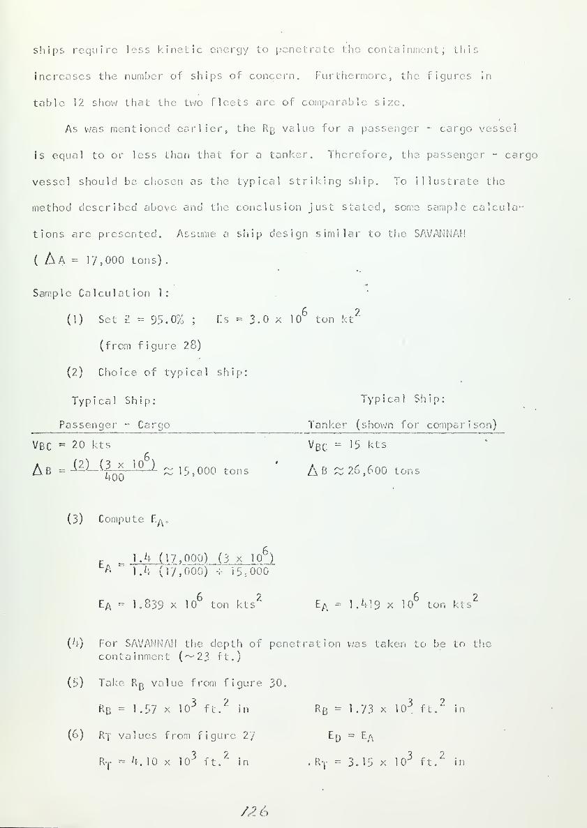
ships require less kinetic energy to penetrate the containment; this
increases the number of ships of concern. Furthermore, the figures in
table 12 show that the two fleets are of comparable size.
As was mentioned earlier, the R B value for a passenger - cargo vessel
is equal to or less than that for a tanker. Therefore, the passenger - cargo
vessel should be chosen as the typical striking ship. To illustrate the
method described above and the conclusion just stated, some sample calcula-
tions are presented. Assume a ship design similar to the SAVANNAH
( A A = 17,000 tons)
.
Sample Calculation 1:
(1) Set 2 = 95.0% ; Es = 3.0 x 10 ton kt
(from figure 28)
(2) Choice of typical ship:
Typical Ship: Typical Ship:
Passenger - Cargo Tanker (shown for comparison)
Vbc = 20 kts V BC:= 15 kts
A B = (2 ) (3 * 10 ) ~ 15,000 tons AB ~ 26,600 tons
(3) Compute E^,
F _ 1.4 ( 17 ,000) (3 x 10⁶
)
A ' 1.4 (17,000) -:• 15.-0CK)
Ea = K839 x 106
ton ktsZ
EA - 1.419 x 1
6ton kts
2
(4) For SAVANNAH the depth of penetration was taken to be to thecontainment (~23 ft.)
(5) Take Rg value from figure 30.
RB = 1-57 x 103
ft.2
in Rb = 1.73 x 10³
ft.2
in
(6) R-| values from figure 2/ En = E/\
RT= 4.10 x 10
3ft.
2in . RT = 3.15 x 10
3ft.
2in
/26


(7) Calculate RA
RA = RT ' R-B
RA - 2.53 x 10³
ft. in RA = 1.42 x, 3 210^ ft. in
Assume a tanker collideswith this design insteadof a passenger - cargo:
rt= ra + r b
RT = (2.53 + 1.73) x 103
Ry = 4.26 x lO"' ft.2
in
Assume a passenger - cargocollides with this designinstead of a tanker.
R-f
- 2.99 x 10³
ft.2
in
Barrier absorption capacityfrom figure 27
Ed (Rt = ^.26 x 103)
Eq ^ 1.9 x 10
but EA = 1.419 x 10
ED > EA
no containment penetration
6 ?E D
~ 1 .33 x 10 ton kts
but EA = 1.S39 x 10 ton kt
E D^EA
conta inment per' et rat ion
Finally, it is necessary to determine the probability that a ship
could penetrate the containment P(D) . Based on the method described, the«
probability could be set at 1- E. However, using the passenger - cargo
value for Rn increases the critical energy for the tanker fleet. This
effect can be calculated and a greater percentage (Z ) of the world fleet
could be excluded. The sample calculation below illustrates this.
Sample Calculation 2:
In Sample Calculation 1 it was found that penetration to the containment
by a tanker would involve an energy absorption in the snips' structure of
6 21.9 x 10 ton kt . Set Ea equal to this value and assume the tanker speed
to be 16 knots; solve for B:
1.4 Aa . vb AbA ' DTAa +Ab 2
Ab = 39,500 tons
(9)
/Z7


Solve for Ec
E c = VBC2A B ~ 5.0 x 10 ton kt
2
2
From figure 28, this eliminates 92.5% of the tanker fleet. With Ec equal
to 3.0 x 10 for passenger - cargo ships, 51.0% of that fleet is eliminated,
Using the percentage figures from table 12, solve for ? :
21
- (.51) (6.3%) + (.925) (7.6%) + (1.0) (86.1%)
21
= 96.35% {an increase of 1.35%)
1
This value of the 2 takes no account of the (])/ac!ded protection pro-
vided by the collision mat, (2) ships travelling at less than full load
displacement, (3) the collisions that are not 90 collisions, and (h) the
reduction in speed due to 'efforts by the ships to back down before collision,
The SAVANNAH study assumed reductions in the potentially dangerous group
by allowing effective speed or displacement decreases, for each of these
factors. As a result the potentially dangerous group was decreased by
about 86%. This decrease is conservative, especially when the effect of
the collision mat is considered. For the SAVANNAH it was stated that the
mat could possibly account for a 3 knot speed reduction. This has been
partially confirmed by collision tests run in Italy, Japan and en the 0TT0
HAHN model (REF-23, ^7). However, the SAVANNAH only credited the mat with
a one knot reduction in effective striking ship speed. While it is be-
lieved from these tests that the collision mat would be more effective than
was credited for SAVANNAH, the results are inconclusive and more study will
be necessary to more accurately determine the added protection provided by
the collision mat. Therefore., no improvement on the 86% figure appears
warranted at this time.
/ 1 o


Having completed the study of ship collision, it is now possible to
determine the value of P(D)
:
P(D) = 1 - [Z1
+ .86 (1-2)]
P(D) - .14 (1-21
) (15)
P(D) = 0.0051 for the example given in this discussion. The choice of a
I
value of It (and hence, 2 ) should be made so as to reduce the overall
probability of containment penetration P(CP) . This will be discussed
later. However, it should be said at this point that the choice of
2 = 100%, eliminating all ships in the world, would result in a poor
design. The necessary added structure would present weight and volume
problems. But even more significant than this is that the necessary
scantlings would be so large (3>~h inches plate thickness) that the
mechanics of failure would probably change. There would be less energy
absorbed in crushing and the "lancing effect" mentioned earlier would be
increased. The collision barrier could become a hazard rather than a
protection.
In studying containment damage following a collision the discussion
has been divided into four parts concerned with the probabilities of col-
lision occuring at critical speed, the nuclear vessel being the struck
vessel, of collision in way of the containment, and finally the probability
of a collision being a penetrating collision based on world fleet striking
energies and ship structures. The probability of containment penetration
is summarized in equation 16 for nuclear passenger - cargo, tanker, and
general cargo ships, respectively,
/I?


P(CP) =
!-(]-. 00254)
l-(l-.00174)n
]-{]-. OOO^i i)n
[-5] Ep(a)-p(b)][.l4(l-Zr
)] (16)
P(CP) - f (n; a, b; 21
)
In determining the necessary collision barrier strength only one of the
unknows of equation 16 is of direct concern, Z . The life of the ship
and the length of the "target area" will have been set by prior considera-
tions not related to ship side structural strength.
Having set trie values of n, a, and b in equation 16 , attention is
directed toward either; (1) a determination of a value of P(CP) for a
particular value of Z , or (2) a selection of a value of £ based on an
assumed value of P(CP). The former approach is more meaningful in that a
particular value of P(CP) is practically (if not completely) impossible
to set. Estimates for the chance of a nuclear accident which would re-
lease hazardous amounts of radioactivity outside the containment have been
made with orders of magnitude from 10 to 1 per year for each reactor
(REF-57) • No one has attempted to fix a particular value for this pro-
bability; therefore, no attempt shall be made here. Instead, the
designer should start with a value of Z, adjust to obtain Z , and determine
the resulting value of P(CP). Comparisons of this with the orders of
magnitude quoted above would then be made. However, such comparisons
would be good only as rough estimates. For one tiling the values quoted
were arrived at very subject! /civ and have little or no analytical basis;
for another, they are measures of radioactivity release. P(CP) is a
/SO


measure of containment penetration. It has been assumed throughout the pre-
vious discussion that such penetration would also involve radioactivity
release. Such is not necessarily the case; but for design purposes it is
a convenient assumption because the relation between collision penetration,
reactor and primary system damage, and radioactivity release is uncertain
and beyond present methods of analysis.
A value of £ of approximately 0.95 is reasonable and gives values of
F'(CP) , for the examples used for illustration (25 year vessel with an 85
-rfeet "target area" amidships), of about 3 x 10 This compares favorably
with the value of about 2 x 10 for hazardous radioactivity release
accidents for a 25 year reactor as given in reference 57- In order to
establish the validity of a 2 - .95 criterion, a pessimistic case was
calculated, assuming a nuclear passenger - cargo ship with a life of hO
years and a value of P(C) equal to one (to present the extseme limiting
case). The value of P(CP) was about 2 x 10 ; the value of radioactivity
release from reference 57> over a h0 year life, using the one year pro-
bability of 10 , was about 2 x 10 . Therefore, if the value of 10?
per year per reactor is accepted as a general point of reference the vaiue
of 2 = .95 yields a value of P(CP) that is better by a factor of ten for the
most pessimistic case.
The height and length of the collision barrier is determined by the
vertical and longitudinal dimensions of the "target area". The longitudinal
extent of the "target area" was discussed in relation to the probability
P(C) . The same argument that was used to set the "length of ship in way of
the containment" is also used in determining the height of the barrier. The
vertical extent must take into consideration the various drafts of striking
ships and the drafts of the nuclear ship. These vary over a wide range de-
pending upon load and trim conditions. Because of this variation the collision
/3/


barrier should extend from the innerbottom to the first deck above the
containment
.
In conclusion, the validity of this method of determining necessary
collision protection for design purposes can be verified by considering
the conservative nature of some assumptions made:
(1) Throughout the discussion it was implicitly assumed that a penetra-
tion of the containment would always result in a release of radioactivity.
However, it is possible that the reactor and primary system would be un-
damaged even if the containment were penetrated.
(2) When determining the probability of collision, P(A) , the nuclear ship
was considered to be equally vulnerable to collision during the entire time
spent in the harbor. However, most of this time would be spent at dock
side where the chance of collision would be much less and where only one
side of the ship would be exposed.
(3) Furthermore, in computing the value of P(A) no account was given to
the extra care that might be exercised in the operation of a nucle::r ship.
(k) V/hen computing P(C) , a pessimistic enveloping curve was assumed for
the variation of damage, length with position of damage. Also no account
was made for a decrease in damage length due to the stronger side structure.
(5) The assumptions involved with P(D) have been discussed.
(6) In comparing P(CP) with a point of reference the most pessimistic
point (10 instead of 10") was chosen.
Cr i ter ia
:
2k. A collision barrier must be provided on both sides of the con-
tainment extending vertically from the innerbottom to the first
deck above the containment,, and extending longitudinally the
entire length of the containment plus a margin at each end
equal to one half the expected damage length.
/3Z-


25. The scantlings of the collision barrier shall be determined by
assuming a value of 2 equal to or greatei than 0.95 and an
appropriate typical striking ship.
26. The typical striking ship shall be a passenger - cargo vessel.
27. A collision mat shall be provided to protect the containmentfrom the movement of transverse members into the containment.
/33


3 . G_r oundinq Protection :
It is not possible to treat the subject of grounding in the same semi-
empirical nature as was done for collision. This is due to the greater num-
ber of variables involved in grounding (ship speed, location of contact,
nature of the bottom, sea state, weather conditions, etc.) and the lack of
sufficient statistical data to treat these. However, grounding and the
related problems of ship structure are discussed here generally, outlining
the requi rements of regulatory and classif icat ion organizations.
Reports of the United States Salvage Association (REF-3, ^3) indicate
that most groundings occur in harbors and channels at low speed. The
worst case of a loss of power off of a rocky lee shore is rare. The
structural damage due to grounding is divided into two categories; that
occurring at the time of contact with the ground, and that occurring over
a period of time due to the working of the stranding ship in rough seas.
The damage occurring on contact will vary, of course, with the type of
bottom and the speed of the shp; but structural damage is usually limited
to the hull and double bottom structure. Care should be taken to provide
enough depth (e.g., 5 feet for SAVANNAH, 8.2 feet for OTTO HAHN) to limit
the structural damage to plant components above the inner bottom. Lloyds
Register of Shipping specifies a minimum depth of 6 feet. Also, the double
bottom structure should not be so rigid that it does not absorb energy
(REF-^7) • Lloyds specifies the use of longitudinal framing in way of the
containment double bottom in order to transmit the loading fore and aft.
Folbwing a grounding in water that is not sheltered from rough seas,
extensive structural damage and possibly breaking up can occur. The
greatest danger for the nuclear vessel is this "long term damage, if it is
in way of the containment. Working to offset this ere efforts by salvage
crews to remove the ship in whole or in part following a grounding. Usually
/3</


there is sufficient time to accomplish this before extensive damage occurs
(REF-^3) . In addition, the increased hull strength around the containment
for collision protection would act to limit the damage.
Due to the inconclusive nature of grounding statistics, no special
criteria for nuclear vessels are listed.
/55


APPLNDIX I
Calculation oT Required Flooding Valve Areas to Limit External Differential
Pressure During Ship Sinking
Figure A- 1—1 shows the sinking velocity and depth to keel as a func-
tion of time. Time zero was taken as the instant the weather deck is at
"the water's edge. The following assumptions were made for this calculation,
based on a Mariner class cargo vessel:
A = 21,000 tons
L = 550 ft.
B = 80 ft.
T = 27 ft. (draft at full load displacement)D = ^5 ft. (measured from keel to weather deck)
Area open to flooding = 100 ft. *
Drag coefficient for sinking hull = 1.0**
Reserve bouyancy = .667
At t - 0, it is assumed that k(f/ of the ship : s volume is filled with water
due to damage. This corresponds to "3 compartment flooding".
Assuming the containment bottom and the ship bottom coincide (a
conservative assumption) and that the space surrounding the containment
has been flooded, the external differential pressure to which the contain-
ment would be subjected with flooding valves open on the bottom is given by
equation A- 1-1
:
PD
= P " PW " PA + patm (A- 1-1)
where: Pq = external differential pressureP = sea pressure at keel
P^/ = pressure of water in containment
Pa = pressure of air in containmentPatm = atmospheric pressure
2* Area due to damage = 33 ft. (REF-¥l)
Area of deck openings =67 ft.
** Cn = 1.9 for a infinite rectangular plate with normal flow, Co ~ 0.8 for
a cylinder with flow normal to axis, L/D = 8.
/Z6


In terms of hydrostatic head, feet of sea water
hD . h-^ . 33.
i r v^ww '(,vi " 2)
where: hD
= external differential pressureh = depth of keel _
Vv/ = volume of water in containment (ft. )„
V = free volume of containmentA = average horizontal cross sectional area of the containment
Figure A-l-2 shows plots of required water volume in the containment
versus water depth (V^/ vs. h) in order to maintain the external differen-
tial pressure just below the collapse pressure as the ship sinks. For the
plots of figure A-l-2 flooding commences when h is equal to the no- flood
collapse depth. The inverse slope of each of these curves (ft. /ft.) is the
necessary water flow that the valve must pass at any depth. This value is
a maximum at the instant of valve opening. Three cases are plotted:
(a) V = ^0,000 ft. ; containmentheight - 30 ft. ; containment collapsepressure = 35.5 ps i (h
Q= 80 ft. S.W.)
(b) Same as (a) except - collapsepressure = 66.7 psi (hn = 150 ft. S.V/.)
(c) Same as (b) except - V = 20,000 ft.
It should be noted for the three cases plotted that the initial inverse
slope is virtually unaffected by the choice of containment collapse pressure;
it is the same for (a) and (b) . However, the inverse slope is affected by
free volume and is reduced in case (c)
.
If the maximum inverse slope is multiplied by the sinking velocity at
the depth of valve opening a max i mum valve flow rate (ft. /sec) is obtained.
Using equation A- 1 - 3 , the necessary valve area is obtained for each case
and listed in table A- I - 1
:
/37


Q = C Ay 2g h D (A- 1-3)
where: Q. - valve flow rate (ft. / sec.)
C = valve flow coefficient (.6)
Ay = valve area (ft. z)
TABLE A- 1-1
Required Valve Area
(valve opening at h = hp
)
Case Ay (ft.2
) Av//A {%)
a 73.4 5.5
b 53.7 4.0
c 45 .
5
6.8
Therefore, it is seen that for the three cases studied the valve area is
2on the order of 50 ft. .
Taking another approach, assume the flood valves are. opened at some
pre-set depth less than the no-flood collapse depth. Assume this valve
opening depth to be 80 feet. In figure A- 1-3 a family of curves such
as those in figure A-l-2 (coordinates reversed), shows the required water
volume necessary to prevent collapse.' Superimposed on these is another
family of curves showing valve flow (ft.") versus depth' for various valve
areas. Any valve area whose curve intersects a curve of constant collapse
pressure would be inadequate for that collapse pressure. From these curves
the following data is tabulated in table A-l-2:
TABLE A-l-2
Required Valve Area
(valve opening before no-flood collapse dep th)
No-f lcod Col lapse
Depth (ft.)
AV (ft.2
) Min. Al lowableColl apse Pressure
(psi)
50 45.035 66.720 111.010 > 178.0
100
150
250>400
/J63


Figure A- 1—1 - Sinking Velocity and Water Depth vs Time
/s?


r ":' : ':: 71
1
-
.:. 1
:
1
:
--
I
; |•
::|1
!
:
;
fit:
.•
:
i
:
' :
:
'
'
.'.;
;
'
;
:*
:
:
; ;.!::,
'
"":
~
;
-
-
——4
- • -•
: '"
:
\'\'-\'.'-'t-
:
-~T730;
; ; J....
': ) ':
:'::: : :
:
;i
-•
...
< / : /
;.
:::;
1i
-
: ' '
/ / 1
:
::: ...
•
; 7/
|/ ' /
.
"
' ; r_2W (0A i
\
:
: :| ::::
/
S^ :::;:.'i / •
; a - .
1 /(b] gj::::
....; • :: .: :;::
I'
. ::
1 /i
:.: :: /.ia
200
; ;
;
:::;(:
•
;:;:'
- t-
... : ::
•
•
/"
\
*
: -H | : :
:
.
||1
. :;:.,::;:
-
:::•;''" •
r.:\:\
'
. .......
: I
' -^ "1^*'
\
""""'..
* j
.:-.r
:
Q -^^._...,„.
- .:
JbO
ifSt
L^~~,r rrr
• T
;--;"";
. » - .
j :-: •
u 1:
.... •
j
- j*\ 't\fM[ :::': :
::-; ;• ::n
——
i
—: : T
:
I
"'•":
:;-..-
1 / \:;\\';;\ :
; ;
;'
*3
3 ll °;
;
'-
;.; ..illit-::
::-i
:.::
.::i;
:
;;.
-'--','
i . . . . — . -—
.
1
-,
~*~
i;:
:
'
: .! .
'
.':: ." '. 1 1:i :; ^LH
i
i *s
iI:-"
- :.:: .-.-.v.. :
: : :
:
r::p::
:ii::l-
i
;
:
:
:.''..
;
'../.
SO
• - - I
. . I
1t
::1|
:j':':'
i
:::: '-.'.'
, >. ^.
. ) ;
.-Ty,
'.;;;
..ia:..:. -
.'
;
; ;
'
-
. ; i
.|
,
i
; r
i
;:;;!;;• :::: ..1 r£
~:t::t:::::t :.: ;
•j
:
• :
::; "
' :
10i
'
.
:
: ; :;\;;;i--—|
—
! I
•
:;i:i:
:
:
: : ;;:
;
-
.
....: !
;.:...: .-.-....
:
;;l
\;;;\ !
:
*•
-1
'
,;-:|.:.
:
. .
. .r
.
Tr:}:' :.
f\i t:::.
: ;'
•
.:;•!::J::
L."..
10 20 30 10
Figure A- 1-2 - Water Depth vs Vw


£
<5
^
-X
JZ*->
D.<1)d
0)
n)
I?
>
in
>
>CDC
DOO
CD
o
I-
o
o_
s_
ai-j
TO
-DCru
0)
3cr
i
I
<0)
Zi
en
(z-WysttJMA Pu* **/*A
xf PdS*V JdPf\
/#/


BIBLIOGRAPHY
1. T. Thompson and J. Berkerley; The Technology of Nuclear Reactor Safety,M.I.T. Press, 1964.
2. R. Farmer; ,rReactor Safety Analysis as Related to Reactor - Siting",
UNICPUAE, 1964.
3. N.S. SAVANNAH Sa fety Assessment Volume 1- 5; Marine Administration/Babeock and V/ilcox, i960.
k. J. J. DiNunno, et. a].; "Calculation of Distance Factors for Power andTest Reactor Sites", TID - \k3kk, AEC, \$SZ.
5
.
Technical Specifications for N.S. SAVANNAH ; First Atom i c Ship Transpor
t
Inc.
6. "Evaluation of the Consequences of the Maximum Credible Accident for
the N.S. SAVANNAH"; First Atomic Ship Transport Inc., I963.
7. S. Gfesstone and A. Sesonske; Nuclear Reactor Engineering, I963.
8. Nucleonics, vol. 2^:1, January 1 966
.
9. "CNSG 111", lecture by R. F. Ryan at the University of Michigan, 1 965
.
10. W. Wiebe, D. U 1 ken , C. Salander, and K. Henning; "Safety-Design Aspectsof Nuclear -Powered Ship Otto Hahn", Nuclear Safely, Voi. 9:6, Nov-Dec 1968.
11. B, Hildrew; "Problems of Merchant Ship Nuclear Propulsion"; The Insti-tute of Marine Engineers Transactions, October I962.
12. M. Pravda and R. Lightner; "Conceptual Study of a Supercritical ReactorPlant for Merchant Ships"; Marine Technology, April 1 966
.
13. W. Cot t re 11 and A. Savolainen; U. S . Reactor Containme nt Technology,ORNL-NSIC-5, 1965.
]k. "Advanced Nuclear Cargo Ship Study", prepared for U. S. Department of
Commerce Maritime Administration, General Dynamics, I968.
15. D. Barton, et.al„; "Predicting Maximum Pressures in Pressure SuppressionReactor Containment"; ASME Paper 6I-WA-222, I96I.
16. G. West, Jr. and E. Roland; "Some Aspects of Nuclear Safety and ShipDesign"; SNAME, I967.
17. T. Neutron; "Fission Gas Release in Thin Tubes of Infinitesimal Length",Symposium of Nuclear Absurdities, Oak Ridge, Tenn., 1 965
.
/o/¥Z


18. J. Noble; "Subatmospher ic Containment"; Transactions American NuclearSociety Annual Meeting, Vol. 10:1, 19&7-
19. H.Karwat; "The Influence of Activity Release and Removal Effect on the
Escape of Fission Produces from a Double Containment"; CONF 650^:07, OakRidge, Term. , I965.
2.0. S. Glasstone; Principle s of Nucl ear Reactor Engineering,Van Nostrand, 1955
21. J. Thorpe; "Nuclear Heat Transfer Equipment"; SNAME, 19&2,
22. L. Baker and R. Ivins; "A Calculation Demonstrating the Effects of theZirconium-Water Reaction on the Analysis of a Loss of Coolant Accident";CONF 650407, Oak Ridge, Tenn., 1 965
.
23. A. D'Arcangelo; "Collision Protection of Nuclear Power Ships"; Universityof Michigan Engineering Summer Conference, 1 965
-
2k. S. E. Morrison; History of U n ited States Naval Operations in Wor ld War
1
1
; Little, Brown and Company, Boston, 1956.
25. "Guide for Explosion Venting", National Fire Protection Association, 1 96^+
.
26. J. Corns tock; Principles of Naval Architecture, SNAME, 19&7-
27. J. Gerritsma; "Behavior of a Ship in a Sea-Way"; Netherlands Ship
Research Centre, I966.
28. Guide for the Classification of Nu c lear Sh ips, American Bureau of Ship-
ping, 1962.
29. "Shock Design of Shipboard Equipment", NAVSHIPS 25"423-30, 1 96 1
.
30. R. Boxnak; "The Role of the U. S. Coast Guard in Nuclear Merchant ShipSafety"; Nuclear Safety, Vol. 8:2, 1967.
31. E. Watson and N. V/i ttenbrock; "Environmental Exposure as a Function of
Containment Vessel Leakage Rate"; CONF 650407, Oak Ridge, Tenn., I965.
32. A. Kramer; Nuclea r Propu lsion for Merchant Ships; Division of TechnicalInformation, AEC, I962.
33. W. Davis and W. Cottrell; "Containment and Engineered Safety of NuclearPower Reactors"; Third International Conference, on the Peaceful Uses ofAtomic Energy, Vol. 13, 1964.
3^. J. Wier; "Argonne Transient Reactor Test Facility"; Nuclear Safety, Vol.
4:2, 1962.
35. J. Diet rick and W. Zinn; So l id Fue l Reac tors ; Add i son-Wesley , 1958.
/43


36. D. Morrison, et.al.; "An Evaluation of the Applicability of ExistingData to the Analytical Description of a Nuclear Reactor Accident";Battele Memorial Institute, BM1 1779, I965.
37- J- Nuchols and J. McGuffey; "Graphi
t
ization failures in Piping";Union Carbide Nuclear Co., Mechanical Engineering, May 1959-
38. H. Falkenberry, et.al.; "A Preliminary Study of a Direct-CycleSteam-Cooled Reactor for Merchant Ship Propulsion"; 0RNL-2759>September 1959.
39. H. Rickover, et. al.; "Some Problems in the Application of NuclearPropulsion to Naval Vessel'; SNAME, Vol. 65, 1957.
kO. C. Hinton and R. Moore; "The Nuclear Propulsion of Ships"; Journal ofthe Joint Panel on Nuclear Marine Propulsion, 1958.
*fl . H. Benford; "Engineering Economy in Tanker Design"; SNAME, Vol. 65, 1957.
hi. R. Moore and C. Iliffe; "Nuclear Propulsion for Ships"; Proceedingsof the Second United Nations International Conference on the PeacefulUses of Atomic Energy, Vol. 8, 1958.
k'S. Personal correspondence with Mr. Harry Townsend, United States SalvageAssociation, April 1969.
kh. M. St. Dennis; "A Note on Probabilistic Method of Assessing Survivabilityto Collision"; Sch if f stechn ik, I962. .
.
^5. V. Minorsky; "An Analysis of Ship Collisions with Reference to Protec-
tion of Nuclear Power Plants"; Journal of Ship Research ill, October 1959
no. K. Arita; "Method for Estimating Ship Collision Damage"; Thesis,Department of Naval Architecture and Marine Engineering, MassachusettsInstitute of Technology, 1 968
.
k~] . G. V/oisin; "Otto Hahn : Safety Features in Germany's Nuclear Ship";Safety at Sea International, 1968.
48. S. Smith and J. Richards; "Nuclear Propulsion for Merchant Ships";
Proceedings of the Second United Nations international Conference on
the Peaceful Uses of Atomic Energy, Vol. 8, 1958.
h 9. Rules and Regulations for Ca rgo a nd Miscellaneous Vessels, U. S. CoastGuard, I963.
50. Rul es and Regu l at ions, fo r Pa ssen ger Vessels , U. S. Coast Guard, 1 963
.
51 • Electrical Engi neering Regulations, U. S. Coast Guard, 1 96 2
.
52. Ma rine Engineering Regulat ions, U. S. Coast Guard, 1 963 <.
/W


53.
5h.
55.
56.
57.
58.
Rul es and Regulati o ns for the Construct ion and Classification of Steel
JL'LLDJ:* Lloyds Register of Shipping, i 967
c
Rules for the Construction and Clas sif i cation of Steel S hi p_s , D e t
Norske Veritas, I967,
Rules for Build ing a nd Cla ssing Steel Vessels > Ame rican Bureau of
Shipping, 1968.
S. Cra ndall and N . Dahl;An Introduction to the Mechanics of Soiids
;
McGraw Hill , 1959.
WASH-7^0, "Theoretical Possibilities and Consequences of .Major Acci-dents in Large Nuclear Power Plants"; AEC, March 1957.
Code of Federal Regulations, Part 20; April 5j 1966.
M.\J


m

thesR2532
Design criteria for nuclear nn//IHlllU/IMiiiiiiiiiiiiiiinii
Powered
3 2768 002 049«q o