Preliminary Results of Adaptive-Reinforcement Learning Control for Morphing Aircraft

http://jim.sagepub.com/Structures
Journal of Intelligent Material Systems and
http://jim.sagepub.com/content/21/17/1699The online version of this article can be found at:
DOI: 10.1177/1045389X10378777
2010 21: 1699 originally published online 10 September 2010Journal of Intelligent Material Systems and StructuresEdward A. Bubert, Benjamin K.S. Woods, Keejoo Lee, Curt S. Kothera and N.M. Wereley
Design and Fabrication of a Passive 1D Morphing Aircraft Skin
Published by:
http://www.sagepublications.com
can be found at:Journal of Intelligent Material Systems and StructuresAdditional services and information for
http://jim.sagepub.com/cgi/alertsEmail Alerts:
http://jim.sagepub.com/subscriptionsSubscriptions:
http://www.sagepub.com/journalsReprints.navReprints:
http://www.sagepub.com/journalsPermissions.navPermissions:
http://jim.sagepub.com/content/21/17/1699.refs.htmlCitations:
at UNIV OF MARYLAND on December 14, 2010jim.sagepub.comDownloaded from

Design and Fabrication of a Passive 1D Morphing Aircraft Skin
EDWARD A. BUBERT,1 BENJAMIN K. S. WOODS,1 KEEJOO LEE,2 CURT S. KOTHERA3AND N. M. WERELEY
1,*1Smart Structures Laboratory, Department of Aerospace Engineering, University of Maryland, College Park, MD 20742, USA
2Department of Aerospace Engineering, Old Dominion University, Norfolk VA 23529, USA
3Advanced Technology Division, Techno-Sciences, Inc., Beltsville, MD 20705, USA
ABSTRACT: Broad-scale area change of a non-porous surface while maintaining resistanceto aerodynamic loading was demonstrated through the development of a passive elastomericmatrix composite morphing skin. The combined system includes an elastomer-fiber-compositesurface layer that is supported by a flexible honeycomb structure, each of which exhibit a near-zero in-plane Poisson’s ratio. A number of elastomers, composite arrangements, and substruc-ture configurations were evaluated and characterization testing led to the selection of the mostappropriate components for prototype development. The complete prototype morphing skindemonstrated 100% uniaxial extension accompanied by a 100% increase in surface area.Results from out-of-plane pressure loading showed that out-of-plane deflection of less than0.1 in. (2.5mm) can be maintained at various levels of area change under pressures of up to200 psf (9.58 kPa). Applications to wing span morphing UAVs are also discussed.
Key Words: morphing skin, mechanized skin, re-entrant honeycomb, zero Poisson’s ratio,wing span morphing, unmanned air vehicles.
NOMENCLATURE
[A] extensional stiffness matrix for unidirectionalcomposite lamina
[B] coupling stiffness matrix for unidirectionalcomposite lamina
b depth of honeycomb cellc honeycomb cell width
CLPT classical laminated plate theory[D] bending stiffness matrix for unidirectional
composite laminaE Young’s modulusEf EMC fiber modulusEL longitudinal elastic modulus for unidirectional
composite laminaET transverse elastic modulus for unidirectional
composite laminaEm EMC matrix modulusE0 honeycomb material elastic modulusE1 effective honeycomb elastic modulusE2 transverse or spanwise EMC elastic modulus
EMC elastomeric matrix compositeF force on honeycomb bending member during
extension
GLT shear modulus for unidirectional compositelamina
h honeycomb cell heighthk distance of top of k-th lamina from bottom of
laminatehk-1 distance of bottom of k-th lamina from
bottom of laminateI honeycomb bending member second moment
of area‘ length of honeycomb bending member leg
{M} vector of CLPT laminate in-plane moments{N} vector of CLPT laminate in-plane forces
n number of laminae in EMC composite[Q] lamina stiffness matrix in material axes½ �Q� lamina stiffness matrix in laminate body axes
RTV room temperature vulcanization[S] lamina compliance matrix in material axest thickness of honeycomb bending memberts EMC laminate skin thickness
UAV unmanned aerial vehicleVf EMC lamina fiber volume fraction� deflection of honeycomb bending bending
member{"0} vector of CLPT laminate mid-plane strains"1 global honeycomb strain� angle between honeycomb rib member and
bending member�f fiber offset angle, measured from chordwise
(1) axis
*Author to whom correspondence should be addressed.E-mail: [email protected] 1�6, 8�25 and 27�31 appear in color online: http://jim.sagepub.com
JOURNAL OF INTELLIGENT MATERIAL SYSTEMS AND STRUCTURES, Vol. 21—November 2010 1699
1045-389X/10/17 1699�19 $10.00/0 DOI: 10.1177/1045389X10378777� The Author(s), 2010. Reprints and permissions:http://www.sagepub.co.uk/journalsPermissions.nav
at UNIV OF MARYLAND on December 14, 2010jim.sagepub.comDownloaded from

� honeycomb material Poisson’s ratio�LT major Poisson’s ratio unidirectional composite
lamina�21 minor Poisson’s ratio for an EMC laminate�1 effective global honeycomb stress
INTRODUCTION
SINCE the Wright Brothers’ first flight, the idea of‘morphing’ an airplane’s characteristics through
continuous, rather than discrete, movable aerodynamicsurfaces has held the promise of more efficient flightcontrol. While the Wrights used a technique known aswing warping, or twisting the wings to control the roll ofthe aircraft (Anderson, 1985), any number of possiblemorphological changes could be undertaken to modifyan aircraft’s flight path or overall performance. Somenotable examples include the Parker Variable CamberWing used for increased forward speed (Parker, 1920),the impact of a variable dihedral wing on aircraft stabil-ity (Munk, 1924), the high speed dash/low speed cruiseabilities associated with wings of varying sweep(Buseman, 1935), and the multiple benefits of cruise/dash performance and efficient roll control gainedthrough telescopic wingspan changes (Sarh, 1991;Gevers, 1997; Blondeau and Pines, 2004).While the aforementioned concepts focused on large-
scale, manned aircraft, morphing technology is certainlynot limited to vehicles of this size. In fact, the develop-ment of a new generation of unmanned aerial vehicles(UAVs), combined with advances in actuator and mate-rials technology, has spawned renewed interest in radicalmorphing configurations capable of matching multiplemission profiles through shape change � this class hascome to be referred to as ‘morphing aircraft’(Toensmeier, 2005). Contemporary research is primarilydedicated to various conformal changes, namely, twist,camber, span, and sweep. It has been shown that morph-ing adjustments in the planform of a wing withouthinged surfaces leads to improved roll performance,which can expand the flight envelope of an aircraft(Gern et al., 2002), and more specifically, morphingto increase the span of a wing results in a reductionin induced drag, allowing for increased range orendurance (Bae et al., 2005). The research presentedhere is intended for just such a span-morphing applica-tion, for example a UAV with span-morphing wingtipsdepicted in Figure 1. By achieving large deformations inthe span dimension over a small section of wing, thewingspan can be altered during flight to optimizeaspect ratio for different roles. Furthermore, differentialspan change between wingtips can generate a rollmoment, replacing the use of ailerons on the aircraft(Henry, 2005).
A key challenge in developing a span-morphing wing-tip is the development of a useful morphing skin, definedhere as a continuous layer of material that would stretchover the morphing structure and mechanism to form asmooth aerodynamic skin surface. For a span-morphingwingtip in particular, the necessity of a high degree ofsurface area change, large strain capability in the spandirection, and little to no strain in the chordwise direc-tion all impose difficult requirements on any proposedmorphing skin. The goal of this effort was a 100%increase in both the span and area of a morphing wingtip, or ‘morphing cell.’
A review of contemporary morphing skin technology(Thill et al., 2008) yields three major areas of researchbeing pursued: compliant structures, shape memorypolymers, and anisotropic elastomeric skins.Compliant structures such as the FlexSys Inc. MissionAdaptive Compliant Wing (MACW) rely on a highlytailored internal structure and a conventional skin mate-rial to allow small amounts of trailing edge camberchange (Hetrick et al., 2007). Due to the large geomet-rical changes required for a span-morphing wingtip asenvisioned here, metal or resin-matrix-composite skinmaterials are unsuitable because they are simplyunable to achieve the desired goal of 100% increasesin morphing cell span and area.
Shape memory polymer (SMP) skin materials are rel-atively new and have recently received attention formorphing aircraft concepts. They may at first glanceseem highly suited to a span-morphing wingtip: shapememory polymers made by Cornerstone ResearchGroup (Perkins et al., 2004) exhibit an order of magni-tude change in modulus and up to 200% strain
Figure 1. Illustration of span-morphing UAV showing 1D morphingwingtips.
1700 E. A. BUBERT ET AL.
at UNIV OF MARYLAND on December 14, 2010jim.sagepub.comDownloaded from

capability when heated past a transition temperature,yet return to their original modulus upon cooling.Re-heating causes the material to return to its originalshape. There have been attempts to capitalize on thecapabilities of SMP skins, such as Lockheed Martin’sZ-wing morphing UAV concept (Bye and McClure,2007). However, electrical heating of the SMP skin toreach transition temperature proved difficult to imple-ment in the wind tunnel test article and the SMP skinwas abandoned as a high-risk option. Additionally, thestate-of-the-art of SMP technology does not appear tobe well-suited for dynamic control morphing objectives.With maximum strains above 100%, low stiffness,
and a lower degree of risk due to their passive operation,elastomeric materials are ideal candidates for a morph-ing skin (Kikuta, 2003). Isotropic elastomer morphingskins have been successfully implemented on the MFX-1UAV (Flanagan et al., 2007). This UAV employs amechanized sliding spar wing structure capable of alter-ing the sweep, wing area, and aspect ratio during flight.Sheets of silicone elastomer connect rigid leading andtrailing edge spars, forming the upper and lower surfacesof the wing. The elastomer skin is reinforced against out-of-plane loads by ribbons stretched taught immediatelyunderneath the skin, which proved effective for windtunnel testing and flight testing. However, suitableimprovements over this skin, such as anisotropic fiberreinforcement and a better developed substructure forout-of-plane reinforcement, are desired for a fully func-tional morphing skin.The present research therefore focuses on the devel-
opment of a passive anisotropic elastomer compositeskin with potential for use in a 1D span-morphingUAV wingtip. The skin should be capable of sustaining100% active strain with negligible major axis Poissoneffects, giving a 100% change in surface area, andshould also be able to withstand typical aerodynamicloads, assumed to range up to 200 psf (9.58 kPa) for amaneuvering flight surface, with minimal out-of-planedeflection. The following will describe the process ofdesigning, building, and testing a morphing skin withthese goals in mind, and will compare the performanceof the final article to the initial design objectives.
CONCEPTUAL DEVELOPMENT
The primary challenge in developing a morphing skinsuitable as an aerodynamic surface is balancing the com-peting goals of low in-plane actuation requirements andhigh out-of-plane stiffness. In order to make the skinviable, actuation requirements must be low enoughthat a reasonable actuation system within the aircraftcan stretch the skin to the desired shape and hold itfor the required morphing duration. At the same time,the skin must withstand typical aerodynamic loads with-out deforming excessively (e.g., rippling or bowing),which would result in degradation to the aerodynamiccharacteristics of the airfoil surface.
To achieve these design goals, a soft, thin siliconeelastomer sheet with highly anisotropic carbon fiberreinforcement, called an elastomeric matrix composite(EMC), would be oriented such that the fiber-dominateddirection runs chordwise at the wingtip, and the matrix-dominated direction runs spanwise (Figure 2(a)).Related research with EMC materials can also befound (Olympio, 2006; Murray et al., 2007).Reinforcing carbon fibers controlling the major axisPoisson’s ratio of the sheet would limit the EMC to1D spanwise shape change (Figure 2(b)). For a givenskin stiffness, actuation requirements will increase inproportion to the skin thickness, ts, while out-of-planestiffness will be proportional to t3s by the second momentof the area. To alleviate these competing factors, a flex-ible substructure is desired (Figure 2(c)), that would becapable of handling out-of-plane loads without greatlyadding to the in-plane stiffness. This allows a thinnerskin which, in turn, reduces actuation requirements.The combined EMC sheet and substructure form a con-tinuous span-morphing skin.
To motivate the goal of low in-plane stiffness for thisresearch, the skin prototype was designed to be actuatedby a span-morphing pneumatic artificial muscle (PAM)scissor mechanism described separately by Wereley andKothera (2007). The PAM scissor mechanism, shown inFigure 3, was designed to transform contraction of thePAM actuator into extensile force necessary in a span-morphing wing. Based upon the maximum performance
(a)Fiberdominated
ZeroPoisson
High strainLow stiffness
Matrixdominated
(c)(b)
Figure 2. Overview of morphing skin conceptual design.
Design and Fabrication of a Passive 1D Morphing Aircraft Skin 1701
at UNIV OF MARYLAND on December 14, 2010jim.sagepub.comDownloaded from

of the PAM and the kinematics of the scissor frame, themaximum force output of the actuation system was pre-dicted as shown by a dashed line in Figure 4. Basedupon these performance predictions, a skin stiffnessgoal was determined such that 100% active straincould be achieved, with the skin simplified as havinglinear stiffness. A margin of 15% was added to the100% strain goal to account for anticipated losses dueto friction or manufacturing shortcomings in the skin oractuation system. The resulting simplified skin stiffnessgoal is plotted in Figure 4 as a solid line.In addition, minimal out-of-plane deflection of the
skin surface under aerodynamic loading was desired.
No specific out-of-plane deflection goal was set ordesigned for, but out-of-plane stiffness of the substruc-ture was kept in mind during the design process.Deflection due to distributed loads was included as afinal test to ensure that the aerodynamic shape of aUAV wing morphing structure could be maintainedduring flight.
EMC DESIGN AND TESTING
The primary phase of the morphing skin developmentwas to fabricate the EMC sheet that would make up theskin or face sheet. A number of design variables wereavailable for tailoring the EMC to the application,including elastomer stiffness, durometer, ease of han-dling during manufacturing, and the quantity, thickness,and angle of carbon fiber reinforcement.
Elastomer Selection
Initially, a large number of silicone elastomers weretested for viability as matrix material. Desired propertiesincluded maximum elongation well over 100%, a lowstiffness to minimize actuation forces, moderate durom-eter to avoid having too soft a skin surface, and goodworking properties. Workability became a primary chal-lenge to overcome, as two-part elastomers with high vis-cosities or very short work times would not fully wet outthe carbon fiber layers. While over a dozen candidateelastomer samples were examined, only four wereselected for further testing. Figure 5 and Table 1 detailsthe silicone elastomers tested as matrix candidates.
The most promising compositions tested were DowCorning 3-4207 series and the Rhodorsil V-330 series.Both exhibited the desired low stiffness and greater than100% elongation, but DC 3-4207 suffered from poorworking qualities and lower maximum elongation and
Flexiblematrixcomposite
Honeycombsubstructure
PAMactuator
Carbonrod
X-framemechanism
Figure 3. Proposed morphing skin prototype including PAMactuation system.
1000
800
600
For
ce (
N)
400
200
00 20
Force required predicted
Force available predicted
X-frame extension (%)
6040 80 100
Figure 4. X-frame force predictions and morphing skin stiffnessdesign goal (Wereley and Kothera, 2007).
0.6
0.5
0.4
Str
ess
(MP
a)
0.2
0.3
0.1
0
0 20
3-4207Sylgard-186
V330, CA35V330, CA45
Strain (%)
6040 80 100
Figure 5. Elastomer stress�strain curves.
1702 E. A. BUBERT ET AL.
at UNIV OF MARYLAND on December 14, 2010jim.sagepub.comDownloaded from

was rejected. Rhodorsil’s V-330 series two-part RTVsilicone elastomer had the right combination of low vis-cosity, long work time, and easy demolding to enableeffective EMC manufacture, and demonstrated veryhigh maximum elongation and tear strength. V-330CA-35 had the lowest stiffness of the two V-330 elasto-mers tested. This led to selecting V-330 CA-35 for use intest article fabrication.
CLPT Predictions and Validation
Concurrently, using classical laminated plate theory(CLPT), a simple model of the EMC laminate wasdeveloped to test the effects of changing composite con-figuration on performance. The skin lay-up shown inFigure 6 was examined: two silicone elastomer facesheets sandwiching two symmetric unidirectionalcarbon fiber/elastomer composite laminae. The unidirec-tional fiber layers are offset by an angle �f from the1-axis, which corresponds to the chordwise direction.Orienting the fiber dominated direction along the wingchord controls minor Poisson effects while retaining lowstiffness and high strain capability in the 2-axis, whichcorresponds to the spanwise direction.In order to determine directional properties of the
EMC laminate, directional properties of each laminamust first be found. The following micromechanics der-ivation comes from Agarwal et al. (Agarwal et al., 2006).For a unidirectional sheet with the material longitudinal(L) and transverse (T) axes oriented along the fiberdirection as shown in Figure 7, we assume that perfectbonding occurs between the fiber and matrix materialsuch that equal strain is experienced by both fiber andmatrix in the L direction. Based upon these
assumptions, the longitudinal elastic modulus is givenby the rule of mixtures:
EL ¼ EfVf þ Em 1� Vfð Þ: ð1Þ
Here EL is the longitudinal elastic modulus for thelayer, Ef is the fiber elastic modulus, Em is the matrixelastic modulus, and Vf is the fiber volume fraction. Tofind the elastic modulus in the transverse direction, it isassumed that stress is uniform through the matrix andfiber. The equation for the transverse modulus, ET, is:
ET ¼ 1= Vf=Ef þ 1� Vfð Þ=Emð Þ: ð2Þ
Calculations based on these micromechanics assump-tions supported the intuitive conclusion that thinnerEMC skins would have a lower in-plane stiffness mod-ulus in the spanwise direction, E2. Predictions for thetransverse elastic modulus and the minor Poisson’sratio are plotted versus fiber offset angle in Figure 8(a)and (b), respectively, as solid lines. In order to providesome validation for the CLPT predictions, three EMCsample coupons were manufactured consisting of0.5mm elastomer face sheets sandwiching two0.2�0.3mm composite lamina with a fiber volume frac-tion of 0.7. Nominal fiber axis offset angles of 0�, 10�,and 20� were used. The measured transverse modulus,Figure 8(a), and minor Poisson’s ratio, Figure 8(b), areplotted below as circles.
As expected, increasing fiber offset angle adverselyincreases the in-plane stiffness of the EMC, requiringgreater actuation forces. Also, it is noteworthy that theinclusion of unidirectional fiber reinforcement at 0�
offset angle nearly eliminates minor Poisson effects aspredicted by CLPT theory.
It is of critical importance to note that, according tothe assumptions used in deriving the lamina transversemodulus in Equation (2), the transverse modulus has alower bound equal to the matrix modulus. This lowerbound is shown in Figure 8(a) as a horizontal black line
T „
T
L
Figure 7. Unidirectional composite layer showing fiber orientation(Agarwal et al., 2006).
Table 1. Elastomer properties.
MaterialModulus
(kPa)Viscosity
(cP)
%Elongation
at break Comments
DC 3-4207 130 430 100þ Hard to demoldSylgard-186 410 65,000 100þ Too viscousV-330, CA-45 570 10,000 500 Excellent workabilityV-330, CA-35 330 10,000 510 Excellent workability
Stretchdirection
Carbon fiberCarbon fiber
Elastomer
1
2
qf
Elastomer
Figure 6. EMC lay-up used in CLPT predictions.
Design and Fabrication of a Passive 1D Morphing Aircraft Skin 1703
at UNIV OF MARYLAND on December 14, 2010jim.sagepub.comDownloaded from

at E2/Em¼ 1. However, the experimental data is close tothis lower bound for the 10� and 20� samples, and themodulus is actually below the lower bound for the 0�
case. Clearly, in this case, there is a problem in themicromechanics from which the transverse modulus pre-diction is derived.Recall it was assumed that perfect bonding between
fiber and matrix occurred as illustrated in Figure 9(a).This implies stress was equally shared between matrixand fiber under transverse loading. Close visual exami-nation of the EMC samples during testing revealed thatthe fiber/matrix bond was actually very poor, and thematrix pulled away from individual fibers under trans-verse loading as illustrated in Figure 9(b). Thus, thefibers carry no stress in the transverse direction, andthe effective cross-sectional area of matrix left to carrytransverse force in the lamina is reduced by the fibervolume fraction. For the case of poor transverse bond-ing exhibited in the fiber laminae, the transverse modu-lus in Equation (2) can thus be simplified to:
ET ¼ Em= 1� Vfð Þ: ð3Þ
Using Equation (3) to calculate transverse modulusfor the fiber laminae, new CLPT predictions for EMCnon-dimensionalized transverse modulus and minorPoisson’s ratio are plotted in Figure 8. Much betteragreement is seen between the analytical and experimen-tal values for E2/Em. In spite of the poor bond betweenfiber and matrix material in the EMCs, the fiber stiffnessstill appears to contribute to the transverse stiffness athigher fiber offset angles. The minor Poisson’s ratio isalso influenced by the fiber offset angle. The EMC’slongitudinal modulus, not shown, also remains high.These facts clearly indicate the fiber continues to con-tribute to the longitudinal stiffness of the fiber laminaeeven when bonding between matrix and fiber is poor.
To explain this contribution, it is hypothesized thatfriction between fiber and matrix help share loadbetween the two materials in the longitudinal direction,while the matrix is free to pull away from the fiber in thetransverse direction. This would explain the stiffeningeffect seen in the transverse modulus at increasedoffset angles and the controlling effect the fiber appearsto have on Poisson’s ratio at very low offset angles.
Based upon these CLPT results, a fiber offset angle of0� was selected to minimize transverse stiffness and also
–5 0 5 10 15 20 250.8
1
1.2
1.4
1.6
1.8
2
2.2(a) (b)
Offset (deg)
E2/
Em
Transverse modulus vs fiber angle
CLPT, perfect bonding
CLPT, poor bonding
Experiment
–5 0 5 10 15 20 25–0.05
0
0.05
0.1
0.15
0.2
0.25
0.3
Offset (deg)
n 21
Poisson’s ratio vs fiber angle
CLPT, perfect bonding
CLPT, poor bonding
Experiment
Figure 8. Comparison of CLPT predictions with experimental data for three different fiber angles: (a) non-dimensionalized transverse elasticmodulus E2/Em; (b) minor Poisson’s ratio n21.
(b)(a)
Figure 9. Fiber/matrix bond: (a) assumed perfect bonding and equal transverse stress sharing in CLPT; (b) actual condition with poorfiber/matrix bond and no fiber stress under transverse loading.
1704 E. A. BUBERT ET AL.
at UNIV OF MARYLAND on December 14, 2010jim.sagepub.comDownloaded from

to minimize the minor Poisson’s ratio. As the analyticaland experimental results in Figure 8(b) indicate, a 0�
fiber offset angle can resist chordwise shape changeduring spanwise morphing. While this conclusionappears obvious, the results demonstrate that with theappropriate correction to micromechanics assumptionsin the transverse direction, simple CLPT analysis can bemore confidently used to predict EMC directional prop-erties. This simplifies the morphing skin design proce-dure by allowing in-plane EMC stiffness to be predictedby analytical methods.
EMC Fabrication and Testing
Three EMC samples were manufactured for in-planetesting using the following method. First, the outer elas-tomer face sheets were pre-cured at room temperaturebetween large aluminum plates spaced to give a precisethickness of 0.5mm, as seen in Figure 10(a). Sheets of0.15mm thick, 4.1 oz/yd2 (0.014 g/cm2) unidirectionalcarbon fiber (Figure 10(b)), were then prepped byremoving the binder threads which otherwise wouldadversely affect the transverse stiffness. The preparedcarbon fiber layers and additional uncured elastomerwere then sandwiched between the outer lamina at theappropriate fiber offset angle and cured at room tem-perature under a weighted caul plate. The result was acontinuous elastomer matrix with layers of fiber embed-ded in the center at offset angles, shown before beingtrimmed to size in Figure 10(c).The graphics in Figure 11 describe the three EMC
sheets manufactured in an evolving attempt to maximize
in-plane and out-of-plane performance. EMC #1 andEMC #2 had the same lay-up with two 0.5mm facesheets sandwiching two 0� offset angle carbon fiberlayers. However, EMC #1 saw an increased effort tocontrol lamina thickness and fiber angle to furtherreduce transverse stiffness, so the carbon fiber laminaended up slightly thinner than in EMC #2. EMC #3was a variation intended to increase out-of-plane stiff-ness at the expense of in-plane stiffness. A single 0� fiberlayer was included at the center of the lay-up to affectthe minor Poisson’s ratio. The central layer was betweentwo symmetric 15� fiber layers, whose offset angle wasintended to increase out-of-plane stiffness. Based onCLPT predictions, this EMC was not expected to becompetitive with EMC #1 and #2 on in-plane stiffnessrequirements, but was included in testing to gain expe-rience with other fiber arrangements.
Sample strips measuring 51mm� 152mm were cutfrom the three EMCs and tested on an MTS machine.Each sample was strained to 100% of its original lengthand then returned to its resting position. Data fromthese tests are presented in Figure 12. Notice the visiblylow Poisson’s ratio effects as the EMC is stretched to100% strain � there is little measurable reduction inwidth. It is also important to note that the stress�straincurves measured for each EMC reflect not only theimpact of their lay-ups on stiffness, but also improve-ments in manufacturing ability. Thus, due to improvedcontrol of carbon fiber angles and the quantity of elas-tomer matrix, EMC #3 has roughly the same stiffness asEMC #2 in spite of the larger amount of carbon fiberpresent and higher fiber angles. EMC #1 exhibited high
(a) (b) (c)
Figure 10. Manufacturing a �1.5 mm EMC: (a) cured 0.5 mm elastomer sheet; (b) raw unidirectional carbon fiber; (c) finished EMC sheet,before trimming and clean-up.
0.5mm elastomersheets
1.4mm 1.7mm 1.8mm
EMC #1 EMC #2 EMC #3
0.5mm elastomersheets
0.5mm elastomersheets
0° fiber layers 0° fiber layers 15° fiber layers 0°fiber layer
Figure 11. Lay-ups of EMC samples fabricated for morphing skin evaluation.
Design and Fabrication of a Passive 1D Morphing Aircraft Skin 1705
at UNIV OF MARYLAND on December 14, 2010jim.sagepub.comDownloaded from

quality control and linearity of fiber arrangement andhas the lowest stiffness of all, regardless of its nominalsimilarity to EMC #2.Based upon these tests, EMC #1 and EMC #2 were
selected for incorporation into integrated test articles.EMC #1 displayed the lowest in-plane stiffness, whileEMC #2 had the second lowest stiffness, making themthe most attractive candidates for a useful morphingskin.
SUBSTRUCTURE DESIGN AND TESTING
The most challenging aspect of the morphing skin todesign was the substructure. Structural requirementsnecessitated high out-of-plane stiffness to help supportthe aerodynamic pressure load while still maintaininglow in-plane stiffness and high strain capability.
Honeycomb Design
The substructure concept originally evolved from theuse of honeycomb core reinforcement in composite
structures such as rotor blades. Honeycomb structuresare naturally suited for high out-of-plane stiffness, and ifproperly designed can have tailored in-plane stiffness aswell (Gibson and Ashby, 1988). By modification of thearrangement of a cellular structure, the desired shapechange properties can be incorporated.
In order to achieve a zero Poisson honeycomb struc-ture, a negative Poisson ratio (auxetic) cellular designpresented by Chaves et al. (2003) was rearranged toresemble a series of v-shaped members connecting par-allel rib-like structures, as seen in comparison inFigure 13. This arrangement gives large strains in onedirection with no deflection at all in the other by meansof extending or compressing the v-shaped members. Thechordwise rib members act as ribs in a conventional air-plane wing by defining the shape of the EMC face sheetand supporting against out of plane loads. The v-shapedmembers connect the ribs into a single deformable sub-structure which can then be bonded to the EMC facesheet as a unit, with the v-shaped bending members con-trolling the rib spacing. The idea of an accordian-likeflexible honeycomb is not new, and was described by
700
EMC #3
EMC #1EMC #2
(a) (b)
600
500
Str
ess
(kP
a)
400
300
200
100
00 0.2
Strain (e)
0.60.4 0.8 1
Figure 12. In-plane skin testing: (a) EMC sample taken to 100% strain; (b) data from EMC samples.
Standard Auxetic Zero-Poisson
Figure 13. Comparison of standard, auxetic, and modified zero-Poisson cellular structures showing strain relationships.
1706 E. A. BUBERT ET AL.
at UNIV OF MARYLAND on December 14, 2010jim.sagepub.comDownloaded from

others for the purpose of 1D morphing aircraft skinscontemporaneously with this research (Olympio andGandhi, 2007).For a standard honeycomb, Gibson and Ashby (1988)
describe the in-plane stiffness as a ratio of in-plane mod-ulus to material modulus, given in terms of the geomet-ric properties of the honeycomb cells. By modifying thisstandard equation, it is possible to describe the in-planestiffness of a zero-Poisson honeycomb structure with cellgeometric properties as illustrated in Figure 14. Here t isthe thickness of the bending members, ‘ is the lengthof the v-shaped bending members, h is the cell height,c is the cell width, and � is the angle between the ribmembers and the bending members. Note that in thefigure the cell is being stretched vertically and F is theforce carried by a bending member under tension. Alsonote that the depth of the cell, denoted as b, is not rep-resented in Figure 14.
With the geometry of the cell defined, an expressioncan be found for the honeycomb’s equivalent of astress�strain relationship. For small deflections, thebending member between points 1 and 2 in Figure 14can be considered an Euler�Bernoulli beam as shown inFigure 15, with the forces causing a second mode deflec-tion similar to a pure moment. From Euler�Bernoullitheory, the cosine component of the force F will cause abending deflection � (Shigley et al., 2004):
� ¼F cos �‘3
12E0I: ð4Þ
Here E0 is the Young’s modulus of the honeycomb mate-rial and I is the second moment of the area of the bend-ing member; in this case I¼ bt3/12. In order to determinean effective stiffness modulus for the honeycomb
q
M
M
F
F
d
Figure 15. Forces and moments on bending member leg.
C
t
q
F
l
F
h2
1
Figure 14. Geometry of zero-Poisson honeycomb cell.
Design and Fabrication of a Passive 1D Morphing Aircraft Skin 1707
at UNIV OF MARYLAND on December 14, 2010jim.sagepub.comDownloaded from

substructure, the relationship in Equation (4) betweenforce and displacement needs to be transformed intoan equivalent stress�strain relationship. The equivalentstress through one cell can be found by using the cellwidth c and honeycomb depth b to establish a referencearea, and the global equivalent strain is determined bynon-dimensionalizing the v-shaped member’s bendingdeflection 2� by the cell height h. These equivalent stres-ses and strains are used to determine a transverse stiff-ness modulus for the honeycomb, E2:
�2 ¼F
cb, ð5Þ
"2 ¼� cos �
h=2, ð6Þ
E2 ¼�2"2: ð7Þ
Substituting Equations (5)�(7) into Equation (4) andsimplifying yields the following expression for the stiff-ness of the overall honeycomb relative to the materialmodulus:
E2
E0¼
t
l
� �3 sin �c
lcos2 �
: ð8Þ
Because this modified Gibson�Ashby model assumesthe bending member legs to be beams with low deflec-tion angles and low local strains, Equation (8) shouldonly be valid for global strains that result in small localdeflections. However, it will be shown that due to thenature of the honeycomb design, relatively large globalstrains are achievable with only small local strains.With this fairly simple equation, the cell design
parameters can easily be varied and their effect on theoverall in-plane stiffness of the structure can be studied.For fixed values of t, h, c, and b, the modulus ratio of thestructure, E2/E0, is plotted in Figure 16 as a function ofthe angle �. As it is shown, smaller angles result in lowerin-plane modulus values. Noting the definitions inFigure 14, it can be seen that decreasing � consequentlyaffects the bending member length l, as the upper andlower ends must meet to form a viable structure. Thus,for a given cell height h, minimum stiffness limitationsare introduced into the design from a practicality stand-point in that the bending members must connect to thestructure and cannot intersect one another. Lowerin-plane stiffness can be achieved by increasing cellwidth to accommodate lower bending member angles.In Figure 17, an example is given of a zero-Poisson
substructure designed in SolidWorks and produced onan Objet PolyJet rapid prototype machine out of VeroBlue plastic. Using this method, a large number of sam-ples could be fabricated with variations in bending
member angle, �. By testing these honeycombs on anMTS machine, a comparison could be made betweenthe predicted effect of bending member angle onin-plane stiffness and the actual observed effect.
The stress�strain test data from a series of rapid pro-totyped honeycombs is presented in Figure 18. Eachhoneycomb was tested over the intended operatingrange, starting at a reference length of 67% of restinglength and extending to 133% of resting length toachieve 100% length change. To test the validity of themodified Gibson�Ashby model, comparisons of experi-mental data and analytical predictions were made. Thestiffness modulus of each experimentally tested honey-comb was determined by applying a linear least squaresregression to the data in Figure 18. The resulting stiff-nesses were then plotted with the analytical predictionsfrom Equation (8) in Figure 19.
Figure 17. Example of Objet PolyJet rapid-prototyped zero-Poissonhoneycomb.
0.001
0.0005
Mod
ulus
rat
io, E
2/E
0
010 20 30
Initial angle, q (deg)
40 50
Figure 16. Analytical results for substructure in-plane stiffness.
1708 E. A. BUBERT ET AL.
at UNIV OF MARYLAND on December 14, 2010jim.sagepub.comDownloaded from

The strong correlation between the analytical predic-tions and measured behavior suggests the assumptionsmade in the modified Gibson�Ashby equation are accu-rate over the intended operating range of the honey-comb substructure, and local strains are indeedrelatively low. Having low local strain is a benefit as itwill increase the fatigue life of the substructure. To min-imize the in-plane stiffness of the substructure, thelowest manufacturable bending member angle, 14�,was selected for integration into complete morphingskin prototypes. Furthermore, this testing demonstratedthe usefulness of the modified Gibson�Ashby equationfor future honeycomb substructure design efforts. Thein-plane stiffness of zero-Poisson honeycomb structurescan be predicted.
Honeycomb Substructure FEM Analysis
Along with analytical modeling and experimental test-ing, an FEM analysis of the zero-Poisson honeycombsubstructure was conducted to examine strain behavior.Specifically, identifying the maximum local strain couldbe useful for fatigue analysis in future work. A geomet-rically non-linear analysis was conducted on the honey-comb model shown in Figure 20 under a prescribeddisplacement at the top in the z-direction. The structurewas clamped at the bottom and constrained to remainparallel to the x�z plane as it underwent 76.2mm (3 in.)contraction and extension, equivalent to±50% strain.The honeycomb material, VeroBlue, is isotropic with aYoung’s modulus of E¼ 2.7GPa and an assumedPoisson’s ratio �¼ 0.3. Ten-node tetrahedral solidelements, provided by a commercial program,COSMOSDesignSTAR, are used for the analysis.
The FEM results indicate low local strain for a singlebending member compared with global strain, as illus-trated in Figure 20. The honeycomb sees a maximumlocal strain of 1.5% while undergoing 30% compressionglobally, a 20 : 1 ratio. This offers hope that a honey-comb substructure capable of high global strains with along fatigue life can be designed by minimizing localstrain, an area which should be a topic of furtherresearch.
Carbon Fiber Stringers
One unfortunate aspect of the zero-Poisson honey-comb described above is the lack of bending stiffness
20(a) (b)
20°
20°
18°
18°
16°
16°
14° 14°
22° 22°15
10
5
0
–5
–10
–15
–20
–25
–30–30
Effe
ctiv
e st
ress
(kP
a)
–10–20 0
Strain (%)
2010 30
Figure 18. Substructure testing: (a) substructure on MTS machine; (b) stress�strain curves of substructures of various interior angles.
120
100
80
60
40
20
0
Effe
ctiv
e m
odul
us (
kPa)
q (deg)
20
Analytical resultsExperimental data
10 12 14 16 18 22 24
Figure 19. In-plane substructure stiffness, analytical versusexperiment.
Design and Fabrication of a Passive 1D Morphing Aircraft Skin 1709
at UNIV OF MARYLAND on December 14, 2010jim.sagepub.comDownloaded from

about the in-plane axis perpendicular to the rib mem-bers. Another structural element is needed to reinforcethe substructure for out-of-plane loads. In order to rein-force the substructure, carbon fiber ‘stringers’ wereadded perpendicular to the rib members. Simply com-prised of carbon fiber rods sliding into holes in the sub-structure, the stringers reinforce the honeycomb againstbending about the transverse axis. The placement of thecarbon fiber stringers in the overall morphing skinarrangement is illustrated in Figure 21(a).Because the stringers are of a fixed length, when the
morphing skin is less than fully extended, they will pro-trude from the morphing unit. There are a number ofpossible ways to mitigate this effect. For example, oneconcept consists of a system of two adjacent units withinterleaving stringers as in Figure 21(b). When com-pressed, the stringers slide into the adjacent unit suchthat the combined system undergoes 100% shapechange with no fixed length members protruding.Alternatively, for a span-morphing wingtip comprised
of only one morphing unit, the sliding stringers couldslide into empty space in the fixed wing structure whenthe wingtip is compressed. There are a number of othersuitable ways to address this issue; the selection of amethod would depend on the system integration require-ments of a given UAV installation.
The impact of the stringers on the in-plane stiffnessof the combined skin was imperceptible. Fit on thestringer through holes was free and the substructureplastic/carbon fiber interface experienced low friction.Additionally, the EMC sheet and bending members ofthe substructure kept the substructure ribs stable andvertical, preventing any binding while sliding along thestringers.
EMC/Substructure Adhesive
In order to integrate the EMC face sheets with thehoneycomb substructure and carry in-plane loads, asuitable bonding agent was necessary. The desired
ESTRN(a) (b)
1.365e–002
1.117e–002
9.926e–003
8.685e–003
7.444e–003
6.204e–003
4.963e–003
3.722e–003
2.482e–003
1.241e–003
2.392e–008
1.241e–002
1.489e–002
Figure 20. FEM for zero-Poisson honeycomb: (a) structural model used in testing; (b) local strain results of 1.5% on bending member for 30%global strain.
(b)(a) EMC facesheet
Zero-Poissonsubstructure
Extension Neutral Compression
Unit 1
Unit 2Sliding stringers
Figure 21. Reinforced morphing skin cells: (a) design of a single cell; (b) interleaving system arrangement.
1710 E. A. BUBERT ET AL.
at UNIV OF MARYLAND on December 14, 2010jim.sagepub.comDownloaded from
adhesive was required to bond the silicone elastomerEMC to the plastic rapid prototyped honeycomb suffi-ciently to withstanding the shear forces generated whiledeforming the structure. In addition, the adhesive alsoneeded to be capable of high strain levels in order tomatch the local strain of the EMC at the bond site.Loads imposed on the adhesive by suction loads(such as aerodynamic loads on the upper surfaceof a wing) were not taken into account in this prelimi-nary study.Due to the fact that the substructure, and not the
EMC itself, would be attached to the actuation mecha-nism, the adhesive was required to transfer all the forcenecessary to strain the EMC sheet. Based upon theknown stiffness of the EMCs selected for integrationinto the morphing skin prototype, the adhesive wasrequired to withstand up to 10.5N/cm of skin width.The adhesive would be bonding the EMC along a stripof plastic 2.54 cm deep, so the equivalent shear strengthrequired was 41.4 kPa.The following two adhesive candidates were selected
for testing:
1. Dow Corning 700 Industrial Grade Silicone Sealant.This is a one-part silicone rubber that is resistant toweathering and withstands temperature extremes.
2. Dow Corning 3-4207 Tough Dielectric Gel. This isthe same material that was initially considered as apotential EMC candidate, but during sample prepa-ration and testing, it was discovered that the
characteristics of this particular elastomer dependedon the mold release, and it turns out that it also dem-onstrates notable adhesive properties.
Both candidates were silicone-based to promote adhe-sion to the silicone EMC skin, and both were capable ofhigh levels of strain. Lap shear specimens as shown inFigure 22 were prepared for testing with a 6.45 cm2
bonded area and placed in the MTS machine. Theupper portion of the test specimen is a sample ofV-330/CA-35 matrix material and the lower portion isa molded polyurethane coupon similar to the materialfrom which the honeycomb structure was fabricated. Inthis arrangement, the bonded joint is in the middle andthe exterior ends are clamped in aluminum fixtures.Note that the fixtures allow for an offset to transferthe force in shear through the bonded joint.
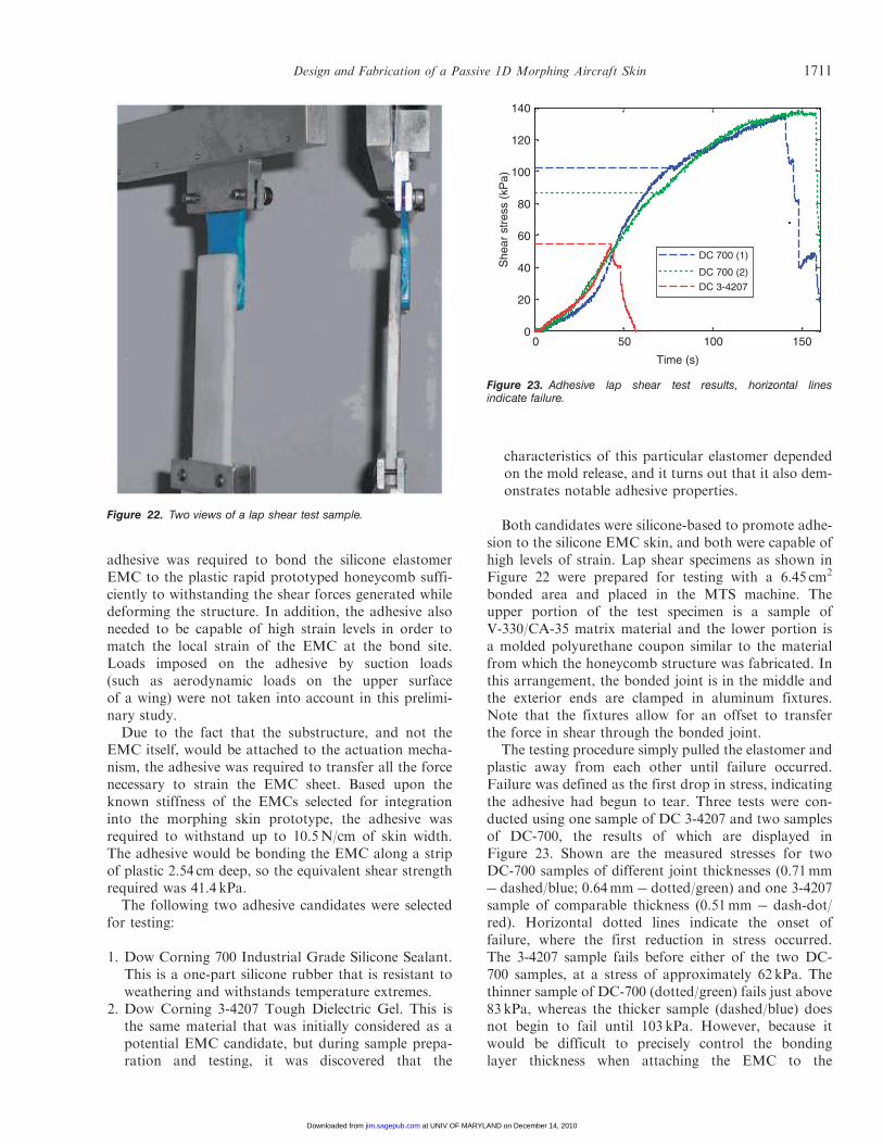
The testing procedure simply pulled the elastomer andplastic away from each other until failure occurred.Failure was defined as the first drop in stress, indicatingthe adhesive had begun to tear. Three tests were con-ducted using one sample of DC 3-4207 and two samplesof DC-700, the results of which are displayed inFigure 23. Shown are the measured stresses for twoDC-700 samples of different joint thicknesses (0.71mm� dashed/blue; 0.64mm � dotted/green) and one 3-4207sample of comparable thickness (0.51mm � dash-dot/red). Horizontal dotted lines indicate the onset offailure, where the first reduction in stress occurred.The 3-4207 sample fails before either of the two DC-700 samples, at a stress of approximately 62 kPa. Thethinner sample of DC-700 (dotted/green) fails just above83 kPa, whereas the thicker sample (dashed/blue) doesnot begin to fail until 103 kPa. However, because itwould be difficult to precisely control the bondinglayer thickness when attaching the EMC to the
Figure 22. Two views of a lap shear test sample.
0 50 100 1500
20
40
60
80
100
120
140
Time (s)
She
ar s
tres
s (k
Pa)
DC 700 (1)
DC 700 (2)
DC 3-4207
Figure 23. Adhesive lap shear test results, horizontal linesindicate failure.
Design and Fabrication of a Passive 1D Morphing Aircraft Skin 1711
at UNIV OF MARYLAND on December 14, 2010jim.sagepub.comDownloaded from

honeycomb core, the lowest DC-700 result (83 kPa) waschosen for comparison to the 3-4207 (62 kPa).Sufficient evidence was provided in this experiment to
demonstrate that the DC-700 was a more suitable adhe-sive for bonding the EMC elastomer matrix to the mod-ified re-entrant honeycomb. Not only did the DC-700fail at a higher stress than the DC 3-4207, but the initialtear in both DC-700 samples did not immediately prop-agate through the adhesive layer. The DC-700 samplescontinued to carry stress until total failure occurred atup to half again as high a stress level, giving it a safetyfactor of approximately 2. Assuming that future designand manufacturing advances can bring skin stiffnessdown even further, the already acceptable safety factorof this adhesive has positive implications for the safetyand reliability for an actual UAV morphing skinapplication.
INTEGRATION AND FINAL TESTING
A 152mm� 152mm morphing skin sample was fab-ricated from EMC #1. VeroBlue 14� angle honeycombwas used for the substructure, and DC 700 adhesive wasused to bond the EMC to the honeycomb substructure.To assist in the attachment, the rib members of the hon-eycomb core were designed with raised edges on oneside, as shown in Figure 24(a). This figure shows aside view of the zero-Poisson honeycomb, where it canbe seen that the top surface has the ribs extended tallerthan the bending members. Therefore, the bonding layercan be applied to the raised rib surfaces and pressedonto the EMC without bonding the bending membersto the EMC. A sectional side view of a single honey-comb cell, shown in Figure 24(b), illustrates how thebonded morphing skin looks. A thin layer of adhesiveis shown between the EMC and the ribs of the honey-comb, but it does not affect the movement of the bend-ing members. The outermost two ribs on thesubstructure were each 26mm wide, providing largebonding sites to carry the load of the skin understrain. This left 100mm of active length capable ofundergoing high strain deformation.The configuration of the morphing skin design is sum-
marized in Table 2. The assembled morphing skin
sample was used to assess in-plane and out-of-planestiffness before fabricating a final 165mm� 330mmfull scale test article for combination and evaluationwith the PAM actuation system described in the‘Introduction’ section.
In-plane Testing
The morphing skin sample was tested on an MTSmachine to 50% strain. The level of strain was limitedin order to prevent unforeseen damage to the morphingskin before it could be tested for out-of-plane stiffness aswell. In Figure 25(a), the morphing skin is shown under-going in-plane testing, with results presented inFigure 25(b). Note that the test procedure strained thespecimen incrementally to measure quasi-static stiffness,holding the position briefly before starting with the nextstage. Relaxation of the EMC sheet is the cause for thedips in force seen in the figure.
Based upon the individually measured stiffnesses ofthe EMC and substructure components used in themorphing skin and the stiffness of the skin overall, theenergy required to strain each structural element can bedetermined, with the adhesive strain energy found bysubtracting the strain energy of the other two compo-nents from the total for the morphing skin. The strainenergy contribution of each element is broken down inFigure 26 in energy per unit width required to strain thesample from 10 to 20 cm.
It can be seen that the adhesive had a considerablestrain energy requirement, more than double that of thehoneycomb substructure. When designing futuremorphing skins the energy to strain the adhesive layer
(b)
Carbon fiberlayer
Elastomer
BendingmemberR
ib
Rib
Adhesive
(a)
Figure 24. EMC structure bonding method: (a) honeycomb core; (b) single cell diagram.
Table 2. Morphing skin configuration.
Test article EMC Honeycomb AdhesiveActivelength
Skin #1 EMC #1,1.4 mm thick,
two CFlayers at 0o
14o zero-Poissonrapid
prototypedVeroBlue
DC-700 100 mm
1712 E. A. BUBERT ET AL.
at UNIV OF MARYLAND on December 14, 2010jim.sagepub.comDownloaded from

must be taken into account to ensure sufficient actuationforce is available to meet strain requirements. Morecareful attention to minimizing the amount of adhesiveused to bond the skin and substructure would likelyreduce the in-plane stiffness of the morphing skin by anon-trivial amount.
Out-of-plane Deflection
The final phase of evaluation for the two morphingskin samples required a method of measuring out-of-plane deflection under distributed loadings, approximat-ing aerodynamic forces. A number of testing protocolswere investigated, including ASTM standard D 6416/D6416M for testing simply supported composite platessubject to a distributed load. This particular test proto-col is intended for very stiff composites, not flexible ormembrane-like composites.A simpler approach to the problem was adopted
wherein acrylic retaining walls were placed above themorphing skin sample into which a distributed load oflead shot and sand could be poured. The final configu-ration of the out-of-plane deflection testing apparatuscan be seen in Figure 27. A set of lead screws stretchedthe morphing skin sample from rest to 100% strain. Theacrylic retaining walls could be adjusted to match theactive skin area, and were tall enough to contain leadshot equivalent to a distributed load of 200 psf(9.58 kPa). By applying a thin layer of sand directly tothe surface of the skin, the weight of the lead shot wasdistributed relatively evenly over the surface of theEMC. Moreover, as the skin deflected under load, thesand would adjust to conform to the surface and con-tinue to spread the weight of the lead. A single-pointlaser position sensor was also placed underneath to mea-sure the maximum deflections at the center of the skin,between the rib members. The assembled out-of-plane
deflection loading apparatus is shown in Figure 28(a),with the complete test setup in Figure 28(b).
The test procedure for each morphing skin coveredthe full range of operation, from resting (neutral posi-tion) to 100% area change. Lead screws were used to setthe skin to a nominal strain condition between 0% and100% of the resting length. The laser position sensorshown in Figure 28(c) was positioned in the center ofa honeycomb cell at the center of the morphing skin,where the greatest deflection is seen. This positioningwas achieved using a small two-axis adjustable tableseen at the bottom of Figure 28(b). The laser waszeroed on the under-surface of the EMC, and the rela-tive distance to the bottom of an adjacent rib was mea-sured. This established a zero measurement for ribdeflection as well. A layer of sand of known weightwas poured onto the surface of the EMC, and leadshot sufficient to load the skin to one of the three desireddistributed loads was added to the top of the sand. Wingloadings of 40 psf (1.92 kPa), 100 psf (4.79 kPa), and200 psf (1.92 kPa) were simulated. Once the load hadbeen applied, measurements were taken at the same
10
(b)(a)
8
6
For
ce p
er u
nit w
idth
(N
/cm
)
4
2
00 0.1 0.2
Strain (e)
0.40.3 0.5 0.6
Figure 25. Morphing skin sample in-plane testing: (a) skin #1 on MTS; (b) data from morphing skin in-plane testing.
Component contribution to strain energy
0
5
10
15
20
25
30
35
Components
Ene
rgy/
wid
th (
J/m
)
Honeycomb
Adhesive
Skin
Figure 26. Contributions to morphing skin strain energy.
Design and Fabrication of a Passive 1D Morphing Aircraft Skin 1713
at UNIV OF MARYLAND on December 14, 2010jim.sagepub.comDownloaded from

points on the EMC and the adjacent rib to determinedeflection. These measurements were repeated for fourdifferent strain conditions (0, 25%, 66%, 100%) and thethree different noted distributed loads.Experimental results from a morphing skin are pro-
vided in Figure 29. It was observed that, relative to therib deflections, the EMC sheet itself deflected very little(less than 0.25mm). The results in Figure 29 thereforeignore the small EMC deflections and show only themaximum deflection measured on the rib at the mid-point of each morphing skin. Overall, the morphingskin deflections show that as the skin is strained andunsupported length increases, the out-of-plane deflec-tion increases. Naturally, the deflection increases withload as well. Based on observation and on these results,the EMC sheets appeared to carry a greater out-of-planeload than expected, probably due to tension in the skin.EMC deflections between ribs remained low at all load-ing and strain conditions, while the substructure
3
2.5
2
Rib
def
lect
ion
(mm
)
1.5
1
0.5
00 20
200psf (9.58kPa)
40psf (1.92kPa)100psf (4.79kPa)
Strain (%)
6040 80 100
Figure 29. Out-of-plane deflection results as measured on thecenter rib.
Resting
Lead screws
Extended
Lead shot
Laser sensor
Retainingwalls
EMC sheet
Honeycomb
Sand
Figure 27. Out-of-plane deflection test apparatus design.
(a) (b) (c)
Figure 28. Out-of-plane deflection testing: (a) test apparatus; (b) laboratory setup; (c) measurement method.
1714 E. A. BUBERT ET AL.
at UNIV OF MARYLAND on December 14, 2010jim.sagepub.comDownloaded from

experienced deflections an order of magnitude greater.Future iterations of morphing skins will require stiffersubstructures to withstand out-of-plane loads.
Full-scale Integration and Evaluation
After proving capable of reaching over 100% strainwith largely acceptable out-of-plane performance, themorphing skin sample from the previous subsectionwas used as the basis for a full scale test article.A 34.3 cm� 14 cm morphing skin was fabricatedand attached to the actuation assembly. The actuationassembly, honeycomb sub-structure, and completedmorphing cell can be seen in Figure 30. Individual com-ponents of the system are pictured in Figure 30(a), whilethe assembled morphing skin test article appearsin Figure 30(b). The active region stretches from 9.1 to
18.3 cm with no transverse contraction, thus, producinga 1D, 100% increase in surface area with zero Poisson’sratio.
To characterize the static performance of the morph-ing cell, input pressure to the PAM actuators wasincreased incrementally from approximately 70 to620 kPa. The strain of the active region was recordedat each input pressure, and a load cell in line with onePAM recorded actuator force for comparison to pre-dicted values. This measurement process was repeatedthree times, recording strain, input pressure, and actua-tor force at each point. Note that the entire upper sur-face of the EMC is not the active region: each of thefixed-length ends of the honeycomb was designed andmanufactured with 25.4mm of excess material to allowadequate EMC bonding area and an attachment pointto the mechanism. This inactive region can be seen on
(a) (b)
34.3 cm
18.3 cm
9.1 cm
Figure 30. Integration of morphing cell: (a) actuation and sub-structure components; (b) complete morphing cell exhibiting 100% area change.
1000
1Test 1Test 2
Test 30.8
0.6
Str
ain
(e)
0.4
0.2
00 600100 200 300
Actuator pressure (kPa)
400 500
800
600
For
ce (
N)
400
200
00 20
Desired skin
Experimental skin resultsMorphing cell data
Force available predictedForce available measured
Force available
Forcerequired
X-frame extension (%)
6040 80 100
Figure 31. Morphing cell data: (a) static performance; (b) comparison with predictions.
Design and Fabrication of a Passive 1D Morphing Aircraft Skin 1715
at UNIV OF MARYLAND on December 14, 2010jim.sagepub.comDownloaded from

the top and bottom of the honeycomb shown in Figure30(a). The two extremities of the arrows in Figure 30(b)also account for the inactive region at both ends of themorphing skin.The static strain response to input actuator pressure is
displayed in Figure 31. Strain is seen to level off withincreasing pressure due to a combination of mechanismkinematics and the PAM actuator load lines, but thesystem was measured to achieve 95% strain at 585 kPaand was observed at 100% strain at slightly over620 kPa.The measured system performance matches analytical
predictions very closely. Evidence is shown inFigure 31(b), where the morphing skin data points over-lay the force�displacement data collected duringin-plane skin testing. The previously mentioned analyt-ical predictions and associated experimental data for theactuation system and skin performance are also repeatedin this figure. The morphing cell performance data,while not perfectly linear, approximately matches theslope of the experimental skin stiffness and intersectsthe actuation system experimental data near 100%extension. Furthermore, although the performancedata falls roughly 15% short of original predictions,the morphing skin meets the design goal, validatingthe analytical design process. Losses were not includedin the original system predictions. However, the marginof error included in the original design for friction,increased skin stiffness, and other losses enabled thefinal morphing cell prototype to achieve 100% strain.It should also be noted that 100% area increases couldbe achieved repeatedly at 1Hz using manual actuatorpressurization.
CONCLUSIONS
A passive 1D morphing skin was designed for use onan existing pneumatic actuation system. The skin con-sisted of an EMC face sheet with a zero-Poisson honey-comb substructure intended to support out of planeloads. In-plane stiffness was controlled to match thecapabilities of the actuator by careful design and testingof each separate skin component. Complete morphingskins were tested for in-plane and out-of-plane perfor-mance and integrated with the actuator to validate thedesign process.
1. An analytical design procedure was used to size indi-vidual morphing skin components so their combinedstiffness matched actuator capabilities. EMC perfor-mance was calculated using classical laminated platetheory with modified micromechanics, successfullypredicting in-plane skin stiffness and Poisson ratio.
A zero-Poisson honeycomb substructure was alsodesigned using a modification to Gibson andAshby’s analytical method to accurately predictin-plane stiffness.
2. Using FEM analysis, the local strain in the honey-comb bending members was determined to be anorder of magnitude lower than global strain. For±30% global strain, the maximum local strain wasapproximately 1.5%. Based on this result, it isexpected a zero-Poisson honeycomb can be designedto achieve high strain with a reasonable fatigue life.
3. Design goals of 100% global strain and 100% areachange were demonstrated on a laboratory prototypeusing the combined morphing skin and actuationmechanism. The morphing skin strained smoothlyand exhibited a very low in-plane Poisson’sratio. Actuation frequencies of roughly 1Hz wereachieved.
ACKNOWLEDGEMENTS
This work was sponsored by the Air Force ResearchLaboratory (AFRL) through a Phase I STTR, contractnumber FA9550-06-C-0132, with technical monitorsDrs Brian Sanders and Victor Giurgiutiu. The authorsgreatly acknowledge the support.
REFERENCES
Agarwal, B.D., Broutman, L.J. and Chandrashekhara, K. 2006.Analysis and Performance of Fiber Composites, John Wiley &Sons, Hoboken.
Anderson, J.D. 1985. Introduction to Flight, 2nd edn, McGraw-Hill,Inc., New York.
Bae, J.S., Seigler, T.M. and Inman, D.J. 2005. ‘‘Aerodynamic andStatic Aeroelastic Characteristics of a Variable-Span MorphingWing,’’ Journal of Aircraft, 42:528�534.
Blondeau, J.E. and Pines, D.J. 2004. ‘‘Pneumatic Morphing AspectRatio Wing,’’ In: 45th AIAA/ASME/ASCE/AHS/ASCStructures, Structural Dynamics & Materials Conference, 19�22April, Palm Springs, CA, Paper No. AIAA 2004-1808.
Buseman, A. 1935. ‘‘Aerodynamic Lift at Supersonic Speeds,’’ Ae.Techl. 1201, Report No. 2844 (British ARC, February 3, 1937),Bd. 12, Nr. 6, October, pp. 210�220.
Bye, D.R. and McClure, P.D. 2007. ‘‘Design of a Morphing Vehicle,’’In: 48th AIAA Structures, Structural Dynamics, and MaterialsConference, 23�26 April, Honolulu, HI, Paper No. AIAA2007-1728.
Chaves, F.D., Avila, J. and Avila, A.F. 2003. ‘‘A Morphological Studyon Cellular Composites with Negative Poisson’s Ratios,’’In: Proceedings of 44th AIAA Structures, Structural Dynamics,and Materials Conference, 7�10 April, Norfolk, VA, Paper No.AIAA 2003-1951.
Flanagan, J., Strutzenberg, R., Myers, R. and Rodrian, J. 2007.‘‘Development and Flight Testing of a Morphing Aircraft, theNextGen MFX-1,’’ In: Proceedings of 48th AIAA Structures,Structural Dynamics, and Materials Conference, 23�26 April,Honolulu, HI, Paper No. AIAA 2007-1707.
1716 E. A. BUBERT ET AL.
at UNIV OF MARYLAND on December 14, 2010jim.sagepub.comDownloaded from

Gern, F.H., Inman, D.J. and Kapania, R.K. 2002. ‘‘Structuraland Aeroelastic Modeling of General Planform Wings withMorphing Airfoils,’’ AIAA Journal, 40:628�637.
Gevers, D.E. 1997. ‘‘Multi-purpose Aircraft,’’ US Patent No.5,645,250.
Gibson, L.J. and Ashby, M.F. 1988. Cellular Solids: Structure andProperties, Pergamon Press, Oxford.
Henry, J.J. 2005. ‘‘Roll Control for UAVs by Use of a Variable SpanMorphing Wing,’’ Master’s Thesis, Department of AerospaceEngineering, University of Maryland, College Park, MD.
Hetrick, J.A., Osborn, R.F., Kota, S., Flick, P.M. and Paul, D.B.2007. ‘‘Flight Testing of Mission Adaptive Compliant Wing,’’In: Proceedings of 48th AIAA Structures, Structural Dynamics,and Materials Conference, 23�26 April, Honolulu, HI, PaperNo. AIAA 2007-1709.
Kikuta, M.T. 2003. ‘‘Mechanical Properties of Candidate Materialsfor Morphing Wings,’’ MS Thesis, Virginia Polytechnic Instituteand State University, Blacksburg, VA.
Munk, M.M. 1924. ‘‘Note on the relative Effect of the Dihedral andthe Sweep Back of Airplane Wings,’’ NACA Technical Note 177.
Murray, G., Gandhi, F. and Bakis, C. 2007. ‘‘Flexible MatrixComposite Skins for One-Dimensional Wing Morphing,’’In: Proceedings of 48th AIAA Structures, Structural Dynamics,and Materials Conference, 23�26 April, Honolulu, HI, PaperNo. AIAA 2007-1737.
Olympio, K.R. 2006. ‘‘Design of a Passive Flexible Skin for MorphingAircraft Structures,’’ MS Thesis, Pennsylvania State University.
Olympio, K. and Gandhi, F. 2007. ‘‘Zero-n Cellular HoneycombFlexible Skins of One-dimensional Wing Morphing,’’In: Proceedings of 48th AIAA Structures, Structural Dynamics,and Materials Conference, 23�26 April, Honolulu, HI, PaperNo. AIAA 2007-1735.
Parker, H.J. 1920. ‘‘The Parker Variable Camber Wing,’’ Report #77Fifth Annual Report, National Advisory Committee forAeronautics, Washington, DC.
Perkins, D.A., Reed, J.L. and Havens, E. 2004. ‘‘Morphing WingStructures for Loitering Air Vehicles,’’ In: 45th AIAAStructures, Structural Dynamics & Materials Conference, 19�22April, Palm Springs, CA, Paper No. AIAA 2004-1888.
Sarh, B. 1991. ‘‘Convertible Fixed Wing Aircraft,’’ US Patent No.4,986,493.
Shigley, J., Mishke, C. and Budynas, R. 2004. Mechanical EngineeringDesign, McGraw-Hill, New York.
Thill, C., Etches, J., Bond, I., Potter, K. and Weaver, P. 2008.‘‘Morphing Skins,’’ The Aeronautical Journal, 112:117�139.
Toensmeier, P.A. 2005. Morphing Aircraft Could Bring Multi-RoleCapability to Next Generation Aircraft, Aviation Weekly, May,pp. 72�73.
Wereley, N.M. and Kothera, C.S. 2007. ‘‘Morphing Aircraft UsingFluidic Artificial Muscles,’’ In: Proceedings of the InternationalConference on Adaptive Structures and Technologies, 2�5October, Ottawa, ON, Paper ID 171.
Design and Fabrication of a Passive 1D Morphing Aircraft Skin 1717
at UNIV OF MARYLAND on December 14, 2010jim.sagepub.comDownloaded from
Copyright © 2022 FDOKUMEN