Design and Development of Vibration Method for Vehicle ...
7
Procedia Engineering 41 (2012) 1114 – 1120 1877-7058 © 2012 Published by Elsevier Ltd. doi:10.1016/j.proeng.2012.07.290 International Symposium on Robotics and Intelligent Sensors 2012 (IRIS 2012) Design and Development of Vibration Method for Vehicle Reverse System (VRS) Kassim A.M*, M. S. Jamri, Aras, M.S.M, Rashid, M.Z.A Faculty of Electrical Engineering, Universiti Teknikal Malaysia Melaka (UTeM), Hang Tuah Jaya, 76100, Durian Tunggal, Melaka, Malaysia Abstract This paper discussed on design and development of Vehicle Reverse System (VRS) by using normal beeping car warning system and combination with vibrators in order to support the hearing impaired. This electronic device is an innovation product to support and help those hearing problem people such as elder person and disability person to have their own confident in driving their vehicles especially for detecting distance and location of the obstacle during reverse condition. This project is about developing of car warning system by using a vibrator as a warning device via main processing unit which consists of peripheral integrated circuit (PIC) and other electronic power supply which is received input signals from the distance sensor and translated it into the vibration composition when detecting obstacle. The vibration motor is a best solution to warn the hearing disability person because it uses touch sense of human when the system is run. In this system, there are four pieces of vibration mot or are mounted to the driver’s seat at different locations. Each location will have its own function that show different direction such as upper left, upper right, bottom left and bottom right. In this project, the effectiveness of the system gives command the direction of obstacle existence is very important and have been confirmed through simulation and experiment. © 2012 The Authors. Published by Elsevier Ltd. Selection and/or peer-review under responsibility of the Centre of Humanoid Robots and Bio-Sensor (HuRoBs), Faculty of Mechanical Engineering, Universiti Teknologi MARA. Keywords: Car warning system, vibration motor (vibrator), hearing impairment person, obstacle detection 1. Introduction In year 2000, hearing impairment became the most frequent sensory deficit in human population where it is affecting more than 250 million people around the world. There is a diversity of definitions of hearing impairment so that the comparison among studies is difficult. According to World Health Organization (WHO), the classification that classified hearing impairment is based to pure tone average in the better hearing ear. The categories are ranges from “no impairment” to “profound impairment” according to threshold level. Table 1 shows the grades of hearing impairment released by WHO[1]. On the other hand, in early 2010, the Organization of the United Nations (UN) has been released the statistic that people with disabilities (PWDs) in the world are 10% of the total population. Hence, the Malaysian population is estimated around 2.8 million people with disabilities. However, the numbers of people with disabilities which are registered with the Social Welfare Department (JKM) are only about 280 thousand people which are 12 percent of the estimated population of the * Corresponding author. Tel.: +6-06-555-2317; Fax: +6-06-555-2222. E-mail address: [email protected] Available online at www.sciencedirect.com Open access under CC BY-NC-ND license. Open access under CC BY-NC-ND license. brought to you by CORE View metadata, citation and similar papers at core.ac.uk provided by Elsevier - Publisher Connector
-
Upload
khangminh22 -
Category
Documents
-
view
3 -
download
0
Transcript of Design and Development of Vibration Method for Vehicle ...
Procedia Engineering 41 ( 2012 ) 1114 – 1120
1877-7058 © 2012 Published by Elsevier Ltd.doi: 10.1016/j.proeng.2012.07.290
International Symposium on Robotics and Intelligent Sensors 2012 (IRIS 2012)
Design and Development of Vibration Method for Vehicle Reverse System (VRS)
Kassim A.M*, M. S. Jamri, Aras, M.S.M, Rashid, M.Z.A Faculty of Electrical Engineering,
Universiti Teknikal Malaysia Melaka (UTeM), Hang Tuah Jaya,
76100, Durian Tunggal, Melaka, Malaysia
Abstract
This paper discussed on design and development of Vehicle Reverse System (VRS) by using normal beeping car warning system and combination with vibrators in order to support the hearing impaired. This electronic device is an innovation product to support and help those hearing problem people such as elder person and disability person to have their own confident in driving their vehicles especially for detecting distance and location of the obstacle during reverse condition. This project is about developing of car warning system by using a vibrator as a warning device via main processing unit which consists of peripheral integrated circuit (PIC) and other electronic power supply which is received input signals from the distance sensor and translated it into the vibration composition when detecting obstacle. The vibration motor is a best solution to warn the hearing disability person because it uses touch sense of human when the system is run. In this system, there are four pieces of vibration motor are mounted to the driver’s seat at different locations. Each location will have its own function that show different direction such as upper left, upper right, bottom left and bottom right. In this project, the effectiveness of the system gives command the direction of obstacle existence is very important and have been confirmed through simulation and experiment. © 2012 The Authors. Published by Elsevier Ltd. Selection and/or peer-review under responsibility of the Centre of Humanoid Robots and Bio-Sensor (HuRoBs), Faculty of Mechanical Engineering, Universiti Teknologi MARA. Keywords: Car warning system, vibration motor (vibrator), hearing impairment person, obstacle detection
1. Introduction
In year 2000, hearing impairment became the most frequent sensory deficit in human population where it is affecting more than 250 million people around the world. There is a diversity of definitions of hearing impairment so that the comparison among studies is difficult. According to World Health Organization (WHO), the classification that classified hearing impairment is based to pure tone average in the better hearing ear. The categories are ranges from “no impairment” to “profound impairment” according to threshold level. Table 1 shows the grades of hearing impairment released by WHO[1]. On the other hand, in early 2010, the Organization of the United Nations (UN) has been released the statistic that people with disabilities (PWDs) in the world are 10% of the total population. Hence, the Malaysian population is estimated around 2.8 million people with disabilities. However, the numbers of people with disabilities which are registered with the Social Welfare Department (JKM) are only about 280 thousand people which are 12 percent of the estimated population of the
* Corresponding author. Tel.: +6-06-555-2317; Fax: +6-06-555-2222. E-mail address: [email protected]
Available online at www.sciencedirect.com
Open access under CC BY-NC-ND license.
Open access under CC BY-NC-ND license.
brought to you by COREView metadata, citation and similar papers at core.ac.uk
provided by Elsevier - Publisher Connector
1115 A.M. Kassim et al. / Procedia Engineering 41 ( 2012 ) 1114 – 1120
disabled in our country [2]. This total number does not reflect to the real situation of disabled people in this country. Most of the disabled are ignored by the government, which they need not be considered.
Table 1. Grades of hearing impairment
Grade of Impairment Audiometric ISO value
(average of 500, 1000, 2000, 4000 Hz)
Impairment Description
0 (no impairment) 25 dBHL or less (better ear) No or very slight hearing problems. Able to hear whispers
1 (slight impairment) 26-40 dBHL (better ear) Able to hear and repeat words spoken in normal voice at 1 metre
2 (moderate impairment) 41-60 dBHL (better ear) Able to hear and repeat words using raised voice at 1 metre
3 (severe impairment) 61-80 dBHL (better ear) Able to hear some words when shouted into better ear
4 (Profound impairment
including deafness)
81 dBHL or greater (better ear) Unable to hear and understand even a shouted voice.
Hearing disabilities people caused whether by natural significant sensory loss or by tinnitus or epidemic of hearing loss in older people usually having the same problem in terms of reversing their vehicles. As a matter of fact, the existing reverse system is only provides beeping sound to the driver which is not suitable for those hearing impairments people. There are several types of car back-up warning system found in the market such as reverse radar, reverse alarm audio system, reverse camera, etc. As known, all these systems are used to alert driver towards the distance in any direction based on location of sensor mounted at the vehicle and the presence of any obstacles usually during parking the car without have to turn around their head.
As mentioned before, typical existing car reverse sensor system is only alert the driver by beeping sound. Therefore, this method cannot be said as user friendly system since it is not applicable for them. Hence, there are a lot of researches that have been actively researched and developed a better warning system such as combining it with automatic parking system (APS), vehicle approaching alarm, rear view camera, reverse camera, etc [3-7] where the distance towards obstacle is able to measure accurately to avoid collision or danger to the driver.
In this paper, the assistive device for car reversing system for hearing impaired person is described. The warning system which is developed is combined the beeping sound with the vibration impact. In addition, the warning system will assist them to predict the location of obstacles by using distance measurement sensor. When the distance sensors detect the obstacles, the generated warning signal will be given quickly to the processing unit and translated into vibration composition. The vibrators are used to alert the driver via vibration mechanism and they are located in the driver’s portable sit base. These vibration motors are arranged to give the vibration alert according to the obstacle area such as upper left, upper right, bottom left and bottom right at the back side of the vehicle. Therefore, the driver would easily recognize and aware of the existence obstacle area by only through vibration. Therefore, it will help the hearing impaired person to easily recognize and aware of the existence obstacle area by only through vibration besides reduce the risk of accident or collision. The effectiveness of this proposed system is also evaluated in this paper.
2. Developed Vibration Method for Vehicle Reverse System
2.1 Device Construction
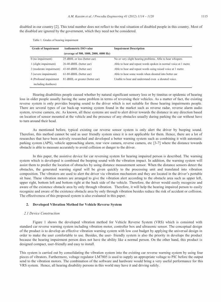
Figure 1 shows the developed vibration method for Vehicle Reverse System (VRS) which is consisted with standard car reverse warning system including vibration motor, controller box and ultrasonic sensor. The conceptual design of the product is to develop an effective vibration warning system with low cost budget by applying the universal design in order to make the user comfortable to use. Besides, the user- friendly system is also the priority in develops the product because the hearing impairment person does not have the ability like a normal person. On the other hand, this product is designed compact, user-friendly and easy to install.
This system is carried out by consolidating the vibration system into the existing car reverse warning system by using four pieces of vibrators. Furthermore, voltage regulator LM7805 is used to supply an appropriate voltage to PIC before the output send to the vibration motors. The combination of the software and hardware would bring a very useful performance for this VRS system. Hence, all hearing disability persons in this world may have it and driving safely.
1116 A.M. Kassim et al. / Procedia Engineering 41 ( 2012 ) 1114 – 1120
Figure 1. Developed “vibration method for Vehicle Reverse System (VRS)”
2.2 Experimental Setup
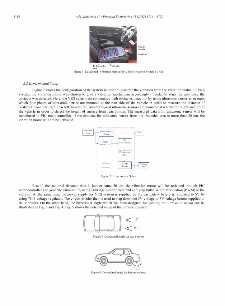
Figure 2 shows the configuration of the system in order to generate the vibration from the vibration motor. In VRS system, the vibration motor was chosen to give a vibration mechanism accordingly in order to warn the user once the obstacle was detected. Here, the VRS system are constructed with obstacles detection by using ultrasonic sensor as an input which four pieces of ultrasonic sensor are mounted at the rear side of the vehicle in order to measure the distance of obstacles from rear right, rear left. In addition, another two of ultrasonic sensors are mounted at rear bottom right and left of the vehicle in order to detect the height of surface from rear bottom. The measured data from ultrasonic sensor will be transferred to PIC microcontroller. If the distance for ultrasonic sensor from the obstacles area is more than 50 cm, the vibration motor will not be activated.
Figure 2. Experimental Setup
Else if, the acquired distance data is less or same 50 cm, the vibration motor will be activated through PIC microcontroller and generate vibration by using H-bridge motor driver and applying Pulse Width Modulation (PWM) to the vibrator. At the same time, the power supply for VRS system is supplied by the car battery before is regulated to 5V by using 7805 voltage regulator. The circuit divider then is used to step down the 5V voltage to 3V voltage before supplied to the vibrators. On the other hand, the directional angle which has been designed for locating the ultrasonic sensor can be illustrated as Fig. 3 and Fig. 4. Fig. 5 shows the detected range of the ultrasonic sensor.
Figure 3. Directional angle for rear sensors
Figure 4. Directional angle for bottom sensors 15°
1117 A.M. Kassim et al. / Procedia Engineering 41 ( 2012 ) 1114 – 1120
Figure 5. Directional angle for obstacle detection
3. Proposed Warning System
3.1 Vibration system
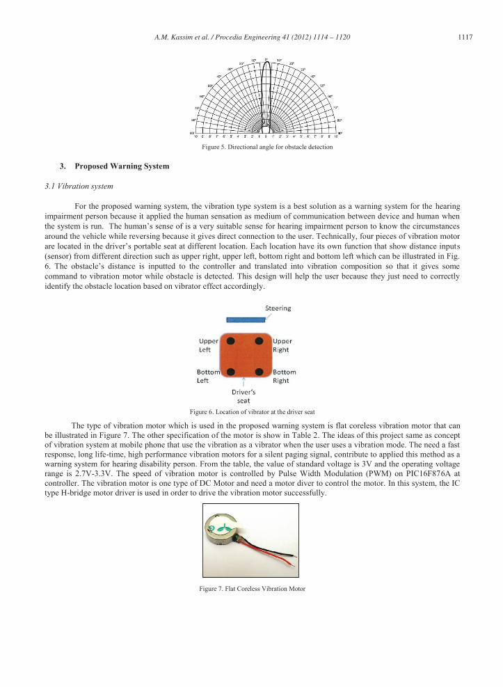
For the proposed warning system, the vibration type system is a best solution as a warning system for the hearing impairment person because it applied the human sensation as medium of communication between device and human when the system is run. The human’s sense of is a very suitable sense for hearing impairment person to know the circumstances around the vehicle while reversing because it gives direct connection to the user. Technically, four pieces of vibration motor are located in the driver’s portable seat at different location. Each location have its own function that show distance inputs (sensor) from different direction such as upper right, upper left, bottom right and bottom left which can be illustrated in Fig. 6. The obstacle’s distance is inputted to the controller and translated into vibration composition so that it gives some command to vibration motor while obstacle is detected. This design will help the user because they just need to correctly identify the obstacle location based on vibrator effect accordingly.
Figure 6. Location of vibrator at the driver seat
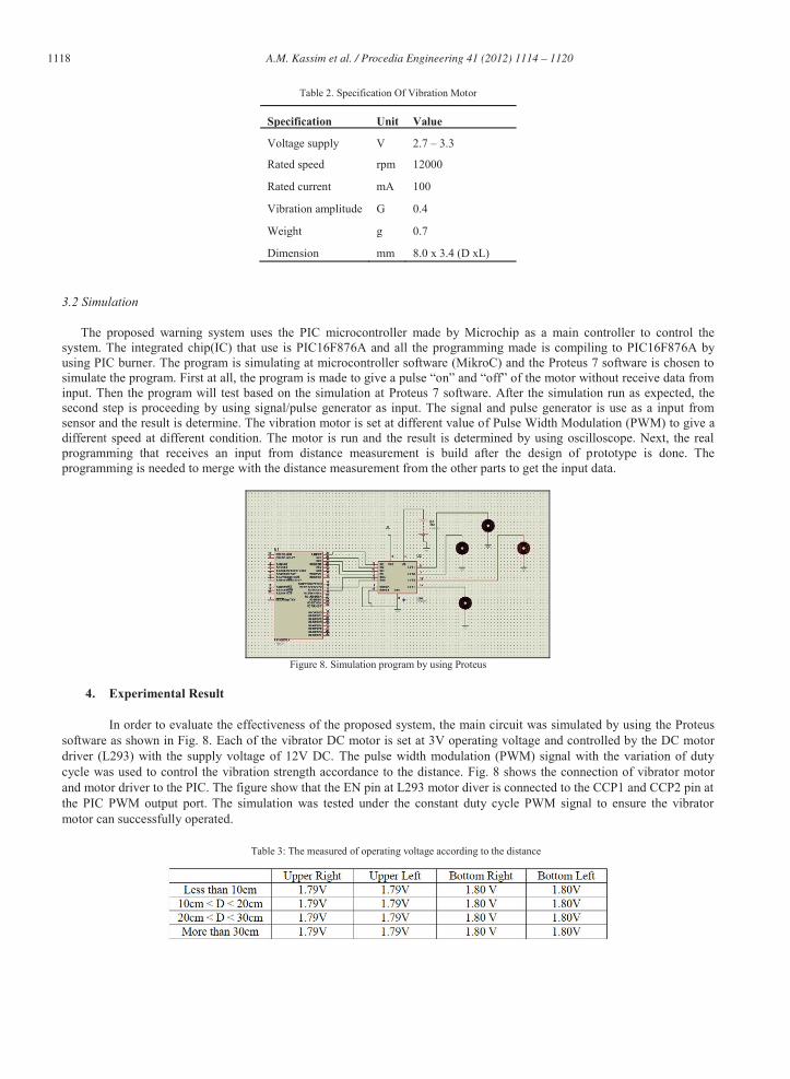
The type of vibration motor which is used in the proposed warning system is flat coreless vibration motor that can be illustrated in Figure 7. The other specification of the motor is show in Table 2. The ideas of this project same as concept of vibration system at mobile phone that use the vibration as a vibrator when the user uses a vibration mode. The need a fast response, long life-time, high performance vibration motors for a silent paging signal, contribute to applied this method as a warning system for hearing disability person. From the table, the value of standard voltage is 3V and the operating voltage range is 2.7V-3.3V. The speed of vibration motor is controlled by Pulse Width Modulation (PWM) on PIC16F876A at controller. The vibration motor is one type of DC Motor and need a motor diver to control the motor. In this system, the IC type H-bridge motor driver is used in order to drive the vibration motor successfully.
Figure 7. Flat Coreless Vibration Motor
1118 A.M. Kassim et al. / Procedia Engineering 41 ( 2012 ) 1114 – 1120
Table 2. Specification Of Vibration Motor
Specification Unit Value
Voltage supply V 2.7 – 3.3
Rated speed rpm 12000
Rated current mA 100
Vibration amplitude G 0.4
Weight g 0.7
Dimension mm 8.0 x 3.4 (D xL)
3.2 Simulation
The proposed warning system uses the PIC microcontroller made by Microchip as a main controller to control the system. The integrated chip(IC) that use is PIC16F876A and all the programming made is compiling to PIC16F876A by using PIC burner. The program is simulating at microcontroller software (MikroC) and the Proteus 7 software is chosen to simulate the program. First at all, the program is made to give a pulse “on” and “off” of the motor without receive data from input. Then the program will test based on the simulation at Proteus 7 software. After the simulation run as expected, the second step is proceeding by using signal/pulse generator as input. The signal and pulse generator is use as a input from sensor and the result is determine. The vibration motor is set at different value of Pulse Width Modulation (PWM) to give a different speed at different condition. The motor is run and the result is determined by using oscilloscope. Next, the real programming that receives an input from distance measurement is build after the design of prototype is done. The programming is needed to merge with the distance measurement from the other parts to get the input data.
Figure 8. Simulation program by using Proteus
4. Experimental Result
In order to evaluate the effectiveness of the proposed system, the main circuit was simulated by using the Proteus software as shown in Fig. 8. Each of the vibrator DC motor is set at 3V operating voltage and controlled by the DC motor driver (L293) with the supply voltage of 12V DC. The pulse width modulation (PWM) signal with the variation of duty cycle was used to control the vibration strength accordance to the distance. Fig. 8 shows the connection of vibrator motor and motor driver to the PIC. The figure show that the EN pin at L293 motor diver is connected to the CCP1 and CCP2 pin at the PIC PWM output port. The simulation was tested under the constant duty cycle PWM signal to ensure the vibrator motor can successfully operated.
Table 3: The measured of operating voltage according to the distance
1119 A.M. Kassim et al. / Procedia Engineering 41 ( 2012 ) 1114 – 1120
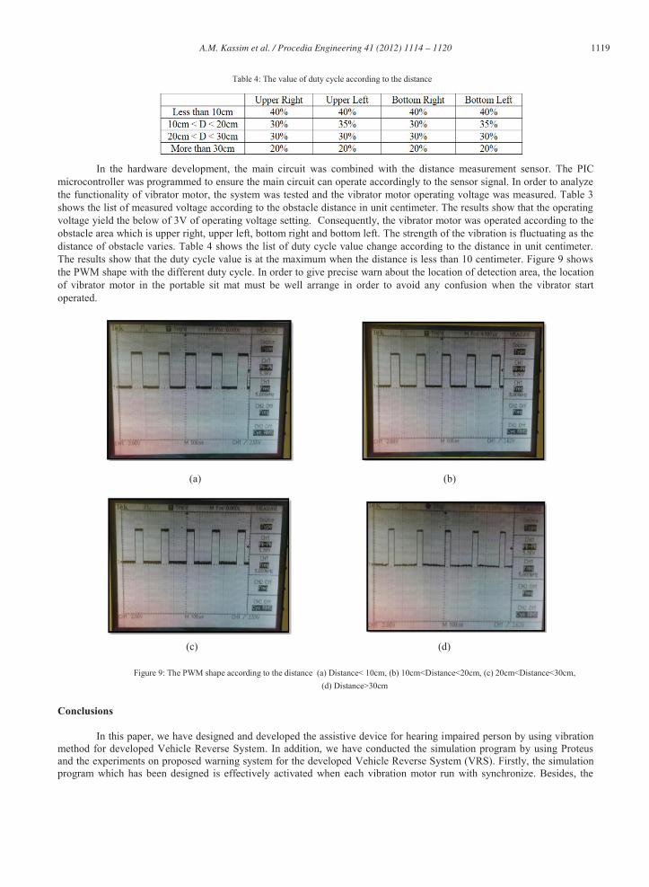
Table 4: The value of duty cycle according to the distance
In the hardware development, the main circuit was combined with the distance measurement sensor. The PIC microcontroller was programmed to ensure the main circuit can operate accordingly to the sensor signal. In order to analyze the functionality of vibrator motor, the system was tested and the vibrator motor operating voltage was measured. Table 3 shows the list of measured voltage according to the obstacle distance in unit centimeter. The results show that the operating voltage yield the below of 3V of operating voltage setting. Consequently, the vibrator motor was operated according to the obstacle area which is upper right, upper left, bottom right and bottom left. The strength of the vibration is fluctuating as the distance of obstacle varies. Table 4 shows the list of duty cycle value change according to the distance in unit centimeter. The results show that the duty cycle value is at the maximum when the distance is less than 10 centimeter. Figure 9 shows the PWM shape with the different duty cycle. In order to give precise warn about the location of detection area, the location of vibrator motor in the portable sit mat must be well arrange in order to avoid any confusion when the vibrator start operated.
(a) (b)
(c) (d)
Figure 9: The PWM shape according to the distance (a) Distance< 10cm, (b) 10cm<Distance<20cm, (c) 20cm<Distance<30cm, (d) Distance>30cm
Conclusions
In this paper, we have designed and developed the assistive device for hearing impaired person by using vibration method for developed Vehicle Reverse System. In addition, we have conducted the simulation program by using Proteus and the experiments on proposed warning system for the developed Vehicle Reverse System (VRS). Firstly, the simulation program which has been designed is effectively activated when each vibration motor run with synchronize. Besides, the
1120 A.M. Kassim et al. / Procedia Engineering 41 ( 2012 ) 1114 – 1120
effectiveness of this developed VRS also confirmed when the vibration motor at developed device are vibrated if the obstacles are detected. The vibration motor is vibrated according to the direction of obstacle which has been detected. In the future, VRS can be commercializing into the current car system.
Acknowledgements
This research was supported by research grant from Universiti Teknikal Malaysia Melaka award no. PJP/2011/FKE (32C) S00948 and technically supported by University of Tokushima, Japan.
References
[1] Deafness and Hearing Problem Report, World Health Organization, April 2010 [2] Country Repor Malaysia, The 7th ASEAN & Japan High Level officials Meeting on Caring Societies: “Towars and inclusive society” –
strengthening the collaboration between social welfare , health and medical systems for children with disabilities, Sept 2009 [3] Tsung-hua Hsu, Jing-Fu Liu, Pen-Ning Yu, Wang-Shuan Lee and Jia-Sing Hsu, “Development of an Automatic Parking System for Vehicle”, IEEE
Vehicle Power and Propulsion Conference (VPPC), 2008. [4] Zhitao Li, “Reverse Radar with Vehicle Approaching Alarm”, Patent Application Publication, 2007. [5] Pin-Houn Lin, “Automatic Alarm System for Detecting Obstacles behind a Backing Vehicle”, United State Patent, 1981. [6] Guanglin-Ma, Manoj Dwivedi, Ran Li, Chong Sun and Anton Kummert, “A Real-Time Rear View Camera Based Obstacle Detection”, Proceeding of
the 12th International IEEE Conference on Intelligent Transportation Systems, 408-413,2009. [7] Zhang Yankun, Hong Chuyang, Weyrich and Norman, “A Single Camera Based Rear Obstacle Detection System”, IEEE Intelligent Vehicle
Symposium (IV),485-490, 2011.