design and development of a smart lighting point and ...
9
Zaria Journal of Electrical Engineering Technology, Department of Electrical Engineering, Ahmadu Bello University, Zaria – Nigeria. Vol. 10 No. 1, March 2021. ISSN: 0261 – 1570. 135 DESIGN AND DEVELOPMENT OF A SMART LIGHTING POINT AND TEMPERATURE CONTROL SYSTEM Ufot, E. G. 1 , Abubakar, I. N. 2 , Dodo, U. A. 3 ,Okosun O. E. 4 , Dodo, M. A. 5 1 Department of Electrical and Electronic Engineering Akwa Ibom State University Ikot Akpaden, Nigeria . 2 Department of Electrical and Electronic Engineering, Federal University of Technology, Minna Niger State, Nigeria. 3 Electrical and Computer Engineering Department, Baze University, Abuja, Nigeria. 4 Department of Electrical and Electronic Engineering, Federal University of Technology, Minna Niger State, Nigeria. 5 Department of Electrical Engineering Technology, Federal Polytechnic P.M.B 55, Bida, Niger State, Nigeria. 1 [email protected], 2 [email protected], 3 [email protected], 4 o.okosun @futminna.edu.ng, 5 [email protected] [email protected] Keywords: – Automation Cooling system Microcontroller Temperature sensing device (LM35) 7segment Display. Article History: – Received: January, 2019. Reviewed: April, 2019 Accepted: May, 2019 Published: June, 2019 ABSTRACT Conservation of energy which is the main focus of this paper is very important in order to reduce utility cost in residential buildings. Hence, a Smart lighting Point and Temperature Control system is designed and developed to control automatically, the electrical appliances in residential buildings. Smart lighting Point and Temperature Control system consist of a microcontroller, which serves as the brainbox of the system. The functionality of a Passive Infra-red sensor is employed in this system to detect the motion of a person entering or leaving the building; the system further detect the difference in surrounding light intensities through the aid of a Light Dependant Resistor to turn ON/OFF the lights automatically. it then checks to see if the temperature within the building is above the pre-set value to turn ON/OFF the cooling system. The number of persons entering or leaving the building is displayed on a seven-segment display. . 1. INTRODUCTION In this present generation, one of the most important and valuable resource is electrical energy; thus, the need for devising a means by which it can be conserved is of paramount importance to our system. Over the years, the challenges associated with energy have become a major problem that the world has been confronted with. Statistic has it that the power requirement by residential buildings forms to a greater extent the largest percentage of the world's power consumption. In fact, electrical appliances control is among recent innovations in residential building, industry and office equipment design and managements have enabled/facilitated the advancement in communications technology [1] [2]. Lighting is a major requirement of any building, whether residential, commercial or industrial, coupled with a cooling system that could be ceiling fans, air conditions, etc. Sometimes, people leave their homes and forget to switch the lights OFF, and other electronic appliances constitute wastage of power. When one want to make life comfortable and less stressful, one of the innovations that comes to mind is automation coupled with the hope of spending less financially in terms of utility bill and also to save the energy consumption at home as it involves a better way [3] of the control and management of home equipment such as lighting, heating/Air-Conditioner etc. This paper seeks to build upon the existing smart system with improvement and a cost-effective approach in achieving it. Since lighting point and temperature control are achieved through ON/OFF switches manually operated, the smart lighting point and temperature control system will take over this task. This paper is made up of two sections: a. Lighting with person counter; and b. Automatic temperature control system. The main idea behind this paper is to control the lighting points and temperature of a building depending upon persons present in the building. The system operates based on the intensities of light inside and surrounding the building given at least one person. The system works base on priority levels. During the daytime, when the surrounding light intensity is sufficiently higher than that in the building, all the lights remain off even though a person is present in the building. At night the sensor detects a difference in light intensities and signals the microcontroller about the difference in the surrounding light intensities. Through the aid of a counter, the number of persons inside
-
Upload
khangminh22 -
Category
Documents
-
view
3 -
download
0
Transcript of design and development of a smart lighting point and ...

Zaria Journal of Electrical Engineering Technology, Department of Electrical Engineering, Ahmadu Bello University, Zaria – Nigeria. Vol. 10 No. 1, March 2021. ISSN: 0261 – 1570.
135
DESIGN AND DEVELOPMENT OF A SMART LIGHTING POINT AND
TEMPERATURE CONTROL SYSTEM
Ufot, E. G.1, Abubakar, I. N.2 , Dodo, U. A.3,Okosun O. E.4, Dodo, M. A.5
1Department of Electrical and Electronic Engineering Akwa Ibom State University
Ikot Akpaden, Nigeria . 2Department of Electrical and Electronic Engineering, Federal University of
Technology, Minna Niger State, Nigeria. 3Electrical and Computer Engineering Department, Baze University, Abuja, Nigeria.
4 Department of Electrical and Electronic Engineering, Federal University of
Technology, Minna Niger State, Nigeria. 5Department of Electrical Engineering Technology, Federal Polytechnic P.M.B 55,
Bida, Niger State, Nigeria. [email protected],[email protected],[email protected],4o.okosun
@futminna.edu.ng, [email protected]
Keywords: –
Automation
Cooling system
Microcontroller
Temperature sensing device (LM35)
7segment Display.
Article History: –
Received: January, 2019.
Reviewed: April, 2019
Accepted: May, 2019
Published: June, 2019
ABSTRACT
Conservation of energy which is the main focus of this paper is very important in order
to reduce utility cost in residential buildings. Hence, a Smart lighting Point and
Temperature Control system is designed and developed to control automatically, the
electrical appliances in residential buildings. Smart lighting Point and Temperature
Control system consist of a microcontroller, which serves as the brainbox of the system.
The functionality of a Passive Infra-red sensor is employed in this system to detect the
motion of a person entering or leaving the building; the system further detect the
difference in surrounding light intensities through the aid of a Light Dependant Resistor
to turn ON/OFF the lights automatically. it then checks to see if the temperature within
the building is above the pre-set value to turn ON/OFF the cooling system. The number
of persons entering or leaving the building is displayed on a seven-segment display.
.
1. INTRODUCTION
In this present generation, one of the most important and
valuable resource is electrical energy; thus, the need for
devising a means by which it can be conserved is of
paramount importance to our system. Over the years, the
challenges associated with energy have become a major
problem that the world has been confronted with. Statistic
has it that the power requirement by residential buildings
forms to a greater extent the largest percentage of the
world's power consumption. In fact, electrical appliances
control is among recent innovations in residential building,
industry and office equipment design and managements
have enabled/facilitated the advancement in
communications technology [1] [2]. Lighting is a major
requirement of any building, whether residential,
commercial or industrial, coupled with a cooling system
that could be ceiling fans, air conditions, etc. Sometimes,
people leave their homes and forget to switch the lights
OFF, and other electronic appliances constitute wastage of
power. When one want to make life comfortable and less
stressful, one of the innovations that comes to mind is
automation coupled with the hope of spending less
financially in terms of utility bill and also to save the energy
consumption at home as it involves a better way [3] of the
control and management of home equipment such as
lighting, heating/Air-Conditioner etc. This paper seeks to
build upon the existing smart system with improvement and
a cost-effective approach in achieving it.
Since lighting point and temperature control are achieved
through ON/OFF switches manually operated, the smart
lighting point and temperature control system will take over
this task. This paper is made up of two sections:
a. Lighting with person counter; and
b. Automatic temperature control system.
The main idea behind this paper is to control the lighting
points and temperature of a building depending upon
persons present in the building. The system operates based
on the intensities of light inside and surrounding the
building given at least one person. The system works base
on priority levels. During the daytime, when the
surrounding light intensity is sufficiently higher than that in
the building, all the lights remain off even though a person
is present in the building. At night the sensor detects a
difference in light intensities and signals the microcontroller
about the difference in the surrounding light intensities.
Through the aid of a counter, the number of persons inside

Zaria Journal of Electrical Engineering Technology, Department of Electrical Engineering, Ahmadu Bello University, Zaria – Nigeria. Vol. 10 No. 1, March 2021. ISSN: 0261 – 1570.
136
the building is recorded and this number is displayed on a
seven-segment display. When the number of persons inside
the building becomes zero, the power supply will be cut off
through the relay interface. Thus the light will be switched
OFF.
A predefined temperature is set for the cooling system as
room temperature is based on the residents' requirement and
convenience and considers surrounding weather conditions.
If this temperature is exceeded, the cooling system will
switch ON. It will remain ON until the temperature returns
to normal, that is, the preset value before it switches OFF.
2. LITERATURE REVIEW
[4] Presented a paper on controlling home appliances using
the flexibility of GSM technology, which involve sending
an SMS to remotely control electrical devices. The system
is operated wirelessly using mobile phone to send the
commands in form of an SMS. The system is flexible in the
sense that it allows house owner to remotely monitor and
control home appliances using his/her handset by sending
commands in form of an SMS and as well receiving current
status of appliances. Through this system, the problems
associated with a wired connection between a remote
appliance and the control unit is completely eliminated.
[5] In this study, a microcontroller based IR remote control
signal decoder was developed for home application. Sony
IR remote was used as IR remote transmitter along with
ATMEL microcontroller for their application.
[6] This paper presented the design and implementation of
SMS based control for monitoring systems. The study had
three modules, each involving sensing unit for monitoring
the complex applications. A microcontroller served as the
processing unit and a communication module that uses
mobile phone via serial port RS-232. The SMS is used to
report the status of the system such as power failure.
[7]This paper presented the development of a
microcontroller based home automation system with
security. ATMEL`s AT89S52 microcontroller use for
control and security purpose.
[8] Designed and implementation of a home automation
and security system by taking advantage of the flexible
technology of ARM7 LPC2148 board and the ARM9
S3C2440A board . The design type is a standalone
embedded system technology of ARM7 LPC2148 which
serves as the central control unit for home users. A
Bluetooth device is used to establish a communication
channel between the ARM7 and ARM9 S3C2440A board,
with all the home appliances connected to the ARM7. The
input/output ports of the embedded system board are used to
establish connections between the system and the home
appliances, it further passes the current status of the
appliances to the ARM7. For security purpose, only
authorized persons through Authentication by the system is
allowed to access home appliances. The cost-effectiveness
and easy for future is one area of interest that made the
system feasible.
[9] Developed a rural population primary healthcare
management(PHC) system. The paper is aimed at providing
PHC services to the rural population through the use of
mobile web technologies. Information management,
transactional exchange and personal communication are
achieved via SMS and mobile phones.
[10] Presented a paper on GSM-Based Automation of
Electrical Household Appliances. The main focus of the
system is to create a medium through which the user can
turn ON/OFF his/her home appliances through the use of
their mobile phone at any location. The home appliances
can be turned ON by via SMS with the keyword 'LL1 or
LL2 or LL3, from the mobile phone of the user to the end
receiver at home; the receiver antenna does the work of
picking the received signal and then, forwards the received
signal to the microcontroller for decoding the keywords.
After the microcontroller have finished decoding the
received signal, it then send command instructions to trigger
device(s) connected to the ports of the system. Once the
device(s) are switched ON, the system through feedback
mechanism sends an SMS containing the current status of
the device(s) back to the user. Similarly, switching OFF of
device(s) is achieved by sending an SMS with the keyword
'LL0'. Once this instructions are carried out, a feedback
SMS containing the current status of the device(s) is sent
back to the user.
[11] Presented a paper where the control of home
appliances was achieved wirelessly by using a computer
and Zigbee wireless communication protocol. Home
appliances were controlled simply by sending a command
via the aid of a computer. The Input is gotten from the
computer via serial communication. through this technique,
the user was able to control the electrical device(s) in a
particular room at a particular time.
[12] Presented a device that controls switching ON/OFF of
home appliances based on preset time. The system operates
in such a way that the user does not need to be around for
the devices to be switched ON/OFF. All devices are time-
operated and will only work when the preset time for a
particular device(s) is due as instructed in the program code.
This scheme takes over manual switching as well automatic

Zaria Journal of Electrical Engineering Technology, Department of Electrical Engineering, Ahmadu Bello University, Zaria – Nigeria. Vol. 10 No. 1, March 2021. ISSN: 0261 – 1570.
137
switching. Home device(s) such as light, electric fan and
other cooling device(s) are controlled by the program codes
in the microcontroller with the help of relays for control
purpose.
[13] Presented a paper on the design of a circuit to meet the
requirement of home appliances control via any remote
control device that is portable in the periphery of the room.
The system is designed to be able to control a load of
excessive energy score from remote area. The device works
satisfactorily and it is also cost effective device.
[14] In their paper, presented the overall design of home
Automation System (HAS) with a view of low cost both
integration Bluetooth and infrared system. This system is
designed to help and provide support in order to meet needs
of elderly and physically persons at home. Also, the main
control system uses wireless Bluetooth and infrared
technology to provide remote access from smart phone and
remote control.
[15] Designed and implemented a prototype household
automation switching system for electrical appliances using
web based interface technology. The major concern of this
study is the conservation of energy at homes and offices by
developing an automated switching system with the
capability of monitoring and regulating energy consumption
within a building with the main aim of optimizing usage of
available energy resources and also to design a medium
where house owners can control their household appliances
from anywhere with mobile phones.
[16] Designed a wireless based electrical appliance control
system that allows home users to control home appliances
via their mobile phone or computer through an application
device. One of the objectives of this paper is to put forth a
user friendly control interface for electrical device using
internet technology and to monitor and prevent wastage of
voltage, making it more convenient to control electrical
appliances from any remote location.
[17] This paper presents Bluetooth based centrally
controlled home automation system via mobile phones and
Arduino Uno board. The system is so designed to enable
users to have control over lights and fan in their home using
Bluetooth technology and an Android mobile phone with a
control circuit.
[18] This paper aimed at combing embedded system and
Android mobile technology to control the speed and
direction of DC motor, temperature along with the control
of light intensity. The system was also deigned to give
feedback for temperature rise.
[19] In their paper, developed the hardware and software for
the control of the speed of induction motor. In this study,
the control of the speed of induction motor was achieved
through wireless means by using Bluetooth and android
application. The user has to install the android application
on their mobile phones so that he/she can control the
devices.
[20] Designed a Bluetooth Based Remote Monitoring &
Control System using the Microcontroller (ATmega16) as
the heart of the system and Bluetooth device. The Bluetooth
device along with different sensors are connected to the
microcontroller to measure different real time parameters
which includes temperature, pressure & humidity
3. MATERIALS AND METHODS
The key components used in this paper are as follows:
a. Light Dependent Resistor (LDR);
b. Passive Infrared (PIR) sensor;
c. Microcontroller (Atmega 16);
d. Seven segment display;
e. Temperature sensing Device (LM 35).
The difference in the surrounding light intensities is
detected by the light dependent resistor (LDR).
Simultaneously, the presence of a person in the building is
detected by the passive infrared (PIR) sensor. Motion is
detected by the PIR sensor by taking into account the
difference in the infrared levels emitted by a person passing
within the premises.
The microcontroller, which serves as the brainbox of this
system, receives analog signals from the all the sensors
connected to each port pins. The received analog signals are
converted to digital signals through the analog to digital
converter (ADC) of the microcontroller. The
Microcontroller also calculates the number of persons
detected by the sensor, after which it sends this data to a
seven-segment display to display the number of persons in
the building and also to activate /deactivate the lighting
points and cooling appliances through relay interface. Fig.1
shows the block diagram of the entire system.
Fig.1 Block Diagram of the entire System
Zaria Journal of Electrical Engineering Technology, Department of Electrical Engineering, Ahmadu Bello University, Zaria – Nigeria. Vol. 10 No. 1, March 2021. ISSN: 0261 – 1570.
138
3.1 Description of Functional Circuit Units of the system
This section gives detail description of the functional units
of the circuit of the system as follows:
a. The Power Supply Unit: The power supply unit is
made up of a 240/12v step-down transformer. Four
diodes in bridge form was used to rectify the A.C
output from the secondary side of the transformer.
The residual A.C signal (ripples) was filtered out
through the help of a capacitor. Based on the
system voltage requirement, voltage regulators of
5v D.C and 12v D.C were used to power different
units each respectively. In order to indicate that the
system is powered, an led was connected in series
with a 1k ohms resistor. Fig.2 shows the circuit
diagram of the power unit.
Fig.2. Power Supply unit
The following calculation were made based on the
system power requirement.
A.C voltage supply Vs= 220v
Frequency = 50Hz
Transformer voltage rating = 220/12v
Transformer current rating = 500mA
Transformer secondary voltage is given by the
equation below
Vsec= Vin√2 (1)
Vsec= 12√2 =16.97v
Rcal = calculated resistance given by the equation
below
V=I Rcal (2)
Rcal = V/I = 16.97/500m = 33.94Ω
Approximately 34Ω
The maximum and minimum output of the
regulator was measured as follows
Vmax = 12.1v
Vmin = 11.8v
Vrip= regulator output voltage range
Vrip =Vmax-Vmin (3)
Vrip =12.1-11.8 = 0.3v
The ripple voltage is given by the equation
Below;
Vac(r.m.s)=Vrip×2√3 (4)
Vac(r.m.s)= 1.039
The value for the selected capacitor was
determined
using the following equations;
Yrip = 𝑉𝑎𝑐(𝑟.𝑚.𝑠)
𝑉𝑑𝑐 (5)
Where Yrip is the ripple factor
Yrip = 1.0392
12 = 0.0866
Cp =1
4√3𝐹𝑅𝑌𝑟𝑖𝑝 (6)
Where Cp is the capacitance
Cp = 1
4√3×50×34×0.0866 = 1000.052431µF
This is approximately 1000 µF which corresponds
to the value of the capacitor used.
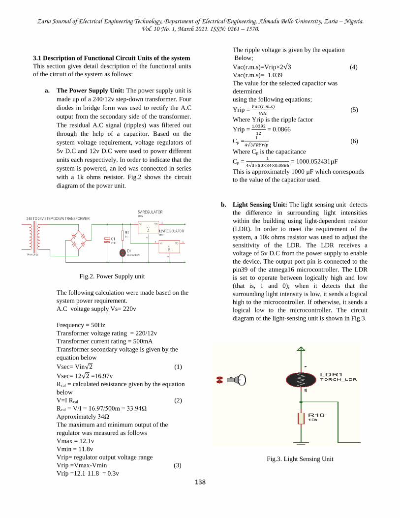
b. Light Sensing Unit: The light sensing unit detects
the difference in surrounding light intensities
within the building using light-dependent resistor
(LDR). In order to meet the requirement of the
system, a 10k ohms resistor was used to adjust the
sensitivity of the LDR. The LDR receives a
voltage of 5v D.C from the power supply to enable
the device. The output port pin is connected to the
pin39 of the atmega16 microcontroller. The LDR
is set to operate between logically high and low
(that is, 1 and 0); when it detects that the
surrounding light intensity is low, it sends a logical
high to the microcontroller. If otherwise, it sends a
logical low to the microcontroller. The circuit
diagram of the light-sensing unit is shown in Fig.3.
Fig.3. Light Sensing Unit

Zaria Journal of Electrical Engineering Technology, Department of Electrical Engineering, Ahmadu Bello University, Zaria – Nigeria. Vol. 10 No. 1, March 2021. ISSN: 0261 – 1570.
139
c. Temperature Sensing Unit: This unit is made up
of a temperature sensing device (LM 35) as shown
in Fig.4, which is internally calibrated and can read
from -40 up to 1500C to detect a difference in
temperature within the building. To enable the
device, a regulated 5v D.C from the power supply
unit was connected to the pin1 of the sensor. The
pin2 of the sensor was connected to pin40 of the
atmega16 microcontroller, and the pin3 was
grounded. When the device is ON, the sensor reads
the changes in the surrounding temperature and
compares this with the preset value. The pin2
serves as the output of the sensor, which sends an
analog signal to the atmega16 microcontroller
when the temperature goes above the preset value.
Fig.4. Temperature Sensing Unit
d. Motion Sensing Unit: The PIR sensor is a motion
sensor that senses the motion of a person entering
or leaving the house. Two of these sensors were
used and are named sensor1 and sensor2. Both
sensors are aligned one after the other at the
entrance of the house and are set to operate as
follows ;
Sensor1
The output pin2 of the PIR sensor is connected to
the base of an NPN transistor to amplify the output
signal, as shown in Fig. 5. Since the output is 3.3v
which is not sufficient to send a logical high to the
microcontroller, and for a logical high, 5v is
required. The collector of the transistor is
connected to the pin18 of the atmega16
microcontroller. The port pin1 of the PIR sensor is
connected to 5v D.C from the power supply and
the pin3 grounded.
Fig.5. PIR Sensor1
Sensor 2
A similar connection was also made to the second
sensor with the collector of the transistor
connected to pin19 of the atmega16
microcontroller, as shown in Fig.6.
Fig.6. PIR Sensor2
Mode of operation: When the system is powered
ON, it initializes for five seconds because both
sensors initially go high, and it takes three seconds
for them to go low. Within this initialization
period, both sensors must have been in a stable low
state and ready to work. The sensors are placed so
that the time interval takes a person entering the
house to be detected by both sensors, one after the
other is three seconds.
This was made so because the PIR sensor, by
default when it goes high, the minimum amount of
time it takes the PIR sensor to go low is three
seconds.
When the first sensor detects a person entering the
house, the system keeps track of that person
internally, waiting for the second sensor to detect

Zaria Journal of Electrical Engineering Technology, Department of Electrical Engineering, Ahmadu Bello University, Zaria – Nigeria. Vol. 10 No. 1, March 2021. ISSN: 0261 – 1570.
140
the same person entering the house. Once the
second sensor detects the same person, the system
count increment by one and is displayed on the
seven-segment display. The microcontroller, in
turn, compares the surrounding light intensities
with those inside the house and activates the
switching circuit to turn ON the light if the light
intensity inside the house is sufficiently low
compared with the outside one. It also turns ON
the cooling system once the temperature goes
above the preset value, the room temperature.
e. Microcontroller Unit: This unit is the brainbox of
the system which coordinates the activities of other
units of the system. The atmega16 microcontroller
been an 8-bit microcontroller permit transmitting
and receiving of 8-bit data simultaneously. The
port pins are dedicated to serving input and output
purposes. For this paper all four ports A, B, C and
D, were utilized for different purposes. The timer
function, interrupt service routine, and analog to
digital conversion (ADC) function was utilized in
this papert. The interrupt service routine INT2 took
care of all the sensing units, which comprised of
the LDR, motion sensors and temperature unit.
While the timer TMR0 was dedicated to taking
care of the seven-segment display and the counter,
which takes record of the number of persons
entering the house. The ADC0 and ADC1
converted the analog signal from the LDR and
temperature sensor to a digital signal.
f. Switching Unit: This unit takes care of switching
the lights and the cooling system ON/OFF
whenever the atmega16 microcontroller senses any
change in the system's state. The unit consists of
relays connected to the collector of an NPN
transistor through a freewheel diode with the base
of each transistor connected through 1-kilo ohms
resistors to pinb6 and pinb7 of the atmega16
microcontroller, respectively and the emitter
grounded as shown in Fig.7. The relays are
connected to the 12v supply of the power unit. The
freewheel diodes serve as protection to the
switches.
Fig.7. Switching Circuit.
g. Display Unit: This unit is shown in Fig.8, and it
consists of a seven-segment display, ULN2003A.
The pins of ULN2003 are connected to the PORTC
pins of the atmega16 microcontroller and the
output to the seven-segment display. It serves the
purpose of amplification so that the seven-segment
display will be very bright. Since the seven-
segment display used here is a common anode
type, all the anodes are connected to the collector
of PNP transistors each. The emitter of each
transistor receives 5v from the power supply, and
the base of the PNP transistors are connected to
pinb0, pin1, pinb2, pinb3 of the PORTB of the
atmega16 microcontroller through 1kilo ohm
resistors each.
Fig.8. Display Unit

Zaria Journal of Electrical Engineering Technology, Department of Electrical Engineering, Ahmadu Bello University, Zaria – Nigeria. Vol. 10 No. 1, March 2021. ISSN: 0261 – 1570.
141
3.2 Conditions to ON/OFF Lighting Point and Cooling
System: If the count on the seven-segment display was
greater than zero, and the light intensity inside the building
is less than the surrounding light intensity, the lights are
automated ON, else the light is automated OFF. If the room
temperature rises above the preset value, then the cooling
system (fan, air condition etc.) will be automated ON, else
the cooling is automated OFF.
3.3 CIRCUIT DESCRIPTION
Proteus 8.1 Professional is the software used to design the
entire system, as shown in Fig.9.
Figure.9. Overall Circuit Diagram.
4. RESULT AND DISCUSSION
The following test was carried out on different units of the
system upon completion, and the result obtained is shown in
Table 1.
Table 1. Test carried out, and the result obtained
S/N
TEST CARRIED
OUT
RESULT
OBTAINED
1
Power supply
The test carried out on
the power supply unit
was found to be 4.99v
and 11.98v,
respectively, which
approximates the 5v
and 12v D.C.
requirement of the
system
2
Light-dependent
resistor
The test carried out on
the output of the LDR
was discovered to be
4.98v which
corresponds to the 5v
required by the
microcontroller for
logical high.
3
Temperature
sensor
The test carried out on
the output of the LDR
was discovered to be
4.98v which
corresponds to the 5v
required by the
microcontroller for
logical high.
4
Microcontroller
The program code
written in C language
using AVR studio was
tested. Also, the output
for the switching unit
was measured to be
4.98v, corresponding to
the 5v requirement for
logically high state
5
Motion sensing
unit
The output signal of
the sensor was
measured to be 5v
whenever the sensor
senses the motion of a
person entering the
building and 0v when
no motion is sensed
6
Display unit
During system
initialization, the
seven-segment display
was tested to check
whether it is
compatible with the
program code and
confirm that the seven-
segment display
displayed the number
of persons entering the
building.
7
Switching unit
Before the motion of a
person is sensed, the
voltage at the collector
side of the BC337
transistor was
measured to be 0.64v.
when each sensor sense
the motion of a person
entering the building,
the voltage at the

Zaria Journal of Electrical Engineering Technology, Department of Electrical Engineering, Ahmadu Bello University, Zaria – Nigeria. Vol. 10 No. 1, March 2021. ISSN: 0261 – 1570.
142
collector of each relay
was measured to be
4.98v as required for
5v logically high state
4.1 DISCUSSION
The voltage supply from the power unit was measured to be
4.99, which is approximately equal to the 5v D.C. required
by the system. The LDR was found to meet the system
requirement of sensing the difference in light intensities
surrounding the building and inside the building for the
lights to be switched ON.
The LM35 was found working very well, reading the
building's temperature and comparing it with the preset
temperature value of the building.
The motion sensor performed very well in detecting the
motions of persons entering and leaving the building.
5. CONCLUSION
This paper has demonstrated the ways and manners in
which energy can be conserved in the building. The
deployment of PIR sensors made it smart because
automation of the lighting points and cooling system was
achieved. This system is reliable and effective as well user
friendly.
REFERENCES
[1] S. N. Deokar, & V. R. Pawar. 2017. “A Review:
IoT Based Power & Security Management for
Smart Home System”, International Conference
on Electronics, Communication and Aerospace
Technology (ICECA), 2017 International
conference by IEEE; INSPEC Accession Number:
17433089; DOI:10.1109/ICECA. 2017. 8203598;
IEEE.
[2] A. Donini, & D. Max-well. 2014. From Face-To-
Face to Face-To-Screen:Remote Management,
Effective-nessAnd Accountability of Humanitaria
Action in Insecure Environments; International
Review of the Red Cross (2013), 95(890): 383-
413;Violence against health care; DOI:
10.1017/S1816383114000265
[3] J. Abedalrahim, J. Alsayaydeh, V. Shkarupylo, M.
Bin Hamid, S. Skrupsky, A. Oliinyk.”Stratified
Model of the Internet of Things Infrastructure”,
Journal of Engineering and Applied Sciences,
13(20), 8634-8638, 2018.
[4] R. Chutia, D. Sonowal, & S. Sharma. “Remote
Household Appliance Control System Using
GSM”, Procedure of International Conference on
Advanced Computing and Communication
Technologies(ACCT 2011). Department of
Electronics and Communication Engineering,
Tezpur Central University Tezpur, Assam, India. ISBN: 978-981-08-7932-7.
[5] G.S Nhivekar and R.R. Mudholkar.
“Microcontroller Based IR Remote Control Signal
Decoder for Home Application”, Advances in
Applied Science Research, 2(4), 410-416, 2011.
[6] M. S. H. Khiyal, A. Khan, and E. Shehzadi, “SMS
Based Wireless Home Appliance Control System
(HACS) for Automating Appliances and
Security”, Issues in Informing Science and
Information Technology, (9), 887-894, 2009.
[7] I. Kaur.“Microcontroller Based Home Automation
System with Security”, International Journal of
Advanced Computer Science and Applications
(IJACSA) , 1(6),2010.
[8] A. Korane, & S. Salunke. “Home Appliances
Control System Based on Android Smartphone”,
International Journal of Advanced Research in
Science and Technology Engineering, 4(7), 124 –
128, 2015.
[9] M.V.R. Murthy. “Mobile Based Primary Health
Care System For Rural India”, W3C workshop on
Role of Mobile Technologies in Fostering Social
Development, Jun 2008.
[10] M.O. Georgewill, & J.C. Ezeofor. “Design and
Implementation of GSM Based Automation of
Household Appliances”, International Journal of
Scientific & Engineering Research, 7(5),544 – 550,
2016.
[11] A.S. Rahama, & D. Mahmoud.” Time Operated
Electrical Appliance Controlling Systems by Using
Microcontroller”, International Journal of Science
and Research, 5(5), 1920 – 1922, 2016.
[12] A.S. Rahama1, & Dr. D. Mahmoud. “Time
Operated Electrical Appliance Controlling Systems
by Using Microcontroller”, International Journal
of Science and Research (IJSR) ISSN (Online):
2319-7064, 5(5), 1920-1922,2016.Retrieved
fromwww.ijsr.net
[13] C. Rajender, B. pears, O. Vijaylaxmi, V.
Devi, B.S. Prasad. “Electrical Appliances in Home
Control through IR Remote ”International Journal

Zaria Journal of Electrical Engineering Technology, Department of Electrical Engineering, Ahmadu Bello University, Zaria – Nigeria. Vol. 10 No. 1, March 2021. ISSN: 0261 – 1570.
143
of Innovative Research in Technology (IJIRT),
3(9), 16-19, 2017.
[14] K.R. Babu, Ayinadis, Getahun, Engida, M.
Mangesthu. “Implementation of Arduino Based
House Automation using Bluetooth, Infrared”,
International Journal of Innovative Research in
Science, Engineering and Technology(IJIRSET),
8(6), 7447-7455, 2019.
[15] O.O.E. Ajibola, & A.O. Balogun.. “Development
of Smart Switch for Household Appliances Using
Web-Based Technology”, Journal of Applied
Sciences and Environmental Management, 23(1)
145–149, 2019.
[16] KO. .OJO, & E.C. ODUNZE. “Design and
Construction of a Wireless Based Electrical
Appliance Control System”, Journal of Applied
Sciences and Environmental Management
(JASEM), 22 (9), 1439–1442, 2018.
[17] Ms. P.V. Gaikwad, and Prof. Y. R.Kalshetty.
“Bluetooth Based Smart Automation System Using
Android”, International Journal of New
Innovations in Engineering and Technology, 7(3)
24-29, 2017.
[18] K.M. Deepashri, P.B. Sachidan, and H.S Latha.
“Industrial Appliances Control Using Android
Mobile & Bluetooth Technology”, International
Journal of Engineering and Manufacturing
Science. 8(1), 33-42, 2018.
[19] Prof .P.N.Khairnar, Kokane Harichandra J.,
Narkhede Amol A., Narkhede Kunal A.,
“Industrial Device Control using Android Mobile
& Bluetooth Technology”, Journal of Basic and
Applied Engineering Research (IJARIIE), 3(2),
2395-4396, 2017.
[20] M. Juned, and S. Unnikrishnan. “Bluetooth Based
Remote Monitoring & Control System”, Journal
of Basic and Applied Engineering Research, 1(8),
108-11, 2014.