Design and Analysis of Clutch Using Sintered Iron ... - CiteSeerX
8
International Journal of Innovative Technology and Exploring Engineering (IJITEE) ISSN: 2278-3075, Volume-3, Issue-7, December 2013 177 Abstract— Clutch system is among the main systems inside a vehicle. Clutch is a mechanical device located between a vehicle engine and its transmission and provides mechanical coupling between the engine and transmission input shaft. Clutch system comprise of flywheel, clutch disc plate and friction material, pressure plate, clutch cover, diaphragm spring and the linkage necessary to operate the clutch. The clutch engages the transmission gradually by allowing a certain amount of slippage between the flywheel and the transmission input shaft. However, the slipping mechanism of the clutch generates heat energy due to friction between the clutch disc and the flywheel. At high sliding velocity, excessive frictional heat is generated which lead to high temperature rise at the clutch disc surface, and this causes thermo-mechanical problems such as thermal deformations and thermo-elastic instability which can lead to thermal cracking, wear and other mode of failure of the clutch disc component. In this project, the modeling of clutch is done in detailed using modeling software. After that the FEM analysis is done for sintered iron friction material. The stresses & deformation obtained for this friction material is then compared to analysis software result. The analysis is done for worn out friction disc. Index Terms — Coefficient of friction, von-misses stress, young’s modulus and poisons ratio. I. INTRODUCTION A clutch is a mechanical device for quickly and easily connecting or disconnecting a pair of rotating coaxial shafts. It is usually placed between the driving motor and the input shaft to a machine, permitting the engine to be started in an unloaded state. Single plate, dry clutch is among the popular type of clutches in use. A clutch is a mechanism designed to disconnect and reconnect driving and driven members. It is a device, which enables one rotary drive shaft to be coupled to another shaft, either when both the shafts are stationary or when there is relative motion between them. The need for the clutch seems mainly from the characteristics of the turning-effort developed by the engine over its lower speed range. When idling, the engine develops insufficient torque for the transmission to be positively engaged. To obtain a smooth engagement, the clutch has to be progressively engaged to take up the drive until the torque transmitted from the engine equals that required to propel the vehicle. Also the clutch disconnects the engine from the transmission to change the gear. The clutch, thus, takes up the drive smoothly and also disengages the drive whenever necessary. Manuscript received December 2013. Ms. Mamta. G. Pawar, Department of Mechanical Engineering, Dr. Babasaheb Ambedkar College of Engineering & Research, Nagpur, India. Mr. Monarch K. Warambhe, Department of Mechanical Engineering, Rajiv Gandhi College Of Engineering and Research, Nagpur, India. Mr. Gautam. R. Jodh, , Department of Mechanical Engineering, Dr. Babasaheb Ambedkar College of Engineering & Research, Nagpur, India. II. AUTOMOTIVE CLUTCH SYSTEM Automotive clutches are located between the engine and the transmission. It provides mechanical coupling between the engine and transmission input shaft. Manual transmission cars need a clutch to enable engaging and disengaging the transmission. The clutch engages the transmission gradually by allowing a certain amount of slippage between the flywheel and the transmission input shaft (Erjavec 2005).Clutch basically consists of six major parts: flywheel, clutch disc, pressure plate, diaphragm spring, clutch cover and the linkage necessary to operate the clutch (Lee and Cho 2006) as shown in Figure 1. Figure 1. Single plate diaphragm clutch system. III. LITERATURE REVIEW In 1885, it was reported that when Karl Friedrich Benz has invented the first commercial gas powered automobile, the famous Tri-Cycle, he also was the first person to invent and use the clutch system to the car (Wikipedia website 2007). Exedy Corp., one of the major players for clutch technology, which manufactured clutches under the brand name of Exedy and Daikin, was reported to produce rigid type disc clutch since 1918, which was a clutch disc with the plate and spline hub secured by rivets (Daikin Clutch website 2007). Until now, clutch manufactures has come out with new and efficient technologies for clutch system to compensate higher torque produced by bigger engine created especially for heavy vehicles. According to Samir Safarni after gear shift & during the clutch re-engagement the clutch disc allows the transmission of progressive torque through its Axial Stiffness. One of the most important components use in coupling & decoupling of motor & transmission during gear change. One of the most important components used in this process is clutch disc that allows a soft gradual re-engagement of torque transmission. This progressive re-engagement obtained by friction disc characteristics in the axial direction preserves the drivers comfort & avoid mechanical shock [06]. According to K. Tripathi, the friction clutch must be design for minimum axial force between Design and Analysis of Clutch Using Sintered Iron as a Friction Material Mamta G. Pawar, Monarch K. Warambhe, Gautam R. Jodh
-
Upload
khangminh22 -
Category
Documents
-
view
2 -
download
0
Transcript of Design and Analysis of Clutch Using Sintered Iron ... - CiteSeerX

International Journal of Innovative Technology and Exploring Engineering (IJITEE)
ISSN: 2278-3075, Volume-3, Issue-7, December 2013
177
Abstract— Clutch system is among the main systems inside a
vehicle. Clutch is a mechanical device located between a vehicle
engine and its transmission and provides mechanical coupling
between the engine and transmission input shaft. Clutch system
comprise of flywheel, clutch disc plate and friction material,
pressure plate, clutch cover, diaphragm spring and the linkage
necessary to operate the clutch. The clutch engages the
transmission gradually by allowing a certain amount of slippage
between the flywheel and the transmission input shaft. However,
the slipping mechanism of the clutch generates heat energy due to
friction between the clutch disc and the flywheel. At high sliding
velocity, excessive frictional heat is generated which lead to high
temperature rise at the clutch disc surface, and this causes
thermo-mechanical problems such as thermal deformations and
thermo-elastic instability which can lead to thermal cracking,
wear and other mode of failure of the clutch disc component.
In this project, the modeling of clutch is done in detailed using
modeling software. After that the FEM analysis is done for
sintered iron friction material. The stresses & deformation
obtained for this friction material is then compared to analysis
software result. The analysis is done for worn out friction disc.
Index Terms — Coefficient of friction, von-misses stress,
young’s modulus and poisons ratio.
I. INTRODUCTION
A clutch is a mechanical device for quickly and easily
connecting or disconnecting a pair of rotating coaxial shafts.
It is usually placed between the driving motor and the input
shaft to a machine, permitting the engine to be started in an
unloaded state. Single plate, dry clutch is among the popular
type of clutches in use. A clutch is a mechanism designed to
disconnect and reconnect driving and driven members. It is a
device, which enables one rotary drive shaft to be coupled to
another shaft, either when both the shafts are stationary or
when there is relative motion between them. The need for the
clutch seems mainly from the characteristics of the turning-effort developed by the engine over its lower speed
range. When idling, the engine develops insufficient torque
for the transmission to be positively engaged. To obtain a
smooth engagement, the clutch has to be progressively
engaged to take up the drive until the torque transmitted from
the engine equals that required to propel the vehicle. Also the
clutch disconnects the engine from the transmission to
change the gear. The clutch, thus, takes up the drive smoothly
and also disengages the drive whenever necessary.
Manuscript received December 2013.
Ms. Mamta. G. Pawar, Department of Mechanical Engineering, Dr.
Babasaheb Ambedkar College of Engineering & Research, Nagpur, India.
Mr. Monarch K. Warambhe, Department of Mechanical Engineering,
Rajiv Gandhi College Of Engineering and Research, Nagpur, India.
Mr. Gautam. R. Jodh, , Department of Mechanical Engineering, Dr.
Babasaheb Ambedkar College of Engineering & Research, Nagpur, India.
II. AUTOMOTIVE CLUTCH SYSTEM
Automotive clutches are located between the engine and
the transmission. It provides mechanical coupling between the engine and transmission input shaft. Manual transmission
cars need a clutch to enable engaging and disengaging the
transmission.
The clutch engages the transmission gradually by allowing
a certain amount of slippage between the flywheel and the
transmission input shaft (Erjavec 2005).Clutch basically
consists of six major parts: flywheel, clutch disc, pressure
plate, diaphragm spring, clutch cover and the linkage
necessary to operate the clutch (Lee and Cho 2006) as shown
in Figure 1.
Figure 1. Single plate diaphragm clutch system.
III. LITERATURE REVIEW
In 1885, it was reported that when Karl Friedrich Benz has
invented the first commercial gas powered automobile, the
famous Tri-Cycle, he also was the first person to invent and
use the clutch system to the car (Wikipedia website 2007).
Exedy Corp., one of the major players for clutch technology,
which manufactured clutches under the brand name of Exedy
and Daikin, was reported to produce rigid type disc clutch
since 1918, which was a clutch disc with the plate and spline
hub secured by rivets (Daikin Clutch website 2007). Until
now, clutch manufactures has come out with new and
efficient technologies for clutch system to compensate higher torque produced by bigger engine created especially for
heavy vehicles.
According to Samir Safarni after gear shift & during the
clutch re-engagement the clutch disc allows the transmission
of progressive torque through its Axial Stiffness. One of the
most important components use in coupling & decoupling of
motor & transmission during gear change. One of the most
important components used in this process is clutch disc that
allows a soft gradual re-engagement of torque transmission.
This progressive re-engagement obtained by friction disc
characteristics in the axial direction preserves the drivers comfort & avoid mechanical shock [06].
According to K. Tripathi, the friction clutch must be
design for minimum axial force between
Design and Analysis of Clutch Using Sintered Iron
as a Friction Material
Mamta G. Pawar, Monarch K. Warambhe, Gautam R. Jodh

Design and Analysis of Clutch Using Sintered Iron as a Friction Material
178
the pressure plate & clutch plate. They suggested that for
optimum design of friction disc the ratio of inner radius to
outer radius should be kept 0.577.There basic design is based
on minimum axial force between pressure plate & clutch
plate. [02]
IV. CLUTCH MATERIALS
The clutch disc is generally made from grey cast iron
(Afferante et al. 2003; Poser et al. 2005). This is because grey
cast iron has a good wear resistance with high thermal
conductivity and the production cost is low compare to other
clutch disc materials such as A1-MMC (aluminum-metal
matrix composite), carbon composites and ceramic based
composites (Terhech et al. 1995; Jang et al. 2003). High
thermal conductivity of diffusivity of the material is considered advantageous because heat is then allowed to
dissipate at higher rate (Bostwick and Szadkowski 1998). In
this project, BS200 or ASTM G2500 grade grey cast iron is
selected as the material for the commercial clutch disc. Some
properties of the material (BS Grade 200lASTM G2500) are
shown in Table below (Heo et al. 2002; CES EduPack 2005).
Table 1. Material Properties of Gray Cast Iron
Structural
Young’s Modulus 120GPa
Poission’s Ratio 0.29
Density 7200 kg/m3
Tensile Strength 220MPa
Shear Modulus 44-54 GPa
Thermal
Thermal Conductivity 310 W/m.K
Specific Heat 450 J/Kg.K
V. SINTERED FRICITON MATERIL
Friction pads are manufactured by sintering blend of
powders consisting of heat absorption material along with
friction generating & lubricating materials. The powders are
blended in optimized proportions & compacted to form a
solid flat button of predetermined shape. They are highly
durable with harsher engagement characteristics compared to
organic linings. The quality of materials used along with the
sintering parameter play an important role in providing the required performance (Aleksandrova et al 1972).Particulate
reinforcement gives the necessary WEAR resistant for the
sintered matrix (Mustafa Boz & AdemKurtt2007 )
A. Wear Coefficient Of Different Friction Material
The different wear coefficient of different friction material is as shown in following table. [11]
Table 2. Typical wear coefficient of clutch friction lining
(Against steel/cast iron)
Lining (Pad )Material Wear Coefficient ,
Ko (psi-1
)
Asbestos Type-I composite 6.46 × 10⁻¹¹
Asbestos Type -II composite 8.09 × 10⁻¹¹
Carbon-carbon composite 2.24 × 10⁻¹¹
Sintered bronze (dry) 2.42 × 10⁻¹¹
Non Asbestos composite (dry) 9.90 × 10⁻¹⁰
Sintered bronze (wet) 5.02 × 10⁻¹³
Sintered bronze composite 9.31 × 10⁻¹¹
Sintered resin composite 3.03 × 10⁻¹¹
B. Clutch Friction Surface Failure Mode
Following table shows the various failure modes in clutch &
the causes of failure & the effect of that failure on the clutch
plate. [11]
Table 3. Failure Mode of Friction Plate PROBLEM CHRACTERSTIS CAUSES
Material Transfer
Friction material adhering to
opposing plate often giving rise to excessive wear
Overheating & unsuitable friction
material
Distortion
Facing out of flatness after high operating temperature
Unsuitable friction material
Reduced Performance
Decreasing in coefficient of friction giving in a permanent loss in performance
Excess oil or grease on friction material or on the opposing surface
Dishing Clutch plate distorted into conical shape
Lack of conformability, temperature of the
outer region is higher than inner region
Banding or crushing
Loss of friction material at the end of band
Crushing and excessive wear of the friction material
Burst Failure
Material splitting &
removed from inner plate
High stresses on
facing when working at higher speed
Grooving
Grooving of the facing material on the line of movement
Material transfer to opposing plate
C. Method Of Analysis
The torque that can be transmitted by a clutch is a function
of its geometry & the magnitude of the actuating force
applied as well the condition of contact prevailing between
the members. The applied force can keep the members
together with a uniform pressure all over its contact area & the consequent analysis is based on uniform pressure
condition.
However as the time progresses some wear takes place
between the contacting members & this may alter or vary the
contact pressure appropriately and uniform pressure
condition may no longer prevail. Hence the analysis here is
based on uniform wear condition.
VI. TECHINCAL SPECIFICTIONS OF SINGLE PLATE
CLUTCH
Table 4. Technical specification Specification
Model Maximum Power
Maximum Torque
Capa
city 1988 CC
TATA 483 DLNA56
48 KW@4500 RPM
115 NM @ 3000RPM
Pressure plate
Inner Diameter
Outer Diameter
Rim diameter
200 mm 230 mm 30 mm
Friction Plate
Inner Diameter
Outer Diameter
Width

International Journal of Innovative Technology and Exploring Engineering (IJITEE)
ISSN: 2278-3075, Volume-3, Issue-7, December 2013
179
128 mm 228 2 mm
Flywheel
External
Diameter No of Teeth
260
122
Diaphragm
Spring
Length Outer
Diameter
50 mm 145 mm
Figure.2 Exploded view of single plate clutch
VII. ANALYSIS OF SINGLE PLATE CLUTCH USING
SINTERED IRON AS A FRCITON MATERIAL
A. Modelling Of Friction Disc
Figure 3. Modelling of Friction Disc
B. Material Data
SINTERED-IRON
Table 5. Material Property
Structural
Young’s Modulus 275.79MPa
Poission’s Ratio 0.34
Density 6.2gm/cm3
Thermal Expansion 0.2/0c
Thermal
Thermal Conductivity 220 W/m0c
Specific Heat 50 J/Kg0
C. Meshed Body
Figure.4. Model > Mesh > Image
D. Static Structural
Figure. 5. Model > Static Structural > Pressure > Image
E. Solution
Table 6. Model > Static Structural > Solution > Results Object
Name
Total
Deformatio
n
Equivalent
Stress 2
Maximum
Shear Stress
Normal
Elastic
Strain
State Solved
Definition
Type Total
Deformatio
n
Equivalent
(von-Mises)
Stress
Maximum
Shear Stress
Normal
Elastic Strain
Orientation X Axis
Coordinate
System
Global
Coordinate
System
Results
Minimum 0. mm 3.9462e-00
4 MPa
2.2781e-00
4 MPa
-9.4649e-00
6 mm/mm
Maximum 5.3008e-005
mm
6.6447e-00
3 MPa
3.6859e-00
3 MPa
1.2851e-005
mm/mm

Design and Analysis of Clutch Using Sintered Iron as a Friction Material
180
Figure 6. Model > Static Structural > Solution > Equivalent
Stress 1 > Image
Figure 7. Model > Static Structural > Solution > Total Deformation > Image
Figure 8. Model > Static Structural > Solution > Maximum Shear Stress > Image
Figure.9.Model > Static Structural > Solution > Normal Elastic Strain > Image
VIII. FINITE ELEMENT METHOD USING SINTERED
IRON AS A FRICTION MATERIAL
Calculation Data:
Assuming maximum force applied on clutch pedal = 110 N
for 75 mm pedal travel
With the help of booster the applied force is transferred 2
times to the friction material
Therefore, Force becomes F= 2 ×110 =220 N
Total force is divided into two parts,
Therefore F1 =F2 =110 N
KEVLAR AS A FRCTION MATERIAL
Young’s Modulus (E) =275.79 Mpa Poisson’s Ratio =0.34
Density = 6.2gm/cm3
Step 1 Discretization: Dividing the part into two CST
elements as shown below
Step 2 Element Connectivity Table
Global Nodes
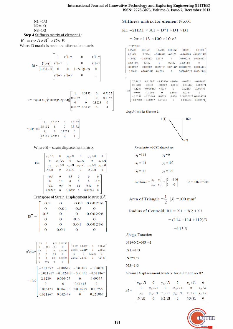
Step 3 Consider Element 1
3(3)
1(1) 2(2)
Coordinates of CST element are:
X1= 112, y1=0
X2 =114, y2 =0
X3 = 112, y3= 100
Jacobian J =
2323
1313
yx
yx =
1002
1000 J =
100 x 2=200
Area of Triangle =2
1 J =100mm2
Radius of Centroid, R1 = X1 + X2 +X3 = (112 +114 +112)/3
=112.8
Shape Function
N1+N2+N3 =1
Local Nodes
Element
No. (1) (2) (3)
1 1 2 3
2 2 4 3
International Journal of Innovative Technology and Exploring Engineering (IJITEE)
ISSN: 2278-3075, Volume-3, Issue-7, December 2013
181
N1 =1/3
N2=1/3
N3=1/3
Step 4 Stiffness matrix of element 1:
BDBAtK T1
Where D matrix is strain transformation matrix
Where B = strain displacement matrix
Transpose of Strain Displacement Matrix (BT)

Design and Analysis of Clutch Using Sintered Iron as a Friction Material
182
.
.
Step 10 By Principle of mini potential energy
Step 11 Applying Boundary Conditions
04
0
0
02
01
01
3
3
yu
u
u
yu
Yu
xu
y
x
By Gauss elimination method canceling 1x, 1y, 2y, 3x, 3y,4y
rows and columns

International Journal of Innovative Technology and Exploring Engineering (IJITEE)
ISSN: 2278-3075, Volume-3, Issue-7, December 2013
183
On solving we get, Nodal displacements as
Step 12 Stresses in Each Element
Stress in element 1, uBD 111
mmu
mmu
x
x
4
4
4
2
10183.0
10393.0
Stress in element 2, uBD 222
RESULT:
Total deformation is found to be 0.293× 10⁻⁴ mm & stress is
found to be 6.237 × 10⁻³ Mpa
RESULT VALIDATION BY USING ANSYS RESULT
FOR SINTERED IRON
Pressure = Force /Area N/mm2
Pressure = 220 / 27960
= 0.007869 Mpa
Now this pressure in applied on the friction disc to fine total deformation & von-misses stresses. The following
results are obtained.
Figure.10.Total Deformation
Figure.11.Equivalent Stress
RESULT: - The total deformation is 5.308 × 10⁻⁵ mm and
Von-misses stresses 0.0066447 Mpa.
IX.CONCLUSION
In single plate clutch friction plate plays very important
role in torque transmission from engine to transmission
system. So the friction material property is very important in
clutch. Generally clutch is in engaged position but when
peddle is pressed clutch is disengaged & at that time there is sudden increase in temperature. Due to friction between
mating part some part of friction material get wear out.
So for designing of clutch disc one should know the wear rate
of that material which are used in clutch disc & common
failure problem associated with clutch Again when some
force is acting on clutch disc there must be some deformation
due to temperature variation & stresses developed in clutch
disc. That should be within the permissible limit.
In this project after designing of clutch disc, the analysis is
done by varying the friction material & following conclusion
is drawn. The stresses using Kevlar as a friction material & sintered
iron is near about same.
Torque transmission capacity of sintered-iron friction
material is 350 to 400N which is more than Kevlar.
Total deformation in Kevlar material is less than
sintered-iron friction material.
Sintered-iron material can sustain higher temperature.
By applying the maximum force i.e, 220 N of the friction
plate of single plate clutch, after analytical calculations &
software analysis the following observations can be obtained.
SINTERED –IRON (FRICTION MATERIAL)
Analytical Calculation Software Analysis
Total Deformation
0.393 × 10⁻⁴ mm Or 3.93 × 10⁻⁵ mm
0.5308 ×10⁻⁴ mm or 5.308 × 10⁻⁵ mm
Stresses 0.6237 × 10⁻⁴N/ mm2 6.237 × 10⁻⁵Mpa
0.00664 Mpa
REFERENCES
[1] Machine Design II, by Prof. K.Gopinath & Prof. M. M. Mayuram
[2] K Tripathi, “Design Optimization of Friction Clutch “
[3] United States Patent Office On - “Auxiliary drive clutch mechanism “
[4] Arvind vadiraj “Engagement characteristic of friction pad for the
commercial vehicle clutch system “ , vol 35 part 5,October 2010 page
no 585-595,Indian Academy Of Science
[5] Samir Safarni & Emmanuel Bellenger.“ Numerical modeling of

Design and Analysis of Clutch Using Sintered Iron as a Friction Material
184
automotive riveted clutch disc for contact pressure verification “.
[6] Mechanical Design Handbook by Thomas A.Dow, Chaper 17
[7] Abdullah M-AL-Shabibi, “Thermo-mechancial behavior of
automotive break & clutch system”.
[8] Han W, Yi S-J “A study of shift control using the clutch pressure
pattern in automatic transmission “Proceedings of the I MECH E Part
D Journal of Automobile Engineering, Volume 217, Number 4, 1
April 2003, pp. 289-298(10).
[9] J.R.Barber,” International Journal of mechanical Sciences and the
Journal of Thermal Stresses, “Department of Mechanical Engineering
University of Michigan, 2002.
[10] “Modelling And Assembly Of Single Plate Friction Clutch Of An
Automobile” Dr.Prafull S. Thakre, volume 2, Issue II/ March,
12.PP1-4, Indian Streams Research Journal.
[11] NSWC-06 Handbook Part B-Chapter 11.