DESIGN & ANALYSIS OF A CONNECTING ROD WITH ...
13
www.jespublication.com DESIGN & ANALYSIS OF A CONNECTING ROD WITH DIFFERENT MATERIALS 1 MOMIN ATHARUDDIN, 2 J.A.SANDEEP KUMAR, 3 P.HUSSAIN, 4 Dr.P.MALLIKARJUNA REDDY 1 M.Tech Student, 2 Assistant Professor, 3 Associate Professor, 4 Professor DEPARTMENT OF MECHANICAL ENGINEERING SVR Engineering College, Nandyal ABSTRACT: Connecting rods are practically generally used in all varieties of automobile engines connecting rod acting as a converting intermediate link between the piston and the crankshaft of the engine, by the reciprocating motion of the piston to the rotary motion of crankshaft. Thus, this study aims to carry out for the load strain, stress, total deformation and analysis of factor of safety of pin end of the connecting rod of different materials. Generally connecting rods are manufactured using aluminium alloys are used for manufactured the connecting rods. In this work existing connecting rod material are replaced by aluminium alloy the connecting rod is the intermediate member between the piston and the Crankshaft. Its primary function is to transmit the push and pull from the piston pin to the crank pin, thus converting the reciprocating motion of the piston into rotary motion of the crank. A parametric model of Connecting rod is modeled fabricated using cnc machine Keywords: connecting Rod, four stroke engine connecting rod, aluminium connecting rod, I. INTRODUCTION Internal Combustion engine has many parts like cylinder, piston, connecting rod, crank and crank shaft. The connecting rod is very important part of an engine. Working of the connecting rod is to transmit power of piston to crank pin. Connecting rod has two ends one is pin end and other is crank end. Pin end is attached with piston. The big end (crank end) is attached to the crank pin by a crank shaft. The function of crank shaft is to transmit the reciprocating motion of piston into rotary motion. The connecting rod should be such that it can sustain the maximum load without any failure during high cycle fatigue. The connecting rod has generally three parts pin end, crank end, and long shank. Design of shank can be different type like rectangular, tubular, circular, I-section and Hsection. Circular section is generally used for low speed engines. I-section is used for high speed engines. Generally connecting rods are being made up of stainless steel and aluminium alloy through the forging process, as this method provides high productivity and that too with a lower production cost. Forces generated on the connected rod are generally by weight and combustion of fuel inside cylinder acts upon piston and then on the connecting rod, which results in both the bending and axial stresses. Therefore it order to study the strain intensity, stress concentration and deformation in the crank end of the connection rod, firstly based on the working parameter and the vehicle chosen the design parameter or dimensions of the connecting rod is calculated, then the model of the connecting rod parts is prepared and finally it is analysed using Finite Element Method and results thus achieved will provide us the required outcome of the work done here .Also further study can also be carried out later on for the dynamic loading working conditions of the connecting rod and also improvement in design can also be made for operation condition and longer life cycle against failure. In a reciprocating piston engine, the connecting rod connects the piston to the crank or crankshaft. In modern automotive internal combustion engines, the connecting rods are most usually made of steel for production engines, but can be made of aluminum (for lightness and the ability to absorb high impact at the expense of durability) or titanium (for a combination of strength and lightness at the expense of affordability) for high performance engines, or of cast iron for applications such as motor scooters. The small end attaches to the piston pin, gudgeon pin (the usual British term) or wrist pin, which is currently most often press fit into the con rod but can swivel in the piston, a "floating wrist pin" design. The connecting rod is under tremendous stress from the reciprocating load represented by the piston, actually stretching and being compressed with every rotation, and the load increases to the third power with increasing engine speed. Failure of a connecting rod, usually called "throwing a rod" is one of the most common causes of catastrophic engine failure in cars, frequently putting the broken rod through the side of the crankcase and thereby
-
Upload
khangminh22 -
Category
Documents
-
view
2 -
download
0
Transcript of DESIGN & ANALYSIS OF A CONNECTING ROD WITH ...
www.jespublication.com
DESIGN & ANALYSIS OF A CONNECTING ROD WITH
DIFFERENT MATERIALS
1MOMIN ATHARUDDIN,
2J.A.SANDEEP KUMAR,
3P.HUSSAIN,
4Dr.P.MALLIKARJUNA REDDY
1M.Tech Student,
2Assistant Professor,
3Associate Professor,
4Professor
DEPARTMENT OF MECHANICAL ENGINEERING
SVR Engineering College, Nandyal
ABSTRACT:
Connecting rods are practically generally used in
all varieties of automobile engines connecting rod
acting as a converting intermediate link between
the piston and the crankshaft of the engine, by the
reciprocating motion of the piston to the rotary
motion of crankshaft. Thus, this study aims to carry
out for the load strain, stress, total deformation and
analysis of factor of safety of pin end of the
connecting rod of different materials. Generally
connecting rods are manufactured using aluminium
alloys are used for manufactured the connecting
rods. In this work existing connecting rod material
are replaced by aluminium alloy the connecting rod
is the intermediate member between the piston and
the Crankshaft. Its primary function is to transmit
the push and pull from the piston pin to the crank
pin, thus converting the reciprocating motion of the
piston into rotary motion of the crank. A parametric
model of Connecting rod is modeled fabricated
using cnc machine
Keywords: connecting Rod, four stroke engine
connecting rod, aluminium connecting rod,
I. INTRODUCTION
Internal Combustion engine has many parts like
cylinder, piston, connecting rod, crank and crank
shaft. The connecting rod is very important part of
an engine. Working of the connecting rod is to
transmit power of piston to crank pin. Connecting
rod has two ends one is pin end and other is crank
end. Pin end is attached with piston. The big end
(crank end) is attached to the crank pin by a crank
shaft. The function of crank shaft is to transmit the
reciprocating motion of piston into rotary motion.
The connecting rod should be such that it can
sustain the maximum load without any failure
during high cycle fatigue. The connecting rod has
generally three parts pin end, crank end, and long
shank. Design of shank can be different type like
rectangular, tubular, circular, I-section and
Hsection. Circular section is generally used for low
speed engines. I-section is used for high speed
engines. Generally connecting rods are being made
up of stainless steel and aluminium alloy through
the forging process, as this method provides high
productivity and that too with a lower production
cost. Forces generated on the connected rod are
generally by weight and combustion of fuel inside
cylinder acts upon piston and then on the
connecting rod, which results in both the bending
and axial stresses.
Therefore it order to study the strain intensity,
stress concentration and deformation in the crank
end of the connection rod, firstly based on the
working parameter and the vehicle chosen the
design parameter or dimensions of the connecting
rod is calculated, then the model of the connecting
rod parts is prepared and finally it is analysed using
Finite Element Method and results thus achieved
will provide us the required outcome of the work
done here .Also further study can also be carried
out later on for the dynamic loading working
conditions of the connecting rod and also
improvement in design can also be made for
operation condition and longer life cycle against
failure.
In a reciprocating piston engine, the connecting rod
connects the piston to the crank or crankshaft. In
modern automotive internal combustion engines,
the connecting rods are most usually made of steel
for production engines, but can be made of
aluminum (for lightness and the ability to absorb
high impact at the expense of durability) or
titanium (for a combination of strength and
lightness at the expense of affordability) for high
performance engines, or of cast iron for
applications such as motor scooters. The small end
attaches to the piston pin, gudgeon pin (the usual
British term) or wrist pin, which is currently most
often press fit into the con rod but can swivel in the
piston, a "floating wrist pin" design. The
connecting rod is under tremendous stress from the
reciprocating load represented by the piston,
actually stretching and being compressed with
every rotation, and the load increases to the third
power with increasing engine speed. Failure of a
connecting rod, usually called "throwing a rod" is
one of the most common causes of catastrophic
engine failure in cars, frequently putting the broken
rod through the side of the crankcase and thereby

www.jespublication.com
rendering the engine irreparable; it can result from
fatigue near a physical defect in the rod, lubrication
failure in a bearing due to faulty maintenance or
from failure of the rod bolts from a defect,
improper tightening, or re-use of already used
(stressed) bolts where not recommended. Despite
their frequent occurrence on televised competitive
automobile events, such failures are quite rare on
production cars during normal daily driving. This is
because production auto parts have a much larger
factor of safety, and often more systematic quality
control. When building a high performance engine,
great attention is paid to the connecting rods,
eliminating stress risers by such techniques as
grinding the edges of the rod to a smooth radius,
shot peening to induce compressive surface stresses
(to prevent crack initiation), balancing all
connecting rod/piston assemblies to the same
weight and Magnafluxings to reveal otherwise
invisible small cracks which would cause the rod to
fail under stress. In addition, great care is taken to
torque the con rod bolts to the exact value
specified; often these bolts must be replaced rather
than reused. The big end of the rod is fabricated as
a unit and cut or cracked in two to establish
precision fit around the big end bearing shell.
Recent engines such as the Ford 4.6 liter engine
and the Chrysler 2.0 liter engine have connecting
rods made using powder metallurgy, which allows
more precise control of size and weight with less
machining and less excess mass to be machined off
for balancing. The cap is then separated from the
rod by a fracturing process, which results in an
uneven mating surface due to the grain of the
powdered metal. This ensures that upon
reassembly, the cap will be perfectly positioned
with respect to the rod, compared to the minor
misalignments, which can occur if the mating
surfaces are both flat. A major source of engine
wear is the sideways force exerted on the piston
through the con rod by the crankshaft, which
typically wears the cylinder into an oval cross-
section rather than circular, making it impossible
for piston rings to correctly seal against the
cylinder walls. Geometrically, it can be seen that
longer connecting rods will reduce the amount of
this sideways force, and therefore lead to longer
engine life. However, for a given engine block, the
sum of the length of the con rod plus the piston
stroke is a fixed number, determined by the fixed
distance between the crankshaft axis and the top of
the cylinder block where the cylinder head fastens;
thus, for a given cylinder block longer stroke,
giving greater engine displacement and power,
requires a shorter connecting rod (or a piston with
smaller compression height), resulting in
accelerated cylinder wear.
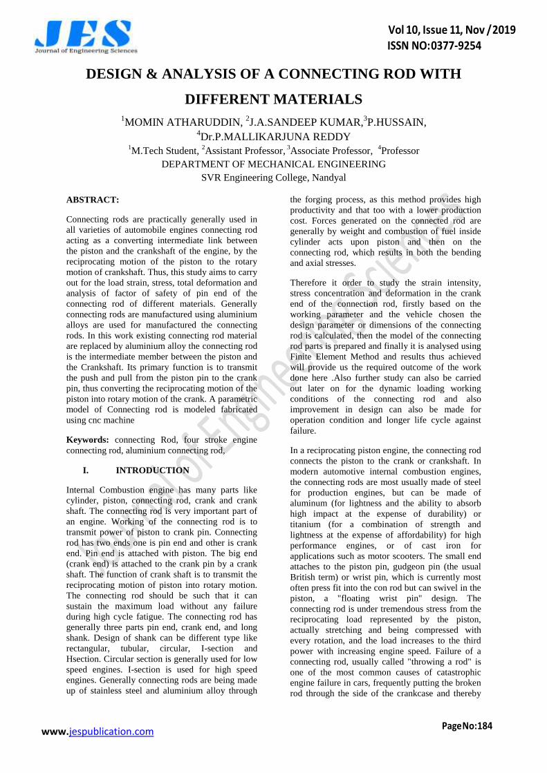
Fig-1 Schematic diagram of connecting rod
DESIGN OF CONNECTING ROD:
A connecting rod is a machine member which is
subjected to alternating direct compressive and
tensile forces. Since the compressive forces are
much higher than the tensile force, therefore the
cross- section of the connecting rod is designed as a
strut and the ranking formula is used. A connecting
rod subjected to an axial load W may buckle with
x-axis as neutral axis in the plane of motion of the
connecting rod,{or} y-axis is a neutral axis. The
connecting rod is considered like both ends hinged
for buckling about x-axis and both ends fixed for
buckling about y-axis. A connecting rod should be
equally strong in buckling about either axis.
According to ranking formula
TYPES OF CONNECTING ROD:
There are many types of connecting rod with
different I section and H section. But there are
basically two types of connecting rod. Connecting
rod with nut and bolt - The connecting rod with cap
at the larger end is joined by means of bolt. This
type of connecting rod is most widely used in multi
cylinder engines. For example trucks, tractor etc.
Connecting rod without nut and bolt - This type of
connecting rod consist of single parts itself. And
mostly used in single cylinder engine. For example
bikes, scooter etc. [4].
www.jespublication.com
The earliest evidence for a connecting rod appears
in the late 3rd century AD Roman Hierapolis
sawmills. It also appears in two 6th century Eastern
Roman saw mills excavated at Ephesus and Gerasa.
The crank and connecting rod mechanism of these
Roman watermills converted the rotary motion of
the waterwheel into the linear movement of the saw
blades. Sometime between 1174 and 1206, the
Arab inventor and engineer Al-Jazari described a
machine which incorporated the connecting rod
with a crankshaft to pump water as part of a
waterraising machine, but the device was
unnecessarily complex indicating that he still did
not fully understand the concept of power
conversion. In Renaissance Italy, the earliest
evidence of albeit mechanically misunderstood
compound crank and connecting-rod is found in the
sketch books of Taccola. A sound understanding of
the motion involved is displayed by the painter
Pisanello who showed a piston-pump driven by a
water-wheel and operated by two simple cranks
and two connecting rods. By the 16th century,
evidence of cranks and connecting rods in the
technological treatises and artwork of Renaissance
Europe becomes abundant.
The piston, rings, and wrist pin:
The piston makes the crankshaft to turn by
utilizing the energy supplied to it by the
combustion of the fuel. It is cylindrical in shape
and reciprocates inside the cylinder. Pistons are
provided with groves near the top and provide an
air tight fit. The pistons do not allow the high
pressure mixture from the combustion chambers
into the crankcase. The piston has four strokes in
total, two upside and two down. During the intake
stroke, the piston moves down and the cylinder is
filled with air fuel mixture. The upward stroke
Compresses the mixture and as it reaches near the
top position, the ignition of the fuel causes the
piston to move downwards, the third stroke. During
the fourth stroke, the piston moves upward and
pushes the burnt gases to the exhaust system. The
piston operates under high pressure and high
temperature. The top portion of the piston is called
as Crown. It’s bottom is called as skirt. The
diameter of the piston crown is less than the skirt.
There are groves at the top for oil ring and
compression rings. The oil groove is wider and
deep than the compression ring. The oil ring scraps
the excess oil and returns back and prevents the oil
reaching the combustion chamber. Lands are the
spaces between the grooves. In the design of
pistons, the weight of the piston is an important
factor. The top surface of the piston called as
“Crown” is provided many shapes viz. convex,
concave, and flat to control the combustion. Some
pistons are provided with a narrow groove above
the top ring to reduce the heat reaching the top ring.
The wrist pin connects the connecting rod at the
bottom of the piston, wherein the pin connects by
passing through the side of the piston.
Piston stroke:The piston stroke displacement is
determined by the axis of the crank throws from the
axis of the crankshaft. Increasing the stroke
increases the low-speed torque of the engine. This
increases the reciprocating vibration and limits the
high speed capability of the engine. If the stroke is
longer than the cylinder bore diameter is called as
"Under square" or long-stroke.
Materials for the Piston:
Cast Iron, Aluminium Alloy and Cast Steel etc. are
the common materials used for piston. These
pistons have greater strength and resistance to
wear. In Aluminium Alloy pistons piston slap
results due to insufficient piston clearance. A
vertical slot is cut to overcome the defect. To
increase the life of grooves and to reduce the wear,
a ferrous metal rings are inserted in the grooves of
high speed engines.
Connecting rod:
The connecting rod links the piston and the
crankshaft. It has a hole at the upper end (small
end) and is connected to the piston by the wrist pin.
The lower end, also called as Big end, is attached to
the crankshaft. The small end is press fit and can
swivel in the piston. The Connecting rods are
usually made of alloy steel, Titanium and
sometimes with aluminum. They are not rigidly
fixed at either end, so that the angle between the
connecting rod and the piston can change as the rod
moves up and down and rotates around the
crankshaft. The big end is connected to the bearing
journal on the crank throw. The connecting rod is
under a lot of stress with every rotation. High factor
of safety is provided as the failure of the
connecting rod is very likely under such heavy
stresses. Attention has to be paid to eliminate the
stress risers in the connecting rod during
production. Also, the bolts should be tightened with
www.jespublication.com
proper torque. Wearing of engine is due to the
sideward force exerted on the piston which results
into wearing of the cylinder into an oval cross
section. For a given engine block, the sum of the
length of the connecting rod plus the piston stroke
is a fixed number. This is determined by the fixed
distance between the crankshaft axis and the top of
the cylinder block where the cylinder head fastens.
Thus, for a given cylinder block longer stroke,
giving greater engine displacement and power,
requires a shorter connecting rod (or a piston with
smaller compression height), resulting in
accelerated cylinder wear
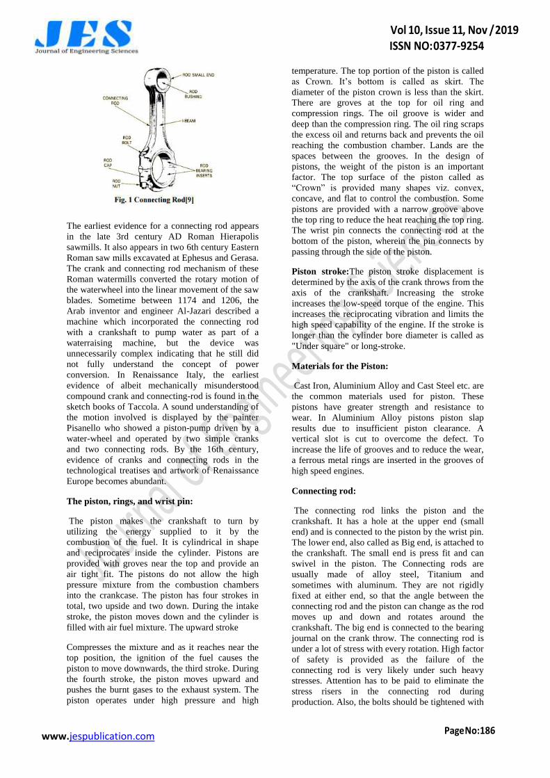
Figure:2 Schematic diagram of connecting rod
The type of rod material you want, or are available
to fit the engine you are building (4340 or 300M
forged or billet steel, aluminum, powder metal or
titanium).
Fatigue design requirement Connecting rod is acted
upon by gas loads and inertial loads during its
operation. The forces include gas forces due to
combustion and inertia forces due to its own
weight. In that point of view fatigue is an important
parameter to be considered for estimating the life of
the component. The magnitudes of inertia forces
are constant but gas forces are varying in nature.
Due to fluctuating nature of these forces the
chances of component failure due to fatigue is very
high. Thus fatigue is one of the significant factors
to be taken into account while optimizing an
existing design. Fatigue in a component arises due
to the following reasons
Material defect
Manufacturing defects
Poor detailing of dimensions while
designing
Error in load calculation
The possible zones of stress concentrations are the
change in cross-section from center shank to small
end, change in cross-section from big end to center
shank and the center shank itself. The connecting
rod is subjected to higher duty cycles and the forces
acting on the connecting rod is also tremendously
high.
The connecting rod is the link that transmits forces
between the piston and the crankshaft. Connecting
rods must be strong enough to remain rigid under
load and yet be light enough to reduce the inertia
forces that are produced when the rod and piston
stop, change direction, and start again at the end of
each stroke.
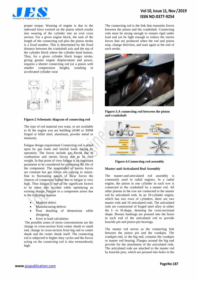
Figure:3.A connecting rod between the piston
and crankshaft
Figure:4.Connecting rod assembly
Master-and-Articulated Rod Assembly
The master-and-articulated rod assembly is
commonly used in radial engines. In a radial
engine, the piston in one cylinder in each row is
connected to the crankshaft by a master rod. All
other pistons in the row are connected to the master
rod by articulated rods. In an 18-cylinder engine,
which has two rows of cylinders, there are two
master rods and 16 articulated rods. The articulated
rods are constructed of forged steel alloy in either
the I- or H-shape, denoting the cross-sectional
shape. Bronze bushings are pressed into the bores
in each end of the articulated rod to provide
knuckle pin and piston-pin bearings.
The master rod serves as the connecting link
between the piston pin and the crankpin. The
crankpin end, or the big end, contains the crankpin
or master rod bearing. Flanges around the big end
provide for the attachment of the articulated rods.
The articulated rods are attached to the master rod
by knuckle pins, which are pressed into holes in the
www.jespublication.com
master rod flanges during assembly. A plain
bearing, usually called a piston-pin bushing, is
installed in the piston end of the master rod to
receive the piston pin.
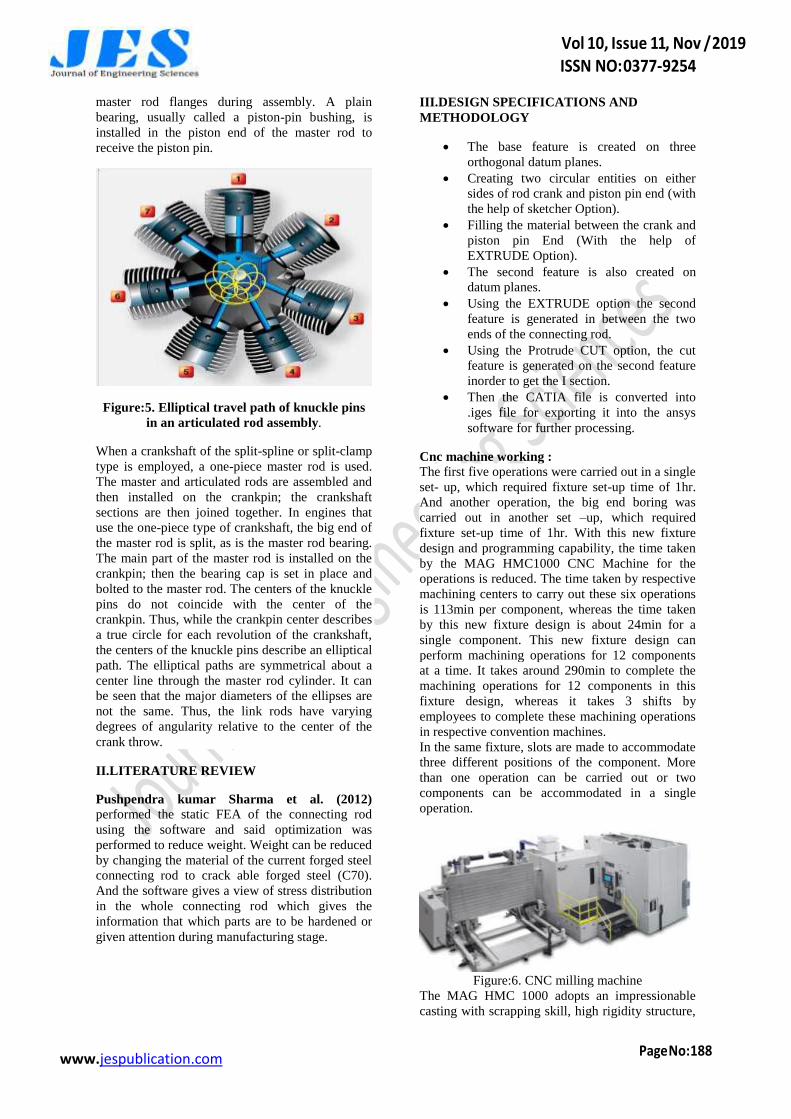
Figure:5. Elliptical travel path of knuckle pins
in an articulated rod assembly.
When a crankshaft of the split-spline or split-clamp
type is employed, a one-piece master rod is used.
The master and articulated rods are assembled and
then installed on the crankpin; the crankshaft
sections are then joined together. In engines that
use the one-piece type of crankshaft, the big end of
the master rod is split, as is the master rod bearing.
The main part of the master rod is installed on the
crankpin; then the bearing cap is set in place and
bolted to the master rod. The centers of the knuckle
pins do not coincide with the center of the
crankpin. Thus, while the crankpin center describes
a true circle for each revolution of the crankshaft,
the centers of the knuckle pins describe an elliptical
path. The elliptical paths are symmetrical about a
center line through the master rod cylinder. It can
be seen that the major diameters of the ellipses are
not the same. Thus, the link rods have varying
degrees of angularity relative to the center of the
crank throw.
II.LITERATURE REVIEW
Pushpendra kumar Sharma et al. (2012) performed the static FEA of the connecting rod
using the software and said optimization was
performed to reduce weight. Weight can be reduced
by changing the material of the current forged steel
connecting rod to crack able forged steel (C70).
And the software gives a view of stress distribution
in the whole connecting rod which gives the
information that which parts are to be hardened or
given attention during manufacturing stage.
III.DESIGN SPECIFICATIONS AND
METHODOLOGY
The base feature is created on three
orthogonal datum planes.
Creating two circular entities on either
sides of rod crank and piston pin end (with
the help of sketcher Option).
Filling the material between the crank and
piston pin End (With the help of
EXTRUDE Option).
The second feature is also created on
datum planes.
Using the EXTRUDE option the second
feature is generated in between the two
ends of the connecting rod.
Using the Protrude CUT option, the cut
feature is generated on the second feature
inorder to get the I section.
Then the CATIA file is converted into
.iges file for exporting it into the ansys
software for further processing.
Cnc machine working :
The first five operations were carried out in a single
set- up, which required fixture set-up time of 1hr.
And another operation, the big end boring was
carried out in another set –up, which required
fixture set-up time of 1hr. With this new fixture
design and programming capability, the time taken
by the MAG HMC1000 CNC Machine for the
operations is reduced. The time taken by respective
machining centers to carry out these six operations
is 113min per component, whereas the time taken
by this new fixture design is about 24min for a
single component. This new fixture design can
perform machining operations for 12 components
at a time. It takes around 290min to complete the
machining operations for 12 components in this
fixture design, whereas it takes 3 shifts by
employees to complete these machining operations
in respective convention machines.
In the same fixture, slots are made to accommodate
three different positions of the component. More
than one operation can be carried out or two
components can be accommodated in a single
operation.
Figure:6. CNC milling machine
The MAG HMC 1000 adopts an impressionable
casting with scrapping skill, high rigidity structure,

www.jespublication.com
and precision axial feed rates to assure high
precision machining capacity. It uses a box way
mechanism with a worktable of dimension
1500x1000mm and the X, Y, Z axes travel
2700x1100x1100mm.
CONNECTING RODS WITH AND WITHOUT
OPENING
Figure.7. shows the connecting rod model
Figure.8.shows the connecting rod model with
slot end
IV.RESULTS AND DISCUSSIONS
The materials were chosen and the connecting rod
was manufactured by the two processes
respectively. The ingot of the specified material
where purchased from the dealers of the required
materials The ingots where machined using the
CNC machine by the model modelled on Pro-
Engineer and it was transferred to the machine. The
work piece on the table was clamped with bench
wise again fixed to the table in the T slots. The
cutter was aligned properly by once setting the co-
ordinates. The bores are precision honed. All
corners where blended to eliminate stress at corners
Figure:9.CNC machining of aluminium block
Figure: 10.Mold preparation of connecting rod
The aluminium connecting rod was produced using
hand layup method First the half Mold was made
by making a wooden pattern around the half
periphery of the rod. The holes were also covered
with the wooden pattern and screws were fit into
them to pull them out after the half Mold is built.
The releasing agent was then applied so that when
the Mold is ready after drying it is easily removed
from the pattern and doesn’t stick to it. The
realizing has to be applied properly otherwise the
Mold may break while separating. The half Mold
was prepared by using the aluminium material
which was placed by hand layer after layer and
applying the general purpose resin mixed with the
accelerator copal and then the catalyst methyl-ethyl
copal is added while layers are added and left for
drying
The connecting rods of the aluminium alloy where
solution heat treated to increase their strength and
mechanical properties at temperatures of around
480c and was held in water for 30 minutes. The
rods after solution heat treatment and stress
revealing operation. The aluminium connecting
rods where then fit in the engine step by step as
shown in the following figures
Figure:11.Connecting using module

www.jespublication.com
Figure:12.Solution Heat Treated Rod
Due to its central role in every combustion piston
engine, mechanical reliability of every Connecting
rod is of upmost importance. Connecting rod
mechanical properties depend on used material and
applied manufacturing technology. Current paper
elaborates three most frequently employed
manufacturing processes to fabricate Connecting
rod classical forging, casting and powder forging.
Hot forging is still the most used technology,
especially for high performance engines as it
enables production of mechanically high reliable
Connecting rod Powder forging alternative is
somewhat more costly than classical forging, but it
requires reduced additional machining operations
and therefore has a strong growing market
Materials and properties:
The connecting rod is under tremendous stress
from the reciprocating load represented by the
piston, actually stretching and being compressed
with every rotation, and the load increases to the
third power with increasing engine speed. Steel is
normally used for construction of automobile
connecting rods because of its strength, durability,
and lower cost. However, steel with its high mass
density exerts excessive stresses on the crankshaft
of a high speed engine. This in turn requires a
heavier crankshaft for carrying the loads and,
therefore, the maximum RPM of the engine is
limited. Additionally, higher inertia loads, such as
those caused by steel connecting rods and heavier
crankshafts reduces the acceleration or declaration
rates of engine speed. The automobile engine
connecting rod is a high volume production, critical
component. It connects reciprocating piston to
rotating crankshaft, transmitting the thrust of the
piston to the crankshaft. Every vehicle that uses an
internal combustion engine requires at least one
connecting rod depending upon the number of
cylinders in the engine. With steel forging, the
material is inexpensive and the rough part
manufacturing process is cost effective. Bringing
the part to final dimensions under tight tolerance
results in high expenditure for machining, as the
blank usually contains more excess material The
first aspect was to investigate and compare fatigue
strength of steel forged connecting rods with that of
the powder forged connecting rods. Due to its large
volume production, it is only logical that
optimization of the connecting rod for its weight or
volume will result in large-scale savings. It can also
achieve the objective of reducing the weight of the
engine component, thus reducing inertia loads,
reducing engine weight and improving engine
performance and fuel economy A composite is a
material that is formed by combining two or more
materials to achieve some superior properties.
Almost all the materials which we see around us
are composites. Some of them like woods, bones,
stones, etc. are natural composites, as they are
either grown in nature or developed by natural
processes..
Table:1. Chemical composition of aluminum
7068 alloy
Element Content %
Zinc, Zn 8.3
Magnesium, Mg 3
Copper, Cu 2.4
Iron, Fe 0.15
Zirconium, Zr 0.15
Silicon, Si 0.12
Manganese, Mn 0.1
Titanium, Ti 0.1
Chromium, Cr 0.05
Other (total) 0.15
Table:2.Physical properties of aluminum 7068
alloy
Properties Metric Imperial
Density 2.85 mg/cm³ 0.103 lb/in³
Melting point 476-635 ºC 890-1175 ºF
Table: 3.Mechanical Properties of aluminum
7068 alloy
Properties Metric Imperial
Tensile strength 641 MPa 93 ksi
Yield strength 590 MPa 85.7 ksi
Elongation 8% 8%
Silicon Carbide Properties:

www.jespublication.com
Properties:
Properties Metric
Flexural Strength 550 MPa
Elastic Modulus 410 GPa
Compressive Strength 3900 MPa
Hardness 2800 Kg
Thermal Conductivity 120 W/m•°K
Specific Heat 750 J/Kg•°K
Table: 4.Forged Steel Properties:
Properties Metric
Tensile Strength 845 MPa
Yield strength 540 GPa
Young’s modulus 210 Mpa
Elongation 15%
Poisson’s ratio 0.3
Density 7.85 g/cm3
Melting point 1416°C
Modeling of connecting rod:
To calculate existing factor of safety of the
connecting rod the flowing considerations are being
taken the connecting rod is designed using CATIA
V5 6R 2018 according to the specifications given
below
Parameter Value
Length of connecting rod 150
Outer diameter of big end 56
Inner diameter of big end 48
Outer diameter of small
end
32
Inner diameter of small
end
24
Figure: 13.Geometric view
ANALYSIS ON ANSYS WORKBENCH 16.2:
A. Introduction to Ansys Ansys is analysis
software. It is used to check design feasibility of
the design almost in all aspect. Ansys as a software
is made to be user-friendly and simplified as much
as possible with lots of interface options to keep the
user as much as possible from the hectic side of
programming and debugging process. A glimpse of
Ansys workbench is shown in figure
Figure:14.Static Structural Analysis System
In this project we took static structural as analysis
system for the analysis of connecting rod. To
analyzing connecting rod using different material at
Ansys workbench 16.2 following step have been
followed:-
Figure: 15.First view of static structure
Meshing After importing the external geometry
further function is meshing. Meshing is done for
better accuracy in result. It is many typesa)
a) Triangular meshing
b) Rectangular meshing
c) Tetrahedron meshing ..........et

www.jespublication.com
Figure:16. Generate meshing
Working on Model:
a) After meshing we go to SET UP we click on
CONNECTING and see like this
Figure: 17.Giving new material to connecting
rod
In Details of CONNECTING click on assignment
we see there are importing materials.
Then we selecting one of them for further
implementation.
Static Structural Setting: In static structure
Analysis we have to fixed one part then right click
on static structure then go to insert and further click
on fixed support and apply on one part of the
connecting rod
Figure:18.Giving fixed support
To define stress various theories have been already
assigned in the ansys like Von-Mises, Maximum
principal etc. In this project Von- Mises used as
stress theory.
Figure:19.Applied stress in model
Deformation: Two type of deformation is given in
Ansys a) Total Deformation It is the volumetric
deformation in geometry. b) Directional
Deformation: In directional deformation,
deformation is in a particular direction i.e. in x, y
and z-direction
Figure: 20.Total deformations in connecting rod
Strain: There are many type of strain in ansys as
von-mises, maximum principle strain, and
maximum shear strain. In this project we discuss
only von-mises strain.
Figure:21.Strain in model
www.jespublication.com
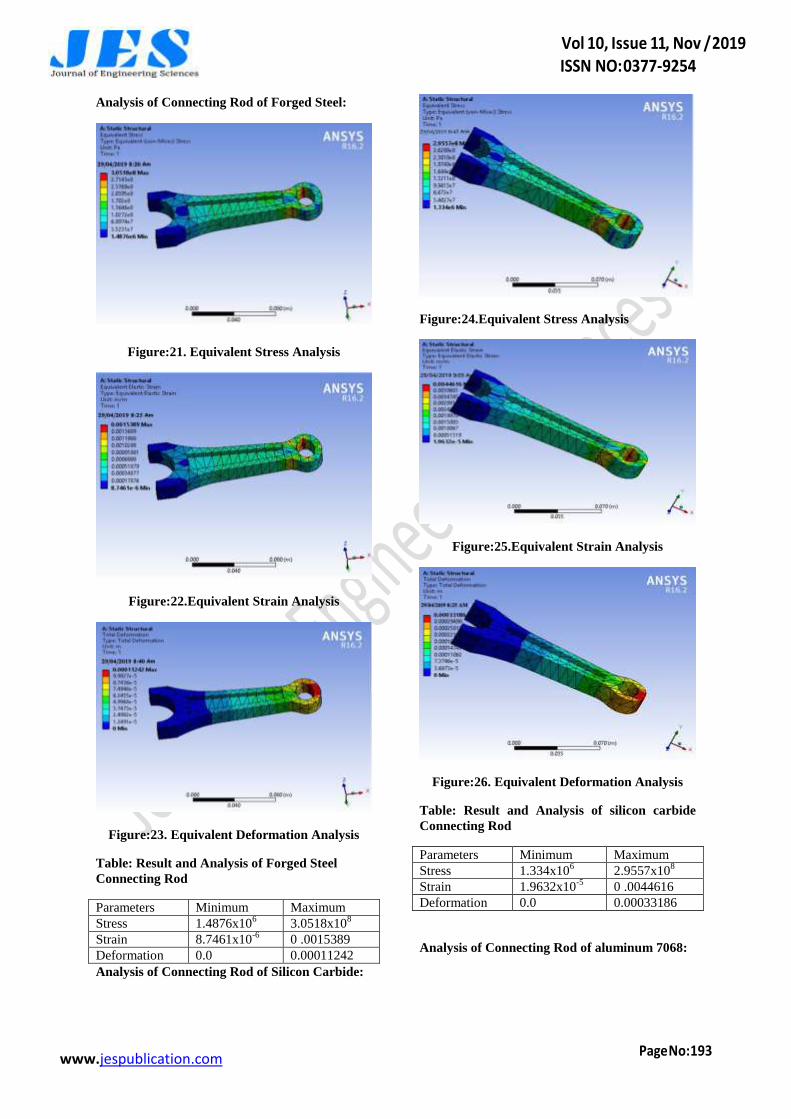
Analysis of Connecting Rod of Forged Steel:
Figure:21. Equivalent Stress Analysis
Figure:22.Equivalent Strain Analysis
Figure:23. Equivalent Deformation Analysis
Table: Result and Analysis of Forged Steel
Connecting Rod
Parameters Minimum Maximum
Stress 1.4876x10⁶ 3.0518x10
8
Strain 8.7461x10⁻⁶
0 .0015389
Deformation 0.0 0.00011242
Analysis of Connecting Rod of Silicon Carbide:
Figure:24.Equivalent Stress Analysis
Figure:25.Equivalent Strain Analysis
Figure:26. Equivalent Deformation Analysis
Table: Result and Analysis of silicon carbide
Connecting Rod
Parameters Minimum Maximum
Stress 1.334x10⁶ 2.9557x10
8
Strain 1.9632x10⁻⁵
0 .0044616
Deformation 0.0 0.00033186
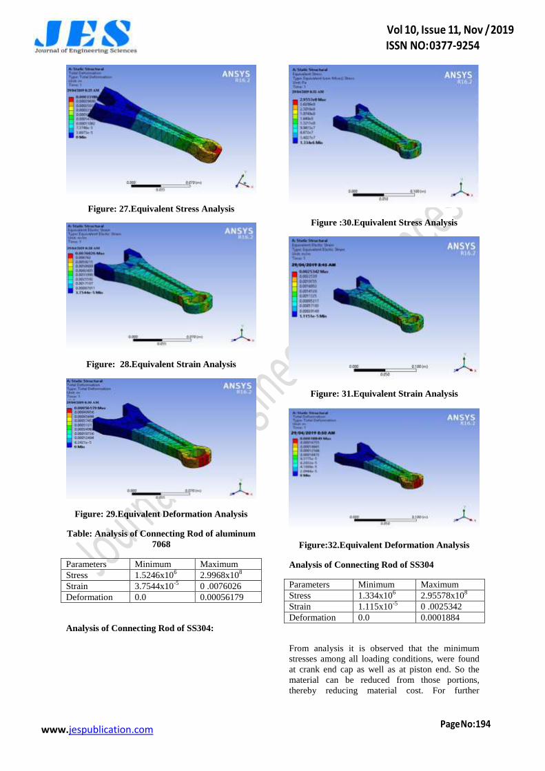
Analysis of Connecting Rod of aluminum 7068:
www.jespublication.com
Figure: 27.Equivalent Stress Analysis
Figure: 28.Equivalent Strain Analysis
Figure: 29.Equivalent Deformation Analysis
Table: Analysis of Connecting Rod of aluminum
7068
Parameters Minimum Maximum
Stress 1.5246x10⁶ 2.9968x10
8
Strain 3.7544x10⁻⁵
0 .0076026
Deformation 0.0 0.00056179
Analysis of Connecting Rod of SS304:
Figure :30.Equivalent Stress Analysis
Figure: 31.Equivalent Strain Analysis
Figure:32.Equivalent Deformation Analysis
Analysis of Connecting Rod of SS304
Parameters Minimum Maximum
Stress 1.334x10⁶ 2.95578x10
8
Strain 1.115x10⁻⁵
0 .0025342
Deformation 0.0 0.0001884
From analysis it is observed that the minimum
stresses among all loading conditions, were found
at crank end cap as well as at piston end. So the
material can be reduced from those portions,
thereby reducing material cost. For further

www.jespublication.com
optimization of material dynamic analysis of
connecting rod is needed. After considering
dynamic load conditions once again finite element
analysis will have to be performed. It will give
more accurate results than existing. It is the
conclusion of this study that the connecting rod can
be designed and optimized under a load range
comprising compressive load as one extreme load
and tensile load. Furthermore, the existing
connecting rod can be replaced by optimization
with a new connecting rod made of lighter in
weight From the above analysis we can conclude
that stresses of all the materials are almost
comparable and also in safe limit, i.e., well below
the yield stress. The section modulus of the
connecting rod should be high enough to prevent
high bending stresses due to inertia forces. F.
Weight of connecting rod is reduced, Thereby
reduces the inertia force by comparing the results
of three different materials used for connecting rod
analysis it is found that equivalent von mises stress
for all the materials is approximately same. From
the static analysis the stress is found maximum at
the small end of the connecting rod. H. Carbon
steel as a connecting rod material is less stiff and
having more weight than forged steel and other
material taking in consideration
V.CONCLUSIONS
In this thesis, a broken connecting rod made of
forged steel is replaced with Aluminium alloys and
The materials are changed so that the weight of the
connecting rod is less when aluminium alloys used
The connecting rod is fabricated forces are
calculated. Analysis is done on the connecting rod
using materials aluminium 6061, the forces were
applied on the piston head and the effect of it on
the connecting rod was studied in this analysis.
Demand of industry for components produced with
high techno-economical performances is
permanently growing. Such trends are exceedingly
noticeable in automotive industry. One of the main
components in every automobile is connecting rod.
It converts linear motion of the piston into the
rotating motion of the crankshaft and it is highly
stressed by cyclic pushing and pulling loads.
Above project gives the idea about designing of the
connecting rod. It explains about the various
stresses to be considered while designing the
connecting rod and different materials used and
comparing the result of all material. These can be
used for designing any connecting rod in
Automobile. Connecting rod can be designed for
weight and cost reduction also to increase the life
time of connecting rod. Up to some level of extent
the weight of the connecting rod is lighter and
having more strength as compared to the original
design.
Future scope:
1. Designing a connecting rod for a specific two
wheeler IC Engine, by numerical method.
2. The connecting rod can be further modified with
suitable alternate material for weight optimization.
REFERENCES
[1] A. Prem kumar “Design & Analysis of
Connecting Rod by Composite Material” ISSN:
3855-0154, IJRD, Vol. 2, Issue 7, July 2015.
[2] Ambrish Tiwari, Jeetendra Kumar Tiwari,
Sharad Kumar Chandrakar “Fatigue Analysis of
Connecting Rod Using Finite Element Analysis to
Explore Weight and Cost Reduction Opportunities
for a Production of Forged Steel Connecting Rod”
ISSN 2250-3234, Vol. 4, Number 7, 2014.
[3] B. Anusha, C.Vijaya Bhaskar Reddy
“Modeling and Analysis of Two Wheeler
Connecting Rod by Using Ansys” ISSN: 2320-
334X, Vol. 6, Issue 5, May. - Jun. 2013
[4] Dr. B.K.Roy. “Design Analysis and
Optimization of Various Parameters of Connecting
Rod using CAE Softwares” ISSN: 2319-6319,
IJNIET, Vol. 1, Issue 1, October 2012.
[5] Fanil Desai, Kiran kumar Jagtap, Abhijeet
Deshpande “Numerical and Experimental Analysis
of Connecting Rod” ISSN 2349-4395, IJEERT,
Vol. 2, Issue 4, July 2014.
[6] G. Naga Malleshwara Rao “Design
Optimization and Analysis of a Connecting Rod
using ANSYS” ISSN: 2319-7064, IJSR, Vol. 2
Issue 7, July 2013.
[7] K. Sudershn Kumar, Dr. K. Tirupathi Reddy,
Syed Altaf Hussain “Modeling and Analysis of
Two Wheeler Connecting Rod” ISSN: 2249-6645,
IJMER, Vol 2, Issue 5, Sep-Oct. 2012.
[8] Kuldeep B, Arun L.R, Mohammed Faheem
“Analysis And Optimization Of Connecting Rod
Using Alfasic Composites” ISSN: 2319-8753,
IJIRSET, Vol. 2, Issue 6, June 2013.
[9] Mr. J.D. Ramani, Prof. Sunil Shukla, Dr.
Pushpendra Kumar Sharma. “FE-Analysis of
Connecting Rod of I.C.Engine by Using Ansys for
Material Optimization” ISSN: 2248-9622, IJERA,
Vol. 4, Issue 3, Version 1, March 2014.
[10] P.S. Shenoy and A Fatemi “Dynamic analysis
of loads and stresses in Connecting Rods”
JMES105, Vol. 220 Part C, 2006.
www.jespublication.com
[11] Prateek Joshi, Mohammad Umair Zaki “FEM
Analysis of Connecting Rod of different materials
using ANSYS” ISSN: 2395-1303, IJET, Vol. 1,
Issue 3, May - June 2015.
[12] Pushpendra Kumar Sharma, Borse Rajendra R
“Fatigue Analysis And Optimiation Of Connecting
Rod Using Finite Element Analysis” ISSN-2319-
8354, IJARSE, Vol. No.1, Issue No. I, September
2012.
[13] R.A. Savanoor, Abhishek Patil, Rakesh Patil,
Amit Rodagi “Finite Element Analysis Of IC
Engine Connecting Rod By Ansys” ISSN: 2278 –
0149, IJMERR, Vol. 3, No. 3, July 2014.
[14] Sushant, Victor Gambhir “Design and
Comparative Performance Analysis of Two
Wheeler Connecting Rod Using Two Different
Materials Namely Carbon 70 Steel and Aluminum
7068 by Finite Element Analysis” ISSN: 2321-
3051, IJRAME, Vol. 2, Issue. 6, June 2014.
[15] Shenoy, P. S. and Fatemi, A. Connecting rod
optimiz- ation for weight and cost reduction. SAE
Technical Paper 2005-01-0987, 2005.
[16] Ferguson, C. R. Internal combustion engines,
applied thermo sciences, 1986 (John Wiley & Sons,
Shrewsbury).
[17] Socie, D. F. and Marquis, G. B. Multiaxial
fatigue, 2000 (Society of Automotive Engineers,
Warrendale, PA).