DEPARTMENT OF DEFENSE STANDARD PRACTICE
257
AMSC N/A AREA SESS DISTRIBUTION STATEMENT A. Approved for public release. Distribution is unlimited. INCH-POUND MIL-STD-2003-3B(SH) 6 October 2020 SUPERSEDING MIL-STD-2003-3A(SH) 3 September 2009 DEPARTMENT OF DEFENSE STANDARD PRACTICE ELECTRIC PLANT INSTALLATION STANDARD METHODS FOR SURFACE SHIPS AND SUBMARINES (PENETRATIONS) Downloaded from http://www.everyspec.com
-
Upload
khangminh22 -
Category
Documents
-
view
1 -
download
0
Transcript of DEPARTMENT OF DEFENSE STANDARD PRACTICE

AMSC N/A AREA SESS
DISTRIBUTION STATEMENT A. Approved for public release. Distribution is unlimited.
INCH-POUND
MIL-STD-2003-3B(SH)
6 October 2020
SUPERSEDING
MIL-STD-2003-3A(SH)
3 September 2009
DEPARTMENT OF DEFENSE
STANDARD PRACTICE
ELECTRIC PLANT INSTALLATION
STANDARD METHODS FOR
SURFACE SHIPS AND SUBMARINES
(PENETRATIONS)
Downloaded from http://www.everyspec.com

MIL-STD-2003-3B(SH)
ii
FOREWORD
1. This standard is approved for use by the Naval Sea Systems Command, Department of the Navy, and is
available for use by all Departments and Agencies of the Department of Defense.
2. This standard disseminates up-to-date information detailing requirements for standard installation
methods for electrical penetrations employed for submarine and surface ship electrical distribution systems.
3. These criteria are for application to new construction, conversion, and alteration of existing ships.
4. Comments, suggestions, or questions on this document should be addressed to Commander, Naval Sea
Systems Command, ATTN: SEA 05S, 1333 Isaac Hull Avenue, SE, Stop 5160, Washington Navy Yard DC
20376-5160 or emailed to CommandStandards@navy mil, with the subject line “Document Comment”. Since contact
information can change, you may want to verify the currency of this address information using the ASSIST Online
database at https://assist.dla mil.
Downloaded from http://www.everyspec.com

MIL-STD-2003-3B(SH)
iii
CONTENTS
PARAGRAPH PAGE
1. SCOPE ...................................................................................................................................................................... 1
1.1 Scope. ................................................................................................................................................................. 1 1.2 Application. ........................................................................................................................................................ 1
2. APPLICABLE DOCUMENTS ................................................................................................................................ 1
2.1 General. .............................................................................................................................................................. 1 2.2 Government documents. ..................................................................................................................................... 1
2.2.1 Specifications, standards, and handbooks. ................................................................................................... 1 2.2.2 Other Government documents, drawings, and publications. ....................................................................... 2
2.3 Order of precedence. ........................................................................................................................................... 3
3. DEFINITIONS ......................................................................................................................................................... 3
3.1 Collective protective system (CPS). ................................................................................................................... 3 3.2 Community stuffing tube for bulkheads. ............................................................................................................ 3 3.3 Kickpipe. ............................................................................................................................................................ 3 3.4 Metal stuffing tube. ............................................................................................................................................. 3
3.4.1 Nylon stuffing tube. ..................................................................................................................................... 3 3.5 Multiple cable penetrator (MCP) or multi-cable transits (MCT). ....................................................................... 3 3.6 RISE expanded sleeve multiple cable penetration sealing system. ..................................................................... 3 3.7 Swage tube. ......................................................................................................................................................... 3
4. GENERAL REQUIREMENTS ................................................................................................................................ 3
4.1 Cable penetrations. ............................................................................................................................................. 3 4.1.1 Installation welding requirements. ............................................................................................................... 4 4.1.2 Cable penetration of structure. ..................................................................................................................... 4 4.1.3 Cable penetration of protective plate bulkheads and decks and bulkheads and decks forming boundaries
of spaces containing volatile combustible or explosive materials. ........................................................................ 4 4.1.4 Cable penetration of decks, structural bulkheads, airtight bulkheads, and fume-tight bulkheads................ 5 4.1.5 Multiple (two or more) penetrations of nonstructural steel bulkheads (other than wire mesh or expanded
metal), bents, web frames, transverse girders, and longitudinal girders. ............................................................... 5 4.1.6 Plastic sealer. ............................................................................................................................................... 5 4.1.7 Cable penetrations spacing. ......................................................................................................................... 5 4.1.8 Stuffing tube packing. .................................................................................................................................. 5 4.1.9 Kickpipes. .................................................................................................................................................... 6 4.1.10 Exterior application. .................................................................................................................................. 6 4.1.11 Stuffing tube clearance. ............................................................................................................................. 6 4.1.12 Swage tube, kickpipe, and stuffing tube welding. ..................................................................................... 6
4.2 Or equal. ............................................................................................................................................................. 6 4.3 Inactive for new design documents .................................................................................................................... 6 4.4 Installation of fiber optic cables in electrical penetrations.................................................................................. 6 4.5 Fastener requirements ......................................................................................................................................... 6 4.6 Hazardous materials............................................................................................................................................ 6 4.7 Installation and servicing of electrical penetrations within the submarine SUBSAFE boundary ....................... 6 4.8 Thread lubricant .................................................................................................................................................. 7
4.8.1 Thread lubricant application ........................................................................................................................ 7 4.9 The terms agreement or approval ....................................................................................................................... 7
5. DETAILED REQUIREMENTS ............................................................................................................................... 7
6. NOTES ..................................................................................................................................................................... 7
6.1 Intended use. ....................................................................................................................................................... 7 6.2 Acquisition requirements. ................................................................................................................................... 7 6.3 Designation of electric plant installation standard methods figures. .................................................................. 7 6.4 Subject term (key word) listing. ......................................................................................................................... 8 6.5 Changes from previous issue. ............................................................................................................................. 8
Downloaded from http://www.everyspec.com

MIL-STD-2003-3B(SH)
iv
APPENDIX 3A – PENETRATIONS – STUFFING TUBES, SUBMARINES ............................................................ 9
A.1 SCOPE ................................................................................................................................................................... 9
A.1.1 Scope .............................................................................................................................................................. 9
A.2. APPLICABLE DOCUMENTS ............................................................................................................................ 9
A.2.1 General ............................................................................................................................................................ 9 A.2.2 Government documents. ................................................................................................................................. 9
A.2.2.1 Specifications, standards, and handbooks ................................................................................................ 9 A.2.2.2 Other Government documents, drawings, and publications................................................................... 10
A.2.3 Non-Government publications ...................................................................................................................... 10 A.2.4 Order of precedence ...................................................................................................................................... 11
A.3 REQUIRED EQUIPMENT AND MATERIALS ................................................................................................ 11
A.3.1 Required equipment and materials ................................................................................................................ 11
A.4 NOTES AND PROCEDURES ............................................................................................................................ 11
A.4.1 Dimensions ................................................................................................................................................... 11 A.4.2 Figures .......................................................................................................................................................... 11
APPENDIX 3B – PENETRATIONS –SURFACE SHIPS.......................................................................................... 47
B.1 SCOPE ................................................................................................................................................................. 47
B.1.1 Scope ............................................................................................................................................................. 47
B.2. APPLICABLE DOCUMENTS ........................................................................................................................... 47
B.2.1 General .......................................................................................................................................................... 47 B.2.2 Government documents. ............................................................................................................................... 47
B.2.2.1 Specifications, standards, and handbooks .............................................................................................. 47 B.2.2.2 Other Government documents, drawings, and publications ................................................................... 48
B.2.3 Non-Government publications ...................................................................................................................... 48 B.2.4 Order of precedence ...................................................................................................................................... 49
B.3 REQUIRED EQUIPMENT AND MATERIALS ................................................................................................ 49
B.3.1 Required equipment and materials ................................................................................................................ 49
B.4 NOTES AND PROCEDURES ............................................................................................................................ 49
B.4.1 Dimensions ................................................................................................................................................... 49 B.4.2 Figures .......................................................................................................................................................... 49
APPENDIX 3C – PENETRATIONS – STUFFING TUBES, GENERAL ............................................................... 202
C.1 SCOPE ............................................................................................................................................................... 202
C.1.1 Scope ........................................................................................................................................................... 202
C.2. APPLICABLE DOCUMENTS ......................................................................................................................... 202
C.2.1 General ........................................................................................................................................................ 202 C.2.2 Government documents. ............................................................................................................................. 202
C.2.2.1 Specifications, standards, and handbooks ............................................................................................ 202 C.2.3 Non-Government publications .................................................................................................................... 202 C.2.4 Order of precedence .................................................................................................................................... 203
C.3 REQUIRED EQUIPMENT AND MATERIALS .............................................................................................. 203
C.3.1 Required equipment and materials .............................................................................................................. 203
C.4 NOTES AND PROCEDURES .......................................................................................................................... 203
C.4.1 Dimensions ................................................................................................................................................. 203 C.4.2 Figures ........................................................................................................................................................ 203
APPENDIX 3D – PENETRATIONS – KICKPIPES ................................................................................................ 223
D.1 SCOPE ............................................................................................................................................................... 223
D.1.1 Scope .......................................................................................................................................................... 223
D.2. APPLICABLE DOCUMENTS ........................................................................................................................ 223
Downloaded from http://www.everyspec.com

MIL-STD-2003-3B(SH)
v
D.2.1 General ........................................................................................................................................................ 223 D.2.2 Government documents. ............................................................................................................................. 223
D.2.2.1 Specifications, standards, and handbooks ............................................................................................ 223 D.2.3 Non-Government publications .................................................................................................................... 223 D.2.4 Order of precedence .................................................................................................................................... 223
D.3 REQUIRED EQUIPMENT AND MATERIALS .............................................................................................. 224
D.3.1 Required equipment and materials .............................................................................................................. 224
D.4 NOTES AND PROCEDURES .......................................................................................................................... 224
D.4.1 Dimensions ................................................................................................................................................. 224 D.4.2 Figures ........................................................................................................................................................ 224
APPENDIX 3E – PENETRATIONS – PRESSURE HULLS, SUBMARINES ....................................................... 235
E.1 SCOPE ............................................................................................................................................................... 235
E.1.1 Scope ........................................................................................................................................................... 235
E.2. APPLICABLE DOCUMENTS ......................................................................................................................... 235
E.2.1 General ........................................................................................................................................................ 235 E.2.2 Government documents. .............................................................................................................................. 235
E.2.2.1 Specifications, standards, and handbooks ............................................................................................ 235 E.2.2.2 Other Government documents, drawings, and publications ................................................................. 236
E.2.3 Non-Government publications .................................................................................................................... 236 E.2.4 Order of precedence .................................................................................................................................... 236
E.3 REQUIRED EQUIPMENT AND MATERIALS .............................................................................................. 236
E.3.1 Required equipment and materials .............................................................................................................. 236
E.4 NOTES AND PROCEDURES .......................................................................................................................... 237
E.4.1 Dimensions .................................................................................................................................................. 237 E.4.2 Figures ......................................................................................................................................................... 237
Downloaded from http://www.everyspec.com

MIL-STD-2003-3B(SH)
vi
LIST OF TABLES
TABLE PAGE
APPENDIX 3A – PENETRATIONS – STUFFING TUBES, SUBMARINES ............................................................ 9
TABLE 3AI. Figures for submarine stuffing tubes installation. ............................................................................. 11 TABLE 3A1-I. Gland nut torque values (see notes 7, 12, and 14). ........................................................................ 14 TABLE 3A1-II. Length modifications (inches). ..................................................................................................... 15 TABLE 3A2-I. Application table. .......................................................................................................................... 16 TABLE 3A3-I. Table of dimensions. ..................................................................................................................... 17 TABLE 3A4-I. Table of dimensions. ..................................................................................................................... 18 TABLE 3A5-I. Bore and length dimensions and strain relief bushings. ................................................................ 20 TABLE 3A6-I. Table of dimensions – sealing plugs, method 3A-6-1. .................................................................. 22 TABLE 3A6-II. Table of dimensions – sealing plugs, method 3A-6-2. ................................................................. 22 TABLE 3A7-I. Associated data and sealing plug dimensions. ............................................................................... 23 TABLE 3A8-I. Table of dimensions. ..................................................................................................................... 27 TABLE 3A9-I. Sleeve dimensions (see note 7). ..................................................................................................... 29 TABLE 3A10-I. Cable assignment to steel, aluminum, and nylon stuffing tubes, MCP blocks, and box
connectors. ............................................................................................................................................................... 30 TABLE 3A11-I. Cable assignment to steel, aluminum, and nylon stuffing tubes, MCP blocks, and box
connectors. ............................................................................................................................................................... 31 TABLE 3A12-I. Cable assignment to steel, aluminum, and nylon stuffing tubes, MCP blocks, and box
connectors. ............................................................................................................................................................... 32 TABLE 3A13-I. Cable assignment to steel, aluminum, and nylon stuffing tubes, MCP blocks, and box
connectors. ............................................................................................................................................................... 33 TABLE 3A14-I. Cable assignment to steel, aluminum, and nylon stuffing tubes, MCP blocks, and box
connectors. ............................................................................................................................................................... 34 TABLE 3A15-I. Cable assignment to steel, aluminum, and nylon stuffing tubes, MCP blocks, and box
connectors. ............................................................................................................................................................... 35 TABLE 3A16-I. Cable assignment to steel, aluminum, and nylon stuffing tubes, MCP blocks, and box
connectors. ............................................................................................................................................................... 36 TABLE 3A17-I. Cable assignment to steel, aluminum, and nylon stuffing tubes, MCP blocks, and box
connectors. ............................................................................................................................................................... 37 TABLE 3A18-I. Cable assignment to steel, aluminum, and nylon stuffing tubes, MCP blocks, and box
connectors. ............................................................................................................................................................... 38 TABLE 3A19-I. Cable assignment to steel, aluminum, and nylon stuffing tubes, MCP blocks, and box
connectors. ............................................................................................................................................................... 39 TABLE 3A20-I. Cable assignment to steel, aluminum, and nylon stuffing tubes, MCP blocks, and box
connectors. ............................................................................................................................................................... 40 TABLE 3A21-I. Cable assignment to steel, aluminum, and nylon stuffing tubes, MCP blocks, and box
connectors. ............................................................................................................................................................... 41 TABLE 3A22-I. Cable assignment to steel, aluminum, and nylon stuffing tubes, MCP blocks, and box
connectors. ............................................................................................................................................................... 42 TABLE 3A23-I. Cable assignment to steel, aluminum, and nylon stuffing tubes, MCP blocks, and box
connectors. ............................................................................................................................................................... 43 TABLE 3A24-I. Cable assignment to steel, aluminum, and nylon stuffing tubes, MCP blocks, and box
connectors. ............................................................................................................................................................... 44 TABLE 3A25-I. Cable assignment to steel, aluminum, and nylon stuffing tubes, MCP blocks, and box
connectors. ............................................................................................................................................................... 45
APPENDIX 3B – PENETRATIONS –SURFACE SHIPS.......................................................................................... 47
TABLE 3BI. Figures for surface ship penetration installation. .............................................................................. 49 TABLE 3B2-I. Hole spacing in decks and bulkheads. ........................................................................................... 53 TABLE 3B3-I. Hole spacing in decks and bulkheads. ........................................................................................... 54 TABLE 3B4-I. Hole spacing in decks and bulkheads. ........................................................................................... 55 TABLE 3B19-I. Stuffing tube body dimensions. ................................................................................................... 78
Downloaded from http://www.everyspec.com

MIL-STD-2003-3B(SH)
vii
TABLE PAGE
TABLE 3B21-I. Cable information and assignment for MCP insert blocks. ......................................................... 86 TABLE 3B21-II. Insert blocks. .............................................................................................................................. 87 TABLE 3B30-I. Reinforced frame opening dimensions. ..................................................................................... 115 TABLE 3B30-II. Frame dimensions. ................................................................................................................... 115 TABLE 3B31-I. List of materials. ........................................................................................................................ 117 TABLE 3B35-I. New stuffing tubes – MIL-S-24235/10. ..................................................................................... 124 TABLE 3B38-I. Packing wire diameter. .............................................................................................................. 127 TABLE 3B41-I. Round carbon steel tube............................................................................................................. 134 TABLE 3B41-II. Round aluminum (alloy 6061-T6). ........................................................................................... 134 TABLE 3B47-I. Type TW penetrator characteristics. .......................................................................................... 145 TABLE 3B49-I. Penetrator sleeve dimensions A, B, and C. ................................................................................ 150 TABLE 3B49-II. Penetrator sleeve dimensions D and E for bulkhead installations. ........................................... 150 TABLE 3B49-III. Penetrator sleeve dimensions D and E for deck installations. ................................................. 150 TABLE 3B54-I. RISE insert sleeve data. ............................................................................................................. 163 TABLE 3B59-I. List of material for type A DMCT. ............................................................................................ 179 TABLE 3B60-I. List of material for type B DMCT. ............................................................................................ 182 TABLE 3B61-I. List of material for round MCT. ................................................................................................ 187 TABLE 3B63-I. Parts list. .................................................................................................................................... 192 TABLE 3B64-I. Typical RGSC MCP frame sizes. .............................................................................................. 199 TABLE 3B64-II. Typical RGSC frame weights. .................................................................................................. 199
APPENDIX 3C – PENETRATIONS – STUFFING TUBES, GENERAL ............................................................... 202
TABLE 3CI. Figures for general purpose stuffing tubes. ..................................................................................... 203 TABLE 3C3-I. Straight tube sizes 1 through 9, ASTM F1836M. ........................................................................ 208 TABLE 3C3-II. Angle tube sizes 1 through 6, ASTM F1836M. ......................................................................... 209 TABLE 3C3-III. NPT tube sizes 1 through 9, ASTM F1836M. .......................................................................... 210 TABLE 3C3-IV. “Y” type tube sizes 1 through 4, ASTM F1836M. ................................................................... 210 TABLE 3C9-I. Inserts PC 3C-9-1. ....................................................................................................................... 217 TABLE 3C9-II. Inserts PCs 3C-9-2 and 3C-9-3. ................................................................................................. 218
APPENDIX 3D – PENETRATIONS – KICKPIPES ................................................................................................ 223
TABLE 3DI. Figures for kickpipes. ..................................................................................................................... 224
APPENDIX 3E – PENETRATIONS – PRESSURE HULLS, SUBMARINES ....................................................... 235
TABLE 3EI. Figures for penetrations of submarine pressure hulls. ..................................................................... 237 TABLE 3E2-I. Quantities for one sealing plug assembly. ................................................................................... 239 TABLE 3E3-I. Cable assignment. ........................................................................................................................ 241 TABLE 3E6-I. Sealing plug assembly. ................................................................................................................ 245
Downloaded from http://www.everyspec.com

MIL-STD-2003-3B(SH)
viii
LIST OF FIGURES
FIGURE PAGE
APPENDIX 3A – PENETRATIONS – STUFFING TUBES, SUBMARINES ............................................................ 9
FIGURE 3A1. MIL-S-24235/1 stuffing tubes for passing cables through pressureproof bulkheads
(submarines). ........................................................................................................................................................... 13 FIGURE 3A2. MIL-S-24235/5 stuffing tube for passing cable through ballast tank partitions (submarines). ...... 16 FIGURE 3A3. Passing cable through tanks (pipe extension) (submarines). .......................................................... 17 FIGURE 3A4. MIL-S-24235 stuffing tube for passing cables through shielded bulkheads (submarines). ............ 18 FIGURE 3A5. Cables through elliptical bulkheads (submarines). ......................................................................... 19 FIGURE 3A6. Sealing plugs for blanking steel stuffing tubes (submarines). ........................................................ 21 FIGURE 3A7. Temporary plugging of steel stuffing tubes (submarines). ............................................................. 23 FIGURE 3A8. Size and details of adapter used for changing size of installed steel bulkhead MIL-S-24235
stuffing tubes (submarines)...................................................................................................................................... 25 FIGURE 3A9. Bushing sleeves for MIL-S-24235 stuffing tubes through steel shielded bulkheads. ..................... 28 FIGURE 3A10. Cable assignment to steel, aluminum, and nylon stuffing tubes, MCP blocks, and box
connectors. ............................................................................................................................................................... 30 FIGURE 3A11. Cable assignment to steel, aluminum, and nylon stuffing tubes, MCP blocks, and box
connectors. ............................................................................................................................................................... 31 FIGURE 3A12. Cable assignment to steel, aluminum, and nylon stuffing tubes, MCP blocks, and box
connectors. ............................................................................................................................................................... 32 FIGURE 3A13. Cable assignment to steel, aluminum, and nylon stuffing tubes, MCP blocks, and box
connectors. ............................................................................................................................................................... 33 FIGURE 3A14. Cable assignment to steel, aluminum, and nylon stuffing tubes, MCP blocks, and box
connectors. ............................................................................................................................................................... 34 FIGURE 3A15. Cable assignment to steel, aluminum, and nylon stuffing tubes, MCP blocks, and box
connectors. ............................................................................................................................................................... 35 FIGURE 3A16. Cable assignment to steel, aluminum, and nylon stuffing tubes, MCP blocks, and box
connectors. ............................................................................................................................................................... 36 FIGURE 3A17. Cable assignment to steel, aluminum, and nylon stuffing tubes, MCP blocks, and box
connectors. ............................................................................................................................................................... 37 FIGURE 3A18. Cable assignment to steel, aluminum, and nylon stuffing tubes, MCP blocks, and box
connectors. ............................................................................................................................................................... 38 FIGURE 3A19. Cable assignment to steel, aluminum, and nylon stuffing tubes, MCP blocks, and box
connectors. ............................................................................................................................................................... 39 FIGURE 3A20. Cable assignment to steel, aluminum, and nylon stuffing tubes, MCP blocks, and box
connectors. ............................................................................................................................................................... 40 FIGURE 3A21. Cable assignment to steel, aluminum, and nylon stuffing tubes, MCP blocks, and box
connectors. ............................................................................................................................................................... 41 FIGURE 3A22. Cable assignment to steel, aluminum, and nylon stuffing tubes, MCP blocks, and box
connectors. ............................................................................................................................................................... 42 FIGURE 3A23. Cable assignment to steel, aluminum, and nylon stuffing tubes, MCP blocks, and box
connectors. ............................................................................................................................................................... 43 FIGURE 3A24. Cable assignment to steel, aluminum, and nylon stuffing tubes, MCP blocks, and box
connectors. ............................................................................................................................................................... 44 FIGURE 3A25. Cable assignment to steel, aluminum, and nylon stuffing tubes, MCP blocks, and box
connectors. ............................................................................................................................................................... 45
APPENDIX 3B – PENETRATIONS –SURFACE SHIPS.......................................................................................... 47
FIGURE 3B1. MIL-S-24235 stuffing tube and kickpipes minimum spacing (surface ships). ............................... 52 FIGURE 3B2. MIL-S-24235 (other than /17 and /18 stuffing tube and pipe (steel) minimum spacing (surface
ships). ...................................................................................................................................................................... 53 FIGURE 3B3. MIL-S-24235/17 swage tube (steel) minimum spacing (surface ships).......................................... 54 FIGURE 3B4. MIL-S-24235/18 reduced diameter swage and kickpipe minimum spacing (surface ships). ......... 55 FIGURE 3B5. MIL-S-24235 stuffing tubes for steel or aluminum bulkheads (surface ships). ............................. 56
Downloaded from http://www.everyspec.com

MIL-STD-2003-3B(SH)
ix
FIGURE PAGE
FIGURE 3B6. MIL-S-24235 stuffing tubes for steel or aluminum bulkheads (surface ships). .............................. 58 FIGURE 3B7. MIL-S-24235 stuffing tubes through shielded bulkheads (surface ships). ..................................... 59 FIGURE 3B8. MIL-S-24235 stuffing tubes for ballistic and type A protective plate bulkheads (surface ships). .. 60 FIGURE 3B9. MIL-S-24235 stuffing tubes through acoustical spaces (surface ships).......................................... 61 FIGURE 3B10. MIL-S-24235 stuffing tubes through acoustical spaces (surface ships)........................................ 63 FIGURE 3B11. MIL-S-24235 stuffing tubes through permanent sections of false decks (surface ships). ............ 65 FIGURE 3B12. MIL-S-24235 stuffing tubes through portable sections of false decks (surface ships). ................ 66 FIGURE 3B13. MIL-S-24235 stuffing tubes through air spaces (surface ships). .................................................. 67 FIGURE 3B14. Stuffing tubes for sonar dome area (surface ships). ...................................................................... 68 FIGURE 3B15. Topside stuffing tubes with riser box (surface ships). .................................................................. 70 FIGURE 3B16. MIL-S-24235 topside stuffing tubes with riser box for medium steel decks (surface ships). ....... 72 FIGURE 3B17. MIL-S-24235 topside stuffing tubes with riser box on medium steel decks not adjacent to a
bulkhead (surface ships). ......................................................................................................................................... 74 FIGURE 3B18. MIL-S-24235 topside stuffing tubes with riser box (surface ships). ............................................. 76 FIGURE 3B19. Stuffing tube for steel and aluminum bulkheads (surface ships). ................................................. 78 FIGURE 3B20. Multiple cable penetrator nomenclature. ...................................................................................... 79 FIGURE 3B21. Cable information and assignment for MCP insert blocks. .......................................................... 86 FIGURE 3B22. Multiple cable penetrator installation notes (type RGS and RGA). .............................................. 89 FIGURE 3B23. Multiple cable penetrator installation in steel or aluminum bulkheads using two-frame
penetrator (types RGS and RGA). ........................................................................................................................... 93 FIGURE 3B24. Multiple cable penetrator details (types RGS and RGA). ............................................................. 95 FIGURE 3B25. Multiple cable penetrator details (types RGSO and RGAO). ....................................................... 99 FIGURE 3B26. Multiple cable penetrator details (types RGS and RGA). ........................................................... 103 FIGURE 3B27. Multiple cable penetrator installation details (types RGS and RGA). ........................................ 109 FIGURE 3B28. Multiple cable penetrator frame in decks (types RGS and RGA). .............................................. 111 FIGURE 3B29. Multiple cable penetrator (type RGS and RGA) shield. ............................................................. 113 FIGURE 3B30. Multiple cable penetrator riser box. ............................................................................................ 114 FIGURE 3B31. Community stuffing tube for minesweepers. .............................................................................. 116 FIGURE 3B32. Community stuffing tubes for minesweepers (details). .............................................................. 119 FIGURE 3B33. Deck outlets for portable cables (surface ships). ........................................................................ 121 FIGURE 3B34. MIL-S-24235 stuffing tubes for smaller size cables using slotted packing disks. ...................... 123 FIGURE 3B35. Changing stuffing tube sizes to accommodate larger cable. ....................................................... 124 FIGURE 3B36. Sealing unused stuffing tubes in medium steel bulkhead and decks. .......................................... 125 FIGURE 3B37. Sealing degaussing cable in bulkhead stuffing tubes. ................................................................. 126 FIGURE 3B38. MIL-S-24235/18 stuffing tube bevel reducing adapter assemblies. ........................................... 127 FIGURE 3B39. Round multiple cable penetrators installation notes. .................................................................. 129 FIGURE 3B40. Round multiple cable penetrators (dimensions). ......................................................................... 132 FIGURE 3B41. Round multiple cable penetrators. .............................................................................................. 133 FIGURE 3B42. Round multiple cable penetrator installation in steel or aluminum decks adjacent to
bulkheads. .............................................................................................................................................................. 136 FIGURE 3B43. Round multiple cable penetrator shield. ..................................................................................... 137 FIGURE 3B44. Round multiple cable penetrator installation in steel or aluminum bulkhead. ............................ 138 FIGURE 3B45. MIL-S-24235/10 stuffing tubes for steel decks and bulkheads with pipe protection (surface
ships). .................................................................................................................................................................... 139 FIGURE 3B46. Multiple cable penetrators installation notes (type TW). ............................................................ 142 FIGURE 3B47. Multiple cable penetrators ordering/selection criteria (type TW). .............................................. 145 FIGURE 3B48. Multiple cable penetrator (type TW) frame details. .................................................................... 148 FIGURE 3B49. Multiple cable penetrator (type TW) sleeve installation. ............................................................ 149 FIGURE 3B50. Multiple cable penetrator (type TW) typical installation in steel bulkhead. ............................... 151 FIGURE 3B51. Community cable tube – watertight decks (poured seal). ........................................................... 153 FIGURE 3B52. Community cable tube – watertight bulkheads (troweled seal). ................................................. 155 FIGURE 3B53. Repair of deteriorated stuffing tubes........................................................................................... 156 FIGURE 3B54. General requirements for RISE MCP sealant installations. ........................................................ 161 FIGURE 3B55. RISE MCP sealant installation instructions for bulkhead and deck watertight and non-
Downloaded from http://www.everyspec.com

MIL-STD-2003-3B(SH)
x
FIGURE PAGE
watertight penetrations. ......................................................................................................................................... 166 FIGURE 3B56. RISE MCP sealant installation instructions for replacing existing multiple cable penetrations. 170 FIGURE 3B57. RISE MCP sealant installation instructions for electro-magnetic compatibility (EMC)
penetrations. ........................................................................................................................................................... 174 FIGURE 3B58. Re-entry/repair of an existing expanded sleeve multiple cable penetration system. ................... 177 FIGURE 3B59. Installation of type A square frame bulkhead double multi-cable transits (DMCTs). ................ 178 FIGURE 3B60. Installation of type B square frame double multi-cable transits (DMCTs). ................................ 181 FIGURE 3B61. Installation of round double multi-cable transits (DMCTs). ....................................................... 186 FIGURE 3B62. RISE MCP sealant installation instructions for single sided bulkhead and deck non-watertight
penetrations. ........................................................................................................................................................... 190 FIGURE 3B63. Multiple cable penetrators used for electro-magnetic compatibility applications....................... 192 FIGURE 3B64. Installation of rounded corner square frame multiple cable penetrators (RGSC). ...................... 197
APPENDIX 3C – PENETRATIONS – STUFFING TUBES, GENERAL ............................................................... 202
FIGURE 3C1. ASTM F1836M nylon stuffing tube typical installation. .............................................................. 204 FIGURE 3C2. ASTM F1836M nylon stuffing tube assembly. ............................................................................ 206 FIGURE 3C3. ASTM F1836M nylon stuffing tube data...................................................................................... 208 FIGURE 3C4. MIL-S-24235 stuffing tubes through refrigerated spaces (surface ships). .................................... 211 FIGURE 3C5. Stuffing tubes through refrigerated spaces. .................................................................................. 212 FIGURE 3C6. MIL-S-24235 stuffing tubes through refrigerated spaces (surface ships). .................................... 214 FIGURE 3C7. MIL-S-24235 stuffing tubes through refrigerated spaces (surface ships). .................................... 215 FIGURE 3C8. MIL-S-24235/3 community stuffing tubes for bulkheads (submarines or surface ships). ............ 216 FIGURE 3C9. Stuffing tube inserts. ..................................................................................................................... 217 FIGURE 3C10. Conduit transition fittings. .......................................................................................................... 219
APPENDIX 3D – PENETRATIONS – KICKPIPES ................................................................................................ 223
FIGURE 3D1. Kickpipes through steel or aluminum decks (surface ships). ....................................................... 225 FIGURE 3D2. Kickpipes through steel or aluminum decks (surface ships). ....................................................... 226 FIGURE 3D3. Kickpipes through steel or aluminum decks (surface ships). ....................................................... 227 FIGURE 3D4. Kickpipes through non-watertight decks (surface ships). ............................................................. 228 FIGURE 3D5. Kickpipes through ballistic plating (surface ships). ...................................................................... 229 FIGURE 3D6. Kickpipes through ballistic plating (surface ships). ...................................................................... 231 FIGURE 3D7. Kickpipes through wooden decks. ................................................................................................ 232 FIGURE 3D8. Kickpipes with unions (surface ships). ......................................................................................... 234
APPENDIX 3E – PENETRATIONS – PRESSURE HULLS, SUBMARINES ....................................................... 235
FIGURE 3E1. Cable connections through pressure hulls of submarines. ............................................................ 238 FIGURE 3E2. Sealing plugs for hull inserts on submarines. ................................................................................ 239 FIGURE 3E3. Passing cable through pressure hull of submarines using cable shearing valve. ........................... 240 FIGURE 3E4. Hull fitting installation for sonar sphere. ...................................................................................... 242 FIGURE 3E5. Mounting pressure-proof electrodes on submarines. .................................................................... 244 FIGURE 3E6. Temporary sealing and securing pressure-proof molded plug assemblies. ................................... 245
Downloaded from http://www.everyspec.com

MIL-STD-2003-3B(SH)
1
1. SCOPE
1.1 Scope. This standard covers standard methods for all types of electrical penetrations, including, but not
restricted to, swage tubes, stuffing tubes, kickpipes, and multiple cable penetrations on surface ships and
submarines.
1.2 Application. The installation methods in this document are intended to be used by all installing activities
as required by contract, ship specifications, or similar implementing documents. These methods do not normally
identify ship or type, but do establish standards for penetration installations in naval ships. The methods in this
document are for new construction as well as for conversions, alterations, and repairs. It is the responsibility of the
user activity to determine which method satisfies their requirements.
2. APPLICABLE DOCUMENTS
2.1 General. The documents listed in this section are specified in sections 3, 4, or 5 of this standard. This
section does not include documents cited in other sections of this standard or recommended for additional
information or as examples. While every effort has been made to ensure the completeness of this list, document
users are cautioned that they must meet all specified requirements of documents cited in sections 3, 4, or 5 of this
standard, whether or not they are listed.
2.2 Government documents.
2.2.1 Specifications, standards, and handbooks. The following specifications, standards, and handbooks form
a part of this document to the extent specified herein. Unless otherwise specified, the issues of these documents are
those cited in the solicitation or contract.
COMMERCIAL ITEM DESCRIPTIONS
A-A-3041 - Wrench, Open End Ratchet (TAC Pattern) for Tube Fitting, Electrical Cable
Terminals, and Stuffing Tube Gland Nuts
A-A-3042 - Socket, Open Detachable, Standard Wall, Octagon
A-A-59004 - Anti-Galling Compound, Thread Lubricating, Seizing Resistant, and Calcium
Hydroxide Containing
A-A-59313 - Thread Compound; Antiseize, Zinc Dust-Petrolatum
DEPARTMENT OF DEFENSE SPECIFICATIONS
MIL-I-3064 - Insulation, Electrical, Plastic-Sealer
MIL-PRF-15624 - Gasket Material, Rubber, 50 Durometer Hardness (Maximum)
MIL-DTL-16685 - Packing, Material and Packing Preformed (Stuffing Tube for Electric Cables)
MIL-S-24235 - Stuffing Tubes, Metal, and Packing Assemblies for Electric Cables, General
Specification for
MIL-S-24235/1 - Stuffing Tubes, Metal, and Packing Assemblies for Electric Cables, Bulkhead,
Pressureproof
MIL-DTL-24705 - Penetrators, Multiple Cable, Electric Cable, General Specification for
DEPARTMENT OF DEFENSE STANDARDS
MIL-STD-22 - Welded Joint Design
MIL-STD-1689 - Fabrication, Welding, and Inspection of Ships Structure
MIL-STD-2003-2 - Electric Plant Installation Standard Methods for Surface Ships and Submarines
(Equipment)
Downloaded from http://www.everyspec.com

MIL-STD-2003-3B(SH)
2
MIL-STD-2003-4 - Electric Plant Installation Standard Methods for Surface Ships and Submarines
(Cableways)
MIL-STD-2042 - Fiber Optic Cable Topology Installation Standard Methods for Surface Ships
and Submarines
MIL-STD-3020 - Fire Resistance of U.S. Naval Surface Ships
(Copies of these documents are available online at https://quicksearch.dla.mil.)
2.2.2 Other Government documents, drawings, and publications. The following other Government
documents, drawings, and publications form a part of this document to the extent specified herein. Unless
otherwise specified, the issues of these documents are those cited in the solicitation or contract.
NAVAL SEA SYSTEMS COMMAND (NAVSEA) DRAWINGS
803-5184182 - Insulation, Passive Fire Protection – Installation Details
(Copies of this document are available from the applicable repositories listed in S0005-AE-PRO-010/EDM, which
can be obtained online via Technical Data Management Information System (TDMIS) at
https://mercury.tdmis navy mil/. Copies of this document may also be obtained from the Naval Ships Engineering
Drawing Repository (NSEDR) online at https://199.208.213.105/webjedmics/index.jsp. To request an NSEDR
account for drawing access, send an email to NNSY JEDMICS NSEDR HELP DESK@navy mil.)
NAVAL SEA SYSTEMS COMMAND (NAVSEA) PUBLICATIONS
0924-LP-062-0010 - Submarine Safety (SUBSAFE) Requirements Manual
S9074-AR-GIB-010/278 - Requirements for Fabrication Welding and Inspection, and Casting
Inspection and Repair for Machinery, Piping, and Pressure Vessels
S9407-AE-ASY-010/CSGA - Cable/Conduit Shield Ground Adapter (CSGA) Installation
Procedures and Technical Specifications
T9070-AJ-DPC-030/072-3 - Conventional Weapons Protection (Fragments)
T9070-AL-DPC-020/077-2 - NAVSEA Hazardous Material Avoidance Process
T9070-AN-DPC-010/100-1 - Reinforcement of Openings in Structure of Surface Ships, Other Than
in Protective Plating
T9070-AN-DPC-020/100-2 - Openings in Decks and Bulkheads for Stuffing Tubes and Pipe
T9074-AD-GIB-010/1688 - Requirements for Fabrication, Welding, and Inspection of Submarine
Structure
(Copies of these documents are available online via Technical Data Management Information System (TDMIS) at
https://mercury.tdmis navy mil/ by searching for the document number without the suffix. Refer questions,
inquiries, or problems to: DSN 296-0669, Commercial (805) 228-0669. These documents are available for
ordering (hard copy) via the Naval Logistics Library (NLL) at https://nll.navsup.navy.mil. For questions regarding
the NLL, contact the NLL Customer Service at nllhelpdesk@navy mil, (866) 817-3130, or (215) 697-2626/DSN
442-2626.)
2.3 Non-Government publications. The following documents form a part of this document to the extent
specified herein. Unless otherwise specified, the issues of these documents are those cited in the solicitation or
contract.
Downloaded from http://www.everyspec.com

MIL-STD-2003-3B(SH)
3
ASTM INTERNATIONAL
ASTM F1836M - Standard Specification for Stuffing Tubes, Nylon, and Packing Assemblies
(Metric)
(Copies of this document are available online at www.astm.org.)
2.3 Order of precedence. Unless otherwise noted herein or in the contract, in the event of a conflict between
the text of this document and the references cited herein, the text of this document takes precedence. Nothing in this
document, however, supersedes applicable laws and regulations unless a specific exemption has been obtained.
3. DEFINITIONS
3.1 Collective protective system (CPS). A system designed to inhibit the entry of chemical, biological, and
radiological contaminants into collective protection zones onboard ships. A collective protection zone is a section
of the ship, which is defined by a physical boundary that inhibits the entry of chemical, biological, and radiological
(CBR) contaminants into the zone. A total protection zone is pressurized and its supply ventilation air is
continuously filtered to remove chemical vapors and CBR particulate and aerosols.
3.2 Community stuffing tube for bulkheads. A system of passing multiple cables through penetrations.
3.3 Kickpipe. A pipe welded into the deck with a stuffing tube attached. Kickpipes provide protection of
electrical cable at deck penetrations and are used to clear an obstruction or preserve alignment. Kickpipes may be
aluminum, steel, stainless steel, or brass to suit the installation or standard pipe sizes to fit the required stuffing
tube.
3.4 Metal stuffing tube. A system of passing single electrical cable through decks and bulkheads and entering
enclosed equipment on naval ships. Metal stuffing tubes are manufactured in accordance with MIL-S-24235.
Stainless steel is an alternative material that should be considered for use in applications highly susceptible to
corrosion.
3.4.1 Nylon stuffing tube. A system of passing single electrical cable through electrical equipment on naval
ships. Nylon stuffing tubes are manufactured in accordance with ASTM F1836M.
3.5 Multiple cable penetrator (MCP) or multi-cable transits (MCT). A system of passing multiple cables
through watertight and non-watertight bulkheads and decks in order to provide watertight, airtight, and firetight
penetration of electrical cable.
3.6 RISE expanded sleeve multiple cable penetration sealing system. A trademark-named surface ship
penetration and structure sealing system that uses rubber insert sleeves around and between cables and sealant to
both sides of the penetration to provide a watertight seal. The sleeves will expand when exposed to heat or flame to
seal the MCP to provide a fire stop and to provide a fluid seal.
3.7 Swage tube. A system of passing single cables through decks on naval ships that combines the features of
the stuffing tube and kickpipe.
4. GENERAL REQUIREMENTS
4.1 Cable penetrations. Cable penetrations of pressure hulls, pressure-proof bulkheads, shielded bulkheads,
ballistic bulkheads, false decks, riser boxes, decks, bulkheads and beams, and other integral parts of the hull shall
be in accordance with figures 3A1 through 3E6 and the requirements of T9070-AN-DPC-010/100-1 and
T9070-AN-DPC-020/100-2. Unless otherwise approved by NAVSEA, metal stuffing tubes, nylon stuffing tubes,
and multiple cable penetrators for cable penetrations shall meet the design and conformance testing requirements of
MIL-S-24235, ASTM F1836M, and MIL-DTL-24705, respectively. Cable penetrations that require passive fire
protection at fire protection boundaries shall meet the requirements of Drawing 803-5184182 and shall be tested in
accordance with MIL-STD-3020. For single cable stuffing tube penetrations that require internal cable shield
bonding and grounding within the tube, see S9407-AE-ASY-010/CSGA for installation procedures.
Downloaded from http://www.everyspec.com

MIL-STD-2003-3B(SH)
4
4.1.1 Installation welding requirements. Unless otherwise specified on the individual figure, the welding of
stuffing tubes, kickpipes, swage tubes, and multiple cable penetrators shall be in accordance with the requirements
of S9074-AR-GIB-010/278, T9074-AD-GIB-010/1688, MIL-STD-22, and MIL-STD-1689.
4.1.2 Cable penetration of structure. Cable penetration of decks, bulkheads, beams, and other integral parts of
the hull shall conform to T9070-AN-DPC-010/100-1 and T9070-AN-DPC-020/100-2. Stuffing tubes in accordance
with MIL-S-24235/1 shall be installed for cable penetrations of pressure-proof submarine bulkheads and sonar
domes, which are filled with water under normal operating conditions. Stuffing tubes in accordance with
MIL-S-24235/1 may be cut in half and each half used for a separate penetration. Penetrations installed, repaired, or
modified in accordance with the instructions in this standard shall be restored to the original integrity requirements.
Metal stuffing tubes or multiple cable penetrators shall be used for cable penetrations of the following (Note:
Multiple cable penetrators shall not be used in tanks or for cable penetrations exposed to weather (except for
electro-magnetic compatibility (EMC) type penetrations covered in figure 3B63):
a. CPS boundaries
b. Watertight cable trunks
c. Watertight bulkheads and decks.
d. Bulkheads designed to withstand a waterhead
e. The portion of bulkheads specified to be watertight to a certain height
f. That portion of bulkheads below the height of the sill or the coaming of compartment accesses
g. Bulkheads surrounding compartments subject to flooding by sprinkling (if watertight):
(1) Garbage disposal rooms
(2) Battery shops
(3) Medical operating rooms
(4) Medical wards
4.1.3 Cable penetration of protective plate bulkheads and decks and bulkheads and decks forming boundaries
of spaces containing volatile combustible or explosive materials. Back-to-back multiple cable penetrations consist
of two single MCPs and shall be installed in accordance with figures 3B59-3B61. The definitions of a type A
protective plating (ballistic) penetration and of a type B protective plating (fragmentation) penetration are in
T9070-AJ-DPC-030/072-3 and in applicable ship specifications.Fig 3B59Fig 3B61
a. Cable penetration of type A protective plating (ballistic) bulkheads: Only metal stuffing tubes or back-to-
back multiple cable penetrations in accordance with MIL-DTL-24705 shall be installed.
b. Cable penetrations of type A protective plating (ballistic) decks below the main deck. The following
installation methods are allowed:
(1) Metal stuffing tubes.
(2) Back-to-back multiple cable penetrators in accordance with MIL-DTL-24705.
(3) Armored riser boxes with either metal stuffing tubes or single multiple cable penetrators in
accordance with MIL-DTL-24705.
c. Cable penetration of type A protective plating (ballistic) bulkheads and decks at main deck and above and
all type B protective plating (fragmentation) bulkheads and decks: Only metal stuffing tubes or single multiple
cable penetrators in accordance with MIL-DTL-24705 shall be used.
d. Cable penetration of bulkheads and decks forming the boundaries of non-magazine storage spaces
containing volatile combustible or explosive materials (e.g., flammable liquid storerooms). Only metal stuffing
tubes or back-to-back multiple cable penetrators in accordance with MIL-DTL-24705 shall be installed.
Downloaded from http://www.everyspec.com

MIL-STD-2003-3B(SH)
5
4.1.4 Cable penetration of decks, structural bulkheads, airtight bulkheads, and fume-tight bulkheads. Cable
penetration of decks, structural bulkheads, airtight bulkheads, and fume-tight bulkheads shall employ one of the
following:
a. Airtight metal stuffing tubes or multiple cable penetrators.
b. Fume-tight chafing collars (for multiple cable penetrations) or nipples (for single cable penetrations)
having a minimum collar length of 3 inches. The entire void area within the collar (this includes the area between
the collar and the cable and the area between the cables) shall be packed with plastic sealer. The minimum
clearance space around cables before packing material is applied shall be ¼ inch for a single cable and 1 inch for
multiple cables. See figures 4C40-4C47 of MIL-STD-2003-4.
NOTE: All surface ship stuffing tubes installed shall show a minimum of two threads and a maximum of five
threads on the gland nut after it is tightened. Stuffing tubes shall have sufficient intermediate packing to ensure a
tight joint when the gland nut is projecting approximately three threads out of the tube to allow for future
tightening.
4.1.5 Multiple (two or more) penetrations of nonstructural steel bulkheads (other than wire mesh or expanded
metal), bents, web frames, transverse girders, and longitudinal girders. Multiple cable penetrations of nonstructural
steel bulkheads, bents, web frames, transverse girders, and longitudinal girders shall employ one of the following:
a. Metal stuffing tubes, multiple cable penetrators, or nipples. Nipples only apply to single cable
penetrations and shall have a minimum length of 2 inches with a minimum annular area between the cable and the
nipple of ¼ inch packed with plastic sealer.
b. Banding collars (for multiple cable penetrations) having a minimum collar length of 3 inches. The entire
void area within the collar (this includes the area between the collar and the cable and the area between the cables)
shall be packed with plastic sealer. The minimum clearance space around cables before packing material is applied
shall be ¼ inch for a single cable and 1 inch for multiple cables. See figures 4C40-4C47 of MIL-STD-2003-4.
Cable penetrations of vertical non-tight structures within a compartment need not be sealed. However, all chafing
collars of the structures selected for sealing shall be sealed.
4.1.6 Plastic sealer. After the cables are properly secured, plastic sealer electrical insulation in accordance
with MIL-I-3064, Type HF shall be used to seal the space around the cable as follows:
a. In cable clamps and bushings, entering the top of an electrical enclosure and the side of an enclosure
without a drip loop.
b. In bushings or nipples used for passing cables through light-tight and fume-tight bulkheads and decks and
to seal around cables as they enter stuffing tubes, kickpipes, and swage tubes, as shown on the individual figures,
except that plastic sealer is not required when silicone (red or white) grommets are used. Where compartment air
tests are required, it is recommended that plastic sealer be installed after the air test has been satisfactorily
performed.
4.1.7 Cable penetrations spacing. The size of stuffing tube groups shall be limited to permit tightening of
gland nuts in the group using stuffing tube wrench set in accordance with A-A-3041 and A-A-3042. Penetration
spacing is specified in T9070-AN-DPC-020/100-2. Spacing for stuffing tubes, swage tubes, and kickpipes in
surface ships shall be as specified in figures 3B1-3B4.
4.1.8 Stuffing tube packing. Stuffing tube packing shall be in accordance with MIL-DTL-16685 for metal
stuffing tubes, either the preformed (coil) class 2 or bulk class 1. When bulk packing is used, the first and last turns
shall be composition “A” (retainer) and the intermediate turns shall be composition “B” (sealing) of class 1.
Reinforced neoprene packing, in accordance with MIL-PRF-15624, class I, may be used as an alternate, asbestos-
free, packing material (see figure 3B38). Stuffing tube packing shall be in accordance with ASTM F1836M for
nylon stuffing tubes.
Downloaded from http://www.everyspec.com

MIL-STD-2003-3B(SH)
6
4.1.9 Kickpipes. Kickpipes (aluminum, brass, stainless steel, or steel) shall be standard pipe sizes. Ends of
pipe shall be chamfered and burrs existing on the inside wall shall be removed to prevent chafing of cable. For
kickpipes, there shall be nine inches minimum between the deck or deck covering to the top of the kickpipe
penetration for kick protection. This minimum does not apply in cases where kick protection is not required, such
as entrance into a transformer.
4.1.10 Exterior application. Stuffing tubes and swage tubes used for exterior application shall have a
corrosion inhibitor in accordance with applicable ship specifications applied prior to installation. The corrosion
inhibitor shall be intact after the stuffing tube is installed.
4.1.11 Stuffing tube clearance. Stuffing tubes shall be installed within a minimum clearance from adjacent
bulkheads or decks of 2 inches to allow for welding and cleaning.
4.1.12 Swage tube, kickpipe, and stuffing tube welding. Swage tubes, kickpipes, and stuffing tubes may be
welded on one side only. Swage tubes, kickpipes, and stuffing tubes adjacent to wet and humid spaces shall be
welded on both sides, except in areas where both sides cannot be accessed (such as sound dampening structure).
Wet and humid spaces are those that, under normal operating conditions, may produce excessive moisture that may
cause corrosion in the unwelded joint (i.e., sculleries, laundries, washrooms, and galleys). Swage tubes and
stuffing tubes shall also be welded on both sides for ballistic applications, shell plating, torpedo defense system
bulkheads, and penetrations exposed to weather. Kickpipe welding through ballistic decks shall be in accordance
with Appendix 3D, figures 3D5 and 3D6.
4.2 Or equal. MIL-STD-2003 uses the term “or equal” to permit the use of parts, components, or tools that are
equivalent and can perform the same function as the specified products. The use of the equivalent product is
allowed as long as the same functional characteristics, performance, equipment safety, personnel safety, suitability
for marine service, life cycle cost, maintenance cost, and supportability are attained, and agreement is obtained
from NAVSEA. The request for agreement for the use of “equal” products shall include data that supports that
functional and performance equivalence is retained.
4.3 Inactive for new design documents. Some of the documents referenced in MIL-STD-2003-3 have been
declared as inactive for new design by decision of the Department of Defense. Where replacement documents are
designated, the replacement document should be substituted for the inactive for new design document. Methods
that reference inactive for new design documents shall not be used for new ship design unless approved by
NAVSEA. Components and products produced in accordance with the inactive for new design documents shall not
be used for new design of systems or equipment; however, this does not prohibit use for maintenance, repair, or
resupply purposes.
4.4 Installation of fiber optic cables in electrical penetrations. Installation of fiber optic cables and blown fiber
cables in electrical penetrations shall be in accordance with requirements of MIL-STD-2042 and this standard. For
fiber optic cable installation, if there are conflicts between this standard and MIL-STD-2042, the requirements of
MIL-STD-2042 take precedence.
4.5 Fastener requirements. Refer to the general fastener requirements in MIL-STD-2003-2.
4.6 Hazardous materials. Materials and products utilized to execute installation methods in this standard
should avoid chemicals listed on the NAVSEA List of Targeted Chemicals (N-LTC) contained within
T9070-AL-DPC-020/077-2. These chemicals pose significant risk to the user, environment, or both, and are
deemed both undesirable and unsustainable by NAVSEA. NAVSEA is minimizing the use of hazardous materials
in procedures such as those covered by this standard. Alternative materials should be considered for applications
covered in this document to minimize the use of targeted chemicals. NAVSEA should be informed of the need for
the use of any of the targeted chemicals prior to procedure execution.
4.7 Installation and servicing of electrical penetrations within the submarine SUBSAFE boundary. Installation
and servicing of electrical penetrations within the submarine SUBSAFE boundary as defined in
NAVSEA 0924-LP-062-0010 shall be in accordance with the requirements of NAVSEA 0924-LP-062-0010 and
this standard. If there are conflicts between this standard and NAVSEA 0924-LP-062-0010, the requirements of
NAVSEA 0924-LP-062-0010 take precedence.
Downloaded from http://www.everyspec.com

MIL-STD-2003-3B(SH)
7
4.8 Thread lubricant. A thread lubricant should be used on all threads used for applying controlled torque for
stuffing tube gland nuts and MCP components. Zinc dust-petrolatum in accordance with A-A-59313 shall be used
on aluminum threads unless otherwise specified in the applicable ship specification or in ship drawings. Thread
lubricant paste in accordance with A-A-59004 shall be used for all other applications under 1000 °F on carbon
alloy steels or under 670 °F in all other applications.
a. When NO-OX-ID is used as a lubricant, no other thread lubricants or sealants are allowed to be used.
b. Thread lubricants containing molybdenum disulfide shall not be used.
4.8.1 Thread lubricant application. To be effective, the lubricant should be applied to the complete thread area
minus the 2 threads closest to the surface of the attached part. A light coat shall be applied over all the external
threads, and then the first one or two internal threads shall be filled. The lubricant in the first threads will then be
distributed over the remaining internal threads as the fastener is assembled. Just enough lubricant shall be used to
coat all of the threads.
4.9 The terms agreement or approval. Wherever such terms as “approved” or “agreement” are used without
further qualification, it is the approval or agreement of the Supervising Authority or NAVSEA, as applicable, that
is intended. In these cases, the approval request and the response shall be formal, in writing, and traceable.
Existing methods allowed by applicable ship specifications, such as departures from specifications, are acceptable.
The Supervising Authority, also referred to as the Supervisor, is defined in the applicable ship specifications.
5. DETAILED REQUIREMENTS
(See figures.)
6. NOTES
(This section contains information of a general or explanatory nature that may be helpful, but is not
mandatory.)
6.1 Intended use. This standard specifies the requirements for swage tubes, stuffing tubes, and kickpipe
methods to be employed both on surface ships and submarines. Standard methods identified for electric plant
installation are intended for new construction, conversion, and alteration of existing ships. The use of this standard
will be specified in the contract, ship specifications, and similar implementing documents (such as
COMUSFLTFORCOMINST 4790.3, Joint Fleet Maintenance Manual (JFMM) and S9086-KC-STM-010/300,
Naval Ships’ Technical Manual Chapter 300, Electric Plant-General).
6.2 Acquisition requirements. Acquisition documents should specify the following:
a. Title, number, and date of this standard.
6.3 Designation of electric plant installation standard methods figures. The electric plant installation standard
method MIL-STD-2003-3 contains drawings that depict standard methods that are applicable for general electric
plant installation on both surface ships and submarines. Each drawing has been assigned a figure number. The
methods shown on the figures are grouped together in the following appendices to this standard. Each appendix
provides requirements for similar functions.
MIL-STD-2003-3 (Penetrations) A. Penetrations - Stuffing Tubes, Submarines (Appendix 3A)
B. Penetrations - Surface Ships (Appendix 3B)
C. Penetrations - Stuffing Tubes, General (Appendix 3C)
D. Penetrations - Kickpipes (Appendix 3D)
E. Penetrations - Pressure Hulls, Submarines (Appendix 3E)
Downloaded from http://www.everyspec.com

MIL-STD-2003-3B(SH)
8
The methods shown on the figures are identified by the following alphanumeric designation system:
METHOD 3A-14-2 3 A- 14- 2
Method (always the last number)
Sequential figure number
Appendix number
MIL-STD-2003, part 3
Thus, method 3A-14-2 identifies method 2, sequential number 14 in Appendix 3A of MIL-STD-2003-3.
6.4 Subject term (key word) listing.
Back-to-back
Banding
Bulkhead
Cable penetrations
Chafing collar
Community stuffing tube
Deck
Electro-magnetic compatibility
Fiber optic
Gland nut
Hull fitting
Kickpipe
Multi-cable transit
Multiple cable penetrator
Packing
Penetration sealing
Penetration spacing
Pressure hull
Riser
Sealer
Sealing plug
Spacing
Stuffing tube
Swage tube
6.5 Changes from previous issue. Marginal notations are not used in this revision to identify changes with
respect to the previous issue due to the extent of the changes.
Downloaded from http://www.everyspec.com

MIL-STD-2003-3B(SH)
APPENDIX 3A
9
APPENDIX 3A – PENETRATIONS – STUFFING TUBES, SUBMARINES
A.1 SCOPE
A.1.1 Scope. This appendix describes the installation standard methods for stuffing tubes in submarines. This
Appendix is a mandatory part of the standard. The information contained herein is intended for compliance.
A.2. APPLICABLE DOCUMENTS
A.2.1 General. The documents listed in this section are specified in this appendix. This section does not
include documents cited in other sections of this standard or recommended for additional information or as
examples. While every effort has been made to ensure the completeness of this list, document users are cautioned
that they must meet all specified requirements of documents cited in this appendix, whether or not they are listed.
A.2.2 Government documents.
A.2.2.1 Specifications, standards, and handbooks. The following specifications, standards, and handbooks
form a part of this document to the extent specified herein. Unless otherwise specified, the issues of these
documents are those cited in the solicitation or contract.
FEDERAL SPECIFICATIONS
MMM-A-101 - Adhesive, HAPs-Free, Bonding Vulcanized Synthetics Rubber to Steel
COMMERCIAL ITEM DESCRIPTIONS
A-A-3041 - Wrench, Open End Ratchet (TAC Pattern) for Tube Fitting, Electrical Cable
Terminals, and Stuffing Tube Gland Nuts
A-A-3042 - Socket, Open Detachable, Standard Wall, Octagon
A-A-59588 - Rubber, Silicone
DEPARTMENT OF DEFENSE SPECIFICATIONS
MIL-DTL-915 - Cable, Electrical, for Shipboard Use, General Specification for
MIL-DTL-24231 - Connectors, Plugs, Receptacles, Adapters, Hull Inserts, and Hull Insert Plugs,
Pressure-Proof, General Specification for
MIL-S-24235 - Stuffing Tubes, Metal, and Packing Assemblies for Electric Cables, General
Specification for
MIL-S-24235/1 - Stuffing Tubes, Metal, and Packing Assemblies for Electric Cables, Bulkhead,
Pressureproof
MIL-DTL-24235/2 - Stuffing Tube, Packing Assemblies for Pressureproof Bulkhead
MIL-S-24235/5 - Stuffing Tubes, Metal, and Packing Assemblies for Electric Cables, Ballast
Tank
MIL-S-24235/7 - Stuffing Tubes, Metal, and Packing Assemblies for Electric Cables, for Cast
Enclosures, Pressureproof
MIL-S-24235/8 - Stuffing Tubes, Metal, and Packing Assemblies for Electric Cables, for Sheet
Metal Enclosures, Pressureproof
MIL-P-24338 - Pipe, Carbon Steel, Seamless
MIL-DTL-24640 - Cables, Lightweight, Low Smoke, Electric, for Shipboard Use, General
Specification for
Downloaded from http://www.everyspec.com

MIL-STD-2003-3B(SH)
APPENDIX 3A
10
MIL-DTL-24643 - Cables, Electric, Low Smoke Halogen-Free, for Shipboard Use General
Specification for
(Copies of these documents are available online at https://quicksearch.dla.mil.)
A.2.2.2 Other Government documents, drawings, and publications. The following other Government
documents, drawings, and publications form a part of this document to the extent specified herein. Unless otherwise
specified, the issues of these documents are those cited in the solicitation or contract.
NAVAL SEA SYSTEMS COMMAND (NAVSEA) DRAWINGS
9000-S6202-73241 - Cable Clamp - Type “C”, Assembly & Details
9000-S6202-1197101 - Stuffing Tube - PP for SS & TSP Type Cables
(Copies of these documents are available from the applicable repositories listed in S0005-AE-PRO-010/EDM,
which can be obtained online via Technical Data Management Information System (TDMIS) at
https://mercury.tdmis navy mil/. Copies of these documents may also be obtained from the Naval Ships Engineering
Drawing Repository (NSEDR) online at https://199.208.213.105/webjedmics/index.jsp. To request an NSEDR
account for drawing access, send an email to NNSY JEDMICS NSEDR HELP DESK@navy mil.)
NAVAL SEA SYSTEMS COMMAND (NAVSEA) PUBLICATIONS
T9074-AD-GIB-010/1688 - Requirements for Fabrication, Welding, and Inspection of Submarine
Structure
(Copies of these documents are available online via Technical Data Management Information System (TDMIS) at
https://mercury.tdmis navy mil/ by searching for the document number without the suffix. Refer questions,
inquiries, or problems to: DSN 296-0669, Commercial (805) 228-0669. These documents are available for ordering
(hard copy) via the Naval Logistics Library (NLL) at https://nll.navsup navy mil. For questions regarding the NLL,
contact the NLL Customer Service at [email protected], (866) 817-3130, or (215) 697-2626/DSN 442-2626.)
A.2.3 Non-Government publications. The following documents form a part of this document to the extent
specified herein. Unless otherwise specified, the issues of these documents are those cited in the solicitation or
contract.
AMERICAN SOCIETY OF MECHANICAL ENGINEERS (ASME)
ASME Y14.38 - Abbreviations and Acronyms for Use in Product Definition and Related
Documents
(Copies of this document are available online at www.asme.org.)
ASTM INTERNATIONAL
ASTM A53/A53M - Standard Specification for Pipe, Steel, Black and Hot-Dipped, Zinc-Coated,
Welded and Seamless
ASTM B21/B21M - Standard Specification for Naval Brass Rod, Bar, and Shapes
ASTM B150/B150M - Standard Specification for Aluminum Bronze Rod, Bar, and Shapes
ASTM B169/B169M - Standard Specification for Aluminum Bronze Sheet, Strip, and Rolled Bar
ASTM F1836M - Standard Specification for Stuffing Tubes, Nylon, and Packing Assemblies
(Metric)
(Copies of these documents are available online at www.astm.org.)
Downloaded from http://www.everyspec.com

MIL-STD-2003-3B(SH)
APPENDIX 3A
11
SAE INTERNATIONAL
SAE-AMS-P-83461 - Packing, Preformed, Petroleum Hydraulic Fluid Resistant, Improved
Performance at 275 °F (135 °C)
SAE-AMS-S-8802 - Sealing Compound, Fuel Resistant, Integral Fuel Tanks and Fuel Cell
Cavities
SAE-AS568 - Aerospace Size Standard for O-Rings
(Copies of these documents are available online at www.sae.org.)
A.2.4 Order of precedence. Unless otherwise noted herein or in the contract, in the event of a conflict between
the text of this document and the references cited herein, the text of this document takes precedence. Nothing in this
document, however, supersedes applicable laws and regulations unless a specific exemption has been obtained.
A.3 REQUIRED EQUIPMENT AND MATERIALS
A.3.1 Required equipment and materials. The required equipment and materials for the proper installation of
submarine stuffing tubes are as shown in the Appendix 3A methods.
A.4 NOTES AND PROCEDURES
A.4.1 Dimensions. For figures and tables in this appendix, all dimensions are in inches unless otherwise noted.
A.4.2 Figures. Table 3AI provides information for the figures in this appendix.
TABLE 3AI. Figures for submarine stuffing tubes installation.
Figure
number Submarine stuffing tubes installation Page
3A1 MIL-S-24235/1 stuffing tubes for passing cables through pressureproof bulkheads
(submarines)
13
3A2 MIL-S-24235/5 stuffing tube for passing cable through ballast tank partitions
(submarines)
16
3A3 Passing cable through tanks (pipe extension) (submarines) 17
3A4 MIL-S-24235 stuffing tube for passing cables through shielded bulkheads (submarines) 18
3A5 Cables through elliptical bulkheads (submarines) 19
3A6 Sealing plugs for blanking steel stuffing tubes (submarines) 21
3A7 Temporary plugging of steel stuffing tubes (submarines) 23
3A8 Size and details of adapter used for changing size of installed steel bulkhead MIL-S-24235
stuffing tubes (submarines)
25
3A9 Bushing sleeves for MIL-S-24235 stuffing tubes through steel shielded bulkheads 28
3A10 Cable assignment to steel, aluminum, and nylon stuffing tubes, MCP blocks, and box
connectors
30
3A11 Cable assignment to steel, aluminum, and nylon stuffing tubes, MCP blocks, and box
connectors
31
3A12 Cable assignment to steel, aluminum, and nylon stuffing tubes, MCP blocks, and box
connectors
32
3A13 Cable assignment to steel, aluminum, and nylon stuffing tubes, MCP blocks, and box
connectors
33
Downloaded from http://www.everyspec.com

MIL-STD-2003-3B(SH)
APPENDIX 3A
12
TABLE 3AI. Figures for submarine stuffing tubes installation – Continued.
Figure
number Submarine stuffing tubes installation Page
3A14 Cable assignment to steel, aluminum, and nylon stuffing tubes, MCP blocks, and box
connectors
34
3A15 Cable assignment to steel, aluminum, and nylon stuffing tubes, MCP blocks, and box
connectors
35
3A16 Cable assignment to steel, aluminum, and nylon stuffing tubes, MCP blocks, and box
connectors
36
3A17 Cable assignment to steel, aluminum, and nylon stuffing tubes, MCP blocks, and box
connectors
37
3A18 Cable assignment to steel, aluminum, and nylon stuffing tubes, MCP blocks, and box
connectors
38
3A19 Cable assignment to steel, aluminum, and nylon stuffing tubes, MCP blocks, and box
connectors
39
3A20 Cable assignment to steel, aluminum, and nylon stuffing tubes, MCP blocks, and box
connectors
40
3A21 Cable assignment to steel, aluminum, and nylon stuffing tubes, MCP blocks, and box
connectors
41
3A22 Cable assignment to steel, aluminum, and nylon stuffing tubes, MCP blocks, and box
connectors
42
3A23 Cable assignment to steel, aluminum, and nylon stuffing tubes, MCP blocks, and box
connectors
43
3A24 Cable assignment to steel, aluminum, and nylon stuffing tubes, MCP blocks, and box
connectors
44
3A25 Cable assignment to steel, aluminum, and nylon stuffing tubes, MCP blocks, and box
connectors
45
Downloaded from http://www.everyspec.com

Downloaded from http://www.everyspec.com

MIL-STD-2003-3B(SH)
APPENDIX 3A
14
NOTES:
1. Stuffing tubes are designed for cables in accordance with the following specifications (latest revisions):
MIL-DTL-915, MIL-DTL-24640, and MIL-DTL-24643.
2. All welding shall comply with approved methods. All welding to or on HY-80 shall comply with
T9074-AD-GIB-010/1688.
3. Tubes may be thrown out of line by welding. This is permissible up to 1⁄16 inch.
4. For non-nuclear bulkheads, grommets may be of neoprene (black). For nuclear bulkheads, grommets shall be
of silicone (red or white).
5. To prevent water seepage with armored cable, use a mixture consisting of 3 to 4 parts by weight of silicone
grease (DC-4 or DC-111; Dow Corning, or equal [see 4.2]) and 1 part by weight of milled fiberglass (Owens
Corning, Composite Materials, Fiberglas, or equal [see 4.2]). See note 10 for methods of applying this
mixture to grommets or cable. In applications where one side of the penetration is submerged, when cables
have an armored layer under the outer jacket, such as LSMDY type, the outer jacket and armored layer shall
be stripped and removed from within 1-2 inches of the bulkhead penetrations and through the penetration.
This ensures that any damage that may occur to the cable outer jacket does not permit water to traverse or
wick along the underlying armor layer and through the penetration.
6. Care shall be taken to assemble the bevel washers in the position indicated hereon.
7. All gland nuts shall be tightened with a torque wrench using the following procedure:
a. Tighten gland nuts to an “A” dimension of approximately ¼ inch (two threads visible on gland nut)
whenever possible without exceeding the maximum torque indicated in table 3A1-I for a particular tube
size (this maximum torque restriction applies only to tube sizes 1 through 4 inclusive). If maximum
torque is obtained before the ¼ inch spacing requirement is achieved, the “A” dimension shall not exceed
⅜ inch.
b. In the event minimum torque (as indicated in table 3A1-I) is not obtained at ⅛ inch, continue to tighten
the gland nut until this torque is reached. If metal-to-metal contact is achieved without obtaining
minimum torque, the gland nut shall be backed off, an additional split gland ring inserted in the stuffing
tube, and the gland nut retightened. No more than two additional gland rings, inserted one at a time, shall
be installed in each end of a tube to raise the torque value to the minimum specified in table 3A1-I.
TABLE 3A1-I. Gland nut torque values (see notes 7, 12, and 14).
Tube size Min.
(ft-lbs)
Max.
(ft-lbs)
Max. “A”
dimension
(inches)
1 17 30 ⅜
2 20 35 ⅜
3 40 80 ⅜
4 50 100 ⅜
5 60 No max. ⅛
6 70 No max. ⅛
7 100 No max. ⅛
8 110 No max. ⅛
9 125 No max. ⅛
FIGURE 3A1. MIL-S-24235/1 stuffing tubes for passing cables through pressureproof bulkheads (submarines) –
Continued.
Downloaded from http://www.everyspec.com

MIL-STD-2003-3B(SH)
APPENDIX 3A
15
NOTES (continued):
8. It is recommended that sockets (type II, class I, style A, form B, standard wall octagon) and wrench heads
(type I, class I, style A, open ratchet, crowfoot, multipurpose) manufactured in accordance with A-A-3041
and A-A-3042 be used with a suitable torque wrench (preferably a sensory signaling type) to tighten gland
nuts. Torque values listed in table 3A1-I were obtained using sockets and wrench heads listed above.
9. Existing gland nuts manufactured to the canceled Drawing 815-1197030 may be used, providing care is taken
to ensure a good fit between the gland nut and the applicable socket. Where possible, use gland nuts in
accordance with MIL-S-24235/1 and MIL-DTL-24235/2. This is necessary to prevent deforming the gland
nut corners and wedging of the socket on the gland nut, causing erroneous torque readings.
10. Methods for applying glass flock mixture:
a. Coat entire inner surface and leading edge of split grommet with mixture just prior to attachment to
cable. Grommet should be attached just outside of tube to minimize loss of mixture.
b. Coat that portion of the cable that will eventually be under grommet (this shall be done just prior to
pulling final few inches of cable into tube).
11. For bulkheads in excess of ½ inch but not greater than 1 inch, tube body dimensions shall be modified as
shown in table 3A1-II.
TABLE 3A1-II. Length modifications (inches).
Tube size
Center
section
dimension
Tube length
“M”
dimension
1 1¾ 6½
2 1¾ 7⅛
3 1¾ 8
4 1¾ 9⅜
5 1¾ 10⅞
6 1¾ 11½
7 1¾ 12¼
8 1¾ 12½
9 1¾ 12¾
12. The “A” dimension for tube sizes 5 through 9 shown in table 3A1-I are desired dimensions. Variations from
this dimension, up to a maximum “A” dimension of 5⁄16 inch, may be approved locally at the discretion of the
Naval Electrical Design Representatives, provided all stuffing tube parts and the installed cable are first
inspected to determine compliance with applicable specifications.
13. This method may be employed on surface ship sonar dome applications. Welding shall be in accordance with
4.1.1.
14. See 4.8 for thread lubrication guidance.
FIGURE 3A1. MIL-S-24235/1 stuffing tubes for passing cables through pressureproof bulkheads (submarines) –
Continued.
Downloaded from http://www.everyspec.com

Downloaded from http://www.everyspec.com

Downloaded from http://www.everyspec.com

Downloaded from http://www.everyspec.com

Downloaded from http://www.everyspec.com

MIL-STD-2003-3B(SH)
APPENDIX 3A
20
TABLE 3A5-I. Bore and length dimensions and strain relief
bushings.
Tube size Strain relief
bushing size
Dimension
“X” (inches)
Dimension
“A” (inches)
1 3¼ 1.488
1.484
2 39⁄16 1.669
1.684
3 43⁄16 2.109
2.103
4 4⅞ 2.299
2.292
5 513⁄16 2.669
2.662
6 5 63⁄16 2.799
2.792
7 5 69⁄16 3.299
3.291
8 6a 7⅛ 3.924
3.916
9 6a 7⅛ 3.924
3.916
FIGURE 3A5. Cables through elliptical bulkheads (submarines) – Continued.
Downloaded from http://www.everyspec.com

MIL-STD-2003-3B(SH)
APPENDIX 3A
21
METHOD 3A-6-1STUFFING TUBE
M L-S-24235/7 & 8
TUBE BODY
"O" R NG (SEE TABLE 3A6-I)
PLUG PC 3A-6-3 (SEE TABLE 3A6-I)
GLAND NUT
TAPPED HOLE FOR
REMOVAL OF SEALING PLUG
SHALL BE POSITIONED
AS SHOWN
METHOD 3A-6-2STUFFING TUBE
DWG. NO. S6202-1197101
PC 3A-6-3PLUG BODY
(SEE TABLE 3A6-I OR 3A6-II AS APPLICABLE)
E
D D
C
A B
1/4"-20 UNC-2B,
3/8" DEEP
TAPPED HOLE FOR
REMOVAL OF SEALING PLUG
SHALL BE POSITIONED
AS SHOWN
TUBE BODY
GLAND NUT (TIGHTEN
DOWN METAL TO METAL)
SPRING-LOCK WASHER
GLAND R NG
PLUG PC 3A-6-3 (SEE TABLE 3A6-II)
"O" R NG (SEE TABLE 3A6-II)
METHOD 3A-6-4HULL FITTING
PLUG
(SAME AS METHOD 3A-6-2)
NOTES:
1. Sealing plugs covered by this figure are intended for temporary blanking of stuffing tubes installed prior to
installation of cables.
2. Material for plug body to be brass in accordance with ASTM B21/B21M.
3. “O” rings shall be synthetic rubber in accordance with SAE-AMS-P-83461. “O” ring sizes shall be in
accordance with SAE-AS568. See tables 3A6-I and 3A6-II.
4. See 4.8 for thread lubrication guidance.
5. See figure 3A1 for gland nut tightening methods.
FIGURE 3A6. Sealing plugs for blanking steel stuffing tubes (submarines).
Downloaded from http://www.everyspec.com

MIL-STD-2003-3B(SH)
APPENDIX 3A
22
TABLE 3A6-I. Table of dimensions – sealing plugs, method 3A-6-1.
M24235/7 and 8
tube size A B C D E
“O” ring size
(see note 3)
A 17⁄32 53⁄64 21⁄16 ¼ 17⁄32 -113
B 23⁄32 11⁄32 27⁄16 5⁄16 23⁄32 -116
C 31⁄32 111⁄32 213⁄16 5⁄16 31⁄32 -214
D 31⁄32 111⁄32 37⁄32 5⁄16 31⁄32 -214
E 13⁄16 137⁄64 213⁄16 5⁄16 13⁄16 -218
F 117⁄32 2 213⁄16 5⁄16 117⁄32 -223
TABLE 3A6-II. Table of dimensions – sealing plugs, method 3A-6-2.
S6202-1197101
tube sym. no. A B C D E
“O” ring PC
no. (see note 3)
2446.1 0.500 0.867 2.077 0.625 0.500 -112
2446.2 0.621 1.084 2.267 0.625 0.646 -115
2446.3 0.725 1.302 2.449 0.625 0.711 -211
2446.4 1.100 1.867 2.782 0.750 1.100 -216
FIGURE 3A6. Sealing plugs for blanking steel stuffing tubes (submarines) – Continued.
Downloaded from http://www.everyspec.com

MIL-STD-2003-3B(SH)
APPENDIX 3A
23
TUBE BODY
BULKHEADLOCK WASHER
SEALING PLUG
GLAND NUT
5/16-18UNC HEX
HEAD CAP SCREW -
3" LONG
METHOD 3A-7-2STUFF NG TUBE SYM. NO. 2408 THROUGH 24213
TUBE SIZE 4 THROUGH 9
BULKHEAD
SEAL NG PLUGLOCK WASHER
GLAND NUT
"O" R NG
5/16-18UNC HEX
HEAD CAP SCREW -
1-1/2" LONG
C
B
A
5/16-18UNC-2B -
2 PLACES -
THREADS 3/8"
DEEP
3/8" 3/8"
D C
B
A
17/32"
5/32"
5/16-18UNC-2B -
THREADS 3/8"
DEEP
"O" RINGS
HEX HEAD CAP SCREW TO BE
INSTALLED N EACH PLUG TO
FAC LITATE REMOVAL
METHOD 3A-7-1 (1 THROUGH 3)TUBE SIZE 1 THROUGH 3 SEALING PLUG DETAILS
METHOD 3A-7-2 (4 THROUGH 9)TUBE SIZE 4 THROUGH 9 SEAL NG PLUG DETA LS
D
45°
TUBE BODY
METHOD 3A-7-1STUFFING TUBE SYM. NO. 2405 THROUGH 2407
TUBE SIZE 1 THROUGH 3
TABLE 3A7-I. Associated data and sealing plug dimensions.
Tube size “O” ring size
(2 required)
Sealing plug
(2 required) A B C D
1 -113 3A-7-1-1 153⁄64 15⁄64 0.986 0.594
2 -116 3A-7-1-2 29⁄64 125⁄64 1.173 0.797
3 -214 3A-7-1-3 2½ 1¾ 1.486 1.047
4 -218 3A-7-2-4 2½ 131⁄32 1.673 1.250
5 -220 3A-7-2-5 3⅛ 219⁄32 1.923 1.422
6 -223 3A-7-2-6 35⁄16 225⁄32 2.173 1.610
7 -225 3A-7-2-7 3½ 231⁄32 2.548 1.860
8 -227 3A-7-2-8 3⅝ 33⁄32 2.861 2.172
9 -228 3A-7-2-9 311⁄16 35⁄32 2.988 2.297
FIGURE 3A7. Temporary plugging of steel stuffing tubes (submarines).
Downloaded from http://www.everyspec.com

MIL-STD-2003-3B(SH)
APPENDIX 3A
24
NOTES:
1. The pieces and methods shown on this figure are means of temporarily plugging an electrical fitting which,
due to design changes, no longer has a specific cable assigned to it. Temporary plugging shall be used for
any of the following conditions:
a. Fitting is so inaccessible as to prevent accomplishing a permanent patch.
b. Welding heat involved in permanent patching is liable to damage adjacent fittings and cable.
c. Immediate reuse is likely on another system.
2. At the time of final preparation for delivery of the ship, all unused cable fittings not in categories 1.a, 1.b, or
1.c shall be removed and patched permanently, as indicated by the applicable hull structural plans for
permanent patching of bulkhead and hull penetrations.
3. “O” rings shall be synthetic rubber in accordance with SAE-AMS-P-83461. “O” ring sizes shall be in
accordance with SAE-AS568. See table 3A7-I.
4. Use existing lockwashers and gland nuts.
5. Material for sealing plugs shall be brass.
6. Hex head cap screws shall remain installed until plug is removed.
7. See 4.8 for thread lubrication guidance.
8. See figure 3A1 for gland nut tightening methods.
9. See 4.5 for fastener and fastener material requirements.
FIGURE 3A7. Temporary plugging of steel stuffing tubes (submarines) – Continued.
Downloaded from http://www.everyspec.com

MIL-STD-2003-3B(SH)
APPENDIX 3A
25
PIECE NO. (PC) 3A-8-1
ES
P
GROMMET FOR TUBE SIZE 2 AND 31. S M LAR TO M24235/2-061 THROUGH -076
EXCEPT FOR DIMENSIONS.
PIECE NO. (PC) 3A-8-2
ES
P
GROMMET FOR TUBE SIZE 4 THROUGH 91. SIMILAR TO M24235/2-090 THROUGH -110
EXCEPT FOR DIMENSIONS.
45°
PIECE NO. (PC) 3A-8-3
BUSHING
1. MATL. AL. BRZ., ASTM B150/B150M AND ASTM B169/B169M.
2. BREAK ALL SHARP CORNERS.
45°3/8"
1/8"
Q DIA X DIAN DIA
250 ALL OVER
Q N
1/8"
PIECE NO. (PC) 3A-8-4
GLAND RING
1. SIMILAR TO M24235/2-120 THROUGH -144
EXCEPT FOR D MENSIONS.
PIECE NO. (PC) 3A-8-5
BEVEL WASHER
1. S MILAR TO M24235/2-160 THROUGH 180
EXCEPT FOR D MENSIONS.
45°
3/32"
Q N
NOTES:
1. This figure provides a method for adapting existing MIL-S-24235 stuffing tubes to accept cables assigned to
smaller tube sizes. To determine dimensions required to adapt a stuffing tube for a particular cable, obtain the
grommet number for the cable from the tables on figures 3A10 through 3A25. Enter table 3A8-I with the
existing tube size and packing symbol number. A dash indicates that particular stuffing tube size/packing
assembly combination is either not applicable or not allowed.
2. Bushing, gland ring, bevel washer, and grommet shall be manufactured to the requirements of MIL-S-24235,
except as shown on this drawing. Each item shall be marked with a piece number consisting of symbol
number and “(MOD)” (for example, “2405.3 (MOD)”).
3. Adapter assembly for stuffing tubes size 2 and 3 consists of four gland rings, PC 3A-8-4, and two grommets,
PC 3A-8-1. Adapter assembly for stuffing tubes size 4 through 9 consists of two each: gland ring,
PC 3A-8-4, grommet, PC 3A-8-2, bushing, PC 3A-8-3, and bevel washer, PC 3A-8-5.
FIGURE 3A8. Size and details of adapter used for changing size of installed steel bulkhead MIL-S-24235 stuffing
tubes (submarines).
Downloaded from http://www.everyspec.com

MIL-STD-2003-3B(SH)
APPENDIX 3A
26
NOTES (continued):
4. Adapter assembly shall be installed in accordance with figure 3A1 for non-nuclear bulkheads.
5. Use of adapter assemblies on nuclear bulkheads shall be in accordance with figure 3A9.
6. On non-nuclear bulkheads, step-down of two sizes is permitted without NAVSEA approval. Step-down of
three or more sizes requires specific NAVSEA approval.
FIGURE 3A8. Size and details of adapter used for changing size of installed steel bulkhead MIL-S-24235 stuffing
tubes (submarines) – Continued.
Downloaded from http://www.everyspec.com

MIL-STD-2003-3B(SH)
APPENDIX 3A
27
TABLE 3A8-I. Table of dimensions.
Tu
be
size
MIL-C-24235 tube modified packing assemblies symbol numbers
001 002 003 004 005 006 007 008 009 010 011 012 013 014 015 016 017 018 019 030 031 032 033 034 035 036 037 038 039 040 041 042 043 044 045 046 047 048
24
05
1
24
05
2
24
05
3
24
05
4
24
05
5
24
05
6
24
05
7
24
06
1
24
06
2
24
06
3
24
06
5
24
06
4
24
07
1
24
07
2
24
07
5
24
07
3
24
07
6
24
07
7
24
07
4
24
08
5
24
08
1
24
08
2
24
08
3
24
08
4
24
09
1
24
09
2
24
09
3
24
10
1
24
10
2
24
10
3
24
11
5
24
11
1
24
11
2
24
11
3
24
11
4
24
12
1
24
12
2
24
12
3
P N X E
2 1½
11
84
N/A
11
73
Q=
03
23
S=
03
12
Q=
04
14
S=
04
04
Q=
04
61
S=
04
55
Q=
05
00
S=
04
90
Q=
05
34
S=
05
30
Q=
05
63
S=
05
58
Q=
06
09
S=
05
90
__ __ __ __ __ __ __ __ __ __ __ __ __ __ __ __ __ __ __ __ __ __ __ __ __ __ __ __ __ __ __
3
115⁄
16
14
97
N/A
14
86
Q=
06
44
S=
06
36
Q=
06
95
S=
06
80
Q=
07
40
S=
07
30
Q=
07
60
S=
07
30
Q=
08
12
S=
08
00
__ __ __ __ __ __ __ __ __ __ __ __ __ __ __ __ __ __ __ __ __ __ __ __ __ __
4 2½
16
84
12
00
16
73
Q=
08
52
S=
08
36
Q=
09
05
S=
09
00
Q=
09
27
S=
09
00
Q=
09
61
S=
09
50
Q=
09
92
S=
09
50
Q=
10
32
S=
10
00
Q=
10
62
S=
10
50
__ __ __ __ __ __ __ __ __ __ __ __ __ __ __ __ __ __ __
5 3
19
34
14
25
19
23
Q=
10
95
S=
10
75
Q=
11
25
S=
11
15
Q=
11
40
S=
11
30
Q=
11
85
S=
11
74
Q=
12
65
S=
12
50
__ __ __ __ __ __ __ __ __ __ __ __ __ __
6 3¼
21
84
16
10
21
73
Q=
13
30
S=
13
00
Q=
13
75
S=
13
70
Q=
14
21
S=
14
15
__ __ __ __ __ __ __ __ __ __ __
7 3½
2549
1860
2548
__ __ __ __ __ __ __
Q=
1479
S=
1470
Q=
1535
S=
1525
Q=
1625
S=
1570
__ __ __ __ __ __ __ __
8 3⅝
2860
2175
2861
__ __ __ __ __ __ __ __ __ __ __ __
Q=
1690
S=
1675
Q=
1719
S=
1715
Q=
1759
S=
1760
Q=
1793
S=
1783
Q=
1844
S=
1840
__ __ __
9 3¾
2987
2300
2986
__ __ __ __ __ __ __ __ __ __ __ __ __ __ __ __ __ __ __
Q=
1981
S=
1885
Q=
2007
S=
2000
Q=
2123
S=
2119
FIGURE 3A8. Size and details of adapter used for changing size of installed steel bulkhead MIL-S-24235 stuffing tubes (submarines) – Continued.
Downloaded from http://www.everyspec.com

Downloaded from http://www.everyspec.com

MIL-STD-2003-3B(SH)
APPENDIX 3A
29
NOTES (continued):
3. Abbreviations are in accordance with ASME Y14.38.
4. The requirements of this figure are not retroactive for existing bushed stuffing tubes.
5. Stuffing tube bushing sleeves in accordance with this figure shall be installed in bushed stuffing tubes through
shielded bulkheads when the difference between the inner diameter of the stuffing tube throat and the outer
diameter of the cable is ¼ inch or greater.
6. Stuffing tube bushing sleeves items 1 through 8 can be installed in one, two, or three sections as required to
facilitate installation.
7. Stuffing tube bushing sleeves items 1 through 8 and grommets item 9 shall be installed in stuffing tube, and
tube shall be packed in accordance with instructions on figure 3A1. The “A” and “B” dimensions of item 9
shall duplicate the “A” and “B” dimensions of items 1-8.
8. Material for items 1 through 8 shall be of steel bar, round with cold finish, or seamless carbon steel pipe in
accordance with MIL-P-24338 may be substituted to facilitate machining, provided that no deviations from
the tolerances of table 3A9-I are made.
9. Grommet item 9 shall be manufactured from silicon sheet rubber 0.25 inch thick in accordance with
A-A-59588, Class 2B, Grade 50 and shall be cemented to bushing items 1 through 8 prior to installation using
adhesive in accordance with MMM-A-101.
10. For dimensions not detailed herein, see MIL-S-24235 and figure 3A8.
TABLE 3A9-I. Sleeve dimensions (see note 7).
Assy Stuffing
tube size
Sleeve
item no.
Dim.
“A”
Dim.
“B” Dim. “L” (note 5)
1 1 - -
“B” =
cable
OD+
0.062
(M-2G)-0.50 = L When sleeve is installed in one section.
2 1 0.750 (M-2G)-0.75 = L When sleeve is installed in two sections.
3 2 1.000 2
(M-2G)-1.00 = L When sleeve is installed in three sections.
3
2 4 3 1.203 (M-2G)-1.25 = L When sleeve is installed in one section.
5 4 1.375 (M-2G)-1.50 = L When sleeve is installed in two sections.
6 5 1.563 2
7 6 1.813 (M-2G)-1.75 = L When sleeve is installed in three sections.
8 7 2.125 3
9 8 2.250
TOLERANCES
Fractional ± 1⁄32"
Decimal ± 0.005"
Angles ± 0°-30′
Unless otherwise noted
FIGURE 3A9. Bushing sleeves for MIL-S-24235 stuffing tubes through steel shielded bulkheads – Continued.
Downloaded from http://www.everyspec.com

MIL-STD-2003-3B(SH)
APPENDIX 3A
30
TABLE 3A10-I. Cable assignment to steel, aluminum, and nylon stuffing tubes, MCP blocks, and box connectors.
Cable Nylon tube MCP 2/ Stuffing tube
Box
conn.
Cable
Type 1/
Size OD
Size
Packing
assembly,
ASTM
F1836M
Insert
block
Insert
block
Surface
size
Submarine
MIL-Spec Slant
sheet Min. Max. Size Grommet
DSS-2 0.370 0.390 2 17-0003 15/9 B 1 2-062 ½ MIL-DTL-915 8
DSS-3 0.480 0.500 4T 19-0001 20/12 30/12 B 1 2-065 ½ MIL-DTL-915 8
DSS-4 0.480 0.500 4T 19-0001 20/12 30/12 B 1 2-065 ½ MIL-DTL-915 8
DSWS-4 0.770 0.800 5 20-0001 30/20 E 2 2-071 1 MIL-DTL-915 7
FSS-2 0.480 0.500 4T 19-0001 20/12 30/12 B 1 2-065 ½ MIL-DTL-915 8
FSS-3 0.480 0.500 4T 19-0001 20/12 30/12 B 1 2-065 ½ MIL-DTL-915 8
FSS-4 0.600 0.625 4T 19-0004 20/15 30/15 C 2 2-068 ¾ MIL-DTL-915 8
MCSF-4 1.388 1.500 7 22-0002 60/37 P 6 2-099 1½ MIL-DTL-915 10
MSP 1.565 1.635 7 22-0003 60/41 R 7 2-101 2 MIL-DTL-915 67
MSPW 1.565 1.635 7 22-0003 60/41 R 7 2-101 2 MIL-DTL-915 66
MWF-7 0.480 0.500 3 18-0018 20/12 30/12 C 1 2-065 ½ MIL-DTL-915 58
MWF-10 0.605 0.635 4T 19-0004 20/16 30/16 D 2 2-068 ¾ MIL-DTL-915 58
MWF-14 0.605 0.635 4T 19-0005 20/16 30/16 D 2 2-068 ¾ MIL-DTL-915 58
MWF-19 0.710 0.745 4T 19-0007 30/18 E 2 2-071 ¾ MIL-DTL-915 58
MWF-24 0.800 0.836 5 20-0002 30/21 G 3 2-072 1 MIL-DTL-915 58
MWF-30 0.905 0.945 5 20-0005 30/23 40/23 J 3 2-074 1 MIL-DTL-915 58
MWF-37 1.005 1.045 5 20-0008 40/26 J 3 2-076 1¼ MIL-DTL-915 58
THOF-42 1.200 1.250 6 21-0004 40/30 L 4 2-094 1¼ MIL-DTL-24643 3
THOF-400 2.680 2.800 9 24-0008 90/71 AA 3 MIL-DTL-915 6
THOF-500 2.920 3.100 120/78 BB 3½ MIL-DTL-915 6
TPUM-6 0.856 0.925 5 20-0004 30/23 G 3 2-074 1 MIL-DTL-915 79
TSP-11 0.680 0.730 4T 19-0007 30/17 D 2 2-070 ¾ MIL-DTL-915 22
TSP-31 0.982 1.062 5 20-0008 40/26 J 4 2-090 1¼ MIL-DTL-915 22
TSPA-11 0.680 0.73 4T 19-0007 30/18 E 2 2-071 1 MIL-DTL-915 22
TSPA-31 0.982 1.062 5 20-0008 40/26 K 4 2-091 1¼ MIL-DTL-915 22
TSS-2 0.385 0.400 2 17-0003 20/10 A 1 2-062 ½ MIL-DTL-915 8
TSS-3 0.480 0.500 4T 19-0001 20/12 30/12 B 1 2-065 ½ MIL-DTL-915 8
TSS-4 0.480 0.500 4T 19-0001 20/12 30/12 B 1 2-065 ½ MIL-DTL-915 8
1PR-A20E 0.28 0.29 1 16-0005 15/7 20/7 1 2-061 MIL-DTL-915 81
1PR-16 0.380 0.400 2 17-0003 20/10 1 2-062 MIL-DTL-915 82
1O-16 0.380 0.400 2 17-0003 20/10 1 2-062 MIL-DTL-915 86
1SPR-16S 0.380 0.400 2 17-0003 20/10 1 2-062 MIL-DTL-915 89
1SWF-2 0.600 0.625 4T 19-0004 20/15 30/15 C 2 2-068 ¾ MIL-DTL-915 47
1TR-16 0.380 0.400 2 17-0003 20/10 1 2-062 MIL-DTL-915 87
2SPR-16 0.630 0.650 4T 19-0004 20/16 30/16 2 2-039 MIL-DTL-915 84
2SWF-3 0.600 0.625 4T 19-0004 20/15 30/15 D 2 2-068 ¾ MIL-DTL-915 48
2SWF-4 0.600 0.625 4T 19-0004 20/15 30/15 D 2 2-068 ¾ MIL-DTL-915 48
2SWF-7 0.780 0.815 5 20-0002 30/20 F 3 2-072 ¾ MIL-DTL-915 48
2SWF-24 1.190 1.250 6 21-0004 40/30 4 2-094 MIL-DTL-915 48
3PR-16 0.530 0.550 4T 19-0002 20/13 30/13 1 2-066 MIL-DTL-915 85
7PR-16 0.630 0.650 4T 19-0004 20/16 30/16 2 2-069 MIL-DTL-915 83
7SPR-16S 0.920 0.950 5 20-0005 30/24 40/24 3 2-074 MIL-DTL-915 88
7SS-2 0.600 0.625 4T 19-0004 20/15 30/15 C 2 2-068 ¾ MIL-DTL-915 8
DX-3 0.223 0.241 1 16-0005 15/6 20/6 A 1 2-061 ½ MIL-DTL-24640 1
DX-4 0.266 0.286 1 16-0005 15/7 20/7 A 1 2-061 ½ MIL-DTL-24640 1
NOTES:
1. Cable assignment to steel, aluminum, and nylon stuffing tubes, MCP blocks, and BX connectors shown on figures 3A10
through 3A25 are for MIL-DTL-915, MIL-DTL-24640, and MIL-DTL-24643 cable.
2. MCP block size and stuffing tube designations are provided for information and guidance. Some of the MCP block and
stuffing tube sizes shown in this table may not accommodate the full range of allowed cable diameters for a given cable type.
In those cases, different MCP block sizes or stuffing tubes should be selected to ensure the required block gap and retest
requirements are met. See figure 3B22 for MCPs.
FIGURE 3A10. Cable assignment to steel, aluminum, and nylon stuffing tubes, MCP blocks, and box connectors.
Downloaded from http://www.everyspec.com

MIL-STD-2003-3B(SH)
APPENDIX 3A
31
TABLE 3A11-I. Cable assignment to steel, aluminum, and nylon stuffing tubes, MCP blocks, and box connectors.
Cable Nylon tube MCP 2/ Stuffing tube
Box
conn.
Cable
Type 1/
Size OD
Size
Packing
assembly,
ASTM
F1836M
Insert
block
Insert
block
Surface
size
Submarine
MIL-Spec Slant
sheet Min. Max. Size Grommet
DXOW-3 0.294 0.316 2 17-0001 15/7 20/7 A 1 2-062 ½ MIL-DTL-24640 19
DXOW-4 0.328 0.354 2 17-0002 15/8 20/8 A 1 2-062 ½ MIL-DTL-24640 19
DXW-3 0.239 0.257 1 16-0005 15/6 20/6 A 1 2-061 ½ MIL-DTL-24640 19
DXW-4 0.281 0.303 1 16-0006 15/7 20/7 A 1 2-061 ½ MIL-DTL-24640 19
FX-3 0.262 0.282 1 16-0006 15/7 20/7 A 1 2-061 ½ MIL-DTL-24640 3
FX-4 0.311 0.335 2 17-0002 15/8 20/8 A 1 2-062 ½ MIL-DTL-24640 3
FXOW-3 0.324 0.350 1 16-0006 15/8 20/8 1 2-062 ½ MIL-DTL-24640 21
FXOW-4 0.366 0.394 2 17-0003 20/9 1 2-062 ½ MIL-DTL-24640 21
FXW-3 0.266 0.286 1 16-0005 15/7 20/7 A 1 2-061 ½ MIL-DTL-24640 21
FXW-4 0.315 0.339 2 17-0002 15/8 20/8 A 1 2-062 ½ MIL-DTL-24640 21
MXCOW-7 0.340 0.366 2 17-0002 15/9 20/9 A 1 2-062 ⅜ MIL-DTL-24640 23
MXCOW-10 0.415 0.447 2 17-0004 20/11 B 1 2-063 ½ MIL-DTL-24640 23
MXCOW-14 0.440 0.474 3 18-0018 20/11 30/11 B 1 2-064 ½ MIL-DTL-24640 23
MXCOW-19 0.477 0.515 4T 19-0001 20/12 30/12 C 1 2-065 ½ MIL-DTL-24640 23
MXCOW-24 0.557 0.601 4T 19-0003 20/15 30/15 C 2 2-068 ¾ MIL-DTL-24640 23
MXCOW-30 0.584 0.630 4T 19-0005 20/15 30/15 C 2 2-068 ¾ MIL-DTL-24640 23
MXCOW-37 0.622 0.670 4T 19-0005 30/16 D 2 2-069 ¾ MIL-DTL-24640 23
MXCOW-44 0.697 0.751 4T 20-0001 30/18 E 2 2-071 1 MIL-DTL-24640 23
MXCOW-61 0.757 0.817 5 20-0002 30/20 F 3 2-072 1 MIL-DTL-24640 23
MXCW-7 0.295 0.319 2 17-0001 15/8 20/8 A 1 2-062 ⅜ MIL-DTL-24640 23
MXCW-10 0.375 0.405 2 17-0004 20/10 B 1 2-062 ½ MIL-DTL-24640 23
MXCW-14 0.402 0.434 3 18-0018 20/10 B 1 2-063 ½ MIL-DTL-24640 23
MXCW-19 0.440 0.474 3 18-0018 20/11 30/11 B 1 2-064 ½ MIL-DTL-24640 23
MXCW-24 0.520 0.560 4T 19-0003 20/14 30/14 C 1 2-067 ¾ MIL-DTL-24640 23
MXCW-30 0.547 0.589 4T 19-0003 20/14 30/14 C 1 2-067 ¾ MIL-DTL-24640 23
MXCW-37 0.584 0.630 4T 19-0005 20/15 30/5 C 2 2-068 ¾ MIL-DTL-24640 23
MXCW-44 0.656 0.708 4T 19-0006 30/17 D 2 2-070 ¾ MIL-DTL-24640 23
MXCW-61 0.729 0.785 5 20-0001 30/19 E 2 2-071 1 MIL-DTL-24640 23
MXO-10 0.349 0.377 3 18-0018 15/9 20/9 A 1 2-062 ⅜ MIL-DTL-24640 8
MXO-14 0.380 0.410 2 17-0004 20/10 B 1 2-063 ½ MIL-DTL-24640 8
MXSO-2 0.282 0.304 1 16-0005 15/7 20/7 A 1 2-061 ⅜ MIL-DTL-24640 10
MXSO-9 0.424 0.458 3 18-0018 20/11 B 1 2-064 ½ MIL-DTL-24640 10
MXSO-21 0.552 0.596 4T 19-0004 20/15 30/15 C 2 2-068 ½ MIL-DTL-24640 10
MXSO-37 0.644 0.694 4T 19-0007 30/17 D 2 2-070 ½ MIL-DTL-24640 10
MXSOW-2 0.282 0.304 1 16-0005 15/7 20/7 A 1 2-061 ⅜ MIL-DTL-24640 10
MXSOW-9 0.424 0.458 3 18-0018 20/11 B 1 2-064 ½ MIL-DTL-24640 10
MXSOW-21 0.552 0.596 4T 19-0004 20/15 30/15 C 2 2-068 ½ MIL-DTL-24640 10
MXSOW-37 0.644 0.694 4T 19-0007 30/17 D 2 2-070 ½ MIL-DTL-24640 10
TTX-3 0.296 0.320 2 17-0002 15/8 20/8 A 1 2-062 ⅜ MIL-DTL-24640 4
TTX-15 0.549 0.591 4T 19-0005 20/14 30/14 C 2 2-068 ½ MIL-DTL-24640 4
TTXOW-1½ 0.253 0.273 1 16-0004 15/6 20/6 A 1 2-061 ⅜ MIL-DTL-24640 24
TTXOW-3 0.333 0.359 2 17-0002 15/9 20/9 A 1 2-062 ⅜ MIL-DTL-24640 24
TTXOW-5 0.376 0.406 2 17-0003 20/10 B 1 2-063 ½ MIL-DTL-24640 24
NOTES:
1. Cable assignment to steel, aluminum, and nylon stuffing tubes, MCP blocks, and BX connectors shown on figures 3A10
through 3A25 are for MIL-DTL-915, MIL-DTL-24640, and MIL-DTL-24643 cable.
2. MCP block size and stuffing tube designations are provided for information and guidance. Some of the MCP block and
stuffing tube sizes shown in this table may not accommodate the full range of allowed cable diameters for a given cable type.
In those cases, different MCP block sizes or stuffing tubes should be selected to ensure the required block gap and retest
requirements are met. See figure 3B22 for MCPs.
FIGURE 3A11. Cable assignment to steel, aluminum, and nylon stuffing tubes, MCP blocks, and box connectors.
Downloaded from http://www.everyspec.com

MIL-STD-2003-3B(SH)
APPENDIX 3A
32
TABLE 3A12-I. Cable assignment to steel, aluminum, and nylon stuffing tubes, MCP blocks, and box connectors.
Cable Nylon tube MCP 2/ Stuffing tube
Box
conn.
Cable
Type 1/
Size OD
Size
Packing
assembly,
ASTM
F1836M
Insert
block
Insert
block
Surface
size
Submarine
MIL-Spec Slant
sheet Min. Max. Size Grommet
TTXOW-15 0.556 0.600 4T 19-0004 20/15 30/15 C 2 2-068 ½ MIL-DTL-24640 24
TTXOW-20 0.614 0.662 4T 19-0005 20/16 30/16 D 2 2-069 ½ MIL-DTL-24640 24
TTXOW-30 0.717 0.772 5 20-0001 30/19 E 2 2-071 1 MIL-DTL-24640 24
TTXOW-40 0.823 0.887 5 20-0004 30/22 40/22 G 3 2-073 1 MIL-DTL-24640 24
TTXS-2 0.335 0 361 2 17-0003 15/9 20/9 A 1 2-062 ⅜ MIL-DTL-24640 5
TTXS-4 0.393 0.424 2 17-0004 20/10 B 1 2-063 ⅜ MIL-DTL-24640 5
TTXSO-2 0.386 0.416 2 17-0004 20/10 B 1 2-063 ½ MIL-DTL-24640 5
TTXSO-6 0.506 0 546 4T 19-0003 20/13 30/13 C 1 2-066 ¾ MIL-DTL-24640 5
TTXSO-8 0.587 0.633 4T 19-0005 20/15 30/15 D 2 2-068 ¾ MIL-DTL-24640 5
TTXSO-10 0.627 0.675 4T 19-0006 30/17 D 2 2-069 ¾ MIL-DTL-24640 5
TTXW-1½ 0.181 0 195 1 16-0004 15/4 20/4 A 1 2-061 ⅜ MIL-DTL-24640 24
TTXW-3 0.285 0 307 2 17-0001 15/7 20/7 A 1 2-061 ⅜ MIL-DTL-24640 24
TTXW-5 0.331 0 357 2 17-0002 15/8 20/8 A 1 2-062 ⅜ MIL-DTL-24640 24
TTXW-10 0. 456 0.492 4T 19-0001 20/12 30/12 B 1 2-065 ½ MIL-DTL-24640 24
TTXW-15 0.527 0 569 4T 19-0003 20/14 30/14 B 1 2-067 ¾ MIL-DTL-24640 24
TTXW-20 0.577 0.621 4T 19-0005 20/15 30/15 C 2 2-068 ¾ MIL-DTL-24640 24
TTXW-30 0.684 0.738 4T 19-0007 30/18 D 2 2-071 ¾ MIL-DTL-24640 24
TTXW-40 0.790 0.852 5 20-0003 30/21 G 3 2-073 1 MIL-DTL-24640 24
TX-3 0.243 0 261 1 16-0005 15/6 20/6 A 1 2-061 ⅜ MIL-DTL-24640 2
TX-4 0.288 0 310 2 17-0001 15/7 20/7 A 1 2-061 ⅜ MIL-DTL-24640 2
TXOW-3 0.305 0 329 2 17-0002 15/8 20/8 A 1 2-062 ⅜ MIL-DTL-24640 20
TXOW-4 0.343 0 369 2 17-0002 15/9 20/9 A 1 2-062 ⅜ MIL-DTL-24640 20
TXW-3 0.246 0 266 1 16-0005 15/6 20/6 A 1 2-061 ⅜ MIL-DTL-24640 20
TXW-4 0.292 0 314 2 17-0002 15/7 20/7 A 1 2-062 ⅜ MIL-DTL-24640 20
1XMSO-7 0.344 0 370 2 17-0002 15/9 20/9 A 1 2-062 ⅜ MIL-DTL-24640 7
1XMSO-16 0.471 0 507 4T 19-0002 20/12 30/12 C 1 2-065 ½ MIL-DTL-24640 7
1XMSO-70 0.859 0 925 5 20-0006 30/23 J 3 2-074 1 MIL-DTL-24640 7
1XSOW-2 0.292 0 314 2 17-0001 15/7 20/7 A 1 2-062 ⅜ MIL-DTL-24640 14
1XSOW-14 0.470 0 506 4T 19-0001 20/12 30/12 C 1 2-065 ½ MIL-DTL-24640 14
1XSOW-20 0.542 0 584 4T 19-0003 20/14 30/14 C 1 2-067 ½ MIL-DTL-24640 14
1XSOW-30 0.614 0.662 4T 19-0005 20/16 30/16 D 2 2-069 ½ MIL-DTL-24640 14
2XAO-2 0.307 0 331 2 17-0001 15/8 20/8 A 1 2-062 ⅜ MIL-DTL-24640 6
2XAO-7 0.392 0.422 2 17-0004 20/10 B 1 2-063 ½ MIL-DTL-24640 6
2XAO-10 0.475 0 511 4T 19-0002 20/12 30/12 C 1 2-065 ½ MIL-DTL-24640 6
2XAO-18 0.567 0.611 4T 19-0004 20/15 30/15 C 2 2-068 ½ MIL-DTL-24640 6
2XAO-40 0.796 0.858 5 20-0004 30/21 G 3 2-073 ¾ MIL-DTL-24640 6
2XO-6 0.305 0 329 2 17-0001 15/8 20/8 A 1 2-062 ⅜ MIL-DTL-24640 12
2XO-18 0.417 0.449 3 18-0018 20/11 B 1 2-064 ½ MIL-DTL-24640 12
2XO-24 0.473 0 509 4T 19-0002 20/12 30/12 C 1 2-065 ½ MIL-DTL-24640 12
2XO-42 0.565 0.609 4T 19-0004 20/15 30/15 C 2 2-068 ½ MIL-DTL-24640 12
2XO-60 0.641 0.691 4T 19-0006 30/17 D 2 2-070 ¾ MIL-DTL-24640 12
2XO-77 0.728 0.785 5 20-0002 30/19 E 2 2-071 ¾ MIL-DTL-24640 12
2XOW-6 0.336 0 363 2 17-0002 15/9 20/9 A 1 2-062 ⅜ MIL-DTL-24640 17
NOTES:
1. Cable assignment to steel, aluminum, and nylon stuffing tubes, MCP blocks, and BX connectors shown on figures 3A10
through 3A25 are for MIL-DTL-915, MIL-DTL-24640, and MIL-DTL-24643 cable.
2. MCP block size and stuffing tube designations are provided for information and guidance. Some of the MCP block and
stuffing tube sizes shown in this table may not accommodate the full range of allowed cable diameters for a given cable type.
In those cases, different MCP block sizes or stuffing tubes should be selected to ensure the required block gap and retest
requirements are met. See figure 3B22 for MCPs.
FIGURE 3A12. Cable assignment to steel, aluminum, and nylon stuffing tubes, MCP blocks, and box connectors.
Downloaded from http://www.everyspec.com

MIL-STD-2003-3B(SH)
APPENDIX 3A
33
TABLE 3A13-I. Cable assignment to steel, aluminum, and nylon stuffing tubes, MCP blocks, and box connectors.
Cable Nylon tube MCP 2/ Stuffing tube
Box
conn.
Cable
Type 1/
Size OD
Size
Packing
assembly,
ASTM
F1836M
Insert
block
Insert
block
Surface
size
Submarine
MIL-Spec Slant
sheet Min. Max. Size Grommet
2XOW-18 0.468 0.504 4T 19-0002 20/12 30/12 C 1 2-065 ½ MIL-DTL-24640 17
2XOW-24 0.546 0.588 4T 19-0004 20/14 30/14 C 1 2-067 ½ MIL-DTL-24640 17
2XOW-42 0.646 0.686 4T 19-0006 30/17 D 2 2-070 ½ MIL-DTL-24640 17
2XOW-60 0.744 0.802 5 20-0002 30/20 F 3 2-072 ¾ MIL-DTL-24640 17
2XOW-77 0.840 0.906 5 20-0005 30/22 G 3 2-074 ¾ MIL-DTL-24640 17
2XS-2 0.308 0.332 2 17-0002 15/8 20/8 A 1 2-062 ⅜ MIL-DTL-24640 9
2XS-3 0.325 0.350 2 17-0002 15/8 20/8 A 1 2-062 ½ MIL-DTL-24640 9
2XS-7 0.423 0.455 3 18-0018 20/11 B 1 2-063 ½ MIL-DTL-24640 9
2XS-10 0.537 0.579 4T 19-0004 20/14 30/14 C 1 2-067 ½ MIL-DTL-24640 9
2XS-14 0.582 0.627 4T 19-0005 20/15 30/15 D 2 2-068 ½ MIL-DTL-24640 9
2XS-19 0.644 0.694 4T 19-0007 30/17 D 2 2-070 ½ MIL-DTL-24640 9
2XS-24 0.758 0.818 5 20-0003 30/20 G 3 2-072 ¾ MIL-DTL-24640 9
2XS-30 0.804 0.866 5 20-0004 30/21 G 3 2-073 ¾ MIL-DTL-24640 9
2XSAOW-3 0.405 0.437 2 17-0004 20/10 B 1 2-063 ½ MIL-DTL-24640 15
2XSAOW-7 0.510 0.550 4T 19-0002 20/13 30/13 C 1 2-066 ½ MIL-DTL-24640 15
2XSAOW-10 0.631 0.681 4T 19-0006 30/17 D 2 2-070 ½ MIL-DTL-24640 15
2XSAOW-14 0.689 0.743 5 20-0001 30/18 D 2 2-071 ½ MIL-DTL-24640 15
2XSAOW-19 0.757 0.817 5 20-0003 30/20 F 3 2-072 ¾ MIL-DTL-24640 15
2XSAOW-24 0.884 0.952 5 20-0006 30/24 40/24 J 3 2-075 ¾ MIL-DTL-24640 15
2XSAOW-30 0.941 1.020 5 20-0007 30/25 40/25 J 3 2-076 1⅜ MIL-DTL-24640 15
2XSAOW-37 1.010 1.090 5 20-0010 40/27 K 4 2-090 1⅜ MIL-DTL-24640 15
2XSAW-3 0.368 0.396 2 17-0004 20/9 B 1 2-062 ½ MIL-DTL-24640 15
2XSAW-7 0.461 0.497 4T 19-0001 20/12 30/12 B 1 2-065 ½ MIL-DTL-24640 15
2XSAW-14 0.641 0.691 4T 19-0006 30/17 D 2 2-069 ½ MIL-DTL-24640 15
2XSAWA-3 0.418 0.456 2 17-0004 20/11 B 1 2-063 ½ MIL-DTL-24640 15
2XSAWA-7 0.511 0.557 4T 19-0001 20/14 30/14 C 1 2-066 ½ MIL-DTL-24640 15
2XSAWA-14 0.691 0.751 4 19-0006 30/18 E 2 2-071 ½ MIL-DTL-24640 15
2XSO-3 0.380 0.410 2 17-0004 20/10 B 1 2-063 ½ MIL-DTL-24640 9
2XSO-7 0.474 0.510 4T 19-0002 20/12 30/12 C 1 2-065 ½ MIL-DTL-24640 9
2XSO-10 0.594 0.640 4T 19-0005 20/16 30/16 D 2 2-069 ½ MIL-DTL-24640 9
2XSO-14 0.636 0.686 4T 19-0006 30/17 D 2 2-070 ½ MIL-DTL-24640 9
2XSO-19 0.709 0.765 5 20-0001 30/19 E 2 2-071 ¾ MIL-DTL-24640 9
2XSO-30 0.869 0.937 5 20-0005 30/23 G 3 2-074 ¾ MIL-DTL-24640 9
2XSOW-3 0.487 0.525 4T 19-0002 20/13 30/13 C 1 2-065 ½ MIL-DTL-24640 16
2XSOW-7 0.606 0.656 4T 19-0005 20/16 30/16 D 2 2-069 ½ MIL-DTL-24640 16
2XSOW-12 0.802 0.864 5 20-0004 30/21 G 3 2-073 ¾ MIL-DTL-24640 16
2XSOW-19 0.938 1.010 5 20-0007 30/25 40/25 J 3 2-076 1⅜ MIL-DTL-24640 16
2XSOW-30 1.180 1.270 6 21-0005 40/32 60/32 M 5 2-095 1⅜ MIL-DTL-24640 16
2XSW-1 0.240 0.258 1 16-0005 15/6 20/6 A 1 2-051 ⅜ MIL-DTL-24640 16
2XSW-3 0.436 0.470 3 18-0018 20/11 30/11 B 1 2-064 ⅜ MIL-DTL-24640 16
2XSW-7 0.573 0.617 4T 19-0005 20/15 30/15 C 2 2-068 ½ MIL-DTL-24640 16
2XSXO-4 0.333 0.359 2 17-0002 15/9 20/9 A 1 2-062 ⅜ MIL-DTL-24640 13
3XS-7 0.601 0.647 4T 19-0005 20/16 30/16 D 2 2-069 ½ MIL-DTL-24640 11
3XSOW-3 0.519 0.559 4T 19-0003 20/14 30/14 C 1 2-067 ½ MIL-DTL-24640 18
3XSOW-7 0.659 0.711 4T 19-0007 30/17 D 2 2-070 ½ MIL-DTL-24640 18
3XSOW-10 0.835 0.901 5 20-0005 30/22 40/22 G 3 2-074 ¾ MIL-DTL-24640 18
NOTES:
1. Cable assignment to steel, aluminum, and nylon stuffing tubes, MCP blocks, and BX connectors shown on figures 3A10
through 3A25 are for MIL-DTL-915, MIL-DTL-24640, and MIL-DTL-24643 cable.
2. MCP block size and stuffing tube designations are provided for information and guidance. Some of the MCP block and
stuffing tube sizes shown in this table may not accommodate the full range of allowed cable diameters for a given cable type.
In those cases, different MCP block sizes or stuffing tubes should be selected to ensure the required block gap and retest
requirements are met. See figure 3B22 for MCPs.
FIGURE 3A13. Cable assignment to steel, aluminum, and nylon stuffing tubes, MCP blocks, and box connectors.
Downloaded from http://www.everyspec.com

MIL-STD-2003-3B(SH)
APPENDIX 3A
34
TABLE 3A14-I. Cable assignment to steel, aluminum, and nylon stuffing tubes, MCP blocks, and box connectors.
Cable Nylon tube MCP 2/ Stuffing tube
Box
conn.
Cable
Type 1/
Size OD
Size
Packing
assembly,
ASTM
F1836M
Insert
block
Insert
block
Surface
size
Submarine
MIL-Spec Slant
sheet Min. Max. Size Grommet
3XSOW-14 0.898 0.968 5 20-0006 30/24 40/24 J 3 2-075 ¾ MIL-DTL-24640 18
3XSOW-19 1.010 1.090 5 20-0010 40/27 K 4 2-091 1⅜ MIL-DTL-24640 18
3XSOW-24 1.200 1.300 6 21-0005 40/32 60/32 M 5 2-095 1⅜ MIL-DTL-24640 18
3XSW-3 0.472 0.508 4T 19-0001 20/11 B 1 2-065 ½ MIL-DTL-24640 18
3XSW-7 0.620 0.668 4T 19-0005 20/16 30/16 D 2 2-069 ½ MIL-DTL-24640 18
3XSW-10 0.803 0.865 5 20-0004 30/21 G 3 2-073 ¾ MIL-DTL-24640 18
3XSW-14 0.873 0.941 5 20-0005 30/23 G 3 2-074 ¾ MIL-DTL-24640 18
7XW-3 0.315 0.339 2 17-0002 15/8 20/8 A 1 2-062 ⅜ MIL-DTL-24640 22
7XW-4 0.374 0.404 2 17-0004 15/9 B 1 2-062 ½ MIL-DTL-24640 22
LS1SAU-44 0.910 0.99 5 20-0006 30/25 40/25 J 3 2-074 1 MIL-DTL-24643 41
LS1SMU-5 0.465 0.500 4T 19-0001 20/12 30/12 B 1 2-065 ½ MIL-DTL-24643 40
LS1SMWU-70 1.465 1.555 7 22-0008 60/39 P 6 2-100 2 MIL-DTL-24643 47
LS1SU-36 0.910 0.985 5 20-0005 30/24 40/24 J 1 MIL-DTL-24643 42
LS1SU-60 1.210 1.310 6 21-0004 40/33 60/33 M 5 2-096 1¼ MIL-DTL-24643 42
LS1SWU-2 0.430 0.455 2 17-0004 20/11 B 1 2-063 ½ MIL-DTL-24643 30
LS1SWU-14 0.825 0.870 5 20-0003 30/21 40/21 G 3 2-073 1 MIL-DTL-24643 30
LS1SWU-20 0.970 1.030 5 20-0007 40/26 J 3 2-076 1¼ MIL-DTL-24643 30
LS1SWU-30 1.135 1.2 6 21-0003 40/30 L 4 2-094 1¼ MIL-DTL-24643 30
LS1S50MU-16 0.760 0.825 5 20-0002 30/20 G 3 2-072 ¾ MIL-DTL-24643 28
LS1S50MU-20 0.835 0.905 5 20-0004 30/22 40/22 G 3 2-074 ¾ MIL-DTL-24643 28
LS1S50MU-40 1.095 1.185 6 21-0001 40/29 L 4 2-094 1 MIL-DTL-24643 28
LS1S50MU-70 1.465 1.555 7 22-0001 60/39 P 6 2-100 1½ MIL-DTL-24643 28
LS1S50MUS-16 0.820 0.885 5 20-0004 30/22 40/22 G 3 2-073 ¾ MIL-DTL-24643 28
LS1S50MUS-20 0.895 0.965 5 20-0005 30/24 40/24 J 3 2-075 ¾ MIL-DTL-24643 28
LS1S50MUS-40 1.155 1.245 6 21-0003 40/31 L 4 2-094 1 MIL-DTL-24643 28
LS1S50MUS-70 1.525 1.615 7 22-0003 60/40 P 7 2-101 1½ MIL-DTL-24643 28
LS1S75MU-8 0.950 1.030 5 20-0007 40/26 J 3 2-076 1 MIL-DTL-24643 39
LS2AU-40 1.320 1.370 6 21-0005 40/34 60/34 M 5 2-096 1½ MIL-DTL-24643 27
LS2AUS-40 1.380 1.430 7 22-0001 60/36 N 6 2-098 1½ MIL-DTL-24643 27
LS2CS-6 0.400 0.430 2 17-0004 20/10 B 1 2-063 ⅜ MIL-DTL-24643 58
LS2CS-18 0.550 0.590 4T 19-0003 20/14 30/14 C 1 2-067 ½ MIL-DTL-24643 58
NOTES:
1. Cable assignment to steel, aluminum, and nylon stuffing tubes, MCP blocks, and BX connectors shown on figures 3A10
through 3A25 are for MIL-DTL-915, MIL-DTL-24640, and MIL-DTL-24643 cable.
2. MCP block size and stuffing tube designations are provided for information and guidance. Some of the MCP block and
stuffing tube sizes shown in this table may not accommodate the full range of allowed cable diameters for a given cable type.
In those cases, different MCP block sizes or stuffing tubes should be selected to ensure the required block gap and retest
requirements are met. See figure 3B22 for MCPs.
FIGURE 3A14. Cable assignment to steel, aluminum, and nylon stuffing tubes, MCP blocks, and box connectors.
Downloaded from http://www.everyspec.com

MIL-STD-2003-3B(SH)
APPENDIX 3A
35
TABLE 3A15-I. Cable assignment to steel, aluminum, and nylon stuffing tubes, MCP blocks, and box connectors.
Cable Nylon tube MCP 2/ Stuffing tube
Box
conn.
Cable
Type 1/
Size OD
Size
Packing
assembly,
ASTM
F1836M
Insert
block
Insert
block
Surface
size
Submarine
MIL-Spec Slant
sheet Min. Max. Size Grommet
LS2CS-42 0.750 0.800 5 20-0002 30/20 E 2 2-071 ¾ MIL-DTL-24643 58
LS2CS-60 0.880 0.930 5 20-0005 30/23 G 3 2-074 ¾ MIL-DTL-24643 58
LS2CS-77 1.000 1.070 5 20-0009 40/27 K 4 2-090 1 MIL-DTL-24643 58
LS2SJ-7 0.600 0.615 4T 19-0003 20/15 30/15 C 2 2-068 ¾ MIL-DTL-24643 43
LS2SJ-9 0.525 0.545 4T 19-0001 20/13 30/13 C 1 2-066 ½ MIL-DTL-24643 43
LS2SJ-11 0.447 0.460 2 17-0004 20/11 B 1 2-064 ½ MIL-DTL-24643 43
LS2SJ-12 0.417 0.430 2 17-0002 20/10 A 1 2-063 ½ MIL-DTL-24643 43
LS2SJ-14 0.337 0.350 1 16-0006 15/8 20/8 A 1 2-062 ½ MIL-DTL-24643 43
LS2SJ-16 0.309 0.325 1 16-0004 15/8 20/8 A 1 2-062 ½ MIL-DTL-24643 43
LS2SJ-18 0.295 0.310 1 16-0004 15/7 20/7 A 1 2-061 ½ MIL-DTL-24643 43
LS2SJ-20 0.273 0.290 1 16-0001 15/7 20/7 A 1 2-061 ½ MIL-DTL-24643 43
LS2SJ-22 0.261 0.275 1 16-0001 15/6 20/6 A 1 2-061 ½ MIL-DTL-24643 43
LS2SU-3 0.480 0.520 4T 19-0001 20/13 30/13 C 1 2-065 ½ MIL-DTL-24643 31
LS2SU-7 0.610 0.660 4T 19-0005 20/16 30/16 D 2 2-069 ¾ MIL-DTL-24643 31
LS2SU-10 0.770 0.830 5 20-0002 30/20 F 3 2-072 1 MIL-DTL-24643 31
LS2SU-14 0.860 0.930 5 20-0004 30/23 G 3 2-074 1 MIL-DTL-24643 31
LS2SU-19 0.970 1.040 5 20-0007 40/26 J 3 2-076 1¼ MIL-DTL-24643 31
LS2SU-24 1.120 1.210 6 21-0001 40/30 L 4 2-094 1¼ MIL-DTL-24643 31
LS2SU-30 1.190 1.260 6 21-0004 40/32 60/32 M 5 2-095 1¼ MIL-DTL-24643 31
LS2SU-37 1.290 1.380 6 21-0004 40/34 60/34 M 5 2-097 1½ MIL-DTL-24643 31
LS2SU-44 1.460 1.550 7 22-0002 60/39 P 6 2-100 2 MIL-DTL-24643 31
LS2SU-61 1.660 1.740 8 23-0003 60/44 R 7 2-103 2 MIL-DTL-24643 31
LS2SUS-3 0.540 0.580 4T 19-0002 20/14 30/14 C 1 2-067 ½ MIL-DTL-24643 31
LS2SUS-7 0.670 0.720 4T 19-0006 30/18 D 2 2-070 ½ MIL-DTL-24643 31
LS2SUS-10 0.830 0.890 5 20-0004 30/22 40/22 G 3 2-073 ¾ MIL-DTL-24643 31
LS2SUS-14 0.920 0.990 5 20-0006 30/25 40/25 J 3 2-075 ¾ MIL-DTL-24643 31
LS2SUS-19 1.030 1.100 5 20-0008 40/26 K 4 2-091 1 MIL-DTL-24643 31
LS2SUS-24 1.180 1.270 6 21-0003 40/32 60/32 M 5 2-095 1 MIL-DTL-24643 31
LS2SUS-30 1.250 1.340 6 21-0004 40/33 60/33 M 5 2-096 1¼ MIL-DTL-24643 31
LS2SUS-37 1.350 1.440 6 21-0007 60/36 N 6 2-098 1¼ MIL-DTL-24643 31
LS2SUS-44 1.520 1.610 7 22-0003 60/40 P 7 2-101 1¼ MIL-DTL-24643 31
LS2SUS-61 1.720 1.800 8 23-0003 50/45 S 7 2-105 1½ MIL-DTL-24643 31
NOTES:
1. Cable assignment to steel, aluminum, and nylon stuffing tubes, MCP blocks, and BX connectors shown on figures 3A10
through 3A25 are for MIL-DTL-915, MIL-DTL-24640, and MIL-DTL-24643 cable.
2. MCP block size and stuffing tube designations are provided for information and guidance. Some of the MCP block and
stuffing tube sizes shown in this table may not accommodate the full range of allowed cable diameters for a given cable type.
In those cases, different MCP block sizes or stuffing tubes should be selected to ensure the required block gap and retest
requirements are met. See figure 3B22 for MCPs.
FIGURE 3A15. Cable assignment to steel, aluminum, and nylon stuffing tubes, MCP blocks, and box connectors.
Downloaded from http://www.everyspec.com

MIL-STD-2003-3B(SH)
APPENDIX 3A
36
TABLE 3A16-I. Cable assignment to steel, aluminum, and nylon stuffing tubes, MCP blocks, and box connectors.
Cable Nylon tube MCP 2/ Stuffing tube
Box
conn.
Cable
Type 1/
Size OD
Size
Packing
assembly,
ASTM
F1836M
Insert
block
Insert
block
Surface
size
Submarine
MIL-Spec Slant
sheet Min. Max. Size Grommet
LS2SWAU-3 0.480 0.520 4T 19-0001 20/13 30/13 C 1 2-065 ½ MIL-DTL-24643 32
LS2SWAU-7 0.610 0.660 4T 19-0005 20/16 30/16 D 2 2-069 ¾ MIL-DTL-24643 32
LS2SWAU-10 0.770 0.830 5 20-0002 30/20 F 3 2-072 1 MIL-DTL-24643 32
LS2SWAU-14 0.860 0.930 5 20-0005 30/23 G 3 2-074 1 MIL-DTL-24643 32
LS2SWAU-19 0.970 1.040 5 20-0007 40/26 J 3 2-076 1¼ MIL-DTL-24643 32
LS2SWAU-24 1.120 1.210 6 21-0003 40/30 L 4 2-094 1¼ MIL-DTL-24643 32
LS2SWAU-30 1.190 1.280 6 21-0004 40/32 60/32 M 5 2-095 1¼ MIL-DTL-24643 32
LS2SWAU-37 1.290 1.380 6 21-0006 40/34 60/34 M 5 2-097 1½ MIL-DTL-24643 32
LS2SWAU-44 1.460 1.550 7 22-0002 60/39 P 6 2-100 2 MIL-DTL-24643 32
LS2SWAU-61 1.660 1.740 8 23-0003 60/44 R 7 2-103 2 MIL-DTL-24643 32
LS2SWL-7 0.860 0.910 5 20-0004 30/23 G 3 2-074 ¾ MIL-DTL-24643 56
LS2SWU-1 0.240 0.255 1 16-0004 15/6 20/6 A 1 2-061 ⅜ MIL-DTL-24643 33
LS2SWU-3 0.670 0.710 4T 19-0005 30/18 D 2 2-070 ½ MIL-DTL-24643 33
LS2SWU-7 0.860 0.910 5 20-0004 30/23 G 3 2-074 ¾ MIL-DTL-24643 33
LS2SWU-12 1.130 1.200 6 21-0001 40/30 L 4 2-094 1⅜ MIL-DTL-24643 33
LS2SWU-19 1.292 1.380 6 21-0005 40/34 60/34 M 5 2-097 1⅜ MIL-DTL-24643 33
LS2SWU-24 1.500 1.590 7 22-0002 60/39 P 7 2-101 1½ MIL-DTL-24643 33
LS2SWU-30 1.670 1.760 8 23-0002 60/44 S 7 2-104 1¾ MIL-DTL-24643 33
LS2SWU-37 1.785 1.870 8 23-0003 60/46 S 8 2-106 1¾ MIL-DTL-24643 33
LS2SWU-61 2.205 2.300 9 24-0004 90/55 W 2⅜ MIL-DTL-24643 33
LS2U-10 0.450 0.480 3 18-0018 20/12 30/12 B 1 2-064 ½ MIL-DTL-24643 45
LS2U-15 0.530 0.560 4T 19-0002 20/14 30/14 C 1 2-067 ½ MIL-DTL-24643 45
LS2U-19 0.550 0.580 4T 19-0002 20/14 30/14 C 1 2-067 ½ MIL-DTL-24643 45
LS2U-30 0.670 0.700 4T 19-0006 30/17 D 2 2-070 ¾ MIL-DTL-24643 45
LS2U-45 0.830 0.870 5 20-0004 30/22 40/22 G 3 2-073 1 MIL-DTL-24643 45
LS2U-60 0.920 0.960 5 20-0005 30/24 40/24 J 3 2-075 1 MIL-DTL-24643 45
LS2UW-42 0.750 0.790 4T 19-0007 30/19 E 2 2-071 ¾ MIL-DTL-24643 57
LS2UWS-42 0.785 0.825 5 20-0002 30/20 F 3 2-073 1 MIL-DTL-24643 57
LS2WAU-40 1.320 1.370 6 21-0005 40/34 60/34 M 5 2-096 1½ MIL-DTL-24643 46
NOTES:
1. Cable assignment to steel, aluminum, and nylon stuffing tubes, MCP blocks, and BX connectors shown on figures 3A10 through
3A25 are for MIL-DTL-915, MIL-DTL-24640, and MIL-DTL-24643 cable.
2. MCP block size and stuffing tube designations are provided for information and guidance. Some of the MCP block and stuffing
tube sizes shown in this table may not accommodate the full range of allowed cable diameters for a given cable type. In those
cases, different MCP block sizes or stuffing tubes should be selected to ensure the required block gap and retest requirements are
met. See figure 3B22 for MCPs.
FIGURE 3A16. Cable assignment to steel, aluminum, and nylon stuffing tubes, MCP blocks, and box connectors.
Downloaded from http://www.everyspec.com

MIL-STD-2003-3B(SH)
APPENDIX 3A
37
TABLE 3A17-I. Cable assignment to steel, aluminum, and nylon stuffing tubes, MCP blocks, and box connectors.
Cable Nylon tube MCP 2/ Stuffing tube
Box
conn.
Cable
Type 1/
Size OD
Size
Packing
assembly,
ASTM
F1836M
Insert
block
Insert
block
Surface
size
Submarine
MIL-Spec Slant
sheet Min. Max. Size Grommet
LS3SF-7 1.000 1.040 5 20-0007 40/26 J 3 2-076 1 MIL-DTL-24643 44
LS3SJ-9 0 594 0.620 4T 19-0003 20/15 30/15 C 2 2-068 ½ MIL-DTL-24643 43
LS3SJ-12 0.440 0.455 2 17-0003 20/11 0 B 1 2-063 ⅜ MIL-DTL-24643 43
LS3SJ-14 0 353 0.370 2 17-0001 15/9 20/9 A 1 2-062 ⅜ MIL-DTL-24643 43
LS3SJ-16 0 323 0.340 1 16-0005 15/8 20/8 A 1 2-062 ⅜ MIL-DTL-24643 43
LS3SJ-18 0 308 0.325 1 16-0004 15/8 20/8 A 1 2-062 ⅜ MIL-DTL-24643 43
LS3SJ-20 0 284 0.300 1 16-0004 15/7 20/7 A 1 2-061 ⅜ MIL-DTL-24643 43
LS3SJ-22 0 271 0.285 1 16-0001 15/7 20/7 A 1 2-061 ⅜ MIL-DTL-24643 43
LS3SU-3 0.650 0.700 4T 19-0005 30/17 D 2 2-070 ¾ MIL-DTL-24643 35
LS3SU-7 0.840 0.910 5 20-0004 30/23 40/22 G 3 2-074 1 MIL-DTL-24643 35
LS3SU-10 1 100 1.190 5 20-0010 40/30 L 4 2-094 1¼ MIL-DTL-24643 35
LS3SU-14 1 200 1.290 6 21-0003 40/32 60/32 M 5 2-095 1¼ MIL-DTL-24643 35
LS3SU-19 1 340 1.430 6 21-0007 60/36 N 6 2-098 1½ MIL-DTL-24643 35
LS3SU-24 1 580 1.670 7 22-0003 60/42 R 7 2-102 2 MIL-DTL-24643 35
LS3SU-30 1.680 1.770 8 23-0002 60/44 S 7 2-103 2 MIL-DTL-24643 35
LS3SU-37 1.840 1.930 8 23-0005 60/48 T 8 2-107 2 MIL-DTL-24643 35
LS3SU-44 2.060 2.150 9 24-0001 60/53 90/54 V 9 2-109 2½ MIL-DTL-24643 35
LS3SUS-3 0.710 0.760 4T 19-0005 30/19 E 2 2-071 ¾ MIL-DTL-24643 35
LS3SUS-7 0 900 0.970 5 20-0004 30/24 40/24 J 3 2-075 1 MIL-DTL-24643 35
LS3SUS-10 1 160 1.250 5 20-0010 40/31 L 4 2-094 1¼ MIL-DTL-24643 35
LS3SUS-14 1 260 1.350 6 21-0003 40/33 60/34 M 5 2-096 1¼ MIL-DTL-24643 35
LS3SUS-19 1.400 1.490 6 21-0007 60/37 P 6 2-099 1½ MIL-DTL-24643 35
LS3SUS-24 1.640 1.730 7 22-0003 60/43 R 7 2-103 2 MIL-DTL-24643 35
LS3SUS-30 1.740 1.830 8 23-0002 60/46 S 7 2-105 2 MIL-DTL-24643 35
LS3SUS-37 1 900 1.990 9 23-0005 60/50 T 8 2-107 2 MIL-DTL-24643 35
LS3SUS-44 2 120 2.210 9 24-0001 60/56 90/55 W 9 2-110 2½ MIL-DTL-24643 35
LS3SWU-3 0.61 0.655 4T 19-0006 20/16 30/16 D 2 2-069 ¾ MIL-DTL-24643 36
LS3SWU-7 0.880 0.940 5 20-0004 30/23 G 3 2-074 1 MIL-DTL-24643 36
LS3SWU-10 1 100 1.180 6 21-0002 40/29 L 4 2-094 1¼ MIL-DTL-24643 36
LS3SWU-14 1 200 1.280 6 21-0004 40/32 60/32 M 5 2-095 1¼ MIL-DTL-24643 36
LS3SWU-19 1 370 1.450 6 21-0007 60/36 N 6 2-098 1½ MIL-DTL-24643 36
LS3SWU-24 1.640 1.76 8 23-0001 60/44 R 7 2-104 2 MIL-DTL-24643 36
LS3SWU-30 1.760 1.860 8 23-0003 60/47 S 8 2-106 2 MIL-DTL-24643 36
LS3SWU-37 1.890 1.94 8 23-0006 60/49 90/49 T 8 2-107 2 MIL-DTL-24643 36
LS3SWU-44 2 140 2.240 9 24-0003 90/56 V 9 2-110 2½ MIL-DTL-24643 36
LS3SWUS-3 0.675 0.71 4T 19-0005 30/17 D 2 2-070 ¾ MIL-DTL-24643 36
LS3SWUS-7 0 940 1.000 5 20-0005 30/25 40/24 J 3 2-075 1 MIL-DTL-24643 36
LS3SWUS-10 1 160 1.240 5 20-0010 40/31 L 4 2-094 1⅜ MIL-DTL-24643 36
LS3SWUS-14 1 260 1.340 6 21-0004 40/33 60/33 M 5 2-096 1⅜ MIL-DTL-24643 36
LS3SWUS-19 1.430 1.510 6 21-0007 60/38 N 6 2-099 1¾ MIL-DTL-24643 36
NOTES:
1. Cable assignment to steel, aluminum, and nylon stuffing tubes, MCP blocks, and BX connectors shown on figures 3A10
through 3A25 are for MIL-DTL-915, MIL-DTL-24640, and MIL-DTL-24643 cable.
2. MCP block size and stuffing tube designations are provided for information and guidance. Some of the MCP block and
stuffing tube sizes shown in this table may not accommodate the full range of allowed cable diameters for a given cable type.
In those cases, different MCP block sizes or stuffing tubes should be selected to ensure the required block gap and retest
requirements are met. See figure 3B22 for MCPs.
FIGURE 3A17. Cable assignment to steel, aluminum, and nylon stuffing tubes, MCP blocks, and box connectors.
Downloaded from http://www.everyspec.com

MIL-STD-2003-3B(SH)
APPENDIX 3A
38
TABLE 3A18-I. Cable assignment to steel, aluminum, and nylon stuffing tubes, MCP blocks, and box connectors.
Cable Nylon tube MCP 2/ Stuffing tube
Box
conn.
Cable
Type 1/
Size OD
Size
Packing
assembly,
ASTM
F1836M
Insert
block
Insert
block
Surface
size
Submarine
MIL-Spec Slant
sheet Min. Max. Size Grommet
LS3SWUS-24 1.700 1.82 7 22-0003 60/46 S 7 2-105 2 MIL-DTL-24643 36
LS3SWUS-30 1.820 1.920 8 23-0004 60/48 T 8 2-107 2 MIL-DTL-24643 36
LS3SWUS-37 1.950 2.050 8 23-0006 60/51 T 8 2-108 2⅜ MIL-DTL-24643 36
LS3SWUS-44 2.200 2.300 9 24-0003 90/55 W 2½ MIL-DTL-24643 36
LS3U-3 0.580 0.620 4T 19-0004 20/15 30/15 C 2 2-068 ¾ MIL-DTL-24643 37
LS3U-7 0.760 0.810 5 20-0002 30/20 E 3 2-072 1 MIL-DTL-24643 37
LS3U-12 1.030 1.090 5 20-0009 40/26 K 4 2-091 1¼ MIL-DTL-24643 37
LS4NW-8 0.684 0.740 4T 19-0008 30/18 D 2 2-070 ¾ MIL-DTL-24643 55
LS4SJ-14 0.380 0.395 2 17-0002 20/9 A 1 2-062 ¾ MIL-DTL-24643 43
LS4SJ-16 0.346 0.360 2 17-0002 15/9 20/9 A 1 2-062 ¾ MIL-DTL-24643 43
LS4SJ-20 0.303 0.320 1 16-0004 15/8 20/8 A 1 2-062 ¾ MIL-DTL-24643 43
LS5KVTSGU-100 1.656 1.74 8 23-0002 60/44 S 7 2-105 2 MIL-DTL-24643 22
LS5KVTSGU-150 1.804 1.950 8 23-0005 60/49 T 8 2-107 2 MIL-DTL-24643 22
LS5KVTSGU-250 2.054 2.220 9 24-0002 90/56 W 9 2-110 2½ MIL-DTL-24643 22
LS5KVTSGU-350 2.266 2.450 9 24-0005 90/62 X 3 MIL-DTL-24643 22
LS5KVTSGU-400 2.405 2.600 9 24-0007 90/65 Y 3 MIL-DTL-24643 22
LS6SGU-100 1.480 1.600 8 23-0001 60/40 P 7 2-101 2 MIL-DTL-24643 19
LS6SGU-125 1.656 1.790 8 23-0004 60/45 S 7 2-105 2 MIL-DTL-24643 19
LS6SGU-150 1.813 1.960 8 23-0006 60/49 T 8 2-107 2 MIL-DTL-24643 19
LS6SGU-200 2.035 2.200 9 24-0003 60/55 W 9 2-109 2½ MIL-DTL-24643 19
LS7PS-6 0.717 0.775 4T 19-0007 30/19 E 2 2-071 1 MIL-DTL-24643 26
LS7SGU-3 0.504 0.545 4T 19-0002 20/13 30/13 C 1 2-066 ½ MIL-DTL-24643 20
LS7SGU-4 0.550 0.595 4T 19-0003 20/15 30/15 C 2 2-068 ¾ MIL-DTL-24643 20
LS8NW-6 0.620 0.670 4T 19-0004 30/16 D 2 2-069 ¾ MIL-DTL-24643 54
LSDCOP-1 0.235 0.250 1 16-0004 15/6 20/6 A 1 2-061 ½ MIL-DTL-24643 2
LSDCOP-1½ 0.300 0.315 1 16-0006 15/7 20/7 A 1 2-062 ½ MIL-DTL-24643 2
LSDCOP-2 0.310 0.330 2 17-0001 15/8 20/8 A 1 2-062 ½ MIL-DTL-24643 2
LSDHOF-3 0.405 0.425 2 17-0004 20/10 B 1 2-063 ½ MIL-DTL-24643 3
LSDHOF-4 0.440 0.460 3 18-0018 20/11 B 1 2-064 ½ MIL-DTL-24643 3
LSDHOF-6 0.490 0.510 4T 19-0001 20/12 30/12 B 1 2-065 ½ MIL-DTL-24643 3
LSDHOF-9 0.540 0.570 4T 19-0003 20/14 30/14 C 1 2-067 ½ MIL-DTL-24643 3
LSDHOF-14 0.675 0.705 4T 19-0007 30/17 D 2 2-070 ¾ MIL-DTL-24643 3
LSDHOF-23 0.820 0.860 5 20-0003 30/21 G 3 2-073 1 MIL-DTL-24643 3
LSDHOF-30 0.920 0.960 5 20-0005 30/24 40/24 J 3 2-075 1 MIL-DTL-24643 3
LSDHOF-83 1.390 1.450 6 21-0007 60/36 N 6 2-098 1½ MIL-DTL-24643 3
LSDHOF-250 2.000 2.100 9 24-0002 60/53 V 8 2-108 2½ MIL-DTL-24643 3
LSDHOF-400 2.400 2.500 9 24-0006 90/60 Y 3 MIL-DTL-24643 3
LSDNW-3 0.361 0.390 2 17-0003 15/9 A 1 2-062 ½ MIL-DTL-24643 48
NOTES:
1. Cable assignment to steel, aluminum, and nylon stuffing tubes, MCP blocks, and BX connectors shown on figures 3A10 through
3A25 are for MIL-DTL-915, MIL-DTL-24640, and MIL-DTL-24643 cable.
2. MCP block size and stuffing tube designations are provided for information and guidance. Some of the MCP block and stuffing
tube sizes shown in this table may not accommodate the full range of allowed cable diameters for a given cable type. In those
cases, different MCP block sizes or stuffing tubes should be selected to ensure the required block gap and retest requirements
are met. See figure 3B22 for MCPs.
FIGURE 3A18. Cable assignment to steel, aluminum, and nylon stuffing tubes, MCP blocks, and box connectors.
Downloaded from http://www.everyspec.com

MIL-STD-2003-3B(SH)
APPENDIX 3A
39
TABLE 3A19-I. Cable assignment to steel, aluminum, and nylon stuffing tubes, MCP blocks, and box connectors.
Cable Nylon tube MCP 2/ Stuffing tube
Box
conn.
Cable
Type 1/
Size OD
Size
Packing
assembly,
ASTM
F1836M
Insert
block
Insert
block
Surface
size
Submarine
MIL-Spec Slant
sheet Min. Max. Size Grommet
LSDNW-4 0.398 0.430 2 17-0004 20/10 B 1 2-063 ½ MIL-DTL-24643 48
LSDNW-9 0.504 0.545 4T 19-0002 20/13 30/13 C 1 2-066 ½ MIL-DTL-24643 48
LSDNW-14 0.564 0.610 4T 19-0004 20/15 30/15 C 2 2-068 ½ MIL-DTL-24643 48
LSDNW-23 0.638 0.690 4T 19-0005 30/17 D 2 2-070 ¾ MIL-DTL-24643 48
LSDNW-50 0.842 0.910 5 20-0004 30/23 G 3 2-074 1 MIL-DTL-24643 48
LSDNW-75 1.000 1.080 5 20-0009 40/27 K 4 2-091 1¼ MIL-DTL-24643 48
LSDNW-100 1.082 1.170 6 21-0002 40/29 L 4 2-093 1¼ MIL-DTL-24643 48
LSDPS-3 0.421 0.455 2 17-0003 20/11 B 1 2-063 ½ MIL-DTL-24643 26
LSDPS-4 0.452 0.489 2 17-0004 20/12 30/12 B 1 2-064 ½ MIL-DTL-24643 26
LSDPS-6 0.541 0.585 4T 19-0001 20/14 30/14 C 1 2-067 ¾ MIL-DTL-24643 26
LSDPS-9 0.581 0.628 4T 19-0002 20/15 30/15 C 2 2-068 ¾ MIL-DTL-24643 26
LSDPS-14 0.675 0.730 4T 19-0007 30/17 D 2 2-070 ¾ MIL-DTL-24643 26
LSDRW 0.620 0.670 4T 19-0005 30/16 D 2 2-069 ¾ MIL-DTL-24643 53
LSDSGU-3 0.362 0.391 2 17-0003 15/9 A 1 2-062 ½ MIL-DTL-24643 15
LSDSGU-4 0.395 0.427 2 17-0004 20/10 B 1 2-063 ½ MIL-DTL-24643 15
LSDSGU-9 0.503 0.544 4T 19-0002 20/13 30/13 C 1 2-066 ¾ MIL-DTL-24643 15
LSDSGU-14 0.620 0.670 4T 19-0006 30/16 D 2 2-069 ¾ MIL-DTL-24643 15
LSDSGU-23 0.722 0.781 5 20-0002 30/19 E 2 2-071 1 MIL-DTL-24643 15
LSDSGU-50 0.843 0.911 5 20-0004 30/23 G 3 2-074 1 MIL-DTL-24643 15
LSDSGU-75 0.993 1.074 5 20-0009 40/27 K 4 2-090 1¼ MIL-DTL-24643 15
LSDSGU-100 1.079 1.167 6 21-0001 40/29 K 4 2-093 1¼ MIL-DTL-24643 15
LSDSGU-200 1.464 1.583 7 22-0003 60/40 P 7 2-101 2 MIL-DTL-24643 15
LSDSGU-300 1.703 1.841 8 23-0004 60/46 S 8 2-106 2 MIL-DTL-24643 15
LSDSGU-400 1.914 2.069 9 24-0001 60/52 V 8 2-108 2½ MIL-DTL-24643 15
LSECM 1.290 1.370 6 21-0006 40/34 60/34 M 5 2-096 1½ MIL-DTL-24643 38
LSFHOF-3 0.460 0.480 3 18-0018 20/12 30/12 B 1 2-064 ½ MIL-DTL-24643 3
LSFHOF-4 0.520 0.550 4T 19-0002 20/13 30/13 C 1 2-066 ¾ MIL-DTL-24643 3
LSFHOF-9 0.630 0.660 4T 19-0005 20/16 30/16 D 2 2-069 ¾ MIL-DTL-24643 3
LSFHOF-42 1.300 1.380 6 21-0006 40/34 60/34 M 5 2-097 1½ MIL-DTL-24643 3
LSFHOF-60 1.430 1.510 7 22-0002 50/38 N 6 2-099 2 MIL-DTL-24643 3
LFHOF-133 1.920 2.000 8 23-0006 60/50 90/50 T 8 2-107 2½ MIL-DTL-24643 3
LSFNW-3 0.413 0.447 3 18-0018 20/11 B 1 2-063 ½ MIL-DTL-24643 50
LSFNW-4 0.475 0.513 4T 19-0001 20/12 30/12 B 1 2-065 ¾ MIL-DTL-24643 50
LSFNW-9 0.583 0.630 4T 19-0004 20/15 30/15 C 2 2-069 ¾ MIL-DTL-24643 50
LSFNW-23 0.768 0.830 5 20-0002 30/20 F 3 2-072 1 MIL-DTL-24643 50
NOTES:
1. Cable assignment to steel, aluminum, and nylon stuffing tubes, MCP blocks, and BX connectors shown on figures 3A10
through 3A25 are for MIL-DTL-915, MIL-DTL-24640, and MIL-DTL-24643 cable.
2. MCP block size and stuffing tube designations are provided for information and guidance. Some of the MCP block and
stuffing tube sizes shown in this table may not accommodate the full range of allowed cable diameters for a given cable type.
In those cases, different MCP block sizes or stuffing tubes should be selected to ensure the required block gap and retest
requirements are met. See figure 3B22 for MCPs.
FIGURE 3A19. Cable assignment to steel, aluminum, and nylon stuffing tubes, MCP blocks, and box connectors.
Downloaded from http://www.everyspec.com
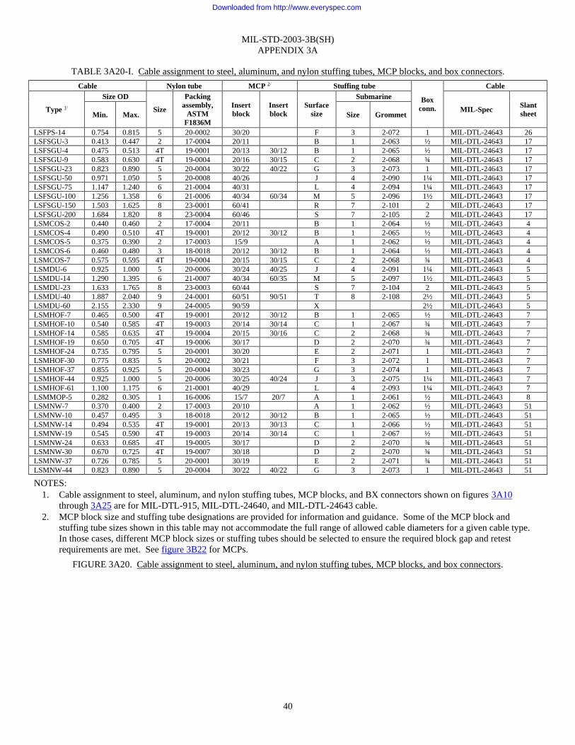
MIL-STD-2003-3B(SH)
APPENDIX 3A
40
TABLE 3A20-I. Cable assignment to steel, aluminum, and nylon stuffing tubes, MCP blocks, and box connectors.
Cable Nylon tube MCP 2/ Stuffing tube
Box
conn.
Cable
Type 1/
Size OD
Size
Packing
assembly,
ASTM
F1836M
Insert
block
Insert
block
Surface
size
Submarine
MIL-Spec Slant
sheet Min. Max. Size Grommet
LSFPS-14 0.754 0.815 5 20-0002 30/20 F 3 2-072 1 MIL-DTL-24643 26
LSFSGU-3 0.413 0.447 2 17-0004 20/11 B 1 2-063 ½ MIL-DTL-24643 17
LSFSGU-4 0.475 0.513 4T 19-0001 20/13 30/12 B 1 2-065 ½ MIL-DTL-24643 17
LSFSGU-9 0.583 0.630 4T 19-0004 20/16 30/15 C 2 2-068 ¾ MIL-DTL-24643 17
LSFSGU-23 0.823 0.890 5 20-0004 30/22 40/22 G 3 2-073 1 MIL-DTL-24643 17
LSFSGU-50 0.971 1.050 5 20-0008 40/26 J 4 2-090 1¼ MIL-DTL-24643 17
LSFSGU-75 1.147 1.240 6 21-0004 40/31 L 4 2-094 1¼ MIL-DTL-24643 17
LSFSGU-100 1.256 1.358 6 21-0006 40/34 60/34 M 5 2-096 1½ MIL-DTL-24643 17
LSFSGU-150 1.503 1.625 8 23-0001 60/41 R 7 2-101 2 MIL-DTL-24643 17
LSFSGU-200 1.684 1.820 8 23-0004 60/46 S 7 2-105 2 MIL-DTL-24643 17
LSMCOS-2 0.440 0.460 2 17-0004 20/11 B 1 2-064 ½ MIL-DTL-24643 4
LSMCOS-4 0.490 0.510 4T 19-0001 20/12 30/12 B 1 2-065 ½ MIL-DTL-24643 4
LSMCOS-5 0.375 0.390 2 17-0003 15/9 A 1 2-062 ½ MIL-DTL-24643 4
LSMCOS-6 0.460 0.480 3 18-0018 20/12 30/12 B 1 2-064 ½ MIL-DTL-24643 4
LSMCOS-7 0.575 0.595 4T 19-0004 20/15 30/15 C 2 2-068 ¾ MIL-DTL-24643 4
LSMDU-6 0.925 1.000 5 20-0006 30/24 40/25 J 4 2-091 1¼ MIL-DTL-24643 5
LSMDU-14 1.290 1.395 6 21-0007 40/34 60/35 M 5 2-097 1½ MIL-DTL-24643 5
LSMDU-23 1.633 1.765 8 23-0003 60/44 S 7 2-104 2 MIL-DTL-24643 5
LSMDU-40 1.887 2.040 9 24-0001 60/51 90/51 T 8 2-108 2½ MIL-DTL-24643 5
LSMDU-60 2.155 2.330 9 24-0005 90/59 X 2½ MIL-DTL-24643 5
LSMHOF-7 0.465 0.500 4T 19-0001 20/12 30/12 B 1 2-065 ½ MIL-DTL-24643 7
LSMHOF-10 0.540 0.585 4T 19-0003 20/14 30/14 C 1 2-067 ¾ MIL-DTL-24643 7
LSMHOF-14 0.585 0.635 4T 19-0004 20/15 30/16 C 2 2-068 ¾ MIL-DTL-24643 7
LSMHOF-19 0.650 0.705 4T 19-0006 30/17 D 2 2-070 ¾ MIL-DTL-24643 7
LSMHOF-24 0.735 0.795 5 20-0001 30/20 E 2 2-071 1 MIL-DTL-24643 7
LSMHOF-30 0.775 0.835 5 20-0002 30/21 F 3 2-072 1 MIL-DTL-24643 7
LSMHOF-37 0.855 0.925 5 20-0004 30/23 G 3 2-074 1 MIL-DTL-24643 7
LSMHOF-44 0.925 1.000 5 20-0006 30/25 40/24 J 3 2-075 1¼ MIL-DTL-24643 7
LSMHOF-61 1.100 1.175 6 21-0001 40/29 L 4 2-093 1¼ MIL-DTL-24643 7
LSMMOP-5 0.282 0.305 1 16-0006 15/7 20/7 A 1 2-061 ½ MIL-DTL-24643 8
LSMNW-7 0.370 0.400 2 17-0003 20/10 A 1 2-062 ½ MIL-DTL-24643 51
LSMNW-10 0.457 0.495 3 18-0018 20/12 30/12 B 1 2-065 ½ MIL-DTL-24643 51
LSMNW-14 0.494 0.535 4T 19-0001 20/13 30/13 C 1 2-066 ½ MIL-DTL-24643 51
LSMNW-19 0.545 0.590 4T 19-0003 20/14 30/14 C 1 2-067 ½ MIL-DTL-24643 51
LSMNW-24 0.633 0.685 4T 19-0005 30/17 D 2 2-070 ¾ MIL-DTL-24643 51
LSMNW-30 0.670 0.725 4T 19-0007 30/18 D 2 2-070 ¾ MIL-DTL-24643 51
LSMNW-37 0.726 0.785 5 20-0001 30/19 E 2 2-071 ¾ MIL-DTL-24643 51
LSMNW-44 0.823 0.890 5 20-0004 30/22 40/22 G 3 2-073 1 MIL-DTL-24643 51
NOTES:
1. Cable assignment to steel, aluminum, and nylon stuffing tubes, MCP blocks, and BX connectors shown on figures 3A10
through 3A25 are for MIL-DTL-915, MIL-DTL-24640, and MIL-DTL-24643 cable.
2. MCP block size and stuffing tube designations are provided for information and guidance. Some of the MCP block and
stuffing tube sizes shown in this table may not accommodate the full range of allowed cable diameters for a given cable type.
In those cases, different MCP block sizes or stuffing tubes should be selected to ensure the required block gap and retest
requirements are met. See figure 3B22 for MCPs.
FIGURE 3A20. Cable assignment to steel, aluminum, and nylon stuffing tubes, MCP blocks, and box connectors.
Downloaded from http://www.everyspec.com

MIL-STD-2003-3B(SH)
APPENDIX 3A
41
TABLE 3A21-I. Cable assignment to steel, aluminum, and nylon stuffing tubes, MCP blocks, and box connectors.
Cable Nylon tube MCP 2/ Stuffing tube
Box
conn.
Cable
Type 1/
Size OD
Size
Packing
assembly,
ASTM
F1836M
Insert
block
Insert
block
Surface
size
Submarine
MIL-Spec Slant
sheet Min. Max. Size Grommet
LSMRI-D-1 0.069 0.075 1 16-0001 A 1 2-061 MIL-DTL-24643 9
LSMRI-D-2½ 0.094 0.102 1 16-0001 A 1 2-061 MIL-DTL-24643 9
LSMRI-T-2½ 0.094 0.102 1 16-0001 A 1 2-061 ⅜ MIL-DTL-24643 9
LSMS-37 0.740 0.800 5 20-0001 30/20 E 2 2-071 1 MIL-DTL-24643 34
LSMSCS-7 0.507 0.544 4T 19-0002 20/13 30/13 C 1 2-066 ½ MIL-DTL-24643 18
LSMSCS-10 0.635 0.682 4T 19-0005 30/17 D 2 2-070 ¾ MIL-DTL-24643 18
LSMSCS-14 0.677 0.728 4T 19-0007 30/17 E 2 2-071 1 MIL-DTL-24643 18
LSMSCS-19 0.742 0.798 5 20-0002 30/20 F 2 2-071 1 MIL-DTL-24643 18
LSMSCS-24 0.850 0.915 5 20-0004 30/23 G 3 2-074 1 MIL-DTL-24643 18
LSMSCS-30 0.893 0.961 5 20-0005 30/24 40/24 J 2 2-069 1¼ MIL-DTL-24643 18
LSMSCS-37 0.986 1.065 5 20-0009 40/26 K 4 2-090 1¼ MIL-DTL-24643 18
LSMSCS-44 1.090 1.174 6 21-0002 40/29 L 4 2-093 1¼ MIL-DTL-24643 18
LSMSCS-61 1.216 1.310 6 21-0005 40/33 60/33 M 5 2-096 1½ MIL-DTL-24643 18
LSMSCS-91 1.429 1.540 7 22-0002 60/39 P 6 2-100 2 MIL-DTL-24643 18
LSMSCU-7 0.447 0.484 3 18-0018 20/12 30/12 B 1 2-064 ½ MIL-DTL-24643 18
LSMSCU-10 0.575 0.622 4T 19-0004 20/15 30/15 C 2 2-068 ¾ MIL-DTL-24643 18
LSMSCU-14 0.617 0.668 4T 19-0005 20/16 30/16 D 2 2-069 ¾ MIL-DTL-24643 18
LSMSCU-19 0.682 0.738 4T 19-0007 30/18 D 2 2-071 ¾ MIL-DTL-24643 18
LSMSCU-24 0.790 0.855 5 20-0003 30/21 G 3 2-073 1 MIL-DTL-24643 18
LSMSCU-30 0.833 0.901 5 20-0004 30/22 40/22 G 3 2-074 1 MIL-DTL-24643 18
LSMSCU-37 0.926 1.002 5 20-0006 30/25 40/25 J 3 2-076 1 MIL-DTL-24643 18
LSMSCU-44 1.030 1.114 5 20-0009 40/28 K 4 2-091 1¼ MIL-DTL-24643 18
LSMSCU-61 1.156 1.250 6 21-0003 40/31 L 4 2-094 1¼ MIL-DTL-24643 18
LSMSCU-91 1.369 1.480 7 22-0001 60/37 N 6 2-099 1½ MIL-DTL-24643 18
LSMU-14 0.365 0.400 2 17-0003 20/10 A 1 2-062 ½ MIL-DTL-24643 29
LSMUS-14 0.425 0.460 2 17-0004 20/11 B 1 2-024 ½ MIL-DTL-24643 29
LSPBTMU-5 0.499 0.540 4T 19-0002 20/13 30/13 C 1 2-066 ½ MIL-DTL-24643 10
LSPBTMU-15 0.694 0.750 4T 19-0007 30/18 D 2 2-071 1 MIL-DTL-24643 10
LSPBTMU-30 0.907 0.980 5 20-0006 30/24 40/24 J 3 2-075 1 MIL-DTL-24643 10
LSPI-3 0.634 0.685 4T 19-0004 30/17 D 2 2-070 ¾ MIL-DTL-24643 25
LSPI-7 0.833 0.900 5 20-0002 30/22 40/22 G 3 2-073 1 MIL-DTL-24643 25
LSPI-12 1.068 1.155 5 20-0009 40/29 K 4 2-093 1¼ MIL-DTL-24643 25
LSSHOF-3 0.195 0.210 1 16-0001 15/5 20/5 A 1 2-061 ½ MIL-DTL-24643 3
LSSHOF-23 0.440 0.460 3 18-0018 20/11 B 1 2-064 ½ MIL-DTL-24643 3
LSSHOF-60 0.570 0.600 4T 19-0004 20/15 30/15 C 2 2-068 ¾ MIL-DTL-24643 3
LSSHOF-150 0.830 0.870 5 20-0003 30/21 40/22 F 3 2-073 1 MIL-DTL-24643 3
LSSHOF-200 0.940 0.980 5 20-0006 30/24 40/24 J 3 3-075 1 MIL-DTL-24643 3
LSSHOF-250 1.035 1.085 5 20-0009 40/26 K 4 2-091 1¼ MIL-DTL-24643 3
NOTES:
1. Cable assignment to steel, aluminum, and nylon stuffing tubes, MCP blocks, and BX connectors shown on figures 3A10
through 3A25 are for MIL-DTL-915, MIL-DTL-24640, and MIL-DTL-24643 cable.
2. MCP block size and stuffing tube designations are provided for information and guidance. Some of the MCP block and
stuffing tube sizes shown in this table may not accommodate the full range of allowed cable diameters for a given cable type.
In those cases, different MCP block sizes or stuffing tubes should be selected to ensure the required block gap and retest
requirements are met. See figure 3B22 for MCPs.
FIGURE 3A21. Cable assignment to steel, aluminum, and nylon stuffing tubes, MCP blocks, and box connectors.
Downloaded from http://www.everyspec.com

MIL-STD-2003-3B(SH)
APPENDIX 3A
42
TABLE 3A22-I. Cable assignment to steel, aluminum, and nylon stuffing tubes, MCP blocks, and box connectors.
Cable Nylon tube MCP 2/ Stuffing tube
Box
conn.
Cable
Type 1/
Size OD
Size
Packing
assembly,
ASTM
F1836M
Insert
block
Insert
block
Surface
size
Submarine
MIL-Spec Slant
sheet Min. Max. Size Grommet
LSSHOF-500 1.380 1.450 7 22-0001 60/36 N 6 2-098 ½ MIL-DTL-24643 3
LSSHOF-650 1.540 1.610 7 22-0003 60/40 P 7 2-101 2 MIL-DTL-24643 3
LSSHOF-800 1.600 1.670 8 23-0001 60/42 R 7 2-101 2 MIL-DTL-24643 3
LSSRW 0.370 0.400 2 17-0003 20/10 A 1 2-062 ½ MIL-DTL-24643 53
LSSSF-7 1.020 1.100 5 20-0009 40/27 K 4 2-091 1 MIL-DTL-24643 11
LSSSGU-50 0.481 0.520 4T 19-0001 20/13 30/13 C 1 2-065 ½ MIL-DTL-24643 14
LSSSGU-75 0.557 0.602 4T 19-0004 20/15 30/15 C 2 2-068 ¾ MIL-DTL-24643 14
LSSSGU-100 0.619 0.669 4T 19-0005 20/16 30/16 D 2 2-069 ¾ MIL-DTL-24643 14
LSSSGU-200 0.807 0.872 5 20-0003 30/22 40/22 G 3 2-073 1 MIL-DTL-24643 14
LSSSGU-300 0.926 1.001 5 20-0006 30/25 40/25 J 3 2-076 1¼ MIL-DTL-24643 14
LSSSGU-400 1.034 1.118 5 20-0010 40/28 K 4 2-092 1¼ MIL-DTL-24643 14
LSSSGU-650 1.268 1.371 6 21-0006 40/34 60/34 M 5 2-097 1½ MIL-DTL-24643 14
LSSSGU-800 1.374 1.485 7 22-0001 60/37 N 6 2-099 1½ MIL-DTL-24643 14
LSSSGU-1000 1.499 1.620 8 23-0001 60/41 P 7 2-101 2 MIL-DTL-24643 14
LSSSGU-1600 1.859 2.010 9 24-0001 60/50 T 8 2-108 2½ MIL-DTL-24643 14
LSSSGU-2000 2.044 2.210 9 24-0004 90/56 W 9 2-110 2½ MIL-DTL-24643 14
LSTCJU-4 0.400 0.430 2 17-0004 20/10 B 1 2-063 ½ MIL-DTL-24643 21
LSTCJX-3 0.686 0.742 4T 19-0005 30/18 D 2 2-071 ¾ MIL-DTL-24643 24
LSTCJX-7 0.909 0.983 5 20-0005 30/24 40/24 J 3 2-075 1 MIL-DTL-24643 24
LSTCJX-12 1.174 1.269 6 21-0003 40/32 M 5 2-095 1¼ MIL-DTL-24643 24
LSTCKX-1 0.422 0.456 2 17-0003 20/11 B 1 2-064 ½ MIL-DTL-24643 24
LSTCKX-3 0.686 0.742 4T 19-0005 30/18 D 2 2-071 ¾ MIL-DTL-24643 24
LSTCKX-7 0.909 0.983 5 20-0005 30/24 40/24 J 3 2-075 1 MIL-DTL-24643 24
LSTCKX-12 1.174 1.269 6 21-0003 40/32 M 5 2-095 1¼ MIL-DTL-24643 24
LSTCOP-2 0.325 0.345 2 17-0001 15/8 20/8 A 1 2-062 ½ MIL-DTL-24643 2
LSTCTU-4 0.400 0.430 2 17-0004 20/10 B 1 2-063 ½ MIL-DTL-24643 21
LSTCTX-1 0.324 0.350 2 17-0001 15/8 20/8 A 1 2-062 ½ MIL-DTL-24643 24
LSTCTX-3 0.511 0.552 4T 19-0001 20/13 30/13 C 1 2-066 ½ MIL-DTL-24643 24
LSTCTX-7 0.676 0.731 4T 19-0005 30/17 D 2 2-071 ¾ MIL-DTL-24643 24
LSTCTX-12 0.892 0.964 5 20-0004 20/24 30/24 J 3 2-075 1 MIL-DTL-24643 24
LSTHOF-3 0.430 0.450 2 17-0004 20/11 B 1 2-064 ½ MIL-DTL-24643 3
LSTHOF-4 0.460 0.480 3 18-0018 20/12 30/12 B 1 2-064 ½ MIL-DTL-24643 3
LSTHOF-6 0.520 0.550 4T 19-0002 20/13 30/13 C 1 2-066 ¾ MIL-DTL-24643 3
LSTHOF-9 0.570 0.600 4T 19-0004 20/15 30/15 C 2 2-068 ¾ MIL-DTL-24643 3
LSTHOF-14 0.720 0.750 4T 19-0007 30/18 E 2 2-070 1 MIL-DTL-24643 3
LSTHOF-23 0.860 0.900 5 20-0004 30/22 40/22 G 3 2-073 1 MIL-DTL-24643 3
LSTHOF-42 1.200 1.250 6 21-0003 40/30 L 4 2-094 1¼ MIL-DTL-24643 3
LSTHOF-150 1.740 1.820 8 23-0004 60/46 S 7 2-105 2 MIL-DTL-24643 3
LSTHOF-250 2.140 2.240 9 24-0003 90/56 W 9 2-100 2½ MIL-DTL-24643 3
LSTHOF-400 2.680 2.800 9 24-0008 90/71 AA 3 MIL-DTL-24643 3
LSTHOF-500 2.920 3.100 120/78 BB 3½ MIL-DTL-24643 3
LSTHOF-600 2.980 3.150 120/79 BB 3½ MIL-DTL-24643 3
LSTNW-3 0.380 0.411 2 17-0003 20/10 B 1 2-063 ½ MIL-DTL-24643 49
LSTNW-4 0.415 0.449 2 17-0004 20/11 B 1 2-063 ½ MIL-DTL-24643 49
NOTES:
1. Cable assignment to steel, aluminum, and nylon stuffing tubes, MCP blocks, and BX connectors shown on figures 3A10
through 3A25 are for MIL-DTL-915, MIL-DTL-24640, and MIL-DTL-24643 cable.
2. MCP block size and stuffing tube designations are provided for information and guidance. Some of the MCP block and
stuffing tube sizes shown in this table may not accommodate the full range of allowed cable diameters for a given cable type.
In those cases, different MCP block sizes or stuffing tubes should be selected to ensure the required block gap and retest
requirements are met. See figure 3B22 for MCPs.
FIGURE 3A22. Cable assignment to steel, aluminum, and nylon stuffing tubes, MCP blocks, and box connectors.
Downloaded from http://www.everyspec.com

MIL-STD-2003-3B(SH)
APPENDIX 3A
43
TABLE 3A23-I. Cable assignment to steel, aluminum, and nylon stuffing tubes, MCP blocks, and box connectors.
Cable Nylon tube MCP 2/ Stuffing tube
Box
conn.
Cable
Type 1/
Size OD
Size
Packing
assembly,
ASTM
F1836M
Insert
block
Insert
block
Surface
size
Submarine
MIL-Spec Slant
sheet Min. Max. Size Grommet
LSTNW-9 0.578 0.625 4T 19-0004 20/15 30/15 C 2 2-068 ¾ MIL-DTL-24643 49
LSTNW-14 0.620 0.670 4T 19-0005 30/16 D 2 2-069 ¾ MIL-DTL-24643 49
LSTNW-23 0.703 0.760 4T 19-0008 30/19 E 2 2-071 1 MIL-DTL-24643 49
LSTNW-50 0.869 0.969 5 20-0005 30/24 40/24 J 3 2-075 1 MIL-DTL-24643 49
LSTNW-75 1.048 1.134 5 20-0010 40/28 K 4 2-093 1¼ MIL-DTL-24643 49
LSTNW-100 1.171 1.266 6 21-0004 40/32 M 5 2-095 1¼ MIL-DTL-24643 49
LSTNW-150 1.401 1.515 7 22-0001 60/38 N 6 2-099 1½ MIL-DTL-24643 49
LSTPNW-1½ 0.217 0.235 1 16-0004 15/5 20/5 A 1 2-061 ½ MIL-DTL-24643 52
LSTPNW-3 0.287 0.310 1 16-0006 15/7 20/7 A 1 2-061 ½ MIL-DTL-24643 52
LSTPNW-5 0.338 0.365 2 17-0001 15/9 20/9 A 1 2-062 ½ MIL-DTL-24643 52
LSTPNW-10 0.435 0.470 3 18-0018 20/11 B 1 2-064 ½ MIL-DTL-24643 52
LSTPNW-15 0.490 0.530 4T 19-0001 20/13 30/13 C 1 2-065 ½ MIL-DTL-24643 52
LSTPNW-20 0.532 0.575 4T 19-0002 20/14 30/14 C 1 2-067 ¾ MIL-DTL-24643 52
LSTPNW-30 0.629 0.680 4T 19-0005 30/17 D 2 2-069 ¾ MIL-DTL-24643 52
LSTPNW-40 0.708 0.765 4T 19-0008 30/19 E 2 2-071 1 MIL-DTL-24643 52
LSTPS-3 0.439 0.475 2 17-0004 20/11 30/11 B 1 2-064 ½ MIL-DTL-24643 26
LSTPS-4 0.512 0.553 3 18-0018 20/13 30/13 C 1 2-066 ½ MIL-DTL-24643 26
LSTPS-6 0.574 0.620 4T 19-0002 20/15 30/15 C 2 2-068 ¾ MIL-DTL-24643 26
LSTPS-9 0.608 0.657 4T 19-0003 20/16 30/16 D 2 2-069 ¾ MIL-DTL-24643 26
LSTPS-14 0.695 0.751 4T 19-0006 30/18 E 2 2-071 1 MIL-DTL-24643 26
LSTPS-23 0.801 0.866 5 20-0003 30/21 G 3 2-073 1 MIL-DTL-24643 26
LSTPS-30 0.915 0.989 5 20-0004 30/25 40/25 J 3 2-075 1 MIL-DTL-24643 26
LSTRW 0.567 0.710 4T 19-0005 30/18 D 2 2-070 ¾ MIL-DTL-24643 53
LSTSGU-3 0.380 0.411 2 17-0003 20/10 B 1 2-063 ½ MIL-DTL-24643 16
LSTSGU-4 0.415 0.449 2 17-0004 20/11 B 1 2-063 ½ MIL-DTL-24643 16
LSTSGU-9 0.532 0.575 4T 19-0003 20/14 30/14 C 1 2-067 ¾ MIL-DTL-24643 16
LSTSGU-14 0.664 0.718 4T 19-0007 30/18 D 2 2-070 ¾ MIL-DTL-24643 16
LSTSGU-23 0.751 0.812 5 20-0003 30/20 E 3 2-072 1 MIL-DTL-24643 16
NOTES:
1. Cable assignment to steel, aluminum, and nylon stuffing tubes, MCP blocks, and BX connectors shown on figures 3A10
through 3A25 are for MIL-DTL-915, MIL-DTL-24640, and MIL-DTL-24643 cable.
2. MCP block size and stuffing tube designations are provided for information and guidance. Some of the MCP block and
stuffing tube sizes shown in this table may not accommodate the full range of allowed cable diameters for a given cable type.
In those cases, different MCP block sizes or stuffing tubes should be selected to ensure the required block gap and retest
requirements are met. See figure 3B22 for MCPs.
FIGURE 3A23. Cable assignment to steel, aluminum, and nylon stuffing tubes, MCP blocks, and box connectors.
Downloaded from http://www.everyspec.com

MIL-STD-2003-3B(SH)
APPENDIX 3A
44
TABLE 3A24-I. Cable assignment to steel, aluminum, and nylon stuffing tubes, MCP blocks, and box connectors.
Cable Nylon tube MCP 2/ Stuffing tube
Box
conn.
Cable
Type 1/
Size OD
Size
Packing
assembly,
ASTM
F1836M
Insert
block
Insert
block
Surface
size
Submarine
MIL-Spec Slant
sheet Min. Max. Size Grommet
LSTSGU-50 0.896 0.969 5 20-0005 30/24 40/24 J 3 2-075 1 MIL-DTL-24643 16
LSTSGU-75 1.049 1.134 5 20-0010 40/28 L 4 2-093 1¼ MIL-DTL-24643 16
LSTSGU-100 1.171 1.266 6 21-0004 40/32 M 5 2-095 1¼ MIL-DTL-24643 16
LSTSGU-150 1.401 1.515 7 22-0002 60/38 N 6 2-099 2 MIL-DTL-24643 16
LSTSGU-200 1.544 1.669 8 23-0001 60/42 R 7 2-101 2 MIL-DTL-24643 16
LSTSGU-300 1.810 1.957 8 24-0003 60/49 T 8 2-107 2 MIL-DTL-24643 16
LSTSGU-400 2.038 2.203 9 23-0006 60/55 W 9 2-110 2½ MIL-DTL-24643 16
LSTTOP-3 0.444 0.480 3 18-0018 20/12 30/12 B 1 2-064 ½ MIL-DTL-24643 12
LSTTOP-5 0.546 0.590 4T 19-0003 20/14 30/14 C 1 2-067 ¾ MIL-DTL-24643 12
LSTTOP-10 0.648 0.700 4T 19-0006 30/17 D 2 2-070 ¾ MIL-DTL-24643 12
LSTTOP-15 0.768 0.830 5 20-0002 30/20 F 3 2-072 1 MIL-DTL-24643 12
LSTTRS-2 0.629 0.680 4T 19-0005 30/17 D 2 2-069 ¾ MIL-DTL-24643 13
LSTTRS-4 0.685 0.740 4T 19-0007 30/18 D 2 2-071 ¾ MIL-DTL-24643 13
LSTTRS-6 0.814 0.880 5 20-0003 30/22 40/22 G 3 2-073 1 MIL-DTL-24643 13
LSTTRS-8 0.916 0.990 5 20-0006 30/25 40/25 J 3 2-075 1¼ MIL-DTL-24643 13
LSTTRS-10 0.999 1.080 5 20-0009 40/27 K 4 2-091 1¼ MIL-DTL-24643 13
LSTTRS-12 1.017 1.100 5 20-0009 40/27 K 4 2-091 1¼ MIL-DTL-24643 13
LSTTRS-16 1.100 1.190 6 21-0001 40/30 L 4 2-094 1¼ MIL-DTL-24643 13
LSTTSU-1½ 0.305 0.330 2 17-0001 15/8 20/8 A 1 2-062 ½ MIL-DTL-24643 23
LSTTSU-3 0.416 0.450 2 17-0004 20/11 B 1 2-063 ½ MIL-DTL-24643 23
LSTTSU-5 0.500 0.540 4T 19-0001 20/13 30/13 C 1 2-066 ¾ MIL-DTL-24643 23
LSTTSU-10 0.624 0.675 4T 19-0004 30/17 D 2 2-069 ¾ MIL-DTL-24643 23
LSTTSU-15 0.740 0.800 4T 19-0007 30/20 E 2 2-071 1 MIL-DTL-24643 23
LSTTSU-20 0.805 0.870 5 20-0002 30/21 40/21 G 3 2-073 1 MIL-DTL-24643 23
LSTTSU-30 0.999 1.080 5 20-0006 40/27 K 4 2-091 1¼ MIL-DTL-24643 23
LSTTSU-40 1.110 1.200 6 21-0002 40/30 L 4 2-094 1¼ MIL-DTL-24643 23
LSTTSU-50 1.295 1.400 6 21-0007 40/35 60/35 M 5 2-097 1½ MIL-DTL-24643 23
LSTTSU-60 1.341 1.450 7 22-0001 60/36 N 6 2-098 1½ MIL-DTL-24643 23
NOTES:
1. Cable assignment to steel, aluminum, and nylon stuffing tubes, MCP blocks, and BX connectors shown on figures 3A10
through 3A25 are for MIL-DTL-915, MIL-DTL-24640, and MIL-DTL-24643 cable.
2. MCP block size and stuffing tube designations are provided for information and guidance. Some of the MCP block and
stuffing tube sizes shown in this table may not accommodate the full range of allowed cable diameters for a given cable type.
In those cases, different MCP block sizes or stuffing tubes should be selected to ensure the required block gap and retest
requirements are met. See figure 3B22 for MCPs.
FIGURE 3A24. Cable assignment to steel, aluminum, and nylon stuffing tubes, MCP blocks, and box connectors.
Downloaded from http://www.everyspec.com

MIL-STD-2003-3B(SH)
APPENDIX 3A
45
TABLE 3A25-I. Cable assignment to steel, aluminum, and nylon stuffing tubes, MCP blocks, and box connectors.
Cable Nylon tube MCP 2/ Stuffing tube
Box
conn.
Cable
Type 1/
Size OD
Size
Packing
assembly,
ASTM
F1836M
Insert
block
Insert
block
Surface
size
Submarine
MIL-spec Slant
sheet Min. Max. Size Grommet
LSC5FS-4 0.240 0.360 1 16-0006 15/9 20/9 A 1 2-062 ⅜ MIL-DTL-24643 59
LSC5FSW-4 0.240 0.380 1 16-0006 15/9 20/9 A 1 2-062 ⅜ MIL-DTL-24643 59
LSC5OS-4 0.290 0.400 1 16-0006 20/10 A 1 2-062 ⅜ MIL-DTL-24643 59
LSC5OSW-4 0.300 0.420 2 17-0002 20/10 A 1 2-063 ½ MIL-DTL-24643 59
LSC5-4 0.220 0.270 1 16-0004 15/6 20/6 A 1 2-061 ⅜ MIL-DTL-24643 60
LSC5W-4 0.230 0.290 1 16-0005 15/7 20/7 A 1 2-061 ⅜ MIL-DTL-24643 60
LSC5P-4 0.230 0.280 1 16-0005 15/7 20/7 A 1 2-061 ⅜ MIL-DTL-24643 61
LSC5POS-4 0.290 0.370 2 17-0002 15/9 20/9 A 1 2-062 ⅜ MIL-DTL-24643 61
LSC5POSR-4 0.230 0.280 1 16-0005 15/7 20/7 A 1 2-061 ⅜ MIL-DTL-24643 61
LSPB2SD-1 0.330 0.390 2 17-0002 15/9 A 1 2-062 ½ MIL-DTL-24643 62
LSPB2SDW-1 0.345 0.405 2 17-0003 20/10 B 1 20-63 ½ MIL-DTL-24643 62
LSPB2SDOS-1 0.440 0.500 4T 19-0001 20/12 30/12 B 1 2-065 ½ MIL-DTL-24643 62
LSPB2SDOSW-1 0.450 0.530 3 18-0018 20/13 30/13 C 1 2-065 ¾ MIL-DTL-24643 62
LSYSGU-2½ 0.535 4T 19-0001 20/13 30/13 C 1 2-066 ¾ MIL-DTL-24643 63
LSYSGU-4 0.580 4T 19-0001 20/14 30/14 C 1 2-067 ¾ MIL-DTL-24643 63
LSYSGU-7 0.640 4T 19-0003 20/16 30/16 C 2 2-069 ¾ MIL-DTL-24643 63
LSYSGU-10 0.730 4T 19-0007 30/18 D 2 2-070 ¾ MIL-DTL-24643 63
LSYSGU-16 1.000 5 20-0006 30/25 40/25 J 4 2-091 1½ MIL-DTL-24643 63
LSYSGU-42 1. 206 6 21-0001 40/30 L 4 2-093 1½ MIL-DTL-24643 63
LSYSGU-65 1.426 6 21-0005 40/36 60/36 M 5 2-096 1½ MIL-DTL-24643 63
LSYSGU-85 1.541 6 21-0007 60/39 N 6 2-098 1½ MIL-DTL-24643 63
LSYSGU-100 1.669 8 23-0001 60/42 P 7 2-101 2 MIL-DTL-24643 63
LSYSGU-133 1.828 8 23-0002 60/46 S 7 2-105 2 MIL-DTL-24643 63
LSYSGU-165 1.99 8 23-0004 60/50 S 8 2-106 2 MIL-DTL-24643 63
LSTPSJ-1-24 0.154 0.186 15/4 MIL-DTL-24643 64
LSTPSJ-1-22 0.166 0.198 15/4 MIL-DTL-24643 64
LSTPSJ-1-20 0.184 0.216 1 16-0001 15/5 20/5 A 1 2-061 ½ MIL-DTL-24643 64
LSTPSJ-1-18 0.204 0.236 1 16-0004 15/5 20/5 A 1 2-061 ½ MIL-DTL-24643 64
LSTPSJ-1-16 0.218 0.250 1 16-0004 15/6 20/6 A 1 2-061 ½ MIL-DTL-24643 64
LSTPSJ-1-14 0.246 0.278 1 16-0004 15/6 20/6 A 1 2-061 ½ MIL-DTL-24643 64
LSTPSJ-2-24 0.230 0.290 1 16-0005 15/7 20/7 A 1 2-061 ½ MIL-DTL-24643 64
LSTPSJ-2-22 0.255 0.315 2 17-0001 15/7 20/7 A 1 2-062 ½ MIL-DTL-24643 64
LSTPSJ-2-20 0.295 0.355 2 17-0004 20/8 B 1 2-063 ½ MIL-DTL-24643 64
LSTPSJ-2-18 0.360 0.420 2 17-0004 20/10 B 1 2-063 ½ MIL-DTL-24643 64
LSTPSJ-2-16 0.390 0.450 3 18-0018 20/11 B 1 2-064 ½ MIL-DTL-24643 64
LSTPSJ-2-14 0.435 0.495 4T 19-0001 20/12 30/12 B 1 2-065 ½ MIL-DTL-24643 64
LSTPSJ-3-24 0.245 0.305 1 16-0005 15/7 20/7 A 1 2-061 ⅜ MIL-DTL-24643 64
LSTPSJ-3-22 0.255 0.315 2 17-0001 15/7 20/7 A 1 2-062 ½ MIL-DTL-24643 64
LSTPSJ-3-20 0.295 0.355 1 16-0006 15/8 20/8 A 1 2-062 ½ MIL-DTL-24643 64
LSTPSJ-3-18 0.360 0.420 2 17-0004 20/10 B 1 2-063 ½ MIL-DTL-24643 64
LSTPSJ-3-16 0.420 0.480 2 17-0002 20/12 30/12 B 1 2-064 ½ MIL-DTL-24643 64
LS3C179DT 0.335 0.365 2 17-0002 15/9 20/9 A 1 2-062 ½ MIL-DTL-24643 65
LS6C176DT 0.425 0.455 2 17-0004 20/11 B 1 2-063 ½ MIL-DTL-24643 65
LS2OW-3 0.412 0.442 2 17-0002 15/11 20/11 A 1 2-062 ½ MIL-DTL-24643 66
LS2OW-4 0.429 0.46 2 17-0002 15/11 A 1 2-062 ½ MIL-DTL-24643 66
LS2OW-9 0.513 0.551 4T 19-0001 20/12 30/12 B 1 2-065 ½ MIL-DTL-24643 66
LS2OW-14 0.639 0.686 4T 19-0006 30/17 D 2 2-070 ¾ MIL-DTL-24643 66
LS2OW-23 0.743 0.797 5 20-0002 30/20 F 2 2-071 1 MIL-DTL-24643 66
FIGURE 3A25. Cable assignment to steel, aluminum, and nylon stuffing tubes, MCP blocks, and box connectors.
Downloaded from http://www.everyspec.com

MIL-STD-2003-3B(SH)
APPENDIX 3A
46
TABLE 3A25-I. Cable assignment to steel, aluminum, and nylon stuffing tubes, MCP blocks, and box connectors – Continued.
Cable Nylon tube MCP 2/ Stuffing tube
Box
conn.
Cable
Type 1/
Size OD
Size
Packing
assembly,
ASTM
F1836M
Insert
block
Insert
block
Surface
size
Submarine
MIL-spec Slant
sheet Min. Max. Size Grommet
LS2OW-50 0.894 0.959 5 20-0004 30/24 40/24 J 3 2-075 ¾ MIL-DTL-24643 66
LS2OW-75 1.033 1.108 5 20-0008 40/28 K 4 2-091 1¼ MIL-DTL-24643 66
LS2OW-100 1.149 1.232 6 21-0001 40/31 L 4 2-094 1¼ MIL-DTL-24643 66
LS2OW-200 1.519 1.630 7 22-0003 60/41 R 7 2-101 2 MIL-DTL-24643 66
LS3OW-3 0.431 0.463 2 17-0002 15/11 A 1 2-062 ½ MIL-DTL-24643 67
LS3OW-4 0.449 0.482 2 17-0004 20/12 B 1 2-063 ½ MIL-DTL-24643 67
LS3OW-9 0 54 0.58 3 18-0018 20/13 30/13 C 1 2-065 ½ MIL-DTL-24643 67
LS3OW-14 0.684 0.733 4T 19-0005 30/17 D 2 2-071 ¾ MIL-DTL-24643 67
LS3OW-23 0.769 0.853 5 20-0003 30/21 G 3 2-073 1 MIL-DTL-24643 67
LS3OW-50 0.957 1.027 5 20-0006 40/25 J 3 2-076 1 MIL-DTL-24643 67
LS3OW-75 1.107 1.187 6 21-0001 40/30 L 4 2-094 1¼ MIL-DTL-24643 67
LS3OW-100 1.231 1.321 6 21-0004 40/33 60/33 M 5 2-096 1½ MIL-DTL-24643 67
LS3OW-200 1.630 1.748 8 23-0002 60/44 S 7 2-103 2 MIL-DTL-24643 67
LS3OW-300 1.916 2.055 3 23-0006 60/52 T 8 2-108 2⅜ MIL-DTL-24643 67
LS3OW-400 2.190 2.349 9 24-0004 90/55 X 2¼ MIL-DTL-24643 67
LS4OW-3 0.463 0.497 2 17-0002 20/11 B 1 2-063 ½ MIL-DTL-24643 68
LS4OW-4 0.485 0.521 3 18-0018 20/12 30/12 B 1 2-064 ½ MIL-DTL-24643 68
LS4OW-9 0.588 0.631 4T 19-0003 20/15 30/15 C 2 2-068 ¾ MIL-DTL-24643 68
LS4OW-14 0.772 0.828 5 20-0002 30/20 G 3 2-072 ¾ MIL-DTL-24643 68
LS4OW-23 0.900 0.965 5 20-0006 30/24 40/24 J 3 2-075 1 MIL-DTL-24643 68
LS4OW-50 1.084 1.163 6 21-0001 40/29 K 4 2-093 1¼ MIL-DTL-24643 68
LS4OW-75 1.254 1.345 6 21-0003 40/34 60/34 M 5 2-096 1⅜ MIL-DTL-24643 68
LS4OW-100 1.396 1.498 7 22-0001 60/37 N 6 2-099 1½ MIL-DTL-24643 68
LS4OW-200 1.850 1.984 8 23-0006 60/50 90/50 T 8 2-107 2½ MIL-DTL-24643 68
LSC264-4 0.735 0.765 4T 19-0005 30/19 E 2 2-071 ¾ MIL-DTL-24643 69
NOTES:
1. Cable assignment to steel, aluminum, and nylon stuffing tubes, MCP blocks, and BX connectors shown on figures 3A10 through
3A25 are for MIL-DTL-915, MIL-DTL-24640, and MIL-DTL-24643 cable.
2. MCP block size and stuffing tube designations are provided for information and guidance. Some of the MCP block and stuffing
tube sizes shown in this table may not accommodate the full range of allowed cable diameters for a given cable type. In those
cases, different MCP block sizes or stuffing tubes should be selected to ensure the required block gap and retest requirements are
met. See figure 3B22 for MCPs.
FIGURE 3A25. Cable assignment to steel, aluminum, and nylon stuffing tubes, MCP blocks, and box connectors – Continued.
Downloaded from http://www.everyspec.com

MIL-STD-2003-3B(SH)
APPENDIX 3B
47
APPENDIX 3B – PENETRATIONS –SURFACE SHIPS
B.1 SCOPE
B.1.1 Scope. This appendix describes the installation standard methods for electrical penetrations in surface
ships. This Appendix is a mandatory part of the standard. The information contained herein is intended for
compliance.
B.2. APPLICABLE DOCUMENTS
B.2.1 General. The documents listed in this section are specified in this appendix. This section does not
include documents cited in other sections of this standard or recommended for additional information or as
examples. While every effort has been made to ensure the completeness of this list, document users are cautioned
that they must meet all specified requirements of documents cited in this appendix, whether or not they are listed.
B.2.2 Government documents.
B.2.2.1 Specifications, standards, and handbooks. The following specifications, standards, and handbooks
form a part of this document to the extent specified herein. Unless otherwise specified, the issues of these
documents are those cited in the solicitation or contract.
COMMERCIAL ITEM DESCRIPTIONS
A-A-3041 - Wrench, Open End Ratchet (TAC Pattern) for Tube Fitting, Electrical Cable
Terminals, and Stuffing Tube Gland Nuts
A-A-3042 - Socket, Open Detachable, Standard Wall, Octagon
DEPARTMENT OF DEFENSE SPECIFICATIONS
MIL-DTL-917 - Electric Power Equipment, Basic Requirements for
MIL-DTL-2726/68 - Receptacle, Plug, Connector, Electrical, 10-Ampere, 125-Volt, 3-Phase,
Grounded (Symbol No. 706.1) (see 4.3)
MIL-I-3064 - Insulation, Electrical, Plastic-Sealer
MIL-PRF-15624 - Gasket Material, Rubber, 50 Durometer Hardness (Maximum)
MIL-DTL-16685 - Packing, Material and Packing Preformed (Stuffing Tube for Electric
Cables)
MIL-R-17882 - Repair Kits, Metallic Pipe and General Purpose, Damage Control
MIL-S-22698 - Steel Plate, Shapes and Bars, Weldable Ordinary Strength and Higher
Strength: Structural
MIL-S-24235 - Stuffing Tubes, Metal, and Packing Assemblies for Electric Cables, General
Specification for
MIL-S-24235/1 - Stuffing Tubes, Metal, and Packing Assemblies for Electric Cables,
Bulkhead, Pressureproof
MIL-S-24235/9 - Stuffing Tubes, Metal, and Packing Assemblies for Electric Cables, Brass
and Steel, for Decks and Bulkheads with Pipe Protection
MIL-S-24235/10 - Stuffing Tubes, Metal, and Packing Assemblies for Electric Cables, Steel,
for Decks and Bulkheads Without Pipe Protection
MIL-S-24235/17 - Stuffing Tubes, Metal, and Packing Assemblies for Electric Cables, Swage
Type, Steel and Aluminum, for Deck and Bulkheads with Pipe Protection
Downloaded from http://www.everyspec.com

MIL-STD-2003-3B(SH)
APPENDIX 3B
48
MIL-S-24235/18 - Stuffing Tubes, Metal, and Packing Assemblies for Electric Cables, Swage
Type, Reduced Diameter, Steel and Aluminum, for Deck and Bulkheads
with Pipe Protection
MIL-S-24235/19 - Stuffing Tubes, Metal, and Packing Assemblies for Electric Cables, Sealing
Plug for Unused Stuffing Tubes
MIL-DTL-24705 - Penetrators, Multiple Cable, Electric Cable, General Specification for
MIL-DTL-24705/1 - Penetrators, Multiple Cable, Electric Cable, Rectangular Metal Frame,
Square-Faced Blocks
MIL-DTL-24705/3 - Penetrators, Multiple Cable, Electric Cable, Round Frame, Square-Faced
Blocks
DEPARTMENT OF DEFENSE STANDARDS
MIL-STD-22 - Welded Joint Design
MIL-STD-2003-2 - Electric Plant Installation Standard Methods for Surface Ships and
Submarines (Equipment)
MIL-STD-2003-4 - Electric Plant Installation Standard Methods for Surface Ships and
Submarines (Cableways)
(Copies of these documents are available online at https://quicksearch.dla.mil.)
B.2.2.2 Other Government documents, drawings, and publications. The following other Government
documents, drawings, and publications form a part of this document to the extent specified herein. Unless otherwise
specified, the issues of these documents are those cited in the solicitation or contract.
NAVAL SEA SYSTEMS COMMAND (NAVSEA) DRAWINGS
302-7583331 - Standard Rise Installation Procedure, Penetration Install
(Copies of this document are available from the applicable repositories listed in S0005-AE-PRO-010/EDM, which
can be obtained online via Technical Data Management Information System (TDMIS) at
https://mercury.tdmis navy mil/. Copies of this document may also be obtained from the Naval Ships Engineering
Drawing Repository (NSEDR) online at https://199.208.213.105/webjedmics/index.jsp. To request an NSEDR
account for drawing access, send an email to NNSY JEDMICS NSEDR HELP DESK@navy mil.)
NAVAL SEA SYSTEMS COMMAND (NAVSEA) PUBLICATIONS
S9086-CJ-STM-010/075 - NSTM Chapter 075, Fasteners
SE000-01-IMB-010 - Navy Installation and Maintenance Book
T9070-AN-DPC-010/100-1 - Reinforcement of Openings in Structure of Surface Ships, Other Than
in Protective Plating
T9070-AN-DPC-020/100-2 - Openings in Decks and Bulkheads for Stuffing Tubes and Pipe
(Copies of these documents are available online via Technical Data Management Information System (TDMIS) at
https://mercury.tdmis navy mil/ by searching for the document number without the suffix. Refer questions,
inquiries, or problems to: DSN 296-0669, Commercial (805) 228-0669. These documents are available for ordering
(hard copy) via the Naval Logistics Library (NLL) at https://nll.navsup.navy mil. For questions regarding the NLL,
contact the NLL Customer Service at [email protected], (866) 817-3130, or (215) 697-2626/DSN 442-2626.)
B.2.3 Non-Government publications. The following documents form a part of this document to the extent
specified herein. Unless otherwise specified, the issues of these documents are those cited in the solicitation or
contract.
Downloaded from http://www.everyspec.com

MIL-STD-2003-3B(SH)
APPENDIX 3B
49
ASTM INTERNATIONAL
ASTM A36/A36M - Standard Specification for Carbon Structural Steel
ASTM A53/A53M - Standard Specification for Pipe, Steel, Black and Hot-Dipped,
Zinc-Coated, Welded and Seamless
ASTM A106/A106M - Standard Specification for Seamless Carbon Steel Pipe for
High-Temperature Service
ASTM A1008/A1008M - Standard Specification for Steel, Sheet, Cold-Rolled, Carbon, Structural,
High-Strength Low-Alloy, High-Strength Low-Alloy with Improved
Formability, Solution Hardened, and Bake Hardenable
ASTM A1011/A1011M - Standard Specification for Steel, Sheet and Strip, Hot-Rolled, Carbon,
Structural, High-Strength Low-Alloy, High-Strength Low-Alloy with
Improved Formability, and Ultra-High Strength
ASTM B209 - Standard Specification for Aluminum and Aluminum-Alloy Sheet and
Plate
ASTM F1836M - Standard Specification for Stuffing Tubes, Nylon, and Packing
Assemblies (Metric)
(Copies of these documents are available online at www.astm.org.)
NATIONAL AEROSPACE STANDARDS COMMITTEE (NA/NAS)
NASM 25027 - Nut, Self-Locking, 250 °F, 450 °F, and 800 °F
(Copies of this document are available online at www.aia-aerospace.org.)
B.2.4 Order of precedence. Unless otherwise noted herein or in the contract, in the event of a conflict between
the text of this document and the references cited herein, the text of this document takes precedence. Nothing in this
document, however, supersedes applicable laws and regulations unless a specific exemption has been obtained.
B.3 REQUIRED EQUIPMENT AND MATERIALS
B.3.1 Required equipment and materials. The required equipment and materials for the proper installation of
surface ship stuffing tubes are as shown in the Appendix 3B methods.
B.4 NOTES AND PROCEDURES
B.4.1 Dimensions. For figures and tables in this appendix, all dimensions are in inches unless otherwise noted.
B.4.2 Figures. Table 3BI provides information for the figures in this appendix.
TABLE 3BI. Figures for surface ship penetration installation.
Figure
number Surface ship penetration installation Page
3B1 MIL-S-24235 stuffing tube and kickpipes minimum spacing (surface ships) 52
3B2 MIL-S-24235 (other than /17 and /18 stuffing tube and pipe (steel) minimum spacing
(surface ships)
53
3B3 MIL-S-24235/17 swage tube (steel) minimum spacing (surface ships) 54
3B4 MIL-S-24235/18 reduced diameter swage and kickpipe minimum spacing (surface ships) 55
3B5 MIL-S-24235 stuffing tubes for steel or aluminum bulkheads (surface ships) 56
Downloaded from http://www.everyspec.com

MIL-STD-2003-3B(SH)
APPENDIX 3B
50
TABLE 3BI. Figures for surface ship stuffing tubes – Continued.
Figure
number Surface ship penetration installation Page
3B6 MIL-S-24235 stuffing tubes for steel or aluminum bulkheads (surface ships) 58
3B7 MIL-S-24235 stuffing tubes through shielded bulkheads (surface ships) 59
3B8 MIL-S-24235 stuffing tubes for ballistic and type A protective plate bulkheads (surface
ships)
60
3B9 MIL-S-24235 stuffing tubes through acoustical spaces (surface ships) 61
3B10 MIL-S-24235 stuffing tubes through acoustical spaces (surface ships) 63
3B11 MIL-S-24235 stuffing tubes through permanent sections of false decks (surface ships) 65
3B12 MIL-S-24235 stuffing tubes through portable sections of false decks (surface ships) 66
3B13 MIL-S-24235 stuffing tubes through air spaces (surface ships) 67
3B14 Stuffing tubes for sonar dome area (surface ships) 68
3B15 Topside stuffing tubes with riser box (surface ships) 70
3B16 MIL-S-24235 topside stuffing tubes with riser box for medium steel decks (surface ships) 72
3B17 MIL-S-24235 topside stuffing tubes with riser box on medium steel decks not adjacent to
a bulkhead (surface ships)
74
3B18 MIL-S-24235 topside stuffing tubes with riser box (surface ships) 76
3B19 Stuffing tube for steel and aluminum bulkheads (surface ships) 78
3B20 Multiple cable penetrator nomenclature 79
3B21 Cable information and assignment for MCP insert blocks 86
3B22 Multiple cable penetrator installation notes (type RGS and RGA) 89
3B23 Multiple cable penetrator installation in steel or aluminum bulkheads using two-frame
penetrator (types RGS and RGA)
93
3B24 Multiple cable penetrator details (types RGS and RGA) 95
3B25 Multiple cable penetrator details (types RGSO and RGAO) 99
3B26 Multiple cable penetrator details (types RGS and RGA) 103
3B27 Multiple cable penetrator installation details (types RGS and RGA) 109
3B28 Multiple cable penetrator frame in decks (types RGS and RGA) 111
3B29 Multiple cable penetrator (type RGS and RGA) shield 113
3B30 Multiple cable penetrator riser box 114
3B31 Community stuffing tube for minesweepers 116
3B32 Community stuffing tubes for minesweepers (details) 119
3B33 Deck outlets for portable cables (surface ships) 121
3B34 MIL-S-24235 stuffing tubes for smaller size cables using slotted packing disks 123
3B35 Changing stuffing tube sizes to accommodate larger cable 124
3B36 Sealing unused stuffing tubes in medium steel bulkhead and decks 125
3B37 Sealing degaussing cable in bulkhead stuffing tubes 126
3B38 MIL-S-24235/18 stuffing tube bevel reducing adapter assemblies 127
3B39 Round multiple cable penetrators installation notes 129
3B40 Round multiple cable penetrators (dimensions) 132
3B41 Round multiple cable penetrators 133
Downloaded from http://www.everyspec.com

MIL-STD-2003-3B(SH)
APPENDIX 3B
51
TABLE 3BI. Figures for surface ship stuffing tubes – Continued.
Figure
number Surface ship penetration installation Page
3B42 Round multiple cable penetrator installation in steel or aluminum decks adjacent to
bulkheads
136
3B43 Round multiple cable penetrator shield 137
3B44 Round multiple cable penetrator installation in steel or aluminum bulkhead 138
3B45 MIL-S-24235/10 stuffing tubes for steel decks and bulkheads with pipe protection
(surface ships)
139
3B46 Multiple cable penetrators installation notes (type TW) 142
3B47 Multiple cable penetrators ordering/selection criteria (type TW) 145
3B48 Multiple cable penetrator (type TW) frame details 148
3B49 Multiple cable penetrator (type TW) sleeve installation 149
3B50 Multiple cable penetrator (type TW) typical installation in steel bulkhead 151
3B51 Community cable tube – watertight decks (poured seal) 153
3B52 Community cable tube – watertight bulkheads (troweled seal) 155
3B53 Repair of deteriorated stuffing tubes 156
3B54 General requirements for RISE MCP sealant installations 161
3B55 RISE MCP sealant installation instructions for bulkhead and deck watertight and non-
watertight penetrations
166
3B56 RISE MCP sealant installation instructions for replacing existing multiple cable
penetrations
170
3B57 RISE MCP sealant installation instructions for electro-magnetic compatibility (EMC)
penetrations
174
3B58 Re-entry/repair of an existing expanded sleeve multiple cable penetration system 177
3B59 Installation of type A square frame bulkhead double multi-cable transits (DMCTs) 178
3B60 Installation of type B square frame double multi-cable transits (DMCTs) 181
3B61 Installation of round double multi-cable transits (DMCTs) 186
3B62 RISE MCP sealant installation instructions for single sided bulkhead and deck non-
watertight penetrations.
190
3B63 Multiple cable penetrators used for electro-magnetic compatibility applications 192
3B64 Installation of rounded corner square frame multiple cable penetrators (RGSC) 197
Downloaded from http://www.everyspec.com

Downloaded from http://www.everyspec.com

MIL-STD-2003-3B(SH)
APPENDIX 3B
53
TABLE 3B2-I. Hole spacing in decks and bulkheads.
(Derived from requirements of T9070-AN-DPC-020/100-2)
Spacing of holes for stuffing tubes and pipes
This table also applicable to armor plate.
No
min
al d
ia. o
f k
ickp
ipe
(iro
n p
ipe
size
)
Dri
ll f
or
pip
e (m
ediu
m
stee
l o
nly
)
Dri
ll f
or
pip
e (b
alli
stic
and
typ
e A
pro
tect
ive
pla
te)
Tub
e si
ze
A B C D E F G J K L M N P R S T V W X Y Z AA BB
⅜" 23⁄32" 0.406" A 115⁄16"
½" ⅞" 0.515" B 2" 2"
¾" 13⁄32" 0.640" C 21⁄16" 21⁄16" 21⁄16"
¾" 13⁄32" 0.750" D 2¼" 25⁄16" 2⅜" 27⁄16"
1" 121⁄64" 0.812" E 2¼" 25⁄16" 2⅜" 2½" 2½"
1" 121⁄64" 0.843" F 2¼" 25⁄16" 2⅜" 2½" 2½" 2½"
1" 121⁄64" 0.953" G 2¾" 213⁄16" 2⅞" 215⁄16" 3" 3" 31⁄16"
1¼" 145⁄64" 1.062" J 2¾" 213⁄16" 2⅞" 215⁄16" 3" 3" 33⁄16" 33⁄16"
1¼" 145⁄64" 1.171" K 2¾" 213⁄16" 2⅞" 215⁄16" 3" 3" 33⁄16" 33⁄16" 33⁄16"
1¼" 145⁄64" 1.265" L 2¾" 213⁄16" 2⅞" 215⁄16" 3" 3" 3¼" 3¼" 3¼" 3¼"
1½" 115⁄16" 1.406" M 2¾" 213⁄16" 2⅞" 215⁄16" 3" 3" 3⅜" 3⅜" 3⅜" 3⅜" 3⅜"
1½" 115⁄16" 1.515" N 35⁄16" 3⅜" 37⁄16" 3½" 39⁄16" 39⁄16" 311⁄16" 3¾" 313⁄16" 313⁄16" 315⁄16" 4"
2" 213⁄32" 1.625" P 35⁄16" 3⅜" 37⁄16" 3½" 39⁄16" 39⁄16" 311⁄16" 3¾" 313⁄16" 313⁄16" 315⁄16" 4⅛" 4⅛"
2" 213⁄32" 1.750" R 35⁄16" 3⅜" 37⁄16" 3½" 39⁄16" 39⁄16" 311⁄16" 3¾" 313⁄16" 313⁄16" 315⁄16" 4⅛" 4⅛" 4⅛"
2" 213⁄32" 1.875" S 35⁄16" 3⅜" 37⁄16" 3½" 39⁄16" 39⁄16" 311⁄16" 3¾" 313⁄16" 313⁄16" 315⁄16" 45⁄16" 45⁄16" 45⁄16" 45⁄16"
2½" 229⁄32" 2.062" T 35⁄16" 3⅜" 37⁄16" 3½" 39⁄16" 39⁄16" 313⁄16" 313⁄16" 313⁄16" 313⁄16" 315⁄16" 47⁄16" 47⁄16" 47⁄16" 47⁄16" 47⁄16"
2½" 229⁄32" 2.187" V 311⁄16" 3¾" 313⁄16" 3⅞" 315⁄16" 315⁄16" 41⁄16" 4⅛" 43⁄16" 4¼" 45⁄16" 47⁄16" 4½" 4½" 411⁄16" 4¾" 413⁄16"
2½" 229⁄32" 2.312" W 311⁄16" 3¾" 313⁄16" 3⅞" 315⁄16" 315⁄16" 41⁄16" 4⅛" 43⁄16" 4¼" 45⁄16" 4½" 4½" 4½" 411⁄16" 4¾" 4⅞" 4⅞"
3" 317⁄32" 2.500" X 311⁄16" 3¾" 313⁄16" 3⅞" 315⁄16" 315⁄16" 4⅛" 4⅛" 43⁄16" 4¼" 45⁄16" 411⁄16" 411⁄16" 411⁄16" 411⁄16" 4¾" 51⁄16" 51⁄16" 51⁄16"
3" 317⁄32" 2.609" Y 311⁄16" 3¾" 313⁄16" 3⅞" 315⁄16" 315⁄16" 4⅛" 4⅛" 43⁄16" 4¼" 45⁄16" 411⁄16" 411⁄16" 411⁄16" 411⁄16" 4¾" 51⁄16" 51⁄16" 51⁄16" 51⁄16"
3" 317⁄32" 2.781" Z 311⁄16" 3¾" 313⁄16" 3⅞" 315⁄16" 315⁄16" 4⅛" 4⅛" 43⁄16" 4¼" 45⁄16" 4¾" 4¾" 4¾" 4¾" 4¾" 5⅛" 5⅛" 5⅛" 5⅛" 55⁄16"
3" 37⁄32" 2.875" AA 313⁄16" 3⅞" 315⁄16" 4" 4" 41⁄32" 45⁄32" 4¼" 49⁄32" 45⁄16" 47⁄16" 415⁄32" 4⅝" 419⁄32" 425⁄32" 431⁄32" 431⁄32" 51⁄16" 59⁄16" 59⁄16" 59⁄16" 517⁄32"
3½" 41⁄32" 3.157" BB 4" 41⁄16" 4⅛" 43⁄16" 43⁄16" 47⁄32" 411⁄32" 47⁄16" 415⁄32" 4½" 4⅝" 421⁄32" 51⁄16" 51⁄16" 51⁄16" 513⁄32" 513⁄32" 513⁄32" 531⁄32" 531⁄32" 531⁄32" 531⁄32" 613⁄32"
NOTE:
1. See figure 3B1 for notes.
FIGURE 3B2. MIL-S-24235 (other than /17 and /18 stuffing tube and pipe (steel) minimum spacing (surface ships).
Downloaded from http://www.everyspec.com

MIL-STD-2003-3B(SH)
APPENDIX 3B
54
TABLE 3B3-I. Hole spacing in decks and bulkheads.
(Derived from requirements of T9070-AN-DPC-020/100-2)
Spacing of hole for swage tubes
This table does not apply to armor plate.
Dri
ll f
or
swag
e tu
be
M242
35/1
7
No
min
al o
uts
ide
dia
. o
f
swag
e tu
be
Tub
e si
ze
A B C D E F G J K L M N P R S T V W X Y Z AA BB
13⁄32 11⁄16 A 23⁄32
13⁄32 11⁄16 B 23⁄32 23⁄32
111⁄32 15⁄16 C 211⁄32 211⁄32 29⁄16
111⁄32 15⁄16 D 211⁄32 211⁄32 29⁄16 29⁄16
111⁄32 15⁄16 E 211⁄32 211⁄32 29⁄16 29⁄16 29⁄16
111⁄32 15⁄16 F 211⁄32 211⁄32 29⁄16 29⁄16 29⁄16 29⁄16
111⁄16 121⁄32 G 221⁄32 221⁄32 229⁄32 229⁄32 229⁄32 229⁄32 39⁄32
115⁄16 129⁄32 J 229⁄32 229⁄32 3⅛ 3⅛ 3⅛ 3⅛ 315⁄32 311⁄16
115⁄16 129⁄32 K 229⁄32 229⁄32 3⅛ 3⅛ 3⅛ 3⅛ 315⁄32 311⁄16 311⁄16
115⁄16 129⁄32 L 229⁄32 229⁄32 3⅛ 3⅛ 3⅛ 3⅛ 315⁄32 311⁄16 311⁄16 311⁄16
213⁄32 2⅜ M 311⁄32 311⁄32 319⁄32 319⁄32 319⁄32 319⁄32 329⁄32 41⁄16 45⁄32 45⁄32 419⁄32
213⁄32 2⅜ N 311⁄32 311⁄32 319⁄32 319⁄32 319⁄32 319⁄32 329⁄32 41⁄16 45⁄32 45⁄32 419⁄32 419⁄32
213⁄32 2⅜ P 311⁄32 311⁄32 319⁄32 319⁄32 319⁄32 319⁄32 329⁄32 41⁄16 45⁄32 45⁄32 419⁄32 419⁄32 419⁄32
213⁄32 2⅜ R 311⁄32 311⁄32 319⁄32 319⁄32 319⁄32 319⁄32 329⁄32 41⁄16 45⁄32 45⁄32 419⁄32 419⁄32 419⁄32 419⁄32
229⁄32 2⅞ S 313⁄16 313⁄16 41⁄16 41⁄16 41⁄16 41⁄16 4⅜ 4⅝ 4⅝ 4⅝ 51⁄16 51⁄16 51⁄16 51⁄16 517⁄32
33⁄16 3⅛ T 43⁄32 43⁄32 45⁄16 45⁄16 45⁄16 45⁄16 421⁄32 4⅞ 4⅞ 4⅞ 511⁄32 511⁄32 511⁄32 511⁄32 513⁄16 61⁄16
35⁄16 3¼ V 43⁄16 43⁄16 47⁄16 47⁄16 47⁄16 47⁄16 4¾ 5 5 5 57⁄16 57⁄16 57⁄16 57⁄16 515⁄16 63⁄16 65⁄16
39⁄16 3½ W 47⁄16 47⁄16 415⁄32 415⁄32 415⁄32 415⁄32 5 5¼ 5¼ 5¼ 511⁄16 511⁄16 511⁄16 511⁄16 65⁄32 67⁄16 617⁄32 625⁄32
39⁄16 3½ X 47⁄16 47⁄16 415⁄32 415⁄32 415⁄32 415⁄32 5 5¼ 5¼ 5¼ 511⁄16 511⁄16 511⁄16 511⁄16 65⁄32 67⁄16 617⁄32 625⁄32 625⁄32
41⁄16 4 Y 429⁄32 429⁄32 55⁄32 55⁄32 55⁄32 55⁄32 515⁄32 523⁄32 523⁄32 523⁄32 65⁄32 65⁄32 65⁄32 65⁄32 6⅝ 629⁄32 71⁄32 7¼ 7¼ 723⁄32
41⁄16 4 Z 429⁄32 429⁄32 55⁄32 55⁄32 55⁄32 55⁄32 515⁄32 523⁄32 523⁄32 523⁄32 65⁄32 65⁄32 65⁄32 65⁄32 6⅝ 629⁄32 71⁄32 7¼ 7¼ 723⁄32 723⁄32
41⁄16 4 AA 429⁄32 429⁄32 55⁄32 55⁄32 55⁄32 55⁄32 515⁄32 523⁄32 523⁄32 523⁄32 65⁄32 65⁄32 65⁄32 65⁄32 6⅝ 629⁄32 71⁄32 7¼ 7¼ 723⁄32 723⁄32 723⁄32
49⁄16 4½ BB 5⅜ 5⅜ 5⅝ 5⅝ 5⅝ 5⅝ 515⁄16 63⁄16 63⁄16 63⁄16 6⅝ 6⅝ 6⅝ 6⅝ 7⅛ 7⅜ 7½ 723⁄32 723⁄32 87⁄32 87⁄32 87⁄32 811⁄32
NOTES:
1. See figure 3B1 for notes.
2. See figure 3B4 for MIL-S-24235/18 spacing.
FIGURE 3B3. MIL-S-24235/17 swage tube (steel) minimum spacing (surface ships).
Downloaded from http://www.everyspec.com

MIL-STD-2003-3B(SH)
APPENDIX 3B
55
TABLE 3B4-I. Hole spacing in decks and bulkheads.
(Derived from requirements of T9070-AN-DPC-020/100-2)
Spacing of hole for swage tubes
This table does not apply to armor plate.
Dri
ll f
or
swag
e tu
be
M242
35/1
8
No
min
al o
uts
ide
dia
. o
f
swag
e tu
be
Tub
e si
ze
A B C D E F G J K L M N P R S T V W X Y Z AA BB
⅞ 0.840 (27⁄32) A 131⁄32
⅞ 0.840 (27⁄32) B 131⁄32 2
13⁄32 1.050 (1⁄16) C 131⁄32 2 21⁄ 6
13⁄32 1.050 (1⁄16) D 27⁄32 2¼ 25⁄16 2⅜
123⁄64 1.315 (121⁄64) E 27⁄32 2¼ 25⁄16 2⅜ 213⁄32
123⁄64 1.315 (121⁄64) F 27⁄32 2¼ 25⁄16 2⅜ 213⁄32 2½
123⁄64 1.315 (121⁄64) G 221⁄32 223⁄32 225⁄32 227⁄32 2⅞ 229⁄32 231⁄32
145⁄64 1.660 (143⁄64) J 221⁄32 223⁄32 225⁄32 227⁄32 2⅞ 229⁄32 231⁄32 33⁄16
145⁄64 1.660 (143⁄64) K 221⁄32 223⁄32 225⁄32 227⁄32 2⅞ 229⁄32 231⁄32 33⁄16 33⁄16
145⁄64 1.660 (143⁄64) L 221⁄32 223⁄32 225⁄32 227⁄32 2⅞ 229⁄32 231⁄32 33⁄16 33⁄16 33⁄16
115⁄64 1.900 (129⁄32) M 221⁄32 223⁄32 225⁄32 227⁄32 2⅞ 229⁄32 3 315⁄32 315⁄32 315⁄32 3⅝
115⁄16 1.900 (129⁄32) N 3¼ 35⁄16 3⅜ 37⁄16 315⁄32 3½ 39⁄16 319⁄32 311⁄16 323⁄32 313⁄16 327⁄32
213⁄32 2.375 (2⅜) P 3¼ 35⁄16 3⅜ 313⁄32 315⁄32 3½ 39⁄16 3⅞ 3⅞ 3⅞ 43⁄32 43⁄32 417⁄32
213⁄32 2.375 (2⅜) R 3¼ 35⁄16 33⁄32 313⁄32 317⁄32 317⁄32 39⁄16 3⅞ 3⅞ 3⅞ 43⁄32 43⁄32 417⁄32 417⁄32
213⁄32 2.375 (2⅜) S 3¼ 35⁄16 311⁄32 313⁄32 317⁄32 317⁄32 41⁄32 3⅞ 3⅞ 3⅞ 43⁄32 43⁄32 417⁄32 417⁄32 417⁄32
215⁄16 2.875 (2⅞) T 39⁄16 39⁄16 325⁄32 425⁄32 41⁄32 41⁄32 41⁄32 411⁄32 411⁄32 411⁄32 419⁄32 419⁄32 51⁄32 51⁄32 51⁄32 5½
215⁄16 2.875 (2⅞) V 3⅝ 311⁄16 325⁄32 313⁄16 41⁄32 41⁄32 41⁄32 411⁄32 411⁄32 411⁄32 419⁄32 41⁄32 51⁄32 51⁄32 51⁄32 5½ 5½
215⁄16 2.875 (2⅞) W 3⅝ 311⁄16 325⁄32 313⁄16 41⁄32 41⁄32 41⁄32 411⁄32 411⁄32 411⁄32 419⁄32 419⁄32 51⁄32 51⁄32 51⁄32 5½ 5½ 5½
39⁄16 3.500 (3½) X 45⁄32 45⁄32 4⅜ 4⅜ 4⅝ 4⅝ 4⅝ 415⁄16 415⁄16 415⁄16 53⁄16 53⁄16 59⁄16 59⁄16 59⁄16 63⁄32 63⁄32 63⁄32 611⁄16
39⁄16 3.500 (3½) Y 45⁄32 45⁄32 4⅜ 4⅜ 4⅝ 4⅝ 4⅝ 415⁄16 415⁄16 415⁄16 53⁄16 53⁄16 59⁄16 59⁄16 59⁄16 63⁄32 63⁄32 63⁄32 611⁄16 611⁄16
39⁄16 3.500 (3½) Z 45⁄32 45⁄32 4⅜ 4⅜ 4⅝ 4⅝ 4⅝ 415⁄16 415⁄16 415⁄16 53⁄16 53⁄16 59⁄16 59⁄16 59⁄16 63⁄32 63⁄32 63⁄32 611⁄16 611⁄16 611⁄16
39⁄16 3.500 (3½) AA 45⁄32 45⁄32 4⅜ 4⅜ 4⅝ 4⅝ 4⅝ 45⁄16 415⁄16 415⁄16 515⁄16 53⁄16 53⁄16 5⅝ 5⅝ 63⁄32 63⁄32 63⁄32 611⁄16 611⁄16 611⁄16 611⁄16
41⁄16 4.000 (4) BB 419⁄32 419⁄32 427⁄32 427⁄32 53⁄32 53⁄32 53⁄32 513⁄32 513⁄32 513⁄32 521⁄32 521⁄32 63⁄32 63⁄32 63⁄32 69⁄16 69⁄16 69⁄16 75⁄32 75⁄32 75⁄32 75⁄32 721⁄32
NOTE:
1. See figure 3B3 for spacing of MIL-S-24235/17 for regular swage tubes.
FIGURE 3B4. MIL-S-24235/18 reduced diameter swage and kickpipe minimum spacing (surface ships).
Downloaded from http://www.everyspec.com

Downloaded from http://www.everyspec.com

Downloaded from http://www.everyspec.com

Downloaded from http://www.everyspec.com

Downloaded from http://www.everyspec.com

Downloaded from http://www.everyspec.com

Downloaded from http://www.everyspec.com

MIL-STD-2003-3B(SH)
APPENDIX 3B
62
NOTES:
1. Pipe nipples and ends of kickpipes shall be threaded for installation of conduit bushing.
2. Plastic sealer is only required on kickpipes, stuffing tubes, etc. when exposed to the elements (penetrates the
skin of the ship).
3. See 4.8 for thread lubrication guidance.
4. See figure 3A1 for gland nut tightening methods.
FIGURE 3B9. MIL-S-24235 stuffing tubes through acoustical spaces (surface ships) – Continued.
Downloaded from http://www.everyspec.com

Downloaded from http://www.everyspec.com

MIL-STD-2003-3B(SH)
APPENDIX 3B
64
NOTES:
1. Pipes used in conjunction with stuffing tubes shall be welded on both sides of the bulkhead for the following
types of bulkheads:
a. Ballistic bulkheads
b. Shell plating
c. Torpedo defense system bulkheads
d. Penetrations exposed to weather or wet spaces
2. Pipe nipples shall be threaded for installation of conduit bushing.
3. Plastic sealer is only required on kickpipes, stuffing tubes, etc. when exposed to the elements (penetrates the
skin of the ship).
4. See 4.8 for thread lubrication guidance.
5. See figure 3A1 for gland nut tightening methods.
FIGURE 3B10. MIL-S-24235 stuffing tubes through acoustical spaces (surface ships) – Continued.
Downloaded from http://www.everyspec.com

Downloaded from http://www.everyspec.com
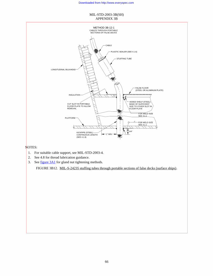
MIL-STD-2003-3B(SH)
APPENDIX 3B
66
NOTES:
1. For suitable cable support, see MIL-STD-2003-4.
2. See 4.8 for thread lubrication guidance.
3. See figure 3A1 for gland nut tightening methods.
FIGURE 3B12. MIL-S-24235 stuffing tubes through portable sections of false decks (surface ships).
METHOD 3B-12-1CABLES THROUGH PORTABLE
SECTIONS OF FALSE DECKS
CABLE
STUFFING TUBE
LONGITUDINAL BULKHEAD
PLATFORM
KICKPIPE (STEEL)
CONTINUOUS LENGTH
(SEE 4.1.9)
1" MIN
3/4"
FALSE FLOOR
(STEEL OR ALUMINUM PLATE)
ADDED SHELF (STEEL)
MAKE OF SUFFICIENT
SIZE TO COVER SLOT IN
FLOOR PLATE
FOR WELD SIZE
SEE 4.1.1
FOR WELD SIZE
SEE 4.1.1
CUT SLOT IN PORTABLE
FLOOR PLATE TO ALLOW
REMOVAL
INSULATION
PLASTIC SEALER (SEE 4.1.6)
Downloaded from http://www.everyspec.com

Downloaded from http://www.everyspec.com

Downloaded from http://www.everyspec.com

MIL-STD-2003-3B(SH)
APPENDIX 3B
69
NOTES:
1. The stuffing tube shown is equivalent to one-half of a standard submarine type double-ended stuffing tube in
accordance with MIL-S-24235/1 (½ of the “M” dimension). See applicable notes on figure 3A1.
2. The arrangement of hull stuffing tube area for sonar dome transducers shall be as specified on detailed
construction drawings. Installation of stuffing tubes shall be in accordance with this figure.
3. Holes for stuffing tubes shall be drilled or otherwise mechanically cut.
4. Stuffing tube spacing shall be in accordance with figures 3B1 and 3B2.
5. Plastic sealer use should be in accordance with 4.1.6.
6. See 4.8 for thread lubrication guidance.
7. For size 9 stuffing tubes, the nylon bevel washer to the left of the grommet shown in the above illustration
may be replaced by a flat washer to avoid the washer cutting into cable when the gland nut is torqued.
8. In applications where one side of the penetration is submerged, when cables have an armored layer under the
outer jacket, such as LSMDY type, the outer jacket and armored layer shall be stripped and removed from
within 1-2 inches of the bulkhead penetrations and through the penetration. This ensures that any damage
that may occur to the cable outer jacket does not permit water to traverse or wick along the underlying armor
layer and through the penetration.
9. See figure 3A1 for gland nut tightening methods.
FIGURE 3B14. Stuffing tubes for sonar dome area (surface ships) – Continued.
Downloaded from http://www.everyspec.com

Downloaded from http://www.everyspec.com

MIL-STD-2003-3B(SH)
APPENDIX 3B
71
NOTES:
1. For suitable cable support, see MIL-STD-2003-4.
2. Tubes shall be spaced 1 inch minimum from bulkhead and from each other in accordance with figures 3B2
and 3B3.
3. See 4.8 for thread lubrication guidance.
4. See figure 3A1 for gland nut tightening methods.
FIGURE 3B15. Topside stuffing tubes with riser box (surface ships) – Continued.
Downloaded from http://www.everyspec.com

Downloaded from http://www.everyspec.com

MIL-STD-2003-3B(SH)
APPENDIX 3B
73
NOTES:
1. For suitable cable support, see MIL-STD-2003-4.
2. Tubes shall be spaced 1 inch minimum from bulkhead and from each other in accordance with stuffing tube
spacing figures 3B2 and 3B3.
3. See 4.8 for thread lubrication guidance.
4. See figure 3A1 for gland nut tightening methods.
FIGURE 3B16. MIL-S-24235 topside stuffing tubes with riser box for medium steel decks (surface ships) –
Continued.
Downloaded from http://www.everyspec.com

Downloaded from http://www.everyspec.com

MIL-STD-2003-3B(SH)
APPENDIX 3B
75
NOTES:
1. For suitable cable support, see MIL-STD-2003-4.
2. Stuffing tubes shall be spaced from each other and framework as prescribed on figures 3B2 and 3B3.
3. See 4.8 for thread lubrication guidance.
4. See figure 3A1 for gland nut tightening methods.
FIGURE 3B17. MIL-S-24235 topside stuffing tubes with riser box on medium steel decks not adjacent to a
bulkhead (surface ships) – Continued.
Downloaded from http://www.everyspec.com

Downloaded from http://www.everyspec.com

MIL-STD-2003-3B(SH)
APPENDIX 3B
77
NOTES:
1. For suitable cable support, see MIL-STD-2003-4.
2. Tubes shall be spaced 1 inch minimum from bulkhead and from each other in accordance with stuffing tube
spacing on figures 3B2 and 3B3.
3. See 4.8 for thread lubrication guidance.
4. See figure 3A1 for gland nut tightening methods.
FIGURE 3B18. MIL-S-24235 topside stuffing tubes with riser box (surface ships) – Continued.
Downloaded from http://www.everyspec.com

Downloaded from http://www.everyspec.com

Downloaded from http://www.everyspec.com
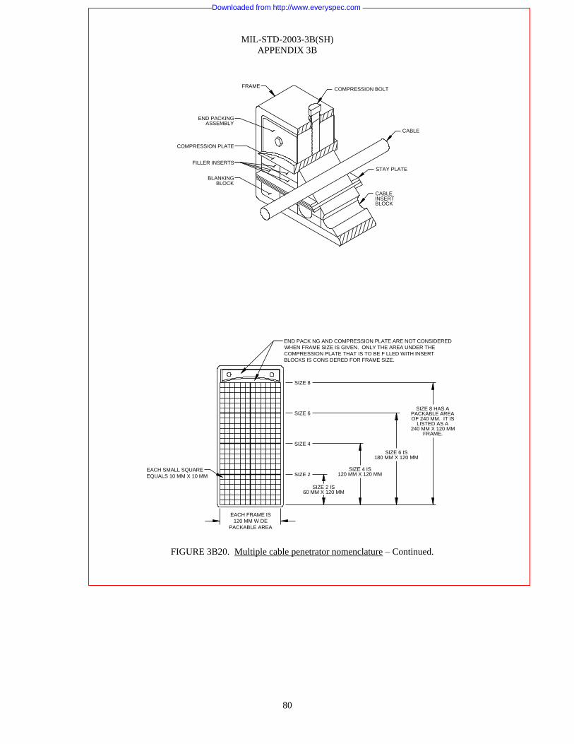
MIL-STD-2003-3B(SH)
APPENDIX 3B
80
COMPRESSION PLATE
BLANKINGBLOCK
FILLER INSERTS
CABLEINSERTBLOCK
STAY PLATE
CABLE
COMPRESSION BOLTFRAME
END PACKINGASSEMBLY
SIZE 2
SIZE 4
SIZE 6
SIZE 8
EACH FRAME IS
120 MM W DE
PACKABLE AREA
EACH SMALL SQUARE
EQUALS 10 MM X 10 MM
END PACK NG AND COMPRESSION PLATE ARE NOT CONSIDERED
WHEN FRAME SIZE IS GIVEN. ONLY THE AREA UNDER THE
COMPRESSION PLATE THAT IS TO BE F LLED WITH INSERT
BLOCKS IS CONS DERED FOR FRAME SIZE.
SIZE 2 IS60 MM X 120 MM
SIZE 4 IS120 MM X 120 MM
SIZE 6 IS180 MM X 120 MM
SIZE 8 HAS APACKABLE AREAOF 240 MM. IT IS
LISTED AS A240 MM X 120 MM
FRAME.
FIGURE 3B20. Multiple cable penetrator nomenclature – Continued.
Downloaded from http://www.everyspec.com

MIL-STD-2003-3B(SH)
APPENDIX 3B
81
WE
DG
E
WE
DG
E
WE
DG
E
WE
DG
E
WEDGE PACK
STAY PLATES
MODULE BLOCKS
SOLIDMODULE
BLOCKSQUARE FRAME SQUARE FRAME
CORNER RADIUS
FIGURE 3B20. Multiple cable penetrator nomenclature – Continued.
Downloaded from http://www.everyspec.com

MIL-STD-2003-3B(SH)
APPENDIX 3B
82
Multiple cable penetrators (MCP):
A system of passing cables through watertight and non-watertight bulkheads and decks designed to suit particular
bulkhead and deck weights. MCP components shall meet the requirements of MIL-DTL-24705. In general, the MCP
component views, tables, and installation instructions in figures 3B20-3B30 apply. However, there are several different
MCP products that meet the requirements of MIL-DTL-24705. Therefore, to achieve satisfactory installation,
manufacturer’s instructions should be used in addition to the instructions in this standard.
Nomenclature:
Throughout this standard of electric plant installation drawings, the following descriptions apply:
a. Rectangular frames and square frame corner radius, unbanded
(1) Consist of four basic sizes; 2, 4, 6, and 8. All are 5.506 inches wide. Size 2 is 4.726 inches high; size 4 is 7.029
inches high; size 6 is 9.333 inches high; and size 8 is 11.660 inches high.
(2) Material shall be either steel or aluminum, ¼ or ⅜ thick (depending on weight of bulkhead or deck) in steel or
½ thick in aluminum. All frames are 2⅜ deep.
(3) There are four different type frames:
RGS – Steel, four corners welded (completely closed)
RGSO – Steel, two corners welded (open bottom)
RGA – Aluminum, four corners welded (completely closed)
RGAO – Aluminum, two corners welded (open bottom)
RGSC – Steel or aluminum, square frame, rounded corners, see figure 3B64
(4) To recap sub-paragraphs (1) through (3), an unbanded frame is identified as follows: an RGS-2 x ⅜ is a
⅜-thick size 2 steel frame with four corners welded (completely closed).
b. Rectangular frames, banded:
(1) Consist of the four basic sizes in sub-paragraph a(1), each of which is enclosed by a reinforcing band of proper
size material to suit particular bulkhead weight. In addition to the band filler, plates are employed to seal empty
spaces between frame and band.
(2) RGS and RGA banded frames are complete units ready to be installed in bulkhead. RGSO and RGAO banded
frames have lower half of band and frame temporarily tack welded. At installation, this tack weld is broken,
frame is wrapped around cables, and all welding is completed.
c. Physical arrangement and identification
(1) Various arrangements of frames are available in all sizes and types. Examples and dimensions are shown on
figures 3B24, 3B25, and 3B26.
(2) Identification of various arrangements are made by the following examples:
FIGURE 3B20. Multiple cable penetrator nomenclature – Continued.
Downloaded from http://www.everyspec.com
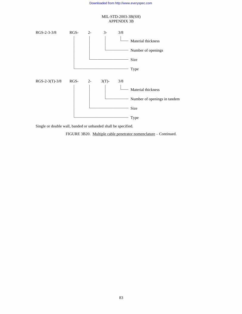
MIL-STD-2003-3B(SH)
APPENDIX 3B
83
RGS-2-3-3/8 RGS- 2- 3- 3/8
Material thickness
Number of openings
Size
Type
RGS-2-3(T)-3/8 RGS- 2- 3(T)- 3/8
Material thickness
Number of openings in tandem
Size
Type
Single or double wall, banded or unbanded shall be specified.
FIGURE 3B20. Multiple cable penetrator nomenclature – Continued.
Downloaded from http://www.everyspec.com

MIL-STD-2003-3B(SH)
APPENDIX 3B
84
Nomenclature (continued):
d. Compression screw or bolt:
(1) Stainless steel, ¾-10UNC thread, when tightened, seats the compression plate farther down into the
transit frame
e. Plug:
(1) Stainless steel, ¾-10UNC thread used to plug tapped hole in frame opposite compression screw
f. Stay plate:
(1) Either steel or aluminum normally placed between every other row of insert blocks keeping them
positioned in the transit frame.
g. Compression plate:
(1) Either cast iron or cast aluminum seats and compresses the insert blocks so that the end packing can be
inserted in the transit frame.
h. End packing – standard (see item q)
(1) Compresses the insert blocks used when frame can be packed from either side
(2) Assembly, which consists of two neoprene elastomer blocks and two end packing washers held together
by two ⅜-16UNC hex head cap screws and hex nuts. Washers, nuts, and cap screws are steel cadmium
plated. For non-magnetic applications, stainless steel is used.
i. End packing – special (see item q):
(1) Compresses the insert blocks used when frame can only be packed from one side
(2) Assembly, which consists of four neoprene elastomer pieces, one end packing washer, two end packing
washers special, and two ⅜-16UNC hex nuts, all are steel cadmium plated. For non-magnetic
applications, stainless steel is used.
j. Insert blocks:
(1) Twin half blocks are specially formulated of a neoprene elastomer with a centered semi-circular groove.
When matched around a cable, these blocks form a single block with a tight fit. Basic sizes are shown
on figure 3B21 for information and guidance.
k. Spares:
(1) Solid blocks are specially formulated of a neoprene elastomer and are used as fillers or spare provisions
for addition of future cables. Sizes are shown on figure 3B21 for information and guidance. When
installing new MCPs, at least 20 percent of the MCP usable area shall be reserved for future cable
installations.
l. Fill-ins:
(1) Same material as insert blocks and spares used to pack thicknesses of 5 or 10 millimeters caused by the
presence of different size blocks in the same row. Also employed to increase the pressure in the
penetrator frame when exceptionally soft cables are used. These fill-ins are available in two sizes
24 x 5/0 or 12 x 10/0 (see figure 3B21). Serrations have been provided to permit slicing of the fill-ins to
the required length.
Example: 6 x 10/0, 8 x 5/0, etc.
Serration spacing MM
m. Tallow:
(1) Tallow is a natural lubricant that allows the blocks, stayplates, compression system and cables to move
freely during the compression process. Without tallow, the friction during compression will create gaps
in the system and an effective seal will not be obtained. Therefore, as stated in the installation
instructions in figures 3B22, 3B39, 3B41, and 3B63, tallow must be applied for every insert block.
n. Sealer:
(1) Liquid silicone rubber applied to cable side of each gauge block upon compression. This provides a
seal between the armor of the cable and its impervious inner sheath.
FIGURE 3B20. Multiple cable penetrator nomenclature – Continued.
Downloaded from http://www.everyspec.com

MIL-STD-2003-3B(SH)
APPENDIX 3B
85
Nomenclature (continued):
o. Nut:
(1) All nuts are to be in accordance with NASM 25027.
p. All dimensions are in inches unless otherwise stated.
q. Wedge: a one-piece compression system that may be used in place of compression plates and end-packing.
The wedge may be installed from one side and may be installed anywhere in the frame.
NOTE:
1. Multiple cable penetrators shall not be used in bulkheads or decks which are exposed to the weather except
for electro-magnetic compatibility (EMC) type penetrations covered in figure 3B63.
FIGURE 3B20. Multiple cable penetrator nomenclature – Continued.
Downloaded from http://www.everyspec.com

MIL-STD-2003-3B(SH)
APPENDIX 3B
86
TABLE 3B21-I Cable information and assignment
for MCP insert blocks
TABLE 3B21-I Cable information and assignment
for MCP insert blocks – Continued
TABLE 3B21-I Cable information and assignment
for MCP insert blocks – Continued
TABLE 3B21-I Cable information and assignment
for MCP insert blocks – Continued
Cable type
Cable
diameter
in inches
Cable
diameter
in mm
Insert
block
part
number
size mm 3/
Insert
block
part
number
size mm 3/
Cable type
Cable
diameter
in inches
Cable
diameter
in mm
Insert
block
part
number
size mm 3/
Insert
block
part
number
size mm 3/
Cable type
Cable
diameter
in inches
Cable
diameter
in mm
Insert
block
part
number
size mm 3/
Insert
block
part
number
size mm 3/
Cable type
Cable
diameter
in inches
Cable
diameter
in mm
Insert
block
part
number
size mm 3/
Insert
block
part
number
size mm 3/
SSGA-3 0 305 7 75 15/7 20/7 RG-12A/U 0 475 12 07 20/12 30/12 MA-14 0 450 11 43 20/11
SSGA-4 0 323 8 20 15/8 20/8 RG-22B/U 0 420 10 67 20/10
SSGA-9 0 371 9 42 15/9 20/9 RG-27A/U 0 670 17 02 30/17
SSGA-14 0 414 10 51 20/10 RG-58C/U 0 195 4 96 15/4 20/4
SSGA-23 0 453 11 50 20/11 RG-59B/U 0 242 6 15 15/6 20/6
SSGA-30 0 484 12 30 20/12 30/12 (TTHFWA) RG-62A/U 0 242 6 15 15/6 20/6
SSGA-40 0 515 13 08 20/13 30/13 TT-1-1/2 0 380 9 65 15/9 20/9 RG-63B/U 0 405 10 29 20/10
SSGA-150 0 844 21 44 30/21 TT-3 0 500 12 70 20/12 30/12 RG-71B/U 0 250 6 35 15/6 20/6
SSGA-500 1 290 32 77 40/30 TT-5 0 590 14 99 20/14 30/14 RG-79B/U 0 475 12 07 20/12 30/12
SSGA-1300 1 880 47 75 60/48 TT-10 0 690 17 53 30/17 RG-111A/U 0 490 12 45 20/12 30/12
TT-15 0 800 20 32 30/20 RG-142B/U 0 195 4 96 15/4 20/4 TCOP-42 1 250 31 75 40/30
DCOP-3 0 425 10 80 20/10 TT-20 0 880 22 35 30/22 40/22 RG-157/U 0 725 18 42 30/18
DCOP-4 0 460 11 68 20/12 30/12 TT-30 1 030 26 16 40/26 RG-213/U 0 405 10 29 20/10
DCOP-6 0 510 12 95 20/13 30/13 TT-40 1 130 28 70 40/28 RG-214/U 0 425 10 80 20/10
DCOP-9 0 570 14 48 20/14 30/14 TT-50 1 265 32 13 40/32 60/32 RG-215/U 0 475 12 07 20/12 30/12
DCOP-14 0 705 17 91 30/18 TT-60 1 350 34 29 40/34 60/34 RG-218/U 0 870 22 10 30/22 40/22
DCOP-23 0 860 21 84 30/22 RG-219/U 0 945 24 01 30/23
DCOP-30 0 960 24 38 30/24 40/24 RG-224/U 0 615 15 62 30/15
DCOP-83 1 450 36 83 60/36 TTRSA-2 0 740 18 80 30/18 RG-227/U 0 490 12 45 20/12 30/12
DCOP-250 2 100 53 34 60/52 TTRSA-4 0 800 20 32 30/20 RG-236/U 0 500 12 70 20/12 30/12 MDGA-19(6) 1 285 32 63 40/32 60/32
DCOP-400 2 500 63 50 90/60 TTRSA-6 0 940 23 88 30/23 RG-258/U 1 886 47 90 60/46 MDGA-19(14) 1 520 38 61 60/38
TTRSA-8 1 050 26 67 40/26 RG-318/U 1 085 27 56 40/26 MDGA-19(23) 1 820 46 23 60/46
DSGA-14 0 680 17 27 30/17 TTRSA-10 1 1 40 28 96 40/28 RG-254/U 1 090 27 69 40/26 MDGA-19(40) 2 100 53 34 60/52
DSGA-23 0 781 19 84 30/19 TTRSA-12 1 160 29 46 40/28 RG-179B/U 0 100 2 54
DSGA-30 0 852 21 64 30/21 TTRSA-16 1 250 31 75 40/30 RG-333/U 1 052 26 72 40/26
DSGA-40 0 898 22 81 30/22 40/22 SPCLXDUCER
7819478P1 1 200 30 48 40/30
DSGA-50 0 961 24 41 30/24 40/24
DSGA-60 1 031 26 19 40/26 2SA
2SWA-3 0 570 14 48 20/14 30/14
DSGA-125 1 374 34 90 40/34 60/34 -7 0 710 18 03 30/18
DSGA-150 1 479 37 57 60/36 -10 0 880 22 35 30/22 40/22
DSGA-250 1 759 34 68 60/44 -14 0 980 24 89 30/24 40/24 ISMU-5 0 500 12 70 20/12 30/12
-19 1 090 27 69 40/26
-24 1 260 32 00 40/30
-30 1 330 34 80 40/34 60/34
-37 1 430 36 32 60/36
-44 1 600 40 64 60/40
-61 1 790 45 47 60/44
FIGURE 3B21. Cable information and assignment for MCP insert blocks.
Downloaded from http://www.everyspec.com

MIL-STD-2003-3B(SH)
APPENDIX 3B
87
TABLE 3B21-I Cable information and assignment
for MCP insert blocks – Continued
TABLE 3B21-I Cable information and assignment
for MCP insert blocks – Continued
TABLE 3B21-I Cable information and assignment
for MCP insert blocks – Continued
Cable type
Cable
diameter
in inches
Cable
diameter
in mm
Insert
block
part
number
size mm 3/
Insert
block
part
number
size mm 3/
Cable type
Cable
diameter
in inches
Cable
diameter
in mm
Insert
block
part
number
size mm 3/
Insert
block
part
number
size mm 3/
Cable type
Cable
diameter
in inches
Cable
diameter
in mm
Insert
block
part
number
size mm 3/
Insert
block
part
number
size mm 3/
TABLE 3B21-II Insert blocks
TABLE 3B21-II Insert
blocks – Continued
Insert
block
part no size
mm 3/
“A”
dim in
“B”
dim in
Insert
block part
no size
mm 3/
“A” dim
in
“B” dim
in
3SA
3SWA-3 0 750 19 05 30/18
-7 0 960 24 38 30/24 40/24
TSGA-14 0 718 18 23 30/18 -10 1 240 31 50 40/30 15/4 0 590 0 157 40/24 1 575 945
TSGA-30 0 902 22 91 30/22 40/22 -14 1 340 34 04 40/33 60/34 15/5 0 590 0 197 40/26 1 575 1 024
TSGA-40 0 950 24 13 30/24 40/24 -19 1 480 37 59 60/36 15/6 0 590 0 236 40/28 1 575 1 102
TSGA-60 1 110 28 19 40/28 -24 1 720 43 69 60/42 15/7 0 590 0 276 40/30 1 575 1 181
TSGA-125 1 458 37 03 60/36 -30 1 820 46 23 60/46 15/8 0 590 0 315 40/32 1 575 1 260
TSGA-250 1 844 46 84 60/46 -37 1 980 50 29 60/50 90/50 15/9 0 590 0 354 40/34 1 575 1 339
TSGA-350 2 123 53 92 60/52 -44 2 200 55 88 90/55
-61 2 360 59 94 90/55 20/4 0 787 0 157 60/32 2 362 1 260
FSGA-60 1 205 30 61 40/30 20/5 0 787 0 197 60/34 2 362 1 339
PBJX-4 0 480 12 19 20/12 30/12 20/6 0 787 0 236 60/36 2 362 1 417
20/7 0 787 0 276 60/38 2 362 1 496
20/8 0 787 0 315 60/40 2 362 1 575
SHFR-4 0 540 13 72 20/13 30/13 20/9 0 787 0 354 60/42 2 362 1 654
MDY-6 1 190 30 23 40/30 DHFR-4 0 844 21 44 30/21 20/10 0 787 0 394 60/44 2 362 1 732
MDY-14 1 570 39 88 60/39 THFR-4 0 683 22 43 30/22 40/22 20/11 0 787 0 433 60/46 2 362 1 811
MDY-23 1 960 49 78 60/49 20/12 0 787 0 472 60/48 2 362 1 890
MDY-40 2 240 56 90 90/55 20/13 0 787 0 512 60/50 2 362 1 969
MDY-60 2 525 64 14 90/63 1S50MA-16 0 875 22 23 30/22 40/22 20/14 0 787 0 551 60/52 2 362 2 047
1S50MA-20 0 955 24 26 30/24 40/24 60/54 2 362 2 128
1S50MA-40 1 235 31 37 40/30 30/12 1 181 0 472
ISA-44 1 040 26 42 40/26 1S50MA-70 1 605 40 77 60/40 30/13 1 181 0 512 90/50 3 543 1 969
30/14 1 181 0 551 90/55 3 543 2 165
30/15 1 181 0 591 90/60 3 543 2 362
ISMWA-70 1 605 40 77 60/40 IS75MA-8 1 080 27 43 40/26 30/16 1 181 0 630 90/65 3 543 2 559
30/17 1 181 0 669 90/70 3 543 2 756
MHFF-2 0 460 11 68 20/11 30/18 1 181 0 709
ISWA-2 0 505 12 83 20/12 30/12 MHFF-4 0 520 13 21 20/13 30/13 30/19 1 181 0 748 120/75 4 724 2 953
ISWA-14 0 920 23 37 30/23 MHFF-7 0 627 15 93 30/15 30/20 1 181 0 787 120/80 4 724 3 150
ISWA-20 1 080 27 43 40/26 MHFF-10 0 795 20 20 30/20 30/21 1 181 0 827 120/85 4 724 3 346
ISWA-30 1 250 31 75 40/30 MHFF-14 0 844 21 44 30/21 30/22 1 181 0 866 120/90 4 724 3 543
MHFF-19 0 995 25 28 30/24 40/24 30/23 1 181 0 906 120/95 4 724 3 740
MHFF-24 1 120 28 45 40/28 30/24 1 181 0 945
MHFF-30 1 194 30 33 40/30
MHFF-37 1 290 32 77 40/32 60/32 40/22 1 575 0 866
MHFF-44 1 420 36 07 60/35
FIGURE 3B21. Cable information and assignment for MCP insert blocks – Continued.
Downloaded from http://www.everyspec.com

MIL-STD-2003-3B(SH)
APPENDIX 3B
88
"A"
"A"
"B"
2.362
866
22
866
22
86622
40 MM
40 MM
INS DE DIAMETER
IN DECIMALS
40/22 INSERT
INS DE DIAMETER
IN MILLIMETERS
TYPICAL INSERT BLOCK DENT FICATION
TSGA-30 CABLE HAS AN OUTSIDE DIAMETER OF 0.902.
SELECT INSERT BLOCKS CONTAINING THE NEXT NSIDE
DIAMETER THAT IS LESS THAN THE OUTSIDE DIAMETER
OF THE CABLE. A SIZE 22 MM HOLE IS 0 866 INCHES AND
WILL PROV DE THE FOLLOWING PRIOR TO
COMPRESSION.
MULTI-LAYER NSERT MODULE
0.036 (1/32")
A STARTING GAP OF 1/32" TO 1/16"
IS RECOMMENDED
4.724
SPACED
SERRATIONS
2 362
"A"
F LL-INS IDENTIFICATION
EXAMPLE:
PART NO. 24X5/0
5 MM SPACED SERRATIONS
24 SERRATIONS
LENGTH=24X5=120 MM=4.724"
TSGA-30
Fill-ins “A” dim.
(inches)
24x5/0 0.196
12x10/0 0.393
"A"
"A"
2.362
Spares
part no.
size mm
“A” dim.
(inches)
15/0 0.590
20/0 0.787
30/0 1.181
NOTES:
1. See figures 3A10 through 3A25 and this figure for current cable assignments.
2. Approved multi-diameter insert blocks may be used, where available.
3. MCP block size designations are provided for information and guidance. Some of the MCP block sizes
shown in this table may not accommodate the full range of allowed cable diameters for a given cable type. In
those cases, different MCP block sizes should be selected to ensure the required block gap and retest
requirements are met. See figure 3B22.
FIGURE 3B21. Cable information and assignment for MCP insert blocks – Continued.
Downloaded from http://www.everyspec.com

MIL-STD-2003-3B(SH)
APPENDIX 3B
89
Installation notes:
RGS and RGA multiple cable penetrators
1. Multiple cable penetrator (MCP) is a modular system that utilizes standard units and dimensions to allow
maximum flexibility and compatibility with various numbers and sizes of cables. Final sealed units will
provide watertight, airtight, and fireproof bulkhead or deck penetrations. In general, the MCP component
views, tables, and installation instructions in figures 3B20-3B30 apply. However, there are several different
MCP products that meet the requirements of MIL-DTL-24705. Therefore, to achieve satisfactory installation,
manufacturer’s instructions should be used in addition to the instructions in this standard.
2. Remove any dirt from inside the frame. Pull all cable through cable penetrator, bearing in mind cables shall
always approach parallel to each other and in a horizontal plane perpendicular to the penetrator. This can be
accomplished if the nearest cable hanger is 16 inches minimum from bulkhead. Cables running up a
bulkhead and through a cable penetrator shall have its full bending radius outside of the penetrator. While in
the process of pulling cables, it is imperative that a reasonable amount of slack should be left to facilitate
movement of cable within the cable penetrator to ease packing operation. See MIL-STD-2003-4 for cable
slack requirements. Also, it is necessary that each cable be identified on the compression screw side of MCP
by lead number and cable size. All cables through a new MCP shall be pulled prior to installing insert blocks.
See 4.4 for specific restrictions and instructions for installation of fiber optic and blown fiber cables in
electrical penetrations.
3. After pulling all cables through a particular MCP, it can be packed. First apply a liberal coat of cable
lubricant (tallow) to all outside surfaces of the insert blocks, the inside portion of the frame, and the curved
surface of the compression plate. When packing armored cable, apply Nelson Fire stop Caulk, or equal
(see 4.2), sealer on the surface of each block that contacts the cable (a ⅛ inch bead every ½ inch around the
circumference). Each frame shall be laid out (blocked) showing solid blocks (used as spares) and cable
assignments prior to packing. A typical example of a packed RGS-4 frame with instructions for packing is
shown below.
a. Select insert blocks and spares from tables 3B21-I and 3A10-I through 3A25-I (presented for information
and guidance) and prepare as above (lubricant and sealer where required). Blocks should be selected to
avoid any gaps under compression. Fill-ins as explained in figure 3B20 and illustrated in figure 3B21
may be used if different size blocks are installed in the same row to ensure an even installation.
Although not desirable, the fill-ins also may be used if soft cable would leave a gap under compression.
For multi-diameter modules, the insert blocks should be adapted by peeling one layer at a time to achieve
a 0.1- to 1-millimeter gap between the two halves when the block is held against the cable. See
following illustration. The layers shall be peeled from both sides to achieve an even installation. Once a
layer is peeled, the layer may not be reinserted into the block.
FIGURE 3B22. Multiple cable penetrator installation notes (type RGS and RGA).
20/0 20/0 20/0 20/0
30/0
60/32
40/28
30/15
30/19
30/13
20/11
END PACKING ASSEMBLY
3/8"-16 HEX NUT
COMPRESSION PLATE
STAY PLATE NO. 2
STAY PLATE NO. 1
FRAME
20/9
COMPRESSION BOLT
20/0 20/0 20/0 20/0 20/0 20/0
20/0 20/0
Downloaded from http://www.everyspec.com

MIL-STD-2003-3B(SH)
APPENDIX 3B
90
INCORRECTGROOVE TOO LARGE
INCORRECTGROOVE TOO SMALL
CORRECT0.1 TO 1 MM (1/32 GAP)
0.1MMTO
1MM
Installation notes (continued):
b. Starting with heaviest cable, place the lower half of the 60/32 insert block under the cable in the frame.
Next, repeat the procedure with the 30/15 then add one 30/0 spare. Add the upper half of the 60/32 and
the 30/15. Place lower half of 30/13 and 30/19 under cable, then add upper halves. Across the top of
these, add stay plate no. 1. Use steel stay plates with steel frames and aluminum stay plates with
aluminum frames. Use corrosion resistant steel (CRES) stay plates for medium or high voltage cables.
c. On top of the stay plate, place four 20/0 spares and the lower half of the 40/28 under its cable. In the
next higher row, place two 20/0 spares and the lower half of 20/9 and 20/11 under their respective cables.
Then add upper halves of 40/28, 20/11, and 20/9. On top of these, add stay plate no. 2.
d. Add compression plate to the frame.
e. Lift compression plate clear of stay plate no. 2. Add final row of six 20/0 spares. Lower compression
plate to this level.
f. If individual conductors of a three-phase power circuit are in different cables, the individual cables shall
be installed in adjacent insert blocks. There shall be no ferrous material, e.g., stay plates or frame
segments between the individual cables. The purpose of this requirement is to avoid heating due to
electro-magnetic induction.
g. Tighten compression screw down on compression plate to compress entire contents of frame and provide
just enough clearance to insert end packing assembly. Apply a generous amount of lubricant to this
cavity to assist insertion of end packing. A wedge, as described in figure 3B20, may be used instead of
the end packing assembly. The wedge may be installed anywhere within the MCP assembly. The wedge
shall be installed in accordance with manufacturer’s instructions. Guidance for wedge installation is
provided in step 28.
h. Disassemble end packing assembly and install in frame around the compression screw. Reassemble and
tighten ⅜-16 UNC hex nuts evenly until end packing insert material expands in the cavity and there is a
slight roll of the material around the end packing metal washers. Back off compression screw
approximately ⅛ of a turn. Packing is now complete.
i. See SE000-01-IMB-010 for modifications to the MCPs to support the installation of waveguides.
4. When a multiple cable penetrator frame is installed in a structure in such a manner that the compression screw
is located on the bottom, packing procedure is the same except:
a. The compression plate is installed first.
b. The frame is packed from the bottom up with the smallest cables being packed first.
5. To add a new cable to a packed frame, loosen the ⅜-16UNC hex nuts and remove the end packing metal
washers. Tighten the compression screw until end packing insert material is loose. Remove insert material
from frame, loosen compression screw, and lift compression plate clear of top six 20/0 spares. Remove these
inserts. Remove compression plate and full access to the insert blocks and cable is available. If a wedge is
used, follow manufacturer instructions for wedge removal.
6. Template all work from ship.
7. All welding and inspection shall be in accordance with 4.1.1.
8. All painting shall be done in accordance with MIL-DTL-917.
9. The structural reinforcement shown on this plan does not apply to flight deck bents, flight deck support
structures, or other similar type structures on other ships. Such cases shall be individually resolved with
structural design.
10. Material of structural reinforcement is to be similar to material of bulkhead, deck, or riser box penetrated.
11. This plan was developed from T9070-AN-DPC-010/100-1, reinforcement of openings in structure of surface
ships other than in protective plating, to permit installation of multiple cable penetrator frame [Tecrona
Products of Nelson Electric, or equal (see 4.2)] in watertight decks and bulkheads of surface ships.
FIGURE 3B22. Multiple cable penetrator installation notes (type RGS and RGA) – Continued.
Downloaded from http://www.everyspec.com

MIL-STD-2003-3B(SH)
APPENDIX 3B
91
Installation notes (continued):
12. Fillet weld reinforcement for T2V.1 weld joints in accordance with MIL-STD-22 shall be ⅛ inch for plating
up to 15.3# and ¼ inch for plating above 17.85#.
13. The bulkheads and decks that are considered to be longitudinal strength members are defined in
T9070-AN-DPC-010/100-1 as components in “strength envelope (i.e., in outside plating, uppermost strength
deck, inner bottom, and their associated longitudinal framing) and for other strength decks within the midship
three-fifths length.” If there is difficulty in definition, consult with structural design.
14. Care should be taken while installing multiple cable penetrators to ensure that all of its coaming protrudes
through bulkhead sufficiently to weld in place. After welding, examine for cracks and sharp edges that may
damage cable when being pulled through penetrator. If grinding is required, ensure grinding areas do not
weaken the penetrator.
15. It is mandatory to maintain a minimum of ⅞ inch from bulkhead to bolt hole center for wrench clearance.
Also, leave a 4-inch clearance to allow for installation of compression screw (from bolt hole side of the
multiple cable penetrator to any structure).
16. Riser box to be attached to bulkhead of 7.65# or heavier. If bulkhead is less than 7.65# adjacent to riser box
installation, install a back plate of 10.2# between the back of the riser box and the bulkhead.
17. After installation is complete, entire penetrator may be painted to suit surrounding structure in accordance
with the applicable ship specifications. Wait 24 hours or longer (refer to manufacturer’s instructions) after
installation before exposing the cables/pipes to strain or pressure. The wait time shall be observed prior to the
post-installation testing.
18. Post installation testing:
a. After installation of a new MCP or work on an existing MCP, retest shall be conducted to confirm
integrity of the electrical penetration.
b. Perform a visual inspection on plastic or rubber inserts inside of the MCP to ensure there are no visible or
discernible openings.
c. For airtight, oiltight, and watertight penetrations, conduct an air blast test or a vacuum box test as
follows:
(1) Air blast test: The air hose nozzle shall be held a maximum of 3 inches from the MCP area. The
distance should be as close to 3 inches as practicable to avoid distortion of the MCP blocks due to
high air flow. The pressure shall be directed at the structure under test in a manner most likely to
disclose leaks. The minimum nozzle diameter shall be ⅜ inch and the nozzle pressure shall be 60 to
90 pounds per square inch gage (PSIG) as monitored at the nozzle.
(a) Obtain a pressure differential in the same direction as would occur during a full compartment,
tank, or void test using the air hose. The air pressure shall be maintained for at least 3 minutes.
As soon as the pressure is applied, apply a soapy solution to the opposite side of the structure
and inspect for leaks.
(2) Vacuum box test requirements: Apply a soapy solution to the joint to be tested. Install the vacuum
box so the pressure differential will be in the same direction as a full compartment, tank, or void
completion test. Draw 10.2"Hg vacuum (minimum). Maintain the vacuum for at least 3 minutes.
Inspect the joint or fitting for leakage by observing the formation of bubbles.
d. For penetrations through fume-tight bulkheads, conduct a visual/light test to ensure no light transmits
from one side of the MCP to the other.
RGSO and RGAO multiple cable penetrators
19. Temporarily insulate cable for protection against welding and burning.
20. Remove old non-watertight structure.
21. Prepare hole in bulkhead to receive multiple cable penetrator frame (designated “RGSO”). External banding
is used only when required.
22. Bottom of “RGSO” unit is tack welded to other three sides – remove this piece.
23. Segregate and confine required cables within each three-sided frame.
24. Wrap welders blanket around cable. Replace bottom piece and continuously weld corners. Grind smooth
same as top corners.
25. Slide unit into prepared hole in bulkhead. Position so that center line of tapped hole is ⅞" out from face of
bulkhead to permit clearance for the compression screw.
FIGURE 3B22. Multiple cable penetrator installation notes (type RGS and RGA) – Continued.
Downloaded from http://www.everyspec.com

MIL-STD-2003-3B(SH)
APPENDIX 3B
92
Installation notes (continued):
26. Weld frame to bulkhead with continuous weld all around frame on both sides of bulkhead.
27. Proceed as outlined in notes 3-18.
28. Guidance for wedge installation: Pack the MCP frame up to and including step 3f above. Then, proceed as
follows:
a. Before inserting the final row of cable or spare insert blocks, insert two stayplates.
b. Separate the two stayplates. Insert the final row between the stayplates.
c. Place the upper stayplate on top of the modules.
d. Lubricate all sides of the wedge, except for the front and back. Turn the wedge according to the
markings and insert into the top of the frame (standard position). As an option, the wedge may be
installed anywhere in the frame. The face marked with “Stayplate this side” shall always face a stayplate.
e. Tighten the wedge fasteners until full stop, approximately 15 foot-pounds.
f. Attach the wedge clip (see following illustration) to the screws to check that the wedge is properly
tightened.
g. Stayplate clips and clamps may be used to simplify horizontal assembly (see following illustration).
h. Proceed to step 6 above.
WEDGE CLIP
STAYPLATE CLIP
CLAMP
NOTE:
1. The tables and dimensions shown on these sheets are for typical steel installations. Other unique situations
shall be handled as a case-by-case basis through the structures department.
FIGURE 3B22. Multiple cable penetrator installation notes (type RGS and RGA) – Continued.
Downloaded from http://www.everyspec.com

Downloaded from http://www.everyspec.com

MIL-STD-2003-3B(SH)
APPENDIX 3B
94
NOTE:
1. Multiple cable penetrator frames are available in various sizes and arrangements. A two-frame penetrator is
shown.
FIGURE 3B23. Multiple cable penetrator installation in steel or aluminum bulkheads using two-frame penetrator
(types RGS and RGA) – Continued.
Downloaded from http://www.everyspec.com
MIL-STD-2003-3B(SH)
APPENDIX 3B
95
⅜ thick single frame
Type A
(see note 3)
B
(see note 3)
Packable area dimensions
per frame (mm)
(see note 2)
RGS-2 5.5 4.726 120/60
RGS-4 5.5 7.029 120/120
RGS-6 5.5 9.333 120/180
RGS-8 5.5 11.660 120/240
⅜ thick 1 thru 6 multi-frame
Type Dim
(see
note 3)
1
Frame
2
Frame
3
Frame
4
Frame
5
Frame
6
Frame
RGS-2 A 5.506 10.637 15.768 20.899 26.030 31.161
RGS-4 A 5.506 10.637 15.768 20.899 26.030 31.161
RGS-6 A 5.506 10.637 15.768 20.899 26.030 31.161
RGS-8 A 5.506 10.637 15.768 20.899 26.030 31.161
RGS-2 B 4.726 4.726 4.726 4.726 4.726 4.726
RGS-4 B 7.029 7.029 7.029 7.029 7.029 7.029
RGS-6 B 9.333 9.333 9.333 9.333 9.333 9.333
RGS-8 B 11.66 11.66 11.66 11.66 11.66 11.66
⅜ thick 1 thru 6 tandem multi-frame
Type Dim
(see note 3)
T Fr. 2T Fr. 3T Fr. 4T Fr. 5T Fr. 6T Fr.
RGS-2 A 5.506 10.637 15.768 20.899 26.030 31.161
RGS-4 A 5.506 10.637 15.768 20.899 26.030 31.161
RGS-6 A 5.506 10.637 15.768 20.899 26.030 31.161
RGS-8 A 5.506 10.637 15.768 20.899 26.030 31.161
RGS-2 B 9.452 9.452 9.452 9.452 9.452 9.452
RGS-4 B 14.058 14.058 14.058 14.058 14.058 14.058
RGS-6 B 18.666 18.666 18.666 18.666 18.666 18.666
RGS-8 B 23.31 23.31 23.31 23.31 23.31 23.31
FIGURE 3B24. Multiple cable penetrator details (types RGS and RGA).
2 FRAME TANDEM
DETAIL "C"
3/8" TYP
A
B
DETAIL "B"
B
A
3/8" TYP
A
B
DETAIL "A"
3/8" TYP
Downloaded from http://www.everyspec.com

MIL-STD-2003-3B(SH)
APPENDIX 3B
96
⅜ single frame banded
Dimension “B” (see note 3)
BHD
plate
#
10.2
12.75
15.3
17.85
20.4
23.0
25.5
28.0
30.6
RGS-2 59⁄16 513⁄16 65⁄16
RGS-4 7⅞ 8⅛ 8⅝
RGS-6 103⁄16 107⁄16 1015⁄16
RGS-8 12½ 12¾ 13¼
BAND ⅜ x 4" ½ x 4" ¾ x 4"
⅜ thick 2 frame banded
Dimension “B” (see note 3)
BHD
plate
#
10.2
12.75
15.3
17.85
20.4
23.0
25.5
28.0
30.6
RGS-2 59⁄16 513⁄16 65⁄16
RGS-4 7⅞ 8⅛ 8⅝
RGS-6 103⁄16 107⁄16 1015⁄16
RGS-8 12½ 12¾ 13¼
BAND ⅜x4" ½x4" ¾x4"
⅜ thick multi-frame banded
Dimension “B” (see note 3)
BHD
plate #
10.2
12.75
15.3
17.85
20.4
23.0
25.5
28.0
30.6
RGS-2 59⁄16 513⁄16 65⁄16
RGS-4 7⅞ 8⅛ 8⅝
RGS-6 103⁄16 107⁄16 1015⁄16
RGS-8 12½ 12¾ 13¼
BAND ⅜ x 4" ½ x 4" ¾ x 4"
FIGURE 3B24. Multiple cable penetrator details (types RGS and RGA) – Continued.
FILLER PLATE
1/8" THICK
21 1/2"
B
2 1/2" RBAND
DETAIL "F"
3/8" TYP
16"
B
2 1/2" RBAND
DETA L "E"
FILLER PLATE
1/8" THICK
3/8" TYP
3/8" TYP
11 1/2"
B
2 1/2" RBAND
DETAIL "D"
FILLER PLATE
1/8" THICK
Downloaded from http://www.everyspec.com

MIL-STD-2003-3B(SH)
APPENDIX 3B
97
⅜ thick 4 frame banded
BHD plate lbs
#
“B” dim (see note 3) “A”
(see note 3) “R” Band
RGS-2 RGS-4 RGS-6 RGS-8
10.2 12.75 15.3 17.85 111⁄16 13⅜ 1511⁄16 18 21¾ 3⅛ ⅜ x 4"
17.85 20.4 23.0 25.55 119⁄16 13⅞ 163⁄16 18½ 22¼ 3⅜ ⅝ x 4"
25.5 28.0 30.6 30.6 1113⁄16 14⅛ 167⁄16 18¾ 22½ 3½ ¾ x 4"
⅜ thick 2 thru 6 tandem multi-frame banded
Dimension “B” (see note 3)
BHD
plate
#
7.65 10.2 12.75
15.3
17.85
20.4 25.5
30.6
35.7
RGS-2 10⅝ 10⅞ 11⅛ 11⅜ 11⅝ 11⅝
RGS-4 153⁄16 157⁄16 1511⁄16 1515⁄16 163⁄16 163⁄16
RGS-6 1913⁄16 201⁄16 205⁄16 209⁄16 2013⁄16 2013⁄16
RGS-8 247⁄16 2411⁄16 2415⁄16 253⁄16 257⁄16 257⁄16
BAND ⅜ x 4 ½ x 4 ⅝ x 4 ¾ x 5 ⅞ x 6 ⅞ x 6½
FIGURE 3B24. Multiple cable penetrator details (types RGS and RGA) – Continued.
2 FRAME TANDEM 16"
3 FRAME TANDEM 21 1/2"
4 FRAME TANDEM 26 5/8"
5 FRAME TANDEM 31 3/4"
6 FRAME TANDEM 36 7/8"
B
3/8" TYP
2 1/2" RBAND
F LLER PLATE
1/8" THICK
DETAIL "H"
3/8" THICK FLAT
BAR IN ALL
ASSEMBLIES
3/8" TYP
A
B
R
BAND
DETAIL "G"
FILLER PLATE
1/8" THICK
Downloaded from http://www.everyspec.com

MIL-STD-2003-3B(SH)
APPENDIX 3B
98
NOTES:
1. Material RGS frames and filler plates are mild steel ASTM A36/A36M. Reinforcing bands are either mild
steel (ASTM A36/A36M) or high tensile steel MIL-S-22698 in order for material to be similar to bulkhead or
deck in which penetration is being made.
2. All single frames have the same packable area, whether in the single frame or multi-frame configuration.
3. For aluminum MCP frames, the frame edge thickness in accordance with MIL-DTL-24705/1 is ½ inch rather
than ⅜ inch for steel frames. Therefore, the appropriate amount should be added to the dimensions shown in
the tables in figure 3B24 to account for the ½-inch aluminum frame edges.
4. Dimensions in inches unless otherwise noted.
FIGURE 3B24. Multiple cable penetrator details (types RGS and RGA) – Continued.
Downloaded from http://www.everyspec.com

Downloaded from http://www.everyspec.com

Downloaded from http://www.everyspec.com

Downloaded from http://www.everyspec.com

Downloaded from http://www.everyspec.com

MIL-STD-2003-3B(SH)
APPENDIX 3B
103
Type I
Size of band
Wt of
structure
penetrated
#
Long’l strength
member BHDs and decks
other than long’l
strength members BHDs Decks
7.65 5" x 5⁄16 12" x 5⁄16 5" x 5⁄16
10.2 5" x 5⁄16 12" x 5⁄16 5" x 5⁄16
12.75 5" x 5⁄16 12" x 5⁄16 5" x 5⁄16
15.3 5" x 5⁄16 12" x 5⁄16 5" x 5⁄16
17.85 5" x ⅜ 12" x ⅜ 5" x 5⁄16
20.4 5" x ⅜ 12" x ⅜ 5" x 5⁄16
25.5 5" x ⅜ 12" x ⅜ 5" x ⅜
30.6 5" x ½ 12" x ½ 5" x ½
35.7 5" x ½ 12" x ½ 5" x ½
FIGURE 3B26. Multiple cable penetrator details (types RGS and RGA).
SINGLE FRAME BANDED
10 1/2"
Downloaded from http://www.everyspec.com

Downloaded from http://www.everyspec.com

Downloaded from http://www.everyspec.com

Downloaded from http://www.everyspec.com

Downloaded from http://www.everyspec.com

MIL-STD-2003-3B(SH)
APPENDIX 3B
108
Type VI
Size of band
Wt of
structure
penetrated
#
Long’l strength
member BHDs and decks
other than long’l
strength members BHDs Decks
7.65 5" x 5⁄16 12" x 5⁄16 5" x 5⁄16
10.2 5" x ⅜ 12" x ⅜ 5" x 5⁄16
12.75 5" x ⅜ 12" x ⅜ 5" x 5⁄16
15.3 5" x ⅜ 12" x ⅜ 5" x 5⁄16
17.85 5" x ½ 12" x ½ 5" x ⅜
20.4 5" x ½ 12" x ½ 5" x ⅜
25.5 5" x ⅝ 12" x ⅝ 5" x ⅜
30.6 5" x ¾ 12" x ¾ 5" x ½
35.7 5" x ¾ 12" x ¾ 5" x ¾
FIGURE 3B26. Multiple cable penetrator details (types RGS and RGA) – Continued.
SINGLE FRAME TANDEM BANDED
10 1/2"
Downloaded from http://www.everyspec.com

MIL-STD-2003-3B(SH)
APPENDIX 3B
109
LO
CA
TE
JA
CK
ING
SC
RE
W H
OL
E
IAW
NO
TE
S O
N F
IGU
RE
3B
20
BU
LK
HE
AD
TE
MP
OR
AR
Y
PR
OT
EC
TIO
N
WH
ILE
WE
LD
ING
(SE
E F
IGU
RE
3B
22
, N
OT
E 2
4)
TY
PE
RG
SO
OR
RG
AO
MU
LT
IPL
E C
AB
LE
PE
NE
TR
AT
ING
FR
AM
E P
OS
ITIO
NS
IN
BU
LK
HE
AD
OR
DE
CK
EX
IST
ING
CA
BL
E
ME
TH
OD
3B
-27-1
HO
LE
FO
R M
UL
TIP
LE
CA
BL
E
PE
NE
TR
AT
OR
FR
AM
E (
SE
E
FIG
UR
E 3
B2
2, N
OT
E 2
1)
BO
TT
OM
OF
RG
SO
UN
IT
(SE
E F
IGU
RE
3B
22
, N
OT
E 2
4)
TE
MP
OR
AR
Y P
RO
TE
CT
ION
WH
ILE
WE
LD
ING
(SE
E F
IGU
RE
3B
22
, N
OT
E 2
4)
EX
TE
RN
AL
BA
ND
ING
(SE
E F
IGU
RE
3B
22
, N
OT
ES
10
AN
D 2
1)
TH
RE
E S
IDE
D P
IEC
E
(SE
E F
IGU
RE
3B
22
,
NO
TE
S 2
2 A
ND
23
)
TY
PE
RG
SO
MU
LT
IPL
E C
AB
LE
PE
NE
TR
AT
OR
FR
AM
E P
OS
ITIO
NE
D A
RO
UN
D E
XIS
TIN
G
CA
BL
E B
EF
OR
E W
EL
DIN
G
FIGURE 3B27. Multiple cable penetrator installation details (types RGS and RGA).
Downloaded from http://www.everyspec.com

MIL-STD-2003-3B(SH)
APPENDIX 3B
110
NOTE:
1. See figure 3B22, notes 19 through 27 for additional information.
FIGURE 3B27. Multiple cable penetrator installation details (types RGS and RGA) – Continued.
Downloaded from http://www.everyspec.com

Downloaded from http://www.everyspec.com

MIL-STD-2003-3B(SH)
APPENDIX 3B
112
NOTE:
1. Multiple cable penetrator frames are available in various sizes and arrangements. Shown is a two-frame
penetrator.
FIGURE 3B28. Multiple cable penetrator frame in decks (types RGS and RGA) – Continued.
Downloaded from http://www.everyspec.com
MIL-STD-2003-3B(SH)
APPENDIX 3B
113
FIGURE 3B29. Multiple cable penetrator (type RGS and RGA) shield.
CA
BL
E S
UP
PO
RT
US
E A
PP
RO
PR
IAT
E
ME
TH
OD
OF
ML-S
TD
-2003-4
SH
IEL
D S
HE
ET
(S
TE
EL
) 1/1
6"
TH
ICK
MA
Y A
LS
O B
E E
XP
AN
DE
D
ME
TA
L O
R P
ER
FO
RA
TE
D
SH
EE
T
ME
TH
OD
3B
-29
-1
9 1
/8"
MN
FO
R P
RO
TE
CT
NG
TH
RE
E O
R M
OR
E
CA
BL
ES
PA
SS
NG
TH
RO
UG
H
WA
TE
RT
IGH
T D
EC
KS
SM
ILA
R T
O
FIG
UR
E 4
D1 (
ML
-ST
D-2
003-4
)
2"
SE
E F
IGU
RE
3B
28
F
OR
DE
TA
ILS
Downloaded from http://www.everyspec.com

MIL-STD-2003-3B(SH)
APPENDIX 3B
114
FIGURE 3B30. Multiple cable penetrator riser box.
BL
KH
D
SE
E T
AB
LE
3B
30
-I
RE
INF
OR
CIN
G R
ING
B
GA
SK
ET
MA
TE
RIA
L
W.T
. D
EC
K
PO
RT
AB
LE
PL
AT
E
MU
LT
IPL
E C
AB
LE
PE
NE
TR
AT
OR
2"
FO
R W
EL
D S
IZE
SE
E
GE
NE
RA
L R
EQ
UIR
EM
EN
TS
4
1"
FO
R W
EL
D S
IZE
SE
E
GE
NE
RA
L R
EQ
UIR
EM
EN
TS
4
BL
KH
D
C O
F C
OM
PR
ES
SIO
N B
OL
TS
"B"
"A"
"A"
CO
NF
IGU
RA
TIO
N I
II-6
X3
FR
AM
E
(FO
R D
IME
NS
ION
S S
EE
TA
BL
E 3
B3
0-I
I)
RIS
ER
BO
X
6X
3 P
EN
ET
RA
TO
R F
RA
ME
"B"
PO
RT
. P
LT
.
BL
KH
D
C O
F C
OM
PR
ES
SIO
N B
OL
TS
"B"
CO
NF
IGU
RA
TIO
N I
V-6
X4
FR
AM
E
(FO
R D
IME
NS
ION
S S
EE
TA
BL
E 3
B3
0-I
I)
6X
4 P
EN
ET
RA
TO
R F
RA
ME "B
"
"A"
"A"
PO
RT
. P
LT
.
RIS
ER
BO
X
L
LL
L
L
L
9"
MIN
18
" M
AX
C O
F C
OM
PR
ES
SIO
N
BO
LT
S
AD
D 1
/2"-
13
ST
UD
S,
LO
CK
WA
SH
ER
S A
ND
NU
TS
SE
E T
AB
LE
FO
R Q
UA
NT
ITY
A
DE
TA
IL A
-A
SC
AL
E 3
" -
1' 0
"
"B"
"B"
1/4
"
15
RIS
ER
BO
X
PO
RT
. P
LA
TE
D
E
C/2
RG
S-6
PE
NE
TR
AT
OR
FR
AM
E
8"
W.T
. D
EC
KC
RE
INF
OR
CE
D O
PE
NIN
G
(SE
E T
AB
LE
3B
30
-I)
"A"
"A"
DE
TA
IL B
-B
TY
PIC
AL
VIE
W -
SE
E C
AB
LE
PE
NE
TR
AT
OR
FR
AM
ES
CO
NF
IGU
RA
TIO
N I
-V A
ND
RE
FE
R T
O T
AB
LE
3B
30
-II
FO
R D
IME
NS
ION
S
BL
KH
D
PO
RT
. P
LT
.C
OF
CO
MP
RE
SS
ION
BO
LT
S
6X
2 P
EN
ET
RA
TO
R
FR
AM
ERIS
ER
BO
X
"B"
"A"
"A"
CO
NF
IGU
RA
TIO
N I
- 6
X2
FR
AM
E
(FO
R D
IME
NS
ION
S S
EE
TA
BL
E 3
B3
0-I
I)
"B"
BL
KH
D
PO
RT
. P
LT
.
C O
F C
OM
PR
ES
SIO
N B
OL
TS
6T
PE
NE
TR
AT
OR
FR
AM
E
"B"
"A"
CO
NF
IGU
RA
TIO
N I
I-6
T F
RA
ME
(FO
R D
IME
NS
ION
S S
EE
TA
BL
E 3
B3
0-I
I)
BL
KH
D
"B"
"B"
CO
NF
IGU
RA
TIO
N V
-6X
2T
FR
AM
E
(FO
R D
IME
NS
ION
S S
EE
TA
BL
E 3
B3
0-I
I)
RIS
ER
BO
X
"B"
"A"
6T
PE
NE
TR
AT
OR
FR
AM
E
"A"
"A"
C O
F C
OM
PR
ES
SIO
N B
OL
TS
PO
RT
. P
LT
.
Downloaded from http://www.everyspec.com

MIL-STD-2003-3B(SH)
APPENDIX 3B
115
TABLE 3B30-I. Reinforced frame opening
dimensions. 1/
No. frames Size of opening
6 x 2 10" x 4"
6 x 3 15" x 4"
6 x 4 20" x 4" or 16" x 5"
NOTE:
1/ Min. of 20 sq. in. opening for each frame.
TABLE 3B30-II. Frame dimensions.
Dimensions
Configuration
number A B C D E
Bolts
req’d.
I 12½" 5" 14" 1¾" 13" 14
II 8" 4½" 21" 1⅛" 20" 16
III 12½" 5" 19" 1⅝" 18" 16
IV 12½" 5" 24" 1½" 23" 18
V 13½" 7" 21" 1⅛" 20" 16
FIGURE 3B30. Multiple cable penetrator riser box – Continued.
Downloaded from http://www.everyspec.com

Downloaded from http://www.everyspec.com

MIL-STD-2003-3B(SH)
APPENDIX 3B
117
TABLE 3B31-I. List of materials.
PC.
no. Qty. Name Material
Matl. spec. or
std. dwg. no.
1 1 Gland body, 3⁄16" plate Alum ASTM B209
2 1 Front face plate, 5⁄16" pl. Alum ASTM B209
3 1 Back face plate, ⅜" pl. Alum ASTM B209
4 1 Flange, ¼" pl. Alum ASTM B209
5 1 Backing plate, ¼" pl. Alum ASTM B209
6 3 Pipe – 1", length to suit Alum ASTM B209
7 3 Cap – fill, drain and vent Alum ASTM B209
8 2 Slat, 2" Alum ASTM B209
9 2 Slat, 1¾" Alum ASTM B209
10 2 Slat, 2¼" Alum ASTM B209
11 32 ¼-20UNC socket head cap
screw, ⅝" long CRES 316
12 32 ¼-20UNC socket head cap
screw, ¼" long CRES 316
13 16 ⅜-16UNC hex head cap
screw, length as reqd. CRES 316
14 16 ⅜" nut CRES 316
15 2 Gasket – Flange, 0.090 thk. Rubber MIL-PRF-15624
16 3 Gasket Cap, 0.090 thk. Rubber MIL-PRF-15624
17 As req’d. Filling compound Rubber
18 As req’d. Plastic sealer MIL-I-3064
Installation notes:
1. The gland is to be positioned on the bulkhead so that there is reasonable access to the filling, drain, and vent
tubes, and so that the top of the gland is horizontal (maximum permissible tilt is 5 degrees).
2. An opening 7⅜ inches high by 7⅛ inches wide should be prepared in the bulkhead for receiving the gland.
3. Fit rubber gaskets and bolt gland to bulkhead.
4. Wipe the gland interior completely to remove traces of grease or oil.
5. Pull cables through gland, removing, where possible, all dirt and grease from cables.
6. The portions of the cables passing through the gland, especially at the slat assembly positions, shall be wiped
clean with rags and cyclohexanone to remove all traces of grease or oil from the cables.
7. Coat the cable holes, butting edges, and butting side of the bottom slats with sealer, PC 18. Fit the slats into
position and screw to gland body (one slat each side).
8. Position the bottom row of cables on the slats.
9. Proceed in a similar manner, to position the cables until all slats are in position.
10. After cables are in position, they should not be disturbed.
FIGURE 3B31. Community stuffing tube for minesweepers – Continued.
Downloaded from http://www.everyspec.com

MIL-STD-2003-3B(SH)
APPENDIX 3B
118
Installation notes (continued):
11. Final gland cleaning operation – Remove the caps from the filling, drain, and vent tubes. Fit a hose to the
drain tube to feed into a clean bucket and provide a clamp on the hose near the gland. Fill the gland with
liquid degreasing agent.
CAUTION – use adequate ventilation, avoid prolonged or repeated breathing of vapor, and avoid prolonged
or repeated contact with skin. Do not take internally.
After about 5 minutes, release the clamp to drain the gland, and blow compressed air through the gland from
the top for about 5 minutes to ensure complete elimination of any fluid that might remain in the gland. Any
leaks noted during the cleaning operation should be repaired.
12. The liquid filling compound, PC 17, consists of two separate liquids that are mixed together immediately
prior to use. The success of the resultant compound depends on thorough mixing, and this should be a stirring
action. The compound should be stirred for 5 minutes. Complete mixing instructions are printed on the
filling compound container.
13. Pour the filling compound into the gland until the tubes are filled.
14. Both sides of the gland shall be inspected during the filling operation for leakage. It may be possible to repair
slight leaks by external application of sealer. If leakage persists, the filling operation shall stop. Immediately
drain the filling compound. After leak has been stopped, the filling operation may be restarted.
15. Fit filling and vent tube caps.
16. See 4.5 for fastener and fastener material requirements.
FIGURE 3B31. Community stuffing tube for minesweepers – Continued.
Downloaded from http://www.everyspec.com

Downloaded from http://www.everyspec.com

MIL-STD-2003-3B(SH)
APPENDIX 3B
120
NOTES:
1. For a list of materials, see figure 3B31.
2. See figure 3B31 for fill, drain, and vent cap detail.
3. Drill front and back slats at the same time.
4. Painting shall be in accordance with approved methods.
5. The diameter of the holes should be same size (+1⁄16, -0) outside diameter of minesweep cable used.
6. The separation of these holes should provide a minimum spacing of 0.625 between cables and also provide a
minimum spacing of 0.5 between cable and inner faces of gland body.
FIGURE 3B32. Community stuffing tubes for minesweepers (details) – Continued.
Downloaded from http://www.everyspec.com

Downloaded from http://www.everyspec.com

MIL-STD-2003-3B(SH)
APPENDIX 3B
122
NOTES (continued):
5. Wood screws shall be in accordance with table I of MIL-STD-2003-2.
6. See 4.8 for thread lubrication guidance.
7. See figure 3A1 for gland nut tightening methods.
8. See 4.5 for fastener and fastener material requirements.
FIGURE 3B33. Deck outlets for portable cables (surface ships) – Continued.
Downloaded from http://www.everyspec.com

Downloaded from http://www.everyspec.com

MIL-STD-2003-3B(SH)
APPENDIX 3B
124
TABLE 3B35-I. New stuffing tubes – MIL-S-24235/10. 1/
Ex
isti
ng
stu
ffin
g t
ub
es
MIL
-S-2
42
35
/10
Size A B C D E F G J K L M N P R S T V W X Y Z AA BB
A X X X X X
B X X X X X
C X X X X X
D X X X X X
E X X X X
F X X X X
G X X X X
J X X X X X
K X X X X X
L X X X X
M X X X X
N X X X X
P X X X X
R X X X X
S X X X X X
T X X X X X X
V X X X X X
W X X X X
X X X X X
Y X X X
Z X X
AA X
BB
NOTE:
1/ X indicates an acceptable combination.
NOTES:
1. Table 3B35-I indicates new tube size limitations for adaptation to undersized non-reusable stuffing tubes.
2. Ream smooth and round off inside edge of existing tube to prevent cable chafing.
3. See figure 3A1 for gland nut tightening methods.
4. See 4.8 for thread lubrication guidance.
FIGURE 3B35. Changing stuffing tube sizes to accommodate larger cable.
METHOD 3B-35-1
NEW STUFFING TUBE
PACK NG
(SEE 4.1.8)
TYPICAL INSTALLATION
CABLE
SEE NOTE 1
BULKHEAD
EXISTING STUFFING TUBE
Downloaded from http://www.everyspec.com

Downloaded from http://www.everyspec.com

MIL-STD-2003-3B(SH)
APPENDIX 3B
126
BANDING
BULKHEAD (STEEL)
FOR WELD SIZE
SEE 4.1.1
GLAND R NG
GLAND NUT
BAND NG
ARMOR
IMPERVIOUS SHEATH NG
DEGAUSSING CABLE
STUFFING TUBE
PACKING (SEE 4.1.8)ROUND INSIDE EDGE
METHOD 3B-37-1
PIPE (STEEL) SIZE 3"
Instructions:
1. Cut away the outer armor, if installed, in the way of the stuffing tube and secure as shown.
2. Insert extra packing rings in stuffing tube.
3. Position the impervious sheathing area within the stuffing tube and tighten gland nut.
4. See figure 3A1 for gland nut tightening methods.
5. See 4.8 for thread lubrication guidance.
FIGURE 3B37. Sealing degaussing cable in bulkhead stuffing tubes.
Downloaded from http://www.everyspec.com

Downloaded from http://www.everyspec.com
MIL-STD-2003-3B(SH)
APPENDIX 3B
128
TABLE 3B38-II. Stuffing tube adapter sets.
Adapter set
(steel)
Adapter set
(aluminum)
Existing
tube
“N” dim.
OD
Effective
reduction size
“A” dim.
ID
3B381SBA 3B381ABA B 0.875 A 0.406
3B382SDA 3B382ADA D 1.032 A 0.406
3B383SDB 3B383ADB D 1.032 B 0.515
3B384SDC 3B384ADC D 1.032 C 0.640
3B385SGB 3B385AGB G 1.360 B 0.516
3B386SGC 3B386AGC G 1.360 C 0.640
3B387SGD 3B387AGD G 1.360 D 0.750
3B388SGE 3B388AGE G 1.360 E 0.812
3B389SGF 3B389AGF G 1.360 F 0.843
3B3810SLG 3B3810ALG L 1.703 G 0.953
3B3811SLJ 3B3811ALJ L 1.703 J 1.062
3B3812SLK 3B3812ALK L 1.703 K 1.172
3B3813SNL 3B3813ANL N 1.875 L 1.265
3B3814SNM 3B3814ANM N 1.875 M 1.406
3B3815SSN 3B3815ASN S 2.562 N 1.515
3B3816SSP 3B3816ASP S 2.562 P 1.625
3B3817SSR 3B3817ASR S 2.562 R 1.750
3B3818SWS 3B3818AWS W 3.000 S 1.875
3B3819SWT 3B3819AWT W 3.000 T 2.062
3B3820SWV 3B3820AWV W 3.000 V 2.187
3B3821SAAX 3B3821AAAX AA 3.625 X 2.500
3B3822SAAY 3B3822AAAX AA 3.625 Y 2.609
3B3823SAAZ 3B3823AAAZ AA 3.625 Z 2.781
NOTES:
1. Adapter set consists of one flat washer and one bevel reducing adapter.
2. Definition of adapter sets numbering system follows:
3B38 I S B A
Figure number
Reduction size
Host tube
Steel or aluminum (S or A)
Sequence
3. Neoprene shall be in accordance with MIL-PRF-15624, class I, grade 50.
4. See figure 3A1 for gland nut tightening methods.
5. See 4.8 for thread lubrication guidance.
FIGURE 3B38. MIL-S-24235/18 stuffing tube bevel reducing adapter assemblies – Continued.
Downloaded from http://www.everyspec.com

MIL-STD-2003-3B(SH)
APPENDIX 3B
129
Installation notes:
1. Round multiple cable penetrator (RMCP) is a modular system that utilizes standard units and dimensions to
allow maximum flexibility and compatibility with various numbers and sizes of cables. Final sealed units are
designed to provide watertight, airtight, and fireproof bulkhead or deck penetrations. Round MCP
components shall meet requirements of MIL-DTL-24705 and MIL-DTL-24705/3. Since there are more than
one variant of RMCPs available, manufacturer’s instructions should be consulted for installation details. The
following general instructions apply. The dimension tables in figures 3B40 and 3B41 cover the smaller
RMCPs shown just before step 3a. For dimensions for the larger RMCP, consult manufacturer’s information.
2. Remove any dirt from inside the frame. Freely lubricate outside of the RMCP with cable lubricant (tallow)
before inserting into pipe sleeve, but do not push RMCP completely into the sleeve at this time.
Pull all cables through the RMCP, bearing in mind that cables shall always approach parallel to each other
and in a horizontal plane to the penetrator. This can be accomplished if the nearest cable hanger is 16 inches
minimum from the bulkhead. Cable running up the bulkhead and through an RMCP shall have its full
bending radius outside of the penetrator. While in the process of pulling cables, it is imperative that a
reasonable amount of slack should be left to facilitate movement of cables within the RMCP to ease packing
operation. See MIL-STD-2003-4 for cable slack requirements. Also, it is necessary that each cable be
identified on the compression nut side of the multiple cable penetrator by lead number and cable size. All
cables through a new round multiple cable penetrator shall be pulled prior to installing insert blocks. See 4.4
for specific restrictions and instructions for installation of fiber optic and blown fiber cables in electrical
penetrations.
3. After pulling all cables through a particular round multiple cable penetrator, it can be packed. First, apply a
liberal coat of cable lubricant (tallow) to all outside surfaces of the insert blocks and inside of the RMCP.
When packing armored cable, apply Nelson Fire Stop Caulk, or equal (see 4.2), sealer on the surface of each
block that contacts the cable (a ⅛-inch bead every ½ inch around the circumference.) Each RMCP shall be
laid out (blocked) showing solid blocks (used as spares) and cable assignments prior to packing. A typical
example of a packed RMCP unit with location assignments for packing is shown below.
20/0
20/10 20/9
20/0
20/020/0 20/0 20/0 20/0 20/0
20/020/0
20/0 20/0
30/19 30/13
30/15
SMALLER RCMP
30/8
60/32
40/28
CUT FOR RETROFIT PURPOSES
LARGER RCMP
CUT FOR RETROFIT PURPOSES
FIGURE 3B39. Round multiple cable penetrators installation notes.
Downloaded from http://www.everyspec.com

MIL-STD-2003-3B(SH)
APPENDIX 3B
130
Installation notes (continued):
a. Select insert blocks and spares (see note 3) from tables 3B21-I and 3A10-I through 3A25-I (presented for
information and guidance) and prepare as illustrated above (lubricant and sealer, where required). Blocks
should be selected to avoid any gaps under compression. Fill-ins as explained in figure 3B20 and
illustrated in figure 3B21 may be used if different size blocks are installed in the same row to ensure an
even installation. Although not desirable, the fill-ins also may be used if soft cable would leave a gap
under compression. For multi-diameter modules, the insert blocks should be adapted by peeling one layer
at a time. The insert blocks should be adapted to achieve a 0.1- to 1-millimeter gap between the two
halves when the block is held against the cable. See following illustration. The layers shall be peeled
from both sides to achieve an even installation. Once a layer is peeled, the layer may not be reinserted
into the block.
INCORRECTGROOVE TOO LARGE
INCORRECTGROOVE TOO SMALL
CORRECT0.1 TO 1 MM (1/32 GAP)
0.1MMTO
1MM
b. Starting with largest cable, place the lower half of the 60/32 insert block under the cable in the unit.
Next, repeat the procedure with the 30/15, then add one 30/0 spare. Add the upper half of the 60/32 and
the 30/15. Place lower half of the 30/13 and 30/19 under cable, then add upper halves.
CAUTION: For easiest packing, do not insert the blocks fully into the square hole until all cable holding and spare
blocks are in their assigned locations.
c. On top of the previously installed blocks, place four 20/0 spares and the lower half of the 40/28 under its
cable. In the next higher row, place two 20/0 spares and the lower half of the 20/9 and 20/11 under their
respective cables. Then add upper halves of 40/28, 20/9, and 20/11 on top.
d. Add final row of six 20/0 spares.
e. All blocks and their RMCP can now be fully inserted simultaneously, i.e., the blocks pushed completely
into the square hole of the plug and RMCP completely into the sleeve.
f. When the RMCP unit is completely filled and inserted, then the nuts are alternately tightened until the
RMCP is secure in the hole. The installation is then complete.
g. If individual conductors of a three-phase power circuit are in different cables, the individual cables shall
be installed in adjacent insert blocks. There shall be no ferrous material between the individual cables.
The purpose of this requirement is to avoid heating due to electro-magnetic induction.
h. See SE000-01-IMB-010 for modifications to the MCPs to support the installation of waveguides.
4. To add a new cable to a packed RMCP unit, loosen the outside hex nuts and remove the desired spare insert
modules. Pull the new cable and add matching cable holding blocks in accordance with previous instructions.
5. Template all work from ship.
6. All welding and inspection shall be in accordance with 4.1.1.
7. All painting shall be done in accordance with MIL-DTL-917.
8. This plan was developed for the reinforcement of openings in structure of surface ships other than in
protective plating to permit installation of round multiple cable penetrator in watertight decks and bulkheads
of surface ships.
9. Fillet weld reinforcement for T2V.1 weld joints in accordance with MIL-STD-22 shall be ⅛ inch for plating
up to 15.3# and ¼ inch for plating above 17.85#.
10. The bulkheads and decks that are considered to be longitudinal strength members are defined as components
in “strength envelope (i.e., in outside plating, uppermost strength deck, inner bottom, and their associated
longitudinal framing) and for other strength decks within the midship three-fifths length”. If there is
difficulty in definition, consult with structural design.
FIGURE 3B39. Round multiple cable penetrators installation notes – Continued.
Downloaded from http://www.everyspec.com

MIL-STD-2003-3B(SH)
APPENDIX 3B
131
Installation notes (continued):
11. After installation is complete, pipe sleeve of penetrator may be painted to suit surrounding structure in
accordance with applicable ship specifications. Wait 24 hours or longer (refer to manufacturer’s instructions)
after installation before exposing the cables/pipes to strain or pressure. The following wait time shall be
observed prior to the post-installation testing.
12. Post-installation testing:
a. After installation of a new RMCP or work on an existing RMCP, retest shall be conducted to confirm
integrity of the electrical penetration.
b. Perform a visual inspection on plastic or rubber inserts inside of the RMCP to ensure there are no visible
or discernible openings.
c. For airtight, oiltight, and watertight penetrations, conduct an air blast test or a vacuum box test as
follows:
(1) Air blast test: The air hose nozzle shall be held a maximum of 3 inches from the MCP area. The
distance should be as close to 3 inches as practicable to avoid distortion of the MCP blocks due to
high air flow. The pressure shall be directed at the structure under test in a manner most likely to
disclose leaks. The minimum nozzle diameter shall be ⅜ inch and the nozzle pressure shall be 60 to
90 PSIG as monitored at the nozzle. Obtain a pressure differential in the same direction as would
occur during a full compartment, tank, or void test using the air hose. The air pressure shall be
maintained for at least 3 minutes. As soon as the pressure is applied, apply a soapy solution to the
opposite side of the structure and inspect for leaks.
(2) Vacuum box test: Apply a soapy solution to the joint to be tested. Install the vacuum box so the
pressure differential will be in the same direction as a full compartment, tank, or void completion
test. Draw 10.2"Hg vacuum (minimum). Maintain the vacuum for at least 3 minutes. Inspect the
joint or fitting for leakage by observing the formation of bubbles.
d. For penetrations through fume-tight bulkheads, conduct a visual/light test to ensure no light transmits
from one side of the RMCP to the other.
Round multiple cable penetrators for existing cables:
13. Temporarily insulate cable for protection against welding and burning.
14. Remove old non-watertight structure.
15. Prepare hole in bulkhead to receive round multiple cable penetrator (designated “RMCPO”). For the smaller
frames, one corner of RMCP is cut with a sharp tool to allow the frame to be opened and placed around the
existing cables. Pipe sleeve shall also be placed around the cable. For the larger RMCP frames, the cut is
between two of the screws that secure one of the compression plates. (See illustration prior to step 3a.)
16. Segregate and confine required cables for protection and installation.
17. Slide unit into prepared sleeve in bulkhead then proceed as outlined in notes 3-12.
NOTES:
1. The round multiple cable penetrator shall not be installed in bulkheads and decks that are exposed to the
weather except for electro-magnetic compatibility (EMC) type penetrations covered in figure 3B63.
2. Insert block cable assignments are shown for guidance and information on figure 3B21.
3. Approved multi-diameter insert blocks may be used where available.
FIGURE 3B39. Round multiple cable penetrators installation notes – Continued.
Downloaded from http://www.everyspec.com

Downloaded from http://www.everyspec.com

MIL-STD-2003-3B(SH)
APPENDIX 3B
133
Nomenclature:
Round multiple cable penetrators (RMCP): a system of passing cables through water and non-watertight
bulkheads and decks designed to suit particular bulkhead and deck weights.
a. Physical arrangement and identification
RMCP 2 -30
Square opening in millimeters for cable acceptance
RMCP and pipe size designation
Round multiple cable penetrator body
b. RMCP consists of seven basic sizes: 2, 2.5, 3, 4, 5, 6, and 8 for insertion into steel pipe (table 3B41-I) or
aluminum pipe (table 3B41-II).
c. Compression hardware for sealing is comprised of the following:
(1) Back compression plate (detail 1) with press fitted compression screw (detail 2) (illustration 3) to
make furnished assembly.
(2) Front compression plate similar to back compression plate, only it is furnished without compression
screw.
(3) Hex nut (illustration 4) to be used with front compression plate and stud.
d. Insert blocks:
Twin half blocks are specially formulated of a neoprene elastomer with a centered semi-circular groove.
When matched around a cable, these blocks form a single block with a tight fit. See note 2.
e. Spares:
Solid blocks are specially formulated of a neoprene elastomer and are used as fillers or spare provisions
for addition of future cables. Sizes shown for information and guidance on figure 3B21. When installing
new MCPs, at least 20 percent of the MCP usable area shall be reserved for future cable installations.
f. Fill-ins:
Same material as insert blocks and spares are used to fill thicknesses of 5 or 10 millimeters created by the
presence of different size blocks in the same row. Also employed to increase the pressure in the
penetrator unit when exceptionally soft cables are used. These fill-ins are available in two sizes: 24x5/0
or 12x10/0. See figure 3B21 for information and guidance. Serrations have been provided to permit
slicing of the fill-ins to the required length. Example: 6x10/0, 8x5/0, etc.
g. Tallow:
Tallow is a natural lubricant that allows the blocks, stayplates, compression system and cables to move
freely during the compression process. Without tallow, the friction during compression will create gaps
in the system and an effective seal will not be obtained. Therefore, as stated in the installation
instructions in figure 3B39, tallow must be applied for every insert block.
h. Sealer:
Liquid silicone rubber applied to cable side of each gauge block. Upon compression, this provides a seal
between the armor of the cable and its impervious inner sheath.
i. Assembly steps:
(1) Place RMCP into appropriate pipe sleeve and leave slightly extended.
(2) Pass cable through RMCP.
(3) Place modules around cable and inside RMCP.
(4) Press complete assembly into pipe until flange is flush with end of pipe.
(5) Then tighten hardware for compression and expansion of multi-plug to achieve air and water seal.
j. All dimensions are in inches unless otherwise stated.
FIGURE 3B41. Round multiple cable penetrators.
Downloaded from http://www.everyspec.com

MIL-STD-2003-3B(SH)
APPENDIX 3B
134
TABLE 3B41-I. Round carbon steel tube.
Ident.
no. OD Wall
Theoretical
ID Type
Pounds
per ft.
Length
for
blkhd
Length
for
deck
RMCP2 2⅜ 0.154 2.067 SCH 40 PIPE 3.653 4 12
RMCP2.5 2⅞ 0.203 2.469 SCH 40 PIPE 5.793 4 12
RMCP3 3½ 0.216 3.068 SCH 40 PIPE 7.576 4 12
RMCP4 4½ 0.237 4.026 SCH 40 PIPE 10.790 4 12
RMCP5 59⁄16 0.258 5.047 SCH 40 PIPE 14.620 4 12
RMCP6 6⅝ 0.280 6.065 SCH 40 PIPE 18.970 4 12
RMCP8 8⅝ 0.322 7.981 SCH 40 PIPE 28.550 4 12
TABLE 3B41-II. Round aluminum (alloy 6061-T6).
Ident.
no. OD Wall
Theoretical
ID Type
Pounds
per ft.
Length
for
blkhd
Length
for
deck
RMCP2 2⅜ 0.154 2.067 SCH 40 PIPE 1.264 4 12
RMCP2.5 2⅞ 0.203 2.469 SCH 40 PIPE 2.004 4 12
RMCP3 3½ 0.216 3.068 SCH 40 PIPE 2.621 4 12
RMCP4 4½ 0.237 4.026 SCH 40 PIPE 3.733 4 12
RMCP5 59⁄16 0.258 5.047 SCH 40 PIPE 5.057 4 12
RMCP6 6⅝ 0.280 6.065 SCH 40 PIPE 6.564 4 12
RMCP8 8⅝ 0.322 7.981 SCH 40 PIPE 9.878 4 12
FIGURE 3B41. Round multiple cable penetrators – Continued.
Downloaded from http://www.everyspec.com

MIL-STD-2003-3B(SH)
APPENDIX 3B
135
ILLUSTRATION 1 ILLUSTRATION 2
SMALLER RCMP
SIDE V EW
FRONT COMPRESSION PLATE
DETAIL 2
BACK COMPRESSION BOLT
END V EW
DETAIL 1
ROUND MULTI-CABLE PENETRATOR
SIDE V EW
ROUND MULTI-CABLE PENETRATOR ASSEMBLY
FRONT COMPRESSION PLATE
RMCP
BACK COMPRESSION PLATE
WITH HARDWARE
COMPRESSION BOLT
COMPRESSION NUT
DETA L 2
BACK COMPRESSION BOLT
S DE VIEW
FRONT COMPRESSION PLATE
ROUND MULTI-CABLE PENETRATOR ASSEMBLY
LARGER RCMP
ROUND MULTI-CABLE PENETRATOR
S DE VIEWEND VIEW
DETAIL 1
FRONT COMPRESSION PLATE
RMCP
BACK COMPRESSION PLATE
WITH HARDWARE
COMPRESSION BOLT
COMPRESSION NUT
NOTES:
1. Bolts and back compression plates are factory assembled into one unit.
2. Insert block cable assignments are shown for information and guidance on figure 3B21.
FIGURE 3B41. Round multiple cable penetrators – Continued.
Downloaded from http://www.everyspec.com

Downloaded from http://www.everyspec.com

MIL-STD-2003-3B(SH)
APPENDIX 3B
137
ME
TH
OD
3B
-43
-1
ST
EE
L
OR
AL
UM
INU
M
SL
EE
VE
2"
9 1
/8"
MIN
SH
IEL
D S
HE
ET
(S
TE
EL
)
1/1
6"
TH
ICK
MA
Y A
LS
O B
E
EX
PA
ND
ED
ME
TA
L O
R
PE
RF
OR
AT
ED
SH
EE
T
CA
BL
E S
UP
PO
RT
- U
SE
AP
PR
OP
RIA
TE
ME
TH
OD
OF
IN
ST
AL
LA
TIO
N
4"
ST
EE
L O
R A
LU
MIN
UM
DE
CK
FIGURE 3B43. Round multiple cable penetrator shield.
Downloaded from http://www.everyspec.com

Downloaded from http://www.everyspec.com

MIL-STD-2003-3B(SH)
APPENDIX 3B
139
FIGURE 3B45. MIL-S-24235/10 stuffing tubes for steel decks and bulkheads with pipe protection (surface ships).
METHOD 3B-45-1
6 3/4±1/32" 11±1/32"
BULKHEADS
(SEE TABLE 3B45-I)
DECKS
(SEE TABLE 3B45-II)
PIPE
(SEE NOTE 4)
WELD
(SEE NOTE 2)
STAMP OR ROLL PART
NUMBER AND SIZE
1/8" HIGH
M24235/10
Downloaded from http://www.everyspec.com

MIL-STD-2003-3B(SH)
APPENDIX 3B
140
TABLE 3B45-I. Bulkheads.
Part no. Tube
size Stuffing tube IPS pipe size Pipe length 1/
3B45B1 A M24235/10-01 ½ SCH 80-(27⁄32) 5
3B45B2 B M24235/10-02 ½ SCH 80-(27⁄32) 5
3B45B3 C M24235/10-03 ¾ SCH 40-(11⁄16) 5
3B45B4 D M24235/10-04 ¾ SCH 40-(11⁄16) 5
3B45B5 E M24235/10-05 1 SCH 40-(121⁄64) 5
3B45B6 F M24235/10-06 1 SCH 40-(121⁄64) 5
3B45B7 G M24235/10-07 1 SCH 40-(121⁄64) 515⁄16
3B45B8 J M24235/10-08 1¼ SCH 40-(121⁄32) 515⁄16
3B45B9 K M24235/10-09 1¼ SCH 40-(121⁄32) 3⅝
3B45B10 L M24235/10-10 1¼ SCH 40-(121⁄32) 3⅝
3B45B11 M M24235/10-11 1½ SCH 40-(129⁄32) 3⅝
3B45B12 N M24235/10-12 1½ SCH 40-(129⁄32) 3⅝
3B45B13 P M24235/10-13 2 SCH 40-(15⁄16) 3⅝
3B45B14 R M24235/10-14 2 SCH 40-(15⁄16) 3⅝
3B45B15 S M24235/10-15 2 SCH 40-(15⁄16) 1⅝
3B45B16 T M24235/10-16 2½ SCH 40-(2⅞) 1⅝
3B45B17 V M24235/10-17 2½ SCH 40-(2⅞) 1⅝
3B45B18 W M24235/10-18 2½ SCH 40-(2⅞) 1⅝
3B45B19 X M24235/10-19 3 SCH 40-(3½) 1⅝
3B45B20 Y M24235/10-20 3 SCH 40-(3½) 1⅝
3B45B21 Z M24235/10-21 3 SCH 40-(3½) 1⅝
3B45B22 AA M24235/10-22 - -
3B45B23 BB M24235/10-23 - -
NOTE: 1/ Pipe length shall be ±1⁄32.
FIGURE 3B45. MIL-S-24235/10 stuffing tubes for steel decks and bulkheads with pipe protection
(surface ships) – Continued.
Downloaded from http://www.everyspec.com

MIL-STD-2003-3B(SH)
APPENDIX 3B
141
TABLE 3B45-II. Decks.
Part no. Tube
size Stuffing tube IPS pipe size Pipe length 1/
3B45D31 A M24235/10-01 ½ SCH 80-(27⁄32) 9¼
3B45D32 B M24235/10-02 ½ SCH 80-(27⁄32) 9¼
3B45D33 C M24235/10-03 ¾ SCH 40-(11⁄16) 9¼
3B45D34 D M24235/10-04 ¾ SCH 40-(11⁄16) 9¼
3B45D35 E M24235/10-05 1 SCH 40-(121⁄64) 9¼
3B45D36 F M24235/10-06 1 SCH 40-(121⁄64) 9¼
3B45D37 G M24235/10-07 1 SCH 40-(121⁄64) 93⁄16
3B45D38 J M24235/10-08 1¼ SCH 40-(121⁄32) 93⁄16
3B45D39 K M24235/10-09 1¼ SCH 40-(121⁄32) 7⅞
3B45D40 L M24235/10-10 1¼ SCH 40-(121⁄32) 7⅞
3B45D41 M M24235/10-11 1½ SCH 40-(129⁄32) 7⅞
3B45D42 N M24235/10-12 1½ SCH 40-(129⁄32) 7⅞
3B45D43 P M24235/10-13 2 SCH 40-(15⁄16) 7⅞
3B45D44 R M24235/10-14 2 SCH 40-(15⁄16) 5⅞
3B45D45 S M24235/10-15 2 SCH 40-(15⁄16) 5⅞
3B45D46 T M24235/10-16 2½ SCH 40-(2⅞) 5⅞
3B45D47 V M24235/10-17 2½ SCH 40-(2⅞) 5⅞
3B45D48 W M24235/10-18 2½ SCH 40-(2⅞) 5⅞
3B45D49 X M24235/10-19 3 SCH 40-(3½) 5⅞
3B45D50 Y M24235/10-20 3 SCH 40-(3½) 5⅞
3B45D51 Z M24235/10-21 3 SCH 40-(3½) 5⅞
3B45D52 AA M24235/10-22 3 SCH 40-(3½) 4⅛
3B45D53 BB M24235/10-23 3½ SCH 40-(4) 4⅛
NOTE: 1/ Pipe length shall be ±1⁄32.
NOTES:
1. This method is equal to and is an acceptable replacement for M24235/17 and /18.
2. Welding shall be in accordance with 4.1.1.
3. Break all sharp edges.
4. Pipe shall be in accordance with ASTM A106/A106M, grade A.
5. See figure 3A1 for gland nut tightening methods.
6. See 4.8 for thread lubrication guidance.
FIGURE 3B45. MIL-S-24235/10 stuffing tubes for steel decks and bulkheads with pipe protection
(surface ships) – Continued.
Downloaded from http://www.everyspec.com

MIL-STD-2003-3B(SH)
APPENDIX 3B
142
General:
1. TW multiple cable penetrators (MCP) are devices utilizing standard units and dimensions that are compatible
with various numbers and sizes of cables that may be used whenever there is a need to seal cables penetrating
watertight, airtight, and fireproof bulkheads and decks. In accordance with 4.1, TW MCPs system shall meet
all performance and qualification requirements of MIL-DTL-24705. See 4.4 for specific restrictions and
instructions for installation of fiber optic and blown fiber cables in electrical penetrations.
2. Frame:
a. One piece cast steel mounting frame to be welded directly into bulkhead or deck.
b. Cast keyways in mounting frame. Align and position sealing block assemblies.
c. Frames may be installed so that sealing block assemblies can be used inserted in either horizontal or
vertical position.
3. Sealing block assembly:
a. Elastomeric material between case-malleable pressure plates protects cable from mechanical damage,
provides high pullout resistance, provides positive cable separation, and expands during fire to seal any
voids left by burned cable insulation.
b. Interchangeable sealing block assemblies fit all TW MCP mounting frames.
c. Cast stops on front pressure plate prevents sealing block assemblies from slipping through frame during
installation.
d. Sealing block assemblies apply for all cable outside diameters from 0.250 inch to 3.500 inches (6.4
millimeters to 88.9 millimeters).
e. Depending on opening size range, a standard sealing block assembly will seal from 2 to 11 cables. It is
possible to increase cable density with double-sided sealing block assemblies (see table 3B47-I, figure
3B47) sandwiched between halves of a standard assembly.
f. Reducers permit sealing block assemblies to accept cables with a smaller outside diameter than the
specified range.
g. Plugs are to fill unused openings in sealing block assemblies.
4. Blank sealing block assemblies are used to fill unused spaces in frames, providing for future expansion.
5. Template all work from ship.
6. All welding and inspection shall be in accordance with 4.1.1.
7. All painting shall be in accordance with MIL-DTL-917.
8. The structural reinforcement shown on this drawing does not apply to flight deck bents, flight deck support
structures, or other similar type structures on other ships. Such cases shall be individually resolved with
structural design.
9. Material or flat bar reinforcement is to be similar to material of bulkhead or deck.
10. This plan was developed to permit installation of the MCP frame in watertight bulkheads and decks on
surface ships.
11. Fillet weld reinforcement for T-2 weld joint shall be ⅛ inch for plating up to 15.3# and ¼ inch for plating
above 17.85#.
12. Post-installation testing:
a. After installation of a new MCP or work on an existing MCP, retest shall be conducted to confirm
integrity of the electrical penetration.
b. Perform a visual inspection on plastic or rubber inserts inside of the MCP to ensure there are no visible or
discernible openings.
FIGURE 3B46. Multiple cable penetrators installation notes (type TW).
Downloaded from http://www.everyspec.com

MIL-STD-2003-3B(SH)
APPENDIX 3B
143
General (continued):
c. For airtight, oiltight, and watertight penetrations, conduct an air blast test or a vacuum box test as
follows:
(1) Air blast test: The air hose nozzle shall be held a maximum of 3 inches from the MCP area. The
distance should be as close to 3 inches as practicable to avoid distortion of the MCP blocks due to
high air flow. The pressure shall be directed at the structure under test in a manner most likely to
disclose leaks. The minimum nozzle diameter shall be ⅜ inch and the nozzle pressure shall be 60 to
90 PSIG as monitored at the nozzle. Obtain a pressure differential in the same direction as would
occur during a full compartment, tank, or void test using the air hose. The air pressure shall be
maintained for at least 3 minutes. As soon as the pressure is applied, apply a soapy solution to the
opposite side of the structure and inspect for leaks.
(2) Vacuum box test: Apply a soapy solution to the joint to be tested. Install the vacuum box so the
pressure differential will be in the same direction as a full compartment, tank, or void completion
test. Draw 10.2"Hg vacuum (minimum). Maintain the vacuum for at least 3 minutes. Inspect the
joint or fitting for leakage by observing the formation of bubbles.
d. For penetrations through fumetight bulkheads, conduct a visual/light test to ensure no light transmits
from one side of the MCP to the other.
Selection of parts:
1. The selection of components is based on the quantity and size of cables going through the penetration. Once
they are known, the sealing block assemblies and frames can be selected.
2. Group cables by outside diameter and rank from largest to smallest. Keeping in mind that sealing block
assemblies are available in ¼-inch increments, group cables that fall within the same sealing block assembly
outside diameter size range. Starting with the largest cable outside diameter, select the sealing block
assemblies required. Specify reducers to accommodate smaller diameter cables and plugs to fill openings not
used; all openings shall be filled.
3. Total the frame spaces required for the specified sealing block assemblies and select the appropriate frame(s).
Keep “spare” requirements in mind when specifying frame. Specify blank sealing block assemblies to fill
unused frame space.
Installation of sealing block assemblies:
1. Clean all inside surfaces of frame and edges of frame openings, removing all foreign materials.
2. Lubricate all inside surfaces of frames with a silicone-based lubricant.
3. Move cables from immediate area of frame where first sealing block assembly will be installed. Group cables
according to their diameter and with respect to sizes of openings in the sealing block assemblies to be
installed. The diameter of openings of sealing block assemblies are in ¼-inch increments (6.4-millimeter)
and each is marked with their size range. Cables to be sealed in a given sealing block assembly need not all
be of the same size. Reducers may be used with cables having an outside diameter up to ¼ inch
(6.4 millimeters) smaller than the range of the opening in the sealing block assembly.
4. Slide the first section of sealing block assembly into frame keyways, beginning at one end or bottom of
frame. Be certain that flat side of this assembly is against inside surface of frame.
5. Arrange cables in slots of sealing block assembly section. While holding these cables in place, slide the
mating section of sealing block into frame.
CAUTION: When individual conductors of a power circuit are carried through a frame, all conductors of that
circuit should be installed in the same sealing block assembly to avoid heating of the pressure plate due to
electro-magnetic induction. There shall be no ferrous metals between the cables that form a multi-phase
power circuit.
Repeat operations of steps 4 and 5 with appropriate sealing block assemblies until all sealing block
assemblies are in place.
6. Install reducers where needed. Fill unused frame spaces with blank sealing block assemblies. Fill unused
openings in the sealing block assemblies with correct size plugs. For holes one size larger than plug, use plug
and reducer in combination. Be sure that plugs and reducers are fully inserted into openings of sealing block
assemblies.
7. Assemble keeper bar over cast stops of front pressure plates.
FIGURE 3B46. Multiple cable penetrators installation notes (type TW) – Continued.
Downloaded from http://www.everyspec.com

MIL-STD-2003-3B(SH)
APPENDIX 3B
144
Installation of sealing block assemblies (continued):
8. Tighten all nuts only a few turns at a time until sealing material “rolls” into spaces between pressure plates of
sealing block assemblies and between pressure plates and frame. This step to be performed when ambient
temperature is at least 40 °F (4.5 °C).
Uniform tightening of compression hardware is important. It can be properly done by noting how far
threaded studs extend through nuts. In general, when assemblies are all installed, extension of threaded studs
will be nearly the same for those assemblies occupying the same number of frame spaces.
CAUTION: Torque values on nuts should not exceed the values specified in S9086-CJ-STM-010/075. These
torque levels are not ordinarily required to provide a seal. However, if nuts are torqued to these values and a
tighter seal is required, retorque after 24 hours.
9. Check tightness of assembly by placing a bright light source on one side of the assembly and inspecting it
from the opposite side to see if any light is visible through the assembly. Any visible light indicates that
proper seal has not been formed. Tighten compression hardware further.
FIGURE 3B46. Multiple cable penetrators installation notes (type TW) – Continued.
Downloaded from http://www.everyspec.com

Downloaded from http://www.everyspec.com

MIL-STD-2003-3B(SH)
APPENDIX 3B
146
Step 2. Group cables that fall within the same sealing assembly OD range.
Cable qty.
Sealing block
OD range
4 2.000-2.250
2 (with reducers) 2.000-2.250
5 0.750-1.000
18 0.500-0.750
8 (with reducers) 0.500-0.750
Total 37
Step 3. Starting with the largest cable OD, select the quantity of sealing block assemblies required. Specify TWR
reducers to accommodate smaller diameter cables where possible and TWP plugs to fill openings not used. (See
example diagram.)
Sealing
block assy
cat. #
OD range Number of
openings
Cables to be
sealed
Openings not
used
Frame
spaces req’d.
TWBS40366 2.000-2.250 3 3 4
TWBS40366 2.000-2.250 3 3 4
TWBS2063 0.750-1.000 6 5 1 2
TWBS2062 0.500-0.750 6 6 2
TWBS2112 0.500-0.750 11 11 2
TWBS2112 0.500-0.750 11 9 2 2
Totals 40 37 3 16
NOTE: In this example, two TWBS2112 sealing block assemblies are sandwiched between two halves of a
TWBS2062. This dramatically increases cable density in minimum frame space. One TWP3 plug is required for
unused opening in TWBS2063 and two TWP1 plugs are required for unused openings in the TWBS2122.
Ten TWR2 and two TWR66 reducers are required for sealing cables of smaller diameter and for use in conjunction
with TWP1 in 0.750 holes.
Step 4. Total the frame spaces required for sealing block assemblies and select appropriate size mounting frame(s).
Factor in spare capacity required for future expansion.
Total frame spaces required 16
Specification requires 25 percent
Spare capacity 4
TOTAL 20 spaces
Selection: One TWFS20 mounting frame with total capacity of 20 spaces, one TWBS3, and one TWBS1 blank
sealing block assembly to fill unused frame space. (Choice of frame could vary based on future expansion needs
and/or specific cable arrangement.)
Step 5. Bill of materials for specification should read:
(1) TWFS 20 (1) TWBS2062 (2) TWP1 (10) TWR2
} For sealing smaller
diameter cables (2) TWBS40366 (2) TWBS2112 (1) TWBS3
(1) TWBS2063 (1) TWP3 (1) TWBS1 (2) TWR66
FIGURE 3B47. Multiple cable penetrators ordering/selection criteria (type TW) – Continued.
Downloaded from http://www.everyspec.com

MIL-STD-2003-3B(SH)
APPENDIX 3B
147
NOTES:
1. TWBS1111 and TWBS2112 sealing block assemblies are used to increase the density of the cable fill. Use
these double-sided assemblies when the quantity of cables exceeds the number of openings in the TWBS2111
or TWBS2062 standard sealing block assemblies.
2. One or more of the double-sided assemblies can be sandwiched between halves of the standard assemblies.
Make sure the TWBS1111 is matched with TWBS21111 and TWBS2112 with TWBS2062.
FIGURE 3B47. Multiple cable penetrators ordering/selection criteria (type TW) – Continued.
TWBS40366 TWBS2062
TWP1/TWR2
TWR2
TWBS3
TWFS20
TWBS1
TWBS2112TWBS2063
TWR66
TWP3
Downloaded from http://www.everyspec.com

MIL-STD-2003-3B(SH)
APPENDIX 3B
148
FIGURE 3B48. Multiple cable penetrator (type TW) frame details.
TWFS10
BLKHD PL
LBS
7.65# 15.3# 25.5#
10 2# 17.85# 30.6#
12.75# 20.4#
D M "A"
D M "B"
9.10±0.098
14 50±0.105
B
A
3 50" R
4 00"
4.00"
A
4.87" R
B
TWFS 10 TWFS 20
TWFS20
BLKHD PL
LBS
7.65# 15.3# 25.5#
10 2# 17.85#
12.75# 20.4#
DIM "A"
DIM "B"
11 00±0.112
23.72±0.126
4 88" R
A
B
4.00"
TWFS 30
TWFS30
BLKHD PL
LBS
7 65# 15.3#
10 2# 17.85#
12.75# 20.4#
DIM "A"
DIM "B"
11 50±0.117
31 82±0.137
B
A
4.00"
1 50" R
TWFS 6
"A"
"B"
5.86 0.087
13 00 0.015
TWFS6
METHOD 3B-48-1
Downloaded from http://www.everyspec.com
Downloaded from http://www.everyspec.com

MIL-STD-2003-3B(SH)
APPENDIX 3B
150
TABLE 3B49-I. Penetrator sleeve dimensions A, B, and C.
Sleeve
Penetrator
Dimen. “A” Dimen. “B” Dimen. “C”
TWFS 6 6.11 12.25 1.62
TWFS 10 9.36 14.75 3.63
TWFS 20 11.25 23.98 5.00
TWFS 30 11.75 32.08 5.00
TABLE 3B49-II. Penetrator sleeve dimensions D and E for bulkhead installations.
Dk pl lbs Dimen. “D” Dimen. “E”
Penetrator
7.65#
10.2#
12.75#
15.3#
17.85#
20.4#
25.5# 30.6# 35.7# 40.8#
7.65#
10.2#
12.75#
15.3#
17.85#
20.4#
25.5# 30.6# 35.7# 40.8#
TWFS 6 N/R N/R N/R N/R 0.625 N/R N/R N/R N/R 3.75
TWFS 10 N/R N/R N/R 0.625 0.625 N/R N/R N/R 3.75 4.50
TWFS 20 N/R N/R 0.625 0.625 0.75 N/R N/R 4.25 5.00 4.75
TWFS 30 N/R 0.625 0.625 0.75 0.75 N/R 4.00 4.75 5.00 5.50
TABLE 3B49-III. Penetrator sleeve dimensions D and E for deck installations.
Dk pl lbs Dimen. “D” / Dimen. “E”
Penetrator 7.65# 10.20# 12.75# 15.3# 17.85# 20.4# 25.5# 30.6# 35.7# 40.8#
TWFS 6 ¼ / 10.0 ¼ / 10.25 6⁄16 / 10.25 5⁄16 / 10.5 ⅜ / 10.5 ⅜ / 10.75 7⁄16 / 11.0 ½ / 11.25 ½ / 11.5 ⅝ / 11.5
TWFS 10 ¼ / 10.0 5⁄16 / 10.5 5⁄16 / 10.5 ⅜ / 10.5 ⅜ / 11.0 ⅜ / 11.0 ½ / 11.5 ½ / 11.5 ⅝ / 12.0 ⅝ / 12.0
TWFS 20 5⁄16 / 10.5 5⁄16 / 10.5 ⅜ / 10.75 ⅜ / 10.75 7⁄16 / 11.0 ½ / 11.0 ½ / 11.5 ⅝ / 11.5 ⅝ / 12.0 ¾ / 12.0
TWFS 30 5⁄16 / 10.25 ⅜ / 10.75 ⅜ / 10.75 7⁄16 / 11.0 ½ / 11.25 ½ / 11.25 ⅝ / 11.75 ⅝ / 11.75 ¾ / 12.25 ¾ / 12.25
FIGURE 3B49. Multiple cable penetrator (type TW) sleeve installation – Continued.
Downloaded from http://www.everyspec.com

MIL-STD-2003-3B(SH)
APPENDIX 3B
151
FIGURE 3B50. Multiple cable penetrator (type TW) typical installation in steel bulkhead.
ME
TH
OD
3B
-50-1
CA
BL
E S
UP
PO
RT
US
E A
PP
RO
PR
IAT
E
ME
TH
OD
IN
MIL
-ST
D-2
00
3-4
16
MIN
.
30
MA
X.
KE
EP
ER
BA
R
PL
UG
RE
DU
CE
R I
NS
ER
T
ST
EE
L D
EC
K
16
MIN
.
30
MA
X.
CA
BL
E
ST
EE
L B
UL
KH
EA
D
CA
BL
E S
UP
PO
RT
US
E A
PP
RO
PR
IAT
E
ME
TH
OD
IN
MIL
-ST
D-2
00
3-4
4"
MIN
.
ST
EE
L D
EC
K
SE
AL
ING
BL
OC
K
AS
SE
MB
LY S
TE
EL
BU
LK
HE
AD
SO
CK
ET
HE
AD
CA
P S
CR
EW
MU
LT
IPL
E C
AB
LE
PE
NE
TR
AT
OR
FR
AM
E (
SE
E N
OT
E)
CA
BL
ES
RE
DU
CE
R I
NS
ER
T
(AL
LO
WIN
G U
SE
OF
SM
AL
LE
R D
IAM
ET
ER
CA
BL
ES
)
PL
UG
S (
TY
PIC
AL
)
Downloaded from http://www.everyspec.com

MIL-STD-2003-3B(SH)
APPENDIX 3B
152
NOTE:
1. Multiple cable penetration penetrator frames are available in various sizes and arrangements; shown is a
twenty-space penetrator.
FIGURE 3B50. Multiple cable penetrator (type TW) typical installation in steel bulkhead – Continued.
Downloaded from http://www.everyspec.com

Downloaded from http://www.everyspec.com

MIL-STD-2003-3B(SH)
APPENDIX 3B
154
NOTES:
1. Deck tube wall thickness, maximum size, and maximum quantity of cables through drilling plate shall be in
accordance with T9070-AN-DPC-010/100-1.
2. Cable size and quantity up to the maximum allowed shall be determined by the shipyard.
3. Cable clearance holes shall be sized in accordance with standard shipyard practice. Holes to be rounded to
prevent abrasion of cable.
4. Minimum clearance between holes in drilling plate and side of tube shall be ⅜ inch.
5. Sealant shall be in accordance with 4.1.6 with a minimum finished pour depth of 3 inches. The starting
compound may be liquid to allow pouring into the mold. Prior to pouring sealant, gaps around the cables shall
be packed with plastic sealer, MIL-I-3064, Type HF (see 4.1.6), to retain sealer when in the liquid state and
serve as a permanent fire stop.
6. This method was canceled by ACN R240316Z dated July 1996. This method has been retained since
activities may need to use the method in certain circumstances. NAVSEA approval is required to use this
method.
FIGURE 3B51. Community cable tube – watertight decks (poured seal) – Continued.
Downloaded from http://www.everyspec.com

MIL-STD-2003-3B(SH)
APPENDIX 3B
155
BU
LK
HE
AD
4
SL
EE
VE
TH
ICK
NE
SS
TO
BE
IN
AC
CO
RD
AN
CE
WIT
H T
90
70-A
N-D
PC
-010/1
00-1
RO
UN
D O
FF
ED
GE
S O
F B
US
HN
GS
TO
PR
EV
EN
T C
AB
LE
AB
RA
SIO
N
BU
SH
NG
, T
O F
IT C
AB
LE
SIZ
E,
1/1
6 T
O 3
/16
ST
OC
K
TA
CK
WE
LD
BU
SH
ING
TO
IN
SE
RT
BO
LT
S A
ND
NU
TS
AS
RE
QU
IRE
D
SL
EE
VE
, 6
X1
2 A
PP
RO
X. M
AX
IMU
M S
IZE
PO
RT
AB
LE
N
SE
RT
TIG
HT
EN
ED
TO
SE
AL
SLE
EV
E
FO
R W
ELD
SIZ
E
SE
E 4
.1.1
PL
AS
TIC
SE
AL
ER
- S
EE
4.1
.6
TA
CK
WE
LD
HE
AD
OF
BO
LT
S
TO
N
SE
RT
AN
D N
SE
RT
TO
SL
EE
VE
BU
SH
ING
. N
UM
BE
R O
F B
US
HIN
GS
DE
TE
RM
INE
D B
Y N
UM
BE
R O
F C
AB
LE
S,
2 C
AB
LE
S M
N, 1
0 C
AB
LE
S M
AX
.
SL
EE
VE
SIZ
E O
F O
PE
NN
G D
ET
ER
MIN
ED
BY
SIZ
E, N
UM
BE
R O
F C
AB
LE
S A
ND
T9
07
0-A
N-D
PC
-010/1
00-1
ME
TH
OD
3B
-52
-1
NOTE: This method was canceled by ACN R240316Z dated July 1996. This method has been retained since activities
may need to use the method in certain circumstances. NAVSEA approval is required to use this method.
FIGURE 3B52. Community cable tube – watertight bulkheads (troweled seal).
Downloaded from http://www.everyspec.com

MIL-STD-2003-3B(SH)
APPENDIX 3B
156
Method 3B-53-1
Repair of Deteriorated Stuffing tubes with CeramAlloy System (or equal [see 4.2])
1. Purpose:
a. This procedure provides technical direction for conducting CeramAlloy System (or equal [see 4.2]) repairs
for deteriorated stuffing tubes in surface ships only. This procedure shall not be used for submarines.
b. This procedure may be used to restore watertight integrity of stuffing tubes in areas where removal of
associated cables is undesirable due to cable material condition.
2. General:
a. This procedure shall not be used for any penetrations that are part of Nuclear Primary or Secondary
Containment Boundaries.
b. This procedure shall only be used on HY-80 or HY-100 bulkheads or decks when the Repair Activity has
the capability to perform the required pre-heat and post-heat welding procedures.
c. This procedure may be used only for stuffing tubes that penetrate weather decks.
d. This procedure shall be evaluated for use on a case basis and shall only be used where stuffing tubes are not
broken and remain watertight through the gland nut. This procedure shall only be used where the deck
around the stuffing tube will maintain structural integrity.
e. Pitting and general corrosion in the area of the stuffing tubes should be evaluated to determine acceptability.
CeramAlloy shall not be used to improve structural integrity of the deck around the stuffing tubes.
f. Supervisor approval shall be obtained to use this procedure for stuffing tube repair.
3. Scope:
a. In order to restore watertight integrity on deteriorated stuffing tubes, the Repair Activity shall apply
MetalClad CeramAlloy (or equal [see 4.2]) to deteriorated stuffing tubes.
b. The CeramAlloy shall be contained by a stainless steel cofferdam. The cofferdam will be referred to as the
CeramAlloy Containment Box (CACB) and shall be custom fabricated liquid-tight seal capable of
adequately containing the CeramAlloy during the curing phase.
4. Surface preparation:
a. All surfaces that CeramAlloy (or equal [see 4.2]) will contact shall be cleaned and de-greased using acetone
or isopropyl alcohol. No residue shall remain on the surface. These surfaces include the stuffing tubes, the
surrounding weather deck area, and the steel plating used in the CACB.
b. Surfaces shall be cleaned to bare metal and roughened using a carbide burr. Care shall be taken while
cleaning to prevent damage of cables where they are exposed due to corrosion of stuffing tubes.
c. Where there are holes in stuffing tubes due to corrosion, apply tape around the stuffing tube to seal the hole
and prevent CeramAlloy from leaking into the stuffing tube. Tape such as duct tape with a shiny exterior
should not be used since CeramAlloy will not bond well to this type of tape.
5. CACB construction and installation:
a. The CACB shall be constructed of stainless steel plate.
b. Steel plates shall be cleaned and roughened as detailed in paragraphs 4.a and 4.b above.
c. For a four-sided CACB application, the CACB shall be installed as shown on the following illustration.
d. If the location of the deteriorated stuffing tubes prevents use of a four-sided CACB due to proximity of the
associated bulkhead, a three-sided CACB shall be used with the bulkhead serving as the fourth side.
e. The overall size of the CACB shall be limited to the minimum required for the specific area, with special
attention towards creation of trip hazards or operational obstructions.
f. CACB depth shall be deep enough to contain a volume sufficient to allow application of the CeramAlloy to
a level approximately ½ inch below the packing gland nut of shortest stuffing tube in the bundle.
g. Four-sided CACBs shall have three sides assembled in the shop with the fourth side to be tack-welded in
place when the CACB is placed around stuffing tubes.
h. The CACB shall be tack-welded to the deck in two locations when the CACB is installed.
i. VT shall be performed on all welded joints in accordance with 4.1.1.
j. After CACB is assembled and CeramAlloy application is complete and has hardened, all new and disturbed
painted surfaces shall be preserved.
FIGURE 3B53. Repair of deteriorated stuffing tubes.
Downloaded from http://www.everyspec.com

MIL-STD-2003-3B(SH)
APPENDIX 3B
157
6. Application of CeramAlloy:
a. The CeramAlloy System (or equal [see 4.2]) shall only be applied if the surface is completely dry and
surface temperature is at least 5 °F above the dew point.
b. Application of the CeramAlloy System (or equal [see 4.2]) shall not be undertaken at temperatures below
50 °F or above 90 °F.
c. Mixing and application of CeramAlloy System (or equal [see 4.2]) shall be in accordance with product
instructions.
d. Apply CeramAlloy (or equal [see 4.2]) paste around stuffing tube to fill pitted, corroded areas. In the four-
sided CACB application, use the paste to fair sides of plate that was tack-welded to the other three sides in
order to seal the seams. Similarly, in the three-sided CACB application, use the paste to fair against the
bulkhead and to seal the seams. Also use the paste to fair the outside seams around bottom as a seal (see the
following illustration).
e. After CeramAlloy (or equal [see 4.2]) paste has hardened, CACB shall be filled with CeramAlloy (or equal
[see 4.2]) liquid to a level approximately ½ inch below the packing gland nut of shortest stuffing tube in the
bundle in accordance with “Process Control Procedure - Kickpipes & Stuffing Tubes Repairing and Coating
with Enecon CeramAlloy System.” After approximately 15 minutes, or when the liquid becomes like a
paste but has not hardened, use some of the remaining paste to form the 15-degree slant on the top surface
of the CeramAlloy, providing a runoff for water.
7. Post-installation test: Repaired stuffing tubes shall be tested to ensure watertight integrity prior to returning to
service.
FIGURE 3B53. Repair of deteriorated stuffing tubes – Continued.
Downloaded from http://www.everyspec.com

Downloaded from http://www.everyspec.com

MIL-STD-2003-3B(SH)
APPENDIX 3B
159
Method 3B-53-2
Repair of Deteriorated Weather Deck Stuffing Tubes Using a Removable Dam and Epoxy Resin
1. Purpose:
a. This procedure provides technical direction for conducting repairs of deteriorated weather deck stuffing
tubes and deck areas around stuffing tubes in surface ships. This procedure shall not be used for
submarines.
b. This procedure may be used to restore watertight integrity of stuffing tubes in areas where removal of
associated cables is undesirable due to cable, stuffing tube, or surrounding deck material condition.
2. General:
a. This procedure shall not be used for any penetrations that are part of Nuclear Primary or Secondary
Containment Boundaries.
b. This procedure may be used only for stuffing tubes that penetrate weather decks.
c. This procedure shall be evaluated for use on a case basis and shall only be used where stuffing tubes are not
broken and remain watertight through the gland nut. This procedure shall only be used where the deck
around the stuffing tube will maintain structural integrity once repaired.
d. Pitting and general corrosion in the area of the stuffing tubes should be evaluated to determine acceptability.
e. Supervisor approval shall be obtained to use this procedure for stuffing tube repair.
3. Scope:
a. In order to restore watertight integrity on deteriorated stuffing tubes, the Repair Activity shall apply an
epoxy resin to deteriorated stuffing tubes.
b. The epoxy resin shall be contained in a removable 16 gauge steel cofferdam.
4. Surface preparation:
a. All surfaces that the epoxy resin will contact shall be cleaned and de-greased using acetone or isopropyl
alcohol. No residue shall remain on the surface. These surfaces include the stuffing tubes, the surrounding
weather deck area, and the steel used for the removable steel cofferdam.
b. Surfaces shall be cleaned to bare metal and roughened using a carbide burr. Care shall be taken while
cleaning to prevent damage of cables where they are exposed due to corrosion of stuffing tubes.
c. Where there are holes in stuffing tubes due to corrosion, tubes shall have cold patch applied to prevent flow
of resin into tube and contacting cable.
d. Wrap and seal holed stuffing tubes and exposed cabling with fiberglass.
5. Steel cofferdam construction and installation:
a. Fabricate and install a temporary protective coaming enclosure around the group of stuffing tubes using 16-
gauge steel.
b. Template length, width and height of coaming enclosure, from existing stuffing tube group, allowing
approximately one-inch clearance from stuffing tubes.
c. Verify that the coaming placement provides a minimum of one inch of clearance from existing stuffing tube
group and that the height of the coaming does not exceed 1.5 inches.
d. The height of applied epoxy shall not protrude above the top of the stuffing tube body and gland nut. The
cable stuffing tube gland nut must remain exposed and serviceable.
e. Tack weld the steel coaming to the deck in accordance with 4.1.1.
6. Application of resin epoxy compound:
a. Fill the coaming enclosure with resin in accordance with MIL-R-17882.
b. The table below provides cure times for the resin. For temperatures below 60 °F, heat lamps shall be used
for curing the epoxy resin. The pot life for the resin is 45 minutes, which means that the epoxy-resin
compound should be used within 45 minutes after mixing. Shelf-life of the material before mixing is two
years.
Temperature (°F) Cure time (hours)
85 4
75 8
65 12
FIGURE 3B53. Repair of deteriorated stuffing tubes – Continued.
Downloaded from http://www.everyspec.com

MIL-STD-2003-3B(SH)
APPENDIX 3B
160
7. Removal of steel coaming. Cut tack welds and remove the steel coaming installed in step 5 above.
8. Post-installation test: Repaired stuffing tubes shall be tested to ensure watertight integrity prior to returning to
service. The test shall be a water hose test as follows.
a. Use a 1½-inch hose with a minimum nozzle diameter of ½ inch.
b. Pressure at the nozzle shall be 50 to 55 PSIG at a maximum distance of 10 feet from the surface being
tested.
c. The stream of water shall be directed against the structure in a manner most likely to disclose leaks.
d. The opposite side of the structure shall be inspected to detect and locate leaks.
e. Allowable leakage: None.
FIGURE 3B53. Repair of deteriorated stuffing tubes – Continued.
Downloaded from http://www.everyspec.com

MIL-STD-2003-3B(SH)
APPENDIX 3B
161
General Requirements for Use of RISE Multiple Cable Penetrator (MCP) Sealant Installations:
1. RISE MCP sealant, or equal (see 4.2), is a surface ship penetration and structure sealing system that may be used
as an alternative to new or existing penetrations in the following situations with the following restrictions:
a. As an alternative to cable collars (steel) filled with MIL-I-3064 sealant to provide a watertight, airtight,
fume-tight and fire-tight penetration for electric, fiber optic, and air blown fiber cables.
b. In penetrations designed to accept MCPs built to MIL-DTL-24705 in applications that do not require
withstanding a waterhead.
c. As an alternate to new or existing stuffing tube areas in accordance with MIL-S-24235
d. The RISE MCP penetration system shall be used with a circular or flat oval steel conduit sleeve (collar)
with a maximum diameter of 8 inches or inside a circular or flat oval single or multiple standard
MIL-DTL-24705 MCP frame with a maximum area of 50 square inches if the penetration is below the
V-line for watertight applications and for applications at Collective Protective System boundaries. There is
no size restriction for non-watertight cable penetrations above the V-line. See MIL-STD-2003-1 for the
definition of V-line.
e. RISE shall not be used aboard Submarines and In-Plant applications aboard Nuclear Aircraft Carriers.
f. RISE shall not be used in ballistic and fragmentation plating, torpedo side protective systems, under bottom
protective systems, any structures that have a blast loading requirement (gun, missile, or nuclear), and all
major transverse watertight bulkheads.
g. RISE shall not be used at magazine boundaries, or for spaces containing hazardous materials.
h. See 4.4 for specific restrictions for installation of fiber optic and blown fiber cables in electrical
penetrations.
2. The RISE MCP system is comprised of two parts; rubber insert sleeves and soft-seal sealant compound.
3. Any RISE MCP sealant installation for electro-magnetic compatibility (EMC) applications requires specific
NAVSEA approval prior to installation. See figure 3B57 for specific procedures for installation of RISE for
EMC applications.
4. The installation of RISE MCP sealant systems shall follow the requirements and methods in figures 3B54-3B58
of this standard and Drawing 302-7583331. If there is a conflict between these two documents, the requirements
of this standard take precedence.
5. For new RISE MCP sealant installations, the cable packing density at the time of initial installation shall provide
a minimum of 20 percent spare (free) surface required for future growth and to ensure the soft-seal can be
effectively applied to produce a watertight seal.
6. When individual conductors of a power circuit are carried through a frame, all conductors of that circuit should
be installed adjacent to each other to avoid heating due to electro-magnetic induction. There shall be no ferrous
material between separate cables that form a set of three-phase conductors.
7. The minimum depth for the MCP for RISE application is 4 inches.
8. Prior to beginning installation of the sleeve system, the inside of the MCP and cable exterior surface shall be
thoroughly cleaned so as to be free of dirt, dust, oils, or foreign residue of any kind. An all-purpose cleaner that
dries rapidly and does not leave any residue or film shall be used. Ensure that the penetration and cables are
fully dried and that the MCP and cables are completely clean before inserting sleeves or applying sealant. The
adhesion of the sealant over time is essential for a lasting pressure boundary and depends on complete cleaning
and drying of the MCP.
9. Curing: Curing of the sealant will depend on factors such as temperature and humidity. Colder temperature and
higher humidity will cause longer curing times. At least one day of curing time shall be allowed for every
1 millimeter of sealant thickness; however, the curing time shall be at least five days.
10. Post-installation testing:
a. For cable penetrations below the flooding water level II (see MIL-STD-2003-1) and for watertight, oiltight,
and airtight penetrations, a pressure drop test shall be conducted as follows to confirm integrity of the
electrical penetration:
(1) The pressure drop test shall be conducted on the completed RISE MCP system after the sealant has
completely cured. It is essential that the sealant be completely cured to prevent failure of the system.
See step 9 for curing requirements.
(2) The test pressure shall be no less than 15 psig. This test is not a compartment test and is not a
substitute for a compartment test.
FIGURE 3B54. General requirements for RISE MCP sealant installations.
Downloaded from http://www.everyspec.com

MIL-STD-2003-3B(SH)
APPENDIX 3B
162
General Requirements for Use of RISE Multiple Cable Penetrator (MCP) Sealant Installations (continued):
(3) Air or dry nitrogen shall be used to pressurize the RISE MCP. Options are available for applying and
monitoring pressure. A ¼-inch threaded hole may be drilled into the MCP followed by installation of a
threaded adapter (see illustration 1). As an alternative, a ¼-inch rubber or vinyl tube may be installed
through one side of the MCP and sealed in the same manner as the cables through the MCP. The other
end of the tube or threaded adapter will be attached to the pressure source.
(4) When the test configuration is complete, the MCP shall be pressurized to the specified pressure. When
the test pressure is reached, the test valve shall be shut and the pressure shall be monitored for
15 minutes. The pressure shall not reduce by more than 0.1 psig in the 15-minute test time.
(5) If a hole was drilled to support the pressure test, the hole shall be sealed with a steel plug. If tubing was
used, the tubing shall be removed and the sealant around the plug shall be repaired.
b. For fumetight penetrations that are not watertight, conduct a visual/light test to ensure no light transmits
from one side of the MCP to the other.
11. Typical required tools to complete a RISE MCP installation:
a. RISE sleeve system material
b. Caulking gun
c. Water spray bottle
d. Plastic putty knife
e. 0.25-inch plastic trowel
f. Shop cloths
g. All-purpose cleaner
h. Cloth or latex gloves
i. Plastic sleeve system re-entry tool for adding or deleting cables from an existing MCP
BHD/STRUCT
FILLER SLEEVE
SEALANT
MCP W/ EXTENDED FRAME
CABLE
SLEEVE
SEALANT
PRESSURE SOURCE/
VALVE1/4" HOLE/ADAPTER
GUAGE
Illustration 1
FIGURE 3B54. General requirements for RISE MCP sealant installations – Continued.
Downloaded from http://www.everyspec.com

MIL-STD-2003-3B(SH)
APPENDIX 3B
163
TABLE 3B54-I. RISE insert sleeve data.
Item
No. Description
NSN/MFR
Part No. Remarks
1 Sleeve, Rise, Rubber Insert 2.36ʺ LG
Size 12/6
850RISE. 12/6. N For CA Dia 0.19 - 0.27
for BHD WT pen
2 Sleeve, Rise, Rubber Insert 2.36ʺ LG
Size 14/8
850RISE. 14/8. N For CA Dia 0.27 - 0.35
for BHD WT pen
3 Sleeve, Rise, Rubber Insert 2.36ʺ LG
Size 16/10
850RISE. 16/10. N For CA Dia 0.35 - 0.43
for BHD WT pen
4 Sleeve, Rise, Rubber Insert 2.36ʺ LG
Size 18/12
850RISE. 18/12. N For CA Dia 0.43 - 0.51
for BHD WT pen
5 Sleeve, Rise, Rubber Insert 2.36ʺ LG
Size 20/14
850RISE. 20/14. N For CA Dia 0.51 - 0.59
for BHD WT pen
6 Sleeve, Rise, Rubber Insert 2.36ʺ LG
Size 22/16
850RISE. 22/16. N For CA Dia 0.59 - 0.67
for BHD WT pen
7 Sleeve, Rise, Rubber Insert 2.36ʺ LG
Size 27/19
850RISE. 27/19. N For CA Dia 0.67 - 0.82
for BHD WT pen
8 Sleeve, Rise, Rubber Insert 2.36ʺ LG
Size 31/23
850RISE. 31/23. N For CA Dia 0.82 - 1.00
for BHD WT pen
9 Sleeve, Rise, Rubber Insert 2.36ʺ LG
Size 35/27
850RISE. 35/27. N For CA Dia 1.00 - 1.14
for BHD WT pen
10 Sleeve, Rise, Rubber Insert 2.36ʺ LG
Size 39/31
850RISE. 39/31. N For CA Dia 1.14 - 1.30
for BHD WT pen
11 Sleeve, Rise, Rubber Insert 2.36ʺ LG
Size 46/36
850RISE. 46/36. N For CA Dia 1.30 - 1.53
for BHD WT pen
12 Sleeve, Rise, Rubber Insert 2.36ʺ LG
Size 52/42
850RISE. 52/42. N For CA Dia 1.53 - 1.77
for BHD WT pen
13 Sleeve, Rise, Rubber Insert 2.36ʺ LG
Size 58/48
850RISE. 58/48. N For CA Dia 1.77 - 2.00
for BHD WT pen
14 Sleeve, Rise, Rubber Insert 2.36ʺ LG
Size 64/54
850RISE. 64/54. N For CA Dia 2.00 - 2.25
for BHD WT pen
15 Sleeve, Rise, Rubber Insert 2.36ʺ LG
Size 70/60
850RISE. 70/60. N For CA Dia 2.25 - 2.50
for BHD WT pen
16 Sleeve, Rise, Rubber Insert 6.3ʺ LG
Size 12/6
850RISE. 12/6 For CA DIA 0.19 - 0.27
for EMC penetrations
17 Sleeve, Rise, Rubber Insert 6.3ʺ LG
Size 14/8
850RISE. 14/8 For CA Dia 0.27 - 0.35
for EMC penetrations
18 Sleeve, Rise, Rubber Insert 6.3ʺ LG
Size 16/10
850RISE. 16/10 For CA Dia 0.35 - 0.43
for EMC penetrations
19 Sleeve, Rise, Rubber Insert 6.3ʺ LG
Size 18/12
850RISE. 18/12 For CA Dia 0.43 - 0.51
for EMC penetrations
FIGURE 3B54. General requirements for RISE MCP sealant installations – Continued.
Downloaded from http://www.everyspec.com

MIL-STD-2003-3B(SH)
APPENDIX 3B
164
TABLE 3B54-I. RISE insert sleeve data – Continued.
Item
No. Description
NSN/MFR
Part No. Remarks
20 Sleeve, Rise, Rubber Insert 6.3ʺ LG
Size 20/14
850RISE. 20/14 For CA Dia 0.51 - 0.59
for EMC penetrations
21 Sleeve, Rise, Rubber Insert 6.3ʺ LG
Size 22/16
850RISE. 22/16 For CA Dia 0.59 - 0.67
for EMC penetrations
22 Sleeve, Rise, Rubber Insert 6.3ʺ LG
Size 27/19
850RISE. 27/19 For CA Dia 0.67 - 0.82
for EMC penetrations
23 Sleeve, Rise, Rubber Insert 6.3ʺ LG
Size 31/23
850RISE. 31/23 For CA Dia 0.82 - 1.00
for EMC penetrations
24 Sleeve, Rise, Rubber Insert 6.3ʺ LG
Size 35/27
850RISE. 35/27 For CA Dia 1.00 - 1.14
for EMC penetrations
25 Sleeve, Rise, Rubber Insert 6.3ʺ LG
Size 39/31
850RISE. 39/31 For CA Dia 1.14 - 1.30
for EMC penetrations
26 Sleeve, Rise, Rubber Insert 6.3ʺ LG
Size 46/36
850RISE. 46/36 For CA Dia 1.30 - 1.53
for EMC penetrations
27 Sleeve, Rise, Rubber Insert 6.3ʺ LG
Size 52/42
850RISE. 52/42 For CA Dia 1.53 - 1.77
for EMC penetrations
28 Sleeve, Rise, Rubber Insert 6.3ʺ LG
Size 58/48
850RISE. 58/48 For CA Dia 1.77 - 2.00
for EMC penetrations
29 Sleeve, Rise, Rubber Insert 6.3ʺ LG
Size 64/54
850RISE. 64/54 For CA Dia 2.00 - 2.25
for EMC penetrations
30 Sleeve, Rise, Rubber Insert 6.3ʺ LG
Size 70/60
850RISE. 70/60 For CA Dia 2.25 - 2.50
for EMC penetrations
31 Sleeve, Rise, Rubber Insert 8.27ʺ LG
Size 12/6
850RISE210. 12/6 For CA Dia 0.19 - 0.27
for deck pen
32 Sleeve, Rise, Rubber Insert 8.27ʺ LG
Size 14/8
850RISE210. 14/8 For CA Dia 0.27 - 0.35
for deck pen
33 Sleeve, Rise, Rubber Insert 8.27ʺ LG
Size 16/10
850RISE210. 16/10 For CA Dia 0.35 - 0.43
for deck pen
34 Sleeve, Rise, Rubber Insert 8.27ʺ LG
Size 18/12
850RISE210. 18/12 For CA Dia 0.43 - 0.51
for deck pen
35 Sleeve, Rise, Rubber Insert 8.27ʺ LG
Size 20/14
850RISE210. 20/14 For CA Dia 0.51 - 0.59
for deck pen
FIGURE 3B54. General requirements for RISE MCP sealant installations – Continued.
Downloaded from http://www.everyspec.com

MIL-STD-2003-3B(SH)
APPENDIX 3B
165
TABLE 3B54-I. RISE insert sleeve data – Continued.
Item
No. Description
NSN/MFR
Part No. Remarks
36 Sleeve, Rise, Rubber Insert 8.27ʺ LG
Size 22/16
850RISE210. 22/16 For CA Dia 0.59 - 0.67
for deck pen
37 Sleeve, Rise, Rubber Insert 8.27ʺ LG
Size 27/19
850RISE210. 27/19 For CA Dia 0.67 - 0.82
for deck pen
38 Sleeve, Rise, Rubber Insert 8.27ʺ LG
Size 31/23
850RISE210. 31/23 For CA Dia 0.82 - 1.00
for deck pen
39 Sleeve, Rise, Rubber Insert 8.27ʺ LG
Size 35/27
850RISE210. 35/27 For CA Dia 1.00 - 1.14
for deck pen
40 Sleeve, Rise, Rubber Insert 8.27ʺ LG
Size 39/31
850RISE210. 39/31 For CA Dia 1.14 - 1.30
for deck pen
41 Sleeve, Rise, Rubber Insert 8.27ʺ LG
Size 46/36
850RISE210. 46/36 For CA Dia 1.30 - 1.53
for deck pen
42 Sleeve, Rise, Rubber Insert 8.27ʺ LG
Size 52/42
850RISE210. 52/42 For CA Dia 1.53 - 1.77
for deck pen
43 Sleeve, Rise, Rubber Insert 8.27ʺ LG
Size 58/48
850RISE210. 58/48 For CA Dia 1.77 - 2.10
for deck pen
44 Sleeve, Rise, Rubber Insert 8.27ʺ LG
Size 64/54
850RISE210. 64/54 For CA Dia 2.00 - 2.25
for deck pen
45 Sleeve, Rise, Rubber Insert 8.27ʺ LG
Size 70/60
850RISE210. 70/60 For CA Dia 2.25 - 2.50
for deck pen
46 Sealant, FIWA
310 mL tube (10.3 oz)
850RISE-FIWA Cartridge
6-month storage life
47 Flexible Rubber, Conductive, for EMC Instl
39ʺ X 6.36ʺ X 3/8ʺ roll
850RISE-
CONDUCTION
For EMC installation
See note 3 and figure 3B57.
48 Extender Frame for Size 4 MCP Frame
BHD type
RISE80-0961 850EXTENDANAVYBUL
KHEAD
0.600
49 Extender Frame for Size 6 MCP Frame
BHD type
RISE80-0962 850EXTENDANAVYBUL
KHEAD
0.700
50 Extender Frame for Size 8 MCP Frame
BHD type
RISE80-0963 850EXTENDANAVYBUL
KHEAD
0.750
FIGURE 3B54. General requirements for RISE MCP sealant installations – Continued.
Downloaded from http://www.everyspec.com

MIL-STD-2003-3B(SH)
APPENDIX 3B
166
Method 3B-55-1
RISE Multiple Cable Penetrator (MCP) Sealant Installation for Bulkhead and Deck Watertight and
Non-Watertight Penetrations
1. Follow all general requirements and limitations of figure 3B54.
2. This figure provides instructions for configuring a RISE penetration using the RISE method.
3. Ensure the penetration can support a RISE MCP installation with at least a 4-inch depth. The minimum 4-inch
depth is required to accommodate the minimum 2½-inch long insert sleeves plus the minimum ¾-inch depth of
caulking sealant applied to both ends of the sleeves. Consequently, when 4-inch deep coamings are used (most
bulkhead coamings), the insert sleeves shall be centered in the coaming. When longer coamings are used (most
deck penetrations), centering the insert sleeves is not necessary as long as the minimum thickness of sealant is
applied at both ends.
4. See illustrations 1-3 for guidance in configuring RISE MCPs.
5. Cables may be installed through the penetration in any order. Cables shall not be pulled so tight to prevent
separation to apply sleeves and sealant.
6. After cables have been installed, a RISE insert sleeve shall be installed around each cable. The insert sleeves
provide the necessary cable separation so that the sealant can flow between the cables to ensure an airtight seal.
Each insert sleeve shall be adjusted in or out to be aligned with other sleeves and to form a clean edge recessed
back approximately ¾ inch from the edge of the coaming.
a. Select the sleeve for the applicable cable diameter from table 3B54-I.
b. The insert sleeves are split lengthwise and, therefore, can be fitted around each cable prior to insertion
inside the penetration.
c. The RISE sleeve system does not require that the insert sleeve inside diameter exactly match the cable
outside diameter; however, the closer the match, the more compact the installation will be.
d. When packing deck MCPs, selecting insert sleeves with a smaller inside diameter than the cable is
beneficial to help hold the sleeve in place over the cable during installation. When many small cables are
passed through the MCP or when otherwise deemed appropriate by the installer, double sleeves may be
used to provide adequate spacing around individual cables to permit/ensure the complete application of
sealant.
e. The sleeves may be overlapped or cut such that all parts of the cable length are covered. Gaps in the
sleeving shall be avoided.
f. Ensure that sufficient spacing exists around each cable to permit application of soft sealant, item 46 from
table 3B54-I.
7. Once all cables have been sleeved, the cable bundle shall be maneuvered such that the free area inside the
coaming will be in the most accessible position to facilitate future access for additional cables.
8. The remaining free space in the penetration shall be filled with RISE filler sleeves evenly split between items 4
and 7 for bulkhead penetrations and items 34 and 37 for deck penetrations from table 3B54-IFig 3B54.
9. Ensure the insert and filler sleeves fit tightly into the MCP. Cables shall not be bunched so tightly as to damage
the insert sleeves or to preclude the injection of sealant between and around each cable. Insert sleeves and filler
sleeves shall be adjusted in or out to form an aligned edge that is recessed ¾ inch from the edges of the MCP.
10. Clean and dry the entire penetration thoroughly. Remove any dirt, rust, or oil residues prior to applying the
sealant.
11. Cables shall be supported by adjacent cable racks on each side of the MCP to ensure the cables do not sag
during the sealant application and curing processes. Movement of the cable during the curing process can cause
leaks. Cables are not permitted to contact the edge of the MCP. Ensure that cables are supported on both sides
of the MCP such that, over time, the cables will not sag and contact the MCP edge.
12. Any cable bends shall be outside the RISE MCP. Cables within the penetration shall be parallel to each other.
All cables shall enter the RISE MCP perpendicular to the MCP sealing surface. See MIL-STD-2003-4 for cable
slack requirements for entrance into the MCP.
FIGURE 3B55. RISE MCP sealant installation instructions for bulkhead and deck watertight and non-watertight
penetrations.
Downloaded from http://www.everyspec.com

MIL-STD-2003-3B(SH)
APPENDIX 3B
167
13. Apply a layer of sealant, item 46 from table 3B54-IFig 3B54, at each end of the penetration.
a. The completed installation shall have a minimum sealant depth of ¾ inch at each face.
b. The penetration will need to be overfilled with sealant because some sealant will be pushed between and
into the empty insert sleeves during the remainder of the RISE MCP installation process.
c. It is advantageous to apply sealant starting at the center of the cable bundle and working toward the edges of
the MCP.
d. Sealant shall be applied completely around each cable. Moving the cable in a circular motion will enhance
the flow of sealant around the cables. Long nozzles supplied with the sealant cartridges should be used to
ensure sealant is completely applied around each cable.
e. Loosening cable rack ties may be necessary while applying sealant to achieve sealant coverage. The cable
rack ties shall be re-tightened after sealant application is complete, but before the sealant has time to begin
curing.
f. Application of the sealant shall be monitored such that there is not run or droop when the sealant is applied
to the bottom face of a deck MCP.
14. Spray a cloth with water to prevent the sealant from sticking to the cloth.
15. While wearing gloves to prevent skin contact with the sealant, use the cloth to press down on the sealant layer.
Then, press down on the sealant with a plastic putty knife, a paint stick, or by hand (wearing gloves). The
smoothing action is essential to obtain effective fume resistance and watertightness.
16. Conduct flashlight tests on the completed penetration immediately after the work is completed. Perform a visual
inspection of the sealant for holes in the sealant. Pay particular attention to the areas around the cables and the
edge of the penetrator. If holes are detected, fill with additional sealant. Shine a one-million candlepower
flashlight on the penetration. If any light is observed on the opposite side of the penetration, apply sealant to the
areas that show light until there is no light shining through.
17. Once the curing requirements of figure 3B54 are met, conduct the post-installation testing required in figure
3B54.
FIGURE 3B55. RISE MCP sealant installation instructions for bulkhead and deck watertight and non-watertight
penetrations – Continued.
Downloaded from http://www.everyspec.com

Downloaded from http://www.everyspec.com

Downloaded from http://www.everyspec.com

MIL-STD-2003-3B(SH)
APPENDIX 3B
170
Method 3B-56-1
RISE Multiple Cable Penetrator (MCP) Sealant Installation Instructions for Replacing Existing Multiple Cable
Penetrators
1. Follow all general requirements and limitations of figure 3B54.
2. This figure provides instructions for replacing a standard MCP with an MCP using the RISE method.
3. See illustrations 1-3 for guidance for replacing a standard MCP with a RISE MCP.
4. Remove the existing hardware from the existing MCP frame, leaving only the MCP frame in place.
5. Clean the area around the inside of the MCP, including existing cables. Clean surfaces will allow better bonding
of the sealant.
6. Apply a thin layer of sealant, item 46 from table 3B54-I, inside the existing MCP prior to inserting the new
extender plates to help seal the penetration.
7. Install the new MCP extension frames, items 48-50 from table 3B54-I, to achieve the minimum required
penetration depth of 4 inches. The extension frames are shown in illustrations 2 and 3.
8. Install a bead of sealant around the perimeter of the new extender frames.
9. Separate the existing cables in the penetration as much as practicable. Pull any new cables to be added through
the penetration. Ensure that, with the existing and added cables, the spare cable capacity requirement in step 5
of figure 3B54 is met.
10. After cables have been installed, a RISE insert sleeve shall be installed around each cable. The insert sleeves
provide the necessary cable separation so that the sealant can flow between the cables to ensure an airtight seal.
Each insert sleeve shall be adjusted in or out to be aligned with other sleeves and to form a clean edge recessed
back approximately ¾ inch from the edge of the coaming.
a. Select the sleeve for the applicable cable diameter from table 3B54-I.
b. The insert sleeves are split lengthwise and, therefore, can be fitted around each cable prior to insertion
inside the penetration.
c. The RISE sleeve system does not require that the insert sleeve inside diameter exactly match the cable
outside diameter; however, the closer the match, the more compact the installation will be.
d. When packing deck MCPs, selecting insert sleeves with a smaller inside diameter than the cable is
beneficial to help hold the sleeve in place over the cable during installation. When many small cables are
passed through the MCP or when otherwise deemed appropriate by the installer, double sleeves may be
used to provide adequate spacing around individual cables to permit/ensure the complete application of
sealant.
e. The sleeves may be overlapped or cut such that all parts of the cable length are covered. Gaps in the
sleeving shall be avoided.
f. Ensure that sufficient spacing exists around each cable to permit application of soft sealant, item 46 from
table 3B54-I.
11. Once all cables have been sleeved, the cable bundle shall be maneuvered such that the free area inside the
coaming of the MCP will be in the most accessible position to facilitate future access for additional cables.
12. The remaining free space in the penetration shall be filled with RISE filler sleeves evenly split between items 4
and 7 for bulkhead penetrations and items 34 and 37 for deck penetrations from table 3B54-I.
13. Ensure the insert and filler sleeves fit tightly into the MCP. Cables shall not be bunched so tightly as to damage
the insert sleeves or to preclude the injection of sealant between and around each cable. Insert sleeves and filler
sleeves shall be adjusted in or out to form an aligned edge that is recessed ¾ inch from the edges of the MCP.
14. Clean and dry the entire penetration thoroughly. Remove any dirt, rust, or oil residues prior to applying the
sealant.
15. Cables shall be supported by adjacent cable racks on each side of the MCP to ensure the cables do not sag
during the sealant application and curing processes. Movement of the cable during the curing process can cause
leaks. Cables are not permitted to contact the edge of the MCP. Ensure that cables are supported on both sides
of the MCP such that, over time, the cables will not sag and contact the MCP edge.
16. Any cable bends shall be outside the RISE MCP. Cables with the penetration shall be parallel to each other. All
cables shall enter the RISE MCP perpendicular to the MCP sealing surface. See MIL-STD-2003-4 for cable
slack requirements for entrance into the MCP.
FIGURE 3B56. RISE MCP sealant installation instructions for replacing existing multiple cable penetrations.
Downloaded from http://www.everyspec.com

MIL-STD-2003-3B(SH)
APPENDIX 3B
171
17. Apply a layer of sealant, item 46 from table 3B54-I, at each end of the penetration.
a. The completed installation shall have a minimum sealant depth of ¾ inch at each face.
b. The penetration will need to be overfilled with sealant because some sealant will be pushed between and
into the empty insert sleeves during the remainder of the RISE MCP installation process.
c. It is advantageous to apply sealant starting at the center of the cable bundle and working toward the edges of
the MCP.
d. Sealant shall be applied completely around each cable. Moving the cable in a circular motion will enhance
the flow of sealant around the cables. Long nozzles supplied with the sealant cartridges should be used to
ensure sealant is completely applied around each cable.
e. Loosening cable rack ties may be necessary while applying sealant to achieve sealant coverage. The cable
rack ties shall be re-tightened after sealant application is complete, but before the sealant has time to begin
curing.
f. Application of the sealant shall be monitored such that there is not run or droop when the sealant is applied
to the bottom face of a deck MCP.
18. Spray a cloth with water to prevent the sealant from sticking to the cloth.
19. While wearing gloves to prevent skin contact with the sealant, use the cloth to press down on the sealant layer.
Then, press down on the sealant with a plastic putty knife, a paint stick, or by hand (wearing gloves). The
smoothing action is essential to obtain effective fume resistance and watertightness.
20. Conduct flashlight tests on the completed penetration immediately after the work is completed. Perform a visual
inspection of the sealant for holes in the sealant. Pay particular attention to the areas around the cables and the
edge of the penetrator. If holes are detected, fill with additional sealant. Shine a one-million candlepower
flashlight on the penetration. If any light is observed on the opposite side of the penetration, apply sealant to the
areas that show light until there is no light shining through.
21. Once the curing requirements of figure 3B54 are met, conduct the post-installation testing required in figure
3B54.
FIGURE 3B56. RISE MCP sealant installation instructions for replacing existing multiple cable penetrations –
Continued.
Downloaded from http://www.everyspec.com

MIL-STD-2003-3B(SH)
APPENDIX 3B
172
SEALANT 3/4" THK
INSERT
SLEEVE (ITEMS 1-15)
BEAD OF SEALANTAROUND PER METER
EXISTING MCT
BHD/STRUCT
FILLER SLEEVE
(ITEM 4 OR 7)
SEALANT 3/4" THK
THIN LAYER OF SEALANTBETWEEN MCT & INSERTR
Illustration 1
3/8" FLANGE
(TYP)
3/8" FLANGE
(TYP)
1.64" 2.00"
3.64" (STD FOR ALL UNITS)
SEE TABLE 3B54-I
(ITEMS 48, 49, AND 50)
Illustration 2
FIGURE 3B56. RISE MCP sealant installation instructions for replacing existing multiple cable penetrations –
Continued.
Downloaded from http://www.everyspec.com

MIL-STD-2003-3B(SH)
APPENDIX 3B
173
3/8" FLANGE3/8" FLANGE
3/8" FLANGE3/8" FLANGE
4-5/8"
SEE TABLE 3B54-I
(ITEMS 48, 49, AND 50)
1/16"
Illustration 3
FIGURE 3B56. RISE MCP sealant installation instructions for replacing existing multiple cable penetrations –
Continued.
Downloaded from http://www.everyspec.com

MIL-STD-2003-3B(SH)
APPENDIX 3B
174
Method 3B-57-1
RISE Multiple Cable Penetration (MCP) Sealant Installation Instructions for Electro-Magnetic Compatibility
(EMC) Penetrations
1. Follow all general requirements and limitations of figure 3B54.
2. Any RISE MCP installation for EMC applications requires specific NAVSEA approval prior to installation.
3. This figure provides instructions for configuring a RISE penetration using the RISE method for a penetration
used to provide EMC.
4. See illustrations 1 and 2 for guidance for configuring a RISE EMC penetration. Either illustration 1 or
illustration 2 may be used.
5. At the place inside the penetration where the conduction flexible compound rubber, item 47 from table 3B54-I,
will be applied, the penetration shall be bare steel without primer and thoroughly cleaned to ensure effective
connection to earth.
6. If cables need to be installed, ensure that, with the existing and added cables, the spare cable capacity
requirement in step 5 of figure 3B54 is met.
7. Clean the area around the inside of the MCP, including cables. Clean surfaces will allow better bonding of the
sealant. Separate the cables in the penetration as much as practicable.
8. Remove the cable sheathing to expose the braid of the shielded cable for the 4-inch area where the conduction
flexible compound rubber will be applied. For Entraco style cable conduit, the jacket shall be removed from
¾ inch inside the penetration to the opposite edge of the penetration. A waveguide with an outer layer shall
have the outer layer removed for the same 4 inches of length that the conduction flexible rubber will be applied.
9. A RISE insert sleeve shall be installed around each cable and waveguide (if installed).
a. Select the sleeve for the applicable cable diameter from table 3B54-I.
b. The insert sleeves are split lengthwise and, therefore, can be fitted around each cable prior to insertion
inside the penetration.
c. When installing the sleeves on a rectangular or elliptical waveguide, the sleeve shall be molded around the
waveguide for as tight a fit as possible. Overlapping or doubling the sleeve over the cable or waveguide is
acceptable.
d. Ensure that sufficient spacing exists around each cable to permit application of soft sealant, part 46 from
table 3B54-I.
10. Once all cables have been sleeved, the cable bundle shall be maneuvered such that the free area of the MCP will
be in the most accessible position to facilitate future access for additional cables.
11. The remaining free space in the penetration shall be filled with RISE filler sleeves evenly split between items 4
and 7 from table 3B54-I.
12. Ensure the insert and filler sleeves fit tightly into the MCP. For MCPs built in accordance with illustration 1,
the insert and filler sleeves shall be pushed into the penetration such that there is 4.75 inches from the MCP edge
to the sleeves. This should leave a ¾-inch recess on the opposite side of the MCP for application of sealant,
item 46 from table 3B54-I. For MCPs built in accordance with illustration 2, the insert and filler sleeves shall be
pushed into the penetration such that there is 5.5 inches from the MCP edge to the sleeves. The filler sleeves
should be flush with the opposite side of the MCP. This should leave ¾ inch on either side of the conductive
putty to apply the sealant.
13. Thoroughly clean the remaining inside wall of the penetration at both ends. Remove any dirt, rust, or oil
residues prior to applying the sealant.
FIGURE 3B57. RISE MCP sealant installation instructions for electro-magnetic compatibility (EMC) penetrations.
Downloaded from http://www.everyspec.com

MIL-STD-2003-3B(SH)
APPENDIX 3B
175
14. Cables shall be supported by adjacent cable racks on each side of the MCP to ensure the cables do not sag
during the sealant application and curing processes. Movement of the cable during the curing process can cause
leaks. Cables are not permitted to contact the edge of the MCP. Ensure that cables are supported on both sides
of the MCP such that, over time, the cables will not sag and contact the MCP edge.
15. For MCPs built in accordance with illustration 1, apply ¾ inch of sealant, item 46 from table 3B54-I, at the edge
of the MCP opposite of the side where the conduction flexible compound rubber will be applied. For MCPs
built in accordance with illustration 2, apply ¾ inch of sealant, item 46 from table 3B54-I, inside the MCP at the
inside edge of the insert and filler sleeves, adjacent to where the conductive putty will be applied.
a. The completed installation shall have a minimum sealant depth of ¾ inch.
b. The penetration will need to be overfilled with sealant because some sealant will be pushed between and
into the empty insert sleeves during the remainder of the RISE MCP installation process.
c. It is advantageous to apply sealant starting at the center of the cable bundle and working toward the edges of
the MCP.
d. Sealant shall be applied completely around each cable. Moving the cable in a circular motion will enhance
the flow of sealant around the cables. Long nozzles supplied with the sealant cartridges should be used to
ensure sealant is completely applied around each cable.
e. Loosening cable rack ties may be necessary while applying sealant to achieve sealant coverage. The cable
rack ties should be re-tightened after sealant application is complete, but before the sealant has time to begin
curing.
16. Spray a cloth with water to prevent the sealant from sticking to the cloth.
17. While wearing gloves to prevent skin contact with the sealant, use the cloth to press down on the sealant layer.
Then, press down on the sealant with a plastic putty knife, a paint stick, or by hand (wearing gloves). The
smoothing action is essential to obtain effective fume resistance and watertightness.
18. Conduct a flashlight test on the penetration. Perform a visual inspection of the sealant for holes in the sealant.
Pay particular attention to the areas around the cables and the edge of the penetrator. If holes are detected, fill
with additional sealant. Shine a one-million candlepower flashlight on the penetration. If any light is observed
on the opposite side of the penetration, apply sealant to the areas that show light until there is no light shining
through.
19. Let the sealant cure for 24 hours if the ambient temperature is 50 °F or greater or 48 hours if the ambient
temperature is less than 50 °F.
20. Pack conduction flexible compound rubber, item 47 from table 3B54-I, into the 4-inch long space in the
penetration where the frame is bare metal and where the cable sheathing or waveguide covering has been
removed in accordance with step 5 above. The conduction flexible compound rubber shall be tightly packed
into place around the cable or waveguide (if applicable) and shall be packed in the entire 4-inch long space.
21. Clean the remaining inside wall of the penetration adjacent to the conductive putty in preparation for the final
sealant application.
22. Repeat steps 14-18 above to apply sealant to the final ¾-inch long outside edge of the penetration adjacent to the
conductive putty. This sealant layer may be crowned, as necessary, to allow water runoff. An excess of ¾-inch
length of sealant is acceptable to achieve crowning.
23. Once the curing requirements of figure 3B54 are met, conduct the post-installation testing required in figure
3B54.
FIGURE 3B57. RISE MCP sealant installation instructions for electro-magnetic compatibility (EMC)
penetrations – Continued.
Downloaded from http://www.everyspec.com

Downloaded from http://www.everyspec.com

MIL-STD-2003-3B(SH)
APPENDIX 3B
177
Method 3B-58-1
Re-Entry/Repair of an Existing Expanding Sleeve Multiple Cable MCP System
1. Follow all general requirements and limitations of figure 3B54.
2. To add cables to a completed RISE MCP installation, carefully remove enough sealant from each face to expose
sufficient filler sleeves to accommodate the added cables. Cut away the sealant layer at both sides of the
penetration with a knife or a hollow punch in a tapering shape. Cutting the sealant at an angle of 45 degrees
creates a good foundation for the sealant mass to be applied later. A non-metallic re-entry tool shall be used and
the tools shall be non-conductive. Care shall be taken not to damage the insulation on existing cables in the
MCP. Sharp edged tools shall not be used.
3. It may be possible to slip a small cable through an existing filler sleeve, whereas a larger cable may require
removal of more than one filler sleeve. When a larger cable than will fit in an installed sleeve will be added,
select a sleeve corresponding to the new cable from table 3B54-I. Place the used or new sleeves around the new
cables and slide the sleeves adjacent to the other sleeves in place.
4. To remove cables from a completed RISE MCP, it is necessary to break the bond between the cables to be
removed and the sealant. A small flat plastic bar may be slipped along the side of the cable to loosen the sealant
from the cable on both ends of the MCP. No knives or sharp edge tools are allowed. Alternatively, the sealant
may be carefully cut on both faces around the cable. The cables to be removed shall be pulled through and out
of the MCP. The cable shall be replaced by filler sleeves, items 4 and 7, from table 3B54-I.
5. Sealant, item 46 from table 3B54-I, shall be applied to the affected area to ensure a completed sealant depth of
¾ inch for each MCP face.
6. Spray a cloth with water to prevent the sealant from sticking to the cloth.
7. While wearing gloves to prevent skin contact with the sealant, use the cloth to press down on the sealant layer.
Then, press down on the sealant with a plastic putty knife, a paint stick, or by hand (wearing gloves). The
smoothing action is essential to obtain effective fume resistance and watertightness.
8. Once the sealant is applied, perform a visual inspection of the sealant for holes in the sealant. Pay particular
attention to the areas around the cables and the edge of the penetrator. If holes are detected, fill with additional
sealant. Conduct a flashlight test on the completed penetration immediately after the work is completed. Shine
a one-million candlepower flashlight on the penetration. If any light is observed on the opposite side of the
penetration, apply sealant to the areas that show light until there is no light shining through.
9. Once the curing requirements of figure 3B54 are met, conduct the post-installation testing required in figure
3B54.
FIGURE 3B58. Re-entry/repair of an existing expanded sleeve multiple cable penetration system.
Downloaded from http://www.everyspec.com

MIL-STD-2003-3B(SH)
APPENDIX 3B
178
Method 3B-59-1
Installation of Type A Square Frame Bulkhead Double Multi-Cable Transits (DMCTs)
General Notes:
1. This method is for installation of type A double multi-cable transits (DMCTs) through specific decks and
bulkheads as required by 4.1.3. 4.1.3 requires that metal stuffing tubes or back-to-back multiple cable
penetrations in accordance with MIL-DTL-24705 be installed in ballistic bulkheads and into spaces other than
magazines that store volatile combustible or explosive material.
2. Compensation is required to restore the structural and protective integrity of the structure being penetrated.
3. Welding shall be in accordance with 4.1.1.
4. Observe the general requirements and installation instructions of figures 3B20 through 3B30. See 4.4 for
specific restrictions and instructions for installation of fiber optic and blown fiber cables in electrical
penetrations.
5. For bulkhead penetrations, the preferred installation is equal distance from both faces of the bulkhead
penetrated. Compensation may be adjusted from either side to suit space arrangement. Sufficient clearance
shall be maintained for welding.
6. The overall length of the compensation is determined by the shipboard location and the hole cut size (clear
opening) in the structure penetrated. See figures 3B20 through 3B30 for standard assemblies.
7. Standard assemblies in accordance with this method are shown in figures 3B20 through 3B30 and shall meet the
requirements of MIL-DTL-24705.
8. DMCT frames and filler plates shall be manufactured from steel plate and shall meet the dimensional
requirements of MIL-DTL-24705 and figures 3B20 through 3B30.
9. Cable supports are not required internal to the DMCT, regardless of the coaming depth.
10. The maximum size of a DMCT shall not exceed a size 6, 4 frame tandem, as shown in figures 3B20 through
3B30 (a total of eight size 6 frames).
FIGURE 3B59. Installation of type A square frame bulkhead double multi-cable transits (DMCTs).
Downloaded from http://www.everyspec.com

MIL-STD-2003-3B(SH)
APPENDIX 3B
179
PACKING BLOCK,FIGURES 3B21 AND 3B22
FILLER PLATE4 PLACES
MCT FRAME2 PLACES
COMPENSATION 3
1
2
Illustration 1
TABLE 3B59-I. List of material for type A DMCT.
Item (see Illustrations) Description
1 DMCT Frame, Steel Plate (see note 8)
2 Filler Plate, Steel Plate (see note 8)
3 Compensation, Steel Plate (see note 2)
FIGURE 3B59. Installation of type A square frame bulkhead double multi-cable transits (DMCTs) – Continued.
Downloaded from http://www.everyspec.com

MIL-STD-2003-3B(SH)
APPENDIX 3B
180
3 INCHES MIN
ORIENTATIONTO SUIT SHIP
ARRANGEMENT
ADJACENTSTRUCTURE
2-3/4 INCH INSIDECOAMING RADIUS
3-3/4 INCH OUTSIDECOAMING RADIUS
A A
B
B
ELEVATION VIEWFABRICATION AND INSTALLATION DETAILS
TYPICAL TYPE-A DMCT
ADJACENTSTRUCTURE
SEE NOTE 3
BULKHEAD
SECTION B-B
ELEVATION VIEW
1 INCH (TYP)
1/4 INCH (TYP)
SEE NOTE 3
SEE NOTE
5
SEE NOTE
6
1
2
3
1
1
1
(TYP)1/4
1/4(TYP)
BULKHEAD
SECTION A-A
PLAN VIEW
(TYP)1/4
1/4(TYP)
4 PLACES
Illustration 2
FIGURE 3B59. Installation of type A square frame bulkhead double multi-cable transits (DMCTs) – Continued.
Downloaded from http://www.everyspec.com

MIL-STD-2003-3B(SH)
APPENDIX 3B
181
General Requirements for Installation of Type B Double Multi-Cable Transits (DMCTs)
General Notes:
1. This method is for installation of type B double multi-cable transits (DMCTs) through specific decks and
bulkheads as required by 4.1.3. 4.1.3 requires that metal stuffing tubes or back-to-back multiple cable
penetrations in accordance with MIL-DTL-24705 be installed in ballistic bulkheads and into spaces other than
magazine that store volatile combustible or explosive material.
2. Compensation is required to restore the structural and protective integrity of the structure being penetrated.
3. Welding shall be in accordance with 4.1.1.
4. Observe the general requirements and installation instructions of figures 3B20 through 3B30. See 4.4 for
specific restrictions and instructions for installation of fiber optic and blown fiber cables in electrical
penetrations.
5. For bulkhead penetrations, the preferred installation is equal distance from both faces of the bulkhead
penetrated. Compensation may be adjusted from either side to suit space arrangement. Sufficient clearance
shall be maintained for welding.
6. The overall length of the compensation is determined by the shipboard location and the hole cut size (clear
opening) in the structure penetrated. See figures 3B20 through 3B30 for standard assemblies.
7. Standard assemblies in accordance with this method are shown in figures 3B20 through 3B30 and shall meet the
requirements of MIL-DTL-24705.
8. DMCT frames and filler plates shall be manufactured from steel plate and shall meet the dimensional
requirements of MIL-DTL-24705 and figures 3B20 through 3B30.
9. Cable supports are not required internal to the DMCT, regardless of the coaming depth.
FILLER PLATE4 PLACES
FRONTFRAME
COMPENSATIONSEE NOTE 2
BACKFRAME
PACKING BLOCK,FIGURES 3B21 AND 3B22
MCT FRAME2 PLACES
4
3
1 OR 2
FIGURE 3B60. Installation of type B square frame double multi-cable transits (DMCTs).
Downloaded from http://www.everyspec.com

MIL-STD-2003-3B(SH)
APPENDIX 3B
182
TABLE 3B60-I. List of material for type B DMCT.
Item (see Illustrations) Description
1 DMCT Frame, Square, Steel Plate (see note 8)
2 DMCT Frame, Square Radius Corner, Steel Plate (see note 8)
3 Filler Plate, Steel Plate, ASTM A36/A36M (see note 8)
4 Compensation, Steel Plate (see note 2)
Method 3B-60-1
Installation of Type B Square Frame Double Multi-Cable Deck Transits
ADJACENTSTRUCTURE
PLAN VIEWTYPICAL SQUARE FRAME DECK TRANSIT
2 INCHES MIN
OPEN OPEN
C C
(TYP)1/8
(TYP)1/8
SECTION C-C
1 INCH
1/4 INCH
9 INCHES
MIN
12 INCHES MIN
48 INCHES MAX
SEE NOTE
6
1/2 INCH MIN SEE NOTE 3
1
1
43
FIGURE 3B60. Installation of type B square frame double multi-cable transits (DMCTs) – Continued.
Downloaded from http://www.everyspec.com

MIL-STD-2003-3B(SH)
APPENDIX 3B
183
Method 3B-60-2
Installation of Type B Square Frame Bulkhead Double Multi-Cable Transits
1
1
4
3
ADJACENTSTRUCTURE
ELEVATION VIEWTYPICAL SQUARE FRAME BULKHEAD TRANSIT
2 INCHES MIN
OPEN OPEN
D D
(TYP)1/8
(TYP)1/8
SECTION D-D
6 INCHES MIN
48 INCHES MAX
SEE NOTE
6SEE NOTE 3
BULKHEADNOTE 5
3 INCHES MIN
FIGURE 3B60. Installation of type B square frame double multi-cable transits (DMCTs) – Continued.
Downloaded from http://www.everyspec.com

MIL-STD-2003-3B(SH)
APPENDIX 3B
184
Method 3B-60-3
Installation of Type B Radius Frame Double Multi Cable Deck Transits
DECK
(TYP)1/8
2
2
4
1 INCH
9 INCHES
MIN
12 INCHES MIN
48 INCHES MAX
SEE NOTE
6
1/2 INCH MIN SEE NOTE 3
ADJACENTSTRUCTURE
PLAN VIEWTYPICAL RADIUS FRAME DECK TRANSIT
2 INCHES MIN
OPEN OPEN
E E
2 INCH INSIDECOAMING RADIUS
(TYP)1/8
SECTION E-E
FIGURE 3B60. Installation of type B square frame double multi-cable transits (DMCTs) – Continued.
Downloaded from http://www.everyspec.com

MIL-STD-2003-3B(SH)
APPENDIX 3B
185
Method 3B-60-4
Installation of Type B Radius Frame Double Multi Cable Bulkhead Transits
EQ
(TYP)1/8
2
4
2
ADJACENTSTRUCTURE
ELEVATION VIEWTYPICAL RADIUS FRAME BULKHEAD TRANSIT
(TYP)1/8
SECTION F-F
6 INCHES MIN
48 INCHES MAX
SEE NOTE
6SEE NOTE 3
BULKHEADEQ
3 MIN
2 INCHES MIN
OPEN OPEN
F F
2 INCH INSIDECOAMING RADIUS
FIGURE 3B60. Installation of type B square frame double multi-cable transits (DMCTs) – Continued.
Downloaded from http://www.everyspec.com

MIL-STD-2003-3B(SH)
APPENDIX 3B
186
General Requirements for Installation of Round Double Multi-Cable Transits (DMCTs)
General Notes:
1. This method is for installation of round double multi-cable transits (DMCTs) through specific decks and
bulkheads as required by 4.1.3. 4.1.3 requires that metal stuffing tubes or back-to-back multiple cable
penetrations in accordance with MIL-DTL-24705 be installed in ballistic bulkheads and into spaces other than
magazine that store volatile combustible or explosive material.
2. Compensation is required to restore the structural and protective integrity of the structure being penetrated.
3. Welding shall be in accordance with 4.1.1.
4. Observe the general requirements and installation instructions of figures 3B39 through 3B44. See 4.4 for
specific restrictions and instructions for installation of fiber optic and blown fiber cables in electrical
penetrations.
5. For bulkhead penetrations, the preferred installation is equal distance from both faces of the bulkhead
penetrated. Compensation may be adjusted from either side to suit space arrangement. Sufficient clearance
shall be maintained for welding.
6. The overall length of the compensation is determined by the shipboard location and the hole cut size (clear
opening) in the structure penetrated. See figures 3B39 through 3B44 for standard assemblies.
7. Standard assemblies in accordance with this method are shown in figures 3B39 through 3B44 and shall meet the
requirements of MIL-DTL-24705.
8. DMCT frames and filler plates shall be manufactured from steel plate and shall meet the dimensional
requirements of MIL-DTL-24705 and figures 3B39 through 3B44.
9. The round DMCTs may also use the larger diameter round frames shown in figure 3B39.
FIGURE 3B61. Installation of round double multi-cable transits (DMCTs).
Downloaded from http://www.everyspec.com

MIL-STD-2003-3B(SH)
APPENDIX 3B
187
RMCP
PACKING BLOCK,FIGURES 3B21 AND 3B22
CABLE
COMPENSATIONSEE NOTE 2
3
2OR1
TABLE 3B61-I. List of material for round MCT.
Item, see Illustrations Description
1 5" round MCT
2 8" round MCT
3 Compensation, steel plate, see note 2
FIGURE 3B61. Installation of round double multi-cable transits (DMCTs) – Continued.
Downloaded from http://www.everyspec.com

Downloaded from http://www.everyspec.com

Downloaded from http://www.everyspec.com

MIL-STD-2003-3B(SH)
APPENDIX 3B
190
Method 3B-62-1
Instructions for RISE Multiple Cable Penetrator (MCP) Sealant Installation for Single Sided Air-Tight and Fire
Zone Bulkhead and Deck Penetrations
1. Follow all general requirements and limitations of figure 3B54.
2. This figure provides instructions for configuring a RISE penetration using the RISE method for single-sided
bulkhead and deck penetrations.
3. Ensure the penetration can support a RISE MCP installation with at least a 3-inch depth. The minimum 3-inch
depth is required to accommodate the minimum 2½-inch long insert sleeves plus the minimum ½-inch depth of
caulking sealant applied to one end of the sleeves.
4. Cables may be installed through the penetration in any order. Cables shall not be pulled so tight to prevent
separation to apply sleeves and sealant.
5. After cables have been installed, a RISE insert sleeve shall be installed around each cable. The insert sleeves
provide the necessary cable separation so that the sealant can flow between the cables to ensure an airtight seal.
Each insert sleeve shall be adjusted in or out to be aligned with other sleeves and to form a clean edge recessed
back approximately ½ inch from the edge of the coaming.
a. Select the sleeve for the applicable cable diameter from items 1-15 for bulkhead penetrations or items 31-45
for deck penetrations from table 3B54-I.
b. The insert sleeves are split lengthwise and, therefore, can be fitted around each cable prior to insertion
inside the penetration.
c. The RISE sleeve system does not require that the insert sleeve inside diameter exactly match the cable
outside diameter; however, the closer the match, the more compact the installation will be.
d. When packing deck MCPs, selecting insert sleeves with a smaller inside diameter than the cable is
beneficial to help hold the sleeve in place over the cable during installation. Electrical tape wrapped around
the cable and sleeve may be used to limit sleeve movement on the cable.
e. The sleeves may be overlapped or cut such that all parts of the cable length are covered. Gaps in the
sleeving shall be avoided.
f. Ensure that sufficient spacing exists around each cable to permit application of soft sealant, item 46 from
table 3B54-I.
6. Once all cables have been sleeved, the cable bundle shall be maneuvered such that the free area inside the
coaming will be in the most accessible position to facilitate future access for additional cables.
7. The remaining free space in the penetration shall be filled with RISE filler sleeves evenly split between items 4
and 7 for bulkhead penetrations and items 34 and 37 for deck penetrations from table 3B54-I.
8. Ensure the insert and filler sleeves fit tightly into the MCP so the sleeves do not shift when sealant is applied.
The filler sleeves should be contained such that the sleeves do not fall out prior to application of the sealant.
Cables shall not be bunched so tightly as to damage the insert sleeves or to preclude the injection of sealant
between and around each cable. Insert sleeves and filler sleeves shall be adjusted in or out to form an aligned
edge that is recessed ½ inch from the edge on one side of the MCP. For deck penetrations, the ½-inch gap
should typically be at the top face for ease of installation of the sealant.
9. Clean and dry the entire penetration thoroughly. Remove any dirt, rust, or oil residues prior to applying the
sealant.
10. Cables shall be supported by adjacent cable racks on each side of the MCP to ensure the cables do not sag
during the sealant application and curing processes. Movement of the cable during the curing process can cause
leaks. Cables are not permitted to contact the edge of the MCP. Ensure that cables are supported on both sides
of the MCP such that, over time, the cables will not sag and contact the MCP edge.
FIGURE 3B62. RISE MCP sealant installation instructions for single sided bulkhead and deck non-watertight
penetrations.
Downloaded from http://www.everyspec.com

Downloaded from http://www.everyspec.com

MIL-STD-2003-3B(SH)
APPENDIX 3B
192
Method 3B-63-1
Multiple Cable Penetrators Used for Electro-Magnetic Compatibility Applications
General Notes:
1. This method is applicable to installing and packing multiple cable penetrators (MCPs) that are used in
electro-magnetic compatibility (EMC) applications. EMC MCPs are used on overall shielded type cables to
provide a 360-degree shield ground at the point of cable penetration. EMC MCPs may be used for entry into
electrical or electronic equipment, for bulkhead or deck penetrations, or for hull penetrations in topside
locations. Shielded round frames may be used in place of rectangular frames. See 4.4 for specific restrictions
and instructions for installation of fiber optic and blown fiber cables in electrical penetrations.
2. EMC MCPs shall meet EMC requirements of MIL-DTL-24705. EMC MCPs utilized for topside locations shall
have frames and stay plates manufactured from CRES 316 material.
3. Packing requirements may vary for different suppliers of EMC MCP assemblies. Applicable supplier
installation instructions should be followed.
4. See table 3B21-I for information and guidance to cross reference cable size with part number for EMC MCP
modules.
5. See figure 3B20 for general MCP nomenclature.
6. A wedge designed for EMC applications may be substituted for the wedge cover assembly.
TABLE 3B63-I. Parts list.
Item Description Remarks
1 Wedge pack
2 Wedge EMC cover assembly Steel, see general note 6
3 Steel stay plate Use with steel frame
4 Aluminum stay plate Use with steel frame
5 CRES stay plate See general note 2
6 Tallow
7 EMC MCP module block See general note 4
FIGURE 3B63. Multiple cable penetrators used for electro-magnetic compatibility applications.
Downloaded from http://www.everyspec.com

Downloaded from http://www.everyspec.com

MIL-STD-2003-3B(SH)
APPENDIX 3B
194
Assembly Instructions (continued):
6. Adapting the EMC MCP module blocks:
a. Peel the outer layers of the module block to the diameter of the cable insulation.
b. Peel the inner layer of the module block to the diameter of the cable shielding.
c. Cut the vertical screen in the module to fit the cable.
d. Cable should fit inside the module block as shown in illustration 3.
7. Adapting the EMC MCP module block foil shield:
a. Fold adhesive foil tape tightly inside the module half from one side along the inner layers.
b. Lift the plastic film from the folded side of the adhesive foil.
c. Fold the foil tape on the other side of the module tightly inside the module half. Ensure there are no air
pockets.
d. Fold back plastic film inside the module half.
8. Lubricate all modules sparsely with tallow, only the inside and outside rubber surfaces. Do not lubricate the
frame or the plastic film.
9. Remove the plastic film while keeping the foil tape clean. Leave protective film on spare modules to protect foil
for later use.
10. Starting with the largest module, insert the modules according to the packing plan. Insert module blocks directly
on top of the cable.
11. Insert stay plates on top of every finished row of modules. Use steel plates with steel frames, aluminum plates
with aluminum frames, and CRES plates with CRES frames.
12. Continue to fill the packing space with cable, modules, and stay plates. Do not slide in the modules to prevent
damage to the conductive foil.
13. Before inserting the final row of modules, insert two stay plates together.
14. Separate the two stay plates and insert the final row of modules between the stay plates. Drop the upper stay
plate on top of the modules. Optional: First insert a row of bottom module halves, then insert the cable or
center plugs (spare modules), and then insert the top module halves.
15. Lubricate all sides of the wedge except the front and back face. Insert the wedge into the frame and tighten the
wedge screws. Optional: The wedge may be inserted in the middle or bottom of the frame. Ensure the marked
side of the wedge is against a stay plate.
16. Install the EMC wedge cover assembly, if provided.
17. Wait 24 hours or longer (refer to manufacturer’s instructions) after installation before exposing the cables/pipes
to strain or pressure. The following wait time shall be observed prior to the post-installation testing. Follow all
retest instructions in figure 3B22.
FIGURE 3B63. Multiple cable penetrators used for electro-magnetic compatibility applications – Continued.
Downloaded from http://www.everyspec.com

MIL-STD-2003-3B(SH)
APPENDIX 3B
195
ADAPTING MODULE BLOCKS
CABLESHIELD
11/16
11/16
1
VERTICALSCREEN
OUTER LAYERS ADPOTEDTO CABLE DIAMETER
FOIL TAPE
FOIL TAPE
INNER LAYERS ADPOTEDTO SHIELD DIAMETER
Illustration 2
MODULE BLOCK SIZING
ADAPT MODULES BY PEELING OFF ONE LAYER AT A TIME TO ACHIEVE A 1 MM GAPBETWEEN THE TWO HALVES WHEN HELD AGAINST THE CABLE.
.1MM TO 1MM GAP
Illustration 3
FIGURE 3B63. Multiple cable penetrators used for electro-magnetic compatibility applications – Continued.
Downloaded from http://www.everyspec.com

MIL-STD-2003-3B(SH)
APPENDIX 3B
196
WEDGE
WEDGE
PACKING MODULEBLOCKS
WEDGE PACKINGSTAY PLATES
Illustration 4
Packing Plan:
1. List the outside dimension of all cables to be packed within the EMC MCP frame.
2. Select the proper size EMC MCP module block from table 3B21-I, shown for information and guidance.
3. Using the layout grid, arrange each selected block on the grid, outlining the location of the blocks in the grid.
Indicate blank or spare modules as well as blocks with cables installed. Note: The grid layout is 10-millimeter
squares.
4. A stay plate should be indicated and installed in between each row of module blocks.
LAYOUT GRID FOR PACKING PLAN
SIZE 8SIZE 6SIZE 4
WEDGE
WEDGE
Illustration 5
FIGURE 3B63. Multiple cable penetrators used for electro-magnetic compatibility applications – Continued.
Downloaded from http://www.everyspec.com

MIL-STD-2003-3B(SH)
APPENDIX 3B
197
Method 3B-64-1
Installation of Rounded Corner Square Frame Multiple Cable Penetrators (RGSC)
The type Rounded Corner Square Frame (RGSC) Multiple Cable Penetrator (MCP) is a version of a rectangular
MCP frame with rounded corners to reduce the risk of cracks forming in decks and bulkheads that are subjected to
heavy loading. The RGSC metal frame is intended for load bearing structures. RGSC is designed with rounded
corners to reduce stress concentration and the risk of cracks around the frame. Similar to the rectangular frames
shown in figure 3B20, the RGSC frame is available in sizes 2, 4, 6, and 8. RGSC can also be installed as multiple
frames. RGSC is available in mild steel, stainless steel, and aluminum. Special cornerblocks and endpackings with
rounded corners are used when installing RGSC MCPs. The wedges included in figures 3B20 and 3B22 may also
be used to secure the cable penetration.
The following are illustrations of the basic parts of the RGSC frame. These are in addition to the wedge,
compression plate, and insert blocks shown in figures 3B20 and 3B21. In addition, the following tables represent
approximate size and weight values for the RGSC MCP frame variants. Manufacturer’s data should be consulted if
more precise information is needed.
END PACKING RIGHT
CORNER BLOCKSROUNDED CORNERSQUARE FRAME
END PACKINGCENTER
END PACKING LEFT
Sample sizes for rounded corner square frame MCPs. Note that frames of different sizes can be combined to
provide the desired cable penetrator. For example, a size four frame can be vertically attached to a size six frame.
FIGURE 3B64. Installation of rounded corner square frame multiple cable penetrators (RGSC).
Downloaded from http://www.everyspec.com

MIL-STD-2003-3B(SH)
APPENDIX 3B
198
W W
2.36" W
H H
HH
R20mm
R30mm
W
4.72" 4.72" 4.72"4.72"
3.94"
6.30"8.66"
11.02"
Frame sizes. See table 3B64-I for typical sizes of rounded corner square frames. Dimensions are in inches.
FIGURE 3B64. Installation of rounded corner square frame multiple cable penetrators (RGSC) – Continued.
Downloaded from http://www.everyspec.com

MIL-STD-2003-3B(SH)
APPENDIX 3B
199
TABLE 3B64-I. Typical RGSC MCP frame sizes.
Frame Size Height
(H)
Width (W)
Multiple
Frames
X1
Width (W)
Multiple
Frames
X2
Width (W)
Multiple
Frames
X3
Width (W)
Multiple
Frames
X4
Width (W)
Multiple
Frames
X5
Width (W)
Multiple
Frames
X6
RGSC-2 4.76 5.53 10.67 15.81 20.94 26.08 31.22
RGSC-4 7.07 5.53 10.67 15.81 20.94 26.08 31.22
RGSC-6 9.37 5.53 10.67 15.81 20.94 26.08 31.22
RGSC-8 11.67 5.53 10.67 15.81 20.94 26.08 31.22
RGSC-2+2 9.53 5.53 10.67 15.81 20.94 26.08 31.22
RGSC-2+4 11.83 5.53 10.67 15.81 20.94 26.08 31.22
RGSC-2+6 14.13 5.53 10.67 15.81 20.94 26.08 31.22
RGSC-2+8 16.44 5.53 10.67 15.81 20.94 26.08 31.22
RGSC-4+4 13.74 5.53 10.67 15.81 20.94 26.08 31.22
RGSC-4+6 16.04 5.53 10.67 15.81 20.94 26.08 31.22
RGSC-4+8 18.35 5.53 10.67 15.81 20.94 26.08 31.22
RGSC-6+6 18.35 5.53 10.67 15.81 20.94 26.08 31.22
RGSC-6+8 20.65 5.53 10.67 15.81 20.94 26.08 31.22
RGSC-8+8 22.95 5.53 10.67 15.81 20.94 26.08 31.22
Frame weights. See table 3B64-II for typical weights of rounded corner square frames. Weight is in pounds.
TABLE 3B64-II. Typical RGSC frame weights.
Material Frame Size
Weight
Multiple
Frames
X1
Weight
Multiple
Frames
X2
Weight
Multiple
Frames
X3
Weight
Multiple
Frames
X4
Weight
Multiple
Frames
X5
Weight
Multiple
Frames
X6
Mild Steel RGSC-2 4.9 8.6 12.6 16.3 20.3 24.0
Mild Steel RGSC-4 6.0 10.1 14.3 18.5 22.7 26.9
Mild Steel RGSC-6 7.1 11.9 16.8 21.6 26.5 31.3
Mild Steel RGSC-8 8.4 13.9 19.6 25.1 30.9 36.4
Mild Steel RGSC-2+2 7.9 17.9 26.2 34.6 43.0 51.4
Mild Steel RGSC-2+4 9.3 19.4 28.2 36.8 45.6 54.2
Mild Steel RGSC-2+6 10.6 20.9 30.0 39.2 48.3 57.3
Mild Steel RGSC-2+8 12.1 22.7 32.4 42.1 51.8 61.5
Mild Steel RGSC-4+4 10.6 20.9 30.0 39.2 48.3 57.3
FIGURE 3B64. Installation of rounded corner square frame multiple cable penetrators (RGSC) – Continued.
Downloaded from http://www.everyspec.com

MIL-STD-2003-3B(SH)
APPENDIX 3B
200
TABLE 3B64-II. Typical RGSC frame weights – Continued.
Material Frame Size
Weight
Multiple
Frames
X1
Weight
Multiple
Frames
X2
Weight
Multiple
Frames
X3
Weight
Multiple
Frames
X4
Weight
Multiple
Frames
X5
Weight
Multiple
Frames
X6
Mild Steel RGSC-4+6 12.1 22.7 32.4 42.1 51.8 61.5
Mild Steel RGSC-4+8 13.0 24.5 34.8 45.2 55.3 65.7
Mild Steel RGSC-6+6 13.0 24.5 34.8 45.2 55.3 65.7
Mild Steel RGSC-6+8 14.3 26.5 37.5 48.7 59.7 70.8
Mild Steel RGSC-8+8 15.9 28.4 40.3 52.2 64.2 76.1
CRES RGSC-2 4.9 8.8 12.8 16.8 20.7 24.7
CRES RGSC-4 6.2 10.4 14.8 19.0 23.4 27.8
CRES RGSC-6 7.3 12.1 17.2 22.0 27.1 31.7
CRES RGSC-8 8.6 14.3 20.1 25.8 31.5 37.3
CRES RGSC-2+2 8.2 18.3 26.9 35.5 44.1 52.7
CRES RGSC-2+4 9.5 19.8 28.9 37.7 46.7 55.6
CRES RGSC-2+6 10.8 21.4 30.9 40.1 49.6 58.9
CRES RGSC-2+8 12.3 23.4 33.3 43.2 53.1 63.1
CRES RGSC-4+4 10.8 21.4 30.9 40.1 49.6 58.9
CRES RGSC-4+6 12.3 23.4 33.3 43.2 53.1 63.1
CRES RGSC-4+8 13.2 25.1 35.7 46.3 56.9 67.5
CRES RGSC-6+6 13.2 25.1 35.7 46.3 56.9 67.5
CRES RGSC-6+8 14.8 27.1 38.6 49.8 61.3 72.5
CRES RGSC-8+8 16.3 29.1 41.4 53.6 65.9 78.0
Aluminum RGSC-2 1.8 3.1 4.4 5.7 7.1 8.4
Aluminum RGSC-4 2.2 3.5 5.1 6.6 7.9 9.5
Aluminum RGSC-6 2.4 4.2 6.0 7.5 9.3 11.0
Aluminum RGSC-8 2.9 4.9 6.8 8.8 10.8 12.8
Aluminum RGSC-2+2 2.9 6.2 9.3 12.1 15.2 18.1
Aluminum RGSC-2+4 3.3 6.8 9.9 13.0 15.9 19.0
Aluminum RGSC-2+6 3.7 7.3 10.6 13.7 17.0 20.1
Aluminum RGSC-2+8 4.2 7.9 11.5 14.8 18.3 21.6
Aluminum RGSC-4+4 3.7 7.3 10.6 13.7 17.0 20.1
Aluminum RGSC-4+6 4.2 7.9 11.5 14.8 18.3 21.6
Aluminum RGSC-4+8 4.6 8.6 12.1 15.9 19.4 22.9
Aluminum RGSC-6+6 4.6 8.6 12.1 15.9 19.4 22.9
Aluminum RGSC-6+8 5.1 9.3 13.2 17.0 20.9 24.7
Aluminum RGSC-8+8 5.5 9.9 14.1 18.3 22.5 26.7
Packed RGSC MCPs. See the following illustrations. Note that the wedge (see figure 3B20) may be installed in
any location within the MCP. Note that the corner blocks reduce the available packing area.
FIGURE 3B64. Installation of rounded corner square frame multiple cable penetrators (RGSC) – Continued.
Downloaded from http://www.everyspec.com

MIL-STD-2003-3B(SH)
APPENDIX 3B
201
Installation Requirements:
1. RGSC MCPs shall meet requirements of MIL-DTL-24705.
2. RGSC MCPs should be installed in accordance with manufacturer’s instructions.
3. In general, the installation steps in figure 3B22 apply and should be observed.
4. After installation of the RGSC MCP, the retest shall be performed in accordance with figure 3B22. Wait 24
hours or longer (refer to manufacturer’s instructions) after installation before exposing the cables/pipes to
strain or pressure. The wait time shall be observed prior to the post-installation testing.
FIGURE 3B64. Installation of rounded corner square frame multiple cable penetrators (RGSC) – Continued.
Downloaded from http://www.everyspec.com

MIL-STD-2003-3B(SH)
APPENDIX 3C
202
APPENDIX 3C – PENETRATIONS – STUFFING TUBES, GENERAL
C.1 SCOPE
C.1.1 Scope. This appendix describes the installation standard methods for stuffing tubes in general
applications. This Appendix is a mandatory part of the standard. The information contained herein is intended for
compliance.
C.2. APPLICABLE DOCUMENTS
C.2.1 General. The documents listed in this section are specified in this appendix. This section does not
include documents cited in other sections of this standard or recommended for additional information or as
examples. While every effort has been made to ensure the completeness of this list, document users are cautioned
that they must meet all specified requirements of documents cited in this appendix, whether or not they are listed.
C.2.2 Government documents.
C.2.2.1 Specifications, standards, and handbooks. The following specifications, standards, and handbooks
form a part of this document to the extent specified herein. Unless otherwise specified, the issues of these
documents are those cited in the solicitation or contract.
DEPARTMENT OF DEFENSE SPECIFICATIONS
MIL-S-24235 - Stuffing Tubes, Metal, and Packing Assemblies for Electric Cables, General
Specification for
MIL-S-24235/3 - Stuffing Tubes, Metal, and Packing Assemblies for Electric Cables, Bulkhead,
for Ballast Tanks
MIL-S-24235/9 - Stuffing Tubes, Metal, and Packing Assemblies for Electric Cables, Brass and
Steel, for Decks and Bulkheads with Pipe Protection
MIL-S-24235/10 - Stuffing Tubes, Metal, and Packing Assemblies for Electric Cables, Steel, for
Decks and Bulkheads Without Pipe Protection
MIL-I-24391 - Insulation Tape, Electrical, Plastic, Pressure-Sensitive
MIL-I-24768/1 - Insulation, Plastic, Laminated, Thermosetting, Glass-Cloth, Melamine-Resin
(GME)
DEPARTMENT OF DEFENSE STANDARDS
MIL-STD-2003-1 - Electric Plant Installation Standard Methods for Surface Ships and Submarines
(Cable)
MIL-STD-2003-4 - Electric Plant Installation Standard Methods for Surface Ships and Submarines
(Cableways)
MIL-STD-2003-5 - Electric Plant Installation Standard Methods for Surface Ships and Submarines
(Connectors)
(Copies of these documents are available online at https://quicksearch.dla.mil.)
C.2.3 Non-Government publications. The following documents form a part of this document to the extent
specified herein. Unless otherwise specified, the issues of these documents are those cited in the solicitation or
contract.
ASTM INTERNATIONAL
ASTM D710 - Standard Specification for Vulcanized Fibre Sheets, Rolls, Rods, and Tubes Used
for Electrical Insulation
Downloaded from http://www.everyspec.com

MIL-STD-2003-3B(SH)
APPENDIX 3C
203
ASTM D4066 - Standard Classification System for Nylon Injection and Extrusion Materials (PA)
ASTM D5948 - Standard Specification for Molding Compounds, Thermosetting
ASTM D6779 - Standard Classification System for and Basis of Specification for Polyamide
Molding and Extrusion Materials (PA)
ASTM F1836M - Standard Specification for Stuffing Tubes, Nylon, and Packing Assemblies
(Metric)
(Copies of these documents are available online at www.astm.org.)
NATIONAL ELECTRICAL MANUFACTURERS ASSOCIATION (NEMA)
NEMA RE 2 - Electrical Insulating Varnish
(Copies of this document are available online at www nema.org.)
SAE INTERNATIONAL
SAE-AMS-P-83461 - Packing, Preformed, Petroleum Hydraulic Fluid Resistant, Improved
Performance at 275 °F (135 °C)
(Copies of this document are available online at www.sae.org.)
C.2.4 Order of precedence. Unless otherwise noted herein or in the contract, in the event of a conflict between
the text of this document and the references cited herein, the text of this document takes precedence. Nothing in this
document, however, supersedes applicable laws and regulations unless a specific exemption has been obtained.
C.3 REQUIRED EQUIPMENT AND MATERIALS
C.3.1 Required equipment and materials. The required equipment and materials for the proper installation of
stuffing tubes in general applications are as shown in the Appendix C methods.
C.4 NOTES AND PROCEDURES
C.4.1 Dimensions. For figures and tables in this appendix, all dimensions are in inches unless otherwise noted.
C.4.2 Figures. Table 3CI provides information for the figures in this appendix.
TABLE 3CI. Figures for general purpose stuffing tubes.
Figure
number Stuffing tube installation Page
3C1 ASTM F1836M nylon stuffing tube typical installation 204
3C2 ASTM F1836M nylon stuffing tube assembly 206
3C3 ASTM F1836M nylon stuffing tube data 208
3C4 MIL-S-24235 stuffing tubes through refrigerated spaces (surface ships) 211
3C5 Stuffing tubes through refrigerated spaces 212
3C6 MIL-S-24235 stuffing tubes through refrigerated spaces (surface ships) 214
3C7 MIL-S-24235 stuffing tubes through refrigerated spaces (surface ships) 215
3C8 MIL-S-24235/3 community stuffing tubes for bulkheads (submarines or surface ships) 216
3C9 Stuffing tube inserts 217
3C10 Conduit transition fittings 219
Downloaded from http://www.everyspec.com

Downloaded from http://www.everyspec.com

MIL-STD-2003-3B(SH)
APPENDIX 3C
205
Installation notes (continued):
10. Screw on cap and tighten sufficiently to compress the grommet to form a tight seal between the cable and
tube.
11. Hold tube body when tightening locknut to prevent turning. Also hold tube body when tightening cap to
prevent breaking the watertight seal.
12. Sealing plugs in accordance with ASTM F1836M shall be used to seal nylon stuffing tubes from which the
cables have been removed. When installing the plugs, the cable grommet shall be discarded, but the nylon
washers shall be retained and left in the stuffing tube. Tube bonding agent is not required on plug.
13. “O” rings shall be furnished by the installing activity in accordance with SAE-AMS-P-83461.
14. When necessary to pass airtight test, apply RTV silicone rubber sealant to the grommet.
NOTES:
1. In general, the sizes of the stuffing tubes do not change when end sealing of cable is used as shown on
Appendix 1A figures of MIL-STD-2003-1. In those instances where end sealing increases the diameter of the
bunched individual leads larger than the throat diameter of the assigned tube, the next larger tube size is
specified.
2. In those cases where the bunched conductor leads cannot be accommodated in a standard grommet, use the
sealing plug assigned to the tube. Freeze the plug to -40 °F and drill a hole to the dimension given, thus
making a new grommet.
FIGURE 3C1. ASTM F1836M nylon stuffing tube typical installation – Continued.
Downloaded from http://www.everyspec.com

Downloaded from http://www.everyspec.com

MIL-STD-2003-3B(SH)
APPENDIX 3C
207
NOTES:
1. Packing assemblies and “O” rings are not furnished with stuffing tubes. They shall be ordered separately by
installing activity to suit installations.
2. “O” rings are not required for non-watertight installations.
3. Secure armor (when present) on cable a minimum of 1 inch from plastic tube face with shrink fit plastic sleeve.
4. See figure 3C1 for general installation notes.
5. See figures 3A10 through 3A25 for cable assignment.
FIGURE 3C2. ASTM F1836M nylon stuffing tube assembly – Continued.
Downloaded from http://www.everyspec.com

MIL-STD-2003-3B(SH)
APPENDIX 3C
208
Stuffing Tube Sizes
TABLE 3C3-I. Straight tube sizes 1 through 9, ASTM F1836M.
Tube size
ASTM
F1836M
part number
National stock
number (NSN)
O ring Clearance
hole Part number Size National stock
number (NSN)
1 1-001 5975-00-296-4092 M83461/1-212 212 5331-01-133-4718 0.885
2 1-002 5975-00-296-4093 M83461/1-214 214 5331-01-173-7962 1.010
3 1-003 5975-00-877-6957 M83461/1-216 216 5331-01-128-4873 1.135
4
See note 1
1-004 5975-00-296-4095 M83461/1-218 218 5331-01-123-3302 1.260
4T 1-005 5975-00-989-5046 M83461/1-220 220 5331-01-185-2570 1.385
5 1-006 5975-00-296-4096 M83461/1-226 226 5331-01-183-0972 2.010
6 1-007 5975-00-296-4097 M83461/1-230 230 5331-01-185-2574 2.510
7 1-008 5975-00-296-4098 M83461/1-232 232 5331-01-113-5624 2.760
8 1-009 5975-00-296-4099 M83461/1-236 236 5331-01-183-0971 3.260
9 1-010 5975-00-296-4100 M83461/1-242 242 5331-01-184-3906 4.010
FIGURE 3C3. ASTM F1836M nylon stuffing tube data.
Downloaded from http://www.everyspec.com

MIL-STD-2003-3B(SH)
APPENDIX 3C
209
TABLE 3C3-II. Angle tube sizes 1 through 6, ASTM F1836M.
Tube
size
ASTM
F1836M part
number
National stock
number (NSN)
O ring Clearance
hole Part number Size National stock
number (NSN)
1 2-001 5975-00-503-4694 M83461/1-212 212 5330-00-187-3638 0.885
2 2-002 5975-00-503-4693 M83461/1-212 212 5330-00-187-3638 0.885
3 2-003 5975-00-877-6956 M83461/1-216 216 5330-00-641-0231 1.135
4T 2-005 5975-00-989-5045 M83461/1-226 220 5330-00-196-5385 1.260
5 2-006 5975-00-503-4695 M83461/1-226 226 2.010
6 2-007 5975-00-503-4697 M83461/1-230 230 5330-00-054-6866 2.510
FIGURE 3C3. ASTM F1836M nylon stuffing tube data – Continued.
Downloaded from http://www.everyspec.com

MIL-STD-2003-3B(SH)
APPENDIX 3C
210
TABLE 3C3-III. NPT tube sizes 1 through 9, ASTM F1836M.
Tube size ASTM F1836M
part number
National stock
number (NSN) NPT tap
1 3-001 5975-00-808-4063 0.5
2 3-002 5975-00-808-4064 0.75
3 3-003 5975-00-877-6955 1.0
4T 3-004 5975-00-752-2945 1.0
5 3-005 5975-00-808-9272 1.5
6 3-006 5330-00-808-4066 2.0
7 3-007 5330-00-808-4067 2.5
8 3-008 5330-00-808-4068 3.0
9 3-009 5330-00-808-4069 3.5
TABLE 3C3-IV. “Y” type tube sizes 1 through 4, ASTM F1836M.
Tube
size
ASTM
F1836M
part number
National stock
number (NSN)
O ring Clearance
hole Part number Size National stock
number (NSN)
1 4-01 5975-00-782-6139 M83461/1-212 212 5331-01-133-4718 0.885
2 4-02 5975-00-782-6140 M83461/1-214 214 5331-01-173-7962 1.010
3 4-03 5975-00-782-6141 M83461/1-216 216 5331-01-128-4873 1.135
4T 4-04 5975-00-782-6142 M83461/1-220 220 5331-01-123-3302 1.385
NOTE:
1. Size 4 straight and angle tube is for replacement only in existing installations where size 4T is not
interchangeable.
FIGURE 3C3. ASTM F1836M nylon stuffing tube data – Continued.
Downloaded from http://www.everyspec.com

Downloaded from http://www.everyspec.com

Downloaded from http://www.everyspec.com

MIL-STD-2003-3B(SH)
APPENDIX 3C
213
NOTES:
1. For suitable cable support, see MIL-STD-2003-4.
2. Plastic pipe and fitting shall be nylon.
3. See figure 3A1 for gland nut tightening methods.
4. See 4.8 for thread lubrication guidance.
FIGURE 3C5. Stuffing tubes through refrigerated spaces – Continued.
Downloaded from http://www.everyspec.com

Downloaded from http://www.everyspec.com

Downloaded from http://www.everyspec.com

Downloaded from http://www.everyspec.com
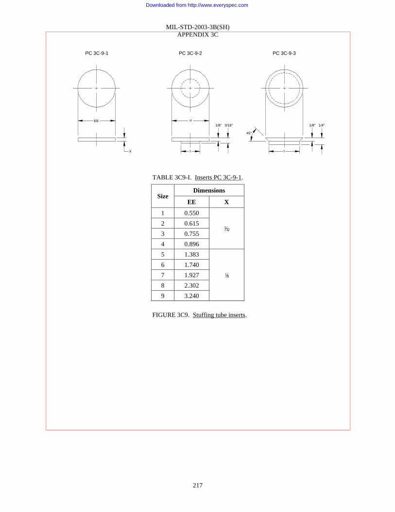
MIL-STD-2003-3B(SH)
APPENDIX 3C
217
TABLE 3C9-I. Inserts PC 3C-9-1.
Size Dimensions
EE X
1 0.550
3⁄32 2 0.615
3 0.755
4 0.896
5 1.383
1⁄8
6 1.740
7 1.927
8 2.302
9 3.240
FIGURE 3C9. Stuffing tube inserts.
PC 3C-9-1
EE
X
PC 3C-9-2
n
1/8"
PC 3C-9-3
t
3/16" 1/8"
t
1/4"
45°
Downloaded from http://www.everyspec.com

MIL-STD-2003-3B(SH)
APPENDIX 3C
218
TABLE 3C9-II. Inserts PCs 3C-9-2 and 3C-9-3.
Size Dimensions
n t
A ¾ ⅜
B ⅞ 15⁄32
C 1 19⁄32
D 1⅛ 23⁄32
E 1⅛ 25⁄32
F 13⁄16 13⁄16
G 1⅜ 29⁄32
J 1½ 11⁄32
K 1⅝ 1⅛
L 111⁄16 17⁄32
M 1⅞ 1⅜
N 115⁄16 115⁄32
P 21⁄16 119⁄32
R 23⁄16 123⁄32
S 29⁄16 127⁄32
T 2¾ 21⁄32
V 2⅞ 25⁄32
W 3 29⁄32
X 3⅛ 215⁄32
Y 3¼ 29⁄16
Z 37⁄16 2¾
AA 3⅝ 227⁄32
NOTES:
1. For method of sealing cable ends, see 4.1.6.
2. For cable assignment, see figure 3C3.
3. Insert PC 3C-9-1 used with nylon stuffing tubes, ASTM F1836M.
4. Insert PCs 3C-9-2 and 3C-9-3 used with steel stuffing tubes, MIL-S-24235, drawn and machined respectively.
5. Insert PCs 3C-9-1, 3C-9-2, and 3C-9-3 may be made of the following materials:
a. Polyamide (nylon) plastic, ASTM D4066 or ASTM D6779.
b. Laminated plastic, MIL-I-24768/1. The laminations shall be parallel to the faces of the insert.
c. Molded phenolic, Type MAJ-60, ASTM D5948.
d. Fiber, ASTM D710, grade “CH”, form “B” or “S”. The fiber shall be given a coat of insulating varnish
in accordance with NEMA RE 2.
FIGURE 3C9. Stuffing tube inserts – Continued.
Downloaded from http://www.everyspec.com

MIL-STD-2003-3B(SH)
APPENDIX 3C
219
Method 3C-10-1
Brazed Conduit Transition Fittings
NOTES:
1. This method covers using adapters and brazing to connect stuffing tubes, coaxial connectors, and connectors
with flexible conduit.
2. Adapter and transition body may be supplied separately or as a unit.
3. Due to tight braid construction, conduit should be formed into the approximate contour of the intended run
before conduit cutting and brazing of the final assembly. This will ensure the flexibility desired for
installation.
4. Prior to cutting the conduit, the wire braid should be lightly silver soldered at the place the cut will be made.
5. The conduit cut shall be square and shall be made with a high-speed knife-edge saw. The cut ends shall be
deburred with a file such that no sharp edges remain.
6. Conduit shall be cleaned by blowing out with air or nitrogen until the conduit is free of any moisture or
foreign particles.
7. For attaching adapters to stuffing tubes:
a. Place end fitting over flexible conduit and silver solder (braze) in place. When soldering, hold the end
fitting and flexible conduit vertically to prevent excess solder from running back onto the conduit and
introducing unwanted stiffness.
b. Slide the coupling nut, the tapered ferrule, and the transition body, in that order, over the end fitting and
onto the flexible conduit.
c. Complete the cable installation through the stuffing tube by normal procedure, except the stuffing tube
gland nut is to be replaced by the adapter.
d. Install the adapter onto the stuffing tube by the same procedure that would have been used for installing
the gland nut. Apply the same torque as would be required for torqueing the gland nut. Connect the
transition body to the adapter and tighten.
8. For attaching coaxial connectors or connectors in accordance with MIL-STD-2003-5:
a. Place end fitting over flexible conduit and silver solder (braze) in place. When soldering, hold the end
fitting and flexible conduit vertically to prevent excess solder from running back onto the conduit and
introducing unwanted stiffness.
b. Slide the coupling nut, the tapered ferrule, and the transition body, in that order, over the end fitting and
onto the flexible conduit.
c. Complete the cable installation to the connector by normal procedure, except the cable grip is to be
replaced by the adapter.
d. Install the adapter onto the connector plug by the same procedure that would have been used for
installing the cable grip. Connect the transition body to the adapter and tighten.
9. For conduit termination at equipment panels:
a. Slide the coupling nut, the tapered ferrule, and the transition body, in that order, over the flexible conduit.
b. Place panel fitting over flexible conduit and silver solder (braze) in place. When soldering, hold the
panel fitting and flexible conduit vertically to prevent excess solder from running back onto the conduit
and introducing unwanted stiffness.
c. Complete cable installation to panel termination by the normal manner. Place the threaded end of the
panel fitting into the panel. Install the lock nut and tighten.
FIGURE 3C10. Conduit transition fittings.
Downloaded from http://www.everyspec.com

Downloaded from http://www.everyspec.com

MIL-STD-2003-3B(SH)
APPENDIX 3C
221
Method 3C-10-2
Reusable Conduit Transition Fittings
NOTES:
1. Adapter and transition body may be supplied separately or as a unit.
2. Due to tight braid construction, conduit should be formed into the approximate contour of the intended run
before conduit cutting and brazing of the final assembly. This will ensure the flexibility desired for
installation.
3. Prior to cutting the conduit, the wire braid should be lightly silver soldered at the place the cut will be made.
4. The conduit cut shall be square and shall be made with a high-speed knife-edge saw. The cut ends shall be
deburred with a file such that no sharp edges remain.
5. Conduit shall be cleaned by blowing out with air or nitrogen until the conduit is free of any moisture or
foreign particles.
6. For attaching adapters to stuffing tubes:
a. Slide the coupling nut, the tapered ferrule, and the transition body, in that order, over the end fitting and
onto the flexible conduit.
b. Complete the cable installation through the stuffing tube by normal procedure, except the stuffing tube
gland nut is to be replaced by the adapter.
c. Install the adapter onto the stuffing tube by the same procedure that would have been used for installing
the gland nut. Apply the same torque as would be required for torqueing the gland nut. Connect the
transition body to the adapter and tighten.
7. For attaching coaxial connectors or connectors in accordance with MIL-STD-2003-5:
a. Slide the coupling nut, the tapered ferrule, and the transition body, in that order, over the end fitting and
onto the flexible conduit.
b. Complete the cable installation to the connector by normal procedure, except the cable grip is to be
replaced by the adapter.
c. Install the adapter onto the connector plug by the same procedure that would have been used for
installing the cable grip. Connect the transition body to the adapter and tighten.
8. For conduit termination at equipment panels:
a. Slide the coupling nut, the tapered ferrule, and the transition body, in that order, over the flexible conduit.
b. Complete cable installation to the panel termination by the normal manner. Place the threaded end of the
panel fitting into the panel. Install locknut and tighten.
9. Hold the transition body in one hand, pull back on the transition body, and pull back on the flexible conduit
until the back end of the end fitting extends approximately ½ inch beyond the male threaded end of the
transition body. Slide the tapered ferrule into place and tighten coupling nut into the transition body.
a. Tighten the coupling nut by hand until snug.
b. Using a strap wrench, continue to advance the coupling nut approximately ⅛ turn.
c. Check for tightness by pulling on the conduit.
d. If the coupling is not sufficiently tight to hold the conduit, loosen the coupling nut approximately ⅛ turn
past the point to which the coupling nut was previously tightened.
e. If necessary, repeat step 9.d, increasing in ⅓ turn increments until the conduit is sufficiently tightened.
FIGURE 3C10. Conduit transition fittings – Continued.
Downloaded from http://www.everyspec.com

Downloaded from http://www.everyspec.com

MIL-STD-2003-3B(SH)
APPENDIX 3D
223
APPENDIX 3D – PENETRATIONS – KICKPIPES
D.1 SCOPE
D.1.1 Scope. This appendix describes the installation standard methods for kickpipes. This Appendix is a
mandatory part of the standard. The information contained herein is intended for compliance.
D.2. APPLICABLE DOCUMENTS
D.2.1 General. The documents listed in this section are specified in in this appendix. This section does not
include documents cited in other sections of this standard or recommended for additional information or as
examples. While every effort has been made to ensure the completeness of this list, document users are cautioned
that they must meet all specified requirements of documents cited in this appendix, whether or not they are listed.
D.2.2 Government documents.
D.2.2.1 Specifications, standards, and handbooks. The following specifications, standards, and handbooks
form a part of this document to the extent specified herein. Unless otherwise specified, the issues of these
documents are those cited in the solicitation or contract.
DEPARTMENT OF DEFENSE SPECIFICATIONS
MIL-S-24235 - Stuffing Tubes, Metal, and Packing Assemblies for Electric Cables, General
Specification for
MIL-S-24235/9 - Stuffing Tubes, Metal, and Packing Assemblies for Electric Cables, Brass and
Steel, for Decks and Bulkheads with Pipe Protection
MIL-S-24235/18 - Stuffing Tubes, Metal, and Packing Assemblies for Electric Cables, Swage
Type, Reduced Diameter, Steel and Aluminum, for Deck and Bulkheads with
Pipe Protection
DEPARTMENT OF DEFENSE STANDARDS
MIL-STD-2003-4 - Electric Plant Installation Standard Methods for Surface Ships and Submarines
(Cableways)
(Copies of these documents are available online at https://quicksearch.dla.mil.)
D.2.3 Non-Government publications. The following documents form a part of this document to the extent
specified herein. Unless otherwise specified, the issues of these documents are those cited in the solicitation or
contract.
ASTM INTERNATIONAL
ASTM F1836M - Standard Specification for Stuffing Tubes, Nylon, and Packing Assemblies
(Metric)
(Copies of this document are available online at www.astm.org.)
SAE INTERNATIONAL
SAE-AMS-WW-T-700/6 - Tube, Aluminum Alloy, Drawn, Seamless, 6061
(Copies of this document are available online at www.sae.org.)
D.2.4 Order of precedence. Unless otherwise noted herein or in the contract, in the event of a conflict between
the text of this document and the references cited herein, the text of this document takes precedence. Nothing in this
document, however, supersedes applicable laws and regulations unless a specific exemption has been obtained.
Downloaded from http://www.everyspec.com

MIL-STD-2003-3B(SH)
APPENDIX 3D
224
D.3 REQUIRED EQUIPMENT AND MATERIALS
D.3.1 Required equipment and materials. The required equipment and materials for the proper installation of
kickpipes are as shown in the Appendix D methods.
D.4 NOTES AND PROCEDURES
D.4.1 Dimensions. For figures and tables in this appendix, all dimensions are in inches unless otherwise noted.
D.4.2 Figures. Table 3DI provides information for the figures in this appendix.
TABLE 3DI. Figures for kickpipes.
Figure
number Installation of kickpipes Page
3D1 Kickpipes through steel or aluminum decks (surface ships) 225
3D2 Kickpipes through steel or aluminum decks (surface ships) 226
3D3 Kickpipes through steel or aluminum decks (surface ships) 227
3D4 Kickpipes through non-watertight decks (surface ships) 228
3D5 Kickpipes through ballistic plating (surface ships) 229
3D6 Kickpipes through ballistic plating (surface ships) 231
3D7 Kickpipes through wooden decks 232
3D8 Kickpipes with unions (surface ships) 234
Downloaded from http://www.everyspec.com

Downloaded from http://www.everyspec.com

Downloaded from http://www.everyspec.com

Downloaded from http://www.everyspec.com

Downloaded from http://www.everyspec.com

Downloaded from http://www.everyspec.com

MIL-STD-2003-3B(SH)
APPENDIX 3D
230
NOTES:
1. See figure 3A1 for gland nut tightening methods.
2. See 4.8 for thread lubrication guidance.
FIGURE 3D5. Kickpipes through ballistic plating (surface ships) – Continued.
Downloaded from http://www.everyspec.com

Downloaded from http://www.everyspec.com

MIL-STD-2003-3B(SH)
APPENDIX 3D
232
NY
LO
N S
TU
FF
ING
TU
BE
(SE
E N
OT
E 2
)
CA
BLE
ALU
MIN
UM
TU
BIN
G. I.P
.S.
EX
TR
A S
TR
ON
G. S
IZE
AS
RE
QU
IRE
D.
SA
E-A
MS
-WW
-T-7
00/6
,
CO
ND
. O
.
(SE
E N
OT
E 2
)
LO
CK
NU
TS
AS
SU
PP
LIE
D
WIT
H S
TU
FF
ING
TU
BE
MA
Y B
E P
LA
ST
IC C
OLLA
R,
UN
TH
RE
AD
ED
, C
EM
EN
TE
D
TO
PIP
E.
MA
TE
RIA
L T
O B
E
SA
ME
AS
PIP
E.
GA
SK
ET
AS
SU
PP
LIE
D
WIT
H S
TU
FF
ING
TU
BE
.
PLA
ST
IC S
EA
LE
R M
AY
BE
US
ED
AS
ALT
ER
NA
TE
(SE
E 4
.1.6
)
LO
CK
NU
T M
AY
BE
PLA
ST
IC
OR
NY
LO
N
BU
LK
HE
AD
DE
CK
- W
.T.
9±1/8
"
ME
TH
OD
3D
-7-1
FO
R P
AS
SIN
G S
ING
LE
CA
BLE
S
TH
RO
UG
H W
.T. W
OO
D D
EC
KS
US
E S
TR
AIG
HT
KIC
KP
IPE
TO
CLE
AR
AN
OB
ST
RU
CT
ION
OR
PR
ES
ER
VE
ALIG
NM
EN
T O
F C
AB
LE
RU
N
ME
TH
OD
3D
-7-2
FO
R P
AS
SIN
G S
ING
LE
CA
BLE
S
TH
RO
UG
H W
.T. W
OO
D D
EC
KS
US
E B
EN
T K
ICK
PIP
E T
O C
ON
SE
RV
E S
PA
CE
AN
D A
LL
OW
SE
CU
RIN
G O
F C
AB
LE
DIR
EC
T T
O B
ULK
HE
AD
CA
BLE
9±1/8
"GA
SK
ET
(R
UB
BE
R)-
GA
SK
ET
MA
Y B
E
OM
ITT
ED
ON
NW
T
BU
LK
HE
AD
S
1/4
-20
UN
C"
HE
X H
EA
D C
AP
SC
RE
W W
ITH
NU
T -
LE
NG
TH
AS
RE
QU
IRE
D (
SE
E N
OT
E 1
)
3/4
" X
3/3
2"
BA
CK
ING
PLA
TE
NY
LO
N S
TU
FF
ING
TU
BE
AS
TM
F18
36
M T
YP
E N
PT
(SE
E N
OT
E 2
)
SE
E N
OT
E 3
3/4
" X
3/3
2"
ALU
MIN
UM
BR
AC
E (
OP
TIO
NA
L)
ALU
MIN
UM
TU
BIN
G. I.P
.S.
EX
TR
A S
TR
ON
G. S
IZE
AS
RE
QU
IRE
D.
SA
E-A
MS
-WW
-T-7
00/6
,
CO
ND
. O
.
(SE
E N
OT
E 2
)
AN
GLE
TO
SU
IT
INS
TA
LLA
TIO
N
LO
CK
NU
TS
AS
TM
F1836M
AS
SU
PP
LIE
D W
ITH
ST
UF
FIN
G
TU
BE
MA
Y B
E P
LA
ST
IC C
OLLA
R,
UN
TH
RE
AD
ED
, C
EM
EN
TE
D
TO
PIP
E.
MA
TE
RIA
L T
O B
E
SA
ME
AS
PIP
E.
BU
LK
HE
AD
W.T
.
1/4
-20U
NC
HE
X
HE
AD
CA
P S
CR
EW
WIT
H N
UT
GA
SK
ET
AS
SU
PP
LIE
D
WIT
H S
TU
FF
ING
TU
BE
.
PLA
ST
IC S
EA
LE
R M
AY
BE
US
ED
AS
ALT
ER
NA
TE
(S
EE
4.1
.6)
LO
CK
NU
T M
AY
BE
PLA
ST
IC
OR
NY
LO
N
FIGURE 3D7. Kickpipes through wooden decks.
Downloaded from http://www.everyspec.com

MIL-STD-2003-3B(SH)
APPENDIX 3D
233
NOTES:
1. Lag or wood screws (CRES) not less than 1 inch long may be used in lieu of hex head cap screws on
bulkheads over 1 inch thick.
2. Plastic pipe fittings and stuffing tube may be used in lieu of aluminum shown. Stuffing tube should be nylon,
ASTM F1836M, NPT type, sized to fit.
3. For suitable cable support, see MIL-STD-2003-4.
4. See figure 3A1 for gland nut tightening methods.
5. See 4.8 for thread lubrication guidance.
6. See 4.5 for fastener and fastener material requirements.
FIGURE 3D7. Kickpipes through wooden decks – Continued.
Downloaded from http://www.everyspec.com

Downloaded from http://www.everyspec.com

MIL-STD-2003-3B(SH)
APPENDIX 3E
235
APPENDIX 3E – PENETRATIONS – PRESSURE HULLS, SUBMARINES
E.1 SCOPE
E.1.1 Scope. This appendix describes the installation standard methods for penetration through pressure hulls
of submarines. This Appendix is a mandatory part of the standard. The information contained herein is intended for
compliance.
E.2. APPLICABLE DOCUMENTS
E.2.1 General. The documents listed in this section are specified in this appendix. This section does not
include documents cited in other sections of this standard or recommended for additional information or as
examples. While every effort has been made to ensure the completeness of this list, document users are cautioned
that they must meet all specified requirements of documents cited in this appendix, whether or not they are listed.
E.2.2 Government documents.
E.2.2.1 Specifications, standards, and handbooks. The following specifications, standards, and handbooks
form a part of this document to the extent specified herein. Unless otherwise specified, the issues of these
documents are those cited in the solicitation or contract.
FEDERAL SPECIFICATIONS
QQ-N-281 - Nickel-Copper Alloy Bar, Rod, Plate, Sheet, Strip, Wire, Forgings, and Structural and
Special Shaped Sections
COMMERCIAL ITEM DESCRIPTIONS
A-A-59588 - Rubber, Silicone
DEPARTMENT OF DEFENSE SPECIFICATIONS
MIL-DTL-915 - Cable, Electrical, for Shipboard Use, General Specification for
MIL-DTL-24231 - Connectors, Plugs, Receptacles, Adapters, Hull Inserts, and Hull Insert
Plugs, Pressure-Proof, General Specification for
MIL-DTL-24231/1 - Connector, Plug, Type I, Molded, Three-, Four-, and Five-Conductor
MIL-DTL-24231/3 - Connector, Plug, Type I, Molded, Seven- and Nine-Conductor (Straight and
90 Degrees)
MIL-DTL-24231/4 - Connector, Plug, Type I, Molded, 14-, 24-, 30-, or 40-Conductor (Straight
and 90 Degrees)
MIL-DTL-24231/18 - Connector, Plug, Type I, Molded, 65-Conductor
MIL-S-24235/16 - Stuffing Tubes, Metal, and Packing Assemblies for Electric Cables, Cable
Shearing Valve, Hull, Pressureproof, Symbols 512, 512.1, 513, and 513.1
(Copies of these documents are available online at https://quicksearch.dla.mil.)
Downloaded from http://www.everyspec.com

MIL-STD-2003-3B(SH)
APPENDIX 3E
236
E.2.2.2 Other Government documents, drawings, and publications. The following other Government
documents, drawings, and publications form a part of this document to the extent specified herein. Unless otherwise
specified, the issues of these documents are those cited in the solicitation or contract.
NAVAL SEA SYSTEMS COMMAND (NAVSEA) DRAWINGS
803-1197218 - Hull Fitting for AN/BQQ-1, Sonar, Sym No. 538
815-1197212 - Electrode - 4000 SBM, Plug In Type Symbols 3012 & 3012-1
(Copies of these documents are available from the applicable repositories listed in S0005-AE-PRO-010/EDM,
which can be obtained online via Technical Data Management Information System (TDMIS) at
https://mercury.tdmis navy mil/. Copies of these documents may also be obtained from the Naval Ships Engineering
Drawing Repository (NSEDR) online at https://199.208.213.105/webjedmics/index.jsp. To request an NSEDR
account for drawing access, send an email to NNSY JEDMICS NSEDR HELP DESK@navy mil.)
NAVAL SEA SYSTEMS COMMAND (NAVSEA) PUBLICATIONS
T9074-AD-GIB-010/1688 - Requirements for Fabrication, Welding, and Inspection of Submarine
Structure
(Copies of this document are available online via Technical Data Management Information System (TDMIS) at
https://mercury.tdmis navy mil/ by searching for the document number without the suffix. Refer questions,
inquiries, or problems to: DSN 296-0669, Commercial (805) 228-0669. This document is available for ordering
(hard copy) via the Naval Logistics Library (NLL) at https://nll.navsup.navy mil. For questions regarding the NLL,
contact the NLL Customer Service at [email protected], (866) 817-3130, or (215) 697-2626/DSN 442-2626.)
E.2.3 Non-Government publications. The following documents form a part of this document to the extent
specified herein. Unless otherwise specified, the issues of these documents are those cited in the solicitation or
contract.
ASTM INTERNATIONAL
ASTM F468 - Standard Specification for Nonferrous Bolts, Hex Cap Screws, Socket Head Cap
Screws, and Studs for General Use
(Copies of this document are available online at www.astm.org.)
SAE INTERNATIONAL
SAE-AMS-G-4343 - Grease, Pneumatic System
SAE-AS568 - Aerospace Size Standard for O-Rings
SAE-AS8660 - Silicone Compound NATO Code Number S-736
SAE-AS23053/5 - Insulation Sleeving, Electrical, Heat Shrinkable, Polyolefin, Flexible
Crosslinked
SAE-AS23053/18 - Insulation Sleeving, Electrical, Heat Shrinkable, Modified Fluoropolymer,
Crosslinked
(Copies of these documents are available online at www.sae.org.)
E.2.4 Order of precedence. Unless otherwise noted herein or in the contract, in the event of a conflict between
the text of this document and the references cited herein, the text of this document takes precedence. Nothing in this
document, however, supersedes applicable laws and regulations unless a specific exemption has been obtained.
E.3 REQUIRED EQUIPMENT AND MATERIALS
E.3.1 Required equipment and materials. The required equipment and materials for the proper installation of
penetrations through pressure hulls of submarines are as shown in the Appendix E methods.
Downloaded from http://www.everyspec.com

MIL-STD-2003-3B(SH)
APPENDIX 3E
237
E.4 NOTES AND PROCEDURES
E.4.1 Dimensions. For figures and tables in this appendix, all dimensions are in inches unless otherwise noted.
E.4.2 Figures. Table 3EI provides information for the figures in this appendix.
TABLE 3EI. Figures for penetrations of submarine pressure hulls.
Figure
number Submarine pressure hull penetrations Page
3E1 Cable connections through pressure hulls of submarines 238
3E2 Sealing plugs for hull inserts on submarines 239
3E3 Passing cable through pressure hull of submarines using cable shearing valve 240
3E4 Hull fitting installation for sonar sphere 242
3E5 Mounting pressure-proof electrodes on submarines 244
3E6 Temporary sealing and securing pressure-proof molded plug assemblies 245
Downloaded from http://www.everyspec.com

Downloaded from http://www.everyspec.com

Downloaded from http://www.everyspec.com
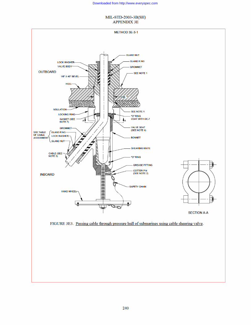
Downloaded from http://www.everyspec.com

MIL-STD-2003-3B(SH)
APPENDIX 3E
241
TABLE 3E3-I. Cable assignment.
Symbol no. Cable OD Grommet
PC no.
Gland ring
PC no. Dim “X”
512
0.475 46 59
2.062 0.510
47 60 0.520
0.545 48 61
512.1
0.627 49 62
2.062 0.632
0.720 50 63
0.750 51 64
513
0.795 52 65
2.562
0.805
0.830 53 66
0.844
0.870 54 67
513.1
0.995 55 68
2.562
1.020 56 69
1.115 57 70
1.120
1.150 58 71
1.156
NOTES:
1. Welding shall comply with T9074-AD-GIB-010/1688.
2. Before assembly, drill hole for cotter pin with valve in full open position. Pin shall be easily removed. Bend
only enough to prevent falling out.
3. The cable shearing valves are designed for cables in accordance with MIL-DTL-915, MIL-DTL-24643, and
MIL-DTL-24640.
4. If valve seat becomes damaged, it can be reversed and reinstalled with a new valve seat gasket. Removal of
valve seat is accomplished by use of a ⅞-12 stud for symbol no. 512 or a 1⅜-12 stud for symbol no. 513.
5. Terminate inboard cable in a junction box, which will be located in the vicinity of the shear valve.
6. For specifications, see MIL-S-24235/16.
7. Cement gasket to valve seat and body.
8. See 4.7 for installations and servicing within the SUBSAFE boundary.
FIGURE 3E3. Passing cable through pressure hull of submarines using cable shearing valve – Continued.
Downloaded from http://www.everyspec.com

Downloaded from http://www.everyspec.com

MIL-STD-2003-3B(SH)
APPENDIX 3E
243
NOTES (continued):
3. Hull insert material shall be Ni-CU Monel, QQ-N-281, class A, hot rolled. Dimensions shown are applicable
after welding in sonar sphere and after machining to accept PCs 1, 3, and 9 of Drawing 803-1197218. Outer
diameter shall be such as to provide adequate compensation. Hull inserts are to be furnished by the
shipbuilder.
4. Cable marker shall consist of heat shrinkable tubing-white in accordance with SAE-AS23053/5, class 1, with
cable designation stamped as required and then covered by a clear heat shrinkable tubing in accordance with
SAE-AS23053/18. This method may be used as an alternate to the standard method of marking sonar cables.
5. See the ship drawings for configuration.
6. See 4.7 for installations and servicing within the SUBSAFE boundary.
FIGURE 3E4. Hull fitting installation for sonar sphere – Continued.
Downloaded from http://www.everyspec.com

Downloaded from http://www.everyspec.com

Downloaded from http://www.everyspec.com

MIL-STD-2003-3B(SH)
APPENDIX 3E
246
NOTES:
1. Typical methods shown hereon are for information and guidance to installing activities for sealing and/or
securing of pressure-proof pin type molded connectors that have been temporarily disconnected from their
associated receptacle.
2. Temporary sealing of pin connector hull fittings or receptacles are shown on figures 3E1 and 3E2.
3. Cables shall be properly secured or protected to prevent damage from chafing, weld splatter, and/or other
hazards.
4. See 4.7 for installations and servicing within the SUBSAFE boundary.
5. See 4.5 for fastener and fastener material requirements.
FIGURE 3E6. Temporary sealing and securing pressure-proof molded plug assemblies – Continued.
Downloaded from http://www.everyspec.com

MIL-STD-2003-3B(SH)
247
CONCLUDING MATERIAL
Preparing activity:
Navy – SH
(Project SESS-2015-029)
NOTE: The activities listed above were interested in this document as of the date of this document. Since
organizations and responsibilities can change, you should verify the currency of the information above using the
ASSIST Online database at https://assist.dla.mil.
Downloaded from http://www.everyspec.com