DENT2022 Course Summary - StudentVIP
14
1 DENT2022 Course Summary MODULE 0 PREVENTIVE DENTISTRY (Prof. Lawrence Walsh) 2 (BLOCK TEACHING WEEK) MODULE I CARIOLOGY (Dr Sowmya Shetty) 6 MODULE II RADIOLOGY (Various) 26 MODULE III TOOTH PREPARATION (Dr Sowmya Shetty) 63 MODULE IV DEEP CARIOUS LESIONS (Various) 75 MODULE V COMPOSITE RESIN (Dr Sowmya Shetty) 79 MODULE VI MISCELLANEOUS TOPICS (Various) 89 Produced by cyrion TM . © 2015. All rights reserved.
-
Upload
khangminh22 -
Category
Documents
-
view
3 -
download
0
Transcript of DENT2022 Course Summary - StudentVIP

1
DENT2022 Course Summary
MODULE 0 PREVENTIVE DENTISTRY (Prof. Lawrence Walsh) 2 (BLOCK TEACHING WEEK)
MODULE I CARIOLOGY (Dr Sowmya Shetty) 6
MODULE II RADIOLOGY (Various) 26
MODULE III TOOTH PREPARATION (Dr Sowmya Shetty) 63
MODULE IV DEEP CARIOUS LESIONS (Various) 75
MODULE V COMPOSITE RESIN (Dr Sowmya Shetty) 79
MODULE VI MISCELLANEOUS TOPICS (Various) 89
Produced by cyrionTM. © 2015. All rights reserved.
2
Module 0 – Preventive Dentistry
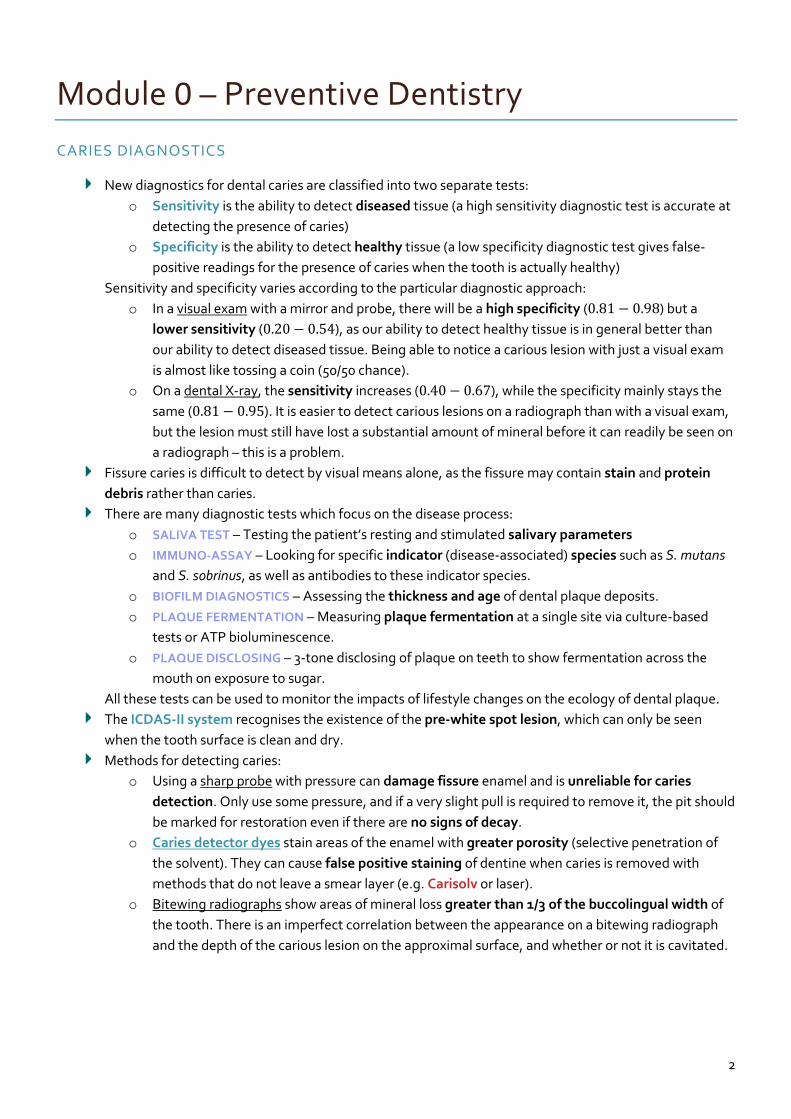
CARIES DIAGNOSTICS
New diagnostics for dental caries are classified into two separate tests:
o Sensitivity is the ability to detect diseased tissue (a high sensitivity diagnostic test is accurate at
detecting the presence of caries)
o Specificity is the ability to detect healthy tissue (a low specificity diagnostic test gives false-
positive readings for the presence of caries when the tooth is actually healthy)
Sensitivity and specificity varies according to the particular diagnostic approach:
o In a visual exam with a mirror and probe, there will be a high specificity (0.81 − 0.98) but a
lower sensitivity (0.20 − 0.54), as our ability to detect healthy tissue is in general better than
our ability to detect diseased tissue. Being able to notice a carious lesion with just a visual exam
is almost like tossing a coin (50/50 chance).
o On a dental X-ray, the sensitivity increases (0.40 − 0.67), while the specificity mainly stays the
same (0.81 − 0.95). It is easier to detect carious lesions on a radiograph than with a visual exam,
but the lesion must still have lost a substantial amount of mineral before it can readily be seen on
a radiograph – this is a problem.
Fissure caries is difficult to detect by visual means alone, as the fissure may contain stain and protein
debris rather than caries.
There are many diagnostic tests which focus on the disease process:
o SALIVA TEST – Testing the patient’s resting and stimulated salivary parameters
o IMMUNO-ASSAY – Looking for specific indicator (disease-associated) species such as S. mutans
and S. sobrinus, as well as antibodies to these indicator species.
o BIOFILM DIAGNOSTICS – Assessing the thickness and age of dental plaque deposits.
o PLAQUE FERMENTATION – Measuring plaque fermentation at a single site via culture-based
tests or ATP bioluminescence.
o PLAQUE DISCLOSING – 3-tone disclosing of plaque on teeth to show fermentation across the
mouth on exposure to sugar.
All these tests can be used to monitor the impacts of lifestyle changes on the ecology of dental plaque.
The ICDAS-II system recognises the existence of the pre-white spot lesion, which can only be seen
when the tooth surface is clean and dry.
Methods for detecting caries:
o Using a sharp probe with pressure can damage fissure enamel and is unreliable for caries
detection. Only use some pressure, and if a very slight pull is required to remove it, the pit should
be marked for restoration even if there are no signs of decay.
o Caries detector dyes stain areas of the enamel with greater porosity (selective penetration of
the solvent). They can cause false positive staining of dentine when caries is removed with
methods that do not leave a smear layer (e.g. Carisolv or laser).
o Bitewing radiographs show areas of mineral loss greater than 1/3 of the buccolingual width of
the tooth. There is an imperfect correlation between the appearance on a bitewing radiograph
and the depth of the carious lesion on the approximal surface, and whether or not it is cavitated.
3
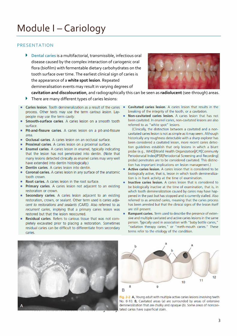
Module I – Cariology
PRESENTATION
Dental caries is a multifactorial, transmissible, infectious oral
disease caused by the complex interaction of cariogenic oral
flora (biofilm) with fermentable dietary carbohydrates on the
tooth surface over time. The earliest clinical sign of caries is
the appearance of a white spot lesion. Repeated
demineralisation events may result in varying degrees of
cavitation and discolouration, and radiographically this can be seen as radiolucent (see-through) areas.
There are many different types of caries lesions:
Tooth habitats favourable for harbouring cariogenic biofilm include:
4
1. Pits and fissures – these are particularly susceptible areas for caries initiation, as they provide
excellent mechanical shelter for microorganisms.
2. Smooth enamel surfaces immediately gingival to proximal contacts, and in the gingival third of
the facial and lingual surfaces of the crown – these areas are relatively protected from the effects
of mastication, tongue movement and salivary flow.
3. Root surfaces (particularly near the cervical line) – these areas are unaffected by flossing
because it may have concave surface contours and occasional roughness.
4. Subgingival areas – these areas are usually neglected in oral hygiene procedures.
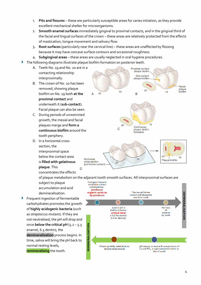
The following diagrams illustrate plaque biofilm formation on posterior teeth.
A. Teeth No. 19 and No. 20 are in a
contacting relationship
interproximally.
B. The crown of No. 20 has been
removed, showing plaque
biofilm on No. 19 both at the
proximal contact and
underneath it (sub-contact).
Facial plaque can also be seen.
C. During periods of unrestricted
growth, the mesial and facial
plaques merge and form a
continuous biofilm around the
tooth periphery.
D. In a horizontal cross-
section, the
interproximal space
below the contact area
is filled with gelatinous
plaque. This
concentrates the effects
of plaque metabolism on the adjacent tooth smooth surfaces. All interproximal surfaces are
subject to plaque
accumulation and acid
demineralisation.
Frequent ingestion of fermentable
carbohydrates promotes the growth
of highly acidogenic bacteria (such
as streptoccus mutans). If they are
not neutralised, the pH will drop and
once below the critical pH (5.2 – 5.5
enamel, 6.5 dentin), the
demineralisation process begins. In
time, saliva will bring the pH back to
normal resting levels,
remineralising the tooth.
5
DIAGNOSIS
There are many methods available to diagnose caries:
o VISUAL-TACTILE – The traditional, most-used method is the visual-tactile method – this entails
simply looking for visual changes in the tooth surface texture/colour, or detecting surface
roughness with a dental explorer/probe. Good lighting and a clean, dry tooth surface is
required. However, the probe MUST NOT BE USED TO DETERMINE A ‘STICK’ (a resistance to
withdrawal from a fissure or pit), as this irreversibly turns a sound, remineralisable surface into a
possible cavitation prone to progression. Instead, a blunt probe should be judiciously used by
gently stroking across the tooth surface.
o RADIOGRAPHS – Smooth-surface caries in proximal regions are usually diagnosed
radiographically. Bitewing radiographs can show mineral loss greater than 1 3⁄ of the
buccolingual width of the tooth, or 2 3⁄ – 3 4⁄ of the enamel thickness. By this stage, the tooth
requires operative treatment/restoration.
o DIGITAL FIBRE OPTICAL TRANSILLUMINATION (FOTI) – Fibre Optic Transillumination (FOTI)
works on the principle of light scattering forward to create a dark area where there is caries
present or a crack in the tooth. FOTI is a useful adjunct to the diagnosis of approximal lesions.
o LASER FLUORESCENCE (DIAGNODENT) – Laser fluorescence technology can be used to detect
and measure bacterial products and changes in the tooth structure. Positive fluorescence occurs
when light is given off by carious tissue. This principle is used by DiagnoDENT.
o ELECTRONIC CARIES DETECTION – When a carious lesion is present, the porosity increases, and
this changes the way that alternating electrical current flows across the tooth. A device called
the CarieScan can measure this change in the flow of current through a tooth.
o OPTICAL COHERENCE TOMOGRAPHY (OCT) – Optical coherence tomography (OCT) provides
high resolution three-dimensional data sets using non-ionising infrared laser radiation, which
could in future replace some applications of conventional dental X-rays.
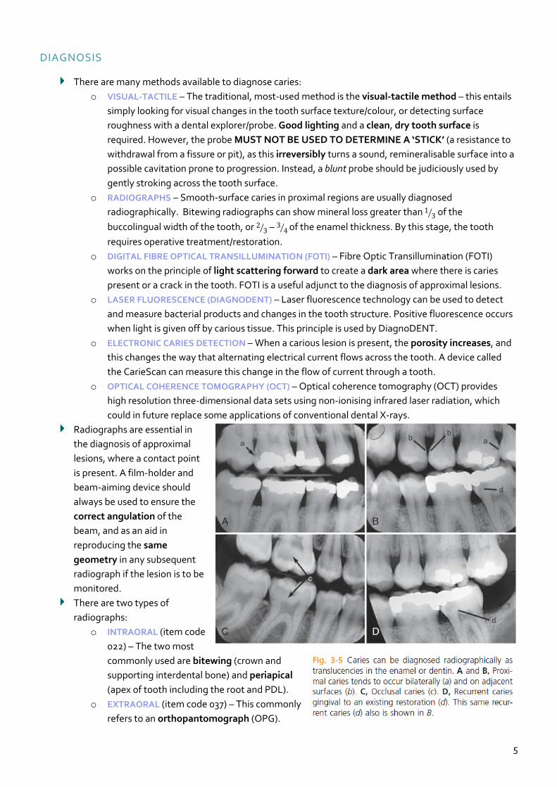
Radiographs are essential in
the diagnosis of approximal
lesions, where a contact point
is present. A film-holder and
beam-aiming device should
always be used to ensure the
correct angulation of the
beam, and as an aid in
reproducing the same
geometry in any subsequent
radiograph if the lesion is to be
monitored.
There are two types of
radiographs:
o INTRAORAL (item code
022) – The two most
commonly used are bitewing (crown and
supporting interdental bone) and periapical
(apex of tooth including the root and PDL).
o EXTRAORAL (item code 037) – This commonly
refers to an orthopantomograph (OPG).
6
Module II – Radiology
RADIATION PHYSICS
X-rays are invisible, have high energy and short wavelengths. They have no mass or charge, as they
are composed of photons. All X-rays travel in a straight line at the speed of light, but they also diverge
from their point of origin. They can either penetrate matter, or be absorbed by it to varying degrees
(depending on the density). X-rays can also cause some substances to fluoresce, and affect photographic
film. Most importantly, X-rays can cause BIOLOGICAL DAMAGE.
An X-ray is a form of high energy electromagnetic (EM) radiation (the movement of energy through
space as a combination of electrical and magnetic fields). Some properties are best described by
quantum physics, whereas others by wave theory:
o QUANTUM THEORY – Quantum physics considers EM radiation as small bundles (quanta) of
energy called photons. Each photon travels at the speed of light and contains a specific amount
of energy. The unit of photon energy is the electron volt (eV) – this is the amount of energy
acquired by one electron accelerating through a potential difference of one volt. Photon energy
and wavelength are related by the following equation:
𝐸 = ℎ ×𝑐
𝜆 where
𝐸 = energy in keV, ℎ = Planck′s constant (4.3 × 10⁻¹⁸ keV)
𝑐 = speed of light, 𝜆 = wavelength in nanometres (nm)
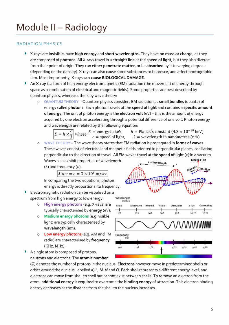
o WAVE THEORY – The wave theory states that EM radiation is propagated in forms of waves.
These waves consist of electrical and magnetic fields oriented in perpendicular planes, oscillating
perpendicular to the direction of travel. All EM waves travel at the speed of light (𝑐) in a vacuum.
Waves also exhibit properties of wavelength
(𝜆) and frequency (𝑣).
𝜆 × 𝑣 = 𝑐 = 3 × 10⁸ m/sec
In comparing the two equations, photon
energy is directly proportional to frequency.
Electromagnetic radiation can be visualised on a
spectrum from high energy to low energy:
o High energy photons (e.g. X-rays) are
typically characterised by energy (eV).
o Medium energy photons (e.g. visible
light) are typically characterised by
wavelength (nm).
o Low energy photons (e.g. AM and FM
radio) are characterised by frequency
(KHz, MHz).
A single atom is composed of protons,
neutrons and electrons. The atomic number
(𝑍) denotes the number of protons in the nucleus. Electrons however move in predetermined shells or
orbits around the nucleus, labelled K, L, M, N and O. Each shell represents a different energy level, and
electrons can move from shell to shell but cannot exist between shells. To remove an electron from the
atom, additional energy is required to overcome the binding energy of attraction. This electron binding
energy decreases as the distance from the shell to the nucleus increases.
7
The binding energy refers to the energy required to completely remove an electron from an atom. If a
free, unbound electron is assumed to have a total energy of zero, the total energy of a bound electron is
zero minus its binding energy.
o EXAMPLE: A K shell electron of
tungsten (𝑍 = 74) (−69,500 eV) is
much more tightly bound than the
K shell electron of hydrogen (𝑍 = 1)
(−13.5 eV), because the energies
increase with 𝑍 (atomic number) and
decrease with distance from the
nucleus.
o The energy required to move an
electron from the innermost
electron orbit (K shell) to the next orbit (L shell) is the difference between the binding energies
of the two orbits.
In a neutral atom, the number of orbiting electrons in shells equals the number of protons in the nucleus.
o If an electron is removed, the atom becomes positively charged (ionised).
o If an electron is displaced from an inner to an outer shell, the atom remains neutral, but is in a
state of excitation.
PRODUCTION OF X-RAYS
X-rays are wave packets (photons) of energy of EM radiation that originate at an atomic level. They are
produced when highly energetic electrons interact with matter, and convert their kinetic energy into
EM radiation. An X-ray beam is made up of millions of photons of different energies.
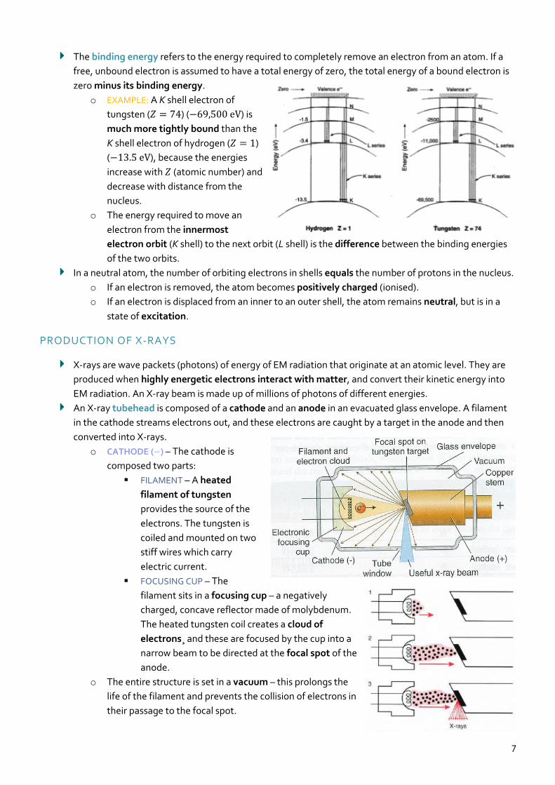
An X-ray tubehead is composed of a cathode and an anode in an evacuated glass envelope. A filament
in the cathode streams electrons out, and these electrons are caught by a target in the anode and then
converted into X-rays.
o CATHODE (−) – The cathode is
composed two parts:
FILAMENT – A heated
filament of tungsten
provides the source of the
electrons. The tungsten is
coiled and mounted on two
stiff wires which carry
electric current.
FOCUSING CUP – The
filament sits in a focusing cup – a negatively
charged, concave reflector made of molybdenum.
The heated tungsten coil creates a cloud of
electrons¸ and these are focused by the cup into a
narrow beam to be directed at the focal spot of the
anode.
o The entire structure is set in a vacuum – this prolongs the
life of the filament and prevents the collision of electrons in
their passage to the focal spot.
8
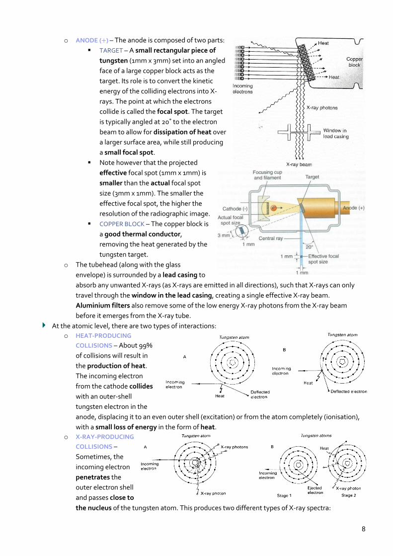
o ANODE (+) – The anode is composed of two parts:
TARGET – A small rectangular piece of
tungsten (1mm x 3mm) set into an angled
face of a large copper block acts as the
target. Its role is to convert the kinetic
energy of the colliding electrons into X-
rays. The point at which the electrons
collide is called the focal spot. The target
is typically angled at 20˚ to the electron
beam to allow for dissipation of heat over
a larger surface area, while still producing
a small focal spot.
Note however that the projected
effective focal spot (1mm x 1mm) is
smaller than the actual focal spot
size (3mm x 1mm). The smaller the
effective focal spot, the higher the
resolution of the radiographic image.
COPPER BLOCK – The copper block is
a good thermal conductor,
removing the heat generated by the
tungsten target.
o The tubehead (along with the glass
envelope) is surrounded by a lead casing to
absorb any unwanted X-rays (as X-rays are emitted in all directions), such that X-rays can only
travel through the window in the lead casing, creating a single effective X-ray beam.
Aluminium filters also remove some of the low energy X-ray photons from the X-ray beam
before it emerges from the X-ray tube.
At the atomic level, there are two types of interactions:
o HEAT-PRODUCING
COLLISIONS – About 99%
of collisions will result in
the production of heat.
The incoming electron
from the cathode collides
with an outer-shell
tungsten electron in the
anode, displacing it to an even outer shell (excitation) or from the atom completely (ionisation),
with a small loss of energy in the form of heat.
o X-RAY-PRODUCING
COLLISIONS –
Sometimes, the
incoming electron
penetrates the
outer electron shell
and passes close to
the nucleus of the tungsten atom. This produces two different types of X-ray spectra:

9
X-RAY FILMS
An intraoral dental film is a direct
exposure film that is sensitive to X-ray
photons, while extraoral films are only
sensitive to light photons, and so require
an intensifying screen which converts X-
ray photons into visible light. Each film
packet is wrapped in an outer
packet/wrapper that is moisture and
light-proof. Inside the packet is a sheet of
lead foil and a black, light-proof interleaf
paper wrapper that is folded around the
actual film.
Structure of an intraoral film:
o The plastic film base is made of clear transparent
cellulose acetate which acts only to support the
emulsion.
o A thin layer of adhesive affixes the base to the emulsion.
o The base is sandwiched on both sides by the
film emulsion – this is composed of silver
halide (usually silver bromide) crystals
embedded in a gelatin matrix. The X-ray
photons sensitise the silver halide crystals
that they strike, and these sensitised crystals
are later reduced to visible black metallic
silver in the developer.
o A protective layer of gelatin shields the emulsion from mechanical damage.
Within the film emulsion, as well as Ag-Br crystals, there are also free Ag+ ions in the crystal lattice, and trace amounts of sulfur at the sensitivity site.
Exposing the Ag-Br crystals to X-ray photons results in the release of electrons (recoil electrons) from Br atoms, and these electrons move to the sensitivity site to give it a negative charge.
The free Ag+ ions are also attracted to the sensitivity site, neutralising the negative charge and forming neutral Ag atoms.
The sensitivity site now becomes the latent image site as the neutral Ag atoms hold a latent image. The collection of these latent image sites in crystals across the entire film eventually forms the final radiographic image.
10
Module III – Tooth Preparation and Restoration
CLASS II PREPARATION
When is a restoration needed?
o For aiding plaque control on occlusal, approximal, free smooth enamel and root surfaces.
o Sensitivity to hot, cold and sweet
o Danger to the pulp
o Progression of the lesion (previous attempts to control through various preservative techniques
has not worked)
o Impaired function
o Drifting is likely due to loss of contact point (maybe fracture)
o The carious lesion is a visual eyesore (i.e. aesthetics)
An amalgam restoration is successful and lasts for years if:
o Tooth preparation is correct
o Matrix is suitable (and a correctly fitting wedge is used)
o The operating field is isolated properly using a rubber dam
o The restorative material is manipulated properly.
Initial clinical procedures:
1. Local anaesthetic is applied.
2. Occlusal contacts should be marked with articulating paper before tooth preparation is
undertaken. A mental note of the contacts should be made for future reference when restoring.
3. Check the interproximal contacts with dental floss and mark the contact points. Measure the
contact point with a periodontal probe on the radiograph, and also in the patient’s mouth. A
mental note is also made of this to give an idea of gingival extension.
4. Placement of a rubber dam is generally recommended.
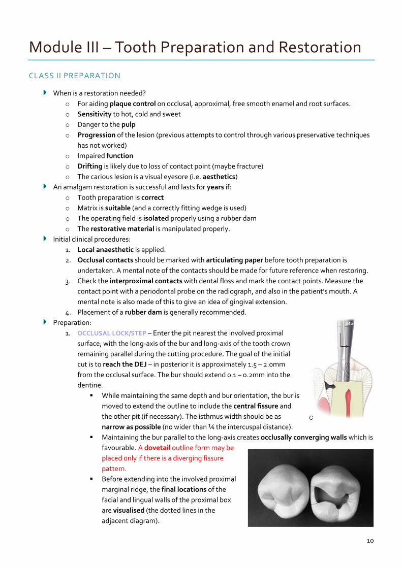
Preparation:
1. OCCLUSAL LOCK/STEP – Enter the pit nearest the involved proximal
surface, with the long-axis of the bur and long-axis of the tooth crown
remaining parallel during the cutting procedure. The goal of the initial
cut is to reach the DEJ – in posterior it is approximately 1.5 – 2.0mm
from the occlusal surface. The bur should extend 0.1 – 0.2mm into the
dentine.
While maintaining the same depth and bur orientation, the bur is
moved to extend the outline to include the central fissure and
the other pit (if necessary). The isthmus width should be as
narrow as possible (no wider than ¼ the intercuspal distance).
Maintaining the bur parallel to the long-axis creates occlusally converging walls which is
favourable. A dovetail outline form may be
placed only if there is a diverging fissure
pattern.
Before extending into the involved proximal
marginal ridge, the final locations of the
facial and lingual walls of the proximal box
are visualised (the dotted lines in the
adjacent diagram).
11
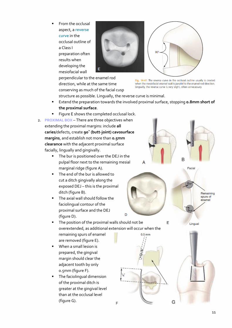
From the occlusal
aspect, a reverse
curve in the
occlusal outline of
a Class I
preparation often
results when
developing the
mesiofacial wall
perpendicular to the enamel rod
direction, while at the same time
conserving as much of the facial cusp
structure as possible. Lingually, the reverse curve is minimal.
Extend the preparation towards the involved proximal surface, stopping 0.8mm short of
the proximal surface.
Figure E shows the completed occlusal lock.
2. PROXIMAL BOX – There are three objectives when
extending the proximal margins: include all
caries/defects, create 90˚ (butt-joint) cavosurface
margins, and establish not more than 0.5mm
clearance with the adjacent proximal surface
facially, lingually and gingivally.
The bur is positioned over the DEJ in the
pulpal floor next to the remaining mesial
marginal ridge (figure A).
The end of the bur is allowed to
cut a ditch gingivally along the
exposed DEJ – this is the proximal
ditch (figure B).
The axial wall should follow the
faciolingual contour of the
proximal surface and the DEJ
(figure D).
The position of the proximal walls should not be
overextended, as additional extension will occur when the
remaining spurs of enamel
are removed (figure E).
When a small lesion is
prepared, the gingival
margin should clear the
adjacent tooth by only
0.5mm (figure F).
The faciolingual dimension
of the proximal ditch is
greater at the gingival level
than at the occlusal level
(figure G).
12
Module IV – Deep Carious Lesions
PULPAL INJURY
Pulp cannot generally not be differentiated from dentine anatomically or functionally, and the two are
usually considered as a dentin-pulp complex. This means that any insult to the dentine will affect the
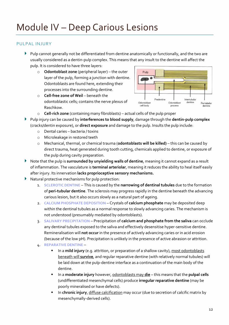
pulp. It is considered to have three layers:
o Odontoblast zone (peripheral layer) – the outer
layer of the pulp, forming a junction with dentine.
Odontoblasts are found here, extending their
processes into the surrounding dentine.
o Cell-free zone of Weil – beneath the
odontoblastic cells; contains the nerve plexus of
Raschkow.
o Cell-rich zone (containing many fibroblasts) – actual cells of the pulp proper
Pulp injury can be caused by interferences to blood supply, damage through the dentin-pulp complex
(cracks/dentin exposure), or direct exposure and damage to the pulp. Insults the pulp include:
o Dental caries – bacteria / toxins
o Microleakage in restored teeth
o Mechanical, thermal, or chemical trauma (odontoblasts will be killed) – this can be caused by
direct trauma, heat generated during tooth cutting, chemicals applied to dentine, or exposure of
the pulp during cavity preparation.
Note that the pulp is surrounded by unyielding walls of dentine, meaning it cannot expand as a result
of inflammation. The vasculature is terminal arteriolar, meaning it reduces the ability to heal itself easily
after injury. Its innervation lacks proprioceptive sensory mechanisms.
Natural protective mechanisms for pulp protection:
1. SCLEROTIC DENTINE – This is caused by the narrowing of dentinal tubules due to the formation
of peri-tubular dentine. The sclerosis may progress rapidly in the dentine beneath the advancing
carious lesion, but it also occurs slowly as a natural part of ageing.
2. CALCIUM PHOSPHATE DEPOSITION – Crystals of calcium phosphate may be deposited deep
within the dentinal tubules as a normal response to slowly advancing caries. The mechanism is
not understood (presumably mediated by odontoblasts).
3. SALIVARY PRECIPITATION – Precipitation of calcium and phosphate from the saliva can occlude
any dentinal tubules exposed to the saliva and effectively desensitise hyper-sensitive dentine.
Remineralisation will not occur in the presence of actively advancing caries or in acid erosion
(because of the low pH). Precipitation is unlikely in the presence of active abrasion or attrition.
4. REPARATIVE DENTINE –
In a mild injury (e.g. attrition, or preparation of a shallow cavity), most odontoblasts
beneath will survive, and regular reparative dentine (with relatively normal tubules) will
be laid down at the pulp-dentine interface as a continuation of the main body of the
dentine.
In a moderate injury however, odontoblasts may die – this means that the pulpal cells
(undifferentiated mesenchymal cells) produce irregular reparative dentine (may be
poorly mineralised or have defects).
In chronic injury, diffuse calcification may occur (due to secretion of calcific matrix by
mesenchymally-derived cells).
13
Module V – Composite Resin
COMPOSITE RESIN
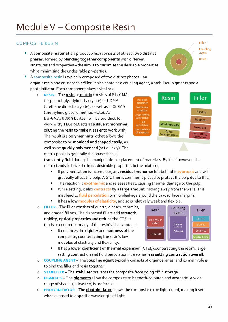
A composite material is a product which consists of at least two distinct
phases, formed by blending together components with different
structures and properties – the aim is to maximise the desirable properties
while minimising the undesirable properties.
A composite resin is typically composed of two distinct phases – an
organic resin and an inorganic filler. It also contains a coupling agent, a stabiliser, pigments and a
photoinitiator. Each component plays a vital role:
o RESIN – The resin or matrix consists of Bis-GMA
(bisphenol-glycidylmethacrylate) or UDMA
(urethane dimethacrylate), as well as TEGDMA
(triethylene glycol dimethacrylate). As
Bis-GMA/UDMA by itself will be too thick to
work with, TEGDMA acts as a diluent monomer,
diluting the resin to make it easier to work with.
The result is a polymer matrix that allows the
composite to be moulded and shaped easily, as
well as be quickly polymerised (set quickly). The
matrix phase is generally the phase that is
transiently fluid during the manipulation or placement of materials. By itself however, the
matrix tends to have the least desirable properties in the mixture:
If polymerisation is incomplete, any residual monomer left behind is cytotoxic and will
gradually affect the pulp. A GIC liner is commonly placed to protect the pulp due to this.
The reaction is exothermic and releases heat, causing thermal damage to the pulp.
While setting, it also contracts by a large amount, moving away from the walls. This
may lead to fluid percolation or microleakage around the cavosurface margins.
It has a low modulus of elasticity, and so is relatively weak and flexible.
o FILLER – The filler consists of quartz, glasses, ceramics,
and graded fillings. The dispersed fillers add strength,
rigidity, optical properties and reduce the CTE. It
tends to counteract many of the resin’s disadvantages:
It enhances the rigidity and hardness of the
composite, counteracting the resin’s low
modulus of elasticity and flexibility.
It has a lower coefficient of thermal expansion (CTE), counteracting the resin’s large
setting contraction and fluid percolation. It also has less setting contraction overall.
o COUPLING AGENT – The coupling agent typically consists of organosilanes, and its main role is
to bind the filler and resin together.
o STABILISER – The stabiliser prevents the composite from going off in storage.
o PIGMENTS – The pigments allow the composite to be tooth-coloured and aesthetic. A wide
range of shades (at least 10) is preferable.
o PHOTOINITIATOR – The photoinitiator allows the composite to be light-cured, making it set
when exposed to a specific wavelength of light.
14
Module VI – Miscellaneous Topics
TREATMENT PLANNING
A treatment plan differs from a patient management plan and a patient care plan.
o ‘Treatment’ implies intervention, invasive or otherwise. It may encompass:
Advice entails getting the patient to change habits and modify risk factors, in order to
prevent disease progression and restore health and function
Restorative intervention involves the dentist intervening via an actual procedure (e.g.
minimal intervention procedures or complex procedures such as endodontics).
o ‘Management’ implies an ability to direct, coordinate and lead a team (patient + associated
dental personnel).
o ‘Care’ implies a responsibility of the health professional to attend to the welfare and autonomy
of the patient as a priority (a patient-centric relationship).
Three questions are of importance when treatment planning:
o Why plan?
To ensure nothing is overlooked (no surprises later on in the treatment stage)
To demonstrate a high level of care (benefits both patient & dentist)
To save time and expense (via prior consideration of how each step impacts on future
stages of the treatment)
To track progress (for both the patient & dentist)
For legal reasons (written plan is part of the legal record.
o When to plan?
At the beginning of the patient-dentist relationship
N.B. Do not rush the plan (consideration of all alternatives & gathering the necessary
information can take time).
o How to plan?
Gather the information (as well as the patient’s wishes & expectations)
Analyse the gathered information & consider the evidence
Consider any variables in the situation (risk/predisposing/modifying factors)
Consider any alternatives & select the most appropriate alternative.
Convey findings to patient & gain patient’s acceptance of that alternative (i.e. informed
consent).
Arrange for this alternative to be undertaken.
Document the plan and the patient’s agreement.
Gathering the information:
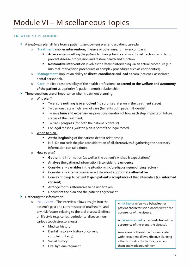
o INTERVIEW – The interview allows insight into the
patient’s past and current state of oral health, and
any risk factors relating to the oral disease & effect
on lifestyle (e.g. caries, periodontal disease, non-
carious tooth structure loss)
Medical history
Dental history (+ history of current
complaint, if any)
Social history
Oral hygiene regiment
A risk factor refers to a behaviour or
patient characteristic associated with the
occurrence of the disease.
A risk assessment is the prediction of the
occurrence of the event (the disease).
Awareness of the risk factors associated
with the patient allows effective planning
either to modify the factors, or accept
them and work around them.