Delving into Unbiased Data Processing for Human Pose ...
15
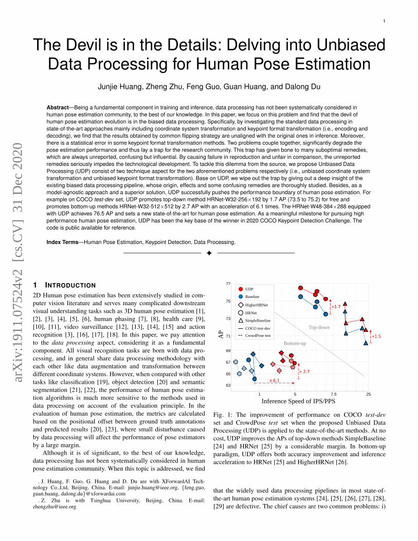
1 The Devil is in the Details: Delving into Unbiased Data Processing for Human Pose Estimation Junjie Huang, Zheng Zhu, Feng Guo, Guan Huang, and Dalong Du Abstract—Being a fundamental component in training and inference, data processing has not been systematically considered in human pose estimation community, to the best of our knowledge. In this paper, we focus on this problem and find that the devil of human pose estimation evolution is in the biased data processing. Specifically, by investigating the standard data processing in state-of-the-art approaches mainly including coordinate system transformation and keypoint format transformation (i.e., encoding and decoding), we find that the results obtained by common flipping strategy are unaligned with the original ones in inference. Moreover, there is a statistical error in some keypoint format transformation methods. Two problems couple together, significantly degrade the pose estimation performance and thus lay a trap for the research community. This trap has given bone to many suboptimal remedies, which are always unreported, confusing but influential. By causing failure in reproduction and unfair in comparison, the unreported remedies seriously impedes the technological development. To tackle this dilemma from the source, we propose Unbiased Data Processing (UDP) consist of two technique aspect for the two aforementioned problems respectively (i.e., unbiased coordinate system transformation and unbiased keypoint format transformation). Base on UDP, we wipe out the trap by giving out a deep insight of the existing biased data processing pipeline, whose origin, effects and some confusing remedies are thoroughly studied. Besides, as a model-agnostic approach and a superior solution, UDP successfully pushes the performance boundary of human pose estimation. For example on COCO test-dev set, UDP promotes top-down method HRNet-W32-256×192 by 1.7 AP (73.5 to 75.2) for free and promotes bottom-up methods HRNet-W32-512×512 by 2.7 AP with an acceleration of 6.1 times. The HRNet-W48-384×288 equipped with UDP achieves 76.5 AP and sets a new state-of-the-art for human pose estimation. As a meaningful milestone for pursuing high performance human pose estimation, UDP has been the key base of the winner in 2020 COCO Keypoint Detection Challenge. The code is public available for reference. Index Terms—Human Pose Estimation, Keypoint Detection, Data Processing. ✦ 1 I NTRODUCTION 2D Human pose estimation has been extensively studied in com- puter vision literature and serves many complicated downstream visual understanding tasks such as 3D human pose estimation [1], [2], [3], [4], [5], [6], human phasing [7], [8], health care [9], [10], [11], video surveillance [12], [13], [14], [15] and action recognition [3], [16], [17], [18]. In this paper, we pay attention to the data processing aspect, considering it as a fundamental component. All visual recognition tasks are born with data pro- cessing, and in general share data processing methodology with each other like data augmentation and transformation between different coordinate systems. However, when compared with other tasks like classification [19], object detection [20] and semantic segmentation [21], [22], the performance of human pose estima- tion algorithms is much more sensitive to the methods used in data processing on account of the evaluation principle. In the evaluation of human pose estimation, the metrics are calculated based on the positional offset between ground truth annotations and predicted results [20], [23], where small disturbance caused by data processing will affect the performance of pose estimators by a large margin. Although it is of significant, to the best of our knowledge, data processing has not been systematically considered in human pose estimation community. When this topic is addressed, we find . J. Huang, F. Guo, G. Huang and D. Du are with XForwardAI Tech- nology Co.,Ltd, Beijing, China. E-mail: [email protected], {feng.guo, guan.huang, dalong.du}@xforwardai.com . Z. Zhu is with Tsinghua University, Beijing, China. E-mail: [email protected] 1 5 7.5 25 65 67 69 71 73 75 77 +1.7 +1.5 + 2.7 AP Inference Speed of IPS/PPS x 6.1 Baseline UDP HigherHRNet HRNet SimpleBaseline COCO test-dev CrowdPose test Top-down Bottom-up 63 Fig. 1: The improvement of performance on COCO test-dev set and CrowdPose test set when the proposed Unbiased Data Processing (UDP) is applied to the state-of-the-art methods. At no cost, UDP improves the APs of top-down methods SimpleBaseline [24] and HRNet [25] by a considerable margin. In bottom-up paradigm, UDP offers both accuracy improvement and inference acceleration to HRNet [25] and HigherHRNet [26]. that the widely used data processing pipelines in most state-of- the-art human pose estimation systems [24], [25], [26], [27], [28], [29] are defective. The chief causes are two common problems: i) arXiv:1911.07524v2 [cs.CV] 31 Dec 2020
-
Upload
khangminh22 -
Category
Documents
-
view
0 -
download
0
Transcript of Delving into Unbiased Data Processing for Human Pose ...
1
The Devil is in the Details: Delving into UnbiasedData Processing for Human Pose Estimation
Junjie Huang, Zheng Zhu, Feng Guo, Guan Huang, and Dalong Du
Abstract—Being a fundamental component in training and inference, data processing has not been systematically considered inhuman pose estimation community, to the best of our knowledge. In this paper, we focus on this problem and find that the devil ofhuman pose estimation evolution is in the biased data processing. Specifically, by investigating the standard data processing instate-of-the-art approaches mainly including coordinate system transformation and keypoint format transformation (i.e., encoding anddecoding), we find that the results obtained by common flipping strategy are unaligned with the original ones in inference. Moreover,there is a statistical error in some keypoint format transformation methods. Two problems couple together, significantly degrade thepose estimation performance and thus lay a trap for the research community. This trap has given bone to many suboptimal remedies,which are always unreported, confusing but influential. By causing failure in reproduction and unfair in comparison, the unreportedremedies seriously impedes the technological development. To tackle this dilemma from the source, we propose Unbiased DataProcessing (UDP) consist of two technique aspect for the two aforementioned problems respectively (i.e., unbiased coordinate systemtransformation and unbiased keypoint format transformation). Base on UDP, we wipe out the trap by giving out a deep insight of theexisting biased data processing pipeline, whose origin, effects and some confusing remedies are thoroughly studied. Besides, as amodel-agnostic approach and a superior solution, UDP successfully pushes the performance boundary of human pose estimation. Forexample on COCO test-dev set, UDP promotes top-down method HRNet-W32-256×192 by 1.7 AP (73.5 to 75.2) for free andpromotes bottom-up methods HRNet-W32-512×512 by 2.7 AP with an acceleration of 6.1 times. The HRNet-W48-384×288 equippedwith UDP achieves 76.5 AP and sets a new state-of-the-art for human pose estimation. As a meaningful milestone for pursuing highperformance human pose estimation, UDP has been the key base of the winner in 2020 COCO Keypoint Detection Challenge. Thecode is public available for reference.
Index Terms—Human Pose Estimation, Keypoint Detection, Data Processing.
F
1 INTRODUCTION
2D Human pose estimation has been extensively studied in com-puter vision literature and serves many complicated downstreamvisual understanding tasks such as 3D human pose estimation [1],[2], [3], [4], [5], [6], human phasing [7], [8], health care [9],[10], [11], video surveillance [12], [13], [14], [15] and actionrecognition [3], [16], [17], [18]. In this paper, we pay attentionto the data processing aspect, considering it as a fundamentalcomponent. All visual recognition tasks are born with data pro-cessing, and in general share data processing methodology witheach other like data augmentation and transformation betweendifferent coordinate systems. However, when compared with othertasks like classification [19], object detection [20] and semanticsegmentation [21], [22], the performance of human pose estima-tion algorithms is much more sensitive to the methods used indata processing on account of the evaluation principle. In theevaluation of human pose estimation, the metrics are calculatedbased on the positional offset between ground truth annotationsand predicted results [20], [23], where small disturbance causedby data processing will affect the performance of pose estimatorsby a large margin.
Although it is of significant, to the best of our knowledge,data processing has not been systematically considered in humanpose estimation community. When this topic is addressed, we find
. J. Huang, F. Guo, G. Huang and D. Du are with XForwardAI Tech-nology Co.,Ltd, Beijing, China. E-mail: [email protected], {feng.guo,guan.huang, dalong.du}@xforwardai.com
. Z. Zhu is with Tsinghua University, Beijing, China. E-mail:[email protected]
1 5 7.5 25
65
67
69
71
73
75
77
+1.7
+1.5
+ 2.7
AP
Inference Speed of IPS/PPS
x 6.1
Baseline
UDP
HigherHRNet
HRNet
SimpleBaseline
COCO test-dev
CrowdPose test
Top-down
Bottom-up
63
Fig. 1: The improvement of performance on COCO test-devset and CrowdPose test set when the proposed Unbiased DataProcessing (UDP) is applied to the state-of-the-art methods. At nocost, UDP improves the APs of top-down methods SimpleBaseline[24] and HRNet [25] by a considerable margin. In bottom-upparadigm, UDP offers both accuracy improvement and inferenceacceleration to HRNet [25] and HigherHRNet [26].
that the widely used data processing pipelines in most state-of-the-art human pose estimation systems [24], [25], [26], [27], [28],[29] are defective. The chief causes are two common problems: i)
arX
iv:1
911.
0752
4v2
[cs
.CV
] 3
1 D
ec 2
020

2
When flipping testing strategy is adopted, the results from flippedimage are unaligned with those from the origin image. The biasderives from utilizing pixel for measuring the size of images whenperforming coordinate system transformation in resizing opera-tion. ii) Defective keypoint format transformation (i.e., encodingand decoding) methods would lead to extra precision degradation.The two problems accumulatively degrade the performance ofhuman pose estimators, lay a trap for the research community andsubsequently has given born to many suboptimal remedies. Theempirical remedies are always unreported but with huge impacton the performance like direct compensation in post processing[24], [25], [26], [27], [28], [29], while the others are reportedbut at tremendous cost of latency like using higher networkoutput resolution in HigherHRNet [26]. It is worth noting that,by causing failure in reproduction and unfair in comparison, theunreported remedies will obstruct the development of the humanpose estimation technologies.
In this paper, we offer a reasonable and free access to thor-oughly solving the two aforementioned problems by proposingUnbiased Data Processing (UDP) system. Corresponding to thetwo aforementioned problems, UDP consists of two technicalaspects: the unbiased coordinate system transformations and theunbiased keypoint format transformations. Aiming at the unbiasedcoordinate system transformations, we firstly propose to followthe principle of defining and analyzing this problem in continuousspace. Then the concept of coordinate system transformation isdefined based on this principle and the targets of unbias in thissub problem are introduced. Subsequently, the coordinate systemtransformations in different elementary operations (e.g., cropping,resizing, rotating and flipping) are formally designed, whichfinally compose the common coordinate system transformationsused in training and testing process. With mathematical reasoning,we verify the unbiased property of the designed coordinate systemtransformation pipeline, and subsequently offer a deep insightof the existing biased coordinate system transformation pipeline,whose origin, effects and some confusing remedies are thoroughlystudied. Analogously, the concept of unbiased keypoint formattransformation is proposed, two unbiased keypoint format trans-formation methods are introduced and a typical biased exampleis analyzed thoroughly. As a result with UDP, the aforementionedtrap can be remove and a higher as well as more reliable baselinecan be achieved.
To showcase the effectiveness of the proposed method, weperform comprehensive experiments on the COCO KeypointDetection benchmarks [20]. As a model-agnostic approach anda superior solution, UDP successfully pushes the performanceboundary of the human pose estimation problem as illustratedin Figure 1. Specifically, UDP boosts the performance of themethods in top-down paradigm without any extra latency. Forexample, UDP promotes the SimpleBaseline [24] by 1.5 AP(70.2 to 71.7) and 1.0 AP (71.9 to 72.9) within ResNet50-256×192 and ResNet152-256×192 configurations, respectively.For HRNet [25] within W32-256×192 and W48-256×192 con-figurations, UDP obtains gains by 1.7 AP (73.5 to 75.2) and1.4 AP (74.3 to 75.7), respectively. The HRNet-W48-384×288equipped with UDP achieves 76.5 AP (1.0 improvement) andsets a new state-of-the-art for top-down human pose estimation.Besides, in bottom-up paradigm, UDP simultaneously offers bothaccuracy improvement and latency reducing on the baselines. ForHRNet-W32-512×512 configuration in HigherHRNet [26], UDPpromotes its performance by 2.7 AP, and at the same time, offers
an acceleration by 6.1 times. For HigherHRNet-W32-512×512configuration, the promotion and acceleration are +0.8 AP and2.6 times respectively. In addition, we also perform experimentson extra dataset CrowdPose [30] to verify the generalizationability of UDP among different data distributions. Experimentalresults show that the performance of UDP in this dataset is inline with that on COCO dataset. Finally to verify the statementin methodology analysis, we measure the contribution of eachelement in UDP and the effect of the existing remedies in relativeworks with exhaustive ablation study. Based on the experimentresults, we call for attention on the data processing aspect whendesigning or evaluating the future works. The code is publicavailable for reference.
This paper is built upon our conference paper [31] andsignificantly extended in several aspects. First, we rearrange themethodology section for methodical stating, and explain it withmore specific background introduction and more detailed math-ematical reasoning. Second, we extend the coverage of UDP byapplying it to methods in bottom-up paradigm and make greatdiscovery and promotion on state-of-the-art method HigherHRNet[26]. Third, we use extra dataset CrowdPose [30] to verify thegeneralization ability of UDP. In COCO and LVIS 2020 compe-titions, UDP serves as the baseline for the winner UDP++ [32],which marks this work as a meaningful milestone for pursuinghigh performance human pose estimation.
2 RELATED WORK
In recent years, research community has witnessed a significantadvance from single person [23], [33], [34], [35], [36], [37], [38],[39], [40], [41] to multi-person pose estimation [20], [25], [26],[27], [42], [43], [44], [45], [46], [47], [48], [49], [50], where thelatter can be generally categorized into bottom-up [26], [44], [45],[46], [49], [51] and top-down [24], [25], [27], [28], [47], [50],[52], [53] approaches.
Bottom-up methods start by detecting identity-free jointsfor all the persons in an input image and then group them intoperson instances. In this paradigm, both cost and efficient areconsidered, both the identity-free joint detection and groupingstrategy are the main concerns. OpenPose [46] builds a model thatcontains two branches to predict keypoint heatmaps and pairwiserelationships (part affinity fields) between them, where the latteracts as the main cue in grouping process. MultiPoseNet [54]simultaneously achieves human detection and pose estimation,and proposes PRN to group the keypoints by the bounding boxof each people. Aiming at resolving the human pose estimationproblem in crowd sense, Li et al. [30] design a new modelby combining joint-candidate single person pose estimation andglobal maximum joints association. Simultaneously, a new datasetnamed CrowdPose is collected specific for performance evaluationin crowd senses. Newell et al. [49] use one network for bothheatmap prediction and embedding study. Grouping is done byutilizing association embedding, which assigns each keypoint witha tag and groups keypoints based on the L2 distance betweentag vectors. As a follower, Chen et al. [26] replace the hourglassstyle networks in [49] with the proposed HigherHRNet. By usinghigher output resolution, HigherHRNet improves the precision ofthe predictions by a large margin.
. https://github.com/HuangJunJie2017/UDP-Pose
. https://cocodataset.org/workshop/coco-lvis-eccv-2020.html

3
Top-down methods achieve multi-person pose estimation bythe two-stages process, including obtaining person bounding boxesthrough a person detector like Faster R-CNN [55] and predictingkeypoint locations within these boxes. As single person poseestimation is performed with fixed scale patches, most state-of-the-art performances on multi-person popular benchmarks COCO [20]are achieved by top-down methods [27], [28], [31]. Existing workswith this paradigm pay more attention to the designing of networkstructure. Chen et al. [56] propose Structure-aware ConvolutionalNetwork trained with Generative Adversarial Networks for humanpose structure exploiting. Following ShuffleNet [57] and SENet[58], Su et al. [59] propose Channel Shuffle Module (CSM) andSpatial, Channel-wise Attention Residual Bottleneck (SCARB)specific for human pose estimation problem. CPN [27] and MSPN[28] are the leading methods on COCO keypoint challenge,adopting cascade network to refine the keypoints prediction. Sim-pleBasline [24] adds a few deconvolutional layers to enlarge theresolution of output features. Thought simple, it has a competitiveperformance among existing works. HRNet [25] maintains high-resolution representations through the whole process, achievingstate-of-the-art performance on public datasets. Mask R-CNN [53]builds an end-to-end framework and achieves a good balancebetween performance and inference speed.
Data processing in human pose estimation mainly includescoordinate system transformation and keypoint format transfor-mation. Coordinate system transformation means transformingthe data (i.e., keypoint coordinates and image matrixes) betweendifferent coordinate systems when some operations are conductedlike cropping, resizing, rotating and flipping. During this process,most state-of-the-art methods [24], [25], [26], [27], [28] use pixelto measure the size of images when performing resizing oper-ation, leading to unaligned results when using flipping strategyin inference. This bias degrades the accuracy by a large margin,lays a trap for research community and has given bone to somesuboptimal remedies. The remedies are all empirical and alwaysunreported. For example, without any explanation, SimpleBaseline[24] HRNet [25] and Darkpose [29] empirically shift the resultfrom flipped image by 1 pixel in network output coordinate systemto suppress the predicting error. CPN [27] and MSPN [28] achievesimilar effect by shifting the average result by 2 pixels in networkinput coordinate system. HigherHRNet [26] proposes to use highernetwork output resolution and conducts the experiment with someunreported compensation for large superiority on the baseline.These remedies are effective and appealing, but being the recipefor disaster as they hinder the development of technology bycausing failure in reproduction and unfair in comparison. In thispaper, we propose unbiased coordinate system transformation tothoroughly solve this problem, which will not only boost the per-formance of the existing methods but also provide a more reliablebaseline for future works. Keypoint format transformation (i.e.,encoding and decoding) commonly denotes the transformationbetween joint coordinates and heatmaps, which is firstly proposedin [38] and has been widely used in state-of-the-art methods[24], [25], [26], [27], [28], [53]. In training process, it encodesthe annotated keypoint coordinate into a heatmap with Gaussiandistribution. And in testing process, it decodes the network pre-dicted heatmap back into keypoint coordinate. This pipeline showssuperior performance when compared with directly predictingthe keypoint coordinates [60], but is still imperfect on accountof its defective design and inherent precision degradation. Thecombined classification and regression format based encoding-
decoding paradigm in [47] provides an mathematically error-freeentrance to further promote the prediction accuracy. Analogously,Darkpose [29] achieve unbiased keypoint format transformationby proposing a distribution-aware decoding method to match theencoding method use in [26]. In this paper, we will introduce thesetwo unbiased keypoint format transformation paradigm, verifytheir unbias property and show their superiority on the baseline.
3 UNBIASED DATA PROCESSING FOR HUMANPOSE ESTIMATION
In human pose estimation, data processing involves the transfor-mation between different coordinate system and the transforma-tion between different keypoint format. In the following, we willgive details introduction of our unbiased data processing methodin these two aspects respectively (i.e., unbiased coordinate systemtransformation and unbiased keypoint format transformation).
3.1 Unbiased Coordinate System Transformation
As it is new to this topic and quite ambiguous to community,for clarified and reasonable statement, the concept of unbiasedcoordinate system transformation is constructed from the base. Wefirstly propose the unified definition of data in continuous space.Then based on this definition, the concept of coordinate systemtransformation and the targets of unbias are introduced. We designthe coordinate system transformation in some elementary oper-ations (i.e., cropping, resizing, rotating and flipping) before weconstruct the common composite transformations between the co-ordinate systems involved in human pose estimation problem(i.e.,source image coordinate system, network input coordinate systemand network output coordinate system). Subsequently, we verifythe unbias properties of the designed coordinate system trans-formation pipeline with mathematical reasoning. And at last toshowcase how the defective coordinate system affect the researchcommunity, some biased data processing methods are analyzed,and the theory behind some reported techniques and unreportedtricks used in state-of-the-arts are thoroughly studied.
3.1.1 An Unified Definition of Data in Continuous Space.The image matrixes and the target keypoint coordinates are themain data involved in human pose estimation problem. The imagesare stored and processed in a discrete format, but the keypointcoordinates are defined, processed and evaluated in continuousspaces. To avoid precision degradation in the coordinate systemtransformation pipeline, an unified paradigm is required for uni-formly analyzing and dealing with different data in the coordinatesystem transformation problems.
To this end, we assume that there is a continuous image planeand consider each image matrix as a discrete sampling result onit, where each pixel in an image matrix is a specific sample point.Formally, in line with the definition of target keypoint coordinatesin COCO dataset [20], we define the coordinate system O-XYas illustrated in Figure 2 to describe the continuous image planes.The origin of the coordinate system is located at the most top-leftpixel, theO-X direction is from left to right and theO-Y directionis from top to down. Besides, the distance between adjacent pixelsis assumed to be equivalent and is defined as the unit lengthof the coordinate system. Then we have an image matrix as asampling result of the image plane I, which is denoted as {I(p) =(r, g, b)|p = (x, y), x ∈ {0, 1, 2...w}, y ∈ {0, 1, 2...h}}. w and

4
Unit Length𝑂𝑂 𝑋𝑋
𝑌𝑌
𝑤𝑤 = 7,𝑤𝑤𝑝𝑝 = 8
ℎ = 10, ℎ𝑝𝑝 = 11
Fig. 2: Illustration of analyzing the coordinate system transforma-tion problem in continuous space. O-XY denotes the coordinatesystem. An image matrix (the set of blue points) is regarded as asampling result of the continuous image plane.
h are the width and height of the image counted in unit lengths.And a set of target keypoints are also defined in the same imageplane and denoted as {k = (x, y)}.
It is worth noting that the size of the sample points definedhere is infinitely small and the size of the images’ semanticallymeaningful area is calculated with the unit length. As a result,the image size (i.e., w for width and h for height) we discussedfollowing is different from the resolution of the image matrix,which is widely used for defining the image size in common sense.Formally, the relationship between them is as follow:
w = wp − 1
h = hp − 1(1)
where wp and hp are the width and height of the image matrixcounted in pixels. We use superscript p to discriminate the vari-ables counted in pixel from those measured in unit length.
𝑂𝑂𝑠𝑠 𝑋𝑋𝑠𝑠
𝑌𝑌𝑠𝑠
𝑂𝑂𝑑𝑑 𝑋𝑋𝑑𝑑
𝑌𝑌𝑑𝑑
𝑇𝑇𝑠𝑠→𝑑𝑑𝑠𝑠𝐤𝐤 𝑑𝑑𝐤𝐤
𝑰𝑰𝑑𝑑 (𝑥𝑥𝑑𝑑 , 𝑦𝑦𝑑𝑑)
𝑰𝑰𝑠𝑠 (𝑥𝑥𝑠𝑠,𝑦𝑦𝑠𝑠)
𝑇𝑇s→𝑑𝑑−1
Fig. 3: The illustration of the coordinate system transformation inhuman pose estimation problem.
3.1.2 The Concept of Coordinate System Transformation.
The coordinate system transformation in human pose estimationcan be generally formulated as the data description transformationfrom the source coordinate system into the destination coordinatesystem. As illustrated in Figure 3, we label the source coordinatesystem with subscript s as Os − XsYs and the target coordinate
system as Od − XdYd. Then the transformation of keypointcoordinates can be formulated as:
kd = Ts→dks (2)
where Ts→d is the coordinate system transformation matrix fromthe source coordinate system to the destination coordinate system.And the transformation of the contents in image matrix can beformulated as:
Id(pd) = Is(T−1s→dpd) (3)
where T−1s→d is the inverse of Ts→d. Equation 3 means that wemake the image constant semantically aligned with the annotatedkeypoints in the destination coordinate system by setting the colorof position pd the same as that in the source image at positionT−1s→dpd. The results of backtracking T−1s→dpd are usually notintegers, and thus, Is(T
−1s→dpd) should be calculated by bilinear
interpolation with the valid surrounding points (i.e., the purplepoints in Figure 3). As we only have a sampling result (i.e., theimage matrix) of the image plane, interpolation is the optimal wayto reduce the precision degradation in image transformation, butcan not thoroughly remedy it. Thus, as the precision degradationof interpolation is irreversible and cumulative, we have a principlethat the less interpolation done in the data processing pipeline isthe better in designing coordinate system transformation pipelines.
3.1.3 The Targets of Unbias.
Unbias is a target in coordinate system transformation design-ing, which contains two aspect: One is to keep the semanticalalignment after performing transformations. Semantical alignmentmeans that the positional relativeness between different data (i.e.,images and keypoint positions) is unchanged (e.g., the annotatedposition of nose in destination space is still exactly located uponthe nose in the image described in destination space). This isguaranteed by keeping the transformation matrix the same in bothEquation 2 and Equation 3.
Another aspect is to make the predicting result exactly alignedwith the ground truth under the assumption that the network hasa perfect learning ability. In other words, we hope the network’slearning ability to be the unique source of precision degradation,and there are no defects in the design of the coordinate transforma-tion pipeline will cause precision degradation. In the following, wewill detail our unbiased coordinate system transformation pipelineand prove its unbiased property.
3.1.4 Coordinate System Transformation in ElementaryOperations.
Coordinate system transformations in human pose estimationderives from some elementary operations like cropping, resizing,rotating and flipping.
Cropping, as illustrated in Figure 4, is conducted according toa specific Region of Interest (ROI) defined in the source coordinatesystem ROI = (bxs, bys, bws, bhs), where (bxs, bys) denotesits center position and (bws, bhs) denotes its width and height.The destination coordinate system can be obtained by moving theorigin of the source coordinate system to the upper left corner ofthe ROI. Thus, the transformation matrix should be designed as:
Tcrop(ROI) =
1 0 −bxs + 0.5bws
0 1 −bys + 0.5bhs0 0 1
(4)

5
𝑂𝑂𝑠𝑠 𝑋𝑋𝑠𝑠
𝑌𝑌𝑠𝑠𝑅𝑅𝑂𝑂𝑅𝑅 = (𝑏𝑏𝑏𝑏𝑠𝑠, 𝑏𝑏𝑏𝑏𝑠𝑠, 𝑏𝑏𝑏𝑏𝑠𝑠, 𝑏𝑏𝑏𝑠𝑠)
(𝑏𝑏𝑏𝑏𝑠𝑠, 𝑏𝑏𝑏𝑏𝑠𝑠)𝑏𝑏𝑏𝑠𝑠
𝑏𝑏𝑏𝑏𝑠𝑠
𝑋𝑋𝑑𝑑
𝑌𝑌𝑑𝑑
𝑂𝑂𝑑𝑑
Crop
Fig. 4: The coordinate system transformation in cropping opera-tion.
𝑂𝑂𝑠𝑠 𝑋𝑋𝑠𝑠
𝑌𝑌𝑠𝑠
𝑂𝑂𝑑𝑑 𝑋𝑋𝑑𝑑
𝑌𝑌𝑑𝑑
Resize
Fig. 5: The coordinate system transformation in resizing operation.
Resizing, as illustrated in Figure 5, changes the samplingstrategy only and keep the semantic constant of the image the sameas the source. We make the four corner sample point semanticallyalign with the source four corner sample point and let the othersample points evenly distributed among the area dividing by thefour corners. Thus the only thing that changes is the unit lengthof the coordinate system and the transformation matrix should bedesigned as:
Tresize(ws, hs, wd, hd) =
wd
ws0 0
0 hd
hs0
0 0 1
(5)
𝑂𝑂𝑠𝑠 𝑋𝑋𝑠𝑠
𝑌𝑌𝑠𝑠
𝑂𝑂𝑑𝑑𝑑𝑋𝑋𝑑𝑑𝑑
𝑌𝑌𝑑𝑑𝑑
𝑂𝑂𝑑𝑑𝑑𝑋𝑋𝑑𝑑𝑑
𝑌𝑌𝑑𝑑𝑑 𝑂𝑂𝑑𝑑 𝑋𝑋𝑑𝑑
𝑌𝑌𝑑𝑑
𝜃𝜃
Rotate
𝑅𝑅𝑂𝑂𝑅𝑅 = (𝑏𝑏𝑏𝑏𝑠𝑠, 𝑏𝑏𝑏𝑏𝑠𝑠, 𝑏𝑏𝑏𝑏𝑠𝑠, 𝑏𝑏𝑏𝑠𝑠)
𝑂𝑂𝑠𝑠 𝑋𝑋𝑠𝑠
𝑌𝑌𝑠𝑠
𝑂𝑂𝑑𝑑 𝑋𝑋𝑑𝑑
𝑌𝑌𝑑𝑑
𝜃𝜃
(𝑏𝑏𝑏𝑏𝑠𝑠, 𝑏𝑏𝑏𝑏𝑠𝑠)𝑏𝑏𝑏𝑠𝑠
𝑏𝑏𝑏𝑏𝑠𝑠
Fig. 6: The coordinate system transformation in rotating operation.
Rotating, as illustrated in Figure 6, is conducted according toa rotation center which is always set as the center of a specific ROIinstead of the origin of the coordinate system. This design aims atkeeping the center position of ROI unchanged (i.e., (bxs, bys) =(bxd, byd)). For example, the ROI refers to the bounding boxesof human instances in top-down paradigm and the whole imagein bottom-up paradigm. So, the transformation matrix should bedesigned as the combination of three elementary transformations:
Trot(θ,ROI)
=Td2→dTd1→d2Ts→d1
=
1 0 bxs0 −1 bys0 0 1
cos θ sin θ 0− sin θ cos θ 0
0 0 1
1 0 −bxs0 −1 bys0 0 1
=
cos θ − sin θ −bxs cos θ + bys sin θ + bxssin θ cos θ −bxs sin θ − bys cos θ + bys0 0 1
(6)
𝑂𝑂𝑠𝑠 𝑋𝑋𝑠𝑠
𝑌𝑌𝑠𝑠
𝑂𝑂𝑑𝑑 𝑋𝑋𝑑𝑑
𝑌𝑌𝑑𝑑
Flip
𝑥𝑥 = 𝑤𝑤𝑠𝑠/2
Fig. 7: The coordinate system transformation in flipping operation.
Flipping, as illustrated in Figure 7, generally takes x = ws/2as the mirror and horizontally exchanges the images’ content. So,the transformation matrix should be designed as:
Tflip(ws) =
−1 0 ws
0 1 00 0 1
(7)
3.1.5 Common Coordinate System Transformation
In human pose estimation as illustrated in Figure 8, there are threecoordinate systems are involved: source image coordinate systemsdenoted as Os-XsYs with subscript s corresponding to the sourceimage with a size of (ws, hs), network input coordinate systemsdenoted as Oi-XiYi with subscript i corresponding to the networkinput with a size of (wi, hi), and network output coordinatesystems denoted as Oo-XoYo with subscript o corresponding tothe network output with a size of (wo, ho).
During the training process, the data is firstly transformed fromthe source image coordinate systems into the network input coor-dinate systems according to a specific ROI (bxs, bys, bws, bhs)and a rotation angle θ. Some elementary operations are conductedorderly:
Tflip(wi) =
−1 0 wi
0 1 00 0 1
Trot(θ, (0.5wi, 0.5hi, wi, hi))
=
cos θ − sin θ −0.5wi cos θ + 0.5hi sin θ + 0.5wi
sin θ cos θ −0.5wi sin θ − 0.5hi cos θ + 0.5hi0 0 1
Tresize(bws, bhs, wi, hi) =
wi
bws0 0
0 hi
bhs0
0 0 1
Tcrop(bxs, bys, bws, bhs) =
1 0 −bxs + 0.5bws
0 1 −bys + 0.5bhs0 0 1
(8)

6
𝑂𝑂𝑜𝑜 𝑋𝑋𝑜𝑜
𝑌𝑌𝑜𝑜
𝑂𝑂𝑖𝑖 𝑋𝑋𝑖𝑖
𝑌𝑌𝑖𝑖
𝑂𝑂𝑠𝑠 𝑋𝑋𝑠𝑠
𝑌𝑌𝑠𝑠
Evaluate
Training
Testing
𝑇𝑇𝑠𝑠→𝑖𝑖,𝑡𝑡𝑡𝑡𝑡𝑡𝑖𝑖𝑡𝑡𝑇𝑇𝑖𝑖→𝑜𝑜
𝒩𝒩
𝑇𝑇𝑠𝑠→𝑖𝑖,𝑡𝑡𝑡𝑡𝑠𝑠𝑡𝑡
𝑇𝑇𝑜𝑜→𝑠𝑠
𝒩𝒩𝑇𝑇𝑖𝑖→(𝑖𝑖,𝑓𝑓𝑓𝑓𝑖𝑖𝑓𝑓) 𝑇𝑇(𝑜𝑜,𝑓𝑓𝑓𝑓𝑖𝑖𝑓𝑓)→𝑜𝑜
𝐈𝐈𝑠𝑠,𝐤𝐤𝑠𝑠𝐤𝐤𝑖𝑖
𝐈𝐈𝑖𝑖
𝐈𝐈𝑠𝑠,𝐤𝐤𝑠𝑠 ��𝐤𝑜𝑜
��𝐤𝑠𝑠
𝐈𝐈𝑖𝑖
𝐈𝐈𝑖𝑖,𝑓𝑓𝑓𝑓𝑖𝑖𝑓𝑓 ��𝐤𝑜𝑜,𝑓𝑓𝑓𝑓𝑖𝑖𝑓𝑓
��𝐤′𝑜𝑜
��𝐤𝑜𝑜,𝑡𝑡𝑎𝑎𝑎𝑎
𝐤𝐤𝑜𝑜
��𝐤𝑜𝑜Supervise
Fig. 8: The illustration of the common coordinate system transformation in human pose estimation problem. Three coordinate systemare involved: source image coordinate system Os-XsYs, network input coordinate system Oi-XiYi and network output coordinatesystem Oo-XoYo.
Then we have the combined transformation:
ki = Ts→i,trainks
Ii(pi) = Is(T−1s→i,trainpi)
Ts→i,train = TflipTrotTresizeTcrop
(9)
Equation 9 integrates not only the necessary transformations likescropping and resizing, but also the optional augmentations (i.e.,Tflipping for random flipping, Trotating for random rotating,Tcropping for half body and random cropping.) used in humanpose estimator training. Cropping and Resizing are necessary,while flipping and rotating are optional. The image matrixes innetwork input space are set as the network input and we have theinference results in the network output space:
ko = N (Ii) (10)
where N denotes the networks. The annotation is simultaneouslytransformed from the network input space into the network outputspace by a simple resizing operation:
ko = Ti→oki
Ti→o = Tresize
Tresize(wi, hi, wo, ho) =
wo
wi0 0
0 ho
hi0
0 0 1
(11)
And ko in the network output space serves as the supervision:
Loss = ||ko − ko|| (12)
The networks are optimized in the training process and as an idealresult, we have:
Loss = ||ko − ko|| = 0
N (Ii) = ko = ko = Ti→oki
(13)
which means that the network learns not only the reflection fromimage matrixes Ii to keypoint positions ki, but also the reflectionof the transformation Ti→o defined in Equation 11.
In testing process, only the image matrixes are transformedfrom the source image coordinate systems into the network inputcoordinate system with the necessary elementary transformations,which should be in line with those in the training process:
Ii(pi) = Is(T−1s→i,testpi)
Ts→i,test = TresizeTcrop
Tresize(bws, bhs, wi, hi) =
wi
bws0 0
0 hi
bhs0
0 0 1
Tcrop(bxs, bys, bws, bhs) =
1 0 −bxs + 0.5bws
0 1 −bys + 0.5bhs0 0 1
(14)
Then the network outputs in Equation 10 are transformed back to

7
the source image coordinate systems by inverse transformations:
ks = To→sko
To→s = TcropTresize
Tresize(wo, ho, bws, bhs) =
bws
wo0 0
0 bhs
ho0
0 0 1
Tcrop(0.5ws − bxs + 0.5bws,
0.5ys − bys + 0.5bhs, ws, hs)
=
1 0 bxs − 0.5bws
0 1 bys − 0.5bhs0 0 1
(15)
With Equation 13 as assumption and taking Equation 11, Equa-tion 14, Equation 15 into consideration, we have the followingidentical relation:
ks = To→sko
= To→sTi→oki
= To→sTi→oTs→i,testks
=
1 0 bxs − 0.5bws
0 1 bys − 0.5bhs0 0 1
bws
wo0 0
0 bhs
ho0
0 0 1
wo
wi0 0
0 ho
hi0
0 0 1
wi
bws0 0
0 hi
bhs0
0 0 1
1 0 −bxs + 0.5bws
0 1 −bys + 0.5bhs0 0 1
ks
= ks
(16)
This inference prove that the result in the source image space isexactly equal to the ground truth, which means that the data trans-formation pipeline designed above is unbiased and no systematicerror would be involved.
When flipping ensemble is used in testing process, the flippedimage is obtained by performing flipping transformation in thenetwork input space:
Ii,flip(pi,flip) = Ii(T−1i→(i,flip)pi,flip)
Ti→(i,flip) = Tflip(wi) =
−1 0 wi
0 1 00 0 1
(17)
Then we have the network prediction ko,flip = N (Ii,flip) whichis subsequently flipped back in the network output space:
k′o = T(o,flip)→oko,flip
T(o,flip)→o = Tflip(wo) =
−1 0 wo
0 1 00 0 1
(18)
with Equation 13 as assumption and taking Equation 11, Equa-tion 17 and Equation 18 into consideration, we have the following
identical relation:
k′o = T(o,flip)→oko,flip
= T(o,flip)→oT(i,flip)→(o,flip)ki,flip
= T(o,flip)→oT(i,flip)→(o,flip)Ti→(i,flip)ki
= Tflip(wo)Tresize(wi, hi, wo, ho)Tflip(wi)ki
=
−1 0 wo
0 1 00 0 1
wo
wi0 0
0 ho
hi0
0 0 1
−1 0 wi
0 1 00 0 1
ki
=
wo
wi0 0
0 ho
hi0
0 0 1
ki
= Ti→oki
= ko
(19)
This inference prove that, in the network output space, the resultsfrom flipped images are aligned with those from the origin images.By taking Equation 16 into consideration, the results from flippedimages in the source image space are also aligned with the groundtruths and no systematic error would be involved. The establishof Equation 16 and Equation 19 guarantees the unbiased propertyin the coordinate system transformation pipeline. They will beused as the guideline for checking biased coordinate systemtransformation pipelines in the following subsection.
3.1.6 Diagnosis of the Biased Coordinate System Transfor-mation
In most state-of-the-arts [24], [25], [26], [27], [28], the bias prob-lem in coordinate system transformation pipeline derives from us-ing resolution (wp
s , hps) counted in pixels instead of size (ws, hs)
measured in unit length when performing resizing transformation.As a consequence, it changes Equation 16 and Equation 19 into:
ks = To→sko
= To→sTi→oki
= To→sTi→oTs→i,testks
=
1 0 bxs − 0.5bws
0 1 bys − 0.5bhs0 0 1
bws
wpo
0 0
0 bhs
hpo
0
0 0 1
wpo
wpi
0 0
0hpo
hpi
0
0 0 1
wpi
bws0 0
0hpi
bhs0
0 0 1
1 0 −bxs + 0.5bws
0 1 −bys + 0.5bhs0 0 1
ks
= ks
(20)
8
k′o = T(o,flip)→oko,flip
= T(o,flip)→oT(i,flip)→(o,flip)ki,flip
= T(o,flip)→oT(i,flip)→(o,flip)Ti→(i,flip)ki
= Tflip(wo)Tresize(wpi , h
pi , w
po , h
po)Tflip(wi)ki
=
−1 0 wo
0 1 00 0 1
wpo
wpi
0 0
0hpo
hpi
0
0 0 1
−1 0 wi
0 1 00 0 1
ki
=
wp
o
wpi
0wp
o
wpi− 1
0hpo
hpi
0
0 0 1
ki
=
1 0wp
o
wpi− 1
0 1 00 0 1
wpo
wpi
0 0
0hpo
hpi
0
0 0 1
ki
=
1 0 1−ss
0 1 00 0 1
ko
(21)
where s = wpi /w
po is the stride factor for describing the size
variation of network features. Here, ks is still equal to ks,indicating that the aforementioned modification will not changethe unbiased property in coordinate system transformation pipelineTo→sTi→oTs→i,test and should have no effect on the precision ofthe predicted results. However when flipping ensemble is adoptedin testing process, k
′o is not exactly aligned with ko, and there is
an offset of 1−ss in Oo-Xo direction. Taking ko as reference, 1−s
s
is the predicting error of result k′o in network output space. If we
directly average k′o and ko as done in most existing works:
ko,avg =k′o + ko
2=
1 0 1−s2s
0 1 00 0 1
ko (22)
the final error in Oo-Xo direction is:
e(x)o = |x(ko,avg)− x(ko)| = |1− s2s| = 0.375|s=4 (23)
where ko is regarded as ground truth as it has been provedunbiased by Equation 20. The magnitude of this predicting error isso large that the performance will be degraded by a considerablemargin. In state-of-the-arts, there are some empirical remediesfor this error, which can be classified into two categories: directcompensation or using higher resolution.
As the error | 1−s2s | has a fixed scale which is determinedby the stride factor, direct compensation is effective, being theremedy in most state-of-the-arts top-down methods [24], [25],[27], [28], [29]. For example, SimpleBaseline [24], HRNet [25]and DarkPose [29] empirically shift the result from flipped imageby one pixel in Oo-Xo direction before performing the averagingoperation to suppress this error:
ko,avg =
1 0 10 1 00 0 1
k′o + ko
2=
1 0 12s
0 1 00 0 1
ko (24)
In this way, the final error can be reduced to
e(x)′o = | 12s| = 0.125|s=4 (25)
where e(x)′o < e(x)o when s > 2, which makes sense in mostexisting top-down methods with a stride factor of 4 [24], [25],[27], [28], [29]. Intuitively, as a result of reasoning, an extracompensation for e(x)′o in network output space can make theresult of existing work more accurate. We will verify this inablation study.
Besides, when mapping e(x)′o back to source image coordinatesystem (Os-XsYs) with Equation 15, we have:
e(x)′s = |1
2s× bws
wpo| = | bws
2wpi
| (26)
where bws is fixed in inference process. Equation 26 means thathigher network input resolution can help suppress the predictederror caused by e(x)′s. In other words, the existing top-downmethods benefit more from higher input resolution and suffer moreaccuracy loss from lower input resolution.
Without shifting one pixel in network output space, we have:
e(x)s = |s− 1
2s× bws
wpo| = |bws(s− 1)
2wpi
| (27)
which means that both higher input resolution and higher outputresolution can help suppress this error. And this contributes themost performance boosting in HigherHRnet [26] who empiricallyproposes to use higher output resolution to pursue high precisionat the cost of tremendous latency in both network inference andpost processing. By contrast, unbiased data processing providesa free access to achieve similar performance improvement with alow output resolution. Besides of using higher output resolution,HigherHRNet uses another unreported operation that resizes thenetwork output into a a resolution as high as the network input.This operation also coincidentally remedies the error causedby biased coordinate system transformation pipeline and benefitthe performance of HigherHRNet structure at the cost of extralatency in post processing. Through ablation study, we will showthis operation are gilding the lily when the coordinate systemtransformation pipeline is unbiased as it will involve extra errorand change the distribution of the network output by performingan extra interpolation in resizing operation.
3.2 Unbiased Keypoint Format Transformation
3.2.1 The Concept of Unbiased Keypoint Format Transfor-mation.
As the coordinate of keypoint is not the superior format forconvolutional network study, the intuitively more proper formatof heatmap is proposed and quickly has been proved effective.The keypoint fromat transformation refers to the transformationsbetween keypoint coordinates and heatmaps which is widely usedin state-of-the-art methods. In common sense, encoding denotesthe transformation from coordinate format into heatmap format,while decoding denotes the inverse transformation.
H = Encoding(k)k = Decoding(H)
(28)
Target of Unbiased in keypoint format transformation de-signing is to avoid precision degeneration in the encoding anddecoding transformation. As a formulated target, we should have:
k = Decoding(Encoding(k)) (29)

9
3.2.2 Unbiased Keypoint Format Transformation.
In this subsection, we will introduce two unbiased keypoint for-mat transformation paradigm and simultaneously showcase theirunbias property.
Combined classification and regression format is inspiredby the works in object detection [55] where anchors are used topredict bounding boxes, and first proposed in [47]. We give detailsintroduction here with some modifications. In training process,each annotated keypoint k = (m,n) is encoded through:
C(x, y,m, n) ={1 if (x−m)2 + (y − n)2 < r2
0 otherwise
X (x, y,m, n) = m− xY(x, y,m, n) = n− y
(30)
where C is the classification heatmap act as the anchor in objectdetection for preliminarily locate the keypoint. r is a hyper-parameter referring the radius of the area classified as positive.Consist of offset vectors, X and Y are the regression heatmapfor preserving the residual locating information. Then the loss isdesigned as:
Loss = Losscls + Lossreg
Losscls = ||C − C||Lossreg = C ∗ ||X − X ||+ C ∗ ||Y − Y||C, X , Y = N (I)
(31)
where C in Lossreg defines the region of interesting, which meansthat we only need to learn the offset among the area where theclassification label is true. The network is optimized in the trainingprocess and as a ideal result, we have:
C, X , Y = C,X ,Y (32)
Then in testing processing, the prediction is decoding by:
k = kh + (X (kh), Y(kh))
kh = argmax(C)(33)
where the position of highest response kh is located first and issubsequently updated by utilizing the predicted offsets. By takingEquation 30 and Equation 32 into consideration, we have:
k = kh + (X (kh), Y(kh))
= (x(kh), y(kh)) + (m− x(kh), n− y(kh))
= (m,n)
= k
(34)
which means that no systematic error is involved in the keypointformat transformation pipeline and the unbiased target in Equa-tion 29 is achieved.
Classification format is widely used in most state-of-the-arts,where classification heatmap is used only with a gaussian-likedistribution:
C(x, y,m, n) = exp(− (x−m)2 + (y − n)2
2δ2) (35)
The loss is designed as:
Loss = ||C − C||C = N (I)
(36)
The network is optimized in the training process and as a idealresult, we have:
C = C (37)
In testing process, we introduce the decoding method DARK[29] who decoding the classification heatmap into keypoint coor-dinates by searching the center of the gaussian distribution wherethe first derivative is equal to zero:
k = kh − C′′(kh)−1C′(kh)
kh = argmax(C)(38)
where C′ and C′′ are the first order derivative and second orderderivative (i.e., Hessian) of C. According to [29], the precisiondegradation caused by Taylor series approximation is negligibleand k is theoretically close to k, which matches the purpose ofunbias.
3.2.3 Analysis of Biased Keypoint Format Transformation.
We take the keypoint format transformation method used inSimpleBaseline [24], HRNet [25] and HigherHRNet [26] as theexample for studying the effect of biased data form transformation.keypoints are encoded into classification heatmap with gaussiandistribution as Equation 35, but are decoded by the a suboptimalmethod:
k = kh + 0.25 ∗ sign(C′(kh))
kh = argmax(C)
sign(x) =
{1 if x > 0
−1 otherwise
(39)
According to the encoding in Equation 35, we have
argmax(C) ={Floor(m) if m− Floor(m) < 0.5
Ceil(m) otherwise
sign(C′(kh)) =
{1 if m− Floor(m) < 0.5
−1 otherwise
(40)
As an example, predicting coordinate in O −X direction has thedistribution of:
m =
{Floor(m) + 0.25 if m− Floor(m) < 0.5
Ceil(m)− 0.25 otherwise(41)
With the assumption that k is uniformly distributed in the imageplane (i.e., both m−Floor(m) and n−Floor(n) are uniformlydistributed in interval [0, 1)), the expected error in each directionis E(|m− m|) = E(|n− n|) = 1/8 = 0.125 unit length with avariance of V (|m− m|) = V (|n− n|) = 1/192 ≈ 0.0052.
When mapping E(|m− m|) back to the source image coordi-nate system (Os-XsYs) with Equation 15, we have:
E(|ms − ms|) = E(|mo − mo|)×bws
wo(42)
Considering error E(|m− m|) and E(|n− n|), the methods withbiased data form transformation benefit from higher network out-put resolution. And this also contributes part of the performanceboosting in HigherHRnet [26].

10
TABLE 1: Performance of proposed UDP on COCO val set. IPS used in bottom-up paradigm denotes the inference speed of Image PerSecond. PPS used in top-down paradigm denotes the inference speed of Person Per Second. † means unreported results in the originalpaper and trained with official implementation by us.
Method Backbone Input size IPS/PPS AP AP50 AP75 APM APL ARBottom-up methods
HigherHRNet [26] HRNet-W32 512× 512 0.8 64.4 - - 57.1 75.6 -+UDP HRNet-W32 512× 512 4.9 (×6.1) 67.0 (+2.6) 86.2 72.0 60.7 76.7 71.6HigherHRNet [26] HigherHRNet-W32 512× 512 1.1 67.1 86.2 73.0 61.5 76.1 718+UDP HigherHRNet-W32 512× 512 2.9 (×2.6) 67.8 (+0.7) 86.2 72.9 62.2 76.4 72.4HigherHRNet [26]† HRNet-W48 640× 640 0.6 67.9 86.7 74.4 62.5 76.2 73.0+UDP HRNet-W48 640× 640 4.1 (×6.8) 68.9 (+1.0) 87.3 74.9 64.1 76.1 73.5HigherHRNet [26] HigherHRNet-W48 640× 640 0.75 69.9 87.2 76.1 65.4 76.4 -+UDP HigherHRNet-W48 640× 640 2.7 (×3.6) 69.9 87.3 76.2 65.9 76.2 74.4
Bottom-up methods with multi-scale ([×2,×1,×0.5]) test as in HigherHRNet [26]UDP HRNet-W32 512× 512 - 70.4 88.2 75.8 65.3 77.6 74.7HigherHRNet [26] HigherHRNet-W32 512× 512 - 69.9 87.1 76.0 65.3 77.0 -+UDP HigherHRNet-W32 512× 512 - 70.2 (+0.3) 88.1 76.2 65.4 77.4 74.5HigherHRNet [26]† HRNet-W48 640× 640 - 71.6 88.6 77.9 67.5 77.8 76.3+UDP HRNet-W48 640× 640 - 71.3 (-0.3) 89.0 77.1 66.9 77.7 75.7HigherHRNet [26] HigherHRNet-W48 640× 640 - 72.1 88.4 78.2 67.8 78.3 -+UDP HigherHRNet-W48 640× 640 - 71.5 (-0.6) 88.3 77.3 67.9 77.2 75.9
Top-down methodsHourglass [40] Hourglass 256× 192 - 66.9 - - - - -CPN [27] ResNet-50 256× 192 - 69.4 - - - - -CPN [27] ResNet-50 384× 288 - 71.6 - - - - -MSPN [28] MSPN 256× 192 - 75.9 - - - - -SimpleBaseline [24] ResNet-50 256× 192 23.0 71.3 89.9 78.9 68.3 77.4 76.9+UDP ResNet-50 256× 192 23.0 72.9(+1.6) 90.0 80.2 69.7 79.3 78.2SimpleBaseline [24] ResNet-152 256× 192 11.5 72.9 90.6 80.8 69.9 79.0 78.3+UDP ResNet-152 256× 192 11.5 74.3(+1.4) 90.9 81.6 71.2 80.6 79.6SimpleBaseline [24] ResNet-50 384× 288 20.3 73.2 90.7 79.9 69.4 80.1 78.2+UDP ResNet-50 384× 288 20.3 74.0(+0.8) 90.3 80.0 70.2 81.0 79.0SimpleBaseline [24] ResNet-152 384× 288 11.1 75.3 91.0 82.3 71.9 82.0 80.4+UDP ResNet-152 384× 288 11.1 76.2(+0.9) 90.8 83.0 72.8 82.9 81.2HRNet [25] HRNet-W32 256× 192 6.9 75.6 91.9 83.0 72.2 81.6 80.5+UDP HRNet-W32 256× 192 6.9 76.8(+1.2) 91.9 83.7 73.1 83.3 81.6HRNet [25] HRNet-W48 256× 192 6.3 75.9 91.9 83.5 72.6 82.1 80.9+UDP HRNet-W48 256× 192 6.3 77.2(+1.3) 91.8 83.7 73.8 83.7 82.0HRNet [25] HRNet-W32 384× 288 6.2 76.7 91.9 83.6 73.2 83.2 81.6+UDP HRNet-W32 384× 288 6.2 77.8(+1.1) 91.7 84.5 74.2 84.3 82.4HRNet [25] HRNet-W48 384× 288 5.3 77.1 91.8 83.8 73.5 83.5 81.8+UDP HRNet-W48 384× 288 5.3 77.8(+0.7) 92.0 84.3 74.2 84.5 82.5
3.2.4 Join Analysis of Biased Coordinate System Transfor-mation and Biased Keypoint Format Transformation.
Error oe(x)′ = 12s in Equation 25 has an impact on the decoding
result distribution. With a specific stride factor s = 4 andconsidering Equation 21, we have:1 0 1
0 1 00 0 1
k′o =
1 0 10 1 00 0 1
1 0 1−ss
0 1 00 0 1
ko
=
1 0 1s
0 1 00 0 1
ko
=
1 0 0.250 1 00 0 1
ko
(43)
As a result, the predicted heatmap from flipped image inOo-XoYois changed into C′o = C(x, y,m + 0.25, n), and the averageheatmap distribution is changed into:
Co,avg =C(x, y,m+ 0.25, n) + C(x, y,m, n)
2≈ C(x, y,m+ 0.125, n)
(44)
where we use a approximation to simplified the following analysis.Finally, error oe(x)′ = 1
2s leads to a variation of the resultdistribution in Equation 39:
m =
Floor(m) + 0.25 if m− Floor(m) < 0.375
Ceil(m)− 0.25 if 0.375 ≤ m− Floor(m) < 0.875
Ceil(m) + 0.25 otherwise(45)
and the expected error inOo-Xo direction is enlarged by just 1/32unit length toE(|m−m|) = 5/32 ≈ 0.156 with a larger varianceof V (|m− m|) = 37/3072 ≈ 0.012.
Considering the error oe(x) = s−12s in Equation 23, the
distribution of decoding result in Equation 39 will change into:
m =
Floor(m)− 0.25 if m− Floor(m) < 0.375
Floor(m) + 0.25 if 0.375 ≤ m− Floor(m) < 0.875
Ceil(m)− 0.25 otherwise(46)
and the expected error in Oo-Xo direction is enlarged by 1/4 unitlength to E(|m − m|) = 3/8 = 0.375 with a larger varianceof V (|m − m|) = 1/48 ≈ 0.0208. Compared with oe(x) =s−12s = 0.375, the biased decoding method contributes a variance
which will have extra negative impact on the final performance. Itis worth noting that, the actual errors are more complicated than

11
that analyzed above, as the approximation in Equation 44 also hasan impact on the errors.
4 EXPERIMENTS
4.1 Result on COCO dataset4.1.1 Implementation DetailsFor top-down paradigm, we take SimpleBaseline [24] and HRNet[25] as baseline and use the official implementation . All trainingsettings are preserved except for the data processing pipelineproposed in this paper. Unbiased keypoint format transformationin combined classification and regression format is used in thisparadigm as default with hyper-parameters r = 0.0625 ∗ wp
o inEquation 30. Classification format is verified in ablation studywith hyper-parameters δ = 2.0 in Equation 35. During inference,HTC [70] detector is used to detect human instances. With multi-scale test, the 80-class and person AP on COCO val set [20] are52.9 and 65.1, respectively. The results of HRNet [25] and Sim-pleBaseline [24] on COCO val set with this human detection arereproduced for fair comparison. The inference speed is tested onval set and measured in Person Per Second (PPS). The hardwareenvironment mainly includes a single RTX 2080ti GPU and anIntel(R) Xeon(R) [email protected] CPU.
For bottom-up paradigm, we take HigherHRNet [26] as base-line and both HRNet and HigherHRNet network structures areexploited. All training settings are preserved except for the dataprocessing pipeline proposed in this paper. During inference, theoperation of resizing the network output is removed and thedecoding method is replaced with the unbiased one in Equation 38.Testing with single scale and multi-scale (i.e., [×2,×1,×0.5],where ×2 means that the input resolution is enlarged by factor2 like 512×512 to 1024×1024) are reported respectively. Theinference speed is measured in Image Per Second (IPS).
4.1.2 Results of top-down paradigm on the val set.We report the performance improvement when UDP is appliedto SimpleBaseline [24] and HRNet [25] in Table 1. Consideringthe series of SimpleBaseline, the promotions are +1.6 AP (71.3to 72.9) for ResNet-50 backbone and +1.4 AP (72.9 to 74.3) forResNet-152 backbone. For higher network input resolution, thepromotions are +0.8 AP and +0.9 AP respectively. For HRNetfamily, the promotion is +1.2 AP (75.6 to 76.8) for HRNet-w32backbone and +1.3 AP (75.9 to 77.2) for HRNet-w48 backbone.For higher network input resolution, the promotions are +1.1 APand +0.7 AP respectively. We summarize some key characteristicsof the results: i) improvements are consistent among differentbackbone types, which indicates that the learning ability of thenetwork has little impact on the precision loss caused by thebiased data processing pipeline. This indicates that more powerfulnetwork structures proposed in future work would not help solvingthe bias problem and UDP is the necessary solution. ii) improve-ments on methods with smaller network input resolution are morethan that with larger network input resolution. This is in linewith the analysis in methodology that larger network input sizecan help suppressing the error and models with smaller networkinput size suffer more precision degression. iii) No extra latency isinvolved in the proposed method, which means that UDP providesthe aforementioned improvement at no cost.
. https://github.com/leoxiaobin/deep-high-resolution-net.pytorch
. https://github.com/HRNet/HigherHRNet-Human-Pose-Estimation
4.1.3 Results of bottom-up paradigm on the val set.We take the most recent method HigherHRNet [26] as the rep-resentative baseline with two network constructions HRNet andHigherHRNet. With biased data processing as reported in [26],HRNet-W32-512×512 configuration only scores 64.4 AP withan inference speed of 0.8 IPS and HigherHRNet-W32-512×512configuration 67.1 AP with an inference speed of 1.1 IPS. Bycontrast with UDP, HRNet-W32-512×512 configuration scores67.0 AP with an inference speed of 4.9 IPS which has 2.6 APsuperiority and 6.1 times faster than the baseline. The perfor-mance of this configuration is even close to the baseline withHigherHRNet-W32-512×512 configuration, and still 4.5 timesfaster than it. HigherHRNet-W32-512×512-UDP configurationscores 67.8 AP with an inference speed of 2.9 IPS, which has0.7 AP superiority and 2.6 times faster than the baseline con-figuration HigherHRNet-W32-512×512. At no cost, UDP offersboth performance boosting and latency reducing. With UDP, wehave a more reasonable performance difference between HRNet-W32-512×512 and HigherHRNet-W32-512×512 on COCO valset, which is +0.8 AP improvement at the cost of +70% extralatency in inference.
4.1.4 Results on the test-dev set.Table 2 and Figure 1 report the performance of UDP on COCOtest-dev set. The results show similar improvement comparedwith val set, indicating the steady generalization property ofUDP. Specifically, our approach promotes SimpleBaseline by 1.5AP (70.2 to 71.7) and 1.0 AP (71.9 to 72.9) within ResNet50-256×192 and ResNet152-256×192 configurations, respectively.For HRNet within W32-256×192 and W48-256×192 configura-tions, UDP obtains gains by 1.7 AP (73.5 to 75.2) and 1.4 AP(74.3 to 75.7), respectively. The HRNet-W48-384×288 equippedwith UDP achieves 76.5 AP and sets a new state-of-the-art forhuman pose estimation.
4.2 Results on CrowdPose datasetWe utilize the CrowdPose [30] dataset to verify the generalizationability of UDP among different data distributions. HigherHRNet[26] is used as baseline and the experimental configurations areset the same as those in COCO dataset. In line with [26], modelsare trained on train and val sets and tested on test set. We reportthe improvement of AP on Table 3. According to the experimentalresults, UDP not only promotes the accuracy of all configurations,but also speeds up the inference by a large margin. This is inline with that in COCO dataset. The exceptional thing is that,when UDP is applied, HigherHRNet-W32-512×512 configuration(65.6 AP with 2.4 IPS inference speed) and HigherHRNet-W48-640×640 configuration (66.7 AP with 1.8 IPS inference speed)with higher output resolution doesn’t show any superiority onHRNet-W32 configuration (66.1 AP with 4.5 IPS inference speed)and HRNet-W48-640×640 configuration (67.2 AP with 4.2 IPSinference speed). This puts doubt on the generalization of the tech-niques proposed in HigherHRNet [26]. Thus we empirically arguethat, by effecting the performance and misguided the researchers,the biased data processing pipeline has a negative effect on thetechnology development.
4.3 Ablation Study on Top-down ParadigmIn this subsection, we use HRNet-W32 backbone and 256 × 192input size to perform ablation study on the techniques involved in

12
TABLE 2: The improvement of AP on COCO test-dev set when the proposed UDP is applied to state-of-the-art methods. † meansunreported results in the original paper and trained with official implementation by us.
Method Backbone Input size AP AP50 AP75 APM APL ARBottom-up methods
AE [49] Hourglass [40] 512× 512 56.6 81.8 61.8 49.8 67.0 -G-RMI [47] ResNet-101 353× 257 64.9 85.5 71.3 62.3 70.0 69.7PersonLab [51] ResNet-152 1401× 1401 66.5 88.0 72.6 62.4 72.3 -PifPaf [61] - - 66.7 - - - - -HigherHRNet [26] HRNet-W32 512× 512 64.1 86.3 70.4 57.4 73.9 -+UDP HRNet-W32 512× 512 66.8 (+2.7) 88.2 73.0 61.1 75.0 71.5HigherHRNet [26] HigherHRNet-W32 512× 512 66.4 87.5 72.8 61.2 74.2 -+UDP HigherHRNet-W32 512× 512 67.2 (+0.8) 88.1 73.6 62.0 74.3 72.0HigherHRNet [26]† HRNet-W48 640× 640 67.4 88.6 74.2 62.6 74.3 72.8+UDP HRNet-W48 640× 640 68.1 (+0.2) 88.3 74.6 63.9 74.1 73.1HigherHRNet [26] HigherHRNet-W48 640× 640 68.4 88.2 75.1 64.4 74.2 -+UDP HigherHRNet-W48 640× 640 68.6 (+0.2) 88.2 75.5 65.0 74.0 73.5
Bottom-up methods with multi-scale ([×2,×1,×0.5]) test as in HigherHRNet [26]UDP HRNet-W32 512× 512 69.3 89.2 76.0 64.8 76.0 74.1HigherHRNet [26]† HRNet-W32 512× 512 68.8 88.8 75.7 64.4 75.0 73.5UDP HigherHRNet-W32 512× 512 69.1 89.1 75.8 64.4 75.5 73.8HigherHRNet [26]† HRNet-W48 640× 640 70.4 89.7 77.4 66.4 75.7 75.2+UDP HRNet-W48 640× 640 70.3 90.1 76.7 66.6 75.3 75.1HigherHRNet [26] HigherHRNet-W48 640× 640 70.5 89.3 77.2 66.6 75.8 -+UDP HigherHRNet-W48 640× 640 70.5 89.4 77.0 66.8 75.4 75.1
Top-down methodsMask-RCNN [53] ResNet-50-FPN [62] - 63.1 87.3 68.7 57.8 71.4 -Integral Pose Regression [63] ResNet-101 [64] 256× 256 67.8 88.2 74.8 63.9 74.0 -SCN [56] Hourglass [40] - 70.5 88.0 76.9 66.0 77.0 -CPN [27] ResNet-Inception 384× 288 72.1 91.4 80.0 68.7 77.2 78.5RMPE [65] PyraNet [66] 320× 256 72.3 89.2 79.1 68.0 78.6 -CFN [67] - - 72.6 86.1 69.7 78.3 64.1 -CPN(ensemble) [27] ResNet-Inception 384× 288 73.0 91.7 80.9 69.5 78.1 79.0Posefix [68] ResNet-152 384× 288 73.6 90.8 81.0 70.3 79.8 79.0CSANet [69] ResNet-152 384× 288 74.5 91.7 82.1 71.2 80.2 80.7MSPN [28] MSPN [28] 384× 288 76.1 93.4 83.8 72.3 81.5 81.6SimpleBaseline [27] ResNet-50 256× 192 70.2 90.9 78.3 67.1 75.9 75.8+UDP ResNet-50 256× 192 71.7 (+1.5) 91.1 79.6 68.6 77.5 77.2SimpleBaseline [27] ResNet-50 384× 288 71.3 91.0 78.5 67.3 77.9 76.6+UDP ResNet-50 384× 288 72.5 (+1.2) 91.1 79.7 68.8 79.1 77.9SimpleBaseline [27] ResNet-152 256× 192 71.9 91.4 80.1 68.9 77.4 77.5+UDP ResNet-152 256× 192 72.9 (+1.0) 91.6 80.9 70.0 78.5 78.4SimpleBaseline [27] ResNet-152 384× 288 73.8 91.7 81.2 70.3 80.0 79.1+UDP ResNet-152 384× 288 74.7 (+0.9) 91.8 82.1 71.5 80.8 80.0HRNet [25] HRNet-W32 256× 192 73.5 92.2 82.0 70.4 79.0 79.0+UDP HRNet-W32 256× 192 75.2 (+1.7) 92.4 82.9 72.0 80.8 80.4HRNet [25] HRNet-W32 384× 288 74.9 92.5 82.8 71.3 80.9 80.1+UDP HRNet-W32 384× 288 76.1 (+1.2) 92.5 83.5 72.8 82.0 81.3HRNet [25] HRNet-W48 256× 192 74.3 92.4 82.6 71.2 79.6 79.7+UDP HRNet-W48 256× 192 75.7 (+1.4) 92.4 83.3 72.5 81.4 80.9HRNet [25] HRNet-W48 384× 288 75.5 92.5 83.3 71.9 81.5 80.5+UDP HRNet-W48 384× 288 76.5 (+1.0) 92.7 84.0 73.0 82.4 81.6
the data processing pipeline. Techniques we study here includesUnbiased Coordinate System Transformation (UCST), FlippingTesting (FT), Shift the Network Output by One Pixel (SNOOP)used in some state-of-the-arts [24], [25], [29], Extra Compensation(EC) proposed in Section 3.1.6 for the residual error left by usingSNOOP, Unbiased Keypoint Format Transformation in CombinedClassification and Regression Form (UKFT-CCRF), UnbiasedKeypoint Format Transformation in Classification Form (UKFT-CF). Experimental settings and the corresponding performance onCOCO val set are listed in Table 4.
When FT is absent, configuration A and B have similarperformances (74.5 AP and 74.4 AP) which is guaranteed bythe establish of Equation 16 and Equation 20. This verify theconjecture that using resolution counted in pixels instead of sizemeasured in unit length when performing resizing transformationhas no impact on the unbias property of the data processingpipeline. However, when FT is adopted, the performance of
configuration C doesn’t shows any improvement on configurationA, and instead, even drops by 1.2 AP from 74.5 AP to 73.3 AP.This showcase the tremendous negative effect of the error e(x)oreported in Equation 23. The trap caused by biased coordinatesystem transformation pipeline is so deep that producing greatdemand for remedies. By contrast with the proposed UCST, con-figuration D (75.7 AP) has 1.3 AP improvement on configurationB (74.4 AP). UCST is the prerequisite for performance improvingwith FT.
By performing an empirical compensation, configuration Ewith SNOOP scores 75.6 AP, which is close to the result in con-figuration D with UCST. This means that, by taking the unbiasedconfiguration D as reference, 66.7% of error e(x)o suppressed bySNOOP has a dominating effect on the performance, and the re-mainder (i.e., e(x)′o) would have little impact on the performance(i.e., around 0.1 AP, 75.6→75.7). We subsequently perform ECin configuration F to verify this. According to the experimental

13
TABLE 3: The improvement of AP on CrowdPose test set when UDP is applied. † means unreported results in the original paper andtrained with official implementation by us.
Method Backbone Input size IPS AP AP50 AP75 APE ARM ARH
SPPE [30] ResNet-101 320× 240 - 66.0 84.2 71.5 75.5 66.3 57.4HigherHRNet [26]† HRNet-W32 512× 512 0.4 65.0 85.9 69.7 72.6 65.4 57.7+UDP HRNet-W32 512× 512 4.5 (×11.3) 66.1 (+1.1) 86.7 70.9 73.5 66.6 58.2HigherHRNet [26]† HigherHRNet-W32 512× 512 0.7 65.5 85.9 70.5 72.8 66.0 57.7+UDP HigherHRNet-W32 512× 512 2.4 (×3.4) 65.6 (+0.1) 86.5 70.5 73.1 66.2 57.5HigherHRNet [26]† HRNet-W48 640× 640 0.34 67.0 87.2 71.9 73.8 67.7 59.6+UDP HRNet-W48 640× 640 4.2 (×12.4) 67.2 (+0.2) 87.4 72.1 74.5 67.8 59.3HigherHRNet [26] HigherHRNet-W48 640× 640 0.5 65.9 86.4 70.6 73.3 66.5 57.9+UDP HigherHRNet-W48 640× 640 1.8 (×3.6) 66.7 (+0.8) 86.6 71.7 74.2 67.3 59.1
Bottom-up methods with multi-scale ([×2,×1,×0.5]) test as in HigherHRNet [26]HigherHRNet [26]† HRNet-W32 512× 512 - 67.4 87.1 72.3 76.1 67.9 58.6+UDP HRNet-W32 512× 512 - 67.8 (+0.4) 88.0 72.7 76.4 68.3 59.3HigherHRNet [26]† HigherHRNet-W32 512× 512 - 61.4 80.1 65.7 69.9 62.7 50.1+UDP HigherHRNet-W32 512× 512 - 67.5 (+6.1) 87.5 72.5 76.1 68.0 58.8HigherHRNet [26]† HRNet-W48 640× 640 - 68.8 88.3 73.9 76.5 69.5 60.2+UDP HRNet-W48 640× 640 - 69.0 (+0.2) 88.5 74.0 76.9 69.5 60.7HigherHRNet [26] HigherHRNet-W48 640× 640 - 67.6 87.4 72.6 75.8 68.1 58.9+UDP HigherHRNet-W48 640× 640 - 68.2 (+0.6) 88.0 72.9 76.6 68.7 59.9
TABLE 4: Ablation study in top-down paradigm on COCO valset. UCST denotes Unbiased Coordinate System Transforma-tion. SNOOP denotes Shift the Network Output by One Pixel.EC denotes Extra Compensation. UKFTCCRF denotes UnbiasedKeypoint Format Transformation in Combined Classification andRegression Form, UKFTCF denotes Unbiased Keypoint FormatTransformation in Classification Form.
ID FT UCST SNOOP EC UKFTCCRF UKFTCF APA 74.5B X 74.4C X 73.3D X X 75.7E X X 75.6F X X X 75.8G X X 74.5H X X X 76.8I X X X 76.8
result, EC offers just 0.2 AP (75.6→75.8) improvement which isin line with the aforementioned inference. We empirically blamethe ineffective of EC for the insensitive of the evaluation system,where the human pose are manually annotated with a certainvariance. Proving by EC, the existence of residual error e(x)′oindicates that the widely used unreported compensation (SNOOP)is a suboptimal remedy not only for its low interpretability, butalso for its poorer accuracy.
With configuration E and I, we replace the encoding-decodingmethods in configuration D with UKFT-CCRF and UKFT-CF, re-spectively. With UKFT, configuration E (76.8 AP) and I (76.8 AP)have similar improvement (+1.1 AP) upon baseline configurationD (75.7 AP), which indicates that the biased keypoint formattransformation has a considerable impact on the performance.Beside, this also tells that the configuration (i.e., HRNet-W32network structure with 256×192 input size and training settingsin [25]) used in this subsection has similar learning ability on thetwo unbiased format introduced in this paper. With configurationG where UCST is absent and only UKFT-CCRF is applied, theperformance degrades by -2.3 AP to 74.5 AP. Both UCST andUKFT are important for accurate prediction and the defects inthe data processing pipeline will have accumulative impact on the
result.
TABLE 5: Ablation study of techniques in bottom-up paradigmon COCO val set. HNOR denotes Higher Network Output Resolu-tion, UCST denotes Unbiased Coordinate System Transformation,UKFT-CF denotes Unbiased Keypoint Format Transformation inClassification Form and RNO denotes Resize the Network Output.
ID HNOR UCST UKFT-CF RNO IPS APA X 0.8 64.4B X 4.9 65.9C X X 4.9 67.0D X X X 0.8 66.1E X 2.9 66.9F X X 1.1 67.1G X X X 1.1 67.1H X X 2.9 67.3I X X X 2.9 67.8J X X X X 1.1 67.8
4.4 Ablation Study on Bottom-up Paradigm
In this subsection, we study how Higher Network Output Res-olution (HNOR), Unbiased Coordinate System Transformation(UCST), Unbiased Keypoint Format Transformation in Classifi-cation Form (UKFT-CF) and Resize the Network Output (RNO)affect the bottom-up method HightHRNet [26]. Flipping Testing(FT) is used as default. Experimental settings and the correspond-ing performance on COCO val set are listed in Table 5.
With configuration B, We firstly remove the operation of RNOand apply UCST to the baseline configuration A (64.4 AP and0.8 IPS). This offers a performance improvement of 1.5 AP and aspeed up of 5.9 times to 65.9 AP with 4.9 IPS inference speed. Byadditionally applying UKFT-CF in configuration B, configurationC scores 67.0 AP with the same inference speed. Both UCST andUKFT are effective as in top-down paradigm.
The referenced configuration F with 67.1 AP and 1.1 IPSinference speed is the recommended settings in HigherHRNet[26]. By constructing configuration E, we remove RNO from itto test the effect of this operation. And according to the result,RNO provides a negligible improvement of 0.2 AP at the highcost of 2.6 times latency in inference. With configuration H and

14
I, we show that the proposed UCST and UKFT-CF incrementallypromote the performance on configuration E by 0.4 AP to 67.3 APand by additionally 0.5 AP to 67.8 AP, while the inference speedis maintained in 2.9 IPS. These improvements are relatively smallwhen compared with that in configuration B and C. This is in linewith the theory that HNOR helps suppress part of the systemicerror hidden in data processing pipeline. When unbiased dataprocessing is applying, the HigherHRNet-W32 backbone (i.e.,configuration I) still has 0.8 AP superiority on HRNet-W32 (i.e.,configuration C) but at the cost of extra 70% latency in inference.
Finally, with configuration D and J, we test the impact ofResize the RNO on the results with UDP. The performancevariances are 0 AP with 6.1 times latency and -0.9 AP with2.6 times latency respectively. RNO is unnecessary for bottom-up paradigm when unbiased data processing is applied. Theperformance degradation in configuration D from C is deridedfrom the distribution variation caused by the resizing operation.As this destroys the precondition of using UKFT-CF, where agaussian distribution is strictly required [29].
5 CONCLUSION
In this paper, the common biased data processing for human poseestimation is quantitatively analysed. Interestingly, we find thatthe systematic errors in standard coordinate system transformationand keypoint format transformation couple together, significantlydegrade the performance of human pose estimators in both top-down and bottom-up paradigms. A trap is laid for the researchcommunity and subsequently give born to many suboptimal reme-dies. This paper solves this problem by formulating a principledUnbiased Data Processing (UDP) strategy , which consists un-biased coordinate system transformation and unbiased keypointformat transformation. UDP not only pushes the performanceboundary of human pose estimation, but also provides a reliablebaseline for research community by wiping out the trap formulatedin the defective data processing pipeline.
REFERENCES
[1] C. Ionescu, D. Papava, V. Olaru, and C. Sminchisescu, “Human3.6m:Large scale datasets and predictive methods for 3d human sensingin natural environments,” IEEE Transactions on Pattern Analysis andMachine Intelligence, vol. 36, no. 7, pp. 1325–1339, jul 2014.
[2] H. Ci, X. Ma, C. Wang, and Y. Wang, “Locally connected network formonocular 3d human pose estimation,” IEEE Transactions on PatternAnalysis and Machine Intelligence, 2020.
[3] D. Luvizon, D. Picard, and H. Tabia, “Multi-task deep learning forreal-time 3d human pose estimation and action recognition,” IEEETransactions on Pattern Analysis and Machine Intelligence, 2020.
[4] K. Wang, L. Lin, C. Jiang, C. Qian, and P. Wei, “3d human pose machineswith self-supervised learning,” IEEE Transactions on Pattern Analysisand Machine Intelligence, vol. 42, no. 5, pp. 1069–1082, 2020.
[5] C. Wang, Y. Wang, Z. Lin, and A. L. Yuille, “Robust 3d human poseestimation from single images or video sequences,” IEEE Transactionson Pattern Analysis and Machine Intelligence, vol. 41, no. 5, pp. 1227–1241, 2019.
[6] X. Zhou, M. Zhu, G. Pavlakos, S. Leonardos, K. G. Derpanis, andK. Daniilidis, “Monocap: Monocular human motion capture using a cnncoupled with a geometric prior,” IEEE Transactions on Pattern Analysisand Machine Intelligence, vol. 41, no. 4, pp. 901–914, 2019.
[7] X. Liang, K. Gong, X. Shen, and L. Lin, “Look into person: Jointbody parsing & pose estimation network and a new benchmark,” IEEEtransactions on pattern analysis and machine intelligence, vol. 41, no. 4,pp. 871–885, 2018.
[8] S. Park, B. X. Nie, and S. C. Zhu, “Attribute and-or grammar for jointparsing of human pose, parts and attributes,” IEEE Transactions onPattern Analysis and Machine Intelligence, vol. 40, no. 7, pp. 1555–1569, 2018.
[9] M. Lu, K. Poston, A. Pfefferbaum, E. V. Sullivan, L. Fei-Fei, K. M.Pohl, J. C. Niebles, and E. Adeli, “Vision-based estimation of mds-updrsgait scores for assessing parkinson’s disease motor severity,” in MedicalImage Computing and Computer Assisted Intervention – MICCAI 2020,A. L. Martel, P. Abolmaesumi, D. Stoyanov, D. Mateus, M. A. Zuluaga,S. K. Zhou, D. Racoceanu, and L. Joskowicz, Eds. Cham: SpringerInternational Publishing, 2020, pp. 637–647.
[10] W. Chen, Z. Jiang, H. Guo, and X. Ni, “Fall detection based on keypoints of human-skeleton using openpose,” Symmetry, vol. 12, no. 5, p.744, 2020.
[11] K. Chen, P. Gabriel, A. Alasfour, C. Gong, W. K. Doyle, O. Devinsky,D. Friedman, P. Dugan, L. Melloni, T. Thesen et al., “Patient-specificpose estimation in clinical environments,” IEEE journal of translationalengineering in health and medicine, vol. 6, pp. 1–11, 2018.
[12] P. Li, J. Zhang, Z. Zhu, Y. Li, L. Jiang, and G. Huang, “State-aware re-identification feature for multi-target multi-camera tracking,” in Proceed-ings of the IEEE Conference on Computer Vision and Pattern RecognitionWorkshops, 2019, pp. 0–0.
[13] R. Zhang, Z. Zhu, P. Li, R. Wu, C. Guo, G. Huang, and H. Xia,“Exploiting offset-guided network for pose estimation and tracking.” inCVPR Workshops, 2019.
[14] M. Andriluka, U. Iqbal, E. Insafutdinov, L. Pishchulin, A. Milan, J. Gall,and B. Schiele, “Posetrack: A benchmark for human pose estimation andtracking,” in Proceedings of the IEEE Conference on Computer Visionand Pattern Recognition, 2018, pp. 5167–5176.
[15] R. Girdhar, G. Gkioxari, L. Torresani, M. Paluri, and D. Tran, “Detect-and-track: Efficient pose estimation in videos,” in Proceedings of theIEEE Conference on Computer Vision and Pattern Recognition, June2018.
[16] J. Carreira and A. Zisserman, “Quo vadis, action recognition a new modeland the kinetics dataset,” in Proceedings of the IEEE Conference onComputer Vision and Pattern Recognition, 2017, pp. 6299–6308.
[17] J. Zhu, W. Zou, Z. Zhu, L. Xu, and G. Huang, “Action machine: Towardperson-centric action recognition in videos,” IEEE Signal ProcessingLetters, vol. 26, no. 11, pp. 1633–1637, 2019.
[18] J. Zhu, W. Zou, Z. Zhu, and Y. Hu, “Convolutional relation network forskeleton-based action recognition,” Neurocomputing, vol. 370, pp. 109–117, 2019.
[19] O. Russakovsky, J. Deng, H. Su, J. Krause, S. Satheesh, S. Ma, Z. Huang,A. Karpathy, A. Khosla, M. Bernstein et al., “Imagenet large scale visualrecognition challenge,” International Journal of Computer Vision, vol.115, no. 3, pp. 211–252, 2015.
[20] T.-Y. Lin, M. Maire, S. Belongie, J. Hays, P. Perona, D. Ramanan,P. Dollar, and C. L. Zitnick, “Microsoft coco: Common objects incontext,” in European Conference on Computer Vision. Springer, 2014,pp. 740–755.
[21] R. Mottaghi, X. Chen, X. Liu, N.-G. Cho, S.-W. Lee, S. Fidler, R. Urta-sun, and A. Yuille, “The role of context for object detection and semanticsegmentation in the wild,” in Proceedings of the IEEE Conference onComputer Vision and Pattern Recognition, 2014, pp. 891–898.
[22] M. Cordts, M. Omran, S. Ramos, T. Rehfeld, M. Enzweiler, R. Benenson,U. Franke, S. Roth, and B. Schiele, “The cityscapes dataset for semanticurban scene understanding,” in Proceedings of the IEEE Conference onComputer Vision and Pattern Recognition, 2016, pp. 3213–3223.
[23] M. Andriluka, L. Pishchulin, P. Gehler, and B. Schiele, “2d human poseestimation: New benchmark and state of the art analysis,” in Proceedingsof the IEEE Conference on Computer Vision and Pattern Recognition,2014, pp. 3686–3693.
[24] B. Xiao, H. Wu, and Y. Wei, “Simple baselines for human pose estimationand tracking,” in European Conference on Computer Vision, 2018, pp.466–481.
[25] J. Wang, K. Sun, T. Cheng, B. Jiang, C. Deng, Y. Zhao, D. Liu,Y. Mu, M. Tan, X. Wang, W. Liu, and B. Xiao, “Deep high-resolutionrepresentation learning for visual recognition,” TPAMI.
[26] B. Cheng, B. Xiao, J. Wang, H. Shi, T. S. Huang, and L. Zhang,“Higherhrnet: Scale-aware representation learning for bottom-up humanpose estimation,” in Proceedings of the IEEE Conference on ComputerVision and Pattern Recognition, 2020, pp. 5386–5395.
[27] Y. Chen, Z. Wang, Y. Peng, Z. Zhang, G. Yu, and J. Sun, “Cascadedpyramid network for multi-person pose estimation,” in Proceedings ofthe IEEE Conference on Computer Vision and Pattern Recognition, 2018,pp. 7103–7112.
[28] W. Li, Z. Wang, B. Yin, Q. Peng, Y. Du, T. Xiao, G. Yu, H. Lu,Y. Wei, and J. Sun, “Rethinking on multi-stage networks for human poseestimation,” arXiv preprint arXiv:1901.00148, 2019.
[29] F. Zhang, X. Zhu, H. Dai, M. Ye, and C. Zhu, “Distribution-awarecoordinate representation for human pose estimation,” in Proceedings

15
of the IEEE Conference on Computer Vision and Pattern Recognition,2020, pp. 7093–7102.
[30] J. Li, C. Wang, H. Zhu, Y. Mao, H.-S. Fang, and C. Lu, “Crowdpose:Efficient crowded scenes pose estimation and a new benchmark,” inProceedings of the IEEE Conference on Computer Vision and PatternRecognition, 2019, pp. 10 863–10 872.
[31] J. Huang, Z. Zhu, F. Guo, and G. Huang, “The devil is in the details:Delving into unbiased data processing for human pose estimation,” inProceedings of the IEEE Conference on Computer Vision and PatternRecognition, 2020, pp. 5700–5709.
[32] J. Huang, Z. Shan, Y. Cai, F. Guo, Y. Ye, X. Chen, Z. Zhu, G. Huang,J. Lu, and D. Du, “Joint coco and lvis workshop at eccv 2020: Cocokeypoint challenge track technical report: Udp++,” in ECCV Workshop,2020.
[33] J. Carreira, P. Agrawal, K. Fragkiadaki, and J. Malik, “Human poseestimation with iterative error feedback,” in Proceedings of the IEEEconference on computer vision and pattern recognition, 2016, pp. 4733–4742.
[34] M. Andriluka, S. Roth, and B. Schiele, “Pictorial structures revisited:People detection and articulated pose estimation,” in Proceedings of theIEEE Conference on Computer Vision and Pattern Recognition, 2009,pp. 1014–1021.
[35] J. Tompson, R. Goroshin, A. Jain, Y. LeCun, and C. Bregler, “Efficientobject localization using convolutional networks,” in Proceedings of theIEEE conference on computer vision and pattern recognition, 2015, pp.648–656.
[36] P. F. Felzenszwalb, R. B. Girshick, D. McAllester, and D. Ramanan,“Object detection with discriminatively trained part-based models,” IEEETransactions on Pattern Analysis and Machine Intelligence, vol. 32,no. 9, pp. 1627–1645, 2010.
[37] A. Toshev and C. Szegedy, “Deeppose: Human pose estimation via deepneural networks,” in Proceedings of the IEEE Conference on ComputerVision and Pattern Recognition, 2014, pp. 1653–1660.
[38] J. J. Tompson, A. Jain, Y. LeCun, and C. Bregler, “Joint training of aconvolutional network and a graphical model for human pose estimation,”in Advances in Neural Information Processing Systems, 2014, pp. 1799–1807.
[39] S.-E. Wei, V. Ramakrishna, T. Kanade, and Y. Sheikh, “Convolutionalpose machines,” in Proceedings of the IEEE Conference on ComputerVision and Pattern Recognition, 2016, pp. 4724–4732.
[40] A. Newell, K. Yang, and J. Deng, “Stacked hourglass networks forhuman pose estimation,” in European Conference on Computer Vision.Springer, 2016, pp. 483–499.
[41] W. Yang, S. Li, W. Ouyang, H. Li, and X. Wang, “Learning featurepyramids for human pose estimation,” in Proceedings of the IEEEInternational Conference on Computer Vision, 2017.
[42] S. Jin, L. Xu, J. Xu, C. Wang, W. Liu, C. Qian, W. Ouyang, andP. Luo, “Whole-body human pose estimation in the wild,” in EuropeanConference on Computer Vision. Springer, 2020, pp. 196–214.
[43] U. Iqbal and J. Gall, “Multi-person pose estimation with local joint-to-person associations,” in European Conference on Computer Vision.Springer, 2016, pp. 627–642.
[44] L. Pishchulin, E. Insafutdinov, S. Tang, B. Andres, M. Andriluka, P. V.Gehler, and B. Schiele, “Deepcut: Joint subset partition and labeling formulti person pose estimation,” in Proceedings of the IEEE Conferenceon Computer Vision and Pattern Recognition, 2016, pp. 4929–4937.
[45] E. Insafutdinov, L. Pishchulin, B. Andres, M. Andriluka, and B. Schiele,“Deepercut: A deeper, stronger, and faster multi-person pose estimationmodel,” in European Conference on Computer Vision, 2016, pp. 34–50.
[46] Z. Cao, G. Hidalgo Martinez, T. Simon, S. Wei, and Y. A. Sheikh,“Openpose: Realtime multi-person 2d pose estimation using part affinityfields,” IEEE Transactions on Pattern Analysis and Machine Intelligence,2019.
[47] G. Papandreou, T. Zhu, N. Kanazawa, A. Toshev, J. Tompson, C. Bregler,and K. Murphy, “Towards accurate multi-person pose estimation in thewild,” in Proceedings of the IEEE Conference on Computer Vision andPattern Recognition, 2017, pp. 4903–4911.
[48] X. Nie, J. Feng, J. Zhang, and S. Yan, “Single-stage multi-person posemachines,” in Proceedings of the IEEE International Conference onComputer Vision, 2019, pp. 6951–6960.
[49] A. Newell, Z. Huang, and J. Deng, “Associative embedding: End-to-end learning for joint detection and grouping,” in Advances in NeuralInformation Processing Systems, 2017, pp. 2277–2287.
[50] T. Golda, T. Kalb, A. Schumann, and J. Beyerer, “Human pose estimationfor real-world crowded scenarios,” in 2019 16th IEEE InternationalConference on Advanced Video and Signal Based Surveillance (AVSS).IEEE, 2019, pp. 1–8.
[51] G. Papandreou, T. Zhu, L.-C. Chen, S. Gidaris, J. Tompson, and K. Mur-phy, “Personlab: Person pose estimation and instance segmentation witha bottom-up, part-based, geometric embedding model,” in EuropeanConference on Computer Vision, 2018, pp. 269–286.
[52] Z. Su, M. Ye, G. Zhang, L. Dai, and J. Sheng, “Cascade feature ag-gregation for human pose estimation,” arXiv preprint arXiv:1902.07837,2019.
[53] K. He, G. Gkioxari, P. Dollar, and R. Girshick, “Mask r-cnn,” IEEETransactions on Pattern Analysis and Machine Intelligence, vol. 42,no. 2, pp. 386–397, 2020.
[54] M. Kocabas, S. Karagoz, and E. Akbas, “Multiposenet: Fast multi-personpose estimation using pose residual network,” in European Conferenceon Computer Vision, 2018, pp. 417–433.
[55] S. Ren, K. He, R. Girshick, and J. Sun, “Faster r-cnn: Towards real-timeobject detection with region proposal networks,” IEEE transactions onpattern analysis and machine intelligence, vol. 39, no. 6, pp. 1137–1149,2016.
[56] Y. Chen, C. Shen, H. Chen, X. Wei, L. Liu, and J. Yang, “Adversariallearning of structure-aware fully convolutional networks for landmarklocalization,” IEEE Transactions on Pattern Analysis and Machine Intel-ligence, vol. 42, no. 7, pp. 1654–1669, 2020.
[57] X. Zhang, X. Zhou, M. Lin, and J. Sun, “Shufflenet: An extremely effi-cient convolutional neural network for mobile devices,” in Proceedings ofthe IEEE conference on computer vision and pattern recognition, 2018,pp. 6848–6856.
[58] J. Hu, L. Shen, and G. Sun, “Squeeze-and-excitation networks,” inProceedings of the IEEE conference on computer vision and patternrecognition, 2018, pp. 7132–7141.
[59] K. Su, D. Yu, Z. Xu, X. Geng, and C. Wang, “Multi-person poseestimation with enhanced channel-wise and spatial information,” inProceedings of the IEEE Conference on Computer Vision and PatternRecognition, 2019, pp. 5674–5682.
[60] X. Sun, B. Xiao, F. Wei, S. Liang, and Y. Wei, “Integral human poseregression,” in European Conference on Computer Vision, 2018, pp. 529–545.
[61] S. Kreiss, L. Bertoni, and A. Alahi, “Pifpaf: Composite fields for humanpose estimation,” in Proceedings of the IEEE Conference on ComputerVision and Pattern Recognition, 2019, pp. 11 977–11 986.
[62] T.-Y. Lin, P. Dollar, R. Girshick, K. He, B. Hariharan, and S. Belongie,“Feature pyramid networks for object detection,” in Proceedings of theIEEE Conference on Computer Vision and Pattern Recognition, July2017.
[63] X. Sun, B. Xiao, F. Wei, S. Liang, and Y. Wei, “Integral human poseregression,” in European Conference on Computer Vision, 2018, pp. 529–545.
[64] K. He, X. Zhang, S. Ren, and J. Sun, “Deep residual learning for imagerecognition,” in Proceedings of the IEEE conference on computer visionand pattern recognition, 2016, pp. 770–778.
[65] H.-S. Fang, S. Xie, Y.-W. Tai, and C. Lu, “Rmpe: Regional multi-personpose estimation,” in Proceedings of the IEEE International Conferenceon Computer Vision, 2017, pp. 2334–2343.
[66] W. Yang, S. Li, W. Ouyang, H. Li, and X. Wang, “Learning featurepyramids for human pose estimation,” in Proceedings of the IEEEInternational Conference on Computer Vision, 2017, pp. 1281–1290.
[67] S. Huang, M. Gong, and D. Tao, “A coarse-fine network for keypointlocalization,” in Proceedings of the IEEE International Conference onComputer Vision, 2017, pp. 3028–3037.
[68] G. Moon, J. Y. Chang, and K. M. Lee, “Posefix: Model-agnostic generalhuman pose refinement network,” in Proceedings of the IEEE Conferenceon Computer Vision and Pattern Recognition, 2019, pp. 7773–7781.
[69] D. Yu, K. Su, X. Geng, and C. Wang, “A context-and-spatialaware network for multi-person pose estimation,” arXiv preprintarXiv:1905.05355, 2019.
[70] K. Chen, J. Pang, J. Wang, Y. Xiong, X. Li, S. Sun, W. Feng, Z. Liu,J. Shi, W. Ouyang et al., “Hybrid task cascade for instance segmentation,”in Proceedings of the IEEE Conference on Computer Vision and PatternRecognition, 2019, pp. 4974–4983.