Decision feedback equalization for CDMA in indoor wireless communications
9
698 IEEE JOURNAL ON SELECTED AREAS IN COMMUNICATIONS, VOL. 12, NO. 4, MAY 1994 Decision Feedback Equalization for CDMA in Indoor Wireless Communications Majeed Abdulrahman, Student Member, IEEE, Asrar U. H. Sheikh, Senior Member, IEEE, and David D. Falconer, Fellow, IEEE Abstract-Commercial interest in Code Division Multiple Ac- cess (CDMA) systems has risen dramatically in the last few years. It yields a potential increase in capacity over other access schemes, because it provides protection against interference, mul- tipath, fading, and jamming. Recently, several interference can- cellation schemes for CDMA have been proposed but they require information about all interfering active users or some channel parameters. In this paper, we present an adaptive fractionally spaced decison feedback equalizer (DFE) for a CDMA system in an indoor wireless Rayleigh fading environment. This system only uses information about the desired user’s spreading code and a training sequence. An analysis on the optimum performance of the DFE receiver shows the advantages of this system over others in terms of capacity improvements. A simulation of this system is also presented to study the convergence properties and implementation considerations of the DFE receiver. Effects on the performance because of sudden birth and death of users in the CDMA system and bit error rate performance of the DFE receiver is also presented. I. INTRODUCTION ODE Division Multiple Access (CDMA) system is a C spread spectrum system in which many users could share the same bandwidth. These users are assigned different spreading codes to spread their signals over a bandwidth which is much wider than their transmitted data bandwidth. Direct sequence spread spectrum (DS/SS) is a CDMA technique in which the transmitted data stream is multiplied by a higher rate spreading code to spread the information’s energy over a wider bandwidth. In the past, spread spectrum techniques have been implemented in military communication systems since they provide protection against interference, multipath, fading, and jamming. Commercial interest in mobile and portable communciations has increased demands to allocate more bandwidth for radio communications, or use more ef- ficient transmission schemes to provide services for wireless communications. One CDMA system that has received much attention re- cently is that designed and implemented by Qualcomm In- corporated [ 11. This system shows considerable improvement in capacity over other FDMA and TDMA systems, since it exploits multipath resolution, voice activity, and antenna Manuscript received June 13, 1993; revised November 29, 1993. M. Abdulrahman is with Bell-Northern Research, Ottawa, Ont., Canada KIY 4H7. A. U.-H. Sheikh and D.D. Falconer are with the PCS Research Laboratory, Department of Systems and Computer Engineering, Carleton University, Ottawa, Canada, KIS 5B6. IEEE Log Number 9215437. sectorization as well as the spreading gain. The main gain in capacity comes from the fact that the same bandwidth could be used in neighboring cells of the cellular system, which is difficult in FDMA or TDMA systems. Using 1.25 MHz bandwidth, a data rate of about 9600 bits per second and EI,/NA (where the noise spectral density NA includes interference) of about 6 dB, the Qualcomm system could provide 120 voice channels in a given cell that uses 120’ sectored antennas and voice activity detection. This capacity, however, drops to 33 channels if an omnidirectional antenna is used and voice activities of users are not considered 121. CDMA systems using linear and nonlinear interference canceling techniques have shown even better performance if the receiver has knowledge of the spreading codes of all users, received powers of some of the interferers, or some channel parameters [3]-[5]. All spreading codes pertaining to a given cell in a cellular radio system are available at the receiver, but it is difficult to provide codes from other cells to the base station; it is also difficult to provide any interfering codes to individual portable receivers. Security is also of a concern when a receiver possesses knowledge of the spreading codes of other users in a given cell. Unpredictable activities of some users, such as an asynchronous mode of data transmission, make it more difficult to estimate their received powers over a given time interval. Estimation of channel parameters is also difficult, especially for the fast varying channel of mobile communications. Considering the drawbacks of the assumptions of these pro- posed systems for CDMA, we propose the use of a fractionally spaced decision feedback equalizer (DFE) for CDMA systems. The choice of a fractionally spaced DFE receiver for CDMA was supported by previous research showing that a DFE receiver improves the performance in a near-end crosstalk (NEXT) environment of digital subscriber loops (DSL) 161. All users in the DSL had the same transmission rate, and the cyclostationarity of the interference was exploited by the DFE in improving the overall performance. In a CDMA system, all users are transmitting at the same chip rate of the spreading code. This suggests the use of fractionally spaced DFE to suppress interference and increase overall capacity. The DFE combines the functions of RAKE reception 171 to exploit diversity resulting from multipath, and performs interference and intersymbol interference (ISI) cancellation. The DFE minimizes the effects of interference as well as IS1 by trying to force zeros in the impulse responses of the interferers at the decision instants. The number of interferers 0733-8716/94$04.00 0 1994 IEEE
-
Upload
independent -
Category
Documents
-
view
0 -
download
0
Transcript of Decision feedback equalization for CDMA in indoor wireless communications

698 IEEE JOURNAL ON SELECTED AREAS IN COMMUNICATIONS, VOL. 12, NO. 4, MAY 1994
Decision Feedback Equalization for CDMA in Indoor Wireless Communications
Majeed Abdulrahman, Student Member, IEEE, Asrar U. H. Sheikh, Senior Member, IEEE, and David D. Falconer, Fellow, IEEE
Abstract-Commercial interest in Code Division Multiple Ac- cess (CDMA) systems has risen dramatically in the last few years. It yields a potential increase in capacity over other access schemes, because it provides protection against interference, mul- tipath, fading, and jamming. Recently, several interference can- cellation schemes for CDMA have been proposed but they require information about all interfering active users or some channel parameters. In this paper, we present an adaptive fractionally spaced decison feedback equalizer (DFE) for a CDMA system in an indoor wireless Rayleigh fading environment. This system only uses information about the desired user’s spreading code and a training sequence. An analysis on the optimum performance of the DFE receiver shows the advantages of this system over others in terms of capacity improvements. A simulation of this system is also presented to study the convergence properties and implementation considerations of the DFE receiver. Effects on the performance because of sudden birth and death of users in the CDMA system and bit error rate performance of the DFE receiver is also presented.
I. INTRODUCTION
ODE Division Multiple Access (CDMA) system is a C spread spectrum system in which many users could share the same bandwidth. These users are assigned different spreading codes to spread their signals over a bandwidth which is much wider than their transmitted data bandwidth. Direct sequence spread spectrum (DS/SS) is a CDMA technique in which the transmitted data stream is multiplied by a higher rate spreading code to spread the information’s energy over a wider bandwidth. In the past, spread spectrum techniques have been implemented in military communication systems since they provide protection against interference, multipath, fading, and jamming. Commercial interest in mobile and portable communciations has increased demands to allocate more bandwidth for radio communications, or use more ef- ficient transmission schemes to provide services for wireless communications.
One CDMA system that has received much attention re- cently is that designed and implemented by Qualcomm In- corporated [ 11. This system shows considerable improvement in capacity over other FDMA and TDMA systems, since it exploits multipath resolution, voice activity, and antenna
Manuscript received June 13, 1993; revised November 29, 1993. M. Abdulrahman is with Bell-Northern Research, Ottawa, Ont., Canada
KIY 4H7. A. U.-H. Sheikh and D.D. Falconer are with the PCS Research Laboratory,
Department of Systems and Computer Engineering, Carleton University, Ottawa, Canada, KIS 5B6.
IEEE Log Number 9215437.
sectorization as well as the spreading gain. The main gain in capacity comes from the fact that the same bandwidth could be used in neighboring cells of the cellular system, which is difficult in FDMA or TDMA systems. Using 1.25 MHz bandwidth, a data rate of about 9600 bits per second and EI,/NA (where the noise spectral density NA includes interference) of about 6 dB, the Qualcomm system could provide 120 voice channels in a given cell that uses 120’ sectored antennas and voice activity detection. This capacity, however, drops to 33 channels if an omnidirectional antenna is used and voice activities of users are not considered 121.
CDMA systems using linear and nonlinear interference canceling techniques have shown even better performance if the receiver has knowledge of the spreading codes of all users, received powers of some of the interferers, or some channel parameters [3]-[5]. All spreading codes pertaining to a given cell in a cellular radio system are available at the receiver, but it is difficult to provide codes from other cells to the base station; it is also difficult to provide any interfering codes to individual portable receivers. Security is also of a concern when a receiver possesses knowledge of the spreading codes of other users in a given cell. Unpredictable activities of some users, such as an asynchronous mode of data transmission, make it more difficult to estimate their received powers over a given time interval. Estimation of channel parameters is also difficult, especially for the fast varying channel of mobile communications.
Considering the drawbacks of the assumptions of these pro- posed systems for CDMA, we propose the use of a fractionally spaced decision feedback equalizer (DFE) for CDMA systems. The choice of a fractionally spaced DFE receiver for CDMA was supported by previous research showing that a DFE receiver improves the performance in a near-end crosstalk (NEXT) environment of digital subscriber loops (DSL) 161. All users in the DSL had the same transmission rate, and the cyclostationarity of the interference was exploited by the DFE in improving the overall performance. In a CDMA system, all users are transmitting at the same chip rate of the spreading code. This suggests the use of fractionally spaced DFE to suppress interference and increase overall capacity.
The DFE combines the functions of RAKE reception 171 to exploit diversity resulting from multipath, and performs interference and intersymbol interference (ISI) cancellation. The DFE minimizes the effects of interference as well as IS1 by trying to force zeros in the impulse responses of the interferers at the decision instants. The number of interferers
0733-8716/94$04.00 0 1994 IEEE

ABDULRAHMAN et al.: DECISION FEEDBACK EQUALIZATION FOR CDMA 69 9
that theoretically can be canceled increases with the signal’s excess bandwidth. For a baseband bandwidth that is S times the data symbol rate, up to 2s - 1 interferers can be canceled [8], [9]. In practice, the maximum number of interferers that can be suppressed with satisfactory performance may be lower than this as a result of factors such as the finite number of equalizer taps, enhancement of background noise by the equalizer, and sensitivities to tap-weight inaccuracy. The use of a DFE instead of a linear equalizer may reduce the noise enhancement effect, and also affords the forward linear filter greater flexibility in handling IS1 as well as cochannel interference. In this paper, we investigate the capabilities of practical DFE-based receivers for suppressing interference in CDMA systems with small processing gain, and which have only crude power control and must contend with multipath.
Two configurations of the DFE receiver have been suggested for CDMA [lo], [ 111. One uses information about the desired user’s spreading code, while the other assumes no knowledge of any spreading code. In both configurations, we do not assume any information about channel parameters or user’s activities but a known training sequence of data symbols is assumed in most cases. This reduces the complexity of the CDMA system, and provides security for users which do not want other systems to have access to their spreading code.
Linear CDMA receivers using transversal filters have also been investigated in [12] and E131 for the case of large spread- ing gains. The receiver has knowledge of only the spreading sequence of the desired user. Two receiver configurations were considered to reduce the complexity of the receiver. One configuration uses a bank of filters where each filter is a shifted version of the desired user’s matched filter, while the other configuration samples the output of the matched filter multiple times in a symbol period. The output of either configuration is used to minimize the Mean Squared Error (MSE) of the receiver.
In Section 11, we describe the proposed DFE receiver for a CDMA system. This provides detailed information about both transmitter and receiver parts of the system. This section also details the fading channels used and different parameters assumed for this particular system. Section 111 presents the optimum Minimum Mean Squared Error (MMSE) performance of the DFE receiver, and provides insight into the potential increases in capacity for this type of receiver. Section IV shows the results of simulation of the DFE receiver, which gives information about convergence and implementa- tion aspects of the proposed CDMA system. Finally, Section V summarizes the conclusions, and the Appendix presents the MMSE analysis.
11. SYSTEM DESCRIPTION
N- 1
bh
\ \
/ AWGN
Fig. 1 . Block diagram of N + 1 CDMA transmitters.
where b t is real-valued transmitted data symbol fl, a k ( t ) is the spreading sequence of user k , Tb is the symbol period, flk is the delay of user k with respect to the desired user, and fo is the carrier frequency. The spreading sequence of user k is defined as:
P-1
X=O
where a: is the spreading code, T, is the chip period, p is the length of the spreading code in terms of chip periods, and k ( t ) is the transmitted pulse shape. Each user’s transmitted signal is assumed to pass through a frequency-selective Rayleigh fading channel. Additive White Gaussian Noise (AWGN), resulting from receiver thermal noise, is also considered in this system. The received chip-energy-to-noise ratio, &/No, which is also the receiver’s input signal-to-thermal noise ratio, is assumed to be 6 dB. With a spreading gain of 8, the corresponding ,?&/No ratio is 15 dB. Note that NO does not include interference from other users.
Fig. 2 shows the block diagram of receiver “0.” The received signal, from N + 1 users, after demodulation is represented as:
N
k=O
where M b
(3)
X m=O Fig. 1 shows the transmitter part of the CDMA system used in this paper. The transmitted signal of user k is a spread spectrum BPSK signal, represented as:
k f k is the number of paths of user k , the complex quantity c m k is the amplitude and phase variation of the mth path of user k , and t m k is the reception time of the mth path of user k . Two receiver configurations were considered. In one configuration, the demodulated signal passes through a spreading sequence matched filter (SSMF) to the desired user
(1) b k a k ( t - XTb - f l k ) e j a T f o t

700 IEEE JOUR1 VAL ON SELECTED AREAS IN COMMUNICATIONS, VOL. 12, NO. 4, MAY 1994
the error is:
Fig. 2 . Block diagram of a CDMA receiver for user “0”.
before being received by the DFE. In the other receiver configuration, the SSMF is replaced by a lowpass filter (LPF) which has a bandwidth equal to the spreading code bandwidth since the DFE is sampling at multiples of the chip rate of the spreading code.
The transmitted signal of each user is assumed to be received at the input of the DFE receiver through three different paths (Mk = 3 ; k = 0, l , . . . ) . To determine the strength of each path, two types of channels were assumed. In one case, which we will call the constant variance model, all paths are assumed to have equal mean and variance, which represents a pessimistic type of channel. The other channel model has the variance of a given path decreasing by e-((L-1/3)), where L is the time, measured in the chip periods of the spreading sequence, with respect to the arrival time of the first path. We will call this type of channel the exponential variance model. The location of the paths and delays of the various users are determined randomly in the first six chips of a bit period, so the delay spread is assumed to be equal to 6T, or 3/4 of a bit period (Tb). In an indoor wireless system, where delay spreads on the order of 100 ns may be encountered this would be representative of a 10 Mb/s system; it could also be typical of lower bit rate systems in outdoor cellular environments. Since the total received powers of all users are equal only in an average sense in both of these models, they correspond to the case of very slow acting (or long-term average) power control. We have also assumed steady-state channels, which means that the channel coefficients do not change during the data transmission period of a user.
The input to decision device is equal to:
1 =o h=l
where N, + 1 and N f are the numbers of forward and feedback taps, respectively, Zl is the setting of the Zth tap of the forward filter, f h the setting of the hth tap of the feedback filter, A = (T,/M) where A4 is an integer, and D is the delay assumed in the system. In order to determine the optimum performance of the DFE receiver, the forward and feedback taps of the DFE are optimized to minimize the MSE, where
Details of derivation of the MMSE are given in the Appendix. The processing gain (PG), or ratio of spread bandwidth
to information bandwidth, of a CDMA system is usually chosen in the order of 100. Since we are using a DFE receiver for equalizing the effects of fading and interference and the forward filter of the DFE performs its sampling at multiples of the chip rate of the spreading code, then the PG should be moderate because higher sampling rate increases the complexity of the overall system. In this work, we have decided to use a processing gain equal to 8. Note that if we define NA to be the equivalent power spectal density of interference plus thermal noise, the signal-to-noise ratio per bit, Eb/NA, of a conventional CDMA receiver is [I]:
(7) NA N + N o / E ,
where PG is the processing gain, and N + 1 is the total number of users. With PG = 8 and E,/No = 6 dB, (∈,) = (32/4N + 1) = 2.75, 3.9, and 5.5 dB for 4, 3, and 2 users, respectively.
We have chosen Walsh or Hadamard codes [ 141 of length 8 to be used as the spreading sequences of the CDMA users. These codes have zero crosscorrelation for users with one received path and equal delay. We do not claim that Walsh codes are the optimum spreading codes for our system since we are dealing with multipath fading channels. More research is needed to find the best spreading codes of the DFE receiver, which is ignored in this paper. The structure of the forward filter of the DFE receiver is similar to that of a RAKE receiver [7]. The RAKE receiver works on combining the energies of the desired user received through the multipath channel without considering the presence of interferers. Using MMSE criteria, the forward filter of the DFE receiver works on maximizing the desired user’s energy and minimizing the effects of existing interference in the channel, AWGN, and ISI.
The performance of the proposed system is evaluated by studying the MMSE of the DFE receiver. Since MSEdB -SNRdB at the output of the receiver, S N R ~ B = (Eb/NA)dB where (Eb/NA)dB is the receiver’s bit-energy- to-interference plus noise ratio, which is about 3 to 6 dB for good performance of a coded coherent system [14], then an M S E ~ B on the order of -6 dB is required for good performance of the proposed DFE receiver. The MSE presented in the optimum and convergence results of the DFE receiver in the following sections is the average of the MSE values obtained for 200 different independent constant variance (or exponential variance) model channels.
PG - Eb - -
111. OPTIMUM PERFORMANCE OF DFE RECEIVERS
Using the derivations given in the Appendix, the MMSE was calculated in terms of the number of forward filter taps. The number of feedback taps was fixed at 2, since the results showed that MMSE does not improve for a number of feedback taps greater than 2. The DFE receiver was optimized

ABDULRAHMAN er al.: DECISION FEEDBACK EQUALIZATION FOR CDMA 70 1
Clup-rate DFE with SSMF constant vanance square pulse 2
0
2
4
-5
-8
IO
-I2 -
14 -
-16-
-
EclND=6dB
1 0 2 4 6 8 10 12 14 16
-181
Number of Forward Film Taps
Fig. 3. transmitted pulses.
Chip-rate DFE using SSMF, constant variance model, and square
to the best sampling phase and decision delay. Preliminary MMSE results of the DFE receiver were shown in [lo]. Fig. 3 give the MMSE performance of a chip-rate DFE receiver that uses an SSMF, square transmitted pulses, and constant variance model.
Performance of the conventional RAKE receiver with three taps, which coherently weights the desired signal’s multipath components, is also shown for comparison. The RAKE re- ceiver results for a different number of users are also averages of the MSE’s of the 200 different channels that were used. The results show that the DFE receiver achieves an MSE of -6 dB for the case of 8 users with only 6 forward taps. A margin of error should be considered, however, when implementing this system, so it is necessary to have a higher number of forward taps in order to maintain good MSE performance. Assuming a margin of error of around, 5 dB, good performance is achieved when 14 taps are used in the forward filter of the DFE receiver.
It was also noticed that the drop in MMSE from 5 to 6 users is smaller than that from 4 to 5 users. This was also noticed for 7 and 8 users and 6 and 7 users cases. The reason was attributed to the spreading codes of these users. When we calculated the MMSE after reassigning the spreading sequences to different users, the results showed a change in overall performance from those seen in Fig. 3. This shows the importance of using good codes in improving overall system performance. Fig. 3 also shows the advantages of our proposed DFE receiver over the RAKE receiver. The forward filter of the DFE simultaneously performs the functions of RAKE, and minimizes the effects of interference, fading, multipath, and AWGN.
The claim that the DFE performs the job of a RAKE is further supported by the results given in Fig. 4, where the DFE receiver gives a better performance for channels with three independently fading paths than for a flat fading channel (with only one fading path). The gains achieved when using multipath channels are due to two reasons. The received average power due to multipath channels is three times that received due to flat fading channels, since the average power of a received path is the same in either case. Another reason is the ability of the DFE to perform implicit diversity by combining the received powers of all paths to improve the
8 B
Chip-rate DFE with SSMF: constant-variance; square pulse
Numberofusers 4 I Cbp-rate DFE wilh SSMF. constant-vanance, square pulse
8
-10
-I2 . ... <. .. ... .
-14
-16
2 4 6 8 10 I2 14 16
Number of Forward Filter Taps
Fig. 4. Multipath channel effects on the performance of the DFE receiver. The “1 path” channels are flat fading channels with the same total average received power as that of one path in the “3 paths” channels.
Chip-rate DFE with LPI? constant-variance ; square pulse.
4 users 1 I
0 2 4 6 8 IO 12 14 16 -25 ’
Number of Forward Pilter Taps
Fig. 5. transmitted pulses.
Chip-rate DFE using LPF, constant variance model, and square
performance. Good MMSE results were also achieved when sampling the forward filter of the DFE at twice the chip rate of the spreading code. However, the DFE with twice chip-rate sampling requires more taps than that needed for chip-rate DFE. The choice of either sampling rate becomes dependent
~~
on design limitations and performance criteria. Fig. 5 shows the MMSE performance for a chip rate DFE
receiver with square pulses and constant variance model, but replacing the SSMF with a LPF. The results show somewhat better performance than that achieved in Fig. 3 for the case of SSMF. A SSMF at the input of the receiver would maximize the desired user energy for the case of one received path and equal delays between all users, especially when using Walsh codes for spreading the data signals. However, the orthogonality of Walsh codes is lost when using multipath channels and the matched filter may then merely act to increase the effective impulse response durations of the transmission channels, which may explain the improvement in the overall performance of the LPF receiver over that of the SSMF receiver.
To exhibit the effects of pulse shaping on performance, Fig. 6 shows the MMSE performance for a chip-rate DFE receiver with SSMF, constant variance model, and square-root raised-
702 IEEE JOURNAL ON SELECTED AREAS IN COMMUNICATIONS, VOL. 12, NO. 4, MAY 1994
Number of Faward filter Taps
Fig. 6. raised-cosine pulses.
Chip-rate DFE using SSMF, constant variance model, and square-root
0 2 4 6 8 IO I2 I4 16
Number of Forward Film Taps
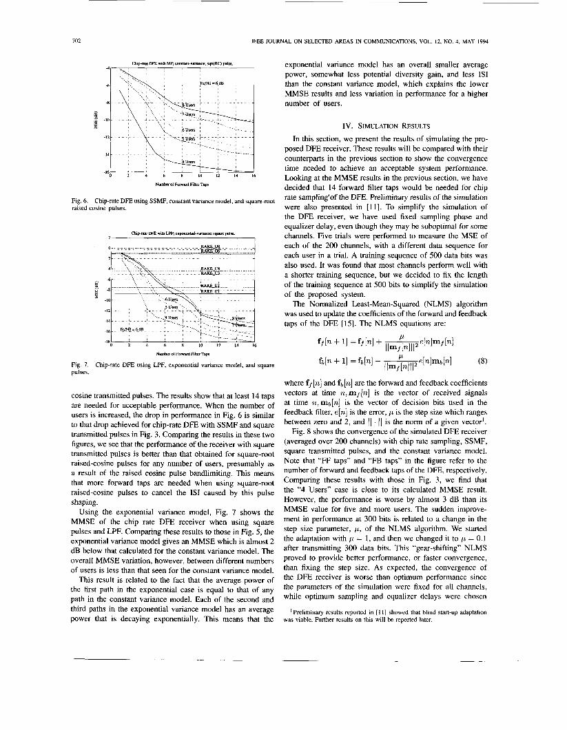
Fig. 7. pulses.
Chip-rate DFE using LPF, exponential variance model, and square
cosine transmitted pulses. The results show that at least 14 taps are needed for acceptable performance. When the number of users is increased, the drop in performance in Fig. 6 is similar to that drop achieved for chip-rate DFE with SSMF and square transmitted pulses in Fig. 3. Comparing the results in these two figures, we see that the performance of the receiver with square transmitted pulses is better than that obtained for square-root raised-cosine pulses for any number of users, presumably as a result of the raised cosine pulse bandlimiting. This means that more forward taps are needed when using square-root raised-cosine pulses to cancel the IS1 caused by this pulse shaping.
Using the exponential variance model, Fig. 7 shows the MMSE of the chip rate DFE receiver when using square pulses and LPF. Comparing these results to those in Fig. 5, the exponential variance model gives an MMSE which is almost 2 dB below that calculated for the constant variance model. The overall MMSE variation, however, between different numbers of users is less than that seen for the constant variance model.
This result is related to the fact that the average power of the first path in the exponential case is equal to that of any path in the constant variance model. Each of the second and third paths in the exponential variance model has an average power that is decaying exponentially. This means that the
exponential variance model has an overall smaller average power, somewhat less potential diversity gain, and less IS1 than the constant variance model, which explains the lower MMSE results and less variation in performance for a higher number of users.
IV. SIMULATION RESULTS In this section, we present the results of simulating the pro-
posed DFE receiver. These results will be compared with their counterparts in the previous section to show the convergence time needed to achieve an acceptable system performance. Looking at the MMSE results in the previous section, we have decided that 14 forward filter taps would be needed for chip rate sarnpling‘of the DFE. Preliminary results of the simulation were also presented in [ l l ] . To simplify the simulation of the DFE receiver, we have used fixed sampling phase and equalizer delay, even though they may be suboptimal for some channels. Five trials were performed to measure the MSE of each of the 200 channels, with a different data sequence for each user in a trial. A training sequence of 500 data bits was also used. It was found that most channels perform well with a shorter training sequence, but we decided to fix the length of the training sequence at 500 bits to simplify the simulation of the proposed system.
The Normalized Least-Mean-Squared (NLMS) algorithm was used to update the coefficients of the forward and feedback taps of the DFE [15]. The NLMS equations are:
where ff[n] and fb[n] are the forward and feedback coefficients vectors at time n,mf[n] is the vector of received signals at time n,mb[n] is the vector of decision bits used in the feedback filter, e[.] is the error, p is the step size which ranges between zero and 2, and ( 1 . ( 1 is the norm of a given vector’.
Fig. 8 shows the convergence of the simulated DFE receiver (averaged over 200 channels) with chip rate sampling, SSMF, square transmitted pulses, and the constant variance model. Note that “FF taps” and “FB taps” in the figure refer to the number of forward and feedback taps of the DFE, respectively. Comparing these results with those in Fig. 3, we find that the “4 Users” case is close to its calculated MMSE result. However, the performance is worse by almost 3 dB than its MMSE value for five and more users. The sudden improve- ment in performance at 300 bits is related to a change in the step size parameter, p, of the NLMS algorithm. We started the adaptation with p = 1, and then we changed it to p = 0.1 after transmitting 300 data bits. This “gear-shifting” NLMS proved to provide better performance, or faster convergence, than fixing the step size. As expected, the convergence of the DFE receiver is worse than optimum performance since the parameters of the simulation were fixed for all channels, while optimum sampling and equalizer delays were chosen
’ Preliminary results reported in [ 1 I ] showed that blind start-up adaptation was viable. Further results on this will be reported later.

ABDULRAHMAN er al.: DECISION FEEDBACK EQUALIZATION FOR CDMA 703
Chip-rate DFE with LPF and conslant-variance d e l .
1 2000 2500 3000
Number of bits m m i t t e d
Fig. 8. constant variance model.
Convergence time of chip-rate DFE using SSMF, square pulses, and
for all channels when calculating the optimum MMSE of the receiver. When sampling the DFE at twice the chip rate of the spreading code but using 14 forward taps as in the chip-rate DFE, the convergence was slower than that of chip-rate DFE. Adding two extra forward taps improved the performance by almost 1.5 dB, which shows the importance of choosing the proper forward filter length to achieve good performance.
Fig. 9 shows the convergence time of the chip-rate DFE with LPF, square pulses, and constant variance model. There is a 2 dB difference between the simulated and calculated MMSE for the case of four users but the convergence is worse for a higher number of users, where the simulation gives an MSE which is worse by at least 5 dB than that calculated in Fig. 5. Similar results were achieved for DFE with twice chip rate sampling, but the performance improves as more forward taps are added to the DFE. This is expected since the forward filter is trying to perform the job of the SSMF, and cancel the effects of interference and AWGN. However, it requires more forward taps to achieve its purpose, so it becomes an implementation issue in deciding on the number of forward taps to use to achieve the acceptable MSE performance of the DFE receiver. The simulation results also show that the SSMF receiver with a number of users greater than 6 gives better performance than that achieved by the LPF system. This is in contrast to the results obtained in the optimum performance of the system. The reason is again related to the parameter optimization that was ignored in the simulation, which causes lower performance in the LPF receiver that uses the same number of forward taps as the SSMF receiver and has no information about the spreading sequence of the desired user. This shows that a DFE receiver with a LPF requires a longer time to converge, since it is trying to perform the job of the matched filter and equalization at the same time.
The effect of pulse shaping on the convergence time of the DFE can be seen in Fig. 10, where square-root raised- cosine pulses were used for the chip-rate DFE with SSMF and constant variance model. Comparing these results with the calculated MMSE in Fig. 6, the “4 Users” case reaches the expected MMSE while the other cases are worse by almost 3 dB than their calculated MMSE. Using the exponential variance model, Fig. 11 shows the convergence time of chip-
0
2
Pulseshape square FFtapsl4 FBraps=2
-6
-8 E
-10-
-12-
-14 - -16 - -18 -
I 500 1000 1500 2000 2500 3 M o
-20 I
Number of bits mlsrmtted
Fig. 9. constant variance model.
Convergence time of chip-rate DFE using LPF, square pulses, and
Cbpratc DFE with SSMF and conslant-vanance d e l
Pulse Shape SQRTWC) FF laps= 14, PB raps= 2 Ecnvo = 6 dB.
2
n
-6
Q 3 - 8
-10
Number of b m uansmtted
Fig. 10. raised-cosine pulses, and constant variance model.
Convergence time of chip-rate DFE using SSMF, square-root
4
-6
Q
4
-6
Q
-12
-14
500 IOM) l5W 2oW 2500 3 M o -18l
Number of bits uansnuned
Fig. 11. exponential variance model.
Convergence time of chip-rate DFE using LPF, square pulses, and
rate DFE with LPF and square pulses. Similar to Fig. 9, the convergence time for 4 users gives an MSE close to the calculated MMSE after a short time of data bit transmission. However, the performance is worse by at least 4 dB for a number of users higher than 4.
In presenting the MMSE and convergence results of the DFE receiver, we assumed that all users start transmitting within one

704 IEEE JOURNAL ON SELECTED AREAS IN COMMUNICATIONS, VOL. 12, NO. 4, MAY 1994
Pulse Shape' SQRT(RC) ’
Blrthsurve new users at 500. ISW. 2500,3500 and 4Mo. ~z-FFfa4s=14.FBlaps=2,EuNo=6dB
-tkathsurve: User 2 teamuam at 3000. User 3 mumates a t W
Cluprate DFE mth SSMP and canstant-variance model. Chjpratc D E wilh SSh5 and constant-varluce model
t rl
I I 1 2 3 4 S 6 7 8
1 0 7 1 0 two u)(M 3wo 4ooo 5000 m
N& of bils urnmilad Number of Users
Fig. 12. Birth of interferers Performance for ChiP-rate D m with Ssm, constant variance model, and square pulses.
Fig. 14. Bit error rate of chip-rate DFE with SSMF, constant variance model, and square pulses.
Oup-me DFE with SSMFand exwnwlial-wiance model
f bmLc e
-14
-16
-18 ‘blrth-cmve” BER = 2 46 40 ’ dealh-curve” BER = 2 36 %
I 0 1000 UMO 3wo 4wo so00 m -20
Number of brls Uansnulad
Chi- D E with LPF and comtant-variance model.
1 1 2 3 4 5 6 7 8
104
Number of Urn Fig. 13. .Death of interferers performance for chip-rate DFE with SSMF, exponential variance model, and square-root raised-cosine pulses. Fig. 15.
and square pulses. Bit error rate of chip-rate DFE with LPF, constant variance model,
bit period. In practice, users transmit and terminate their access to the system at different times. Fig. 12 shows the case of sudden access or birth of users in the DFE receiver that uses a SSMF, constant variance model, and square pulses. The system starts with one user, and new users are given access starting at 500 bits with another new user every 1000 bits to a maximum of six users in the system. A user usually transmits at full power at the moment of establishing access in the system. This case is presented in the “Full Power” curve of Fig. 12. This situation causes a sudden drop in system performance, which might lead to a MSE lower than that required for good performance. This happened when the fifth user established access to the system, where the MSE went below the required -6 dB. This lead us to suggest the use of the “Low Power” access scheme, where a new user is asked to increase his power linearly over a short period of time.
Fig. 12 shows the case where a new user increases his power linearly over 250 bits. The time to establish full power could be used to transmit control information before actual data transmission could start. Comparing both access schemes for birth of new users, we find that the Low Power access scheme gives an improvement of almost 2 dB for the case of the third and fifth users access to the system. Fig. 13 shows the effects of sudden termination or death of users
on the performance of the DFE receiver. The “birth curve” represents the case of users accessing the receiver that uses a SSMF, exponential variance model, and square-root raised- cosine pulses. The “death curve” shows the performance of the DFE receiver when users 2 and 3 terminate their access at 3000 and 4000 bits, respectively. As expected, the termination of access improves the MMSE performance of the DFE receiver.
Looking at the bit error rate (BER) of the proposed DFE receiver, Fig. 14 shows that four users provide a good BER when using a SSMF at the input of the DFE. In calculating the BER, one trial was performed for each channel and each user transmits 50,000 data bits. Fig. 15 shows the BER when the SSMF is replaced by a LPF. The results are worse in this case because the LPF receiver uses the same number of forward taps as the SSMF receiver and has no knowledge of the spreading code of the desired user but still provides good BER for four users. BER in the order of lo-’ is acceptable in the system for voice transmissions. The BER of the LPF case and the corresponding overall MSE could be improved by adding more forward taps. It was also noticed that the results of MSE and BER are similar in providing the same conclusion in

ABDULRAHMAN er al.: DECISION FEEDBACK EQUALIZATION FOR CDMA
terms of the capability of the DFE receiver to handle a number of users equal to half or more of the processing gain.
V. CONCLUSIONS
We have proposed the use of fractionally spaced DFE for CDMA systems. The optimum performance, convergence time, and BER results show the capabilities of this receiver in minimizing the effects of interference, multipath, fading, and AWGN in a slow acting (and, therefore, imprecise) power control environment. Two receiver configurations were considered: one that has knowledge of desired user spreading code (SSMF receiver), and the other has no information about all spreading codes (LPF receiver). A study of the optimum performance showed that the LPF receiver gives better MMSE performance than that obtained by the SSMF receiver. However, the opposite is true when a simulation of both receivers was performed. One reason was that parameter optimization was ignored in the simulation in order to simplify the implementation. Using a PG equal to 8, the receiver could easily service up to four users, which is equal to 50% of the processing gain. As shown by the 'RAKE' curves of Figs. 3 and 7, a conventional coherent RAKE receiver with this processing gain and equally imprecise power control would handle at most one or two users. Of course, both the DFE and conventional RAKE systems can benefit from exploiting voice activity and sectored antennas, as suggested in [I].
APPENDIX
MMSE ANALYSIS FOR FRACTIONALLY SPACED DFE RECEIVER IN CDMA SYSTEMS
Equation (4) represents the signal received at the input of the DFE receiver. This equation could be rewritten as:
d k ( t ) = b t h k ( t - X T b ) (9) x
where M k
h k ( t ) = c m k a k ( t - f l k - t m k ) . (10) m=O
This received signal is passed through an SSMF (or LPF) before being processed by the equalizer part of the receiver. The received signal at the input of the DFE is presented as:
N
= g k ( t ) + 19 ( t ) (11) k=O
70s
where
v k ( t ) = 1 h k ( T ) a o ( T - t)* d T
M n
C m k / a k ( 7 - f l k - t , k ) a O ( T - t)* dT m=O
M k
= C m k R O K ( t - f l k - t m k ) (13)
R o k ( t ) = a k ( T ) a 0 ( 7 - t)* dT (14)
m=O
s and
19 ( t ) = n(r)a0(7 - t)* d 7 . (15) S Assuming that all b t are uncorrelated; E(b$) = 0; = 1; and there are no decision errors, then (5) could be expressed as:
where
UH = [Z,* 1 2; , . . . , Zirz, f ; 1 f; 1 . . . , fi;, 1 x: = [ g ( n T b ) * , g ( n T b - A)*, * . . ,
(17)
g(nTb - N z A ) * , b ~ - l - , , " ' , b ~ - N , - , ]
= [GZ bIf-T-D] (18)
and H is the Hermitian transpose of a matrix.
be equal to: Similar to the analysis given in [6], the MMSE is found to
MMSE = 1 - VHA-lV = 1 - VHUopt (19)
where Uopt gives the optimum settings of the forward and feedback coefficients of the DFE receiver, A = E(X,XF) and V = E(X,b;-,).
To calculate the MMSE, matrix A and vector V need to be calculated. Vector V could be written as:

706 IEEE JOURNAL ON SELECTED AREAS IN COMMUNICATIONS, VOL. 12, NO. 4, MAY 1994
- -
and the 4 matrix could be calculated as:
where (see top of previous page)
a: is the variance of AWGN, and I is a N f by N f identity matrix.
REFERENCES
[ 11 K. S. Gilhousen, I. M. Jacobs, R. Padovani, A. J. Viterbi, L. A. Weaver, Jr., and C. E. Wheatley 111, “On the capacity of a cellular CDMA system,’’ IEEE Trans. Vehic. Technol., vol. 40, no. 2, pp. 303-312, May 1991.
[2] A. Salmasi and K. S. Gilhousen, “On the system design aspects of code division mulitple access (CDMA) applied to digital cellular and personal communications networks,” in IEEE 4Ist Vehic. Technol. Conf., 1991, pp. 57-62.
131 R. Lupas and S. Verdu, “Near-far resistance of multiuser detectors in asynchronous channels,” IEEE Trans. Commun., vol. 38, no. 4, pp. 49C508, Apr. 1990.
[4] Z. Xie, R. T. Short, and C. K. Rushforth, “A family of suboptimum detectors for coherent multiuser communciations,” IEEE J . Select. Areas Commun., vol. 8, no. 4, pp. 683-690, May 1990.
[5] R. Kohno, H. Imai, M. Hatori, and S. Pasupathy, “Combination of an adaptive array antenna and a canceller of interference for direct- sequence spread-spectrum multiple-access system,’’ IEEE J. Select. Areas Commun., vol. 8, no. 4, pp. 675-682, May 1990.
[6] M. Abdulrahman and D. D. Falconer, “Cyclostationary crosstalk sup- pression by decision feedback equalization on digital subscriber loops,” IEEE J. Select. Areas Commun., vol. 10, no. 3, pp. 640-649, Apr. 1992.
[7] G. L. Turin, “Introduction to spread-spectrum antimultipath techniquies and their application to urban digital radio,” Proc. IEEE., vol. 68, no.
[8] B. R. Petersen and D. D. Falconer, “Minimum mean square equalization in cyclostationary and stationary interference-Analysis and subscriber line calculations,” IEEE J . Selecr. Areas Commun., vol. 9, no. 6, pp.
[9] D. D. Falconer, M. Abdulrahman, N. W. K. Lo, B. R. Petersen, and A. U. H. Sheikh, “Advances in equalization and diversity for portable wireless systems,” Digir. Signal Process., vol. 3, no. 3, pp. 148-162, Mar. 1993.
3, pp. 328-353, Mar. 1980.
931-940, Aug. 1991.
[lo] M. Abdulrahman, D. D. Falconer, and A. U. H. Sheikh, “Equalization for interference cancellation in spread spectrum multiple access systems,” in IEEE 42nd Vehic. Technol. Conf., 1992, pp. 71-74.
[ 111 M. Abdulrahman, A. U. H. Sheikh, and D. D. Falconer, “DFE conver- gence for interference cancellation is spread spectrum multiple access systems,” in IEEE 43rd Vehic. Technol. Conf., 1993, pp. 807-810.
[I21 U. Madhow and M. L. Honig, “Minimum mean squared error inter- ference suppression for direct sequence spread-spectrum code division multiple access,” in Proc. ICUPC, 1992.
[13] U. Madhow and M. L. Honig, “Error probability and near-far resistance of minimum mean squared error interference suppression schemes for CDMA,” in Proc IEEE GLOBECOM, 1992, pp. 1339-1343.
1141 J. G. h o a k k , Digital Communications. New York: McGraw-Hill, 1989.
[ 151 G. C. Goodwin and K. S. Sin, Adaptive Filrering Prediction and Control. Englewood Cliffs, NJ: Prentice-Hall, 1984.
Majeed Abdulrahman (S’89) received the B.A.Sc. degree in electrical engineenng from the University of Ottawa, Ottawa, Ontano, Canada in 1988, and the M.Eng. and Ph.D. degrees in electrical engineenng from Carleton University, Ottawa, in 1989 and 1994, respectively.
Dunng his undergraduate studies at the University of Ottawa, he worked with Bell-Northem Research, Ottawa. He was the recipient of the NSERC federal scholarship for the maximum period of four years during his graduate studies at Carleton University.
He is currently working with Bell-Northem Research in Ottawa. His research interests are in spread spectrum systems and its applications for indoor wireless communications, cellular system design, adaptive equalization, digital subscnber lines, and ISDN.
Asrar U. H. Sheikh (M’70-M’82-SM ‘84) re- ceived the B.S. degree from the University of En- gineenng and Technology, Lahore, Pakistan, and received the M.Sc. and Ph.D. degrees from the University of Birmingham, Birmingham, England, in 1966 and 1969, respectively
He held lectureships at universities in Pakistan, Iran, and Libya between 1969 and 1975 before returning to Birmingham as a Research Fellow. In 1981, he joined Carleton University, Ottawa, On- tano, Canada as an Associate Professor. At present,
he is a Professor in the Department of Systems and Computer Engineering. From 1988 to 1991, he was Associate Chairman for Graduate Studies. Presently, he is the Director of the PCS Laboratory at Carleton University. Currently, he is leading a major research project on Universal, Secure, and Efficient Telecommunications (USETS) He has published extensively in the areas of mobile and personal communications, and impulsive noise. His current interests are in signal processing in communications, digital cellular systems, DS and FH spread spectrum systems, and personal communication systems. He has been consultant to several private and government agencies. He is a co-recipient of the Paul Adonan Premium from the IERE for his work on impulsive noise characterization. He is also a Professional Engineer licensed in the Province of Ontano.
David D. Falconer (M’68-SM’83-F’86), for photograph and biography, see this issue, p. 653.