Decentralized Sensor Fusion for Ubiquitous Networking Robotics in Urban Areas
41
Sensors 2010, 10, 2274 - 2314; doi:10.3390/s100302274 OPEN ACCESS sensors ISSN 1424-8220 www.mdpi.com/journal/sensors Article Decentralized Sensor Fusion for Ubiquitous Networking Robotics in Urban Areas Alberto Sanfeliu 1, , Juan Andrade-Cetto 1 , Marco Barbosa 2 , Richard Bowden 3 , Jes ´ us Capit ´ an 5 , Andreu Corominas 1 , Andrew Gilbert 3 , John Illingworth 3 , Luis Merino 4 , Josep M. Mirats 1 , Pl´ ınio Moreno 2 , An´ ıbal Ollero 5,6 , Jo ˜ ao Sequeira 2 and Matthijs T.J. Spaan 2 1 Institut de Rob ` otica i Inform` atica Industrial, CSIC-UPC, Barcelona, Spain; E-Mails: [email protected] (J.A.-C.); [email protected] (A.C.); [email protected] (J.M.M.) 2 Instituto Superior T´ ecnico & Institute for Systems and Robotics, Lisbon, Portugal; E-Mails: [email protected] (M.B.); [email protected] (P.M.); [email protected] (J.S.); [email protected] (M.T.J.S.) 3 Centre for Vision Speech and Signal Processing, University of Surrey, Guildford, UK; E-Mails: [email protected] (R.B.); [email protected] (A.G.); [email protected] (J.I.) 4 Pablo de Olavide University, Seville, Spain; E-Mail: [email protected] 5 Robotics, Vision and Control Group, University of Seville, Seville, Spain; E-Mail: [email protected] 6 Center for Advanced Aerospace Technology, Seville, Spain Author to whom correspondence should be addressed; E-Mail: [email protected]; Tel.: +34-934015751; Fax: +34-934015750. Received: 12 January 2010; in revised form: 2 February 2010 / Accepted: 28 February 2010 / Published: 19 March 2010 Abstract: In this article we explain the architecture for the environment and sensors that has been built for the European project URUS (Ubiquitous Networking Robotics in Urban Sites), a project whose objective is to develop an adaptable network robot architecture for cooperation between network robots and human beings and/or the environment in urban areas. The project goal is to deploy a team of robots in an urban area to give a set of services to a user community. This paper addresses the sensor architecture devised for URUS and the type of robots and sensors used, including environment sensors and sensors onboard the robots. Furthermore, we also explain how sensor fusion takes place to achieve urban outdoor execution of robotic services. Finally some results of the project related to the sensor network are highlighted.
-
Upload
independent -
Category
Documents
-
view
0 -
download
0
Transcript of Decentralized Sensor Fusion for Ubiquitous Networking Robotics in Urban Areas

Sensors 2010, 10, 2274 - 2314; doi:10.3390/s100302274
OPEN ACCESS
sensorsISSN 1424-8220
www.mdpi.com/journal/sensors
Article
Decentralized Sensor Fusion for Ubiquitous NetworkingRobotics in Urban AreasAlberto Sanfeliu 1,�, Juan Andrade-Cetto 1 , Marco Barbosa 2, Richard Bowden 3,Jesus Capitan 5, Andreu Corominas 1, Andrew Gilbert 3, John Illingworth 3, Luis Merino 4,Josep M. Mirats 1, Plınio Moreno 2, Anıbal Ollero 5,6, Joao Sequeira 2 and Matthijs T.J. Spaan 2
1 Institut de Robotica i Informatica Industrial, CSIC-UPC, Barcelona, Spain;
E-Mails: [email protected] (J.A.-C.); [email protected] (A.C.); [email protected] (J.M.M.)2 Instituto Superior Tecnico & Institute for Systems and Robotics, Lisbon, Portugal;
E-Mails: [email protected] (M.B.); [email protected] (P.M.); [email protected] (J.S.);
[email protected] (M.T.J.S.)3 Centre for Vision Speech and Signal Processing, University of Surrey, Guildford, UK;
E-Mails: [email protected] (R.B.); [email protected] (A.G.);
[email protected] (J.I.)4 Pablo de Olavide University, Seville, Spain; E-Mail: [email protected] Robotics, Vision and Control Group, University of Seville, Seville, Spain;
E-Mail: [email protected] Center for Advanced Aerospace Technology, Seville, Spain
� Author to whom correspondence should be addressed; E-Mail: [email protected];
Tel.: +34-934015751; Fax: +34-934015750.
Received: 12 January 2010; in revised form: 2 February 2010 / Accepted: 28 February 2010 /Published: 19 March 2010
Abstract: In this article we explain the architecture for the environment and sensors that has
been built for the European project URUS (Ubiquitous Networking Robotics in Urban Sites), a
project whose objective is to develop an adaptable network robot architecture for cooperation
between network robots and human beings and/or the environment in urban areas. The project
goal is to deploy a team of robots in an urban area to give a set of services to a user community.
This paper addresses the sensor architecture devised for URUS and the type of robots and
sensors used, including environment sensors and sensors onboard the robots. Furthermore,
we also explain how sensor fusion takes place to achieve urban outdoor execution of robotic
services. Finally some results of the project related to the sensor network are highlighted.

Sensors 2010, 10 2275
Keywords: network robot systems; distributed sensors; robot sensors; camera network
1. Introduction
In the URUS project [1] we needed to interconnect and manage multiple services that enable urban
robots to perform social urban tasks. To this end, we have designed an architecture that takes advantage
of all information available within a large set of ubiquitous sensors, including fixed cameras, wireless
sensors, Mica2 sensors and various sensing devices onboard the robots, such as cameras and laser range
finders. Two characteristics of this architecture are of particular relevance: it is a highly distributed
architecture, and it is scalable. Contrary to other architectures for multiple robot interoperability, our
system does not make use of a central server that receives and combines all the information available
to obtain, for instance, a fused estimation of a given variable, say a tracked person position [2]. Such
kind of systems are dependent on a central node, thus not robust to communication failures, latencies
or drop outs, and they do not scale well with the number of nodes. In the URUS architecture, we opted
for a decentralized system in which each subsystem only manages local information and exchanges with
its peers local estimates of any given variable. Decentralized data fusion takes place by means of an
information filter (IF), dual to the more common Kalman filter typically used for data fusion [3]. The
IF has very nice characteristics for decentralization, with applications in other robotics contexts such as
aerial robot decentralized perception [4]. One of the applications of decentralized data fusion in URUS
is person tracking and guiding, employing the local sensors of the robot and the environment camera
network, efficiently coping with occlusions, and single module tracking failures.
The article is organized as follows. We first present the objectives of the URUS project, the partners
and the robot sites where the experiments take place. Then, we explain the distributed URUS architecture
and the sensors in a network that combines cameras and Mica2 sensors. Next, we describe the sensors
that are included in some of the robots used for the experiments. The robotic systems described in
this paper include Tibi and Dabo from the Institut de Robotica i Informatica Industrial (CSIC-UPC),
Romeo from the Asociacion de Investigacion y Cooperacion Industrial de Andalucıa (AICIA) and a fleet
of Pioneer robots from the Instituto Superior Tecnico (IST). Next we describe how information fusion
from several sensors takes place, and the software architecture that we have developed to manage such
heterogeneous set of sensors and systems. Finally, we explain how we use these sensors for several
robot services as required by some of the URUS experiments, including for instance robot localization
and people tracking.
2. The URUS Project
2.1. Objectives of the URUS Project
The general objective of the URUS project is the development of new ways for the cooperation
between network robots and human beings and/or the environment in urban areas, in order to achieve
efficiently tasks that for single systems would be too complex, time consuming or costly. For instance,

Sensors 2010, 10 2276
the cooperation between robots and video cameras can solve surveillance problems for blind spots
in urban areas, or the cooperation between robots and wireless communications devices can improve
efficiency in people assistance services. The focus of the project is in urban pedestrian areas, for which
there exists a growing interest in reducing the number of cars and improving the quality of life. Network
robots become an important instrument towards these goals.
Network robots is a new concept that integrates robots, sensors, communications and mobile devices
in a cooperative way. Meaning that, not only a physical connection between these elements exists, but
also, that there is a need for the development of novel intelligent cooperation methods for task oriented
purposes, new ways of communication between the different elements, and new robot mobility methods
using the ubiquity of sensors and robots.
The URUS project is focused on designing and developing a network of robots that in a cooperative
way interact with human beings and the environment for tasks of guidance and assistance, transportation
of goods, and surveillance in urban areas. Specifically, our objective has been the design and
development of a networked robot architecture that integrates cooperating urban robots, intelligent
sensors (video cameras, acoustic sensors, etc.), intelligent devices (PDA, mobile telephones, etc.) and
communications. The main scientific and technological challenges that have been addressed during the
course of the project are: navigation and motion coordination among robots; cooperative environment
perception; cooperative map building and updating; task negotiation within cooperative systems; human
robot interaction; and wireless communication strategies between users (through mobile phones, PDAs),
the environment (cameras, acoustic sensors, etc.), and the robots.
Figure 1. Barcelona Robot Lab.
Moreover, we have devised two demonstration scenarios in the Barcelona Robot Lab, a 10,000 m2
area devoted to urban robotics experimentation (Figure 1). Scenario 1 involves transporting a person or
goods to a destination; and Scenario 2 is devoted to drive people slowly and orderly towards the main exit
in public spaces at closing hour. In the first case, a person calls, by means of a mobile phone, for a robots
in order to receive the service. The robot that has the transport functionality, is available and closest
to that person, approaches the person, identifies the person, and guides him or her to the requested
final destination. All this, with the aid of the distributed sensor network for the tasks of localization,

Sensors 2010, 10 2277
identification, guidance, and robot navigation. In the second case, the trigger signal for the surveillance
service of public space is the closing time or a human gesture. Then, the appropriate robots available for
this service approach the area where people is gathered and directs them to leave the space.
2.2. Project Participants
The project participants are:
• Institut de Robotica i Informatica Industrial, CSIC-UPC, Barcelona, Spain
• Laboratoire d’Analyse et d’Architecture des Systemes, CNRS, Toulouse, France
• Swiss Federal Institute of Technology Zurich, Switzerland
• Asociacion de Investigacion y Cooperacion Industrial de Andalucıa, Seville, Spain
• Scuola Superiore di Studi Universitari e di Perfezionamento Sant’Anna, Pisa, Italy
• Universidad de Zaragoza, Spain
• Institute for Systems and Robotics, Instituto Superior Tecnico, Lisbon, Portugal
• University of Surrey, Guildford, UK
• Urban Ecology Agency of Barcelona, Spain
• Telefonica I + D, Spain
• RoboTech, Italy
2.3. Barcelona Robot Lab
The Barcelona Robot Lab, built within the context of this project, is an outdoor urban experimental
robotics site located at the Universitat Politecnica de Catalunya (UPC) campus, which includes 6
university buildings over a 10,000 m2 area. In this area we have placed 21 fixed color video cameras
connected through a Gigabit Ethernet connection to a computer rack. The position of the cameras is
shown in Figure 2, with varying density in the positioning of the cameras, according to the various
objectives of the project. Specifically, there are five cameras directed towards the Computer Science
School (FIB) square, to have enough resolution for the detection of human gestures. There is also
increased density in the positioning of the cameras in front of building A6, for the same reason. The rest
of the area is covered with sparser density only to guarantee almost complete coverage of the area during
people and robot tracking.
This outdoor facility is also equipped with 9 WLAN antennas with complete area coverage.
Specifically for this project, we have installed the IEEE 802.11a protocol, contrary to the more common
b/g/ or n networks. The reason was to limit as much as possible interferences with the university
WLAN also covering the same area. The laboratory is also equipped with 802.15.4 wireless sensors
for location purposes. Further information on the Barcelona Robot Lab experimental site can be seen at
(http://www.urus.upc.es).

Sensors 2010, 10 2278
Figure 2. Camera network. (a) Colour video camera deployed in the URUS project.
(b) The position of the cameras within the Barcelona Robot Lab.
(a) (b)
2.4. ISRobotNet
The Institute for Systems and Robotics at Instituto Superior Tecnico, in Lisbon, has developed also
a testbed for NRS, the Intelligent Sensor and Robot Network (ISRobotNet), that enables testing a wide
range of perception and robot navigation techniques, as well as human robot-interaction, distributed
decision making, and task and resource allocation. The ISRobotNet testbed, also part of the URUS
project, is composed of a 160 m2 indoor area with 10 webcams placed at the ceiling such that some of
their fields of view do not overlap. The cameras are distributed in 4 groups, each of which is managed by
its own computer for image acquisition. The managing computers are connected to the global ISR/IST
network and can be accessed by duly authorized external agents. Ongoing work will extend the number
of cameras and the usable indoor space to include multiple floors. Robots will use the same elevators as
ordinary people to move between floors. Besides the camera sensors, four Pioneer ATs and one ATRV-Jr
robots are available. Each of the robots is equipped with sonar, onboard cameras, laser range finder and
is Wi-Fi connected to the network. Figure 3 shows one of the floors at ISR/IST where the testbed is
implemented and a map with the camera fields of view.
ISRobotNet is built around the kernel of a service-oriented architecture (MeRMaID) [5], and extended
to use the YARP networking software [6]. The testbed is being used to develop different components,
namely, cooperative perception, people and robot detection and tracking using the camera network,
and decision making. Arbitrary computational resources can be distributed over the network for fully
decentralized use. Basic services such as robot teleoperation and direct image acquisition and recording
from the camera network, as well as event logging, are also available.

Sensors 2010, 10 2279
Figure 3. ISRobotNet.
3. The URUS Architecture
The sensor architecture of URUS has being designed to manage distributed information coming from
different sensors and systems, and they have to be used for flexible and dynamic robot services. The
architecture is distributed among subsystems which are interconnected through various means, Ethernet
cable, WLAN and GSM/3G (see Figure 4).
The architecture is divided in three layers:
• Environment Layer:
– The networked cameras oversee the environment and are connected through a Gigabit
connection to a rack of servers.
– The wireless Zigbee sensors all communicate to a single subsystem which is also connected
to the system through one computer.
– The WLAN environment antennas are connected through the Gigabit connection to the
rack servers.
– People use devices to connect to the robots and the environment sensors. For instance, a
mobile phone with PDA features is connected through GSM/3G to the system.
• Robot Sensor Layer:
– The robots have their own sensors connected through proprietary networks (usually
Ethernet) which are connected through WLAN and GSM/3G to the system. A proprietary
communications service has been developed to transparently switch between WLAN and 3G
depending on network availability.
• Server Layer:
– The server rack (8 servers with 4 cores each) are connected through Ethernet to the
Environment Layer and the Robot Sensor Layer.
The network of cameras is used to detect, track and identify people gestures in the urban area, as
well as to detect and identify the robots. They can also be used for other services, such as surveillance,

Sensors 2010, 10 2280
obstacle detection, etc. The wireless sensors, in this case Mica 2 sensor motes, are used mainly to
enhance person and robot localization, based on radio signals. The Mica2 localization estimates are
robustly fused with map-based localization methods in a decentralized way. Robot localization using
GPS signals is not possible in the Barcelona Robot Lab, as in many urban areas due to satellite occlusion.
The localization of the robots is so important, that we need to use as many methods as possible in order
to minimize localization uncertainty.
Figure 4. URUS global architecture.
The sensors onboard the robots are used mainly for navigation, localization and security; for robot
and person identification, including the identification of human gestures and actions; and for human
robot interaction.
Robots share information with other robots and with the server layer, through WLAN and GSM/3G.
If WLAN is lost, for example when a robot crosses an area where the signal strength of the assigned AP
(Access Point) is lost, then the robot either connects to another AP, or the robot connects to the system
through GSM/3G.
The fully distributed software architecture is developed over YARP [6]. It can be used on any type of
robots, sensors and human wearable devices. Specifically, we have developed standard procedures for
connecting software modules allowing the share of information among the robots, sensors and human
wearable devices.

Sensors 2010, 10 2281
At the level of sensor fusion for estimating system variables such as robot or people localization, data
was fused in a decentralized form, with each component implementation independent from each other.
However, at the experiment level, a central station was devised to handle task allocation and human
operator commands through a GSM interface. This station had a finite state automata that took care of
processing the experiment scripts and handling contingencies.
4. Sensors in the Urban Site
4.1. Camera Network
The camera network consists of 21 IP color video cameras distributed around the Barcelona Robot
Lab. The cameras are connected to each building switch with a Gigabit link. From each building, there
is a Gigabit connection to the computer rack with servers dedicated to process URUS software. These
servers are in a rack located in another building 200 m away from the NRS (Network Robot System)
area. Each camera has a dedicated IP and is only accessible from the proprietary network that we have
built. The parameters of the cameras can be modified independently and they include a time stamp that
is used in the tracking functions.
The camera network serves as a mean to detect, localize and map environmental information in a
globally coherent frame of reference. Persons and robots must be localized in a unique coordinate
system even though they are observed by distant cameras. We perform image-feature registration for
camera calibration. In contrast to other approaches that use a calibration pattern or stereo geometry over
architectural features to infer depth, depth information is obtained from the range map. The reason to use
the range map to geometrically relate the cameras is because no overlapping fields of view are available
in the camera network. Additionally, being an outdoor system, it is constantly susceptible to weather
conditions, such as rain and wind, and thus it is expected to have slight but visible positioning and
orientation changes from time to time. The calibration methodology must therefore encompass simple
self-adjusting mechanisms.
The development of powerful laser sensors combined with Simultaneous Location and Mapping
(SLAM) methodologies [7, 8] allow the possibility to have available high precision Laser Range Finder
(LRF) data registered over large areas. These large outdoor LRF datasets have started recently to be
acquired also for the purpose of creating robot navigation systems in urban areas. The LRF map is
acquired over the complete area of the network and, in particular, contains the areas corresponding to
the fields of view of the cameras. We exploit these novel technologies proposing a methodology for
calibrating an outdoor distributed camera network using LRF data.
The laser based map, whose construction is discussed further in this section, is used as external
information to aid the calibration procedure of the distributed camera network. For our case, in which
the cameras have non-overlapping fields of view, it is impossible to estimate the relative position between
them unless external data is used to refer the camera calibration parameters to a global reference frame.
Since calibration inevitably requires some user intervention, in large camera networks this can be a very
tedious procedure if one does not develop practical and semiautomated methods that facilitate and speed
up user input. See Figure 5.

Sensors 2010, 10 2282
Figure 5. Camera calibration. (a) Lines are automatically extracted by intersecting planes
on the LRF map, (b) The optimization method registers these 3D features with 2D lines on
the images, and (c) Final reprojection of the segmented laser data after calibration.
(a) (b) (c)
The idea of the approach is the following: in a first stage, the LRF map is registered to an aerial
view of the site and the user sets up the position and nominal calibration parameters of the cameras in
the network. This allows user selection of an initial camera field of view onto the LRF area of interest
likely to be observed by each camera. In a second stage, lines extracted from the LRF area of interest are
represented in the nominally calibrated camera coordinate system and are reprojected to the real-time
cameras’ acquired images. This allows the user to perceive the calibration errors and input information
to a non-linear optimization procedure that refines both intrinsic and extrinsic calibration parameters.
The optimization process matches 3D lines to image lines. The 3D lines are extracted by intersecting
planes on the segmented LRF set. A novel approach to 3D range segmentation based on local variation
is used [9]. To show the applicability of the calibration results, homographies of the walking areas are
computed [10].
4.2. Mica2 Network
Latest advances in low-power electronics and wireless communication systems have made possible
a new generation of devices able to sense environmental variables and process this information.
Moreover, they have wireless communication capabilities and are able to form ad-hoc networks and
relay the information they gather to a gateway. This kind of system is usually called a Wireless Sensor
Network (WSN).
In URUS, a network of wireless Crossbow’s Mica2 sensor nodes is deployed in the urban scenario.
Each Mica2 node (see Figure 6, a) has a suite of sensorial devices, including accelerometers, light and
sound sensors, humidity sensors, etc., a tiny processor, based on the ATmega128L microcontroller, and
a communication module on the 868/916 MHz band. These sensor nodes can be used for monitoring
applications. In addition, the signal strength received by the set of static nodes of the WSN (Received
Signal Strength Indicator, RSSI) can be used to infer the position of a mobile object or a person carrying
one of the nodes. And thus, one of the applications developed in the project is an algorithm for mobile
sensor tracking, which can be used for tracking persons in urban scenarios.

Sensors 2010, 10 2283
Figure 6. Mica2 network. (a) One of the sensor nodes employed in the system. (b) Scheme
of the integration of the nodes into the architecture.
(a) (b)
These sensors are integrated within the URUS system through a gateway which receives the
information from the sensor nodes (see Figure 6b). The sensor nodes build themselves an ad-hoc network
to send all the information to this gateway. In the gateway, a service that provides estimations on the
position of mobile nodes is placed.
4.3. Site Map
We need to build the required maps for our heterogeneous fleet of service robots in urban settings [1].
With these maps the robots should be able to perform path planning and navigate to accomplish their
tasks, such as guidance, assistance, transportation of goods, and surveillance. The experimental area has
several levels and underpasses, poor GPS coverage, moderate vegetation, several points with aliasing
(different points in the environment which cannot be disambiguated form local sensory data), large
amounts of regularity from building structures, and sunlight exposure severely subject to shadows.
Our technique to Simultaneous Localization and Mapping (SLAM) is described in detail in [7, 11, 12],
and is summarized here. We introduce a principled on-line approach for Pose SLAM, the variant
of SLAM in which the state vector contains a history of visited robot locations, which only keeps
non-redundant poses and highly informative links (see Figure 7). This is achieved by computing two
measures; the distance between a given pair of poses and the mutual information gain when linking two
poses. In [11], we show that, in Pose SLAM, the exact form of these two measures can be computed in
constant time. When compared to other existing approaches [13], the proposed system produces a more
compact map that translates into a significant reduction of the computational cost and a delay of the filter
inconsistency, maintaining the quality of the estimation for longer mapping sequences.
By applying the proposed strategy, the robot closes only few loops and operates in open loop for
long periods, which is feasible using recent odometric techniques [14, 15]. Our Pose SLAM approach
includes a novel state recovery procedure at loop closure that takes advantage of the inherent sparsity
of the information matrix scaling linearly both in time and memory. This computational cost is further

Sensors 2010, 10 2284
amortized over the period where the robot operates in open loop, for which we introduce a factorization
of the cross- covariance that allows the state to be updated in constant time. Thus, the proposed
state recovery strategy outperforms state of the art approaches that take linear time for very sparse
matrices (i.e., when the robot operates in open loop), but are worst case quadratic when many loops are
closed [13]. After this, the bottleneck for real time execution is not state recovery, but data association.
That is, detecting poses close to the current one for which feature matching is likely. Exploiting the
factorization of the cross-covariance, we introduced also in [11] a tree-based method for data association
using interval arithmetic to encode the internal nodes of the tree. The main advantage of that method is
that it improves the search up to logarithmic time. Moreover, by taking into account the cross-covariances
from the very beginning it also avoids false positives, typically present in existing tree-based data
association techniques[16]. This offers the possibility to use Pose SLAM for mapping large scale
environments, such as the Barcelona Robot Lab.
Figure 7. Filtered trajectory (in red) using encoder and visual odometry on a dataset
collected at the Barcelona Robot Lab. Loop closure links are displayed in green, the black
ellipse indicates the final robot location and its associated covariance at a 95% confidence
level. (a) standard approach: incorporating all poses and all links to the filter; and (b)
proposed approach: incorporating only relevant poses and links.
(a) (b)
Aerial views of the site are shown in Figures 7 and 8. In order to build the maps described in this
paper, we built our proprietary 3D scanning system, using a Leuze RS4 scanner and controlling its
pitch with a DC motor and a computer. The system was installed atop an Activmedia Pioneer 2AT
robotic platform. The system yields 3D point clouds with ranges up to 30 m, and sizes of about 76,000
points. The sensor noise level is 5 cm in depth estimation for each laser beam. Figure 9 portrays the
complete device. The robot was tele-operated through the site along a path of over 600 m (see Figure 9b).
Sensors 2010, 10 2285
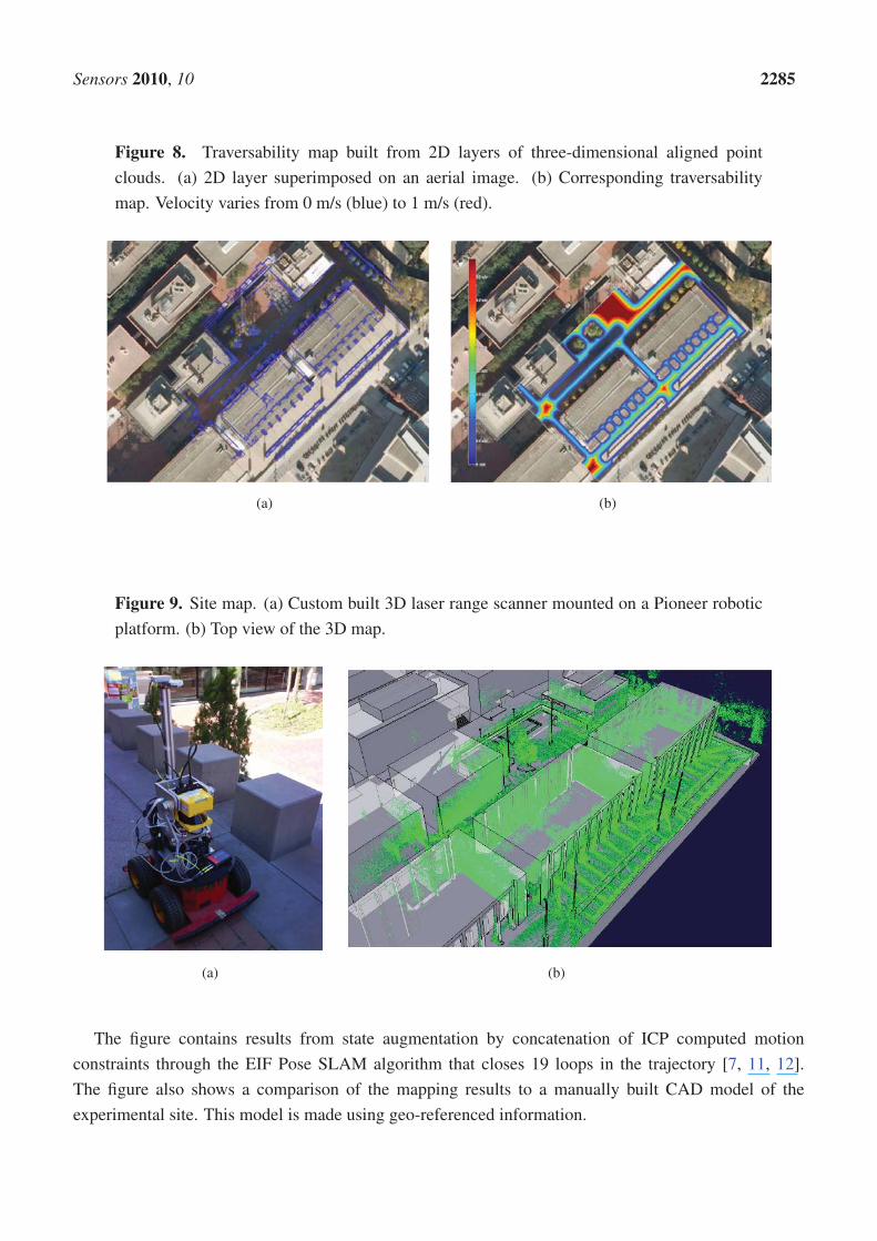
Figure 8. Traversability map built from 2D layers of three-dimensional aligned point
clouds. (a) 2D layer superimposed on an aerial image. (b) Corresponding traversability
map. Velocity varies from 0 m/s (blue) to 1 m/s (red).
(a) (b)
Figure 9. Site map. (a) Custom built 3D laser range scanner mounted on a Pioneer robotic
platform. (b) Top view of the 3D map.
(a) (b)
The figure contains results from state augmentation by concatenation of ICP computed motion
constraints through the EIF Pose SLAM algorithm that closes 19 loops in the trajectory [7, 11, 12].
The figure also shows a comparison of the mapping results to a manually built CAD model of the
experimental site. This model is made using geo-referenced information.

Sensors 2010, 10 2286
5. Sensors Included in Urban Robots
5.1. Sensors in the Robots Tibi and Dabo - Architecture and Functionalities
Tibi and Dabo (Figure 10) are two robots built at IRI with functionalities to navigate in urban areas, to
assist and guide people from one origin to a destination. Traction is based on Segway RMP200 robotic
platforms, and they have been customized with a variety of sensors:
Figure 10. (a) Tibi and Dabo; (b) Tibi sensors.
(a) (b)
• Sensors for navigation: Two Leuze RS4 and one Hokuyo laser rangefinders, as well as Segway’s
own odometric sensors (encoders and IMU).
– The first Leuze rangefinder is located in the bottom front with a 180◦ horizontal view. This
sensor is used for localization, security and navigation.
– The second Leuze rangefinder is located in the bottom back, also with a 180◦ horizontal view.
This sensor is used for localization, security and navigation.
– The Hokuyo rangefinder is located in the front, but placed vertically about the robot chest,
also with a 180◦ field of view. It is used for navigation and security.
• Sensors for global localization: GPS and compass.
– The GPS is used for low resolution global localization, and can only be used in open areas
where several satellites are visible. In particular, for the URUS scenario, this type of sensor
has very limited functionality due to loss of line of sight to satellites from building structures.
– The compass is used also used for recovering robot orientation. Also, in the URUS scenario,
this sensor has proven of limited functionality due to its large uncertainty in the presence of
metallic structures.

Sensors 2010, 10 2287
• Sensors for map building: One custom built 3D range scanner and two cameras.
– The two cameras are located to the sides of the robots and facing front to ensure a good
baseline for stereo triangulation, and they are used for map building in conjunction with the
laser sensors. These cameras can also be used for localization and navigation.
– A custom built 3D laser range finder unit has been developed in the context of the project.
This unit, placed on top of a Pioneer platform has been used to register finely detailed
three dimensional maps of the Barcelona Robot Lab that allow localization, map building,
traversability computation, and calibration of the camera sensor network.
– Vision sensors: One Bumblebee camera sensor.
– The Bumblebee camera sensor is a stereo-vision system that is used for detection, tracking
and identification of robots and human beings. Moreover we use this camera as image
supplier for robot teleoperation.
• Tactile display:
– The tactile display is used for Human Robot Interaction (HRI), to assist people and to
display information about the status of the robot, as well as task specific information, such as
destination information during a guidance service.
The internal architecture of these robots can be seen in Figure 11. We can see all hardware and sensors
on the left side and their connection to the Acquisition/Actuation system. Colors in the figure indicate
development state at an early stage of the project. Green indicates software modules that were completed,
yellow indicates software modules that were in development at that time, and red indicates software
modules that were still not developed. The second Acquisition/Actuation subsystem, second column in
the figure, includes all drivers that connect hardware and sensors to the localization, motion controller,
visual tracking, obstacle avoidance, gesture server and TS interaction modules. The safety subsystem
in the third column uses the process monitor to control the robot platform, using the information from
the robot sensors and the heart beats of the robot systems. The Estimation and Planning subsystem use
the localization and path planning to control the robot motion. The different operation modes for these
robots are: path execution, guiding person, tele-operation and human robot interaction. Each one of
these operation modes are used in the URUS project to give specific services.

Sensors 2010, 10 2288
Figure 11. Internal architecture of Tibi & Dabo.
(a)
5.2. Romeo Sensors—Architecture and Functionalities
Romeo is an electric car modified with sensors and actuators to navigate autonomously in outdoor
scenarios, including urban environments. Figure 12 shows the robot and its main sensors:
• Odometric sensors: Romeo has wheel encoders for velocity estimation, and a KVH Industries’
gyroscope and an Inertial Measurement Unit (IMU) for angular velocity estimation.
• Rangefinders: Romeo has one SICK’s LMS 220-30106 laser rangefinder located in the frontal
part of the robot, at a height of 95 cm, for obstacle avoidance and localization. Moreover, it
has 2 Hokuyo’s URG-04LX (low range, up to 4 meters) in the back for backwards perception,
and 1 Hokuyo’s UTM-30LX (up to 30 meters) at the top of Romeo’s roof and tilted
for 3D perception.
• Novatel’s OEM differential GPS receiver.
• Firewire color camera, which can be used for person tracking and guiding.
• Tactile screen, which is used for robot control and for human-robot interaction.

Sensors 2010, 10 2289
Figure 12. Sensors on board Romeo. Sensors for localization (GPS, gyro, encoders, Sick
laser), map building and navigation (laser rangefinders). (a) front view; (b) rear view.
(a) (b)
Figure 13, a, shows the basic software architecture for robot navigation in pedestrian environments.
For localization, Romeo fuses all its odometric sensors (encoders, gyroscope, IMU) with an Extended
Kalman Filter (EKF-LOC) to estimate its 6D pose. In order to compensate the drift associated to
odometry, Romeo carries a differential GPS receiver. However, as stated before, in urban environments,
often the GPS measurements are not available, or are affected by multi-path effects, which can produce
erroneous estimates, thus localization is map-based and only assisted by GPS. All robots, Tibi, Dabo,
and Romeo use the same map-based localization mechanism developed by Corominas et al. [17, 18],
and described further in this paper, allowing the cancelation of drift error at a rate of 1 Hz.
Figure 13. (a) basic architecture of Romeo. (b) 3D information obtained by Romeo from
the Romeo lasers. Different obstacles can be identified, like stairs, trees or small steps.
(a) (b)

Sensors 2010, 10 2290
For navigation, Romeo combines the pose information from the localization algorithm with the data
from its lasers to build a 3D representation of the environment (see Figure 13b). From this representation,
it is possible to obtain a traversability map; that is, a grid in which each cell indicates if it can be drivable
by Romeo or not, such as the one shown in Figure 8b. The analysis to decide if a place is drivable or not
depends mainly on the slope at each point of the map. At the same time, mobile obstacles can be also
identified. This is used by the obstacle avoidance module to command the robot.
Romeo carries on board cameras that can be used for person tracking and guiding. The algorithms
employed for this are based on a combination of person detection and tracking. The tracking algorithm is
based on the mean shift technique [19]. In parallel, a face detection algorithm is applied to the image [20],
the results from the tracking and the detection applications are combined, so that the robot employs the
face detector when the tracker is lost to recover the track. As a result, the robots can obtain estimates of
the pose of a person face on the image plane (see Figure 14).
Figure 14. People tracking from Romeo for guidance.
5.3. ISTRobotNet Architecture and Functionalities
IST is using Pioneer 3AT robots equipped with odometry, ultrasound, and laser range finder sensors
(Figure 15). Basic navigation capabilities, namely path planning and obstacle avoidance, are available
for each robot. Localization for these robots is also is based on the fusion of odometry and range
information and the a priori defined world map. Contrary to the robots that navigate in the Barcelona
Robot Lab, the CARMEN package is used for map building and localization at the ISRobotNet site.
A grid is superimposed on the map obtained with CARMEN, and the centers of each cell constitute the
set of waypoints used in the robot navigation.
An auction based high level supervision is implemented by a distributed component [21]. This
approach is flexible enough to allow fast prototyping in behavior development. The robot tasks consist in
the use of navigation behaviors to reach a given cell in the grid map. The robot supervisor is synthesized
by formulating POMDP’s for each possible task [22]. Thus, the robots task fitness is the value function
of the POMDP for each task. The benefit of using the POMDP approach is that it is possible to compare
the fitness of unrelated tasks, such as navigation and the use of onboard sensors for tracking.
The camera detection events are sent to the speculators, see Figure 15, which process this information
and determine if a robot should approach the cell where the detection occurred. Since in general the

Sensors 2010, 10 2291
number of detection events and mobile robots is different, an auction protocol is implemented to compute
the optimal task assignment solution given the robots individual fitness values.
Figure 15. (a) IST robots and, (b) the auction based distributed approach to high level
supervision.
(a) (b)
Experiments integrating all the components required for the URUS project have been carried out at
the ISRobotNet. A typical experiment can be identified with a rendezvous scenario where a service robot
meets a person detected by the camera network. Each camera detecting persons and robots associates
an uncertainty measure (covariance matrix) to each localization hypothesis in world coordinates. When
targets are observed by more than one camera, a Bayesian data fusion process joins the information from
the several cameras and provides a posteriori distribution of the data, assuming Gaussian uncertainties.
Figure 16. Rendezvous experiment. Integrated experiment at ISRobotNet.
Figure 16 shows (i) the detections provided by the camera network; (ii) the person and robot positions
displayed in the 2D world map and (iii) the environment discrete grid cells. The maps show trajectories
of persons and robots obtained by gathering information from all the cameras. False positive detections

Sensors 2010, 10 2292
are due mainly to occlusions in the field of view of the cameras, but the false detection rate is very
low and does not influence the probabilistic localization methods. The green and red dots indicate
estimated robot and people trajectories, respectively. The box and circles map represents the likelihood
of person and robot positions (the darker the cell, the higher the likelihood) and the blue circle shows
the selected cell for commanding the next robot position, determined by the decision process. This
information is then used to plan minimal cost paths accounting, for instance, for the relevance of visiting
extra locations [23, 24].
6. Decentralized Sensor Fusion for Robotic Services
From the perception point of view, in the URUS system (Figure 17), the information obtained by the
fixed camera network or the wireless sensor network is fused with the information each robot obtains
about the environment to improve perception estimates. In a guiding task for instance, the targets
identified by the camera network (see Figure 17, right) can be combined with the information from
the other systems (robots, and WSN, see Figure 17) to improve the tracking of the person being guided.
Combining information from several sources, allows to cope with occlusions, to obtain better tracking
capabilities as information of different modalities is employed, and to obtain predictions for uncovered
zones, as the robots can move to cover these zones.
Figure 17. A block description of the sensor fusion architecture in URUS.
One option is to have a centralized system that receives all the information and performs data fusion.
However, such approach presents some drawbacks, as it does not scale well with the number of robots
and other systems; the central element can be a bottleneck; and communication failures are critical.
Therefore, in URUS we have implemented a decentralized estimation system (as shown in Figure 17).
In a decentralized data fusion system [25, 26], there are a set of fusion nodes which only employ local

Sensors 2010, 10 2293
information (data from local sensors; for instance, a camera subnet, or the sensors on board the robot) to
obtain a local estimate on the quantity of interest (for instance, the position of the person being guided).
Then, these nodes share their local estimates among themselves if they are within communication range.
The main idea is that, as the nodes only use local communications, the system is scalable. Also, as each
node accumulates information from its local sensors, temporal communication failures can be coped
without losing information. Finally, fusing information from neighbor nodes allows for consistent global
estimation in a decentralized form.
Figure 18. (a-b) Tracks obtained by the camera on board Romeo. (c-d) Tracks obtained by
the camera network in the same experiment.
(a) (b)
(c) (d)
Using the trackers developed in the project, the camera network and the robots are able to obtain local
estimates of the variable at hand (i.e., the position of people on the image plane, see Figure 18). These
estimates, characterized as Gaussian distributions (mean and covariance matrix) and the ones provided
by the WSN, can be fused in order to obtain an accurate estimate of such variable. The Information
Filter (IF), which corresponds to the dual implementation of the Kalman Filter (KF), is very suitable
for decentralized data fusion using Gaussian estimates. While the KF represents the distribution using
its first and second order moments (mean μ and covariance Σ ), the IF employs the so-called canonical
representation, encoded by the information vector η = Σ−1μ and the information matrix Ω = Σ−1.
Prediction and updates for the linear IF are easily derived from the linear KF [3]. In the case of nonlinear

Sensors 2010, 10 2294
motion models (i.e., robot kinematics) and nonlinear measurement functions (i.e., perspective projection
on cameras), first order linearization leads to the Extended Information Filter (EIF).
The main interest of the EIF, compared to the EKF, is that it can be easily decentralized. In a
decentralized approach, each node of the network employs only local measurements zi, of the event
at hand (as said, for instance, the position of the person as observed by a local sensor), to obtain a
local estimate of such event (the person trajectory), represented by ηi and Ωi, and then, shares this
estimate with its neighbors. The information coming from neighboring nodes is locally fused in order to
improve such local estimate. The decentralized fusion rule produces locally, the same result that would
be obtained using a centralized EIF. This is because for the EIF, data fusion is an additive process [26]:
ηi ← ηi + ηj − ηij
Ωi ← Ωi + Ωj − Ωij
The update rules state that each node should sum up the information received from other nodes.
The additional terms ηij and Ωij represent the common information between nodes. This common
information is due to previous communications between nodes, and should be removed to avoid double
counting of information, known as rumor propagation. This common information is maintained by
a separated EIF called channel filter [27]. This common information is locally estimated assuming a
tree-shaped network topology, i.e., there exist no cycles or duplicated paths of information.
The decentralized system has as advantages that the system is scalable, as each fusion node employs
only local communications. Moreover, communications dropouts do not compromise the system
(although the performance can be degraded during the dropout). Another advantage of using delayed
states is that the belief states can be received asynchronously. Each node in the network can accumulate
evidence, and send it whenever it is possible. However, as the dimension of the state trajectories grow
with time, the size of the message needed to communicate the estimate of a node also does. For the
normal operation of the system, only the state trajectory over a limited time interval is needed, so these
trajectories can be bounded. Note that the trajectories should be longer than the maximum expected
delay in the network in order not to miss any measurements information.
7. Software Architecture to Manage Sensors Networks
The ever-increasing level of autonomy demanded by networked robotic systems is naturally leading to
an increase in the complexity in their components. In robotics parlance these components and strategies
are known as middleware, following similar designations in computer engineering, referring to computer
software that connects software components or applications. MeRMaID (Multiple-Robot Middleware
for Intelligent Decision-making) is a robot programming framework, used in URUS, whose goal is
to provide a simplified and systematic high-level behavior programming environment for multi-robot
teams, supported on a middleware layer [5]. This middleware layer uses the Service concept as its basic
building block.
The middleware layer used in URUS extends that developed for RoboCup competitions [28]. The
functional architecture, guides the development of the embedded components so as to improve overall
dependability. This way, MeRMaID ensures that separately developed components will be more easily

Sensors 2010, 10 2295
assembled together at integration time. The use of this architectural layer is not mandatory. The
developer can build its application using only the support layer, without any constraints on how to
connect subsystems. Figure 19 depicts an overview of the structure of both levels of MeRMaID. For
a thorough description of MeRMaID and its functionalities, refer to [5].
Figure 19. General structure overview of the middleware layer MeRMaID::support.
Among the advantages in using the MeRMaID framework are (i) reduced time to have third part
components fully integrated in to the system, and (ii) the automatic validation of the interactions
among services, assuring the developer that all protocols and specifications are correctly followed. The
integration of functionality provided by image processing software connected to the camera network in
this setup is an example of quick integration with software not developed using MeRMaID. The software
to detect people and robots was developed by an independent team without any constraint on how they
would later integrate it with the rest of the system at ISRobotNet. Given that the software was able to
detect events visible by the camera network that occur asynchronously, the Data Feed mechanism was
chosen as appropriate to make this information available. In fact, the whole camera network can be seen
as just a producer of a stream of asynchronous events. It was quite simple to insert a valid data feed
mechanism in the camera network code. Developers only needed to write data to a YARP Port (which is
YARP’s fundamental building block for communications) and populate the system’s description file with
a declaration of what data they were exporting. This approach can be applied for any data producing
software component in the system. Services developed using MeRMaID Support also benefit from
simplified access and full syntactic validation of the sent data.
8. Some Results in the URUS Project
In this section we only explain briefly three examples developed in the URUS project, where a
combination of sensors is used for specific robotic functionalities: localization using robot sensors and
environment sensors; tracking people and detection of gestures; and tracking of persons and robots using
Mica2 sensors.

Sensors 2010, 10 2296
8.1. Localization
One of the main functions that any robot operating in an urban environment must have is localization.
Without this functionality the robots cannot perform missions like, “Go to destination X to pick up a
person and guide him to destination Y”. The robot must first know its position and pose with respect
to the global reference frame, and then know where is the X and Y positions are within that reference
frame, to be able to navigate and guide the person. One could think this is a trivial task in an urban
setting that could be solved for instance, with a GPS sensor. However, GPS signals are often unreliable
for autonomous robot navigation in urban pedestrian areas: there is lack of satellite visibility for accurate
position estimation. For this reason, we have developed a map-based position estimation method for
precise and fast localization using the information sensed by the laser rangefinders installed in the robot,
a GIS-augmented map of the environment, and the camera network. For the robots Tibi and Dabo, we
use the front and rear laser sensors. Usually, the aggregation of evidence from laser data is sufficient
for accurate map-based localization. Nonetheless, in some cases of aliasing, estimates on robot location
coming from the camera network help disambiguate between similar localization hypotheses, and also
as strong localization evidence in densely populated areas [17, 29]. The method in [30] is based on a
particle filter approach [31], and is summarized here. Note that the localization mechanism described
next accounts for a local node of the decentralized position estimation mechanism detailed in Section 6.
Other nodes include for instance, each robot localization estimate coming from each of the cameras in
the network.
Let X tr = (xt
r, ytr, θ
tr) be the robot state a time t, and assume it is limited to a bounding box in
the three-dimensional pose space, X tr ∈ Γ = {(xmin, xmax), (ymin, ymax), (−π, π)}. The particle filter
steps are:
1. Propagation: All particles are propagated using the kinematic model of the robot and the
odometric observation.
X ti = f(X t−1
i , ot0); ∀i = 1 . . . Np
2. Correction: Particle weights are updated according to the likelihood of the particle state given the
observations, k = 1 . . . NB:
wji = wj−1
i
NB∏k=1
p(X ti |otk); ∀i = 1 . . . Np
where p(X ti |otk) = Lk(o
tk, o
gk(X
ti )) and Lk(o
tk, o
gk(X
ti )) is the likelihood function between two
observations: the current one made by the k-th observer, otk (a ray traced from the laser scanner),
and the expected one ogk(Xti ), computed using the k-th observation and the environment model.
This ogk(Xti ) observation is called synthetic because is computed using models. We have as
many likelihood functions as sensors we have, and they are included in the computation of this
likelihood. For example, for the laser scan this function is:
L1(ot1, o
g1(x
ti)) =
1
NL
NL∑j=1
erfcσt1,j − σg
1,i(Xti )
σ1
√2

Sensors 2010, 10 2297
where σ1 is the noise for the laser observation and
σg1,i(X
ti ) = raytr
(xti, y
ti , θ
ti −
Δα
2+ j
Δα
NL
)
with Δα the aperture angle of the laser scan and raytr(Xp) is a function to evaluate the distance
of a given position in the map, Xp, with the closest obstacle of the map, following an extended ray
casted at the proper heading. The details of the other two steps, set estimate and resampling, can
be seen in [30].
Integration of Asynchronous Data
Given the asynchronous nature of the data coming from the various sensors (laser scanners, odometry,
and eventually GPS) (see Figure 20a), the particle filter integrates observations taking into account their
time stamps. The filter does not propagate the particle set once per iteration as classical approaches do.
Instead, the proposed algorithm propagates the particle set only when a new observation arrives with
a time stamp greater than the last propagation. At this point, the filter propagates with the kinematic
model and the odometric observation and, then, integrates the observation as a delayed one. In order
to integrate delayed observations, the proposed approach maintains a delayed history of past estimates
and back-propagates particles to compute observation models at those instances where particles were
expected to be [32] (see Figure 20b). The experiments using this particle filter in the Barcelona Robot
Lab can be seen in Figure 21.
Figure 20. (a) Tibi and Dabo asynchronous navigation. (b) Particle propagation. Backward
propagation of the particle X ti when integrating observation otk.
(a) (b)

Sensors 2010, 10 2298
Figure 21. Robot localization. (a) Simulated results with multiple sensors. (b) Robot
localization in the real outdoor campus environment with the robot Tibi. The red path
indicates ground truth, the green path indicates robot odometry, and the blue path the
resulting filter estimate. (c) Map based localization results in the same environment for
the robot Romeo. The red path indicates local estimates, and the blue path indicates
global localization.
(a) (b) (c)
8.2. Tracking People and Detecting Gestures Using the Camera Network of Barcelona Robot Lab
8.2.1. The Method
The fixed cameras cover a wide area of the experiment site and are the basis for the fusion of the other
sensors, they are able to track objects of interest both on and across different cameras without explicit
calibration. The approach is based on a method proposed by Gilbert and Bowden [33]. Intra camera
objects of interest are identified with a Gaussian mixture model [34] and are linked temporally with a
Kalman filter to provide intra camera movement trajectories. When the object of interest enters a new
camera field of view, the transfer of the object position estimate to the new camera is challenging since
cameras have no overlapping fields of view, making many traditional image plane calibration techniques
impossible. In addition, handling a large number of cameras means that traditional time consuming
calibration is impractical. Therefore, the approach needs to learn the relationships between the cameras
automatically. This is achieved by the way of two cues, modeling the color, and the inter-camera motion
of objects. These two weak cues, are then combined to allow the technique to determine if objects
have been previously tracked on another camera or are new object instances. The approach learns these
camera relationships, and unlike previous work, it does not require a priori calibration or explicit training
periods. Incrementally learning the cues over time allows for accuracy increase without supervised input.
8.2.2. Forming Temporal Links between Cameras
To learn the temporal links between cameras, we make use of the key assumption that, given time,
objects (such as people) will follow similar routes inter-camera and that the repetition of the routes will

Sensors 2010, 10 2299
form marked and consistent trends in the overall data. Initially the system is subdivided so that each
camera is a single region. It identifies temporal reappearance links at the camera-to-camera level. After
sufficient evidence has been accumulated, the noise floor level is measured for each link. If the maximum
peak of the distribution is found to exceed the noise floor level, this indicates a possible correlation
between the two blocks as shown in Figure 22. If a link is found between two regions, they are both
subdivided to each create four new equal sized regions providing a higher level of detail. Regions with
little or no data are removed to maintain scalability.
Figure 22. An example of a probability distribution showing a distinct link between
two regions.
8.2.3. Modelling Color Variations
The color quantization descriptor, used to form temporal reappearance links, assumes a similar color
response between cameras. However this is seldom the case. Therefore, a color calibration of these
cameras is proposed that can be learnt incrementally, simultaneously with the temporal relationships
discussed in the section above. People tracked inter-camera are automatically used as the calibration
objects, and a transformation matrix is formed incrementally to model the color changes between
specific cameras.
The transformation matrices for the cameras are initialized as identity matrices assuming a uniform
prior of color variation between cameras. When a person is tracked inter-camera and is identified as the
same object, the difference between the two color descriptors, is modeled by a transform matrix. The
matrix is calculated by computing the transformation that maps the person’s descriptor from the previous
camera to the person’s current descriptor. This transformation is computed via SVD. The matrix is then
averaged with the appropriate camera transformation matrix, and repeated with other tracked people to
gradually build a color transformation between cameras.

Sensors 2010, 10 2300
8.2.4. Calculating Posterior Appearance Distributions
With the weak cues learnt, when an object which leaves a region, we can model its reappearance
probability over time as
P (Ot|Oy) =∑∀x
wxP (Ox,t|Oy)
where the weight wx at time t is given as
wx =
∑Ti=0 f
x|yΦ∑
∀y∑T
i=0 fx|yΦ
representing the ratio of weak feature responses in region x given the feature has also been observed
in region y. This probability is then used to weight the observation likelihood obtained through color
similarity to obtain a posterior probability of a match. Tracking objects is then achieved by maximizing
the posterior probability within a set time window.
In order to provide additional information of the objects of interest being tracked over the cameras,
we also address the distinction of the objects by classifying them as a person or a robot.
8.2.5. Classification of Objects of Interest as Person or Robot
The intra camera tracking algorithm provides a unique identifier for every object of interest based
on color cues. In addition to the identifier, the discrimination of the objects between people and robots
provides a useful cue for the fusion procedure. We propose to categorize the objects of interest as human
or robots by the differences on their motion patterns, which are obtained from the optical flow [35].
We assume the robots are rigid bodies that produce flow vectors with very similar orientations, while a
person produces patterns on different orientations.
The discrimination of the motion patterns relies on: (i) optical flow-based features and (ii) a learning
algorithm with temporal consistency. We compare two types of flow features, which have been used
previously to detect people: (i) Histogram of gradients (HOG) [36], which computes the histogram of
the optic flow orientation weighted by its magnitude and (ii) Motion boundary histogram (MBH) [37],
computed from the gradient of the optical flow. Similarly to HOG, this feature is obtained by the
weighted histogram of the optical flow’s gradient.
In order to classify an object of interest at every frame, a boosting algorithm uses labeled samples of
either HOG or MBH features in a binary problem: person vs. robot. We use the GentleBoost algorithm,
which provides a framework to sequentially fit additive models (i.e., weak learners) in order to build a
final strong classifier. We select a weak learner that considers the temporal evolution of the features, the
Temporal Stumps [35], which are an extension of the commonly used decision stumps. The output of
the strong classifier at each frame is related to the person/robot likelihood.
8.2.6. Gesture Detection
The key gesture to be recognized by the camera network is people waving. The importance of this
specific gesture is due to its “universal” nature: it is used as an attention triggering and emergency
indicator by most people independently of their culture. It is worth to point that state-of-the-art,

Sensors 2010, 10 2301
high performance, hand gesture recognition systems still present robustness problems that limit their
application to (i) high resolution targets and (ii) uncluttered backgrounds. Thus, the project team
concentrated its efforts in developing practical and robust waving detectors that can be applied to low
resolution targets and arbitrary background clutter for outdoors environments. We address the robustness
under different conditions by implementing two specialized waving detectors: (a) one suited for low
resolution targets that relies on the local temporal consistency of optical flow-based features and (ii) the
second one suited for arbitrary clutter on the image, which relies on data mining of a very large set of
spatio-temporal features. In the following we describe the techniques utilized for each detector.
1. Local temporal consistency of flow-based features [38]. This approach relies on a qualitative
representation of body parts’ movements in order to build the model of waving patterns. Human
activity is modeled using simple motion statistics information, not requiring the (time-consuming)
pose reconstruction of parts of the human body. We use focus of attention (FOA) features [39],
which compute optical flow statistics with respect to the target’s centroid. In order to detect waving
activities at every frame, a boosting algorithm uses labeled samples of FOA features in a binary
problem: waving vs not waving. We use the Temporal Gentleboost algorithm [40], which improves
boosting performance by adding a new parameter to the weak classifier: the (short-term) temporal
support of the features. We improve the noise robustness of the boosting classification by defining
a waving event, which imposes the occurrence of a minimum number of single-frame waving
classifications in a suitably defined temporal window.
2. Scale Invariant Mined Dense Corners Method. The generic human action detector [33] utilizes
an over complete set of features, that are data mined to find the optimal subset to represent an
action class.
Space-time features have shown good performance for action recognition [41, 42]. They can
provide a compact representation of interest points, with the ability to be invariant to some image
transformations. While many are designed to be sparse in occurrence [40], we use dense simple
2D Harris corners [43]. While sparsity makes the problem tractable, it is not necessarily optimal
in terms of class separability and classification.
The features are detected in (x,y), (x,t) and (y,t) channels in the sequences at multiple image scales.
This provides information on spatial and temporal image changes but is a far denser detection rate
than 3D Harris corners [44] and encodes both spatial and spatio-temporal aspects of the data. The
over complete set of features are then reduced through the levels of mining. Figure 23 shows the
large amount of corners detected on two frames.

Sensors 2010, 10 2302
Figure 23. 2D Harris corner detection on two frames.
8.2.7. Neighbourhood Grouping
Given a set of encoded corners, their relationships to other corners are used to build stronger
compound features. Our approach is to define neighborhoods centered upon the feature that encode
the relative displacement in terms of angle rather than distance hence achieving scale invariance. To
do this, each detected interest point forms the centre of a neighborhood. The neighborhood is divided
into 8 quadrants in the x, y, t domain which radiate from the centre of the neighborhood out to the borders
of the image in x, y and one frame either side either t− 1 or t, t+ 1 (see Figure 24b,c).
Figure 24. (a) Close-up example of a 3x3x3 neighborhood of an interest point, with size
local features shown as corners. (b) Spatial and temporal encoding applied to each local
feature. (c) Concatenating the local features into a transaction vector for this interest point.
Each quadrant is given a label, all feature codes found within a unique quadrant are appended
with the quadrant label. A vector of these elements is formed for every interest point found in

Sensors 2010, 10 2303
the video sequence and contains the relative spatial encoding to all other features on the frame.
This called a Transaction file, these are collected together into a large single file, containing
around 2,000,000 transactions, where a single transaction contains around 400 items or encoded features.
To condense or summarize this vast amount of information, a priori data mining is employed [45]. This
computationally efficient approach, finds the frequent co-occurring configurations of encoded features
among the tens of thousands of transaction vectors from the training sequences. Given a new query
frame sequence, the features are detected and grouped as outlined above. This forms a new query set of
transactions. A global classifier then exhaustively compares frequent mined configurations to the image
feature groups in the query transaction set. It works as a voting scheme by accumulating the occurrences
of the mined compound features. In order to learn the wave class for the URUS system, the training
database is based on the KTH dataset [41]. We used the training setup proposed by the authors, in
addition we added training examples from the URUS fixed cameras, and negative examples from other
action classes and false positive detections from the URUS cameras.
8.2.8. Fixed Camera Experiments
A series of experiments were performed on the fixed camera system, to illustrate the incrementally
learnt cross camera relations, the inter-camera relationships were learnt for a total of 5 days. The number
of tracked objects on each camera was 200 per day. This is relatively low and made the region subdivision
unsuitable after the second level of subdivision. Figure 25 shows resultant temporal likelihoods for a
number of inter-camera links at a single subdivision level.
Figure 25. Inter camera temporal likelihoods.
The black vertical line indicates a reappearance of zero seconds, it can be seen that there is strong
links between cameras 3 and 4 and between 3 and 5, while there is no visible link between 3 and
6 and between 3 and 14. This is due to the increased distance and people will rarely reappear on
cameras 6 and 14 after they were tracked on camera 3.

Sensors 2010, 10 2304
Table 1 shows the accuracy results of tracking people inter-camera. The inter-camera links were
formed over up to 5 days and the test sequence consists of a 1 hour sequence on the cameras, with
a total of 50 people tracked inter-camera. A 1 subdivision is a region per camera, 2 subdivision is
the where any linked regions are subdivided. All people that moved inter-camera were ground-truthed
and a true positive occurred when a person was assigned the same ID as that they were assigned on a
previous camera.
Table 1. Accuracy of fixed inter-camera tracking over days.
Data amount (days)
Method 0 1 2 5
1 Subdiv 34% 38% 56% 78%
2 Subdiv 34% 10% 60% 83%
Figure 26. Cross camera tracking; (a) Person 11000001 on camera 11, (b) Person 11000001
correctly identified on camera 12 (c) Person 13000027 on camera 13 (d) Person 13000027
correctly identified on camera 12.
The column for 0 days indicates performance without learning the camera time and color
relationships. It is poor generally due to large color variations inter-camera due to shadow and
lighting changes. The 2 level subdivision initially performs poorly as it requires greater data to build
relationships. However by 5 days significant improvement is shown for both one and two levels of
region subdivision. Little performance is gained from the additional subdivision on this system due to
the lower levels of traffic and low level of routes between the cameras due to their closeness. However
for a more distributed system the additional detail of the region relationships would aid the tracking
performance greater. Figure 26 gives example frames of tracking inter-camera for two separate people.
8.2.9. Classification of Robots and Humans
An initial test of the person vs. robot classifier was performed on the ISRobotNet. We grabbed
five groups of sequences, where each one includes images from 10 cameras. One group with a person
walking, another group with a different person walking, two groups with the same Pioneer robot moving
in two different conditions, and the last group with a third person loitering. The people class videos have

Sensors 2010, 10 2305
a total of 9,500 samples of the optical flow and the robot class videos have a total of 4,100 samples. We
follow a cross validation approach to compare the classification result of the GentleBoost algorithm, so
we build two different groups of training and testing sets. The best classification result for this setup
was 95% recognition rate, provided by the MBH feature [35]. Figure 27 shows examples of correct
detections of people and robots.
Figure 27. Examples of correct detections of (a) a person and (b) a Pioneer robot.
(a) (b)
Figure 28. Examples of correct detections of (a) a person and (b) two robots.
(a) (b)
From the results at the ISRobotNet, we select the MBH feature for a second group of tests, at the
Barcelona Robot Lab. It is important to mention that the localization of some of the cameras on the
Barcelona Robot Lab provide a point of view with large perspective effects on the optical flow features,
so it is necessary to perform the training step with the new sequences. We grabbed sequences with people
and robots performing naturally (i.e., no given script or pre-defined actions known) for each camera.
The actions include walking, loitering and waiting for person. The people class videos have a total

Sensors 2010, 10 2306
of 19,444 samples of the optical flow and the robot class videos have a total of 2,955 samples. We
follow the approach of the ISRobotNet test, building two different groups of training and testing sets.
The average recognition rate of the two sets is 88.4%. Figure 28 shows examples of correct detections
of people and robots.
8.2.10. Gesture Detection with Local Temporal Consistency of Flow-based Features
The learning step of the Temporal Gentleboost algorithm with the FOA features was performed at the
ISRobotNet. The training sequences have 4,229 frames (2,303 waving and 1,926 not waving), and the
testing sequence has 4,600 frames (1,355 waving and 3,245 not waving). The FOA feature sampling is
π/4. The support window of the Temporal boost algorithm is 20 frames. The event window size is 2 s
(20 frames), considering a waving event if at least 60% of the single-frame classifications are positive.
We follow a cross validation approach to compare the classification result of the GentleBoost algorithm,
so we build two different groups of training and testing sets. The average performance of the two sets is
94.4%, on the ISRobotNet.
We assume that the person is not translating on the image while performing the waving action, so the
features selected by the Gentleboost algorithm on the ISRobotNet setup, are able to generalize well to
different conditions, such as the target distance to the camera and the target size on the image. Thus,
we use the parameters of the GentleBoost algorithm learned on the ISRobotNet in order to classify
waving events in sequences grabbed at the Barcelona Robot Lab. The testing sequences have 3,288
(1,150 waving and 2,138 not waving). The recognition rate was 86.3%, which shows the generalization
capabilities of the method. Figure 29 shows examples of the waving detection on a sequence recorded at
the Barcelona Robot Lab.
Figure 29. Examples of correct detections of a waving event, marked by the word waving
on the bounding box.
(a) (b)
It should be noted however that these performance results are preliminary, and a more exhaustive
test campaign of the method is envisaged. It is necessary for instance, to validate the method under

Sensors 2010, 10 2307
significant variations of illuminants (severe shadows, cloudy days, different hours of the day, etc.). This
is the subject of further research.
8.3. Tracking with Mica2 Nodes
The WSN deployed in the environment can be used to estimate the position of mobile nodes of the
network from the measured signal strength received by each static node, which is used for person tracking
(see Figure 30a).
Figure 30. (a) Setup for person tracking based on radio-signal power. (b) Each power
measurement delimits a feasible region within the map.
(a) (b)
The algorithm to estimate the mobile node position is, as the robot localization algorithm discussed
earlier, also based on particle filtering. In this case however, the current belief represents the position of
the mobile node and is described by a set of particles; each particle representing a potential hypothesis
about the actual position of the person carrying the node (see Figure 30a). At each filter iteration,
kinematic models of the motion of the person and map information are used to predict the future position
of the particles. The addition of the map information allows identifying and discarding unlikely motions
with simple collision analysis. When the network of static nodes receives new messages from the mobile
node, the weight of the different particles is updated with the RSSI indicator. By considering radio
propagation models, it is possible to determine the likelihood of receiving a certain signal power as a
function of the distance from the particle to the receiving node [46]. Each transmission restricts the
position of the particles to an annular shaped area around the receiving node (see Figure 30b).
As a result, the filter provides an estimate of the 3D position of the mobile node with one meter
accuracy (depending on the density of nodes in the network). Figure 31 shows the evolution of the
particles for a particular person guiding experiment at the Barcelona Robot Lab. Figure 32 shows the
estimated position of the person estimated by the WSN, compared to that of the guiding robot which is
in average about 3 meters ahead of the tracked person. The red dots indicate individual estimates of the
particle filter and are shown to give an idea of the distribution of the localization estimate.

Sensors 2010, 10 2308
Figure 31. The evolution of the tracking estimates. Particle evolution (in red), and signal
strength of each node (in green).
Figure 32. Estimated position of the person (green) and its standard deviation (red),
compared with the position of the robot (blue) during a guiding mission.
(a)
Decentralized Tracking with Cameras and Wireless Sensor Network
The full system can take advantage of all the information sources (cameras, robots, WSN) to improve
the reliability and accuracy of the different services, as for example in tracking applications. In order to
illustrate the benefits of the data fusion process described in Section 6, results from a simple setup are
presented here. This setup consists of two fixed cameras and a WSN. The objective was to track one
person cooperatively. In the experiment, the person is not always in the field of view of the cameras,
appearing and disappearing from the image plane several times.
Three instances of the decentralized algorithm summarized in Section VI (see [26] for a thorough
description) are launched, processing each camera’s data and the WSN estimations. They communicate
to exchange estimated trajectories. The received data is fused with the local estimations (tracks on the
image plane), leading to a decentralized tracking of the person.

Sensors 2010, 10 2309
Figure 33 shows the estimated person position (X and Y coordinates) compared with a centralized
estimation (employing a central EKF filter). One important benefit from the system is that, if the
communications channels are active, the different elements have nearly the same information. That
way, one robot or camera, even not seeing the person, can know where it is. Also, the uncertainty is
decreased due to the redundancies in the system.
Figure 33. Estimated X and Y by the camera (red) compared to the centralized estimation
(black), with the 3-sigma bound. The estimations are nearly the same, except during times
when no communications occur.
(a) (b)
9. Lessons Learned
Sensor fusion has proven to be a difficult undertaking in the URUS project. The issues that make it
difficult include heterogeneity and latency of sensors and systems, the mobility of some of the sensors
translating to network connectivity issues, and the challenges of environment perception in outdoor
dynamic environments.
With regards to robot localization, we report here on results for a pair of experimental sessions
that lasted for nearly three hours of autonomous navigation, and traversing over 3.5 km. The session
included 35 navigation requests of which 77% of them were completed successfully. Of the 8 missions
that did not reach completion, 1 was due to hardware malfunction of the Wifi interface, and 7 were due
to software glitches. Of these, 5 resulted in poor localization, 1 was due to a failure in the path execution
module, and 1 was the cause of limited obstacle avoidance capabilities.
The URUS localization module has room for improvement especially for those areas in the
environment in which 3D perception is still an issue. This is, on ramps and near stairs. Moreover,
path planning should also be improved to more robustly avoid obstacle-occluded intermediate waypoints.
Furthermore, the robot sensing capabilities should also be enhanced. Our laser-based localization module
cannot deal consistently with glass walls and in situations with extreme illumination conditions. Finally
little but dangerous obstacles such as small holes and curbs in the path remain a perception challenge for
Segway-type robotic platforms.

Sensors 2010, 10 2310
For the case of detection and tracking, the use of delayed states and a decentralized system was
very important, as the switching between 3G and Wifi, which occurred from time to time in the system,
produced significant latencies and communications drop-outs. The system was able to operate in guiding
missions under these circumstances. For instance, when communications were re-established, the local
estimates at each robot were combined with the accumulated information from other nodes, obtaining a
good global estimate (see Section 8).
The point of fusing the data from cameras and the Mica2 WSN together was to increase reliability
of the tracking compared to just using the cameras alone, as in cross camera tracking, occlusions and
illumination changes will cause the tracking to fail between the uncalibrated non-overlapping cameras. A
decentralized approach was used where each sensor had its own processing engine. This meant that they
could work independently, and the system was not vulnerable to a sensor failing elsewhere in the system.
This improves scalability and robustness of the system. A more detailed account of our decentralized
tracking approach that fuses information from the camera network, the Mica sensors, and the onboard
robot cameras is presented in [47].
10. Conclusions
We have presented in this article the architecture design of the URUS sensors for a Network Robot
System. This architecture has been deployed in a real urban environment and is used to test and verify
people assistant robot services. We have described the sensors used in several of the robots that we have
built and the sensors that we have deployed in the urban environment. Moreover, we have described
an example how to fuse such heterogeneous sensor information during urban robotic tasks using among
other techniques, decentralized data fusion, information-based filtering, and asynchronous data handling.
The paper also discussed specific results on some of the application domains of the architecture.
This paper presents significant advances in urban robotic sensor integration. During the course of our
research, we have identified several important technological issues that must be solved in order to be
able to unleash robots in cities at a commercial level. For instance, the WLAN communication systems
and protocols are not appropriate for robot deployment, the laser range sensors must be redesigned to
capture 3D data or the HRI sensors must be further developed.
Moreover we have realized that the experimental sites, such as the Barcelona Robot Lab, have allowed
us to test the technology in real environments and in contact with people, a main feature required for
city robots.
The URUS project is touching upon a very new and exciting technology, that of networked robotics
services in urban outdoor environments. The choice of methods and architecture portrayed in this article
is of course not the only choice, and perhaps not the most suited in some occasions, but we hope that
with this articles and with our research endeavors, we can identify scientific and technological aspects
for which the state of the art does not provide compelling solutions, paving the road for future work in
the field.

Sensors 2010, 10 2311
Acknowledgements
This work has been supported by URUS, the Ubiquitous Robotics in Urban Settings project, funded
by the European Commission (FP6-IST-045062), by CONET, the Cooperating Objects Network of
Excellence (FP7-2007-2-224053), by the Spanish National projects UbRob, Ubiqitous Robotics in Urban
Settings (DPI2007-61452) and PAU, Perception and Action under Uncertainty (DPI2008-06022) of the
DPI program; and MIPRCV, Multimodal Interaction in Pattern Recognition and Computer Vision of the
Consolider Ingenio 2010 program (CSD2007-00018); and by the project SIRE, funded by the Andalusian
Government (P06-TEP-01494). The authors would like to express their acknowledgment to the rest of
the URUS team, a group of over 50 professionals from several institutions across Europe.
References
1. Sanfeliu, A.; Andrade-Cetto, J. Ubiquitous networking robotics in urban settings. In Proceedingsof IROS Workshop Netw. Rob. Syst., Beijing, China, October 15, 2006; pp. 14–18.
2. Capitan, J.; Mantecon, D.; Soriano, P.; Ollero, A. Autonomous perception techniques for urban and
industrial fire scenarios. In Proceedings of IEEE Int. Workshop Safety, Secur. Rescue Rob., Roma,
Italy, September 27–29, 2007; pp. 1–6.
3. Grime, S.; Durrant-Whyte, H.F. Data fusion in decentralized sensor networks. Control Eng.Practice 1994, 2, 849–863.
4. Sukkarieh, S.; Nettleton, E.; Kim, J.H.; Ridley, M.; Goktogan, A.; Durrant-Whyte, H. The ANSER
project: Data fusion across multiple uninhabited air vehicles. Int. J. Robot. Res. 2003, 22, 505–539.
5. Barbosa, M.; Ramos, N.; Lima, P. Mermaid - Multiple-robot middleware for intelligent
decision-making. In Proceedings of the 6th IFAC/EURON Sym. Intell. Auton. Vehicles, Toulouse,
France, September 3–5, 2007.
6. Metta, G.; Fitzpatrick, P.; Natale, L. Yarp: Yet another robot platform. Int. J Adv. Robotic Syst.2006, 3, 43–48.
7. Valencia, R.; Teniente, E.; Trulls, E.; Andrade-Cetto, J. 3D Mapping for urban serviece robots.
In Proceedings of IEEE/RSJ Int. Conf. Intell. Robots Syst., Saint Louis, MO, USA, October 11–15,
2009; pp. 3076–3081.
8. Thrun, S.; Burgard, W.; Fox, D. Probabilistic Robotics; MIT Press: Cambridge, UK, 2005.
9. Ortega, A.; Haddad, I.; Andrade-Cetto, J. Graph-based segmentation of range data with applications
to 3D urban mapping. In Proceedings of European Conf. Mobile Robotics, Mlini, Croatia,
September 23–25, 2009; pp. 193–198.
10. Ortega, A.; Dias, B.; Teniente, E.; Bernardino, A.; Gaspar, J.; Andrade-Cetto, J. Calibrating an
Outdoor Distributed Camera Network using Laser Range Finder Data. In Proceedings of IEEE/RSJInt. Conf. Intell. Robots Syst., Saint Louis, MO, USA, October 11–15, 2009, pp. 303–308.
11. Ila, V.; Porta, J.M.; Andrade-Cetto, J. Information-based compact Pose SLAM. IEEE Trans. Robot.2010, 26, 78–93.
12. Ila, V.; Porta, J.; Andrade-Cetto, J. Reduced state representation in delayed State SLAM.
In Proceedings of IEEE/RSJ Int. Conf. Intell. Robots Syst., Saint Louis, MO, USA, October 11–15,
2009, pp. 4919–4924.

Sensors 2010, 10 2312
13. Eustice, R.M.; Singh, H.; Leonard, J.J. Exactly sparse delayed-state filters for view-based SLAM.
IEEE Trans. Robot. 2006, 22, 1100–1114.
14. Konolige, K.; Agrawal, M.; Sola, J. Large scale visual odometry for rough terrain. In Proceedingsof the 13th Int. Sym. Robot. Res., Hiroshima, Japan, November 26–29, 2007.
15. Ila, V.; Andrade-Cetto, J.; Sanfeliu, A. Outdoor delayed-state visually augmented odometry. In
PProceedings of the 6th IFAC/EURON Sym. Intell. Auton. Vehicles, Toulouse, France, September
3–5, 2007.
16. Uhlmann, J. Introduction to the algorithmics of data association in Multiple-Target Tracking. In
Handbook of Multisensor Data Fusion; Liggins, M.E., Hall, D.E., Llinas, J., Eds.; CRC Press: Boca
Raton, FL, USA, 2001.
17. Corominas-Murtra, A.; Mirats-Tur, J.; Sanfeliu, A. Action evaluation for mobile robot global
localization in cooperative environments. Robot. Auton. Syst. 2008, 56, 807–818.
18. Mirats-Tur, J.; Zinggerling, C.; Corominas-Murtra, A. Geographical information systems for map
based navigation in urban environments. Robot. Auton. Syst. 2009, 57, 922–930.
19. Bradski, G. Computer vision face tracking for use in a perceptual user interface. Intel Techn. J.1998, pp. 1–15.
20. Viola, P.; Jones, M. Robust real-time face detection. Int. J. Comput. Vision 2004, 57, 137–154.
21. Goncalves, N.; Sequeira, J. Multirobot task assignment in active surveillance. In Proceedings ofthe 14th Portuguese Conf. Artificial Intell., Aveiro, Portugal, October 12–15, 2009; Volume 5816,
pp. 310–322.
22. Spaan, M.; Goncalves, N.; Sequeira, J. Multirobot Coordination by Auctioning POMDPs. In
Proceedings of IEEE Int. Conf. Robot. Automat., Anchorage, AK, USA, May 3–8, 2010, (to
appear).
23. Kaelbling, L.; Littman, M.; Cassandra, A. Planning and acting in partially observable stochastic
domains. Artif. Intell. 1998, 101, 99–134.
24. Pahliani, A.; Spaan, M.; Lima, P. Decision-theoretic robot guidance for active cooperative
perception. In Proceedings of IEEE/RSJ Int. Conf. Intell. Robots Syst., Saint Louis, MO, USA,
October 11–15, 2009; pp. 4837–4842.
25. Nettleton, E.; Thrun, S.; Durrant-Whyte, H.; Sukkarieh, S. Decentralised SLAM with
low-bandwidth communication for teams of vehicles. In Field and Service Robots, Recent Advancesin Research and Applications; Springer: Berlin, Germany, 2003; Volume 24, pp. 179–188.
26. Capitan, J.; Merino, L.; Caballero, F.; Ollero, A. Delayed-state information filter for cooperative
decentralized tracking. In Proceedings of IEEE Int. Conf. Robot. Automat., Kobe, Japan, May
12–17, 2009; pp. 3865–3870.
27. Bourgault, F.; Durrant-Whyte, H. Communication in general decentralized filters and the
coordinated search strategy. In Proceedings of the 7th Int. Conf. Information Fusion, Stockholm,
Sweden, June 28–July 1, 2004; pp. 723–730.
28. Lima, P.; Messias, J.; Santos, J.; Estilita, J.; Barbosa, M.; Ahmad, A.; Carreira, J. ISocRob 2009
team description paper. In Proceedings of Robocup Sym., Graz, Austria, June 25–July 5, 2009.

Sensors 2010, 10 2313
29. Corominas, A.; Mirats, J.; Sandoval, O.; Sanfeliu, A. Real-time software for mobile robot
simulation and experimentation in cooperative environments. In Proceedings of the 1st Int. Conf.Simulation, Modelling, Programming Autonomous Robots, Venice, Italy, November 3–7, 2008;
Volume 5325, pp. 135–146.
30. Corominas-Murtra, A.; Mirats-Tur, J.; Sanfeliu, A. Efficient active global localization for mobile
robots operating in large and cooperative environments. In Proceedings of IEEE Int. Conf. Robot.Automat., Pasadena, CA, USA, May 19–23, 2008; pp. 2758–2763.
31. Fox, D.; Burgard, W.; Kruppa, H.; Thrun, S. A probabilistic approach to collaborative multi-robot
localization. Auton. Robot. 2000, 8, 325–344.
32. Corominas-Murtra, A.; Mirats-Tur, J.; Sanfeliu, A. Integrating asynchronous observations for
mobile robot position tracking in cooperative environments. In Proceedings of IEEE/RSJ Int. Conf.Intell. Robots Syst., Saint Louis, MO, USA, October 11–15, 2009; pp. 3850–3855.
33. Gilbert, A.; Illingworth, J.; Bowden, R. Scale invariant action recognition using compound features
mined from dense spatio-temporal corners. In Proceedings of the 10th European Conf. Comput.Vision, Marseille, France, October 12–18, 2008; Volume 5302, pp. 222–233.
34. Kaew-Trakul-Pong, P.; Bowden, R. A real-time adaptive visual surveillance system for tracking low
resolution colour targets in dynamically changing scenes. Image Vision Comput. 2003, 21, 913–929.
35. Figueira, D.; Moreno, P.; Bernardino, A.; Gaspar, J.; Santos-Victor, J. Optical flow based detection
in mixed human robot environments. In Proceedings of the 5th Int. Sym. Visual Computing, Las
Vegas, NV, USA, November 30–December 2, 2009; Volume 5875, pp. 223–232.
36. Dalal, N.; Triggs, B. Histograms of oriented gradients for human detection. In Proceedings ofthe 19th IEEE Conf. Comput. Vision Pattern Recog., San Diego, CA, USA, June 20–25, 2005; pp.
886–893.
37. Dalal, N.; Triggs, B.; Schmid, C. Human detection using oriented histograms of flow and
appearance. In Proceedings of the 9th European Conf. Comput. Vision, Graz, Austria, May 7–13,
2006; Volume 3951, pp. 428–441.
38. Moreno, P.; Bernardino, A.; Santos-Victor, J. Waving detection using the local temporal consistency
of flow-based features for real-time applications. In Proceedings of the 6th Int. Conf. Image Anal.Recog., Halifax, Canada, June 6–8, 2009; Volume 5627, pp. 886–895.
39. Pla, F.; Ribeiro, P.; Santos-Victor, J.; Bernardino, A. Extracting motion features for visual human
activity representation. In Proceedings of the 2nd Iberian Conf. on Pattern Recognition and ImageAnalysis, Estoril, Portugal, June 7–9, 2005; Vol. 3522, pp. 537–544.
40. Ribeiro, P.; Moreno, P.; Santos-Victor, J. Boosting with temporal consistent learners: An
application to human activity recognition. In Proceedings of the 3rd Int. Sym. Visual Computing,
Lake Tahoe, NV, November 26–28, 2007; Volume 4841, pp. 464–475.
41. Schuldt, A.; Laptev, I.; Caputo, B. Recognizing human actions: A local SVM approach. In
Proceedings of the 17th IAPR Int. Conf. Pattern Recog., Cambridge, UK, August 23–26, 2004;
Volume 3; pp. 32–36.
42. Dollar, P.; Rabaud, V.; Cottrell, G.; Belongie, S. Behavior recognition via sparse spatio-temporal
features. In Proceedings of the 14th Int. Conf. Comput. Communications and Networks, San Diego,
CA, USA, October 17–19, 2005; pp. 65–72.

Sensors 2010, 10 2314
43. Harris, C.G.; Stephens, M. A combined corner edge detector. In Proceedings of Alvey Vision Conf.,Manchester, UK, August 31–September 2, 1988; pp. 189–192.
44. Laptev, I.; Marszalek, M.; Schmid, C.; .; Rozenfeld, B. Learning realistic human actions from
movies. In Proceedings of the 22nd IEEE Conf. Comput. Vision Pattern Recog., Anchorage, AL,
USA, June 24–26, 2008; pp. 1–8.
45. Agrawal, R.; Srikant, R. Fast algorithms for mining association rules in large databases. In
Proceedings of the 20th Int. Conf. Very Large Data Bases, Santiago de Chile, Chile, September
12–15, 1994; pp. 487–499.
46. Caballero, F.; Merino, L.; Gil, P.; Maza, I.; Ollero, A. A probabilistic framework for entire WSN
localization using a mobile robot. Robot. Auton. Syst. 2008, 56, 798–806.
47. Gilbert, A.; J.Illingworth.; Capitan, J.; Bowden, R.; Merino, L. Accurate fusion of robot, camera
and wireless sensors for surveillance applications. In Proceedings of the 9th IEEE Int. WorkshopVisual Surveillance, Kyoto, Japan, October 3, 2009.
c© 2010 by the authors; licensee Molecular Diversity Preservation International, Basel, Switzerland.
This article is an open-access article distributed under the terms and conditions of the Creative Commons
Attribution license http://creativecommons.org/licenses/by/3.0/.