Smartphone based ubiquitous sensing platform leveraging ...
89
University of Northern Iowa University of Northern Iowa UNI ScholarWorks UNI ScholarWorks Dissertations and Theses @ UNI Student Work 2017 Smartphone based ubiquitous sensing platform leveraging audio Smartphone based ubiquitous sensing platform leveraging audio jack for power and communication jack for power and communication Ranjana Joshi University of Northern Iowa Let us know how access to this document benefits you Copyright ©2017 Ranjana Joshi Follow this and additional works at: https://scholarworks.uni.edu/etd Part of the Electrical and Computer Engineering Commons Recommended Citation Recommended Citation Joshi, Ranjana, "Smartphone based ubiquitous sensing platform leveraging audio jack for power and communication" (2017). Dissertations and Theses @ UNI. 474. https://scholarworks.uni.edu/etd/474 This Open Access Dissertation is brought to you for free and open access by the Student Work at UNI ScholarWorks. It has been accepted for inclusion in Dissertations and Theses @ UNI by an authorized administrator of UNI ScholarWorks. For more information, please contact [email protected].
-
Upload
khangminh22 -
Category
Documents
-
view
0 -
download
0
Transcript of Smartphone based ubiquitous sensing platform leveraging ...
University of Northern Iowa University of Northern Iowa
UNI ScholarWorks UNI ScholarWorks
Dissertations and Theses @ UNI Student Work
2017
Smartphone based ubiquitous sensing platform leveraging audio Smartphone based ubiquitous sensing platform leveraging audio
jack for power and communication jack for power and communication
Ranjana Joshi University of Northern Iowa
Let us know how access to this document benefits you
Copyright ©2017 Ranjana Joshi
Follow this and additional works at: https://scholarworks.uni.edu/etd
Part of the Electrical and Computer Engineering Commons
Recommended Citation Recommended Citation Joshi, Ranjana, "Smartphone based ubiquitous sensing platform leveraging audio jack for power and communication" (2017). Dissertations and Theses @ UNI. 474. https://scholarworks.uni.edu/etd/474
This Open Access Dissertation is brought to you for free and open access by the Student Work at UNI ScholarWorks. It has been accepted for inclusion in Dissertations and Theses @ UNI by an authorized administrator of UNI ScholarWorks. For more information, please contact [email protected].

Copyright by
RANJANA JOSHI
2017
All Rights Reserved

SMARTPHONE BASED UBIQUITOUS SENSING PLATFORM LEVERAGING
AUDIO JACK FOR POWER AND COMMUNICATION
An Abstract of a Dissertation
Submitted
in Partial Fulfillment
of the Requirements for the Degree
Doctor of Industrial Technology
Approved: ____________________________________ Dr. Hong Nie, Committee Chair ____________________________________
Dr. Patrick Pease Interim Dean of the Graduate College
Ranjana Joshi
University of Northern Iowa
December, 2017

ABSTRACT
With the popularization of smartphones, various smartphone centric ubiquitous
sensing applications, which use a smartphone in conjunction with external sensors for
data acquisition, processing, display, communication, and storage, have emerged.
Because smartphones do not have a universal data interfaces, many ubiquitous sensing
applications use the earphone and the microphone channels of the 3.5mm audio interface
for data communications so that they can work with various types of smartphones. The
earphone channels of the 3.5mm audio interface can only send AC signal out of a
smartphone, hence DC power needs to be harvested from the earphone channels.
In this research, based on frequency shift keying (FSK) modulation scheme, we have
proposed a joint power harvesting and communication technology that can
simultaneously harvest power and transfer data using the same earphone channels. The
joint power harvesting and communication technology is demonstrated with a prototype
system, which can power an external microcontroller and sensors through the 3.5mm
audio interface of a smartphone, display sensor measurement results on a smartphone,
and control the outputs of the microcontroller from a smartphone. The newly proposed
smartphone sensing platform is expected to harvest double or more power from both
earphone channels in comparison to single channel harvesting designs and hence has the
potential to support more smartphone powered sensing applications.
Furthermore, the sensing platform is expected to support a reliable communication
with much higher data rate from a smartphone to external sensors than existing designs.

SMARTPHONE BASED UBIQUITOUS SENSING PLATFORM LEVERAGING
AUDIO JACK FOR POWER AND COMMUNICATION
A Dissertation
Submitted
in Partial Fulfillment
of the Requirements for the Degree
Doctor of Industrial Technology
Approved: ___________________________________________ Dr. Hong Nie, Committee Chair ___________________________________________ Dr. Jin Zhu, Co-Chair ___________________________________________ Dr. Nageswara Rao Posinasetti, Committee Member ___________________________________________ Dr. Mark Ecker, Committee Member ___________________________________________ Dr. Karthik Iyer, Committee Member
Ranjana Joshi
University of Northern Iowa
December, 2017

ii
ACKNOWLEDGEMENT
I have spent nearly 5 years completing my education at the University of Northern
Iowa and I have many people to thank for their support and guidance. It is my great
pleasure to acknowledge people who have given me guidance, help and encouragement.
This dissertation would not have been possible without the financial support from the
Department of Technology and the head of the department, professors and staff who
always work hard to support as many students as they can.
While writing this acknowledgement, I am thinking of the very first person I met
during my education, my co-advisor and one of my committee members, Dr. Jin Zhu. At
the beginning of my studies at UNI, she offered me a research project which not only
exposed me to a new work culture, but also helped me gain more confidence as a
researcher. Since then, she has always closely monitored my research and projects at
UNI. I would like to take this opportunity to thank her for being a great support and
mentor.
Each of the members of my Dissertation Committee has provided me with extensive
personal and professional guidance and taught me a great deal about both scientific
research and life in general.
I would especially like to thank Dr. Hong Nie, the chairman of my committee. As my
teacher and mentor, he has taught me more than I can ever give him credit for. He has
always been a tremendous support in providing resources for the success of this research.
He is professional and, an excellent researcher who is always excited about his work and

iii
helps others have the joy of thinking out of the box. I would like to thank him for his
valuable time and effort towards my dissertation and my career.
I would like to thank my other committee members Dr. Rao, Dr. Karthik Iyer and Dr.
Mark Ecker for closely reviewing my progress and helping me finish my dissertation. I
have learned a lot while working with each of you and because you are not closely related
to my field, you raised important questions which I would have overlooked. Thanks for
your efforts and valuable input in completion of this dissertation.
I am especially indebted to Dr. Mohammed Fahmy as my professor. He was very
motivating and the best critic I have ever met. The writing and presentation for his classes
prepared me well to participate and excel in college and international conferences.
I owe special thanks to Dr. Julie Zhang for being the key motivator to my
participation in the graduate symposium where I invested much time in studying and
presenting the related work of my research.
The research and writing related courses I took from Dr. Salim and Dr.VarzaVand
were extremely helpful for my research. They showed excitement in my work and shared
their ideas, suggestions, and experience, which further helped me to refine my research
study.
I also would like to thank the head of the department Dr. Lisa Riddle for her
flexibility and effort in guiding me through various situations and her understanding of
the difficulty of being both a doctoral student and a part time student employee in John
Deere.

iv
My deep appreciation goes out to Ziyan Li, my research team member for his
invaluable contribution towards my PhD. There are other non-technical aspects of
finishing this work and I would like to sincerely thank the staff of the Department of
Technology Vickie Turner and Susan Quam for their immense support in keeping the
semester smooth for students.
Nobody has been more important to me in the pursuit of this project than the
members of my family. I would express my gratitude to my parents, my parents-in-law,
my host family and my brother, whose support and constant encouragement helped me
through the hard times of this program. My deepest appreciation is expressed to them for
their love, understanding, and inspiration. Without their blessings and encouragement, I
would not have been able to finish this work. Most importantly, I wish to thank my
loving and supportive husband, Gopal, and my beloved daughter Smera, who were very
supportive and invested their time in pursuit of my dream.

v
TABLE OF CONTENTS
PAGE LIST OF TABLES ...................................................................................................... viii
LIST OF FIGURES ........................................................................................................ ix
LIST OF EQUATIONS .................................................................................................. xi
CHAPTER 1. INTRODUCTION .................................................................................... 1
Background ..................................................................................................................1 Statement of Problem ...................................................................................................4 Purpose of the Study ....................................................................................................5 Need for the Study .......................................................................................................6 Assumptions of the Study .............................................................................................7 Research Question........................................................................................................8 Delimitations of the Study ............................................................................................8 Limitations of the Study ...............................................................................................8 Definition of Terms ......................................................................................................9
CHAPTER 2. LITERATURE REVIEW ........................................................................ 11
Smartphones Sensing ................................................................................................. 11 Peripheral Devices for Smartphone Sensing ............................................................... 12 3.5mm Audio Interfaced Power Harvesting and Communication Technologies .......... 18
Double Audio Channel Power Harvesting............................................................... 18 Single Audio Channel Power Harvesting ................................................................ 22 Microphone Bias Power Harvesting ........................................................................ 26
vi
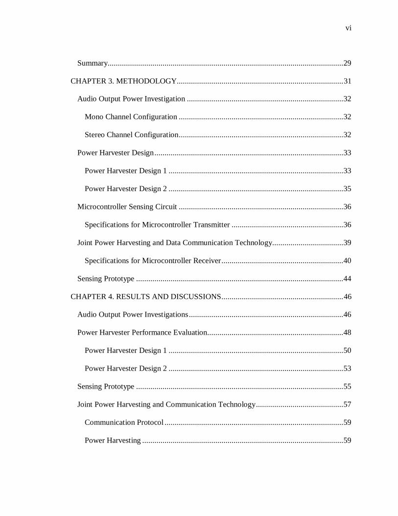
Summary.................................................................................................................... 29
CHAPTER 3. METHODOLOGY.................................................................................. 31
Audio Output Power Investigation ............................................................................. 32 Mono Channel Configuration ................................................................................. 32 Stereo Channel Configuration ................................................................................. 32
Power Harvester Design ............................................................................................. 33
Power Harvester Design 1 ...................................................................................... 33 Power Harvester Design 2 ...................................................................................... 35
Microcontroller Sensing Circuit ................................................................................. 36
Specifications for Microcontroller Transmitter ....................................................... 36
Joint Power Harvesting and Data Communication Technology................................... 39
Specifications for Microcontroller Receiver ............................................................ 40
Sensing Prototype ...................................................................................................... 44
CHAPTER 4. RESULTS AND DISCUSSIONS ............................................................ 46
Audio Output Power Investigations ............................................................................ 46 Power Harvester Performance Evaluation................................................................... 48
Power Harvester Design 1 ...................................................................................... 50 Power Harvester Design 2 ...................................................................................... 53
Sensing Prototype ...................................................................................................... 55 Joint Power Harvesting and Communication Technology ........................................... 57
Communication Protocol ........................................................................................ 59 Power Harvesting ................................................................................................... 59

vii
Discussion .................................................................................................................. 62
CHAPTER 5. CONCLUSION AND FUTURE RECOMMENDATIONS ..................... 64
Conclusion ................................................................................................................. 65 Future Recommendation ............................................................................................ 66
REFERENCES .............................................................................................................. 68
APPENDIX. TI-MSP430 F1611 DATASHEET ............................................................ 71

viii
LIST OF TABLES
TABLE PAGE
1 Comparison of Different Smartphones Interfaces to Connect External Sensors ....................................................................................3
2 Specification and Differences Between 3 Versions of Windoo Device .............. 19
3 Manchester and Differential Manchester Communication Code ....................... 37
4 Example Settings for the FSK Communication System ..................................... 42
5 Experimental Settings for Measuring the Power Output with Mono and Stereo Channel Configurations ................................................................... 46
6 Maximum Power Output and the Correspondence Voltage, Current and Load for the Mono and Stereo Channel Configurations ............................... 48
7 Experimental Settings for Performance Evaluation of Power Harvesting Design 1 and FSK Communication. ................................................. 49
8 Measurement Results for the Power Harvesting Circuit using Stereo Channel Configuration with Different Types of AC Signals .............................. 52
9 Measurement Results for Novel Power Harvesting Circuit ................................ 60

ix
LIST OF FIGURES
FIGURE PAGE
1. Market Share of Different Operating System in 2017 ........................................1
2. USB interfaced Smartphone Sensing Platform Architecture ............................ 14
3. Structure of the 3.5mm Audio Interface for Smartphones. ............................... 18
4. Block Diagram Windoo Smartphone Sensing Platform ................................... 20
5. Block Diagram Hijack Smartphone Sensing Platform ...................................... 22
6. Power Harvester Circuit for Hijack Smartphone Sensing Platform .................. 23
7. Data Communication Technology for Hijack Smartphone Sensing Platform ... 24
8. Block Diagram AudioDAQ Smartphone Sensing Platform .............................. 26
9. Power Harvester Circuit for AudioDAQ Smartphone Sensing Platform 1 ........ 28
10. A) Mono Channel Configuration B) Stereo Channel Configuration ................. 33
11. Proposed Power Harvester Circuit 1 for Smartphone Sensing Platform ........... 34
12. Proposed Power Harvester Circuit 2 for Smartphone Sensing Platform ........... 35
13. Example Frame Structure for Transmitting 3 Bytes from Microcontroller ....... 38
14. Block Diagram of the Joint Power Harvesting and Communication Technology ..................................................................................................... 39 15. Midpoint Setting Circuit for Microcontroller Receiver .................................... 40
16. Microcontroller Demodulation Approach ........................................................ 43
17. Sensing Prototype Architecture ....................................................................... 44
18. Output Voltage, Current, and Power of the 3.5mm Audio Interface using the Mono and the Stereo Channel Configurations ............................................ 47 19. Power Harvester Performance Evaluation using stereo channel configuration ................................................................................................... 49

x
20. Testing Circuit for Power Harvesting: (A) Step-up Transformer, (B) FET- based Bridge Rectifier, (C) Schottky Diode and Filtering Capacitors .............. 50 21. Voltages of the Power Harvesting Circuit using the Mono Channel Configuration with a Load of 500 ohm. AC Signal Type: (A) 16 kHz (B) 20 kHz (C) FSK. Channel 1 (orange): Input of Step-up Transformer. Channel 2 (green): Output of Rectifier. Channel 3 (blue): DC output ............................... 51 22. DC Power Output vs. Frequency of the Sinusoidal Signal ............................... 54
23. Experimental Setup for the Sensing Platform .................................................. 56
24. DC Power Output for the FSK Signal .............................................................. 59
25. FSK Signal Obtained between the Left Earphone Channel .............................. 61

xi
LIST OF EQUATIONS
EQUATION PAGE
1 FSK Frequency f0 ................................................................................... 41
2 FSK Frequency f1 ................................................................................... 41
3 FSK Symbol duration T_b0 ...................................................................... 41
4 FSK Symbol duration T_b1 ...................................................................... 41
5 Averaging bit duration R_b ...................................................................... 42
6 Estimate FSK Frequency f0 ...................................................................... 57
7 Estimate FSK Frequency f0 ...................................................................... 57
8 Estimate FSK Symbol duration T_b0........................................................ 58
9 Estimate FSK Symbol duration T_b1........................................................ 58
10 Estimate Averaging bit duration R_b ........................................................ 58

1
CHAPTER 1
INTRODUCTION
Background
The smartphone seems to be an emerging tool having solutions for the field of
ubiquitous sensing and this has significantly changed the way smartphone resources are
used. Smartphones as the devices provide not only mobile communications, but also
powerful information processing, connectivity to internet, user interface, and storage
abilities (Smartphone Users, 2014).
Smartphones are equipped with powerful processors and a multitude of built in sensors,
which make them a promising tool to support various sensing applications. Smartphones
can further be utilized to address a wide range of sensing applications by interfacing the
external sensors to them. In 2014 the recorded number of smartphone users were 2.6
billion and this is expected to reach 6.1 billion by 2020 (Boxall, 2015 ). In Figure 1, the
market share of different smartphones is categorized based on mobile operating system
(Mobile/Tablet Operating System Market Share, 2017).
Figure 1. Market Share of Different Operating System in 2017

2
The wide applicability and popularity of smartphones opened a whole new area of
research for smartphone peripherals to facilitate more sensing applications. Health care is
one sector with huge need for a smartphone sensing platform. The low cost and mobility
provided by a smartphone sensing platform make them useful for addressing critical
health needs of people living in rural and undeveloped countries (Black et al., 2009).
Such smartphone based sensing platforms are desirable in applications where low power
sensors are interfaced to smartphones to attain low cost, flexibility and mobility and
tradeoff the speed and security to some extent.
To implement a smartphone-powered sensing peripheral, the hardware and software
interface need to be designed to supply the power to the external sensors and establish
data communication between external sensors and a smartphone. Smartphones can
connect to a variety of external sensors over wired and wireless channels. There are three
available interfaces to connect smartphones to external sensors; Bluetooth, USB and
Audio jack. These three interfaces are compared in Table 1.

3
Table 1
Comparison of Different Smartphones Interfaces to Connect External Sensors
Smartphone Interface/ Features
Bluetooth (Mint, n.d.)
USB (Black et al., 2009)
3.5mm Audio Interface
Type Wireless Wired Wired
Data Communication Yes Yes Yes
Power Output No DC AC
Power to External
Sensing Platform
External
Battery
Powered
USB Powered External Battery
Powered (Breathometer,
2017; Mint, n.d.;
Nanobionics, 2017)
Audio Power Harvesting
Circuits (Kuo, Schmid,
& Dutta, 2010)
Limitations External
Battery
Cost.
Physically Non-
Universal
Hardware
Interface
External Battery Cost
Harvesters Designs
supports iPhone only
(Kuo et al., 2010)
Harvester Designs
limited to some Sensors
only (Windoo, 2017)
Among various analog interfaces of smartphones, the 3.5mm audio interface is truly
open to provide wide enough bandwidth to support the communication between external
sensors and smartphones. The earphone channels in the 3.5mm audio interface only allow

4
alternative current (AC) signal being sent out from a smartphone; the interface cannot
provide direct current (DC) power to external sensors. Thus, to address the power
requirement of an external sensing platform, the peripheral devices need to use an
external battery or a power harvesting circuit. This smartphone interface works with a
broad range of headsets and hands free devices and is physically standardized across
many smartphones (Verma, Robinson, & Dutta, 2012). The current research studies show
various limitations because of electrical variations in the 3.5mm audio interface across
different smartphones. This research explores the feasibility of audio interface to support
various smartphone powered ubiquitous sensing applications across different
smartphones. The purpose of this study is to analyze, design and build a smartphone
powered external sensing platform. The main building blocks of the design are a power
harvester circuit, a microcontroller based sensing platform, and Android smartphone and
external sensors.
Statement of Problem
The problem of this research study is to build an Android smartphone-powered
sensing platform that leverages the audio jack of Android smartphones to be powered and
to establish data communication. Smartphones have become powerful computing
platforms, which if used with external sensors can be converted to anything from
educational tools to health monitoring devices. There has been considerable research to
develop a 3.5mm audio interface smartphone powered sensing platform that can work
with different types of smartphones. The maximum available power from the audio port
of a smartphone is highly dependent on the output driver of the smartphone, therefore it

5
varies a lot between different manufacturers and even between models from the same
manufacturer (Silicon Labs, 2017). The audio power output for Android is considerably
low in comparison to iPhone and hence the existing 3.5mm audio interface technology
works with iPhone only.
This research will address the problem by designing a new power harvester that can
harvest enough power to support Android smartphones as well as iPhone. The data
communication technology needs to be designed in adherence to support the maximum
power harvesting with higher data rate using Android smartphones. The performance of
the new power harvester design should be tested for efficiency to achieve at least the
same, if not better performance with Android powered sensing platform in comparison to
existing iPhone powered sensing platform.
Purpose of the Study
The purpose of this study is to design a sensing platform for Android smartphones,
which can harvest power through the 3.5mm audio interface of the smartphone, receive
measurement results from external sensors, and send control information from a
smartphone to an external device. The objectives of this study are:
1. To design and develop a power harvesting circuit to power the microcontroller
circuit on external sensing platform using the 3.5mm audio interface of the
Android smartphone.
2. To design and develop the microcontroller circuit and hardware interfaces for
external sensing platform.

6
3. To develop and integrate the prototype board consisting of 3.5mm audio interface,
Microcontroller circuit and power harvesting circuit.
4. To define and develop the data communication protocol to establish two-way
communications between Android smartphone and external sensing platform.
5. To test and analyze the performance of Android smartphone centric sensing
platform based on the harvested power and the error free communication with
smartphone.
Need for the Study
Smartphones OS market is shared among different smartphones as illustrated in
Figure 1 (Mobile/Tablet Operating System Market Share, 2017). The three available
interfaces to connect smartphones to external sensors are Bluetooth, USB and Audio jack.
Only USB interface has the inherent capability to power and communicate with external
sensors but not all smartphones have the same USB interface.
The need of this study is to address the lack of universal data interface in
smartphones: Android phones use the micro-USB or USB Type-C interface and iPhones
use a 30-pin dock connector or a Lightning connector, which are proprietary data
interfaces. It means that the external sensing hardware designed for iPhones and iPads
may not work with other types of smartphones and vice versa. This limits the market
value of smartphone dependent smartphone sensing platforms and increases the
production cost. To address this issue, existing smartphone based ubiquitous sensing
platforms use 3.5 mm audio interface and get power either from smartphone battery or
from external battery. The external battery powered sensing platforms not only increase

7
the size and cost of external sensing platform but also hurt user experience as the battery
must be switched periodically. To avoid additional external battery, power needs to be
harvested from an earphone channel. This issue was addressed in a previous study, where
researchers built a hardware platform, which harvests power using one earphone channel
of the smartphone and establishes two-way data communications using the other
earphone channel and microphone (Kuo et al., 2010). However, the hardware platform
cannot harvest enough power to support external sensors using smartphones other than
iPhone.
Considering the analysis of 2017 market share, the Android operating system (OS) is
the most popular OS holding 64% of the total share in smartphone industry
(Mobile/Tablet, 2017). Hence, there is a need to address the lack of universal smartphone
powered sensing platform that supports the huge market of Android phones.
Assumptions of the Study
For this research, certain assumptions are made that will serve as the basis for the
calculations and measurements ensuring the performance of the design. These
assumptions are:
1. The resistance values used for load calculations are relatively accurate.
2. The readings recorded from multi-meter and Oscilloscope are accurate.
3. The smartphones used for measurement and testing have uniform behavior for the
same model.

8
Research Question
The goal of this research is to develop the Android smartphone sensing platform and
evaluate its performance in sensing. The research questions for this study were:
1. Would the Android smartphones harvest enough power for the external sensing
platform to support sensing applications?
2. What is the data communication technology between smartphone and sensing
platform using Audio interface?
3. Would the joint power harvesting and communication technology achieve a
reliable data communication?
Delimitations of the Study
This study is delimited to:
1. The Android smartphone model: ZTE Awe N800
2. The MSP430 Microcontroller on external Sensing platform
Limitations of the Study
The following limitations are to be applied to this study:
1. The developed prototype can be used with most Android smartphones and
iPhones.
2. The developed prototype supports only low power sensors with operating voltage
less than 2V.
3. The study is performed and tested with a few available Android smartphones.
4. The study is not analyzing the power dissipation of smartphone battery while
attached to external sensing platform.

9
Definition of Terms
Sensors: A sensor is an electrical transducer that translates the physical properties into the
electrical signals (Intro to Sensors, 2017). In various sensing applications, a sensor helps
to decode the physical parameters from the environment or objects and provide it to the
computing unit to make decisions and perform tasks.
Smartphone: The mobile phones today are known as smartphones as they can provide
more than communication by rapidly replacing other gadgets, such as watches, cameras,
video cameras, etc. (Smartphone Users, 2014)
Ubiquitous Sensing: Ubiquitous sensing is to embed the sensing invisibly into people's
lives. Ubiquitous Sensing involves a sensor network with user interface that allows the
sensing of people, the sensing of environment and the networking to other similar devices
(Biru, Rotondi, & Minerva, 2015).
Microcontroller: A microcontroller contains a processor, memory and programmable
input/output peripherals on a single chip. It can be programmed to perform specific tasks.
Microcontrollers are present in smartphones, cameras, microwave ovens, washing
machines, etc. (Future Electronics, 2017)
Sensing Platform: Sensing platform is the hardware platform that has sensor and its
interface circuit to transfer the information to a processing unit or have on board a
processor.
Sampling frequency: The sampling frequency can also be expressed as sample rate being
the number of samples per second in an audio signal ( Smith, 1997). Most Smartphones

10
have a sampling frequency of 44100 hertz implies a recording with a duration of 1 minute
(60 seconds) will contain 2,646,000 samples (Sampling Frequency, 2004).
FSK: Frequency shift keyed is a modulation scheme where the carrier frequency is
frequency shifted by the message bits. An FSK waveform, derived from a binary message
consists of two frequencies f0 and f1 to represent bit ‘0’ and ‘1’ respectively
(Middlestead, 2017).
Operating system: An operating system is a System Software for Smartphone phones that
is responsible for the overall performance of the smartphone and can be used for
classification and comparison of smartphones available in the market (Beal, 2011).

11
CHAPTER 2
LITERATURE REVIEW
Smartphones Sensing
Smartphone sensing requires a user Application (App; Beal, 2011) running on the
smartphone phone operating system, a sensor internally (Sensor Overview, 2017) or a
sensor externally attached to the smartphone and data logging of sensed data. The phone
operating system offers an Application Programming Interface (API) for
building software applications to make smartphones a user interface in sensing
applications. In 2005, Nokia workshop had a discussion focused on smartphones as a user
interface for existing sensor networks which then led to the start of Nokia SensorPlanet
project with an aim to explore the future of smartphone sensing (Campbell & Choudhury,
2012). In 2007 Nokia released the smartphone N95 with an embedded accelerometer for
video stabilization and photo orientation. The API for accelerometer was released later in
that year and this launch immediately led researchers to study and develop new phone-
based sensing applications.
We do not realize how sensing is making our daily life easy and productive as we are
surrounded by a multitude of sensors in the form of appliances and equipment at our
home and work. In various sensing applications, a sensor helps to decode the physical
parameters from the environment or objects and provide it to the computing unit to make
decisions and perform tasks. With advancement in computing technology, we are
surrounded by computers of different sizes, and the emergence of smartphones led to a
new era for ubiquitous sensing. Most smartphones have built-in sensors like-

12
accelerometers, barometers and magnetometers (Sensor Overview, 2017). Smartphones
API is used to read raw data from sensors to control other features on the phone and to
provide user interface. Smartphone sensing using inbuilt sensors has various useful
applications like, in gaming applications where you want to monitor device movement or
positioning, or in weather applications where you want to monitor changes in the ambient
environment near smartphones (Sensor Overview, 2017). Modern smartphones have a
large set of inbuilt sensors, which support social, educational, entertainment,
environmental, and health related sensing applications. These sensing features can be
easily accessed by downloading different smartphone apps.
To increase the usability of smartphones and to broaden the range of sensing
applications, the researchers integrated external sensors to the smartphones. The use of
smartphone for sensing applications is convenient and shows great demand for
Smartphone sensing platforms in consumer applications.
Peripheral Devices for Smartphone Sensing
There are a variety of sensors available in the market to apply control and decision
making to almost any process. In the past few years various smartphone centric
ubiquitous sensing applications have emerged, which jointly use a smartphone with
external sensors for sensing applications (Breathometer, 2017; Black et al., 2009; Mint,
n.d.; Nanobionics, n.d.; Square, n.d.; Verma et al., 2012; Windoo, 2017; Kuo et al.,
2010). Smartphones can connect to a variety of external sensors over wired and wireless
channels. To make external sensors work the hardware and software interface needs to be

13
designed to supply the power to the external sensors and establish data communication
between external sensors and a smartphone.
The Breathometer Mint is a wireless sensing device that users can connect to their
smartphone and perform breath analysis to understand their oral health. Mint device
supports Android and iOS smartphone devices and uses Bluetooth LE technology for
connection. Mint device measures volatile sulfur compounds (VSCs) in the mouth, which
helps the smartphone user to plan a dental visit to treat poor oral health (Mint, n.d.). The
iDevices Thermostat from Apple allows you to control the temperature of your home
using iPhone; or Siri voice commands. The iDevices Connected app and Apple HomeKit
technology makes it easy to control iDevices Thermostat based on your daily routine
(iDevices Thermostat, 2017). Although, wireless technology in smartphones supports the
data communication with external sensing platform, the power requirements of external
sensing platform need an external battery between smartphone and external sensing
platform.
The research in (Black et al., 2009) proposed the prototype for smartphone based
health devices and mobile phone applications called mHealth to aid health workers in
remote and underserved areas. The proposed architecture for health devices is shown in
Figure 2, which uses USB interface of a smartphone to establish the connection with the
microcontroller as well as provide power to the microcontroller, and the external medical
sensors are attached to the analog or digital ports of the microcontroller. The mHealth
applications support Java Micro Edition programming language and operating systems
such as Nokia OS and Symbian OS, iPhone OS, Android, and others.

14
Figure 2. USB Interfaced Smartphone Sensing Platform Architecture
The research proposed five mHealth applications; a respiratory and pulse rate
calculator, a gestational date calculator, a formulary/drug dose calculator, a drip rate
calculator, and a drug reminder alarm. The researchers developed a low-cost Nossal
Oximeter device, a microcontroller attached to an oximeter probe to leverage
smartphone’s processing and interface capabilities. Nossal Oximeter device is tested with
the mHealth application and is useful for the diagnosis and assessment of severity of
respiratory disease.
Although, USB interface supports the data communication and power requirements
with external sensing platform, it is not a universal hardware interface since physically
the USB interface varies (Verma et al., 2012). The demand to build a universal external
sensing platform has led researchers to search for a universal peripheral interface port.
This is how 3.5 mm audio interfaced peripherals gained attention.
15
In (Square, 2017) Square Inc. developed a device which converts a smartphone into a
mobile point of sale machine and allows everyone to accept credit card payment. The
device acts as a small magnetic reader that plugs into the headphone jack of a
smartphone. The swiped credit or debit card information is converted to an audio signal
and is fed into the microphone input of a smartphone. The smartphone processor then
routes this information to Square’s software application on the smartphone. Smartphone
application encrypts the data for security purpose and transmits it using either Wi-Fi or a
3G Internet connection to back-end servers, where a connection is established with the
payment networks to complete the transactions. The Square inc CEO Jack Dorsey states
what accounted for invention and popularity of Square card reader: the smartphones are
ubiquitous with low-cost and have powerful processors to conduct complex tasks and
increase the use of electronic payment using credit or debit cards (Malik, 2009).
Breathometer is an audio/headphone jack interfaced device used in conjunction with a
mobile application to transform a smartphone into a breathalyzer to estimate your Blood
Alcohol Content; BAC (Breathometer, 2017). The Breathometer device supports iPhones
and Android 2.3 or above and the free mobile application (App) is available for
downloads from the iTunes or Google Play store respectively (Breathometer review ,
2014).
In (Nanobionics, 2017), MoboSens is a smartphone based sensing platform for
accurate nitrate concentration measurements in water. MoboSens is developed by a
research group at University of Illinois to allow citizens to conveniently monitor water
quality. MoboSens Application on smartphone uses GPS and mobile broadband to collect

16
and share environmental data to spread awareness. The information generated using the
MoboSens device is shared on social media, and Nitrate Sensing Maps are available on
both phone and internet.
The square card reader, breathometer device and Mobosens device are battery
powered, not only increasing the size and cost of these devices, but also hurting user
experience as the battery must be renewed periodically. Recent studies used energy
harvesting techniques to implement smartphone powered sensing platforms. Power
harvester circuit is present on the external sensing platform and harvest DC power from
the Audio channel interface of the smartphone.
In (JDC Electronics, 2016; Windoo, 2017) JDC Electronic SA developed Skywatch
Windoo, a weather station for your smartphone. The Skywatch Windoo device is attached
to a smartphone using a headphone jack and is compatible with ios and Android
smartphones. Skywatch Windoo 3 allows one to monitor wind speed, temperature,
humidity and pressure for any outdoor activities, and measured data can be stored and
shared on Facebook, twitter or Windoo.ch.
The researchers at University of Michigan developed an efficient power harvesting
design called Hijack to drive external sensing platforms without giving up on
communication from the smartphone to sensing platform (Kuo et al., 2010). The external
hardware design consists of the microcontroller based sensing platform and the 3.5mm
audio interfaced energy harvesting circuit. This architecture supports the power
harvesting and communication technology for smartphone sensing platforms. An
oscilloscope application is used by the researchers to demonstrate the functions of the

17
developed sensing platform. The device is small enough to carry along with the
smartphone, so it can be used as a portable oscilloscope for engineering students.
After the Hijack design, the researchers at University of Michigan presented a new
platform, called AudioDAQ, which harvests energy from the microphone bias signal of a
smartphone and provides both power and communication to external sensor (Verma et
al., 2012). The AudioDAQ design is universal across different smartphones for limited
sensing applications. The AudioDAQ platform supports a broad range of smartphones for
data acquisition from analog peripherals without using a microcontroller. The AudioDAQ
architecture is demonstrated by low-power EKG monitors that capture cardiac signals
and store this data on Cloud.
Recent research has used the power harvester techniques in place of the external
battery to reduce the cost of the design and to improve the user experience. These studies
show that the existing power harvesting techniques are still not meeting the requirements
for a universal sensing platform as the 3.5mm audio interface is universal physically but
not electrically. The electrical characteristic of audio interface limits the compatibility of
sensing platforms with different smartphones and sensors. Windoo device, Hijack device
and AudioDAQ device are three existing power harvesting designs that are discussed in
detail in the next section of this literature review with focus on the limitations of
harvesting techniques and data communication technologies.

18
3.5mm Audio Interfaced Power Harvesting and Communication Technologies
The structure of the 3.5mm audio interface is shown in Figure 3. We can see that the
audio interface for smartphones has four connectors: the connectors A and B are
respectively the left and the right earphone channels, which send audio signal out from a
smartphone; the connector C is the common/ground; and the connector D is the
microphone channel, which sends audio signal into a smartphone (Kuo et al., 2010).
Figure 3. Structure of the 3.5mm Audio Interface for Smartphones.
To implement smartphone powered ubiquitous sensing applications using the 3.5mm
audio interface Windoo, Hijack and AudoDaq device implemented different power
harvesting and data communication technologies, which are studied in detail under this
section.
Double Audio Channel Power Harvesting
Double channel power harvesting (DCPH) technology uses both left and right
earphone channels for power harvesting. Windoo device is based on DCPH technology
and has three versions; Windoo 1, Windoo 2 and Windoo 3 (JDC Electronics, 2016).

19
These devices can be useful for environmental monitoring during outdoor recreational
services. The specifications and features of three versions are compared under Table 2
(JDC Electronics, 2016).
Table 2
Specifications and Differences Between 3 Versions of Windoo Device
Features Specifications Windoo 1 Windoo 2 Windoo 3
Wind Speed
Resolution: ± 0.1 km/h
Min: 3km/h; Max: 150km/h
Accuracy ± 2%
Temperature
Resolution: 0,1 units
Min: -25 °C; Max: 60 °C
Accuracy ± 0.3 °C
Humidity
Resolution: 0,1 units
Accuracy ± 4 %RH
Min: 5 %RH; Max: 95 %RH
X
Pressure
Resolution: 0,1 units
Accuracy ± 0.2 hPa
Min: 300 hPa; Max: 1100 hPa
X X
Dimensions 20 mm, length 52 mm
Weight 38 g
(Table continues)

20
Smartphones Apple: iPhone (4S, 5, 5C, 5 S), iPad mini(2, 3), iPod touch
Samsung: Galaxy (S3, S4, S4 mini), Galaxy Tab 10.1, Galaxy Note
2 Others: Nexus 4, HTC One S
Software OS Software iOS 6.0 or newer
Android Ice Cream Sandwich (4.0) or newer
Sensing platform. The Windoo Smartphone Sensing platform block diagram
representation is shown in Figure 4. The device consists of 3.5mm audio interface plug, a
power harvester circuit and a Swiss-made sensor set. All components are enclosed in tiny
aluminum housing with multidirectional propeller spin on top of the device to measure
wind speed and direction. The Swiss-made sensor set can measure temperature (and wind
chill), humidity and pressure. The device sends all the weather information to the
accompanying smartphone app, where it can be viewed and stored/shared on Facebook,
Twitter and Windoo's websites. The app can also graph and map the data (JDC
Electronics, 2016; Windoo, 2017).
Figure 4. Block Diagram Windoo Smartphone Sensing Platform

21
Power harvester and data communication technology. The Windoo devices, use both
left and right earphone channels to harvest power from the smartphone and supply it to
external sensors. The sensor on external Windoo devices continuously sends information
to the smartphone by establishing one-way communication from an external sensor to the
smartphone. To gets more power from smartphones, researchers harvest power using
both earphone channels. The harvester shorts the left and the right earphone channels to
increase the signal amplitude (JDC Electronics, 2016; Windoo, 2017).
Smartphone firmware. A specific smartphone App is required to be downloaded and
installed on smartphones to support Windoo devices power harvesting and data
communication architecture. Windoo devices supports Android and iPhones and the
respective Apps can be found in App Store (iTunes, 2017) or the Google Play Store
(Skywatch Windoo, 2017).
Limitations. Windoo.ch app generates identical in phase AC signals on left and right
earphone channels to harvest power for an externally attached Windoo device (JDC
Electronics, 2016). The approach gives up the communication from the smartphone to the
Windoo device. This design is not applicable to the wide variety of sensors or
microcontroller based sensor platforms where control is needed from the smartphone user
interface. Windoo technology can only handle simple sensors because the only control
from the smartphone is disconnecting the power, and the external sensor sends
information to the smartphone in a repeat pattern.
22
Single Audio Channel Power Harvesting
Single channel power harvesting (SCPH) technology uses one earphone channel for
power harvesting. Hijack device is a microcontroller based sensing platform which uses
SCPH technology. The sensing platform with a microcontroller has several benefits; it
allows multiplexing of inputs, and it allows interfacing of different sensors by supporting
interfaces like ADC, GPIO, I2C, SPI, UART, or other (Kuo et al., 2010).
Sensing platform. The Hijack device consists of 3.5mm audio interface plug, a power
harvester circuit and a microcontroller based sensing circuit. The block diagram
representation for Hijack device is shown in Figure 5.
Figure 5. Block Diagram Hijack Smartphone Sensing Platform
Hijack device in conjunction with iPhone is used to demonstrate different sensing
applications. The designed application runs partly on the iPhone and partly on Hijack
sensing platform. The research demonstrated how the Hijack device when attached to an
iPhone turns an iPhone into an inexpensive oscilloscope, EKG monitor, and soil moisture
sensor.

23
Power harvester and data communication technology. The Hijack device uses the
right earphone channel output for energy harvesting to power the external sensing
platform. The left earphone channel and microphone are used to establish two-way
communications between the smartphone and sensing platform.
Power Harvester. The Hijack power harvester circuit as shown in Figure 6 aims to
harvest energy from an iPhone Audio channel to power the microcontroller and sensors
on external sensing platform.
Figure 6. Power Harvester Circuit for Hijack Smartphone Sensing Platform
The power harvester circuit sidesteps the two engineering challenges (Kuo et al., 2010):
• Increase the signal amplitude, and
• Convert the AC signal into a DC signal
The low voltage sinusoidal signal output from right audio channel is first boosted
using 1:20 micro transformer circuit. The boosted AC signal output is then rectified to
DC signal using the FET rectifier bridge (Q1, Q2, Q3, Q4). The Schottky diode (D1) is

24
used to block the filter capacitor (C2, C3) discharge through the FET bridge. The DC
output of the harvester circuit is further used to power the microcontroller circuit and
external sensors on the sensing platform.
Data Communication. This technology supports two-way communication between the
smartphone and sensing platform; the left audio channel sends a data stream coded with
Manchester code to the microcontroller (on the smartphone sensing platform), and the
microphone input (on the smartphone) receives a data stream coded with Manchester
code from the microcontroller. Both the phone and the microcontroller implement
Manchester decoding to recover the data (Kuo et al., 2010). The bi-directional
communication between the phone and microcontroller supports 8.82 kbps data rate. The
data communication technology illustrated in Figure 7 uses several hardware features on
microcontroller to efficiently modulate and demodulate FSK signals.
Figure 7. Data Communication Technology for Hijack Smartphone Sensing Platform

25
Microcontroller Decoder: The comparator, timer capture and UART receiver
peripherals are used to detect the incoming data stream from the left audio channel of the
smartphone. The comparator at Vcc/2 is used to interpret the incoming Manchester
encoded signal into ones and zeros. The output of the comparator is driving the timer
capture unit sensitive on both rising and falling edges. The timer unit captures the time
between successive samples and estimates the symbol width. The output of timer
decision is then externally connected back into the receiver port of the UART peripheral.
The UART receiver is then responsible for decoding the frame.
Microcontroller Encoder: The timer capture and UART transmitter peripherals are
used to transmit data stream into the microphone input of the smartphone. The UART
transmitter first generates the output data bits at 300 baud. The generated bits are fed
back into a microcontroller interrupt line and a timer compare unit is used to correct the
frequency. The square wave output of the timer compare is then filtered and fed into the
microphone input of the smartphone.
Smartphone Firmware. A specific smartphone App is used to support Hijack device
power harvesting and data communication architecture. Hijack device supports iPhones
and the respective Apps can be found in App Store (iTunes, 2017). The application
running on iPhone generates a 22 kHz tone on the right audio channel to power the
microcontroller using the power harvester circuit.
Limitations. The study shows that the energy harvesting hardware delivers 7.4 mW to
a load using the iPhone’s headset port. But for many other smartphones, like Android,

26
this hardware platform cannot harvest enough power to support various ubiquitous
sensing applications (Kuo et al., 2010).
Microphone Bias Power Harvesting
Microphone bias power harvesting (MBPH) technology uses microphone bias voltage
for power harvesting. AudioDAQ is an audio interfaced data acquisition platform which
uses the MBPH technology to power external sensors. The design interfaces the simple
analog peripherals directly to the smartphone without using a microcontroller (Verma et
al., 2012).
Sensing Platform. AudioDAQ device leverages the smartphone resources for
capturing, storing and processing analog sensor data. The block diagram representation
for AudioDAQ device is shown in Figure 8. The external sensors get powered using the
microphone bias voltage through a linear regulator. The external sensor data is encoded
as analog audio using the phone’s built-in voice memo application or any custom created
App. This design is more universal as it works across a broad range of phones.
Figure 8. Block Diagram AudioDAQ Smartphone Sensing Platform

27
The AudioDAQ device consists of 3.5mm audio interface plug, a linear regulator
circuit and a sensor circuit. The research demonstrated a data acquisition platform that
captures EKG signal continuously and stores it on Cloud for further processing, and
visualization.
Power harvesting and data communication technology. The microphone channel is
used both to power external sensors and to input sensor data into the smartphone. The
design needs to consider that the power supply and data transfer characteristics are deeply
coupled. The Microphone harvester design includes three important blocks: internal
microphone circuit, microphone power harvester and sensor communication interface
shown in Figure 9.
Power harvester. The AudioDAQ power harvesting design uses the microphone bias
voltage to power external sensor with an aim to address the issue with Hijack design
which was not able to work with different smartphones. This design circuit is universal
enough to work across many smartphones for data acquisition using simple analog
sensors.
The AudioDAQ requires 1.8 V open-circuit voltage of the microphone bias line to
make it compatible with nearly all the smartphones. The microphone bias voltage acts as
a high-impedance voltage source with its current limiting resistance R1. A microphone
harvester circuit uses a linear regulator to provide stable supply to the external sensor.
The RC filter at input of a regulator stabilizes the linear regulator and prevents regulator
control loop noise.

28
Figure 9. Power Harvester Circuit for AudioDAQ Smartphone Sensing Platform 1
Data communication. The Microphone input of the smartphone is band limited to
amplitudes around 10 mV peak-to-peak, and audio frequencies in the 20 Hz to 20 kHz
range. To pass signals which are below 20 Hz or are DC in nature, the design modulates
the analog signal into the audio passband using an analog multiplexer. The analog
multiplexer is driven from a counter and is clocked with an RC oscillator at 1.2 kHz to
produce an analog signal from the sensors to a voltage anywhere between system ground
and the reference voltage of 1.8 V. To limit the input voltage range, a scaling resistor R4
is used between the output of the multiplexer and the microphone bias line. The raw
signal captured by the phone’s microphone line is recorded and can be transmitted to a
computer for further processing and decoding.
Limitations. The AudioDAQ design is useful for data acquisition applications where
low power sensors are used for continuous monitoring for long time periods. The sensing
platform using a microphone line is not capable of supporting an arbitrary hardware
peripheral. The range of sensors it supports is still limited and hence it can’t be used as a
universal sensing platform.

29
Summary The advancement in sensor and embedded technology opened the doors for several
ubiquitous sensing applications. Using a Smartphone headset port as a peripheral
interface for data communication is ubiquitous and seems as an attractive option for
making peripheral devices platform independent. All these recently introduced
peripherals, like the Square card reader (Square, 2017), Breathometer (Breathometer,
2017), Mobosens (Nanobionics, 2017), Windoo (Windoo, 2017) and hijack (Kuo et al.,
2010) reflect a growing interest in using the headphone jack for more than just headsets.
However, there are features associated with smartphones from different manufacturers,
and even for different models from the same manufacturer, which vary considerably and
result in the incompatibility between peripheral devices and smartphones.
Audio interface only allows alternative current (AC) signal in the audible frequency
range, which is not suitable for direct current (DC) powered peripheral devices. The
smartphone independent sensing platforms like Square card reader, Breathometer and
MoboSense are battery powered which increases the size and cost of external devices and
hurts user experience as the battery must be changed periodically. The research in (Kuo
et al., 2010; Verma et al., 2012; Windoo, 2017) leverages the audio jack driver to harvest
energy for peripheral devices.
Hijack and Windoo use custom written phone software on the smartphone to
generate sinusoidal waveform at the audio output which is fed to the energy harvesting
circuit for the peripheral devices. The energy harvesting from the audio output presents
significant design challenges. The Skywatch Windoo device shorts the left and the right

30
earphone channels to harvest more power using both channels of the smartphone. This
approach results in no communication from the smartphone to the microcontroller. The
output power capability of headphone jacks differs a lot from Android to iPhones,
Android headphone jack power output is considerably low in comparison to iPhone
resulting in the peripherals built to work with the iPhone not working on many Android
phones; like the Hijack device is limited to work with iPhone only. The AudioDAQ
system uses the microphone bias voltage to power peripherals and it has limitations due
to the coupling of data transmission and energy harvesting on the microphone channel.
The microphone line is limited to support some hardware peripherals showing trade-off
between signal reconstruction and maximum power delivered (Verma et al., 2012).
The literature review leads to the conclusion that several currently developed
smartphones powered sensing platforms are either not supporting Android
smartphones(Hijack) or address limited sensing applications (Windoo, AudioDAQ).
Smartphone peripheral sensing platforms are truly disruptive and the outcomes of this
review will help in the design of a 3.5mm audio interfaced ubiquitous sensing platform
having the potential to meet consumer applications for different smartphone sensing
applications.

31
CHAPTER 3
METHODOLOGY
This research involved the design and development of a smartphone powered
ubiquitous sensing platform with the capability to harvest enough power using Android
smartphones to support various sensing applications. To design an Android ubiquitous
sensing platform, we chose the 3.5mm audio interface to connect the Android smartphone
with the external sensing platform.
This research addresses various limitations of existing smartphone powered sensing
platforms. A smartphone sensing platform consists of a power harvester circuit and a
microcontroller circuit with external sensor interface. First, different power harvester
designs are examined using different configurations and modulation schemes with left
and right earphone channels in the 3.5mm audio interface. The performance of power
harvester and useful modulation schemes for data communication is tested using Android
smartphones. The results are evaluated based on the output DC power of the power
harvester circuit.
After finalizing the power harvesting and data communication technology, the
microcontroller circuit and its interfaces are designed and developed. The smartphone is
indirectly interfaced to external sensors via a microcontroller. The microcontroller circuit
uses audio channel interface to establish two-way data communication with the
smartphone. The microcontroller based sensing platform can connect to a wide variety of
sensors over different communication protocols to support various sensing applications.

32
The two main building blocks of this smartphone powered sensing platform are
following:
• Power Harvester circuit
• Microcontroller sensing circuit
Audio Output Power Investigation This investigates the output power of the audio interface with two types of channel
configurations. The results of these configurations are used to define the input interface
of the power harvester circuit in the sensing platform. The experimental setup for Mono
and Stereo Channel Configuration is shown in Figure 10 A and B respectively.
Mono Channel Configuration
As shown in Figure 10.A, in the mono channel configuration, a load is connected
between the right earphone channel and the common/ground of the 3.5 mm audio
interface. This configuration is to duplicate the hardware setup used by Hijack device
(Kuo et al., 2010).
Stereo Channel Configuration
The stereo channel configuration is our newly proposed configuration for joint power
harvesting and data communications. As shown in Figure 10.B, in the stereo channel
configuration, a load is connected between the right and the left earphone channels.
Meanwhile, the AC signals outputted by the right and the left earphone channels are
designed to have 180-degree phase difference (i.e. the two signals are opposite to each
other).

33
Figure 10. A) Mono Channel Configuration B) Stereo Channel Configuration
Power Harvester Design
The study involves the development and testing of two different power harvester
designs. The hijack device uses single audio channel (Mono channel configuration) for
power harvesting and it is expected that using both earphone channels (Stereo channel
configuration) with proper modulation scheme the DC output will increase.
Power Harvester Design 1
In literature review, the research conducted by [Michigan] used the mono channel
configuration where the power harvester is connected between the right earphone channel
and the common/ground of the 3.5 mm audio interface. The proposed power harvester
design is like the one given by [Michigan] except that the stereo channel configuration is
used instead of the mono channel configuration. The circuit for Power harvester design 1
is shown in Figure11.

34
Figure 11. Proposed Power Harvester Circuit 1 for Smartphone Sensing Platform
The output of the stereo channel configuration is first boosted by the combination of a
capacitor (C1) and a 1:10 step-up transformers (TX1), and then the boosted signal is
rectified by a FET-based full wave bridge rectifier (Q1~Q4). Here using FET switches
instead of diodes, the voltage loss during the rectification is reduced (Seeman, Sanders, &
Rabaey, 2007). The function of the Schottky diode (D1) is to block the discharging
current from the capacitors (C2 and C3) to the rectifier. Finally, the rectified signal is
filtered by a lowpass filter (C2 and C3) to generate the DC power output.
The sensing platform establishes two-way data communications with a left or right
earphone channel (from the smartphone to the microcontroller) and the microphone
channel (from the microcontroller to the smartphone; Kuo et al., 2010). This architecture
of the sensing platform using stereo channel configuration is named joint power
harvesting and communication technology.

35
Power Harvester Design 2
The Power harvester design 2 is shown in Figure 12. It is a quadrupler circuit based
novel power harvesting design that can generate DC power with enough high voltage
without using a transformer.
Figure 12. Proposed Power Harvester Circuit 2 for Smartphone Sensing Platform
A voltage quadrupler circuit can boost the input signal without the use of a
transformer. Theoretically, the combination of capacitors and Schottky diodes can boost
the peak-to-peak voltage between the two earphone channels by four times considering
the small voltage drop on the Schottky diodes (D1~D4) is omitted. Thus, the power
harvesting circuit can provide the similar voltage of DC power as that in (Kuo et al.,
2010) can.
This architecture of the sensing platform is a joint power harvesting and
communication technology using stereo channel configuration. The right earphone
channel is connected to the ground of the power harvesting circuit through a large

36
capacitor C2, so the voltage difference between the right earphone channel and the
ground is a DC value. Thus, the FSK signal for demodulation at the microcontroller
needs to be obtained between the left earphone channel and the ground of the power
harvesting circuit.
Microcontroller Sensing Circuit
The external sensing platform uses a low power microcontroller to connect external
sensors to the smartphone. The 3.5mm audio interface is used to establish two-way data
communication between microcontroller and the smartphone. The earphone channel is
used to communicate from the smartphone to the microcontroller and the microphone
channel is used to communicate from the microcontroller to the smartphone.
Microcontroller has different interfaces for gathering information from variety of external
sensors. Microcontroller translates and sends the sensor readings to the smartphone on
the microphone channel.
The Olimex MSP430f1611 prototype board is used to implement external sensing
platform. The MSP430 family of Texas Instruments is an ultralow power
microcontrollers class combined with five low power modes to achieve extended battery
life in portable sensing applications (TI MSP430 Datasheet, 2017). The IAR embedded
workbench IDE is used for software implementation.
Specifications for Microcontroller Transmitter
The microcontroller (MCU) transmits the sensor information on microphone input
channel of the smartphone. The codec of a smartphone records it as a sound signal; the
phase of a sound may have a 180 degree shift which is not noticeable because our ears do

37
not detect phase but frequency. However, for data communications from MCU to
Smartphone, phase information is used to modulate bit information, so we must tackle
this phase ambiguity. Thus, we proposed differential Manchester codes to transmit bit
information from an MCU to a smartphone.
Differential Manchester Coding. The Differential Manchester Code is a variation of
the Manchester code. It is a biphase code illustrated in Table 3; for bit ‘0’ transmission,
the current Manchester code is the same as the previous Manchester code, and for bit ‘1’
transmission, the current Manchester code is opposite to the previous Manchester code
(Data Encoding Techniques, 2017).
For example, if the previous Manchester code is “01”, the current Manchester code is
“01” when bit ‘0’ is transmitted, and “10” when bit ‘1’ is transmitted; if the previous
Manchester code is “10”, the current Manchester code is “10” when bit ‘0’ is transmitted,
and “01” when bit ‘1’ is transmitted.
Table 3
Manchester and Differential Manchester Communication Code
Original Data Output (transition at bit center)
Manchester Code Differential Manchester Code Logic 0 0 to 1 No change in Phase
Logic 1 1 to 0 Change in Phase
Frame structure for Transmitter. The Bit information is transmitted in frames using
timer compare unit of microcontroller. The beginning of each frame is Preamble bits 16
“01” Manchester code followed by a “10” start bit then a byte and an odd-parity

38
modulated with differential Manchester code. If there is more data to send a bit ‘1’
(Differential Manchester Code) is transmitted before the next byte and the associated
parity bit. After all bytes and associated parity bits are transmitted, four bits “0101”
modulated with differential Manchester code are transmitted to indicate the end of the
frame.
An example frame is given in Figure 14.
Figure 13. Example Frame Structure for Transmitting 3 Bytes from Microcontroller
Information bytes: 23 (00010111), 158 (10011110), 208 (11010000)
Information bytes with parity bits: 23(00010111-1), 158(10011110-0), 208(11010000-0)
Differential Manchester coding output:
• Preamble: 01,01,01,01,01,01,01,01,01,01,01,01,01,01,01,01,10
• Bytes 1: (23) 10,10,10,01,01,10,01,10,01
• Bit ‘1’ before Bytes 2: 10
• Bytes 2: (158) 01,01,01,10,01,10,01,01,01
• Bit ‘1’ before Bytes 3: 10

39
• Bytes 3: (208) 01,10,10,01,01,01,01,01,01
• Tail: 01,10,10,01
Joint Power Harvesting and Data Communication Technology In this research, based on frequency shift keying (FSK) modulation scheme, we
proposed a joint power harvesting and communication technology that can
simultaneously harvest power and transfer data with the same earphone channels. The
block diagram of a joint power harvesting and communication technology is shown in
Figure 13. In comparison to single channel harvesting (Kuo et al., 2010), this technology
is expected to harvest more than doubled power from both earphone channels without
affecting the data communications between a smartphone and a microcontroller. After
reviewing the different characteristics of data rates and output power of the two power
harvesting circuits, we will use the most efficient design to develop smartphone powered
sensing prototype.
Figure 14. Block Diagram of the Joint Power Harvesting and Communication Technology

40
Specifications for Microcontroller Receiver
The FSK signal from one of the earphone channels is sent to an AC coupling and
midpoint setting circuit shown in Figure 15 (Kuo et al., 2010); to shift the midpoint of the
FSK signal to Vcc/2, where Vcc is the supply voltage of the microcontroller.
Figure 15. Midpoint Setting Circuit for Microcontroller Receiver
Then a comparator in the microcontroller, which is internally referenced to Vcc/2,
converts the FSK signal into a digital signal, and a timer in the microcontroller times the
duration between any two adjacent rising edges of the digital signal. Finally, the
microcontroller recovers the data information as “0” and “1” from the timing outputs.
The key technical challenge to implementing the joint power harvesting and
communication technology is to design an FSK demodulation approach in which a low-
power microcontroller can perform the demodulation with stringently limited resources.
In this research, we have proposed a novel noncoherent FSK demodulation approach,

41
which uses a timer to measure the duration between two adjacent rising edges of the FSK
signal. Because the timer in a microcontroller is typically driven by a high-speed clock,
this approach can differentiate the two modulation frequencies in a much better way.
The smartphone uses a sampling clock, fs, at 44.1 kHz. An FSK signal transmitted
from the smartphone uses two different frequencies; f0 to represent bit “0” and f1 to
represent bit “1”.
𝒇𝒇𝟎𝟎 = 𝑴𝑴𝟎𝟎
𝑵𝑵𝒇𝒇𝒔𝒔 (1)
𝒇𝒇𝟏𝟏 = 𝑴𝑴𝟏𝟏𝑵𝑵𝒇𝒇𝒔𝒔 (2)
Where, M0, M1and N are integers. To maintain continuous phase between any two
adjacent symbols, either Q periods of f0 signal is transmitted to represent “0” or Q
periods of f1 signal is transmitted to represent “1” and Q must be the multiple of the least
common multiplier of M0 and M1. Thus, the symbol duration when “0” and “1” is
transmitted is given by equation 3 and equation 4 respectively.
𝑻𝑻𝒃𝒃𝟎𝟎 = 𝑸𝑸𝑵𝑵𝑴𝑴𝟎𝟎𝒇𝒇𝒔𝒔
= 𝑸𝑸𝑵𝑵𝑴𝑴𝟎𝟎𝑻𝑻𝒔𝒔 (3)
𝑻𝑻𝒃𝒃𝟏𝟏 = 𝑸𝑸𝑵𝑵
𝑴𝑴𝟏𝟏𝒇𝒇𝒔𝒔= 𝑸𝑸𝑵𝑵
𝑴𝑴𝟏𝟏𝑻𝑻𝒔𝒔 (4)

42
The averaging bit duration is
𝑹𝑹𝒃𝒃 = 𝟐𝟐𝑻𝑻𝒃𝒃𝟎𝟎+𝑻𝑻𝒃𝒃𝟏𝟏
(5)
To clearly demonstrate the effects of N, M0, M1, and Q on f0, f1, T0, T1, and Rb,
three possible settings for N, M0, M1, and Q are given in Table 4 as the example settings
for the FSK communication system.
Table 4
Example Settings for the FSK Communication System
Parameters Setting No. 1 Setting No. 2 Setting No. 3
N 22 11 11
M0 9 4 2
M1 11 5 3
Q 99 20 6
f0 18.04 kHz 16.04 kHz 8.02 kHz
f1 22.05 kHz 20.05 kHz 12.03 kHz
T0 in Ts 242 55 33
T1 in Ts 198 44 22
Rb 200.5 b/s 890.9 b/s 1.604 kb/s

43
Our planed demodulation approach is shown in Figure 16. The timer counter unit
adds timer values for Q rising edges of the received signal. We compare the time of Q
edges with a threshold to decide whether we received a bit ‘0’ or a bit ‘1’.
Figure 16. Microcontroller Demodulation Approach

44
Sensing Prototype To thoroughly investigate the performance of the novel power harvesting circuit and
the related FSK communication system, we proposed a prototype system demonstrating
sensing application. The smartphone based sensing prototype architecture is shown in
Figure 17.
Figure 17. Sensing Prototype Architecture
The system consists of an Android smartphone and an external device built with a
microcontroller, an external sensor, and other related components. The prototype system
connects the external device with the smartphone through the 3.5mm audio interface.
With this connection, the system can implement the following features:
1. Power the external device with both earphone channels of the smartphone: through
45
harvesting power from a FSK signal.
2. Provide data communication from the microcontroller to the smartphone with the
microphone channel of the smartphone: Differential Manchester code is used for
modulation.
3. Provide data communication from the smartphone to the microcontroller with one
earphone channel of the smartphone: FSK scheme is used for modulation.
4. Display the measurement results of the sensor on the smartphone.
5. Control the outputs of the microcontroller from the smartphone: for example,
individually turn on/off a group of LEDs connected to the microcontroller from the
smartphone.
The proposed Joint Power Harvesting and communication technology is expected to
support Android smartphone sensing applications. The use of double channel power
harvester is expected to harvest at least double DC power in comparison to 7.4 mW using
a single channel power harvester.

46
CHAPTER 4
RESULTS AND DISCUSSIONS
Audio Output Power Investigations The output power of the audio interface with mono channel and stereo channel
configurations is investigated under this section. The experimental settings for measuring
the power output of the 3.5 mm audio interface with mono channel and the stereo channel
configuration are shown in Table 5.
Table 5
Experimental Settings for Measuring the Power Output with Mono and Stereo Channel Configurations
Channel configuration Mono channel configuration and Stereo channel configuration
Hardware Android smartphone (ZTE N800 Awe, 2017)
Software AudioOut App (Android open source project, 2017)
Measuring equipment Oscilloscope and Multimeter
Output signal FSK signal with two frequencies points at 16 kHz and 20 kHz
Data Rate 1 kbps
Volume Maximum
Load 0 to 15 kΩ

47
With the FSK signal described in Table 5 and for both the mono and the stereo
channel configurations, we have measured the output voltage of the 3.5mm audio
interface when the load resistance varies from 0 to 15 kΩ. The relation of the output
voltage, current, and power of the 3.5 mm audio interface are calculated and depicted in
Figure 18 for both the mono and the stereo channel configurations. And, the maximum
power output and the corresponding voltage, current and load for the mono and the stereo
channel configurations are summarized in Table 6.
Figure 18. Output Voltage, Current, and Power of the 3.5mm Audio Interface using the Mono and the Stereo Channel Configurations

48
Table 6
Maximum Power Output and the correspondence Voltage, Current and Load for the Mono and Stereo Channel Configurations
Measurements Mono channel configuration Stereo channel configuration
Load 1.9 Ω 3.77 Ω
Maximum power output
28.8 mW 75 mW
Output voltage (rms) 234 mV 532 mV
Output current (rms) 123 mA 141 mA
From Figure18 and Table 6, we can conclude that the stereo channel
configuration is a highly efficient approach to harvest power from the audio interface,
providing about 2.6 times more power than the mono channel configuration can.
Power Harvester Performance Evaluation The Power harvesting circuit first boosts the amplitude of the AC signal (i.e. the FSK
signal) and then converts the signal into DC to power the external sensing platform. The
Power harvester design performance evaluation is conducted using the more efficient
stereo channel configuration instead of the mono channel configuration. The
experimental setup for the performance evaluation of two power harvester designs are
shown in Figure 19 and the experimental settings are shown in Table 7.

49
Figure 19. Power Harvester Performance Evaluation using Stereo Channel Configuration
Table 7
Experimental Settings for Performance Evaluation of Power Harvesting Design 1 and FSK Communication.
Smartphone ZTE N800 (ZTE N800 Awe, 2017)
App An audio app developed by us
Audio output Sinusoidal signal or FSK signal
Audio volume Maximum
DC load A variable resistor from 0Ω to 1kΩ
Measuring equipment Oscilloscope and Multimeter

50
Power Harvester Design 1
To evaluate the performance of the proposed power harvester, a testing circuit has
been implemented on a breadboard and is shown in Fig. 20.
Figure 20. Testing Circuit for Power Harvesting: (A) Step-up Transformer, (B) FET-based Bridge Rectifier, (C) Schottky Diode and Filtering Capacitors
The Eclipse IDE with built-in Android Developer Tools (Kuo et al., 2010) is used to
create an audio app that can generate three types of AC signals: a 16 kHz sinusoidal
wave, a 20 kHz sinusoidal wave, and an FSK signal with two modulation frequencies at
16 kHz and 20 kHz. To fulfill the energy harvester requirement to use the stereo channel
configuration, this audio app also ensures that the signals outputted by the left and the
right earphone channels have 180-degree phase difference.
The power harvester performance was tested with the audio channel output of the
smartphone being 16 kHz sinusoidal wave, 20 kHz sinusoidal wave, and FSK signal

51
respectively. The corresponding voltages of the power harvesting circuit at the input of
the step-up transformer, the output of the FET-based bridge rectifier, and the DC output
are shown with 100 Ω to 1. 5 kΩ varying load resistance. When the load resistance is 500
Ω, the power at the DC output achieves its maximum value, and the corresponding
measurement results are illustrated in Fig. 20 and summarized in Table 8.
Figure 21. Voltages of the Power Harvesting Circuit using the Mono Channel Configuration with a Load of 500 ohm. AC Signal Type: (A) 16 kHz (B) 20 kHz (C) FSK. Channel 1 (orange): Input of Step-up Transformer. Channel 2 (green): Output of Rectifier. Channel 3 (blue): DC output

52
Table 8
Measurement Results for the Power Harvesting Circuit using Stereo Channel Configuration with Different Types of AC Signals
AC signal Type 16 kHz 20 kHz FSK Units
Channel 1: Input of stepup transformer (rms value) 468 446 440 mV
Channel 2: Output of rectifier (peak value) 4.4 4.25 4.45 V
Channel 3: DC output 4.08 3.97 3.98 V
DC power 33.3 31.5 31.7 mW
From the measurement results, we have the following three observations. First, the
type of AC signal has almost no effect on power harvesting. We can harvest almost the
same amount of power from an FSK signal as from a sinusoidal wave. Second, even
when the power at the DC output achieves its maximum value, which typically means a
heavy load, the shape of the FSK signal does not have serious distortion. Thus, we still
can demodulate data from the FSK signal without any error. The first and the second
conclusions ensure that we can simultaneously harvest power and transfer data with the
same earphone channels. The last, but not the least, observation is that the power
harvesting circuit using the stereo channel configuration can harvest more than two times
the power from the audio interface as compared to that using the mono channel
configuration.
But, boosting the voltage of the AC signal with a transformer has quite a few
disadvantages. First, because the highest frequency of the AC signal is limited by a half
of the sampling frequency of the smartphone, fs=44.1 kHz, either the size and the cost of

53
the transformer is large, or the efficiency of the power transformation is low. Second,
there is limited flexibility to choose the frequency of the AC signal, and hence it is very
difficult to increase the data rate for the FSK communication system without reducing the
power efficiency of the transformer. For example, the No. 3 setting in Table 1 cannot be
used by this power harvesting circuit.
Power Harvester Design 2
The Power harvester design 2 is a novel power harvesting circuit that can generate
DC power with enough high voltage without using a transformer. To thoroughly
investigate the performance of the novel power harvesting circuit and the related FSK
communication system, a prototype circuit for power harvesting has been implemented.
First, by setting the audio output as a sinusoidal signal, the DC power outputs for
different values of load resistance are measured when the frequency of the AC signal is
respectively set at 1 kHz, 2 kHz, 4 kHz, 8 kHz, 10 kHz, 12 kHz, 14 kHz, 16 kHz, 18 kHz,
and 20 kHz. As shown in Figure 22, when the frequency of the AC signal is lower than
4 kHz, the DC power output is substantially lower than when other frequencies are used.
The DC power output peaks at a frequency range between 8 kHz and 12 kHz. When the
frequency is higher than 12 kHz, DC power output reduces gradually with the increase of
the frequency.

54
Figure 22. DC Power Output vs. Frequency of the Sinusoidal Signal
Because the measurements with the sinusoidal signal show that the novel power
harvesting circuit has the highest DC power output at a frequency range between 8 kHz
and 12 kHz, the No. 3 setting in Table 4 is used to generate the FSK signal for power
harvesting as well as data communications. The measurement results shows that the
circuit can harvest similar amounts of DC power from the FSK signal as from the
sinusoidal signal, and the highest output power is 36.3 mW when the load resistance is
100 Ω.
The goal of this research is to develop the Android smartphone powered sensing
platform and evaluate its performance in sensing. While designing, the sensing prototype,
the power harvesting design needs to be taken in to consideration. To design efficient

55
Android power harvester, the Quadruple based power harvesting design 2 shows better
performance by harvesting 36.3 mW power in comparison to 31.7 mW by power
harvesting design 1. Also, Figure 22 shows the quadruple based power harvester can
support the higher data rates as shown in No. 3 setting in Table 4. After achieving the
desired performance of power harvesting design, we started the implementation of a
sensing prototype system for the joint power harvesting and communication technology.
Sensing Prototype The prototype system uses the power harvester design 2 for implementing
smartphone centric ubiquitous sensing. The experimental setup for the sensing platform
shown in Figure 23, consists of an Android smartphone (ZTE N800) and an external
sensing platform built with a power harvester, a microcontroller (MSP430f1611), a
potentiometer sensor, and LEDs. The Audio app displayed on a smartphone provides a
user interface to send information to the sensing platform and to display the measurement
results received by the sensing platform.
The sensing prototype uses Differential Manchester code to communicate from the
sensing platform (microcontroller) to the smartphone over the microphone channel of the
smartphone. The information transmitted from the microcontroller (MCU) gets recorded
as a sound signal at the microphone input. The phase of the recorded sound may have an
180o degree shift and this phase ambiguity is resolved with proposed differential
Manchester codes. The continuous reading from the sensor (potentiometer) attached to
the analog port of the microcontroller is encoded as Differential Manchester (DM) coded
data stream before transmitting. The encoded data stream from the microcontroller is then

56
transmitted on the microphone input of a smartphone via an opto-isolator because the
reference grounds for sensing platform and smartphone are different. The smartphone
decodes the received data stream and the readings are displayed on a smartphone app.
With the designed protocol discussed in chapter 3, up to 7.35kb/s, data rate can be
achieved from the sensing platform to a smartphone.
Figure 23. Experimental Setup for the Sensing Platform
The data communicates from the smartphone to the sensing platform
(microcontroller) with the left earphone channel of the smartphone and uses a novel non-
coherent FSK demodulation approach to achieve joint power harvesting and
communication technology. The four Led buttons on Audio App can be toggled and the

57
send button is used to transmit the frame of Led status to the sensing platform via left
earphone channel. The four LEDs placed on the sensing platform then display the status
of the frame received from smartphone. With an Olimex MSP430f1611 prototype board,
we have verified the performance of joint power harvesting and communication
technology and the results are in the next section.
Joint Power Harvesting and Communication Technology To achieve joint power harvesting and communication technology, the proposed non-
coherent FSK demodulation uses the timer to measure the duration between two adjacent
rising edges of the FSK signal. The timer is driven by a high-speed clock and thus
differentiates the two modulation frequencies in a much better way. The No. 3 setting in
Table 4 is used to generate the FSK signal for power harvesting as well as data
communications. To maintain continuous phase between any two adjacent symbols Q
periods of f0 and f1 signal is transmitted. The FSK signal frequency is calculated with
fs= 44.1 kHz, N=11, M0=2, M1=3, Q=6 and the calculation results are shown in equation
6 and equation 7.
𝒇𝒇𝟎𝟎 = 𝑴𝑴𝟎𝟎𝑵𝑵𝒇𝒇𝒔𝒔 = 𝟖𝟖.𝟎𝟎𝟐𝟐 𝐤𝐤𝐤𝐤𝐤𝐤 (6)
𝒇𝒇𝟏𝟏 = 𝑴𝑴𝟏𝟏𝑵𝑵𝒇𝒇𝒔𝒔 = 𝟏𝟏𝟐𝟐.𝟎𝟎𝟎𝟎 𝒌𝒌𝒌𝒌𝒌𝒌 (7)

58
The symbol duration when “0” and “1” is transmitted is calculated in equation 8 and
equation 9 respectively:
𝑻𝑻𝒃𝒃𝟎𝟎 = 𝑸𝑸𝑵𝑵𝑴𝑴𝟎𝟎𝒇𝒇𝒔𝒔
= 𝑸𝑸𝑵𝑵𝑴𝑴𝟎𝟎𝑻𝑻𝒔𝒔 = 𝟎𝟎𝟎𝟎 𝑻𝑻𝒔𝒔 (8)
𝑻𝑻𝒃𝒃𝟏𝟏 = 𝑸𝑸𝑵𝑵
𝑴𝑴𝟏𝟏𝒇𝒇𝒔𝒔= 𝑸𝑸𝑵𝑵
𝑴𝑴𝟏𝟏𝑻𝑻𝒔𝒔 = 𝟐𝟐𝟐𝟐 𝑻𝑻𝒔𝒔 (9)
The average bit rate achieved is calculated in equation 10.
𝑹𝑹𝒃𝒃 = 𝟐𝟐𝑻𝑻𝒃𝒃𝟎𝟎+𝑻𝑻𝒃𝒃𝟏𝟏
= 𝟏𝟏.𝟔𝟔𝟎𝟎𝟔𝟔 𝐤𝐤𝐤𝐤/𝐬𝐬 (10)
In summary, to transmit bit ‘0’, 6 cycles of 8 kHz are transmitted which is 33
sampling point of smartphone and the symbol duration, Tb0 is 748.3 µs. Similarly, to
transmit bit ‘1’, 6 cycles of 12 kHz are transmitted which is 22 sampling point of
smartphone and the symbol duration, Tb1 is 498.87 µs.
To ensure that the joint power harvesting and data communication technology
perform efficiently, we have designed a communication protocol for communication
from Smartphone to microcontroller.
59
Communication Protocol
When no data needs to be sent from the smartphone to the microcontroller, the
smartphone keeps sending “0” and “1” alternatively on its left and right earphone channel
to allow continuous power harvesting; when the smartphone needs to send data, it will
send “00” as the starting bits of the frame, which is followed by a byte of data and a
parity bit. If the smartphone needs to send another byte after the previous byte, it will
duplicate the parity bit of the previous byte as the starting bit, and then send a byte of
data and a parity bit. If no more data needs to be sent, a bit that is opposite to the last
parity bit is sent to resume the pattern of sending ‘0’ and ‘1’ alternatively.
Power Harvesting
The newly proposed power harvesting technology uses the FSK signal to harvest DC
power and the related results are shown in Fig. 24 and Table 9.
Figure 24. DC Power Output for the FSK Signal
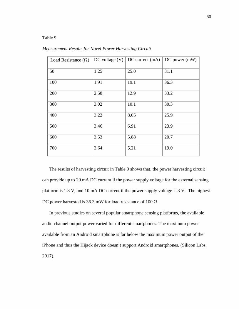
60
Table 9
Measurement Results for Novel Power Harvesting Circuit
Load Resistance (Ω) DC voltage (V) DC current (mA) DC power (mW)
50 1.25 25.0 31.1
100 1.91 19.1 36.3
200 2.58 12.9 33.2
300 3.02 10.1 30.3
400 3.22 8.05 25.9
500 3.46 6.91 23.9
600 3.53 5.88 20.7
700 3.64 5.21 19.0
The results of harvesting circuit in Table 9 shows that, the power harvesting circuit
can provide up to 20 mA DC current if the power supply voltage for the external sensing
platform is 1.8 V, and 10 mA DC current if the power supply voltage is 3 V. The highest
DC power harvested is 36.3 mW for load resistance of 100 Ω.
In previous studies on several popular smartphone sensing platforms, the available
audio channel output power varied for different smartphones. The maximum power
available from an Android smartphone is far below the maximum power output of the
iPhone and thus the Hijack device doesn’t support Android smartphones. (Silicon Labs,
2017).

61
In general, the power harvested above 30 mW for an operating voltage of 2 V is
sufficient to support low power sensing applications and the designed power harvesting
circuit harvested 36.3 mW DC output power. The TI MSP430F1611 microcontroller used
in the sensing platform belongs to an ultralow power family with one active mode and
five software selectable low-power modes of operation. While running in active mode,
the supply voltage of the controller ranges from 1.8 V to 3.6 V and draws a mere 0.7 mA
at 1.8 V (TI MSP430 Datasheet, 2017); leaving sufficient power to support a variety of
sensors.
From the measurement results and sensing porotype performance, we can state that
the prototype system is harvesting enough power to support low power Android
smartphone sensing applications.
Figure 25. FSK Signal Obtained between the Left Earphone Channel and the Ground
As shown in Figure. 25, even when the load resistance is 100 Ω, i.e. the harvesting
circuit has the highest DC power output, almost no distortion is observed on the rising

62
edge of the FSK signal of left earphone channel. Thus, extensive demodulation tests
show that we can achieve a reliable error-free demodulation for the designed sensing
prototype.
Discussion
The smartphone sensing platform provides a universal data interface and the
hardware can work with various types of smartphones. The software design is easy to
change for smartphone working with different operating systems. In this dissertation, the
performance of the smartphone sensing platform is tested with Android smartphones.
The proposed technology employs the stereo channel configuration to harvest power
between the right and left earphone channels. The newly designed power harvesting
circuit using the Quadruple circuit has successfully omitted the limitations of the
transformer based power harvester. The Quadruple based power harvesting circuit is
independent of the frequency of the audio output signal; the No. 3 setting in Table 1
increased the data rate for the FSK communication system without affecting the DC
power output.
Circuit measurements show that by coherently harvesting power from both earphone
channels, the proposed technology can extract more than two times the power as from
one earphone channel. Meanwhile, circuit measurements also show that power harvesting
will not cause serious distortion on the FSK signal and hence the data transferred from a
smartphone to external sensors can be recovered without any error.

63
The sensing prototype using Olimex MSP430f1611 prototype board demonstrated
that even with a heavy load, the newly developed timer-based demodulation approach
can achieve a reliable error-free performance on demodulating the FSK signal.

64
CHAPTER 5
CONCLUSION AND FUTURE RECOMMENDATIONS
Smartphone based ubiquitous sensing platforms have revolutionized many sectors of
our economy, including business, healthcare, social networks, environmental monitoring,
and transportation. Chapter 1 introduces the wide applicability and popularity of
smartphones and the emergence of a whole new area of research for smartphone
peripherals to facilitate more sensing applications. This study aims to build an Android
smartphone-powered sensing platform that leverages the audio jack of Android
smartphones to power and to establish data communication. Chapter 2 explores the
related literature in the field of smartphone peripherals and states the limitations of
existing smartphone powered sensing platforms; they are either not supporting Android
smartphones or address limited sensing applications. Chapter 3 describes the
methodology used in this research study to design the Android smartphone powered
sensing platform to support sensing applications. This chapter explores different design
aspects of sensing platforms with an aim to design sensing prototype for Android
Smartphone. Based on the results obtained in chapter 4, the Sensing prototype
successfully implemented the joint power harvesting and communication technology.
This chapter closes with a discussion on the performance of the prototype system for the
joint power harvesting and communication technology.

65
Conclusion
The pervasiveness and computing capability of smartphones, in addition to
communication, make them an ideal user interface for ubiquitous sensing applications. In
this research, based on FSK modulation scheme, we have proposed a joint power
harvesting and communication technology that can simultaneously harvest power and
transfer data with the same earphone channels. By setting the AC signals outputted by the
right and left earphone channels to have 180-degree phase difference, the newly proposed
technology employs the stereo channel configuration to harvest power between the right
and left earphone channels. Circuit measurements show that by coherently harvesting
power from both earphone channels, the proposed technology can extract more than two
times the power as from one earphone channel. This enhanced performance of the power
harvester design will be a solution to different smartphone manufactures whose
maximum available power is considerably low in comparison to iPhone.
The circuit measurements also show that power harvesting will not cause serious
distortion on the FSK signal and hence the data transferred from a smartphone to external
sensors can be recovered without any error. Finally, with an Olimex MSP430f1611
prototype board, we have verified that even with a heavy load, the newly developed
timer-based demodulation approach can achieve a reliable error-free performance on
demodulating the FSK signal.
In this growing economy, smartphones are becoming ever more affordable and are an
indispensable part of our daily life. The smartphone powered sensing platforms are
needed in applications where sensing platforms are equipped with low power sensors to

66
achieve low cost, flexibility and mobility with a possible tradeoff of speed and security.
With this enhanced performance of the power harvester design, the joint power
harvesting and communication technology results in a universal hardware that can
support most smartphone centric ubiquitous sensing applications. The software design
needs to be changed for different smartphones based on the smartphone operating system.
We evaluated the performance of the smartphone sensing platform with Android
smartphone.
Future Recommendation
While this dissertation has demonstrated the universal smartphone sensing platform
using joint power harvesting and communication technology, many opportunities for
extending the scope of this dissertation remain. This section presents some of these
directions.
There is some scope of improvement in the efficiency of the Power Harvester. The
sensing platform can leverage the Microphone Bias voltage to provide additional useful
power as needed for different sensing applications. This is to increase throughput by
supporting more number of external sensors.
The developed prototype can be used with most Android smartphones and iPhones.
The iPhone audio output power is considerably higher than Android and so the
performance of the Power Harvester is expected to be even better with a higher DC
output power. To avoid the interface issues and with Sensing platform it might be better
to design a portable power harvester from Android to iPhone with not much difference in
the performance.

67
The data modulation schemes and communication protocols designed between
smartphone and sensing platform attains satisfying data rates which has potential to
support most smartphone based sensing applications. There is still scope to test and
redefine the data modulation schemes and communication protocols for achieving higher
data rates and lower bit error rate.
This study is not analyzing the power dissipation of smartphone battery while
attached to external sensing platform. There is scope of further research in this direction
to study the performance of Power Harvester in sustaining the battery life of the
smartphone.

68
REFERENCES
Android open source project. (2017). Retrieved from https://developer.andr oid.com/sdk/index.html?hl=i
Beal, V. (2011, August 10). Mobile Operating Systems (Mobile OS) Explained. Retrieved
from Webopedia: http://www.webopedia.com/DidYouKnow/Hardware_Software/mobile-operating-systems-mobile-os-explained.html
Biru, A., Rotondi, D., & Minerva, R. (2015, May 13). Definition of the Internet of Things.
Retrieved from iot.ieee.org: https://iot.ieee.org/images/files/pdf/IEEE_IoT_Towards_Definition_Internet_of_Things_Issue1_14MAY15.pdf
Black, J., Koch, F., Sonenberg, L., Scheepers, R., Khandoker, A., Charry, E., . . . Soe, N.
L. (2009). Mobile solutions for front-line health workers in developing countries. ProceedingProceedings of 11th International Conference on e-Health Networking, Applications and Services, 89-93.
Boxall, A. (2015 , June 6). The number of smartphone users in the world is expected to
reach a giant 6.1 billion by 2020. Retrieved from http://www.digitaltrends.com/mobile/smartphone-users-number-6-1-billion-by-2020/
Breathometer. (2017, April). Retrieved 4 19, 2017, from Breathometer:
http://www.breathometer.com Breathometer review . (2014, August 20). Retrieved from JerseyKids:
http://jerseykids.net/2014/08/20/3740/ Campbell, A., & Choudhury, T. (2012). From Smart to Cognitive Phones. Retrieved from
Cornell: http://www.cs.cornell.edu/~tanzeem/pubs/IEEE_Pervasive_CognitivePhones.pdf
Data Encoding Techniques. (2017, May). Retrieved from Tutorialspoint:
https://www.tutorialspoint.com/digital_communication/digital_communication_data_encoding_techniques.htm
Future Electronics. (2017, January). Retrieved April 5, 2017, from
https://www.futureelectronics.com/en/Microcontrollers/microcontrollers.aspx iDevices Thermostat. (2017, May). Retrieved 2017, from Apple:
http://www.apple.com/shop/product/HL1Z2LL/A/idevices-

69
thermostat?fnode=3f9ea52da61893e866c66fb1be7a122e5a6f874772e4c80fdef355335b75f2b2169a8456dbf8578ca015d1f220243b39dc7cb58998978907134f1254e4067965233b5ce970e98a4909965b1db4dc58e0be4091cd279bb8863a1003906
Intro to Sensors. (2017). Retrieved from NYU Engineering:
http://engineering.nyu.edu/gk12/amps-cbri/pdf/Intro%20to%20Sensors.pdf iTunes. (2017, January). iTunes. Retrieved March 29, 2017, from App Store:
https://itunes.apple.com/app/windoo/id855129246?mt=8 JDC Electronics. (2016, January). Retrieved March 29, 2017, from
http://windoo.ch/specifications Kuo, Y.-S., Schmid, T., & Dutta, P. (2010). Hijacking Power and Bandwidth from the
Mobile Phone's Audio Interface. Proceedings of First ACM Annual Symposium on Computing for Development. London.
Malik, O. (2009, December 1). Jack Dorsey on Square, How It Works & Why It Disrupts.
Retrieved from Gigaom: https://gigaom.com/2009/12/01/jack-dorsey-on-square-why-it-is-disruptive/
Middlestead, R. W. (2017). FREQUENCY SHIFT KEYING (FSK) MODULATION,
DEMODULATION, AND PERFORMANCE. In Digital Communications with Emphasis on Data Modems (pp. 207-225). John Wiley & Sons, Inc.
Mint. (n.d.). Retrieved April 19, 2017, from Breathometer:
https://www.breathometer.com/mint/ Mobile/Tablet Operating System Market Share. (2017). Retrieved from NET Market
Share: https://www.netmarketshare.com/operating-system-market-share.aspx?qprid=8&qpcustomd=1&qptimeframe=Y
Nanobionics. (2017, January). Retrieved from Mobosens:
http://nanobionics.mntl.illinois.edu/mobosens Sampling Frequency. (2004, April 15). Retrieved from ppgb:
http://www.fon.hum.uva.nl/praat/manual/sampling_frequency.html Seeman, M. D., Sanders, S. R., & Rabaey, J. R. (2007). An ultra-low-power power
management IC for wireless sensor nodes. Proc. 29th IEEE Custom Integrated Circuits Conference (pp. 567-570.). Piscataway, NJ: IEEE Press.
Sensor Overview. (2017, May). Retrieved 2017, from Android:
https://developer.android.com/guide/topics/sensors/sensors_overview.html

70
Silicon Labs. (2017). Retrieved from Connect the EFM32 with a Smart Phone through the Audio Jack: http://www.silabs.com/Support%20Documents/TechnicalDocs/AN005
Skywatch Windoo. (2017, April). Retrieved March 29, 2017, from Google Play:
https://play.google.com/store/apps/details?id=ch.skywatch.windoo Smartphone Users Worldwide Will Total 1.75 Billion in 2014. (2014, January 16).
Retrieved from http://www.emarketer.com/Article/Smartphone -Users- Smith, S. W. (1997). The Sampling Theorem. In Digital Signal Processing. San Diego:
California Technical Pub. Square. (2017, January). Retrieved 4 19, 2017, from Squareup:
https://squareup.com/reader TI MSP430 Datasheet. (2017, April). Retrieved from Texas Instrument:
http://www.ti.com/lit/ds/symlink/msp430f1612.pdf Verma, S., Robinson, A., & Dutta, P. (2012, November). AudioDAQ: Turning the Mobile Phone’s Ubiquitous Headset Port into a Universal Data Acquisition
Interface. Sensys ACM. Windoo. (2017, April). Retrieved 4 19, 2017, from Skywatch Windoo:
http://www.windoo.ch ZTE N800 Awe. (2017, April). Retrieved 2017, from PDAdb.net: http://pdadb.net/index.php?m=specs&id=4982&c=zte_n800_awe

71
APPENDIX
TI-MSP430 F1611 DATASHEET
• Low Supply Voltage Range: 1.8 V to 3.6 V
• Ultralow Power Consumption −Active Mode: 330μA at 1 MHz, 2.2V −Standby Mode: 1.1 μA −Off Mode (RAM Retention): 0.2 μA
• Five Power-Saving Modes
• Wake-Up From Standby Mode in Less Than 6 μs
• 16-Bit RISC Architecture, 125-ns Instruction Cycle Time
• Three-Channel Internal DMA 12-Bit Analog-to-Digital (A/D) Converter With Internal Reference, Sample-and-Hold, and Autoscan Feature
• Dual 12-Bit Digital-to-Analog (D/A) Converters With Synchronization
• 16-Bit Timer_A With Three Capture/Compare Registers
• 16-Bit Timer_B With Three or Seven Capture/Compare-With-Shadow Registers
• On-Chip Comparator Serial Communication Interface (USART0),
Functions as Asynchronous UART or Synchronous SPI or I2CTM Interface
• Serial Communication Interface (USART1), Functions as Asynchronous UART or Synchronous SPI Interface
• Supply Voltage Supervisor/Monitor Wih Programmable Level Detection
• Brownout Detector
• Bootstrap Loader
• Serial Onboard Programming, No External Programming Voltage Needed, Programmable Code Protection by Security Fuse
• Family Members Include −MSP430F1611 48KB+256B Flash Memory 10KB RAM
• Available in 64-Pin QFP Package (PM) and 64-Pin QFN Package (RTD)
• For Complete Module Descriptions, See the MSP430x1xx Family User’s Guide, Literature Number SLAU049
Description
The Texas Instruments MSP430 family of ultralow power microcontrollers consist of
several devices featuring different sets of peripherals targeted for various applications.

72
The architecture, combined with five low power modes is optimized to achieve extended
battery life in portable measurement applications. The device features a powerful 16-bit
RISC CPU, 16-bit registers, and constant generators that contribute to maximum code
efficiency. The digitally controlled oscillator (DCO) allows wake-up from low-power
modes to active mode in less than 6 μs.
The MSP430F15x/16x/161x series are microcontroller configurations with two built-in
16-bit timers, a fast 12-bit A/D converter, dual 12-bit D/A converter, one or two universal
serial synchronous/asynchronous communication interfaces (USART), I2C, DMA, and
48 I/O pins. In addition, the MSP430F161x series offers extended RAM addressing for
memory-intensive applications and large C-stack requirements. Typical applications
include sensor systems, industrial control applications, hand-held meters, etc.
Development Tool Support
All MSP430 microcontrollers include an Embedded Emulation Module (EEM) allowing
advanced debugging and programming through easy to use development tools.
Recommended hardware options include the following:
Debugging and Programming Interface − MSP-FET430UIF (USB) − MSP-FET430PIF (Parallel Port)
Debugging and Programming Interface with Target Board − MSP-FET430U64 (PM package)
Standalone Target Board − MSP-TS430PM64 (PM package)
Production Programmer − MSP-GANG430

73
Pin Designation MSP430F1611
PM, RTD PACKAGE (TOP VIEW)

74
absolute maximum ratings over operating free-air temperature (unless otherwise noted) †
Voltage applied at VCC to VSS . . . . . . . . . . . . . . . . . . . . . . . . . . . . . . . . . −0.3 V to 4.1 V
Voltage applied to any pin (see Note) . . . . . . . . . . . . . . . . . . . . . . −0.3 V to VCC + 0.3 V
Diode current at any device terminal . . . . .. . . . . . . . . . . . . . . . . . . . . . . . . . . . . . . . ±2 mA
Storage temperature, Tstg: Unprogrammed device . . . . . . . . . . . . . . . . . . −55°C to 150°C
Programmed device . . . . . . . .. . . . . . . . . . . . . . −55°C to 85°C
NOTE: All voltages referenced to VSS. The JTAG fuse-blow voltage, VFB, is allowed to exceed the absolute maximum rating. The voltage is applied to the TDI/TCLK pin when blowing the JTAG fuse. Recommended operating conditions
MIN NOM MAX Unit
Supply voltage during program execution, VCC (AVCC = DVCC = VCC)
1.8 3.6 V
Supply voltage during flash memory programming, VCC (AVCC = DVCC = VCC)
2.7 3.6 V
Operating free-air temperature range, TA -40 85 °C
LFXT1 crystal frequency, f(LFXT1)
Watch crystal 32.768 kHz
Ceramic resonator
450 8000 kHz
Crystal 1000 8000 kHz
XT2 crystal frequency f Ceramic resonator 450 8000 XT2 crystal frequency, f(XT2)
450 8000 kHz
1000 8000 kHz
Processor frequency (signal MCLK), f(System) DC 4.15 MHz
DC 8 MHz