Re-Writing Dali: the Construction of an Imperial Locality in the ...
Upload
khangminh22Category
view
1download
0
DALI Dimming Protocol
What is DALI dimming?
When should DALI dimming be used for high-end residential projects?
Xavio Business Manual Doc # 60260
Whitepaper – 4th May 2021
Xavio Design of Mayfair | 2nd Floor Berkeley Square House | Berkeley Square | Mayfair | London | W1J 6BD | UK
T: 0203 301 0077 | E: [email protected] | www.xavio-design.com
2
DALI Dimming Protocol
What is DALI dimming, and when should it be used for high-end residential projects?
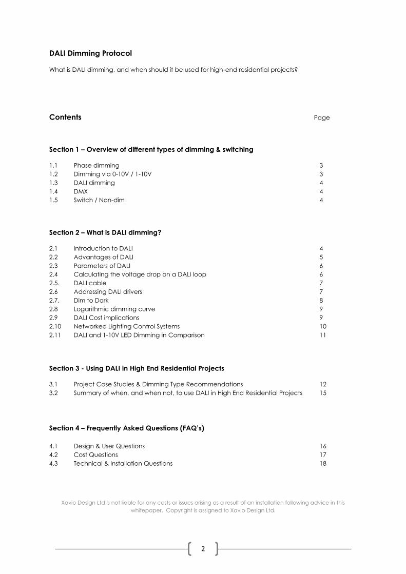
Contents Page
Section 1 – Overview of different types of dimming & switching
1.1 Phase dimming 3
1.2 Dimming via 0-10V / 1-10V 3
1.3 DALI dimming 4
1.4 DMX 4
1.5 Switch / Non-dim 4
Section 2 – What is DALI dimming?
2.1 Introduction to DALI 4
2.2 Advantages of DALI 5
2.3 Parameters of DALI 6
2.4 Calculating the voltage drop on a DALI loop 6
2.5. DALI cable 7
2.6 Addressing DALI drivers 7
2.7. Dim to Dark 8
2.8 Logarithmic dimming curve 9
2.9 DALI Cost implications 9
2.10 Networked Lighting Control Systems 10
2.11 DALI and 1-10V LED Dimming in Comparison 11
Section 3 - Using DALI in High End Residential Projects
3.1 Project Case Studies & Dimming Type Recommendations 12
3.2 Summary of when, and when not, to use DALI in High End Residential Projects 15
Section 4 – Frequently Asked Questions (FAQ’s)
4.1 Design & User Questions 16
4.2 Cost Questions 17
4.3 Technical & Installation Questions 18
Xavio Design Ltd is not liable for any costs or issues arising as a result of an installation following advice in this
whitepaper. Copyright is assigned to Xavio Design Ltd.
3
SECTION 1 – Overview of different types of dimming & switching.
1.1 |Phase dimming
- Mains voltage dimming. (A controller changes the shape of the electrical sine wave to control
dimming through the twin & earth 240V cable.)
- No extra control cable required.
- Used typically in high end residential for chandeliers, decorative wall lights, table lamps and
floor lamps.
- If phase dimming is used with LED downlights, the result is often less successful than using 0-10V
or DALI.
- Rarely possible to achieve successful performance with LED linear strips.
- Rarely possible with recessed LED floor uplighters, LED stairlights, and other LED accent lights.
- Limited dimming range.
- When used with LED phase dimming lamps (i.e. LED candle lamps for chandeliers) the dimming
levels often cannot go below 30%.
- Numbers of LED luminaires need to be carefully checked against the dimmer specifications.
Phase dimming of LED is rarely straightforward, and often highly problematic. Lutron systems in
particular have different levels of wattage output, and circuits must often be divided to ensure
compatibility.
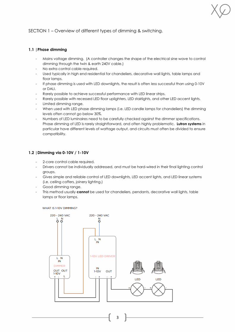
1.2 |Dimming via 0-10V / 1-10V
- 2-core control cable required.
- Drivers cannot be individually addressed, and must be hard-wired in their final lighting control
groups.
- Gives simple and reliable control of LED downlights, LED accent lights, and LED linear systems
(i.e. ceiling coffers, joinery lighting.)
- Good dimming range.
- This method usually cannot be used for chandeliers, pendants, decorative wall lights, table
lamps or floor lamps.
4
1.3 |DALI dimming
- 2-core control cable required.
- Lighting circuits can be re-configured digitally (within certain parameters) after installation is
completed.
- Typically used to give very fine and flexible control of LED downlights, LED accent lights, and
LED linear systems (i.e. ceiling coffers, joinery lighting.)
- Very wide dimming range.
- This method often cannot be used for chandeliers, pendants, decorative wall lights, table
lamps or floor lamps. (unless a specialist interface is used, and some manufacturers are starting
to give this as an option, as they recognise the advantages of DALI.)
- The latest versions of DALI (DT-8, for example) can also provide control of RGBW/Tuneable
White luminaires, which previous versions could not. This is still only capable of simple colour
change applications, and DMX should be used for any complex requirements.
1.4 |DMX
- Requires a specialist control cable and interface.
- Highly addressable and controllable via user interfaces that can be very complex if required.
- Commonly used mainly for the control of colour programmable RGB or RGBW LED luminaires,
for example underwater swimming pool lighting, colour changing coffer lighting in a games
room or home cinema, disco rooms, or other mood systems.
- Generally only used with professionally designed systems and for specialist applications.
1.5 |Switch / Non-dim
- No control cable required.
- No brightness control or addressing is possible.
- In high end residential projects, this is sometimes used for 5A circuits where it is not known if the
table/floor lamps will be dimmable. Also used for lightsources that are very low in output and
will never need to be dimmed.
SECTION 2 – What is DALI dimming?
2.1|Introduction to DALI
In any dimming system, the ballasts and controllers must be able to speak and hear the same
language. In the case of digital dimming systems, this language is either proprietary – that is, unique to
a particular manufacturer and, if allowed, other adopters – or an open standard; such as DALI protocol.
DALI stands for Digital Addressable Lighting Interface.
It is a non-proprietary interface standard for dimmable electronic control gear, offering huge flexibility
and a range of additional benefits.
A 2-wire control line manages a group of DALI ballasts (drivers) either individually or in a broadcast
scenario. Switching and dimming are handled via the control line with no need for a relay.
DALI is royalty-free, two-way, open, non-proprietary and interoperable digital protocol and a standard
in the United States and Europe. (Original European Standard 60929, NEMA 243-2004.)
This protocol has now been internationally standardised through the International Electrotechnical
Commission (IEC). The full DALI protocol is set out in the technical standard IEC 62386.
5
2.2 |Advantages of DALI
1. Circuit ‘groups’ can be assigned digitally after installation. No need to decide at design stage
as to which luminaires will be grouped together.
2. No relays are needed for switching the fixtures. (Switching & dimming are handled exclusively
via the control line.)
3. Synchronised changes from one lighting scene to another. Even if different luminaires are
started at different dimming values or different types of lamps are combined with each other,
DALI changes from one lighting scene to another in synchronism. All the light sources reach the
new light value at the same time.
4. Flexible for a later change of use. With DALI, the lighting groups are not hard-wired. The
individual fixtures are grouped by simply assigning them to groups with the aid of a controller.
These groupings can be changed at any time.
5. Provides true interchangeability across drivers and controls. By specifying DALI as an open
platform, multiple manufacturers can be involved in a system, instead of being tied to a single
supplier. This can result in more flexibility of choice, potentially lower costs, ensures future
availability, and enables the system designer to select the best products from various
manufacturers and combine them to achieve desired results.
6. DALI provides standardised ballast performance. It ensures consistent dimming performance
across all dimming drivers regardless of type or manufacturer, more reliably than with other
dimming types.
7. Simplified wiring. Daisy-chain and spurs are allowed. The digital protocol allows robust
communication even with low-cost cable, and with most devices being polarity insensitive,
mistakes in wiring are reduced.
8. A single pair of control wires, which form the bus, connect the ballasts and controls directly,
which simplifies wiring in spaces with multiple control zones by reducing the number of home-
runs.
9. The level of skilled labour is reduced because there is no need to pull cables according to a
zoning schedule. Each ballast on the circuit is wired in the same way.
10. Standard 2-core cable can be used. (1.5mm²)
11. Free wiring topology.
12. DALI low voltage power and data on same pair of wires.
13. DALI uses a system of distributed intelligence: multiple controllers communicate with intelligent
drivers. Each controller operates as a ‘master’ and controls communication on the control line.
Drivers react only as ‘slaves’ at the request of the ‘master’. Certain parameters are stored
directly in the DALI unit. (e.g. scene values, group addresses.)
14. Interference of data transmission is large ruled out for DALI thanks to a generously designed
interference voltage distance as well as the wide ranges for digital ‘low’ and ‘high’. This
means that shielded control lines are not required.
15. DALI uses floating control input. This means that the control input is galvanically separated
from the mains voltage (basic insulation, however no extra-low voltage SELV.) Thus, the DALI
drivers may be operated on different external cables (phases.)
6
2.3|Parameters of DALI
1. A maximum of 64 DALI devices on one ‘loop’ or subnet.
2. A maximum of 16 groups per DALI ‘loop’ or subnet. (Or Zones)
3. A maximum of 16 memory scenes per DALI unit.
4. The standard states that the DALI protocol is designed to sit below the level of a building
management system.
5. Max 300 metres of DALI cabling (with a line cross-section of 1.5mm²)
6. Max 240mA device consumption.
7. A voltage drop of 2V must not be exceeded.
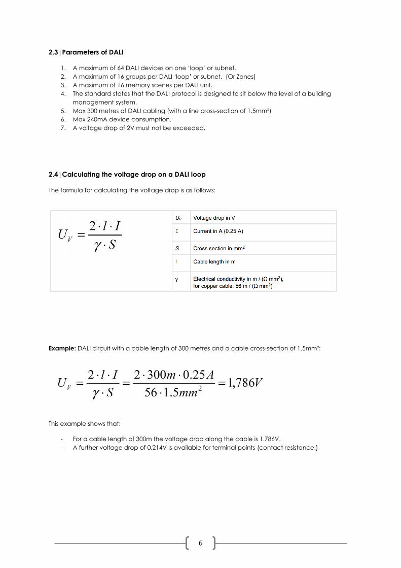
2.4|Calculating the voltage drop on a DALI loop
The formula for calculating the voltage drop is as follows:
Example: DALI circuit with a cable length of 300 metres and a cable cross-section of 1.5mm²:
This example shows that:
- For a cable length of 300m the voltage drop along the cable is 1.786V.
- A further voltage drop of 0.214V is available for terminal points (contact resistance.)
7
2.5|DALI Cable
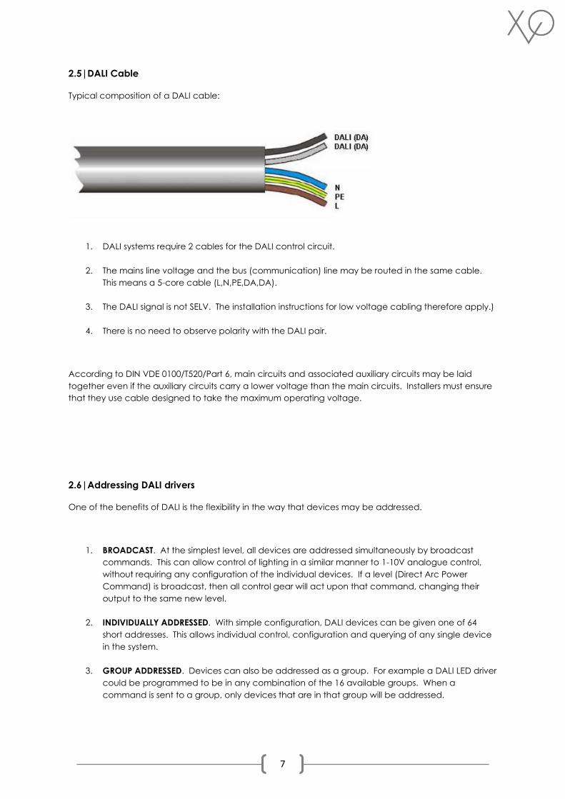
Typical composition of a DALI cable:
1. DALI systems require 2 cables for the DALI control circuit.
2. The mains line voltage and the bus (communication) line may be routed in the same cable.
This means a 5-core cable (L,N,PE,DA,DA).
3. The DALI signal is not SELV. The installation instructions for low voltage cabling therefore apply.)
4. There is no need to observe polarity with the DALI pair.
According to DIN VDE 0100/T520/Part 6, main circuits and associated auxiliary circuits may be laid
together even if the auxiliary circuits carry a lower voltage than the main circuits. Installers must ensure
that they use cable designed to take the maximum operating voltage.
2.6|Addressing DALI drivers
One of the benefits of DALI is the flexibility in the way that devices may be addressed.
1. BROADCAST. At the simplest level, all devices are addressed simultaneously by broadcast
commands. This can allow control of lighting in a similar manner to 1-10V analogue control,
without requiring any configuration of the individual devices. If a level (Direct Arc Power
Command) is broadcast, then all control gear will act upon that command, changing their
output to the same new level.
2. INDIVIDUALLY ADDRESSED. With simple configuration, DALI devices can be given one of 64
short addresses. This allows individual control, configuration and querying of any single device
in the system.
3. GROUP ADDRESSED. Devices can also be addressed as a group. For example a DALI LED driver
could be programmed to be in any combination of the 16 available groups. When a
command is sent to a group, only devices that are in that group will be addressed.
8
2.7|Dim to Dark
Using high quality LED drivers, such as EldoLED, DALI has the power and range to give very effective
dimming down to 0.1%. This is a huge advantage over less sophisticated LED dimming techniques such
as phase dimming.
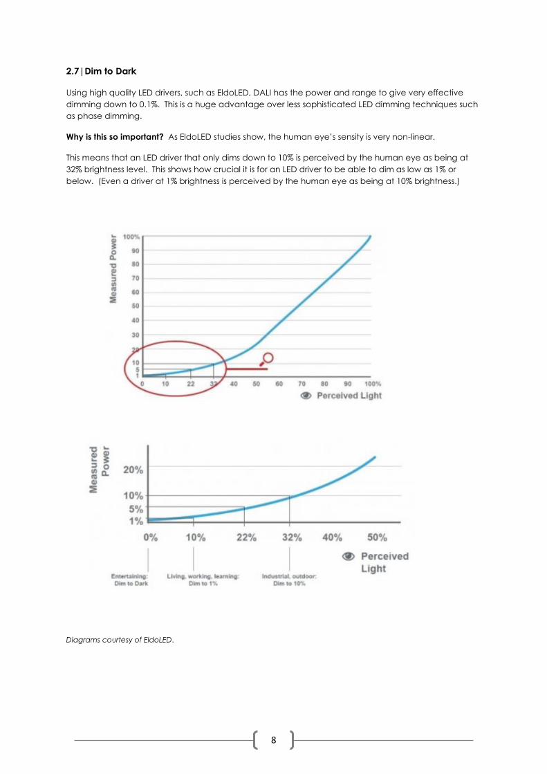
Why is this so important? As EldoLED studies show, the human eye’s sensity is very non-linear.
This means that an LED driver that only dims down to 10% is perceived by the human eye as being at
32% brightness level. This shows how crucial it is for an LED driver to be able to dim as low as 1% or
below. (Even a driver at 1% brightness is perceived by the human eye as being at 10% brightness.)
Diagrams courtesy of EldoLED.
9
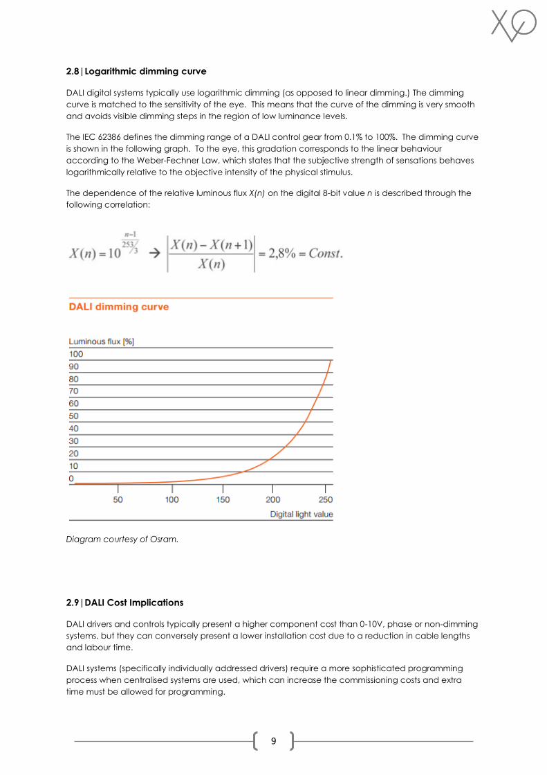
2.8|Logarithmic dimming curve
DALI digital systems typically use logarithmic dimming (as opposed to linear dimming.) The dimming
curve is matched to the sensitivity of the eye. This means that the curve of the dimming is very smooth
and avoids visible dimming steps in the region of low luminance levels.
The IEC 62386 defines the dimming range of a DALI control gear from 0.1% to 100%. The dimming curve
is shown in the following graph. To the eye, this gradation corresponds to the linear behaviour
according to the Weber-Fechner Law, which states that the subjective strength of sensations behaves
logarithmically relative to the objective intensity of the physical stimulus.
The dependence of the relative luminous flux X(n) on the digital 8-bit value n is described through the
following correlation:
Diagram courtesy of Osram.
2.9|DALI Cost Implications
DALI drivers and controls typically present a higher component cost than 0-10V, phase or non-dimming
systems, but they can conversely present a lower installation cost due to a reduction in cable lengths
and labour time.
DALI systems (specifically individually addressed drivers) require a more sophisticated programming
process when centralised systems are used, which can increase the commissioning costs and extra
time must be allowed for programming.
10
2.10|Networked Lighting Control Systems
DALI dimming uses less rack space per circuit on a typical lighting control system (such as a Lutron QS
Homeworks) than any other type of dimming protocol.
This is an advantage in projects with limited space for Lutron panels. (For example, if panels are being
concealed in joinery on each floor level where space may be at a premium.)
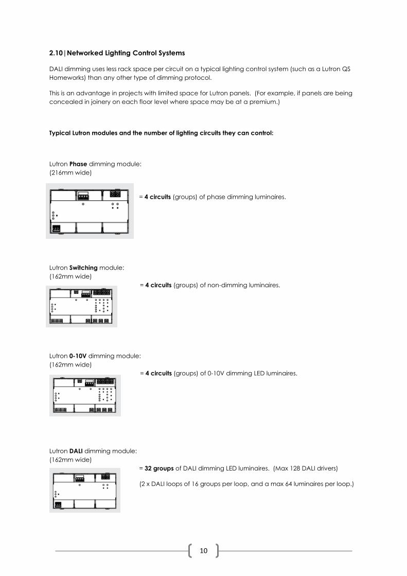
Typical Lutron modules and the number of lighting circuits they can control:
Lutron Phase dimming module:
(216mm wide)
= 4 circuits (groups) of phase dimming luminaires.
Lutron Switching module:
(162mm wide)
= 4 circuits (groups) of non-dimming luminaires.
Lutron 0-10V dimming module:
(162mm wide)
= 4 circuits (groups) of 0-10V dimming LED luminaires.
Lutron DALI dimming module:
(162mm wide)
= 32 groups of DALI dimming LED luminaires. (Max 128 DALI drivers)
(2 x DALI loops of 16 groups per loop, and a max 64 luminaires per loop.)
11
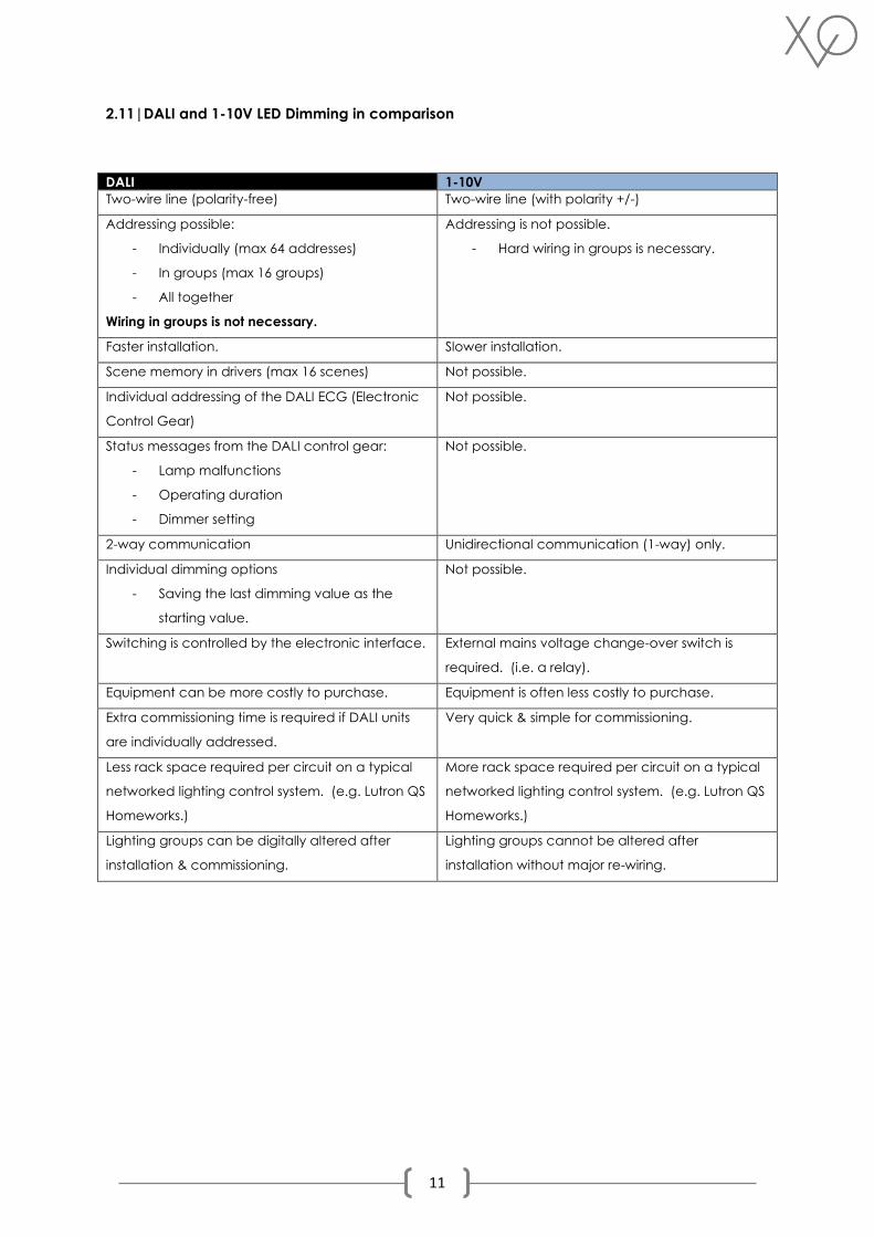
2.11|DALI and 1-10V LED Dimming in comparison
DALI 1-10V
Two-wire line (polarity-free) Two-wire line (with polarity +/-)
Addressing possible:
- Individually (max 64 addresses)
- In groups (max 16 groups)
- All together
Wiring in groups is not necessary.
Addressing is not possible.
- Hard wiring in groups is necessary.
Faster installation. Slower installation.
Scene memory in drivers (max 16 scenes) Not possible.
Individual addressing of the DALI ECG (Electronic
Control Gear)
Not possible.
Status messages from the DALI control gear:
- Lamp malfunctions
- Operating duration
- Dimmer setting
Not possible.
2-way communication Unidirectional communication (1-way) only.
Individual dimming options
- Saving the last dimming value as the
starting value.
Not possible.
Switching is controlled by the electronic interface. External mains voltage change-over switch is
required. (i.e. a relay).
Equipment can be more costly to purchase. Equipment is often less costly to purchase.
Extra commissioning time is required if DALI units
are individually addressed.
Very quick & simple for commissioning.
Less rack space required per circuit on a typical
networked lighting control system. (e.g. Lutron QS
Homeworks.)
More rack space required per circuit on a typical
networked lighting control system. (e.g. Lutron QS
Homeworks.)
Lighting groups can be digitally altered after
installation & commissioning.
Lighting groups cannot be altered after
installation without major re-wiring.
12
SECTION 3 – Using DALI in High End Residential Projects
3.1|Project Case Studies & Dimming Type Recommendations
• It is assumed that all of these projects have a networked lighting control system such as Lutron
Homeworks QS.
• Please note that a lighting consultant should always be referred to on a project-by-project
basis when making these decisions, as there may be many factors to consider. The examples
below are given as a guide only.
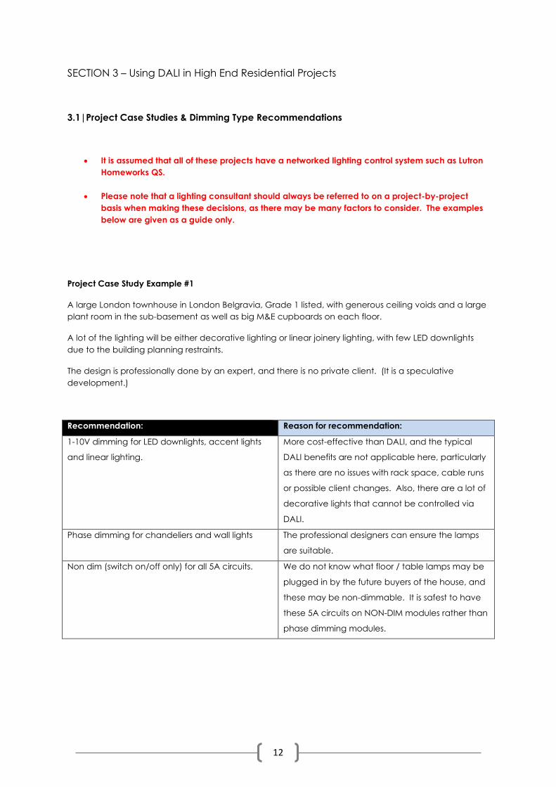
Project Case Study Example #1
A large London townhouse in London Belgravia, Grade 1 listed, with generous ceiling voids and a large
plant room in the sub-basement as well as big M&E cupboards on each floor.
A lot of the lighting will be either decorative lighting or linear joinery lighting, with few LED downlights
due to the building planning restraints.
The design is professionally done by an expert, and there is no private client. (It is a speculative
development.)
Recommendation: Reason for recommendation:
1-10V dimming for LED downlights, accent lights
and linear lighting.
More cost-effective than DALI, and the typical
DALI benefits are not applicable here, particularly
as there are no issues with rack space, cable runs
or possible client changes. Also, there are a lot of
decorative lights that cannot be controlled via
DALI.
Phase dimming for chandeliers and wall lights The professional designers can ensure the lamps
are suitable.
Non dim (switch on/off only) for all 5A circuits. We do not know what floor / table lamps may be
plugged in by the future buyers of the house, and
these may be non-dimmable. It is safest to have
these 5A circuits on NON-DIM modules rather than
phase dimming modules.
13
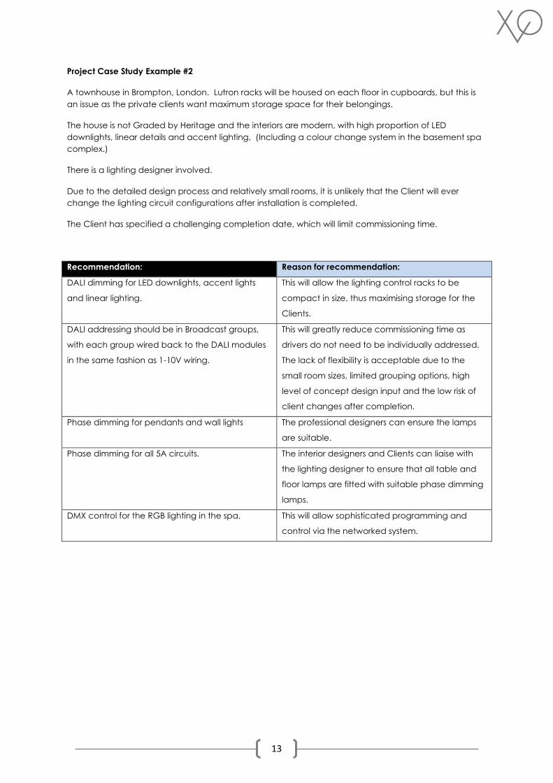
Project Case Study Example #2
A townhouse in Brompton, London. Lutron racks will be housed on each floor in cupboards, but this is
an issue as the private clients want maximum storage space for their belongings.
The house is not Graded by Heritage and the interiors are modern, with high proportion of LED
downlights, linear details and accent lighting. (Including a colour change system in the basement spa
complex.)
There is a lighting designer involved.
Due to the detailed design process and relatively small rooms, it is unlikely that the Client will ever
change the lighting circuit configurations after installation is completed.
The Client has specified a challenging completion date, which will limit commissioning time.
Recommendation: Reason for recommendation:
DALI dimming for LED downlights, accent lights
and linear lighting.
This will allow the lighting control racks to be
compact in size, thus maximising storage for the
Clients.
DALI addressing should be in Broadcast groups,
with each group wired back to the DALI modules
in the same fashion as 1-10V wiring.
This will greatly reduce commissioning time as
drivers do not need to be individually addressed.
The lack of flexibility is acceptable due to the
small room sizes, limited grouping options, high
level of concept design input and the low risk of
client changes after completion.
Phase dimming for pendants and wall lights The professional designers can ensure the lamps
are suitable.
Phase dimming for all 5A circuits. The interior designers and Clients can liaise with
the lighting designer to ensure that all table and
floor lamps are fitted with suitable phase dimming
lamps.
DMX control for the RGB lighting in the spa. This will allow sophisticated programming and
control via the networked system.
14
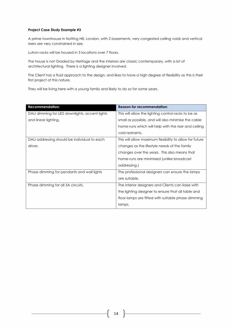
Project Case Study Example #3
A prime townhouse in Notting Hill, London, with 2 basements, very congested ceiling voids and vertical
risers are very constrained in size.
Lutron racks will be housed in 3 locations over 7 floors.
The house is not Graded by Heritage and the interiors are classic contemporary, with a lot of
architectural lighting. There is a lighting designer involved.
The Client has a fluid approach to the design, and likes to have a high degree of flexibility as this is their
first project of this nature.
They will be living here with a young family and likely to do so for some years.
Recommendation: Reason for recommendation:
DALI dimming for LED downlights, accent lights
and linear lighting.
This will allow the lighting control racks to be as
small as possible, and will also minimise the cable
home-runs which will help with the riser and ceiling
void restraints.
DALI addressing should be individual to each
driver.
This will allow maximum flexibility to allow for future
changes as the lifestyle needs of the family
changes over the years. This also means that
home-runs are minimised (unlike broadcast
addressing.)
Phase dimming for pendants and wall lights The professional designers can ensure the lamps
are suitable.
Phase dimming for all 5A circuits. The interior designers and Clients can liaise with
the lighting designer to ensure that all table and
floor lamps are fitted with suitable phase dimming
lamps.
15
3.2|Summary of when, and when not, to consider using DALI in High End Residential Projects
DALI dimming control should be considered for residential projects when:
1. The lighting groups may need to change in the future and cannot be predicted with a high
degree of certainty at concept & design development stage. For example, if the lifestyle uses
of rooms are not known or may change, the client wishes to retain a degree of flexibility, a
professional lighting designer is not being used, or positions of artwork / furniture / objets d’art
etc are not fixed.
2. There is limited physical space for lighting control racks and panels and they need to be as
small as possible.
3. There is a lot of architectural lighting with complex scenes.
4. There are large open-plan rooms or areas with multiple uses and functions.
5. There is limited cable run space in risers, conduits, ceiling voids and other service areas.
6. A very wide range of dimming control is required, i.e. the final user may wish for lighting to be
able to be dimmed to extremely low levels.
7. There is a fully networked lighting control system such as Lutron or Crestron.
DALI dimming control is probably NOT suitable for residential projects when:
1. There is a lot of decorative lighting which can only be controlled via phase dimming.
2. There is a lot of lighting that does not require dimming or cannot be dimmed.
3. There are significant cost restraints to the project.
4. It is a mid-range speculative development with no private client and therefore the flexibility of
DALI is not an advantage and the costs may make it prohibitive.
5. The electrical contractors are not comfortable or experienced with DALI systems.
6. There is only a short space of time allowed for commissioning of the lighting control system.
(DALI takes longer to programme.)
7. There is no networked lighting control system.
8. There is no complete re-wire and DALI cabling cannot be installed due to parts of the property
that are not going to be included in the project.
Please note: a lighting professional or electrical engineer should always be consulted regarding
dimming types on large projects, due to the often very substantial cost of control and lighting
equipment.
16
SECTION 4 - Frequently Asked Questions (FAQ’s)
4.1|Design & User Questions
Can DALI dimming be used for chandeliers and decorative wall lights?
Typically this is not possible. It is rare to find chandeliers and wall lights that can be dimmed via DALI
protocol. This is because most of these products are designed in traditional ways with 240V
lampholders which therefore can only be dimmed via Phase dimming methods.
Some modern LED chandeliers and wall lights will have integral drivers, and sometimes these can be
adapted to take DALI control. However, DALI drivers are often slightly larger than other types of drivers
and may not physically fit into the luminaire. Occasionally there is an option to house the driver in a
remote location or in the ceiling/wall void, but this is often not possible. DALI-to-Phase interfaces are
available in the market but need suitable remote locations.
Are DALI drivers always bigger than phase dim or 0-10V drivers?
Typically DALI drivers are slightly longer than other types as they have more electronics on board.
However, increasingly these drivers are becoming smaller and there are now a variety of compact
DALI drivers available which can fit vertically into 150mm ceiling voids through downlight cut-outs.
Is it true that linear LED strips can NOT be dimmed via DALI control?
No, this is not true. 5-10 years ago there were very few DALI drivers capable of effectively controlling
12V and 24V DC LED lightsources (such as flexible LED strip), but manufacturers such as EldoLED, Osram
and Meanwell are now producing highly effective DALI drivers for linear LED systems. DALI is now a
common dimming protocol for linear LED strips.
Is it easy to change group configurations after a DALI installation is complete?
Although this is a relatively straightforward process with lighting control systems, it can be very time-
consuming and may be expensive if you are paying for professional programmers to do this. It is always
best to spend more time at design stage and to get the groupings right from the start!
How many lights can be put together on a single physical DALI cable?
64 DALI devices is the maximum number of units per DALI cable. For example, you may have a DALI
loop in a residential projects with:
- 40 x individual ceiling DALI LED downlights
- 5 x DALI drivers for recessed floor uplighters
- 5 x DALI drivers for LED recessed wall stairlights.
- 14 x DALI drivers for LED linear strip systems such as joinery lighting.
This is then up to maximum and you need to start another physical cable run for the next set of DALI
devices. Please note you can only have a maximum of 16 groups of lights per loop.
17
This info on the number of units per DALI cable applies if you are individually addressing each DALI unit.
(Broadcast addressing requires separate DALI cable runs for each group, so if for example you require
10 groups with 6 lights in each it is necessary to run 10 x DALI loops from the controller. This method
speeds up the commissioning but reduces flexibility and is more inefficient on installation time and
cabling costs.)
What is a ‘bus’ line in an electronic / electrical installation jargon?
A bus line is a communication cable that transfers data between devices. It is a transmission path on
which signals are dropped off or picked up at every device attached to the line. Only devices
addressed by the signals pay attention to them; the others discard the signal.
(The term is derived from its similarity to buses in a town or city that pick up or drop off passengers at
each bus stop along the route.)
Are all DALI drivers only suitable for logarithmic dimming?
No, many high quality DALI drivers can be programmed for linear dimming if required, although
logarithmic dimming is generally preferred for residential projects.
4.2|Cost Questions
What are the cost factors that should be considered when deciding whether to specify a DALI system as
opposed to another type of dimming protocol?
The following cost factors should be collated by the project QS from different professionals, to obtain a
full comparison between a DALI install and, for example a 1-10V + Phase dim install:
1. Consultants’ fees in designing the system. (Obtain costs from the lighting consultant, the M&E
consultant, and the AV/lighting control consultant.) Fees may be slightly higher for a DALI
system.
2. Procurement costs for the lighting control equipment. (i.e. the Lutron system or similar.) Costs
may be slightly higher for a DALI system from some manufacturers.
3. Procurement costs for the luminaires and drivers. Costs may be slightly higher for a DALI system
from some manufacturers.
4. Costs of cables and other electrical materials.
5. Cost of installation. (Labour only.)
6. Cost of programming & commissioning the lighting control system.
7. Call-out costs if you do choose to reconfigure / re-programme your system at a future date
after the original commissioning is completed.
18
Do DALI drivers cost more than 1-10V drivers?
DALI drivers are slightly more expensive to purchase from some manufacturers than 1-10V drivers, but
the gap is rapidly closing and many downlight manufacturers (such as Orluna) now have identical
prices for both options.
4.3| Technical & Installation Questions
What are the technical parameters and limits of DALI?
- Maximum number of DALI units: 64
- Maximum number of DALI groups: 16
- Maximum number of DALI scenes: 16
- DALI voltage: 9.5-22.5V, typically 16V.
- DALI system current: max 250mA (depending on the installed DALI power supply.)
- Data transfer rate: 1200 baud
- Maximum cable length: the max cable length depends on the max permitted voltage drop
along the DALI cable; this is defined as 2V max. This corresponds to a maximum cable length
of 300 metres for a line cross-section of 1.5mm².
- Contact resistances must also be taken into consideration. A voltage drop of 2V must not be
exceeded.
- DALI is NOT SELV, so installation instructions for 240V must be followed.
Does polarity matter on the driver connections?
No, polarity does not need to be observed with a DALI pair.
Which cable topologies are suitable for DALI?
✓ Line, star, tree and bus are suitable.
X Topologies such as ring, mash and fully connected are NOT suitable.
Can the DALI control line be routed in the same cable as the power supply?
Yes, the DALI system is installed using standard installation material for mains voltage, plus 2 wires are
needed for the DALI control circuit. The line voltage and bus line may be routed in the same cable.
What happens in a DALI circuit if a wire with a cross-section of 0.75mm² is used instead of the
recommended cross-section of 1.5mm²?
The maximum possible cable length is reduced to about 150 metres instead of the 300 metres that can
be achieved with a 1.5mm² cross-section.

19
How many DALI groups can be programmed in a large open-plan space, and are there any limits to
this?
We recommend that in any large visually open space, the number of DALI groups per loop is limited to
8. (not the 16 that is digitally possible.) The reason for this is that with more than 8 groups you can see a
‘popcorn’ (ripple delay) effect when the groups are turned on. Groups that are furthest from the LCP
(lighting control panel) processor can take longer to come on, and there are a lot of commands going
down the cables, resulting in a slightly disjointed visual experience for the user. However, with up to 8
groups this effect is not noticeable.
Please note that if you need more than 8 zones in an open plan space, this is easily achievable by
adding more DALI loops. The limit is on the 8 zones (programmed sub-groups) per loop. There is no limit
to the number of loops you can have.
If a DALI driver fails after install, will the end user then need to call out a specialist AV engineer who will
charge them to re-address and assign the replacement DALI driver?
Usually not – most intelligent DALI lighting control systems have a short-term memory function (ranging
from a few weeks to a few months, depending on the manufacturer) which can automatically re-
assign the original DALI address to a new device that replaces a faulty item.
The DALI system ‘remembers’ that a device has failed, and saves the address number ready for the
replacement driver. This means that no specialist re-programming of the driver is required, and it can
be replaced by any regular electrician or maintenance engineer as if it was a basic non-dim driver or
component.
N.B – this only works if there is only ONE failed unit on the DALI loop. If 2 units or more fail before the first
failure is rectified, then the system is unable to know which address belongs to which location and the
DALI sub-groups will all need to be re-programmed by a DALI programmer. Also, if the fault is left for
too long then the saved address will be erased.
Lighting control manufacturers will be able to advise if this clever and useful function is available on
their processor, and for how long the memory will hold the digital DALI address of the failed driver or
device.
Xavio Design of Mayfair | 2nd Floor Berkeley Square House | Berkeley Square | Mayfair | London | W1J 6BD | UK
T: 0203 301 0077 | E: [email protected] | www.xavio-design.com
Copyright © 2022 FDOKUMEN