D630 - OTC Tools
37
User Manual - I - D630 Wireless Automotive Diagnostic System OPERATION Version 1.4 Copyright ©2012
-
Upload
khangminh22 -
Category
Documents
-
view
3 -
download
0
Transcript of D630 - OTC Tools

User Manual
- I -
D630
Wireless Automotive Diagnostic System
OPERATION
Version 1.4
Copyright ©2012

User Manual
- II -
D630 User Manual instructions
Please read this user manual carefully before using the D630.
This user manual is based on the current features and functions available at the time of print.
When reading the manual, please pay special attention to the words “Note”, “Caution” and
“Warn”. Read them carefully for appropriate operation.
D630 main unit maintenance:
Avoid shaking or dismantling as it may damage the internal components
Do not use hard or sharp objects to touch it; do not use excessive force; do not expose the
screen to strong sunlight for a long period
Caution: keep them away from water, moisture, high temperature or very low temperature;
Keep the units away from strong magnetic fields.
Operation Instructions
For safe operation please follow the instructions below;
Keep the D630 away from heat or fumes when using it;
Make sure the car is securely parked the park brake applied and the selector is at P or N position
to prevent the vehicle from moving when engine starts;
Make sure the diagnostic link connector (DLC) is connected before starting the test.
Do not switch off the power or unplug the connectors during testing, otherwise you may damage
the ECU or D630;

User Manual
- III -
INDEX
PAGE
INTRODUCTION 1
MAIN CABLE CONNECTION 6
VEHICLE SELECTION 7
STARTING THE D630 9
TEST PROCDURE EXAMPLE (1) 10
TEST PROCDURE EXAMPLE (2) 18
SOFTWARE UPDATES 28
OPTIONAL EQUIPMENT AND PROGRAMS 28
WARRANTY CERTIFICATE 34
User Manual
- 1 -
1 Introduction
Function and Feature
Extensive coverage for Asian, Australian,
American, European and Chinese Cars
Multi-functions
Wireless diagnosis operated from the tablet
CAN-BUS with high/low speed
One OBDII connector for all CAN bus
systems
Automatic software updates
6-layer electronic circuit board
Self-check function
1.2 Layout of Main Unit
The main unit layout is as shown in left picture.
1. Tablet PC (optional)
2. Wireless adaptor
3. Vehicle communication interface
4. Vehicle DLC
5. Main cable port
6. Power indicator
7. Wireless operation indicator
8. USB port
9. Power supply (+12V) port

User Manual
- 2 -
Name: Main Cable
Quantity: 1
Function: Connect the main
unit and connectors with
vehicle
Name: BENZ-38 connector
Quantity: 1
Function: Used for testing
Mercedes-Benz vehicles
equipped with a circular
38-pin DLC
Name: Benz-14 connector
Quantity: 1
Function: Used for testing
Mercedes-Benz sprinter
Name: BMW-20 connector
Quantity: 1
Function: Used for testing
BMW vehicles equipped
with a 20-pin DLC
Name: Chery/Fiat -3 connector
Quantity: 1
Function: Used for testing
Chery/Fiat vehicles
equipped with a 3-pin DLC
Name: GM-12 connector
Quantity: 1
Function: Used for testing
GM/Daewoo vehicles
equipped with a 12-pin DLC

User Manual
- 3 -
Name: Kia-20 connector
Quantity: 1
Function: Used for testing
KIA vehicles equipped with
a 20-pin DLC
Name: Mazda-17 connector
Quantity: 1
Function: Used for testing
MAZDA vehicles equipped
with a 17-pin DLC
Name: Toyota-17 connector
Quantity: 1
Function: Used for testing
Toyota/Lexus vehicles
equipped with a
semi-circular 17pin DLC
Name: Toyota-22 connector
Quantity: 1
Function: Used for testing
Toyota/Lexus vehicles with
a rectangular 22-pin DLC
Name: MIT-12+16 connector
Quantity: 1
Function: Used for testing
Mitsubishi and Hyundai
vehicles equipped with a
12-pin or 16-pin DLC
Name: Honda-3 connector
Quantity: 1
Function: Used for testing
HONDA and ACURA
vehicles equipped with a
3-pin DLC

User Manual
- 4 -
Name: Benz-4 connector
Quantity: 1
Function: Used for testing
Mercedes-Benz before 1997
with flash codes, which are
usually equipped with either
a rectangular 8-pin or 16-pin
DLC
Name: Audi-4 connector
Quantity: 1
Function: Used for testing
VW/Audi vehicles with a
4-pin (2x2) DLC
Name: Nissan-14 connector
Quantity: 1
Function: Used for testing
Nissan and Infiniti vehicles
equipped with a 14-pin DLC
Name: OBD-16 connector
Quantity: 1
Function: Used for testing
all vehicles compliant with
OBDII, EOBD and J1962
with 16-pin DLC
Name: Citroen-16C connector
Quantity: 1
Function: Used for testing
Citroen vehicles equipped
with a 16-pin DLC
Name: Jumper
Quantity: 1
Function: Short circuit test
for flash code reading

User Manual
- 5 -
Name: Battery power cable
Quantity: 1
Function: Gains
power supply from battery
Name: Cigarette lighter power cable
Quantity: 1
Function: Gains power
supply via cigarette lighter
on car
Name: D630 charger
Quantity: 1
Function: Used to charge
the D630 tablet.
NOTE: Configuration varies as per software package. For complete configuration, please refer to the
relevant shipping list.
USB Dongle is supplied in a complete package. In this package, there is a driver
software CD. It is necessary to install the driver for the USB Dongle.
The D630 is also supplied with a USB cable, this cable is to allow setting up of the
optional printer, it can also be used to connect the PC and the VCI in the case of a
suspected problem with the Bluetooth, if you are unable to communicate wirelessly,
disconnect the USB dongle from the D630 and connect the USB cable in the same port
the dongle was in, disconnect and re-connect the power from the VCI which will allow it
to reset. This procedure will allow communication until the problem is resolved. Do not
use the cable and Bluetooth at the same time as this will cause a communication failure
and an error message “Reset failed”.

User Manual
- 6 -
Main Cable connection
1. DLC
2. Connector
3. Main cable
4. Vehicle communication
interface
5. Tablet PC
6. Wireless adaptor
Diagnostic connection:
a) Locate the position of the DLC
b) Select corresponding connections for the make/model and
type of DLC
c) Connect the main cable to the VCI and to the DLC
connector
d) Ensure the wireless connector (dongle) is attached to the
USB port of the tablet
e) Connect the VCI to the DLC and check the power indicator
(green) light is on and wireless indicator is flashing. If there
is no power indicated, check for 12V at the DLC connector.
If no power is available connect the VCI to a 12V external
power source – Cigarette lighter or battery.
f) The blue light on the VCI will flash approximately 2 times
per second while looking for the scan tool and then flash
once every 2 seconds once paired with scan tool and
communication is established
g) Ensure wireless adapter is connected before launching
program

User Manual
- 7 -

User Manual
- 8 -
Vehicle selection
For most cars the vehicle selection is straight forward and will need no explanation, simply go to the
manufacturer, model, system required, but with some models knowledge of that make will be required. Please
consider when you are selecting a vehicle that the D630 is a global tool and the software is developed all over
the world. When you are testing a car and the make does not appear in the menu that you select consider the
country of origin, eg. (what is a Holden Barina before it is re-badged?) most car selection is straight forward, but
there is still a couple of models that will require a little more thought. Some will be separated by the type of DLC
connector, some will be “CANBUS” or “WITHOUT CANBUS” the following VW test will show this. Look to the
country of the parent manufacturer and select the model, we will show Barina here as an example here.
Select Europe / opel / Europe opel /year / and the models will be shown, for the Barina it will be displayed as
CORSA-A or CORSA-B open each one and check the engine type available matches with the car you are
testing (corsa-b) will be most common.

User Manual
- 9 -
Select the engine of your vehicle. Once you have identified the correct model match (Corsa-A or Corsa-B) you
can then scroll back to access the other vehicle systems.
“Most Technicians that have used aftermarket scan tools in the past will be
familiar with this procedure”.

User Manual
- 10 -
In the following pages we will demonstrate
connection to VW as an example, different
manufactures and models will vary in
configurations, information lay out and
connections. If you wish to work through
menus to learn the tool, check the demo box
before starting the communication software.
This function will allow you to see the items
available for testing, and show simulated
data to represent test conditions. When
using the demo mode, not all manufactures
and models are represented.
Interface Instruction
Starting Interface
The interface shown on the left picture will appear
on the screen after the scan tool button is clicked.
Diagnostic Program
In the diagnostic screen you can select regional
vehicle makes including: Australian, European,
Asian, America and Others OBDⅡ/EOBD).

User Manual
- 11 -
Test Example (1) VW
Engine ECU Testing Methods
Testing Description
(1) Connect to the DLC and run the D630 program.
(2) Click on [Europe] to enter interface as shown
on the left image;
(3) Select diagnostic program
(take Volkswagen for example)
Click on [VW] to enter its diagnostic program as
shown in the left image. The version currently
installed on your scan tool is displayed at the top of
the screen.
(4). Select the version (V3.2) and click on [OK] to
download the diagnosis program as shown in left
image. Click on [Cancel] to go back to the previous
menu if necessary;
(5). Select vehicle type. (for this version of
Volkswagen we have two vehicle types for
selection: [With Canbus] and [Without Canbus].
If you are unsure vehicles with Canbus will have
DLC pins 6 and 14 populated.
Here we choose [Without CANbus] as an
example to start the test.

User Manual
- 12 -
(6) Select system:
[Common system Auto-Scan]: Test the
common-use ECU automatically;
[All system Auto-Scan]: Test all ECU
automatically;
[Common]: by choosing this item, all common-use
ECU will be displayed on the screen, the users can
then select the ECU required;
Other systems: Enter the systems as per relevant
ECU type.
(7) Click on [Common] to enter the interface
shown on the left.
Select [01-Engine] to enter the interface with the
following functions.
[01-Interrogate control unit versions]
[02-Interrogate fault memory]
[03-Final control diagnosis]
[04-Introduction of basis setting]
[05-Erase fault memory]
[06-End output]
[07-Coding]
[08-Read measuring value block]
[09-Read individual measuring value]
[10-Adaptation]
[11-Login procedure]
[15-Write VIN]
Note: Functions 04,07,10,15 require knowledge of
the systems operation, please use properly.

User Manual
- 13 -
①[01-Interrogate control unit versions]
Click on [01-Interrogate control unit versions] to
see the information on the control unit as shown on
the left.
Note: Read out old ECU codes with this function
when performing ECU coding.
② [02-Interrogate fault memory]
To display the DTC saved in the current control unit,
click [02-Interrogate fault memory]. Please refer
to the left image.
③ [03-Final control diagnosis]
Click on the button [03-Final control diagnosis] to
test relevant actuator automatically as shown on
the left image. Click on [Active Test] to begin the
actuator test.
④ [04-Introduction of basis setting]
Click on the button [04-Introduction of basis
setting] for basic setting. Input desired text using
the number keys and click on the button [OK] to
start the basic setting.
[Del]: Delete the input numbers;
[Left]: Move cursor to left;
[Right]: Move cursor to right;
[Home]: Move cursor to Home;
[End: Move cursor to End;
[Enter]: confirm enters.

User Manual
- 14 -
The window of “Basic setting!” in left image will pop
up after Basic Setting is done.
[Input]: continue to Input Channel number;
[Back]: Back to the Function Menu.
Note: Under basic setting mode, you can perform
solenoid and engine control unit adaptation without
starting the engine, or finish λ control process
self-adaptation when engine starts. Also you can
check faults or ignition timing by connecting or
disconnecting λ control.
⑤ [05-Erase fault memory]
Click on the button [05-Erase fault memory] to
erase DTC as shown on the left image.
[OK]: Return to the previous menu
⑥ [06-End output]
To exit from the diagnostic program, please click on
[06-End output].
[Yes]: Exit the diagnosis program
[No]: Return to the previous menu
⑦ [07-Coding]
Click on [07-Code control unit] to go to interface
shown in left image. Then input the code and click
on [OK], the D630 will begin the coding. Click on
[OK] after coding is successful.
Note: Please only code the ECU after the ECU has
been changed or a function has been added (ie
Cruise control). You can get the code of the old
ECU by choosing [01-Interrogate control unit
versions], then recode the new ECU accordingly.

User Manual
- 15 -
⑧ [08-Read measuring value block]
Click on [08-Read measuring value block] to
enter interface shown in left image. Please input
the relevant channel number, and click on [OK] to
read data stream information.
Note: For channel definition, please refer to
relevant technical manual.
The left image is the data stream of Group 01.
[Page Up]: See previous group data stream;
[Page Down]: See next group data stream;
[Waveform]: Review data stream in graph;
[Replay]: Review data stream;
[Channel]: Return to the interface to input
channel number;
[Back]: Return to the Function Menu.
[Print]: save the current screen to SD card.
⑨ [09-Read individual measuring value]
Click on [09-Read individual measuring value] to
enter the interface shown in the left image. Input
the channel number and click on [OK] to view the
relative data.
Click on [Read Value], and current value will be
displayed.
[Input]: Back to the input interface;
[Increase]: View the data of next channel
number.
[Decrease]: View the data of the previous
channel number;
[Read value]: Read current value;
[Back]: Back to function list menu;
[Print]: Save the current screen to SD card

User Manual
- 16 -
⑩ [10-Adaptation]
Click on [10-Adaptation] to enter the interface of
inputting channel number as shown in left image.
Note: Self-adaptation includes: self-study during
idle, service reset, IMMO adaptation and so on.
You should login first for some of the functions. For
login methods, please refer to [11-Login
procedure] on page 26.
After inputting the relative channel number, click on
[OK] to enter the interface as shown in left image.
[Input]: Back to the “input channel number”
interface;
[Read]: Read the adaptation value of current
channel;
[Back]: Back to function list interface;
[Print]: Save the current screen to SD card.
Click on the button [Read] to read the adaptation
value of current channel.
[Input]: Input new adaptation value;
[Back]: Back to function list menu.
[Print]: Save the current screen to SD card.
Click on [Input] in enter the “input adaptation value”
interface shown on the left. Input the new value
and then click the button [Ok] to go to the next
step.

User Manual
- 17 -
After inputting the new value, new adaptation value
will be displayed on the screen. If no error is found,
please click on the button [Change] to go to the
next step.
Last step: Click on the button [Save] to save the
new adaptation value and go back to the
self-adaptation interface.
User Manual
- 18 -
[11-Login procedure]
To perform adaptation in some group, login will be
needed first. Just click on the button [11-Login
procedure], input the code number and then click
on [OK].
Note: Login is required when performing functions
such as ECU coding, change channel adaptation
and IMMO, etc.
[15-Write VIN]
Volkswagen/Audi uses the 3rd
generation anti-theft
technology, if you change engine control unit and
instrument cluster at the same time you must
rewrite the VIN code. Please click on [15-Write VIN]
to input the new VIN.
FCC NOTE:
THE MANUFACTURER IS NOT
RESPONSIBLE FOR ANY RADIO OR TV
INTERFERENCE CAUSED BY UNAUTHORIZED
MODIFICATIONS TO THIS EQUIPMENT. SUCH
MODIFICATIONS COULD VOID THE USER'S
AUTHORITY TO OPERATE THE EQUIPMENT.

User Manual
- 19 -
Test Example (2)
This example will outline a Mitsubishi Lancer demonstrating the Normal / Self study / Compare modes. This Self
study / Compare function is very helpful in finding intermittent faults, it allows us to compare the data when the
engine is running normally and when the intermittent fault occurs.
1/ From the main screen we have selected Asia and then Mitsubishi
2/ Select the software version (V 5.6)

User Manual
- 20 -
3/ Select the Year range
4/ Select country destination (MMAL for Australian models)

User Manual
- 21 -
5/ Select model (Lancer CY)
6/ Select the model

User Manual
- 22 -
7/ Select the year range
8/ Select the engine model

User Manual
- 23 -
9/ Select the system to be tested
10/ Select the function you wish to test (I have selected read data stream for this example)

User Manual
- 24 -
11/ Select the component, sensors etc. you wish to monitor (or click select all to view all)
12/ Next a pop up box will appear offering normal mode / self study / compare, we have selected self study and
chosen to test at idle. Press OK

User Manual
- 25 -
13/ The unit will display the live data from the from the engine management system and the scan tool is
recording the peak (high / low) readings from the engine sensors selected (not all parameters record data).
14/ After recording the data (no fixed time, but if the time is too short the window of the data captured may be too
narrow and will show all parameters changing outside the standard value) close and re-open the Read Data
Stream again but this time in compare mode again at idle,

User Manual
- 26 -
15/ You will now notice in the Right hand column where it is headed standard value there is now a set of figures,
this is the information that was captured during the self-study, it shows the highest and lowest figures that were
displayed during the self-study (not all data lines are supported)

User Manual
- 27 -
16/ You will notice the readings in the standard data column shows the min / max values recorded, now if the
incoming data moves outside of these values the data line will become highlighted in RED to show that the
parameter had moved outside of its previously recorded “normal” state.

User Manual
- 28 -
Fig 2-1 update client starting interface
Fig 2-2 login interface

User Manual
- 29 -
2.3 Software update
2.3.1 Upgrading Instructions
2.3.1.1 Run D630 update client program
Double click to run the “D630Client.exe” program under the folder named “tools” in the CD program. You will go
to update interface as shown in Fig 2-1.
2.3.1.2 Login the Server
(1) Input the serial number and click on [Connect to server] to enter the Fig 2-2 interface.
(2) Server. The default server is ‘Mirror Site(Euro)’. Normally you do not need to change the server.
(3) Input the password (see 2.2.5) and click on [OK].
Note:
① Be sure that both S/N and password are correct. Please pay attention if the letters are capitalized or not.
② If login takes a long time because of low internet speed, you can exit and retry;
③ Internet firewall might affect the login. If login fails, please make sure you have an internet connection, and
ensure any installed firewall is not blocking the connection to the server. You may contact your local distributor
for further operating instructions.
Fig2-3 Program list interface

User Manual
- 30 -
Fig2-4
Fig2-5 Modify password interface

User Manual
- 31 -
(4) After login succeeds, the diagnosis program for the different manufacturers will be displayed as shown in
Fig2-3, please wait for a short time for complete download.
2.3.3.3 Modify Password
After login succeeds, users can change the original password.
Operation instruction:
(1) Click on the button [Connect to server] in the interface shown in Fig.2-3 to enter the interface shown in
Fig.2-4.
(2) Click on button [Modify password] to enter interface in Fig.2-5. After inputting the current password and
new password, click on [OK]. You will get a confirmation for successful modification if the new password is OK.
Note: If you forget the password, please contact SPX or your local dealer.
Fig2-6 Input customer info interface

User Manual
- 32 -
Fig.2-7 Download interface
Fig.2-8 Download interface 2
User Manual
- 33 -
2.3.3.4 Input Customer Information
You must fill in your personal information when you first login to D630 update client; otherwise you will not be
able to download the diagnostic program.
Operation instruction:
Click on the button [Customer info] after login succeeds. You can see the interface shown in Fig2-6. Input your
information in relevant space and click [OK] to save the information.
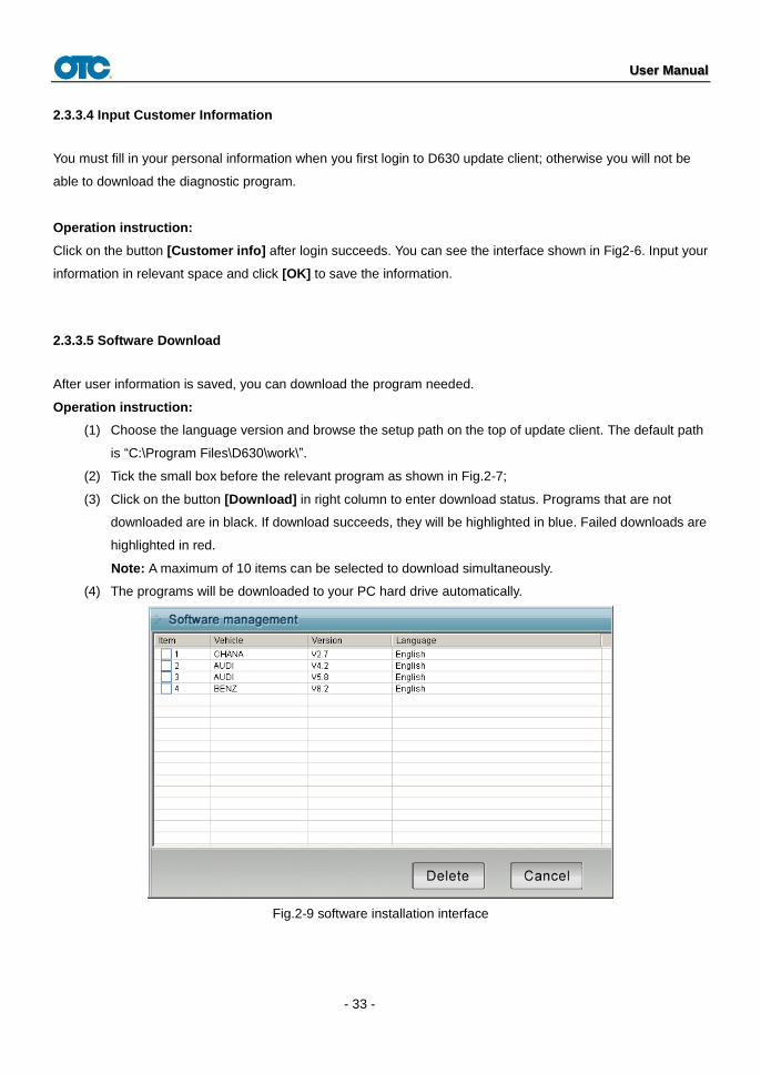
2.3.3.5 Software Download
After user information is saved, you can download the program needed.
Operation instruction:
(1) Choose the language version and browse the setup path on the top of update client. The default path
is “C:\Program Files\D630\work\”.
(2) Tick the small box before the relevant program as shown in Fig.2-7;
(3) Click on the button [Download] in right column to enter download status. Programs that are not
downloaded are in black. If download succeeds, they will be highlighted in blue. Failed downloads are
highlighted in red.
Note: A maximum of 10 items can be selected to download simultaneously.
(4) The programs will be downloaded to your PC hard drive automatically.
Fig.2-9 software installation interface

User Manual
- 34 -
2.3.3.6 Update
After download is complete, click on [Update] on the right column to finish the software update.
2.3.3.7 Software Management
You can delete old versions of software on the download list by entering software management.
Operating instruction:
Click on the button [Management] to enter the interface shown in Fig. 2-10. Select the software not needed and
click on [Delete]. The selected software will be uninstalled automatically.
2.3.3.8 Exit
After finishing all of the steps, click on [Exit] to exit from the update client.