D - Guide elements - Yukme
314
-
Upload
khangminh22 -
Category
Documents
-
view
0 -
download
0
Transcript of D - Guide elements - Yukme
Guide Elements
The great importance of exact alignment between punches and matrices in stamping dies has been recognized widely. The accuracy and maintenance of this alignment depends entirely on the quality and wear resistance of the guide elements.As a consequence of recent rapid developments in stamping techniques it has also been accepted that conventional bush-pillar sets of casehardened steel can no longer stand up to the demands of the modern press shop with its more sophisticated dies, ever faster presses and the stresses in today’s carbide tools.The introduction of FIBRO Guide Elements made available an extensive range, principally based on superlative quality, and comprising some new, highly advanced bearing materials as well as novel assembly techniques of superior accuracy.Recent additions have further broadened this range, especially in regard of demountable guiding components.All FIBRO Guide Bushes for permanent fixing are laid out for epoxy-bonding. This highly reliable method ensures unparalleled accuracy together with the elimination of shrink allowances and rectification honing.Ball Bearing Guides principally excel in undemanding maintenance and through the complete absence of bearing play. Their easy movement on the bench makes them very popular with die makers. Highest stroking speeds present no problems. But common to all ball bearings there remains the characteristic weakness to shock loads, the danger of ball impingement. To some extent this can be compensated for by oversized pillar diameters and the use of four-pillar die sets.
The group of Sliding-Type Guides affords much greater stability, partly due to the damping effect of the all-important, vital oil film . . . which in the past used to be threatened always by the vagaries of lubrication service and the propensity to rupture at high frequencies of travel reversal.Extensive protection against these perils is offered by FIBRO Sintered Ferrite Bushes. Used in most of our sliding guide systems, their advanced technology comprises:– porous structure, vacuum-filled with oil – carbonitrided surface of extreme hardness – outstanding friction properties – exceptional wear-resistance – thousands of oil-retaining porosity pockets.In combination with our mirror-finished pillars, ferrite guide bushes represent a guiding system of alltogether superior properties. A system that virtually precludes seizing under all but the most extreme running conditions.Beyond such limitations there exist combinations of high velocities with very short strokes where even ferrite bushes cannot guarantee permanence of the oil film. Here, the rigidity of the sliding guide has to be weighed up against the safety of ball bearings: die set guides are not entirely without problems yet! But at FIBRO we find ourselves very busy indeed with the remainder.Technical progress may incur modifications without notice.FIBRO GUIDE ELEMENTS – DESIGNED AND PRODUCED BY PEOPLE IN PURSUIT OF PERFECTION.
Guide Elements
yukme.com.mx tel: (722) 217 2236 [email protected]
Guide Elements
subject to alterations
The great importance of exact alignment between punches and matrices in stamping dies has been recognized widely. The accuracy and maintenance of this alignment depends entirely on the quality and wear resistance of the guide elements.As a consequence of recent rapid developments in stamping techniques it has also been accepted that conventional bush-pillar sets of casehardened steel can no longer stand up to the demands of the modern press shop with its more sophisticated dies, ever faster presses and the stresses in today’s carbide tools.The introduction of FIBRO Guide Elements made available an extensive range, principally based on superlative quality, and comprising some new, highly advanced bearing materials as well as novel assembly techniques of superior accuracy.Recent additions have further broadened this range, especially in regard of demountable guiding components.All FIBRO Guide Bushes for permanent fixing are laid out for epoxy-bonding. This highly reliable method ensures unparalleled accuracy together with the elimination of shrink allowances and rectification honing.Ball Bearing Guides principally excel in undemanding maintenance and through the complete absence of bearing play. Their easy movement on the bench makes them very popular with die makers. Highest stroking speeds present no problems. But common to all ball bearings there remains the characteristic weakness to shock loads, the danger of ball impingement. To some extent this can be compensated for by oversized pillar diameters and the use of four-pillar die sets.
The group of Sliding-Type Guides affords much greater stability, partly due to the damping effect of the all-important, vital oil film . . . which in the past used to be threatened always by the vagaries of lubrication service and the propensity to rupture at high frequencies of travel reversal.Extensive protection against these perils is offered by FIBRO Sintered Ferrite Bushes. Used in most of our sliding guide systems, their advanced technology comprises:– porous structure, vacuum-filled with oil – carbonitrided surface of extreme hardness – outstanding friction properties – exceptional wear-resistance – thousands of oil-retaining porosity pockets.In combination with our mirror-finished pillars, ferrite guide bushes represent a guiding system of alltogether superior properties. A system that virtually precludes seizing under all but the most extreme running conditions.Beyond such limitations there exist combinations of high velocities with very short strokes where even ferrite bushes cannot guarantee permanence of the oil film. Here, the rigidity of the sliding guide has to be weighed up against the safety of ball bearings: die set guides are not entirely without problems yet! But at FIBRO we find ourselves very busy indeed with the remainder.Technical progress may incur modifications without notice.FIBRO GUIDE ELEMENTS – DESIGNED AND PRODUCED BY PEOPLE IN PURSUIT OF PERFECTION.
Guide Elements
D3
Contents
subject to alterations
Notes on guide elements
Guide elements - Pairing classification
Guide elements - Selection matrix
Deflection of pillars and bending equation
206.51.Ball cage, small dimension
206.54.Guide bush for ball bearing, small dimension
202.19.Guide pillar DIN 9825/ISO 9182-2
202.17.Guide pillar with ball cage retainer
202.22.Guide pillar with internal thread on both sides, ~DIN 9825/~ISO 9182-2
202.23.Guide pillar with internal thread on bottom, ~DIN 9825/~ISO 9182-2
202.24.Guide pillar with internal thread on top, ~DIN 9825/~ISO 9182-2
202.21.Guide pillar endwise bolt-on type, ~DIN 9825/~ISO 9182-2
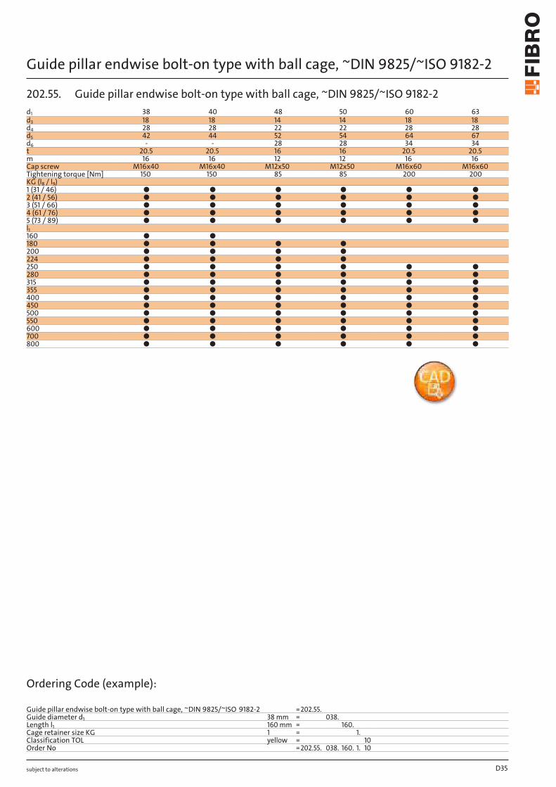
202.55.Guide pillar endwise bolt-on type with ball cage, ~DIN 9825/ ~ISO 9182-2
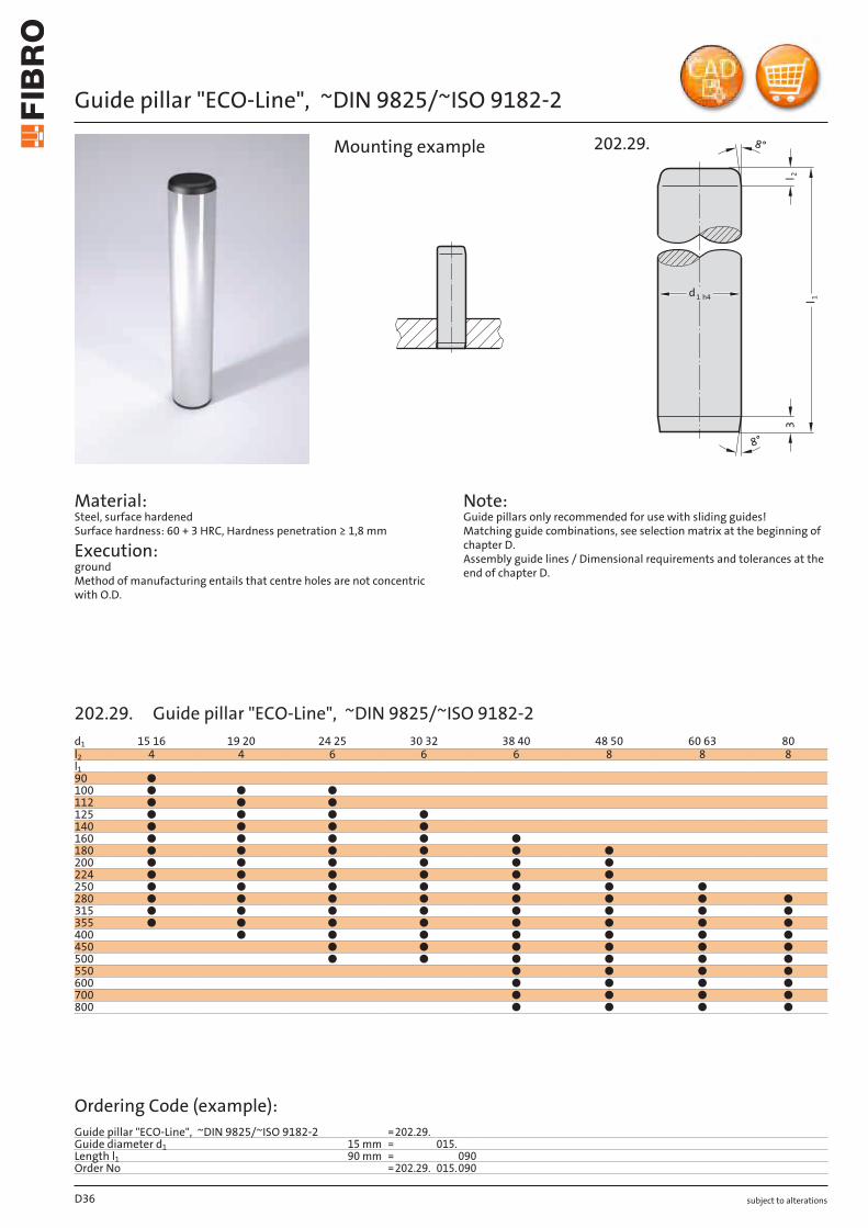
202.29.Guide pillar "ECO-Line", ~DIN 9825/ ~ISO 9182-2
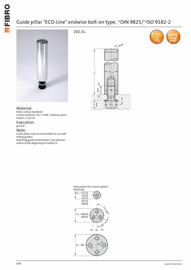
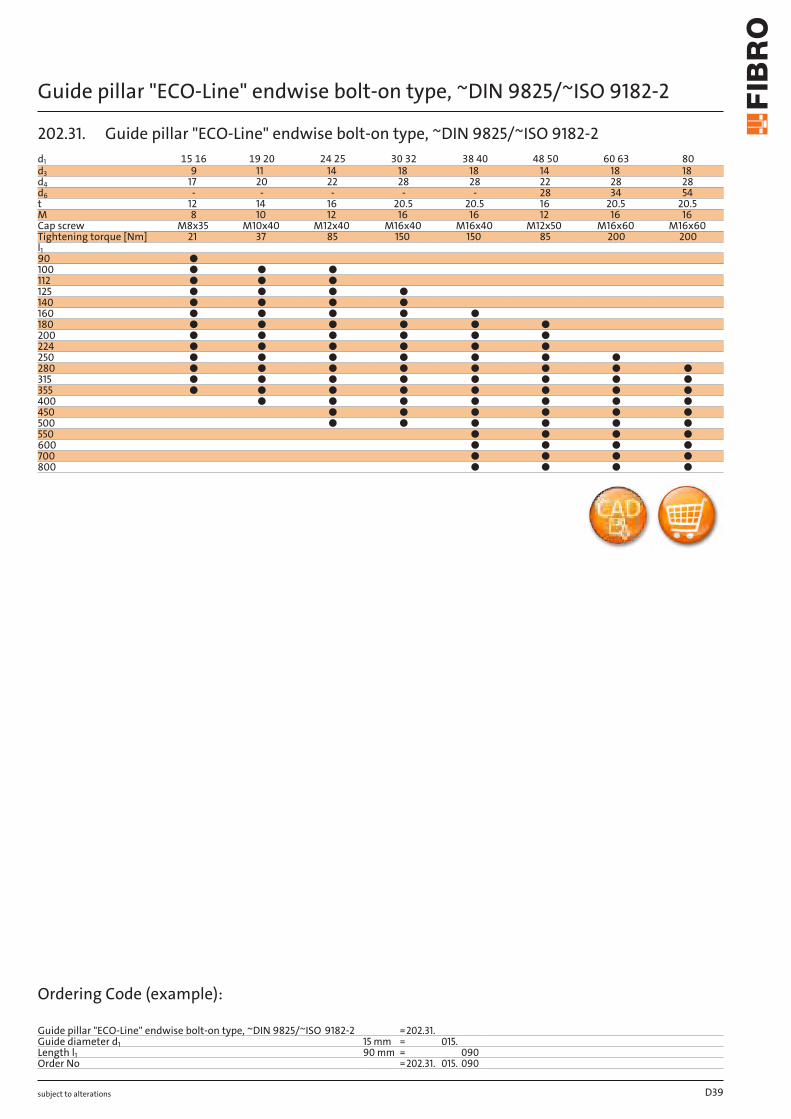
202.31.Guide pillar "ECO-Line" endwise bolt-on type, ~DIN 9825/ ~ISO 9182-2
2021.50.Guide pillar, conical, DIN 9825/ ISO 9182-4/AFNOR
D4
D21
D22-23
D24
D25
D26
D26
D27
D28
D29
D30
D31
D32
D34
D36
D38
D40
Contents
subject to alterations
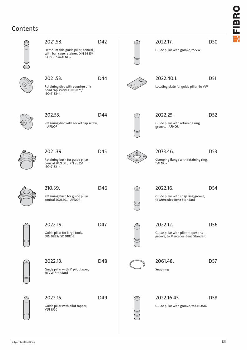
2021.58.Demountable guide pillar, conical, with ball cage retainer, DIN 9825/ ISO 9182-4/AFNOR
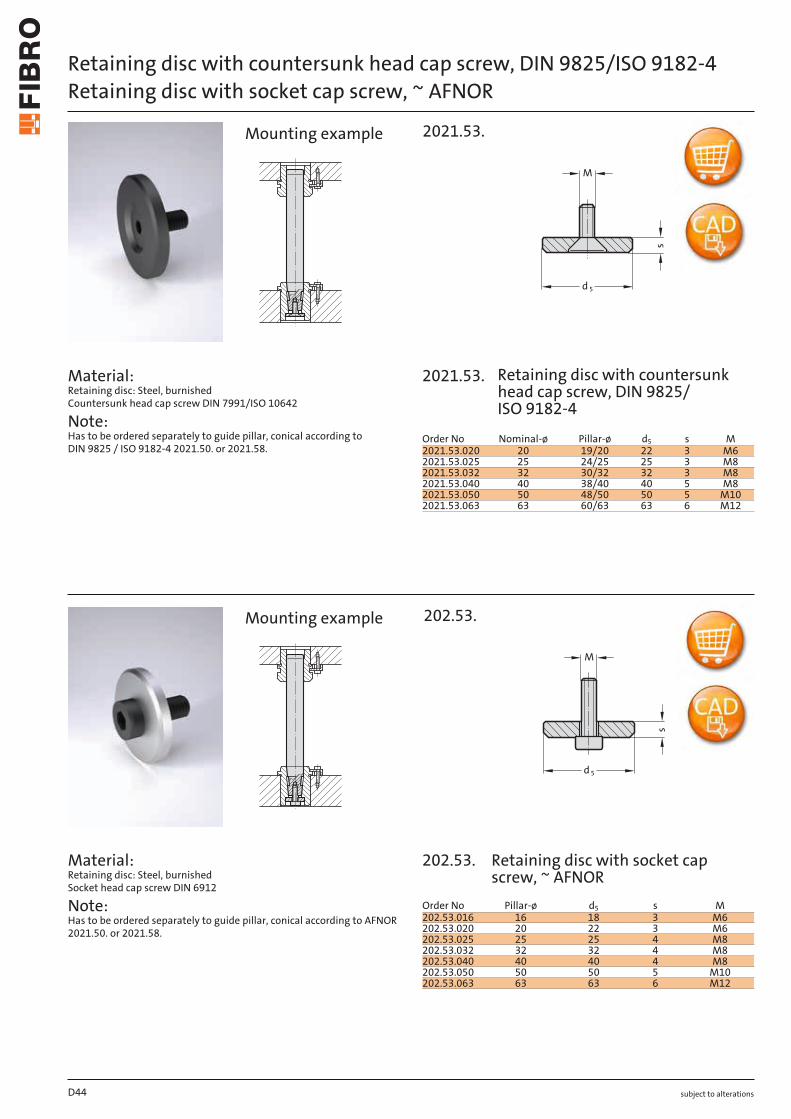
2021.53.Retaining disc with countersunk head cap screw, DIN 9825/ ISO 9182- 4
202.53.Retaining disc with socket cap screw, ~ AFNOR
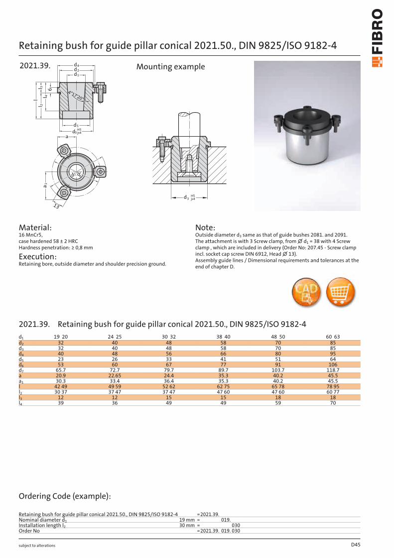
2021.39.Retaining bush for guide pillar conical 2021.50., DIN 9825/ ISO 9182- 4
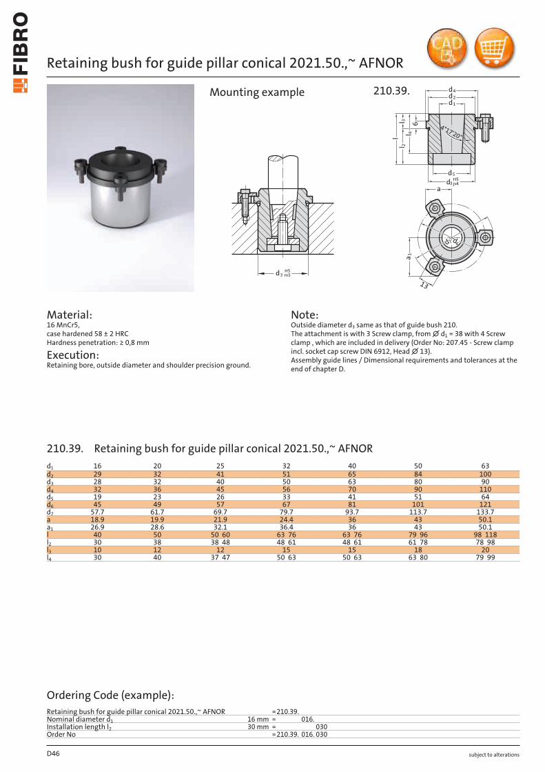
210.39.Retaining bush for guide pillar conical 2021.50.,~ AFNOR
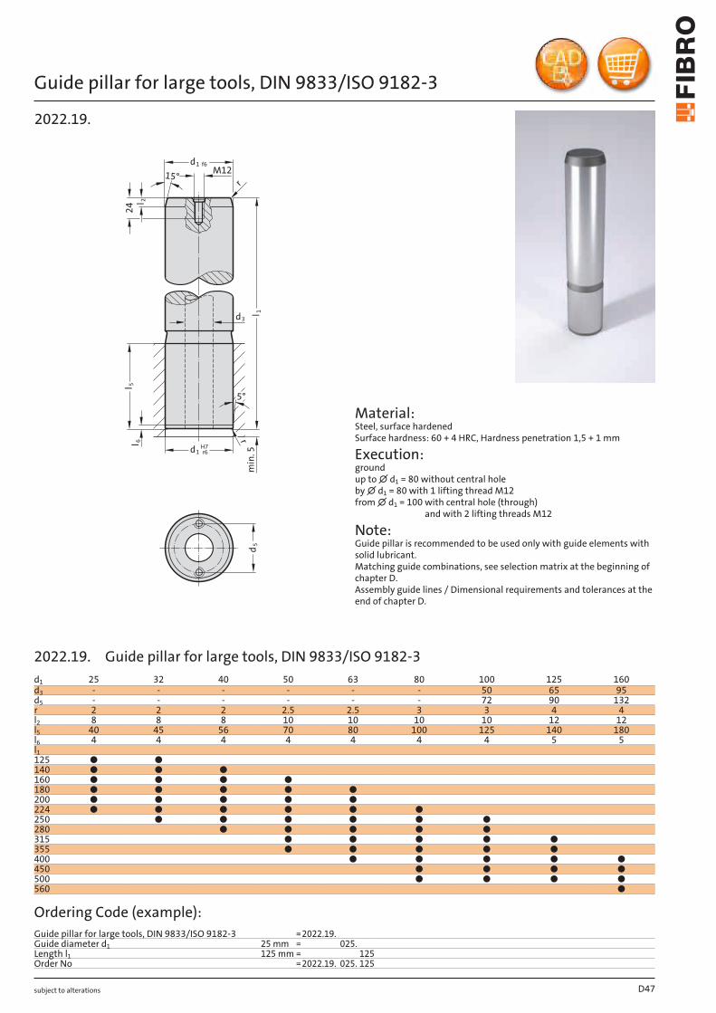
2022.19.Guide pillar for large tools, DIN 9833/ISO 9182-3
2022.13.Guide pillar with 5° pilot taper, to VW-Standard
2022.15.Guide pillar with pilot tapper, VDI 3356
2022.17.Guide pillar with groove, to VW
2022.40.1.Locating plate for guide pillar, to VW
2022.25.Guide pillar with retaining ring groove, ~AFNOR
2073.46.Clamping flange with retaining ring, ~AFNOR
2022.16.Guide pillar with snap ring groove, to Mercedes-Benz Standard
2022.12.Guide pillar with pilot tapper and groove, to Mercedes-Benz Standard
2061.48.Snap ring
2022.16.45.Guide pillar with groove, to CNOMO
D5
D42
D44
D44
D45
D46
D47
D48
D49
D50
D51
D52
D53
D54
D56
D57
D58
Contents
subject to alterations
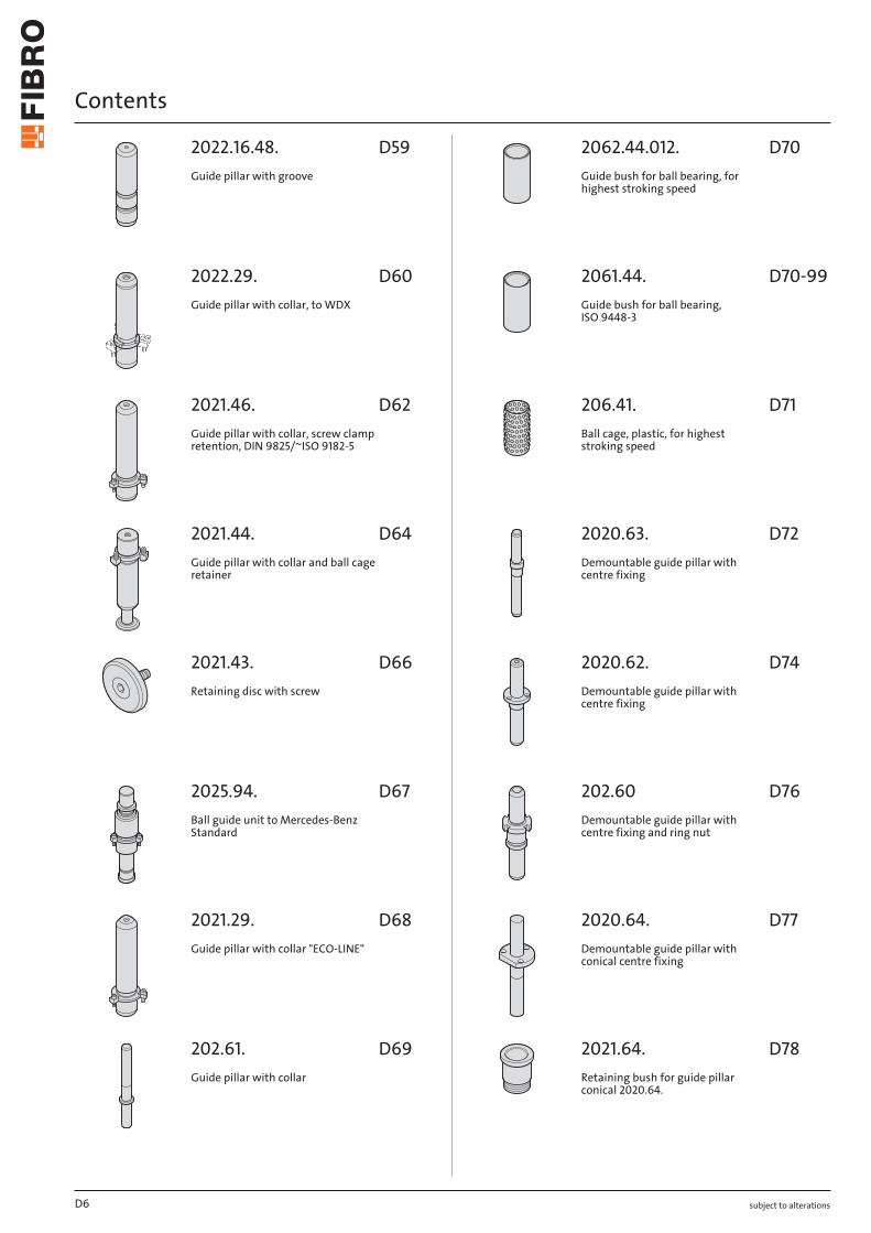
2022.16.48.Guide pillar with groove
2022.29.Guide pillar with collar, to WDX
2021.46.Guide pillar with collar, screw clamp retention, DIN 9825/~ISO 9182-5
2021.44.Guide pillar with collar and ball cage retainer
2021.43.Retaining disc with screw
2025.94.Ball guide unit to Mercedes-Benz Standard
2021.29.Guide pillar with collar "ECO-LINE"
202.61.Guide pillar with collar
2062.44.012.Guide bush for ball bearing, for highest stroking speed
2061.44.Guide bush for ball bearing, ISO 9448-3
206.41.Ball cage, plastic, for highest stroking speed
2020.63.Demountable guide pillar with centre fixing
2020.62.Demountable guide pillar with centre fixing
202.60Demountable guide pillar with centre fixing and ring nut
2020.64.Demountable guide pillar with conical centre fixing
2021.64.Retaining bush for guide pillar conical 2020.64.
D6
D59
D60
D62
D64
D66
D67
D68
D69
D70
D70-99
D71
D72
D74
D76
D77
D78
Contents
subject to alterations
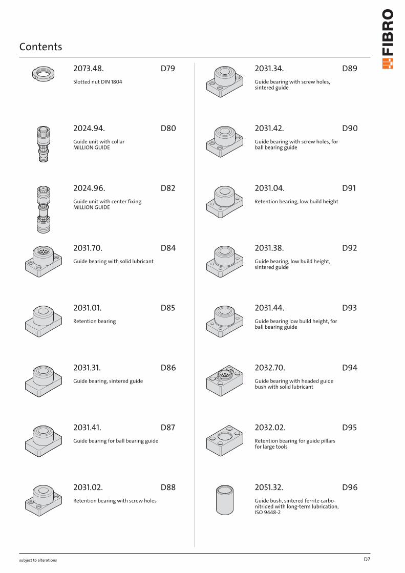
2073.48.Slotted nut DIN 1804
2024.94.Guide unit with collar MILLION GUIDE
2024.96.Guide unit with center fixing MILLION GUIDE
2031.70.Guide bearing with solid lubricant
2031.01.Retention bearing
2031.31.Guide bearing, sintered guide
2031.41.Guide bearing for ball bearing guide
2031.02.Retention bearing with screw holes
2031.34.Guide bearing with screw holes, sintered guide
2031.42.Guide bearing with screw holes, for ball bearing guide
2031.04.Retention bearing, low build height
2031.38.Guide bearing, low build height, sintered guide
2031.44.Guide bearing low build height, for ball bearing guide
2032.70.Guide bearing with headed guide bush with solid lubricant
2032.02.Retention bearing for guide pillars for large tools
2051.32.Guide bush, sintered ferrite carbo-nitrided with long-term lubrication, ISO 9448-2
D7
D79
D80
D82
D84
D85
D86
D87
D88
D89
D90
D91
D92
D93
D94
D95
D96
Contents
subject to alterations
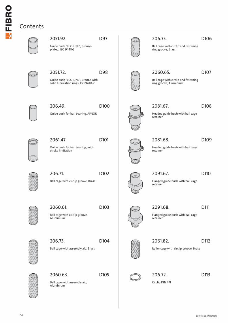
2051.92.Guide bush "ECO-LINE", bronze-plated, ISO 9448-2
2051.72.Guide bush "ECO-LINE", Bronze with solid lubrication rings, ISO 9448-2
206.49.Guide bush for ball bearing, AFNOR
2061.47.Guide bush for ball bearing, with stroke limitation
206.71.Ball cage with circlip groove, Brass
2060.61.Ball cage with circlip groove, Aluminium
206.73.Ball cage with assembly aid, Brass
2060.63.Ball cage with assembly aid, Aluminium
206.75.Ball cage with circlip and fastening ring groove, Brass
2060.65.Ball cage with circlip and fastening ring groove, Aluminium
2081.67.Headed guide bush with ball cage retainer
2081.68.Headed guide bush with ball cage retainer
2091.67.Flanged guide bush with ball cage retainer
2091.68.Flanged guide bush with ball cage retainer
2061.82.Roller cage with circlip groove, Brass
206.72.Circlip DIN 471
D8
D97
D98
D100
D101
D102
D103
D104
D105
D106
D107
D108
D109
D110
D111
D112
D113
Contents
subject to alterations
2061.84.Roller cage with assembly aid, Brass
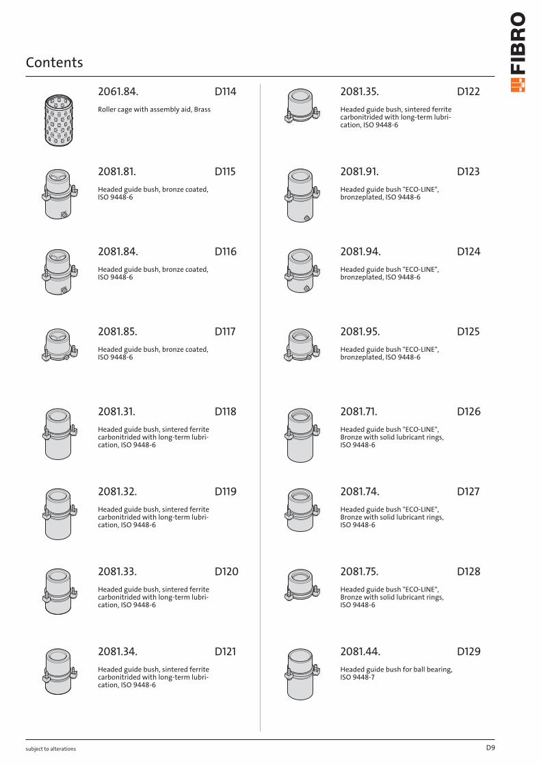
2081.81.Headed guide bush, bronze coated, ISO 9448-6
2081.84.Headed guide bush, bronze coated, ISO 9448-6
2081.85.Headed guide bush, bronze coated, ISO 9448-6
2081.31.Headed guide bush, sintered ferrite carbonitrided with long-term lubri-cation, ISO 9448-6
2081.32.Headed guide bush, sintered ferrite carbonitrided with long-term lubri-cation, ISO 9448-6
2081.33.Headed guide bush, sintered ferrite carbonitrided with long-term lubri-cation, ISO 9448-6
2081.34.Headed guide bush, sintered ferrite carbonitrided with long-term lubri-cation, ISO 9448-6
2081.35.Headed guide bush, sintered ferrite carbonitrided with long-term lubri-cation, ISO 9448-6
2081.91.Headed guide bush "ECO-LINE", bronzeplated, ISO 9448-6
2081.94.Headed guide bush "ECO-LINE", bronzeplated, ISO 9448-6
2081.95.Headed guide bush "ECO-LINE", bronzeplated, ISO 9448-6
2081.71.Headed guide bush "ECO-LINE", Bronze with solid lubricant rings, ISO 9448-6
2081.74.Headed guide bush "ECO-LINE", Bronze with solid lubricant rings, ISO 9448-6
2081.75.Headed guide bush "ECO-LINE", Bronze with solid lubricant rings, ISO 9448-6
2081.44.Headed guide bush for ball bearing, ISO 9448-7
D9
D114
D115
D116
D117
D118
D119
D120
D121
D122
D123
D124
D125
D126
D127
D128
D129

Contents
subject to alterations
2081.45.Headed guide bush for ball bearing, ISO 9448-7
2081.46.Headed guide bush for ball bearing, ISO 9448-7
2081.47.Headed guide bush for ball bearing, ISO 9448-7
2081.49.Headed guide bush for ball bearing, ISO 9448-7
2091.31.Flanged guide bush, sintered ferrite carbonitrided with long-term lubri-cation, ISO 9448-4
2091.32.Flanged guide bush, sintered ferrite carbonitrided with long-term lubri-cation, ISO 9448-4
2091.34.Flanged guide bush, sintered ferrite carbonitrided with long-term lubri-cation, ISO 9448-4
2091.91.Flanged guide bush "ECO-LINE", bronzeplated, ISO 9448-4
2091.92.Flanged guide bush "ECO-LINE", bronzeplated, ISO 9448-4
2091.94.Flanged guide bush "ECO-LINE", bronzeplated, ISO 9448-4
2091.71.Flanged guide bush "ECO-LINE", Bronze with solid lubricant rings, ISO 9448-4
2091.72.Flanged guide bush "ECO-LINE", Bronze with solid lubricant rings, ISO 9448-4
2091.74.Flanged guide bush "ECO-LINE", Bronze with solid lubricant rings, ISO 9448-4
2091.44.Flanged guide bush for ball bearing, ISO 9448-5
2091.45.Flanged guide bush for ball bearing, ISO 9448-5
2091.46.Flanged guide bush for ball bearing, ISO 9448-5
D10
D130
D131
D132
D133
D134
D135
D136
D137
D138
D139
D140
D141
D142
D143
D144
D145
Contents
subject to alterations
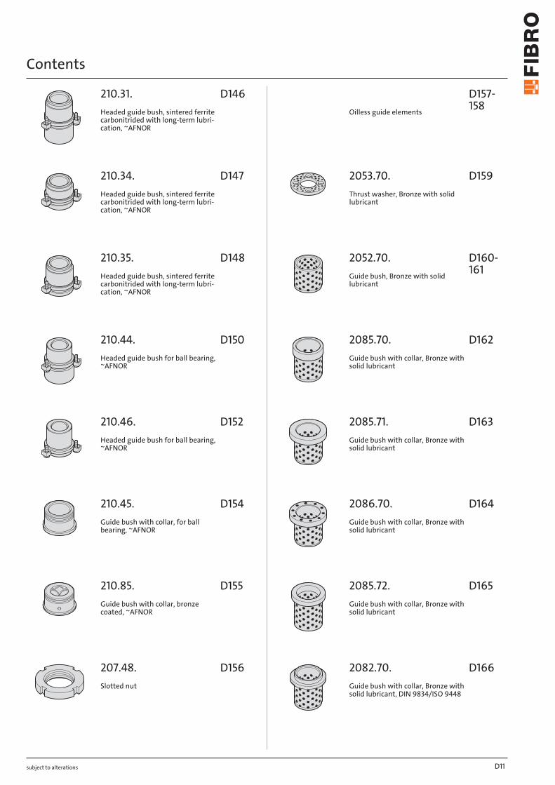
210.31.Headed guide bush, sintered ferrite carbonitrided with long-term lubri-cation, ~AFNOR
210.34.Headed guide bush, sintered ferrite carbonitrided with long-term lubri-cation, ~AFNOR
210.35.Headed guide bush, sintered ferrite carbonitrided with long-term lubri-cation, ~AFNOR
210.44.Headed guide bush for ball bearing, ~AFNOR
210.46.Headed guide bush for ball bearing, ~AFNOR
210.45.Guide bush with collar, for ball bearing, ~AFNOR
210.85.Guide bush with collar, bronze coated, ~AFNOR
207.48.Slotted nut
Oilless guide elements
2053.70.Thrust washer, Bronze with solid lubricant
2052.70.Guide bush, Bronze with solid lubricant
2085.70.Guide bush with collar, Bronze with solid lubricant
2085.71.Guide bush with collar, Bronze with solid lubricant
2086.70.Guide bush with collar, Bronze with solid lubricant
2085.72.Guide bush with collar, Bronze with solid lubricant
2082.70.Guide bush with collar, Bronze with solid lubricant, DIN 9834/ISO 9448
D11
D146
D147
D148
D150
D152
D154
D155
D156
D157-158
D159
D160-161
D162
D163
D164
D165
D166
Contents
subject to alterations
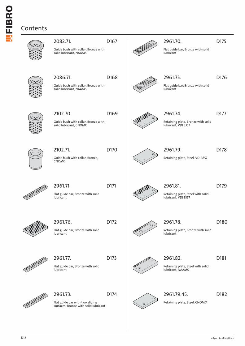
2082.71.Guide bush with collar, Bronze with solid lubricant, NAAMS
2086.71.Guide bush with collar, Bronze with solid lubricant, NAAMS
2102.70.Guide bush with collar, Bronze with solid lubricant, CNOMO
2102.71.Guide bush with collar, Bronze, CNOMO
2961.71.Flat guide bar, Bronze with solid lubricant
2961.76.Flat guide bar, Bronze with solid lubricant
2961.77.Flat guide bar, Bronze with solid lubricant
2961.73.Flat guide bar with two sliding surfaces, Bronze with solid lubricant
2961.70.Flat guide bar, Bronze with solid lubricant
2961.75.Flat guide bar, Bronze with solid lubricant
2961.74.Retaining plate, Bronze with solid lubricant, VDI 3357
2961.79.Retaining plate, Steel, VDI 3357
2961.81.Retaining plate, Steel with solid lubricant, VDI 3357
2961.78.Retaining plate, Bronze with solid lubricant
2961.82.Retaining plate, Steel with solid lubricant, NAAMS
2961.79.45.Retaining plate, Steel, CNOMO
D12
D167
D168
D169
D170
D171
D172
D173
D174
D175
D176
D177
D178
D179
D180
D181
D182
Contents
subject to alterations
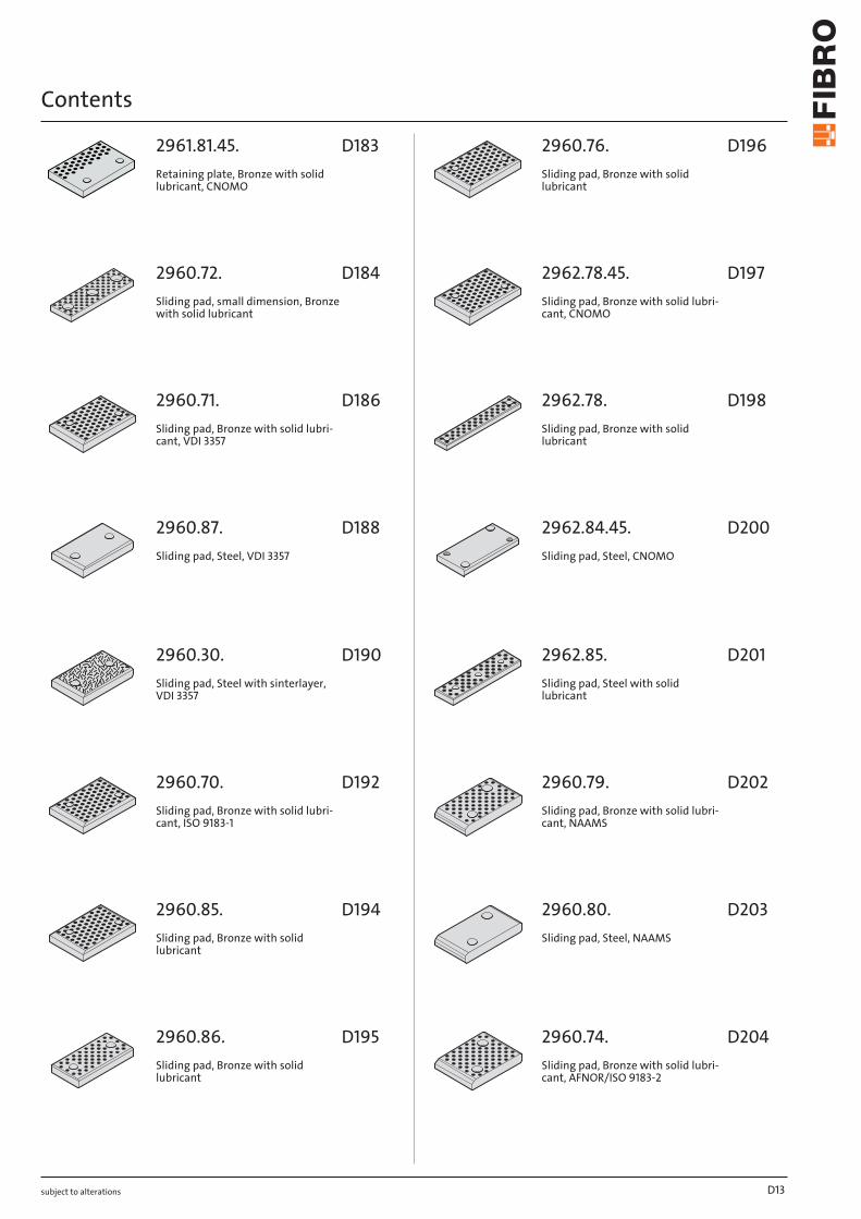
2961.81.45.Retaining plate, Bronze with solid lubricant, CNOMO
2960.72.Sliding pad, small dimension, Bronze with solid lubricant
2960.71.Sliding pad, Bronze with solid lubri-cant, VDI 3357
2960.87.Sliding pad, Steel, VDI 3357
2960.30.Sliding pad, Steel with sinterlayer, VDI 3357
2960.70.Sliding pad, Bronze with solid lubri-cant, ISO 9183-1
2960.85.Sliding pad, Bronze with solid lubricant
2960.86.Sliding pad, Bronze with solid lubricant
2960.76.Sliding pad, Bronze with solid lubricant
2962.78.45.Sliding pad, Bronze with solid lubri-cant, CNOMO
2962.78.Sliding pad, Bronze with solid lubricant
2962.84.45.Sliding pad, Steel, CNOMO
2962.85.Sliding pad, Steel with solid lubricant
2960.79.Sliding pad, Bronze with solid lubri-cant, NAAMS
2960.80.Sliding pad, Steel, NAAMS
2960.74.Sliding pad, Bronze with solid lubri-cant, AFNOR/ISO 9183-2
D13
D183
D184
D186
D188
D190
D192
D194
D195
D196
D197
D198
D200
D201
D202
D203
D204
Contents
subject to alterations
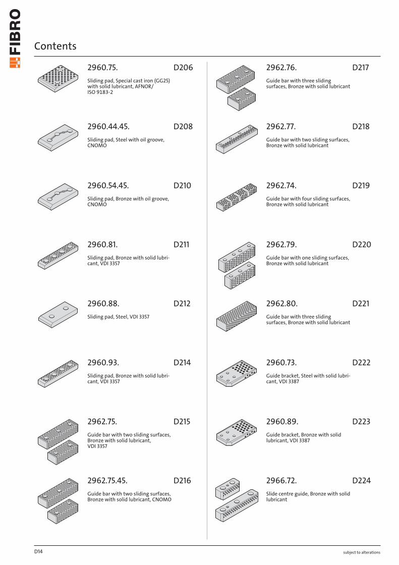
2960.75.Sliding pad, Special cast iron (GG25) with solid lubricant, AFNOR/ ISO 9183-2
2960.44.45.Sliding pad, Steel with oil groove, CNOMO
2960.54.45.Sliding pad, Bronze with oil groove, CNOMO
2960.81.Sliding pad, Bronze with solid lubri-cant, VDI 3357
2960.88.Sliding pad, Steel, VDI 3357
2960.93.Sliding pad, Bronze with solid lubri-cant, VDI 3357
2962.75.Guide bar with two sliding surfaces, Bronze with solid lubricant, VDI 3357
2962.75.45.Guide bar with two sliding surfaces, Bronze with solid lubricant, CNOMO
2962.76.Guide bar with three sliding surfaces, Bronze with solid lubricant
2962.77.Guide bar with two sliding surfaces, Bronze with solid lubricant
2962.74.Guide bar with four sliding surfaces, Bronze with solid lubricant
2962.79.Guide bar with one sliding surfaces, Bronze with solid lubricant
2962.80.Guide bar with three sliding surfaces, Bronze with solid lubricant
2960.73.Guide bracket, Steel with solid lubri-cant, VDI 3387
2960.89.Guide bracket, Bronze with solid lubricant, VDI 3387
2966.72.Slide centre guide, Bronze with solid lubricant
D14
D206
D208
D210
D211
D212
D214
D215
D216
D217
D218
D219
D220
D221
D222
D223
D224

Contents
subject to alterations
2960.90.Overrun Cam, Steel hardened, VDI 3357
2960.91.Overrun Cam, Steel hardened and gas nitrided, VDI 3357
2960.92.Overrun Cam, Bronze with solid lubricant, VDI 3357
2962.70.Angled guide gib, Bronze with solid lubricant
2962.70.45.Angled guide gib, Bronze with solid lubricant, CNOMO
2962.71.Angled guide gib, Bronze with solid lubricant
2962.72.Angled guide gib, Bronze with solid lubricant
2962.73.Angled guide gib, Bronze with solid lubricant
2962.81.Angled guide gib, Bronze with solid lubricant
2962.82.Angled guide gib, Bronze with solid lubricant
2962.83.Angled guide gib, Bronze with solid lubricant
2964.77.T-Guide bar, Bronze with solid lubricant
2964.78.T-Guide bar, Bronze with solid lubricant
2963.82.Sliding block, Bronze with solid lubri-cant, NAAMS
2963.83.Prismatic guide, Steel, NAAMS
2963.84.Sliding block, Bronze with solid lubri-cant, VDI 3357
D15
D225
D226
D227
D228
D229
D230
D231
D232
D233
D234
D235
D236
D236
D237
D237
D238
Contents
subject to alterations
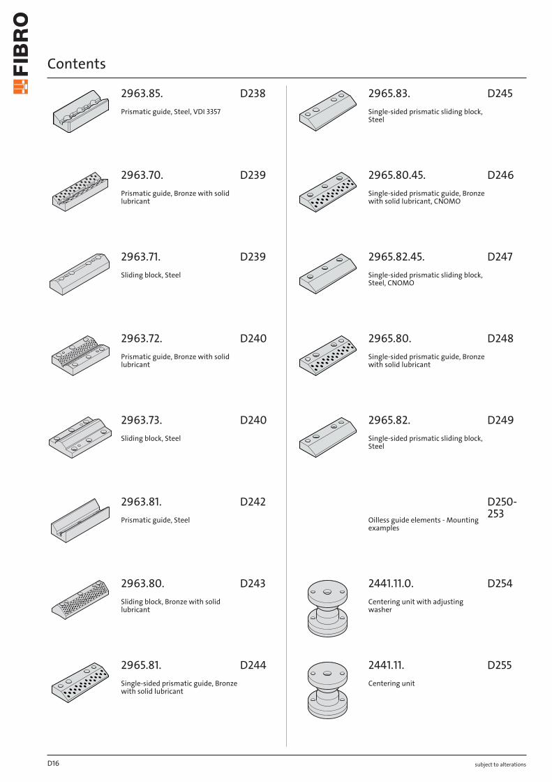
2963.85.Prismatic guide, Steel, VDI 3357
2963.70.Prismatic guide, Bronze with solid lubricant
2963.71.Sliding block, Steel
2963.72.Prismatic guide, Bronze with solid lubricant
2963.73.Sliding block, Steel
2963.81.Prismatic guide, Steel
2963.80.Sliding block, Bronze with solid lubricant
2965.81.Single-sided prismatic guide, Bronze with solid lubricant
2965.83.Single-sided prismatic sliding block, Steel
2965.80.45.Single-sided prismatic guide, Bronze with solid lubricant, CNOMO
2965.82.45.Single-sided prismatic sliding block, Steel, CNOMO
2965.80.Single-sided prismatic guide, Bronze with solid lubricant
2965.82.Single-sided prismatic sliding block, Steel
Oilless guide elements - Mounting examples
2441.11.0.Centering unit with adjusting washer
2441.11.Centering unit
D16
D238
D239
D239
D240
D240
D242
D243
D244
D245
D246
D247
D248
D249
D250-253
D254
D255
Contents
subject to alterations
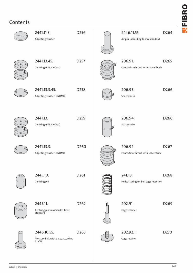
2441.11.3.Adjusting washer
2441.13.45.Centring unit, CNOMO
2441.13.3.45.Adjusting washer, CNOMO
2441.13.Centring unit, CNOMO
2441.13.3.Adjusting washer, CNOMO
2445.10.Centring pin
2445.11.Centring pin to Mercedes-Benz standard
2446.10.55.Pressure bolt with base, according to VW
2446.11.55.Air pin, according to VW standard
206.91.Concertina shroud with spacer bush
206.93.Spacer bush
206.94.Spacer tube
206.92.Concertina shroud with spacer tube
241.18.Helical spring for ball cage retention
202.91.Cage retainer
202.92.1.Cage retainer
D17
D256
D257
D258
D259
D260
D261
D262
D263
D264
D265
D266
D266
D267
D268
D269
D270
Contents
subject to alterations
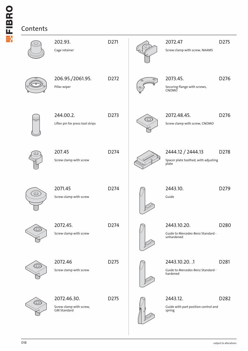
202.93.Cage retainer
206.95./2061.95.Pillar wiper
244.00.2.Lifter pin for press tool strips
207.45Screw clamp with screw
2071.45Screw clamp with screw
2072.45.Screw clamp with screw
2072.46Screw clamp with screw
2072.46.30.Screw clamp with screw, GM Standard
2072.47Screw clamp with screw, NAAMS
2073.45.Securing flange with screws, CNOMO
2072.48.45.Screw clamp with screw, CNOMO
2444.12 / 2444.13Spacer plate toothed, with adjusting plate
2443.10.Guide
2443.10.20.Guide to Mercedes-Benz Standard - unhardened
2443.10.20. .1Guide to Mercedes-Benz Standard - hardened
2443.12.Guide with part position control and spring
D18
D271
D272
D273
D274
D274
D274
D275
D275
D275
D276
D276
D278
D279
D280
D281
D282
Contents
subject to alterations
2443.13.Guide with part position control, VDI
2018.00.60.08.030Inductive proximity switch
2018.00.60.23.01.5Cable - straight
2018.00.60.23.02.5Cable , 90° connector
2443.14.55.Position monitor for boards
2443.14.00.60.18.044Inductive proximity switch
2443.14.00.60.23.01.5Cable - straight
2443.14.00.60.23.02.5Cable , 90° connector
Ball bearing guides - Loading Diagram
Ball bearing guides - Tables of dynamic load indexes
Guide elements - Mounting guide-lines, Dimension tables
D19
D283
D284
D285
D285
D287
D288
D289
D289
D290
D291
D292-298

subject to alterationsD20
12.2019
3
2
3
1
2
1
3
4
2
1
3
4
2
1
3
Slide guide with solid lubrication rings (ECO-LINE)
This low-maintenance guide type consists of a copper alloy with integrated solid lubrica-tion rings.
The base frame material used offers good guide stability and very good emergency running proper-ties. Following initial lubrication, the solid lubrication is slowly distributed into the sliding zone in ongoing operation of the solid lubrication and provides low-maintenance operation (depending on the usage conditions). The solid lubrication rings take up 25-35% of the total guide surface (depending on the design) and only permit linear movements.The ground running surface achieves good quality in terms of dimensional and shape tolerances and optimal roughness. see low-maintenance sliding elements - description
(1) Guide pillar (2) Guide bushing (3) Solid lubrication ring
subject to alterations
NOTES ON GUIDE ELEMENTS
Precision slide guide, sintered ferrites
This guide type consists of self-lubricating sintered ferrites with carbonitrided surface.
The sintered material used has a porosity content of 18-20 by volume that is filled with an oil under vacuum. In ongoing operation, this oil enters the sliding zone, facilitating long-term lubrication (depending on the usage conditions). As initial and additional lubrication, a suitable grease can be filled into the supply grooves, which reduces the maintenance intervals.Carbonitriding - a case hardening process - considerably increases the wear resistance of the sliding layer. The precision ground running surface achieves very high quality in terms of dimensional and shape tolerances and low roughness. The guidance accuracy can be changed via pairing classifica-tion. For bearing clearance ranges, see chapter D.
(1) Guide pillar (2) Sintered ferrite guide bush (3) Carbonitriding
Precision slide guide, bronze-coated
This guide type consists of a steel body with bronze-coated running surface with helical oil groove and a lubricating nipple for ongoing lubrication.
The steel body used ensures a high level of intrinsic stability even with high side and edge loads due to its high tensile strength.The bronze running surface is optimally connected to the steel body and has very good emergency running properties. A permanent lubricant supply with grease is necessary for reliable continuous operation.The precision ground running surface achieves very high quality in terms of dimensional and shape tolerances and low roughness.
(1) Guide pillar (2) Guide bushing (3) Bronze coating (4) Oil groove
Slide guide, bronze-coated (ECO-LINE)
This guide type consists of a steel body with bronze-coated running surface with helical oil groove and a lubricating nipple for ongoing lubrication.
The steel body used ensures a high level of intrinsic stability even with high side and edge loads due to its high tensile strength.The bronze running surface is optimally connected to the steel body and has very good emergency running properties. A permanent lubricant supply with grease is necessary for reliable continuous operation.The precision ground running surface achieves high quality in terms of dimensional and shape tole-rances and low roughness.
(1) Guide pillar (2) Guide bushing (3) Bronze coating (4) Oil groove

12.2019
3
1
2
1
3
4
2
1
3
2 4
2
1
3
4
subject to alterations
NOTES ON GUIDE ELEMENTS
Slide guide with non-liquid lubricant pockets
This low-maintenance guide type consists of a copper alloy with integrated non-liquid lubricant pockets.
The base frame material used offers good guide stability and very good emergency running proper-ties. Following initial lubrication, the solid lubrication slowly enters the sliding zone in ongoing opera-tion of the solid lubrication and provides low-maintenance operation (depending on the usage condi-tions). The non-liquid lubricant pockets take up 25-35% of the total guide surface (depending on the design) and permit linear and/or rotational movements (depending on the organisation of the non-li-quid lubricant pockets).The ground running surface achieves good quality in terms of dimensional and shape tolerances and optimal roughness. see low-maintenance sliding elements - description
(1) Guide pillar (2) Guide bushing (3) Non-liquid lubricant pocket
Precision roller bearing
This guide type is backlash-free with high stability due to pre-stressed roll barrels (balls) and suitable for maximum speeds thanks to the low rolling friction.
The base frame material used for the guide bushes offers very good guide stability. Together with the hardened precision balls and corresponding gliding pins, this creates smooth-running and precise guidance. Due to the point contact of the rollers, this is not completely rigid under load, however. This can be influenced via the pairing classification.The ball cages are made from brass or aluminium and due to the high number of rollers have a high dynamic load index – a significant factor for long service life.The precision ground running surface achieves very high quality in terms of dimensional and shape tolerances and minimal roughness. For bearing clearance ranges, see chapter D.
(1) Guide pillar (2) Guide bushing (3) Brass or aluminium cage (4) Ball
Precision roller guide
This guide type is backlash-free with very high stability due to pre-stressed roll barrels (rolls) and suitable for maximum speeds thanks to the low rolling friction.
The guide bushes for ball guides are also used here. Together with the hardened precision rollers and corresponding gliding pins, this creates smooth-running and very precise guidance. Due to the linear contact of the rollers this is not completely rigid under load, but is considerably more stable than ball guides.The roller cages are made from brass and due to the optimum number of rollers have a high dynamic load index – a significant factor for long service life.The precision ground running surface achieves very high quality in terms of dimensional and shape tolerances and minimal roughness.To achieve optimal bias, only gliding pins red = .30 and gliding pins yellow = .10 are used!
(1) Guide pillar (2) Guide bushing (3) Cage (4) Roller
Precision needle roller guide (Million Guide)
This guide type is back-lash free with maximum stability due to pre-stressed roll barrels (needle rolls) and suitable for maximum speeds due to the low rolling friction.
The Million Guide units represent the tip of the guide units. Together with the hardened precision needle rollers and corresponding gliding pins and bushes, this creates smooth-running and maximum precision guidance. Due to the linear contact of the rollers this is not completely rigid under load, but is more stable than roller guides.The needle roller cages are made from plastic and due to the optimum number of rollers have a high dynamic load index – a significant factor for long service life. The high-precision ground running surface achieves maximum quality in terms of dimensional and shape tolerances and very low roughness.The components of this guide unit are coordinated with one another and for optimum bias.
(1) Guide pillar (2) Guide bushing (3) Plastic ball cage (4) Needle roller
12.2019subject to alterations
GUIDE TYPE SELECTION AID
Criteria / Guide type
Pre
cisi
on s
lide
guid
e,
sint
ered
ferr
ites
Pre
cisi
on s
lide
guid
e,
bro
nze-
coat
ed
Slid
e gu
ide,
bro
nze-
coa-
ted
(EC
O-L
INE
)
Slid
e gu
ide
with
sol
id
lub
ricat
ion
rings
(E
CO
-LIN
E)
Slid
e gu
ide
with
non
-liq
uid
lub
rican
t p
ocke
ts
Pre
cisi
on r
olle
r b
earin
g
Pre
cisi
on r
olle
r gu
ide
Pre
cisi
on n
eed
le r
olle
r gu
ide
(Mill
ion
Gui
de)
Load capacity / High stresses ++ ++ + +++ +++ o ++ +++
Impact load / Pulsations - ++ ++ ++ ++ - o o
High stroke speed o - - - - +++ +++ ++++
Ease of movement / Low friction +1 + + + + +++1 ++ ++
Resistance to wear / Bearing life ++ + + ++ ++ +++ +++ ++++
Low-maintenance operation ++ - - +++ +++ - - -
Tolerance to contamination and dust - o o + ++ - - -
Tolerance to pillar offset o + + ++ ++ - - -
Guide behaviour can change
due to pairing classification
Suitable for rotational movements 2
Low-corrosion designs
(on request)
++++ = Excellent, +++ = excellent, ++ = good, + = satisfactory, o = adequate, - = Not as good
1 Variable due to the pairing classification2 Depending on the arrangement of the solid lubricant deposits
The selection aid helps with orientation. Depending on the application, installation situation and ambient conditions, an advance check or test is essen-tial.
subject to alterations
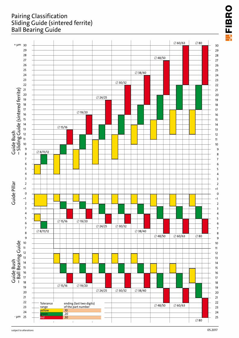
Pairing Classification Sliding guide (sintered ferrite)Ball bearing guide
Recommendation for pairing selection:Cutting clearance Sliding guide
bearing clearanceBall bearing preloading
Description Recommendation
small small large Piece parts with small tolerances, closely specified cut edge properties and contours – also parts from thin material
Pairing 1
medium medium medium Piece parts from sheet thicker than 1 mm – also pr eferably for progression dies
Pairing 2
large large small Where demands on edges and burrs are not stringent; note that large die clearances require smaller shearing forces
Pairing 3
Selection of punch-matrix clearance is largely determind by piece part charcteristics such as percentage of sheared land versus breakaway, but also by demands on burr formation.Further criterias are the part piece material, as well as the type and condition of the tooling and the press.
Sliding guide Ball bearingGuide pillar Guide bush Guide pillar Guide bushColour Order No Colour Order No Colour Order No Colour Order Noyellow .10 yellow .10 yellow .10 red .30
Pairing 1 green .20 yellow .10 yellow .10 green .20green .20 red .30
green .20 green .20 yellow .10 yellow .10Pairing 2 red .30 yellow .10 green .20 green .20
yellow .10 green .20 red .30 red .30
red .30 red .30 green .20 yellow .10Pairing 3 green .20 red .30 red .30 green .20
yellow .10 red .30 red .30 yellow .10
Identification for tolerances with color dots on the outside of the guide pillars and bushings.Selection Criteria: die clearance – stock thickness – material
Note for 4-pillar die sets:Please be aware that tight bushing clearances or high preloads are generally unsuitable for 4-pillar die sets. Deviation from the bore geometry and from the perpendicularity requieres a pairing classification of pairing 2 or even better pairing 3. The pairing classification does not signify any difference in quality, rather a selection of the optimum bushing clearance in the case of guide pillars or the optimum preloading in the case of ball bearings (see also chart next page).
Ordering Code (example):Guide Pillar, tolerance range yellow = 202.19.040.260.10 Sintered ferrite bushing with tolerance code green = 2081.31.040.20
Combination possibilities guide pillars, cages and bushings:
05.2017
302928272625242322212019181716151413121110
98765432
+10
–123456789
10111213141516171819202122232425
302928272625242322212019181716151413121110
98765432
+10
–123456789
10111213141516171819202122232425
[ 48/50
[ 60/63 [ 80
[ 80
[ 60/63[ 48/50
[ 38/40[ 30/32[ 24/25[ 19/20[ 15/16
[ 8/11/12
[ 15/16 [ 19/20[ 24/25 [ 30/32
[ 38/40[ 48/50 [ 60/63 [ 80
[ 15/16
[ 19/20
[ 24/25
[ 30/32
[ 38/40
[ 8/11/12
+ µm
- µm
subject to alterations
Pairing Classification Sliding Guide (sintered ferrite)Ball Bearing Guide
Gui
de B
ush
– Ba
ll Be
arin
g G
uide
Gui
de B
ush
– Sl
idin
g G
uide
(sin
tere
d fe
rrite
)G
uide
Pill
ar
Tolerance range
ending (last two digits) of the part number
yellow .10green .20red .30
subject to alterations
Pairing Classification Sliding guide (sintered ferrite)Ball bearing guide
Recommendation for pairing selection:Cutting clearance Sliding guide
bearing clearanceBall bearing preloading
Description Recommendation
small small large Piece parts with small tolerances, closely specified cut edge properties and contours – also parts from thin material
Pairing 1
medium medium medium Piece parts from sheet thicker than 1 mm – also pr eferably for progression dies
Pairing 2
large large small Where demands on edges and burrs are not stringent; note that large die clearances require smaller shearing forces
Pairing 3
Selection of punch-matrix clearance is largely determind by piece part charcteristics such as percentage of sheared land versus breakaway, but also by demands on burr formation.Further criterias are the part piece material, as well as the type and condition of the tooling and the press.
Sliding guide Ball bearingGuide pillar Guide bush Guide pillar Guide bushColour Order No Colour Order No Colour Order No Colour Order Noyellow .10 yellow .10 yellow .10 red .30
Pairing 1 green .20 yellow .10 yellow .10 green .20green .20 red .30
green .20 green .20 yellow .10 yellow .10Pairing 2 red .30 yellow .10 green .20 green .20
yellow .10 green .20 red .30 red .30
red .30 red .30 green .20 yellow .10Pairing 3 green .20 red .30 red .30 green .20
yellow .10 red .30 red .30 yellow .10
Identification for tolerances with color dots on the outside of the guide pillars and bushings.Selection Criteria: die clearance – stock thickness – material
Note for 4-pillar die sets:Please be aware that tight bushing clearances or high preloads are generally unsuitable for 4-pillar die sets. Deviation from the bore geometry and from the perpendicularity requieres a pairing classification of pairing 2 or even better pairing 3. The pairing classification does not signify any difference in quality, rather a selection of the optimum bushing clearance in the case of guide pillars or the optimum preloading in the case of ball bearings (see also chart next page).
Ordering Code (example):Guide Pillar, tolerance range yellow = 202.19.040.260.10 Sintered ferrite bushing with tolerance code green = 2081.31.040.20
Combination possibilities guide pillars, cages and bushings:
302928272625242322212019181716151413121110
98765432
+10
–123456789
10111213141516171819202122232425
302928272625242322212019181716151413121110
98765432
+10
–123456789
10111213141516171819202122232425
[ 48/50
[ 60/63 [ 80
[ 80
[ 60/63[ 48/50
[ 38/40[ 30/32[ 24/25[ 19/20[ 15/16
[ 8/11/12
[ 15/16 [ 19/20[ 24/25 [ 30/32
[ 38/40[ 48/50 [ 60/63 [ 80
[ 15/16
[ 19/20
[ 24/25
[ 30/32
[ 38/40
[ 8/11/12
+ µm
- µm
subject to alterations
Pairing Classification Sliding Guide (sintered ferrite)Ball Bearing Guide
Gui
de B
ush
– Ba
ll Be
arin
g G
uide
Gui
de B
ush
– Sl
idin
g G
uide
(sin
tere
d fe
rrite
)G
uide
Pill
ar
Tolerance range
ending (last two digits) of the part number
yellow .10green .20red .30
05.2017
D24
202.
17.
202.
55.
202.
19.
2021
.44.
20
2.21
. 20
21.4
6.
202.
22.
2021
.50.
20
2.23
. 20
21.5
8.
202.
24.
202.
61.
2020
.64.
20
20.6
3.
202.
60.
20
20.6
2.
2022
.25.
2022
.16.
45.
2022
.16.
48.
2021
.28.
20
22.1
7.
2022
.12.
20
22.1
9.
2022
.13.
20
22.2
9.
2022
.15.
20
22.1
6.
202.
29.
2021
.29.
20
2.31
.
202.
19.
.3
0.94
20
21.4
6.
.30.
94
.30 .20 .10 h3 .30 .20 .10 h5-0.010-0.025
f6 h4 .30
206.49. 2081.46. 210.44. 2081.47. 210.45. 2081.49. 210.46. 2081.67. 2031.41. 2081.68. 2031.42. 2091.44. 2031.44. 2091.45. 2061.44. 2091.46. 2061.47. 2091.67. 2081.44. 2091.68. 2081.45.
.10 ●1 ●1 ●1 ●1 ●1 ●1 ●1⊠ ⊠ ⊠ ●1 ●
.20 ●1 ●1 ●1 ●1 ●1 ●1 ●1⊠ ⊠ ⊠ ⊠ ●
.30 ●1 ●1 ●1 ●1 ●1 ●1 ●1⊠ ⊠ ⊠ ⊠ ●
210.31. 2081.32. 210.34. 2081.33. 210.35. 2081.34. 2031.31. 2081.35. 2031.34. 2091.31. 2031.38. 2091.32. 2051.32. 2091.34. 2081.31.
.10 ●1 ●1 ●1⊠ ●1 ●1 ●1
⊠ ⊠ ⊠ ● ⊠
.20 ●1 ●1 ●1⊠ ●1 ●1 ●1
⊠ ⊠ ⊠ ● ⊠
.30 ●1 ●1 ●1⊠ ●1 ●1 ●1
⊠ ⊠ ⊠ ● ⊠
2051.72. 2091.71. 2081.71. 2091.72. 2081.74. 2091.74. 2081.75.
H6 ● ○ ⊠ ⊠ ⊠ ⊠ ⊠ ⊠ ⊠ ⊠ ● ⊠
210.85. 2081.85. 2081.81. 2081.84.
IT5 ● ● ○ ⊠ ⊠ ⊠ ⊠ ⊠ ⊠ ⊠ ● ⊠
2051.92. 2091.91. 2081.91. 2091.92. 2081.94. 2091.94. 2081.95.
H5 ● ○ ⊠ ⊠ ⊠ ⊠ ⊠ ⊠ ⊠ ⊠ ● ⊠
2031.70. 2087.70. 2082.70. 2087.71. 2082.71. 2087.72. 2085.70. 2082.73. 2085.72.
H7 ● ⊠ ⊠ ⊠ ⊠ ⊠ ⊠ ● ● ● ● ⊠
2085.71. E7 ● ● ● ⊠ ⊠ ⊠ ⊠ ● ● ● ● ⊠
2032.70. 2086.70. 2052.70.
F7 ● ● ⊠ ⊠ ⊠ ⊠ ⊠ ● ● ● ● ⊠
2102.70. 2102.71. G7 ● ● ⊠ ⊠ ⊠ ⊠ ⊠ ● ● ● ● ⊠
2086.71. C9 ● ● ● ⊠ ⊠ ⊠ ⊠ ● ● ● ● ⊠
subject to alterations
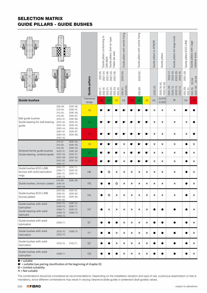
SELECTION MATRIX GUIDE PILLARS - GUIDE BUSHES
● = suitable●1 = suitable (see pairing classification at the beginning of chapter D) ○ = Limited suitability⊠ = Not suitable
The combinations should be considered as recommendations. Depending on the installation situation and type of use, a previous examination or test is mandatory, since different combinations may result in varying clearance (slide guide) or pretension (ball guides) values.
Gu
ide
pill
ars
Gui
de
pill
ars
conf
orm
ing
to
DIN
982
5G
uid
e p
illar
s, b
olt-
on
typ
eP
alle
t d
ie s
ets
Gui
de
pill
ars
with
cen
tre
fixin
g
Gui
de
pill
ars
with
cen
tre
fixin
g
Gui
de
pill
ars
to A
FNO
R
Gui
de
pill
ars
Gui
de
pill
ars
for
larg
e to
ols
Gui
de
pill
ars
EC
O-L
INE
Gui
de
pill
ars
with
cag
e re
tain
er b
ore
Guide bushesTolerance
range
Ball guide bushesGuide bearing for ball bearing guide
Sintered ferrite guide bushesGuide bearing, sintered guide
Guide bushes ECO-LINE bronze with solid lubrication rings
Guide bushes, bronze coated
Guide bushes ECO-LINE bronze plated
Guide bushes with solid lubricationGuide bearing with solid lubricant
Guide bushes with solid lubrication
Guide bushes with solid lubrication
Guide bushes with solid lubrication
Guide bushes with solid lubrication
2021.46.
2021.39.
2021.50.
43/1
2021.46.
32
202.21.
10
202.19.
210.39.
2021.43.
ject to altesubjectsub
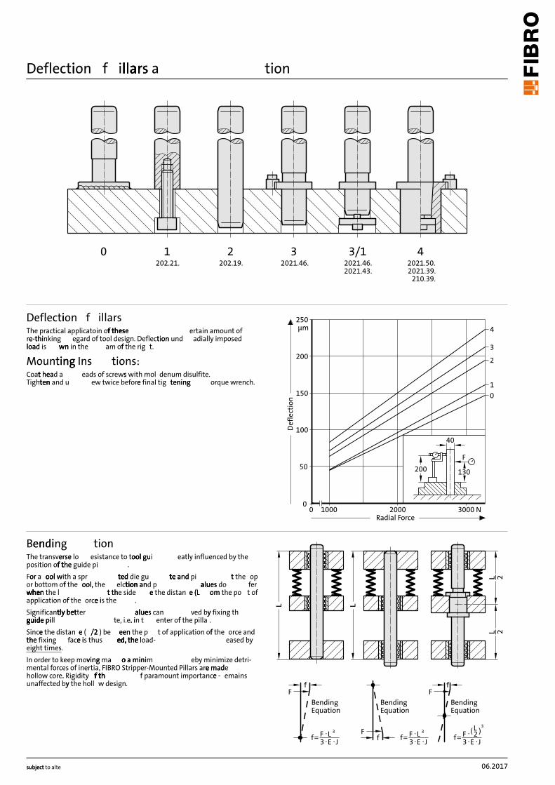
Deflectioni f illarsllallars allar tion
De
fle
ctio
n
4
00 1000 3000 N2000
F
40
130200 50
100
150
200
250
3
2
1
0
Radial Force
µm
Deflectioni f illars
The practical applicatoin these f these f thesf off th ertain amount of
-tre-thinkinge hi egard of tool design. ion u Deflectiont nd adially imposed
loadloa n in wd is wnw n the am th off e rig t.
Mountinging Ins tions:
heatCoatt head a eads of wit screwss h mol denum disulfite.
en aen tTightent nd u ew twice fina beforee l tig teningtening orque wrench.
Bendingendi tion
The transverseerse lo esistance to toolool guiool gu eatly influenced by the
position thf off the f the guide pi .
Foror a oolool woo ed died tl with a spr tedt e and e and te ate gu tet thpi tt e op
or bottom th off ol,e ool,o ion antion andiont the elctiont lualue p aluesa s do fer
whenwhenwhen whewhen the l tt tht the side ee the distan ee (L(L omom the po t of
application off the orcee ie is the .
Significantlytly bettly bettly bett luealuer aluesa es can ved byy fixing th
guideguide piguiguidguide pill te, i.e.. i. in t enter off the pilla .
Sincee the distan ee ( /2/2 en ) be eene the p t of application off the orce and
thethe fixing facee ie is thus ed,ed, ed, the load-ed, the led, the eased by
eight times.
In order to keep ing movingv ma oo a a minio o minim eby detri minimize -
mental forces of inertia, FIBRO Stripper-Mounted Pillars made mad aree e
hollow Rigidit core.. thf thfy ff thf th f paramount importancee - emains
unaffected th byy e holl w design. fF
f
Bending Equation
f F L3 E J
3 Ff
Bending Equation
f F L3 E J
3
FBending Equation
f F 23 E J
3L
06.2017
09.2019
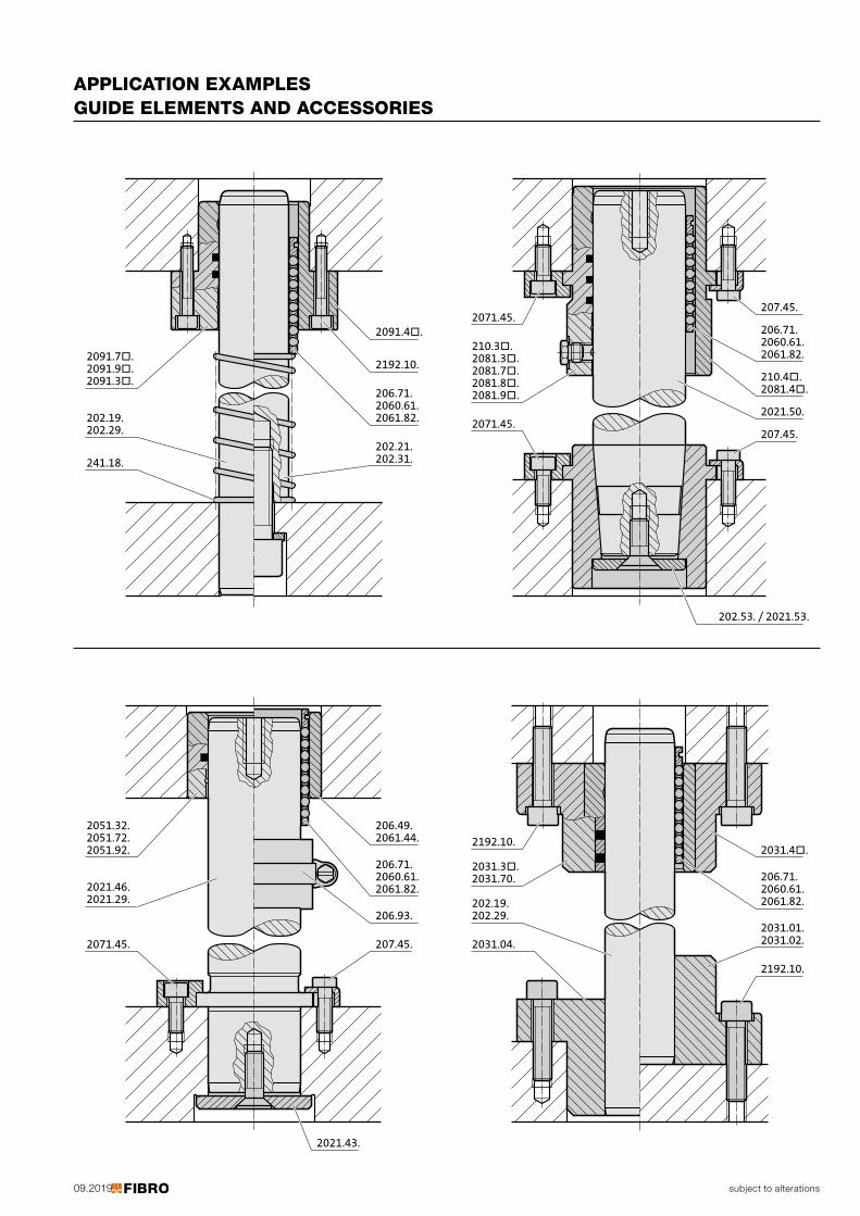
2091.4�.
2192.10.
2061.82.
2060.61.
206.71.
202.31.
202.21.
2091.3�.
2091.9�.
2091.7�.
202.29.
202.19.
241.18.
2061.44.
2061.82.
206.93.
207.45.
2051.92.
2021.29.2021.46.
2071.45.
2060.61.206.71.
206.49.2051.72.2051.32.
2021.43.
207.45.
2061.82.
2081.4�.
207.45.
2071.45.
2081.9�.2081.8�.
2071.45.
2060.61.206.71.
210.4�.
2021.50.
2081.7�.2081.3�.210.3�.
202.53. / 2021.53.
2031.4�.
2061.82.
2031.02.
2192.10.
2192.10.
202.29.
202.19.
2031.04.
2060.61.
206.71.
2031.01.
2031.70.
2031.3�.
subject to alterations
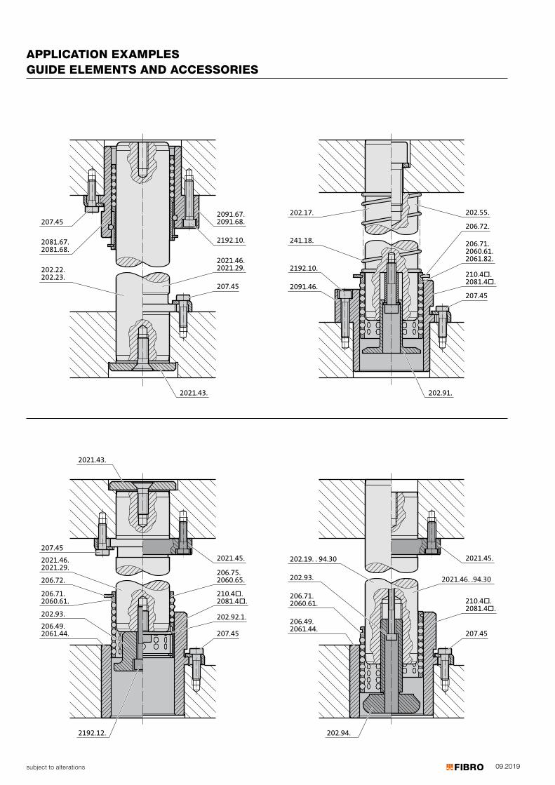
APPLICATION EXAMPLES GUIDE ELEMENTS AND ACCESSORIES
09.2019
2091.67.
2091.68.207.45
202.22.
202.23.
2081.67.
2081.68.
2192.10.
2021.46.
2021.29.
207.45
2021.43.
207.45
206.71.2060.61.
2021.46.2021.29.
2021.43.
2192.12.
206.72.
202.93.206.49.2061.44.
2021.45.
210.4�.2081.4�.
207.45
202.92.1.
206.75.2060.65.
241.18.
202.55.202.17.
2192.10.
206.72.
210.4�.2081.4�.
207.452091.46.
206.71.2060.61.2061.82.
202.91.
206.71.2060.61.
202.93.
202.19. . 94.30
206.49.2061.44.
202.94.
2021.45.
207.45
2021.46. .94.30
210.4�.2081.4�.
subject to alterations
APPLICATION EXAMPLES GUIDE ELEMENTS AND ACCESSORIES

subject to alterations
Ball cage, small dimensionGuide bush for ball bearing, small dimension
Material: Cage: Brass Balls: Steel hardened (DIN 5401)
Material: Roller bearing steel 100 Cr 6 Hardness: hardened to 60 + 4 HRC Remarks: available in stainless steel on request
Execution: Guide bush bores d2 fine-honed to IT3
Note: Assembly guide lines / Dimensional requirements and tolerances at the end of chapter D.
˜d
k
˜l
206.51.
˜d
˛l
˛d hˆ
ˆd hˇ
206.54.
09.2017
Ordering Code (example):Ball cage, small dimension =206.51.Guide diameter d1 5 mm = 005.Length l1 30 mm = 030Order No =206.51. 005. 030
Ordering Code (example):Guide bush for ball bearing, small dimension =206.54.Guide diameter d1 5 mm = 005.Length l1 10 mm = 010Order No =206.54. 005. 010
d1 3 4 5 6 8k 1 1 1 1 1l1 Total number of balls10 24 30 36 4215 40 50 60 70 7020 56 65 78 78 8425 80 102 102 11230 105 126 126 12635 120 144 14440 175
d1 3 4 5 6 8d2 5 6 7 8 10d3 7 8 10 11 14l110 ● ● ●15 ● ● ● ● ●20 ● ● ● ● ●25 ● ● ● ●30 ● ● ●35 ● ●40 ●
206.51.
206.54.
Ball cage, small dimension
Guide bush for ball bearing, small dimension
subject to alterations
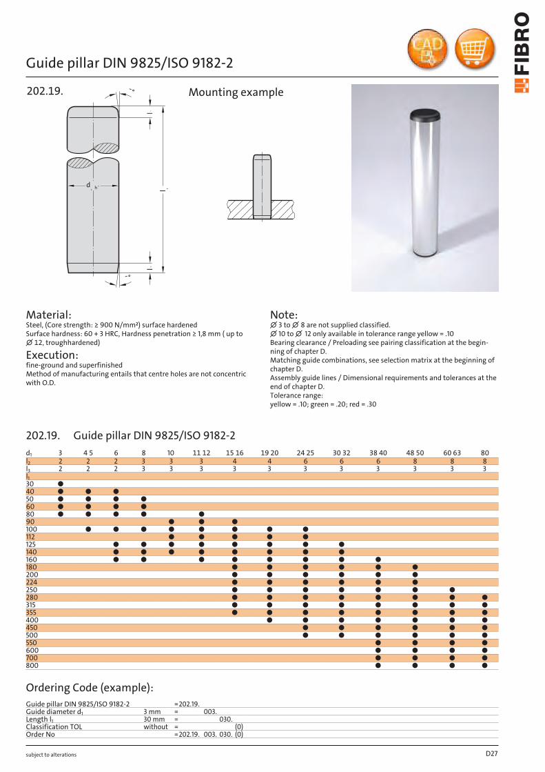
Guide pillar DIN 9825/ISO 9182-2
˜°
˜°
˛l˙l
d˛ h˘
˘l
202.19.
Material: Steel, (Core strength: ≥ 900 N/mm²) surface hardened Surface hardness: 60 + 3 HRC, Hardness penetration ≥ 1,8 mm ( up to ∅ 12, troughhardened)
Execution: fine-ground and superfinished Method of manufacturing entails that centre holes are not concentric with O.D.
Note: ∅ 3 to ∅ 8 are not supplied classified. ∅ 10 to ∅ 12 only available in tolerance range yellow = .10 Bearing clearance / Preloading see pairing classification at the begin-ning of chapter D.Matching guide combinations, see selection matrix at the beginning of chapter D.Assembly guide lines / Dimensional requirements and tolerances at the end of chapter D.Tolerance range: yellow = .10; green = .20; red = .30
Mounting example
D27
d1 3 4 5 6 8 10 11 12 15 16 19 20 24 25 30 32 38 40 48 50 60 63 80l2 2 2 2 3 3 3 4 4 6 6 6 8 8 8l3 2 2 2 3 3 3 3 3 3 3 3 3 3 3l130 ●40 ● ● ●50 ● ● ● ●60 ● ● ● ●80 ● ● ● ● ●90 ● ● ●100 ● ● ● ● ● ● ● ●112 ● ● ● ● ●125 ● ● ● ● ● ● ● ●140 ● ● ● ● ● ● ● ●160 ● ● ● ● ● ● ● ●180 ● ● ● ● ● ●200 ● ● ● ● ● ●224 ● ● ● ● ● ●250 ● ● ● ● ● ● ●280 ● ● ● ● ● ● ● ●315 ● ● ● ● ● ● ● ●355 ● ● ● ● ● ● ● ●400 ● ● ● ● ● ● ●450 ● ● ● ● ● ●500 ● ● ● ● ● ●550 ● ● ● ●600 ● ● ● ●700 ● ● ● ●800 ● ● ● ●
Ordering Code (example):Guide pillar DIN 9825/ISO 9182-2 =202.19.Guide diameter d1 3 mm = 003.Length l1 30 mm = 030.Classification TOL without = (0)Order No =202.19. 003. 030. (0)
202.19. Guide pillar DIN 9825/ISO 9182-2
subject to alterations
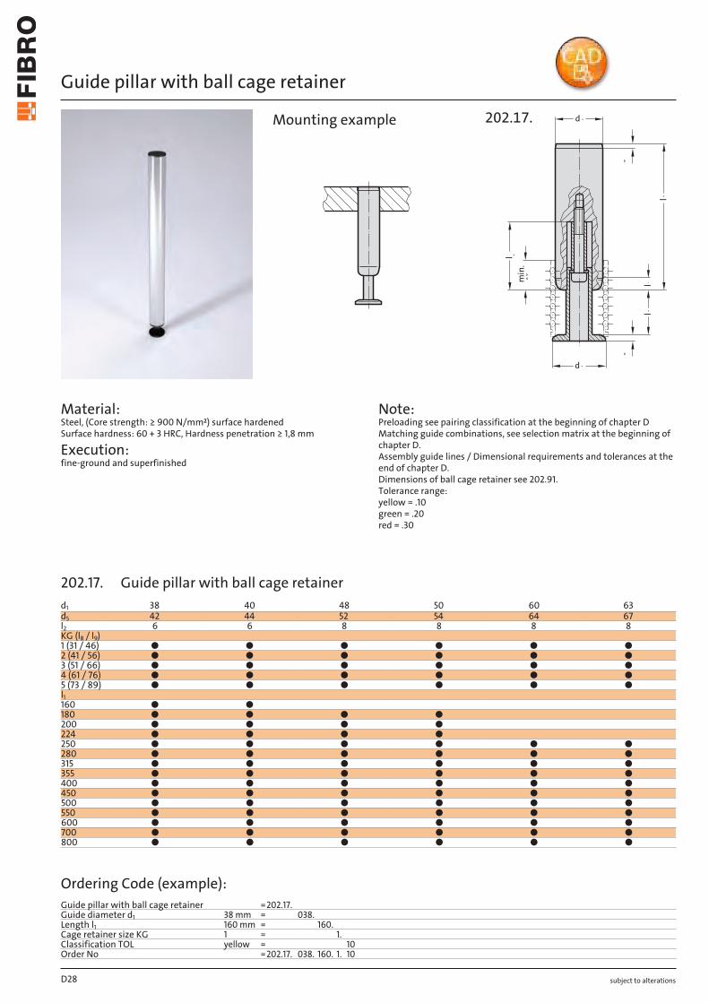
Guide pillar with ball cage retainer
Material: Steel, (Core strength: ≥ 900 N/mm²) surface hardened Surface hardness: 60 + 3 HRC, Hardness penetration ≥ 1,8 mm
Execution: fine-ground and superfinished
Note: Preloading see pairing classification at the beginning of chapter D Matching guide combinations, see selection matrix at the beginning of chapter D. Assembly guide lines / Dimensional requirements and tolerances at the end of chapter D. Dimensions of ball cage retainer see 202.91. Tolerance range: yellow = .10 green = .20 red = .30
min
. ˆ
ˇ
˘d
˜d
˛l
˜l˙l
ˆl
ˇ˘
202.17.Mounting example
D28
d1 38 40 48 50 60 63d5 42 44 52 54 64 67l2 6 6 8 8 8 8KG (l8 / l9)1 (31 / 46) ● ● ● ● ● ●2 (41 / 56) ● ● ● ● ● ●3 (51 / 66) ● ● ● ● ● ●4 (61 / 76) ● ● ● ● ● ●5 (73 / 89) ● ● ● ● ● ●l1160 ● ●180 ● ● ● ●200 ● ● ● ●224 ● ● ● ●250 ● ● ● ● ● ●280 ● ● ● ● ● ●315 ● ● ● ● ● ●355 ● ● ● ● ● ●400 ● ● ● ● ● ●450 ● ● ● ● ● ●500 ● ● ● ● ● ●550 ● ● ● ● ● ●600 ● ● ● ● ● ●700 ● ● ● ● ● ●800 ● ● ● ● ● ●
Ordering Code (example):Guide pillar with ball cage retainer =202.17.Guide diameter d1 38 mm = 038.Length l1 160 mm = 160.Cage retainer size KG 1 = 1.Classification TOL yellow = 10Order No =202.17. 038. 160. 1. 10
202.17. Guide pillar with ball cage retainer
subject to alterations
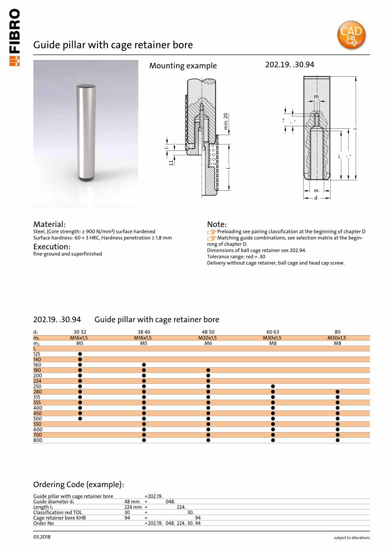
Guide pillar with cage retainer bore
Material: Steel, (Core strength: ≥ 900 N/mm²) surface hardened Surface hardness: 60 + 3 HRC, Hardness penetration ≥ 1,8 mm
Execution: fine-ground and superfinished
Note: Preloading see pairing classification at the beginning of chapter D Matching guide combinations, see selection matrix at the begin-ning of chapter D. Dimensions of ball cage retainer see 202.94. Tolerance range: red = .30 Delivery without cage retainer, ball cage and head cap screw.
l °
min
. 20
l °11
˜° ˜˛
°˝ ˙˛l ˜
˜d˜m
˛m
202.19. .30.94Mounting example
03.2018
d1 30 32 38 40 48 50 60 63 80m1 M16x1,5 M16x1,5 M20x1,5 M30x1,5 M30x1,5m2 M5 M5 M6 M8 M8l1125 ●140 ●160 ● ●180 ● ● ●200 ● ● ●224 ● ● ●250 ● ● ● ●280 ● ● ● ● ●315 ● ● ● ● ●355 ● ● ● ● ●400 ● ● ● ● ●450 ● ● ● ● ●500 ● ● ● ● ●550 ● ● ● ●600 ● ● ● ●700 ● ● ● ●800 ● ● ● ●
Ordering Code (example):Guide pillar with cage retainer bore =202.19.Guide diameter d1 48 mm = 048.Length l1 224 mm = 224.Classification red TOL 30 = 30.Cage retainer bore KHB 94 = 94Order No =202.19. 048. 224. 30. 94
202.19. .30.94 Guide pillar with cage retainer bore
subject to alterations
Guide pillar with internal thread on both sides, ~DIN 9825/~ISO 9182-2
202.22. 60°
d1 h3
l 1
M8
20
Material: Steel, (Core strength: ≥ 900 N/mm²) surface hardened Surface hardness: 60 + 3 HRC, Hardness penetration ≥ 1,8 mm
Execution: fine-ground and superfinished Method of manufacturing entails that centre holes are not concentric with O.D.
Note: Bearing clearance / Preloading see pairing classification at the begin-ning of chapter D. Matching guide combinations, see selection matrix at the beginning of chapter D. Assembly guide lines / Dimensional requirements and tolerances at the end of chapter D. Tolerance range: yellow = .10 green = .20 red = .30
Mounting example
D29
d1 15 16 19 20 24 25 30 32 38 40 48 50 60 63 80l2 4 4 6 6 6 8 8 8l190 ●100 ● ● ●112 ● ● ●125 ● ● ● ●140 ● ● ● ●160 ● ● ● ● ●180 ● ● ● ● ● ●200 ● ● ● ● ● ●224 ● ● ● ● ● ●250 ● ● ● ● ● ● ●280 ● ● ● ● ● ● ● ●315 ● ● ● ● ● ● ● ●355 ● ● ● ● ● ● ● ●400 ● ● ● ● ● ● ●450 ● ● ● ● ● ●500 ● ● ● ● ● ●550 ● ● ● ●600 ● ● ● ●700 ● ● ● ●800 ● ● ● ●
Ordering Code (example):
Guide pillar with internal thread on both sides, ~DIN 9825/~ISO 9182-2 =202.22.Guide diameter d1 15 mm = 015.Length l1 90 mm = 090.Classification TOL yellow = 10Order No =202.22. 015.090. 10
202.22. Guide pillar with internal thread on both sides, ~DIN 9825/~ISO 9182-2
subject to alterations
Guide pillar with internal thread on bottom, ~DIN 9825/~ISO 9182-2
Material: Steel, (Core strength: ≥ 900 N/mm²) surface hardened Surface hardness: 60 + 3 HRC, Hardness penetration ≥ 1,8 mm
Execution: fine-ground and superfinished Method of manufacturing entails that centre holes are not concentric with O.D.
Note: Bearing clearance / Preloading see pairing classification at the begin-ning of chapter D. Matching guide combinations, see selection matrix at the beginning of chapter D. Assembly guide lines / Dimensional requirements and tolerances at the end of chapter D. Tolerance range: yellow = .10 green = .20 red = .30
60°
1d
h3
1l
M8
20
202.23.Mounting example
D30
d1 15 16 19 20 24 25 30 32 38 40 48 50 60 63 80l2 4 4 6 6 6 8 8 8l190 ●100 ● ● ●112 ● ● ●125 ● ● ● ●140 ● ● ● ●160 ● ● ● ● ●180 ● ● ● ● ● ●200 ● ● ● ● ● ●224 ● ● ● ● ● ●250 ● ● ● ● ● ● ●280 ● ● ● ● ● ● ● ●315 ● ● ● ● ● ● ● ●355 ● ● ● ● ● ● ● ●400 ● ● ● ● ● ● ●450 ● ● ● ● ● ●500 ● ● ● ● ● ●550 ● ● ● ●600 ● ● ● ●700 ● ● ● ●800 ● ● ● ●
Ordering Code (example):Guide pillar with internal thread on bottom, ~DIN 9825/~ISO 9182-2 =202.23.Guide diameter d1 15 mm = 015.Length l1 90 mm = 090.Classification TOL yellow = 10Order No =202.23. 015.090. 10
202.23. Guide pillar with internal thread on bottom, ~DIN 9825/~ISO 9182-2

subject to alterations
Guide pillar with internal thread on top, ~DIN 9825/~ISO 9182-2
60°
1d
h3
1l
M8
20
202.24.
Material: Steel, (Core strength: ≥ 900 N/mm²) surface hardened Surface hardness: 60 + 3 HRC, Hardness penetration ≥ 1,8 mm
Execution: fine-ground and superfinished Method of manufacturing entails that centre holes are not concentric with O.D.
Note: Bearing clearance / Preloading see pairing classification at the begin-ning of chapter D. Matching guide combinations, see selection matrix at the beginning of chapter D. Assembly guide lines / Dimensional requirements and tolerances at the end of chapter D. Tolerance range: yellow = .10 green = .20 red = .30
Mounting example
D31
d1 15 16 19 20 24 25 30 32 38 40 48 50 60 63 80l2 4 4 6 6 6 8 8 8l190 ●100 ● ● ●112 ● ● ●125 ● ● ● ●140 ● ● ● ●160 ● ● ● ● ●180 ● ● ● ● ● ●200 ● ● ● ● ● ●224 ● ● ● ● ● ●250 ● ● ● ● ● ● ●280 ● ● ● ● ● ● ● ●315 ● ● ● ● ● ● ● ●355 ● ● ● ● ● ● ● ●400 ● ● ● ● ● ● ●450 ● ● ● ● ● ●500 ● ● ● ● ● ●550 ● ● ● ●600 ● ● ● ●700 ● ● ● ●800 ● ● ● ●
Ordering Code (example):Guide pillar with internal thread on top, ~DIN 9825/~ISO 9182-2 =202.24.Guide diameter d1 15 mm = 015.Length l1 90 mm = 090.Classification TOL yellow = 10Order No =202.24. 015.090. 10
202.24. Guide pillar with internal thread on top, ~DIN 9825/~ISO 9182-2
subject to alterations
Guide pillar endwise bolt-on type, ~DIN 9825/~ISO 9182-2
Material: Steel, (Core strength: ≥ 900 N/mm²) surface hardened Surface hardness: 60 + 3 HRC, Hardness penetration ≥ 1,8 mm
Execution: fine precision ground End face square within 0.005 mm in 100 mm
Note: Bearing clearance / Preloading see pairing classification at the begin-ning of chapter D. Matching guide combinations, see selection matrix at the beginning of chapter D. Tolerance range: yellow = .10 green = .20 red = .30
d
60°
d 1 = 15/1619/2024/2530/3238/40
d 1 = 48/5060/63
d 1 = 80
3 x 120°
Hole pattern for column (pillar)fastening
6
d 6
l 1 -
3
0,005/100 A
8°
3
min
.t
1,5
x M
min
.
A
d1 h3
M
d 4
d3
202.21.
D32
d1 15 16 19 20 24 25 30 32 38 40 48 50 60 63 80d3 9 11 14 18 18 14 18 18d4 17 20 22 28 28 22 28 28d6 - - - - - 28 34 54t 12 14 16 20.5 20.5 16 20.5 20.5M 8 10 12 16 16 12 16 16Cap screw M8x35 M10x40 M12x40 M16x40 M16x40 M12x50 M16x60 M16x60Tightening torque [Nm] 21 37 85 150 150 85 200 200l190 ●100 ● ● ●112 ● ● ●125 ● ● ● ●140 ● ● ● ●160 ● ● ● ● ●180 ● ● ● ● ● ●200 ● ● ● ● ● ●224 ● ● ● ● ● ●250 ● ● ● ● ● ● ●280 ● ● ● ● ● ● ● ●315 ● ● ● ● ● ● ● ●355 ● ● ● ● ● ● ● ●400 ● ● ● ● ● ● ●450 ● ● ● ● ● ●500 ● ● ● ● ● ●550 ● ● ● ●600 ● ● ● ●700 ● ● ● ●800 ● ● ● ●
Ordering Code (example):Guide pillar endwise bolt-on type, ~DIN 9825/~ISO 9182-2 =202.21.Guide diameter d1 15 mm = 015.Length l1 90 mm = 090.Classification TOL yellow = 10Order No =202.21. 015.090. 10
202.21. Guide pillar endwise bolt-on type, ~DIN 9825/~ISO 9182-2

subject to alterations D33
subject to alterations
Guide pillar endwise bolt-on type with ball cage, ~DIN 9825/~ISO 9182-2
Material: Steel, (Core strength: ≥ 900 N/mm²) surface hardened Surface hardness: 60 + 3 HRC, Hardness pene-tration ≥ 1,8 mm
Execution: fine precision ground End face square within 0.005 mm in 100 mm
Note: Preloading see pairing classification at the beginning of chapter D Matching guide combinations, see selection matrix at the beginning of chapter D. Dimensions of ball cage retainer see 202.91. Tolerance range: yellow = .10 green = .20 red = .30
1,5
x m
1l
4d
1d
m
3d
t
min
.
20
5d
9l
2l8l
4
202.55.
X
d
60°
d 1 = 15/1619/2024/2530/3238/40
d 1 = 48/5060/63
3 x 120°
Hole pattern for column (pillar)fastening
6
D34
subject to alterations
Guide pillar endwise bolt-on type with ball cage, ~DIN 9825/~ISO 9182-2
D35
d1 38 40 48 50 60 63d3 18 18 14 14 18 18d4 28 28 22 22 28 28d5 42 44 52 54 64 67d6 - - 28 28 34 34t 20.5 20.5 16 16 20.5 20.5m 16 16 12 12 16 16Cap screw M16x40 M16x40 M12x50 M12x50 M16x60 M16x60Tightening torque [Nm] 150 150 85 85 200 200KG (l8 / l9)1 (31 / 46) ● ● ● ● ● ●2 (41 / 56) ● ● ● ● ● ●3 (51 / 66) ● ● ● ● ● ●4 (61 / 76) ● ● ● ● ● ●5 (73 / 89) ● ● ● ● ● ●l1160 ● ●180 ● ● ● ●200 ● ● ● ●224 ● ● ● ●250 ● ● ● ● ● ●280 ● ● ● ● ● ●315 ● ● ● ● ● ●355 ● ● ● ● ● ●400 ● ● ● ● ● ●450 ● ● ● ● ● ●500 ● ● ● ● ● ●550 ● ● ● ● ● ●600 ● ● ● ● ● ●700 ● ● ● ● ● ●800 ● ● ● ● ● ●
Ordering Code (example):
Guide pillar endwise bolt-on type with ball cage, ~DIN 9825/~ISO 9182-2 =202.55.Guide diameter d1 38 mm = 038.Length l1 160 mm = 160.Cage retainer size KG 1 = 1.Classification TOL yellow = 10Order No =202.55. 038. 160. 1. 10
202.55. Guide pillar endwise bolt-on type with ball cage, ~DIN 9825/~ISO 9182-2
subject to alterations
Guide pillar "ECO-Line", ~DIN 9825/~ISO 9182-2
Material: Steel, surface hardened Surface hardness: 60 + 3 HRC, Hardness penetration ≥ 1,8 mm
Execution: ground Method of manufacturing entails that centre holes are not concentric with O.D.
Note: Guide pillars only recommended for use with sliding guides! Matching guide combinations, see selection matrix at the beginning of chapter D. Assembly guide lines / Dimensional requirements and tolerances at the end of chapter D.
8°
8°
1l
2l
d1 h4
3
202.29.Mounting example
D36
d1 15 16 19 20 24 25 30 32 38 40 48 50 60 63 80l2 4 4 6 6 6 8 8 8l190 ●100 ● ● ●112 ● ● ●125 ● ● ● ●140 ● ● ● ●160 ● ● ● ● ●180 ● ● ● ● ● ●200 ● ● ● ● ● ●224 ● ● ● ● ● ●250 ● ● ● ● ● ● ●280 ● ● ● ● ● ● ● ●315 ● ● ● ● ● ● ● ●355 ● ● ● ● ● ● ● ●400 ● ● ● ● ● ● ●450 ● ● ● ● ● ●500 ● ● ● ● ● ●550 ● ● ● ●600 ● ● ● ●700 ● ● ● ●800 ● ● ● ●
Ordering Code (example):Guide pillar "ECO-Line", ~DIN 9825/~ISO 9182-2 =202.29.Guide diameter d1 15 mm = 015.Length l1 90 mm = 090Order No =202.29. 015.090
202.29. Guide pillar "ECO-Line", ~DIN 9825/~ISO 9182-2

subject to alterations D37
subject to alterations
Guide pillar "ECO-Line" endwise bolt-on type, ~DIN 9825/~ISO 9182-2
Material: Steel, surface hardened Surface hardness: 60 + 3 HRC, Hardness pene-tration ≥ 1,8 mm
Execution: ground
Note: Guide pillars only recommended for use with sliding guides! Matching guide combinations, see selection matrix at the beginning of chapter D.
l 1 -
3
8°
3
min
.t
1,5
x M
min
.
d1 h4
M
d 4
d3
202.31.
X
d
60°
d 1 = 15/1619/2024/2530/3238/40
d 1 = 48/5060/63
d 1 = 80
3 x 120°
Hole pattern for column (pillar)fastening
6
d 6
D38
subject to alterations
Guide pillar "ECO-Line" endwise bolt-on type, ~DIN 9825/~ISO 9182-2
D39
d1 15 16 19 20 24 25 30 32 38 40 48 50 60 63 80d3 9 11 14 18 18 14 18 18d4 17 20 22 28 28 22 28 28d6 - - - - - 28 34 54t 12 14 16 20.5 20.5 16 20.5 20.5M 8 10 12 16 16 12 16 16Cap screw M8x35 M10x40 M12x40 M16x40 M16x40 M12x50 M16x60 M16x60Tightening torque [Nm] 21 37 85 150 150 85 200 200l190 ●100 ● ● ●112 ● ● ●125 ● ● ● ●140 ● ● ● ●160 ● ● ● ● ●180 ● ● ● ● ● ●200 ● ● ● ● ● ●224 ● ● ● ● ● ●250 ● ● ● ● ● ● ●280 ● ● ● ● ● ● ● ●315 ● ● ● ● ● ● ● ●355 ● ● ● ● ● ● ● ●400 ● ● ● ● ● ● ●450 ● ● ● ● ● ●500 ● ● ● ● ● ●550 ● ● ● ●600 ● ● ● ●700 ● ● ● ●800 ● ● ● ●
Ordering Code (example):
Guide pillar "ECO-Line" endwise bolt-on type, ~DIN 9825/~ISO 9182-2 =202.31.Guide diameter d1 15 mm = 015.Length l1 90 mm = 090Order No =202.31. 015. 090
202.31. Guide pillar "ECO-Line" endwise bolt-on type, ~DIN 9825/~ISO 9182-2
subject to alterations
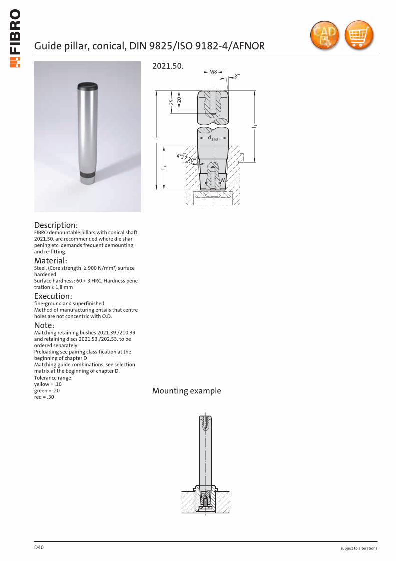
Guide pillar, conical, DIN 9825/ISO 9182-4/AFNOR
Description: FIBRO demountable pillars with conical shaft 2021.50. are recommended where die shar-pening etc. demands frequent demounting and re-fitting.
Material: Steel, (Core strength: ≥ 900 N/mm²) surface hardened Surface hardness: 60 + 3 HRC, Hardness pene-tration ≥ 1,8 mm
Execution: fine-ground and superfinished Method of manufacturing entails that centre holes are not concentric with O.D.
Note: Matching retaining bushes 2021.39./210.39. and retaining discs 2021.53./202.53. to be ordered separately. Preloading see pairing classification at the beginning of chapter D Matching guide combinations, see selection matrix at the beginning of chapter D. Tolerance range: yellow = .10 green = .20 red = .30
20
M8
3l
1l
8°
l
25
d1 h3
4°17'20"
M
2021.50.
X
Mounting example
D40
subject to alterations
Guide pillar, conical, DIN 9825/ISO 9182-4/AFNOR
D41
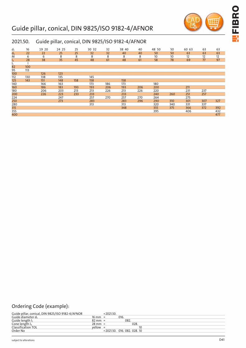
d1 16 19 20 24 25 25 30 32 32 38 40 40 48 50 50 60 63 63 63d5 22 22 25 25 32 32 40 40 50 50 63 63 63M 6 6 8 8 8 8 8 8 10 10 12 12 12l3 28 38 35 45 48 61 48 61 58 78 69 77 97l1 l82 10095 113100 126 123112 130 138 135 145125 143 151 148 158 158 158140 166 163 173 186 173 180160 186 183 193 193 206 193 206 200 211180 206 203 213 213 226 213 226 220 231 237200 226 223 233 233 233 240 260 251 257224 247 257 270 257 270 264 275250 273 283 283 296 290 310 301 307 327280 313 313 320 340 331 337315 348 355 375 366 372 392355 395 406 432400 477
Ordering Code (example):Guide pillar, conical, DIN 9825/ISO 9182-4/AFNOR =2021.50.Guide diameter d1 16 mm = 016.Guide length l1 82 mm = 082.Cone length l3 28 mm = 028.Classification TOL yellow = 10Order No =2021.50. 016. 082. 028. 10
2021.50. Guide pillar, conical, DIN 9825/ISO 9182-4/AFNOR
subject to alterations
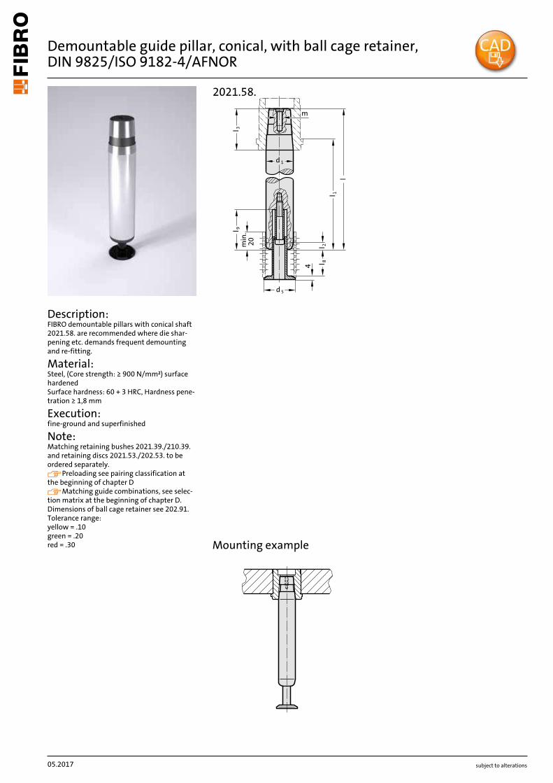
Demountable guide pillar, conical, with ball cage retainer, DIN 9825/ISO 9182-4/AFNOR
Description: FIBRO demountable pillars with conical shaft 2021.58. are recommended where die shar-pening etc. demands frequent demounting and re-fitting.
Material: Steel, (Core strength: ≥ 900 N/mm²) surface hardened Surface hardness: 60 + 3 HRC, Hardness pene-tration ≥ 1,8 mm
Execution: fine-ground and superfinished
Note: Matching retaining bushes 2021.39./210.39. and retaining discs 2021.53./202.53. to be ordered separately. Preloading see pairing classification at the beginning of chapter D Matching guide combinations, see selec-tion matrix at the beginning of chapter D. Dimensions of ball cage retainer see 202.91. Tolerance range: yellow = .10 green = .20 red = .30
4
l 1
l
3lm
in.
20
5d
l 9
l 2l 8
1d
2021.58.
m
X
Mounting example
05.2017
subject to alterations
Demountable guide pillar, conical, with ball cage retainer, DIN 9825/ISO 9182-4/AFNOR
05.2017
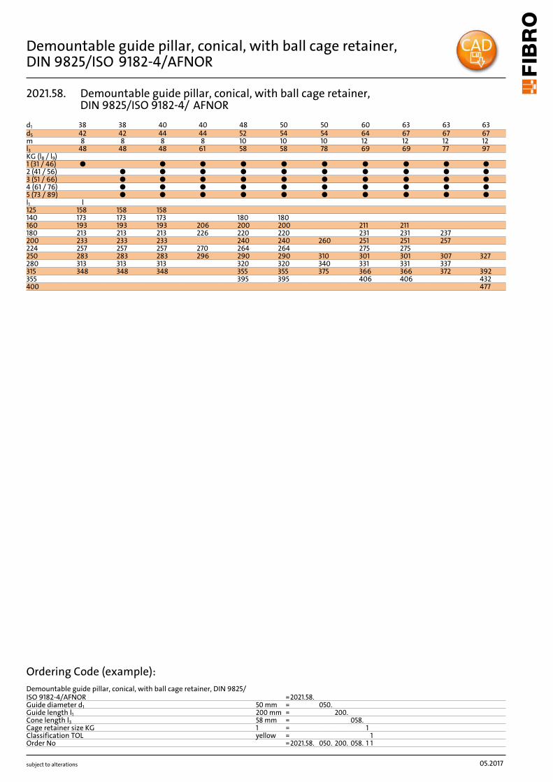
d1 38 38 40 40 48 50 50 60 63 63 63d5 42 42 44 44 52 54 54 64 67 67 67m 8 8 8 8 10 10 10 12 12 12 12l3 48 48 48 61 58 58 78 69 69 77 97KG (l8 / l9)1 (31 / 46) ● ● ● ● ● ● ● ● ● ●2 (41 / 56) ● ● ● ● ● ● ● ● ● ●3 (51 / 66) ● ● ● ● ● ● ● ● ● ●4 (61 / 76) ● ● ● ● ● ● ● ● ● ●5 (73 / 89) ● ● ● ● ● ● ● ● ● ●l1 l125 158 158 158140 173 173 173 180 180160 193 193 193 206 200 200 211 211180 213 213 213 226 220 220 231 231 237200 233 233 233 240 240 260 251 251 257224 257 257 257 270 264 264 275 275250 283 283 283 296 290 290 310 301 301 307 327280 313 313 313 320 320 340 331 331 337315 348 348 348 355 355 375 366 366 372 392355 395 395 406 406 432400 477
Ordering Code (example):Demountable guide pillar, conical, with ball cage retainer, DIN 9825/ISO 9182-4/AFNOR =2021.58.Guide diameter d1 50 mm = 050.Guide length l1 200 mm = 200.Cone length l3 58 mm = 058.Cage retainer size KG 1 = 1Classification TOL yellow = 1Order No =2021.58. 050. 200. 058. 1 1
2021.58. Demountable guide pillar, conical, with ball cage retainer, DIN 9825/ISO 9182-4/ AFNOR
subject to alterations
Retaining disc with countersunk head cap screw, DIN 9825/ISO 9182-4Retaining disc with socket cap screw, ~ AFNOR
Material: Retaining disc: Steel, burnished Countersunk head cap screw DIN 7991/ISO 10642
Note: Has to be ordered separately to guide pillar, conical according to DIN 9825 / ISO 9182-4 2021.50. or 2021.58.
Material: Retaining disc: Steel, burnished Socket head cap screw DIN 6912
Note: Has to be ordered separately to guide pillar, conical according to AFNOR 2021.50. or 2021.58.
Mounting example
Mounting example
M
s
5d
2021.53.
Ms
5d
202.53.
D44
Order No Nominal-ø Pillar-ø d5 s M2021.53.020 20 19/20 22 3 M62021.53.025 25 24/25 25 3 M82021.53.032 32 30/32 32 3 M82021.53.040 40 38/40 40 5 M82021.53.050 50 48/50 50 5 M102021.53.063 63 60/63 63 6 M12
Order No Pillar-ø d5 s M202.53.016 16 18 3 M6202.53.020 20 22 3 M6202.53.025 25 25 4 M8202.53.032 32 32 4 M8202.53.040 40 40 4 M8202.53.050 50 50 5 M10202.53.063 63 63 6 M12
2021.53.
202.53. Retaining disc with socket cap screw, ~ AFNOR
Retaining disc with countersunk head cap screw, DIN 9825/ISO 9182-4
subject to alterations
Retaining bush for guide pillar conical 2021.50., DIN 9825/ISO 9182-4
js4
H5
13
6l 4
l 2
l
d
d1
d4
d2
d5
l 3
a
a1
3
4°17'20"
d7 6d
2021.39.
Material: 16 MnCr5, case hardened 58 ± 2 HRC Hardness penetration: ≥ 0,8 mm
Execution: Retaining bore, outside diameter and shoulder precision ground.
Note: Outside diameter d3 same as that of guide bushes 2081. and 2091. The attachment is with 3 Screw clamp, from ∅ d1 = 38 with 4 Screw clamp , which are included in delivery (Order No: 207.45 - Screw clamp incl. socket cap screw DIN 6912, Head ∅ 13). Assembly guide lines / Dimensional requirements and tolerances at the end of chapter D.
3d H5
js4
Mounting example
D45
d1 19 20 24 25 30 32 38 40 48 50 60 63d2 32 40 48 58 70 85d3 32 40 48 58 70 85d4 40 48 56 66 80 95d5 23 26 33 41 51 64d6 53 60 67 77 91 106d7 65.7 72.7 79.7 89.7 103.7 118.7a 20.9 22.65 24.4 35.3 40.2 45.5a1 30.3 33.4 36.4 35.3 40.2 45.5l 42 49 49 59 52 62 62 75 65 78 78 95l2 30 37 37 47 37 47 47 60 47 60 60 77l3 12 12 15 15 18 18l4 39 36 49 49 59 70
Ordering Code (example):
Retaining bush for guide pillar conical 2021.50., DIN 9825/ISO 9182-4 =2021.39.Nominal diameter d1 19 mm = 019.Installation length l2 30 mm = 030Order No =2021.39. 019. 030
2021.39. Retaining bush for guide pillar conical 2021.50., DIN 9825/ISO 9182-4
subject to alterations
Retaining bush for guide pillar conical 2021.50.,~ AFNOR
Material: 16 MnCr5, case hardened 58 ± 2 HRC Hardness penetration: ≥ 0,8 mm
Execution: Retaining bore, outside diameter and shoulder precision ground.
Note: Outside diameter d3 same as that of guide bush 210. The attachment is with 3 Screw clamp, from ∅ d1 = 38 with 4 Screw clamp , which are included in delivery (Order No: 207.45 - Screw clamp incl. socket cap screw DIN 6912, Head ∅ 13). Assembly guide lines / Dimensional requirements and tolerances at the end of chapter D.
3dH5
m5
js4
H5
13
6l 4
l 2
l
d
d1
d4
d2
d5
l 3
a
a1
3
4°17'20"
d7 6d
210.39.Mounting example
D46
d1 16 20 25 32 40 50 63d2 29 32 41 51 65 84 100d3 28 32 40 50 63 80 90d4 32 36 45 56 70 90 110d5 19 23 26 33 41 51 64d6 45 49 57 67 81 101 121d7 57.7 61.7 69.7 79.7 93.7 113.7 133.7a 18.9 19.9 21.9 24.4 36 43 50.1a1 26.9 28.6 32.1 36.4 36 43 50.1l 40 50 50 60 63 76 63 76 79 96 98 118l2 30 38 38 48 48 61 48 61 61 78 78 98l3 10 12 12 15 15 18 20l4 30 40 37 47 50 63 50 63 63 80 79 99
Ordering Code (example):Retaining bush for guide pillar conical 2021.50.,~ AFNOR =210.39.Nominal diameter d1 16 mm = 016.Installation length l2 30 mm = 030Order No =210.39. 016. 030
210.39. Retaining bush for guide pillar conical 2021.50.,~ AFNOR
subject to alterations
Guide pillar for large tools, DIN 9833/ISO 9182-3
15°
l 1
f61dM12
l 2
24
r
1 r6dH7
min
. 5
l 5l 6
5°
r
3d
d5
2022.19.
Material: Steel, surface hardened Surface hardness: 60 + 4 HRC, Hardness penetration 1,5 + 1 mm
Execution: ground up to ∅ d1 = 80 without central hole by ∅ d1 = 80 with 1 lifting thread M12 from ∅ d1 = 100 with central hole (through)
and with 2 lifting threads M12
Note: Guide pillar is recommended to be used only with guide elements with solid lubricant. Matching guide combinations, see selection matrix at the beginning of chapter D. Assembly guide lines / Dimensional requirements and tolerances at the end of chapter D.
D47
d1 25 32 40 50 63 80 100 125 160d3 - - - - - - 50 65 95d5 - - - - - - 72 90 132r 2 2 2 2.5 2.5 3 3 4 4l2 8 8 8 10 10 10 10 12 12l5 40 45 56 70 80 100 125 140 180l6 4 4 4 4 4 4 4 5 5l1125 ● ●140 ● ● ●160 ● ● ● ●180 ● ● ● ● ●200 ● ● ● ● ●224 ● ● ● ● ● ●250 ● ● ● ● ● ●280 ● ● ● ● ●315 ● ● ● ● ●355 ● ● ● ● ●400 ● ● ● ● ●450 ● ● ● ●500 ● ● ● ●560 ●
Ordering Code (example):Guide pillar for large tools, DIN 9833/ISO 9182-3 =2022.19.Guide diameter d1 25 mm = 025.Length l1 125 mm = 125Order No =2022.19. 025. 125
2022.19. Guide pillar for large tools, DIN 9833/ISO 9182-3
subject to alterations
Guide pillar with 5° pilot taper, to VW-Standard
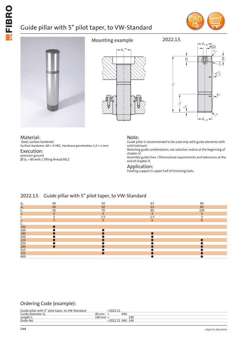
Material: Steel, surface hardened Surface hardness: 60 + 4 HRC, Hardness penetration 1,5 + 1 mm
Execution: precision ground ∅ d1 = 80 with 1 lifting thread M12
Note: Guide pillar is recommended to be used only with guide elements with solid lubricant. Matching guide combinations, see selection matrix at the beginning of chapter D. Assembly guide lines / Dimensional requirements and tolerances at the end of chapter D.
Application: Floating support in upper half of trimming tools.
d2H6
M121 f6d
5°
5°0-2
2 r6d
r
r
r1
l 1
l 5
l 62
5 24
2022.13.Mounting example
D48
d1 40 50 63 80d2 40 50 63 80l5 56 70 80 100l6 4 4 4 4r 2 2.5 2.5 3r1 3 5 6 8l1140 ●160 ● ●180 ● ● ●200 ● ● ●224 ● ● ● ●250 ● ● ● ●280 ● ● ● ●315 ● ● ●355 ● ● ●400 ● ●
Ordering Code (example):Guide pillar with 5° pilot taper, to VW-Standard =2022.13.Guide diameter d1 40 mm = 040.Length l1 140 mm = 140Order No =2022.13. 040. 140
2022.13. Guide pillar with 5° pilot taper, to VW-Standard
subject to alterations
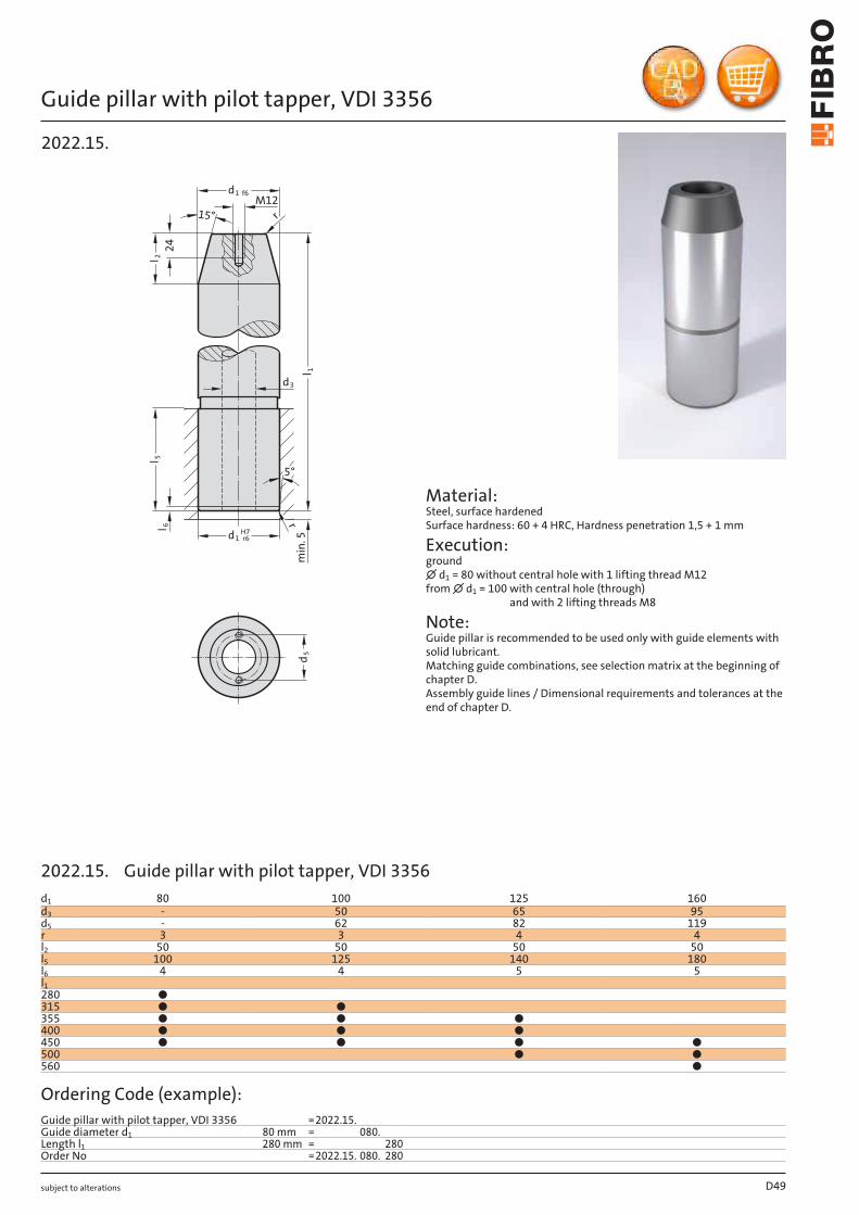
Guide pillar with pilot tapper, VDI 3356
l 1
1 r6dH7
min
. 5
r
1 f6dM12
15°
l 2l 5
l 62
4
5°
r
3d
d5
2022.15.
Material: Steel, surface hardened Surface hardness: 60 + 4 HRC, Hardness penetration 1,5 + 1 mm
Execution: ground ∅ d1 = 80 without central hole with 1 lifting thread M12 from ∅ d1 = 100 with central hole (through)
and with 2 lifting threads M8
Note: Guide pillar is recommended to be used only with guide elements with solid lubricant. Matching guide combinations, see selection matrix at the beginning of chapter D. Assembly guide lines / Dimensional requirements and tolerances at the end of chapter D.
D49
d1 80 100 125 160d3 - 50 65 95d5 - 62 82 119r 3 3 4 4l2 50 50 50 50l5 100 125 140 180l6 4 4 5 5l1280 ●315 ● ●355 ● ● ●400 ● ● ●450 ● ● ● ●500 ● ●560 ●
Ordering Code (example):Guide pillar with pilot tapper, VDI 3356 =2022.15.Guide diameter d1 80 mm = 080.Length l1 280 mm = 280Order No =2022.15. 080. 280
2022.15. Guide pillar with pilot tapper, VDI 3356
subject to alterations
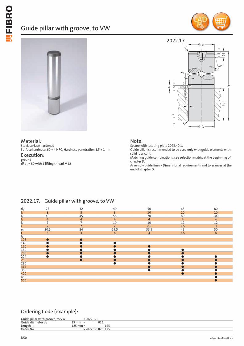
Guide pillar with groove, to VW
Material: Steel, surface hardened Surface hardness: 60 + 4 HRC, Hardness penetration 1,5 + 1 mm
Execution: ground ∅ d1 = 80 with 1 lifting thread M12
Note: Secure with locating plate 2022.40.1. Guide pillar is recommended to be used only with guide elements with solid lubricant. Matching guide combinations, see selection matrix at the beginning of chapter D. Assembly guide lines / Dimensional requirements and tolerances at the end of chapter D.
5°
r
15°
1 f6d
24l 2
l 1
l 5
l 7 s
e 2
t
1 r6dH7
l 6
r
2022.17.
D50
d1 25 32 40 50 63 80l2 8 8 8 10 10 10l5 40 45 56 70 80 100l6 4 4 4 4 4 4l7 7 7 10 10 12 12r 2 2 2 2.5 2.5 3e2 20.5 24 29.5 33.5 43 50t 3 3 4 4 6.5 8l1125 ● ●140 ● ● ●160 ● ● ● ●180 ● ● ● ● ●200 ● ● ● ● ●224 ● ● ● ● ● ●250 ● ● ● ● ●280 ● ● ● ●315 ● ● ●355 ● ● ●400 ● ●450 ●500 ●
Ordering Code (example):Guide pillar with groove, to VW =2022.17.Guide diameter d1 25 mm = 025.Length l1 125 mm = 125Order No =2022.17. 025. 125
2022.17. Guide pillar with groove, to VW
subject to alterations
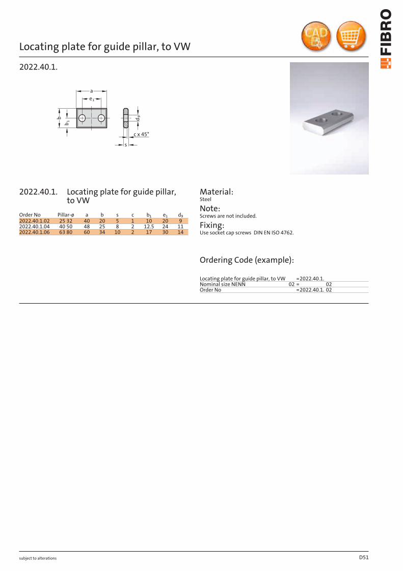
Locating plate for guide pillar, to VWb
1
d9
b
s
a
e1
c x 45°
2022.40.1.
Material:
D51
Order No Pillar-ø a b s c b1 e1 d92022.40.1.02 3225 40 20 5 1 10 20 92022.40.1.04 40 50 48 25 8 2 12.5 24 112022.40.1.06 63 80 60 34 10 2 17 30 14
Steel
Note: Screws are not included.
Fixing: Use socket cap screws DIN EN ISO 4762.
Ordering Code (example):
Locating plate for guide pillar, to VW =2022.40.1.Nominal size NENN 02 = 02Order No =2022.40.1. 02
2022.40.1. Locating plate for guide pillar, to VW
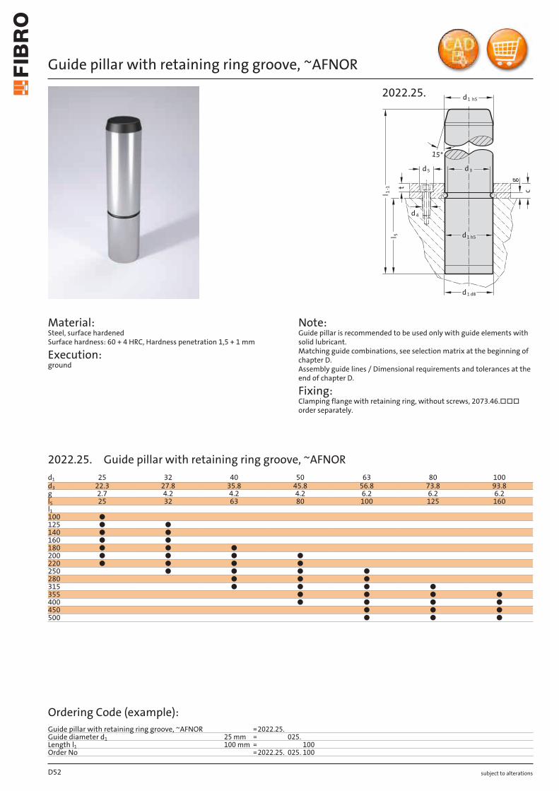
subject to alterations
Guide pillar with retaining ring groove, ~AFNOR
Material: Steel, surface hardened Surface hardness: 60 + 4 HRC, Hardness penetration 1,5 + 1 mm
Execution: ground
Note: Guide pillar is recommended to be used only with guide elements with solid lubricant. Matching guide combinations, see selection matrix at the beginning of chapter D. Assembly guide lines / Dimensional requirements and tolerances at the end of chapter D.
Fixing: Clamping flange with retaining ring, without screws, 2073.46.□□□ order separately.
15°
g
1-1 t
d5 d
d1 d8
5
l
d1 h5
l
3
4d
c
d1 h5
2022.25.
D52
d1 25 32 40 50 63 80 100d3 22.3 27.8 35.8 45.8 56.8 73.8 93.8g 2.7 4.2 4.2 4.2 6.2 6.2 6.2l5 25 32 63 80 100 125 160l1100 ●125 ● ●140 ● ●160 ● ●180 ● ● ●200 ● ● ● ●220 ● ● ● ●250 ● ● ● ●280 ● ● ●315 ● ● ● ●355 ● ● ● ●400 ● ● ● ●450 ● ● ●500 ● ● ●
Ordering Code (example):Guide pillar with retaining ring groove, ~AFNOR =2022.25.Guide diameter d1 25 mm = 025.Length l1 100 mm = 100Order No =2022.25. 025. 100
2022.25. Guide pillar with retaining ring groove, ~AFNOR
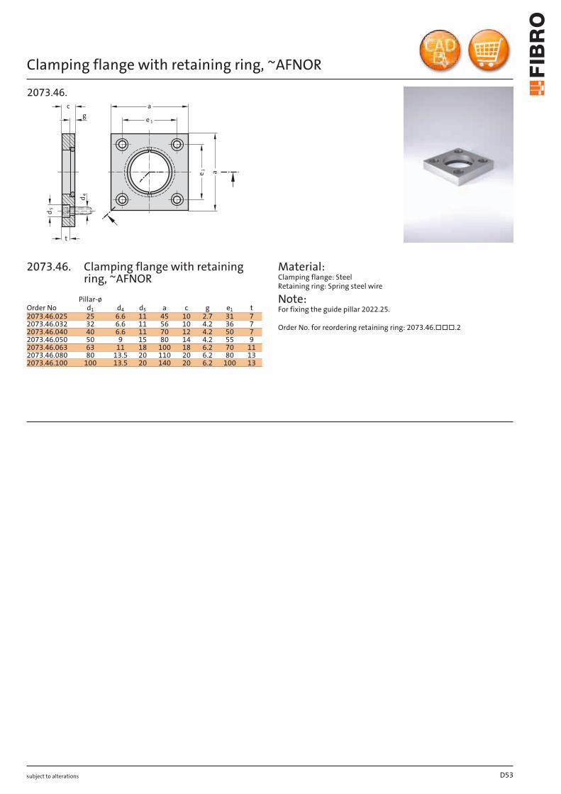
subject to alterations
Clamping flange with retaining ring, ~AFNOR
t
c
e 1
e 1
a
a
g
d 5
d 4
2073.46.
Material: Clamping flange: Steel Retaining ring: Spring steel wire
Note: For fixing the guide pillar 2022.25.
Order No. for reordering retaining ring: 2073.46.□□□.2
D53
Order NoPillar-ø
d1 d4 d5 a c g e1 t2073.46.025 25 6.6 11 45 10 2.7 31 72073.46.032 32 6.6 11 56 10 4.2 36 72073.46.040 40 6.6 11 70 12 4.2 50 72073.46.050 50 9 15 80 14 4.2 55 92073.46.063 63 11 18 100 18 6.2 70 112073.46.080 80 13.5 20 110 20 6.2 80 132073.46.100 100 13.5 20 140 20 6.2 100 13
2073.46. Clamping flange with retaining ring, ~AFNOR
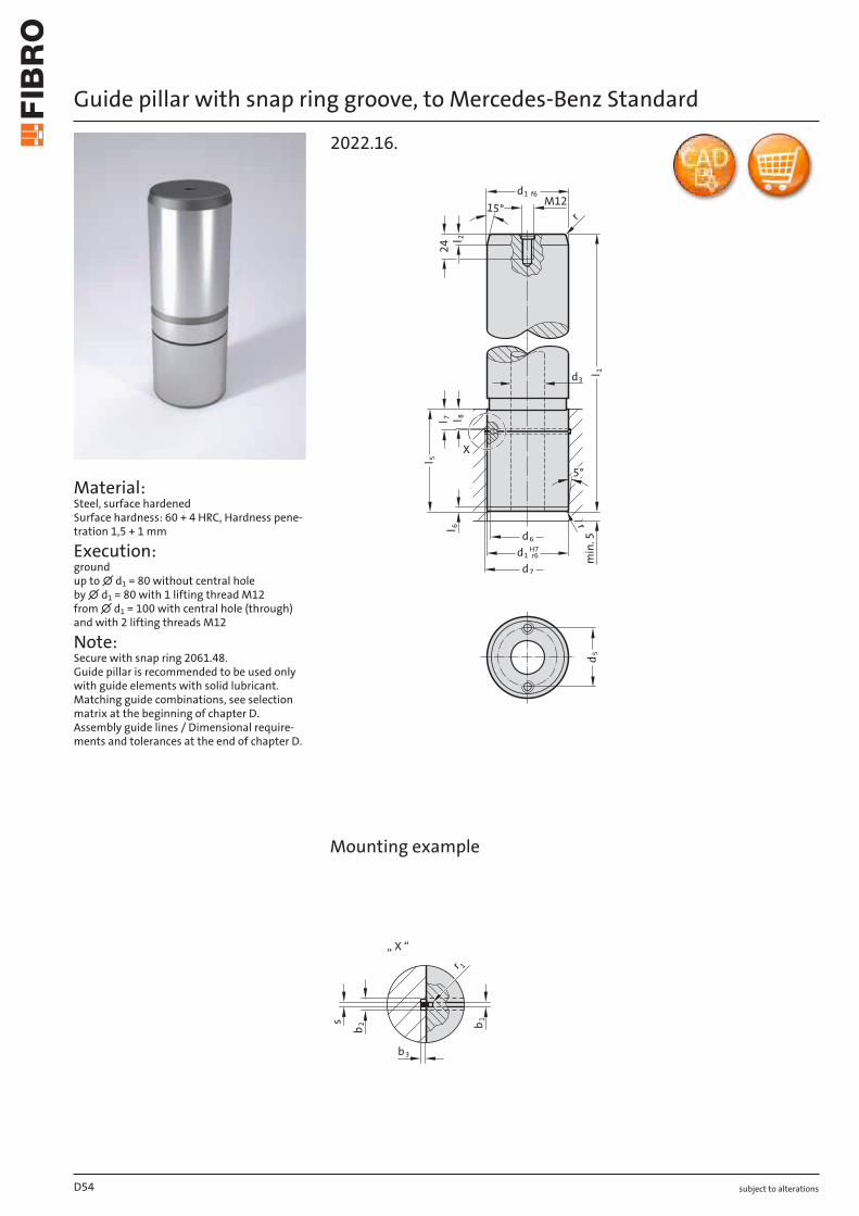
subject to alterations
Guide pillar with snap ring groove, to Mercedes-Benz Standard
Material: Steel, surface hardened Surface hardness: 60 + 4 HRC, Hardness pene-tration 1,5 + 1 mm
Execution: ground up to ∅ d1 = 80 without central hole by ∅ d1 = 80 with 1 lifting thread M12 from ∅ d1 = 100 with central hole (through) and with 2 lifting threads M12
Note: Secure with snap ring 2061.48. Guide pillar is recommended to be used only with guide elements with solid lubricant. Matching guide combinations, see selection matrix at the beginning of chapter D. Assembly guide lines / Dimensional require-ments and tolerances at the end of chapter D.
d5
15°
d3
5°
l 1
d7
d6
d1 r6H7
min
. 5
l 7 l 8
d1 f6
M12
l 2
l 5
l 62
4
r
r
X
2022.16.
X
„ X “
s b 1b 2
b3
r 1
Mounting example
D54
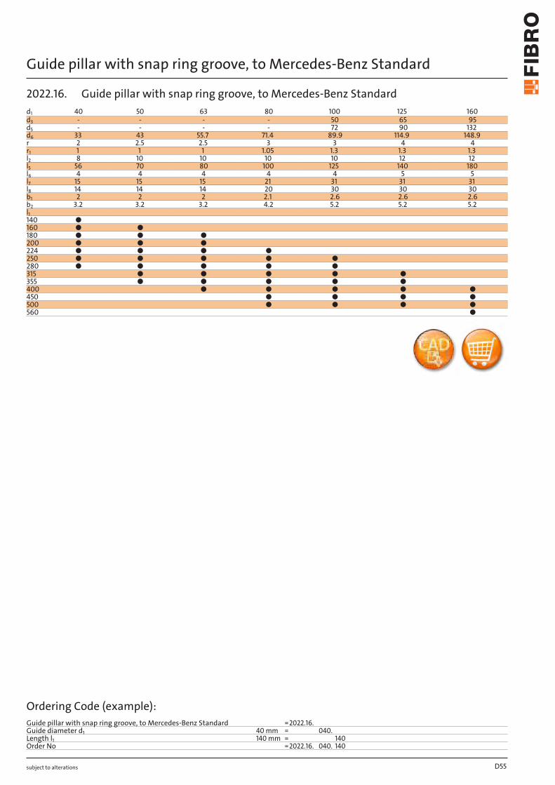
subject to alterations
Guide pillar with snap ring groove, to Mercedes-Benz Standard
D55
d1 40 50 63 80 100 125 160d3 - - - - 50 65 95d5 - - - - 72 90 132d6 33 43 55.7 71.4 89.9 114.9 148.9r 2 2.5 2.5 3 3 4 4r1 1 1 1 1.05 1.3 1.3 1.3l2 8 10 10 10 10 12 12l5 56 70 80 100 125 140 180l6 4 4 4 4 4 5 5l7 15 15 15 21 31 31 31l8 14 14 14 20 30 30 30b1 2 2 2 2.1 2.6 2.6 2.6b2 3.2 3.2 3.2 4.2 5.2 5.2 5.2l1140 ●160 ● ●180 ● ● ●200 ● ● ●224 ● ● ● ●250 ● ● ● ● ●280 ● ● ● ● ●315 ● ● ● ● ●355 ● ● ● ● ●400 ● ● ● ● ●450 ● ● ● ●500 ● ● ● ●560 ●
Ordering Code (example):Guide pillar with snap ring groove, to Mercedes-Benz Standard =2022.16.Guide diameter d1 40 mm = 040.Length l1 140 mm = 140Order No =2022.16. 040. 140
2022.16. Guide pillar with snap ring groove, to Mercedes-Benz Standard
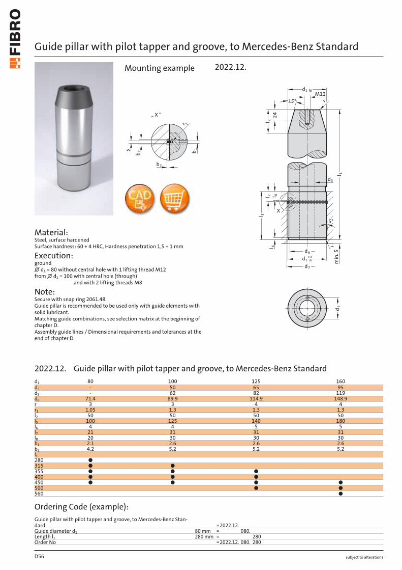
subject to alterations
Guide pillar with pilot tapper and groove, to Mercedes-Benz Standard
Material: Steel, surface hardened Surface hardness: 60 + 4 HRC, Hardness penetration 1,5 + 1 mm
Execution: ground ∅ d1 = 80 without central hole with 1 lifting thread M12 from ∅ d1 = 100 with central hole (through)
and with 2 lifting threads M8
Note: Secure with snap ring 2061.48. Guide pillar is recommended to be used only with guide elements with solid lubricant. Matching guide combinations, see selection matrix at the beginning of chapter D. Assembly guide lines / Dimensional requirements and tolerances at the end of chapter D.
„ X “
s b 1b 2
b3
r 1
3d
X
5°
l 1
d7
d6
1 r6dH7
min
. 5
8ll 7
r
1 f6dM12
15°
l 2
l 5
l 62
4
r
d5
2022.12.Mounting example
D56
d1 80 100 125 160d3 - 50 65 95d5 - 62 82 119d6 71.4 89.9 114.9 148.9r 3 3 4 4r1 1.05 1.3 1.3 1.3l2 50 50 50 50l5 100 125 140 180l6 4 4 5 5l7 21 31 31 31l8 20 30 30 30b1 2.1 2.6 2.6 2.6b2 4.2 5.2 5.2 5.2l1280 ●315 ● ●355 ● ● ●400 ● ● ●450 ● ● ● ●500 ● ●560 ●
Ordering Code (example):Guide pillar with pilot tapper and groove, to Mercedes-Benz Stan-dard =2022.12.Guide diameter d1 80 mm = 080.Length l1 280 mm = 280Order No =2022.12. 080. 280
2022.12. Guide pillar with pilot tapper and groove, to Mercedes-Benz Standard
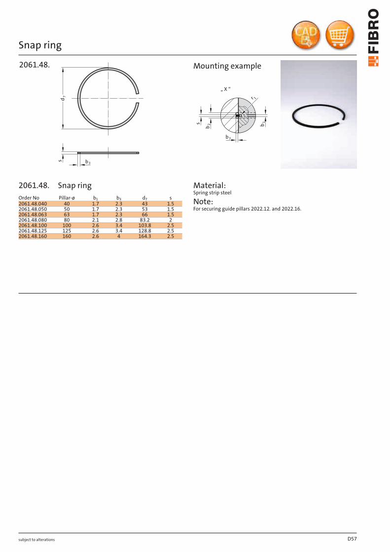
subject to alterations
Snap ringd
7
s b3
2061.48.
„ X “
s b 1b 2
b3
r 1
Mounting example
Material: Spring strip steel
Note: For securing guide pillars 2022.12. and 2022.16.
D57
Order No Pillar-ø b1 b3 d7 s2061.48.040 40 1.7 2.3 43 1.52061.48.050 50 1.7 2.3 53 1.52061.48.063 63 1.7 2.3 66 1.52061.48.080 80 2.1 2.8 83.2 22061.48.100 100 2.6 3.4 103.8 2.52061.48.125 125 2.6 3.4 128.8 2.52061.48.160 160 2.6 4 164.3 2.5
2061.48. Snap ring
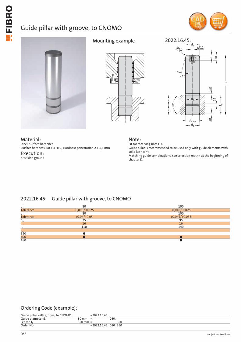
subject to alterations
Guide pillar with groove, to CNOMO
Material: Steel, surface hardened Surface hardness: 60 + 3 HRC, Hardness penetration 2 + 1,6 mm
Execution: precision ground
Note: Fit for receiving bore H7. Guide pillar is recommended to be used only with guide elements with solid lubricant. Matching guide combinations, see selection matrix at the beginning of chapter D.
10
15°
M12d1
d2
d2 -0,5
d6
R4,5
l 2
30
l 1
l 6
1210
==
90°
2022.16.45.Mounting example
D58
d1 80 100Tolerance -0,010/-0,025 -0,010/-0,025d2 80 100Tolerance +0,04/+0,05 +0,045/+0,055d6 75 95l2 16 16l6 110 140l1350 ●400 ● ●450 ●
Ordering Code (example):Guide pillar with groove, to CNOMO =2022.16.45.Guide diameter d1 80 mm = 080.Length l1 350 mm = 350Order No =2022.16.45. 080. 350
2022.16.45. Guide pillar with groove, to CNOMO
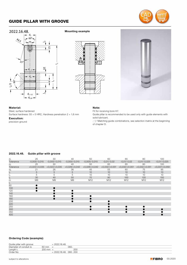
03.2020
3l
e
m
d
15°
1d
2 -0,5d
6d
R4,5 2l
25
1l
6l
10
90
°
1 -1
d2 p6
6l/2
60°
2022.16.48.
subject to alterations
GUIDE PILLAR WITH GROOVE
Material: Steel, surface hardened Surface hardness: 55 + 5 HRC, Hardness penetration 2 + 1,6 mm
Execution: precision ground
Note: Fit for receiving bore H7. Guide pillar is recommended to be used only with guide elements with solid lubricant. Matching guide combinations, see selection matrix at the beginning of chapter D.
Mounting example
2022.16.48. Guide pillar with groove
d1 25 30 40 50 60 65 80 100Tolerance -0,005/-0,015 -0,005/-0,015 -0,005/-0,015 -0,005/-0,015 -0,01/-0,02 -0,01/-0,02 -0,01/-0,025 -0,01/-0,025d2 25 30 40 50 60 65 80 100Tolerance +0,022/+0,035 +0,022/+0,035 +0,026/+0,042 +0,026/+0,042 +0,032/+0.051 +0,032/+0.051 +0,032/+0.051 +0,037/+0,059d6 21 26 36 45 55 60 75 95l2 5 5 5 10 10 10 10 10l3 5 5 5 10 10 10 10 10l6 30 40 50 70 90 100 120 150m M8 M8 M8 M12 M12 M12 M12 M12l81
0 ●100 ● ●120 ● ● ●140 ● ●160 ● ● ●180 ● ● ●200 ● ● ●220 ●250 ● ● ● ●300 ● ● ● ● ●350 ● ● ● ●400 ● ●
Ordering Code (example):
Guide pillar with groove = 2022.16.48.Diameter of conduit d1 60 mm = 060.Length l1 200 mm = 200Order No = 2022.16.48. 060. 200
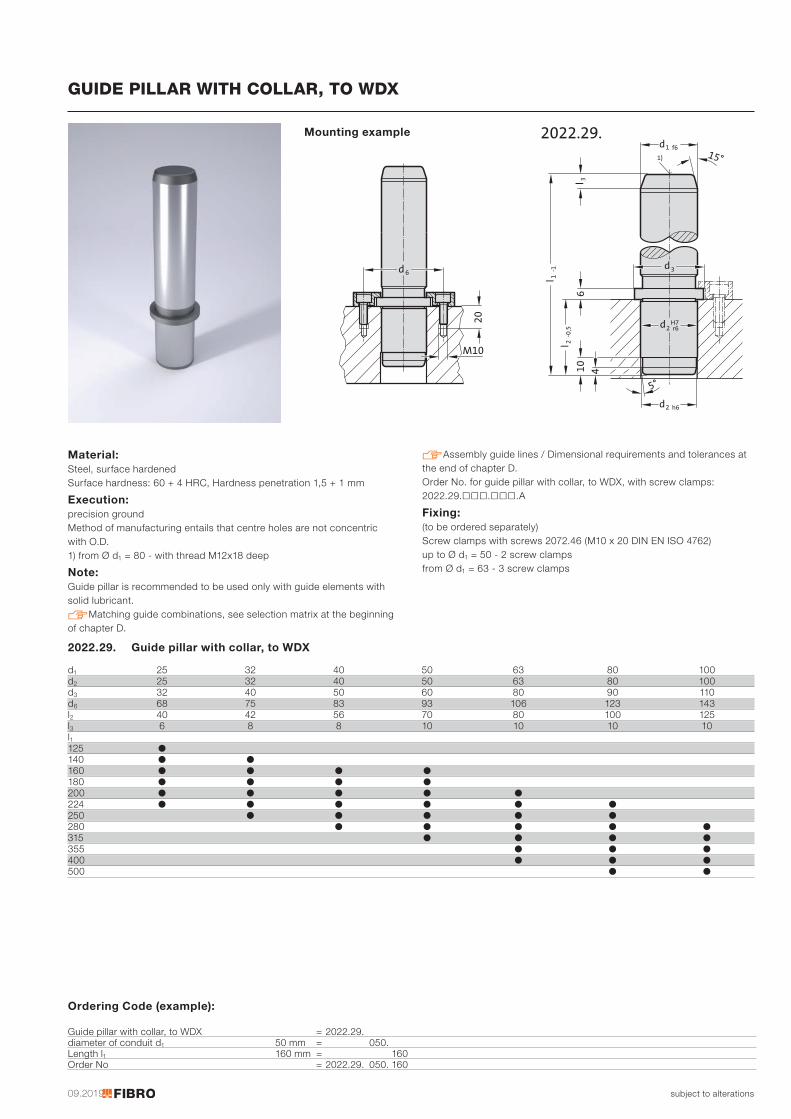
09.2019
l 3410
6l 2
-0,5
d2 h6
1 f6
5°
15°)1
d
l 1-1
d2H7r6
d3
2022.29.
20
d6
M10
subject to alterations
GUIDE PILLAR WITH COLLAR, TO WDX
Material: Steel, surface hardened Surface hardness: 60 + 4 HRC, Hardness penetration 1,5 + 1 mm
Execution: precision ground Method of manufacturing entails that centre holes are not concentric with O.D. 1) from Ø d1 = 80 - with thread M12x18 deep
Note:Guide pillar is recommended to be used only with guide elements with solid lubricant. Matching guide combinations, see selection matrix at the beginning of chapter D.
Assembly guide lines / Dimensional requirements and tolerances at the end of chapter D. Order No. for guide pillar with collar, to WDX, with screw clamps: 2022.29.□□□.□□□.A
Fixing: (to be ordered separately) Screw clamps with screws 2072.46 (M10 x 20 DIN EN ISO 4762) up to Ø d1 = 50 - 2 screw clamps from Ø d1 = 63 - 3 screw clamps
Mounting example
2022.29. Guide pillar with collar, to WDX
d1 25 32 40 50 63 80 100d2 25 32 40 50 63 80 100d3 32 40 50 60 80 90 110d6 68 75 83 93 106 123 143l2 40 42 56 70 80 100 125l3 6 8 8 10 10 10 10l1125 ●140 ● ●160 ● ● ● ●180 ● ● ● ●200 ● ● ● ● ●224 ● ● ● ● ● ●250 ● ● ● ● ●280 ● ● ● ● ●315 ● ● ● ●355 ● ● ●400 ● ● ●500 ● ●
Ordering Code (example):
Guide pillar with collar, to WDX = 2022.29.diameter of conduit d1 50 mm = 050.Length l1 160 mm = 160Order No = 2022.29. 050. 160

subject to alterations D61
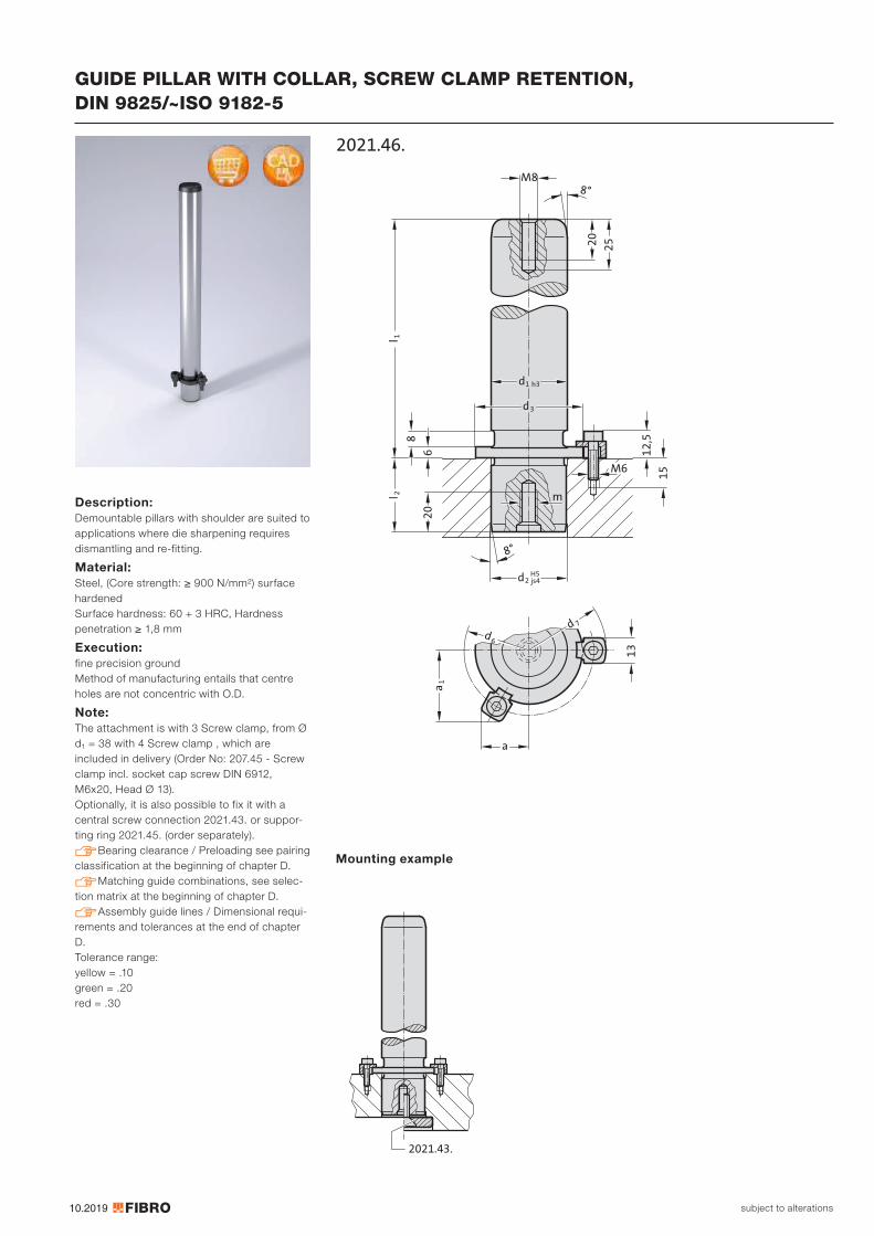
10.2019
M8
252
0
8
62
0
13
a1
a
d6
d 7
l 2l 1
M6
15
12
,5
8°
d2H5js4
8°
d1 h3
d3
m
2021.46.
2021.43.
subject to alterations
GUIDE PILLAR WITH COLLAR, SCREW CLAMP RETENTION, DIN 9825/~ISO 9182-5
Description: Demountable pillars with shoulder are suited to applications where die sharpening requires dismantling and re-fitting.
Material: Steel, (Core strength: ≥ 900 N/mm²) surface hardened Surface hardness: 60 + 3 HRC, Hardness penetration ≥ 1,8 mm
Execution: fine precision ground Method of manufacturing entails that centre holes are not concentric with O.D.
Note: The attachment is with 3 Screw clamp, from Ø d1 = 38 with 4 Screw clamp , which are included in delivery (Order No: 207.45 - Screw clamp incl. socket cap screw DIN 6912, M6x20, Head Ø 13). Optionally, it is also possible to fix it with a central screw connection 2021.43. or suppor-ting ring 2021.45. (order separately). Bearing clearance / Preloading see pairing classification at the beginning of chapter D. Matching guide combinations, see selec-tion matrix at the beginning of chapter D. Assembly guide lines / Dimensional requi-rements and tolerances at the end of chapter D.Tolerance range: yellow = .10 green = .20 red = .30
Mounting example
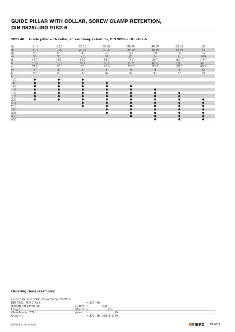
10.2019subject to alterations
GUIDE PILLAR WITH COLLAR, SCREW CLAMP RETENTION, DIN 9825/~ISO 9182-5
2021.46. Guide pillar with collar, screw clamp retention, DIN 9825/~ISO 9182-5
d1 15 16 19 20 24 25 30 32 38 40 48 50 60 63 80d2 15 16 19 20 24 25 30 32 38 40 48 50 60 63 80d3 22 25 32 40 50 63 80 95d6 33 36 43 51 61 74 91 106d7 45.7 48.7 55.7 63.7 73.7 86.7 103.7 118.7a 15.9 16.6 18.4 20.4 29.2 33.8 39.8 46.2a1 21.7 23 26 29.5 29.2 33.8 39.8 46.2m 8 8 8 8 8 8 8 12l2 20 23 30 37 37 47 47 60l1100 ● ● ●112 ● ● ● ●125 ● ● ● ● ●140 ● ● ● ● ● ●160 ● ● ● ● ● ● ●180 ● ● ● ● ● ● ●200 ● ● ● ● ● ● ● ●224 ● ● ● ● ● ●250 ● ● ● ● ● ●280 ● ● ● ● ●315 ● ● ● ● ●355 ● ● ● ●400 ● ● ●
Ordering Code (example):
Guide pillar with collar, screw clamp retention, DIN 9825/~ISO 9182-5 = 2021.46.diameter of conduit d1 32 mm = 032.Length l1 315 mm = 315.Classification TOL yellow = 10Order No = 2021.46. 032. 315. 10
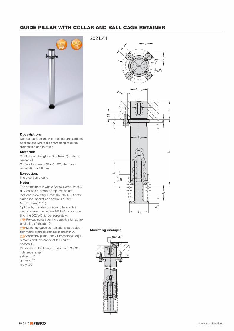
10.2019
m
12,5
15
6
l 1
d 1
d2 js4
8
M6
min
. 2
0
d 5
l 9
l 8
4
l 2
13
d7
d 6
a
a 1
2021.44.
Mounting example
2021.43
subject to alterations
GUIDE PILLAR WITH COLLAR AND BALL CAGE RETAINER
Description: Demountable pillars with shoulder are suited to applications where die sharpening requires dismantling and re-fitting.
Material: Steel, (Core strength: ≥ 900 N/mm²) surface hardened Surface hardness: 60 + 3 HRC, Hardness penetration ≥ 1,8 mm
Execution: fine precision ground
Note: The attachment is with 3 Screw clamp, from Ø d1 = 38 with 4 Screw clamp , which are included in delivery (Order No: 207.45 - Screw clamp incl. socket cap screw DIN 6912, M6x20, Head Ø 13). Optionally, it is also possible to fix it with a central screw connection 2021.43. or suppor-ting ring 2021.45. (order separately). Preloading see pairing classification at the beginning of chapter D Matching guide combinations, see selec-tion matrix at the beginning of chapter D. Assembly guide lines / Dimensional requi-rements and tolerances at the end of chapter D. Dimensions of ball cage retainer see 202.91.Tolerance range: yellow = .10 green = .20 red = .30
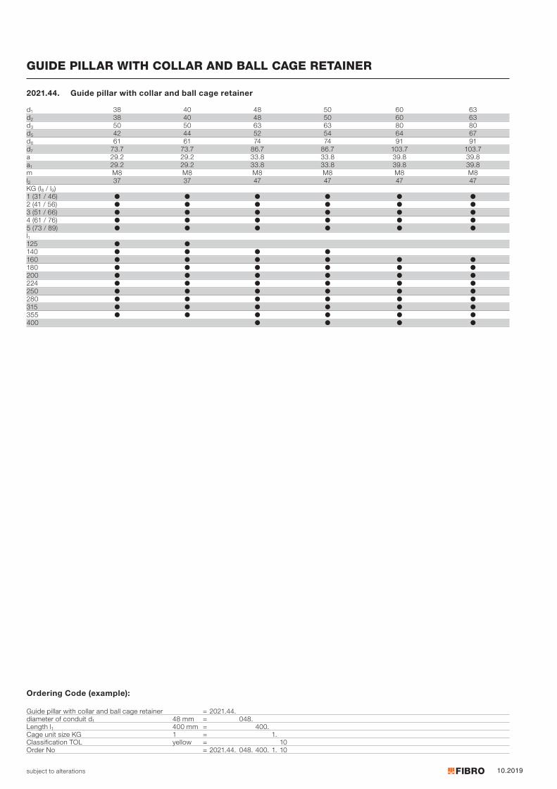
10.2019subject to alterations
GUIDE PILLAR WITH COLLAR AND BALL CAGE RETAINER
d1 38 40 48 50 60 63d2 38 40 48 50 60 63d3 50 50 63 63 80 80d5 42 44 52 54 64 67d6 61 61 74 74 91 91d7 73.7 73.7 86.7 86.7 103.7 103.7a 29.2 29.2 33.8 33.8 39.8 39.8a1 29.2 29.2 33.8 33.8 39.8 39.8m M8 M8 M8 M8 M8 M8l2 37 37 47 47 47 47KG (l8 / l9)1 (31 / 46) ● ● ● ● ● ●2 (41 / 56) ● ● ● ● ● ●3 (51 / 66) ● ● ● ● ● ●4 (61 / 76) ● ● ● ● ● ●5 (73 / 89) ● ● ● ● ● ●l1125 ● ●140 ● ● ● ●160 ● ● ● ● ● ●180 ● ● ● ● ● ●200 ● ● ● ● ● ●224 ● ● ● ● ● ●250 ● ● ● ● ● ●280 ● ● ● ● ● ●315 ● ● ● ● ● ●355 ● ● ● ● ● ●400 ● ● ● ●
2021.44. Guide pillar with collar and ball cage retainer
Ordering Code (example):
Guide pillar with collar and ball cage retainer = 2021.44.diameter of conduit d1 48 mm = 048.Length l1 400 mm = 400.Cage unit size KG 1 = 1.Classification TOL yellow = 10Order No = 2021.44. 048. 400. 1. 10
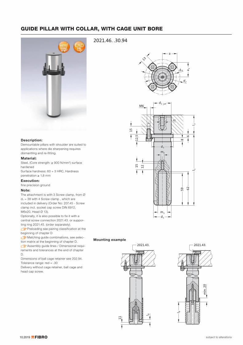
10.2019
m1
62
59
15
12
m
12
,5
15
6
d2 js4
8
M6
l 2
13
d7
d 6
a
a1
l 1
d1
m2
d3
2021.46. .30.94
11
2021.43. 2021.43.
min
. 20
l 8
l 8
subject to alterations
GUIDE PILLAR WITH COLLAR, WITH CAGE UNIT BORE
Description: Demountable pillars with shoulder are suited to applications where die sharpening requires dismantling and re-fitting.
Material: Steel, (Core strength: ≥ 900 N/mm²) surface hardened Surface hardness: 60 + 3 HRC, Hardness penetration ≥ 1,8 mm
Execution: fine precision ground
Note: The attachment is with 3 Screw clamp, from Ø d1 = 38 with 4 Screw clamp , which are included in delivery (Order No: 207.45 - Screw clamp incl. socket cap screw DIN 6912, M6x20, Head Ø 13). Optionally, it is also possible to fix it with a central screw connection 2021.43. or suppor-ting ring 2021.45. (order separately). Preloading see pairing classification at the beginning of chapter D Matching guide combinations, see selec-tion matrix at the beginning of chapter D. Assembly guide lines / Dimensional requi-rements and tolerances at the end of chapter D. Dimensions of ball cage retainer see 202.94. Tolerance range: red = .30 Delivery without cage retainer, ball cage and head cap screw.
Mounting example
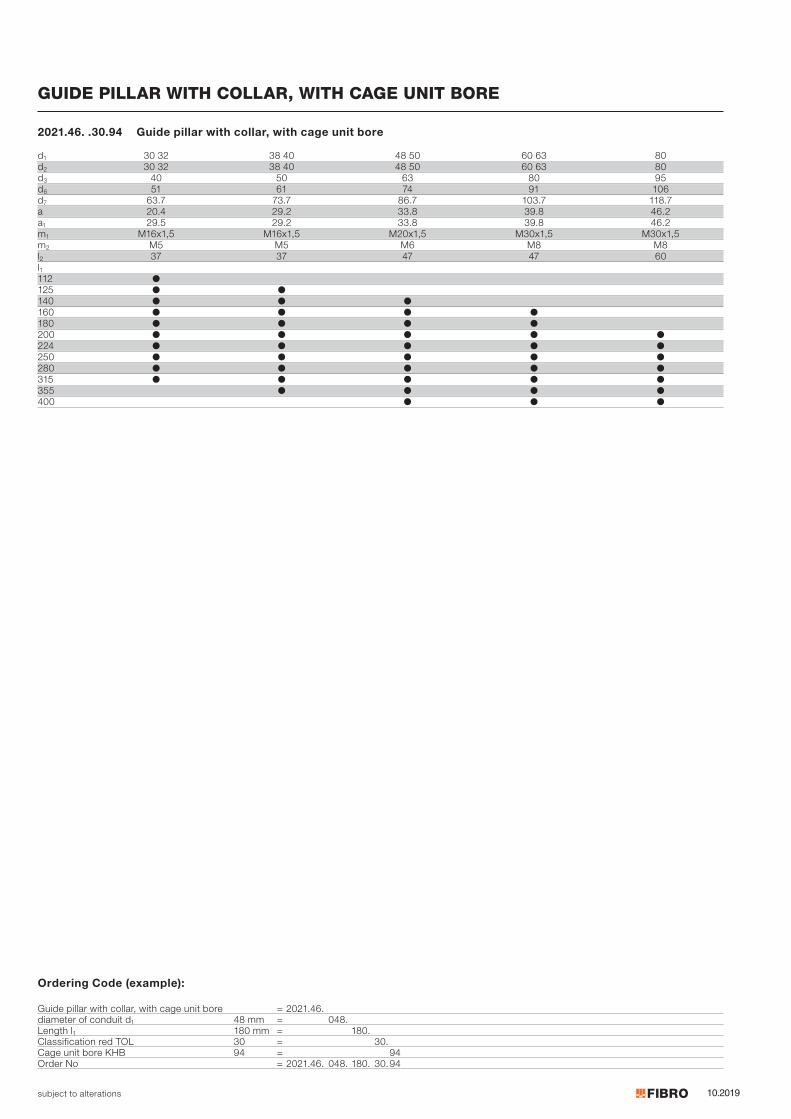
10.2019subject to alterations
Ordering Code (example):
Guide pillar with collar, with cage unit bore = 2021.46.diameter of conduit d1 48 mm = 048.Length l1 180 mm = 180.Classification red TOL 30 = 30.Cage unit bore KHB 94 = 94Order No = 2021.46. 048. 180. 30.94
GUIDE PILLAR WITH COLLAR, WITH CAGE UNIT BORE
2021.46. .30.94 Guide pillar with collar, with cage unit bore
d1 30 32 38 40 48 50 60 63 80d2 30 32 38 40 48 50 60 63 80d3 40 50 63 80 95d6 51 61 74 91 106d7 63.7 73.7 86.7 103.7 118.7a 20.4 29.2 33.8 39.8 46.2a1 29.5 29.2 33.8 39.8 46.2m1 M16x1,5 M16x1,5 M20x1,5 M30x1,5 M30x1,5m2 M5 M5 M6 M8 M8l2 37 37 47 47 60l1112 ●125 ● ●140 ● ● ●160 ● ● ● ●180 ● ● ● ●200 ● ● ● ● ●224 ● ● ● ● ●250 ● ● ● ● ●280 ● ● ● ● ●315 ● ● ● ● ●355 ● ● ● ●400 ● ● ●

10.2019
13
6
8
M
a
2dH6j6
d3
1d
f6
6d
7d
a1
l 2l 1
2021.28.M8
2520
8°
2021.43.
subject to alterations
GUIDE PILLAR WITH COLLAR
Material: Steel, surface hardened Surface hardness: 60 + 4 HRC, Hardness penetration 1,5 + 1 mm
Execution: ground Method of manufacturing entails that centre holes are not concentric with O.D.
Note: Guide pillars only recommended for use with sliding guides! The attachment is with 3 Screw clamp, from Ø d1 = 38 with 4 Screw clamp , which are included in delivery (Order No: 207.45 - Screw clamp incl. socket cap screw DIN 6912, M6x20, Head Ø 13). Optionally, it is also possible to fix it with a central screw connection 2021.43. or suppor-ting ring 2021.45. (order separately). Matching guide combinations, see selec-tion matrix at the beginning of chapter D. Assembly guide lines / Dimensional requi-rements and tolerances at the end of chapter D. Mounting example

10.2019subject to alterations
GUIDE PILLAR WITH COLLAR
2021.28. Guide pillar with collar
Ordering Code (example):
Guide pillar with collar = 2021.28.diameter of conduit d1 32 mm = 032.Length l1 112 mm = 112Order No = 2021.28. 032. 112
d1 15 16 19 20 24 25 30 32 38 40 48 50 60 63 80d2 15 16 19 20 24 25 30 32 38 40 48 50 60 63 80d3 22 25 32 40 50 63 80 95d6 33 36 43 51 61 74 91 106d7 45.7 48.7 55.7 63.7 73.7 86.7 103.7 118.7a 15.9 16.6 18.4 20.4 29.2 33.8 39.8 46.2a1 21.7 23 26 29.5 29.2 33.8 39.8 46.2m M8 M8 M8 M8 M8 M8 M8 M12l2 20 23 30 37 37 47 47 60l1100 ● ● ●112 ● ● ● ●125 ● ● ● ● ●140 ● ● ● ● ● ●160 ● ● ● ● ● ● ●180 ● ● ● ● ● ● ●200 ● ● ● ● ● ● ● ●224 ● ● ● ● ● ●250 ● ● ● ● ● ●280 ● ● ● ● ●315 ● ● ● ● ●355 ● ● ● ●400 ● ● ●
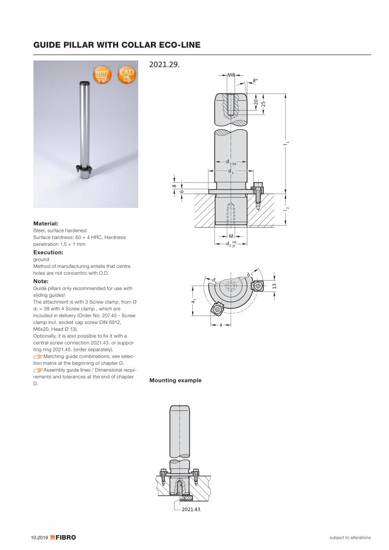
10.2019
13
6
8
M
a
2dH6j6
d3
1d
h4
6d
7d
a1
l 2l 1
2021.29.M8
2520
8°
2021.43.
subject to alterations
GUIDE PILLAR WITH COLLAR ECO-LINE
Material: Steel, surface hardened Surface hardness: 60 + 4 HRC, Hardness penetration 1,5 + 1 mm
Execution: ground Method of manufacturing entails that centre holes are not concentric with O.D.
Note: Guide pillars only recommended for use with sliding guides! The attachment is with 3 Screw clamp, from Ø d1 = 38 with 4 Screw clamp , which are included in delivery (Order No: 207.45 - Screw clamp incl. socket cap screw DIN 6912, M6x20, Head Ø 13). Optionally, it is also possible to fix it with a central screw connection 2021.43. or suppor-ting ring 2021.45. (order separately). Matching guide combinations, see selec-tion matrix at the beginning of chapter D. Assembly guide lines / Dimensional requi-rements and tolerances at the end of chapter D.
Mounting example
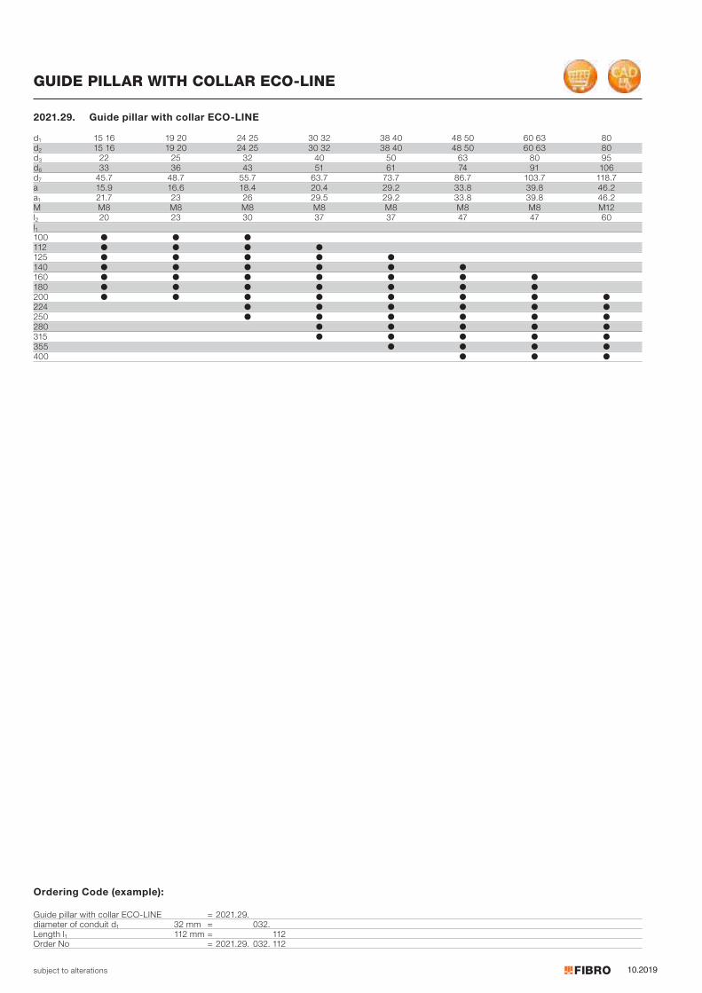
10.2019subject to alterations
GUIDE PILLAR WITH COLLAR ECO-LINE
d1 15 16 19 20 24 25 30 32 38 40 48 50 60 63 80d2 15 16 19 20 24 25 30 32 38 40 48 50 60 63 80d3 22 25 32 40 50 63 80 95d6 33 36 43 51 61 74 91 106d7 45.7 48.7 55.7 63.7 73.7 86.7 103.7 118.7a 15.9 16.6 18.4 20.4 29.2 33.8 39.8 46.2a1 21.7 23 26 29.5 29.2 33.8 39.8 46.2M M8 M8 M8 M8 M8 M8 M8 M12l2 20 23 30 37 37 47 47 60l1100 ● ● ●112 ● ● ● ●125 ● ● ● ● ●140 ● ● ● ● ● ●160 ● ● ● ● ● ● ●180 ● ● ● ● ● ● ●200 ● ● ● ● ● ● ● ●224 ● ● ● ● ● ●250 ● ● ● ● ● ●280 ● ● ● ● ●315 ● ● ● ● ●355 ● ● ● ●400 ● ● ●
2021.29. Guide pillar with collar ECO-LINE
Ordering Code (example):
Guide pillar with collar ECO-LINE = 2021.29.diameter of conduit d1 32 mm = 032.Length l1 112 mm = 112Order No = 2021.29. 032. 112
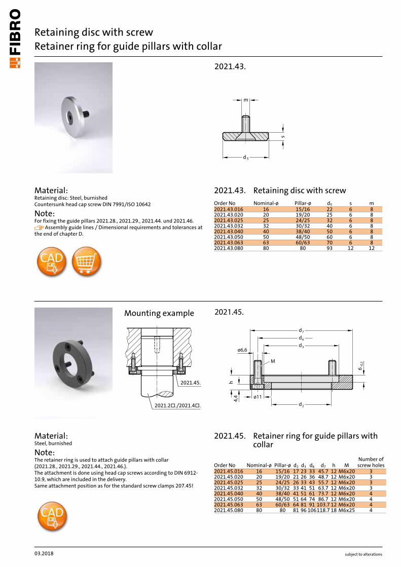
subject to alterations
Retaining disc with screwRetainer ring for guide pillars with collar
Material: Retaining disc: Steel, burnished Countersunk head cap screw DIN 7991/ISO 10642
Note: For fixing the guide pillars 2021.28., 2021.29., 2021.44. und 2021.46. Assembly guide lines / Dimensional requirements and tolerances at the end of chapter D.
Material: Steel, burnished
Note: The retainer ring is used to attach guide pillars with collar (2021.28., 2021.29., 2021.44., 2021.46.). The attachment is done using head cap screws according to DIN 6912- 10.9, which are included in the delivery. Same attachment position as for the standard screw clamps 207.45!
2021.45.
2021.2�./2021.4�.
Mounting example
m
s
d5
2021.43.
2021.45.
ø11
6-0
,2
d7
d6
d3
d2
4,4
h
ø6,6
M
03.2018
Order No Nominal-ø Pillar-ø d5 s m2021.43.016 16 15/16 22 6 82021.43.020 20 19/20 25 6 82021.43.025 25 24/25 32 6 82021.43.032 32 30/32 40 6 82021.43.040 40 38/40 50 6 82021.43.050 50 48/50 60 6 82021.43.063 63 60/63 70 6 82021.43.080 80 80 93 12 12
Order No Nominal-ø Pillar-ø d2 d3 d6 d7 h MNumber of screw holes
2021.45.016 16 15/16 17 23 33 45.7 12 M6x20 32021.45.020 20 19/20 21 26 36 48.7 12 M6x20 32021.45.025 25 24/25 26 33 43 55.7 12 M6x20 32021.45.032 32 30/32 33 41 51 63.7 12 M6x20 32021.45.040 40 38/40 41 51 61 73.7 12 M6x20 42021.45.050 50 48/50 51 64 74 86.7 12 M6x20 42021.45.063 63 60/63 64 81 91 103.7 12 M6x20 42021.45.080 80 80 81 96 106118.7 18 M6x25 4
2021.43.
2021.45. Retainer ring for guide pillars with collar
Retaining disc with screw
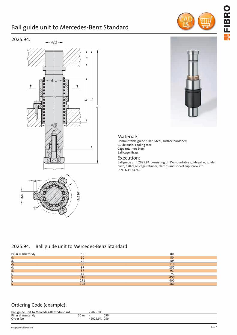
subject to alterations
Ball guide unit to Mercedes-Benz Standardø2
3
d2R6js4
d9
d1 h3
d5
d3H5js4
d 6
3x12
0°
8
l 3
l 6 l 4
l 2
2025.94.
Material: Demountable guide pillar: Steel, surface hardened Guide bush: Tooling steel Cage retainer: Steel Ball cage: Brass
Execution: Ball guide unit 2025.94. consisting of: Demountable guide pillar, guide bush, ball cage, cage retainer, clamps and socket cap screws to DIN EN ISO 4762.
D67
Pillar diameter d1 50 80d2 50 80d3 70 105d5 80 118d6 97 135d9 57 91l2 47 75l3 316 450l4 271 400l6 128 160
Ordering Code (example):Ball guide unit to Mercedes-Benz Standard =2025.94.Pillar diameter d1 50 mm = 050Order No =2025.94. 050
2025.94. Ball guide unit to Mercedes-Benz Standard
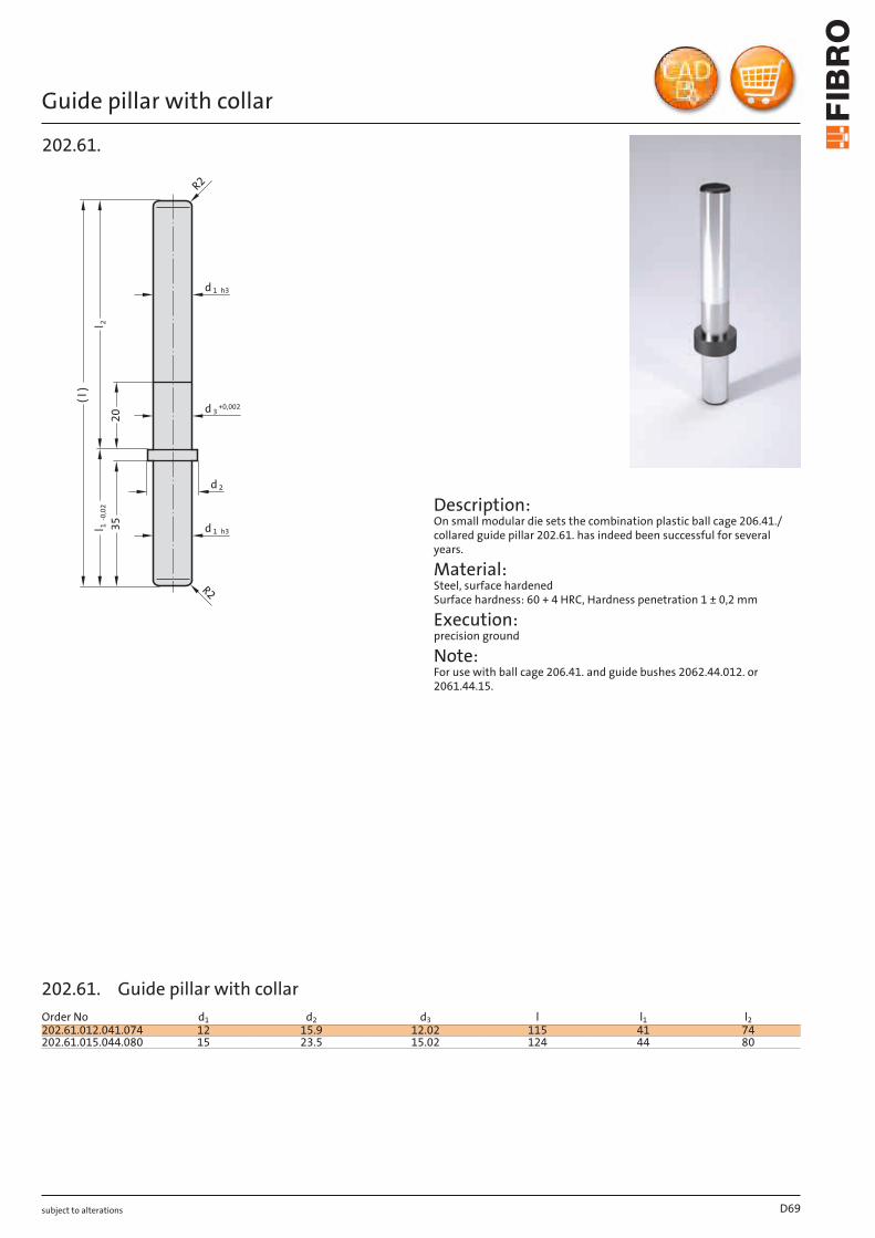
subject to alterations
Guide pillar with collar
+0,002
2ll 1
-0,0
2
( l )
d 2
d 3
d 1 h3
1 h3
R2
20
35
d
R2
202.61.
Description: On small modular die sets the combination plastic ball cage 206.41./ collared guide pillar 202.61. has indeed been successful for several years.
Material: Steel, surface hardened Surface hardness: 60 + 4 HRC, Hardness penetration 1 ± 0,2 mm
Execution: precision ground
Note: For use with ball cage 206.41. and guide bushes 2062.44.012. or 2061.44.15.
D69
Order No d1 d2 d3 l l1 l2202.61.012.041.074 12 15.9 12.02 115 41 74202.61.015.044.080 15 23.5 15.02 124 44 80
202.61. Guide pillar with collar
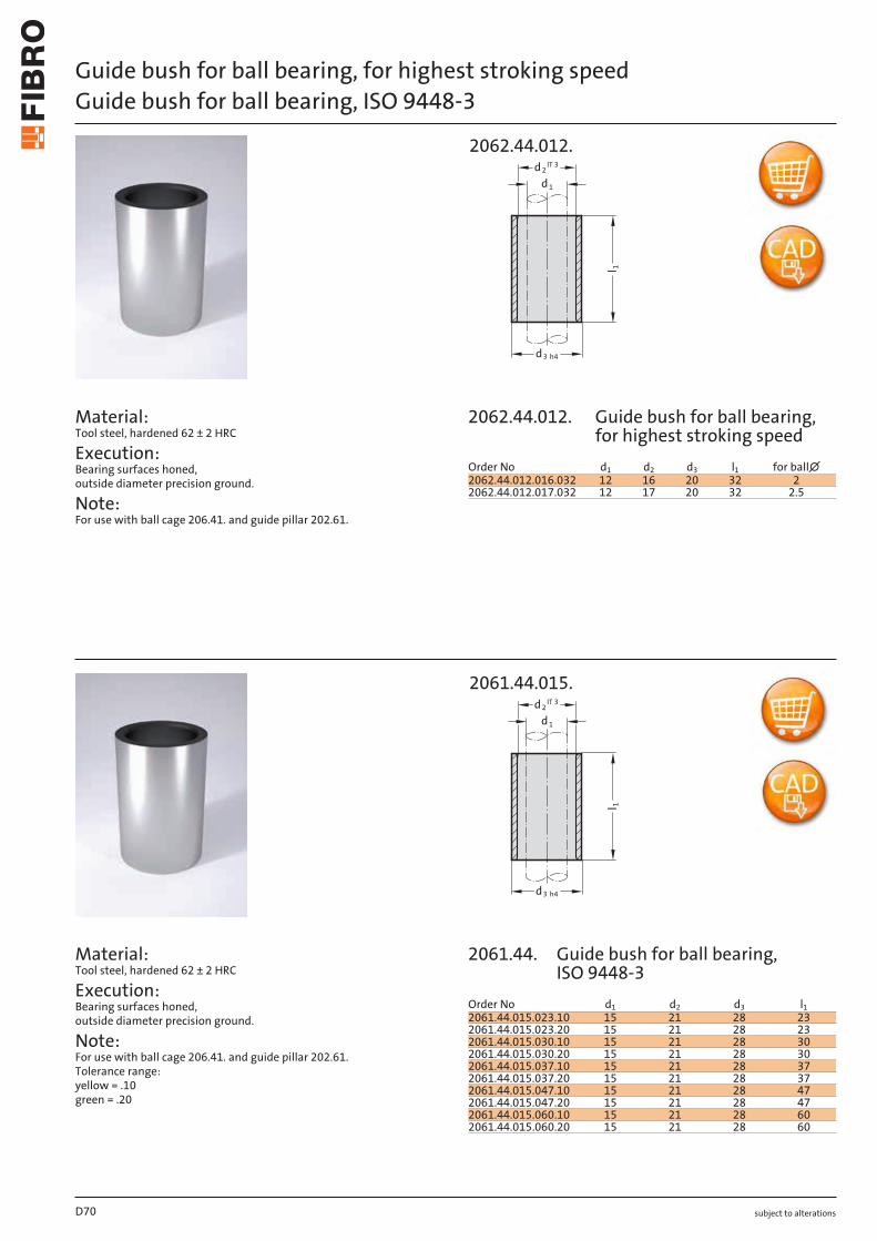
subject to alterations
Guide bush for ball bearing, for highest stroking speedGuide bush for ball bearing, ISO 9448-3
Material: Tool steel, hardened 62 ± 2 HRC
Execution: Bearing surfaces honed, outside diameter precision ground.
Note: For use with ball cage 206.41. and guide pillar 202.61.
Material: Tool steel, hardened 62 ± 2 HRC
Execution: Bearing surfaces honed, outside diameter precision ground.
Note: For use with ball cage 206.41. and guide pillar 202.61. Tolerance range: yellow = .10 green = .20
l 1
3
d
d h4
2d IT 3
1
2062.44.012.
l 1
3
d
d h4
2d IT 3
1
2061.44.015.
D70
Order No d1 d2 d3 l1 for ball∅2062.44.012.016.032 12 16 20 32 22062.44.012.017.032 12 17 20 32 2.5
Order No d1 d2 d3 l12061.44.015.023.10 15 21 28 232061.44.015.023.20 15 21 28 232061.44.015.030.10 15 21 28 302061.44.015.030.20 15 21 28 302061.44.015.037.10 15 21 28 372061.44.015.037.20 15 21 28 372061.44.015.047.10 15 21 28 472061.44.015.047.20 15 21 28 472061.44.015.060.10 15 21 28 602061.44.015.060.20 15 21 28 60
2062.44.012.
2061.44. Guide bush for ball bearing, ISO 9448-3
Guide bush for ball bearing, for highest stroking speed
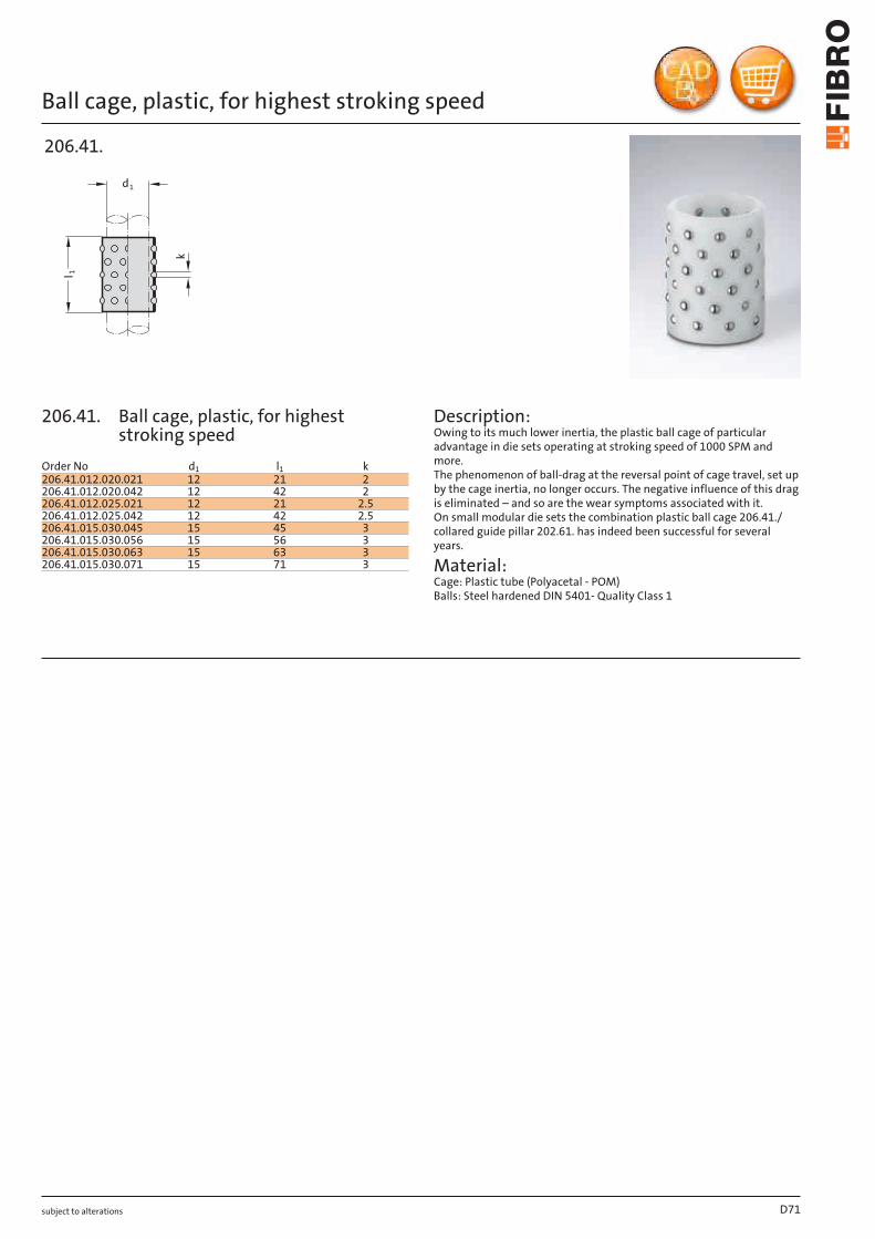
subject to alterations
Ball cage, plastic, for highest stroking speed
dk
l 1
1
206.41.
Description: Owing to its much lower inertia, the plastic ball cage of particular advantage in die sets operating at stroking speed of 1000 SPM and more. The phenomenon of ball-drag at the reversal point of cage travel, set up by the cage inertia, no longer occurs. The negative influence of this drag is eliminated – and so are the wear symptoms associated with it. On small modular die sets the combination plastic ball cage 206.41./ collared guide pillar 202.61. has indeed been successful for several years.
Material: Cage: Plastic tube (Polyacetal - POM) Balls: Steel hardened DIN 5401- Quality Class 1
D71
Order No d1 l1 k206.41.012.020.021 12 21 2206.41.012.020.042 12 42 2206.41.012.025.021 12 21 2.5206.41.012.025.042 12 42 2.5206.41.015.030.045 15 45 3206.41.015.030.056 15 56 3206.41.015.030.063 15 63 3206.41.015.030.071 15 71 3
206.41. Ball cage, plastic, for highest stroking speed
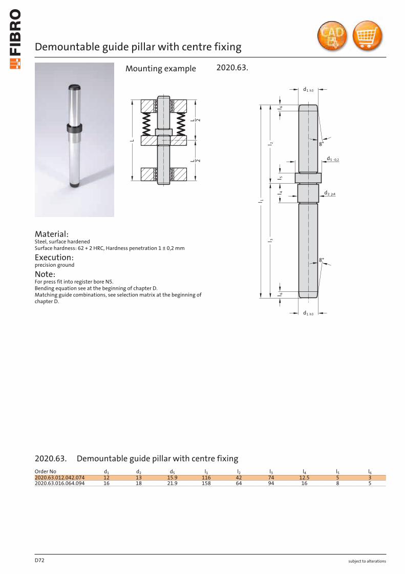
subject to alterations
Demountable guide pillar with centre fixing
Material: Steel, surface hardened Surface hardness: 62 + 2 HRC, Hardness penetration 1 ± 0,2 mm
Execution: precision ground
Note: For press fit into register bore N5. Bending equation see at the beginning of chapter D. Matching guide combinations, see selection matrix at the beginning of chapter D.
L
LL
22
l
8°
8°
d1 h3
d1 h3
l 3l 2
l 1
l 4l 5
6l 6
d2 js4
d5 -0,2
2020.63.Mounting example
D72
Order No d1 d2 d5 l1 l2 l3 l4 l5 l62020.63.012.042.074 12 13 15.9 116 42 74 12.5 5 32020.63.016.064.094 16 18 21.9 158 64 94 16 8 5
2020.63. Demountable guide pillar with centre fixing

subject to alterations D73
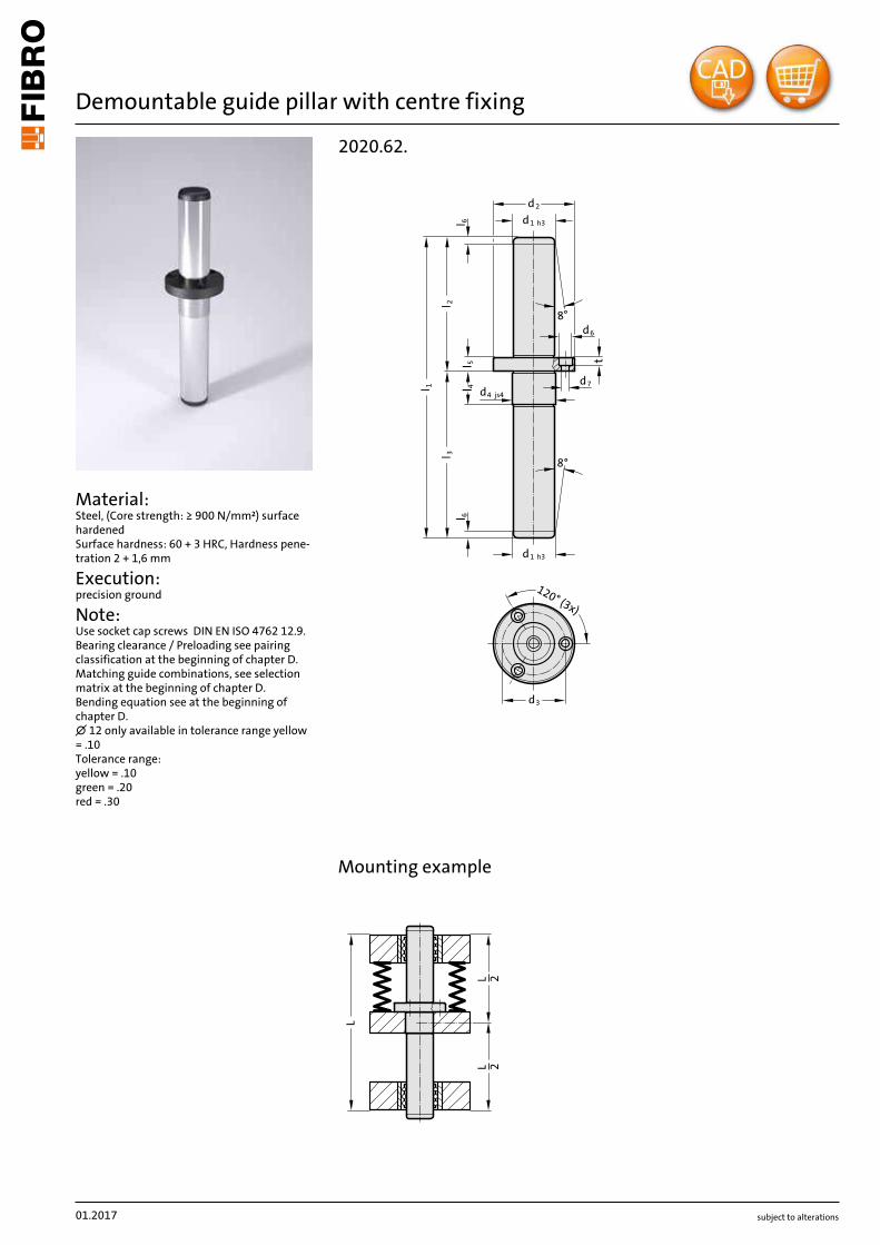
subject to alterations
Demountable guide pillar with centre fixing
Material: Steel, (Core strength: ≥ 900 N/mm²) surface hardened Surface hardness: 60 + 3 HRC, Hardness pene-tration 2 + 1,6 mm
Execution: precision ground
Note: Use socket cap screws DIN EN ISO 4762 12.9. Bearing clearance / Preloading see pairing classification at the beginning of chapter D. Matching guide combinations, see selection matrix at the beginning of chapter D. Bending equation see at the beginning of chapter D. ∅ 12 only available in tolerance range yellow = .10 Tolerance range: yellow = .10 green = .20 red = .30
t
d4 js4
d1 h3
l 6
120° (3x)
d3
l 6l 5
4ll
l 3l 2
l 1
8°
8°
dd1 h3
d6
d7
2
2020.62.
X
L
LL
22
Mounting example
01.2017
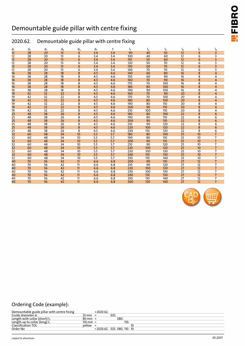
subject to alterations
Demountable guide pillar with centre fixing
01.2017
d1 d2 d3 d4 d6 d7 t l1 l2 l3 l4 l5 l612 28 20 13 6 3.4 3.4 90 40 50 12 6 312 28 20 13 6 3.4 3.4 100 40 60 12 6 312 28 20 13 6 3.4 3.4 110 50 60 12 6 312 28 20 13 6 3.4 3.4 120 50 70 12 6 312 28 20 13 6 3.4 3.4 130 60 70 12 6 312 28 20 13 6 3.4 3.4 140 70 70 12 6 316 38 28 18 8 4.5 4.6 140 60 80 16 8 416 38 28 18 8 4.5 4.6 150 60 90 16 8 416 38 28 18 8 4.5 4.6 160 70 90 16 8 416 38 28 18 8 4.5 4.6 170 70 100 16 8 416 38 28 18 8 4.5 4.6 180 80 100 16 8 416 38 28 18 8 4.5 4.6 190 90 100 16 8 419 42 32 22 8 4.5 4.6 160 70 90 20 8 419 42 32 22 8 4.5 4.6 170 70 100 20 8 419 42 32 22 8 4.5 4.6 180 80 100 20 8 419 42 32 22 8 4.5 4.6 190 80 110 20 8 419 42 32 22 8 4.5 4.6 200 90 110 20 8 419 42 32 22 8 4.5 4.6 210 100 110 20 8 425 48 38 26 8 4.5 4.6 180 80 100 22 8 625 48 38 26 8 4.5 4.6 190 80 110 22 8 625 48 38 26 8 4.5 4.6 200 90 110 22 8 625 48 38 26 8 4.5 4.6 210 90 120 22 8 625 48 38 26 8 4.5 4.6 220 100 120 22 8 625 48 38 26 8 4.5 4.6 230 110 120 22 8 632 60 48 34 10 5.5 5.7 180 80 100 25 10 732 60 48 34 10 5.5 5.7 190 80 110 25 10 732 60 48 34 10 5.5 5.7 200 90 110 25 10 732 60 48 34 10 5.5 5.7 210 90 120 25 10 732 60 48 34 10 5.5 5.7 220 100 120 25 10 732 60 48 34 10 5.5 5.7 230 100 130 25 10 732 60 48 34 10 5.5 5.7 240 110 130 25 10 732 60 48 34 10 5.5 5.7 250 110 140 25 10 740 70 56 42 11 6.6 6.8 200 90 110 27 12 740 70 56 42 11 6.6 6.8 210 90 120 27 12 740 70 56 42 11 6.6 6.8 220 100 120 27 12 740 70 56 42 11 6.6 6.8 230 100 130 27 12 740 70 56 42 11 6.6 6.8 240 110 130 27 12 740 70 56 42 11 6.6 6.8 250 110 140 27 12 740 70 56 42 11 6.6 6.8 260 120 140 27 12 7
Ordering Code (example):Demountable guide pillar with centre fixing =2020.62.Guide diameter d1 25 mm = 025.Length with collar (short) l2 80 mm = 080.Length up to collar (long) l3 110 mm = 110.Classification TOL yellow = 10Order No =2020.62. 025. 080. 110. 10
2020.62. Demountable guide pillar with centre fixing
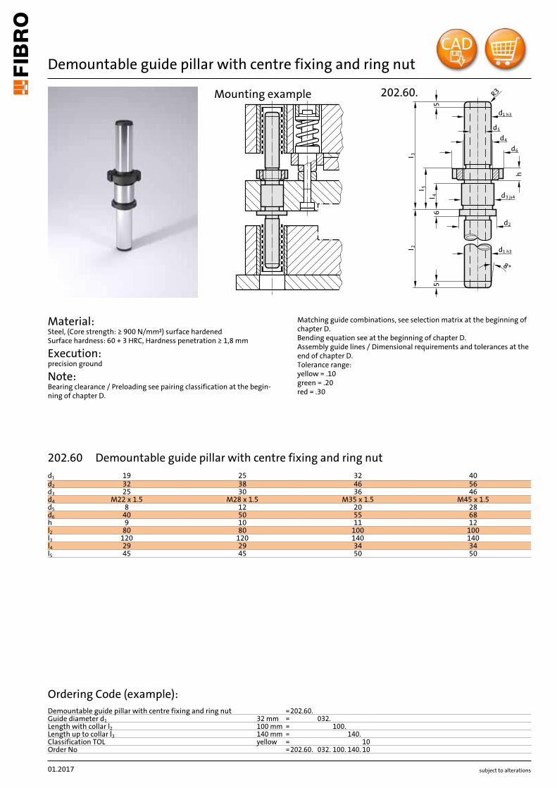
subject to alterations
Demountable guide pillar with centre fixing and ring nut
Material: Steel, (Core strength: ≥ 900 N/mm²) surface hardened Surface hardness: 60 + 3 HRC, Hardness penetration ≥ 1,8 mm
Execution: precision ground
Note: Bearing clearance / Preloading see pairing classification at the begin-ning of chapter D.
Matching guide combinations, see selection matrix at the beginning of chapter D. Bending equation see at the beginning of chapter D. Assembly guide lines / Dimensional requirements and tolerances at the end of chapter D. Tolerance range: yellow = .10 green = .20 red = .30
I 2I 3
I 5
8°
56
5
h
d5
d1 h3
R3
2
d3 js4I 4
d
d1 h3
d4
d6
202.60.Mounting example
01.2017
d1 19 25 32 40d2 32 38 46 56d3 25 30 36 46d4 M22 x 1.5 M28 x 1.5 M35 x 1.5 M45 x 1.5d5 8 12 20 28d6 40 50 55 68h 9 10 11 12l2 80 80 100 100l3 120 120 140 140l4 29 29 34 34l5 45 45 50 50
Ordering Code (example):Demountable guide pillar with centre fixing and ring nut =202.60.Guide diameter d1 32 mm = 032.Length with collar l2 100 mm = 100.Length up to collar l3 140 mm = 140.Classification TOL yellow = 10Order No =202.60. 032. 100. 140. 10
202.60 Demountable guide pillar with centre fixing and ring nut
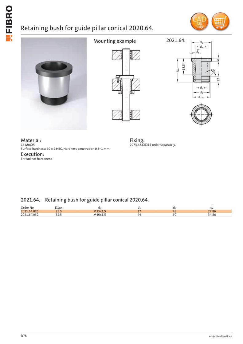
subject to alterations
Retaining bush for guide pillar conical 2020.64.
Material: 16 MnCr5 Surface hardness: 60 ± 2 HRC, Hardness penetration 0,8–1 mm
Execution: Thread not hardenend
Fixing: 2073.48.□□15 order separately.
2°
612
51 33,84
45°
d3 n5
d2
d1
d5
d6
2021.64.Mounting example
D78
Order No D1xx d2 d3 d5 d62021.64.025 25.5 M35x1,5 37 43 27.862021.64.032 32.5 M40x1,5 44 50 34.86
2021.64. Retaining bush for guide pillar conical 2020.64.
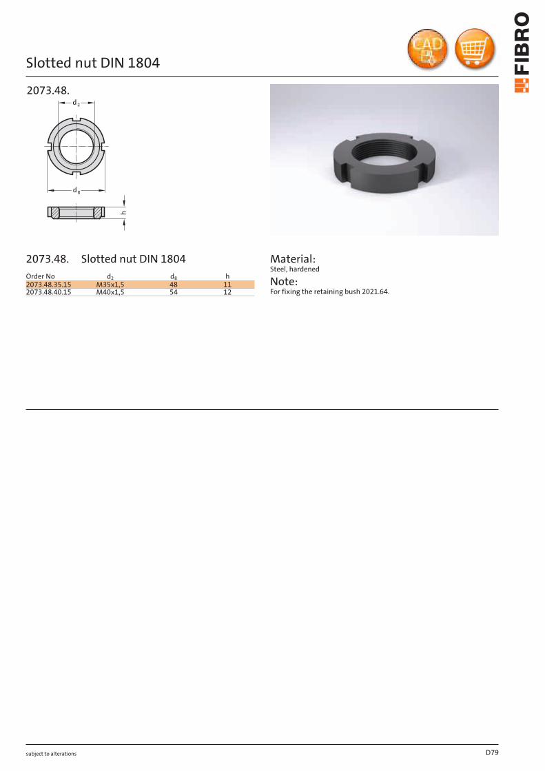
subject to alterations
Slotted nut DIN 1804
h
d8
d2
2073.48.
Material: Steel, hardened
Note: For fixing the retaining bush 2021.64.
D79
Order No d2 d8 h2073.48.35.15 M35x1,5 48 112073.48.40.15 M40x1,5 54 12
2073.48. Slotted nut DIN 1804
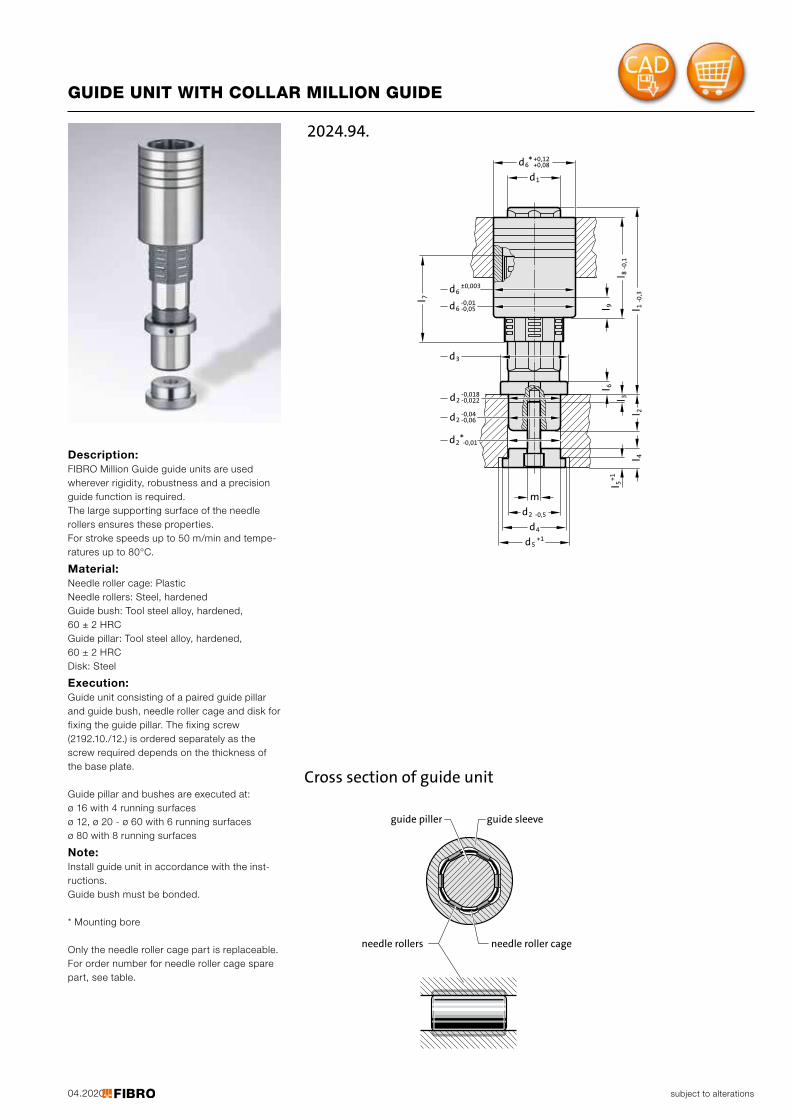
Note: Install guide unit in accordance with the inst-ructions. Guide bush must be bonded.
* Mounting bore
Only the needle roller cage part is replaceable. For order number for needle roller cage spare part, see table.
04.2020
m
d4
d5+1
d2 -0,5
-0,01d6 -0,05
d6±0,003
d3
-0,018d2 -0,022
-0,04d2 -0,06
d2*-0,01
l 1-0,3
l 8-0,1
l 9l 6
l 3
l 2l 4
l 5+1
l 7
d6 +0,08+0,12
d1
*
2024.94.
subject to alterations
GUIDE UNIT WITH COLLAR MILLION GUIDE
Description: FIBRO Million Guide guide units are used wherever rigidity, robustness and a precision guide function is required. The large supporting surface of the needle rollers ensures these properties. For stroke speeds up to 50 m/min and tempe-ratures up to 80°C.
Material: Needle roller cage: Plastic Needle rollers: Steel, hardened Guide bush: Tool steel alloy, hardened, 60 ± 2 HRC Guide pillar: Tool steel alloy, hardened, 60 ± 2 HRC Disk: Steel
Execution: Guide unit consisting of a paired guide pillar and guide bush, needle roller cage and disk for fixing the guide pillar. The fixing screw (2192.10./12.) is ordered separately as the screw required depends on the thickness of the base plate.
Guide pillar and bushes are executed at: Ø 16 with 4 running surfacesØ 12, Ø 20 - Ø 60 with 6 running surfacesØ 80 with 8 running surfaces
guide piller guide sleeve
needle rollers needle roller cage
Cross section of guide unit
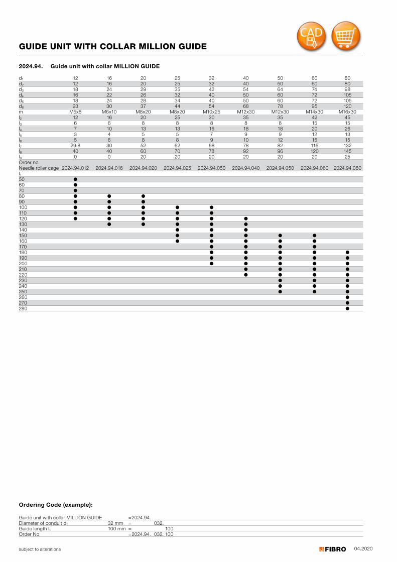
04.2020subject to alterations
Ordering Code (example):
Guide unit with collar MILLION GUIDE =2024.94.Diameter of conduit d1 32 mm = 032.Guide length l1 100 mm = 100Order No =2024.94. 032. 100
GUIDE UNIT WITH COLLAR MILLION GUIDE
d1 12 16 20 25 32 40 50 60 80d2 12 16 20 25 32 40 50 60 80d3 18 24 29 35 42 54 64 74 98d4 16 22 26 32 40 50 60 72 105d5 18 24 28 34 40 50 60 72 105d6 23 30 37 44 54 68 78 95 120m M5x8 M6x10 M8x20 M8x20 M10x25 M12x30 M12x30 M14x30 M16x30l2 12 16 20 25 30 35 35 42 45l3 6 6 8 8 8 8 8 15 15l4 7 10 13 13 16 18 18 20 26l5 3 4 5 5 7 9 9 12 13l6 5 6 8 8 9 10 12 15 15l7 29.8 30 52 62 68 78 82 116 132l8 40 40 60 70 78 92 96 120 145l9 0 0 20 20 20 20 20 20 25Order no.Needle r oller c age 2024.94.012 2024.94.016 2024.94.020 2024.94.025 2024.94.050 2024.94.040 2024.94.050 2024.94.060 2024.94.080l51
0 ●60 ●70 ●80 ● ● ●90 ● ● ●100 ● ● ● ● ●110 ● ● ● ● ●120 ● ● ● ● ● ●130 ● ● ● ● ●140 ● ● ●150 ● ● ● ● ●160 ● ● ● ● ●170 ● ● ● ●180 ● ● ● ● ●190 ● ● ● ● ●200 ● ● ● ● ●210 ● ● ● ●220 ● ● ● ●230 ● ● ●240 ● ● ●250 ● ● ●260 ●270 ●280 ●
2024.94. Guide unit with collar MILLION GUIDE
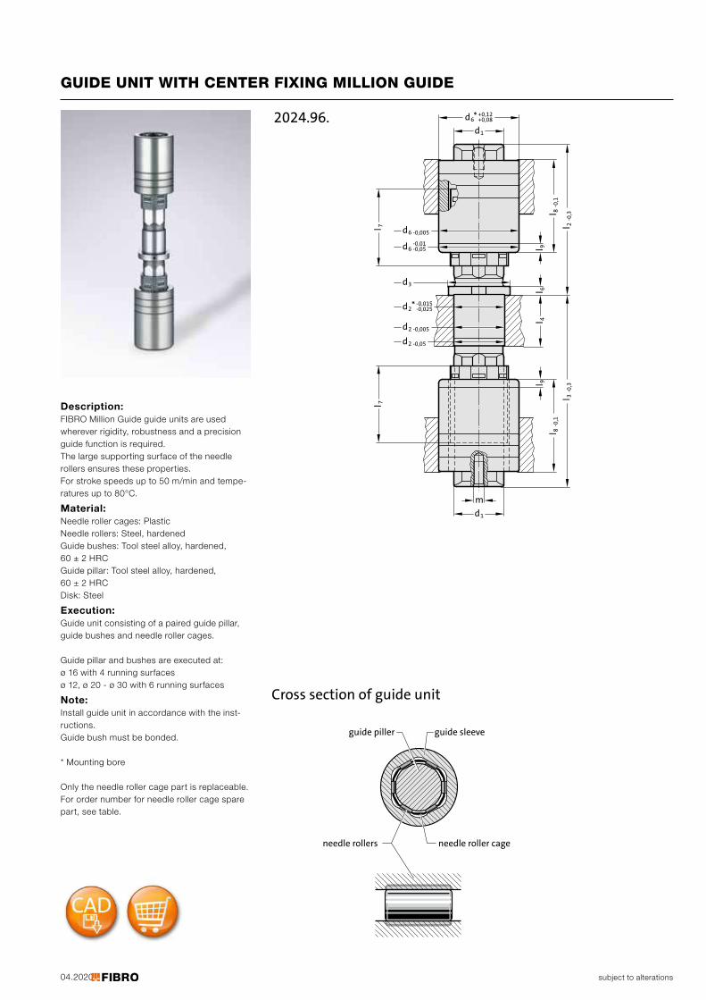
04.2020
-0,015-0,025
m
d1
d1
d6 -0,005
d6 -0,05-0,01
d2 -0,005
d2 -0,05
d3
l 3-0,3
l 2-0,3
l 9l 8
-0,1
l 9l 6
l 4l 8
-0,1
l 7l 7
d2
d6* +0,08+0,12
*
2024.96.
subject to alterations
GUIDE UNIT WITH CENTER FIXING MILLION GUIDE
Description: FIBRO Million Guide guide units are used wherever rigidity, robustness and a precision guide function is required. The large supporting surface of the needle rollers ensures these properties. For stroke speeds up to 50 m/min and tempe-ratures up to 80°C.
Material: Needle roller cages: Plastic Needle rollers: Steel, hardened Guide bushes: Tool steel alloy, hardened, 60 ± 2 HRC Guide pillar: Tool steel alloy, hardened, 60 ± 2 HRC Disk: Steel
Execution: Guide unit consisting of a paired guide pillar, guide bushes and needle roller cages.
Guide pillar and bushes are executed at: Ø 16 with 4 running surfacesØ 12, Ø 20 - Ø 30 with 6 running surfaces
Note: Install guide unit in accordance with the inst-ructions. Guide bush must be bonded.
* Mounting bore
Only the needle roller cage part is replaceable. For order number for needle roller cage spare part, see table.
guide piller guide sleeve
needle rollers needle roller cage
Cross section of guide unit
04.2020subject to alterations
GUIDE UNIT WITH CENTER FIXING MILLION GUIDE
2024.96. Guide unit with center fixing MILLION GUIDE
d1 12 16 20 25 28d2 13 16.5 20.5 25.5 28.5d3 19 23 27 32 35d6 22 28 34 40 45m M5x8 M6x15 M8x20 M8x20 M8x20l4 12 16 20 25 28l6 4 5 5 5 5l7 30 30 46 56 66l8 30 40 50 60 65l9 20 20 20Order no. 2024.94.012 2024.94.016 2024.96.020 2024.96.025 2024.96.028 Needle roller cage l3 l250 40 50 60 60 40 50 60 70 40 50 60 40 50 60 80 40 50 60 70 50 60 70 90 50 60 70 80 50 60 70 80 60 70 80 70 80 90100 60 70 80 90 60 70 80 90 70 80 90110 70 80 90 70 80 90
Ordering Code (example):
Guide unit with center fixing MILLION GUIDE = 2024.96.Diameter of conduit d1 20 mm = 020.Length to bush l³ 80 mm = 080.Length with bush l2 50 mm = 050Order No = 2024.96. 020. 080. 050
subject to alterations
Guide bearing with solid lubricant
d4
1t
h1
h
H7
d3
d1
be2
a
e 1
Guide Brush 2052.70.
d5
2031.70.
Material: Basic body: Special cast iron Guide bush 2052.70.: Bronze with solid lubricant, oilless lubricating
Execution: Face and top machined.
Note: Notes on sliding type guides at the beginning of chapter D. Matching guide combinations, see selection matrix at the beginning of chapter D.
Mounting example
D84
d1 19 20 24 25 30 32 38 40 50 63 80d3 45 50 65 80 96 110 130d4 9 9 11 13.5 17.5 17.5 22a 85 90 115 130 160 180 215b 45 50 65 80 96 110 130e1 64 68 83 95 118 132 160e2 24 28 34 45 55 62 75h 18 22 25 30 35 35 40h1 37 47 60 77 95 120 120t1 3 3 3 3 4 4 10
Ordering Code (example):Guide bearing with solid lubricant =2031.70.Guide diameter d1 19 mm = 019Order No =2031.70. 019
2031.70. Guide bearing with solid lubricant
subject to alterations
Retention bearing
1h
3d
d1R6
a
h
b
2031.01.
Material: Special cast iron
Execution: Face and top machined. Hole fine bored to d1R6 fit.
Note: Check squareness of pillars after press-fitting.
Mounting example
D85
d1 15 16 19 20 24 25 30 32 38 40 48 50 60 63 80d3 35 45 50 65 80 96 110 130a 70 85 90 115 130 160 180 215b 35 45 50 65 80 96 110 130h 18 18 22 25 30 35 35 40h1 30 37 47 60 77 95 120 120
Ordering Code (example):Retention bearing =2031.01.Guide diameter d1 15 mm = 015Order No =2031.01. 015
2031.01. Retention bearing
subject to alterations
Guide bearing, sintered guide
3d
1d
h
1h
a
b
2031.31.
Material: Basic body: Special cast iron Guide bush 2051.32.: Sintered ferrite of high purity, carbonitrided, long- term lubrication
Execution: Face and top machined. Bores honed.
Note: Notes on sliding type guides at the beginning of chapter D. Bearing clearance see pairing classification at the beginning of chapter D. Matching guide combinations, see selection matrix at the beginning of chapter D.
Tolerance range: yellow = .10 green = .20 red = .30
Mounting example
D86
d1 15 16 19 20 24 25 30 32 38 40 48 50 60 63 80d3 35 45 50 65 80 96 110 130a 70 85 90 115 130 160 180 215b 35 45 50 65 80 96 110 130h 18 18 22 25 30 35 35 40h1 30 37 47 60 77 95 120 120
Ordering Code (example):Guide bearing, sintered guide =2031.31.Guide diameter d1 15 mm = 015.Classification TOL yellow = 10Order No =2031.31. 015.10
2031.31. Guide bearing, sintered guide
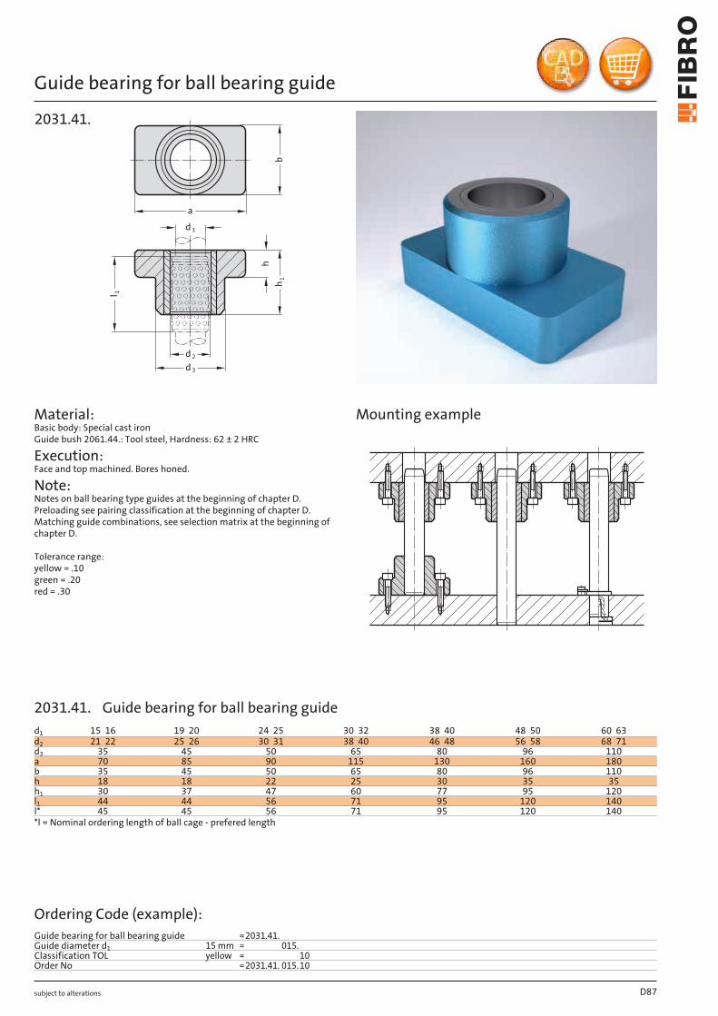
subject to alterations
Guide bearing for ball bearing guidel
h1
1
1d
3d
2d
h
a
b
2031.41.
Mounting example
D87
d1 15 16 19 20 24 25 30 32 38 40 48 50 60 63d2 21 22 25 26 30 31 38 40 46 48 56 58 68 71d3 35 45 50 65 80 96 110a 70 85 90 115 130 160 180b 35 45 50 65 80 96 110h 18 18 22 25 30 35 35h1 30 37 47 60 77 95 120l1 44 44 56 71 95 120 140l* 45 45 56 71 95 120 140*l = Nominal ordering length of ball cage - prefered length
Ordering Code (example):Guide bearing for ball bearing guide =2031.41.Guide diameter d1 15 mm = 015.Classification TOL yellow = 10Order No =2031.41. 015.10
Material: Basic body: Special cast iron Guide bush 2061.44.: Tool steel, Hardness: 62 ± 2 HRC
Execution: Face and top machined. Bores honed.
Note: Notes on ball bearing type guides at the beginning of chapter D. Preloading see pairing classification at the beginning of chapter D. Matching guide combinations, see selection matrix at the beginning of chapter D.
Tolerance range: yellow = .10 green = .20 red = .30
2031.41. Guide bearing for ball bearing guide
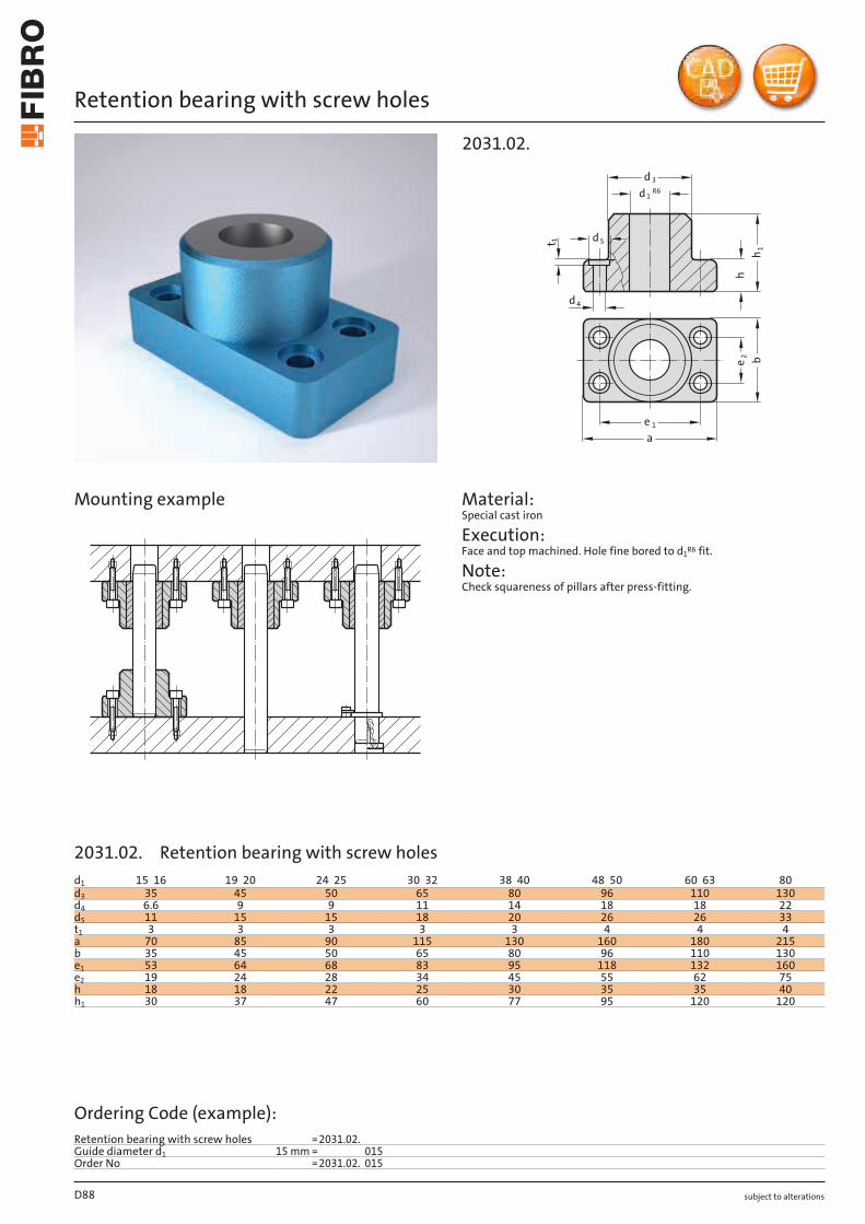
subject to alterations
Retention bearing with screw holes
1t
3d
d1R6
1h
h
4d
b
2e
1e
a
5d
2031.02.
Material: Special cast iron
Execution: Face and top machined. Hole fine bored to d1R6 fit.
Note: Check squareness of pillars after press-fitting.
Mounting example
D88
d1 15 16 19 20 24 25 30 32 38 40 48 50 60 63 80d3 35 45 50 65 80 96 110 130d4 6.6 9 9 11 14 18 18 22d5 11 15 15 18 20 26 26 33t1 3 3 3 3 3 4 4 4a 70 85 90 115 130 160 180 215b 35 45 50 65 80 96 110 130e1 53 64 68 83 95 118 132 160e2 19 24 28 34 45 55 62 75h 18 18 22 25 30 35 35 40h1 30 37 47 60 77 95 120 120
Ordering Code (example):Retention bearing with screw holes =2031.02.Guide diameter d1 15 mm = 015Order No =2031.02. 015
2031.02. Retention bearing with screw holes
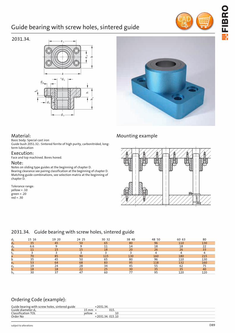
subject to alterations
Guide bearing with screw holes, sintered guide
3d
1d
h
1h
a
b
4d
1t
5d
2031.34.1e
2e
Material: Basic body: Special cast iron Guide bush 2051.32.: Sintered ferrite of high purity, carbonitrided, long- term lubrication
Execution: Face and top machined. Bores honed.
Note: Notes on sliding type guides at the beginning of chapter D. Bearing clearance see pairing classification at the beginning of chapter D. Matching guide combinations, see selection matrix at the beginning of chapter D.
Tolerance range: yellow = .10 green = .20 red = .30
Mounting example
D89
d1 15 16 19 20 24 25 30 32 38 40 48 50 60 63 80d3 35 45 50 65 80 96 110 130d4 6.6 9 9 11 14 18 18 22d5 11 15 15 18 20 26 26 33t1 3 3 3 3 3 4 4 4a 70 85 90 115 130 160 180 215b 35 45 50 65 80 96 110 130e1 53 64 68 83 95 118 132 160e2 19 24 28 34 45 55 62 75h 18 18 22 25 30 35 35 40h1 30 37 47 60 77 95 120 120
Ordering Code (example):Guide bearing with screw holes, sintered guide =2031.34.Guide diameter d1 15 mm = 015.Classification TOL yellow = 10Order No =2031.34. 015.10
2031.34. Guide bearing with screw holes, sintered guide
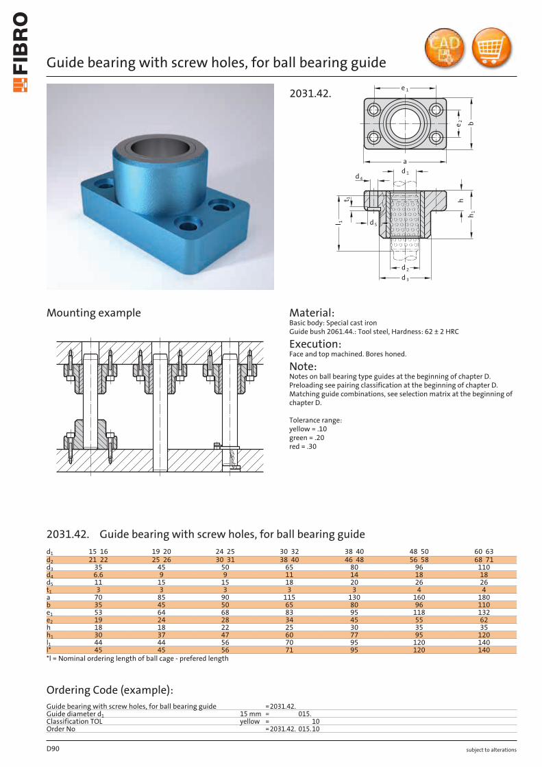
subject to alterations
Guide bearing with screw holes, for ball bearing guide
l
h1
1
1d
3d
2d
h
a
b
4d
1t
5d
2031.42.1e
2e
Material: Basic body: Special cast iron Guide bush 2061.44.: Tool steel, Hardness: 62 ± 2 HRC
Execution: Face and top machined. Bores honed.
Note: Notes on ball bearing type guides at the beginning of chapter D. Preloading see pairing classification at the beginning of chapter D. Matching guide combinations, see selection matrix at the beginning of chapter D.
Tolerance range: yellow = .10 green = .20 red = .30
Mounting example
D90
d1 15 16 19 20 24 25 30 32 38 40 48 50 60 63d2 21 22 25 26 30 31 38 40 46 48 56 58 68 71d3 35 45 50 65 80 96 110d4 6.6 9 9 11 14 18 18d5 11 15 15 18 20 26 26t1 3 3 3 3 3 4 4a 70 85 90 115 130 160 180b 35 45 50 65 80 96 110e1 53 64 68 83 95 118 132e2 19 24 28 34 45 55 62h 18 18 22 25 30 35 35h1 30 37 47 60 77 95 120l1 44 44 56 70 95 120 140l* 45 45 56 71 95 120 140*l = Nominal ordering length of ball cage - prefered length
Ordering Code (example):Guide bearing with screw holes, for ball bearing guide =2031.42.Guide diameter d1 15 mm = 015.Classification TOL yellow = 10Order No =2031.42. 015.10
2031.42. Guide bearing with screw holes, for ball bearing guide
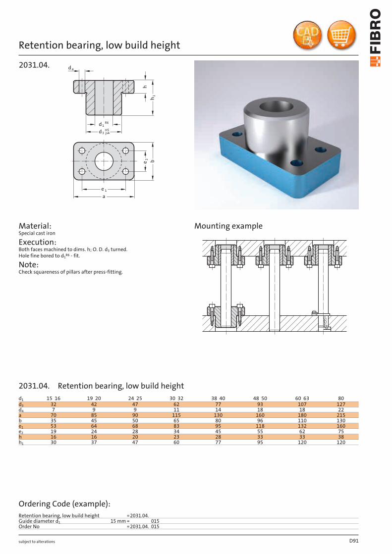
subject to alterations
Retention bearing, low build height
1e
a
b
2e
h
1h
4d
d3H5js4
d1R6
2031.04.
Material: Special cast iron
Execution: Both faces machined to dims. h; O. D. d3 turned. Hole fine bored to d1R6 - fit.
Note: Check squareness of pillars after press-fitting.
Mounting example
D91
d1 15 16 19 20 24 25 30 32 38 40 48 50 60 63 80d3 32 42 47 62 77 93 107 127d4 7 9 9 11 14 18 18 22a 70 85 90 115 130 160 180 215b 35 45 50 65 80 96 110 130e1 53 64 68 83 95 118 132 160e2 19 24 28 34 45 55 62 75h 16 16 20 23 28 33 33 38h1 30 37 47 60 77 95 120 120
Ordering Code (example):Retention bearing, low build height =2031.04.Guide diameter d1 15 mm = 015Order No =2031.04. 015
2031.04. Retention bearing, low build height

subject to alterations
Guide bearing, low build height, sintered guide
d3H5js4
h
1d
1h
1e
a
b
2e
4d
2031.38.
Material: Basic body: Special cast iron Guide bush 2051.32.: Sintered ferrite of high purity, carbonitrided, long- term lubrication
Execution: Both faces machined to dims. h; O. D. d3 turned. Bores honed.
Note: Notes on sliding type guides at the beginning of chapter D. Bearing clearance see pairing classification at the beginning of chapter D. Matching guide combinations, see selection matrix at the beginning of chapter D.
Tolerance range: yellow = .10 green = .20 red = .30
Mounting example
D92
d1 15 16 19 20 24 25 30 32 38 40 48 50 60 63 80d3 32 42 47 62 77 93 107 127d4 7 9 9 11 14 18 18 22a 70 85 90 115 130 160 180 215b 35 45 50 65 80 96 110 130e1 53 64 68 83 95 118 132 160e2 19 24 28 34 45 55 62 75h 16 16 20 23 28 33 33 38h1 30 37 47 60 77 95 120 120
Ordering Code (example):Guide bearing, low build height, sintered guide =2031.38.Guide diameter d1 15 mm = 015.Classification TOL yellow = 10Order No =2031.38. 015.10
2031.38. Guide bearing, low build height, sintered guide
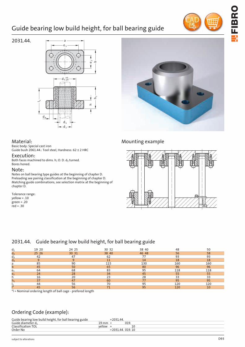
subject to alterations
Guide bearing low build height, for ball bearing guide
d3H5js4
l
h
1
1
h
2d
1d
4d
1e
a
b
2e
2031.44.
Material: Basic body: Special cast iron Guide bush 2061.44.: Tool steel, Hardness: 62 ± 2 HRC
Execution: Both faces machined to dims. h; O. D. d3 turned. Bores honed.
Note: Notes on ball bearing type guides at the beginning of chapter D. Preloading see pairing classification at the beginning of chapter D. Matching guide combinations, see selection matrix at the beginning of chapter D.
Tolerance range: yellow = .10 green = .20 red = .30
Mounting example
D93
d1 19 20 24 25 30 32 38 40 48 50d2 25 26 30 31 38 40 46 48 56 58d3 42 47 62 77 93 93d4 9 9 11 14 18 18a 85 90 115 130 160 160b 45 50 65 80 96 96e1 64 68 83 95 118 118e2 24 28 34 45 55 55h 16 20 23 28 33 33h1 37 47 60 77 95 95l1 44 56 70 95 120 120l* 45 56 71 95 120 10*l = Nominal ordering length of ball cage - prefered length
Ordering Code (example):Guide bearing low build height, for ball bearing guide =2031.44.Guide diameter d1 19 mm = 019.Classification TOL yellow = 10Order No =2031.44. 019. 10
2031.44. Guide bearing low build height, for ball bearing guide
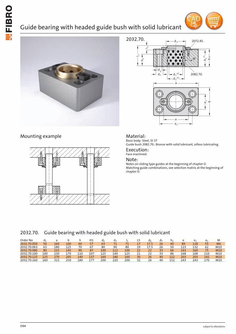
subject to alterations
Guide bearing with headed guide bush with solid lubricant
2072.45.
H7
H7 2082.70.
h
e1
e
ad 2
d 1
d 3
l
b
1
l 5
h 1+1 ±2
e 2
d6
h 2
d 7
M
2032.70.
Material: Basic body: Steel, St 37 Guide bush 2082.70.: Bronze with solid lubricant, oilless lubricating
Execution: Face machined.
Note: Notes on sliding type guides at the beginning of chapter D. Matching guide combinations, see selection matrix at the beginning of chapter D.
Mounting example
D94
Order No d1 a b h H1 d2 d3 l1 L5 d6 d7 h2 e e1 e2 M2032.70.050 50 160 100 60 57 63 71 71 17 17.5 26 40 89 118 55 M62032.70.063 63 180 125 70 67 80 90 80 19 17.5 26 50 123 132 62 M102032.70.080 80 215 145 90 87 100 112 100 22 22 33 66 143 160 75 M102032.70.100 100 230 170 110 107 125 140 125 21 22 33 86 168 168 110 M102032.70.125 125 270 205 140 137 160 180 160 30 26 40 112 203 203 142 M102032.70.160 160 315 250 180 177 200 220 200 32 26 40 152 243 243 170 M10
2032.70. Guide bearing with headed guide bush with solid lubricant
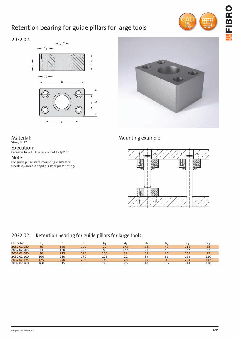
subject to alterations
Retention bearing for guide pillars for large tools
2032.02.
h2 h1
H7
e 1
a
d1
be2
d6
d7
±2
Material: Steel, St 37
Execution: Face machined. Hole fine bored to d1H7 fit.
Note: For guide pillars with mounting diameter r6. Check squareness of pillars after press-fitting.
Mounting example
D95
Order No d1 a b h1 d6 d7 h2 e1 e22032.02.050 50 160 100 70 17.5 26 40 118 552032.02.063 63 180 125 80 17.5 26 50 132 622032.02.080 80 215 145 100 22 33 66 160 752032.02.100 100 230 170 125 22 33 86 168 1102032.02.125 125 270 205 140 26 40 112 203 1422032.02.160 160 315 250 180 26 40 152 243 170
2032.02. Retention bearing for guide pillars for large tools
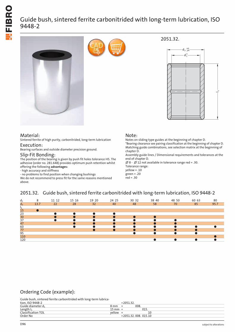
subject to alterations
Guide bush, sintered ferrite carbonitrided with long-term lubrication, ISO 9448-2
Material: Sintered ferrite of high purity, carbonitrided, long-term lubrication
Execution: Bearing surfaces and outside diameter precision ground.
Slip-Fit Bonding: The position of the bearing is given by push fit holes tolerance H5. The adhesive (order no. 281.648) provides optimum push retention whilst offering the following advantages: - high accuracy and stiffness - no problems to find position when changing bushings We do not recommend to press fit for the same reasons mentioned above.
Note: Notes on sliding type guides at the beginning of chapter D. *Bearing clearance see pairing classification at the beginning of chapter D. Matching guide combinations, see selection matrix at the beginning of chapter D. Assembly guide lines / Dimensional requirements and tolerances at the end of chapter D. ∅ 8 - ∅ 12 not available in tolerance range red = .30. Tolerance range: yellow = .10 green = .20 red = .30
l 1
1
3dH5
js4
d *
2051.32.
D96
d1 8 11 12 15 16 19 20 24 25 30 32 38 40 48 50 60 63 80d3 13.7 22 28 32 40 48 58 70 85 95.7l115 ●23 ● ● ● ●30 ● ● ● ● ● ●37 ● ● ● ● ● ● ●47 ● ● ● ● ● ●60 ● ● ● ● ● ● ● ●77 ● ● ● ● ● ●95 ● ● ● ●110 ●120 ● ● ● ●
Ordering Code (example):Guide bush, sintered ferrite carbonitrided with long-term lubrica-tion, ISO 9448-2 =2051.32.Guide diameter d1 8 mm = 008.Length l1 15 mm = 015.Classification TOL yellow = 10Order No =2051.32. 008. 015.10
2051.32. Guide bush, sintered ferrite carbonitrided with long-term lubrication, ISO 9448-2
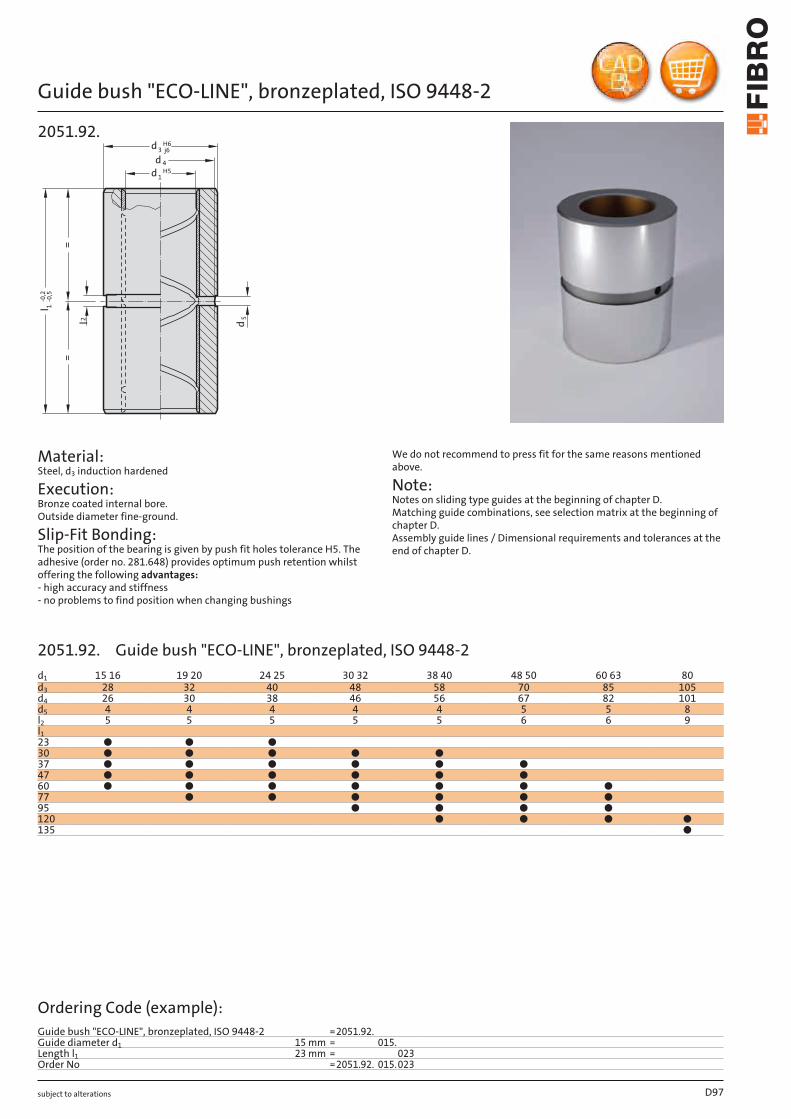
subject to alterations
Guide bush "ECO-LINE", bronzeplated, ISO 9448-2
3d
j6
H6
1d H5
4d
5d
l-0
,2
1-0
,5
l2
==
2051.92.
Material: Steel, d3 induction hardened
Execution: Bronze coated internal bore. Outside diameter fine-ground.
Slip-Fit Bonding: The position of the bearing is given by push fit holes tolerance H5. The adhesive (order no. 281.648) provides optimum push retention whilst offering the following advantages: - high accuracy and stiffness - no problems to find position when changing bushings
We do not recommend to press fit for the same reasons mentioned above.
Note: Notes on sliding type guides at the beginning of chapter D. Matching guide combinations, see selection matrix at the beginning of chapter D. Assembly guide lines / Dimensional requirements and tolerances at the end of chapter D.
D97
d1 15 16 19 20 24 25 30 32 38 40 48 50 60 63 80d3 28 32 40 48 58 70 85 105d4 26 30 38 46 56 67 82 101d5 4 4 4 4 4 5 5 8l2 5 5 5 5 5 6 6 9l123 ● ● ●30 ● ● ● ● ●37 ● ● ● ● ● ●47 ● ● ● ● ● ●60 ● ● ● ● ● ● ●77 ● ● ● ● ● ●95 ● ● ● ●120 ● ● ● ●135 ●
Ordering Code (example):Guide bush "ECO-LINE", bronzeplated, ISO 9448-2 =2051.92.Guide diameter d1 15 mm = 015.Length l1 23 mm = 023Order No =2051.92. 015.023
2051.92. Guide bush "ECO-LINE", bronzeplated, ISO 9448-2
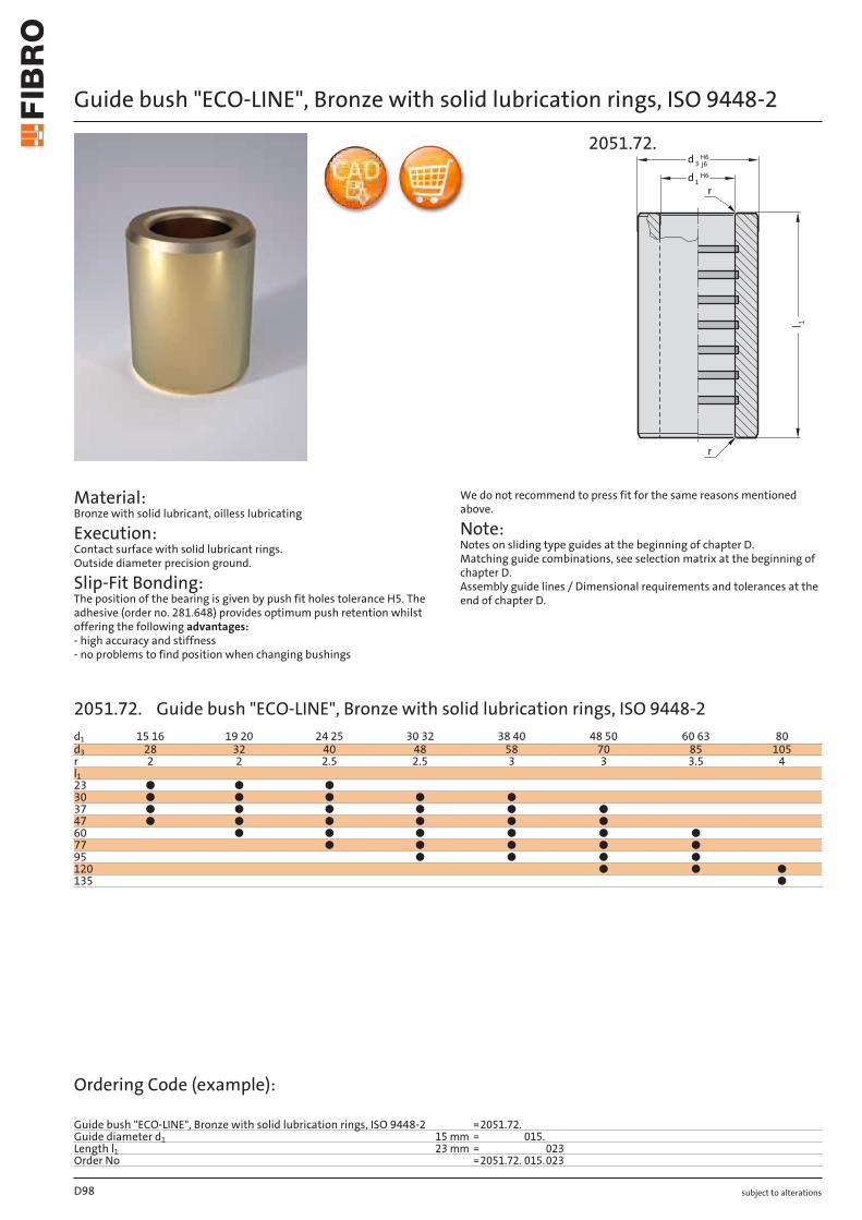
subject to alterations
Guide bush "ECO-LINE", Bronze with solid lubrication rings, ISO 9448-2
Material: Bronze with solid lubricant, oilless lubricating
Execution: Contact surface with solid lubricant rings. Outside diameter precision ground.
Slip-Fit Bonding: The position of the bearing is given by push fit holes tolerance H5. The adhesive (order no. 281.648) provides optimum push retention whilst offering the following advantages: - high accuracy and stiffness - no problems to find position when changing bushings
We do not recommend to press fit for the same reasons mentioned above.
Note: Notes on sliding type guides at the beginning of chapter D. Matching guide combinations, see selection matrix at the beginning of chapter D. Assembly guide lines / Dimensional requirements and tolerances at the end of chapter D.
r
r
3d j6H6
1d H6
1l
2051.72.
D98
d1 15 16 19 20 24 25 30 32 38 40 48 50 60 63 80d3 28 32 40 48 58 70 85 105r 2 2 2.5 2.5 3 3 3.5 4l123 ● ● ●30 ● ● ● ● ●37 ● ● ● ● ● ●47 ● ● ● ● ● ●60 ● ● ● ● ● ●77 ● ● ● ● ●95 ● ● ● ●120 ● ● ●135 ●
Ordering Code (example):
Guide bush "ECO-LINE", Bronze with solid lubrication rings, ISO 9448-2 =2051.72.Guide diameter d1 15 mm = 015.Length l1 23 mm = 023Order No =2051.72. 015.023
2051.72. Guide bush "ECO-LINE", Bronze with solid lubrication rings, ISO 9448-2
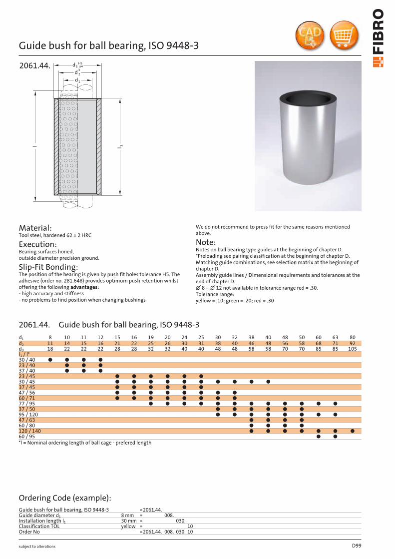
subject to alterations
Guide bush for ball bearing, ISO 9448-3
2061.44.
l 1
dd3
H5js4
d1
2
l
*
Material: Tool steel, hardened 62 ± 2 HRC
Execution: Bearing surfaces honed, outside diameter precision ground.
Slip-Fit Bonding: The position of the bearing is given by push fit holes tolerance H5. The adhesive (order no. 281.648) provides optimum push retention whilst offering the following advantages: - high accuracy and stiffness - no problems to find position when changing bushings
We do not recommend to press fit for the same reasons mentioned above.
Note: Notes on ball bearing type guides at the beginning of chapter D. *Preloading see pairing classification at the beginning of chapter D. Matching guide combinations, see selection matrix at the beginning of chapter D. Assembly guide lines / Dimensional requirements and tolerances at the end of chapter D. ∅ 8 - ∅ 12 not available in tolerance range red = .30. Tolerance range: yellow = .10; green = .20; red = .30
D99
d1 8 10 11 12 15 16 19 20 24 25 30 32 38 40 48 50 60 63 80d2 11 14 15 16 21 22 25 26 30 31 38 40 46 48 56 58 68 71 92d3 18 22 22 22 28 28 32 32 40 40 48 48 58 58 70 70 85 85 105l1 / l*30 / 40 ● ● ● ●23 / 40 ● ● ●37 / 40 ● ● ●23 / 45 ● ● ● ● ● ●30 / 45 ● ● ● ● ● ● ● ● ● ●37 / 45 ● ● ● ● ● ●47 / 56 ● ● ● ● ● ● ● ●60 / 71 ● ● ● ● ● ● ● ●77 / 95 ● ● ● ● ● ● ● ● ● ● ● ●37 / 50 ● ● ● ● ● ●95 / 120 ● ● ● ● ● ● ● ●47 / 63 ● ● ● ●60 / 80 ● ● ● ●
● ● ● ● ● ● ●● ●
120 / 14060 / 95*l = Nominal ordering length of ball cage - prefered length
Ordering Code (example):Guide bush for ball bearing, ISO 9448-3 =2061.44.Guide diameter d1 8 mm = 008.Installation length l1 30 mm = 030.Classification TOL yellow = 10Order No =2061.44. 008. 030. 10
2061.44. Guide bush for ball bearing, ISO 9448-3
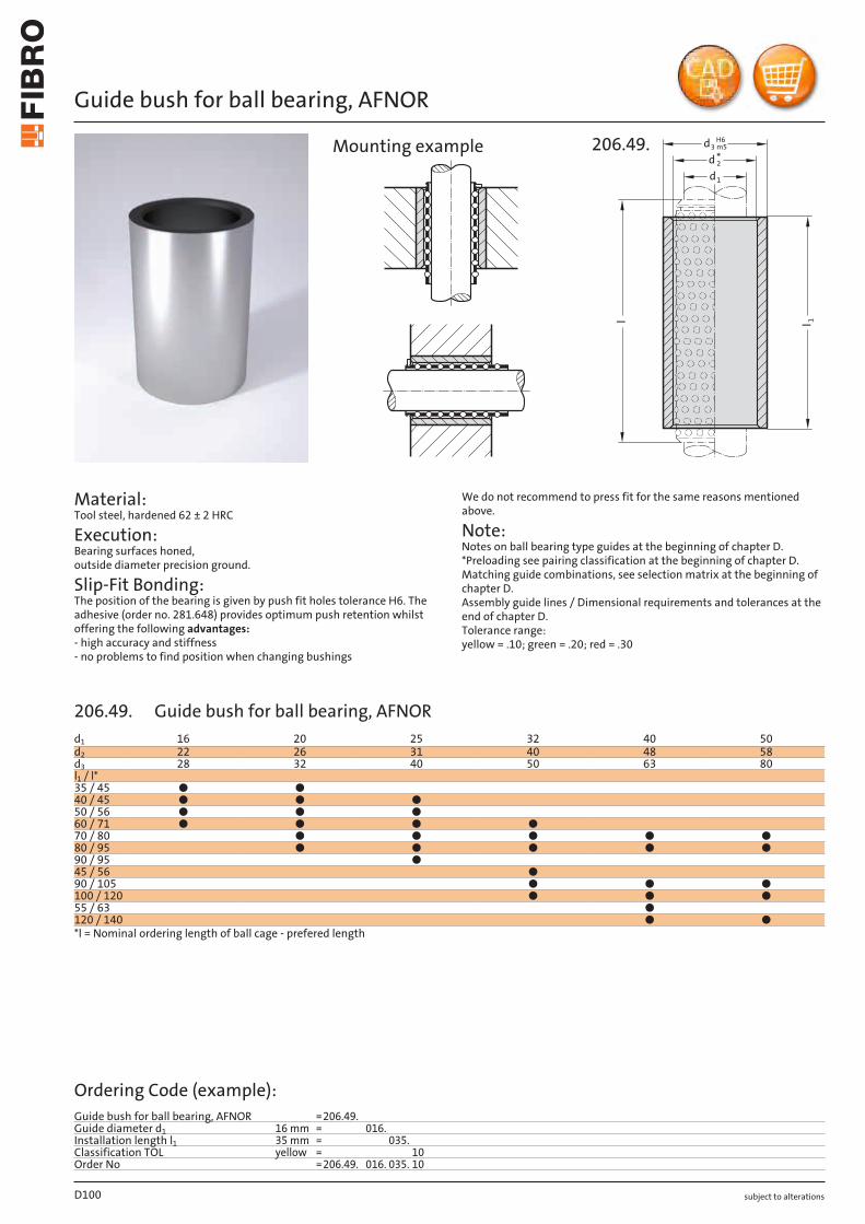
subject to alterations
Guide bush for ball bearing, AFNOR
Material: Tool steel, hardened 62 ± 2 HRC
Execution: Bearing surfaces honed, outside diameter precision ground.
Slip-Fit Bonding: The position of the bearing is given by push fit holes tolerance H6. The adhesive (order no. 281.648) provides optimum push retention whilst offering the following advantages: - high accuracy and stiffness - no problems to find position when changing bushings
We do not recommend to press fit for the same reasons mentioned above.
Note: Notes on ball bearing type guides at the beginning of chapter D. *Preloading see pairing classification at the beginning of chapter D. Matching guide combinations, see selection matrix at the beginning of chapter D. Assembly guide lines / Dimensional requirements and tolerances at the end of chapter D. Tolerance range: yellow = .10; green = .20; red = .30
1
d
3dH6
m5
1d
2
ll
*
206.49.Mounting example
D100
d1 16 20 25 32 40 50d2 22 26 31 40 48 58d3 28 32 40 50 63 80l1 / l*35 / 45 ● ●40 / 45 ● ● ●50 / 56 ● ● ●60 / 71 ● ● ● ●70 / 80 ● ● ● ● ●80 / 95 ● ● ● ● ●90 / 95 ●45 / 56 ●90 / 105 ● ● ●100 / 120 ● ● ●55 / 63 ●120 / 140 ● ●*l = Nominal ordering length of ball cage - prefered length
Ordering Code (example):Guide bush for ball bearing, AFNOR =206.49.Guide diameter d1 16 mm = 016.Installation length l1 35 mm = 035.Classification TOL yellow = 10Order No =206.49. 016. 035. 10
206.49. Guide bush for ball bearing, AFNOR
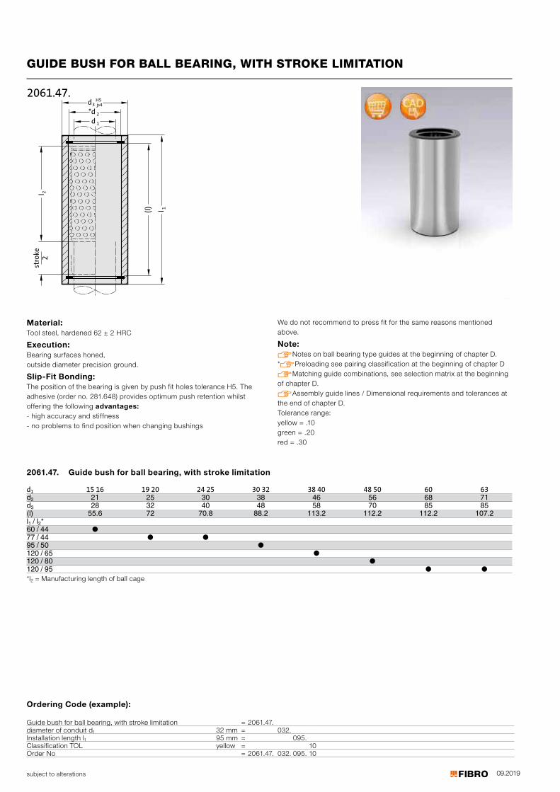
09.2019subject to alterations
GUIDE BUSH FOR BALL BEARING, WITH STROKE LIMITATION
l 22
l 1
*dd3
H5
d 1
2
js4
2061.47.
(l)
stro
ke
Material: Tool steel, hardened 62 ± 2 HRC
Execution: Bearing surfaces honed, outside diameter precision ground.
Slip-Fit Bonding: The position of the bearing is given by push fit holes tolerance H5. The adhesive (order no. 281.648) provides optimum push retention whilst offering the following advantages: - high accuracy and stiffness- no problems to find position when changing bushings
We do not recommend to press fit for the same reasons mentioned above.
Note: Notes on ball bearing type guides at the beginning of chapter D. *Preloading see pairing classification at the beginning of chapter DMatching guide combinations, see selection matrix at the beginningof chapter D.Assembly guide lines / Dimensional requirements and tolerances at the end of chapter D.Tolerance range: yellow = .10 green = .20 red = .30
d
Guide bush for ball bearing, with stroke limitation
15 16 19 20 24 25 30 32 38 40 48 50 60 63d
12 21 25 30 38 46 56 68 71
d3 28 32 40 48 58 70 85 85(l) 55.6 72 70.8 88.2 113.2 112.2 112.2 107.2l1 / l2*60 / 44 ● 77 / 44 ● ● 95 / 50 ● 120 / 65 ● 120 / 80 ● 120 / 95 ● ●*l2 = Manufacturing length of ball cage
2061.47.
Ordering Code (example):
Guide bush for ball bearing, with stroke limitation = 2061.47.diameter of conduit d1 32 mm = 032.Installation length l1 95 mm = 095.Classification TOL yellow = 10Order No = 2061.47. 032. 095. 10
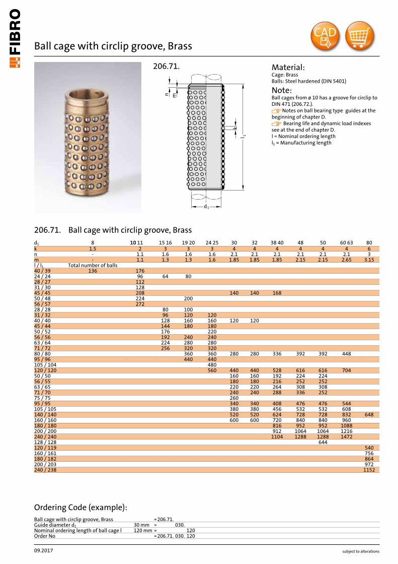
subject to alterations
Ball cage with circlip groove, Brass
1d
1l
k
n m
206.71. Material: Cage: Brass Balls: Steel hardened (DIN 5401)
Note: Ball cages from ø 10 has a groove for circlip to DIN 471 (206.72.). Notes on ball bearing type guides at the beginning of chapter D. Bearing life and dynamic load indexes see at the end of chapter D. l = Nominal ordering lengthl1 = Manufacturing length
09.2017
d1 8 11 1010 15 16 19 20 24 25 30 32 38 40 48 50 60 63 80k 1.5 2 3 3 3 4 4 4 4 4 4 6n - 1.1 1.6 1.6 1.6 2.1 2.1 2.1 2.1 2.1 2.1 3m - 1.1 1.3 1.3 1.6 1.85 1.85 1.85 2.15 2.15 2.65 3.15l / l1 Total number of balls40 / 39 136 17624 / 24 96 64 8028 / 27 11231 / 30 12845 / 45 208 140 140 16850 / 48 224 20056 / 57 27228 / 28 80 10031 / 32 96 120 12040 / 40 128 160 160 120 12045 / 44 144 180 18050 / 52 176 22056 / 56 192 240 24063 / 64 224 280 28071 / 72 256 320 32080 / 80 360 360 280 280 336 392 392 44895 / 96 440 440105 / 104 480120 / 120 560 440 440 528 616 616 70450 / 50 160 160 192 224 22456 / 55 180 180 216 252 25263 / 65 220 220 264 308 30871 / 70 240 240 288 336 25275 / 75 26095 / 95 340 340 408 476 476 544105 / 105 380 380 456 532 532 608140 / 140 520 520 624 728 728 832 648160 / 160 600 600 720 840 840 960180 / 180 816 952 952 1088200 / 200 912 1064 1064 1216240 / 240 1104 1288 1288 1472128 / 128 644120 / 119 540160 / 161 756180 / 182 864200 / 203 972240 / 238 1152
Ordering Code (example):Ball cage with circlip groove, Brass =206.71.Guide diameter d1 30 mm = 030.Nominal ordering length of ball cage l 120 mm = 120Order No =206.71. 030. 120
206.71. Ball cage with circlip groove, Brass

subject to alterations
Ball cage with circlip groove, Aluminium
Material: Cage: Aluminium Balls: Steel hardened (DIN 5401)
Note: Ball cages from ø 10 has a groove for circlip to DIN 471 (206.72.). Notes on ball bearing type guides at the beginning of chapter D. Bearing life and dynamic load indexes see at the end of chapter D. l = Nominal ordering lengthl1 = Manufacturing length
1d
1l
k
n m
2060.61.
09.2017
d1 10 11 12 15 16 19 20 24 25 30 32 38 40 48 50 60 63 80k 2 2 3 3 3 3 3 4 4 4 4 6n 1.1 1.1 1.6 1.6 1.6 1.6 1.6 2.1 2.1 2.1 2.1 3m 1.1 1.1 1.3 1.3 1.3 1.3 1.6 1.85 1.85 2.15 2.65 3.15l / l1 Total number of balls40 / 39 176 17656 / 57 272 27245 / 44 144 144 180 180 18056 / 56 192 192 240 240 24063 / 64 224 22471 / 72 256 256 320 320 32024 / 24 64 8028 / 28 80 10031 / 32 120 120 12080 / 80 360 360 360 280 336 39295 / 96 440 440 44040 / 40 160 120120 / 120 560 440 528 616 70445 / 45 140 16850 / 50 160 192 22456 / 55 180 21671 / 70 24095 / 95 340 408 476 544105 / 105 380 456 532 608140 / 140 520 624 728 832 648160 / 160 600 720 840 96063 / 65 264 308180 / 180 816 952 1088200 / 200 912 1064 1216240 / 240 1104 1288 1472120 / 119 540160 / 161 756180 / 182 864200 / 203 972240 / 238 1152
Ordering Code (example):Ball cage with circlip groove, Aluminium =2060.61.Guide diameter d1 38 mm = 038.Nominal ordering length of ball cage l 50 mm = 050Order No =2060.61. 038. 050
2060.61. Ball cage with circlip groove, Aluminium
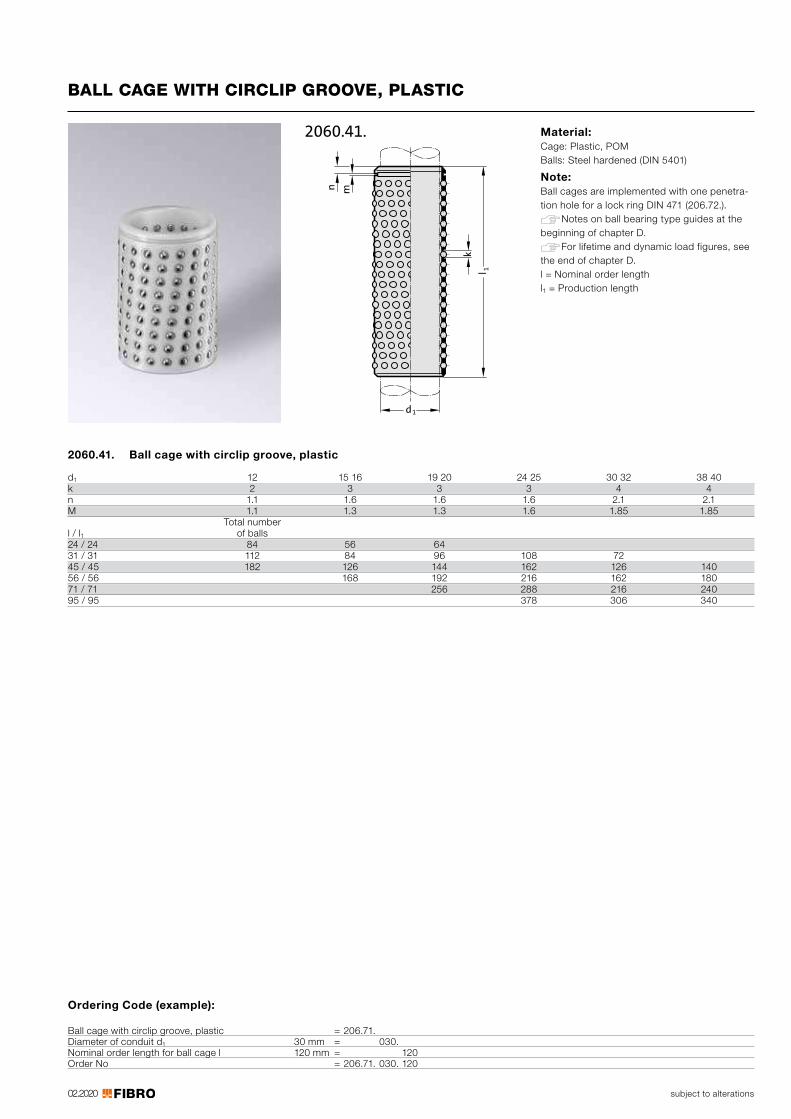
02.2020
1d
1l
k
n m
2060.41.
subject to alterations
BALL CAGE WITH CIRCLIP GROOVE, PLASTIC
Material: Cage: Plastic, POM Balls: Steel hardened (DIN 5401)
Note: Ball cages are implemented with one penetra-tion hole for a lock ring DIN 471 (206.72.). Notes on ball bearing type guides at the beginning of chapter D. For lifetime and dynamic load figures, see the end of chapter D. l = Nominal order lengthl1 = Production length
Ordering Code (example):
Ball cage with circlip groove, plastic = 206.71.Diameter of conduit d1 30 mm = 030.Nominal order length for ball cage l 120 mm = 120Order No = 206.71. 030. 120
2060.41. Ball cage with circlip groove, plastic
d1 12 15 16 19 20 24 25 30 32 38 40k 2 3 3 3 4 4n 1.1 1.6 1.6 1.6 2.1 2.1M 1.1 1.3 1.3 1.6 1.85 1.85
Total number l / l1 of balls 24 / 24 84 56 64 31 / 31 112 84 96 108 72 45 / 45 182 126 144 162 126 14056 / 56 168 192 216 162 18071 / 71 256 288 216 24095 / 95 378 306 340

Änderungen vorbehalten
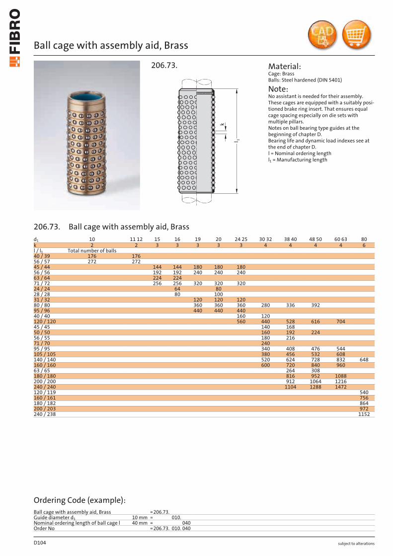
subject to alterations
Ball cage with assembly aid, Brass
k
l 1
206.73. Material: Cage: Brass Balls: Steel hardened (DIN 5401)
Note: No assistant is needed for their assembly. These cages are equipped with a suitably posi-tioned brake ring insert. That ensures equal cage spacing especially on die sets with multiple pillars. Notes on ball bearing type guides at the beginning of chapter D. Bearing life and dynamic load indexes see at the end of chapter D. l = Nominal ordering length l1 = Manufacturing length
D104
d1 10 11 12 15 16 19 20 24 25 30 32 38 40 48 50 60 63 80k 2 2 3 3 3 3 3 4 4 4 4 6l / l1 Total number of balls40 / 39 176 17656 / 57 272 27245 / 44 144 144 180 180 18056 / 56 192 192 240 240 24063 / 64 224 22471 / 72 256 256 320 320 32024 / 24 64 8028 / 28 80 10031 / 32 120 120 12080 / 80 360 360 360 280 336 39295 / 96 440 440 44040 / 40 160 120120 / 120 560 440 528 616 70445 / 45 140 16850 / 50 160 192 22456 / 55 180 21671 / 70 24095 / 95 340 408 476 544105 / 105 380 456 532 608140 / 140 520 624 728 832 648160 / 160 600 720 840 96063 / 65 264 308180 / 180 816 952 1088200 / 200 912 1064 1216240 / 240 1104 1288 1472120 / 119 540160 / 161 756180 / 182 864200 / 203 972240 / 238 1152
Ordering Code (example):Ball cage with assembly aid, Brass =206.73.Guide diameter d1 10 mm = 010.Nominal ordering length of ball cage l 40 mm = 040Order No =206.73. 010. 040
206.73. Ball cage with assembly aid, Brass
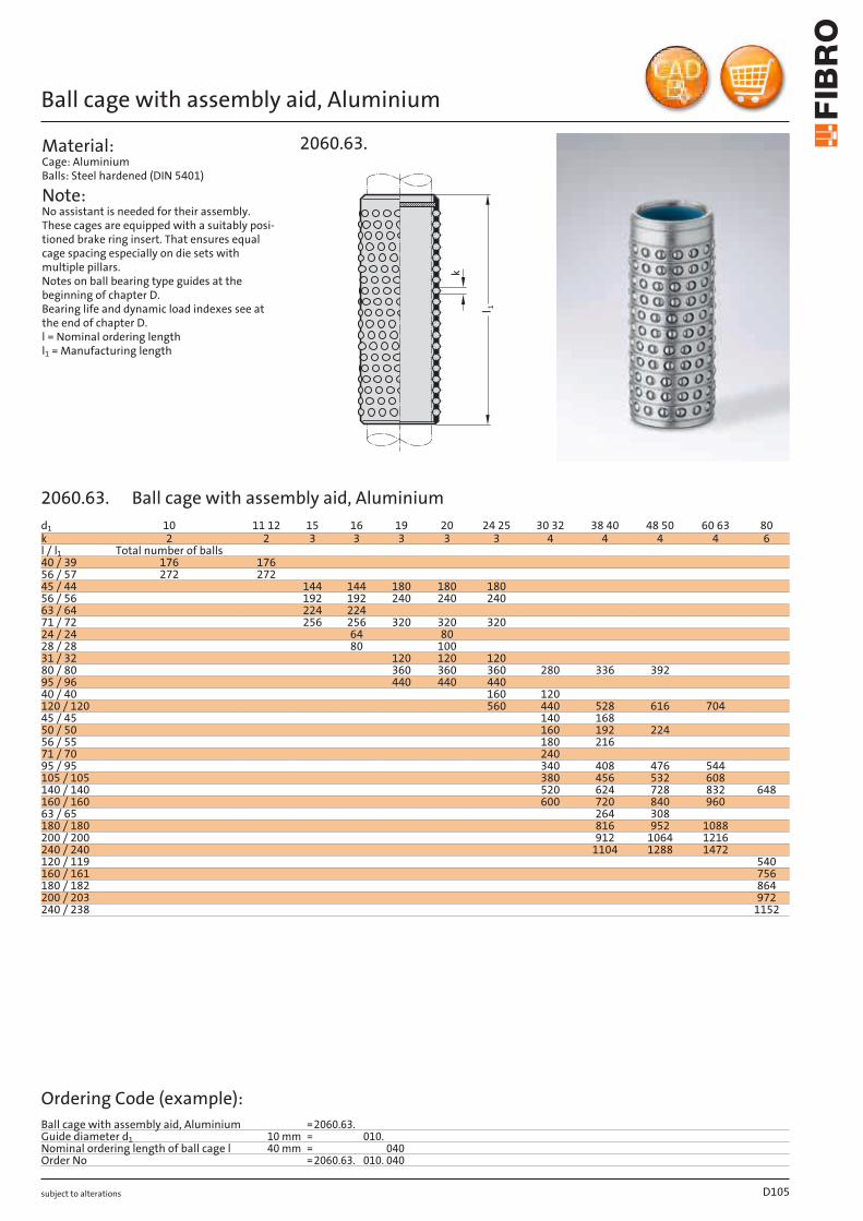
subject to alterations
Ball cage with assembly aid, Aluminium
Material: Cage: Aluminium Balls: Steel hardened (DIN 5401)
Note: No assistant is needed for their assembly. These cages are equipped with a suitably posi-tioned brake ring insert. That ensures equal cage spacing especially on die sets with multiple pillars. Notes on ball bearing type guides at the beginning of chapter D. Bearing life and dynamic load indexes see at the end of chapter D. l = Nominal ordering length l1 = Manufacturing length
k
l 1
2060.63.
D105
d1 10 11 12 15 16 19 20 24 25 30 32 38 40 48 50 60 63 80k 2 2 3 3 3 3 3 4 4 4 4 6l / l1 Total number of balls40 / 39 176 17656 / 57 272 27245 / 44 144 144 180 180 18056 / 56 192 192 240 240 24063 / 64 224 22471 / 72 256 256 320 320 32024 / 24 64 8028 / 28 80 10031 / 32 120 120 12080 / 80 360 360 360 280 336 39295 / 96 440 440 44040 / 40 160 120120 / 120 560 440 528 616 70445 / 45 140 16850 / 50 160 192 22456 / 55 180 21671 / 70 24095 / 95 340 408 476 544105 / 105 380 456 532 608140 / 140 520 624 728 832 648160 / 160 600 720 840 96063 / 65 264 308180 / 180 816 952 1088200 / 200 912 1064 1216240 / 240 1104 1288 1472120 / 119 540160 / 161 756180 / 182 864200 / 203 972240 / 238 1152
Ordering Code (example):Ball cage with assembly aid, Aluminium =2060.63.Guide diameter d1 10 mm = 010.Nominal ordering length of ball cage l 40 mm = 040Order No =2060.63. 010. 040
2060.63. Ball cage with assembly aid, Aluminium
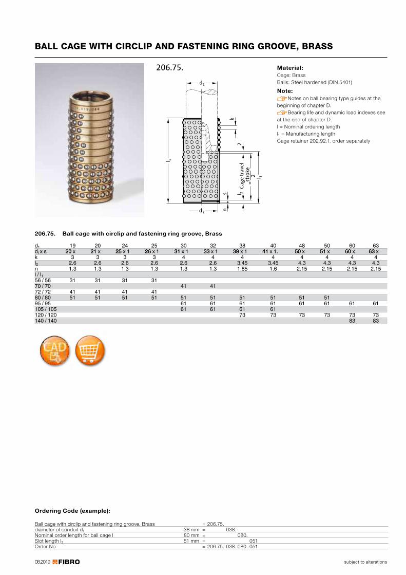
08.2019 subject to alterations
BALL CAGE WITH CIRCLIP AND FASTENING RING GROOVE, BRASS
id
k
sn
l 2C
ag
e t
rav
el
= st
rok
e2
2
3
1l
1d
l
206.75. Material: Cage: Brass Balls: Steel hardened (DIN 5401)
Note: Notes on ball bearing type guides at the beginning of chapter D. Bearing life and dynamic load indexes see at the end of chapter D. l = Nominal ordering lengthl1 = Manufacturing lengthCage retainer 202.92.1. order separately
206.75. Ball cage with circlip and fastening ring groove, Brass
d 19 20 24 25 30 32 38 40 48 50 60 63di
1 x s 2020 x 1212 x 5252 x 1 2626 x 1 3131 x 1 3333 x 1 3939 x 1 4141 x 1. 5050 x 5151 x 6060 x 6363 x
k 3 3 3 3 4 4 4 4 4 4 4 4l2 2.6 2.6 2.6 2.6 2.6 2.6 3.45 3.45 4.3 4.3 4.3 4.3n 1.3 1.3 1.3 1.3 1.3 1.3 1.85 1.6 2.15 2.15 2.15 2.15l / l156 / 56 31 31 31 31 70 / 70 41 41 72 / 72 41 41 41 41 80 / 80 51 51 51 51 51 51 51 51 51 51 95 / 95 61 61 61 61 61 61 61 61
/105 105 61 61 61 61 120 / 120 73 73 73 73 73 73140 / 140 83 83
Ordering Code (example):
Ball cage with circlip and fastening ring groove, Brass = 206.75.diameter of conduit d1 38 mm = 038.Nominal order length for ball cage l 80 mm = 080.Slot length l3 51 mm = 051Order No = 206.75. 038. 080. 051
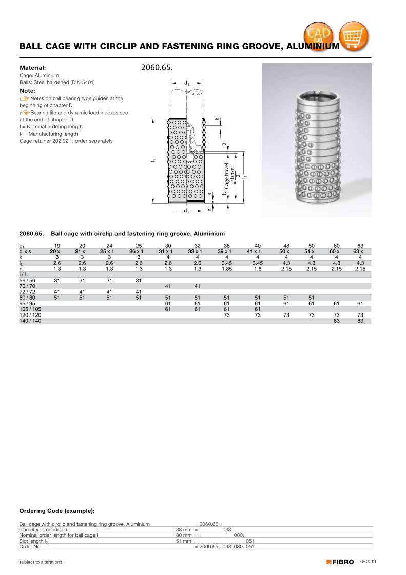
08.2019subject to alterations
BALL CAGE WITH CIRCLIP AND FASTENING RING GROOVE, ALUMINIUM
Material: Cage: Aluminium Balls: Steel hardened (DIN 5401)
Note: Notes on ball bearing type guides at the beginning of chapter D. Bearing life and dynamic load indexes see at the end of chapter D. l = Nominal ordering lengthl1 = Manufacturing lengthCage retainer 202.92.1. order separately
idk
sn
l 2C
ag
e t
rav
el
=
stro
ke
2
2
3
1l
1d
l
2060.65.
2060.65. Ball cage with circlip and fastening ring groove, Aluminium
d 19 20 24 25 30 32 38 40 48 50 60 63di
1 x s 2020 x 1212 x 5252 x 1 2626 x 1 3131 x 1 3333 x 1 3939 x 1 4141 x 1. 5050 x 5151 x 6060 x 6363 x
k 3 3 3 3 4 4 4 4 4 4 4 4l2 2.6 2.6 2.6 2.6 2.6 2.6 3.45 3.45 4.3 4.3 4.3 4.3n 1.3 1.3 1.3 1.3 1.3 1.3 1.85 1.6 2.15 2.15 2.15 2.15l / l156 / 56 31 31 31 31 70 / 70 41 41 72 / 72 41 41 41 41 80 / 80 51 51 51 51 51 51 51 51 51 51 95 / 95 61 61 61 61 61 61 61 61
/105 105 61 61 61 61 120 / 120 73 73 73 73 73 73140 / 140 83 83
Ordering Code (example):
Ball cage with circlip and fastening ring groove, Aluminium = 2060.65.diameter of conduit d1 38 mm = 038.Nominal order length for ball cage l 80 mm = 080.Slot length l3 51 mm = 051Order No = 2060.65. 038. 080. 051
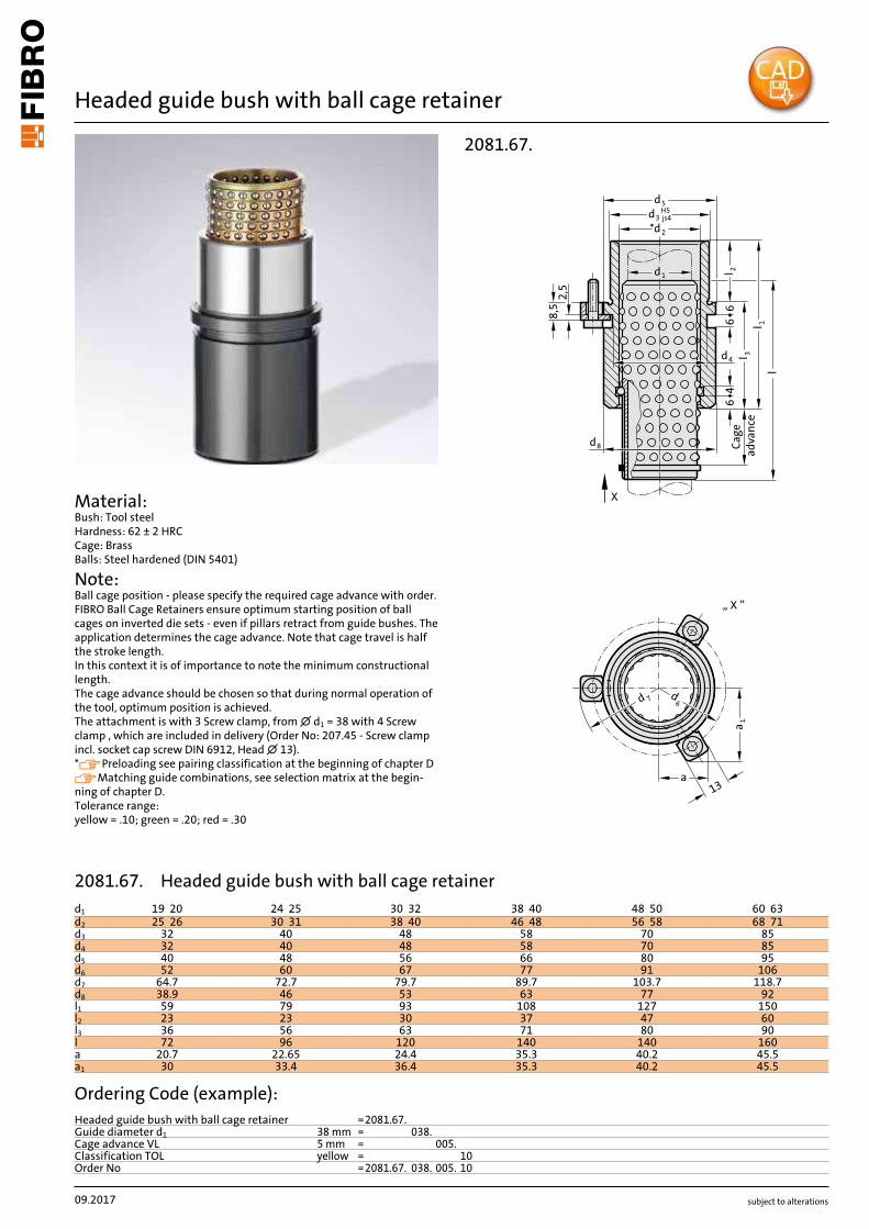
subject to alterations
Headed guide bush with ball cage retainer
Material: Bush: Tool steel Hardness: 62 ± 2 HRC Cage: Brass Balls: Steel hardened (DIN 5401)
Note: Ball cage position - please specify the required cage advance with order. FIBRO Ball Cage Retainers ensure optimum starting position of ball cages on inverted die sets - even if pillars retract from guide bushes. The application determines the cage advance. Note that cage travel is half the stroke length. In this context it is of importance to note the minimum constructional length. The cage advance should be chosen so that during normal operation of the tool, optimum position is achieved. The attachment is with 3 Screw clamp, from ∅ d1 = 38 with 4 Screw clamp , which are included in delivery (Order No: 207.45 - Screw clamp incl. socket cap screw DIN 6912, Head ∅ 13). *Preloading see pairing classification at the beginning of chapter DMatching guide combinations, see selection matrix at the begin-ning of chapter D. Tolerance range: yellow = .10; green = .20; red = .30
2081.67.
2,5
8,5
8d
4d
66
l
46
2l
2*d
3dH5
js4
1d
X
5d
Ca
ge
ad
va
nce
3l
1l
a1
a
7d 6d
13
„ X ”
09.2017
d1 19 20 24 25 30 32 38 40 48 50 60 63d2 25 26 30 31 38 40 46 48 56 58 68 71d3 32 40 48 58 70 85d4 32 40 48 58 70 85d5 40 48 56 66 80 95d6 52 60 67 77 91 106d7 64.7 72.7 79.7 89.7 103.7 118.7d8 38.9 46 53 63 77 92l1 59 79 93 108 127 150l2 23 23 30 37 47 60l3 36 56 63 71 80 90l 72 96 120 140 140 160a 20.7 22.65 24.4 35.3 40.2 45.5a1 30 33.4 36.4 35.3 40.2 45.5
Ordering Code (example):Headed guide bush with ball cage retainer =2081.67.Guide diameter d1 38 mm = 038.Cage advance VL 5 mm = 005.Classification TOL yellow = 10Order No =2081.67. 038. 005. 10
2081.67. Headed guide bush with ball cage retainer

subject to alterations
Headed guide bush with ball cage retainer
2081.68.2
,58
,5
8d
4d
66
l
46
2l
2*d
3dH5
js4
1d
X
5d
Ca
ge
ad
va
nce
3l
1l
a1
a
7d 6d
13
„ X ”
Material: Bush: Tool steel Hardness: 62 ± 2 HRC Cage: Aluminium Balls: Steel hardened (DIN 5401)
Note: Ball cage position - please specify the required cage advance with order. FIBRO Ball Cage Retainers ensure optimum starting position of ball cages on inverted die sets - even if pillars retract from guide bushes. The application determines the cage advance. Note that cage travel is half the stroke length. In this context it is of importance to note the minimum constructional length. The cage advance should be chosen so that during normal operation of the tool, optimum position is achieved. The attachment is with 3 Screw clamp, from ∅ d1 = 38 with 4 Screw clamp , which are included in delivery (Order No: 207.45 - Screw clamp incl. socket cap screw DIN 6912, Head ∅ 13). *Preloading see pairing classification at the beginning of chapter DMatching guide combinations, see selection matrix at the begin-ning of chapter D. Tolerance range: yellow = .10; green = .20; red = .30
09.2017
d1 19 20 24 25 30 32 38 40 48 50 60 63d2 25 26 30 31 38 40 46 48 56 58 68 71d3 32 40 48 58 70 85d4 32 40 48 58 70 85d5 40 48 56 66 80 95d6 52 60 67 77 91 106d7 64.7 72.7 79.7 89.7 103.7 118.7d8 38.9 46 53 63 77 92l1 59 79 93 108 127 150l2 23 23 30 37 47 60l3 36 56 63 71 80 90l 72 96 120 140 140 160a 20.7 22.65 24.4 35.3 40.2 45.5a1 30 33.4 36.4 35.3 40.2 45.5
Ordering Code (example):Headed guide bush with ball cage retainer =2081.68.Guide diameter d1 38 mm = 038.Cage advance VL 5 mm = 005.Classification TOL yellow = 10Order No =2081.68. 038. 005. 10
2081.68. Headed guide bush with ball cage retainer
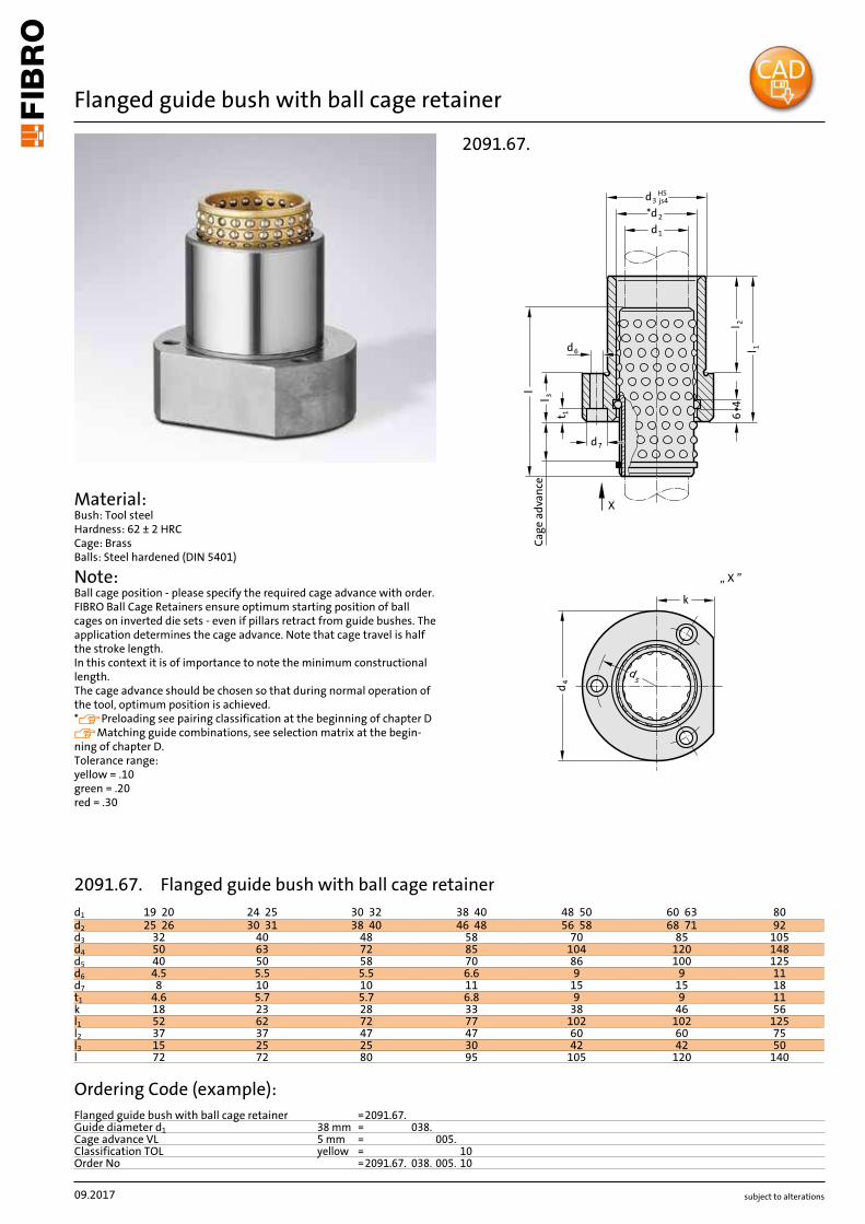
subject to alterations
Flanged guide bush with ball cage retainer
d5
k
d 4
Cage
adv
ance
l 3l
d6
46
l 1l 2
d3 jsH5
4
*d2
d1
X
„ X ”
d7
t 1
2091.67.
09.2017
d1 19 20 24 25 30 32 38 40 48 50 60 63 80d2 25 26 30 31 38 40 46 48 56 58 68 71 92d3 32 40 48 58 70 85 105d4 50 63 72 85 104 120 148d5 40 50 58 70 86 100 125d6 4.5 5.5 5.5 6.6 9 9 11d7 8 10 10 11 15 15 18t1 4.6 5.7 5.7 6.8 9 9 11k 18 23 28 33 38 46 56l1 52 62 72 77 102 102 125l2 37 37 47 47 60 60 75l3 15 25 25 30 42 42 50l 72 72 80 95 105 120 140
Ordering Code (example):Flanged guide bush with ball cage retainer =2091.67.Guide diameter d1 38 mm = 038.Cage advance VL 5 mm = 005.Classification TOL yellow = 10Order No =2091.67. 038. 005. 10
Material: Bush: Tool steel Hardness: 62 ± 2 HRC Cage: Brass Balls: Steel hardened (DIN 5401)
Note: Ball cage position - please specify the required cage advance with order. FIBRO Ball Cage Retainers ensure optimum starting position of ball cages on inverted die sets - even if pillars retract from guide bushes. The application determines the cage advance. Note that cage travel is half the stroke length. In this context it is of importance to note the minimum constructional length. The cage advance should be chosen so that during normal operation of the tool, optimum position is achieved. *Preloading see pairing classification at the beginning of chapter DMatching guide combinations, see selection matrix at the begin-ning of chapter D. Tolerance range: yellow = .10 green = .20 red = .30
2091.67. Flanged guide bush with ball cage retainer
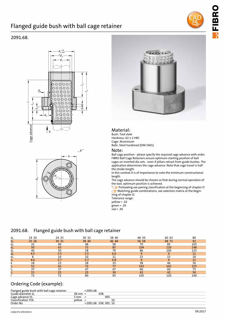
subject to alterations
Flanged guide bush with ball cage retainer
d5
k
d 4
Cage
adv
ance
l 3l
d6
46
l 1l 2
d3 jsH5
4
*d2
d1
X
„ X ”
d7
t 12091.68.
Material: Bush: Tool steel Hardness: 62 ± 2 HRC Cage: Aluminium Balls: Steel hardened (DIN 5401)
Note: Ball cage position - please specify the required cage advance with order. FIBRO Ball Cage Retainers ensure optimum starting position of ball cages on inverted die sets - even if pillars retract from guide bushes. The application determines the cage advance. Note that cage travel is half the stroke length. In this context it is of importance to note the minimum constructional length. The cage advance should be chosen so that during normal operation of the tool, optimum position is achieved. *Preloading see pairing classification at the beginning of chapter DMatching guide combinations, see selection matrix at the begin-ning of chapter D. Tolerance range: yellow = .10 green = .20 red = .30
09.2017
d1 19 20 24 25 30 32 38 40 48 50 60 63 80d2 25 26 30 31 38 40 46 48 56 58 68 71 92d3 32 40 48 58 70 85 105d4 50 63 72 85 104 120 148d5 40 50 58 70 86 100 125d6 4.5 5.5 5.5 6.6 9 9 11d7 8 10 10 11 15 15 18t1 4.6 5.7 5.7 6.8 9 9 11k 18 23 28 33 38 46 56l1 52 62 72 77 102 102 125l2 37 37 47 47 60 60 75l3 15 25 25 30 42 42 50l 72 72 80 95 105 120 140
Ordering Code (example):Flanged guide bush with ball cage retainer =2091.68.Guide diameter d1 38 mm = 038.Cage advance VL 5 mm = 005.Classification TOL yellow = 10Order No =2091.68. 038. 005. 10
2091.68. Flanged guide bush with ball cage retainer
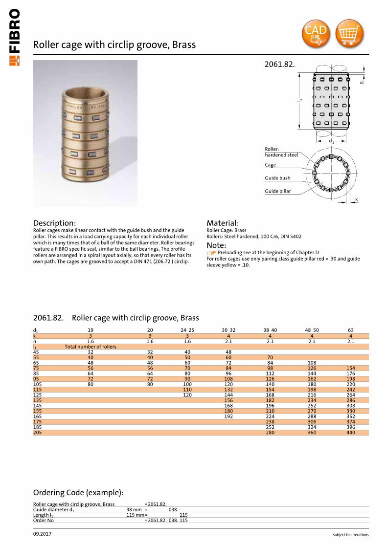
subject to alterations
Roller cage with circlip groove, Brass
Description: Roller cages make linear contact with the guide bush and the guide pillar. This results in a load carrying capacity for each individual roller which is many times that of a ball of the same diameter. Roller bearings feature a FIBRO specific seal, similar to the ball bearings. The profile rollers are arranged in a spiral layout axially, so that every roller has its own path. The cages are grooved to accept a DIN 471 (206.72.) circlip.
Material: Roller Cage: Brass Rollers: Steel hardened, 100 Cr6, DIN 5402
Note: Preloading see at the beginning of Chapter D For roller cages use only pairing class guide pillar red = .30 and guide sleeve yellow = .10.
d1
1l
Roller:
hardened steel
Guide pillar
Guide bush
Cage
k
2061.82.
n
09.2017
d1 19 20 24 25 30 32 38 40 48 50 63k 3 3 3 4 4 4 4n 1.6 1.6 1.6 2.1 2.1 2.1 2.1l1 Total number of rollers45 32 32 40 4855 40 40 50 60 7065 48 48 60 72 84 10875 56 56 70 84 98 126 15485 64 64 80 96 112 144 17695 72 72 90 108 126 162 198105 80 80 100 120 140 180 220115 110 132 154 198 242125 120 144 168 216 264135 156 182 234 286145 168 196 252 308155 180 210 270 330165 192 224 288 352175 238 306 374185 252 324 396205 280 360 440
Ordering Code (example):Roller cage with circlip groove, Brass =2061.82.Guide diameter d1 38 mm = 038.Length l1 115 mm= 115Order No =2061.82. 038. 115
2061.82. Roller cage with circlip groove, Brass
subject to alterations
Circlip DIN 471
s
d2
Installation space required
206.72.
n
s
1d
ad
Mounting example
Description: For securing the ball and roller cages
Execution: to DIN 471
D113
d1 da x s d2 d1 da x s d210 13 x 1 20.2 30 37 x 1.5 4911 14 x 1 21.4 32 38 x 1.75 51.412 15 x 1 22.6 38 45 x 1.75 59.115 20 x 1.2 28.4 40 47 x 1.75 60.816 21 x 1.2 29.6 48 55 x 2 70.218 23 x 1.2 32.2 50 57 x 2 72.619 24 x 1.2 33.2 60 67 x 2.5 83.120 25 x 1.2 34.2 63 70 x 2.5 8724 29 x 1.5 39.1 80 90 x 3 108.525 30 x 1.5 40.5
Ordering Code (example):Circlip DIN 471 =206.72.Guide diameter d1 10 mm = 010Order No =206.72. 010
206.72. Circlip DIN 471

subject to alterations
Roller cage with assembly aid, Brass
Description: Roller cages make linear contact with the guide bush and the guide pillar. This results in a load carrying capacity for each individual roller which is many times that of a ball of the same diameter. Roller bearings feature a FIBRO specific seal, similar to the ball bearings. The profile rollers are arranged in a spiral layout axially, so that every roller has its own path.
Material: Roller Cage: Brass Rollers: Steel hardened, 100 Cr6, DIN 5402
Note: No assistant is needed for their assembly. These cages are equipped with a suitably positioned brake ring insert. That ensures equal cage spacing especially on die sets with multiple pillars. Preloading see at the beginning of Chapter D. For roller cages use only pairing class guide pillar red = .30 and guide sleeve yellow = .10.
Roller Cagehardened steel
Guide Pillar
Guide bush
Cage
k
d1
l 1
2061.84.
D114
d1 19 20 24 25 30 32 38 40 48 50 63k 3 3 3 4 4 4 4l1 Total number of rollers45 32 32 40 4855 40 40 50 60 7065 48 48 60 72 84 10875 56 56 70 84 98 126 15485 64 64 80 96 112 144 17695 72 72 90 108 126 162 198105 80 80 100 120 140 180 220115 110 132 154 198 242125 120 144 168 216 264135 156 182 234 286145 168 196 252 308155 180 210 270 330165 192 224 288 352175 238 306 374185 252 324 396205 280 360 440
Ordering Code (example):Roller cage with assembly aid, Brass =2061.84.Guide diameter d1 19 mm = 019.Length l1 45 mm = 045Order No =2061.84. 019. 045
2061.84. Roller cage with assembly aid, Brass
subject to alterations
Headed guide bush, bronze coated, ISO 9448-6
5d
3d H5js4
1d
M8x1
d
4d
8
l 23l
66
45°
1 l
a
1a
6d
7d
„ X ”
X
2081.81.
Material: 1.0503 ∅ d3 and d8 induction hardened to 500+100 HV 10.
Execution: Bronze coated internal bore. Diameter d3 and collar face precision ground.
Note: The attachment is with 3 screw clamps, from ∅ d1 = 38 with 4 screw clamps, which are included in delivery (Order No: 207.45 - screw clamp incl. socket cap screw DIN 6912, Head ∅ 13). Notes on sliding type guides at the beginning of chapter D. Matching guide combinations, see selection matrix at the beginning of chapter D. Assembly guide lines / Dimensional requirements and tolerances at the end of chapter D.
Mounting example
D115
d1 19 20 24 25 30 32 38 40 48 50 60 63 80Tolerance +0.003/+0.012 +0.003/+0.012 +0.004/+0.015 +0.004/+0.015 +0.004/+0.015 +0.005/+0.018 +0.005/+0.018d3 32 40 48 58 70 85 105d4 32 40 48 58 70 85 105d5 40 48 56 66 80 95 118d6 52 60 67 77 91 106 129d7 64.7 72.7 79.7 89.7 103.7 118.7 141d8 39 46 53 63 77 92 115a 20.9 22.7 24.4 35.3 40.2 45.5 54.5a1 30.3 33.4 36.4 35.3 40.2 45.5 54.5l1 59 79 93 108 127 150 150l2 23 23 30 37 47 60 60l3 36 56 63 71 80 90 90
Ordering Code (example):Headed guide bush, bronze coated, ISO 9448-6 =2081.81.Guide diameter d1 19 mm = 019Order No =2081.81. 019
2081.81. Headed guide bush, bronze coated, ISO 9448-6
subject to alterations
Headed guide bush, bronze coated, ISO 9448-6
Material: 1.0503 ∅ d3 and d8 induction hardened to 500+100 HV 10.
Execution: Bronze coated internal bore. Diameter d3 and collar face precision ground.
Note: The attachment is with 3 screw clamps, from ∅ d1 = 38 with 4 screw clamps, which are included in delivery (Order No: 207.45 - screw clamp incl. socket cap screw DIN 6912, Head ∅ 13). Notes on sliding type guides at the beginning of chapter D. Matching guide combinations, see selection matrix at the beginning of chapter D. Assembly guide lines / Dimensional requirements and tolerances at the end of chapter D.
a1
a
6d
7d
„ X ”
5d
3dH5
js4
3l
M8x1
d
4d
8
l 2
66
1d
45°
X
1 l
2081.84.Mounting example
D116
d1 19 20 24 25 30 32 38 40 48 50 60 63 80Tolerance +0.003/+0.012 +0.003/+0.012 +0.004/+0.015 +0.004/+0.015 +0.004/+0.015 +0.005/+0.018 +0.005/+0.018d3 32 40 48 58 70 85 105d4 32 40 48 58 70 85 105d5 40 48 56 66 80 95 118d6 52 60 67 77 91 106 129d7 65.7 72.7 79.7 89.7 103.7 118.7 141d8 39 46 53 63 77 92 115a 20.9 22.7 24.4 35.3 40.2 45.5 54.5a1 30.3 33.4 36.4 35.3 40.2 45.5 54.5l1 43 59 75 82 97 116 120l2 23 23 30 37 47 60 60l3 20 36 45 45 50 56 60
Ordering Code (example):Headed guide bush, bronze coated, ISO 9448-6 =2081.84.Guide diameter d1 19 mm = 019Order No =2081.84. 019
2081.84. Headed guide bush, bronze coated, ISO 9448-6
subject to alterations
Headed guide bush, bronze coated, ISO 9448-6
a
1a
6d
7d
„ X ”
1 l
3l
d
4d
5
3dH5
js4
1d
M8x1
l 2
6
X
2081.85.
Material: 1.0503 ∅ d3 and d8 induction hardened to 500+100 HV 10.
Execution: Bronze coated internal bore. Diameter d3 and collar face precision ground.
Note: The attachment is with 3 screw clamps, from ∅ d1 = 38 with 4 screw clamps, which are included in delivery (Order No: 207.45 - screw clamp incl. socket cap screw DIN 6912, Head ∅ 13). Notes on sliding type guides at the beginning of chapter D. Matching guide combinations, see selection matrix at the beginning of chapter D. Assembly guide lines / Dimensional requirements and tolerances at the end of chapter D.
Mounting example
D117
d1 19 20 24 25 30 32 38 40 48 50 60 63 80Tolerance +0.003/+0.012 +0.003/+0.012 +0.004/+0.015 +0.004/+0.015 +0.004/+0.015 +0.005/+0.018 +0.005/+0.018d3 32 40 48 58 70 85 105d4 32 40 48 58 70 85 105d5 40 48 56 66 80 95 118d6 52 60 67 77 91 106 129d7 65.7 72.7 79.7 89.7 103.7 118.7 141a 20.9 22.7 24.4 35.3 40.2 45.5 54.4a1 30.3 33.4 36.4 35.3 40.2 45.5 54.4l1 35 35 42 52 65 80 80l2 23 23 30 37 47 60 60l3 12 12 12 15 18 20 20
Ordering Code (example):Headed guide bush, bronze coated, ISO 9448-6 =2081.85.Guide diameter d1 19 mm = 019Order No =2081.85. 019
2081.85. Headed guide bush, bronze coated, ISO 9448-6
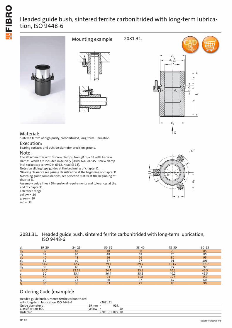
subject to alterations
Headed guide bush, sintered ferrite carbonitrided with long-term lubrica-tion, ISO 9448-6
Material: Sintered ferrite of high purity, carbonitrided, long-term lubrication
Execution: Bearing surfaces and outside diameter precision ground.
Note: The attachment is with 3 screw clamps, from ∅ d1 = 38 with 4 screw clamps, which are included in delivery (Order No: 207.45 - screw clamp incl. socket cap screw DIN 6912, Head ∅ 13). Notes on sliding type guides at the beginning of chapter D. *Bearing clearance see pairing classification at the beginning of chapter D. Matching guide combinations, see selection matrix at the beginning of chapter D. Assembly guide lines / Dimensional requirements and tolerances at the end of chapter D. Tolerance range: yellow = .10 green = .20 red = .30
1l
l2
3l
66
8d
3dH5
js4
d *1
5d
13
a
1a
6d
7d
„ X ”
X
d4
2081.31.Mounting example
D118
d1 19 20 24 25 30 32 38 40 48 50 60 63d3 32 40 48 58 70 85d4 32 40 48 58 70 85d5 40 48 56 66 80 95d6 52 60 67 77 91 106d7 64.7 72.7 79.7 89.7 103.7 118.7d8 39 46 53 63 77 92a 20.7 22.65 24.4 35.3 40.2 45.5a1 30 33.4 36.4 35.3 40.2 45.5l1 59 79 93 108 127 150l2 23 23 30 37 47 60l3 36 56 63 71 80 90
Ordering Code (example):Headed guide bush, sintered ferrite carbonitrided with long-term lubrication, ISO 9448-6 =2081.31.Guide diameter d1 19 mm = 019.Classification TOL yellow = 10Order No =2081.31. 019. 10
2081.31. Headed guide bush, sintered ferrite carbonitrided with long-term lubrication, ISO 9448-6
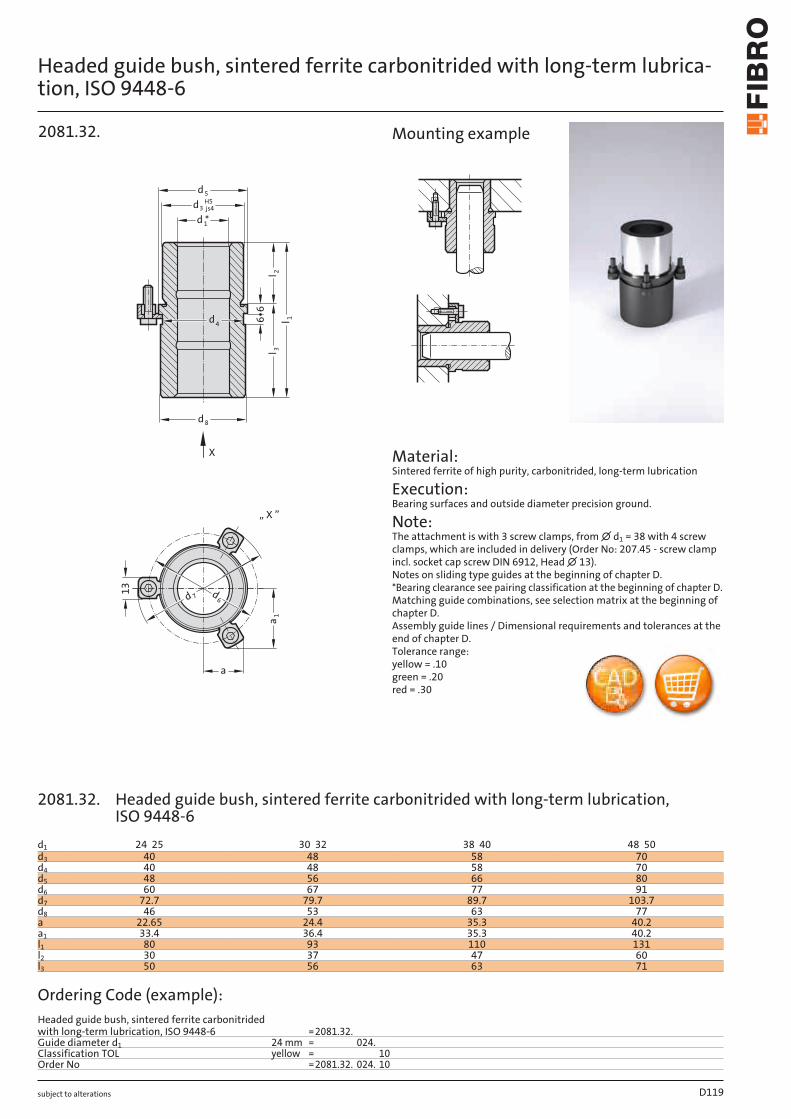
subject to alterations
Headed guide bush, sintered ferrite carbonitrided with long-term lubrica-tion, ISO 9448-6
13
a
1a
6d
7d
„ X ”
X
l 32l
1l
66
8d
3dH5
js4
d *1
5d
d4
2081.32.
Material: Sintered ferrite of high purity, carbonitrided, long-term lubrication
Execution: Bearing surfaces and outside diameter precision ground.
Note: The attachment is with 3 screw clamps, from ∅ d1 = 38 with 4 screw clamps, which are included in delivery (Order No: 207.45 - screw clamp incl. socket cap screw DIN 6912, Head ∅ 13). Notes on sliding type guides at the beginning of chapter D. *Bearing clearance see pairing classification at the beginning of chapter D. Matching guide combinations, see selection matrix at the beginning of chapter D. Assembly guide lines / Dimensional requirements and tolerances at the end of chapter D. Tolerance range: yellow = .10 green = .20 red = .30
Mounting example
D119
d1 24 25 30 32 38 40 48 50d3 40 48 58 70d4 40 48 58 70d5 48 56 66 80d6 60 67 77 91d7 72.7 79.7 89.7 103.7d8 46 53 63 77a 22.65 24.4 35.3 40.2a1 33.4 36.4 35.3 40.2l1 80 93 110 131l2 30 37 47 60l3 50 56 63 71
Ordering Code (example):Headed guide bush, sintered ferrite carbonitrided with long-term lubrication, ISO 9448-6 =2081.32.Guide diameter d1 24 mm = 024.Classification TOL yellow = 10Order No =2081.32. 024. 10
2081.32. Headed guide bush, sintered ferrite carbonitrided with long-term lubrication, ISO 9448-6
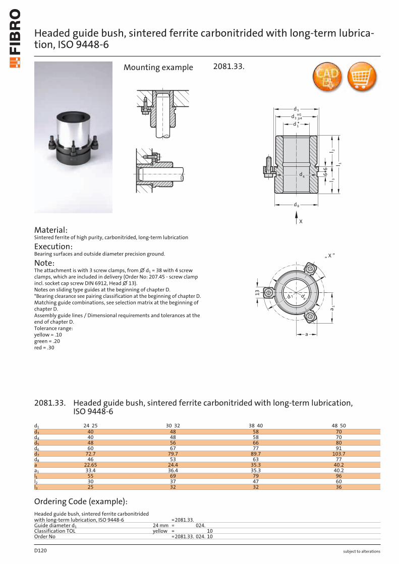
subject to alterations
Headed guide bush, sintered ferrite carbonitrided with long-term lubrica-tion, ISO 9448-6
Material: Sintered ferrite of high purity, carbonitrided, long-term lubrication
Execution: Bearing surfaces and outside diameter precision ground.
Note: The attachment is with 3 screw clamps, from ∅ d1 = 38 with 4 screw clamps, which are included in delivery (Order No: 207.45 - screw clamp incl. socket cap screw DIN 6912, Head ∅ 13). Notes on sliding type guides at the beginning of chapter D. *Bearing clearance see pairing classification at the beginning of chapter D. Matching guide combinations, see selection matrix at the beginning of chapter D. Assembly guide lines / Dimensional requirements and tolerances at the end of chapter D. Tolerance range: yellow = .10 green = .20 red = .30
13
a1
a
6d
7d
„ X ”
X
l 32l
1l
66
8d
3dH5
js4
d *1
5d
d4
2081.33.Mounting example
D120
d1 24 25 30 32 38 40 48 50d3 40 48 58 70d4 40 48 58 70d5 48 56 66 80d6 60 67 77 91d7 72.7 79.7 89.7 103.7d8 46 53 63 77a 22.65 24.4 35.3 40.2a1 33.4 36.4 35.3 40.2l1 55 69 79 96l2 30 37 47 60l3 25 32 32 36
Ordering Code (example):Headed guide bush, sintered ferrite carbonitrided with long-term lubrication, ISO 9448-6 =2081.33.Guide diameter d1 24 mm = 024.Classification TOL yellow = 10Order No =2081.33. 024. 10
2081.33. Headed guide bush, sintered ferrite carbonitrided with long-term lubrication, ISO 9448-6
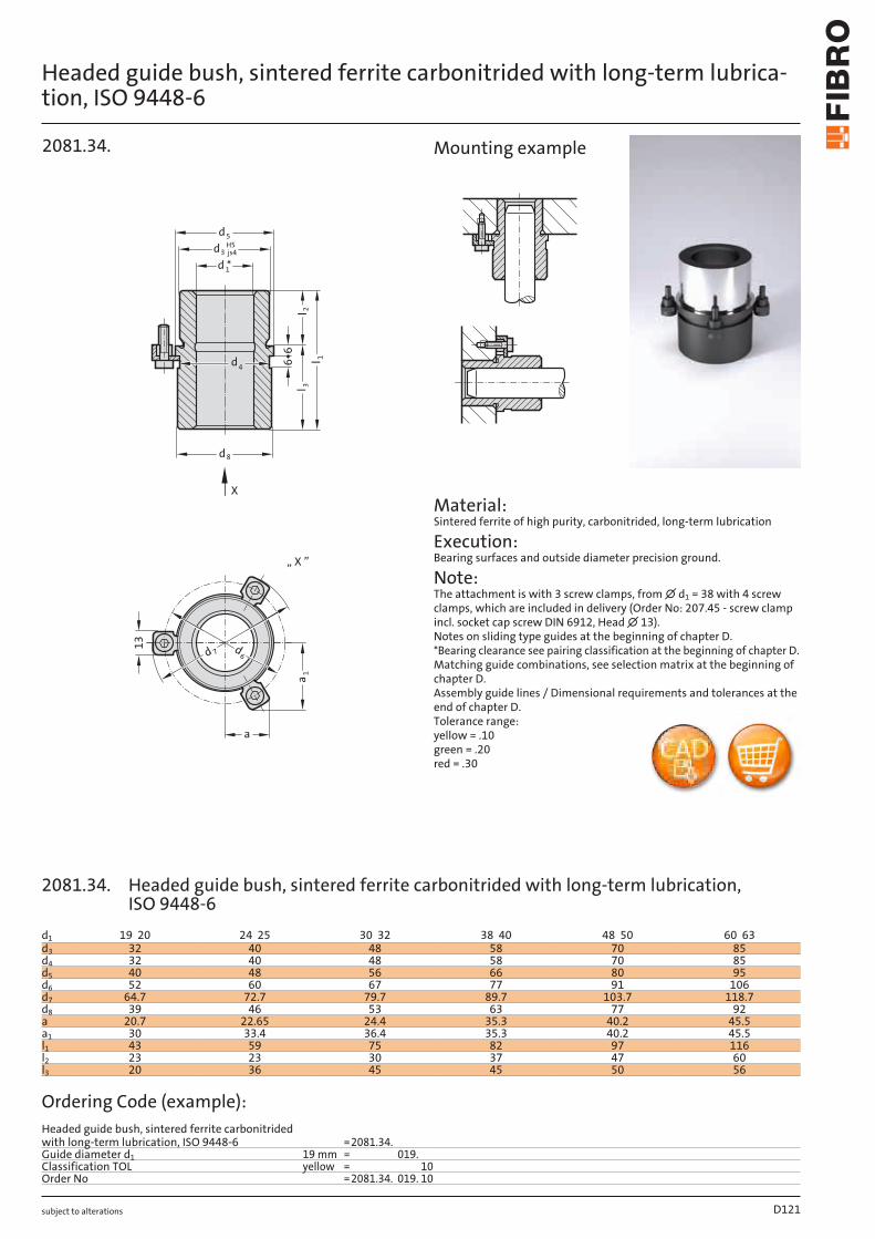
subject to alterations
Headed guide bush, sintered ferrite carbonitrided with long-term lubrica-tion, ISO 9448-6
13
a
1a
6d
7d
„ X ”
X
l 32l
1l
66
8d
3dH5
js4
d *1
5d
d4
2081.34.
Material: Sintered ferrite of high purity, carbonitrided, long-term lubrication
Execution: Bearing surfaces and outside diameter precision ground.
Note: The attachment is with 3 screw clamps, from ∅ d1 = 38 with 4 screw clamps, which are included in delivery (Order No: 207.45 - screw clamp incl. socket cap screw DIN 6912, Head ∅ 13). Notes on sliding type guides at the beginning of chapter D. *Bearing clearance see pairing classification at the beginning of chapter D. Matching guide combinations, see selection matrix at the beginning of chapter D. Assembly guide lines / Dimensional requirements and tolerances at the end of chapter D. Tolerance range: yellow = .10 green = .20 red = .30
Mounting example
D121
d1 19 20 24 25 30 32 38 40 48 50 60 63d3 32 40 48 58 70 85d4 32 40 48 58 70 85d5 40 48 56 66 80 95d6 52 60 67 77 91 106d7 64.7 72.7 79.7 89.7 103.7 118.7d8 39 46 53 63 77 92a 20.7 22.65 24.4 35.3 40.2 45.5a1 30 33.4 36.4 35.3 40.2 45.5l1 43 59 75 82 97 116l2 23 23 30 37 47 60l3 20 36 45 45 50 56
Ordering Code (example):Headed guide bush, sintered ferrite carbonitrided with long-term lubrication, ISO 9448-6 =2081.34.Guide diameter d1 19 mm = 019.Classification TOL yellow = 10Order No =2081.34. 019. 10
2081.34. Headed guide bush, sintered ferrite carbonitrided with long-term lubrication, ISO 9448-6
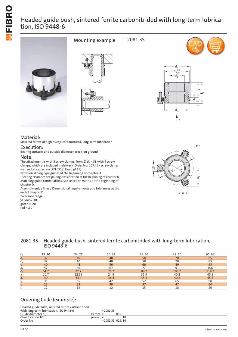
subject to alterations
Headed guide bush, sintered ferrite carbonitrided with long-term lubrica-tion, ISO 9448-6
Material: Sintered ferrite of high purity, carbonitrided, long-term lubrication
Execution: Bearing surfaces and outside diameter precision ground.
Note: The attachment is with 3 screw clamps, from ∅ d1 = 38 with 4 screw clamps, which are included in delivery (Order No: 207.45 - screw clamp incl. socket cap screw DIN 6912, Head ∅ 13). Notes on sliding type guides at the beginning of chapter D. *Bearing clearance see pairing classification at the beginning of chapter D. Matching guide combinations, see selection matrix at the beginning of chapter D. Assembly guide lines / Dimensional requirements and tolerances at the end of chapter D. Tolerance range: yellow = .10 green = .20 red = .30
13
a
1a
6d
7d
„ X ”
X
2ll 3
1l
6
4d
3d
H5
js4
d *1
5d
2081.35.Mounting example
D122
d1 19 20 24 25 30 32 38 40 48 50 60 63d3 32 40 48 58 70 85d4 32 40 48 58 70 85d5 40 48 56 66 80 95d6 52 60 67 77 91 106d7 64.7 72.7 79.7 89.7 103.7 118.7a 20.7 22.65 24.4 35.3 40.2 45.5a1 30 33.4 36.4 35.3 40.2 45.5l1 35 35 42 52 65 80l2 23 23 30 37 47 60l3 12 12 12 15 18 20
Ordering Code (example):Headed guide bush, sintered ferrite carbonitrided with long-term lubrication, ISO 9448-6 =2081.35.Guide diameter d1 19 mm = 019.Classification TOL yellow = 10Order No =2081.35. 019. 10
2081.35. Headed guide bush, sintered ferrite carbonitrided with long-term lubrication, ISO 9448-6
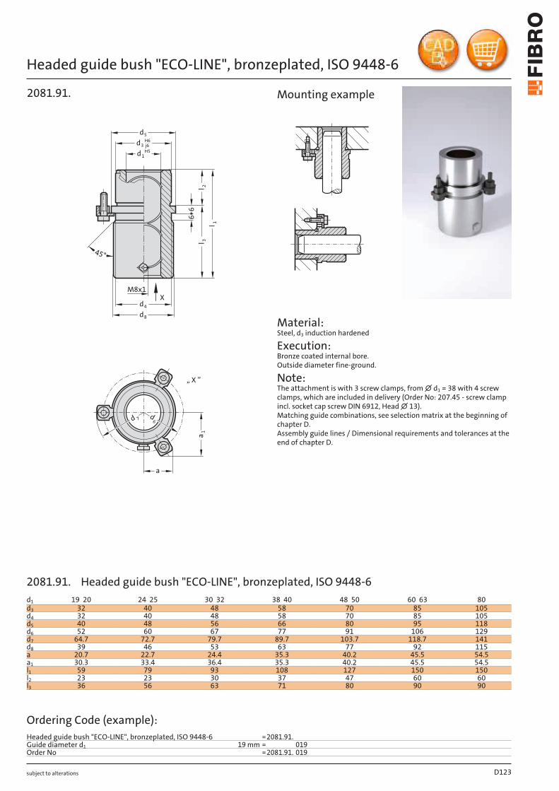
subject to alterations
Headed guide bush "ECO-LINE", bronzeplated, ISO 9448-6
a
1a
6d
7d
„ X ”
5d
3dH6
j6
1d
M8x1
d
4d
8
l 23l
66
45°
1 l
H5
X
2081.91.
Material: Steel, d3 induction hardened
Execution: Bronze coated internal bore. Outside diameter fine-ground.
Note: The attachment is with 3 screw clamps, from ∅ d1 = 38 with 4 screw clamps, which are included in delivery (Order No: 207.45 - screw clamp incl. socket cap screw DIN 6912, Head ∅ 13). Matching guide combinations, see selection matrix at the beginning of chapter D. Assembly guide lines / Dimensional requirements and tolerances at the end of chapter D.
Mounting example
D123
d1 19 20 24 25 30 32 38 40 48 50 60 63 80d3 32 40 48 58 70 85 105d4 32 40 48 58 70 85 105d5 40 48 56 66 80 95 118d6 52 60 67 77 91 106 129d7 64.7 72.7 79.7 89.7 103.7 118.7 141d8 39 46 53 63 77 92 115a 20.7 22.7 24.4 35.3 40.2 45.5 54.5a1 30.3 33.4 36.4 35.3 40.2 45.5 54.5l1 59 79 93 108 127 150 150l2 23 23 30 37 47 60 60l3 36 56 63 71 80 90 90
Ordering Code (example):Headed guide bush "ECO-LINE", bronzeplated, ISO 9448-6 =2081.91.Guide diameter d1 19 mm = 019Order No =2081.91. 019
2081.91. Headed guide bush "ECO-LINE", bronzeplated, ISO 9448-6
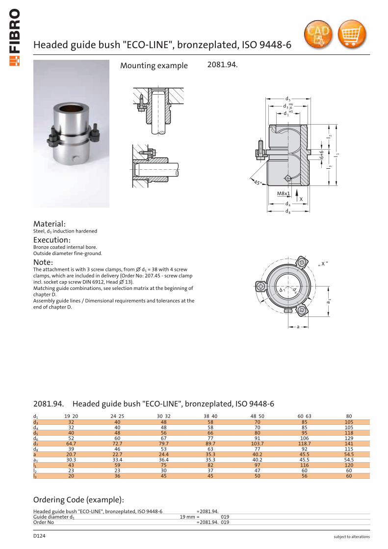
subject to alterations
Headed guide bush "ECO-LINE", bronzeplated, ISO 9448-6
a1
a
6d
7d
„ X ”
5d
3dH6
j6
3l
M8x1
d
4d
8
l 2
66
45°
X
1 l
1dH5
2081.94.Mounting example
D124
d1 19 20 24 25 30 32 38 40 48 50 60 63 80d3 32 40 48 58 70 85 105d4 32 40 48 58 70 85 105d5 40 48 56 66 80 95 118d6 52 60 67 77 91 106 129d7 64.7 72.7 79.7 89.7 103.7 118.7 141d8 39 46 53 63 77 92 115a 20.7 22.7 24.4 35.3 40.2 45.5 54.5a1 30.3 33.4 36.4 35.3 40.2 45.5 54.5l1 43 59 75 82 97 116 120l2 23 23 30 37 47 60 60l3 20 36 45 45 50 56 60
Ordering Code (example):Headed guide bush "ECO-LINE", bronzeplated, ISO 9448-6 =2081.94.Guide diameter d1 19 mm = 019Order No =2081.94. 019
Material: Steel, d3 induction hardened
Execution: Bronze coated internal bore. Outside diameter fine-ground.
Note: The attachment is with 3 screw clamps, from ∅ d1 = 38 with 4 screw clamps, which are included in delivery (Order No: 207.45 - screw clamp incl. socket cap screw DIN 6912, Head ∅ 13). Matching guide combinations, see selection matrix at the beginning of chapter D. Assembly guide lines / Dimensional requirements and tolerances at the end of chapter D.
2081.94. Headed guide bush "ECO-LINE", bronzeplated, ISO 9448-6

subject to alterations
Headed guide bush "ECO-LINE", bronzeplated, ISO 9448-6
a
1a
6d
7d
„ X ”
1 l
3l
d
4d
5
3dH6
j6
M8x1
l 2
6
1dH5
X
2081.95.
Material: Steel, d3 induction hardened
Execution: Bronze coated internal bore. Outside diameter fine-ground.
Note: The attachment is with 3 screw clamps, from ∅ d1 = 38 with 4 screw clamps, which are included in delivery (Order No: 207.45 - screw clamp incl. socket cap screw DIN 6912, Head ∅ 13). Matching guide combinations, see selection matrix at the beginning of chapter D. Assembly guide lines / Dimensional requirements and tolerances at the end of chapter D.
Mounting example
D125
d1 19 20 24 25 30 32 38 40 48 50 60 63 80d3 32 40 48 58 70 85 105d4 32 40 48 58 70 85 105d5 40 48 56 66 80 95 118d6 52 60 67 77 91 106 129d7 64.7 72.7 79.7 89.7 103.7 118.7 141a 20.7 22.65 24.4 35.3 40.2 45.5 54.4a1 30 33.4 36.4 35.3 40.2 45.5 54.4l1 35 35 42 52 65 80 80l2 23 23 30 37 47 60 60l3 12 12 12 15 18 20 20
Ordering Code (example):Headed guide bush "ECO-LINE", bronzeplated, ISO 9448-6 = 2081.95.Guide diameter d1 19 mm = 019Order No = 2081.95. 019
2081.95. Headed guide bush "ECO-LINE", bronzeplated, ISO 9448-6
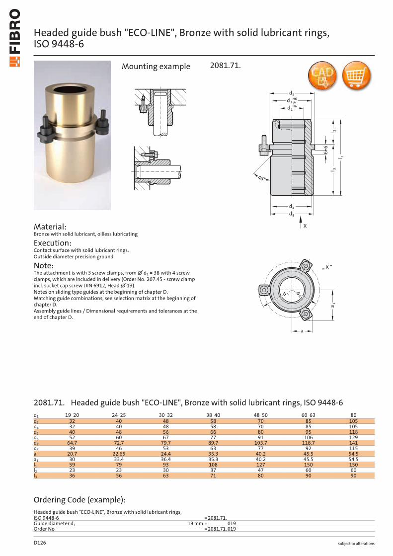
subject to alterations
Headed guide bush "ECO-LINE", Bronze with solid lubricant rings, ISO 9448-6
Material: Bronze with solid lubricant, oilless lubricating
Execution: Contact surface with solid lubricant rings. Outside diameter precision ground.
Note: The attachment is with 3 screw clamps, from ∅ d1 = 38 with 4 screw clamps, which are included in delivery (Order No: 207.45 - screw clamp incl. socket cap screw DIN 6912, Head ∅ 13). Notes on sliding type guides at the beginning of chapter D. Matching guide combinations, see selection matrix at the beginning of chapter D. Assembly guide lines / Dimensional requirements and tolerances at the end of chapter D.
a1
a
6d
7d
„ X ”
5d
d
4d
8
l 23l
66
45°
1 l
3dH6
j6
1dH6
X
2081.71.Mounting example
D126
d1 19 20 24 25 30 32 38 40 48 50 60 63 80d3 32 40 48 58 70 85 105d4 32 40 48 58 70 85 105d5 40 48 56 66 80 95 118d6 52 60 67 77 91 106 129d7 64.7 72.7 79.7 89.7 103.7 118.7 141d8 39 46 53 63 77 92 115a 20.7 22.65 24.4 35.3 40.2 45.5 54.5a1 30 33.4 36.4 35.3 40.2 45.5 54.5l1 59 79 93 108 127 150 150l2 23 23 30 37 47 60 60l3 36 56 63 71 80 90 90
Ordering Code (example):Headed guide bush "ECO-LINE", Bronze with solid lubricant rings, ISO 9448-6 =2081.71.Guide diameter d1 19 mm = 019Order No =2081.71. 019
2081.71. Headed guide bush "ECO-LINE", Bronze with solid lubricant rings, ISO 9448-6
subject to alterations
Headed guide bush "ECO-LINE", Bronze with solid lubricant rings, ISO 9448-6
a
1a
6d
7d
„ X ”
5d
3l
d
4d
8
l 2
66
45°
X
1 l
3dH6
j6
1dH6
2081.74.
Material: Bronze with solid lubricant, oilless lubricating
Execution: Contact surface with solid lubricant rings. Outside diameter precision ground.
Note: The attachment is with 3 screw clamps, from ∅ d1 = 38 with 4 screw clamps, which are included in delivery (Order No: 207.45 - screw clamp incl. socket cap screw DIN 6912, Head ∅ 13). Notes on sliding type guides at the beginning of chapter D. Matching guide combinations, see selection matrix at the beginning of chapter D. Assembly guide lines / Dimensional requirements and tolerances at the end of chapter D.
Mounting example
D127
d1 19 20 24 25 30 32 38 40 48 50 60 63 80d3 32 40 48 58 70 85 105d4 32 40 48 58 70 85 105d5 40 48 56 66 80 95 118d6 52 60 67 77 91 106 129d7 64.7 72.7 79.7 89.7 103.7 118.7 141d8 39 46 53 63 77 92 115a 20.7 22.65 24.4 35.3 40.2 45.5 54.5a1 30 33.4 36.4 35.3 40.2 45.5 54.5l1 43 59 75 82 97 116 120l2 23 23 30 37 47 60 60l3 20 36 45 45 50 56 60
Ordering Code (example):Headed guide bush "ECO-LINE", Bronze with solid lubricant rings, ISO 9448-6 =2081.74.Guide diameter d1 19 mm = 019Order No =2081.74. 019
2081.74. Headed guide bush "ECO-LINE", Bronze with solid lubricant rings, ISO 9448-6
subject to alterations
Headed guide bush "ECO-LINE", Bronze with solid lubricant rings, ISO 9448-6
Material: Bronze with solid lubricant, oilless lubricating
Execution: Contact surface with solid lubricant rings. Outside diameter precision ground.
Note: The attachment is with 3 screw clamps, from ∅ d1 = 38 with 4 screw clamps, which are included in delivery (Order No: 207.45 - screw clamp incl. socket cap screw DIN 6912, Head ∅ 13). Notes on sliding type guides at the beginning of chapter D. Matching guide combinations, see selection matrix at the beginning of chapter D. Assembly guide lines / Dimensional requirements and tolerances at the end of chapter D.
a1
a
6d
7d
„ X ”
1 l
3l
d
4d
5
l 2
6
3dH6
j6
1dH6
X
2081.75.Mounting example
D128
d1 19 20 24 25 30 32 38 40 48 50 60 63 80d3 32 40 48 58 70 85 105d4 32 40 48 58 70 85 105d5 40 48 56 66 80 95 118d6 52 60 67 77 91 106 129d7 64.7 72.7 79.7 89.7 103.7 118.7 141a 20.7 22.65 24.4 35.3 40.2 45.5 54.4a1 30 33.4 36.4 35.3 40.2 45.5 54.4l1 35 35 42 52 65 80 80l2 23 23 30 37 47 60 60l3 12 12 12 15 18 20 20
Ordering Code (example):Headed guide bush "ECO-LINE", Bronze with solid lubricant rings, ISO 9448-6 = 2081.75.Guide diameter d1 19 mm = 19Order No = 2081.75. 19
2081.75. Headed guide bush "ECO-LINE", Bronze with solid lubricant rings, ISO 9448-6

subject to alterations
Headed guide bush for ball bearing, ISO 9448-7
a
a1
13
7d 6d
„ X ”
1l2l
3l
l
8d
2
dH5
js4
1
*d
d
3
66
5d
d4
X
2081.44.
Material: Tool steel, hardened 62 ± 2 HRC
Execution: Bearing surfaces honed, outside diameter precision ground.
Note: The attachment is with 3 screw clamps, from ∅ d1 = 38 with 4 screw clamps, which are included in delivery (Order No: 207.45 - screw clamp incl. socket cap screw DIN 6912, Head ∅ 13). Notes on ball bearing type guides at the beginning of chapter D. *Preloading see pairing classification at the beginning of chapter D. Matching guide combinations, see selection matrix at the beginning of chapter D. Ball guide capacity calculations at the end of chapter D. Assembly guide lines / Dimensional requirements and tolerances at the end of chapter D. Tolerance range: yellow = .10 green = .20 red = .30
Mounting example
D129
d1 19 20 24 25 30 32 38 40 48 50 60 63 80d2 25 26 30 31 38 40 46 48 56 58 68 71 92d3 32 40 48 58 70 85 105d4 32 40 48 58 70 85 105d5 40 48 56 66 80 95 118d6 52 60 67 77 91 106 129d7 64.7 72.7 79.7 89.7 103.7 118.7 141.7d8 39 46 53 63 77 92 115a 20.7 22.65 24.4 35.3 40.2 45.5 54.5a1 30 33.4 36.4 35.3 40.2 45.5 54.5l1 59 79 93 108 127 150 150l2 23 23 30 37 47 60 60l3 36 56 63 71 80 90 90l* 71 95 120 120 140 160 160*l = Nominal ordering length of ball cage - prefered length
Ordering Code (example):Headed guide bush for ball bearing, ISO 9448-7 =2081.44.Guide diameter d1 19 mm = 019.Classification TOL yellow = 10Order No =2081.44. 019. 10
2081.44. Headed guide bush for ball bearing, ISO 9448-7
subject to alterations
Headed guide bush for ball bearing, ISO 9448-7
Material: Tool steel, hardened 62 ± 2 HRC
Execution: Bearing surfaces honed, outside diameter precision ground.
Note: The attachment is with 3 screw clamps, from ∅ d1 = 38 with 4 screw clamps, which are included in delivery (Order No: 207.45 - screw clamp incl. socket cap screw DIN 6912, Head ∅ 13). Notes on ball bearing type guides at the beginning of chapter D. *Preloading see pairing classification at the beginning of chapter D. Matching guide combinations, see selection matrix at the beginning of chapter D. Ball guide capacity calculations at the end of chapter D. Assembly guide lines / Dimensional requirements and tolerances at the end of chapter D. Tolerance range: yellow = .10 green = .20 red = .30
a
a1
13
7d 6d
„ X ”
3l2l
1l
8d
2
dH5
js4
1
*d
d
3
66
5d
d4
X
2081.45.
l
Mounting example
D130
d1 24 25 30 32 38 40 48 50d2 30 31 38 40 46 48 56 58d3 40 48 58 70d4 40 48 58 70d5 48 56 66 80d6 60 67 77 91d7 72.7 79.7 89.7 103.7d8 46 53 63 77a 22.65 24.4 35.3 40.2a1 33.4 36.4 35.3 40.2l1 80 93 110 131l2 30 37 47 60l3 50 56 63 71l* 95 120 140 160*l = Nominal ordering length of ball cage - prefered length
Ordering Code (example):Headed guide bush for ball bearing, ISO 9448-7 =2081.45.Guide diameter d1 24 mm = 024.Classification TOL yellow = 10Order No =2081.45. 024. 10
2081.45. Headed guide bush for ball bearing, ISO 9448-7
subject to alterations
Headed guide bush for ball bearing, ISO 9448-7
a
a1
13
7d 6d
„ X ”
3l
1l2l
8d
2
dH5
js4
1
*d
d
3
66
5d
d4
X
2081.46.l
Material: Tool steel, hardened 62 ± 2 HRC
Execution: Bearing surfaces honed, outside diameter precision ground.
Note: The attachment is with 3 screw clamps, from ∅ d1 = 38 with 4 screw clamps, which are included in delivery (Order No: 207.45 - screw clamp incl. socket cap screw DIN 6912, Head ∅ 13). Notes on ball bearing type guides at the beginning of chapter D. *Preloading see pairing classification at the beginning of chapter D. Matching guide combinations, see selection matrix at the beginning of chapter D. Ball guide capacity calculations at the end of chapter D. Assembly guide lines / Dimensional requirements and tolerances at the end of chapter D. Tolerance range: yellow = .10 green = .20 red = .30
Mounting example
D131
d1 19 20 24 25 30 32 38 40 48 50 60 63 80d2 25 26 30 31 38 40 46 48 56 58 68 71 92d3 32 40 48 58 70 85 105d4 32 40 48 58 70 85 105d5 40 48 56 66 80 95 118d6 52 60 67 77 91 106 129d7 64.7 72.7 79.7 89.7 103.7 118.7 141.7d8 39 46 53 63 77 92 115a 20.7 22.65 24.4 35.3 40.2 45.5 54.5a1 30 33.4 36.4 35.3 40.2 45.5 54.5l1 43 59 75 82 97 116 120l2 23 23 30 37 47 60 60l3 20 36 45 45 50 56 60l* 56 71 95 105 120 140 140*l = Nominal ordering length of ball cage - prefered length
Ordering Code (example):Headed guide bush for ball bearing, ISO 9448-7 =2081.46.Guide diameter d1 19 mm = 019.Classification TOL yellow = 10Order No =2081.46. 019. 10
2081.46. Headed guide bush for ball bearing, ISO 9448-7
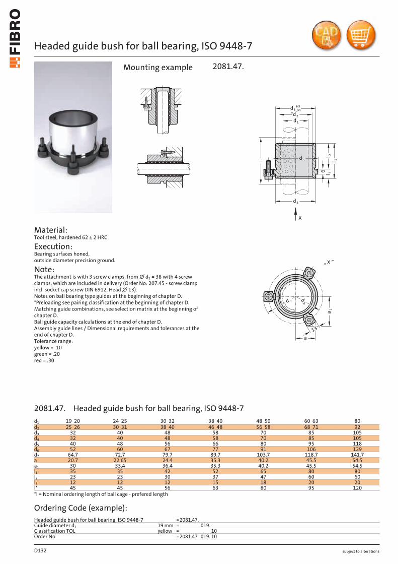
subject to alterations
Headed guide bush for ball bearing, ISO 9448-7
a
a1
13
7d 6d
„ X ”
3l
1l2l
4d
2
dH5
js4
1
*d
d
3
6
5d
X
2081.47.
l
Mounting example
D132
d1 19 20 24 25 30 32 38 40 48 50 60 63 80d2 25 26 30 31 38 40 46 48 56 58 68 71 92d3 32 40 48 58 70 85 105d4 32 40 48 58 70 85 105d5 40 48 56 66 80 95 118d6 52 60 67 77 91 106 129d7 64.7 72.7 79.7 89.7 103.7 118.7 141.7a 20.7 22.65 24.4 35.3 40.2 45.5 54.5a1 30 33.4 36.4 35.3 40.2 45.5 54.5l1 35 35 42 52 65 80 80l2 23 23 30 37 47 60 60l3 12 12 12 15 18 20 20l* 45 45 56 63 80 95 120*l = Nominal ordering length of ball cage - prefered length
Ordering Code (example):Headed guide bush for ball bearing, ISO 9448-7 =2081.47.Guide diameter d1 19 mm = 019.Classification TOL yellow = 10Order No =2081.47. 019. 10
Material: Tool steel, hardened 62 ± 2 HRC
Execution: Bearing surfaces honed, outside diameter precision ground.
Note: The attachment is with 3 screw clamps, from ∅ d1 = 38 with 4 screw clamps, which are included in delivery (Order No: 207.45 - screw clamp incl. socket cap screw DIN 6912, Head ∅ 13). Notes on ball bearing type guides at the beginning of chapter D. *Preloading see pairing classification at the beginning of chapter D. Matching guide combinations, see selection matrix at the beginning of chapter D. Ball guide capacity calculations at the end of chapter D. Assembly guide lines / Dimensional requirements and tolerances at the end of chapter D. Tolerance range: yellow = .10 green = .20 red = .30
2081.47. Headed guide bush for ball bearing, ISO 9448-7

subject to alterations
Headed guide bush for ball bearing, ISO 9448-7
a
a1
13
7d 6d
„ X ”
3l
1l2l
8d
2
dH5
js4
1
*d
d
3
66
5d
d4
X
2081.49.l
Material: Tool steel, hardened 62 ± 2 HRC
Execution: Bearing surfaces honed, outside diameter precision ground.
Note: The attachment is with 3 screw clamps, from ∅ d1 = 38 with 4 screw clamps, which are included in delivery (Order No: 207.45 - screw clamp incl. socket cap screw DIN 6912, Head ∅ 13). Notes on ball bearing type guides at the beginning of chapter D. *Preloading see pairing classification at the beginning of chapter D. Matching guide combinations, see selection matrix at the beginning of chapter D. Ball guide capacity calculations at the end of chapter D. Assembly guide lines / Dimensional requirements and tolerances at the end of chapter D. Tolerance range: yellow = .10 green = .20 red = .30
Mounting example
D133
d1 24 25 30 32 38 40 48 50d2 30 31 38 40 46 48 56 58d3 40 48 58 70d4 40 48 58 70d5 48 56 66 80d6 60 67 77 91d7 72.7 79.7 89.7 103.7d8 46 53 63 77a 22.65 24.4 35.3 40.2a1 33.4 36.4 35.3 40.2l1 55 69 79 96l2 30 37 47 60l3 25 32 32 36l* 71 80 95 120*l = Nominal ordering length of ball cage - prefered length
Ordering Code (example):Headed guide bush for ball bearing, ISO 9448-7 =2081.49.Guide diameter d1 24 mm = 024.Classification TOL yellow = 10Order No =2081.49. 024. 10
2081.49. Headed guide bush for ball bearing, ISO 9448-7
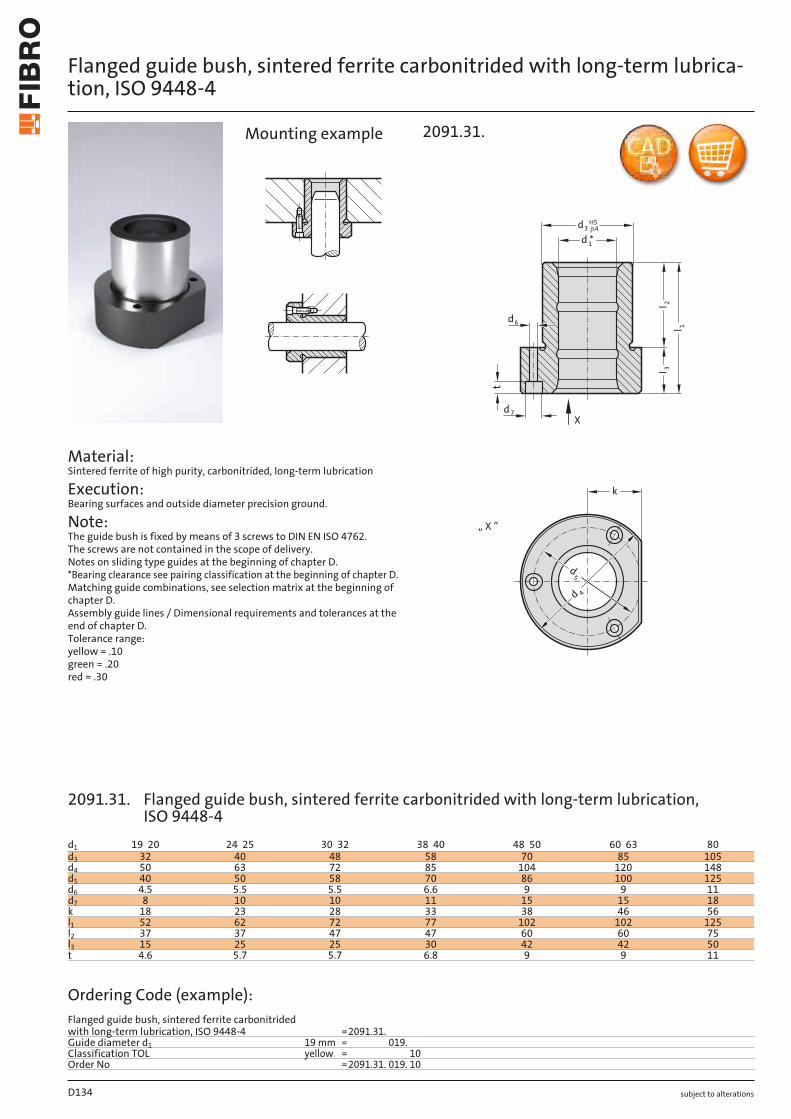
subject to alterations
Flanged guide bush, sintered ferrite carbonitrided with long-term lubrica-tion, ISO 9448-4
Material: Sintered ferrite of high purity, carbonitrided, long-term lubrication
Execution: Bearing surfaces and outside diameter precision ground.
Note: The guide bush is fixed by means of 3 screws to DIN EN ISO 4762. The screws are not contained in the scope of delivery. Notes on sliding type guides at the beginning of chapter D. *Bearing clearance see pairing classification at the beginning of chapter D. Matching guide combinations, see selection matrix at the beginning of chapter D. Assembly guide lines / Dimensional requirements and tolerances at the end of chapter D. Tolerance range: yellow = .10 green = .20 red = .30
k
d5
d 4
„ X ”
t
l 3
l 1
l 2
d *d3
H5js4
1
d6
Xd7
2091.31.Mounting example
D134
d1 19 20 24 25 30 32 38 40 48 50 60 63 80d3 32 40 48 58 70 85 105d4 50 63 72 85 104 120 148d5 40 50 58 70 86 100 125d6 4.5 5.5 5.5 6.6 9 9 11d7 8 10 10 11 15 15 18k 18 23 28 33 38 46 56l1 52 62 72 77 102 102 125l2 37 37 47 47 60 60 75l3 15 25 25 30 42 42 50t 4.6 5.7 5.7 6.8 9 9 11
Ordering Code (example):Flanged guide bush, sintered ferrite carbonitrided with long-term lubrication, ISO 9448-4 =2091.31.Guide diameter d1 19 mm = 019.Classification TOL yellow = 10Order No =2091.31. 019. 10
2091.31. Flanged guide bush, sintered ferrite carbonitrided with long-term lubrication, ISO 9448-4
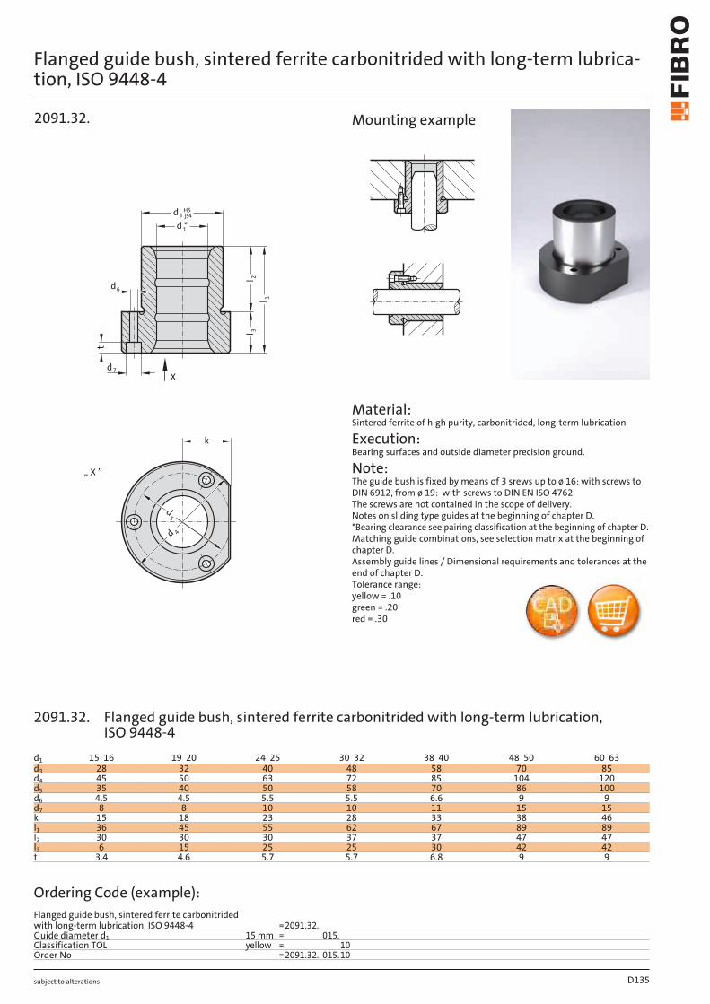
subject to alterations
Flanged guide bush, sintered ferrite carbonitrided with long-term lubrica-tion, ISO 9448-4
k
d5
d 4
„ X ”
ll
d3H5js4
d *1
d6
l 3
1
2
t
Xd7
2091.32.
Material: Sintered ferrite of high purity, carbonitrided, long-term lubrication
Execution: Bearing surfaces and outside diameter precision ground.
Note: The guide bush is fixed by means of 3 srews up to ø 16: with screws to DIN 6912, from ø 19: with screws to DIN EN ISO 4762. The screws are not contained in the scope of delivery. Notes on sliding type guides at the beginning of chapter D. *Bearing clearance see pairing classification at the beginning of chapter D. Matching guide combinations, see selection matrix at the beginning of chapter D. Assembly guide lines / Dimensional requirements and tolerances at the end of chapter D. Tolerance range: yellow = .10 green = .20 red = .30
Mounting example
D135
d1 15 16 19 20 24 25 30 32 38 40 48 50 60 63d3 28 32 40 48 58 70 85d4 45 50 63 72 85 104 120d5 35 40 50 58 70 86 100d6 4.5 4.5 5.5 5.5 6.6 9 9d7 8 8 10 10 11 15 15k 15 18 23 28 33 38 46l1 36 45 55 62 67 89 89l2 30 30 30 37 37 47 47l3 6 15 25 25 30 42 42t 3.4 4.6 5.7 5.7 6.8 9 9
Ordering Code (example):Flanged guide bush, sintered ferrite carbonitrided with long-term lubrication, ISO 9448-4 =2091.32.Guide diameter d1 15 mm = 015.Classification TOL yellow = 10Order No =2091.32. 015.10
2091.32. Flanged guide bush, sintered ferrite carbonitrided with long-term lubrication, ISO 9448-4
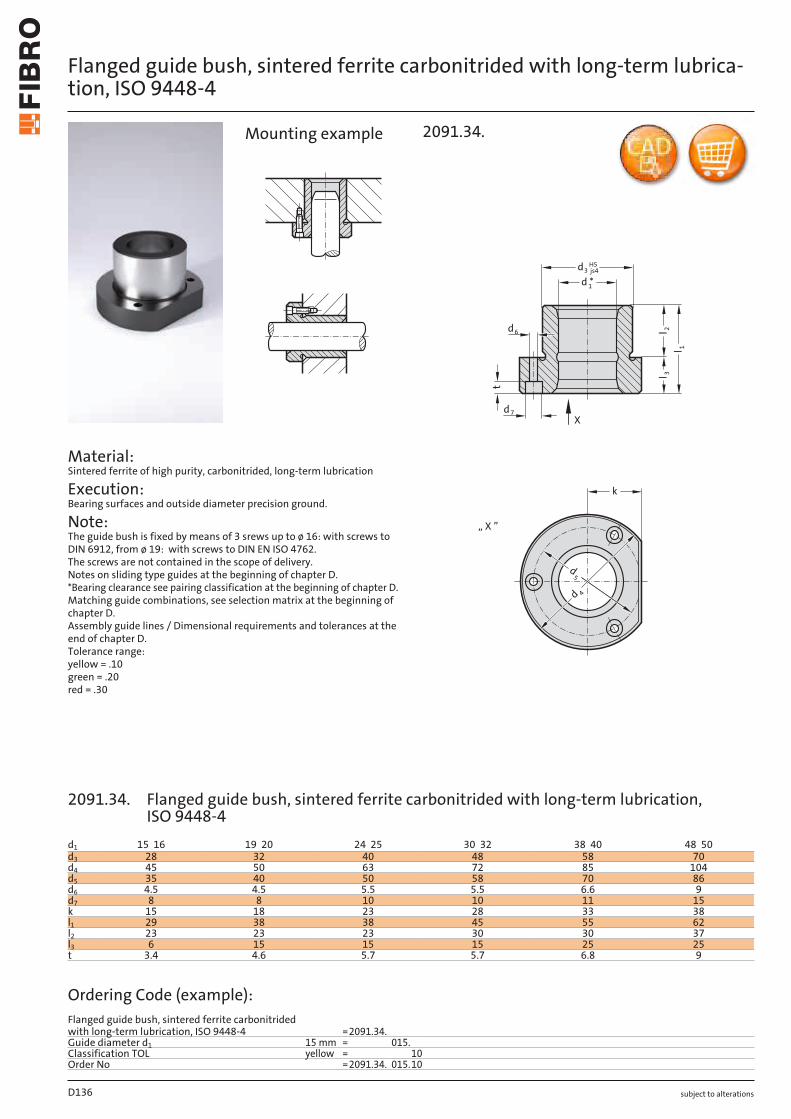
subject to alterations
Flanged guide bush, sintered ferrite carbonitrided with long-term lubrica-tion, ISO 9448-4
Material: Sintered ferrite of high purity, carbonitrided, long-term lubrication
Execution: Bearing surfaces and outside diameter precision ground.
Note: The guide bush is fixed by means of 3 srews up to ø 16: with screws to DIN 6912, from ø 19: with screws to DIN EN ISO 4762. The screws are not contained in the scope of delivery. Notes on sliding type guides at the beginning of chapter D. *Bearing clearance see pairing classification at the beginning of chapter D. Matching guide combinations, see selection matrix at the beginning of chapter D. Assembly guide lines / Dimensional requirements and tolerances at the end of chapter D. Tolerance range: yellow = .10 green = .20 red = .30
k
d5
d 4
„ X ”
l 3
l 1
l 2
d3H5js4
d *1
d6
t
Xd7
2091.34.Mounting example
D136
d1 15 16 19 20 24 25 30 32 38 40 48 50d3 28 32 40 48 58 70d4 45 50 63 72 85 104d5 35 40 50 58 70 86d6 4.5 4.5 5.5 5.5 6.6 9d7 8 8 10 10 11 15k 15 18 23 28 33 38l1 29 38 38 45 55 62l2 23 23 23 30 30 37l3 6 15 15 15 25 25t 3.4 4.6 5.7 5.7 6.8 9
Ordering Code (example):Flanged guide bush, sintered ferrite carbonitrided with long-term lubrication, ISO 9448-4 =2091.34.Guide diameter d1 15 mm = 015.Classification TOL yellow = 10Order No =2091.34. 015.10
2091.34. Flanged guide bush, sintered ferrite carbonitrided with long-term lubrication, ISO 9448-4
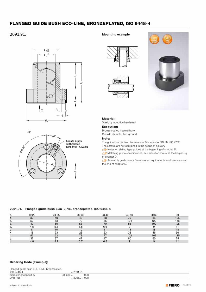
09.2019subject to alterations
FLANGED GUIDE BUSH ECO-LINE, BRONZEPLATED, ISO 9448-43
x1
20
°
30°
k
7d
t
X
4d
3d
j6
H6
1d H5
2l
1l
6d
„X“
5d
Grease nipple
with thread
DIN 3405 -A M8x1
2091.91.
Material: Steel, d3 induction hardened
Execution: Bronze coated internal bore. Outside diameter fine-ground.
Note: The guide bush is fixed by means of 3 screws to DIN EN ISO 4762. The screws are not contained in the scope of delivery. Notes on sliding type guides at the beginning of chapter D. Matching guide combinations, see selection matrix at the beginning of chapter D. Assembly guide lines / Dimensional requirements and tolerances at the end of chapter D.
Mounting example
2091.91. Flanged guide bush ECO-LINE, bronzeplated, ISO 9448-4
d 19 20 24 25 30 32 38 40 48 50 60 63 80d
13 32 40 48 58 70 85 105
d4 50 63 72 85 104 120 146d5 40 50 58 70 86 100 125d6 4.5 5.5 5.5 6.6 9 9 11d7 8 10 10 11 15 15 18k 18 23 28 33 38 46 56l1 52 62 72 77 102 102 125l2 37 37 47 47 60 60 75t 4.6 5.7 5.7 6.8 9 9 11
Ordering Code (example):
Flanged guide bush ECO-LINE, bronzeplated, ISO 9448-4 = 2091.91.diameter of conduit d1 38 mm = 038Order No = 2091.91. 038
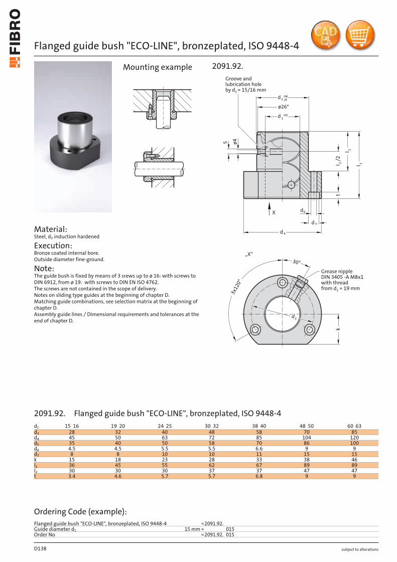
subject to alterations
Flanged guide bush "ECO-LINE", bronzeplated, ISO 9448-4
Material: Steel, d3 induction hardened
Execution: Bronze coated internal bore. Outside diameter fine-ground.
Note: The guide bush is fixed by means of 3 srews up to ø 16: with screws to DIN 6912, from ø 19: with screws to DIN EN ISO 4762. The screws are not contained in the scope of delivery. Notes on sliding type guides at the beginning of chapter D. Matching guide combinations, see selection matrix at the beginning of chapter D. Assembly guide lines / Dimensional requirements and tolerances at the end of chapter D.
5
Grease nippleDIN 3405 -A M8x1with threadfrom d1 = 19 mm
3x
12
0°
30°
k
7d
t
X
4d
3d
j6H6
1d H5
2l
1l
6d
„X“
5d
ø26*
2l/2
ø4
2091.92.
Groove andlubrication holeby d1 = 15/16 mm
Mounting example
D138
d1 15 16 19 20 24 25 30 32 38 40 48 50 60 63d3 28 32 40 48 58 70 85d4 45 50 63 72 85 104 120d5 35 40 50 58 70 86 100d6 4.5 4.5 5.5 5.5 6.6 9 9d7 8 8 10 10 11 15 15k 15 18 23 28 33 38 46l1 36 45 55 62 67 89 89l2 30 30 30 37 37 47 47t 3.4 4.6 5.7 5.7 6.8 9 9
Ordering Code (example):Flanged guide bush "ECO-LINE", bronzeplated, ISO 9448-4 =2091.92.Guide diameter d1 15 mm = 015Order No =2091.92. 015
2091.92. Flanged guide bush "ECO-LINE", bronzeplated, ISO 9448-4
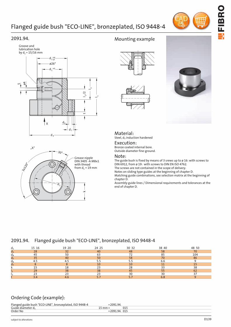
subject to alterations
Flanged guide bush "ECO-LINE", bronzeplated, ISO 9448-4
Groove and
lubrication hole
by d1
= 15/16 mm
5
3x
12
0°
30°
k
7d
t
X
4d
3d
j6
H6
1d H5
2l
1l
6d
„X“
5d
ø26*
2l/
2
ø4
2091.94.
Grease nipple
DIN 3405 -A M8x1
with thread
from d1 = 19 mm
Material: Steel, d3 induction hardened
Execution: Bronze coated internal bore. Outside diameter fine-ground.
Note: The guide bush is fixed by means of 3 srews up to ø 16: with screws to DIN 6912, from ø 19: with screws to DIN EN ISO 4762. The screws are not contained in the scope of delivery. Notes on sliding type guides at the beginning of chapter D. Matching guide combinations, see selection matrix at the beginning of chapter D. Assembly guide lines / Dimensional requirements and tolerances at the end of chapter D.
Mounting example
D139
d1 15 16 19 20 24 25 30 32 38 40 48 50d3 28 32 40 48 58 70d4 45 50 63 72 85 104d5 35 40 50 58 70 86d6 4.5 4.5 5.5 5.5 6.6 9d7 8 8 10 10 11 15k 15 18 23 28 33 38l1 29 38 38 45 55 62l2 23 23 23 30 30 37t 3.4 4.6 5.7 5.7 6.8 9
Ordering Code (example):Flanged guide bush "ECO-LINE", bronzeplated, ISO 9448-4 =2091.94.Guide diameter d1 15 mm = 015Order No =2091.94. 015
2091.94. Flanged guide bush "ECO-LINE", bronzeplated, ISO 9448-4
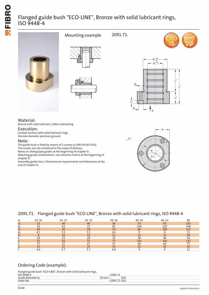
subject to alterations
Flanged guide bush "ECO-LINE", Bronze with solid lubricant rings, ISO 9448-4
Material: Bronze with solid lubricant, oilless lubricating
Execution: Contact surface with solid lubricant rings. Outside diameter precision ground.
Note: The guide bush is fixed by means of 3 screws to DIN EN ISO 4762. The screws are not contained in the scope of delivery. Notes on sliding type guides at the beginning of chapter D. Matching guide combinations, see selection matrix at the beginning of chapter D. Assembly guide lines / Dimensional requirements and tolerances at the end of chapter D.
t
l 3
1l
2l
6d
3dH6
j6
d 1H6
7d
k
d5
d 4
„ X ”
X
2091.71.Mounting example
D140
d1 19 20 24 25 30 32 38 40 48 50 60 63 80d3 32 40 48 58 70 85 105d4 50 63 72 85 104 120 148d5 40 50 58 70 86 100 125d6 4.5 5.5 5.5 6.6 9 9 11d7 8 10 10 11 15 15 18k 18 23 28 33 38 46 56l1 52 62 72 77 102 102 125l2 37 37 47 47 60 60 75l3 15 25 25 30 42 42 50t 4.6 5.7 5.7 6.8 9 9 11
Ordering Code (example):Flanged guide bush "ECO-LINE", Bronze with solid lubricant rings, ISO 9448-4 =2091.71.Guide diameter d1 19 mm = 019Order No =2091.71. 019
2091.71. Flanged guide bush "ECO-LINE", Bronze with solid lubricant rings, ISO 9448-4
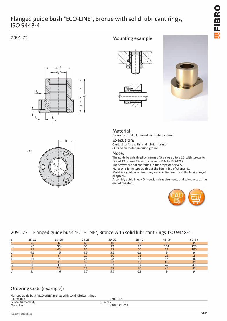
subject to alterations
Flanged guide bush "ECO-LINE", Bronze with solid lubricant rings, ISO 9448-4
ll
d6
l 3
1
2
t
d3 j6H6
d 1H6
d7
k
d5
d 4
„ X ”
X
2091.72.
Material: Bronze with solid lubricant, oilless lubricating
Execution: Contact surface with solid lubricant rings. Outside diameter precision ground.
Note: The guide bush is fixed by means of 3 srews up to ø 16: with screws to DIN 6912, from ø 19: with screws to DIN EN ISO 4762. The screws are not contained in the scope of delivery. Notes on sliding type guides at the beginning of chapter D. Matching guide combinations, see selection matrix at the beginning of chapter D. Assembly guide lines / Dimensional requirements and tolerances at the end of chapter D.
Mounting example
D141
d1 15 16 19 20 24 25 30 32 38 40 48 50 60 63d3 28 32 40 48 58 70 85d4 45 50 63 72 85 104 120d5 35 40 50 58 70 86 100d6 4.5 4.5 5.5 5.5 6.6 9 9d7 8 8 10 10 11 15 15k 15 18 23 28 33 38 46l1 36 45 55 62 67 89 89l2 30 30 30 37 37 47 47l3 6 15 25 25 30 42 42t 3.4 4.6 5.7 5.7 6.8 9 9
Ordering Code (example):Flanged guide bush "ECO-LINE", Bronze with solid lubricant rings, ISO 9448-4 =2091.72.Guide diameter d1 15 mm = 015Order No =2091.72. 015
2091.72. Flanged guide bush "ECO-LINE", Bronze with solid lubricant rings, ISO 9448-4

subject to alterations
Flanged guide bush "ECO-LINE", Bronze with solid lubricant rings, ISO 9448-4
Material: Bronze with solid lubricant, oilless lubricating
Execution: Contact surface with solid lubricant rings. Outside diameter precision ground.
Note: The guide bush is fixed by means of 3 srews up to ø 16: with screws to DIN 6912, from ø 19: with screws to DIN EN ISO 4762. The screws are not contained in the scope of delivery. Notes on sliding type guides at the beginning of chapter D. Matching guide combinations, see selection matrix at the beginning of chapter D. Assembly guide lines / Dimensional requirements and tolerances at the end of chapter D.
k
l 3
l 1
2l
3dH6
j6
d 1
6d
t
d5
d 4
X
„ X ”
H6
7d
2091.74.Mounting example
D142
d1 15 16 19 20 24 25 30 32 38 40 48 50d3 28 32 40 48 58 70d4 45 50 63 72 85 104d5 35 40 50 58 70 86d6 4.5 4.5 5.5 5.5 6.6 9d7 8 8 10 10 11 15k 15 18 23 28 33 38l1 29 38 38 45 55 62l2 23 23 23 30 30 37l3 6 15 15 15 25 25t 3.4 4.6 5.7 5.7 6.8 9
Ordering Code (example):Flanged guide bush "ECO-LINE", Bronze with solid lubricant rings, ISO 9448-4 =2091.74.Guide diameter d1 15 mm = 015Order No =2091.74. 015
2091.74. Flanged guide bush "ECO-LINE", Bronze with solid lubricant rings, ISO 9448-4
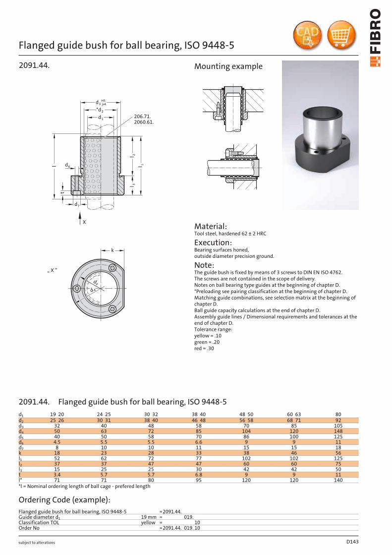
subject to alterations
Flanged guide bush for ball bearing, ISO 9448-5
k
d 4
d5
„ X ”
d6
t
l 3l 1
l 2
d3H5js4
*d2
d1
X
206.71.2060.61.
d7
2091.44.l
Material: Tool steel, hardened 62 ± 2 HRC
Execution: Bearing surfaces honed, outside diameter precision ground.
Note: The guide bush is fixed by means of 3 screws to DIN EN ISO 4762. The screws are not contained in the scope of delivery. Notes on ball bearing type guides at the beginning of chapter D. *Preloading see pairing classification at the beginning of chapter D. Matching guide combinations, see selection matrix at the beginning of chapter D. Ball guide capacity calculations at the end of chapter D. Assembly guide lines / Dimensional requirements and tolerances at the end of chapter D. Tolerance range: yellow = .10 green = .20 red = .30
Mounting example
D143
d1 19 20 24 25 30 32 38 40 48 50 60 63 80d2 25 26 30 31 38 40 46 48 56 58 68 71 92d3 32 40 48 58 70 85 105d4 50 63 72 85 104 120 148d5 40 50 58 70 86 100 125d6 4.5 5.5 5.5 6.6 9 9 11d7 8 10 10 11 15 15 18k 18 23 28 33 38 46 56l1 52 62 72 77 102 102 125l2 37 37 47 47 60 60 75l3 15 25 25 30 42 42 50t 3.4 5.7 5.7 6.8 9 9 11l* 71 71 80 95 120 120 140*l = Nominal ordering length of ball cage - prefered length
Ordering Code (example):Flanged guide bush for ball bearing, ISO 9448-5 =2091.44.Guide diameter d1 19 mm = 019.Classification TOL yellow = 10Order No =2091.44. 019. 10
2091.44. Flanged guide bush for ball bearing, ISO 9448-5
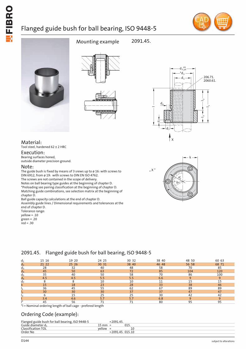
subject to alterations
Flanged guide bush for ball bearing, ISO 9448-5
Material: Tool steel, hardened 62 ± 2 HRC
Execution: Bearing surfaces honed, outside diameter precision ground.
Note: The guide bush is fixed by means of 3 srews up to ø 16: with screws to DIN 6912, from ø 19: with screws to DIN EN ISO 4762. The screws are not contained in the scope of delivery. Notes on ball bearing type guides at the beginning of chapter D. *Preloading see pairing classification at the beginning of chapter D. Matching guide combinations, see selection matrix at the beginning of chapter D. Ball guide capacity calculations at the end of chapter D. Assembly guide lines / Dimensional requirements and tolerances at the end of chapter D. Tolerance range: yellow = .10 green = .20 red = .30
k
d 4
d5
„ X ”
l 2l 1
l 3
d6
t
d3H5js4
*d2
d1
X
206.71.2060.61.
d7
2091.45.
l
Mounting example
D144
d1 15 16 19 20 24 25 30 32 38 40 48 50 60 63d2 21 22 25 26 30 31 38 40 46 48 56 58 68 71d3 28 32 40 48 58 70 85d4 45 50 63 72 85 104 120d5 35 40 50 58 70 86 100d6 4.5 4.5 5.5 5.5 6.6 9 9d7 8 8 10 10 11 15 15k 15 18 23 28 33 38 46l1 36 45 55 62 67 89 89l2 30 30 30 37 37 47 47l3 6 15 25 25 30 42 42t 3.4 4.6 5.7 5.7 6.8 9 9l* 45 56 71 71 80 95 95*l = Nominal ordering length of ball cage - prefered length
Ordering Code (example):Flanged guide bush for ball bearing, ISO 9448-5 =2091.45.Guide diameter d1 15 mm = 015.Classification TOL yellow = 10Order No =2091.45. 015.10
2091.45. Flanged guide bush for ball bearing, ISO 9448-5
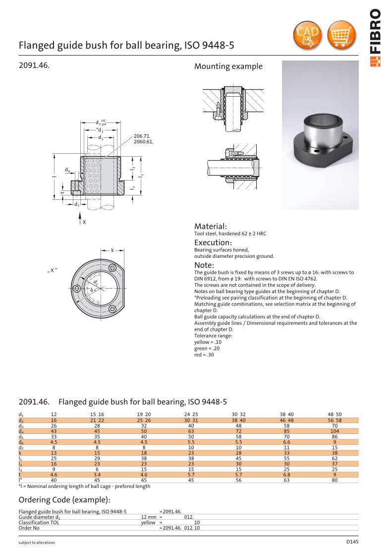
subject to alterations
Flanged guide bush for ball bearing, ISO 9448-5
k
d 4
d5
„ X ”
l 3l 2
l 1
d6
t
d3H5js4
*d2
d1
X
206.71.2060.61.
d7
2091.46.l
Material: Tool steel, hardened 62 ± 2 HRC
Execution: Bearing surfaces honed, outside diameter precision ground.
Note: The guide bush is fixed by means of 3 srews up to ø 16: with screws to DIN 6912, from ø 19: with screws to DIN EN ISO 4762. The screws are not contained in the scope of delivery. Notes on ball bearing type guides at the beginning of chapter D. *Preloading see pairing classification at the beginning of chapter D. Matching guide combinations, see selection matrix at the beginning of chapter D. Ball guide capacity calculations at the end of chapter D. Assembly guide lines / Dimensional requirements and tolerances at the end of chapter D. Tolerance range: yellow = .10 green = .20 red = .30
Mounting example
D145
d1 12 15 16 19 20 24 25 30 32 38 40 48 50d2 16 21 22 25 26 30 31 38 40 46 48 56 58d3 26 28 32 40 48 58 70d4 43 45 50 63 72 85 104d5 33 35 40 50 58 70 86d6 4.5 4.5 4.5 5.5 5.5 6.6 9d7 8 8 8 10 10 11 15k 13 15 18 23 28 33 38l1 25 29 38 38 45 55 62l2 16 23 23 23 30 30 37l3 9 6 15 15 15 25 25t 4.6 3.4 4.6 5.7 5.7 6.8 9l* 40 45 45 45 56 63 80*l = Nominal ordering length of ball cage - prefered length
Ordering Code (example):Flanged guide bush for ball bearing, ISO 9448-5 =2091.46.Guide diameter d1 12 mm = 012.Classification TOL yellow = 10Order No =2091.46. 012. 10
2091.46. Flanged guide bush for ball bearing, ISO 9448-5
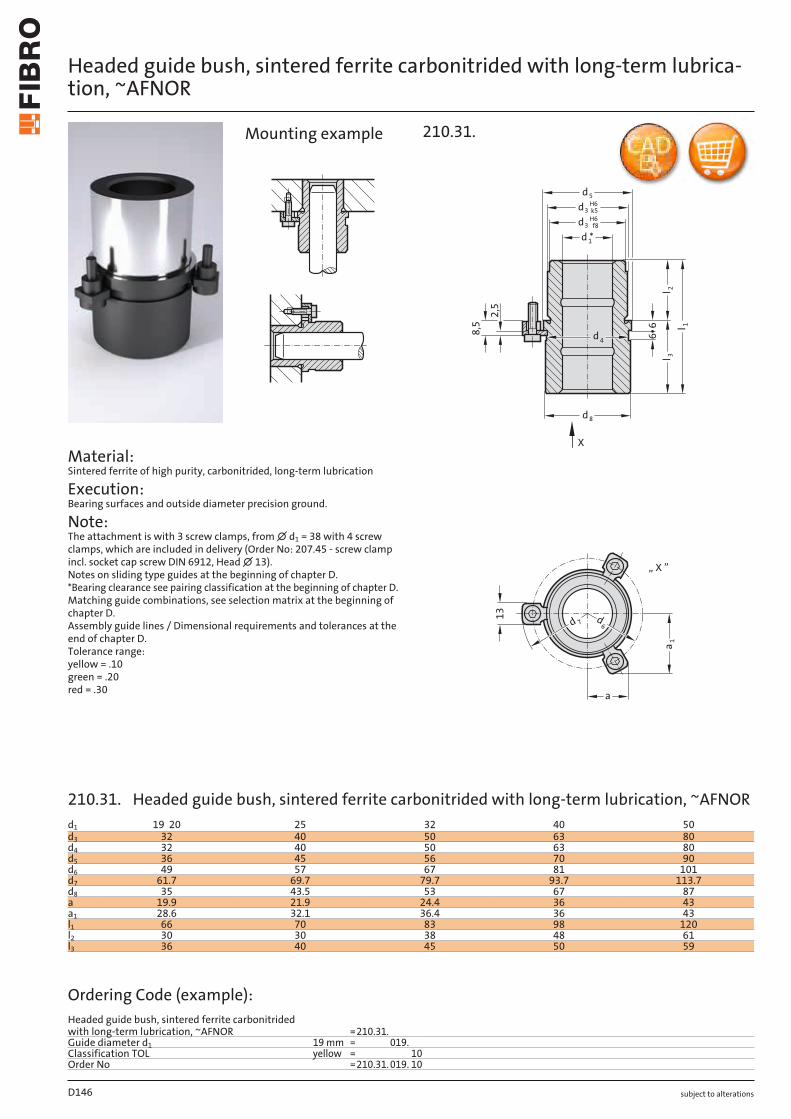
subject to alterations
Headed guide bush, sintered ferrite carbonitrided with long-term lubrica-tion, ~AFNOR
Material: Sintered ferrite of high purity, carbonitrided, long-term lubrication
Execution: Bearing surfaces and outside diameter precision ground.
Note: The attachment is with 3 screw clamps, from ∅ d1 = 38 with 4 screw clamps, which are included in delivery (Order No: 207.45 - screw clamp incl. socket cap screw DIN 6912, Head ∅ 13). Notes on sliding type guides at the beginning of chapter D. *Bearing clearance see pairing classification at the beginning of chapter D. Matching guide combinations, see selection matrix at the beginning of chapter D. Assembly guide lines / Dimensional requirements and tolerances at the end of chapter D. Tolerance range: yellow = .10 green = .20 red = .30
13
a
1a
6d
7d
„ X ”
8,5 6
6
d *1
5d
3dH6
k5
3dH6
f8
8d
l 3
1l
2l
2,5
d4
X
210.31.Mounting example
D146
d1 19 20 25 32 40 50d3 32 40 50 63 80d4 32 40 50 63 80d5 36 45 56 70 90d6 49 57 67 81 101d7 61.7 69.7 79.7 93.7 113.7d8 35 43.5 53 67 87a 19.9 21.9 24.4 36 43a1 28.6 32.1 36.4 36 43l1 66 70 83 98 120l2 30 30 38 48 61l3 36 40 45 50 59
Ordering Code (example):Headed guide bush, sintered ferrite carbonitrided with long-term lubrication, ~AFNOR =210.31.Guide diameter d1 19 mm = 019.Classification TOL yellow = 10Order No =210.31. 019. 10
210.31. Headed guide bush, sintered ferrite carbonitrided with long-term lubrication, ~AFNOR
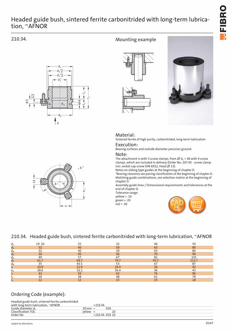
subject to alterations
Headed guide bush, sintered ferrite carbonitrided with long-term lubrica-tion, ~AFNOR
13
a
1a
6d
7d
„ X ”
l
5d
8d
d *1
3dH6
k5
3dH6
f8
l 32
l 1
668
,5
2,5
d4
X
210.34.
Material: Sintered ferrite of high purity, carbonitrided, long-term lubrication
Execution: Bearing surfaces and outside diameter precision ground.
Note: The attachment is with 3 screw clamps, from ∅ d1 = 38 with 4 screw clamps, which are included in delivery (Order No: 207.45 - screw clamp incl. socket cap screw DIN 6912, Head ∅ 13). Notes on sliding type guides at the beginning of chapter D. *Bearing clearance see pairing classification at the beginning of chapter D. Matching guide combinations, see selection matrix at the beginning of chapter D. Assembly guide lines / Dimensional requirements and tolerances at the end of chapter D. Tolerance range: yellow = .10 green = .20 red = .30
Mounting example
D147
d1 19 20 25 32 40 50d3 32 40 50 63 80d4 32 40 50 63 80d5 36 45 56 70 90d6 49 57 67 81 101d7 61.7 69.7 79.7 93.7 113.7d8 35 43.5 53 67 87a 19.9 21.9 24.4 36 43a1 28.6 32.1 36.4 36 43l1 42 50 63 76 96l2 30 38 48 61 78l3 12 12 15 15 18
Ordering Code (example):Headed guide bush, sintered ferrite carbonitrided with long-term lubrication, ~AFNOR =210.34.Guide diameter d1 19 mm = 019.Classification TOL yellow = 10Order No =210.34. 019. 10
210.34. Headed guide bush, sintered ferrite carbonitrided with long-term lubrication, ~AFNOR
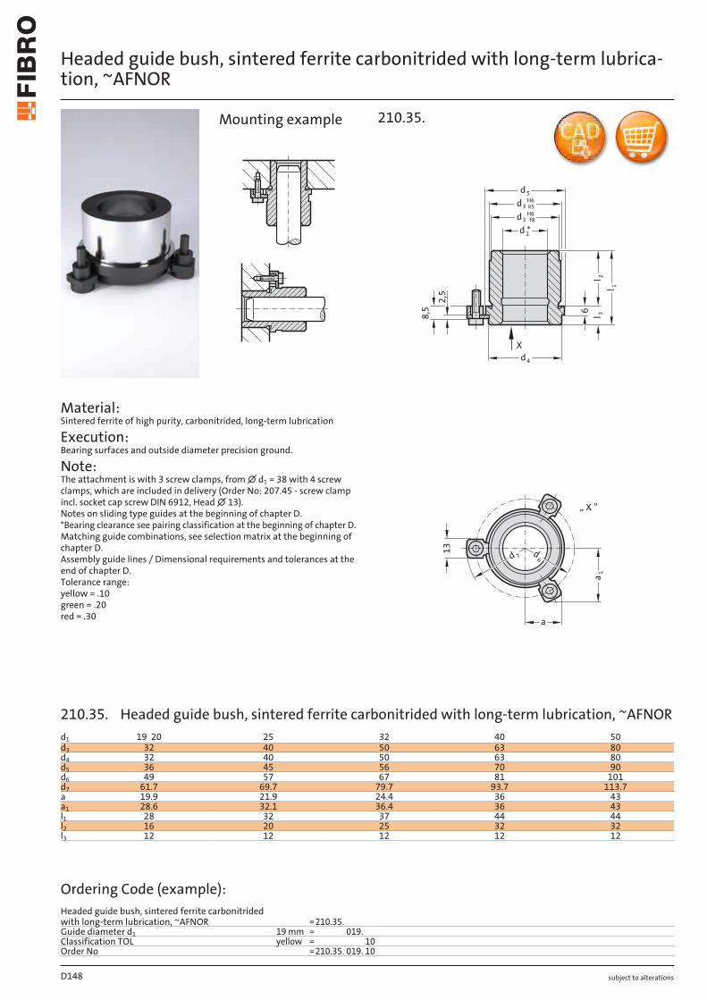
subject to alterations
Headed guide bush, sintered ferrite carbonitrided with long-term lubrica-tion, ~AFNOR
Material: Sintered ferrite of high purity, carbonitrided, long-term lubrication
Execution: Bearing surfaces and outside diameter precision ground.
Note: The attachment is with 3 screw clamps, from ∅ d1 = 38 with 4 screw clamps, which are included in delivery (Order No: 207.45 - screw clamp incl. socket cap screw DIN 6912, Head ∅ 13). Notes on sliding type guides at the beginning of chapter D. *Bearing clearance see pairing classification at the beginning of chapter D. Matching guide combinations, see selection matrix at the beginning of chapter D. Assembly guide lines / Dimensional requirements and tolerances at the end of chapter D. Tolerance range: yellow = .10 green = .20 red = .30
13
a
1a
6d
7d
„ X ”
6
5d
d *1
3dH6
k5
3dH6
f8
4d
ll 3
2
l 1
X
8,5
2,5
210.35.Mounting example
D148
d1 19 20 25 32 40 50d3 32 40 50 63 80d4 32 40 50 63 80d5 36 45 56 70 90d6 49 57 67 81 101d7 61.7 69.7 79.7 93.7 113.7a 19.9 21.9 24.4 36 43a1 28.6 32.1 36.4 36 43l1 28 32 37 44 44l2 16 20 25 32 32l3 12 12 12 12 12
Ordering Code (example):Headed guide bush, sintered ferrite carbonitrided with long-term lubrication, ~AFNOR =210.35.Guide diameter d1 19 mm = 019.Classification TOL yellow = 10Order No =210.35. 019. 10
210.35. Headed guide bush, sintered ferrite carbonitrided with long-term lubrication, ~AFNOR

subject to alterations D149

subject to alterations
Headed guide bush for ball bearing, ~AFNOR
Material: Tool steel, hardened 62 ± 2 HRC
Execution: Bearing surfaces honed, outside diameter precision ground.
Note: The attachment is with 3 screw clamps, from ∅ d1 = 38 with 4 screw clamps, which are included in delivery (Order No: 207.45 - screw clamp incl. socket cap screw DIN 6912, Head ∅ 13). Notes on ball bearing type guides at the beginning of chapter D. *Preloading see pairing classification at the beginning of chapter D Matching guide combinations, see selection matrix at the beginning of chapter D. Ball guide capacity calculations at the end of chapter D. Assembly guide lines / Dimensional require-ments and tolerances at the end of chapter D.Tolerance range: yellow = .10 green = .20 red = .30
d4d8
*d2d1
d3 k5H6
d5
l 1l 3
l
l 26
6„ X ”
a 1
a
d6d 7
13
X
210.44.
X
Mounting example
D150
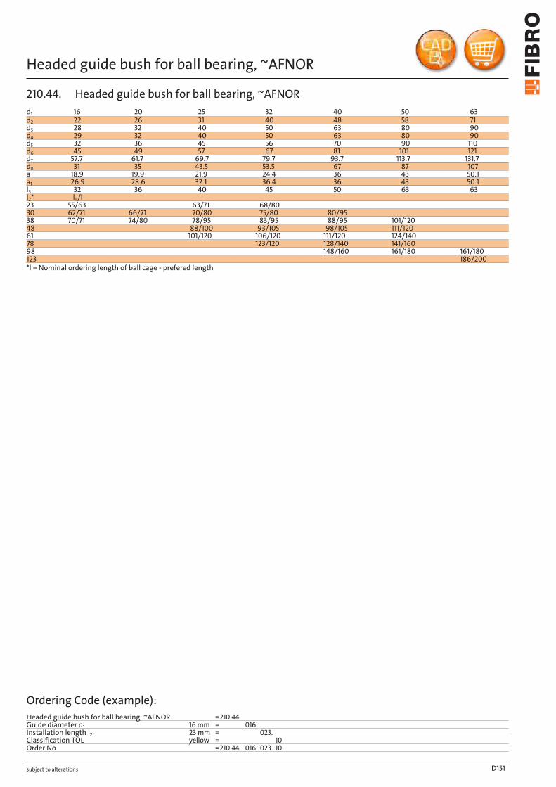
subject to alterations
Headed guide bush for ball bearing, ~AFNOR
D151
d1 16 20 25 32 40 50 63d2 22 26 31 40 48 58 71d3 28 32 40 50 63 80 90d4 29 32 40 50 63 80 90d5 32 36 45 56 70 90 110d6 45 49 57 67 81 101 121d7 57.7 61.7 69.7 79.7 93.7 113.7 131.7d8 31 35 43.5 53.5 67 87 107a 18.9 19.9 21.9 24.4 36 43 50.1a1 26.9 28.6 32.1 36.4 36 43 50.1l3 32 36 40 45 50 63 63l2* l1 /l23 55/63 63/71 68/8030 62/71 66/71 70/80 75/80 80/9538 70/71 74/80 78/95 83/95 88/95 101/12048 88/100 93/105 98/105 111/12061 101/120 106/120 111/120 124/14078 123/120 128/140 141/16098 148/160 161/180 161/180123 186/200*l = Nominal ordering length of ball cage - prefered length
Ordering Code (example):Headed guide bush for ball bearing, ~AFNOR =210.44.Guide diameter d1 16 mm = 016.Installation length l2 23 mm = 023.Classification TOL yellow = 10Order No =210.44. 016. 023. 10
210.44. Headed guide bush for ball bearing, ~AFNOR
subject to alterations
Headed guide bush for ball bearing, ~AFNOR
Material: Tool steel, hardened 62 ± 2 HRC
Execution: Bearing surfaces honed, outside diameter fine-ground.
Note: The attachment is with 3 screw clamps, from ∅ d1 = 38 with 4 screw clamps, which are included in delivery (Order No: 207.45 - screw clamp incl. socket cap screw DIN 6912, Head ∅ 13). Notes on ball bearing type guides at the beginning of chapter D. *Preloading see pairing classification at the beginning of chapter D Matching guide combinations, see selection matrix at the beginning of chapter D. Ball guide capacity calculations at the end of chapter D. Assembly guide lines / Dimensional require-ments and tolerances at the end of chapter D.Tolerance range: yellow = .10 green = .20 red = .30
„ X ”
a 1
a
d6d 7
13
X
l 2
l 1l 3
l
6
d4
*d2
d1
d3 k5H6
d5
210.46.
X
Mounting example
D152
subject to alterations
Headed guide bush for ball bearing, ~AFNOR
D153
d1 16 20 25 32 40 50 63d2 22 26 31 40 48 58 71d3 28 32 40 50 63 80 90d4 29 32 40 50 63 80 90d5 32 36 45 56 70 90 110d6 45 49 57 67 81 101 121d7 57.7 61.7 69.7 79.7 93.7 113.7 131.7a 18.9 19.9 21.9 24.4 36 43 50.1a1 26.9 28.6 32.1 36.4 36 43 50.1l3 10 12 12 15 15 18 20l2* l1 /l23 33/4530 40/45 42/45 42/45 45/5638 48/56 50/56 50/56 53/7148 58/63 60/71 60/71 63/71 63/8061 73/80 76/80 76/95 79/9578 90/105 93/105 93/105 96/40598 113/120 113/120 116/140 118/120123 143/160*l = Nominal ordering length of ball cage - prefered length
Ordering Code (example):Headed guide bush for ball bearing, ~AFNOR =210.46.Guide diameter d1 16 mm = 016.Installation length l2 23 mm = 023.Classification TOL yellow = 10Order No =210.46. 016. 023. 10
210.46. Headed guide bush for ball bearing, ~AFNOR
subject to alterations
Guide bush with collar, for ball bearing, ~AFNOR
h
l
M*d 2
d 1
d 4
d3 k5H6
l 1
l 3
l 4l 2
+2
210.45.d 6
Mounting example
D154
d1 16 16 20 20 20 25 25 25 32 32 32 40 40 40 50 50d2 22 22 26 26 26 31 31 31 40 40 40 48 48 48 58 58d3 28 28 32 32 32 40 40 40 50 50 50 63 63 63 80 80d4 32 32 36 36 36 45 45 45 56 56 56 70 70 70 90 90d6 40 40 44 44 44 55 55 55 65 65 65 81 81 81 100 100M M27x1 M27x1 M30x1 M30x1 M30x1 M39x1 M39x1 M39x1 M48x1 M48x1 M48x1 M60x1 M60x1 M60x1 M76x1 M76x1h 3 3 4 4 4 4 4 4 5 5 5 6 6 6 8 8l1 16 20 17 21 25 22 26 31 26 31 38 32 39 47 41 49l2 8 12 8 12 16 12 16 21 15 20 27 20 27 35 26 34l3 3 3 3 3 3 3 3 3 4 4 4 4 4 4 5 5l4 5 5 6 6 6 7 7 7 7 7 7 8 8 8 10 10l* 24 28 24 28 31 31 40 40 40 40 50 50 50 56 50 63*l = Nominal ordering length of ball cage - prefered length
Ordering Code (example):Guide bush with collar, for ball bearing, ~AFNOR =210.45.Guide diameter d1 16 mm = 016.Total length l1 16 mm = 016.Classification TOL yellow = 10Order No =210.45. 016. 016. 10
Material: Tool steel, hardened 62 ± 2 HRC
Execution: Bearing surfaces honed, outside diameter precision ground.
Note: The guide bush is fixed with slotted nut 207.48. Notes on ball bearing type guides at the beginning of chapter D. *Preloading see pairing classification at the beginning of chapter D. Matching guide combinations, see selection matrix at the beginning of chapter D. Ball guide capacity calculations at the end of chapter D. Assembly guide lines / Dimensional requirements and tolerances at the end of chapter D. Tolerance range: yellow = .10 green = .20 red = .30
210.45. Guide bush with collar, for ball bearing, ~AFNOR

subject to alterations
Guide bush with collar, bronze coated, ~AFNOR
hd G5/G6
M
1
d 4
d2 k5
d5
l 3
l
2l
l 1
l 4
210.85.
d 6
Material: 1.0503 ∅ d2 induction hardened to 500+100 HV 10
Execution: Bronze coated internal bore. Diameter d2 and collar face precision ground. up to ∅ d1 = 25 tolerance G6 from ∅ d1 = 32 tolerance G5
Note: The guide bush is fixed with slotted nut 207.48. Notes on sliding type guides at the beginning of chapter D. Matching guide combinations, see selection matrix at the beginning of chapter D. Assembly guide lines / Dimensional requirements and tolerances at the end of chapter D.
Mounting example
D155
d1 16 16 20 20 25 25 32 32 40 40 50 50TOL +0.006/
+0.017+0.006/ +0.017
+0.007/ +0.020
+0.007/ +0.020
+0.007/ +0.020
+0.007/ +0.020
+0.009/ +0.020
+0.009/ +0.020
+0.009/ +0.020
+0.009/ +0.020
+0.009/ +0.020
+0.009/ +0.020
d2 28 28 32 32 40 40 50 50 63 63 80 80d4 32 32 36 36 45 45 56 56 70 70 90 90d5 3 3 4 4 4 4 4 4 7 7 7 7d6 40 40 44 44 55 55 65 65 81 81 100 100h 3 3 4 4 4 4 5 5 6 6 8 8M M27x1 M27x1 M30x1 M30x1 M39x1 M39x1 M48x1 M48x1 M60x1 M60x1 M76x1 M76x1l 16 20 21 25 26 31 31 38 39 47 41 49l1 3 3 3 3 3 3 4 4 4 4 5 5l2 11 15 15 19 19 24 24 31 31 39 31 39l3 5 5 6 6 7 7 7 7 8 8 10 10l4 5.5 7.5 5 9.5 9.5 12 12 15.5 15.5 19.5 15.5 19.5
Ordering Code (example):Guide bush with collar, bronze coated, ~AFNOR =210.85.Guide diameter d1 16 mm = 016.Total length l 16 mm = 016Order No =210.85. 016. 016
210.85. Guide bush with collar, bronze coated, ~AFNOR
Oilless GuideElements
subject to alterations
Slotted nut
Material: Steel
Note: For fixing the guide bushes 210.45. and 210.85.
h
td 6
m (5H)
bH
13
207.48.
D156
Order No d6 b t h m207.48.016 40 5 3 3 M27 x 1207.48.020 44 5 4 4 M30 x 1207.48.025 55 6 4 4 M39 x 1207.48.032 65 6 5 5 M48 x 1207.48.040 81 7 6 6 M60 x 1207.48.050 100 8 8 8 M76 x 1
207.48. Slotted nut
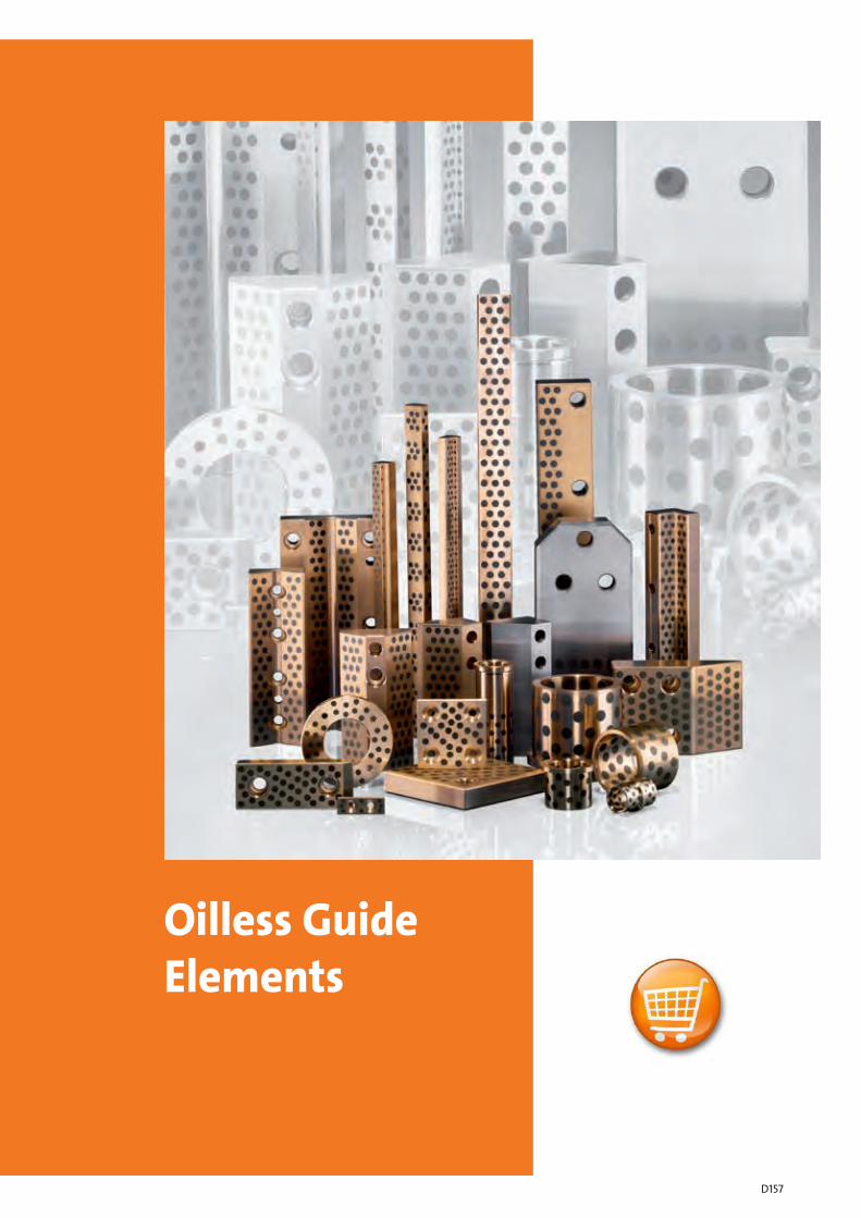
Oilless GuideElements
D157
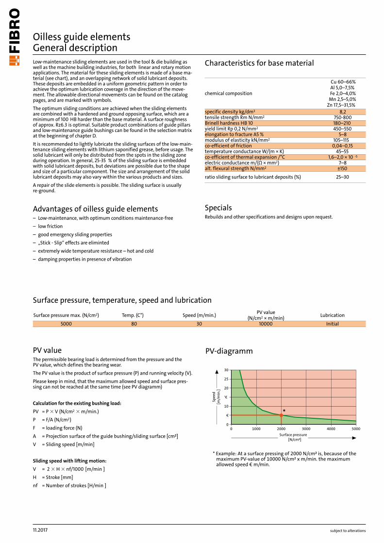
Cu 60–66% Al 5,0–7,5% Fe 2,0–4,0%
Mn 2,5–5,0% Zn 17,5–31,5%
8,2750-800180–210450–550
5–8105–115
0,04–0,1545–55
1,6–2,0 × 10 -5
7–8±150
25–30
5000 80 30 10000
subject to alterations
Oilless guide elements General descriptionLow-maintenance sliding elements are used in the tool & die building as well as the machine building industries, for both linear and rotary motion applications. The material for these sliding elements is made of a base ma-terial (see chart), and an overlapping network of solid lubricant deposits. These deposits are embedded in a uniform geometric pattern in order to achieve the optimum lubrication coverage in the direction of the move-ment. The allowable directional movements can be found on the catalog pages, and are marked with symbols.The optimum sliding conditions are achieved when the sliding elements are combined with a hardened and ground opposing surface, which are a minimum of 100 HB harder than the base material. A surface roughness of approx. Rz6.3 is optimal. Suitable product combinations of guide pillars and low-maintenance guide bushings can be found in the selection matrix at the beginning of chapter D.It is recommended to lightly lubricate the sliding surfaces of the low-main-tenance sliding elements with lithium saponified grease, before usage. The solid lubricant will only be distributed from the spots in the sliding zone during operation. In general, 25-35 % of the sliding surface is embedded with solid lubricant deposits, but deviations are possible due to the shape and size of a particular component. The size and arrangement of the solid lubricant deposits may also vary within the various products and sizes.A repair of the slide elements is possible. The sliding surface is usually re-ground.
Advantages of oilless guide elements– Low-maintenance, with optimum conditions maintenance-free– low friction– good emergency sliding properties– „Stick - Slip“ effects are eliminted – extremely wide temperature resistance – hot and cold– damping properties in presence of vibration
Characteristics for base material
Surface pressure, temperature, speed and lubrication
PV valueThe permissible bearing load is determined from the pressure and the PV value, which defines the bearing wear.The PV value is the product of surface pressure (P) and running velocity (V).Please keep in mind, that the maximum allowed speed and surface pres-sing can not be reached at the same time (see PV diagramm)
Calculation for the existing bushing load: PV = P × V (N/cm2 × m/min.)P = F/A (N/cm2)F = loading force (N)A = Projection surface of the guide bushing/sliding surface [cm²]V = Sliding speed [m/min]
Sliding speed with lifting motion: V = 2 × H × nf/1000 [m/min ]H = Stroke [mm]nf = Number of strokes [H/min ]
chemical composition
specific density kg/dm3
tensile strength Rm N/mm2
Brinell hardness HB 10yield limit Rp 0,2 N/mm2
elongation to fracture A5 %modulus of elasticity kN/mm2
co-efficient of frictiontemperature conductance W/(m × K)co-efficient of thermal expansion /°Celectric conductance m/(Ω × mm2)alt. flexural strength N/mm2
ratio sliding surface to lubricant deposits (%)
SpecialsRebuilds and other specifications and designs upon request.
Surface pressure max. (N/cm2) Temp. (C°) Speed (m/min.) PV value (N/cm2 × m/min) Lubrication
Initial
PV-diagramm
* Example: At a surface pressing of 2000 N/cm² is, because of themaximum PV-value of 10000 N/cm² x m/min. the maximumallowed speed € m/min.
0 1000 2000 3000 4000 5000
0
€
10
‘€
20
25
30
Surface pressure[N/cm²]
Spee
d[m
/min
.]
*
11.2017
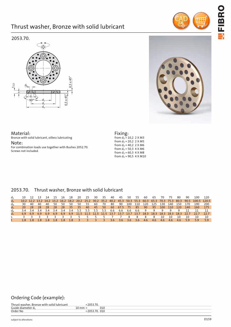
CU 60–66% Al 5,0–7,5% Fe 2,0–4,0%
Mn 2,5–5,0% Zn 17,5–31,5%
8,2770
180–210560450
812
105–11515
0,04–0,1045–55+300
1,6–2,0 × 10 -5
1,8–2,37–8
±150
25–30
5000 80 30 100003000 150 60 20000
subject to alterations
Oilless guide elements General descriptionOilless Guide Elements with embedded solid lubricants are used inapplications of linear or rotary motion in toolmaking, general machineconstruction and similar engineering uses. The structure of the base ma-terial provides closely spaced deposits of solid lubricant – properties andspecifications as per table below.The elements satisfy highest demands in terms of load bearing capacity atlow sliding speeds, within an extensive temperature band.The lubricant deposits are arranged in staggered geometrical patterns,thus ensuring optimal lubrication effect along the sliding motion, especial-ly with counter bearings which are hardened and ground.The sliding surfaces should be lightly greased with lithium grease emulsi-on, prior to commissioning.On flat guideways and pillar guides, from 25 to 30 per cent of the slidingsurfaces consist of lubricant deposits. Surfaces of counter bearings musthave a ground finish, preferably with a lay parallel with the sliding motion.
Choice of element-typeStandard:– for general uses at temperatures up to 200°CSpecial Types on request
Advantages of oilless guide elements– good emergency sliding properties– highest carrying capacity at low speed– use under water or with chemical solutions– extremely wide temperature resistance – hot and cold– damping properties in presence of vibration
Oilless guide elements – Material data
Surface pressure, temperature, speed and lubrication
PV valueThe permissible bearing load is determined from the pressure and thePV value, which defines the bearing wear.The PV value is the product of surface pressure (P) and running velocity (V).
The permissible bearing load is determined from the PV value.PV = P × V (N/cm2 × m/min.)P = F/A (N/cm2) F = max. load (N)A = projected area of the bearing
chemical composition
specific density kg/dm3
tensile strength Rm N/mm2
Brinell hardness HB 10shear strength N/mm2
yield limit Rp 0,2 N/mm2
elongation to fracture A5 %elongation %modulus of elasticity kN/mm2
stroking velocity m/minco-efficient of frictiontemperature conductance W/(m × K)temperature resistance °Cco-efficient of thermal expansion /°Cco-efficient of shrinkage %electric conductance m/(Ω × mm2)alt. flexural strength N/mm2
ratio sliding surface to lubricant deposits (%)
Surface pressure max. (N/cm2) Temp. (C°) Speed (m/min.) PV value (N/cm2 × m/min) Lubrication
InitialPressure Iubrication
subject to alterations
Thrust washer, Bronze with solid lubricant
2053.70.
90°
d
-0,1
0,5
x 4
5°
5d3d
4d
s 0,5
x 4
5°
7
d6
t
Material: Bronze with solid lubricant, oilless lubricating
Note: For combination loads use together with Bushes 2052.70. Screws not included.
Fixing: from d3 = 10,2 2 X M3 from d3 = 20,2 2 X M5 from d3 = 40,2 2 X M6 from d3 = 50,3 4 X M6 from d3 = 60,3 4 X M8 from d3 = 90,5 4 X M10
D159
d1 10 12 13 14 15 16 18 20 25 30 35 40 45 50 55 60 65 70 75 80 90 100 120d3 10.2 12.2 13.2 14.2 15.2 16.2 18.2 20.2 25.2 30.2 35.2 40.2 45.3 50.3 55.3 60.3 65.3 70.3 75.3 80.3 90.5 100.5 120.5d4 30 40 40 40 50 50 50 50 55 60 70 80 90 100 110 120 125 130 140 150 170 190 200d5 20 28 28 28 28 28 35 35 40 45 50 60 67.5 75 85 90 95 100 110 120 140 160 175d6 3.4 3.4 3.4 3.4 3.4 3.4 3.4 5.5 5.5 5.5 5.5 6.6 6.6 6.6 6.6 9 9 9 9 9 11 11 11d7 6.9 6.9 6.9 6.9 6.9 6.9 6.9 11.5 11.5 11.5 11.5 13.7 13.7 13.7 13.7 18.3 18.3 18.3 18.3 18.3 22.7 22.7 22.7s 3 3 3 3 3 3 3 5 5 5 5 7 7 8 8 8 8 10 10 10 10 10 10t 1.8 1.8 1.8 1.8 1.8 1.8 1.8 3 3 3 3 3.6 3.6 3.6 3.6 4.6 4.6 4.6 4.6 4.6 5.9 5.9 5.9
Ordering Code (example):Thrust washer, Bronze with solid lubricant =2053.70.Guide diameter d1 10 mm = 010Order No =2053.70. 010
2053.70. Thrust washer, Bronze with solid lubricant
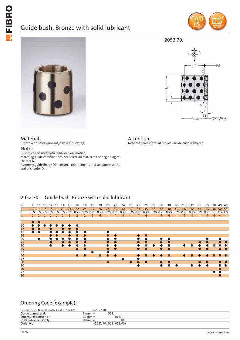
subject to alterations
Guide bush, Bronze with solid lubricant
Material: Bronze with solid lubricant, oilless lubricating
Note: Bushes can be used with radial or axial motion. Matching guide combinations, see selection matrix at the beginning of chapter D. Assembly guide lines / Dimensional requirements and tolerances at the end of chapter D.
Attention: Note that press fitment reduces inside bush diameter.
2052.70.
d2 m6
l 4
15°
r
r
d1F7 A
Ø0,02 A
l 1
D160
d1 8 10 10 12 13 14 15 16 18 19 20 20 20 24 25 25 25 28 30 30 30 31.5 32 35 35 38 40 40d2 12 14 15 18 19 20 21 22 24 25 26 28 30 32 32 33 35 38 38 40 42 40 42 44 45 48 50 55r 0.5 0.5 0.5 0.5 0.5 0.5 0.75 0.75 0.75 0.75 0.75 0.75 0.75 0.75 0.75 0.75 0.75 0.75 0.75 0.75 0.75 0.75 0.75 0.75 0.75 1.5 1.5 1.5l4 2 2 2 2 2 2 2 2 2 2 4 4 4 4 4 4 4 4 4 4 4 4 4 4 4 4 4 4l18 ● ●10 ● ● ● ● ● ● ● ●12 ● ● ● ● ● ●15 ● ● ● ● ● ● ● ● ●16 ● ● ● ● ● ● ● ● ●20 ● ● ● ● ● ● ● ● ● ● ● ● ● ● ●25 ● ● ● ● ● ● ● ● ● ● ● ● ● ● ●30 ● ● ● ● ● ● ● ● ● ● ● ● ● ● ● ● ● ● ●35 ● ● ● ● ● ● ● ● ● ● ● ●37 ● ●40 ● ● ● ● ● ● ● ● ● ● ● ● ● ● ● ● ●47 ● ●50 ● ● ● ● ● ● ● ● ● ●60 ● ● ● ● ● ● ● ● ●70 ●77 ● ●80 ●
Ordering Code (example):Guide bush, Bronze with solid lubricant =2052.70.Guide diameter d1 8 mm = 008.External diameter d2 12 mm = 012.Installation length l1 8 mm = 008Order No =2052.70. 008. 012. 008
2052.70. Guide bush, Bronze with solid lubricant
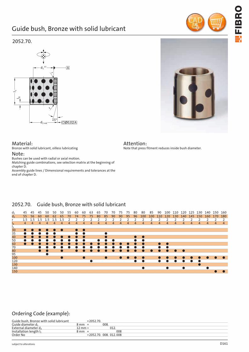
subject to alterations
Guide bush, Bronze with solid lubricant
2052.70.
d2 m6
l 4
15°
r
r
d1F7 A
Ø0,02 A
l 1
Material: Bronze with solid lubricant, oilless lubricating
Note: Bushes can be used with radial or axial motion. Matching guide combinations, see selection matrix at the beginning of chapter D. Assembly guide lines / Dimensional requirements and tolerances at the end of chapter D.
Attention: Note that press fitment reduces inside bush diameter.
D161
d1 45 45 45 50 50 50 55 60 60 63 65 70 70 75 75 80 80 85 90 100 110 120 125 130 140 150 160d2 55 56 60 60 62 65 70 74 75 75 80 85 90 90 95 96 100 100 110 120 130 140 145 150 160 170 180r 1.5 1.5 1.5 1.5 1.5 1.5 2 2 2 2 2 2 2 2 2 2 2 2 2 2 2 2 2 2 2 2 2l4 4 4 4 4 4 4 4 4 4 4 4 4 4 4 4 4 4 4 4 4 4 4 4 4 4 4 4l130 ● ● ● ● ● ● ● ●35 ● ● ● ● ● ● ● ●40 ● ● ● ● ● ● ● ● ● ● ● ●50 ● ● ● ● ● ● ● ● ● ● ● ● ● ●60 ● ● ● ● ● ● ● ● ● ● ● ● ● ● ● ● ● ● ●70 ● ● ● ● ● ● ● ● ● ● ● ● ● ● ● ● ●80 ● ● ● ● ● ● ● ● ● ● ● ● ● ● ● ● ● ●95 ●100 ● ● ● ● ● ● ● ● ● ● ● ● ● ● ● ●120 ● ● ● ● ● ● ● ● ●130 ●140 ● ● ● ●150 ● ●
Ordering Code (example):Guide bush, Bronze with solid lubricant =2052.70.Guide diameter d1 8 mm = 008.External diameter d2 12 mm = 012.Installation length l1 8 mm = 008Order No =2052.70. 008. 012. 008
2052.70. Guide bush, Bronze with solid lubricant
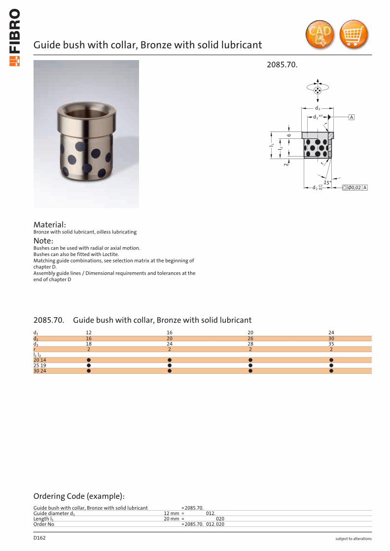
subject to alterations
Guide bush with collar, Bronze with solid lubricant
Material: Bronze with solid lubricant, oilless lubricating
Note: Bushes can be used with radial or axial motion. Bushes can also be fitted with Loctite. Matching guide combinations, see selection matrix at the beginning of chapter D. Assembly guide lines / Dimensional requirements and tolerances at the end of chapter D
2085.70.
2
2dG7
k6
d3
d1H7
r
r
Ø0,02 A
15°
1l
2l
6
A
D162
d1 12 16 20 24d2 16 20 26 30d3 18 24 28 35r 2 2 2 2l1 l220 14 ● ● ● ●25 19 ● ● ● ●30 24 ● ● ● ●
Ordering Code (example):Guide bush with collar, Bronze with solid lubricant =2085.70.Guide diameter d1 12 mm = 012.Length l1 20 mm = 020Order No =2085.70. 012. 020
2085.70. Guide bush with collar, Bronze with solid lubricant
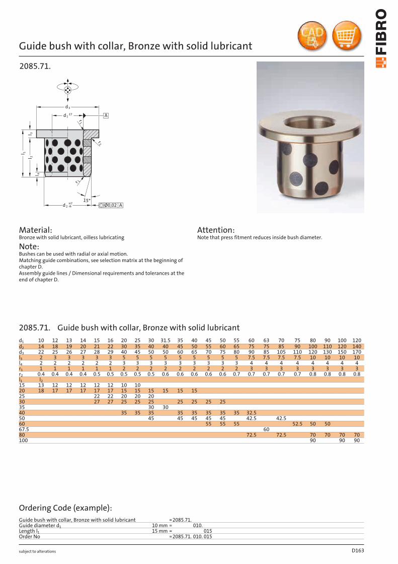
subject to alterations
Guide bush with collar, Bronze with solid lubricant
2085.71.
1
1
2
2dH7
r6
d3
d1E7
Ø0,02 A
A
2l3l
4l
15°
r
r
r
1l
Material: Bronze with solid lubricant, oilless lubricating
Note: Bushes can be used with radial or axial motion. Matching guide combinations, see selection matrix at the beginning of chapter D. Assembly guide lines / Dimensional requirements and tolerances at the end of chapter D.
Attention: Note that press fitment reduces inside bush diameter.
D163
d1 10 12 13 14 15 16 20 25 30 31.5 35 40 45 50 55 60 63 70 75 80 90 100 120d2 14 18 19 20 21 22 30 35 40 40 45 50 55 60 65 75 75 85 90 100 110 120 140d3 22 25 26 27 28 29 40 45 50 50 60 65 70 75 80 90 85 105 110 120 130 150 170l3 2 3 3 3 3 3 5 5 5 5 5 5 5 5 5 7.5 7.5 7.5 7.5 10 10 10 10l4 2 2 2 2 2 2 3 3 3 3 3 3 3 3 3 4 4 4 4 4 4 4 4r1 1 1 1 1 1 1 2 2 2 2 2 2 2 2 2 3 3 3 3 3 3 3 3r2 0.4 0.4 0.4 0.4 0.5 0.5 0.5 0.5 0.5 0.6 0.6 0.6 0.6 0.6 0.7 0.7 0.7 0.7 0.7 0.8 0.8 0.8 0.8l1 l215 13 12 12 12 12 12 10 1020 18 17 17 17 17 17 15 15 15 15 15 1525 22 22 20 20 2030 27 27 25 25 25 25 25 25 2535 30 3040 35 35 35 35 35 35 35 35 32.550 45 45 45 45 45 42.5 42.560 55 55 55 52.5 50 5067.5 6080 72.5 72.5 70 70 70 70100 90 90 90
Ordering Code (example):Guide bush with collar, Bronze with solid lubricant =2085.71.Guide diameter d1 10 mm = 010.Length l1 15 mm = 015Order No =2085.71. 010. 015
2085.71. Guide bush with collar, Bronze with solid lubricant
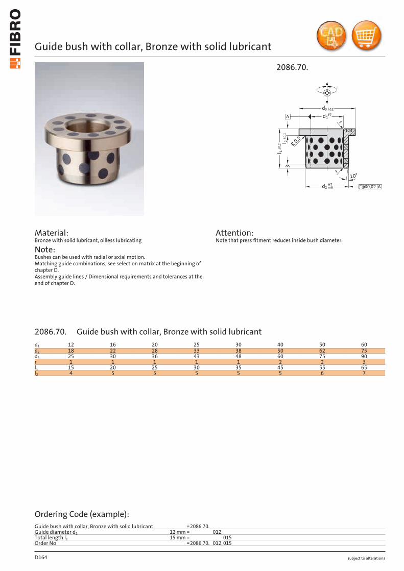
subject to alterations
Guide bush with collar, Bronze with solid lubricant
Material: Bronze with solid lubricant, oilless lubricating
Note: Bushes can be used with radial or axial motion. Matching guide combinations, see selection matrix at the beginning of chapter D. Assembly guide lines / Dimensional requirements and tolerances at the end of chapter D.
Attention: Note that press fitment reduces inside bush diameter.
2086.70.
H7
l±
0,2
1
±0
,1 2
10°
m6d2
1F7d
d3 h12
R 0
,5
r
Ø0,02 A
rA
l3
D164
d1 12 16 20 25 30 40 50 60d2 18 22 28 33 38 50 62 75d3 25 30 36 43 48 60 75 90r 1 1 1 1 1 2 2 3l1 15 20 25 30 35 45 55 65l2 4 5 5 5 5 5 6 7
Ordering Code (example):Guide bush with collar, Bronze with solid lubricant =2086.70.Guide diameter d1 12 mm = 012.Total length l1 15 mm = 015Order No =2086.70. 012. 015
2086.70. Guide bush with collar, Bronze with solid lubricant
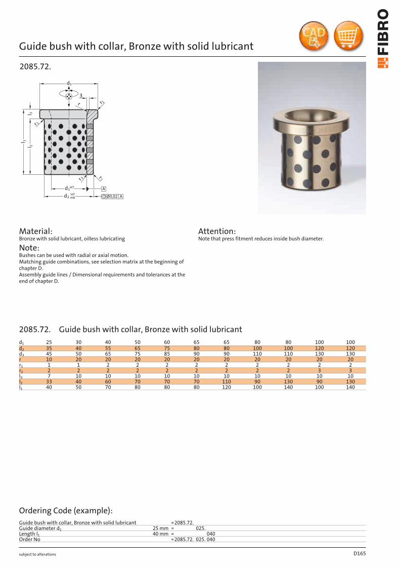
subject to alterations
Guide bush with collar, Bronze with solid lubricant
2085.72.
3
d3
d2 m6H7
Ø0,02 A
d1H7 A
r 2 r1
r 1r
r 1
l 2
l 1
l 3
Material: Bronze with solid lubricant, oilless lubricating
Note: Bushes can be used with radial or axial motion. Matching guide combinations, see selection matrix at the beginning of chapter D. Assembly guide lines / Dimensional requirements and tolerances at the end of chapter D.
Attention: Note that press fitment reduces inside bush diameter.
D165
d1 25 30 40 50 60 65 65 80 80 100 100d2 35 40 55 65 75 80 80 100 100 120 120d3 45 50 65 75 85 90 90 110 110 130 130r 10 20 20 20 20 20 20 20 20 20 20r1 1 1 2 2 2 2 2 2 2 2 2r2 2 2 2 2 2 2 2 2 2 3 3l3 7 10 10 10 10 10 10 10 10 10 10l2 33 40 60 70 70 70 110 90 130 90 130l1 40 50 70 80 80 80 120 100 140 100 140
Ordering Code (example):Guide bush with collar, Bronze with solid lubricant =2085.72.Guide diameter d1 25 mm = 025.Length l1 40 mm = 040Order No =2085.72. 025. 040
2085.72. Guide bush with collar, Bronze with solid lubricant
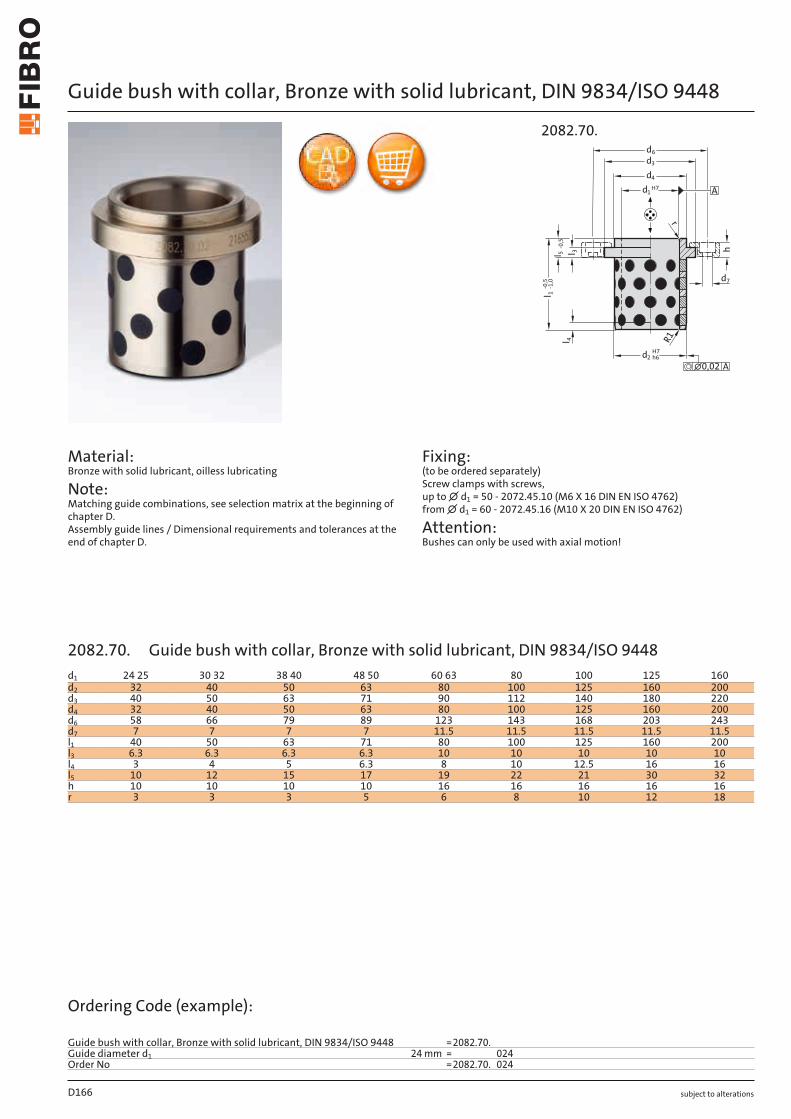
subject to alterations
Guide bush with collar, Bronze with solid lubricant, DIN 9834/ISO 9448
Material: Bronze with solid lubricant, oilless lubricating
Note: Matching guide combinations, see selection matrix at the beginning of chapter D. Assembly guide lines / Dimensional requirements and tolerances at the end of chapter D.
Fixing: (to be ordered separately) Screw clamps with screws, up to ∅ d1 = 50 - 2072.45.10 (M6 X 16 DIN EN ISO 4762) from ∅ d1 = 60 - 2072.45.16 (M10 X 20 DIN EN ISO 4762)
Attention: Bushes can only be used with axial motion!
2082.70.
7d
3l h
H7
2 h6d
1 -1
,0l
1d H7
3d
4d
4l
r
R1
A
∅0,02 A
5 -
0,5
l
-0,5
d6
D166
d1 24 25 30 32 38 40 48 50 60 63 80 100 125 160d2 32 40 50 63 80 100 125 160 200d3 40 50 63 71 90 112 140 180 220d4 32 40 50 63 80 100 125 160 200d6 58 66 79 89 123 143 168 203 243d7 7 7 7 7 11.5 11.5 11.5 11.5 11.5l1 40 50 63 71 80 100 125 160 200l3 6.3 6.3 6.3 6.3 10 10 10 10 10l4 3 4 5 6.3 8 10 12.5 16 16l5 10 12 15 17 19 22 21 30 32h 10 10 10 10 16 16 16 16 16r 3 3 3 5 6 8 10 12 18
Ordering Code (example):
Guide bush with collar, Bronze with solid lubricant, DIN 9834/ISO 9448 =2082.70.Guide diameter d1 24 mm = 024Order No =2082.70. 024
2082.70. Guide bush with collar, Bronze with solid lubricant, DIN 9834/ISO 9448
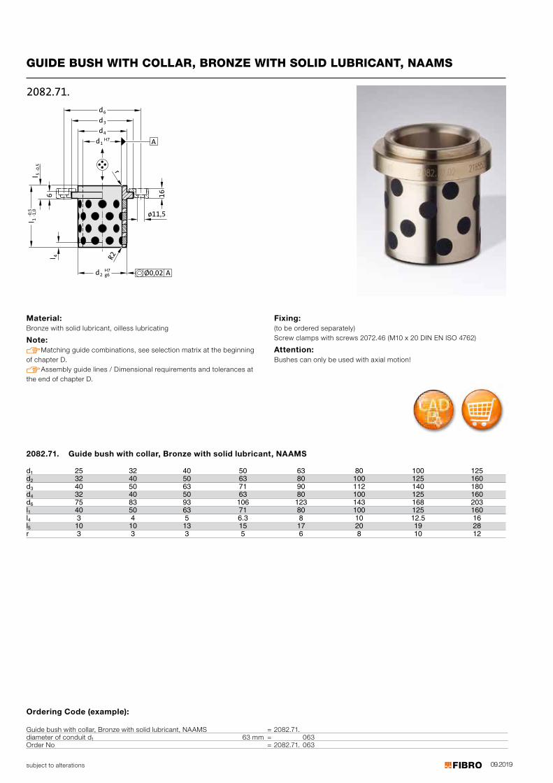
09.2019
6
l-0,5
1-1,0
16
4l
r
R2
3d
d
d6
1dH7
4
H72 g6d
ø11,5
2082.71.
A
Ø0,02 A
5-0,5
l
subject to alterations
GUIDE BUSH WITH COLLAR, BRONZE WITH SOLID LUBRICANT, NAAMS
Material: Bronze with solid lubricant, oilless lubricating
Note: Matching guide combinations, see selection matrix at the beginning of chapter D. Assembly guide lines / Dimensional requirements and tolerances at the end of chapter D.
Fixing: (to be ordered separately) Screw clamps with screws 2072.46 (M10 x 20 DIN EN ISO 4762)
Attention: Bushes can only be used with axial motion!
d 25 32 40 50 63 80 100 125d
12 32 40 50 63 80 100 125 160
d3 40 50 63 71 90 112 140 180d4 32 40 50 63 80 100 125 160d6 75 83 93 106 123 143 168 203l1 40 50 63 71 80 100 125 160l4 3 4 5 6.3 8 10 12.5 16l5 10 10 13 15 17 20 19 28r 3 3 3 5 6 8 10 12
2082.71. Guide bush with collar, Bronze with solid lubricant, NAAMS
Ordering Code (example):
Guide bush with collar, Bronze with solid lubricant, NAAMS = 2082.71.diameter of conduit d1 63 mm = 063Order No = 2082.71. 063

subject to alterations
Guide bush with collar, Bronze with solid lubricant, NAAMS
Material: Bronze with solid lubricant, oilless lubricating
Note: Bushes can be used with radial or axial motion. Matching guide combinations, see selection matrix at the beginning of chapter D. Assembly guide lines / Dimensional requirements and tolerances at the end of chapter D.
Fixing: (to be ordered separately) Screw clamps with screws 2072.47 (M8 x 20 DIN EN ISO 4762)
30°
6 13
1l
2l R2
M8
5°
4
3d
1d C9
6d
A
2 g6dH7
Ø0,02 A
2086.71.
D168
d1 25 32 40 50 63 80 100 125d2 32 40 50 63 80 100 125 160d3 40 50 63 71 90 112 140 180d6 29 34 40.5 44.5 54 65 79 99l1 40 50 55 63 75 90 115 138l2 4 4 5 6 8 10 12 12
Ordering Code (example):Guide bush with collar, Bronze with solid lubricant, NAAMS =2086.71.Guide diameter d1 25 mm = 025Order No =2086.71. 025
2086.71. Guide bush with collar, Bronze with solid lubricant, NAAMS
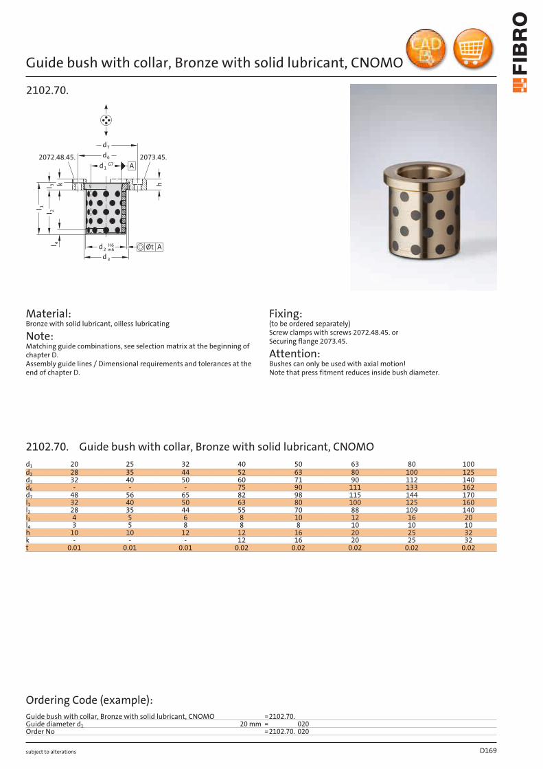
subject to alterations
Guide bush with collar, Bronze with solid lubricant, CNOMO
hl 3 k
2l
1l
4l
2072.48.45. 2073.45.
3d
d2
H6
m6
d1G7
6d
7d
Øt A
A
2102.70.
Material: Bronze with solid lubricant, oilless lubricating
Note: Matching guide combinations, see selection matrix at the beginning of chapter D. Assembly guide lines / Dimensional requirements and tolerances at the end of chapter D.
Fixing: (to be ordered separately) Screw clamps with screws 2072.48.45. or Securing flange 2073.45.
Attention: Bushes can only be used with axial motion! Note that press fitment reduces inside bush diameter.
D169
d1 20 25 32 40 50 63 80 100d2 28 35 44 52 63 80 100 125d3 32 40 50 60 71 90 112 140d6 - - - 75 90 111 133 162d7 48 56 65 82 98 115 144 170l1 32 40 50 63 80 100 125 160l2 28 35 44 55 70 88 109 140l3 4 5 6 8 10 12 16 20l4 3 5 8 8 8 10 10 10h 10 10 12 12 16 20 25 32k - - - 12 16 20 25 32t 0.01 0.01 0.01 0.02 0.02 0.02 0.02 0.02
Ordering Code (example):Guide bush with collar, Bronze with solid lubricant, CNOMO =2102.70.Guide diameter d1 20 mm = 020Order No =2102.70. 020
2102.70. Guide bush with collar, Bronze with solid lubricant, CNOMO
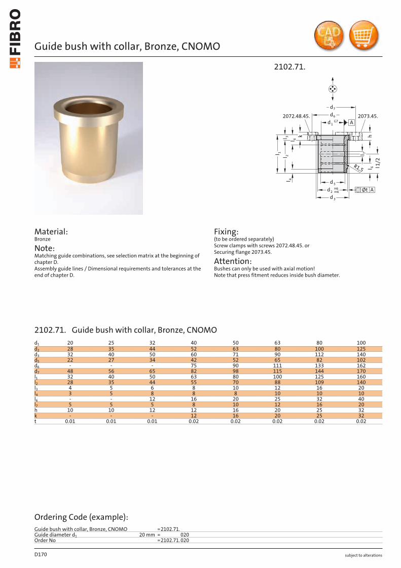
subject to alterations
Guide bush with collar, Bronze, CNOMO
Material: Bronze
Note: Matching guide combinations, see selection matrix at the beginning of chapter D. Assembly guide lines / Dimensional requirements and tolerances at the end of chapter D.
Fixing: (to be ordered separately) Screw clamps with screws 2072.48.45. or Securing flange 2073.45.
Attention: Bushes can only be used with axial motion! Note that press fitment reduces inside bush diameter.
hl 6
l
k
6l 32l
1l
4l
l1/2
l 7
2072.48.45. 2073.45.
R1,5
3d
5d
d2H6m6 Øt A
d1G7
6d
7d
2102.71.
A
D170
d1 20 25 32 40 50 63 80 100d2 28 35 44 52 63 80 100 125d3 32 40 50 60 71 90 112 140d5 22 27 34 42 52 65 82 102d6 - - - 75 90 111 133 162d7 48 56 65 82 98 115 144 170l1 32 40 50 63 80 100 125 160l2 28 35 44 55 70 88 109 140l3 4 5 6 8 10 12 16 20l4 3 5 8 8 8 10 10 10l6 - - 12 16 20 25 32 40l7 5 5 5 8 10 12 16 20h 10 10 12 12 16 20 25 32k - - - 12 16 20 25 32t 0.01 0.01 0.01 0.02 0.02 0.02 0.02 0.02
Ordering Code (example):Guide bush with collar, Bronze, CNOMO =2102.71.Guide diameter d1 20 mm = 020Order No =2102.71. 020
2102.71. Guide bush with collar, Bronze, CNOMO
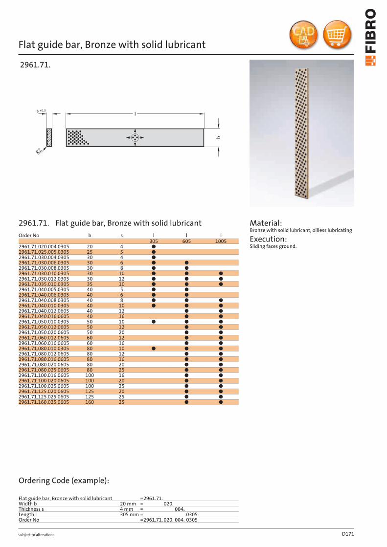
subject to alterations
Flat guide bar, Bronze with solid lubricant
b
R2
s +0,3
l
2961.71.
Material: Bronze with solid lubricant, oilless lubricating
Execution: Sliding faces ground.
D171
Order No b s l l l305 605 1005
2961.71.020.004.0305 20 4 ●2961.71.025.005.0305 25 5 ●2961.71.030.004.0305 30 4 ●2961.71.030.006.0305 30 6 ● ●2961.71.030.008.0305 30 8 ● ●2961.71.030.010.0305 30 10 ● ● ●2961.71.030.012.0305 30 12 ● ● ●2961.71.035.010.0305 35 10 ● ● ●2961.71.040.005.0305 40 5 ● ●2961.71.040.006.0305 40 6 ● ●2961.71.040.008.0305 40 8 ● ● ●2961.71.040.010.0305 40 10 ● ● ●2961.71.040.012.0605 40 12 ● ●2961.71.040.016.0605 40 16 ● ●2961.71.050.010.0305 50 10 ● ● ●2961.71.050.012.0605 50 12 ● ●2961.71.050.020.0605 50 20 ● ●2961.71.060.012.0605 60 12 ● ●2961.71.060.016.0605 60 16 ● ●
80 10 ● ● ●80 12 ● ●80 16 ● ●80 20 ● ●80 25 ● ●
100 16 ● ●100 20 ● ●100 25 ● ●125 20 ● ●125 25 ● ●
2961.71.080.010.03052961.71.080.012.06052961.71.080.016.06052961.71.080.020.06052961.71.080.025.06052961.71.100.016.06052961.71.100.020.06052961.71.100.025.06052961.71.125.020.06052961.71.125.025.06052961.71.160.025.0605 160 25 ● ●
Ordering Code (example):
Flat guide bar, Bronze with solid lubricant =2961.71.Width b 20 mm = 020.Thickness s 4 mm = 004.Length l 305 mm = 0305Order No =2961.71. 020. 004. 0305
2961.71. Flat guide bar, Bronze with solid lubricant
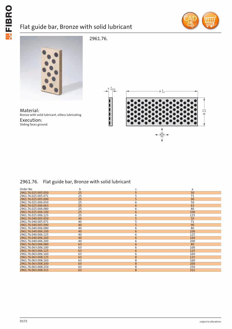
subject to alterations
Flat guide bar, Bronze with solid lubricant
Material: Bronze with solid lubricant, oilless lubricating
Execution: Sliding faces ground.
a 0-0,2
-0,1
-0,2
b
s 0-0,015
2961.76.
D172
Order No b s a2961.76.025.005.050 25 5 502961.76.025.005.071 25 5 712961.76.025.005.090 25 5 902961.76.025.006.050 25 6 502961.76.025.006.063 25 6 632961.76.025.006.080 25 6 802961.76.025.006.100 25 6 1002961.76.025.006.125 25 6 1252961.76.040.005.050 40 5 502961.76.040.005.071 40 5 712961.76.040.005.090 40 5 902961.76.040.006.080 40 6 802961.76.040.006.100 40 6 1002961.76.040.006.125 40 6 1252961.76.040.006.160 40 6 1602961.76.040.006.200 40 6 2002961.76.063.006.080 63 6 802961.76.063.006.100 63 6 1002961.76.063.006.125 63 6 1252961.76.063.006.160 63 6 1602961.76.063.008.125 63 8 1252961.76.063.008.160 63 8 1602961.76.063.008.200 63 8 2002961.76.063.008.250 63 8 2502961.76.063.008.315 63 8 315
2961.76. Flat guide bar, Bronze with solid lubricant
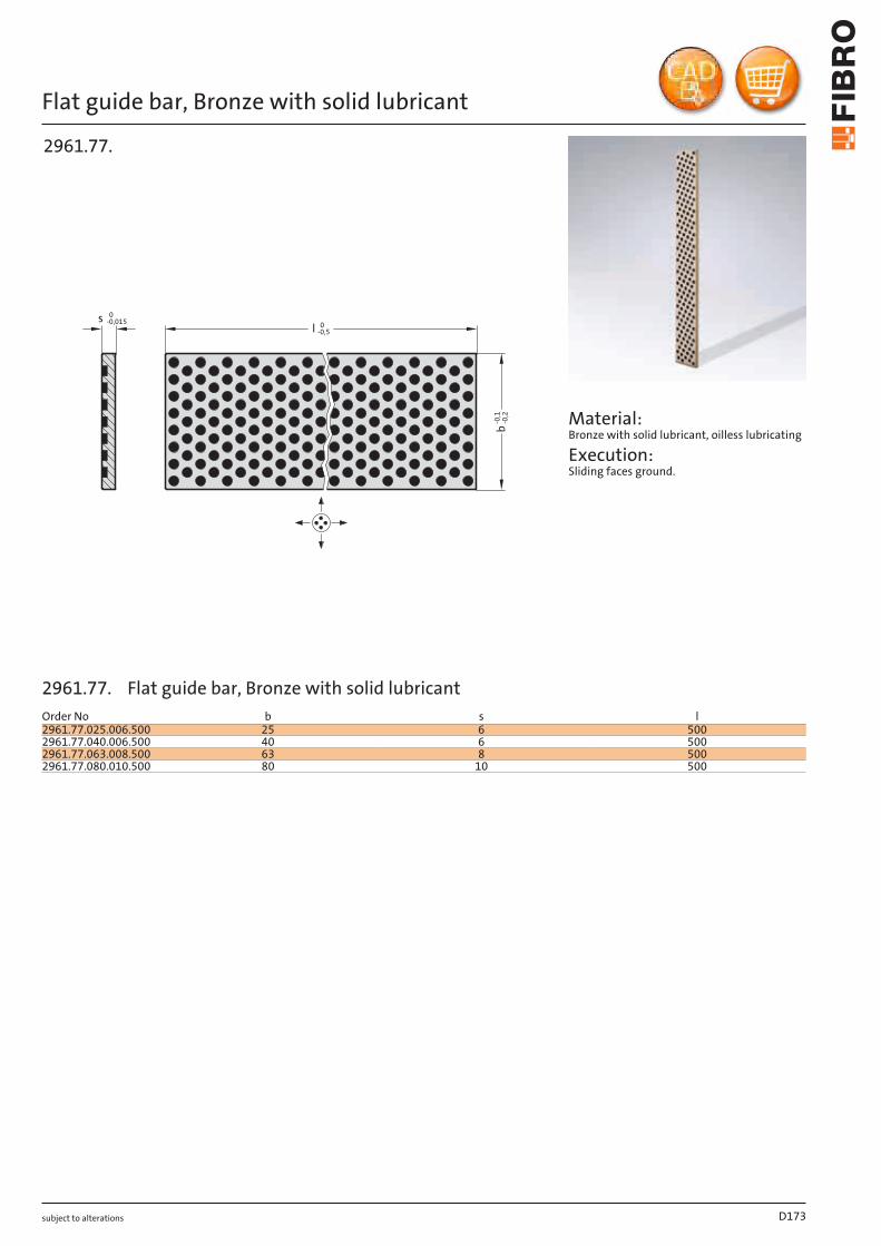
subject to alterations
Flat guide bar, Bronze with solid lubricant
l 0-0,5
b-0
,1-0
,2
s 0-0,015
2961.77.
Material: Bronze with solid lubricant, oilless lubricating
Execution: Sliding faces ground.
D173
Order No b s l2961.77.025.006.500 25 6 5002961.77.040.006.500 40 6 5002961.77.063.008.500 63 8 5002961.77.080.010.500 80 10 500
2961.77. Flat guide bar, Bronze with solid lubricant
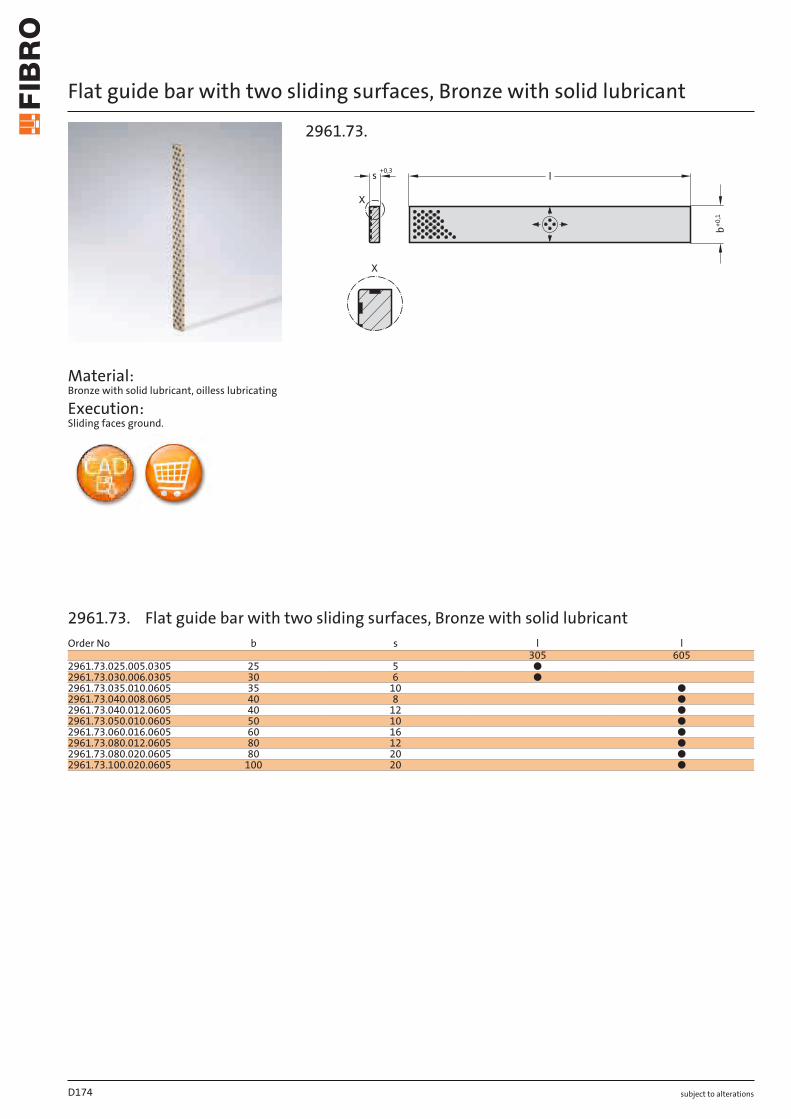
subject to alterations
Flat guide bar with two sliding surfaces, Bronze with solid lubricant
Material: Bronze with solid lubricant, oilless lubricating
Execution: Sliding faces ground.
+0,3s
X
l
b+0,1
X
2961.73.
D174
Order No b s l l305 605
2961.73.025.005.0305 25 5 ●2961.73.030.006.0305 30 6 ●2961.73.035.010.0605 35 10 ●2961.73.040.008.0605 40 8 ●2961.73.040.012.0605 40 12 ●2961.73.050.010.0605 50 10 ●2961.73.060.016.0605 60 16 ●2961.73.080.012.0605 80 12 ●2961.73.080.020.0605 80 20 ●2961.73.100.020.0605 100 20 ●
2961.73. Flat guide bar with two sliding surfaces, Bronze with solid lubricant
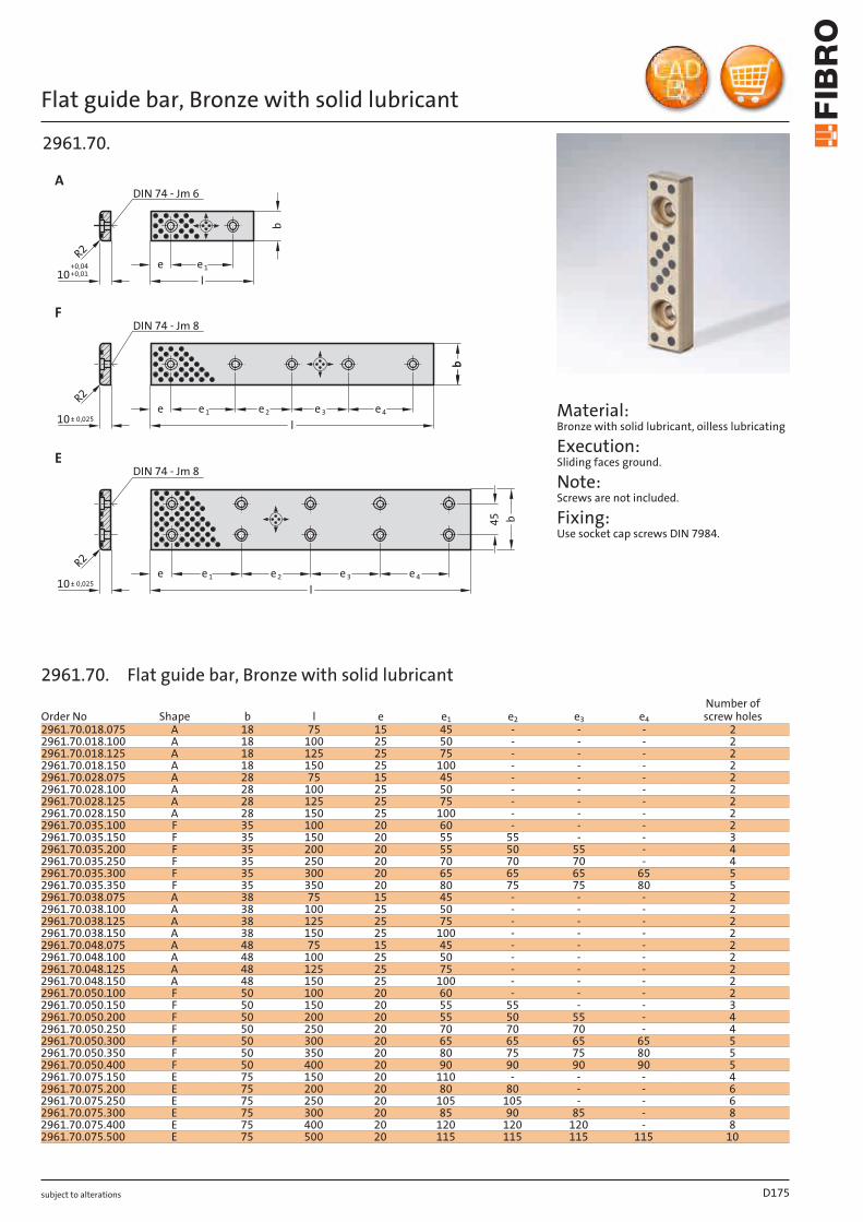
subject to alterations
Flat guide bar, Bronze with solid lubricant
le 4e 3e 2e 1e
l
l
e 4e 3e 2e e 1
45 b
10+0,04+0,01
R2
DIN 74 - Jm 6
be e 1
A
DIN 74 - Jm 8
DIN 74 - Jm 8
F
10± 0,025
R2
R2
10± 0,025
E
bb
2961.70.
Material: Bronze with solid lubricant, oilless lubricating
Execution: Sliding faces ground.
Note: Screws are not included.
Fixing: Use socket cap screws DIN 7984.
D175
Order No Shape b l e e1 e2 e3 e4
Number of screw holes
2961.70.018.075 A 18 75 15 45 - - - 22961.70.018.100 A 18 100 25 50 - - - 22961.70.018.125 A 18 125 25 75 - - - 22961.70.018.150 A 18 150 25 100 - - - 22961.70.028.075 A 28 75 15 45 - - - 22961.70.028.100 A 28 100 25 50 - - - 22961.70.028.125 A 28 125 25 75 - - - 22961.70.028.150 A 28 150 25 100 - - - 22961.70.035.100 F 35 100 20 60 - - - 22961.70.035.150 F 35 150 20 55 55 - - 32961.70.035.200 F 35 200 20 55 50 55 - 42961.70.035.250 F 35 250 20 70 70 70 - 42961.70.035.300 F 35 300 20 65 65 65 65 52961.70.035.350 F 35 350 20 80 75 75 80 52961.70.038.075 A 38 75 15 45 - - - 22961.70.038.100 A 38 100 25 50 - - - 22961.70.038.125 A 38 125 25 75 - - - 22961.70.038.150 A 38 150 25 100 - - - 22961.70.048.075 A 48 75 15 45 - - - 22961.70.048.100 A 48 100 25 50 - - - 22961.70.048.125 A 48 125 25 75 - - - 22961.70.048.150 A 48 150 25 100 - - - 22961.70.050.100 F 50 100 20 60 - - - 22961.70.050.150 F 50 150 20 55 55 - - 32961.70.050.200 F 50 200 20 55 50 55 - 42961.70.050.250 F 50 250 20 70 70 70 - 42961.70.050.300 F 50 300 20 65 65 65 65 52961.70.050.350 F 50 350 20 80 75 75 80 52961.70.050.400 F 50 400 20 90 90 90 90 52961.70.075.150 E 75 150 20 110 - - - 42961.70.075.200 E 75 200 20 80 80 - - 62961.70.075.250 E 75 250 20 105 105 - - 62961.70.075.300 E 75 300 20 85 90 85 - 82961.70.075.400 E 75 400 20 120 120 120 - 82961.70.075.500 E 75 500 20 115 115 115 115 10
2961.70. Flat guide bar, Bronze with solid lubricant
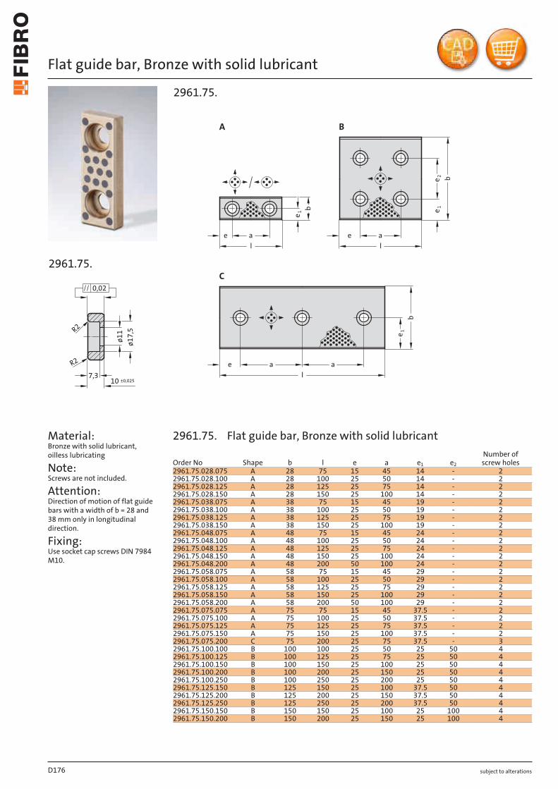
subject to alterations
Flat guide bar, Bronze with solid lubricant
ø17,5R2
R2
7,3
ø11
0,02
10 ±0,025
2961.75.
Material: Bronze with solid lubricant, oilless lubricating
Note: Screws are not included.
Attention: Direction of motion of flat guide bars with a width of b = 28 and 38 mm only in longitudinal direction.
Fixing: Use socket cap screws DIN 7984 M10.
e1
e1
e2
e1
b
b
b
a
l
ae
e
l
a
l
ae
BA
C
2961.75.
D176
Order No Shape b l e a e1 e2
Number of screw holes
2961.75.028.075 A 28 75 15 45 14 - 22961.75.028.100 A 28 100 25 50 14 - 22961.75.028.125 A 28 125 25 75 14 - 22961.75.028.150 A 28 150 25 100 14 - 22961.75.038.075 A 38 75 15 45 19 - 22961.75.038.100 A 38 100 25 50 19 - 22961.75.038.125 A 38 125 25 75 19 - 22961.75.038.150 A 38 150 25 100 19 - 22961.75.048.075 A 48 75 15 45 24 - 22961.75.048.100 A 48 100 25 50 24 - 22961.75.048.125 A 48 125 25 75 24 - 22961.75.048.150 A 48 150 25 100 24 - 22961.75.048.200 A 48 200 50 100 24 - 22961.75.058.075 A 58 75 15 45 29 - 22961.75.058.100 A 58 100 25 50 29 - 22961.75.058.125 A 58 125 25 75 29 - 22961.75.058.150 A 58 150 25 100 29 - 22961.75.058.200 A 58 200 50 100 29 - 22961.75.075.075 A 75 75 15 45 37.5 - 22961.75.075.100 A 75 100 25 50 37.5 - 22961.75.075.125 A 75 125 25 75 37.5 - 22961.75.075.150 A 75 150 25 100 37.5 - 22961.75.075.200 C 75 200 25 75 37.5 - 32961.75.100.100 B 100 100 25 50 25 50 42961.75.100.125 B 100 125 25 75 25 50 42961.75.100.150 B 100 150 25 100 25 50 42961.75.100.200 B 100 200 25 150 25 50 42961.75.100.250 B 100 250 25 200 25 50 42961.75.125.150 B 125 150 25 100 37.5 50 42961.75.125.200 B 125 200 25 150 37.5 50 42961.75.125.250 B 125 250 25 200 37.5 50 42961.75.150.150 B 150 150 25 100 25 100 42961.75.150.200 B 150 200 25 150 25 100 4
2961.75. Flat guide bar, Bronze with solid lubricant
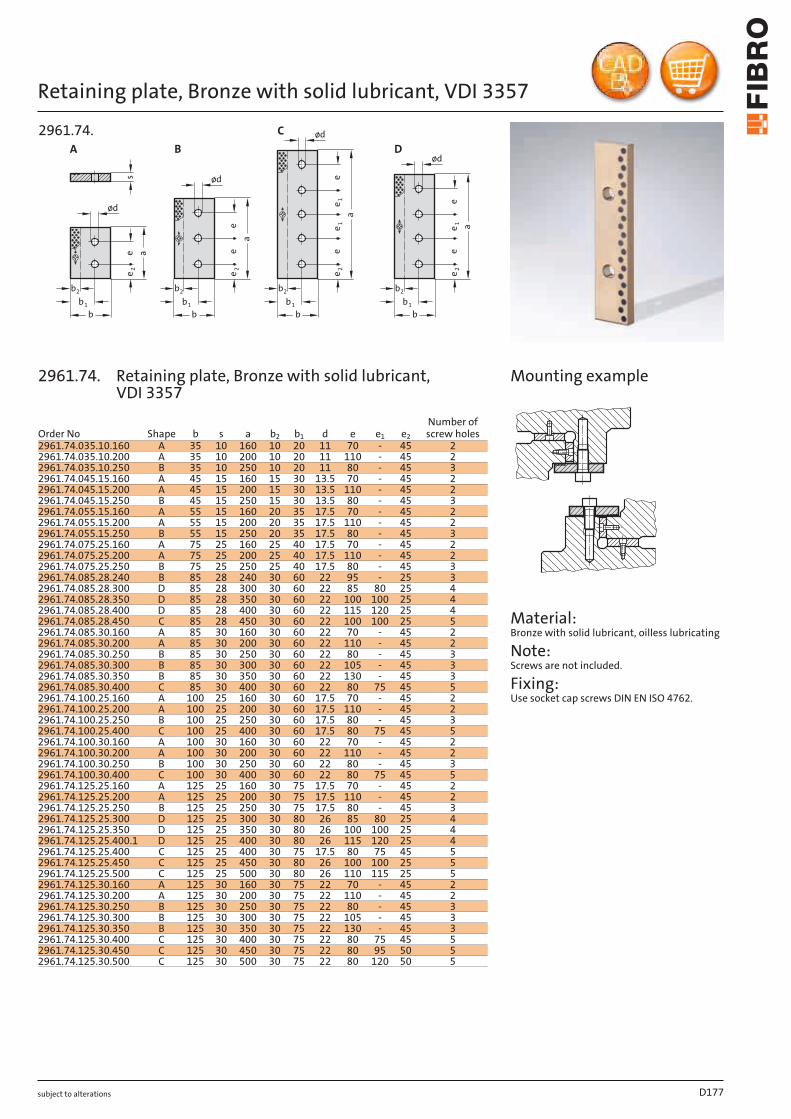
subject to alterations
Retaining plate, Bronze with solid lubricant, VDI 3357
e1
e1
eee
ee
e2
e2
e2
e2
a
a
a
2b
1b
b
2b
1b
b
2b
1b
b
e a
s
2b
1b
b
A
ød
ød
ød
ød
ee1
B
C
D
2961.74.
Material: Bronze with solid lubricant, oilless lubricating
Note: Screws are not included.
Fixing: Use socket cap screws DIN EN ISO 4762.
Mounting example
D177
Order No Shape b s a b2 b1 d e e1 e2
Number of screw holes
2961.74.035.10.160 A 35 10 160 10 20 11 70 - 45 22961.74.035.10.200 A 35 10 200 10 20 11 110 - 45 22961.74.035.10.250 B 35 10 250 10 20 11 80 - 45 32961.74.045.15.160 A 45 15 160 15 30 13.5 70 - 45 22961.74.045.15.200 A 45 15 200 15 30 13.5 110 - 45 22961.74.045.15.250 B 45 15 250 15 30 13.5 80 - 45 32961.74.055.15.160 A 55 15 160 20 35 17.5 70 - 45 22961.74.055.15.200 A 55 15 200 20 35 17.5 110 - 45 22961.74.055.15.250 B 55 15 250 20 35 17.5 80 - 45 32961.74.075.25.160 A 75 25 160 25 40 17.5 70 - 45 22961.74.075.25.200 A 75 25 200 25 40 17.5 110 - 45 22961.74.075.25.250 B 75 25 250 25 40 17.5 80 - 45 32961.74.085.28.240 B 85 28 240 30 60 22 95 - 25 32961.74.085.28.300 D 85 28 300 30 60 22 85 80 25 42961.74.085.28.350 D 85 28 350 30 60 22 100 100 25 42961.74.085.28.400 D 85 28 400 30 60 22 115 120 25 42961.74.085.28.450 C 85 28 450 30 60 22 100 100 25 52961.74.085.30.160 A 85 30 160 30 60 22 70 - 45 22961.74.085.30.200 A 85 30 200 30 60 22 110 - 45 22961.74.085.30.250 B 85 30 250 30 60 22 80 - 45 32961.74.085.30.300 B 85 30 300 30 60 22 105 - 45 32961.74.085.30.350 B 85 30 350 30 60 22 130 - 45 32961.74.085.30.400 C 85 30 400 30 60 22 80 75 45 52961.74.100.25.160 A 100 25 160 30 60 17.5 70 - 45 22961.74.100.25.200 A 100 25 200 30 60 17.5 110 - 45 22961.74.100.25.250 B 100 25 250 30 60 17.5 80 - 45 32961.74.100.25.400 C 100 25 400 30 60 17.5 80 75 45 52961.74.100.30.160 A 100 30 160 30 60 22 70 - 45 2
A 100 30 200 30 60 22 110 - 45 2B 100 30 250 30 60 22 80 - 45 3C 100 30 400 30 60 22 80 75 45 5
2961.74.100.30.2002961.74.100.30.2502961.74.100.30.4002961.74.125.25.160 A 125 25 160 30 75 17.5 70 - 45 22961.74.125.25.200 A 125 25 200 30 75 17.5 110 - 45 22961.74.125.25.250 B 125 25 250 30 75 17.5 80 - 45 32961.74.125.25.300 D 125 25 300 30 80 26 85 80 25 42961.74.125.25.350 D 125 25 350 30 80 26 100 100 25 42961.74.125.25.400.1 D 125 25 400 30 80 26 115 120 25 42961.74.125.25.400 C 125 25 400 30 75 17.5 80 75 45 52961.74.125.25.450 C 125 25 450 30 80 26 100 100 25 52961.74.125.25.500 C 125 25 500 30 80 26 110 115 25 52961.74.125.30.160 A 125 30 160 30 75 22 70 - 45 22961.74.125.30.200 A 125 30 200 30 75 22 110 - 45 22961.74.125.30.250 B 125 30 250 30 75 22 80 - 45 32961.74.125.30.300 B 125 30 300 30 75 22 105 - 45 32961.74.125.30.350 B 125 30 350 30 75 22 130 - 45 32961.74.125.30.400 C 125 30 400 30 75 22 80 75 45 52961.74.125.30.450 C 125 30 450 30 75 22 80 95 50 52961.74.125.30.500 C 125 30 500 30 75 22 80 120 50 5
2961.74. Retaining plate, Bronze with solid lubricant, VDI 3357
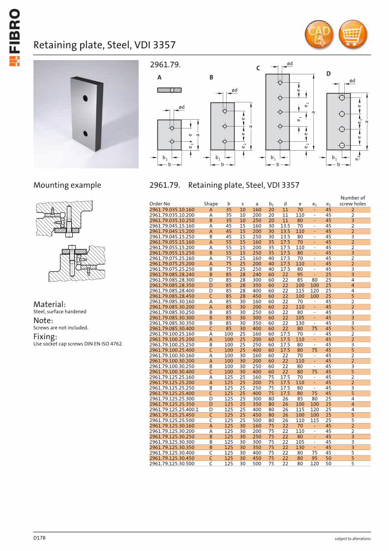
subject to alterations
Retaining plate, Steel, VDI 3357
Material: Steel, surface hardened
Note: Screws are not included.
Fixing: Use socket cap screws DIN EN ISO 4762.
e2
ød
b1b
a
ee
e1
D
ød
1b
b
ae
A
e2
ød
1b
b
a
ee
B
e2
ød
1b
b
a
e
ee
1
e1
C
e2
2961.79.
Mounting example
D178
Order No Shape b s a b1 d e e1 e2
Number of screw holes
2961.79.035.10.160 A 35 10 160 20 11 70 - 45 22961.79.035.10.200 A 35 10 200 20 11 110 - 45 22961.79.035.10.250 B 35 10 250 20 11 80 - 45 32961.79.045.15.160 A 45 15 160 30 13.5 70 - 45 22961.79.045.15.200 A 45 15 200 30 13.5 110 - 45 22961.79.045.15.250 B 45 15 250 30 13.5 80 - 45 32961.79.055.15.160 A 55 15 160 35 17.5 70 - 45 22961.79.055.15.200 A 55 15 200 35 17.5 110 - 45 22961.79.055.15.250 B 55 15 250 35 17.5 80 - 45 32961.79.075.25.160 A 75 25 160 40 17.5 70 - 45 22961.79.075.25.200 A 75 25 200 40 17.5 110 - 45 22961.79.075.25.250 B 75 25 250 40 17.5 80 - 45 32961.79.085.28.240 B 85 28 240 60 22 95 - 25 32961.79.085.28.300 D 85 28 300 60 22 85 80 25 42961.79.085.28.350 D 85 28 350 60 22 100 100 25 42961.79.085.28.400 D 85 28 400 60 22 115 120 25 42961.79.085.28.450 C 85 28 450 60 22 100 100 25 52961.79.085.30.160 A 85 30 160 60 22 70 - 45 22961.79.085.30.200 A 85 30 200 60 22 110 - 45 22961.79.085.30.250 B 85 30 250 60 22 80 - 45 32961.79.085.30.300 B 85 30 300 60 22 105 - 45 32961.79.085.30.350 B 85 30 350 60 22 130 - 45 32961.79.085.30.400 C 85 30 400 60 22 80 75 45 52961.79.100.25.160 A 100 25 160 60 17.5 70 - 45 22961.79.100.25.200 A 100 25 200 60 17.5 110 - 45 22961.79.100.25.250 B 100 25 250 60 17.5 80 - 45 32961.79.100.25.400 C 100 25 400 60 17.5 80 75 45 52961.79.100.30.160 A 100 30 160 60 22 70 - 45 2
A 100 30 200 60 22 110 - 45 2B 100 30 250 60 22 80 - 45 3C 100 30 400 60 22 80 75 45 5A 125 25 160 75 17.5 70 - 45 2A 125 25 200 75 17.5 110 - 45 2B 125 25 250 75 17.5 80 - 45 3
2961.79.100.30.2002961.79.100.30.2502961.79.100.30.4002961.79.125.25.1602961.79.125.25.2002961.79.125.25.2502961.79.125.25.400 C 125 25 400 75 17.5 80 75 45 52961.79.125.25.300 D 125 25 300 80 26 85 80 25 42961.79.125.25.350 D 125 25 350 80 26 100 100 25 42961.79.125.25.400.1 D 125 25 400 80 26 115 120 25 42961.79.125.25.450 C 125 25 450 80 26 100 100 25 52961.79.125.25.500 C 125 25 500 80 26 110 115 25 52961.79.125.30.160 A 125 30 160 75 22 70 - 45 22961.79.125.30.200 A 125 30 200 75 22 110 - 45 22961.79.125.30.250 B 125 30 250 75 22 80 - 45 32961.79.125.30.300 B 125 30 300 75 22 105 - 45 32961.79.125.30.350 B 125 30 350 75 22 130 - 45 32961.79.125.30.400 C 125 30 400 75 22 80 75 45 52961.79.125.30.450 C 125 30 450 75 22 80 95 50 52961.79.125.30.500 C 125 30 500 75 22 80 120 50 5
2961.79. Retaining plate, Steel, VDI 3357
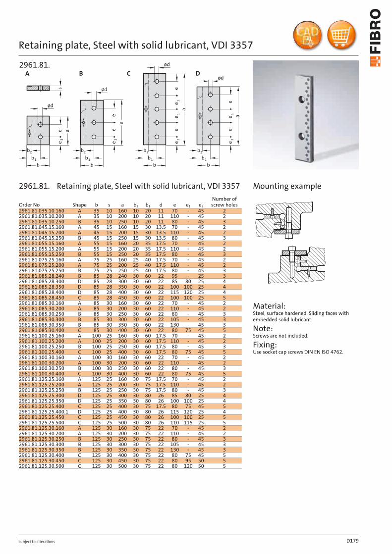
subject to alterations
Retaining plate, Steel with solid lubricant, VDI 3357
A
e 2e a
s
b2
b1
b
øde
ee 2
a
b2
b1
b
ød
B
e 1e
ee 2
a
b2
b1
b
ød
e 1
C
e 1e
e 2
a
b2
b1
b
ød
e
D
2961.81.
Material: Steel, surface hardened. Sliding faces with embedded solid lubricant.
Note: Screws are not included.
Fixing: Use socket cap screws DIN EN ISO 4762.
Mounting example
D179
Order No Shape b s a b2 b1 d e e1 e2
Number of screw holes
2961.81.035.10.160 A 35 10 160 10 20 11 70 - 45 22961.81.035.10.200 A 35 10 200 10 20 11 110 - 45 22961.81.035.10.250 B 35 10 250 10 20 11 80 - 45 32961.81.045.15.160 A 45 15 160 15 30 13.5 70 - 45 22961.81.045.15.200 A 45 15 200 15 30 13.5 110 - 45 22961.81.045.15.250 B 45 15 250 15 30 13.5 80 - 45 32961.81.055.15.160 A 55 15 160 20 35 17.5 70 - 45 22961.81.055.15.200 A 55 15 200 20 35 17.5 110 - 45 22961.81.055.15.250 B 55 15 250 20 35 17.5 80 - 45 32961.81.075.25.160 A 75 25 160 25 40 17.5 70 - 45 22961.81.075.25.200 A 75 25 200 25 40 17.5 110 - 45 22961.81.075.25.250 B 75 25 250 25 40 17.5 80 - 45 32961.81.085.28.240 B 85 28 240 30 60 22 95 - 25 32961.81.085.28.300 D 85 28 300 30 60 22 85 80 25 42961.81.085.28.350 D 85 28 350 30 60 22 100 100 25 42961.81.085.28.400 D 85 28 400 30 60 22 115 120 25 42961.81.085.28.450 C 85 28 450 30 60 22 100 100 25 52961.81.085.30.160 A 85 30 160 30 60 22 70 - 45 22961.81.085.30.200 A 85 30 200 30 60 22 110 - 45 22961.81.085.30.250 B 85 30 250 30 60 22 80 - 45 32961.81.085.30.300 B 85 30 300 30 60 22 105 - 45 32961.81.085.30.350 B 85 30 350 30 60 22 130 - 45 32961.81.085.30.400 C 85 30 400 30 60 22 80 75 45 52961.81.100.25.160 A 100 25 160 30 60 17.5 70 - 45 22961.81.100.25.200 A 100 25 200 30 60 17.5 110 - 45 22961.81.100.25.250 B 100 25 250 30 60 17.5 80 - 45 32961.81.100.25.400 C 100 25 400 30 60 17.5 80 75 45 52961.81.100.30.160 A 100 30 160 30 60 22 70 - 45 22961.81.100.30.200 A 100 30 200 30 60 22 110 - 45 22961.81.100.30.250 B 100 30 250 30 60 22 80 - 45 32961.81.100.30.400 C 100 30 400 30 60 22 80 75 45 52961.81.125.25.160 A 125 25 160 30 75 17.5 70 - 45 22961.81.125.25.200 A 125 25 200 30 75 17.5 110 - 45 22961.81.125.25.250 B 125 25 250 30 75 17.5 80 - 45 32961.81.125.25.300 D 125 25 300 30 80 26 85 80 25 42961.81.125.25.350 D 125 25 350 30 80 26 100 100 25 42961.81.125.25.400 C 125 25 400 30 75 17.5 80 75 45 52961.81.125.25.400.1 D 125 25 400 30 80 26 115 120 25 42961.81.125.25.450 C 125 25 450 30 80 26 100 100 25 52961.81.125.25.500 C 125 25 500 30 80 26 110 115 25 52961.81.125.30.160 A 125 30 160 30 75 22 70 - 45 22961.81.125.30.200 A 125 30 200 30 75 22 110 - 45 22961.81.125.30.250 B 125 30 250 30 75 22 80 - 45 32961.81.125.30.300 B 125 30 300 30 75 22 105 - 45 32961.81.125.30.350 B 125 30 350 30 75 22 130 - 45 32961.81.125.30.400 C 125 30 400 30 75 22 80 75 45 52961.81.125.30.450 C 125 30 450 30 75 22 80 95 50 52961.81.125.30.500 C 125 30 500 30 75 22 80 120 50 5
2961.81. Retaining plate, Steel with solid lubricant, VDI 3357
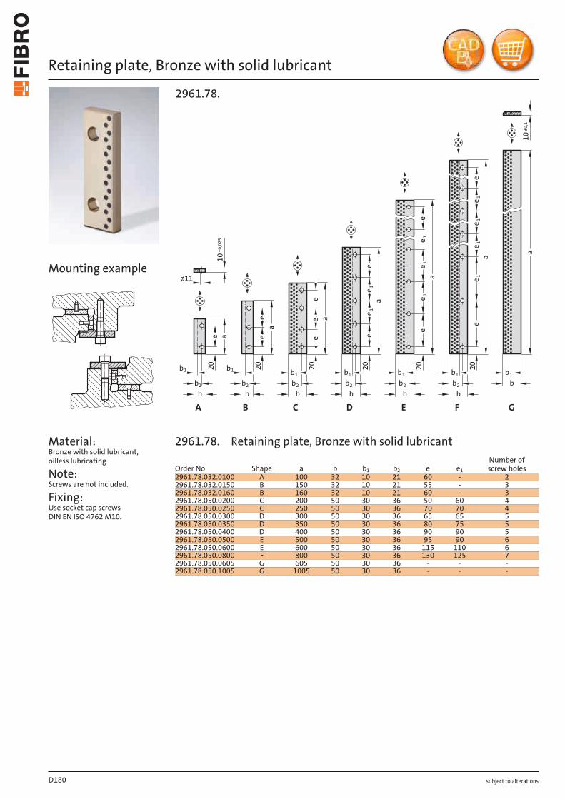
subject to alterations
Retaining plate, Bronze with solid lubricant
Material: Bronze with solid lubricant, oilless lubricating
Note: Screws are not included.
Fixing: Use socket cap screws DIN EN ISO 4762 M10.
b1
b
a
a
e1
ee1
e
a
ee
10
±0,025
ø11
b2 b2
bb
e
a
a
1e
b2
b
20
a
aee
1e
b1
ee
1e
20
b1
b2
b
20
20
ee
b1 b1
G
10
±0,1
b1
b2
b
20
1e
1e
1e
20
1e
1e
b1
b2
b
F EDC B A
2961.78.
Mounting example
D180
Order No Shape a b b1 b2 e e1
Number of screw holes
2961.78.032.0100 A 100 32 10 21 60 - 22961.78.032.0150 B 150 32 10 21 55 - 32961.78.032.0160 B 160 32 10 21 60 - 32961.78.050.0200 C 200 50 30 36 50 60 42961.78.050.0250 C 250 50 30 36 70 70 42961.78.050.0300 D 300 50 30 36 65 65 52961.78.050.0350 D 350 50 30 36 80 75 52961.78.050.0400 D 400 50 30 36 90 90 52961.78.050.0500 E 500 50 30 36 95 90 62961.78.050.0600 E 600 50 30 36 115 110 62961.78.050.0800 F 800 50 30 36 130 125 72961.78.050.0605 G 605 50 30 36 - - -2961.78.050.1005 G 1005 50 30 36 - - -
2961.78. Retaining plate, Bronze with solid lubricant
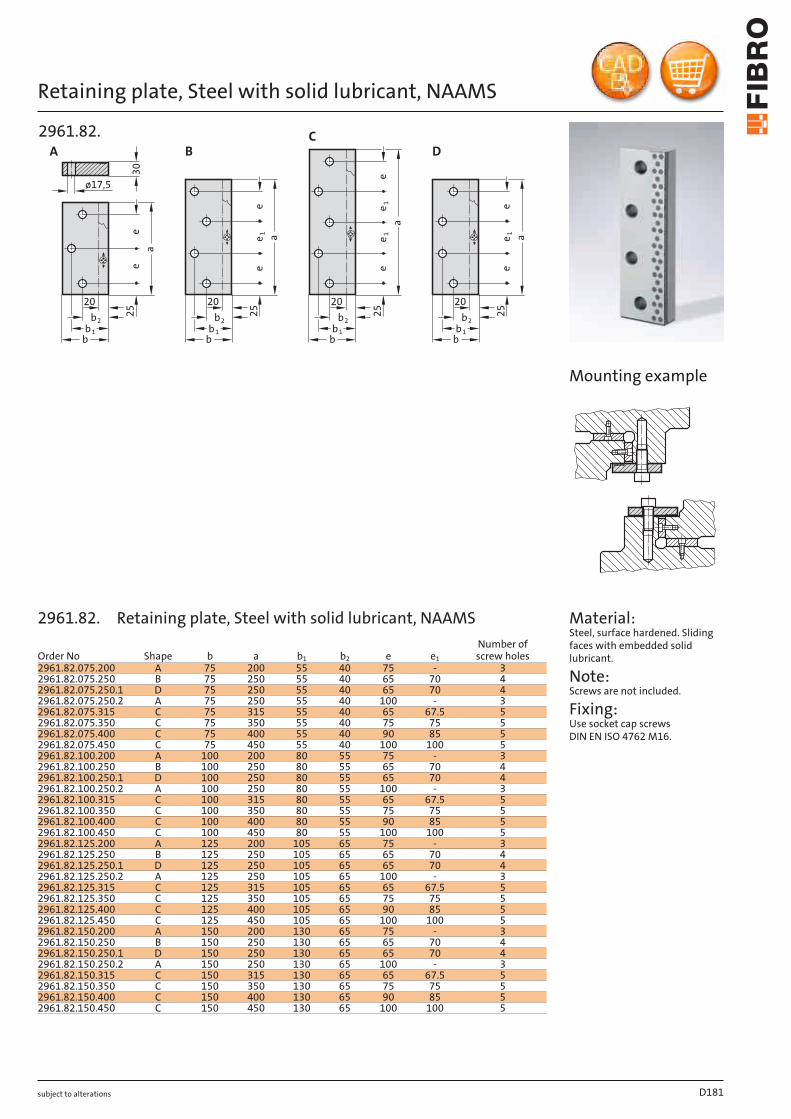
subject to alterations
Retaining plate, Steel with solid lubricant, NAAMS
30
A
ø17,5
a
a
a
ae1
e1
e1
e1e
e
ee
ee
ee
25
2b
1b
b
20
25
25
25
2b
1b
b
20
2b
1b
b
20
2b
1b
b
20
B D
C
2961.82.
Material: Steel, surface hardened. Sliding faces with embedded solid lubricant.
Note: Screws are not included.
Fixing: Use socket cap screws DIN EN ISO 4762 M16.
Mounting example
D181
Order No Shape b a b1 b2 e e1
Number of screw holes
2961.82.075.200 A 75 200 55 40 75 - 32961.82.075.250 B 75 250 55 40 65 70 42961.82.075.250.1 D 75 250 55 40 65 70 42961.82.075.250.2 A 75 250 55 40 100 - 32961.82.075.315 C 75 315 55 40 65 67.5 52961.82.075.350 C 75 350 55 40 75 75 52961.82.075.400 C 75 400 55 40 90 85 52961.82.075.450 C 75 450 55 40 100 100 52961.82.100.200 A 100 200 80 55 75 - 32961.82.100.250 B 100 250 80 55 65 70 42961.82.100.250.1 D 100 250 80 55 65 70 42961.82.100.250.2 A 100 250 80 55 100 - 32961.82.100.315 C 100 315 80 55 65 67.5 52961.82.100.350 C 100 350 80 55 75 75 52961.82.100.400 C 100 400 80 55 90 85 52961.82.100.450 C 100 450 80 55 100 100 52961.82.125.200 A 125 200 105 65 75 - 32961.82.125.250 B 125 250 105 65 65 70 42961.82.125.250.1 D 125 250 105 65 65 70 42961.82.125.250.2 A 125 250 105 65 100 - 32961.82.125.315 C 125 315 105 65 65 67.5 52961.82.125.350 C 125 350 105 65 75 75 52961.82.125.400 C 125 400 105 65 90 85 52961.82.125.450 C 125 450 105 65 100 100 52961.82.150.200 A 150 200 130 65 75 - 32961.82.150.250 B 150 250 130 65 65 70 42961.82.150.250.1 D 150 250 130 65 65 70 42961.82.150.250.2 A 150 250 130 65 100 - 32961.82.150.315 C 150 315 130 65 65 67.5 52961.82.150.350 C 150 350 130 65 75 75 52961.82.150.400 C 150 400 130 65 90 85 52961.82.150.450 C 150 450 130 65 100 100 5
2961.82. Retaining plate, Steel with solid lubricant, NAAMS
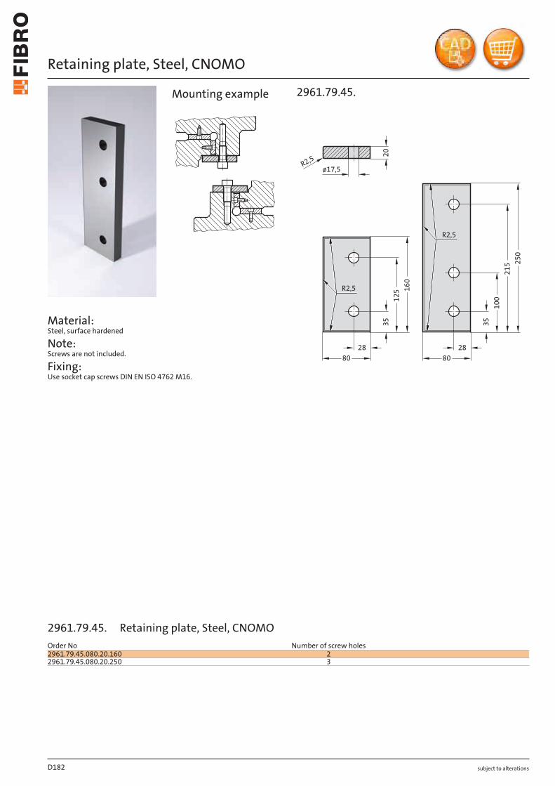
subject to alterations
Retaining plate, Steel, CNOMO
Material: Steel, surface hardened
Note: Screws are not included.
Fixing: Use socket cap screws DIN EN ISO 4762 M16.
20
35
16
0
12
5
21
5
10
0
25
0
ø17,5
28
8080
28
35
R2,5
R2,5
R2,5
2961.79.45.Mounting example
D182
2961.79.45. Retaining plate, Steel, CNOMOOrder No Number of screw holes2961.79.45.080.20.160 22961.79.45.080.20.250 3
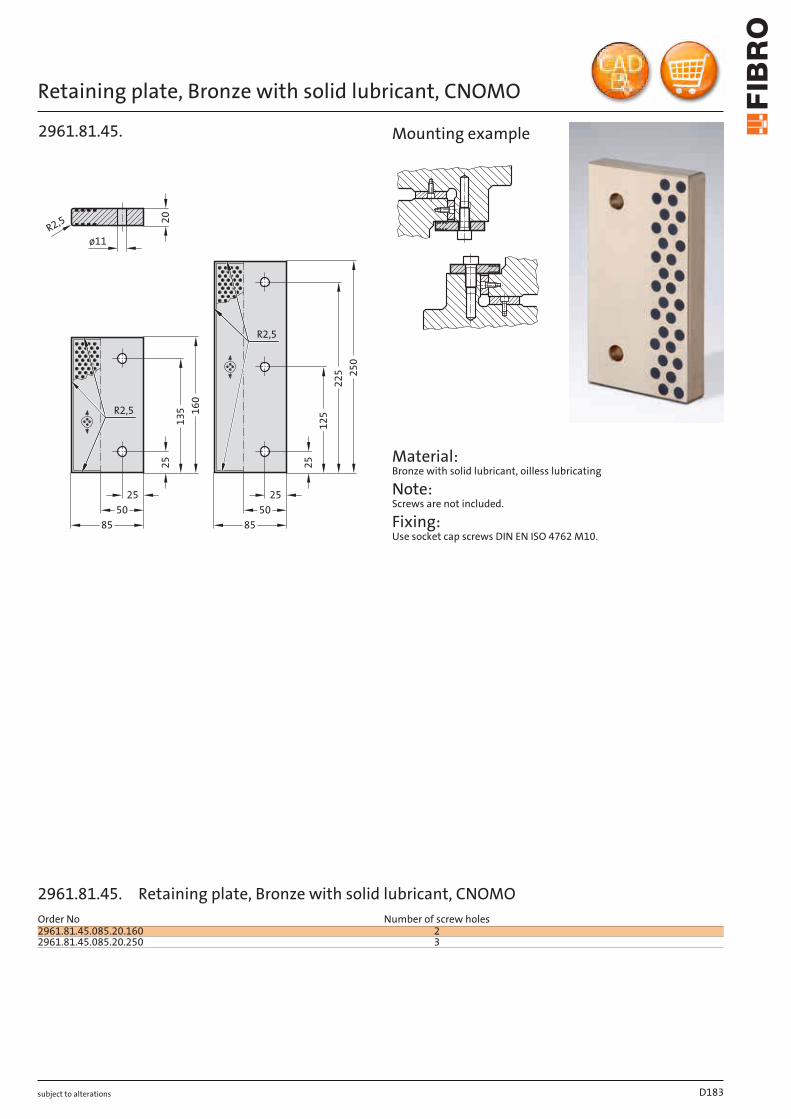
subject to alterations
Retaining plate, Bronze with solid lubricant, CNOMO
20
25
160
135
85
50
25
85
50
25
250
225
125
25
ø11
R2,5
R2,5
R2,5
2961.81.45.
Material: Bronze with solid lubricant, oilless lubricating
Note: Screws are not included.
Fixing: Use socket cap screws DIN EN ISO 4762 M10.
Mounting example
D183
Order No Number of screw holes2961.81.45.085.20.160 22961.81.45.085.20.250 3
2961.81.45. Retaining plate, Bronze with solid lubricant, CNOMO

subject to alterations
Sliding pad, small dimension, Bronze with solid lubricantd
5 ± 0,025
90
°
2960.72.
Material: Bronze with solid lubricant, oilless lubricating
Note: Screws are not included.
Fixing: Use countersunk cap screws DIN 7991/ISO 10642.
15
15
15
15
ee
a
ea
ee
a
ea
1e
1e
b
b
b
b
A B
C D
2960.72.
D184
Order No Shape b a e e1 dNumber of screw holes
2960.72.018.050 A 18 50 20 - 6.5 22960.72.018.075 A 18 75 45 - 6.5 22960.72.018.100 A 18 100 70 - 6.5 22960.72.018.150 B 18 150 60 - 6.5 32960.72.028.050 A 28 50 20 - 9 22960.72.028.075 A 28 75 45 - 9 22960.72.028.100 A 28 100 70 - 9 22960.72.028.150 B 28 150 60 - 9 32960.72.038.050 A 38 50 20 - 9 22960.72.038.075 A 38 75 45 - 9 22960.72.038.100 A 38 100 70 - 9 22960.72.038.150 B 38 150 60 - 9 32960.72.048.075 A 48 75 45 - 9 22960.72.048.100 A 48 100 70 - 9 22960.72.048.125 A 48 125 95 - 9 22960.72.048.150 B 48 150 60 - 9 32960.72.075.075 C 75 75 45 45 9 42960.72.075.100 C 75 100 70 45 9 42960.72.075.125 C 75 125 95 45 9 42960.72.075.150 D 75 150 60 45 9 62960.72.100.100 C 100 100 70 70 9 42960.72.100.125 C 100 125 95 70 9 42960.72.100.150 D 100 150 60 70 9 6
2960.72. Sliding pad, small dimension, Bronze with solid lubricant

subject to alterations D185

subject to alterations
Sliding pad, Bronze with solid lubricant, VDI 3357
Material: Bronze with solid lubricant, oilless lubricating
Note: Screws are not included.
Fixing: Use socket cap screws DIN EN ISO 4762.
H
1lea
b
1e
1l
b
a
1lea
1e
b
D B
G
1lea
1e
b
2960.71.
X
t
dd 110
15°
R5
20
0,020
-0,02
3x45
°
2960.71.
D186
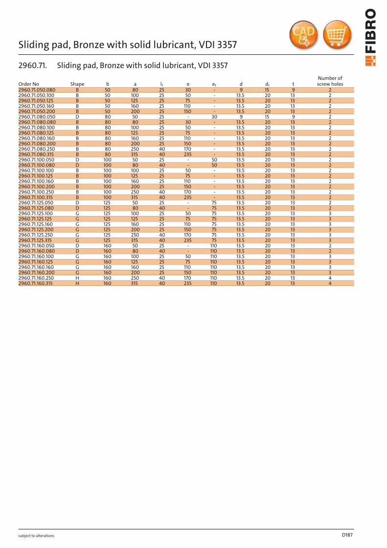
subject to alterations
Sliding pad, Bronze with solid lubricant, VDI 3357
D187
Order No Shape b a l1 e e1 d d1 tNumber of screw holes
2960.71.050.080 B 50 80 25 30 - 9 15 9 22960.71.050.100 B 50 100 25 50 - 13.5 20 13 22960.71.050.125 B 50 125 25 75 - 13.5 20 13 22960.71.050.160 B 50 160 25 110 - 13.5 20 13 22960.71.050.200 B 50 200 25 150 - 13.5 20 13 22960.71.080.050 D 80 50 25 - 30 9 15 9 22960.71.080.080 B 80 80 25 30 - 13.5 20 13 22960.71.080.100 B 80 100 25 50 - 13.5 20 13 22960.71.080.125 B 80 125 25 75 - 13.5 20 13 22960.71.080.160 B 80 160 25 110 - 13.5 20 13 22960.71.080.200 B 80 200 25 150 - 13.5 20 13 22960.71.080.250 B 80 250 40 170 - 13.5 20 13 22960.71.080.315 B 80 315 40 235 - 13.5 20 13 22960.71.100.050 D 100 50 25 - 50 13.5 20 13 22960.71.100.080 D 100 80 40 - 50 13.5 20 13 22960.71.100.100 B 100 100 25 50 - 13.5 20 13 22960.71.100.125 B 100 125 25 75 - 13.5 20 13 22960.71.100.160 B 100 160 25 110 - 13.5 20 13 22960.71.100.200 B 100 200 25 150 - 13.5 20 13 22960.71.100.250 B 100 250 40 170 - 13.5 20 13 22960.71.100.315 B 100 315 40 235 - 13.5 20 13 22960.71.125.050 D 125 50 25 - 75 13.5 20 13 22960.71.125.080 D 125 80 40 - 75 13.5 20 13 22960.71.125.100 G 125 100 25 50 75 13.5 20 13 32960.71.125.125 G 125 125 25 75 75 13.5 20 13 32960.71.125.160 G 125 160 25 110 75 13.5 20 13 32960.71.125.200 G 125 200 25 150 75 13.5 20 13 32960.71.125.250 G 125 250 40 170 75 13.5 20 13 32960.71.125.315 G 125 315 40 235 75 13.5 20 13 32960.71.160.050 D 160 50 25 - 110 13.5 20 13 22960.71.160.080 D 160 80 40 - 110 13.5 20 13 22960.71.160.100 G 160 100 25 50 110 13.5 20 13 32960.71.160.125 G 160 125 25 75 110 13.5 20 13 32960.71.160.160 G 160 160 25 110 110 13.5 20 13 32960.71.160.200 G 160 200 25 150 110 13.5 20 13 32960.71.160.250 H 160 250 40 170 110 13.5 20 13 42960.71.160.315 H 160 315 40 235 110 13.5 20 13 4
2960.71. Sliding pad, Bronze with solid lubricant, VDI 3357
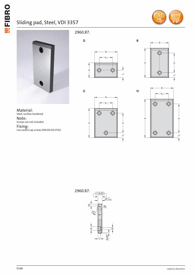
subject to alterations
Sliding pad, Steel, VDI 3357
Material: Steel, surface hardened
Note: Screws are not included.
Fixing: Use socket cap screws DIN EN ISO 4762.
H
1lea
b
1e
1l
b
a
1e
l
a
1e
b
D B
G
1lea
1e
b
2960.87.
X
t
dd 110
15°
R5
20
0,020
-0,02
3x45
°
2960.87.
D188
subject to alterations
Sliding pad, Steel, VDI 3357
D189
Order No Shape b a l1 e e1 d d1 tNumber of screw holes
2960.87.050.080 B 50 80 25 30 - 9 15 9 22960.87.050.100 B 50 100 25 50 - 13.5 20 13 22960.87.050.125 B 50 125 25 75 - 13.5 20 13 22960.87.050.160 B 50 160 25 110 - 13.5 20 13 22960.87.050.200 B 50 200 25 150 - 13.5 20 13 22960.87.080.050 D 80 50 25 - 30 9 15 9 22960.87.080.080 B 80 80 25 30 - 13.5 20 13 22960.87.080.100 B 80 100 25 50 - 13.5 20 13 22960.87.080.125 B 80 125 25 75 - 13.5 20 13 22960.87.080.160 B 80 160 25 110 - 13.5 20 13 22960.87.080.200 B 80 200 25 150 - 13.5 20 13 22960.87.080.250 B 80 250 40 170 - 13.5 20 13 22960.87.080.315 B 80 315 40 235 - 13.5 20 13 22960.87.100.050 D 100 50 25 - 50 13.5 20 13 22960.87.100.080 D 100 80 40 - 50 13.5 20 13 22960.87.100.100 B 100 100 25 50 - 13.5 20 13 22960.87.100.125 B 100 125 25 75 - 13.5 20 13 22960.87.100.160 B 100 160 25 110 - 13.5 20 13 22960.87.100.200 B 100 200 25 150 - 13.5 20 13 22960.87.100.250 B 100 250 40 170 - 13.5 20 13 22960.87.100.315 B 100 315 40 235 - 13.5 20 13 22960.87.125.050 D 125 50 25 - 75 13.5 20 13 22960.87.125.080 D 125 80 40 - 75 13.5 20 13 22960.87.125.100 G 125 100 25 50 75 13.5 20 13 32960.87.125.125 G 125 125 25 75 75 13.5 20 13 32960.87.125.160 G 125 160 25 110 75 13.5 20 13 32960.87.125.200 G 125 200 25 150 75 13.5 20 13 32960.87.125.250 G 125 250 40 170 75 13.5 20 13 32960.87.125.315 G 125 315 40 235 75 13.5 20 13 32960.87.160.050 D 160 50 25 - 110 13.5 20 13 22960.87.160.080 D 160 80 40 - 110 13.5 20 13 22960.87.160.100 G 160 100 25 50 110 13.5 20 13 32960.87.160.125 G 160 125 25 75 110 13.5 20 13 32960.87.160.160 G 160 160 25 110 110 13.5 20 13 32960.87.160.200 G 160 200 25 150 110 13.5 20 13 32960.87.160.250 H 160 250 40 170 110 13.5 20 13 42960.87.160.315 H 160 315 40 235 110 13.5 20 13 4
2960.87. Sliding pad, Steel, VDI 3357
04.2020
H
l 2l 3
l 1
b
b2
l 2
l 1
b
l 2l 3
l 1
b2
b
D B
G
l 2l 3l 1
b2
b
2960.30.
2960.30.
subject to alterations
SLIDING PAD, STEEL WITH SINTERLAYER, VDI 3357
Description: Steel with sinterlayer is a two-layer material. It ensures low maintenance, selflubricating service even in arduous multishift applications.
Material: Steel plate with sinterlayer, part of lubricant 20-25%.
Note: Screws are not included.
Fixing: Use socket cap screws DIN EN ISO 4762.
04.2020subject to alterations
SLIDING PAD, STEEL WITH SINTERLAYER, VDI 3357
Number of Order No Shape b l1 l2 l3 b2 d d1 t screw holes2960.30.050.080 B 50 80 25 55 9 15 9 22960.30.050.100 B 50 100 25 75 13.5 20 13 22960.30.050.125 B 50 125 25 100 13.5 20 13 22960.30.050.160 B 50 160 25 125 13.5 20 13 22960.30.050.200 B 50 200 25 175 13.5 20 13 22960.30.080.050 D 80 50 25 0 30 9 15 9 22960.30.080.080 B 80 80 25 55 13.5 20 13 22960.30.080.100 B 80 100 25 75 13.5 20 13 22960.30.080.125 B 80 125 25 100 13.5 20 13 22960.30.080.160 B 80 160 25 135 13.5 20 13 22960.30.080.200 B 80 200 25 175 13.5 20 13 22960.30.080.250 B 80 250 40 210 13.5 20 13 22960.30.080.315 B 80 315 40 275 13.5 20 13 22960.30.100.050 D 100 50 25 0 50 13.5 20 13 22960.30.100.080 D 100 80 40 0 50 13.5 20 13 22960.30.100.100 B 100 100 25 75 13.5 20 13 22960.30.100.125 B 100 125 25 100 13.5 20 13 22960.30.100.160 B 100 160 25 135 13.5 20 13 22960.30.100.200 B 100 200 25 175 13.5 20 13 22960.30.100.250 B 100 250 40 210 13.5 20 13 22960.30.100.315 B 100 315 40 275 13.5 20 13 22960.30.125.050 D 125 50 25 0 75 13.5 20 13 22960.30.125.080 D 125 80 40 0 75 13.5 20 13 22960.30.125.100 G 125 100 25 75 75 13.5 20 13 32960.30.125.125 G 125 125 25 100 75 13.5 20 13 32960.30.125.160 G 125 160 25 135 75 13.5 20 13 32960.30.125.200 G 125 200 25 175 75 13.5 20 13 32960.30.125.250 G 125 250 40 210 75 13.5 20 13 32960.30.125.315 G 125 315 40 275 75 13.5 20 13 32960.30.160.050 D 160 50 25 0 110 13.5 20 13 22960.30.160.080 D 160 80 40 0 110 13.5 20 13 22960.30.160.100 G 160 100 25 75 110 13.5 20 13 32960.30.160.125 G 160 125 25 100 110 13.5 20 13 32960.30.160.160 G 160 160 25 135 110 13.5 20 13 32960.30.160.200 G 160 200 25 175 110 13.5 20 13 32960.30.160.250 H 160 250 40 210 110 13.5 20 13 42960.30.160.315 H 160 315 40 275 110 13.5 20 13 4
2960.30. Sliding pad, Steel with sinterlayer, VDI 3357
subject to alterations
Sliding pad, Bronze with solid lubricant, ISO 9183-1
Material: Bronze with solid lubricant, oilless lubricating
Note: Screws are not included.
Fixing: Use socket cap screws DIN EN ISO 4762 M12.
e 2
e 1
b
l 1
a
l2
A
e 1
b
l 1
a
B
a
e 1
b
l 1e 1
C
a
l 1
e 2
b
l2
D
b
e 1
e 2
a
l 1
l 2
Ea
e 1
b
e 2
l 1
l2
e 1
F
2960.70.
X
ø2
0
15°
R5
R10
10
0,02
20 ± 0,025
ø1
3,5
13
2960.70.
D192
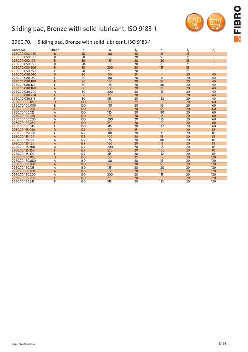
subject to alterations
Sliding pad, Bronze with solid lubricant, ISO 9183-1
D193
Order No Shape b a l1 e1 l2 e22960.70.050.080 B 50 80 20 35 25 -2960.70.050.100 B 50 100 20 55 25 -2960.70.050.125 B 50 125 20 80 25 -2960.70.050.160 B 50 160 20 115 25 -2960.70.050.200 B 50 200 20 155 25 -2960.70.050.250 C 50 250 20 100 25 -2960.70.080.050 D 80 50 25 - 20 402960.70.080.080 E 80 80 20 35 20 402960.70.080.100 E 80 100 20 55 20 402960.70.080.125 E 80 125 20 80 20 402960.70.080.160 A 80 160 20 115 20 402960.70.080.200 A 80 200 20 155 20 402960.70.080.250 F 80 250 20 100 20 402960.70.080.315 F 80 315 20 132 20 402960.70.100.050 D 100 50 25 - 20 602960.70.100.080 E 100 80 20 35 20 602960.70.100.100 E 100 100 20 55 20 602960.70.100.125 A 100 125 20 80 20 602960.70.100.160 A 100 160 20 115 20 602960.70.100.200 A 100 200 20 155 20 602960.70.100.250 F 100 250 20 100 20 602960.70.100.315 F 100 315 20 132 20 602960.70.125.050 D 125 50 25 - 20 852960.70.125.080 E 125 80 20 35 20 852960.70.125.100 A 125 100 20 55 20 852960.70.125.125 A 125 125 20 80 20 852960.70.125.160 A 125 160 20 115 20 852960.70.125.200 A 125 200 20 155 20 852960.70.125.250 F 125 250 20 100 20 852960.70.125.315 F 125 315 20 132 20 852960.70.160.050 D 160 50 25 - 20 1202960.70.160.080 A 160 80 20 35 20 1202960.70.160.100 A 160 100 20 55 20 1202960.70.160.125 A 160 125 20 80 20 1202960.70.160.160 A 160 160 20 115 20 1202960.70.160.200 A 160 200 20 155 20 1202960.70.160.250 F 160 250 20 100 20 1202960.70.160.315 F 160 315 20 132 20 120
2960.70. Sliding pad, Bronze with solid lubricant, ISO 9183-1
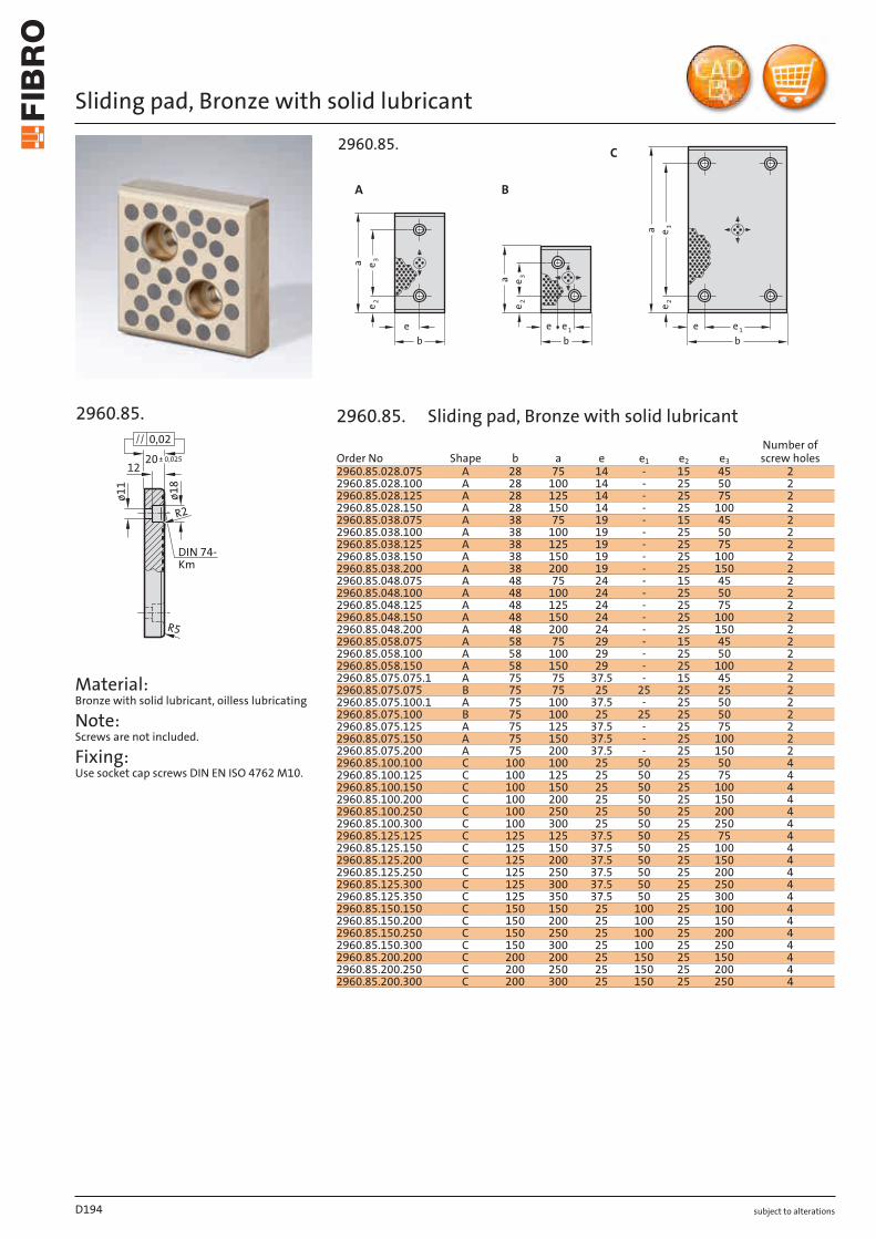
subject to alterations
Sliding pad, Bronze with solid lubricant
R2
ø1
1
ø1
8
R5
1220± 0,025
0,02
DIN 74-
Km
2960.85.
Material: Bronze with solid lubricant, oilless lubricating
Note: Screws are not included.
Fixing: Use socket cap screws DIN EN ISO 4762 M10.
e ebbbe 1e 1e
a
a
a
3e
3e
3e
A B
C
2e2e2e
2960.85.
D194
Order No Shape b a e e1 e2 e3
Number of screw holes
2960.85.028.075 A 28 75 14 - 15 45 22960.85.028.100 A 28 100 14 - 25 50 22960.85.028.125 A 28 125 14 - 25 75 22960.85.028.150 A 28 150 14 - 25 100 22960.85.038.075 A 38 75 19 - 15 45 22960.85.038.100 A 38 100 19 - 25 50 22960.85.038.125 A 38 125 19 - 25 75 22960.85.038.150 A 38 150 19 - 25 100 22960.85.038.200 A 38 200 19 - 25 150 22960.85.048.075 A 48 75 24 - 15 45 22960.85.048.100 A 48 100 24 - 25 50 22960.85.048.125 A 48 125 24 - 25 75 22960.85.048.150 A 48 150 24 - 25 100 22960.85.048.200 A 48 200 24 - 25 150 22960.85.058.075 A 58 75 29 - 15 45 22960.85.058.100 A 58 100 29 - 25 50 22960.85.058.150 A 58 150 29 - 25 100 22960.85.075.075.1 A 75 75 37.5 - 15 45 22960.85.075.075 B 75 75 25 25 25 25 22960.85.075.100.1 A 75 100 37.5 - 25 50 22960.85.075.100 B 75 100 25 25 25 50 22960.85.075.125 A 75 125 37.5 - 25 75 22960.85.075.150 A 75 150 37.5 - 25 100 22960.85.075.200 A 75 200 37.5 - 25 150 22960.85.100.100 C 100 100 25 50 25 50 42960.85.100.125 C 100 125 25 50 25 75 42960.85.100.150 C 100 150 25 50 25 100 42960.85.100.200 C 100 200 25 50 25 150 42960.85.100.250 C 100 250 25 50 25 200 42960.85.100.300 C 100 300 25 50 25 250 42960.85.125.125 C 125 125 37.5 50 25 75 42960.85.125.150 C 125 150 37.5 50 25 100 42960.85.125.200 C 125 200 37.5 50 25 150 42960.85.125.250 C 125 250 37.5 50 25 200 42960.85.125.300 C 125 300 37.5 50 25 250 42960.85.125.350 C 125 350 37.5 50 25 300 42960.85.150.150 C 150 150 25 100 25 100 42960.85.150.200 C 150 200 25 100 25 150 42960.85.150.250 C 150 250 25 100 25 200 42960.85.150.300 C 150 300 25 100 25 250 42960.85.200.200 C 200 200 25 150 25 150 42960.85.200.250 C 200 250 25 150 25 200 42960.85.200.300 C 200 300 25 150 25 250 4
2960.85. Sliding pad, Bronze with solid lubricant
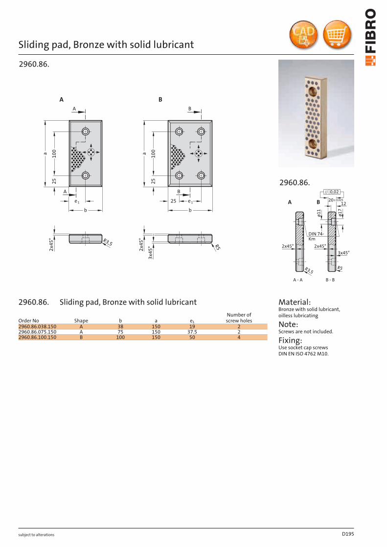
subject to alterations
Sliding pad, Bronze with solid lubricant
R3,5
2x
45
°
B
BA
A
1e
b
1e25
b
10
0
a
25
25
10
0
a
B A
2x
45
°
R5
3x
45
°
2960.86.
B - BA - A
A B
ø11
ø17
R3,5 R5
1220± 0,025
3x45° 2x45° 2x45°
0,02
DIN 74- Km
2960.86.
Material: Bronze with solid lubricant, oilless lubricating
Note: Screws are not included.
Fixing: Use socket cap screws DIN EN ISO 4762 M10.
D195
Order No Shape b a e1
Number of screw holes
2960.86.038.150 A 38 150 19 22960.86.075.150 A 75 150 37.5 22960.86.100.150 B 100 150 50 4
2960.86. Sliding pad, Bronze with solid lubricant

subject to alterations
Sliding pad, Bronze with solid lubricant
R2
25 -0,02
13 +0,5
ø2
0
ø1
4
R5
Km 12
DIN 74
0,02
2960.76.
Material: Bronze with solid lubricant, oilless lubricating
Note: Screws are not included.
Fixing: Use socket cap screws DIN EN ISO 4762 M12.
3x
45
°
3x
45
°
bb
1e1e1e
2525
25
25
ee
e
a
a
B A
2960.76.
D196
Order No Shape b a e e1
Number of screw holes
2960.76.080.100 A 80 100 50 30 22960.76.080.125 A 80 125 75 30 22960.76.080.160 A 80 160 110 30 22960.76.080.200 B 80 200 75 15 32960.76.100.125 A 100 125 75 50 22960.76.100.160 A 100 160 110 50 22960.76.100.200 B 100 200 75 25 32960.76.125.125 A 125 125 75 75 2
2960.76. Sliding pad, Bronze with solid lubricant
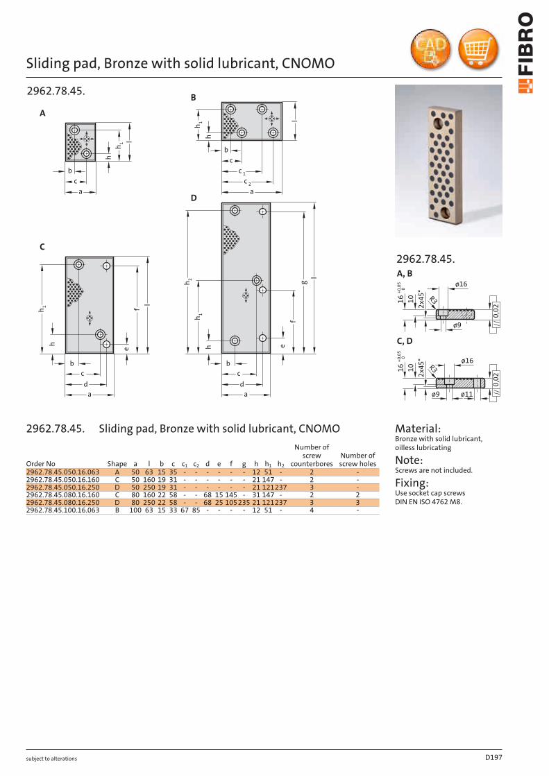
subject to alterations
Sliding pad, Bronze with solid lubricant, CNOMO
hh
h
c
g
a
l
a
b
h
lf
a
e
cd
b
a
cd
l
fe
l
B
D
C
A
bc
b
c 1
c 2
h1
h 2
h 1
hh 1
1
2962.78.45.
0,022x45°
ø9
ø16
10
0,02
016
+0,05
R3
ø11
C, D
ø9
R310
016
+0,05
A, B
ø16
2x45°
2962.78.45.
Material: Bronze with solid lubricant, oilless lubricating
Note: Screws are not included.
Fixing: Use socket cap screws DIN EN ISO 4762 M8.
D197
Order No Shape a l b c c1 c2 d e f g h h1 h2
Number of screw
counterboresNumber of screw holes
2962.78.45.050.16.063 A 50 63 15 35 - - - - - - 12 51 - 2 -2962.78.45.050.16.160 C 50 160 19 31 - - - - - - 21 147 - 2 -2962.78.45.050.16.250 D 50 250 19 31 - - - - - - 21 121237 3 -2962.78.45.080.16.160 C 80 160 22 58 - - 68 15 145 - 31 147 - 2 22962.78.45.080.16.250 D 80 250 22 58 - - 68 25 105235 21 121237 3 32962.78.45.100.16.063 B 100 63 15 33 67 85 - - - - 12 51 - 4 -
2962.78.45. Sliding pad, Bronze with solid lubricant, CNOMO
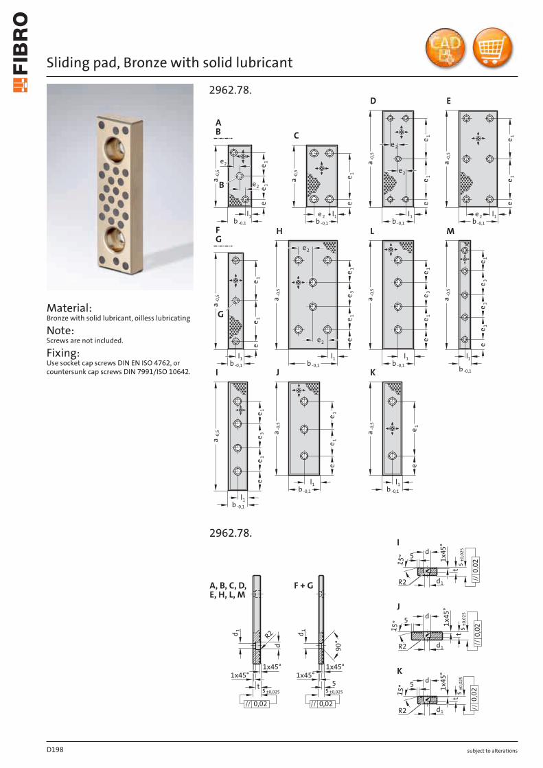
subject to alterations
Sliding pad, Bronze with solid lubricant
Material: Bronze with solid lubricant, oilless lubricating
Note: Screws are not included.
Fixing: Use socket cap screws DIN EN ISO 4762, or countersunk cap screws DIN 7991/ISO 10642.
2962.78.
l1l
l1
e
ee
a -0,5
a -0,5
a -0,5
a -0,5
a -0,5 a -0,5
a -0,5
a -0,5
a -0,5 a -0,5
a -0,5
e 1e 1
e
e 1e
e 1e 1
e
e 1e 1
e
A
B
C
D E
F
G
LH M
JI K
e 11e
e
e 1e 1
e 3
e 1e 1
3ee
e 1e 1
e 3e 3
e 1e 1
e 3
e 1e 1
e
e 1e
b -0,1 b -0,1 b -0,1 b -0,1
b -0,1 b -0,1 b -0,1 b -0,1
b -0,1
b -0,1 b -0,1
l1 l1 l1
l1 l1 1
l1
l1 l1
e2 e2
e2
e2B
e2
e2
G
e2
e2
X
2962.78.d
R2
R2
R2
I
J
K
15°
15°
15°
5 1x45
°ts ±
0,025
0,02
d1
d1
d1
d
d
5
5
t1x45
°
s ±0,025
0,02
t1x45
°
s ±0,025
0,02
d
1x45°
t1x45°
0,02
R2d 1
x45°1
51x45°
0,02
d 1
s ±0,025s ±0,025
90°
A, B, C, D,
E, H, L, M
F + G
D198
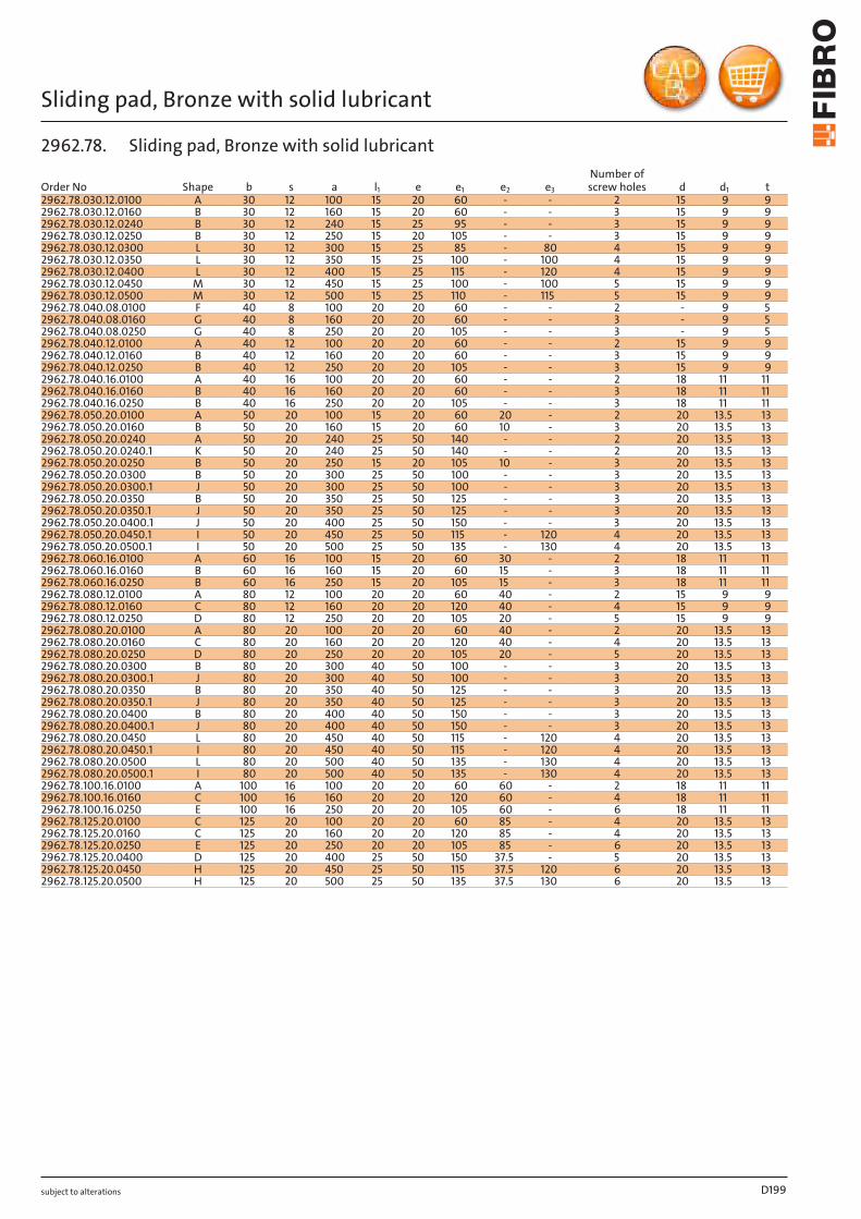
subject to alterations
Sliding pad, Bronze with solid lubricant
D199
Order No Shape b s a l1 e e1 e2 e3
Number of screw holes d d1 t
2962.78.030.12.0100 A 30 12 100 15 20 60 - - 2 15 9 92962.78.030.12.0160 B 30 12 160 15 20 60 - - 3 15 9 92962.78.030.12.0240 B 30 12 240 15 25 95 - - 3 15 9 92962.78.030.12.0250 B 30 12 250 15 20 105 - - 3 15 9 92962.78.030.12.0300 L 30 12 300 15 25 85 - 80 4 15 9 92962.78.030.12.0350 L 30 12 350 15 25 100 - 100 4 15 9 92962.78.030.12.0400 L 30 12 400 15 25 115 - 120 4 15 9 92962.78.030.12.0450 M 30 12 450 15 25 100 - 100 5 15 9 92962.78.030.12.0500 M 30 12 500 15 25 110 - 115 5 15 9 92962.78.040.08.0100 F 40 8 100 20 20 60 - - 2 - 9 52962.78.040.08.0160 G 40 8 160 20 20 60 - - 3 - 9 52962.78.040.08.0250 G 40 8 250 20 20 105 - - 3 - 9 52962.78.040.12.0100 A 40 12 100 20 20 60 - - 2 15 9 92962.78.040.12.0160 B 40 12 160 20 20 60 - - 3 15 9 92962.78.040.12.0250 B 40 12 250 20 20 105 - - 3 15 9 92962.78.040.16.0100 A 40 16 100 20 20 60 - - 2 18 11 112962.78.040.16.0160 B 40 16 160 20 20 60 - - 3 18 11 112962.78.040.16.0250 B 40 16 250 20 20 105 - - 3 18 11 112962.78.050.20.0100 A 50 20 100 15 20 60 20 - 2 20 13.5 132962.78.050.20.0160 B 50 20 160 15 20 60 10 - 3 20 13.5 132962.78.050.20.0240 A 50 20 240 25 50 140 - - 2 20 13.5 132962.78.050.20.0240.1 K 50 20 240 25 50 140 - - 2 20 13.5 132962.78.050.20.0250 B 50 20 250 15 20 105 10 - 3 20 13.5 132962.78.050.20.0300 B 50 20 300 25 50 100 - - 3 20 13.5 132962.78.050.20.0300.1 J 50 20 300 25 50 100 - - 3 20 13.5 132962.78.050.20.0350 B 50 20 350 25 50 125 - - 3 20 13.5 132962.78.050.20.0350.1 J 50 20 350 25 50 125 - - 3 20 13.5 132962.78.050.20.0400.1 J 50 20 400 25 50 150 - - 3 20 13.5 132962.78.050.20.0450.1 I 50 20 450 25 50 115 - 120 4 20 13.5 132962.78.050.20.0500.1 I 50 20 500 25 50 135 - 130 4 20 13.5 132962.78.060.16.0100 A 60 16 100 15 20 60 30 - 2 18 11 112962.78.060.16.0160 B 60 16 160 15 20 60 15 - 3 18 11 112962.78.060.16.0250 B 60 16 250 15 20 105 15 - 3 18 11 112962.78.080.12.0100 A 80 12 100 20 20 60 40 - 2 15 9 92962.78.080.12.0160 C 80 12 160 20 20 120 40 - 4 15 9 92962.78.080.12.0250 D 80 12 250 20 20 105 20 - 5 15 9 92962.78.080.20.0100 A 80 20 100 20 20 60 40 - 2 20 13.5 132962.78.080.20.0160 C 80 20 160 20 20 120 40 - 4 20 13.5 132962.78.080.20.0250 D 80 20 250 20 20 105 20 - 5 20 13.5 132962.78.080.20.0300 B 80 20 300 40 50 100 - - 3 20 13.5 132962.78.080.20.0300.1 J 80 20 300 40 50 100 - - 3 20 13.5 132962.78.080.20.0350 B 80 20 350 40 50 125 - - 3 20 13.5 132962.78.080.20.0350.1 J 80 20 350 40 50 125 - - 3 20 13.5 132962.78.080.20.0400 B 80 20 400 40 50 150 - - 3 20 13.5 132962.78.080.20.0400.1 J 80 20 400 40 50 150 - - 3 20 13.5 132962.78.080.20.0450 L 80 20 450 40 50 115 - 120 4 20 13.5 132962.78.080.20.0450.1 I 80 20 450 40 50 115 - 120 4 20 13.5 132962.78.080.20.0500 L 80 20 500 40 50 135 - 130 4 20 13.5 132962.78.080.20.0500.1 I 80 20 500 40 50 135 - 130 4 20 13.5 132962.78.100.16.0100 A 100 16 100 20 20 60 60 - 2 18 11 112962.78.100.16.0160 C 100 16 160 20 20 120 60 - 4 18 11 112962.78.100.16.0250 E 100 16 250 20 20 105 60 - 6 18 11 112962.78.125.20.0100 C 125 20 100 20 20 60 85 - 4 20 13.5 132962.78.125.20.0160 C 125 20 160 20 20 120 85 - 4 20 13.5 132962.78.125.20.0250 E 125 20 250 20 20 105 85 - 6 20 13.5 132962.78.125.20.0400 D 125 20 400 25 50 150 37.5 - 5 20 13.5 132962.78.125.20.0450 H 125 20 450 25 50 115 37.5 120 6 20 13.5 132962.78.125.20.0500 H 125 20 500 25 50 135 37.5 130 6 20 13.5 13
2962.78. Sliding pad, Bronze with solid lubricant
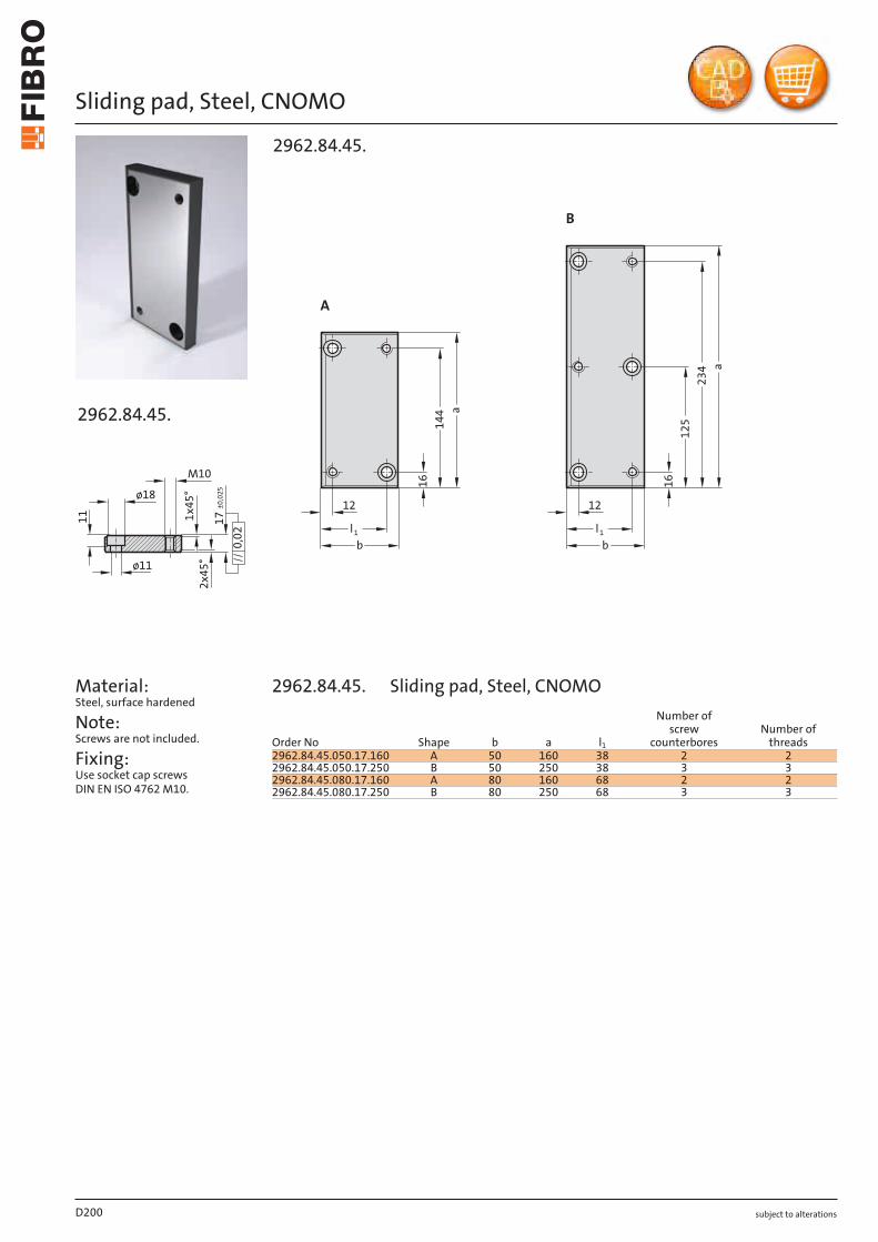
subject to alterations
Sliding pad, Steel, CNOMO
2x
45
°
17
±0
,02
5
0,0
2
11 1x
45
°ø18
M10
ø11
2962.84.45.
Material: Steel, surface hardened
Note: Screws are not included.
Fixing: Use socket cap screws DIN EN ISO 4762 M10.
16
234
125
1212
16
144
a
a
1l
1l
bb
A
B
2962.84.45.
D200
Order No Shape b a l1
Number of screw
counterboresNumber of
threads2962.84.45.050.17.160 A 50 160 38 2 22962.84.45.050.17.250 B 50 250 38 3 32962.84.45.080.17.160 A 80 160 68 2 22962.84.45.080.17.250 B 80 250 68 3 3
2962.84.45. Sliding pad, Steel, CNOMO
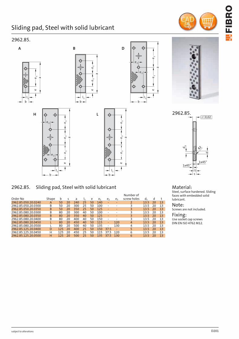
subject to alterations
Sliding pad, Steel with solid lubricant
ee
eee
e3
e3
e1
e1
aa
a
a
a
l1
l1
l1
l1
l1
bb
bbb
A B D
H L
e 1
e 1e 1 e 1
e 1e 1
e 1
e2
e2
e2
e2
2962.85.
d
1x45°
t
1x45°
0,02
R2d1
2962.85.
s
Material: Steel, surface hardened. Sliding faces with embedded solid lubricant.
Note: Screws are not included.
Fixing: Use socket cap screws DIN EN ISO 4762 M12.
D201
Order No Shape b s a l1 e e1 e2 e3
Number of screw holes d1 d t
2962.85.050.20.0240 A 50 20 240 25 50 140 - - 2 13.5 20 132962.85.050.20.0300 B 50 20 300 25 50 100 - - 3 13.5 20 132962.85.050.20.0350 B 50 20 350 25 50 125 - - 3 13.5 20 132962.85.080.20.0300 B 80 20 300 40 50 100 - - 3 13.5 20 132962.85.080.20.0350 B 80 20 350 40 50 125 - - 3 13.5 20 132962.85.080.20.0400 B 80 20 400 40 50 150 - - 3 13.5 20 132962.85.080.20.0450 L 80 20 450 40 50 115 - 120 4 13.5 20 132962.85.080.20.0500 L 80 20 500 40 50 135 - 130 4 13.5 20 132962.85.125.20.0400 D 125 20 400 25 50 150 37.5 - 5 13.5 20 132962.85.125.20.0450 H 125 20 450 25 50 115 37.5 120 6 13.5 20 132962.85.125.20.0500 H 125 20 500 25 50 135 37.5 130 6 13.5 20 13
2962.85. Sliding pad, Steel with solid lubricant
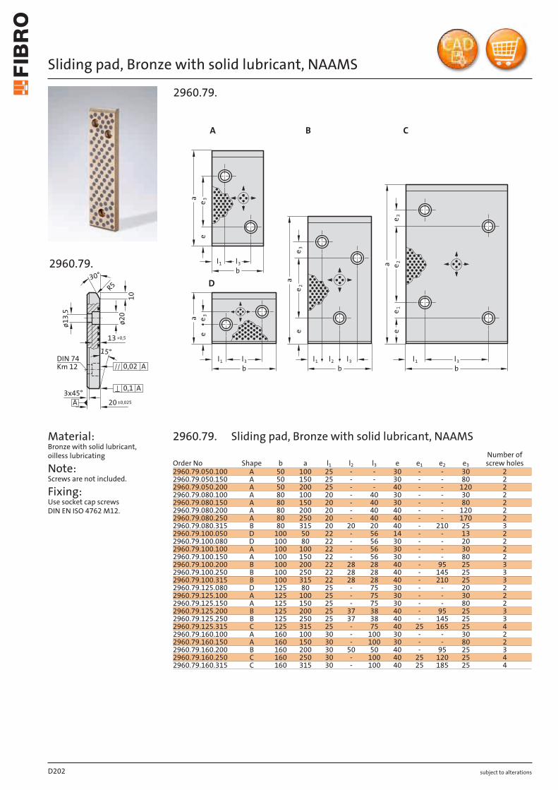
subject to alterations
Sliding pad, Bronze with solid lubricant, NAAMS
+0,5
±0,025
ø13,
5
1315°
10ø2
0
R530°
3x45°20
Km 12 DIN 74
0,02 A
0,1 A
A
2960.79.
Material: Bronze with solid lubricant, oilless lubricating
Note: Screws are not included.
Fixing: Use socket cap screws DIN EN ISO 4762 M12.
3e
2e
1e
3e
2e
3e
3e
ee
ee
l3l3l2l3
l3l1
l1l1l1
bbb
b
a
a
aa
A B C
D
2960.79.
D202
Order No Shape b a l1 l2 l3 e e1 e2 e3
Number of screw holes
2960.79.050.100 A 50 100 25 - - 30 - - 30 22960.79.050.150 A 50 150 25 - - 30 - - 80 22960.79.050.200 A 50 200 25 - - 40 - - 120 22960.79.080.100 A 80 100 20 - 40 30 - - 30 22960.79.080.150 A 80 150 20 - 40 30 - - 80 22960.79.080.200 A 80 200 20 - 40 40 - - 120 22960.79.080.250 A 80 250 20 - 40 40 - - 170 22960.79.080.315 B 80 315 20 20 20 40 - 210 25 32960.79.100.050 D 100 50 22 - 56 14 - - 13 22960.79.100.080 D 100 80 22 - 56 30 - - 20 22960.79.100.100 A 100 100 22 - 56 30 - - 30 22960.79.100.150 A 100 150 22 - 56 30 - - 80 22960.79.100.200 B 100 200 22 28 28 40 - 95 25 32960.79.100.250 B 100 250 22 28 28 40 - 145 25 32960.79.100.315 B 100 315 22 28 28 40 - 210 25 32960.79.125.080 D 125 80 25 - 75 30 - - 20 22960.79.125.100 A 125 100 25 - 75 30 - - 30 22960.79.125.150 A 125 150 25 - 75 30 - - 80 22960.79.125.200 B 125 200 25 37 38 40 - 95 25 32960.79.125.250 B 125 250 25 37 38 40 - 145 25 32960.79.125.315 C 125 315 25 - 75 40 25 165 25 42960.79.160.100 A 160 100 30 - 100 30 - - 30 22960.79.160.150 A 160 150 30 - 100 30 - - 80 22960.79.160.200 B 160 200 30 50 50 40 - 95 25 32960.79.160.250 C 160 250 30 - 100 40 25 120 25 42960.79.160.315 C 160 315 30 - 100 40 25 185 25 4
2960.79. Sliding pad, Bronze with solid lubricant, NAAMS
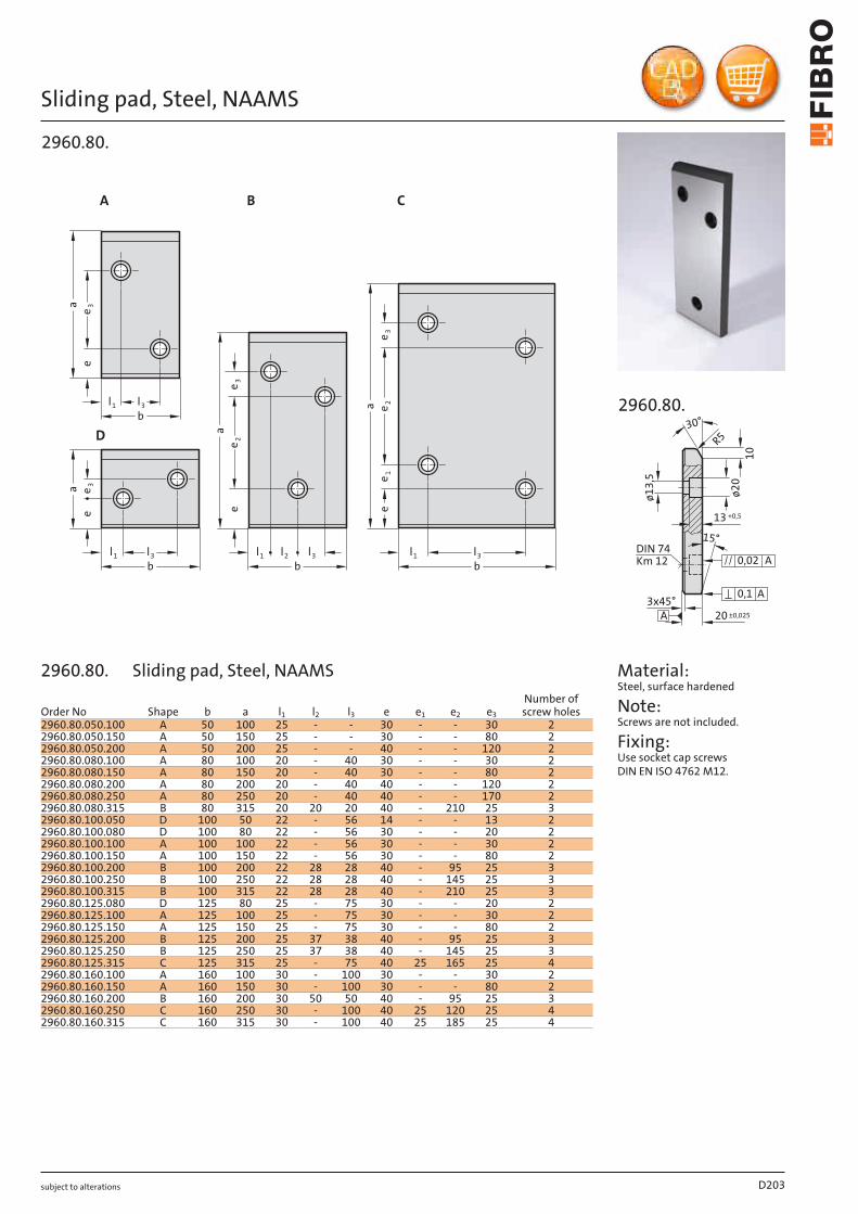
subject to alterations
Sliding pad, Steel, NAAMS
3e
2e
1e
3e
2e
3e
3e
ee
ee
l3
l3
l2
l3
l3
l1
l1
l1
l1
bbb
b
a
a
aa
D
2960.80.
A B C
+0,5
±0,025
1315°
10
ø13,
5
ø20
R530°
3x45°20
Km 12 DIN 74
0,02 A
0,1 A
A
2960.80.
Material: Steel, surface hardened
Note: Screws are not included.
Fixing: Use socket cap screws DIN EN ISO 4762 M12.
D203
Order No Shape b a l1 l2 l3 e e1 e2 e3
Number of screw holes
2960.80.050.100 A 50 100 25 - - 30 - - 30 22960.80.050.150 A 50 150 25 - - 30 - - 80 22960.80.050.200 A 50 200 25 - - 40 - - 120 22960.80.080.100 A 80 100 20 - 40 30 - - 30 22960.80.080.150 A 80 150 20 - 40 30 - - 80 22960.80.080.200 A 80 200 20 - 40 40 - - 120 22960.80.080.250 A 80 250 20 - 40 40 - - 170 22960.80.080.315 B 80 315 20 20 20 40 - 210 25 32960.80.100.050 D 100 50 22 - 56 14 - - 13 22960.80.100.080 D 100 80 22 - 56 30 - - 20 22960.80.100.100 A 100 100 22 - 56 30 - - 30 22960.80.100.150 A 100 150 22 - 56 30 - - 80 22960.80.100.200 B 100 200 22 28 28 40 - 95 25 32960.80.100.250 B 100 250 22 28 28 40 - 145 25 32960.80.100.315 B 100 315 22 28 28 40 - 210 25 32960.80.125.080 D 125 80 25 - 75 30 - - 20 22960.80.125.100 A 125 100 25 - 75 30 - - 30 22960.80.125.150 A 125 150 25 - 75 30 - - 80 22960.80.125.200 B 125 200 25 37 38 40 - 95 25 32960.80.125.250 B 125 250 25 37 38 40 - 145 25 32960.80.125.315 C 125 315 25 - 75 40 25 165 25 42960.80.160.100 A 160 100 30 - 100 30 - - 30 22960.80.160.150 A 160 150 30 - 100 30 - - 80 22960.80.160.200 B 160 200 30 50 50 40 - 95 25 32960.80.160.250 C 160 250 30 - 100 40 25 120 25 42960.80.160.315 C 160 315 30 - 100 40 25 185 25 4
2960.80. Sliding pad, Steel, NAAMS
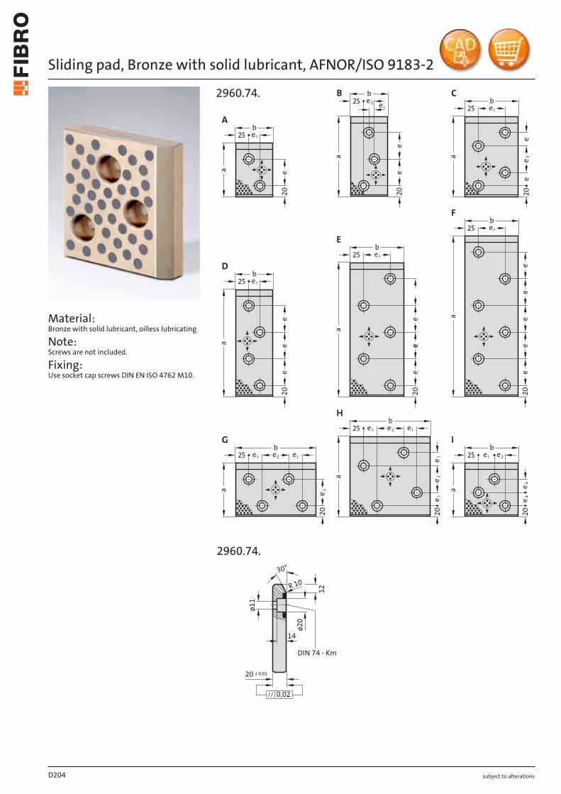
subject to alterations
Sliding pad, Bronze with solid lubricant, AFNOR/ISO 9183-2
Material: Bronze with solid lubricant, oilless lubricating
Note: Screws are not included.
Fixing: Use socket cap screws DIN EN ISO 4762 M10.
e
e
2020
202020
202020
e2
b
b
a
A
a
a a
a
a
a
a
a
bb
b
b
b
b
b
25
2525
25
25
25
25
25
25
e1
e2 e1 e1
e1
e1
e1
e2
e2
e1
e1 e1
e1e1
e 3
e 3
e 2e 1
e 1
e 4e 4
ee
e
ee
e
ee
ee
ee
ee
e
20
B C
D
E
F
G
H
I
2960.74.
X
2960.74.
30°
14
R 10
12
ø1
1
ø2
0
0,02
20 ± 0,01
DIN 74 - Km
D204

subject to alterations
Sliding pad, Bronze with solid lubricant, AFNOR/ISO 9183-2
D205
Order No Shape b a e e1 e2 e3 e4
Number of screw holes
2960.74.070.100 A 70 100 50 20 - - - 22960.74.070.150 B 70 150 50 10 20 - - 32960.74.070.200 D 70 200 50 20 - - - 42960.74.100.100 I 100 100 - 30 20 - 25 32960.74.100.150 C 100 150 25 50 - 50 - 42960.74.100.200 D 100 200 50 50 - - - 42960.74.100.250 E 100 250 50 50 - - - 52960.74.100.300 F 100 300 50 50 - - - 62960.74.150.100 G 150 100 - 25 50 50 - 42960.74.150.150 H 150 150 - 25 50 - - 42960.74.150.200 D 150 200 50 100 - - - 42960.74.150.250 E 150 250 50 100 - - - 52960.74.150.300 F 150 300 50 100 - - - 62960.74.200.100 G 200 100 - 50 50 50 - 4
2960.74. Sliding pad, Bronze with solid lubricant, AFNOR/ISO 9183-2
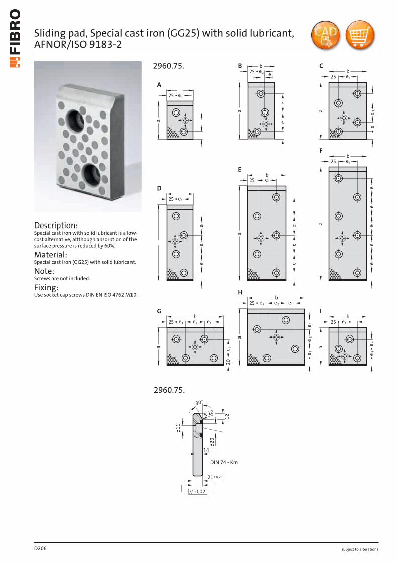
subject to alterations
Sliding pad, Special cast iron (GG25) with solid lubricant, AFNOR/ISO 9183- 2
Description: Special cast iron with solid lubricant is a low- cost alternative, altthough absorption of the surface pressure is reduced by 60%.
Material: Special cast iron (GG25) with solid lubricant.
Note: Screws are not included.
Fixing: Use socket cap screws DIN EN ISO 4762 M10.
e
e
2020
202020
202020
e2
b
b
a
A
a
a a
a
a
a
a
a
bb
b
b
b
b
b
25
2525
25
25
25
25
25
25
e1
e2 e1 e1
e1
e1
e1
e2
e2
e1
e1 e1
e1e1
e 3
e 3
e 2e 1
e 1
e 4e 4
ee
e
ee
e
ee
ee
ee
ee
e
20
B C
D
E
F
G
H
I
2960.75.
X
2960.75.
21± 0,25
30°
14
R 10
12
ø1
1
ø2
0
0,02
DIN 74 - Km
D206
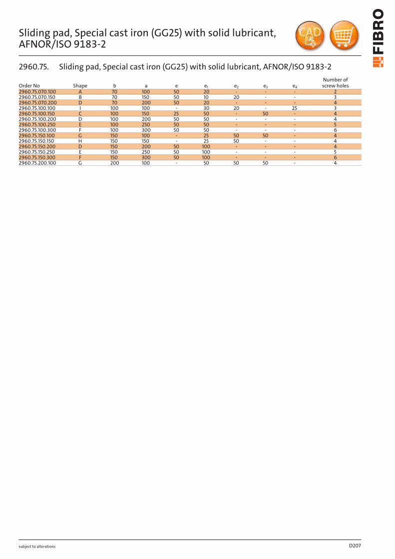
subject to alterations
Sliding pad, Special cast iron (GG25) with solid lubricant, AFNOR/ISO 9183- 2
D207
Order No Shape b a e e1 e2 e3 e4
Number of screw holes
2960.75.070.100 A 70 100 50 20 - - - 22960.75.070.150 B 70 150 50 10 20 - - 32960.75.070.200 D 70 200 50 20 - - - 42960.75.100.100 I 100 100 - 30 20 - 25 32960.75.100.150 C 100 150 25 50 - 50 - 42960.75.100.200 D 100 200 50 50 - - - 42960.75.100.250 E 100 250 50 50 - - - 52960.75.100.300 F 100 300 50 50 - - - 62960.75.150.100 G 150 100 - 25 50 50 - 42960.75.150.150 H 150 150 - 25 50 - - 42960.75.150.200 D 150 200 50 100 - - - 42960.75.150.250 E 150 250 50 100 - - - 52960.75.150.300 F 150 300 50 100 - - - 62960.75.200.100 G 200 100 - 50 50 50 - 4
2960.75. Sliding pad, Special cast iron (GG25) with solid lubricant, AFNOR/ISO 9183-2
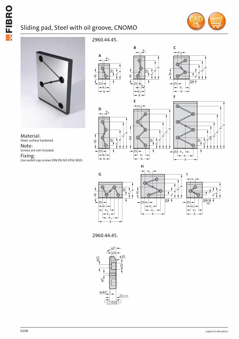
subject to alterations
Sliding pad, Steel with oil groove, CNOMO
Material: Steel, surface hardened
Note: Screws are not included.
Fixing: Use socket cap screws DIN EN ISO 4762 M10.
25
e 1
70
e 9
25e 1
45
25
145
e 1
b
a
a
bb
b
a
a
25e 1
25
95
e 9
e 1
e2
25
45
2025
70
20
25
e 9
e 4
A
e 1
e 9
a
e 5
e 4
e 6e 5
e 4
e 1
e 9
45
20
B C
e 5
e 4
e 6
e 920
D
145
e 5
e 4
e 6e 7
20
b
E
e 1
e 5
e 4
e 6e 7
e 8
20
a
b
e 9
F
e 2e 3
e 9
4e20 a
b
G
e 2e 3
e 5 e 6
20
a
e 4
b
25 e1
H
e 2
e 5
e 4
a
2032
,5
b
e9
I
2960.44.45.
X
2960.44.45.
14
3x45°21±0,25
ø7
ø11
ø20
30°
R10
0,02
D208
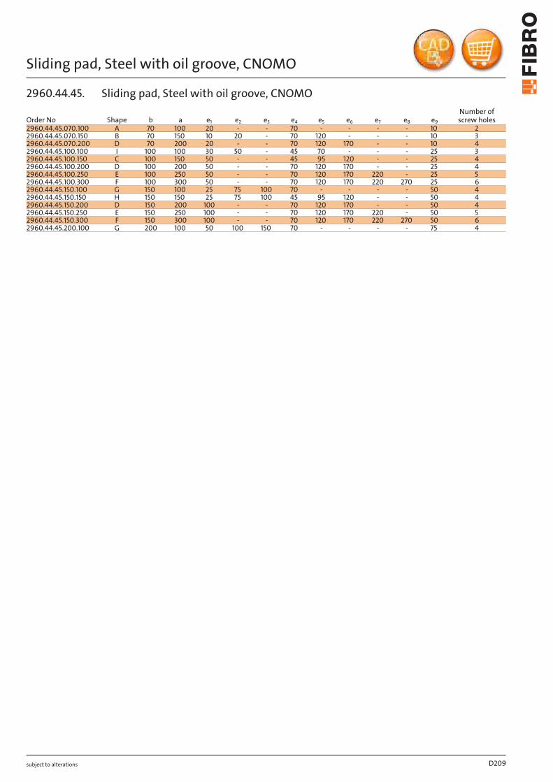
subject to alterations
Sliding pad, Steel with oil groove, CNOMO
D209
Order No Shape b a e1 e2 e3 e4 e5 e6 e7 e8 e9
Number of screw holes
2960.44.45.070.100 A 70 100 20 - - 70 - - - - 10 22960.44.45.070.150 B 70 150 10 20 - 70 120 - - - 10 32960.44.45.070.200 D 70 200 20 - - 70 120 170 - - 10 42960.44.45.100.100 I 100 100 30 50 - 45 70 - - - 25 32960.44.45.100.150 C 100 150 50 - - 45 95 120 - - 25 42960.44.45.100.200 D 100 200 50 - - 70 120 170 - - 25 42960.44.45.100.250 E 100 250 50 - - 70 120 170 220 - 25 52960.44.45.100.300 F 100 300 50 - - 70 120 170 220 270 25 62960.44.45.150.100 G 150 100 25 75 100 70 - - - - 50 42960.44.45.150.150 H 150 150 25 75 100 45 95 120 - - 50 42960.44.45.150.200 D 150 200 100 - - 70 120 170 - - 50 42960.44.45.150.250 E 150 250 100 - - 70 120 170 220 - 50 52960.44.45.150.300 F 150 300 100 - - 70 120 170 220 270 50 62960.44.45.200.100 G 200 100 50 100 150 70 - - - - 75 4
2960.44.45. Sliding pad, Steel with oil groove, CNOMO
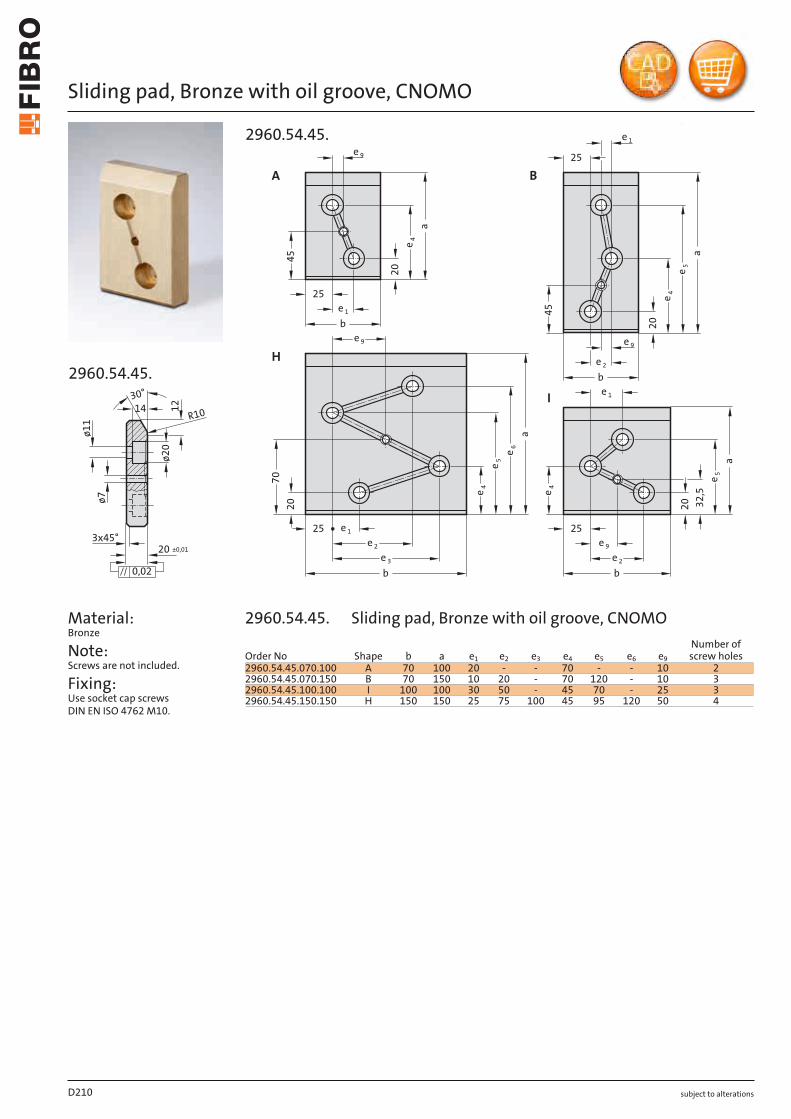
subject to alterations
Sliding pad, Bronze with oil groove, CNOMO
14
3x45°20 ±0,01
ø7
ø11
ø20
12
30°
R10
0,02
2960.54.45.
Material: Bronze
Note: Screws are not included.
Fixing: Use socket cap screws DIN EN ISO 4762 M10.
A
9e
1e
b
254
5
20
4e
a
9e
1e
2e
3e
b
25
70
20
4e
a
6e
5e
1e
45
20
a
4e
5e
25
2e
b
32
,5
20
4e
a5
e
b
9e
2e
25
1e
H
B
I
9e
2960.54.45.
D210
Order No Shape b a e1 e2 e3 e4 e5 e6 e9
Number of screw holes
2960.54.45.070.100 A 70 100 20 - - 70 - - 10 22960.54.45.070.150 B 70 150 10 20 - 70 120 - 10 32960.54.45.100.100 I 100 100 30 50 - 45 70 - 25 32960.54.45.150.150 H 150 150 25 75 100 45 95 120 50 4
2960.54.45. Sliding pad, Bronze with oil groove, CNOMO

10.2019
25
25
10
ø15
ø9
25
e1
ee
25
e
a
a
bb
9
12 -0,02
A
15°
15°
9
3x45° 3x45°
12 -0,02
0,02 0,02
ø9
ø15
10
B
a
a e
ee
D H
bb
10
ø15
ø9
915°
3x45°
12 -0,02
0,02
10
ø15
ø9
915°
3x45°
12 -0,02
0,02
2960.81.
e2 e2
subject to alterations
SLIDING PAD, BRONZE WITH SOLID LUBRICANT, VDI 3357
Material: Bronze with solid lubricant, oilless lubricating
Note: Screws are not included.
Fixing: Use socket cap screws DIN EN ISO 4762 M8.
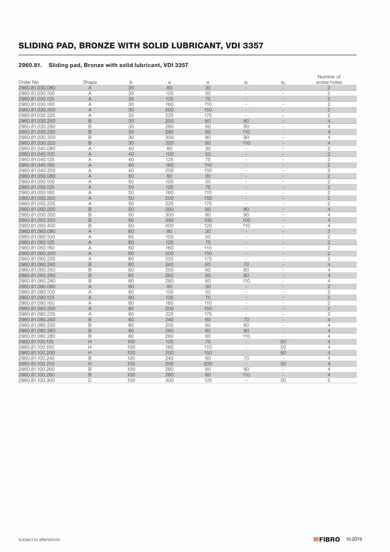
10.2019subject to alterations
SLIDING PAD, BRONZE WITH SOLID LUBRICANT, VDI 3357
Number of Order No Shape b a e e1 e2 screw holes2960.81.030.080 A 30 80 30 - - 22960.81.030.100 A 30 100 50 - - 22960.81.030.125 A 30 125 75 - - 22960.81.030.160 A 30 160 110 - - 22960.81.030.200 A 30 200 150 - - 22960.81.030.225 A 30 225 175 - - 22960.81.030.250 B 30 250 60 80 - 42960.81.030.260 B 30 260 60 90 - 42960.81.030.280 B 30 280 60 110 - 42960.81.030.300 B 30 300 80 90 - 42960.81.030.320 B 30 320 80 110 - 42960.81.040.080 A 40 80 30 - - 22960.81.040.100 A 40 100 50 - - 22960.81.040.125 A 40 125 75 - - 22960.81.040.160 A 40 160 110 - - 22960.81.040.200 A 40 200 150 - - 22960.81.050.080 A 50 80 30 - - 22960.81.050.100 A 50 100 50 - - 22960.81.050.125 A 50 125 75 - - 22960.81.050.160 A 50 160 110 - - 22960.81.050.200 A 50 200 150 - - 22960.81.050.225 A 50 225 175 - - 22960.81.050.250 B 50 250 60 80 - 42960.81.050.300 B 50 300 80 90 - 42960.81.050.350 B 50 350 100 100 - 42960.81.050.400 B 50 400 120 110 - 42960.81.060.080 A 60 80 30 - - 22960.81.060.100 A 60 100 50 - - 22960.81.060.125 A 60 125 75 - - 22960.81.060.160 A 60 160 110 - - 22960.81.060.200 A 60 200 150 - - 22960.81.060.225 A 60 225 175 - - 22960.81.060.240 B 60 240 60 70 - 42960.81.060.250 B 60 250 60 80 - 42960.81.060.260 B 60 260 60 90 - 42960.81.060.280 B 60 280 60 110 - 42960.81.080.080 A 80 80 30 - - 22960.81.080.100 A 80 100 50 - - 22960.81.080.125 A 80 125 75 - - 22960.81.080.160 A 80 160 110 - - 22960.81.080.200 A 80 200 150 - - 22960.81.080.225 A 80 225 175 - - 22960.81.080.240 B 80 240 60 70 - 42960.81.080.250 B 80 250 60 80 - 42960.81.080.260 B 80 260 60 90 - 42960.81.080.280 B 80 280 60 110 - 42960.81.100.125 H 100 125 75 - 50 42960.81.100.160 H 100 160 110 - 50 42960.81.100.200 H 100 200 150 - 50 42960.81.100.240 B 100 240 60 70 - 42960.81.100.250 H 100 250 200 - 50 42960.81.100.260 B 100 260 60 90 - 42960.81.100.280 B 100 280 60 110 - 42960.81.100.300 D 100 300 125 - 50 5
2960.81. Sliding pad, Bronze with solid lubricant, VDI 3357
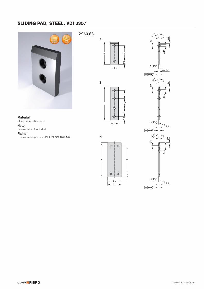
10.2019
25
10
ø15
ø9
25
ea
b
915°
3x45°12 -0,02
0,02
15°
9
ø9
ø15
10
12 -0,02
3x45°
0,02
25
ee
e1
b
a
b
a e
10
ø15
ø9
915°
3x45°12 -0,02
0,02
A
B
H
2960.88.
e2
subject to alterations
SLIDING PAD, STEEL, VDI 3357
Material: Steel, surface hardened
Note: Screws are not included.
Fixing: Use socket cap screws DIN EN ISO 4762 M8.
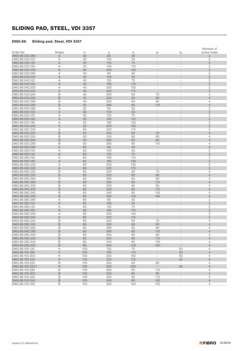
10.2019subject to alterations
SLIDING PAD, STEEL, VDI 3357
Number of Order No Shape b a e e1 e2 screw holes2960.88.030.080 A 30 80 30 - - 22960.88.030.100 A 30 100 50 - - 22960.88.030.125 A 30 125 75 - - 22960.88.030.160 A 30 160 110 - - 22960.88.030.200 A 30 200 150 - - 22960.88.040.080 A 40 80 30 - - 22960.88.040.100 A 40 100 50 - - 22960.88.040.125 A 40 125 75 - - 22960.88.040.160 A 40 160 110 - - 22960.88.040.200 A 40 200 150 - - 22960.88.040.225 A 40 225 175 - - 22960.88.040.240 B 40 240 60 70 - 42960.88.040.250 B 40 250 60 80 - 42960.88.040.260 B 40 260 60 90 - 42960.88.040.280 B 40 280 60 110 - 42960.88.050.080 A 50 80 30 - - 22960.88.050.100 A 50 100 50 - - 22960.88.050.125 A 50 125 75 - - 22960.88.050.160 A 50 160 110 - - 22960.88.050.180 A 50 180 130 - - 22960.88.050.200 A 50 200 150 - - 22960.88.050.225 A 50 225 175 - - 22960.88.050.240 B 50 240 60 70 - 42960.88.050.250 B 50 250 60 80 - 42960.88.050.260 B 50 260 60 90 - 42960.88.050.280 B 50 280 60 110 - 42960.88.060.080 A 60 80 30 - - 22960.88.060.100 A 60 100 50 - - 22960.88.060.125 A 60 125 75 - - 22960.88.060.160 A 60 160 110 - - 22960.88.060.180 A 60 180 130 - - 22960.88.060.200 A 60 200 150 - - 22960.88.060.225 A 60 225 175 - - 22960.88.060.240 B 60 240 60 70 - 42960.88.060.250 B 60 250 60 80 - 42960.88.060.260 B 60 260 60 90 - 42960.88.060.280 B 60 280 60 110 - 42960.88.060.300 B 60 300 80 90 - 42960.88.060.320 B 60 320 80 110 - 42960.88.060.340 B 60 340 80 130 - 42960.88.060.350 B 60 350 100 100 - 42960.88.080.080 A 80 80 30 - - 22960.88.080.100 A 80 100 50 - - 22960.88.080.125 A 80 125 75 - - 22960.88.080.160 A 80 160 110 - - 22960.88.080.200 A 80 200 150 - - 22960.88.080.225 A 80 225 175 - - 22960.88.080.240 B 80 240 60 70 - 42960.88.080.250 B 80 250 60 80 - 42960.88.080.260 B 80 260 60 90 - 42960.88.080.280 B 80 280 60 110 - 42960.88.080.300 B 80 300 80 90 - 42960.88.080.320 B 80 320 80 110 - 42960.88.080.340 B 80 340 80 130 - 42960.88.080.350 B 80 350 100 100 - 42960.88.100.125 H 100 125 75 - 50 42960.88.100.160 H 100 160 110 - 50 42960.88.100.200 H 100 200 150 - 50 42960.88.100.225 H 100 225 175 - 50 42960.88.100.250 B 100 250 60 80 - 42960.88.100.250.1 H 100 250 200 - 50 42960.88.100.280 B 100 280 60 110 - 42960.88.100.300 B 100 300 80 90 - 42960.88.100.320 B 100 320 80 110 - 42960.88.100.340 B 100 340 80 130 - 42960.88.100.350 B 100 350 100 100 - 4
2960.88. Sliding pad, Steel, VDI 3357
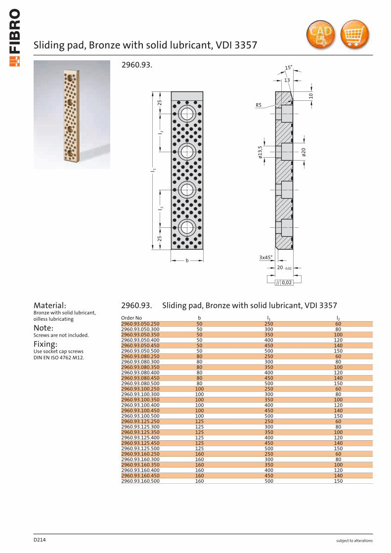
subject to alterations
Sliding pad, Bronze with solid lubricant, VDI 3357
Material: Bronze with solid lubricant, oilless lubricating
Note: Screws are not included.
Fixing: Use socket cap screws DIN EN ISO 4762 M12.
l 225
25
10
b
13
3x45°
20 - 0,02
0,02
15°
l 1l 2
ø13,
5
ø20
R5
2960.93.
D214
Order No b l1 l22960.93.050.250 50 250 602960.93.050.300 50 300 802960.93.050.350 50 350 1002960.93.050.400 50 400 1202960.93.050.450 50 450 1402960.93.050.500 50 500 1502960.93.080.250 80 250 602960.93.080.300 80 300 802960.93.080.350 80 350 1002960.93.080.400 80 400 1202960.93.080.450 80 450 1402960.93.080.500 80 500 1502960.93.100.250 100 250 602960.93.100.300 100 300 802960.93.100.350 100 350 1002960.93.100.400 100 400 1202960.93.100.450 100 450 1402960.93.100.500 100 500 1502960.93.125.250 125 250 602960.93.125.300 125 300 802960.93.125.350 125 350 1002960.93.125.400 125 400 1202960.93.125.450 125 450 1402960.93.125.500 125 500 1502960.93.160.250 160 250 602960.93.160.300 160 300 802960.93.160.350 160 350 1002960.93.160.400 160 400 1202960.93.160.450 160 450 1402960.93.160.500 160 500 150
2960.93. Sliding pad, Bronze with solid lubricant, VDI 3357
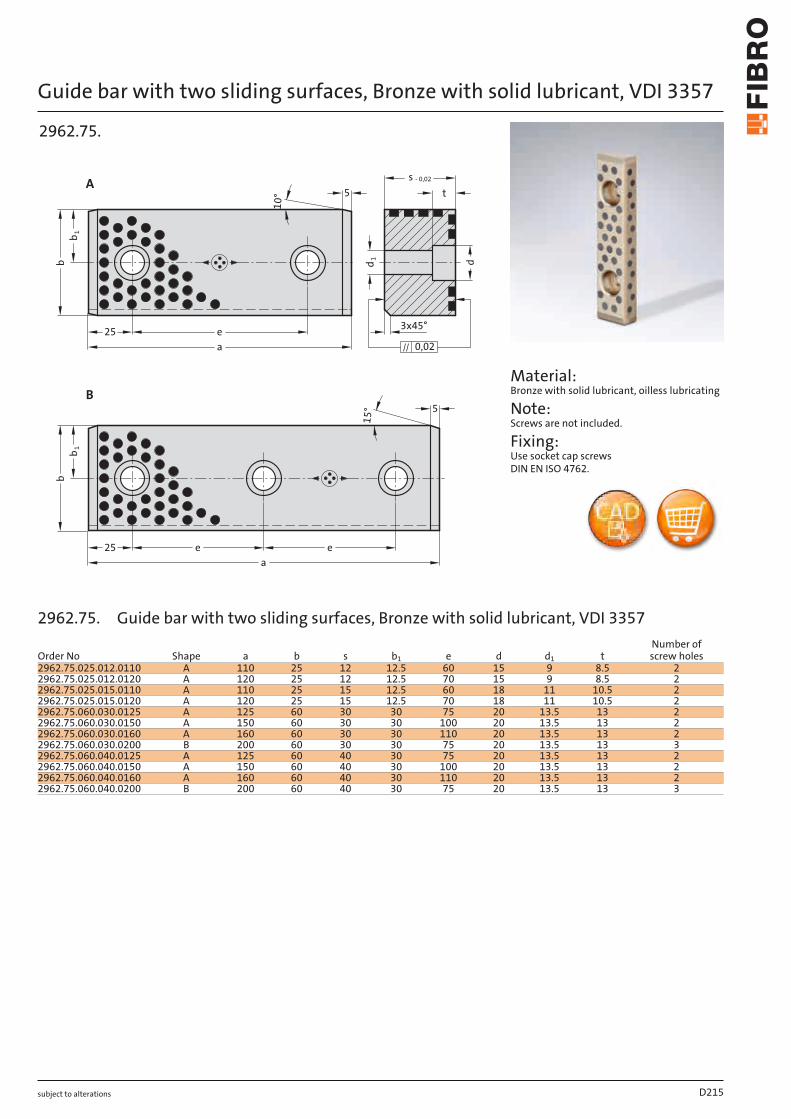
subject to alterations
Guide bar with two sliding surfaces, Bronze with solid lubricant, VDI 33571
b1
b
d
t
a
e e
15
°
s
10
° 5
a
e25
b
0,02
5
25
b
A
B
- 0,02
d1
3x45°
2962.75.
Material: Bronze with solid lubricant, oilless lubricating
Note: Screws are not included.
Fixing: Use socket cap screws DIN EN ISO 4762.
D215
Order No Shape a b s b1 e d d1 tNumber of screw holes
2962.75.025.012.0110 A 110 25 12 12.5 60 15 9 8.5 22962.75.025.012.0120 A 120 25 12 12.5 70 15 9 8.5 22962.75.025.015.0110 A 110 25 15 12.5 60 18 11 10.5 22962.75.025.015.0120 A 120 25 15 12.5 70 18 11 10.5 22962.75.060.030.0125 A 125 60 30 30 75 20 13.5 13 22962.75.060.030.0150 A 150 60 30 30 100 20 13.5 13 22962.75.060.030.0160 A 160 60 30 30 110 20 13.5 13 22962.75.060.030.0200 B 200 60 30 30 75 20 13.5 13 32962.75.060.040.0125 A 125 60 40 30 75 20 13.5 13 22962.75.060.040.0150 A 150 60 40 30 100 20 13.5 13 22962.75.060.040.0160 A 160 60 40 30 110 20 13.5 13 22962.75.060.040.0200 B 200 60 40 30 75 20 13.5 13 3
2962.75. Guide bar with two sliding surfaces, Bronze with solid lubricant, VDI 3357
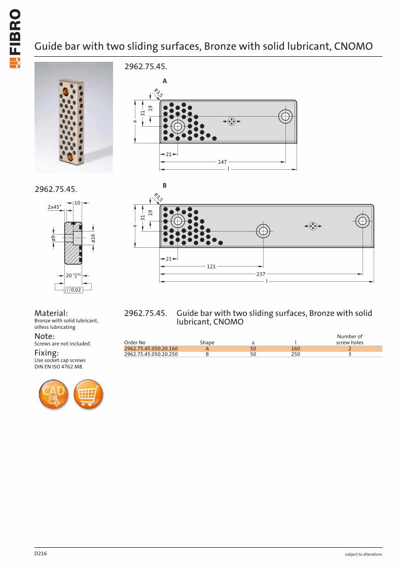
subject to alterations
Guide bar with two sliding surfaces, Bronze with solid lubricant, CNOMO
ø1
6
ø9
10
20 +0,010
0,02
2x45°
2962.75.45.
Material: Bronze with solid lubricant, oilless lubricating
Note: Screws are not included.
Fixing: Use socket cap screws DIN EN ISO 4762 M8.
31
31
aa
l
237
21
l
147
21
A
121
19
19
R3,5
R3,5
B
2962.75.45.
D216
Order No Shape a lNumber of screw holes
2962.75.45.050.20.160 A 50 160 22962.75.45.050.20.250 B 50 250 3
2962.75.45. Guide bar with two sliding surfaces, Bronze with solid lubricant, CNOMO
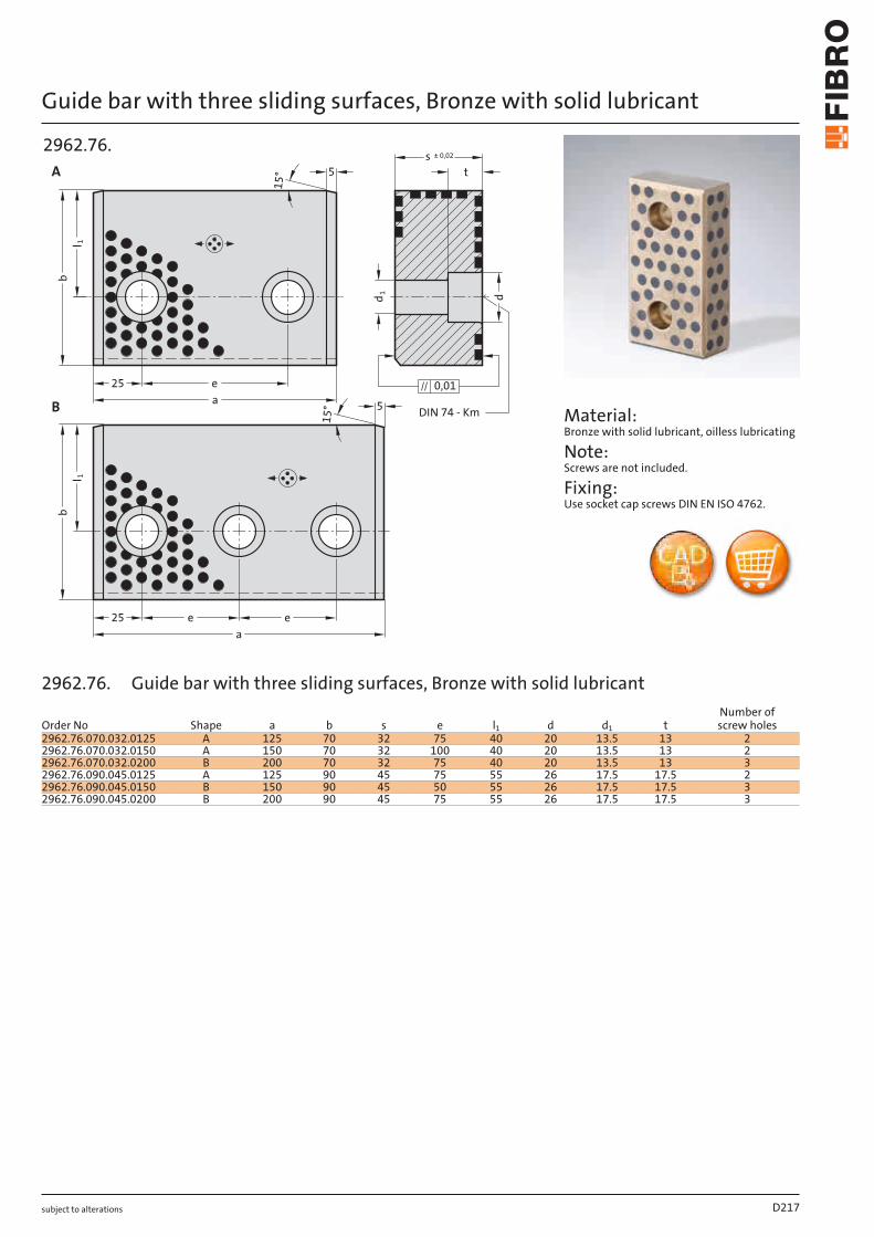
subject to alterations
Guide bar with three sliding surfaces, Bronze with solid lubricant
15
°
15
°
l 1l 1
a
ee
s ± 0,02
5
a
e25
b
0,01
DIN 74 - Km5
25
b
B
A t
d1
d
2962.76.
Material: Bronze with solid lubricant, oilless lubricating
Note: Screws are not included.
Fixing: Use socket cap screws DIN EN ISO 4762.
D217
Order No Shape a b s e l1 d d1 tNumber of screw holes
2962.76.070.032.0125 A 125 70 32 75 40 20 13.5 13 22962.76.070.032.0150 A 150 70 32 100 40 20 13.5 13 22962.76.070.032.0200 B 200 70 32 75 40 20 13.5 13 32962.76.090.045.0125 A 125 90 45 75 55 26 17.5 17.5 22962.76.090.045.0150 B 150 90 45 50 55 26 17.5 17.5 32962.76.090.045.0200 B 200 90 45 75 55 26 17.5 17.5 3
2962.76. Guide bar with three sliding surfaces, Bronze with solid lubricant
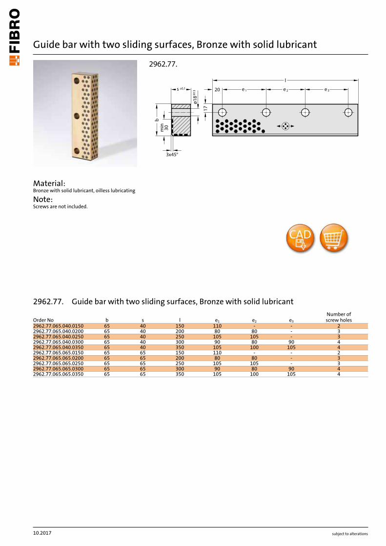
subject to alterations
Guide bar with two sliding surfaces, Bronze with solid lubricant
Material: Bronze with solid lubricant, oilless lubricating
Note: Screws are not included.
l
b
s ±0,1
ø18
H13
17
e 3e 2e 120
3x45°m
in 30
2962.77.
10.2017
Order No b s l e1 e2 e3
Number of screw holes
2962.77.065.040.0150 65 40 150 110 - - 22962.77.065.040.0200 65 40 200 80 80 - 32962.77.065.040.0250 65 40 250 105 105 - 32962.77.065.040.0300 65 40 300 90 80 90 42962.77.065.040.0350 65 40 350 105 100 105 42962.77.065.065.0150 65 65 150 110 - - 22962.77.065.065.0200 65 65 200 80 80 - 32962.77.065.065.0250 65 65 250 105 105 - 32962.77.065.065.0300 65 65 300 90 80 90 42962.77.065.065.0350 65 65 350 105 100 105 4
2962.77. Guide bar with two sliding surfaces, Bronze with solid lubricant
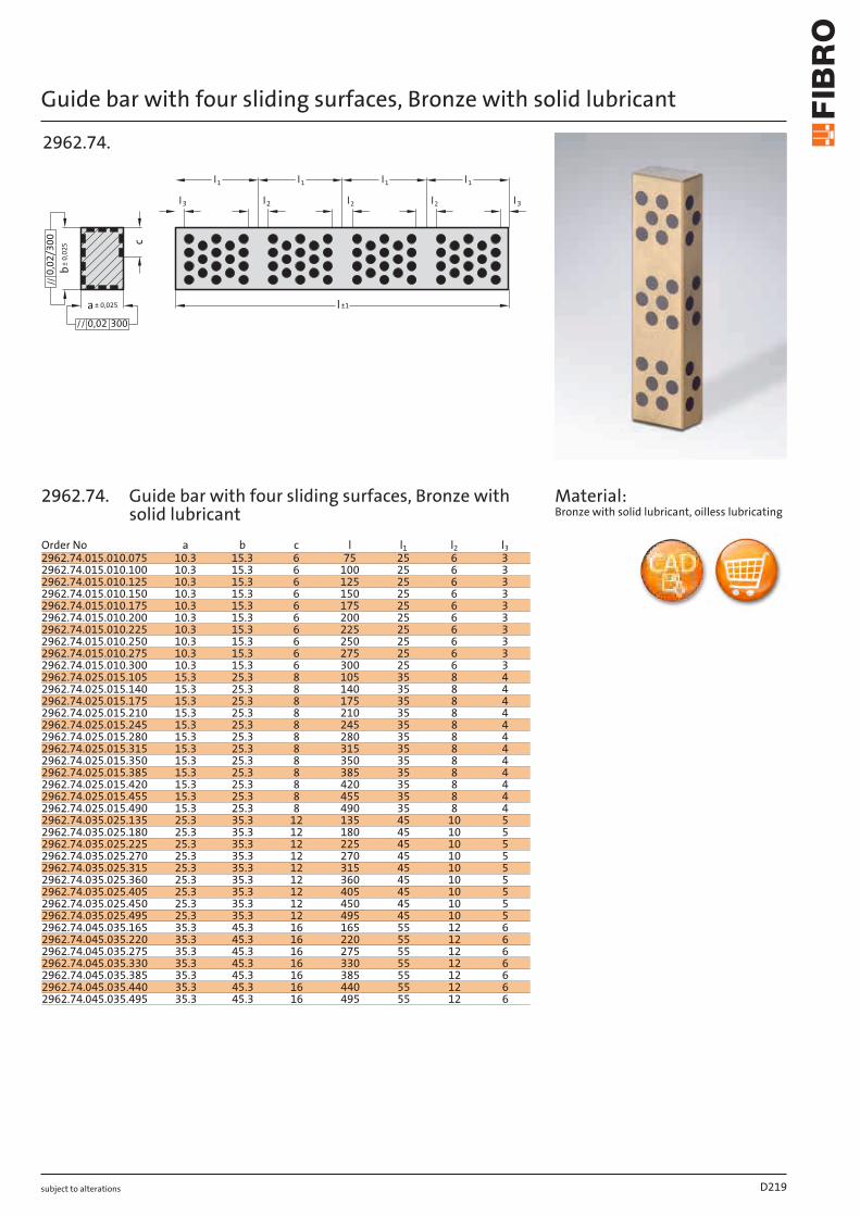
subject to alterations
Guide bar with four sliding surfaces, Bronze with solid lubricant
l ±1
l3l2l2l2l3
l1l1 l1 l1
c
b± 0
,025
a ± 0,025
3000,02
0,02
/300
2962.74.
Material: Bronze with solid lubricant, oilless lubricating
D219
Order No a b c l l1 l2 l32962.74.015.010.075 10.3 15.3 6 75 25 6 32962.74.015.010.100 10.3 15.3 6 100 25 6 32962.74.015.010.125 10.3 15.3 6 125 25 6 32962.74.015.010.150 10.3 15.3 6 150 25 6 32962.74.015.010.175 10.3 15.3 6 175 25 6 32962.74.015.010.200 10.3 15.3 6 200 25 6 32962.74.015.010.225 10.3 15.3 6 225 25 6 32962.74.015.010.250 10.3 15.3 6 250 25 6 32962.74.015.010.275 10.3 15.3 6 275 25 6 32962.74.015.010.300 10.3 15.3 6 300 25 6 32962.74.025.015.105 15.3 25.3 8 105 35 8 42962.74.025.015.140 15.3 25.3 8 140 35 8 42962.74.025.015.175 15.3 25.3 8 175 35 8 42962.74.025.015.210 15.3 25.3 8 210 35 8 42962.74.025.015.245 15.3 25.3 8 245 35 8 42962.74.025.015.280 15.3 25.3 8 280 35 8 42962.74.025.015.315 15.3 25.3 8 315 35 8 42962.74.025.015.350 15.3 25.3 8 350 35 8 42962.74.025.015.385 15.3 25.3 8 385 35 8 42962.74.025.015.420 15.3 25.3 8 420 35 8 42962.74.025.015.455 15.3 25.3 8 455 35 8 42962.74.025.015.490 15.3 25.3 8 490 35 8 42962.74.035.025.135 25.3 35.3 12 135 45 10 52962.74.035.025.180 25.3 35.3 12 180 45 10 52962.74.035.025.225 25.3 35.3 12 225 45 10 52962.74.035.025.270 25.3 35.3 12 270 45 10 52962.74.035.025.315 25.3 35.3 12 315 45 10 52962.74.035.025.360 25.3 35.3 12 360 45 10 52962.74.035.025.405 25.3 35.3 12 405 45 10 52962.74.035.025.450 25.3 35.3 12 450 45 10 52962.74.035.025.495 25.3 35.3 12 495 45 10 52962.74.045.035.165 35.3 45.3 16 165 55 12 62962.74.045.035.220 35.3 45.3 16 220 55 12 62962.74.045.035.275 35.3 45.3 16 275 55 12 62962.74.045.035.330 35.3 45.3 16 330 55 12 62962.74.045.035.385 35.3 45.3 16 385 55 12 62962.74.045.035.440 35.3 45.3 16 440 55 12 62962.74.045.035.495 35.3 45.3 16 495 55 12 6
2962.74. Guide bar with four sliding surfaces, Bronze with solid lubricant
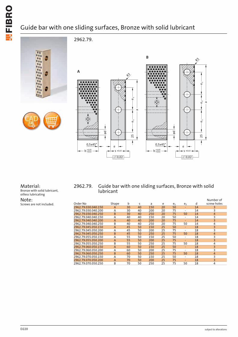
subject to alterations
Guide bar with one sliding surfaces, Bronze with solid lubricant
Material: Bronze with solid lubricant, oilless lubricating
Note: Screws are not included.
e 2e 1
e 1e 1e 1
25 25
a
a
e0,5x45° e
ødød
R3
0,020,02
R3
0,5x45°
B
A
b +0,05+0,02 s ±0,02 b +0,05
+0,02 s ±0,02
2962.79.
D220
Order No Shape b s a e e1 e2 dNumber of screw holes
2962.79.030.040.150 A 30 40 150 20 50 - 14 32962.79.030.040.200 A 30 40 200 20 75 - 14 32962.79.030.040.250 B 30 40 250 20 75 50 14 42962.79.040.040.150 A 40 40 150 20 50 - 14 32962.79.040.040.200 A 40 40 200 20 75 - 14 32962.79.040.040.250 B 40 40 250 20 75 50 14 42962.79.045.050.150 A 45 50 150 25 50 - 18 32962.79.045.050.200 A 45 50 200 25 75 - 18 32962.79.045.050.250 B 45 50 250 25 75 50 18 42962.79.055.050.150 A 55 50 150 25 50 - 18 32962.79.055.050.200 A 55 50 200 25 75 - 18 32962.79.055.050.250 B 55 50 250 25 75 50 18 42962.79.060.050.150 A 60 50 150 25 50 - 18 32962.79.060.050.200 A 60 50 200 25 75 - 18 32962.79.060.050.250 B 60 50 250 25 75 50 18 42962.79.070.050.150 A 70 50 150 25 50 - 18 32962.79.070.050.200 A 70 50 200 25 75 - 18 32962.79.070.050.250 B 70 50 250 25 75 50 18 4
2962.79. Guide bar with one sliding surfaces, Bronze with solid lubricant
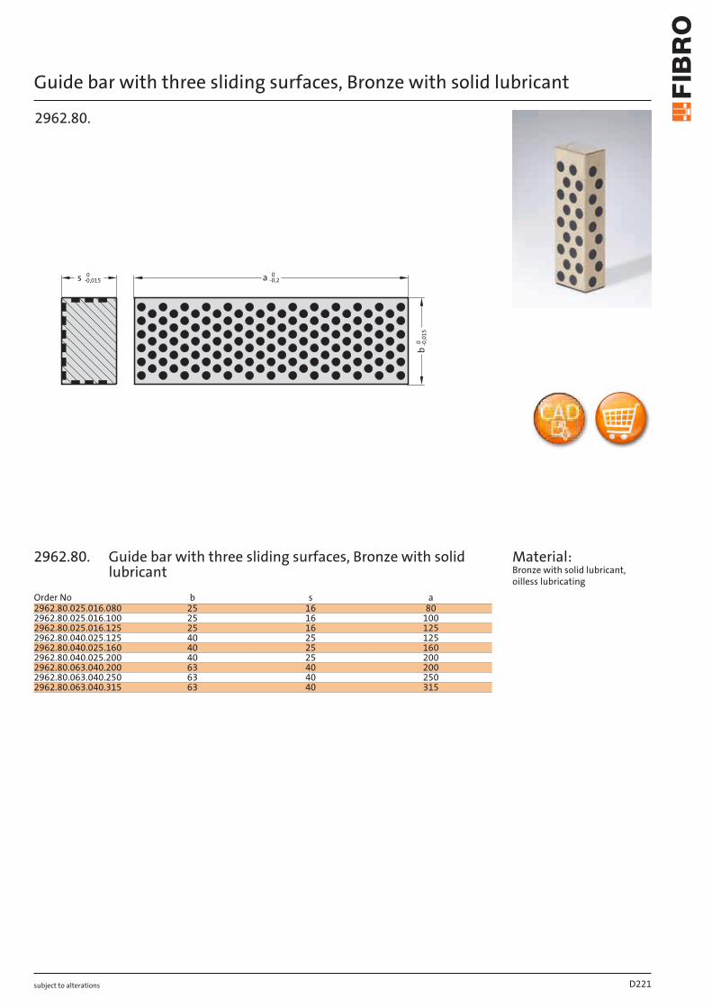
subject to alterations
Guide bar with three sliding surfaces, Bronze with solid lubricant
b0 -0,015
0a -0,2s 0-0,015
2962.80.
Material: Bronze with solid lubricant, oilless lubricating
D221
Order No b s a2962.80.025.016.080 25 16 802962.80.025.016.100 25 16 1002962.80.025.016.125 25 16 1252962.80.040.025.125 40 25 1252962.80.040.025.160 40 25 1602962.80.040.025.200 40 25 2002962.80.063.040.200 63 40 2002962.80.063.040.250 63 40 2502962.80.063.040.315 63 40 315
2962.80. Guide bar with three sliding surfaces, Bronze with solid lubricant
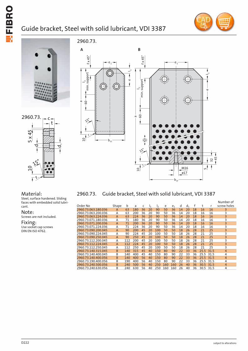
subject to alterations
Guide bracket, Steel with solid lubricant, VDI 33875
x 4
5
t
c
d
1
10
15°
r
d
2960.73.
Material: Steel, surface hardened. Sliding faces with embedded solid lubri-cant.
Note: Screws are not included.
Fixing: Use socket cap screws DIN EN ISO 4762.
4532
5M16ø17
e 1e 1f x 4
5°
l 1e
e
a
a
15°
r
15°
r10
10
l 2m
in. s
uppo
rtl 2m
in. s
uppo
rt
60
60
b f7
bf7
l 1
f x 4
5°
2960.73.A B
D222
Order No Shape b a c l1 l2 e e1 d d1 f t rNumber of screw holes
2960.73.063.180.036 A 63 180 36 20 90 50 36 14 20 18 16 16 32960.73.063.200.036 A 63 200 36 20 90 50 36 14 20 18 16 16 32960.73.063.224.036 A 63 224 36 20 90 50 36 14 20 18 16 16 32960.73.071.180.036 A 71 180 36 20 90 50 36 14 20 18 16 16 32960.73.071.200.036 A 71 200 36 20 90 50 36 14 20 18 16 16 32960.73.071.224.036 A 71 224 36 20 90 50 36 14 20 18 16 16 32960.73.090.200.045 A 90 200 45 20 100 50 50 18 26 28 21 25 32960.73.090.224.045 A 90 224 45 20 100 50 50 18 26 28 21 25 32960.73.090.250.045 A 90 250 45 20 100 50 50 18 26 28 21 25 32960.73.112.200.045 A 112 200 45 20 100 50 50 18 26 28 21 25 32960.73.112.224.045 A 112 224 45 20 100 50 50 18 26 28 21 25 32960.73.112.250.045 A 112 250 45 20 100 50 50 18 26 28 21 25 32960.73.140.315.045 B 140 315 45 40 150 80 90 22 33 36 25.5 31.5 42960.73.140.400.045 B 140 400 45 40 150 80 90 22 33 36 25.5 31.5 42960.73.140.400.056 B 140 400 56 40 150 80 90 22 33 36 25.5 31.5 42960.73.190.400.056 B 190 400 56 40 150 80 90 22 33 36 25.5 31.5 42960.73.240.500.056 B 240 500 56 40 250 160 160 26 40 36 30.5 31.5 42960.73.240.630.056 B 240 630 56 40 250 160 160 26 40 36 30.5 31.5 4
2960.73. Guide bracket, Steel with solid lubricant, VDI 3387
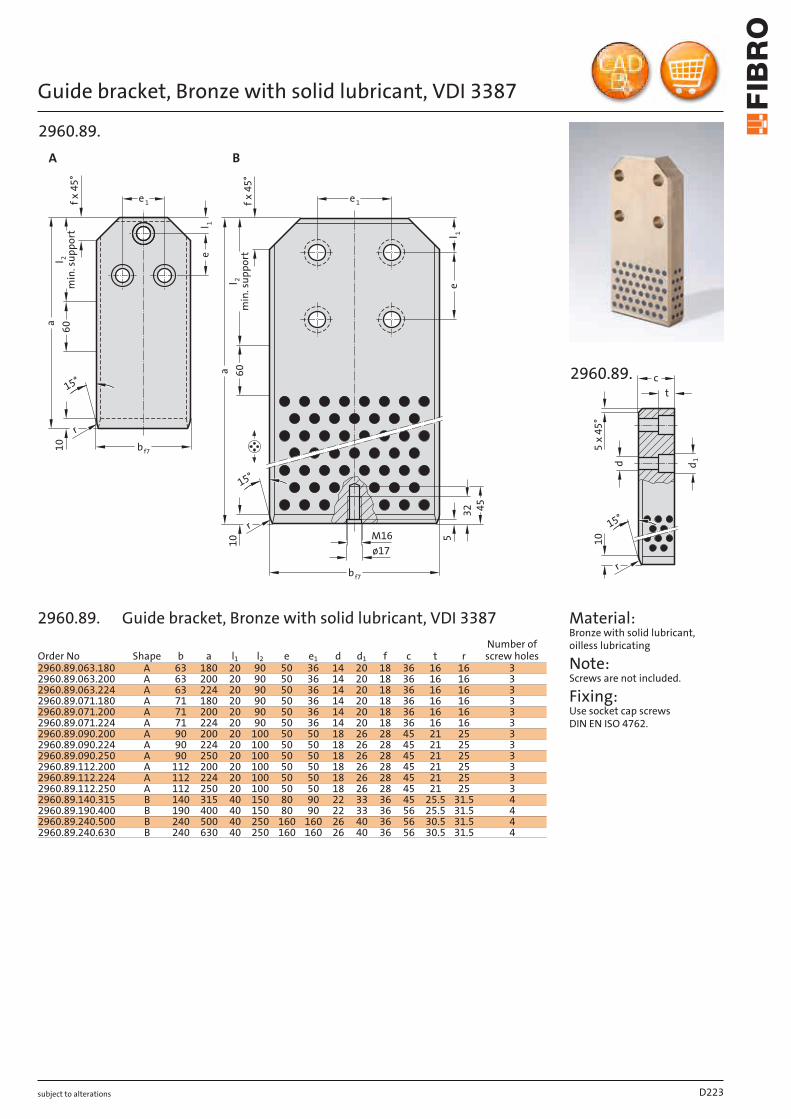
subject to alterations
Guide bracket, Bronze with solid lubricant, VDI 3387
4532
5M16ø17
e 1e 1f x 4
5°
l 1e
e
a
a
15°
r
15°
r
10
10
l 2m
in. s
uppo
rtl 2m
in. s
uppo
rt
60
60
b f7
bf7
l 1
f x 4
5°
2960.89.A B
5 x
45
°
t
c
d
1
10
15°
r
d
2960.89.
Material: Bronze with solid lubricant, oilless lubricating
Note: Screws are not included.
Fixing: Use socket cap screws DIN EN ISO 4762.
D223
Order No Shape b a l1 l2 e e1 d d1 f c t rNumber of screw holes
2960.89.063.180 A 63 180 20 90 50 36 14 20 18 36 16 16 32960.89.063.200 A 63 200 20 90 50 36 14 20 18 36 16 16 32960.89.063.224 A 63 224 20 90 50 36 14 20 18 36 16 16 32960.89.071.180 A 71 180 20 90 50 36 14 20 18 36 16 16 32960.89.071.200 A 71 200 20 90 50 36 14 20 18 36 16 16 32960.89.071.224 A 71 224 20 90 50 36 14 20 18 36 16 16 32960.89.090.200 A 90 200 20 100 50 50 18 26 28 45 21 25 32960.89.090.224 A 90 224 20 100 50 50 18 26 28 45 21 25 32960.89.090.250 A 90 250 20 100 50 50 18 26 28 45 21 25 32960.89.112.200 A 112 200 20 100 50 50 18 26 28 45 21 25 32960.89.112.224 A 112 224 20 100 50 50 18 26 28 45 21 25 32960.89.112.250 A 112 250 20 100 50 50 18 26 28 45 21 25 32960.89.140.315 B 140 315 40 150 80 90 22 33 36 45 25.5 31.5 42960.89.190.400 B 190 400 40 150 80 90 22 33 36 56 25.5 31.5 42960.89.240.500 B 240 500 40 250 160 160 26 40 36 56 30.5 31.5 42960.89.240.630 B 240 630 40 250 160 160 26 40 36 56 30.5 31.5 4
2960.89. Guide bracket, Bronze with solid lubricant, VDI 3387
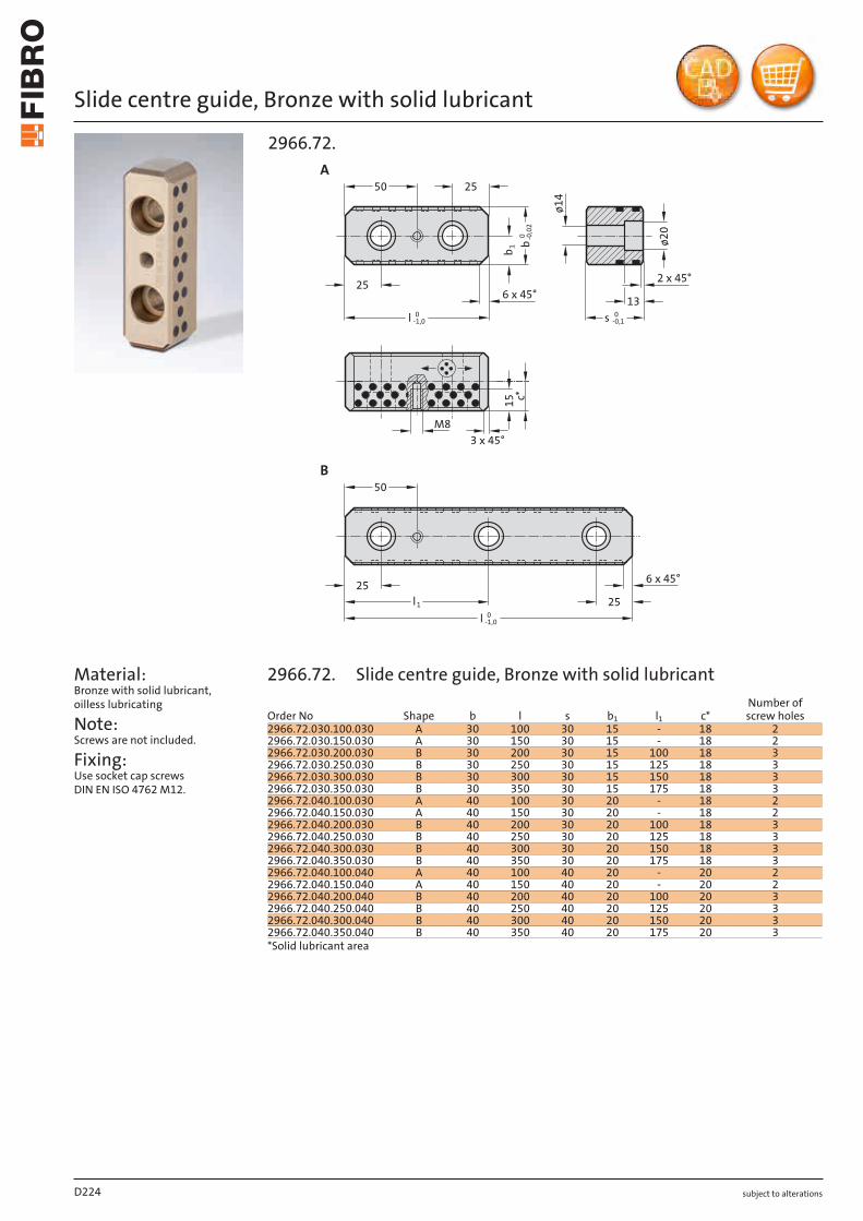
subject to alterations
Slide centre guide, Bronze with solid lubricant
Material: Bronze with solid lubricant, oilless lubricating
Note: Screws are not included.
Fixing: Use socket cap screws DIN EN ISO 4762 M12.
25
25
A
B
50
2513
50
25l1
l -1,00
l -1,00
M8
6 x 45°2 x 45°
3 x 45°
6 x 45°
ø20
ø14
s 0-0,1
15 c*b -
0,02
0b 1
2966.72.
D224
Order No Shape b l s b1 l1 c*Number of screw holes
2966.72.030.100.030 A 30 100 30 15 - 18 22966.72.030.150.030 A 30 150 30 15 - 18 22966.72.030.200.030 B 30 200 30 15 100 18 32966.72.030.250.030 B 30 250 30 15 125 18 32966.72.030.300.030 B 30 300 30 15 150 18 32966.72.030.350.030 B 30 350 30 15 175 18 32966.72.040.100.030 A 40 100 30 20 - 18 22966.72.040.150.030 A 40 150 30 20 - 18 22966.72.040.200.030 B 40 200 30 20 100 18 32966.72.040.250.030 B 40 250 30 20 125 18 32966.72.040.300.030 B 40 300 30 20 150 18 32966.72.040.350.030 B 40 350 30 20 175 18 32966.72.040.100.040 A 40 100 40 20 - 20 22966.72.040.150.040 A 40 150 40 20 - 20 22966.72.040.200.040 B 40 200 40 20 100 20 32966.72.040.250.040 B 40 250 40 20 125 20 32966.72.040.300.040 B 40 300 40 20 150 20 32966.72.040.350.040 B 40 350 40 20 175 20 3*Solid lubricant area
2966.72. Slide centre guide, Bronze with solid lubricant
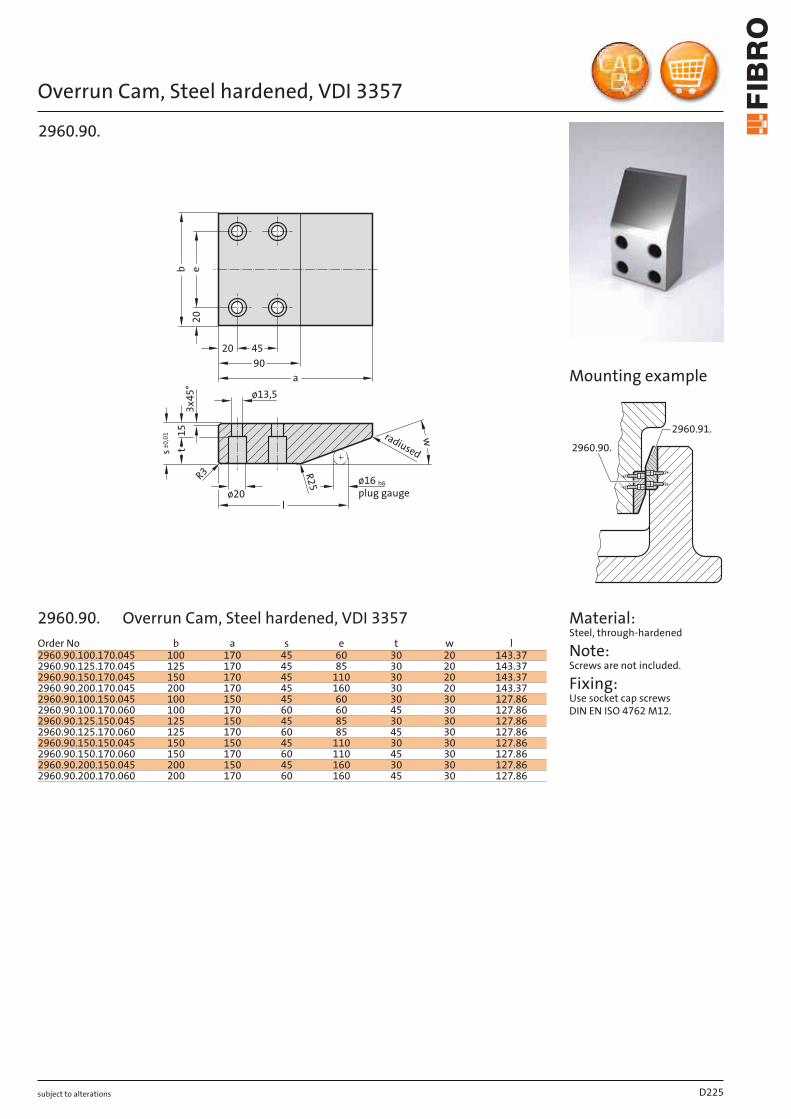
subject to alterations
Overrun Cam, Steel hardened, VDI 3357
plug gaugeø16 h6
wradiused
R2
5R3
s±
0,0
1 15
20
eb
a
90
4520
ø20
ø13,5
3x
45
°
l
t
2960.90.
Material: Steel, through-hardened
Note: Screws are not included.
Fixing: Use socket cap screws DIN EN ISO 4762 M12.
2960.90.
2960.91.
Mounting example
D225
Order No b a s e t w l2960.90.100.170.045 100 170 45 60 30 20 143.372960.90.125.170.045 125 170 45 85 30 20 143.372960.90.150.170.045 150 170 45 110 30 20 143.372960.90.200.170.045 200 170 45 160 30 20 143.372960.90.100.150.045 100 150 45 60 30 30 127.862960.90.100.170.060 100 170 60 60 45 30 127.862960.90.125.150.045 125 150 45 85 30 30 127.862960.90.125.170.060 125 170 60 85 45 30 127.862960.90.150.150.045 150 150 45 110 30 30 127.862960.90.150.170.060 150 170 60 110 45 30 127.862960.90.200.150.045 200 150 45 160 30 30 127.862960.90.200.170.060 200 170 60 160 45 30 127.86
2960.90. Overrun Cam, Steel hardened, VDI 3357
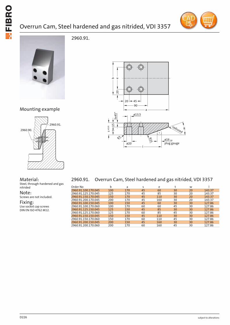
subject to alterations
Overrun Cam, Steel hardened and gas nitrided, VDI 3357
Material: Steel, through-hardened and gas nitrided
Note: Screws are not included.
Fixing: Use socket cap screws DIN EN ISO 4762 M12.
2960.90.
2960.91.
plug gaugeø16 h6
wradiused
R2
5
R3
s±
0,0
1 15
20
eba
90
4520
ø20
ø13,53
x4
5°
l
t
2960.91.
Mounting example
D226
Order No b a s e t w l2960.91.100.170.045 100 170 45 60 30 20 143.372960.91.125.170.045 125 170 45 85 30 20 143.372960.91.150.170.045 150 170 45 110 30 20 143.372960.91.200.170.045 200 170 45 160 30 20 143.372960.91.100.150.045 100 150 45 60 30 30 127.862960.91.100.170.060 100 170 60 60 45 30 127.862960.91.125.150.045 125 150 45 85 30 30 127.862960.91.125.170.060 125 170 60 85 45 30 127.862960.91.150.150.045 150 150 45 110 30 30 127.862960.91.150.170.060 150 170 60 110 45 30 127.862960.91.200.150.045 200 150 45 160 30 30 127.862960.91.200.170.060 200 170 60 160 45 30 127.86
2960.91. Overrun Cam, Steel hardened and gas nitrided, VDI 3357
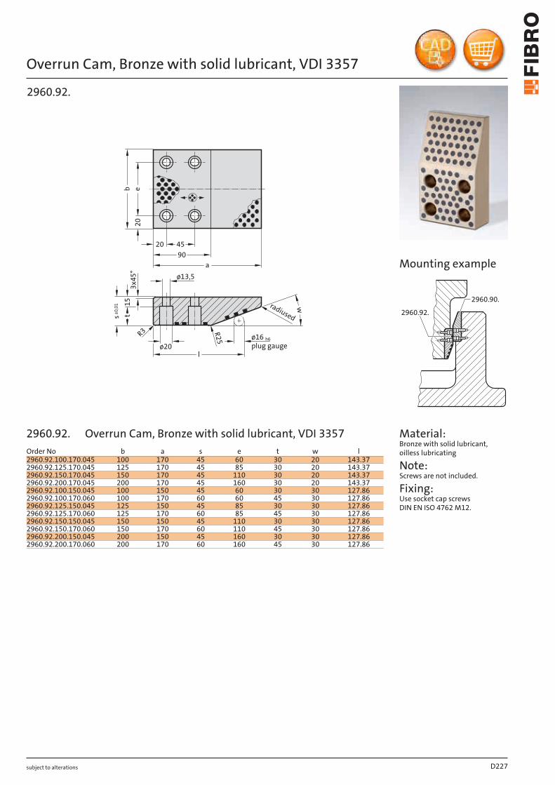
subject to alterations
Overrun Cam, Bronze with solid lubricant, VDI 3357
plug gaugeø16 h6
wradiused
R2
5R3
s±
0,0
1 15
20
eb
a
90
4520
ø20
ø13,5
3x
45
°
l
t
2960.92.
Material: Bronze with solid lubricant, oilless lubricating
Note: Screws are not included.
Fixing: Use socket cap screws DIN EN ISO 4762 M12.
2960.92.
2960.90.
Mounting example
D227
Order No b a s e t w l2960.92.100.170.045 100 170 45 60 30 20 143.372960.92.125.170.045 125 170 45 85 30 20 143.372960.92.150.170.045 150 170 45 110 30 20 143.372960.92.200.170.045 200 170 45 160 30 20 143.372960.92.100.150.045 100 150 45 60 30 30 127.862960.92.100.170.060 100 170 60 60 45 30 127.862960.92.125.150.045 125 150 45 85 30 30 127.862960.92.125.170.060 125 170 60 85 45 30 127.862960.92.150.150.045 150 150 45 110 30 30 127.862960.92.150.170.060 150 170 60 110 45 30 127.862960.92.200.150.045 200 150 45 160 30 30 127.862960.92.200.170.060 200 170 60 160 45 30 127.86
2960.92. Overrun Cam, Bronze with solid lubricant, VDI 3357

subject to alterations
Angled guide gib, Bronze with solid lubricant
Material: Bronze with solid lubricant, oilless lubricating
Note: Screws are not included.
Fixing: Use socket cap screws DIN EN ISO 4762.
et
d
20l
e 4e 2 e 3e 1
R2
a1
d1
a 3 ±0,1
a 4+0
,1+0
,05 a 2
2962.70.
D228
Order No a1 a2 l a3 a4 e e1 e2 e3 e4 d d1 tNumber of screw holes
2962.70.026.100 26 20 100 8 10 9 60 - - - 15 9 9.6 22962.70.026.150 26 20 150 8 10 9 55 55 - - 15 9 9.6 32962.70.026.200 26 20 200 8 10 9 55 50 55 - 15 9 9.6 42962.70.032.100 32 30 100 10 15 11 60 - - - - 11 - 22962.70.032.150 32 30 150 10 15 11 55 55 - - - 11 - 32962.70.032.200 32 30 200 10 15 11 55 50 55 - - 11 - 42962.70.032.250 32 30 250 10 15 11 70 70 70 - - 11 - 42962.70.050.200 50 45 200 22 25 14 55 50 55 - 18 11 25 42962.70.050.250 50 45 250 22 25 14 70 70 70 - 18 11 25 42962.70.050.300 50 45 300 22 25 14 65 65 65 65 18 11 25 52962.70.050.350 50 45 350 22 25 14 80 75 75 80 18 11 25 5
2962.70. Angled guide gib, Bronze with solid lubricant
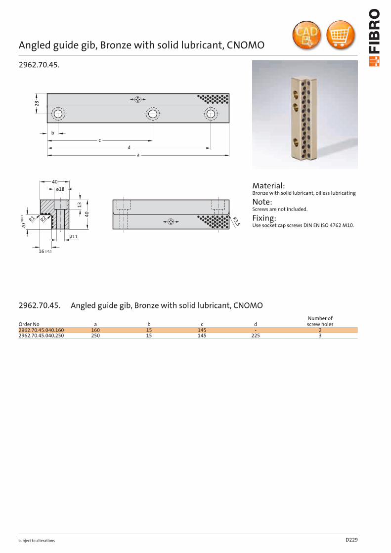
subject to alterations
Angled guide gib, Bronze with solid lubricant, CNOMO
40
40
b
28
a
d
c
R3
,5
ø18
ø11
16 ± 0,1
13
R2R
1
20
±0
,01
2962.70.45.
Material: Bronze with solid lubricant, oilless lubricating
Note: Screws are not included.
Fixing: Use socket cap screws DIN EN ISO 4762 M10.
D229
Order No a b c dNumber of screw holes
2962.70.45.040.160 160 15 145 - 22962.70.45.040.250 250 15 145 225 3
2962.70.45. Angled guide gib, Bronze with solid lubricant, CNOMO
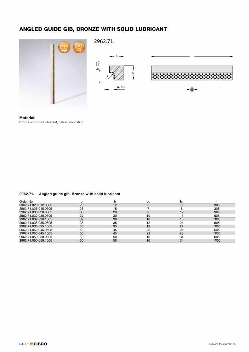
09.2019
b l
h
r
b 1±0,1
h1
+0,1
+0,0
5
2962.71.
subject to alterations
ANGLED GUIDE GIB, BRONZE WITH SOLID LUBRICANT
Material: Bronze with solid lubricant, oilless lubricating
Order No b h b1 h1 l2962.71.020.012.0305 20 12 5 6 3052962.71.025.015.0305 25 15 7 8 3052962.71.030.020.0305 30 20 9 12 3052962.71.032.030.0605 32 30 10 15 6052962.71.032.030.1005 32 30 10 15 10052962.71.035.035.0605 35 35 12 24 6052962.71.035.035.1005 35 35 12 24 10052962.71.050.045.0605 50 45 22 25 6052962.71.050.045.1005 50 45 22 25 10052962.71.050.050.0605 50 50 16 34 6052962.71.050.050.1005 50 50 16 34 1005
2962.71. Angled guide gib, Bronze with solid lubricant
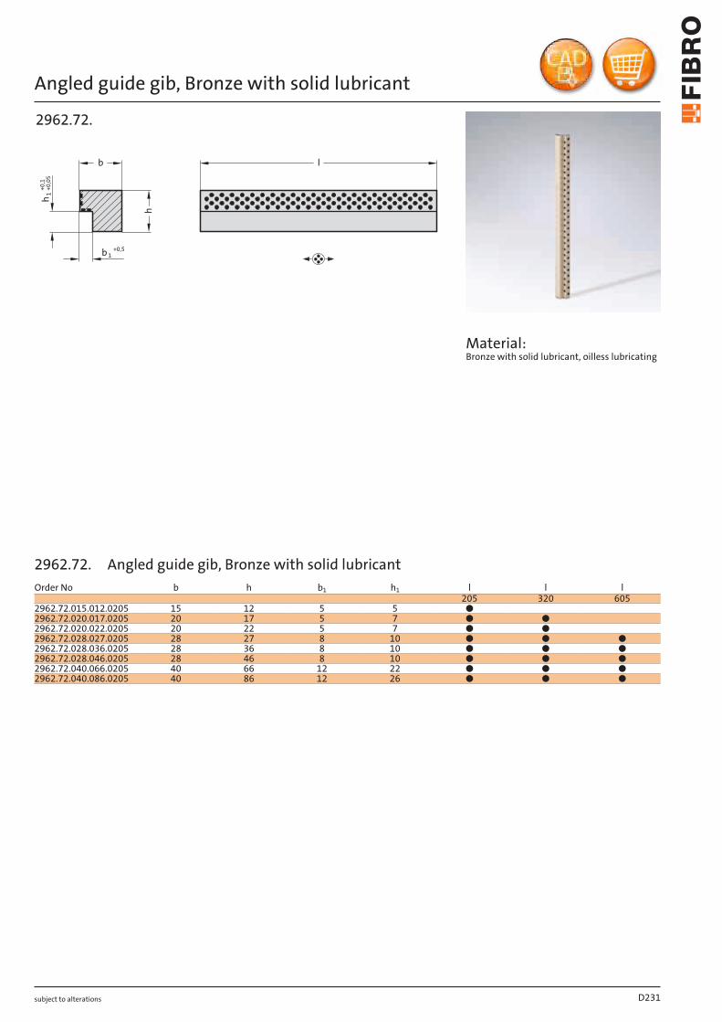
subject to alterations
Angled guide gib, Bronze with solid lubricant
b lh
b 1+0,5
h1
+0,1
+0,0
5
2962.72.
Material: Bronze with solid lubricant, oilless lubricating
D231
Order No b h b1 h1 l l l205 320 605
2962.72.015.012.0205 15 12 5 5 ●2962.72.020.017.0205 20 17 5 7 ● ●2962.72.020.022.0205 20 22 5 7 ● ●2962.72.028.027.0205 28 27 8 10 ● ● ●2962.72.028.036.0205 28 36 8 10 ● ● ●2962.72.028.046.0205 28 46 8 10 ● ● ●2962.72.040.066.0205 40 66 12 22 ● ● ●2962.72.040.086.0205 40 86 12 26 ● ● ●
2962.72. Angled guide gib, Bronze with solid lubricant
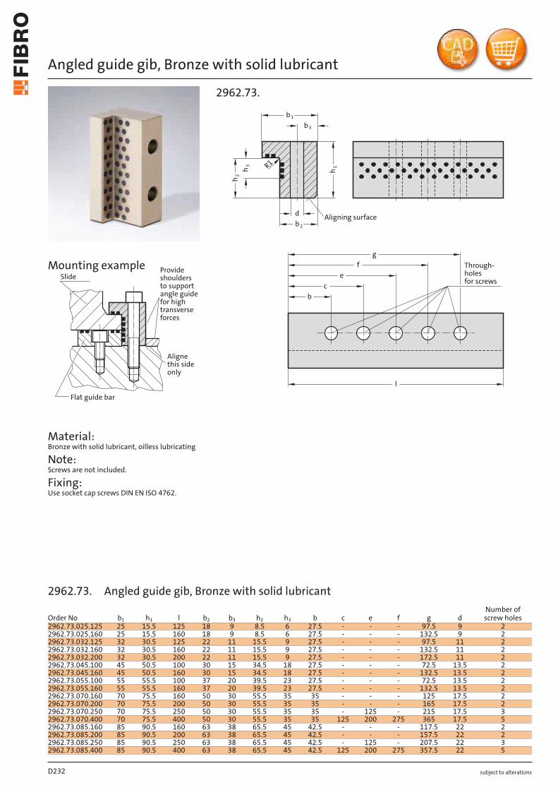
subject to alterations
Angled guide gib, Bronze with solid lubricant
Provideshouldersto supportangle guidefor hightransverseforces
Alignethis sideonly
Flat guide bar
SlideMounting example
Material: Bronze with solid lubricant, oilless lubricating
Note: Screws are not included.
Fixing: Use socket cap screws DIN EN ISO 4762.
2962.73.
d
l
R1
Through-holesfor screws
Aligning surface
e
gf
cb
h 1
b 1
b 3
b 2
h 3h 2
D232
Order No b1 h1 l b2 b3 h2 h3 b c e f g dNumber of screw holes
2962.73.025.125 25 15.5 125 18 9 8.5 6 27.5 - - - 97.5 9 22962.73.025.160 25 15.5 160 18 9 8.5 6 27.5 - - - 132.5 9 22962.73.032.125 32 30.5 125 22 11 15.5 9 27.5 - - - 97.5 11 22962.73.032.160 32 30.5 160 22 11 15.5 9 27.5 - - - 132.5 11 22962.73.032.200 32 30.5 200 22 11 15.5 9 27.5 - - - 172.5 11 22962.73.045.100 45 50.5 100 30 15 34.5 18 27.5 - - - 72.5 13.5 22962.73.045.160 45 50.5 160 30 15 34.5 18 27.5 - - - 132.5 13.5 22962.73.055.100 55 55.5 100 37 20 39.5 23 27.5 - - - 72.5 13.5 22962.73.055.160 55 55.5 160 37 20 39.5 23 27.5 - - - 132.5 13.5 22962.73.070.160 70 75.5 160 50 30 55.5 35 35 - - - 125 17.5 22962.73.070.200 70 75.5 200 50 30 55.5 35 35 - - - 165 17.5 22962.73.070.250 70 75.5 250 50 30 55.5 35 35 - 125 - 215 17.5 32962.73.070.400 70 75.5 400 50 30 55.5 35 35 125 200 275 365 17.5 52962.73.085.160 85 90.5 160 63 38 65.5 45 42.5 - - - 117.5 22 22962.73.085.200 85 90.5 200 63 38 65.5 45 42.5 - - - 157.5 22 22962.73.085.250 85 90.5 250 63 38 65.5 45 42.5 - 125 - 207.5 22 32962.73.085.400 85 90.5 400 63 38 65.5 45 42.5 125 200 275 357.5 22 5
2962.73. Angled guide gib, Bronze with solid lubricant
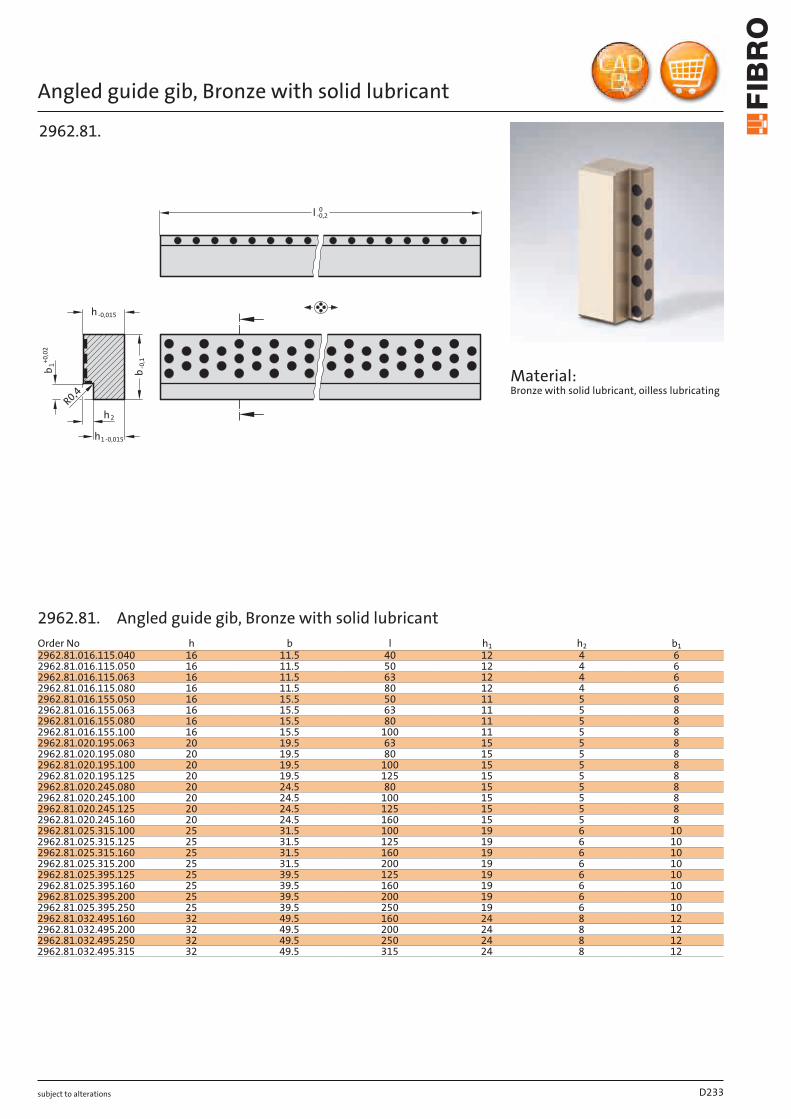
subject to alterations
Angled guide gib, Bronze with solid lubricant
h
-0,1
R0,4
b1
+0
,02
h -0,015
b
h2
1-0,015
l 0-0,2
2962.81.
Material: Bronze with solid lubricant, oilless lubricating
D233
Order No h b l h1 h2 b12962.81.016.115.040 16 11.5 40 12 4 62962.81.016.115.050 16 11.5 50 12 4 62962.81.016.115.063 16 11.5 63 12 4 62962.81.016.115.080 16 11.5 80 12 4 62962.81.016.155.050 16 15.5 50 11 5 82962.81.016.155.063 16 15.5 63 11 5 82962.81.016.155.080 16 15.5 80 11 5 82962.81.016.155.100 16 15.5 100 11 5 82962.81.020.195.063 20 19.5 63 15 5 82962.81.020.195.080 20 19.5 80 15 5 82962.81.020.195.100 20 19.5 100 15 5 82962.81.020.195.125 20 19.5 125 15 5 82962.81.020.245.080 20 24.5 80 15 5 82962.81.020.245.100 20 24.5 100 15 5 82962.81.020.245.125 20 24.5 125 15 5 82962.81.020.245.160 20 24.5 160 15 5 8
25 31.5 100 19 6 1025 31.5 125 19 6 1025 31.5 160 19 6 1025 31.5 200 19 6 1025 39.5 125 19 6 1025 39.5 160 19 6 1025 39.5 200 19 6 1025 39.5 250 19 6 1032 49.5 160 24 8 1232 49.5 200 24 8 1232 49.5 250 24 8 12
2962.81.025.315.1002962.81.025.315.1252962.81.025.315.1602962.81.025.315.2002962.81.025.395.1252962.81.025.395.1602962.81.025.395.2002962.81.025.395.2502962.81.032.495.1602962.81.032.495.2002962.81.032.495.2502962.81.032.495.315 32 49.5 315 24 8 12
2962.81. Angled guide gib, Bronze with solid lubricant
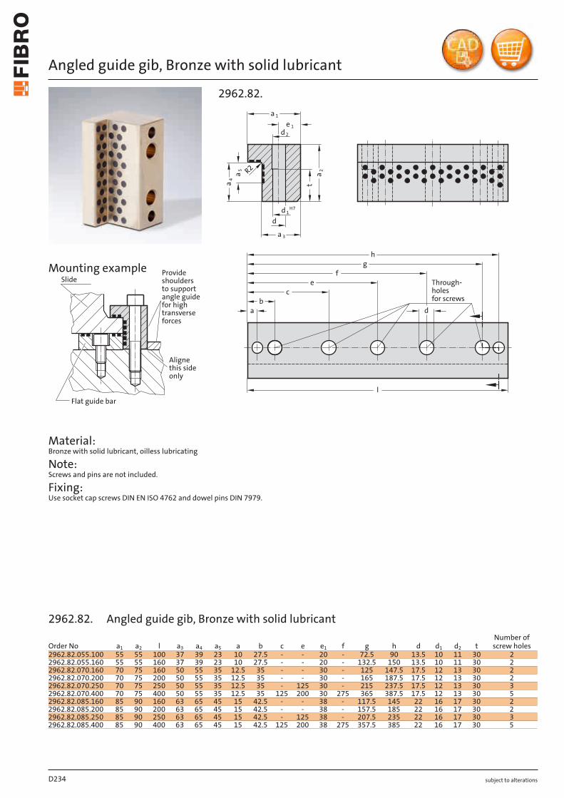
subject to alterations
Angled guide gib, Bronze with solid lubricant
Provideshouldersto supportangle guidefor hightransverseforces
Alignethis sideonly
Flat guide bar
SlideMounting example
Material: Bronze with solid lubricant, oilless lubricating
Note: Screws and pins are not included.
Fixing: Use socket cap screws DIN EN ISO 4762 and dowel pins DIN 7979.
d
hg
fe
bc
a
l
Through-holesfor screws
t
R2
a 1
d 2
da
4
a5
a2
e 1
d 1H7
a 3
2962.82.
D234
Order No a1 a2 l a3 a4 a5 a b c e e1 f g h d d1 d2 tNumber of screw holes
2962.82.055.100 55 55 100 37 39 23 10 27.5 - - 20 - 72.5 90 13.5 10 11 30 22962.82.055.160 55 55 160 37 39 23 10 27.5 - - 20 - 132.5 150 13.5 10 11 30 22962.82.070.160 70 75 160 50 55 35 12.5 35 - - 30 - 125 147.5 17.5 12 13 30 22962.82.070.200 70 75 200 50 55 35 12.5 35 - - 30 - 165 187.5 17.5 12 13 30 22962.82.070.250 70 75 250 50 55 35 12.5 35 - 125 30 - 215 237.5 17.5 12 13 30 32962.82.070.400 70 75 400 50 55 35 12.5 35 125 200 30 275 365 387.5 17.5 12 13 30 52962.82.085.160 85 90 160 63 65 45 15 42.5 - - 38 - 117.5 145 22 16 17 30 22962.82.085.200 85 90 200 63 65 45 15 42.5 - - 38 - 157.5 185 22 16 17 30 22962.82.085.250 85 90 250 63 65 45 15 42.5 - 125 38 - 207.5 235 22 16 17 30 32962.82.085.400 85 90 400 63 65 45 15 42.5 125 200 38 275 357.5 385 22 16 17 30 5
2962.82. Angled guide gib, Bronze with solid lubricant
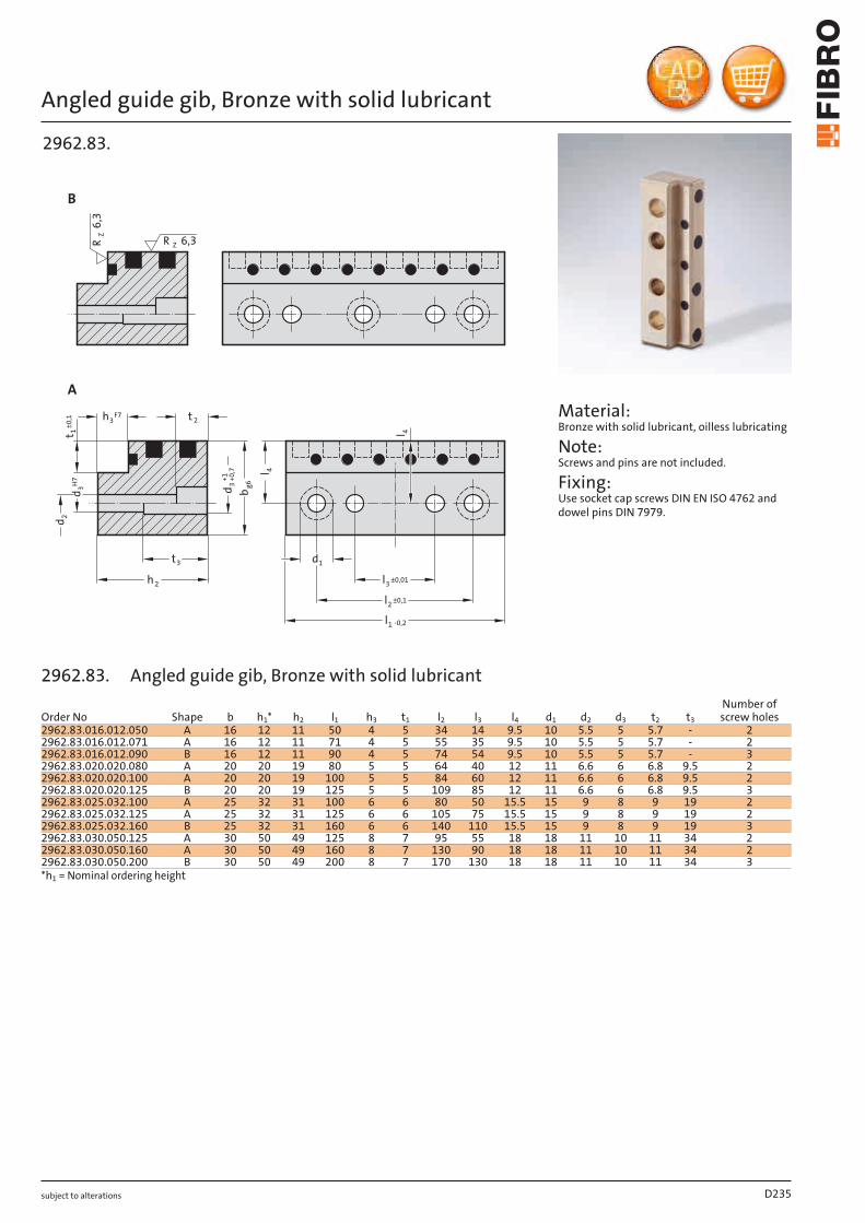
subject to alterations
Angled guide gib, Bronze with solid lubricant
+0,7
dd
H7
F7
d
l2 ±0,1
l3 ±0,01
l1 -0,2
1
l 4
3h 2t
3t
h2
t 1±0,1
2
3 g6
bd+1
3
RZ6,3
R Z 6,3
B
A
l 4
2962.83.
Material: Bronze with solid lubricant, oilless lubricating
Note: Screws and pins are not included.
Fixing: Use socket cap screws DIN EN ISO 4762 and dowel pins DIN 7979.
D235
Order No Shape b h1* h2 l1 h3 t1 l2 l3 l4 d1 d2 d3 t2 t3
Number of screw holes
2962.83.016.012.050 A 16 12 11 50 4 5 34 14 9.5 10 5.5 5 5.7 - 22962.83.016.012.071 A 16 12 11 71 4 5 55 35 9.5 10 5.5 5 5.7 - 22962.83.016.012.090 B 16 12 11 90 4 5 74 54 9.5 10 5.5 5 5.7 - 32962.83.020.020.080 A 20 20 19 80 5 5 64 40 12 11 6.6 6 6.8 9.5 22962.83.020.020.100 A 20 20 19 100 5 5 84 60 12 11 6.6 6 6.8 9.5 22962.83.020.020.125 B 20 20 19 125 5 5 109 85 12 11 6.6 6 6.8 9.5 32962.83.025.032.100 A 25 32 31 100 6 6 80 50 15.5 15 9 8 9 19 22962.83.025.032.125 A 25 32 31 125 6 6 105 75 15.5 15 9 8 9 19 22962.83.025.032.160 B 25 32 31 160 6 6 140 110 15.5 15 9 8 9 19 32962.83.030.050.125 A 30 50 49 125 8 7 95 55 18 18 11 10 11 34 22962.83.030.050.160 A 30 50 49 160 8 7 130 90 18 18 11 10 11 34 22962.83.030.050.200 B 30 50 49 200 8 7 170 130 18 18 11 10 11 34 3*h1 = Nominal ordering height
2962.83. Angled guide gib, Bronze with solid lubricant
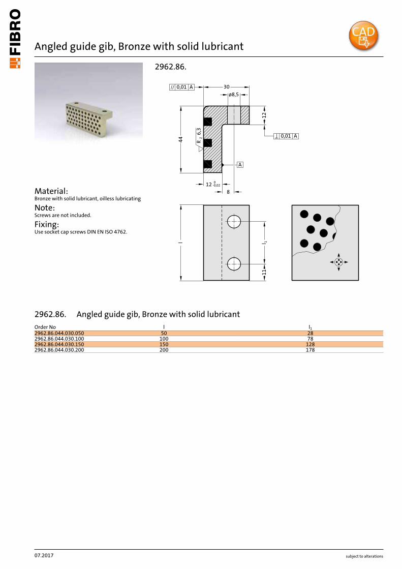
subject to alterations
Angled guide gib, Bronze with solid lubricant
Material: Bronze with solid lubricant, oilless lubricating
Note: Screws are not included.
Fixing: Use socket cap screws DIN EN ISO 4762.
8
ø8,5
l
30
44
12
11
120-0,02
l 1
0,01 A
0,01 A
A
RZ6,3
2962.86.
07.2017
Order No l l12962.86.044.030.050 50 282962.86.044.030.100 100 782962.86.044.030.150 150 1282962.86.044.030.200 200 178
2962.86. Angled guide gib, Bronze with solid lubricant
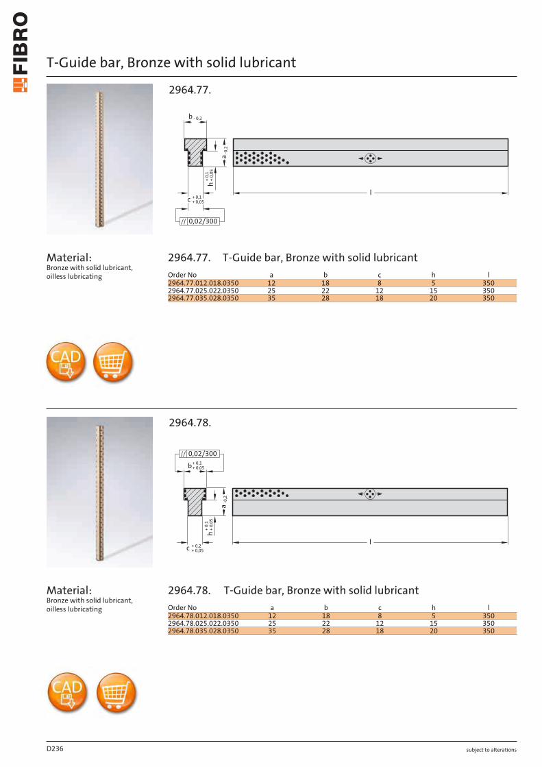
subject to alterations
T-Guide bar, Bronze with solid lubricant
Material: Bronze with solid lubricant, oilless lubricating
Material: Bronze with solid lubricant, oilless lubricating
+ 0
,1+
0,0
5
+ 0,05c + 0,1l
a-0
,2
h
b - 0,2
0,02/300
2964.77.
-0,2
c + 0,2+ 0,05
+ 0,1+ 0,05
l
a
+ 0,
1h
+ 0,
05
b0,02/300
2964.78.
D236
Order No a b c h l2964.77.012.018.0350 12 18 8 5 3502964.77.025.022.0350 25 22 12 15 3502964.77.035.028.0350 35 28 18 20 350
Order No a b c h l2964.78.012.018.0350 12 18 8 5 3502964.78.025.022.0350 25 22 12 15 3502964.78.035.028.0350 35 28 18 20 350
2964.77.
2964.78.
T-Guide bar, Bronze with solid lubricant
T-Guide bar, Bronze with solid lubricant
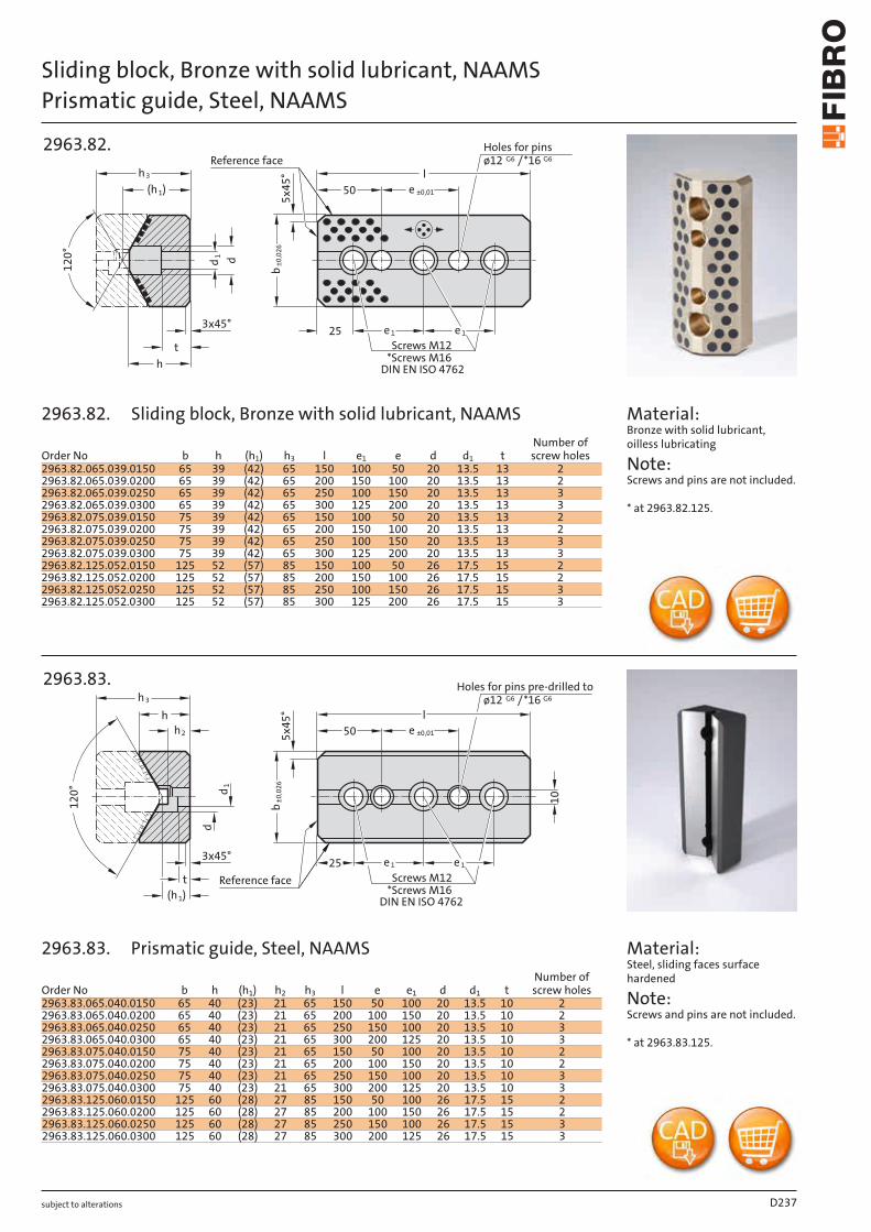
subject to alterations
Sliding block, Bronze with solid lubricant, NAAMSPrismatic guide, Steel, NAAMS
d1
t
h
3x45°25
12
0°
l
50
e 1 e 1
5x
45
°
(h 1)
d
Screws M12
*Screws M16
DIN EN ISO 4762
ø12 G6
Holes for pins
/*16 G6Reference face
h3
e ±0,01
b±
0,0
26
2963.82.
(h 1)
t
h
h2
12
0°
10
l
50
25 e 1e 1
5x
45
°
3x45°
d1
d
ø12 G6
Holes for pins pre-drilled to
/*16 G6
Screws M12
*Screws M16
DIN EN ISO 4762
Reference face
h3
e ±0,01
b±
0,0
26
2963.83.
Material: Bronze with solid lubricant, oilless lubricating
Note: Screws and pins are not included.
* at 2963.82.125.
Material: Steel, sliding faces surface hardened
Note: Screws and pins are not included.
* at 2963.83.125.
D237
Order No b h (h1) h3 l e1 e d d1 tNumber of screw holes
2963.82.065.039.0150 65 39 (42) 65 150 100 50 20 13.5 13 22963.82.065.039.0200 65 39 (42) 65 200 150 100 20 13.5 13 22963.82.065.039.0250 65 39 (42) 65 250 100 150 20 13.5 13 32963.82.065.039.0300 65 39 (42) 65 300 125 200 20 13.5 13 32963.82.075.039.0150 75 39 (42) 65 150 100 50 20 13.5 13 22963.82.075.039.0200 75 39 (42) 65 200 150 100 20 13.5 13 22963.82.075.039.0250 75 39 (42) 65 250 100 150 20 13.5 13 32963.82.075.039.0300 75 39 (42) 65 300 125 200 20 13.5 13 32963.82.125.052.0150 125 52 (57) 85 150 100 50 26 17.5 15 22963.82.125.052.0200 125 52 (57) 85 200 150 100 26 17.5 15 22963.82.125.052.0250 125 52 (57) 85 250 100 150 26 17.5 15 32963.82.125.052.0300 125 52 (57) 85 300 125 200 26 17.5 15 3
Order No b h (h1) h2 h3 l e e1 d d1 tNumber of screw holes
2963.83.065.040.0150 65 40 (23) 21 65 150 50 100 20 13.5 10 22963.83.065.040.0200 65 40 (23) 21 65 200 100 150 20 13.5 10 22963.83.065.040.0250 65 40 (23) 21 65 250 150 100 20 13.5 10 32963.83.065.040.0300 65 40 (23) 21 65 300 200 125 20 13.5 10 32963.83.075.040.0150 75 40 (23) 21 65 150 50 100 20 13.5 10 22963.83.075.040.0200 75 40 (23) 21 65 200 100 150 20 13.5 10 22963.83.075.040.0250 75 40 (23) 21 65 250 150 100 20 13.5 10 32963.83.075.040.0300 75 40 (23) 21 65 300 200 125 20 13.5 10 32963.83.125.060.0150 125 60 (28) 27 85 150 50 100 26 17.5 15 22963.83.125.060.0200 125 60 (28) 27 85 200 100 150 26 17.5 15 22963.83.125.060.0250 125 60 (28) 27 85 250 150 100 26 17.5 15 32963.83.125.060.0300 125 60 (28) 27 85 300 200 125 26 17.5 15 3
2963.82.
2963.83. Prismatic guide, Steel, NAAMS
Sliding block, Bronze with solid lubricant, NAAMS
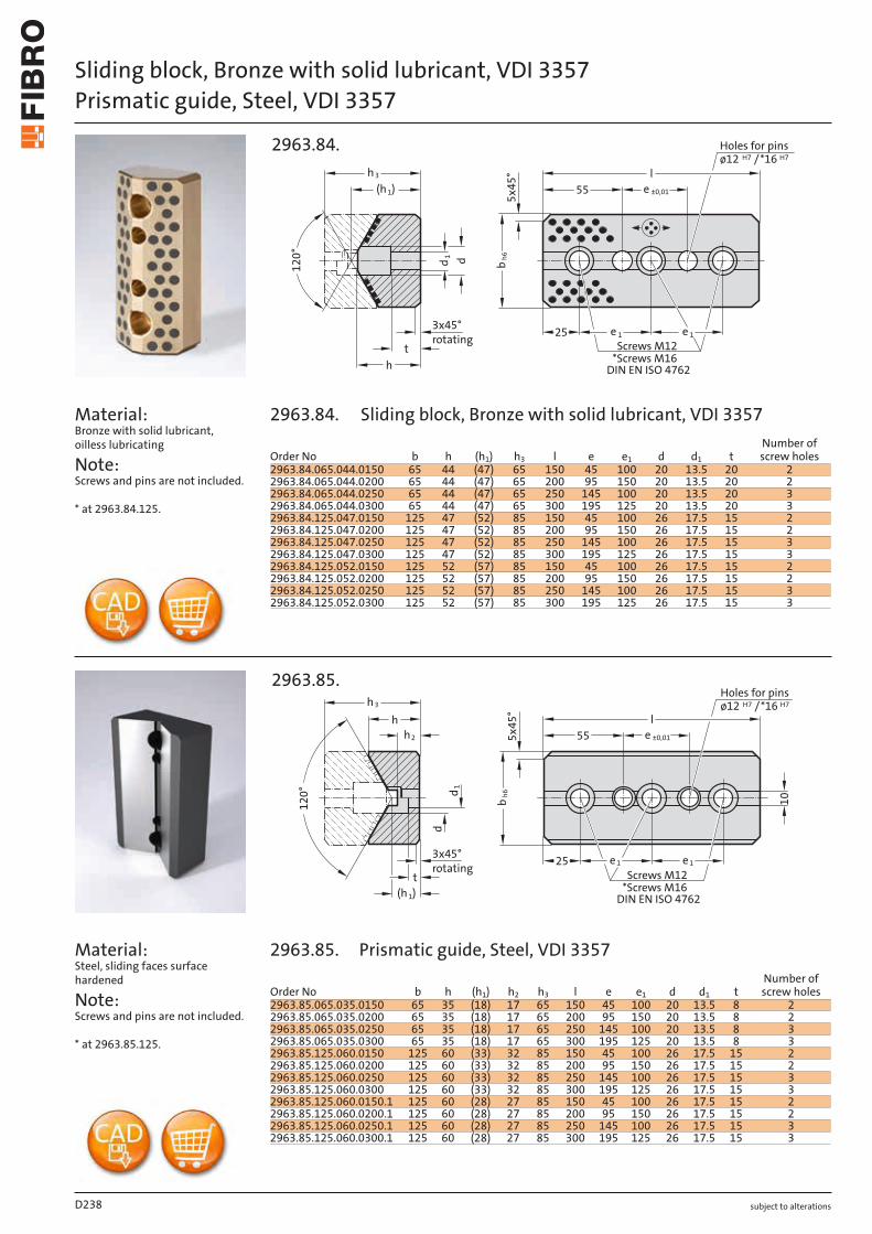
subject to alterations
Sliding block, Bronze with solid lubricant, VDI 3357Prismatic guide, Steel, VDI 3357
Material: Bronze with solid lubricant, oilless lubricating
Note: Screws and pins are not included.
* at 2963.84.125.
Material: Steel, sliding faces surface hardened
Note: Screws and pins are not included.
* at 2963.85.125.
h
t
d1
d
ø12 H7
Holes for pins
25
l
55
5x
45
°
e 1 e 1
3x45°
12
0°
Screws M12
*Screws M16
DIN EN ISO 4762
/*16 H7
(h 1) e ±0,01
bh
6
h3
rotating
2963.84.
d1
Screws M12
*Screws M16
DIN EN ISO 4762
h
d
t
10
e 125 e 1
l
555x
45
°
3x45°
(h 1)
h2
ø12 H7
Holes for pins
/*16 H7
e ±0,01
bh
6
12
0°
h3
rotating
2963.85.
D238
Order No b h (h1) h3 l e e1 d d1 tNumber of screw holes
2963.84.065.044.0150 65 44 (47) 65 150 45 100 20 13.5 20 22963.84.065.044.0200 65 44 (47) 65 200 95 150 20 13.5 20 22963.84.065.044.0250 65 44 (47) 65 250 145 100 20 13.5 20 32963.84.065.044.0300 65 44 (47) 65 300 195 125 20 13.5 20 32963.84.125.047.0150 125 47 (52) 85 150 45 100 26 17.5 15 22963.84.125.047.0200 125 47 (52) 85 200 95 150 26 17.5 15 22963.84.125.047.0250 125 47 (52) 85 250 145 100 26 17.5 15 32963.84.125.047.0300 125 47 (52) 85 300 195 125 26 17.5 15 32963.84.125.052.0150 125 52 (57) 85 150 45 100 26 17.5 15 22963.84.125.052.0200 125 52 (57) 85 200 95 150 26 17.5 15 22963.84.125.052.0250 125 52 (57) 85 250 145 100 26 17.5 15 32963.84.125.052.0300 125 52 (57) 85 300 195 125 26 17.5 15 3
Order No b h (h1) h2 h3 l e e1 d d1 tNumber of screw holes
2963.85.065.035.0150 65 35 (18) 17 65 150 45 100 20 13.5 8 22963.85.065.035.0200 65 35 (18) 17 65 200 95 150 20 13.5 8 22963.85.065.035.0250 65 35 (18) 17 65 250 145 100 20 13.5 8 32963.85.065.035.0300 65 35 (18) 17 65 300 195 125 20 13.5 8 32963.85.125.060.0150 125 60 (33) 32 85 150 45 100 26 17.5 15 22963.85.125.060.0200 125 60 (33) 32 85 200 95 150 26 17.5 15 22963.85.125.060.0250 125 60 (33) 32 85 250 145 100 26 17.5 15 32963.85.125.060.0300 125 60 (33) 32 85 300 195 125 26 17.5 15 32963.85.125.060.0150.1 125 60 (28) 27 85 150 45 100 26 17.5 15 22963.85.125.060.0200.1 125 60 (28) 27 85 200 95 150 26 17.5 15 22963.85.125.060.0250.1 125 60 (28) 27 85 250 145 100 26 17.5 15 32963.85.125.060.0300.1 125 60 (28) 27 85 300 195 125 26 17.5 15 3
2963.84.
2963.85. Prismatic guide, Steel, VDI 3357
Sliding block, Bronze with solid lubricant, VDI 3357
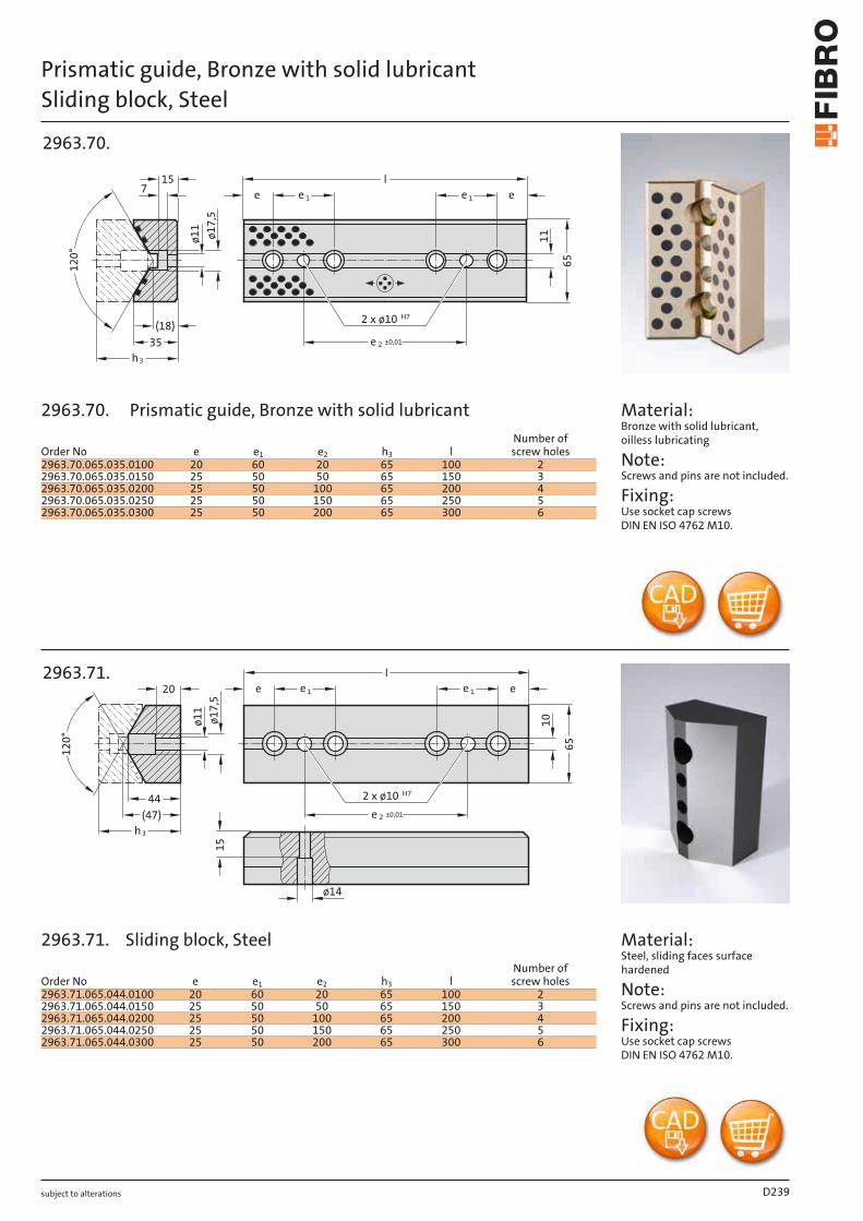
subject to alterations
Prismatic guide, Bronze with solid lubricantSliding block, Steel
2 x ø10 H7
65
l
e 1 e
35
(18)
715
12
0°
ø1
7,5
ø1
1e e 1
11
e 2 ±0,01
h3
2963.70.
ø14
15
65
l
e e 1
(47)
44
ø1
7,5
ø1
1
20
12
0°
e 1 e
10
2 x ø10 H7
e 2 ±0,01
h3
2963.71.
Material: Bronze with solid lubricant, oilless lubricating
Note: Screws and pins are not included.
Fixing: Use socket cap screws DIN EN ISO 4762 M10.
Material: Steel, sliding faces surface hardened
Note: Screws and pins are not included.
Fixing: Use socket cap screws DIN EN ISO 4762 M10.
D239
Order No e e1 e2 h3 lNumber of screw holes
2963.70.065.035.0100 20 60 20 65 100 22963.70.065.035.0150 25 50 50 65 150 32963.70.065.035.0200 25 50 100 65 200 42963.70.065.035.0250 25 50 150 65 250 52963.70.065.035.0300 25 50 200 65 300 6
Order No e e1 e2 h3 lNumber of screw holes
2963.71.065.044.0100 20 60 20 65 100 22963.71.065.044.0150 25 50 50 65 150 32963.71.065.044.0200 25 50 100 65 200 42963.71.065.044.0250 25 50 150 65 250 52963.71.065.044.0300 25 50 200 65 300 6
2963.70.
2963.71. Sliding block, Steel
Prismatic guide, Bronze with solid lubricant
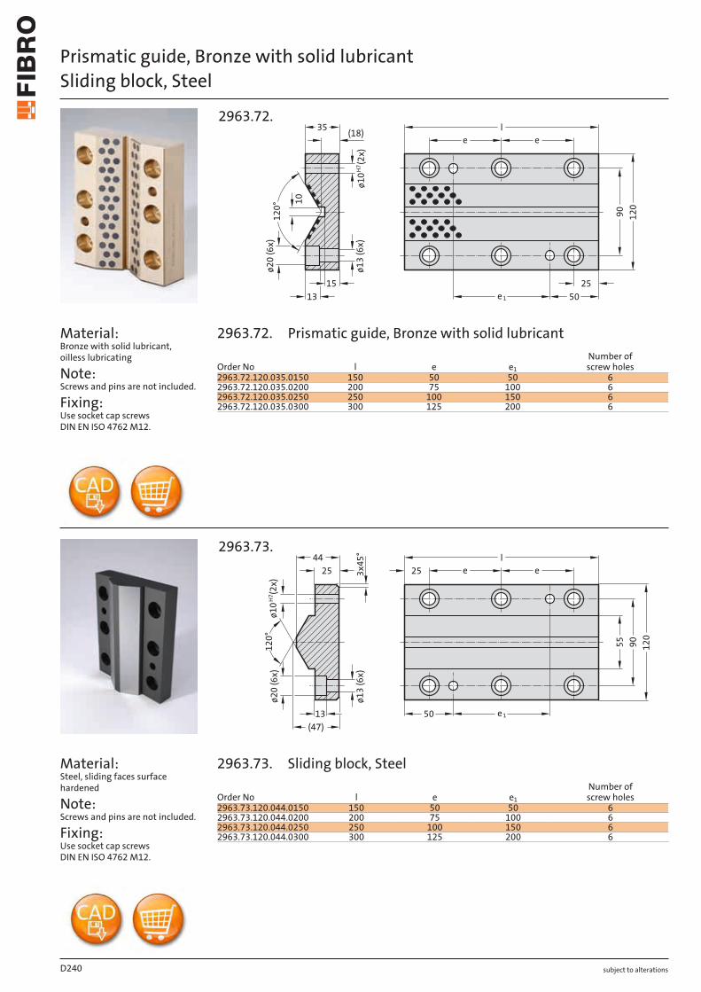
subject to alterations
Prismatic guide, Bronze with solid lubricantSliding block, Steel
Material: Bronze with solid lubricant, oilless lubricating
Note: Screws and pins are not included.
Fixing: Use socket cap screws DIN EN ISO 4762 M12.
Material: Steel, sliding faces surface hardened
Note: Screws and pins are not included.
Fixing: Use socket cap screws DIN EN ISO 4762 M12.
(18)
13
H7
ø1
0
(2
x)
ø2
0 (
6x
)
ø1
3 (
6x
)
12
0
90
e 1 50
25
ee
l
151
20
° 10
35
2963.72.
13
ø2
0 (
6x
)
ø1
3 (
6x
)
(47)
3x
45
°
44
25
12
0°
55
12
0
90
e 150
25 e e
l
ø1
0
(2
x)
H7
2963.73.
D240
Order No l e e1
Number of screw holes
2963.72.120.035.0150 150 50 50 62963.72.120.035.0200 200 75 100 62963.72.120.035.0250 250 100 150 62963.72.120.035.0300 300 125 200 6
Order No l e e1
Number of screw holes
2963.73.120.044.0150 150 50 50 62963.73.120.044.0200 200 75 100 62963.73.120.044.0250 250 100 150 62963.73.120.044.0300 300 125 200 6
2963.72.
2963.73. Sliding block, Steel
Prismatic guide, Bronze with solid lubricant

subject to alterations D241
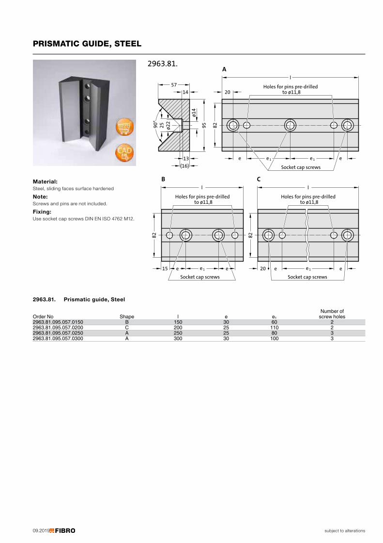
09.2019 subject to alterations
PRISMATIC GUIDE, STEEL
Material: Steel, sliding faces surface hardened
Note: Screws and pins are not included.
Fixing: Use socket cap screws DIN EN ISO 4762 M12.
(16)
82
82
13
14
57
ø1
4
ø2
2
25
90
°
95
ee15
l
20
ee 1e
82
20 e e
2963.81.A
B C
e 1
Socket cap screws
l
Holes for pins pre-drilledto ø11,8
Holes for pins pre-drilledto ø11,8
l
Holes for pins pre-drilledto ø11,8
e 1
Socket cap screws
e 1
Socket cap screws
Number of Order No Shape l e e1 screw holes2963.81.095.057.0150 B 150 30 60 22963.81.095.057.0200 C 200 25 110 22963.81.095.057.0250 A 250 25 80 32963.81.095.057.0300 A 300 30 100 3
2963.81. Prismatic guide, Steel
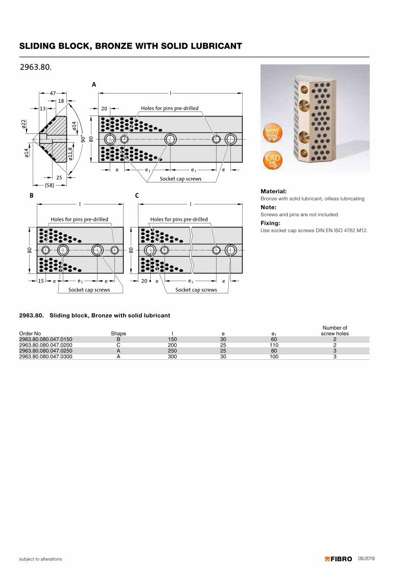
09.2019subject to alterations
SLIDING BLOCK, BRONZE WITH SOLID LUBRICANT
(58)
ø1
4ø
11
,8
13
ø2
2ø
14
l
80
90
°
18
e15
l
20
ee 1
25
47
A
e
80
B
l
80
C
20 e e
2963.80.
Holes for pins pre-drilled
Holes for pins pre-drilled
Holes for pins pre-drilled
e 1 e
Socket cap screws
e 1
ocket cap scrS ews
e 1
Socket cap screws
Material: Bronze with solid lubricant, oilless lubricating
Note: Screws and pins are not included.
Fixing: Use socket cap screws DIN EN ISO 4762 M12.
Number of Order No Shape l e e1 screw holes2963.80.080.047.0150 B 150 30 60 22963.80.080.047.0200 C 200 25 110 22963.80.080.047.0250 A 250 25 80 32963.80.080.047.0300 A 300 30 100 3
2963.80. Sliding block, Bronze with solid lubricant
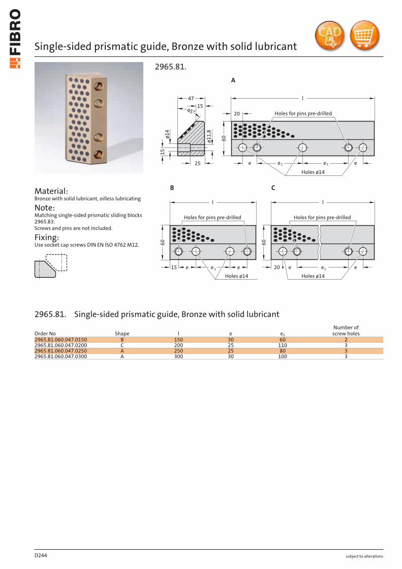
subject to alterations
Single-sided prismatic guide, Bronze with solid lubricant
Material: Bronze with solid lubricant, oilless lubricating
Note: Matching single-sided prismatic sliding blocks 2965.83. Screws and pins are not included.
Fixing: Use socket cap screws DIN EN ISO 4762 M12.
15
45°
ø1
4
Holes for pins pre-drilled
ø1
1,8
15
60
20
ee 1 e 125
15
47
e6
0
Holes ø14
Holes ø14
Holes for pins pre-drilled
Holes for pins pre-drilled
60
Holes ø14
20
2965.81.
A
B C
l
eee
l
1 1
l
ee e
D244
Order No Shape l e e1
Number of screw holes
2965.81.060.047.0150 B 150 30 60 22965.81.060.047.0200 C 200 25 110 32965.81.060.047.0250 A 250 25 80 32965.81.060.047.0300 A 300 30 100 3
2965.81. Single-sided prismatic guide, Bronze with solid lubricant
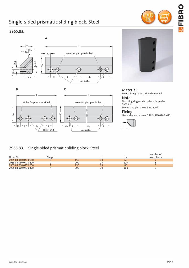
subject to alterations
Single-sided prismatic sliding block, Steel
Holes for pins pre-drilled
15
60
20
ee 1 e 1e
60
Holes ø14
Holes ø14
Holes for pins pre-drilled
15
45°
ø1
4
ø1
1,8
25
15
47
Holes for pins pre-drilled
60
Holes ø14
20
2965.83.
A
B C
l
eee
l
1 e1
l
ee
Material: Steel, sliding faces surface hardened
Note: Matching single-sided prismatic guides 2965.81. Screws and pins are not included.
Fixing: Use socket cap screws DIN EN ISO 4762 M12.
D245
Order No Shape l e e1
Number of screw holes
2965.83.060.047.0150 B 150 30 60 22965.83.060.047.0200 C 200 25 110 32965.83.060.047.0250 A 250 25 80 32965.83.060.047.0300 A 300 30 100 3
2965.83. Single-sided prismatic sliding block, Steel

subject to alterations
Single-sided prismatic guide, Bronze with solid lubricant, CNOMO
Material: Bronze with solid lubricant, oilless lubricating
Note: Matching single-sided prismatic sliding blocks 2965.82.45. Screws and pins are not included.
Fixing: Use socket cap screws DIN EN ISO 4762 M10.
12
3x45°
A
45°
135
25
25
225
125
l
l
gl
h
p
132
5ø
18
ø1
1
B
2965.80.45.
D246
Order No Shape lg h l pNumber of screw holes
2965.80.45.060.045.160 A 60 45 160 50 22965.80.45.060.045.250 B 60 45 250 50 32965.80.45.080.060.160 A 80 60 160 80 22965.80.45.080.060.250 B 80 60 250 80 3
2965.80.45. Single-sided prismatic guide, Bronze with solid lubricant, CNOMO
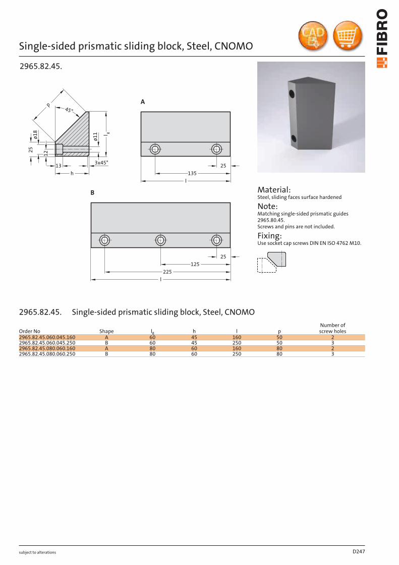
subject to alterations
Single-sided prismatic sliding block, Steel, CNOMO1
2
3x45°
A
45°
135
25
25
225
125
l
l
gl
h
p
13
25
ø1
8
ø1
1
B
2965.82.45.
Material: Steel, sliding faces surface hardened
Note: Matching single-sided prismatic guides 2965.80.45. Screws and pins are not included.
Fixing: Use socket cap screws DIN EN ISO 4762 M10.
D247
Order No Shape lg h l pNumber of screw holes
2965.82.45.060.045.160 A 60 45 160 50 22965.82.45.060.045.250 B 60 45 250 50 32965.82.45.080.060.160 A 80 60 160 80 22965.82.45.080.060.250 B 80 60 250 80 3
2965.82.45. Single-sided prismatic sliding block, Steel, CNOMO
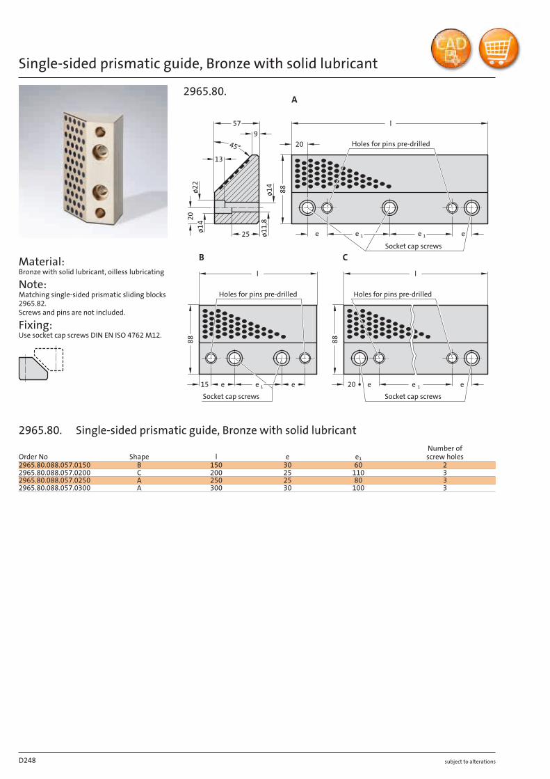
subject to alterations
Single-sided prismatic guide, Bronze with solid lubricant
Material: Bronze with solid lubricant, oilless lubricating
Note: Matching single-sided prismatic sliding blocks 2965.82. Screws and pins are not included.
Fixing: Use socket cap screws DIN EN ISO 4762 M12.
20
13
Holes for pins pre-drilled45°
57
9
88
20
e
1
e25
ø1
4ø
11
,8
ø2
2ø
14
2015 e e
Socket cap screws
88
Holes for pins pre-drilled
88
Holes for pins pre-drilled
1
Socket cap screws
e 1
Socket cap screws
l
1 e
2965.80.A
B C
ee e
l
e
l
1
D248
Order No Shape l e e1
Number of screw holes
2965.80.088.057.0150 B 150 30 60 22965.80.088.057.0200 C 200 25 110 32965.80.088.057.0250 A 250 25 80 32965.80.088.057.0300 A 300 30 100 3
2965.80. Single-sided prismatic guide, Bronze with solid lubricant
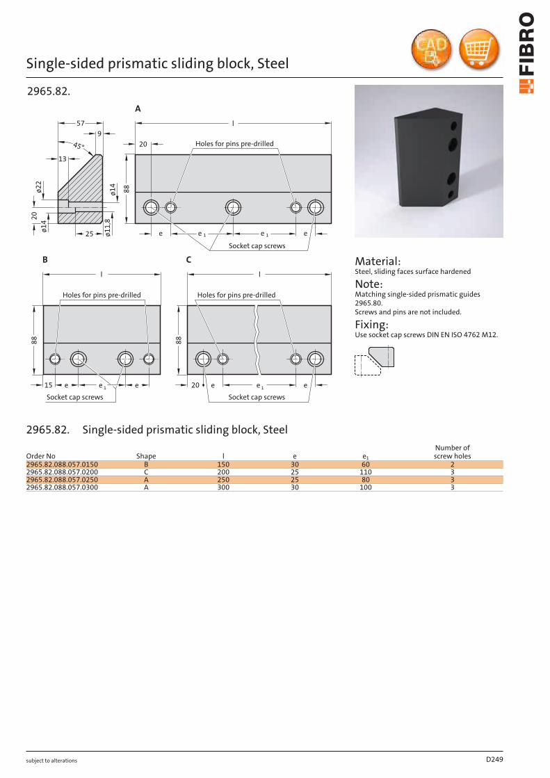
subject to alterations
Single-sided prismatic sliding block, Steel
20
Holes for pins pre-drilled
88
20
e1e
88
Holes for pins pre-drilled
20
13
45°
57
9
25
ø1
4ø
11
,8
ø2
2ø
14
88
Holes for pins pre-drilled
15 e e
Socket cap screws
e 1
Socket cap screws
e 1
Socket cap screws
e
l
2965.82.
A
B C
ee
l
e1
l
Material: Steel, sliding faces surface hardened
Note: Matching single-sided prismatic guides 2965.80. Screws and pins are not included.
Fixing: Use socket cap screws DIN EN ISO 4762 M12.
D249
Order No Shape l e e1
Number of screw holes
2965.82.088.057.0150 B 150 30 60 22965.82.088.057.0200 C 200 25 110 32965.82.088.057.0250 A 250 25 80 32965.82.088.057.0300 A 300 30 100 3
2965.82. Single-sided prismatic sliding block, Steel
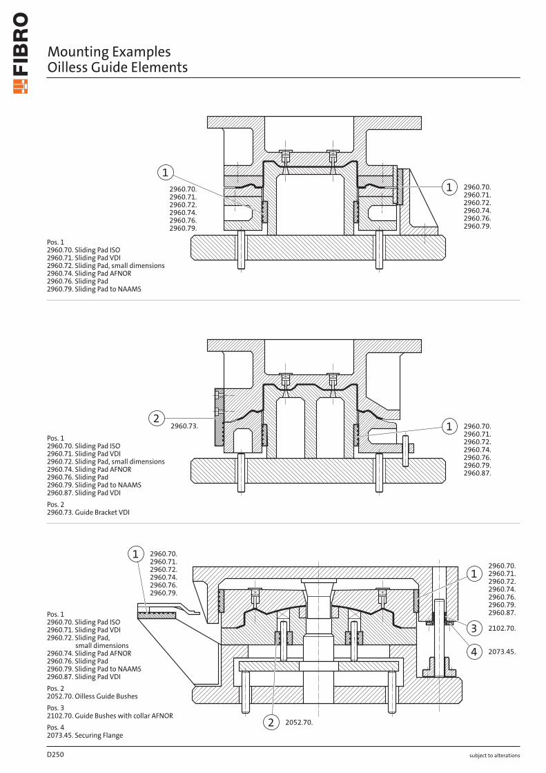
˜ °˛˝˙.ˇ˜.
˘
2960.72.
2960.71.
2960.70.
2960.74.
2961.70.
˙ 2960.90.
ˇ2102.70.
˝ 2960.72.
2961.70.
2960.92.
° 2960.91.
1
2960.70.
˜°˛˝.ˆ˜.
˜°˛˝.ˆ˜.˜ °˛˝°.ˆˇ.°˛˝°.ˆ˘. ˜ °˛˝°.ˆˇ.
°˛˝°.ˆ˘.° °˛˝˜.ˆˇ.
° °˛˝˜.ˆˇ.
˘ °˛˝˜.ˆ˛. ˘ 2961.74.
44°˛˝ˇ.ˆ°.°˛˝˜.ˆˇ.
°˛˝ˇ.ˆ°.°˛˝˜.ˆˇ.
2961.81.
2961.78.2961.74.
°˛˝˜.ˆ˛.2961.81.
2961.75.
subject to alterations
Mounting Examples Oilless Guide Elements
Pos. 12960.70. Sliding Pad ISOPos. 22960.91. Overrun Cam to VDIPos. 32960.90. Overrun cam to VDI2960.92. Overrun cam to VDIPos. 42102.70. Guide Bushe with collar
AFNORPos. 52073.45. Securing FlangePos. 62960.70. Sliding Pad ISO2960.71. Sliding Pad VDI2960.72. Sliding Pad,
small dimensions2960.74. Sliding Pad AFNOR2961.70. Flat Guide BarPos. 72960.72. Sliding Pad, small dimensions2961.70. Flat Guide Bar
Pos. 12962.70. Angled Guide Gib2962.73. Angled Guide GibPos. 22960.72. Sliding Pad, small dimensions2961.70. Flat Guide Bar2961.75.Pos. 32961.74. Retaining Plate to VDI2961.79.2961.81.Pos. 42960.72. Sliding Pad, small dimensions2961.70. Flat Guide Bar
2960.79.
1
1
2960.72.2960.71.2960.70.
2960.72.2960.71.2960.70.
2960.74.2960.76.2960.79.
2960.74.2960.76.
2
2960.72.2960.71.
1 2960.70.2960.73.
2960.74.2960.76.2960.79.2960.87.
2960.72.2960.71.2960.70.
1
1
2960.72.2960.71.2960.70.
2 2052.70.
2960.74.2960.76.2960.79.
2960.74.2960.76.2960.79.
3 2102.70.
4 2073.45.
2960.87.
subject to alterations
Mounting Examples Oilless Guide Elements
Pos. 1 2960.70. Sliding Pad ISO 2960.71. Sliding Pad VDI 2960.72. Sliding Pad, small dimensions 2960.74. Sliding Pad AFNOR 2960.76. Sliding Pad 2960.79. Sliding Pad to NAAMS
Pos. 1 2960.70. Sliding Pad ISO 2960.71. Sliding Pad VDI 2960.72. Sliding Pad, small dimensions 2960.74. Sliding Pad AFNOR 2960.76. Sliding Pad 2960.79. Sliding Pad to NAAMS 2960.87. Sliding Pad VDI
Pos. 2 2960.73. Guide Bracket VDI
Pos. 1 2960.70. Sliding Pad ISO 2960.71. Sliding Pad VDI 2960.72. Sliding Pad,
small dimensions 2960.74. Sliding Pad AFNOR 2960.76. Sliding Pad 2960.79. Sliding Pad to NAAMS 2960.87. Sliding Pad VDI
Pos. 2 2052.70. Oilless Guide Bushes
Pos. 3 2102.70. Guide Bushes with collar AFNOR
Pos. 4 2073.45. Securing Flange
D250
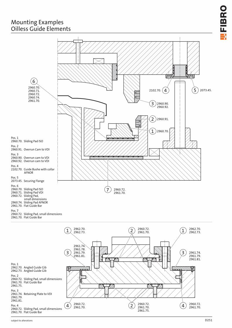
˜°˛˝.ˆ°.
ˇˇ
˜°˛˝.ˆ˜.˜°˛˝.ˆˇ.˜°˛˝.ˆ˝.
˜°˛˝.ˆ˜.˜°˛˝.ˆˇ.˜°˛˝.ˆ˝.
˜°˛˝.ˆ˘.˜°˛˝.ˆ˛.˜°˛˝.ˆ°.
˜°˛˝.ˆ˘.˜°˛˝.ˆ˛.
˜
˜°˛˝.ˆ˜.˜°˛˝.ˆˇ.˜°˛˝.ˆ˝.ˇ˜°˛˝.ˆ˘.
2960.74.˜°˛˝.ˆ˛.˜°˛˝.ˆ°.2960.87.
˜°˛˝.ˆ˜.˜°˛˝.ˆˇ.˜°˛˝.ˆ˝.
ˇ
ˇ˜°˛˝.ˆ˜.˜°˛˝.ˆˇ.˜°˛˝.ˆ˝.
˜ ˜˝˘˜.ˆ˝.
2960.74.˜°˛˝.ˆ˛.˜°˛˝.ˆ°.
2960.74.˜°˛˝.ˆ˛.˜°˛˝.ˆ°.
˜ˇ˝˜.ˆ˝.3
2073.45.4
2960.87.
subject to alterations
Mounting Examples Oilless Guide Elements
Pos. 12960.70. Sliding Pad ISO2960.71. Sliding Pad VDI2960.72. Sliding Pad, small dimensions2960.74. Sliding Pad AFNOR2960.76. Sliding Pad2960.79. Sliding Pad to NAAMS
Pos. 12960.70. Sliding Pad ISO2960.71. Sliding Pad VDI2960.72. Sliding Pad, small dimensions2960.74. Sliding Pad AFNOR2960.76. Sliding Pad2960.79. Sliding Pad to NAAMS2960.87. Sliding Pad VDIPos. 22960.73. Guide Bracket VDI
Pos. 12960.70. Sliding Pad ISO2960.71. Sliding Pad VDI2960.72. Sliding Pad,
small dimensions2960.74. Sliding Pad AFNOR2960.76. Sliding Pad2960.79. Sliding Pad to NAAMS2960.87. Sliding Pad VDIPos. 22052.70. Oilless Guide BushesPos. 32102.70. Guide Bushes with collar AFNORPos. 42073.45. Securing Flange
5
2073.45.
6
2960.72.
2960.71.
2960.70.
2960.74.
2961.70.
3
2960.90.
4
2102.70.
7
2960.72.
2961.70.
2960.92.
2
2960.91.
1
2960.70.
2960.72.
2960.72.1
2962.70.2962.73. 1
2962.70.2962.73.2 2961.70.
2 2961.70.
3 2961.79. 3 2961.74.
442960.72.2961.70.
2960.72.2961.70.
2961.81.
2961.78.2961.74.
2961.79.2961.81.
2961.75.
subject to alterations
Mounting Examples Oilless Guide Elements
Pos. 1 2960.70. Sliding Pad ISO
Pos. 2 2960.91. Overrun Cam to VDI
Pos. 3 2960.90. Overrun cam to VDI 2960.92. Overrun cam to VDI
Pos. 4 2102.70. Guide Bushe with collar
AFNOR
Pos. 5 2073.45. Securing Flange
Pos. 6 2960.70. Sliding Pad ISO 2960.71. Sliding Pad VDI 2960.72. Sliding Pad,
small dimensions 2960.74. Sliding Pad AFNOR 2961.70. Flat Guide Bar
Pos. 7 2960.72. Sliding Pad, small dimensions 2961.70. Flat Guide Bar
Pos. 1 2962.70. Angled Guide Gib 2962.73. Angled Guide Gib
Pos. 2 2960.72. Sliding Pad, small dimensions 2961.70. Flat Guide Bar 2961.75.
Pos. 3 2961.74. Retaining Plate to VDI 2961.79. 2961.81.
Pos. 4 2960.72. Sliding Pad, small dimensions 2961.70. Flat Guide Bar
D251
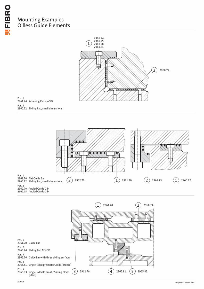
˜°˛˝.ˆˇ.˜°˛˝.˘ˆ.˜˜°˛˝.ˆ˝.ˇ
4 52962.75.3 2963.81. 2963.80.
subject to alterations
Mounting Examples Oilless Guide Elements
Pos. 12960.70. Sliding Pad ISOPos. 22960.71. Sliding Pad VDI2960.87.Pos. 32962.75. Guide Bar with two sliding surfacesPos. 42963.81. Prismatic GuidePos. 52963.80. Sliding Block
2 2960.72.
2961.74.2961.75.2961.78.2961.81.
1
2961.70.1 2960.72.12 2962.73.2 2962.70.
4 5
22961.70.1
2962.76.3 2965.81. 2965.83.
2960.74.
subject to alterations
Mounting ExamplesOilless Guide Elements
Pos. 1 2961.74. Retaining Plate to VDI
Pos. 2 2960.72. Sliding Pad, small dimensions
Pos. 1 2961.70. Flat Guide Bar 2960.72. Sliding Pad, small dimensions
Pos. 2 2962.70. Angled Guide Gib 2962.73. Angled Guide Gib
Pos. 1 2961.70. Guide Bar
Pos. 2 2960.74. Sliding Pad AFNOR
Pos. 3 2962.76. Guide Bar with three sliding surfaces
Pos. 4 2965.81. Single-sided prismatic Guide (Bronze)
Pos. 5 2965.83. Single-sided Prismatic Sliding Block
(Steel)
D252
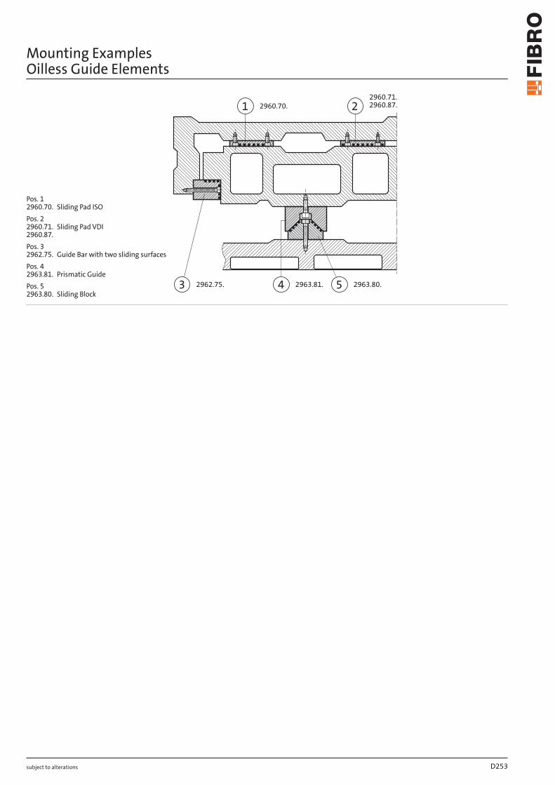
˜°˛˝.ˆ˜.˜
˜°˛ˇ.ˆ˘.2961.75.2961.78.2961.81.
ˇ
˜°˛˝.ˆˇ.˝ ˜°˛ˇ.ˆ˜.˝˜°˛˜.ˆ˘.˜˜°˛˜.ˆˇ.˜
˜ °
˛2961.70.ˆ
˛˝˙˛.˘˙.3 2965.81. 2965.83.
2960.74.
subject to alterations
Mounting ExamplesOilless Guide Elements
Pos. 12961.74. Retaining Plate to VDIPos. 22960.72. Sliding Pad, small dimensions
Pos. 12961.70. Flat Guide Bar2960.72. Sliding Pad, small dimensionsPos. 22962.70. Angled Guide Gib2962.73. Angled Guide Gib
Pos. 12961.70. Guide BarPos. 22960.74. Sliding Pad AFNORPos. 32962.76. Guide Bar with three sliding surfacesPos. 42965.81. Single-sided prismatic Guide (Bronze)Pos. 52965.83. Single-sided Prismatic Sliding Block
(Steel)
2960.71.
2 2960.87.1 2960.70.
3 2962.75. 4 2963.81. 5 2963.80.
subject to alterations
Mounting Examples Oilless Guide Elements
Pos. 1 2960.70. Sliding Pad ISO
Pos. 2 2960.71. Sliding Pad VDI 2960.87.
Pos. 3 2962.75. Guide Bar with two sliding surfaces
Pos. 4 2963.81. Prismatic Guide
Pos. 5 2963.80. Sliding Block
D253
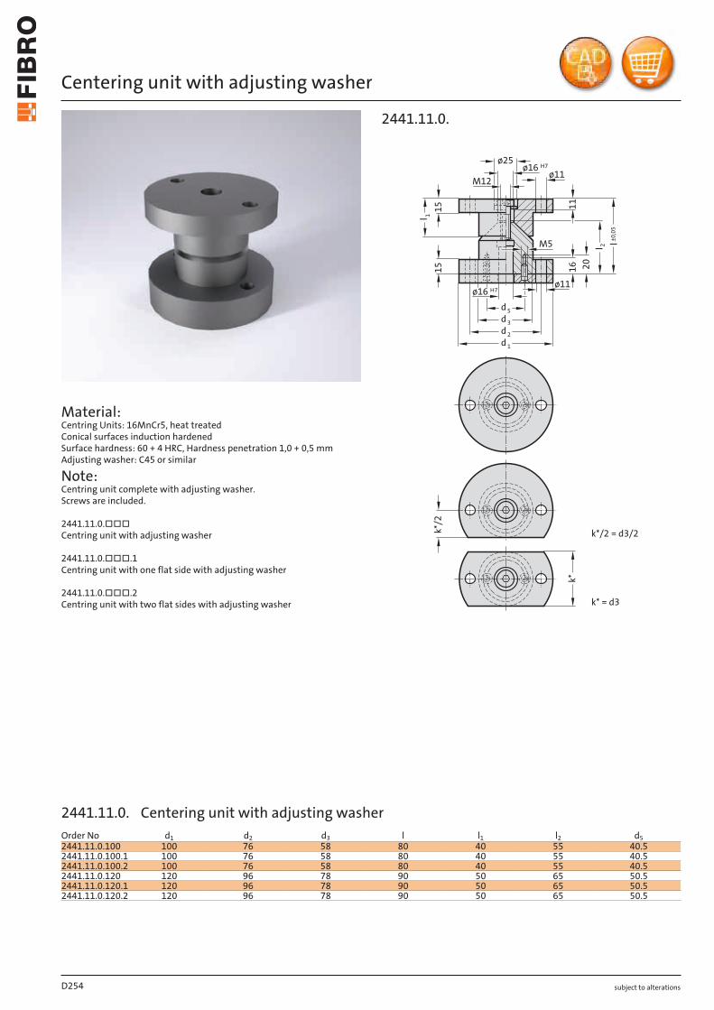
subject to alterations
Centering unit with adjusting washer
ø16
ø25
20
l 2
l±0
,05
11
16
M5
l 1
15
15
H7
ø16 H7
ø11M12
ø11
d3
d1
d2
d5
k*/
2
k*
k* = d3
k*/2 = d3/2
2441.11.0.
D254
Order No d1 d2 d3 l l1 l2 d52441.11.0.100 100 76 58 80 40 55 40.52441.11.0.100.1 100 76 58 80 40 55 40.52441.11.0.100.2 100 76 58 80 40 55 40.52441.11.0.120 120 96 78 90 50 65 50.52441.11.0.120.1 120 96 78 90 50 65 50.52441.11.0.120.2 120 96 78 90 50 65 50.5
Material: Centring Units: 16MnCr5, heat treated Conical surfaces induction hardened Surface hardness: 60 + 4 HRC, Hardness penetration 1,0 + 0,5 mm Adjusting washer: C45 or similar
Note: Centring unit complete with adjusting washer. Screws are included.
2441.11.0.□□□ Centring unit with adjusting washer
2441.11.0.□□□.1 Centring unit with one flat side with adjusting washer
2441.11.0.□□□.2 Centring unit with two flat sides with adjusting washer
2441.11.0. Centering unit with adjusting washer
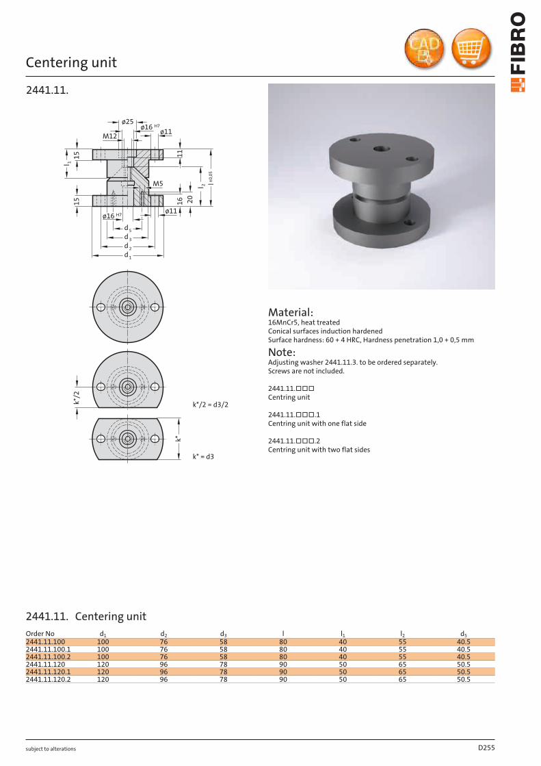
subject to alterations
Centering unit1
51
5 20
M51
11
6
ø16 H7ø11
ø16 H7ø25
k*/
2
k*
k* = d3
k*/2 = d3/2
ø11M12
d 3
d 1
d 2
d 5
l 2
l±0
,05
l 1
2441.11.
Material: 16MnCr5, heat treated Conical surfaces induction hardened Surface hardness: 60 + 4 HRC, Hardness penetration 1,0 + 0,5 mm
Note: Adjusting washer 2441.11.3. to be ordered separately. Screws are not included.
2441.11.□□□ Centring unit
2441.11.□□□.1 Centring unit with one flat side
2441.11.□□□.2 Centring unit with two flat sides
D255
Order No d1 d2 d3 l l1 l2 d52441.11.100 100 76 58 80 40 55 40.52441.11.100.1 100 76 58 80 40 55 40.52441.11.100.2 100 76 58 80 40 55 40.52441.11.120 120 96 78 90 50 65 50.52441.11.120.1 120 96 78 90 50 65 50.52441.11.120.2 120 96 78 90 50 65 50.5
2441.11. Centering unit
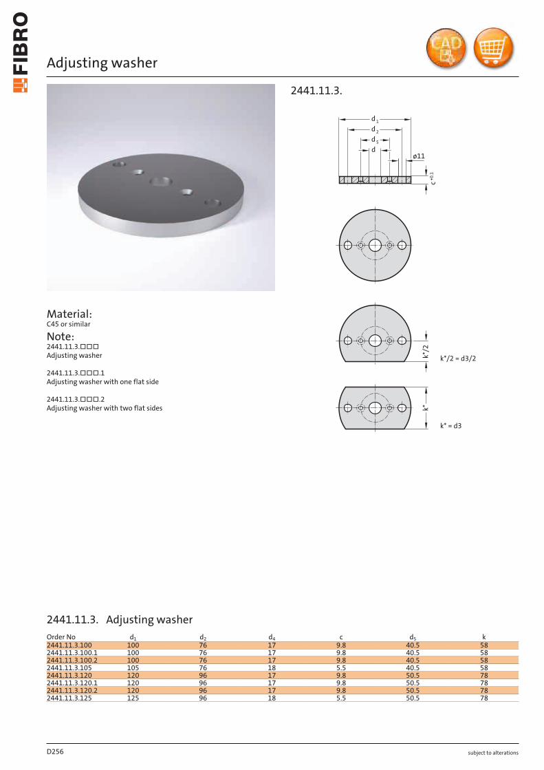
subject to alterations
Adjusting washer
Material: C45 or similar
Note: 2441.11.3.□□□ Adjusting washer
2441.11.3.□□□.1 Adjusting washer with one flat side
2441.11.3.□□□.2 Adjusting washer with two flat sides
d 5
d 1
d 2
+0
.1
dø11
k*/
2k
*k* = d3
k*/2 = d3/2
c
2441.11.3.
D256
Order No d1 d2 d4 c d5 k2441.11.3.100 100 76 17 9.8 40.5 582441.11.3.100.1 100 76 17 9.8 40.5 582441.11.3.100.2 100 76 17 9.8 40.5 582441.11.3.105 105 76 18 5.5 40.5 582441.11.3.120 120 96 17 9.8 50.5 782441.11.3.120.1 120 96 17 9.8 50.5 782441.11.3.120.2 120 96 17 9.8 50.5 782441.11.3.125 125 96 18 5.5 50.5 78
2441.11.3. Adjusting washer

subject to alterations
Centring unit, CNOMO
ø18,5
120°(3x)
3d2d
d5
M10ø10 G6(2x) ø13 H13 (3x)
d2
d6
d5
0,5h1
h3
0,5
d1
ø11
ø18
ø13 H13ø10(2x) (3x)
G6
h2
22
22
4d
l(±0,25)
15
2441.13.45.
Material: X153CrMoV12 (1.2379), hardened 58 ± 2 HRC
Note: Order No for centring unit to CNOMO with adjusting washer: 2441.13.0.45. Screws and pins are not included.
D257
Order No d1 d2 d3 d4 d5 d6 h1 h2 h3 l2441.13.45.040 40 90 69 45 50 67 36 61 61 (86)2441.13.45.060 60 110 89 65 70 89 46 61 61 (86)
2441.13.45. Centring unit, CNOMO
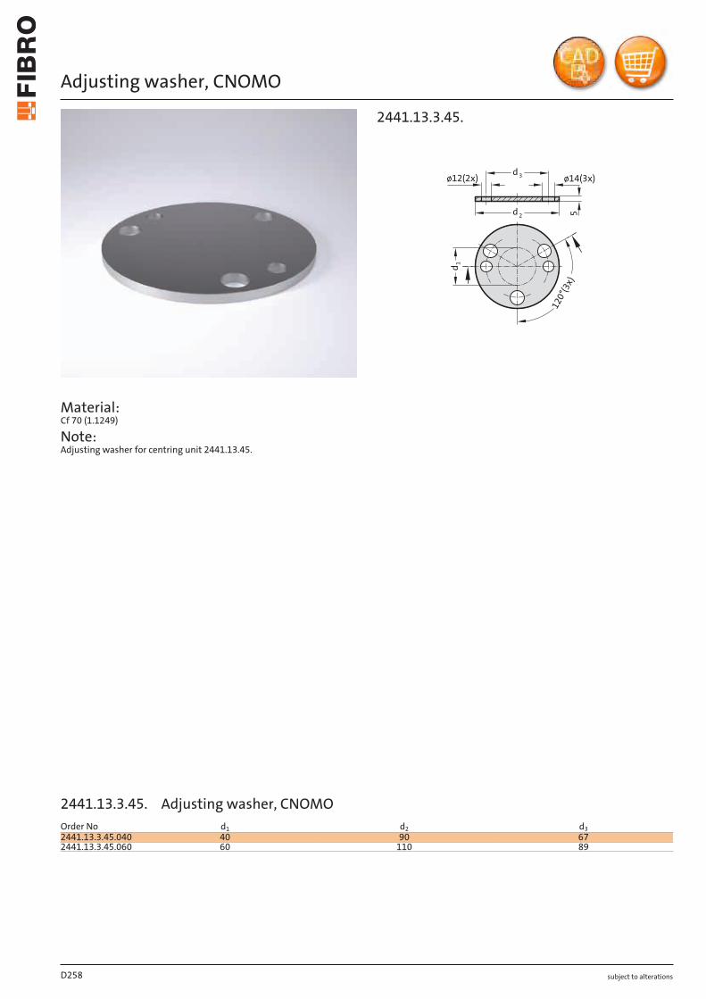
subject to alterations
Adjusting washer, CNOMO
Material: Cf 70 (1.1249)
Note: Adjusting washer for centring unit 2441.13.45.
5
1
2
0
°
(
3
x
)
d
1
d
2
d
3
ø14(3x)
ø12(2x)
2441.13.3.45.
D258
Order No d1 d2 d32441.13.3.45.040 40 90 672441.13.3.45.060 60 110 89
2441.13.3.45. Adjusting washer, CNOMO
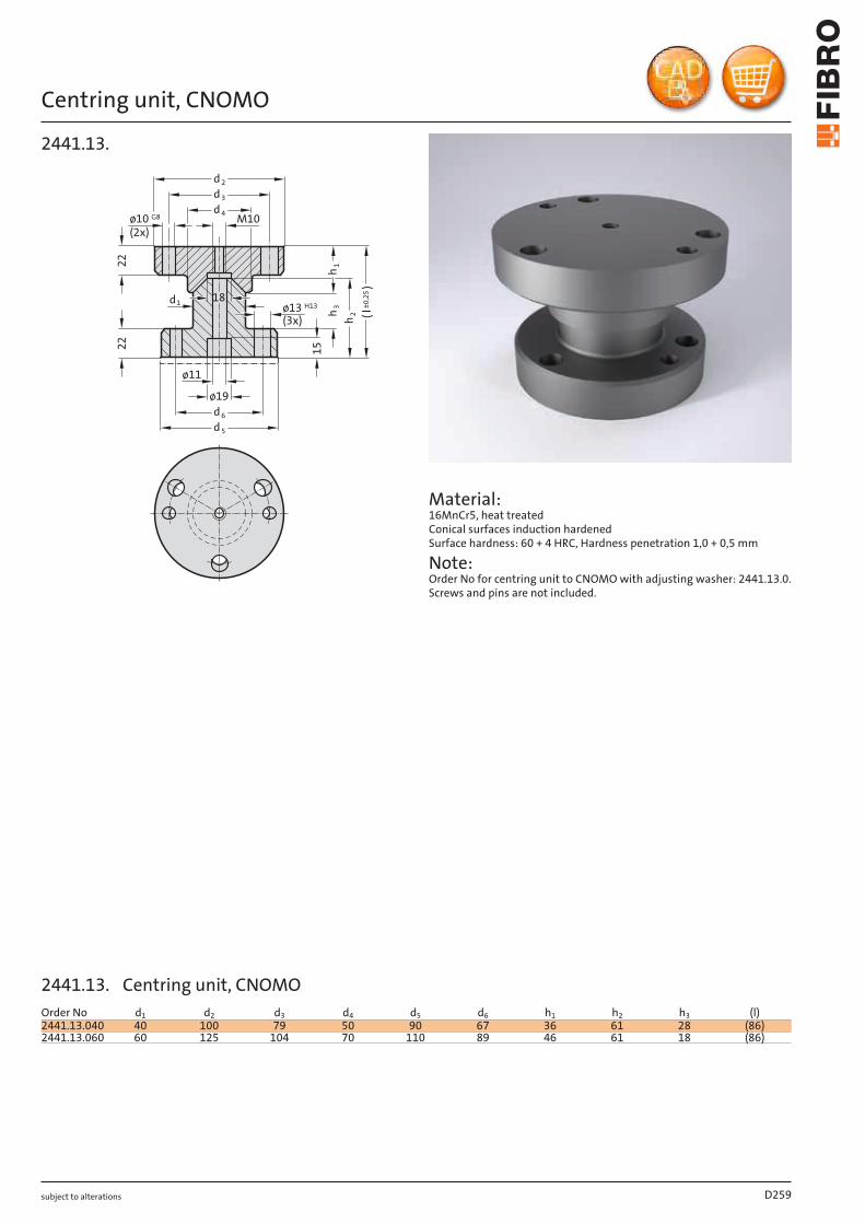
subject to alterations
Centring unit, CNOMO
ø10 G8
(2x)
22
22
15
ø19
M10
d2
d3
d4
d6
d5
ø11
h3
h1
h2 l(±0,25)
d 18ø13 H13
(3x)
1
2441.13.
Material: 16MnCr5, heat treated Conical surfaces induction hardened Surface hardness: 60 + 4 HRC, Hardness penetration 1,0 + 0,5 mm
Note: Order No for centring unit to CNOMO with adjusting washer: 2441.13.0. Screws and pins are not included.
D259
Order No d1 d2 d3 d4 d5 d6 h1 h2 h3 (l)2441.13.040 40 100 79 50 90 67 36 61 28 (86)2441.13.060 60 125 104 70 110 89 46 61 18 (86)
2441.13. Centring unit, CNOMO

subject to alterations
Adjusting washer, CNOMO
Material: 100 Cr 6
Note: Adjusting washer for centring unit 2441.13.
3x
12
0°
d 2
d 3
5
ø12 (2x) ø15 (3x)
d1
2441.13.3.
D260
Order No d1 d2 d32441.13.3.040 40 90 672441.13.3.060 60 110 89
2441.13.3. Adjusting washer, CNOMO
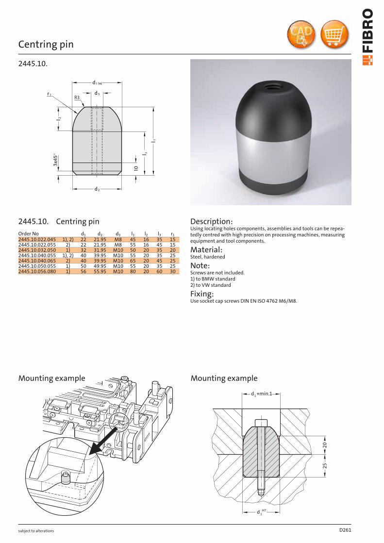
subject to alterations
Centring pin
3
R3
2445.10.
Description: Using locating holes components, assemblies and tools can be repea-tedly centred with high precision on processing machines, measuring equipment and tool components.
Material: Steel, hardened
Note: Screws are not included. 1) to BMW standard 2) to VW standard
Fixing: Use socket cap screws DIN EN ISO 4762 M6/M8.
20
+min.1
1d H7
1d
25
Mounting example Mounting example
D261
Order No d1 d2 d3 l1 l2 l3 r12445.10.022.045 1), 2) 22 21.95 M8 45 16 35 152445.10.022.055 2) 22 21.95 M8 55 16 45 152445.10.032.050 1) 32 31.95 M10 50 20 35 202445.10.040.055 1), 2) 40 39.95 M10 55 20 35 252445.10.040.065 2) 40 39.95 M10 65 20 45 252445.10.050.055 1) 50 49.95 M10 55 20 35 252445.10.056.080 1) 56 55.95 M10 80 20 60 30
2445.10. Centring pin
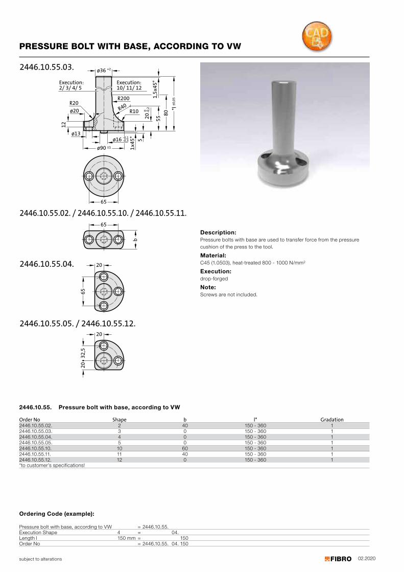
02.2020subject to alterations
Ordering Code (example):
Pressure bolt with base, according to VW = 2446.10.55.Execution Shape 4 = 04.Length l 150 mm = 150Order No = 2446.10.55. 04. 150
PRESSURE BOLT WITH BASE, ACCORDING TO VW
Description: Pressure bolts with base are used to transfer force from the pressure cushion of the press to the tool.
Material: C45 (1.0503), heat-treated 800 - 1000 N/mm2
Execution: drop-forged
Note: Screws are not included.
2446.10.55. Pressure bolt with base, according to VW
Order No Shape b l* Gradation2446.10.55.02. 2 40 150 - 360 12446.10.55.03. 3 0 150 - 360 12446.10.55.04. 4 0 150 - 360 12446.10.55.05. 5 0 150 - 360 12446.10.55.10. 10 60 150 - 360 12446.10.55.11. 11 40 150 - 360 1
12 0 150 - 360 1 2446.10.55.12. *to customer’s specifications!
b
ø36 +2
12
ø20
ø16 -0,1-0,3
ø90 ±1
ø13
201,
5x45
°
*l±0
,05
1x45
° 50 -0
,2
2446.10.55.03.
R20
5580
R40R200
R10
32,5
65
202446.10.55.04.
2446.10.55.05. / 2446.10.55.12.
65
2446.10.55.02. / 2446.10.55.10. / 2446.10.55.11.65
20
20Execution:10/ 11/ 12
Execution:2/ 3/ 4/ 5
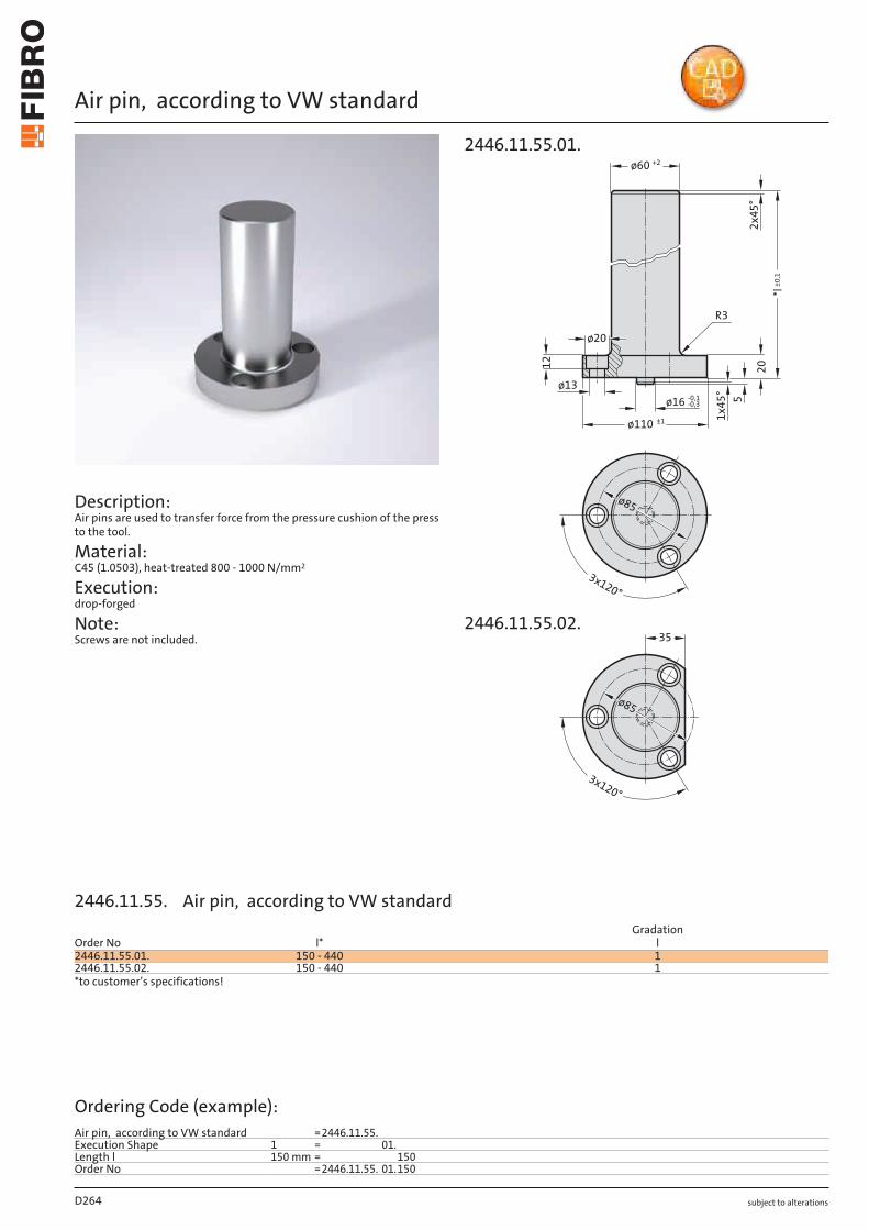
subject to alterations
Air pin, according to VW standard
Description: Air pins are used to transfer force from the pressure cushion of the press to the tool.
Material: C45 (1.0503), heat-treated 800 - 1000 N/mm2
Execution: drop-forged
Note: Screws are not included.
2012
ø60 +2
ø110 ±1
ø20
ø13
ø16 -0,1-0,3
*l±
0,1
2x
45
°
1x
45
°
5
R3
35
3x120°
ø85
3x120°
ø85
2446.11.55.01.
2446.11.55.02.
D264
Order No l*Gradation
l2446.11.55.01. 150 - 440 12446.11.55.02. 150 - 440 1*to customer’s specifications!
Ordering Code (example):Air pin, according to VW standard =2446.11.55.Execution Shape 1 = 01.Length l 150 mm = 150Order No =2446.11.55. 01.150
2446.11.55. Air pin, according to VW standard
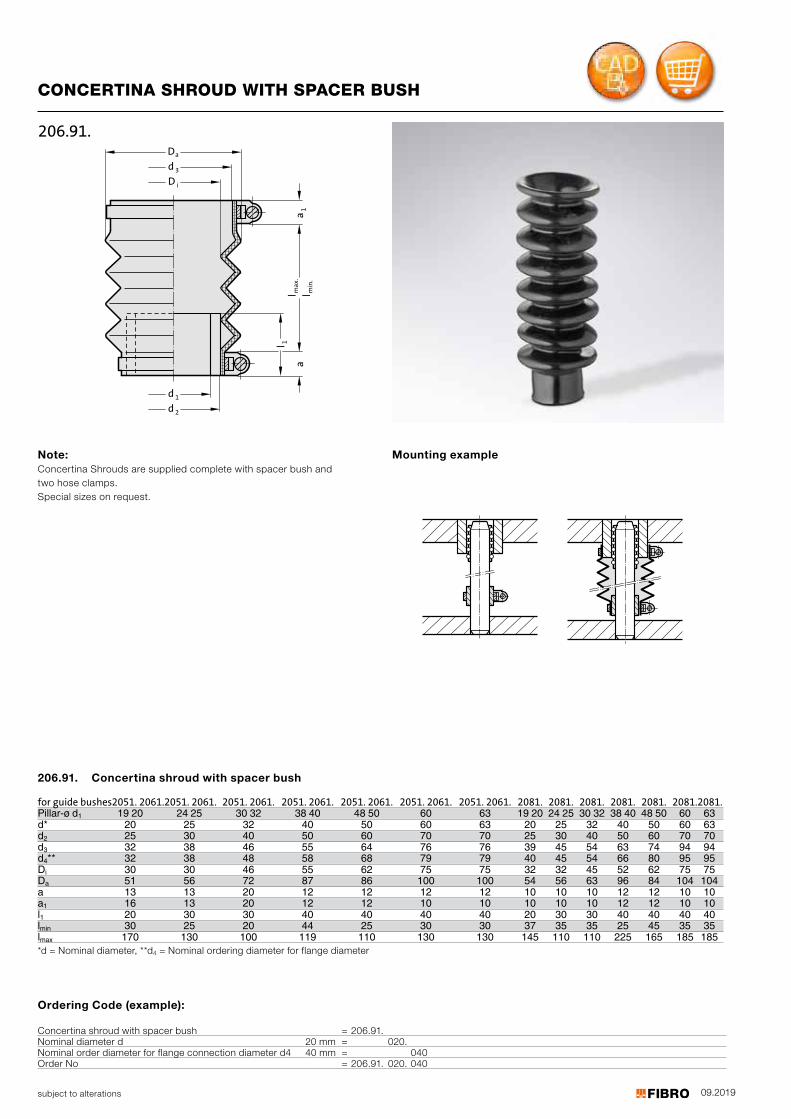
09.2019
1l
max.
a1
a
i
3d
aD
D
2d
1d
l min.
l
206.91.
subject to alterations
Ordering Code (example):
Concertina shroud with spacer bush = 206.91.Nominal diameter d 20 mm = 020.Nominal order diameter for flange connection diameter d4 40 mm = 040Order No = 206.91. 020. 040
CONCERTINA SHROUD WITH SPACER BUSH
Note: Concertina Shrouds are supplied complete with spacer bush and two hose clamps. Special sizes on request.
Mounting example
for guide bushes 2051. 2061. 2051. 2061. 2051. 2061. 2051. 2061. 2051. 2061. 2051. 2061. 2051. 2061. 2081. 2081. 2081. 2081. 2081. 2081. 2081.Pillar-ø d1 19 20 24 25 30 32 38 40 48 50 60 63 19 20 24 25 30 32 38 40 48 50 60 63d* 20 25 32 40 50 60 63 20 25 32 40 50 60 63 d2 25 30 40 50 60 70 70 25 30 40 50 60 70 70 d3 32 38 46 55 64 76 76 39 45 54 63 74 94 94 d4** 32 38 48 58 68 79 79 40 45 54 66 80 95 95 DiDa
30 30 46 55 62 75 75 32 32 45 52 62 75 75 51 56 72 87 86 100 100 54 56 63 96 84 104 104
a 13 13 20 12 12 12 12 10 10 10 12 12 10 10 a1 16 13 20 12 12 10 10 10 10 10 12 12 10 10 l1 20 30 30 40 40 40 40 20 30 30 40 40 40 40 lmin 30 25 20 44 25 30 30 37 35 35 25 45 35 35 lmax 170 130 100 119 110 130 130 145 110 110 225 165 185 185 *d = Nominal diameter, **d4 = Nominal ordering diameter for flange diameter
206.91. Concertina shroud with spacer bush
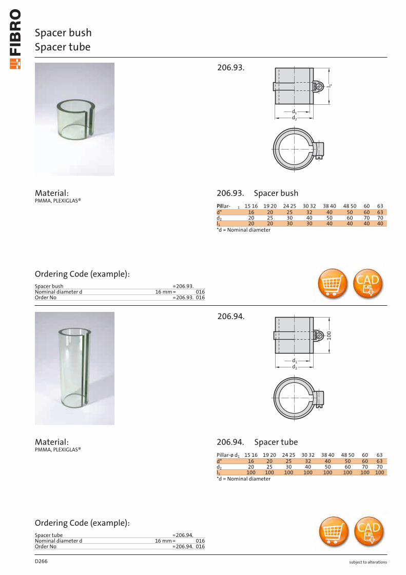
subject to alterations
Spacer bushSpacer tube
Material: PMMA, PLEXIGLAS®
Material: PMMA, PLEXIGLAS®
l 1
d1
d2
206.93.
100
d1d2
206.94.
D266
Ordering Code (example):Spacer bush =206.93.Nominal diameter d 16 mm = 016Order No =206.93. 016
Ordering Code (example):Spacer tube =206.94.Nominal diameter d 16 mm = 016Order No =206.94. 016
PPillar-il 1 1615 19 20 24 25 3230 4038 5048 60 63d* 16 20 25 32 40 50 60 63d2 20 25 30 40 50 60 70 70l1 20 20 30 30 40 40 40 40*d = Nominal diameter
Pillar-ø d1 15 16 19 20 24 25 30 32 38 40 48 50 60 63d* 16 20 25 32 40 50 60 63d2 20 25 30 40 50 60 70 70l1 100 100 100 100 100 100 100 100*d = Nominal diameter
206.93.
206.94.
Spacer bush
Spacer tube
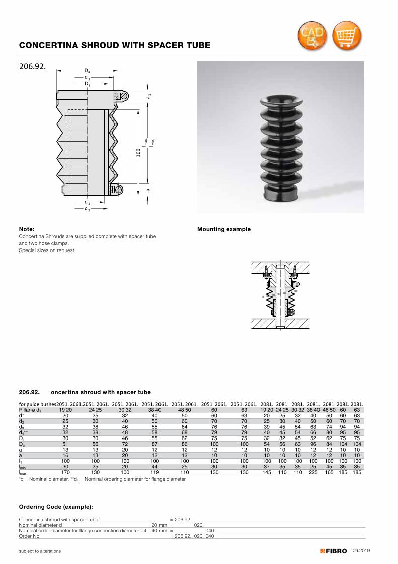
09.2019
D
10
0
d1d
a
3d
D
2
a1
am
ax
.l m
in.
l
i
206.92.
subject to alterations
CONCERTINA SHROUD WITH SPACER TUBE
Note: Concertina Shrouds are supplied complete with spacer tube and two hose clamps. Special sizes on request.
Mounting example
for guide bushes 2051. 2061. 2051. 2061. 2051. 2061. 2051. 2061. 2051. 2061. 2051. 2061. 2051. 2061. 2081. 2081. 2081. 2081. 2081. 2081. 2081.Pillar-ø d1 19 20 24 25 30 32 38 40 48 50 60 63 19 20 24 25 30 32 38 40 48 50 60 63d* 20 25 32 40 50 60 63 20 25 32 40 50 60 63 d2 25 30 40 50 60 70 70 25 30 40 50 60 70 70 d3 32 38 46 55 64 76 76 39 45 54 63 74 94 94 d4** 32 38 48 58 68 79 79 40 45 54 66 80 95 95 DiDa
30 30 46 55 62 75 75 32 32 45 52 62 75 75 51 56 72 87 86 100 100 54 56 63 96 84 104 104
a 13 13 20 12 12 12 12 10 10 10 12 12 10 10 a1 16 13 20 12 12 10 10 10 10 10 12 12 10 10 l1 100 100 100 100 100 100 100 100 100 100 100 100 100 100 lmin 30 25 20 44 25 30 30 37 35 35 25 45 35 35 lmax 170 130 100 119 110 130 130 145 110 110 225 165 185 185 *d = Nominal diameter, **d4 = Nominal ordering diameter for flange diameter
206.92.. oncertina shroud with spacer tube
Ordering Code (example):
Concertina shroud with spacer tube = 206.92.Nominal diameter d 20 mm = 020.Nominal order diameter for flange connection diameter d4 40 mm = 040Order No = 206.92. 020. 040

subject to alterations
Helical spring for ball cage retention
Calculation: Formula for selecting spring 241.18.: FL = [l - (l2 + (l1 - l3))] x 1,1 Formula for calculating the block length LBL of the selected spring: LBL = ( l0 x d : s) + 2 x d FL = Length of compressed spring l = Length of guide pillar (Customer specified) l1 = Cage length (Customer specified) l2 = Compression length of guide pillar (Customer specified) l3 = Ball cage retainer size (Customer specified) 1.1 = Safety factor l0 = Length of uncompressed spring d = Spring wire diameter s = Pitch
Without ball cageretainer
With ball cageretainer202.91.
With ball cageretainer202.91.
3l
1l
2l
l LF
Without ball cageretainer
With ball cageretainer202.92.1.
With ball cageretainer202.92.1.
ø pillar d₁
ds
l 0
d2
d3241.18.
Mounting example Mounting example
D268
d1 d2 d3 s d l0 Gradation l019/20 20.5 22.5 14 1 40 - 140 1024/25 25.5 27.9 14 1.2 40 - 160 1030/32 32.5 35.7 16 1.6 50 - 230 1038 38.5 42.5 18 2 60 - 230 1040 40.5 45.1 20 2.3 60 - 230 1048/50 50.5 55.7 20 2.6 70 - 280 1060 60.5 66.9 20 3.2 80 - 250 1063 63.5 69.9 20 3.2 80 - 250 10
Ordering Code (example):Helical spring for ball cage retention =241.18.Inside diameter d2 20.5 mm = 205.Length l0 40 mm = 040Order No =241.18. 205. 040
241.18. Helical spring for ball cage retention
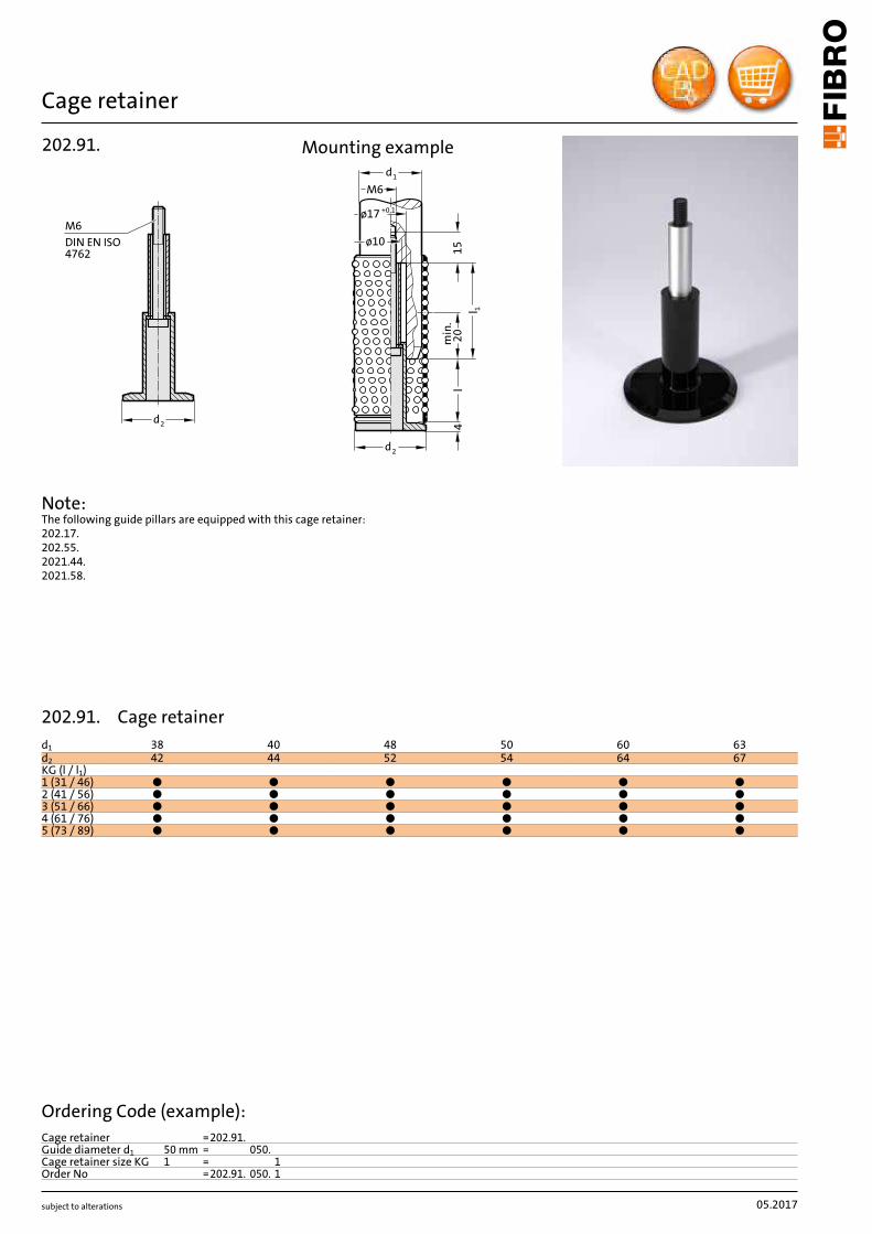
subject to alterations
Cage retainer
2d
M6
DIN EN ISO4762
202.91.
Note: The following guide pillars are equipped with this cage retainer: 202.17. 202.55. 2021.44. 2021.58.
2d
l4
min
.2
0
1l
15ø10
+0,1ø17
M6
1d
Mounting example
05.2017
d1 38 40 48 50 60 63d2 42 44 52 54 64 67KG (l / l1)1 (31 / 46) ● ● ● ● ● ●2 (41 / 56) ● ● ● ● ● ●3 (51 / 66) ● ● ● ● ● ●4 (61 / 76) ● ● ● ● ● ●5 (73 / 89) ● ● ● ● ● ●
Ordering Code (example):Cage retainer =202.91.Guide diameter d1 50 mm = 050.Cage retainer size KG 1 = 1Order No =202.91. 050. 1
202.91. Cage retainer
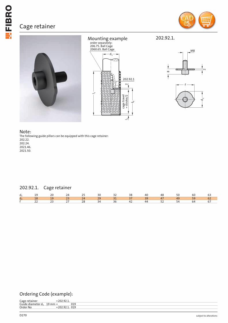
°l
subject to alterations
Cage retainer
Note: The following guide pillars can be equipped with this cage retainer: 202.22. 202.24. 2021.46. 2021.50.
3l
l 2
ca
ge
tra
ve
l
= s
tro
ke
/2
2
202.92.1
1d
1l
order separately:
206.75. Ball Cage
2060.65. Ball Cage
202.92.1.
8
d 2
M8
2
f
Mounting example
D270
d1 19 20 24 25 30 32 38 40 48 50 60 63d2 18 19 23 24 29 31 37 39 47 49 59 62f 22 23 27 28 34 36 42 44 52 54 64 67
Ordering Code (example):Cage retainer =202.92.1.Guide diameter d1 19 mm = 019Order No =202.92.1. 019
202.92.1. Cage retainer
https://shop.fibro.de/produkt_shop.asp?area=hauptmenue&site=normalienshop&cls=02&S_KEYWORD=202.92.1.
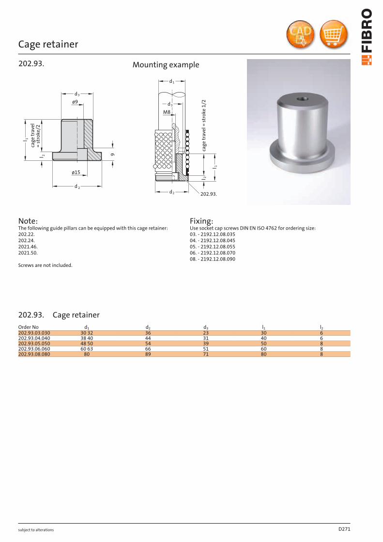
subject to alterations
Cage retainer
9
d3
d 2
ø9
ø15
l 1
2l
cag
e t
rave
l=
str
oke
/2
202.93.
Fixing: Use socket cap screws DIN EN ISO 4762 for ordering size: 03. - 2192.12.08.035 04. - 2192.12.08.045 05. - 2192.12.08.055 06. - 2192.12.08.070 08. - 2192.12.08.090
cag
e tr
avel
= s
tro
ke 1
/2l 2
3
d1
d2
d
M8
l 1
202.93.
Mounting example
D271
Order No d1 d2 d3 l1 l2202.93.03.030 30 32 36 23 30 6202.93.04.040 38 40 44 31 40 6202.93.05.050 48 50 54 39 50 8202.93.06.060 60 63 66 51 60 8202.93.08.080 80 89 71 80 8
Note: The following guide pillars can be equipped with this cage retainer: 202.22. 202.24. 2021.46. 2021.50.
Screws are not included.
202.93. Cage retainer

09.2019
d4
105
71
2
m
m
d
d2
60
116
d4
d5
d5
202.94.
202.94. .1
202.94. .2
61
d3
d3
l 8
min
. 20
l 8
11
subject to alterations
CAGE RETAINER
Description: Cage unit allows both accurate cage centring as well as a variably adjus-table cage feed length (l8). The cage feed length can be adjusted by turning the thread m in the column. A cheese head screw in accordance with DIN EN ISO 4762 serves as anti-rotation device.
Material: Steel
Note: The following guide pillars can be equipped with this cage retainer: 202.19. .30.94 2021.46. .30.94
Screws are not included.
Fixing: Socket cap screws DIN EN ISO 4762 for nominal diameter ød : 32 / 40 = 2192.12.05.
50 = 2192.12.06. 63 / 80 = 2192.12.08.
Length calculation of the safety screw fastening : Cage retainer 202.94. .1 : Screw length = Cage feed length + 25 mm Cage retainer 202.94. .2 : Screw length = Cage feed length - 20 mm
202.94. Cage retainer
l8
Order No Nominal-ø Pillar-ø d2 d3 d4 d5 m Cage feed length202.94.032.1 32 30/32 35 25 5.5 10 M16x1,5 5-50202.94.040.1 40 38/40 43 33 5.5 10 M16x1,5 5-50202.94.050.1 50 48/50 53 43 6.6 11 M20x1,5 5-50202.94.063.1 63 60/63 66 56 9 15 M30x1,5 5-50202.94.080.1 80 80 88 74 9 15 M30x1,5 5-50202.94.032.2 32 30/32 35 25 5.5 10 M16x1,5 50-100202.94.040.2 40 38/40 43 33 5.5 10 M16x1,5 50-100202.94.050.2 50 48/50 53 43 6.6 11 M20x1,5 50-100202.94.063.2 63 60/63 66 56 9 15 M30x1,5 50-100202.94.080.2 80 80 88 74 9 15 M30x1,5 50-100
Mounting example
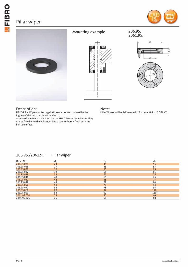
subject to alterations
Pillar wiper
Description: FIBRO Pillar Wipers protect against premature wear caused by the ingress of dirt into the die set guides. Outside diameters match boss dias. on FIBRO Die Sets (Cast Iron). They can be fitted onto the bolster, or into a counterbore – flush with the bolster surface.
Note: Pillar Wipers will be delivered with 3 screws M 4 × 16 DIN 963.
8,5
3d
1d
2d
206.95.2061.95.
Mounting example
D272
Order No d1 d2 d3206.95.024 24 45 55206.95.025 25 45 55206.95.030 30 55 65206.95.032 32 55 65206.95.038 38 65 75206.95.040 40 65 75206.95.042 42 65 75206.95.048 48 78 94206.95.050 50 78 94206.95.052 52 78 94206.95.060 60 92 110206.95.063 63 92 1102061.95.024 24 50 602061.95.025 25 50 60
206.95./2061.95. Pillar wiper
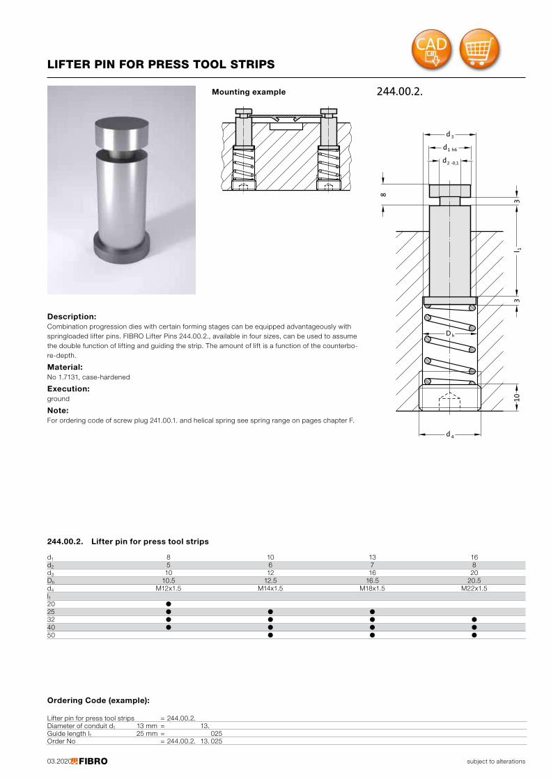
03.2020
10
3
8
1 h6d
3d
2 -0,1d
4d
hD
31l
244.00.2.
subject to alterations
LIFTER PIN FOR PRESS TOOL STRIPS
Description: Combination progression dies with certain forming stages can be equipped advantageously with springloaded lifter pins. FIBRO Lifter Pins 244.00.2., available in four sizes, can be used to assume the double function of lifting and guiding the strip. The amount of lift is a function of the counterbo-re-depth.
Material: No 1.7131, case-hardened
Execution: ground
Note: For ordering code of screw plug 241.00.1. and helical spring see spring range on pages chapter F.
Mounting example
Ordering Code (example):
Lifter pin for press tool strips = 244.00.2.Diameter of conduit d1 13 mm = 13.Guide length l1 25 mm = 025Order No = 244.00.2. 13. 025
244.00.2. Lifter pin for press tool strips
d1 8 10 13 16d2 5 6 7 8d3 10 12 16 20Dh 10.5 12.5 16.5 20.5d4 M12x1.5 M14x1.5 M18x1.5 M22x1.5l21
0 ●25 ● ● ●32 ● ● ● ●40 ● ● ● ●50 ● ● ●
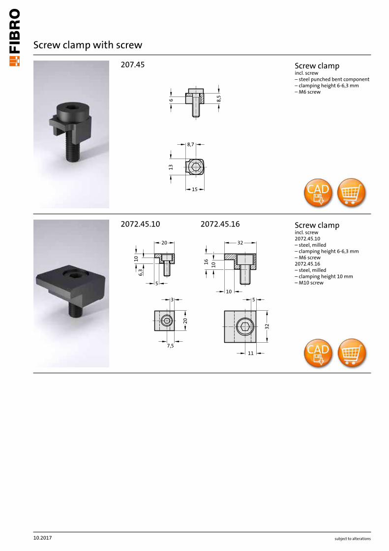
˜
°˛,˙
°°˙,ˆ
+˘,°
ø˜ø16
ø°°ø23
2071.45
15/16 19/20 24/25 30/32 38/40 48/50 60/63 802021.28./ 29./ 44./ 46.
d6 38 42 49 57 67 80 97 112d7 56.5 60.3 67.1 74.9 84.6 97.4 114.2 129.1
2021.39. - 2081.31./ 32./ 33./ 34./ 35. - 2081.44./ 45./ 46./ 47./ 49. - 2081.71./ 74./ 75. -2081.81./ 84./ 85. - 2081.91./ 94./ 95.
d6 -- 59 65 73 83 97 112 135d7 -- 76.8 82.7 90.5 100.4 114.2 129.1 152.0
210.31./ 34./ 35. - 210.39. - 210.44./ 45./ 46. - 210.85.d6 53 56 64 75 87 107 127 --d7 71.0 73.9 81.7 92.5 104.3 124.1 144.0 --
˜° dd
˝˙,ˇ ø23
subject to alterations
Screw clamp with screw
Description:Strengthened holding piece 2071.45 alterna tive to holding piece 207.45
Note:The attachment is with 3 Screw clamp, from ød1 = 38 with 4 Scr ew clamp , which are included in delivery.(Order No: 2071.45 - Scr ew clamp incl. socket cap screw M6x20 DIN EN ISO 4762).
Screw clampincl. screw– clamping height 6 mm– M6 screw
2071.45 Scr ew clamp with screwNominal diameterusable for:
usable for:
usable for:
subject to alterations
Screw clamp with screw
15
8,7
6 8,5
13
207.45
7,5
11
32
5
10
10
32
3
6,3
20
5
20
10
16
2072.45.10 2072.45.16
Screw clamp incl. screw – steel punched bent component– clamping height 6-6,3 mm– M6 screw
Screw clamp incl. screw 2072.45.10 – steel, milled– clamping height 6-6,3 mm– M6 screw 2072.45.16 – steel, milled– clamping height 10 mm– M10 screw
10.2017
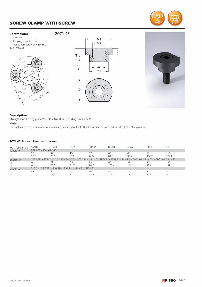
D287
7
19
,5
11
5,8
+0
,1
ø7
ø16
ø11
ø23
2071.45
15/16 19/20 24/25 30/32 38/40 48/50 60/63 802021.28./ 29./ 44./ 46.
d6 38 42 49 57 67 80 97 112d7 56,5 60,3 67,1 74,9 84,6 97,4 114,2 129,1
2021.39. - 2081.31./ 32./ 33./ 34./ 35. - 2081.44./ 45./ 46./ 47./ 49. - 2081.71./ 74./ 75. - 2081.81./ 84./ 85. - 2081.91./ 94./ 95.d6 -- 59 65 73 83 97 112 135d7 -- 76,8 82,7 90,5 100,4 114,2 129,1 152
210.31./ 34./ 35. - 210.39. - 210.44./ 45./ 46. - 210.85.d6 53 56 64 75 87 107 127 --d7 71 73,9 81,7 92,5 104,3 124,1 144 --
76d
d
19
,5 ø23
subject to alterations
Screw clamp incl. screw – clamping height 6 mm– ocket cap screw DIN EN ISO4762 M6x20
Description: Strengthened holding piece 2071.45 alternative to holding piece 207.45
Note: The fastening of the guide post/guide socket is carried out with 3 holding pieces, from Ø d1 = 38 with 4 holding pieces.
2071.45 Screw clamp with screw
Nominal diameterusable for:
usable for:
usable for:
SCREW CLAMP WITH SCREW
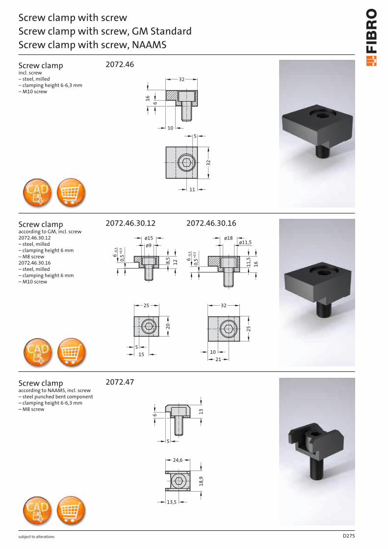
subject to alterations
Screw clamp with screwScrew clamp with screw, GM StandardScrew clamp with screw, NAAMS
Screw clamp incl. screw – steel, milled – clamping height 6-6,3 mm – M10 screw
Screw clamp according to GM, incl. screw 2072.46.30.12 – steel, milled – clamping height 6 mm – M8 screw 2072.46.30.16 – steel, milled – clamping height 6 mm – M10 screw
Screw clamp according to NAAMS, incl. screw – steel punched bent component – clamping height 6-6,3 mm – M8 screw
6
11
32
510
32
16
2072.46
ø11,5ø9
11,5
8,5
105
21
25 32
15
20
25
ø15 ø18
12
16
6-0,3
0,5
+0,5
6-0,3
0,5
+0,5
2072.46.30.12 2072.46.30.16
13,5
18,9
24,6
5
6 13
2072.47
D275
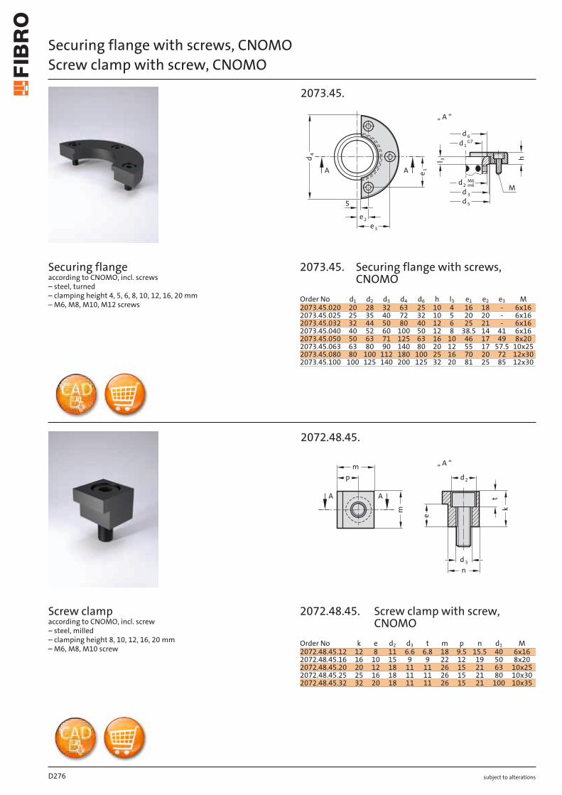
subject to alterations
Securing flange with screws, CNOMOScrew clamp with screw, CNOMO
Securing flange according to CNOMO, incl. screws – steel, turned – clamping height 4, 5, 6, 8, 10, 12, 16, 20 mm – M6, M8, M10, M12 screws
Screw clamp according to CNOMO, incl. screw – steel, milled – clamping height 8, 10, 12, 16, 20 mm – M6, M8, M10 screw
e1
4d
e 2
e 3
5
3l h
3d
5d
6d
d1G7
d2M6m6
M
A A
„ A “
2073.45.
m
pm
kt
e
nd 3
d2
A A
„ A “
2072.48.45.
D276
Order No d1 d2 d3 d4 d6 h l3 e1 e2 e3 M2073.45.020 20 28 32 63 25 10 4 16 18 - 6x162073.45.025 25 35 40 72 32 10 5 20 20 - 6x162073.45.032 32 44 50 80 40 12 6 25 21 - 6x162073.45.040 40 52 60 100 50 12 8 38.5 14 41 6x162073.45.050 50 63 71 125 63 16 10 46 17 49 8x202073.45.063 63 80 90 140 80 20 12 55 17 57.5 10x252073.45.080 80 100 112 180 100 25 16 70 20 72 12x302073.45.100 100 125 140 200 125 32 20 81 25 85 12x30
Order No k e d2 d3 t m p n d1 M2072.48.45.12 12 8 11 6.6 6.8 18 9.5 15.5 40 6x162072.48.45.16 16 10 15 9 9 22 12 19 50 8x202072.48.45.20 20 12 18 11 11 26 15 21 63 10x252072.48.45.25 25 16 18 11 11 26 15 21 80 10x302072.48.45.32 32 20 18 11 11 26 15 21 100 10x35
2073.45.
2072.48.45.
Securing flange with screws, CNOMO
Screw clamp with screw, CNOMO

subject to alterations D277
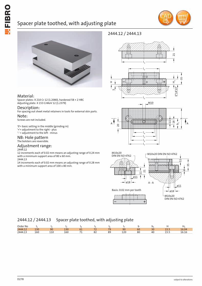
subject to alterations
Spacer plate toothed, with adjusting plate
Material: Spacer plates: X 210 Cr 12 (1.2080), hardened 58 + 2 HRC Adjusting plate: X 153 CrMoV 12 (1.2379)
Description: For spacing out sheet metal retainers in tools for external skin parts.
Note: Screws are not included.
'0'= basic setting in the middle (grinding-in) '+'= adjustment to the right - plus '-' = adjustment to the left - minus
NB: Hole pattern The bolsters are reversible.
Adjustment range: 2444.12 12 increments each of 0.02 mm means an adjusting range of 0.24 mm with a minimum support area of 80 x 60 mm. 2444.13 14 increments each of 0.02 mm means an adjusting range of 0.28 mm with a minimum support area of 100 x 80 mm.
11
M10
20
11
5
0°14
'13"
l 1
l 2
l 3
H H1 35
0
0
21
435
ø18
ø11
M10x20 DIN EN ISO 4762
M10x20DIN EN ISO 4762
A - A
l 4
l 5
l 6
l 7
18 b 1
b
AA
11 21
ø11
ø18
Basis: 0.02 mm per tooth
M10x20DIN EN ISO 4762
2444.12 / 2444.13
D278
Order No l1 l2 l3 l4 l5 l6 l7 b b1 H H12444.12 130 90 130 61 72 79 90 60 30 15.5 16.042444.13 160 110 160 71 82 89 120 80 40 15.5 16.16
2444.12 / 2444.13 Spacer plate toothed, with adjusting plate
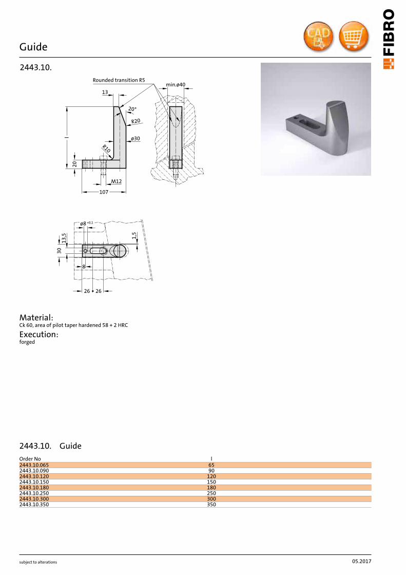
subject to alterations
Guide
ø8 +0,1
13
,5 1,5
8
min.ø40
ø30
20°
13
R20
107
M12
20
l
30
2626
R10
Rounded transition R5
2443.10.
Material: Ck 60, area of pilot taper hardened 58 + 2 HRC
Execution: forged
05.2017
2443.10. GuideOrder No l2443.10.065 652443.10.090 902443.10.120 1202443.10.150 1502443.10.180 1802443.10.250 2502443.10.300 3002443.10.350 350
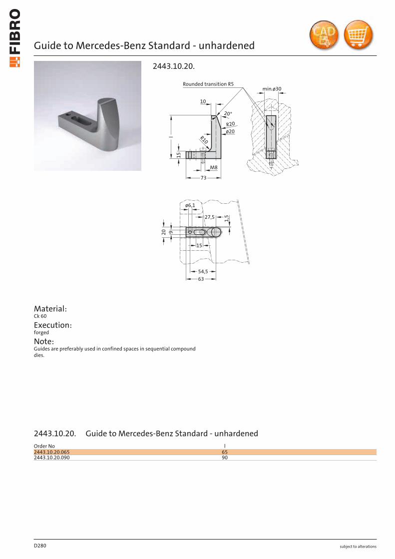
subject to alterations
Guide to Mercedes-Benz Standard - unhardened
Material: Ck 60
Execution: forged
Note: Guides are preferably used in confined spaces in sequential compound dies.
54,5
63
73
20
15
l9
1,5
10
min.ø30
M8
R10
R20
ø20
20°
ø6,1
27,5
15
Rounded transition R5
2443.10.20.
D280
Order No l2443.10.20.065 652443.10.20.090 90
2443.10.20. Guide to Mercedes-Benz Standard - unhardened
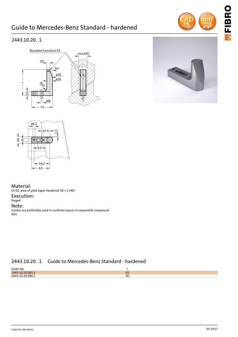
subject to alterations
Guide to Mercedes-Benz Standard - hardened
54,5
63
73
20
15
l9
1,5
10
min.ø30
M8
R10
R20
ø20
20°
ø6,1
27,5
15
Rounded transition R5
2443.10.20. .1
Material: Ck 60, area of pilot taper hardened 58 + 2 HRC
Execution: forged
Note: Guides are preferably used in confined spaces in sequential compound dies.
05.2017
Order No l2443.10.20.065.1 652443.10.20.090.1 90
2443.10.20. .1 Guide to Mercedes-Benz Standard - hardened

subject to alterations
Guide with part position control and spring
2018.00.60.08.030
Mounting example
Material: Guide: Ck 60, area of pilot taper hardened 50 + 5 HRC Flap: St 37 Spring: Spring steel wire
Execution: forged
Note: See following pages for accessories.
Roundedtransition R5
30
20
107
l
l 1
l 2
8
ø6,5
4010
58
R4,5Thickness8mm
26 26
Version with short flap:l = 120, 150 mm
1)
15°
4010
ø6,5
8
10
8
32
rounded
Thickness8mm
Version with long flap:l = 180, 250 mm
2)
M12
R10
13
20°
R20
ø8 +0,1
13
,5
8
min.ø40
ø30
2443.12.
05.2017
Order No l l1 l22443.12.120 120 55 702443.12.150 150 55 702443.12.180 180 105 1202443.12.250 250 105 120
2443.12. Guide with part position control and spring
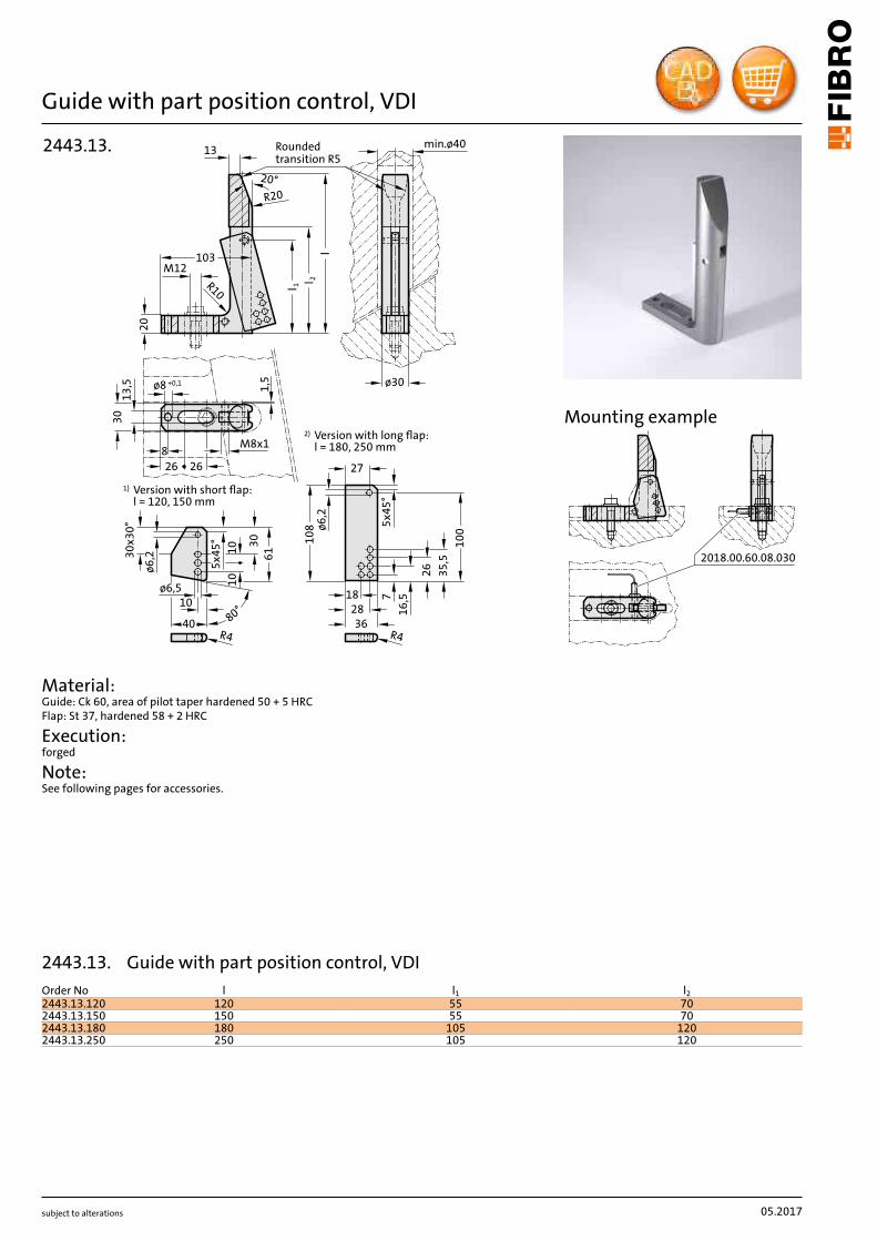
subject to alterations
Guide with part position control, VDI
M8x1
ø30
80°40
10ø6,5 1
0
5x4
5°
10
61
30
ø6
,2
27
16
,5
l
18
36
26
35
,5
10
8
Version with short flap:l = 120, 150 mm
1)
Version with long flap:l = 180, 250 mm
2)
10
0
20
7
28
M12
13
20°
R20
l 1l 2R10
103
Roundedtransition R5
ø6
,2
5x4
5°
30
x30
°
R4 R4
min.ø40
ø8 +0,1
13
,5 1,5
8
30
2626
2443.13.
Material: Guide: Ck 60, area of pilot taper hardened 50 + 5 HRC Flap: St 37, hardened 58 + 2 HRC
Execution: forged
Note: See following pages for accessories.
2018.00.60.08.030
Mounting example
05.2017
Order No l l1 l22443.13.120 120 55 702443.13.150 150 55 702443.13.180 180 105 1202443.13.250 250 105 120
2443.13. Guide with part position control, VDI
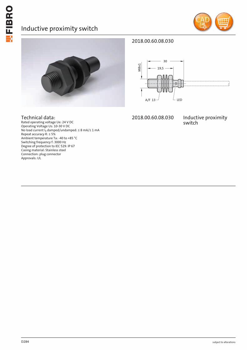
subject to alterations
Inductive proximity switch
Technical data: Rated operating voltage Ue: 24 V DC Operating Voltage Us: 10-30 V DC No load current I0 damped/undamped: ≤ 8 mA/≤ 1 mA Repeat accuracy R: ≤ 5% Ambient temperature Ta: -40 to +85 °C Switching frequency f: 3000 Hz Degree of protection to IEC 529: IP 67 Casing material: Stainless steel Connection: plug connector Approvals: UL
2018.00.60.08.030
M8
x1
LED
19,5
30
A/F 13
D284
2018.00.60.08.030 Inductive proximity switch
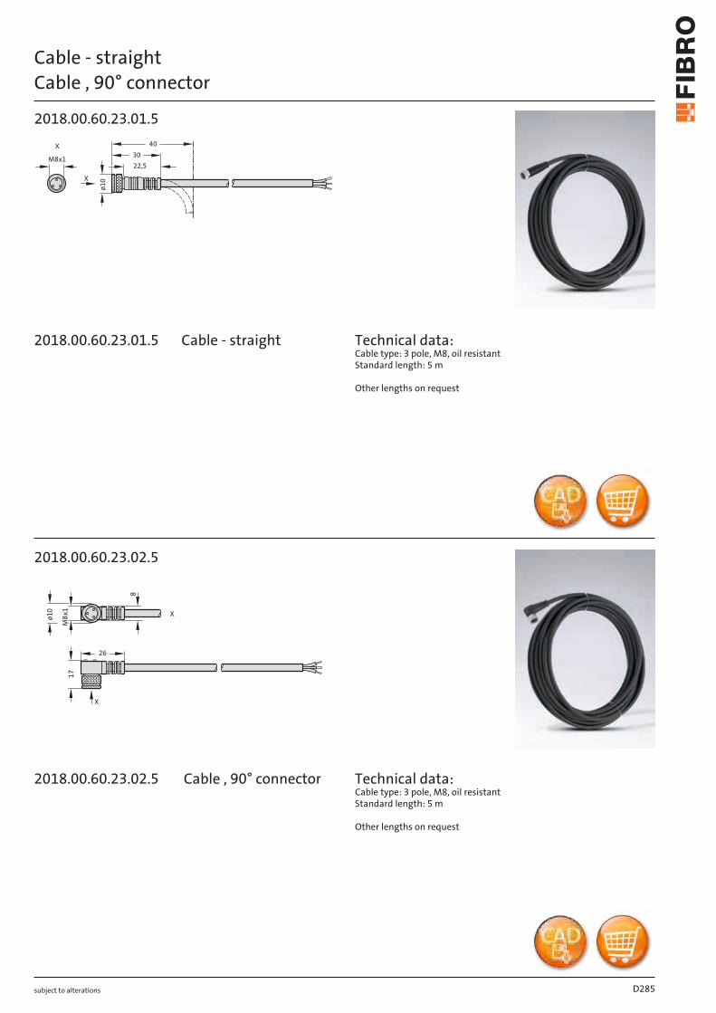
subject to alterations
Cable - straightCable , 90° connector
2018.00.60.23.01.5
M8x1
X
ø1
0
30
22,5
40X
2018.00.60.23.02.5
ø1
0
M8
x1
X
17
8
26
X
Technical data: Cable type: 3 pole, M8, oil resistant Standard length: 5 m
Other lengths on request
Technical data: Cable type: 3 pole, M8, oil resistant Standard length: 5 m
Other lengths on request
D285
2018.00.60.23.01.5
2018.00.60.23.02.5
Cable - straight
Cable , 90° connector

subject to alterationsD286
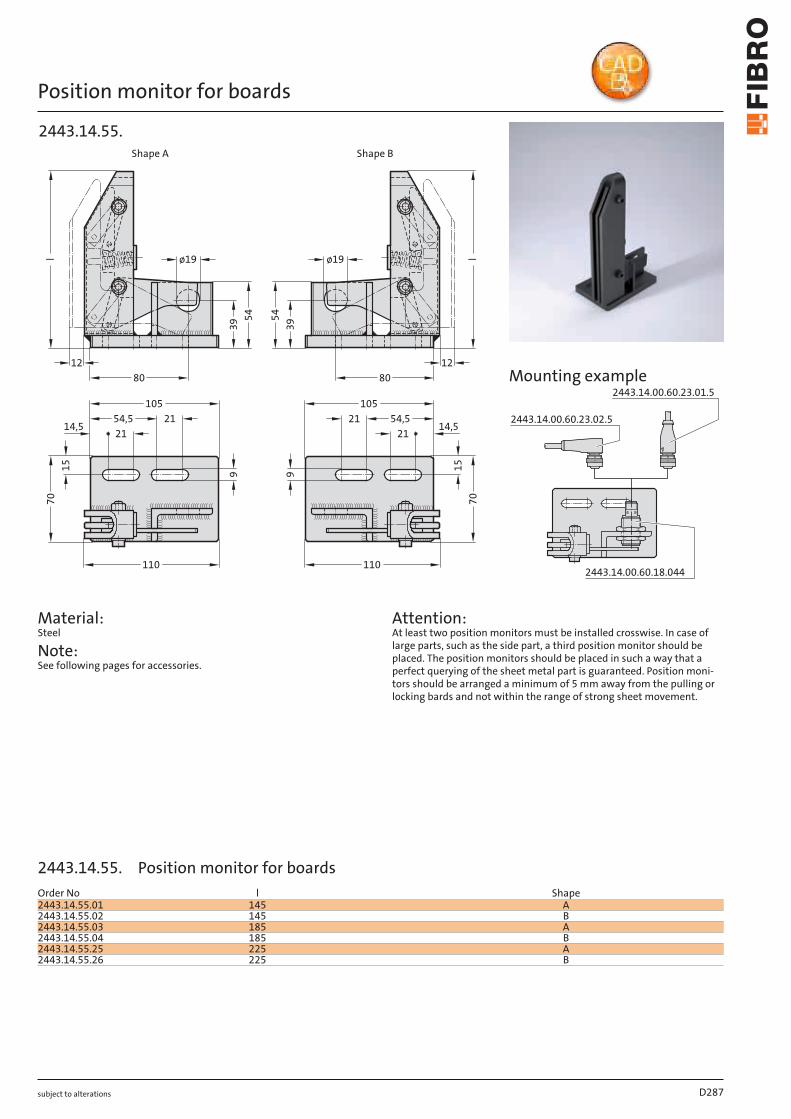
subject to alterations
Position monitor for boards
110
70
ø19
110
12
21105
91570
l
3954
80
54,52114,5
lø1954
39
8012
10521 54,5
14,521
9 15
Shape A Shape B
2443.14.55.
Material: Steel
Note: See following pages for accessories.
Attention: At least two position monitors must be installed crosswise. In case of large parts, such as the side part, a third position monitor should be placed. The position monitors should be placed in such a way that a perfect querying of the sheet metal part is guaranteed. Position moni-tors should be arranged a minimum of 5 mm away from the pulling or locking bards and not within the range of strong sheet movement.
2443.14.00.60.23.02.5
2443.14.00.60.23.01.5
2443.14.00.60.18.044
Mounting example
D287
Order No l Shape2443.14.55.01 145 A2443.14.55.02 145 B2443.14.55.03 185 A2443.14.55.04 185 B2443.14.55.25 225 A2443.14.55.26 225 B
2443.14.55. Position monitor for boards
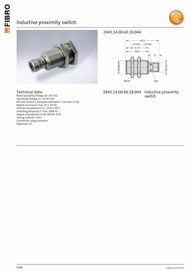
subject to alterations
Inductive proximity switch
Technical data: Rated operating voltage Ue: 24 V DC Operating Voltage Us: 10-30 V DC No load current I0 damped/undamped: ≤ 10 mA/≤ 3 mA Repeat accuracy R: max. (% v. Sr) 5% Ambient temperature Ta: -25 to +70°C Switching frequency f: max. 1000 Hz Degree of protection to IEC 60529: IP 67 Casing material: CuZn Connection: plug connector Approvals: UL
15
11
44,5
29,5
M1
8x
1
M1
2x
1
25 Nm 35 Nm
LEDSW24
2443.14.00.60.18.044
D288
2443.14.00.60.18.0 44 Inductive proximity switch
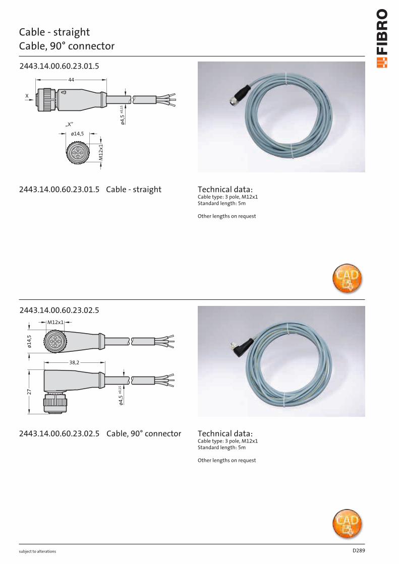
subject to alterations
Cable - straightCable, 90° connector
M1
2x
1
ø14,5
ø4
,5±
0,1
5
44
X
„X”
2443.14.00.60.23.01.5
38,2
ø1
4,5
M12x1
27
ø4
,5±
0,1
5
2443.14.00.60.23.02.5
Technical data: Cable type: 3 pole, M12x1 Standard length: 5m
Other lengths on request
Technical data: Cable type: 3 pole, M12x1 Standard length: 5m
Other lengths on request
D289
2443.14.00.60.23.01 .5
2443.14.00.60.23.0 2.5 Cable, 90° connector
Cable - straight
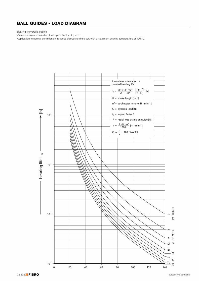
02.2020 subject to alterations
BALL GUIDES - LOAD DIAGRAM
f s833
27
20 40 60 80 100 120 1400
110
410
210
310
[h]
2115
129
63
3024
182
. H. n
f = v
[m. m
in.-1
]
H = stroke length [mm]
nf = strokes per minute [H . min -1 ]
C = dynamic load [N]
sf = impact factor 1
F = radial load acting on guide [N]
2 . .H nfv = [m . min -1 ]
hL = [h]333 mm
Formula for calculation ofnominal bearing life
2
1000
. .H nf. C
. F3
bear
ing
life
L h
Q = F . 100 [% of C ]C
Bearing life versus loading Values shown are based on the Impact Factor of fs = 1: Application to normal conditions in respect of press and die set, with a maximum bearing temperature of 100 °C.
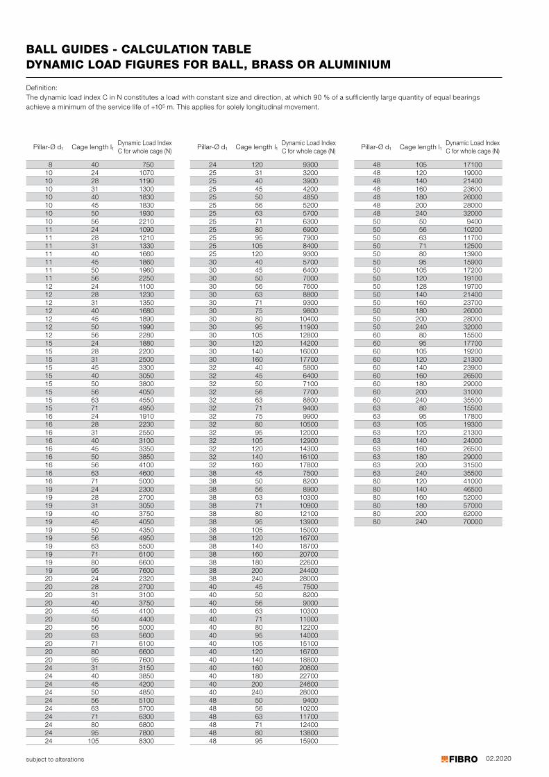
02.2020
8 40 75010 24 107010 28 119010 31 130010 40 183010 45 183010 50 193010 56 221011 24 109011 28 121011 31 133011 40 166011 45 186011 50 196011 56 225012 24 110012 28 123012 31 135012 40 168012 45 189012 50 199012 56 228015 24 188015 28 220015 31 250015 45 330015 40 305015 50 380015 56 405015 63 455015 71 495016 24 191016 28 223016 31 255016 40 310016 45 335016 50 385016 56 410016 63 460016 71 500019 24 230019 28 270019 31 305019 40 375019 45 405019 50 435019 56 495019 63 550019 71 610019 80 660019 95 760020 24 232020 28 270020 31 310020 40 375020 45 410020 50 440020 56 500020 63 560020 71 610020 80 660020 95 760024 31 315024 40 385024 45 420024 50 485024 56 510024 63 570024 71 630024 80 680024 95 780024 105 8300
24 120 930025 31 320025 40 390025 45 420025 50 485025 56 520025 63 570025 71 630025 80 690025 95 790025 105 840025 120 930030 40 570030 45 640030 50 700030 56 760030 63 880030 71 930030 75 980030 80 1040030 95 1190030 105 1280030 120 1420030 140 1600030 160 1770032 40 580032 45 640032 50 710032 56 770032 63 880032 71 940032 75 990032 80 1050032 95 1200032 105 1290032 120 1430032 140 1610032 160 1780038 45 750038 50 820038 56 890038 63 1030038 71 1090038 80 1210038 95 1390038 105 1500038 120 1670038 140 1870038 160 2070038 180 2260038 200 2440038 240 2800040 45 750040 50 820040 56 900040 63 1030040 71 1100040 80 1220040 95 1400040 105 1510040 120 1670040 140 1880040 160 2080040 180 2270040 200 2460040 240 2800048 50 940048 56 1020048 63 1170048 71 1240048 80 1380048 95 15900
48 105 1710048 120 1900048 140 2140048 160 2360048 180 2600048 200 2800048 240 3200050 50 940050 56 1020050 63 1170050 71 1250050 80 1390050 95 1590050 105 1720050 120 1910050 128 1970050 140 2140050 160 2370050 180 2600050 200 2800050 240 3200060 80 1550060 95 1770060 105 1920060 120 2130060 140 2390060 160 2650060 180 2900060 200 3100060 240 3550063 80 1550063 95 1780063 105 1930063 120 2130063 140 2400063 160 2650063 180 2900063 200 3150063 240 3550080 120 4100080 140 4650080 160 5200080 180 5700080 200 6200080 240 70000
subject to alterations
BALL GUIDES - CALCULATION TABLEDYNAMIC LOAD FIGURES FOR BALL, BRASS OR ALUMINIUM
Definition: The dynamic load index C in N constitutes a load with constant size and direction, at which 90 % of a sufficiently large quantity of equal bearings achieve a minimum of the service life of +105 m. This applies for solely longitudinal movement.
Pillar-Ø d1 Cage length l1Dynamic Load Index C for whole cage (N)
Pillar-Ø d1 Cage length l1Dynamic Load Index C for whole cage (N)
Pillar-Ø d1 Cage length l1Dynamic Load Index C for whole cage (N)
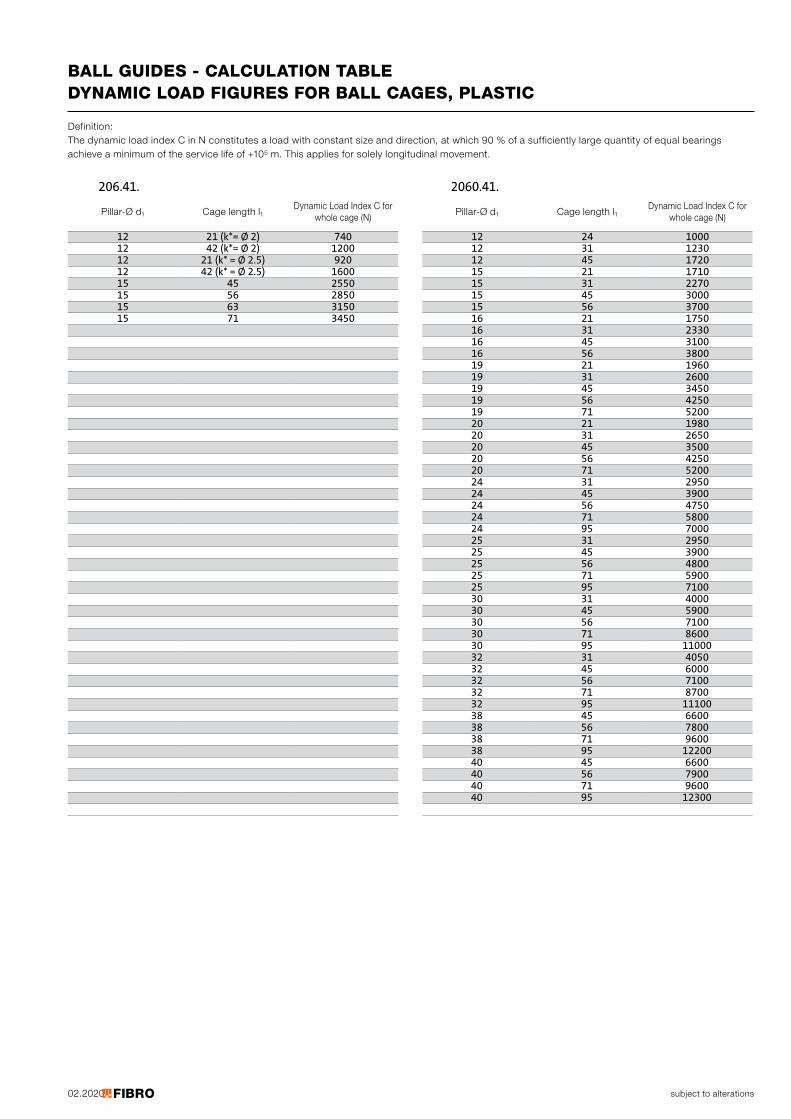
02.2020
12 21 (k*= Ø 2) 74012 42 (k*= Ø 2) 120012 21 (k* = Ø 2.5) 92012 42 (k* = Ø 2.5) 160015 45 255015 56 285015 63 315015 71 3450
12 24 100012 31 123012 45 172015 21 171015 31 227015 45 300015 56 370016 21 175016 31 233016 45 310016 56 380019 21 196019 31 260019 45 345019 56 425019 71 520020 21 198020 31 265020 45 350020 56 425020 71 520024 31 295024 45 390024 56 475024 71 580024 95 700025 31 295025 45 390025 56 480025 71 590025 95 710030 31 400030 45 590030 56 710030 71 860030 95 1100032 31 405032 45 600032 56 710032 71 870032 95 1110038 45 660038 56 780038 71 960038 95 1220040 45 660040 56 790040 71 960040 95 12300
206.41. 2060.41.
subject to alterations
BALL GUIDES - CALCULATION TABLEDYNAMIC LOAD FIGURES FOR BALL CAGES, PLASTIC
Definition: The dynamic load index C in N constitutes a load with constant size and direction, at which 90 % of a sufficiently large quantity of equal bearings achieve a minimum of the service life of +105 m. This applies for solely longitudinal movement.
Pillar-Ø d1 Cage length l1Dynamic Load Index C for
whole cage (N)Pillar-Ø d1 Cage length l1
Dynamic Load Index C for whole cage (N)
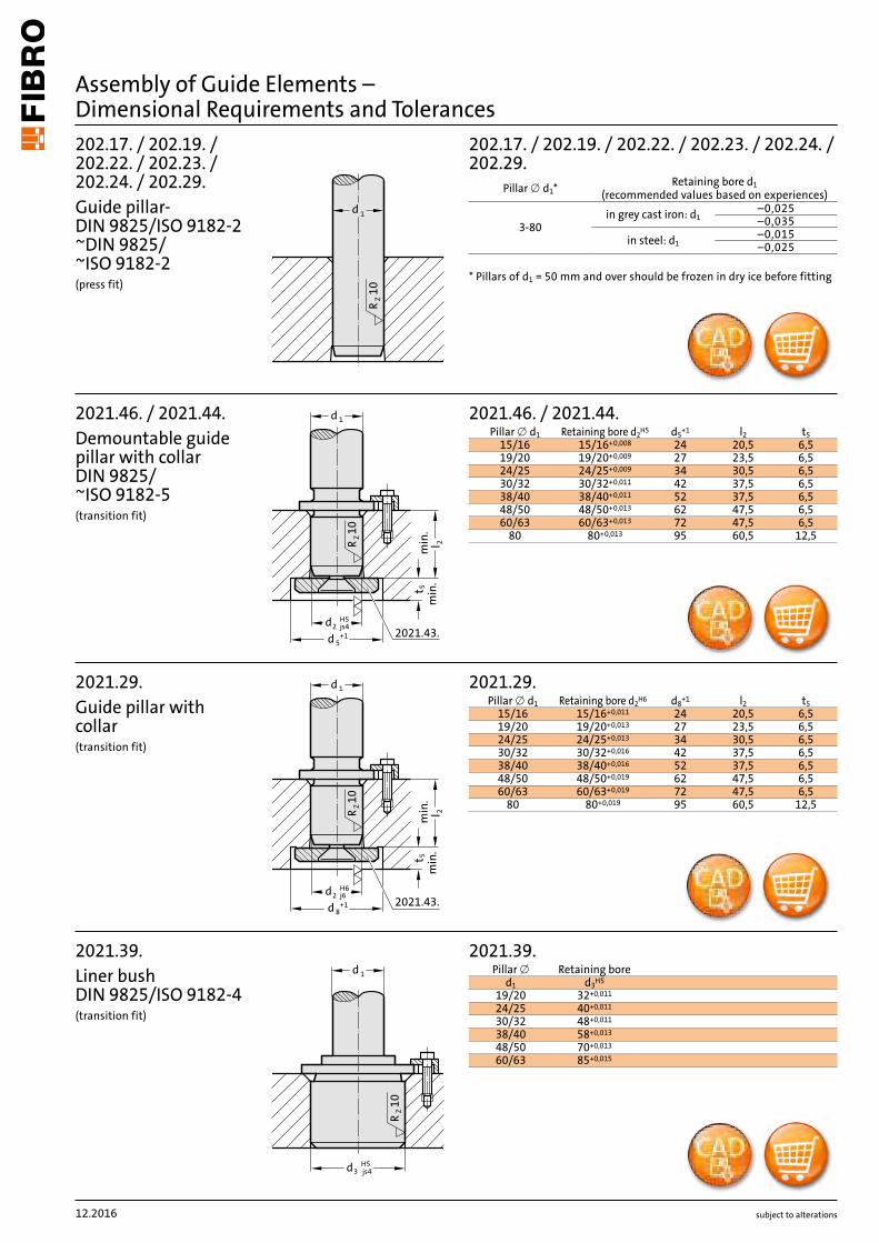
d 1
ZR10
min.
l 2
H52 js4d
1d
5
min.
t 5
R10
Z
d +1 2021.43.
1d
H53 js4d
ZR
10
min.
l 2
H62 j6d
1d
8
min.
t 5
R10
Z
d +1 2021.43.
202.17. / 202.19. / 202.22. / 202.23. / 202.24. / 202.29.
3-80–0,025–0,035–0,015–0,025
2021.46. / 2021.44.d5+1 l2 t5
15/16 15/16+0,008 24 20,5 6,519/20 19/20+0,009 27 23,5 6,524/25 24/25+0,009 34 30,5 6,530/32 30/32+0,011 42 37,5 6,538/40 38/40+0,011 52 37,5 6,548/50 48/50+0,013 62 47,5 6,560/63 60/63+0,013 72 47,5 6,5
80 80+0,013 95 60,5 12,5
2021.39.d1 d3H5
19/20 0,01132+
24/25 40+0,011
30/32 48+0,011
38/40 0,01358+
48/50 70+0,013
60/63 85+0,015
2021.29.d8+1 l2 t5
15/16 15/16+0,011 24 20,5 6,519/20 19/20+0,013 27 23,5 6,524/25 24/25+0,013 34 30,5 6,530/32 30/32+0,016 42 37,5 6,538/40 38/40+0,016 52 37,5 6,548/50 48/50+0,019 62 47,5 6,560/63 60/63+0,019 72 47,5 6,5
80 80+0,019 95 60,5 12,5
subject to alterations
Assembly of Guide Elements – Dimensional Requirements and Tolerances202.17. / 202.19. / 202.22. / 202.23. / 202.24. / 202.29.Guide pillar-DIN 9825/ISO 9182-2 ~DIN 9825/ ~ISO 9182-2(press fit)
2021.46. / 2021.44.Demountable guide pillar with collar DIN 9825/ ~ISO 9182-5(transition fit)
2021.39.Liner bush DIN 9825/ISO 9182-4(transition fit)
2021.29.Guide pillar with collar (transition fit)
Pillar x d1* Retaining bore d1 (recommended values based on experiences)in grey cast iron: d1
in steel: d1
* Pillars of d1 = 50 mm and over should be frozen in dry ice before fitting
Pillar x d1 Retaining bore d2H5
Pillar x Retaining bore
Pillar x d1 Retaining bore d2H6
12.2016
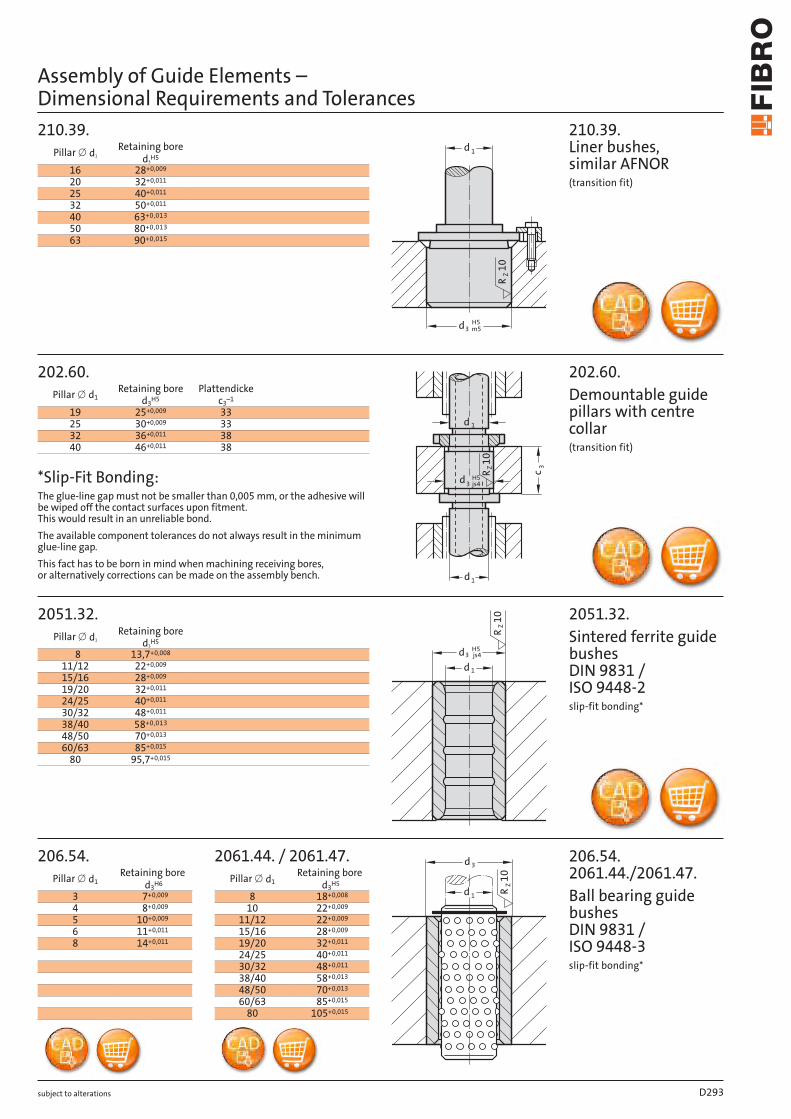
˜d
R˜˝
Z
min
.˙l
H˘js4˙d
1d
˘d
min
.˘t
R10
Z
+1
˜d
H˝jsˇ˘d
R˜0
Z
min
.˙l
H˘j6˙d
1d
8d
min
.˘t
R10
Z
+1
202.17. / 202.19. / 202.22. / 202.23. / 202.24. / 202.29.
3-80–0,025–0,035–0,015–0,025
2021.46. / 2021.44.d5+1 l2 t5
15/16 15/16 +0,008 24 20,5 6,519/20 19/20 +0,009 27 23,5 6,524/25 24/25 +0,009 34 30,5 6,530/32 30/32 +0,011 42 37,5 6,538/40 38/40+0,011 52 37,5 6,548/50 48/50+0,013 62 47,5 6,560/63 60/63+0,013 72 47,5 6,5
80 80+0,013 95 60,5 12,5
2021.39.d1 d3H5
19/20 32 +0,011
24/25 40+0,011
30/32 48+0,011
38/40 58+0,013
48/50 70+0,013
60/63 85+0,015
2021.29.d8+1 l2 t5
15/16 15/16 +0,008 24 20,5 6,519/20 19/20 +0,009 27 23,5 6,524/25 24/25 +0,009 34 30,5 6,530/32 30/32 +0,011 42 37,5 6,538/40 38/40+0,011 52 37,5 6,548/50 48/50+0,013 62 47,5 6,560/63 60/63+0,013 72 47,5 6,5
80 80+0,013 95 60,5 12,5
subject to alterations
Assembly of Guide Elements – Dimensional Requirements and Tolerances202.17. / 202.19. / 202.22. / 202.23. / 202.24. / 202.29.Guide pillar-DIN 9825/ISO 9182-2 ~DIN 9825/ ~ISO 9182-2(press fit)
2021.46. / 2021.44.Demountable guide pillar with collar DIN 9825/ ~ISO 9182-5(transition fit)
2021.39.Liner bush DIN 9825/ISO 9182-4(transition fit)
2021.29.Guide pillar with collar (transition fit)
Pillar x d1 * Retaining bore d1(recommended values based on experiences)
in grey cast iron: d1
in steel: d1
* Pillars of d1 = 50 mm and over should be frozen in dry ice before fitting
Pillar x d1 Retaining bore d2H5
Pillar x Retaining bore
Pillar x d1 Retaining bore d2H5
1d
H5
m3 5d
R1
0Z
d 1
c 3
d 1
d3 js4H5
ZR10
RZ
10
d 1
d3H5js4
3d
10
ZR
1d
210.39.
16 28+0,009
20 32+0,011
25 40+0,011
32 50+0,011
40 0,01363+
50 80+0,013
63 0,01590+
202.60.
19 0,00925+ 3325 30+0,009 3332 0,01136+ 3840 0,01146+ 38
2051.32.
8 13,7+0,008
11/12 22+0,009
15/16 28+0,009
19/20 32+0,011
24/25 40+0,011
30/32 48+0,011
38/40 0,01358+
48/50 70+0,013
60/63 85+0,015
80 95,7+0,015
206.54. 2061.44. / 2061.47.
3 7+0,009 8 18+0,008
4 8+0,009 10 22+0,009
5 10+0,009 11/12 22+0,009
6 11+0,011 15/16 28+0,009
8 14+0,011 19/20 32+0,011
24/25 40+0,011
30/32 48+0,011
38/40 58+0,013
48/50 70+0,013
60/63 85+0,015
80 105+0,015
subject to alterations
Assembly of Guide Elements – Dimensional Requirements and Tolerances
210.39. Liner bushes, similar AFNOR(transition fit)
Pillar x d1Retaining bore
d3H5
202.60.Demountable guide pillars with centre collar(transition fit)
Pillar x d1Retaining bore
d3H5Plattendicke
c3–1
2051.32. Sintered ferrite guide bushes DIN 9831 / ISO 9448-2slip-fit bonding*
Pillar x d1Retaining bore
d3H5
206.54. 2061.44./2061.47.Ball bearing guide bushes DIN 9831 / ISO 9448-3 slip-fit bonding*
Pillar x d1Retaining bore
d3H6 Pillar x d1Retaining bore
d3H5
*Slip-Fit Bonding:The glue-line gap must not be smaller than 0,005 mm, or the adhesive will be wiped off the contact surfaces upon fitment. This would result in an unreliable bond.The available component tolerances do not always result in the minimum glue-line gap.This fact has to be born in mind when machining receiving bores, or alternatively corrections can be made on the assembly bench.
D293
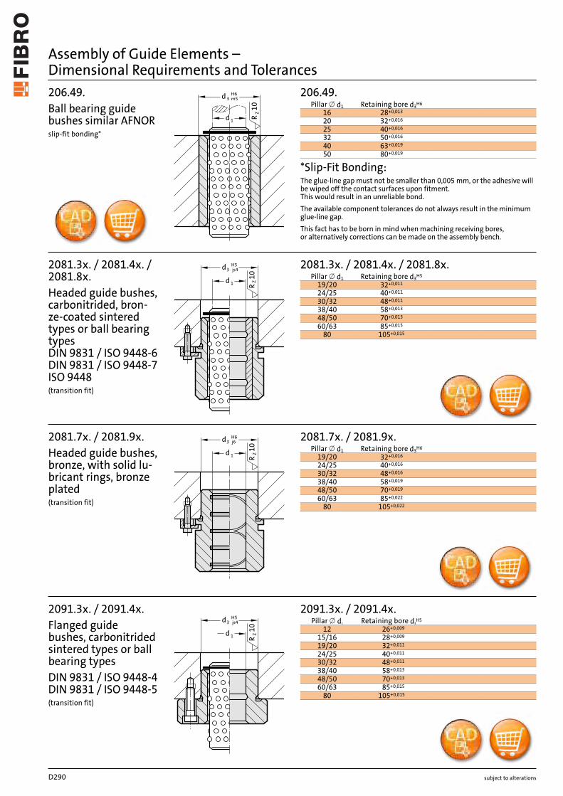
˜d˛d
˜˝Z
R
j˘H˘
˜°Z
R
Mˆh˘˜d
H°r˝˙d
H°r°˝d
2091.7x .19/20 32 +0,016
24/25 40+0,016
30/32 48+0,016
38/40 58+0,019
48/50 70+0,019
60/63 85+0,022
80 105 +0,022
2022.25.
25 -0,004-0,017
32 -0,004-0,02040
5063 -0,005
-0,02480
100 -0,006-0,028
2022.12. / 2022.15. / 2022.16. / 2022.17. / 2022.19. / 2022.29.
25 +0,0210
32 +0,025040
5063 +0,030
080
100 +0,0350
125 +0,0400160
2022.13.40 +0,016
05063 +0,019
080
subject to alterations
2091.7x .Guide bush with solid lubrication rings DIN 9831 / ISO 9448-4(transition fit)
Pillar x d1 Retaining bore d3H6
2022.25.Guide pillar AFNOR(transition fit)
Pillar x d1 Retaining bore d1 M6
2022.12. / 2022.15. / 2022.16. / 2022.17. / 2022.19. / 2022.29.Guide pillar DIN 9833/ISO 9182-3 Mercedes-Benz / VDI / VW / WDX(press fit)
Pillar x d1 Retaining bore d1 H7
Pillars of d1 = 50 mm and over should be frozen in dry ice before fitting
2022.13.Guide pillar VW(press fit)
Pillar x d1 Bohrung d1 H6
Pillars of d1 = 50 mm and over should be frozen in dry ice before fitting
Assembly of Guide Elements – Dimensional Requirements and Tolerances
1d
H53 js4d
RZ10
js4
1d
H5
3d
10
ZR
3 m5
H6d
10
ZR
1d
1d
H63 j6d
10
ZR
2081.3x. / 2081.4x. / 2081.8x.19/20 32+0,011
24/25 40+0,011
30/32 48+0,011
38/40 58+0,013
48/50 70+0,013
60/63 85+0,015
80 105+0,015
2091.3x. / 2091.4x.12 26+0,009
15/16 28+0,009
19/20 32+0,011
24/25 40+0,011
30/32 48+0,011
38/40 58+0,013
48/50 70+0,013
60/63 85+0,015
80 105+0,015
206.49.16 28+0,013
20 32+0,016
25 40+0,016
32 50+0,016
40 63+0,019
50 80+0,019
2081.7x. / 2081.9x.19/20 32+0,016
24/25 40+0,016
30/32 48+0,016
38/40 58+0,019
48/50 70+0,019
60/63 85+0,022
80 105+0,022
subject to alterations
2081.3x. / 2081.4x. / 2081.8x.Headed guide bushes, carbonitrided, bron-ze-coated sintered types or ball bearing types DIN 9831 / ISO 9448-6 DIN 9831 / ISO 9448-7 ISO 9448(transition fit)
Pillar x d1 Retaining bore d3H5
2091.3x. / 2091.4x.Flanged guide bushes, carbonitrided sintered types or ball bearing typesDIN 9831 / ISO 9448-4 DIN 9831 / ISO 9448-5(transition fit)
Pillar x d1 Retaining bore d3H5
206.49.Ball bearing guide bushes similar AFNOR slip-fit bonding*
Pillar x d1 Retaining bore d3H6
2081.7x. / 2081.9x.Headed guide bushes, bronze, with solid lu-bricant rings, bronze plated(transition fit)
Pillar x d1 Retaining bore d3H6
*Slip-Fit Bonding:The glue-line gap must not be smaller than 0,005 mm, or the adhesive will be wiped off the contact surfaces upon fitment. This would result in an unreliable bond.The available component tolerances do not always result in the minimum glue-line gap.This fact has to be born in mind when machining receiving bores, or alternatively corrections can be made on the assembly bench.
Assembly of Guide Elements – Dimensional Requirements and Tolerances
D290
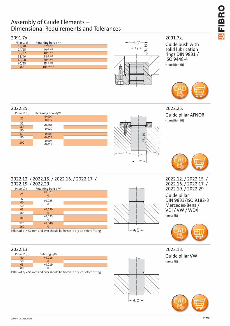
˜d
H˝jsˇ˘d
10
ZR
js˛
˝d
Hˇ˘d
10
ZR
˜ m˛H˙d
ˇ˘Z
Rˇd
˜d
H˝j˝ˆd
˜ˇZ
R
2081.3x . / 2081.4x . / 2081.8x .19/20 32 +0,011
24/25 40+0,011
30/32 48+0,011
38/40 58+0,013
48/50 70+0,013
60/63 85+0,015
80 105 +0,015
2091.3x . / 2091.4x .12 26+0,009
15/16 28+0,009
19/20 32 +0,011
24/25 40+0,011
30/32 48+0,011
38/40 58+0,013
48/50 70+0,013
60/63 85+0,015
80 105 +0,015
206.49.16 28+0,013
20 32 +0,016
25 40+0,016
32 50+0,016
40 63+0,019
50 80+0,019
2081.7x . / 2081.9x .19/20 32 +0,016
24/25 40+0,016
30/32 48+0,016
38/40 58+0,019
48/50 70+0,019
60/63 85+0,022
80 105 +0,022
subject to alterations
2081.3x . / 2081.4x. / 2081.8x .Headed guide bushes, carbonitrided, bron-ze-coated sintered types or ball bearing types DIN 9831 / ISO 9448-6 DIN 9831 / ISO 9448-7 ISO 9448(transition fit)
Pillar x d1 Retaining bore d3H5
2091.3x . / 2091.4x.Flanged guide bushes, carbonitrided sintered types or ball bearing typesDIN 9831 / ISO 9448-4 DIN 9831 / ISO 9448-5(transition fit)
Pillar x d1 Retaining bore d3H5
206.49.Ball bearing guide bushes similar AFNOR slip-fit bonding*
Pillar x d1 Retaining bore d3H6
2081.7x . / 2081.9x.Headed guide bushes, bronze, with solid lu-bricant rings, bronze plated(transition fit)
Pillar x d1 Retaining bore d3H6
*Slip-Fit Bonding:The glue-line gap must not be smaller than 0,005 mm, or the adhesive willbe wiped off the contact surfaces upon fitment.This would result in an unreliable bond.The available component tolerances do not always result in the minimumglue-line gap.This fact has to be born in mind when machining receiving bores,or alternatively corrections can be made on the assembly bench.
Assembly of Guide Elements – Dimensional Requirements and Tolerances
1d
3d
10
ZR
j6H6
R Z10
M6
H7d 61 r
H6d 61 r
2091.7x.19/20 32+0,016
24/25 40+0,016
30/32 48+0,016
38/40 58+0,019
48/50 0,01970+
60/63 0,02285+
80 0,022105+
2022.25.
25 -0,004 -0,017
32 -0,004 -0,02040
5063 -0,005
-0,02480100 -0,006
-0,028
2022.12. / 2022.15. / 2022.16. / 2022.17. / 2022.19. / 2022.29.
25 +0,021 0
32 +0,025 040
5063 +0,030
080100 +0,035
0125 +0,040
0160
2022.13.40 +0,016
05063 +0,019
080
subject to alterations
2091.7x.Guide bush with solid lubrication rings DIN 9831 / ISO 9448-4(transition fit)
Pillar x d1 Retaining bore d3H6
2022.25.Guide pillar AFNOR(transition fit)
Pillar x d1 Retaining bore d1M6
2022.12. / 2022.15. / 2022.16. / 2022.17. / 2022.19. / 2022.29.Guide pillar DIN 9833/ISO 9182-3 Mercedes-Benz / VDI / VW / WDX(press fit)
Pillar x d1 Retaining bore d1H7
Pillars of d1 = 50 mm and over should be frozen in dry ice before fitting
2022.13.Guide pillar VW(press fit)
Pillar x d1 Bohrung d1H6
Pillars of d1 = 50 mm and over should be frozen in dry ice before fitting
Assembly of Guide Elements – Dimensional Requirements and Tolerances
D295

˜d
H˝gˆˇd
˜d
H˝m˝ˆd
˜d
H˝hˆˇd
2102.70. / 2102.71. 25 35 +0,016
032 4440 52 +0,019
050 6363 80
80 100 +0,0220
100 125 +0,0250
2082.70. 24/25 32/35 +0,025
030/32 40/4238/40 5048/50 63 +0,030
060/63 80
80 100 +0,0350
100 125 +0,0400125 160
160 200 +0,0460
2082.71. / 2086.71.
25/32/40 32/40/50 +0,0250
50/63 63/80 +0,0300
80 100 +0,0350
100/125 125/160 +0,0400
subject to alterations
2082.71. / 2086.71. Guide Bush with collar to NAAMS, bronze with non-liquid lubricant(slip fit)
2102.70. / 2102.71.Guide Bushes with collar, bronze with non-liquid lubricant/ bronze, CNOMO(transition fit)
Pillar [ d1 Retaining bore d2H6 limits d2H6
2082.70.Guide Bushes with collar, bronze with non-liquid lubricant DIN 9834/ISO 9448(slip fit)
Pillar [ d1 Retaining bore d2H7 limits d2H7
Pillar [ d1 Retaining bore d2H7 limits d2H7
Assembly of Guide Elements – Dimensional Requirements and Tolerances
1d
m2 6d
1
d
H7
r62
d
1
d
G7
k62
d
10 14 +0,018012 18
13 19+0,021
014 2015 2116 2220 3025 35
+0,0250
30 4031,5 4035 4540 50
45 55+0,030
050 6055 6560 7563 7570 85
+0,0350
75 9080 10090 110
100 120120 140 +0,040
0
2052.70.1) / 2086.70. / 2085.72.
8 12 +0,024 +0,006
+0,018 010 14/15
12 1813 19
+0,028 +0,007
+0,021 0
14 2015 2116 22
18/19 24/2520 26/28/3025 32/33/35
+0,034 +0,009
+0,025 0
28 3830 38/40/42
31,5 4032 4235 44/4538 4840 5040 55
+0,040 +0,010
+0,030 0
45 55/56/6050 60/62/6555 7060 74/7563 7565 8070 85/90
+0,047 +0,012
+0,035 0
75 90/9580 96/10085 10090 110
100 120110 130
+0,054 +0,014
+0,040 0
120 140125 145130 150140 160150 170160 180
2085.70.
12 16 +0,024 +0,006
16 20 +0,028 +0,00720 26
24 30
2085.71.
subject to alterations
Pillar x d1Retaining
bore d2limits d2H7 Pillar x d1
Rboretaining
e d2limits d2H7
Pillar x d1Retaining bore
d2bonding limitsd2G7 Tr
H7ansition fit limits
d2
2052.70.1) / 2086.70. / 2085.72. Guide Bushes/ Guide Bushes with collar, Bronze with non-liquid lubricantslip-fit bonding*: Retaining bore d2 = G7transition fit: Retaining bore d2 = H71) if required secure with set screw
2085.71. Guide Bushes with collar, Bronze with non-liquid lubricant(press fit)
Pillar x d1 Retaining bore d2G7 limits d2G7
2085.70. Guide Bushes with collar, Bronze with non-liquid lubricant(transition fit)
*Slip-Fit Bonding:The glue-line gap must not be smaller than 0,005 mm, or the adhesive will be wiped off the contact surfaces upon fitment. This would result in an unreliable bond.The available component tolerances do not always result in the minimum glue-line gap.This fact has to be born in mind when machining receiving bores, or alternatively corrections can be made on the assembly bench.
Assembly of Guide Elements – Dimensional Requirements and Tolerances
D296
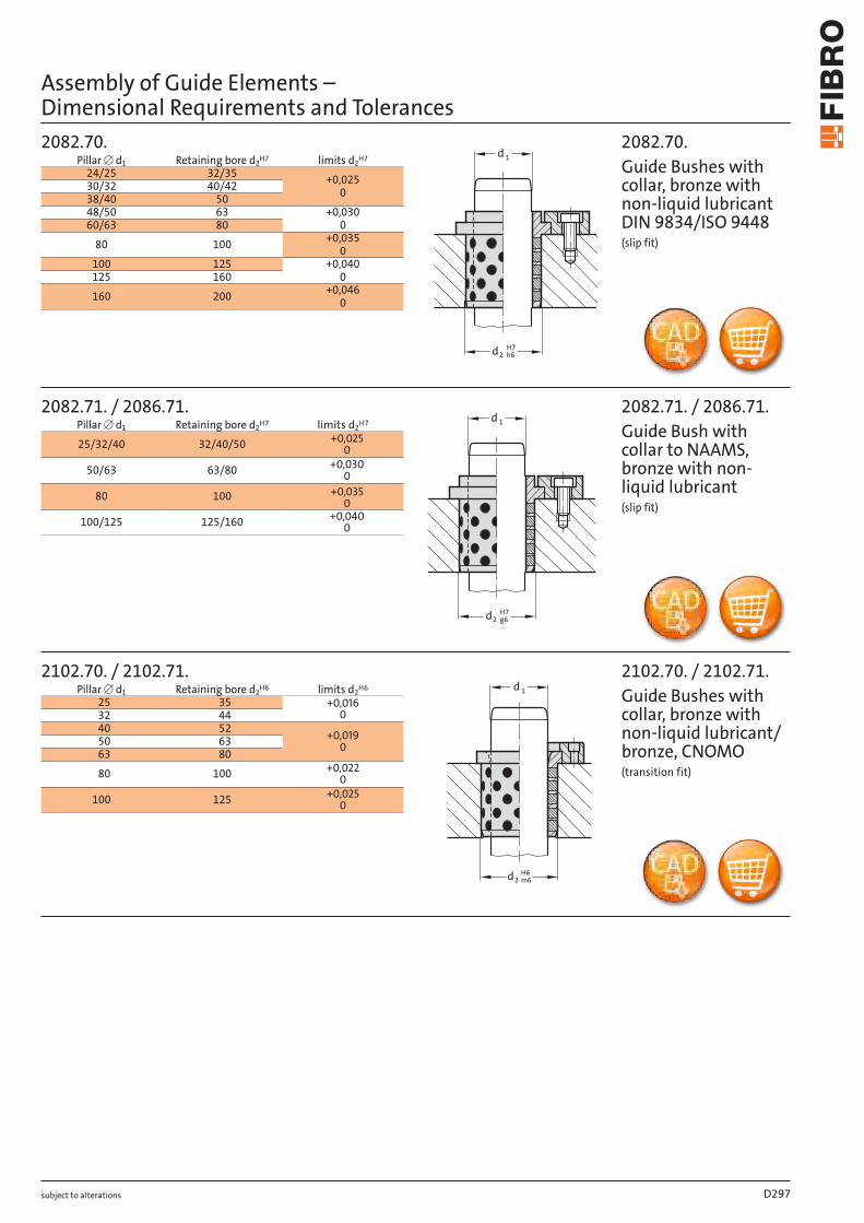
˜d
m˝˙d
˜d
H˝rˆˇd
˜d
G˝kˆˇd
10 14 +0,018012 18
13 19
+0,0210
14 2015 2116 2220 3025 35
+0,0250
30 4031,5 4035 4540 50
45 55
+0,0300
50 6055 6560 7563 7570 85
+0,0350
75 9080 10090 110
100 120
120 140 +0,0400
2052.70. 1) / 2086.70. / 2085.72.
8 12 +0,024+0,006
+0,018010 14/15
12 1813 19
+0,028+0,007
+0,0210
14 2015 2116 22
18/19 24/2520 26/28/3025 32/33/35
+0,034+0,009
+0,0250
28 3830 38/40/42
31,5 4032 4235 44/4538 4840 5040 55
+0,040+0,010
+0,0300
45 55/56/6050 60/62/6555 7060 74/7563 7565 8070 85/90
+0,047+0,012
+0,0350
75 90/9580 96/10085 10090 110
100 120110 130
+0,054+0,014
+0,0400
120 140125 145130 150140 160150 170160 180
2085.70.
12 16 +0,024+0,006
16 20 +0,028+0,00720 26
24 30
2085.71.
subject to alterations
Pillar x d1Retaining
bore d2limits d2H7 Pillar x d1
Retaining bore d2
limits d2H7
Pillar x d1Retaining bore
d2bonding limitsd2G7 Transition fit limits
d2H7
2052.70. 1) / 2086.70. / 2085.72. Guide Bushes/ Guide Bushes with collar, Bronze with non-liquid lubricantslip-fit bonding*:Retaining bore d2 = G7transition fit:Retaining bore d2 = H71) if required secure with set screw
2085.71.Guide Bushes with collar, Bronze with non-liquid lubricant(press fit)
Pillar x d1 Retaining bore d2G7 limits d2G7
2085.70.Guide Bushes with collar, Bronze with non-liquid lubricant(transition fit)
*Slip-Fit Bonding:The glue-line gap must not be smaller than 0,005 mm, or the adhesive willbe wiped off the contact surfaces upon fitment.This would result in an unreliable bond.The available component tolerances do not always result in the minimumglue-line gap.This fact has to be born in mind when machining receiving bores,or alternatively corrections can be made on the assembly bench.
Assembly of Guide Elements – Dimensional Requirements and Tolerances
1
d
H7
g62
d
1d
H6
m2 6d
1
d
H7
h62
d
2102.70. / 2102.71. 25 35 +0,016
032 4440 52 +0,019
050 6363 8080 100 +0,022
0
100 125 +0,025 0
2082.70. 24/25 32/35 +0,025
030/32 40/4238/40 5048/50 63 +0,030
060/63 8080 100 +0,035
0100 125 +0,040
0125 160160 200 +0,046
0
2082.71. / 2086.71.
25/32/40 32/40/50 +0,025 0
50/63 63/80 +0,030 0
80 100 +0,035 0
100/125 125/160 +0,040 0
subject to alterations
2082.71. / 2086.71. Guide Bush with collar to NAAMS, bronze with non-liquid lubricant(slip fit)
2102.70. / 2102.71.Guide Bushes with collar, bronze with non-liquid lubricant/ bronze, CNOMO(transition fit)
Pillar [ d1 Retaining bore d2H6 limits d2H6
2082.70.Guide Bushes with collar, bronze with non-liquid lubricant DIN 9834/ISO 9448(slip fit)
Pillar [ d1 Retaining bore d2H7 limits d2H7
Pillar [ d1 Retaining bore d2H7 limits d2H7
Assembly of Guide Elements – Dimensional Requirements and Tolerances
D297
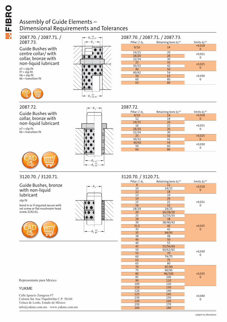
1
d
H7
e7, f7
2
d
H7
k6h6,
2
d
1
d
e72
d
H7
k62
d
1
d
H7
g62
d
3120.70. / 3120.71. 8 12 +0,018
010 14/1512 1813 19
+0,021 0
14 2015 2116 22
18/19 24/2520 26/28/3025 32/33/35
+0,025 0
28 3830 38/40/42
31,5 4032 4235 44/4538 4840 5040 55
+0,030 0
45 55/56/6050 60/62/6555 7060 74/7563 7565 8070 85/90
+0,035 0
75 90/9580 96/10085 10090 110
100 120110 130
+0,0400
120 140125 145130 150140 160150 170160 180
2087.72. 9/10 14 +0,018
012 1814/15 20
+0,021 0
16 2218/20 2622/24 30
25 32 +0,025 030/32 42
40/42 54 +0,030050 66
60 80
2087.70. / 2087.71. / 2087.73.
9/10 14 +0,018 0
14/15 20 +0,021 018/20 26
22/24 3025 35 +0,025
030/32 4240 50
40/42 54+0,030
050 6360 8063 80
subject to alterations
Pillar [ d1 Retaining bore d2H7 limits d2H7
2087.70. / 2087.71. / 2087.73. Guide Bushes with centre collar/ with collar, bronze with non-liquid lubricante7 = slip fit f7 = slip fit h6 = slip fit k6 = transition fit
2087.72. Guide Bushes with collar, bronze with non-liquid lubricante7 = slip fit k6 = transition fit
Pillar [ d1 Retaining bore d2H7 limits d2H7
Pillar [ d1 Retaining bore d2H7 limits d2H7
3120.70. / 3120.71.
Guide Bushes, bronze with non-liquid lubricantslip fitbond in or if required secure with set screw or flat mushroom head screw 2192.61.
Assembly of Guide Elements – Dimensional Requirements and Tolerances
Calle Ignacio Zaragoza #7Colonia Sta Ana Tlapaltitilán C.P. 50160Toluca de Lerdo, Estado de México
YUKME
Representante para México
[email protected] · www.yukme.com.mx