Cybersecurity Framework Manufacturing Profile Low Impact ...
353
NISTIR 8183A Volume 2 Cybersecurity Framework Manufacturing Profile Low Impact Level Example Implementations Guide: Volume 2 – Process-based Manufacturing System Use Case Keith Stouffer Timothy Zimmerman CheeYee Tang Jeffrey Cichonski Michael Pease Neeraj Shah Wesley Downard This publication is available free of charge from: https://doi.org/10.6028/NIST.IR.8183A-2
-
Upload
khangminh22 -
Category
Documents
-
view
1 -
download
0
Transcript of Cybersecurity Framework Manufacturing Profile Low Impact ...

NISTIR 8183A
Volume 2
Cybersecurity Framework Manufacturing Profile
Low Impact Level Example
Implementations Guide: Volume 2 – Process-based Manufacturing System Use Case
Keith Stouffer
Timothy Zimmerman
CheeYee Tang
Jeffrey Cichonski
Michael Pease
Neeraj Shah
Wesley Downard
This publication is available free of charge from:
https://doi.org/10.6028/NIST.IR.8183A-2

NISTIR 8183A
Volume 2
Cybersecurity Framework Manufacturing Profile
Low Impact Level Example
Implementations Guide: Volume 2 – Process-based Manufacturing System Use Case
Keith Stouffer Neeraj Shah
Timothy Zimmerman Strativia, LLC
CheeYee Tang Largo, Maryland
Michael Pease
Intelligent Systems Division
Engineering Laboratory
Jeffrey Cichonski Wesley Downard
Applied Cybersecurity Division G2, Inc.
Information Technology Laboratory Annapolis Junction, Maryland
This publication is available free of charge from:
https://doi.org/10.6028/NIST.IR.8183A-2
September 2019
U.S. Department of Commerce Wilbur L. Ross, Jr., Secretary
National Institute of Standards and Technology
Walter Copan, NIST Director and Under Secretary of Commerce for Standards and Technology

National Institute of Standards and Technology Internal Report 8183A, Volume 2 353 pages (September 2019)
This publication is available free of charge from:
https://doi.org/10.6028/NIST.IR.8183A-2
Certain commercial entities, equipment, or materials may be identified in this document in order to describe an
experimental procedure or concept adequately. Such identification is not intended to imply recommendation or
endorsement by NIST, nor is it intended to imply that the entities, materials, or equipment are necessarily the best
available for the purpose.
There may be references in this publication to other publications currently under development by NIST in accordance
with its assigned statutory responsibilities. The information in this publication, including concepts and methodologies,
may be used by federal agencies even before the completion of such companion publications. Thus, until each
publication is completed, current requirements, guidelines, and procedures, where they exist, remain operative. For
planning and transition purposes, federal agencies may wish to closely follow the development of these new
publications by NIST.
Organizations are encouraged to review all draft publications during public comment periods and provide feedback to NIST. Many NIST cybersecurity publications, other than the ones noted above, are available at https://csrc.nist.gov/publications.
Comments on this publication may be submitted to:
National Institute of Standards and Technology Attn: Applied Cybersecurity Division, Information Technology Laboratory
100 Bureau Drive (Mail Stop 2000) Gaithersburg, MD 20899-2000 Email: [email protected]
All comments are subject to release under the Freedom of Information Act (FOIA).

NISTIR 8183A VOL. 2 CSF MFG PROFILE LOW IMPACT LEVEL EXAMPLE IG PROCESS-BASED MFG SYSTEM USE CASE
ii
Th
is p
ublic
atio
n is
ava
ilable
free
of c
ha
rge
from
: http
s://d
oi.o
rg/1
0.6
02
8/N
IST
.IR.8
18
3A
-2
Abstract
This guide provides example proof-of-concept solutions demonstrating how available open-
source and commercial off-the-shelf (COTS) products could be implemented in process-based
manufacturing environments to satisfy the requirements in the Cybersecurity Framework (CSF)
Manufacturing Profile Low Impact Level. The example proof-of-concept solutions include
measured network, device, and operational performance impacts observed during the
implementation. Manufacturers should make their own determinations about the breadth of the
proof-of-concept solutions they voluntarily implement. Some important factors to consider
include: company size, cybersecurity expertise, risk tolerance, and the threat landscape. The CSF
Manufacturing Profile can be used as a roadmap for managing cybersecurity risk for
manufacturers and is aligned with manufacturing sector goals and industry best practices. The
Manufacturing Profile provides a voluntary, risk-based approach for managing cybersecurity
activities and cyber risk to manufacturing systems. The Manufacturing Profile is meant to
complement but not replace current cybersecurity standards and industry guidelines that the
manufacturer is embracing.
Keywords
Computer security; Cybersecurity Framework (CSF); distributed control systems (DCS);
industrial control systems (ICS); information security; manufacturing; network security;
programmable logic controllers (PLC); risk management; security controls; supervisory control
and data acquisition (SCADA) systems.
Supplemental Content
Additional volumes of this publication include:
NISTIR 8183A Volume 1, Cybersecurity Framework Manufacturing Profile Low Impact
Level Example Implementations Guide: Volume 1 – General Implementation Guidance.
https://doi.org/10.6028/NIST.IR.8183A-1
NISTIR 8183A Volume 3, Cybersecurity Framework Manufacturing Profile Low Impact
Level Example Implementations Guide: Volume 3 – Discrete-based Manufacturing
System Use Case. https://doi.org/10.6028/NIST.IR.8183A-3

NISTIR 8183A VOL. 2 CSF MFG PROFILE LOW IMPACT LEVEL EXAMPLE IG PROCESS-BASED MFG SYSTEM USE CASE
iii
Th
is p
ublic
atio
n is
ava
ilable
free
of c
ha
rge
from
: http
s://d
oi.o
rg/1
0.6
02
8/N
IST
.IR.8
18
3A
-2
Acknowledgments
The authors gratefully acknowledge and appreciate the significant contributions from individuals
and organizations in the public and private sectors, whose thoughtful and constructive comments
improved the overall quality, thoroughness, and usefulness of this publication. A special
acknowledgement to the members of the ISA99, Industrial Automation and Control Systems
Security Committee and the Department of Homeland Security Industrial Control System Joint
Working Group (ICSJWG) for their exceptional contributions to this publication.
Note to Readers
This guide describes a proof-of-concept solution for securing manufacturing environments that
has only been tested in a lab environment. Manufacturers should make their own determinations
about the breadth of the proof-of-concept solutions they voluntarily implement. Some important
factors to consider include: company size, cybersecurity expertise, risk tolerance, and the threat
landscape. We welcome feedback on its contents and your input. Comments, suggestions, and
success stories will improve subsequent versions of this guide. Please contribute your thoughts to
Revision to Include Updates in Cybersecurity Framework Version 1.1
The Cybersecurity Framework Manufacturing Profile, NISTIR 8183, was drafted and released
when the Cybersecurity Framework was at Version 1.0. This guide provides implementation
guidance and example proof-of-concept solutions with respect to the language in the original
Cybersecurity Framework Manufacturing Profile.
The Cybersecurity Framework Manufacturing Profile, NISTIR 8183, is scheduled to be revised
to include the updates in the Cybersecurity Framework Version 1.1, and will be published as
NISTIR 8183, Revision 1.
Once NISTIR, 8183, Revision 1 has been released, this implementation guide will be revised to
include the updates in the Cybersecurity Framework Version 1.1 as well, and will be published
as NISTIR 8183A, Revision 1.
NISTIR 8183A VOL. 2 CSF MFG PROFILE LOW IMPACT LEVEL EXAMPLE IG PROCESS-BASED MFG SYSTEM USE CASE
iv
Th
is p
ublic
atio
n is
ava
ilable
free
of c
ha
rge
from
: http
s://d
oi.o
rg/1
0.6
02
8/N
IST
.IR.8
18
3A
-2
Table of Contents
Executive Summary ..................................................................................................... vi
1. Introduction ............................................................................................................ 1
Purpose and Scope ........................................................................................ 1
Audience ......................................................................................................... 2 Document Structure ........................................................................................ 3
2. Process-based Manufacturing System Low Impact Level Use Case ............... 4
Introduction ..................................................................................................... 4 Process-based Low Impact Level Use Case .................................................. 4
3. Policy and Procedure Implementations ............................................................... 9
Cybersecurity Program Document Example ................................................... 9 Cybersecurity Policy Document Example ..................................................... 20
Cybersecurity Operations Document Example ............................................. 35 Risk Management Document Example ......................................................... 51 Incident Response Plan Document Example ................................................ 59
System Recovery Plan Document Example ................................................. 73 Service Level Agreement .............................................................................. 94
4. Technical Solution Implementations .................................................................. 98
Introduction ................................................................................................... 98 Open-AudIT ................................................................................................ 101
CSET .......................................................................................................... 110
GRASSMARLIN .......................................................................................... 115 Wireshark .................................................................................................... 125 Veeam Backup and Replication .................................................................. 132
Security Onion ............................................................................................ 147 Cisco AnyConnect VPN .............................................................................. 160
Microsoft Active Directory ........................................................................... 184 Symantec Endpoint Protection .................................................................... 218
Tenable Nessus .......................................................................................... 231 NamicSoft ................................................................................................... 241 The Hive Project ......................................................................................... 251 Microsoft EFS ............................................................................................. 260 GTB Inspector ............................................................................................. 271 Graylog ....................................................................................................... 279 DBAN .......................................................................................................... 295
Network Segmentation and Segregation .................................................... 299 Network Boundary Protection ..................................................................... 303 Managed Network Interfaces ...................................................................... 316 Time Synchronization ................................................................................. 320 System Use Monitoring ............................................................................... 324 Ports and Services Lockdown ..................................................................... 330

NISTIR 8183A VOL. 2 CSF MFG PROFILE LOW IMPACT LEVEL EXAMPLE IG PROCESS-BASED MFG SYSTEM USE CASE
v
Th
is p
ublic
atio
n is
ava
ilable
free
of c
ha
rge
from
: http
s://d
oi.o
rg/1
0.6
02
8/N
IST
.IR.8
18
3A
-2
Media Protection ......................................................................................... 335
Appendix A - Acronyms and Abbreviations ........................................................... 338
Appendix B - Glossary .............................................................................................. 341
Appendix C - References .......................................................................................... 345
NISTIR 8183A VOL. 2 CSF MFG PROFILE LOW IMPACT LEVEL EXAMPLE IG PROCESS-BASED MFG SYSTEM USE CASE
vi
Th
is p
ublic
atio
n is
ava
ilable
free
of c
ha
rge
from
: http
s://d
oi.o
rg/1
0.6
02
8/N
IST
.IR.8
18
3A
-2
Executive Summary
This guide provides example proof-of-concept solutions demonstrating how available open-
source and commercial off-the-shelf (COTS) products could be implemented in process-based
manufacturing environments to satisfy the requirements in the Cybersecurity Framework (CSF)
Manufacturing Profile [4] Low Impact Level. A manufacturing system could be classified as
Low potential impact if the loss of integrity, availability, or confidentiality could be expected to
have a limited adverse effect on manufacturing operations, manufactured product, assets, brand
image, finances, personnel, the general public, or the environment. A limited adverse effect
means that, for example, the loss of integrity, availability, or confidentiality might:
• result in degradation in mission capability to an extent and duration that the system can
perform its primary functions, but the effectiveness of the functions is noticeably
reduced,
• result in minor damage to operational assets,
• result in minor financial loss, or
• result in minor harm to individuals.
The example proof-of-concept solutions include measured network, device, and operational
performance impacts observed during the implementation. Manufacturers should make their own
determinations about the breadth of the proof-of-concept solutions they voluntarily implement.
Some important factors to consider include: company size, cybersecurity expertise, risk
tolerance, and the threat landscape.
The CSF Manufacturing Profile can be used as a roadmap for managing cybersecurity risk for
manufacturers and is aligned with manufacturing sector goals and industry best practices. The
Manufacturing Profile provides a voluntary, risk-based approach for managing cybersecurity
activities and cyber risk to manufacturing systems. The Manufacturing Profile is meant to
complement but not replace current cybersecurity standards and industry guidelines that the
manufacturer is embracing.
The CSF Manufacturing Profile focuses on desired cybersecurity outcomes and can be used as a
roadmap to identify opportunities for improving the current cybersecurity posture of the
manufacturing system. The Manufacturing Profile provides a prioritization of security activities
to meet specific business/mission goals. Relevant and actionable security practices that can be
implemented to support key business/mission goals are then identified.
While the proof-of-concept solutions in this guide used a suite of commercial products, this
guide does not endorse these particular products, nor does it guarantee compliance with any
regulatory initiatives. Each organization’s information security experts should identify the
products that will best integrate with their existing tools and manufacturing system
infrastructure. Organizations may voluntarily adopt these solutions or one that adheres to these
guidelines in whole or can use this guide as a starting point for tailoring and implementing parts
of a solution. This guide does not describe regulations or mandatory practices, nor does it carry
any statutory authority.

NISTIR 8183A VOL. 2 CSF MFG PROFILE LOW IMPACT LEVEL EXAMPLE IG PROCESS-BASED MFG SYSTEM USE CASE
1
Th
is p
ublic
atio
n is
ava
ilable
free
of c
ha
rge
from
: http
s://d
oi.o
rg/1
0.6
02
8/N
IST
.IR.8
18
3A
-2
1. Introduction
The Executive Order 13636, “Improving Critical Infrastructure Cybersecurity,” [1] directed the
development of the voluntary Cybersecurity Framework that provides a prioritized, flexible,
repeatable, performance-based, and cost-effective approach to manage cybersecurity risk [1] for
those processes, information, and systems directly involved in the delivery of critical
infrastructure services.
The Cybersecurity Framework is a voluntary risk-based assemblage of industry standards and
best practices designed to help organizations manage cybersecurity risks [2]. The Framework,
created through collaboration between government and the private sector, uses a common
language to address and manage cybersecurity risk in a cost-effective way based on business
needs without imposing additional regulatory requirements.
To address the needs of manufacturers, a Manufacturing Profile [4] of the Cybersecurity
Framework was developed, through collaboration between government and the private sector, to
be an actionable approach for implementing cybersecurity controls into a manufacturing system
and its environment. The Profile defines specific cybersecurity activities and outcomes for the
protection of the manufacturing system, its components, facility, and environment. Through use
of the Profile, the manufacturer can align cybersecurity activities with business requirements,
risk tolerances, and resources. The Profile provides a manufacturing sector-specific approach to
cybersecurity from standards, guidelines, and industry best practices.
Purpose and Scope
Many small and medium sized manufacturers have expressed challenges in implementing a
standards-based cybersecurity program. This guide provides example proof-of-concept solutions
demonstrating how available open-source and commercial off-the-shelf (COTS) products could
be implemented in process-based manufacturing environments to satisfy the requirements in the
Cybersecurity Framework (CSF) Manufacturing Profile Low Impact Level. A manufacturing
system could be classified as Low potential impact if the loss of integrity, availability, or
confidentiality could be expected to have a limited adverse effect on manufacturing operations,
manufactured product, assets, brand image, finances, personnel, the general public, or the
environment. A limited adverse effect means that, for example, the loss of integrity, availability,
or confidentiality might:
• result in degradation in mission capability to an extent and duration that the system can
perform its primary functions, but the effectiveness of the functions is noticeably
reduced,
• result in minor damage to operational assets,
• result in minor financial loss, or
• result in minor harm to individuals.
Example proof-of-concept solutions with measured network, device, and operational
performance impacts for a process-based manufacturing environment (Volume 2) and a discrete-
based manufacturing environment (Volume 3) are included in the guide. Manufacturers should
make their own determinations about the breadth of the proof-of-concept solutions they

NISTIR 8183A VOL. 2 CSF MFG PROFILE LOW IMPACT LEVEL EXAMPLE IG PROCESS-BASED MFG SYSTEM USE CASE
2
Th
is p
ublic
atio
n is
ava
ilable
free
of c
ha
rge
from
: http
s://d
oi.o
rg/1
0.6
02
8/N
IST
.IR.8
18
3A
-2
voluntarily implement. Some important factors to consider include: company size, cybersecurity
expertise, risk tolerance, and the threat landscape. The CSF Manufacturing Profile can be used as
a roadmap for managing cybersecurity risk for manufacturers and is aligned with manufacturing
sector goals and industry best practices. The Manufacturing Profile provides a voluntary, risk-
based approach for managing cybersecurity activities and cyber risk to manufacturing systems.
The Manufacturing Profile is meant to enhance but not replace current cybersecurity standards
and industry guidelines that the manufacturer is embracing.
While the proof-of-concept solutions in this guide used a suite of commercial products, this
guide does not endorse these particular products, nor does it guarantee compliance with any
regulatory initiatives. Each organization’s information security experts should identify the
products that will best integrate with their existing tools and manufacturing system
infrastructure. Organizations may voluntarily adopt these solutions or one that adheres to these
guidelines in whole or can use this guide as a starting point for tailoring and implementing parts
of a solution. This guide does not describe regulations or mandatory practices, nor does it carry
any statutory authority.
This project is guided by the following assumptions:
• the solutions were developed in a lab environment,
• the environment is based on a typical small manufacturer’s environment,
• the environment does not reflect the complexity of a production environment, and
• an organization can access the skills and resources required to implement a
manufacturing cybersecurity solution.
Audience
This document covers details specific to manufacturing systems. Readers of this document
should be acquainted with operational technology, general computer security concepts, and
communication protocols such as those used in networking. The intended audience is varied and
includes the following:
• control engineers, integrators, and architects who design or implement secure
manufacturing systems,
• system administrators, engineers, and other information technology (IT) professionals
who administer, patch, or secure manufacturing systems,
• managers who are responsible for manufacturing systems,
• senior management who are trying to understand implications and consequences as they
justify and implement a manufacturing systems cybersecurity program to help mitigate
impacts to business functionality, and
• researchers, academic institutions and analysts who are trying to understand the unique
security needs of manufacturing systems.

NISTIR 8183A VOL. 2 CSF MFG PROFILE LOW IMPACT LEVEL EXAMPLE IG PROCESS-BASED MFG SYSTEM USE CASE
3
Th
is p
ublic
atio
n is
ava
ilable
free
of c
ha
rge
from
: http
s://d
oi.o
rg/1
0.6
02
8/N
IST
.IR.8
18
3A
-2
Document Structure
Volume 2 is divided into the following major sections:
• Section 2 provides an overview of the process-based manufacturing system use case.
• Section 3 provides the detailed policy and procedure documents developed for the
process-based manufacturing system use case.
• Section 4 provides the detailed technical capability implementations and associated
performance measurements for the process-based manufacturing system use case.
• Appendix A provides a list of acronyms and abbreviations used in this document.
• Appendix B provides a glossary of terms used in this document.
• Appendix C provides a list of references used in the development of this document.

NISTIR 8183A VOL. 2 CSF MFG PROFILE LOW IMPACT LEVEL EXAMPLE IG PROCESS-BASED MFG SYSTEM USE CASE
4
Th
is p
ublic
atio
n is
ava
ilable
free
of c
ha
rge
from
: http
s://d
oi.o
rg/1
0.6
02
8/N
IST
.IR.8
18
3A
-2
2. Process-based Manufacturing System Low Impact Level Use Case
Introduction
This use case is a proof-of-concept demonstrating how available open-source and commercial
off-the-shelf (COTS) products could be implemented in a process-based manufacturing
environment to satisfy the requirements in the Cybersecurity Framework (CSF) Manufacturing
Profile Low Impact Level. Manufacturers should make their own determinations about the
breadth of the proof-of-concept solutions they voluntarily implement. Some important factors to
consider include: company size, cybersecurity expertise, risk tolerance, and the threat landscape.
Process-based Low Impact Level Use Case
The fictional company, Westman Industries (i.e. Westman), is a chemical manufacturer
producing commercial grade chemical products for use in the transportation, building and
construction, and other industries. It is headquartered in Westland, a city with a population of
about 100,000 people.
Westman operates its manufacturing facility 24 hours per day, 7 days per week (24/7), except for
a scheduled maintenance shutdown for about 2 weeks every year, typically at the end of
December.
To increase industrial competitiveness, Westman has introduced process automation equipment
to improve production efficiency and to lower production costs. Industrial automation equipment
like programmable logic controllers (PLC), human-machine-interfaces (HMI), and data
historians are deployed in the factory to monitor and control the production operation.
Mission
Westman’s mission is to supply high quality chemical products for industrial application.
Facility
Westman facility is a single building about 5000 m2, with about 3500 m2 of manufacturing space
which includes the production space, a distribution facility, and several above ground chemical
storage tanks. The remainder of the facility contains the administrative and engineering office
space.
The perimeter of the facility is fenced, and the main entrance has a gate that is open during
business hours and is locked after hours. There are two entrances to the main building. One is for
employee access and is protected by a badge access system. Employees must swipe their
assigned badge to enter the building. The other entrance is located at the front lobby, staffed by a
receptionist during normal business hours. Guests and visitors are required to sign in and receive
proper identification before entering the building or facility. The Westman facility does not have
any contracted security guards at the gate or entrances.

NISTIR 8183A VOL. 2 CSF MFG PROFILE LOW IMPACT LEVEL EXAMPLE IG PROCESS-BASED MFG SYSTEM USE CASE
5
Th
is p
ublic
atio
n is
ava
ilable
free
of c
ha
rge
from
: http
s://d
oi.o
rg/1
0.6
02
8/N
IST
.IR.8
18
3A
-2
Employees
Westman has 200 full-time employees, with most of the employees working on the
manufacturing floor. A small team of full-time manufacturing/control engineers is responsible
for the manufacturing, control and automation equipment controlling the manufacturing process.
Their mission is to ensure the safe and efficient operation of the production system.
Westman also has a small team of full-time IT personnel responsible for the enterprise IT
systems.
Westman’s senior managers have the following positions and responsibilities:
Westman
Management
Major Responsibility
Chief Executive
Officer (CEO)
Oversight of the company
Director of Operations Oversight of manufacturing operations. Management of the manufacturing
staff and control engineers. Reports to the CEO.
Director of Product
Development
Oversight of product development. Management of the on-site chemists.
Reports to the CEO.
Director of Marketing Oversight of marketing and sales. Reports to the CEO.
Controller/Finances Manager of finance staff. Reports to the CEO.
General Counsel Handles all legal matters. Reports to the CEO.
IT Manager Manager of IT staff. Reports to the CEO.
HR Manager Manager of human resources staff. Reports to the CEO.

NISTIR 8183A VOL. 2 CSF MFG PROFILE LOW IMPACT LEVEL EXAMPLE IG PROCESS-BASED MFG SYSTEM USE CASE
6
Th
is p
ublic
atio
n is
ava
ilable
free
of c
ha
rge
from
: http
s://d
oi.o
rg/1
0.6
02
8/N
IST
.IR.8
18
3A
-2
Supply Chain
Raw materials are utilized to support the continuous operation of the manufacturing process.
Raw materials are typically supplied through a long-term contract established with suppliers and
are transported to the facility on a regular basis.
The end products are typically sold to customers in large quantity. Delivery is sub-contracted to
several logistics companies which will handle the transportation from the Westman facility to the
end customers. Westman's products are typically used as raw materials or additives in chemical
processes performed by other industrial manufacturers.
Supporting Services
The supporting services required by Westman are electricity, natural gas, water, and
Internet. The broadband Internet connection is a business class service provided by a large
national provider with business class service level agreement.
Legal and Regulatory Requirements
As a chemical manufacturer, Westman and its employees are required to comply with all federal
and state legal and regulatory requirements for chemical and hazardous materials. Westman is
also required to comply with all legal, regulatory and safety requirements.
Critical Infrastructure
The chemical sector is considered a critical infrastructure under the Presidential Policy Directive
21 (PPD-21).
Manufacturing Process
The manufacturing system consists of five major chemical processing components: a reactor, a
product condenser, a vapor-liquid separator, a recycle compressor, and a product stripper to
separate the end products. The manufacturing system has 12 valves for controlling the flow of
chemicals through the system, and 41 sensor measurements for monitoring the chemical process.
All valves and sensors are connected to the automation equipment (PLCs) through a DeviceNet
communications bus. Valves are equipped with manual overrides, enabling workers to override
the automation equipment during an emergency.
Raw materials are fed to the reactor where the materials are mixed and the main reaction takes
place. Output from the reactor flows downstream to the product condenser and the vapor-liquid
separator. Any output from the reactor still in the gaseous form is recycled through a compressor
and fed back into the main reactor. All condensed components continuously flow to the product
stripper, which separates the components into the final products. Quality assurance samples are
taken at various stages of the process to validate the product quality and process efficiency.

NISTIR 8183A VOL. 2 CSF MFG PROFILE LOW IMPACT LEVEL EXAMPLE IG PROCESS-BASED MFG SYSTEM USE CASE
7
Th
is p
ublic
atio
n is
ava
ilable
free
of c
ha
rge
from
: http
s://d
oi.o
rg/1
0.6
02
8/N
IST
.IR.8
18
3A
-2
Systems
The administrative office is supported by a small team of IT personnel mainly using general
enterprise IT applications (e.g., email, web applications, and enterprise planning applications).
The IT personnel maintain a central file storage that is used to store source code, chemical
formulas, drawings, procedures, and diagrams, and is backed up regularly. The product
development staff and the manufacturing engineers are authorized to access this storage.
The IT personnel also installed and configured a Historian database on the manufacturing floor
to record manufacturing process data. IT personnel are responsible for regular data backup of the
Historian, and the manufacturing engineers are responsible for the configuration and operation of
the Historian.
Data
Data transferred over, or stored within the company network include:
• PLC program code
• Chemical formulas and calculations
• Workflow and operating manuals and documentation
• Electrical diagrams
• Network diagrams
• Quality Assurance procedures
• Historical production data
NOTE: All data listed above are considered proprietary, trade secrets, or sensitive.
Network
The IT systems within the administrative offices are connected to the corporate network, which
is managed by the IT team. The manufacturing floor has a separate network for automation
equipment and is managed by the manufacturing engineers.
The manufacturing network consists of a typical Ethernet based TCP/IP network and other
industrial protocols, e.g., DeviceNet.
Some of the production equipment vendors require Westman to provide remote access to the
equipment. The remote access allows the authorized vendors to connect to the manufacturing
equipment to provide maintenance and support.
NISTIR 8183A VOL. 2 CSF MFG PROFILE LOW IMPACT LEVEL EXAMPLE IG PROCESS-BASED MFG SYSTEM USE CASE
8
Th
is p
ublic
atio
n is
ava
ilable
free
of c
ha
rge
from
: http
s://d
oi.o
rg/1
0.6
02
8/N
IST
.IR.8
18
3A
-2
Mission Objectives
Maintain Personnel Safety
Westman commits to safe operation of the manufacturing system and to always put personnel
safety as its highest priority. All manufacturing processes, protocols, automation processes and
equipment, operating procedures and guidelines are designed to ensure personnel safety.
Maintain Environmental Safety
Westman complies with all applicable regulations regarding environmental safety. Westman is
committed to ensuring environmentally-friendly operation of its manufacturing process and
working to reduce its environmental footprint. Environmental impact caused by the
manufacturing process is measured and reviewed on a quarterly basis.
Maintain Quality of Product
Westman has a world-class manufacturing facility and process. It has employed state of the art
automation, equipment, and techniques to ensure the high quality of its products. It has
developed a quality assurance program using automation equipment, including PLCs, Historian,
and high precision sensors operating on a high-speed control network to monitor product quality.
Maintain Production Goals
Meeting the monthly production goals is an important objective for Westman and ensures the
supply of products to its customers in a timely fashion. It also maintains financial stability for
Westman.
Constant 24/7 production enables Westman to plan its manufacturing operation to meet its
production goals and customer demand. The investment in automation equipment and skilled
professionals enables Westman to maintain the monthly production goals.
Protect Trade Secrets
Westman is committed to protecting its trade secrets, including product development,
manufacturing processes, product quality, and supply chain management.

NISTIR 8183A VOL. 2 CSF MFG PROFILE LOW IMPACT LEVEL EXAMPLE IG PROCESS-BASED MFG SYSTEM USE CASE
9
Th
is p
ublic
atio
n is
ava
ilable
free
of c
ha
rge
from
: http
s://d
oi.o
rg/1
0.6
02
8/N
IST
.IR.8
18
3A
-2
3. Policy and Procedure Implementations
This section includes example policy and procedure documents and statements that were
developed for the fictional company Westman. Each organization’s information security experts
should identify the policy and procedure documents and statements that will best integrate with
their existing cybersecurity program and manufacturing system infrastructure.
Cybersecurity Program Document Example
This section provides example content that a Cybersecurity Program document may contain, including example policy
and procedure statements that were developed for the fictional company Westman. Certain commercial entities,
equipment, or materials may be identified in this document in order to describe a concept adequately. Such
identification is not intended to imply recommendation or endorsement by NIST, nor is it intended to imply that the
entities, equipment, or materials are necessarily the best available for the purpose. Each organization’s information
security experts should identify the content, and policy and procedure statements that will best integrate with their
existing cybersecurity program and manufacturing system infrastructure.
Cybersecurity Program
for
Westman
Document Owner: Director of Operations
Version
Version Date Description Author
1.0 02-22-2018 Initial Draft Director of Operations
2.0 04-21-2018 Major changes to the initial draft Director of Operations
Approval
(By signing below, approvers agree to all terms and conditions outlined in this document.)
Approvers Role Signed Approval Date
S. Forthright CEO <digital signature> 4-22-2018
M. West General Counsel <digital signature> 4-23-2018

NISTIR 8183A VOL. 2 CSF MFG PROFILE LOW IMPACT LEVEL EXAMPLE IG PROCESS-BASED MFG SYSTEM USE CASE
10
Th
is p
ublic
atio
n is
ava
ilable
free
of c
ha
rge
from
: http
s://d
oi.o
rg/1
0.6
02
8/N
IST
.IR.8
18
3A
-2
Purpose
The Cybersecurity Program establishes guidelines and principles for initiating, implementing,
maintaining, and improving cybersecurity management for Westman.
This program is designed to:
• ensure the security and confidentiality of employees and business information,
• protect against any anticipated threats or hazards to the security or integrity of such
information, and
• protect against unauthorized access to or use of such information that could result in
substantial harm or inconvenience to Westman, its partners, or customers.
Audience
This document is intended to be used by the CEO, IT Manager, Director of Operations and any
other members as deemed appropriate by the management. It supports the company’s
responsibility for implementing a cybersecurity program.
Commitment from Management
Westman’s leadership team is committed to the development of this Information Security
Program. It fully supports and owns the ultimate responsibility of this program. This
commitment involves allocating necessary funding to information security work and responding
without delay to new situations. The leadership team will participate in any information security
related event.
Company Overview
Role in the Industrial sector
Westman is a chemical manufacturer producing commercial grade chemical products for use in
the transportation, building and construction, and other industrial products.
Westman operates its manufacturing facility 24 hours per day and 365 days per year, except for a
scheduled maintenance shutdown for about 2 weeks every year, typically at the end of
December. To increase competitiveness, Westman has introduced process automation equipment
to improve the production efficiency and to lower cost. Industrial automation equipment like
Programmable Logic Controller (PLC), Human-Machine-Interface (HMI), and Data Historian
are deployed in the factory to control and monitor the production operation.
The chemical sector is considered a critical infrastructure under the Presidential Policy Directive
21 (PPD-21).

NISTIR 8183A VOL. 2 CSF MFG PROFILE LOW IMPACT LEVEL EXAMPLE IG PROCESS-BASED MFG SYSTEM USE CASE
11
Th
is p
ublic
atio
n is
ava
ilable
free
of c
ha
rge
from
: http
s://d
oi.o
rg/1
0.6
02
8/N
IST
.IR.8
18
3A
-2
Mission Objectives
1. Maintain Personnel Safety
Westman commits to safe operation of the manufacturing system and to always put
personnel safety as its highest priority. All manufacturing processes, protocols,
automation processes and equipment, operating procedures and guidelines are designed
to ensure personnel safety.
2. Maintain Environmental Safety
Westman complies with all applicable regulations regarding environmental safety.
Westman is committed to ensuring environmentally-friendly operation of its
manufacturing process and working to reduce its environmental footprint. Environmental
impact caused by the manufacturing process is measured and reviewed on a quarterly
basis.
3. Maintain Quality of Product
Westman has a world-class manufacturing facility and process. It has employed state of
the art automation, equipment, and techniques to ensure the high quality of its products. It
has developed a quality assurance program using automation equipment, including PLCs,
Historian, and high precision sensors operating on a high-speed control network to
monitor product quality.
4. Maintain Production Goals
Meeting the monthly production goals is an important objective for Westman and ensures
the supply of products to its customers in a timely fashion. It also maintains financial
stability for Westman.
Constant 24/7 production enables Westman to plan its manufacturing operation to meet
its production goals and customer demand. The investment in automation equipment and
skilled professionals enables Westman to maintain the monthly production goals.
5. Protect Trade Secrets
Westman is committed to protecting its trade secrets, including product development,
manufacturing processes, product quality, and supply chain management.
Role in the Supply chain
Raw materials are supplied through a long-term contract established with suppliers and are
transported to the facility on a regular basis.
The end products are typically sold to customers in a large quantity. Delivery is sub-contracted to
several logistics companies which will handle the transportation from the Westman facility to the
end customers. Westman's products are typically being used as raw materials or addictive for
other industrial manufacturers

NISTIR 8183A VOL. 2 CSF MFG PROFILE LOW IMPACT LEVEL EXAMPLE IG PROCESS-BASED MFG SYSTEM USE CASE
12
Th
is p
ublic
atio
n is
ava
ilable
free
of c
ha
rge
from
: http
s://d
oi.o
rg/1
0.6
02
8/N
IST
.IR.8
18
3A
-2
Communication to Company
All critical and operational aspects of the Manufacturing system, key resources should be
documented in network diagrams, manuals or other artifacts. The documentation will be
reviewed on a yearly basis by the Director of Operations with assistance from the IT Manager.
This information will be shared with all employees and contractors depending on their role in the
company.
Critical Manufacturing System Components
Critical manufacturing system components are defined as the following:
• Engineering workstation
• Supervisory PLC
• HMI Server
• OPC and Controller Server
• Historian Database Server
• Network devices
Supporting Services
The supporting services required by Westman are broadband Internet, electricity, natural gas,
and water supply. The broadband Internet connection is a business class service provided by a
national provider with a business class service level agreement.
Information Security Policy
The purpose of this Information Security Policy is to provide an overview of the policies,
standards, procedures and technical controls that make up Westman’s Information Security
Program. This policy is developed and executed by the Director of Operations, and has
expectations set for protecting Westman’s IT and Operational Technology (OT) assets.
Applicable Laws and Regulations
As a chemical manufacturer, Westman is required to comply with all federal and state legal or
regulatory requirements for chemical and hazardous materials. Westman is also required to
comply with all legal, regulatory and safety requirements as an employer.
NISTIR 8183A VOL. 2 CSF MFG PROFILE LOW IMPACT LEVEL EXAMPLE IG PROCESS-BASED MFG SYSTEM USE CASE
13
Th
is p
ublic
atio
n is
ava
ilable
free
of c
ha
rge
from
: http
s://d
oi.o
rg/1
0.6
02
8/N
IST
.IR.8
18
3A
-2
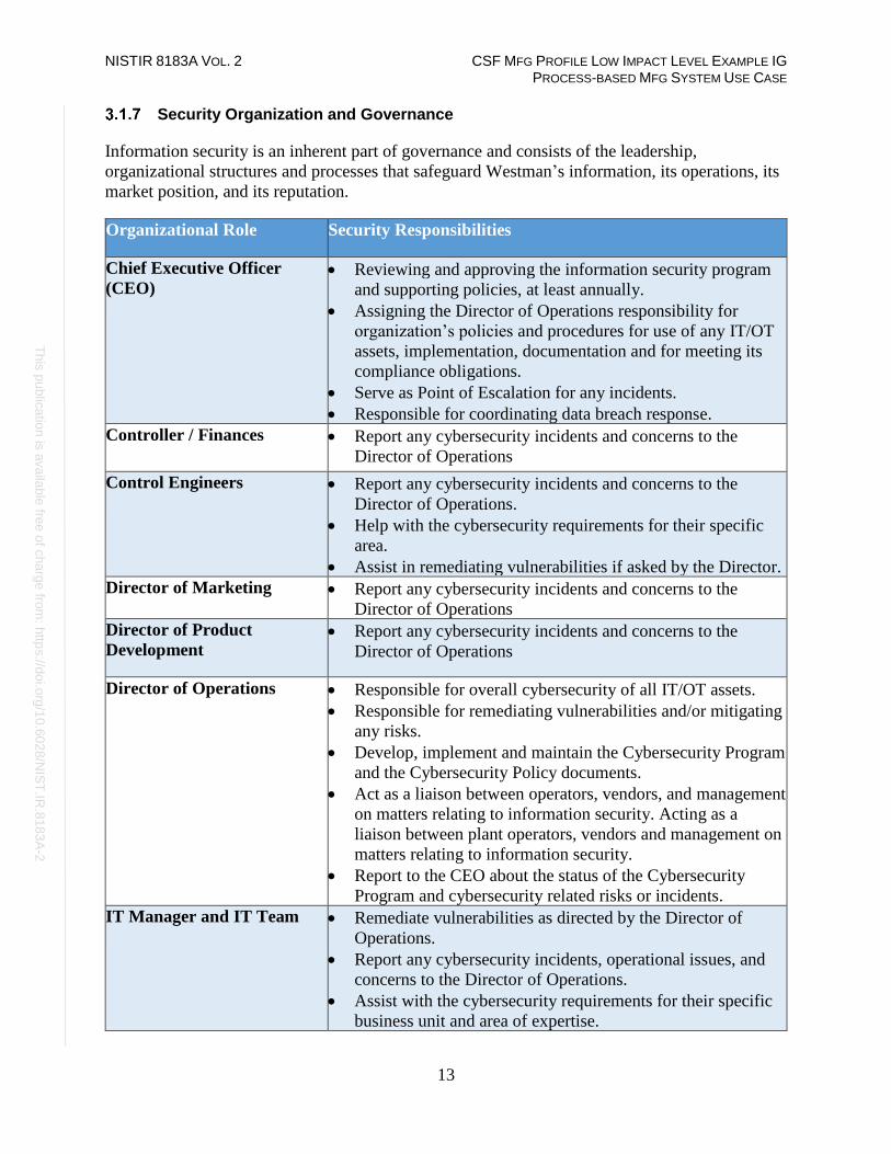
Security Organization and Governance
Information security is an inherent part of governance and consists of the leadership,
organizational structures and processes that safeguard Westman’s information, its operations, its
market position, and its reputation.
Organizational Role Security Responsibilities
Chief Executive Officer
(CEO) • Reviewing and approving the information security program
and supporting policies, at least annually.
• Assigning the Director of Operations responsibility for
organization’s policies and procedures for use of any IT/OT
assets, implementation, documentation and for meeting its
compliance obligations.
• Serve as Point of Escalation for any incidents.
• Responsible for coordinating data breach response.
Controller / Finances • Report any cybersecurity incidents and concerns to the
Director of Operations
Control Engineers • Report any cybersecurity incidents and concerns to the
Director of Operations.
• Help with the cybersecurity requirements for their specific
area.
• Assist in remediating vulnerabilities if asked by the Director.
Director of Marketing • Report any cybersecurity incidents and concerns to the
Director of Operations
Director of Product
Development • Report any cybersecurity incidents and concerns to the
Director of Operations
Director of Operations • Responsible for overall cybersecurity of all IT/OT assets.
• Responsible for remediating vulnerabilities and/or mitigating
any risks.
• Develop, implement and maintain the Cybersecurity Program
and the Cybersecurity Policy documents.
• Act as a liaison between operators, vendors, and management
on matters relating to information security. Acting as a
liaison between plant operators, vendors and management on
matters relating to information security.
• Report to the CEO about the status of the Cybersecurity
Program and cybersecurity related risks or incidents.
IT Manager and IT Team • Remediate vulnerabilities as directed by the Director of
Operations.
• Report any cybersecurity incidents, operational issues, and
concerns to the Director of Operations.
• Assist with the cybersecurity requirements for their specific
business unit and area of expertise.
NISTIR 8183A VOL. 2 CSF MFG PROFILE LOW IMPACT LEVEL EXAMPLE IG PROCESS-BASED MFG SYSTEM USE CASE
14
Th
is p
ublic
atio
n is
ava
ilable
free
of c
ha
rge
from
: http
s://d
oi.o
rg/1
0.6
02
8/N
IST
.IR.8
18
3A
-2
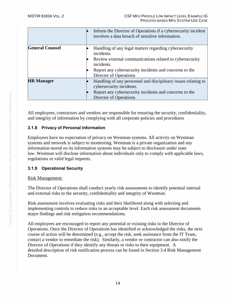
• Inform the Director of Operations if a cybersecurity incident
involves a data breach of sensitive information.
General Counsel • Handling of any legal matters regarding cybersecurity
incidents.
• Review external communications related to cybersecurity
incidents.
• Report any cybersecurity incidents and concerns to the
Director of Operations
HR Manager • Handling of any personnel and disciplinary issues relating to
cybersecurity incidents.
• Report any cybersecurity incidents and concerns to the
Director of Operations
All employees, contractors and vendors are responsible for ensuring the security, confidentiality,
and integrity of information by complying with all corporate policies and procedures
Privacy of Personal Information
Employees have no expectation of privacy on Westman systems. All activity on Westman
systems and network is subject to monitoring. Westman is a private organization and any
information stored on its information systems may be subject to disclosure under state
law. Westman will disclose information about individuals only to comply with applicable laws,
regulations or valid legal requests.
Operational Security
Risk Management:
The Director of Operations shall conduct yearly risk assessments to identify potential internal
and external risks to the security, confidentiality and integrity of Westman.
Risk assessment involves evaluating risks and their likelihood along with selecting and
implementing controls to reduce risks to an acceptable level. Each risk assessment documents
major findings and risk mitigation recommendations.
All employees are encouraged to report any potential or existing risks to the Director of
Operations. Once the Director of Operations has identified or acknowledged the risks, the next
course of action will be determined (e.g., accept the risk, seek assistance from the IT Team,
contact a vendor to remediate the risk). Similarly, a vendor or contractor can also notify the
Director of Operations if they identify any threats or risks to their equipment. A
detailed description of risk notification process can be found in Section 3.4 Risk Management
Document.
NISTIR 8183A VOL. 2 CSF MFG PROFILE LOW IMPACT LEVEL EXAMPLE IG PROCESS-BASED MFG SYSTEM USE CASE
15
Th
is p
ublic
atio
n is
ava
ilable
free
of c
ha
rge
from
: http
s://d
oi.o
rg/1
0.6
02
8/N
IST
.IR.8
18
3A
-2
Physical Security:
The perimeter of the facility is fenced, and the main entrance has a gate that is open during
business hours and locked after hours. There are two entrances to the main building. One is for
employees only which is normally locked, employees must swipe their company-issued
identification to enter the building. The other entrance located at the front lobby is open during
normal business hours. Guests and visitors are required to sign in with proper identification.
Additionally, personnel security is addressed through pre-employment screenings, adequate
position descriptions, terms of employment, and cybersecurity education and training. Additional
details regarding physical security requirements are mentioned in Section 3.2.6 Physical Security
of the Cybersecurity Policy.
Access Control:
Access to IT and OT systems is based on the principle of least privilege depending on the user’s
role in the organization. Proper authorization and approval by the Director of Operations are
required prior to granting access or operating any components of the manufacturing
system. Controls are in place to restrict access through authentication methods and other
technical means. Passwords are managed through a formal process and secure log-on procedures.
Sensitive systems are explicitly identified and audited regularly.
Appropriate authentication controls are used for external connections and remote users. Physical
and logical access to critical components are controlled. Duties are separated to protect systems
and data and access rights are audited at regular intervals.
Cybersecurity Awareness Training
Cybersecurity awareness information is provided to new employees at the time of hire. Online
resources are provided to educate employees on best practices and the importance of reporting
cybersecurity incidents. Additionally, the Director of Operations will ensure the employee
understands their role and responsibilities in Westman’s Cybersecurity Program.
Any information about potential or existing cyber threats to Westman’s systems may be
exchanged routinely between the Director of Operations and external vendors. Likewise, any
news about email scams, phishing attempts and other malicious actions are posted to inform
users of possible threats.
NISTIR 8183A VOL. 2 CSF MFG PROFILE LOW IMPACT LEVEL EXAMPLE IG PROCESS-BASED MFG SYSTEM USE CASE
16
Th
is p
ublic
atio
n is
ava
ilable
free
of c
ha
rge
from
: http
s://d
oi.o
rg/1
0.6
02
8/N
IST
.IR.8
18
3A
-2
Training for Users and Managers
Employees must perform online computer-based training or classroom-based training per
management approval. Below is an example list of potential training options. Trade organization
subscriptions to newsletters and magazines will offer more industry specific training classes.
Example Training
• ICS-CERT VLP1 (Virtual Learning Portal)
• SCADAhacker2
• SANS Industrial Control Systems Training3
• ISA Training4
Training for Privileged Users
Training for privileged users includes the assigned training for regular users. Advanced training
will be provided from industry trade groups specializing in automation or other specialty training
organization focusing on cybersecurity for ICS environments.
Example Training
• International Society of Automation (ISA)5
• SANS (Information Security Training)6
Training for Third Party contractors
Third party contractors must complete cybersecurity awareness training before they are allowed
to access any IT/OT systems. Training can be completed in person at a training facility, or online
in a virtual classroom environment.
Example Training
• SANS Industrial Control Systems Training7 (training with instructors – fee applies).
• ICS-CERT VLP8 (Virtual Learning Portal) (virtual classroom environment at no cost).
1 https://ics-cert-training.inl.gov 2 https://scadahacker.com/training.html 3 https://ics.sans.org/training/courses 4 https://www.isa.org/training-and-certification/isa-training/security-cybersecurity-and-ansi-isa99-training-courses/ 5 https://www.isa.org 6 https://www.sans.org 7 https://ics.sans.org/training/courses 8 https://ics-cert-training.inl.gov

NISTIR 8183A VOL. 2 CSF MFG PROFILE LOW IMPACT LEVEL EXAMPLE IG PROCESS-BASED MFG SYSTEM USE CASE
17
Th
is p
ublic
atio
n is
ava
ilable
free
of c
ha
rge
from
: http
s://d
oi.o
rg/1
0.6
02
8/N
IST
.IR.8
18
3A
-2
Third Party Responsibilities and Requirements
1. Third party contractors and vendors are required to comply with the Cybersecurity Policy
to protect sensitive information and to ensure sensitive information is secured.
2. Third party contractors and vendors will be re-evaluated yearly from the date of
completion of the first security compliance check. During this re-certification process, all
objectives listed in the Security Awareness Training section above will be revisited to
ensure compliance.
3. All remote connections from third party providers will be conducted using a desktop
sharing program. These connections will be monitored and audited.
4. All software and hardware tools used on the network must be approved by the Director of
Operations before they can be used or deployed.
5. Any data that will be shared requires a documented memorandum of understanding to be
executed by both parties.
6. Network accounts will only be created and enabled as required. Accounts used by
vendors for remote access require approval from the Director of Operations. Refer to
Remote Maintenance Approval in the Cybersecurity Policy document for additional
details on the approval process.
Fire Protection, Safety, and Environmental Systems
All fire and safety systems for protecting the manufacturing system must comply with local,
state, and federal laws. This is to include safety regulations for workers’ safety from
Occupational Safety and Health Administration (OSHA). Industry regulations for safety will be
followed per guidance from the regulating industry. Any fire protection systems must be
designed to protect human life as a first priority, and manufacturing equipment as a second
priority. Fire protection for the manufacturing system must be safe to use around electrical
equipment (e.g., PLCs, HMIs, robots, servers). Fire protection systems must be certified
compliant by a licensed and accredited vendor.
All environmental systems (e.g., HVAC) used in the manufacturing system environment must be
compliant with all local, state, and federal laws, and must be designed to protect human life as a
first priority, and manufacturing equipment as a second priority.
Emergency Power
A short-term uninterruptible power supply (UPS) is used to facilitate both an orderly shutdown
and transition of the organization to a long-term alternate power in the event of a major power
loss.

NISTIR 8183A VOL. 2 CSF MFG PROFILE LOW IMPACT LEVEL EXAMPLE IG PROCESS-BASED MFG SYSTEM USE CASE
18
Th
is p
ublic
atio
n is
ava
ilable
free
of c
ha
rge
from
: http
s://d
oi.o
rg/1
0.6
02
8/N
IST
.IR.8
18
3A
-2
Incident Management
Westman’s Incident Response Plan and System Recovery Plan describe the detection, analysis,
containment, eradication, recovery and review of cybersecurity incidents. The process for
responding to cybersecurity incidents is designated in the Incident Response Plan, while the
procedures for system recovery and resilience requirements are defined in the System Recovery
Plan. Cybersecurity incidents are managed by the Director of Operations who ensures that
cybersecurity incidents are promptly reported, investigated, documented and resolved in a
manner that restores operation quickly and, if required, maintains evidence for further
disciplinary, legal, or law enforcement actions. The Incident Response Plan and System
Recovery Plans are reviewed annually and updated as required.
Lessons learned from cybersecurity incidents will be used to revise and improve detection
capabilities while increasing protection for the organization and manufacturing system.
Information Sharing Plan
Information sharing with outside entities like trade organizations and local, state, and federal
agencies can help strengthen cybersecurity. Information sharing, especially when receiving
information from other outside entities, will improve situational awareness, and result in a more
secure manufacturing system.
Trade Organizations
Relationships will be established with trade organizations. These relationships will be used to
share information regarding cybersecurity incidents detected within the manufacturing facility.
Information shared with trade organizations regarding cybersecurity incidents must have all
proprietary information and trade secrets removed. This information will be listed as
unclassified. Information regarding a cybersecurity incident containing information relating to
proprietary, customer, or trade secret process will require a Non-Disclosure Agreement (NDA)
before data is transmitted; this would be considered sensitive information requiring approval
from executive management before being sent.
Local Government
Relationships shall be established with local government with the primary purpose to share
cybersecurity incident data.
State Government
Relationships shall be established with any state government organization with the primary
purpose to share cybersecurity incident data. Trade organizations should be able to provide
contact information for state government incident sharing organizations, if they exist.

NISTIR 8183A VOL. 2 CSF MFG PROFILE LOW IMPACT LEVEL EXAMPLE IG PROCESS-BASED MFG SYSTEM USE CASE
19
Th
is p
ublic
atio
n is
ava
ilable
free
of c
ha
rge
from
: http
s://d
oi.o
rg/1
0.6
02
8/N
IST
.IR.8
18
3A
-2
Federal Government
Relationships shall be established with federal government agencies whose purpose is to share
cybersecurity incident data. Some federal government agencies are listed below.
• DHS (CISA)9 Agency for reporting incidents of Phishing, Malware, Vulnerabilities.
• DHS (NCCIC)10 Agency for reporting cybersecurity incidents relating to Industrial
Control Systems.
Periodic Reevaluation of the Program
The Cybersecurity Program document will be continuously updated to reflect changes made to
the manufacturing system and to improve cybersecurity. Lessons learned will be incorporated to
help improve this document in the event a cybersecurity incident occurs.
The Director of Operations shall reevaluate and modify the Program from time to time as
deemed appropriate. The Director of Operations shall base such reevaluation and modification
on the following:
• The results of the risk assessment and monitoring efforts
• Any material changes to Westman’s operations, business or infrastructure components
• Any cybersecurity incident
Additional Resources
1. Implementing Effective Information Security Program by SANS Resources11
2. InfoSec Program Plan by University of Tennessee Knoxville12
3. GCADA Sample Information Security Procedure13
4. IT Security Program by Old Dominion University14
9 https://www.us-cert.gov/report 10 https://ics-cert.us-cert.gov/Report-Incident 11 https://www.sans.org/reading-room/whitepapers/hsoffice/designing-implementing-effective-information-security-program-
protecting-data-assets-of-1398 12 https://oit.utk.edu/wp-content/uploads/2015-11-11-utk-sec-prog-plan.pdf 13 http://www.gcada.org/pdf/Sample%20Information%20Security%20Procedure%20(safeguard%20policy).pdf
14 https://www.odu.edu/content/dam/odu/offices/occs/docs/odu-it-security-program.pdf

NISTIR 8183A VOL. 2 CSF MFG PROFILE LOW IMPACT LEVEL EXAMPLE IG PROCESS-BASED MFG SYSTEM USE CASE
20
Th
is p
ublic
atio
n is
ava
ilable
free
of c
ha
rge
from
: http
s://d
oi.o
rg/1
0.6
02
8/N
IST
.IR.8
18
3A
-2
Cybersecurity Policy Document Example
This section provides example content that a Cybersecurity Policy document may contain, including example policy
and procedure statements that were developed for the fictional company Westman. Certain commercial entities,
equipment, or materials may be identified in this document in order to describe a concept adequately. Such
identification is not intended to imply recommendation or endorsement by NIST, nor is it intended to imply that the
entities, equipment, or materials are necessarily the best available for the purpose. Each organization’s information
security experts should identify the content, and policy and procedure statements that will best integrate with their
existing cybersecurity program and manufacturing system infrastructure.
Cybersecurity Policy
for
Westman
Document Owner: Director of Operations
Version
Version Date Description Author
1.0 02-22-2018 Initial Draft Director of Operations
2.0 04-21-2018 Major changes to the initial draft Director of Operations
Approval
(By signing below, approvers agree to all terms and conditions outlined in this document.)
Approvers Role Signed Approval Date
S. Forthright CEO <digital signature> 4-22-2018
Purpose
This Cybersecurity Policy defines the security requirements for the proper and secure use of IT
and OT services in the organization. The goal of the defined policies is to protect the
organization and its users against cybersecurity threats that could jeopardize the integrity,
privacy, reputation, and business outcomes of the company.

NISTIR 8183A VOL. 2 CSF MFG PROFILE LOW IMPACT LEVEL EXAMPLE IG PROCESS-BASED MFG SYSTEM USE CASE
21
Th
is p
ublic
atio
n is
ava
ilable
free
of c
ha
rge
from
: http
s://d
oi.o
rg/1
0.6
02
8/N
IST
.IR.8
18
3A
-2
Scope
This Cybersecurity Policy applies to any employee, contractor, or individual with access to the
manufacturing system, or its data.
Policy Maintenance
The Cybersecurity Policy must be approved by the Director of Operations in consultation with
the IT Manager and CEO before it can be disseminated to employees. Any updates to this
document must also be approved by the Director of Operations.
This policy document will be reviewed by the Director of Operations on an annual basis and will
notify all employees of any updates made to the policy.
Role-based Cybersecurity Responsibilities
Cybersecurity responsibilities vary depending on an individual’s role in the company. Each is
defined below.
Employees
Organizational Role Security Responsibilities
Chief Executive Officer
(CEO) • Reviewing and approving the information security program
and supporting policies, at least annually.
• Assigning the Director of Operations responsibility for
organization’s policies and procedures for use of any IT/OT
assets, implementation, documentation and for meeting its
compliance obligations.
• Serve as Point of Escalation for any incidents.
• Responsible for coordinating data breach response.
Controller / Finances • Report any cybersecurity incidents and concerns to the
Director of Operations
Control Engineers • Report any cybersecurity incidents and concerns to the
Director of Operations.
• Help with the cybersecurity requirements for their specific
area.
• Assist in remediating vulnerabilities if asked by the Director.
Director of Marketing • Report any cybersecurity incidents and concerns to the
Director of Operations
Director of Product
Development • Report any cybersecurity incidents and concerns to the
Director of Operations

NISTIR 8183A VOL. 2 CSF MFG PROFILE LOW IMPACT LEVEL EXAMPLE IG PROCESS-BASED MFG SYSTEM USE CASE
22
Th
is p
ublic
atio
n is
ava
ilable
free
of c
ha
rge
from
: http
s://d
oi.o
rg/1
0.6
02
8/N
IST
.IR.8
18
3A
-2
Director of Operations • Responsible for overall cybersecurity of all IT/OT assets.
• Responsible for remediating vulnerabilities and/or mitigating
any risks.
• Develop, implement and maintain the Cybersecurity Program
and the Cybersecurity Policy documents.
• Act as a liaison between operators, vendors, and management
on matters relating to information security. Acting as a liaison
between plant operators, vendors and management on matters
relating to information security.
• Report to the CEO about the status of the Cybersecurity
Program and cybersecurity related risks or incidents.
IT Manager and IT Team • Remediate vulnerabilities as directed by the Director of
Operations.
• Report any cybersecurity incidents, operational issues, and
concerns to the Director of Operations.
• Assist with the cybersecurity requirements for their specific
business unit and area of expertise.
• Inform the Director of Operations if a cybersecurity incident
involves a data breach of sensitive information.
General Counsel • Handling of any legal matters regarding cybersecurity
incidents.
• Review external communications related to cybersecurity
incidents.
• Report any cybersecurity incidents and concerns to the
Director of Operations
HR Manager • Handling of any personnel and disciplinary issues relating to
cybersecurity incidents.
• Report any cybersecurity incidents and concerns to the
Director of Operations
External Personnel
Role Security Responsibilities
Equipment Vendor • Assist in remediating vulnerabilities, upgrading software
or hardware as required.
• Comply with Westman cybersecurity policy.
Visitor • Comply with Westman cybersecurity policy.

NISTIR 8183A VOL. 2 CSF MFG PROFILE LOW IMPACT LEVEL EXAMPLE IG PROCESS-BASED MFG SYSTEM USE CASE
23
Th
is p
ublic
atio
n is
ava
ilable
free
of c
ha
rge
from
: http
s://d
oi.o
rg/1
0.6
02
8/N
IST
.IR.8
18
3A
-2
Employee requirements
1. Employees must complete cybersecurity awareness training and agree to uphold the
acceptable use policy.
2. Employees must immediately notify the Director of Operations if an unescorted or
unauthorized individual is found in the facility.
3. Employees must always use a secure password on all systems as per the password policy.
These credentials must be unique and must not be used on other external systems or
services.
4. Terminated employees must return all company records, in any format.
5. Employees must verify with the Director of Operations that authorizations have been
granted before allowing external personnel to connect to the IT or OT network.
6. Employees must report any physical or cybersecurity incidents to the Director of
Operations.
Physical Security
1. Employees must always use and display company-provided physical identification (ID).
2. IDs must be designed to enable the immediate visual distinction between employees,
external personnel, and visitors.
3. Sharing of IDs for any reason is strictly prohibited.
4. A sign-in sheet will be maintained by the receptionist to record all Visitor visits. These
log records will be reviewed periodically by the Director of Operations.
5. Any visitors, contractors and/or maintenance personnel must always be escorted by an
employee.
6. Unauthorized removal of any company documentation, equipment, or media from the
facility is restricted, unless authorized by the Director of Operations.
7. All activities of visitors, contractors, and maintenance personnel will be subject to
monitoring while onsite. The Director of Operations, or a designated employee, will be
assigned to monitor all computer activities if the visitor, contractor, or maintenance
personnel is connected to any company network.
8. Monthly security status monitoring of the company will be conducted to check for any
physical security incidents.

NISTIR 8183A VOL. 2 CSF MFG PROFILE LOW IMPACT LEVEL EXAMPLE IG PROCESS-BASED MFG SYSTEM USE CASE
24
Th
is p
ublic
atio
n is
ava
ilable
free
of c
ha
rge
from
: http
s://d
oi.o
rg/1
0.6
02
8/N
IST
.IR.8
18
3A
-2
Information Technology (IT) Assets
1. IT assets must only be used for the business activities they are assigned and authorized to
perform.
2. Every employee is responsible for the preservation and proper use of the IT assets they
have been assigned.
3. IT assets must not be left unduly exposed.
4. Desktops and laptops must be locked if left unattended. This policy should be
automatically enforced whenever possible.
5. IT assets must not be accessed by non-authorized individuals. Authorization can be
obtained from Director of Operations.
6. Configuration changes are to be conducted through the change control process,
identifying risks and noteworthy implementation changes.
7. All assets must be protected by authentication technologies (e.g., passwords).
8. Passwords must follow the password policy.
9. The Director of Operations must be notified immediately after an asset is discovered to
be lost or stolen.
10. Use of personal devices to access IT resources is prohibited.
11. Storage of sensitive information on portable media is prohibited, unless authorized by the
Director of Operations.
12. Any sensitive information stored on IT assets, or being transported on a portable device,
must be protected in such a way to deny unauthorized access, and must be encrypted in
line with industry best practices and any applicable laws or regulations.
IT Asset Inventory
Description Quantity
SuperMicro Servers 6
Allen Bradley 5700 Switches 2
Allen Bradley 8300 Router 1
HP Tower Workstation 1

NISTIR 8183A VOL. 2 CSF MFG PROFILE LOW IMPACT LEVEL EXAMPLE IG PROCESS-BASED MFG SYSTEM USE CASE
25
Th
is p
ublic
atio
n is
ava
ilable
free
of c
ha
rge
from
: http
s://d
oi.o
rg/1
0.6
02
8/N
IST
.IR.8
18
3A
-2
Operational Technology (OT) Assets
1. OT assets must not be used for operations they are not assigned or authorized to perform.
2. The Director of Operations and Operators are responsible for the preservation and correct
use of the OT assets they have been assigned.
3. Physical access to OT assets is forbidden for non-authorized personnel.
4. All personnel interacting directly with OT assets must have proper training.
5. The Director of Operations is responsible for all OT devices. A Control Engineer is
solely responsible for maintenance and configuration of the OT devices. No other
personnel are authorized to modify OT asset configurations, including any modification
to interfacing hardware or software.
6. Usage of security tools on the OT network must be approved by the Director of
Operations.
7. All operators must be notified before security tools are used on the OT network.
8. Concept of least privilege must be followed when authorizing access to OT assets.
9. OT assets, such as PLCs, safety systems, etc., should have their keys in the “Run”
position at all times unless being actively programmed.
10. Accessing IT devices or internet use from the OT network, or OT assets, unless
authorized, is prohibited.
11. Use of personal devices to access OT resources is prohibited.
OT Asset Inventory
Description Quantity
Allen Bradley ControlLogix PLC 1
OT Assets Inventory
Lifecycle Accountability of Assets
1. Any IT or OT asset that needs to be decommissioned must be sanitized of all data, as per
the manufacturer guidelines. This task will be usually performed by the IT Support staff.
2. In case of an employee termination, an IT asset such as a desktop PC or laptop must be
reimaged prior to assigning it to a different employee.
NISTIR 8183A VOL. 2 CSF MFG PROFILE LOW IMPACT LEVEL EXAMPLE IG PROCESS-BASED MFG SYSTEM USE CASE
26
Th
is p
ublic
atio
n is
ava
ilable
free
of c
ha
rge
from
: http
s://d
oi.o
rg/1
0.6
02
8/N
IST
.IR.8
18
3A
-2
System Maintenance
1. Any maintenance tasks involving external personnel (e.g., contractors, vendors) must be
approved by the Director of Operations.
2. External personnel with access to company resources must properly secure any resources
that are used to access Westman networks or systems.
3. All remote maintenance activities will be controlled and monitored to ensure no harmful
or malicious activities occur. Detailed logging of the activity will be performed by an
employee.
4. All systems and technical controls must be verified upon the completion of maintenance
for any cybersecurity related impact.
5. The Director of Operations will log all maintenance activities in a Maintenance Tracker.
Data
1. Access to sensitive data must be authorized by the Director of Operations.
2. Data must not be shared informally. When access to sensitive information is required,
personnel can request access from the Director of Operations and should take all
necessary steps to prevent unauthorized access.
3. The Director of Operations must immediately be notified in the event a device is lost
containing sensitive data (e.g. mobiles, laptops, USB devices).
4. Encrypted portable media or secure protocols must be used while transporting or
transferring sensitive company data.
5. Extra precautions must be taken by remotely-operating employees to ensure sensitive
data is appropriately protected.
6. Physical copies of data should be stored in a secure location when not in use.
7. Personnel should ensure physical copies of sensitive data are not left unattended (e.g., on
a printer or a desk).
8. Physical copies of sensitive data should be shredded or disposed in a secure manner when
no longer required.

NISTIR 8183A VOL. 2 CSF MFG PROFILE LOW IMPACT LEVEL EXAMPLE IG PROCESS-BASED MFG SYSTEM USE CASE
27
Th
is p
ublic
atio
n is
ava
ilable
free
of c
ha
rge
from
: http
s://d
oi.o
rg/1
0.6
02
8/N
IST
.IR.8
18
3A
-2
Data types considered sensitive, proprietary, or containing trade secrets
Description Digital
Files
Physical
Copies Databases
PLC program code ✓
Chemical formulas ✓ ✓
Quality Assurance Procedures ✓ ✓
Operating manuals and documentation ✓ ✓
Electrical diagrams ✓ ✓
Network diagrams ✓ ✓
Historical production data ✓ ✓
Credentials Management
The purpose of this policy is to establish a standard for the creation of strong passwords,
protection of those passwords, frequency of change and employee expectations.
All staff, vendors, contractors or other stakeholders who use Westman’s IT and OT systems
should be given authenticated access to those systems by assigning individual credentials
[username and password]. All access and restrictions to those access will be controlled by these
credentials.
The creation and removal of IT system accounts is managed via Microsoft Active Directory. In
addition, the IT manager will determine and authorize user access to IT or OT systems.
Westman reserves the right to suspend without notice access to any system or service.
Password Policy for Active Directory Accounts
1. All passwords must be at least 10 characters long and contain a combination of upper-
case and lower-case letters, numbers, and special characters.
2. Passwords must be changed every 90 days and cannot match a password used within the
past 12 months.
3. Passwords must not be a dictionary name or proper name.
4. Passwords must not be inserted into email messages or other forms of electronic
communication.
5. Employees must choose unique passwords for all company accounts and may not use a
password that they are already using for a personal account.
6. Whenever possible, use of multi-factor authentication is recommended.

NISTIR 8183A VOL. 2 CSF MFG PROFILE LOW IMPACT LEVEL EXAMPLE IG PROCESS-BASED MFG SYSTEM USE CASE
28
Th
is p
ublic
atio
n is
ava
ilable
free
of c
ha
rge
from
: http
s://d
oi.o
rg/1
0.6
02
8/N
IST
.IR.8
18
3A
-2
7. Default passwords, such as those preconfigured in newly-procured assets, must be
removed before the asset is installed or connected to any organizational network.
8. Sharing of passwords is forbidden.
9. Passwords must not be revealed or exposed to public sight.
10. Personnel must refrain from writing passwords down.
11. Personnel must not use the “remember password” feature prevalent on many applications.
Privileged Accounts
Privileged Users
1. The Director of Operations has privileged access to the manufacturing system within
Westman.
2. The IT Manager has privileged access to the IT infrastructure within Westman.
3. All other privileged user accounts are granted to individuals on a case-by-case basis by
the Director of Operations.
Responsibilities
1. Any privileged user within the manufacturing environment will have two accounts. A
primary account used for normal activities, and a privileged “administrator” account for
performing privileged functions.
o Primary accounts are used for normal daily operations.
o Primary accounts will have the same rights as a standard Westman user account
(e.g., email access, Internet access).
o Privileged accounts will have administrative privileges and must only be used when
performing administrative functions within the manufacturing system (e.g., system
updates of firmware or software, system reconfigurations, device restarts).
2. Privileged users will adhere to securely using Administrative accounts when performing
duties within the manufacturing system. If a privileged account becomes compromised
this could have a damaging impact on the manufacturing process.
Antivirus
1. Antivirus will be installed on all devices that are able to support this protection (e.g.,
workstations and servers) and be configured to limit resources consumed as not to impact
manufacturing system production.
2. Installed antivirus will be configured to receive push updates from a central management
server, or other antivirus clients if supported.

NISTIR 8183A VOL. 2 CSF MFG PROFILE LOW IMPACT LEVEL EXAMPLE IG PROCESS-BASED MFG SYSTEM USE CASE
29
Th
is p
ublic
atio
n is
ava
ilable
free
of c
ha
rge
from
: http
s://d
oi.o
rg/1
0.6
02
8/N
IST
.IR.8
18
3A
-2
Internet
1. Only authorized Internet access from the manufacturing system network is permitted.
2. Internet access for individual devices must be approved by the Director of Operations.
3. Inbound and outbound traffic must be regulated using firewalls in the perimeter.
4. All internal and external communications must be monitored and logged. Logs must be
reviewed regularly by the plant operators and reported to the Director of Operations.
Continuous Monitoring
1. Comprehensive network monitoring using commercial or open-source tools to detect
attacks, attack indicators, and unauthorized network connections must be implemented.
2. The manufacturing system must be monitored for any cybersecurity attack indicators. 3. All external boundary network communications will be monitored.
4. All cybersecurity incidents must be logged in the incident response management system
for documentation and tracking purposes.
5. All local, state, federal, regulatory, and other mandated detection activities that apply to
the manufacturing system must be followed in accordance with the law, regulations, or
policies.
6. Monitoring activity levels will be increased during periods of increased risk or other
factors.
7. All cybersecurity incidents must be communicated to the personnel defined below:
Event Severity List of Personnel
Low (All Events) Control Engineers
Medium IT Staff, Control Engineers
High (Requiring
Urgent Attention)
IT Manager, Director of Operations
8. Details of cybersecurity events will be shared with ICS-CERT15 to help secure the
organization, including helping secure the industry. The Department of Homeland
Security Cybersecurity and Infrastructure Security Agency (CISA) provides services for
manufacturers to report cybersecurity events.
15 https://ics-cert.us-cert.gov/

NISTIR 8183A VOL. 2 CSF MFG PROFILE LOW IMPACT LEVEL EXAMPLE IG PROCESS-BASED MFG SYSTEM USE CASE
30
Th
is p
ublic
atio
n is
ava
ilable
free
of c
ha
rge
from
: http
s://d
oi.o
rg/1
0.6
02
8/N
IST
.IR.8
18
3A
-2
User Access Agreement
Each employee provided with access to any IT or OT resources (e.g., the manufacturing system,
email, HR system) will be required to review and accept the terms of a User Access Agreement.
Remote Access
This policy applies to the users and devices that require access to manufacturing system
resources from remote locations. The following rules are applicable for a one-time request.
1. All remote access requires approval by the Director of Operations. The IT Manager must
also be informed. Vendors requesting remote access must be registered with the company
and are required to submit all work order details using the Maintenance Order Approval
Form.
2. Remote access to sensitive information is not permitted on an unencrypted connection.
An exception to this rule may only be authorized in cases where it’s strictly required.
3. A VPN account will be setup by the IT Team and credentials shared with the vendor.
Once connected via a VPN, the vendor will be permitted Remote Desktop access to select
systems such as the Engineering Workstation or HMI Server depending on the nature of
the task. The access will be disabled upon completion of the work.
4. All activities will be subject to monitoring by IT staff. Monitoring will start and continue
until the remote session is no longer required, or work has been completed. Appointed
individuals will indicate when the remote session is active and ensure the manufacturing
system environment has been returned to the same state as before the remote connection
was established.
5. Installation of any software such as desktop sharing software on authorized devices will
be performed by the IT staff.
6. Use of remote access technologies on personal devices is prohibited.
7. All devices connected via remote access technologies must use the most up-to-date anti-
virus software and virus signatures.
8. During an onsite visit, all activities will be subject to monitoring. Dedicated IT personnel
will be assigned to monitor the vendor over the shoulder while he/she is working off a
computer.
9. Split tunneling will be disabled. All internet bound traffic will be directed through the
corporate network during a VPN session.

NISTIR 8183A VOL. 2 CSF MFG PROFILE LOW IMPACT LEVEL EXAMPLE IG PROCESS-BASED MFG SYSTEM USE CASE
31
Th
is p
ublic
atio
n is
ava
ilable
free
of c
ha
rge
from
: http
s://d
oi.o
rg/1
0.6
02
8/N
IST
.IR.8
18
3A
-2
Remote Maintenance Approval Process
Shown below is the approval process and procedure for performing remote maintenance on
IT/OT assets.

NISTIR 8183A VOL. 2 CSF MFG PROFILE LOW IMPACT LEVEL EXAMPLE IG PROCESS-BASED MFG SYSTEM USE CASE
32
Th
is p
ublic
atio
n is
ava
ilable
free
of c
ha
rge
from
: http
s://d
oi.o
rg/1
0.6
02
8/N
IST
.IR.8
18
3A
-2
Maintenance Approval Form
Maintenance Order Approval Form
Vendor Name
Vendor Address
Vendor Phone number
Does the Vendor provide support to
Westman currently? YES NO
Does the Vendor system intended to be used
have Anti-virus installed? YES NO
What items will be supported and/or worked
upon during this session?
PC / Laptops
Servers
Control System Devices
Any other IT/OT Device
Software
Details:
Will any software or program need to be
installed on Westman's systems?
YES NO
Details (if YES):
Does this software require licensing to be
purchased? YES NO
Details of the task to be performed
Is this a recurring activity YES NO
Vendor Signature
Work Approved (To be filled by Director of
Operations) YES NO
Director of Operations Signature
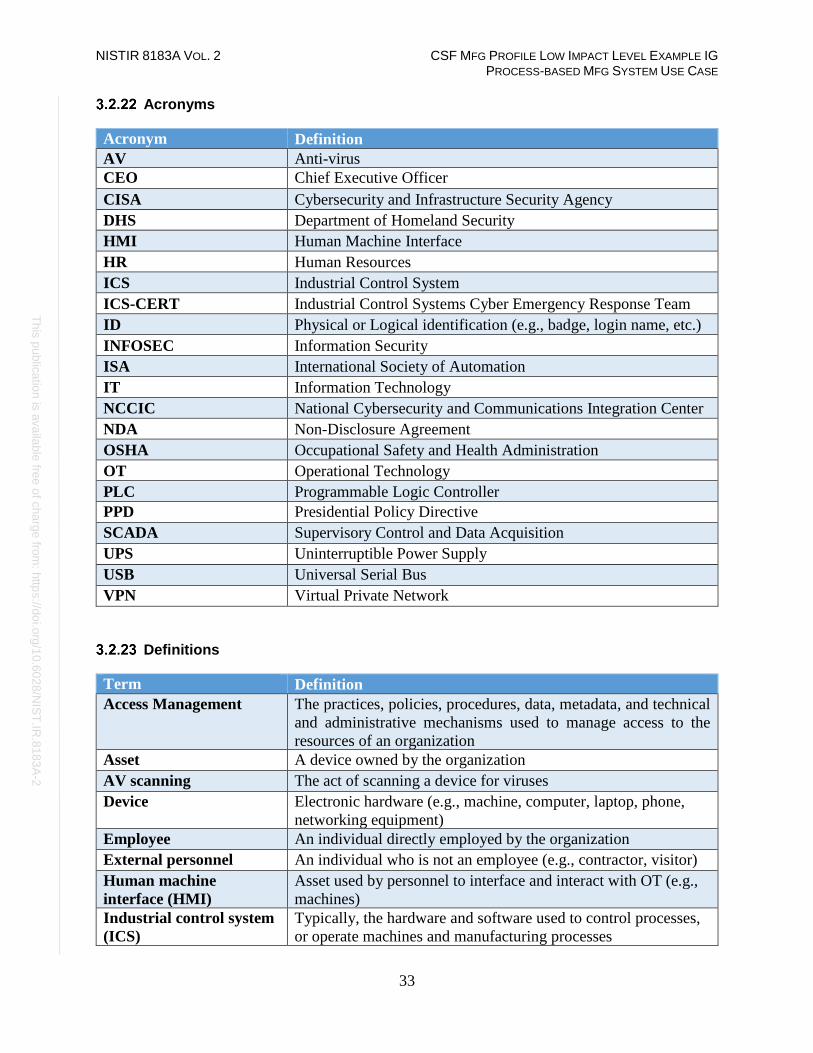
NISTIR 8183A VOL. 2 CSF MFG PROFILE LOW IMPACT LEVEL EXAMPLE IG PROCESS-BASED MFG SYSTEM USE CASE
33
Th
is p
ublic
atio
n is
ava
ilable
free
of c
ha
rge
from
: http
s://d
oi.o
rg/1
0.6
02
8/N
IST
.IR.8
18
3A
-2
Acronyms
Acronym Definition
AV Anti-virus
CEO Chief Executive Officer
CISA Cybersecurity and Infrastructure Security Agency
DHS Department of Homeland Security
HMI Human Machine Interface
HR Human Resources
ICS Industrial Control System
ICS-CERT Industrial Control Systems Cyber Emergency Response Team
ID Physical or Logical identification (e.g., badge, login name, etc.)
INFOSEC Information Security
ISA International Society of Automation
IT Information Technology
NCCIC National Cybersecurity and Communications Integration Center
NDA Non-Disclosure Agreement
OSHA Occupational Safety and Health Administration
OT Operational Technology
PLC Programmable Logic Controller
PPD Presidential Policy Directive
SCADA Supervisory Control and Data Acquisition
UPS Uninterruptible Power Supply
USB Universal Serial Bus
VPN Virtual Private Network
Definitions
Term Definition
Access Management The practices, policies, procedures, data, metadata, and technical
and administrative mechanisms used to manage access to the
resources of an organization
Asset A device owned by the organization
AV scanning The act of scanning a device for viruses
Device Electronic hardware (e.g., machine, computer, laptop, phone,
networking equipment)
Employee An individual directly employed by the organization
External personnel An individual who is not an employee (e.g., contractor, visitor)
Human machine
interface (HMI)
Asset used by personnel to interface and interact with OT (e.g.,
machines)
Industrial control system
(ICS)
Typically, the hardware and software used to control processes,
or operate machines and manufacturing processes

NISTIR 8183A VOL. 2 CSF MFG PROFILE LOW IMPACT LEVEL EXAMPLE IG PROCESS-BASED MFG SYSTEM USE CASE
34
Th
is p
ublic
atio
n is
ava
ilable
free
of c
ha
rge
from
: http
s://d
oi.o
rg/1
0.6
02
8/N
IST
.IR.8
18
3A
-2
Term Definition
Information technology
(IT)
Information Technology which includes devices such as servers,
laptops, workstations, switches and routers.
Least privilege A user is only authorized to perform the functions necessary to
perform their job
Operating system Software that operates a device (e.g., Windows, Linux);
typically, the interface used by the user
Operational technology
(OT)
Operational Technology which includes Industrial control
system devices that are used by the manufacturing process.
Personal device A device owned by an individual; not owned or controlled by the
organization
Personnel All employees and external personnel, excluding visitors
Portable media USB flash drive, compact disc (CD), external hard drive, laptop
Remote access
technologies
Software used to connect a device to the IT or OT network via
the Internet, usually performed by personnel located off-site
Security tools
Sensitive Information Data containing customer, personnel, proprietary, or trade
secrets information pertaining to the operations of the
organization; data that could cause damage to the organization if
obtained by an attacker
Split tunneling The process of allowing a remote user or device to establish a
non-remote connection with a system and simultaneously
communicate via some other connection to a resource in an
external network. This method of network access enables a user
to access remote devices (e.g., a networked printer) at the same
time as accessing uncontrolled networks. [NIST SP 800-171 R1]
User Individual using a device
Virus signature Data used by antivirus software to identify viruses
Vulnerability A weakness or a flaw in the system which an attacker can
exploit to gain access.
Vulnerability scanning Software used to detect common or known vulnerabilities on a
device
Additional Resources
1. Security Policies by SANS Resources16
2. Template for Security Policy by Project Management Docs17
3. Data Security Policy by Sophos labs18
16 https://www.sans.org/security-resources/policies 17 http://www.projectmanagementdocs.com/template/Security-Policy.doc 18 https://www.sophos.com/en-us/medialibrary/PDFs/other/sophos-example-data-security-policies-na.pdf?la=en

NISTIR 8183A VOL. 2 CSF MFG PROFILE LOW IMPACT LEVEL EXAMPLE IG PROCESS-BASED MFG SYSTEM USE CASE
35
Th
is p
ublic
atio
n is
ava
ilable
free
of c
ha
rge
from
: http
s://d
oi.o
rg/1
0.6
02
8/N
IST
.IR.8
18
3A
-2
Cybersecurity Operations Document Example
This section provides example content that a Cybersecurity Operations document may contain, including example
policy and procedure statements that were developed for the fictional company Westman. Certain commercial entities,
equipment, or materials may be identified in this document in order to describe a concept adequately. Such
identification is not intended to imply recommendation or endorsement by NIST, nor is it intended to imply that the
entities, equipment, or materials are necessarily the best available for the purpose. Each organization’s information
security experts should identify the content, and policy and procedure statements that will best integrate with their
existing cybersecurity program and manufacturing system infrastructure.
Cybersecurity Operations
for
Westman
Document Owner: Director of Operations
Version
Version Date Description Author
1.0 02-22-2018 Initial Draft Director of Operations
2.0 04-21-2018 Major changes to the initial draft Director of Operations
Approval
(By signing below, approvers agree to all terms and conditions outlined in this document.)
Approvers Role Signed Approval Date
S. Forthright CEO <digital signature> 4-22-2018
Introduction
This document defines the operational steps management and employees will follow ensuring
consistence with response to events occurring within the manufacturing system for Westman.
This document contains content which should be referred to often to help ensure all employees
and individuals performing work within the manufacturing system are familiar with
cybersecurity operations.
NISTIR 8183A VOL. 2 CSF MFG PROFILE LOW IMPACT LEVEL EXAMPLE IG PROCESS-BASED MFG SYSTEM USE CASE
36
Th
is p
ublic
atio
n is
ava
ilable
free
of c
ha
rge
from
: http
s://d
oi.o
rg/1
0.6
02
8/N
IST
.IR.8
18
3A
-2
Purpose
To provide a consistent cybersecurity operational environment for supporting the manufacturing
systems.
Scope
Management, employees, contractors, or individuals requiring access to the manufacturing
system for changes should be familiar with the contents included within this document.
Asset Inventory
Identifying assets within the manufacturing system is a vital first step in protecting the company
from malicious activities that could result in disruption to production. Additionally, knowing
what devices are authorized to connect to the network enables the detection of unapproved
devices which could be an indication of malicious activity. Similarly, tracking software installed
on networked devices provides the necessary information to support software update and
patching processes to eliminate vulnerabilities. Westman uses both manual and automated asset
inventory tools to support asset inventory management. Specifically, two types of asset
inventories are performed on the manufacturing system:
• Manual Inventory - Devices that cannot be automatically scanned (e.g., PLC, machining
stations). These devices are manually entered into an excel spreadsheet and updated at
least quarterly.
• Automated Inventory - Devices that can be automatically scanned will be configured in
the asset inventory tool for auditing (i.e., Open-AudIT). Access to Open-AudIT is granted
only to authorized personnel.
All inventory processes are conducted during manufacturing system down time and must include
both hardware and software. Periodic hardware and software scans are performed on devices
within the manufacturing system to detect any unauthorized hardware or software changes.
Examples of changes that might occur within the manufacturing system include updating
software, license, system patches, firmware updates, and adding new devices like PLCs’ or
HMIs’ or other ICS components required for operations. To detect these changes within the
manufacturing system, scans are conducted at least quarterly to record current device
information, configuration, and installed software (e.g., license information, software version,
and configuration). These scan results are used to identify any unauthorized hardware and non-
essential software applications installed on devices within the manufacturing system.
Additionally, device configuration baselines are used to ensure inadvertent changes are detected
before system integrity impacts can affect the manufacturing process. Both manual and
automated methods are used to capture current device configurations for validation against
approved baselines. The manual method is used for ICS devices that do not support automated
scanning tools. Specifically, devices lacking SSH, SNMP, WMI services are manually
documented in the excel spreadsheet. Automated device configuration scans are implemented
using Open-AudIT which was selected for Westman due to scalable configuration depending on
required needs.

NISTIR 8183A VOL. 2 CSF MFG PROFILE LOW IMPACT LEVEL EXAMPLE IG PROCESS-BASED MFG SYSTEM USE CASE
37
Th
is p
ublic
atio
n is
ava
ilable
free
of c
ha
rge
from
: http
s://d
oi.o
rg/1
0.6
02
8/N
IST
.IR.8
18
3A
-2
Once scanning has been performed, the information gathered is compared to approved baselines
with any identified changes documented for review and investigation. Any hardware or software
identified within the manufacturing system that is not authorized or required for operations is
scheduled for removal at the earliest opportunity that does not impact the manufacturing process.
Otherwise, for any identified changes, if the change is approved, the associated baseline is
updated to reflect the approved change. If the change is not approved, the device is reverted to
the approved configuration and an investigation into how the unauthorized change was deployed
is performed to determine if a cybersecurity incident occurred.
Device configuration baselines must be reviewed at least quarterly and updated after any
approved engineering change to the manufacturing system. During the period between baseline
reviews, any new equipment added or configuration changes implemented will initiate a new
baseline scan to be performed. Additionally, GRASSMARLIN19 and Wireshark20 are used for
updating the environment network diagrams, verifying information flows, and providing any
additional information for supporting baseline updates after new equipment is added to the
environment.
Networking
The Westman network environment for supporting manufacturing must be secured from
unauthorized access and tampering to ensure the availability, integrity, and confidentiality of the
information used to support the manufacturing processes. This requires all network connection
with manufacturing system components be documented and cables clearly labeled to indicate
their designated purpose. Additionally, all network switches must be configured for supporting
network segmentation and port security, to control network traffic and prevent unauthorized
devices from accessing the manufacturing network. Any network connection with the
manufacturing environment will be reviewed and authorized by the Director of Operations
before being placed into production.
To assist with these efforts, Westman creates and maintains a comprehensive network baseline
that provides an accurate document of the network environment and supports the processes to
detect anomalies within the manufacturing system networks. The network baseline
documentation is reviewed and updated at least quarterly to identify all components and
communications required for manufacturing production operations. Tools used for this process
include Open-AudIT, GRASSMARLIN, and Wireshark. Additionally, using company provided
network diagram tools, the network baseline documentation will include detailed network
diagrams for all internal and external network connection including any cloud services.
Specifically, network diagrams will include all relevant information for connection services
provided including: assigned IP address for devices, service provided, data flow directions, data
types, support phone number, customer number, contact person, support level agreement, and
hours of support. The network baseline documentation will also include the configuration details
for network segmentation and port security within the environment.
19 https://github.com/nsacyber/GRASSMARLIN 20 https://www.wireshark.org
NISTIR 8183A VOL. 2 CSF MFG PROFILE LOW IMPACT LEVEL EXAMPLE IG PROCESS-BASED MFG SYSTEM USE CASE
38
Th
is p
ublic
atio
n is
ava
ilable
free
of c
ha
rge
from
: http
s://d
oi.o
rg/1
0.6
02
8/N
IST
.IR.8
18
3A
-2
The Westman network for manufacturing systems is segmented to improve speed and
cybersecurity within the environment. Network traffic between network segments is controlled
using firewall network devices configured, based on the approved network baseline, to allow
approved network traffic to enter or leave the manufacturing network segments while dropping
all other traffic. The details associated with the network segmentation, firewalls, and firewall
rules is also included in the network baseline documentation.
The Westman network for manufacturing systems also utilizes managed switches that are
configured with port security enabled. Port security provides the ability to allow authorized
devices, based on their unique Media Access Control (MAC) addresses, to utilize specific
network switch ports. The port security documentation will include a reference to the asset
information for the approved devices and list device MAC addresses with the assigned network
switch and switch port.
Should Westman require vendor or contractor remote maintenance support, these activities will
be coordinated and approved before remote access is allowed. All remote maintenance activities
will be controlled and monitored by a knowledgeable Westman employee to ensure no harmful
or malicious activities occur. Any vendors or contractors connecting to Westman for remote
maintenance will: require approval from the Director of Operations before connecting; utilize the
approved secure remote access procedures; and have the remote access revoked after completing
the approved task(s). All remote access maintenance activities will be documented to ensure a
proper audit trail for activity conducted within the manufacturing systems.
All network devices will be configured to forward logs to the Westman internal Syslog server.
For the Westman network for manufacturing systems, this includes the network switches, the
Cisco Adaptive Security Appliance (ASA) firewall supporting the Cybersecurity LAN network,
and the Stratix 8300 series firewall in the workcell.
At least monthly, authorized Westman personnel will use the information collected from these
devices and the GRASSMARLIN tool to perform comparisons of current network activity to the
documented baseline. These efforts will help identify any unusual traffic which might indicate
either system issues or potential malicious activity. Additionally, switch logs will be checked at
least monthly to ensure no rogue devices have attempted to connect. Any observed network
activity not already documented in the baseline must be reconciled and either incorporated into
the baseline or investigated as a possible system or cybersecurity incident.
Additionally, authorized Westman personnel will utilize a wireless enabled laptop or mobile
device configured to use either the native capabilities of the operating system or approved
wireless scanning software to perform weekly sweeps within the manufacturing areas to detect
for unauthorized wireless devices or rogue access points. Any detected anomalies will be
documented including location(s) of detection and submitted for additional investigation.

NISTIR 8183A VOL. 2 CSF MFG PROFILE LOW IMPACT LEVEL EXAMPLE IG PROCESS-BASED MFG SYSTEM USE CASE
39
Th
is p
ublic
atio
n is
ava
ilable
free
of c
ha
rge
from
: http
s://d
oi.o
rg/1
0.6
02
8/N
IST
.IR.8
18
3A
-2
Manufacturing System Security
Adherence to the Cybersecurity Program by all personnel is critical to reduce the risk of
cybersecurity incidents on the manufacturing system. The following sections describe policies
and procedures relating to manufacturing system security.
3.3.6.1 Change Control
Any changes to the manufacturing system must be tracked by the change control process,
ensuring that all personnel are notified of the proposed changes and are involved in the process.
Changes will be formally reviewed and authorized before implementation.
A thorough review of the change must be performed to determine if:
• the change will impact manufacturing system performance, or
• the change will impact the security of the manufacturing system.
Change control reviewers will make a final determination before any changes are performed,
along with justifications for accepted risks.
Approved changes will be scheduled during downtime or other maintenance activities to limit
impact to production. Once changes have been completed, a security review will be conducted to
determine if any unexpected changes to cybersecurity controls occurred as a result of the changes
implemented. Any unexpected cybersecurity control changes are reviewed and processed in
accordance with the Vulnerability and Remediation Management processes.
The manufacturing system will be evaluated quarterly to identify devices that are critical to its
operation. This information will be used to provide a criticality report outlining the critical
equipment and will be used to update other company cybersecurity documents and procedures.

NISTIR 8183A VOL. 2 CSF MFG PROFILE LOW IMPACT LEVEL EXAMPLE IG PROCESS-BASED MFG SYSTEM USE CASE
40
Th
is p
ublic
atio
n is
ava
ilable
free
of c
ha
rge
from
: http
s://d
oi.o
rg/1
0.6
02
8/N
IST
.IR.8
18
3A
-2
Below is a table of devices that must be part of the change control process:
Device Name Item Type Details
Engineering
Workstation Software
BIOS/Firmware patches, IT programs (Antivirus, Backup
agent etc.), Plant apps (Factory Talk, RSLinx etc.)
Hardware Storage and Memory upgrade
OPC Server Software
BIOS/Firmware patches, IT programs (Antivirus, Backup
agent etc.), Plant apps (PI, FactoryTalk Services
Platform, RSLINX, Matrikon OPC)
Hardware Storage and Memory upgrade
Historian VM Software
BIOS/Firmware patches, IT programs (Antivirus, Backup
agent etc.), SQL Server patches,
Hardware Storage and Memory upgrade
Plant Simulator Software
BIOS/Firmware patches, IT programs (Antivirus, Backup
agent etc.)
Hardware Storage and Memory upgrade
Controller Host Software
BIOS/Firmware patches, IT programs (Antivirus, Backup
agent etc.), Plant apps (MATLAB, Matrikon OPC)
Hardware Storage and Memory upgrade
HMI Host Software
OS Patches (Windows), BIOS/Firmware patches, IT
programs (Antivirus, Backup agent etc.), Plant apps
(FactoryTalk View Site, FT Services Platform, FT View
Studio)
Hardware Storage and Memory upgrade
PLC Software Firmware upgrade and any type of configuration change
Allen Bradley
Boundary Router Software
Firmware upgrade, Firewall rules and any type of
configuration change
Allen Bradley
Layer-2 Switches Software Firmware upgrade and any type of configuration change
Cisco ASA
Firewall Software
Firmware upgrade, Firewall rules and any type of
configuration change
Switches Software Firmware upgrade and any type of configuration change
Active Directory Software Group Policy deployment, User account
creation/modification
Symantec
Antivirus Software
Antivirus version upgrades, Any Endpoint policy
deployment via Symantec Manager
Nessus Software Running vulnerability scan(s)

NISTIR 8183A VOL. 2 CSF MFG PROFILE LOW IMPACT LEVEL EXAMPLE IG PROCESS-BASED MFG SYSTEM USE CASE
41
Th
is p
ublic
atio
n is
ava
ilable
free
of c
ha
rge
from
: http
s://d
oi.o
rg/1
0.6
02
8/N
IST
.IR.8
18
3A
-2
3.3.6.2 Personnel Actions
Actions performed on manufacturing system devices may require authentication. Those actions
are defined in the following tables. The term All Users only applies to users that have been
granted authorization to interact with the device.
Authentication Required to Physically/Logically Interact with Device? Engineering
Workstation
Supervisory
PLC HMI Controller
Local
Historian
OPC
Server
VLAN
switches
Boundary
router
Physical
Interaction
(All Users)
Y N N Y Y Y Y Y
Logical/Network
Interaction
(All Users)
Y Y Y Y Y Y Y Y
HMI User Actions Requiring Authentication
View
Process
Status
Modify
Process
Setpoints
Silence/Clear
Alarms
All Users N Y Y
Engineering Workstation User Actions Requiring Authentication
Login to
Workstation
View/Modify
PLC Logic
Access
Engineering
Files
All Other
Actions
All Users Y Y Y Y
Historian User Actions Requiring Authentication
View
Historical Data
Modify
Historical
Data
Modify
Configuration
Login to
Server
Desktop/CLI
All Users Y Y Y Y
OPC Server User Actions Requiring
Authentication
Modify
Configuration
Login to
Desktop/CLI
All Users Y Y

NISTIR 8183A VOL. 2 CSF MFG PROFILE LOW IMPACT LEVEL EXAMPLE IG PROCESS-BASED MFG SYSTEM USE CASE
42
Th
is p
ublic
atio
n is
ava
ilable
free
of c
ha
rge
from
: http
s://d
oi.o
rg/1
0.6
02
8/N
IST
.IR.8
18
3A
-2
Controller User Actions Requiring Authentication
Modify
Configuration
Login to
Desktop/CLI
Modify Control
Logic
All Users Y Y Y
VLAN switches User Actions Requiring Authentication
Modify
Configuration View switch status
All Users Y Y
PLC Actions Requiring Authentication
Power
On/Off
Reboot Process
Interaction
(Run/Stop/Reset)
Modify
Logic
Change Mode (Run/Config)
All
Users
N N N Y Y
3.3.6.3 Monitoring the Manufacturing System
The manufacturing system environment will be monitored for unauthorized activity associated
with personnel, software, network devices, and wireless access points. Westman has established
a central log server (Syslog Server) for supporting this capability and is configured to aggregate
all system-generated logs and store the logs for archival and forensics purposes. Whenever
supported, devices within the manufacturing system must be configured to send log data to the
central syslog repository.
Logs will be checked periodically looking for abnormal alerts being generated from the
manufacturing system. Specifically, logged events will be examined to determine if any impact
the manufacturing process. At a minimum, detected cybersecurity event notification will be
investigated to determine root cause and appropriate remediation steps will be taken to clear
events and return the manufacturing system to a known good operating state. Events impacting
the manufacturing process will be reviewed to determine correlation with risk assessment
outcomes and identify actions required to improve Westman’s cybersecurity posture.
All non-employees physically accessing the manufacturing system will be required to sign the
visitor log, including the date, time of entry, and time of exit. Any unauthorized visitors will be
escorted out of the facility. Visitors must always be escorted by an employee of Westman.

NISTIR 8183A VOL. 2 CSF MFG PROFILE LOW IMPACT LEVEL EXAMPLE IG PROCESS-BASED MFG SYSTEM USE CASE
43
Th
is p
ublic
atio
n is
ava
ilable
free
of c
ha
rge
from
: http
s://d
oi.o
rg/1
0.6
02
8/N
IST
.IR.8
18
3A
-2
3.3.6.4 Backups
The following backup procedures are defined for servers and hosts of the manufacturing system:
• Veeam directory backups are performed on select directories containing configuration
and logic data for the manufacturing system are performed weekly during periods of low
volume production (e.g., overnight).
• Veeam full system image backups are performed quarterly during periods of low volume
production (e.g., overnight), and after any engineering change.
Host Veeam
Directory
Backups
Veeam Full
System Image
Other Methods
Engineering
Workstation ✓ ✓
OPC Server ✓ Process
Controller
Server
✓
HMI Host
Server ✓
Local Historian
Host ✓ OSIsoft PI historian data of the
manufacturing process is duplicated in
real-time to the DMZ Historian. Hyper-V Host
Server ✓
Active
Directory
Server
✓
Backup Active
Directory
Server
✓
DMZ Historian ✓ The native OSIsoft PI application backup
feature archives production data from the
manufacturing process. These backups are
stored on the local host; restore the host to
obtain the most recent backup version.
NOTE: Any recovered historical data will
be limited to data present at the time of the
backup. Symantec
Antivirus
Server
✓
Security Onion
Server ✓
Graylog Server ✓

NISTIR 8183A VOL. 2 CSF MFG PROFILE LOW IMPACT LEVEL EXAMPLE IG PROCESS-BASED MFG SYSTEM USE CASE
44
Th
is p
ublic
atio
n is
ava
ilable
free
of c
ha
rge
from
: http
s://d
oi.o
rg/1
0.6
02
8/N
IST
.IR.8
18
3A
-2
GTB Inspector
Server ✓
GTB Console
Server ✓
The Hive
Project Incident
Response
Server
✓
Nessus
Vulnerability
Scanner Server
✓
Windows
WSUS Server ✓
The following backup methods described are for hosts and devices that cannot be performed by
the Veeam tool.
Host Backup Methods
Local Historian Database
Virtual Machine Backup of the VHD is handled by the Veeam full system
image of the host server, Local Historian Host (FGS-
61338LHH). Controller PLC Backup of the PLC project files is handled by the Veeam full
system image of the Engineering Workstation (FGS-
47631EHH), as the files are stored locally on that host. Veeam full image backups of Engineering Workstation (FGS-
47631EHH) must be manually performed after any
engineering changes to the PLC project or its configuration. Backup of the SD card contents is performed annually during
the plant shutdown. Manufacturing System
Router / Firewall Perform a configuration backup via the CLI or web UI after
any engineering change. Boundary Router Perform a configuration backup via the CLI or web UI after
any engineering change. Supervisory LAN Switch Perform a configuration backup via the CLI or web UI after
any engineering change. Control LAN Switch Perform a configuration backup via the CLI or web UI after
any engineering change. VMware Host Perform regular backups of each running Virtual Machine
hosted on VMWware ESXi using Veeam.
Perform a backup of the ESXi Host configuration after any
configuration changes. (see VMWare KB21 for additional
details).
21 https://kb.vmware.com/s/article/2042141
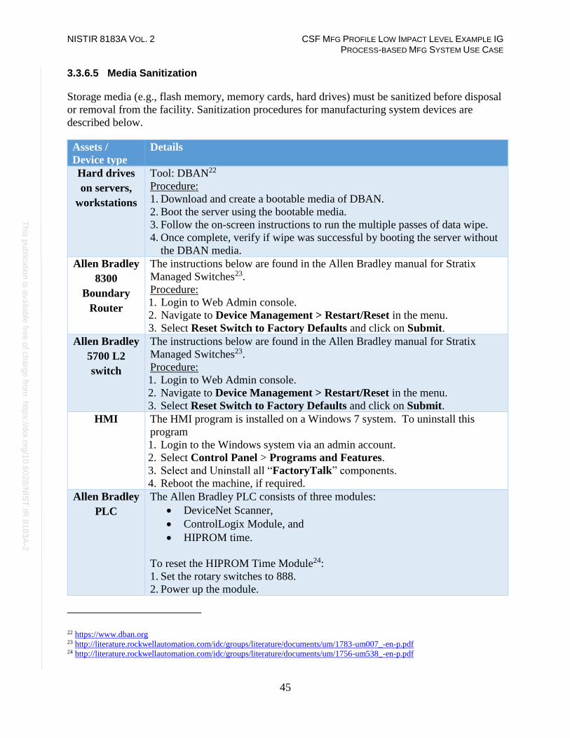
NISTIR 8183A VOL. 2 CSF MFG PROFILE LOW IMPACT LEVEL EXAMPLE IG PROCESS-BASED MFG SYSTEM USE CASE
45
Th
is p
ublic
atio
n is
ava
ilable
free
of c
ha
rge
from
: http
s://d
oi.o
rg/1
0.6
02
8/N
IST
.IR.8
18
3A
-2
3.3.6.5 Media Sanitization
Storage media (e.g., flash memory, memory cards, hard drives) must be sanitized before disposal
or removal from the facility. Sanitization procedures for manufacturing system devices are
described below.
Assets /
Device type
Details
Hard drives
on servers,
workstations
Tool: DBAN22
Procedure:
1. Download and create a bootable media of DBAN.
2. Boot the server using the bootable media.
3. Follow the on-screen instructions to run the multiple passes of data wipe.
4. Once complete, verify if wipe was successful by booting the server without
the DBAN media.
Allen Bradley
8300
Boundary
Router
The instructions below are found in the Allen Bradley manual for Stratix
Managed Switches23.
Procedure:
1. Login to Web Admin console.
2. Navigate to Device Management > Restart/Reset in the menu.
3. Select Reset Switch to Factory Defaults and click on Submit. Allen Bradley
5700 L2
switch
The instructions below are found in the Allen Bradley manual for Stratix
Managed Switches23.
Procedure:
1. Login to Web Admin console.
2. Navigate to Device Management > Restart/Reset in the menu.
3. Select Reset Switch to Factory Defaults and click on Submit.
HMI The HMI program is installed on a Windows 7 system. To uninstall this
program
1. Login to the Windows system via an admin account.
2. Select Control Panel > Programs and Features.
3. Select and Uninstall all “FactoryTalk” components.
4. Reboot the machine, if required.
Allen Bradley
PLC
The Allen Bradley PLC consists of three modules:
• DeviceNet Scanner,
• ControlLogix Module, and
• HIPROM time.
To reset the HIPROM Time Module24:
1. Set the rotary switches to 888.
2. Power up the module.
22 https://www.dban.org 23 http://literature.rockwellautomation.com/idc/groups/literature/documents/um/1783-um007_-en-p.pdf 24 http://literature.rockwellautomation.com/idc/groups/literature/documents/um/1756-um538_-en-p.pdf

NISTIR 8183A VOL. 2 CSF MFG PROFILE LOW IMPACT LEVEL EXAMPLE IG PROCESS-BASED MFG SYSTEM USE CASE
46
Th
is p
ublic
atio
n is
ava
ilable
free
of c
ha
rge
from
: http
s://d
oi.o
rg/1
0.6
02
8/N
IST
.IR.8
18
3A
-2
To reset the DeviceNet Scanner Module25:
1. Set the rotary switches to 888.
2. Power on the module.
Instructions for clearing the memory in the ControlLogix 5571 module are
defined in the Allen Bradley ControlLogix 5000 Manual26.
1. Remove the ESM from the controller.
2. Remove power from the controller.
3. Remove power either by:
a. turning power off to the chassis while the controller is installed in the
chassis, or
b. removing the controller from the powered chassis.
4. Reinstall the ESM into the controller.
5. Restore power to the controller.
3.3.6.6 Resources are Maintained
Resource performance can impact manufacturing process performance. Operators must perform
daily checks on the manufacturing system components they operate or are responsible for. These
checks must include physical observation of all components, and review of any warning
messages or indicators, and any other areas of concern designated by the Director of Operations.
Personnel Training
Training is vital for keeping the company safe from cybersecurity threats. All employees,
contractors and vendors must complete required annual cybersecurity training before being
allowed to work or continue working within the manufacturing system environment. Individuals
with privileged access are required to complete additional training identified by the Director of
Operations or the IT Manager related to managing the cybersecurity controls and configurations
for the devices they are granted privileged access rights.
Vulnerability Management
Vulnerability management is an essential component of any information security program and
the process of vulnerability assessment is vital to effective vulnerability management.
The following general policies apply to vulnerability management:
• The Engineers or IT staff will not make any temporary changes to information systems,
for the sole purpose of "passing" an assessment. Vulnerabilities on information systems
shall be mitigated and eliminated through proper analyses and repair methodologies.
25 http://literature.rockwellautomation.com/idc/groups/literature/documents/in/1756-in566_-en-p.pdf 26 http://literature.rockwellautomation.com/idc/groups/literature/documents/um/1756-um001_-en-p.pdf

NISTIR 8183A VOL. 2 CSF MFG PROFILE LOW IMPACT LEVEL EXAMPLE IG PROCESS-BASED MFG SYSTEM USE CASE
47
Th
is p
ublic
atio
n is
ava
ilable
free
of c
ha
rge
from
: http
s://d
oi.o
rg/1
0.6
02
8/N
IST
.IR.8
18
3A
-2
• No devices connected to the network shall be specifically configured to block
vulnerability scans from authorized scanning engines.
• Use caution when running vulnerability scans against OT networks such as the
Supervisory LAN and Field LAN Network. Scans should be scheduled off hours and
during periods of maintenance.
• It is recommended to run authenticated scans from the vulnerability scanner.
3.3.8.1 Vulnerability Management Process
3.3.8.2 Vulnerability Scanning and Management Tools
Tenable-Nessus is being used to perform vulnerability scans in Westman. The results generated
by Nessus at the completion of the scan are imported into NamicSoft, a vulnerability
management, parsing and reporting tool. NamicSoft is used to create customized reports and
logically group results for a consistent workflow within the organization. The reports are
reviewed by the Director of Operations and the IT Manager and shared with IT staff members as
required to coordinate remediation or mitigation activities.
3.3.8.3 Vulnerability Scan Targets
All devices connected to the Plant and Supervisory network segments are scanned. The IT Staff
will configure a scan for all network segments of Westman.
A new scan can be established, or a modification can be made to an existing scan, by submitting
a request to the IT Manager.

NISTIR 8183A VOL. 2 CSF MFG PROFILE LOW IMPACT LEVEL EXAMPLE IG PROCESS-BASED MFG SYSTEM USE CASE
48
Th
is p
ublic
atio
n is
ava
ilable
free
of c
ha
rge
from
: http
s://d
oi.o
rg/1
0.6
02
8/N
IST
.IR.8
18
3A
-2
Note: If an individual identifies that a scan is impacting the manufacturing process, they must
report the situation immediately to the IT Manager to request stopping the scan and report the
situation to the Director of Operations.
3.3.8.4 Vulnerability Scan Frequencies
Scans are performed by the IT Staff on an on-demand, per-request basis as needed. Due to the
potential impact to manufacturing processes, scans are performed only during scheduled
preventive maintenance periods. The Director of Operations and IT manager shall coordinate at
least one (1) assessment per month for at least the DMZ, Cybersecurity, Management, and
Engineering LAN segments provided the scans can be coordinated without impacting the
manufacturing process. All network segments and devices are scanned during the annual plant
shut down period.
All device scans should be performed during hours appropriate to the business needs of the
organization and to minimize disruption to normal operations. Any new device discovered needs
to be reported, confirmed that the device is approved, and classified under its appropriate group.
3.3.8.5 Vulnerability Reporting
Upon completion of a vulnerability scan, the result is imported into NamicSoft for report
generation. The generated reports are achieved and retained as proof that an assessment occurred
and for supporting trend analysis.
All IT/OT devices are organized into groups in NamicSoft as per the system they reside in. A
device may belong to one or more groups. Reports are generated for the entire system so that the
devices and vulnerabilities can be easily presented to the IT Staff, IT Manager and Director of
Operations. Below is a table of type of reports that are generated and disseminated.
Status Reports Frequency Purpose
Host table with affected
vulnerabilities
Monthly Information is presented for each host.
Vulnerability Assessment
Report
Monthly Information is presented for both scanned
networks.
Host specific report Ad-hoc Information is presented for requested
host.
Mitigated vulnerabilities report Post remediation Upon re-scanning a host to check if
vulnerabilities have been mitigated or not

NISTIR 8183A VOL. 2 CSF MFG PROFILE LOW IMPACT LEVEL EXAMPLE IG PROCESS-BASED MFG SYSTEM USE CASE
49
Th
is p
ublic
atio
n is
ava
ilable
free
of c
ha
rge
from
: http
s://d
oi.o
rg/1
0.6
02
8/N
IST
.IR.8
18
3A
-2
Remediation Management and Priorities
All vulnerabilities discovered must be analyzed by the Director of Operations and the IT
Manager with assistance from control engineers and OT service contractor (if needed) to decide
the next course of action.
All vulnerabilities discovered should be remediated within the remediation times defined in the
following table.
Severity Description Remediation time
Critical Nessus uses Common Vulnerability Scoring
System (CVSS) for rating vulnerabilities. A
Critical vulnerability has a CVSS base score of
9.0 or 10.
Within 15 days of discovery
High High-severity vulnerabilities have a CVSS score
between 7.0 and 8.9.
Within 30 days of discovery
Medium Medium-severity vulnerabilities have a CVSS
score of 4.0 to 6.9 and can be mitigated within an
extended time frame.
Within 45 days of discovery
Low Low-severity vulnerabilities are defined with a
CVSS score of 1.0 to 3.9. Not all low
vulnerabilities can be mitigated easily due to
applications and normal operating system
operations. These should be documented
Within 180 days of discovery
Info Info level do not present cybersecurity risk and
are listed for informational purposes only. It is
optional to remediate them.
Not required to remediate

NISTIR 8183A VOL. 2 CSF MFG PROFILE LOW IMPACT LEVEL EXAMPLE IG PROCESS-BASED MFG SYSTEM USE CASE
50
Th
is p
ublic
atio
n is
ava
ilable
free
of c
ha
rge
from
: http
s://d
oi.o
rg/1
0.6
02
8/N
IST
.IR.8
18
3A
-2
3.3.9.1 Exception Management
Exceptions are sometimes required as part of the organizational risk management process to
ensure regulatory, cybersecurity, and manufacturing priorities are properly aligned to create a
cost-effective cybersecurity environment for supporting the manufacturing systems. There are
two primary use cases associated with exception requests: false positives – vulnerabilities
identified incorrectly or that are not actually present within the identified system; and risk
acceptance – risks that cannot be avoided, mitigated, or transferred.
False Positives exceptions must be documented and approved by the Director of Operations.
Approved false positives will be submitted to the IT Staff who will update scanning and
reporting to exclude the false positive results from future reports.
Risk acceptances are necessary to address vulnerabilities that may exist in operating systems,
applications, web applications or OT devices that cannot be remediated, or otherwise avoided.
For example, vendors may have appliances that are not patched, services may be exposed for
proper application operations, and systems may still be commissioned that are considered end-
of-life by the developer and manufacturer. Exceptions may also be requested for vulnerabilities
not identified as risks to the system and organization (e.g., if a patchable vulnerability is only
exploitable by a user utilizing a web browser and accessing a compromised website, then a risk
acceptance exception to the patch that has an identified impact on the manufacturing process
could be considered given the mitigations of blocking internet access from the manufacturing
network segments).
Risk acceptance exceptions must be requested through the IT Team with an explanation
containing:
• Mitigating controls: what changes, tools, or procedures have been implemented to
minimize the risk.
• Risk acceptance explanation: details as to why this risk is not relevant to the company
and systems.
• Risk analysis: if the vulnerability is indeed compromised, what risk and systems will be
affected.
Any other exceptions to this policy, such as exemption from the vulnerability assessment process
must be internally discussed and approved by the Director of Operations.

NISTIR 8183A VOL. 2 CSF MFG PROFILE LOW IMPACT LEVEL EXAMPLE IG PROCESS-BASED MFG SYSTEM USE CASE
51
Th
is p
ublic
atio
n is
ava
ilable
free
of c
ha
rge
from
: http
s://d
oi.o
rg/1
0.6
02
8/N
IST
.IR.8
18
3A
-2
Risk Management Document Example
This section provides example content that a Risk Management document may contain, including example policy and
procedure statements that were developed for the fictional company Westman. Certain commercial entities,
equipment, or materials may be identified in this document in order to describe a concept adequately. Such
identification is not intended to imply recommendation or endorsement by NIST, nor is it intended to imply that the
entities, equipment, or materials are necessarily the best available for the purpose. Each organization’s information
security experts should identify the content, and policy and procedure statements that will best integrate with their
existing cybersecurity program and manufacturing system infrastructure.
Risk Management Strategy
for
Westman
Document Owner: Director of Operations
Version
Version Date Description Author
1.0 02-22-2018 Initial Draft Director of Operations
2.0 04-21-2018 Major changes to the initial draft Director of Operations
Approval
(By signing below, approvers agree to all terms and conditions outlined in this document.)
Approvers Role Signed Approval Date
S. Forthright CEO <digital signature> 4-22-2018
This Risk Management Plan defines how cybersecurity risks associated with the Westman
manufacturing systems will be identified, analyzed, and managed. This document can be used by
the Director of Operations and senior management to foresee risks, estimate impacts, and define
responses.
Scope
Any employee, contractor, or individual with access to the organization’s systems or data.

NISTIR 8183A VOL. 2 CSF MFG PROFILE LOW IMPACT LEVEL EXAMPLE IG PROCESS-BASED MFG SYSTEM USE CASE
52
Th
is p
ublic
atio
n is
ava
ilable
free
of c
ha
rge
from
: http
s://d
oi.o
rg/1
0.6
02
8/N
IST
.IR.8
18
3A
-2
Risk Management Process
Risk Management is an iterative process. As the program progresses, more information will be
gained about the program, and the risk statement will be adjusted to reflect the current
understanding. The overall process involves Identifying, Analysis, Categorizing, Remediating,
and Reporting. A Risk Management Log is maintained to track known risks and remediation
efforts.
Identification
Risks will be identified as early as possible in the project to minimize their impact. For the
purposes of this process, risks are threats exploiting vulnerabilities or weaknesses in technology,
processes, or policy that may cause an adverse impact or harm to the organizational operations,
organizational assets, or individuals.
There are many different types of threats that can affect IT and OT infrastructure. Common
threat sources (adapted from NIST SP 800-3027) include:
• Adversarial — individuals, groups, organizations, or states that seek to exploit the
organization’s dependence on cyber resources.
• Accidental — Erroneous actions taken by individuals in the course of executing their
everyday responsibility
• Structural — Failure of equipment, environmental controls, or software due to gaining,
resource depletion, or other circumstances which exceed expected operating parameters.
• Environmental — Natural disasters and failures of critical infrastructures on which the
organization depends, but which are outside the control of the organization.
The Director of Operations and IT Team will coordinate the formal manufacturing system annual
risk assessments in accordance with the latest version of the NIST SP 800-3028 guidance. During
this process, specific organizational threat events will be identified and defined for use in
assessing vulnerabilities and weaknesses to determine if a risk exists.
For continuous monitoring and risk management, Westman’s employees or external contractors
must report any potential risk following the risk notification process described below.
Additionally, software tools including, but not limited to, Nessus and CSET29 are used to support
the risk assessment process by identifying vulnerabilities and weaknesses in the technology,
processes, or policies for the organization.
The Director of Operations will perform a CSET assessment at least annually. Due to the
potential impact to manufacturing processes, scans are performed only during scheduled
preventive maintenance periods. Nessus results will be imported into NamicSoft and reports
generated and distributed to the Director of Operations and the IT Manager. Additionally, other
27 https://nvlpubs.nist.gov/nistpubs/Legacy/SP/nistspecialpublication800-30.pdf 28 https://nvlpubs.nist.gov/nistpubs/Legacy/SP/nistspecialpublication800-30.pdf 29 https://ics-cert.us-cert.gov/Assessments

NISTIR 8183A VOL. 2 CSF MFG PROFILE LOW IMPACT LEVEL EXAMPLE IG PROCESS-BASED MFG SYSTEM USE CASE
53
Th
is p
ublic
atio
n is
ava
ilable
free
of c
ha
rge
from
: http
s://d
oi.o
rg/1
0.6
02
8/N
IST
.IR.8
18
3A
-2
types of risks, such as hardware based, physical, or environmental will be identified and
documented manually.
Note: Any software-based vulnerabilities that cannot be remediated per the Vulnerability
Management Plan will be included in the risk analysis process to determine the appropriate
corrective action.
Risk Notification Process
Analysis
To begin the analysis process, each vulnerability must be assigned a vulnerability score from 1 to
10. Vulnerabilities identify by CSET will be manually assigned a score from 1 to 10 based on the
severity of the finding by the assessor. For vulnerabilities identified through scanning tools such
as Nessus, the CVSS associated with the vulnerability will be used as the vulnerability score.
At a minimum, vulnerabilities with a score in at the high (vulnerability score: 7.0 to 8.9) and
critical (vulnerability score of 9.0 to 10) range will be analyzed to determine if an associated

NISTIR 8183A VOL. 2 CSF MFG PROFILE LOW IMPACT LEVEL EXAMPLE IG PROCESS-BASED MFG SYSTEM USE CASE
54
Th
is p
ublic
atio
n is
ava
ilable
free
of c
ha
rge
from
: http
s://d
oi.o
rg/1
0.6
02
8/N
IST
.IR.8
18
3A
-2
threat or threat event exists that has a probability of occurrence greater than zero. For each
vulnerability, threat pairs, an impact on operations will be estimated. A qualitative risk analysis
process will be used to determine the overall probability and impact levels using the guidance in
the tables below. These factors are then combined to provide an estimated quantitative risk score
for use in reporting and prioritization.
Probability Description Quantitative Value
High Greater than <70 %> probability of occurrence in a year 0.8
Medium Between <30 %> and <70 %> probability of occurrence
in a year
0.5
Low Below <30 %> probability of occurrence in a year 0.3
Note: At the discretion of the assessor or the Director of Operations, the probability quantitative
value may be adjusted to more accurately represent the probability of occurrence up to a
maximum of 1 representing 100 % probability of occurrence and to a minimum of 0 representing
0 % probability due to no identified threat or threat event being identified for the vulnerability or
weakness.
Impact Description Quantitative Value
High Risk that has the potential to seriously impact production
cost, production schedule or performance
1
Medium Risk that has the potential to moderately impact
production cost, production schedule or performance
0.5
Low Risk that has relatively minor impact on cost, schedule
or performance
0.1
Notes: Overall impact scores are the product of the qualitative level from the impact table and
the asset criticality as defined below resulting in an impact range of 1-10. If an asset criticality
has not been defined, then assume an asset criticality of 10 until the asset can be properly
categorized.
Asset Criticality Matrix
Once a list of Westman assets or systems requiring protection have been identified by the
Hardware Inventory process, they will be assigned a value. Asset Value is the degree of impact
that would be caused by the unavailability, malfunctioning or destruction of the asset.
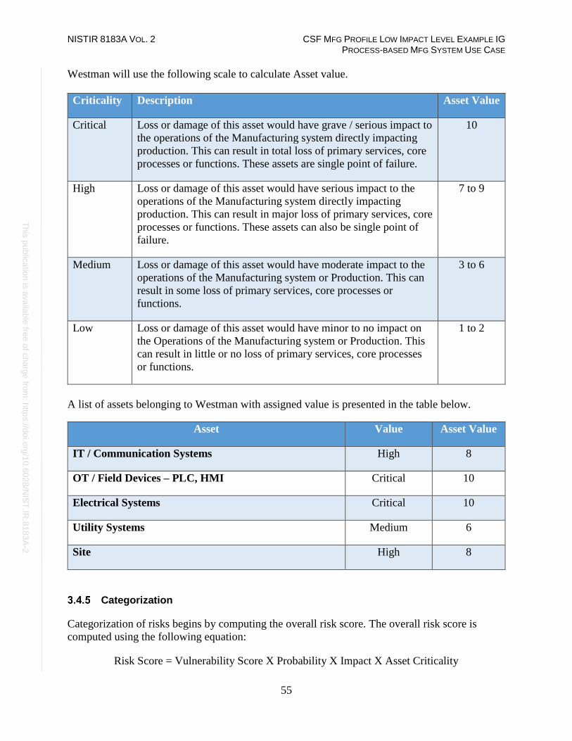
NISTIR 8183A VOL. 2 CSF MFG PROFILE LOW IMPACT LEVEL EXAMPLE IG PROCESS-BASED MFG SYSTEM USE CASE
55
Th
is p
ublic
atio
n is
ava
ilable
free
of c
ha
rge
from
: http
s://d
oi.o
rg/1
0.6
02
8/N
IST
.IR.8
18
3A
-2
Westman will use the following scale to calculate Asset value.
Criticality Description Asset Value
Critical Loss or damage of this asset would have grave / serious impact to
the operations of the Manufacturing system directly impacting
production. This can result in total loss of primary services, core
processes or functions. These assets are single point of failure.
10
High Loss or damage of this asset would have serious impact to the
operations of the Manufacturing system directly impacting
production. This can result in major loss of primary services, core
processes or functions. These assets can also be single point of
failure.
7 to 9
Medium Loss or damage of this asset would have moderate impact to the
operations of the Manufacturing system or Production. This can
result in some loss of primary services, core processes or
functions.
3 to 6
Low Loss or damage of this asset would have minor to no impact on
the Operations of the Manufacturing system or Production. This
can result in little or no loss of primary services, core processes
or functions.
1 to 2
A list of assets belonging to Westman with assigned value is presented in the table below.
Asset Value Asset Value
IT / Communication Systems High 8
OT / Field Devices – PLC, HMI Critical 10
Electrical Systems Critical 10
Utility Systems Medium 6
Site High 8
Categorization
Categorization of risks begins by computing the overall risk score. The overall risk score is
computed using the following equation:
Risk Score = Vulnerability Score X Probability X Impact X Asset Criticality

NISTIR 8183A VOL. 2 CSF MFG PROFILE LOW IMPACT LEVEL EXAMPLE IG PROCESS-BASED MFG SYSTEM USE CASE
56
Th
is p
ublic
atio
n is
ava
ilable
free
of c
ha
rge
from
: http
s://d
oi.o
rg/1
0.6
02
8/N
IST
.IR.8
18
3A
-2
The resulting risk score (1 to 100) is then used for determining the overall risk level (adapted
from NIST SP 800-3030) which is utilize for prioritizing remediation efforts.
Risk Level Description Risk Score
Very High Very high risk means that the identified vulnerability could be
expected to have multiple severe or catastrophic adverse effects
on organizational operations, organizational assets, or individuals.
96 to 100
High High risk means that the identified vulnerability could be expected
to have a severe or catastrophic adverse effect on organizational
operations, organizational assets, or individuals.
80 to 95
Medium Moderate risk means that the identified vulnerability could be
expected to have a serious adverse effect on organizational
operations, organizational assets, or individuals.
21 to 79
Low Low risk means that the identified vulnerability could be expected
to have a limited adverse effect on organizational operations,
organizational assets, or individuals.
5 to 20
Very Low Very low risk means that the identified vulnerability could be
expected to have a negligible adverse effect on organizational
operations, organizational assets, or individuals.
0 to 4
The resulting risk information is then entered into the risk management log for tracking and for
coordinating remediation.
Remediation
For each risk rated moderate or higher, one of the following approaches will be selected for
remediation:
• Avoid – eliminate the threat by eliminating the cause
• Mitigate – Identify ways to reduce the probability or the impact of the risk
• Accept – accept the risk
• Transfer – transfer the risk by having another party responsible for the risk (buy
insurance, outsourcing, etc.)
30 https://nvlpubs.nist.gov/nistpubs/Legacy/SP/nistspecialpublication800-30.pdf

NISTIR 8183A VOL. 2 CSF MFG PROFILE LOW IMPACT LEVEL EXAMPLE IG PROCESS-BASED MFG SYSTEM USE CASE
57
Th
is p
ublic
atio
n is
ava
ilable
free
of c
ha
rge
from
: http
s://d
oi.o
rg/1
0.6
02
8/N
IST
.IR.8
18
3A
-2
Risk mitigations and transfer efforts may require additional research and time to implement. As
necessary, the Director of Operations will reach out to IT/OT Vendor for any risks and request
remediation assistance. For any corrective actions taken, including risk acceptance, the risk
management log must be updated.
Each risk mitigation and transfer effort will be maintained on the Risk Management log and
tracked by the Director of Operation until completed. Once completed, an assessment of the
implemented mitigation will be performed to assess the new residual risk level for the
vulnerability and determine if the residual risk is within an acceptable range for continued
operations.
Any risk acceptances must follow the process established in the Remediation Management and
Priorities and Exception Management sections of the Cybersecurity Operations Document.
Reporting
This table describes the frequency and format of how the Director of Operations or IT Manager
will document, analyze, communicate, and escalate outcomes of the risk management processes.
Reporting
Method
Description Frequency
Risk
Management log
A document to report the results of risk
identification, analysis, and response
planning
Yearly
CSET Report A document describing Risk assessment
results
Yearly
NamicSoft
report
A document containing results of Nessus
vulnerability scans.
Manual/Post
vulnerability assessment
The Director of Operations will share the results of risk assessments (either the Risk
Management Log or CSET Report) with the CEO.
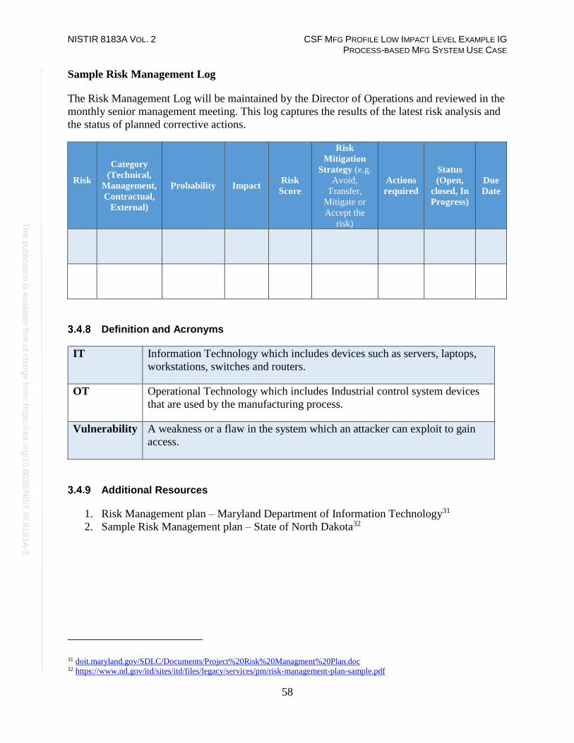
NISTIR 8183A VOL. 2 CSF MFG PROFILE LOW IMPACT LEVEL EXAMPLE IG PROCESS-BASED MFG SYSTEM USE CASE
58
Th
is p
ublic
atio
n is
ava
ilable
free
of c
ha
rge
from
: http
s://d
oi.o
rg/1
0.6
02
8/N
IST
.IR.8
18
3A
-2
Sample Risk Management Log
The Risk Management Log will be maintained by the Director of Operations and reviewed in the
monthly senior management meeting. This log captures the results of the latest risk analysis and
the status of planned corrective actions.
Risk
Category
(Technical,
Management,
Contractual,
External)
Probability Impact Risk
Score
Risk
Mitigation
Strategy (e.g.
Avoid,
Transfer,
Mitigate or
Accept the
risk)
Actions
required
Status
(Open,
closed, In
Progress)
Due
Date
Definition and Acronyms
IT Information Technology which includes devices such as servers, laptops,
workstations, switches and routers.
OT Operational Technology which includes Industrial control system devices
that are used by the manufacturing process.
Vulnerability A weakness or a flaw in the system which an attacker can exploit to gain
access.
Additional Resources
1. Risk Management plan – Maryland Department of Information Technology31
2. Sample Risk Management plan – State of North Dakota32
31 doit.maryland.gov/SDLC/Documents/Project%20Risk%20Managment%20Plan.doc 32 https://www.nd.gov/itd/sites/itd/files/legacy/services/pm/risk-management-plan-sample.pdf

NISTIR 8183A VOL. 2 CSF MFG PROFILE LOW IMPACT LEVEL EXAMPLE IG PROCESS-BASED MFG SYSTEM USE CASE
59
Th
is p
ublic
atio
n is
ava
ilable
free
of c
ha
rge
from
: http
s://d
oi.o
rg/1
0.6
02
8/N
IST
.IR.8
18
3A
-2
Incident Response Plan Document Example
This section provides example content that an Incident Response Plan document may contain, including example
policy and procedure statements that were developed for the fictional company Westman. Certain commercial entities,
equipment, or materials may be identified in this document in order to describe a concept adequately. Such
identification is not intended to imply recommendation or endorsement by NIST, nor is it intended to imply that the
entities, equipment, or materials are necessarily the best available for the purpose. Each organization’s information
security experts should identify the content, and policy and procedure statements that will best integrate with their
existing cybersecurity program and manufacturing system infrastructure.
Incident Response Plan
for
Westman
Document Owner: Director of Operations
Version
Version Date Description Author
1.0 02-22-2018 Initial Draft Director of Operations
2.0 04-21-2018 Major revision Director of Operations
Approval
(By signing below, approvers agree to all terms and conditions outlined in this document.)
Approvers Role Signed Approval Date
S. Forthright CEO <digital signature> 4-22-2018
Statement of Management Commitment
Westman’s management team is committed to information security and appropriate incident
response to accidental or deliberate cybersecurity incidents within the company. Westman has
created the Incident Response Plan to establish an actionable information security incident
handling capability that includes planning, detection, analysis, containment, and reporting for
cybersecurity incidents.
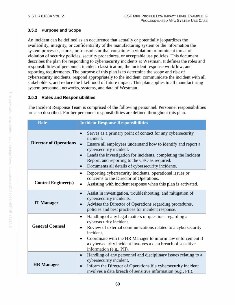
NISTIR 8183A VOL. 2 CSF MFG PROFILE LOW IMPACT LEVEL EXAMPLE IG PROCESS-BASED MFG SYSTEM USE CASE
60
Th
is p
ublic
atio
n is
ava
ilable
free
of c
ha
rge
from
: http
s://d
oi.o
rg/1
0.6
02
8/N
IST
.IR.8
18
3A
-2
Purpose and Scope
An incident can be defined as an occurrence that actually or potentially jeopardizes the
availability, integrity, or confidentiality of the manufacturing system or the information the
system processes, stores, or transmits or that constitutes a violation or imminent threat of
violation of security policies, security procedures, or acceptable use policies. This document
describes the plan for responding to cybersecurity incidents at Westman. It defines the roles and
responsibilities of personnel, incident classification, the incident response workflow, and
reporting requirements. The purpose of this plan is to determine the scope and risk of
cybersecurity incidents, respond appropriately to the incident, communicate the incident with all
stakeholders, and reduce the likelihood of future impact. This plan applies to all manufacturing
system personnel, networks, systems, and data of Westman.
Roles and Responsibilities
The Incident Response Team is comprised of the following personnel. Personnel responsibilities
are also described. Further personnel responsibilities are defined throughout this plan.
Role Incident Response Responsibilities
Director of Operations
• Serves as a primary point of contact for any cybersecurity
incident.
• Ensure all employees understand how to identify and report a
cybersecurity incident.
• Leads the investigation for incidents, completing the Incident
Report, and reporting to the CEO as required.
• Documents all details of cybersecurity incidents.
Control Engineer(s)
• Reporting cybersecurity incidents, operational issues or
concerns to the Director of Operations.
• Assisting with incident response when this plan is activated.
IT Manager
• Assist in investigation, troubleshooting, and mitigation of
cybersecurity incidents.
• Advises the Director of Operations regarding procedures,
policies and best practices for incident response.
General Counsel
• Handling of any legal matters or questions regarding a
cybersecurity incident.
• Review of external communications related to a cybersecurity
incident.
• Coordinate with the HR Manager to inform law enforcement if
a cybersecurity incident involves a data breach of sensitive
information (e.g., PII).
HR Manager
• Handling of any personnel and disciplinary issues relating to a
cybersecurity incident.
• Inform the Director of Operations if a cybersecurity incident
involves a data breach of sensitive information (e.g., PII).

NISTIR 8183A VOL. 2 CSF MFG PROFILE LOW IMPACT LEVEL EXAMPLE IG PROCESS-BASED MFG SYSTEM USE CASE
61
Th
is p
ublic
atio
n is
ava
ilable
free
of c
ha
rge
from
: http
s://d
oi.o
rg/1
0.6
02
8/N
IST
.IR.8
18
3A
-2
Policy
1. Upon notification of a cybersecurity event, the Director of Operations must
determine if the Incident Response Plan should be activated based on available
information from event.
2. The Director of Operations must inform all personnel listed in Section 3.5.7 of this
document when the response plan has been activated.
3. Impact to the manufacturing system must be determined by thorough investigation,
and an incident type and severity level assigned. The Incident Report Template form
should be used for this purpose. The severity level will be assigned by the Director
of Operations in consultation with the IT Manager.
4. Approval must be received from the CEO and General Counsel if additional
resources (i.e., external entities) are to be contacted to assist with incident response
(e.g., forensic investigators, IT consultants, cybersecurity consultants, law
enforcement, etc.).
5. The Director of Operations or IT Manager must coordinate the Incident Response
Plan with stakeholders.
6. User awareness, training, and testing procedures must be reviewed after every
incident and updated as necessary.
7. The General Counsel should be involved throughout the incident response due to the
potential for legal action arising from the incident.
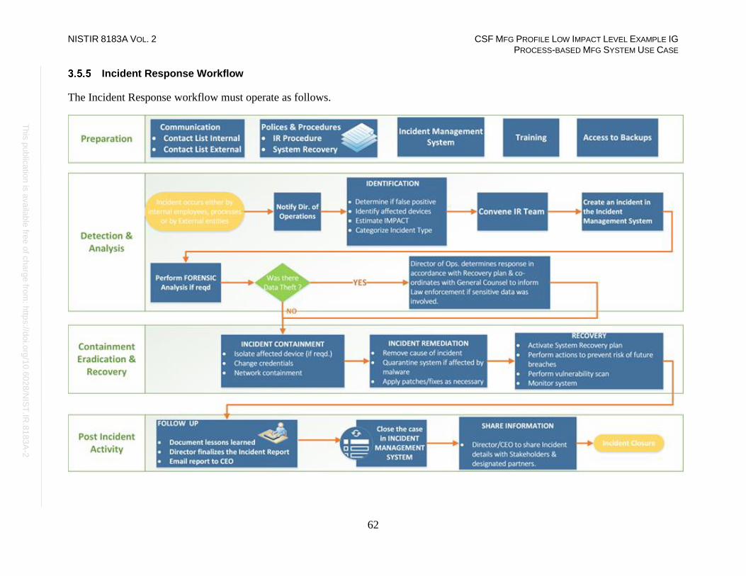
NISTIR 8183A VOL. 2 CSF MFG PROFILE LOW IMPACT LEVEL EXAMPLE IG PROCESS-BASED MFG SYSTEM USE CASE
62
Th
is p
ublic
atio
n is
ava
ilable
free
of c
ha
rge
from
: http
s://d
oi.o
rg/1
0.6
02
8/N
IST
.IR.8
18
3A
-2
Incident Response Workflow
The Incident Response workflow must operate as follows.

NISTIR 8183A VOL. 2 CSF MFG PROFILE LOW IMPACT LEVEL EXAMPLE IG PROCESS-BASED MFG SYSTEM USE CASE
63
Th
is p
ublic
atio
n is
ava
ilable
free
of c
ha
rge
from
: http
s://d
oi.o
rg/1
0.6
02
8/N
IST
.IR.8
18
3A
-2
Internal and External Communications
The following policies are applicable to internal and external communications that are performed
during an incident response:
• The CEO must identify and promptly contact primary partners, stakeholders, and
customers to inform them about response activities. This should be performed once the
impact of the incident is understood, and a corporate response has been prepared.
• The Director of Operations must contact all personnel responsible for system recovery,
listed below, once this plan has been executed.
• The Director of Operations must establish reporting requirements on the progress of
incident response activities to stakeholders.
• Communications with any external entities must be initiated by personnel explicitly
authorized by this plan, or as authorized by the Director of Operations during execution
of this plan.
• Approval must be received from the CEO and General Counsel before collaborating with
any outside entity during an incident response.

NISTIR 8183A VOL. 2 CSF MFG PROFILE LOW IMPACT LEVEL EXAMPLE IG PROCESS-BASED MFG SYSTEM USE CASE
64
Th
is p
ublic
atio
n is
ava
ilable
free
of c
ha
rge
from
: http
s://d
oi.o
rg/1
0.6
02
8/N
IST
.IR.8
18
3A
-2
Personnel Contact Information
The following table contains the contact information for critical Westman personnel who will
likely be involved in the Incident Response process.
Name Title Contact
Type
Contact Information
S. Forthright Chief Executive
Officer (CEO)
Work 301-555-0141 ext. 102
Mobile 240-555-0159
Alternate 301-555-3554
Email [email protected]
W. Lumbergh Director of
Operations
Work 301-555-0141 ext. 103
Mobile 240-555-0110
Alternate 301-555-3110
Email [email protected]
E. Dufresne Control Engineer Work 301-555-0141 ext. 110
Mobile 240-555-0543
Alternate 301-555-3543
Email [email protected]
M. West General Counsel Work 301-555-0141 ext. 107
Mobile 240-555-2173
Alternate 301-555-3173
Email [email protected]
E. Kenmore IT Manager Work 301-555-0141 ext. 108
Mobile 240-555-0824
Alternate 301-555-3824
Email [email protected]
J. Smith HR Manager Work 301-555-0141 ext. 109
Mobile 240-555-0543
Alternate 301-555-3543
Email [email protected]

NISTIR 8183A VOL. 2 CSF MFG PROFILE LOW IMPACT LEVEL EXAMPLE IG PROCESS-BASED MFG SYSTEM USE CASE
65
Th
is p
ublic
atio
n is
ava
ilable
free
of c
ha
rge
from
: http
s://d
oi.o
rg/1
0.6
02
8/N
IST
.IR.8
18
3A
-2
External Contact Information
The following table contains the contact information for external entities that may be contacted
while execution of the Incident Response Plan is ongoing to support or provide relevant
information to support the response process. External entities and organizations listed below
must only be contacted by authorized personnel, as per the guidance described in this plan.
Name Title Contact
Type
Contact Information
OT Contractor
Cyberdyne Systems
Account # 88525462A
General
Support
Work 1-800-555-6543 Option 1, 3, 5
Mobile N/A
Alternate N/A
Email [email protected]
Power Company
Account # 5486548
General
Support
Work 1-800-555-4343 Option 1,4,7,9
Mobile N/A
Alternate N/A
Email N/A
Telecom Carrier
Account # 3340444
General
Support
Work 1-800-555-8769
Mobile N/A
Alternate N/A
Email N/A
Insurance Provider
Account # 8858444
Agent
(R. Parr)
Work 1-800-555-7643
Mobile 240-555-5698
Alternate 240-555-5433
Email [email protected]
Information Sharing Policy
1. The Director of Operations, in collaboration with the CEO, IT Manager, and General
Counsel, must promptly prepare a report detailing relevant information about the
incident response, and may share the report with designated sharing partners.
2. All communications regarding information sharing about an incident or incident
response to external parties must be made in consultation with the CEO.
3. The CEO, Director of Operations, IT Manager, and General Counsel must determine
the relevant information about the incident to be shared.

NISTIR 8183A VOL. 2 CSF MFG PROFILE LOW IMPACT LEVEL EXAMPLE IG PROCESS-BASED MFG SYSTEM USE CASE
66
Th
is p
ublic
atio
n is
ava
ilable
free
of c
ha
rge
from
: http
s://d
oi.o
rg/1
0.6
02
8/N
IST
.IR.8
18
3A
-2
Public Communications
1. Any public response must be clear, consistent, and professional.
2. The CEO and General Counsel must approve all public communications regarding a
cybersecurity incident.
3. If required, an outside public relations firm may be contracted to assist in development of
a response and responding to any public inquiry.
4. All communications with the media must be approved by the CEO and General Counsel.
5. The CEO, Director of Operations, or General Counsel may communicate the public
response, depending on the severity of the cybersecurity incident.
Plan Maintenance
This plan must be reviewed and updated after:
• the plan is executed in response to a cybersecurity incident,
• the plan is executed during an incident response exercise,
• any organizational changes, or
• any modifications or maintenance to the manufacturing system or its components that
may impact this plan.
The Director of Operations must update the document in consultation with Controls Engineers
and other personnel, as required, and must communicate any changes or updates made to this
policy to personnel responsible for its execution.
Plan Testing
This plan must be tested during planned downtime each calendar year. During this time, Incident
Response team members must be convened to perform the following activities:
• incident response tabletop exercises,
• review of the documented procedures,
• validation of plan effectiveness,
• identification of any gaps or weaknesses in the plan execution, and
• update the plan with any outdated or missing information.

NISTIR 8183A VOL. 2 CSF MFG PROFILE LOW IMPACT LEVEL EXAMPLE IG PROCESS-BASED MFG SYSTEM USE CASE
67
Th
is p
ublic
atio
n is
ava
ilable
free
of c
ha
rge
from
: http
s://d
oi.o
rg/1
0.6
02
8/N
IST
.IR.8
18
3A
-2
Incident Type Classification
Westman defines the following types of cybersecurity incidents for internal classification.
Incident Type Description
Intrusion A security event, or a combination of multiple
security events, that constitutes a security incident
in which an intruder gains, or attempts to gain,
access to a system or system resource without
having authorization to do so.33
Denial of Service (DoS) The prevention of authorized access to a system
resource or the delaying of system operations and
functions.34
Virus or malware Software or firmware intended to perform an
unauthorized process that will have adverse impact
on the confidentiality, integrity, or availability of an
information system. A virus, worm, Trojan horse, or
other code-based entity that infects a host. Spyware
and some forms of adware are also examples of
malicious code.35
Social engineering An attempt to trick someone into revealing
information (e.g., a password) that can be used to
attack systems or networks.36
Data loss The exposure of proprietary, sensitive, or classified
information through either data theft or data
leakage.37
Missing or stolen IT/OT hardware Any manufacturing system hardware (in-use,
backup, spare, or surplus) that cannot be accounted
for.
User account compromise The unauthorized disclosure, modification, or use of
a user account on the manufacturing system.
System misuse The unauthorized use of a manufacturing system
component.
33 CNSSI 4009-2015 (IETF RFC 4949 Ver 2) 34 NIST SP 800-82 Rev. 2 under Denial of Service (DoS) (RFC 4949) 35 NIST SP 800-82 Rev. 2 under Malware (NIST SP 800-53) 36 NIST SP 800-82 Rev. 2 under Social Engineering (NIST SP 800-61) 37 CNSSI 4009-2015 (NIST SP 800-137)
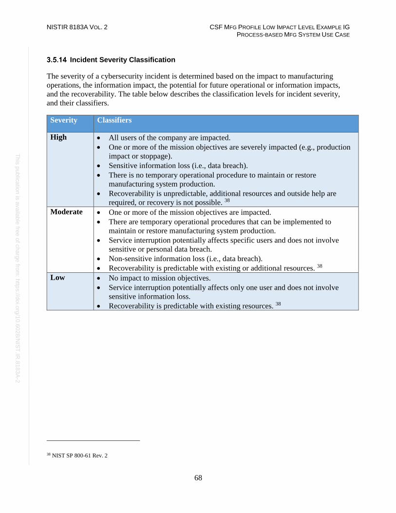
NISTIR 8183A VOL. 2 CSF MFG PROFILE LOW IMPACT LEVEL EXAMPLE IG PROCESS-BASED MFG SYSTEM USE CASE
68
Th
is p
ublic
atio
n is
ava
ilable
free
of c
ha
rge
from
: http
s://d
oi.o
rg/1
0.6
02
8/N
IST
.IR.8
18
3A
-2
Incident Severity Classification
The severity of a cybersecurity incident is determined based on the impact to manufacturing
operations, the information impact, the potential for future operational or information impacts,
and the recoverability. The table below describes the classification levels for incident severity,
and their classifiers.
Severity Classifiers
High • All users of the company are impacted.
• One or more of the mission objectives are severely impacted (e.g., production
impact or stoppage).
• Sensitive information loss (i.e., data breach).
• There is no temporary operational procedure to maintain or restore
manufacturing system production.
• Recoverability is unpredictable, additional resources and outside help are
required, or recovery is not possible. 38
Moderate • One or more of the mission objectives are impacted.
• There are temporary operational procedures that can be implemented to
maintain or restore manufacturing system production.
• Service interruption potentially affects specific users and does not involve
sensitive or personal data breach.
• Non-sensitive information loss (i.e., data breach).
• Recoverability is predictable with existing or additional resources. 38
Low • No impact to mission objectives.
• Service interruption potentially affects only one user and does not involve
sensitive information loss.
• Recoverability is predictable with existing resources. 38
38 NIST SP 800-61 Rev. 2

NISTIR 8183A VOL. 2 CSF MFG PROFILE LOW IMPACT LEVEL EXAMPLE IG PROCESS-BASED MFG SYSTEM USE CASE
69
Th
is p
ublic
atio
n is
ava
ilable
free
of c
ha
rge
from
: http
s://d
oi.o
rg/1
0.6
02
8/N
IST
.IR.8
18
3A
-2
Incident Report Form Template
Incident Reporting Form 39,40
Contact Information
Date: Time:
Name: Title: Dept:
Office Phone:
Incident Details
Incident Date: Incident Time:
Type of Incident - Check all that apply
Intrusion System Misuse Social Engineering
Denial of Service Data Breach User Account Compromise
Virus / Malware Hardware Stolen Other
Description of Incident:
Impact or Potential Impact - Check All that Apply
Loss or Compromise of Data Financial Loss
Damage to Systems Other Organizations Affected
Damage to Public Damage to Integrity or Production
System Downtime Unknown at this time
Description of Impact:
39 Pennsylvania Department of Human Services, http://www.dhs.pa.gov/cs/groups/webcontent/documents/form/p_031584.doc 40 AHIMA BOK, https://bok.ahima.org/doc?oid=76732

NISTIR 8183A VOL. 2 CSF MFG PROFILE LOW IMPACT LEVEL EXAMPLE IG PROCESS-BASED MFG SYSTEM USE CASE
70
Th
is p
ublic
atio
n is
ava
ilable
free
of c
ha
rge
from
: http
s://d
oi.o
rg/1
0.6
02
8/N
IST
.IR.8
18
3A
-2
Incident Reporting Form (cont.)
Affected Systems
Host IP Address Applications (if any) Operating System
Scope of Data Loss (if any)
Public - Data previously approved for release or is publicly available.
Internal Use - Data intended for internal company use, other affiliated organizations, or
business partners. Unauthorized disclosure may be against laws or regulations and may
cause harm the company or its business partners or its customers.
Sensitive - Private, proprietary, customer, or trade secret data. Restricted to those with
legitimate business need for access. Unauthorized disclosure is against laws or regulations,
and will likely harm the company, its business partners, or customers (e.g., trade secrets,
source code, personnel data, PII).
Data Loss Details
Description of Data Loss:
Follow Up Actions Initiated
Law Enforcement Notified System Removal from Network
Restored from Backups Log Files Examined
AV Definitions Updated No Actions
System Reimage or Quarantine Other
Description of Actions Initiated:
Director of Operations Sign-Off
Name: Signature: Date:

NISTIR 8183A VOL. 2 CSF MFG PROFILE LOW IMPACT LEVEL EXAMPLE IG PROCESS-BASED MFG SYSTEM USE CASE
71
Th
is p
ublic
atio
n is
ava
ilable
free
of c
ha
rge
from
: http
s://d
oi.o
rg/1
0.6
02
8/N
IST
.IR.8
18
3A
-2
Acronyms
Acronym Definition
CEO Chief Executive Officer
CNSSI Committee on National Security Systems Instruction
DMZ Demilitarized Zone
DOS Denial of Service
HR Human Resources
IRP Incident Response Plan
IT Information Technology
LAN Local Area Network
NIST SP National Institute of Standards and Technology Special
Publication
NTP Network Time Protocol
OT Operational Technology
PII Personally Identifiable Information
PLC Programmable Logic Controller
RFC Request for Comment
SD Secure Digital
VHD Virtual Hard Drive
Definitions
Term Definition
Sensitive Proprietary, customer, trades secret or other information with
access restricted to those with legitimate business need.
Unauthorized disclosure is against laws or regulations, and will
likely harm the company, its business partners, or customers
(e.g., trade secrets, source code, personnel data, PII). Incident An occurrence that actually or potentially jeopardizes the
availability, integrity, or confidentiality of the manufacturing
system or the information the system processes, stores, or
transmits or that constitutes a violation or imminent threat of
violation of security policies, security procedures, or acceptable
use policies.
Internal Use Data intended for internal company use, other affiliated
organizations, or business partners. Unauthorized disclosure may
be against laws or regulations and may cause harm the company
or its business partners or its customers.
Personnel All employees, contractors, vendors, and individuals authorized
to perform work at the facility, physically or remotely.
Public Data previously approved for release or is publicly available.

NISTIR 8183A VOL. 2 CSF MFG PROFILE LOW IMPACT LEVEL EXAMPLE IG PROCESS-BASED MFG SYSTEM USE CASE
72
Th
is p
ublic
atio
n is
ava
ilable
free
of c
ha
rge
from
: http
s://d
oi.o
rg/1
0.6
02
8/N
IST
.IR.8
18
3A
-2
Term Definition
Stakeholder Individual or organization having a right, share, claim, or
interest in a system or in its possession of characteristics that
meet their needs and expectations. (e.g., Business Owners,
System Owners, Integrators, Vendors, Human Resources
Offices, Physical and Personnel Security Offices, Legal
Departments, Operations Personnel).
Vulnerability Weakness in an information system, system security procedures,
internal controls, or implementation that could be exploited or
triggered by a threat source.

NISTIR 8183A VOL. 2 CSF MFG PROFILE LOW IMPACT LEVEL EXAMPLE IG PROCESS-BASED MFG SYSTEM USE CASE
73
Th
is p
ublic
atio
n is
ava
ilable
free
of c
ha
rge
from
: http
s://d
oi.o
rg/1
0.6
02
8/N
IST
.IR.8
18
3A
-2
System Recovery Plan Document Example
This section provides example content that a System Recovery Plan document may contain, including example policy
and procedure statements that were developed for the fictional company Westman. Certain commercial entities,
equipment, or materials may be identified in this document in order to describe a concept adequately. Such
identification is not intended to imply recommendation or endorsement by NIST, nor is it intended to imply that the
entities, equipment, or materials are necessarily the best available for the purpose. Each organization’s information
security experts should identify the content, and policy and procedure statements that will best integrate with their
existing cybersecurity program and manufacturing system infrastructure.
System Recovery Plan
for
Westman
Document Owner: Director of Operations
Version
Version Date Description Author
1.0 02-22-2018 Initial Draft Director of Operations
2.0 04-21-2018 Major changes to the initial draft Director of Operations
Approval
(By signing below, approvers agree to all terms and conditions outlined in this document.)
Approvers Role Signed Approval Date
S. Forthright CEO <digital signature> 4-22-2018
Purpose
The System Recovery Plan is designed to ensure the continuation of vital
manufacturing/business processes in the event a cybersecurity incident occurs. Its purpose is to
provide a structured approach for responding to cybersecurity incidents by leveraging the
infrastructure inventory and configuration information relevant to the organization’s IT and OT
environments to restore operational capabilities.

NISTIR 8183A VOL. 2 CSF MFG PROFILE LOW IMPACT LEVEL EXAMPLE IG PROCESS-BASED MFG SYSTEM USE CASE
74
Th
is p
ublic
atio
n is
ava
ilable
free
of c
ha
rge
from
: http
s://d
oi.o
rg/1
0.6
02
8/N
IST
.IR.8
18
3A
-2
Objectives
This System Recovery Plan has been developed to accomplish the following objectives:
• limit the magnitude of any loss by minimizing the duration of a manufacturing
interruption,
• assess damage, repair the damage, and restore manufacturing system operation,
• manage the recovery operation in an organized and effective manner, and
• prepare personnel to respond effectively in system recovery situations.
Plan Execution
This plan is executed during or after a cybersecurity incident, as directed by the Director of
Operations.
Roles and Responsibilities
The Incident Response team will be repurposed as the System Recovery team while execution of
the System Recovery Plan is ongoing. Team members will have the following roles and
responsibilities:
Role Responsibilities
Director of Operations • Lead and oversee the entire system recovery process.
• Contact any contractors or vendors for assistance, as
needed.
• Make sure all employees understand their roles and
responsibilities.
• Update this document as per the Maintenance Policy.
• Update the CEO periodically on the progress of the
system recovery process.
Chief Executive Officer (CEO) • Assist the Director of Operations in their role as
required.
• Serve as point of escalation for any issues.
Control Engineers, IT Staff • Recover, restore, troubleshoot, and resolve any
recovery issues on manufacturing system hardware,
software, or systems.
• Escalate any issues related to recovery to the Director
of Operations.
• Comply with this plan.
OT Contractors • Assist with the recovery of any manufacturing system
hardware, software, or systems, as required.
• Advise the Director of Operations of any
recommended procedures, policies, and best practices
to assist with the recovery process.
• Comply with this plan.

NISTIR 8183A VOL. 2 CSF MFG PROFILE LOW IMPACT LEVEL EXAMPLE IG PROCESS-BASED MFG SYSTEM USE CASE
75
Th
is p
ublic
atio
n is
ava
ilable
free
of c
ha
rge
from
: http
s://d
oi.o
rg/1
0.6
02
8/N
IST
.IR.8
18
3A
-2
Internal and External Communications
All communications guidance provided in the Incident Response Plan also applies to the System
Recovery Plan. The following recovery-specific guidance must also be followed:
• The CEO will contact primary partners and customers to inform them about recovery
activities. This should be performed once the impact of the incident is understood, and a
corporate response has been prepared.
• The Director of Operations will contact all personnel responsible for system recovery,
listed below, once this plan is executed.
• The General Counsel will be involved throughout the system recovery process due to the
potential for legal action arising from the cybersecurity incident.
• The Director of Operations, IT Manager, and Control Engineers will periodically update
the CEO and other stakeholders on the progress of recovery activities. The CEO will
define the required stakeholders and update period based on the impact of the incident.
• Communications with external entities must be initiated by personnel explicitly
authorized by this plan, or as authorized by the Director of Operations during execution
of this plan.
Restoring Trust
• The CEO or Director of Operations, with the advice of any contracted consultants and
forensic experts, will notify all partners, vendors, and customers of the steps taken to
restore the manufacturing system and strengthen cybersecurity controls.
• The Director of Operations and IT Manager will discuss with employees the cause for the
plan to be executed and what actions are being taken to avoid similar incidents from
occurring in the future.
• After the cybersecurity incident has been mitigated and all facts surrounding the incident
are known, the Director of Operations will provide a full report to be released publicly.
The report will contain content relevant to the cybersecurity incident, along with the steps
being taken to safeguard the manufacturing system, and describe the actions being taken
to avoid similar incidents from occurring in the future.

NISTIR 8183A VOL. 2 CSF MFG PROFILE LOW IMPACT LEVEL EXAMPLE IG PROCESS-BASED MFG SYSTEM USE CASE
76
Th
is p
ublic
atio
n is
ava
ilable
free
of c
ha
rge
from
: http
s://d
oi.o
rg/1
0.6
02
8/N
IST
.IR.8
18
3A
-2
Personnel Contact Information
The following table contains the contact information for critical Westman personnel who will
likely be involved in the system recovery process.
Name Title Contact
Type
Contact Information
S. Forthright Chief Executive
Officer (CEO)
Work 301-555-0141 ext. 102
Mobile 240-555-0159
Alternate 301-555-3554
Email [email protected]
W. Lumbergh Director of
Operations
Work 301-555-0141 ext. 103
Mobile 240-555-0110
Alternate 301-555-3110
Email [email protected]
E. Dufresne Control Engineer Work 301-555-0141 ext. 110
Mobile 240-555-0543
Alternate 301-555-3543
Email [email protected]
M. West General Counsel Work 301-555-0141 ext. 107
Mobile 240-555-2173
Alternate 301-555-3173
Email [email protected]
E. Kenmore IT Manager Work 301-555-0141 ext. 108
Mobile 240-555-0824
Alternate 301-555-3824
Email [email protected]
J. Smith HR Manager Work 301-555-0141 ext. 109
Mobile 240-555-0543
Alternate 301-555-3543
Email [email protected]

NISTIR 8183A VOL. 2 CSF MFG PROFILE LOW IMPACT LEVEL EXAMPLE IG PROCESS-BASED MFG SYSTEM USE CASE
77
Th
is p
ublic
atio
n is
ava
ilable
free
of c
ha
rge
from
: http
s://d
oi.o
rg/1
0.6
02
8/N
IST
.IR.8
18
3A
-2
External Contact Information
The following table contains the contact information for external entities and organizations that
may be contacted while execution of the System Recovery Plan is ongoing to support or provide
relevant information to support the recovery process. External entities and organizations listed
below must only be contacted by authorized personnel, as per the guidance described in this
System Recovery Plan.
Name Title Contact
Type
Contact Information
OT Contractor
Cyberdyne Systems
Account # 88525462A
General
Support
Work 1-800-555-6543 Option 1, 3, 5
Mobile N/A
Alternate N/A
Email [email protected]
Power Company
Account # 5486548
General
Support
Work 1-800-555-4343 Option 1,4,7,9
Mobile N/A
Alternate N/A
Email N/A
Telecom Carrier
Account # 3340444
General
Support
Work 1-800-555-8769
Mobile N/A
Alternate N/A
Email N/A
Insurance Provider
Account # 8858444
Agent
(R. Parr)
Work 1-800-555-7643
Mobile 240-555-5698
Alternate 240-555-5433
Email [email protected]
Plan Maintenance
The System Recovery Plan must be reviewed and updated after:
• the plan is executed in response to a cybersecurity incident,
• the plan is executed during an incident response or recovery exercise,
• any organizational changes, or
• any modifications or maintenance to the manufacturing system or its components that
may impact this plan.
The Director of Operations is responsible for updating the document in consultation with
Controls Engineers and other personnel, as required.

NISTIR 8183A VOL. 2 CSF MFG PROFILE LOW IMPACT LEVEL EXAMPLE IG PROCESS-BASED MFG SYSTEM USE CASE
78
Th
is p
ublic
atio
n is
ava
ilable
free
of c
ha
rge
from
: http
s://d
oi.o
rg/1
0.6
02
8/N
IST
.IR.8
18
3A
-2
Plan Testing
This plan must be tested during planned downtime each calendar year. During this time, System
Recovery team members must be convened to perform the following activities:
• system recovery tabletop exercises,
• review of the documented procedures,
• validation of plan effectiveness,
• identification of any gaps or weaknesses in the plan execution, and
• update the plan with any outdated or missing information.
Hardware to be Recovered
The following tables document important information to support the recovery of manufacturing
system devices. Each device is listed in its own table with relevant information (e.g., hostname,
file systems, physical location, backup strategies). The recovery strategies for each device below
is described in Section 3.6.12. For more detailed system information regarding each host,
reference the Hardware Inventory.
3.6.11.1 Plant Servers
Engineering Workstation
Hostname FGS-47631EHH
Model HP Z230
IP Address 172.16.3.10
Network Engineering LAN
Location Cabinet 101
Type Physical
Operating System Windows 7
File System(s) C: (465GB)
Backup Strategies Veeam directory backups are performed on select directories
containing configuration and logic data for the manufacturing
system:
• weekly during periods of low volume production (e.g.,
overnight).
Veeam full system image backups are performed:
• quarterly during periods of low volume production (e.g.,
overnight), and
• after engineering change.
Recovery Priority Medium
Recovery Strategies Veeam Directory Recovery (Section 3.6.12.1)
Veeam Full Image Recovery (Section 3.6.12.2)

NISTIR 8183A VOL. 2 CSF MFG PROFILE LOW IMPACT LEVEL EXAMPLE IG PROCESS-BASED MFG SYSTEM USE CASE
79
Th
is p
ublic
atio
n is
ava
ilable
free
of c
ha
rge
from
: http
s://d
oi.o
rg/1
0.6
02
8/N
IST
.IR.8
18
3A
-2
OPC Server
Hostname FGS-61338OSH
Model Supermicro Z97X
IP Address 172.16.2.5
Network Supervisory LAN
Location Cabinet 101
Type Physical
Operating System Windows 7
File System(s) C: (233 GB)
O:\OPC_Share (\\172.16.2.5)
Backup Strategies Veeam full system image backups are performed:
• quarterly during periods of low volume
production (e.g., overnight), and
• after engineering change.
Recovery Priority High
Recovery Strategies Veeam Full Image Recovery (Section 3.6.12.2)
Process Controller Server
Hostname FGS-61338CH
Model Supermicro Z97X
IP Address 172.16.1.5
Network Operations LAN
Location Cabinet 101
Type Physical
Operating System Windows 7
File System(s) C: (233 GB)
Backup Strategies Veeam full system image backups are performed:
• quarterly during periods of low volume
production (e.g., overnight), and
• after engineering change.
Recovery Priority High
Recovery Strategies Veeam Full Image Recovery (Section 3.6.12.2)
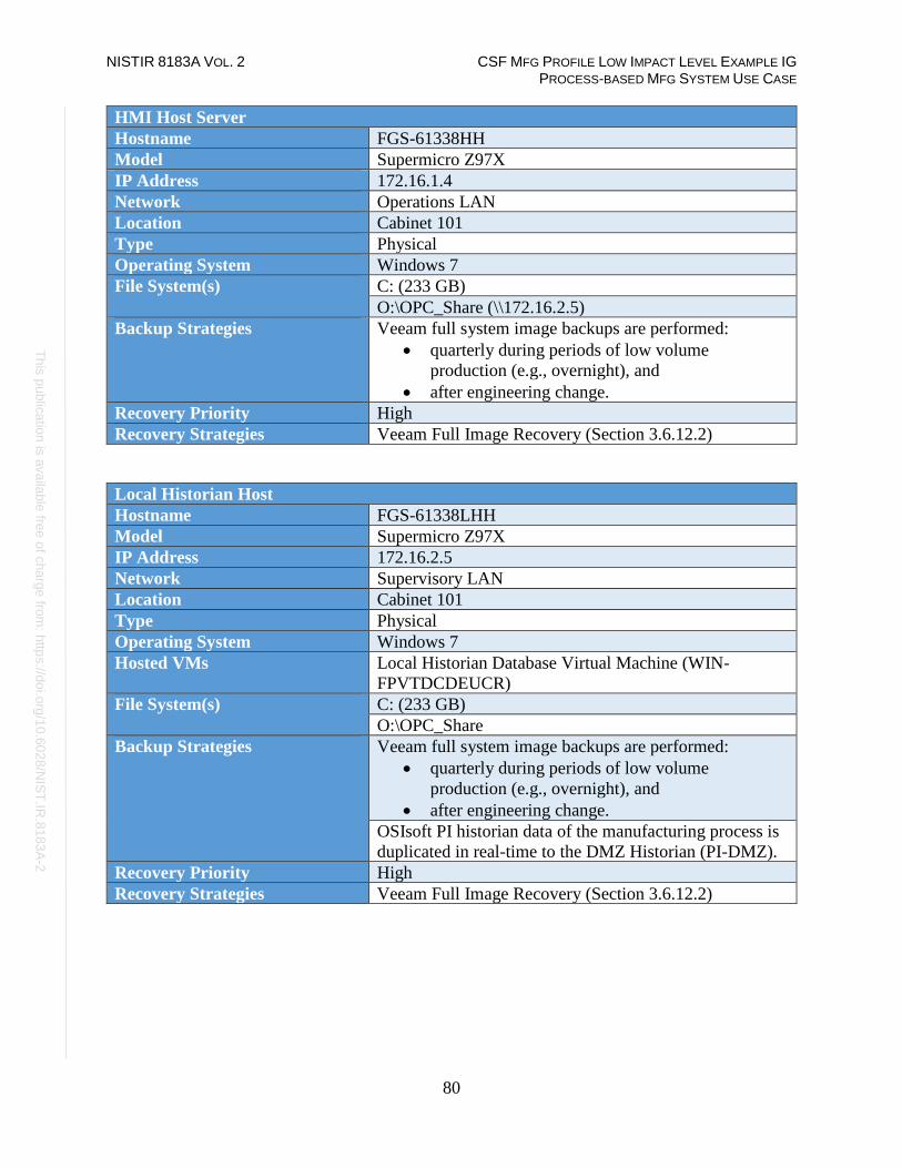
NISTIR 8183A VOL. 2 CSF MFG PROFILE LOW IMPACT LEVEL EXAMPLE IG PROCESS-BASED MFG SYSTEM USE CASE
80
Th
is p
ublic
atio
n is
ava
ilable
free
of c
ha
rge
from
: http
s://d
oi.o
rg/1
0.6
02
8/N
IST
.IR.8
18
3A
-2
HMI Host Server
Hostname FGS-61338HH
Model Supermicro Z97X
IP Address 172.16.1.4
Network Operations LAN
Location Cabinet 101
Type Physical
Operating System Windows 7
File System(s) C: (233 GB)
O:\OPC_Share (\\172.16.2.5)
Backup Strategies Veeam full system image backups are performed:
• quarterly during periods of low volume
production (e.g., overnight), and
• after engineering change.
Recovery Priority High
Recovery Strategies Veeam Full Image Recovery (Section 3.6.12.2)
Local Historian Host
Hostname FGS-61338LHH
Model Supermicro Z97X
IP Address 172.16.2.5
Network Supervisory LAN
Location Cabinet 101
Type Physical
Operating System Windows 7
Hosted VMs Local Historian Database Virtual Machine (WIN-
FPVTDCDEUCR)
File System(s) C: (233 GB)
O:\OPC_Share
Backup Strategies Veeam full system image backups are performed:
• quarterly during periods of low volume
production (e.g., overnight), and
• after engineering change.
OSIsoft PI historian data of the manufacturing process is
duplicated in real-time to the DMZ Historian (PI-DMZ).
Recovery Priority High
Recovery Strategies Veeam Full Image Recovery (Section 3.6.12.2)
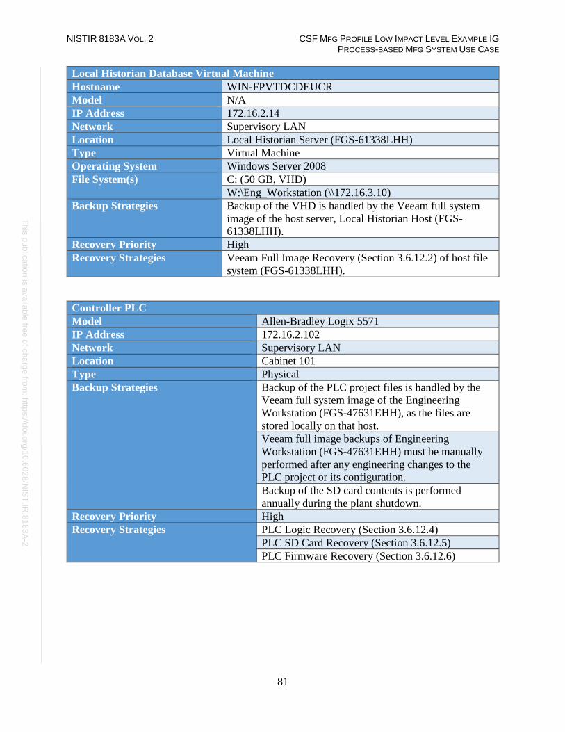
NISTIR 8183A VOL. 2 CSF MFG PROFILE LOW IMPACT LEVEL EXAMPLE IG PROCESS-BASED MFG SYSTEM USE CASE
81
Th
is p
ublic
atio
n is
ava
ilable
free
of c
ha
rge
from
: http
s://d
oi.o
rg/1
0.6
02
8/N
IST
.IR.8
18
3A
-2
Local Historian Database Virtual Machine
Hostname WIN-FPVTDCDEUCR
Model N/A
IP Address 172.16.2.14
Network Supervisory LAN
Location Local Historian Server (FGS-61338LHH)
Type Virtual Machine
Operating System Windows Server 2008
File System(s) C: (50 GB, VHD)
W:\Eng_Workstation (\\172.16.3.10)
Backup Strategies Backup of the VHD is handled by the Veeam full system
image of the host server, Local Historian Host (FGS-
61338LHH).
Recovery Priority High
Recovery Strategies Veeam Full Image Recovery (Section 3.6.12.2) of host file
system (FGS-61338LHH).
Controller PLC
Model Allen-Bradley Logix 5571
IP Address 172.16.2.102
Network Supervisory LAN
Location Cabinet 101
Type Physical
Backup Strategies Backup of the PLC project files is handled by the
Veeam full system image of the Engineering
Workstation (FGS-47631EHH), as the files are
stored locally on that host.
Veeam full image backups of Engineering
Workstation (FGS-47631EHH) must be manually
performed after any engineering changes to the
PLC project or its configuration.
Backup of the SD card contents is performed
annually during the plant shutdown.
Recovery Priority High
Recovery Strategies PLC Logic Recovery (Section 3.6.12.4)
PLC SD Card Recovery (Section 3.6.12.5)
PLC Firmware Recovery (Section 3.6.12.6)

NISTIR 8183A VOL. 2 CSF MFG PROFILE LOW IMPACT LEVEL EXAMPLE IG PROCESS-BASED MFG SYSTEM USE CASE
82
Th
is p
ublic
atio
n is
ava
ilable
free
of c
ha
rge
from
: http
s://d
oi.o
rg/1
0.6
02
8/N
IST
.IR.8
18
3A
-2
3.6.11.2 Network Devices
Manufacturing System Router / Firewall
Hostname CiscoASA
Model Cisco ASA 5512
IP Address(es) Corporate Network: REDACTED
Cybersecurity LAN: 10.100.0.1
DMZ LAN: 10.100.1.1
Management LAN: 10.100.2.4
Location Cabinet 102
Type Physical
Operating System Firmware: FTD 6.2.3.7 Build 51
Backup Strategies Manual. Performed via the CLI or web UI.
Recovery Priority High
Recovery Strategies Cisco ASA Recovery (Section 3.6.12.7)
Boundary Router
Model Allen-Bradley 8300
IP Address 10.100.2.8
Location Cabinet 101
Type Physical
Operating System Firmware: V15.2(4a) EA5 Crypto
Backup Strategies Manual. Performed through CLI or web UI
Recovery Priority High
Recovery Strategies Allen-Bradley 8300 Recovery (3.6.12.8)
Supervisory LAN Switch
Model Allen-Bradley 5700
IP Address 172.16.2.2
Location Cabinet 101
Type Physical
Operating System Firmware: v15.2(5)EA.fc4
Backup Strategies Manual. Performed through CLI or web UI
Recovery Priority High
Recovery Strategies Allen-Bradley 5700 Recovery (3.6.12.9)

NISTIR 8183A VOL. 2 CSF MFG PROFILE LOW IMPACT LEVEL EXAMPLE IG PROCESS-BASED MFG SYSTEM USE CASE
83
Th
is p
ublic
atio
n is
ava
ilable
free
of c
ha
rge
from
: http
s://d
oi.o
rg/1
0.6
02
8/N
IST
.IR.8
18
3A
-2
Control LAN Switch
Model Allen-Bradley 5700
IP Address 172.16.1.3
Location Cabinet 101
Type Physical
Operating System Firmware: v15.2(5)EA.fc4
Backup Strategies Manual. Performed through CLI or web UI
Recovery Priority High
Recovery Strategies Allen-Bradley 5700 Recovery (3.6.12.9)
3.6.11.3 Cybersecurity LAN Servers
Hyper-V Host Server
Hostname LANVH
Model Dell PowerEdge R620
IP Address 10.100.2.10
Network Management LAN (Hosted VMs are on Cybersecurity
LAN)
Location Cabinet 102
Type Physical
Operating System Windows Server 2012 R2 Datacenter x64 Edition
Hosted VMs • LAN-AD
• LAN-AD02
• SymantecMgrVM
• Security Onion
• Graylog
• GTBInspector
• GTBCC
• The-Hive
• NessusVM
• WSUS
File System(s) C: (1 TB)
D: (3.5 TB)
Backup Strategies Veeam full system image backups are performed:
• daily overnight, and
• after any configuration change.
Recovery Priority High
Recovery Strategies Veeam Full Image Recovery (Section 3.6.12.2)

NISTIR 8183A VOL. 2 CSF MFG PROFILE LOW IMPACT LEVEL EXAMPLE IG PROCESS-BASED MFG SYSTEM USE CASE
84
Th
is p
ublic
atio
n is
ava
ilable
free
of c
ha
rge
from
: http
s://d
oi.o
rg/1
0.6
02
8/N
IST
.IR.8
18
3A
-2
Active Directory Server
Hostname LAN-AD
Model N/A
IP Address 10.100.0.13
Network Cybersecurity LAN
Location Hyper-V Host Server (LANVH)
Type Virtual
Operating System Windows Server 2012 R2
File System(s) 45 GB (VHD)
Backup Strategies Veeam full system image backups are performed:
• daily overnight, and
• after any configuration change.
Recovery Priority High
Recovery Strategies Veeam Full Image Recovery (Section 3.6.12.2)
Backup Active Directory Server
Hostname LAN-AD02
Model N/A
IP Address 10.100.0.17
Network Cybersecurity LAN
Location Hyper-V Host Server (LANVH)
Type Virtual
Operating System Windows Server 2012 R2
File System(s) 250 GB (VHD)
Backup Strategies Veeam full system image backups are performed:
• daily overnight, and
• after any configuration change.
Recovery Priority High
Recovery Strategies Veeam Full Image Recovery (Section 3.6.12.2)

NISTIR 8183A VOL. 2 CSF MFG PROFILE LOW IMPACT LEVEL EXAMPLE IG PROCESS-BASED MFG SYSTEM USE CASE
85
Th
is p
ublic
atio
n is
ava
ilable
free
of c
ha
rge
from
: http
s://d
oi.o
rg/1
0.6
02
8/N
IST
.IR.8
18
3A
-2
DMZ Historian
Hostname PI-DMZ
Model N/A
IP Address 10.100.1.4
Network Manufacturing DMZ
Location Cabinet 102
Type Virtual
Operating System Windows 2008 R2 Standard Edition
File System(s) 250 GB (VHD)
Backup Strategies Veeam full system image backups are performed:
• daily overnight, and
• after any configuration change.
The native OSIsoft PI application backup feature archives
production data from the manufacturing process. These
backups are stored on the local host; restore the host to
obtain the most recent backup version. NOTE: Any
recovered historical data will be limited to data present at
the time of the backup.
Recovery Priority Medium
Recovery Strategies Veeam Full Image Recovery (Section 3.6.12.2)
OSIsoft PI production data recovery.
VMware Host
Hostname ESXi-Host
Model Dell R710
IP Address 10.100.2.9
Network Management LAN
Location Cabinet 102
Type Physical
Operating System vmWare vSphere ESXi 6.0.0
Hosted VMs • PI-DMZ
• Veeam
File System(s) 4.5 TB (DataStore1)
Backup Strategies Manual. Performed through CLI or web UI
Recovery Priority High
Recovery Strategies VMWare ESXi Recovery (3.6.12.11)

NISTIR 8183A VOL. 2 CSF MFG PROFILE LOW IMPACT LEVEL EXAMPLE IG PROCESS-BASED MFG SYSTEM USE CASE
86
Th
is p
ublic
atio
n is
ava
ilable
free
of c
ha
rge
from
: http
s://d
oi.o
rg/1
0.6
02
8/N
IST
.IR.8
18
3A
-2
Veeam Backup Server
Hostname Veeam
Model N/A
IP Address 10.100.0.10
Network Cybersecurity LAN
Location VMware Host (ESXi-Host)
Type Virtual
Operating System Windows Server 2012 R2
File System(s) C: (50 GB, VHD)
E: (500 GB, VHD)
F: (4 TB, VHD)
Network Share (Host, F:\Backup\Network Devices)
Backup Strategies Veeam full system image backups are performed:
• daily overnight, and
• after any configuration change.
Recovery Priority High
Recovery Strategies Veeam Instant Virtual Machine Recovery (3.6.12.3)
Symantec Antivirus Server
Hostname SymantecMgrVM
Model N/A
IP Address 10.100.0.5
Network Cybersecurity LAN
Location Hyper-V Host Server (LANVH)
Type Virtual
Operating System Windows Server 2012 R2
File System(s) 70 GB (VHD)
Backup Strategies Veeam full system image backups are performed:
• daily overnight, and
• after any configuration change.
Recovery Priority Medium
Recovery Strategies Veeam Full Image Recovery (Section 3.6.12.2)

NISTIR 8183A VOL. 2 CSF MFG PROFILE LOW IMPACT LEVEL EXAMPLE IG PROCESS-BASED MFG SYSTEM USE CASE
87
Th
is p
ublic
atio
n is
ava
ilable
free
of c
ha
rge
from
: http
s://d
oi.o
rg/1
0.6
02
8/N
IST
.IR.8
18
3A
-2
Security Onion Server
Hostname Security Onion
Model N/A
IP Address 10.100.0.26
Network Cybersecurity LAN
Location Hyper-V Host Server (LANVH)
Type Virtual
Operating System Ubuntu 16.04
File System(s) Root File System (500 GB, VHD)
Backup Strategies Veeam full system image backups are performed:
• daily overnight, and
• after any configuration change.
Recovery Priority Low
Recovery Strategies Veeam Full Image Recovery (Section 3.6.12.2)
Graylog Server
Hostname Graylog
Model N/A
IP Address 10.100.0.14
Network Cybersecurity LAN
Location Hyper-V Host Server (LANVH)
Type Virtual
Operating System Ubuntu 14.04
File System(s) Root File System (50 GB)
Data File System (500 GB)
Backup Strategies Veeam full system image backups are performed:
• daily overnight, and
• after any configuration change.
Recovery Priority Low
Recovery Strategies Veeam Full Image Recovery (Section 3.6.12.2)

NISTIR 8183A VOL. 2 CSF MFG PROFILE LOW IMPACT LEVEL EXAMPLE IG PROCESS-BASED MFG SYSTEM USE CASE
88
Th
is p
ublic
atio
n is
ava
ilable
free
of c
ha
rge
from
: http
s://d
oi.o
rg/1
0.6
02
8/N
IST
.IR.8
18
3A
-2
GTB Inspector Server
Hostname GTBInspector
Model N/A
IP Address 10.100.0.175
Network Cybersecurity LAN
Location Hyper-V Host Server (LANVH)
Type Virtual
Operating System CentOS 7.4.1708
File System(s) 162 GB (Vendor configured)
Backup Strategies Veeam full system image backups are performed:
• daily overnight, and
• after any configuration change.
Recovery Priority Low
Recovery Strategies Veeam Full Image Recovery (Section 3.6.12.2)
GTB Console Server
Hostname GTBCC
Model N/A
IP Address 10.100.0.176
Network Cybersecurity LAN
Location Hyper-V Host Server (LANVH)
Type Virtual
Operating System CentOS 7.4.1708
File System(s) 107 GB (vendor configured)
Backup Strategies Veeam full system image backups are performed:
• daily overnight, and
• after any configuration change.
Recovery Priority Low
Recovery Strategies Veeam Full Image Recovery (Section 3.6.12.2)
The Hive Project Incident Response Server
Hostname The-Hive
Model N/A
IP Address 10.100.0.51
Network Cybersecurity LAN
Location Hyper-V Host Server (LANVH)
Type Virtual
Operating System Ubuntu 16.04
File System(s) Root file system (50 GB, VHD)
Backup Strategies Veeam full system image backups are performed:
• daily overnight, and
• after any configuration change.
Recovery Priority Low
Recovery Strategies Veeam Full Image Recovery (Section 3.6.12.2)
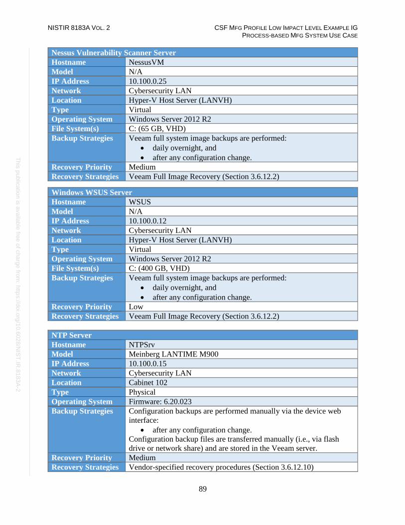
NISTIR 8183A VOL. 2 CSF MFG PROFILE LOW IMPACT LEVEL EXAMPLE IG PROCESS-BASED MFG SYSTEM USE CASE
89
Th
is p
ublic
atio
n is
ava
ilable
free
of c
ha
rge
from
: http
s://d
oi.o
rg/1
0.6
02
8/N
IST
.IR.8
18
3A
-2
Nessus Vulnerability Scanner Server
Hostname NessusVM
Model N/A
IP Address 10.100.0.25
Network Cybersecurity LAN
Location Hyper-V Host Server (LANVH)
Type Virtual
Operating System Windows Server 2012 R2
File System(s) C: (65 GB, VHD)
Backup Strategies Veeam full system image backups are performed:
• daily overnight, and
• after any configuration change.
Recovery Priority Medium
Recovery Strategies Veeam Full Image Recovery (Section 3.6.12.2)
Windows WSUS Server
Hostname WSUS
Model N/A
IP Address 10.100.0.12
Network Cybersecurity LAN
Location Hyper-V Host Server (LANVH)
Type Virtual
Operating System Windows Server 2012 R2
File System(s) C: (400 GB, VHD)
Backup Strategies Veeam full system image backups are performed:
• daily overnight, and
• after any configuration change.
Recovery Priority Low
Recovery Strategies Veeam Full Image Recovery (Section 3.6.12.2)
NTP Server
Hostname NTPSrv
Model Meinberg LANTIME M900
IP Address 10.100.0.15
Network Cybersecurity LAN
Location Cabinet 102
Type Physical
Operating System Firmware: 6.20.023
Backup Strategies Configuration backups are performed manually via the device web
interface:
• after any configuration change.
Configuration backup files are transferred manually (i.e., via flash
drive or network share) and are stored in the Veeam server.
Recovery Priority Medium
Recovery Strategies Vendor-specified recovery procedures (Section 3.6.12.10)

NISTIR 8183A VOL. 2 CSF MFG PROFILE LOW IMPACT LEVEL EXAMPLE IG PROCESS-BASED MFG SYSTEM USE CASE
90
Th
is p
ublic
atio
n is
ava
ilable
free
of c
ha
rge
from
: http
s://d
oi.o
rg/1
0.6
02
8/N
IST
.IR.8
18
3A
-2
Recovery Procedures
The following table defines generalized recovery procedures manufacturing system devices.
3.6.12.1 Veeam Directory Level Recovery
Directory level (file-level) backups enable restoration and recovery of individual files and
folders. Data required for this type of restoration are stored in the Veeam Server. Reference
Veeam guidance41 to complete the restoration process.
Warning: The manufacturing system must be in a non-operational state when the recovery is
performed if the host to be recovered is in the Operations LAN or Supervisory LAN.
3.6.12.2 Veeam Full Image Recovery
Full image (volume-level) backups enable restoration and recovery of a host, or specific volumes
of the host file system. Data required for this type of restoration are stored in the Veeam Server.
Reference Veeam guidance42 to complete the restoration process.
Warning: The manufacturing system must be in a non-operational state when the recovery is
performed if the host to be recovered is in the Operations LAN or Supervisory LAN.
3.6.12.3 Veeam Instant Virtual Machine Recovery
Virtual Machine backups enable full system images to be created, similar to Veeam Full Image
backups for physical hosts. These types of backups can be used for recovery of files, file
systems, and complete restoration. Reference Veeam guidance for Hyper-V43, VMWare44, and
Veeam45 to complete the restoration process.
3.6.12.4 PLC Logic Recovery
PLC logic recovery can be performed to restore the PLC logic back to a known state in case of
compromise or corruption. This operation must be performed from the Engineering Workstation.
Reference Allen-Bradley PLC guidance46 to complete the restoration process.
Warning: The manufacturing system must be in a non-operational state when this recovery is
performed.
41 https://helpcenter.veeam.com/docs/backup/vsphere/restore_vead.html?ver=95u4 42 https://www.veeam.com/veeam_backup_9_5_u4_enterprise_manager_user_guide_pg.pdf 43 https://helpcenter.veeam.com/docs/backup/hyperv/data_recovery.html?ver=95u4 44 https://helpcenter.veeam.com/docs/backup/vsphere/data_recovery.html?ver=95u4 45 https://helpcenter.veeam.com/docs/backup/vsphere/vbr_config_restore.html?ver=95u4 46 https://literature.rockwellautomation.com/idc/groups/literature/documents/pm/1756-pm014_-en-p.pdf

NISTIR 8183A VOL. 2 CSF MFG PROFILE LOW IMPACT LEVEL EXAMPLE IG PROCESS-BASED MFG SYSTEM USE CASE
91
Th
is p
ublic
atio
n is
ava
ilable
free
of c
ha
rge
from
: http
s://d
oi.o
rg/1
0.6
02
8/N
IST
.IR.8
18
3A
-2
3.6.12.5 PLC SD Card Recovery
PLC SD card recovery can be performed to rapidly restore the PLC logic back to an operational
state in case of compromise or corruption. The following is a high-level overview of the process.
Additional details are available in manufacturer documentation.47
1. Power off the PLC and remove the SD card from the front of the device.
2. Insert the SD card into the Engineering Workstation.
3. Delete all existing contents from the SD card, or simply reformat the card.
4. Copy and paste the files from the most recent backup onto the SD card.
5. Safely remove the SD card from the Engineering Workstation.
6. Insert the SD card into the PLC and power on the device.
Notice: This recovery can only restore the logic; it will not restore any configuration of the PLC
or other modules within the chassis.
Warning: Do not use this recovery method if the PLC or any of the other modules have been
replaced as part of this recovery.
Warning: The manufacturing system must be in a non-operational state when this recovery is
performed.
3.6.12.6 PLC Firmware Recovery
PLC firmware recovery can be performed to restore the PLC operating system. This operation
must be performed from the Engineering Workstation.
1. Download the most recent firmware image from the Beckhoff website.48
2. Power off the PLC and remove the SD card from the front of the device.
3. Insert the SD card into the Engineering Workstation.
4. Delete all existing contents from the SD card, or simply reformat the card.
5. Copy and paste the new firmware files from the most recent backup onto the SD card.
6. Safely remove the SD card from the Engineering Workstation.
7. Insert the SD card into the PLC and power on the device.
8. Connect to the PLC from the Engineering Workstation TwinCAT software, open the PLC
project, activate the configuration, and deploy the PLC project.
9. Disconnect from the PLC.
Warning: The manufacturing system must be in a non-operational state when this recovery is
performed.
47 https://literature.rockwellautomation.com/idc/groups/literature/documents/pm/1756-pm017_-en-p.pdf 48 https://infosys.beckhoff.com

NISTIR 8183A VOL. 2 CSF MFG PROFILE LOW IMPACT LEVEL EXAMPLE IG PROCESS-BASED MFG SYSTEM USE CASE
92
Th
is p
ublic
atio
n is
ava
ilable
free
of c
ha
rge
from
: http
s://d
oi.o
rg/1
0.6
02
8/N
IST
.IR.8
18
3A
-2
3.6.12.7 Cisco ASA 5512 Recovery
Recovery procedures can be performed to restore the Cisco ASA 5512 back to a known state in
case of compromise or corruption. This operation must be performed from a device connected to
the Cybersecurity LAN. Reference Cisco guidance49 to complete the restoration process.
3.6.12.8 Allen-Bradley 8300 Recovery
In most cases, restoring the configuration may be enough, however, in certain situations,
performing the vendor-specified factory reset procedure before restoring may be required. To
perform the factor reset, perform the following steps:
1. Begin by removing the power from the switch.
2. Next, press the Express Setup button with a thin wire or paperclip while applying power.
3. Release the button when you see 3 LED's on the front of the unit (EIP Mod, EIP Net and
Setup) turn red. The switch will continue to boot normally. (Approximately 3 min)
4. Restore configuration from archived configuration backups. Refer to the user manual for
detailed instructions50.
3.6.12.9 Allen-Bradley 5700 Recovery
In most cases, restoring the configuration may be enough, however, in certain situations,
performing the vendor-specified factory reset procedure before restoring may be required.
To perform the factor reset, perform the following steps:
From the Device Manager:
1. From the menu, go to Admin > Restart/Reset.
2. On the Restart / Reset tab, click Reset the switch to factory defaults, and then restart
the switch.
3. Restore configuration from archived configuration backups. Refer to the user manual
for detailed instructions51.
3.6.12.10 NTP Server Recovery
NTP Server recovery can be performed through the device web interface52. If the device is not
operational, attempt to perform the vendor-specified Factory Reset procedure via the
display/keypad on the front of the device. Once the device is operational, restore configuration
from archived configuration backups via the web interface.
49 https://www.cisco.com/c/en/us/td/docs/security/asa/roadmap/asaroadmap.html 50 https://literature.rockwellautomation.com/idc/groups/literature/documents/um/1783-um007_-en-p.pdf 51 https://literature.rockwellautomation.com/idc/groups/literature/documents/um/1783-um007_-en-p.pdf 52 https://www.meinbergglobal.com/download/docs/manuals/english/m900_gps.pdf
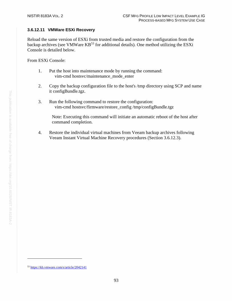
NISTIR 8183A VOL. 2 CSF MFG PROFILE LOW IMPACT LEVEL EXAMPLE IG PROCESS-BASED MFG SYSTEM USE CASE
93
Th
is p
ublic
atio
n is
ava
ilable
free
of c
ha
rge
from
: http
s://d
oi.o
rg/1
0.6
02
8/N
IST
.IR.8
18
3A
-2
3.6.12.11 VMWare ESXi Recovery
Reload the same version of ESXi from trusted media and restore the configuration from the
backup archives (see VMWare KB53 for additional details). One method utilizing the ESXi
Console is detailed below.
From ESXi Console:
1. Put the host into maintenance mode by running the command:
vim-cmd hostsvc/maintenance_mode_enter
2. Copy the backup configuration file to the host's /tmp directory using SCP and name
it configBundle.tgz.
3. Run the following command to restore the configuration:
vim-cmd hostsvc/firmware/restore_config /tmp/configBundle.tgz
Note: Executing this command will initiate an automatic reboot of the host after
command completion.
4. Restore the individual virtual machines from Veeam backup archives following
Veeam Instant Virtual Machine Recovery procedures (Section 3.6.12.3).
53 https://kb.vmware.com/s/article/2042141

NISTIR 8183A VOL. 2 CSF MFG PROFILE LOW IMPACT LEVEL EXAMPLE IG PROCESS-BASED MFG SYSTEM USE CASE
94
Th
is p
ublic
atio
n is
ava
ilable
free
of c
ha
rge
from
: http
s://d
oi.o
rg/1
0.6
02
8/N
IST
.IR.8
18
3A
-2
Service Level Agreement
This section provides example content that a Vendor Service Level Agreement may contain, including example policy
and procedure statements that were developed for the fictional company Westman. Certain commercial entities,
equipment, or materials may be identified in this document in order to describe a concept adequately. Such
identification is not intended to imply recommendation or endorsement by NIST, nor is it intended to imply that the
entities, equipment, or materials are necessarily the best available for the purpose. Each organization’s information
security experts should identify the content, and policy and procedure statements that will best integrate with their
existing cybersecurity program and manufacturing system infrastructure.
Service Level Agreement (SLA)
for Vendor
by
Westman
Effective Date: 02-22-2019
Document Owner: CEO
Version
Version Date Description Author
1.0 02-22-2019 Service Level Agreement CEO
Approval
(By signing below, approvers agree to all terms and conditions outlined in this Agreement.)
Approvers Role Signed Approval Date
Westman Customer <digital signature> 2-22-2019
Vendor Service
Provider
<digital signature> 2-22-2019
Overview
This Agreement represents a Service Level Agreement (“SLA” or “Agreement”) between
Westman and Vendor (Service Provider) for the provisioning of IT/OT services required to
support and sustain the product or service.
This Agreement remains valid until superseded by a revised agreement mutually endorsed by the
stakeholders.

NISTIR 8183A VOL. 2 CSF MFG PROFILE LOW IMPACT LEVEL EXAMPLE IG PROCESS-BASED MFG SYSTEM USE CASE
95
Th
is p
ublic
atio
n is
ava
ilable
free
of c
ha
rge
from
: http
s://d
oi.o
rg/1
0.6
02
8/N
IST
.IR.8
18
3A
-2
This Agreement outlines the parameters of all IT/OT services covered as they are mutually
understood by the primary stakeholders. This Agreement does not supersede current processes
and procedures unless explicitly stated herein.
Goals and Objectives
The purpose of this Agreement is to ensure that the proper elements and commitments are in
place to provide consistent IT/OT service support and delivery to Westman by the Service
Provider(s). The goal of this Agreement is to obtain mutual understanding for IT/OT services
provision between the Service Provider and Westman.
The objectives of this Agreement are to:
• Provide clear reference to service ownership, accountability, roles and/or responsibilities.
• Present a clear, concise and measurable description of service provision to the customer.
• Match perceptions of expected service provision with actual service support and delivery.
Stakeholders
The following Service Provider and Westman will be used as the basis of the Agreement and
represent the primary stakeholders associated with this SLA:
IT Service Provider: Service Provider
IT/OT Customer: Westman
Periodic Review
This Agreement is valid from the effective date outlined herein and is valid until further notice.
This Agreement should be reviewed at a minimum once per fiscal year; however, in lieu of a
review during any period specified, the current Agreement will remain in effect.
The Business Relationship Manager (“Document Owner”) is responsible for facilitating regular
reviews of this document. Contents of this document may be amended as required, provided
mutual agreement is obtained from the primary stakeholders and communicated to all affected
parties. The Document Owner will incorporate all subsequent revisions and obtain mutual
agreements / approvals as required.
Business Relationship Manager: Westman (CEO)
Review Period: Yearly (12 months)
Previous Review Date: 02-22-2019
Next Review Date: 02-22-2020

NISTIR 8183A VOL. 2 CSF MFG PROFILE LOW IMPACT LEVEL EXAMPLE IG PROCESS-BASED MFG SYSTEM USE CASE
96
Th
is p
ublic
atio
n is
ava
ilable
free
of c
ha
rge
from
: http
s://d
oi.o
rg/1
0.6
02
8/N
IST
.IR.8
18
3A
-2
Service Scope
The following Services are covered by this Agreement:
• Apply system updates to manufacturing environment per vendor’s recommendation
• Apply system updates to IT equipment when patches are released per vendor.
• Backup configure information for all IT/OT equipment within Westman
• Ensure cybersecurity tools are operating correctly within the environment
• Provide liaison service between OT vendor and Westman
• Product recommendation for new equipment being purchased and installed with
Westman’s manufacturing environment
• Manned telephone support
• Monitored email support
• Remote assistance using Remote Desktop and a Virtual Private Network where available
• Planned or Emergency Onsite assistance (extra costs apply)
• Monthly system health check
Westman’s Requirements
Westman’s responsibilities and requirements in support of this Agreement include:
• Payment for all support costs at the agreed interval.
• Reasonable availability of Westman representative(s) when resolving a service-related
incident or request.
Service Provider Requirements
Service Provider responsibilities and/or requirements in support of this Agreement include:
• Meeting response times associated with service-related incidents.
• Appropriate notification to Westman for all scheduled maintenance.
Service Assumptions
Assumptions related to in-scope services and/or components include:
• Changes to services will be communicated and documented to all stakeholders.
Service Management
Effective support of in-scope services is a result of maintaining consistent service levels. The
following sections provide relevant details on service availability, monitoring of in-scope services
and related components.

NISTIR 8183A VOL. 2 CSF MFG PROFILE LOW IMPACT LEVEL EXAMPLE IG PROCESS-BASED MFG SYSTEM USE CASE
97
Th
is p
ublic
atio
n is
ava
ilable
free
of c
ha
rge
from
: http
s://d
oi.o
rg/1
0.6
02
8/N
IST
.IR.8
18
3A
-2
Service Availability
Coverage parameters specific to the service(s) covered in this Agreement are as follows:
• Telephone support: 8:00 A.M. to 5:00 P.M. Monday – Friday
• Calls received out of office hours will be forwarded to a mobile phone and
best efforts will be made to answer / action the call, however there will be
a backup answer phone service
• Email support: Monitored 8:00 A.M. to 5:00 P.M. Monday – Friday
• Emails received outside of office hours will be collected, however no action
can be guaranteed until the next working day
• Onsite assistance guaranteed within 72 hours during the business week
Service Requests
In support of services outlined in this Agreement, the Service Provider will respond to service-
related incidents and/or requests submitted by Westman within the following time frames:
• 0 to 8 hours (during business hours) for issues classified as High priority.
• Within 48 hours for issues classified as Medium priority.
• Within 5 working days for issues classified as Low priority.
Remote assistance will be provided at the discretion of Westman in-line with the above
timescales and dependent on the priority of the support request. The service provider may not
utilize remote access as an alternative for providing onsite support as described in section 3.7.10
of this agreement.
Personnel Changes
The Service Provider will notify Westman within 24 hours when an individual supporting
Westman leaves the Service Provider or is transferred. Westman will disable remote access, if
granted, for the individual within 24 hours of notification. The Service Provider will revoke the
individual’s access to Westman information and information systems within 24 hours.
Additionally, any system account passwords the individual had will need to be changed to ensure
user access into the network has been completely removed.

NISTIR 8183A VOL. 2 CSF MFG PROFILE LOW IMPACT LEVEL EXAMPLE IG PROCESS-BASED MFG SYSTEM USE CASE
98
Th
is p
ublic
atio
n is
ava
ilable
free
of c
ha
rge
from
: http
s://d
oi.o
rg/1
0.6
02
8/N
IST
.IR.8
18
3A
-2
4. Technical Solution Implementations
Introduction
This section includes proof-of-concept technical solution implementations developed for the
fictional company Westman. An overview of these technical solutions is discussed in Section 6
of Volume 1 and potential technical solutions are discussed in Section 7 of Volume 1. Each
organization’s information security experts should identify the technical solutions that will best
integrate with their existing cybersecurity program and manufacturing system infrastructure.
There are five main areas of performance indicators being collected in the Process Control
System (PCS):
1. Manufacturing process performance: measures the performance of the manufacturing
process, i.e. the chemical continuous process.
2. Network performance: measures the performance of the underlying TCP/IP network.
3. Computing resources performance: measures the performance of the computers,
hardware, and software processes.
4. Industrial protocol performance: measures the performance of the industrial
communication protocol, i.e. the DeviceNet in the PCS.
5. OPC Data Exchange performance: measures the performance of the data exchange
mechanism of the system.
Measurements in different areas provide insight of the entire system performance from different
perspectives. The manufacturing process performance provides indicators on how well the high-
level manufacturing process and overall system perform. However, this may not be able to
provide enough detail on the performance of the sub-systems, therefore measurements are also
performed at sub-system levels. For example, a typical chemical continuous manufacturing is a
relatively slow process in comparison with available network bandwidth. Therefore, a moderate
TCP/IP network delay may not reflect in the measurement of the high-level manufacturing
process performance. However, such TCP/IP delay may have significant impact on the sub-
systems. The effects will not be reflected in the high-level measurement until significant delays
are accumulated in sub-systems. Measurements in multiple levels provide details and in-depth
understanding to key performance areas of the entire system. It helps to understand how the
aggregate effects will impact the performance. Aggregate effects will be important to the high-
level manufacturing performance.
Each technical solution implementation is organized as an experiment. For the measurement
purpose, each experiment has a fixed runtime of 4 hours (14 400 seconds). Performance metrics
and network packet capture are collected during the entire experiment run.
After the experiment is completed, all the collected metrics and network packet capture will go
through the post processing stage to filter, sort and rearrange data in proper order. The last step is
to compute the key performance indicators from the sorted dataset using a set of Python scripts
developed by NIST.

NISTIR 8183A VOL. 2 CSF MFG PROFILE LOW IMPACT LEVEL EXAMPLE IG PROCESS-BASED MFG SYSTEM USE CASE
99
Th
is p
ublic
atio
n is
ava
ilable
free
of c
ha
rge
from
: http
s://d
oi.o
rg/1
0.6
02
8/N
IST
.IR.8
18
3A
-2
Additional technical detail of the Process Control System and the measurement process is
described in NISTIR 8188.54
Implementation Note – Due Diligence Implementing Technical Solutions
It is important to note that the procedures used during this implementation (i.e., install a tool,
then measure the impact) should not be used in a production system. Care must be taken before
using any technical solutions, especially those that actively scan the manufacturing system
network and its devices; manufacturers should first assess how these tools work and what impact
they might have on the connected control equipment [3]. Technology evaluations may include
testing in similar, non-production control system environments to ensure that the tools do not
adversely impact the production systems. Impact could be due to the nature of the information or
the volume of network traffic. While this impact may be acceptable in IT systems, it may not be
acceptable in a manufacturing system. In general, any operation that actively scans the
manufacturing network should be scheduled to occur only during planned downtimes. [3]
Certain commercial entities, equipment, or materials may be identified in this document in order to describe an
experimental procedure or concept adequately. Such identification is not intended to imply recommendation or
endorsement by NIST, nor is it intended to imply that the entities, materials, or equipment are necessarily the best
available for the purpose. Each organization’s information security experts should identify the technical solutions that
will best integrate with their existing cybersecurity program and manufacturing system infrastructure.
54 NISTIR 8188: Key Performance Indicators for Process Control System Cybersecurity Performance Analysis.

NISTIR 8183A VOL. 2 CSF MFG PROFILE LOW IMPACT LEVEL EXAMPLE IG PROCESS-BASED MFG SYSTEM USE CASE
100
Th
is p
ublic
atio
n is
ava
ilable
free
of c
ha
rge
from
: http
s://d
oi.o
rg/1
0.6
02
8/N
IST
.IR.8
18
3A
-2
Implementation Note - Availability of Measurement Data
All raw and processed measurement data captured from each experiment is freely available
online at: https://doi.org/10.18434/M32071.
Links to each of the data files are provided below, and directly referenced at the end of each
implementation.
• Open-AudIT KPI data
• Open-AudIT measurement data
• Wireshark KPI data
• Wireshark measurement data
• Veeam full backup KPI data
• Veeam full backup measurement data
• Veeam incremental backup KPI data
• Veeam incremental backup measurement data
• Cisco VPN KPI data
• Cisco VPN measurement data
• Active Directory KPI data
• Active Directory measurement data
• Symantec AV KPI data
• Symantec AV measurement data
• Nessus KPI data
• Nessus measurement data
• File Encryption KPI data
• File Encryption measurement data
• Firewall KPI data
• Firewall measurement data

NISTIR 8183A VOL. 2 CSF MFG PROFILE LOW IMPACT LEVEL EXAMPLE IG PROCESS-BASED MFG SYSTEM USE CASE
101
Th
is p
ublic
atio
n is
ava
ilable
free
of c
ha
rge
from
: http
s://d
oi.o
rg/1
0.6
02
8/N
IST
.IR.8
18
3A
-2
Open-AudIT
Technical Solution Overview
Open-AudIT is an asset inventory tool providing scanning of hardware and software within the
manufacturing environment. Open-AudIT scans are highly customizable to each environment,
depending on the level required.
Open-AudIT cost depends on the level of functionality desired for your environment. Editions
offered by Open-AudIT vary from entry level community edition which is free, all the way up to
enterprise edition. Enterprise was chosen since it contains the ability to setup scheduled
scanning, dashboards, and baselining of equipment.
Open-AudIT is a downloadable Open Virtual Appliance (OVA) which is easy to install. OVA
install allows installation in a hypervisor environment allowing for installation within an existing
virtual environment without requiring purchasing additional hardware. Configuration for initial
discovery scans is straightforward.
Technical Capabilities Provided by Solution
Open-AudIT provides components of the following Technical Capabilities:
• Hardware Inventory
• Software Inventory
• Systems Development Lifecycle Management
• Configuration Management
• Baseline Establishment (Enterprise Edition)
• Change Control
Subcategories Addressed by Implementing Solution
ID.AM-1, ID.AM-2, ID.AM-3, ID.AM-4, PR.DS-3, PR.IP-1, PR.IP-2, PR.IP-3, PR.IP-4,
PR.IP-6, PR.MA-1, DE.AE-1, DE.CM-7

NISTIR 8183A VOL. 2 CSF MFG PROFILE LOW IMPACT LEVEL EXAMPLE IG PROCESS-BASED MFG SYSTEM USE CASE
102
Th
is p
ublic
atio
n is
ava
ilable
free
of c
ha
rge
from
: http
s://d
oi.o
rg/1
0.6
02
8/N
IST
.IR.8
18
3A
-2
Architecture Map of Where Solution was Implemented
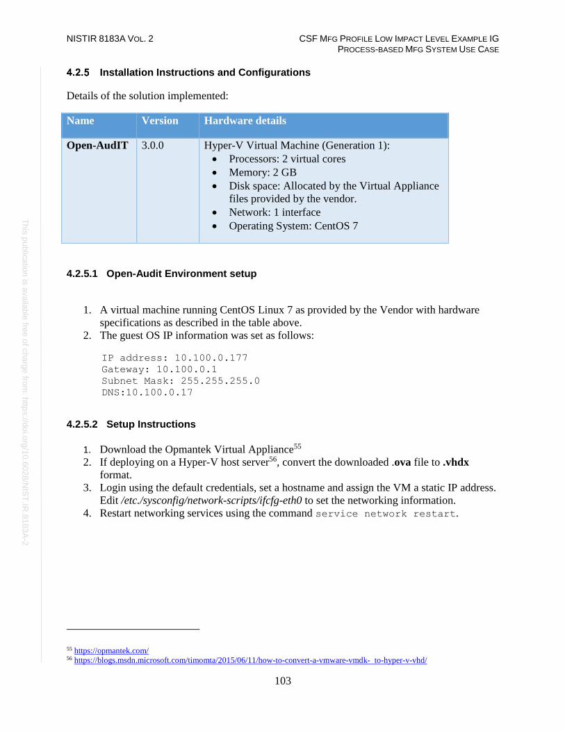
NISTIR 8183A VOL. 2 CSF MFG PROFILE LOW IMPACT LEVEL EXAMPLE IG PROCESS-BASED MFG SYSTEM USE CASE
103
Th
is p
ublic
atio
n is
ava
ilable
free
of c
ha
rge
from
: http
s://d
oi.o
rg/1
0.6
02
8/N
IST
.IR.8
18
3A
-2
Installation Instructions and Configurations
Details of the solution implemented:
Name Version Hardware details
Open-AudIT 3.0.0 Hyper-V Virtual Machine (Generation 1):
• Processors: 2 virtual cores
• Memory: 2 GB
• Disk space: Allocated by the Virtual Appliance
files provided by the vendor.
• Network: 1 interface
• Operating System: CentOS 7
4.2.5.1 Open-Audit Environment setup
1. A virtual machine running CentOS Linux 7 as provided by the Vendor with hardware
specifications as described in the table above.
2. The guest OS IP information was set as follows:
IP address: 10.100.0.177
Gateway: 10.100.0.1
Subnet Mask: 255.255.255.0
DNS:10.100.0.17
4.2.5.2 Setup Instructions
1. Download the Opmantek Virtual Appliance55 2. If deploying on a Hyper-V host server56, convert the downloaded .ova file to .vhdx
format.
3. Login using the default credentials, set a hostname and assign the VM a static IP address.
Edit /etc./sysconfig/network-scripts/ifcfg-eth0 to set the networking information.
4. Restart networking services using the command service network restart.
55 https://opmantek.com/ 56 https://blogs.msdn.microsoft.com/timomta/2015/06/11/how-to-convert-a-vmware-vmdk- to-hyper-v-vhd/

NISTIR 8183A VOL. 2 CSF MFG PROFILE LOW IMPACT LEVEL EXAMPLE IG PROCESS-BASED MFG SYSTEM USE CASE
104
Th
is p
ublic
atio
n is
ava
ilable
free
of c
ha
rge
from
: http
s://d
oi.o
rg/1
0.6
02
8/N
IST
.IR.8
18
3A
-2
4.2.5.3 Additional Setup via Web browser
1. Navigate to the Open-Audit Web UI (Example http://<ip-address-of-server>)
2. Select Yes, if prompted to proceed to untrusted site. This error is produced since SSL has
not been configured and Open-AudIT redirects HTTP sessions over to HTTPS.
3. Click on Open-AudIT Enterprise.
4. Login using the default username / password mentioned on the webpage.
5. Click on Admin > LDAP Server > Create LDAP Servers for Active Directory
integration.
Screenshot of our Active directory connection provided for reference.
6. Click Submit once all information has been entered.
4.2.5.4 Active Directory Groups for LDAP Integration
• Create the following Security Groups of Global Type in your Active Directory to
integrate with Open-AudIT.
open-audit_roles_admin
open-audit_roles_org_admin
open-audit_roles_reporter
open-audit_roles_user
open-audit_orgs_default_organisation
• Add the appropriate users to these groups. Test logging in with your Active Directory
credentials.

NISTIR 8183A VOL. 2 CSF MFG PROFILE LOW IMPACT LEVEL EXAMPLE IG PROCESS-BASED MFG SYSTEM USE CASE
105
Th
is p
ublic
atio
n is
ava
ilable
free
of c
ha
rge
from
: http
s://d
oi.o
rg/1
0.6
02
8/N
IST
.IR.8
18
3A
-2
4.2.5.5 Configuring Discover Credentials
1. Click on Discover > Discoveries > Create Credentials.
2. Enter the requested information:
Name – Name of the Credentials being used. Example (SSH)
Organization – Default Organization is selected. Pickup another if
your configuring more the one organization.
Description – Description of item being added.
Type – Select which type of credentials will be used. (SNMP (v1 / v2), SNMP v3,
SSH, SSH Key, or Windows)
Credentials – enter the appropriate credentials for the select type from above.
The image below shows Discover credentials created for scanning plant network.
3. Click Submit.
4.2.5.6 Organization Groups
1. Click on Manage > Orgs > Create Orgs
2. Enter Name and Description.
3. Click Submit.
The image below shows an Organization Group created as per our environment

NISTIR 8183A VOL. 2 CSF MFG PROFILE LOW IMPACT LEVEL EXAMPLE IG PROCESS-BASED MFG SYSTEM USE CASE
106
Th
is p
ublic
atio
n is
ava
ilable
free
of c
ha
rge
from
: http
s://d
oi.o
rg/1
0.6
02
8/N
IST
.IR.8
18
3A
-2
4.2.5.7 Discovery Scans
1. Click on Discover > Discoveries > Create Discoveries
2. Enter a name under Name.
3. Enter a network subnet to be scanned under Subnet.
4. Select the Open-Audit server under Network Address.
5. Click Advanced to setup additional options if desired. These options are Org, Type,
Devices Assigned to Org, and Devices Assigned to Location.
6. Click Submit.
The image below shows Discovery scan created for scanning the plant network
4.2.5.8 Additional Information
1. Change all default passwords before deploying in production.
2. Use Secure LDAP (LDAPS). If unable to use LDAPS make sure account being used for
syncing groups has least privilege rights. (Not an Administrator and not a Domain
Administrator)
3. Use SNMPv3 whenever using SNMP for scanning devices.
4. Software is Open Source. Professional Edition allows up to 20 machines after that there is
a cost which is relatively inexpensive. Upgrade to Enterprise Edition to perform system
baselines scans.
5. For more information and hardware requirements, visit the Community forums57
57 https://community.opmantek.com

NISTIR 8183A VOL. 2 CSF MFG PROFILE LOW IMPACT LEVEL EXAMPLE IG PROCESS-BASED MFG SYSTEM USE CASE
107
Th
is p
ublic
atio
n is
ava
ilable
free
of c
ha
rge
from
: http
s://d
oi.o
rg/1
0.6
02
8/N
IST
.IR.8
18
3A
-2
Highlighted Performance Impacts
The following performance measurement experiment was performed for the Open-AudIT tool
while the manufacturing system was operational:
Experiment PL003.1- Open-AudIT asset inventory tool network scan and authenticated scan
A small performance impact to the network behavior was observed in the PCS system during the
Open-AudIT scan. The network traffic was slightly increased in part of the PCS system during
the scan. For example, the path delay from PLC to OPC was slightly higher especially in the
latter part of the experience when Open-AudIT was performing the authenticated scan. However,
the round trip time from the Controller to the OPC was mostly the same throughout the scan. It
appears that some part of the system has a more noticeable impact than the other parts.
Figure 4-1 Plot showing the path delay from the PLC to OPC server
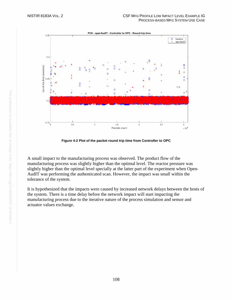
NISTIR 8183A VOL. 2 CSF MFG PROFILE LOW IMPACT LEVEL EXAMPLE IG PROCESS-BASED MFG SYSTEM USE CASE
108
Th
is p
ublic
atio
n is
ava
ilable
free
of c
ha
rge
from
: http
s://d
oi.o
rg/1
0.6
02
8/N
IST
.IR.8
18
3A
-2
Figure 4-2 Plot of the packet round trip time from Controller to OPC
A small impact to the manufacturing process was observed. The product flow of the
manufacturing process was slightly higher than the optimal level. The reactor pressure was
slightly higher than the optimal level specially at the latter part of the experiment when Open-
AudIT was performing the authenticated scan. However, the impact was small within the
tolerance of the system.
It is hypothesized that the impacts were caused by increased network delays between the hosts of
the system. There is a time delay before the network impact will start impacting the
manufacturing process due to the iterative nature of the process simulation and sensor and
actuator values exchange.

NISTIR 8183A VOL. 2 CSF MFG PROFILE LOW IMPACT LEVEL EXAMPLE IG PROCESS-BASED MFG SYSTEM USE CASE
109
Th
is p
ublic
atio
n is
ava
ilable
free
of c
ha
rge
from
: http
s://d
oi.o
rg/1
0.6
02
8/N
IST
.IR.8
18
3A
-2
Figure 4-3 Plot of the production flow of the manufacturing process
Figure 4-4 Plot of the reactor pressure of the manufacturing process
Links to Entire Performance Measurement Data Set
• Open-AudIT KPI data
• Open-AudIT measurement data

NISTIR 8183A VOL. 2 CSF MFG PROFILE LOW IMPACT LEVEL EXAMPLE IG PROCESS-BASED MFG SYSTEM USE CASE
110
Th
is p
ublic
atio
n is
ava
ilable
free
of c
ha
rge
from
: http
s://d
oi.o
rg/1
0.6
02
8/N
IST
.IR.8
18
3A
-2
CSET
Technical Solution Overview
Cyber Security Evaluation Tool (CSET) is a tool provided by the Department of Homeland
Security for performing Cybersecurity evaluation against an organization. This evaluation is a
completely manual process of answering multiple questions to determine organizational
cybersecurity posture based on implemented cybersecurity practices against current
cybersecurity status. This evaluation will help identify areas within the organization that required
more attention and resources.
Technical Capabilities Provided by Solution
CSET provides components of the following Technical Capabilities described in Section 6 of
Volume 1:
• Network Architecture Documentation
• Risk Assessment
Subcategories Addressed by Implementing Solution
ID.AM-3, ID.AM-4, ID.RA-1

NISTIR 8183A VOL. 2 CSF MFG PROFILE LOW IMPACT LEVEL EXAMPLE IG PROCESS-BASED MFG SYSTEM USE CASE
111
Th
is p
ublic
atio
n is
ava
ilable
free
of c
ha
rge
from
: http
s://d
oi.o
rg/1
0.6
02
8/N
IST
.IR.8
18
3A
-2
Architecture Map of Where Solution was Implemented

NISTIR 8183A VOL. 2 CSF MFG PROFILE LOW IMPACT LEVEL EXAMPLE IG PROCESS-BASED MFG SYSTEM USE CASE
112
Th
is p
ublic
atio
n is
ava
ilable
free
of c
ha
rge
from
: http
s://d
oi.o
rg/1
0.6
02
8/N
IST
.IR.8
18
3A
-2
Installation Instructions and Configurations
Details of the solution implemented:
Name Version Hardware Details
CSET 8.1 Laptop with the following specs:
• Processor: i7
• Memory: 16 GB
• Disk: 256 GB
• OS: Windows 7 Professional
4.3.5.1 Environment setup
CSET was installed on a temporary Windows laptop in the plant network on an on-demand basis
4.3.5.2 Installation
1. Download CSET58. After clicking the link, you will be asked to identify yourself and
will then be given the opportunity to download the file CSET_x.x.iso (where x.x
represents the download version).
2. Use any ISO-specific utility program that can mount the file.
3. Find and run the CSET_Setup.exe file in the folder, virtual drive, or CD.
4. Complete the instructions in the installation wizard to install the program.
4.3.5.3 Running CSET
1. Launch the program by double-clicking its desktop icon
2. Select New Assetment on the home screen.
3. Click Start Here button in the lower right corner of program.
4. Enter all required information
58 https://www.us-cert.gov/forms/csetiso.

NISTIR 8183A VOL. 2 CSF MFG PROFILE LOW IMPACT LEVEL EXAMPLE IG PROCESS-BASED MFG SYSTEM USE CASE
113
Th
is p
ublic
atio
n is
ava
ilable
free
of c
ha
rge
from
: http
s://d
oi.o
rg/1
0.6
02
8/N
IST
.IR.8
18
3A
-2
5. Click Continue to proceed.
6. Click the drop-down menus and select the appropriate choices.
7. Click Continue to proceed.
8. (Optional) Click the Create a network diagram button to create one, otherwise click
Continue.
9. Change Mode Selection to Advanced and Cybersecurity Frame-based Approach
10. Click Continue to use default profile or create a new profile.
11. Click Continue again.
12. Answer all the questions as they appear.
13. Complete all questions and generate a final report.
NISTIR 8183A VOL. 2 CSF MFG PROFILE LOW IMPACT LEVEL EXAMPLE IG PROCESS-BASED MFG SYSTEM USE CASE
114
Th
is p
ublic
atio
n is
ava
ilable
free
of c
ha
rge
from
: http
s://d
oi.o
rg/1
0.6
02
8/N
IST
.IR.8
18
3A
-2
4.3.5.4 Additional Information
Video tutorials59 are available on the CSET YouTube Channel to help you better understand how
to use this tool.
Lessons Learned
• The tool is only as good as information entered. Make sure each answer is thought out
before answering.
• Mark any answer for review as needed so there will be follow up.
• When completed your organization will receive a 0 to 100 score depending on readiness.
Highlighted Performance Impacts
No performance measurement experiments were performed for CSET due to its typical
installation location (i.e., external to the manufacturing system).
Links to Entire Performance Measurement Data Set
N/A
59 https://www.youtube.com/c/CSETCyberSecurityEvaluationTool

NISTIR 8183A VOL. 2 CSF MFG PROFILE LOW IMPACT LEVEL EXAMPLE IG PROCESS-BASED MFG SYSTEM USE CASE
115
Th
is p
ublic
atio
n is
ava
ilable
free
of c
ha
rge
from
: http
s://d
oi.o
rg/1
0.6
02
8/N
IST
.IR.8
18
3A
-2
GRASSMARLIN
Technical Solution Overview
GRASSMARLIN is an open source, passive network mapper dedicated to industrial networks
and developed by the National Security Agency (NSA). GRASSMARLIN gives a snapshot of
the industrial system including:
• Devices on the network
• Communications between these devices
• Metadata extracted from these communications
Points to consider:60
• Passive IP network mapping tool
• Hardware agnostic portable Java based tool
• Can only see and map hosts where you are capturing data from.
Technical Capabilities Provided by Solution
GRASSMARLIN provides components of the following Technical Capabilities described in
Section 6 of Volume 1:
• Network Architecture Documentation
• Baseline Establishment
• Map Data Flows
Subcategories Addressed by Implementing Solution
ID.AM-3, ID.AM-4, PR.AC-5, PR.IP-1, DE.AE-1, DE.CM-7
60 GRASSMARLIN Briefing PowerPoint 2017: https://github.com/nsacyber/GRASSMARLIN /blob/master/GRASSMARLIN
_Briefing_20170210.pptx

NISTIR 8183A VOL. 2 CSF MFG PROFILE LOW IMPACT LEVEL EXAMPLE IG PROCESS-BASED MFG SYSTEM USE CASE
116
Th
is p
ublic
atio
n is
ava
ilable
free
of c
ha
rge
from
: http
s://d
oi.o
rg/1
0.6
02
8/N
IST
.IR.8
18
3A
-2
Architecture Map of Where Solution was Implemented

NISTIR 8183A VOL. 2 CSF MFG PROFILE LOW IMPACT LEVEL EXAMPLE IG PROCESS-BASED MFG SYSTEM USE CASE
117
Th
is p
ublic
atio
n is
ava
ilable
free
of c
ha
rge
from
: http
s://d
oi.o
rg/1
0.6
02
8/N
IST
.IR.8
18
3A
-2
Installation Instructions and Configurations
Details of the solution implemented:
Name Version Hardware Details
GRASSMARLIN 3.2.1 Laptop with the following specs:
• Processor: i7
• Memory: 16 GB
• Disk: 256 GB
• OS: Windows 7 Professional
4.4.5.1 Environment Setup
1. A temporary Windows laptop with GRASSMARLIN installed was setup in the plant
network on an on-demand basis.
4.4.5.2 Installation
1. Download GRASSMARLIN61
2. Run the installer. The installer will install additional programs such as Java and
Wireshark during the setup.
4.4.5.3 Using the Software
GRASSMARLIN can operate in a real time passive mode by sniffing the live traffic or by
importing a recorded pcap file. Data in GRASSMARLIN is stored in a Session. The Session
contains imported files and visual state information.
1. To capture network packets & save to a pcap file on a Linux system
a. Install tcpdump package if not present already
b. Run, tcpdump -i <mirror-port interface> - w mypcap.pcap
For example: tcpdump -i eth1 -w /home/icssec/pcs.pcap
Where eth1 is the span / mirror port connection
2. Run GRASSMARLIN on a Windows system by double clicking the program icon from
the Programs Menu. On a Linux system, run sudo grassmarlin to launch the
installer.
61 https://github.com/nsacyber/GRASSMARLIN/releases

NISTIR 8183A VOL. 2 CSF MFG PROFILE LOW IMPACT LEVEL EXAMPLE IG PROCESS-BASED MFG SYSTEM USE CASE
118
Th
is p
ublic
atio
n is
ava
ilable
free
of c
ha
rge
from
: http
s://d
oi.o
rg/1
0.6
02
8/N
IST
.IR.8
18
3A
-2
3. Import a pcap in GRASSMARLIN as follows:
• Click on the Import icon in the toolbar (or select Import files from the File
Menu)
• Click on Add Files. Browse to the pcap file. Once done, the pcap will now show
up under Pending Imports.
• Select the file and click on Import Selected. Hit the Close button upon
completion to back to the Main interface. The Import process can take several
minutes to hours depending on the size of the pcap file.
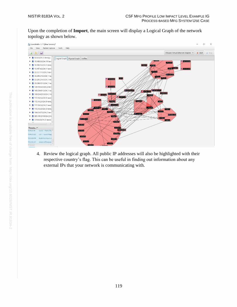
NISTIR 8183A VOL. 2 CSF MFG PROFILE LOW IMPACT LEVEL EXAMPLE IG PROCESS-BASED MFG SYSTEM USE CASE
119
Th
is p
ublic
atio
n is
ava
ilable
free
of c
ha
rge
from
: http
s://d
oi.o
rg/1
0.6
02
8/N
IST
.IR.8
18
3A
-2
Upon the completion of Import, the main screen will display a Logical Graph of the network
topology as shown below.
4. Review the logical graph. All public IP addresses will also be highlighted with their
respective country’s flag. This can be useful in finding out information about any
external IPs that your network is communicating with.

NISTIR 8183A VOL. 2 CSF MFG PROFILE LOW IMPACT LEVEL EXAMPLE IG PROCESS-BASED MFG SYSTEM USE CASE
120
Th
is p
ublic
atio
n is
ava
ilable
free
of c
ha
rge
from
: http
s://d
oi.o
rg/1
0.6
02
8/N
IST
.IR.8
18
3A
-2
5. Right-click any external IP address > View Details. For instance, the image below
shows a host with IP 172.16.3.10 communicating with an IP address from Netherlands.
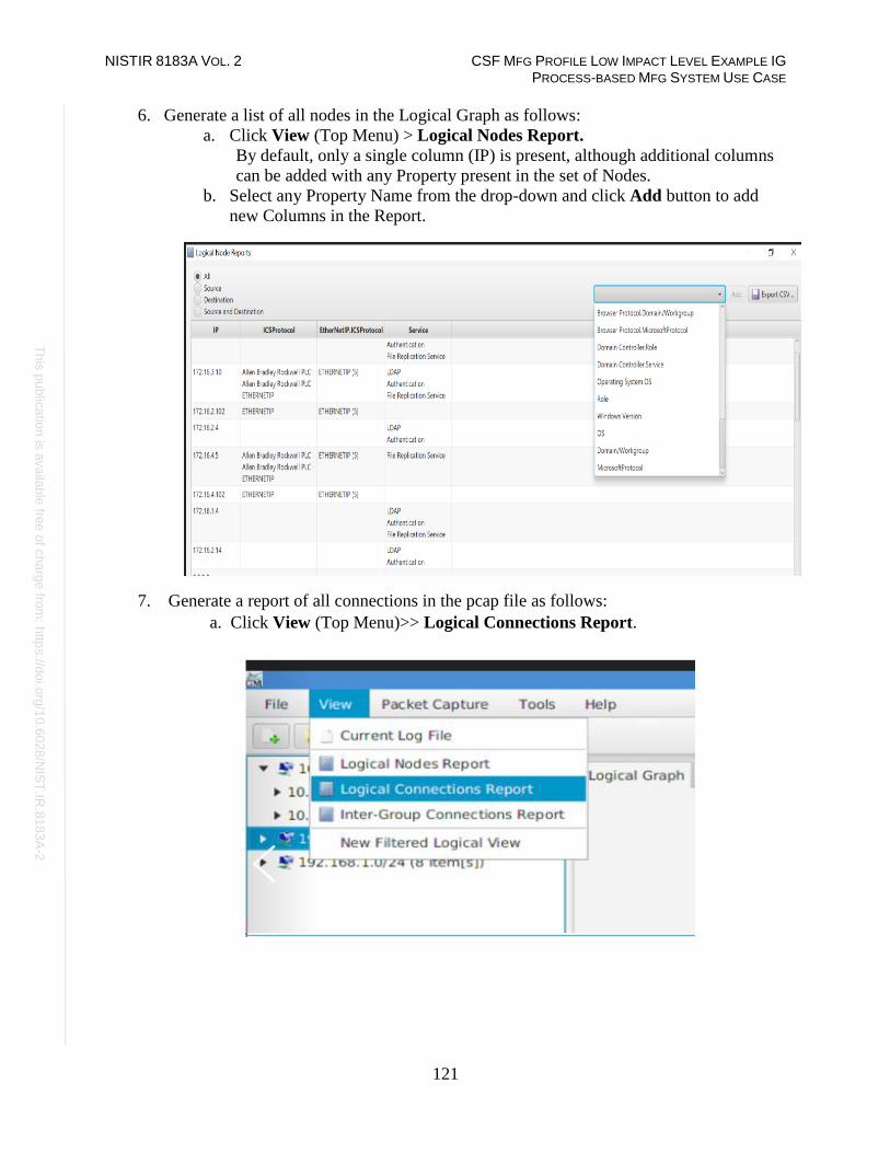
NISTIR 8183A VOL. 2 CSF MFG PROFILE LOW IMPACT LEVEL EXAMPLE IG PROCESS-BASED MFG SYSTEM USE CASE
121
Th
is p
ublic
atio
n is
ava
ilable
free
of c
ha
rge
from
: http
s://d
oi.o
rg/1
0.6
02
8/N
IST
.IR.8
18
3A
-2
6. Generate a list of all nodes in the Logical Graph as follows:
a. Click View (Top Menu) > Logical Nodes Report.
By default, only a single column (IP) is present, although additional columns
can be added with any Property present in the set of Nodes.
b. Select any Property Name from the drop-down and click Add button to add
new Columns in the Report.
7. Generate a report of all connections in the pcap file as follows:
a. Click View (Top Menu)>> Logical Connections Report.

NISTIR 8183A VOL. 2 CSF MFG PROFILE LOW IMPACT LEVEL EXAMPLE IG PROCESS-BASED MFG SYSTEM USE CASE
122
Th
is p
ublic
atio
n is
ava
ilable
free
of c
ha
rge
from
: http
s://d
oi.o
rg/1
0.6
02
8/N
IST
.IR.8
18
3A
-2
b. Click on Export CSV for further analysis of all the communications happening
on your network. This will generate an output similar to the image show below.
8. To view all the logical communications for a specific host for capturing a baseline:
a. Right-click on a Node > View Frames.
This opens a new screen as shown below displaying all the different
IP addresses that particular host is communicating with including Port and
Protocol information.
b. Click on Export CSV button to export this data to a csv file.
Note: This process needs to be repeated for every node.

NISTIR 8183A VOL. 2 CSF MFG PROFILE LOW IMPACT LEVEL EXAMPLE IG PROCESS-BASED MFG SYSTEM USE CASE
123
Th
is p
ublic
atio
n is
ava
ilable
free
of c
ha
rge
from
: http
s://d
oi.o
rg/1
0.6
02
8/N
IST
.IR.8
18
3A
-2
9. Generate a Watch -Graph as follows:
a. Right-click a node > Select Watch Connections from the Watch Connections
menu.
This will generate a graph in a new window Watch <IP address>

NISTIR 8183A VOL. 2 CSF MFG PROFILE LOW IMPACT LEVEL EXAMPLE IG PROCESS-BASED MFG SYSTEM USE CASE
124
Th
is p
ublic
atio
n is
ava
ilable
free
of c
ha
rge
from
: http
s://d
oi.o
rg/1
0.6
02
8/N
IST
.IR.8
18
3A
-2
4.4.5.4 Additional Information
A User guide62 is available for GRASSMARLIN.
Highlighted Performance Impacts
No performance measurement experiments were performed for the use of GRASSMARLIN due
to its installation location and how it was used (i.e., the software performed offline analysis of
PCAP files captured by other software).
Links to Entire Performance Measurement Data Set
N/A
62 https://github.com/nsacyber/GRASSMARLIN

NISTIR 8183A VOL. 2 CSF MFG PROFILE LOW IMPACT LEVEL EXAMPLE IG PROCESS-BASED MFG SYSTEM USE CASE
125
Th
is p
ublic
atio
n is
ava
ilable
free
of c
ha
rge
from
: http
s://d
oi.o
rg/1
0.6
02
8/N
IST
.IR.8
18
3A
-2
Wireshark
Technical Solution Overview
Wireshark is a free and open-source packet analyzer.
Technical Capabilities Provided by Solution
Wireshark provides components of the following Technical Capabilities described in Section 6
of Volume 1:
• Network Architecture Documentation
• Baseline Establishment
• Map Data Flows
• Forensics
Subcategories Addressed by Implementing Solution
ID.AM-3, ID.AM-4, PR.AC-5, PR.IP-1, DE.AE-1, DE.AE-2, DE.CM-7, RS.AN-3

NISTIR 8183A VOL. 2 CSF MFG PROFILE LOW IMPACT LEVEL EXAMPLE IG PROCESS-BASED MFG SYSTEM USE CASE
126
Th
is p
ublic
atio
n is
ava
ilable
free
of c
ha
rge
from
: http
s://d
oi.o
rg/1
0.6
02
8/N
IST
.IR.8
18
3A
-2
Architecture Map of Where Solution was Implemented

NISTIR 8183A VOL. 2 CSF MFG PROFILE LOW IMPACT LEVEL EXAMPLE IG PROCESS-BASED MFG SYSTEM USE CASE
127
Th
is p
ublic
atio
n is
ava
ilable
free
of c
ha
rge
from
: http
s://d
oi.o
rg/1
0.6
02
8/N
IST
.IR.8
18
3A
-2
Installation Instructions and Configurations
Details of the solution implemented:
Name Version Hardware Details
Wireshark 3.0.2 Laptop with the following specs.
• Processor: i7
• Memory: 16 GB
• Disk: 256 GB
• OS: Windows 7
Professional
4.5.5.1 Environment Setup
A Windows laptop with Wireshark installed was setup on an on-demand basis.
4.5.5.2 Installation
1. Download Wireshark63 (Select 32bit or 64 bit)
2. Run the exe to start install process. For instance, Wireshark-win64-3.0.1.exe
3. Click Next, leave the defaults selected and continue install.
4. Click I Agree to continue, when prompted for Npcap install
5. Now click Next and Finish to start process.
6. Select Reboot Now or I want to manually reboot later.
7. Click Finish to complete.
4.5.5.3 Running Wireshark
1. Launch Wireshark by doing a right-click on the Wireshark Desktop icon > Run as
Administrator (Windows 10). Wireshark requires administrative privileges to be fully
functional, otherwise there will be undesired results.
2. Select the interface to capture traffic from the list of interfaces displayed
63 https://www.wireshark.org
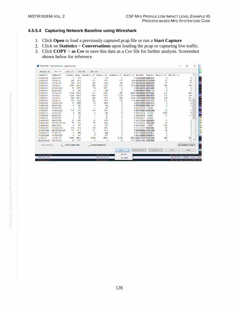
NISTIR 8183A VOL. 2 CSF MFG PROFILE LOW IMPACT LEVEL EXAMPLE IG PROCESS-BASED MFG SYSTEM USE CASE
128
Th
is p
ublic
atio
n is
ava
ilable
free
of c
ha
rge
from
: http
s://d
oi.o
rg/1
0.6
02
8/N
IST
.IR.8
18
3A
-2
4.5.5.4 Capturing Network Baseline using Wireshark
1. Click Open to load a previously captured pcap file or run a Start Capture
2. Click on Statistics > Conversations upon loading the pcap or capturing live traffic.
3. Click COPY > as Csv to save this data as a Csv file for further analysis. Screenshot
shown below for reference

NISTIR 8183A VOL. 2 CSF MFG PROFILE LOW IMPACT LEVEL EXAMPLE IG PROCESS-BASED MFG SYSTEM USE CASE
129
Th
is p
ublic
atio
n is
ava
ilable
free
of c
ha
rge
from
: http
s://d
oi.o
rg/1
0.6
02
8/N
IST
.IR.8
18
3A
-2
4. (Optional) Click on Statistics > IPv4 Statistics > Destination and Ports to get a list of
all the ports. This will generate a list of ports used by all the IP addresses in the traffic.
Click Copy, to copy the results to a word document or click Save as to save as a plain
text file. Hit Close when done.

NISTIR 8183A VOL. 2 CSF MFG PROFILE LOW IMPACT LEVEL EXAMPLE IG PROCESS-BASED MFG SYSTEM USE CASE
130
Th
is p
ublic
atio
n is
ava
ilable
free
of c
ha
rge
from
: http
s://d
oi.o
rg/1
0.6
02
8/N
IST
.IR.8
18
3A
-2
Highlighted Performance Impacts
The following performance measurement experiment was performed for the Wireshark tool
while the manufacturing system was operational:
Experiment PL015.2-wireshark
Significant performance impact on computing resources was observed when using Wireshark for
network traffic capture. Both the processor and memory utilization of the host were significantly
higher than normal. There was no performance impact to the manufacturing process observed.
Figure 4-5 Processor utilization of the OPC computer during Wireshark network capture
Figure 4-6 Memory utilization of the OPC computer during Wireshark network capture

NISTIR 8183A VOL. 2 CSF MFG PROFILE LOW IMPACT LEVEL EXAMPLE IG PROCESS-BASED MFG SYSTEM USE CASE
131
Th
is p
ublic
atio
n is
ava
ilable
free
of c
ha
rge
from
: http
s://d
oi.o
rg/1
0.6
02
8/N
IST
.IR.8
18
3A
-2
Wireshark started at around 1900 seconds experiment time and continued to capture network
traffic for about 3 hours. During this period of time, the processor utilization of the OPC
computer kept going up. Wireshark has a sizeable impact to the processor utilization. The
Wireshark data file was about 2.3 GB in this case.
The memory utilization has a similar impact to the processor utilization, except the memory
utilization stayed high after the Wireshark has stopped capturing the network traffic. It is
hypothesized that Wireshark stored the captured data in memory until the data was saved into the
hard drive. Therefore, the memory utilization stayed high even after the Wireshark has stopped
the network capture. Even though the processor and memory utilization were significantly
higher, they were still below the full capability of the computer and therefore did not have major
impact to the manufacturing process. However, for the manufacturing system that has a high
utilization in normal run time, the use of Wireshark may cause a performance impact.
The PCS system uses an external computer to use Wireshark to perform network traffic capture
for this reason. Care should be taken if using Wireshark on a production system.
Links to Entire Performance Measurement Data Set
• Wireshark KPI data
• Wireshark measurement data

NISTIR 8183A VOL. 2 CSF MFG PROFILE LOW IMPACT LEVEL EXAMPLE IG PROCESS-BASED MFG SYSTEM USE CASE
132
Th
is p
ublic
atio
n is
ava
ilable
free
of c
ha
rge
from
: http
s://d
oi.o
rg/1
0.6
02
8/N
IST
.IR.8
18
3A
-2
Veeam Backup and Replication
Technical Solution Overview
Veeam Backup and Replication64 is a proprietary backup and system recovery software
developed by Veeam for virtual environments. It is built on VMware vSphere and Microsoft
Hyper-V hypervisors. The software provides backup, restore and replication functionality.
Veeam also has products such as “Veeam agent for Windows” and “Veeam agent for Linux” for
backing up physical Windows and Linux servers respectively.
Points to consider:
• Free backup edition available for virtual and physical servers.
• Support for file level backups as well as system image type of backups.
• Backups can be run without having to shut down the system. This can be very critical in
manufacturing environments.
• Tech support available for Free edition users.
• Easy to setup and use.
Technical Capabilities Provided by Solution
Veeam Backup and Replication provides components of the following Technical Capabilities
described in Section 6 of Volume 1:
• Data Backup
• Data Replication
Subcategories Addressed by Implementing Solution
PR.IP-4
64 https://www.veeam.com/vm-backup-recovery-replication-software.html

NISTIR 8183A VOL. 2 CSF MFG PROFILE LOW IMPACT LEVEL EXAMPLE IG PROCESS-BASED MFG SYSTEM USE CASE
133
Th
is p
ublic
atio
n is
ava
ilable
free
of c
ha
rge
from
: http
s://d
oi.o
rg/1
0.6
02
8/N
IST
.IR.8
18
3A
-2
Architecture Map of Where Solution was Implemented

NISTIR 8183A VOL. 2 CSF MFG PROFILE LOW IMPACT LEVEL EXAMPLE IG PROCESS-BASED MFG SYSTEM USE CASE
134
Th
is p
ublic
atio
n is
ava
ilable
free
of c
ha
rge
from
: http
s://d
oi.o
rg/1
0.6
02
8/N
IST
.IR.8
18
3A
-2
Installation Instructions and Configurations
Details of the solutions implemented:
Name Version Hardware Details
Veeam Backup and
Replication
9.5 VMware Virtual Machine
• Processors: 2 virtual cores
• Memory: 8 GB
• Disk space:4 TB.
• Network: 1 interface
• Operating System: Windows
2012R2
Veeam Agent for Windows
(Free version)
3.0.0.748 Installed on all Physical Windows
computers of the plant
4.6.5.1 Environment Setup
1. A virtual machine running Windows 2012 R2 was setup with hardware specifications as
described in the table above.
2. The guest OS IP information was set as follows:
IP address: 10.100.0.10
Gateway: 10.100.0.1
Subnet Mask: 255.255.255.0
DNS:10.100.0.17
3. A backups network share was created on the server. Within this folder, different sub
folders were created as per the hostnames of each system to be backed up. Each system’s
backup job was in turn configured to be saved to its corresponding hostname folder on
the Veeam server via a UNC path
4. A user account veeamuser was created in our Active Directory and assigned read/write
permissions for the above backups share.
4.6.5.2 Initial Setup
1. Download Veeam Backup & Replication65
2. Install the prerequisites as mentioned in the product guide. Run the installer, follow
the on-screen instructions to complete the install66.
3. Create a network share folder on the Veeam server for storing all the backups.
4. Create a Service account in Active Directory with read/write permissions to this network
share.
65 https://www.veeam.com 66 https://helpcenter.veeam.com/docs/backup/hyperv/install_vbr.html?ver=95u4

NISTIR 8183A VOL. 2 CSF MFG PROFILE LOW IMPACT LEVEL EXAMPLE IG PROCESS-BASED MFG SYSTEM USE CASE
135
Th
is p
ublic
atio
n is
ava
ilable
free
of c
ha
rge
from
: http
s://d
oi.o
rg/1
0.6
02
8/N
IST
.IR.8
18
3A
-2
The Free Edition of Veeam Backup and Replication lets you manage virtual machine backups
from the Central Veeam Backup and Replication Console. However, any physical servers using
the Free version of Veeam agent for Windows cannot be managed from the Central console.
These need to be managed locally from the client system itself.
4.6.5.3 Performing Backups
All Windows systems of the plant network were configured for Backup using Veeam Agent for
Windows67. The agent was installed on all the physical windows clients. Connectivity between
each client and the Veeam Server was verified by accessing the backups share folder (created in
the above section) from each client.
1. Download and install Veeam Agent for Microsoft Windows on the physical Windows
systems as required. In the Free version, a backup or restore operation needs to be
initiated from the client system.
2. Double click the Veeam backup icon in the System tray to launch the wizard
3. Create a Recovery Media as follows
a. Follow the on-screen prompts during the setup to create one OR
b. Run Veeam.Endpoint.RecoveryMedia.exe program under C:\Program
Files\Veeam\Endpoint Backup directory to create one manually.
c. Select ISO image file under Available Bootable Media Types
67 https://www.veeam.com/windows-endpoint-server-backup-free.html

NISTIR 8183A VOL. 2 CSF MFG PROFILE LOW IMPACT LEVEL EXAMPLE IG PROCESS-BASED MFG SYSTEM USE CASE
136
Th
is p
ublic
atio
n is
ava
ilable
free
of c
ha
rge
from
: http
s://d
oi.o
rg/1
0.6
02
8/N
IST
.IR.8
18
3A
-2
d. Enter the Name and Location to save the ISO.
This Recovery Media is required for Recovery operations involving Full Computer
Image or Volume level backup.
4. To perform a backup of Entire Computer type (System Image)
a. Right-click on the Veeam Tray, select Control Panel > Backup > Add New Job
b. Enter the name of the Backup job
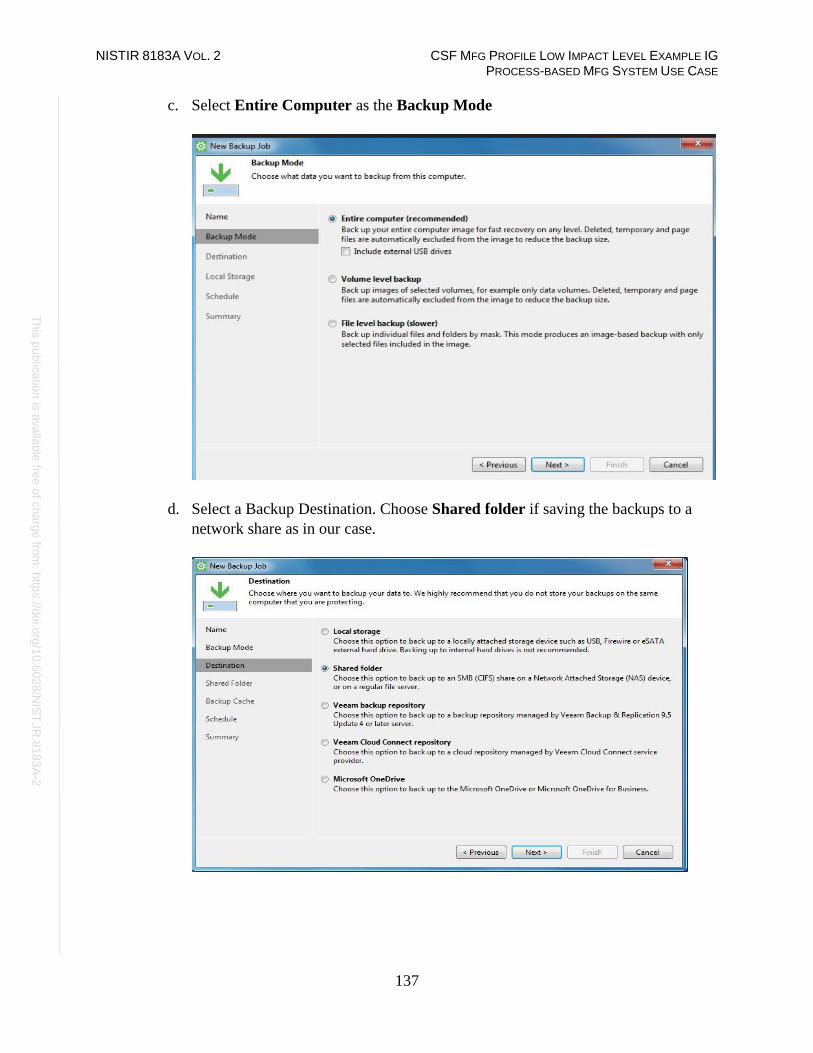
NISTIR 8183A VOL. 2 CSF MFG PROFILE LOW IMPACT LEVEL EXAMPLE IG PROCESS-BASED MFG SYSTEM USE CASE
137
Th
is p
ublic
atio
n is
ava
ilable
free
of c
ha
rge
from
: http
s://d
oi.o
rg/1
0.6
02
8/N
IST
.IR.8
18
3A
-2
c. Select Entire Computer as the Backup Mode
d. Select a Backup Destination. Choose Shared folder if saving the backups to a
network share as in our case.

NISTIR 8183A VOL. 2 CSF MFG PROFILE LOW IMPACT LEVEL EXAMPLE IG PROCESS-BASED MFG SYSTEM USE CASE
138
Th
is p
ublic
atio
n is
ava
ilable
free
of c
ha
rge
from
: http
s://d
oi.o
rg/1
0.6
02
8/N
IST
.IR.8
18
3A
-2
e. Enter the path of the Network share and the Active Directory user credentials
created earlier. Select the Number of Restore Points as per your retention policy.
f. Configure a Schedule. Hit Apply when done.

NISTIR 8183A VOL. 2 CSF MFG PROFILE LOW IMPACT LEVEL EXAMPLE IG PROCESS-BASED MFG SYSTEM USE CASE
139
Th
is p
ublic
atio
n is
ava
ilable
free
of c
ha
rge
from
: http
s://d
oi.o
rg/1
0.6
02
8/N
IST
.IR.8
18
3A
-2
5. To perform a backup of File-Level Type
a. Repeat Steps listed above in Step 4, except for one change. Select the Backup
Mode as File-Level (Slower).
b. Select the Directories to be backed up. Click Next to complete the remaining
steps.
4.6.5.4 Performing Recovery
1. Follow the steps below to Restore Individual files
a. Double click on the Veeam Agent in Windows System tray of the client >
Restore > Individual Files.
b. Select Network Storage as the location under Backup Location page. Hit Next.
c. Select Shared folder under Remote Storage. Click Next.
d. Specify the UNC path and access-credentials of the shared folder under Shared
folder. For instance, \\10.100.0.10\backups\workstation in our case.
e. Select a Restore point from which you want to recover data at the Restore Point
step. Click Next to initiate the Restore process.
f. Review the steps at the Summary page
2. Follow the steps below to Recover Volumes or an Entire Computer image,
a. Boot the system using the Recovery media created earlier. Click on Bare Metal
Recovery
b. Select Local Storage if restoring backups from an External USB Drive or Network
Storage if restoring from a network share as in our case.

NISTIR 8183A VOL. 2 CSF MFG PROFILE LOW IMPACT LEVEL EXAMPLE IG PROCESS-BASED MFG SYSTEM USE CASE
140
Th
is p
ublic
atio
n is
ava
ilable
free
of c
ha
rge
from
: http
s://d
oi.o
rg/1
0.6
02
8/N
IST
.IR.8
18
3A
-2
c. Configure Network Settings. Choose either DHCP or Static IP and hit Continue
d. Select Share folder at the Network Storage Step. Hit Next
e. Enter the UNC- path and access-credentials of Share folder to restore from.
f. Select a Backup from the list of backups the wizard displays and hit Next.
g. Select a Restore point under Restore Points from which you want to recover data.

NISTIR 8183A VOL. 2 CSF MFG PROFILE LOW IMPACT LEVEL EXAMPLE IG PROCESS-BASED MFG SYSTEM USE CASE
141
Th
is p
ublic
atio
n is
ava
ilable
free
of c
ha
rge
from
: http
s://d
oi.o
rg/1
0.6
02
8/N
IST
.IR.8
18
3A
-2
h. Select a Restore Mode at the Restore Mode step. If the disk type and layout on the
system has not changed select “Entire Computer”. There is a Manual restore available
for advanced users.
i. Map restored drives as per your system layout under Disk Mapping step68.
j. Review the summary at the Summary page. Hit Restore to start the restore process.
68 https://helpcenter.veeam.com/docs/agentforwindows/userguide/baremetal_disk_mapping.html?ver=30

NISTIR 8183A VOL. 2 CSF MFG PROFILE LOW IMPACT LEVEL EXAMPLE IG PROCESS-BASED MFG SYSTEM USE CASE
142
Th
is p
ublic
atio
n is
ava
ilable
free
of c
ha
rge
from
: http
s://d
oi.o
rg/1
0.6
02
8/N
IST
.IR.8
18
3A
-2
Highlighted Performance Impacts
The following performance measurement experiment was performed for the Veeam Backup tool
while the manufacturing system was operational:
Experiment PL009.2- Veeam full backup
Experiment PL010.1- Veeam incremental backup
A small performance impact to the manufacturing process was observed in, however, a more
noticeable impact was observed in the network traffic. For example, the round trip time from the
Controller to the OPC was increased significantly during the backup. The path delay from the
OPC to HMI was also increased significantly during the backup. The amount of backup traffic
could take up a large portion of the available bandwidth.
Also, there is storage consideration, example of backup size in the PCS system: HMI: 96 GB,
OPC: 29 GB, Controller: 31 GB, Historian: 194 GB
Network usage should be taken into consideration on when to perform a full backup, a low
network utilization time is likely to reduce the impact to the system. One important feature of the
Veeam backup is its ability to throttle to adapt to the network utilization in order to avoid taking
up all the available bandwidth for the backup traffic.
Incremental backup should be considered for periodic backup instead of full image backup.

NISTIR 8183A VOL. 2 CSF MFG PROFILE LOW IMPACT LEVEL EXAMPLE IG PROCESS-BASED MFG SYSTEM USE CASE
143
Th
is p
ublic
atio
n is
ava
ilable
free
of c
ha
rge
from
: http
s://d
oi.o
rg/1
0.6
02
8/N
IST
.IR.8
18
3A
-2
During the full backup, the network traffic increased dramatically. In one case, the backup of the
HMI and Controller hosts represented 99.6 % of the total traffic verse 0.4 % of the normal
traffic.
Figure 4-7 Plot of packet round trip time from Controller to OPC during Veeam full backup
Figure 4-8 Plot of the path delay from OPC to HMI during Veeam full backup
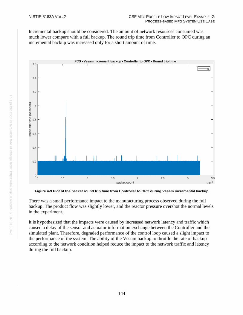
NISTIR 8183A VOL. 2 CSF MFG PROFILE LOW IMPACT LEVEL EXAMPLE IG PROCESS-BASED MFG SYSTEM USE CASE
144
Th
is p
ublic
atio
n is
ava
ilable
free
of c
ha
rge
from
: http
s://d
oi.o
rg/1
0.6
02
8/N
IST
.IR.8
18
3A
-2
Incremental backup should be considered. The amount of network resources consumed was
much lower compare with a full backup. The round trip time from Controller to OPC during an
incremental backup was increased only for a short amount of time.
Figure 4-9 Plot of the packet round trip time from Controller to OPC during Veeam incremental backup
There was a small performance impact to the manufacturing process observed during the full
backup. The product flow was slightly lower, and the reactor pressure overshot the normal levels
in the experiment.
It is hypothesized that the impacts were caused by increased network latency and traffic which
caused a delay of the sensor and actuator information exchange between the Controller and the
simulated plant. Therefore, degraded performance of the control loop caused a slight impact to
the performance of the system. The ability of the Veeam backup to throttle the rate of backup
according to the network condition helped reduce the impact to the network traffic and latency
during the full backup.
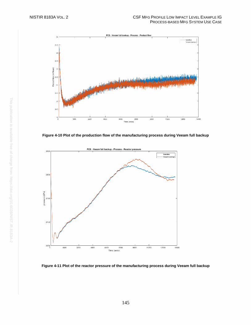
NISTIR 8183A VOL. 2 CSF MFG PROFILE LOW IMPACT LEVEL EXAMPLE IG PROCESS-BASED MFG SYSTEM USE CASE
145
Th
is p
ublic
atio
n is
ava
ilable
free
of c
ha
rge
from
: http
s://d
oi.o
rg/1
0.6
02
8/N
IST
.IR.8
18
3A
-2
Figure 4-10 Plot of the production flow of the manufacturing process during Veeam full backup
Figure 4-11 Plot of the reactor pressure of the manufacturing process during Veeam full backup

NISTIR 8183A VOL. 2 CSF MFG PROFILE LOW IMPACT LEVEL EXAMPLE IG PROCESS-BASED MFG SYSTEM USE CASE
146
Th
is p
ublic
atio
n is
ava
ilable
free
of c
ha
rge
from
: http
s://d
oi.o
rg/1
0.6
02
8/N
IST
.IR.8
18
3A
-2
Links to Entire Performance Measurement Data Set
• Veeam full backup KPI data
• Veeam full backup measurement data
• Veeam incremental backup KPI data
• Veeam incremental backup measurement data
NISTIR 8183A VOL. 2 CSF MFG PROFILE LOW IMPACT LEVEL EXAMPLE IG PROCESS-BASED MFG SYSTEM USE CASE
147
Th
is p
ublic
atio
n is
ava
ilable
free
of c
ha
rge
from
: http
s://d
oi.o
rg/1
0.6
02
8/N
IST
.IR.8
18
3A
-2
Security Onion
Technical Solution Overview
Security Onion is a free and open source Linux distribution for intrusion detection, enterprise
cybersecurity monitoring, and log management. It includes Elasticsearch, Logstash, Kibana,
Snort, Suricata, Bro, OSSEC, Sguil, Squert, NetworkMiner, and other cybersecurity tools.69
Security Onion combines three core functions:
• full packet capture
• network-based and host-based intrusion detection systems (NIDS and HIDS,
respectively)
• and powerful analysis tools
Points to consider:
• Open source software, available as an ISO distribution to deploy in any type of
environment (physical or virtual).
• Collection of different open-source tools such as SNORT, BRO, OSSEC SGQUIL,
KIBANA, ELSA etc. integrated into one product which otherwise would require a lot of
manual work to integrate.
• Support for standalone instance and distributed deployment for large organizations.
• Provides a front-end to Snort and BRO IDS which are natively command line-based.
• Fully customizable rule-set. Has inbuilt detection rules to detect a variety of cyber-attacks
and anomalies for both IT and OT environments.
• Learning curve associated. Familiarity with SNORT and BRO IDS rule-set.
• Hardware resource intensive.
• No reporting capabilities out of the box.
Technical Capabilities Provided by Solution
Security Onion provides components of the following Technical Capabilities described in
Section 6 of Volume 1:
• Network Boundary Protection
• Network Monitoring
• Event Logging
• Forensics
Subcategories Addressed by Implementing Solution
PR.AC-5, PR.DS-5, PR.MA-2, PR.PT-1, PR.PT-4, DE.AE-2, DE.AE-3, DE.CM-1, DE.CM-6,
DE.CM-7, DE.DP-3, RS.AN-3
69 https://securityonion.net/

NISTIR 8183A VOL. 2 CSF MFG PROFILE LOW IMPACT LEVEL EXAMPLE IG PROCESS-BASED MFG SYSTEM USE CASE
148
Th
is p
ublic
atio
n is
ava
ilable
free
of c
ha
rge
from
: http
s://d
oi.o
rg/1
0.6
02
8/N
IST
.IR.8
18
3A
-2
Architecture Map of Where Solution was Implemented

NISTIR 8183A VOL. 2 CSF MFG PROFILE LOW IMPACT LEVEL EXAMPLE IG PROCESS-BASED MFG SYSTEM USE CASE
149
Th
is p
ublic
atio
n is
ava
ilable
free
of c
ha
rge
from
: http
s://d
oi.o
rg/1
0.6
02
8/N
IST
.IR.8
18
3A
-2
Installation Instructions and Configurations
Details of the solution implemented:
Name Version Hardware Details
Security Onion 16.04.5.2 Hyper-V Virtual Machine
• Processors: 4 virtual cores
• Memory: 20 GB
• Disk space: 500 GB
• Network: 2 interfaces
• Operating System: Ubuntu 16.04
4.7.5.1 Security Onion Environment Setup
1. A virtual machine running customized version of Ubuntu Linux 16.04 as provided by the
Vendor with hardware specifications as described in the table above.
2. Configured two network connections to the virtual machines as follows
Interface: eth0
Mode: Primary interface for management.
Interface: eth1
Mode: Monitoring port with the connection originating from a Network
Aggregator device that was configured to receive Mirrored traffic from all the three
network devices of the plant.
3. The guest OS IP information was set as follows:
Interface: eth0
IP address: 10.100.0.26
Gateway: 10.100.0.1
Subnet Mask: 255.255.255.0
DNS:10.100.0.17
4.7.5.2 Setup Instructions
1. Download the ISO image of Security Onion70 and deploy it on your Hyper-visor of
choice.
2. Review the hardware requirements71 prior to proceeding with the next steps.
70 https://securityonion.net 71 https://securityonion.readthedocs.io/en/latest/
NISTIR 8183A VOL. 2 CSF MFG PROFILE LOW IMPACT LEVEL EXAMPLE IG PROCESS-BASED MFG SYSTEM USE CASE
150
Th
is p
ublic
atio
n is
ava
ilable
free
of c
ha
rge
from
: http
s://d
oi.o
rg/1
0.6
02
8/N
IST
.IR.8
18
3A
-2
3. Setup the two network connections for the virtual machine before powering it ON as
follows.
• (eth0) for management IP address
• (eth1) for the monitoring interface. This connection would be either from a SPAN
port or a Network TAP which is receiving mirrored traffic from all network
devices.
4. Power-On the VM, Complete the default OS setup. Perform a reboot.
5. Ensure to set the OS time-zone to UTC as Security Onion uses UTC by default. Changing
time-zone can cause other issues.
6. Login to the console locally and click on the Setup icon on the Desktop to configure the
network interfaces. Reboot when done.6. Click on the Setup icon again to complete next
phase of the setup.
7. Click YES, Continue! and then select Evaluation Mode in the next screen for
standalone deployments.
8. Follow the on-screen options and complete the wizard. A system reboot would again be
required.
9. Configure appropriate firewall rules for remote connectivity,
a. Run sudo so-allow
b. Select a – analyst option
c. Enter the IP address or ip-range of client-pc where you intend to access security onion
interface from.
Instructions to setup a firewall72 are available from Security Onion.
10. Run the command sudo nsm_sensor_ps-status to check the status of each
component
11. Access the Security Onion application either via the SQUERT Web interface73 or via
Kibana.74
4.7.5.3 Configuring Snort Updates
1. Register for an account on https://snort.org to be eligible for downloading the Registered
Rule set. Upon registration, note down the oink code tied to your account.
2. Copy-paste the OINK code in the rule_url parameter in
/etc./nsm/pulledpork/pulledpork.conf file of the server and save the changes.
rule_url=https://www.snort.org/reg-rules/|snortrules-
snapshot.tar.gz|<oink-code>
3. For systems with Internet Access,
4. Uncomment & Set LOCAL_NIDS_RULE_TUNING=no in the
/etc./nsm/securityonion.conf
72 https://github.com/Security-Onion-Solutions/security-onion/wiki/Firewall 73 https://IP address-of-security-onion/ 74 https://ip-address-of-security-onion/app/kibana
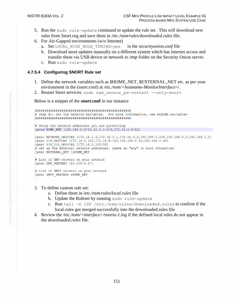
NISTIR 8183A VOL. 2 CSF MFG PROFILE LOW IMPACT LEVEL EXAMPLE IG PROCESS-BASED MFG SYSTEM USE CASE
151
Th
is p
ublic
atio
n is
ava
ilable
free
of c
ha
rge
from
: http
s://d
oi.o
rg/1
0.6
02
8/N
IST
.IR.8
18
3A
-2
5. Run the sudo rule-update command to update the rule set. This will download new
rules from Snort.org and save them in /etc./nsm/rules/downloaded.rules file.
6. For Air-Gapped environments (w/o Internet)
a. Set LOCAL_NIDS_RULE_TUNING=yes in the securityonion.conf file
b. Download snort updates manually on a different system which has internet access and
transfer these via USB device or network to /tmp folder on the Security Onion server.
c. Run sudo rule-update
4.7.5.4 Configuring SNORT Rule set
1. Define the network variables such as $HOME_NET, $EXTERNAL_NET etc. as per your
environment in the (snort.conf) at /etc./nsm/<hostname-MonitorInterface>/.
2. Restart Snort services: sudo nsm_sensor_ps-restart --only-snort
Below is a snippet of the snort.conf in our instance
3. To define custom rule set:
a. Define them in /etc./nsm/rules/local.rules file
b. Update the Ruleset by running sudo rule-update
c. Run tail -n 100 /etc./nsm/rules/downloaded.rules to confirm if the
local.rules got merged successfully into the downloaded.rules file
4. Review the /etc./nsm/<interface>/snortu-1.log if the defined local rules do not appear in
the downloaded.rules file.

NISTIR 8183A VOL. 2 CSF MFG PROFILE LOW IMPACT LEVEL EXAMPLE IG PROCESS-BASED MFG SYSTEM USE CASE
152
Th
is p
ublic
atio
n is
ava
ilable
free
of c
ha
rge
from
: http
s://d
oi.o
rg/1
0.6
02
8/N
IST
.IR.8
18
3A
-2
4.7.5.5 Rules Implemented to Monitor our Plant Network
Shown below are some of the rules used in our local.rules file to detect common IT and ICS-
specific anomalies.

NISTIR 8183A VOL. 2 CSF MFG PROFILE LOW IMPACT LEVEL EXAMPLE IG PROCESS-BASED MFG SYSTEM USE CASE
153
Th
is p
ublic
atio
n is
ava
ilable
free
of c
ha
rge
from
: http
s://d
oi.o
rg/1
0.6
02
8/N
IST
.IR.8
18
3A
-2
Snort Rules for ICS/ SCADA75
75 Snort Rules for ICS/ SCADA: https://github.com/ITI/ICS-Security-Tools/blob/master/configurations/rules/talos-snort.rules

NISTIR 8183A VOL. 2 CSF MFG PROFILE LOW IMPACT LEVEL EXAMPLE IG PROCESS-BASED MFG SYSTEM USE CASE
154
Th
is p
ublic
atio
n is
ava
ilable
free
of c
ha
rge
from
: http
s://d
oi.o
rg/1
0.6
02
8/N
IST
.IR.8
18
3A
-2
4.7.5.6 Tuning Security Onion:
1. Set the DAYSTOKEEP parameter in the /etc./nsm/securityonion.conf file to change the
database retention period. The default retention period for Sguil database is 30 days
2. To use any of the commented-out rules from downloaded.rules file, note down the
Generator ID (GID) and Signature ID (SID) value defined in the rule that’s commented
out and list them in /etc./nsm/pulledpork/enablesid.conf file. Avoid directly
uncommenting these in the downloaded.rules file.
3. To silence any false alerts, note down the Generator ID (GID) and Signature ID (SID)
value of the rule that is generating the alert and define them in the
/etc./nsm/pulledpork/disablesid.conf file. Shown on the next page is a snippet from our
disablesid.conf file showing the SIDs we have disabled.

NISTIR 8183A VOL. 2 CSF MFG PROFILE LOW IMPACT LEVEL EXAMPLE IG PROCESS-BASED MFG SYSTEM USE CASE
155
Th
is p
ublic
atio
n is
ava
ilable
free
of c
ha
rge
from
: http
s://d
oi.o
rg/1
0.6
02
8/N
IST
.IR.8
18
3A
-2
4. Follow the instructions on the wiki for managing the size of pcap files to maintain the
storage space on server.
4.7.5.7 BRO IDS Setup
Zeek (formerly known as BRO) is a powerful IDS that comes preinstalled in Security Onion
server alongside Snort. It is beyond the scope of this document to explain detailed working of
BRO. At a high level,
1. Place any custom scripts for BRO in /opt/bro/share/bro/policy/ directory. Refer to the
security onion wiki76 for additional reference on BRO.
2. Enable Windows SMB File share monitoring as follows,
a. Add the below line at the end of /opt/bro/share/bro/site/local.bro file
@load policy/protocols/smb
b. Restart BRO: sudo nsm_sensor_ps-restart --only-bro
4.7.5.8 OSSEC Setup
Ossec is a Host Intrusion Detection System (HIDS) supported on both Windows & Linux
platforms. The OSSEC server (now replaced with Wazuh) comes pre-installed with Security
Onion. It is beyond the scope of this document to explain detailed working of the OSSEC
product. The Ossec official website and other documentation links under References can be a
useful source.
1. Download the Ossec agent installer77 specific to your Operating System.
76 https://securityonion.readthedocs.io/en/latest/ 77 http://www.ossec.net/
# example disablesid.conf V3.1
# Example of modifying state for individual rules
# 1:1034,1:9837,1:1270,1:3390,1:710,1:1249,3:13010
3:19187
119:19 # http_inspect: LONG HEADER
123:8 # frag3: Fragmentation overlap
128:4 # ssh: Protocol mismatch
129:4 # stream5: TCP Timestamp is outside of PAWS window
129:5 # stream5: Bad segment, overlap adjusted size less than/equal 0
129:7 # stream5: Limit on number of overlapping TCP packets reached
129:12 # stream5: TCP Small Segment Threshold Exceeded

NISTIR 8183A VOL. 2 CSF MFG PROFILE LOW IMPACT LEVEL EXAMPLE IG PROCESS-BASED MFG SYSTEM USE CASE
156
Th
is p
ublic
atio
n is
ava
ilable
free
of c
ha
rge
from
: http
s://d
oi.o
rg/1
0.6
02
8/N
IST
.IR.8
18
3A
-2
2. Copy over the agent to the client system and run the setup process using the instructions
mentioned on the Ossec website. During the install, mention the IP address of Security
Onion server as the IP address of Ossec server.
3. Run the command so-allow to manage firewall settings on the Security Onion server
to receive data from Ossec clients.78
4. Add any custom OSSEC rules for monitoring to the local_rules.xml file under
/var/ossec/rules directory. If a decoder is required to parse custom logs, it should be
defined under in local_decoder.xml file under /var/ossec/etc. directory.
5. View the Ossec alerts either from Kibana Interface or Squert web interface
6. To monitor USB drive detection using OSSEC:
a. Add the following lines79 to the local Ossec.conf file on the Windows endpoint
b. Add the following lines to the /var/ossec/rules /local_rules.xml file on the Security
Onion server to generate an alert
7. To monitor for Unauthorized assets on the network:
a. Install the arpwatch package on the Security Onion server
b. Run arpwatch -i <interface> command to start the service
For instance: arpwatch -i eth1 where eth1 is monitoring port.
78 https://github.com/Security-Onion-Solutions/security-onion/wiki/Firewall 79 https://www.ossec.net/docs/manual/monitoring/process-monitoring.html

NISTIR 8183A VOL. 2 CSF MFG PROFILE LOW IMPACT LEVEL EXAMPLE IG PROCESS-BASED MFG SYSTEM USE CASE
157
Th
is p
ublic
atio
n is
ava
ilable
free
of c
ha
rge
from
: http
s://d
oi.o
rg/1
0.6
02
8/N
IST
.IR.8
18
3A
-2
c. Add a new rule to the local_rules.xml file as shown below. This references this
inbuilt decoder at /var/ossec/etc./arpwatch_decoder.xml and alerts when a new
device is plugged into our network
d. Restart OSSEC server after adding any local /rules with the command sudo service ossec-hids-server restart
The image below shows a sample alert in Squert Web Interface, when a new system was
physically connected to the network:
Note: This package relies on the local ARP cache of the system to detect new devices.
8. To monitor for Specific events from Windows hosts using OSSEC
▪ Note down the EventID to alert on from the Event Viewer. For instance, assume you
need to monitor EventID 1001 belonging to Factory Talk Service, which is the Event
generated for any login failures from Rockwell Factory Talk software.

NISTIR 8183A VOL. 2 CSF MFG PROFILE LOW IMPACT LEVEL EXAMPLE IG PROCESS-BASED MFG SYSTEM USE CASE
158
Th
is p
ublic
atio
n is
ava
ilable
free
of c
ha
rge
from
: http
s://d
oi.o
rg/1
0.6
02
8/N
IST
.IR.8
18
3A
-2
▪ Edit the local ossec.conf of the client to include this EventID in question under the
<location> attribute of the Event category. For instance:
▪ Define a corresponding rule in the local_rules.xml file to generate an alert. Ensure to
set level >=7 for Ossec to generate an alert. For instance:

NISTIR 8183A VOL. 2 CSF MFG PROFILE LOW IMPACT LEVEL EXAMPLE IG PROCESS-BASED MFG SYSTEM USE CASE
159
Th
is p
ublic
atio
n is
ava
ilable
free
of c
ha
rge
from
: http
s://d
oi.o
rg/1
0.6
02
8/N
IST
.IR.8
18
3A
-2
Lessons Learned:
The full packet capture feature in Security Onion can fill up the hard disk space quickly
depending on the amount of network traffic in your environment. Ensure to plan and allocate
substantial amount of storage for the server along with configuring the necessary data retention
options in securityonion.conf file. Trimming your pcaps can allow you to store them for longer
periods of time.80
Highlighted Performance Impacts
No performance measurement experiments were performed for the use of Security Onion due to
its installation location and how it was used (i.e., the software performed passive analysis of
network traffic external to the manufacturing system).
Links to Entire Performance Measurement Data Set
N/A
80 https://www.netresec.com/?page=Blog&month=2017-12&post=Don%27t-Delete-PCAP-Files---Trim-Them

NISTIR 8183A VOL. 2 CSF MFG PROFILE LOW IMPACT LEVEL EXAMPLE IG PROCESS-BASED MFG SYSTEM USE CASE
160
Th
is p
ublic
atio
n is
ava
ilable
free
of c
ha
rge
from
: http
s://d
oi.o
rg/1
0.6
02
8/N
IST
.IR.8
18
3A
-2
Cisco AnyConnect VPN
Technical Solution Overview
The AnyConnect Secure Mobility Client81 is a modular endpoint software product by Cisco. It
provides VPN access through Secure Sockets Layer (SSL) and IPsec IKEv2 and also offers
enhanced security through various built-in modules. AnyConnect clients are available across a
broad set of platforms, including Windows, macOS, Linux, iOS, Android, Windows
Phone/Mobile, BlackBerry, and ChromeOS.
Points to consider:
• Provides additional cybersecurity in the form of Web Security and DNS-Based security.
• OS Platform independent: The VPN clients are supported on Windows, Mac and Linux.
• Administrators can control which networks or resources for endpoints to connect. It
provides an IEEE 802.1X supplicant that can be provisioned as part of authentication,
authorization, and accounting (AAA) capabilities along with some unique encryption
technologies such as MACsec IEEE 802.1AE.
• Cisco Proprietary Product. This replaces the earlier free product called AnyConnect VPN
client. You must either have a Cisco Adaptive Security appliance (ASA) Firewall or
Cisco Firepower Services Appliance and an active AnyConnect Secure Mobility Client
license.
Technical Capabilities Provided by Solution
Cisco AnyConnect VPN provides components of the following Technical Capabilities described
in Section 6 of Volume 1:
• Secure Remote Access
• Data Replication
Subcategories Addressed by Implementing Solution
PR.AC-5, PR.IP-4, PR.MA-2
81 https://www.cisco.com/c/dam/en/us/products/collateral/security/anyconnect-secure-mobility-client/at_a_glance_c45-
578609.pdf
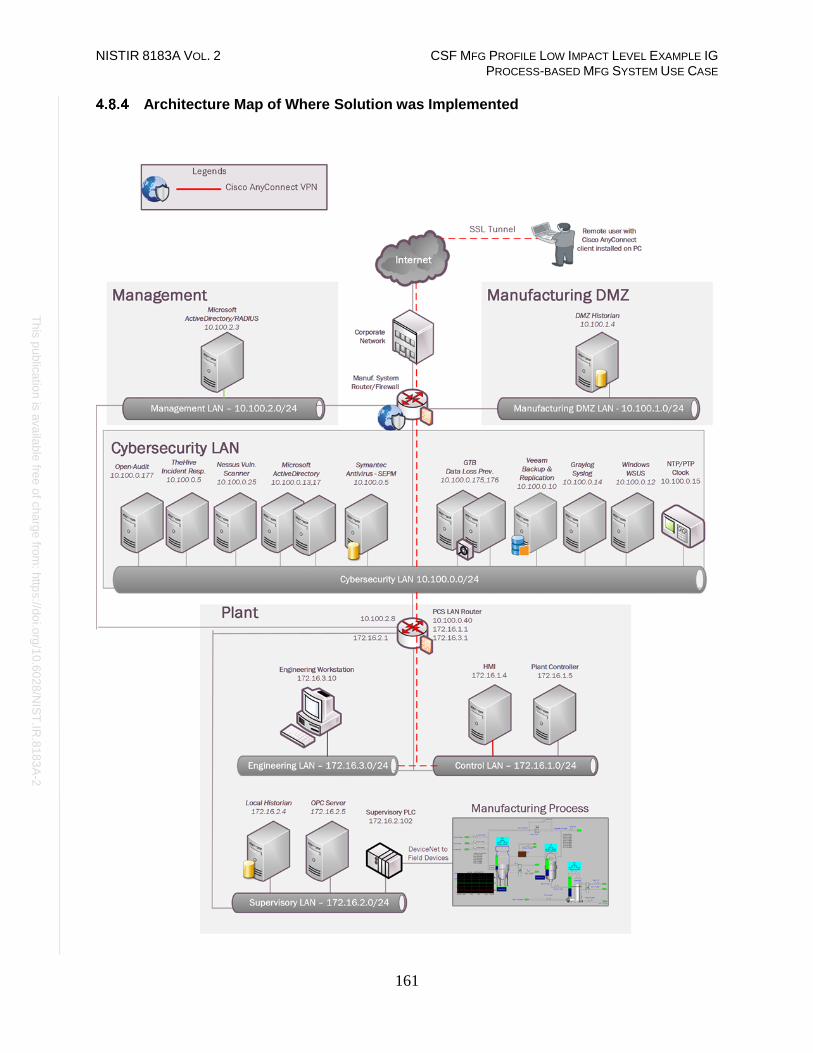
NISTIR 8183A VOL. 2 CSF MFG PROFILE LOW IMPACT LEVEL EXAMPLE IG PROCESS-BASED MFG SYSTEM USE CASE
161
Th
is p
ublic
atio
n is
ava
ilable
free
of c
ha
rge
from
: http
s://d
oi.o
rg/1
0.6
02
8/N
IST
.IR.8
18
3A
-2
Architecture Map of Where Solution was Implemented

NISTIR 8183A VOL. 2 CSF MFG PROFILE LOW IMPACT LEVEL EXAMPLE IG PROCESS-BASED MFG SYSTEM USE CASE
162
Th
is p
ublic
atio
n is
ava
ilable
free
of c
ha
rge
from
: http
s://d
oi.o
rg/1
0.6
02
8/N
IST
.IR.8
18
3A
-2
Installation Instructions and Configurations
Details of the solutions implemented:
Device Function OS / Version
Cisco ASA 5512 with Firepower
services
Firewall FTD 6.2.3
AnyConnect VPN VPN Client software 4.7.01076
Virtual Machine (Mgmt-AD.mgmt.lab) Active Directory,
DNS, NPS (Radius)
Windows 2012
R2 4.8.5.1 Environment Overview
Secure Remote Access was implemented using the Cisco AnyConnect VPN. The AnyConnect
VPN was configured on the Cisco ASA firewall in the Cybersecurity LAN network. A Windows
server was setup in the Management LAN network of the plant for hosting Active Directory and
Radius Authentication services for VPN clients.
4.8.5.2 Setup of a Radius server on Windows
The high-level steps for setting up a Radius server for authenticating Cisco ASA users are:
1. Install the following roles on the server either using Server Manager or power shell.
Different servers must be used to separate out the Roles and for redundancy.
• Active Directory Services
• DNS Server
• Network Policy Server
2. Create a security group in Active Directory for VPN users and add those users requiring
remote access to this group. For instance, a group called VPN-users was created in our
AD server and a user vpnuser01 was added to this group.

NISTIR 8183A VOL. 2 CSF MFG PROFILE LOW IMPACT LEVEL EXAMPLE IG PROCESS-BASED MFG SYSTEM USE CASE
163
Th
is p
ublic
atio
n is
ava
ilable
free
of c
ha
rge
from
: http
s://d
oi.o
rg/1
0.6
02
8/N
IST
.IR.8
18
3A
-2
3. Launch the Network Policy Server console. Create a new Radius client for your firewall
device by clicking on Radius Clients > New.
4. Enter the IP address of the Interface on the ASA. This is typically the Default Gateway of
the subnet where the AD/Radius server is in. Enter a strong passphrase for Shared secret.
The image below shows a Radius client created for our Cisco-ASA firewall.

NISTIR 8183A VOL. 2 CSF MFG PROFILE LOW IMPACT LEVEL EXAMPLE IG PROCESS-BASED MFG SYSTEM USE CASE
164
Th
is p
ublic
atio
n is
ava
ilable
free
of c
ha
rge
from
: http
s://d
oi.o
rg/1
0.6
02
8/N
IST
.IR.8
18
3A
-2
5. Click on Network Policies under Polices. Create a Network Policy here corresponding to
the Radius client setup earlier. The image below shows network policy created for the
Cisco-ASA client. Ensure the policy is enabled.
6. Click ADD under Conditions tab to add the following two conditions at a minimum.
Add more conditions as per your requirement.
• VPN-Users security group created earlier.
• Client IPv4 Address: IP address of the Radius client created earlier.

NISTIR 8183A VOL. 2 CSF MFG PROFILE LOW IMPACT LEVEL EXAMPLE IG PROCESS-BASED MFG SYSTEM USE CASE
165
Th
is p
ublic
atio
n is
ava
ilable
free
of c
ha
rge
from
: http
s://d
oi.o
rg/1
0.6
02
8/N
IST
.IR.8
18
3A
-2
7. Select the authentication methods under Constraints as shown below. This is as per
Cisco documentation.82
82 https://www.cisco.com/c/en/us/support/docs/security/asa-5500-x-series-next-generation-firewalls/117641-config-asa-00.html

NISTIR 8183A VOL. 2 CSF MFG PROFILE LOW IMPACT LEVEL EXAMPLE IG PROCESS-BASED MFG SYSTEM USE CASE
166
Th
is p
ublic
atio
n is
ava
ilable
free
of c
ha
rge
from
: http
s://d
oi.o
rg/1
0.6
02
8/N
IST
.IR.8
18
3A
-2
8. Click Standard under Radius Attributes under Settings tab. Set the following attributes
• Framed Protocol= PPP
• Service-Type=Framed
• Class = <Name of group policy>. This policy is configured in the Firewall for VPN
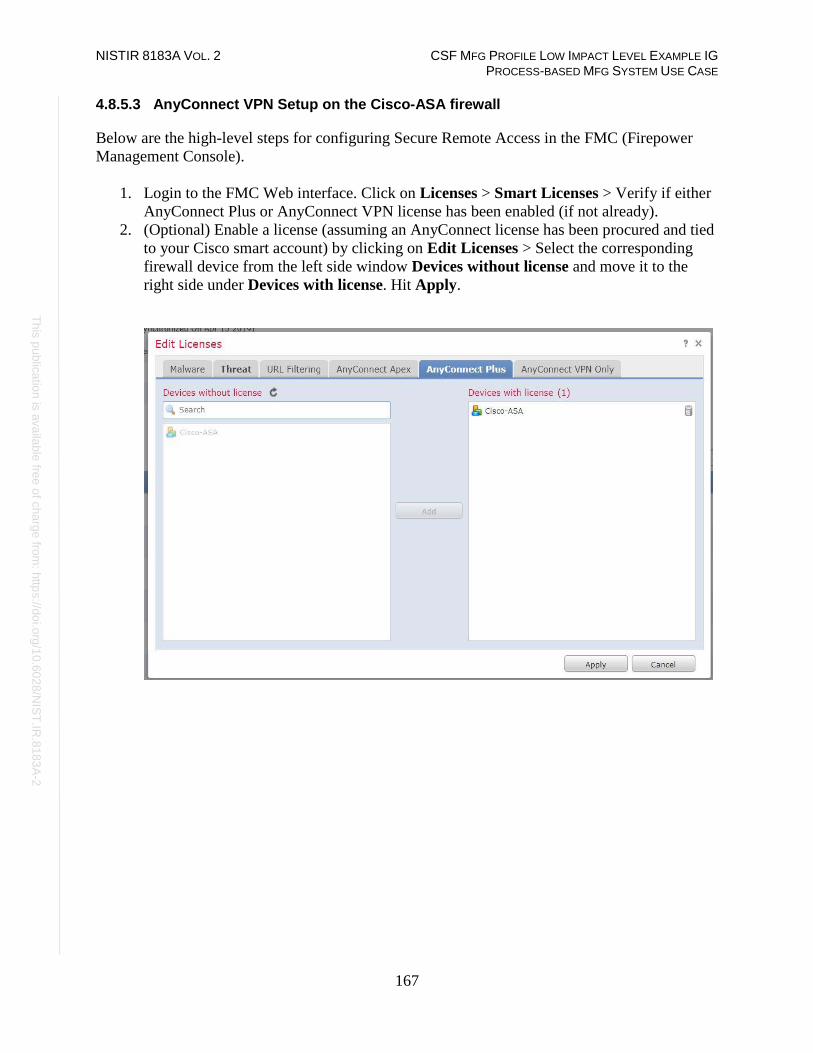
NISTIR 8183A VOL. 2 CSF MFG PROFILE LOW IMPACT LEVEL EXAMPLE IG PROCESS-BASED MFG SYSTEM USE CASE
167
Th
is p
ublic
atio
n is
ava
ilable
free
of c
ha
rge
from
: http
s://d
oi.o
rg/1
0.6
02
8/N
IST
.IR.8
18
3A
-2
4.8.5.3 AnyConnect VPN Setup on the Cisco-ASA firewall
Below are the high-level steps for configuring Secure Remote Access in the FMC (Firepower
Management Console).
1. Login to the FMC Web interface. Click on Licenses > Smart Licenses > Verify if either
AnyConnect Plus or AnyConnect VPN license has been enabled (if not already).
2. (Optional) Enable a license (assuming an AnyConnect license has been procured and tied
to your Cisco smart account) by clicking on Edit Licenses > Select the corresponding
firewall device from the left side window Devices without license and move it to the
right side under Devices with license. Hit Apply.

NISTIR 8183A VOL. 2 CSF MFG PROFILE LOW IMPACT LEVEL EXAMPLE IG PROCESS-BASED MFG SYSTEM USE CASE
168
Th
is p
ublic
atio
n is
ava
ilable
free
of c
ha
rge
from
: http
s://d
oi.o
rg/1
0.6
02
8/N
IST
.IR.8
18
3A
-2
3. Click on Objects menu > Object Management > Radius Server Group > Add Radius
Server Group (if not already configured)
4. Click Add Radius Server Group > Enter a Name and Description > Hover the mouse
to Radius Servers in the bottom menu >> Click on + to add one.
5. Enter the IP address of the Radius Server, a strong shared secret passphrase at the New
Radius Server screen. Click Save.

NISTIR 8183A VOL. 2 CSF MFG PROFILE LOW IMPACT LEVEL EXAMPLE IG PROCESS-BASED MFG SYSTEM USE CASE
169
Th
is p
ublic
atio
n is
ava
ilable
free
of c
ha
rge
from
: http
s://d
oi.o
rg/1
0.6
02
8/N
IST
.IR.8
18
3A
-2
6. Click on the Devices menu > VPN > Remote Access > Wizard > Add a new
Configuration. This will launch the Remote Access VPN Policy wizard
7. Perform the following actions on Policy Assignment
a. Define a Name, Description.
b. Select a protocol (SSL, IPSec-IKEv2). It is possible to select both.
c. Move the appropriate firewall device under “Available Devices” (left-side) to
“Selected Devices” right-side window
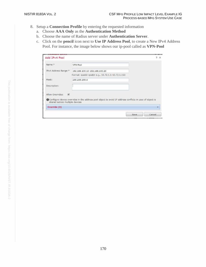
NISTIR 8183A VOL. 2 CSF MFG PROFILE LOW IMPACT LEVEL EXAMPLE IG PROCESS-BASED MFG SYSTEM USE CASE
170
Th
is p
ublic
atio
n is
ava
ilable
free
of c
ha
rge
from
: http
s://d
oi.o
rg/1
0.6
02
8/N
IST
.IR.8
18
3A
-2
8. Setup a Connection Profile by entering the requested information
a. Choose AAA Only as the Authentication Method
b. Choose the name of Radius server under Authentication Server.
c. Click on the pencil icon next to Use IP Address Pool, to create a New IPv4 Address
Pool. For instance, the image below shows our ip-pool called as VPN-Pool

NISTIR 8183A VOL. 2 CSF MFG PROFILE LOW IMPACT LEVEL EXAMPLE IG PROCESS-BASED MFG SYSTEM USE CASE
171
Th
is p
ublic
atio
n is
ava
ilable
free
of c
ha
rge
from
: http
s://d
oi.o
rg/1
0.6
02
8/N
IST
.IR.8
18
3A
-2
d. Create a new Group Policy or Edit the Default Group Policy under Group Policy as
per your requirement. This is the policy name to be referenced on the Radius server
setup on Windows.
For reference, the following changes were put in our Default Group Policy
• Under General > VPN Protocols > SSL
• Under General > Banner > Enter a custom welcome message
• Under General > Split Tunneling > Allow all traffic over tunnel (Split tunnel
was disabled)
• Create a new Client Profile (if not already) under the AnyConnect tab
• Idle Session Timeout was set to 30 minutes Under Advanced > Session Settings
Refer to the images below for reference.
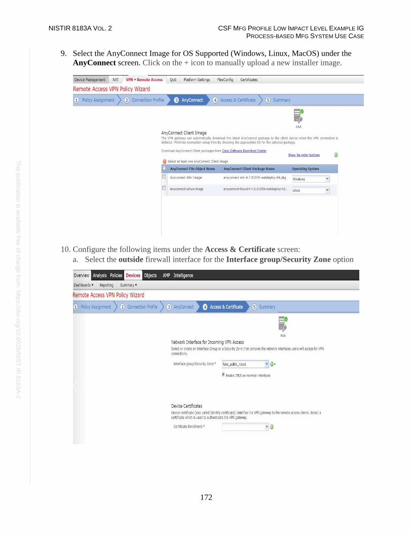
NISTIR 8183A VOL. 2 CSF MFG PROFILE LOW IMPACT LEVEL EXAMPLE IG PROCESS-BASED MFG SYSTEM USE CASE
172
Th
is p
ublic
atio
n is
ava
ilable
free
of c
ha
rge
from
: http
s://d
oi.o
rg/1
0.6
02
8/N
IST
.IR.8
18
3A
-2
9. Select the AnyConnect Image for OS Supported (Windows, Linux, MacOS) under the
AnyConnect screen. Click on the + icon to manually upload a new installer image.
10. Configure the following items under the Access & Certificate screen:
a. Select the outside firewall interface for the Interface group/Security Zone option

NISTIR 8183A VOL. 2 CSF MFG PROFILE LOW IMPACT LEVEL EXAMPLE IG PROCESS-BASED MFG SYSTEM USE CASE
173
Th
is p
ublic
atio
n is
ava
ilable
free
of c
ha
rge
from
: http
s://d
oi.o
rg/1
0.6
02
8/N
IST
.IR.8
18
3A
-2
b. Select a certificate to authenticate the VPN gateway under Device Certificates. This
can be an existing one or click + to create a self-signed certificate. A self-signed
certificate was used in our environment.
11. Review the Summary page. If all settings appear correct click Finish to apply them

NISTIR 8183A VOL. 2 CSF MFG PROFILE LOW IMPACT LEVEL EXAMPLE IG PROCESS-BASED MFG SYSTEM USE CASE
174
Th
is p
ublic
atio
n is
ava
ilable
free
of c
ha
rge
from
: http
s://d
oi.o
rg/1
0.6
02
8/N
IST
.IR.8
18
3A
-2
4.8.5.4 Additional configuration
Once the Remote Access VPN policy wizard is completed, the following configurations need to
be put in place for the remote access VPN to work on all device targets:
• Access Control policy
• Device Certificate
• NAT Exemption
1. Create an Access Control Policy:
a. Define an ACL rule to allow VPN traffic on to whichever network segments you wish
to permit.
For example, the Image and the table below lists the details of an ACL rule put in
place to allow VPN traffic from outside to only a couple of internal servers in the
Process Control system over Remote Desktop Port 3389.

NISTIR 8183A VOL. 2 CSF MFG PROFILE LOW IMPACT LEVEL EXAMPLE IG PROCESS-BASED MFG SYSTEM USE CASE
175
Th
is p
ublic
atio
n is
ava
ilable
free
of c
ha
rge
from
: http
s://d
oi.o
rg/1
0.6
02
8/N
IST
.IR.8
18
3A
-2
Source Destination Selection
Zones Outside Inside
Networks
VPN_Pool
(Network)
HMI Server (Host)
and Workstation
(Host)
Ports Any 3389 TCP
Action Allow
Inspection
Enabled. Balanced connectivity
over Security.
2. Create a Device Certificate
a. Associate the self-signed or external certificate created earlier with the Firewall
device.
3. Create a NAT Exemption rule as follows:
a. Define a NAT rule to exempt VPN traffic assuming NAT is already enabled on
firewall.
b. Click on Devices Menu > NAT > Select <NAT Policy> > Add Rule.
c. Add the Source, Destination interface objects.
d. Select the Translation settings under Translation as per your environment.
e. Select Do not proxy ARP on Destination Interface under Advanced tab

NISTIR 8183A VOL. 2 CSF MFG PROFILE LOW IMPACT LEVEL EXAMPLE IG PROCESS-BASED MFG SYSTEM USE CASE
176
Th
is p
ublic
atio
n is
ava
ilable
free
of c
ha
rge
from
: http
s://d
oi.o
rg/1
0.6
02
8/N
IST
.IR.8
18
3A
-2
The images below show a NAT Rule created to exempt VPN Traffic.

NISTIR 8183A VOL. 2 CSF MFG PROFILE LOW IMPACT LEVEL EXAMPLE IG PROCESS-BASED MFG SYSTEM USE CASE
177
Th
is p
ublic
atio
n is
ava
ilable
free
of c
ha
rge
from
: http
s://d
oi.o
rg/1
0.6
02
8/N
IST
.IR.8
18
3A
-2
4.8.5.5 Client Connection
1. Install the VPN software (for a new Windows client system) as follows:
a. Open a web browser and navigate to the IP address of the Outside interface of the
Firewall.
b. Enter the Active Directory user credentials at the logon prompt.
c. Download the AnyConnect client software. Run the .exe to install it.

NISTIR 8183A VOL. 2 CSF MFG PROFILE LOW IMPACT LEVEL EXAMPLE IG PROCESS-BASED MFG SYSTEM USE CASE
178
Th
is p
ublic
atio
n is
ava
ilable
free
of c
ha
rge
from
: http
s://d
oi.o
rg/1
0.6
02
8/N
IST
.IR.8
18
3A
-2
2. Double click on the Cisco AnyConnect VPN in the System-tray to launch the software.
Click Connect.
3. Click Connect Anyway if prompted on the Untrusted Certificate warning message when
using a self-signed certificate as in our case. Note: This warning message will not pop-
up when using a public CA certificate.
4. Enter the AD user credentials.

NISTIR 8183A VOL. 2 CSF MFG PROFILE LOW IMPACT LEVEL EXAMPLE IG PROCESS-BASED MFG SYSTEM USE CASE
179
Th
is p
ublic
atio
n is
ava
ilable
free
of c
ha
rge
from
: http
s://d
oi.o
rg/1
0.6
02
8/N
IST
.IR.8
18
3A
-2
5. Look out for the pop-up message showing the Client as Connected.
6. Login to any of the hosts as permitted by the ACL rule setup earlier.
For instance, upon establishing the connection, the two servers in Process Control
System whitelisted earlier in the ACL Rule were accessed using RDP to perform Remote
Maintenance.
4.8.5.6 Additional Information
Cisco AnyConnect VPN83
Cisco ASA VPN User Authentication84
83 https://www.cisco.com/c/dam/en/us/products/collateral/security/anyconnect-secure-mobility-client/at_a_glance_c45-
578609.pdf 84 https://www.cisco.com/c/en/us/support/docs/security/asa-5500-x-series-next-generation-firewalls/117641-config-asa-00.html
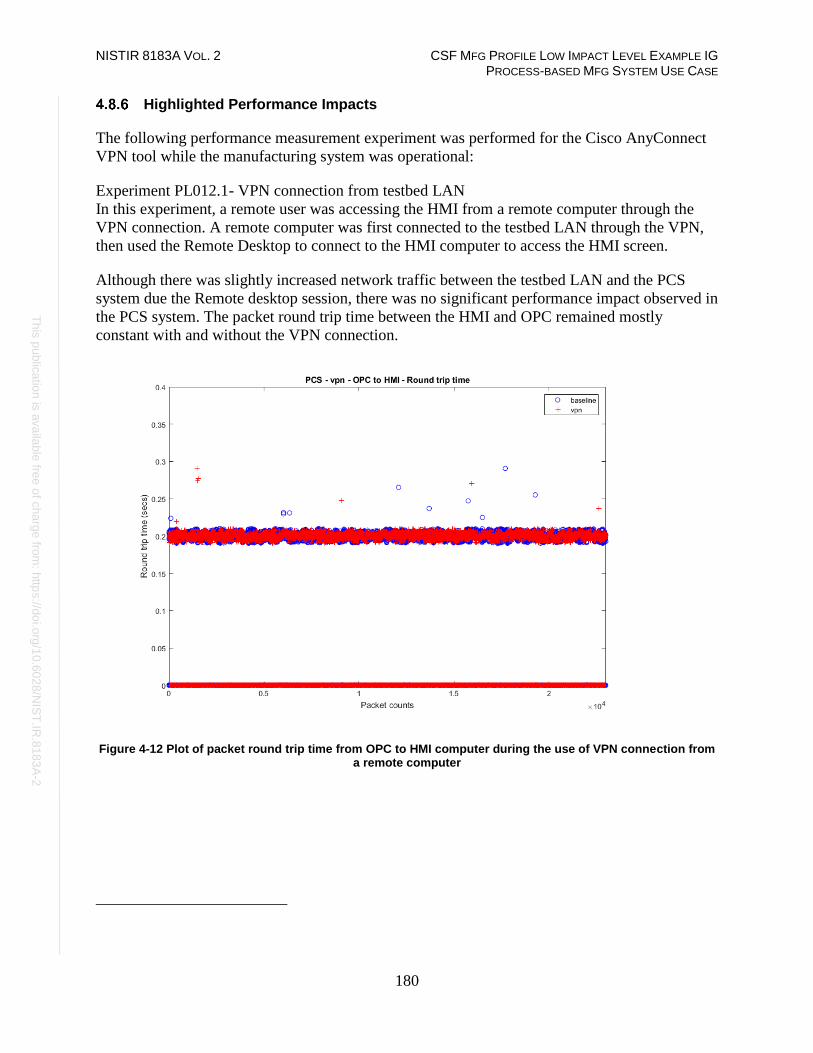
NISTIR 8183A VOL. 2 CSF MFG PROFILE LOW IMPACT LEVEL EXAMPLE IG PROCESS-BASED MFG SYSTEM USE CASE
180
Th
is p
ublic
atio
n is
ava
ilable
free
of c
ha
rge
from
: http
s://d
oi.o
rg/1
0.6
02
8/N
IST
.IR.8
18
3A
-2
Highlighted Performance Impacts
The following performance measurement experiment was performed for the Cisco AnyConnect
VPN tool while the manufacturing system was operational:
Experiment PL012.1- VPN connection from testbed LAN
In this experiment, a remote user was accessing the HMI from a remote computer through the
VPN connection. A remote computer was first connected to the testbed LAN through the VPN,
then used the Remote Desktop to connect to the HMI computer to access the HMI screen.
Although there was slightly increased network traffic between the testbed LAN and the PCS
system due the Remote desktop session, there was no significant performance impact observed in
the PCS system. The packet round trip time between the HMI and OPC remained mostly
constant with and without the VPN connection.
Figure 4-12 Plot of packet round trip time from OPC to HMI computer during the use of VPN connection from a remote computer

NISTIR 8183A VOL. 2 CSF MFG PROFILE LOW IMPACT LEVEL EXAMPLE IG PROCESS-BASED MFG SYSTEM USE CASE
181
Th
is p
ublic
atio
n is
ava
ilable
free
of c
ha
rge
from
: http
s://d
oi.o
rg/1
0.6
02
8/N
IST
.IR.8
18
3A
-2
Figure 4-13 Plot of packet round trip time from HMI to OPC computer during the use of VPN connection from a remote computer

NISTIR 8183A VOL. 2 CSF MFG PROFILE LOW IMPACT LEVEL EXAMPLE IG PROCESS-BASED MFG SYSTEM USE CASE
182
Th
is p
ublic
atio
n is
ava
ilable
free
of c
ha
rge
from
: http
s://d
oi.o
rg/1
0.6
02
8/N
IST
.IR.8
18
3A
-2
The manufacturing process also remained stable without any significant performance impact
observed. The reactor pressure and product flow rate remained constant with and without the
VPN connection.
Figure 4-14 Manufacturing process product flow rate during the use of VPN connection from a remote computer

NISTIR 8183A VOL. 2 CSF MFG PROFILE LOW IMPACT LEVEL EXAMPLE IG PROCESS-BASED MFG SYSTEM USE CASE
183
Th
is p
ublic
atio
n is
ava
ilable
free
of c
ha
rge
from
: http
s://d
oi.o
rg/1
0.6
02
8/N
IST
.IR.8
18
3A
-2
Figure 4-15 Manufacturing process reactor pressure during the use of VPN connection from a remote computer
Links to Entire Performance Measurement Data Set
• Cisco VPN KPI data
• Cisco VPN measurement data
NISTIR 8183A VOL. 2 CSF MFG PROFILE LOW IMPACT LEVEL EXAMPLE IG PROCESS-BASED MFG SYSTEM USE CASE
184
Th
is p
ublic
atio
n is
ava
ilable
free
of c
ha
rge
from
: http
s://d
oi.o
rg/1
0.6
02
8/N
IST
.IR.8
18
3A
-2
Microsoft Active Directory
Technical Solution Overview
Active Directory (AD) is a directory service developed by Microsoft for Windows
domain networks. A directory is a hierarchical structure that stores information about objects on
the network. A directory service, such as Active Directory Domain Services (AD DS), provides
the methods for storing directory data and making this data available to network users and
administrators. For example, AD DS stores information about user accounts, such as names,
passwords, phone numbers, and so on, and enables other authorized users on the same network to
access this information. A server running Active Directory Domain Services (AD DS) is called
a domain controller. It authenticates and authorizes all users and computers in a Windows
domain type network—assigning and enforcing cybersecurity policies for all computers and
installing or updating software. Active Directory uses Lightweight Directory Access
Protocol (LDAP) versions 2 and 3, Microsoft's version of Kerberos and DNS.85
Points to consider:
• Cost of infrastructure can get high.
• Requires expertise to setup and maintain. Setup involves detailed planning.
• It is prone to being hacked.
Technical Capabilities Provided by Solution
Microsoft Active Directory provides components of the following Technical Capabilities
described in Section 6 of Volume 1:
• Credential Management
• Authentication and Authorization
Subcategories Addressed by Implementing Solution
PR.AC-1, PR.MA-1, PR.MA-2, PR-PT-3, PR.PT-4, DE.CM-3
85 https://docs.microsoft.com/en-us/windows-server/identity/ad-ds/get-started/virtual-dc/active-directory-domain-services-
overview

NISTIR 8183A VOL. 2 CSF MFG PROFILE LOW IMPACT LEVEL EXAMPLE IG PROCESS-BASED MFG SYSTEM USE CASE
185
Th
is p
ublic
atio
n is
ava
ilable
free
of c
ha
rge
from
: http
s://d
oi.o
rg/1
0.6
02
8/N
IST
.IR.8
18
3A
-2
Architecture Map of Where Solution was Implemented

NISTIR 8183A VOL. 2 CSF MFG PROFILE LOW IMPACT LEVEL EXAMPLE IG PROCESS-BASED MFG SYSTEM USE CASE
186
Th
is p
ublic
atio
n is
ava
ilable
free
of c
ha
rge
from
: http
s://d
oi.o
rg/1
0.6
02
8/N
IST
.IR.8
18
3A
-2
Installation Instructions and Configurations
Details of the environment:
Hostname Roles Domain
Name
Hardware Details
LAN-AD Active
Directory, DNS
Server
LAN.lab Hyper-V Virtual Machine
(Generation 2):
• Processors: 2 virtual cores
• Memory: 6 GB
• Disk space: 70 GB
• Network: 1 network adapter
• OS: Windows 2012 R2
LAN-
AD02
Active
Directory, DNS
Server
LAN.lab
Hyper-V Virtual Machine
(Generation 2):
• Processors: 2 virtual cores
• Memory: 6 GB
• Disk space: 70 GB
• Network: 1 network adapter
• OS: Windows 2012 R2
Mgmt-AD Active
Directory, DNS,
Network Policy
Server (Radius)
Mgmt.lab
Hyper-V Virtual Machine
(Generation 2):
• Processors: 2 virtual cores
• Memory: 4 GB
• Disk space: 40 GB
• Network: 1 network adapter
• OS: Windows 2012 R2

NISTIR 8183A VOL. 2 CSF MFG PROFILE LOW IMPACT LEVEL EXAMPLE IG PROCESS-BASED MFG SYSTEM USE CASE
187
Th
is p
ublic
atio
n is
ava
ilable
free
of c
ha
rge
from
: http
s://d
oi.o
rg/1
0.6
02
8/N
IST
.IR.8
18
3A
-2
4.9.5.1 Environment Setup
Our setup consists of two separate Active Directory (AD) domain environments; one for the
Cybersecurity -LAN network and other for the Management network. For security reasons, the
AD domain in the Cybersecurity LAN network is separate from the domain of the Management
network. This Domain Controller (DC) in the Management network has Windows NPS (Radius)
services installed for authenticating the network devices.
1. Two virtual machines, each running Windows 2012 R2 were setup on a Hyper-V host
server of the Cybersecurity LAN network for authenticating Windows/Linux devices.
The hardware specifications of these are described in the table above.
2. One virtual machine running Windows 2012 R2 was setup in the Management network
for authenticating VPN users and network devices such as boundary routers.
3. The guest OS IP information of these servers was set as follows:
Hostname: LAN-AD.lan.lab
IP address: 10.100.0.5
Gateway: 10.100.0.1
Subnet Mask: 255.255.255.0
DNS:127.0.0.1, 10.100.0.13
Hostname: LAN-AD02.lan.lab
IP address: 10.100.0.13
Gateway: 10.100.0.1
Subnet Mask: 255.255.255.0
DNS:10.100.0.17,127.0.0.1
Hostname: Mgmt-AD.mgmt.lab
IP address: 10.100.2.3
Gateway: 10.100.2.1
Subnet Mask: 255.255.255.0
DNS:127.0.0.1

NISTIR 8183A VOL. 2 CSF MFG PROFILE LOW IMPACT LEVEL EXAMPLE IG PROCESS-BASED MFG SYSTEM USE CASE
188
Th
is p
ublic
atio
n is
ava
ilable
free
of c
ha
rge
from
: http
s://d
oi.o
rg/1
0.6
02
8/N
IST
.IR.8
18
3A
-2
4.9.5.2 Installing Active Directory Domain Services & DNS Server
Prerequisites
Windows 2012 R2 server (preferably two for redundancy) up to date on patches, static IP address
assigned with primary DNS server set to 127.0.0.1 (localhost)
1. Launch the Windows Server Manager and click on Add Roles and Features
2. Click “Next” at the first page as shown below

NISTIR 8183A VOL. 2 CSF MFG PROFILE LOW IMPACT LEVEL EXAMPLE IG PROCESS-BASED MFG SYSTEM USE CASE
189
Th
is p
ublic
atio
n is
ava
ilable
free
of c
ha
rge
from
: http
s://d
oi.o
rg/1
0.6
02
8/N
IST
.IR.8
18
3A
-2
3. Select Role Based or Feature Based Installation under Installation Type
4. Select Active Directory Domain Services and DNS Server to install. Click Next.

NISTIR 8183A VOL. 2 CSF MFG PROFILE LOW IMPACT LEVEL EXAMPLE IG PROCESS-BASED MFG SYSTEM USE CASE
190
Th
is p
ublic
atio
n is
ava
ilable
free
of c
ha
rge
from
: http
s://d
oi.o
rg/1
0.6
02
8/N
IST
.IR.8
18
3A
-2
5. Click Next on the Features screen, leave the default options selected,
6. Click Next on the AD DS screen and the following DNS Server screen as well.
7. Verify your settings on the Confirmation screen. Click Install to proceed.

NISTIR 8183A VOL. 2 CSF MFG PROFILE LOW IMPACT LEVEL EXAMPLE IG PROCESS-BASED MFG SYSTEM USE CASE
191
Th
is p
ublic
atio
n is
ava
ilable
free
of c
ha
rge
from
: http
s://d
oi.o
rg/1
0.6
02
8/N
IST
.IR.8
18
3A
-2
8. Wait till the installation process completes and shows an Installation succeeded
message. Hit Close button.
9. Launch Server Manager again and click on Promote this server to a domain
controller.
10. Select Add a new forest on the Deployment Configuration step, as this would be a new
domain controller in a new forest. Mention a Root Domain name as applicable to your
environment.

NISTIR 8183A VOL. 2 CSF MFG PROFILE LOW IMPACT LEVEL EXAMPLE IG PROCESS-BASED MFG SYSTEM USE CASE
192
Th
is p
ublic
atio
n is
ava
ilable
free
of c
ha
rge
from
: http
s://d
oi.o
rg/1
0.6
02
8/N
IST
.IR.8
18
3A
-2
11. Set a Directory Services Restore Mode password in the next step. Click Next
12. Under “DNS Options” leave the default options selected. Click Next

NISTIR 8183A VOL. 2 CSF MFG PROFILE LOW IMPACT LEVEL EXAMPLE IG PROCESS-BASED MFG SYSTEM USE CASE
193
Th
is p
ublic
atio
n is
ava
ilable
free
of c
ha
rge
from
: http
s://d
oi.o
rg/1
0.6
02
8/N
IST
.IR.8
18
3A
-2
13. Confirm the NETBIOS domain name under Additional Options. Click Next.
14. Leave the default folder paths as it is Under Paths. Click Next

NISTIR 8183A VOL. 2 CSF MFG PROFILE LOW IMPACT LEVEL EXAMPLE IG PROCESS-BASED MFG SYSTEM USE CASE
194
Th
is p
ublic
atio
n is
ava
ilable
free
of c
ha
rge
from
: http
s://d
oi.o
rg/1
0.6
02
8/N
IST
.IR.8
18
3A
-2
15. Confirm all the settings On the Review Options page. Click Next.
16. Click Install on the Prerequisites Check to launch the installation process. The server
will auto reboot upon completion.
17. Login with domain administrator credentials upon reboot. Open Server Manager and
click on Active Directory Users and Computers under Tools to manage your AD.
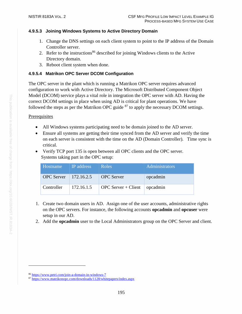
NISTIR 8183A VOL. 2 CSF MFG PROFILE LOW IMPACT LEVEL EXAMPLE IG PROCESS-BASED MFG SYSTEM USE CASE
195
Th
is p
ublic
atio
n is
ava
ilable
free
of c
ha
rge
from
: http
s://d
oi.o
rg/1
0.6
02
8/N
IST
.IR.8
18
3A
-2
4.9.5.3 Joining Windows Systems to Active Directory Domain
1. Change the DNS settings on each client system to point to the IP address of the Domain
Controller server.
2. Refer to the instructions86 described for joining Windows clients to the Active
Directory domain.
3. Reboot client system when done.
4.9.5.4 Matrikon OPC Server DCOM Configuration
The OPC server in the plant which is running a Matrikon OPC server requires advanced
configuration to work with Active Directory. The Microsoft Distributed Component Object
Model (DCOM) service plays a vital role in integration the OPC server with AD. Having the
correct DCOM settings in place when using AD is critical for plant operations. We have
followed the steps as per the Matrikon OPC guide 87 to apply the necessary DCOM settings.
Prerequisites
• All Windows systems participating need to be domain joined to the AD server.
• Ensure all systems are getting their time synced from the AD server and verify the time
on each server is consistent with the time on the AD (Domain Controller). Time sync is
critical.
• Verify TCP port 135 is open between all OPC clients and the OPC server.
Systems taking part in the OPC setup:
Hostname IP address Roles Administrators
OPC Server 172.16.2.5 OPC Server opcadmin
Controller 172.16.1.5 OPC Server + Client opcadmin
1. Create two domain users in AD. Assign one of the user accounts, administrative rights
on the OPC servers. For instance, the following accounts opcadmin and opcuser were
setup in our AD.
2. Add the opcadmin user to the Local Administrators group on the OPC Server and client.
86 https://www.petri.com/join-a-domain-in-windows-7 87 https://www.matrikonopc.com/downloads/1128/whitepapers/index.aspx
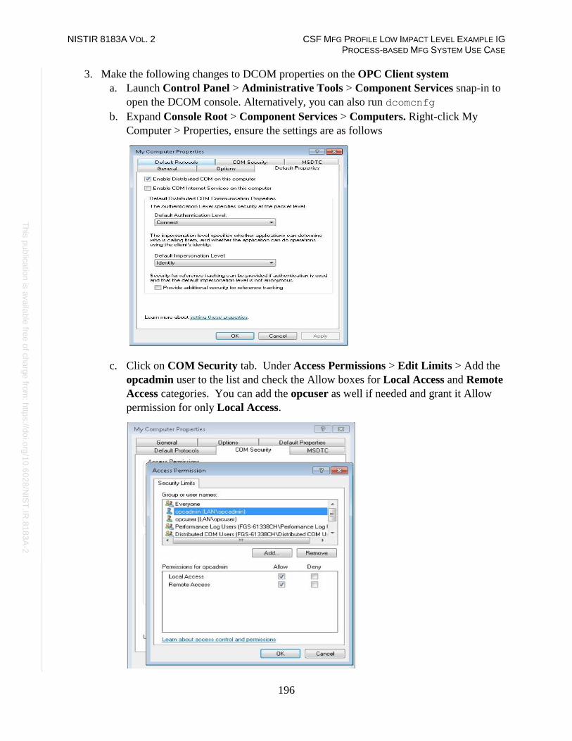
NISTIR 8183A VOL. 2 CSF MFG PROFILE LOW IMPACT LEVEL EXAMPLE IG PROCESS-BASED MFG SYSTEM USE CASE
196
Th
is p
ublic
atio
n is
ava
ilable
free
of c
ha
rge
from
: http
s://d
oi.o
rg/1
0.6
02
8/N
IST
.IR.8
18
3A
-2
3. Make the following changes to DCOM properties on the OPC Client system
a. Launch Control Panel > Administrative Tools > Component Services snap-in to
open the DCOM console. Alternatively, you can also run dcomcnfg
b. Expand Console Root > Component Services > Computers. Right-click My
Computer > Properties, ensure the settings are as follows
c. Click on COM Security tab. Under Access Permissions > Edit Limits > Add the
opcadmin user to the list and check the Allow boxes for Local Access and Remote
Access categories. You can add the opcuser as well if needed and grant it Allow
permission for only Local Access.

NISTIR 8183A VOL. 2 CSF MFG PROFILE LOW IMPACT LEVEL EXAMPLE IG PROCESS-BASED MFG SYSTEM USE CASE
197
Th
is p
ublic
atio
n is
ava
ilable
free
of c
ha
rge
from
: http
s://d
oi.o
rg/1
0.6
02
8/N
IST
.IR.8
18
3A
-2
d. Click Edit Default button under Access Permissions window > Ensure that
“<server-name>\Administrators” group has all the boxes checked. The opcadmin
user was made part of this Administrators group earlier. If adding opcuser, grant it
Allow for Local Access only
e. Click Edit Default button under the Launch and Activation Permissions window
> Ensure the Administrators group has ALLOW Permissions for all 4 categories.
The other opcuser should have ALLOW only for Local Launch

NISTIR 8183A VOL. 2 CSF MFG PROFILE LOW IMPACT LEVEL EXAMPLE IG PROCESS-BASED MFG SYSTEM USE CASE
198
Th
is p
ublic
atio
n is
ava
ilable
free
of c
ha
rge
from
: http
s://d
oi.o
rg/1
0.6
02
8/N
IST
.IR.8
18
3A
-2
f. Reboot the system after these changes are made. Repeat the process on each client.
This completes the OPC client-side configuration.
4. Make the following changes to the DCOM properties on the OPC server system:
a. Launch the Control Panel > Administrative Tools > Component Services snap-
in to open the DCOM console.
b. Expand Console Root > Component Services > Computers. Right-click My
Computer > Properties. Ensure the settings are as follows

NISTIR 8183A VOL. 2 CSF MFG PROFILE LOW IMPACT LEVEL EXAMPLE IG PROCESS-BASED MFG SYSTEM USE CASE
199
Th
is p
ublic
atio
n is
ava
ilable
free
of c
ha
rge
from
: http
s://d
oi.o
rg/1
0.6
02
8/N
IST
.IR.8
18
3A
-2
c. Click on the COM Security tab > Access Permissions > Edit Default > Add the
opcadmin user and grant it ALLOW permissions for Local Access and Remote
Access boxes.
d. Click Edit Default under Launch and Activation Permissions> Add the
Administrators group. Check on ALLOW Boxes for all 4 categories. If adding the
other opcuser, it will only have Local Launch permissions.

NISTIR 8183A VOL. 2 CSF MFG PROFILE LOW IMPACT LEVEL EXAMPLE IG PROCESS-BASED MFG SYSTEM USE CASE
200
Th
is p
ublic
atio
n is
ava
ilable
free
of c
ha
rge
from
: http
s://d
oi.o
rg/1
0.6
02
8/N
IST
.IR.8
18
3A
-2
5. Note down the names of the opc-server software installed in your environment on the
OPC make the DCOM changes as explained below on each of their application folders.
In our case, the list of the s/w is as follows
• Harmony (Installed on OPC Server)
• RSLINX (Installed on OPC Server)
• MATLAB (Installed on the Controller)
6. Make the following changes on the application folders of the OPC-server & Client
system
a. Launch the DCOM console. Browse to Console Root > Component Services >
Computers > My Computer > DCOM Config.
b. Right-click the <application folder> from the list of applications in the right pane
Click Properties. For example, find the “Harmony” folder, right click to view its
Properties.

NISTIR 8183A VOL. 2 CSF MFG PROFILE LOW IMPACT LEVEL EXAMPLE IG PROCESS-BASED MFG SYSTEM USE CASE
201
Th
is p
ublic
atio
n is
ava
ilable
free
of c
ha
rge
from
: http
s://d
oi.o
rg/1
0.6
02
8/N
IST
.IR.8
18
3A
-2
c. Set Authentication Level to Default on the General tab.
d. Select Run application on this computer on the Location tab.
e. Assign the following permissions to the opcadmin account on Security Tab:
• Launch and Activation Permissions: Use System Defaults • Access Permissions: Use System Defaults • Configuration Permissions: Customize Full Control as shown below. (Note
opcadmin is a member of Administrators group)

NISTIR 8183A VOL. 2 CSF MFG PROFILE LOW IMPACT LEVEL EXAMPLE IG PROCESS-BASED MFG SYSTEM USE CASE
202
Th
is p
ublic
atio
n is
ava
ilable
free
of c
ha
rge
from
: http
s://d
oi.o
rg/1
0.6
02
8/N
IST
.IR.8
18
3A
-2
f. Assign the following permissions to the opcuser account on Security Tab:
• Launch and Activation Permissions: Use System Defaults • Access Permissions: Use System • Configuration Permissions: Allow Read
g. Choose the This user option under Identity Tab. Enter the user name and
password for the admin user opcadmin AD account. Click OK to save your
settings. Reboot system.
h. Repeat the above steps on the other application folders such as RSLINX and
MATLAB (on the Controller Server in our case).
i. Reboot system when done.

NISTIR 8183A VOL. 2 CSF MFG PROFILE LOW IMPACT LEVEL EXAMPLE IG PROCESS-BASED MFG SYSTEM USE CASE
203
Th
is p
ublic
atio
n is
ava
ilable
free
of c
ha
rge
from
: http
s://d
oi.o
rg/1
0.6
02
8/N
IST
.IR.8
18
3A
-2
Shown below are some screenshots of the MATLAB folder for reference.
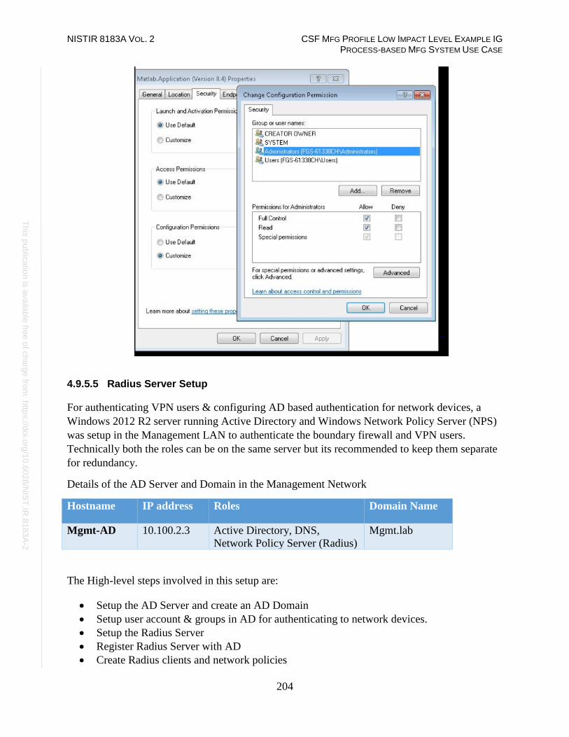
NISTIR 8183A VOL. 2 CSF MFG PROFILE LOW IMPACT LEVEL EXAMPLE IG PROCESS-BASED MFG SYSTEM USE CASE
204
Th
is p
ublic
atio
n is
ava
ilable
free
of c
ha
rge
from
: http
s://d
oi.o
rg/1
0.6
02
8/N
IST
.IR.8
18
3A
-2
4.9.5.5 Radius Server Setup
For authenticating VPN users & configuring AD based authentication for network devices, a
Windows 2012 R2 server running Active Directory and Windows Network Policy Server (NPS)
was setup in the Management LAN to authenticate the boundary firewall and VPN users.
Technically both the roles can be on the same server but its recommended to keep them separate
for redundancy.
Details of the AD Server and Domain in the Management Network
Hostname IP address Roles Domain Name
Mgmt-AD 10.100.2.3 Active Directory, DNS,
Network Policy Server (Radius)
Mgmt.lab
The High-level steps involved in this setup are:
• Setup the AD Server and create an AD Domain
• Setup user account & groups in AD for authenticating to network devices.
• Setup the Radius Server
• Register Radius Server with AD
• Create Radius clients and network policies

NISTIR 8183A VOL. 2 CSF MFG PROFILE LOW IMPACT LEVEL EXAMPLE IG PROCESS-BASED MFG SYSTEM USE CASE
205
Th
is p
ublic
atio
n is
ava
ilable
free
of c
ha
rge
from
: http
s://d
oi.o
rg/1
0.6
02
8/N
IST
.IR.8
18
3A
-2
1. Follow the steps in the previous section to setup an AD server and creating a domain.
2. Create user account(s) in AD for logging in to the network devices. Once done, create
security group(s) as required for regulating access for this user account.
For instance, a user account called icsuser01 and a Security Group Network Admins were
created in our mgmt.lab domain. The icsuser01 user was added to the Network Admins
group.
3. Follow the steps below to setup a Radius server on a Windows 2012 R2 system
a. Launch Server Manager. Click Add Roles and Features
b. Install the Network Policy Server role.

NISTIR 8183A VOL. 2 CSF MFG PROFILE LOW IMPACT LEVEL EXAMPLE IG PROCESS-BASED MFG SYSTEM USE CASE
206
Th
is p
ublic
atio
n is
ava
ilable
free
of c
ha
rge
from
: http
s://d
oi.o
rg/1
0.6
02
8/N
IST
.IR.8
18
3A
-2
c. Open the Network Policy Server Console. Right-click NPS (local) > Click on
Register Server in Active Directory
4. Create Radius Clients and Policies in NPS as follows:
a. Launch the Network Policy Server snap-in, Right-click Radius Client > New to
create a Radius client for the Network Device in question.
b. Enter a matching name of the Network Device, IP address of the management
interface of this device and create a strong passphrase. Hit OK when done.
This will create the Radius client. Verify that you can ping the IP address of the
network device from the Radius server.

NISTIR 8183A VOL. 2 CSF MFG PROFILE LOW IMPACT LEVEL EXAMPLE IG PROCESS-BASED MFG SYSTEM USE CASE
207
Th
is p
ublic
atio
n is
ava
ilable
free
of c
ha
rge
from
: http
s://d
oi.o
rg/1
0.6
02
8/N
IST
.IR.8
18
3A
-2
The image below shows a Radius client created for the Allen Bradley Boundary Router/Firewall
device in the plant.

NISTIR 8183A VOL. 2 CSF MFG PROFILE LOW IMPACT LEVEL EXAMPLE IG PROCESS-BASED MFG SYSTEM USE CASE
208
Th
is p
ublic
atio
n is
ava
ilable
free
of c
ha
rge
from
: http
s://d
oi.o
rg/1
0.6
02
8/N
IST
.IR.8
18
3A
-2
c. Create a new policy for the radius client by clicking on Policies > Network Policies.
The image below shows the network policy created for the Allen Bradley firewall
d. Click on Conditions tab to define Conditions for the policy.
e. Click ADD button > Select the user/groups option from the list > Select the security
group (Network-admins) setup earlier in our AD. This will allow users from this
group to login as admins for managing the switch.
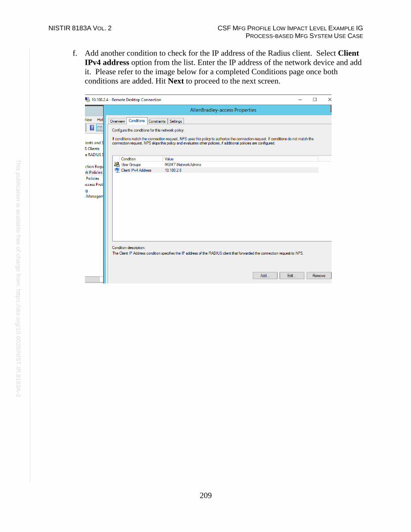
NISTIR 8183A VOL. 2 CSF MFG PROFILE LOW IMPACT LEVEL EXAMPLE IG PROCESS-BASED MFG SYSTEM USE CASE
209
Th
is p
ublic
atio
n is
ava
ilable
free
of c
ha
rge
from
: http
s://d
oi.o
rg/1
0.6
02
8/N
IST
.IR.8
18
3A
-2
f. Add another condition to check for the IP address of the Radius client. Select Client
IPv4 address option from the list. Enter the IP address of the network device and add
it. Please refer to the image below for a completed Conditions page once both
conditions are added. Hit Next to proceed to the next screen.
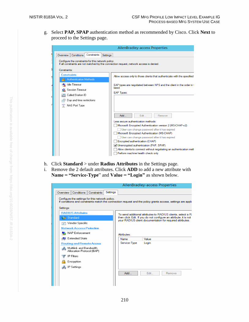
NISTIR 8183A VOL. 2 CSF MFG PROFILE LOW IMPACT LEVEL EXAMPLE IG PROCESS-BASED MFG SYSTEM USE CASE
210
Th
is p
ublic
atio
n is
ava
ilable
free
of c
ha
rge
from
: http
s://d
oi.o
rg/1
0.6
02
8/N
IST
.IR.8
18
3A
-2
g. Select PAP, SPAP authentication method as recommended by Cisco. Click Next to
proceed to the Settings page.
h. Click Standard > under Radius Attributes in the Settings page.
i. Remove the 2 default attributes. Click ADD to add a new attribute with
Name = “Service-Type” and Value = “Login” as shown below.

NISTIR 8183A VOL. 2 CSF MFG PROFILE LOW IMPACT LEVEL EXAMPLE IG PROCESS-BASED MFG SYSTEM USE CASE
211
Th
is p
ublic
atio
n is
ava
ilable
free
of c
ha
rge
from
: http
s://d
oi.o
rg/1
0.6
02
8/N
IST
.IR.8
18
3A
-2
j. Add a new attribute under Vendor Specific Attributes by selecting Cisco-AV-pair
from the list,
Vendor = Cisco
Value = shell:priv-lvl=15
This will assign the user privilege level =15 meaning root level privileges.
k. Click on OK/Apply button to save the changes
4.9.5.6 Configuring Boundary Router for Radius Authentication
1. Configure AAA group on the Boundary Router for authenticating against a Radius
server.
The following commands were run on our Allen Bradley Boundary firewall to enable
it to authenticate against the Radius server.
#enable
#configure terminal
(config)#aaa new-model
(config)#aaa authentication login default group radius local
(config)#aaa authorization exec default group radius local
(config)#radius server host 10.100.2.3
(config)# radius server-key <passphrase>
(config)# end
#wr mem
NISTIR 8183A VOL. 2 CSF MFG PROFILE LOW IMPACT LEVEL EXAMPLE IG PROCESS-BASED MFG SYSTEM USE CASE
212
Th
is p
ublic
atio
n is
ava
ilable
free
of c
ha
rge
from
: http
s://d
oi.o
rg/1
0.6
02
8/N
IST
.IR.8
18
3A
-2
Highlighted Performance Impacts
The following performance measurement experiment was performed for the Active Directory
service while the manufacturing system was operational:
PL002.1 Active Directory service active with non-OPC accounts being configured as non-
Administrator privilege.
There was no performance impact to the manufacturing process observed during the experiment.
However, performance impact was observed at the implementation of the Active Directory (AD)
service. At the initial implementation, the team focused on the Active Directory installation and
user configuration, but not knowing the need for DCOM configuration initially, causing
unplanned production interruption. DCOM and user account configuration for every OPC client
were modified to use AD instead of local authentication. Without modification, the OPC client
failed to communicate with the OPC DA server and caused all OPC data exchange to cease
operation. This failure caused the manufacturing process entered the emergency shutdown state.
Another impact observed at implementation was the time synchronization source with the AD.
Authentication failed due to time discrepancy between hosts and AD. It is because the hosts were
synchronized to a different time source than the AD and the time difference was greater than 5
minutes. When the host joins the AD domain, each host should use the same time source as AD.
For example, all hosts in PCS use AD as the time source, and AD uses an external NTP server as
its time source.
Care should be taken to ensure proper operation of the Active Directory service. Failure in
authentication causes error in operation of the OPC server, which handles all the data exchange
of the controller and the plant operation. The manufacturing process entered emergency
shutdown state because the controller lost the ability to communicate to the sensors and
actuators. Redundancy and backup are highly recommended. Ability to switch between primary
and secondary AD should be seamless to avoid impact to the system.

NISTIR 8183A VOL. 2 CSF MFG PROFILE LOW IMPACT LEVEL EXAMPLE IG PROCESS-BASED MFG SYSTEM USE CASE
213
Th
is p
ublic
atio
n is
ava
ilable
free
of c
ha
rge
from
: http
s://d
oi.o
rg/1
0.6
02
8/N
IST
.IR.8
18
3A
-2
There was no significant impact to the network performance observed. For example, the round
trip time from OPC to HMI is mostly the same with the Active Directory.
Figure 4-16 Packet round trip time from OPC to HMI with Active Directory.

NISTIR 8183A VOL. 2 CSF MFG PROFILE LOW IMPACT LEVEL EXAMPLE IG PROCESS-BASED MFG SYSTEM USE CASE
214
Th
is p
ublic
atio
n is
ava
ilable
free
of c
ha
rge
from
: http
s://d
oi.o
rg/1
0.6
02
8/N
IST
.IR.8
18
3A
-2
The controller is another major component required modification to use Active Directory. The
Controller authenticates against the AD server. The controller also has the updated DCOM so
that it can continue to communicate with the OPC server. The packet round trip time from the
Controller to OPC was slightly elevated, with a small number of packets had a slightly increased
round trip time. There was no significant increase in inter packet delay from the Controller to
OPC observed.
Figure 4-17 Packet round trip time from Controller to OPC with the Active Directory enabled (red)

NISTIR 8183A VOL. 2 CSF MFG PROFILE LOW IMPACT LEVEL EXAMPLE IG PROCESS-BASED MFG SYSTEM USE CASE
215
Th
is p
ublic
atio
n is
ava
ilable
free
of c
ha
rge
from
: http
s://d
oi.o
rg/1
0.6
02
8/N
IST
.IR.8
18
3A
-2
Figure 4-18 Inter packet delay of Controller to OPC with the Active Directory enabled (red)

NISTIR 8183A VOL. 2 CSF MFG PROFILE LOW IMPACT LEVEL EXAMPLE IG PROCESS-BASED MFG SYSTEM USE CASE
216
Th
is p
ublic
atio
n is
ava
ilable
free
of c
ha
rge
from
: http
s://d
oi.o
rg/1
0.6
02
8/N
IST
.IR.8
18
3A
-2
There was no significant performance impact to the manufacturing process observed with the use
of Active Directory. For example, the product flow rate remained consistent with and without the
use of Active Directory.
Figure 4-19 Manufacturing process product flow rate during the use of Active Directory (red)
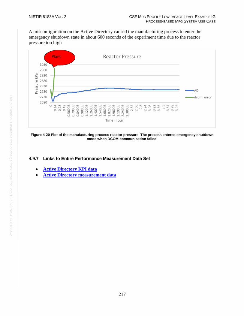
NISTIR 8183A VOL. 2 CSF MFG PROFILE LOW IMPACT LEVEL EXAMPLE IG PROCESS-BASED MFG SYSTEM USE CASE
217
Th
is p
ublic
atio
n is
ava
ilable
free
of c
ha
rge
from
: http
s://d
oi.o
rg/1
0.6
02
8/N
IST
.IR.8
18
3A
-2
A misconfiguration on the Active Directory caused the manufacturing process to enter the
emergency shutdown state in about 600 seconds of the experiment time due to the reactor
pressure too high
Figure 4-20 Plot of the manufacturing process reactor pressure. The process entered emergency shutdown mode when DCOM communication failed.
Links to Entire Performance Measurement Data Set
• Active Directory KPI data
• Active Directory measurement data
2680
2730
2780
2830
2880
2930
2980
3030
0
0.1
4
0.2
8
0.4
2
0.5
60
05
0.7
00
05
0.8
40
05
0.9
80
05
1.1
20
05
1.2
60
05
1.4
00
05
1.5
40
05
1.6
80
05
1.8
20
05
1.9
60
05
2.1
00
05
2.2
40
05
2.3
80
05
2.5
2
2.6
6
2.8
2.9
4
3.0
8
3.2
2
3.3
6
3.5
3.6
4
3.7
8
3.9
2
Pre
ssu
re k
Pa
Time (hour)
Reactor Pressure
AD
dcom_error
Plant

NISTIR 8183A VOL. 2 CSF MFG PROFILE LOW IMPACT LEVEL EXAMPLE IG PROCESS-BASED MFG SYSTEM USE CASE
218
Th
is p
ublic
atio
n is
ava
ilable
free
of c
ha
rge
from
: http
s://d
oi.o
rg/1
0.6
02
8/N
IST
.IR.8
18
3A
-2
Symantec Endpoint Protection
Technical Solution Overview
Symantec Endpoint Protection (SEP)88 is an endpoint protection solution that can help defend
against ransomware and other emerging threats.
Points to consider:
• Next Generation Antivirus / Endpoint protection solution to prevent against virus attacks
and emerging cyber threats such as zero-day attacks, ransomware etc.
• OS Platform independent: The endpoint agents are supported on Windows and Linux.
• Comes with a lightweight agent and virus definition sets that require minimal network
bandwidth.
• Diverse Feature set: Core capabilities include Antivirus, Host Firewall, Intrusion
Prevention, Host Integrity, System lockdown, Application White listing and USB
Device Control.
• Centralized Management: All endpoints, rule sets, policies can be centrally managed
from the Symantec Endpoint Manager console.
• The Symantec Manager component is supported only on Windows OS.
• The Linux agent requires the OS kernel on Linux systems to be at a certain level for
installation. In addition, the Linux agent is a 32-bit installer. If installing on a 64-bit
Linux system, it requires certain 32-bit packages/libraries to be installed as a
prerequisite. This may conflict with some of the existing packages on the system.
• The endpoint agent on each system by default needs to communicate outbound with a
range of public IP addresses for its Reputation analysis and Global Threat intelligence
feature. It is recommended to allow this traffic from your firewall to leverage the
advanced features of the product.
• Important: System reboot is required to complete the installation process on
clients/endpoints.
Technical Capabilities Provided by Solution
Symantec Endpoint Protection provides components of the following Technical Capabilities
described in Section 6 of Volume 1:
• Anti-virus/malware
Subcategories Addressed by Implementing Solution
DE.CM-4
88 https://www.symantec.com/content/dam/symantec/docs/data-sheets/endpoint-protection-14-en.pdf

NISTIR 8183A VOL. 2 CSF MFG PROFILE LOW IMPACT LEVEL EXAMPLE IG PROCESS-BASED MFG SYSTEM USE CASE
219
Th
is p
ublic
atio
n is
ava
ilable
free
of c
ha
rge
from
: http
s://d
oi.o
rg/1
0.6
02
8/N
IST
.IR.8
18
3A
-2
Architecture Map of Where Solution was Implemented

NISTIR 8183A VOL. 2 CSF MFG PROFILE LOW IMPACT LEVEL EXAMPLE IG PROCESS-BASED MFG SYSTEM USE CASE
220
Th
is p
ublic
atio
n is
ava
ilable
free
of c
ha
rge
from
: http
s://d
oi.o
rg/1
0.6
02
8/N
IST
.IR.8
18
3A
-2
Installation Instructions and Configurations
Details of the solutions implemented:
Name Version Deployment
mode
Hardware Details
Symantec Endpoint
Protection Manager
(SEPM)
14.2 Build
758
On-premise Hyper-V Virtual Machine (Generation
2):
• Processors: 2 virtual cores
• Memory: 6 GB
• Disk space: 70 GB
• Network: 1 network adapter
• OS: Windows 2012 R2
Symantec Endpoint
agent for Windows
(Client)
14.2.758.000
0
Installed on all Windows systems of
the plant
4.10.5.1 Environment setup
1. A virtual machine running Windows 2012 R2 was setup on a Hyper-V host server of the
Cybersecurity LAN network of the plant with hardware specifications as described in the
table above.
2. The guest OS IP information of this server was set as follows:
IP address: 10.100.0.5
Gateway: 10.100.0.1
Subnet Mask: 255.255.255.0
DNS:10.100.0.17
3. The Symantec Endpoint Protection Manager (SEPM) virtual machine was deployed in
the Cybersecurity LAN network of the plant. This central instance communicates with
all the endpoint agents deployed on to the Process Control systems. Likewise, all
endpoints report their status to the Manager server. The communication ports required to
be opened are different for Windows clients as compared to Mac/Linux clients. A
detailed list of firewall ports89 is available for reference.
4.10.5.2 Setup of the SEPM Server
1. Download the Symantec Endpoint Protection .zip bundle from the Symantec website. A
license is required to register and download the product.
2. Open the extracted folder and run the Setup.exe file. Mid-way during the install, enter a
strong admin password when prompted.
89 https://support.symantec.com/en_US/article.HOWTO81103.html
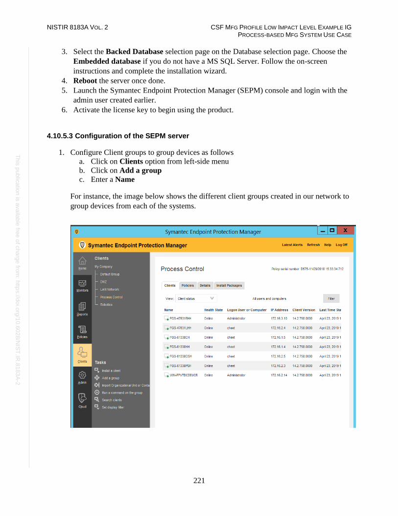
NISTIR 8183A VOL. 2 CSF MFG PROFILE LOW IMPACT LEVEL EXAMPLE IG PROCESS-BASED MFG SYSTEM USE CASE
221
Th
is p
ublic
atio
n is
ava
ilable
free
of c
ha
rge
from
: http
s://d
oi.o
rg/1
0.6
02
8/N
IST
.IR.8
18
3A
-2
3. Select the Backed Database selection page on the Database selection page. Choose the
Embedded database if you do not have a MS SQL Server. Follow the on-screen
instructions and complete the installation wizard.
4. Reboot the server once done.
5. Launch the Symantec Endpoint Protection Manager (SEPM) console and login with the
admin user created earlier.
6. Activate the license key to begin using the product.
4.10.5.3 Configuration of the SEPM server
1. Configure Client groups to group devices as follows
a. Click on Clients option from left-side menu
b. Click on Add a group
c. Enter a Name
For instance, the image below shows the different client groups created in our network to
group devices from each of the systems.

NISTIR 8183A VOL. 2 CSF MFG PROFILE LOW IMPACT LEVEL EXAMPLE IG PROCESS-BASED MFG SYSTEM USE CASE
222
Th
is p
ublic
atio
n is
ava
ilable
free
of c
ha
rge
from
: http
s://d
oi.o
rg/1
0.6
02
8/N
IST
.IR.8
18
3A
-2
2. Integrate SEP Manager with Active Directory/LDAP using the following instructions
a. Click on ADMIN > Servers > Local Site > Server Name > Edit Server
Properties
b. Click on Directory servers tab under Server Properties for <Server>.
c. Click further on ADD button as shown below to configure domain details.
d. Logout once done and try logging in back with your AD credentials.
3. Configure SMTP server using the following instructions,
a. Click on ADMIN > Servers > Local Site > Server Name > Edit Server
Properties
b. Click on Email server tab under Server Properties for <Server>.
c. Enter the details. Click OK when done.
4. Configure a policy for Excluded Hosts to exclude IP addresses of systems such as
vulnerability scanners from getting blocked when performing a scan.
a. Click Policies > Intrusion Prevention or Create a new Policy
b. Click Excluded Hosts. Add the IP address of the system in question.
c. Link the policy to the appropriate client group.

NISTIR 8183A VOL. 2 CSF MFG PROFILE LOW IMPACT LEVEL EXAMPLE IG PROCESS-BASED MFG SYSTEM USE CASE
223
Th
is p
ublic
atio
n is
ava
ilable
free
of c
ha
rge
from
: http
s://d
oi.o
rg/1
0.6
02
8/N
IST
.IR.8
18
3A
-2
5. (Optional) Setup device control such as restricting USB devices using the following
instructions.
a. Create a policy under Application and Device Control.
b. Click Device Control
c. Click Add under Blocked devices
d. Select one or more devices to block. For instance: USB
e. Ensure to select Keyboard and Mice under Devices excluded from blocking.90
90 https://support.symantec.com/us/en/article.howto80866.html

NISTIR 8183A VOL. 2 CSF MFG PROFILE LOW IMPACT LEVEL EXAMPLE IG PROCESS-BASED MFG SYSTEM USE CASE
224
Th
is p
ublic
atio
n is
ava
ilable
free
of c
ha
rge
from
: http
s://d
oi.o
rg/1
0.6
02
8/N
IST
.IR.8
18
3A
-2
4.10.5.4 Installing Endpoint Agent on Client Systems
The high-level steps in getting the AV installed on client systems are as follows:
• Create a deployment package specific for a client group
• Deploy the package.
• Restart the client system to complete the install.
1. Creating a deployment package:
a. Login to the Symantec Manager console. Click on Clients > Group Name where
the endpoint device needs to be in.
b. Click on Install client under Tasks. For instance, to create a deployment package
for the group Process Control, click on that group name followed by Install Client
option.
c. Select New Package Deployment if this is your first agent installation of that
group. If you have already deployed the agent on other systems of this group, you
can re-use the same package and skip this wizard completely.

NISTIR 8183A VOL. 2 CSF MFG PROFILE LOW IMPACT LEVEL EXAMPLE IG PROCESS-BASED MFG SYSTEM USE CASE
225
Th
is p
ublic
atio
n is
ava
ilable
free
of c
ha
rge
from
: http
s://d
oi.o
rg/1
0.6
02
8/N
IST
.IR.8
18
3A
-2
d. Click Next. Choose the appropriate OS Platform as per the endpoint OS, from the
dropdown list of Install Packages. You will notice the Group Name is already
prepopulated. This ensure the client will be placed directly in that group upon
install.
e. (Optional) Select Include virus definitions in the client installation package
under Content Options. Click Next.
2. Deploying the package:
a. Select a preferred option of Installation method on the next page.
b. (Option 1) Choose Save Package to create a local installer which then needs to
be copied over the target machine.
c. (Option 2) Choose the Remote Push method will make the SEPM server
perform a network deployment to the target machine(s). Ensure the user has
administrative privileges to install the package on the target system.

NISTIR 8183A VOL. 2 CSF MFG PROFILE LOW IMPACT LEVEL EXAMPLE IG PROCESS-BASED MFG SYSTEM USE CASE
226
Th
is p
ublic
atio
n is
ava
ilable
free
of c
ha
rge
from
: http
s://d
oi.o
rg/1
0.6
02
8/N
IST
.IR.8
18
3A
-2
d. (Option 3) Choose Web Link and Email to email a link of the installer to the
user.
e. Click Next.
3. Restart the endpoint machine upon installing the agent to complete the install process.
Check the Symantec Manager console to verify if the client name is green ONLINE and
the virus definitions are current.

NISTIR 8183A VOL. 2 CSF MFG PROFILE LOW IMPACT LEVEL EXAMPLE IG PROCESS-BASED MFG SYSTEM USE CASE
227
Th
is p
ublic
atio
n is
ava
ilable
free
of c
ha
rge
from
: http
s://d
oi.o
rg/1
0.6
02
8/N
IST
.IR.8
18
3A
-2
4.10.5.5 Additional Information
• Official Symantec Endpoint Protection v14 installation guides91
• How-to-guides from Symantec for Endpoint protection92 can be found at
• Official install guide for Windows systems93
Lessons learned
If using Symantec Firewall, ensure to disable the client’s OS firewall to avoid conflicts. When
you install the console for the first time, it adds a default Firewall policy to each group
automatically. Similarly, a client typically gets default firewall settings if a firewall policy is not
configured from the console.
Highlighted Performance Impacts
The following performance measurement experiment was performed for the Symantec anti-virus
tool while the manufacturing system was operational:
Experiment PL008.2- Symantec AV scan
During the Symantec anti-virus scan, sizeable performance impact was observed on the host
processor Utilization. However, no significant performance impact was observed on the
manufacturing process. A full Symantec scan can take up a considerable amount of processor
power.
91 https://support.symantec.com/en_US/article.DOC9449.html 92 https://support.symantec.com/us/en/how-to-guides.html 93 https://support.symantec.com/en_US/article.DOC9445.html

NISTIR 8183A VOL. 2 CSF MFG PROFILE LOW IMPACT LEVEL EXAMPLE IG PROCESS-BASED MFG SYSTEM USE CASE
228
Th
is p
ublic
atio
n is
ava
ilable
free
of c
ha
rge
from
: http
s://d
oi.o
rg/1
0.6
02
8/N
IST
.IR.8
18
3A
-2
Figure 4-21 Plot of processor utilization of the OPC computer during the Symantec anti-virus scan (Red), and the baseline processor utilization (gray)
No significant performance impact to the network was observed. For example, the packet round
trip time between the OPC and PLC remained mostly the same.
Figure 4-22 Plot of processor utilization of HMI computer during a Symantec scan (red) and without a Symantec scan (blue)
0
10
20
30
40
50
60
700
40
08
00
12
00
16
00
20
00
24
00
28
00
32
00
36
00
40
00
44
00
48
00
52
00
56
00
60
00
64
00
68
00
72
00
76
00
80
00
84
00
88
00
92
00
96
00
10
00
01
04
00
10
80
01
12
00
11
60
01
20
00
12
40
01
28
00
13
20
01
36
00
14
00
0
Pro
cess
or
Usa
ge (
%)
Time (sec)
Processor Usage, OPC DA
Symantec
baseline
FullScan start FullScan endQuickScanQuickScan

NISTIR 8183A VOL. 2 CSF MFG PROFILE LOW IMPACT LEVEL EXAMPLE IG PROCESS-BASED MFG SYSTEM USE CASE
229
Th
is p
ublic
atio
n is
ava
ilable
free
of c
ha
rge
from
: http
s://d
oi.o
rg/1
0.6
02
8/N
IST
.IR.8
18
3A
-2
No significant performance impact to the network was observed. For example, the packet round
trip time between the OPC and PLC remained mostly the same.
Figure 4-23 Packet round trip time between OPC and PLC during Symantec scan (red)
There was no significant impact to the manufacturing process observed. The product flow and
the reactor pressure remain very close to the baseline measurement during the Symantec scan.
Figure 4-24 Manufacturing process product flow rate

NISTIR 8183A VOL. 2 CSF MFG PROFILE LOW IMPACT LEVEL EXAMPLE IG PROCESS-BASED MFG SYSTEM USE CASE
230
Th
is p
ublic
atio
n is
ava
ilable
free
of c
ha
rge
from
: http
s://d
oi.o
rg/1
0.6
02
8/N
IST
.IR.8
18
3A
-2
Figure 4-25 Manufacturing process Reactor pressure
It is hypothesized that the impact to the processor utilization was caused by the Symantec AV
during the scan. In the case of the PCS system, the normal processor utilization is relatively low
and therefore the increased usage did not cause any performance impact to the manufacturing
process. If the normal utilization of the host is close to 100 %, there is potential performance
impact due to the increase utilization during scan time.
Links to Entire Performance Measurement Data Set
• Symantec AV KPI data
• Symantec AV measurement data

NISTIR 8183A VOL. 2 CSF MFG PROFILE LOW IMPACT LEVEL EXAMPLE IG PROCESS-BASED MFG SYSTEM USE CASE
231
Th
is p
ublic
atio
n is
ava
ilable
free
of c
ha
rge
from
: http
s://d
oi.o
rg/1
0.6
02
8/N
IST
.IR.8
18
3A
-2
Tenable Nessus
Technical Solution Overview
Nessus Professional is a vulnerability assessment software from Tenable. It features high-speed
asset discovery, configuration auditing, target profiling, malware detection, sensitive data
discovery and more. Nessus supports technologies such as scanning operating systems, network
devices, next generation firewalls, hypervisors, databases, web servers and critical infrastructure
for vulnerabilities, threats and compliance violations.94 It supports both authenticated and
unauthenticated scans.
Points to consider:
• Easy to setup, User friendly dashboard, fast scanning and can be configured to work in a
distributed environment.
• Support for Industrial Protocols such as MODBUS, DNP3 etc. It has the necessary
plugins to detect vulnerabilities on ICS/SCADA systems making it ideal to use in OT
environments.
• Comes with a variety of Out-of-box policy and configuration templates.
• No limit on number of IPs or number of assessments you can run.
• Support for scanning devices behind a firewall.
• No integration available with LDAP or AD in the Professional edition.
• Multiple user accounts not supported for logging in to the Web UI.
Technical Capabilities Provided by Solution
Tenable Nessus provides components of the following Technical Capabilities described in
Section 6 of Volume 1:
• Vulnerability Scanning
• Vulnerability Management
Subcategories Addressed by Implementing Solution
ID.RA-1, DE.CM-4, DE.CM-8, RS.MI-3
94 http://info.tenable.com/rs/934-XQB-568/images/NessusPro__DS__EN_v8.pdf

NISTIR 8183A VOL. 2 CSF MFG PROFILE LOW IMPACT LEVEL EXAMPLE IG PROCESS-BASED MFG SYSTEM USE CASE
232
Th
is p
ublic
atio
n is
ava
ilable
free
of c
ha
rge
from
: http
s://d
oi.o
rg/1
0.6
02
8/N
IST
.IR.8
18
3A
-2
Architecture Map of Where Solution was Implemented

NISTIR 8183A VOL. 2 CSF MFG PROFILE LOW IMPACT LEVEL EXAMPLE IG PROCESS-BASED MFG SYSTEM USE CASE
233
Th
is p
ublic
atio
n is
ava
ilable
free
of c
ha
rge
from
: http
s://d
oi.o
rg/1
0.6
02
8/N
IST
.IR.8
18
3A
-2
Installation Instructions and Configurations
Details of the solution implemented:
Name Version Deployment
Mode
Hardware Details
Nessus
Professional
7.2.0 Standalone Hyper-V Virtual Machine (Generation 2):
• Processors: 2 virtual cores
• Memory: 6 GB
• Disk space: 70 GB
• Network: 1 network adapter
• OS: Windows 2012 R2
4.11.5.1 Environment setup
1. A virtual machine running Windows 2012 R2 was setup on a Hyper-V host server of the
Cybersecurity LAN network of the plant with hardware specifications as described in the
table above.
2. The guest OS IP information of this server was set as follows:
IP address: 10.100.0.25
Gateway: 10.100.0.1
Subnet Mask: 255.255.255.0
DNS:10.100.0.17
4.11.5.2 Setup Instructions
1. Download the Nessus Professional installer.95
2. Run the installer. Follow the on-screen instructions of the setup wizard.
3. Register the product during installation either in online or offline mode. An online
mode96 is suitable for environments where Nessus server has internet access while an
offline mode is suitable for air-gapped environments.
4. Navigate to the Nessus web interface97 post installation.
5. Login to the Nessus UI, Click Settings to configure SMTP Server, LDAP Server and
Custom CA Certificate (if applicable)
6. Configure Firewall rules as described in the Nessus documentation for credentials scans
to allow SSH, WMI or SNMP traffic depending on the type of hosts between the Nessus
server and the scan targets. For unauthenticated scans, the firewall should be allowed for
any-any communication between the Nessus server and target network.
95 https://www.tenable.com/ 96 https://docs.tenable.com/nessus/Content/ManageNessusOffline.htm 97 https://<IP address of Nessus server>:8834

NISTIR 8183A VOL. 2 CSF MFG PROFILE LOW IMPACT LEVEL EXAMPLE IG PROCESS-BASED MFG SYSTEM USE CASE
234
Th
is p
ublic
atio
n is
ava
ilable
free
of c
ha
rge
from
: http
s://d
oi.o
rg/1
0.6
02
8/N
IST
.IR.8
18
3A
-2
4.11.5.3 Configuring Scans and Policies
Prerequisites for performing credentials-based scan of Windows. All of these were enabled on
the Windows systems of our Plant network.
• Enable the Windows Management Instrumentation (WMI) service on the target.98
• Enable the Remote Registry service on the target.
• Enable File and Printer Sharing in the target's network configuration.
• Use an SMB account that has local administrator rights on the target. (You can use a
domain account, but that account must be a local administrator on the devices being
scanned.)
• Open Ports 139 (TCP) and 445 (TCP) between the Nessus scanner and the target.
• Enable the default administrative shares (i.e. IPC$, ADMIN$, C$) (AutoShareServer =
1). These are enabled by default and can cause other issues if disabled.99
• Run the commands below from an elevated Command prompt or PowerShell (Right click
CMD > Run as administrator) on a host in the same network as the target.
net use \\<IP-address of Target>\ipc$/user:
This command will test if we can access the IPC$ share without a username
(This is how Nessus tests to see if SMB is running) net use \\x.x.x.x\ipc$ /user:username password
net use \\x.x.x.x\admin$ /user:username password
These commands are for SMB Logon test. These commands should return
"The command completed successfully." If it does not, then the credentials
did not work or do not have sufficient privileges.
Note: To have a successful credential scan, these commands should not return errors.
Use the Policy feature of Nessus for performing credentials checks, A Policy lets you create a
scan template where in device credentials and other custom settings can be saved for scanning
assets. Once created, a policy can then later be assigned to a scan.
98 https://technet.microsoft.com/en-us/library/cc180684.aspx 99 http://support.microsoft.com/kb/842715/en-us.

NISTIR 8183A VOL. 2 CSF MFG PROFILE LOW IMPACT LEVEL EXAMPLE IG PROCESS-BASED MFG SYSTEM USE CASE
235
Th
is p
ublic
atio
n is
ava
ilable
free
of c
ha
rge
from
: http
s://d
oi.o
rg/1
0.6
02
8/N
IST
.IR.8
18
3A
-2
1. Create a Policy using the following instructions
a. Click on Policies from the left-side explorer bar
b. Click on New Policy button.
c. Choose from any on the default templates available. The Advanced Scan
template was selected for our use. Click on Credentials tab under a template to
configure host-based credentials (SSH, Windows, SNMP, etc.).
d. Click Save when done.
2. Create a Scan using the following instructions
a. Click Scans on the Home Page > +New Scan > User Defined > Select
<Policy>
b. Enter a Name, Description and Network Range or Host IP addresses.
c. Click on Schedule to configure a schedule
d. Click Notifications to configure Email recipients.
e. Click Save.
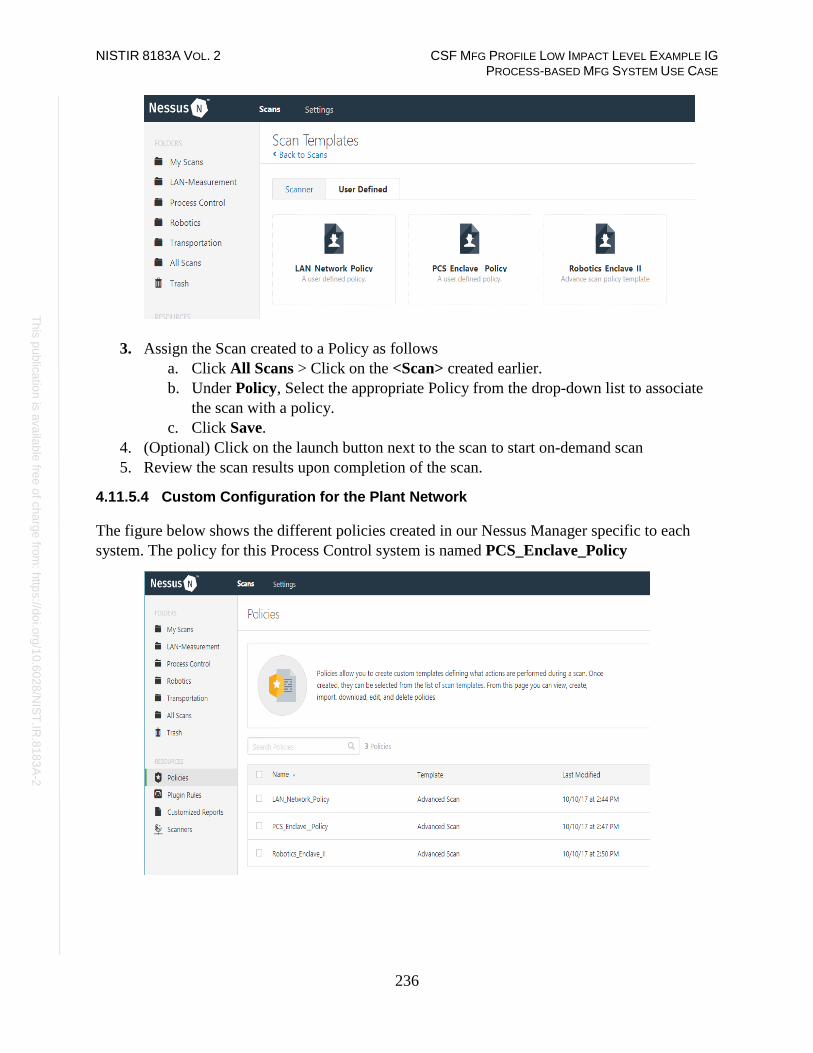
NISTIR 8183A VOL. 2 CSF MFG PROFILE LOW IMPACT LEVEL EXAMPLE IG PROCESS-BASED MFG SYSTEM USE CASE
236
Th
is p
ublic
atio
n is
ava
ilable
free
of c
ha
rge
from
: http
s://d
oi.o
rg/1
0.6
02
8/N
IST
.IR.8
18
3A
-2
3. Assign the Scan created to a Policy as follows
a. Click All Scans > Click on the <Scan> created earlier.
b. Under Policy, Select the appropriate Policy from the drop-down list to associate
the scan with a policy.
c. Click Save.
4. (Optional) Click on the launch button next to the scan to start on-demand scan
5. Review the scan results upon completion of the scan.
4.11.5.4 Custom Configuration for the Plant Network
The figure below shows the different policies created in our Nessus Manager specific to each
system. The policy for this Process Control system is named PCS_Enclave_Policy

NISTIR 8183A VOL. 2 CSF MFG PROFILE LOW IMPACT LEVEL EXAMPLE IG PROCESS-BASED MFG SYSTEM USE CASE
237
Th
is p
ublic
atio
n is
ava
ilable
free
of c
ha
rge
from
: http
s://d
oi.o
rg/1
0.6
02
8/N
IST
.IR.8
18
3A
-2
The figure below shows the corresponding scan job settings which has the PCS_Enclave_Policy
assigned to it.
4.11.5.5 Additional Information
• Official Nessus Documentation100
• Credentials checks for scanning Windows targets101
100 https://docs.tenable.com/nessus/Content/GettingStarted.htm 101 https://docs.tenable.com/nessus/Content/CredentialedChecksOnWindows.htm

NISTIR 8183A VOL. 2 CSF MFG PROFILE LOW IMPACT LEVEL EXAMPLE IG PROCESS-BASED MFG SYSTEM USE CASE
238
Th
is p
ublic
atio
n is
ava
ilable
free
of c
ha
rge
from
: http
s://d
oi.o
rg/1
0.6
02
8/N
IST
.IR.8
18
3A
-2
Highlighted Performance Impacts
The following performance measurement experiment was performed for the Nessus vulnerability
assessment tool while the manufacturing system was operational:
Experiment PL006.1- Nessus vulnerability network scan
There was no significant performance impact to the manufacturing process observed during the
Nessus vulnerability scan. No significant network traffic increased during the Nessus scan was
observed. For example, the packet round trip time from the Controller to OPC stayed mostly
constant throughout the Nessus scan.
Figure 4-26 Packet round trip time from Controller to OPC during Nessus scan
Some part of the system recorded a slightly increased network traffic, for example, the network
utilization and average bit rate from OPC to HMI during the Nessus scan was about 14.11 % and
1.41 Mbit/sec respectively, while the baseline is 13.81 % and 1.38 Mbit/sec respectively. The
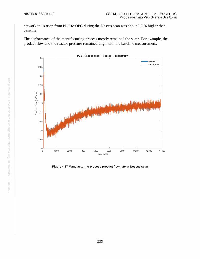
NISTIR 8183A VOL. 2 CSF MFG PROFILE LOW IMPACT LEVEL EXAMPLE IG PROCESS-BASED MFG SYSTEM USE CASE
239
Th
is p
ublic
atio
n is
ava
ilable
free
of c
ha
rge
from
: http
s://d
oi.o
rg/1
0.6
02
8/N
IST
.IR.8
18
3A
-2
network utilization from PLC to OPC during the Nessus scan was about 2.2 % higher than
baseline.
The performance of the manufacturing process mostly remained the same. For example, the
product flow and the reactor pressure remained align with the baseline measurement.
Figure 4-27 Manufacturing process product flow rate at Nessus scan

NISTIR 8183A VOL. 2 CSF MFG PROFILE LOW IMPACT LEVEL EXAMPLE IG PROCESS-BASED MFG SYSTEM USE CASE
240
Th
is p
ublic
atio
n is
ava
ilable
free
of c
ha
rge
from
: http
s://d
oi.o
rg/1
0.6
02
8/N
IST
.IR.8
18
3A
-2
Figure 4-28 Manufacturing process reactor pressure at Nessus scan
Links to Entire Performance Measurement Data Set
• Nessus KPI data
• Nessus measurement data

NISTIR 8183A VOL. 2 CSF MFG PROFILE LOW IMPACT LEVEL EXAMPLE IG PROCESS-BASED MFG SYSTEM USE CASE
241
Th
is p
ublic
atio
n is
ava
ilable
free
of c
ha
rge
from
: http
s://d
oi.o
rg/1
0.6
02
8/N
IST
.IR.8
18
3A
-2
NamicSoft
Technical Solution Overview
NamicSoft Scan Report Assistant is a parser and reporting tool for Nessus, Burp, Nexpose
OpenVAS and NCATS.102
Technical Capabilities Provided by Solution
NamicSoft provides components of the following Technical Capabilities described in Section 6
of Volume 1:
• Vulnerability Management
Subcategories Addressed by Implementing Solution
ID.RA-1, DE.CM-4, RS.MI-3
102 https://www.namicsoft.com/

NISTIR 8183A VOL. 2 CSF MFG PROFILE LOW IMPACT LEVEL EXAMPLE IG PROCESS-BASED MFG SYSTEM USE CASE
242
Th
is p
ublic
atio
n is
ava
ilable
free
of c
ha
rge
from
: http
s://d
oi.o
rg/1
0.6
02
8/N
IST
.IR.8
18
3A
-2
Architecture Map of Where Solution was Implemented

NISTIR 8183A VOL. 2 CSF MFG PROFILE LOW IMPACT LEVEL EXAMPLE IG PROCESS-BASED MFG SYSTEM USE CASE
243
Th
is p
ublic
atio
n is
ava
ilable
free
of c
ha
rge
from
: http
s://d
oi.o
rg/1
0.6
02
8/N
IST
.IR.8
18
3A
-2
Installation Instructions and Configurations
Details of the solutions implemented:
Name Version
NamicSoft Scan Report
Assistant
3.5.0
4.12.5.1 Environment setup
1. NamicSoft was installed on our Nessus Scanner server as described in Section 4.11.
2. The guest OS IP information of this server was set as follows:
IP address: 10.100.0.25
Gateway: 10.100.0.1
Subnet Mask: 255.255.255.0
DNS:10.100.0.17
4.12.5.2 Setup Instructions
1. Download NamicSoft103
2. Run the installer on a Windows PC. NamicSoft is currently supported on 64-bit Windows
with .Net Framework 4.5 installed
3. Launch the program by double clicking its Desktop icon. If using for the first time, the
installation will prompt for a license file. If a license is not entered, it runs in free mode.
The free mode is limited to five hosts.
Note: The software is tied to a Windows user account. Any changes made by a user would not be
visible to a different user logging in to the same system.
4.12.5.3 Configuration for reporting Nessus scans
1. Export a Scan Report of Nessus format from the Nessus web interface.
2. Launch NamicSoft Report Assistant. Click Import on left-side explorer, select Nessus
103 https://www.namicsoft.com

NISTIR 8183A VOL. 2 CSF MFG PROFILE LOW IMPACT LEVEL EXAMPLE IG PROCESS-BASED MFG SYSTEM USE CASE
244
Th
is p
ublic
atio
n is
ava
ilable
free
of c
ha
rge
from
: http
s://d
oi.o
rg/1
0.6
02
8/N
IST
.IR.8
18
3A
-2
3. Click on Choose button to import files
4. Browse to the Nessus scan report. Under Import Vulnerabilities with following
vulnerabilities, Check / Uncheck whichever severity of vulnerabilities you wish to be
included in the report and click Import.
For instance, the image below shows Informational types being excluded and other
severity levels such as High, Critical, Medium Low being selected. When the Import
finishes, the Status bar should display All files read.
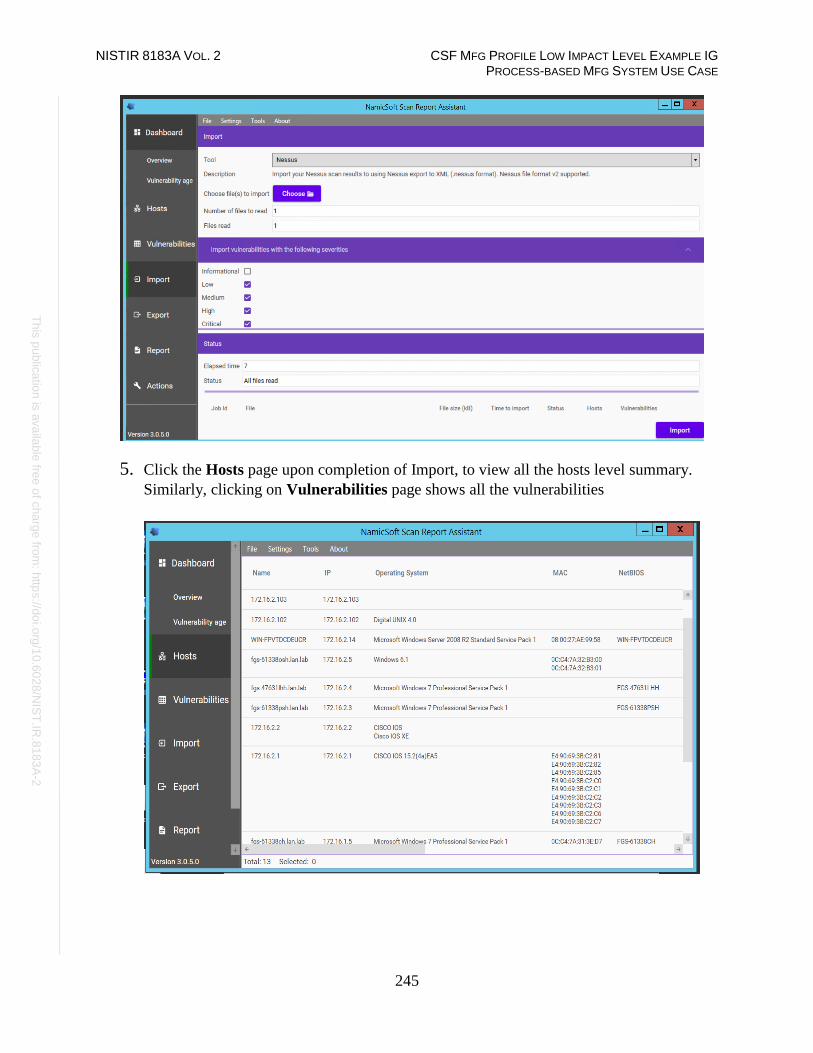
NISTIR 8183A VOL. 2 CSF MFG PROFILE LOW IMPACT LEVEL EXAMPLE IG PROCESS-BASED MFG SYSTEM USE CASE
245
Th
is p
ublic
atio
n is
ava
ilable
free
of c
ha
rge
from
: http
s://d
oi.o
rg/1
0.6
02
8/N
IST
.IR.8
18
3A
-2
5. Click the Hosts page upon completion of Import, to view all the hosts level summary.
Similarly, clicking on Vulnerabilities page shows all the vulnerabilities

NISTIR 8183A VOL. 2 CSF MFG PROFILE LOW IMPACT LEVEL EXAMPLE IG PROCESS-BASED MFG SYSTEM USE CASE
246
Th
is p
ublic
atio
n is
ava
ilable
free
of c
ha
rge
from
: http
s://d
oi.o
rg/1
0.6
02
8/N
IST
.IR.8
18
3A
-2
6. (Optional) Mark a Vulnerability as Fixed by selecting the Vulnerability > Right Click >
Vulnerability Fixed.
7. Click on Save Workspace under Actions. Ensure to Save your workspace after every
change made. When running NamicSoft the next time, you can load this saved workspace
file.

NISTIR 8183A VOL. 2 CSF MFG PROFILE LOW IMPACT LEVEL EXAMPLE IG PROCESS-BASED MFG SYSTEM USE CASE
247
Th
is p
ublic
atio
n is
ava
ilable
free
of c
ha
rge
from
: http
s://d
oi.o
rg/1
0.6
02
8/N
IST
.IR.8
18
3A
-2
8. Click on Report as shown below to generate a report. Select one of the default reporting
templates from the list or create a custom one. To use a default template, select one from
the list >> Create Report.
9. Click Open Report to view the Report.

NISTIR 8183A VOL. 2 CSF MFG PROFILE LOW IMPACT LEVEL EXAMPLE IG PROCESS-BASED MFG SYSTEM USE CASE
248
Th
is p
ublic
atio
n is
ava
ilable
free
of c
ha
rge
from
: http
s://d
oi.o
rg/1
0.6
02
8/N
IST
.IR.8
18
3A
-2
4.12.5.4 Creating Custom Template
1. Copy one of the existing template files located under C:\Program Files(x86)\NamicSoft
Scan Report Assistant\templates and save it to a different folder. 2. Open the copied file in MS Word to begin editing. The image below shows a customized
template file created for Process Control System. This report generates a summary of
hosts and their respective vulnerabilities based on the Severity level.
Custom reports104 can also be created.
3. Save your changes and give the file a name.
4. Copy this file back to the templates directory on the NamicSoft machine. For instance,
the image below shows our customized file – PCS- Host Summary copied back to the
templates folder.
104 https://www.namicsoft.com/doc/content-controls/

NISTIR 8183A VOL. 2 CSF MFG PROFILE LOW IMPACT LEVEL EXAMPLE IG PROCESS-BASED MFG SYSTEM USE CASE
249
Th
is p
ublic
atio
n is
ava
ilable
free
of c
ha
rge
from
: http
s://d
oi.o
rg/1
0.6
02
8/N
IST
.IR.8
18
3A
-2
5. Launch NamicSoft again. The custom report should now appear under the list. Select it
and click on Create Report.

NISTIR 8183A VOL. 2 CSF MFG PROFILE LOW IMPACT LEVEL EXAMPLE IG PROCESS-BASED MFG SYSTEM USE CASE
250
Th
is p
ublic
atio
n is
ava
ilable
free
of c
ha
rge
from
: http
s://d
oi.o
rg/1
0.6
02
8/N
IST
.IR.8
18
3A
-2
6. Review the output to confirm your changes.
7. (Optional) Use the Compare Workspaces feature under Action Menu to report on
Vulnerabilities remediated based off the previous vulnerability scans as follows
a. Load Nessus result from your previous scan. Save as a workspace.
b. Clear the workspace in the GUI (or restart NamicSoft)
c. Load Nessus results from the latest scan
d. Open Actions > Compare workspaces. Choose Compare with current workspace
and point Workspace 2 to your workspace saved earlier.
e. Choose Excel output file (target)
f. Click Compare Workspaces
Highlighted Performance Impacts
No performance measurement experiments were performed for the use of NamicSoft due to its
installation location and how it was used (i.e., the software performed offline analysis of
vulnerability data captured by other software at a location external to the manufacturing system).
Links to Entire Performance Measurement Data Set
N/A

NISTIR 8183A VOL. 2 CSF MFG PROFILE LOW IMPACT LEVEL EXAMPLE IG PROCESS-BASED MFG SYSTEM USE CASE
251
Th
is p
ublic
atio
n is
ava
ilable
free
of c
ha
rge
from
: http
s://d
oi.o
rg/1
0.6
02
8/N
IST
.IR.8
18
3A
-2
The Hive Project
Technical Solution Overview
A scalable, open source and free Security Incident Response Platform.105
Technical Capabilities Provided by Solution
The Hive Project provides components of the following Technical Capabilities described in
Section 6 of Volume 1:
• Incident Management
Subcategories Addressed by Implementing Solution
RS.MI-2, RS.MI-3
105 https://thehive-project.org/

NISTIR 8183A VOL. 2 CSF MFG PROFILE LOW IMPACT LEVEL EXAMPLE IG PROCESS-BASED MFG SYSTEM USE CASE
252
Th
is p
ublic
atio
n is
ava
ilable
free
of c
ha
rge
from
: http
s://d
oi.o
rg/1
0.6
02
8/N
IST
.IR.8
18
3A
-2
Architecture Map of Where Solution was Implemented

NISTIR 8183A VOL. 2 CSF MFG PROFILE LOW IMPACT LEVEL EXAMPLE IG PROCESS-BASED MFG SYSTEM USE CASE
253
Th
is p
ublic
atio
n is
ava
ilable
free
of c
ha
rge
from
: http
s://d
oi.o
rg/1
0.6
02
8/N
IST
.IR.8
18
3A
-2
Installation Instructions and Configurations
Details of the solution implemented:
Name Version Hardware Details
TheHive 3.0.10 Hyper-V Virtual Machine
• Processors: 2 virtual cores
• Memory: 4 GB
• Disk space: 50 GB
• Network: 1 interface
• Operating System: Ubuntu 16.04
4.13.5.1 Environment Setup
1. A preconfigured training VM as provided by the Vendor was deployed on Hyper-V host
server with the hardware specifications as described above.
2. The guest OS IP information was set as follows:
IP address: 10.100.0.51
Gateway: 10.100.0.1
Subnet Mask: 255.255.255.0
DNS:10.100.0.17
4.13.5.2 Setup Instructions
1. Download the software106
2. Install the binaries on a supported version of Linux.107
3. Complete the setup process as per the instructions. Once done, TheHive can be accessed
from http://<ip-address_of_hive_server>:9000
106 https://github.com/TheHive-Project/TheHive 107 https://github.com/TheHive-Project/TheHiveDocs/blob/master/installation/install-guide.md

NISTIR 8183A VOL. 2 CSF MFG PROFILE LOW IMPACT LEVEL EXAMPLE IG PROCESS-BASED MFG SYSTEM USE CASE
254
Th
is p
ublic
atio
n is
ava
ilable
free
of c
ha
rge
from
: http
s://d
oi.o
rg/1
0.6
02
8/N
IST
.IR.8
18
3A
-2
4.13.5.3 Additional Setup via Web Browser
1. Create the associated database if accessing TheHive for the first time, by clicking on
the Update Database button as shown below:
2. Follow the wizard to setup a user account.
3. Login to TheHive URL with these credentials. The default page will show you a List of
Cases assigned to your account. There will be none initially for a new setup.

NISTIR 8183A VOL. 2 CSF MFG PROFILE LOW IMPACT LEVEL EXAMPLE IG PROCESS-BASED MFG SYSTEM USE CASE
255
Th
is p
ublic
atio
n is
ava
ilable
free
of c
ha
rge
from
: http
s://d
oi.o
rg/1
0.6
02
8/N
IST
.IR.8
18
3A
-2
4. Click on Admin > Users > User Management page, to create Additional user accounts.
Click on +Add User to create a new user.
5. Create a new Incident / case as follows:
a. Click on the New Case menu option
b. Fill in all the details.
c. Click on Add Task to add a task under a case. Each task can be individually
assigned to an analyst for the work to be performed. By default, a task doesn’t
have an owner until someone clicks into it, or “takes” it from the Waiting tasks
queue in the top menu bar.
d. Hit Create Case button when done.

NISTIR 8183A VOL. 2 CSF MFG PROFILE LOW IMPACT LEVEL EXAMPLE IG PROCESS-BASED MFG SYSTEM USE CASE
256
Th
is p
ublic
atio
n is
ava
ilable
free
of c
ha
rge
from
: http
s://d
oi.o
rg/1
0.6
02
8/N
IST
.IR.8
18
3A
-2
6. Create a Custom Case Template as follows:
a. Click on Admin > Case Templates button on top right-hand corner
b. Click +New Case Template
c. Fill out the information in the fields.
d. Click Save Case Template
7. (Optional) Open up a Case and click on Observables tab > +Add Observables to add
Custom Observables such as domain names, IP addresses, files, filenames etc. to a case.
In addition, observables can also be marked as Indicators of Compromise (IOC).

NISTIR 8183A VOL. 2 CSF MFG PROFILE LOW IMPACT LEVEL EXAMPLE IG PROCESS-BASED MFG SYSTEM USE CASE
257
Th
is p
ublic
atio
n is
ava
ilable
free
of c
ha
rge
from
: http
s://d
oi.o
rg/1
0.6
02
8/N
IST
.IR.8
18
3A
-2
8. (Optional) Use the Cortex engine108 via http://<ip_of_hive_server>:9001 to perform
detailed analysis on observables or IOCs such as domain names, IP addresses, hashes.
This can be achieved by enabling or creating Analyzers in Cortex.
The high-level steps in configuring Cortex are:
a. Setup Cortex
b. Create an Administrator account
c. Create an Organization
d. Create an Organization Administrator account
e. Enable or Configure Analyzers
f. Integrate with the Hive instance
108 https://github.com/TheHive- Project/CortexDocs

NISTIR 8183A VOL. 2 CSF MFG PROFILE LOW IMPACT LEVEL EXAMPLE IG PROCESS-BASED MFG SYSTEM USE CASE
258
Th
is p
ublic
atio
n is
ava
ilable
free
of c
ha
rge
from
: http
s://d
oi.o
rg/1
0.6
02
8/N
IST
.IR.8
18
3A
-2
4.13.5.4 Integration with Security Onion
Our Security Onion instance was integrated with the Hive Instance to create a case for IDS alerts
generated by Security Onion.
1. Create a dedicated user account in Hive with permissions to Allow alerts creation.
Ensure Roles: None is set for security purposes of this user account.
2. Click on Create API Key to create an API key for this user

NISTIR 8183A VOL. 2 CSF MFG PROFILE LOW IMPACT LEVEL EXAMPLE IG PROCESS-BASED MFG SYSTEM USE CASE
259
Th
is p
ublic
atio
n is
ava
ilable
free
of c
ha
rge
from
: http
s://d
oi.o
rg/1
0.6
02
8/N
IST
.IR.8
18
3A
-2
3. (To be performed on the Security Onion server) Create a new rules file hive.yaml under
the /etc./elastalert/rules directory of the Security Onion server mentioning the IP address
of the Hive Server as shown below.109
Highlighted Performance Impacts
No performance measurement experiments were performed for the use of the Hive Project due to
its typical installation and usage location (i.e., external to the manufacturing system).
Links to Entire Performance Measurement Data Set
N/A
109 https://securityonion.readthedocs.io/en/latest/hive.html#thehive.

NISTIR 8183A VOL. 2 CSF MFG PROFILE LOW IMPACT LEVEL EXAMPLE IG PROCESS-BASED MFG SYSTEM USE CASE
260
Th
is p
ublic
atio
n is
ava
ilable
free
of c
ha
rge
from
: http
s://d
oi.o
rg/1
0.6
02
8/N
IST
.IR.8
18
3A
-2
Microsoft EFS
Technical Solution Overview
EFS is a file level encryption tool provided by Windows. The Encrypted File System, or EFS,
provides an additional level of security for files and directories. It provides cryptographic
protection of individual files on NTFS file system volumes using a public-key system.110
Technical Capabilities Provided by Solution
Microsoft EFS provides components of the following Technical Capabilities described in Section
6 of Volume 1:
• Encryption
Subcategories Addressed by Implementing Solution
PR.DS-5
110 https://docs.microsoft.com/en-us/windows/desktop/fileio/file-encryption

NISTIR 8183A VOL. 2 CSF MFG PROFILE LOW IMPACT LEVEL EXAMPLE IG PROCESS-BASED MFG SYSTEM USE CASE
261
Th
is p
ublic
atio
n is
ava
ilable
free
of c
ha
rge
from
: http
s://d
oi.o
rg/1
0.6
02
8/N
IST
.IR.8
18
3A
-2
Architecture Map of Where Solution was Implemented

NISTIR 8183A VOL. 2 CSF MFG PROFILE LOW IMPACT LEVEL EXAMPLE IG PROCESS-BASED MFG SYSTEM USE CASE
262
Th
is p
ublic
atio
n is
ava
ilable
free
of c
ha
rge
from
: http
s://d
oi.o
rg/1
0.6
02
8/N
IST
.IR.8
18
3A
-2
Installation Instructions and Configurations
4.14.5.1 Environment Setup
Windows EFS was used to encrypt sensitive folders on the Engineering workstation of the plant.
Hostname IP Address OS
Engineering
Workstation
172.16.3.10 Windows 7
Professional 64bit
4.14.5.2 Instructions for Encryption
1. Select a parent folder to encrypt. Right Click Folder Name > Properties > General
Tab > Advanced

NISTIR 8183A VOL. 2 CSF MFG PROFILE LOW IMPACT LEVEL EXAMPLE IG PROCESS-BASED MFG SYSTEM USE CASE
263
Th
is p
ublic
atio
n is
ava
ilable
free
of c
ha
rge
from
: http
s://d
oi.o
rg/1
0.6
02
8/N
IST
.IR.8
18
3A
-2
2. Choose the option Apply changes to folder, subfolders and files. Click OK.
3. Click Apply. This will begin the encryption process.
4. Confirm by checking if the folders have turned green upon completion of the
encryption as shown below. Any new folder added to this parent folder will be
automatically encrypted.
5. Backup the Encryption Key using the following steps,
a. Double click the pop-up message or alternatively, this process can also be
launched manually from Control Panel > All Control Panel Items > User
Accounts > Manage your encryption certificates
Note: This process is different for a Windows 10 system.

NISTIR 8183A VOL. 2 CSF MFG PROFILE LOW IMPACT LEVEL EXAMPLE IG PROCESS-BASED MFG SYSTEM USE CASE
264
Th
is p
ublic
atio
n is
ava
ilable
free
of c
ha
rge
from
: http
s://d
oi.o
rg/1
0.6
02
8/N
IST
.IR.8
18
3A
-2
b. Click Next

NISTIR 8183A VOL. 2 CSF MFG PROFILE LOW IMPACT LEVEL EXAMPLE IG PROCESS-BASED MFG SYSTEM USE CASE
265
Th
is p
ublic
atio
n is
ava
ilable
free
of c
ha
rge
from
: http
s://d
oi.o
rg/1
0.6
02
8/N
IST
.IR.8
18
3A
-2
c. Select existing certificate or Create a new one. It is safe to go with the default
option
d. Select Backup the Certificate and Key Now. Click Browse to choose a destination
for saving the pfx bundle file. For instance: a USB drive. Enter a password for added
protection.
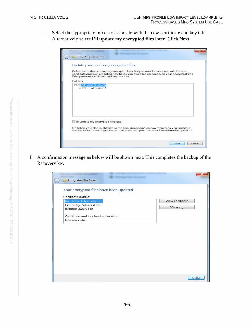
NISTIR 8183A VOL. 2 CSF MFG PROFILE LOW IMPACT LEVEL EXAMPLE IG PROCESS-BASED MFG SYSTEM USE CASE
266
Th
is p
ublic
atio
n is
ava
ilable
free
of c
ha
rge
from
: http
s://d
oi.o
rg/1
0.6
02
8/N
IST
.IR.8
18
3A
-2
e. Select the appropriate folder to associate with the new certificate and key OR
Alternatively select I’ll update my encrypted files later. Click Next
f. A confirmation message as below will be shown next. This completes the backup of the
Recovery key

NISTIR 8183A VOL. 2 CSF MFG PROFILE LOW IMPACT LEVEL EXAMPLE IG PROCESS-BASED MFG SYSTEM USE CASE
267
Th
is p
ublic
atio
n is
ava
ilable
free
of c
ha
rge
from
: http
s://d
oi.o
rg/1
0.6
02
8/N
IST
.IR.8
18
3A
-2
4.14.5.3 Using Encrypted files on a Different Computer
If you want to use your encrypted files on another computer, you need to export the EFS
certificate and key from your computer or the USB backup and then import it at the other
computer.
Highlighted Performance Impacts
The following performance measurement experiment was performed for the Microsoft EFS tool
while the manufacturing system was operational:
Experiment PL013.1- Enable file level encryption on HMI host
The FactoryTalk HMI application has a designated file folder to contain the log files for the HMI
data. EFS tool was used to encrypt the data log file in this experiment.
There were noticeable performance impacts to the computing resources observed when the EFS
was activated for the data log files, especially at the initial operation of the HMI. The processor
utilization was noticeable higher from 450 seconds to 750 seconds experiment time and
occasionally higher throughout the first 3000 seconds. The disk write operation was significantly
higher in the first 800 seconds of the experiment time. The HMI application attempted to access
the data log files at the initialization stage and therefore most of the impacts were observed at the
beginning of the operation.
On the network side, no significant performance impact was observed. The packet round trip
time between the HMI and OPC in both directions reminded mostly constant before and after the
EFS was enabled.

NISTIR 8183A VOL. 2 CSF MFG PROFILE LOW IMPACT LEVEL EXAMPLE IG PROCESS-BASED MFG SYSTEM USE CASE
268
Th
is p
ublic
atio
n is
ava
ilable
free
of c
ha
rge
from
: http
s://d
oi.o
rg/1
0.6
02
8/N
IST
.IR.8
18
3A
-2
Figure 4-29 HMI computer processor utilization with EFS enable (red) and without EFS enable (blue)
Figure 4-30 HMI computer disk write operation with EFS enable (red) and without EFS enable (blue)

NISTIR 8183A VOL. 2 CSF MFG PROFILE LOW IMPACT LEVEL EXAMPLE IG PROCESS-BASED MFG SYSTEM USE CASE
269
Th
is p
ublic
atio
n is
ava
ilable
free
of c
ha
rge
from
: http
s://d
oi.o
rg/1
0.6
02
8/N
IST
.IR.8
18
3A
-2
Figure 4-31 Packet round trip time from HMI to OPC with EFS enable (red) and without EFS enable (blue)
Figure 4-32 Packet round trip time from OPC to HMI with EFS enable (red) and without EFS enable (blue)
The HMI application was not able to access the data log files and new data from operation was
not logged. The HMI flagged an error/warning message to the operator.
Care should be taken for encrypting application specific files or folders. There is performance
impact to the manufacturing process in the form of losing the ability to log data files in the HMI.

NISTIR 8183A VOL. 2 CSF MFG PROFILE LOW IMPACT LEVEL EXAMPLE IG PROCESS-BASED MFG SYSTEM USE CASE
270
Th
is p
ublic
atio
n is
ava
ilable
free
of c
ha
rge
from
: http
s://d
oi.o
rg/1
0.6
02
8/N
IST
.IR.8
18
3A
-2
Figure 4-33 HMI screen with warning message “Unable to access data log set files”
Links to Entire Performance Measurement Data Set
• File Encryption KPI data
• File Encryption measurement data
NISTIR 8183A VOL. 2 CSF MFG PROFILE LOW IMPACT LEVEL EXAMPLE IG PROCESS-BASED MFG SYSTEM USE CASE
271
Th
is p
ublic
atio
n is
ava
ilable
free
of c
ha
rge
from
: http
s://d
oi.o
rg/1
0.6
02
8/N
IST
.IR.8
18
3A
-2
GTB Inspector
Technical Solution Overview
GTB Inspector by GTB Technologies is a Data Loss Prevention (DLP) solution that has the
ability to detect, log, and block network traffic trying to leave the network. Inspector detects and
blocks FTP, Email, HTTP, HTTPS (SSL/TLS), Finger Printed files, USB protection, and other
configured exfiltration methods. Inspector is the main component that analyzes all network
traffic. GTB Central Console is the device Inspector reports back to. Central Console allows for
groups and escalation paths depending on the alerting required.
Points to consider:
• All DLP products have a high cost to implement.
• All DLP products require configuration that can be extensive.
Technical Capabilities Provided by Solution
GTB Inspector provides components of the following Technical Capabilities described in
Section 6 of Volume 1:
• Data Loss Prevention
Subcategories Addressed by Implementing Solution
PR.DS-5

NISTIR 8183A VOL. 2 CSF MFG PROFILE LOW IMPACT LEVEL EXAMPLE IG PROCESS-BASED MFG SYSTEM USE CASE
272
Th
is p
ublic
atio
n is
ava
ilable
free
of c
ha
rge
from
: http
s://d
oi.o
rg/1
0.6
02
8/N
IST
.IR.8
18
3A
-2
Architecture Map of Where Solution was Implemented

NISTIR 8183A VOL. 2 CSF MFG PROFILE LOW IMPACT LEVEL EXAMPLE IG PROCESS-BASED MFG SYSTEM USE CASE
273
Th
is p
ublic
atio
n is
ava
ilable
free
of c
ha
rge
from
: http
s://d
oi.o
rg/1
0.6
02
8/N
IST
.IR.8
18
3A
-2
Installation Instructions and Configurations
Details of the solutions implemented:
Name Version Purpose Hardware Details
GTB
Inspector
15.6.0 Network DLP Hyper-V Virtual Machine (Generation 1):
• Processors: 2 virtual cores
• Memory: 6 GB
• Disk space: 20 to 30GB (As per the
Virtual Appliance file provided by
the vendor)
• Network: 3 network adapters
• OS: CentOS Linux 7 Core
GTB
Central
Console
15.6.0 Central
Reporting and
Management
for all GTB
products
Hyper-V Virtual Machine (Generation 1):
• Processors: 2 virtual cores
• Memory: 6 GB
• Disk space: 20 to 30GB (As per the
Virtual Appliance file provided by
the vendor)
• Network: 1 network adapter
• OS: CentOS Linux 7 Core
4.15.5.1 Environment Setup
1. Two virtual machines were setup in the Cybersecurity LAN network of the plant, using
the ISO image provided by the vendor. Their hardware specifications are described in the
table above.
2. The GTB Inspector server was deployed in Bridge [Inline] mode as per the official
diagram provided by the vendor which is shown below. For additional details, refer to the
official install guide.

NISTIR 8183A VOL. 2 CSF MFG PROFILE LOW IMPACT LEVEL EXAMPLE IG PROCESS-BASED MFG SYSTEM USE CASE
274
Th
is p
ublic
atio
n is
ava
ilable
free
of c
ha
rge
from
: http
s://d
oi.o
rg/1
0.6
02
8/N
IST
.IR.8
18
3A
-2
3. The guest OS networking information on the VM’s was set as follows:
Virtual Machine: GTB-Inspector
Network interface:eth0
IP address: 10.100.0.175
Gateway: 10.100.0.1
Subnet Mask: 255.255.255.0
DNS:10.100.0.17
Network interface:eth2->connected to Monitor Port1 of a Network Aggregator device
Network interface:eth3->connected to WAN interface of our Cisco-ASA firewall.
Virtual Machine: GTB-Central
Network interface:eth0
IP address: 10.100.0.176
Gateway: 10.100.0.1
Subnet Mask: 255.255.255.0
DNS:10.100.0.17
4.15.5.2 Setting up the GTB Central console
1. Download the ISO file of GTB Central Console and install guides111
2. Setup the virtual machine by booting off the ISO on your preferred Hypervisor.
3. Perform initial configuration such as creating a DNS record, assigning a Static IP
address to the server, etc.
4. Login to the Central Console Web UI using the default credentials. Click
Administration > Licensing to upload the license file. Restart once done.
5. Click DLP Setup tab > Network to enter the IP address settings.
6. Click DLP Setup tab > LDAP to configure AD server details.
7. Click DLP Setup tab > Email & Alerts. to configure smtp server settings.
8. Click DLP Setup tab > Date & Time > Enter NTP Server details.
9. Click DLP Setup tab > SIEM > Enter the IP address of Syslog / SIEM server
4.15.5.3 Setting up the GTB Inspector
7. Download the ISO file of GTB Inspector and install guides112
8. Setup the virtual machine using the ISO files on your preferred Hypervisor.
9. Perform initial configuration such as creating DNS records, assigning Static IP address,
setting up the LAN and WAN interfaces for the Inspector server, etc. For detailed
instructions, refer to the GTB product install guides.
10. Login to the Inspector server Web UI using the default credentials as provided. Click
Administration > Licensing to upload the license file. Restart once done.
11. Click Configuration tab > Email Alerts. to configure smtp server settings.
111 https://gttb.com/downloads/ 112 https://gttb.com/downloads/

NISTIR 8183A VOL. 2 CSF MFG PROFILE LOW IMPACT LEVEL EXAMPLE IG PROCESS-BASED MFG SYSTEM USE CASE
275
Th
is p
ublic
atio
n is
ava
ilable
free
of c
ha
rge
from
: http
s://d
oi.o
rg/1
0.6
02
8/N
IST
.IR.8
18
3A
-2
12. Click Configuration tab > LDAP Integration, to configure Active Directory server
details.
13. Click Configuration tab > Network > Set the Deployment Mode as required.
14. Click Configuration tab > SIEM > Enter the IP address of Syslog / SIEM server.
15. Click Configuration tab > SSL Proxy > Upload a Public Certificate (if any) for SSL
decryption.
16. Click Configuration tab > Central Console > Enter the hostname of the GTB Central
server. Ensure the inspector can reach the Central console.
4.15.5.4 Creating ACL Rules on the Central Console
1. Login to the Central Console Web UI. Click DLP-Setup > Network DLP
2. Click on the <Inspector server name> listed under Categories.
3. Click Add button. The Add New ACL Rule window should pop-up
4. Enter the information as required under Name, Protocol, Source, Destination, File
Type.
Selecting Protocol = Any will enable the Inspector to inspect all protocols.
Note: This may cause a performance impact depending on the number of clients within
your organization.
5. Click Add under Enforcement to configure Policy/Sets. Select from any of the default
policies for Credit Card Numbers (CCN), Social Security etc., or create a new one.
6. Select the action to be taken – Log, Block, S-Block and Pass.
7. Check mark the File Capture option to retain a copy of the offending data.
8. Click Save.
9. Click Deploy-All. This sends newly created policy to the Inspector.
10. (Optional) Order rules if more than one by clicking the UP / DOWN arrows. Rules
always work from Top to down.
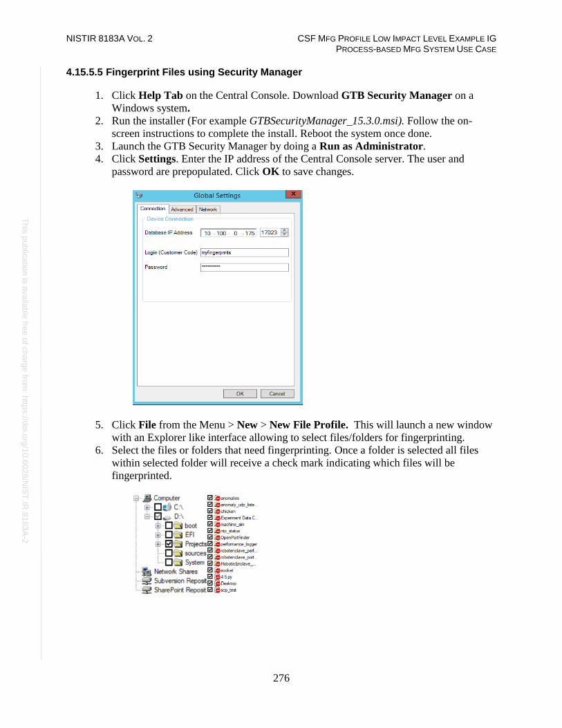
NISTIR 8183A VOL. 2 CSF MFG PROFILE LOW IMPACT LEVEL EXAMPLE IG PROCESS-BASED MFG SYSTEM USE CASE
276
Th
is p
ublic
atio
n is
ava
ilable
free
of c
ha
rge
from
: http
s://d
oi.o
rg/1
0.6
02
8/N
IST
.IR.8
18
3A
-2
4.15.5.5 Fingerprint Files using Security Manager
1. Click Help Tab on the Central Console. Download GTB Security Manager on a
Windows system.
2. Run the installer (For example GTBSecurityManager_15.3.0.msi). Follow the on-
screen instructions to complete the install. Reboot the system once done.
3. Launch the GTB Security Manager by doing a Run as Administrator.
4. Click Settings. Enter the IP address of the Central Console server. The user and
password are prepopulated. Click OK to save changes.
5. Click File from the Menu > New > New File Profile. This will launch a new window
with an Explorer like interface allowing to select files/folders for fingerprinting.
6. Select the files or folders that need fingerprinting. Once a folder is selected all files
within selected folder will receive a check mark indicating which files will be
fingerprinted.
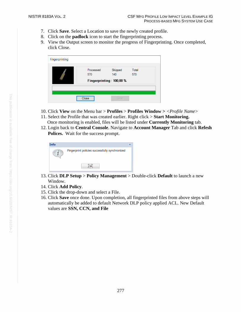
NISTIR 8183A VOL. 2 CSF MFG PROFILE LOW IMPACT LEVEL EXAMPLE IG PROCESS-BASED MFG SYSTEM USE CASE
277
Th
is p
ublic
atio
n is
ava
ilable
free
of c
ha
rge
from
: http
s://d
oi.o
rg/1
0.6
02
8/N
IST
.IR.8
18
3A
-2
7. Click Save. Select a Location to save the newly created profile.
8. Click on the padlock icon to start the fingerprinting process.
9. View the Output screen to monitor the progress of Fingerprinting. Once completed,
click Close.
10. Click View on the Menu bar > Profiles > Profiles Window > <Profile Name>
11. Select the Profile that was created earlier. Right click > Start Monitoring.
Once monitoring is enabled, files will be listed under Currently Monitoring tab.
12. Login back to Central Console. Navigate to Account Manager Tab and click Refesh
Polices. Wait for the success prompt.
13. Click DLP Setup > Policy Management > Double-click Default to launch a new
Window.
14. Click Add Policy.
15. Click the drop-down and select a File.
16. Click Save once done. Upon completion, all fingerprinted files from above steps will
automatically be added to default Network DLP policy applied ACL. New Default
values are SSN, CCN, and File

NISTIR 8183A VOL. 2 CSF MFG PROFILE LOW IMPACT LEVEL EXAMPLE IG PROCESS-BASED MFG SYSTEM USE CASE
278
Th
is p
ublic
atio
n is
ava
ilable
free
of c
ha
rge
from
: http
s://d
oi.o
rg/1
0.6
02
8/N
IST
.IR.8
18
3A
-2
Additional Information on Fingerprinting:
• Fingerprint feature only allows for one active Profile at a time. If another profile is
set to Start Monitoring, a warning message as shown below will be generated
• Install GTB Security Manager on a machine that can be the central repositoiry for
all fingerprinted files. Creating a large folder were the files can placed into for
fingerprinting. Files need not remain in saved location once the profile has been
fingerprinted and uploaded to Central Console. Access to fingerprinted files is only
required when changes are made to profile containing said files.
• Fingerprinted files follow acl rules created within Central Console. Rules are
processed in order from top to bottom. The first rule with a matching violation takes
precedence over rules below.
Highlighted Performance Impacts
No performance measurement experiments were performed for the installation of GTB into the
PCS due to its location within the network topology. No manufacturing process components
across the boundary on a regular basis while the system is operational.
Links to Entire Performance Measurement Data Set
N/A

NISTIR 8183A VOL. 2 CSF MFG PROFILE LOW IMPACT LEVEL EXAMPLE IG PROCESS-BASED MFG SYSTEM USE CASE
279
Th
is p
ublic
atio
n is
ava
ilable
free
of c
ha
rge
from
: http
s://d
oi.o
rg/1
0.6
02
8/N
IST
.IR.8
18
3A
-2
Graylog
Technical Solution Overview
Graylog is an open source log management tool. It can collect, parse and enrich logs, wire data,
and event data from any data source. Graylog also provides centralized configuration
management for 3rd party collectors such as beats, fluentd and nxlog. The processing pipelines
allow for greater flexibility in routing, blacklisting, modifying and enriching messages in real-
time as they enter Graylog. It has a powerful search syntax to help query exactly what we are
looking for. With Graylog one can even create dashboards to visualize metrics and observe
trends in one central location.113
Points to consider:
• Open source product with good community support
• Easy to setup and customize. Support log collection from any OS platform.
• It is packaged for major Linux distributions, has a VM ready for use and Docker images are
also available.
• The dashboard part, even if though well integrated and useful, lacks many features and
visualizations contained in other elastic search tools such as Kibana (like aggregations).
Technical Capabilities Provided by Solution
Graylog provides components of the following Technical Capabilities described in Section 6 of
Volume 1:
• Network Monitoring
• Event Logging
• Forensics
Subcategories Addressed by Implementing Solution
PR.DS-5, PR.MA-2, PR.PT-1, PR.PT-4, DE.AE-2, DE.AE-3, DE.CM-1, DE.CM-6, DE.CM-7,
DE.DP-3, RS.AN-3
113 http://docs.graylog.org/en/3.0/

NISTIR 8183A VOL. 2 CSF MFG PROFILE LOW IMPACT LEVEL EXAMPLE IG PROCESS-BASED MFG SYSTEM USE CASE
280
Th
is p
ublic
atio
n is
ava
ilable
free
of c
ha
rge
from
: http
s://d
oi.o
rg/1
0.6
02
8/N
IST
.IR.8
18
3A
-2
Architecture Map of Where Solution was Implemented

NISTIR 8183A VOL. 2 CSF MFG PROFILE LOW IMPACT LEVEL EXAMPLE IG PROCESS-BASED MFG SYSTEM USE CASE
281
Th
is p
ublic
atio
n is
ava
ilable
free
of c
ha
rge
from
: http
s://d
oi.o
rg/1
0.6
02
8/N
IST
.IR.8
18
3A
-2
Installation Instructions and Configurations
Details of the solution implemented:
Name Version Hardware Details
Graylog
Enterprise
2.4.6 Hyper-V Virtual Machine (Generation 1):
• Processors: 2 virtual cores
• Memory: 6 GB
• Disk space: 400 GB Total
(i) Root volume as allocated by the Virtual
Appliance file provided by the vendor.
(ii) 350+ GB Data volume for log storage
• Network: 1 network adapter
• OS: Ubuntu 14
4.16.5.1 Environment Setup
1. A preconfigured virtual machine (.ova) provided by the vendor was setup on a Hyper-V
host server of the Cybersecurity LAN network of the plant with hardware specifications
as described in the table above.
2. The guest OS IP information of this server was set as follows:
IP address: 10.100.0.14
Gateway: 10.100.0.1
Subnet Mask: 255.255.255.0
DNS:10.100.0.17
3. UDP ports 514, 5415 and 1202 were opened on the firewall as required by Graylog to
collect syslog messages from the clients. For more information, visit
http://docs.graylog.org/en/3.0/
4.16.5.2 Initial Setup
1. Download the installation package as per the Operating system from the Graylog
website.114
Note: Graylog provides a preconfigured VM for use in test/training environments.
2. Assign a static IP address to the Linux system (if not already).
3. Install the package using the instructions mentioned in the Graylog documentation.115
4. Login to the Web Interface using the default credentials and change the admin password.
5. Configure Active Directory integration as follows
a. Click on System > Authentication on the Top menu.
114 https://www.graylog.org 115 http://docs.graylog.org/en/3.0/pages/installation/operating_system_packages.html

NISTIR 8183A VOL. 2 CSF MFG PROFILE LOW IMPACT LEVEL EXAMPLE IG PROCESS-BASED MFG SYSTEM USE CASE
282
Th
is p
ublic
atio
n is
ava
ilable
free
of c
ha
rge
from
: http
s://d
oi.o
rg/1
0.6
02
8/N
IST
.IR.8
18
3A
-2
b. Click on LDAP / Active Directory on the Authentication Management page and
enter the AD server details. Refer to the Graylog docs for detailed instructions.
c. Click on LDAP Group Mapping to configure Group Mapping options to
control the type of access to be assigned to the users. Change the Default User
Role depending on your requirement.
4.16.5.3 Receiving Syslog from Windows Servers
NXlog116 was used as the log shipping utility to forward events from all Windows systems of the
plant to our Graylog server. The community edition of NXlog is free to use.
1. Download and install NXlog on the Windows hosts in question.
2. Edit the nxlog.conf file located at C:\Program Files (x86)\nxlog\conf directory as per
whichever category of events you would like to forward to your Graylog server.117
For reference, the following event IDs were configured for forwarding from the Engineering
Workstation of the plant:
• Event ID 1074 from System category to notify us when system gets rebooted
• Event ID 1034 from Application category
• Event ID 4625 from Security category
• Event ID 4689 from Security category and ProcessName=C:\Program
Files\..\Rockwell\Rsvsc.host.exe to notify us when the process for Rockwell Automation
software stops.
• All events [*] from Microsoft-Windows-TerminalServices-LocalSessionManager
category to notify us when a user logs in or logs out of the system.
• Event ID 190 from Veeam category to notify us for backup completion messages
• Event ID 1001 from FTDiag category which is a custom event ID generated by Factory
Talk Administration Software where there is an authentication failure.
116 https://nxlog.co/ 117 https://nxlog.co/documentation/nxlog-user-guide/

NISTIR 8183A VOL. 2 CSF MFG PROFILE LOW IMPACT LEVEL EXAMPLE IG PROCESS-BASED MFG SYSTEM USE CASE
283
Th
is p
ublic
atio
n is
ava
ilable
free
of c
ha
rge
from
: http
s://d
oi.o
rg/1
0.6
02
8/N
IST
.IR.8
18
3A
-2
The figure below shows the nxlog.conf file with the above configuration.
3. Save nxlog.conf and restart the NXLOG windows service. The device will now begin
sending syslog (events) to the Graylog server. If the service fails to start, check the syntax
of your nxlog.conf file for any blank spaces or missing parenthesis. Nxlog.conf file is very
sensitive to proper indentation.
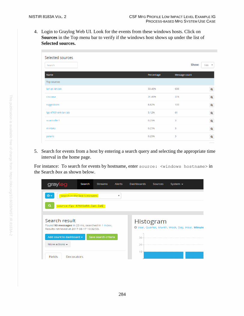
NISTIR 8183A VOL. 2 CSF MFG PROFILE LOW IMPACT LEVEL EXAMPLE IG PROCESS-BASED MFG SYSTEM USE CASE
284
Th
is p
ublic
atio
n is
ava
ilable
free
of c
ha
rge
from
: http
s://d
oi.o
rg/1
0.6
02
8/N
IST
.IR.8
18
3A
-2
4. Login to Graylog Web UI. Look for the events from these windows hosts. Click on
Sources in the Top menu bar to verify if the windows host shows up under the list of
Selected sources.
5. Search for events from a host by entering a search query and selecting the appropriate time
interval in the home page.
For instance: To search for events by hostname, enter source: <windows hostname> in
the Search box as shown below.

NISTIR 8183A VOL. 2 CSF MFG PROFILE LOW IMPACT LEVEL EXAMPLE IG PROCESS-BASED MFG SYSTEM USE CASE
285
Th
is p
ublic
atio
n is
ava
ilable
free
of c
ha
rge
from
: http
s://d
oi.o
rg/1
0.6
02
8/N
IST
.IR.8
18
3A
-2
4.16.5.4 Syslog Configuration for Active Directory Domain Controllers
1. Enable Auditing on the Domain Controllers as follows:
a. Open Group Policy Management Console on the DC.
b. Edit the Default Domain Controllers Policy or Create a new GPO and link to the
Domain Controllers OU.
c. Expand Computer Configuration > Policies > Windows Settings > Security
Settings > Local Policies. Pick or click on the policies you would like to audit on one
at a time and enable Policy settings of Success/Failure.
For reference, below is a snippet of our Default DC Policy with auditing enabled.
d. (Optional) Use Advanced Audit Policies if desired in place of the regular Audit
Policy mentioned in Step C to have more granular control on the Categories to audit.

NISTIR 8183A VOL. 2 CSF MFG PROFILE LOW IMPACT LEVEL EXAMPLE IG PROCESS-BASED MFG SYSTEM USE CASE
286
Th
is p
ublic
atio
n is
ava
ilable
free
of c
ha
rge
from
: http
s://d
oi.o
rg/1
0.6
02
8/N
IST
.IR.8
18
3A
-2
2. Edit the nxlog.conf file on the domain controllers to forward events from the Security
Category. Filter the Event IDs as required. Restart the nxlog service.
3. Install the Active Directory Content Pack as follows:
a. Download the AD Content Pack from Graylog marketplace118
b. Permit traffic on UDP port 5414 on the Graylog server as well in the Network
Firewall as required by this AD Content Pack.
c. Login to the Graylog Web UI. Click on System > Content Packs
d. Click on Import content packs to import it. Once import is completed you should see
Active Directory under Select Content packs. This is the pack we just imported.
118 https://marketplace.graylog.org/addons/750b88ea-67f7-47b1-9a6c-cbbc828d9e25

NISTIR 8183A VOL. 2 CSF MFG PROFILE LOW IMPACT LEVEL EXAMPLE IG PROCESS-BASED MFG SYSTEM USE CASE
287
Th
is p
ublic
atio
n is
ava
ilable
free
of c
ha
rge
from
: http
s://d
oi.o
rg/1
0.6
02
8/N
IST
.IR.8
18
3A
-2
e. Click on Dashboards to view the new graphs of the AD user and group activities.
The graphs will begin populating data assuming the AD server is successfully sending
over the events to Graylog server.

NISTIR 8183A VOL. 2 CSF MFG PROFILE LOW IMPACT LEVEL EXAMPLE IG PROCESS-BASED MFG SYSTEM USE CASE
288
Th
is p
ublic
atio
n is
ava
ilable
free
of c
ha
rge
from
: http
s://d
oi.o
rg/1
0.6
02
8/N
IST
.IR.8
18
3A
-2
f. Look for events from the AD server on the main dashboard. Use the search query as
explained in previous steps to look for events using the server hostname.
4.16.5.5 Receiving Syslog from Boundary Firewall/Network Devices
1. Login to Network switch/router either via Web UI or CLI.
2. (If using Web UI) Look for the option of Syslog or Monitoring in the Menu.
3. Enter the IP address of Graylog server. Save the settings.
4. (If using CLI) Refer to the vendor documentation for enabling logging.
For reference, shown below are commands that were run on the Allen Bradley Stratix Boundary
Router to forward syslog to the IP address of our Graylog server.
#enable
#configure terminal
(config)#logging enable
(config)#logging 10.100.0.14
(config)#logging trap informational
(config)#end
#wr mem

NISTIR 8183A VOL. 2 CSF MFG PROFILE LOW IMPACT LEVEL EXAMPLE IG PROCESS-BASED MFG SYSTEM USE CASE
289
Th
is p
ublic
atio
n is
ava
ilable
free
of c
ha
rge
from
: http
s://d
oi.o
rg/1
0.6
02
8/N
IST
.IR.8
18
3A
-2
4.16.5.6 Configuring Pipelines/Rules
It was observed that messages from Network devices ended up in Graylog under the device’s IP
address as the Source instead of its hostname. This an expected behavior as different vendor
devices log in different formats. To overcome this, Graylog offers native features such as
Pipelines, Rules, Grok Patterns and Lookup Tables to get around this.119
1. Click on System > Pipelines option in the TOP Menu bar
2. Click on Add new pipeline to create one.
3. Click on Manage Rules button for Rules
4. Click on Create rule to create a rule to associate with a pipeline.
The following image shows the details of one such pipeline Correct PCS 8300 Router
Name and its corresponding rule Correct PCS 8300 Router Name that was created to
make the Allen Bradley Boundary Router display its hostname correctly in the search
results.
119 http://docs.graylog.org/en/2.4/pages/pipelines.html

NISTIR 8183A VOL. 2 CSF MFG PROFILE LOW IMPACT LEVEL EXAMPLE IG PROCESS-BASED MFG SYSTEM USE CASE
290
Th
is p
ublic
atio
n is
ava
ilable
free
of c
ha
rge
from
: http
s://d
oi.o
rg/1
0.6
02
8/N
IST
.IR.8
18
3A
-2
The result in the Search pane now shows the hostname PCS-AB8300 as configured in the
Rule.

NISTIR 8183A VOL. 2 CSF MFG PROFILE LOW IMPACT LEVEL EXAMPLE IG PROCESS-BASED MFG SYSTEM USE CASE
291
Th
is p
ublic
atio
n is
ava
ilable
free
of c
ha
rge
from
: http
s://d
oi.o
rg/1
0.6
02
8/N
IST
.IR.8
18
3A
-2
4.16.5.7 Configuring Email Notifications for Alert conditions
Email alerts for any custom events, alert conditions can be setup. The process below shows how
our Graylog was configured to send out email notifications for any events related to Veeam
Backups that were received from the Windows clients.
Follow this process to define your custom alert conditions.
There are three configuration settings required for email notification to work:
• Creating a stream.
• Adding an alert condition.
• Creating a notification.
1. Click on Streams on the Top-Menu > Create a Stream > Enter Title, Description,
and Index Set which should default to Default index set 2. Click Save to save the changes
3. Click on Alerts in the Top menu > Manage conditions > Add New Condition to
define a condition.

NISTIR 8183A VOL. 2 CSF MFG PROFILE LOW IMPACT LEVEL EXAMPLE IG PROCESS-BASED MFG SYSTEM USE CASE
292
Th
is p
ublic
atio
n is
ava
ilable
free
of c
ha
rge
from
: http
s://d
oi.o
rg/1
0.6
02
8/N
IST
.IR.8
18
3A
-2
4. Click the Drop menu under Alert on Stream and select the stream created earlier.
Under Condition Type, select Message Count Alert Condition.
5. Click Add Alert Condition. Fill out the required information in the window.
6. Click Save to complete (See below for example of current Message Count Alert
Condition).

NISTIR 8183A VOL. 2 CSF MFG PROFILE LOW IMPACT LEVEL EXAMPLE IG PROCESS-BASED MFG SYSTEM USE CASE
293
Th
is p
ublic
atio
n is
ava
ilable
free
of c
ha
rge
from
: http
s://d
oi.o
rg/1
0.6
02
8/N
IST
.IR.8
18
3A
-2
7. Create a notification as follows:
a. Click on Manage notifications in upper right-hand corner.
b. Click Add New Notification
c. Select notification created earlier from the drop-down menu under Notify on
Stream.
d. Select Email Alert Callback under Notification Type
e. Click Add alert notification button
f. Title: < Some text> For instance: Veeam Backup Alerts
g. (For Reference) Email Subject: “Successful Veeam Backup source: ${foreach
backlog message}${message.source}${end}” without the quotes, see below
for screen shot of current callback wording.
h. Sender: < sender address >
i. E-mail Body:
j. User Receivers: Select a Graylog user if desired
k. Email Receivers: Enter email address for individuals receiving these alerts
l. Click Save
8. Test new Streams / Alerts / Notifications to ensure they are configured correctly.
4.16.5.8 Additional Information
• There are many useful Content packs and plugins available120 as per vendor specific
technologies, devices such as Cisco, Microsoft DNS, Bro IDS, Cacti, Symantec etc.
• Additional guidance is available on creating pipelines.121
120 https://marketplace.graylog.org 121 https://jalogisch.de/2018/working-with-cisco-asa-nexus-on-graylog/
Alert Description: ${check_result.resultDescription}
Date: ${check_result.triggeredAt}
Stream ID: ${stream.id}
Stream title: ${stream.title}
Stream description: ${stream.description}
Alert Condition Title: ${alertCondition.title}
${if backlog}Last messages accounting for this alert:
${foreach backlog message}${message}
${end}${else}<No backlog>
${end}

NISTIR 8183A VOL. 2 CSF MFG PROFILE LOW IMPACT LEVEL EXAMPLE IG PROCESS-BASED MFG SYSTEM USE CASE
294
Th
is p
ublic
atio
n is
ava
ilable
free
of c
ha
rge
from
: http
s://d
oi.o
rg/1
0.6
02
8/N
IST
.IR.8
18
3A
-2
Lessons Learned
Carefully configure the level of logging on each system. In case of Windows clients, filter out
Event IDs in the nxlog.conf instead of enabling every event category, as this can generate a high
volume of events which in turn will impact search operations in Graylog and overall
performance of the Graylog server. When using Group Policy to enable auditing, select only the
categories which are required. Some categories such as Process Creation generate tremendous
amounts of noise.
Highlighted Performance Impacts
No performance measurement experiments were performed for the use of the Graylog due to its
typical installation and usage location (i.e., external to the manufacturing system).
Links to Entire Performance Measurement Data Set
N/A

NISTIR 8183A VOL. 2 CSF MFG PROFILE LOW IMPACT LEVEL EXAMPLE IG PROCESS-BASED MFG SYSTEM USE CASE
295
Th
is p
ublic
atio
n is
ava
ilable
free
of c
ha
rge
from
: http
s://d
oi.o
rg/1
0.6
02
8/N
IST
.IR.8
18
3A
-2
DBAN
Technical Solution Overview
DBAN is a free open source data wiping utility allowing the ability to sanitize hard drives to
ensure data is not left behind when drives are beginning decommissioned and prepared for
removal from on-premise. DBAN and other hard drive sanitization tools only work with spinning
hard drives, SSD hard drives and other flash media refer to vendors for specific directions for
sanitizing media before removing from company control.
Technical Capabilities Provided by Solution
DBAN provides components of the following Technical Capabilities described in Section 6 of
Volume 1:
• Media Sanitization
Subcategories Addressed by Implementing Solution
PR.DS-3, PR.IP-6

NISTIR 8183A VOL. 2 CSF MFG PROFILE LOW IMPACT LEVEL EXAMPLE IG PROCESS-BASED MFG SYSTEM USE CASE
296
Th
is p
ublic
atio
n is
ava
ilable
free
of c
ha
rge
from
: http
s://d
oi.o
rg/1
0.6
02
8/N
IST
.IR.8
18
3A
-2
Architecture Map of Where Solution was Implemented
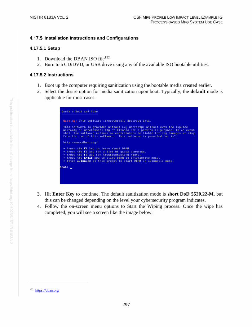
NISTIR 8183A VOL. 2 CSF MFG PROFILE LOW IMPACT LEVEL EXAMPLE IG PROCESS-BASED MFG SYSTEM USE CASE
297
Th
is p
ublic
atio
n is
ava
ilable
free
of c
ha
rge
from
: http
s://d
oi.o
rg/1
0.6
02
8/N
IST
.IR.8
18
3A
-2
Installation Instructions and Configurations
4.17.5.1 Setup
1. Download the DBAN ISO file122
2. Burn to a CD/DVD, or USB drive using any of the available ISO bootable utilities.
4.17.5.2 Instructions
1. Boot up the computer requiring sanitization using the bootable media created earlier.
2. Select the desire option for media sanitization upon boot. Typically, the default mode is
applicable for most cases.
3. Hit Enter Key to continue. The default sanitization mode is short DoD 5520.22-M, but
this can be changed depending on the level your cybersecurity program indicates.
4. Follow the on-screen menu options to Start the Wiping process. Once the wipe has
completed, you will see a screen like the image below.
122 https://dban.org

NISTIR 8183A VOL. 2 CSF MFG PROFILE LOW IMPACT LEVEL EXAMPLE IG PROCESS-BASED MFG SYSTEM USE CASE
298
Th
is p
ublic
atio
n is
ava
ilable
free
of c
ha
rge
from
: http
s://d
oi.o
rg/1
0.6
02
8/N
IST
.IR.8
18
3A
-2
5. Remove the physical hard drive from device post completion. It is now ready for
disposal.
Additional Information
Not all hard drives can be wiped clean using this sanitization method. Media that is either SSD or
flash memory is written differently than spinning drives, so follow SSD/Flash media vendors’
recommendations for proper media sanitization for all non-spinning hard drives.
Highlighted Performance Impacts
No performance measurement experiments were performed for the use of DBAN due to its
typical installation and usage location (i.e., external to the manufacturing system).
Links to Entire Performance Measurement Data Set
N/A

NISTIR 8183A VOL. 2 CSF MFG PROFILE LOW IMPACT LEVEL EXAMPLE IG PROCESS-BASED MFG SYSTEM USE CASE
299
Th
is p
ublic
atio
n is
ava
ilable
free
of c
ha
rge
from
: http
s://d
oi.o
rg/1
0.6
02
8/N
IST
.IR.8
18
3A
-2
Network Segmentation and Segregation
Technical Solution Overview
Network segmentation and segregation solutions enable a manufacturer to separate the
manufacturing system network from other networks (e.g., corporate networks, guest networks),
segment the internal manufacturing system network into smaller networks, and control the
communication between specific hosts and services.
Each router’s native capabilities were leveraged to implemented network segmentation.
Technical Capabilities Provided by Solution
Network Segmentation and Segregation provides components of the following Technical
Capabilities described in Section 6 of Volume 1:
• Network Segmentation and Segregation
Subcategories Addressed by Implementing Solution
PR.AC-5

NISTIR 8183A VOL. 2 CSF MFG PROFILE LOW IMPACT LEVEL EXAMPLE IG PROCESS-BASED MFG SYSTEM USE CASE
300
Th
is p
ublic
atio
n is
ava
ilable
free
of c
ha
rge
from
: http
s://d
oi.o
rg/1
0.6
02
8/N
IST
.IR.8
18
3A
-2
Architecture Map of Where Solution was Implemented

NISTIR 8183A VOL. 2 CSF MFG PROFILE LOW IMPACT LEVEL EXAMPLE IG PROCESS-BASED MFG SYSTEM USE CASE
301
Th
is p
ublic
atio
n is
ava
ilable
free
of c
ha
rge
from
: http
s://d
oi.o
rg/1
0.6
02
8/N
IST
.IR.8
18
3A
-2
Installation Instructions and Configurations
4.18.5.1 Environment Setup
The following devices were involved in implementing Network Segmentation:
Device Details Location
Cisco-ASA 5512 NGFW, running Firepower Services FTD 6.2.3 Manufacturing
System
Allen Bradley
Stratix 8300
Firewall, Router Work cell
4.18.5.2 Segmentation in the Cybersecurity LAN
Following is a list of interfaces created on the Boundary Router/Firewall – Cisco ASA of the
Cybersecurity LAN network:
Interface IP address of
Interface
Subnet Description
GE 0/0 129.6.66.x 129.x.x.x/x Uplink to Corporate
GE 0/1 10.100.0.1 10.100.0.0/24 Cybersecurity LAN
GE 0/2 129.6.1.x 129.x.x.x/x VPN users
GE 0/3 10.100.2.1 10.100.2.0/24 Management LAN
GE 0/4 10.100.1.1 10.100.1.0/24 Manufacturing DMZ LAN
4.18.5.3 Segmentation in the Plant
The Work Cell consists of the following network devices:
Type Description
Allen Bradley Stratix 8300 Boundary protection Firewall, Router
Allen Bradley Stratix 5700 Layer-2 Switch for the Control Network
Allen Bradley Stratix 5700 Layer-2 Switch for the Supervisory Network

NISTIR 8183A VOL. 2 CSF MFG PROFILE LOW IMPACT LEVEL EXAMPLE IG PROCESS-BASED MFG SYSTEM USE CASE
302
Th
is p
ublic
atio
n is
ava
ilable
free
of c
ha
rge
from
: http
s://d
oi.o
rg/1
0.6
02
8/N
IST
.IR.8
18
3A
-2
List of interfaces created on the Boundary Router – Allen Bradley 8300:
Interface IP address of
Interface
Subnet Description
Fa 1/1 172.16.1.1 172.16.1.0/24 Supervisory Vlan1
Fa 1/2 172.16.2.1 172.16.2.0/24 Control Vlan1
Fa 1/3 172.16.3.1 172.16.3.0/24 Engineering LAN
Fa 1/4 10.100.0.40 Uplink to Cybersecurity LAN
Gi 1/1 10.100.2.8 Management interface
One of the Stratix 5700 switches was connected to the Fa1/1 interface of the 8300 Router and
used for the Supervisory (Vlan1) sub-network. Devices connected to this switch were assigned
an IP address from the 172.16.1.0/24 subnet.
The other Stratix 5700 switch was connected to the Fa 1/2 interface of the Router and used for
the Control (Vlan2) sub- network. Devices connected to this switch were assigned an IP address
from the 172.16.2.0/24 subnet.
Highlighted Performance Impacts
No performance measurement experiments were performed for network segmentation and
segregation due to it being implemented on the PCS before the Manufacturing Profile
implementation was initiated.
Links to Entire Performance Measurement Data Set
N/A

NISTIR 8183A VOL. 2 CSF MFG PROFILE LOW IMPACT LEVEL EXAMPLE IG PROCESS-BASED MFG SYSTEM USE CASE
303
Th
is p
ublic
atio
n is
ava
ilable
free
of c
ha
rge
from
: http
s://d
oi.o
rg/1
0.6
02
8/N
IST
.IR.8
18
3A
-2
Network Boundary Protection
Technical Solution Overview
Boundary Protection devices are implemented to monitor and control connections and
communications at the external boundary and key internal boundaries within the organization.
Boundary protection mechanisms include for example, routers, firewalls, gateways, data diodes
separating system components into logically separate networks and sub networks.
Technical Capabilities Provided by Solution
Network Boundary Protection provides components of the following Technical Capabilities
described in Section 6 of Volume 1:
• Network Boundary Protection
Subcategories Addressed by Implementing Solution
PR.AC-5, PR.PT-4, DE.CM-1

NISTIR 8183A VOL. 2 CSF MFG PROFILE LOW IMPACT LEVEL EXAMPLE IG PROCESS-BASED MFG SYSTEM USE CASE
304
Th
is p
ublic
atio
n is
ava
ilable
free
of c
ha
rge
from
: http
s://d
oi.o
rg/1
0.6
02
8/N
IST
.IR.8
18
3A
-2
Architecture Map of Where Solution was Implemented

NISTIR 8183A VOL. 2 CSF MFG PROFILE LOW IMPACT LEVEL EXAMPLE IG PROCESS-BASED MFG SYSTEM USE CASE
305
Th
is p
ublic
atio
n is
ava
ilable
free
of c
ha
rge
from
: http
s://d
oi.o
rg/1
0.6
02
8/N
IST
.IR.8
18
3A
-2
Installation Instructions and Configurations
4.19.5.1 Environment Setup
The following devices were implemented for Boundary protection:
Device Details Location
Cisco-ASA 5512 NGFW, running
Firepower Services
FTD 6.2.3
Manufacturing System
Allen Bradley Stratix 8300 Firewall, Router Work cell
GTB Inspector Data Loss
Prevention (DLP)
virtual appliance
Cybersecurity LAN
Security Onion Running Snort, BRO
IDS
Cybersecurity LAN
4.19.5.2 Configuration on Cisco-ASA
The following features, settings were enabled on the ASA firewall:
• Network Segmentation
• ACL Rules
• NAT policy for Internet access
• Snort Inspection
• DMZ network
Network Segmentation
Separate network interfaces were configured for the different network segments as listed below:
• Inside Interface (Network: 10.100.0.0/24)
• DMZ Interface (Network: 10.100.1.0/24)
• Outside Interface (Network:129.6.91.x/24, Uplink to NIST Corporate for Internet)
• Public interface (Network:129.6.1.x/24 For VPN Users)
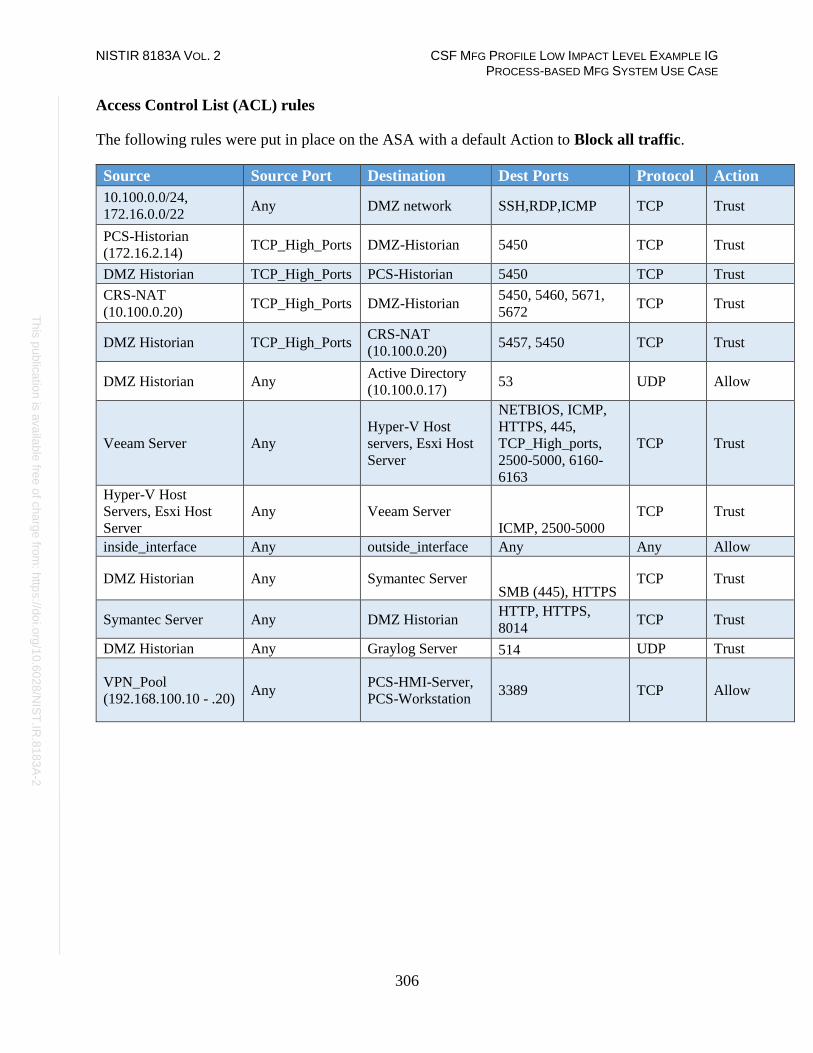
NISTIR 8183A VOL. 2 CSF MFG PROFILE LOW IMPACT LEVEL EXAMPLE IG PROCESS-BASED MFG SYSTEM USE CASE
306
Th
is p
ublic
atio
n is
ava
ilable
free
of c
ha
rge
from
: http
s://d
oi.o
rg/1
0.6
02
8/N
IST
.IR.8
18
3A
-2
Access Control List (ACL) rules
The following rules were put in place on the ASA with a default Action to Block all traffic.
Source Source Port Destination Dest Ports Protocol Action
10.100.0.0/24,
172.16.0.0/22 Any DMZ network SSH,RDP,ICMP TCP Trust
PCS-Historian
(172.16.2.14) TCP_High_Ports DMZ-Historian 5450 TCP Trust
DMZ Historian TCP_High_Ports PCS-Historian 5450 TCP Trust
CRS-NAT
(10.100.0.20) TCP_High_Ports DMZ-Historian
5450, 5460, 5671,
5672 TCP Trust
DMZ Historian TCP_High_Ports CRS-NAT
(10.100.0.20) 5457, 5450 TCP Trust
DMZ Historian Any Active Directory
(10.100.0.17) 53 UDP Allow
Veeam Server Any
Hyper-V Host
servers, Esxi Host
Server
NETBIOS, ICMP,
HTTPS, 445,
TCP_High_ports,
2500-5000, 6160-
6163
TCP Trust
Hyper-V Host
Servers, Esxi Host
Server
Any Veeam Server
ICMP, 2500-5000
TCP Trust
inside_interface Any outside_interface Any Any Allow
DMZ Historian Any Symantec Server SMB (445), HTTPS
TCP Trust
Symantec Server Any DMZ Historian HTTP, HTTPS,
8014 TCP Trust
DMZ Historian Any Graylog Server 514 UDP Trust
VPN_Pool
(192.168.100.10 - .20) Any
PCS-HMI-Server,
PCS-Workstation 3389 TCP Allow

NISTIR 8183A VOL. 2 CSF MFG PROFILE LOW IMPACT LEVEL EXAMPLE IG PROCESS-BASED MFG SYSTEM USE CASE
307
Th
is p
ublic
atio
n is
ava
ilable
free
of c
ha
rge
from
: http
s://d
oi.o
rg/1
0.6
02
8/N
IST
.IR.8
18
3A
-2
NAT Policy
A Dynamic NAT policy was configured to allow internet access:
Type of NAT rule Auto NAT
Source Interface inside
Destination Interface outside
Original sources 10.100.0.0/8
Translated Source Destination Interface IP
Options Translate DNS Replies that
match this Rule: False
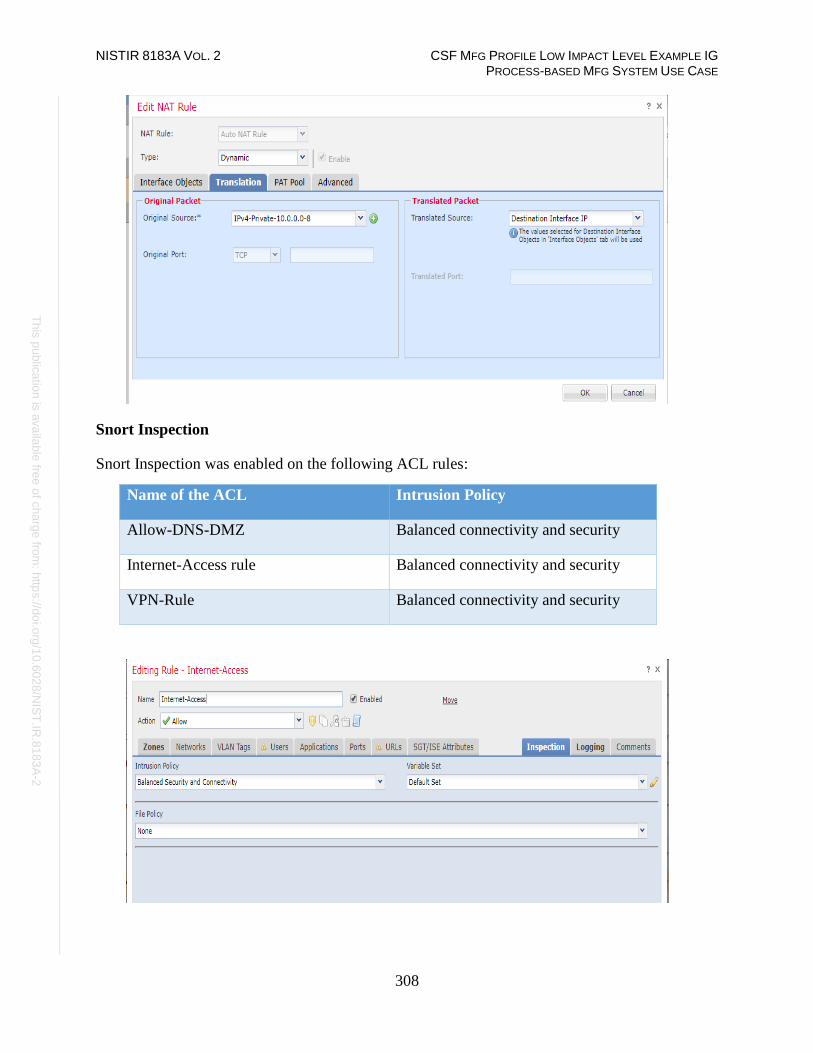
NISTIR 8183A VOL. 2 CSF MFG PROFILE LOW IMPACT LEVEL EXAMPLE IG PROCESS-BASED MFG SYSTEM USE CASE
308
Th
is p
ublic
atio
n is
ava
ilable
free
of c
ha
rge
from
: http
s://d
oi.o
rg/1
0.6
02
8/N
IST
.IR.8
18
3A
-2
Snort Inspection
Snort Inspection was enabled on the following ACL rules:
Name of the ACL Intrusion Policy
Allow-DNS-DMZ Balanced connectivity and security
Internet-Access rule Balanced connectivity and security
VPN-Rule Balanced connectivity and security

NISTIR 8183A VOL. 2 CSF MFG PROFILE LOW IMPACT LEVEL EXAMPLE IG PROCESS-BASED MFG SYSTEM USE CASE
309
Th
is p
ublic
atio
n is
ava
ilable
free
of c
ha
rge
from
: http
s://d
oi.o
rg/1
0.6
02
8/N
IST
.IR.8
18
3A
-2
DMZ Network
A Separate interface was setup for the Manufacturing DMZ LAN Network for hosting the
DMZ Historian server.
4.19.5.3 Configuration of Allen Bradley Firewall:
The following features and settings were enabled on this firewall:
• Network Segmentation
• ACL Rules
Network Segmentation
Separate network interfaces were configured for the different network segments as listed below:
• Supervisory VLAN1 (Network: 172.16.1.0/24)
• Control VLAN2 Interface (Network: 172.16.2.0.0/24)
• Engineering LAN (Network: 172.16.3.0/24)
• Uplink (IP:10.100.0.40, Uplink to Cybersecurity LAN)
• Management interface (IP:10.100.2.8)

NISTIR 8183A VOL. 2 CSF MFG PROFILE LOW IMPACT LEVEL EXAMPLE IG PROCESS-BASED MFG SYSTEM USE CASE
310
Th
is p
ublic
atio
n is
ava
ilable
free
of c
ha
rge
from
: http
s://d
oi.o
rg/1
0.6
02
8/N
IST
.IR.8
18
3A
-2
Access Control List (ACL) rules
Three ACLs of Extended type were created as shown below. Each one was associated to a
specific network interface as an Inbound ACL:
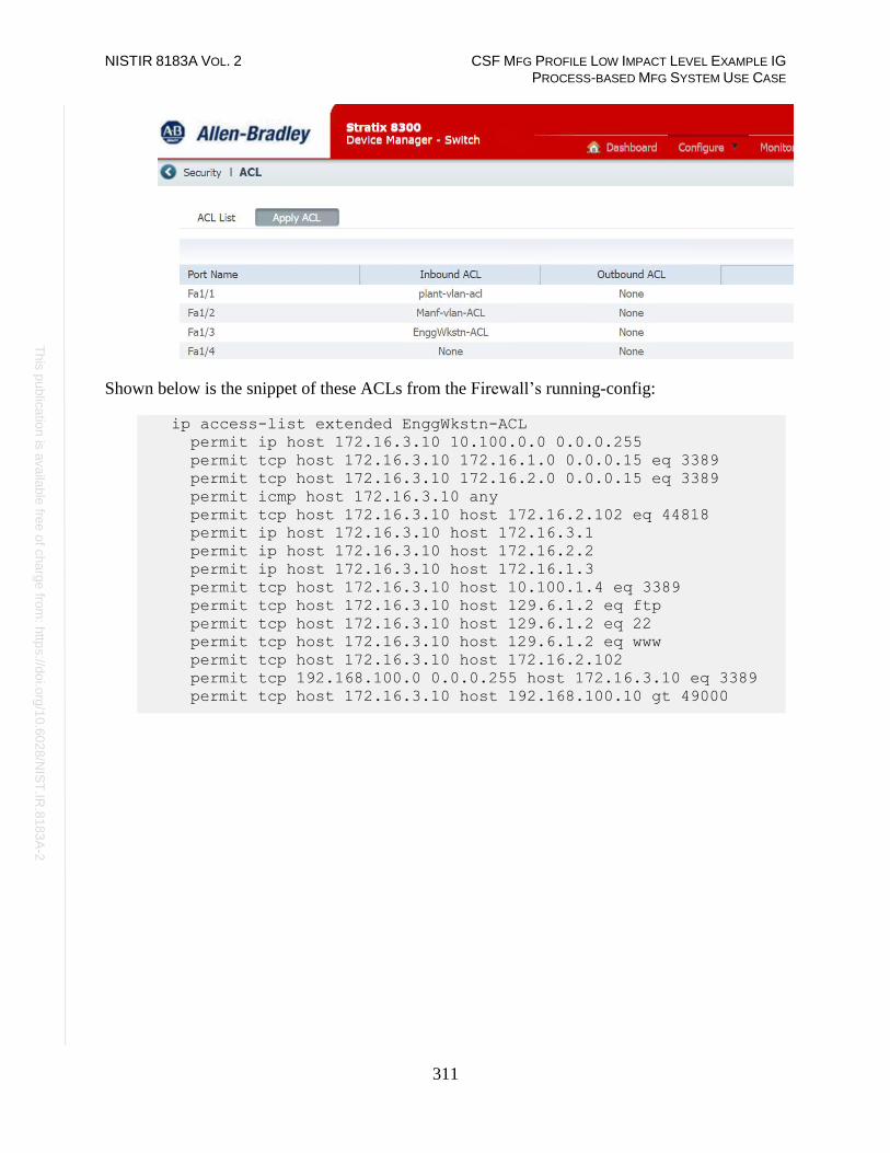
NISTIR 8183A VOL. 2 CSF MFG PROFILE LOW IMPACT LEVEL EXAMPLE IG PROCESS-BASED MFG SYSTEM USE CASE
311
Th
is p
ublic
atio
n is
ava
ilable
free
of c
ha
rge
from
: http
s://d
oi.o
rg/1
0.6
02
8/N
IST
.IR.8
18
3A
-2
Shown below is the snippet of these ACLs from the Firewall’s running-config:
ip access-list extended EnggWkstn-ACL
permit ip host 172.16.3.10 10.100.0.0 0.0.0.255
permit tcp host 172.16.3.10 172.16.1.0 0.0.0.15 eq 3389
permit tcp host 172.16.3.10 172.16.2.0 0.0.0.15 eq 3389
permit icmp host 172.16.3.10 any
permit tcp host 172.16.3.10 host 172.16.2.102 eq 44818
permit ip host 172.16.3.10 host 172.16.3.1
permit ip host 172.16.3.10 host 172.16.2.2
permit ip host 172.16.3.10 host 172.16.1.3
permit tcp host 172.16.3.10 host 10.100.1.4 eq 3389
permit tcp host 172.16.3.10 host 129.6.1.2 eq ftp
permit tcp host 172.16.3.10 host 129.6.1.2 eq 22
permit tcp host 172.16.3.10 host 129.6.1.2 eq www
permit tcp host 172.16.3.10 host 172.16.2.102
permit tcp 192.168.100.0 0.0.0.255 host 172.16.3.10 eq 3389
permit tcp host 172.16.3.10 host 192.168.100.10 gt 49000

NISTIR 8183A VOL. 2 CSF MFG PROFILE LOW IMPACT LEVEL EXAMPLE IG PROCESS-BASED MFG SYSTEM USE CASE
312
Th
is p
ublic
atio
n is
ava
ilable
free
of c
ha
rge
from
: http
s://d
oi.o
rg/1
0.6
02
8/N
IST
.IR.8
18
3A
-2
ip access-list extended Manf-vlan-ACL
permit ip 172.16.2.0 0.0.0.15 172.16.1.0 0.0.0.15 log
permit icmp 172.16.2.0 0.0.0.255 any log
permit tcp 172.16.2.0 0.0.0.255 host 172.16.3.10 gt 49000 log
permit ip 172.16.2.0 0.0.0.255 host 10.100.0.5 log
permit ip 172.16.2.0 0.0.0.255 host 10.100.0.10 log
permit ip 172.16.2.0 0.0.0.255 host 10.100.0.13 log
permit ip 172.16.2.0 0.0.0.255 host 10.100.0.17 log
permit ip 172.16.2.0 0.0.0.255 host 10.100.0.25 log
permit ip 172.16.2.0 0.0.0.255 host 10.100.0.177 log
permit tcp 172.16.2.0 0.0.0.255 host 10.100.0.234 log
permit tcp 172.16.2.0 0.0.0.255 host 10.100.0.12 eq www log
permit tcp 172.16.2.0 0.0.0.255 host 10.100.0.12 eq 443 log
permit tcp 172.16.2.0 0.0.0.255 host 10.100.0.12 eq 8530 log
permit udp 172.16.2.0 0.0.0.255 host 10.100.0.14 eq syslog
ip access-list extended plant-vlan-acl
permit ip 172.16.1.0 0.0.0.15 172.16.2.0 0.0.0.15 log
permit icmp 172.16.1.0 0.0.0.255 any log
permit tcp 172.16.1.0 0.0.0.255 host 172.16.3.10 gt 49000 log
permit ip 172.16.1.0 0.0.0.255 host 10.100.0.5 log
permit ip 172.16.1.0 0.0.0.255 host 10.100.0.10 log
permit ip 172.16.1.0 0.0.0.255 host 10.100.0.13 log
permit ip 172.16.1.0 0.0.0.255 host 10.100.0.17 log
permit ip 172.16.1.0 0.0.0.255 host 10.100.0.25 log
permit tcp 172.16.1.0 0.0.0.255 host 10.100.0.234 log
permit udp 172.16.1.0 0.0.0.255 host 10.100.0.14 eq syslog log
permit tcp 172.16.1.0 0.0.0.255 host 10.100.0.12 eq www log
permit tcp 172.16.1.0 0.0.0.255 host 10.100.0.12 eq 443 log
permit tcp 172.16.1.0 0.0.0.255 host 10.100.0.12 eq 8530 log
permit ip 172.16.1.0 0.0.0.255 host 10.100.0.177 log
permit tcp 192.168.100.0 0.0.0.255 host 172.16.1.4 eq 3389 log
permit tcp host 172.16.1.4 192.168.100.0 0.0.0.255 gt 49000
log
4.19.5.4 Configuration of GTB Inspector:
Refer to Section 4.15 for details.
4.19.5.5 Configuration of Security Onion:
Refer to Section 4.7 for details

NISTIR 8183A VOL. 2 CSF MFG PROFILE LOW IMPACT LEVEL EXAMPLE IG PROCESS-BASED MFG SYSTEM USE CASE
313
Th
is p
ublic
atio
n is
ava
ilable
free
of c
ha
rge
from
: http
s://d
oi.o
rg/1
0.6
02
8/N
IST
.IR.8
18
3A
-2
Highlighted Performance Impacts
The following performance measurement experiment was performed for the network boundary
protection while the manufacturing system was operational:
Experiment PL004.1- Firewall rules are activated at the PCS boundary router
There was no significant performance impact observed when firewall rules were activated. For
example, the packet round trip time between the HMI and OPC remained mostly constant before
and after the firewall rules were activated.
Care needs to be used for implementation of the rules and a thorough understanding of the
system is important. A misconfigured firewall rule can block a legitimate connection and cause
system failure.
In the PCS system implementation, a thorough analysis on network connections was performed
to identify all the legitimate connections in order to implement the firewall rules. Some network
connections are legitimate but not obvious or only stayed connected for a short amount of time.
Validation test was performed to ensure all the legitimate network connections for normal
operation are allowed. The implementation and validation tests were completed during a planned
system down time.
Figure 4-35 Packet round trip time from HMI to OPC before and after firewall rules were activated

NISTIR 8183A VOL. 2 CSF MFG PROFILE LOW IMPACT LEVEL EXAMPLE IG PROCESS-BASED MFG SYSTEM USE CASE
314
Th
is p
ublic
atio
n is
ava
ilable
free
of c
ha
rge
from
: http
s://d
oi.o
rg/1
0.6
02
8/N
IST
.IR.8
18
3A
-2
Figure 4-36 Packet round trip time from OPC to HMI before and after firewall rules were activated
Figure 4-37 Manufacturing process product flow rate before and after firewall rules were activated

NISTIR 8183A VOL. 2 CSF MFG PROFILE LOW IMPACT LEVEL EXAMPLE IG PROCESS-BASED MFG SYSTEM USE CASE
315
Th
is p
ublic
atio
n is
ava
ilable
free
of c
ha
rge
from
: http
s://d
oi.o
rg/1
0.6
02
8/N
IST
.IR.8
18
3A
-2
Figure 4-38 Manufacturing process reactor pressure before and after firewall rules were activated
Links to Entire Performance Measurement Data Set
• Firewall KPI data
• Firewall measurement data

NISTIR 8183A VOL. 2 CSF MFG PROFILE LOW IMPACT LEVEL EXAMPLE IG PROCESS-BASED MFG SYSTEM USE CASE
316
Th
is p
ublic
atio
n is
ava
ilable
free
of c
ha
rge
from
: http
s://d
oi.o
rg/1
0.6
02
8/N
IST
.IR.8
18
3A
-2
Managed Network Interfaces
Technical Solution Overview
Managing network interfaces controls what network devices are plugged into switches within the
manufacturing system, along with physical labeling of the connections to help with system
identification and classification. Required actions will be performed directly on the exterior of
the switch. Switch port in use will be labeled logically within switch console itself, along with
the corresponding network cable for easy identification. All cable should be labeled/identified at
the switch and at the opposite end of the network cable. Switch Port Security should be
configured to restrict access to only allowed preconfigured Media Access Control (MAC)
addresses devices.
There is a minimal cost for labeling. The effort to implement can be high, but not difficult. The
effort will be spent taking the required time to accurately identify cabling connections.
Most switches have built in Port security. Since this technical control is built into switches there
is no additional cost for implementation. Configuration for Port security is well documented and
easily configured.
Technical Capabilities Provided by Solution
Managed Network Interfaces provides components of the following Technical Capabilities
described in Section 6 of Volume 1:
• Managed Network Interfaces
Subcategories Addressed by Implementing Solution
PR.AC-5

NISTIR 8183A VOL. 2 CSF MFG PROFILE LOW IMPACT LEVEL EXAMPLE IG PROCESS-BASED MFG SYSTEM USE CASE
317
Th
is p
ublic
atio
n is
ava
ilable
free
of c
ha
rge
from
: http
s://d
oi.o
rg/1
0.6
02
8/N
IST
.IR.8
18
3A
-2
Architecture Map of Where Solution was Implemented

NISTIR 8183A VOL. 2 CSF MFG PROFILE LOW IMPACT LEVEL EXAMPLE IG PROCESS-BASED MFG SYSTEM USE CASE
318
Th
is p
ublic
atio
n is
ava
ilable
free
of c
ha
rge
from
: http
s://d
oi.o
rg/1
0.6
02
8/N
IST
.IR.8
18
3A
-2
Installation Instructions and Configurations
The following actions were performed for implementing Managed Network Interfaces.
4.20.5.1 Port Labelling:
Port labeling provides ability for others to understand and know what network devices belong
where. Managing your switches with correct labeling and classification makes troubleshooting
simpler along with improving cybersecurity.
1. Configure Port labelling on the Allen Bradley Router and switches as follows:
a. Login to the Switch / Router via web browser
b. Click on Configure > Port Settings.
c. Click Edit on the Port to be labelled.
d. Type into Description field the desired label.
e. Click OK to save changes and exit.
2. Alternatively, the cli commands for labelling the ports are:
#enable
#configure terminal
(config)#Interface FastEthernet1/3
description <label>
(config)#end
#wr mem
4.20.5.2 Port Security Configuration
Port security or MAC address filtering is a security method for access control. Using this
method, we can blacklist, or whitelist certain devices based on their MAC address. This prevents
unauthorized devices from being plugged into a network switch while trying to obtain sensitive
information, which could be used for mapping out network connections for possible data
exfiltration. When an unauthorized device is plugged into a protected port a warning message is
logged and sent to a syslog server if supported by switch vendor.
1. Configure Port Security on the Allen Bradley Router and switches as follows:
a. Login to the device via web browser.
b. Click, Configure > Security > Port Security
c. Click Edit button upon selecting the desired port requiring security.
d. Check in a box next to Enable. Click Add Learned MAC Addresses or Add
the Addresses manually.
e. Click OK to save changes once MAC addresses have been added.
f. Change Maximum MAC Count to the required MACs being assigned to this
port, if more than one MAC addresses are required to be added.
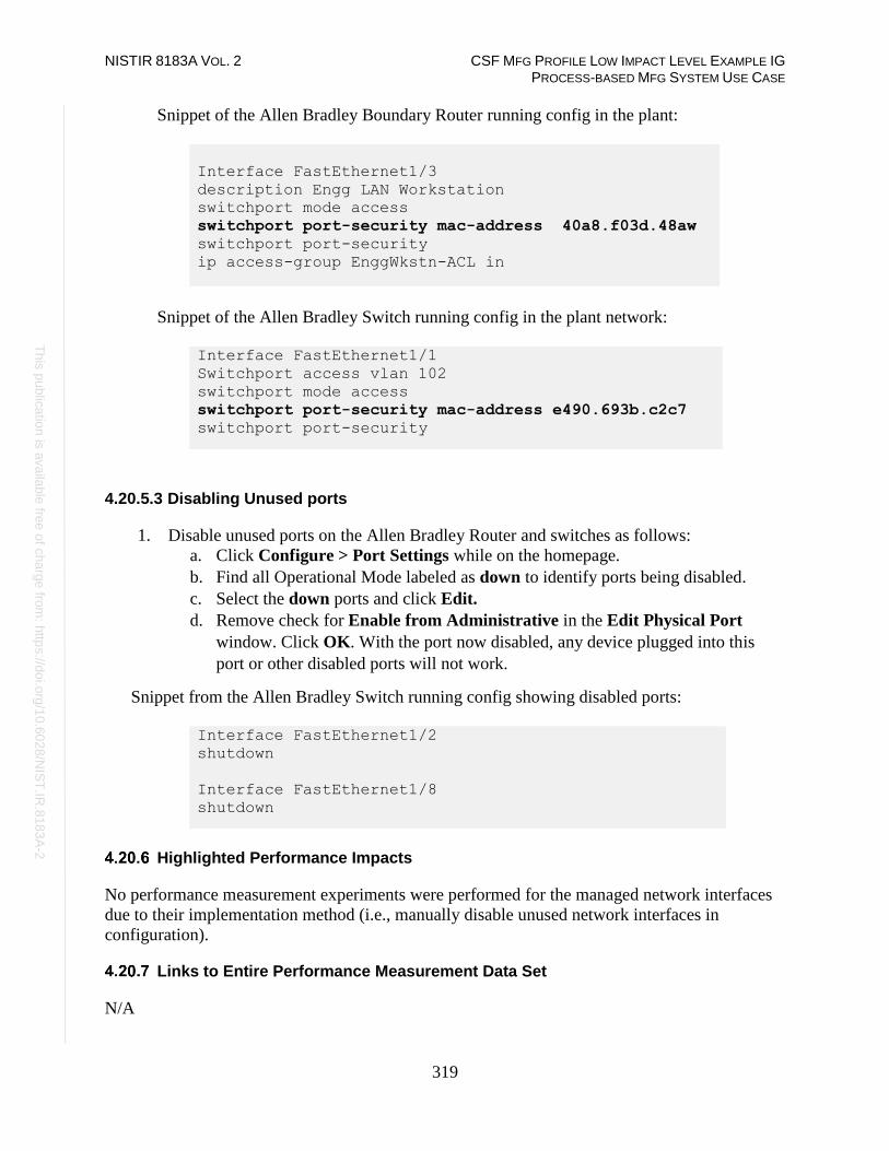
NISTIR 8183A VOL. 2 CSF MFG PROFILE LOW IMPACT LEVEL EXAMPLE IG PROCESS-BASED MFG SYSTEM USE CASE
319
Th
is p
ublic
atio
n is
ava
ilable
free
of c
ha
rge
from
: http
s://d
oi.o
rg/1
0.6
02
8/N
IST
.IR.8
18
3A
-2
Snippet of the Allen Bradley Boundary Router running config in the plant:
Interface FastEthernet1/3
description Engg LAN Workstation
switchport mode access
switchport port-security mac-address 40a8.f03d.48aw
switchport port-security
ip access-group EnggWkstn-ACL in
Snippet of the Allen Bradley Switch running config in the plant network:
Interface FastEthernet1/1
Switchport access vlan 102
switchport mode access
switchport port-security mac-address e490.693b.c2c7
switchport port-security
4.20.5.3 Disabling Unused ports
1. Disable unused ports on the Allen Bradley Router and switches as follows:
a. Click Configure > Port Settings while on the homepage.
b. Find all Operational Mode labeled as down to identify ports being disabled.
c. Select the down ports and click Edit.
d. Remove check for Enable from Administrative in the Edit Physical Port
window. Click OK. With the port now disabled, any device plugged into this
port or other disabled ports will not work.
Snippet from the Allen Bradley Switch running config showing disabled ports:
Interface FastEthernet1/2
shutdown
Interface FastEthernet1/8
shutdown
Highlighted Performance Impacts
No performance measurement experiments were performed for the managed network interfaces
due to their implementation method (i.e., manually disable unused network interfaces in
configuration).
Links to Entire Performance Measurement Data Set
N/A
NISTIR 8183A VOL. 2 CSF MFG PROFILE LOW IMPACT LEVEL EXAMPLE IG PROCESS-BASED MFG SYSTEM USE CASE
320
Th
is p
ublic
atio
n is
ava
ilable
free
of c
ha
rge
from
: http
s://d
oi.o
rg/1
0.6
02
8/N
IST
.IR.8
18
3A
-2
Time Synchronization
Technical Solution Overview
Time synchronization allows devices to synchronize with a reliable time source. Time
synchronization is vital for system logins, event tracking and all other time sensitive events
occurring with a manufacturing system.
Technical Capabilities Provided by Solution
Time Synchronization provides components of the following Technical Capabilities described in
Section 6 of Volume 1:
• Time Synchronization
Subcategories Addressed by Implementing Solution
PR.PT-1

NISTIR 8183A VOL. 2 CSF MFG PROFILE LOW IMPACT LEVEL EXAMPLE IG PROCESS-BASED MFG SYSTEM USE CASE
321
Th
is p
ublic
atio
n is
ava
ilable
free
of c
ha
rge
from
: http
s://d
oi.o
rg/1
0.6
02
8/N
IST
.IR.8
18
3A
-2
Architecture Map of Where Solution was Implemented

NISTIR 8183A VOL. 2 CSF MFG PROFILE LOW IMPACT LEVEL EXAMPLE IG PROCESS-BASED MFG SYSTEM USE CASE
322
Th
is p
ublic
atio
n is
ava
ilable
free
of c
ha
rge
from
: http
s://d
oi.o
rg/1
0.6
02
8/N
IST
.IR.8
18
3A
-2
Installation Instructions and Configurations
Details of the NTP server implemented:
Name IP address Purpose Hardware Details
Grandmaster 10.100.0.15 NTP/PTP
Clock
Model: Meinberg Lantime
M900
4.21.5.1 Meinberg M900 Time Server
Industrial / Manufacturing environments typically need higher time accuracy than the ones
provided by default capabilities of a typical Windows Active Directory environment. To
accommodate this, an external hardware clock such as this one was implemented for higher time
accuracy up to milliseconds level. This device was configured to obtain its Upstream time from
the NIST Time server.
4.21.5.2 NTP Configuration on the Domain Controller
The Active Directory Domain controller holding the PDC Emulator role 123 in the manufacturing
system was configured to obtain its time from the Meinberg Lantime M900 device.
Change the following registry key on the Domain Controller to have w32Time.exe sync its time
from an external source IP address.
HKEY_LOCAL_MACHINE\SYSTEM\CurrentControlSet\Services\W32Time\Para
meters\NtpServer
The image below shows our Domain Controller pointing to the IP address of Meinberg
LAN Time clock
123 https://support.microsoft.com/en-us/help/197132/active-directory-fsmo-roles-in-windows

NISTIR 8183A VOL. 2 CSF MFG PROFILE LOW IMPACT LEVEL EXAMPLE IG PROCESS-BASED MFG SYSTEM USE CASE
323
Th
is p
ublic
atio
n is
ava
ilable
free
of c
ha
rge
from
: http
s://d
oi.o
rg/1
0.6
02
8/N
IST
.IR.8
18
3A
-2
4.21.5.3 NTP Configuration on the Member-servers
All windows computers were joined to our Active Directory domain. Domain joined machines
automatically sync their time by contacting local domain controller which is the Active Directory
server.
4.21.5.4 NTP Configuration on Networking devices
All other devices such as Switches, Routers within the manufacturing system were configured to
sync their time from the Meinberg M900 using NTP.
The NTP Settings on the Allen Bradley Boundary Router and Switches can be set as follows:
1. Login to the web interface of the router/switch.
2. Click on Configure > NTP 3. Click Add to add new time server.
4. Enter the IP address of the time source. 5. Click Save
6. Logout when done.
Additional Information
The master time reference selected should be as close to your physical location as possible. This
should reduce the Off Set.
Highlighted Performance Impacts
No performance measurement experiments were performed for time synchronization due to its
installation in the system before the Manufacturing Profile implementation was initiated.
Links to Entire Performance Measurement Data Set
N/A

NISTIR 8183A VOL. 2 CSF MFG PROFILE LOW IMPACT LEVEL EXAMPLE IG PROCESS-BASED MFG SYSTEM USE CASE
324
Th
is p
ublic
atio
n is
ava
ilable
free
of c
ha
rge
from
: http
s://d
oi.o
rg/1
0.6
02
8/N
IST
.IR.8
18
3A
-2
System Use Monitoring
Technical Solution Overview
System use monitoring is accomplished by multiple tools to protect manufacturing system
environment from harmful activities using data loss protection, system hardening and syslog
server for monitoring, store and auditing. Each tool provides a different level required to protect
the manufacturing system.
Implementation effort is moderate requiring understanding of Linux and Windows systems,
along with virtual machine experience.
Technical Capabilities Provided by Solution
System Use Monitoring provides components of the following Technical Capabilities described
in Section 6 of Volume 1:
• System Use Monitoring
System Use Monitoring was provided by GTB Inspector, Ports and Services Lockdown, and
Graylog.
Subcategories Addressed by Implementing Solution
PR.AC-1, PR.DS-5, PR.MA-2, DE.CM-3

NISTIR 8183A VOL. 2 CSF MFG PROFILE LOW IMPACT LEVEL EXAMPLE IG PROCESS-BASED MFG SYSTEM USE CASE
325
Th
is p
ublic
atio
n is
ava
ilable
free
of c
ha
rge
from
: http
s://d
oi.o
rg/1
0.6
02
8/N
IST
.IR.8
18
3A
-2
Architecture Map of Where Solution was Implemented

NISTIR 8183A VOL. 2 CSF MFG PROFILE LOW IMPACT LEVEL EXAMPLE IG PROCESS-BASED MFG SYSTEM USE CASE
326
Th
is p
ublic
atio
n is
ava
ilable
free
of c
ha
rge
from
: http
s://d
oi.o
rg/1
0.6
02
8/N
IST
.IR.8
18
3A
-2

NISTIR 8183A VOL. 2 CSF MFG PROFILE LOW IMPACT LEVEL EXAMPLE IG PROCESS-BASED MFG SYSTEM USE CASE
327
Th
is p
ublic
atio
n is
ava
ilable
free
of c
ha
rge
from
: http
s://d
oi.o
rg/1
0.6
02
8/N
IST
.IR.8
18
3A
-2
Installation Instructions and Configurations
System use monitoring was implemented using a combination of tools such as GTB Inspector,
Graylog and native Windows Server capabilities such as enabling auditing and restricting
administrative user accounts.
GTB DLP: See Section 4.15.5 for instructions.
Graylog: See Section 4.16.5 for instructions
4.22.5.1 Enabling Auditing on Windows
Auditing Logon events
a. Launch the Group Policy manager on the Domain controller by running
gpedit.msc.
b. Edit either the Default Domain Controller Group Policy or create a new group
policy object and link it to appropriate servers OU.
c. Navigate to Computer Configuration > Polices> Windows Settings >Security
Settings > Local Polices > Audit Policy
d. Change the Audit Account logon events, Audit logon events, Audit Object access
settings to reflect Success, Failure. See image below for reference.

NISTIR 8183A VOL. 2 CSF MFG PROFILE LOW IMPACT LEVEL EXAMPLE IG PROCESS-BASED MFG SYSTEM USE CASE
328
Th
is p
ublic
atio
n is
ava
ilable
free
of c
ha
rge
from
: http
s://d
oi.o
rg/1
0.6
02
8/N
IST
.IR.8
18
3A
-2
Auditing Process Termination
a. Navigate to Computer Configuration > Polices > Windows Settings > Security
Settings > Advanced Audit Configuration
b. Change Detailed Tracking and Logon/Logoff to Success / Success, Failure (See
Image)
4.22.5.2 Windows - Restricting Administrative Users:
Review the local Administrators group on each system and add only those accounts that needed
to have Administrative privileges on the system.
For instance: An AD service account opc-admin was created to run OPC-server services and
was granted Administrative privileges on the 2 servers below:
• OPC Server
• Controller Server
4.22.5.3 Restricting Access to the PLC
Remote Access to PLC was regulated through the Firewall to allow access only from the
Engineering workstation.

NISTIR 8183A VOL. 2 CSF MFG PROFILE LOW IMPACT LEVEL EXAMPLE IG PROCESS-BASED MFG SYSTEM USE CASE
329
Th
is p
ublic
atio
n is
ava
ilable
free
of c
ha
rge
from
: http
s://d
oi.o
rg/1
0.6
02
8/N
IST
.IR.8
18
3A
-2
Highlighted Performance Impacts
No performance measurement experiments were performed for the installation of GTB into the
PCS due to its location within the network topology. No manufacturing process components
across the boundary on a regular basis while the system is operational.
No performance measurement experiments were performed for the use of the Graylog due to its
typical installation and usage location (i.e., external to the manufacturing system).
Links to Entire Performance Measurement Data Set
N/A

NISTIR 8183A VOL. 2 CSF MFG PROFILE LOW IMPACT LEVEL EXAMPLE IG PROCESS-BASED MFG SYSTEM USE CASE
330
Th
is p
ublic
atio
n is
ava
ilable
free
of c
ha
rge
from
: http
s://d
oi.o
rg/1
0.6
02
8/N
IST
.IR.8
18
3A
-2
Ports and Services Lockdown
Technical Solution Overview
Ports and services lockdown solutions enable a manufacturer to discover and disable
nonessential logical network ports and services. A logical port is a number assigned to a
“logical” connection. Port numbers are assigned to a service, which is helpful to TCP/IP in
identifying what ports it must send traffic to. Hackers use port scanners and vulnerability
scanners to identify open ports on servers. By revealing which ports are open, the hacker can
identify what kind of services are running and the type of system. Closing unnecessary ports by
uninstalling unnecessary programs considerably reduces the attack surface. These actions need to
be performed manually.
Native OS capabilities, Open-Audit and Nessus scanner were leveraged to inventory list of ports
and applications currently running on each device of the plant.
Technical Capabilities Provided by Solution
Ports and Services Lockdown provides components of the following Technical Capabilities
described in Section 6 of Volume 1:
• Ports and Services Lockdown
Subcategories Addressed by Implementing Solution
PR.IP-1, PR.PT-3

NISTIR 8183A VOL. 2 CSF MFG PROFILE LOW IMPACT LEVEL EXAMPLE IG PROCESS-BASED MFG SYSTEM USE CASE
331
Th
is p
ublic
atio
n is
ava
ilable
free
of c
ha
rge
from
: http
s://d
oi.o
rg/1
0.6
02
8/N
IST
.IR.8
18
3A
-2
Architecture Map of Where Solution was Implemented

NISTIR 8183A VOL. 2 CSF MFG PROFILE LOW IMPACT LEVEL EXAMPLE IG PROCESS-BASED MFG SYSTEM USE CASE
332
Th
is p
ublic
atio
n is
ava
ilable
free
of c
ha
rge
from
: http
s://d
oi.o
rg/1
0.6
02
8/N
IST
.IR.8
18
3A
-2
Installation Instructions and Configurations
The following steps were performed on the Plant Infrastructure as part of Ports and Services
Lockdown.
4.23.5.1 Removal of Unwanted programs from Windows systems:
The following guidelines can be used to identify unwanted programs for removal:
1. Perform a software inventory of each system using Open-Audit. Review the reports to
identify a list of unwanted programs and uninstall them. This includes some software that
comes by default with the OS.
2. Use Netstat utility to gather information about which applications are running or using
which TCP/IP ports on each system
For instance: netstat -aon | more will generate a list of processes and the
associated process identifier (PID)
3. Use the PID from the above output with the Windows Task Manager for further analysis. Within Task Manager (Windows 7), enable the PID column by clicking on View > Select
Columns.

NISTIR 8183A VOL. 2 CSF MFG PROFILE LOW IMPACT LEVEL EXAMPLE IG PROCESS-BASED MFG SYSTEM USE CASE
333
Th
is p
ublic
atio
n is
ava
ilable
free
of c
ha
rge
from
: http
s://d
oi.o
rg/1
0.6
02
8/N
IST
.IR.8
18
3A
-2
4. Use Show Processes for All Users to search for the PID in the list. To end that process,
Right Click > Open File Location or Go to Service(s) options to control the process or
stop it.
5. Other alternatives are using Resource Monitor (resmon.exe) and TCPView from
SysInternals. See the image below of TCPView for reference.

NISTIR 8183A VOL. 2 CSF MFG PROFILE LOW IMPACT LEVEL EXAMPLE IG PROCESS-BASED MFG SYSTEM USE CASE
334
Th
is p
ublic
atio
n is
ava
ilable
free
of c
ha
rge
from
: http
s://d
oi.o
rg/1
0.6
02
8/N
IST
.IR.8
18
3A
-2
4.23.5.2 Disabling of Unsecure services on Network Devices
Use the following guidelines to disable unsecure services on all Allen Bradley devices of the
Plant:
1. Disable unsecure services such as Telnet, SNMP (v1 and v2). If SNMP is required,
change the default community string or use SNMP v3.
2. Set a password for enable mode using the following commands for reference
#enable #configure terminal (config)#enable secret <password>
4.23.5.3 Restrict ssh access
Run the following Cisco commands to restrict ssh access from select few networks.
#enable #configure terminal (config)#access-list 1 permit 172.16.0.0 0.0.255.255 (config)#line vty 0 15 (config)#access-class 1 in
4.23.5.4 Hardening the PLC
Follow these actions to harden the PLC.
1. Disable unsecure services such as Telnet, SNMP and HTTP.
2. Use Firewall rules to restrict Remote Access to the PLC from only the Engineering
Workstation.
Highlighted Performance Impacts
No performance measurement experiments were performed for the managed network interfaces
due to their implementation method (i.e., manually disabled network ports and removed
unwanted Windows programs and services).
Links to Entire Performance Measurement Data Set
N/A

NISTIR 8183A VOL. 2 CSF MFG PROFILE LOW IMPACT LEVEL EXAMPLE IG PROCESS-BASED MFG SYSTEM USE CASE
335
Th
is p
ublic
atio
n is
ava
ilable
free
of c
ha
rge
from
: http
s://d
oi.o
rg/1
0.6
02
8/N
IST
.IR.8
18
3A
-2
Media Protection
Technical Solution Overview
Hardware-based port locks provide a low-cost solution for protecting USB ports. Implementation
and ease of use provide for quick install and easy removal. USB Port locks provide a simple yet
effective solution to restrict USB use. Once USB Port lock has been inserted and engaged there
is no way of removing the lock device without damaging the USB port unless a key is used. Each
USB Port lock can block up to two ports. These ports are the inserted port, and the port directly
to either side depending on the blocking plate direction. USB Port Lock can be purchased with a
collar that protects attached USB Mice and Keyboards from removal without prior approval.
Technical Capabilities Provided by Solution
Media Protection provides components of the following Technical Capabilities described in
Section 6 of Volume 1:
• Media Protection
Subcategories Addressed by Implementation
PR.PT-2

NISTIR 8183A VOL. 2 CSF MFG PROFILE LOW IMPACT LEVEL EXAMPLE IG PROCESS-BASED MFG SYSTEM USE CASE
336
Th
is p
ublic
atio
n is
ava
ilable
free
of c
ha
rge
from
: http
s://d
oi.o
rg/1
0.6
02
8/N
IST
.IR.8
18
3A
-2
Architecture Map of Where Solution was Implemented
NISTIR 8183A VOL. 2 CSF MFG PROFILE LOW IMPACT LEVEL EXAMPLE IG PROCESS-BASED MFG SYSTEM USE CASE
337
Th
is p
ublic
atio
n is
ava
ilable
free
of c
ha
rge
from
: http
s://d
oi.o
rg/1
0.6
02
8/N
IST
.IR.8
18
3A
-2
Installation Instructions and Configurations
Insert USB Port lock then push locking button in to secure. Kensington provides inserts to block
multiple ports including locks designed for securing USB Keyboards and Mice.
Patience is required when using this product so as not to inadvertently damage the USB port.
Highlighted Performance Impacts
No performance measurement experiments were performed for the USB port locks due to their
implementation method (i.e., physically restricting access to USB ports).
Links to Entire Performance Measurement Data Set
N/A

NISTIR 8183A VOL. 2 CSF MFG PROFILE LOW IMPACT LEVEL EXAMPLE IG PROCESS-BASED MFG SYSTEM USE CASE
338
Th
is p
ublic
atio
n is
ava
ilable
free
of c
ha
rge
from
: http
s://d
oi.o
rg/1
0.6
02
8/N
IST
.IR.8
18
3A
-2
Appendix A - Acronyms and Abbreviations
Selected acronyms and abbreviations used in this document are defined below.
AAA Authentication, Authorization, and Accounting
ACL Access Control List
AD Active Directory
API Application Programming Interface
ARP Address Resolution Protocol
AV Anti-Virus
CCN Credit Card Number
CD Compact Disk
CEO Chief Executive Officer
COTS Commercial Off-The-Shelf
CSET Cyber Security Evaluation Tool
CSF Cybersecurity Framework
DC Domain Controller
DCS Distributed Control System
DHCP Dynamic Host Configuration Protocol
DHS Department of Homeland Security
DLP Data Loss Prevention
DMZ Demilitarized Zone
DNS Domain Name System
DS Domain Services
EFS Encrypted File System
FIPS Federal Information Processing Standards
FTP File Transfer Protocol
GID Generator ID
HIDS Host Intrusion Detection System
HMI Human Machine Interface
HR Human Resources
HTTP Hypertext Transfer Protocol
HTTPS Hypertext Transfer Protocol Secure
HVAC Heating, Ventilation, and Air Conditioning
ICMP Internet Control Message Protocol
ICS Industrial Control System
ICS-CERT Industrial Control Systems Cyber Emergency Response Team
ICSJWG Industrial Control System Joint Working Group
IDE Integrated Drive Electronics

NISTIR 8183A VOL. 2 CSF MFG PROFILE LOW IMPACT LEVEL EXAMPLE IG PROCESS-BASED MFG SYSTEM USE CASE
339
Th
is p
ublic
atio
n is
ava
ilable
free
of c
ha
rge
from
: http
s://d
oi.o
rg/1
0.6
02
8/N
IST
.IR.8
18
3A
-2
IDS Intrusion Detection System
IEEE Institute of Electrical and Electronics Engineers
IG Implementation Guide
IP Internet Protocol
ISA The International Society of Automation
ISE Identity Services Engine
ISO International Organization for Standardization
IT Information Technology
KPI Key Performance Indicator
LAN Local Area Network
LDAP Lightweight Directory Access Protocol
LDAPS Secure LDAP
MAC Media Access Control
MFG Manufacturing
MGMT Management
NAT Network Address Translation
NCCIC National Cybersecurity and Communications Integration Center
NETBIOS Network Basic Input/Output System
NIDS Network Intrusion Detection System
NIST National Institute of Standards and Technology
NISTIR National Institute of Standards and Technology Internal Report
NPS Network Policy Server
NSA National Security Agency
NTFS New Technology File System
NTP Network Time Protocol
NVD National Vulnerability Database
OPC Open Platform Communications
OS Operating System
OSSEC Open Source HIDS SECurity
OT Operational Technology
PC Personal Computer
PCS Process Control System
PLC Programmable Logic Controller
PPD Presidential Policy Directive
PPP Point to Point protocol
PPTP Point to Point tunneling protocol
PTP Precision Time Protocol
RDP Remote Desktop Protocol
SCADA Supervisory Control and Data Acquisition

NISTIR 8183A VOL. 2 CSF MFG PROFILE LOW IMPACT LEVEL EXAMPLE IG PROCESS-BASED MFG SYSTEM USE CASE
340
Th
is p
ublic
atio
n is
ava
ilable
free
of c
ha
rge
from
: http
s://d
oi.o
rg/1
0.6
02
8/N
IST
.IR.8
18
3A
-2
SDLC System Development Lifecycle
SEC Security
SEPM Symantec End-Point Protection Manager
SID Signature ID
SIEM Security Information and Event Management
SMB Server Message Block
SMTP Simple Mail Transfer Protocol
SNMP Simple Network Management Protocol
SSH Secure Shell
SSL Secure Socket Layer
SSN Social Security Number
TCP Transmission Control Protocol
TLS Transport Layer Security
UAC User Access Control
UI User Interface
UNC Universal Naming Convention
UPN Universal Principal Name
UPS Uninterruptable Power Supply
USB Universal Serial Bus
US-CERT United States Computer Emergency Readiness Team
VHD Virtual Hard Drive
VHDX Hyper-V virtual hard disk
VLAN Virtual Local Area Network
VPN Virtual Private Network
WAN Wide Area Network
WMI Windows Management Instrumentation
XML eXtensible Markup Language

NISTIR 8183A VOL. 2 CSF MFG PROFILE LOW IMPACT LEVEL EXAMPLE IG PROCESS-BASED MFG SYSTEM USE CASE
341
Th
is p
ublic
atio
n is
ava
ilable
free
of c
ha
rge
from
: http
s://d
oi.o
rg/1
0.6
02
8/N
IST
.IR.8
18
3A
-2
Appendix B - Glossary
Selected terms used in in this document are defined below.
Business/Mission Objectives - Broad expression of business goals. Specified target outcome
for business operations.
Capacity Planning - Systematic determination of resource requirements for the
projected output, over a specific period. [businessdictionary.com]
Category - The subdivision of a Function into groups of cybersecurity outcomes closely tied to
programmatic needs and particular activities.
Critical Infrastructure - Essential services and related assets that underpin American society
and serve as the backbone of the nation's economy, security, and health. [DHS]
Criticality Reviews - A determination of the ranking and priority of manufacturing system
components, services, processes, and inputs in order to establish operational thresholds and
recovery objectives.
Critical Services - The subset of mission essential services required to conduct manufacturing
operations. Function or capability that is required to maintain health, safety, the environment and
availability for the equipment under control. [62443]
Cyber Risk - Risk of financial loss, operational disruption, or damage, from the failure of the
digital technologies employed for informational and/or operational functions introduced to a
manufacturing system via electronic means from the unauthorized access, use, disclosure,
disruption, modification, or destruction of the manufacturing system.
Cybersecurity - The process of protecting information by preventing, detecting, and responding
to attacks. [CSF]
Defense-in-depth - The application of multiple countermeasures in a layered or stepwise manner
to achieve security objectives. The methodology involves layering heterogeneous security
technologies in the common attack vectors to ensure that attacks missed by one technology are
caught by another. [62443 1-1]
Event - Any observable occurrence on a manufacturing system. Events can include
cybersecurity changes that may have an impact on manufacturing operations (including mission,
capabilities, or reputation). [CSF]
Firmware - Software program or set of instructions programmed on the flash ROM of a
hardware device. It provides the necessary instructions for how the device communicates with
the other computer hardware. [Techterms.com]

NISTIR 8183A VOL. 2 CSF MFG PROFILE LOW IMPACT LEVEL EXAMPLE IG PROCESS-BASED MFG SYSTEM USE CASE
342
Th
is p
ublic
atio
n is
ava
ilable
free
of c
ha
rge
from
: http
s://d
oi.o
rg/1
0.6
02
8/N
IST
.IR.8
18
3A
-2
Framework - The Cybersecurity Framework developed for defining protection of critical
infrastructure. It provides a common language for understanding, managing, and expressing
cybersecurity risk both internally and externally. Includes activities to achieve specific
cybersecurity outcomes, and references examples of guidance to achieve those outcomes.
Function - Primary unit within the Cybersecurity Framework. Exhibits basic cybersecurity
activities at their highest level.
Incident - An occurrence that actually or potentially jeopardizes the confidentiality, integrity, or
availability of an information system or the information the system processes, stores, or transmits
or that constitutes a violation or imminent threat of violation of security policies, security
procedures, or acceptable use policies. [CSF]
Integrator - A value-added engineering organization that focuses on industrial control and
information systems, manufacturing execution systems, and plant automation, that has
application knowledge and technical expertise, and provides an integrated solution to an
engineering problem. This solution includes final project engineering, documentation,
procurement of hardware, development of custom software, installation, testing, and
commissioning. [CSIA.com]
Manufacturing Operations - Activities concerning the facility operation, system processes,
materials input/output, maintenance, supply and distribution, health, and safety, emergency
response, human resources, security, information technology and other contributing measures to
the manufacturing enterprise.
Network Access - any access across a network connection in lieu of local access (i.e., user being
physically present at the device).
Operational technology - Hardware and software that detects or causes a change through the
direct monitoring and/or control of physical devices, processes and events in the enterprise.
[Gartner.com]
Programmable Logic Controller - A solid-state control system that has a user-programmable
memory for storing instructions for the purpose of implementing specific functions such as I/O
control, logic, timing, counting, three mode (PID) control, communication, arithmetic, and data
and file processing. [800-82]
Profile - A representation of the outcomes that a particular system or organization has selected
from the Framework Categories and Subcategories. [CSF]
- Target Profile - the desired outcome or ‘to be’ state of cybersecurity implementation
- Current Profile – the ‘as is’ state of system cybersecurity
Protocol - A set of rules (i.e., formats and procedures) to implement and control some type of
association (e.g., communication) between systems. [800-82]

NISTIR 8183A VOL. 2 CSF MFG PROFILE LOW IMPACT LEVEL EXAMPLE IG PROCESS-BASED MFG SYSTEM USE CASE
343
Th
is p
ublic
atio
n is
ava
ilable
free
of c
ha
rge
from
: http
s://d
oi.o
rg/1
0.6
02
8/N
IST
.IR.8
18
3A
-2
Remote Access - Access by users (or information systems) communicating external to an
information system security perimeter. Network access is any access across a network
connection in lieu of local access (i.e., user being physically present at the device). [800-53]
Resilience Requirements - The business-driven availability and reliability characteristics for the
manufacturing system that specify recovery tolerances from disruptions and major incidents.
Risk Assessment - The process of identifying risks to agency operations (including mission,
functions, image, or reputation), agency assets, or individuals by determining the probability of
occurrence, the resulting impact, and additional security controls that would mitigate this impact.
Part of risk management, synonymous with risk analysis. Incorporates threat and vulnerability
analyses. [800-82]
Risk Tolerance - The level of risk that the Manufacturer is willing to accept in pursuit of
strategic goals and objectives. [800-53]
Router - A computer that is a gateway between two networks at OSI layer 3 and that relays and
directs data packets through that inter-network. The most common form of router operates on IP
packets. [800-82]
Security Control - The management, operational, and technical controls (i.e., safeguards or
countermeasures) prescribed for a system to protect the confidentiality, integrity, and availability
of the system, its components, processes, and data. [800-82]
Subcategory - The subdivision of a Category into specific outcomes of technical and/or
management activities. Examples of Subcategories include “External information systems are
catalogued,” “Data-at-rest is protected,” and “Notifications from detection systems are
investigated.” [CSF]
Supporting Services - Providers of external system services to the manufacturer through a
variety of consumer-producer relationships including but not limited to: joint ventures; business
partnerships; outsourcing arrangements (i.e., through contracts, interagency agreements, lines of
business arrangements); licensing agreements; and/or supply chain exchanges. Supporting
services include, for example, Telecommunications, engineering services, power, water,
software, tech support, and security. [800-53]
Switch - A device that channels incoming data from any of multiple input ports to the specific
output port that will take the data toward its intended destination. [Whatis.com]
System Categorization - The characterization of a manufacturing system, its components, and
operations, based on an assessment of the potential impact that a loss of availability, integrity, or
confidentiality would have on organizational operations, organizational assets, or individuals.
[FIPS 199]
Third-Party Relationships - relationships with external entities. External entities may include,
for example, service providers, vendors, supply-side partners, demand-side partners, alliances,
NISTIR 8183A VOL. 2 CSF MFG PROFILE LOW IMPACT LEVEL EXAMPLE IG PROCESS-BASED MFG SYSTEM USE CASE
344
Th
is p
ublic
atio
n is
ava
ilable
free
of c
ha
rge
from
: http
s://d
oi.o
rg/1
0.6
02
8/N
IST
.IR.8
18
3A
-2
consortiums, and investors, and may include both contractual and non-contractual parties.
[DHS]
Third-party Providers - Service providers, integrators, vendors, telecommunications, and
infrastructure support that are external to the organization that operates the manufacturing
system.
Thresholds - Values used to establish concrete decision points and operational control limits to
trigger management action and response escalation.

NISTIR 8183A VOL. 2 CSF MFG PROFILE LOW IMPACT LEVEL EXAMPLE IG PROCESS-BASED MFG SYSTEM USE CASE
345
Th
is p
ublic
atio
n is
ava
ilable
free
of c
ha
rge
from
: http
s://d
oi.o
rg/1
0.6
02
8/N
IST
.IR.8
18
3A
-2
Appendix C - References
1. Executive Order no. 13636, Improving Critical Infrastructure Cybersecurity, DCPD-
201300091, February 12, 2013. https://www.govinfo.gov/app/details/FR-2013-02-
19/2013-03915
2. National Institute of Standards and Technology (2014) Framework for Improving Critical
Infrastructure Cybersecurity, Version 1.0. (National Institute of Standards and
Technology, Gaithersburg, MD), February 12, 2014.
https://doi.org/10.6028/NIST.CSWP.02122014
3. Stouffer KA, Lightman S, Pillitteri VY, Abrams M, Hahn A (2015) Guide to Industrial
Control Systems (ICS) Security. (National Institute of Standards and Technology,
Gaithersburg, MD), NIST Special Publication (SP) 800-82, Rev. 2.
https://doi.org/10.6028/NIST.SP.800-82r2
4. Stouffer K, Zimmerman T, Tang CY, Lubell J, Cichonski J, McCarthy J (2019)
Cybersecurity Framework Manufacturing Profile. (National Institute of Standards and
Technology, Gaithersburg, MD), NIST Internal Report (NISTIR) 8183, Includes updates
as of May 20, 2019. https://doi.org/10.6028/NIST.IR.8183