
Cuaderno 4: Planta Propulsora y sus auxiliares - RUC
226
REMOLCADOR DE SALVAMENTO LUCHA CONTRA LA CONTAMINACION Y FIFI 68 TPF Cuaderno 4: Planta Propulsora y sus auxiliares Alba Jove Rodríguez Proyecto de fin de grado 15-01
-
Upload
khangminh22 -
Category
Documents
-
view
0 -
download
0
Transcript of Cuaderno 4: Planta Propulsora y sus auxiliares - RUC

REMOLCADOR DE SALVAMENTO LUCHA
CONTRA LA CONTAMINACION Y FIFI
68 TPF
Cuaderno 4: Planta Propulsora y sus auxiliares
Alba Jove Rodríguez Proyecto de fin de grado 15-01
Alba Jove Rodríguez C.4. Planta Propulsora Proyecto 15-01 y auxiliares
Página 1
Escola Politécnica Superior
DEPARTAMENTO DE INGENIERÍA NAVAL Y OCEÁNICA
GRADO EN INGENIERÍA DE PROPULSIÓN Y SERVICIOS DEL BUQUE
CURSO 2.014-2015
PROYECTO NÚMERO 15-01
TIPO DE BUQUE : REMOLCADOR DE SALVAMENTO LUCHA CONTRA LA
CONTAMINACION Y FIFI I 68 TPF
CLASIFICACIÓN, COTA Y REGLAMENTOS DE APLICACIÓN: Bureau
Veritas, Hull, mach, salvage tug,..
CARACTERÍSTICAS DE LA CARGA: EQUIPO KOSEQ DE LUCHA CONTRA
LA CONTAMINACION DEL MAR
VELOCIDAD Y AUTONOMÍA 13 nudos y 2500 millas en condiciones de servicio y
buque na mar
SISTEMAS Y EQUIPOS DE CARGA / DESCARGA
Los habituales en este tipo de buques
PROPULSIÓN: DIESEL MECANICA PROPULSORES AXIMUTALES
TRIPULACIÓN Y PASAJE: 12 tripulantes.
OTROS EQUIPOS E INSTALACIONES: UNIDAD EMPUJADORA
TRANSVERSAL EN PROA, EQUIPO CI FIFI, EQUIPO DE REMOLQUE
Ferrol, Setiembre de 2014
ALUMNO: D. Alba Jove Rodríguez

Alba Jove Rodríguez C.4. Planta Propulsora Proyecto 15-01 y auxiliares
Página 2
Índice
1. Introducción ...................................................................................................... 4
2. Planta Propulsora .............................................................................................. 5
2.1. Descripción: ................................................................................................ 5
2.2. Las diferentes partes ................................................................................... 5
2.3. Esquema ..................................................................................................... 6
2.4. Necesidades de la planta. ........................................................................... 6
2.5. Combustible. .............................................................................................. 6
3. Justificación de la potencia del motor propulsor................................................ 7
4. Generadores: ................................................................................................... 10
5. Servicios auxiliares del motor .......................................................................... 10
5.1. Servicios de combustibles ............................................................................. 10
5.1.1. Tanques de combustible: ................................................................... 13
5.1.2. Dimensionamiento de las bombas de trasiego y las tuberías. .............. 20
5.1.2. Separadoras. ...................................................................................... 30
5.2. Servicios de lubricación: ............................................................................ 33
5.2.1. Sistema de lubricación interno ........................................................... 33
5.2.2. Sistema de lubricación externo .......................................................... 34
5.2.3. Cálculos ............................................................................................. 35
5.3. Servicio de aire de arranque:..................................................................... 39
5.3.1. Botellas .............................................................................................. 40
5.3.2. Compresores: ..................................................................................... 41
5.4. Sistema de refrigeración ........................................................................... 42
5.4.1. Agua dulce ......................................................................................... 42
5.4.1.1. Circuito de baja temperatura .......................................................... 45
5.4.1.2. Circuito de alta temperatura ........................................................... 46
5.4.1.3. Intercambiadores ........................................................................... 47
5.4.1.4. Precalentadores de agua dulce: ...................................................... 48
5.4.2. Agua salada ....................................................................................... 50
6. Ventilación de la cámara de máquinas. ............................................................ 51
6.1. Condiciones de diseño .............................................................................. 51
6.2. Calculo del flujo de aire para la combustión .............................................. 52

Alba Jove Rodríguez C.4. Planta Propulsora Proyecto 15-01 y auxiliares
Página 3
6.3. Flujo de aire para evacuación de la emisión de calor ................................. 54
6.4. Ventiladores: ............................................................................................ 58
Anexo 1 (Guía motor)
Anexo 2 (Bombas de trasiego)
Anexo 3 (Plano de tanques)
Anexo 4 (Plano de cámara de máquinas)
Anexo 5 (Compresor)
Anexo 6 (Ventiladores)

Alba Jove Rodríguez C.4. Planta Propulsora Proyecto 15-01 y auxiliares
Página 4
1. Introducción
En este cuaderno tendremos la definición de la planta propulsora y de que sistemas
auxiliares son necesarios.
En el cuaderno 6, teníamos que el motor diésel que mejor se adaptaba a nuestras
necesidades era el wartsila 8L26 de 900 rpm, por lo que los cálculos de todos los
sistemas auxiliares estarán relacionados con este motor.
Las ventajas de este tipo de motor frente a otros que nos pueden suministrar la misma
potencia es el peso y las dimensiones.
Además para los diferentes cálculos tendremos en cuenta:
Reglamento SOLAS
Sociedad de Clasificación bureau veritas
Norma UNE-EN ISO 8861:1999.(Ventilación de la sala de máquinas de barcos de
motor diésel)
Recordamos las dimensiones principales de este buque:
Dimensiones Principales del Remolcador de 68TPF
Lpp 35,80
B 13,00
CB 0,56
D 6,40
∆ 1472,59
T 5,40
Fn 0,36
Cm 0,87
Cp 0,63
Cf 0,81
BP(Kw) 4466
El contenido del cuaderno es el siguiente:
Definición de la planta propulsora
Servicios auxiliares
Consumos y autonomía
Ventilación de la cámara de máquinas

Alba Jove Rodríguez C.4. Planta Propulsora Proyecto 15-01 y auxiliares
Página 5
2. Planta Propulsora
2.1. Descripción:
De los Rpas tenemos:
Propulsión: Diésel mecánica con propulsores azimutales.
Velocidad y autonomía: 13 nudos y 2500 millas en condiciones de servicio y
buque na mar.
68 TPf.
En el cuaderno 6, mediante el programa Nav-Cad y el programa hidro-online, fue
calculado que para tener 68 Tpf necesitamos una potencia de:
2600*2=5200 Kw, para cumplir con los 68 TPF
En aguas libres la potencia seria:1488 Kw
La planta propulsora constará de 2 motores diésel de 2600 Kw cada uno, cada uno de
los motores estará conectado a un propulsor azimutal mediante un eje Kardan. No es
necesaria una reductora ya que esta va incorporada en el propio azimutal.
2.2. Las diferentes partes
Motor wartsila 8L26

Alba Jove Rodríguez C.4. Planta Propulsora Proyecto 15-01 y auxiliares
Página 6
Schottel SRP 4000
Eje Kardan
2.3. Esquema
2.4. Necesidades de la planta.
La planta propulsora aparte de cumplir las potencias necesarias tendrá que cumplir
con:
Flexibilidad y manejo en el buque.
Mínimo impacto medioambiental.
Costes de mantenimiento.
2.5. Combustible.
El motor principal se alimentara de MDO(Marine Diesel Oil), el objetivo de utilizar este
combustible es disminuir la misión de óxidos de azufre.

Alba Jove Rodríguez C.4. Planta Propulsora Proyecto 15-01 y auxiliares
Página 7
3. Justificación de la potencia del motor propulsor
Ya tenemos claro cuál va ser el motor que vamos tener, que sería un wartsila
8l26.Pero antes de continuar con el cuaderno tenemos que comprobar que la
potencia real es la que nos indica el fabricante.
El cálculo se realiza, calculando la potencia por cilindro del motor partiendo de la
presión media efectiva, el volumen de los cilindros, las revoluciones del motor, y de
si éste es de dos(a=1) o de cuatro tiempos (a=2). Los valores que tenemos son los
siguientes:
Y la formula también está indicada en la guía del motor siendo:

Alba Jove Rodríguez C.4. Planta Propulsora Proyecto 15-01 y auxiliares
Página 8
Presión efectiva:
𝑃𝑒 = 325 ∗ 4 ∗ 1.2 ∗ 10^9
2602 ∗ 320 ∗ 900 ∗ п = 25.5 𝑏𝑎𝑟
Pe= 25.5 bar
Volumen del cilindro:
V𝑜𝑙𝑢𝑚𝑒𝑛 𝑐𝑖𝑙𝑖𝑛𝑑𝑟𝑜(𝑐𝑚3) = 𝐿 ∗ п𝐷2
4= 32 ∗
262∗п
4=16989,75 cm3
V(cm3)= 16989.75 cm3
BHP
𝐵𝐻𝑃 (𝐻𝑃
𝑐𝑖𝑙) =
𝑛(𝑟𝑝𝑚) ∗ 𝑃𝑒(𝑏𝑎𝑟) ∗ 𝑉𝑐𝑖𝑙(𝑐𝑚3)
𝑎 ∗ 450000 = 433,24
𝐻𝑃
𝑐𝑖𝑙
BHP= 433.24 Hp/cil
Potencia total:
𝑃𝑜𝑡𝑒𝑛𝑐𝑖𝑎 𝑡𝑜𝑡𝑎𝑙 = 8 ∗ 433.24 = 3465.9 𝐻𝑃 = 2582,5 𝐾𝑤
Pt= 2582.5 Kw
Este valor es inferior al indicado por el fabricante (2600 kW), aunque suficiente para
las condiciones de nuestro proyecto.

Alba Jove Rodríguez C.4. Planta Propulsora Proyecto 15-01 y auxiliares
Página 9
En las siguientes imágenes podemos ver las dimensiones de nuestro motor.
A partir de la guía del motor tenemos que calcularan y diseñaran todos los elementos
auxiliares que corresponden a este motor.
Los equipos que componen principalmente el sistema auxiliar de propulsión son:
Servicio de combustible
Servicio de lubricación
Servicio de aire de arranque
Servicio de agua dulce
Servicio de agua salada
Sistema de ventilación

Alba Jove Rodríguez C.4. Planta Propulsora Proyecto 15-01 y auxiliares
Página 10
4. Generadores:
La energía eléctrica a bordo del buque es generada por generadores diésel. El cálculo
de los generadores se realizara en el cuaderno 11. En principio las características
parecidas al buque base vamos llevar los siguientes generadores:
2*225 Kw / 1500 rpm Volvo Penta
1*130 Kw /1500 rpm Volvo Penta (Puerto)
1* 105Kw / 1500 rpm Volvo Penta (Emergencia)
5. Servicios auxiliares del motor
Una vez que sabemos el motor que necesitamos, tenemos que proceder al cálculo de
los sistemas auxiliares de nuestro motor.
Sabiendo que el motor que mejor se adapta, es el wärtsilä 8L26, nos vamos a su
catálogo y buscamos los siguientes servicios:
5.1. Servicios de combustibles
Los motores de wärtsilä van equipados mediante un sistema de combustible interno
compuesto por válvulas y bomba de inyección.

Alba Jove Rodríguez C.4. Planta Propulsora Proyecto 15-01 y auxiliares
Página 11
En este proyecto este sistema no será estudiado aun así lo podemos ver en la siguiente
imagen:
En este proyecto se estudiara el sistema externo del combustible, el cual se en carga
de proveer a los motores el combustible suficientemente limpio y con la presión y
temperatura necesaria. Los diferentes elementos que componen el sistema serian:
Tanques(tanques de almacenamiento, tanques de sedimentación, tanques de
uso diario)
Bombas de circulación
Separadoras
Otros elementos como válvulas, filtros, tuberías, elementos/sensores de
medición) .

Alba Jove Rodríguez C.4. Planta Propulsora Proyecto 15-01 y auxiliares
Página 12
Antes de empezar a describir los diferentes elementos del sistema de combustible
vamos describir el combustible usado. El combustible elegido es el marine diésel fuel
(MDF), por ser el más apropiado para motores de velocidad media, sus propiedades
son las siguientes:
El estudio que se realizará en este proyecto es el del sistema externo de combustible,
además el combustible elegido es el MDF, un ejemplo de este sistema seria el
siguiente.

Alba Jove Rodríguez C.4. Planta Propulsora Proyecto 15-01 y auxiliares
Página 13
5.1.1. Tanques de combustible:
El combustible esta inicialmente el los tanques almacén, de los cuales pasan a los de
sedimentación donde se realiza la separación total de lodos y agua. Una vez listo
pasaría a los tanques de uso diario, desde los cuales de alimentarán los motores.

Alba Jove Rodríguez C.4. Planta Propulsora Proyecto 15-01 y auxiliares
Página 14
Tanque almacén
El volumen del tanque almacén deberá cumplir con la siguiente formula:
Tanques de sedimentación
Este tipo de tanques es necesario porque en ellos se produce la separación de lodos y
de agua.
El volumen del tanque de sedimentación deberá cumplir con:
Tanques de uso diario
La capacidad mínima de cada tanque de uso diario será de 8h en condiciones de
máximo consumo y su temperatura debe mantenerse en torno a los 20-40ºC.Su fondo
es inclinado para una mayor eficiencia. Y este tanque no se puede acumular los lodos
en el tubo de succión.
El volumen del tanque de uso diario deberá cumplir con:

Alba Jove Rodríguez C.4. Planta Propulsora Proyecto 15-01 y auxiliares
Página 15
El esquema de los tanques seria el siguiente
5.1.1.1. Volumen necesario motor principal:
Para proceder al cálculo de los volúmenes de los tanques primero tenemos que saber
cuál es el consumo de nuestro buque a la condición de navegación dada por los Rpas.
Este remolcador navega a un 28,7% de la potencia máxima, por lo tanto tenemos que
realizar el consumo para esta potencia, sabiendo que el consumo al 100% es de
189g/Kw*h.
𝐶𝑜𝑛𝑠𝑢𝑚𝑜 (28,7%) = 189𝑔
𝐾𝑤 ∗ ℎ ∗ 2600 ∗ 0.287 = 142 𝑘𝑔/ℎ
Consumo (28.7%)= 142 Kg/h
El volumen de los tanques está relacionado con la autonomía del buque teniendo en
cuenta que en la hora de llegada a puerto tenemos que tener un 10% de combustible.
Autonomía, 2500 millas
Velocidad de servicio, 13 nudos
Horas, 2500/13=192.31 h
Densidad 890 Kg/m3
Tanque almacenamiento
T. sedimentación(24h)
T. uso diario(8h)
motor
Generador
T. sedimentación(24h)
T. uso diario(8h)
motor
Generador
Alba Jove Rodríguez C.4. Planta Propulsora Proyecto 15-01 y auxiliares
Página 16
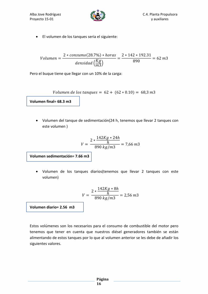
El volumen de los tanques seria el siguiente:
𝑉𝑜𝑙𝑢𝑚𝑒𝑛 = 2 ∗ 𝑐𝑜𝑛𝑠𝑢𝑚𝑜(28.7%) ∗ ℎ𝑜𝑟𝑎𝑠
𝑑𝑒𝑛𝑠𝑖𝑑𝑎𝑑 (𝐾𝑔𝑚3)
=2 ∗ 142 ∗ 192.31
890= 62 𝑚3
Pero el buque tiene que llegar con un 10% de la carga:
𝑉𝑜𝑙𝑢𝑚𝑒𝑛 𝑑𝑒 𝑙𝑜𝑠 𝑡𝑎𝑛𝑞𝑢𝑒𝑠 = 62 + (62 ∗ 0.10) = 68,3 𝑚3
Volumen final= 68.3 m3
Volumen del tanque de sedimentación(24 h, tenemos que llevar 2 tanques con
este volumen )
𝑉 = 2 ∗
142𝐾𝑔 ∗ 24ℎℎ
890 𝑘𝑔/𝑚3= 7,66 𝑚3
Volumen sedimentación= 7.66 m3
Volumen de los tanques diarios(tenemos que llevar 2 tanques con este
volumen)
𝑉 = 2 ∗
142𝐾𝑔 ∗ 8ℎℎ
890 𝑘𝑔/𝑚3= 2,56 𝑚3
Volumen diario= 2.56 m3
Estos volúmenes son los necesarios para el consumo de combustible del motor pero
tenemos que tener en cuenta que nuestros diésel generadores también se están
alimentando de estos tanques por lo que al volumen anterior se les debe de añadir los
siguientes valores.

Alba Jove Rodríguez C.4. Planta Propulsora Proyecto 15-01 y auxiliares
Página 17
5.1.1.2. Volumen necesario generadores:
Para calcular el combustible necesario para los generadores, nos vamos guiar por el
buque base, y nos vamos situar en la situación más extremas. Recordamos los distintos
diésel-generadores que lleva nuestro buque:
(Volvo Penta 225Kw (tenemos 2 unidades)
Volvo Penta 130Kw (tenemos 1 unidades)
Volvo Penta 105Kw (tenemos 1 unidades).
Al volumen total le tenemos que añadir:
𝑉𝑜𝑙𝑢𝑚𝑒𝑛(400𝐾𝑤) =142 ∗ 400 ∗ 2 ∗ 192
890= 24 𝑚3
𝑉𝑜𝑙𝑢𝑚𝑒𝑛(225𝐾𝑤) =142 ∗ 225 ∗ 2 ∗ 192
890= 14 𝑚3
𝑉𝑜𝑙𝑢𝑚𝑒𝑛(130𝐾𝑤) =130 ∗ 244 ∗ 1 ∗ 192
890= 3.62𝑚3
𝑉𝑜𝑙𝑢𝑚𝑒𝑛(105𝐾𝑤) =105 ∗ 212 ∗ 1 ∗ 192
890= 3.0 𝑚3
A los tanques de sedimentación:
𝑉𝑜𝑙𝑢𝑚𝑒𝑛(400𝐾𝑤) =142 ∗ 400 ∗ 2 ∗ 24
890= 3.55𝑚3
𝑉𝑜𝑙𝑢𝑚𝑒𝑛(225𝐾𝑤) =142 ∗ 225 ∗ 2 ∗ 24
890= 1.70𝑚3
𝑉𝑜𝑙𝑢𝑚𝑒𝑛(130𝐾𝑤) =142 ∗ 130 ∗ 2 ∗ 24
890= 0.50 𝑚3
𝑉𝑜𝑙𝑢𝑚𝑒𝑛(105𝐾𝑤) =142 ∗ 105 ∗ 2 ∗ 24
890= 0.38𝑚3

Alba Jove Rodríguez C.4. Planta Propulsora Proyecto 15-01 y auxiliares
Página 18
A los tanques diarios:
𝑣𝑜𝑙𝑢𝑚𝑒𝑛(400𝐾𝑤) =142 ∗ 400 ∗ 2 ∗ 8
890= 1.03𝑚3
𝑣𝑜𝑙𝑢𝑚𝑒𝑛(225𝐾𝑤) =142 ∗ 225 ∗ 2 ∗ 8
890= 0.58𝑚3
𝑉𝑜𝑙𝑢𝑚𝑒𝑛(225𝐾𝑤) =142 ∗ 130 ∗ 2 ∗ 8
890= 0.175𝑚3
𝑉𝑜𝑙𝑢𝑚𝑒𝑛(225𝐾𝑤) =142 ∗ 105 ∗ 2 ∗ 8
890= 0.134𝑚3
5.1.1.3. Volumen total
𝑉𝑜𝑙𝑢𝑚𝑒𝑛 𝑑𝑒 𝑙𝑜𝑠 𝑡𝑎𝑛𝑞𝑢𝑒𝑠 = 68.3 + 24 + 14 + 3.62 + 3.0 = 112.92 𝑚3
Volumen tanques = 112.92 m3
𝑉𝑜𝑙𝑢𝑚𝑒𝑛 𝑑𝑒 𝑠𝑒𝑑𝑖𝑚𝑒𝑛𝑡𝑎𝑐𝑖ó𝑛 = 7.66 + 3.55 + 1.7 + 0.5 + 0.38 = 13.8 𝑚3
Volumen sedimentación= 13.8 m3
𝑉𝑜𝑙𝑢𝑚𝑒𝑛 𝑑𝑖𝑎𝑟𝑖𝑜 = 2.56 + 1.03 + 0.58 + 0.175 + 0.134 = 4.479 𝑚3
Volumen diario= 13.8 m3
En este proyecto no fueron calculados los tanques del buque , ya que estos cálculos
son realizados en arquitectura naval.
Como se vieron necesarios para realizar el cálculo de las bombas a continuación
tendríamos un pequeño esquema de los tanques de combustible, teniendo los de
alimentación y los de sedimentación en el doble fondo del buque y los de consumo
diario en la cámara de máquinas:

Alba Jove Rodríguez C.4. Planta Propulsora Proyecto 15-01 y auxiliares
Página 19

Alba Jove Rodríguez C.4. Planta Propulsora Proyecto 15-01 y auxiliares
Página 20
5.1.2. Dimensionamiento de las bombas de trasiego y las tuberías
5.1.2.1. Descripción
Tuberías
El cálculo de las tuberías, se realizaran a partir del caudal que circulan por ellas y de la
velocidad, siendo la recomendable 1m/s.
Para el cálculo de las tuberías se va tener en cuenta:
- Caudal que circula por las tuberías a partir de las bombas de trasiego
- Diámetro óptimo de las tuberías
- Determinar la longitud del sistema
Bombas de trasiego
Las bombas de trasiego son las que son capaces de llenar tanto el tanque de
sedimentación como los tanques diarios en menos de 10h.
Para calcular la capacidad de la bomba de trasiego que tenemos entre el tanque de
almacenamiento y los de sedimentación tenemos que tener en cuenta de que tenemos
2 tanques.
Por otra parte también tenemos una bomba de trasiego de combustible de los tanques
de sedimentación a los de uso diario. Esta bomba será capaz de llenar los dos tanques
de uso diario en 8h.
En ambos casos tendremos que tener una bomba de trasiego de reserva.
5.1.2.2. Bomba de trasiego T.alimentación – T.sedimentación
𝑄𝑏𝑜𝑚𝑏𝑎 = 2 ∗15.75 𝑀3
10ℎ= 3.15 m3/h
Diámetro óptimo de la tubería.
El diámetro de las tuberías se realiza de manera conjunta dada la similitud de las
propiedades del fluido.
𝑄 = 𝑣 ∗ 𝑝𝑖 ∗𝐷2
4= 1 ∗ 3.14 ∗
𝑑2
4= 3.15 𝑚3/ℎ
√4 ∗ 3.15/𝑝𝑖 = 0.033 𝑚 = 33 𝑚𝑚

Alba Jove Rodríguez C.4. Planta Propulsora Proyecto 15-01 y auxiliares
Página 21
Una vez que tenemos este valor nos vamos a las tablas de norma ANSI B-36-10/AP de
donde sacamos el valor normalizado para el diámetro:
El valor normalizado del diámetro exterior de la tubería es de 33.4 mm por lo que la
velocidad es:
𝑄 = 𝑣 ∗ 𝑝𝑖 ∗𝑑2
4= 3.15, 𝑣 = 0.99
𝑚
𝑠= 1 𝑚/𝑠
Además tenemos que cumplir con los espesores mínimos por lo tanto el diámetro
exterior de la tubería por lo tanto el diámetro de la tubería será:
𝛷 = 33.4 + 40 = 73.4 𝑚𝑚

Alba Jove Rodríguez C.4. Planta Propulsora Proyecto 15-01 y auxiliares
Página 22
Nos vamos a la norma Une y buscamos tuberías normalizadas las tuberías que
suministran los tanques de sedimentación:
DN Diámetro Exterior (mm)
Espesor (mm)
Diámetro interior (mm)
80 88.9 4.85 84.05
Longitud de la tubería y accesorios
Tramo Longitud
1/1* 0.65 m
2/2* 0.15 m
3/3* 0.6 m
4/4* 0.3 m
5/5* 0.15 m
6/6* 0.65 m
7 0.7 m
8/8* 0.9 m
9/9* 0.6 m
10/10* 1.60 m
11/11* 0.75 m
12/12* 1.95 m
13 1.17 m

Alba Jove Rodríguez C.4. Planta Propulsora Proyecto 15-01 y auxiliares
Página 23
Accesorios
A parte de la longitud de las tuberías también tenemos que tener en cuenta los
accesorios y las válvulas, los codos de las tuberías se pueden despreciar.
Calculo de las pérdidas de carga
Las pérdidas de carga que nos podemos encontrar son:
- Perdidas por fricción (ecuación de Darcy- Weisbach y diagrama de Moody)
- Perdidas codos
- Perdidas válvulas
Se tiene que cumplir:
𝑃1
Ɣ+ 𝑧1 +
𝑣1^2
2 ∗ 𝑔− 𝐻𝑝𝑒𝑟𝑑𝑖𝑑𝑎𝑠 + ℎ𝑏𝑜𝑚𝑏𝑎 =
𝑃2
Ɣ+ 𝑧2 +
𝑣2^2
2 ∗ 𝑔
1. Perdidas por fricción
𝐻𝑓 = 𝑓 ∗𝑙 ∗ 𝑣2
𝑑 ∗ 2 ∗ 9.8
f: lo calculamos por f= 64/Re por estar en régimen laminar----f=0. 28
Re: Re= v*D /ѵ
v: Q=v*п*0.0889^2/4
Tramo Longitud F*v2 Perdidas
1 0.65 m 0.28 0.0021
2 0.15 m 0.28 0.0005
3 0.6 m 0.28 0.00194
4 0.3 m 0.28 0.00098
5 0.15 m 0.28 0.0005
6 0.65 m 0.28 0.0021
7 0.7 m 0.28 0.0030
8 0.9 m 0.28 0.0030
9 0.6 m 0.28 0.00194
10 1.60 m 0.28 0.0052
11 0.75 m 0.28 0.0030
12 1.95 m 0.28 0.0064
13 1.17 m 0.28 0.0040
0.035

Alba Jove Rodríguez C.4. Planta Propulsora Proyecto 15-01 y auxiliares
Página 24
2. Perdidas en accesorios
Tipo k Cantidad Perdidas
Válvulas 5 5 0.0257
Codos 0.9 4 0.0037
Total 0.03
Una vez que sabemos cuáles son las pérdidas en un tramo de la tubería tenemos
que hacer los cálculos para el caso más desfavorable que seria cuando el tanque de
alimentación está lleno. Vamos tomar A(tanque de alimentación) y S (tanque de
sedimentación).
𝑃𝐴
Ɣ+ 𝑧𝐴 +
𝑣𝐴^2
2 ∗ 𝑔− 𝐻𝑝𝑒𝑟𝑑𝑖𝑑𝑎𝑠 + ℎ𝑏𝑜𝑚𝑏𝑎 =
𝑃𝑆
Ɣ+ 𝑧𝑆 +
𝑣𝑆^2
2 ∗ 𝑔
12211𝐾𝑔
𝑚 ∗ 𝑠2
890 𝑘𝑔 ∗𝑚
𝑚3 ∗ 𝑠2
− 𝐻𝑝𝑒𝑟𝑑𝑖𝑑𝑎𝑠 = 13.62 𝑚
Hbomba= 13.62 m
Las bombas de trasiego serán una bombas de tornillo, que es otra forma de designar
las bombas centrifugas. Para saber la potencia necesaria de nuestra bomba usaremos
la siguiente formula:
𝑊 =(𝑄 ∗ Ɣ ∗ 𝐻𝑏𝑜𝑚𝑏𝑎)
264 ∗ 0.3=
2.5 ∗ 0.890 ∗ 13.62
264 ∗ 0.30= 0.4𝐾𝑤
El rendimiento será de aproximadamente 30%.
Se llevaran 2 bombas una de seguridad.
5.1.2.3. Bomba de trasiego T.sedimentación – T.diarios.
𝑄𝑏𝑜𝑚𝑏𝑎 = 2 ∗6 𝑚3
8ℎ=1.5 m3/h

Alba Jove Rodríguez C.4. Planta Propulsora Proyecto 15-01 y auxiliares
Página 25
Diámetro óptimo de la tubería.
El diámetro de las tuberías se realiza de manera conjunta dada la similitud de las
propiedades del fluido.
𝑄 = 𝑣 ∗ 𝑝𝑖 ∗𝐷2
4= 1 ∗ 3.14 ∗
𝑑2
4= 1.5 𝑚3/ℎ
√4 ∗ 1.50/𝑝𝑖 = 0.023 𝑚 = 23 𝑚𝑚
Una vez que tenemos este valor nos vamos a las tablas de norma ANSI B-36-10/AP de
donde sacamos el valor normalizado para el diámetro:

Alba Jove Rodríguez C.4. Planta Propulsora Proyecto 15-01 y auxiliares
Página 26
El valor normalizado del diámetro exterior de la tubería es de 26.7 mm por lo que la
velocidad es:
𝑄 = 𝑣 ∗ 𝑝𝑖 ∗𝑑2
4= 3.15, 𝑣 = 0.99
𝑚
𝑠= 1 𝑚/𝑠
Además tenemos que cumplir con los espesores mínimos por lo tanto el diámetro
exterior de la tubería por lo tanto el diámetro de la tubería será:
𝛷 = 26.7 + 40 = 66.7 𝑚𝑚
Nos vamos a la norma Une y buscamos tuberías normalizadas las tuberías que
suministran los tanques de sedimentación:
DN Diámetro Exterior
(mm)
Espesor
(mm)
Diámetro
interior (mm)
80 88.9 4.85 84.05
65 76.1 4.5 71.6
Longitud de la tubería y accesorios

Alba Jove Rodríguez C.4. Planta Propulsora Proyecto 15-01 y auxiliares
Página 27
Tramo Longitud
1 1.20 m
2 2.60 m
3 1.60 m
4/4* 0.60 m
5/5* 1.60 m
6/6* 1.10 m
7/7* 0.60 m
8 1.15 m
9 1.30 m
10 0.55 m
Accesorios
A parte de la longitud de las tuberías también tenemos que tener en cuenta los
accesorios y las válvulas, los codos de las tuberías se pueden despreciar
Calculo de las pérdidas de carga
Las pérdidas de carga que nos podemos encontrar son:
- Perdidas por fricción (ecuación de Darcy- Weisbach y diagrama de Moody)
- Perdidas codos
- Perdidas válvulas
Se tiene que cumplir:
𝑃1
Ɣ+ 𝑧1 +
𝑣1^2
2 ∗ 𝑔− 𝐻𝑝𝑒𝑟𝑑𝑖𝑑𝑎𝑠 + ℎ𝑏𝑜𝑚𝑏𝑎 =
𝑃2
Ɣ+ 𝑧2 +
𝑣2^2
2 ∗ 𝑔
1. Perdidas por fricción
𝐻𝑓 = 𝑓 ∗𝑙 ∗ 𝑣2
𝑑 ∗ 2 ∗ 9.8
f: lo calculamos por f= 64/Re por estar en régimen laminar----f=0. 02
Re: Re= v*D /ѵ
v: Q=v*п*0.0889^2/4=0.07 m/s

Alba Jove Rodríguez C.4. Planta Propulsora Proyecto 15-01 y auxiliares
Página 28
Tramo Longitud cnt Perdidas
1 1.20 m 0.04 0.001
2 2.60 m 0.04 0.0022
3 1.60 m 0.04 0.001
4/4* 0.60 m 0.04 0.0005
5/5* 1.60 m 0.04 0.001
6/6* 1.10 m 0.04 0.0008
7/7* 0.60 m 0.04 0.0005
8 1.15 m 0.04 0.0008
9 1.30 m 0.04 0.001
10 0.55 m 0.04 0.0005
0.009
2. Perdidas en accesorios
Tipo K Cantidad Perdidas
Válvulas 5 4 0.005
Codos 0.9 7 0.0008
Total 0.0058
Una vez que sabemos cuáles son las pérdidas en un tramo de la tubería tenemos que
hacer los cálculos para el caso más desfavorable que sería cuando el tanque de
alimentación está lleno. Vamos tomar S(tanque de sedimentación) y D (tanque de
diario)
𝑃𝑆
Ɣ+ 𝑧𝑆 +
𝑣𝑆^2
2 ∗ 𝑔− 𝐻𝑝𝑒𝑟𝑑𝑖𝑑𝑎𝑠 + ℎ𝑏𝑜𝑚𝑏𝑎 =
𝑃𝐷
Ɣ+ 𝑧𝐷 +
𝑣𝐷^2
2 ∗ 𝑔
12211𝐾𝑔
𝑚 ∗ 𝑠2
890 𝑘𝑔 ∗𝑚
𝑚3 ∗ 𝑠2
2.6 − 𝐻𝑝𝑒𝑟𝑑𝑖𝑑𝑎𝑠 = 16.2 𝑚
Hbomba= 16.20 m
Las bombas de trasiego serán una bombas de tornillo, que es otra forma de designar
las bombas centrifugas. Para saber la potencia necesaria de nuestra bomba usaremos
la siguiente formula:
𝑃 =(𝑄 ∗ Ɣ ∗ 𝐻𝑏𝑜𝑚𝑏𝑎)
264 ∗ 0.30=
1.5 ∗ 0.890 ∗ 16.2
264 ∗ 0.30= 0.30𝐾𝑤
ɳ,El rendimiento será de aproximadamente 30%.

Alba Jove Rodríguez C.4. Planta Propulsora Proyecto 15-01 y auxiliares
Página 29
Se llevaran 2 bombas una de seguridad.
Una vez que tenemos calculadas las potencias entramos en un catálogo de bombas
centrifugas de la serie BT para ver si podrían ser estas potencias:

Alba Jove Rodríguez C.4. Planta Propulsora Proyecto 15-01 y auxiliares
Página 30
5.1.2. Separadoras.
A continuación se muestra el separador mostrado por el fabricante:
Los cálculos también se hacen a partir de la siguiente formula:
𝑄 =𝑃 ∗ 𝑏 ∗ 24(ℎ)
(𝑑𝑒𝑛𝑠𝑖𝑑𝑎𝑑 ∗ 𝑡)=
2600 ∗ (1.15 ∗ 142) ∗ 24
890 ∗ 23.5= 0.5 𝑚3/ℎ
P, max continuous rating of the diesel engine(KW)
b,Specific fuel consumption + 15% (g/Kwh)
Density of the fuel (Kg/m3)
Daily separating time for self clearning separator(h) usually=23h or 23,5 h
Como tenemos 2 motores principales:
𝑄 = 0.5 ∗ 2 = 1 𝑚3

Alba Jove Rodríguez C.4. Planta Propulsora Proyecto 15-01 y auxiliares
Página 31
También tenemos que tener en cuenta los generadores:
𝑄(400 𝑘𝑤) = 2 ∗400 ∗ (1.15 ∗ 142) ∗ 24
890 ∗ 23.5= 0.17 𝑚3/ℎ
𝑄(225 𝑘𝑤) = 2 ∗255 ∗ (1.15 ∗ 233) ∗ 24
890 ∗ 23.5= 0.16 𝑚3/ℎ
𝑄( 130 𝑘𝑤) = 1 ∗130 ∗ (1.15 ∗ 244) ∗ 24
890 ∗ 23.5= 0.05𝑚3/ℎ
𝑄(105 𝑘𝑤) = 1 ∗105 ∗ (1.15 ∗ 212) ∗ 24
890 ∗ 23.5= 0.03 𝑚3/ℎ
El caudal total seria la suma de los motores más los generadores:
𝑄 = 1.40 𝑚3/ℎ
Se llevaran en el buque 2 separadoras.
Bombas de alimentación de las separadoras:
Se llevaran 2 bombas,(una de reserva),la capacidad de estas bombas será como
mínimo de 1.24 m3/h, y la presión será dada por el fabricante.
Precalentador de la separadora.
La fórmula que utilizamos para calcular la potencia es la dada en el manual de wartsila.
𝑃 = 𝑄 ∗𝐴𝑇
1700
En la guía nos dice que la temperatura a la salida del precalentador debe ser de 10-
40ºC, y la temperatura en los tanques debe ser de 15º, poniéndonos en el caso as
extremo AT=40-15=25ºc
𝑃 = 1.24 ∗25
1700= 18.25 𝐾𝑤

Alba Jove Rodríguez C.4. Planta Propulsora Proyecto 15-01 y auxiliares
Página 32
Bomba de circulación de combustible
En el guion de wartsila tenemos en la página 48, como calcular la capacidad de las
bombas de combustible.
𝐶𝑎𝑝𝑎𝑐𝑖𝑑𝑎𝑑 = 2600𝑘𝑤 ∗6 ∗ 142 𝑔
𝐾𝑤 ℎ+ 255𝑘𝑤 ∗
6 ∗ 233𝑔
𝐾𝑤 ℎ+ 130𝑘𝑤 ∗
6 ∗ 244𝑔
𝐾𝑤ℎ+
+400𝐾𝑤 ∗6 ∗ 142𝑔
𝐾𝑤 ℎ=
2762.01 𝐾𝑔
ℎ∗
1 𝑚3
890 𝑘𝑔= 3.48 𝑚3/ℎ
𝐶𝑎𝑝𝑎𝑐𝑖𝑑𝑎𝑑 = 2600𝑘𝑤 ∗6 ∗ 142 𝑔
𝐾𝑤 ℎ+ 255𝑘𝑤 ∗
6 ∗ 233𝑔
𝐾𝑤 ℎ+ 105𝑘𝑤 ∗
6 ∗ 212𝑔
𝐾𝑤ℎ=
2705.25 𝐾𝑔
ℎ∗
1 𝑚3
890 𝑘𝑔= 3.42 𝑚3/ℎ
Aunque las capacidades de las bombas son distintas, por seguridad y diseño se llevaran
3 bombas con las siguientes características:
BOMBAS
Cantidad 3
Caudal(m3/h) 3.5
Presión(bar) 16

Alba Jove Rodríguez C.4. Planta Propulsora Proyecto 15-01 y auxiliares
Página 33
5.2. Servicios de lubricación:
El servicio de lubricación es el encargado de proporcionar aceite.
La función principal de los aceites es lubricar los motores, para protegerlos de las
fricciones excesivas, de altas temperaturas y de posibles corrosiones químicas que se
pueden producir en la cámara de combustión.
5.2.1. Sistema de lubricación interno
Los motores de wartsila van equipados mediante un sistema de lubricación interno
compuesto por válvulas y bombas de pre-lubricación :
Alba Jove Rodríguez C.4. Planta Propulsora Proyecto 15-01 y auxiliares
Página 34
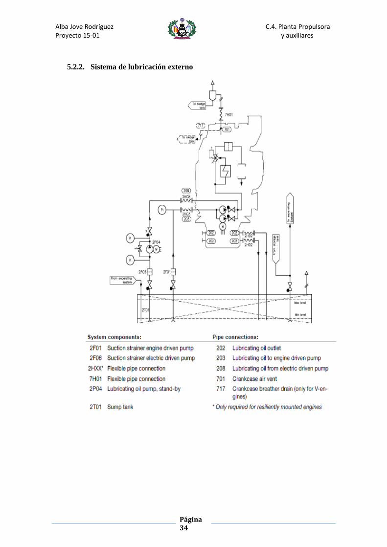
5.2.2. Sistema de lubricación externo

Alba Jove Rodríguez C.4. Planta Propulsora Proyecto 15-01 y auxiliares
Página 35
5.2.3. Cálculos
En la siguiente tabla tenemos los datos necesarios para realizar todos los cálculos:
5.2.3.1.Volumen de los tanques:
El consumo de aceite está considerado entre 0,5 Kg/Kwh según la guía del motor y
sabiendo que es estimado en valor del combustible.
Esto quiero decir que si cada 142 Kg/h consumimos 0.5kg/ el volumen del tanque los
podemos realizar de la siguiente manera.
Para una autonomía de 2500 millas tenemos:
Consumo del motor:
𝐶𝑜𝑛𝑠𝑢𝑚𝑜 𝑑𝑒 𝑎𝑐𝑒𝑖𝑡𝑒 = 0.5𝑔
𝐾𝑤ℎ∗ 2600 ∗
2500 𝑚𝑖𝑙𝑙𝑎𝑠
13= 250 𝑘𝑔 = 0.28 𝑚3
𝐶𝑜𝑛𝑠𝑢𝑚𝑜 𝑑𝑒 𝑙𝑜𝑠 2 𝑚𝑜𝑡𝑜𝑟𝑒𝑠 = 0.28 ∗ 2 = 0.56 𝑚3
Nota: se toma como densidad del aceite 905Kg/m3

Alba Jove Rodríguez C.4. Planta Propulsora Proyecto 15-01 y auxiliares
Página 36
Consumo de los diésel-generadores
𝐶(400 𝑘𝑤) = 2 ∗0.04 (
𝑙ℎ
) ∗ 0.001 (𝑚3
𝑙) ∗ 192ℎ
1= 0.015𝑚3
𝐶(225 𝑘𝑤) = 2 ∗0.04 (
𝑙ℎ
) ∗ 0.001 (𝑚3
𝑙) ∗ 192ℎ
1= 0.015𝑚3
𝐶( 130 𝑘𝑤) = 1 ∗0.02 (
𝑙ℎ
) ∗ 0.001 (𝑚3
𝑙) ∗ 192ℎ
1= 0.0039𝑚3
𝑐(105 𝑘𝑤) = 1 ∗0.02 (
𝑙ℎ
) ∗ 0.001 (𝑚3
𝑙) ∗ 192ℎ
1= 0.0039
𝑚3
ℎ
El volumen necesario para los generadores= 0.037 m3
El volumen necesario para cada suministro es de 0.28+(0.037)=0.317 m3
Vol.Tanque.Lubricación= 0.634 m3
5.2.3.2. Separadora.
Para calcular el caudal de las separadoras tenemos en cuenta los pasos y las formulas
dadas en la guía del motor:

Alba Jove Rodríguez C.4. Planta Propulsora Proyecto 15-01 y auxiliares
Página 37
Caudal para los motores principales
𝑄 =1.35 ∗ 𝑃 ∗ 𝑛
23=
1.35 ∗ 2600 ∗ 4
23= 0.62𝑚3/ℎ
Como tenemos 2 motores el caudal será
𝑄 = 0.62 ∗ 2 = 1.24 𝑚3
Caudal para los diésel-generadores
𝑄(225𝐾𝑤) =1.35 ∗ 𝑃 ∗ 𝑛
23=
1.35 ∗ 400 ∗ 4
23= 0.10 𝑚3/ℎ
𝑄(225𝐾𝑤) =1.35 ∗ 𝑃 ∗ 𝑛
23=
1.35 ∗ 225 ∗ 4
23= 0.06 𝑚3/ℎ
𝑄(130𝐾𝑤) =1.35 ∗ 𝑃 ∗ 𝑛
23=
1.35 ∗ 130 ∗ 4
23= 0.03 𝑚3/ℎ
𝑄(105𝐾𝑤) =1.35 ∗ 𝑃 ∗ 𝑛
23=
1.35 ∗ 105 ∗ 4
23= 0.025 𝑚3/ℎ
El caudal total
𝑄 = 1.24 + 0.06 + 0.03 + 0.025 + 0.1 = 1.455 𝑚3/ℎ = 1455𝑙/ℎ
5.2.3.3. Bombas
Bombas de alimentación de la separadora
Se tendrán 2 bombas de alimentación a las separadoras, una de ellas en reserva, con
capacidad para el caudal total calculado.
BOMBAS
Cantidad 2
Caudal(m3/h) 1.455
Presión(bar) 8

Alba Jove Rodríguez C.4. Planta Propulsora Proyecto 15-01 y auxiliares
Página 38
Bombas de trasiego
Las bombas de trasiego serán capaz de suministrar 1.6 m3 en el tiempo de media hora.
Dispondremos una bomba para cada motor y una de reserva para cada uno. Trabajará
a 800Kpa(8 bar).
𝑃𝑜𝑡𝑒𝑛𝑐𝑖𝑎(𝐾𝑤) =𝑄 (
𝑚3ℎ
) ∗ 𝐻(𝑚𝑐𝑎) ∗ 𝑑𝑒𝑛𝑠 (𝑡
𝑚3)
264 ∗ 𝑛=
1.60.5⁄ ∗ 80 ∗ 0.850
370 ∗ 0.44= 1.4 𝐾𝑤
Bombas lubricación Pincipal.
En la tabla insertada al principio de este apartado tenemos los datos necesarios para el
cálculo de la potencia:
𝑃𝑜𝑡𝑒𝑛𝑐𝑖𝑎(𝐾𝑤) =𝑄 (
𝑚3ℎ
) ∗ 𝐻(𝑚𝑐𝑎) ∗ 𝑑𝑒𝑛𝑠 (𝑡
𝑚3)
370 ∗ 𝑛=
81 ∗ 45 ∗ 0.850
370 ∗ 0.5= 16𝐾𝑤
Bombas lubricación Stand-by.
Las bombas de lubricación de los motores principales se dimensionarán como se indica
en el manual del wartsila:

Alba Jove Rodríguez C.4. Planta Propulsora Proyecto 15-01 y auxiliares
Página 39
Con esta descripción y la primera tabla de este apartado obtenemos las siguientes
características para las bombas:
BOMBAS
Cantidad 2
Caudal(m3/h) 81
Presión(bar) 8
𝑃𝑜𝑡𝑒𝑛𝑐𝑖𝑎(𝐾𝑤) =𝑄 (
𝑚3ℎ
) ∗ 𝐻(𝑚𝑐𝑎) ∗ 𝑑𝑒𝑛𝑠 (𝑡
𝑚3)
370 ∗ 𝑛=
81 ∗ 80 ∗ 0.850
370 ∗ 0.5= 17 𝐾𝑤
Existe una clara diferencia entre la bomba de stand-by y la de alimentación, la primera
sería una bomba de reserva de esta, por lo tanto aunque la guía del motor nos de unos
caudales diferentes vamos instalar 2 bombas iguales y sus características serían las
siguientes:
BOMBAS
Potencia(Kw) 23.5
Caudal(m3/h) 75
Presión(bar) 8
5.3. Servicio de aire de arranque:
Todos los motores son arrancados mediante aire comprimido a una presión de 30
bares(indicada en la guía del motor). El arranque se realiza por inyección directa.
En este servicio también tenemos un sistema interno y un sistema externo.
En este apartado se calculará la capacidad de las botellas de aire comprimido para el
arranque de los motores, correspondiente al servicio externo de aire de arranque.
Éste está regulado por las Sociedades de Clasificación, en nuestro caso el Bureau
Veritas.

Alba Jove Rodríguez C.4. Planta Propulsora Proyecto 15-01 y auxiliares
Página 40
En la guía del motor tenemos:
5.3.1. Botellas
Para realizar el cálculo de las botellas vamos usar el Bureau Veritas y la guía del motor.

Alba Jove Rodríguez C.4. Planta Propulsora Proyecto 15-01 y auxiliares
Página 41
𝑉𝑟 =𝑃𝑒 ∗ 𝑉𝑒 ∗ 𝑛
𝑃𝑟𝑚𝑎𝑥 − 𝑃𝑟𝑚𝑖𝑛=
0.1 ∗ 1.8 ∗ 6
3 − 1.8= 0.9𝑚3
N=6(ch1,sec 2,[3.1.1],en el convenio tenemos que el número de arrancadas serán 12
pero nunca inferior a 6
En el Bureau veritas se nos indica que se debe llevar como mínimo 2 botelles. Por lo
que se llevaran 2 botellas con las siguientes características.
5.3.2. Compresores:
Se necesitan dos compresores, con una capacidad suficiente para cargarl las botellas
de aire en 1h(según indica el Bureau Veritas).
Tenemos:
𝑃1 ∗ 𝑉1𝛾 = 𝑃2 ∗ 𝑉2𝛾
DATOS
P1(Mpa) 1.8
P2(Mpa) 3
V2(m3) 2*0.5=1
𝛾 1.4
V1(m3) 1.44

Alba Jove Rodríguez C.4. Planta Propulsora Proyecto 15-01 y auxiliares
Página 42
El caudal seria 1.44 m3/h , por lo que necesitamos un compresor que se nos adapte a
este caudal.
La potencia seria:
𝑃𝑜𝑡𝑒𝑛𝑐𝑖𝑎 = 𝜸
𝜸 − 𝟏∗ (
𝑷𝟏 ∗ 𝑸
𝟐𝟕) ∗ (
𝑷𝟐
𝑷𝟏)
𝜸−𝟏𝜸
− 𝟏 ∗ (𝟏
𝟎. 𝟔𝟓) = 𝟎. 𝟓𝟒 𝑲𝒘
El compresor elegido para la instalación seria el modelo más sencillo de Hatlapa L9, sus
características son las siguientes:
5.4. Sistema de refrigeración
El sistema de refrigeración consta de un sistema de agua dulce y un sistema de agua
salada.
Otra opción sería utilizar aceite en el sistema de refrigeración pero el agua es más
eficiente.
Para los siguientes apartados vamos utilizar la guía del motor wartsila.
5.4.1. Agua dulce

Alba Jove Rodríguez C.4. Planta Propulsora Proyecto 15-01 y auxiliares
Página 43
El sistema de agua dulce se puede estudiar de dos formas:
1. El primer estudio se divide en circuitos de alta y baja temperatura. El circuito de
baja temperatura es el encardo de enfriar el aceite de refrigeración y el circuito
de alta es el encargado de refrigerar las camisas y las cabezas de los cilindros y
del turbocompresor.
2. También se puede dividir en un sistema interno y un sistema externo. Su
sistema interno de refrigeración se diferencia del anterior en el número de
etapas del turbocompresor. En este caso, sólo existe una etapa y se encuentra
en el circuito de baja temperatura.
A continuación se muestra el sistema interno y externo de un motor en línea.

Alba Jove Rodríguez C.4. Planta Propulsora Proyecto 15-01 y auxiliares
Página 44

Alba Jove Rodríguez C.4. Planta Propulsora Proyecto 15-01 y auxiliares
Página 45
5.4.1.1. Circuito de baja temperatura
Se llevarán 2 bombas, y las características las tenemos en la guía del motor:
Caudal (Q=56 m3/h)
Diámetro (d=204mm)
Presión de columna de agua (P=27 mH2O=2.7 bar)

Alba Jove Rodríguez C.4. Planta Propulsora Proyecto 15-01 y auxiliares
Página 46
La potencia necesaria será:
𝑷(𝑲𝑾) =𝟓𝟔 𝒎𝟑/𝒉 ∗ 𝟐𝟕(𝒎𝒄𝒂) ∗ 𝟏
𝟐𝟕𝟎= 𝟓. 𝟔 𝑲𝒘
5.4.1.2. Circuito de alta temperatura
Caudal (45 m3/h)
Diámetro (d=216 mm)
Presión de columna de agua (P=36 mca=3.6 bar)

Alba Jove Rodríguez C.4. Planta Propulsora Proyecto 15-01 y auxiliares
Página 47
𝑷(𝑲𝑾) =𝟒𝟓 𝒎𝟑/𝒉 ∗ 𝟑𝟔(𝒎𝒄𝒂) ∗ 𝟏
𝟐𝟕𝟎= 𝟔. 𝟎 𝑲𝒘
5.4.1.3.Intercambiadores
5.4.1.3.1. Aceite lubricante
Los intercambiadores encargados de enfriar el aceite lubricante se pueden calcular con
la siguiente formula:
𝑃 = 𝑞 ∗ 𝑑𝑒𝑛𝑠 ∗ 𝐶𝑝 ∗ 𝐴𝑡 ∗ (1000/3600) = 347 𝑘𝑤
q= caudal de aceite de lubricación de las bombas principales=81 m3/h
dens=densidad del aceite lubricante=0.92 t/m3
Cp= densidad de aceite lubricante(KJ/KgK)=1.672
At= Incremento de temperatura del aceite(78-68)=10º
5.4.1.3.2. Agua dulce
Para calcular el caudal necesario en estes intercambiadores, nos vamos a la guía de
wartsila de la serie 32.

Alba Jove Rodríguez C.4. Planta Propulsora Proyecto 15-01 y auxiliares
Página 48
Los datos necesarios para el cálculo de la formula los tenemos en la especificación
técnica de nuestra guía del motor:
𝑞 = 𝑞𝑙𝑡 + 3.6 ∗ ∅
4.15 ∗ (𝑇𝑜𝑢𝑡 − 𝑇𝑖𝑛)= 56 +
3.6 ∗ 441
4.15 ∗ (91 − 38)= 63 𝑚3/ℎ
5.4.1.4. Precalentadores de agua dulce:
Se recomienda calentar el agua del circuito de alta temperatura cerca de la
temperatura normal de operación en instalaciones que operan con diésel marino.
El precalentador del agua de refrigeración tiene por tanto la función de calentar dicha
agua a una temperatura superior a los 60º.
La potencia de calentamiento determina el tiempo requerido para calentar el motor.La
potencia mínima requerida para el calentamiento del motor desde 20ºc a 60/70ºc de
10 a 15 h es:

Alba Jove Rodríguez C.4. Planta Propulsora Proyecto 15-01 y auxiliares
Página 49
De la guía del motor obtenemos todos los datos necesarios para resolver la fórmula:
𝑃 =(70 − 20) ∗ (45 ∗ 0.14 + 0.48 ∗ 1.6 + 0.4 ∗ 1.16)
15+ 0.75 ∗ 8 = 31.2 𝐾𝑤
Meng=peso del motor (45tn)
Vlo= oil volume wet sump now (1.6)
Vfw=water volume in engine (0.4)
Ncyl=8
Se llevarán tres precalentadores, uno de los cuales será de reserva, cada uno de ellos
será de 31.2 Kw.
Alba Jove Rodríguez C.4. Planta Propulsora Proyecto 15-01 y auxiliares
Página 50
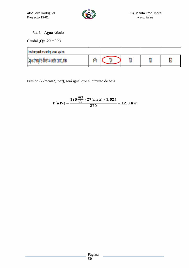
5.4.2. Agua salada
Caudal (Q=120 m3/h)
Presión (27mca=2,7bar), será igual que el circuito de baja
𝑷(𝑲𝑾) =𝟏𝟐𝟎
𝒎𝟑𝒉
∗ 𝟐𝟕(𝒎𝒄𝒂) ∗ 𝟏. 𝟎𝟐𝟓
𝟐𝟕𝟎= 𝟏𝟐. 𝟑 𝑲𝒘

Alba Jove Rodríguez C.4. Planta Propulsora Proyecto 15-01 y auxiliares
Página 51
6. Ventilación de la cámara de máquinas.
La ventilación es una parte muy importante dentro de los sistemas auxiliares. Ya que el
aire que se suministra en la cámara de máquinas va ser utilizada para:
Aire de combustión de los motores, tanto los motores principales como los
diésel-generadores.
Aire de evacuación de calor generado por os motores y resto de equipos
Aire de ventilación para renovaciones
Para el cálculo de la ventilación de la cámara de máquinas se utilizara la norma
ISO_EN_ISO_8861_1999.
6.1. Condiciones de diseño
Para cumplir los requisitos anteriores el sistema de ventilación debe cumplir:
El aire debe distribuirse a todas las partes de la sala de máquinas, de tal manera
que no que bolsas de aire caliente en ninguna zona de la sala de maquinas
Se debe tener especial cuidado con las zonas de gran emisión de calor y zonas
de trabajo, se debe tener siempre un ambiente limpio y confortable.
El flujo de aire total en la sala de máquinas debe ser al menos el valor mas alto de los
dos cálculos siguiente:
Q=qc +qh, siendo qc el flujo de aire que se necesita en la combustión y qh el
flujo de aire para la evacuación de calor
Q=1.5*qc, el flujo de aire total de la sala de máquinas no debe ser menor que el
flujo de aire para combustión más el 50%.
Los cálculos deben basarse en el máximo régimen de los motores diésel principales, los
motores diésel de los generadores, calderas y el resto de maquinaria trabajando
simultáneamente en condiciones normales, y con un aumento de 12.5 K.4
Para los cálculos de la cámara de máquinas se tomará como temperatura exterior +35º

Alba Jove Rodríguez C.4. Planta Propulsora Proyecto 15-01 y auxiliares
Página 52
6.2.Calculo del flujo de aire para la combustión
La cantidad de flujo de aire para la combustión (qc), debe calcularse en metros
cúbicos por segundo, siguiendo la siguiente ecuación.
𝑞𝑐 = 𝑞𝑑𝑝 + 𝑞𝑑𝑔 + 𝑞𝑏
qdp, es el flujo de aire para la combustión de los motores principales diésel, en
metros cúbicos.
qdg, es el flujo de aire para la combustión de los motores diésel generadores en
metros cúbicos por segundo
qb, es el flujo de aire para la combustión de la caldera en metros cúbicos por
segundo, si es relevante en condiciones normales.
qdp,(Combustión motores principales)
El flujo de aire para combustión para los motores principales diésel debe calcularse en
metros cúbicos a partir de la siguiente formula:
𝑞𝑑𝑝 =𝑃𝑑𝑝 ∗ 𝑚𝑎𝑑
𝑑𝑒𝑛𝑠𝑖𝑑𝑎𝑑=
2 ∗ 0.002 ∗ 2600
1.13= 9.20𝑚3/𝑠
Pdp, es la potencia normalizada de los motores principales, la máxima potencia
de salida continua en Kw
mad, es el aire necesario en la combustión del motor(0.002Kg/Kw.s)
densidad,1.13 Kg/m3.
qdp=9.20 m3/s
qdg,(Combustión de los generadores)
El flujo de aire para combustión para los diésel generadores debe calcularse en metros
cúbicos a partir de la siguiente formula:
𝑞𝑑𝑔 =𝑃𝑑𝑝 ∗ 𝑚𝑎𝑑
𝑑𝑒𝑛𝑠𝑖𝑑𝑎𝑑=
2 ∗ 0.002 ∗ 400
1.13= 1.41 𝑚3/𝑠

Alba Jove Rodríguez C.4. Planta Propulsora Proyecto 15-01 y auxiliares
Página 53
𝑞𝑑𝑔 =𝑃𝑑𝑝 ∗ 𝑚𝑎𝑑
𝑑𝑒𝑛𝑠𝑖𝑑𝑎𝑑=
2 ∗ 0.002 ∗ 225
1.13= 0.90 𝑚3/𝑠
𝑞𝑑𝑔 =𝑃𝑑𝑝 ∗ 𝑚𝑎𝑑
𝑑𝑒𝑛𝑠𝑖𝑑𝑎𝑑=
0.002 ∗ 130
1.13= 0.23 𝑚3/𝑠
𝑞𝑑𝑔 =𝑃𝑑𝑝 ∗ 𝑚𝑎𝑑
𝑑𝑒𝑛𝑠𝑖𝑑𝑎𝑑=
0.002 ∗ 105
1.13= 0.186 𝑚3/𝑠
Pdg, es la potencia normalizada de cada uno de los diésel generadores, la
máxima potencia de salida continua en Kw
mad, es el aire necesario en la combustión del motor(0.002Kg/Kw.s)
densidad,1.13 Kg/m3.
qb( la combustión de la caldera)
En estos cálculos lo consideramos nulo.
𝑞𝑐 = 𝑞𝑑𝑝 + 𝑞𝑑𝑔 + 𝑞𝑏 = 9.2 + 1.41 + 0.9 + 0.23 + 0.186 + 0 = 11.94 𝑚3/𝑠
qc= 11.94 m/s

Alba Jove Rodríguez C.4. Planta Propulsora Proyecto 15-01 y auxiliares
Página 54
6.3. Flujo de aire para evacuación de la emisión de calor
La cantidad de flujo de aire necesaria para la evacuación de calor qh, debe calcularse,
en metros cúbicos por segundo, como sigue:
𝑞ℎ =∅𝑑𝑝 + ∅𝑑𝑔 + ∅𝑏 + ∅𝑝 + ∅𝑔 + ∅𝑒𝑙 + ∅𝑒𝑝 + ∅𝑡 + ∅𝑜
𝜌 ∗ 𝑐 ∗ ∆𝑡− 0.4 ∗ (𝑞𝑑𝑝 + 𝑞𝑑𝑔)
− 𝑞𝑏 =
∅𝒅𝒑 (emisión de los motores diésel principales)
Como tenemos 2 motores ∅𝒅𝒑 = 𝟏𝟐𝟐 ∗ 𝟐 = 𝟏𝟒𝟒 𝑲𝒘
∅𝒅𝒑 = 𝟏𝟐𝟐 ∗ 𝟐 = 𝟏𝟒𝟒 𝑲𝒘

Alba Jove Rodríguez C.4. Planta Propulsora Proyecto 15-01 y auxiliares
Página 55
∅𝒅𝒈 ( emisión de los motores diésel generador)
La fórmula que tenemos que utilizar es ϕdg=(0.396*P0.70),para 2 diésel generadores de
400 Kw, para 2 diésel generadores de 225 Kw, un diésel generador de 130Kw y un
diésel generador de 105 Kw.
∅𝑑𝑔 = 2 ∗ (0.396 ∗ 4000.70) + 2 ∗ (0.396 ∗ 2250.70) + (0.396 ∗ 1300.70)
+ (0.396 ∗ 1050.70) = 109.8 𝐾𝑤
∅𝒃 (emisión de las calderas y calentadores de flujo térmico)
En este buque no es necesario.

Alba Jove Rodríguez C.4. Planta Propulsora Proyecto 15-01 y auxiliares
Página 56
∅𝒈 (emisión del calor de los generadores eléctricos )
Utilizamos el rendimiento recomendado por la UNE (Ƞ=0.94% )
∅𝑔 = 400 ∗ 2 ∗ (1 − 0.94) + 225 ∗ 2 ∗ (1 − 0.94) +
130 ∗ 1 ∗ (1 − 0.94) + 105 ∗ 1 ∗ (1 − 0.94) = 89.5 𝐾w
∅𝒆𝒍 (emisión de calor de las instalaciones eléctricas)
Debe de calcularse en Kw, de acuerdo con cada uno de los siguientes métodos
alternativos:
1. Cuando se sepan todos los detalles de las instalaciones eléctricas, la emisión de
calor se debe tomar como la suma de la emisión simultanea de calor.
2. Cuando no se saben todos los detalles de las instalaciones eléctricas la emisión
de calor se toma como el 20% de la potencia de régimen del equipo eléctrico y
de la iluminación en la mar.
3. Cuando no se puede calcular por los dos puntos anteriores se toma de la forma
conservadora y ∅𝒆𝒍 = ∅𝒈
∅𝒆𝒍 = ∅𝒈 = 𝟖𝟗. 𝟓 𝑲𝒘
∅𝒆𝒑 ( emisión de la color por las tuberías de escape)
La emisión de calor de las tuberías de escape puede determinarse a partir de las curvas
en el apartado 7.3 de la norma, en Kilovatios por metro de tubería.

Alba Jove Rodríguez C.4. Planta Propulsora Proyecto 15-01 y auxiliares
Página 57
Si utilizara como At=300 k al no haber cifras específicas disponibles, y el diámetro de la
tubería nos la da la guía del motor.
Para el cálculo de los generadores nos vamos guiar por la guía del volvo penta
(ϕ=0.490 mm).
De la gráfica podemos sacar la emisión de las tuberías de escape de los motores
principales y las longitudes de las tuberías de escape las tomamos de la sala de
máquinas.
Para los motores principales:
0.45 Kw/m
Longitud=2*3m=6m
Emision=0.45*6=2.7 Kw
Para los cuatro generadores:

Alba Jove Rodríguez C.4. Planta Propulsora Proyecto 15-01 y auxiliares
Página 58
0.4 Kw/ m
Longitud=4*3=12
Emisión=0.4*12=4.8 Kw
Emisión de otros componentes
En este apartado se tienen en cuenta otros elementos que no fueron calculados
individualmente, como los compresores, intercambiadores de calor, sistemas de
tuberías,…
Se tomara este valor como el 20% de la emisión de los generadores eléctricos:
𝛷𝑜𝑡𝑟𝑜𝑠 = 0.2 ∗ 89.5 = 17.9 𝐾𝑤
Si aplicamos la ecuación tenemos:
𝑞ℎ =∅𝑑𝑝 + ∅𝑑𝑔 + ∅𝑏 + ∅𝑝 + ∅𝑔 + ∅𝑒𝑙 + ∅𝑒𝑝 + ∅𝑡 + ∅𝑜
𝜌 ∗ 𝑐 ∗ ∆𝑡− 0.4 ∗ (𝑞𝑑𝑝 + 𝑞𝑑𝑔) − 𝑞𝑏 =
𝑞ℎ =144 + 109.8 + 89.5 + 89.5 + 7.5 + 17.9
1.13 ∗ 1.01 ∗ 12.5− 0.4 ∗ (9.2 + 2.8) = 27.32 𝐾𝑤
Para saber el flujo total tenemos que saber cuál de las 2 formulas nos da el
mayor resultado:
𝑄1 = 𝑞𝑐 + 𝑞ℎ = 11.94 + 27.32 = 39.26 𝑚3/𝑠
𝑄2 = 1.5 ∗ 𝑞𝑐 = 17.92 𝑚3/𝑠
El flujo total de aire es 39.26 m3/s = 141336.00 m3/h
6.4. Ventiladores:
Tenemos que aplicar un porcentaje de 5%:
𝑄 = 141336 + 0.05 ∗ 1441336 = 148402,00 𝑚3/ℎ
Una vez que sabemos cuál es el flujo de aire calculado tenemos que elegir el modelo de
los ventiladores:
Deberán ser ventiladores helicoidales
4 ventiladores +1 para tener uno de reserva.

Alba Jove Rodríguez C.4. Planta Propulsora Proyecto 15-01 y auxiliares
Página 59
El modelo elegido es HTP-80-4T-15 porque es el que mejor se adapta, las
características principales son las siguientes y la guía de los ventiladores será anexada.
Descripción de la ventilación elegida
Tipo HTP-80-4T-15
Cantidad 5
Velocidad unitaria (r/min) 1460
Potencia unitaria (Kw) 11
Potencia total(Kw) 55
Caudal unitario (m3/h) 40.000
Caudal total (m3/h) 200.000

ANEXO 1 (Guía Motor)

WÄRTSILÄ 26 PRODUCT GUIDE


IntroductionThis Product Guide provides data and system proposals for the early design phase of marine engine install-ations. For contracted projects specific instructions for planning the installation are always delivered. Anydata and information herein is subject to revision without notice. This 1/2013 issue replaces all previousissues of the Wärtsilä 26 Project Guides.
UpdatesPublishedIssue
Updates throughout the product guide20.11.20131/2013
Attached drawings updated (Online version).xx.01.20102/2009
Technical data added for IMO Tier 2 engines, Compact Silencer System added,Chapter Exhaust Emissions updated and several other minor updates
26.11.20091/2009
Wärtsilä, Ship Power Technology
Vaasa, November 2013
THIS PUBLICATION IS DESIGNED TO PROVIDE AS ACCURATE AND AUTHORITATIVE INFORMATION REGARDING THE SUBJECTS COVERED ASWAS AVAILABLE AT THE TIME OF WRITING. HOWEVER, THE PUBLICATION DEALS WITH COMPLICATED TECHNICAL MATTERS AND THE DESIGNOF THE SUBJECT AND PRODUCTS IS SUBJECT TO REGULAR IMPROVEMENTS, MODIFICATIONS AND CHANGES. CONSEQUENTLY, THE PUB-LISHER AND COPYRIGHT OWNER OF THIS PUBLICATION CANNOT TAKE ANY RESPONSIBILITY OR LIABILITY FOR ANY ERRORS OR OMISSIONSIN THIS PUBLICATION OR FOR DISCREPANCIES ARISING FROM THE FEATURES OF ANY ACTUAL ITEM IN THE RESPECTIVE PRODUCT BEINGDIFFERENT FROM THOSE SHOWN IN THIS PUBLICATION. THE PUBLISHER AND COPYRIGHT OWNER SHALL NOT BE LIABLE UNDER ANY CIR-CUMSTANCES, FOR ANY CONSEQUENTIAL, SPECIAL, CONTINGENT, OR INCIDENTAL DAMAGES OR INJURY, FINANCIAL OR OTHERWISE,SUFFERED BY ANY PART ARISING OUT OF, CONNECTED WITH, OR RESULTING FROM THE USE OF THIS PUBLICATION OR THE INFORMATIONCONTAINED THEREIN.
COPYRIGHT © 2013 BY WÄRTSILÄ FINLAND OY
ALL RIGHTS RESERVED. NO PART OF THIS PUBLICATION MAY BE REPRODUCED OR COPIED IN ANY FORM OR BY ANY MEANS, WITHOUT PRIORWRITTEN PERMISSION OF THE COPYRIGHT OWNER.
Product Guide W26 - 1/2013 iii
Wärtsilä 26 - Product GuideIntroduction
Table of Contents
11. Main Data and Outputs .............................................................................................................................11.1 Maximum continuous output ............................................................................................................21.2 Reference conditions ........................................................................................................................21.3 Operation in inclined position ..........................................................................................................31.4 Dimensions and weights ..................................................................................................................
62. Operating Ranges .....................................................................................................................................62.1 Engine operating range ....................................................................................................................82.2 Loading capacity ..............................................................................................................................
102.3 Operation at low load and idling .......................................................................................................102.4 Low air temperature ........................................................................................................................
113. Technical Data ...........................................................................................................................................113.1 Wärtsilä 6L26 ...................................................................................................................................133.2 Wärtsilä 8L26 ...................................................................................................................................153.3 Wärtsilä 9L26 ...................................................................................................................................173.4 Wärtsilä 12V26 .................................................................................................................................193.5 Wärtsilä 16V26 .................................................................................................................................
214. Description of the Engine .........................................................................................................................214.1 Definitions .........................................................................................................................................214.2 Main engine components .................................................................................................................254.3 Cross section of the engine ..............................................................................................................274.4 Overhaul intervals and expected life times .......................................................................................274.5 Engine storage .................................................................................................................................
285. Piping Design, Treatment and Installation ..............................................................................................285.1 Pipe dimensions ...............................................................................................................................295.2 Trace heating ....................................................................................................................................295.3 Operating and design pressure ........................................................................................................305.4 Pipe class .........................................................................................................................................305.5 Insulation ..........................................................................................................................................305.6 Local gauges ....................................................................................................................................305.7 Cleaning procedures ........................................................................................................................315.8 Flexible pipe connections .................................................................................................................325.9 Clamping of pipes .............................................................................................................................
346. Fuel Oil System .........................................................................................................................................346.1 Acceptable fuel characteristics .........................................................................................................376.2 Internal fuel oil system .....................................................................................................................406.3 External fuel oil system ....................................................................................................................
577. Lubricating Oil System .............................................................................................................................577.1 Lubricating oil requirements .............................................................................................................587.2 Internal lubricating oil system ...........................................................................................................627.3 External lubricating oil system ..........................................................................................................677.4 Crankcase ventilation system ...........................................................................................................687.5 Flushing instructions ........................................................................................................................
698. Compressed Air System ...........................................................................................................................698.1 Instrument air quality ........................................................................................................................698.2 Internal compressed air system .......................................................................................................728.3 External compressed air system ......................................................................................................
759. Cooling Water System ..............................................................................................................................759.1 Water quality ...................................................................................................................................769.2 Internal cooling water system ...........................................................................................................829.3 External cooling water system ..........................................................................................................
iv Product Guide W26 - 1/2013
Wärtsilä 26 - Product GuideTable of Contents

9110. Combustion Air System ...........................................................................................................................9110.1 Engine room ventilation ....................................................................................................................9210.2 Combustion air system design .........................................................................................................
9511. Exhaust Gas System .................................................................................................................................9511.1 Internal exhaust gas system .............................................................................................................9911.2 Exhaust gas outlet ............................................................................................................................
10011.3 External exhaust gas system ...........................................................................................................
10612. Turbocharger Cleaning .............................................................................................................................10612.1 Turbine cleaning system ...................................................................................................................10612.2 Compressor cleaning system ...........................................................................................................
10713. Exhaust Emissions ...................................................................................................................................10713.1 Diesel engine exhaust components .................................................................................................10813.2 Marine exhaust emissions legislation ...............................................................................................11213.3 Methods to reduce exhaust emissions .............................................................................................
11314. Automation System ..................................................................................................................................11314.1 UNIC C2 ...........................................................................................................................................11814.2 Functions ..........................................................................................................................................11914.3 Alarm and monitoring signals ...........................................................................................................12114.4 Electrical consumers ........................................................................................................................
12315. Foundation .................................................................................................................................................12315.1 Steel structure design ......................................................................................................................12315.2 Mounting of main engines ................................................................................................................13115.3 Mounting of generating sets .............................................................................................................13315.4 Flexible pipe connections .................................................................................................................
13416. Vibration and Noise ..................................................................................................................................13416.1 External forces and couples .............................................................................................................13516.2 Torque variations ..............................................................................................................................13516.3 Mass moments of inertia ..................................................................................................................13616.4 Air borne noise .................................................................................................................................13716.5 Exhaust noise ...................................................................................................................................
13817. Power Transmission .................................................................................................................................13817.1 Flexible coupling ...............................................................................................................................13917.2 Clutch ...............................................................................................................................................13917.3 Shaft locking device ..........................................................................................................................14017.4 Power-take-off from the free end ......................................................................................................14217.5 Input data for torsional vibration calculations ...................................................................................14317.6 Turning gear .....................................................................................................................................
14418. Engine Room Layout ................................................................................................................................14418.1 Crankshaft distances ........................................................................................................................14718.2 Space requirements for maintenance ..............................................................................................14718.3 Transportation and storage of spare parts and tools ........................................................................14718.4 Required deck area for service work ................................................................................................
15219. Transport Dimensions and Weights ........................................................................................................15219.1 Lifting of main engines .....................................................................................................................15419.2 Lifting of generating sets ..................................................................................................................15519.3 Engine components ..........................................................................................................................
15720. Product Guide Attachments .....................................................................................................................
15821. ANNEX ........................................................................................................................................................15821.1 Unit conversion tables ......................................................................................................................16021.2 Collection of drawing symbols used in drawings ..............................................................................
Product Guide W26 - 1/2013 v
Wärtsilä 26 - Product GuideTable of Contents

vi Product Guide W26 - 1/2013
Wärtsilä 26 - Product Guide
This page intentionally left blank

1. Main Data and OutputsThe Wärtsilä 26 is a 4-stroke, non-reversible, turbocharged and intercooled diesel engine with direct fuelinjection.
260 mmCylinder bore ..........................................
320 mmStroke .....................................................
17,0 l/cylPiston displacement ..............................
2 inlet valves and 2 exhaust valvesNumber of valves ...................................
6, 8 and 9 in-line; 12 and 16 in V-formCylinder configuration ............................
55°V angle ...................................................
clockwise, counter-clockwise on requestDirection of rotation ................................
900, 1000 rpmSpeed .....................................................
9.6, 10.7 m/sMean piston speed ................................
1.1 Maximum continuous outputTable 1.1 Rating table for Wärtsilä 26
Generating setsMain enginesCylinder con-figuration 1000 rpm900 rpm1000 rpm900 rpm
[kWe][KVA][kWe][KVA][kW][kW]
1969246118822352204019506L26
2625328125093136272026008L26
2953369128233528306029259L26
39374922376447044080390012V26
52506562501862735440520016V26
The generator outputs are calculated for an efficiency of 96.5% and a power factor of 0.8. The maximumfuel rack position is mechanically limited to 110% of the continuous output for engines driving generators.
The mean effective pressure pe can be calculated as follows:
where:
mean effective pressure [bar]Pe =
output per cylinder [kW]P =
engine speed [rpm]n =
Cylinder diameter [mm]D =
length of piston stroke [mm]L =
operating cycle (4)c =
Product Guide W26 - 1/2013 1
Wärtsilä 26 - Product Guide1. Main Data and Outputs

1.2 Reference conditionsThe output is available up to a charge air coolant temperature of max. 38°C and an air temperature of max.45°C. For higher temperatures, the output has to be reduced according to the formula stated in ISO 3046-1:2002 (E).
The specific fuel oil consumption is stated in the chapter Technical data. The stated specific fuel oil con-sumption applies to engines without engine driven pumps, operating in ambient conditions according toISO 15550:2002 (E). The ISO standard reference conditions are:
100 kPatotal barometric pressure
25°Cair temperature
30%relative humidity
25°Ccharge air coolant temperature
Correction factors for the fuel oil consumption in other ambient conditions are given in standard ISO 3046-1:2002.
1.3 Operation in inclined positionMax. inclination angles at which the engine will operate satisfactorily.
15°Transverse inclination, permanent (list) .........
22.5°Transverse inclination, momentary (roll) ........
5°Longitudinal inclination, permanent (trim) ......
7.5°Longitudinal inclination, momentary (pitch) ....
Larger angles are possible with special arrangements.
2 Product Guide W26 - 1/2013
Wärtsilä 26 - Product Guide1. Main Data and Outputs

1.4 Dimensions and weights
1.4.1 Main enginesFigure 1.1 In-line engines (DAAE034755b)
GFdryFwetEDCC*BB*AA*Engine
28668189504002430202019601833188241304387W 6L26
36468189504002430210720101868202350595302W 8L26
40368189504002430210720161868202354495691W 9L26
WeightNN*MM*KIHEngine
wet sumpdry sump
17.217.0904669117111031420920186W 6L26
21.921.61054794125811671420920186W 8L26
23.623.31054794125811671420920186W 9L26
Dry sumpWet sumpEngine
GzGyGxGz *Gy *Gx *GzGyGxGz *Gy *Gx *
458901300458901551450901300450901551W 6L26
465781704465782002457781704457782002W 8L26
462741921462742204454741921454742204W 9L26
* Turbocharger at flywheel end.
All dimensions in mm. Weight in metric tons with liquids (wet sump) but without flywheel.
Product Guide W26 - 1/2013 3
Wärtsilä 26 - Product Guide1. Main Data and Outputs
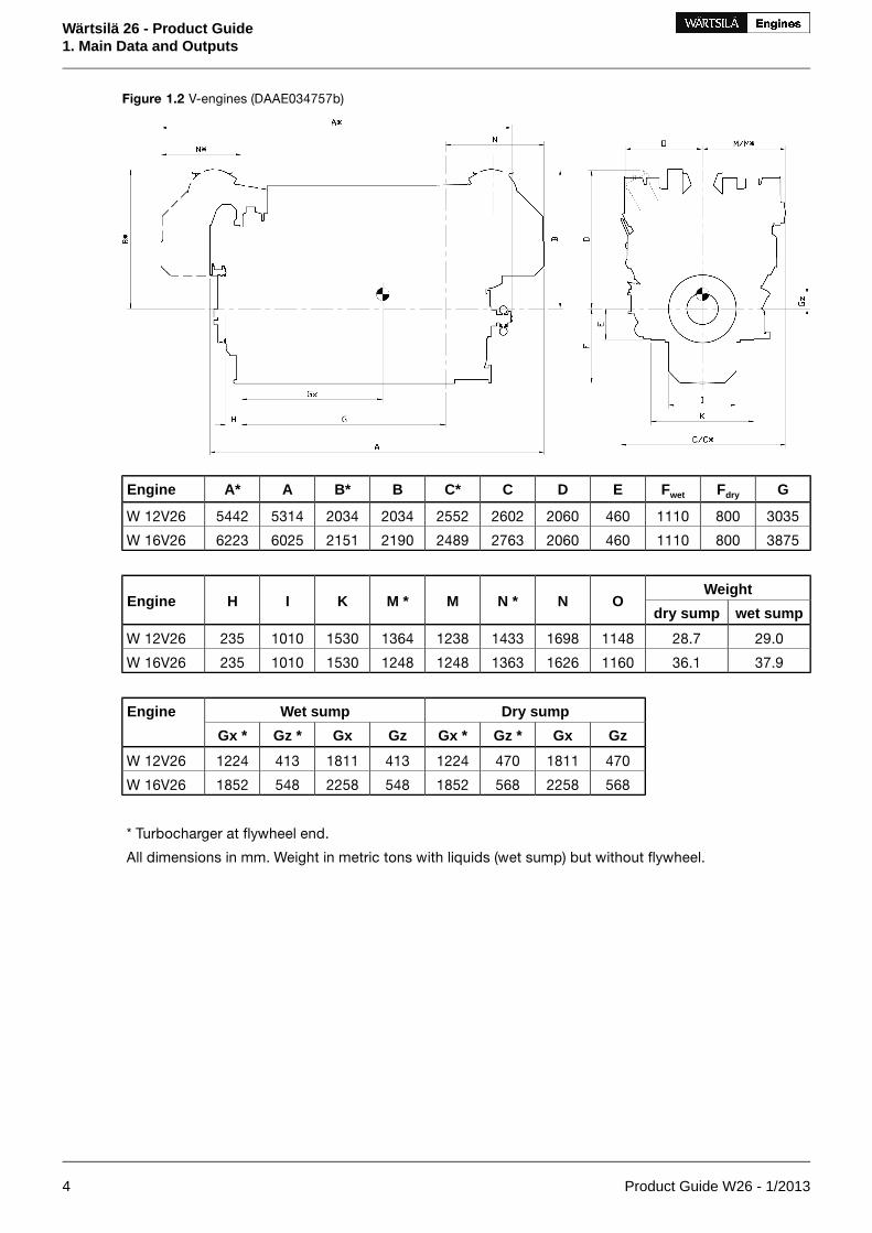
Figure 1.2 V-engines (DAAE034757b)
GFdryFwetEDCC*BB*AA*Engine
303580011104602060260225522034203453145442W 12V26
387580011104602060276324892190215160256223W 16V26
WeightONN *MM *KIHEngine
wet sumpdry sump
29.028.71148169814331238136415301010235W 12V26
37.936.11160162613631248124815301010235W 16V26
Dry sumpWet sumpEngine
GzGxGz *Gx *GzGxGz *Gx *
4701811470122441318114131224W 12V26
5682258568185254822585481852W 16V26
* Turbocharger at flywheel end.
All dimensions in mm. Weight in metric tons with liquids (wet sump) but without flywheel.
4 Product Guide W26 - 1/2013
Wärtsilä 26 - Product Guide1. Main Data and Outputs

1.4.2 Generating setsFigure 1.3 Generating sets (DAAE034758b)
WeightMLIHGFEDCB*BA*AEngine
351833230019101600243012009213200600070283575007500W 6L26
451868230019101600243012009213300700070283580008000W 8L26
501868230019101600243013009213400750070283585008500W 9L26
602126**2700231020002765156098136006700-1263-8400W 12V26
702156**2700231020002765156098140007730-1400-9700W 16V26
* Turbocharger at flywheel end. ** TC inclination 30°
All dimensions in mm. Weight in metric tons with liquids (wet sump) but without flywheel.
NOTE! Generating set dimensions are for indication only, based on low voltage generators. Final gen-erating set dimensions and weights depend on selection of generator and flexible coupling.
Product Guide W26 - 1/2013 5
Wärtsilä 26 - Product Guide1. Main Data and Outputs

2. Operating Ranges
2.1 Engine operating rangeBelow nominal speed the load must be limited according to the diagrams in this chapter in order to maintainengine operating parameters within acceptable limits. Operation in the shaded area is permitted only tem-porarily during transients. Minimum speed is indicated in the diagram, but project specific limitations mayapply.
2.1.1 Controllable pitch propellersAn automatic load control system is required to protect the engine from overload. The load control reducesthe propeller pitch automatically, when a pre-programmed load versus speed curve (“engine limit curve”)is exceeded, overriding the combinator curve if necessary. The engine load is derived from fuel rack positionand actual engine speed (not speed demand).
The propulsion control must also include automatic limitation of the load increase rate. Maximum loadingrates can be found later in this chapter.
The propeller efficiency is highest at design pitch. It is common practice to dimension the propeller so thatthe specified ship speed is attained with design pitch, nominal engine speed and 85% output in the specifiedloading condition. The power demand from a possible shaft generator or PTO must be taken into account.The 15% margin is a provision for weather conditions and fouling of hull and propeller. An additional enginemargin can be applied for most economical operation of the engine, or to have reserve power.
Figure 2.1 Operating field for CP propeller
2.1.2 Fixed pitch propellersThe thrust and power absorption of a given fixed pitch propeller is determined by the relation between shipspeed and propeller revolution speed. The power absorption during acceleration, manoeuvring or towingis considerably higher than during free sailing for the same revolution speed. Increased ship resistance, for
6 Product Guide W26 - 1/2013
Wärtsilä 26 - Product Guide2. Operating Ranges

reason or another, reduces the ship speed, which increases the power absorption of the propeller over thewhole operating range.
Loading conditions, weather conditions, ice conditions, fouling of hull, shallow water, and manoeuvringrequirements must be carefully considered, when matching a fixed pitch propeller to the engine. Thenominal propeller curve shown in the diagram must not be exceeded in service, except temporarily duringacceleration and manoeuvring. A fixed pitch propeller for a free sailing ship is therefore dimensioned sothat it absorbs max. 85% of the engine output at nominal engine speed during trial with loaded ship. Typ-ically this corresponds to about 82% for the propeller itself.
If the vessel is intended for towing, the propeller is dimensioned to absorb 95% of the engine power atnominal engine speed in bollard pull or towing condition. It is allowed to increase the engine speed to101.7% in order to reach 100% MCR during bollard pull.
A shaft brake should be used to enable faster reversing and shorter stopping distance (crash stop). Theship speed at which the propeller can be engaged in reverse direction is still limited by the windmillingtorque of the propeller and the torque capability of the engine at low revolution speed.
Figure 2.2 Operating field for FP Propeller
FP propellers in twin screw vessels
Requirements regarding manoeuvring response and acceleration, as well as overload with one engine outof operation must be very carefully evaluated if the vessel is designed for free sailing, in particular if openpropellers are applied. If the bollard pull curve significantly exceeds the maximum overload limit, accelerationand manoeuvring response can be very slow. Nozzle propellers are less problematic in this respect.
2.1.3 DredgersMechanically driven dredging pumps typically require a capability to operate with full torque down to 70%or 80% of nominal engine speed. This requirement results in significant de-rating of the engine.
Product Guide W26 - 1/2013 7
Wärtsilä 26 - Product Guide2. Operating Ranges

Figure 2.3 Operating field for Dredgers
2.2 Loading capacityControlled load increase is essential for highly supercharged diesel engines, because the turbochargerneeds time to accelerate before it can deliver the required amount of air. A slower loading ramp than themaximum capability of the engine permits a more even temperature distribution in engine componentsduring transients.
The engine can be loaded immediately after start, provided that the engine is pre-heated to a HT-watertemperature of 60…70ºC, and the lubricating oil temperature is min. 40 ºC.
The ramp for normal loading applies to engines that have reached normal operating temperature.
2.2.1 Mechanical propulsionFigure 2.4 Maximum recommended load increase rates for variable speed engines
The propulsion control must include automatic limitation of the load increase rate. If the control system hasonly one load increase ramp, then the ramp for a preheated engine should be used. In tug applications the
8 Product Guide W26 - 1/2013
Wärtsilä 26 - Product Guide2. Operating Ranges

engines have usually reached normal operating temperature before the tug starts assisting. The “emergency”curve is close to the maximum capability of the engine.
If minimum smoke during load increase is a major priority, slower loading rate than in the diagram can benecessary below 50% load.
Large load reductions from high load should also be performed gradually. In normal operation the loadshould not be reduced from 100% to 0% in less than 15 seconds. When absolutely necessary, the loadcan be reduced as fast as the pitch setting system can react (overspeed due to windmilling must be con-sidered for high speed ships).
2.2.2 Diesel electric propulsion and auxiliary enginesFigure 2.5 Maximum recommended load increase rates for engines operating at nominal speed
In diesel electric installations loading ramps are implemented both in the propulsion control and in thepower management system, or in the engine speed control in case isochronous load sharing is applied. Ifa ramp without knee-point is used, it should not achieve 100% load in shorter time than the ramp in thefigure. When the load sharing is based on speed droop, the load increase rate of a recently connectedgenerator is the sum of the load transfer performed by the power management system and the load increaseperformed by the propulsion control.
The “emergency” curve is close to the maximum capability of the engine and it shall not be used as thenormal limit. In dynamic positioning applications loading ramps corresponding to 20-30 seconds from zeroto full load are however normal. If the vessel has also other operating modes, a slower loading ramp is re-commended for these operating modes.
In typical auxiliary engine applications there is usually no single consumer being decisive for the loadingrate. It is recommended to group electrical equipment so that the load is increased in small increments,and the resulting loading rate roughly corresponds to the “normal” curve.
In normal operation the load should not be reduced from 100% to 0% in less than 15 seconds. If the ap-plication requires frequent unloading at a significantly faster rate, special arrangements can be necessaryon the engine. In an emergency situation the full load can be thrown off instantly.
Maximum instant load steps
The electrical system must be designed so that tripping of breakers can be safely handled. This requiresthat the engines are protected from load steps exceeding their maximum load acceptance capability. Themaximum permissible load step is 30% MCR. The resulting speed drop is less than 10% and the recoverytime to within 1% of the steady state speed at the new load level is max. 5 seconds.
When electrical power is restored after a black-out, consumers are reconnected in groups, which maycause significant load steps. The engine can be loaded in three steps up to 100% load, provided that thesteps are 0-30-65-100. The engine must be allowed to recover for at least 7 seconds before applying thefollowing load step, if the load is applied in maximum steps.
Product Guide W26 - 1/2013 9
Wärtsilä 26 - Product Guide2. Operating Ranges

Start-up time
A diesel generator typically reaches nominal speed in about 20...25 seconds after the start signal. The ac-celeration is limited by the speed control to minimise smoke during start-up.
2.3 Operation at low load and idlingThe engine can be started, stopped and operated on heavy fuel under all operating conditions. Continuousoperation on heavy fuel is preferred rather than changing over to diesel fuel at low load operation andmanoeuvring. The following recommendations apply:
Absolute idling (declutched main engine, disconnected generator)
• Maximum 10 minutes if the engine is to be stopped after the idling. 3-5 minutes idling before stop isrecommended.
• Maximum 6 hours if the engine is to be loaded after the idling.
Operation below 20 % load on HFO or below 10 % load on MDF
• Maximum 100 hours continuous operation. At intervals of 100 operating hours the engine must beloaded to minimum 70 % of the rated output.
Operation above 20 % load on HFO or above 10 % load on MDF
• No restrictions.
2.4 Low air temperatureIn cold conditions the following minimum inlet air temperatures apply:
• Starting + 5ºC
• Idling - 5ºC
• High load - 10ºC
If the engine is equipped with a two-stage charge air cooler, sustained operation between 0 and 40% loadcan require special provisions in cold conditions to prevent too low engine temperature.
For further guidelines, see chapter Combustion air system design.
10 Product Guide W26 - 1/2013
Wärtsilä 26 - Product Guide2. Operating Ranges

3. Technical Data
3.1 Wärtsilä 6L26Table 3.1
MEIMO Tier 2
MEIMO Tier 2
AE/DEIMO Tier 2
AE/DEIMO Tier 2
Wärtsilä 6L26
340325340325kW/cylCylinder output
10009001000900rpmEngine speed
2040195020401950kWEngine output
2.42.552.42.55MPaMean effective pressure
Combustion air system (Note 1)
4.13.94.13.7kg/sFlow of air at 100% load
45454545°CTemperature at turbocharger intake, max.
55555555°CAir temperature after air cooler, nom. (TE601)
Exhaust gas system (Note 2)
4.24.04.23.8kg/sFlow at 100% load
3.53.43.73.3kg/sFlow at 85% load
3.13.03.43.0kg/sFlow 75% load
2.32.02.52.2kg/sFlow 50% load
312306312329°CTemp. after turbo, 100% load (TE517)
313311304326°CTemp. after turbo, 85% load (TE517)
327326311337°CTemp. after turbo, 75% load (TE517)
322327320342°CTemp. after turbo, 50% load (TE517)
3.03.03.03.0kPaBackpressure, max.
500500500500mmExhaust gas pipe diameter, min
502487501486mmCalculated exhaust diameter for 35 m/s
Heat balance (Note 3)
356320356331kWJacket water
300275301284kWLubricating oil
751719751636kWCharge air
96919691kWRadiation
Fuel system (Note 4)
700±50700±50700±50700±50kPaPressure before injection pumps (PT101)
3.22.93.22.9m³/hEngine driven pump capacity at 12 cSt (MDF only)
1.71.61.71.6m3/hFuel flow to engine (without engine driven pump), approx.
16...2416...2416...2416...24cStHFO viscosity before engine
140140140140°CHFO temperature before engine, max. (TE 101)
2.02.02.02.0cStMDF viscosity, min
45454545°CMDF temperature before engine, max. (TE 101)
190188190187g/kWhFuel consumption at 100% load
187185188185g/kWhFuel consumption at 85% load
190188191189g/kWhFuel consumption at 75% load
192189202198g/kWhFuel consumption at 50% load
8.27.88.27.7kg/hClean leak fuel quantity, MDF at 100% load
1.61.61.61.5kg/hClean leak fuel quantity, HFO at 100% load
Lubricating oil system (Note 5)
450450450450kPaPressure before bearings, nom. (PT201)
800800800800kPaPressure after pump, max.
30303030kPaSuction ability including pipe loss, max.
80808080kPaPriming pressure, nom. (PT201)
68686868°CTemperature before bearings, nom. (TE201)
78787878°CTemperature after engine, approx.
66606660m³/hPump capacity (main), engine driven
55555555m³/hPump capacity (main), stand-by
11 / 1311 / 1311 / 1311 / 13m³/hPriming pump capacity, 50Hz/60Hz
1.31.31.31.3m³Oil volume, wet sump, nom.
2.82.62.82.6m³Oil volume in separate system oil tank, nom.
0.50.50.50.5g/kWhOil consumption (100% load), approx.
150150150150l/min/cylCrankcase ventilation flow rate
0.30.30.30.3kPaCrankcase backpressure (max)
1.4 / 2.01.4 / 2.01.4 / 2.01.4 / 2.0lOil volume in speed governor
Product Guide W26 - 1/2013 11
Wärtsilä 26 - Product Guide3. Technical Data

MEIMO Tier 2
MEIMO Tier 2
AE/DEIMO Tier 2
AE/DEIMO Tier 2
Wärtsilä 6L26
340325340325kW/cylCylinder output
10009001000900rpmEngine speed
High temperature cooling water system
350 + static350 + static350 + static350 + statickPaPressure at engine, after pump, nom. (PT401)
500500500500kPaPressure at engine, after pump, max. (PT401)
81818181°CTemperature before cylinders, approx. (TE401)
91919191°CHT-water out from the engine, nom (TE402)
35353535m³/hCapacity of engine driven pump, nom.
210210210210kPaPressure drop over engine
60606060kPaPressure drop in external system, max
70...15070...15070...15070...150kPaPressure from expansion tank
0.30.30.30.3m³Water volume in engine
Low temperature cooling water system
280 + static260 + static280 + static260 + statickPaPressure at engine, after pump, nom. (PT471)
500500500500kPaPressure at engine, after pump, max. (PT471)
25...3825...3825...3825...38°CTemperature before engine (TE471)
47424742m³/hCapacity of engine driven pump, nom.
60606060kPaPressure drop in external system, max.
50505050kPaPressure drop over charge air cooler
16161616kPaPressure drop over oil cooler
70...15070...15070...15070...150kPaPressure from expansion tank
80808080m3/hCapacity engine driven seawater pump, max.
Starting air system (Note 6)
3000300030003000kPaPressure, nom.
3300330033003300kPaPressure, max.
1800180018001800kPaLow pressure limit in air vessels
1.41.41.41.4Nm3Starting air consumption, start (successful)
Notes:
At ISO 3046-1 conditions (ambient air temperature 25°C, LT-water 25°C) and 100% load. Tolerance 5%.Note 1
At ISO 3046-1 conditions (ambient air temperature 25°C, LT-water 25°C) and 100% load. Flow tolerance 5% and temperature tolerance 20°C.Note 2
The heat balances are made for ISO 3046/1 standard reference conditions. The heat balances include engine driven pumps (two water pumps and one lube oilpump).
Note 3
According to ISO 3046/1, lower calorific value 42 700 kJ/kg at constant engine speed, with engine driven pumps (two cooling water + one lubricating oil pumps).Tolerance 5%.The fuel consumption at 85 % load is guaranteed and the values at other loads are given for indication only.
Note 4
Speed governor oil volume depends on the speed governor type.Note 5
At manual starting the consumption may be 2...3 times lower.Note 6
ME = Engine driving propeller, variable speed
AE = Auxiliary engine driving generator
DE = Diesel-Electric engine driving generator
Subject to revision without notice.
12 Product Guide W26 - 1/2013
Wärtsilä 26 - Product Guide3. Technical Data

3.2 Wärtsilä 8L26
MEIMO Tier 2
MEIMO Tier 2
AE/DEIMO Tier 2
AE/DEIMO Tier 2
Wärtsilä 8L26
340325340325kW/cylCylinder output
10009001000900rpmEngine speed
2720260027202600kWEngine output
2.42.552.42.55MPaMean effective pressure
Combustion air system (Note 1)
5.45.25.45.0kg/sFlow of air at 100% load
45454545°CTemperature at turbocharger intake, max.
55555555°CAir temperature after air cooler, nom. (TE601)
Exhaust gas system (Note 2)
5.55.35.65.1kg/sFlow at 100% load
4.74.54.94.4kg/sFlow at 85% load
4.24.04.54.0kg/sFlow 75% load
3.12.73.33.0kg/sFlow 50% load
312306312329°CTemp. after turbo, 100% load (TE517)
313311304326°CTemp. after turbo, 85% load (TE517)
327326311337°CTemp. after turbo, 75% load (TE517)
322327320342°CTemp. after turbo, 50% load (TE517)
3.03.03.03.0kPaBackpressure, max.
550550550550mmExhaust gas pipe diameter, min
574561578560mmCalculated exhaust diameter for 35 m/s
Heat balance (Note 3)
474427474441kWJacket water
401367401378kWLubricating oil
10029581002849kWCharge air
128122128122kWRadiation
Fuel system (Note 4)
700±50700±50700±50700±50kPaPressure before injection pumps (PT101)
4.13.74.13.7m³/hEngine driven pump capacity at 12 cSt (MDF only)
2.32.22.32.1m3/hFuel flow to engine (without engine driven pump), approx.
16...2416...2416...2416...24cStHFO viscosity before engine
140140140140°CHFO temperature before engine, max. (TE 101)
2.02.02.02.0cStMDF viscosity, min
45454545°CMDF temperature before engine, max. (TE 101)
190188190187g/kWhFuel consumption at 100% load
187185188185g/kWhFuel consumption at 85% load
190188191189g/kWhFuel consumption at 75% load
192189202198g/kWhFuel consumption at 50% load
10.910.310.910.3kg/hClean leak fuel quantity, MDF at 100% load
2.22.12.22.1kg/hClean leak fuel quantity, HFO at 100% load
Lubricating oil system (Note 5)
450450450450kPaPressure before bearings, nom. (PT201)
800800800800kPaPressure after pump, max.
30303030kPaSuction ability including pipe loss, max.
80808080kPaPriming pressure, nom. (PT201)
68686868°CTemperature before bearings, nom. (TE201)
78787878°CTemperature after engine, approx.
90819081m³/hPump capacity (main), engine driven
75757575m³/hPump capacity (main), stand-by
16 / 1916 / 1916 / 1916 / 19m³/hPriming pump capacity, 50Hz/60Hz
1.61.61.61.6m³Oil volume, wet sump, nom.
3.73.53.73.5m³Oil volume in separate system oil tank, nom.
0.50.50.50.5g/kWhOil consumption (100% load), approx.
150150150150l/min/cylCrankcase ventilation flow rate
0.30.30.30.3kPaCrankcase backpressure (max)
1.4 / 2.01.4 / 2.01.4 / 2.01.4 / 2.0lOil volume in speed governor
High temperature cooling water system
370 + static360 + static370 + static360 + statickPaPressure at engine, after pump, nom. (PT401)
500500500500kPaPressure at engine, after pump, max. (PT401)
81818181°CTemperature before cylinders, approx. (TE401)
91919191°CHT-water out from the engine, nom (TE402)
Product Guide W26 - 1/2013 13
Wärtsilä 26 - Product Guide3. Technical Data

MEIMO Tier 2
MEIMO Tier 2
AE/DEIMO Tier 2
AE/DEIMO Tier 2
Wärtsilä 8L26
340325340325kW/cylCylinder output
10009001000900rpmEngine speed
45454545m³/hCapacity of engine driven pump, nom.
220220220220kPaPressure drop over engine
60606060kPaPressure drop in external system, max
70...15070...15070...15070...150kPaPressure from expansion tank
0.40.40.40.4m³Water volume in engine
Low temperature cooling water system
250 + static270 + static250 + static270 + statickPaPressure at engine, after pump, nom. (PT471)
500500500500kPaPressure at engine, after pump, max. (PT471)
25...3825...3825...3825...38°CTemperature before engine (TE471)
62566256m³/hCapacity of engine driven pump, nom.
60606060kPaPressure drop in external system, max.
50505050kPaPressure drop over charge air cooler
18181818kPaPressure drop over oil cooler
70...15070...15070...15070...150kPaPressure from expansion tank
120120120120m3/hCapacity engine driven seawater pump, max.
Starting air system (Note 6)
3000300030003000kPaPressure, nom.
3300330033003300kPaPressure, max.
1800180018001800kPaLow pressure limit in air vessels
1.81.81.81.8Nm3Starting air consumption, start (successful)
Notes:
At ISO 3046-1 conditions (ambient air temperature 25°C, LT-water 25°C) and 100% load. Tolerance 5%.Note 1
At ISO 3046-1 conditions (ambient air temperature 25°C, LT-water 25°C) and 100% load. Flow tolerance 5% and temperature tolerance 20°C.Note 2
The heat balances are made for ISO 3046/1 standard reference conditions. The heat balances include engine driven pumps (two water pumps and one lube oilpump).
Note 3
According to ISO 3046/1, lower calorific value 42 700 kJ/kg at constant engine speed, with engine driven pumps (two cooling water + one lubricating oil pumps).Tolerance 5%.The fuel consumption at 85 % load is guaranteed and the values at other loads are given for indication only.
Note 4
Speed governor oil volume depends on the speed governor type.Note 5
At manual starting the consumption may be 2...3 times lower.Note 6
ME = Engine driving propeller, variable speed
AE = Auxiliary engine driving generator
DE = Diesel-Electric engine driving generator
Subject to revision without notice.
14 Product Guide W26 - 1/2013
Wärtsilä 26 - Product Guide3. Technical Data

3.3 Wärtsilä 9L26
MEIMO Tier 2
MEIMO Tier 2
AE/DEIMO Tier 2
AE/DEIMO Tier 2
Wärtsilä 9L26
340325340325kW/cylCylinder output
10009001000900rpmEngine speed
3060292530602925kWEngine output
2.42.552.42.55MPaMean effective pressure
Combustion air system (Note 1)
6.05.86.15.6kg/sFlow of air at 100% load
45454545°CTemperature at turbocharger intake, max.
55555555°CAir temperature after air cooler, nom. (TE601)
Exhaust gas system (Note 2)
6.26.06.25.7kg/sFlow at 100% load
5.35.15.55.0kg/sFlow at 85% load
4.74.65.14.5kg/sFlow 75% load
3.53.13.83.3kg/sFlow 50% load
312306312329°CTemp. after turbo, 100% load (TE517)
313311304326°CTemp. after turbo, 85% load (TE517)
327326311337°CTemp. after turbo, 75% load (TE517)
322327320342°CTemp. after turbo, 50% load (TE517)
3.03.03.03.0kPaBackpressure, max.
600600600600mmExhaust gas pipe diameter, min
610597611595mmCalculated exhaust diameter for 35 m/s
Heat balance (Note 3)
534481534496kWJacket water
451413451425kWLubricating oil
112710781127955kWCharge air
144137144137kWRadiation
Fuel system (Note 4)
700±50700±50700±50700±50kPaPressure before injection pumps (PT101)
4.13.74.13.7m³/hEngine driven pump capacity at 12 cSt (MDF only)
2.62.42.62.4m3/hFuel flow to engine (without engine driven pump), approx.
16...2416...2416...2416...24cStHFO viscosity before engine
140140140140°CHFO temperature before engine, max. (TE 101)
2.02.02.02.0cStMDF viscosity, min
45454545°CMDF temperature before engine, max. (TE 101)
190188190187g/kWhFuel consumption at 100% load
187185188185g/kWhFuel consumption at 85% load
190188191189g/kWhFuel consumption at 75% load
192189202198g/kWhFuel consumption at 50% load
12.311.612.311.6kg/hClean leak fuel quantity, MDF at 100% load
2.52.32.52.3kg/hClean leak fuel quantity, HFO at 100% load
Lubricating oil system (Note 5)
450450450450kPaPressure before bearings, nom. (PT201)
800800800800kPaPressure after pump, max.
30303030kPaSuction ability including pipe loss, max.
80808080kPaPriming pressure, nom. (PT201)
68686868°CTemperature before bearings, nom. (TE201)
78787878°CTemperature after engine, approx.
90819081m³/hPump capacity (main), engine driven
75757575m³/hPump capacity (main), stand-by
16 / 1916 / 1916 / 1916 / 19m³/hPriming pump capacity, 50Hz/60Hz
1.71.71.71.7m³Oil volume, wet sump, nom.
4.13.94.13.9m³Oil volume in separate system oil tank, nom.
0.50.50.50.5g/kWhOil consumption (100% load), approx.
150150150150l/min/cylCrankcase ventilation flow rate
0.30.30.30.3kPaCrankcase backpressure (max)
1.4 / 2.01.4 / 2.01.4 / 2.01.4 / 2.0lOil volume in speed governor
High temperature cooling water system
350 + static360 + static350 + static360 + statickPaPressure at engine, after pump, nom. (PT401)
500500500500kPaPressure at engine, after pump, max. (PT401)
81818181°CTemperature before cylinders, approx. (TE401)
91919191°CHT-water out from the engine, nom (TE402)
Product Guide W26 - 1/2013 15
Wärtsilä 26 - Product Guide3. Technical Data

6. Fuel Oil System
6.1 Acceptable fuel characteristicsThe fuel specifications are based on the ISO 8217:2010 (E) standard. Observe that a few additional propertiesnot included in the standard are listed in the tables. For maximum fuel temperature before the engine, seechapter "Technical Data".
The fuel shall not contain any added substances or chemical waste, which jeopardizes the safety of install-ations or adversely affects the performance of the engines or is harmful to personnel or contributes overallto air pollution.
6.1.1 Marine Diesel Fuel (MDF)Distillate fuel grades are ISO-F-DMX, DMA, DMZ, DMB. These fuel grades are referred to as MDF (MarineDiesel Fuel).
The distillate grades mentioned above can be described as follows:
• DMX: A fuel which is suitable for use at ambient temperatures down to -15°C without heating the fuel.Especially in merchant marine applications its use is restricted to lifeboat engines and certain emer-gency equipment due to the reduced flash point. The low flash point which is not meeting the SOLASrequirement can also prevent the use in other marine applications, unless the fuel system is built ac-cording to special requirements. Also the low viscosity (min. 1.4 cSt) can prevent the use in enginesunless the fuel can be cooled down enough to meet the min. injection viscosity limit of the engine.
• DMA: A high quality distillate, generally designated as MGO (Marine Gas Oil).
• DMZ: A high quality distillate, generally designated as MGO (Marine Gas Oil). An alternative fuel gradefor engines requiring a higher fuel viscosity than specified for DMA grade fuel.
• DMB: A general purpose fuel which may contain trace amounts of residual fuel and is intended forengines not specifically designed to burn residual fuels. It is generally designated as MDO (MarineDiesel Oil).
Table 6.1 MDF specifications
Test methodref.
ISO-F-DMB
ISO-F-DMZ
ISO-F-DMA
UnitProperty
2.02.02.0cStViscosity, before injection pumps, min. 1)
242424cStViscosity, before injection pumps, max. 1)
232cStViscosity at 40°C, min.
ISO 31041166cStViscosity at 40°C, max.
ISO 3675 or12185
900890890kg/m³Density at 15°C, max.
ISO 4264354040Cetane index, min.
ISO 8574 or14596
21.51.5% massSulphur, max.
ISO 2719606060°CFlash point, min.
IP 570222mg/kgHydrogen sulfide. max. 2)
ASTM D6640.50.50.5mg KOH/gAcid number, max.
ISO 10307-10.1 3)——% massTotal sediment by hot filtration, max.
ISO 1220525 4)2525g/m3Oxidation stability, max.
ISO 10370—0.300.30% massCarbon residue: micro method on the10% volume distillation residue max.
ISO 103700.30——% massCarbon residue: micro method, max.
ISO 30160-6-6°CPour point (upper) , winter quality, max. 5)
34 Product Guide W26 - 1/2013
Wärtsilä 26 - Product Guide6. Fuel Oil System

Test methodref.
ISO-F-DMB
ISO-F-DMZ
ISO-F-DMA
UnitProperty
ISO 3016600°CPour point (upper) , summer quality, max.5)
3) 4) 7)Clear and bright 6)—Appearance
ISO 37330.3 3)——% volumeWater, max.
ISO 62450.010.010.01% massAsh, max.
ISO 12156-1520 7)520520µmLubricity, corrected wear scar diameter(wsd 1.4) at 60°C , max. 8)
Remarks:
Additional properties specified by Wärtsilä, which are not included in the ISO specification.1)
The implementation date for compliance with the limit shall be 1 July 2012. Until that the specifiedvalue is given for guidance.
2)
If the sample is not clear and bright, the total sediment by hot filtration and water tests shall be re-quired.
3)
If the sample is not clear and bright, the test cannot be undertaken and hence the oxidation stabilitylimit shall not apply.
4)
It shall be ensured that the pour point is suitable for the equipment on board, especially if the shipoperates in cold climates.
5)
If the sample is dyed and not transparent, then the water limit and test method ISO 12937 shall apply.6)
If the sample is not clear and bright, the test cannot be undertaken and hence the lubricity limit shallnot apply.
7)
The requirement is applicable to fuels with a sulphur content below 500 mg/kg (0.050 % mass).8)
6.1.2 Heavy Fuel Oil (HFO)Residual fuel grades are referred to as HFO (Heavy Fuel Oil). The fuel specification HFO 2 covers the cat-egories ISO-F-RMA 10 to RMK 700. Fuels fulfilling the specification HFO 1 permit longer overhaul intervalsof specific engine components than HFO 2.
Table 6.2 HFO specifications
Test method ref.Limit HFO 2Limit HFO 1UnitProperty
16...2416...24cStViscosity, before injection pumps 1)
ISO 3104700700cStViscosity at 50°C, max.
ISO 3675 or12185
991 / 1010 2)991 / 1010 2)kg/m³Density at 15°C, max.
ISO 8217, AnnexF
870850CCAI, max.3)
ISO 8754 or14596
Statutory requirements% massSulphur, max. 4) 5)
ISO 27196060°CFlash point, min.
IP 57022mg/kgHydrogen sulfide, max. 6)
ASTM D6642.52.5mg KOH/gAcid number, max.
ISO 10307-20.10.1% massTotal sediment aged, max.
ISO 103702015% massCarbon residue, micro method, max.
ASTM D 3279148% massAsphaltenes, max.1)
ISO 30163030°CPour point (upper), max. 7)
Product Guide W26 - 1/2013 35
Wärtsilä 26 - Product Guide6. Fuel Oil System

Test method ref.Limit HFO 2Limit HFO 1UnitProperty
ISO 3733 orASTM D6304-C 1)
0.50.5% volumeWater, max.
ISO 3733 orASTM D6304-C 1)
0.30.3% volumeWater before engine, max.1)
ISO 6245 orLP1001 1)
0.150.05% massAsh, max.
ISO 14597 or IP501 or IP 470
450100mg/kgVanadium, max. 5)
IP 501 or IP 47010050mg/kgSodium, max. 5)
IP 501 or IP 4703030mg/kgSodium before engine, max.1) 5)
ISO 10478 or IP501 or IP 470
6030mg/kgAluminium + Silicon, max.
ISO 10478 or IP501 or IP 470
1515mg/kgAluminium + Silicon before engine, max.1)
IP 501 or IP 4703030mg/kgUsed lubricating oil, calcium, max. 8)
IP 501 or IP 4701515mg/kgUsed lubricating oil, zinc, max. 8)
IP 501 or IP 5001515mg/kgUsed lubricating oil, phosphorus, max. 8)
Remarks:
Additional properties specified by Wärtsilä, which are not included in the ISO specification.1)
Max. 1010 kg/m³ at 15°C provided that the fuel treatment system can remove water and solids(sediment, sodium, aluminium, silicon) before the engine to specified levels.
2)
Straight run residues show CCAI values in the 770 to 840 range and have very good ignition quality.Cracked residues delivered as bunkers may range from 840 to - in exceptional cases - above 900.Most bunkers remain in the max. 850 to 870 range at the moment. CCAI value cannot always beconsidered as an accurate tool to determine the ignition properties of the fuel, especially concerningfuels originating from modern and more complex refinery process.
3)
The max. sulphur content must be defined in accordance with relevant statutory limitations.4)
Sodium contributes to hot corrosion on the exhaust valves when combined with high sulphur andvanadium contents. Sodium also strongly contributes to fouling of the exhaust gas turbine bladingat high loads. The aggressiveness of the fuel depends on its proportions of sodium and vanadiumand also on the total amount of ash. Hot corrosion and deposit formation are, however, also influencedby other ash constituents. It is therefore difficult to set strict limits based only on the sodium andvanadium content of the fuel. Also a fuel with lower sodium and vanadium contents than specifiedabove, can cause hot corrosion on engine components.
5)
The implementation date for compliance with the limit shall be 1 July 2012. Until that, the specifiedvalue is given for guidance.
6)
It shall be ensured that the pour point is suitable for the equipment on board, especially if the shipoperates in cold climates.
7)
The fuel shall be free from used lubricating oil (ULO). A fuel shall be considered to contain ULO wheneither one of the following conditions is met:
• Calcium > 30 mg/kg and zinc > 15 mg/kg
• Calcium > 30 mg/kg and phosphorus > 15 mg/kg
8)
36 Product Guide W26 - 1/2013
Wärtsilä 26 - Product Guide6. Fuel Oil System

6.2 Internal fuel oil system
Figure 6.1 Internal fuel oil system, MDF (DAAE031815b)
System components
Injection pump01
Injection valve02
Fuel oil leakage collector03
Duplex fine filter04
Engine driven fuel feedpump
05
Pressure regulating valve06
Sensors and indicators
Fuel oil temperature, engine inletTI101Fuel oil pressure, engine inletPT101
Fuel oil pressure, engine inlet (if GL)PI101Fuel oil temperature, engine inletTE101
Fuel oil stand-by pump start (if stand-bypump)
PS110Fuel oil leakage, injection pipeLS103A/B
Fuel oil filter, pressure differencePDS113
StandardPressure classSizePipe connections
DIN2633/DIN2513R13
PN16DN32Fuel inlet, in-line engines101
DIN2633/DIN2513R13
PN16DN32Fuel inlet, 12V101
DIN2633/DIN2513R13
PN16DN40Fuel inlet, 16V101
DIN2633/DIN2513V13
PN16DN32Fuel outlet, in-line engines102
DIN2633/DIN2513R13
PN16DN25Fuel outlet, V-engines102
Product Guide W26 - 1/2013 37
Wärtsilä 26 - Product Guide6. Fuel Oil System

StandardPressure classSizePipe connections
DIN2353PN250OD22Leak fuel drain, clean fuel103
DIN2353PN250OD22Leak fuel drain, dirty fuel104
DIN2633PN16DN32Fuel stand-by connection, in-line engines105
DIN2633PN16DN25Fuel stand-by connection, V-engines105
DIN2353PN250OD22Drain from fuel filter drip tray, V-enginesonly
111
DIN2633PN16DN32Fuel from starting/day tank, in-line engines114
DIN2633PN16DN25Fuel from starting/day tank, V-engines114
38 Product Guide W26 - 1/2013
Wärtsilä 26 - Product Guide6. Fuel Oil System

Figure 6.2 Internal fuel oil system, HFO (DAAE031861c)
System components
Fuel oil leakage collector03Injection pump01
Adjustable orifice04Injection valve02
Sensors and indicators
Fuel oil temperature, engine inletTI101Fuel oil pressure, engine inletPT101
Fuel oil pressure, engine inlet (if GL)PI101Fuel oil temperature, engine inletTE101
Fuel oil leakage, injection pipe A/B bankLS103A/B
StandardPressure classSizePipe connections
DIN2633/DIN2513R13
PN16DN32Fuel inlet, in-line engines101
DIN2633/DIN2513V13
PN16DN25Fuel inlet, V-engines101
DIN2633/DIN2513R13
PN16DN32Fuel outlet, in-line engines102
DIN2633/DIN2513V13
PN16DN25Fuel outlet, V-engines102
DIN2353PN250OD22Leak fuel drain, clean fuel103
DIN2353PN250OD22Leak fuel drain, dirty fuel104
Product Guide W26 - 1/2013 39
Wärtsilä 26 - Product Guide6. Fuel Oil System

The engine can be specified to either operate on heavy fuel oil (HFO) or on marine diesel fuel (MDF). Theengine is designed for continuous operation on HFO. It is however possible to operate HFO engines onMDF intermittently without alternations. If the operation of the engine is changed from HFO to continuousoperation on MDF, then a change of exhaust valves from Nimonic to Stellite is recommended.
A pressure control valve in the fuel return line on the engine maintains desired pressure before the injectionpumps.
6.2.1 Leak fuel systemClean leak fuel from the injection valves and the injection pumps is collected on the engine and drained bygravity through a clean leak fuel connection. The clean leak fuel can be re-used without separation. Thequantity of clean leak fuel is given in chapter Technical data.
Other possible leak fuel and spilled water and oil is separately drained from the hot-box through dirty fueloil connections and it shall be led to a sludge tank.
6.3 External fuel oil systemThe design of the external fuel system may vary from ship to ship, but every system should provide wellcleaned fuel of correct viscosity and pressure to each engine. Temperature control is required to maintainstable and correct viscosity of the fuel before the injection pumps (see Technical data). Sufficient circulationthrough every engine connected to the same circuit must be ensured in all operating conditions.
The fuel treatment system should comprise at least one settling tank and two separators. Correct dimen-sioning of HFO separators is of greatest importance, and therefore the recommendations of the separatormanufacturer must be closely followed. Poorly centrifuged fuel is harmful to the engine and a high contentof water may also damage the fuel feed system.
Injection pumps generate pressure pulses into the fuel feed and return piping. The fuel pipes between thefeed unit and the engine must be properly clamped to rigid structures. The distance between the fixingpoints should be at close distance next to the engine. See chapter Piping design, treatment and installation.
A connection for compressed air should be provided before the engine, together with a drain from the fuelreturn line to the clean leakage fuel or overflow tank. With this arrangement it is possible to blow out fuelfrom the engine prior to maintenance work, to avoid spilling.
NOTE! In multiple engine installations, where several engines are connected to the same fuel feed circuit,it must be possible to close the fuel supply and return lines connected to the engine individually.This is a SOLAS requirement. It is further stipulated that the means of isolation shall not affectthe operation of the other engines, and it shall be possible to close the fuel lines from a positionthat is not rendered inaccessible due to fire on any of the engines.
6.3.1 Fuel heating requirements HFOHeating is required for:
• Bunker tanks, settling tanks, day tanks
• Pipes (trace heating)
• Separators
• Fuel feeder/booster units
To enable pumping the temperature of bunker tanks must always be maintained 5...10°C above the pourpoint, typically at 40...50°C. The heating coils can be designed for a temperature of 60°C.
The tank heating capacity is determined by the heat loss from the bunker tank and the desired temperatureincrease rate.
40 Product Guide W26 - 1/2013
Wärtsilä 26 - Product Guide6. Fuel Oil System

Figure 6.3 Fuel oil viscosity-temperature diagram for determining the pre-heating temperatures of fuel oils (4V92G0071b)
Example 1: A fuel oil with a viscosity of 380 cSt (A) at 50°C (B) or 80 cSt at 80°C (C) must be pre-heatedto 115 - 130°C (D-E) before the fuel injection pumps, to 98°C (F) at the separator and to minimum 40°C (G)in the bunker tanks. The fuel oil may not be pumpable below 36°C (H).
To obtain temperatures for intermediate viscosities, draw a line from the known viscosity/temperature pointin parallel to the nearest viscosity/temperature line in the diagram.
Example 2: Known viscosity 60 cSt at 50°C (K). The following can be read along the dotted line: viscosityat 80°C = 20 cSt, temperature at fuel injection pumps 74 - 87°C, separating temperature 86°C, minimumbunker tank temperature 28°C.
6.3.2 Fuel tanksThe fuel oil is first transferred from the bunker tanks to settling tanks for initial separation of sludge andwater. After centrifuging the fuel oil is transferred to day tanks, from which fuel is supplied to the engines.
Product Guide W26 - 1/2013 41
Wärtsilä 26 - Product Guide6. Fuel Oil System

Settling tank, HFO (1T02) and MDF (1T10)
Separate settling tanks for HFO and MDF are recommended.
To ensure sufficient time for settling (water and sediment separation), the capacity of each tank should besufficient for min. 24 hours operation at maximum fuel consumption.
The tanks should be provided with internal baffles to achieve efficient settling and have a sloped bottomfor proper draining.
The temperature in HFO settling tanks should be maintained between 50°C and 70°C, which requiresheating coils and insulation of the tank. Usuallly MDF settling tanks do not need heating or insulation, butthe tank temperature should be in the range 20...40°C.
Day tank, HFO (1T03) and MDF (1T06)
Two day tanks for HFO are to be provided, each with a capacity sufficient for at least 8 hours operation atmaximum fuel consumption.
A separate tank is to be provided for MDF. The capacity of the MDF tank should ensure fuel supply for 8hours.
Settling tanks may not be used instead of day tanks.
The day tank must be designed so that accumulation of sludge near the suction pipe is prevented and thebottom of the tank should be sloped to ensure efficient draining.
HFO day tanks shall be provided with heating coils and insulation. It is recommended that the viscosity iskept below 140 cSt in the day tanks. Due to risk of wax formation, fuels with a viscosity lower than 50 cStat 50°C must be kept at a temperature higher than the viscosity would require. Continuous separation isnowadays common practice, which means that the HFO day tank temperature normally remains above90°C.
The temperature in the MDF day tank should be in the range 20...40°C.
The level of the tank must ensure a positive static pressure on the suction side of the fuel feed pumps. Ifblack-out starting with MDF from a gravity tank is foreseen, then the tank must be located at least 15 mabove the engine crankshaft.
Starting tank, MDF (1T09)
The starting tank is needed when the engine is equipped with the engine driven fuel feed pump and whenthe MDF day tank (1T06) cannot be located high enough, i.e. less than 2 meters above the engine crankshaft.
The purpose of the starting tank is to ensure that fuel oil is supplied to the engine during starting. Thestarting tank shall be located at least 2 meters above the engine crankshaft. The volume of the starting tankshould be approx. 60 l.
Leak fuel tank, clean fuel (1T04)
Clean leak fuel is drained by gravity from the engine. The fuel should be collected in a separate clean leakfuel tank, from where it can be pumped to the day tank and reused without separation. The pipes from theengine to the clean leak fuel tank should be arranged continuosly sloping. The tank and the pipes must beheated and insulated, unless the installation is designed for operation on MDF only.
The leak fuel piping should be fully closed to prevent dirt from entering the system.
Leak fuel tank, dirty fuel (1T07)
In normal operation no fuel should leak out from the components of the fuel system. In connection withmaintenance, or due to unforeseen leaks, fuel or water may spill in the hot box of the engine. The spilledliquids are collected and drained by gravity from the engine through the dirty fuel connection.
Dirty leak fuel shall be led to a sludge tank. The tank and the pipes must be heated and insulated, unlessthe installation is designed for operation exclusively on MDF.
42 Product Guide W26 - 1/2013
Wärtsilä 26 - Product Guide6. Fuel Oil System

6.3.3 Fuel treatment
Separation
Heavy fuel (residual, and mixtures of residuals and distillates) must be cleaned in an efficient centrifugalseparator before it is transferred to the day tank.
Classification rules require the separator arrangement to be redundant so that required capacity is maintainedwith any one unit out of operation.
All recommendations from the separator manufacturer must be closely followed.
Centrifugal disc stack separators are recommended also for installations operating on MDF only, to removewater and possible contaminants. The capacity of MDF separators should be sufficient to ensure the fuelsupply at maximum fuel consumption. Would a centrifugal separator be considered too expensive for aMDF installation, then it can be accepted to use coalescing type filters instead. A coalescing filter is usuallyinstalled on the suction side of the circulation pump in the fuel feed system. The filter must have a lowpressure drop to avoid pump cavitation.
Separator mode of operation
The best separation efficiency is achieved when also the stand-by separator is in operation all the time,and the throughput is reduced according to actual consumption.
Separators with monitoring of cleaned fuel (without gravity disc) operating on a continuous basis can handlefuels with densities exceeding 991 kg/m3 at 15°C. In this case the main and stand-by separators shouldbe run in parallel.
When separators with gravity disc are used, then each stand-by separator should be operated in serieswith another separator, so that the first separator acts as a purifier and the second as clarifier. This arrange-ment can be used for fuels with a density of max. 991 kg/m3 at 15°C. The separators must be of the samesize.
Separation efficiency
The term Certified Flow Rate (CFR) has been introduced to express the performance of separators accordingto a common standard. CFR is defined as the flow rate in l/h, 30 minutes after sludge discharge, at whichthe separation efficiency of the separator is 85%, when using defined test oils and test particles. CFR isdefined for equivalent fuel oil viscosities of 380 cSt and 700 cSt at 50°C. More information can be found inthe CEN (European Committee for Standardisation) document CWA 15375:2005 (E).
The separation efficiency is measure of the separator's capability to remove specified test particles. Theseparation efficiency is defined as follows:
where:
separation efficiency [%]n =
number of test particles in cleaned test oilCout =
number of test particles in test oil before separatorCin =
Separator unit (1N02/1N05)
Separators are usually supplied as pre-assembled units designed by the separator manufacturer.
Typically separator modules are equipped with:
• Suction strainer (1F02)
• Feed pump (1P02)
• Pre-heater (1E01)
• Sludge tank (1T05)
• Separator (1S01/1S02)
Product Guide W26 - 1/2013 43
Wärtsilä 26 - Product Guide6. Fuel Oil System

• Sludge pump
• Control cabinets including motor starters and monitoring
Figure 6.4 Fuel transfer and separating system (3V76F6626d)
Separator feed pumps (1P02)
Feed pumps should be dimensioned for the actual fuel quality and recommended throughput of the separ-ator. The pump should be protected by a suction strainer (mesh size about 0.5 mm)
An approved system for control of the fuel feed rate to the separator is required.
MDFHFODesign data:
0.5 MPa (5 bar)0.5 MPa (5 bar)Design pressure
50°C100°CDesign temperature
100 cSt1000 cStViscosity for dimensioning electric motor
Separator pre-heater (1E01)
The pre-heater is dimensioned according to the feed pump capacity and a given settling tank temperature.
The surface temperature in the heater must not be too high in order to avoid cracking of the fuel. The tem-perature control must be able to maintain the fuel temperature within ± 2°C.
44 Product Guide W26 - 1/2013
Wärtsilä 26 - Product Guide6. Fuel Oil System

Recommended fuel temperature after the heater depends on the viscosity, but it is typically 98°C for HFOand 20...40°C for MDF. The optimum operating temperature is defined by the sperarator manufacturer.
The required minimum capacity of the heater is:
where:
heater capacity [kW]P =
capacity of the separator feed pump [l/h]Q =
temperature rise in heater [°C]ΔT =
For heavy fuels ΔT = 48°C can be used, i.e. a settling tank temperature of 50°C. Fuels having a viscosityhigher than 5 cSt at 50°C require pre-heating before the separator.
The heaters to be provided with safety valves and drain pipes to a leakage tank (so that the possible leakagecan be detected).
Separator (1S01/1S02)
Based on a separation time of 23 or 23.5 h/day, the service throughput Q [l/h] of the separator can be es-timated with the formula:
where:
max. continuous rating of the diesel engine(s) [kW]P =
specific fuel consumption + 15% safety margin [g/kWh]b =
density of the fuel [kg/m3]ρ =
daily separating time for self cleaning separator [h] (usually = 23 h or 23.5 h)t =
The flow rates recommended for the separator and the grade of fuel must not be exceeded. The lower theflow rate the better the separation efficiency.
Sample valves must be placed before and after the separator.
MDF separator in HFO installations (1S02)
A separator for MDF is recommended also for installations operating primarily on HFO. The MDF separatorcan be a smaller size dedicated MDF separator, or a stand-by HFO separator used for MDF.
Sludge tank (1T05)
The sludge tank should be located directly beneath the separators, or as close as possible below the sep-arators, unless it is integrated in the separator unit. The sludge pipe must be continuously falling.
Product Guide W26 - 1/2013 45
Wärtsilä 26 - Product Guide6. Fuel Oil System

6.3.4 Fuel feed system - MDF installationsFigure 6.5 Fuel feed system (DAAE034759)
Pipe connectionsSystem components
Fuel inlet101Cooler (MDF)1E04
Fuel outlet102Suction strainer, MDF1F07
Leak fuel drain, clean fuel103.XFlexible pipe connection *1H0X
Leak fuel drain104.XFlow meter1I03
Fuel stand-by connection105Stand-by pump, MDF1P08
Leak fuel tank, clean fuel1T04
Day tank, MDF1T06
Leak fuel tank, dirty fuel1T07
Return fuel tank1T13
* Only required for resiliently mounted enginesQuick closing valve (fuel tank)1V10
46 Product Guide W26 - 1/2013
Wärtsilä 26 - Product Guide6. Fuel Oil System

Figure 6.6 Typical example of external fuel system for multiple engine installation (DAAE034761)
Pipe connectionsSystem components
Fuel inlet101Cooler (MDF)1E04
Fuel outlet102Suction strainer, MDF1F07
Leak fuel drain, clean fuel103.XFlexible pipe connection *1H0X
Leak fuel drain, dirty fuel104.XStand-by pump, MDF1P08
Fuel stand-by connection105Leak fuel tank, clean fuel1T04
Day-tank, MDF1T06
Leak fuel tank, dirty fuel1T07
Starting tank1T09
Quick closing valve (fuel tank)1V10
* Only required for resiliently mounted enginesRemote controlled shut off valve1V11
Product Guide W26 - 1/2013 47
Wärtsilä 26 - Product Guide6. Fuel Oil System

If the engines are to be operated on MDF only, heating of the fuel is normally not necessary. In such caseit is sufficient to install the equipment listed below. Some of the equipment listed below is also to be installedin the MDF part of a HFO fuel oil system.
Circulation pump, MDF (1P03)
The circulation pump maintains the pressure at the injection pumps and circulates the fuel in the system.It is recommended to use a screw pump as circulation pump. A suction strainer with a fineness of 0.5 mmshould be installed before each pump. There must be a positive static pressure of about 30 kPa on thesuction side of the pump.
Design data:
6 x the total consumption of the connected enginesCapacity
1.6 MPa (16 bar)Design pressure
1.0 MPa (10 bar)Max. total pressure (safety valve)
see chapter "Technical Data"Nominal pressure
50°CDesign temperature
90 cStViscosity for dimensioning of electric mo-tor
Stand-by pump, MDF (1P08)
The stand-by pump is required in case of a single main engine equipped with an engine driven pump. It isrecommended to use a screw pump as stand-by pump. The pump should be placed so that a positivestatic pressure of about 30 kPa is obtained on the suction side of the pump.
Design data:
6 x the total consumption of the connected engineCapacity
1.6 MPa (16 bar)Design pressure
1.2 MPa (12 bar)Max. total pressure (safety valve)
50°CDesign temperature
90 cStViscosity for dimensioning of electric mo-tor
Flow meter, MDF (1I03)
If the return fuel from the engine is conducted to a return fuel tank instead of the day tank, one consumptionmeter is sufficient for monitoring of the fuel consumption, provided that the meter is installed in the feedline from the day tank (before the return fuel tank). A fuel oil cooler is usually required with a return fuel tank.
The total resistance of the flow meter and the suction strainer must be small enough to ensure a positivestatic pressure of about 30 kPa on the suction side of the circulation pump.
There should be a by-pass line around the consumption meter, which opens automatically in case of ex-cessive pressure drop.
Fine filter, MDF (1F05)
The fuel oil fine filter is a full flow duplex type filter with steel net. This filter must be installed as near theengine as possible.
The diameter of the pipe between the fine filter and the engine should be the same as the diameter beforethe filters.
Design data:
according to fuel specificationsFuel viscosity
50°CDesign temperature
Larger than feed/circulation pump capacityDesign flow
48 Product Guide W26 - 1/2013
Wärtsilä 26 - Product Guide6. Fuel Oil System

Design data:
1.6 MPa (16 bar)Design pressure
37 μm (absolute mesh size)Fineness
Maximum permitted pressure drops at 14 cSt:
20 kPa (0.2 bar)- clean filter
80 kPa (0.8 bar)- alarm
Pressure control valve, MDF (1V02)
The pressure control valve is installed when the installation includes a feeder/booster unit for HFO andthere is a return line from the engine to the MDF day tank. The purpose of the valve is to increase thepressure in the return line so that the required pressure at the engine is achieved.
Design data:
Equal to circulation pumpCapacity
50°CDesign temperature
1.6 MPa (16 bar)Design pressure
0.4...0.7 MPa (4...7 bar)Set point
MDF cooler (1E04)
The fuel viscosity may not drop below the minimum value stated in Technical data. When operating onMDF, the practical consequence is that the fuel oil inlet temperature must be kept below 45°C. Very lightfuel grades may require even lower temperature.
Sustained operation on MDF usually requires a fuel oil cooler. The cooler is to be installed in the return lineafter the engine(s). LT-water is normally used as cooling medium.
If MDF viscosity in day tank exceeds stated minimum viscosity limit then it is recommended to install anMDF cooler into the engine fuel supply line in order to have reliable viscosity control.
Design data:
2 kW/cylHeat to be dissipated
80 kPa (0.8 bar)Max. pressure drop, fuel oil
60 kPa (0.6 bar)Max. pressure drop, water
min. 15%Margin (heat rate, fouling)
50/150°CDesign temperature MDF/HFO installation
Return fuel tank (1T13)
The return fuel tank shall be equipped with a vent valve needed for the vent pipe to the MDF day tank. Thevolume of the return fuel tank should be at least 100 l.
Black out start
Diesel generators serving as the main source of electrical power must be able to resume their operation ina black out situation by means of stored energy. Depending on system design and classification regulations,it may in some cases be permissible to use the emergency generator. HFO engines without engine drivenfuel feed pump can reach sufficient fuel pressure to enable black out start by means of:
• A gravity tank located min. 15 m above the crankshaft
• A pneumatically driven fuel feed pump (1P11)
• An electrically driven fuel feed pump (1P11) powered by an emergency power source
Product Guide W26 - 1/2013 49
Wärtsilä 26 - Product Guide6. Fuel Oil System

6.3.5 Fuel feed system - HFO installationsFigure 6.7 Example of fuel oil system (HFO), multiple engine installation (DAAE034765b)
System components:
Day tank (HFO)1T03Heater (booster unit)1E02
Leak fuel tank (clean fuel)1T04Cooler (booster unit)1E03
Day tank (MDF)1T06Cooler (MDF)1E04
Leak fuel tank (dirty fuel)1T07Safety filter (HFO)1F03
De-aeration tank (booster unit)1T08Fine filter (MDF)1F05
Changeover valve1V01Suction filter (booster unit)1F06
Pressure control valve (MDF)1V02Suction strainer (MDF)1F07
Pressure control valve (booster unit)1V03Automatic filter (HFO)1F08
Pressure control valve (HFO)1V04Flow meter (booster unit)1I01
Overflow valve (HFO)1V05Viscosity meter (booster unit)1I02
Venting valve (booster unit)1V07Feeder/booster unit1N01
Change over valve1V08Circulation pump (MDF)1P03
Quick closing valve1V10Fuel feed pump (booster unit)1P04
Remote controlled shut off valve1V11Circulation pump (booster unit)1P06
Pipe connections:
Leak fuel drain, clean fuel103Fuel inlet101
50 Product Guide W26 - 1/2013
Wärtsilä 26 - Product Guide6. Fuel Oil System

Pipe connections:
Leak fuel drain, dirty fuel104Fuel outlet102
HFO pipes shall be properly insulated. If the viscosity of the fuel is 180 cSt/50°C or higher, the pipes mustbe equipped with trace heating. It sha ll be possible to shut off the heating of the pipes when operating onMDF (trace heating to be grouped logically).
Starting and stopping
The engine can be started and stopped on HFO provided that the engine and the fuel system are pre-heatedto operating temperature. The fuel must be continuously circulated also through a stopped engine in orderto maintain the operating temperature. Changeover to MDF for start and stop is not required.
Prior to overhaul or shutdown of the external system the engine fuel system shall be flushed and filled withMDF.
Changeover from HFO to MDF
The control sequence and the equipment for changing fuel during operation must ensure a smooth changein fuel temperature and viscosity. When MDF is fed through the HFO feeder/booster unit, the volume in thesystem is sufficient to ensure a reasonably smooth transfer.
When there are separate circulating pumps for MDF, then the fuel change should be performed with theHFO feeder/booster unit before switching over to the MDF circulating pumps. As mentioned earlier, sustainedoperation on MDF usually requires a fuel oil cooler. The viscosity at the engine shall not drop below theminimum limit stated in chapter Technical data.
Number of engines in the same system
When the fuel feed unit serves Wärtsilä 26 engines only, maximum two engines should be connected tothe same fuel feed circuit, unless individual circulating pumps before each engine are installed.
Main engines and auxiliary engines should preferably have separate fuel feed units. Individual circulatingpumps or other special arrangements are often required to have main engines and auxiliary engines in thesame fuel feed circuit. Regardless of special arrangements it is not recommended to supply more thanmaximum two main engines and two auxiliary engines, or one main engine and three auxiliary engines fromthe same fuel feed unit.
In addition the following guidelines apply:
• Twin screw vessels with two engines should have a separate fuel feed circuit for each propeller shaft.
• Twin screw vessels with four engines should have the engines on the same shaft connected to differentfuel feed circuits. One engine from each shaft can be connected to the same circuit.
Feeder/booster unit (1N01)
A completely assembled feeder/booster unit can be supplied. This unit comprises the following equipment:
• Two suction strainers
• Two fuel feed pumps of screw type, equipped with built-on safety valves and electric motors
• One pressure control/overflow valve
• One pressurized de-aeration tank, equipped with a level switch operated vent valve
• Two circulating pumps, same type as the fuel feed pumps
• Two heaters, steam, electric or thermal oil (one heater in operation, the other as spare)
• One automatic back-flushing filter with by-pass filter
• One viscosimeter for control of the heaters
• One control valve for steam or thermal oil heaters, a control cabinet for electric heaters
• One thermostatic valve for emergency control of the heaters
• One control cabinet including starters for pumps
Product Guide W26 - 1/2013 51
Wärtsilä 26 - Product Guide6. Fuel Oil System

• One alarm panel
The above equipment is built on a steel frame, which can be welded or bolted to its foundation in the ship.The unit has all internal wiring and piping fully assembled. All HFO pipes are insulated and provided withtrace heating.
Figure 6.8 Feeder/booster unit, example (DAAE006659)
Fuel feed pump, booster unit (1P04)
The feed pump maintains the pressure in the fuel feed system. It is recommended to use a screw pump asfeed pump. The capacity of the feed pump must be sufficient to prevent pressure drop during flushing ofthe automatic filter.
A suction strainer with a fineness of 0.5 mm should be installed before each pump. There must be a positivestatic pressure of about 30 kPa on the suction side of the pump.
Design data:
Total consumption of the connected engines added withthe flush quantity of the automatic filter (1F08)
Capacity
1.6 MPa (16 bar)Design pressure
52 Product Guide W26 - 1/2013
Wärtsilä 26 - Product Guide6. Fuel Oil System

Design data:
0.7 MPa (7 bar)Max. total pressure (safety valve)
100°CDesign temperature
1000 cStViscosity for dimensioning of electric motor
Pressure control valve, booster unit (1V03)
The pressure control valve in the feeder/booster unit maintains the pressure in the de-aeration tank by dir-ecting the surplus flow to the suction side of the feed pump.
Design data:
Equal to feed pumpCapacity
1.6 MPa (16 bar)Design pressure
100°CDesign temperature
0.3...0.5 MPa (3...5 bar)Set-point
Automatic filter, booster unit (1F08)
It is recommended to select an automatic filter with a manually cleaned filter in the bypass line. The auto-matic filter must be installed before the heater, between the feed pump and the de-aeration tank, and itshould be equipped with a heating jacket. Overheating (temperature exceeding 100°C) is however to beprevented, and it must be possible to switch off the heating for operation on MDF.
Design data:
According to fuel specificationFuel viscosity
100°CDesign temperature
If fuel viscosity is higher than 25 cSt/100°CPreheating
Equal to feed pump capacityDesign flow
1.6 MPa (16 bar)Design pressure
Fineness:
35 μm (absolute mesh size)- automatic filter
35 μm (absolute mesh size)- by-pass filter
Maximum permitted pressure drops at 14 cSt:
20 kPa (0.2 bar)- clean filter
80 kPa (0.8 bar)- alarm
Flow meter, booster unit (1I01)
If a fuel consumption meter is required, it should be fitted between the feed pumps and the de-aerationtank. When it is desired to monitor the fuel consumption of individual engines in a multiple engine installation,two flow meters per engine are to be installed: one in the feed line and one in the return line of each engine.
There should be a by-pass line around the consumption meter, which opens automatically in case of ex-cessive pressure drop.
If the consumption meter is provided with a prefilter, an alarm for high pressure difference across the filteris recommended.
De-aeration tank, booster unit (1T08)
It shall be equipped with a low level alarm switch and a vent valve. The vent pipe should, if possible, be leddownwards, e.g. to the overflow tank. The tank must be insulated and equipped with a heating coil. Thevolume of the tank should be at least 100 l.
Product Guide W26 - 1/2013 53
Wärtsilä 26 - Product Guide6. Fuel Oil System

Circulation pump, booster unit (1P06)
The purpose of this pump is to circulate the fuel in the system and to maintain the required pressure at theinjection pumps, which is stated in the chapter Technical data. By circulating the fuel in the system it alsomaintains correct viscosity, and keeps the piping and the injection pumps at operating temperature.
When more than two engines are connected to the same feeder/booster unit, individual circulation pumps(1P12) must be installed before each engine.
Design data:
Capacity:
6 x the total consumption of the connected engine- without circulation pumps (1P12)
15% more than total capacity of all circulation pumps- with circulation pumps (1P12)
1.6 MPa (16 bar)Design pressure
1.0 MPa (10 bar)Max. total pressure (safety valve)
150°CDesign temperature
500 cStViscosity for dimensioning of electric motor
Heater, booster unit (1E02)
The heater must be able to maintain a fuel viscosity of 14 cSt at maximum fuel consumption, with fuel ofthe specified grade and a given day tank temperature (required viscosity at injection pumps stated inTechnical data). When operating on high viscosity fuels, the fuel temperature at the engine inlet may notexceed 135°C however.
The power of the heater is to be controlled by a viscosimeter. The set-point of the viscosimeter shall besomewhat lower than the required viscosity at the injection pumps to compensate for heat losses in thepipes. A thermostat should be fitted as a backup to the viscosity control.
To avoid cracking of the fuel the surface temperature in the heater must not be too high. The heat transferrate in relation to the surface area must not exceed 1.5 W/cm2.
The required heater capacity can be estimated with the following formula:
where:
heater capacity (kW)P =
total fuel consumption at full output + 15% margin [l/h]Q =
temperature rise in heater [°C]ΔT =
Viscosimeter, booster unit (1I02)
The heater is to be controlled by a viscosimeter. The viscosimeter should be of a design that can withstandthe pressure peaks caused by the injection pumps of the diesel engine.
Design data:
0...50 cStOperating range
180°CDesign temperature
4 MPa (40 bar)Design pressure
Pump and filter unit (1N03)
When more than two engine are connected to the same feeder/booster unit, a circulation pump (1P12)must be installed before each engine. The circulation pump (1P12) and the safety filter (1F03) can be com-bined in a pump and filter unit (1N03). A safety filter is always required.
54 Product Guide W26 - 1/2013
Wärtsilä 26 - Product Guide6. Fuel Oil System

There must be a by-pass line over the pump to permit circulation of fuel through the engine also in casethe pump is stopped. The diameter of the pipe between the filter and the engine should be the same sizeas between the feeder/booster unit and the pump and filter unit.
Circulation pump (1P12)
The purpose of the circulation pump is to ensure equal circulation through all engines. With a commoncirculation pump for several engines, the fuel flow will be divided according to the pressure distribution inthe system (which also tends to change over time) and the control valve on the engine has a very flatpressure versus flow curve.
In installations where MDF is fed directly from the MDF tank (1T06) to the circulation pump, a suctionstrainer (1F07) with a fineness of 0.5 mm shall be installed to protect the circulation pump. The suctionstrainer can be common for all circulation pumps.
Design data:
6 x the fuel consumption of the engineCapacity
1.6 MPa (16 bar)Design pressure
1.0 MPa (10 bar)Max. total pressure (safety valve)
150°CDesign temperature
Pressure for dimensioning of electric motor(ΔP):
0.7 MPa (7 bar)- if MDF is fed directly from day tank
0.3 MPa (3 bar)- if all fuel is fed through feeder/booster unit
500 cStViscosity for dimensioning of electric motor
Safety filter (1F03)
The safety filter is a full flow duplex type filter with steel net. The filter should be equipped with a heatingjacket. The safety filter or pump and filter unit shall be installed as close as possible to the engine.
Design data:
according to fuel specificationFuel viscosity
150°CDesign temperature
Equal to circulation pump capacityDesign flow
1.6 MPa (16 bar)Design pressure
37 μm (absolute mesh size)Filter fineness
Maximum permitted pressure drops at 14 cSt:
20 kPa (0.2 bar)- clean filter
80 kPa (0.8 bar)- alarm
Overflow valve, HFO (1V05)
When several engines are connected to the same feeder/booster unit an overflow valve is needed betweenthe feed line and the return line. The overflow valve limits the maximum pressure in the feed line, when thefuel lines to a parallel engine are closed for maintenance purposes.
The overflow valve should be dimensioned to secure a stable pressure over the whole operating range.
Design data:
Equal to circulation pump (1P06)Capacity
1.6 MPa (16 bar)Design pressure
150°CDesign temperature
0.2...0.7 MPa (2...7 bar)Set-point (Δp)
Product Guide W26 - 1/2013 55
Wärtsilä 26 - Product Guide6. Fuel Oil System

6.3.6 FlushingThe external piping system must be thoroughly flushed before the engines are connected and fuel is circulatedthrough the engines. The piping system must have provisions for installation of a temporary flushing filter.
The fuel pipes at the engine (connections 101 and 102) are disconnected and the supply and return linesare connected with a temporary pipe or hose on the installation side. All filter inserts are removed, exceptin the flushing filter of course. The automatic filter and the viscosimeter should be bypassed to preventdamage. The fineness of the flushing filter should be 35 μm or finer.
56 Product Guide W26 - 1/2013
Wärtsilä 26 - Product Guide6. Fuel Oil System

7. Lubricating Oil System
7.1 Lubricating oil requirements
7.1.1 Engine lubricating oilThe lubricating oil must be of viscosity class SAE 40 and have a viscosity index (VI) of minimum 95. Thelubricating oil alkalinity (BN) is tied to the fuel grade, as shown in the table below. BN is an abbreviation ofBase Number. The value indicates milligrams KOH per gram of oil.
Table 7.1 Fuel standards and lubricating oil requirements
Lubricating oil BNFuel standardCat-egory
10...30
GRADE NO. 1-D, 2-DDMX, DMADX, DAISO-F-DMX, DMA
ASTM D 975-01,BS MA 100: 1996CIMAC 2003ISO8217: 1996(E)
A
15...30DMBDBISO-F-DMB
BS MA 100: 1996CIMAC 2003ISO 8217: 1996(E)
B
30...55
GRADE NO. 4-DGRADE NO. 5-6DMC, RMA10-RMK55DC, A30-K700ISO-F-DMC, RMA10-RMK55
ASTM D 975-01,ASTM D 396-04,BS MA 100: 1996CIMAC 2003ISO 8217: 1996(E)
C
BN 50-55 lubricants are to be selected in the first place for operation on HFO. BN 40 lubricants can alsobe used with HFO provided that the sulphur content of the fuel is relatively low, and the BN remains abovethe condemning limit for acceptable oil change intervals. BN 30 lubricating oils should be used togetherwith HFO only in special cases; for example in SCR (Selective Catalyctic Reduction) installations, if bettertotal economy can be achieved despite shorter oil change intervals. Lower BN may have a positive influenceon the lifetime of the SCR catalyst.
It is not harmful to the engine to use a higher BN than recommended for the fuel grade.
Different oil brands may not be blended, unless it is approved by the oil suppliers. Blending of different oilsmust also be approved by Wärtsilä, if the engine still under warranty.
An updated list of approved lubricating oils is supplied for every installation.
7.1.2 Oil in speed governor or actuatorAn oil of viscosity class SAE 30 or SAE 40 is acceptable in normal operating conditions. Usually the sameoil as in the engine can be used. At low ambient temperatures it may be necessary to use a multigrade oil(e.g. SAE 5W-40) to ensure proper operation during start-up with cold oil.
7.1.3 Oil in turning deviceIt is recommended to use EP-gear oils, viscosity 400-500 cSt at 40°C = ISO VG 460.
An updated list of approved oils is supplied for every installation.
Product Guide W26 - 1/2013 57
Wärtsilä 26 - Product Guide7. Lubricating Oil System

7.2 Internal lubricating oil systemFigure 7.1 Internal lubricating oil system, dry sump engines(DAAE034767b)
System components, dry sump
Turbocharger08Thermostatic valve05Main lubricating oil pump01
Sample valve09Automatic filter06Pre-lubricating oil pump02
Crankcase safety reliefvalves
10Centrifugal filter07Pressure control valve03
Lubricating oil cooler04
Sensors and indicators, dry sump
Lubricating oil temp. TC A/B outlet (if ME)TE272/TE282Lubricating oil pressure, engine inletPT201
Main bearing temperature (optional), cyl. nTE70nLubricating oil pressure TC A/B inletPT271/PT281
Lubricating oil pressure, engine inlet (if GL)PI201Lubricating oil pressure, engine inletPTZ201
Lubricating oil stand-by pump startPS210Lubricating oil filter pressure differencePDT243
Crankcase pressure (if FAKS)PT700Lubricating oil temp. engine inletTE201
Lubricating oil temp. before cooler (if FAKS)TE202Lubricating oil temp. engine inletTI201
Lubricating oil temp. LOC outlet (if FAKS)TE232Oil mist detector (optional)QU700
StandardPressure classSizePipe connections, dry sump
DIN2573PN6DN150Lubricating oil outlet202
DIN2576PN10DN150Lubricating oil to engine driven pump203
-PN10PCD125 - 4xØ14Lubricating oil to priming pump, in-line engines205
DIN2576PN10L26: DN80V26: DN100
Lubricating oil from el. driven pump208
DIN910L26: Plug G 1 1/2"V26: Plug G 3/4"
Lubricating oil drain216
58 Product Guide W26 - 1/2013
Wärtsilä 26 - Product Guide7. Lubricating Oil System

StandardPressure classSizePipe connections, dry sump
DIN2577DIN2573
PN16PN6
L26: DN80V26: DN100
Crankcase ventilation701
Product Guide W26 - 1/2013 59
Wärtsilä 26 - Product Guide7. Lubricating Oil System

Figure 7.2 Internal lubricating oil system, wet sump engines (DAAE034768c)
System components, wet sump
Centrifugal filter07Main lubricating oil pump01
Turbocharger08Pre-lubricating oil pump02
Sample valve09Pressure control valve03
Crankcase safety relief valves10Lubricating oil cooler04
Strainer11Thermostatic valve05
Automatic filter06
Sensors and indicators, wet sump
Lubricating oil temp. TC A/B outlet (if ME)TE272/TE282Lubricating oil temp. engine inletTE201
Lubr.oil temp. before cooler (if FAKS)TE202Lubricating oil temp. engine inletTI201
Oil mist detector (optional)QU700Lubricating oil pressure, engine inletPT201
Crankcase pressure (if FAKS)PT700Lubricating oil pressure TC A/B inletPT271/PT281
Lubricating oil temp. LOC outlet (if FAKS)TE232Lubricating oil pressure, engine inletPTZ201
Lubricating oil pressure, engine inlet (if GL)PI201Differential pressure lubricating oil filterPDT243
Lubricating oil stand-by pump start (optional)PS210Lubricating oil levelLS204
Main bearing temp. (optional), cyl. nTE70n
StandardPressure classSizePipe connections, wet sump
DIN2573PN6L26: DN125V26: DN150
Lubricating oil to el.driven pump207
DIN2576PN10L26: DN80V26: DN100
Lubricating oil from el. driven pump208
DIN910Plug G 1 1/2"Lubricating oil from separator and filling213
DIN2573PN10DN40Lubricating oil from separator and filling(in case of separator valves and flanges)
213
60 Product Guide W26 - 1/2013
Wärtsilä 26 - Product Guide7. Lubricating Oil System

StandardPressure classSizePipe connections, wet sump
DIN910Plug G 1 1/2"Lubricating oil to separator and drain214
DIN2576PN10DN40Lubricating oil to separator and drain(in case of separator valves and flanges)
214
DIN910Plug G 1 1/2"Lubricating oil drain (wet sump)216
DIN2576PN10DN80Lubricating oil overflow, in-line engines221
DIN2577DIN2573
PN16PN6
L26: DN80V26: DN100
Crankcase ventilation701
The lubricating oil sump is of wet sump type for auxiliary and diesel-electric engines. Dry sump is recom-mended for main engines operating on HFO. The dry sump type has two oil outlets at each end of the engine.Two of the outlets shall be connected to the system oil tank.
The direct driven lubricating oil pump is of gear type and is equipped with a combined pressure controland safety relief valve. The pump is dimensioned to provide sufficient flow even at low speeds. A stand-bypump connection is available as option. Concerning suction height, flow rate and pressure of the enginedriven pump, see Technical data.
The pre-lubricating oil pump is an electric motor driven gear pump equipped with a safety valve. The pumpshould always be running, when the engine is stopped. Concerning suction height, flow rate and pressureof the pre-lubricating oil pump, see Technical data.
The lubricating oil module built on the engine consists of the lubricating oil cooler, thermostatic valve andautomatic filter.
The centrifugal filter is installed to clean the back-flushing oil from the automatic filter.
All dry sump engines are delivered with a running-in filter in oil supply line to the main bearings. This filteris to be removed after commissioning.
Product Guide W26 - 1/2013 61
Wärtsilä 26 - Product Guide7. Lubricating Oil System

7.3 External lubricating oil systemFigure 7.3 Typical example of an external lubricating oil system for a single main engine with a dry sump (DAAE034769a)
Pipe connections:System components:
Lubricating oil outlet202Suction strainer engine driven pump2F01
Lubricating oil to engine driven pump203Suction strainer electric driven pump2F06
Lubricating oil from electric driven pump208Flexible pipe connection2HXX*
Crankcase air vent701Flexible pipe connection7H01
Crankcase breather drain (only for V-en-gines)
717Lubricating oil pump, stand-by2P04
* Only required for resiliently mounted enginesSump tank2T01
62 Product Guide W26 - 1/2013
Wärtsilä 26 - Product Guide7. Lubricating Oil System

Figure 7.4 Typical example of an external lubricating oil system for a wet sump engine (DAAE034770a)
Pipe connections:System components:
Lubricating oil to electric driven pump207Flexible pipe connection2HXX*
Lubricating oil from electric driven pump208Flexible pipe connection7H01
Lubricating oil from separator213Lubricating oil pump, stand-by2P04
Lubricating oil to separator214
Lubricating oil overflow (inline only)221
Crankcase air vent701
Crankcase breather drain (only for V-en-gines)
717* Only required for resiliently mounted engines
7.3.1 Separation system
Separator unit (2N01)
Each engine must have a dedicated lubricating oil separator and the separators shall be dimensioned forcontinuous separating. If the installation is designed to operate on MDF only, then intermittent separatingmight be sufficient.
Auxiliary engines operating on a fuel having a viscosity of max. 380 cSt / 50°C may have a common lubric-ating oil separator unit. Three in-line engines may have a common lubricating oil separator unit. In installationwith V engines as auxiliary engines, two engines may have a common lubricating oil separator unit. In in-stallations with four or more engines two lubricating oil separator units should be installed.
Separators are usually supplied as pre-assembled units.
Product Guide W26 - 1/2013 63
Wärtsilä 26 - Product Guide7. Lubricating Oil System

Typically lubricating oil separator units are equipped with:
• Feed pump with suction strainer and safety valve
• Preheater
• Separator
• Control cabinet
The lubricating oil separator unit may also be equipped with an intermediate sludge tank and a sludgepump, which offers flexibility in placement of the separator since it is not necessary to have a sludge tankdirectly beneath the separator.
Separator feed pump (2P03)
The feed pump must be selected to match the recommended throughput of the separator. Normally thepump is supplied and matched to the separator by the separator manufacturer.
The lowest foreseen temperature in the system oil tank (after a long stop) must be taken into account whendimensioning the electric motor.
Separator preheater (2E02)
The preheater is to be dimensioned according to the feed pump capacity and the temperature in the systemoil tank. When the engine is running, the temperature in the system oil tank located in the ship's bottom isnormally 65...75°C. To enable separation with a stopped engine the heater capacity must be sufficient tomaintain the required temperature without heat supply from the engine.
Recommended oil temperature after the heater is 95°C.
The surface temperature of the heater must not exceed 150°C in order to avoid cooking of the oil.
The heaters should be provided with safety valves and drain pipes to a leakage tank (so that possibleleakage can be detected).
Separator (2S01)
The separators should preferably be of a type with controlled discharge of the bowl to minimize the lubric-ating oil losses.
The service throughput Q [l/h] of the separator can be estimated with the formula:
where:
volume flow [l/h]Q =
engine output [kW]P =
number of through-flows of tank volume per day: 5 for HFO, 4 for MDFn =
operating time [h/day]: 24 for continuous separator operation, 23 for normal dimensioningt =
Sludge tank (2T06)
The sludge tank should be located directly beneath the separators, or as close as possible below the sep-arators, unless it is integrated in the separator unit. The sludge pipe must be continuously falling.
Renovating oil tank (2T04)
In case of wet sump engines the oil sump content can be drained to this tank prior to separation.
Renovated oil tank (2T05)
This tank contains renovated oil ready to be used as a replacement of the oil drained for separation.
64 Product Guide W26 - 1/2013
Wärtsilä 26 - Product Guide7. Lubricating Oil System

7.3.2 System oil tank (2T01)Recommended oil tank volume is stated in chapter Technical data.
The system oil tank is usually located beneath the engine foundation. The tank may not protrude under thereduction gear or generator, and it must also be symmetrical in transverse direction under the engine. Thelocation must further be such that the lubricating oil is not cooled down below normal operating temperature.Suction height is especially important with engine driven lubricating oil pump. Losses in strainers etc. addto the geometric suction height. Maximum suction ability of the pump is stated in chapter Technical data.
The pipe connection between the engine oil sump and the system oil tank must be flexible to preventdamages due to thermal expansion. The return pipes from the engine oil sump must end beneath the min-imum oil level in the tank. Further on the return pipes must not be located in the same corner of the tankas the suction pipe of the pump.
The suction pipe of the pump should have a trumpet shaped or conical inlet to minimise the pressure loss.For the same reason the suction pipe shall be as short and straight as possible and have a sufficient dia-meter. A pressure gauge shall be installed close to the inlet of the lubricating oil pump. The suction pipeshall further be equipped with a non-return valve of flap type without spring. The non-return valve is partic-ularly important with engine driven pump and it must be installed in such a position that self-closing is en-sured.
Suction and return pipes of the separator must not be located close to each other in the tank.
The ventilation pipe from the system oil tank may not be combined with crankcase ventilation pipes.
It must be possible to raise the oil temperature in the tank after a long stop. In cold conditions it can benecessary to have heating coils in the oil tank in order to ensure pumpability. The separator heater cannormally be used to raise the oil temperature once the oil is pumpable. Further heat can be transferred tothe oil from the preheated engine, provided that the oil viscosity and thus the power consumption of thepre-lubricating oil pump does not exceed the capacity of the electric motor.
Product Guide W26 - 1/2013 65
Wärtsilä 26 - Product Guide7. Lubricating Oil System

Figure 7.5 Example of system oil tank arrangement (DAAE007020e)
Design data:
1.2...1.5 l/kW, see also Technical dataOil tank volume
75...80% of tank volumeOil level at service
60% of tank volumeOil level alarm
7.3.3 New oil tank (2T03)In engines with wet sump, the lubricating oil may be filled into the engine, using a hose or an oil can, throughthe crankcase cover or through the separator pipe. The system should be arranged so that it is possibleto measure the filled oil volume.
7.3.4 Suction strainers (2F01, 2F04, 2F06)It is recommended to install a suction strainer before each pump to protect the pump from damage. Thesuction strainer and the suction pipe must be amply dimensioned to minimize pressure losses. The suctionstrainer should always be provided with alarm for high differential pressure.
Design data:
0.5...1.0 mmFineness
66 Product Guide W26 - 1/2013
Wärtsilä 26 - Product Guide7. Lubricating Oil System

7.3.5 Lubricating oil pump, stand-by (2P04)The stand-by lubricating oil pump is normally of screw type and should be provided with an overflow valve.
Design data:
see Technical dataCapacity
0.8 MPa (8 bar)Design pressure, max
100°CDesign temperature, max.
SAE 40Lubricating oil viscosity
500 mm2/s (cSt)Viscosity for dimensioning the electricmotor
7.4 Crankcase ventilation systemThe purpose of the crankcase ventilation is to evacuate gases from the crankcase in order to keep thepressure in the crankcase within acceptable limits.
Each engine must have its own vent pipe into open air. The crankcase ventilation pipes may not be combinedwith other ventilation pipes, e.g. vent pipes from the system oil tank.
The diameter of the pipe shall be large enough to avoid excessive back pressure. Other possible equipmentin the piping must also be designed and dimensioned to avoid excessive flow resistance.
A condensate trap must be fitted on the vent pipe near the engine.
The connection between engine and pipe is to be flexible.
Design data:
see Technical dataFlow
see Technical dataBackpressure, max.
80°CTemperature
Figure 7.6 Condensate trap (DAAE032780)
Minimum size of the ventilation pipe after the con-densate trap is:
W L26: DN100W V26: DN125
The max. back-pressure must also be considered whenselecting the ventilation pipe size.
Product Guide W26 - 1/2013 67
Wärtsilä 26 - Product Guide7. Lubricating Oil System

7.5 Flushing instructionsFlushing instructions in this Product Guide are for guidance only. For contracted projects, read the specificinstructions included in the installation planning instructions (IPI).
7.5.1 Piping and equipment built on the engineFlushing of the piping and equipment built on the engine is not required and flushing oil shall not be pumpedthrough the engine oil system (which is flushed and clean from the factory). It is however acceptable tocirculate the flushing oil via the engine sump if this is advantageous. Cleanliness of the oil sump shall beverified after completed flushing.
7.5.2 External oil systemRefer to the system diagram(s) in section External lubricating oil system for location/description of thecomponents mentioned below.
If the engine is equipped with a wet oil sump the external oil tanks, new oil tank (2T03), renovating oil tank(2T04) and renovated oil tank (2T05) shall be verified to be clean before bunkering oil. Especially pipesleading from the separator unit (2N01) directly to the engine shall be ensured to be clean for instance bydisconnecting from engine and blowing with compressed air.
If the engine is equipped with a dry oil sump the external oil tanks, new oil tank and the system oil tank(2T01) shall be verified to be clean before bunkering oil.
Operate the separator unit continuously during the flushing (not less than 24 hours). Leave the separatorrunning also after the flushing procedure, this to ensure that any remaining contaminants are removed.
If an electric motor driven stand-by pump (2P04) is installed then piping shall be flushed running the pumpcirculating engine oil through a temporary external oil filter (recommended mesh 34 microns) into the engineoil sump through a hose and a crankcase door. The pump shall be protected by a suction strainer (2F06).
Whenever possible the separator unit shall be in operation during the flushing to remove dirt. The separatorunit is to be left running also after the flushing procedure, this to ensure that any remaining contaminantsare removed.
7.5.3 Type of flushing oil
Viscosity
In order for the flushing oil to be able to remove dirt and transport it with the flow, ideal viscosity is 10...50cSt. The correct viscosity can be achieved by heating engine oil to about 65°C or by using a separateflushing oil which has an ideal viscosity in ambient temperature.
Flushing with engine oil
The ideal is to use engine oil for flushing. This requires however that the separator unit is in operation toheat the oil. Engine oil used for flushing can be reused as engine oil provided that no debris or other con-tamination is present in the oil at the end of flushing.
Flushing with low viscosity flushing oil
If no separator heating is available during the flushing procedure it is possible to use a low viscosity flushingoil instead of engine oil. In such a case the low viscosity flushing oil must be disposed of after completedflushing. Great care must be taken to drain all flushing oil from pockets and bottom of tanks so that flushingoil remaining in the system will not compromise the viscosity of the actual engine oil.
Lubricating oil sample
To verify the cleanliness a LO sample shall be taken by the shipyard after the flushing is completed. Theproperties to be analyzed are Viscosity, BN, AN, Insolubles, Fe and Particle Count.
Commissioning procedures shall in the meantime be continued without interruption unless the commissioningengineer believes the oil is contaminated.
68 Product Guide W26 - 1/2013
Wärtsilä 26 - Product Guide7. Lubricating Oil System

8. Compressed Air SystemCompressed air is used to start engines and to provide actuating energy for safety and control devices.The use of starting air for other purposes is limited by the classification regulations.
To ensure the functionality of the components in the compressed air system, the compressed air has tobe free from solid particles and oil.
8.1 Instrument air qualityThe quality of instrument air, from the ships instrument air system, for safety and control devices must fulfillthe following requirements.
Instrument air specification:
1 MPa (10 bar)Design pressure
0.7 MPa (7 bar)Nominal pressure
+3°CDew point temperature
1 mg/m3Max. oil content
3 µmMax. particle size
8.2 Internal compressed air systemThe engine is started with a pneumatic starting motor operating at a nominal pressure of 3 MPa (30 bar)for V-engines or 1 MPa (10 bar) for in-line engines. The starting motor drives a pinion that turns the gearmounted on the flywheel. At 100 rpm the master starter valve closes, and the pinion is drawn back by springforce. If the electric system fails, the pinion will be pushed back by the driving force of the diesel engine.
The engine can not be started when the turning gear is engaged.
Each HP fuel pump is provided with a pneumatic stop cylinder which pushes the fuel injection pumps tozero-delivery when activated. The stop solenoid valve which admits air to the pneumatic stop cylinders willbe activated by the engine stop and safety system, also in case of an overspeed or an emergency stopcommand.
Product Guide W26 - 1/2013 69
Wärtsilä 26 - Product Guide8. Compressed Air System

Figure 8.1 Internal compressed air system, in-line engines (DAAE038893a)
System components
Booster for governor09Air filter with water separator01
Starting air motor10Stop unit05
Blocking valve, turning gear engaged11Emergency shut off valve06
Start solenoid valve (with manual switch)12Pneumatic stop cylinder at each injectionpump
07
Pneumatic speed setting governor13Booster solenoid valve08
Sensors and indicators
Booster valve for governorCV351Starting air pressure, engine inletPT301
Charge air shut off valveCV621Control air pressurePT311
Starting air pressure, engine inletPI301Stop/shutdown solenoid valveCV153.1
Control air pressurePI311Stop/shutdown solenoid valve 2CV153.2
Instrument air valve controlCV321
StandardPressure classSizePipe connections
ISO 7005-1PN40DN40Starting air inlet, 3 MPa301
DIN2353PN250OD6Control air to speed governor304
70 Product Guide W26 - 1/2013
Wärtsilä 26 - Product Guide8. Compressed Air System

Figure 8.2 Internal compressed air system, V-engines (DAAE034771b)
System components
Booster solenoid valve08Air filter with water separator01
Booster for governor09By-pass valve02
Starting air motor10Exhaust waste gate03
Blocking valve, turning gear engaged11Air waste gate04
Start solenoid valve (with manual switch)12Stop unit05
Pneumatic speed setting governor13Emergency shut off valve06
Pneumatic stop cylinder at each injectionpump
07
Sensors and indicators
Exhaust waste gate control valveCV519Starting air pressure, engine inletPT301
Charge air shut off valveCV621Control air pressurePT311
By-pass control valveCVS643Stop/shutdown solenoid valveCV153.1
Air waste gate controlCV656Stop/shutdown solenoid valve 2CV153.2
Starting air pressure, engine inletPI301Instrument air valve controlCV321
Control air pressurePI311Booster valve for governorCV351
StandardPressure classSizePipe connections
DIN2635PN40DN40Starting air inlet301
DIN2353PN400OD8Control air inlet302
DIN2353PN250OD6Control air to speed governor (in case ofmechanical governor with pneumatic speedsetting)
304
Product Guide W26 - 1/2013 71
Wärtsilä 26 - Product Guide8. Compressed Air System

8.3 External compressed air systemThe design of the starting air system is partly determined by classification regulations. Most classificationsocieties require that the total capacity is divided into two equally sized starting air receivers and startingair compressors. The requirements concerning multiple engine installations can be subject to special con-sideration by the classification society.
The starting air pipes should always be slightly inclined and equipped with manual or automatic drainingat the lowest points.
Instrument air to safety and control devices must be treated in an air dryer.
Figure 8.3 Example of external compressed air system (DAAE002629b)
Pipe connectionsSystem components
Starting air inlet, 3 MPa301Starting air system filter, engine inlet3F02
Starting air compressor unit3N02
Starting air compressor3P01
Starting air, oil and water separator3S01
Starting air receiver3T01
8.3.1 Starting air compressor unit (3N02)At least two starting air compressors must be installed. It is recommended that the compressors are capableof filling the starting air vessel from minimum (1.8 MPa) to maximum pressure in 15...30 minutes. For exactdetermination of the minimum capacity, the rules of the classification societies must be followed.
8.3.2 Oil and water separator (3S01)An oil and water separator should always be installed in the pipe between the compressor and the air vessel.Depending on the operation conditions of the installation, an oil and water separator may be needed in thepipe between the air vessel and the engine.
72 Product Guide W26 - 1/2013
Wärtsilä 26 - Product Guide8. Compressed Air System

8.3.3 Starting air vessel (3T01)The starting air vessels should be dimensioned for a nominal pressure of 3 MPa.
The number and the capacity of the air vessels for propulsion engines depend on the requirements of theclassification societies and the type of installation.
It is recommended to use a minimum air pressure of 1.8 MPa, when calculating the required volume of thevessels.
The starting air vessels are to be equipped with at least a manual valve for condensate drain. If the airvessels are mounted horizontally, there must be an inclination of 3...5° towards the drain valve to ensureefficient draining.
Figure 8.4 Starting air vessel
Weight[kg]
Dimensions [mm]Size[Litres] DL3 1)L2 1)L1
1703241102431807125
2004801102431217180
2744801102431767250
4504801332433204500
6256501332552740710
81065013325535601000
1) Dimensions are approximate.
The starting air consumption stated in technical data is for a successful start. During start the main startingvalve is kept open until the engine starts, or until the max. time for the starting attempt has elapsed. A failedstart can consume two times the air volume stated in technical data. If the ship has a class notation forunattended machinery spaces, then the starts are to be demonstrated.
The required total starting air vessel volume can be calculated using the formula:
where:
total starting air vessel volume [m3]VR =
normal barometric pressure (NTP condition) = 0.1 MPapE =
air consumption per start [Nm3] See Technical dataVE =
required number of starts according to the classification societyn =
maximum starting air pressure = 3 MPapRmax =
minimum starting air pressure = 1.8 MPapRmin =
Product Guide W26 - 1/2013 73
Wärtsilä 26 - Product Guide8. Compressed Air System

NOTE! The total vessel volume shall be divided into at least two equally sized starting air vessels.
8.3.4 Starting air filter (3F02)Condense formation after the water separator (between starting air compressor and starting air vessels)create and loosen abrasive rust from the piping, fittings and receivers. Therefore it is recommended to installa filter before the starting air inlet on the engine to prevent particles to enter the starting air equipment.
An Y-type strainer can be used with a stainless steel screen and mesh size 400 µm. The pressure dropshould not exceed 20 kPa (0.2 bar) for the engine specific starting air consumption under a time span of 4seconds.
74 Product Guide W26 - 1/2013
Wärtsilä 26 - Product Guide8. Compressed Air System
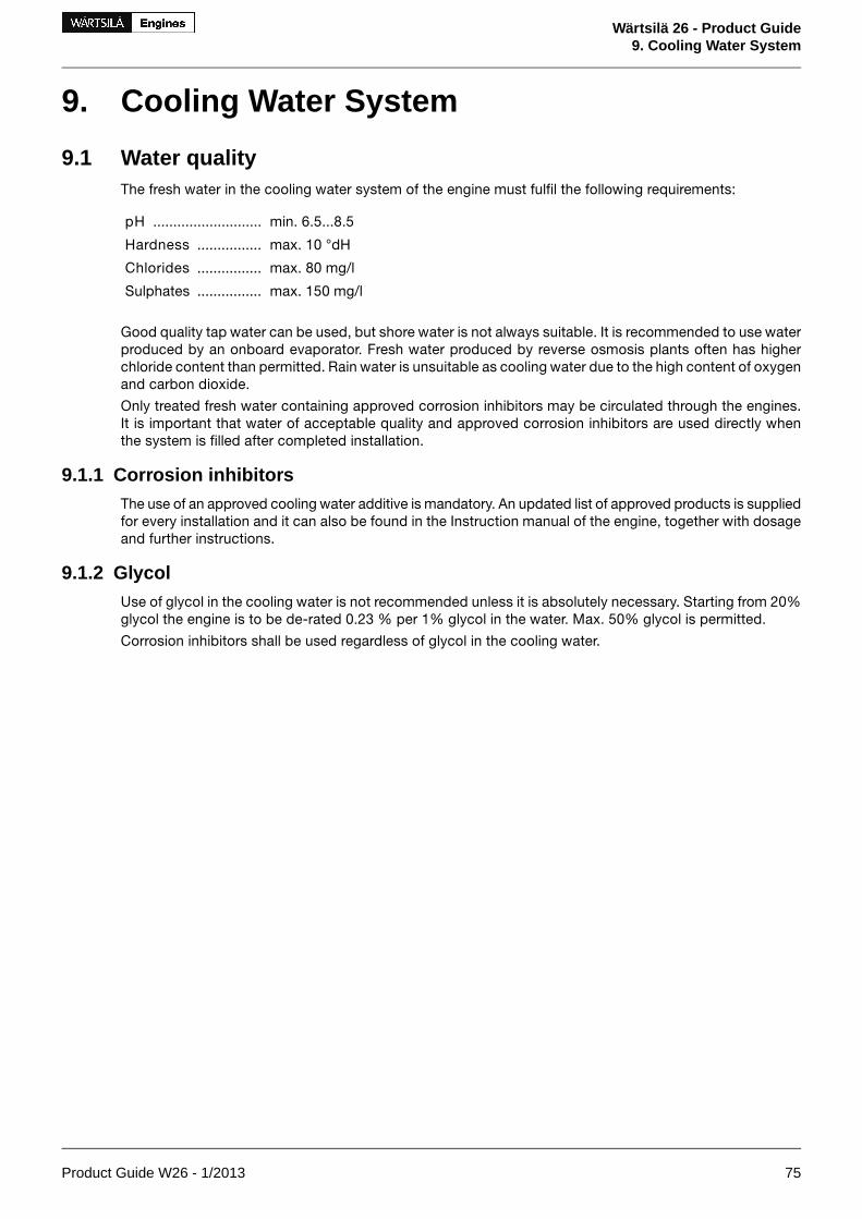
9. Cooling Water System
9.1 Water qualityThe fresh water in the cooling water system of the engine must fulfil the following requirements:
min. 6.5...8.5pH ...........................
max. 10 °dHHardness ................
max. 80 mg/lChlorides ................
max. 150 mg/lSulphates ................
Good quality tap water can be used, but shore water is not always suitable. It is recommended to use waterproduced by an onboard evaporator. Fresh water produced by reverse osmosis plants often has higherchloride content than permitted. Rain water is unsuitable as cooling water due to the high content of oxygenand carbon dioxide.
Only treated fresh water containing approved corrosion inhibitors may be circulated through the engines.It is important that water of acceptable quality and approved corrosion inhibitors are used directly whenthe system is filled after completed installation.
9.1.1 Corrosion inhibitorsThe use of an approved cooling water additive is mandatory. An updated list of approved products is suppliedfor every installation and it can also be found in the Instruction manual of the engine, together with dosageand further instructions.
9.1.2 GlycolUse of glycol in the cooling water is not recommended unless it is absolutely necessary. Starting from 20%glycol the engine is to be de-rated 0.23 % per 1% glycol in the water. Max. 50% glycol is permitted.
Corrosion inhibitors shall be used regardless of glycol in the cooling water.
Product Guide W26 - 1/2013 75
Wärtsilä 26 - Product Guide9. Cooling Water System

9.2 Internal cooling water systemFigure 9.1 Internal cooling water system, in-line engines (DAAE038904c)
System components
HT thermostatic valve05HT cooling water pump01
LT thermostatic valve06LT cooling water pump02
Sea water pump07Lubricating oil cooler03
Charge air cooler04
Sensors and indicators
HT water temp. after cylinder jacketsTI402HT water pressure before cylinder jackets(if GL)
PI401
LT water pressure before cylinder jackets (ifGL)
PI471HT water temp. before cylinder jacketsTE401
LT water temp. engine inlet (if GL)TE471HT water pressure before cylinder jacketsPT401
LT water pressure, engine inletPT471HT water stand-by pump start (if stand-bypump)
PS410
LT water stand-by pump start (if stand-bypump)
PS460HT water pressure before cylinder jackets(if GL)
PSZ401
LT water temp. after lube oil cooler (if FAKS)TE482HT water temp. after cylinder jacketsTE402
LT water temp. after CACTE472HT water temp. after cylinder jacketsTEZ402
StandardPressure classSizePipe connections (in-line engines)
DIN2576PN10DN80HT water inlet401
DIN2576PN10DN80HT water outlet402
DIN2353PN250OD12HT water air vent404
DIN2576PN10DN80HT water to preheater405
DIN2576PN10DN80Water from preheater406
76 Product Guide W26 - 1/2013
Wärtsilä 26 - Product Guide9. Cooling Water System

StandardPressure classSizePipe connections (in-line engines)
DIN2576PN10DN80HT water to stand-by pump407
DIN2576PN10DN80HT water from stand-by pump408
DIN2576PN10DN80LT water inlet451
DIN2576PN10DN80LT water outlet452
DIN2353PN10OD10LT water air vent454
DIN2576PN10DN80LT water to stand-by pump456
DIN2576PN10DN80LT water from stand-by pump457
DIN2576PN10DN80Sea water to engine driven pump476
DIN2576PN10DN80Sea water from engine driven pump477
Figure 9.2 Internal cooling water system, V-engines (DAAE038906b)
System components
HT thermostatic valve05HT cooling water pump01
LT thermostatic valve06LT cooling water pump02
Charge air cooler (HT)08Lubricating oil cooler03
Charge air cooler (LT)04
Sensors and indicators
HT water temp. after cylinder jacketsTI402HT water pressure before cylinder jackets(if GL)
PI401
LT water pressure before cylinder jackets (ifGL)
PI471HT water stand-by pump start (if stand-bypump)
PS410
LT water temp. engine inletTE471HT water temp. before cylinder jacketsTE401
LT water pressure, engine inletPT471HT water pressure before cylinder jacketsPT401
LT water stand-by pump start (if stand-bypump)
PS460HT water pressure before cylinder jackets(if GL)
PSZ401
Product Guide W26 - 1/2013 77
Wärtsilä 26 - Product Guide9. Cooling Water System

Sensors and indicators
LT water temp after CAC (if FAKS)TE472HT water temp. after cylinder jacketsTE402
LT water temp. after lube oil coolerTE482HT water temp. after cylinder jacketsTEZ402
StandardPressure classSizePipe connection
DIN2576PN10DN100HT water inlet401
DIN2576PN10DN100HT water outlet402
DIN2353OD12HT water air vent404
DIN2576PN10DN100HT water to pre-heater405
DIN2576PN10DN100HT water from pre-heater406
DIN2576PN10DN100HT water to stand-by pump407
DIN2576PN10DN100HT water from stand-by pump408
DIN2576PN10DN100LT water inlet451
DIN2576PN10DN100LT water outlet452
DIN2576PN10DN100LT water to stand-by pump456
DIN2576PN10DN100LT water from stand-by pump457
The fresh water cooling system is divided into a high temperature (HT) and a low temperature (LT) circuit.The HT water circulates through cylinder jackets, cylinder heads and the 1st stage of the charge air cooler,if the engine is equipped with a two-stage charge air cooler. V-engines are equipped with a two-stagecharge air cooler, while in-line engines have a single-stage charge air cooler.
The LT water circulates through the charge air cooler and the lubricating oil cooler, which is built on theengine.
Temperature control valves regulate the temperature of the water out from the engine, by circulating somewater back to the cooling water pump inlet. The HT temperature control valve is always mounted on theengine, while the LT temperature control valve can be either on the engine or separate. In installations wherethe engines operate on MDF only it is possible to install the LT temperature control valve in the externalsystem and thus control the LT water temperature before the engine.
9.2.1 Engine driven circulating pumpsThe LT and HT cooling water pumps are engine driven. The engine driven pumps are located at the freeend of the engine.
Pump curves for engine driven pumps are shown in the diagrams. The nominal pressure and capacity canbe found in the chapter Technical data.
Table 9.1 Impeller diameters of engine driven HT & LT pumps
LT + gearbox cooling(optional)
LTHTEnginespeed[rpm]
Engine Non returnvalve orifice*
Ø [mm]
impellerØ [mm]
Non returnvalve ori-
fice*Ø [mm]
impellerØ [mm]
Non returnvalve orifice*
Ø [mm]
impellerØ [mm]
4747
204196
4040
204196
4040
216196
9001000
6L26
5459
216204
5447
204196
4754
216196
9001000
8L26
5954
216216
5959
204196
5454
216196
9001000
9L26
---178178
-178178
9001000
12V26
78 Product Guide W26 - 1/2013
Wärtsilä 26 - Product Guide9. Cooling Water System

LT + gearbox cooling(optional)
LTHTEnginespeed[rpm]
Engine Non returnvalve orifice*
Ø [mm]
impellerØ [mm]
Non returnvalve ori-
fice*Ø [mm]
impellerØ [mm]
Non returnvalve orifice*
Ø [mm]
impellerØ [mm]
---199199
-199199
9001000
16V26
*) Only for in-line engines.
Product Guide W26 - 1/2013 79
Wärtsilä 26 - Product Guide9. Cooling Water System

Table 9.2 Nominal flows and heads of engine driven HT & LT pumps
LT + gearbox cooling(optional)
LTHTEnginespeed[rpm]
EngineHead
[m H2O]Flow[m3/h]
Head[m H2O]
Flow[m3/h]
Head[m H2O]
Flow[m3/h]
2627
5257
2627
4247
3535
3535
9001000
6L26
2527
7076
2725
5662
3636
4545
9001000
8L26
2727
7885
2526
6370
3634
5050
9001000
9L26
--2835
6067
2835
6067
9001000
12V26
--3544
8089
3544
8089
9001000
16V26
Figure 9.3 Pump curves W26 in-line
80 Product Guide W26 - 1/2013
Wärtsilä 26 - Product Guide9. Cooling Water System
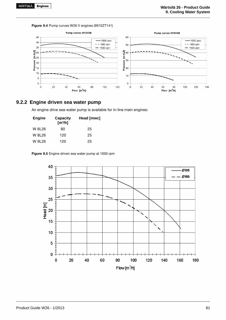
Figure 9.4 Pump curves W26 V engines (9910ZT141)
9.2.2 Engine driven sea water pumpAn engine drive sea-water pump is available for in-line main engines:
Head [mwc]Capacity[m³/h]
Engine
2580W 6L26
25120W 8L26
25120W 9L26
Figure 9.5 Engine driven sea water pump at 1000 rpm
Product Guide W26 - 1/2013 81
Wärtsilä 26 - Product Guide9. Cooling Water System

9.3 External cooling water systemFigure 9.6 External cooling water system example, only for MDF (DAAE038900c)
System components:
Circulating pump (evaporator)4P19Heat recovery (evaporator)4E03
Adjustable throttle valve (LT cooler)4R03Heater (preheater)4E05
Adjustable throttle valve (LT water)4R07Central cooler4E08
Air deaerator (HT)4S02Cooler (installation parts)4E12
Additive dosing tank4T03Preheating unit4N01
Drain tank4T04Stand-by pump (HT)4P03
Expansion tank4T05Circulating pump (preheater)4P04
Temperature control valve (heat recovery)4V02Stand-by pump (LT)4P05
Temperature control valve (central cooler)4V08Transfer pump4P09
Pipe connections are listed below the internal cooling water system diagrams
82 Product Guide W26 - 1/2013
Wärtsilä 26 - Product Guide9. Cooling Water System

Figure 9.7 External cooling water system example (DAAE038901c)
System components:
Adjustable throttle valve (LT cooler)4R03Heat recovery (evaporator)4E03
Adjustable throttle valve (HT valve)4R05Raw water cooler (HT)4E04
Air deaerator (HT)4S02Heater (preheater)4E05
Air deaerator (LT)4S03Raw water cooler (LT)4E06
Additive dosing tank4T03Preheating unit4N01
Drain tank4T04Stand-by pump (HT)4P03
Expansion tank4T05Circulating pump (preheater)4P04
Temperature control valve (heat recovery)4V02Stand-by pump (LT)4P05
Temperature control valve (central cooler)4V08Circulating pump (evaporator)4P19
Transfer pump4P09
Pipe connections are listed below the internal cooling water system diagrams
Product Guide W26 - 1/2013 83
Wärtsilä 26 - Product Guide9. Cooling Water System

Figure 9.8 External cooling water system example (DAAE038902c)
System components:
Transfer pump4P09Heat recovery (evaporator)4E03
Circulating pump (evaporator)4P19Heater (preheater)4E05
Adjustable throttle valve (LT cooler)4R03Central cooler4E08
Air venting4S01Cooler (installation parts)4E12
Additive dosing tank4T03Preheating unit4N01
Drain tank4T04Stand-by pump (HT)4P03
Expansion tank4T05Circulating pump (preheater)4P04
Temperature control valve (heat recovery)4V02Stand-by pump (LT)4P05
Temperature control valve (central cooler)4V08Circulating pump4P06
Pipe connections are listed below the internal cooling water system diagrams
It is recommended to divide the engines into several circuits in multi-engine installations. One reason is ofcourse redundancy, but it is also easier to tune the individual flows in a smaller system. Malfunction dueto entrained gases, or loss of cooling water in case of large leaks can also be limited. In some installationsit can be desirable to separate the HT circuit from the LT circuit with a heat exchanger.
The external system shall be designed so that flows, pressures and temperatures are close to the nominalvalues in Technical data and the cooling water is properly de-aerated.
84 Product Guide W26 - 1/2013
Wärtsilä 26 - Product Guide9. Cooling Water System

Pipes with galvanized inner surfaces are not allowed in the fresh water cooling system. Some cooling wateradditives react with zinc, forming harmful sludge. Zinc also becomes nobler than iron at elevated temperat-ures, which causes severe corrosion of engine components.
Ships (with ice class) designed for cold sea-water should have provisions for recirculation back to the seachest from the central cooler:
• For melting of ice and slush, to avoid clogging of the sea water strainer
• To enhance the temperature control of the LT water, by increasing the seawater temperature
9.3.1 Stand-by circulation pumps (4P03, 4P05)Stand-by pumps should be of centrifugal type and electrically driven. Required capacities and deliverypressures are stated in Technical data.
NOTE! Some classification societies require that spare pumps are carried onboard even though theship has multiple engines. Stand-by pumps can in such case be worth considering also for thistype of application.
9.3.2 Sea water pump (4P11)The capacity of electrically driven sea water pumps is determined by the type of coolers and the amountof heat to be dissipated.
Significant energy savings can be achieved in most installations with frequency control of electrically drivensea water pumps. Minimum flow velocity (fouling) and maximum sea water temperature (salt deposits) arehowever issues to consider.
9.3.3 Temperature control valve for central cooler (4V08)When it is desired to utilize the engine driven LT-pump for cooling of external equipment, e.g. a reductionor a generator, there must be a common LT temperature control valve in the external system, instead ofan individual valve for each engine. The common LT temperature control valve is installed after the centralcooler and controls the temperature of the water before the engine and the external equipment, by partlybypassing the central cooler. The valve can be either direct acting or electrically actuated.
The set-point of the temperature control valve 4V08 is 38 ºC in the type of system described above.
Engines operating on HFO must have individual LT temperature control valves. A separate pump is requiredfor the external equipment in such case, and the set-point of 4V08 can be lower than 38 ºC if necessary.
When there is no temperature control valve in the seawater system (4V07, see figure 9.16), it is advised toinstall a temperature control valve over the central cooler(s) in order to maintain the temperature beforeengine at a constant value.
9.3.4 Temperature control valve for heat recovery (4V02)The temperature control valve after the heat recovery controls the maximum temperature of the water thatis mixed with HT water from the engine outlet before the HT pump. The control valve can be either self-actuated or electrically actuated.
The set-point is usually somewhere close to 75 ºC.
The arrangement shown in the example system diagrams also results in a smaller flow through the centralcooler, compared to a system where the HT and LT circuits are connected in parallel to the cooler.
9.3.5 Coolers for other equipment and MDF coolersThe engine driven LT circulating pump can supply cooling water to one or two small coolers installed inparallel to the engine, for example a MDF cooler or a reduction gear cooler. This is only possible for enginesoperating on MDF, because the LT temperature control valve cannot be built on the engine to control thetemperature after the engine. Separate circulating pumps are required for larger flows.
Design guidelines for the MDF cooler are given in chapter Fuel system.
Product Guide W26 - 1/2013 85
Wärtsilä 26 - Product Guide9. Cooling Water System

9.3.6 Fresh water central cooler (4E08)The fresh water cooler can be of either plate, tube or box cooler type. Plate coolers are most common.Several engines can share the same cooler.
It can be necessary to compensate a high flow resistance in the circuit with a smaller pressure drop overthe central cooler.
The flow to the fresh water cooler must be calculated case by case based on how the circuit is designed.
As an alternative for the central coolers of the plate or of the tube type a box cooler can be installed. Theprinciple of box cooling is very simple. Cooling water is forced through a U-tube-bundle, which is placedin a sea-chest having inlet- and outlet-grids. Cooling effect is reached by natural circulation of the surroundingwater. The outboard water is warmed up and rises by its lower density, thus causing a natural upward cir-culation flow which removes the heat.
Box cooling has the advantage that no raw water system is needed, and box coolers are less sensitive forfouling and therefor well suited for shallow or muddy waters.
9.3.7 Waste heat recoveryThe waste heat in the HT cooling water can be used for fresh water production, central heating, tank heatingetc. The system should in such case be provided with a temperature control valve to avoid unnecessarycooling, as shown in the example diagrams. With this arrangement the HT water flow through the heat re-covery can be increased.
The heat available from HT cooling water is affected by ambient conditions. It should also be taken intoaccount that the recoverable heat is reduced by circulation to the expansion tank, radiation from pipingand leakages in temperature control valves.
9.3.8 Air ventingAir may be entrained in the system after an overhaul, or a leak may continuously add air or gas into thesystem. The engine is equipped with vent pipes to evacuate air from the cooling water circuits. The ventpipes should be drawn separately to the expansion tank from each connection on the engine, except forthe vent pipes from the charge air cooler on V-engines, which may be connected to the corresponding lineon the opposite cylinder bank.
Venting pipes to the expansion tank are to be installed at all high points in the piping system, where air orgas can accumulate.
The vent pipes must be continuously rising.
86 Product Guide W26 - 1/2013
Wärtsilä 26 - Product Guide9. Cooling Water System

Figure 9.9 Automatic de-aerator (9811MR102).
The water flow is forced in a circular movement in the air separator. Air and gas collect in the centre of theseparator due to the higher centrifugal force on water.
9.3.9 Expansion tank (4T05)The expansion tank compensates for thermal expansion of the coolant, serves for venting of the circuitsand provides a sufficient static pressure for the circulating pumps.
Design data:
70 - 150 kPa (0.7...1.5 bar)Pressure from the expansion tank at pump inlet
min. 10% of the total system volumeVolume
NOTE! The maximum pressure at the engine must not be exceeded in case an electrically driven pumpis installed significantly higher than the engine.
Concerning the water volume in the engine, see chapter Technical data.
The expansion tank should be equipped with an inspection hatch, a level gauge, a low level alarm and ne-cessary means for dosing of cooling water additives.
The vent pipes should enter the tank below the water level. The vent pipes must be drawn separately tothe tank (see air venting) and the pipes should be provided with labels at the expansion tank.
The balance pipe down from the expansion tank must be dimensioned for a flow velocity not exceeding1.0...1.5 m/s in order to ensure the required pressure at the pump inlet with engines running. The flowthrough the pipe depends on the number of vent pipes to the tank and the size of the orifices in the ventpipes. The table below can be used for guidance.
Product Guide W26 - 1/2013 87
Wärtsilä 26 - Product Guide9. Cooling Water System
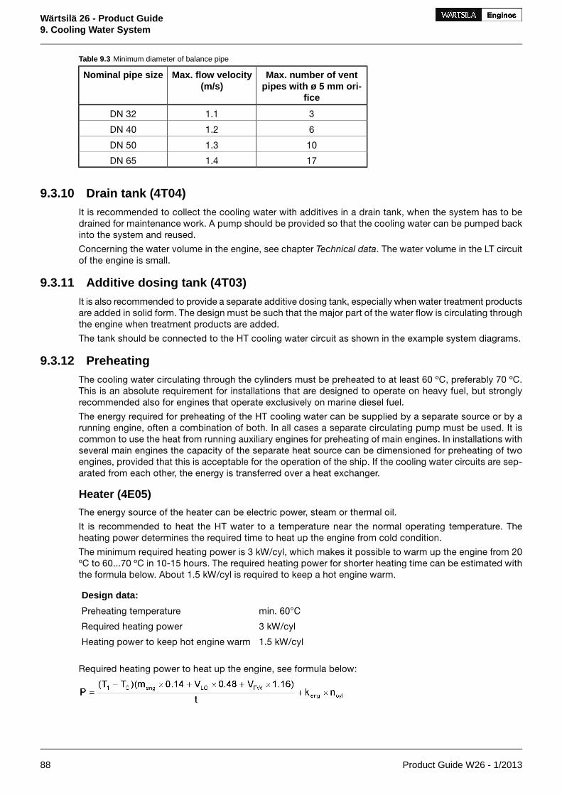
Table 9.3 Minimum diameter of balance pipe
Max. number of ventpipes with ø 5 mm ori-
fice
Max. flow velocity(m/s)
Nominal pipe size
31.1DN 32
61.2DN 40
101.3DN 50
171.4DN 65
9.3.10 Drain tank (4T04)It is recommended to collect the cooling water with additives in a drain tank, when the system has to bedrained for maintenance work. A pump should be provided so that the cooling water can be pumped backinto the system and reused.
Concerning the water volume in the engine, see chapter Technical data. The water volume in the LT circuitof the engine is small.
9.3.11 Additive dosing tank (4T03)It is also recommended to provide a separate additive dosing tank, especially when water treatment productsare added in solid form. The design must be such that the major part of the water flow is circulating throughthe engine when treatment products are added.
The tank should be connected to the HT cooling water circuit as shown in the example system diagrams.
9.3.12 PreheatingThe cooling water circulating through the cylinders must be preheated to at least 60 ºC, preferably 70 ºC.This is an absolute requirement for installations that are designed to operate on heavy fuel, but stronglyrecommended also for engines that operate exclusively on marine diesel fuel.
The energy required for preheating of the HT cooling water can be supplied by a separate source or by arunning engine, often a combination of both. In all cases a separate circulating pump must be used. It iscommon to use the heat from running auxiliary engines for preheating of main engines. In installations withseveral main engines the capacity of the separate heat source can be dimensioned for preheating of twoengines, provided that this is acceptable for the operation of the ship. If the cooling water circuits are sep-arated from each other, the energy is transferred over a heat exchanger.
Heater (4E05)
The energy source of the heater can be electric power, steam or thermal oil.
It is recommended to heat the HT water to a temperature near the normal operating temperature. Theheating power determines the required time to heat up the engine from cold condition.
The minimum required heating power is 3 kW/cyl, which makes it possible to warm up the engine from 20ºC to 60...70 ºC in 10-15 hours. The required heating power for shorter heating time can be estimated withthe formula below. About 1.5 kW/cyl is required to keep a hot engine warm.
Design data:
min. 60°CPreheating temperature
3 kW/cylRequired heating power
1.5 kW/cylHeating power to keep hot engine warm
Required heating power to heat up the engine, see formula below:
88 Product Guide W26 - 1/2013
Wärtsilä 26 - Product Guide9. Cooling Water System

where:
Preheater output [kW]P =
Preheating temperature = 60...70 °CT1 =
Ambient temperature [°C]T0 =
Engine weight [ton]meng =
Lubricating oil volume [m3] (wet sump engines only)VLO =
HT water volume [m3]VFW =
Preheating time [h]t =
Engine specific coefficient = 0.75 kWkeng =
Number of cylindersncyl =
P < 2.5 kW/cylThe formula above should not be usedfor
Circulation pump for preheater (4P04)
Design data:
0.45 m3/h per cylinderCapacity
80...100 kPa (0.8...1.0 bar)Delivery pressure
Preheating unit (4N01)
A complete preheating unit can be supplied. The unit comprises:
• Electric or steam heaters
• Circulating pump
• Control cabinet for heaters and pump
• Set of thermometers
• Non-return valve
• Safety valve
Figure 9.10 Electric pre-heating unit, main dimensions
Product Guide W26 - 1/2013 89
Wärtsilä 26 - Product Guide9. Cooling Water System

Mass [kg] (wet)B [mm]H [mm]L [mm]Heating power[kW]*
93460800105012 (16)
95460800125016 (21)
95460800125018 (24)
103480840125024 (32)
125480840125032 (42)
9.3.13 ThrottlesThrottles (orifices) are to be installed in all by-pass lines to ensure balanced operating conditions for tem-perature control valves. Throttles must also be installed wherever it is necessary to balance the waterflowbetween alternate flow paths.
9.3.14 Thermometers and pressure gaugesLocal thermometers should be installed wherever there is a temperature change, i.e. before and after heatexchangers etc.
Local pressure gauges should be installed on the suction and discharge side of each pump.
90 Product Guide W26 - 1/2013
Wärtsilä 26 - Product Guide9. Cooling Water System

10. Combustion Air System
10.1 Engine room ventilationTo maintain acceptable operating conditions for the engines and to ensure trouble free operation of allequipment, attention shall be paid to the engine room ventilation and the supply of combustion air.
The air intakes to the engine room must be located and designed so that water spray, rain water, dust andexhaust gases cannot enter the ventilation ducts and the engine room.
The dimensioning of blowers and extractors should ensure that an overpressure of about 50 Pa is maintainedin the engine room in all running conditions.
For the minimum requirements concerning the engine room ventilation and more details, see applicablestandards, such as ISO 8861.
The amount of air required for ventilation is calculated from the total heat emission Φ to evacuate. To de-termine Φ, all heat sources shall be considered, e.g.:
• Main and auxiliary diesel engines
• Exhaust gas piping
• Generators
• Electric appliances and lighting
• Boilers
• Steam and condensate piping
• Tanks
It is recommended to consider an outside air temperature of no less than 35°C and a temperature rise of11°C for the ventilation air.
The amount of air required for ventilation is then calculated using the formula:
where:
air flow [m³/s]qv =
total heat emission to be evacuated [kW]Φ =
air density 1.13 kg/m³ρ =
specific heat capacity of the ventilation air 1.01 kJ/kgKc =
temperature rise in the engine room [°C]ΔT =
The heat emitted by the engine is listed in chapter Technical data.
The engine room ventilation air has to be provided by separate ventilation fans. These fans should preferablyhave two-speed electric motors (or variable speed). The ventilation can then be reduced according to outsideair temperature and heat generation in the engine room, for example during overhaul of the main enginewhen it is not preheated (and therefore not heating the room).
The ventilation air is to be equally distributed in the engine room considering air flows from points of deliverytowards the exits. This is usually done so that the funnel serves as exit for most of the air. To avoid stagnantair, extractors can be used.
It is good practice to provide areas with significant heat sources, such as separator rooms with their ownair supply and extractors.
Under-cooling of the engine room should be avoided during all conditions (service conditions, slowsteaming and in port). Cold draft in the engine room should also be avoided, especially in areas of frequentmaintenance activities. For very cold conditions a pre-heater in the system should be considered. Suitablemedia could be thermal oil or water/glycol to avoid the risk for freezing. If steam is specified as heatingmedium for the ship, the pre-heater should be in a secondary circuit.
Product Guide W26 - 1/2013 91
Wärtsilä 26 - Product Guide10. Combustion Air System

Figure 10.1 Engine room ventilation, turbocharger with air filter (DAAE092651)
Figure 10.2 Engine room ventilation, air duct connected to the turbocharger (DAAE092652A)
10.2 Combustion air system designUsually, the combustion air is taken from the engine room through a filter on the turbocharger. This reducesthe risk for too low temperatures and contamination of the combustion air. It is important that the combustionair is free from sea water, dust, fumes, etc.
92 Product Guide W26 - 1/2013
Wärtsilä 26 - Product Guide10. Combustion Air System

During normal operating conditions the air temperature at turbocharger inlet should be kept between15...35°C. Temporarily max. 45°C is allowed. For the required amount of combustion air, see sectionTechnical data.
The combustion air shall be supplied by separate combustion air fans, with a capacity slightly higher thanthe maximum air consumption. The combustion air mass flow stated in technical data is defined for anambient air temperature of 25°C. Calculate with an air density corresponding to 30°C or more when trans-lating the mass flow into volume flow. The expression below can be used to calculate the volume flow.
where:
combustion air volume flow [m³/s]qc =
combustion air mass flow [kg/s]m' =
air density 1.15 kg/m³ρ =
The fans should preferably have two-speed electric motors (or variable speed) for enhanced flexibility. Inaddition to manual control, the fan speed can be controlled by engine load.
In multi-engine installations each main engine should preferably have its own combustion air fan. Thus theair flow can be adapted to the number of engines in operation.
The combustion air should be delivered through a dedicated duct close to the turbocharger, directed towardsthe turbocharger air intake. The outlet of the duct should be equipped with a flap for controlling the directionand amount of air. Also other combustion air consumers, for example other engines, gas turbines andboilers shall be served by dedicated combustion air ducts.
If necessary, the combustion air duct can be connected directly to the turbocharger with a flexible connectionpiece. With this arrangement an external filter must be installed in the duct to protect the turbocharger andprevent fouling of the charge air cooler. The permissible total pressure drop in the duct is max. 1.5 kPa.The duct should be provided with a step-less change-over flap to take the air from the engine room or fromoutside depending on engine load and air temperature.
For very cold conditions heating of the supply air must be arranged. The combustion air fan is stoppedduring start of the engine and the necessary combustion air is drawn from the engine room. After starteither the ventilation air supply, or the combustion air supply, or both in combination must be able tomaintain the minimum required combustion air temperature. The air supply from the combustion air fan isto be directed away from the engine, when the intake air is cold, so that the air is allowed to heat up in theengine room.
10.2.1 Charge air shut-off valve, "rigsaver" (optional)In installations where it is possible that the combustion air includes combustible gas or vapour the enginescan be equipped with charge air shut-off valve. This is regulated mandatory where ingestion of flammablegas or fume is possible.
10.2.2 Condensation in charge air coolersAir humidity may condense in the charge air cooler, especially in tropical conditions. The engine equippedwith a small drain pipe from the charge air cooler for condensed water.
The amount of condensed water can be estimated with the diagram below.
Product Guide W26 - 1/2013 93
Wärtsilä 26 - Product Guide10. Combustion Air System
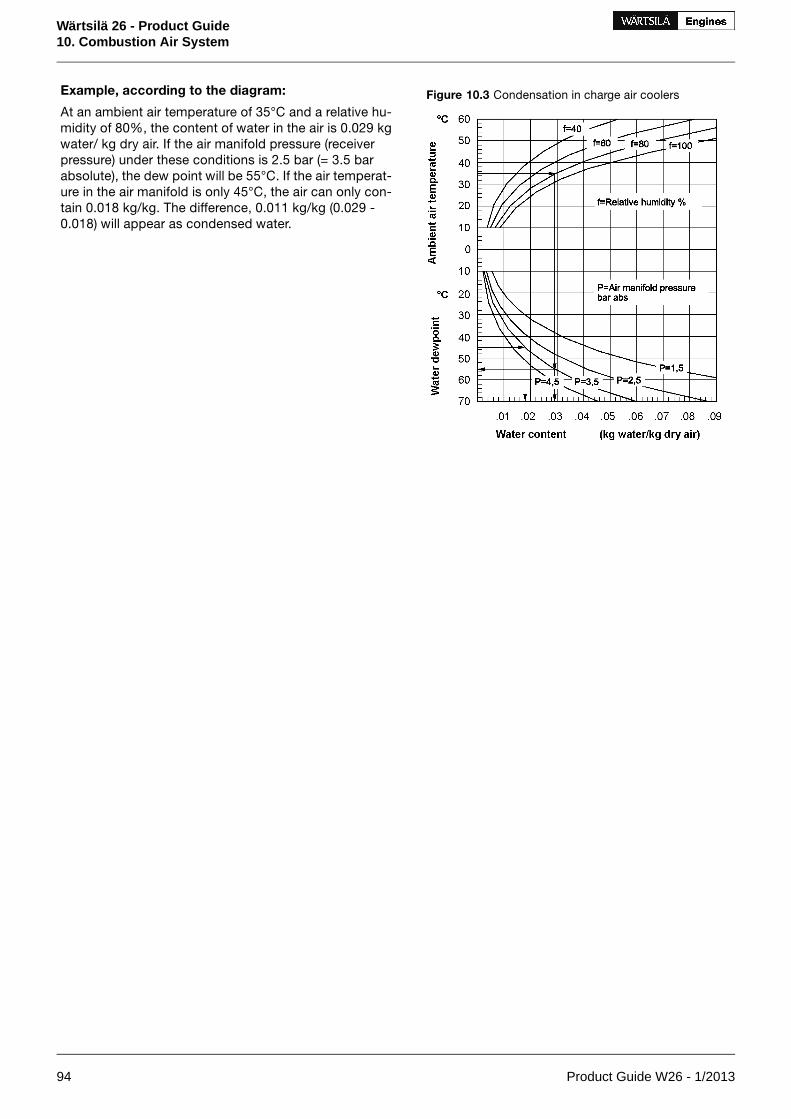
Figure 10.3 Condensation in charge air coolersExample, according to the diagram:
At an ambient air temperature of 35°C and a relative hu-midity of 80%, the content of water in the air is 0.029 kgwater/ kg dry air. If the air manifold pressure (receiverpressure) under these conditions is 2.5 bar (= 3.5 barabsolute), the dew point will be 55°C. If the air temperat-ure in the air manifold is only 45°C, the air can only con-tain 0.018 kg/kg. The difference, 0.011 kg/kg (0.029 -0.018) will appear as condensed water.
94 Product Guide W26 - 1/2013
Wärtsilä 26 - Product Guide10. Combustion Air System

11. Exhaust Gas System
11.1 Internal exhaust gas systemFigure 11.1 Charge air and exhaust gas system 8L, 2-pulse system (DAAE047964a)
Figure 11.2 Charge air and exhaust gas system 6L & 9L, 3-pulse system (DAAE038908a)
System components, in-line engines
Turbine cleaning device07Charge air cooler01
Charge air shut-off valve (optional)08Turbocharger03
Safety valve09Compressor cleaning device04
Indicator valve10Air filter and silencer05
Air waste gate11Suction branch (alternative for 05)06
Sensors and indicators, in-line engines
Exhaust gas temp. after cylinder (if GL)TI5xxAExhaust gas temp. after cylinderTE5xx1A
Charge air temp. engine inletTI601Exhaust gas temp. TC inletTE511
Product Guide W26 - 1/2013 95
Wärtsilä 26 - Product Guide11. Exhaust Gas System

Sensors and indicators, in-line engines
Charge air temp. CAC inletTI621Exhaust gas temp. TC outletTE517
Charge air temp. TC inlet (if FAKS)TE600TC speedSE518
Charge air temp. CAC inlet (if FAKS)TE621Charge air pressure, engine inlet (if GL)PI601
Charge air shut-off valve position (optional)GS621Charge air pressure, engine inletPT601
Air waste gate positionGT656Charge air pressure, engine inletPT601.2
Charge air temp. engine inletTE601
StandardPressure classSizePipe connections, in-line engines
PN66L: DN3008L, 9L: DN350
Exhaust gas outlet501
Quick couplingCleaning water to turbine502
6L: Øint 280; Øpc 340; 12XØ148L, 9L: Øint 333; Øpc 405; 12XØ14
Air inlet to turbocharger(if suction branch)
601
DIN2535PN400OD8Condensate after air cooler607
Figure 11.3 Charge air and exhaust gas system 12V, pulse system (DAAE042959a)
System components, 12V-engine
Turbine cleaning device07Charge air cooler (HT)01
Charge air shut-off valve (optional)08Charge air cooler (LT)02
Safety valve09Turbocharger03
Indicator valve10Compressor cleaning device04
Air waste gate11Air filter and silencer05
Suction branch (alternative for 05)06
96 Product Guide W26 - 1/2013
Wärtsilä 26 - Product Guide11. Exhaust Gas System

Figure 11.4 Charge air and exhaust gas system 16V, with SPEX, by-pass and waste gate (DAAE038909a)
System components, 16V-engine
Charge air shut-off valve (optional)08Charge air cooler (HT)01
Charge air by-pass valve09Charge air cooler (LT)02
Exhaust waste gate valve10Turbocharger03
Air waste gate11Compressor cleaning device04
Indicator valve12Air filter and silencer05
Safety valve13Suction branch (alternative for 05)06
Turbine cleaning device07
Sensors and indicators, V-engines
Charge air temp. CAC inletTI621Exhaust gas temp. after cylinder, A-bank
TE5xx1A
Charge air pressure, engine inlet (if GL)PI601Exhaust gas temp. after cylinder, B-bank
TE5xx1B
Exhaust gas temp. after cylinder, A-bank (if GL)TI5xxAExhaust gas temp. TC inlet, A-bankTE511
Exhaust gas temp. after cylinder, B-bank (if GL)TI5xxBExhaust gas temp. TC inlet, B-bankTE521
Charge air pressure, engine inletPT601.2Exhaust gas temp. TC outlet, A-bankTE517
Charge air temp. TC inlet (if FAKS)TE600Exhaust gas temp. TC outlet, B-bankTE527
Charge air temp. CAC inlet (if FAKS)TE621TC speed, A-bankSE518
Charge air shut-off valve position, A-bankGS621TC speed, B-bankSE528
Charge air shut-off valve position, B-bankGS631Charge air pressure, engine inletPT601
Air waste gate positionGT656Charge air temp. engine inletTE601
Charge air temp. engine inletTI601
Product Guide W26 - 1/2013 97
Wärtsilä 26 - Product Guide11. Exhaust Gas System

StandardPressure classSizePipe connections, V-engines
PN612V: DN45016V: DN400
Exhaust gas outlet501
Quick couplingCleaning water to turbine502
16V: DN25Cleaning water from turbine503
12V: Øint 280; Øpc 340; 12XØ1416V: Øint 378; Øpc 495; 16XØ22
Air inlet to turbocharger(if suction branch)
601
DIN2535PN400OD8Condensate after air cooler607
98 Product Guide W26 - 1/2013
Wärtsilä 26 - Product Guide11. Exhaust Gas System

11.2 Exhaust gas outletThe exhaust gas outlet from the turbocharger can be inclined into several positions. The possibilities dependon the cylinder configuration as shown in figures of this section. The turbocharger can be located at bothends, the figure shows only free end solutions. A flexible bellow has to be mounted directly on the turbineoutlet to protect the turbocharger from external forces.
Figure 11.5 Exhaust outlet possibilities, in-line engines
Figure 11.6 Exhaust outlet possibilities, 12V-engine
Product Guide W26 - 1/2013 99
Wärtsilä 26 - Product Guide11. Exhaust Gas System
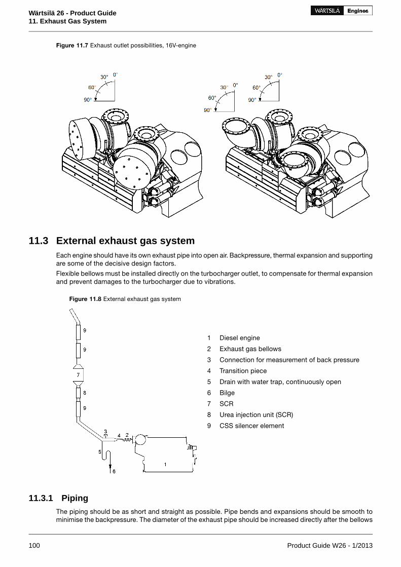
Figure 11.7 Exhaust outlet possibilities, 16V-engine
11.3 External exhaust gas systemEach engine should have its own exhaust pipe into open air. Backpressure, thermal expansion and supportingare some of the decisive design factors.
Flexible bellows must be installed directly on the turbocharger outlet, to compensate for thermal expansionand prevent damages to the turbocharger due to vibrations.
Diesel engine1
Exhaust gas bellows2
Connection for measurement of back pressure3
Transition piece4
Drain with water trap, continuously open5
Bilge6
SCR7
Urea injection unit (SCR)8
CSS silencer element9
Figure 11.8 External exhaust gas system
11.3.1 PipingThe piping should be as short and straight as possible. Pipe bends and expansions should be smooth tominimise the backpressure. The diameter of the exhaust pipe should be increased directly after the bellows
100 Product Guide W26 - 1/2013
Wärtsilä 26 - Product Guide11. Exhaust Gas System

on the turbocharger. Pipe bends should be made with the largest possible bending radius; the bendingradius should not be smaller than 1.5 x D.
The recommended flow velocity in the pipe is maximum 35…40 m/s at full output. If there are many resistancefactors in the piping, or the pipe is very long, then the flow velocity needs to be lower. The exhaust gasmass flow given in chapter Technical data can be translated to velocity using the formula:
Where:
gas velocity [m/s]v =
exhaust gas mass flow [kg/s]m' =
exhaust gas temperature [°C]T =
exhaust gas pipe diameter [m]D =
The exhaust pipe must be insulated with insulation material approved for concerned operation conditions,minimum thickness 30 mm considering the shape of engine mounted insulation. Insulation has to be con-tinuous and protected by a covering plate or similar to keep the insulation intact.
Closest to the turbocharger the insulation should consist of a hook on padding to facilitate maintenance.It is especially important to prevent the airstream to the turbocharger from detaching insulation, which willclog the filters.
After the insulation work has been finished, it has to be verified that it fulfils SOLAS-regulations. Surfacetemperatures must be below 220°C on whole engine operating range.
11.3.2 SupportingIt is very important that the exhaust pipe is properly fixed to a support that is rigid in all directions directlyafter the bellows on the turbocharger. There should be a fixing point on both sides of the pipe at the support.The bellows on the turbocharger may not be used to absorb thermal expansion from the exhaust pipe. Thefirst fixing point must direct the thermal expansion away from the engine. The following support must preventthe pipe from pivoting around the first fixing point.
Absolutely rigid mounting between the pipe and the support is recommended at the first fixing point afterthe turbocharger. Resilient mounts can be accepted for resiliently mounted engines with long bellows,provided that the mounts are self-captive; maximum deflection at total failure being less than 2 mm radialand 4 mm axial with regards to the bellows. The natural frequencies of the mounting should be on a safedistance from the running speed, the firing frequency of the engine and the blade passing frequency of thepropeller. The resilient mounts can be rubber mounts of conical type, or high damping stainless steel wirepads. Adequate thermal insulation must be provided to protect rubber mounts from high temperatures.When using resilient mounting, the alignment of the exhaust bellows must be checked on a regular basisand corrected when necessary.
After the first fixing point resilient mounts are recommended. The mounting supports should be positionedat stiffened locations within the ship’s structure, e.g. deck levels, frame webs or specially constructedsupports.
The supporting must allow thermal expansion and ship’s structural deflections.
11.3.3 Back pressureThe maximum permissible exhaust gas back pressure is stated in chapter Technical Data. The back pressurein the system must be calculated by the shipyard based on the actual piping design and the resistance ofthe components in the exhaust system. The exhaust gas mass flow and temperature given in chapterTechnical Data may be used for the calculation.
Each exhaust pipe should be provided with a connection for measurement of the back pressure. The backpressure must be measured by the shipyard during the sea trial.
Product Guide W26 - 1/2013 101
Wärtsilä 26 - Product Guide11. Exhaust Gas System

11.3.4 Exhaust gas bellows (5H01, 5H03)Bellows must be used in the exhaust gas piping where thermal expansion or ship’s structural deflectionshave to be segregated. The flexible bellows mounted directly on the turbocharger outlet serves to minimisethe external forces on the turbocharger and thus prevent excessive vibrations and possible damage. Allexhaust gas bellows must be of an approved type.
11.3.5 SCR-unit (11N03)The exhaust gas piping must be straight at least 3...5 meters in front of the SCR unit. If both an exhaustgas boiler and a SCR unit will be installed, then the exhaust gas boiler shall be installed after the SCR. Ar-rangements must be made to ensure that water cannot spill down into the SCR, when the exhaust boileris cleaned with water.
11.3.6 Exhaust gas boilerIf exhaust gas boilers are installed, each engine should have a separate exhaust gas boiler. Alternatively,a common boiler with separate gas sections for each engine is acceptable.
For dimensioning the boiler, the exhaust gas quantities and temperatures given in chapter Technical datamay be used.
102 Product Guide W26 - 1/2013
Wärtsilä 26 - Product Guide11. Exhaust Gas System
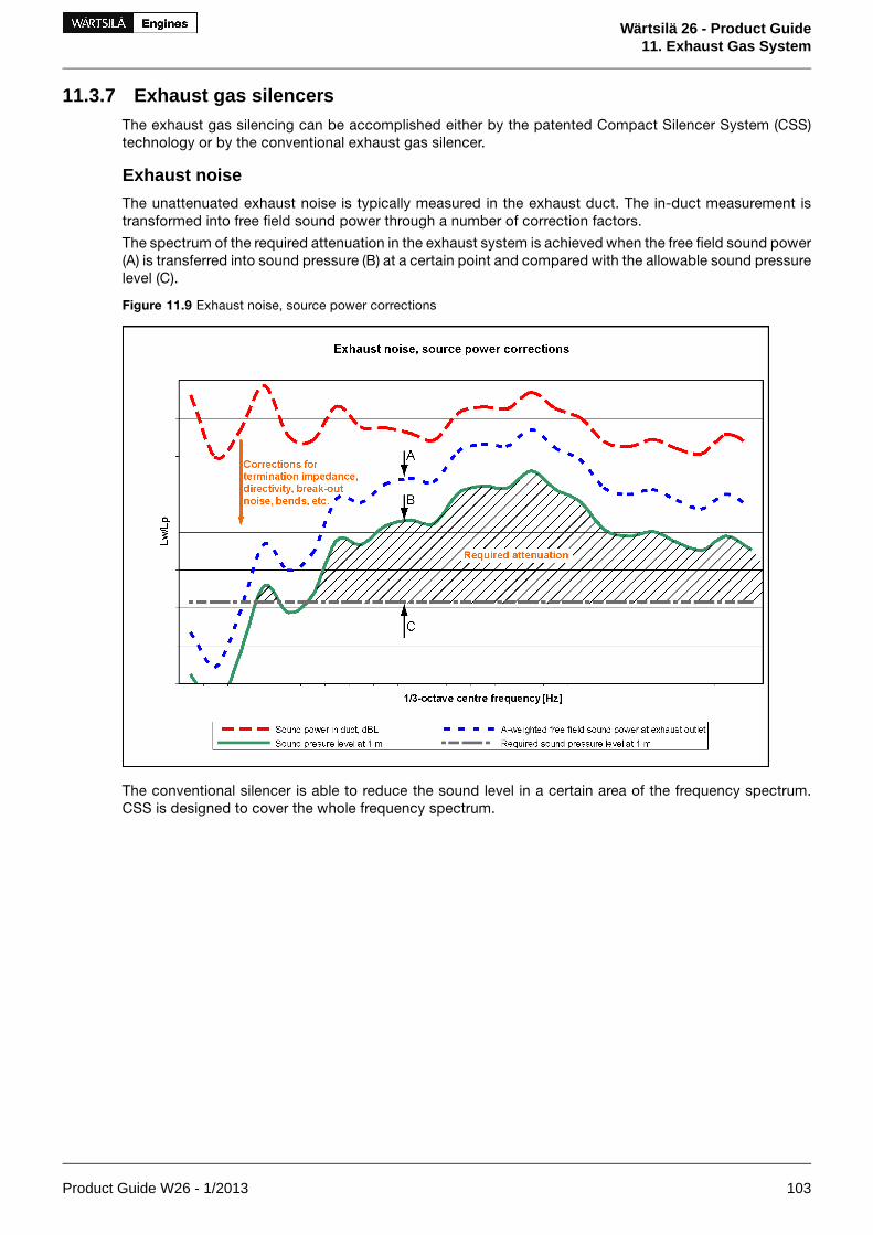
11.3.7 Exhaust gas silencersThe exhaust gas silencing can be accomplished either by the patented Compact Silencer System (CSS)technology or by the conventional exhaust gas silencer.
Exhaust noise
The unattenuated exhaust noise is typically measured in the exhaust duct. The in-duct measurement istransformed into free field sound power through a number of correction factors.
The spectrum of the required attenuation in the exhaust system is achieved when the free field sound power(A) is transferred into sound pressure (B) at a certain point and compared with the allowable sound pressurelevel (C).
Figure 11.9 Exhaust noise, source power corrections
The conventional silencer is able to reduce the sound level in a certain area of the frequency spectrum.CSS is designed to cover the whole frequency spectrum.
Product Guide W26 - 1/2013 103
Wärtsilä 26 - Product Guide11. Exhaust Gas System

Silencer system comparison
With a conventional silencer system, the design of the noise reduction system usually starts from the engine.With the CSS, the design is reversed, meaning that the noise level acceptability at a certain distance fromthe ship's exhaust gas pipe outlet, is used to dimension the noise reduction system.
Figure 11.10 Silencer system comparison
Compact silencer system (5N02)
The CSS system is optimized for each installation as a complete exhaust gas system. The optimization ismade according to the engine characteristics, to the sound level requirements and to other equipment in-stalled in the exhaust gas system, like SCR, exhaust gas boiler or scrubbers.
The CSS system is built up of three different CSS elements; resistive, reactive and composite elements.The combination-, amount- and length of the elements are always installation specific. The diameter of theCSS element is 1.4 times the exhaust gas pipe diameter.
The noise attenuation is valid up to a exhaust gas flow velocity of max 40 m/s. The pressure drop of a CSSelement is lower compared to a conventional exhaust gas silencer (5R02).
104 Product Guide W26 - 1/2013
Wärtsilä 26 - Product Guide11. Exhaust Gas System

Conventional exhaust gas silencer (5R02)
Yard/designer should take into account that unfavourable layout of the exhaust system (length of straightparts in the exhaust system) might cause amplification of the exhaust noise between engine outlet and thesilencer. Hence the attenuation of the silencer does not give any absolute guarantee for the noise level afterthe silencer.
When included in the scope of supply, the standard silencer is of the absorption type, equipped with aspark arrester. It is also provided with a soot collector and a condense drain, but it comes without mountingbrackets and insulation. The silencer can be mounted either horizontally or vertically.
The noise attenuation of the standard silencer is either 25 or 35 dB(A). This attenuation is valid up to a flowvelocity of max. 40 m/s.
Figure 11.11 Exhaust gas silencer (9855MR366)
Table 11.1 Typical dimensions of the exhaust gas silencer
Attenuation: 35 dB(A)Attenuation: 25 dB(A)C [mm]A [mm]
Enginetype Weight
[kg]L [mm]Weight
[kg]L [mm]
8604280690343012005006L26
13105260980401013006008L26
13105260980401013006009L26
1910605014704550150070012V26
2490634019304840170080016V26
Flanges: DIN 2501
Product Guide W26 - 1/2013 105
Wärtsilä 26 - Product Guide11. Exhaust Gas System

12. Turbocharger CleaningRegular water cleaning of the turbine and the compressor reduces the formation of deposits and extendsthe time between overhauls. Fresh water is injected into the turbocharger during operation. Additives,solvents or salt water must not be used and the cleaning instructions in the operation manual must becarefully followed.
12.1 Turbine cleaning systemA dosing unit consisting of a flow meter and an adjustable throttle valve is delivered for each installation.The dosing unit is installed in the engine room and connected to the engine with a detachable rubber hose.The rubber hose is connected with quick couplings and the length of the hose is normally 10 m. One dosingunit can be used for several engines.
Water supply:
Fresh water
0.3 MPa (3 bar)Min. pressure
2 MPa (20 bar)Max. pressure
80 °CMax. temperature
15-30 l/min (depending on cylinder configuration)Flow
The turbocharges are cleaned one at a time on V-engines.
Figure 12.1 Turbine cleaning system (DAAE003884)
SizePipe connectionsSystem components
Quick couplingCleaning water to turbine502Dosing unit with shut-off valve01
Rubber hose02
12.2 Compressor cleaning systemThe compressor side of the turbocharger is cleaned using a separate dosing vessel mounted on the engine.
106 Product Guide W26 - 1/2013
Wärtsilä 26 - Product Guide12. Turbocharger Cleaning

13. Exhaust EmissionsExhaust emissions from the diesel engine mainly consist of nitrogen, oxygen and combustion products likecarbon dioxide (CO2), water vapour and minor quantities of carbon monoxide (CO), sulphur oxides (SOx),nitrogen oxides (NOx), partially reacted and non-combusted hydrocarbons (HC) and particulate matter (PM).
There are different emission control methods depending on the aimed pollutant. These are mainly dividedin two categories; primary methods that are applied on the engine itself and secondary methods that areapplied on the exhaust gas stream.
13.1 Diesel engine exhaust componentsThe nitrogen and oxygen in the exhaust gas are the main components of the intake air which don't takepart in the combustion process.
CO2 and water are the main combustion products. Secondary combustion products are carbon monoxide,hydrocarbons, nitrogen oxides, sulphur oxides, soot and particulate matters.
In a diesel engine the emission of carbon monoxide and hydrocarbons are low compared to other internalcombustion engines, thanks to the high air/fuel ratio in the combustion process. The air excess allows analmost complete combustion of the HC and oxidation of the CO to CO2, hence their quantity in the exhaustgas stream are very low.
13.1.1 Nitrogen oxides (NOx)
The combustion process gives secondary products as Nitrogen oxides. At high temperature the nitrogen,usually inert, react with oxygen to form Nitric oxide (NO) and Nitrogen dioxide (NO2), which are usuallygrouped together as NOx emissions. Their amount is strictly related to the combustion temperature.
NO can also be formed through oxidation of the nitrogen in fuel and through chemical reactions with fuelradicals. NO in the exhaust gas flow is in a high temperature and high oxygen concentration environment,hence oxidizes rapidly to NO2. The amount of NO2 emissions is approximately 5 % of total NOx emissions.
13.1.2 Sulphur Oxides (SOx)
Sulphur oxides (SOx) are direct result of the sulphur content of the fuel oil. During the combustion processthe fuel bound sulphur is rapidly oxidized to sulphur dioxide (SO2). A small fraction of SO2 may be furtheroxidized to sulphur trioxide (SO3).
13.1.3 Particulate Matter (PM)The particulate fraction of the exhaust emissions represents a complex mixture of inorganic and organicsubstances mainly comprising soot (elemental carbon), fuel oil ash (together with sulphates and associatedwater), nitrates, carbonates and a variety of non or partially combusted hydrocarbon components of thefuel and lubricating oil.
13.1.4 SmokeAlthough smoke is usually the visible indication of particulates in the exhaust, the correlations betweenparticulate emissions and smoke is not fixed. The lighter and more volatile hydrocarbons will not be visiblenor will the particulates emitted from a well maintained and operated diesel engine.
Smoke can be black, blue, white, yellow or brown in appearance. Black smoke is mainly comprised ofcarbon particulates (soot). Blue smoke indicates the presence of the products of the incomplete combustionof the fuel or lubricating oil. White smoke is usually condensed water vapour. Yellow smoke is caused byNOx emissions. When the exhaust gas is cooled significantly prior to discharge to the atmosphere, thecondensed NO2 component can have a brown appearance.
Product Guide W26 - 1/2013 107
Wärtsilä 26 - Product Guide13. Exhaust Emissions

13.2 Marine exhaust emissions legislation
13.2.1 International Maritime Organization (IMO)The increasing concern over the air pollution has resulted in the introduction of exhaust emission controlsto the marine industry. To avoid the growth of uncoordinated regulations, the IMO (International MaritimeOrganization) has developed the Annex VI of MARPOL 73/78, which represents the first set of regulationson the marine exhaust emissions.
MARPOL Annex VI - Air Pollution
The MARPOL 73/78 Annex VI entered into force 19 May 2005. The Annex VI sets limits on Nitrogen Oxides,Sulphur Oxides and Volatile Organic Compounds emissions from ship exhausts and prohibits deliberateemissions of ozone depleting substances.
Nitrogen Oxides, NOx Emissions
The MARPOL 73/78 Annex VI regulation 13, Nitrogen Oxides, applies to diesel engines over 130 kW installedon ships built (defined as date of keel laying or similar stage of construction) on or after January 1, 2000.The NOx emissions limit is expressed as dependent on engine speed. IMO has developed a detailed NOxTechnical Code which regulates the enforcement of these rules.
EIAPP Certification
An EIAPP (Engine International Air Pollution Prevention) Certificate is issued for each engine showing thatthe engine complies with the NOx regulations set by the IMO.
When testing the engine for NOx emissions, the reference fuel is Marine Diesel Oil (distillate) and the testis performed according to ISO 8178 test cycles. Subsequently, the NOx value has to be calculated usingdifferent weighting factors for different loads that have been corrected to ISO 8178 conditions. The usedISO 8178 test cycles are presented in the following table.
Table 13.1 ISO 8178 test cycles
100100100100100Speed (%)D2: Auxiliary engine
10255075100Power (%)
0.10.30.30.250.05Weightingfactor
100100100100Speed (%)E2: Diesel electricpropulsion or controllablepitch propeller
255075100Power (%)
0.150.150.50.2Weightingfactor
638091100Speed (%)E3: Fixed pitch propeller
255075100Power (%)
0.150.150.50.2Weightingfactor
IdleIntermediateRatedSpeedC1:"Variable -speed and -load auxiliary engine ap-plication"
05075100105075100Torque (%)
0.150.10.10.10.10.150.150.15Weightingfactor
108 Product Guide W26 - 1/2013
Wärtsilä 26 - Product Guide13. Exhaust Emissions

Engine family/group
As engine manufacturers have a variety of engines ranging in size and application, the NOx Technical Codeallows the organising of engines into families or groups. By definition, an engine family is a manufacturer’sgrouping, which through their design, are expected to have similar exhaust emissions characteristics i.e.,their basic design parameters are common. When testing an engine family, the engine which is expectedto develop the worst emissions is selected for testing. The engine family is represented by the parent engine,and the certification emission testing is only necessary for the parent engine. Further engines can be certifiedby checking document, component, setting etc., which have to show correspondence with those of theparent engine.
Technical file
According to the IMO regulations, a Technical File shall be made for each engine. The Technical File containsinformation about the components affecting NOx emissions, and each critical component is marked witha special IMO number. The allowable setting values and parameters for running the engine are also specifiedin the Technical File. The EIAPP certificate is part of the IAPP (International Air Pollution Prevention) Certi-ficate for the whole ship.
IMO NOx emission standards
The first IMO Tier 1 NOx emission standard entered into force in 2005 and applies to marine diesel enginesinstalled in ships constructed on or after 1.1.2000 and prior to 1.1.2011.
The Marpol Annex VI and the NOx Technical Code were then undertaken a review with the intention to furtherreduce emissions from ships. In the IMO MEPC meeting in April 2008 proposals for IMO Tier 2 and IMOTier 3 NOx emission standards were agreed. Final adoption for IMO Tier 2 and Tier 3 was taken by IMO/MEPC58 in October 2008.
The IMO Tier 2 NOx standard entered into force 1.1.2011 and replaced the IMO Tier 1 NOx emissionstandard globally. The Tier 2 NOx standard applies for marine diesel engines installed in ships constructedon or after 1.1.2011.
The IMO Tier 3 NOx emission standard effective date is not finalized. The Tier 3 standard will apply in des-ignated emission control areas (ECA). The ECA areas are to be defined by the IMO. So far, the NorthAmerican ECA and the US Caribbean Sea ECA has been defined. The IMO Tier 2 NOx emission standardwill apply outside the Tier 3 designated areas. The Tier 3 NOx emission standard is not applicable to recre-ational ships < 24 m and for ships with combined propulsion power < 750 kW subject to satisfactorydemonstration to Administration that the ship cannot meet Tier 3.
The NOx emissions limits in the IMO standards are expressed as dependent on engine speed. These areshown in figure 1.1.
Product Guide W26 - 1/2013 109
Wärtsilä 26 - Product Guide13. Exhaust Emissions

Figure 13.1 IMO NOx emission limits
IMO Tier 1 NOx emission standard
The IMO Tier 1 NOx emission standard applies to ship built from year 2000 until end 2010.
The IMO Tier 1 NOx limit is defined as follows:
= 45 x rpm-0.2 when 130 < rpm < 2000NOx [g/kWh]
The NOx level is a weigthed awerage of NOx emissions at different loads, in accordance with the applicabletest cycle for the specific engine operating profile.
IMO Tier 2 NOx emission standard (new ships 2011)
The IMO Tier 2 NOx emission standard entered into force in 1.1.2011 and applies globally for new marinediesel engines > 130 kW installed in ships which keel laying date is 1.1.2011 or later.
The IMO Tier 2 NOx limit is defined as follows:
= 44 x rpm-0.23 when 130 < rpm < 2000NOx [g/kWh]
The NOx level is a weighted average of NOx emissions at different loads, and the test cycle is based on theengine operating profile according to ISO 8178 test cycles. IMO Tier 2 NOx emission levels correspondsto about 20% reduction from the IMO Tier 1 NOx emission standard. This reduction is reached with engineoptimization.
IMO Tier 3 NOx emission standard (new ships, upcoming limit in ECA)
The IMO Tier 3 NOx emission standard has not yet entered into force. When it enter into force, it will applyfor new marine diesel engines > 130 kW, when operating inside a designated emission control area (ECA).
The IMO Tier 3 NOx limit is defined as follows:
= 9 x rpm-0.2 when 130 < rpm < 2000NOx [g/kWh]
The IMO Tier 3 NOx emission level corresponds to an 80% reduction from the IMO Tier 1 NOx emissionstandard. The reduction can be reached by applying a secondary exhaust gas emission control system. ASelective Catalytic Reduction (SCR) system is an efficient way to reach the NOx reduction needed for theIMO Tier 3 standard.
110 Product Guide W26 - 1/2013
Wärtsilä 26 - Product Guide13. Exhaust Emissions

Sulphur Oxides, SOx emissions
Marpol Annex VI has set a maximum global fuel sulphur limit of currently 3,5% (from 1.1.2012) in weightfor any fuel used on board a ship. Annex VI also contains provisions allowing for special SOx EmissionControl Areas (SECA) to be established with more stringent controls on sulphur emissions. In a “SOxEmission Control Area”, which currently comprises the Baltic Sea, the North Sea, the English Channel andthe area outside North America (200 nautical miles), the sulphur content of fuel oil used onboard a shipmust currently not exceed 1% in weight. On january1, 2014, the US Caribbean Sea SECA will become ef-fective.
The Marpol Annex VI has undertaken a review with the intention to further reduce emissions from ships.The upcoming limits for future fuel oil sulphur contents are presented in the following table.
Table 13.2 Fuel sulphur caps
Date of implementationAreaFuel sulphur cap
1 July 2010SECA AreasMax. 1.0% S in fuel
1 January 2012GloballyMax 3.5% S in fuel
1 January 2015SECA AreasMax. 0.1% S in fuel
1 January 2020GloballyMax. 0.5% S in fuel
Abatement technologies including scrubbers are allowed as alternatives to low sulphur fuels. The exhaustgas system can be applied to reduce the total emissions of sulphur oxides from ships, including both aux-iliary and main propulsion engines, calculated as the total weight of sulphur dioxide emissions.
Product Guide W26 - 1/2013 111
Wärtsilä 26 - Product Guide13. Exhaust Emissions

13.2.2 Other LegislationsThere are also other local legislations in force in particular regions.
13.3 Methods to reduce exhaust emissionsAll standard Wärtsilä engines meet the NOx emission level set by the IMO (International Maritime Organisation)and most of the local emission levels without any modifications. Wärtsilä has also developed solutions tosignificantly reduce NOx emissions when this is required.
Diesel engine exhaust emissions can be reduced either with primary or secondary methods. The primarymethods limit the formation of specific emissions during the combustion process. The secondary methodsreduce emission components after formation as they pass through the exhaust gas system.
Refer to the "Wärtsilä Environmental Product Guide" for information about exhaust gas emission controlsystems.
112 Product Guide W26 - 1/2013
Wärtsilä 26 - Product Guide13. Exhaust Emissions

ANEXO 2 (Bombas trasiego)

22/6/2015
http://pdf.nauticexpo.es/pdfen/garbarino/btseries/3103739751.html#open 1/2

22/6/2015
http://pdf.nauticexpo.es/pdfen/garbarino/btseries/3103739751.html#open 2/2

ANEXO 3 (Plano de tanques)
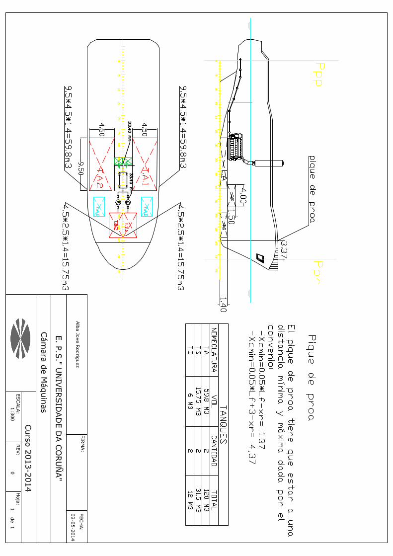

ANEXO 4 (Plano de cámara de máquinas)


ANEXO 5 (Compresor)
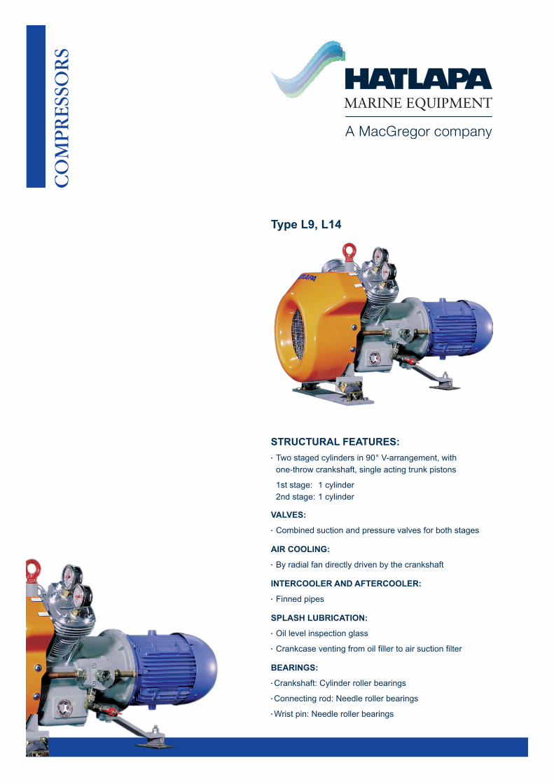
Type L9, L14
STRUCTURAL FEATURES:• Twostagedcylindersin90°V-arrangement,with one-throwcrankshaft,singleactingtrunkpistons
1ststage:1cylinder 2ndstage:1cylinder
VALVES:• Combinedsuctionandpressurevalvesforbothstages
AIR COOLING: • Byradialfandirectlydrivenbythecrankshaft
INTERCOOLER AND AFTERCOOLER:• Finnedpipes
SPLASH LUBRICATION:• Oillevelinspectionglass
• Crankcaseventingfromoilfillertoairsuctionfilter
BEARINGS:•Crankshaft:Cylinderrollerbearings
•Connectingrod:Needlerollerbearings
•Wristpin:Needlerollerbearings

TypeL9,L14
B
C
A B
C
A
Type Cylinders Stage Speedr.p.m
F.A.Dm³/h
PowerkW
Weight incl. e-motorapprox. kg
Dimensions A B C
L9 2 2 1150 1450 1750
6.6 8.7 10.5
1.7 2.3 2.8
120 120 120
820 540 540 820 540 540 820 540 540
L14 2 2 1150 1450 1750
10.5 14 17
2.7 3.5 4.2
140 140 140
840 540 540 840 540 540 840 540 540
Alldataapplytoafinalpressureof30bar.Therightforalterationofspecificationanddatatoincorporateimprovementsindesignisreserved.
Version:03/2014
Illustrations,technicaldata,weightsanddimensionsaresubjecttoalterationwithoutpreviousnotice.

ANEXO 6 (Ventiladores)

57
HGT: Ventiladores helicoidales tubulares de gran diámetro, con motor directoHGTX: Ventiladores helicoidales tubulares de gran diámetro, con motor exterior
HGTHGTX Ventiladores helicoidales tubulares, equipados con hélices de aluminio de 3, 6 ó 9 álabes con diversos
ángulos de inclinación.
Ventilador:� Dirección aire motor-hélice� Hélices en fundición de aluminio de 3, 6 ó 9 álabes, con ángulo de inclinación ajustable.� Envolvente tubular en chapa de acero� HGT: La versión standard es de carcasa corta. La versión en carcasa larga está equipada con trampilla de
inspección.� �/.;?!�=LYZP}U�Z[HUKHYK�LU�JHYJHZH�SHYNH��LX\PWHKH�JVU�[YHTWPSSH�KL�PUZWLJJP}U�
Código de pedido
HGT
/.;?
Motor:� Motores trifásicos IE2� Motores clase F, con rodamientos
a bolas, protección IP55� Trifásicos 230/400V-50Hz
(hasta 5,5CV) y 400/690V-50Hz(po-tencias superiores a 5,5CV)
� Temperatura de trabajo: -25ºC+ 50ºC (HGT), ���¢*�����¢*��/.;?�
Acabado: � Anticorrosivo en resina de poliester
polimerizada a 190ºC, previo
desengrase alcalino y pretratamiento libre de fosfatos.
Bajo demanda: � Dirección aire hélice-motor.� Hélices reversibles 100%.� Bobinados especiales para diferentes
tensiones.� �*LY[PÄJHJP}U�(;,?�*H[LNVYxH��� HGT: Ventiladores con carcasa larga
equipada con trampilla de inspección � Motores de dos velocidades
HGT 125 4T 6-20 10º PV
Diámetro hélice en cm
HGT: Ventiladores helicoidales tubulares de gran diámetro, con motor directo/.;?!�=LU[PSHKVYLZ� helicoidales tubulares de gran diámetro, con motor exterior
Número de polos motor4=1400 r/min. 50 Hz6=900 r/min. 50 Hz8=750 r/min. 50 Hz
T=Trifásico Potencia motor (CV)
Número de palas3 palas6 palas9 palas
�/.;������;�������� �/.;?������;�������� ����� � ������ ����� ����� ������ ��� ���� ���� ����/.;������;�������� �/.;?������;�������� ����� � ������ ������ ������ ������ � � �� � ���� �� �/.;������;�������� �/.;?������;�������� ����� � � ���� ������ ������ ����� �� ���� ���� ����/.;������;�������� �/.;?������;�������� ����� � ������ ������ ������ ����� �� ���� ���� ����/.;������;�������� �/.;?������;�������� ����� � ������ ������ ������ ������� �� ���� ���� ����/.;������;�������� �/.;?������;�������� ����� � ������ ������ ������ ������� �� ���� � �� �� �/.;������;�������� �/.;?������;�������� ����� � � ���� � � �� ������ �� ���� �� ���� ���� ����/.;������;�������� �/.;?������;�������� ����� � ������ ������ ������ ������� �� �� � ���� ����/.;������;�������� �/.;?������;�������� ����� � � ���� ������ ������ ������ � � ���� �� � � ��/.;������;�������� �/.;?������;�������� ����� � ������ ������ ������ ����� �� ���� � �� ����/.;������;�������� �/.;?������;�������� ����� � ������ ������ ������ ����� �� ���� ���� ����/.;������;�������� �/.;?������;�������� ����� � ������ ������ ������ ������� �� �� � ���� ����/.;������;�������� �/.;?������;�������� ����� � � ���� � � �� ������ ������� �� ���� ���� ����/.;������;�������� �/.;?������;�������� ����� � ������ ������ ������ ������� �� � �� ���� �� �/.;������;�������� �/.;?������;�������� ����� � ����� ������ ������ ������� �� �� � � � ����/.;������;����������/.;?������;��������� ����� � ������� ������ ������ ������� �� � �� ���� ����/.;������;� ������ �/.;?������;� ������ ����� � ������ ������ ������ � ���� ��� �� � ���� ����/.;������;� ������ �/.;?������;� ������ ����� � ������ ������ ������ ����� � � ���� ���� ���
HGT HGTX
Características técnicas
Velocidad
(r/min)
Modelo Intensidad máxima admisible (A)
230V 400V 690V
Potencia instalada
(kW)
Caudal máximo(m3/h)
Nivel presión sonoradB(A)
Peso aprox. (Kg) HGT HGTXLarga Corta
PV=Pabellón de aspiración
Ánguloinclinaciónpalas

58
Características técnicasVelocidad
(r/min)
Modelo Intensidad máxima admisible (A)
230V 400V 690V
Potencia instalada
(kW)
Caudal máximo(m3/h)
Nivel presión sonoradB(A)
Peso aprox. (Kg) HGT HGTXLarga Corta
�/.;������;� ������ �/.;?������;� ������ ����� � ������ ������ ������ ������� �� ���� ���� ����/.;������;� ������ �/.;?������;� ������ ����� � � ���� � � �� ������ ������� �� � �� ���� ����/.;������;� ������ �/.;?������;� ������ ����� � ������ ������ ������ ������� �� ���� ���� ����/.;������;� ������ �/.;?������;� ������ ����� � ����� ������ ������ ������� �� ���� ���� ����/.;������;� ��������/.;?������;� ������� ����� � ������� ������ ������ ������� � ���� ���� � ��/.;������;������� �/.;?������;������� ��� ������ ����� � ����� ������ � � ���� ���� ����/.;������;��������� �/.;?������;��������� ��� ������ ���� � ����� ������ ��� �� � ���� ����/.;������;��������� �/.;?������;��������� ��� � ������ ����� ����� ������ ��� ���� ���� ����/.;������;�������� �/.;?������;�������� ��� � ������ ����� ����� ������ ��� ���� ���� ����/.;������;�������� �/.;?������;�������� ��� � ������ ������ ������ ������ ��� ���� ���� � ��/.;������;�������� �/.;?������;�������� ��� � ��� �� ������ ������ ����� ��� ���� ���� ����/.;������;��������� �/.;?������;��������� ��� ������ ���� � ����� ������ ��� ���� ���� �� �/.;������;��������� �/.;?������;��������� ��� � ������ ����� ����� ������ ��� ���� � �� ����/.;������;�������� �/.;?������;�������� ��� � ������ ����� ����� ������ � � ���� ���� � ��/.;������;������ �/.;?������;������ ��� � ������ ������ ������ ������ ��� ���� ���� ����/.;������;�������� �/.;?������;�������� ��� � ��� �� ������ ������ ����� ��� ���� ���� ����/.;������;�������� �/.;?������;�������� ��� � ������ ������ ������ ������� ��� �� � ���� � ��/.;������;� ������ �/.;?������;� ������ ��� � ������ ����� ����� ������ ��� ���� ���� ����/.;������;� ������ �/.;?������;� ������ ��� � ������ ������ ������ ������ ��� � �� ���� ����/.;������;� ������ �/.;?������;� ������ ��� � ��� �� ������ ������ � ��� ��� ���� ���� ����/.;������;� ������ �/.;?������;� ������ ��� � ������ ������ ������ ����� ��� ���� ���� ����/.;������;� ������ �/.;?������;� ������ ��� � ������ ������ ������ ������� ��� ���� � �� ����/.;������;������� �/.;?������;������� ���� ���� ����� � ����� ������ ��� �� � ���� ����/.;������;������� �/.;?������;������� ���� ������ ����� � ����� �� ��� ��� ���� ���� ����/.;������;��������� �/.;?������;��������� ���� ������ ���� � ����� ������ ��� �� � ���� �� �/.;������;��������� �/.;?������;��������� ���� � ������ ����� ����� � ���� ��� ���� ���� ����/.;������;������� �/.;?������;������� ���� ���� ����� � ����� ������ � � ���� ���� �� �/.;������;������� �/.;?������;������� ���� ������ ����� � ����� ������ ��� ���� � �� ����/.;������;��������� �/.;?������;��������� ���� ������ ���� � ����� ������ ��� ���� ���� ����/.;������;��������� �/.;?������;��������� ���� � ������ ����� ����� ������ ��� ���� ���� � ��/.;������;�������� �/.;?������;�������� ���� � ������ ���� ����� ������ ��� ���� ���� ����/.;������;� ����� �/.;?������;� ����� ���� ������ ����� � ����� ������ ��� ���� ���� ����/.;������;� ������� �/.;?������;� ������� ���� ������ ���� � ����� ������ ��� ���� �� � ����/.;������;� ������� �/.;?������;� ������� ���� � ������ ����� ����� ������ ��� ���� ���� ����/.;������;� ������ �/.;?������;� ������ ���� � ������ ���� ����� ������ ��� ���� ���� ����/.;������;� ������ �/.;?������;� ������ ���� � ������ ������ ������ ������ � � ���� �� � �� HGT-140-6T/3-4 960 12,70 7,33 3,00 51000 82 251 214 HGT-140-6T/3-5,5 960 16,50 9,53 4,00 56700 83 258 221 HGT-140-6T/3-7,5 975 11,50 6,64 5,50 67900 84 266 229 HGT-140-6T/3-10 965 15,20 8,78 7,50 80100 85 320 281 HGT-140-6T/3-15 965 22,60 13,05 11,00 96900 86 334 295 HGT-140-6T/3-20 970 27,90 16,11 15,00 106000 88 414 364 HGT-140-6T/6-5,5 960 16,50 9,53 4,00 58000 82 268 231 HGT-140-6T/6-7,5 975 11,50 6,64 5,50 66000 84 276 239 HGT-140-6T/6-10 965 15,20 8,78 7,50 80700 85 330 291 HGT-140-6T/6-15 965 22,60 13,05 11,00 96700 86 344 305 HGT-140-6T/6-20 970 27,90 16,11 15,00 104000 87 423 374 HGT-140-6T/6-25 970 34,64 20,00 18,50 115000 88 466 417 HGT-140-6T/6-30 970 41,57 24,00 22,00 119000 89 486 437 HGT-140-6T/9-10 965 15,20 8,78 7,50 70000 84 339 300 HGT-140-6T/9-15 965 22,60 13,05 11,00 86000 86 353 314 HGT-140-6T/9-20 970 27,90 16,11 15,00 97500 87 433 383 HGT-140-6T/9-25 970 34,64 20,00 18,50 111000 88 475 427 HGT-140-6T/9-30 970 41,57 24,00 22,00 118500 89 495 447 HGT-140-6T/9-40 973 53,69 31,00 30,00 132000 91 561 499 HGT-140-6T/9-50 975 65,82 38,00 37,00 139000 92 623 568 HGT-140-8T/3-3 705 9,53 5,50 2,20 50000 78 258 221 HGT-140-8T/3-4 705 12,82 7,40 3,00 57000 78 265 228 HGT-140-8T/3-5,5 710 16,11 9,30 4,00 65400 79 307 268 HGT-140-8T/3-7,5 725 12,70 7,33 5,50 77500 81 320 281 HGT-140-8T/3-10 725 17,00 9,81 7,50 86000 82 350 311 HGT-140-8T/6-3 705 9,53 5,50 2,20 47500 78 268 231 HGT-140-8T/6-4 705 12,82 7,40 3,00 57600 79 275 238
HGT HGTX

59
HGT HGTX
HGT-140-8T/6-5,5 710 16,11 9,30 4,00 65200 80 317 278 HGT-140-8T/6-7,5 725 12,70 7,33 5,50 73300 81 330 291 HGT-140-8T/6-10 725 17,00 9,81 7,50 82200 82 360 321 HGT-140-8T/6-15 725 21,70 12,53 11,00 94200 83 419 370 HGT-140-8T/9-4 705 12,82 7,40 3,00 47200 79 284 247 HGT-140-8T/9-5,5 710 16,11 9,30 4,00 64400 79 326 287 HGT-140-8T/9-7,5 725 12,70 7,33 5,50 69200 81 339 300 HGT-140-8T/9-10 725 17,00 9,81 7,50 78700 82 369 330 HGT-140-8T/9-15 725 21,70 12,53 11,00 94300 83 429 379 HGT-140-8T/9-20 725 31,70 18,30 15,00 103000 86 485 437 HGT-160-6T/3-5,5 960 16,50 9,53 4,00 66000 81 327 275 HGT-160-6T/3-7,5 975 11,50 6,64 5,50 76100 82 335 283 HGT-160-6T/3-10 965 15,20 8,78 7,50 84000 83 393 339 HGT-160-6T/3-15 965 22,60 13,05 11,00 102000 85 407 353 HGT-160-6T/3-20 970 27,90 16,11 15,00 127000 86 500 431 HGT-160-6T/3-25 970 34,64 20,00 18,50 136700 87 543 473 HGT-160-6T/3-30 970 41,57 24,00 22,00 145000 89 563 493 HGT-160-6T/6-10 965 15,20 8,78 7,50 75000 83 404 350 HGT-160-6T/6-15 965 22,60 13,05 11,00 93500 85 418 364 HGT-160-6T/6-20 970 27,90 16,11 15,00 120500 86 510 441 HGT-160-6T/6-25 970 34,64 20,00 18,50 130000 87 553 484 HGT-160-6T/6-30 970 41,57 24,00 22,00 140000 88 573 504 HGT-160-6T/6-40 973 53,69 31,00 30,00 158000 89 656 557 HGT-160-6T/6-50 975 65,82 38,00 37,00 171000 91 714 629 HGT-160-6T/9-15 965 22,60 13,05 11,00 87000 85 428 374 HGT-160-6T/9-20 970 27,90 16,11 15,00 104000 86 520 451 HGT-160-6T/9-25 970 34,64 20,00 18,50 127000 87 563 494 HGT-160-6T/9-30 970 41,57 24,00 22,00 135000 88 583 514 HGT-160-6T/9-40 973 53,69 31,00 30,00 147000 89 666 567 HGT-160-6T/9-50 975 65,82 38,00 37,00 165000 90 724 640 HGT-160-6T/9-60 980 84,80 48,96 45,00 177000 91 844 745 HGT-160-6T/9-75 980 96,99 56,00 55,00 193000 92 932 833 HGT-160-6T/9-100 985 131,64 76,00 75,00 207500 93 1002 903 HGT-160-8T/3-3 705 9,53 5,50 2,20 54000 76 327 275 HGT-160-8T/3-4 705 12,82 7,40 3,00 57500 77 334 282 HGT-160-8T/3-5,5 710 16,11 9,30 4,00 74000 79 380 326 HGT-160-8T/3-7,5 725 12,70 7,33 5,50 83500 80 393 339 HGT-160-8T/3-10 725 17,00 9,81 7,50 97500 81 423 369 HGT-160-8T/3-15 725 21,70 12,53 11,00 115000 83 496 427 HGT-160-8T/6-4 705 12,82 7,40 3,00 70900 76 344 292 HGT-160-8T/6-5,5 710 16,11 9,30 4,00 84500 77 391 337 HGT-160-8T/6-7,5 725 12,70 7,33 5,50 77000 79 404 350 HGT-160-8T/6-10 725 17,00 9,81 7,50 95000 80 434 380 HGT-160-8T/6-15 725 21,70 12,53 11,00 109000 82 506 437 HGT-160-8T/6-20 725 31,70 18,30 15,00 123000 83 563 494 HGT-160-8T/6-25 725 35,85 20,70 18,50 130000 84 641 542 HGT-160-8T/9-7,5 725 12,70 7,33 5,50 70000 79 414 360 HGT-160-8T/9-10 725 17,00 9,81 7,50 87000 80 444 390 HGT-160-8T/9-15 725 21,70 12,53 11,00 103000 82 516 447 HGT-160-8T/9-20 725 31,70 18,30 15,00 117000 83 573 504 HGT-160-8T/9-25 725 35,85 20,70 18,50 133000 84 651 552 HGT-160-8T/9-30 725 41,60 24,02 22,00 140000 85 666 567 HGT-160-8T/9-40 730 60,79 35,10 30,00 151000 86 724 640
Características técnicasVelocidad
(r/min)
Modelo Intensidad máxima admisible (A)
230V 400V 690V
Potencia instalada
(kW)
Caudal máximo(m3/h)
Nivel presión sonoradB(A)
Peso aprox. (Kg) HGT HGTXLarga Corta
HGT HGTX

60
Los valores indicados, se determinan mediante medidas de nivel de presión y potencia sonora en dB(A) obtenidas en campo libre a una distan-cia equivalente a dos veces la envergadura del ventilador más el diámetro de la hélice, con un mínimo de 1,5 mts.
Características acústicas
,ZWLJ[YV�KL�WV[LUJPH�ZVUVYH�3^�(��LU�K)�(��WVY�IHUKH�KL�MYLJ\LUJPH�LU�/a
Modelo 63 125 250 500 1000 2000 4000 8000125-4T/3-10 70 76 88 98 98 94 86 82125-4T/3-15 71 77 89 99 99 95 87 83125-4T/3-20 72 78 90 100 100 96 88 84125-4T/3-25 73 79 91 101 101 97 89 85125-4T/3-30 74 80 92 102 102 98 90 86125-4T/3-40 75 81 93 103 103 99 91 87125-4T/3-50 76 82 94 104 104 100 92 88125-4T/3-60 77 83 95 105 105 101 93 89125-4T/6-20 66 74 90 97 99 94 88 84125-4T/6-25 67 75 91 98 100 95 89 85125-4T/6-30 68 76 92 99 101 96 90 86125-4T/6-40 69 77 93 100 102 97 91 87125-4T/6-50 71 79 95 102 104 99 93 89125-4T/6-60 72 80 96 103 105 100 94 90125-4T/6-75 72 80 96 103 105 100 94 90125-4T/6-100 74 82 98 105 107 102 96 92125-4T/9-25 66 74 91 97 98 93 88 84125-4T/9-30 67 75 92 98 99 94 89 85125-4T/9-40 68 76 93 99 100 95 90 86125-4T/9-50 70 78 95 101 102 97 92 88125-4T/9-60 72 80 97 103 104 99 94 90125-4T/9-75 72 80 97 103 104 99 94 90125-4T/9-100 74 82 99 105 106 101 96 92125-6T/3-4 64 72 84 88 86 81 72 68125-6T/3-5,5 66 74 86 90 88 83 74 70125-6T/3-7,5 67 75 87 91 89 84 75 71125-6T/3-10 68 76 88 92 90 85 76 72125-6T/3-15 69 77 89 93 91 86 77 73125-6T/3-20 71 79 91 95 93 88 79 75125-6T/6-5,5 59 68 81 84 85 82 71 67125-6T/6-7,5 60 69 82 85 86 83 72 68125-6T/6-10 61 70 83 86 87 84 73 69125-6T/6-15 63 72 85 88 89 86 75 71125-6T/6-20 65 74 87 90 91 88 77 73125-6T/6-25 66 75 88 91 92 89 78 74125-6T/9-10 57 67 82 86 85 84 73 69125-6T/9-15 59 69 84 88 87 86 75 71125-6T/9-20 62 72 87 91 90 89 78 74125-6T/9-25 64 74 89 93 92 91 80 76125-6T/9-30 66 76 91 95 94 93 82 78125-8T/3-3 56 63 74 78 77 70 61 57125-8T/3-4 59 66 77 81 80 73 64 60125-8T/3-5,5 60 67 78 82 81 74 65 61125-8T/3-7,5 62 69 80 84 83 76 67 63125-8T/6-3 53 61 73 78 77 72 61 57125-8T/6-4 54 62 74 79 78 73 62 58125-8T/6-5,5 56 64 76 81 80 75 64 60125-8T/6-7,5 58 66 78 83 82 77 66 62125-8T/6-10 59 67 79 84 83 78 67 63125-8T/9-4 51 62 72 78 79 74 63 59125-8T/9-5,5 53 64 74 80 81 76 65 61125-8T/9-7,5 56 67 77 83 84 79 68 64125-8T/9-10 58 69 79 85 86 81 70 66125-8T/9-15 59 70 80 86 87 82 71 67140-6T/3-4 66 76 84 89 88 87 74 74140-6T/3-5,5 69 79 87 92 91 90 77 77140-6T/3-7,5 69 79 87 92 91 90 77 77140-6T/3-10 70 80 88 93 92 91 78 78140-6T/3-15 71 81 89 94 93 92 79 79140-6T/3-20 73 83 91 96 95 94 81 81140-6T/6-5,5 66 81 90 92 89 83 75 71140-6T/6-7,5 67 82 91 93 90 84 76 72140-6T/6-10 68 83 92 94 91 85 77 73140-6T/6-15 69 84 93 95 92 86 78 74140-6T/6-20 71 86 95 97 94 88 80 76140-6T/6-25 72 87 96 98 95 89 81 77140-6T/6-30 73 88 97 99 96 90 82 78
140-6T/9-10 66 84 93 92 91 87 78 73140-6T/9-15 67 85 94 93 92 88 79 74140-6T/9-20 69 87 96 95 94 90 81 76140-6T/9-25 70 88 97 96 95 91 82 77140-6T/9-30 70 88 97 96 95 91 82 77140-6T/9-40 71 89 98 97 96 92 83 78140-6T/9-50 74 92 101 100 99 95 86 81140-8T/3-3 60 70 78 83 82 81 68 63140-8T/3-4 64 74 82 87 86 85 72 67140-8T/3-5,5 65 75 83 88 87 86 73 68140-8T/3-7,5 66 76 84 89 88 87 74 69140-8T/3-10 68 78 86 91 90 89 76 71140-8T/6-3 61 73 82 86 84 78 68 65140-8T/6-4 63 75 84 88 86 80 70 67140-8T/6-5,5 64 76 85 89 87 81 71 68140-8T/6-7,5 65 77 86 90 88 82 72 69140-8T/6-10 66 78 87 91 89 83 73 70140-8T/6-15 68 80 89 93 91 85 75 72140-8T/9-4 61 72 83 88 86 82 72 67140-8T/9-5,5 62 73 84 89 87 83 73 68140-8T/9-7,5 63 74 85 90 88 84 74 69140-8T/9-10 64 75 86 91 89 85 75 70140-8T/9-15 65 76 87 92 90 86 76 71140-8T/9-20 67 78 89 94 92 88 78 73160-6T/3-5,5 67 77 85 90 89 88 75 70160-6T/3-7,5 68 78 86 91 90 89 76 71160-6T/3-10 69 79 87 92 91 90 77 72160-6T/3-15 70 80 88 93 92 91 78 73160-6T/3-20 72 82 90 95 94 93 80 75160-6T/3-25 73 83 91 96 95 94 81 76160-6T/3-30 74 84 92 97 96 95 82 77160-6T/6-10 67 82 91 93 90 84 76 72160-6T/6-15 68 83 92 94 91 85 77 73160-6T/6-20 70 85 94 96 93 87 79 75160-6T/6-25 71 86 95 97 94 88 80 76160-6T/6-30 71 86 95 97 94 88 80 76160-6T/6-40 72 87 96 98 95 89 81 77160-6T/6-50 74 89 98 100 97 91 83 79160-6T/9-15 67 85 94 93 92 88 79 74160-6T/9-20 68 86 95 94 93 89 80 75160-6T/9-25 69 87 96 95 94 90 81 76160-6T/9-30 70 88 97 96 95 91 82 77160-6T/9-40 71 89 98 97 96 92 83 78160-6T/9-50 72 90 99 98 97 93 84 79160-6T/9-60 72 90 99 98 97 93 84 79160-6T/9-75 73 91 100 99 98 94 85 80160-6T/9-100 75 93 102 101 100 96 87 82160-8T/3-3 61 71 79 84 83 82 69 64160-8T/3-4 63 73 81 86 85 84 71 66160-8T/3-5,5 64 74 82 87 86 85 72 67160-8T/3-7,5 65 75 83 88 87 86 73 68160-8T/3-10 66 76 84 89 88 87 74 69160-8T/3-15 68 78 86 91 90 89 76 71160-8T/6-4 60 75 84 86 83 77 69 65160-8T/6-5,5 61 76 85 87 84 78 70 66160-8T/6-7,5 62 77 86 88 85 79 71 67160-8T/6-10 63 78 87 89 86 80 72 68160-8T/6-15 65 80 89 91 88 82 74 70160-8T/6-20 66 81 90 92 89 83 75 71160-8T/6-25 68 83 92 94 91 85 77 73160-8T/9-7,5 60 78 87 86 85 81 72 67160-8T/9-10 62 80 89 88 87 83 74 69160-8T/9-15 63 81 90 89 88 84 75 70160-8T/9-20 64 82 91 90 89 85 76 71160-8T/9-25 65 83 92 91 90 86 77 72160-8T/9-30 66 84 93 92 91 87 78 73160-8T/9-40 68 86 95 94 93 89 80 75
Modelo 63 125 250 500 1000 2000 4000 8000
HGT HGTX

61
Dimensiones mm
ØA ØB C (Consultar tamaño constructivo motor) ØD E* ØJ NModelo 132 160 180 200 225 250 280 larga corta(Std) HGT-125 1365 1320 570 - - - - - - 1250 500 700 15 20x18ºHGT-125 1365 1320 - 700 - - - - - 1250 500 700 15 20x18ºHGT-125 1365 1320 - - 765 825 - - - 1250 500 900 15 20x18ºHGT-125 1365 1320 - - - - 910 - - 1250 500 1000 15 20x18ºHGT-125 1365 1320 - - - - - 985 - 1250 600 1000 15 20x18ºHGT-125 1365 1320 - - - - - - 1190 1250 700 1200 15 20x18ºHGT-140 1515 1470 570 - - - - - - 1400 400 650 15 20x18ºHGT-140 1515 1470 - 700 - - - - - 1400 450 700 15 20x18ºHGT-140 1515 1470 - - 765 825 - - - 1400 550 900 15 20x18ºHGT-140 1515 1470 - - - - 910 - - 1400 550 1000 15 20x18ºHGT-140 1515 1470 - - - - - 985 - 1400 600 1000 15 20x18ºHGT-160 1735 1680 570 - - - - - - 1600 400 650 19 24x15ºHGT-160 1735 1680 - 700 - - - - - 1600 450 700 19 24x15ºHGT-160 1735 1680 - - 765 825 - - - 1600 550 900 19 24x15ºHGT-160 1735 1680 - - - - 910 - - 1600 550 1000 19 24x15ºHGT-160 1735 1680 - - - - - 985 - 1600 600 1000 19 24x15ºHGT-160 1735 1680 - - - - - - 1190 1600 700 1200 19 24x15º
Tamaños constructivos motores según potencia Polos r/min CV 3 4 5,5 7,5 10 15 20 25 30 40 50 60 75 1004T 1500 - - - - 132 160 160 180 180 200 225 225 250 2806T 1000 - 132 132 132 160 160 180 200 200 225 250 280 280 2808T 750 132 132 160 160 160 180 200 225 225 250 - - - -
ØA ØB ØD E H (Consultar tamaño constructivo motor) ØJ NModelo 132 160 180 200 225 250 280 /.;�?����� ����� ����� ����� ��� ����� ����� ����� �� �� �� �� ��� ��_��¢/.;�?����� ����� ����� ����� ��� �� �� �� � ��� � �� �� �� ��� ��_��¢/.;�?����� ����� ����� ����� ����� �� �� �� �� �� ����� �� ��� ��_��¢/.;�?����� ����� ����� ����� ����� �� �� �� �� �� �� �� �� ��� ��_��¢
Tamaños constructivos motores según potencia Polos r/min CV 3 4 5,5 7,5 10 15 20 25 30 40 50 60 75 1004T 1500 - - - - 132 160 160 180 180 200 225 225 250 2806T 1000 - 132 132 132 160 160 180 200 200 225 250 280 280 2808T 750 132 132 160 160 160 180 200 225 225 250 - - - -
HGT
HGTX
HGT HGTXHGT HGTX
* Versión estándar subministrada en carcasa corta. Bajo demanda carcasa larga con trampilla de inspección.

62
EJEMPLO SELECCIÓN
EJEMPLO CÓDIGO PEDIDO
Datos de partida� Punto de trabajo:� Caudal: 12.500 m3/h� Pérdida de carga: 7,5 mmH2O
Pasos para la selección del equipo
(Q�OD�JUÀðFD�GH�SUHVLRQHV�� 1. Marcar el punto de trabajo,
KLÄUPKV�WVY�LS�JH\KHS�KL�[YHIHQV�(12.500 m3/h) y la pérdida de carga (7,5 mmH2O).
� 2. Escoger la curva del equipo que más se acerque por encima al punto de trabajo. En nuestro caso se obtiene una curva de 22º de ángulo de pala.
(Q�OD�JUÀðFD�GH�SRWHQFLD�� 3. Marcar el punto de trabajo,
KLÄUPKV�WVY�LS�JH\KHS�KL�[YHIHQV�(12.500 m3/h) y la curva de án-gulo de pala escogido (22º).
� 4. Leer la potencia absorbida en el eje de potencias a la izquier-da. La Pa= 560 W en el punto de trabajo.
� 5. Buscar recta roja que más se acerque al punto de trabajo por encima. En la parte derecha de SH�NYmÄJH�ZL�VI[PLUL�LS�]HSVY�KL�potencia instalada de motor. En nuestro caso 0,75 kW o 1 CV
Potencia absorbida 3RWHQFLD�0RWRU�5HFRPHQGDGD�NZ�&9�
Curvas características
Diámetro Hélice (cm): 125 Número de polos: 8 Número de palas: 3Q= Caudal en m3/h, m3/s y cfm. Pe= Presión estática en mmH2O, Pa e inwg.
HGT 125 8T 3 1 22
Diámetro hélice en cm
HGT: Ventiladores helicoidales tubulares de gran diámetro, con motor directo/.;?!�=LU[PSHKVYLZ�OLSPJVPKH-les tubulares de gran diámetro, con motor exterior
Número de polos motor4=1400 r/min. 50 Hz6=900 r/min. 50 Hz8=750 r/min. 50 Hz
T=TrifásicoM=Monofásico
Potencia motor (CV)
Número de palas3 palas6 palas9 palas
Angulo inclinación palas
HGT HGTX

63
Curvas características
Diámetro Hélice (cm): 125 Número de palas: 4 Número de polos: 3 Q= Caudal en m3/h, m3/s y cfm. Pe= Presión estática en mmH2O, Pa e inwg.
Potencia absorbida 3RWHQFLD�0RWRU�5HFRPHQGDGD�NZ�&9�
*VUZ\S[HY�JHYHJ[LYxZ[PJHZ�KLS�W\U[V�KL�Tm_PTH�LÄJPLUJPH��),7��HS�ÄUHS�KL�SH�ZLYPL�
HGT HGTXHGT HGTX

64
Curvas características
Diámetro Hélice (cm): 125 Número de palas: 4 Número de polos: 6 Q= Caudal en m3/h, m3/s y cfm. Pe= Presión estática en mmH2O, Pa e inwg.
*VUZ\S[HY�JHYHJ[LYxZ[PJHZ�KLS�W\U[V�KL�Tm_PTH�LÄJPLUJPH��),7��HS�ÄUHS�KL�SH�ZLYPL�
HGT HGTX

65
Curvas características Q= Caudal en m3/h, m3/s y cfm. Pe= Presión estática en mmH2O, Pa e inwg.
*VUZ\S[HY�JHYHJ[LYxZ[PJHZ�KLS�W\U[V�KL�Tm_PTH�LÄJPLUJPH��),7��HS�ÄUHS�KL�SH�ZLYPL�
Diámetro Hélice (cm): 125 Número de palas: 4 Número de polos: 9
Potencia absorbida 3RWHQFLD�0RWRU�5HFRPHQGDGD�NZ�&9�
HGT HGTX

66
Curvas características Q= Caudal en m3/h, m3/s y cfm. Pe= Presión estática en mmH2O, Pa e inwg.
*VUZ\S[HY�JHYHJ[LYxZ[PJHZ�KLS�W\U[V�KL�Tm_PTH�LÄJPLUJPH��),7��HS�ÄUHS�KL�SH�ZLYPL�
Diámetro Hélice (cm): 125 Número de palas: 6 Número de polos: 3
HGT HGTX

67
Curvas características Q= Caudal en m3/h, m3/s y cfm. Pe= Presión estática en mmH2O, Pa e inwg.
*VUZ\S[HY�JHYHJ[LYxZ[PJHZ�KLS�W\U[V�KL�Tm_PTH�LÄJPLUJPH��),7��HS�ÄUHS�KL�SH�ZLYPL�
Diámetro Hélice (cm): 125 Número de palas: 6 Número de polos: 6
HGT HGTXHGT HGTX

68
Curvas características Q= Caudal en m3/h, m3/s y cfm. Pe= Presión estática en mmH2O, Pa e inwg.
*VUZ\S[HY�JHYHJ[LYxZ[PJHZ�KLS�W\U[V�KL�Tm_PTH�LÄJPLUJPH��),7��HS�ÄUHS�KL�SH�ZLYPL�
Diámetro Hélice (cm): 125 Número de palas: 6 Número de polos: 9
HGT HGTX

69
Curvas características Q= Caudal en m3/h, m3/s y cfm. Pe= Presión estática en mmH2O, Pa e inwg.
*VUZ\S[HY�JHYHJ[LYxZ[PJHZ�KLS�W\U[V�KL�Tm_PTH�LÄJPLUJPH��),7��HS�ÄUHS�KL�SH�ZLYPL�
Diámetro Hélice (cm): 125 Número de palas: 8 Número de polos: 3
HGT HGTXHGT HGTX

70
Curvas características Q= Caudal en m3/h, m3/s y cfm. Pe= Presión estática en mmH2O, Pa e inwg.
*VUZ\S[HY�JHYHJ[LYxZ[PJHZ�KLS�W\U[V�KL�Tm_PTH�LÄJPLUJPH��),7��HS�ÄUHS�KL�SH�ZLYPL�
Diámetro Hélice (cm): 125 Número de palas: 8 Número de polos: 6
HGT HGTX

71
Curvas característicasQ= Caudal en m3/h, m3/s y cfm. Pe= Presión estática en mmH2O, Pa e inwg.
*VUZ\S[HY�JHYHJ[LYxZ[PJHZ�KLS�W\U[V�KL�Tm_PTH�LÄJPLUJPH��),7��HS�ÄUHS�KL�SH�ZLYPL�
Diámetro Hélice (cm): 125 Número de palas: 8 Número de polos: 9
HGT HGTX

72
Curvas características Q= Caudal en m3/h, m3/s y cfm. Pe= Presión estática en mmH2O, Pa e inwg.
*VUZ\S[HY�JHYHJ[LYxZ[PJHZ�KLS�W\U[V�KL�Tm_PTH�LÄJPLUJPH��),7��HS�ÄUHS�KL�SH�ZLYPL�
Diámetro Hélice (cm): 140 Número de palas: 6 Número de polos: 3
HGT HGTX

73
Curvas características Q= Caudal en m3/h, m3/s y cfm. Pe= Presión estática en mmH2O, Pa e inwg.
*VUZ\S[HY�JHYHJ[LYxZ[PJHZ�KLS�W\U[V�KL�Tm_PTH�LÄJPLUJPH��),7��HS�ÄUHS�KL�SH�ZLYPL�
Diámetro Hélice (cm): 140 Número de palas: 6 Número de polos: 6
HGT HGTXHGT HGTX

74
Curvas características Q= Caudal en m3/h, m3/s y cfm. Pe= Presión estática en mmH2O, Pa e inwg.
*VUZ\S[HY�JHYHJ[LYxZ[PJHZ�KLS�W\U[V�KL�Tm_PTH�LÄJPLUJPH��),7��HS�ÄUHS�KL�SH�ZLYPL�
Diámetro Hélice (cm): 140 Número de palas: 6 Número de polos: 9
HGT HGTX

75
Curvas características Q= Caudal en m3/h, m3/s y cfm. Pe= Presión estática en mmH2O, Pa e inwg.
*VUZ\S[HY�JHYHJ[LYxZ[PJHZ�KLS�W\U[V�KL�Tm_PTH�LÄJPLUJPH��),7��HS�ÄUHS�KL�SH�ZLYPL�
Diámetro Hélice (cm): 140 Número de palas: 8 Número de polos: 3
HGT HGTXHGT HGTX

76
Curvas características Q= Caudal en m3/h, m3/s y cfm. Pe= Presión estática en mmH2O, Pa e inwg.
*VUZ\S[HY�JHYHJ[LYxZ[PJHZ�KLS�W\U[V�KL�Tm_PTH�LÄJPLUJPH��),7��HS�ÄUHS�KL�SH�ZLYPL�
Diámetro Hélice (cm): 140 Número de palas: 8 Número de polos: 6
HGT HGTX

77
Curvas características Q= Caudal en m3/h, m3/s y cfm. Pe= Presión estática en mmH2O, Pa e inwg.
*VUZ\S[HY�JHYHJ[LYxZ[PJHZ�KLS�W\U[V�KL�Tm_PTH�LÄJPLUJPH��),7��HS�ÄUHS�KL�SH�ZLYPL�
Diámetro Hélice (cm): 140 Número de palas: 8 Número de polos: 9
HGT HGTXHGT HGTX

78
Curvas características Q= Caudal en m3/h, m3/s y cfm. Pe= Presión estática en mmH2O, Pa e inwg.
*VUZ\S[HY�JHYHJ[LYxZ[PJHZ�KLS�W\U[V�KL�Tm_PTH�LÄJPLUJPH��),7��HS�ÄUHS�KL�SH�ZLYPL�
Diámetro Hélice (cm): 160 Número de palas: 6 Número de polos: 3
HGT HGTX

79
Curvas características Q= Caudal en m3/h, m3/s y cfm. Pe= Presión estática en mmH2O, Pa e inwg.
*VUZ\S[HY�JHYHJ[LYxZ[PJHZ�KLS�W\U[V�KL�Tm_PTH�LÄJPLUJPH��),7��HS�ÄUHS�KL�SH�ZLYPL�
Diámetro Hélice (cm): 160 Número de palas: 6 Número de polos: 6
HGT HGTX

80
Curvas características Q= Caudal en m3/h, m3/s y cfm. Pe= Presión estática en mmH2O, Pa e inwg.
*VUZ\S[HY�JHYHJ[LYxZ[PJHZ�KLS�W\U[V�KL�Tm_PTH�LÄJPLUJPH��),7��HS�ÄUHS�KL�SH�ZLYPL�
Diámetro Hélice (cm): 160 Número de palas: 6 Número de polos: 9
HGT HGTX

81
Curvas características Q= Caudal en m3/h, m3/s y cfm. Pe= Presión estática en mmH2O, Pa e inwg.
*VUZ\S[HY�JHYHJ[LYxZ[PJHZ�KLS�W\U[V�KL�Tm_PTH�LÄJPLUJPH��),7��HS�ÄUHS�KL�SH�ZLYPL�
Diámetro Hélice (cm): 160 Número de palas: 8 Número de polos: 3
HGT HGTXHGT HGTX

82
Curvas características Q= Caudal en m3/h, m3/s y cfm. Pe= Presión estática en mmH2O, Pa e inwg.
*VUZ\S[HY�JHYHJ[LYxZ[PJHZ�KLS�W\U[V�KL�Tm_PTH�LÄJPLUJPH��),7��HS�ÄUHS�KL�SH�ZLYPL�
Diámetro Hélice (cm): 160 Número de palas: 8 Número de polos: 6
HGT HGTX

83
Curvas características Q= Caudal en m3/h, m3/s y cfm. Pe= Presión estática en mmH2O, Pa e inwg.
*VUZ\S[HY�JHYHJ[LYxZ[PJHZ�KLS�W\U[V�KL�Tm_PTH�LÄJPLUJPH��),7��HS�ÄUHS�KL�SH�ZLYPL�
Diámetro Hélice (cm): 160 Número de palas: 8 Número de polos: 9
HGT HGTXHGT HGTX

84
HGT-125-4T/3 ∢�B¢D� 75� 4*� ,*� =:+� :9� ʾL��B�D� 5� BR>D� BT3�OD� BTT/26D� B974D8 11 C S NO 1,00 52,1% 52,9 7,62 41511 35,13 147210 11 C S NO 1,00 52,7% 53,0 9,08 46792 37,56 146712 11 C S NO 1,00 53,8% 53,8 10,54 52185 39,90 146114 15 C S NO 1,01 55,8% 55,8 11,86 57655 42,19 147516 15 C S NO 1,01 55,2% 55,0 13,61 62205 44,33 147118 18,5 C S NO 1,01 54,5% 54,3 15,48 67316 46,06 147720 18,5 C S NO 1,01 54,3% 53,9 17,35 72427 47,79 147422 22 C S NO 1,01 52,6% 52,2 19,81 77315 49,54 147124 30 C S NO 1,01 51,4% 50,9 22,05 82218 50,63 148326 30 C S NO 1,01 51,5% 50,8 24,34 84773 54,27 148128 30 C S NO 1,01 48,3% 47,6 26,88 90252 52,81 147930 37 C S NO 1,01 46,3% 45,5 29,54 94744 53,05 147832 37 C S NO 1,01 44,6% 43,8 32,09 99128 53,03 147634 37 B T NO 1,01 74,3% 73,4 35,81 116210 84,11 147336 45 B T NO 1,01 72,7% 71,8 39,09 121252 86,13 147638 45 B T NO 1,01 72,2% 71,1 42,20 125686 89,03 1474
Erp��*HYHJ[LYxZ[PJHZ�KLS�W\U[V�KL�Tm_PTH�LÄJPLUJPH��),7�∢�B¢D� Ángulo inclinación palas en gradosPN Potencia nominal motor en kWMC Categoría de mediciónEC� *H[LNVYxH�KL�LÄJPLUJPH S Estática T TotalVSD Variador de velocidad
SR� 9LSHJP}U�LZWLJxÄJHʾLB�D� ,ÄJPLUJPHN� .YHKV�KL�LÄJPLUJPHBR>D Potencia eléctricaBT3�OD CaudalBTT/26D Presión estática o total (Según EC)B974D Velocidad
HGT-125-4T/6 ∢�B¢D� 75� 4*� ,*� =:+� :9� ʾL��B�D� 5� BR>D� BT3�OD� BTT/26D� B974D8 15 C S NO 1,01 57,6% 57,5 11,86 48508 51,71 147510 15 C S NO 1,01 56,2% 56,0 14,36 52757 56,25 146912 18,5 C S NO 1,01 56,4% 56,1 16,61 58230 59,12 147514 22 C S NO 1,01 57,7% 57,3 18,64 63848 61,84 147316 30 C S NO 1,01 57,3% 56,7 21,37 68837 65,30 148318 30 C S NO 1,01 56,5% 55,9 24,19 77896 64,43 148120 30 C S NO 1,01 56,7% 56,0 27,14 80997 69,77 147922 37 C S NO 1,01 54,9% 54,1 30,76 85910 72,17 147724 37 C S NO 1,01 53,8% 52,9 34,57 88480 77,19 147426 45 C S NO 1,01 52,2% 51,2 38,69 93638 79,23 147628 55 C S NO 1,01 49,8% 48,7 43,83 102038 78,56 148130 55 C S NO 1,01 46,8% 45,7 48,64 106474 78,56 147932 75 C S NO 1,01 44,7% 43,4 53,11 110911 78,56 148734 75 B T NO 1,01 70,7% 69,4 58,84 131496 116,23 148536 75 B T NO 1,01 70,3% 68,9 63,99 136742 120,78 148438 75 B T NO 1,01 70,3% 68,9 68,95 142272 125,19 1483
HGT-125-4T/9 ∢�B¢D� 75� 4*� ,*� =:+� :9� ʾL��B�D� 5� BR>D� BT3�OD� BTT/26D� B974D8 18,5 C S NO 1,01 69,2% 68,8 17,75 37304 120,90 147410 22 C S NO 1,01 61,9% 61,4 20,39 41359 112,05 147012 30 C S NO 1,01 58,3% 57,8 22,06 50452 93,68 148314 30 C S NO 1,01 56,6% 56,0 23,35 73859 65,67 148216 30 C S NO 1,01 53,6% 52,9 28,35 80439 69,38 147818 37 C S NO 1,01 52,4% 51,5 33,35 87528 73,29 147520 45 C S NO 1,01 51,9% 50,9 38,40 94456 77,46 147622 45 C S NO 1,01 50,6% 49,5 43,20 97688 82,16 147324 55 C S NO 1,01 50,3% 49,1 47,60 101406 86,68 148026 55 C S NO 1,01 50,7% 49,4 52,34 106241 91,67 147828 75 C S NO 1,01 49,7% 48,4 57,78 112236 93,94 148630 75 C S NO 1,01 49,3% 47,9 63,58 120361 95,67 148432 75 C S NO 1,01 48,2% 46,8 69,13 125253 97,81 148334 90 B T NO 1,01 74,6% 73,1 76,06 140724 148,06 148436 90 B T NO 1,01 72,6% 71,1 82,79 145177 152,12 148338 90 B T NO 1,02 70,5% 68,9 90,21 149120 156,66 1481
HGT HGTX

85
HGT-125-6T/3 ∢�B¢D� 75� 4*� ,*� =:+� :9� ʾL��B�D� 5� BR>D� BT3�OD� BTT/26D� B974D8 2,2 C S NO 1,00 48,6% 52,7 2,29 27197 15,08 96110 3 C S NO 1,00 49,2% 52,8 2,73 30657 16,12 96912 3 C S NO 1,00 50,2% 53,4 3,17 34190 17,13 96414 4 C S NO 1,00 52,1% 55,0 3,57 37774 18,11 97016 4 C S NO 1,00 51,5% 54,0 4,10 40755 19,03 96518 5,5 C S NO 1,00 52,1% 54,3 4,55 44104 19,77 98220 5,5 C S NO 1,00 51,9% 53,8 5,11 47452 20,51 98022 7,5 C S NO 1,00 50,3% 51,8 5,83 50654 21,27 97624 7,5 C S NO 1,00 49,3% 50,5 6,53 53010 22,32 97326 7,5 C S NO 1,00 48,6% 49,5 7,28 56526 22,97 97028 11 C S NO 1,00 46,4% 47,1 7,94 59317 22,84 97830 11 C S NO 1,00 44,3% 44,7 8,68 62074 22,77 97532 11 C S NO 1,00 42,7% 42,9 9,43 64946 22,76 97334 11 B T NO 1,00 71,1% 71,2 10,52 76138 36,11 97036 15 B T NO 1,00 69,6% 69,6 11,49 79441 36,97 98038 15 B T NO 1,00 69,1% 69,0 12,40 82346 38,21 978
HGT-125-6T/6 ∢�B¢D� 75� 4*� ,*� =:+� :9� ʾL��B�D� 5� BR>D� BT3�OD� BTT/26D� B974D8 4 C S NO 1,00 53,8% 56,6 3,57 31781 22,20 97010 5,5 C S NO 1,00 53,8% 56,1 4,23 34565 24,14 98312 5,5 C S NO 1,00 53,9% 55,9 4,89 38151 25,38 98114 5,5 C S NO 1,00 54,5% 56,2 5,54 41832 26,55 97816 7,5 C S NO 1,00 54,2% 55,4 6,35 45100 28,03 97418 7,5 C S NO 1,00 53,5% 54,4 7,19 51036 27,66 97020 11 C S NO 1,00 54,2% 54,9 7,98 53067 29,95 97722 11 C S NO 1,00 52,5% 52,8 9,04 56286 30,98 97424 11 C S NO 1,00 51,1% 51,2 10,22 57719 33,26 97126 15 C S NO 1,00 50,0% 49,9 11,37 61349 34,01 98028 15 C S NO 1,00 47,4% 47,3 12,95 66852 33,72 97730 15 C S NO 1,00 44,6% 44,4 14,37 69759 33,72 97432 18,5 C S NO 1,00 41,8% 41,5 15,95 72666 33,72 97734 18,5 B T NO 1,00 66,2% 65,8 17,68 86152 49,89 97536 22 B T NO 1,01 66,3% 65,9 19,07 89589 51,84 97738 22 B T NO 1,01 66,4% 65,9 20,55 93213 53,74 975
HGT-125-6T/9 ∢�B¢D� 75� 4*� ,*� =:+� :9� ʾL��B�D� 5� BR>D� BT3�OD� BTT/26D� B974D8 5,5 C S NO 1,01 66,1% 67,9 5,22 24441 51,89 97910 7,5 C S NO 1,00 59,2% 60,6 6,00 27097 48,10 97512 7,5 C S NO 1,00 55,2% 56,4 6,56 33055 40,21 97314 7,5 C S NO 1,00 53,5% 54,5 6,94 48390 28,19 97216 11 C S NO 1,00 51,3% 51,8 8,33 52702 29,78 97618 11 C S NO 1,00 50,1% 50,2 9,80 57346 31,46 97220 15 C S NO 1,00 49,6% 49,6 11,28 61885 33,25 98022 15 C S NO 1,00 48,4% 48,3 12,70 64003 35,27 97724 15 C S NO 1,00 48,2% 48,0 14,05 65542 37,94 97526 18,5 C S NO 1,01 47,7% 47,5 15,62 69606 39,35 97828 18,5 C S NO 1,01 46,5% 46,2 17,36 73534 40,32 97530 22 C S NO 1,01 46,5% 46,1 18,95 78857 41,07 97732 22 C S NO 1,01 45,5% 45,0 20,60 82062 41,98 97534 30 B T NO 1,01 71,3% 70,7 22,38 92199 63,56 98236 30 B T NO 1,01 69,4% 68,8 24,36 95116 65,30 98038 30 B T NO 1,01 67,4% 66,7 26,55 97699 67,25 978
Erp��*HYHJ[LYxZ[PJHZ�KLS�W\U[V�KL�Tm_PTH�LÄJPLUJPH��),7�
HGT HGTXHGT HGTX

86
HGT-125-8T/3 ∢�B¢D� 75� 4*� ,*� =:+� :9� ʾL��B�D� 5� BR>D� BT3�OD� BTT/26D� B974D8 1,1 C S NO 1,00 42,3% 48,2 1,15 20612 8,66 71610 1,5 C S NO 1,00 44,2% 49,8 1,32 23235 9,26 72012 1,5 C S NO 1,00 45,1% 50,3 1,54 25912 9,84 71514 1,5 C S NO 1,00 46,3% 51,1 1,75 28629 10,40 71016 2,2 C S NO 1,00 45,8% 50,2 2,01 30888 10,93 71918 2,2 C S NO 1,00 45,2% 49,3 2,28 33426 11,36 71520 2,2 C S NO 1,00 45,0% 48,8 2,56 35964 11,78 71022 3 C S NO 1,00 44,6% 48,1 2,86 38311 12,24 71724 3 C S NO 1,00 44,3% 47,5 3,17 38268 13,50 71326 4 C S NO 1,00 43,9% 46,8 3,49 42094 13,38 72228 4 C S NO 1,00 41,5% 44,2 3,86 44508 13,23 71930 4 C S NO 1,00 39,6% 42,0 4,23 46875 13,12 71632 5,5 C S NO 1,00 41,0% 43,3 4,27 49222 13,07 73334 5,5 B T NO 1,00 68,3% 70,4 4,77 57704 20,74 73136 5,5 B T NO 1,00 66,9% 68,7 5,21 60208 21,24 73038 5,5 B T NO 1,00 66,4% 68,0 5,62 62409 21,95 728
HGT-125-8T/6 ∢�B¢D� 75� 4*� ,*� =:+� :9� ʾL��B�D� 5� BR>D� BT3�OD� BTT/26D� B974D8 1,5 C S NO 1,00 47,8% 52,6 1,75 24087 12,75 71010 2,2 C S NO 1,00 46,7% 50,9 2,12 26197 13,87 71712 2,2 C S NO 1,00 46,8% 50,7 2,45 28914 14,58 71214 3 C S NO 1,00 48,9% 52,5 2,69 31704 15,25 71916 3 C S NO 1,00 48,0% 51,2 3,12 34181 16,10 71318 4 C S NO 1,00 48,2% 51,1 3,47 38680 15,89 72220 4 C S NO 1,00 48,3% 50,9 3,90 40219 17,20 71922 4 C S NO 1,00 46,8% 49,1 4,42 42659 17,80 71524 5,5 C S NO 1,00 48,4% 50,5 4,66 45625 18,18 73226 5,5 C S NO 1,00 48,0% 49,8 5,15 46496 19,54 73028 7,5 C S NO 1,00 46,3% 47,9 5,77 50667 19,37 73330 7,5 C S NO 1,00 43,6% 44,8 6,40 52870 19,37 73132 7,5 C S NO 1,00 41,3% 42,3 7,03 55073 19,37 73034 11 B T NO 1,00 66,1% 66,9 7,70 65294 28,66 73536 11 B T NO 1,00 65,7% 66,2 8,38 67899 29,78 73338 11 B T NO 1,00 65,8% 66,1 9,03 70645 30,87 732
HGT-125-8T/9 ∢�B¢D� 75� 4*� ,*� =:+� :9� ʾL��B�D� 5� BR>D� BT3�OD� BTT/26D� B974D8 2,2 C S NO 1,00 57,4% 61,1 2,62 18524 29,81 71010 3 C S NO 1,00 52,5% 55,8 2,94 20537 27,63 71612 3 C S NO 1,00 48,9% 52,0 3,22 25052 23,10 71214 3 C S NO 1,00 47,4% 50,4 3,41 36675 16,19 71016 4 C S NO 1,00 45,7% 48,2 4,07 39942 17,11 71818 5,5 C S NO 1,00 48,1% 50,4 4,44 43462 18,07 73320 5,5 C S NO 1,00 47,7% 49,5 5,11 46902 19,10 73022 5,5 C S NO 1,00 46,5% 48,0 5,75 48507 20,26 72824 7,5 C S NO 1,00 47,1% 48,4 6,26 49674 21,79 73226 7,5 C S NO 1,00 47,1% 48,2 6,89 52754 22,60 73028 7,5 C S NO 1,00 45,9% 46,7 7,65 55731 23,16 72830 11 C S NO 1,00 46,0% 46,5 8,32 59770 23,52 73332 11 C S NO 1,00 45,1% 45,4 9,05 62194 24,12 73234 11 B T NO 1,00 69,4% 69,5 10,01 69877 36,51 73036 11 B T NO 1,00 67,6% 67,6 10,90 72088 37,51 72838 15 B T NO 1,00 67,1% 67,0 11,61 74046 38,63 733
Erp��*HYHJ[LYxZ[PJHZ�KLS�W\U[V�KL�Tm_PTH�LÄJPLUJPH��),7�
HGT HGTX

87
HGT-140-6T/9 ∢�B¢D� 75� 4*� ,*� =:+� :9� ʾL��B�D� 5� BR>D� BT3�OD� BTT/26D� B974D8 11 C S NO 1,01 59,9% 60,2 9,00 32703 60,56 97510 11 C S NO 1,01 53,0% 53,1 10,45 36257 56,12 97012 15 C S NO 1,00 49,4% 49,4 11,43 44228 46,93 98014 15 C S NO 1,00 47,9% 47,9 12,09 64747 32,90 97816 15 C S NO 1,00 45,4% 45,2 14,68 70516 34,75 97418 18,5 C S NO 1,00 43,9% 43,6 17,45 76730 36,71 97520 22 C S NO 1,01 43,9% 43,4 19,93 82804 38,80 97622 30 C S NO 1,01 43,6% 43,0 22,03 85637 41,15 98224 30 C S NO 1,01 43,1% 42,4 24,40 88897 43,42 98026 30 C S NO 1,01 43,4% 42,7 26,83 93135 45,91 97828 30 C S NO 1,01 42,8% 42,0 29,85 100645 46,65 97630 37 B T NO 1,01 65,3% 64,5 31,99 116137 66,06 98032 37 B T NO 1,01 64,5% 63,6 35,49 119380 70,46 97834 45 B T NO 1,01 63,6% 62,6 38,77 123186 73,50 98436 45 B T NO 1,01 61,9% 60,8 42,20 127100 75,48 98338 55 B T NO 1,01 60,4% 59,3 45,72 130545 77,70 985
HGT-140-6T/3 ∢�B¢D� 75� 4*� ,*� =:+� :9� ʾL��B�D� 5� BR>D� BT3�OD� BTT/26D� B974D8 4 C S NO 1,00 43,6% 46,1 4,00 36390 17,60 96610 5,5 C S NO 1,00 45,1% 47,3 4,65 41020 18,81 98212 5,5 C S NO 1,00 46,1% 47,8 5,40 45747 19,99 97914 7,5 C S NO 1,00 47,8% 49,2 6,08 50542 21,13 97516 7,5 C S NO 1,00 47,3% 48,3 6,97 54531 22,20 97118 11 C S NO 1,00 47,2% 47,9 7,85 59012 23,07 97820 11 C S NO 1,00 47,0% 47,4 8,79 63492 23,94 97522 11 C S NO 1,00 44,4% 44,5 10,16 68187 24,30 97124 15 C S NO 1,00 43,6% 43,6 11,39 71105 25,65 98026 15 C S NO 1,00 43,2% 43,1 12,60 74264 26,91 97828 15 C S NO 1,00 40,9% 40,7 13,90 77986 26,76 97530 18,5 B T NO 1,00 64,0% 63,7 15,73 94783 39,00 97832 18,5 B T NO 1,00 64,2% 63,8 17,03 99158 40,47 97634 18,5 B T NO 1,00 61,6% 61,2 18,73 101655 41,68 97336 22 B T NO 1,00 60,7% 60,2 20,28 106107 42,63 97538 22 B T NO 1,00 60,2% 59,7 21,90 110043 44,01 973
HGT-140-6T/6 ∢�B¢D� 75� 4*� ,*� =:+� :9� ʾL��B�D� 5� BR>D� BT3�OD� BTT/26D� B974D8 7,5 C S NO 1,00 49,3% 50,7 6,08 42524 25,90 97510 7,5 C S NO 1,00 48,2% 49,0 7,36 46249 28,17 97012 11 C S NO 1,00 48,9% 49,4 8,42 51047 29,61 97614 11 C S NO 1,00 49,4% 49,6 9,55 55972 30,98 97316 11 C S NO 1,00 48,5% 48,5 11,07 60345 32,71 96918 15 C S NO 1,00 47,9% 47,8 12,53 68287 32,27 97820 15 C S NO 1,00 48,1% 47,9 14,06 71005 34,95 97522 18,5 C S NO 1,00 46,1% 45,8 16,09 75312 36,15 97724 18,5 C S NO 1,00 44,2% 43,8 18,32 80549 36,94 97426 22 C S NO 1,01 43,7% 43,2 20,15 84172 38,41 97628 30 C S NO 1,01 42,6% 42,1 22,47 89450 39,35 98230 30 B T NO 1,01 61,5% 60,8 25,18 105037 54,13 98032 30 B T NO 1,01 60,3% 59,6 27,67 110368 55,55 97734 37 B T NO 1,01 59,9% 59,1 30,15 114996 57,67 98136 37 B T NO 1,01 59,5% 58,6 32,79 119625 59,87 98038 37 B T NO 1,01 59,5% 58,6 35,32 124508 61,99 978
Erp��*HYHJ[LYxZ[PJHZ�KLS�W\U[V�KL�Tm_PTH�LÄJPLUJPH��),7�
HGT HGTXHGT HGTX

88
HGT-140-8T/3 ∢�B¢D� 75� 4*� ,*� =:+� :9� ʾL��B�D� 5� BR>D� BT3�OD� BTT/26D� B974D8 2,2 C S NO 1,00 38,7% 43,2 1,96 27580 10,11 72010 2,2 C S NO 1,00 39,2% 43,2 2,33 31089 10,81 71412 3 C S NO 1,00 41,3% 45,0 2,62 34671 11,48 71914 3 C S NO 1,00 42,4% 45,7 2,99 38306 12,14 71516 3 C S NO 1,00 41,9% 44,8 3,43 41329 12,75 71018 4 C S NO 1,00 42,1% 44,7 3,83 44725 13,25 72020 4 C S NO 1,00 41,9% 44,2 4,30 48120 13,75 71622 5,5 C S NO 1,00 43,3% 45,5 4,60 51261 14,28 73224 5,5 C S NO 1,00 42,4% 44,3 5,16 53756 14,96 73026 5,5 C S NO 1,00 41,9% 43,5 5,71 56323 15,62 72828 7,5 C S NO 1,00 40,4% 41,7 6,20 59552 15,43 73230 7,5 B T NO 1,00 63,2% 64,2 6,93 71836 22,40 73032 7,5 B T NO 1,00 63,4% 64,2 7,51 75151 23,24 72834 11 B T NO 1,00 61,5% 62,1 8,16 77044 23,94 73436 11 B T NO 1,00 60,2% 60,5 8,91 80418 24,49 73238 11 B T NO 1,00 59,7% 59,8 9,62 83401 25,28 731
HGT-140-8T/6 ∢�B¢D� 75� 4*� ,*� =:+� :9� ʾL��B�D� 5� BR>D� BT3�OD� BTT/26D� B974D8 3 C S NO 1,00 43,7% 47,1 2,98 32229 14,88 71510 4 C S NO 1,00 43,4% 46,3 3,56 35052 16,18 72212 4 C S NO 1,00 43,6% 46,0 4,11 38688 17,01 71714 5,5 C S NO 1,00 47,5% 49,8 4,33 42421 17,79 73316 5,5 C S NO 1,00 46,6% 48,5 5,02 45735 18,79 73118 5,5 C S NO 1,00 46,0% 47,6 5,68 51754 18,54 72820 7,5 C S NO 1,00 47,0% 48,3 6,26 53815 20,07 73222 7,5 C S NO 1,00 45,5% 46,4 7,09 57078 20,77 72924 11 C S NO 1,00 44,6% 45,3 7,97 58997 22,14 73426 11 C S NO 1,00 43,8% 44,1 8,82 62213 22,80 73228 11 C S NO 1,00 41,5% 41,6 10,05 67794 22,60 73030 15 B T NO 1,00 61,2% 61,2 11,01 79607 31,09 73332 15 B T NO 1,00 60,0% 60,0 12,10 83648 31,91 73234 15 B T NO 1,00 59,2% 59,1 13,27 87155 33,13 73036 15 B T NO 1,00 58,8% 58,6 14,43 90663 34,39 72838 18,5 B T NO 1,00 58,3% 58,0 15,69 94364 35,61 731
HGT-140-8T/9 ∢�B¢D� 75� 4*� ,*� =:+� :9� ʾL��B�D� 5� BR>D� BT3�OD� BTT/26D� B974D8 4 C S NO 1,00 53,4% 55,7 4,40 24785 34,78 71510 5,5 C S NO 1,00 50,9% 53,0 4,73 27479 32,24 73212 5,5 C S NO 1,00 47,5% 49,3 5,18 33520 26,95 73014 5,5 C S NO 1,00 46,1% 47,7 5,48 49072 18,90 72916 7,5 C S NO 1,00 44,4% 45,6 6,54 53444 19,96 73118 7,5 C S NO 1,00 43,4% 44,1 7,69 58154 21,09 72820 11 C S NO 1,00 43,5% 43,9 8,76 62756 22,29 73222 11 C S NO 1,00 42,4% 42,5 9,85 64904 23,64 73024 11 C S NO 1,00 42,2% 42,2 10,91 66465 25,43 72826 15 C S NO 1,00 43,2% 43,2 11,73 70586 26,37 73228 15 C S NO 1,00 42,1% 42,0 13,03 74569 27,03 73030 15 B T NO 1,00 64,6% 64,4 14,10 87828 38,06 72932 18,5 B T NO 1,00 63,2% 63,0 15,76 90477 40,47 73134 18,5 B T NO 1,00 61,6% 61,3 17,41 93362 42,22 72936 22 B T NO 1,00 61,9% 61,5 18,37 96329 43,35 73838 22 B T NO 1,00 60,1% 59,6 20,01 98939 44,63 737
Erp��*HYHJ[LYxZ[PJHZ�KLS�W\U[V�KL�Tm_PTH�LÄJPLUJPH��),7�
HGT HGTX

89
Erp��*HYHJ[LYxZ[PJHZ�KLS�W\U[V�KL�Tm_PTH�LÄJPLUJPH��),7�
HGT-160-6T/3 ∢�B¢D� 75� 4*� ,*� =:+� :9� ʾL��B�D� 5� BR>D� BT3�OD� BTT/26D� B974D8 7,5 C S NO 1,00 45,2% 45,9 7,53 54320 22,98 96910 11 C S NO 1,00 46,2% 46,5 8,87 61231 24,57 97512 11 C S NO 1,00 47,1% 47,2 10,30 68287 26,10 97114 15 C S NO 1,00 48,4% 48,3 11,72 75445 27,60 97916 15 C S NO 1,00 47,8% 47,6 13,45 81399 29,00 97618 18,5 C S NO 1,00 46,8% 46,5 15,45 88088 30,14 97820 18,5 C S NO 1,00 46,6% 46,2 17,32 94775 31,26 97522 22 C S NO 1,00 45,0% 44,6 19,83 100960 32,47 97624 22 C S NO 1,00 44,1% 43,5 22,24 105875 34,02 97326 30 C S NO 1,00 44,3% 43,7 24,20 110931 35,51 98028 30 C S NO 1,00 41,9% 41,3 26,72 117291 35,09 97830 37 B T NO 1,00 66,1% 65,3 29,69 141484 50,94 98232 37 B T NO 1,01 66,3% 65,4 32,14 148014 52,85 98034 37 B T NO 1,01 63,6% 62,7 35,35 151742 54,44 97836 45 B T NO 1,01 62,9% 61,9 38,17 158387 55,68 98438 45 B T NO 1,01 62,4% 61,4 41,21 164263 57,49 983
HGT-160-6T/6 ∢�B¢D� 75� 4*� ,*� =:+� :9� ʾL��B�D� 5� BR>D� BT3�OD� BTT/26D� B974D8 15 C S NO 1,00 49,9% 49,9 11,72 63476 33,83 97910 15 C S NO 1,00 48,7% 48,5 14,19 69036 36,80 97512 18,5 C S NO 1,00 48,4% 48,1 16,58 76198 38,68 97614 18,5 C S NO 1,00 48,9% 48,5 18,81 83550 40,46 97316 22 C S NO 1,01 48,4% 47,9 21,63 90077 42,72 97418 30 C S NO 1,01 48,6% 48,0 24,04 101933 42,15 98020 30 C S NO 1,01 48,8% 48,1 26,98 105991 45,64 97822 37 C S NO 1,01 47,6% 46,8 30,37 112419 47,22 98124 37 C S NO 1,01 45,7% 44,8 34,59 120236 48,25 97926 45 C S NO 1,01 44,8% 43,8 37,89 124823 49,92 98528 45 C S NO 1,01 43,4% 42,3 43,04 133523 51,39 98230 55 B T NO 1,01 62,9% 61,8 47,98 156789 70,70 98432 55 B T NO 1,01 61,7% 60,5 52,72 164748 72,55 98234 75 B T NO 1,01 61,6% 60,4 57,10 171656 75,33 98936 75 B T NO 1,01 61,2% 59,9 62,08 178566 78,19 98838 75 B T NO 1,01 61,2% 59,9 66,88 185855 80,97 987
HGT-160-6T/9 ∢�B¢D� 75� 4*� ,*� =:+� :9� ʾL��B�D� 5� BR>D� BT3�OD� BTT/26D� B974D8 18,5 C S NO 1,01 59,3% 59,0 17,72 48815 79,09 97510 22 C S NO 1,01 52,9% 52,4 20,41 54121 73,30 97512 30 C S NO 1,01 50,2% 49,7 21,93 66019 61,29 98214 30 C S NO 1,01 48,7% 48,1 23,21 96649 42,97 98116 30 C S NO 1,01 46,2% 45,4 28,18 105260 45,39 97718 37 C S NO 1,01 45,4% 44,5 32,93 114536 47,95 98020 45 C S NO 1,01 45,5% 44,5 37,51 123602 50,68 98522 45 C S NO 1,01 44,3% 43,3 42,20 127831 53,75 98324 55 C S NO 1,01 44,0% 42,9 46,51 136572 55,04 98426 55 C S NO 1,01 44,4% 43,2 51,12 139024 59,97 98328 75 C S NO 1,01 44,4% 43,1 56,15 150233 60,93 98930 75 B T NO 1,01 67,2% 65,9 60,57 173360 86,28 98932 75 B T NO 1,01 66,4% 65,0 67,20 178199 92,03 98734 90 B T NO 1,01 65,2% 63,8 73,66 183881 96,00 99236 90 B T NO 1,01 63,5% 62,0 80,18 189724 98,58 99238 90 B T NO 1,01 61,6% 60,0 87,35 194865 101,48 991
HGT HGTX
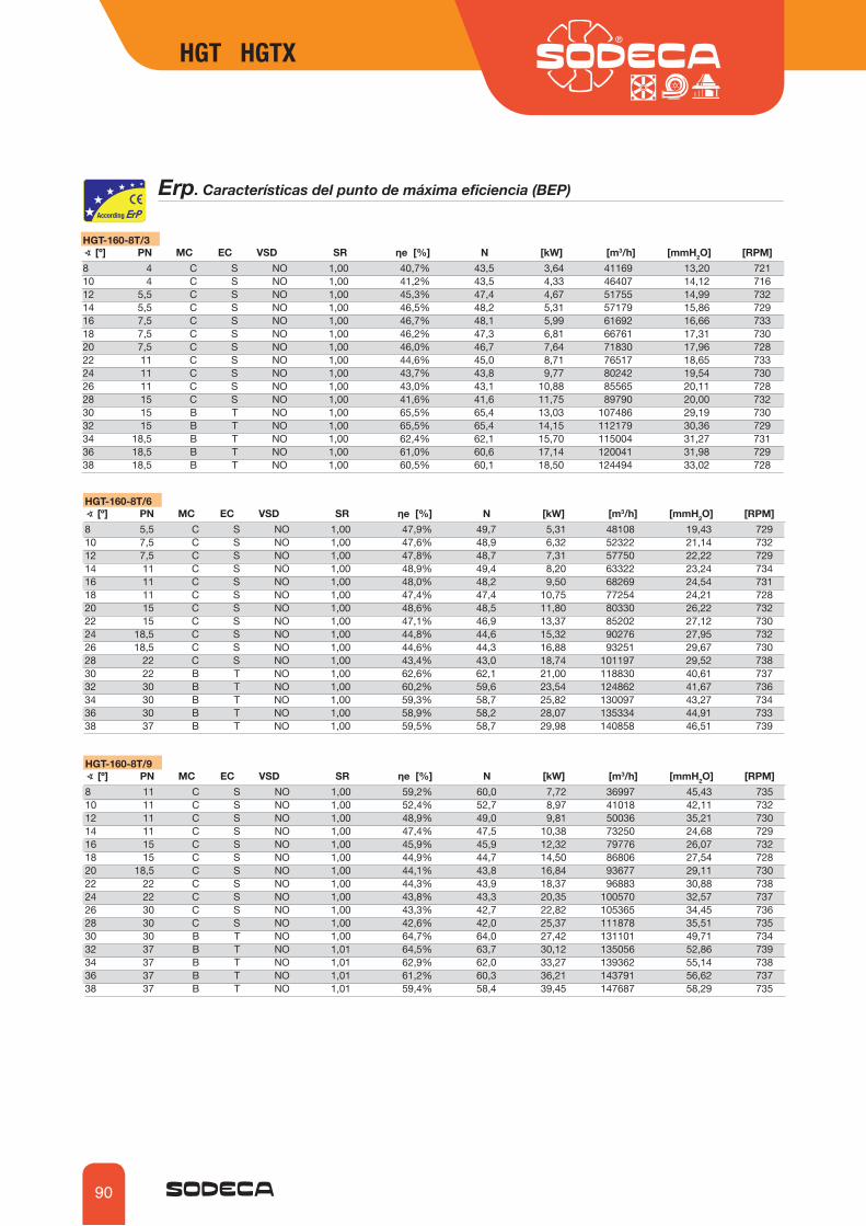
90
Erp��*HYHJ[LYxZ[PJHZ�KLS�W\U[V�KL�Tm_PTH�LÄJPLUJPH��),7�
HGT-160-8T/3 ∢�B¢D� 75� 4*� ,*� =:+� :9� ʾL��B�D� 5� BR>D� BT3�OD� BTT/26D� B974D8 4 C S NO 1,00 40,7% 43,5 3,64 41169 13,20 72110 4 C S NO 1,00 41,2% 43,5 4,33 46407 14,12 71612 5,5 C S NO 1,00 45,3% 47,4 4,67 51755 14,99 73214 5,5 C S NO 1,00 46,5% 48,2 5,31 57179 15,86 72916 7,5 C S NO 1,00 46,7% 48,1 5,99 61692 16,66 73318 7,5 C S NO 1,00 46,2% 47,3 6,81 66761 17,31 73020 7,5 C S NO 1,00 46,0% 46,7 7,64 71830 17,96 72822 11 C S NO 1,00 44,6% 45,0 8,71 76517 18,65 73324 11 C S NO 1,00 43,7% 43,8 9,77 80242 19,54 73026 11 C S NO 1,00 43,0% 43,1 10,88 85565 20,11 72828 15 C S NO 1,00 41,6% 41,6 11,75 89790 20,00 73230 15 B T NO 1,00 65,5% 65,4 13,03 107486 29,19 73032 15 B T NO 1,00 65,5% 65,4 14,15 112179 30,36 72934 18,5 B T NO 1,00 62,4% 62,1 15,70 115004 31,27 73136 18,5 B T NO 1,00 61,0% 60,6 17,14 120041 31,98 72938 18,5 B T NO 1,00 60,5% 60,1 18,50 124494 33,02 728
HGT-160-8T/6 ∢�B¢D� 75� 4*� ,*� =:+� :9� ʾL��B�D� 5� BR>D� BT3�OD� BTT/26D� B974D8 5,5 C S NO 1,00 47,9% 49,7 5,31 48108 19,43 72910 7,5 C S NO 1,00 47,6% 48,9 6,32 52322 21,14 73212 7,5 C S NO 1,00 47,8% 48,7 7,31 57750 22,22 72914 11 C S NO 1,00 48,9% 49,4 8,20 63322 23,24 73416 11 C S NO 1,00 48,0% 48,2 9,50 68269 24,54 73118 11 C S NO 1,00 47,4% 47,4 10,75 77254 24,21 72820 15 C S NO 1,00 48,6% 48,5 11,80 80330 26,22 73222 15 C S NO 1,00 47,1% 46,9 13,37 85202 27,12 73024 18,5 C S NO 1,00 44,8% 44,6 15,32 90276 27,95 73226 18,5 C S NO 1,00 44,6% 44,3 16,88 93251 29,67 73028 22 C S NO 1,00 43,4% 43,0 18,74 101197 29,52 73830 22 B T NO 1,00 62,6% 62,1 21,00 118830 40,61 73732 30 B T NO 1,00 60,2% 59,6 23,54 124862 41,67 73634 30 B T NO 1,00 59,3% 58,7 25,82 130097 43,27 73436 30 B T NO 1,00 58,9% 58,2 28,07 135334 44,91 73338 37 B T NO 1,00 59,5% 58,7 29,98 140858 46,51 739
HGT-160-8T/9 ∢�B¢D� 75� 4*� ,*� =:+� :9� ʾL��B�D� 5� BR>D� BT3�OD� BTT/26D� B974D8 11 C S NO 1,00 59,2% 60,0 7,72 36997 45,43 73510 11 C S NO 1,00 52,4% 52,7 8,97 41018 42,11 73212 11 C S NO 1,00 48,9% 49,0 9,81 50036 35,21 73014 11 C S NO 1,00 47,4% 47,5 10,38 73250 24,68 72916 15 C S NO 1,00 45,9% 45,9 12,32 79776 26,07 73218 15 C S NO 1,00 44,9% 44,7 14,50 86806 27,54 72820 18,5 C S NO 1,00 44,1% 43,8 16,84 93677 29,11 73022 22 C S NO 1,00 44,3% 43,9 18,37 96883 30,88 73824 22 C S NO 1,00 43,8% 43,3 20,35 100570 32,57 73726 30 C S NO 1,00 43,3% 42,7 22,82 105365 34,45 73628 30 C S NO 1,00 42,6% 42,0 25,37 111878 35,51 73530 30 B T NO 1,00 64,7% 64,0 27,42 131101 49,71 73432 37 B T NO 1,01 64,5% 63,7 30,12 135056 52,86 73934 37 B T NO 1,01 62,9% 62,0 33,27 139362 55,14 73836 37 B T NO 1,01 61,2% 60,3 36,21 143791 56,62 73738 37 B T NO 1,01 59,4% 58,4 39,45 147687 58,29 735
HGT HGTX

91
HGTX-125-4T/3 ∢�B¢D� 75� 4*� ,*� =:+� :9� ʾL��B�D� 5� BR>D� BT3�OD� BTT/26D� B974D8 11 C S NO 1,00 51,1% 51,8 7,77 41511 35,13 147110 11 C S NO 1,00 51,7% 51,9 9,26 46792 37,56 146612 11 C S NO 1,00 52,7% 52,8 10,75 52185 39,90 146014 15 C S NO 1,01 54,7% 54,6 12,11 57655 42,19 147416 15 C S NO 1,01 54,1% 53,9 13,89 62205 44,33 147118 18,5 C S NO 1,01 53,4% 53,2 15,80 67316 46,06 147720 18,5 C S NO 1,01 53,2% 52,8 17,71 72427 47,79 147422 22 C S NO 1,01 51,6% 51,1 20,22 77315 49,54 147024 30 C S NO 1,01 50,4% 49,8 22,51 82218 50,63 148326 30 C S NO 1,01 50,4% 49,8 24,84 84773 54,27 148128 30 C S NO 1,01 47,3% 46,6 27,43 90252 52,81 147930 37 C S NO 1,01 45,4% 44,6 30,15 94744 53,05 147732 37 C S NO 1,01 43,7% 42,9 32,74 99128 53,03 147534 45 B T NO 1,01 72,8% 71,9 36,54 116210 84,11 147736 45 B T NO 1,01 71,3% 70,3 39,88 121252 86,13 147538 45 B T NO 1,01 70,7% 69,7 43,06 125686 89,03 1473
Erp��*HYHJ[LYxZ[PJHZ�KLS�W\U[V�KL�Tm_PTH�LÄJPLUJPH��),7�
HGTX-125-4T/6 ∢�B¢D� 75� 4*� ,*� =:+� :9� ʾL��B�D� 5� BR>D� BT3�OD� BTT/26D� B974D8 15 C S NO 1,01 56,4% 56,4 12,10 48508 51,71 147410 15 C S NO 1,01 55,1% 54,9 14,66 52757 56,25 146912 18,5 C S NO 1,01 55,3% 55,0 16,95 58230 59,12 147514 22 C S NO 1,01 56,5% 56,1 19,02 63848 61,84 147216 30 C S NO 1,01 56,1% 55,6 21,81 68837 65,30 148318 30 C S NO 1,01 55,4% 54,7 24,68 77896 64,43 148120 30 C S NO 1,01 55,5% 54,8 27,70 80997 69,77 147922 37 C S NO 1,01 53,8% 53,0 31,39 85910 72,17 147624 37 C S NO 1,01 52,7% 51,8 35,28 88480 77,19 147326 45 C S NO 1,01 51,2% 50,2 39,48 93638 79,23 147628 55 C S NO 1,01 48,8% 47,7 44,72 102038 78,56 148130 55 C S NO 1,01 45,9% 44,7 49,63 106474 78,56 147932 75 C S NO 1,01 43,8% 42,5 54,19 110911 78,56 148634 75 B T NO 1,01 69,3% 68,0 60,04 131496 116,23 148536 75 B T NO 1,01 68,9% 67,5 65,30 136742 120,78 148438 75 B T NO 1,01 68,9% 67,5 70,36 142272 125,19 1482
HGTX-125-4T/9 ∢�B¢D� 75� 4*� ,*� =:+� :9� ʾL��B�D� 5� BR>D� BT3�OD� BTT/26D� B974D8 18,5 C S NO 1,01 67,8% 67,4 18,12 37304 120,90 147310 22 C S NO 1,01 60,6% 60,1 20,81 41359 112,05 147012 30 C S NO 1,01 57,2% 56,6 22,51 50452 93,68 148314 30 C S NO 1,01 55,4% 54,8 23,82 73859 65,67 148216 30 C S NO 1,01 52,5% 51,8 28,92 80439 69,38 147818 37 C S NO 1,01 51,3% 50,4 34,03 87528 73,29 147420 45 C S NO 1,01 50,8% 49,9 39,18 94456 77,46 147622 55 C S NO 1,01 49,8% 48,8 43,85 97688 82,16 148124 55 C S NO 1,01 49,3% 48,1 48,57 101406 86,68 147926 75 C S NO 1,01 50,0% 48,7 53,06 106241 91,67 148728 75 C S NO 1,01 48,7% 47,4 58,96 112236 93,94 148530 75 C S NO 1,01 48,3% 46,9 64,88 120361 95,67 148432 75 C S NO 1,01 47,3% 45,8 70,54 125253 97,81 148234 90 B T NO 1,01 73,1% 71,6 77,61 140724 148,06 148436 90 B T NO 1,01 71,2% 69,6 84,48 145177 152,12 148238 90 B T NO 1,02 69,1% 67,4 92,05 149120 156,66 1481
HGT HGTXHGT HGTX
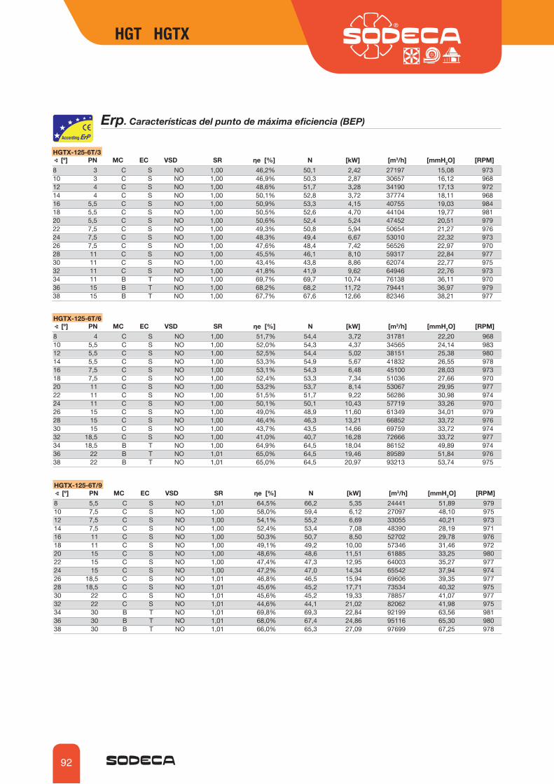
92
Erp��*HYHJ[LYxZ[PJHZ�KLS�W\U[V�KL�Tm_PTH�LÄJPLUJPH��),7�
HGTX-125-6T/3 ∢�B¢D� 75� 4*� ,*� =:+� :9� ʾL��B�D� 5� BR>D� BT3�OD� BTT/26D� B974D8 3 C S NO 1,00 46,2% 50,1 2,42 27197 15,08 97310 3 C S NO 1,00 46,9% 50,3 2,87 30657 16,12 96812 4 C S NO 1,00 48,6% 51,7 3,28 34190 17,13 97214 4 C S NO 1,00 50,1% 52,8 3,72 37774 18,11 96816 5,5 C S NO 1,00 50,9% 53,3 4,15 40755 19,03 98418 5,5 C S NO 1,00 50,5% 52,6 4,70 44104 19,77 98120 5,5 C S NO 1,00 50,6% 52,4 5,24 47452 20,51 97922 7,5 C S NO 1,00 49,3% 50,8 5,94 50654 21,27 97624 7,5 C S NO 1,00 48,3% 49,4 6,67 53010 22,32 97326 7,5 C S NO 1,00 47,6% 48,4 7,42 56526 22,97 97028 11 C S NO 1,00 45,5% 46,1 8,10 59317 22,84 97730 11 C S NO 1,00 43,4% 43,8 8,86 62074 22,77 97532 11 C S NO 1,00 41,8% 41,9 9,62 64946 22,76 97334 11 B T NO 1,00 69,7% 69,7 10,74 76138 36,11 97036 15 B T NO 1,00 68,2% 68,2 11,72 79441 36,97 97938 15 B T NO 1,00 67,7% 67,6 12,66 82346 38,21 977
HGTX-125-6T/6 ∢�B¢D� 75� 4*� ,*� =:+� :9� ʾL��B�D� 5� BR>D� BT3�OD� BTT/26D� B974D8 4 C S NO 1,00 51,7% 54,4 3,72 31781 22,20 96810 5,5 C S NO 1,00 52,0% 54,3 4,37 34565 24,14 98312 5,5 C S NO 1,00 52,5% 54,4 5,02 38151 25,38 98014 5,5 C S NO 1,00 53,3% 54,9 5,67 41832 26,55 97816 7,5 C S NO 1,00 53,1% 54,3 6,48 45100 28,03 97318 7,5 C S NO 1,00 52,4% 53,3 7,34 51036 27,66 97020 11 C S NO 1,00 53,2% 53,7 8,14 53067 29,95 97722 11 C S NO 1,00 51,5% 51,7 9,22 56286 30,98 97424 11 C S NO 1,00 50,1% 50,1 10,43 57719 33,26 97026 15 C S NO 1,00 49,0% 48,9 11,60 61349 34,01 97928 15 C S NO 1,00 46,4% 46,3 13,21 66852 33,72 97630 15 C S NO 1,00 43,7% 43,5 14,66 69759 33,72 97432 18,5 C S NO 1,00 41,0% 40,7 16,28 72666 33,72 97734 18,5 B T NO 1,00 64,9% 64,5 18,04 86152 49,89 97436 22 B T NO 1,01 65,0% 64,5 19,46 89589 51,84 97638 22 B T NO 1,01 65,0% 64,5 20,97 93213 53,74 975
HGTX-125-6T/9 ∢�B¢D� 75� 4*� ,*� =:+� :9� ʾL��B�D� 5� BR>D� BT3�OD� BTT/26D� B974D8 5,5 C S NO 1,01 64,5% 66,2 5,35 24441 51,89 97910 7,5 C S NO 1,00 58,0% 59,4 6,12 27097 48,10 97512 7,5 C S NO 1,00 54,1% 55,2 6,69 33055 40,21 97314 7,5 C S NO 1,00 52,4% 53,4 7,08 48390 28,19 97116 11 C S NO 1,00 50,3% 50,7 8,50 52702 29,78 97618 11 C S NO 1,00 49,1% 49,2 10,00 57346 31,46 97220 15 C S NO 1,00 48,6% 48,6 11,51 61885 33,25 98022 15 C S NO 1,00 47,4% 47,3 12,95 64003 35,27 97724 15 C S NO 1,00 47,2% 47,0 14,34 65542 37,94 97426 18,5 C S NO 1,01 46,8% 46,5 15,94 69606 39,35 97728 18,5 C S NO 1,01 45,6% 45,2 17,71 73534 40,32 97530 22 C S NO 1,01 45,6% 45,2 19,33 78857 41,07 97732 22 C S NO 1,01 44,6% 44,1 21,02 82062 41,98 97534 30 B T NO 1,01 69,8% 69,3 22,84 92199 63,56 98136 30 B T NO 1,01 68,0% 67,4 24,86 95116 65,30 98038 30 B T NO 1,01 66,0% 65,3 27,09 97699 67,25 978
HGT HGTX

93
HGTX-125-8T/3 ∢�B¢D� 75� 4*� ,*� =:+� :9� ʾL��B�D� 5� BR>D� BT3�OD� BTT/26D� B974D8 1,1 C S NO 1,00 39,7% 45,5 1,22 20612 8,66 71310 1,5 C S NO 1,00 41,6% 47,0 1,41 23235 9,26 71812 1,5 C S NO 1,00 42,5% 47,5 1,63 25912 9,84 71314 2,2 C S NO 1,00 43,7% 48,3 1,86 28629 10,40 72116 2,2 C S NO 1,00 43,3% 47,5 2,12 30888 10,93 71718 2,2 C S NO 1,00 42,8% 46,8 2,41 33426 11,36 71320 3 C S NO 1,00 44,2% 47,9 2,61 35964 11,78 71922 3 C S NO 1,00 42,5% 45,8 3,00 38311 12,24 71524 3 C S NO 1,00 42,3% 45,3 3,33 38268 13,50 71126 4 C S NO 1,00 42,0% 44,8 3,65 42094 13,38 72128 4 C S NO 1,00 39,9% 42,4 4,02 44508 13,23 71830 4 C S NO 1,00 38,1% 40,4 4,39 46875 13,12 71532 5,5 C S NO 1,00 39,6% 41,9 4,42 49222 13,07 73334 5,5 B T NO 1,00 66,3% 68,3 4,91 57704 20,74 73136 5,5 B T NO 1,00 65,2% 66,9 5,34 60208 21,24 72938 5,5 B T NO 1,00 64,9% 66,4 5,75 62409 21,95 728
HGTX-125-8T/6 ∢�B¢D� 75� 4*� ,*� =:+� :9� ʾL��B�D� 5� BR>D� BT3�OD� BTT/26D� B974D8 2,2 C S NO 1,00 45,1% 49,7 1,86 24087 12,75 72110 2,2 C S NO 1,00 44,1% 48,3 2,24 26197 13,87 71512 2,2 C S NO 1,00 44,4% 48,1 2,58 28914 14,58 71014 3 C S NO 1,00 46,5% 50,0 2,83 31704 15,25 71716 3 C S NO 1,00 45,8% 48,9 3,27 34181 16,10 71218 4 C S NO 1,00 46,1% 48,9 3,63 38680 15,89 72120 4 C S NO 1,00 46,4% 48,9 4,06 40219 17,20 71822 5,5 C S NO 1,00 48,7% 51,1 4,24 42659 17,80 73424 5,5 C S NO 1,00 47,0% 49,0 4,81 45625 18,18 73126 5,5 C S NO 1,00 46,7% 48,5 5,29 46496 19,54 72928 7,5 C S NO 1,00 45,4% 46,9 5,88 50667 19,37 73330 7,5 C S NO 1,00 42,7% 43,9 6,53 52870 19,37 73132 7,5 C S NO 1,00 40,5% 41,4 7,18 55073 19,37 72934 11 B T NO 1,00 64,8% 65,5 7,86 65294 28,66 73436 11 B T NO 1,00 64,4% 64,8 8,55 67899 29,78 73338 11 B T NO 1,00 64,4% 64,7 9,21 70645 30,87 732
HGTX-125-8T/9 ∢�B¢D� 75� 4*� ,*� =:+� :9� ʾL��B�D� 5� BR>D� BT3�OD� BTT/26D� B974D8 3 C S NO 1,00 56,3% 59,9 2,67 18524 29,81 71910 3 C S NO 1,00 50,0% 53,2 3,09 20537 27,63 71412 3 C S NO 1,00 46,7% 49,7 3,37 25052 23,10 71114 4 C S NO 1,00 46,1% 49,0 3,50 36675 16,19 72216 4 C S NO 1,00 44,0% 46,4 4,23 39942 17,11 71618 5,5 C S NO 1,00 46,6% 48,8 4,59 43462 18,07 73220 5,5 C S NO 1,00 46,4% 48,2 5,25 46902 19,10 73022 7,5 C S NO 1,00 46,3% 47,9 5,77 48507 20,26 73324 7,5 C S NO 1,00 46,1% 47,4 6,39 49674 21,79 73126 7,5 C S NO 1,00 46,2% 47,2 7,03 52754 22,60 73028 11 C S NO 1,00 45,5% 46,3 7,72 55731 23,16 73530 11 C S NO 1,00 45,1% 45,5 8,49 59770 23,52 73332 11 C S NO 1,00 44,2% 44,4 9,24 62194 24,12 73234 11 B T NO 1,00 68,0% 68,0 10,21 69877 36,51 73036 11 B T NO 1,00 66,2% 66,2 11,12 72088 37,51 72838 15 B T NO 1,00 65,7% 65,7 11,85 74046 38,63 732
Erp��*HYHJ[LYxZ[PJHZ�KLS�W\U[V�KL�Tm_PTH�LÄJPLUJPH��),7�
HGT HGTXHGT HGTX
Accesorios
Ver apartado accesorios.
INT AR RFT/ RFM CUADROS RT BTUB BAC PS S SI PVPT/H

68
HTP HTP
HTP ,_[YHJ[VYLZ�H_PHSLZ�[\I\SHYLZ��KL�HS[H�WYLZP}U
Extractores axiales tubulares de alta presión y gran robustez, especialmente diseñados para instalaciones de minería o aplicaciones con grandes pérdidas de carga
Ventilador:� Envolvente tubular en chapa de acero de gran espesor� Soporte de motor soldado al envolvente.� Directrices de alto rendimiento aerodinámico para ganancia de presión� ÔW[PTH�WYV[LJJP}U�Z\WLYÄJPHS�TLKPHU[L�HJLYV�KL�HS[H�JHSPKHK�� Hélice de alto rendimiento, construida en fundición de aluminio� Sentido de aire hélice-motor� Conexión eléctrica en caja de bornes externa.
Motor:� �4V[VYLZ�LÄJPLUJPH�0,����L_JLW[V�WV[LUJPHZ�
inferiores a 0,75 Kw, monofásicos y 2 velocidades.
� Motores clase F, con rodamientos a bolas, protección IP-55
� Trifásicos 230/400V-50Hz (hasta 5,5CV) y 400/690V-50Hz (potencias superiores a 5,5CV)
� ;LTWLYH[\YH�KL�[YHIHQV����¢*�����¢*
Acabado:� Acero de alta protección anticorrosivo,
imprimación especial y pintura de alta calidad para ambientes corrosivos.
Bajo demanda:� Motores normalizados IP-55, motores
ATEX y de 2 Velocidades� Hélice en acero inoxidable o hierro� Construcción total en acero inoxidable� Construcción en acero galvanizado en
caliente
*}KPNV�KL�WLKPKV
HTP 63 2T 10 20º PV
Número de polos motor2=2950 r/min. 50 Hz4=1450 r/min. 50 Hz
Diámetro hélice en cm.
Extractores axiales tubulares de alta presión
T=Trifásico Potencia motor (CV)
Hélice de alta presión
Angulo inclinación palas
Características técnicas
Velocidad
(r/min)
Modelo Intensidad máxima admisible (A)
230V 400V 690V
Potencia instalada
(kW)
Caudal máximo(m3/h)
Peso aprox.(Kg)
NPSdB(A)
HTP-50-2T-4 2900 10,18 5,88 - 3,00 13850 49 82HTP-50-2T-5,5 2870 13,60 7,82 - 4,00 16450 65 83HTP-56-2T-5,5 2870 13,60 7,82 - 4,00 18050 69 88HTP-56-2T-10 2870 - 14,50 8,41 7,50 25500 147 89HTP-63-2T-10 2870 - 14,50 8,41 7,50 23850 132 94HTP-63-2T-15 2940 - 20,30 11,70 11,00 29400 167 94HTP-63-2T-20 2935 - 27,40 15,90 15,00 34400 181 97HTP-63-2T-25 2930 - 32,40 18,70 18,50 37200 199 98HTP-63-2T-30 2935 - 38,00 22,00 22,00 39800 208 99HTP-63-4T-1,5 1400 4,03 2,32 - 1,10 12850 92 79HTP-63-4T-2 1430 5,96 3,44 - 1,50 15650 93 79HTP-63-4T-3 1445 8,36 4,83 - 2,20 18600 101 83HTP-63-4T-4 1445 10,96 6,33 - 3,00 19900 104 84HTP-71-2T-15 2940 - 20,30 11,70 11,00 32850 184 93HTP-71-2T-20 2935 - 27,40 15,90 15,00 39250 198 95HTP-71-2T-25 2930 - 32,40 18,70 18,50 43450 216 95HTP-71-2T-30 2935 - 38,00 22,00 22,00 45500 225 95HTP-71-2T-40 2940 - 50,00 29,00 30,00 52550 303 98HTP-71-4T-2 1445 8,36 4,83 - 2,20 17500 110 83HTP-71-4T-3 1445 8,36 4,83 - 2,20 20650 118 83HTP-71-4T-4 1445 10,96 6,33 - 3,00 23950 121 84
PV=Pabellón de aspiración

69
HTP HTP
Características técnicas
Velocidad
(r/min)
Modelo Intensidad máxima admisible (A)
230V 400V 690V
Potencia instalada
(kW)
Caudal máximo(m3/h)
Peso aprox.(Kg)
NPSdB(A)
HTP-71-4T-5,5 1440 14,10 8,12 - 4,00 27400 127 87HTP-71-4T-7,5 1440 - 11,60 6,72 5,50 31700 141 90HTP-80-4T-4 1445 10,96 6,33 - 3,00 19300 146 86HTP-80-4T-5,5 1440 14,10 8,12 - 4,00 22850 152 86HTP-80-4T-7,5 1440 - 11,60 6,72 5,50 28000 166 86HTP-80-4T-10 1400 - 2,32 1,34 1,10 31500 177 87HTP-80-4T-15 1460 - 20,20 11,60 11,00 40000 217 91HTP-90-4T-7,5 1440 - 11,60 6,72 5,50 27450 196 90HTP-90-4T-10 1455 - 14,20 8,20 7,50 32500 207 90HTP-90-4T-15 1460 - 20,20 11,60 11,00 42200 247 90HTP-90-4T-20 1460 - 27,50 15,90 15,00 50050 266 94HTP-90-4T-25 1460 - 35,00 20,00 18,50 54550 294 95HTP-90-4T-30 1465 - 42,00 24,00 22,00 61750 311 97HTP-100-4T-15 1460 - 20,20 11,60 11,00 46100 282 93HTP-100-4T-20 1460 - 27,50 15,90 15,00 56300 301 93HTP-100-4T-25 1460 - 35,00 20,00 18,50 59900 329 93HTP-100-4T-30 1465 - 42,00 24,00 22,00 69900 346 96HTP-100-4T-40 1465 - 55,00 32,00 30,00 80500 401 98HTP-125-4T-40 1465 - 55,00 32,00 30,00 81000 503 100HTP-125-4T-50 1470 - 69,20 40,10 37,00 96800 525 100HTP-125-4T-60 1470 - 81,00 47,00 45,00 105050 558 100HTP-125-4T-75 1475 - 99,00 57,00 55,00 127800 599 100HTP-125-4T-100 1480 - 133,00 77,00 75,00 147350 674 104HTP-125-4T-125 1480 - 159,00 92,00 90,00 156800 703 105
Los valores indicados, se determinan mediante medidas de nivel de presión y potencia en dB(A), obtenidas en campo libre a una distancia equivalente a dos veces la envergadura del ventilador más el diámetro de la hélice, con un mínimo de 1,5 m
Características acústicas
,ZWLJ[YV�KL�WV[LUJPH�ZVUVYH�3^�(��LU�K)�(��WVY�IHUKH�KL�MYLJ\LUJPH�LU�/aModelo LpdB(A) 63 125 250 500 1000 2000 4000 8000HTP-50-2T-4 80 57 77 85 90 92 89 82 71HTP-50-2T-5,5 81 58 78 86 91 93 90 83 72HTP-56-2T-5,5 86 63 83 91 96 98 95 88 77HTP-56-2T-10 87 64 84 92 97 99 96 89 78HTP-63-2T-10 94 70 82 92 104 105 104 99 91HTP-63-2T-15 94 70 82 92 104 105 104 99 91HTP-63-2T-20 97 73 85 95 107 108 107 102 94HTP-63-2T-25 98 74 86 96 108 109 108 103 95HTP-63-2T-30 99 75 87 97 109 110 109 104 96HTP-63-4T-1,5 79 55 67 77 89 90 89 84 76HTP-63-4T-2 79 55 67 77 89 90 89 84 76HTP-63-4T-3 83 59 71 81 93 94 93 88 80HTP-63-4T-4 84 60 72 82 94 95 94 89 81HTP-71-2T-15 93 65 83 93 102 104 103 100 93HTP-71-2T-20 95 67 85 95 104 106 105 102 95HTP-71-2T-25 95 67 85 95 104 106 105 102 95HTP-71-2T-30 95 67 85 95 104 106 105 102 95HTP-71-2T-40 98 70 88 98 107 109 108 105 98HTP-71-4T-2 83 55 73 83 92 93 93 90 83HTP-71-4T-3 83 55 72 83 92 93 93 90 83HTP-71-4T-4 84 56 74 84 94 95 95 91 85HTP-71-4T-5,5 87 59 77 87 97 98 98 95 88HTP-71-4T-7,5 90 62 80 90 100 101 101 97 91
Modelo LpdB(A) 63 125 250 500 1000 2000 4000 8000HTP-80-4T-4 86 58 75 86 95 96 96 93 86HTP-80-4T-5,5 86 58 76 86 95 96 96 93 86HTP-80-4T-7,5 86 58 76 86 95 96 96 93 86HTP-80-4T-10 87 59 77 87 97 98 98 94 88HTP-80-4T-15 91 63 81 91 101 102 102 99 92HTP-90-4T-7,5 90 62 79 90 99 100 100 97 90HTP-90-4T-10 90 62 80 90 99 100 100 97 90HTP-90-4T-15 90 62 80 90 100 101 101 98 91HTP-90-4T-20 94 66 83 94 103 104 104 101 94HTP-90-4T-25 95 67 85 95 104 105 105 102 95HTP-90-4T-30 97 69 87 97 107 108 108 104 98HTP-100-4T-15 93 65 83 93 102 103 103 100 93HTP-100-4T-20 93 65 82 93 102 103 103 100 93HTP-100-4T-25 93 65 83 93 102 103 103 100 93HTP-100-4T-30 96 67 85 96 105 106 106 103 96HTP-100-4T-40 98 70 88 98 107 108 108 105 98HTP-125-4T-40 100 72 89 100 109 110 110 107 100HTP-125-4T-50 100 72 90 100 109 110 110 107 100HTP-125-4T-60 100 72 89 100 109 110 110 107 100HTP-125-4T-75 100 72 90 100 110 111 111 108 101HTP-125-4T-100 104 76 93 104 113 114 114 111 104HTP-125-4T-125 105 77 95 105 114 115 115 112 105
Dimensiones mm
Modelo Potencia ØA ØB ØD E E1 C ØJ N/;7�����;� � ���� ���� ���� �� �� ���� ��� ��_��¢/;7�����;� � ���� ���� ���� �� �� ���� ��� ��_��¢/;7�����;� � ���� � �� ���� ���� ���� ���� ��� ��_��¢/;7�����;� � ���� � �� ���� ���� ���� ���� ��� ��_��¢/;7�����;� � ���� ���� ���� ���� ���� ��� ��� ��_��¢��»/;7�����;� � ���� ���� ���� ���� ���� ���� ��� ��_��¢��»/;7�����;� �����»�� ��� ���� ���� ���� ���� ���� ��� ��_��¢��»/;7�����;� �»������������ ��� ���� ���� ���� ���� � �� ��� ��_��¢��»/;7� ���;� �»������� ����� ��� ��� ���� ���� ���� ��� ��_��¢��»/;7� ���;� ������������������ ����� ��� ��� ���� ���� ��� ��� ��_��¢��»/;7������;� �������� ����� ����� ����� ���� ���� ���� ��� ��_��¢��»/;7������;� ������������� ����� ����� ����� ���� ���� ��� ��� ��_��¢��»/;7����� ������������������ ����� ����� ����� ���� ���� ����� ��� ��_��¢/;7����� ���������� ����� ����� ����� ��� ���� ����� ��� ��_��¢

70
HTP
EJEMPLO SELECCIÓN
EJEMPLO CÓDIGO PEDIDO
Datos de partida� Punto de trabajo:� Caudal: 12.500 m3/h� Pérdida de carga: 7,5 mmH2O
Pasos para la selección del equipo
(Q�OD�JUÀðFD�GH�SUHVLRQHV�� 1. Marcar el punto de trabajo,
KLÄUPKV�WVY�LS�JH\KHS�KL�[YHIHQV�(12.500 m3/h) y la pérdida de carga (7,5 mmH2O).
� 2. Escoger la curva del equipo que más se acerque por encima al punto de trabajo. En nuestro caso se obtiene una curva de ��¢�KL�mUN\SV�KL�WHSH�
(Q�OD�JUÀðFD�GH�SRWHQFLD�� 3. Marcar el punto de trabajo,
KLÄUPKV�WVY�LS�JH\KHS�KL�[YHIHQV�(12.500 m3/h) y la curva de án-N\SV�KL�WHSH�LZJVNPKV����¢��
� 4. Leer la potencia absorbida en el eje de potencias a la izquier-da. La Pa= 560 W en el punto de trabajo.
� 5. Buscar recta roja que más se acerque al punto de trabajo por encima. En la parte derecha de SH�NYmÄJH�ZL�VI[PLUL�LS�]HSVY�KL�potencia instalada de motor. En nuestro caso 0,75 kW o 1 CV
Potencia absorbida 3RWHQFLD�0RWRU�5HFRPHQGDGD�NZ�&9�
Curvas características
HTP-63-4T
Q= Caudal en m3/h, m3/s y cfm. Pe= Presión estática en mmH2O., Pa e inwg.
HTP 63 4T 1 22º
Diámetro hélice en cm
Extractores axiales tubulares de alta presión
Número de polos motor4=1400 r/min. 50 Hz6=900 r/min. 50 Hz8=750 r/min. 50 Hz
T=TrifásicoM=Monofásico
Potencia motor (CV)
Angulo inclinación palas

71
HTP
Curvas característicasQ= Caudal en m3/h, m3/s y cfm. Pe= Presión estática en mmH2O, Pa e inwg.
HTP-50-2T
Potencia absorbida 3RWHQFLD�0RWRU�5HFRPHQGDGD�NZ�&9�
*VUZ\S[HY�JHYHJ[LYxZ[PJHZ�KLS�W\U[V�KL�Tm_PTH�LÄJPLUJPH��),7��HS�ÄUHS�KL�SH�ZLYPL�
HTP
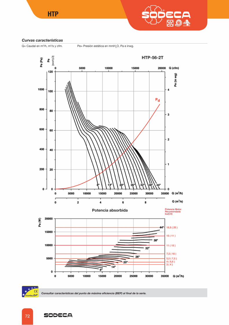
72
Curvas característicasQ= Caudal en m3/h, m3/s y cfm. Pe= Presión estática en mmH2O, Pa e inwg.
Potencia absorbida 3RWHQFLD�0RWRU�5HFRPHQGDGD�NZ�&9�
HTP-56-2T
*VUZ\S[HY�JHYHJ[LYxZ[PJHZ�KLS�W\U[V�KL�Tm_PTH�LÄJPLUJPH��),7��HS�ÄUHS�KL�SH�ZLYPL�
HTP HTP

73
Curvas característicasQ= Caudal en m3/h, m3/s y cfm. Pe= Presión estática en mmH2O, Pa e inwg.
Potencia absorbida 3RWHQFLD�0RWRU�5HFRPHQGDGD�NZ�&9�
HTP-63-2T
*VUZ\S[HY�JHYHJ[LYxZ[PJHZ�KLS�W\U[V�KL�Tm_PTH�LÄJPLUJPH��),7��HS�ÄUHS�KL�SH�ZLYPL�
HTP HTP

74
Curvas característicasQ= Caudal en m3/h, m3/s y cfm. Pe= Presión estática en mmH2O, Pa e inwg.
HTP-63-4T
Potencia absorbida 3RWHQFLD�0RWRU�5HFRPHQGDGD�NZ�&9�
*VUZ\S[HY�JHYHJ[LYxZ[PJHZ�KLS�W\U[V�KL�Tm_PTH�LÄJPLUJPH��),7��HS�ÄUHS�KL�SH�ZLYPL�
HTP HTP

75
Curvas característicasQ= Caudal en m3/h, m3/s y cfm. Pe= Presión estática en mmH2O, Pa e inwg.
HTP-71-2T
Potencia absorbida 3RWHQFLD�0RWRU�5HFRPHQGDGD�NZ�&9�
*VUZ\S[HY�JHYHJ[LYxZ[PJHZ�KLS�W\U[V�KL�Tm_PTH�LÄJPLUJPH��),7��HS�ÄUHS�KL�SH�ZLYPL�
HTP HTP

76
Curvas característicasQ= Caudal en m3/h, m3/s y cfm. Pe= Presión estática en mmH2O, Pa e inwg.
HTP-71-4T
Potencia absorbida 3RWHQFLD�0RWRU�5HFRPHQGDGD�NZ�&9�
*VUZ\S[HY�JHYHJ[LYxZ[PJHZ�KLS�W\U[V�KL�Tm_PTH�LÄJPLUJPH��),7��HS�ÄUHS�KL�SH�ZLYPL�
HTP HTP

77
Curvas característicasQ= Caudal en m3/h, m3/s y cfm. Pe= Presión estática en mmH2O, Pa e inwg.
HTP-80-4T
Potencia absorbida 3RWHQFLD�0RWRU�5HFRPHQGDGD�NZ�&9�
*VUZ\S[HY�JHYHJ[LYxZ[PJHZ�KLS�W\U[V�KL�Tm_PTH�LÄJPLUJPH��),7��HS�ÄUHS�KL�SH�ZLYPL�
HTP HTP

78
Curvas característicasQ= Caudal en m3/h, m3/s y cfm. Pe= Presión estática en mmH2O, Pa e inwg.
HTP-90-4T
Potencia absorbida 3RWHQFLD�0RWRU�5HFRPHQGDGD�NZ�&9�
*VUZ\S[HY�JHYHJ[LYxZ[PJHZ�KLS�W\U[V�KL�Tm_PTH�LÄJPLUJPH��),7��HS�ÄUHS�KL�SH�ZLYPL�
HTP HTP

79
Curvas característicasQ= Caudal en m3/h, m3/s y cfm. Pe= Presión estática en mmH2O, Pa e inwg.
HTP-100-4T
Potencia absorbida 3RWHQFLD�0RWRU�5HFRPHQGDGD�NZ�&9�
*VUZ\S[HY�JHYHJ[LYxZ[PJHZ�KLS�W\U[V�KL�Tm_PTH�LÄJPLUJPH��),7��HS�ÄUHS�KL�SH�ZLYPL�
HTP HTP
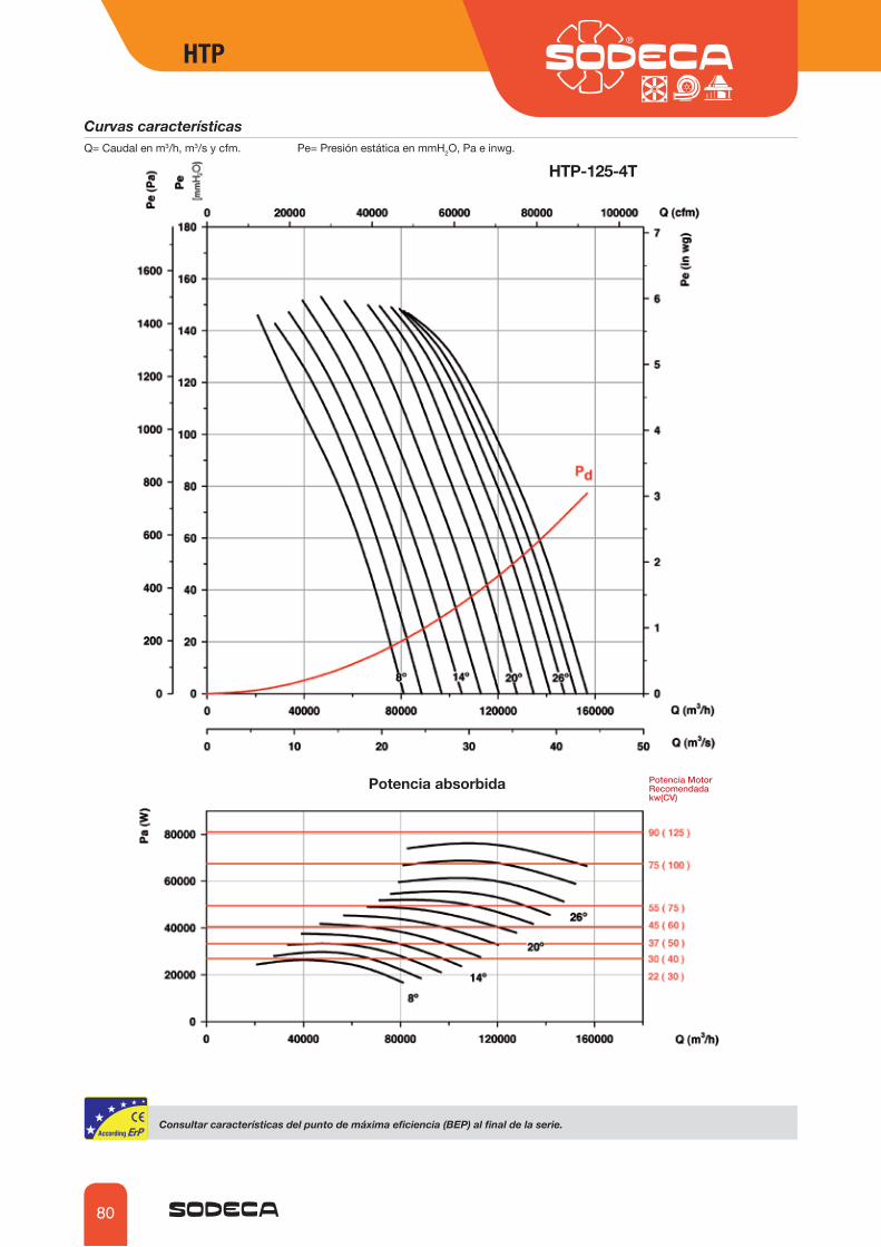
80
Curvas característicasQ= Caudal en m3/h, m3/s y cfm. Pe= Presión estática en mmH2O, Pa e inwg.
HTP-125-4T
Potencia absorbida 3RWHQFLD�0RWRU�5HFRPHQGDGD�NZ�&9�
*VUZ\S[HY�JHYHJ[LYxZ[PJHZ�KLS�W\U[V�KL�Tm_PTH�LÄJPLUJPH��),7��HS�ÄUHS�KL�SH�ZLYPL�
HTP HTP

81
HTP-50-2T ∢�B¢D� 75� 4*� ,*� =:+� :9� ʾL��B�D� 5� BR>D� BT3�OD� BTT/26D� B974D8 2,2 C S NO 1,00 40,3% 45,0 1,797 6731 39,48 288810 2,2 C S NO 1,00 39,0% 43,2 2,167 7180 43,23 286412 3 C S NO 1,01 38,3% 42,1 2,485 7884 44,29 291414 3 C S NO 1,01 37,3% 40,7 2,832 8541 45,39 290116 4 C S NO 1,01 35,6% 38,7 3,255 8962 47,55 291418 4 C S NO 1,01 34,0% 36,7 3,700 9368 49,31 290220 4 C S NO 1,01 33,5% 36,0 4,023 9537 51,91 289322 5,5 C S NO 1,01 34,7% 37,0 4,363 10176 54,63 293624 5,5 B T NO 1,00 49,6% 51,8 4,627 16615 50,79 293226 5,5 B T NO 1,01 49,5% 51,4 5,143 17229 54,30 292428 7,5 B T NO 1,01 48,9% 50,4 5,725 18386 55,89 293830 7,5 B T NO 1,01 48,8% 50,0 6,436 19548 59,00 2930
Erp��*HYHJ[LYxZ[PJHZ�KLS�W\U[V�KL�Tm_PTH�LÄJPLUJPH��),7�∢�B¢D� Ángulo inclinación palas en gradosPN Potencia nominal motor en kWMC Categoría de mediciónEC� *H[LNVYxH�KL�LÄJPLUJPH S Estática T TotalVSD Variador de velocidad
SR� 9LSHJP}U�LZWLJxÄJHʾLB�D� ,ÄJPLUJPHN� .YHKV�KL�LÄJPLUJPHBR>D Potencia eléctrica[m3�OD Caudal[mmH26D Presión estática o total (Según EC)B974D Velocidad
HTP-56-2T ∢�B¢D� 75� 4*� ,*� =:+� :9� ʾL��B�D� 5� BR>D� BT3�OD� BTT/26D� B974D8 2,2 C S NO 1,00 60,5% 65,0 1,914 10060 42,26 288010 3 C S NO 1,01 54,8% 58,6 2,491 10410 48,18 291312 3 C S NO 1,01 50,9% 54,2 3,018 11389 49,56 289514 4 C S NO 1,01 49,1% 52,0 3,526 11508 55,31 290716 5,5 C S NO 1,01 48,1% 50,6 4,046 13418 53,26 294018 5,5 C S NO 1,01 45,8% 47,9 4,663 14275 54,95 293120 5,5 C S NO 1,01 44,5% 46,3 5,246 15266 56,14 292322 7,5 B T NO 1,01 60,9% 62,4 5,756 18179 70,82 293724 7,5 B T NO 1,01 60,3% 61,6 6,362 19341 72,87 293126 7,5 B T NO 1,01 60,1% 61,1 6,944 20914 73,33 292528 11 B T NO 1,01 57,1% 57,8 7,856 21588 76,35 295730 11 B T NO 1,01 54,4% 54,7 8,890 22868 77,67 295232 11 B T NO 1,01 53,0% 53,0 9,914 25263 76,40 294634 15 B T NO 1,01 51,8% 51,8 10,932 26289 79,08 295336 15 B T NO 1,01 50,9% 50,8 11,965 27557 81,16 294838 15 B T NO 1,01 50,2% 50,1 13,018 28272 84,97 2944
HTP-63-2T ∢�B¢D� 75� 4*� ,*� =:+� :9� ʾL��B�D� 5� BR>D� BT3�OD� BTT/26D� B974D8 7,5 C S NO 1,01 63,1% 64,6 5,696 13562 97,33 294010 7,5 C S NO 1,01 61,7% 62,9 6,567 14654 101,55 293012 7,5 C S NO 1,01 60,8% 61,7 7,428 15642 106,10 292114 11 C S NO 1,01 61,7% 62,3 8,081 16570 110,56 295716 11 C S NO 1,01 61,1% 61,4 9,179 17063 120,77 295118 11 C S NO 1,01 59,5% 59,6 10,320 18242 123,71 294520 15 C S NO 1,01 59,7% 59,7 11,390 20352 122,82 295122 15 C S NO 1,02 58,8% 58,7 12,321 19247 138,18 294824 15 C S NO 1,02 58,1% 57,9 13,671 21081 138,33 294226 18,5 C S NO 1,02 57,5% 57,2 14,909 23032 136,65 295628 18,5 C S NO 1,02 54,9% 54,6 16,763 23740 142,38 295030 22 C S NO 1,02 52,7% 52,3 18,566 24546 146,29 295732 22 C S NO 1,02 50,8% 50,3 20,405 25369 150,12 2953
HTP HTP

82
HTP-63-4T ∢�B¢D� 75� 4*� ,*� =:+� :9� ʾL��B�D� 5� BR>D� BT3�OD� BTT/26D� B974D8 0,75 C S NO 1,00 56,9% 63,9 0,790 6781 24,33 142410 1,1 C S NO 1,00 57,0% 63,7 0,888 7327 25,39 146012 1,1 C S NO 1,00 56,2% 62,5 1,005 7821 26,53 145514 1,1 C S NO 1,00 55,8% 61,8 1,118 8285 27,64 145016 1,5 C S NO 1,00 56,1% 61,8 1,251 8532 30,19 145818 1,5 C S NO 1,00 54,6% 60,0 1,407 9121 30,93 145320 1,5 C S NO 1,00 54,3% 59,4 1,566 10176 30,70 144822 2,2 C S NO 1,00 54,4% 59,3 1,664 9623 34,55 145824 2,2 C S NO 1,00 53,7% 58,4 1,846 10541 34,58 145426 2,2 C S NO 1,00 52,8% 57,2 2,029 11516 34,16 144928 2,2 C S NO 1,00 50,4% 54,5 2,281 11870 35,60 144330 3 C S NO 1,00 48,9% 52,7 2,500 12273 36,57 144332 3 C S NO 1,00 47,2% 50,7 2,747 12685 37,53 143734 3 C S NO 1,00 43,9% 47,1 3,045 13549 36,21 143036 4 C S NO 1,00 41,3% 44,3 3,334 14297 35,38 145738 4 C S NO 1,00 38,2% 41,0 3,590 15407 32,71 1453
HTP-71-2T ∢�B¢D� 75� 4*� ,*� =:+� :9� ʾL��B�D� 5� BR>D� BT3�OD� BTT/26D� B974D8 11 C S NO 1,01 65,9% 66,0 10,153 20358 120,78 294610 15 C S NO 1,01 65,0% 65,0 11,308 21567 125,28 295212 15 C S NO 1,01 63,9% 63,8 12,610 22971 128,86 294614 15 C S NO 1,01 63,6% 63,4 13,873 23869 135,83 294116 18,5 C S NO 1,02 62,7% 62,4 15,552 26171 136,80 295418 18,5 C S NO 1,02 61,4% 61,1 17,341 29550 132,46 294820 22 C S NO 1,02 62,9% 62,5 18,923 28934 151,17 295622 22 C S NO 1,02 60,8% 60,3 21,346 31510 151,41 295124 30 C S NO 1,02 58,0% 57,4 24,236 34832 148,18 296626 30 C S NO 1,02 56,8% 56,2 26,558 37324 148,58 296328 30 C S NO 1,02 56,1% 55,4 28,110 37671 153,78 296130 30 C S NO 1,02 54,3% 53,5 30,493 38513 157,94 2958
HTP-71-4T ∢�B¢D� 75� 4*� ,*� =:+� :9� ʾL��B�D� 5� BR>D� BT3�OD� BTT/26D� B974D8 1,5 C S NO 1,00 60,5% 65,9 1,384 10179 30,19 145410 1,5 C S NO 1,00 59,1% 64,2 1,555 10783 31,32 144812 2,2 C S NO 1,00 59,1% 64,0 1,703 11486 32,22 145714 2,2 C S NO 1,00 58,9% 63,5 1,874 11935 33,96 145316 2,2 C S NO 1,00 57,6% 61,8 2,117 13085 34,20 144718 3 C S NO 1,00 57,2% 61,2 2,330 14775 33,11 144720 3 C S NO 1,00 58,4% 62,2 2,548 14467 37,79 144222 3 C S NO 1,00 56,5% 59,9 2,874 15755 37,85 143424 4 C S NO 1,00 54,1% 57,2 3,246 17416 37,04 145826 4 C S NO 1,00 53,0% 55,9 3,557 18662 37,15 145428 4 C S NO 1,00 52,4% 55,1 3,765 18836 38,44 145130 4 C S NO 1,00 50,7% 53,2 4,084 19256 39,49 144732 5,5 C S NO 1,01 50,6% 53,0 4,276 19555 40,65 147334 5,5 C S NO 1,01 48,4% 50,5 4,696 20811 40,15 147036 5,5 C S NO 1,01 45,9% 47,7 5,196 22143 39,56 146738 5,5 C S NO 1,01 44,0% 45,6 5,649 23383 39,07 1464
Erp��*HYHJ[LYxZ[PJHZ�KLS�W\U[V�KL�Tm_PTH�LÄJPLUJPH��),7�
HTP-80-4T ∢�B¢D� 75� 4*� ,*� =:+� :9� ʾL��B�D� 5� BR>D� BT3�OD� BTT/26D� B974D8 3 C S NO 1,00 45,9% 49,1 3,042 12859 39,86 143110 4 C S NO 1,00 46,8% 49,7 3,466 14380 41,40 145512 4 C S NO 1,00 47,5% 50,1 3,949 15604 44,16 144914 4 C S NO 1,01 49,1% 51,3 4,404 16927 46,89 144316 5,5 C S NO 1,01 50,3% 52,3 4,871 18604 48,40 146918 5,5 C S NO 1,01 49,3% 51,0 5,411 19531 50,19 146520 7,5 C S NO 1,01 49,1% 50,6 5,909 20646 51,65 146822 7,5 C S NO 1,01 47,9% 49,1 6,605 21619 53,75 146524 7,5 C S NO 1,01 47,2% 48,1 7,294 22603 55,93 146126 11 C S NO 1,01 46,7% 47,4 7,845 23377 57,56 148128 11 C S NO 1,01 45,1% 45,6 8,461 23934 58,57 147930 11 C S NO 1,01 43,8% 44,1 9,108 24700 59,31 147832 11 C S NO 1,01 43,0% 43,2 9,553 24657 61,26 147634 11 C S NO 1,01 42,7% 42,7 10,208 25847 61,88 1475
HTP HTP
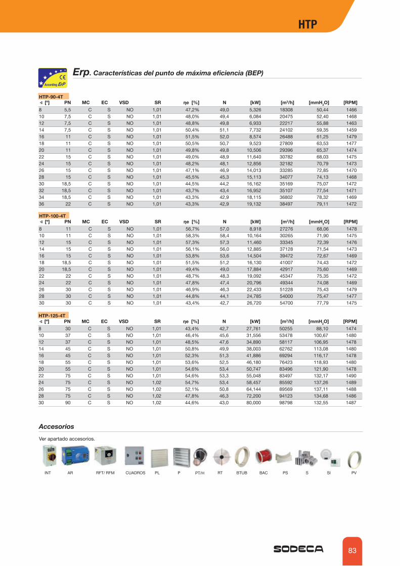
83
HTP-90-4T ∢�B¢D� 75� 4*� ,*� =:+� :9� ʾL��B�D� 5� BR>D� BT3�OD� BTT/26D� B974D8 5,5 C S NO 1,01 47,2% 49,0 5,326 18308 50,44 146610 7,5 C S NO 1,01 48,0% 49,4 6,084 20475 52,40 146812 7,5 C S NO 1,01 48,8% 49,8 6,933 22217 55,88 146314 7,5 C S NO 1,01 50,4% 51,1 7,732 24102 59,35 145916 11 C S NO 1,01 51,5% 52,0 8,574 26488 61,25 147918 11 C S NO 1,01 50,5% 50,7 9,523 27809 63,53 147720 11 C S NO 1,01 49,8% 49,8 10,506 29396 65,37 147422 15 C S NO 1,01 49,0% 48,9 11,640 30782 68,03 147524 15 C S NO 1,01 48,2% 48,1 12,856 32182 70,79 147326 15 C S NO 1,01 47,1% 46,9 14,013 33285 72,85 147028 15 C S NO 1,01 45,5% 45,3 15,113 34077 74,13 146830 18,5 C S NO 1,01 44,5% 44,2 16,162 35169 75,07 147232 18,5 C S NO 1,01 43,7% 43,4 16,952 35107 77,54 147134 18,5 C S NO 1,01 43,3% 42,9 18,115 36802 78,32 146936 22 C S NO 1,01 43,3% 42,9 19,132 38497 79,11 1472
HTP-100-4T ∢�B¢D� 75� 4*� ,*� =:+� :9� ʾL��B�D� 5� BR>D� BT3�OD� BTT/26D� B974D8 11 C S NO 1,01 56,7% 57,0 8,918 27276 68,06 147810 11 C S NO 1,01 58,3% 58,4 10,164 30265 71,90 147512 15 C S NO 1,01 57,3% 57,3 11,460 33345 72,39 147614 15 C S NO 1,01 56,1% 56,0 12,885 37128 71,54 147316 15 C S NO 1,01 53,8% 53,6 14,504 39472 72,67 146918 18,5 C S NO 1,01 51,5% 51,2 16,130 41007 74,43 147220 18,5 C S NO 1,01 49,4% 49,0 17,884 42917 75,60 146922 22 C S NO 1,01 48,7% 48,3 19,092 45347 75,35 147224 22 C S NO 1,01 47,8% 47,4 20,796 49344 74,08 146926 30 C S NO 1,01 46,9% 46,3 22,433 51228 75,43 147928 30 C S NO 1,01 44,8% 44,1 24,785 54000 75,47 147730 30 C S NO 1,01 43,4% 42,7 26,720 54700 77,79 1475
HTP-125-4T ∢�B¢D� 75� 4*� ,*� =:+� :9� ʾL��B�D� 5� BR>D� BT3�OD� BTT/26D� B974D8 30 C S NO 1,01 43,4% 42,7 27,761 50255 88,10 147410 37 C S NO 1,01 46,4% 45,6 31,556 53478 100,67 148012 37 C S NO 1,01 48,5% 47,6 34,890 58117 106,95 147814 45 C S NO 1,01 50,8% 49,9 38,003 62762 113,08 148016 45 C S NO 1,01 52,3% 51,3 41,886 69294 116,17 147818 55 C S NO 1,01 53,6% 52,5 46,180 76423 118,93 148020 55 C S NO 1,01 54,6% 53,4 50,747 83496 121,90 147822 75 C S NO 1,01 54,6% 53,3 55,048 83497 132,17 149024 75 C S NO 1,02 54,7% 53,4 58,457 85592 137,26 148926 75 C S NO 1,02 52,1% 50,8 64,144 89569 137,11 148828 75 C S NO 1,02 47,8% 46,3 72,200 94123 134,68 148630 90 C S NO 1,02 44,6% 43,0 80,000 98798 132,55 1487
Erp��*HYHJ[LYxZ[PJHZ�KLS�W\U[V�KL�Tm_PTH�LÄJPLUJPH��),7�
Accesorios
Ver apartado accesorios.
INT AR RFT/ RFM CUADROS PL P RT BTUB BAC PS S SI PVPT/H
HTP HTP