CS1 Group Catalogue
136
247 Rack PLCs Programmable Controllers Rack PLCs CS1 Series Introduction 249 Lineup 272 CPU Units 274 Power Supplies 278 Basic System Configuration 280 Duplex System Configuration 286 Programming 288 Dimensions 292 I/O allocations 293 Current consumption 295 Unit Descriptions 299 Basic I/O Units 300 Analog/Temperature Units 315 Position/Motion Units 338 Communication Units 349 Fieldbus Units 356 Ordering Information 370
-
Upload
khangminh22 -
Category
Documents
-
view
1 -
download
0
Transcript of CS1 Group Catalogue

247Rack PLCs
Pro
gra
mm
able
C
on
tro
llersRack PLCs
CS1 SeriesIntroduction 249Lineup 272CPU Units 274
Power Supplies 278Basic System Configuration 280Duplex System Configuration 286Programming 288
Dimensions 292I/O allocations 293Current consumption 295Unit Descriptions 299
Basic I/O Units 300Analog/Temperature Units 315Position/Motion Units 338Communication Units 349Fieldbus Units 356
Ordering Information 370
Y201-EN2-03.book Seite 247 Donnerstag, 30. März 2006 1:52 13

248 Programmable Controllers
Y201-EN2-03.book Seite 248 Donnerstag, 30. März 2006 1:52 13

249
Pro
gra
mm
able
C
on
tro
llers
Rack PLC series
CS1
The evolution of the SYSMAC CS1 is accelerating advances in the production site.
Cycle time (example)
38 Ksteps/ms(Ratio of basic instructions to
special instructions = 1:1)
Peripheral servicing responsiveness
More than 2 times faster
than previous models
LD instruction processing speed
0.02 µs (min.)
Further improvements to instruction execution efficiency, the core of overall PLC performance, enable the highest speeds in the industry. This allows the optimization of processing time and accuracy.
CX-One includes powerful software packages for program development, simulation, and communications. Develop more efficient value-added systems in the time allowed.
Integrated Development Environment and Middleware
Instructions That Fit the Application
Ultimate Performance
Program development
CX-Programmer Simulation
CX-Simulator Communications middleware
CX-Server
High-precision Positioning
Double-precision floating-point instructions Automatic Adjustment of PID Constants
PID instructions with autotuning Program Simplification
Set and reset instructions for DM/EM Area bits
Error Generation for Debugging
Failure diagnosis instructions High-resolution Approximation
APR instruction Workpiece Information Control for Conveyor Systems
Table data processing instructions for stacks
11 22
33
These PLCs have a variety of special instructions that allow their operation to suit the
application. High-precision control can be achieved without complex programs.
Large capacityI/O points: 5,120 max.
Program capacity: 250 Ksteps max.DM capacity: 448 kW max.
Y201-EN2-03.book Seite 249 Donnerstag, 30. März 2006 1:52 13

250 Programmable Controllers
The CS1 supports message communications across three network levels, from information networks down to component networks, allowing greater on-site information management. Remote monitoring of installations is also possible using Web functions via the Internet.
Up to 35 peripheral devices can be connected to a CS1 PLC via serial communications. Data can be exchanged with peripheral devices easily using the protocol macro function, eliminating the need for time-consuming communications programs.
Today´s CS1 PLCs have complete upward compatibility with existing CS1 systems. Facilities performance can be upgraded simply by replacing the CPU Unit (see note). Also, features such as battery-free operation ensure greater convenience for maintenance and operation.
A variety of system expansions based on CS1 PLCs, such as PLC-based process automation systems, high-precision positioning systems, and remote monitoring systems are possible.
Seamless Networking
Easier Connection to Peripheral Devices
Inheritance and Maintenance
PLC-based System Expansion
PLC-based process automation systems
High-precision positioning systems
Remote monitoring systems
PLC base
Easy communi-cations using protocol macros.
Serial communi-cations
DeviceNet
Controller Link
Ethernet
44
5 6 75 6 7
Cont
rolle
r net
wor
kIn
form
atio
n ne
twor
kCo
mpo
nent
net
wor
k
Internet
Web browser (monitoring)
Open Network Controller
100% Upward Compatibility with Existing CS1 Systems
Battery-free OperationMemory Cards
Remote MaintenanceConformance to Global
StandardsEtc.
Field network systems
Onsite information terminalsNote: When replacing a CPU Unit with a different model, always test the system to confirm that it has not been adversely affected.
Y201-EN2-03.book Seite 250 Donnerstag, 30. März 2006 1:52 13

251
Pro
gra
mm
able
C
on
tro
llers
Use the improved SYSMAC CS1 PLCs to scale advanced systems to the optimum size.
0.5 ms
0.3 ms
Faster Instruction Execution and Faster Overall Performance
System Bus Baud Rate Doubled
Reduced Variation in Cycle Time During Data Processing
In addition to further improvements to the instruction execution engine, which is the core of overall PLC performance, the high-speed RISC chip has been upgraded to realize the fastest instruction execution performance in the industry. Also, the
new models have a mode where instruction execution and peripheral processing are processed in parallel, enabling balanced improvements in overall speed.
Common Processing: 1.6 Times Faster
Previous CS1 models
New CS1 models
The figures above are for high-speed, general-purpose PLCs with interchangeable boards.
40 ns
20 ns
170 ns
20 ns
37 µs
2.1 µs
5
16
Previous CS1 models
New CS1 models
Long Long execution execution timetime
Table data/text string processing
Table data/text string processing
Long execution time
The cycle is temporarily extended when the instruction is executed.
Variation
Only start of processing designated.
Background processing performed over several cycles to limit the impact on cycle time and thus reduce variation in cycle time.
Baud rate
doubled
System bus
CS1 CPU Bus UnitsCS1 I/O UnitsCS1 Special I/O Units
CPU Unit
The data transfer rate between the CPU Unit and certain Units has been doubled to further improve total system performance.
Instructions that require long execution time, such as table data processing instructions and text string processing instructions, are processed over multiple
cycles to minimize variations in cycle time and maintain stable I/O response.
LD Instruction Processing Speed: 2 Times Faster
OUT Instruction Processing Speed: 8 Times Faster
Subroutine Processing Speed: 17.6 Times Faster
PCMIX Value: 3 Times Higher
The PCMIX is the average number of instructions that can be executed in 1 µs and expresses the over execution performance of the ladder program. This unit was conceived to allow comparing the performance of PLCs from different manufacturers using a common metric.
8 Ksteps/ms
Basic instructions only: 38 Ksteps/msIncluding special instructions: 22 Ksteps/ms
Previous CS1 models
New CS1 models
Cycle Time: 2.5 to 4.8 Times Shorter(Cycle time for 128 inputs and 128 outputs)
With normal I/O refresh, 1-ms pulses are not lost even for large-capacity (e.g., 30-Kstep) programs. This allows use in applications requiring a high working accuracy, such as molding equipment.
The development of a special LSI to execute instructions and use of a high-speed RISC chip enable high-speed processing at the CPU.
Cycle time overhead due to program structuring is minimized.
Programs consisting mainly of basic instructions are processed at ultrahigh speed.
Previous CS1 models
New CS1 models
Previous CS1 models
New CS1 models
Previous CS1 models
New CS1 models
1The evolution of the SYSMAC CS1 is accelerating advances in the production site.
Y201-EN2-03.book Seite 251 Donnerstag, 30. März 2006 1:52 13

252 Programmable Controllers
Program Capacity
Two Series of Expansion Racks Up to 50 m Long for Long-distance Expansion with Up to 72 Units and 7 Racks
Control Up to 960 Points with Units Mounted to the CPU Rack
Large Capacity CPU Units for Greater Component Control Power
Improved Refresh Performance for Data Links, Remote I/O Communications, and Protocol Macros
Wide Lineup Makes It Easy to Build the Optimum System
250 Ksteps
120 Ksteps
60 Ksteps
30 Ksteps
20 Ksteps
10 Ksteps
50 m50 m
CPU
960 pts 1,280 pts 5,120 ptsNumber of I/O points
Product lineup (Example: LD instruction processing speed, DM capacity)
(LD: 0.02 µs, DM: 448 Kwords)
(LD: 0.02 µs, DM: 256 Kwords)
(LD: 0.04 µs, DM: 128 Kwords)
(LD: 0.02 µs, DM: 128 Kwords)
(LD: 0.02 µs, DM: 64 Kwords)
(LD: 0.02 µs, DM: 64 Kwords)
(LD: 0.04 µs, DM: 64 Kwords)
(LD: 0.04 µs, DM: 64 Kwords)
(LD: 0.04 µs, DM: 64 Kwords)
I/O Control Unit
2 Series of Expansion Racks; Up to 7 Racks Total
9 Units
Terminating Resistor
I/O Interface Unit
Ten I/O Units of 96 points each
Five Analog OutputUnits of 8 points each
Five Analog Input Units of 8 points each
CPU Unit
DLNK
n
Immediate I/O refresh
CIO Area words allocated to CPU Bus UnitsDM Area words allocated for CPU Bus UnitsSpecific Area for CPU Bus Units
CPU Bus Unit n
Data exchange during communi-cations cycle
Controller Link Unit
DeviceNet Unit
Serial Communications Unit
Data links
Remote I/O
Protocol macros
Refresh functionUnit name
Socket service based on manipulation of specific bits.
Ethernet Unit
With an expansion capacity of up to 80 Units and 7 Racks over a distance of 12 meters, the CS1 can meet large-scale control needs. Alternatively, an I/O Control Unit and I/O Interface Units can be used to connect two series of CS1 Long-distance Expansion Racks extending up to 50 m each and containing a total of up to 72 Units and 7 Racks. CS1 Basic I/O Units, CS1 Special I/O Units, and CS1 CPU Bus Units can be mounted anywhere on the Racks and programmed without being concerned about special remote programming requirements.Note: C200H Units cannot be mounted on the Long-distance Expansion Racks.
The CS1 provides a high level of space efficiency. As many as 960 I/O points can be controlled by simply mounting ten Basic I/O Units, with 96 I/O points each, to the CPU Rack. Alternatively, as many as 80 analog I/O points can be used by mounting five Analog Input Units and five Analog Output Units.
The CS1 CPU Units boast amazing capacity with up to 5,120 I/O points, 250 Ksteps of programming, 448 Kwords of data memory (including expanded data memory) and 4,096 timers/counters each. With a large programming capacity, CS1 PLCs are not only ideal for large-scale systems but easily handle value-added applications and other advanced data processing.
In the past, I/O refresh processing with the CPU Bus Unit only occurred during I/O refresh after instructions were executed.
With the new CS1, however, I/O can be refreshed immediately by using the DLNK instruction. Immediate refreshing for processes peculiar to the CPU Bus Unit, such as for data links and DeviceNet remote I/O communications, and for allocated CIO Area/DM Area words when instructions are executed, means greater refresh responsiveness for CPU Bus Units.
A total of nine CPU Unit models provide for a wide range of applications, from small-scale systems to large. The lineup also includes Memory Cards, Serial Communications Boards, and a wide selection of Special I/O Units that can be used with any CPU Units to flexibly build the system that meets the requirements.
Y201-EN2-03.book Seite 252 Donnerstag, 30. März 2006 1:52 13
253
Pro
gra
mm
able
C
on
tro
llers
Equipped with functions demanded by the production site to suit a variety of applications
Nested Interlocks (for CPU Unit Ver. 2.0 or Later)
Although strictly speaking the present interlock instructions do not allow nesting, applications can be created to include combination of complete and partial interlock conditions that achieve nested interlocks.
TIME-PROPORTIONAL OUTPUT (TPO) Instruction (for CPU Unit Ver. 2.0 or Later)
=DT
Time-proportioning PID control can be handled by the PLC by combining the PID and TPO (TIME-PROPORTIONAL OUTPUT) instructions.
PID
S
C
D
TPO
S
C
B
SSR
Emergency stop button
Product added by contact a
Contact a
Operator
Emergency stop button
MILH 0
MILC 1
MILH 1
MILC 0
Conveyor operates
Product added
Worker present (a)
CX-Programmer ScreenSupport Software clearly shows the interlock status.
Compared using BCMP2 instruction
The time interval for execution by the GRY instruction is determined by the response speed for reading data from the absolute encoder.
Absolute encoder
Parallel wiring
GRY BCMP2
ON
OFF
OFF
ON
OFF
Upper limit Lower limit
Comparison table OutputAngular data
Value converted by GRY instruction
Cam switch
Easy Cam Switch Control with Ladder Instructions (for CPU Unit Ver. 2.0 or Later)
Easy Calendar Timer Function (for CPU Unit Ver. 2.0 or Later)
Turn ON at 5:00 every evening
Compares two dates/times Comparison can be limited to any combination of years, months, days, hours, minutes, or seconds.Example:A calendar timer function can be easily set up to start a process at exactly 5:00 every evening.
20 % 80 %
1 s
(1) Conveyor operates(2) Contact "a" turns ON when operator is present and products are supplied.(3) When the emergency stop button is pressed, the conveyor and product addition both stop.
Gray code converted into binary, BCD, or angles.
Compared to see whether data is between upper and lower limits.
Man
ipul
ated
var
iabl
e
2The evolution of the SYSMAC CS1 is accelerating advances in the production site.
Y201-EN2-03.book Seite 253 Donnerstag, 30. März 2006 1:52 13

254 Programmable Controllers
500.00
PT
FALS
PT
I/O bus error
Error in Special I/O Unit
Floating-point decimal
Character string
Conversion instruction
E.g., 500.00 353030E23030
Character-string display element
Serial communications
Measurement device (example)
Floating-point decimal
Character string
Conversion instruction
PIDAT Autotuning for PID constants
PID control instruction with autotuning
D00000#0000
OUTB
a
a
a
a
With CS1-series PLCsWith other PLCs
ORWD00000
#0001D00000
ANDWD00000
#FFFED00000
FAL
PT(example)
Floating-point decimal instruction
High-precision positioning
Convert Between Floating-point Decimal and Character Strings The new CS1 can convert floating-point decimal (real numbers) to character strings (ASCII) for display on a PT (operator interface). The data can be displayed on the PT as a character-string display element.
The new CS1 can convert ASCII character strings read from measurement devices by serial communications to floating-point decimal data for use in data processing.
Highly Accurate Positioning with XY TablesThe new CS1 has many double-precision processing instructions for floating-point decimal operations, enabling positioning with greater accuracy.
Error Status Generation for Debugging
PID AutotuningThe new CS1 can autotune PID constants with a PID control instruction. The limit cycle method is used for autotuning, so the tuning is completed quickly. This is particularly effective for multiple-loop PID control.
Simpler Ladder ProgramsLadder programs that use a lot of basic instructions can be simplified using differentiation instructions LD NOT, AND NOT, and OR NOT, and instructions that access bits in the DM and EM Areas.
A specified error status can be simulated by executing the diagnostic instructions (FAL/FALS). With the new CS1, debugging is simple for applications that display messages on a PT or other display device based on the error status of the CPU Unit.
Easy Reading of Maintenance Data via DeviceNet (for CPU Unit Ver. 2.0 or Later)
The addition of special explicit message instructions makes it easy to send explicit messages without having to consider FINS commands. Transferring data among PLCs with explicit messages is also simplified.
Binary Set Values for Timer/Counter InstructionsThe SV for a timer or counter instruction can be specified using either BCD or binary. Using binary SV enables longer timers and higher-value counters.
An error has occurred at unit number xx.
There is a possibility that rack number xx is disconnected.
Examples: Timer/Counter InstructionsTIM (BCD): 0 to 999.0 sTIMX(550) (binary) 0 to 6553.5 sCNT (BCD): 0 to 999 countsCNTX(546) (binary) 0 to 65,535 counts
Applicable Timer/Counter InstructionsTIMER: TIMX(550)COUNTER: CNTX(546)HIGH-SPEED TIMER: TIMHX(551)ONE-MS TIMER: TMHHX(552)ACCUMULATIVE TIMER: TTIMX(555)LONG TIMER: TIMLX(553)MULTI-OUTPUT TIMER: MTIMX(554)REVERSIBLE COUNTER: CNTRX(548)RESET TIMER/COUNTER: CNRX(547)
Special explicit message instruction
No need to consider FINS
DeviceNet
Y201-EN2-03.book Seite 254 Donnerstag, 30. März 2006 1:52 13

255
Pro
gra
mm
able
C
on
tro
llers
Easier and more efficient design, development and maintenance with Windows-based software and middleware
Improved Support Software in an Integrated Windows-based Development EnvironmentThe CX-One software suite provides tools for more efficient design and development using the CX-Programmer for programming and network configuration, and CX-Simulator for operation simulation.
CX-Programmer (Programming
software)
CX-Simulator (Virtual CPU Unit)
Windows
Online connection
Online connectionIntegrated development environment
Inside the personal computer
System PLCCS1
CX-Programmer CX-Simulator
CX-Integrator Network Configuration Tool
OMRON FB LibraryFB
What is the OMRON FB Library?The OMRON FB Library is a set of functional objects for ladder programming for OMRON CS/CJ-series PLCs. By incorporating the OMRON function blocks provided by OMRON into a ladder program, the program interface for different control devices is easily completed. This reduces the number of working hours required for program development and, at the same time, improves product quality through standardization.
DeviceNet Master Unit
Example: Function Block for Writing Temperature Controller SPs
(Unit Ver. 3.0 or later)
The Structured Text (ST) Language Enables Trigonometric Functions and other Arithmetic Processes
Recovery Possible by Uploading Function Blocks from Working PLC
(Unit Ver. 3.0 or later)
(Unit Ver. 3.0 or later)
DeviceNet
Temperature Controller
SYSMAC CJ-series PLC (See note.)
Normalend
Temperature Controller
unit number
Address
Simply paste a function block from the OMRON FB Library into the ladder program and enter the unit number, set point, and other parameters.
Programs with function blocks can be uploaded from working PLCs.
FB
CX-Programmer Ver.5.0
CS/CJ-series Unit Ver. 3.0
CX-Programmer Ver. 5.0 or higher is required.
The OMRON FB library provides function blocks for setting SPs, reading PVs, and reading/writing RUN/STOP status and other Temperature Controller parameters. The programmer simply pastes function blocks from the OMRON FB Library into the ladder program. The desired functions can be utilized simply by inputting the Temperature Controller unit number and address.
In addition to ladder programming, function block logic can be written in ST, which conforms to IEC61131-3. With ST, arithmetic processing is also possible, including processing of absolute values, square roots, logarithms, and trigonometric functions (SIN, COS, and TAN). Processing difficult to achieve in ladder programs becomes easy to write.
Programs with function blocks can be uploaded from CPU Units, just like normal programs, without the need for additional memory, such as a Memory Card.
3The evolution of the SYSMAC CS1 is accelerating advances in the production site.
Y201-EN2-03.book Seite 255 Donnerstag, 30. März 2006 1:52 13

256 Programmable Controllers
Middleware to Support PLC-centered System ConstructionEasy development of user applications for communications with the new CS1.
CX-Simulator
CX-Simulator
CS1
Actual PLCCS1
Sequential data
Virtual external input
Virtual CPU Unit
System status setting window
Debugging console window
Virtual CPU Unit
Virtual CPU Unit
Start
Stop
Network support: Controller Link, Ethernet, or RS-232C serial communications
CS1
Visual Basic user application
Compolet
Fins Gateway
Network board or port
Excel
PLC Reporter (Fins Gateway)
Network board or port
Network support: Controller Link, Ethernet, or RS-232C serial communications
Enhanced Efficiency for Program Development Teams (for CPU Unit Ver. 2.0 or Later)
Multiple programmers will enjoy better efficiency when working on task-based programs, thanks to automatic checking for address duplication among tasks, downloading and uploading in task units, and easy monitoring of task operating status.
Programs Can Be Executed, Monitored, and Debugged without an Actual PLC
Data Logging On-site and Operation Verification in the Office
SYSMAC Compolet: Accessing the CS1 with Visual Basic
Comprehensive Debugging Functions Including Ladder Step Execution and Break PointsThe new CS1 has comprehensive debugging functions, including ladder step execution (execution by instruction), start point settings, break point setting, I/O break conditions, and scan execution. This enables more detailed debugging without using an actual PLC. Interrupt tasks can be simulated, enabling more realistic debugging.
Copy and Paste between Spreadsheets and Symbol TablesYou can use your favorite spreadsheet application to prepare an allocation table with symbol names, addresses, and I/O comments, then copy and paste it into a symbol table, and also do the reverse. This greatly improves programming productivity.
The CX-Simulator Software simulates ladder execution of the new CS1 CPU Unit on a computer. Online functions, such as monitoring of I/O bit status, monitoring of I/O memory present values, forced set/reset, differential monitoring, data tracing, and online editing, can be performed by connecting to the virtual CPU Unit on the computer from the CX-Programmer using the CX-Simulator. This reduces the total lead time to machine or system startup.
Use SYSMAC Compolet for communications with OMRON PLCs to greatly reduce development time of user applications for CS1 I/O memory read and write, forced set/reset, and FINS message communications using Visual Basic.
PLC Reporter 32: Add-on Software for Accessing the New CS1 Using ExcelUse PLC Reporter 32 to automatically collect specific CS1 I/O memory data into Excel 97 or Excel 2000 cells without special programming. Basically, a system can be constructed with a computer, PLC Reporter 32, Excel, and a host link cable. The cost of constructing a monitoring system can thus be greatly reduced.
Checking for address duplication among tasks developed by multiple programmers is automatically executed with the cross reference report of CX-Programmer.
Download only the revised tasks.
The report shows that this address is used in the program in the right column, and tells how many times it is used.
CX-Programmer list of duplicate addresses
The execution status of each task can be monitored with CX-Programmer to improve debugging efficiency.
Monitoring with CX-Programmer
Task 1
Executing
Task 1
Executing
Task 1
Executing
When development is done by several people, only the tasks that have been revised need to be downloaded from CX-Programmer.
Ch
eck
fo
r d
up
lica
te a
dd
ress
es
Sequential data from I/O memory in the actual PLC can be obtained and saved as a data recreation file (CSV format). On-site PLC ladder execution can be recreated on a computer by inputting this
data to the CX-Simulator as virtual external input data.
Y201-EN2-03.book Seite 256 Donnerstag, 30. März 2006 1:52 13

257
Pro
gra
mm
able
C
on
tro
llers
Further improvements to communications functions. Seamless networks increase production site transparency
The Solution for Communicating across Network LevelsThe SYSMAC CS1 enables FINS message communications across a maximum of eight levels (See note) (using CX-Programmer Ver. 4.0 or higher) in comparison with three levels in previous OMRON systemsExpansion up to eight levels lets you build a seamless communications system for sending FINS messages across multiple levels of Ethernet and Controller Link networks.
Flexible System Building Based on the DeviceNetThe CS1 Series supports the worldwide multivendor bus standard, DeviceNet. Component connections in a multivendor environment are greatly enhanced by connecting to up to 64 nodes for a wide range of FA applications, and by device profiles and configurator tools that ensure high reliability and easy maintenance. Production systems can be configured even more flexibly by incorporating products such as the MULTIPLE I/O TERMINAL.
A Wide Range of Systems, from Small-scale to LargeOMRON offers a full lineup of reliable PLCs including the "flagship" CS1 Series, and ranging from the small-scale CQM1H to the large-scale CV Series. The CS1 Series meets the needs not only of small-scale to large-scale systems, but of distributed systems as well. This allows the construction of the optimum system for the scale and applications of the production site.
High Event Responsiveness and High-speed Instruction ExecutionThe new CS1 has an operating mode that allows parallel processing for program execution and peripheral services. This has the following benefits.
Functions for Better Ethernet SupportEthernet is becoming an increasingly important standard for information networks. Up to eight socket interfaces for TCP/IP and UDP/IP are supported, in addition to FINS messages, FTP file transfers, and mail notification, so that production management can now be organically linked with the production site.
Note: For CPU Unit Ver. 2.0 or later.
Normal mode Parallel processing mode
I/O refresh
I/O refresh
Peripheral service
Peripheral services cannot be executed in shorter period than cycle time.
(Instruction execution)
Peripheral servicing
(Peripheral servicing)
Parallel processing
Can be executed in shorter period than cycle time.
Event services with Special I/O Units, CPU Bus Units, and Inner Boards.Peripheral and RS-232C port servicing.Event services using Communications Board.
Response time: Approx. 1/3 Sending/receiving FINS commands and other event processing.
CS1
Host SCADA software
Peripheral services independent from cycle time.
Cycle time
Fast large-volume data exchangeNo variations in data exchange timing
Fast exchange with host computers of large amounts of data, without dependence on the program capacity of the new CS1.Smooth refreshing of data exchanged with SCADA software without variations in timing.Cycle time not affected if communications traffic or networks increase when expanding facilities in the future.
4The evolution of the SYSMAC CS1 is accelerating advances in the production site.
Y201-EN2-03.book Seite 257 Donnerstag, 30. März 2006 1:52 13

258 Programmable Controllers
Add a Redundant Optical Ring to Your Controller Link Communications
Remote Monitoring via the Web
A redundant network configuration will keep communications flowing over the duplicate ring-shaped path in the event of a broken optical fiber, preventing system malfunction.
Connecting via an ONC enables remote monitoring from a Web browser with a user-defined Web application (using Web Tool Kit). It is also possible to automatically collect data on a Memory Card mounted to an ONC and automatically transfer data to the host PLC (using Data Collection/Distribution Software).
CS1
CS1
CS1
CS1
CS1
ONC
CJ1
Remote I/O communications
Robot or other device
DeviceNet Slave DRT2-series Series
ProgrammableSlave
DeviceNet
CompoBus/S
Controller Link
Ethernet
Controller Link Unit Controller Link Unit
Modem
Modem
Public telephone line
Head office, remote office, home, business trip destination• CX-Programmer
Head office, remote office, home, business trip destination• Web browser
Head office or remote office• Web browser• CX-Programmer
Internet
Data links
(Intranet)
Serial communications
HTTP/socket
Automatic FTP transfer of collected data
FINS message
FINS message
DeviceNet Unit
DeviceNet Configurator
RS-232C
FIN
S m
essa
ge
FINS message
Open Network Controller• Web server function• Email client (SMTP) • FTP client (Collected data file transferred to host using FTP when transfer conditions are met.)• FINS message communications
Ethernet Unit• TCP/IP or UDP/IP socket service• FINS message communications• Message client (SMTP) function• FTP server function (File read/write to Memory Card)
DeviceNet Unit (can operate as master or slave)
Temperature Controller (PID and other parameter settings possible from the DeviceNet Configurator).
Co
ntr
olle
r n
etw
ork
Sea
mle
ss
Info
rmat
ion
net
wo
rkC
om
po
nen
t n
etw
ork
Y201-EN2-03.book Seite 258 Donnerstag, 30. März 2006 1:52 13

259
Pro
gra
mm
able
C
on
tro
llers
Construction of systems in multivendor environments simplified with protocol macros.
More Ports for Even More Serial Device ConnectionsProtocol macros make it easy to create serial communications protocols (communications frames, error checks, retries, error processing, etc.) to match those of remote communications devices. Multiple ports are provided for this function. Each PLC supports up to 16 Serial Communications Units (32 ports total) and one Serial Communications Board (with 2 ports). This makes it possible to connect up to 34 devices with serial communications at a speed of 38.4 Kbps. Message length has been increased from 256 to 1,000 bytes to give communications more power than ever before.
When the CPU Unit (Ver. 3.0 or later) or Serial Communications Board or Serial Communications Unit (Ver. 1.2 or later) receive a FINS command containing a CompoWay/F command (see note 1) via network or serial communications, the command is automatically converted to a protocol suitable for the message and forwarded using serial communications.
CompoWay/F (See note 2.)Host Link FINS (Possible only with Serial Communications Boards or Serial Communications Units Ver. 1.2 or later)
Windows-based Software Simplifies Serial Device ConnectionsProtocol macros for Serial Communications Units and Boards can be created using the CX-Protocol, thus enabling message tracing and greatly reducing the time involved in connecting various serial devices.
(CPU Unit Ver. 3.0 or later)(Serial Communications Units/Boards with Ver. 1.2 or later)Serial Gateway
Note 1: FINSAbbreviation for Factory Interface Network Service. A command system for message services common to OMRON networks. FINS commands can be sent across up to 8 network levels, including serial communications paths using a serial gateway. (Possible only with CS/CJ-series CPU Unit Ver. 2.0 or later.)
Note 2: CompoWay/FCompoWay/F is an integrated communications protocol used for OMRON general-purpose serial communications. It is used by Temperature Controllers, Digital Panel Meters, Timer/Counters, Smart Sensors, Cam Positioners, Safety Controllers, etc. (as of July 2004).
Gateway FINS network
Serial communicationsComponent/PLC
Truly Seamless Incorporation of OMRON Components and Other Devices into Networks
When CompoWay/F commands are enclosed in FINS commands and sent to Serial Communications Boards or Serial Communications Units (Ver. 1.2) or serial ports on CPU Unit Ver. 3.0, the enclosed CompoWay/F command is retrieved using a Serial Gateway Function and sent as a CompoWay/F command.
Serial Gateway System (Reference)
FINS command received
Serial Gateway: FINS command "capsule" opened and contents retrieved.Sent as a CompoWay/F command
Temperature Controller Smart Sensor
OMRON Components
5The evolution of the SYSMAC CS1 is accelerating advances in the production site.
Y201-EN2-03.book Seite 259 Donnerstag, 30. März 2006 1:52 13
260 Programmable Controllers
NT Links (1:N Mode)
Programmable Terminal
Programmable Terminal
PLC-to-PT connection in NT Link (1:N mode) communicati-ons can be either one-to-one or one-to-many.
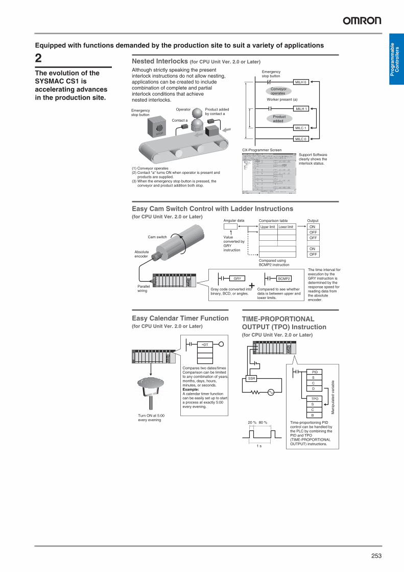
Baud rate increased from 38,400 bps to 57,600 bps for faster communications.Standard system protocol added for greater connectability with components and PLCs.•CompoWay/F Master•Host Link Master functions•Mitsubishi Computer Link Master
Wide Range of Applicable Protocols Allows for High Value-added ProgramsThe CS1 Series supports a wide range of serial communications protocols, such as Host Link, no-protocol, NT Link, peripheral bus, and more. These allow for high value-added programs such as MMI, communications, and data processing.
The Fastest Communications in the Industry with High-speed NT LinksCombine with one of the NS Series Programmable Terminals (NS8, NS10, or NS12) to enable connecting High-speed NT Links. Using NT Link terminology together with a communications speed of 115 Kbps provides high-speed response.
Enhanced Protocol Macro Functionality
Supports No-protocol Communications
(Serial Communications Units/Boards with Ver. 1.2 or later)
(Serial Communications Units/Boards with Ver. 1.2 or later)
Serial CommunicationsBoard
Serial CommunicationsUnit
No-protocol communications supported for Serial Communications Units and Serial Communications BoardsThis mode enables components to be connected to multiple communications ports using no-protocol communications.Serial port I/O instructions executable using no-protocol communications from Serial Communications Units and Serial Communications Boards (TXDU, RXDU, TXD, and RXD) are supported for CPU Units with Ver. 3.0 or later.
Serial Communications Configuration Example
Host Links No-protocolSending Host Link and
FINS commands
DeviceResponse
TXD instruction or RXD instructionusing CPU Unit's RS-232 port or Serial Communications Board
TXD instruction or RXD instructionusing Serial CommunicationsUnit
CPU UnitRS-232C Port
Data input from a bar code reader
Data output to printer
Reading and writing of I/O memory and operating modes
(ProgrammingConsole bus)
CX-ProgrammerCX-ProtocolCX-Motion
ASCII Unit Serial Communications UnitSerial Communications Board
CPU Unit
Host computer, etc.
Host Link
Programming Devices
Programming Console
Peripheral bus
NT Link
Protocol macros Protocol macros
Protocol macros
Programmable Terminal
Non-OMRON PLCs, etc.
Microcomputer, etc.
Commercially-available external device
Temperature controller, bar code reader, etc.
General-purpose protocol using BASIC in ASCII Unit
Commercially-available external device
Y201-EN2-03.book Seite 260 Donnerstag, 30. März 2006 1:52 13

261
Pro
gra
mm
able
C
on
tro
llers
Advanced management and resource inheritance providing powerful support for maintenance and operation
Office
Do
wn
load
Upload
PC Card Adapter
Memory Card
Production site
Programming Console
Modem
1. Remote programming/monitoring via modem (See note.)
Note: The same kind of programming and monitoring performed via normal Host Link is possible.
Ethernet
ModemHost Link
Phone line
3. Mail
2. Remote programming/monitoring via Host Link (See note.)
Remote Maintenance1. Program or monitor a remote PLC via a modem connection.2. Program or monitor a network PLC via a Host Link connection.3. Send e-mail for errors from PLCs connected to Ethernet.
Memory Cards for Data File ManagementUser programs, I/O memory, or system parameters can be converted to Windows-based files and stored in Memory Cards or in EM file memory in the CPU Unit. It is also possible to automatically read the user program and other data from the Memory Card to the CPU Unit at startup, replacing ROM operation. Change programs on-site using only a Memory Card and Programming Console, or use Memory Cards to store symbol tables or I/O comments. Connecting a Programming Device allows monitoring operations with ladder programs with comments. It is also possible to save and read data such as DM data to a Memory Card during operation, and the Memory Cards are ideal for operations such as saving quality data and reading recipes.
6The evolution of the SYSMAC CS1 is accelerating advances in the production site.
Y201-EN2-03.book Seite 261 Donnerstag, 30. März 2006 1:52 13

262 Programmable Controllers
In addition to applying read protection functions to the user program area and tasks, you can also protect against the transfer of user programs to a Memory Card.This prevents leaks of proprietary information by completely protecting against the reading of programs inside the PLC.
When an I/O Unit, a Special I/O Unit, or a CPU Bus Unit is malfunctioning, it is now possible to replace the faulty Unit while the system continues operating.This is particularly effective for systems that cannot be stopped when a problem has occurred in another part of the system.(This function requires a CS1D-CPU S CPU Unit, a CS1D-BC082 or CS1D-BI092 Backplane, and a CS1D-PA207R or CS1D-PD024 Power Supply Unit.)
CVM1/CV
C200HX/HG/HE
CS1
Easy replacement
CS1
Built-in flash memory User program Parameter area data
Battery-free operation with no Memory Card.
Internal Flash Memory-based Battery-free OperationFlash memory (non-volatile memory) is built into the new CS1's CPU Unit. User programs and system parameters (e.g., PC Setup and data link tables) are automatically saved to this flash memory. This means that the new CS1 can operate without a Memory Card and battery.
Boost Program Security by Keeping Part of It Hidden (for CPU Unit Ver. 2.0 or Later)
You can prevent access to special tasks by requiring the user to have a password to read them.
This allows you to hide crucial parts of the program.
By applying write protection, you can also prevent a user from inadvertently writing over the hidden part of the program. This provides additional protection for your program.
Easy Replacement of Existing ModelsPrograms designed for existing models (C200HX/HG/HE, CVM1, or CV-series PLCs) using the CX-Programmer can be converted for use with the new CS1. The following functions are available to make the conversion to the new CS1 even easier.
Replace Malfunctioning Units without Turning OFF the Power (Online Unit Replacement)
CV-CS address conversion instruction to convert programs designed for the CVM1/CV that include internal I/O memory addresses.C200HX/HG/HE: Region comparison (ZCP and ZCPL) instructions.
Reading possible
Reading possible
Write enabled
Write protection
Task 1
Task 2
Task 3
Use a password to prevent reading of only task 2.
CX-Programmer Ver. 4.0
Read protection
No transfer possible
CX-Programmer Ver. 4.0
Memory Card
Prevent Information Leaks from PLCs(for CPU Unit Ver. 2.0 or Later)
You can now stop specific nodes from writing over the network.By preventing unintentionally writes to the PLC while monitoring data over the network, you can prevent potential problems.
Write Protection from a Specific Node over the Network(for CPU Unit Ver. 2.0 or Later)
Read protection
Write protection
Faulty Unit
Remove the faulty Unit after stopping access to it.
Resume access after replacing the Unit.
CPUPS
(1) (2)
Crucial programming cannot be read.
Store All I/O Comments, Symbol Names, Rung Comments, and Other Information in CPU Unit Comment Memory
When downloading projects, the Memory Card, EM file memory, or comment memory (in the CPU Unit's flash memory) can be selected as the transfer destination for I/O comments, symbol names, rung comments, and other data. This enables data such as I/O comments, symbol names, and rung comments to be stored in the CPU Unit's internal comment
memory when a Memory Card or EM file memory are both not available. (PLC models: CS/CJ-series with unit version 3.0 or later only.)
(Unit Ver. 3.0 or later)
CX-Programmer Ver. 5.0 or higher required.
Y201-EN2-03.book Seite 262 Donnerstag, 30. März 2006 1:52 13
263
Pro
gra
mm
able
C
on
tro
llers
The CS1 Duplex System Boots the Reliability of Facilities and Equipment
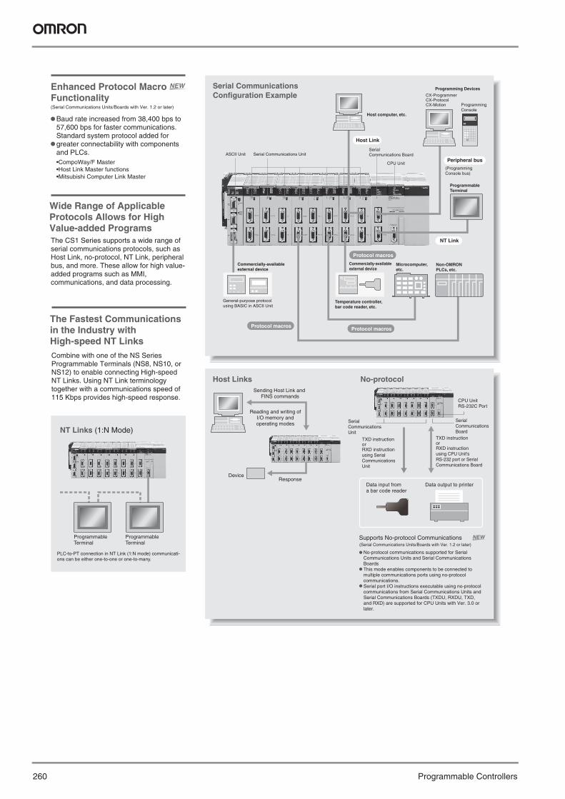
Hot Standby System Adopted for CPU Unit Duplexing
When a problem occurs in the CPU Unit, the system instantly switches control to the other CPU Unit, enabling continuous operation with minimal effect on the system.Because there is no need for special duplex programming, the design process is simple and design steps are reduced.
Online Unit ReplacementWith either a Duplex-CPU or Single-CPU CS1D System, Basic I/O Units, Special I/O Units, and CPU Bus Units can be replaced online while the system continues operation. Although operation will stop for the Unit being replaced, all other Units will continue operation.
Duplex operation is possible for any or all of the following: CPU Units, Power Supply Units, and Communications Units.
The system can also be configured with only one each of the CPU, Power Supply, and Communications Units. This lets you optimize the system cost by selecting the Units that you need. (The Duplex Unit must be used even when using only one each of the CPU, Power Supply, and Communications Units.)
Controller Link Unit
Ethernet UnitDuplex CPU Units
Controller Link Unit Ethernet Unit
Duplex Power Supply Units can be used, even with a Single-CPU System.
Duplex-CPU System
Single-CPU System
Duplex Communications Units can be used, even with a Single-CPU System.
Duplex Power Supply Units
During System Operation with Power Supplied
Unit replaced
Perform the online Unit replacement operation from the Programming Console or CX-Programmer.
Use duplex operation for the CPU Unit, power supply, or communications depending on system requirements for reliability, costs, and functionality. For example, use duplex operation for all of these for systems that must never go
down or use duplex operation for only the power supply (which has a relatively short service life). Just build in the redundancy required by the system.
7The evolution of the SYSMAC CS1 is accelerating advances in the production site.
Y201-EN2-03.book Seite 263 Donnerstag, 30. März 2006 1:52 13

264 Programmable Controllers
Initial and maintenance costs are reduced.
Duplex Ethernet for Greater Information Network Reliability
Monitor Connection Status to an Ethernet Network
Allows effective use of software assets.The same support software can be used in systems combining the CS1 and CJ1 Series, and all software programs and data are compatible.Their application and reuse are extremely easy.There is also no need for ladder programs for duplexing. This means that when converting an existing system to a Duplex System, there is almost no need to revise ladder programs.
Complete compatibility among Units.The CS1D Duplex System is fully compatible with the I/O Units of the entire CS Series. Accordingly, the same Units and materials can be used for restoring the system and conducting maintenance. There is no need to purchase different Units and materials for each system, making the CS1D Duplex System highly economical.(C200H Units, however, cannot be used with CS1D PLCs. Refer to user documentation for details.)
Unit failed.
Break
Line backed up with loopback
Node backed up.
Network participation
list
Network participation
list
Ethernet networkEthernet network
Either the CS1W-CLK12-V1 or CS1W-CLK52-V1 is required for a Duplex Controller Link network.
The complex programming required in previous applications for duplex communications with Ethernet is eliminated.
Previously, twice the memory was required to implement data links for two Controller Link Units, and it was necessary to determine which data could be used.
Just create the data links for one Controller Link Unit to eliminated wasted data memory. The Duplex Controller Link Units share the data links.
Two sets of the same data link areas were required and program-ming was required to select the areas.
Programming to determine destination
Tried first.
SEND
PLC automatically determines destination.
Destination
Other Unit tried if no response from first Unit.
SEND
Previously it was necessary to program operation for both Ethernet Units.
Just program the operation as if for one Ethernet Unit, and the PLC will determine the destination and send the message.
SEND
The CS1D-ETN21D and CS1D CPU Unit version 1.1 or higher are required for a duplex Ethernet network.
Increase the Reliability of Information with Duplex Networks
Program without Being Concerned with Duplex Operation
With redundant networks and Communications Units, communications will continue even if a network line is broken or one of the Communications Units fails. The communications path is automatically selected for each
communications process (as opposed to switching the entire line), to enable creating a highly reliable network even against a network line broken in more than one location.
The connection status for each line is stored in the CIO Area words allocated in the CPU Unit. This enables the ladder program or host to quickly detect faulty nodes or lines to make maintenance easier.
Duplex Networks between PLCs with Controller LinkEven if one Unit fails, the other Unit will back it up and continue communications. Even if a line breaks, a loopback will be used to maintain the network.
Participation list showing node A is
not connected.
Participation list showing node B is not
connected.
No special programming is required to use duplex communications with the CS1D, making it simple to design programs for duplex systems.
Controller Link networks enable allocating data link areas without wasting memory.
This path is automatically selected.
This path is automatically selected.
This path is automatically selected.
Ethernet
Ethernet
Unit failure
Y201-EN2-03.book Seite 264 Donnerstag, 30. März 2006 1:52 13
265
Pro
gra
mm
able
C
on
tro
llers8
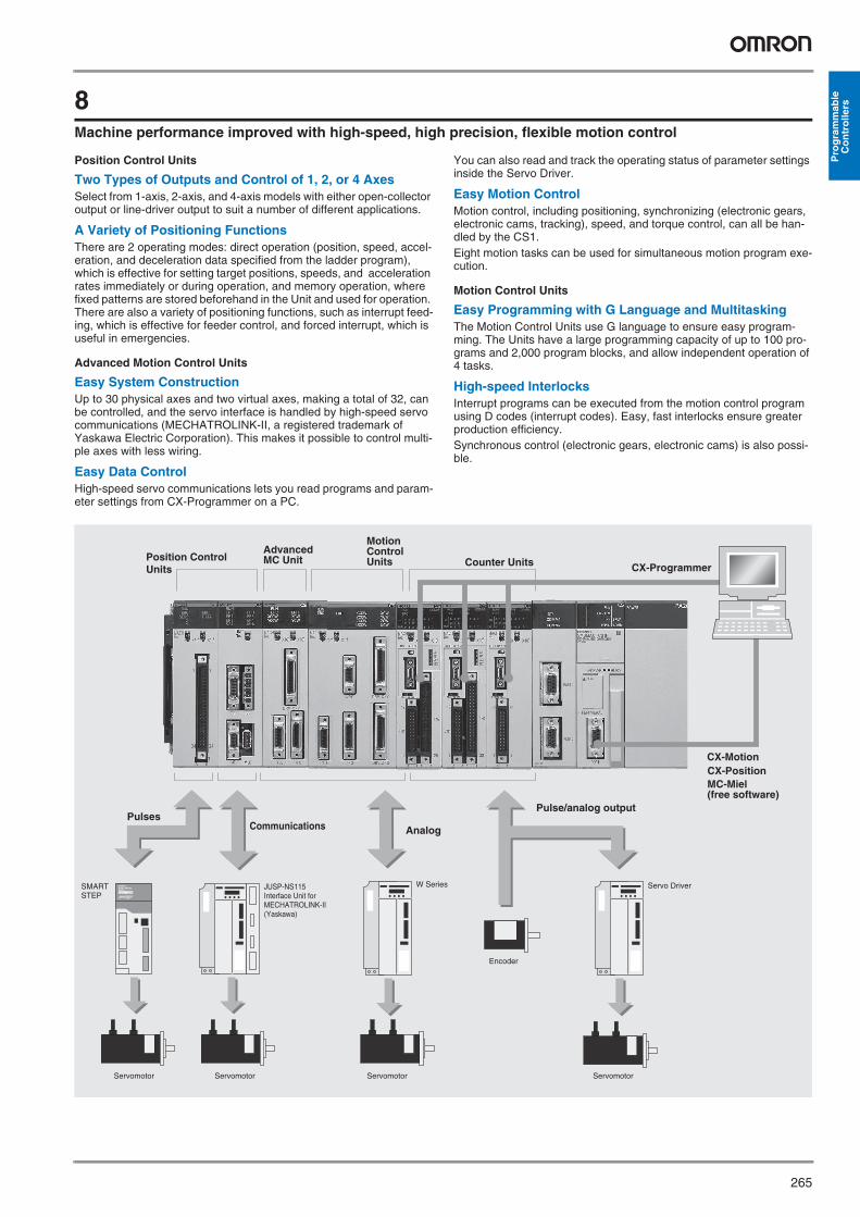
Machine performance improved with high-speed, high precision, flexible motion control
Position Control Units
Two Types of Outputs and Control of 1, 2, or 4 AxesSelect from 1-axis, 2-axis, and 4-axis models with either open-collector output or line-driver output to suit a number of different applications.
A Variety of Positioning FunctionsThere are 2 operating modes: direct operation (position, speed, accel-eration, and deceleration data specified from the ladder program), which is effective for setting target positions, speeds, and acceleration rates immediately or during operation, and memory operation, where fixed patterns are stored beforehand in the Unit and used for operation. There are also a variety of positioning functions, such as interrupt feed-ing, which is effective for feeder control, and forced interrupt, which is useful in emergencies.
Advanced Motion Control Units
Easy System ConstructionUp to 30 physical axes and two virtual axes, making a total of 32, can be controlled, and the servo interface is handled by high-speed servo communications (MECHATROLINK-II, a registered trademark of Yaskawa Electric Corporation). This makes it possible to control multi-ple axes with less wiring.
Easy Data ControlHigh-speed servo communications lets you read programs and param-eter settings from CX-Programmer on a PC.
You can also read and track the operating status of parameter settings inside the Servo Driver.
Easy Motion ControlMotion control, including positioning, synchronizing (electronic gears, electronic cams, tracking), speed, and torque control, can all be han-dled by the CS1. Eight motion tasks can be used for simultaneous motion program exe-cution.
Motion Control Units
Easy Programming with G Language and MultitaskingThe Motion Control Units use G language to ensure easy program-ming. The Units have a large programming capacity of up to 100 pro-grams and 2,000 program blocks, and allow independent operation of 4 tasks.
High-speed InterlocksInterrupt programs can be executed from the motion control program using D codes (interrupt codes). Easy, fast interlocks ensure greater production efficiency.Synchronous control (electronic gears, electronic cams) is also possi-ble.
ServomotorServomotorServomotorServomotor
W SeriesSMARTSTEP
Servo Driver
Encoder
CX-MotionCX-Position
CX-Programmer
Customizable Counter UnitsPosition Control
Units
Motion Control Units
PulsesAnalog
Pulse/analog output
Communications
JUSP-NS115 Interface Unit for MECHATROLINK-II (Yaskawa)
MC-Miel (free software)
Advanced MC Unit
ServomotorServomotorServomotorServomotor
W SeriesSMARTSTEP
Servo Driver
Encoder
CX-MotionCX-Position
CX-ProgrammerCounter UnitsPosition Control Units
Motion Control Units
PulsesAnalog
Pulse/analog output
Communications
JUSP-NS115 Interface Unit for MECHATROLINK-II (Yaskawa)
MC-Miel (free software)
Advanced MC Unit
Y201-EN2-03.book Seite 265 Donnerstag, 30. März 2006 1:52 13

266 Programmable Controllers
Smart Process ControlOMRON PLC-based Process Control brings Major Innovations to Process Automation
PLC-based Process ControlPLC-based Process Control
Ethernet/Controller Link
Touch Panels
Operation, Monitoring, and Data Logging
PLC (CS-series) PLC (CS1 Duplex)
User Application
Provides an exceptionally open environment with PLC-basedprocess control to advance standardization and IT integration ofthe process control system.
HMI Software
NS-series PT
CS1D Process-control CPU UnitDuplex Process-control CPU Unit can help reduce riskinsystems that must not stop.
Process I/O UnitsAnalog I/O Units are available for diverse functions such as Isolators, power supplies, and signal conversion.
Loop Control Board/UnitCondenses DCS functionsin a compact Unit and enables function-block programming.
CX-Process ToolFunction blocks can bepasted into windows andgraphic programming canbe perfomed by arrangingblocks with the mouse.
Special HMI software CX-Process Monitor Plus
Commercially available HMI software HMI software compatible with FinsGateway
Function block programmingSequence programming using either step ladders or sequence tablesA direct link to HMI products
DCS functionality in a PLCAnalog Units with signal conversion functionsA scaleable system configuration
Duplex operation supportedComplete maintenance functions
9The evolution of the SYSMAC CS1 is accelerating advances in the production site.
Y201-EN2-03.book Seite 266 Donnerstag, 30. März 2006 1:52 13

267
Pro
gra
mm
able
C
on
tro
llers
Diversified Loop Control is even easier to use.Programming becomes even easier with function-block programming.
PID1
PID2
Temperature
Temperature
Steam
Split conversion
PV1
PV2
MV2
MV1
RSP1
With Function Blocks:
Isolated-type Ai4 Terminal
Isolated-type Ao4 Terminal
Example: Cascade Control (Heating and Cooling)
Analog Input Unit
Analog Output Unit
Loop Control Unit/Board
Heat exchange
Cooling water
Drain
Packed with complete DCS functionality, the LCBs/LCUs are programmed with function blocks designed specifically for process control. Similar to preparing a flow sheet, function blocks are pasted and connections made using a graphic interface. A wide array of control methods, from basic PID control to cascade and feed-forward control, are possible.
PLC-based Process Control Application Examples
SYSMAC CS1 PLC with advanced Loop Control Board
EthernetEthernet
Personal computer
HMI software
Personal computer
HMI software
A
B
A
B
C
SYSMAC CS1 Duplex(CS1D Process-control CPU Unit)
Flowrate control (blending PID control)
Reaction control
Flowrate Control outputs
Motor
Motor
Mot
or
Motor Motor
Materials tanks
Intermediate tank
Product tanks
Drying equipment
In-line Blending in a Food Plant Batch Control in a Chemical Plant
Split ConversionBasic PID
Y1
Y2
Y3
Y4
PID2
PID1
SP
Y1
MV
PV
PVE
RSP
MIE
MVE
Y1
Y2
X1
Basic PID
SP
Y1
MV
PV
PVE
RSP
MIE
MVE
Y1
Y2
Y3
Y4
Y201-EN2-03.book Seite 267 Donnerstag, 30. März 2006 1:52 13

268 Programmable Controllers
DeviceNet Creates Many Advantages for Development and Design, for Production and Startup, and for Operation and Maintenance
Ethernet
Configurator
SYSMAC CS-series DeviceNet UnitCS1W-DRM21-V1
Programmable Terminal
NT631
DeviceNet Option Unit for OMNUC W Series AC Servo DriversR88A-NCW152-DRT
DeviceNet Interface UnitNT-DRT21
Smart Slave
Environment-resistive TerminalsDRT2-HD16C (-1)DRT2-ID08C/OD08C (-1)
DeviceNet Wireless LinkWD30-ME
Smart Slave
Remote I/O TerminalsDRT2-ID16/OD16 (-1)XWT-ID16/OD16 (-1)XWT-ID08/OD08 (-1)
Smart Slave
Analog I/O TerminalDRT2-AD04/DA02DRT2-AD04H
Smart Slave
Transistor Remote I/O Terminals with 3-tier Terminal BlockDRT2-ID16(-1)/OD16(-1)/MD16TA(-1)
Smart Slave
Transistor Connector Terminals with MIL ConnectorsDRT2-ID32ML(-1)/OD32ML(-1)/MD32ML(-1)
Smart Slave
Relay Output Remote I/O TerminalDRT2-ROS16
Smart Slave
Sensor Connector TerminalsDRT2- D16S (-1)
Transistor Screwless Clamp TerminalsWithout detectionfunction DRT2-ID32SL(-1)/OD32SL(-1)/MD32SL(-1)With detection functionDRT2-ID32SLH(-1)/OD32SLH(-1)/MD32SLH(-1)
Smart Slave
Temperature Input TerminalsDRT2-TS04TDRT2-TS04P
PCB Terminals (MIL connector)DRT2- D32B(-1)/DRT2- D32BV(-1)
10The evolution of the SYSMAC CS1 is accelerating advances in the production site.
Y201-EN2-03.book Seite 268 Donnerstag, 30. März 2006 1:52 13

269
Pro
gra
mm
able
C
on
tro
llers
RS-232C
Advantages in Development and Design
Advantages in Production and Startup
Hardware Advantages
Software Advantages
CompoBus/S
Many compatible components for more options and easier system construction.No restrictions on Master, enabling equipment modularization at the Slaves.
Hardware AdvantagesAssembly time shortened by standardization and modularization.Number of work hours reduced by less wiring.Simple wiring checking process to help prevent wiring mistakes.Simple implementation of distributed equipment manufacturing.Distributed I/O for more compact control panels and equipment.
Advantages in Operation and MaintenanceOperation Advantages
Recipe control quickly improves yields.Preventative maintenance to avoid system shutdowns and increase operating rates.Simple layout changes.Lines can be constructed for modular replacement.
Maintenance AdvantagesEasy identification of fault locations reduces time to restore operation.A wide variety of data can be collected from components, aiding preventative maintenance.Simple plug-and-play replacement using connectors.Online replacement for maintenance without stopping the system.
Simple software standardization with profile specified for each component.Open network construction eliminates the need to consider communications protocols, allowing program development using ladder diagrams only.
Startup AdvantagesSimple re-assembly at delivery site.Simple settings and communications work, shortening startup time.Establishing communications with components with plug-and-play simplicity.Simple identification of faults with complete monitoring tools.
High-function General-purpose Inverter (with DeviceNet Communications Card)3G3RV
DeviceNet Wireless LinkWD30-SE
Visual Sensor ControllerF150-C10E-3-DRT
Temperature Input TerminalsDRT2-TS04T/TS04P
MULTIPLE I/O TERMINAL
Waterproof TerminalsDRT1- D CL (-1)
DeviceNet Communications Unit for Fiber AmplifiersE3X-DRT21
Smart Slave
DeviceNet Communications Unit for Modular Temperature ControllersE5ZN-DRT
SYSMAC CQM1H/CQM1DeviceNet I/O Unit(16 inputs and 16 outputs)CQM1-DRT21
Multi-function Compact Inverter(with DeviceNet Communications Unit)3G3MV
RS-232C UnitDRT1-232C2
Programmable SlaveCPM2C-S100C-DRTCPM2C-S110C-DRT
Digital Panel MetersK3HB-DRT
Digital Temperature ControllersE5ER-DRT
Y201-EN2-03.book Seite 269 Donnerstag, 30. März 2006 1:52 13

270 Programmable Controllers
Greater Compatibility with PLCsMultilingual Globalization for Greater Machine Flexibility
NS-series Programmable Terminal
Memory Card (Sold separately.)(HMC-EF )
1:N NT Link
RS-232C
Serial port A or B
CS-/CJ-series PLC
Ladder Monitor (Started from System Menu.)
CX-Programmer CXT file
I/O comment extraction tool
Ladder Monitor application
I/O comment file for Ladder Monitor
Install
0000.00
SW1 SW2 ER LAMP01
0000.01 CF003 0002.00
Note: CS- and CJ-series PLCs connected via a 1:N NT Link to serial port A or B on an NS-series Programmable Terminal can be monitored.
CD-ROM
Programming Console FunctionProgramming Console functionality is displayed when Programming Console is selected as the operating mode.
Ladder Monitor FunctionSave the NS-EXT01 Ladder Monitor system program on a Memory Card (the NS-EXT01 is sold separately) and install the Memory Card to enable monitoring of a ladder program (I/O bit status monitor, address/instruction search, multiple I/O bit monitor, etc.) being executed in a CS/CJ-series PLC connected by a serial connection. It is also possible to display I/O comments created with the CX-Programmer.
Programming Console FunctionIf a Programming Console is selected as the operating mode, a Programming Console is displayed on the Ladder Monitor screen. Operating methods are exactly the same as for a CS-/CJ-series Programming Console. Timer set values can be changed, bit addresses can be added or changed, and many other operations can be performed on-site, all from the screen of the NS-series PT. The
functionality of the Ladder Monitor and Programming Console can be used for primary on-site response without a personal computer.
Ethernet
Controller Link
Personalcomputer
NS-seriesPT
NS-seriesPT
NS-series PT NS-series PT
CS/CJ-series PLC
CS/CJ-series PLC
CS/CJ-series PLC
CS/CJ-series PLC
Direct access
Direct access
Direct access
Direct access
Direct access
Direct access
Switch Box FunctionThe Switch Box Function has been added to the NS-series Programmable Terminals. The Switch Box Function can be used to monitor the status of each bit in a word or a combination of user-selected bits organized like a ladder program section. The Switch Box Function makes it possible to perform basic troubleshooting on the factory floor even without a computer.
(Using NS-EXT01-V2 Ladder Monitor)
Connect to Ethernet or, for High-speed Communications with PLCs, to Controller Link. PT Network Capabilities Are More Powerful than Ever Before.
The Switch Box provides the following functions:
Switching between Monitoring Contiguous or Noncontiguous Bits and Contiguous WordsThe I/O memory monitor function monitor words or combinations of specified bits. Bit/word comments are imported from the CX-Programmer.
Register the Words or Bit Combinations To Be Monitored by GroupComments can be input for individual groups, e.g., so that the operating conditions of words or bits can be described in text.
Same User Interface as the Switch Box Utility for Personal ComputersThe same displays can be monitors in the office on a personal computer and onsite at the NS-series PT, making discussions clearer.
11The evolution of the SYSMAC CS1 is accelerating advances in the production site.
Y201-EN2-03.book Seite 270 Donnerstag, 30. März 2006 1:52 13

271
Pro
gra
mm
able
C
on
tro
llers
NS Series: Easily Create Multilingual Screens on Your Windows System
NS Series: Easily Create Multilingual Screens on Your Windows System
Translation Agency
NS-Designer: Source languagescreens
CSV file containingsource language
Export (See note.)
Import (See note.)
Note: Refer to the operation manual for NS-Designer for information on importing and exporting.
S-Designer: Source language
Other language
CSV file containingsource and other language
CSV file containing source and other language
Switch labels
Machine Vendor
Multilingual Version to Develop for Various Demands
Create Chinese or Korean screens on your Windows system.Support multiple languages with the same screen data.Create the source language labels and let suppliers handle the other languages.
Multi-language Input with Japanese WindowsWhen Windows 2000 or XP is being used, Simplified Chinese, Traditional Chinese, Korean, and other language text can be input in NS-Designer. Select the desired language with Global IME to input a different language. You can also use this program together with RAKURAKU CHUUGOKUGO and RAKURAKU KANKOKUGO (Chinese and Korean input systems) to convert Japanese to Chinese and Korean.
Label Switching to Select from Multiple Languages Up to 16 groups of labels (labels 0 to 15) can be registered for functional objects such as buttons, lamps, labels, and alarm settings. (Each label can correspond to a different language, for example, label 0 = Japanese, label 1 = Simplified Chinese, label 2 = Korean, label 3 = English, etc.)Once all of the labels have been input in each language with the multilingual input function, all of the labels can be switched to a different language at once just by specifying the corresponding label number from the PLC.
Use Screen Import/Export Functions to Separate Translation WorkProperty information for labels and other objects in screen data created using the NS-Designer can be exported to CSV files. These files can be edited in Excel and other programs. The screens can be created in the source language and then labels and other text exported to CSV files, which can be sent to translators for conversion to other languages. The translated CSV files can then be imported to automatically input the desired languages into labels.
Example: The label switch function can be used to switch between English and Simplified Chinese.
Ladder program(From CX-Programmer through NS-series PT to PLC)
Screen data or Data in Memory Card(From CX-Designer through PLC to NS-series PT)SPMA
Ladder programs can be monitored or transferred from the CX-Programmer through the NS-series PT to PLCs that are connected to the PT in series or via a network.
You may want to transfer screens to a PT through the PLC without changing computer connections or transfer a ladder program to the PLC through the PT by using the Ethernet or Controller Link.
NS-series PTs provide Smart Active Parts (SAP library) enabling direct access to data in various devices.
NS12-V112-inch Model
NS10-V110-inch Model
NS8-V18-inch Model
For more information on this software, refer to the following site or send email to the following address.URL: http://www.omronsoft.co.jp/SP/E-mail: [email protected]
CS/CJ series PLC
CS/CJ series PLCSerial Peripheral bus
Personal computer
Personal computer
Peripheral (or RS-232C) NS-series PT
NS-series PT
RS-232C
Ethernet
Controller Link
CS/CJ series PLC
NT Link
Serial
NS-series PT
NS-series PT
Simply paste into the screen.
Color and size can also be
changed.
NS-series PT
Access devices without programs
Example: RS-232C
Example: Ethernet
Example: DeviceNet
PLC System Components
Smart Active Parts (SAP library)
NT Link
Serial
NT Link
Serial
(Tool bus)
Screen transfer from the Controller Link is supported from version 6.
NS5-V15-inch Model
Y201-EN2-03.book Seite 271 Donnerstag, 30. März 2006 1:52 13

272 Programmable Controllers
RDYEXECCOMM
PORT
LCB01
C200HW-PA@@@/-PD@@@CS1D-PA@@@/-PD@@@
CS1G-CPU@@HCS1D-CPU@@H/P/S
CS1W-SCB21CS1W-SCB41
CS1W-LCB01/05
HMC-EF172/372/672
CS1W-BI@@@(3, 5, 8, or 10 slots) C200HW-PA@@@/-PD@@@
CS1D-PA@@@/-PD@@@
CS1W-II102
CV500-CN@@2
CS1W-IC102
C200HW-PA204/204S/204R/209R/PD024
CS1W-SCU21-V1 CS1W-DRM21-V1CS1W-CLK21/12/52-V1 CS1W-MCH71CS1W-ETN21CS1D-ETN21DCS1W-LC001
SYSMAC CS1A Complete Lineup of Units for Optimal Control.
CPU Rack
I/O Control Unit
Long-distanceExpansionConnecting Cable
CS1 I/OConnecting Cable
CS1 to C200HI/O Connecting Cable
C200H I/OConnecting Cable
CS1 Expansion Rack
C200H Expansion Rack
C200HX/HG/HEExpansion I/O Backplane
Power Supply Units
CS1 Expansion Backplane
I/O InterfaceUnit
CPU Backplane
Loop ControlBoard
CPU Units Power SupplyUnits
TerminatingResistor
Memory Card
Power Supply Units
CS1 CPU Bus Units
C200H Expansion Rack
Serial Communi-cations Board
CV500-TER01(Two provided with CS1W-IC102)
Note: This is for CS1 Units only. UseCS1W-BI@@3 for C200H Units.
C200H-CN@@1(30 cm, 70 cm, 2 m, 5 m, 10 m)
CS1W-CN@@1(30 cm, 70 cm, 2 m, 3 m, 5 m, 10 m, 12 m)
CS1W-CN@@3(30 cm, 70 cm, 2 m, 3 m, 5 m, 10 m, 12 m)
Note: C200H Unitscannot be used inlong-distanceexpansion.
C200HW-BI@@1(-V1)(3, 5, 8, or 10 slots)
CS1W-BC@@@(2, 3, 5, 8, or 10 slots)
CS1D-BC@@@(5 slot duplex CPU, 8 slot single CPU)Note: Expansion is not possible for 2-slot Backplanes. These Backplanes are for CS1 Units only.Use a CS1W-BC@@3 Backplane for C200H Units.
Controller Link Unit Motion Controller UnitEthernet UnitLoop Control Unit
DeviceNet Unit
CS1W-PRM21
PROFIBUS-DP Unit
(50 m max.)
Serial Commu-nications Unit
Y201-EN2-03.book Seite 272 Donnerstag, 30. März 2006 1:52 13

273
Pro
gra
mm
able
C
on
tro
llers
C200H-TM001 CS1W-SF200
P207Basic I/O Units
Special I/O Units
96 ptsOutput Unit:CS1W-OD29@
96 ptsInput Unit:CS1W-ID291
16 ptsOutput Unit:CS1W-OD21@
32 ptsOutput Unit:CS1W-OD23@
64 ptsOutput Unit:CS1W-OD26@
16 ptsInput Unit:CS1W-ID211
32 ptsInput Unit:CS1W-ID231
64 ptsInput Unit:CS1W-ID261
32 inputs/32 outputsI/O Unit:CS1W-MD26@
32 inputs/32 outputsTTL I/O Unit:CS1W-MD561(available soon)
48 inputs/48 outputsI/O Unit:CS1W-MD29@/561
16 ptsAC Input Unit:CS1W-IA111/211
8 ptsTriac Output Unit:CS1W-OA201
16 ptsTriac Output Unit:CS1W-OA211
8 pts (independent)Relay Output Unit:CS1W-OC201
16 ptsRelay Output Unit:CS1W-OC211
Note: C200H Basic I/O Units and High-density I/O (Group-2) Units can also be used.
Interrupt functionsupported on CPURack only.(Two Unitsmountable onCPU Rack.)
16 ptsCS1W-INT01
16 ptsCS1W-IDP01
Process I/O UnitCS1W-P@@@(-V1)
Temperature Sensor UnitsC200H-TS@@@
Temperature Control UnitsC200H-TC@@@C200H-TV@@@
PID Control UnitsC200H-PID0@
Position Control Units*C200HW-NC@@@
CAN(open) UnitC200HW-CORT21-V1
PROFIBUS-DP Master UnitC200HW-PRM21
PROFIBUS-DP I/O Link UnitC200HW-PRT21
Position Control UnitCS1W-NC@@@
2-axis Motion Control Unit*C200H-MC221
4-axis Motion Control Unit*C200H-MC402E
ID Sensor Units*C200H-IDS@@
ASCII Units*C200H-ASC@@
GP-IB Interface UnitCS1W-GPI01
DeviceNet I/O Link UnitC200HW-DRT21
CompoBus/S Master UnitC200HW-SRM21-V1
High-speed Counter Units*C200H-CT@@@
Analog Input UnitCS1W-AD041-V1/081-V1
Analog Output UnitCS1W-DA041/08V/08C
Analog I/O UnitCS1W-MAD44
Motion Control UnitCS1W-MC221/421
High-speed CounterUnitCS1W-CT021/041
SSI input unitCS1W-CTS21
The following restrictions exist in data transfers with the CPU Unit for bit and DM Area specifications for the C200H Special I/O Units marked with asterisks, as well as in data transfers programmed from these Units. Refer to CS-series PLC Operation manuals for details. • Converting data for the CPU Unit using bit and DM Area specifications (source/destination area type and addresss designation). • Exchanging data with the CPU Unit using instructions (PC READ, PC WRITE, etc.) in the C200H Special I/O Unit program.
Note: HMC-372/672 Memory Cards cannot be used with CS1G-CPU@@H, CS1H-CPU@@H, CJ1G-CPU@@H, or CJ1H-CPU@@H CPU Units prior to Lot No. 02108 (manufactured priorto January 8, 2002, nor with NS-7-series PTs prior to Lot. No. 0852 (manufactured prior to May 8, 2002). Check lot numbers before ordering.
CS1 Special I/O Unit
C200H Basic I/O Unit
Interrupt Input Unit Analog Timer Unit High-speed Input Unit
Safety Relay Unit
C200H Special I/O Unit
ID Sensor Units*CS1W-V600C11/-V600C12
Y201-EN2-03.book Seite 273 Donnerstag, 30. März 2006 1:52 13

274 Programmable Controllers
CS1H/G-CPU@@H
CS1-series
With the CS1 PLCs, Memory Cards and specified ranges of the EM Area can be used as file memory. File memory can be used to store the entire user program, I/O memory contents, and/or parameter area contents.
Note: Memory Card Adapter: HMC-AP001 (The Memory Card Adapter can be used to mount Memory Cards in PC card slots to use the Cards on a personal computer.)
Inner Board CompartmentAn Inner Board can be mounted here.
Peripheral Port
RS-232C Port
Indicators
Memory Card Indicators
Memory Card Power Supply Switch
Memory Card Eject Button
Memory Card Connector
Memory Card (See note.)
The MCPWR indicator lights green when power is being supplied. The BUSY indicator lights orange when the Memory Card is being accessed.
The Memory Card power supply switch is pressed to turn OFF power before removing the Memory Card.
Press the Memory Card eject button to remove the Memory Card.
The RS-232C port connects Peripheral Devices other than Programming Consoles, such as host computers, general-purpose external devices, and Program-mable Terminals.
The peripheral port connects Programming Devices, such as a Programming Console or host computer.
File memory Memory type Capacity ModelFlash memory 30 MB HMC-EF372
64 MB HMC-EF672
RAM EM Area capacity of CPU Unit (Max. capacity for CS1H-CPU67: 832 KB).
From the specified bank in the EM area of I/O memory to the last bank (specified in PC Setup).
Memory Cards
EM File Memory
EM areaBank 0Bank n
Bank C
EM File Memory
Y201-EN2-03.book Seite 274 Donnerstag, 30. März 2006 1:52 13

CS1-series 275
Pro
gra
mm
able
C
on
tro
llersSpecifications
CPU Units
Note: The available data memory capacity is the sum of the Data Memory (DM) and the Extended Data Memory (EM).
Note: 1. A Loop Control Board cannot be mounted in CS1D-CPU@@D, use CS1D-CPU@@P instead. A Serial communications Board cannot be mounted in CS1D-CPU@@P.
Common Specifications
Note: A max. of 10 or 16 C200H Special I/O Units can be used depending on the CPU Unit. Some I/O Units are Special I/O Units.
Model I/O bits Program ca-pacity
Data memory ca-pacity (See Note.)
LD instruction pro-cessing speed
Built-in ports Options
CS1H-CPU67HCS1D-CPU67HCS1D-CPU67SCS1D-CPU67P
5,120 bits (Up to 7 Expansion Racks)
250 kSteps 448 kWords 0.02 µs Peripheral port and RS-232C port.
Memory CardsInner Board such as Serial Communications Board, Loop Control Board (See note 1.)CS1H-CPU66H 120 kSteps 256 kWords
CS1H-CPU65HCS1D-CPU65HCS1D-CPU65SCS1D-CPU65P
60 kSteps 128 kWords
CS1H-CPU64H 30 kSteps 64 kWordsCS1H-CPU63H 20 kStepsCS1G-CPU45H 5,120 bits
(Up to 7 Expansion Racks)60 kSteps 128 kWords 0.04 µs
CS1G-CPU44HCS1D-CPU44S
1,280 bits (Up to 3 Expansion Racks)
30 kSteps 64 kWords
CS1G-CPU43H 960 bits (Up to 2 Expansion Racks)
20 kStepsCS1G-CPU42HCS1D-CPU42S
10 kSteps
Item SpecificationControl method Stored programI/O control method Cyclic scan and immediate processingProgramming Ladder diagramInstruction length 1 to 7 steps per instructionLadder instructions Approx. 400 (3-digit function codes)Execution time Basic instructions: 0.02 μs min., Special instructions: 0.04 μs min.Function Blocks (CPU Ver. 3.0 or higher) Languages supported for use in function block programming: Ladder program language and IEC 61131-3 Structured Text.Number of tasks 288 (256 of which are also used as interrupt tasks)
Cyclic tasks are executed each cycle and are controlled with TKON(820) and TKOF(821) instructions.The following 4 types of interrupt tasks are supported: Power OFF tasks:1 max., Scheduled interrupt tasks: 2 max., I/O interrupt tasks: 32 max., External interrupt tasks: 256 max.
Interrupt types(not applicable for CS1D CPUs)
Scheduled Interrupts:Interrupts generated at a time scheduled by CPU Unit’s built-in timer.I/O Interrupts:Interrupts from Interrupt Input Units.Power OFF Interrupts:Interrupts executed when CPU Unit’s power is turned OFF.External I/O Interrupts:Interrupts from Special I/O Units, CS1 Special Units, or Inner Board.
CIO (Core I/O) Area(The CIO Area can be used as work bits if not used as shown here.)
I/O Area 5,120: CIO 000000 to CIO 031915 (320 words from CIO 0000 to CIO 0319)Setting of first rack words can be changed from default (CIO 0000) so that CIO 0000 to CIO 0999 can be used. I/O bits are allocated to Basic I/O Units, such as CS1 Basic I/O Units, C200H Basic I/O Units, and C200H Group-2 High-density I/O Units.
Link Area 3,200 (200 words): CIO 10000 to CIO 119915 (words CIO 1000 to CIO 1199)Link bits are used for data links and are allocated to Units in Controller Link Systems and PC Link Systems.
CS1 CPU Bus Unit Area
6,400 (400 words): CIO 150000 to CIO 189915 (words CIO 1500 to CIO 1899)CS1 CPU Bus Unit bits store operating status of CS1 CPU Bus Units. (25 words per Unit, 16 Units max.)
Special I/O Unit Area 15,360 (960 words): CIO 200000 to CIO 295915 (words CIO 2000 to CIO 2959)Special I/O Unit bits are allocated to CS1 Special I/O Units and C200H Special I/O Units. (See Note.)(10 words per Unit, 96 Units max.) The maximum number of slots, however, is limited to 80 including expansion slots, so maximum number of Units is actually 80.)Note: Some I/O Units are classified as Special I/O Units.
Inner Board Area 1,600 (100 words): CIO 190000 to CIO 199915 (words CIO 1900 to CIO 1999)Inner Board bits are allocated to Inner Boards. (100 I/O words max.)
SYSMAC BUS Area 800 (50 words): CIO 300000 to CIO 304915 (words CIO 3000 to CIO 3049)SYSMAC BUS bits are allocated to Slave Racks connected to SYSMAC BUS Remote I/O Master Units. (10 words per Rack, 5 Racks max.)
Y201-EN2-03.book Seite 275 Donnerstag, 30. März 2006 1:52 13
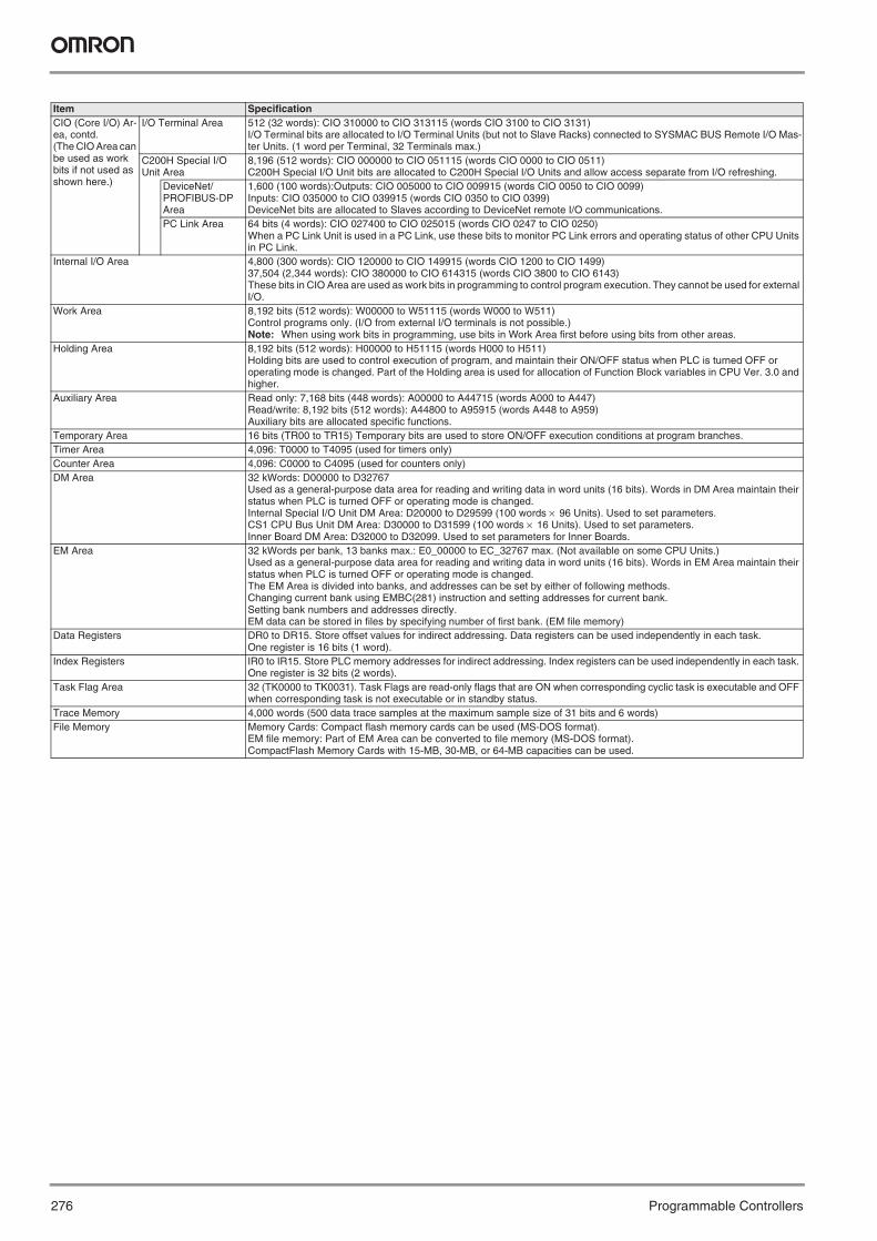
276 Programmable Controllers
Item SpecificationCIO (Core I/O) Ar-ea, contd.(The CIO Area can be used as work bits if not used as shown here.)
I/O Terminal Area 512 (32 words): CIO 310000 to CIO 313115 (words CIO 3100 to CIO 3131)I/O Terminal bits are allocated to I/O Terminal Units (but not to Slave Racks) connected to SYSMAC BUS Remote I/O Mas-ter Units. (1 word per Terminal, 32 Terminals max.)
C200H Special I/O Unit Area
8,196 (512 words): CIO 000000 to CIO 051115 (words CIO 0000 to CIO 0511)C200H Special I/O Unit bits are allocated to C200H Special I/O Units and allow access separate from I/O refreshing.
DeviceNet/PROFIBUS-DP Area
1,600 (100 words):Outputs: CIO 005000 to CIO 009915 (words CIO 0050 to CIO 0099)Inputs: CIO 035000 to CIO 039915 (words CIO 0350 to CIO 0399)DeviceNet bits are allocated to Slaves according to DeviceNet remote I/O communications.
PC Link Area 64 bits (4 words): CIO 027400 to CIO 025015 (words CIO 0247 to CIO 0250)When a PC Link Unit is used in a PC Link, use these bits to monitor PC Link errors and operating status of other CPU Units in PC Link.
Internal I/O Area 4,800 (300 words): CIO 120000 to CIO 149915 (words CIO 1200 to CIO 1499)37,504 (2,344 words): CIO 380000 to CIO 614315 (words CIO 3800 to CIO 6143)These bits in CIO Area are used as work bits in programming to control program execution. They cannot be used for external I/O.
Work Area 8,192 bits (512 words): W00000 to W51115 (words W000 to W511)Control programs only. (I/O from external I/O terminals is not possible.)Note: When using work bits in programming, use bits in Work Area first before using bits from other areas.
Holding Area 8,192 bits (512 words): H00000 to H51115 (words H000 to H511)Holding bits are used to control execution of program, and maintain their ON/OFF status when PLC is turned OFF or operating mode is changed. Part of the Holding area is used for allocation of Function Block variables in CPU Ver. 3.0 and higher.
Auxiliary Area Read only: 7,168 bits (448 words): A00000 to A44715 (words A000 to A447)Read/write: 8,192 bits (512 words): A44800 to A95915 (words A448 to A959)Auxiliary bits are allocated specific functions.
Temporary Area 16 bits (TR00 to TR15) Temporary bits are used to store ON/OFF execution conditions at program branches.Timer Area 4,096: T0000 to T4095 (used for timers only)Counter Area 4,096: C0000 to C4095 (used for counters only)DM Area 32 kWords: D00000 to D32767
Used as a general-purpose data area for reading and writing data in word units (16 bits). Words in DM Area maintain their status when PLC is turned OFF or operating mode is changed.Internal Special I/O Unit DM Area: D20000 to D29599 (100 words × 96 Units). Used to set parameters.CS1 CPU Bus Unit DM Area: D30000 to D31599 (100 words × 16 Units). Used to set parameters.Inner Board DM Area: D32000 to D32099. Used to set parameters for Inner Boards.
EM Area 32 kWords per bank, 13 banks max.: E0_00000 to EC_32767 max. (Not available on some CPU Units.)Used as a general-purpose data area for reading and writing data in word units (16 bits). Words in EM Area maintain their status when PLC is turned OFF or operating mode is changed.The EM Area is divided into banks, and addresses can be set by either of following methods.Changing current bank using EMBC(281) instruction and setting addresses for current bank.Setting bank numbers and addresses directly.EM data can be stored in files by specifying number of first bank. (EM file memory)
Data Registers DR0 to DR15. Store offset values for indirect addressing. Data registers can be used independently in each task. One register is 16 bits (1 word).
Index Registers IR0 to IR15. Store PLC memory addresses for indirect addressing. Index registers can be used independently in each task. One register is 32 bits (2 words).
Task Flag Area 32 (TK0000 to TK0031). Task Flags are read-only flags that are ON when corresponding cyclic task is executable and OFF when corresponding task is not executable or in standby status.
Trace Memory 4,000 words (500 data trace samples at the maximum sample size of 31 bits and 6 words)File Memory Memory Cards: Compact flash memory cards can be used (MS-DOS format).
EM file memory: Part of EM Area can be converted to file memory (MS-DOS format).CompactFlash Memory Cards with 15-MB, 30-MB, or 64-MB capacities can be used.
Y201-EN2-03.book Seite 276 Donnerstag, 30. März 2006 1:52 13
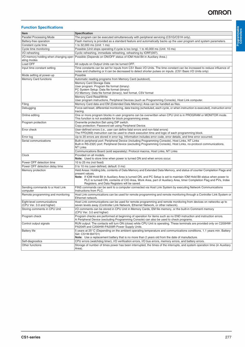
CS1-series 277
Pro
gra
mm
able
C
on
tro
llers
Function Specifications
Item SpecificationParallel Processing Mode The program can be executed simultaneously with peripheral servicing (CS1G/CS1H only).Battery-free operation Flash memory is provided as a standard feature and automatically backs up the user program and system parameters.Constant cycle time 1 to 32,000 ms (Unit: 1 ms)Cycle time monitoring Possible (Unit stops operating if cycle is too long): 1 to 40,000 ms (Unit: 10 ms)I/O refreshing Cyclic refreshing, immediate refreshing, refreshing by IORF(097).I/O memory holding when changing oper-ating modes
Possible (Depends on ON/OFF status of IOM Hold Bit in Auxiliary Area.)
Load OFF All outputs on Output Units can be turned OFF.Input time constant setting Time constants can be set for inputs from CS1 Basic I/O Units. The time constant can be increased to reduce influence of
noise and chattering or it can be decreased to detect shorter pulses on inputs. (CS1 Basic I/O Units only)Mode setting at power-up PossibleMemory Card functions Automatic reading programs from Memory Card (autoboot).
Memory Card Storage DataUser program: Program file format (binary)PC System Setup: Data file format (binary)I/O Memory: Data file format (binary), text format, CSV formatMemory Card Read/WriteUser program instructions, Peripheral Devices (such as Programming Console), Host Link computer.
Filing Memory Card data and EM (Extended Data Memory) Area can be handled as files.Debugging Force-set/reset, differential monitoring, data tracing (scheduled, each cycle, or when instruction is executed), instruction error
tracing. Online editing One or more program blocks in user programs can be overwritten when CPU Unit is in PROGRAM or MONITOR mode.
This function is not available for block programming areas.Program protection Overwrite protection:Set using DIP switch.
Copy protection: Password set using Peripheral Device.Error check User-defined errors (i.e., user can define fatal errors and non-fatal errors)
The FPD(269) instruction can be used to check execution time and logic of each programming block.Error log Up to 20 errors are stored in error log. Information includes error code, error details, and time error occurred.Serial communications Built-in peripheral port: Peripheral Device (including Programming Console), Host Links, NT Links
Built-in RS-232C port: Peripheral Device (excluding Programming Console), Host Links, no-protocol communications, NT LinksCommunications Board (sold separately): Protocol macros, Host Links, NT Links
Clock Provided on all models.Note: Used to store time when power is turned ON and when errors occur.
Power OFF detection time 10 to 25 ms (not fixed)Power OFF detection delay time 0 to 10 ms (user-defined, default: 0 ms)Memory protection Held Areas: Holding bits, contents of Data Memory and Extended Data Memory, and status of counter Completion Flags and
present values.Note: If IOM Hold Bit in Auxiliary Area is turned ON, and PC Setup is set to maintain IOM Hold Bit status when power to
PLC is turnedl ON, contents of CIO Area, Work Area, part of Auxiliary Area, timer Completion Flag and PVs, Index Registers, and Data Registers will be saved.
Sending commands to a Host Link computer
FINS commands can be sent to a computer connected via Host Link System by executing Network Communications Instructions from PLC.
Remote programming and monitoring Host Link communications can be used for remote programming and remote monitoring through a Controller Link System or Ethernet network.
Eight-level communications (CPU Ver. 3.0 and higher)
Host Link communications can be used for remote programming and remote monitoring from devices on networks up to seven levels away (Controller Link Network, Ethernet Network, or other network).
Storing comments in CPU Unit I/O comments can be stored in CPU Unit in Memory Cards, EM file memory, or the built-in Comment memory (CPU Ver. 3.0 and higher)
Program check Program checks are performed at beginning of operation for items such as no END instruction and instruction errors. A Peripheral Device (excluding Programming Console) can also be used to check programs.
Control output signals RUN output: The contacts will turn ON (close) while CPU Unit is operating. These terminals are provided only on C200HW-PA204R and C200HW-PA209R Power Supply Units.
Battery life 5 years at 25° C (Depending on the ambient operating temperature and communications conditions, 1.1 years min. Battery Set: CS1W-BAT01) Note: Use a replacement battery that is no more than 2 years old from the date of manufacture.
Self-diagnostics CPU errors (watchdog timer), I/O verification errors, I/O bus errors, memory errors, and battery errors.Other functions Storage of number of times power has been interrupted, the times of the interrupts, and system operation time (in Auxiliary
Area).
Y201-EN2-03.book Seite 277 Donnerstag, 30. März 2006 1:52 13

278 Programmable Controllers
Specifications - Power Supply Units
Note: 1. Disconnect the Power Supply Unit’s LG terminal from the GR terminal when testing insulation and dielectric strength.2. Only when mounted to a Backplane.3. Depth is 153 mm for C200HW-PA209R.4. Enquire separately for general specifications of Process I/O Units.
Item SpecificationsPower Supply Unit C200HW-PA204 C200HW-PA204S C200HW-PA204R C200HW-PA209R C200HW-PD024 C200HW-PD106RSupply voltage 100 to 120 V AC or 200 to 240 V AC, 50/60 Hz 24 V DC 100 V DCOperating voltage range 85 to 132 V AC or 170 to 264 V AC 19.2 to 28.8 V DC 85 to 143 V DCPower consumption 120 VA max. 180 VA max. 40 W max. 50 W max.Inrush current 30 A max. 30 A max./100 to 120
V AC40 A max./200 to 240 V AC
30 A max.
Output capacity 4.6 A, 5 V DC (including CPU Unit power) 9 A, 5 V DC (including CPU Unit power)
4.6 A, 5 V DC (in-cluding CPU Unit power)
6 A, 5 V DC (including CPU Unit power)
0.625 A, 26 V DCTotal: 30 W
0.625 A, 26 V DC or 0.8 A, 24 V DCTotal: 30 W
0.625 A, 24 V DCTotal: 30 W
1.3 A, 26 V DCTotal: 45 W
0.625 A, 26 V DCTotal: 30 W
1 A, 26 V DCTotal: 30 W
Output terminal Not provided 24 V DC load current consumptionLess than 0.3 A: +17%/–11%0.3 A or greater: +10%/–11%(Lot No. 0197 or higher)
Not provided Not provided
RUN output (See Note 2.)
Not provided Contact configuration: SPST-NOSwitch capacity: 250 V AC, 2 A (resis-tive load)250 V AC, 0.5 A (induc-tion load), 24 V DC, 2 A
Contact configuration: SPST-NOSwitch capacity: 240 V AC, 2 A (resis-tive load)120 V AC, 0.5 A (in-ductive load)24 V DC, 2 A (resis-tive load)24 V DC, 2 A (induc-tive load)
Not provided Contact configuration: SPST-NOSwitch capacity: 250 V AC, 2 A (resis-tive load)250 V AC, 0.5 A (in-duction load), 24 V DC, 2 A
Insulation resistance 20 MΩ min. (at 500 V DC) between AC external and GR terminals (See Note 1.) 20 MΩ min. (at 500 V DC) between DC ex-ternal and GR terminals (See Note 1.)
Dielectric strength 2,300 V AC 50/60 Hz for 1 min between AC external and GR terminals (See Note 1.)Leakage current: 10 mA max.
1,000 V AC 50/60 Hz for 1 min be-tween DC external and GR terminals, leakage current: 10 mA max. (See Note 1.)
2,300 V AC 50/60 Hz for 1 min between AC external and GR ter-minals (See Note 1.)Leakage current: 10 mA max.
1,000 V AC 50/60 Hz for 1 min between AC external and GR terminals (See Note 1.)Leakage current: 10 mA max.
Noise immunity Conforms to IEC61000-4-4, 2 kV (power lines)Vibration resistance 10 to 57 Hz, 0.075-mm amplitude, 57 to 150 Hz, acceleration: 9.8 m/s2 in X, Y, and Z directions for 80 minutes
(Sweep time 8 min × 10 = total time 80 min.)CPU Unit mounted to a DIN rail: 2 to 55 Hz, 2.9 m/s2 in X, Y, and Z directions for 20 minutes. According to JIS C0040 / IEC 60068-2-6
Shock resistance 147 m/s2, 3 times each in X, Y, and Z directions According to JIS C0041 / IEC 60068-2-27Ambient operating tempera-ture
0 to 55° C
Ambient operating humidity 10% to 90% (with no condensation)Atmosphere Must be free from corrosive gases.Ambient storage tempera-ture
–20 to 75° C (excluding battery)
Grounding Less than 100 ΩEnclosure IP20, intended for panel mounting.Weight All models are each 6 kg max.CPU Rack Dimensions (mm) (See note 3.)
2 slots:198.5 × 157 × 123 (W x H x D) 8 slots: 435 × 130 × 123 (W x H x D) 3 slots: 260 × 130 × 123 (W x H x D) 10 slots:505 × 130 × 123 (W x H x D) 5 slots: 330 × 130 × 123 (W x H x D)
Product standards Conforms to UL, CSA, cULus, cUL, NK, Lloyd’s, and EC directives. cULus
Y201-EN2-03.book Seite 278 Donnerstag, 30. März 2006 1:52 13
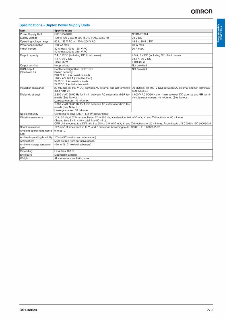
CS1-series 279
Pro
gra
mm
able
C
on
tro
llers
Specifications - Duplex Power Supply Units
Item SpecificationsPower Supply Unit CS1D-PA207R CS1D-PD024Supply voltage 100 to 120 V AC or 200 to 240 V AC, 50/60 Hz 24 V DCOperating voltage range 85 to 132 V AC or 170 to 264 V AC 19.2 to 28.8 V DCPower consumption 150 VA max. 40 W max.Inrush current 30 A max./100 to 120 V AC
40 A max./200 to 240 V AC30 A max.
Output capacity 7 A, 5 V DC (including CPU Unit power) 4.3 A, 5 V DC (including CPU Unit power)1.3 A, 26 V DCTotal: 35 W
0.56 A, 26 V DCTotal: 28 W
Output terminal Not provided Not providedRUN output (See Note 2.)
Contact configuration: SPST-NOSwitch capacity: 240 V AC, 2 A (resistive load)120 V AC, 0.5 A (inductive load)24 V DC, 2 A (resistive load)24 V DC, 2 A (inductive load)
Not provided
Insulation resistance 20 MΩ min. (at 500 V DC) between AC external and GR terminals (See Note 2.)
20 MΩ min. (at 500 V DC) between DC external and GR terminals (See Note 2.)
Dielectric strength 2,300 V AC 50/60 Hz for 1 min between AC external and GR ter-minals (See Note 2.)Leakage current: 10 mA max.
1,000 V AC 50/60 Hz for 1 min between DC external and GR termi-nals, leakage current: 10 mA max. (See Note 2.)
1,000 V AC 50/60 Hz for 1 min between AC external and GR ter-minals (See Note 1.)Leakage current: 10 mA max.
Noise immunity Conforms to IEC61000-4-4, 2 kV (power lines)Vibration resistance 10 to 57 Hz, 0.075-mm amplitude, 57 to 150 Hz, acceleration: 9.8 m/s2 in X, Y, and Z directions for 80 minutes
(Sweep time 8 min × 10 = total time 80 min.)CPU Unit mounted to a DIN rail: 2 to 55 Hz, 2.9 m/s2 in X, Y, and Z directions for 20 minutes. According to JIS C0040 / IEC 60068-2-6
Shock resistance 147 m/s2, 3 times each in X, Y, and Z directions According to JIS C0041 / IEC 60068-2-27Ambient operating tempera-ture
0 to 55° C
Ambient operating humidity 10% to 90% (with no condensation)Atmosphere Must be free from corrosive gases.Ambient storage tempera-ture
–20 to 75° C (excluding battery)
Grounding Less than 100 ΩEnclosure Mounted in a panel.Weight All models are each 6 kg max.
Y201-EN2-03.book Seite 279 Donnerstag, 30. März 2006 1:52 13

280 Programmable Controllers
Basic System Configuration
CPU RackA CPU Rack consists of a CPU Unit, Power Supply Unit, CPU Back-plane, Basic I/O Units, Special I/O Units, and CPU Bus Units. The Serial Communications Board and Memory Cards are optional.Note: The Backplane depends on the type of CPU Rack, Expansion I/
O Racks, and Slave Racks that are used.
Expansion RacksBoth C200H and CS1 Expansion Racks can be used.• C200H Expansion I/O Racks can be connected to CPU Racks, CS1
Expansion Racks, or other C200H Expansion I/O Racks.• CS1 Expansion Racks can be connected to CPU Racks or other CS1
Expansion Racks. An Expansion Rack consists of a Power Supply Unit, a CS1 or C200H Expansion I/O Backplane, Basic I/O Units, Special I/O Units, and a CS1 CPU Bus Units.
Long-distance Expansion RacksAn I/O Control Unit and I/O Interface Units can be used to extend the normal limit of 12 m to 50 m for each of two series of CS1 Expansion Racks. The following Units can be mounted to Long-distance Expan-sion Racks: CS1 Basic I/O Units, CS1 Special I/O Units, and CS1 CPU Bus Units. (C200H Units cannot be mounted to Long-distance Expan-sion Racks.)
CPU Rack
Configuration
Products Used in CPU Racks
CPU RackCPU Backplane
Memory Card
I/O Connecting Cable
Expansion Rack
I/O Backplane
Remote I/O Master Unit
I/O UnitsSpecial I/O UnitsCS1 CPU Bus Units
Serial Communications Board
I/O UnitsSpecial I/O UnitsCS1 CPU Bus Units
Power Supply Unit
Power Supply Unit
Name Configuration RemarksCPU Backplane One of each Unit required for every CPU Rack.
Refer to the following table for model number.CPU UnitPower Supply UnitMemory Card Install as required.
Refer to the following table for model number.Serial Communications Board
Name Model SpecificationsCS1H-CPU67H I/O bits: 5,120, Program capacity: 250 kSteps
Data Memory: 448 kWords (DM: 32 kWords, EM: 32 kWords x 13 banks)CS1H-CPU66H I/O bits: 5,120, Program capacity: 120 kSteps
Data Memory: 256 kWords (DM: 32 kWords, EM: 32 kWords x 7 banks)CS1H-CPU65H I/O bits: 5,120, Program capacity: 60 kSteps
Data Memory: 128 kWords (DM: 32 kWords, EM: 32 kWords x 3 banks)CS1H-CPU64H I/O bits: 5,120, Program capacity: 30 kSteps
Data Memory: 64 kWords (DM: 32 kWords, EM: 32 kWords x 1 bank)CS1H-CPU63H I/O bits: 5,120, Program capacity: 20 kSteps
Data Memory: 32 kWords (DM: 32 kWords, EM: 32 kWords x 1 bank)CS1G-CPU45H I/O bits: 5,120, Program capacity: 60 kSteps
Data Memory: 128 kWords (DM: 32 kWords, EM: 32 kWords x 3 banks)CS1G-CPU44H I/O bits: 1,280, Program capacity: 30 kSteps
Data Memory: 64 kWords (DM: 32 kWords, EM: 32 kWords x 1 banks)CS1G-CPU43H I/O bits: 960, Program capacity: 20 kSteps
Data Memory: 64 kWords (DM: 32 kWords, EM: 32 kWords x 1 bank)CS1G-CPU42H I/O bits: 960, Program capacity: 10 kSteps
Data Memory: 64 kWords (DM: 32 kWords, EM: 32 kWords x 1 bank)CS1W-BC022 2 slots (Connection to Expansion Back-
plane is not possible.)These Backplanes are for CS1 Units only. Use CS1W-BC@@3 Backplanes if C200H Units are to be installed.CS1W-BC032 3 slots
CS1W-BC052 5 slotsCS1W-BC082 8 slotsCS1W-BC102 10 slots
CPU Rack
CPU Units
CPU Backplanes
Y201-EN2-03.book Seite 280 Donnerstag, 30. März 2006 1:52 13

CS1-series 281
Pro
gra
mm
able
C
on
tro
llers
Expansion Racks
Expansion Rack Configuration
Products Used in Expansion Racks
C200HW-PA204 100 to 120 V AC or 200 to 240 V AC, Output capacity: 4.6 A, 5 V DCC200HW-PA204S 100 to 120 V AC or 200 to 240 V AC (0.8 A 24 V DC service power)
Output capacity: 4.6 A, 5 V DCC200HW-PA204R 100 to 120 V AC or 200 to 240 V AC (with RUN output) Output capacity: 4.6 A, 5 V DCC200HW-PD024 24 V DC, Output capacity: 4.6 A, 5 V DCC200HW-PA209R 100 to 120 V AC or 200 to 240 V AC (with RUN output) Output capacity:
9 A, 5 V DC
I/O Control Unit CS1W-IC102 Connects to CS1 Expansion Racks (two Terminating Resistors included). Must be used together with I/O Interface Units to connect Long-distance Expansion Racks (50 m max.). Not required to connect CS1 Expansion Racks within 12 m.
HMC-EF372 Flash memory, 30 MBHMC-EF672 Flash memory, 64 MBHMC-AP001 Memory Card adapter
Serial Communications Boards CS1W-SCB21-V1 2 x RS-232C ports, protocol macro functionCS1W-SCB41-V1 1 x RS-232C port + 1 x RS-422/485 port, protocol macro function
Programming Consoles CQM1-PRO01-E An English Keyboard Sheet (CS1W-KS001-E) is required.C200H-PRO27-E
Programming Console Connection Cables
CS1W-CN114 Connects the CQM1-PRO01-E Programming Console. (Length: 0.05 m)CS1W-CN224 Connects the C200H-PRO27-E Programming Console. (Length: 2.0 m)CS1W-CN624 Connects the C200H-PRO27-E Programming Console. (Length: 6.0 m)
CX-One CX-ONE-AL##C-E*1 Omron's integrated software for programming and configuration of all control system components, including PLCs, HMI, drives, temperature controllers and advanced sen-sors.
Programming Device Connecting Cables (for peripheral port)
CS1W-CN118 Connects DOS computer, D-Sub 9-pin receptacle (Length: 0.1 m)CS1W-CN226 Connects DOS computer, D-Sub 9-pin (Length: 2.0 m)CS1W-CN626 Connects DOS computer, D-Sub 9-pin (Length: 6.0 m)XW2Z-200S-CV Connects DOS computer, D-Sub 9-pin (Length: 2.0 m)XW2Z-500S-CV Connects DOS computer, D-Sub 9-pin (Length: 5.0 m)
Programming Device Connecting Cable (for RS-232C port)
XW2Z-200S-V Connects DOS computer, D-Sub 9-pin (Length: 2.0 m) (For Host Link connection)XW2Z-500S-V Connects DOS computer, D-Sub 9-pin (Length: 5.0 m) (For Host Link connection)
Battery Set CS1W-BAT01 For CS1 Series only.Note: Use a replacement battery that is no more than 2 years old from the date of man-
ufacture.
*1 ## = Number of licences; 01, 03, 10
Rack Configuration RemarksCS1 Expansion Rack CS1 Expansion I/O Backplane One of each Unit is required.
Power Supply UnitFor connection to a CPU Backplane or CS1 Expansion I/O Backplane: CS1 I/O Connecting CableFor connection to a C200H Expansion I/O Backplane: CS1 to C200H I/O Con-necting Cable
C200H Expansion I/O Rack C200H Expansion I/O Backplane One of each Unit is required.A CS1 Expansion Rack cannot be connected after a C200H Expansion I/O Rack.
Power Supply UnitFor connection to a CPU Backplane or CS1 Expansion I/O Backplane: CS1 to C200H I/O Connecting CableFor connection to a C200H Expansion I/O Backplane: C200H I/O Connecting Ca-ble
Name Model Specifications Cable LengthCS1 Expansion I/O Back-planes
CS1W-BI032 3 slots These Backplanes are for CS1 Units only. Use CS1W-BI@@3 Backplanes if C200H Units are to be installed.
---CS1W-BI052 5 slotsCS1W-BI082 8 slotsCS1W-BI102 10 slots
C200H Expansion I/O Back-planes
C200HW-BI031 3 slotsC200HW-BI051 5 slotsC200HW-BI081-V1 8 slotsC200HW-BI101-V1 10 slots
Power Supply Units C200HW-PA204 100 to 120 V AC or 200 to 240 V ACOutput capacity: 4.6 A, 5 V DC
C200HW-PA204S 100 to 120 V AC or 200 to 240 V AC (with power output terminal: 0.8 A, 24 V DC)Output capacity: 4.6 A, 5 V DC
C200HW-PA204R 100 to 120 V AC or 200 to 240 V AC (with RUN output)Output capacity: 4.6 A, 5 V DC
C200HW-PA209R 100 to 120 V AC or 200 to 240 V AC (with RUN output)Output capacity: 9 A, 5 V DC
C200HW-PD024 24 V DC
Name Model Specifications
Power Supply Units
Memory Cards
Y201-EN2-03.book Seite 281 Donnerstag, 30. März 2006 1:52 13

282 Programmable Controllers
I/O Interface Unit CS1W-II102 Connects CS1 Expansion Racks. Must be used together with I/O Control Unit to connect Long-distance Expansion Racks (50 m max.). Not required to connect CS1 Expansion Racks within 12 m.
---
CS1 I/O Connecting Cables
CS1W-CN313 0.3 m
CS1W-CN713 0.7 m
CS1W-CN223 2 m
CS1W-CN323 3 m
CS1W-CN523 5 m
CS1W-CN133 10 m
CS1W-CN133-B2 12 m
Long-distance Connecting Cables
CV500-CN312 For Long-distance Expansion RacksConnects the I/O Control Unit to I/O Interface Units or connects one I/O In-terface Unit to the next I/O Interface Unit.
0.3 mCV500-CN612 0.6 mCV500-CN122 1 mCV500-CN222 2 mCV500-CN322 3 mCV500-CN522 5 mCV500-CN132 10 mCV500-CN232 20 mCV500-CN332 30 mCV500-CN432 40 mCV500-CN532 50 m
CS1-C200H I/O Connecting Cables
CS1W-CN311 Connects C200H Expansion I/O Backplanes to CPU Backplanes or CS1 Ex-pansion I/O Backplanes.
0.3 mCS1W-CN711 0.7 mCS1W-CN221 2 mCS1W-CN321 3 mCS1W-CN521 5 mCS1W-CN131 10 mCS1W-CN131-B2 12 m
C200H I/O Connecting Cables
C200H-CN311 Connects C200H Expansion I/O Backplanes to other C200H Expansion I/O Backplanes.
0.3 mC200H-CN711 0.7 mC200H-CN221 2 mC200H-CN521 5 mC200H-CN131 10 m
Name Model Specifications Cable Length
@ @ @ @Reading the production number
Year (e.g., 1997=7)
Day (01 to 31)
Month (1 to 9, X (10), Y (11), Z (12))
Connects CS1 Expansion I/O Backplanes to CPU Backplanes or other CS1 Expansion I/O Backplanes.
When using a CS1W-CN313 or CS1W-CN713 I/O Connecting Cable with a CS1@-CPU@@H CPU Unit, use only Cables produced on or after September 20, 2001 (production number 2091). Cables with no production number, a 6-digit production number, or produced before September 20, 2001, cannot be used.
Y201-EN2-03.book Seite 282 Donnerstag, 30. März 2006 1:52 13

CS1-series 283
Pro
gra
mm
able
C
on
tro
llers
Expansion Rack PatternsThe following diagrams show the 5 possible patterns of Expansion Racks.
12 m 12 m
CPU Rack with CS1 Expansion RacksCPU Rack
CS1 Expansion Rack
CS1 Expansion Rack
CS1 Expansion Rack
CPU Rack with CS1 Expansion Racks and C200H Expansion I/O Racks
CS1 Expansion Rack
CPU Rack
CS1 I/O Connecting Cable
CS1 I/O Connecting Cable
CS1 I/O Connecting Cable
7 Racks max.
CS1 to C200H I/O Connecting Cable
C200H I/O Connecting Cable
C200H I/O Connecting Cable
C200H Expansion I/O Rack
C200H Expansion I/O Rack
CS1 I/O Connecting Cable
7 Racks max. (Three C200H Expansion I/O Racks max.)
50 m
50 m
CPU Rack with CS1 Long-Distance Expansion Racks
CPU Rack
CS1 Expansion Rack
CS1 Expansion Rack
CS1 Expansion Rack
CS1 Expansion Rack
CS1 Expansion Rack
CS1 Expansion Rack
CS1 Expansion Rack
I/O Control Unit
I/O Interface Unit
I/O Interface Unit
I/O Interface Unit
I/O Interface Unit
I/O Interface Unit
I/O Interface Unit
I/O Interface Unit
Terminating Resistor
Terminating Resistor
Long-distance Connecting Cables
Long-distance Connecting Cable
Long-distance Connecting Cable
Long-distance Connecting Cable
Long-distance Connecting Cable
Long-distance Connecting Cable
Up to 7 Racks in 2 series
Note: C200H Units cannot be mounted to Long-distance Expansion Racks.
Y201-EN2-03.book Seite 283 Donnerstag, 30. März 2006 1:52 13
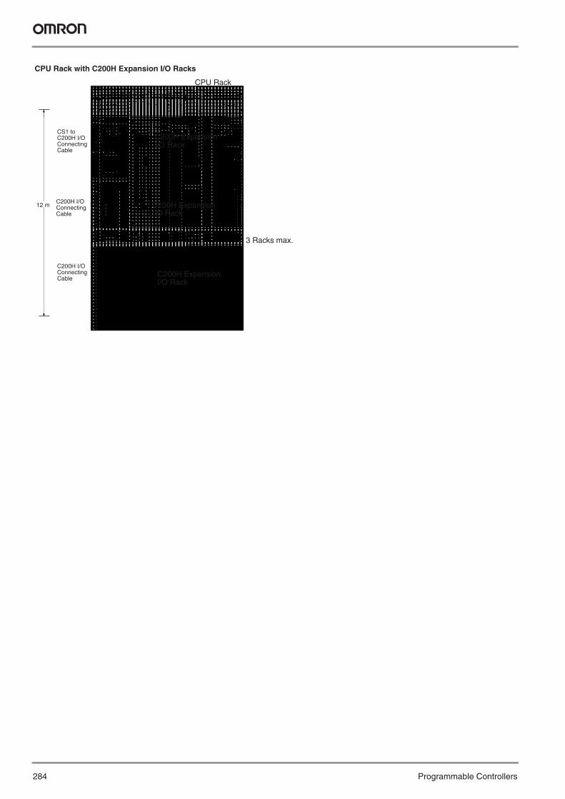
284 Programmable Controllers
12 m
CPU Rack with C200H Expansion I/O Racks
CPU Rack
3 Racks max.
CS1 to C200H I/O Connecting Cable
C200H I/O Connecting Cable
C200H I/O Connecting Cable
C200H Expansion I/O Rack
C200H Expansion I/O Rack
C200H Expansion I/O Rack
Y201-EN2-03.book Seite 284 Donnerstag, 30. März 2006 1:52 13
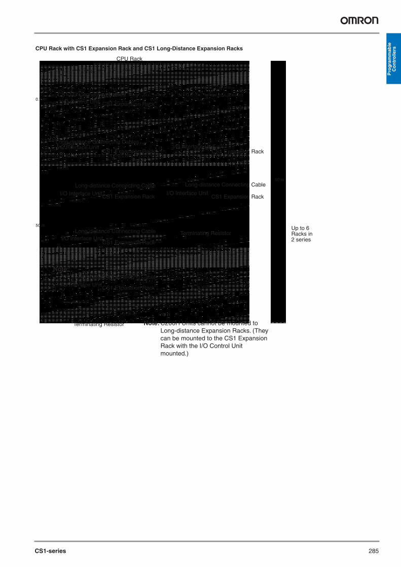
CS1-series 285
Pro
gra
mm
able
C
on
tro
llers
Note:
0.7 m
50 m
50 m
CPU Rack with CS1 Expansion Rack and CS1 Long-Distance Expansion Racks
CPU Rack
CS1 Expansion Rack
CS1 Expansion Rack
CS1 Expansion Rack
CS1 Expansion Rack
Note:
CS1 Expansion Rack
CS1 Expansion Rack
CS1 Expansion Rack
I/O Control Unit
I/O Interface Unit
Terminating Resistor
Long-distance Connecting Cables
Terminating Resistor
I/O Interface Unit
I/O Interface Unit
I/O Interface Unit
I/O Interface Unit
I/O Interface UnitLong-distance Connecting Cable
Long-distance Connecting Cable
Long-distance Connecting Cable
Long-distance Connecting Cable
CS1 I/O Connecting Cables
Up to 6 Racks in 2 series
Note: C200H Units cannot be mounted to Long-distance Expansion Racks. (They can be mounted to the CS1 Expansion Rack with the I/O Control Unit mounted.)
Y201-EN2-03.book Seite 285 Donnerstag, 30. März 2006 1:52 13

286 Programmable Controllers
CPU RackA CPU Rack consists of a Duplex CPU Backplane to which CPU Units,Power Supply Units, a Duplex Unit, CS1-series Basic I/O Units, CS1-series Special I/O Units, and CS1-series CPU Bus Units are mounted. Memory Cards and Inner Boards to mount in the CPU Units areoptional. (Inner Board cannot be mounted to the CS1D-CPU@@H/P)The CPU Units, Power Supply Units, Duplex CPU Backplane, andDuplex Unit are all designed specifically for CS1D PLCs.
Note: Different Backplanes are used for the CPU Rack and ExpansionRacks. Be sure to use the correct Backplane.
Expansion RacksAn Expansion Rack consists of an Expansion Backplane to whichPower Supply Units, CS1-series Basic I/O Units, CS1-series Special I/O Units, and CS1-series CPU Bus Units are mounted.The Power Supply Units and Expansion Backplane are designed spe-cifically for CS1D PLCs.CS1-series Expansion Backplanes and C200H Backplanes cannot beconnected.
Long-distance Expansion RacksA Long-distance Expansion Rack consists of an Expansion Backplaneto which an I/O Interface Unit, CS1-series Basic I/O Units, CS1-seriesSpecial I/O Units, and CS1-series CPU Bus Units are mounted. An I/OControl Unit is used to connect to the Long-distance Expansion Racks.Using Long-distance Expansion Rack increases the normal limit of 12 m for the Rack to 50 m.
CS1D PLCsWith a CS1D Duplex-CPU System, two CPU Units can be mounted tothe CPU Rack for Duplex Mode operation (Duplex Mode), or just oneCPU Unit can be mounted for Simplex Mode operation. In either case,a Duplex Unit is required. With a CS1D Single-CPU System, just one CPU Unit is mounted and aDuplex Unit is not required.Also, two Power Supply Units can be mounted to any Rack to increaseredundancy. (Racks can also be operated with only one Power SupplyUnit.) With any of these combinations, there are no further restrictionsif the system configuration, e.g., the same number of Expansion Rackscan be used as with the other CS1-series PLCs.Note: C200H Basic I/O Units, C200H Special I/O Units, and C200H
CPU Bus Units cannot be mounted on any Rack.
System Configuration (Duplex Systems)
Up to 5 Units can be mounted.CS1-series Basic I/O UnitsCS1-series Special I/O UnitsCS1-series CPU Bus UnitsNote: C200H Units cannot be mounted.
Duplex CPU Units Duplex Power Supply Units
CS1D CPU Rack
PORT
BUSY
RUN
ERR/ALM
INH
PRPHL
MCPWR
BKUP
COMM
SYSMACCS1D-CPU67HPROGRAMMABLE CONTROLLER
PORT
BUSY
RUN
ERR/ALM
INH
PRPHL
MCPWR
BKUP
COMM
SYSMACCS1D-CPU67HPROGRAMMABLE CONTROLLER
OPENOPEN
PERIPHERALPERIPHERAL
DPL01DPL STATUS
CPU STATUS
CPU STATUS
ACTIVE
ACTIVE
L
R
LEFT CPU
RIGHT CPU
DPL SW
USE
NO USE
USE
NO USE
ON
ON
INIT.
SPLACT.LEFT
PRPHLCOMMA39512RSV
ACT.RIGHT
DPLOFF
ON
SW
DUPLEX
PORT
BUSY
RUN
ERR/ALM
INH
PRPHL
MCPWR
BKUP
COMM
SYSMACCS1D-CPU67SPROGRAMMABLE CONTROLLER
OPEN
PERIPHERAL
Duplex Power Supply Units
CS1D CPU Units for Single-CPU SystemCS1D-CPU42S/44S/65S/67S
Duplex CPU Backplane CS1D-BC082S (See note.)
CS1D Power Supply Units CS1D-PA207R/PD024
CS1D CPU Rack
Duplex-CPU System
Single-CPU System
Duplex CPU Backplane CS1D-BC052 (See note.)
Duplex (DPL) Unit CS1D-DPL01 CS1D CPU Units for
Duplex-CPU System CS1D-CPU65H/67H/65P/67P
CS1D Power Supply Units CS1D-PA207R/PD024
Up to 8 Units can be mounted.CS1-series Basic I/O UnitsCS1-series Special I/O UnitsCS1-series CPU Bus UnitsNote: C200H Units cannot be mounted.
Y201-EN2-03.book Seite 286 Donnerstag, 30. März 2006 1:52 13

CS1-series 287
Pro
gra
mm
able
C
on
tro
llers
CS1D CPU Rack + CS1D Expansion Rack
CS1D CPU Rack + CS1D Long-distance Expansion Racks
Expansion Patterns for CS1D PLCs
Name Model Specifications Cable LengthLong-distance Connecting Cables
CV500-CN312 For Long-distance Expansion RacksConnects the I/O Control Unit to I/O Interface Units or connects one I/O Interface Unit to the next I/O Interface Unit.
0.3 mCV500-CN612 0.6 mCV500-CN122 1 mCV500-CN222 2 mCV500-CN322 3 mCV500-CN522 5 mCV500-CN132 10 mCV500-CN232 20 mCV500-CN332 30 mCV500-CN432 40 mCV500-CN532 50 m
CS1-C200H I/O Connecting Cables
CS1W-CN311 Connects C200H Expansion I/O Backplanes to CPU Backplanes or CS1 Expansion I/O Backplanes.
0.3 mCS1W-CN711 0.7 mCS1W-CN221 2 mCS1W-CN321 3 mCS1W-CN521 5 mCS1W-CN131 10 mCS1W-CN131-B2 12 m
C200H I/O Connecting Cables
C200H-CN311 Connects C200H Expansion I/O Backplanes to other C200H Expansion I/O Backplanes.
0.3 mC200H-CN711 0.7 mC200H-CN221 2 mC200H-CN521 5 mC200H-CN131 10 m
I/O Interface UnitCS1D Expansion Rack
CS1D Expansion Rack
Long-distance Connecting Cable
I/O Interface Unit
Long-distance Connecting Cable
I/O Interface Unit
Terminating resistance
Terminating resistance
I/O Interface Unit
Long-distance Connecting Cable
CS1D Expansion Rack
CS1D Expansion Rack CS1D Expansion Rack
CS1D Expansion Rack
CS1D CPU Rack
CS1D Expansion Rack
I/O Control Unit
Long-distance Connecting Cable
I/O Interface Unit
Long-distance Connecting Cable
I/O Interface Unit
Long-distance Connecting Cable
I/O Interface Unit
CS1D Expansion Rack
CS1D Expansion Rack
CS1D CPU Rack
CS1 Connecting Cable
CS1 Connecting Cable
CS1 Connecting Cable
7 E
xpan
sion
Rac
ks m
ax.
7 E
xpan
sion
Rac
k m
ax. (
tota
l in
two
serie
s)
CS1D Expansion Rack
Y201-EN2-03.book Seite 287 Donnerstag, 30. März 2006 1:52 13

288 Programmable Controllers
Connections to Programming Devices
Serial Communications Units
Serial Communications Board
Peripheral port
Hardware
RS-232C port
Software
IBM PC/AT or compatible
Note: Refer to the next page for details of cables for connecting to computers. Choose the appropriate cable for the communications mode.
XW2Z-200S-CV (See note.)XW2Z-500S-CV (See note.)
CX-One
Connecting Cable
USB-Serial Conversion CableCS1W-CIP31
Y201-EN2-03.book Seite 288 Donnerstag, 30. März 2006 1:52 13

289
Pro
gra
mm
able
C
on
tro
llers
USB-SerialConversion CableCS1W-CIF31
USB-SerialConversion CableCS1W-CIF31
USB-SerialConversion CableCS1W-CIF31
NEW
NEW
NEW
Hardware SoftwareConnecting Cable
CS1W-KS001-E
CS1W-KS001-E
IBM PC/AT or compatible
C200H-PRO27-E
CQM1H-PRO01-E
CS1W-CN118 IBM PC/AT or compatible
IBM PC/AT or compatibleCS1W-CN114
(See previous page.)
RS-232C connector (25 pins)
CS1W-CN226CS1W-CN626
XW2Z-@00S-@(@)RS-232C Cable
CQM1-CIF02 Connecting Cable
CS1W-CN224CS1W-CN624
CX-One
Y201-EN2-03.book Seite 289 Donnerstag, 30. März 2006 1:52 13

290 Programmable Controllers
Windows-based Programming Software: CX-Programmer
Connecting to the Peripheral Port
Peripheral Port Connecting Cables
The following cables can be used for an RS-232C connection from the computer to the peripheral port.
Connecting to the RS-232C Port
RS-232C Port Connecting Cables
Note: Cables with model numbers ending in “CV” are antistatic.The following cables can be used for an RS-232C connection from the computer to an RS-232C port. (Unlike cables with model numbers ending in “-CV,” however, these cables do not support peripheral bus connection and do not have anti-static specifications.)
The following serial communications modes can be used to connect a computer with the CX-Programmer to a CS1 PLC.
Programming Consoles
Model Cable Cable lengthCQM1H-PRO01-E Not required. ---
Model Cable Cable lengthC200H-PR027-E CS1W-CN224 2.0 m
CS1W-CN624 6.0 m
Name Model SpecificationsCX-Pro-grammer
WS02-CXPC1-EV@@ For 1 license OS: Windows 95/98 or Windows NT/Me/2000/XP
WS02-CXPC1-EL03-V@@ For 3 licensesWS02-CXPC1-EL10-V@@ For 10 licenses
CQM1H-PRO01-E
Peripheral port
CS1W-KS001-E Key Sheet
CQM1-PRO01-E Programming
Cable provided with CQM1H-PRO01-E (2 m)
C200H-PRO27-E
Peripheral port
CS1W-KS001-E Key Sheet
C200H-PRO27-E Programming Console
CS1W-CN224: 2.0 m CS1W-CN624: 6.0 m
Cable Length Computer connector
CS1W-CN226 2.0 m D-sub, 9-pin, maleCS1W-CN626 6.0 m
Mode Connecting cables Length Computer connector
Peripheral bus or Host Link
XW2Z-200S-CV or XW2Z-500S-CV
CS1W-CN118
2 or 5 m + 0.1 m
D-sub, 9-pin, male
Host Link XW2Z-200S-V or XW2Z-500S-V
Mode Cable Length Computer connectorPeripheral bus or Host Link
XW2Z-200S-CV 2.0 m D-sub, 9-pin, maleXW2Z-500S-CV 5.0 m
Mode Cable Length Computer connectorHost Link XW2Z-200S-V 2.0 m D-sub, 9-pin, male
XW2Z-500S-V 5.0 m
Mode FeaturesPeripheral bus The faster mode, peripheral bus is generally used for
CX-Programmer connections.Only 1:1 connections are possible. The baud rate is automatically detected with the CS1.
Host Link A standard protocol for host computers.Slower than peripheral bus, but allows modem or optical adapt-er connections, or long-distance or 1:N connections via RS422A/485.
Peripheral port
Connecting Cable
RS-232C, 9-pin (D-sub)
RS-232C port on CPU Unit
RS-232C ports on Serial Communications BoardRS-232C,
9-pin (D-sub)
RS-232C cable XW2Z-200S-CV (2 m) XW2Z-500S-CV (5 m)
Y201-EN2-03.book Seite 290 Donnerstag, 30. März 2006 1:52 13

291
Pro
gra
mm
able
C
on
tro
llers
Using a USB-Serial Conversion Cable to Connect to a Peripheral or RS-232C Port
General Specifications of USB-Serial Conversion Cable
OS with Drivers for USB-Serial Conversion CableWindows 98, ME, 2000, or XP
Applicable SoftwareCX-Programmer, CX-Simulator, CX-Protocol, CX-Motion, CX-Positio-ner, CS-Process, DeviceNet Configurator, PLC Reporter 32, CX-Desi-gner, and NT Support Software for Windows (NTST) (See note.)Note: There are restrictions to the COM port numbers that can be used
for the NTST.
Applicable Communications MiddlewareFinsGateway and CX-Server
Applicable PLCs and PTsThe OMRON PLCs and PTs supported by the applicable software can be used. These are listed below.
PLCsCS Series, CJ Series, C Series (C200HS, C200HX/HG/HE, C200H, C1000H, C2000H, CQM1, CPM1, CPM1A, SRMT, CQM1H, and CPM2C), CVM1, and CV Series
PTsNS Series and NT Series
Peripheral Port Connecting Cables
RS-232C Port Connecting Cables
Connection in Tool Bus Mode is not possible. The connector does not have ESD measures.
USB interface standard Conforms to USB Specification 1.1.DTE speed 115.2 Kbits/sConnectors On computer USB (A plug connector, male)
On PLC RS-232C (D-sub, 9-pin, female)Power supply Bus power (supplied from upstream, 5 V
DC)Current consumption 35 mAOperating envi-ronment
Ambient temperature
0 to 55 ° C
Ambient humidity
10% to 90% (with no condensation)
Ambient atmosphere
No corrosive gases
Weight 50 g
IBM PC/AT or compatible with USB port
Peripheral or RS-232C port
CS1W-CIF31 USB-Serial Conversion Cable
Serial Connecting Cable:CS1W-CN226/CN626XW2Z-200S-CV/500S-CVXW2Z-200S-V/500S-VCQM1-CIF02
Computer Serial Communications Node
Connecting Cable model number Length Computer connector
IBM PC/AT or compatible
Tool bus or SYSMAC WAY CS1W-CIF31 CS1W-CN226 0.5 m + 2.0 m USB (A plug connector)CS1W-CN626 0.5 m + 6.0 m
CS1W-CIF31 XW2Z-200S-CV/XW2Z-500S-CV
CS1W-CN118 0.5 m + (2.0 m or 5.0 m) + 0.1 m
SYSMAC WAY CS1W-CIF31 XW2Z-200S-V/XW2Z-500S-V
0.5 m + (2.0 m or 5.0 m) + 0.1 m
Computer Serial Communications Node
Connecting Cable model number Length Computer connector
IBM PC/AT or compatible Tool bus or SYSMAC WAY CS1W-CIF31 XW2Z-200S-CV 0.5 m + 2.0 m USB (A plug connector)XW2Z-500S-CV 0.5 m + 5.0 m
SYSMAC WAY CS1W-CIF31 XW2Z-200S-V (See note.)
0.5 m + 2.0 m
XW2Z-500S-V (See note.)
0.5 m + 5.0 m
Y201-EN2-03.book Seite 291 Donnerstag, 30. März 2006 1:52 13

292 Programmable Controllers
Dimensions
Unit: mm
Backplanes
CPU Backplane with 2 Slots
Note: Expansion Backplanes cannot be connected to 2-slot CPU Back-planes.
CPU Backplane with 3, 5, 8, or 10 Slots
Unit: mm
Mounting DepthThe depth of all Racks is from 118 to 153 mm depending on the Units that are mounted. Additional depth is required to connect Peripheral Devices and Cables. Be sure to allow sufficient mounting depth.
Note: I/O Connecting Cables require sufficient space to maintain the min. bending radius.
Backplane A B W H DCS1W-BC022/023 (2 slots) 172.3 145 198.5 157 123CS1W-BC032/033 (3 slots) 246 118 260 132CS1W-BC052/053 (5 slots) 316 330CS1W-BC082/083 (8 slots) 421 435CS1W-BC102/103 (10 slots) 491 505CS1D-BC052/082S (Duplex System)
172.3±0.3
145±0.3
Four, M4
CS1W-BC023 CPU Backplane
A±0.3
118±0.3
80
118±0.3
W
130
130
A±0.3
Four, M4
66 min.
CPU Backplane
Expansion Backplane
Four, M4
Backplane Model A WCPU Backplanes CS1W-BC022/023 (2 slots) 172.3 198.5
CS1W-BC032/033 (3 slots) 246 260CS1W-BC052/053 (5 slots) 316 330CS1W-BC082/083 (8 slots) 421 435CS1W-BC102/103 (10 slots) 491 505CS1D-BC052/082S (Duplex System)
CS1 Expansion Backplanes
CS1W-BI032/033 (3 slots) 246 260CS1W-BI052/053 (5 slots) 316 330CS1W-BI082/083 (8 slots) 421 435CS1W-BI102/103 (10 slots) 491 505CS1D-BI092 (Duplex System)
C200H Expansion I/O Backplanes
C200HW-BI031 (3 slots) 175 189C200HW-BI051 (5 slots) 245 259C200HW-BI081-V1 (8 slots)
350 364
C200HW-BI101-V1 (10 slots)
420 434
118 to 153 mm
180 to 223 mm
R ≥ 69 mm R ≥ 41 mm
R ≥ 41 mm R ≥ 80 mm
CS1 I/O Connecting Cable (Cable diameter: 8.6 mm)
C200H I/O Connecting Cable (Cable diameter: 5.1 mm)
CS1 to C200H I/O Connecting Cable (Cable diameter: 5.1 mm)
Long-distance Connecting Cable (Cable diameter: 10 mm)
Y201-EN2-03.book Seite 292 Donnerstag, 30. März 2006 1:52 13
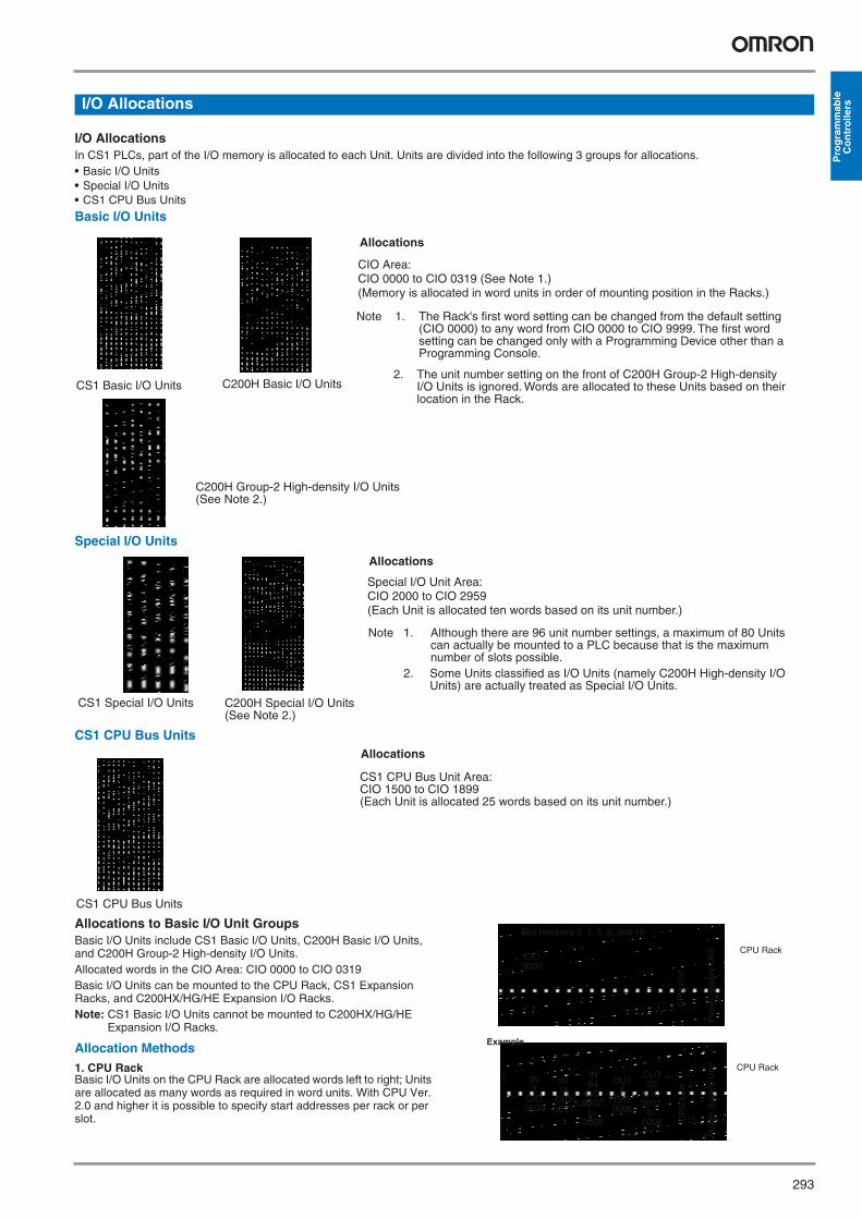
293
Pro
gra
mm
able
C
on
tro
llersI/O Allocations
I/O AllocationsIn CS1 PLCs, part of the I/O memory is allocated to each Unit. Units are divided into the following 3 groups for allocations.• Basic I/O Units• Special I/O Units• CS1 CPU Bus Units
Basic I/O Units
Special I/O Units
CS1 CPU Bus Units
Allocations to Basic I/O Unit GroupsBasic I/O Units include CS1 Basic I/O Units, C200H Basic I/O Units, and C200H Group-2 High-density I/O Units. Allocated words in the CIO Area: CIO 0000 to CIO 0319Basic I/O Units can be mounted to the CPU Rack, CS1 Expansion Racks, and C200HX/HG/HE Expansion I/O Racks.Note: CS1 Basic I/O Units cannot be mounted to C200HX/HG/HE
Expansion I/O Racks.
Allocation Methods1. CPU RackBasic I/O Units on the CPU Rack are allocated words left to right; Units are allocated as many words as required in word units. With CPU Ver. 2.0 and higher it is possible to specify start addresses per rack or per slot.
CS1 Basic I/O Units C200H Basic I/O Units
Allocations
C200H Group-2 High-density I/O Units(See Note 2.)
CIO Area: CIO 0000 to CIO 0319 (See Note 1.) (Memory is allocated in word units in order of mounting position in the Racks.)
Note 1. The Rack's first word setting can be changed from the default setting (CIO 0000) to any word from CIO 0000 to CIO 9999. The first word setting can be changed only with a Programming Device other than a Programming Console.
2. The unit number setting on the front of C200H Group-2 High-density I/O Units is ignored. Words are allocated to these Units based on their location in the Rack.
CS1 Special I/O Units
Allocations
C200H Special I/O Units(See Note 2.)
Special I/O Unit Area:CIO 2000 to CIO 2959(Each Unit is allocated ten words based on its unit number.)
Note 1. Although there are 96 unit number settings, a maximum of 80 Units can actually be mounted to a PLC because that is the maximum number of slots possible.
2. Some Units classified as I/O Units (namely C200H High-density I/O Units) are actually treated as Special I/O Units.
CS1 CPU Bus Units
Allocations
CS1 CPU Bus Unit Area: CIO 1500 to CIO 1899 (Each Unit is allocated 25 words based on its unit number.)
Slot numbers 2, 3, 5, 8, and 10
CPU Rack
CP
U U
nit
Pow
er S
uppl
y U
nit
CPU Rack
CP
U U
nit
Pow
er S
uppl
y U
nit
Example
IN 8
CIO 0000
IN 16
CIO 0001
IN 64
CIO 0002
to 0005
OUT 8
CIO 0006
OUT 32
CIO 0007
to 0008
CIO 0000
Y201-EN2-03.book Seite 293 Donnerstag, 30. März 2006 1:52 13

294 Programmable Controllers
2. Allocations to CS1 Expansion and C200H Expansion I/O RacksI/O allocations to Basic I/O Units continue from the CPU Rack to the Expansion Racks. Words are allocated from left to right and each Unit is allocated as many words as it requires in word units, just like Units in the CPU Rack.
3. CS1 Long-distance Expansion RacksWords are allocated to series A and then series B. Otherwise, allocati-ons are the same as for other Racks.
CPU Rack
CP
U U
nit
Pow
er S
uppl
y U
nit
Pow
er S
uppl
y U
nit
Pow
er S
uppl
y U
nit
CS1 Expansion Rack
CS1 Expansion Rack
CIO 0000
Words allocated in order from Rack nearest CPU Rack.
CPU Rack
CP
U U
nit
Pow
er S
uppl
y U
nit
Series B
Pow
er S
uppl
y U
nit
Pow
er S
uppl
y U
nit
Pow
er S
uppl
y U
nit
I/O Control Unit
Series A
CS1 Expansion Rack
CS1 Expansion Rack
I/O Interface Unit
CS1 Expansion Rack
Pow
er S
uppl
y U
nit CS1 Expansion
Rack
I/O Interface Unit
I/O Interface Unit
I/O Interface Unit
Terminating resistance
Terminating resistance
Y201-EN2-03.book Seite 294 Donnerstag, 30. März 2006 1:52 13

295
Pro
gra
mm
able
C
on
tro
llers
Allocations to Special I/O UnitsSpecial I/O Units include CS1 Special I/O Units and C200H Special I/O Units.Each of these Units is allocated ten words in the Special I/O Unit Area (CIO 2000 to CIO 2959).Special /O Units can be mounted to the CPU Rack, CS1 Expansion Racks, and C200H Expansion I/O Racks. (See note.)Note: CS1 Special I/O Units cannot be mounted to C200H Expansion
I/O Racks.Each Unit is allocated 10 words in the Special I/O Unit Area, as shown in the following table.
Note: Special I/O Units are ignored during I/O allocation to Basic I/O Units. Slots containing Special I/O Units are treated as empty slots.
Allocations to CS1 CPU Bus UnitsEach CS1 CPU Bus Unit is allocated 25 words in the CS1 CPU Bus Unit Area (CIO 1500 to CIO 1899). CS1 CPU Bus Units can be mounted to the CPU Rack or CS1 Expan-sion Racks.Each Unit is allocated 25 words in the CPU Bus Unit Area, as shown in the following table.
Note: CS1 CPU Bus Units are ignored during I/O allocation to Basic I/O Units. Slots containing CS1 CPU Bus Units are treated as empty slots.
Current ConsumptionThe amount of current/power that can be supplied to the Units mounted in a Rack is limited by the capacity of the Rack’s Power Supply Unit. The system must be designed so that the total current consumption of the Units does not exceed the maximum current for each voltage group and the total power consumption does not exceed the maximum for the Power Supply Unit.
CPU Racks and Expansion RacksThe following table shows the maximum currents and power that can be supplied by Power Supply Units on CPU Racks and Expansion Racks (both CS1 Expansion Racks and C200H Expansion I/O Racks).
Note: 1. When calculating current/power consumption in a CPU Rack, be sure to include the power required by the CPU Backplane and CPU Unitthemselves.
2. Likewise, be sure to include the power required by the Expansion Backplane itself when calculating current/power consumption in anExpansion Rack.
Be sure both Condition 1 and Condition 2 are met.
Condition 1: Maximum Current Supply
1. Current required at 5 V DC by all Units (A) ≤ Max. Current shown in table2. Current required at 26 V DC by all Units (B) ≤ Max. Current shown in table3. Current required at 24 V DC by all Units (C) ≤ Max. Current shown in table
Condition 2: Maximum Total Current Supply
1. A × 5 V DC + B × 26 V DC + C × 24 V DC ≤ Max. Power shown in table
Example CalculationsIn this example, the following Units are mounted to a CPU Rack with a C200HW-PA204S Power Supply Unit.
Unit number Words allocated0 CIO 2000 to CIO 20091 CIO 2010 to CIO 20192 CIO 2020 to CIO 2029... ...15 CIO 2150 to CIO 2159... ...95 CIO 2950 to CIO 2959
Unit number Words allocated0 CIO 1500 to CIO 15241 CIO 1525 to CIO 15492 CIO 1550 to CIO 1574... ...15 CIO 1875 to CIO 1899
Power Supply Unit Max. Current Consumption Max. Total Power Consumption5-V group 26-V group 24-V group
C200HW-PA204 4.6 A 0.6 A None 30 WC200HW-PA204S 4.6 A 0.6 A 0.8 A 30 WC200HW-PA204R 4.6 A 0.6 A None 30 WC200HW-PD204 4.6 A 0.6 A None 30 WC200HW-PA209R 9.0 A 1.3 A None 45 WC200HW-PD106R 6.0 A 1.0 A None 30 WCS1D-PA207R 7.0 A 1.3 A None 35 WCS1D-PD024 4.3 A 0.56 A None 28 W
Unit Model Quantity 5- V DC 26- V DC 24- V DCCPU Backplane (8 slots)
CS1W-BC083 1 0.11 A --- ---
CPU Unit CS1H-CPU67-EV1 1 1.10 A --- ---Input Units C200H-ID216 2 0.10 A --- ---
CS1W-ID291 2 0.20 A --- ---Output Units C200H-OC221 2 0.01 A 0.075 A ---Special I/O Unit C200H-NC213 1 0.30 A --- ---CPU Bus Unit CS1W-CLK21 1 0.50 A --- ---Service Power Supply Unit (24 V DC) 0.3 A used --- --- 0.3 ATotal current/power consumption13.15+3.9+7.2 = 24.25 (≤30 W)
2.63 A (≤4.6) x 5 V = 13.15W 0.15 A ⟨ ≤0.6A) x 26 V = 3.9 W 0.3 A ⟨ ≤0.8A) x 24 V = 7.2 W
Y201-EN2-03.book Seite 295 Donnerstag, 30. März 2006 1:52 13

296 Programmable Controllers
Current Consumption Tables
5- V DC Voltage Group
Note: Add 0.15 A per port when the NT-AL001-E is connected.
Basic I/O Units
Note: This table may contain Units that are no longer in production
Name Model Consumption (A)CPU Units(These values include current consumption by a Programming Console.)
CS1H-CPU67HCS1D-CPU67HCS1D-CPU67S
0.82 (See note.)
CS1H-CPU66H 0.82 (See note.)CS1H-CPU65HCS1D-CPU65HCS1D-CPU65S
0.82 (See note.)
CS1H-CPU64H 0.82 (See note.)CS1H-CPU63H 0.82 (See note.)CS1G-CPU45H 0.78 (See note.)CS1G-CPU44HCS1D-CPU44S
0.78 (See note.)
CS1G-CPU43H 0.78 (See note.)CS1G-CPU42HCS1D-CPU42S
0.78 (See note.)
Duplex Process CPU Units CS1D-CPU67PCS1D-CPU65P
1.04
Loop Control Boards CS1W-LCB01 0.22 (See note.)CS1W-LCB05 0.22 (See note.)
Serial Communication Boards CS1W-SCB21-V1 0.28 (See note.)CS1W-SCB41-V1 0.36 (See note.)
CPU Backplanes (for CS1 Units only)
CS1W-BC022 0.11CS1W-BC032 0.11CS1W-BC052 0.11CS1W-BC082 0.11CS1W-BC102 0.11
CPU Backplanes CS1W-BC023 0.11CS1W-BC033 0.11CS1W-BC053 0.11CS1W-BC083 0.11CS1W-BC103 0.11
I/O Control Unit CS1W-IC102 0.92CS1 Expansion Backplanes (for CS1 Units only)
CS1W-BI032 0.23CS1W-BI052 0.23CS1W-BI082 0.23CS1W-BI102 0.23
CS1 Expansion Backplanes CS1W-BI033 0.23CS1W-BI053 0.23CS1W-BI083 0.23CS1W-BI103 0.23
I/O Interface Unit CS1W-II102 0.23C200H Expansion I/O Backplanes C200HW-BI031 0.15
C200HW-BI051 0.15C200HW-BI081-V1 0.15C200HW-BI101-V1 0.15
CS1 Duplex Backplane CS1D-BC052 Total0.55CS1 Duplex Unit CS1D-DPL01
CS1D Single CPU Backplane CS1D-BC082S 0.17CS1D Expansion Backplane CS1D-BI092 0.28
Category Name Model Consumption (A)C200H Input Units
DC Input Units C200H-ID211 0.01C200H-ID212 0.01
AC Input Units C200H-IA121 0.01C200H-IA122 0.01C200H-IA122V 0.01C200H-IA221 0.01C200H-IA222 0.01C200H-IA222V 0.01
C200H Input Units
AC/DC Input Units
C200H-IM211 0.01C200H-IM212 0.01
B7A Interface Units
C200H-B7AI1 0.10C200H-B7A12 0.10
Interrupt Input Unit
C200HS-INT01 0.02
C200H Group-2 High-density Input Units
DC Input Units C200H-ID216 0.10C200H-ID217 0.12C200H-ID218 0.10C200H-ID219 0.12C200H-ID111 0.12
CS1 Input Units
DC Input Units CS1W-ID211 0.10CS1W-ID231 0.15CS1W-ID261 0.15CS1W-ID291 0.20
AC Input Units CS1W-IA111 0.11CS1W-IA211 0.11
Interrupt Input Unit
CS1W-INT01 0.10
High-speed Input Unit
CS1W-IDP01 0.10
Safety Relay Unit CS1W-SF200 0.10C200H Output Units
Relay Output Units
C200H-OC221 0.01C200H-OC222 0.01C200H-OC222N 0.008C200H-OC225 0.05C200H-OC226N 0.03C200H-OC223 0.01C200H-OC224 0.01C200H-OC224N 0.01
Transistor Out-put Units
C200H-OD411 0.14C200H-OD213 0.14C200H-OD214 0.14C200H-OD216 0.01C200H-OD211 0.16C200H-OD217 0.01C200H-OD212 0.18C200H-OD21A 0.16
B7A Interface Units
C200H-B7A01 0.10C200H-B7A02 0.10
Triac Output Units
C200H-OA223 0.18C200H-OA222V 0.20C200H-OA224 0.27
CS1 Output Units
Relay Output Units
CS1W-OC201 0.10CS1W-OC211 0.13
Transistor Out-put Units
CS1W-OD211 0.17CS1W-OD212 0.17CS1W-OD231 0.27CS1W-OD232 0.27CS1W-OD261 0.39CS1W-OD262 0.39CS1W-OD291 0.48CS1W-OD292 0.48
Triac Output Units
CS1W-OA201 0.23 max. (0.07+0.02×No. of points ON)
CS1W-OA211 0.406 max. (0.07+0.021× No. of points ON)
C200H Group-2 High-density Output Units
Transistor Out-put Units
C200H-OD218 0.27C200H-OD21B 0.48C200H-OD219 0.48
CS1 I/O Units DC Input/Tran-sistor Output Units
CS1W-MD261 0.27CS1W-MD262 0.27CS1W-MD291 0.35CS1W-MD292 0.35
TTL I/O Unit CS1W-MD561 0.27C200H I/O Units
B7A Interface Units
C200H-B7A21 0.10C200H-B7A22 0.10
Analog Timer Unit
C200H-TM001 0.06
Category Name Model Consumption (A)
Y201-EN2-03.book Seite 296 Donnerstag, 30. März 2006 1:52 13

297
Pro
gra
mm
able
C
on
tro
llers
Special I/O Units
CS1 CPU Bus Units
Note: Add 0.15 A per port when the NT-AL001-E is connected.Note: This table may contain Units that are no longer in production
Category Name Model Consumption (A)
C200H High-density I/O Units (Special I/O Units)
DC Input Unit C200H-ID215 0.13TTL Input Unit C200H-ID501 0.13Transistor Output Unit C200H-OD215 0.22TTL Output Unit C200H-OD501 0.22TTL I/O Unit C200H-MD501 0.18DC Input Transistor Out-put Unit
C200H-MD215 0.18C200H-MD115 0.18
C200H Special I/O Units
Temperature Control Units
C200H-TC001 0.33C200H-TC002 0.33C200H-TC003 0.33C200H-TC101 0.33C200H-TC102 0.33C200H-TC103 0.33
Heat/Cool Temperature Control Units
C200H-TV001 0.33C200H-TV002 0.33C200H-TV003 0.33C200H-TV101 0.33C200H-TV102 0.33C200H-TV103 0.33
Temperature Sensor Units
C200H-TS001 0.45C200H-TS002 0.45C200H-TS101 0.45C200H-TS102 0.45
C200H Special I/O Units
PID Control Units C200H-PID01 0.33C200H-PID02 0.33C200H-PID03 0.33
Cam Positioner Unit C200H-CP114 0.30ASCII Units C200H-ASC02 0.20
C200H-ASC11 0.25C200H-ASC21 0.30C200H-ASC31 0.30
Analog Input Units C200H-AD001 0.55C200H-AD002 0.45C200H-AD003 0.10
Analog Output Units C200H-DA001 0.65C200H-DA002 0.60C200H-DA003 0.10C200H-DA004 0.10
Analog I/O Units C200H-MAD01 0.10High-speed Counter Units
C200H-CT001-V1 0.30C200H-CT002 0.30C200H-CT021 0.45
Motion Control Unit C200H-MC221 0.65 (w/Teaching Box: 0.85)
C200HW-MC402-E
0.60
Position Control Units C200HW- NC113 0.30C200HW-NC213 0.30C200HW-NC413 0.50
ID Sensor Units C200H-IDS01-V1 0.25C200H-IDS21 0.25
Fuzzy Logic Unit C200H-FZ001 0.30Voice Unit C200H-OV001 0.30DeviceNet Master Unit C200HW-
DRM21-V10.25
DeviceNet I/O Link Unit C200HW-DRT21 0.25CANopen Unit C200HW-
CORT21-V10.25
PROFIBUS-DP Master Unit
C200HW-PRM21 0.60
PROFIBUS-DP I/O Link Unit
C200HW-PRT21 0.25
CompoBus/S Master Unit
C200HW-SRM21-V1
0.15
PC Link Unit C200H-LK401 0.35
Category Name Model Consumption (A)
CS1 Special I/O Unit
Analog Input Unit CS1W-AD0@1-V1 0.13CS1W-AD161 0.15
Analog Output Unit CS1W-DA0@@ 0.13Analog I/O Unit CS1W-MAD44 0.20Isolated Thermocouple Input Unit
CS1W-PTS01-V1 0.15CS1W-PTS11 0.12CS1W-PTS51 0.25CS1W-PTS55 0.18
Isolated Temperature- resistance Thermome-ter Input Unit
CS1W-PTS02 0.15CS1W-PTS12 0.12CS1W-PTS52 0.25CS1W-PTS56 0.18
Isolated Temperature- resistance Thermometer Input Unit (Ni508.4 Ω)
CS1W-PTS03 0.15
Isolated Two-wire Transmission Device Input Unit
CS1W-PTW01 0.15
Isolated DC Input Unit CS1W-PDC01 0.15CS1W-PDC11 0.12CS1W-PDC55 0.18
Isolated Pulse Input Unit CS1W-PPS01 0.20Isolated Control Output Unit
CS1W-PMV01 0.15CS1W-PMV02 0.12
Power Transducer Input Unit
CS1W-PTR01 0.15
100-mV DC Input Unit CS1W-PTR02Motion Control Units CS1W-MC221 0.60
(w/Teaching Box: 0.80 A)
CS1W-MC421 0.70 (w/Teaching Box: 1.00 A)
Position Control Units CS1W-NC113/ 133 0.25CS1W-NC213/ 233CS1W-NC413/ 433 0.36
High-speed Counter Units
CS1W-CT021CS1W-CT041 0.45
SSI Input Unit CS1W-CTS21 0.32Customizable Counter Units
CS1W-HCP22-V1 0.80CS1W-HCA12-V1CS1W-HCA22-V1
0.75
CS1W-HIO01-V1 0.60GP-IB Interface Unit CS1W-GPI01 0.26RFID Sensor Unit CS1W-V600C11 0.26
CS1W-V600C12 0.32
Category Name Model Consump-tion (A)
CS1 CPU Bus Units
Loop Control Unit CS1W-LC001 0.36Motion Control Unit CS1W-MCH71 0.8Controller Link Units CS1W-CLK52-V1 0.65
CS1W-CLK21-V1 0.33CS1W-CLK12-V1 0.52
SYSMAC LINK Unit CS1W-SLK21 0.48CS1W-SLK11 0.47
Serial Communica-tions Unit
CS1W-SCU21 0.29 (See Note.)
Ethernet Unit CS1W-ETN@@, -ETN21D 0.40DeviceNet Unit CS1W-DRM21-V1 0.29PROFIBUS-DP Master Unit
CS1W-PRM21 0.40
Y201-EN2-03.book Seite 297 Donnerstag, 30. März 2006 1:52 13

298 Programmable Controllers
26-V Current Consumption
Note: This table may contain Units that are no longer in production
Category Name Model Consumption (A)C200H Out-put Units
Relay Output Units
C200H-OC221 0.075 for 8 points ON at the same timeC200H-OC222
C200H-OC223C200H-OC224C200H-OC225C200H-OC222N 0.09 for 8 points ON at
the same timeC200H-OC226NC200H-OC224N
Transistor Output Units
C200H-OD216 0.075 for 8 points ON at the same timeC200H-OD217
CS1 Output Units
Relay Output Units
CS1W-OC201 0.006 for each point ON at the same timeCS1W-OC211
C200H Spe-cial I/O Units
Analog Input Unit C200H-AD003 0.10Analog Output Units
C200H-DA003 0.20C200H-DA004 0.25
Analog I/O Unit C200H-MAD01 0.20ID Sensor Units C200H-IDS01-V1 0.12
C200H-IDS21 0.12CS1 Special I/O Units
Analog Input Unit CS1W-AD0@1-V1 0.09CS1W-AD161 0.06
Analog Output Units
CS1W-DA041 0.18CS1W-DA08V 0.18CS1W-DA08C 0.25
Analog I/O Unit CS1W-MAD44 0.20Isolated Thermocouple Input Unit
CS1W-PTS01 0.15CS1W-PTS11 0.08CS1W-PTS55 0.06
Isolated Tempe-rature-resistance Thermometer Input Unit
CS1W-PTS02 0.15CS1W-PTS12 0.07CS1W-PTS56 0.06
Isolated Tempera-ture- resistance Thermometer Input Unit (Ni508.4 Ω)
CS1W-PTS03 0.15
Isolated Two-wire Transmission Device Input Unit
CS1W-PTW01 0.16
Isolated DC Input Unit
CS1W-PDC01CS1W-PDC11 0.12CS1W-PDC55 0.06
Isolated Pulse Input Unit
CS1W-PPS01 0.16
Isolated Control Output Unit
CS1W-PMV01CS1W-PMV02 0.12
Power Transducer Input Unit
CS1W-PTR01 0.08
100-mV DC Input Unit
CS1W-PTR02
Customizable Counter Unit
CS1W-HCA@2 0.15
RFID Sensor Unit CS1W-V600C1@ 0.12
Y201-EN2-03.book Seite 298 Donnerstag, 30. März 2006 1:52 13

299
Pro
gra
mm
able
C
on
tro
llersCS1 Unit Descriptions
Unit Classification Model PageI/O Units Input Units CS1 Basic I/O Unit CS1W-ID2@@ 300
CS1W-IA@11 301C200H Basic I/O Unit C200H-ID@11 300
C200H-IA@11 301C200H-IM21@ 301
C200H Special I/O Unit C200H-ID501 300Output Units CS1 Basic I/O Unit CS1W-OA2@ 301
CS1W-OC@@@ 301CS1W-OD2@@ 301
C200H Basic I/O Unit C200H-OA22@(@) 301C200H-OC22@(@) 301C200H-OD@@@ 301
C200H Group-2 High Density Units C200H-OD2@@ 301C200H Special I/O Unit C200H-OD501 301
I/O Units CS1 Basic I/O Unit CS1W-MD@@@ 302C200H Special I/O Unit C200H-MD@@@ 302
High-speed Input Unit CS1 Basic I/O Unit CS1W-IDP01 302Interrupt Input Unit CS1 Basic I/O Unit CS1W-INT01 313
C2ooH Basic I/O Unit C200H-INT01 313Analog Timer Unit C200H Special I/O Unit C200H-TM001 315Safety Relay Unit CS1 Basic I/O Unit CS1W-SF200 316Analog I/O Units Input Units CS1 Special I/O Unit CS1W-AD@@@(-V1) 318
C200H Special I/O Unit C200H-AD003 318Output Units CS1 Special I/O Unit CS1W-DA041/08V/08C 320
C200H Special I/O Unit C200H-DA00@ 320Analog I/O Units CS1 Basic I/O Unit CS1W-MAD44 322
C200H Special I/O Unit C200H-MAD01 322Loop Control Unit CS1 CPU Bus Unit CS1W-LC001 323Loop Control Board Inner Board CS1W-LCB01/05 323Duplex Process CPU CS1D-CPU65P/67P 323Process I/O Units CS1 Special I/O Unit CS1W-P@@0@ 326Temperature Sensor Units CS1 Special I/O Unit CS1W-PTS@@ 336
C200H Special I/O Unit C200H-TS@@@ 336Temperature Control Units C200H Special I/O Unit C200H-TC@@@ 337Position Control Units CS1 Special I/O Unit CS1W-NC@@3 338
C200H Special I/O Unit C200HW-NC@@3 338Motion Control Unit CS1 Special I/O Unit CS1W-MC@21 339
C200H Special I/O Unit C200HW-MC402-E 341CS1 CPU Bus Unit CS1W-MCH71 343
High-speed Counter Units CS1 Special I/O Unit CS1W-CT0@1 345CS1W-CTS21 347
C200H Special I/O Unit C200H-CT021 345ID Sensor Units CS1 Special I/O Unit CS1W-V600C1@ 354
C200H Special I/O Unit C200H-IDS01-V1 354ASCII Units C200H Special I/O Unit C200H-ASC@1 350Serial Communications Boards/Unit
Serial Communications Boards Inner Board CS1W-SCB@1-V1 351Serial Communications Unit CS1 CPU Bus Unit CS1W-SCU21-V1 351
RS-232C/RS-422 Conversion Unit --- NT-AL001 353GP-IB Interface Unit --- CS1W-GPI01 355Ethernet Unit CS1 CPU Bus Unit CS1W-ETN21, CS1D-ETN21D 357Controller Link Boards/Unit
Controller Link Unit CS1 CPU Bus Unit CS1W-CLK@@-V1 359Controller Link Boards Personal computer ISA board 3F8F7-CLK@@-V1 359
PROFIBUS-DP Units PROFIBUS-DP Master Unit CS1 CPU Bus Unit CS1W-PRM21 361PROFIBUS-DP I/O Link Unit C200H Special I/O Unit C200HW-PRT21 362
DeviceNet and Compo-Bus/S Units
DeviceNet Unit CS1 CPU Bus Unit CS1W-DRM21-V1 363I/O Link Unit C200H Special I/O Unit C200HW-DRT21 365CompoBus/S Master Unit C200H Special I/O Unit C200HW-SRM21-V1 368
CANopen/User-defined CAN Unit C200H Special I/O Unit C200HW-CORT21-V1 366
Y201-EN2-03.book Seite 299 Donnerstag, 30. März 2006 1:52 13

300 Programmable Controllers
CS1-series
Basic I/O Units
I/O Units
DC Input Units
TTL Input Units
Classification Input voltage Inputs Connections Model RemarksCS1 Basic I/O Unit 24 V DC 16 pts Removable terminal
blockCS1W-ID211 Input current: 7 mA
24 V DC 32 pts Connector CS1W-ID231 Input current: 6 mA24 V DC 64 pts CS1W-ID26124 V DC 96 pts CS1W-ID291 Input current: approx.
5 mAC200H Basic I/O Unit 12 to 24 V DC 8 pts Removable terminal
blockC200H-ID211 Input current: 10 mA
12 to 24 V DC 16 pts Removable terminal block
C200H-ID212 Input current: 7 mA
C200H Group-2 I/O Units 24 V DC 32 pts Connector C200H-ID216 Input current: 4.1 mA24 V DC 64 pts C200H-ID21724 V DC 32 pts C200H-ID218 Input current: 6 mA24 V DC 64 pts C200H-ID21912 V DC 64 pts C200H-ID111 Input current: 4.1 mA
C200H Special I/O Unit 24 V DC 32 pts C200H-ID215 Input current: 4.1 mA
Classification Input voltage Inputs Connections Model RemarksC200H Special I/O Unit 5 V DC 32 pts Connector C200H-ID501 Pulse-catch inputs
Output UnitsCS1W-OD21@16 points
Input UnitCS1W-ID21116 points
Output UnitsCS1W-OD23@32 points
Input UnitCS1W-ID23132 points
I/O UnitsCS1W-MD26@32/32 points
Output UnitsCS1W-OD26@64 points
Input UnitCS1W-ID26164 points
I/O UnitsCS1W-MD29@48/48 points
Output UnitsCS1W-OD29@96 points
Input UnitCS1W-ID29196 points
Relay Output UnitCS1W-OC21116 points
Relay Output UnitCS1W-OC2018 independent points
Triac Output UnitCS1W-OA21116 points
Triac Output UnitCS1W-OA2018 points
AC Input UnitsCS1W-IA@1116 points
Input UnitC200H-I@@@@8 pointsOutput UnitsC200H-O@@@@5/8 points
Input UnitC200H-I@@@@16 pointsOutput UnitsC200H-O@@@@16 points
Input UnitC200H-ID@@@32/64 pointsOutput UnitsC200H-OD@@@@32/64 points
I/O UnitsC200H-MD@@@@16/16 points
Output UnitsC200H-OD@@@@32 points
Input UnitC200H-ID@@@32 points
Y201-EN2-03.book Seite 300 Donnerstag, 30. März 2006 1:52 13

Basic I/O Units 301
Pro
gra
mm
able
C
on
tro
llers
AC Input Units (and 100 V DC)
AC/DC Input Units
Relay Output Units
Transistor Output Units
TTL Output Unit
Triac Output Units
Classification Input voltage Inputs Connections ModelCS1 Basic I/O Units 100 to 120 V AC, or 100 to 120 V DC 16 pts Removable terminal block CS1W-IA111
200 to 240 V AC 16 pts CS1W-IA211C200H Basic I/O Units 100 to 120 V AC 8 pts C200H-IA121
16 pts C200H-IA122C200H-IA122V
200 to 240 V AC 8 pts C200H-IA22116 pts C200H-IA222
C200H-IA222V
Classification Input voltage Inputs Connections ModelC200H Basic I/O Units 12 to 24 V AC/ V DC 8 pts Removable terminal block C200H-IM211
24 V AC/ V DC 16 pts C200H-IM212
Classification Outputs Connections ModelCS1 Basic I/O Units 8 pts (independent) Removable terminal block CS1W-OC201
16 pts CS1W-OC211C200H Basic I/O Units 8 pts C200H-OC221
12 pts C200H-OC22212 pts C200H-OC222N16 pts C200H-OC22516 pts C200H-OC226N5 pts C200H-OC2238 pts C200H-OC2248 pts C200H-OC224N
Classification Outputs Max. switching capacity Connections ModelCS1 Basic I/O Units 16 pts 12 to 24 V DC, 0.5 A/pt, 8 A/Unit sinking Removable
terminal blockCS1W-OD211
24 V DC, 0.5 A/pt, 5 A/Unit, sourcing, short circuit protec-tion, alarm
CS1W-OD212
32 pts 12 to 24 V DC, 0.5 A/pt, 5 A/Unit, sinking Connector CS1W-OD23124 V DC, 0.5 A/pt, 5 A/Unit, sourcing, short circuit protec-tion, alarm
CS1W-OD232
64 pts 12 to 24 V DC, 0.3 A/pt, 6.4 A/Unit, sinking CS1W-OD26124 V DC, 0.3 A/pt, 6.4 A/Unit, sourcing, short circuit protec-tion, alarm
CS1W-OD262
96 pts 12 to 24 V DC, 0.1 A sinking, 7.2 A/Unit CS1W-OD29112 to 24 V DC, 0.1 A sourcing, 7.2 A/Unit CS1W-OD292
C200H Basic I/O Units 8 pts 12 to 48 V DC, 1 A sinking Removable terminal block
C200H-OD4118 pts 24 V DC, 2.1 A, sinking C200H-OD2138 pts 24 V DC, 0.8 A, sourcing, short circuit protection C200H-OD2148 pts 5 to 24 V DC, 0.3 A, sourcing C200H-OD21612 pts 24 V DC, 0.3 A, sinking C200H-OD21116 pts 24 V DC, 0.3 A, sinking C200H-OD21212 pts 5 to 24 V DC, 0.3 A, sourcing C200H-OD21716 pts 24 V DC, 1.0 A, sourcing, short circuit protection C200H-OD21A16 pts 24 V DC, 0.3 A, sinking C200H-OD212
C200H Group-2 I/O Units 32 pts 16 mA at 4.5 V to 100 mA at 26.4 V, sinking Connector C200H-OD21832 pts 500 mA at 24 V DC, sourcing, short circuit protection C200H-OD21B64 pts 16 mA at 4.5 V to 100 mA at 26.4 V, sinking C200H-OD219
C200H Special I/O Unit 32 pts 16 mA at 4.5 V to 100 mA at 26.4 V, sinking128-pt dynamic outputs possible
C200H-OD215
Classification Outputs Max. switching capacity Connections ModelC200H Special I/O Unit 32 pts 5 V DC, 35 mA
128-pt dynamic outputs possibleConnector C200H-OD501
Classification Outputs Max. switching capacity Connections ModelCS1 Basic I/O Units 8 pts 250 V AC, 1.2 A, 50/60 Hz Removable terminal block CS1W-OA201
16 pts 250 V AC, 0.5 A, 50/60 Hz CS1W-OA211C200H Basic I/O Units 8 pts 250 V AC, 1.2 A, 50/60 Hz C200H-OA223
12 pts 250 V AC, 0.3 A, 50/60 Hz C200H-OA222V12 pts 250 V AC, 0.5 A, 50/60 Hz C200H-OA224
Y201-EN2-03.book Seite 301 Donnerstag, 30. März 2006 1:52 13

302 Programmable Controllers
Mixed I/O Units
Note: In addition to the normal I/O functions, C200H High-density I/O Units (Special I/O Units) provide the following functions.• Dynamic I/O (except for OD501/OD215): In stead of normal static inputs and normal static outputs, dynamic outputs and dynamic inputs
are used to increase I/O capacity to 128 inputs and 128 outputs through the use of strobe signal outputs. These functions can be usedto reduce wiring to devices with more digits, such as displays and keyboards.
• Pulse-catch Inputs (except OD501/OD215): Eight of the inputs can be set as pulse-catch inputs to reliably capture short pulses fromdevices like photomicroswitches.
TTL I/O Unit
High-speed Input
Circuit Configuration and Terminal Arrangement
CS1W-ID211
Name Classifica-tion
Inputs/ Outputs
Input voltage
Max. switching ca-pacity
Connections Model Remarks
DC Input/ Transis-tor Output Units
CS1 Basic I/O Units
32 inputs/ 32 outputs
24 V DC 12 to 24 V DC, 0.3 A, sinking
Connector CS1W-MD261 ---
32 inputs/ 32 outputs
24 V DC, 0.3 A, sourcing, load short protection, alarm
CS1W-MD262 ---
48 inputs/ 48 outputs
24 V DC 12 to 24 V DC, 0.1 A, sinking
CS1W-MD291 ---
48 inputs/ 48 outputs
12 to 24 V DC, 0.1 A, sourcing
CS1W-MD292 ---
C200H Spe-cial I/O Units
16 inputs/ 16 outputs
24 V DC 16 mA at 4.5 V to 100 mA at 26.4 V DC, sinking
C200H-MD215 Pulse-catch inputs, 128-pt dynamic outputs possible
16 inputs/ 16 outputs
12 V DC 24 V DC, 50 mA, sinking
C200H-MD115
Name Classification Inputs/ Out-puts
Input voltage
Max. switch-ing capacity
Connections Model Remarks
TTL I/O Unit CS1 Basic I/O Units 32 inputs + 32 outputs
5 V DC 5 V DC, 35 mA
Connector CS1W-MD561 ---
C200H Special I/O Units
16 inputs/ 16 outputs
C200H-MD501 Pulse-catch, 128-pt dynamic outputs possible
Name Classification Inputs Max. switching capacity ModelPulse-catch Input Unit CS1 Basic I/O Units 16 pts 24 V DC, 7 mA CS1W-IDP01
Circuit configuration Terminal arrangement
Input indicator
Inte
rnal
circ
uits
IN00to
IN07
IN08to
IN15
3.3 kΩ
3.3 kΩ
470 Ω
470 Ω
Polarity of the input power supply can connected in either direction.
24 V DC
24 V DC
Y201-EN2-03.book Seite 302 Donnerstag, 30. März 2006 1:52 13

Basic I/O Units 303
Pro
gra
mm
able
C
on
tro
llers
CS1W-ID231
CS1W-ID261
Circuit configuration Terminal arrangement
Circuit configuration Terminal arrangement
Input indicator
Inte
rnal
circ
uits
560 Ω
3.9 kΩ
3.9 kΩ
560 Ω
1000 pF
1000 pF
I/O word "m + 1" I/O word "m"
24 V DC
24 V DC
Input indicator
Inte
rnal
circ
uits
Inte
rnal
circ
uits
Indicator switching circuit
560 Ω
3.9 kΩ
560 Ω
3.9 kΩ
1000 pF
1000 pF
I/O word "m"I/O word "m+1" I/O word "m+3"I/O word "m+2"
24 V DC24
V DC
24 V DC
24 V DC
Y201-EN2-03.book Seite 303 Donnerstag, 30. März 2006 1:52 13

304 Programmable Controllers
CS1W-ID291
CS1W-IA111
CS1W-IA211
Circuit configuration Terminal arrangement
Circuit configuration Terminal arrangement
Circuit configuration Terminal arrangement
Input indicator
Indicator switch circuit
x 3 CN1 circuits
x 3 CN2 circuits
Inte
rnal
circ
uits
Inte
rnal
circ
uits
560 Ω
4.7 kΩ
560 Ω
4.7 kΩ
1000 pF
1000 pF
Wor
d (m
+2)
Wor
d (m
+1)
Wor
d m
Wor
d (m
+3)
Wor
d (m
+4)
Wor
d (m
+5)
24 V DC
24 V DC
24 V
DC
24 V
DC
24 V
DC
24 V
DC
IN0toIN7
COM0
IN8toIN15
COM1
Input indicator
Inte
rnal
circ
uits2.2 k
2.2 k
100 to 120 V AC/V DC
100 to 120 V AC/V DC
IN0toIN7
COM0
IN8toIN15
COM1
Input indicator
Inte
rnal
circ
uits
200 to 240 V AC
200 to 240 V AC
Y201-EN2-03.book Seite 304 Donnerstag, 30. März 2006 1:52 13

Basic I/O Units 305
Pro
gra
mm
able
C
on
tro
llers
CS1W-OC201
CS1W-OC211
CS1W-OD211
Circuit configuration Terminal arrangement
Circuit configuration Terminal arrangement
Circuit configuration Terminal arrangement
Inte
rnal
circ
uits Output indicator
OUT
OUTC
2 A 250 V AC, 2 A 24 V DC, 0.1 A 120 V DC max.
See note 2.
Note: There are no restrictions in the polaritywhen connecting a DC power supply.
IN0toIN7
COM0
IN8toIN15
COM1
Inte
rnal
circ
its
Output indicator
2 A 250 V AC, 2 A 24 V DC, 0.1 A 120 V DC max.
Output indicator
Inte
rnal
circ
uits
12 to 24 V DC
12 to 24 V DC
Y201-EN2-03.book Seite 305 Donnerstag, 30. März 2006 1:52 13

306 Programmable Controllers
CS1W-OD212
CS1W-OD231
Circuit configuration Terminal arrangement
Circuit configuration Terminal arrangement
Inte
rnal
circ
uits
Output indicator
ERR indicator
Sho
rt-c
ircui
t pr
otec
tion
Sho
rt-c
ircui
t pr
otec
tion
24 V DC
24 V DC
Output indicator
Inte
rnal
circ
uits
12 to 24 V DC 12 to 24 V DC
I/O word "m"I/O word "m + 1"
Y201-EN2-03.book Seite 306 Donnerstag, 30. März 2006 1:52 13

Basic I/O Units 307
Pro
gra
mm
able
C
on
tro
llers
CS1W-OD232
CS1W-OD261
CS1W-OD262
Circuit configuration Terminal arrangement
Circuit configuration Terminal arrangement
Circuit configuration Terminal arrangement
Inte
rnal
circ
uits
Output Indicator
ERR indicator
Sho
rt-c
ircui
t pr
otec
tion
Sho
rt-c
ircui
t pr
otec
tion
Inte
rnal
circ
uits
Output Indicator
ERR indicator
Sho
rt-c
ircui
t pr
otec
tion
Sho
rt-c
ircui
t pr
otec
tion
Inte
rnal
circ
uits
I/O indicator
(Outputs)
(Inputs)
1000 pF
560 Ω
3.9 kΩ
12 to 24 V DC
12 to 24 V DC
12 to 24 V DC
12 to 24 V DC
12 to 24 V DC
12 to 24 V DC
I/O word "m"I/O word "m+1" I/O word "m+3"I/O word "m+2"
Inte
rnal
circ
uits
Output indicator
Sho
rt-c
ircui
t pr
otec
tion
Sho
rt-c
ircui
t pr
otec
tion
ERR indicator
I/O word "m+2" I/O word "m+3"
24 V DC
24 V DC
24 V DC
24 V DC24 V DC 24 V DC
I/O word "m"I/O word "m+1"
COM2(+V)
COM2(+V) COM3(+V)
COM3(+V)
CN1 CN2
Y201-EN2-03.book Seite 307 Donnerstag, 30. März 2006 1:52 13

308 Programmable Controllers
CS1W-OD291
CS1W-OD292
Circuit configuration Terminal arrangement
Circuit configuration Terminal arrangement
Output indicator
Indicator switch circuitBlown fuse detection circuit
x 3 CN1 circuits
10.2 to 26.4 V DC
x 3 CN1 circuits
10.2 to 26.4 V DC
Fuse
ERR indicator
Fuse
Inte
rnal
circ
uits
Inte
rnal
circ
uits
Wor
d (m
+2)
Wor
d (m
+1)
Wor
d m
Wor
d (m
+3)
Wor
d (m
+4)
Wor
d (m
+5)
12 to 24 V DC
12 to 24 V DC
12 to 24 V DC
12 to 24 V DC
12 to 24 V DC
12 to 24 V DC
Output indicatorIndicator switch circuitBlown fuse detection circuit
x 3 CN1 circuits
x 3 CN2 circuits
Fuse
ERR indicator
Fuse
Inte
rnal
circ
uits
Inte
rnal
circ
uits
Wor
d (m
+2)
Wor
d (m
+1)
Wor
d m
Wor
d (m
+3)
Wor
d (m
+4)
Wor
d (m
+5)
12 to 24 V DC
12 to 24 V DC
12 to 24 V DC
12 to 24 V DC
12 to 24 V DC
12 to 24 V DC
Y201-EN2-03.book Seite 308 Donnerstag, 30. März 2006 1:52 13

Basic I/O Units 309
Pro
gra
mm
able
C
on
tro
llers
CS1W-OA201
CS1W-OA211
CS1W-MD261
Circuit configuration Terminal arrangement
Circuit configuration Terminal arrangement
Circuit configuration Terminal arrangement
IN0toIN7
COMInte
rnal
circ
uits
Fuse
Blown fusedetection circuit
Output indicator
ERR indicator
1.2 A 250 V AC max.
IN0toIN7
COM0
IN8toIN15
COM1
Output indicator
Inte
rnal
circ
uits
Fuse
Fuse
0.5 A 250 V ACmax.
Inte
rnal
circ
uits
I/O indicator
(Outputs)
(Inputs)
1000 pF
560 Ω
3.9 kΩ
12 to 24 V DC12 to 24 V DC
24 V DC
24 V DC
Inputs OutputsI/O word "m" I/O word "m+1"
Y201-EN2-03.book Seite 309 Donnerstag, 30. März 2006 1:52 13

310 Programmable Controllers
CS1W-MD262
CS1W-MD291
Circuit configuration Terminal arrangement
Circuit configuration Terminal arrangement
Inte
rnal
circ
uits
I/O indicator
(Outputs)
(Inputs)ERR indicator
Sho
rt-c
ircui
t pr
otec
tion
1000 pF
560 Ω
3.9 kΩ
24 V DC
24 V DC
24 V DC 24 V DC
I/O word "m"I/O word "m+1" I/O word "m+3"I/O word "m+2"
Output indicatorIndicator switch circuitBlown fuse detection circuit
x 3 CN1 (Output)
10.2 to 26.4 V DC
x 3 CN2 (Input)
Fuse
ERR indicator
Inte
rnal
circ
uits
Inte
rnal
circ
uits
1000 pF
560 Ω
4.7 kΩ
Wor
d (m
+2)
Wor
d (m
+1)
Wor
d m
Wor
d (m
+3)
Wor
d (m
+4)
Wor
d (m
+5)
12 to 24 V DC
12 to 24 V DC
12 to 24 V DC
24 V DC
24 V
DC
24 V
DC
Y201-EN2-03.book Seite 310 Donnerstag, 30. März 2006 1:52 13

Basic I/O Units 311
Pro
gra
mm
able
C
on
tro
llers
CS1W-MD292
CS1W-MD561
Circuit configuration Terminal arrangement
Circuit configuration Terminal arrangement
Output indicator
Indicator switch circuitBlown fuse detection circuit
x 3 CN1 (Output)
x 3 CN2 (Input)
Fuse
ERR indicator
Inte
rnal
circ
uits
Inte
rnal
circ
uits
1000 pF
560 Ω
4.7 kΩ
Wor
d (m
+2)
Wor
d (m
+1)
Wor
d m
Wor
d (m
+3)
Wor
d (m
+4)
Wor
d (m
+5)
12 to 24 V DC
12 to 24 V DC
12 to 24 V DC
24 V DC
24 V
DC
24 V
DC
IN00
IN15
COM
1.1 kΩ
1000 pF2.4 kΩ
OUT00
OUT155
+V
COM
4.7 kΩ
100 Ω
to
to
4.7 kΩ
Inte
rnal
circ
uits
Inte
rnal
circ
uits
× 2 CN1 (Output)
× 2 CN2 (Input)
1
2
3
4
5
6
7
8
9
10
11
12
13
14
15
16
17
18
19
20+V
1
2
3
4
5
6
7
8
9
10
0
1
2
3
4
5
6
7
COM0
+V
0
1
2
3
4
5
6
7
COM1
+V
11
12
13
14
15
16
17
18
19
8
9
10
11
12
13
14
15
COM0
8
9
10
11
12
13
14
15
COM1
20+V
L
L
L
L
L
L
L
L
L
L
L
L
L
L
L
L
L
L
L
L
L
L
L
L
L
L
L
L
L
L
L
5 V DC
L
AB
CN1
5 V DC
1 0
2 1
3 2
4 3
5 4
6 5
7 6
8 7
9 COM3
10 8
11 9
12 10
13 11
14 12
15 13
16 14
17 15
18 COM3
19 NC
20 NC
10
21
32
43
54
65
76
87
9COM2
108
119
1210
1311
1412
1513
1614
1715
18COM2
19NC
20NC
5 V DC
BA
CN2
5 V DC
I/O word "m+1" I/O word "m" I/O word "m+2" I/O word "m+3"
Y201-EN2-03.book Seite 311 Donnerstag, 30. März 2006 1:52 13

312 Programmable Controllers
CS1W-IDP01
Circuit configuration Terminal arrangement
Input indicator
Inte
rnal
circ
uits
IN00toIN07
IN08toIN15
470 Ω3.3 kΩ
470 Ω3.3 kΩ
1000 pF
1000 pF
24 V DC
24 V DC
*1 Polarity of the input power supply can be connected in either direction. *2 Terminal numbers A0 to A9 and B0 to B9 are used in this manual, but they are not printed the Unit.
Y201-EN2-03.book Seite 312 Donnerstag, 30. März 2006 1:52 13

313Interrupt Input Units
Pro
gra
mm
able
C
on
tro
llers
CS1W-INT01, C200HS-INT01
Interrupt Input UnitsTriggers interrupt task execution in the CPU• When the CPU Unit receives an Input from the
Interrupt Input, the CPU Unit immediately suspends execution of the Cyclic Task (Regular Program) and executes the I/O Interrupt Task (CS1G/CS1H Only).The Interrupt Input Unit operates as a regular Input Unit in the CS1D PLCs.
• Mount the Interrupt Input Unit in the CPU Rack.• Up to 2 CS1W-INT01 or 4 C200HS-INT01 Interrupt
Input Units can be mounted.
System Configuration
Circuit Configuration (CS1W-INT01) Terminal Arrangement (CS1W-INT01)
CPU Unit
I/O interrupt task
Input indicator
0.5 ms min.
0.1 ms min.
Inte
rnal
circ
uits
IN00toIN07
IN08toIN15
470 Ω
470 Ω3.3 kΩ
3.3 kΩ
Polarity of the input power supply can connected in either direction.
24 V DC
24 V DC
Y201-EN2-03.book Seite 313 Donnerstag, 30. März 2006 1:52 13

314 Programmable Controllers
Specifications
Note: The interrupt function can be used with the CPU backplane (except CS1D) only.
Classifications Input voltage Inputs Input pulse width Connections Allocations ModelCS1W Basic I/O Unit 24 V DC 16 pts ON: 0.1 ms min.
OFF: 0.5 ms min.Removable terminal block
16 bits (CIO 0319 to CIO 2000)
CS1W-INT01
C200H Basic I/O Unit 12 to 24 V DC 8 pts ON: 0.2 ms max.OFF: 0.5 ms max.
8 bits C200HS-INT01
Y201-EN2-03.book Seite 314 Donnerstag, 30. März 2006 1:52 13

315Analog Timer Unit
Pro
gra
mm
able
C
on
tro
llers
C200H-TM001
Analog Timer UnitEasy On-site timer Adjustments• Provides four timers easily adjusted on-site via
front-panel adjustments or external variable resis-tors: No Programming Device required. Using timer pause inputs enables Usage as accumulative timer.
System Configuration
Specifications
T0
T3
Timer set input
Timer pause input
Resistance
Resistance
Analog Timer Unit
Set value
Set value
4 pts
Time up outputs
Classification Timers Setting range Time setting method CPU Unit bits Allocations (CIO 0319 to CIO 2000)
Model
C200H Basic I/O Unit
4 pts 0.1 to 1.0 s, 1 to 10 s, 2 to 60 s, 1 to 10 min
Internal or external variable resistor
Timer set input, tim-er pause input, and time up output
16 bits C200H-TM001
Y201-EN2-03.book Seite 315 Donnerstag, 30. März 2006 1:52 13

316 Programmable Controllers
CS1W-SF200
Safety Relay UnitReduced Wiring and Space for Safety Circuits• This Safety Relay Unit mounts as an I/O Unit and
provides both safety relays and inputs for monitor-ing.
• Safety relays and monitor inputs in 1 Unit to reduce wiring and space.
• Safety relays operate with separate power supply from PLC.
• Monitor safety circuit output, K1/K2 relay, or power status from PLC.
• Four general-purpose inputs provided.• Safety standards: EN954-1 and EN60204-1
Internal Connections Specifications
General
Note: Measured while mounted to PLC.
Ratings of Safety Circuits
Ratings of General Inputs3.3 kΩ
0.01 μF 470 Ω
Indicator
Indicator
Indicator
Input indicator
Safety circuits
Internal circuits
General inputs
Item SpecificationsContact resistance 100 mΩ (5 V DC, 1 A, voltage drop method)Operating time 300 ms max. (not including bounce)Response time 10 ms max. (time from input OFF to main contact
OFF, not including bounce)Insulation resistance (See note.)
20 MΩ min. (at 500 V DC) for following: Safety circuits-safety outputs, General inputs-safety outputs, Different poles of safety outputs, and safety circuits-general inputs
Withstand voltage (See note.)
2,500 V AC, 50/60 Hz for 1 min for following: Safety circuits-safety outputs, General inputs-safety outputs, Different poles of safety outputs 500 V AC, 50/60 Hz for 1 min for Safety circuits-general inputs
Durability Mechanical: 5,000,000 min. (7,200 time/hr)Electrical: 100,000 min. (1,800 time/hr)
Weight 300 g
Item SpecificationPower Supply voltage 24 V DC
Fluctuation –15%/+10% of supply voltageConsumption 24 V DC: 1.7 W max.
Inputs Current 75 mA max.Switching Rated load 250 V AC, 5 A
Rated ON current 5 A
Item SpecificationsPower voltage 24 V DCFluctuation –15%/+10% of supply voltageInput impedance 3.3 kΩInput current 7 mA typ. (24 V DC)ON voltage/current 14.4 V DC min./3 mA min.OFF voltage/current 5 V DC max./1 mA max.ON/OFF response 8 ms max. (Set to 1 to 32 in PC Setup)Circuits 4 points, 1 commonON points 100% simultaneously ON
Y201-EN2-03.book Seite 316 Donnerstag, 30. März 2006 1:52 13

317
Pro
gra
mm
able
C
on
tro
llersAnalog I/O Selection Guide
Note: Inputs are isolated from PLC signals for all Units.
Classification Model I/O capacity
Isolation between I/O points*
I/O ranges/types Conversion time
Remarks Page
Analog Input Units
CS1W-AD041-V1 4 inputs No 1 to 5 V, 0 to 5 V, 0 to 10 V, ±10 V, 4 to 20 mA
0.25 ms/pt --- 318CS1W-AD081-V1 8 inputsCS1W-AD161 16 inputs 2 x 34-pin MIL connectors 318CS1W-PTW01 4 inputs Yes 1 to 5 V, 4 to 20 mA 100 ms/4 pts Built-in power supply for 2-wire
transmission device, measured value alarms (HH, H, L, LL), other features
326
CS1W-PDC11 4 inputs 4 to 20mA, 0 to 20mA, 0 to 10V, +/-10V, 0 to 5V, +/-5V, 1 to 5V, 0 to 1.25V, +/-1.25V
20 ms/4 pts, 10 ms/2 pts
Process value alarms (HH,H,L,LL)Rate-of-change calculation and alarmInput disconnection detectionTop, bottom, valley holdAccumulated value outputVariable range zero-span adjustment
326
CS1W-PDC55 8 inputs 4 to 20 mA, 0 to 10 V, 0 to 5 V, 1 to 5 V
250 ms/8 pts Measured value alarms (H, L) and other features
326
CS1W-PTR01 No –1 mA to 1 mA, 0 to 1 mA 200 ms/8 pts Motor overdrive prevention, measured value alarms (H, L), other features
326
CS1W-PTR02 –100 mV to 100 mV, 0 to 100 mV
Measured value alarms (H, L), other features
326
C200H-AD003 1 to 5 V, 0 to 10 V, –10 to 10 V, 4 to 20 mA
1 ms/pt max. --- 318
Analog Output Units
CS1W-DA041 4 outputs No 1 to 5 V, 0 to 5 V, 0 to 10 V, ±10 V, 4 to 20 mA
1 ms/pt --- 320
CS1W-DA08V 8 outputs 1 to 5 V, 0 to 5 V, 0 to 10 V, ±10 V
CS1W-DA08C 4 to 20 mAC200H-DA003 8 outputs No 1 to 5 V, 0 to 10 V,
–10 to 10 V1 ms/pt max. --- 320
C200H-DA004 4 to 20 mAAnalog I/O Unit CS1W-MAD44 4 inputs and
4 outputsNo Inputs: 1 to 5 V, 0 to 5 V,
0 to 10 V, ±10 V, 4 to 20 mAOutputs: 1 to 5 V, 0 to 5 V, 0 to 10 V, ±10 V
1 ms/pt --- 322
C200H-MAD01 2 inputs and 2 outputs
Inputs: 1 to 5 V, 0 to 5 V, 0 to 10 V, ±10 V, 4 to 20 mAOutputs: 1 to 5 V, 0 to 5 V, 0 to 10 V, ±10 V
1 ms/pt max.
Temperature Sensor Input Units
CS1W-PTS11 4 inputs Yes B, E, J, K, L, N, R, S, T, U, WRe5-26, PLII, ±100 mV
20 ms/4 pts10 ms/2 pts
Measured value alarms (HH, H, L, LL), input disconnection alarms, top hold, bottom hold, valley hold, zero span adjustment over user-set range, other fea-tures.
CS1W-PTS12 Pt100Ω (JIS, IEC), JPt100Ω, Pt50Ω, Ni508.4Ω
CJ1W-PTS51 B, J, K, R, S, T, L 250 ms/4 pts Measured value alarms (H, L), input disconnection alarm, and other features
336
CJ1W-PTS52 Pt100 (IEC, JIS), JPt100 250 ms/8 ptsCJ1W-PTS55 8 inputs B, J, K, R, S, T, L 250 ms/4 ptsCJ1W-PTS56 Pt100 (IEC, JIS), JPt100 250 ms/8 ptsC200H-TS001 4 inputs No K, J 4.8 s max. --- 336C200H-TS002 K, LC200H-TS101 JPt100C200H-TS102 5 inputs Pt100
Y201-EN2-03.book Seite 317 Donnerstag, 30. März 2006 1:52 13

318 Programmable Controllers
CS1W-AD@@1-V1, C200H-AD003
Analog Input UnitsConvert Analog Signals to Binary Data• Wire burnout detection• Peak-hold function• Moving average filter function• Offset gain settingNote: Analog Input Terminals are also available as
remote I/O terminals for DeviceNet, PROFIBUS-DP or CompoBus/S.
FunctionConverts input signals such as 1 to 5 V or 4 to 20 mA to binary values between 0000 and 0FA0 Hex and stores the results in the allocated words each cycle. The ladder diagram can be used to transfer the data
to the DM Area or the SCALING instructions (e.g., SCL(194)) can be used to scale the data to the desired ranges.
Terminal Arrangement
CS1W-AD041-V1 CS1W-AD081-V1
Input 2 (+)
Input 2 (–)
Input 4 (+)
Input 4 (–)
N.C.
N.C.
N.C.
N.C.
Input 1 (+)
Input 1 (–)
Input 3 (+)
Input 3 (–)
AG
N.C.
N.C.
N.C.
N.C.
B1
B2
B3
B4
B5
B6
B7
B8
B9
A1
A2
A3
A4
A5
A6
A7
A8
A9
AG
B10
N.C.
N.C.
N.C.
A10
A11
Input 2 (+)
Input 2 (–)
Input 4 (+)
Input 4 (–)
Input 6 (–)
AG
Input 8 (+)
Input 8 (–)
Input 1 (+)
Input 1 (–)
Input 3 (+)
Input 3 (–)
AG
Input 5 (+)
Input 5 (–)
AG
Input 7 (+)
B1
B2
B3
B4
B5
B6
B7
B8
B9
A1
A2
A3
A4
A5
A6
A7
A8
A9
AG
B10
Input 6 (+)
Input 7 (–)
N.C.
A10
A11
Y201-EN2-03.book Seite 318 Donnerstag, 30. März 2006 1:52 13

Analog Input Units 319
Pro
gra
mm
able
C
on
tro
llers
CS1W-AD161
Specifications
Note: Process I/O Units with individually isolated channels are also available for analog I/O. Refer to page 326.
Model CS1W-AD041-V1 CS1W-AD081-V1 C200HW-AD003 CS1W-AD161Classification CS1 Special I/O Units C200 Special I/O Units CS1 Special I/O UnitsUnit number 0 to 95 0 to 95 0 to F 0 to 94Inputs 4 pts 8 pts 8 pts 16 ptsSignal range
Voltages 1 to 5 V Yes0 to 10 V Yes0 to 5 V Yes Yes --- Yes–10 to 10 V Yes
Currents 4 to 20 mA Yes0 to 20 mA ---
Signal range settings 4 settings (one for each point)
8 settings (one for each point)
8 settings (one for each point)
16 settings(one for each point)
Resolution 1/8000 1/8000 1/4000 1/8000Conversion speed 0.25 ms/pt max. 0.25 ms/pt max. 1 ms/pt. max 0.25 ms/ptOverall accuracy (at 25 °C) Voltage: ±0.2%
Current: ±0.4%Voltage: ±0.2%Current: ±0.2%
Connections Terminal block 2 x 34 point MIL connectorsFeatures Wire burnout detection Yes
Peak-hold function YesMean function Yes
CN2 Inputs 9 to16 CN1 Inputs 1 to 8Input 9+ 1 2 Input 10+ Input 1+ 1 2 Input 2+Current mode 9 3 4 Current mode 10 Current mode 1 3 4 Current mode 2Input 9− 5 6 Input 10− Input 1− 5 6 Input 2−AG 7 8 AG AG 7 8 AGInput 11+ 9 10 Input 12+ Input 3+ 9 10 Input 4+Current mode 11 11 12 Current mode 12 Current mode 3 11 12 Current mode 4Input 11− 13 14 Input 12− Input 3− 13 14 Input 4−AG AG AG 15 16 AGInput 13+ 17 18 Input 14+ Input 15+ 17 18 Input 6+Current mode 13 19 20 Current mode 14 Current mode 5 19 20 Current mode 6Input 13− 21 22 Input 14− Input 5− 21 22 Input 6−AG AG AG 23 24 AGInput 15+ Input 16+ Input 7+ 25 26 Input 8+Current mode 15 28 Current mode 16 Current mode 7 27 28 Current mode 8Input 15− 30 Input 16− Input 7− 29 30 Input 8−AG 31 32 AG AG 31 32 AGNC 33 NC NC 33 34 NC34
15 16
23 2425 262729
Y201-EN2-03.book Seite 319 Donnerstag, 30. März 2006 1:52 13
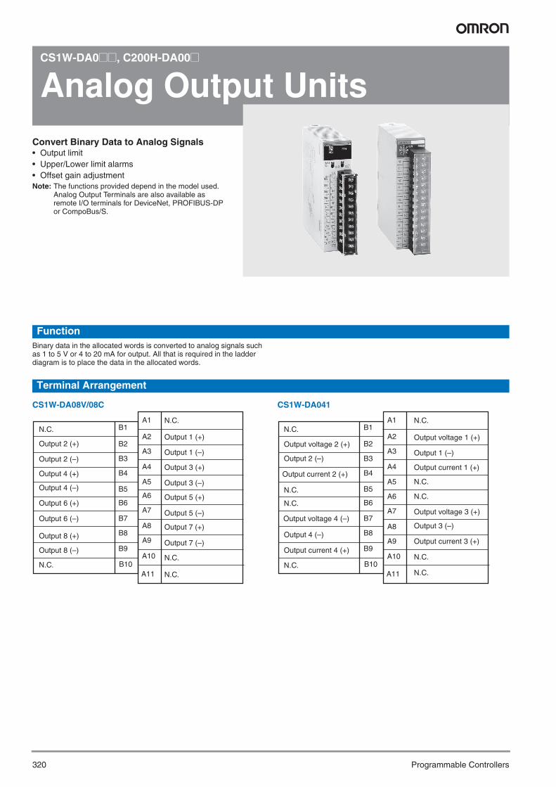
320 Programmable Controllers
CS1W-DA0@@, C200H-DA00@
Analog Output UnitsConvert Binary Data to Analog Signals • Output limit• Upper/Lower limit alarms• Offset gain adjustmentNote: The functions provided depend in the model used.
Analog Output Terminals are also available as remote I/O terminals for DeviceNet, PROFIBUS-DP or CompoBus/S.
FunctionBinary data in the allocated words is converted to analog signals such as 1 to 5 V or 4 to 20 mA for output. All that is required in the ladder diagram is to place the data in the allocated words.
Terminal Arrangement
CS1W-DA08V/08C CS1W-DA041
Output 2 (+)
Output 2 (–)
Output 4 (+)
Output 4 (–)
Output 6 (–)
Output 8 (+)
Output 8 (–)
Output 1 (+)
Output 1 (–)
Output 3 (+)
Output 3 (–)
Output 5 (+)
Output 5 (–)
Output 7 (+)
B1
B2
B3
B4
B5
B6
B7
B8
B9
A1
A2
A3
A4
A5
A6
A7
A8
A9
B10
Output 6 (+)
Output 7 (–)
N.C.
A10
A11N.C.
N.C.
N.C.
N.C.
Output current 2 (+)
Output 2 (–)
Output current 4 (+)
Output 4 (–)
Output current 1 (+)
Output 1 (–)
B1
B2
B3
B4
B5
B6
B7
B8
B9
A1
A2
A3
A4
A5
A6
A7
A8
A9
B10
N.C.
A10
A11
N.C.
Output voltage 2 (+)
N.C.
N.C.
Output voltage 4 (–)
N.C.
Output voltage 1 (+)
N.C.
N.C.
Output current 3 (+)
Output 3 (–)
Output voltage 3 (+)
N.C.
N.C.
Y201-EN2-03.book Seite 320 Donnerstag, 30. März 2006 1:52 13

Analog Output Units 321
Pro
gra
mm
able
C
on
tro
llersSpecifications
Note: Process I/O Units with individually isolated channels are also available for analog I/O. Refer to page 326.
Model CS1W-DA041 CS1W-DA08V CS1W-DA08C C200H-DA003 C200H-DA004Classification CS1 Special I/O Units C200H Special I/O UnitsUnit numbers 0 to 95 0 to 95 0 to 95 0 to F 0 to FOutputs 4 pts 8 pts 8 pts 8 pts 8 ptsSignal range Voltages 1 to 5 V Yes Yes --- Yes ---
0 to 10 V Yes Yes --- Yes ---0 to 5 V Yes Yes --- --- ---–10 to 10 V Yes Yes --- Yes ---
Currents 4 to 20 mA Yes --- Yes --- Yes0 to 20 mA --- --- --- --- ---
Signal range settings 4 settings (one for each point)
8 settings (one for each point)
8 settings (one for each point)
8 settings (one for each point)
8 settings (one for each point)
Resolution 1/4000 1/4000 1/4000 1/4000 1/4000Conversion speed 1.0 ms/pt max. 1.0 ms/pt max. 1.0 ms/pt max. 1.0 ms/pt max. 1.0 ms/pt max.Overall accuracy (at 25 °C) Voltage: ±0.3%FS
Current: ±0.5%FS±0.3% FS ±0.5% FS ±0.3% FS ±0.5% FS
Connections Terminal block Terminal block Terminal block Terminal block Terminal blockFeatures Output hold function --- Yes Yes Yes Yes
Y201-EN2-03.book Seite 321 Donnerstag, 30. März 2006 1:52 13

322 Programmable Controllers
CS1W-MAD44, C200H-MAD01
Analog I/O UnitsAnalog Inputs and Outputs combined in One Unit• Moving average filter function• Peak hold function• Wire burnout detection• Output hold function• Ratio conversions
FunctionOne Unit performs both analog input and analog output operations. The Unit can also be used for ratio and bias processing, which can be per-formed on analog inputs to output the results as analog outputs.
Terminal Arrangement (CS1W-MAD44)
Specifications
Output 2 (+) B1
Output 2 (–) B2
Output 4 (+) B3
Output 4 (–) B4
N.C. B5
Input 2 (+) B6
Input 2 (–) B7
AG B8
Input 4 (+) B9
Input 4 (–) B10
A1
A2
A3
A4
A5
A6
A7
A8
A9
A10
A11
Output 1 (+)
Output 1 (–)
Output 3 (+)
Output 3 (–)
N.C.
Input 1 (+)
Input 1 (–)
AG
Input 3 (+)
Input 3 (–)
N.C.
Model C200H-MAD01 CS1W-MAD44Classification C200H Special I/O Unit CS1 Special I/O UnitUnit numbers 0 to F 0 to 95Inputs 2 pts 4 ptsOutputs 2 pts 4 ptsInput signal ranges Voltages 1 to 5 V Yes Yes
0 to 5 V --- Yes0 to 10 V Yes Yes–10 to 10 V Yes Yes4 to 20 mA Yes Yes
Output signal ranges Currents 1 to 5 V Yes Yes0 to 5 V --- Yes0 to 10 V Yes Yes–10 to 10 V Yes Yes4 to 20 mA Yes ---
Resolution 1/4000 (inputs/outputs) 1/4000 (inputs/outputs)Conversion speed 1.0 ms/pt max (inputs/outputs) 1.0 ms/pt max (inputs/outputs)Overall accuracy
Inputs Voltage: ±0.2%Current: ±0.4%
Voltage: ±0.2%Current: ±0.4%
Outputs Voltage: ±0.3%Current: ±0.5%
Voltage: ±0.3%
Connections Terminal block Terminal blockFeatures Mean function Yes Yes
Peak hold Yes YesWire burnout detection Yes YesOutput hold Yes YesRatio conversion Yes Yes
Y201-EN2-03.book Seite 322 Donnerstag, 30. März 2006 1:52 13

323Loop Control Unit
Pro
gra
mm
able
C
on
tro
llers
CS1W-LC001, CS1W-LCB01/05, CS1D-CPU@@P
Loop Control UnitIntegrate Process Control and Monitoring functions with PLC sequence control.With easy-to-use DCS-style function block configuration, complex control systems can be set up in minutes.• The control system can be scaled to match the con-
trolled system, from a few loops that replace a Con-troller to hundreds of loops that perform large-scale process control.
• A variety of control programs can be created by selecting from more than 70 kinds of function blocks suitable for loop control, such as PID calculations, Segment Programs, and square root calculations.
• The CX-Process Tool, included in CX-One, can be used for easy programming.
• A Tuning Screen can be opened in the CX-Process Tool to change parameters while monitoring the sta-tus.
• Duplex systems are available for applications that require high reliability.
• The NS Face Plate Auto Builder software can be used to automatically create a touch panel for NS-series PTs from a function block screen.
FunctionThe CS1-series Loop Control Boards and Units are packed with DCS functions and can use function block programs, which are ideal for pro-cess control. Graphical programming can be used, so function blocks can be pasted into a window and connected with the mouse.
A wide variety of control methods can be executed, from regular PID control to cascade control and feed-forward control.
System Configuration
NS-series PT
Analog I/O
Create and transfer the function block data with the CX-Process Tool.
CS1-series PLC and Loop Control Board/Unit
Y201-EN2-03.book Seite 323 Donnerstag, 30. März 2006 1:52 13
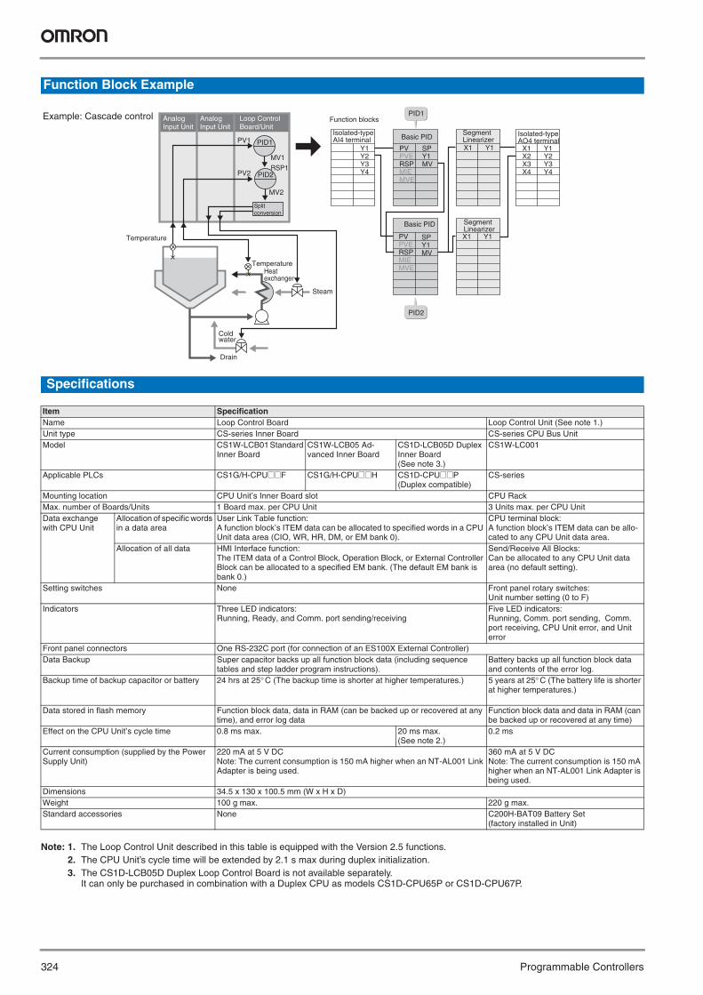
324 Programmable Controllers
Specifications
Note: 1. The Loop Control Unit described in this table is equipped with the Version 2.5 functions.2. The CPU Unit’s cycle time will be extended by 2.1 s max during duplex initialization.3. The CS1D-LCB05D Duplex Loop Control Board is not available separately.
It can only be purchased in combination with a Duplex CPU as models CS1D-CPU65P or CS1D-CPU67P.
Function Block Example
Item SpecificationName Loop Control Board Loop Control Unit (See note 1.)Unit type CS-series Inner Board CS-series CPU Bus UnitModel CS1W-LCB01 Standard
Inner BoardCS1W-LCB05 Ad-vanced Inner Board
CS1D-LCB05D Duplex Inner Board (See note 3.)
CS1W-LC001
Applicable PLCs CS1G/H-CPU@@F CS1G/H-CPU@@H CS1D-CPU@@P(Duplex compatible)
CS-series
Mounting location CPU Unit’s Inner Board slot CPU RackMax. number of Boards/Units 1 Board max. per CPU Unit 3 Units max. per CPU UnitData exchange with CPU Unit
Allocation of specific words in a data area
User Link Table function:A function block’s ITEM data can be allocated to specified words in a CPU Unit data area (CIO, WR, HR, DM, or EM bank 0).
CPU terminal block:A function block’s ITEM data can be allo-cated to any CPU Unit data area.
Allocation of all data HMI Interface function:The ITEM data of a Control Block, Operation Block, or External Controller Block can be allocated to a specified EM bank. (The default EM bank is bank 0.)
Send/Receive All Blocks:Can be allocated to any CPU Unit data area (no default setting).
Setting switches None Front panel rotary switches:Unit number setting (0 to F)
Indicators Three LED indicators:Running, Ready, and Comm. port sending/receiving
Five LED indicators:Running, Comm. port sending, Comm. port receiving, CPU Unit error, and Unit error
Front panel connectors One RS-232C port (for connection of an ES100X External Controller)Data Backup Super capacitor backs up all function block data (including sequence
tables and step ladder program instructions).Battery backs up all function block data and contents of the error log.
Backup time of backup capacitor or battery 24 hrs at 25° C (The backup time is shorter at higher temperatures.) 5 years at 25° C (The battery life is shorter at higher temperatures.)
Data stored in flash memory Function block data, data in RAM (can be backed up or recovered at any time), and error log data
Function block data and data in RAM (can be backed up or recovered at any time)
Effect on the CPU Unit’s cycle time 0.8 ms max. 20 ms max. (See note 2.)
0.2 ms
Current consumption (supplied by the Power Supply Unit)
220 mA at 5 V DCNote: The current consumption is 150 mA higher when an NT-AL001 Link Adapter is being used.
360 mA at 5 V DCNote: The current consumption is 150 mA higher when an NT-AL001 Link Adapter is being used.
Dimensions 34.5 x 130 x 100.5 mm (W x H x D)Weight 100 g max. 220 g max.Standard accessories None C200H-BAT09 Battery Set
(factory installed in Unit)
Y1Y2Y3Y4
PID2
PID1
SPY1MV
PVPVERSPMIEMVE
Y1X1
SPY1MV
PVPVERSPMIEMVE
Y1X1
X1X2X3X4
Y1Y2Y3Y4
PID1
PID2
PV1
PV2
MV2
MV1
RSP1
Function blocks
Isolated-typeAI4 terminal
Isolated-typeAO4 terminal
Example: Cascade control
Basic PIDSegmentLinearizer
Basic PID SegmentLinearizer
Temperature
Temperature
Steam
Split conversion
Analog Input Unit
Analog Input Unit
Loop Control Board/Unit
Heat exchanger
Cold water
Drain
Y201-EN2-03.book Seite 324 Donnerstag, 30. März 2006 1:52 13

Loop Control Unit 325
Pro
gra
mm
able
C
on
tro
llers
Note: 1. Operation cycles of 0.01, 0.02, and 0.05 s cannot be set for the CS1D-LCB05D.2. Control blocks such as those for PID control.3. Operation blocks for process control such as those for alarms, square roots, time/date calculations, and pulse-train computations.
Functional Specifications
Item SpecificationsModel numbers CS1W-LCB01 CS1W-LCB05
CS1D-LCB05DCS1W-LC001
Operation method Function block methodOperation cycle Settable cycles:
0.01, 0.02, 0.05, 0.1, 0.2, 0.5, 1, or 2 s(default: 1 s)Can be set for each function block. (See note 1.)
Settable cycles:0.1, 0.2, 0.5, 1, or 2 s (default: 1 s)Can be set for each function block.
Number of function blocks
Analog operation
Control blocks (See note 2.)
50 blocks max. 500 blocks max. 32 blocks max.
Operation blocks (See note 3.)
249 blocks max.
External controller blocks
32 blocks max. (CS1D-LCB05D not included)
Sequence control Sequence tables None 200 tables max.32 conditions and 32 actions per table max. (expandable to 64 conditions and 64 actions per ta-ble)6,400 rules total max.
None
Step ladder program blocks
20 blocks max.2,000 commands total100 commands max. per blockSeparable into a 100 steps max.
200 blocks max.4,000 commands total100 commands max. per blockSeperable into a 100 steps max.
I/O blocks Field terminal blocks 80 blocks max.User link tables
2,400 data items max. None
All data HMI functions2,040 words max.Allocated 1 EM Area bank
HMI functions20,040 words max.Allocated 1 EM Area bank
Send/Receive All Blocks: 1 block each max.
CPU terminal blocks None 16 blocks max.Node terminal blocks None 1000 blocks max.
System common blocks 1 block max.Method for creating and transfering function blocks
Created and transferred using CX-Process Tool (purchased separately).
Control methods PID control method PID with 2 degrees of freedom (with auto-tuning)Control combinations Any of the following function blocks can be combined:
Basic PID control, cascade control, feed-forward control, sample PI control, Smith dead time compen-sation control, PID control with differential gap, override control, program control, time-proportional control, etc.
Alarms PID block internal alarms 4 PV alarms (upper upper-limit, upper limit, lower limit, lower lower-limit) and 1 deviation alarm per PID block
Alarm blocks High/low alarm blocks, deviation alarm blocks
Y201-EN2-03.book Seite 325 Donnerstag, 30. März 2006 1:52 13
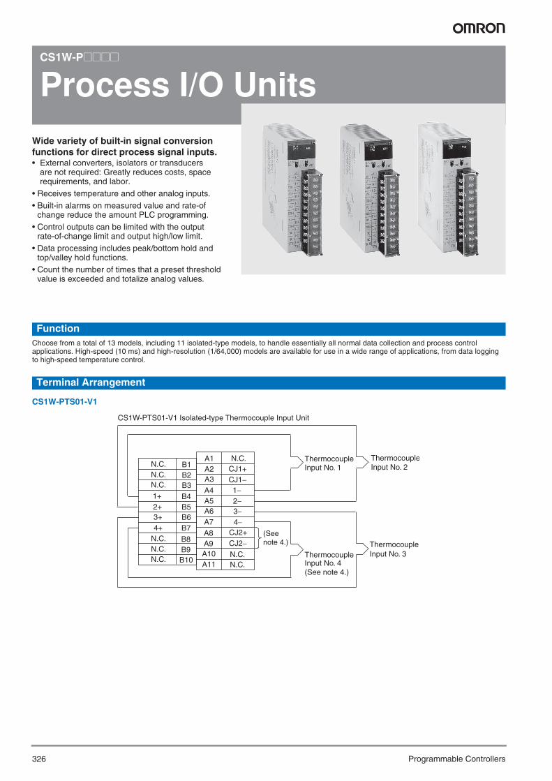
326 Programmable Controllers
CS1W-P@@@@
Process I/O UnitsWide variety of built-in signal conversion functions for direct process signal inputs.• External converters, isolators or transducers
are not required: Greatly reduces costs, space requirements, and labor.
• Receives temperature and other analog inputs. • Built-in alarms on measured value and rate-of
change reduce the amount PLC programming.
• Control outputs can be limited with the output rate-of-change limit and output high/low limit.
• Data processing includes peak/bottom hold and top/valley hold functions.
• Count the number of times that a preset threshold value is exceeded and totalize analog values.
FunctionChoose from a total of 13 models, including 11 isolated-type models, to handle essentially all normal data collection and process control applications. High-speed (10 ms) and high-resolution (1/64,000) models are available for use in a wide range of applications, from data logging to high-speed temperature control.
Terminal Arrangement
CS1W-PTS01-V1
N.C.N.C.N.C.
1+2+3+4+
N.C.N.C.N.C.
B1B2B3
B4B5B6B7
B8B9B10
N.C.CJ1+CJ1−1−2−3−4−
N.C.N.C.
A1A2A3
A4A5A6A7
A8A9A10A11
CJ2+CJ2−
CS1W-PTS01-V1 Isolated-type Thermocouple Input Unit
ThermocoupleThermocouple
ThermocoupleThermocouple
Input No. 2Input No. 1
Input No. 3Input No. 4 (See note 4.)
(See note 4.)
Y201-EN2-03.book Seite 326 Donnerstag, 30. März 2006 1:52 13

Process I/O Units 327
Pro
gra
mm
able
C
on
tro
llers
CS1W-PTS11
CS1W-PTS51
N.C.
N.C.
N.C.
1+
2+
3+
4+
N.C.
N.C.
N.C.
B1
B2
B3
B4
B5
B6
B7
B8
B9
B10
A1
A2
A3
A4
A5
A6
A7
A8
A9
A10
A11
N.C.
CJ1+
CJ1−
1−
2−
3−
4−
CJ2+
CJ2−
N.C.
N.C.
*2
No. 1 thermocouple input
No. 2 thermocouple input
No. 4 thermocouple input (*1)
No. 3 thermocouple input
External alarm outputs
2−2+
CJ
CJ
4−4+
ALM2
ALM4
0V
N.C.
B1
B2
B3
B4
B5
B6
B7
B8
B9
B10
A1
A2
A3
A4
A5
A6
A7
A8
A9
A10
A11
N.C
1−1+
N.C.
N.C.
3−3+
ALM1
ALM3
24V
N.C.
No. 2 thermocouple input
Cold junction sensor
No. 4 thermocouple input
No. 1 thermocouple input
No. 3 thermocouple input
External alarm outputsL
L
L
L
Y201-EN2-03.book Seite 327 Donnerstag, 30. März 2006 1:52 13

328 Programmable Controllers
CS1W-PTS55
CS1W-PTS02
N.C.
N.C.
1+
2+
3+
4+
5+
6+
7+
8+
B1
B2
B3
B4
B5
B6
B7
B8
B9
B10
A1
A2
A3
A4
A5
A6
A7
A8
A9
A10
A11
Cold junction sensor
N.C. B11
N.C. B12A12
CJ1+
CJ1-
1-
2-
3-
4-
5-
6-
7-
8-
CJ2+
CJ2-Cold junction sensor
No. 8 thermocouple input
No. 7 thermocouple input
No. 6 thermocouple input
No. 5 thermocouple input
No. 4 thermocouple input
No. 3 thermocouple input
No. 2 thermocouple input
No. 1 thermocouple input
CS1W-PTS02 Isolated-type Resistance Thermometer Unit
No. 2 input
No. 1 input
No. 3 input
No. 4 input
Resistance thermometer
Resistance thermometer
Resistance thermometer
Resistance thermometer
Y201-EN2-03.book Seite 328 Donnerstag, 30. März 2006 1:52 13

Process I/O Units 329
Pro
gra
mm
able
C
on
tro
llers
CS1W-PTS03
CS1W-PTS12
CS1W-PTS52
CS1W-PTS03 Isolated-type Resistance Thermometer Unit
Input No. 2
Input No. 1
Input No. 3
Input No. 4
Resistance thermometer
Resistance thermometer (Ni508.4 Ω)
Resistance thermometer
Resistance thermometer
N.C.
N.C.
N.C.
2A
2B
2b
N.C.
N.C.
N.C.
N.C.
B1
B2
B3
B4
B5
B6
B7
B8
B9
B10
A1
A2
A3
A4
A5
A6
A7
A8
A9
A10
A11
N.C.
1A
1B
1b
3A
3B
3b
N.C.
4A
4B
4b
No. 2 Platinum-resistance Thermometer input
No. 1 Platinum-resistance Thermometer input
No. 3 Platinum-resistance Thermometer input
No. 4 Platinum-resistance Thermometer input
External alarm outputs
2b
2B
2A
4b
4B
4A
ALM2
ALM4
0V 0V
N.C. N.C.
B1
B2
B3
B4
B5
B6
B7
B8
B9
B10
A1
A2
A3
A4
A5
A6
A7
A8
A9
A10
A11
N.C
1b
1B
1A
3b
3B
3A
ALM1
ALM3
24V
N.C.
External alarm outputsL
L
L
L
No. 2 Platinum-resistance Thermometer input
No. 4 Platinum-resistance Thermometer input
No. 1 Platinum-resistance Thermometer input
No. 3 Platinum-resistance Thermometer input
Y201-EN2-03.book Seite 329 Donnerstag, 30. März 2006 1:52 13
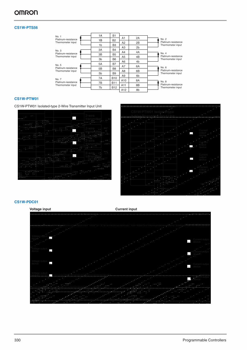
330 Programmable Controllers
CS1W-PTS56
CS1W-PTW01
CS1W-PDC01
1A
1B
1b
3A
3B
3b
5A
5B
5b
7A
B1
B2
B3
B4
B5
B6
B7
B8
B9
B10
A1
A2
A3
A4
A5
A6
A7
A8
A9
A10
A11
2A
2B
2b
4A
4B
4b
6A
6B
6b
8A
8B
No. 2 Platinum-resistance Thermometer input
No. 4 Platinum-resistance Thermometer input
No. 1 Platinum-resistance Thermometer input
No. 3 Platinum-resistance Thermometer input
7B
7b
B11
B12A12 8b
No. 6 Platinum-resistance Thermometer input
No. 8 Platinum-resistance Thermometer input
No. 5Platinum-resistance Thermometer input
No. 7 Platinum-resistance Thermometer input
CS1W-PTW01 Isolated-type 2-Wire Transmitter Input Unit
Current output device
Current output device
Current output device
Current output device
−
−
−
−
CS1W-PTW01 Isolated-type 2-Wire Transmitter Input Unit
2-wire transmitter
2-wire transmitter
2-wire transmitter
2-wire transmitter
−
−
−
−
Current inputVoltage input
Voltage output device Current output
device
Voltage output device
Voltage output device
Voltage output device
Current output device
Current output device
Current output device
−
−
−
−
−
−
−
−
Y201-EN2-03.book Seite 330 Donnerstag, 30. März 2006 1:52 13

Process I/O Units 331
Pro
gra
mm
able
C
on
tro
llers
CS1W-PDC11
CS1W-PDC55
CS1W-PTR01
V1
COM1
V2
COM2
V3
COM3
V4
COM4
N.C.
N.C.
B1
B2
B3
B4
B5
B6
B7
B8
B9
B10
A1
A2
A3
A4
A5
A6
A7
A8
A9
A10
A11
N.C.
I1
N.C.
I2
N.C.
I3
N.C.
I4
N.C.
N.C.
N.C.
CS1W-PDC11
Voltage Inputs
+
−
+
−
+
−
+
−
Voltage output device
Voltage output device
Voltage output device
Voltage output device
CS1W-PDC11
Current inputs
V1
COM1
V2
COM2
V3
COM3
V4
COM4
N.C.
N.C.
B1
B2
B3
B4
B5
B6
B7
B8
B9
B10
A1
A2
A3
A4
A5
A6
A7
A8
A9
A10
A11
N.C.
I1
N.C.
I2
N.C.
I3
N.C.
I4
N.C.
N.C.
N.C.
Current output device
Current output device
Current output device
Current output device
+
−
+
−
+
−
+
−
V1+I1+COM1V3+I3+COM3V5+I5+COM5V7+I7+COM7
B1B2B3B4B5B6B7B8B9B10B11B12
A1A2A3A4A5A6A7A8A9A10A11A12
V2+I2+COM2V4+I4+COM4V6+I6+COM6V8+I8+COM8
+Voltage output device
-+
Voltage output device
-+
Voltage output device
-+
Voltage output device
-
+Voltage output device
-+
Voltage output device
-+
Voltage output device
-+
Voltage output device
-
V1+I1+COM1V3+I3+COM3V5+I5+COM5V7+I7+COM7
B1B2B3B4B5B6B7B8B9B10B11B12
A1A2A3A4A5A6A7A8A9A10A11A12
V2+I2+COM2V4+I4+COM4V6+I6+COM6V8+I8+COM8
CS1W-PDC55+
Current output device
-+
Current output device
-+
Current output device
-+
Current output device
-
+Current output device
-+
Current output device
-+
Current output device
-+
Current output device
-
CS1W-PDC55
Voltage Inputs Current inputs
CS1W-PRT01 Power Transducer Input Unit
Powertransducer
Powertransducer
Powertransducer
Powertransducer
Powertransducer
Powertransducer
Powertransducer
Powertransducer
−
−
−
−
−
−
−
−
Y201-EN2-03.book Seite 331 Donnerstag, 30. März 2006 1:52 13
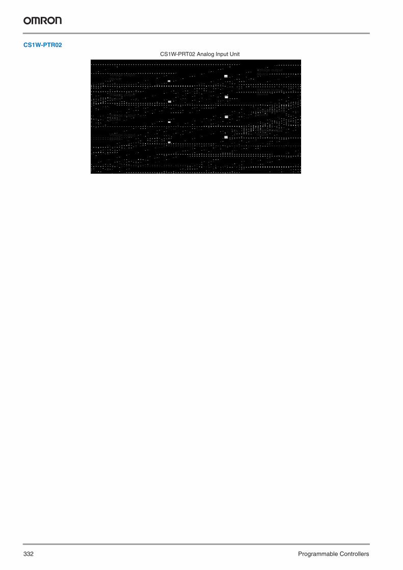
332 Programmable Controllers
CS1W-PTR02CS1W-PRT02 Analog Input Unit
Voltage output device
Voltage output device
Voltage output device
Voltage output device
Voltage output device
Voltage output device
Voltage output device
Voltage output device
−
−
−
−
−
−
−
−
Y201-EN2-03.book Seite 332 Donnerstag, 30. März 2006 1:52 13
Process I/O Units 333
Pro
gra
mm
able
C
on
tro
llers
CS1W-PPS01
No-voltage Semiconductor Input Voltage Input
CS1W-PPS01 Isolated-type Pulse Input Unit CS1W-PPS01 Isolated-type Pulse Input Unit
Voltage pulse generation
Contact Input
CS1W-PPS01 Isolated-type Pulse Input Unit CS1W-PPS01 Isolated-type Pulse Input Unit
3-wire Sensor Input
Internal power supply
Internal power supply
Internal power supply
Internal power supply
−
−
−
−
Y201-EN2-03.book Seite 333 Donnerstag, 30. März 2006 1:52 13

334 Programmable Controllers
CS1W-PMV01
CS1W-PMV02
Voltage Output Current Output
CS1W-PMV01 Isolated-type Analog Output Unit CS1W-PMV01 Isolated-type Analog Output Unit
Load
Load
Load Load resistance
Load Load resistance
Load resistance
Load resistance
−
−
−
−
−
−
−
−
−
−
−
−
−
−
−
−
V1L B1
COM1 B2
V2L B3
COM2 B4
V3L B5
COM3 B6
V4L B7
COM4 B8
N.C. B9
N.C. B10
V1H
COM1
V2H
COM2
V3H
COM3
V4H
COM4
N.C.
N.C.
N.C.
+
+
−
−A3
A4
A5
A6
A7
A8
A9
A10
A11
A1
A2
CS1W-PMV02 Isolated-type Analog Output Unit
Y201-EN2-03.book Seite 334 Donnerstag, 30. März 2006 1:52 13

Process I/O Units 335
Pro
gra
mm
able
C
on
tro
llersSpecifications
Note: Refer to pages 318 to 322 for descriptions of the Analog I/O Units (CS1W-AD0@@, CS1W-DA0@@, CS1W-MAD44.)
Unit name Model I/O capacity
Field I/O isolation
I/O range/type Accuracy/effective resolution Main features
Isolated-type Thermocouple Input Unit
CS1W-PTS11 4 inputs All inputs isolated.
B, E, J, K, L, N, R, S, T, U, WRe5-26,PL II, ±100 mV
Standard accuracy: ±0.05% of full scaleTemp coefficient: ±0.01%/° CEffective resolution: 1/64,000Conversion cycle: 20 ms/4 pts10 ms/2 pts
Output scaling, measured value alarms (HH, H, L, LL), rate-of-change opera-tion and alarms, input dis-connection alarms, top hold, bottom hold, valley hold, zero span adjust-ment over user-set range
Isolated-type Resistance Thermometer Input Unit
CS1W-PTS12 4 inputs All inputs isolated.
Pt100Ω (JIS, IEC), JPt100Ω, Pt50Ω, Ni508.4Ω
Standard accuracy: Larger of ±0.05% of full scale or ±0.1° CTemp coefficient: ±0.01%/° CEffective resolution: 1/64,000Conversion cycle:20 ms/4 pts10 ms/2 pts
Output scaling, measured value alarms (HH, H, L, LL), rate-of-change opera-tion and alarms, input dis-connection alarms, top hold, bottom hold, valley hold, zero span adjust-ment over user-set range
Isolated-type Thermocouple Input Units (Economical type)
CS1W-PTS51 4 inputs All inputs are isolated
B, J, K, R, S, T, L Overall accuracy: ± 0.3% of PV or ± 1°C, whichever is larger, ± 1digit max.Conversion cycle: 250 ms/4 pts
Process value alarms (H, L)Process value alarm DO outputInput disconnection detection
CS1W-PTS55 8 inputs
Isolated-type Resistance Thermometer Input Unit (Economical type)
CS1W-PTS52 4 inputs Alle inputs are isolated
Pt100 (JIS, IEC), JPt100 Overall accuracy: ± 0.3% of PVor ± 0.8°C, whichever is larger,± 1 digit max.Conversion cycle: 250 ms/4 pts
Process value alarms (H, L)Process valu alarm DO outputInput disconnection detection
CS1W-PTS56 8 inputs
Isolated-type Two-wire Transmission Device Input Unit
CS1W-PTW01 4 inputs All inputs isolated.
4 to 20 mA, 1 to 5 V Standard accuracy: ±0.2%Temp coefficient: ±0.015%/° CResolution: 1/4,096Conversion cycle: 100 ms/4 pts
Built-in power supply for 2-wire transmission device output scaling (±32,000), measured value alarms (HH, H, L, LL), rate-of-change operation and alarms, input disconnec-tion alarms
Isolated-type Analog Input Unit
CS1W-PDC11 4 inputs All inputs isolated.
4 to 20 mA, 0 to 20 mA, 0 to 10 V, ±10 V, 0 to 5 V, ± 5 V, 1 to 5 V, 0 to 1.25 V, ±1.25 V
Standard accuracy: ±0.05% of full scaleTemp coefficient: ±0.01%/° CEffective resolution: 1/64,000Conversion cycle:20 ms/4 pts10 ms/2 pts
Output scaling, measured value alarms (HH, H, L, LL), rate-of-change opera-tion and alarms, input dis-connection alarms, top hold, bottom hold, valley hold, total value measure-ment
CS1W-PDC55 8 inputs All inputs isolated
4 to 20 mA, 0 to 10 V, 0 to 5 V, 1 to 5 V
Standard accuracy: ±0.3% full scale. Resolution 1/16000. Conversion cycle 250 ms/8 pts
Measured value alarms (H, L), input detection
Isolated-type Pulse Input Unit
CS1W-PPS01 4 inputs All inputs isolated.
Max. counting speed: 20 K pulses/s (voltage input or no-voltage semi-conductor in-put) or20 pulses/s(contact input)
--- Built-in sensor power sup-ply, contact bounce filter, unit pulse conversion, ac-cumulative and instanta-neous value output, 4 instantaneous value alarms.
Isolated-type Control Output Unit
CS1W-PMV01 4 outputs All outputs isolated.
4 to 20 mA, 1 to 5 V Standard accuracy: 4 to 20 mA: ±0.1%1 to 5 V: ±0.2%
Temp coefficient: ±0.015%/° C4,000 (outputs)Conversion cycle: 100 ms/4 pts
Output disconnection alarms, control output an-swerback input, output rate-of-change limit, out-put high/low limits
Isolated-type Power Voltage Output Unit
CS1W-PMV02 4 outputs All outputs isolated
0 to 10 V, ±10 V, 0 to 5 V, ±5 V, 0 to 1 V, ±1 V
Standard accuracy: ±0.1%Temp coefficient: ±0.015%/° CResolution (at full scale):±10 V or ±1 V: 1/16,0000 to 10 V, 0 to 1 V, or ±5 V: 1/8,0000 to 5 V: 1/4,000Conversion cycle: 40 ms/4 pts
Output rate-of-change limit, Output high/low limit, Output scaling (±32,000)
Power Transducer Input Unit
CS1W-PTR01 8 inputs No isolation between inputs.
±1 mA, 0 to 1 mA Standard accuracy: ±0.2%Temp coefficient: ±0.015%/° CResolution: 1/4,096Conversion cycle: 200 ms/8 pts
Motor overdrive preven-tion at startup, output scal-ing (±32,000), measured value alarms (H, L)
Analog Input Unit CS1W-PTR02 8 inputs No isolation between inputs.
±100 mV, 0 to 100 mV Standard accuracy: ±0.2%Temp coefficient: ±0.015%/° CResolution: 1/4,096Conversion cycle: 200 ms/8 pts
Output scaling (±32,000), measured value alarms (H, L)
Y201-EN2-03.book Seite 335 Donnerstag, 30. März 2006 1:52 13

336 Programmable Controllers
CS1W-PTS@@, C200H-TS@@@
Temperature Sensor UnitsDirect Input from Four to Eight Temperature Sensors• Input directly from up to eight temperature sensors
with one Unit. (The types of temperature sensor and temperature ranges can be set separately for each input for the CS1W-PTS@@.)
• Models available with isolated inputs to prevent unwanted current flow between temperature sensor inputs (CS1W-PTS@@ only).
• Provided with measured value alarms (4 points each) (CS1W-PTS@@ only).
• Sensor disconnection detection provided.
FunctionUsing input from thermocouples or resistance thermometers (up to 8 inputs), the Unit converts the measured temperatures into BCD or binary data and stores them in the allocated relay area every cycle. The data can be processed using the ladder program.
Circuit Configuration
Specifications
Note: Refer to page 326 for information on CS1W-PTS@@ Process I/O Units.
Temperature sensors
4 points
Model CS1W-PTS11 CS1W-PTS51 CS1W-PTS55 CS1W-PTS12 CS1W-PTS52 CS1W-PTS56 C200H-TS001/002/101/102Classification CS1 Special I/O Units C200H Special I/O UnitsUnit numbers 0 to 95 0 to 95 0 to 95 0 to 95 0 to 95 0 to 95 0 to 9Inputs 4 pts 4 pts 8 pts 4 pts 4 pts 8 pts 4 ptsInput signals
Thermo-couples
K Yes Yes Yes --- --- --- TS001, TS002J Yes Yes Yes --- --- --- TS001L Yes Yes Yes --- --- --- TS002R Yes Yes Yes --- --- --- ---S Yes Yes Yes --- --- --- ---T Yes Yes Yes --- --- --- ---E Yes --- --- --- --- --- ---B Yes Yes Yes --- --- --- ---N Yes --- --- --- --- --- ---W Yes --- --- --- --- --- ---U Yes --- --- --- --- --- ---PLII Yes --- --- --- ------ --- ---±100 mV Yes --- --- --- --- --- ---
Resistance thermome-ters
JPt100 --- --- --- Yes Yes Yes TS101PT100 --- --- --- Yes Yes Yes TS102Ni508.4Ω --- --- --- Yes Yes Yes ---
Input signal range settings 4 pts set individually
4 pts set individually
8 pts set individually
4 pts set individually
4 pts set individually
8 pts set individually
One setting for all 4 pts
A/D conversion output data 4-digit binary
4-digit binary or BCD
4-digit binary or BCD
4-digit binary
4-digit binary or BCD
4-digit binary or BCD
4-digit BCD
Conversion speed 20 ms/4 points, 10 ms/2 points
250 ms/Unit 250 ms/Unit 20 ms/4 points, 10 ms/2 points
250 ms/Unit 250 ms/Unit 4.8 s max. (when 4 pts are set for Unit)
Overall accuracy
Standard accuracy ±0.05% of full scale
±0.3% of PV or ±1°C, whichever is larger, ±1 digit max.
Larger of ±0.05% of full scale or ±0.1°C
±0.3% of PV or ±0.8°C, whichever is larger, ±1 digit max.
±1% + 1°C
Temperature coeffi-cient
±0.01%/°C
Cold junction compensation error
±1°C ---
Connections Terminal block
Y201-EN2-03.book Seite 336 Donnerstag, 30. März 2006 1:52 13

337Temperature Control Units
Pro
gra
mm
able
C
on
tro
llers
C200H-TC@@@
Temperature Control UnitsOne Unit Functions as Two Temperature Controllers• Supports 2-loop PID control (two degrees of free-
dom) or ON/OFF control.• Input directly from two temperature sensors (ther-
mocouples: R, S, K, J, T, E, B, N, L, or U) or plati-num resistance thermometers (JPt00, Pt100).
• Open-collector, voltage, or current outputs• Sampling period: 500 ms• Run/start control.• Two internal alarms per loop.• Detects heater burnout though current detectors for
both loops.• Record up to eight sets of target values, alarm val-
ues, and PID parameters.• Connects to Data Setting Console.
FunctionPerform 2-loop PID control based on inputs from thermocouples or platinum resistance thermometers to control a transistor, voltage, or current output. Words allocated to the Unit in memory can be mani-pulated from the ladder diagram to start/stop operation, set the target value, read the process value, or perform other operations.
System Configuration
Specifications
General
Data Setting Console
Output cable
Manipulated variable
Data Setting Console
Two tem-perature sensors
Classification Temperature sensor inputs Control outputs Unit numbers ModelC200H Special I/O Unit Thermocouples (R, S, K, J, T, E,
B, N, L, or U)Open-collector (pulse) 0 to 9 C200H-TC001Voltage (pulse) C200H-TC002Current (linear) C200H-TC003
Platinum resistance thermome-ters (JPt00, Pt100)
Open-collector (pulse) C200H-TC101Voltage (pulse) C200H-TC102Current (linear) C200H-TC103
Specifications ModelMonitoring, setting, and changing present values, set points, alarm values, PID parameters, bank numbers, etc.
C200H-DSC01
Y201-EN2-03.book Seite 337 Donnerstag, 30. März 2006 1:52 13

338 Programmable Controllers
CS1W-NC@@@, C200HW-NC@@@
Position Control UnitsHigh-speed, High-precision Positioning with 1, 2, or 4 Axes• Simple positioning systems can be created by
directly specifying operation from the CPU Unit when required.
• Positioning data is saved in internal flash memory, eliminating the need to maintain a backup battery.
• Use Windows-based Support Software to easily cre-ate positioning data and store data and parameters in files. (Use WS01-NCTF1-E with C200HW-NC@ models and WS02-NCTC1-E with CS1W-NC@@ models.)
• Interrupt feeding, forced starting, and other features also supported.
FunctionThese Position Control Units support open-loop control with pulse-train outputs. Position using automatic trapezoid or S-curve acceleration and deceleration. Models available with 1, 2, or 4 axes. Use in combination with servomotors or stepping motors that accept pulse-train inputs.
System Configuration
Specifications
Inputs
Pulse-input Servo Driver
Servomotor
Servo Relay Unit
Model CS1W-NC113CS1W-NC133
CS1W-NC213CS1W-NC233
CS1W-NC413CS1W-NC433
C200HW-NC113 C200HW-NC213 C200HW-NC413
Unit name Position Control UnitClassification CS1 Special I/O Units C200H Special I/O UnitsUnit numbers 0 to 95 0 to 15 (0 to F)Control method Open-loop, automatic trapezoid acceleration/decelerationControl output signals CS1W-NC@13: Open-collector outputs
CS1W-NC@33: Line-driver outputsOpen-collector
Controlled axes 1 2 4 1 2 4Operating modes Direct operation or memory operationData format Binary (hexadecimal) BCDAffect on scan time for end refresh 0.29 to 0.41 ms max./unit 2.6 to 4.5 ms max./unitAffect on scan time for IOWR/IORD
0.6 to 0.7 ms max./instructions 2.6 to 5.5 ms max./instructions
Startup time 2 ms min. (Refer to operation manual for conditions.) 7.51 ms min. (Refer to operation manual for conditions.)Position data –1,073,741,823 to +1,073,741,823 pulses –9,999,999 to +9,999,999 pulsesNo. of positions 100 per axisSpeed data 1 to 500 kpps (in 1-pps units) 1 to 500 kpps (specified as factor)No. of speeds 100 per axisAcceleration/ deceleration times
0 to 250 s (time to max. speed)
Acceleration/deceleration curves
Trapezoidal or S-curve
Saving data in CPU Flash memoryWindows-based Support Software CX-Position SYSMAC-NCT (WS01-NCTF1-E)
Y201-EN2-03.book Seite 338 Donnerstag, 30. März 2006 1:52 13

339Motion Control Units
Pro
gra
mm
able
C
on
tro
llers
CS1W-MC421/-MC221
Motion Control UnitsHigh-precision, Two-axis Motion Control with Multi-tasking G-language Programming• High-speed control of up to 4 axes with one Unit and
up to 76 axes with one PLC (19 Units x 4 axes) (assumes that Power Supply Unit capacity is not exceeded).
• Winding operations easily controlled at high-speed using traverse positioning control.
• High-speed response to commands from CPU Unit (8 ms for 2 axes, 13 ms for 4 axes).
• Encoder response of 2 Mpps possible with 4x frequency multiplication for applications with high-speed, high-precision servomotors.
• D interrupt code outputs to CPU Unit at end of positioning or at specified positions (D code output time: 3.3 ms max.).
• CX-Motion Windows-based Support SoftwareDefine user mnemonics to use in place of G codes to simplify MC program development and analysis.
• Servo trace function from CX-Motion to trace error counter changes or motor speeds.
• Automatic Loading FunctionMC programs and positioning data can be auto-matically downloaded from computer memory when required by the MC Unit.
FunctionThe Motion Controller provides closed-loop control with analog outputs for up to 2 or 4 axes, and supports the G language for advanced, high-speed, high-precision position control, such as traverse operation. Multi-tasking allows you to run the two axes independently for a wider range of application.
System Configuration
Note: The C200H-MC221 can also be used with CS1 PLCs.
CX-Motion
CPU Unit
Servomotor4 axes
Analog Input Servo Driver
Terminal Block Conversion UnitTeaching
Box
Y201-EN2-03.book Seite 339 Donnerstag, 30. März 2006 1:52 13

340 Programmable Controllers
Specifications
General
CX-Motion: Windows-based Support Software
Model CS1W-MC421 CS1W-MC221Classification CS1 Special I/O UnitControl method Closed loop with automatic trapezoid or S-curve acceleration/decelerationControl output signals AnalogInternal programming language G language (Program started by command sent from CPU Unit’s ladder program.)Controlled axes 4 axes max. 2 axes max.Maximum position value –39,999,999 to 39,999,999 (for minimum setting unit of 1)Synchronous axis control 4 axes max. 2 axes max.Positioning Linear interpolation 4 axes max. 2 axes max.
Arc interpolation 2 axes max. in a planeHelical interpolation 2-axis arc interpolation in a plane + feed axis ---Traverse 2-axis traverse feedingInfinite feed Infinite feeding of one or more axesInterrupt feed Interrupt feeding for specified axes (Positioning can be specified for when there is no interrupt.)
Task program-ming capacity
Number of tasks 4 tasks max. 2 tasks max.Number of programs 25 programs when using 4 tasks 50 programs when using 2 tasksProgram capacity 500 blocks per task when using 4 tasks 1,000 blocks per task when using 2 tasks
Model WS02-MCTC1-EV@Supported MC Units CS1W-MC221/421, C200H-MC221, and CV500-MC221/421Applicable computer DOS, OS: Windows 95/98 or Windows NT Version 4.0Functions Functions required for MC Unit control: Creating/editing/saving/printing system parameters, positioning data, and MC programs; moni-
toring MC Unit operation
Y201-EN2-03.book Seite 340 Donnerstag, 30. März 2006 1:52 13

341Motion Control Unit
Pro
gra
mm
able
C
on
tro
llers
C200HW-MC402-E
Motion Control UnitAdvanced multi-axes Motion Control with Multi-task BASIC language programming• Advanced Motion control of 4 axes per unit and up
to 16 modules can be installed in one PLC• Analogue outputs for position, Speed and Torque
control• Hardware registration input for every axis• Electronic CAM profiles and axes synchronization• Friendly Motion Perfect Windows-based program-
ming and debugging software. Provides versatile test and monitoring functions including a 4-channel software oscilloscope.
FunctionThe advanced Motion control unit provides closed-loop control of up to 4 axes, programmed in a multi-task BASIC type language and supported by the powerful software tool. The unit provides a complete command set, allowing applications such as flying saws, rotaring knives, any synchro-nization and electronic CAM profile to be easily programmed.
System Configuration
Servomotor�4 Axes
Analog Input�Servo Driver
Termnal Block�Conversion Unit
C200HW-MC402Motion Perfect
I/O
Y201-EN2-03.book Seite 341 Donnerstag, 30. März 2006 1:52 13

342 Programmable Controllers
Specifications
General
Motion Perfect Software
Model C200HW-MC402-EClassification C200H Special I/O UnitControl Method Closed loop Position, Speed and Torque controlControl Output signals AnalogueProgramming language BASIC type motion control languageControlled axes 4 real axes and 4 virutal axesMeasurement units User definablePositioning Linear interpolation 4 axes
Arc interpolation For any 2 axesHelical interpolation For any 3 axesAxes Synchronization For any 2 axesAxes Linked CAM profile For any 2 axesHardware Registration Interrupt 4 axes
Task programming capacity Number of tasks Up 5 tasks simultaneous plus interface taskNumber of programs 14Data storage capacity 251 (VR) + 16000 (Table) max.
Model Motion PerfectSupported MC Units C200HW-MC402-E, R88A-MCW151-E,
R88A-MCW151-DRT-EApplicable computer Windows 95/98/2000/NT4.0Functions Programming and debugging software
tool. Test and moitoring functions including a 4-channel software oscillos-cope.
Y201-EN2-03.book Seite 342 Donnerstag, 30. März 2006 1:52 13

343Motion Control Unit
Pro
gra
mm
able
C
on
tro
llers
CS1W-MCH71
Motion Control UnitMulti-axes Motion Control over high-speed MECHATROLINK-II• Up to 30 axes controlled with less wiring• Supports Position, speed and Torque control• Electronic CAM profiles and axes synchronization• Hardware registration input for every axis• Program control commands, like Multi-task
programming and branching commands, and various arithmetic operations for maximum program efficiency
• Access to the complete system from one point
FunctionMulti-axes control is made easy by freely combining control axes. Up to 32 axes can be used, including 30 physical axes and two virtual axes, and each axis can be set individually. Position Control, synchronized control (electronic gear, electronic Cam, follow-up), speed control, and
torque control are all supported, enabling a wide range of applications. By using high-speed servo communications, motion programs, system parameters, system data, and servo drive parameters can be set and read from the software tool.
System Configuration
Support Software (MC-Miel for MCH, free software)
CS-series Programmable Controller
CS1W-MCH71 motion control unit
Sigma IIor W-seriesservo drive
JUSP-NS115 MECHATROLINK-II Interface Unit
MECHATROLINK-II
JEPMC-W6022 Terminating Resistor
30 nodes max.; total length: 50 m
Limit switches, contact sensors
Y201-EN2-03.book Seite 343 Donnerstag, 30. März 2006 1:52 13

344 Programmable Controllers
Ordering InformationMotion Controller
Mechatrolink-II related devices
SpecificationsGeneral
Name ModelMotion Control Unit CS1W-MCH71Support Software MC-Miel (free of charge)
Name Model RemarksMechatrolink-II Interface Unit JUSP-NS115 For Sigma-II and W-series Servo drivesMechatrolink-II Terminator JEPMC-W6022 Terminating resistorMechatrolink-II Cables JEPMC-W6003-A5 0.5 meter
JEPMC-W6003-01 1 meterJEPMC-W6003-03 3 metersJEPMC-W6003-05 5 metersJEPMC-W6003-10 10 metersJEPMC-W6003-20 20 metersJEPMC-W6003-30 30 meters
24V DC I/O Module JEPMC-IO2310 64 Inputs, 64 OutputsCounter Module JEPMC-PL2900 Reversible counters, 2 channelsPulse Output Module JEPMC-PL2910 Pulse train positioning, 2 channels
Model CS1W-MCH71Classification CS-series CPU Bus unitApplicable PLCs CS-series, new version (CS1[]-CPU[][]H)Control Method MECHATROLINK-II (Position, Speed and Torque control )Controlled devices Sigma-II and W-series Servo Drives (ver. 38 or later) with MECHATROLINK-II Interface and various I/O Units. Programming language BASIC type motion control languageControlled axes 32 max, including 30 physical or virtual axes and 2 virtual axesControl functions Positioning (PTP) Executes positioning independently for each axis at a specified speed or the speed system parameter.
(Simultaneous specification: Up to eight axes/block, Simultaneous execution: Up to 32 blocks/Unit)Linear interpolation Executes linear interpolation for up to eight axes at a time at the specified interpolation feed speed.
(Simultaneous specification: Up to eight axes/block, Simultaneous execution: Up to 32 blocks/system)Circular interpolation Executes circular interpolation for two axes in either clockwise or counterclockwise at the specified interpolation
feed speed. Helical circular interpolation is also possible with single-axis linear interpolation added. (Simultaneous specification: Two or three axes/block, Simultaneous execution: Up to 16 blocks/system)
Other functions Origin searches, interrupt feeding, timed positioning, traverse positioning, independent electronic cam, synchronized electronic cam, link operation, electronic gear, follow-up synchronization, speed reference, torque reference
Motionprograms
Number of tasks, number of programs
Up to 8 tasks and 256 programs/Unit (8 parallel branches per task max.)
Program capacity In motion program conversion, 8,000 blocks/Unit max. (2 Mbytes); number of blocks: 800Data capacity Position data: 10,240 points/Unit; Cam data: 32 max.; 16,000 points/UnitSubroutine nesting Five levels max.
Y201-EN2-03.book Seite 344 Donnerstag, 30. März 2006 1:52 13
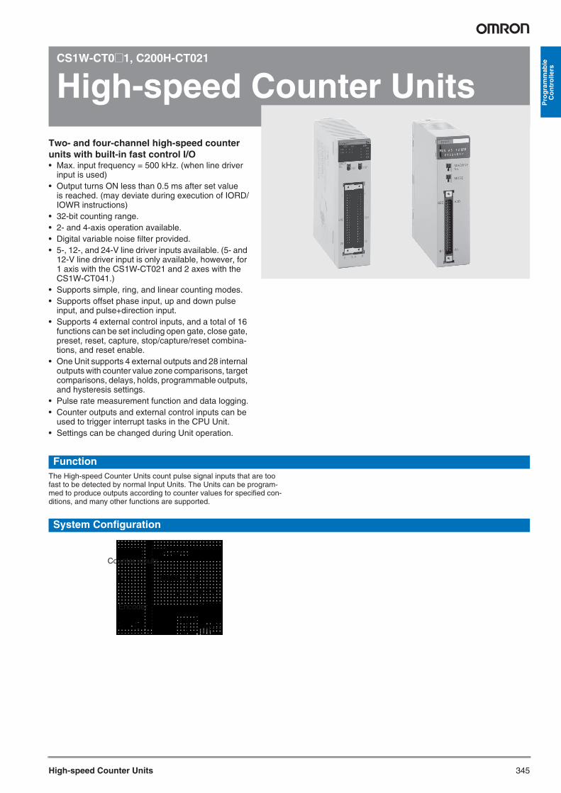
345High-speed Counter Units
Pro
gra
mm
able
C
on
tro
llers
CS1W-CT0@1, C200H-CT021
High-speed Counter UnitsTwo- and four-channel high-speed counter units with built-in fast control I/O• Max. input frequency = 500 kHz. (when line driver
input is used) • Output turns ON less than 0.5 ms after set value
is reached. (may deviate during execution of IORD/IOWR instructions)
• 32-bit counting range.• 2- and 4-axis operation available.• Digital variable noise filter provided.• 5-, 12-, and 24-V line driver inputs available. (5- and
12-V line driver input is only available, however, for 1 axis with the CS1W-CT021 and 2 axes with the CS1W-CT041.)
• Supports simple, ring, and linear counting modes.• Supports offset phase input, up and down pulse
input, and pulse+direction input.• Supports 4 external control inputs, and a total of 16
functions can be set including open gate, close gate, preset, reset, capture, stop/capture/reset combina-tions, and reset enable.
• One Unit supports 4 external outputs and 28 internal outputs with counter value zone comparisons, target comparisons, delays, holds, programmable outputs, and hysteresis settings.
• Pulse rate measurement function and data logging.• Counter outputs and external control inputs can be
used to trigger interrupt tasks in the CPU Unit.• Settings can be changed during Unit operation.
FunctionThe High-speed Counter Units count pulse signal inputs that are too fast to be detected by normal Input Units. The Units can be program-med to produce outputs according to counter values for specified con-ditions, and many other functions are supported.
System Configuration
Counter inputs
Encoder
Y201-EN2-03.book Seite 345 Donnerstag, 30. März 2006 1:52 13

346 Programmable Controllers
Terminal Arrangement
Specifications
General
Item Connector 2 (CN2) Pin No.
Connector 1 (CN1) Pin No.
Row A Row B Row A Row B
Power Supply (to feed the outputs)
-PS: 0V +PS: 12 to 24V 1 -PS: 0V +PS:12 to 24V 1
Digital Outputs [0-3] (NPN/PNP)
O2: NPN O2: PNP 2 O0: NPN O0: PNP 2
O3: NPN O3: PNP 3 O1: NPN O1: PNP 3
Spare 4 4
Digital Inputs[0-3]
I2: 0V I2: 24V 5 I0: 0V I0: 24V 5
I3: 0V I3: 24V 6 I1: 0V I1: 24V 6
Spare 7 7
Counter 1 & Counter 2
A CH2: LD- / 0V CH2: LD+ 8 CH1: LD- / 0V CH1: LD+ 8
CH2: 12V CH2: 24V 9 CH1: 5V CH1: 24V 9
B CH2: LD- / 0V CH2: LD+ 10 CH1: LD- / 0V CH1: LD+ 10
CH2: 12V CH2: 24V 11 CH1: 5V CH1: 24V 11
Z CH2: LD- / 0V CH2: LD+ 12 CH1: LD- / 0V CH1: LD+ 12
CH2: 12V CH2: 24V 13 CH1: 5V CH1: 24V 13
Spare 14 14
Counter 3 & Counter 4*
A CH4: LD- / 0V CH4: LD+ 15 CH3: LD- / 0V CH3: LD+ 15
CH4: 12V CH4: 24V 16 CH3: 5V CH3: 24V 16
B CH4: LD- / 0V CH4: LD+ 17 CH3: LD- / 0V CH3: LD+ 17
CH4:12V CH4: 24V 18 CH3: 5V CH3: 24V 18
Z CH4: LD- / 0V CH4: LD+ 19 CH3: LD- / 0V CH3: LD+ 19
CH4:12V CH4: 24V 20 CH3: 5V CH3: 24V 20
Classification Number of counters
Encoder A and B input, pulse input, Z signal
Maximum counting speed
Unit numbers Model
C200H Special I/O Unit 2 Open-collectorInput voltage: 12 V DC or 24 V DC
50 kcps 0 to F C200H-CT021
RS-422 line driver 75 kcpsCS1 Special I/O Unit 2 Open-collector
Input voltage: 5 V DC, 12 V DC, or 24 V DC(5- and 12- V DC input only possible for 1 axis.)
50 kcps 0 to 92 (4 unit numbers per Unit)
CS1W-CT021
RS-422 line driver 500 kcps4 Open-collector
Input voltage: 5 V DC, 12 V DC, or 24 V DC(5- and 12- V DC input only possible up to 2 axes.)
50 kcps CS1W-CT041
RS-422 line driver 500 kcps
Y201-EN2-03.book Seite 346 Donnerstag, 30. März 2006 1:52 13

347SSI Encoder Input Unit
Pro
gra
mm
able
C
on
tro
llers
CS1W-CTS21
SSI Encoder Input UnitSSI (synchronous serial interface) is a standard communication protocol developed for absolute encoders. It provides easier connection and reduced wiring compared to parallel connection.
Specifications
SSI Communication Input Specifications
Item SpecificationCLK lines Non-isolated differential line driver,
RS422 compliantDATA lines Electrically isolated differential line
receiver, RS422 compliantNumber of data-bits 9 to 31 (default: 24)Value coding Gray/Binary/Tannenbaum/Raw
(default Gray)Clock frequency 100kHz to 1.5MHzMonoflop time 10μs to 99,990μs (default: 40 μs)Sample rate About 2500 Samples/sec with
2 encoders connected (with default settings)
SSI ENCODER
DATA
+
-
+
-
Shielded twisted-pair cable
DATAx+
DATAx–
CLOCKx+
CLOCKx–+ ENCx_PS
0V ENCx_PS
0V ENC_PS + ENC_PS
A20
A8
B8
A12
B12
A10
B10
CLK
RS422
+
-
ENCODERPS
CTS21
Item Digital InputsInput Voltage 24 V DC (19.6 V to 26.4 V)Input Current (typical) 7.6 mAON Voltage (min.) 19.6 VOFF Voltage (max.) 4 VMax. repetition rate 1 kHzMin. pulse width 10 μsInput Voltage 24 V DC (19.6V to 26.4V)
2 kW
1 kW
24V
A5/A6
B5/B6
0V
680W
Y201-EN2-03.book Seite 347 Donnerstag, 30. März 2006 1:52 13
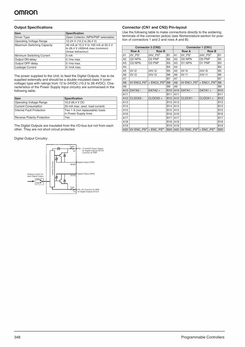
348 Programmable Controllers
Output Specifications
The power supplied to the Unit, to feed the Digital Outputs, has to be supplied externally and should be a double insulated class II (over-voltage) type with ratings from 12 to 24VDC (10.2 to 26.4VDC). Cha-racteristics of the Power Supply Input circuitry are summarised in the following table.
The Digital Outputs are insulated from the I/O-bus but not from each other. They are not short circuit protected.
Digital Output Circuitry:
Connector (CN1 and CN2) Pin-layoutUse the following table to make connections directly to the soldering terminals of the connector jack(s) (see Nomenclature section for posi-tion of connectors 1 and 2 and rows A and B):
Item SpecificationDriver Type Open Collector (NPN/PNP selectable)Operating Voltage Range 12-24 V (10.2 to 26.4 V)Maximum Switching Capacity 46 mA at 10.2 V to 100 mA at 20.4 V
to 26.4 V (400mA max./common) (linear behaviour)
Minimum Switching Current 5 mAOutput ON-delay 0.1ms max.Output OFF-delay 0.1ms max.Leakage Current 0.1mA max.
Item SpecificationOperating Voltage Range 10.2-26.4 V DCCurrent Consumption 25 mA max. (excl. load current)Internal Fault Protection Two 1 A (not replaceable) fuses
in Power Supply linesReverse Polarity Protection Yes
Software switch foreach Digital Output
NPN
PNP
Fuse
B1
B2/B3
A2/A3
A1
FusePS-: 0V Common for NPNfor Digital Outputs O0-O3
Digital Output (NPN)
Digital Output (PNP)
PS+: 12-24VDC Power Supply for Digital Outputs O0-O3Common for PNP
Inte
rnal
Circ
uitr
y
Connector 2 (CN2) Connector 1 (CN1)Row A Row B Row A Row B
A1 0V_PS¹ 24V_PS2 B1 A1 0V_PS¹ 24V_PS2 B1A2 O2 NPN O2 PNP B2 A2 O0 NPN O0 PNP B2A3 O3 NPN O3 PNP B3 A3 O1 NPN O1 PNP B3A4 B4 A4 B4A5 0V I2 24V I2 B5 A5 0V I0 24V I0 B5A6 0V I3 24V I3 B6 A6 0V I1 24V I1 B6A7 B7 A7 B7A8 0V ENC2_PS3 + ENC2_PS4 B8 A8 0V ENC1_PS3 + ENC1_PS4 B8A9 B9 A9 B9A10 DATA2 - DATA2 + B10 A10 DATA1 - DATA1 + B10A11 B11 A11 B11A12 CLOCK2 - CLOCK2 + B12 A12 CLOCK1 - CLOCK1 + B12A13 B13 A13 B13A14 B14 A14 B14A15 B15 A15 B15A16 B16 A16 B16A17 B17 A17 B17A18 B18 A18 B18A19 B19 A19 B19A20 0V ENC_PS3 + ENC_PS4 B20 A20 0V ENC_PS3 + ENC_PS4 B20
Y201-EN2-03.book Seite 348 Donnerstag, 30. März 2006 1:52 13

349
Pro
gra
mm
able
C
on
tro
llersSerial Communication Units
Serial Communications Features
Note: Requires SCU/SCB Ver 1.2 or later mounted on CS1 CPU Unit Ver 3.0.
Unit Model Ports Serial communications mode BASIC program-ming
Message communi-cations
Protocol macros
Host Link NT Links No-proto-col
Peripheral bus
Program-ming Console bus
Serial Gateway (see note)
General-purpose external devices
Host computers
OMRON PTs
General-purpose external devices
Program-ming Devices
Program-ming Console
Compo-Way/F devices, Inverters, Servo Drives
General-purpose external device
CPU Units All models Port 1: Peripheral No Yes Yes No Yes Yes No No NoPort 2: RS-232C No Yes Yes Yes Yes No Yes No No
ASCII Units C200H- ASC11
Port 1: RS-232C No No No No No No Yes Yes NoPort 2: RS-232C No No No No No No Yes Yes No
C200H- ASC21
Port 1: RS-232C No No No No No No Yes Yes NoPort 2: RS-422A/485 No No No No No No Yes Yes No
C200H- ASC31
Port 1: RS-232C No No No No No No Yes Yes NoPort 2: RS-232C No No No No No No Yes Yes No
Serial Com-munications Boards/Units
CS1W- SCB21-V1
Port 1: RS-232C Yes Yes Yes No No No No No NoPort 2: RS-232C Yes Yes Yes No No No No No No
CS1W- SCB41-V1
Port 1: RS-232C Yes Yes Yes No No No No No NoPort 2: RS-422A/485 Yes Yes Yes No No No No No No
CS1W- SCU21-V1
Port 1: RS-232C Yes Yes Yes No No No No No NoPort 2: RS-232C Yes Yes Yes No No No No No No
Y201-EN2-03.book Seite 349 Donnerstag, 30. März 2006 1:52 13
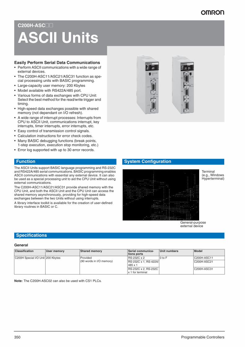
350 Programmable Controllers
C200H-ASC@@
ASCII UnitsEasily Perform Serial Data Communications• Perform ASCII communications with a wide range of
external devices.• The C200H-ASC11/ASC21/ASC31 function as spe-
cial processing units with BASIC programming.• Large-capacity user memory: 200 Kbytes• Model available with RS422A/485 port.• Various forms of data exchanges with CPU Unit:
Select the best method for the read/write trigger and timing.
• High-speed data exchanges possible with shared memory (not dependant on I/O refresh).
• A wide range of interrupt processes: Interrupts from CPU to ASCII Unit, communications interrupt, key interrupts, timer interrupts, error interrupts, etc.
• Easy control of transmission control signals.• Calculation instructions for error check codes.• Many BASIC debugging functions (break points,
1-step execution, execution stop monitoring, etc.)• Error log supported with up to 30 error records.
FunctionThe ASCII Units support BASIC language programming and RS-232C and RS422A/485 serial communications. BASIC programming enables ASCII communications with essential any external device. It can also be used as a special processing unit to aid the CPU Unit without using external communications.The C200H-ASC11/ASC21/ASC31 provide shared memory with the CPU Unit, and both the ASCII Unit and the CPU Unit can access the shared memory asynchronously, providing for high-speed data exchanges between the two Units without using interrupts.A library interface toolkit is available for the creation of user-defined library routines in BASIC or C.
System Configuration
Specifications
General
Note: The C200H-ASC02 can also be used with CS1 PLCs.
RS-232C
RS-232C
BASIC program
Terminal (e.g., Windows Hyperterminal)
General-purpose external device
Classification User memory Shared memory Serial communica-tions ports
Unit numbers Model
C200H Special I/O Unit 200 Kbytes Provided (90 words in I/O memory)
RS-232C x 2 0 to F C200H-ASC11RS-232C x 1, RS-422A/485 x 1
C200H-ASC21
RS-232C x 2, RS-232C x 1 for terminal
C200H-ASC31
Y201-EN2-03.book Seite 350 Donnerstag, 30. März 2006 1:52 13
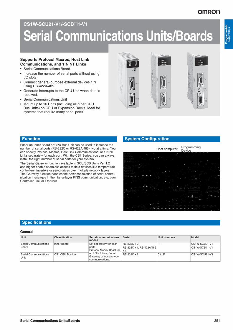
351Serial Communications Units/Boards
Pro
gra
mm
able
C
on
tro
llers
CS1W-SCU21-V1/-SCB@1-V1
Serial Communications Units/BoardsSupports Protocol Macros, Host Link Communications, and 1:N NT Links• Serial Communications Board• Increase the number of serial ports without using
I/O slots.• Connect general-purpose external devices 1:N
using RS-422A/485.• Generate interrupts to the CPU Unit when data is
received.• Serial Communications Unit• Mount up to 16 Units (including all other CPU
Bus Units) on CPU or Expansion Racks. Ideal for systems that require many serial ports.
FunctionEither an Inner Board or CPU Bus Unit can be used to increase the number of serial ports (RS-232C or RS-422A/485) two at a time. You can specify Protocol Macros, Host Link Communications, or 1:N NT Links separately for each port. With the CS1 Series, you can always install the right number of serial ports for your system.The Serial Gateway function available in SCU/SCB Units Ver.1.2 and higher enable seamless access to field devices like temperature controllers, inverters or servo drives over multiple network layers. The Gateway function handles the de/encapsulation of serial commu-nication messages in the higher-layer FINS communication, e.g. over Controller Link or Ethernet.
System Configuration
Specifications
General
Host computer
PT
Machine MachineDevice Device
Non-OMRON PLC
Serial Commu-nications Board
Serial Commu-nications Unit
Microcomputer or other device
Programming Device
Unit Classification Serial communications modes
Serial Unit numbers Model
Serial Communications Board
Inner Board Set separately for each port: Protocol Macro, Host Link, or 1:N NT Link, Serial Gateway or non-protocol communications.
RS-232C x 2 --- CS1W-SCB21-V1RS-232C x 1, RS-422A/485 x 1
CS1W-SCB41-V1
Serial Communications Unit
CS1 CPU Bus Unit RS-232C x 2 0 to F CS1W-SCU21-V1
Y201-EN2-03.book Seite 351 Donnerstag, 30. März 2006 1:52 13

352 Programmable Controllers
Protocol MacrosEasily Create Protocols for Data Exchange with External Devices; Execute with One Instruction
FunctionProtocols for communications with external devices can be easily crea-ted according to the communications standards required by the exter-nal device. Protocol macros enable communications with essentially any external device with an RS-232C or RS-422A/485 port without pro-gramming communications in the PLC. Standard system protocols are provided as a standard feature for com-munications with OMRON components, such as Temperature Control-lers, Panel Meters, Bar Code Readers, and Modems. A Windows-based tool called CX-Protocol is also available to enable creation of protocols for most any external device.
System Configuration
Types of Protocol
Standard System Protocols
CX-ProtocolCD-ROM
User-created protocols
Standard system protocols (provided in Unit or Board)
OMRON component
Create and transfer protocols
General-purpose external device
Protocols External devices Required productsStandard system protocols OMRON components Serial Communications Board or UnitUser-created protocols General-purpose external device Serial Communications Board or Unit + CX-Protocol (Windows-based protocol support
software)
Component Model Send/receive sequencesCompoWay/F-compatible components OMRON CompoWay/F slave
components CompoWay/F command send/response receive
Digital Controllers and Temperature Control-lers
Small Digital Controller with Communications (53 x 53 mm) E5CK Present value read, set point read, ma-nipulated variable read, etc.Set point write, alarm write, PID param-eter write, etc.
Temperature Controllers with Digital Indications (Thermac J with com-munications) (96 x 96 mm or 48 x 96 mm)
E5@J-A2H0
Digital Controllers with Communications (96 x 96 mm) ES100@High-density Temperature Controller with communications (8 control points)
E5ZE
Intelligent Signal Processors (special specifications) K3T@ Display value read, comparison value read, write, etc.
Bar Code Readers Laser Scanner type V500 Read start, data read, read stop, etc.CCD type V520
Laser Micrometer 3Z4L Measurement condition set, continuous measurement start, etc.
Visual Inspection Sys-tems
High speed, high precision, low cost F200 Measurement, continuous measure-ment, etc.High-precision inspection/positioning F300
Character inspection software/positioning software F350 Measurement, positioning, inspection, character inspection, etc.
RFID Controllers Electromagnetic coupling (for short distances) V600 Carrier data read, autoread, write, etc.Microwave (for long distances) V620
Hayes Modem AT Command --- Modem initialize, dial, send, etc.OMRON PLCs with Host Link (C-mode) protocol C-Series PLCs ---OMRON PLCs with Host Link (FINS) protocol CS/CJ-series PLCs Requires SCU/SCB Ver. 1.2 or higher
Y201-EN2-03.book Seite 352 Donnerstag, 30. März 2006 1:52 13

353RS-232C/RS-422A Adapter Unit
Pro
gra
mm
able
C
on
tro
llers
NT-AL001
RS-232C/RS-422A Adapter UnitAllows integration of RS232C devices into RS-422A networks.• Long-distance transmissions are possible through
an RS-422A interface. By converting from RS-232C to RS-422A and then back to RS-232C, a transmis-sion distance of up to 500 m can be achieved.
• No power supply is required. If the 5-V terminal (150 mA max.) is connected from the RS-232C device, a separate power supply is not required to drive the Adapter Unit.
• The removable terminal block enables wiring not possible with D-sub connectors. (The RS-232C interface is 9-pin D-sub.)
Specifications
RS-232C Interface
RS-422A Interface
Item SpecificationBaud rate 64 Kbps max.Transmission distance 2 m max.Connector 9-pin, D-sub connector (female)
Item SpecificationBaud rate 64 Kbps max. (depends on RS-232C baud rate)Transmission distance 500 m max.Terminal block 8 terminals, M3.0; detachable
Y201-EN2-03.book Seite 353 Donnerstag, 30. März 2006 1:52 13

354 Programmable Controllers
CS1W-V600@@@/C200H-IDS01-V1
RFID Sensor UnitEasy integration of RFID Systems into PLC's. • Connects V600 RFID read/write heads directly to
the PLC.• Function checking possible with standard hand-held
Programming Console.• Read data from Data Carriers simply by sending
a read command.• The C200H-IDS01-V1 can read/write up to 1,024
bytes. The CS1W-V600C11/12 can read/write up to 2,048 bytes.
FunctionRead/write data in Data Carrier memory by sending read/write com-mands from the CPU Unit to the Read/Write Head.
One Read/Write Head can be connected to the CS1W-V600C11 and two Read/Write Heads can be connected to the CS1W-V600C12. The data transfer speed has been increased in both models.
System Configuration
Specifications
Data Carrier
Read/ Write Head
Classification Connectable ID System Connectable Read/Write Heads
External power supply Unit numbers Model
CS1 CPU Bus Unit V600 Series (electromagnetic, for short distances)
1 Read/Write Head Not required 0 to 95 CS1W-V600C112 Read/Write Heads 24 V DC 0 to 94 CS1W-V600C12
C200H Special I/O Unit --- Not required 0 to 9 C200H-IDS01-V1
Y201-EN2-03.book Seite 354 Donnerstag, 30. März 2006 1:52 13

355GP-IB Interface Unit
Pro
gra
mm
able
C
on
tro
llers
CS1W-GPI01
GP-IB Interface Unit• Enables communications between SYSMAC
CS-series PLCs and GP-IB instruments. • Conforms to the standard interface IEEE-488-1978
(GP-IB).• Usable in either Master Mode (controller) or Slave
Mode (talker, listener).• Communications with GP-IB instruments are easily
implimented simply by using the INTELLIGENT I/O READ and INTELLIGENT I/O WRITE (IORD/IOWR) instruction in the ladder program in the CPU Unit to read and write buffer memory in the GP-IB Interface Unit.
Specifications
Item SpecificationName SYSMAC CS-series GP-IB Interface UnitModel number CS1W-GPI01Unit type CS1 Special I/O UnitMounting location CS1 CPU Rack or CS1 Expansion RackMax. number of GP-IB Interface Units Up to 4 GP-IB Interface Units per CPU UnitUnit number setting range 0 to 95GP-IB Interface Unit settings when editing the I/O tables offline with the CX-Programmer
Number of unit numbers used: 1Number of input words allocated: 5Number of output words allocated: 5
Transmission method 8-bit parallel data transferCommunications method Half duplexInterface Conforms to IEEE-488-1978 (24-pin) standardsHandshaking method Three-line handshakingFunctional specifications(GP-IB interface functions)
Master mode: SH1, AH1, T6, TE0, L4, LE0, C1 to C4, and C28Slave mode: SH1, AH1, T6, TE0, L4, LE0, SR1, RL0, PP0, DC1, and DT0
Connection configurations Star configuration or daisy-chain configurationTransmission distance Limits on the length of cables in the system
(All three of these conditions must be satisfied simultaneously.)Total cable length ≤ Number of devices in the system × 2 mTotal cable length ≤ 20 mLength of a single cable ≤ 4 m (for a 1:1 connection)
Max. number of connected devices 15 devices max. including the GP-IB Interface UnitGP-IB device address 0 to 30Delimiters Select from the following: CR + LF, CR, LF, EOI, or user-set code.Max. data transfer size 512 bytes max. in a single reception or transmissionMax. number of connectors 2 (connectors can be stacked)Current consumption 5 VDC, 330 mADimensions 35 × 130 × 101 mm (W × H × D) Weight 258 g max.
Y201-EN2-03.book Seite 355 Donnerstag, 30. März 2006 1:52 13

356 Programmable Controllers
Communications NetworksOverview
Specifications
Communications
Note: 1. For high-speed communications mode. Trunk line length is 100 m (30 m max. for 4-core VCTF or special flat cable).2. For long-distance communications mode (200 m max. for 4-core VCTF or special flat cable). 3. Different types of cables cannot be mixed.
Level Network Functions Communications Unit/BoardInformation net-works
Ethernet Host computer to PLC FINS messages Ethernet UnitPLC to PLCHost computer to CPU Unit memory card
FTP server
UNIX computer or other socket ser-vice to PLC
Socket services
Controller Link Computers connected directly to network and PLC
FINS messages Controller Link Support Board and UnitData links (offsets and automatic setting)
Control networks
Controller Link PLC to PLC FINS messages Controller Link UnitData links (offsets and automatic setting)
DeviceNet FINS messages on open network DeviceNet Master Unit DeviceNet PLC to components (slaves) High-capacity remote I/O on open network
(fixed or user allocations)DeviceNet Master Unit
PROFIBUS-DP PLC to components (slaves) High-capacity remote I/O on open network (user allocations)
PROFIBUS-DP Master, I/O Unit
CAN/CANopen Component to components Freely configurable, object-oriented communication using CANopen or user-defined CAN protocols
CANopen Unit
CompoBus/S PLC to components (slaves) High-speed remote I/O with OMRON network (fixed allocations)
CompoBus/S Master Unit
Network Ethernet Controller Link PROFIBUS-DP DeviceNet CANopen CompoBus/SMessages Yes Yes Limited to DPV1
devicesYes Yes ---
Data links --- Yes Manually configurable --- Yes ---Remote I/O --- --- Yes Yes Yes YesMaximum speed 10/100 Mbps 2 Mbps
Comm cycle: Approx. 34 ms (Wired: 32 nodes, 2-Kbits + 2-Kword data links)
12 MbpsComm cycle from 1 ms
500 Kbps Comm cycle: Approx. 5 ms (128 inputs and 128 outputs)
1 Mbps (acyclic, on-event communication)
750 Kbps (See note 1.) Comm cycle: Approx. 1 ms (128 inputs and 128 outputs)
Total distance --- Twisted-pairs:1 km (at 500 bps)Optical: 20 km
1200 m up to 93.75 kbps, 100 m at 12 Mbps. Extension by optical links is possible.
500 m (at 125 kbps)
5 km at 10 kbps to 40 m at 1 Mbps
Trunk line: 500 m(See note 2.)Communications cy-cle: 6 ms max.
Maximum nodes --- 32/62 with repeaters 126 with repeaters 63 127 32Communications media
--- Special twisted-pair cable or optical cable
PROFIBUS cable DeviceNet cable ISO11898. e.g. DeviceNet cable
2-core or 4-core VCTF cable, special flat cable (See note 3.)
Network data link ca-pacity
--- 32,000/62,000 words --- --- --- ---
Remote I/O capacity
--- --- 300 words (C200H)7000 words (CJ1, CS1)
32,000 pts (with Configurator)2,048 pts (without Configurator)
Up to 200 words configurable
256 pts
Supporting PLCs CS1, CJ1, CVM1, CV Series, C200HX/HG/HE
CS1, CJ1, CVM1, CV Series, C200HX/HG/HE
CS1, CJ1, C200HX/HG/HE/HS, CQM1/CQM1H (I/O link), CPM1A (I/O link)
CS1, CJ1, CVM1, CV Series, C200HX/HG/HE, C200HS, CQM1/CQM1H (with I/O Link), CPM2C (with I/O Link)
CS1, C200HX/HG/HE
CS1, CJ1, C200HX/HG/HE, C200HS, CQM1/CQM1H, CPM2C-S1@0C (-DRT) SRM1;CPM1A/CPM2C (with I/O Link)
Y201-EN2-03.book Seite 356 Donnerstag, 30. März 2006 1:52 13

357Ethernet Units
Pro
gra
mm
able
C
on
tro
llers
CS1W-ETN@@
Ethernet UnitsEnables fast data transfer within Factory Automation systems, and easily links FA systems to plant management systems• Access socket services simply by manipulating
specific bits in memory.• Take advantage of data transfer by e-mail.• Seamless communication with Controller Link
and other networks.• Use the Ethernet standard protocols, TCP/IP and
UDP/IP.• Use OMRON’s standard FINS message
communications.• Exchange files with host computers using FTP.• Set communications parameters with the
CX-Programmer setup menus.
• While the 100Base-TX model maintains backward compatibility withthe earlier models (10Base-5 and 10Base-T), the new model has abasic system repsonse performance about 4 times faster.
• The FINS message communications capabilities have beenimproved dramatically.
• Increased number of nodes (from 124 to 254 nodes)
• Supports TCP/IP protocol as well as the earlier UDP/IP protocol.
• The host computer’s IP address can be set dynamically (DHCP).
• A mail receiving function has been added (POP3).• A function has been added that automatically corrects the PLC’s
internal clock (SNTP) .• Various kinds of servers can be specified by their host name (DNS).
FunctionAchieve a wide range of communications from PLCs connected to an Ethernet network: Transfer data with TCP/IP or UDP/IP socket ser-vices, executed OMRON’s standard FINS commands, transfer files with FTP, or send mail with SMTP. Select the communications services that are required and flexibly connect PLCs on an information level Ethernet network.
Features of the 100Base-TX Model
Y201-EN2-03.book Seite 357 Donnerstag, 30. März 2006 1:52 13

358 Programmable Controllers
System Configuration
Specifications
Router
UDP/TCP socket
FINS messages
Wireless
FINS messages
FTP
FINS
• FTP software • Mail software
• CX-Programmer• Mail software
• DNS server • POP3 server• SMTP server• SNTP server
NS-series PT
FINS
FINS
CX-Programmer
Ethernet UnitSYSMACCS Series
Large file
Mail sent
Commands recorded
Mail received
Ethernet UnitSYSMACCS Series
Ethernet
Ethernet
Intranet
Administration FloorServer Room
Factory Line
IP router
Fire
wal
l
Internet
Memory Card
Rou
ter
Unit name Type Communications service Connector ModelEthernet Unit(100Base-TX)
CS CPU Bus Unit FINS communications service (TCP/IP, UDP/IP), FTP server functions, socket services, mail transmission service, mail receive (remote command receive), automatically adjusted PLC built-in clock, server/host name specification)
100Base-TX(10Base-T)
CS1W-ETN21CS1D-ETN21D
Y201-EN2-03.book Seite 358 Donnerstag, 30. März 2006 1:52 13

359Controller Link Units and PCI Boards
Pro
gra
mm
able
C
on
tro
llers
CS1W-CLK@@-V1, 3G8F7-CLK@@-V1, CS1W-RPT0@
Controller Link Units and PCI Boards
OMRON’s efficient and easy-to-use FA Network• Achieve high-capacity, flexible data links.• Transfer large volumes of data through a message
service.• Connect through twisted-pair cables or optical fiber
cables.• Connect CS1, CJ1, C200HX/HG/HE and CQM1H
PLCs.• Complete error correction and troubleshooting
functions.• Quick configuration of communication links with
CX-Programmer's setup menus.• Increase network reliability with duplex
connections for optical networks.• Use either ring mode or bus mode for optical net-
works.
FunctionController Link is OMRON’s proprietary FA-level network. It supports automatic data links between PLCs and between PLCs and host com-puter, as well as programmed data transfers using a message service.
You get high-capacity, flexible data links and high-capacity data trans-fers with messages. For a low-cost communications system, twisted-pair cables can be used.
System Configuration
Use Repeater Units for T-branch Wiring, Extension, Expansion, and Optical Sections
T-branching Enables More Flexible Wiring Solution for Layout, Building, and Expansion of Networks
Wired Types Support Long-distance ExtensionThe total extended length that was previously 500 m at 2 Mbps can be extended to up to 1.5 km by using two Repeater Units.
Connect up to 64 Nodes Using Wired TypesNetworks can be constructed with up to 62 nodes when Controller Link Units/Support Boards with -V1 suffix are combined with Repeater Units.
Wiring with Optical Cables Increases Noise ImmunityUsing two Repeater Units for optical ring enables wiring with optical cables in parts of the network subject to noise.
Simpler, More Flexible Data Links
Change Data Link Tables Whilte Data Links Are Active• When data link tables are changed due to additional nodes or other
networking changes, data link tables can be transferred without stop-ping any data link communications.
• Flexbile system configurations can be changed by combining nodeexpansion using Repeater Units.
Y201-EN2-03.book Seite 359 Donnerstag, 30. März 2006 1:52 13

360 Programmable Controllers
Specifications
Note: Lot numbers for the CS1W-CLK12-V1 and CS1W-CLK52-V1 are 030602 or later (June 2003 or later).
Main Specifications Related to Version Upgrade for Unit Ver. 1.2
Note: CX-Programmer Ver. 5.0 or higher is requested to set a data link area with a maximum number of send and receive words of 20,000 words per Controller Unit, or to allocate the same area for Area 1 and Area 2.
Specifications for Networks Using Repeaters
Note: 1. Specifications for each segment are the same as for Wired Controller Link networks.2. Maximum transmission distance: Total wired cable length between the two nodes separated by the longest total wired cable length.3. Maximum number of Repeater levels: Maximum number of Repeaters in a path linking any two nodes. For optical ring types, one set of
two Units comprises one level.
Unit/Board Classification Compatible PLC Media Model ConnectionsController Link Units CPU Bus Unit CS Series Wired CS1W-CLK21-V1 Can be mounted together
with previous Controller Link Units/Support Boards.
Optical ring (H-PCF cable)
CS1W-CLK12-V1(See note.)
Optical ring (GI cable)
CS1W-CLK52-V1(See note.)
Controller Link Support Boards
Personal computer board (for PCI bus)
--- Wired 3G8F7-CLK21-EV1Optical ring(H-PCF cable)
3G8F7-CLK12-EV1
Optical ring(GI cable)
3G8F7-CLK52-EV1
Controller Link Repeater Units
--- Not mounted to PLC Twisted-pair cable CS1W-RPT01 Unit mounted indepen-dently using either DIN Track or screws.
Optical ring(H-PCF cable)
CS1W-RPT02
Optical ring (GI cable)
CS1W-RPT03
Item Unit Ver. 1.2 or later Pre-Ver. 1.2Number of data link words Number of send/receive words per Unit
Total of Area 1 and Area 2: 20,000 words max.Number of send/receive words per UnitTotal of Area 1 and Area 2: 12,000 words max.
Number of send words per Unit Total of Area 1 and Area 2: 1,000 words max.Data Link Area allocations User-set allocations Areas 1 and 2: CIO Area (including data link words), DM Area, and EM Area
Automatically set equal allocations
Area 1: CIO Area (including data link words), Area 2: DM Area and EM Area
Automatically set 1: N allocations
Areas 1 and 2: CIO Area (including data link words), DM Area, and EM Area
Maximum number of Controller Link Units connected to a single CPU Unit
8 Units max. 4 Units max.
Item Segment (See note 1.) Total networkTransmission path configuration Multi-drop Tree (using Repeaters to connect each segment)Baud rate/maximum transmission distance (See note 2.)
2 Mbps: 500 m1 Mbps: 800 m500 kbps: 1 km
2 Mbps: 1.5 km1 Mbps: 2.4 km400 kbps: 3.0 km
Maximum number of nodes Controller Link Unit + Repeater UnitTotal number of nodes: 32
Controller Link Unit: 62 nodes (using a Controller Link Unit htat supports 62 nodes)
Maximum number of Repeater levels (See note 3.) --- 2 levels
Y201-EN2-03.book Seite 360 Donnerstag, 30. März 2006 1:52 13

361PROFIBUS-DP Master Unit
Pro
gra
mm
able
C
on
tro
llers
CS1W-PRM21
PROFIBUS-DP Master Unit• PROFIBUS-DP master class one with support
of DP-V1 data types.• 7 kWord I/O• Simple configuration through FDT/DTM
based configurator• Special CPU unit• Handles data independent of the CPU unit,
thus reducing CPU load
FunctionThe CS1W-PRM21 is a master system (DPM1). It exchanges I/O data and communication/status information with the CPU of the PLC. To configure the CS1W-PRM21 a serial port of the CPU can be used. But because configuring is done through FINS
communication virtual any accesspoint on the PLC network can be used. It exchanges data and commands with PROFIBUS-DP slave stations over the PROFIBUS network.
Specifications
Model RemarksCS1W-PRM21 Main function Basic PROFIBUS-DP master Class 1
functions plus: DPV1 data types supportUnit No. 0-15 Special CPU unitMaximum number of units mountable per PLC
16 Maximum depends on PLC CPU-type
Configurator FTD/DTM based Incorporates a Generic DTM to use with GSD-file based slaves
Supported baud rate(s) All baud rates as specified by the standard EN50170 Volume 2, the PROFIBUS exten-sions to EN50170, as well as the standard IEC61158:9.6 kBit/s,19.2 kBit/s,45.45 kBit/s.93.75 kBit/s,187.5 kBit/s,500 kBit/s,1.5 MBit/s,3 MBit/s,6 MBit/s,12 MBit/s
The baud rate value to be used must be selected through the Configurator.
Selectable PROFIBUS address 0-125 Set through the configuratorMaximum number of PROFIBUS slaves 125Maximum number of I/O points 7168 wordsMaximum number of I/O points per PROFIBUS slave
244 bytes In / 244 bytes Out
Control and status ares size 25 wordsSupported Global_Control services Sync
Unsync Freeze Unfreeze Clear
Through Control Area
Supported Master-Slave communication services
Data_Exchange Slave_Diag Set_PRM Chk_Cfg Global_Control
Power consumption 400 mA at 5 VDimensions 34.5 mm wide x 130 mm height x
111.2 mm depthWeight 154 grAmbient temperature Operating: 0 °C to 50 °C
Y201-EN2-03.book Seite 361 Donnerstag, 30. März 2006 1:52 13
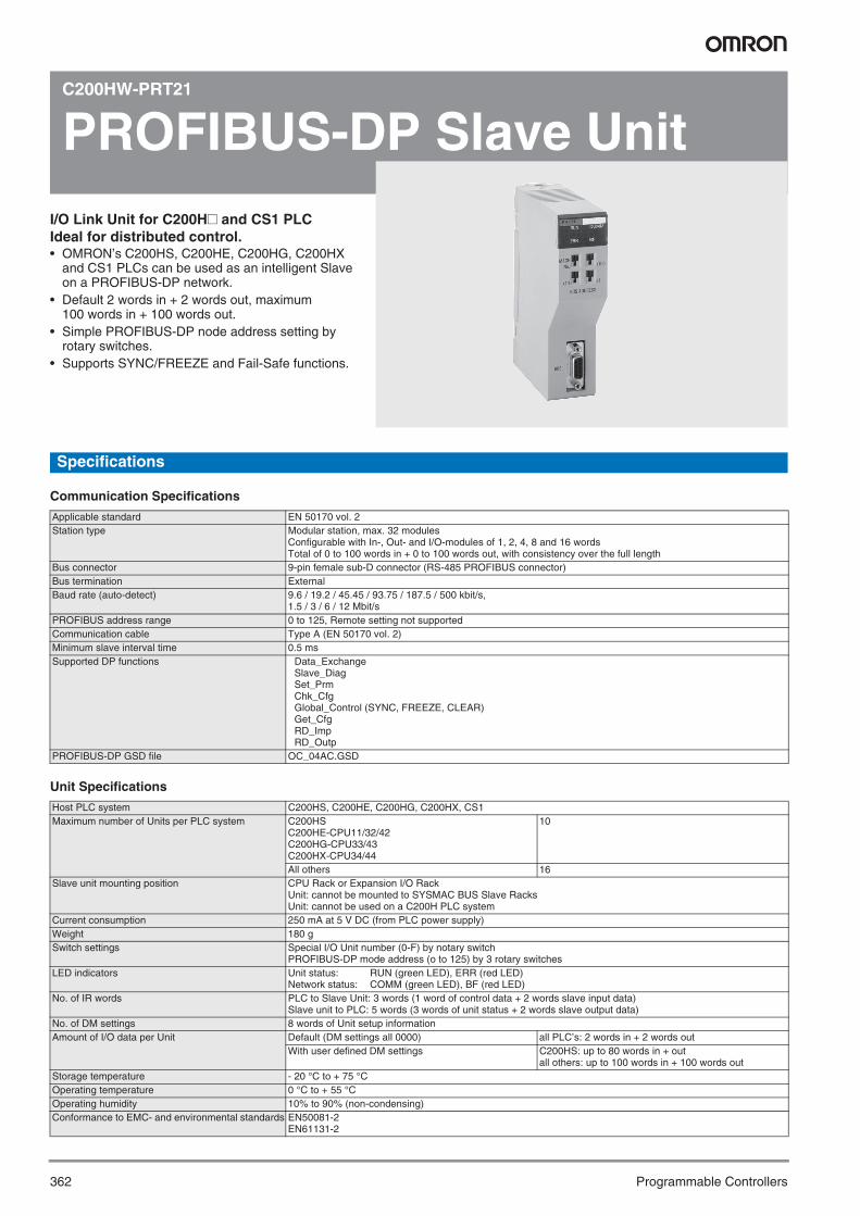
362 Programmable Controllers
C200HW-PRT21
PROFIBUS-DP Slave UnitI/O Link Unit for C200H# and CS1 PLC Ideal for distributed control.• OMRON’s C200HS, C200HE, C200HG, C200HX
and CS1 PLCs can be used as an intelligent Slave on a PROFIBUS-DP network.
• Default 2 words in + 2 words out, maximum 100 words in + 100 words out.
• Simple PROFIBUS-DP node address setting by rotary switches.
• Supports SYNC/FREEZE and Fail-Safe functions.
Specifications
Communication Specifications
Unit Specifications
Applicable standard EN 50170 vol. 2Station type Modular station, max. 32 modules
Configurable with In-, Out- and I/O-modules of 1, 2, 4, 8 and 16 wordsTotal of 0 to 100 words in + 0 to 100 words out, with consistency over the full length
Bus connector 9-pin female sub-D connector (RS-485 PROFIBUS connector)Bus termination ExternalBaud rate (auto-detect) 9.6 / 19.2 / 45.45 / 93.75 / 187.5 / 500 kbit/s,
1.5 / 3 / 6 / 12 Mbit/sPROFIBUS address range 0 to 125, Remote setting not supportedCommunication cable Type A (EN 50170 vol. 2)Minimum slave interval time 0.5 msSupported DP functions Data_Exchange
Slave_Diag Set_Prm Chk_Cfg Global_Control (SYNC, FREEZE, CLEAR) Get_Cfg RD_Imp RD_Outp
PROFIBUS-DP GSD file OC_04AC.GSD
Host PLC system C200HS, C200HE, C200HG, C200HX, CS1Maximum number of Units per PLC system C200HS
C200HE-CPU11/32/42C200HG-CPU33/43C200HX-CPU34/44
10
All others 16Slave unit mounting position CPU Rack or Expansion I/O Rack
Unit: cannot be mounted to SYSMAC BUS Slave RacksUnit: cannot be used on a C200H PLC system
Current consumption 250 mA at 5 V DC (from PLC power supply)Weight 180 gSwitch settings Special I/O Unit number (0-F) by notary switch
PROFIBUS-DP mode address (o to 125) by 3 rotary switchesLED indicators Unit status: RUN (green LED), ERR (red LED)
Network status: COMM (green LED), BF (red LED)No. of IR words PLC to Slave Unit: 3 words (1 word of control data + 2 words slave input data)
Slave unit to PLC: 5 words (3 words of unit status + 2 words slave output data)No. of DM settings 8 words of Unit setup informationAmount of I/O data per Unit Default (DM settings all 0000) all PLC’s: 2 words in + 2 words out
With user defined DM settings C200HS: up to 80 words in + outall others: up to 100 words in + 100 words out
Storage temperature - 20 °C to + 75 °COperating temperature 0 °C to + 55 °COperating humidity 10% to 90% (non-condensing)Conformance to EMC- and environmental standards EN50081-2
EN61131-2
Y201-EN2-03.book Seite 362 Donnerstag, 30. März 2006 1:52 13

363DeviceNet Unit
Pro
gra
mm
able
C
on
tro
llers
CS1W-DRM21-V1
DeviceNet UnitMultivendor Field Network• Control of up to 32,000 points (2,000 words) per
master.• Remote I/O communications can be allocated in any
area using DM settings.• 16 DeviceNet Units can be mounted for each CPU
Unit (3 max. for fixed allocations).• When using the Configurator (see note), remote I/O
can be allocated in an order independent of node address.
Note: The Configurator is allocating a node-address if con-nected to DeviceNet using a DeviceNet communica-tion card. It is not doing this if connected through the serial communications interface of the CPU.
• DeviceNet Units can be used as a master and a slave, and this functionality can be used simul-taneously.
Note: DeviceNet Units allow DeviceNet networks to be treated exactly like Controller Link, Ethernet, or other networks for message communications or remote pro-gramming and monitoring by a CX-Programmer.
FunctionOMRON supports the DeviceNet open field network, a multivendor network for machine/line control and information. The following types of communications are possible.
1. Remote I/O communications for automatic data transfers betweenthe CPU Unit and Slaves (with no programming in the CPU Unit).
2. Explicit message communications. This can be programmed fromthe CPU unit (IOWR and CMND instructions) and read from/writeto other DeviceNet units.
3. With explict message communication FINS commands can besend to other devices that support FINS messaging.
System Configuration
Slaves
63 nodes max.
DeviceNet
MULTIPLE I/O TERMINAL
ConfiguratorDeviceNet Master Unit
500 Kbps: 100 m125 Kbps: 500 m
DeviceNet I/O Link Unit Non-I/O slaves
Y201-EN2-03.book Seite 363 Donnerstag, 30. März 2006 1:52 13

364 Programmable Controllers
Ordering Information
Specifications
Master/Slave Specifications
Note: 1. Refer to the DeviceNet (CompoBus/D) Operation Manual (W267) for the communications power supply specifications.2. The DeviceNet unit uses a node of the 64 supported by DeviceNet, leaves connection is possible to 63 slaves.3. When the DeviceNet is used a slave, “input” and “output” respectively refer to input from the master to the slave and output from the slave
to the master.4. The maximum message length includes the command code when using the CMND instruction.5. The CS1W–DRM21 cannot perform message communications with the E5ZE-8@D1@B. Use the E5ZE-8@D1@B-V2, which is a later ver-
sion. For details on the E5ZE-8@D1@B-V2, refer to the catalog for the product itself (SGTD-017).
DeviceNet Unit
DeviceNet Configurator
Compatible PLCs Maximum number of I/O points ModelFixed allocations User-set allocations
Using allocated DM Area words
Using Configurator
CS1 Series When used as a master
Input: 1,024 pointsOutput: 1,024 pointsTotal: 2,048 points (128 words)
Input: 8,000 pointsOutput: 8,000 pointsTotal: 16,000 points (1,000 words)
Input: 8,000 points x 2 blocksOutput: 8,000 points x 2 blocksTotal: 32,000 points (2,000 words)
CS1W-DRM21
When used as a slave
Input: 16 pointsOutput: 16 pointsTotal: 32 points (2 words)
Input: 1,600 pointsOutput: 1,600 pointsTotal: 3,200 points (200 words)
Input: 1,600 points x 1 blockOutput: 1,600 points x 2 blocksTotal: 4,800 points (300 words)
Communications power supply voltage 11 to 25 V DC (supplied from the communications connector) (See note 1.)
Current consumption Communications:30 mA max.Internal circuit:290 mA max.
Max. number of connectable slaves
Remote I/O, explicit message service 63 (See note 2.)
Max. number of I/O points Fixed allocations When used as a master
2,048 points
When used as a slave
32 points
User-set allocations
Using allocated DM Area words
When used as a master
16,000 points
When used as a slave
3,200 points
Using Configurator When used as a master
32,000 points
When used as a slave
4,800 points
Number of allocated words Fixed allocations When used as a master
64 input and 64 output wordsSoftware switch/status area: 25 words
When used as a slave
1 input word, 1 output word (See note 3.)
User-set allocations
Using allocated DM Area words
When used as a master
500 input and 500 output wordsSoftware switch/status area: 25 words
When used as a slave
100 input and 100 output words (See note 3.)Software switch/status area: 25 words
Using Configurator When used as a master
500 input words x 2 blocks, 500 output words x 2 blocksSoftware switch/Status area: 25 words
When used as a slave
100 input words x 1 blocks, 100 output words x 2 blocksSoftware switch/Status area: 25 words
Max. message length 542 bytes (See note 4.)Max. number of Units mountable to PLC
Fixed allocations 3User-set allocations 16
Weight 172 g max.
Classification Types of communications Specifications Unit numbers ModelCS1 CPU Bus Unit Remote I/O communications master
(fixed or user-set allocations)Remote I/O communications slave (fixed or user-set allocations)Message communications
Up to 16 Units can be mounted when a Configurator is used.
0 to F (Configurator required to mount 16 Units.)
CS1W-DRM21
C200H Special I/O Unit
Remote I/O communications master C200HW-DRM21-V1Remote I/O communications slave C200HW-DRT21
Model number SpecificationsWS02-CFDC1-E Software only (Windows 95, 98, NT 4.0, 2000, or XP)3G8E2-DRM21-E-V1 PC card with software (Windows 95 or 98)
Y201-EN2-03.book Seite 364 Donnerstag, 30. März 2006 1:52 13

365DeviceNet I/O Link Unit
Pro
gra
mm
able
C
on
tro
llers
C200HW-DRT21
DeviceNet I/O Link UnitI/O Link Unit is ideal for distributed control.PLC can be used as an Intelligent Slave on the DeviceNet.• Intelligent DeviceNet Slave• Supports I/O and message communications.• Maximum I/O area size:
512 input points (32 words)512 output points (32 words)
• Programming Console or Configurator freely allocates I/O areas.
Ratings/CharacteristicsGeneral Specifications
Function SpecificationsSettings (Slave)
Message Communications
35 × 130 × 101 mm (W × H × D)
Refer to the relevant catalog for details on CS1-series and C200HX/HG/HE PLCs (CS1 Series: Cat. No. P047; C200HX/HG/HE: Cat. No. P036).
Ordering Information
Name Max. number I/O points ModelI/O Link Unit (for SYSMAC CS1, C200HX/HG/HE) 512 inputs, 512 outputs (1,024 points in total) C200HW-DRT21
Specifications
Item SpecificationCommunications power supply voltage
11 to 25 V DC
Current consumption Communications power supply: 45 mA max.Internal circuit power supply: 250 mA max. at 5 V DC
Max. number of I/O points 512 input points (32 words)512 output points (32 words)
Default area Write area (linking with Master’s write area): 1 word out of 350 IR wordsRead area (linking with Master’s read area): 1 word out of 50 IR words
No. of connectable Units 10 max. (CS1/C200HX/HG/HE CPU Unit handles up to 880 I/O points)16 max. (CS1/C200HX/HG/HE CPU Unit handles more than 880 I/O points)
Weight 250 g max.
Item SpecificationFunction A write area block and a read area block can be freely allocated to any areas or addresses respectivelyAllowable setting area Both read and write areas can be allocated to IR, DM, HR, AR, LR, T/C, and EM areasFirst address A readable or writable area by word (with some restrictions)Area size Set in 1-byte increments up to 64 bytes for both read and write areasSetting method Configurator Refer to the DeviceNet Configurator Operation Manual (W328).
Programming Console 1. Write the set value to I/O setting area allocated to the Special I/O Area.2. Turn ON the software switch allocated to the Special I/O Area and write
the settings.3. Turn the Programming Console OFF and ON or reset the AR area.
Item SpecificationFunction Supports messages that can be written to or read from the CS1/C200HX/HG/HE’s user I/O areas (i.e., IR, DM, HR, AR, LR, T/C,
and EM areas)Master OMRON’s Master Unit or compatible unit from RockwellMax. message size Slave (C200HW-DRT21)
200 bytes per READ or WRITE command
Dimensions
Precautions
Y201-EN2-03.book Seite 365 Donnerstag, 30. März 2006 1:52 13
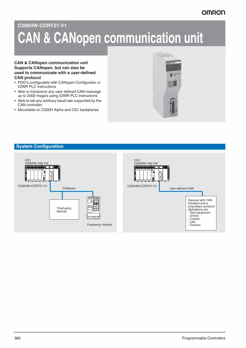
366 Programmable Controllers
C200HW-CORT21-V1
CAN & CANopen communication unitCAN & CANopen communication unitSupports CANopen, but can also be used to communicate with a user-defined CAN protocol• PDO’s configurable with CANopen Configurator or
IOWR PLC instructions• Able to transceive any user defined CAN message
up to 2000 msgs/s using IOWR PLC instructions• Able to set any arbitrary baud rate supported by the
CAN controller• Mountable on C200H Alpha and CS1 backplanes
System Configuration
CS1C200HE/-HG/-HX
C200HW-CORT21-V1
Third-party devices
Frequency Inverter
CANopenC200HW-CORT21-V1
CS1C200HE/-HG/-HX
Devices with CAN interface and a proprietary protocol:Aplications are:- Test equipment- Drives- Cranes- Lifts- Tractors
User-defined CAN
Y201-EN2-03.book Seite 366 Donnerstag, 30. März 2006 1:52 13
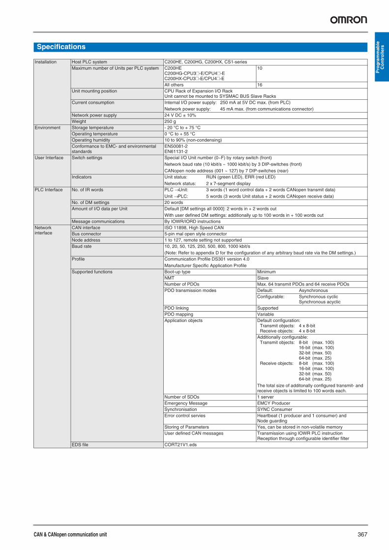
CAN & CANopen communication unit 367
Pro
gra
mm
able
C
on
tro
llersSpecifications
Installation Host PLC system C200HE, C200HG, C200HX, CS1-seriesMaximum number of Units per PLC system C200HE
C200HG-CPU3#-E/CPU4#-EC200HX-CPU3#-E/CPU4#-E
10
All others 16Unit mounting position CPU Rack of Expansion I/O Rack
Unit cannot be mounted to SYSMAC BUS Slave RacksCurrent consumption Internal I/O power supply: 250 mA at 5V DC max. (from PLC)
Network power supply: 45 mA max. (from communications connector)Network power supply 24 V DC ± 10%Weight 250 g
Environment Storage temperature - 20 °C to + 75 °COperating temperature 0 °C to + 55 °COperating humidity 10 to 90% (non-condensing)Conformance to EMC- and environmental standards
EN50081-2EN61131-2
User Interface Switch settings Special I/O Unit number (0~F) by rotary switch (front)Network baud rate (10 kbit/s ~ 1000 kbit/s) by 3 DIP-switches (front)CANopen node address (001 ~ 127) by 7 DIP-switches (rear)
Indicators Unit status: RUN (green LED), ERR (red LED)Network status: 2 x 7-segment display
PLC Interface No. of IR words PLC → Unit: 3 words (1 word control data + 2 words CANopen transmit data)Unit → PLC: 5 words (3 words Unit status + 2 words CANopen receive data)
No. of DM settings 20 wordsAmount of I/O data per Unit Default [DM settings all 0000]: 2 words in + 2 words out
With user defined DM settings: additionally up to 100 words in + 100 words outMessage communications By IOWR/IORD instructions
Network interface
CAN interface ISO 11898, High Speed CANBus connector 5-pin mal open style connectorNode address 1 to 127, remote setting not supportedBaud rate 10, 20, 50, 125, 250, 500, 800, 1000 kbit/s
(Note: Refer to appendix D for the configuration of any arbitrary baud rate via the DM settings.)Profile Communication Profile DS301 version 4.0
Manufacturer Specific Application ProfileSupported functions Boot-up type Minimum
NMT SlaveNumber of PDOs Max. 64 transmit PDOs and 64 receive PDOsPDO transmission modes Default: Asynchronous
Configurable: Synchronous cyclicSynchronous acyclic
PDO linking SupportedPDO mapping VariableApplication objects Default configuration:
Transmit objects: 4 x 8-bitReceive objects: 4 x 8-bit
Additionally configurable:Transmit objects: 8-bit (max. 100)
16-bit (max. 100)32-bit (max. 50)64-bit (max. 25)
Receive objects: 8-bit (max. 100)16-bit (max. 100)32-bit (max. 50)64-bit (max. 25)
The total size of additonally configured transmit- and receive objects is limited to 100 words each.
Number of SDOs 1 serverEmergency Message EMCY ProducerSynchronisation SYNC ConsumerError control servies Heartbeat (1 producer and 1 consumer) and
Node guardingStoring of Parameters Yes, can be stored in non-volatile memoryUser defined CAN messages Transmission using IOWR PLC instruction
Reception through configurable identifier filterEDS file CORT21V1.eds
Y201-EN2-03.book Seite 367 Donnerstag, 30. März 2006 1:52 13

368 Programmable Controllers
C200HW-SRM21-V1
CompoBus/S Master UnitCompoBus/S is a high-speed I/O bus• Up to 256 I/O points per Master.• Up to 32 Slaves per Master.• Communications cycle time: 0.5 ms (at 750 kbps).• Communications distance: Up to 500 m
(at 93.75 kbps).Free wiring with any branching method for up to 200 m (in long-distance communications mode).
FunctionA high-speed ON/OFF bus that automatically transfers remote I/O sta-tus to the CPU Unit without any programming in the CPU Unit. High-speed remote I/O is supported by a communications cycle time of 1 ms maximum for 256 I/O points.
System Configuration
Specifications
General
Unit Specifications
These flags use the AR area.
CompoBus/S Master Unit
CompoBus/S network
Slaves32 Terminals max.
Remote I/O
750 Kbps, 100 m93.75 Kbps, 500 m
Classification Communications Specifications Unit number ModelC200H Special I/O Unit Remote I/O No. of mountable Units: 16 0 to F C200HW-SRM21-V1
Current consumption 150 mA max. at 5 V DCNumber of I/O points 256 points (128 inputs/128 outputs), 128 points (64 inputs/64 outputs) (switchable)Number of occupied words 256 points:20 words (8 input words/8 output words, 4 status data)
128 points:10 words (4 input words/4 output words, 2 status data)PLC CS1, C200HX (-ZE), C200HG (-ZE), C200HE (-ZE), C200HSNumber of Master Units mountable
C200HE 128 points: 10, 256 points: 5C200HG-CPU33/43 128 points: 10, 256 points: 5C200HG-CPU53/63 128 points: 16, 256 points: 8C200HX-CPU34/44 128 points: 10, 256 points: 5C200HX-CPU54/64 128 points: 16, 256 points: 8C200HS 128 points: 10, 256 points: 5CS1 128 points: 16, 256 points: 8
Number of points per node number 8 pointsMax. number of Slaves per Master 32Status data Communications Error Flag and Active Slave Node (see note)Weight 200 g max.Approved standards UL 508 (E95399), CSA C22.2 No. 142 (LR51460)
Y201-EN2-03.book Seite 368 Donnerstag, 30. März 2006 1:52 13

CompoBus/S Master Unit 369
Pro
gra
mm
able
C
on
tro
llers
Communications Specifications
Note: 1. A terminator must be connected to the point in the system most remote from the Master.2. The communications baud rate is set by the DIP switch.
Communications method CompoBus/S protocolCoding method Manchester coding methodConnection method Multi-drop method and T-branch method (see note 1)Communications baud rate 750,000 bps, 93,750 bps (see note 2)Communications cycle time
High-speed communications mode
0.5 ms with 8 Slaves for inputs and 8 Slaves for outputs0.8 ms with 16 Slaves for inputs and 16 Slaves for outputs
Long-distance communications mode
4.0 ms with 8 Slaves for inputs and 8 Slaves for outputs6.0 ms with 16 Slaves for inputs and 16 Slaves for outputs
Communications cable
2-conductor VCTF cable (0.75 x 2), 4-conductor VCTF cable (0.75 x 4)Special Flat Cable
Communications distance
High-speed communications mode
2-conductor VCTF cable:Main line length:100 m max.Branch line length:3 m max.Total branch line length:50 m max.Special Flat Cable, 4-conductor VCTF cable:Main line length:30 m max.Branch line length:3 m max.Total branch line length:30 m max.(When Special Flat Cable is used to connect fewer than 16 Slaves, the main line can be up to 100 m long and the total branch line length can be up to 50 m.)
Long-distance communications mode
2-conductor VCTF cable:Main line length:500 m max.Branch line length:6 m max.Total branch line length:120 m max.Special Flat Cable, 4-conductor VCTF cable:Variable branch wiring (total cable length 200 m max.)(There are no limits on the branching format or main, branch, or total line lengths.The terminator must be connected to the point in the system farthest from the master.)
Max. number of connecting nodes 32Error control checks Manchester code check, frame length check, and parity check
Y201-EN2-03.book Seite 369 Donnerstag, 30. März 2006 1:52 13

370 Programmable Controllers
Ordering InformationInternational StandardsThe indicated standards are those current for UL, CSA, cULus, NK and Lloyds standards and EC directives as of September 2004. Abbreviations used:U = UL, U1 = UL Class I Div.2 for hazardous locations, C = CSA, UC = cULus, UC1 = cULus Class I Div.2 for hazardous locationsCU = cUL, N = NK (Nippon Kaiji Kyokai), L = Lloyd's Register, CE = EC Directives. Please contact OMRON representative for application conditions.
CPU Rack
Note: When using a CS1W-CN313 or CS1W-CN713 I/O Connecting Cable with a CS1@-CPU@@H CPU Unit, use only Cables produced on or after September 20, 2001 (production number 2091). Cables with no production number, a 6-digit production number, or produced before September 20, 2001, cannot be used.
Name Specifications Model StandardsCPU Units (See note.)
I/O bits Programcapacity
Data memory capacity --- ---
5,120 250 kSteps 448 kWords (DM: 32 kWords, EM: 32 kWords × 13 banks) CS1H-CPU67H UC1, N, L, CE5,120 120 kSteps 256 kWords (DM: 32 kWords, EM: 32 kWords × 7 banks) CS1H-CPU66H5,120 60 kSteps 128 kWords (DM: 32 kWords, EM: 32 kWords × 3 banks) CS1H-CPU65H5,120 30 kSteps 64 kWords (DM: 32 kWords, EM: 32 kWords × 1 bank) CS1H-CPU64H5,120 20 kSteps 64 kWords (DM: 32 kWords, EM: 32 kWords × 1 bank) CS1H-CPU63H5,120 60 kSteps 128 kWords (DM: 32 kWords, EM: 32 kWords × 3 banks) CS1G-CPU45H1,280 30 kSteps 64 kWords (DM: 32 kWords, EM: 32 kWords × 1 bank) CS1G-CPU44H960 20 kSteps 64 kWords (DM: 32 kWords, EM: 32 kWords × 1 bank) CS1G-CPU43H960 10 kSteps 64 kWords (DM: 32 kWords, EM: 32 kWords × 1 bank) CS1G-CPU42H
CPU Backplanes (for CS1 Units only)
2 slots (Does not connect to Expansion Rack.) CS1W-BC022 U, C, N, L, CE3 slots CS1W-BC0325 slots CS1W-BC0528 slots CS1W-BC08210 slots CS1W-BC102
CPU Backplanes(for CS1- and C200H I/O Units)
2 slots (Does not connect to Expansion Rack.) CS1W-BC023 U, C, N, L, CE3 slots CS1W-BC0335 slots CS1W-BC0538 slots CS1W-BC08310 slots CS1W-BC103
Power Supply Units 100 to 120 V AC or 200 to 240 V AC; Output capacity: 4.6 A, 5 V DC C200HW-PA204 U, C, N, L, CE100 to 120 V AC or 200 to 240 V AC (with 0.8 A, 24 V DC service power supply)Output capacity: 4.6 A, 5 V DC
C200HW-PA204S
100 to 120 V AC or 200 to 240 V AC (with RUN output) Output capacity: 4.6 A, 5 V DC C200HW-PA204R U, C100 to 120 V AC or 200 to 240 V AC (with RUN output) Output capacity: 9 A, 5 V DC C200HW-PA209R U, C, N, L, CE24 V DC, Output capacity: 4.6 A, 5 V DC C200HW-PD024 UC1, N, L, CE100 V DC, Output capacity: 6 A, 5 V DC C200HW-PD106R U, C
I/O Control Unit For Expansion Racks connected over a distance of more than 12 m (2 terminating resistors included. C200H Units cannot be used on Long-distance Expansion Racks.)
CS1W-IC102 U, C, CE
Memory Cards Flash memory, 30 MB HMC-EF372 L, CEFlash memory, 64 MB HMC-EF672Memory Card Adapter (for computer PCMIA slot) HMC-AP001 CE
Serial Communications Boards
2 × RS-232C ports, protocol macro function CS1W-SCB21-V1 U, C, N, L, CE1 × RS-232C port + 1 × RS-422/485 port, protocol macro function CS1W-SCB41-V1
Programming Consoles An English Keyboard Sheet (CS1W-KS001-E) is required.(Connects to peripheral port on CPU Unit only. Cannot be connected to RS-232C port.)
CQM1-PRO01-E U, C, CEC200H-PRO27-E U, C, N, CE
Programming Console Key Sheet
For C200H-PRO27 and CQM1H-PRO01 CS1W-KS001-E CE
Programming Console Connecting Cables
Connects the C200H-PRO27-E Programming Console. (Length: 2.0 m) CS1W-CN224Connects the C200H-PRO27-E Programming Console. (Length: 6.0 m) CS1W-CN624
CX-One Omron's integrated software for programming and configuration of all control system compo-nents, including PLCs, HMI, drives, temperature controllers and advanced sensors.
CX-ONE-AL@@C-E*1
*1 @@ = Number of licences; 01, 03, 10
---
Peripheral Device Connecting Cables (for peripheral port)
Connects personal computers, D-Sub 9-pin receptacle (Length: 0.1 m) (Conversion cable to connect RS-232C cable to peripheral port)
CS1W-CN118 CE
Peripheral bus or Host Link Connects personal computers, D-Sub 9-pin (Length: 2.0 m) CS1W-CN226Connects personal computers, D-Sub 9-pin (Length: 6.0 m) CS1W-CN626
Peripheral Device Connecting Cables (for RS-232C port)
Peripheral bus or Host Link, antistatic
Connects personal computers, D-Sub 9-pin (Length: 2.0 m) XW2Z-200S-CV ---Connects personal computers, D-sub 9-pin (Length: 5.0 m) XW2Z-500S-CV
Host Link Connects personal computers, D-Sub 9-pin (Length: 2.0 m) XW2Z-200S-VConnects personal computers, D-Sub 9-pin (Length: 5.0 m) XW2Z-500S-V
USB-Serial Conversion Cable
Converts between USB and RS-232C, cable length: 0.5 mPC driver provided on CD-ROM. Refer to Using a USB-Serial Conversion Cable to Connect to a Peripheral or RS-232C Port on page 291 for specifications.
CS1W-CIF31 ---
Battery Set For CS1 Series only. (Install a replacement battery within 2 years of the production date.) CS1W-BAT01 L, CE
Y201-EN2-03.book Seite 370 Donnerstag, 30. März 2006 1:52 13

371
Pro
gra
mm
able
C
on
tro
llersSYSMAC CS1D Duplex System
Name Specifications Model StandardsDuplex CPU Units I/O capacity Program capacity Data memory capacity --- UC1, N, L, CE
5,120 points 60 Ksteps 128 Kwords(DM: 32 Kwords, EM: 32 Kwords x 3 banks)
CS1D-CPU65H
250 Ksteps 448 Kwords(DM: 32 Kwords, EM: 32 Kwords x 13 banks)
CS1D-CPU67H
Duplex process control CPUs (include LCB05 option board for duplex system)
5,120 points 60 Ksteps 128 Kwords(DM: 32 Kwords, EM: 32 Kwords x 3 banks)
CS1D-CPU65PCS1D-CPU67P
UC1, CE
Single CPU Units supporting online I/O unit replacement
5120 250 kSteps 448 kWords(DM: 32 kWords, EM 32 kWords x 13 banks)
CS1D-CPU67S UC1, N, L, CE
5120 60 kSteps 128 kWords (DM: 32 kWords, EM 32 kWords x 3 banks)
CS1D-CPU65S
1280 30 kSteps 64 kWords (DM: 32 kWords, EM 32 kWords x 1 bank)
CS1D-CPU44S
960 10 kSteps 64 kWords (DM: 32 kWords, EM 32 kWords x 1 bank)
CS1D-CPU42S
Duplex Unit --- CS1D-DPL01 UC1, N, L, CECS1D Power Supply Units 100 to 120 VAC or 200 to 240 VAC, 50/60 Hz (with RUN output)
Output capacity: 7 A, 5 VDC; 1.3 A, 26 VDC, 35 W total max.CS1D-PA207R
24 VDC, Output capacity: 4.3 A, 5 VDC; 0.56 A, 26 VDC, 28 W total max. CS1D-PD024Duplex CPU Backplane 5 slots, supports dual CPUs and duplex unit, dual power supplies and
on-line Unit replacementCS1D-BC052
Single CPU backplane 8 slots (supports dual power supply and on-line Unit replacement) CS1D-BC082SExpansion Backplane 9 slots (Used both for CS1D Expansion Racks and CS1D Long-distance Expansion
Racks.) CS1D-BI092
Controller Link Units Optical ring type with H-PCF cable CS1D-CLK12-V1Optical ring type with GI cable CS1D-CLK52-V1
CX-One Omron's integrated software for programming and configuration of all control system components, including PLCs, HMI, drives, temperature controllers and advanced sen-sors.
CX-ONE-AL@@C-E*1 ---
Optical Fiber Cable H-PCF cable for for interconnection between Duplex Controller Link Units, cable length: 50 cm
CS1D-CN051 ---
*1 @@ = Number of licences; 01, 03, 10
Y201-EN2-03.book Seite 371 Donnerstag, 30. März 2006 1:52 13
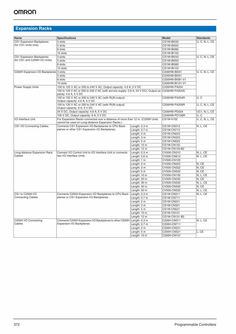
372 Programmable Controllers
Expansion Racks
Name Specifications Model StandardsCS1 Expansion Backplanes (for CS1 Units only)
3 slots CS1W-BI032 U, C, N, L, CE5 slots CS1W-BI0528 slots CS1W-BI08210 slots CS1W-BI102
CS1 Expansion Backplanes (for CS1 and C200H I/O Units)
3 slots CS1W-BI033 U, C, N, L, CE5 slots CS1W-BI0538 slots CS1W-BI08310 slots CS1W-BI103
C200H Expansion I/O Backplanes 3 slots C200HW-BI031 U, C, N, L, CE5 slots C200HW-BI0518 slots C200HW-BI081-V110 slots C200HW-BI101-V1
Power Supply Units 100 to 120 V AC or 200 to 240 V AC, Output capacity: 4.6 A, 5 V DC C200HW-PA204100 to 120 V AC or 200 to 240 V AC (with service supply: 0.8 A, 24 V DC), Output ca-pacity: 4.6 A, 5 V DC
C200HW-PA204S
100 to 120 V AC or 200 to 240 V AC (with RUN output)Output capacity: 4.6 A, 5 V DC
C200HW-PA204R U, C
100 to 120 V AC or 200 to 240 V AC (with RUN output)Output capacity: 9 A, 5 V DC
C200HW-PA209R U, C, N, L, CE
24 V DC, Output capacity: 4.6 A, 5 V DC C200HW-PD024 UC1, N, L, CE100 V DC, Output capacity: 6 A, 5 V DC C200HW-PD106R U, C
I/O Interface Unit For Expansion Racks connected over a distance of more than 12 m. (C200H Units cannot be used on Long-distance Expansion Racks.)
CS1W-II102 U, C, N, L, CE
CS1 I/O Connecting Cables Connects CS1 Expansion I/O Backplanes to CPU Back-planes or other CS1 Expansion I/O Backplanes.
Length: 0.3 m CS1W-CN313 N, L, CELength: 0.7 m CS1W-CN713Length: 2 m CS1W-CN223Length: 3 m CS1W-CN323Length: 5 m CS1W-CN523Length: 10 m CS1W-CN133Length: 12 m CS1W-CN133-B2
Long-distance Expansion Rack Cables
Connect I/O Control Unit to I/O Interface Unit or connects two I/O Interface Units
Length: 0.3 m CV500-CN312 N, L, CELength: 0.6 m CV500-CN612 N, L, CELength: 1 m CV500-CN122Length: 2 m CV500-CN222 N, CELength: 3 m CV500-CN322 N, CELength: 5 m CV500-CN522 N, CELength: 10 m CV500-CN132 N, L, CELength: 20 m CV500-CN232 N, CELength: 30 m CV500-CN332 N, L, CELength: 40 m CV500-CN432 N, CELength: 50 m CV500-CN532 N, L, CE
CS1 to C200H I/O Connecting Cables
Connects C200H Expansion I/O Backplanes to CPU Back-planes or CS1 Expansion I/O Backplanes.
Length: 0.3 m CS1W-CN311 N, L, CELength: 0.7 m CS1W-CN711Length: 2 m CS1W-CN221Length: 3 m CS1W-CN321Length: 5 m CS1W-CN521Length: 10 m CS1W-CN131Length: 12 m CS1W-CN131-B2
C200H I/O Connecting Cables
Connects C200H Expansion I/O Backplanes to other C200H Expansion I/O Backplanes.
Length: 0.3 m C200H-CN311 N, L, CELength: 0.7 m C200H-CN711Length: 2 m C200H-CN221Length: 5 m C200H-CN521 L, CELength: 10 m C200H-CN131
Y201-EN2-03.book Seite 372 Donnerstag, 30. März 2006 1:52 13

373
Pro
gra
mm
able
C
on
tro
llersI/O Units
CS1 Basic I/O Units
Note: Interrupt inputs are not supported on these Racks (i.e., used as normal I/O Unit).
Classifica-tion
Name Specifications Mountable Racks Words allocated
(CIO 0000 to CIO 0319)
Model StandardsCPU Rack
C200H Expansion I/O Racks
CS1 Expansion
Racks
CS1 Long-
distance Racks
SYSMAC BUS Slave Racks
CS1 Input Units
DC Input Units 24 VDC, 16 inputs, 7 mA Yes No Yes Yes No 1 CS1W-ID211 UC1, N, L, CE24 VDC, 32 inputs, 6 mA Yes No Yes Yes No 2 CS1W-ID231
24 VDC, 64 inputs, 6 mA Yes No Yes Yes No 4 CS1W-ID26124 VDC, 96 inputs, approx. 5 mA
Yes No Yes Yes No 6 CS1W-ID291 U, C, N, L, CE
AC Input Units 100 to 120 VAC, 100 to 120 VDC, 16 inputs
Yes No Yes Yes No 1 CS1W-IA111 UC1, N, L, CE
200 to 240 VAC, 16 inputs Yes No Yes Yes No 1 CS1W-IA211 UC, N, L, CEInterrupt Input Unit
24 VDC, 16 inputs, 7 mA Yes No Yes (See note.)
Yes (See note.)
No 1 CS1W-INT01 UC1, N, L, CE
High-speed Input Unit
24 VDC, 16 inputs, 7 mA Yes No Yes Yes No 1 CS1W-IDP01
Safety Relay Unit
24 VDC, 2 channels with 4 in-puts each, 4 pts/common
Yes No Yes Yes No 1 CS1W-SF200 U, C, CE
CS1 Out-put Units
Relay Output Units
250 VAC or 120 VDC, inde-pendent contacts, 8 outputs, 2 A
Yes No Yes Yes No 1 CS1W-OC201 UC1, N, L, CE
250 VAC or 120 VDC, 16 outputs, 2 A
Yes No Yes Yes No 1 CS1W-OC211
Transistor Output Units
12 to 24 VDC, 0.5A, 16 sinking outputs
Yes No Yes Yes No 1 CS1W-OD211
24 VDC, 0.5A, 16 sourcing outputs
Yes No Yes Yes No 1 CS1W-OD212 U, C, N, L, CE
12 to 24 VDC, 0.5A, 32 sinking outputs
Yes No Yes Yes No 2 CS1W-OD231 UC1, N, L, CE
24 VDC, 0.5A, 32 sourcing outputs
Yes No Yes Yes No 2 CS1W-OD232 U, C, N, L, CE
12 to 24 VDC, 0.3A, 64 sinking outputs
Yes No Yes Yes No 4 CS1W-OD261 UC1, N, L, CE
24 VDC, 0.3A, 64 sourcing outputs
Yes No Yes Yes No 4 CS1W-OD262
12 to 24 VDC, 0.1A, 96 sinking outputs
Yes No Yes Yes No 6 CS1W-OD291 U, C, N, L, CE
12 to 24 VDC, 0.1A, 96 sourcing outputs
Yes No Yes Yes No 6 CS1W-OD292
Triac Output Units
250 VAC, 1.2 A, 8 outputs Yes No Yes Yes No 1 CS1W-OA201 UC, N, L, CE250 VAC, 0.5 A, 16 outputs
Yes No Yes Yes No 1 CS1W-OA211
CS1 I/O Units
DC Input/ Transistor Output Units
24 VDC, 6 mA, 32 inputs, 12 to 24 VDC, 0.3 A, 32 sinking outputs
Yes No Yes Yes No Inputs: 2Outputs: 2
CS1W-MD261 UC1, N, L, CE
24 VDC, 6 mA, 32 inputs, 24 VDC, 0.3 A, 32 sourcing outputs
Yes No Yes Yes No Inputs: 2Outputs: 2
CS1W-MD262 U, C, N, L, CE
24 VDC, approx. 5 A, 48 inputs, 12 to 24 VDC, 0.1 A, 48 outputs, sinking inputs/outputs
Yes No Yes Yes No Inputs: 3Outputs: 3
CS1W-MD291
24 VDC, approx. 5A, 48 inputs, 12 to 24 VDC, 0.1 A, 48 outputs, sourcing inputs/outputs
Yes No Yes Yes No Inputs: 3Outputs: 3
CS1W-MD292
TTL I/O Unit 5 VDC, 32 inputs, 32 outputs
Yes No Yes Yes No Inputs: 2Outputs: 2
CS1W-MD561 UC, N, L, CE
Y201-EN2-03.book Seite 373 Donnerstag, 30. März 2006 1:52 13

374 Programmable Controllers
C200H Basic I/O Units
Note: 1. C200H Units cannot be used with CS1D CPU Units. 2. Interrupt inputs are not supported on these Racks (i.e., used as normal I/O Unit).3. The C200H-ID001 (no-voltage contacts, 8 inputs, NPN) and C200H-ID002 (no-voltage contacts, 8 inputs, PNP) cannot be used.
Classifica-tion
Name Specifications Mountable Racks Words allocated
(CIO 0000 to CIO 0319)
Model StandardsCPU Rack
C200H Expansion I/O Racks
CS1 Expansion
Racks
CS1 Long-
distance Racks
SYSMAC BUS Slave Racks
C200H Input Units (See note 1.)
DC Input Units 12 to 24 VDC, 8 inputs Yes Yes Yes No Yes 1 C200H-ID211 U, C, N, L, CE24 VDC, 16 inputs Yes Yes Yes No Yes 1 C200H-ID212
AC Input Units 100 to 120VAC, 8 inputs
Yes Yes Yes No Yes 1 C200H-IA121 U, C, N, L
100 to 120VAC, 16 inputs
Yes Yes Yes No Yes 1 C200H-IA122
100 to 120VAC, 16 inputs
Yes Yes Yes No Yes 1 C200H-IA122V CE
200 to 240VAC, 8 inputs
Yes Yes Yes No Yes 1 C200H-IA221 U, C, N, L
200 to 240VAC, 16 inputs
Yes Yes Yes No Yes 1 C200H-IA222
200 to 240VAC, 16 inputs
Yes Yes Yes No Yes 1 C200H-IA222V CE
AC/DC Input Units
12 to 24 VAC/VDC, 8 inputs
Yes Yes Yes No Yes 1 C200H-IM211 U, C, N, L, CE
24 VAC/VDC, 16 inputs
Yes Yes Yes No Yes 1 C200H-IM212
Interrupt Input Unit
12 to 24 VDC, 8 inputs
Yes Yes (See note 2.)
Yes (See note 2.)
No (See note 2.)
No 1 C200HS-INT01
C200H Out-put Units (See note 1.)
Relay Bit Out-put Units
250 VAC/24VDC, 2 A, 8 outputs max.
Yes Yes Yes No Yes 1 C200H-OC221 U, C, N
250 VAC/24VDC, 2 A, 12 outputs max.
Yes Yes Yes No Yes 1 C200H-OC222
250 VAC/24VDC, 2A, 12 outputs max.
Yes Yes Yes No Yes 1 C200H-OC222N CE
250 VAC/24VDC, 2 A, 16 outputs max.
Yes Yes Yes No Yes 1 C200H-OC225 U, C, N, L
250 VAC/24VDC, 2 A, 16 outputs max.
Yes Yes Yes No Yes 1 C200H-OC226N CE
250 VAC/24VDC, 2 A, independent contacts, 5 outputs max.
Yes Yes Yes No Yes 1 C200H-OC223 U, C, N, L
250 VAC/24 VDC, 2 A, independent contacts, 8 outputs max.
Yes Yes Yes No Yes 1 C200H-OC224
250 VAC/24 VDC, 2 A, independent contacts, 8 outputs max.
Yes Yes Yes No Yes 1 C200H-OC224N CE
C200H Out-put Units (See note 1.)
Transistor Out-put Units
12 to 48 VDC, 1A, 8 sinking outputs
Yes Yes Yes No Yes 1 C200H-OD411 U, C, N, L, CE
24 VDC, 2.1 A, 8 sinking outputs
Yes Yes Yes No Yes 1 C200H-OD213
24 VDC, 0.8 A, 8 sourcing outputs, load short-circuit protection.
Yes Yes Yes No Yes 1 C200H-OD214 U, C, N, L
5 to 24 VDC, 0.3 A, 8 sourcing outputs
Yes Yes Yes No Yes 1 C200H-OD216
24 VDC, 0.3 A, 12 sinking outputs
Yes Yes Yes No Yes 1 C200H-OD211 U, C, N, L, CE
5 to 24 VDC, 0.3 A, 12 sourcing outputs
Yes Yes Yes No Yes 1 C200H-OD217
24 VDC, 0.3 A, 16 sinking outputs
Yes Yes Yes No Yes 1 C200H-OD212
24 VDC, 1 A, 16 sourcing outputs, load short-circuit pro-tection.
Yes Yes Yes No Yes 1 C200H-OD21A CE
Triac Output Units
250 VAC, 1.2 A, 8 outputs
Yes Yes Yes No Yes 1 C200H-OA223 CE
250 VAC, 0.3 A, 12 outputs
Yes Yes Yes No Yes 1 C200H-OA222V
250 VAC, 0.5 A, 12 outputs
Yes Yes Yes No Yes 1 C200H-OA224 U, C, N, L
Y201-EN2-03.book Seite 374 Donnerstag, 30. März 2006 1:52 13
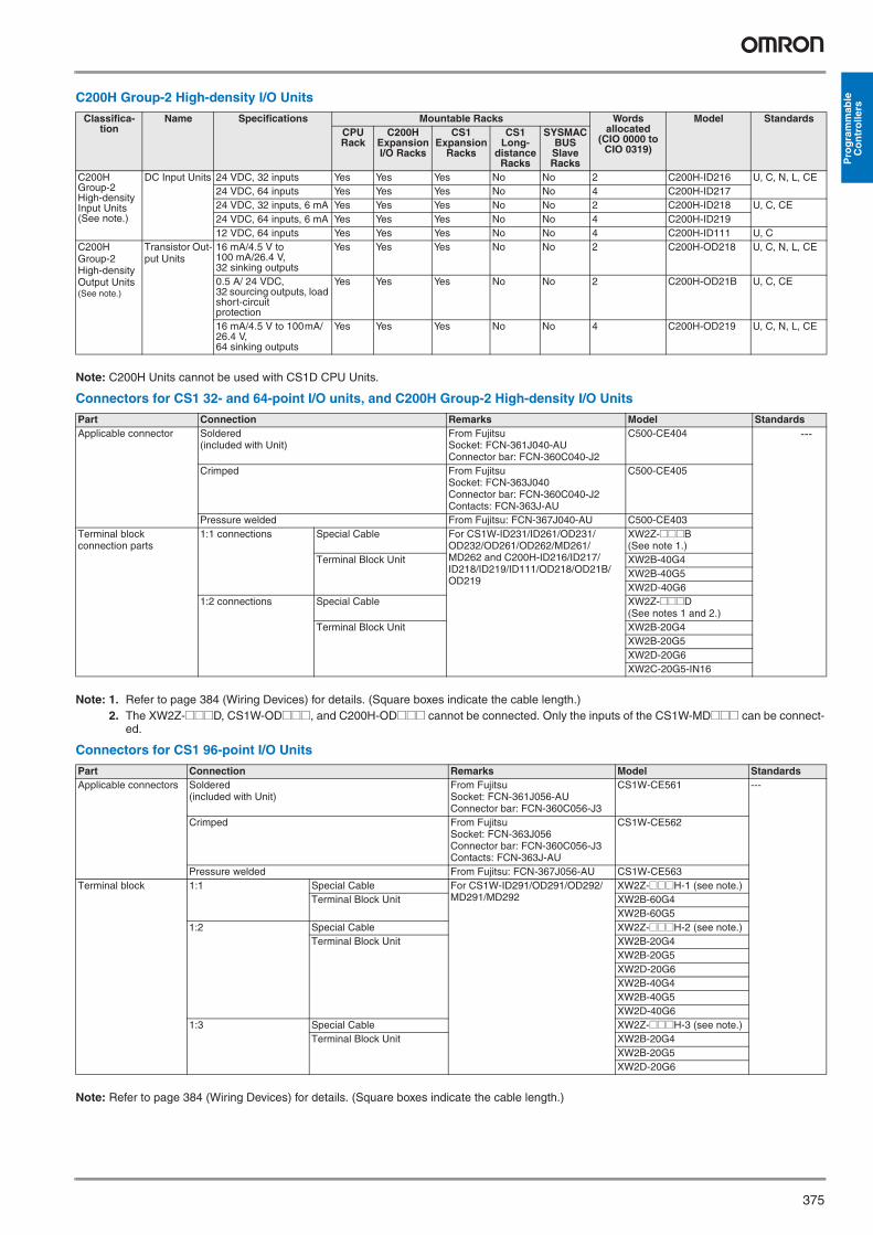
375
Pro
gra
mm
able
C
on
tro
llers
C200H Group-2 High-density I/O Units
Note: C200H Units cannot be used with CS1D CPU Units.
Connectors for CS1 32- and 64-point I/O units, and C200H Group-2 High-density I/O Units
Note: 1. Refer to page 384 (Wiring Devices) for details. (Square boxes indicate the cable length.)2. The XW2Z-@@@D, CS1W-OD@@@, and C200H-OD@@@ cannot be connected. Only the inputs of the CS1W-MD@@@ can be connect-
ed.
Connectors for CS1 96-point I/O Units
Note: Refer to page 384 (Wiring Devices) for details. (Square boxes indicate the cable length.)
Classifica-tion
Name Specifications Mountable Racks Words allocated
(CIO 0000 to CIO 0319)
Model StandardsCPU Rack
C200H Expansion I/O Racks
CS1 Expansion
Racks
CS1 Long-
distance Racks
SYSMAC BUS Slave Racks
C200H Group-2 High-density Input Units (See note.)
DC Input Units 24 VDC, 32 inputs Yes Yes Yes No No 2 C200H-ID216 U, C, N, L, CE24 VDC, 64 inputs Yes Yes Yes No No 4 C200H-ID21724 VDC, 32 inputs, 6 mA Yes Yes Yes No No 2 C200H-ID218 U, C, CE24 VDC, 64 inputs, 6 mA Yes Yes Yes No No 4 C200H-ID21912 VDC, 64 inputs Yes Yes Yes No No 4 C200H-ID111 U, C
C200H Group-2 High-density Output Units (See note.)
Transistor Out-put Units
16 mA/4.5 V to 100 mA/26.4 V, 32 sinking outputs
Yes Yes Yes No No 2 C200H-OD218 U, C, N, L, CE
0.5 A/ 24 VDC, 32 sourcing outputs, load short-circuit protection
Yes Yes Yes No No 2 C200H-OD21B U, C, CE
16 mA/4.5 V to 100mA/26.4 V, 64 sinking outputs
Yes Yes Yes No No 4 C200H-OD219 U, C, N, L, CE
Part Connection Remarks Model StandardsApplicable connector Soldered
(included with Unit)From FujitsuSocket: FCN-361J040-AUConnector bar: FCN-360C040-J2
C500-CE404 ---
Crimped From FujitsuSocket: FCN-363J040Connector bar: FCN-360C040-J2Contacts: FCN-363J-AU
C500-CE405
Pressure welded From Fujitsu: FCN-367J040-AU C500-CE403Terminal block connection parts
1:1 connections Special Cable For CS1W-ID231/ID261/OD231/ OD232/OD261/OD262/MD261/ MD262 and C200H-ID216/ID217/ID218/ID219/ID111/OD218/OD21B/OD219
XW2Z-@@@B(See note 1.)
Terminal Block Unit XW2B-40G4XW2B-40G5XW2D-40G6
1:2 connections Special Cable XW2Z-@@@D(See notes 1 and 2.)
Terminal Block Unit XW2B-20G4XW2B-20G5XW2D-20G6XW2C-20G5-IN16
Part Connection Remarks Model StandardsApplicable connectors Soldered
(included with Unit)From FujitsuSocket: FCN-361J056-AUConnector bar: FCN-360C056-J3
CS1W-CE561 ---
Crimped From FujitsuSocket: FCN-363J056Connector bar: FCN-360C056-J3Contacts: FCN-363J-AU
CS1W-CE562
Pressure welded From Fujitsu: FCN-367J056-AU CS1W-CE563Terminal block 1:1 Special Cable For CS1W-ID291/OD291/OD292/
MD291/MD292XW2Z-@@@H-1 (see note.)
Terminal Block Unit XW2B-60G4XW2B-60G5
1:2 Special Cable XW2Z-@@@H-2 (see note.)Terminal Block Unit XW2B-20G4
XW2B-20G5XW2D-20G6XW2B-40G4XW2B-40G5XW2D-40G6
1:3 Special Cable XW2Z-@@@H-3 (see note.)Terminal Block Unit XW2B-20G4
XW2B-20G5XW2D-20G6
Y201-EN2-03.book Seite 375 Donnerstag, 30. März 2006 1:52 13

376 Programmable Controllers
C200H High-density I/O Units Classified as Special I/O Units
Connectors for C200H High-density I/O Units
Note: Refer to page 384 (Wiring Devices) for details. (Square boxes indicate the cable length.)
C200H Special I/O Units (Cannot be used with CS1D)
Name Specifications Mountable Racks Unit No.
Model StandardsCPU Rack C200H Ex-
pansion I/O Racks
CS1 Expan-sion Racks
CS1 Long-distance Racks
SYSMAC BUS Slave Racks
DC Input Units 24 V DC, 32 inputs Yes Yes Yes No Yes 0 to 9 C200H-ID215 U, C, N, L, CETTL Input Units 5 V DC, 32 inputs Yes Yes Yes No Yes C200H-ID501Transistor Output Units 24 V DC, 32 sinking
outputsYes Yes Yes No Yes C200H-OD215
TTL Output Units 5 V DC, 32 sinking outputs
Yes Yes Yes No Yes C200H-OD501
TTL I/O Units 5 V DC, 16 inputs, 16 sinking outputs
Yes Yes Yes No Yes C200H-MD501
DC Input/Transistor Output Units
24 V DC, 16 inputs, 16 sinking outputs
Yes Yes Yes No Yes C200H-MD215
12 V DC, 16 inputs, 16 sinking outputs
Yes Yes Yes No Yes C200H-MD115 U, C, N
Part Connection Remarks Model StandardsApplicable connectors
Soldered(included with Unit)
From FujitsuSocket: FCN-361J024-AUConnector bar: FCN-360C024-J2
C500-CE241 ---
Crimped From FujitsuSocket: FCN-363J024Connector bar: FCN-360C024-J2Contacts: FCN-363J-AU
C500-CE242
Pressure welded From Fujitsu: FCN-367J024-AU/F C500-CE243Terminal block connection parts
Special Cable For C200H-ID215/ID501/OD215/ MD115/MD215For C200H-ID215/ID501/MD115/ MD215/MD501@@@ = cable length
XW2Z-@@@A (See note.)Terminal Block Connector XW2B-20G4
XW2B-20G5XW2D-20G6XW2B-20G5-DXW2B-40G5-T
Special Cable XW2Z-@@@A (see note)Terminal Block Connector XW2C-20G6-IN16
Name Specifications Mountable Racks Unit No. Model StandardsCPU Rack
C200H Ex-pansion I/O Racks
CS1 Expan-sion Racks
CS1 Long-distance Racks
SYSMAC BUS Slave Racks
Temperature Control Units
Thermocouple input, time-proportioning PID, or ON/OFF transistor output
Yes Yes Yes No Yes 0 to 9 C200H-TC001 U, C, CE
Thermocouple input, time-proportioning PID, or ON/OFF voltage out-put
Yes Yes Yes No Yes C200H-TC002
Thermocouple input, PID current output
Yes Yes Yes No Yes C200H-TC003
Temperature-resistance thermometer input, time-proportioning PID, or ON/OFF transistor out-put
Yes Yes Yes No Yes C200H-TC101
Temperature-resistance thermometer input, time-proportioning PID, or ON/OFF voltage output
Yes Yes Yes No Yes C200H-TC102
Temperature-resistance thermometer input, PID current output
Yes Yes Yes No Yes C200H-TC103
Data Setting Console
Used with Temperature Control Units.Monitoring, setting, and changing present val-ues, set points, alarm values, PID parameters, bank numbers, etc.
--- --- C200H-DSC01 ---
Connecting Cable, 2 m
--- C200H-CN225
Connecting Cable, 4 m
--- C200H-CN425
Y201-EN2-03.book Seite 376 Donnerstag, 30. März 2006 1:52 13

377
Pro
gra
mm
able
C
on
tro
llers
Heat/Cool Temperature Control Units
Thermocouple input, time-proportioning PID, or ON/OFF transistor output
Yes Yes Yes No Yes 0 to 9 C200H-TV001 U, C, CE
Thermocouple input, time-proportioning PID, or ON/OFF voltage out-put
Yes Yes Yes No Yes C200H-TV002
Thermocouple input, PID current output
Yes Yes Yes No Yes C200H-TV003
Temperature-resistance thermometer input, time-proportioning PID, or ON/OFF transistor out-put
Yes Yes Yes No Yes C200H-TV101
Temperature-resistance thermometer input, time-proportioning PID, or ON/OFF voltage output
Yes Yes Yes No Yes C200H-TV102
Temperature-resistance thermometer input, PID current output
Yes Yes Yes No Yes C200H-TV103
Temperature Sensor Units
Thermocouple input, K/J selectable
Yes Yes Yes No Yes 0 to 9 C200H-TS001 U, C
Thermocouple input, K/L selectable
Yes Yes Yes No Yes C200H-TS002
Temperature-resistance thermometer,JPt 100
Yes Yes Yes No Yes C200H-TS101
Temperature-resistance thermometer,Pt 100
Yes Yes Yes No Yes C200H-TS102
PID Control Units Voltage output/current input, time-proportion-ing PID, or ON/OFF tran-sistor output
Yes Yes Yes No Yes 0 to 9 C200H-PID01 U, C, CE
Voltage output/current input, time-proportion-ing PID, or ON/OFF volt-age output
Yes Yes Yes No Yes C200H-PID02
Voltage output/current input, PID current output
Yes Yes Yes No Yes C200H-PID03
Data Setting Console
Used with PID Control Units.Monitoring, setting, and changing present val-ues, set points, alarm values, PID parameters, bank numbers, etc.
--- --- C200H-DSC01 ---
Connecting Cable, 2 m --- C200H-CN225Connecting Cable, 4 m --- C200H-CN425
ASCII Units 200-Kbyte RAM, 2 RS-232C ports
Yes Yes Yes No Yes 0 to F C200H-ASC11 U, C, CE
200-Kbyte RAM, RS-232C port, RS-422/485 port
Yes Yes Yes No Yes C200H-ASC21
200-Kbyte RAM, 3 RS-232C ports (1 terminal only)
Yes Yes Yes No Yes C200H-ASC31
Analog Input Units 4 to 20 mA, 1 to 5/0 to 10 V/–10 to +10 V (select-able); 8 inputs; 1/4,000 resolution
Yes Yes Yes No Yes 0 to F C200H-AD003 U, C, N, L, CE
Ánalog Output Units
1 to 5 V, –10 to +10 V (selectable), 8 outputs; 1/4,000 resolution
Yes Yes Yes No Yes 0 to F C200H-DA003 U, C, N, L, CE
4 to 20 mA, 8 outputs; 1/4,000 resolution
Yes Yes Yes No Yes C200H-DA004
Analog I/O Units 2 inputs (4 to 20 mA,1 to 5 V, etc.)2 outputs (4 to 20 mA, 1 to 5 V, etc.)
Yes Yes Yes No Yes C200H-MAD01
High-Speed Counter Units
Two-axis pulse input, counting rate: 75 kcps max., line driver compat-ible
Yes Yes Yes No Yes 0 to F C200H-CT021 U, C, CE
Name Specifications Mountable Racks Unit No. Model StandardsCPU Rack
C200H Ex-pansion I/O Racks
CS1 Expan-sion Racks
CS1 Long-distance Racks
SYSMAC BUS Slave Racks
Y201-EN2-03.book Seite 377 Donnerstag, 30. März 2006 1:52 13

378 Programmable Controllers
Motion Control Units
G-language program-mable, two-axis analog outputs
Yes Yes Yes No Yes 0 to F C200H-MC221 U, C, CE
MC Support SoftwareIBM PC/AT or compati-ble
--- --- CV500-ZN3AT1-E ---
Connecting Cable: 3.3 m --- CV500-CIF01Teaching Box --- CVM1-PRO01 U, C, CEConnection cable for Teaching Box: 2 m long
--- CV500-CN224 CE
Memory Pack --- CVM1-MP702 U, C, CETerminal Block Conver-sion UnitSimplifies wiring.
--- XW2B-20J6-6 ---
Connecting Cable for Terminal Block Conver-sion Unit
--- XW2Z-100J-F1
4 axes, analog+digital I/O, Motion Perfect BASIC language
Yes Yes Yes No No 0 to F C200HW-MC402-E CE
Position Control Units
One-axis pulse-train open-collector output
Yes Yes Yes No Yes 0 to F C200HW-NC113 U, C, CE
Two-axis pulse-train open-collector output
Yes Yes Yes No Yes C200HW-NC213
Four-axis pulse-train open-collector output
Yes Yes Yes No Yes C200HW-NC413
Peripheral Port Connect-ing Cables for computer
--- --- CS1W-CN226 (2 m) CECS1W-CN626 (6 m)
RS-232C Port Connect-ing Cables for computer
--- XW2Z-200S-CV (2 m)NCT V1.11 or earlier
---
XW2Z-500S-CV (5 m)NCT V1.11 or earlierXW2Z-200S (2 m)(See note 1.)XW2Z-500S (5 m)(See note 1.)
1-axis Relay Unit for C200HW-NC113
XW2B-20J6-1B
2-axis Relay Unit for C200HW-NC213/NC413
XW2B-40J6-2B
1-axis U, H, M Connect-ing Cables for C200HW-NC113
XW2Z-050J-A6 (0.5 m)XW2Z-100J-A6 (1 m)
2-axis U, H, M Connect-ing Cables for C200HW-NC213/NC413
XW2Z-050J-A7 (0.5 m)XW2Z-100J-A7 (1 m)
1-axis UEP Connecting Cables for C200HW-NC113
XW2Z-050J-A8 (0.5 m)XW2Z-100J-A8 (1 m)
2-axis UEP Connecting Cables for C200HW-NC213/NC413
--- --- XW2Z-050J-A9 (0.5 m)
---
XW2Z-100J-A9 (1 m)
Name Specifications Mountable Racks Unit No. Model StandardsCPU Rack
C200H Ex-pansion I/O Racks
CS1 Expan-sion Racks
CS1 Long-distance Racks
SYSMAC BUS Slave Racks
Y201-EN2-03.book Seite 378 Donnerstag, 30. März 2006 1:52 13

379
Pro
gra
mm
able
C
on
tro
llers
CS1 Special I/O Units
Name Specifications Mountable Racks Unit No. Model StandardsCPU Rack
C200H Ex-pansion I/O Racks
CS1 Expan-sion Racks
CS1 Long-distance Racks
SYSMAC BUS Slave Racks
Analog Input Units 4 inputs (1 to 5 V, 0 to 5 V, 0 to 10 V, –10 to 10 V, 4 to 20 mA) Resolution: 1/4,000
Yes No Yes Yes No 0 to 95 CS1W-AD041-V1 UC1, N, L, CE
8 inputs (1 to 5 V, 0 to 5 V, 0 to 10 V, –10 to 10 V, 4 to 20 mA) Resolution: 1/4,000
CS1W-AD081-V1
16 inputs (1 to 5 V, 0 to 5 V, 0 to 10 V,–10 to 10 V, 4 to 20 mA)
0 to 94 CS1W-AD161 UC1, N, CE
Analog Output Units
4 outputs (1 to 5 V, 0 to 5 V, 0 to 10 V, –10 to 10 V, 4 to 20 mA) Resolution: 1/4,000
0 to 95 CS1W-DA041 UC1, N, L, CE
8 outputs (1 to 5 V, 0 to 5 V, 0 to 10 V, –10 to 10 V, 4 to 20 mA) Resolution: 1/4,000
CS1W-DA08V
8 outputs (4 to 20 mA) Resolution: 1/4,000
CS1W-DA08C
Analog I/O Unit 4 inputs (4 to 20 mA, 1 to 5 V, etc.)4 outputs (1 to 5 V, 0 to 10 V, etc.)
CS1W-MAD44
Process I/O UnitsIsolated Ther-mocouple Input Unit
4 inputs, B, E, J, K, N, R, S, T, U, WRe5-26, PLII, ±100 mV
Yes No Yes Yes No 0 to 95 CS1W-PTS11 UC1, CE, N
4 inputs, B, J, K, R, S, T, L
CS1W-PTS51 CE, UC1
8 inputs, B, J, K, R, S, T, L
CS1W-PTS55 UC1, CE
Isolated Temperature-resistance
4 inputs, Pt100Ω (JIS, IEC), JPt100Ω, Pt150Ω, Ni508.4Ω
CS1W-PTS12 UC1, CE, N
Thermometer Input Unit
4 inputs, Pt100Ω (JIS, IEC), JP5100Ω
CS1W-PTS52 UC1, CE
8 inputs, Pt100Ω (JIS, IEC), JPt100Ω
CS1W-PTS56
Isolated Two-wire Transmis-sion Device In-put Unit
4 inputs, 4 to 20 mA, 1 to 5 V
CS1W-PTW01 UC1, CE
Isolated DC Input Unit
4 inputs, 4 to 20 mA, 1 to 5 V, 0 to 5 V, ±5 V, 0 to 10 V, ±10 V
CS1W-PDC01
4 inputs, 4 to 20 mA, 0 to 20 mA, 0 to 10 V, ±10V, 0 to 5 V, ±5V, 1 to 5 V, 0 to 1.25 V, ±1.25 V
CS1W-PDC11 UC1, CE, N
8 inputs, 4 to 20 mA, 0 to 10 V, 1 to 5 V, 0 to 5 V
CS1W-PDC55
Isolated Pulse Input Unit
4 inputs CS1W-PPS01 UC1, CE
Isolated Control Output Unit
4 outputs, 4 to 20 mA, 1 to 5 V
CS1W-PMV01
4 outputs, 0 to 10 V, ±10 V, 0 to 5 V, ±5 V, 0 to 1 V, ±1 V
CS1W-PMV02
Power Trans-ducer Input Unit
8 inputs, 0 to 1 mA, ±1 mA
CS1W-PTR01
100-mV DC Input Unit
8 inputs, 0 to 100 mA, ±100 mV
CS1W-PTR02
Loop Control Units Control loops: 32Porcesses: 250
Yes No No No No 0 to F CS1W-LC001 UC1, N, CE
Loop Control Boards
50 blocks maximum in-cluding both adjustment and operation blocks
CPU Unit Inner Board for CS1-H PLCs CS1W-LCB01 UC1, N, CE
500 blocks maximum in-cluding both adjustment and operation blocks
CS1W-LCO05
Y201-EN2-03.book Seite 379 Donnerstag, 30. März 2006 1:52 13

380 Programmable Controllers
High-Speed Counter Units
Pulse input: 2 pts Count-ing speed: 500 kcps max.
Yes No Yes Yes No 0 to 92 CS1W-CT021 U, C, CE
Pulse input: 4 pts Count-ing speed: 500 kcps max.
CS1W-CT041
Solder terminal; 40p and a Connector Cover
--- --- C500-CE401 ---
Solderless terminal; 40p and a Connector Cover (Crimped)
--- C500-CE402
Pressure welded termi-nal; 40p
--- C500-CE403
Solder terminal; 40p and a Connector Cover (Hor-izontal-type)
--- C500-CE404
Crimp-style terminal; 40p and a Connector Cover (Horizontal-type)
--- C500-CE405
Position Control Units
One-axis pulse train open-collector output
Yes No Yes Yes No 0 to 95 CS1W-NC113 U, C, N, L, CE
Two-axis pulse train open-collector output
CS1W-NC213
Four-axis pulse train open-collector output
0 to 94 CS1W-NC413
One-axis pulse train line-driver output
0 to 95 CS1W-NC133
Two axis pulse train line-driver output
CS1W-NC233
Four axis pulse train line-driver output
0 to 94 CS1W-NC433
SSI Unit SSI encoder inputs: 2 channels
Yes No Yes Yes No 0 to 94 CS1W-CTS21 CE
Motion Control Units
4 axes, analog outputs, G language
Yes No Yes Yes No 0 to 93 CS1W-MC421 U, C, CE
2 axes, analog outputs, G language
CS1W-MC221
MCH high-speed serial link
0 to F CS1W-MCH71
Computer Con-necting Cables
Peripheral port on CPU Unit
--- CS1W-CN226 (2 m) CECS1W-CN626 (6 m)
RS-232C port on CPU Unit
XW2Z-200S-CV (2 m)
---
XW2Z-500S-CV (5 m)
Teaching Box --- --- CVM1-PRO01 U, C, CETeaching Box Connecting Cable (2 m) CV500-CN224 CEMemory Pack CVM1-MP702 U, C, CEMC Terminal Block Conversion Unit for 2 Axes (simplifies wiring I/O connectors)
XW2B-20J6-6 ---
MC Terminal Block Conversion Unit for 4 Axes (simplifies wiring I/O connectors)
XW2B-40J6-7
MC Terminal Block Conversion Unit Cable XW2Z-100J-F1
Serial Commu-nications Unit
Two RS-232C Ports Yes No Yes Yes No 0 to F CS1W-SCU21-V1 U, C, L, N, CE
RS-232C–RS-422A Conver-sion Unit
1 RS-232C port and 1 RS-422A terminal block
--- --- NT-AL001 ---
Ethernet Unit 100Base-Tx Yes No Yes Yes No 0 to F CS1W-ETN21CS1D-ETN21D
UC1, L, N,
Controller Link Units
Wired Yes No Yes Yes No 0 to F CS1W-CLK21-V1 U, C, L, N, CEOptical (H-PCF cable) 0 to F CS1W-CLK12-V1 U, C, CEOptical (GI fiber 62.5/125 μm)
CS1W-CLK52-V1
Controller Link Support Boards
Wired --- --- 3G8F7-CLK21-V1 CEOptical (H-PCF cable) 3G8F7-CLK12-V1Optical (GI fiber 62.5/125 μm)
3G8F7-CLK52-V1
Controller Link Relay Terminals
Wired (a set of 5) --- --- CJ1W-TB101 ---
Controller Link Repeater Units
Twisted-pair --- --- CS1W-RPT01 UC1, CEOptical ring (H-PCF cable)
--- --- CS1W-RPT02
Optical ring(GI cable)
--- --- CS1W-RPT03
GPIB Unit Supports Master and Slave Modes
Yes No Yes Yes No 0 to 95 CS1W-GPI01 UC, CE
Name Specifications Mountable Racks Unit No. Model StandardsCPU Rack
C200H Ex-pansion I/O Racks
CS1 Expan-sion Racks
CS1 Long-distance Racks
SYSMAC BUS Slave Racks
Y201-EN2-03.book Seite 380 Donnerstag, 30. März 2006 1:52 13

381
Pro
gra
mm
able
C
on
tro
llers
Note: 1. A 25-pin to 9-pin adapter is required to connected to a 9-pin, D-sub RS-232C connector on an IBM PC/AT or compatible.Note: Setting tool software for the Processing I/O Units also supports CS1W-AD@@@, CS1WS-DA@@@, and CS1W-MAD44.
Optional Products
Note: Two Terminating Resistors are included with the CS1W-IC102 I/O Control Unit.
DeviceNet Unit Functions as master and/or slave; allows control of 2,048 points max. per mas-ter.
Yes No Yes Yes No --- CS1W-DRM21-V1 0 to F
PROFIBUS-DP Unit
Master Unit for up to 7000 remote I/O words
Yes No Yes Yes No 0 to F CS1W-PRM21 CE
Master Unit for up to 300 remote I/O words
Yes Yes Yes No No C200HW-PRM21
I/O Link for up to 200 I/O words
C200HW-PRT21 U, L, C, CE
CAN/CANopen Unit
Freely configurable CAN communica-tion, or CANopen protocol
Yes Yes Yes No No 0 to F C200HW-CORT21-V1
U, C, CE
Name Specifications Model StandardsCover for 10-pin terminal block C200H-COV11 ---
Short protection for 10-pin terminal block (package of 10 covers); 8 pts C200H-COV02Short protection for 19-pin terminal block (package of 10 covers); 12 pts C200H-COV03
Protective cover for unused I/O Connecting Cable connectors C500-COV01
CS1 Special I/O Unit Connector Cover
Protective cover for unused I/O Connecting Cable connectors CV500-COV01
Electrically insulate C200H Expansion I/O Backplanes from the control panel to increase noise resistance.
For 3-slot Backplane C200HW-ATT32 N, L, CEFor 5-slot Backplane C200HW-ATT52For 8-slot Backplane C200HW-ATT82For 10-slot Backplane C200HW-ATTA2
24 V DC, for C200H-OC221/OC222/OC223/OC224/OC225 G6B-1174P-FD-US ---
Used to attach C200H-PRO27-E Hand-held Programming Console to a panel. C200H-ATT01
Space Unit Used for empty I/O slot on the CS1W-BC@@3/BI@@3 or C200HW-BI@@@. C200H-SP001 ---Used for empty I/O slot on CS1W-BC@@2/BI@@2 and CS1D-BC@@@(S)/BI@@@ CS1W-SP001Used for empty Power Supply Unit slot on CS1D-BC@@@(S)/BI@@@; same shape as the CS1W-PA207R.
CS1W-SP002
Used for empty Power Supply Unit slot on CS1D-BC@@@(S)/BI@@@; same shape as the CS1W-PA207R.
CS1W-SP002
Battery Set For CS-series CPU Units. (Use batteries within wo years of manufacture). CS1W-BAT01 L, CETerminating Resistor (See note.) Mounts to end of CS1 Long-distance Expansion Rack CV500-TER01 U, C
Name Specifications Mountable Racks Unit No. Model StandardsCPU Rack
C200H Ex-pansion I/O Racks
CS1 Expan-sion Racks
CS1 Long-distance Racks
SYSMAC BUS Slave Racks
I/O Unit Cover
Terminal Block Covers
C200H Unit Connector Cover
C200H Expansion I/O Backplane Insulation Plates
I/O Unit CoverRelay
Programming Console Mounting Bracket
Y201-EN2-03.book Seite 381 Donnerstag, 30. März 2006 1:52 13

382 Programmable Controllers
Mounting Rails and Accessories
Name Specifications Model number StandardsDIN rail Mounting Bracket 1 set (2 included) C200H-DIN01 ---DIN rails Length: 50 cm; height: 7.3 cm PFP-50N
Length: 1 m; height: 7.3 cm PFP-100NLength: 50 cm; height: 16 mm PFP-100N2
End Plate --- PFP-MSpacer PFP-S
In the interest of product improvement, specifications are subject to change without notice.
ALL DIMENSIONS SHOWN ARE IN MILLIMETERS.To convert millimeters into inches, multiply by 0.03937. To convert grams into ounces, multiply by 0.03527.
Cat. No. P08E-EN-03A
Y201-EN2-03.book Seite 382 Donnerstag, 30. März 2006 1:52 13