
CryoTiger Field Service Manual
63
264059A REV 03 CRYOTIGER ® Field Service Manual Field Service Manual CRYOTIGER ® Systems Helix Polycold Systems Inc. 3800 Lakeville Highway Petaluma, CA 94954 U.S.A. Tel: 707-769-7000 Fax: 707-769-1380
-
Upload
khangminh22 -
Category
Documents
-
view
0 -
download
0
Transcript of CryoTiger Field Service Manual
264059A REV 03
CRYOTIGER® Field Service Manual
Field Service Manual
CRYOTIGER® Systems
Helix Polycold Systems Inc.3800 Lakeville Highway
Petaluma, CA 94954U.S.A.
Tel: 707-769-7000Fax: 707-769-1380
264059A REV 03
CRYOTIGER® Field Service Manual
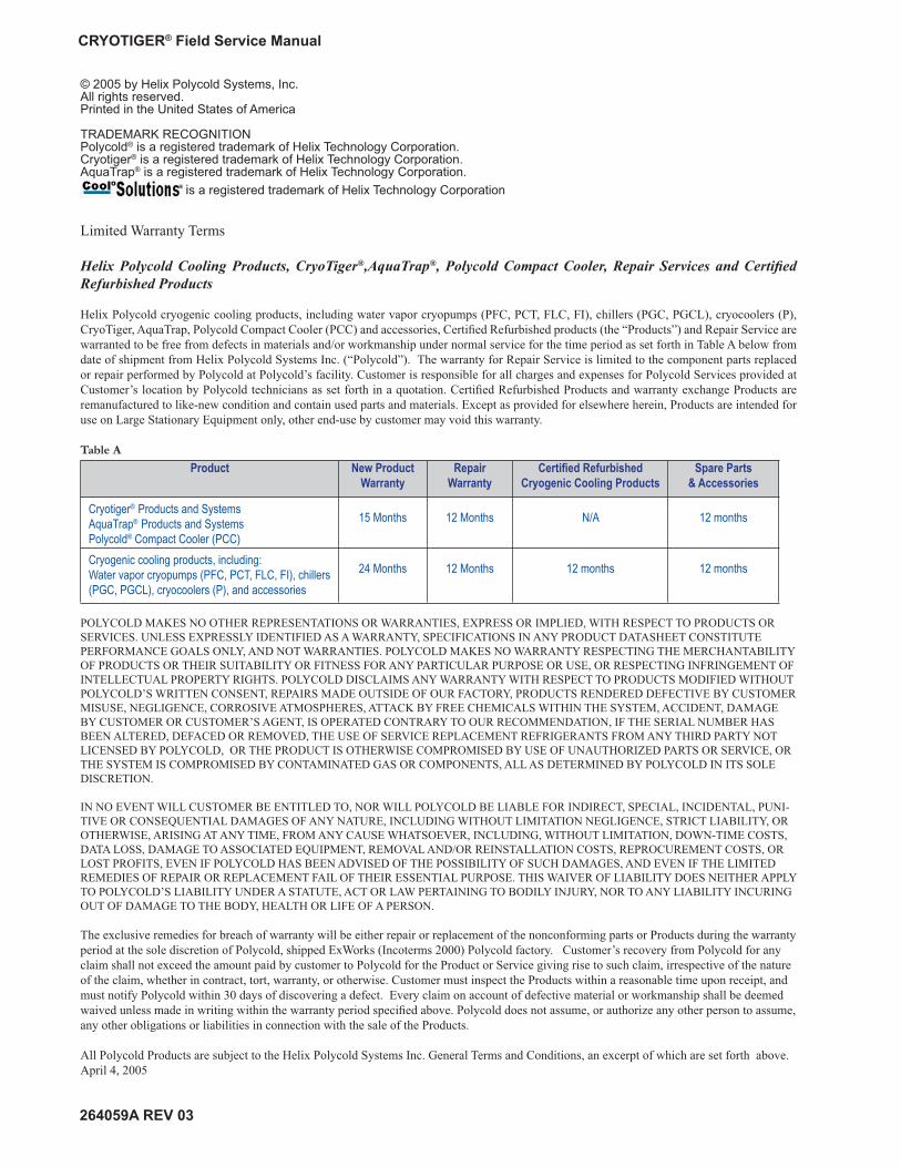
Limited Warranty Terms
Helix Polycold Cooling Products, CryoTiger®,AquaTrap®, Polycold Compact Cooler, Repair Services and Certifi ed Refurbished Products
Helix Polycold cryogenic cooling products, including water vapor cryopumps (PFC, PCT, FLC, FI), chillers (PGC, PGCL), cryocoolers (P), CryoTiger, AquaTrap, Polycold Compact Cooler (PCC) and accessories, Certifi ed Refurbished products (the “Products”) and Repair Service are warranted to be free from defects in materials and/or workmanship under normal service for the time period as set forth in Table A below from date of shipment from Helix Polycold Systems Inc. (“Polycold”). The warranty for Repair Service is limited to the component parts replaced or repair performed by Polycold at Polycold’s facility. Customer is responsible for all charges and expenses for Polycold Services provided at Customer’s location by Polycold technicians as set forth in a quotation. Certifi ed Refurbished Products and warranty exchange Products are remanufactured to like-new condition and contain used parts and materials. Except as provided for elsewhere herein, Products are intended for use on Large Stationary Equipment only, other end-use by customer may void this warranty.
Table A
Product New Product Warranty
Repair Warranty
Certifi ed RefurbishedCryogenic Cooling Products
Spare Parts& Accessories
Cryotiger® Products and SystemsAquaTrap® Products and SystemsPolycold® Compact Cooler (PCC)
15 Months 12 Months N/A 12 months
Cryogenic cooling products, including:Water vapor cryopumps (PFC, PCT, FLC, FI), chillers (PGC, PGCL), cryocoolers (P), and accessories
24 Months 12 Months 12 months 12 months
POLYCOLD MAKES NO OTHER REPRESENTATIONS OR WARRANTIES, EXPRESS OR IMPLIED, WITH RESPECT TO PRODUCTS OR SERVICES. UNLESS EXPRESSLY IDENTIFIED AS A WARRANTY, SPECIFICATIONS IN ANY PRODUCT DATASHEET CONSTITUTE PERFORMANCE GOALS ONLY, AND NOT WARRANTIES. POLYCOLD MAKES NO WARRANTY RESPECTING THE MERCHANTABILITY OF PRODUCTS OR THEIR SUITABILITY OR FITNESS FOR ANY PARTICULAR PURPOSE OR USE, OR RESPECTING INFRINGEMENT OF INTELLECTUAL PROPERTY RIGHTS. POLYCOLD DISCLAIMS ANY WARRANTY WITH RESPECT TO PRODUCTS MODIFIED WITHOUT POLYCOLD’S WRITTEN CONSENT, REPAIRS MADE OUTSIDE OF OUR FACTORY, PRODUCTS RENDERED DEFECTIVE BY CUSTOMER MISUSE, NEGLIGENCE, CORROSIVE ATMOSPHERES, ATTACK BY FREE CHEMICALS WITHIN THE SYSTEM, ACCIDENT, DAMAGE BY CUSTOMER OR CUSTOMER’S AGENT, IS OPERATED CONTRARY TO OUR RECOMMENDATION, IF THE SERIAL NUMBER HAS BEEN ALTERED, DEFACED OR REMOVED, THE USE OF SERVICE REPLACEMENT REFRIGERANTS FROM ANY THIRD PARTY NOT LICENSED BY POLYCOLD, OR THE PRODUCT IS OTHERWISE COMPROMISED BY USE OF UNAUTHORIZED PARTS OR SERVICE, OR THE SYSTEM IS COMPROMISED BY CONTAMINATED GAS OR COMPONENTS, ALL AS DETERMINED BY POLYCOLD IN ITS SOLE DISCRETION.
IN NO EVENT WILL CUSTOMER BE ENTITLED TO, NOR WILL POLYCOLD BE LIABLE FOR INDIRECT, SPECIAL, INCIDENTAL, PUNI-TIVE OR CONSEQUENTIAL DAMAGES OF ANY NATURE, INCLUDING WITHOUT LIMITATION NEGLIGENCE, STRICT LIABILITY, OR OTHERWISE, ARISING AT ANY TIME, FROM ANY CAUSE WHATSOEVER, INCLUDING, WITHOUT LIMITATION, DOWN-TIME COSTS, DATA LOSS, DAMAGE TO ASSOCIATED EQUIPMENT, REMOVAL AND/OR REINSTALLATION COSTS, REPROCUREMENT COSTS, OR LOST PROFITS, EVEN IF POLYCOLD HAS BEEN ADVISED OF THE POSSIBILITY OF SUCH DAMAGES, AND EVEN IF THE LIMITED REMEDIES OF REPAIR OR REPLACEMENT FAIL OF THEIR ESSENTIAL PURPOSE. THIS WAIVER OF LIABILITY DOES NEITHER APPLY TO POLYCOLD’S LIABILITY UNDER A STATUTE, ACT OR LAW PERTAINING TO BODILY INJURY, NOR TO ANY LIABILITY INCURING OUT OF DAMAGE TO THE BODY, HEALTH OR LIFE OF A PERSON.
The exclusive remedies for breach of warranty will be either repair or replacement of the nonconforming parts or Products during the warranty period at the sole discretion of Polycold, shipped ExWorks (Incoterms 2000) Polycold factory. Customer’s recovery from Polycold for any claim shall not exceed the amount paid by customer to Polycold for the Product or Service giving rise to such claim, irrespective of the nature of the claim, whether in contract, tort, warranty, or otherwise. Customer must inspect the Products within a reasonable time upon receipt, and must notify Polycold within 30 days of discovering a defect. Every claim on account of defective material or workmanship shall be deemed waived unless made in writing within the warranty period specifi ed above. Polycold does not assume, or authorize any other person to assume, any other obligations or liabilities in connection with the sale of the Products.
All Polycold Products are subject to the Helix Polycold Systems Inc. General Terms and Conditions, an excerpt of which are set forth above. April 4, 2005
© 2005 by Helix Polycold Systems, Inc.All rights reserved.Printed in the United States of America
TRADEMARK RECOGNITIONPolycold® is a registered trademark of Helix Technology Corporation.Cryotiger® is a registered trademark of Helix Technology Corporation.AquaTrap® is a registered trademark of Helix Technology Corporation.
is a registered trademark of Helix Technology Corporation

264059A REV 03
CRYOTIGER® Field Service Manual TABLE OF CONTENTS
i
Table of Contents1 INTRODUCTION ............................................................................................................... 1
2 SAFETY INFORMATION AND WARNINGS ..................................................................... 3
3 REQUIRED EQUIPMENT ................................................................................................. 5
4 TERMS AND DEFINITIONS ............................................................................................. 6
5 REFRIGERANT ADDITION PROCEDURE ...................................................................... 7
Purpose ...................................................................................................................... 7Key Parts .................................................................................................................... 85.1 Prepare the Area ............................................................................................. 105.2 Set Up Remote Compressor Switch (Refer To Figure 5) ................................. 105.3 Check the Service Bottle Pressure (Refer To Figure 6) ....................................115.4 Install the Vent Line (Refer to Figure 7) ............................................................115.5 Purge the Manifolds (Refer to Figure 8) .......................................................... 125.6 Evacuate and Refi ll the Manifolds (Refer to Figure 9) ..................................... 135.7 Install the Compressor Charge Manifold (Refer to Figures 10 and 11) ........... 135.8 Charge the System by Remote Operation of the Compressor (Refer to Figure 11) ......................................................................................... 155.9 Disconnect Charge Equipment and Reconnect the System ............................ 175.10 Manifold Storage at Customer’s Facility .......................................................... 185.11 Prepare Manifolds for Shipping (Refer to Figure 13) ....................................... 18
6 FIELD RECHARGE PROCEDURE FOR DEPRESSURIZED SYSTEMS ...................... 20
Purpose .................................................................................................................... 20Key Parts .................................................................................................................. 206.1 Prepare the Area ............................................................................................. 216.2 Set Up Remote Compressor Switch (Refer To Figure 5) ................................. 216.3 Check the Service Bottle Pressure (Refer To Figure 6) ................................... 226.4 Vent the System and the Manifolds (Refer to Figure 16) ................................. 226.5 Evacuate the System and the Manifolds (Refer To Figure 17) ........................ 246.6 Prime the System with CRYOTIGER® Gas (Refer to Figure 18) ..................... 256.7 Charge the System by Remote Operation of the Compressor ........................ 25

264059A REV 03
CRYOTIGER® Field Service Manual TABLE OF CONTENTS
ii
6.8 Remove Compressor Charge Manifold From the System (Refer to Figure 19) ........................................................................................ 266.9 Remove Supplemental Charge Volume from the System (Refer to Figure 20) ........................................................................................ 276.10 Reconnect the System (Refer To Figure 21) ................................................... 286.11 Manifold Storage at Customer’s Facility .......................................................... 296.12 Prepare Manifolds for Shipping (Refer to Figure 22) ....................................... 30
7 FIELD CLEANUP OF CRYOTIGER® SYSTEM WITHOUT COMPRESSOR EXCHANGE .................................................................................................................... 32
Purpose .................................................................................................................... 32Key Parts .................................................................................................................. 327.1 Prepare the Area ............................................................................................. 327.2 Set up Remote Compressor Switch (Refer To Figure 5) ................................. 337.3 Vent the Cold End and the Gas Lines (Refer to Figures 23 and 24) ............... 337.4 Purge the Gas Lines and the Cold End (Refer to Figure 25) ........................... 347.5 Check the Service Bottle Pressure (Refer To Figure 6) ................................... 357.6 Vent the Compressor and the Manifolds (Refer to Figure 26) ......................... 357.7 Evacuate the Compressor and the Manifolds (Refer to Figure 27) ................. 377.8 Charge the Compressor with Dry Nitrogen and Warm Up (Refer to Figure 28) ........................................................................................ 377.9 Charge and Vent the Compressor (Refer to Figure 29) ................................... 387.10 Reconnect System, Evacuate and Prime with Cryotiger Gas (Refer to Figure 30) ........................................................................................ 397.11 Charge the System by Remote Operation of the Compressor (Refer to Figure 31) ........................................................................................ 407.12 Remove Compressor Charge Manifold from the System (Refer to Figure 19) ........................................................................................ 427.13 Remove Supplemental Charge Volume from the System (Refer to Figure 20) ........................................................................................ 427.14 Reconnect the System (Refer to Figure 21) .................................................... 437.15 Manifold Storage at Customer’s Facility .......................................................... 437.16 Prepare Manifolds for Shipping (Refer to Figure 22) ....................................... 44
8 FIELD CLEANUP OF CRYOTIGER® SYSTEM WITH COMPRESSOR EXCHANGE .................................................................................................................... 46
Purpose .................................................................................................................... 46Key Parts .................................................................................................................. 468.1 Prepare the Area ............................................................................................. 468.2 Set Up Remote Compressor Switch (Refer To Figure 5) ................................. 47
264059A REV 03
CRYOTIGER® Field Service Manual TABLE OF CONTENTS
iii
8.3 Vent the Cold End and the Gas Lines (Refer to Figures 23 and 24) ............... 478.4 Purge the Gas Lines and the Cold End (Refer to Figure 25) ........................... 488.5 Check the Service Bottle Pressure (Refer To Figure 6) ................................... 488.6 Vent the Cold End, Gas Lines and the Manifolds (Refer to Figure 32) ........... 488.7 Evacuate and Refi ll the Cold End, Gas Lines and the Manifolds (Refer to Figure 33) ........................................................................................ 498.8 Reconnect System (Refer to Figure 21) ......................................................... 508.9 Charge the System by Remote Operation of the Compressor (Refer to Figure 31) ........................................................................................ 508.10 Disconnect Charge Equipment and Reconnect the System ............................ 518.11 Manifold Storage at Customer’s Facility .......................................................... 528.12 Prepare Manifolds for Shipping (Refer to Figure 22) ....................................... 52
ADDENDUM
A.1 MOISTURE CLEANUP OF UNUSED ¼” SUPERFLEX LINES ........................ 54
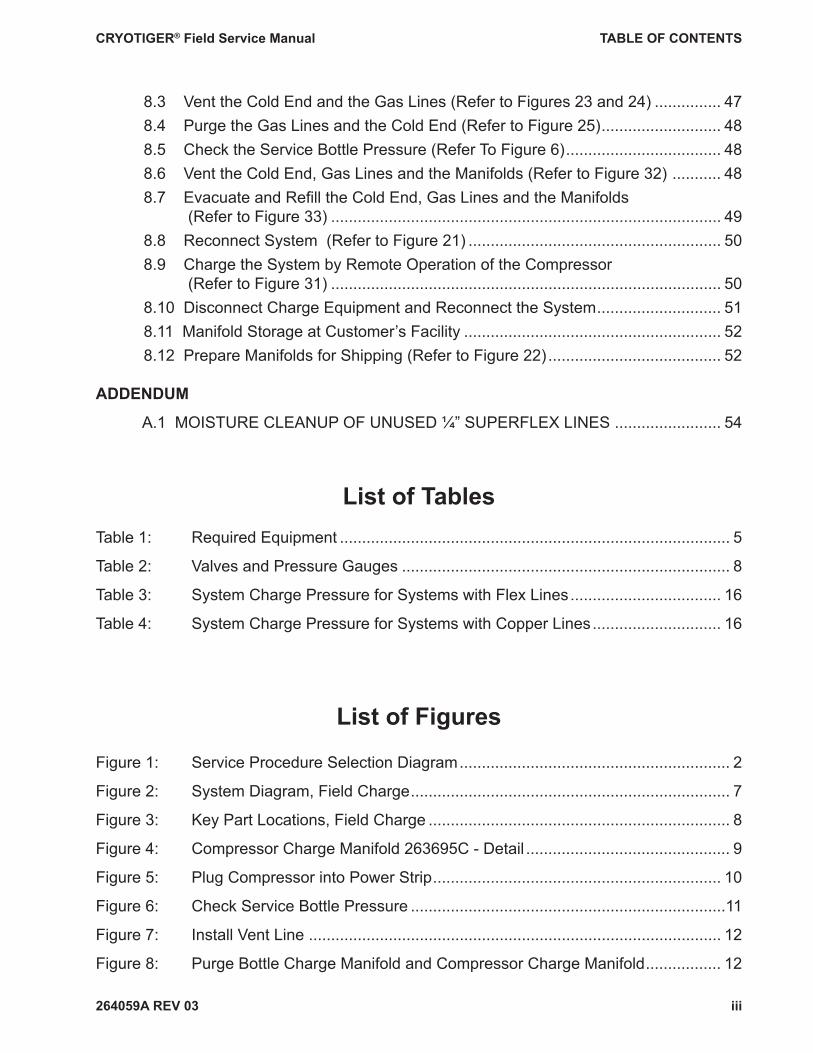
List of TablesTable 1: Required Equipment ........................................................................................ 5
Table 2: Valves and Pressure Gauges .......................................................................... 8
Table 3: System Charge Pressure for Systems with Flex Lines .................................. 16
Table 4: System Charge Pressure for Systems with Copper Lines ............................. 16
List of Figures
Figure 1: Service Procedure Selection Diagram ............................................................. 2
Figure 2: System Diagram, Field Charge ........................................................................ 7
Figure 3: Key Part Locations, Field Charge .................................................................... 8
Figure 4: Compressor Charge Manifold 263695C - Detail .............................................. 9
Figure 5: Plug Compressor into Power Strip ................................................................. 10
Figure 6: Check Service Bottle Pressure .......................................................................11
Figure 7: Install Vent Line ............................................................................................. 12
Figure 8: Purge Bottle Charge Manifold and Compressor Charge Manifold ................. 12
264059A REV 03
CRYOTIGER® Field Service Manual TABLE OF CONTENTS
iv
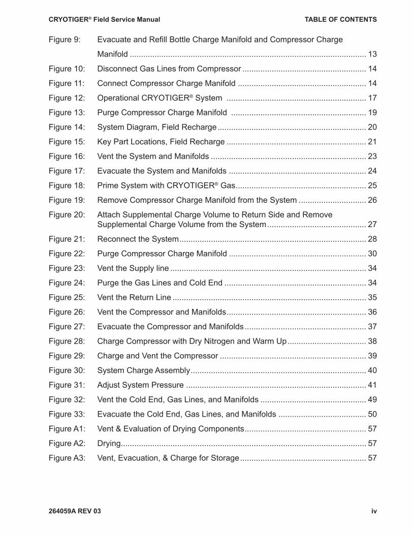
Figure 9: Evacuate and Refi ll Bottle Charge Manifold and Compressor Charge
Manifold ......................................................................................................... 13
Figure 10: Disconnect Gas Lines from Compressor ....................................................... 14
Figure 11: Connect Compressor Charge Manifold ......................................................... 14
Figure 12: Operational CRYOTIGER® System .............................................................. 17
Figure 13: Purge Compressor Charge Manifold ............................................................ 19
Figure 14: System Diagram, Field Recharge .................................................................. 20
Figure 15: Key Part Locations, Field Recharge .............................................................. 21
Figure 16: Vent the System and Manifolds ..................................................................... 23
Figure 17: Evacuate the System and Manifolds ............................................................. 24
Figure 18: Prime System with CRYOTIGER® Gas .......................................................... 25
Figure 19: Remove Compressor Charge Manifold from the System .............................. 26
Figure 20: Attach Supplemental Charge Volume to Return Side and Remove Supplemental Charge Volume from the System ............................................ 27
Figure 21: Reconnect the System ................................................................................... 28
Figure 22: Purge Compressor Charge Manifold ............................................................. 30
Figure 23: Vent the Supply line ....................................................................................... 34
Figure 24: Purge the Gas Lines and Cold End ............................................................... 34
Figure 25: Vent the Return Line ...................................................................................... 35
Figure 26: Vent the Compressor and Manifolds .............................................................. 36
Figure 27: Evacuate the Compressor and Manifolds ...................................................... 37
Figure 28: Charge Compressor with Dry Nitrogen and Warm Up ................................... 38
Figure 29: Charge and Vent the Compressor ................................................................. 39
Figure 30: System Charge Assembly .............................................................................. 40
Figure 31: Adjust System Pressure ................................................................................ 41
Figure 32: Vent the Cold End, Gas Lines, and Manifolds ............................................... 49
Figure 33: Evacuate the Cold End, Gas Lines, and Manifolds ....................................... 50
Figure A1: Vent & Evaluation of Drying Components ...................................................... 57
Figure A2: Drying ............................................................................................................. 57
Figure A3: Vent, Evacuation, & Charge for Storage ........................................................ 57
264059A REV 03
CRYOTIGER® Field Service Manual 1 INTRODUCTION
1
This fi eld service manual contains procedures that guide qualifi ed service personnel to charge systems or to clean up systems that contain contaminated gas.
The Refrigerant Addition Procedure (Section 5) gives step-by-step instructions for add-ing CRYOTIGER® gas to systems which are low on charge.
If the pressure in the system to be charged is lower than 70 psig, then the Field Re-charge Procedure for Depressurized Systems (Section 6) should be followed to re-charge the system.
If it is determined that the gas in the system has been contaminated, then one of the two remaining procedures should be followed.
The procedure entitled Field Cleanup of CRYOTIGER® System with Compressor Ex-change (Section 7) should be followed when downtime at the customer’s site is to be minimized and an exchange compressor is available.
If no exchange compressor is available, then the procedure entitled Field Cleanup of CRYOTIGER® System without Compressor Exchange (Section 8) should be followed to clean up the contaminated system.
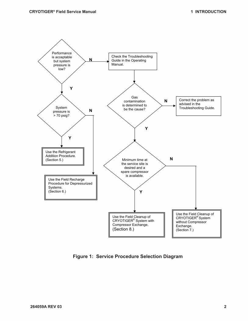
Use the Service Procedure Selection Diagram on the following page to determine which procedure to follow.
1 INTRODUCTION
264059A REV 03
CRYOTIGER® Field Service Manual 1 INTRODUCTION
2
Figure 1: Service Procedure Selection Diagram
Correct the problem as advised in the Troubleshooting Guide.
Performanceis acceptable but system pressure is
low?
Gascontamination
is determined to be the cause?
Check the Troubleshooting Guide in the Operating Manual.
Use the Refrigerant Addition Procedure.(Section 5.)
Use the Field Recharge Procedure for Depressurized Systems. (Section 6.)
Use the Field Cleanup of CRYOTIGER® System with Compressor Exchange. (Section 8.)
Use the Field Cleanup of CRYOTIGER® System without Compressor Exchange.(Section 7.)
Y
System pressure is> 70 psig?
Minimum time at the service site is
desired and a spare compressor
is available.
N
N
Y
Y
N
N
Y

264059A REV 03
CRYOTIGER® Field Service Manual 2 SAFETY INFORMATION AND WARNINGS
3
The refrigerant is fl ammable.
Refrigerant vapors can ignite easily and burn explosively.Make all gas connections carefully so that gas does not escape.
Supply pressure must remain below 345 psig at all times.
Do not allow the compressor supply pressure to rise above 345 psig. Exceeding the pres-sures listed in this procedure can cause the fl ammable CRYOTIGER® gas to vent and ignite.
Eliminate all ignition sources.Do not smoke.Extinguish all open and concealed fl ames, pilot lights, and other sources of heat or sparks.Turn off heaters, electric motors, electric tools, and other sources of ignition during this pro-cedure except the CRYOTIGER® compressor as directed in the procedures.Do not use in areas where static electric sparks may be generated.
Handle gas lines carefully.
Keep gas lines free of dirt and debris.Inspect seals and sealing surfaces. Follow the cleaning procedure in the System Operating Manual if dirt and debris are found.
Improper gas connections or disconnections can cause gas to escape.Use extreme care in making or breaking all gas line connections.
Use only with adequate ventilation.
All work on the CRYOTIGER® system, including recharging, should be performed in a well-ventilated area.
2 SAFETY INFORMATION AND WARNINGS
264059A REV 03
CRYOTIGER® Field Service Manual 2 SAFETY INFORMATION AND WARNINGS
4
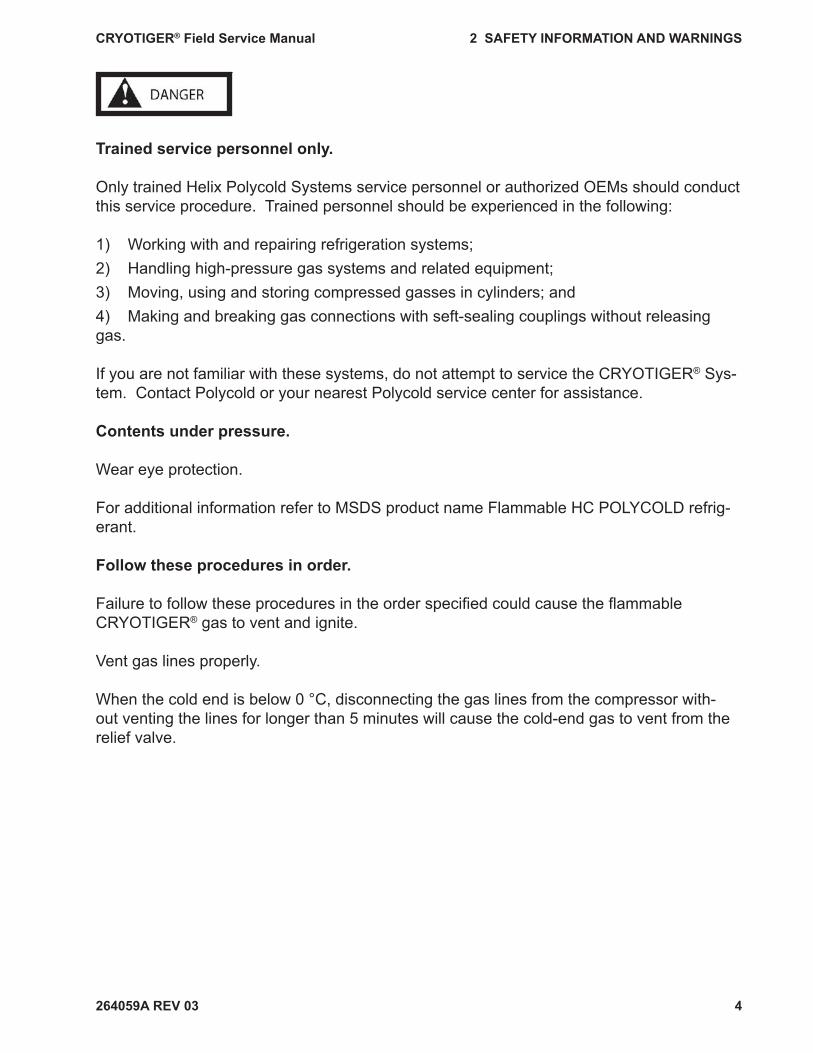
Trained service personnel only.
Only trained Helix Polycold Systems service personnel or authorized OEMs should conduct this service procedure. Trained personnel should be experienced in the following:
1) Working with and repairing refrigeration systems;2) Handling high-pressure gas systems and related equipment;3) Moving, using and storing compressed gasses in cylinders; and4) Making and breaking gas connections with seft-sealing couplings without releasing gas.
If you are not familiar with these systems, do not attempt to service the CRYOTIGER® Sys-tem. Contact Polycold or your nearest Polycold service center for assistance.
Contents under pressure.
Wear eye protection.
For additional information refer to MSDS product name Flammable HC POLYCOLD refrig-erant.
Follow these procedures in order.
Failure to follow these procedures in the order specifi ed could cause the fl ammable CRYOTIGER® gas to vent and ignite.
Vent gas lines properly.
When the cold end is below 0 °C, disconnecting the gas lines from the compressor with-out venting the lines for longer than 5 minutes will cause the cold-end gas to vent from the relief valve.
264059A REV 03
CRYOTIGER® Field Service Manual 3 REQUIRED EQUIPMENT
5
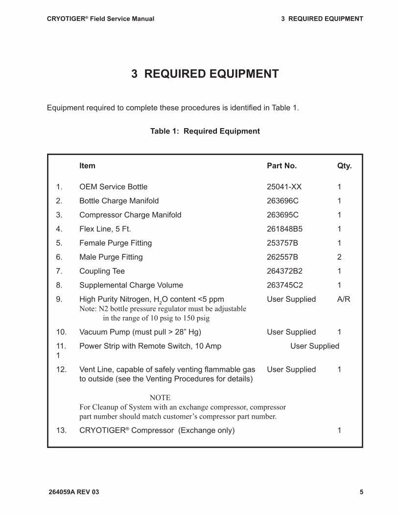
Equipment required to complete these procedures is identifi ed in Table 1.
Table 1: Required Equipment
Item Part No. Qty.
1. OEM Service Bottle 25041-XX 1
2. Bottle Charge Manifold 263696C 1
3. Compressor Charge Manifold 263695C 1
4. Flex Line, 5 Ft. 261848B5 1
5. Female Purge Fitting 253757B 1
6. Male Purge Fitting 262557B 2
7. Coupling Tee 264372B2 1
8. Supplemental Charge Volume 263745C2 1
9. High Purity Nitrogen, H2O content <5 ppm User Supplied A/R Note: N2 bottle pressure regulator must be adjustable in the range of 10 psig to 150 psig
10. Vacuum Pump (must pull > 28” Hg) User Supplied 1
11. Power Strip with Remote Switch, 10 Amp User Supplied 1
12. Vent Line, capable of safely venting fl ammable gas User Supplied 1 to outside (see the Venting Procedures for details)
NOTE For Cleanup of System with an exchange compressor, compressor part number should match customer’s compressor part number.
13. CRYOTIGER® Compressor (Exchange only) 1
3 REQUIRED EQUIPMENT
264059A REV 03
CRYOTIGER® Field Service Manual 4 TERMS AND DEFINITIONS
6
To complete this procedure, you need to be familiar with the equipment listed in Table 1, the system diagram in Figure 2, and the following terms:
System Pressure: the pressure indicated by the pressure gauge on the compressor when the compressor is not running; also called equalization pressure and balance pressure.
Return Pressure: the pressure indicated by the pressure gauge on the compressor when the compressor is running. This is the pressure of the gas returning to the compressor.
Supply Pressure: the pressure indicated by the pressure gauge on the compressor supply manifold when the compressor is running. This is the pressure of the gas going from the compressor to the cold end.
4 TERMS AND DEFINITIONS

264059A REV 03
CRYOTIGER® Field Service Manual 5 Refrigerant Addition Procedure
7
Figure 2: System Diagram, Field Charge
Note: Re-read Safety Information and Warnings, before starting this pro-cedure.
Purpose
This procedure guides qualifi ed personnel in fi eld adding refrigerant charge to CRYOTIGER® systems. These guidelines must be followed in order to avoid gas leaks and to prevent an accidental fi re. This is not a procedure for completely recharging a system. If the pressure in the system to be charged is lower than 70 psig, refer to Field Recharge Procedure for Depressurized Systems.
5 REFRIGERANT ADDITION PROCEDURE
Cold End
Compressor Charge Manifold
Cryotiger Compressor
Power Strip
Vacuum Pump
Vent Line
Bottle Charge Manifold Flex Line
OEMService Bottle
Cord
Gas Lines
Return Gas Line (Green)
Supply Gas Line (Red)
Dry Nitrogen
Return Supply
264059A REV 03
CRYOTIGER® Field Service Manual 5 Refrigerant Addition Procedure
8
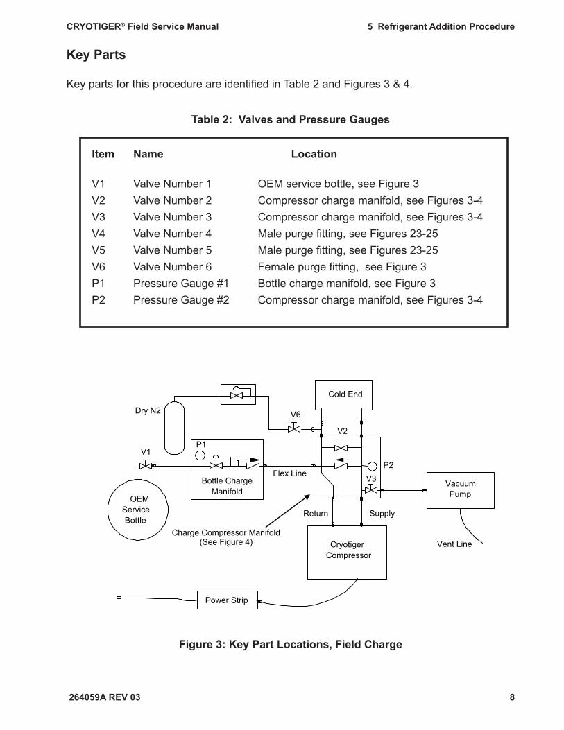
Key Parts
Key parts for this procedure are identifi ed in Table 2 and Figures 3 & 4.
Table 2: Valves and Pressure Gauges
Item Name Location
V1 Valve Number 1 OEM service bottle, see Figure 3V2 Valve Number 2 Compressor charge manifold, see Figures 3-4V3 Valve Number 3 Compressor charge manifold, see Figures 3-4V4 Valve Number 4 Male purge fi tting, see Figures 23-25V5 Valve Number 5 Male purge fi tting, see Figures 23-25V6 Valve Number 6 Female purge fi tting, see Figure 3P1 Pressure Gauge #1 Bottle charge manifold, see Figure 3P2 Pressure Gauge #2 Compressor charge manifold, see Figures 3-4
Figure 3: Key Part Locations, Field Charge
Cold End
OEM Service Bottle
CryotigerCompressor
Power Strip
VacuumPump
Vent Line
P1
Bottle ChargeManifold
V1
V2
V3P2
Flex Line
Return Supply
Charge Compressor Manifold (See Figure 4)
V6Dry N2

264059A REV 03
CRYOTIGER® Field Service Manual 5 Refrigerant Addition Procedure
9
The compressor charge manifold is depicted in Figure 4, which shows valve and pressure gauge numbering.
Figure 4: Compressor Charge Manifold 263695C - Detail
Charge Coupling
P2
V2
Relief Valve
Supply Coupling
V3
Return Coupling
Vacuum/ Vent Connection
264059A REV 03
CRYOTIGER® Field Service Manual 5 Refrigerant Addition Procedure
10
5.1 Prepare the Area
5.1.1 Eliminate all sources of ignition
• Turn off heaters, electric motors, electric tools, and other sources of ignition during this procedure except the CRYOTIGER® compressor as directed in the procedure.
• Do not smoke. • Extinguish all open and concealed fl ames, pilot lights, and other sources of
heat or sparks. • Do not use in areas where static electric sparks may be generated.
5.1.2 Remove all fl ammable liquids stored in the area.
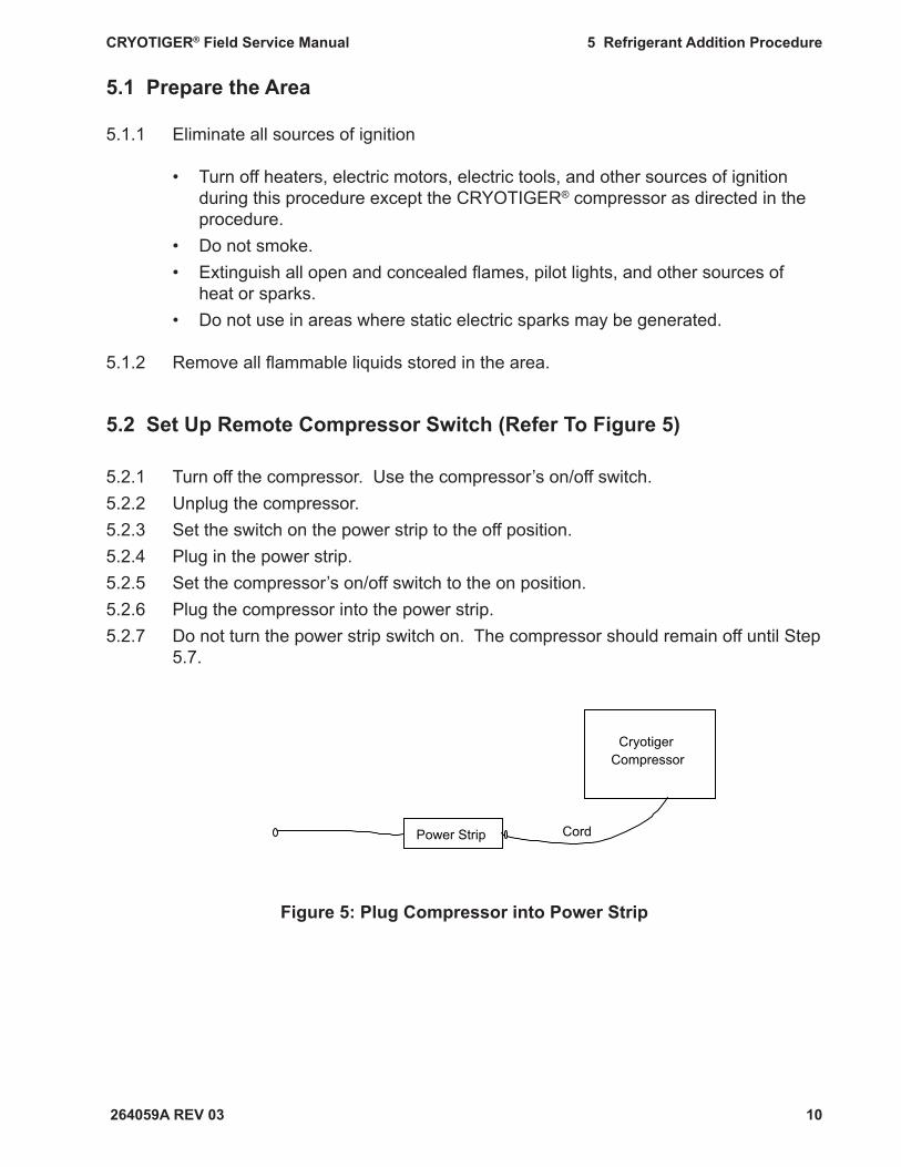
5.2 Set Up Remote Compressor Switch (Refer To Figure 5)
5.2.1 Turn off the compressor. Use the compressor’s on/off switch.5.2.2 Unplug the compressor. 5.2.3 Set the switch on the power strip to the off position.5.2.4 Plug in the power strip.5.2.5 Set the compressor’s on/off switch to the on position. 5.2.6 Plug the compressor into the power strip. 5.2.7 Do not turn the power strip switch on. The compressor should remain off until Step
5.7.
Figure 5: Plug Compressor into Power Strip
CryotigerCompressor
Power Strip Cord
264059A REV 03
CRYOTIGER® Field Service Manual 5 Refrigerant Addition Procedure
11
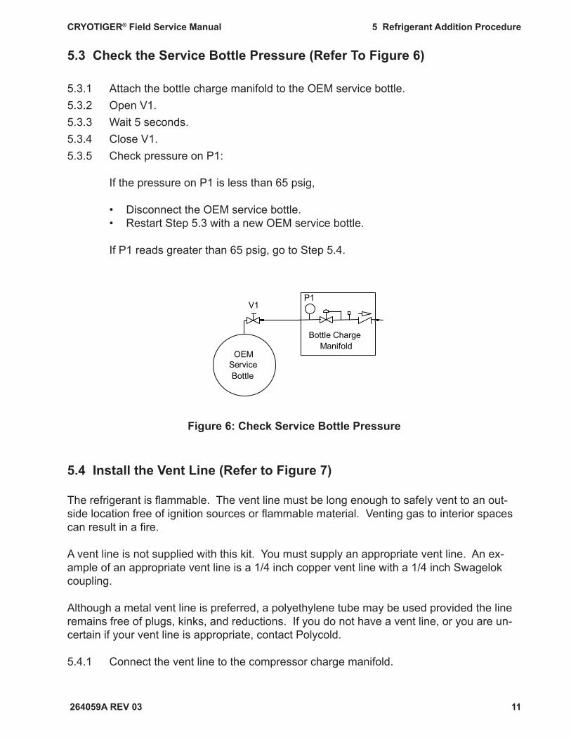
5.3 Check the Service Bottle Pressure (Refer To Figure 6)
5.3.1 Attach the bottle charge manifold to the OEM service bottle. 5.3.2 Open V1. 5.3.3 Wait 5 seconds.5.3.4 Close V1.5.3.5 Check pressure on P1:
If the pressure on P1 is less than 65 psig,
• Disconnect the OEM service bottle. • Restart Step 5.3 with a new OEM service bottle.
If P1 reads greater than 65 psig, go to Step 5.4.
OEM Service Bottle
V1P1
Bottle Charge Manifold
5.4 Install the Vent Line (Refer to Figure 7)
The refrigerant is fl ammable. The vent line must be long enough to safely vent to an out-side location free of ignition sources or fl ammable material. Venting gas to interior spaces can result in a fi re.
A vent line is not supplied with this kit. You must supply an appropriate vent line. An ex-ample of an appropriate vent line is a 1/4 inch copper vent line with a 1/4 inch Swagelok coupling.
Although a metal vent line is preferred, a polyethylene tube may be used provided the line remains free of plugs, kinks, and reductions. If you do not have a vent line, or you are un-certain if your vent line is appropriate, contact Polycold.
5.4.1 Connect the vent line to the compressor charge manifold.
Figure 6: Check Service Bottle Pressure
264059A REV 03
CRYOTIGER® Field Service Manual 5 Refrigerant Addition Procedure
12
Figure 7: Install Vent Line
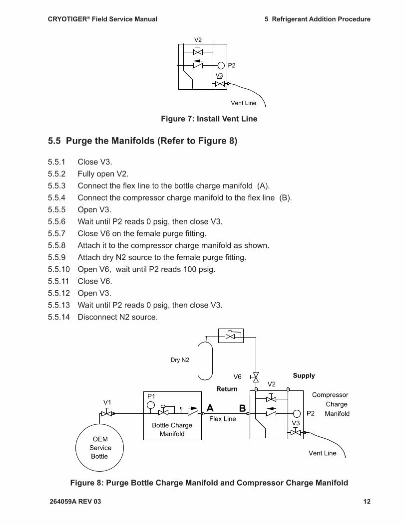
5.5 Purge the Manifolds (Refer to Figure 8)
5.5.1 Close V3.5.5.2 Fully open V2.5.5.3 Connect the fl ex line to the bottle charge manifold (A).5.5.4 Connect the compressor charge manifold to the fl ex line (B). 5.5.5 Open V3.5.5.6 Wait until P2 reads 0 psig, then close V3.5.5.7 Close V6 on the female purge fi tting.5.5.8 Attach it to the compressor charge manifold as shown. 5.5.9 Attach dry N2 source to the female purge fi tting.5.5.10 Open V6, wait until P2 reads 100 psig.5.5.11 Close V6.5.5.12 Open V3.5.5.13 Wait until P2 reads 0 psig, then close V3.5.5.14 Disconnect N2 source.
Figure 8: Purge Bottle Charge Manifold and Compressor Charge Manifold
Vent Line
V2
V3
P2
OEMServiceBottle
P1
Bottle ChargeManifold
V1
Flex Line
Vent Line
V3P2
CompressorChargeManifold
A B
V2V6
Dry N2
Return
Supply

264059A REV 03
CRYOTIGER® Field Service Manual 5 Refrigerant Addition Procedure
13
5.6 Evacuate and Refi ll the Manifolds (Refer to Figure 9)
5.6.1 Disconnect the vent line from the compressor charge manifold and connect the vacuum pump in its place (C).
5.6.2 Connect the vent line to the vacuum pump exhaust (D).5.6.3 Switch on the vacuum pump.5.6.4 Slowly open V3. 5.6.5 Wait until P2 reads greater than 28 inches Hg in vacuum.5.6.6 Close V3.5.6.7 Switch off the vacuum pump.5.6.8 Open V1.
Figure 9: Evacuate and Refi ll Bottle Charge Manifold and Compressor Charge Manifold
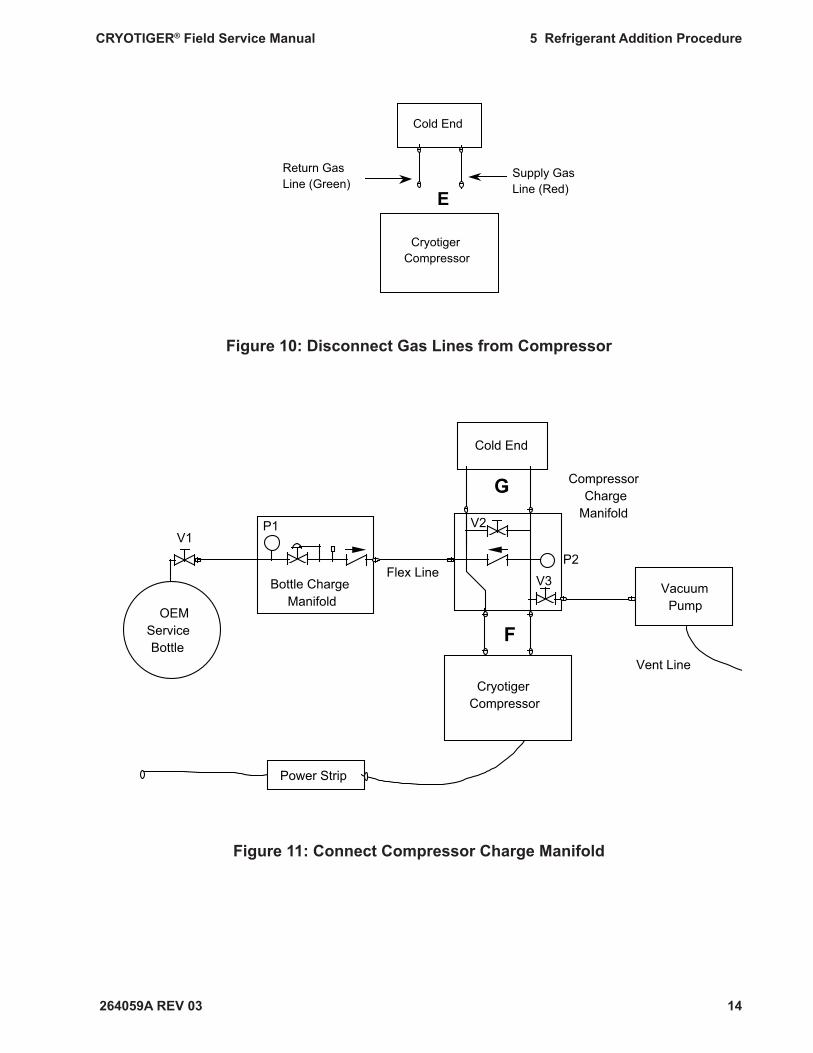
5.7 Install the Compressor Charge Manifold (Refer to Figures 10 and 11)
5.7.1 Disconnect the gas lines from the compressor (E). See Figure 10.5.7.2 Connect the compressor charge manifold to the compressor (F). See Figure 11.5.7.3 Connect the gas lines to the compressor charge manifold (G). See Figure 11.5.7.4 Close V2. The system is now ready for recharging.
OEMServiceBottle
P1
Bottle Charge Manifold
V1
Flex LineV3
P2
CompressorCharge
Manifold
VacuumPump
Vent Line
C
D
V2
264059A REV 03
CRYOTIGER® Field Service Manual 5 Refrigerant Addition Procedure
14
Figure 10: Disconnect Gas Lines from Compressor
Figure 11: Connect Compressor Charge Manifold
Cold End
CryotigerCompressor
Return Gas Line (Green)
Supply Gas Line (Red)E
Cold End
CompressorCharge
Manifold
OEMServiceBottle
CryotigerCompressor
Power Strip
VacuumPump
Vent Line
P1
Bottle Charge Manifold
V1V2
V3P2
Flex Line
F
G
264059A REV 03
CRYOTIGER® Field Service Manual 5 Refrigerant Addition Procedure
15
5.8 Charge the System by Remote Operation of the Compressor (Refer to Figure 11)
Supply pressure must remain below 345 psig at all times.Do not allow the compressor supply pressure to rise above 345 psig. Exceeding the pressures listed in this procedure can cause the fl ammable CRYOTIGER® gas to vent and ignite.
5.8.1 Turn on the compressor using the power strip.5.8.2 When P2 reaches 330 psig, switch off the compressor using the power strip. Do
not allow the compressor supply pressure to rise above 345 psig during charging.5.8.3 Adjust system pressure: • If your system has fl ex lines, refer to Table 3. • If your system has copper lines, refer to Table 4.5.8.4 Compare P2 to the recommended system pressure in Table 3 or Table 4. • If P2 is more than 15 psig below the recommended system pressure, repeat
Step 5.8 to increase system pressure. • If P2 is more than 5 psig above the recommended system pressure, go to Step
5.8.5. • If P2 is within tolerance, go to Step 5.9.5.8.5 Disconnect the vacuum pump.5.8.6 Connect the vent line in its place (as in Figure 6 of Step 5.5).5.8.7 Open V2.5.8.8 Slowly open V3 and gradually vent gas from the system until P2 reads the recom-
mended system pressure.5.8.9 Repeat steps 5.8.3 - 5.8.8 as necessary to adjust P2 to +5/-15 psig of recommend-
ed system pressure.

264059A REV 03
CRYOTIGER® Field Service Manual 5 Refrigerant Addition Procedure
16
Table 3 - System Charge Pressure for Systems with Flex Lines
Gas Line Length (ft.) System Charge Pressure (psig)*
0 to 10 275 11 to 15 265 16 to 25 255 26 to 50 240
*Tolerance on charge is +5/-15 psig. System will achieve full performance operating within +5/-25 psig of nominal charge pressure.
Table 4 - System Charge Pressure for Systems with Copper Lines
Gas Line Length (ft.) System Charge Pressure (psig)*
0 to 25 275 26 to 40 270 41 to 60 260 61 to 85 250 86 to 120 240 121 to 150 235
*Tolerance on charge is +5/-15 psig. System will achieve full performance operating within +5/-25 psig of nominal charge pressure.
264059A REV 03
CRYOTIGER® Field Service Manual 5 Refrigerant Addition Procedure
17
5.9 Disconnect Charge Equipment and Reconnect the System
5.9.1 Switch off the compressor at the power strip.5.9.2 Disconnect the gas lines from the compressor charge manifold.5.9.3 Disconnect the compressor charge manifold from the compressor.5.9.4 Reconnect the gas lines to the compressor.5.9.5 Read the system pressure indicated by the gauge on the compressor. • If the system pressure is more than 15 psig below the recommended system
pressure in Table 3 or Table 4, repeat Steps 5.7 and 5.8; • If the system pressure is within the recommended pressure, go to Step 5.9.6.5.9.6 Unplug the power strip from the wall or other supply.5.9.7 Turn the compressor switch to the off position.5.9.8 Unplug the compressor from the power strip. 5.9.9 Plug in the compressor to the wall or other supply.5.9.10 Turn on the compressor using the compressor switch.
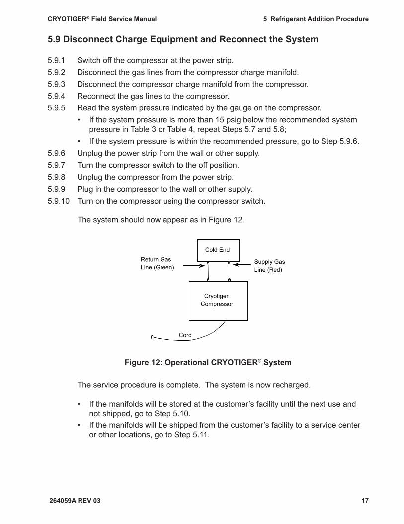
The system should now appear as in Figure 12.
Figure 12: Operational CRYOTIGER® System
The service procedure is complete. The system is now recharged.
• If the manifolds will be stored at the customer’s facility until the next use and not shipped, go to Step 5.10.
• If the manifolds will be shipped from the customer’s facility to a service center or other locations, go to Step 5.11.
Cold End
Cryotiger Compressor
Cord
Return Gas Line (Green)
Supply Gas Line (Red)
264059A REV 03
CRYOTIGER® Field Service Manual 5 Refrigerant Addition Procedure
18
5.10 Manifold Storage at Customer’s Facility
NOTE: If the manifolds will be stored at the customer’s facility and not shipped to other location(s), the manifolds do not need to be evacuated and refi lled with nitrogen.
5.10.1 Close V1.5.10.2 Disconnect the vent line or vacuum pump from the compressor charge manifold.5.10.3 Disconnect the fl ex line from the compressor charge manifold.5.10.4 Disconnect the fl ex line from the bottle charge manifold.5.10.5 Disconnect the bottle charge manifold from the OEM service bottle.5.10.6 Store manifolds and equipment for further use.
The refrigerant gas is fl ammable.
Refrigerant vapors can ignite easily and burn explosively. Store the OEM service bottle and equipment in the same location that you
use for storing a propane bottle.
Follow the same safety precautions used for storing propane bottles.
Store the equipment away from heat, fl ame and sparks. Store the equipment in a location with adequate ventilation. The equipment and OEM service bottle temperature should not exceed 125°
F (52° C).
See instructions on the OEM service bottle for further safety and storage information.
5.11 Prepare Manifolds for Shipping (Refer to Figure 13)
NOTE: If the manifolds will be shipped from a customer’s facility to a service center or other location(s), manifolds must be evacuated and re-fi lled with nitrogen prior to shipping.
5.11.1 Close V1.5.11.2 Connect the vent line to the compressor charge manifold.5.11.3 Connect the 5 foot fl ex line to the compressor charge manifold.5.11.4 Close valve V6 on the female purge fi tting and connect it to the compressor charge
manifold as shown in Figure 13.
264059A REV 03
CRYOTIGER® Field Service Manual 5 Refrigerant Addition Procedure
19
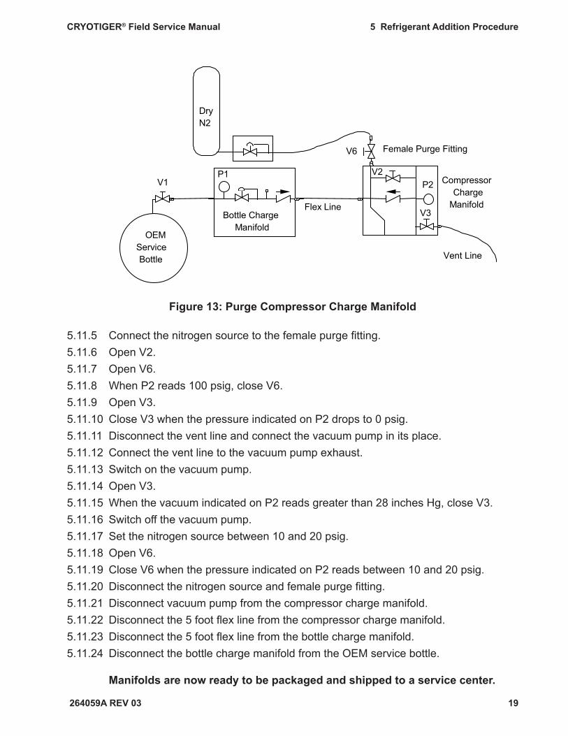
Figure 13: Purge Compressor Charge Manifold
5.11.5 Connect the nitrogen source to the female purge fi tting.5.11.6 Open V2.5.11.7 Open V6. 5.11.8 When P2 reads 100 psig, close V6.5.11.9 Open V3. 5.11.10 Close V3 when the pressure indicated on P2 drops to 0 psig.5.11.11 Disconnect the vent line and connect the vacuum pump in its place.5.11.12 Connect the vent line to the vacuum pump exhaust.5.11.13 Switch on the vacuum pump.5.11.14 Open V3.5.11.15 When the vacuum indicated on P2 reads greater than 28 inches Hg, close V3.5.11.16 Switch off the vacuum pump. 5.11.17 Set the nitrogen source between 10 and 20 psig.5.11.18 Open V6. 5.11.19 Close V6 when the pressure indicated on P2 reads between 10 and 20 psig.5.11.20 Disconnect the nitrogen source and female purge fi tting. 5.11.21 Disconnect vacuum pump from the compressor charge manifold. 5.11.22 Disconnect the 5 foot fl ex line from the compressor charge manifold. 5.11.23 Disconnect the 5 foot fl ex line from the bottle charge manifold. 5.11.24 Disconnect the bottle charge manifold from the OEM service bottle.
Manifolds are now ready to be packaged and shipped to a service center.
OEM Service Bottle
P1
Bottle Charge Manifold
V1
Flex Line
Vent Line
V3
P2 Compressor Charge
Manifold
DryN2
V2
V6 Female Purge Fitting
264059A REV 03
CRYOTIGER® Field Service Manual 6 Field Recharge Procedure For Depressurized Systems
20
Note: Re-read Safety Information and Warnings, before starting this pro-cedure.
Purpose
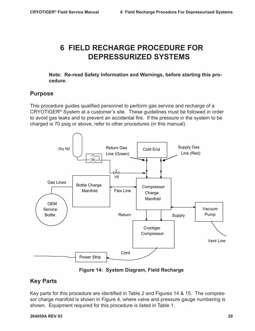
This procedure guides qualifi ed personnel to perform gas service and recharge of a CRYOTIGER® System at a customer’s site. These guidelines must be followed in order to avoid gas leaks and to prevent an accidental fi re. If the pressure in the system to be charged is 70 psig or above, refer to other procedures (in this manual).
Figure 14: System Diagram, Field Recharge
Key Parts
Key parts for this procedure are identifi ed in Table 2 and Figures 14 & 15. The compres-sor charge manifold is shown in Figure 4, where valve and pressure gauge numbering is shown. Equipment required for this procedure is listed in Table 1.
6 FIELD RECHARGE PROCEDURE FOR DEPRESSURIZED SYSTEMS
Cold End
Compressor ChargeManifold
Cryotiger Compressor
Power Strip
Vacuum Pump
Vent Line
Bottle Charge Manifold Flex Line
OEMService Bottle
Cord
Gas Lines
Return Gas Line (Green)
Supply Gas Line (Red)
Return Supply
V6
Dry N2
264059A REV 03
CRYOTIGER® Field Service Manual 6 Field Recharge Procedure For Depressurized Systems
21
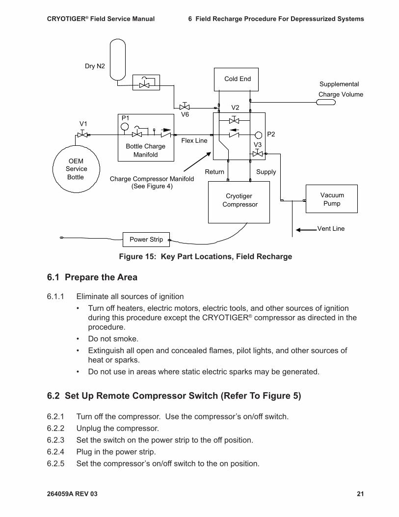
Figure 15: Key Part Locations, Field Recharge
6.1 Prepare the Area
6.1.1 Eliminate all sources of ignition • Turn off heaters, electric motors, electric tools, and other sources of ignition
during this procedure except the CRYOTIGER® compressor as directed in the procedure.
• Do not smoke. • Extinguish all open and concealed fl ames, pilot lights, and other sources of
heat or sparks. • Do not use in areas where static electric sparks may be generated.
6.2 Set Up Remote Compressor Switch (Refer To Figure 5)
6.2.1 Turn off the compressor. Use the compressor’s on/off switch.6.2.2 Unplug the compressor.6.2.3 Set the switch on the power strip to the off position.6.2.4 Plug in the power strip.6.2.5 Set the compressor’s on/off switch to the on position.
Cold End
OEMServiceBottle
CryotigerCompressor
Power Strip
VacuumPump
Vent Line
P1
Bottle ChargeManifold
V1
V2
V3P2
Flex Line
Return SupplyCharge Compressor Manifold
(See Figure 4)
V6
Dry N2
SupplementalCharge Volume
264059A REV 03
CRYOTIGER® Field Service Manual 6 Field Recharge Procedure For Depressurized Systems
22
6.2.6 Plug the compressor into the power strip. 6.2.7 Do not turn the power strip switch on. The compressor should remain off until Step
6.7.
6.3 Check the Service Bottle Pressure (Refer To Figure 6)
6.3.1 Attach the bottle charge manifold to the OEM service bottle. 6.3.2 Open V1. 6.3.3 Wait 5 seconds.6.3.4 Close V1.6.3.5 Check pressure on P1: If the pressure on P1 is less than 65 psig, • disconnect the OEM service bottle. • restart Step 6.3 with a new OEM service bottle. If P1 reads greater than 65 psig, go to Step 6.4.
6.4 Vent the System and the Manifolds (Refer to Figure 16)
The refrigerant is fl ammable. The vent line must be long enough to safely vent to an outside location free of ignition sources or fl ammable material. Venting gas to interior spaces can result in a fi re.
A vent line is not supplied with this kit. You must supply an appropriate vent line. An example of an appropriate vent line is a 1/4 inch copper vent line with a 1/4 inch Swagelok coupling.
Although a metal vent line is preferred, a polyethylene tube may be used provided the line remains free of plugs, kinks, and reductions. If you do not have a vent line, or you are uncertain if your vent line is appropriate, contact Polycold.
6.4.1 Close V3.6.4.2 Connect the vent line to the compressor charge manifold.6.4.3 Disconnect the gas lines from the compressor.6.4.4 Attach the compressor charge manifold to the compressor.6.4.5 Attach the supplemental charge volume to the supply side of the compressor
charge manifold.6.4.6 Close V6 on the female purge fi tting.
264059A REV 03
CRYOTIGER® Field Service Manual 6 Field Recharge Procedure For Depressurized Systems
23
6.4.7 Attach it to the coupling tee as shown.6.4.8 Connect coupling tee to the return side of the compressor charge manifold.6.4.9 Attach the gas lines to the coupling tee (return side) and supplemental charge volume
(supply side).6.4.10 Connect the fl ex line to the bottle charge manifold (A).6.4.11 Connect the compressor charge manifold to the fl ex line (B). 6.4.12 Open V2.6.4.13 Slowly open V3 and vent the gas from the system until P2 reads 0 psig.6.4.14 Close V3.6.4.15 Open V6.6.4.16 When P2 reads 100 psig, close V6.6.4.17 Open V3, wait until P2 reads 0 psig.6.4.18 Close V3.6.4.19 Disconnect cold end, the gas line (return side) and supplemental charge volume (dis-
charge side) from the compressor charge manifold.6.4.20 Set N2 source to 30 psig.6.4.21 Open V6.6.4.22 Close V2.
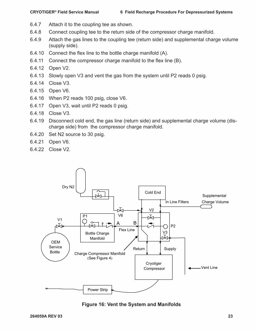
Figure 16: Vent the System and Manifolds
Cold End
OEMServiceBottle
CryotigerCompressor Vent Line
P1
Bottle ChargeManifold
V1
V2
V3P2
Flex Line
Power Strip
Return SupplyCharge Compressor Manifold
(See Figure 4)
V6
Dry N2
In Line FiltersSupplementalCharge Volume
A B
264059A REV 03
CRYOTIGER® Field Service Manual 6 Field Recharge Procedure For Depressurized Systems
24
6.4.23 Switch on the compressor.6.4.24 When P2 reads 300 psig, close V6.6.4.25 Open V2 until the return pressure gauge reads 60 psig.6.4.26 Run the compressor for 15 min.6.4.27 Turn the compressor off.6.4.28 Open V2.6.4.29 Open V3, wait until P2 reads 0 psig.6.4.30 Open V6 and purge the compressor with dry N2 for 3 min.6.4.31 Close V3.6.4.32 Repeat steps 6.4.22 through 6.4.29.6.4.33 Close V3.6.4.34 Disconnect dry N2 source.6.4.35 Reconnect cold end, gas line and supplemental charge volume to the compressor
charge manifold.
6.5 Evacuate the System and the Manifolds (Refer To Figure 17)
6.5.1 Disconnect the vent line from the compressor charge manifold and connect the vacuum pump in its place (C).
6.5.2 Connect the vent line to the vacuum pump exhaust (D).
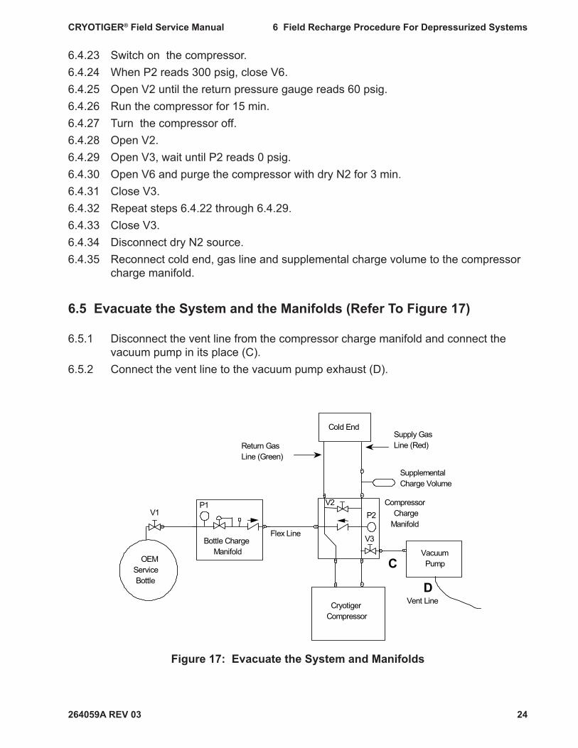
Figure 17: Evacuate the System and Manifolds
OEM Service Bottle
P1
Bottle Charge Manifold
V1
Flex LineV3
P2Compressor
Charge Manifold
V2
Cryotiger Compressor
Cold End
Return Gas Line (Green)
Supply Gas Line (Red)
Supplemental Charge Volume
Vacuum Pump
Vent Line
C
D

264059A REV 03
CRYOTIGER® Field Service Manual 6 Field Recharge Procedure For Depressurized Systems
25
6.5.3 Switch on the vacuum pump.6.5.4 Slowly open V3.6.5.5 Evacuate the system and manifolds for a minimum of 2 hours.6.5.6 Close V3.6.5.7 Switch off the vacuum pump.
6.6 Prime the System with CRYOTIGER® Gas (Refer to Figure 18)
6.6.1 Open V1.6.6.2 Close V2. The system is now ready for recharging.
Figure 18: Prime System with CRYOTIGER® Gas
6.7 Charge the System by Remote Operation of the Compressor.
Supply pressure must remain below 345 psig at all times.
Do not allow the compressor supply pressure to rise above 345 psig.Exceeding the pressures listed in this procedure can cause the fl ammable CRYOTIGER® gas to vent and ignite.
OEMServiceBottle
P1
Bottle ChargeManifold
V1
Flex Line V3
P2Compressor
ChargeManifold
V2
CryotigerCompressor
Cold End
Return GasLine (Green)
Supply GasLine (Red)
SupplementalCharge Volume
Vent Line
264059A REV 03
CRYOTIGER® Field Service Manual 6 Field Recharge Procedure For Depressurized Systems
26
6.7.1 Turn on the compressor using the power strip.6.7.2 When P2 reaches 330 psig, switch off the compressor using the power strip. Do
not allow the compressor supply pressure to rise above 345 psig during charging.6.7.3 Adjust system pressure: • If your system has fl ex lines, refer to Table 3. • If your system has copper lines, refer to Table 4.6.7.4 Compare P2 to the recommended system pressure in Table 3 or Table 4. • If P2 is more than 15 psig below the recommended system pressure, repeat
Step 6.7 to increase system pressure. • If P2 is more than 5 psig above the recommended system pressure, go to Step
6.7.5. • If P2 is within tolerance, go to Step 6.8.6.7.5 Disconnect the vacuum pump.6.7.6 Connect the vent line in its place (as in Figure 18).6.7.7 Open V2.6.7.8 Slowly open V3 and gradually vent gas from the system until P2 reads the recom-
mended system pressure.6.7.9 Repeat steps 6.7.3 - 6.7.8 as necessary to adjust P2 to +5/-15 psig of recommend-
ed system pressure.
6.8 Remove Compressor Charge Manifold from the System (Refer to Figure 19)
6.8.1 Switch off the compressor.6.8.2 Disconnect the supplemental charge volume (supply side) and gas line (return
side) from the compressor charge manifold.
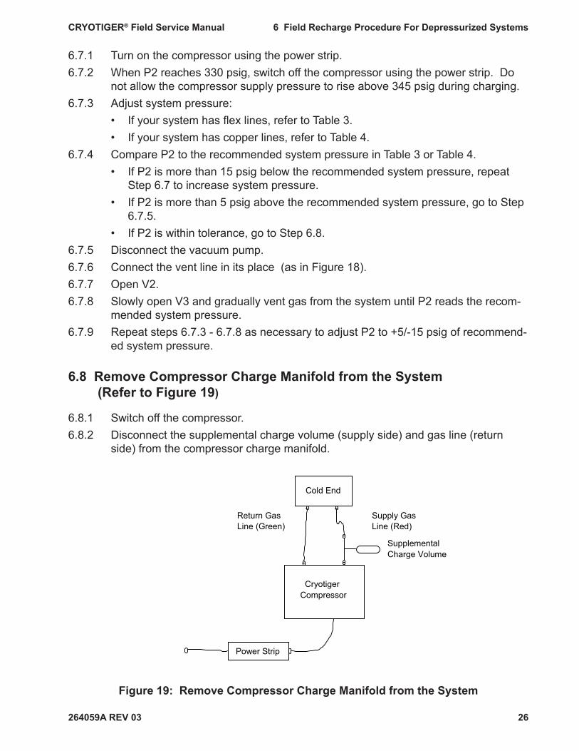
Figure 19: Remove Compressor Charge Manifold from the System
Cold End
Cryotiger Compressor
Power Strip
Supplemental Charge Volume
Supply Gas Line (Red)
Return Gas Line (Green)
264059A REV 03
CRYOTIGER® Field Service Manual 6 Field Recharge Procedure For Depressurized Systems
27
6.8.3 Disconnect the 5 foot fl ex line from the compressor charge manifold. 6.8.4 Disconnect the vacuum pump or vent line from the compressor charge manifold.6.8.5 Disconnect the compressor charge manifold from the compressor. 6.8.6 Maintain the gas charge in the manifold.6.8.7 Connect the supplemental charge volume (supply side) to the compressor.6.8.8 Connect the gas line (return side) to the compressor.6.8.9 Switch on the compressor and allow the system to cool down.
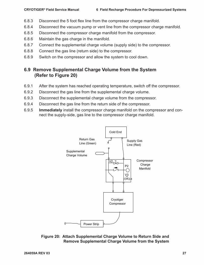
6.9 Remove Supplemental Charge Volume from the System (Refer to Figure 20)
6.9.1 After the system has reached operating temperature, switch off the compressor.6.9.2 Disconnect the gas line from the supplemental charge volume.6.9.3 Disconnect the supplemental charge volume from the compressor.6.9.4 Disconnect the gas line from the return side of the compressor.6.9.5 Immediately install the compressor charge manifold on the compressor and con-
nect the supply-side, gas line to the compressor charge manifold.
Figure 20: Attach Supplemental Charge Volume to Return Side and Remove Supplemental Charge Volume from the System
Compressor Charge
Manifold
Cryotiger Compressor
V2
V3
P2
Power Strip
Cold End
Supply Gas Line (Red)
Supplemental Charge Volume
Return Gas Line (Green)

264059A REV 03
CRYOTIGER® Field Service Manual 6 Field Recharge Procedure For Depressurized Systems
28
When the cold end is below 0° C, disconnecting the gas lines from the compressor without venting the lines for longer than 5 minutes will cause the fl ammable CRYOTIGER® gas to vent from the relief valve.
6.9.6 Attach the supplemental charge volume to the return side of the compressor charge manifold.
6.9.7 Close V2 and then open it one turn.6.9.8 Switch on the compressor. 6.9.9 Adjust V2 so that the pressure gauge on the compressor reads between 10 psig
and 30 psig. 6.9.10 While the compressor is running, disconnect the supplemental charge volume from
the manifold.
6.10 Reconnect the System (Refer To Figure 21)
6.10.1 Switch off the compressor at the power strip.6.10.2 Unplug the power strip from the wall or other supply.6.10.3 Unplug the compressor from the power strip.6.10.4 Turn the compressor switch to the off position.6.10.5 Disconnect the supply-side, gas line from the compressor charge manifold.
When the cold end is below 0° C, disconnecting the gas lines from the compressor without venting the lines for longer than 5 minutes will cause the fl ammable CRYOTIGER® gas to vent from the relief valve.
Figure 21: Reconnect the System
Cold End
Cryotiger Compressor
Cord
Return Gas Line (Green)
Supply Gas Line (Red)

264059A REV 03
CRYOTIGER® Field Service Manual 6 Field Recharge Procedure For Depressurized Systems
29
6.10.6 Disconnect the compressor charge manifold from the compressor.6.10.7 Immediately reconnect the gas lines to the compressor.6.10.8 Plug the compressor into its original power supply. 6.10.9 Switch the compressor on.
The service procedure is complete. The system is now recharged. • If the manifolds will be stored at the customer’s facility until the next use and
not shipped, go to Step 6.11. • If the manifolds will be shipped from the customer’s facility to a service center
or other locations, go to Step 6.12.
6.11 Manifold Storage at Customer’s Facility.
NOTE: If the manifolds will be stored at the customer’s facility and not shipped to other location(s), the manifolds do not need to be evacuated and refi lled with nitrogen.
6.11.1 Close V1.6.11.2 Disconnect the vent line or vacuum pump from the compressor charge manifold.6.11.3 Disconnect the fl ex line from the compressor charge manifold.6.11.4 Disconnect the fl ex line from the bottle charge manifold.6.11.5 Disconnect the bottle charge manifold from the OEM service bottle.6.11.6 Store manifolds and equipment for further use.
The refrigerant gas is fl ammable.
Refrigerant vapors can ignite easily and burn explosively.Store the OEM service bottle and equipment in the same location that you use for storing a propane bottle.
Follow the same safety precautions used for storing propane bottles.
Store the equipment away from heat, fl ame and sparks.Store the equipment in a location with adequate ventilation.
The equipment and OEM service bottle temperature should not exceed 125° F (52° C).
See instructions on the OEM service bottle for further safety and storage information.
264059A REV 03
CRYOTIGER® Field Service Manual 6 Field Recharge Procedure For Depressurized Systems
30
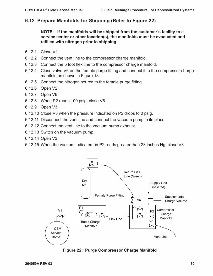
6.12 Prepare Manifolds for Shipping (Refer to Figure 22)
NOTE: If the manifolds will be shipped from the customer’s facility to a service center or other location(s), the manifolds must be evacuated and refi lled with nitrogen prior to shipping.
6.12.1 Close V1.6.12.2 Connect the vent line to the compressor charge manifold.6.12.3 Connect the 5 foot fl ex line to the compressor charge manifold.6.12.4 Close valve V6 on the female purge fi tting and connect it to the compressor charge
manifold as shown in Figure 13.6.12.5 Connect the nitrogen source to the female purge fi tting.6.12.6 Open V2. 6.12.7 Open V6. 6.12.8 When P2 reads 100 psig, close V6.6.12.9 Open V3.6.12.10 Close V3 when the pressure indicated on P2 drops to 0 psig.6.12.11 Disconnect the vent line and connect the vacuum pump in its place.6.12.12 Connect the vent line to the vacuum pump exhaust.6.12.13 Switch on the vacuum pump.6.12.14 Open V3.6.12.15 When the vacuum indicated on P2 reads greater than 28 inches Hg, close V3.
Figure 22: Purge Compressor Charge Manifold
OEM Service Bottle
P1
Bottle Charge Manifold
V1
Flex Line V3
P2 Compressor Charge
Manifold
V2
Dry N2
V6Female Purge Fitting Supplemental
Charge Volume
Supply Gas Line (Red)
Return Gas Line (Green)
Vent Line
264059A REV 03
CRYOTIGER® Field Service Manual 6 Field Recharge Procedure For Depressurized Systems
31
6.12.16 Switch off the vacuum pump. 6.12.17 Set the nitrogen source between 10 and 20 psig.6.12.18 Open V6. 6.12.19 Close V6 when the pressure indicated on P2 reads between 10 and 20 psig.6.12.20 Disconnect the nitrogen source and female purge fi tting. 6.12.21 Disconnect vacuum pump from the compressor charge manifold. 6.12.22 Disconnect the 5 foot fl ex line from the compressor charge manifold. 6.12.23 Disconnect the 5 foot fl ex line from the bottle charge manifold. 6.12.24 Disconnect the bottle charge manifold from the OEM service bottle.
Manifolds are now ready to be packaged and shipped to a service center.

264059A REV 02
CRYOTIGER® Field Service Manual 7 Field Cleanup of CRYOTIGER® System without Compressor Exchange
32
Note: Re-read Safety Information and Warnings, before starting this pro-cedure.
Purpose This procedure guides qualifi ed personnel to perform gas service and recharge of a CRYO-TIGER® System at a customer’s site. These guidelines must be followed in order to avoid gas leaks and to prevent an accidental fi re.
Special Note: The system should be left running before the service engineer arrives to min-imize the on-site service time. You should instruct the system owner to leave the system running before you arrive. If the system is warm, turn it on and allow it to reach minimum temperature before starting this procedure. Do not begin this service procedure until the system reaches the minimum temperature.
Key Parts Key parts for this procedure are identifi ed in Table 2 and Figures 14 and 15. The compres-sor charge manifold is shown in Figure 4, where valve and pressure gauge numbering is shown. Equipment required for this procedure is listed in Table 1.
7.1 Prepare the Area
7.1.1 Eliminate all sources of ignition • Turn off heaters, electric motors, electric tools, and other sources of ignition
during this procedure except the CRYOTIGER® compressor as directed in the procedure.
• Do not smoke. • Extinguish all open and concealed fl ames, pilot lights, and other sources of
heat or sparks. • Do not use in areas where static electric sparks may be generated.7.1.2 Remove all fl ammable liquids stored in the area.
7 FIELD CLEANUP OF CRYOTIGER® SYSTEM WITHOUT COMPRESSOR EXCHANGE

264059A REV 02
CRYOTIGER® Field Service Manual 7 Field Cleanup of CRYOTIGER® System without Compressor Exchange
33
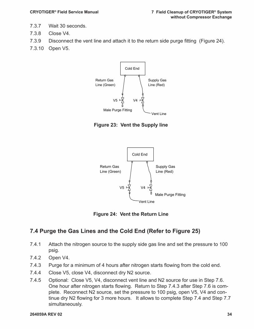
7.3 Vent the Cold End and the Gas Lines (Refer to Figures 23 and 24)
The refrigerant is fl ammable. The vent line must be long enough to safely vent to an outside location free of ignition sources or fl ammable material. Venting gas to interior spaces can result in a fi re.
A vent line is not supplied with this kit. You must supply an appropriate vent line. An example of an appropriate vent line is a 1/4 inch copper vent line with a 1/4 inch Swagelok coupling.
Although a metal vent line is preferred, a polyethylene tube may be used provided the line remains free of plugs, kinks, and reductions. If you do not have a vent line, or you are uncertain if your vent line is appropriate, contact Polycold.
When the cold end is below 0° C, disconnecting the gas lines from the compressor without venting the lines for longer than 5 minutes will cause the cold end gas to vent from the relief valve. Complete Steps 7.3.4 to 7.3.6 in order immediately after completing Step 7.3.3.
7.3.1 Switch off the compressor.7.3.2 Close the valves on both male purge fi ttings.7.3.3 Disconnect both gas lines from the CRYOTIGER compressor.7.3.4 Immediately attach male purge fi ttings to the supply and return gas lines .7.3.5 Immediately attach the vent line to the supply side purge fi tting (Figure 23).7.3.6 Immediately open V4.
7.2 Set Up Remote Compressor Switch (Refer To Figure 5)
7.2.1 Turn off the compressor. Use the compressor’s on/off switch.7.2.2 Unplug the compressor. 7.2.3 Set the switch on the power strip to the off position.7.2.4 Plug in the power strip.7.2.5 Set the compressor’s on/off switch to the on position. 7.2.6 Plug the compressor into the power strip. 7.2.7 Turn the power strip switch on. The compressor should restart.
264059A REV 02
CRYOTIGER® Field Service Manual 7 Field Cleanup of CRYOTIGER® System without Compressor Exchange
34
Figure 23: Vent the Supply line
7.3.7 Wait 30 seconds.7.3.8 Close V4.7.3.9 Disconnect the vent line and attach it to the return side purge fi tting (Figure 24).7.3.10 Open V5.
Figure 24: Vent the Return Line
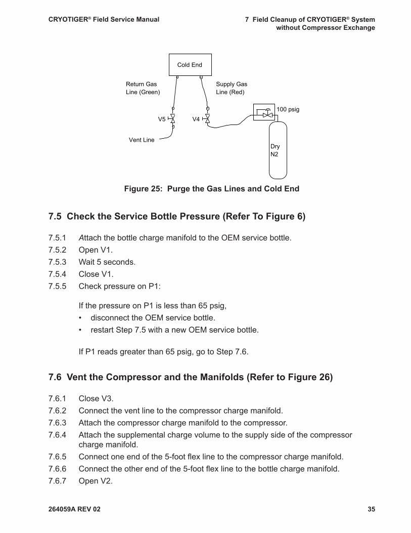
7.4 Purge the Gas Lines and the Cold End (Refer to Figure 25)
7.4.1 Attach the nitrogen source to the supply side gas line and set the pressure to 100 psig.
7.4.2 Open V4.7.4.3 Purge for a minimum of 4 hours after nitrogen starts fl owing from the cold end.7.4.4 Close V5, close V4, disconnect dry N2 source.7.4.5 Optional: Close V5, V4, disconnect vent line and N2 source for use in Step 7.6.
One hour after nitrogen starts fl owing. Return to Step 7.4.3 after Step 7.6 is com-plete. Reconnect N2 source, set the pressure to 100 psig, open V5, V4 and con-tinue dry N2 fl owing for 3 more hours. It allows to complete Step 7.4 and Step 7.7 simultaneously.
Cold End
Male Purge FittingVent Line
Return Gas Line (Green)
Supply Gas Line (Red)
V5 V4
Cold End
V5 V4
Male Purge Fitting
Return Gas Line (Green)
Supply Gas Line (Red)
Vent Line
264059A REV 02
CRYOTIGER® Field Service Manual 7 Field Cleanup of CRYOTIGER® System without Compressor Exchange
35
Figure 25: Purge the Gas Lines and Cold End
7.5 Check the Service Bottle Pressure (Refer To Figure 6)
7.5.1 Attach the bottle charge manifold to the OEM service bottle. 7.5.2 Open V1. 7.5.3 Wait 5 seconds.7.5.4 Close V1.7.5.5 Check pressure on P1:
If the pressure on P1 is less than 65 psig, • disconnect the OEM service bottle. • restart Step 7.5 with a new OEM service bottle.
If P1 reads greater than 65 psig, go to Step 7.6.
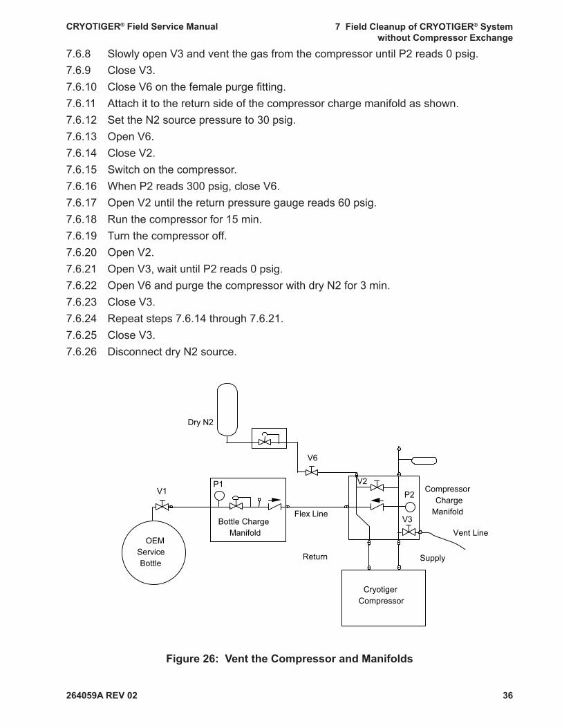
7.6 Vent the Compressor and the Manifolds (Refer to Figure 26)
7.6.1 Close V3.7.6.2 Connect the vent line to the compressor charge manifold.7.6.3 Attach the compressor charge manifold to the compressor.7.6.4 Attach the supplemental charge volume to the supply side of the compressor
charge manifold.7.6.5 Connect one end of the 5-foot fl ex line to the compressor charge manifold.7.6.6 Connect the other end of the 5-foot fl ex line to the bottle charge manifold.7.6.7 Open V2.
Cold End
Vent Line
100 psig
Dry N2
V5 V4
Return Gas Line (Green)
Supply Gas Line (Red)
264059A REV 02
CRYOTIGER® Field Service Manual 7 Field Cleanup of CRYOTIGER® System without Compressor Exchange
36
7.6.8 Slowly open V3 and vent the gas from the compressor until P2 reads 0 psig.7.6.9 Close V3.7.6.10 Close V6 on the female purge fi tting.7.6.11 Attach it to the return side of the compressor charge manifold as shown.7.6.12 Set the N2 source pressure to 30 psig.7.6.13 Open V6.7.6.14 Close V2.7.6.15 Switch on the compressor.7.6.16 When P2 reads 300 psig, close V6.7.6.17 Open V2 until the return pressure gauge reads 60 psig.7.6.18 Run the compressor for 15 min.7.6.19 Turn the compressor off.7.6.20 Open V2.7.6.21 Open V3, wait until P2 reads 0 psig.7.6.22 Open V6 and purge the compressor with dry N2 for 3 min.7.6.23 Close V3.7.6.24 Repeat steps 7.6.14 through 7.6.21.7.6.25 Close V3.7.6.26 Disconnect dry N2 source.
Figure 26: Vent the Compressor and Manifolds
OEM Service Bottle
P1
Bottle Charge Manifold
V1
Flex Line
Vent LineV3
P2Compressor
Charge Manifold
V2
Cryotiger Compressor
Dry N2
Return Supply
V6

264059A REV 02
CRYOTIGER® Field Service Manual 7 Field Cleanup of CRYOTIGER® System without Compressor Exchange
37
7.7 Evacuate the Compressor and the Manifolds (Refer to Figure 27)
7.7.1 Disconnect the vent line from the compressor charge manifold and connect the vacuum pump in its place (A).
7.7.2 Connect the vent line to the vacuum pump exhaust (B).7.7.3 Switch on the vacuum pump.7.7.4 Open V3.7.7.5 Wait 5 minutes.7.7.6 Disconnect the 5-foot fl ex line from the compressor charge manifold.7.7.7 Open V1.7.7.8 Evacuate the compressor, supplemental charge volume, and compressor charge
manifold for a minimum of 2 hours.7.7.9 After waiting 2 hours, close V3.7.7.10 Switch off the vacuum pump.
Figure 27: Evacuate the Compressor and Manifolds
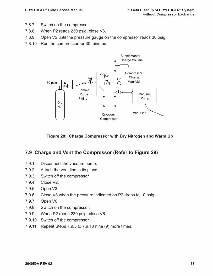
7.8 Charge the Compressor with Dry Nitrogen and Warm Up (Refer to Figure 28)
7.8.1 Close valve V6 on the female purge fi tting.7.8.2 Attach it to the compressor charge manifold as shown.7.8.3 Attach the dry nitrogen source to the female purge fi tting.7.8.4 Set the dry nitrogen pressure to 30 psig.7.8.5 Open V6.7.8.6 Close V2.
OEMServiceBottle
P1
Bottle Charge Manifold
V1
Flex Line V3
P2
CompressorCharge
Manifold
V2
CryotigerCompressor
SupplementalCharge Volume
VacuumPump
Vent Line
A
B
264059A REV 02
CRYOTIGER® Field Service Manual 7 Field Cleanup of CRYOTIGER® System without Compressor Exchange
38
7.8.7 Switch on the compressor.7.8.8 When P2 reads 230 psig, close V6.7.8.9 Open V2 until the pressure gauge on the compressor reads 30 psig.7.8.10 Run the compressor for 30 minutes.
Figure 28: Charge Compressor with Dry Nitrogen and Warm Up
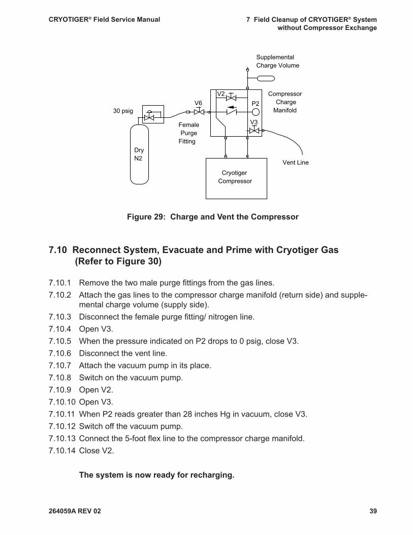
7.9 Charge and Vent the Compressor (Refer to Figure 29)
7.9.1 Disconnect the vacuum pump.7.9.2 Attach the vent line in its place.7.9.3 Switch off the compressor.7.9.4 Close V2.7.9.5 Open V3.7.9.6 Close V3 when the pressure indicated on P2 drops to 10 psig.7.9.7 Open V6.7.9.8 Switch on the compressor.7.9.9 When P2 reads 230 psig, close V6.7.9.10 Switch off the compressor.7.9.11 Repeat Steps 7.9.5 to 7.9.10 nine (9) more times.
V3
P2
CompressorCharge
Manifold
V2
CryotigerCompressor
SupplementalCharge Volume
VacuumPump
Vent Line
30 psig
DryN2
V6
FemalePurge
Fitting
264059A REV 02
CRYOTIGER® Field Service Manual 7 Field Cleanup of CRYOTIGER® System without Compressor Exchange
39
Figure 29: Charge and Vent the Compressor
7.10 Reconnect System, Evacuate and Prime with Cryotiger Gas (Refer to Figure 30)
7.10.1 Remove the two male purge fi ttings from the gas lines.7.10.2 Attach the gas lines to the compressor charge manifold (return side) and supple-
mental charge volume (supply side).7.10.3 Disconnect the female purge fi tting/ nitrogen line.7.10.4 Open V3.7.10.5 When the pressure indicated on P2 drops to 0 psig, close V3.7.10.6 Disconnect the vent line.7.10.7 Attach the vacuum pump in its place.7.10.8 Switch on the vacuum pump.7.10.9 Open V2.7.10.10 Open V3.7.10.11 When P2 reads greater than 28 inches Hg in vacuum, close V3.7.10.12 Switch off the vacuum pump.7.10.13 Connect the 5-foot fl ex line to the compressor charge manifold.7.10.14 Close V2.
The system is now ready for recharging.
V3
P2Compressor
ChargeManifold
V2
CryotigerCompressor
Vent Line
30 psig
DryN2
V6
FemalePurge
Fitting
SupplementalCharge Volume
264059A REV 02
CRYOTIGER® Field Service Manual 7 Field Cleanup of CRYOTIGER® System without Compressor Exchange
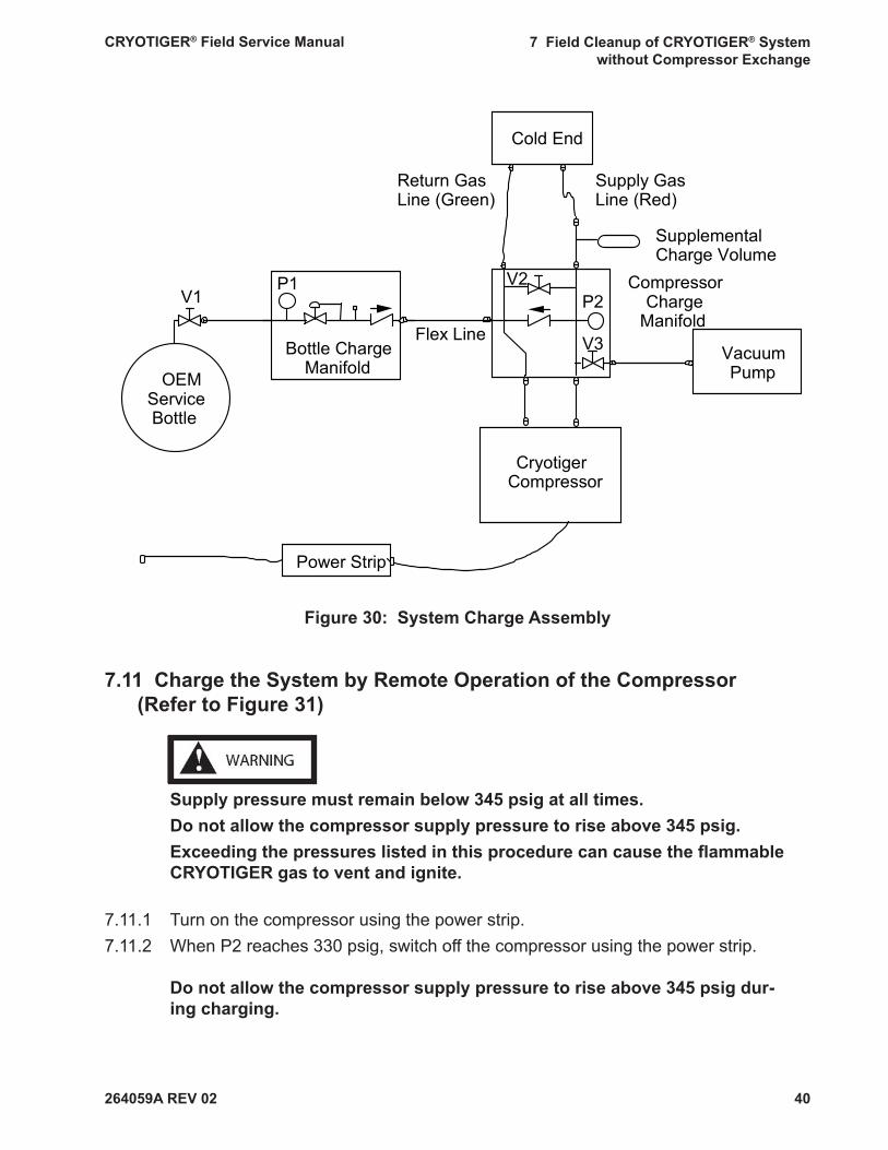
40
Figure 30: System Charge Assembly
7.11 Charge the System by Remote Operation of the Compressor (Refer to Figure 31)
Supply pressure must remain below 345 psig at all times.Do not allow the compressor supply pressure to rise above 345 psig. Exceeding the pressures listed in this procedure can cause the fl ammable CRYOTIGER gas to vent and ignite.
7.11.1 Turn on the compressor using the power strip.7.11.2 When P2 reaches 330 psig, switch off the compressor using the power strip.
Do not allow the compressor supply pressure to rise above 345 psig dur-ing charging.
Cold End
Compressor Charge
Manifold
OEM Service Bottle
Cryotiger Compressor
Power Strip
Vacuum Pump
P1
Bottle Charge Manifold
V1V2
V3
P2
Flex Line
Supplemental Charge Volume
Supply Gas Line (Red)
Return Gas Line (Green)

264059A REV 02
CRYOTIGER® Field Service Manual 7 Field Cleanup of CRYOTIGER® System without Compressor Exchange
41
Figure 31: Adjust System Pressure
7.11.3 Adjust system pressure: • If your system has fl ex lines, refer to Table 3. • If your system has copper lines, refer to Table 4.7.11.4 Compare P2 to the recommended system pressure in Table 3 or Table 4. • If P2 is more than 15 psig below the recommended system pressure, repeat
Step 7.11 to increase system pressure. • If P2 is more than 5 psig above the recommended system pressure, go to Step
7.11.5. • If P2 is within tolerance, go to Step 7.12.7.11.5 Disconnect the vacuum pump.7.11.6 Connect the vent line in its place (as in Figure 31).7.11.7 Open V2.7.11.8 Slowly open V3 and gradually vent gas from the system until P2 reads the recom-
mended system pressure.7.11.9 Repeat steps 7.11.3-7.11.8 as necessary to adjust P2 to +5/-15 psig of recom-
mended system pressure.
Compressor Charge
Manifold
OEM Service Bottle
Cryotiger Compressor
Power Strip
P1
Bottle Charge Manifold
V1V2
V3
P2
Flex Line
Vent Line
Cold End
Supplemental Charge Volume
Supply Gas Line (Red)
Return Gas Line (Green)
264059A REV 02
CRYOTIGER® Field Service Manual 7 Field Cleanup of CRYOTIGER® System without Compressor Exchange
42
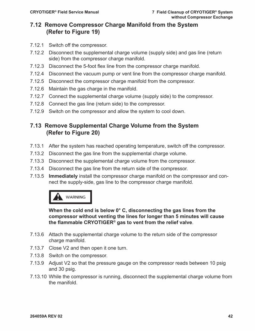
7.12 Remove Compressor Charge Manifold from the System (Refer to Figure 19)
7.12.1 Switch off the compressor.7.12.2 Disconnect the supplemental charge volume (supply side) and gas line (return
side) from the compressor charge manifold.7.12.3 Disconnect the 5-foot fl ex line from the compressor charge manifold.7.12.4 Disconnect the vacuum pump or vent line from the compressor charge manifold.7.12.5 Disconnect the compressor charge manifold from the compressor.7.12.6 Maintain the gas charge in the manifold.7.12.7 Connect the supplemental charge volume (supply side) to the compressor.7.12.8 Connect the gas line (return side) to the compressor.7.12.9 Switch on the compressor and allow the system to cool down.
7.13 Remove Supplemental Charge Volume from the System (Refer to Figure 20)
7.13.1 After the system has reached operating temperature, switch off the compressor.7.13.2 Disconnect the gas line from the supplemental charge volume.7.13.3 Disconnect the supplemental charge volume from the compressor.7.13.4 Disconnect the gas line from the return side of the compressor.7.13.5 Immediately install the compressor charge manifold on the compressor and con-
nect the supply-side, gas line to the compressor charge manifold.
When the cold end is below 0° C, disconnecting the gas lines from the compressor without venting the lines for longer than 5 minutes will cause the fl ammable CRYOTIGER® gas to vent from the relief valve.
7.13.6 Attach the supplemental charge volume to the return side of the compressor charge manifold.
7.13.7 Close V2 and then open it one turn. 7.13.8 Switch on the compressor.7.13.9 Adjust V2 so that the pressure gauge on the compressor reads between 10 psig
and 30 psig.7.13.10 While the compressor is running, disconnect the supplemental charge volume from
the manifold.
264059A REV 02
CRYOTIGER® Field Service Manual 7 Field Cleanup of CRYOTIGER® System without Compressor Exchange
43
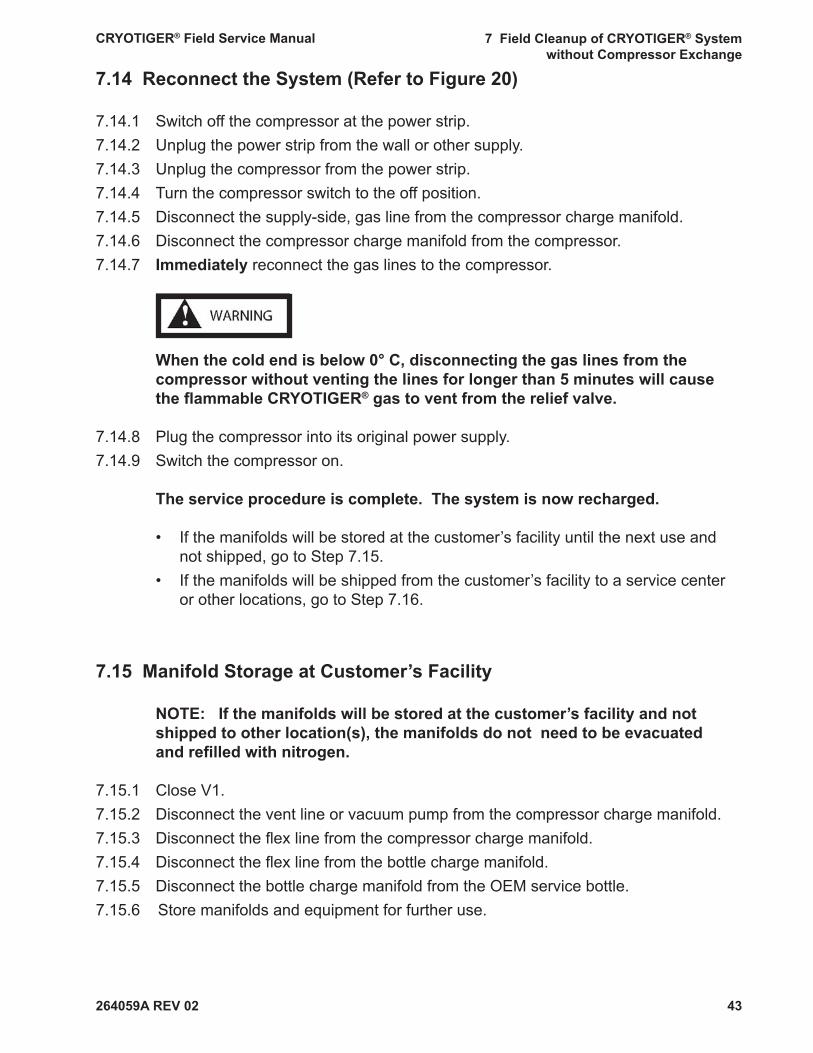
7.14 Reconnect the System (Refer to Figure 20)
7.14.1 Switch off the compressor at the power strip.7.14.2 Unplug the power strip from the wall or other supply.7.14.3 Unplug the compressor from the power strip.7.14.4 Turn the compressor switch to the off position.7.14.5 Disconnect the supply-side, gas line from the compressor charge manifold.7.14.6 Disconnect the compressor charge manifold from the compressor.7.14.7 Immediately reconnect the gas lines to the compressor.
When the cold end is below 0° C, disconnecting the gas lines from the compressor without venting the lines for longer than 5 minutes will cause the fl ammable CRYOTIGER® gas to vent from the relief valve.
7.14.8 Plug the compressor into its original power supply.7.14.9 Switch the compressor on.
The service procedure is complete. The system is now recharged.
• If the manifolds will be stored at the customer’s facility until the next use and not shipped, go to Step 7.15.
• If the manifolds will be shipped from the customer’s facility to a service center or other locations, go to Step 7.16.
7.15 Manifold Storage at Customer’s Facility
NOTE: If the manifolds will be stored at the customer’s facility and not shipped to other location(s), the manifolds do not need to be evacuated and refi lled with nitrogen.
7.15.1 Close V1.7.15.2 Disconnect the vent line or vacuum pump from the compressor charge manifold.7.15.3 Disconnect the fl ex line from the compressor charge manifold.7.15.4 Disconnect the fl ex line from the bottle charge manifold.7.15.5 Disconnect the bottle charge manifold from the OEM service bottle.7.15.6 Store manifolds and equipment for further use.
264059A REV 02
CRYOTIGER® Field Service Manual 7 Field Cleanup of CRYOTIGER® System without Compressor Exchange
44
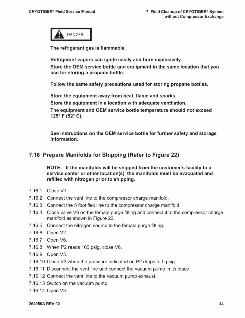
The refrigerant gas is fl ammable.
Refrigerant vapors can ignite easily and burn explosively.Store the OEM service bottle and equipment in the same location that you use for storing a propane bottle.
Follow the same safety precautions used for storing propane bottles.
Store the equipment away from heat, fl ame and sparks.Store the equipment in a location with adequate ventilation.The equipment and OEM service bottle temperature should not exceed 125° F (52° C).
See instructions on the OEM service bottle for further safety and storage information.
7.16 Prepare Manifolds for Shipping (Refer to Figure 22)
NOTE: If the manifolds will be shipped from the customer’s facility to a service center or other location(s), the manifolds must be evacuated and refi lled with nitrogen prior to shipping.
7.16.1 Close V1.7.16.2 Connect the vent line to the compressor charge manifold.7.16.3 Connect the 5 foot fl ex line to the compressor charge manifold.7.16.4 Close valve V6 on the female purge fi tting and connect it to the compressor charge
manifold as shown in Figure 22.7.16.5 Connect the nitrogen source to the female purge fi tting.7.16.6 Open V2. 7.16.7 Open V6.7.16.8 When P2 reads 100 psig, close V6.7.16.9 Open V3.7.16.10 Close V3 when the pressure indicated on P2 drops to 0 psig.7.16.11 Disconnect the vent line and connect the vacuum pump in its place.7.16.12 Connect the vent line to the vacuum pump exhaust.7.16.13 Switch on the vacuum pump.7.16.14 Open V3.
264059A REV 02
CRYOTIGER® Field Service Manual 7 Field Cleanup of CRYOTIGER® System without Compressor Exchange
45
7.16.15 When the vacuum indicated on P2 reads greater than 28 inches Hg, close V3.7.16.16 Switch off the vacuum pump. 7.16.17 Set the nitrogen source between 10 and 20 psig.7.16.18 Open V6. 7.16.19 Close V6 when the pressure indicated on P2 reads between 10 and 20 psig.7.16.20 Disconnect the nitrogen source and female purge fi tting. 7.16.21 Disconnect vacuum pump from the compressor charge manifold. 7.16.22 Disconnect the 5 foot fl ex line from the compressor charge manifold. 7.16.23 Disconnect the 5 foot fl ex line from the bottle charge manifold. 7.16.24 Disconnect the bottle charge manifold from the OEM service bottle.
Manifolds are now ready to be packaged and shipped to a service center.
264059A REV 02
CRYOTIGER® Field Service Manual 8 Field Cleanup of CRYOTIGER® System with Compressor Exchange
46
Note: Re-read Safety Information and Warnings, before starting this pro-cedure.
Purpose This procedure guides qualifi ed personnel to perform gas service and recharge of a CRYO-TIGER® System at a customer’s site. These guidelines must be followed in order to avoid gas leaks and to prevent an accidental fi re.
Special Note: The system should be left running before the service engineer arrives to min-imize the on-site service time. You should instruct the system owner to leave the system running before you arrive. If the system is warm, turn it on and allow it to reach minimum temperature before starting this procedure. Do not begin this service procedure until the system reaches the minimum temperature.
Key Parts
Key parts for this procedure are identifi ed in Table 2 and Figures 2 and 3. The compres-sor charge manifold is shown in Figure 4, where valve and pressure gauge numbering is shown. Equipment required for this procedure is listed in Table 1.
8 Field Cleanup of CRYOTIGER® System with Compressor Exchange
8.1 Prepare the Area
8.1.1 Eliminate all sources of ignition • Turn off heaters, electric motors, electric tools, and other sources of ignition
during this procedure except the CRYOTIGER® compressor as directed in the procedure.
• Do not smoke. • Extinguish all open and concealed fl ames, pilot lights, and other sources of
heat or sparks. • Do not use in areas where static electric sparks may be generated.
264059A REV 02
CRYOTIGER® Field Service Manual 8 Field Cleanup of CRYOTIGER® System with Compressor Exchange
47
8.3 Vent the Cold End and the Gas Lines (Refer to Figures 23 and 24)
The refrigerant is fl ammable. The vent line must be long enough to safely vent to an outside location free of ignition sources or fl ammable material. Venting gas to interior spaces can result in a fi re.
A vent line is not supplied with this kit. You must supply an appropriate vent line. An example of an appropriate vent line is a 1/4 inch copper vent line with a 1/4 inch Swagelok coupling.
Although a metal vent line is preferred, a polyethylene tube may be used provided the line remains free of plugs, kinks, and reductions. If you do not have a vent line, or you are uncertain if your vent line is appropriate, contact Polycold.
When the cold end is below 0° C, disconnecting the gas lines from the compressor without venting the lines for longer than 5 minutes will cause the cold end gas to vent from the relief valve. Complete Steps 8.3.4 to 8.3.6 in order immediately after completing Step 8.3.3.
8.3.1 Switch off the compressor.8.3.2 Close the valves on both male purge fi ttings.8.3.3 Disconnect both gas lines from the CRYOTIGER® compressor.8.3.4 Immediately attach male purge fi ttings to the supply and return gas lines.8.3.5 Immediately attach the vent line to the supply side purge fi tting (Figure 23).
8.2 Set Up Remote Compressor Switch (Refer To Figure 5)
8.2.1 Turn off the compressor. Use the compressor’s on/off switch.8.2.2 Unplug the compressor. 8.2.3 Set the switch on the power strip to the off position8.2.4 Plug in the power strip.8.2.5 Set the compressor’s on/off switch to the on position. 8.2.6 Plug the compressor into the power strip. 8.2.7 Turn the power strip switch on. The compressor should restart.
264059A REV 02
CRYOTIGER® Field Service Manual 8 Field Cleanup of CRYOTIGER® System with Compressor Exchange
48
8.3.6 Immediately open V4.8.3.7 Wait 30 seconds.8.3.8 Close V4.8.3.9 Disconnect the vent line and attach it to the return side purge fi tting (Figure 24).8.3.10 Open V5.
8.4 Purge the Gas Lines and the Cold End (Refer to Figure 25)
8.4.1 Attach the nitrogen source to the supply side gas line and set the pressure to 100 psig.
8.4.2 Open V4.8.4.3 Purge for a minimum of 4 hours after nitrogen starts fl owing from the cold end.
8.5 Check The Service Bottle Pressure (Refer To Figure 6)
8.5.1 Attach the bottle charge manifold to the OEM service bottle. 8.5.2 Open V1. 8.5.3 Wait 5 seconds.8.5.4 Close V1.8.5.5 Check pressure on P1:
If the pressure on P1 is less than 65 psig, • Disconnect the OEM service bottle. • Restart Step 8.5 with a new OEM service bottle.
If P1 reads greater than 65 psig, go to Step 8.6.
8.6 Vent the Cold End, Gas Lines and the Manifolds (Refer to Figure 32)
8.6.1 Close V3.8.6.2 Connect the vent line to the compressor charge manifold.8.6.3 Connect the 5-foot fl ex line between the compressor charge manifold and the
bottle charge manifold.8.6.4 Disconnect the male purge fi ttings from the gas lines.8.6.5 Close V6 on the female purge fi tting.8.6.6 Attach it to the coupling tee as shown.8.6.7 Connect coupling tee to the return side of the compressor charge manifold.8.6.8 Connect the gas line to the supply side and coupling tee to the return side of the
compressor charge manifold.
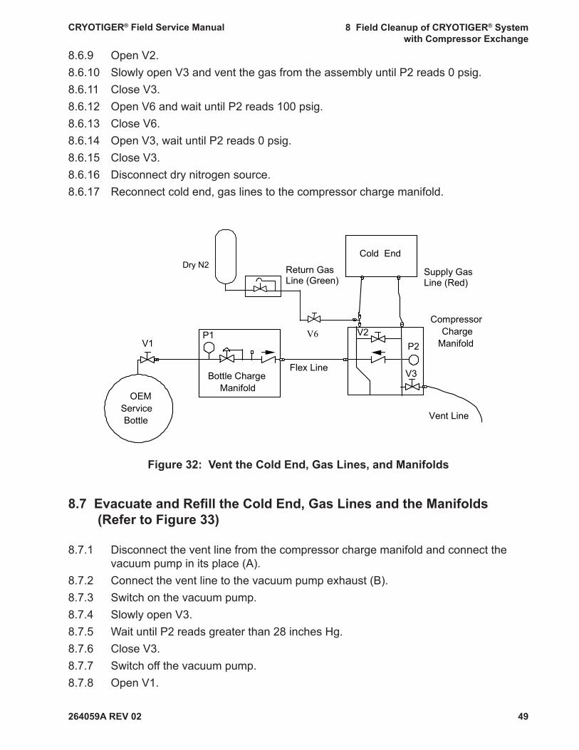
264059A REV 02
CRYOTIGER® Field Service Manual 8 Field Cleanup of CRYOTIGER® System with Compressor Exchange
49
8.6.9 Open V2.8.6.10 Slowly open V3 and vent the gas from the assembly until P2 reads 0 psig.8.6.11 Close V3.8.6.12 Open V6 and wait until P2 reads 100 psig.8.6.13 Close V6.8.6.14 Open V3, wait until P2 reads 0 psig.8.6.15 Close V3. 8.6.16 Disconnect dry nitrogen source.8.6.17 Reconnect cold end, gas lines to the compressor charge manifold.
Figure 32: Vent the Cold End, Gas Lines, and Manifolds
8.7 Evacuate and Refi ll the Cold End, Gas Lines and the Manifolds (Refer to Figure 33)
8.7.1 Disconnect the vent line from the compressor charge manifold and connect the vacuum pump in its place (A).
8.7.2 Connect the vent line to the vacuum pump exhaust (B).8.7.3 Switch on the vacuum pump.8.7.4 Slowly open V3.8.7.5 Wait until P2 reads greater than 28 inches Hg.8.7.6 Close V3.8.7.7 Switch off the vacuum pump.8.7.8 Open V1.
OEM Service Bottle
P1
Bottle Charge Manifold
V1
Flex Line
Vent Line
V3
P2
Compressor Charge
Manifold
Cold End
Supply Gas Line (Red)
Return Gas Line (Green)
V2
Dry N2
V6

264059A REV 02
CRYOTIGER® Field Service Manual 8 Field Cleanup of CRYOTIGER® System with Compressor Exchange
50
Figure 33: Evacuate the Cold End, Gas Lines, and Manifolds
8.8 Reconnect System (Refer to Figure 21)
8.8.1 Disconnect the gas lines from the compressor charge manifold.8.8.2 Attach the compressor charge manifold to the exchange compressor.8.8.3 Re-attach the gas lines to the compressor charge manifold.8.8.4 Close V2.
The system is now ready for recharging.
8.9 Charge the System by Remote Operation of the Compressor (Refer to Figure 31)
Supply pressure must remain below 345 psig at all times.
Do not allow the compressor supply pressure to rise above 345 psig. Exceeding the pressures listed in this procedure can cause the fl ammable CRYOTIGER® gas to vent and ignite.
8.9.1 Turn on the compressor using the power strip.8.9.2 When P2 reaches 330 psig, switch off the compressor using the power strip.
Do not allow the compressor supply pressure to rise above 345 psig dur-ing charging.
Vacuum Pump
Vent Line
OEM Service Bottle
P1
Bottle Charge Manifold
V1
Flex Line V3
P2
Compressor Charge
Manifold
Cold End
V2
Supply Gas Line (Red)
Return Gas Line (Green)
B
A
264059A REV 02
CRYOTIGER® Field Service Manual 8 Field Cleanup of CRYOTIGER® System with Compressor Exchange
51
8.9.3 Adjust system pressure: • If your system has fl ex lines, refer to Table 3. • If your system has copper lines, refer to Table 4.8.9.4 Compare P2 to the recommended system pressure in Table 3 or Table 4. • If P2 is more than 15 psig below the recommended system pressure, repeat
Step 8.9 to increase system pressure. • If P2 is more than 5 psig above the recommended system pressure, go to Step
8.9.5. • If P2 is within tolerance, go to Step 8.10.8.9.5 Disconnect the vacuum pump.8.9.6 Connect the vent line in its place (as in Figure 31).8.9.7 Open V2.8.9.8 Slowly open V3 and gradually vent gas from the system until P2 reads the recom-
mended system pressure.8.9.9 Repeat steps 8.9.3 - 8.9.8 as necessary to adjust P2 to +5/-15 psig of recommend-
ed system pressure.
8.10 Disconnect Charge Equipment and Reconnect the System
8.10.1 Switch off the compressor at the power strip.8.10.2 Disconnect the gas lines from the compressor charge manifold.8.10.3 Disconnect the compressor charge manifold from the compressor.8.10.4 Reconnect the gas lines to the compressor.8.10.5 Read the system pressure indicated by the gauge on the compressor. • If the system pressure is more than 15 psig below the recommended system
pressure in Table 3 or Table 4, repeat Steps 8.8 and 8.9. • If the system pressure is within the recommended pressure, go to Step 8.10.6.8.10.6 Unplug the power strip from the wall or other supply.8.10.7 Turn the compressor switch to the off position.8.10.8 Unplug the compressor from the power strip .8.10.9 Plug in the compressor to the wall or other supply.8.10.10 Turn on the compressor using the compressor switch.
The service procedure is complete. The system is now recharged.
• If the manifolds will be stored at the customer’s facility until the next use and not shipped, go to Step 8.11.
• If the manifolds will be shipped from the customer’s facility to a service center or other locations, go to Step 8.12.
264059A REV 02
CRYOTIGER® Field Service Manual 8 Field Cleanup of CRYOTIGER® System with Compressor Exchange
52
8.11 Manifold Storage at Customer’s Facility
NOTE: If the manifolds will be stored at the customer’s facility and not shipped to other location(s), the manifolds do not need to be evacuated and refi lled with nitrogen.
8.11.1 Close V1.8.11.2 Disconnect the vent line or vacuum pump from the compressor charge manifold.8.11.3 Disconnect the fl ex line from the compressor charge manifold.8.11.4 Disconnect the fl ex line from the bottle charge manifold.8.11.5 Disconnect the bottle charge manifold from the OEM service bottle.8.11.6 Store manifolds and equipment for further use.
The refrigerant gas is fl ammable.Refrigerant vapors can ignite easily and burn explosively.Store the OEM service bottle and equipment in the same location that you use for storing a propane bottle.Follow the same safety precautions used for storing propane bottles.Store the equipment away from heat, fl ame and sparks.Store the equipment in a location with adequate ventilation.The equipment and OEM service bottle temperature should not exceed 125° F (52° C).See instructions on the OEM service bottle for further safety and storage information.
8.12 Prepare Manifolds for Shipping (Refer to Figure 22)
NOTE: If the manifolds will be shipped from the customer’s facility to a service center or other location(s), the manifolds must be evacuated and refi lled with nitrogen prior to shipping.
8.12.1 Close V1.8.12.2 Connect the vent line to the compressor charge manifold.8.12.3 Connect the 5 foot fl ex line to the compressor charge manifold.8.12.4 Close valve V6 on the female purge fi tting and connect it to the compressor charge
manifold as shown in Figure 22.8.12.5 Connect the nitrogen source to the female purge fi tting.8.12.6 Open V2.
264059A REV 02
CRYOTIGER® Field Service Manual 8 Field Cleanup of CRYOTIGER® System with Compressor Exchange
53
8.12.7 Open V6.8.12.8 When P2 reads 100 psig, close V6.8.12.9 Open V3.8.12.10 Close V3 when the pressure indicated on P2 drops to 0 psig.8.12.11 Disconnect the vent line and connect the vacuum pump in its place.8.12.12 Connect the vent line to the vacuum pump exhaust.8.12.13 Switch on the vacuum pump.8.12.14 Open V3.8.12.15 When the vacuum indicated on P2 reads greater than 28 inches Hg, close V3.8.12.16 Switch off the vacuum pump. 8.12.17 Set the nitrogen source between 10 and 20 psig.8.12.18 Open V6. 8.12.19 Close V6 when the pressure indicated on P2 reads between 10 and 20 psig.8.12.20 Disconnect the nitrogen source and female purge fi tting. 8.12.21 Disconnect vacuum pump from the compressor charge manifold. 8.12.22 Disconnect the 5 foot fl ex line from the compressor charge manifold. 8.12.23 Disconnect the 5 foot fl ex line from the bottle charge manifold. 8.12.24 Disconnect the bottle charge manifold from the OEM service bottle.
Manifolds are now ready to be packaged and shipped to a service center.
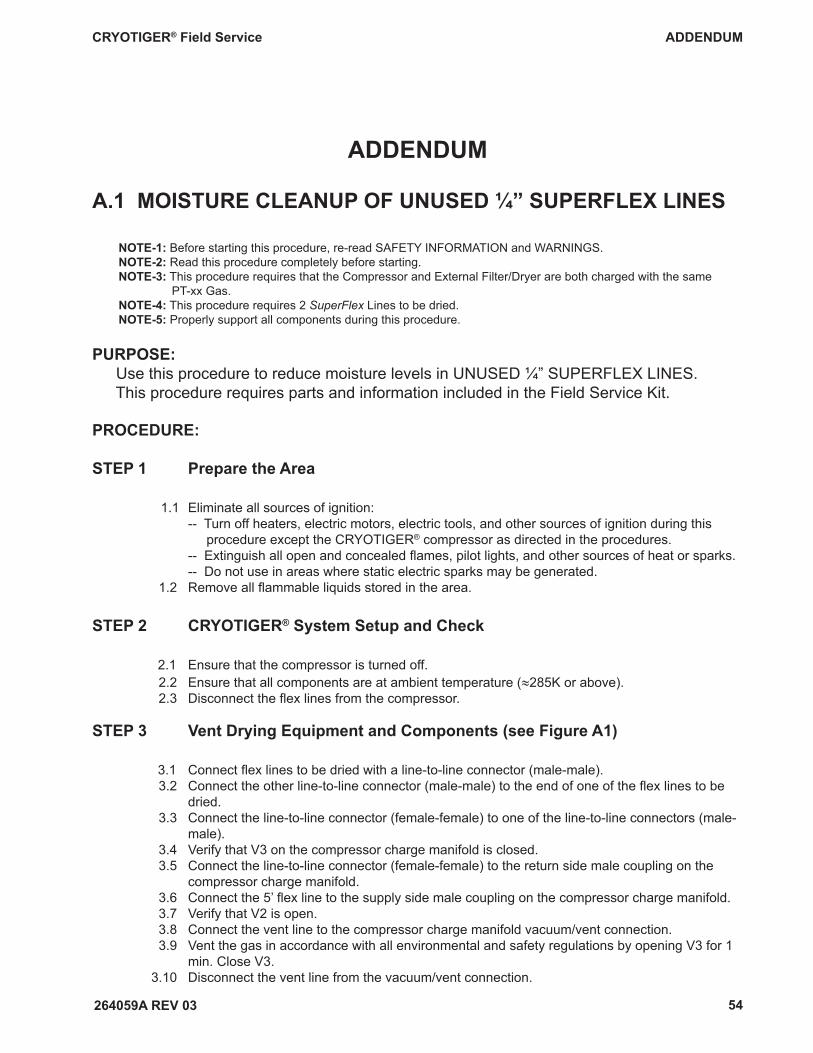
CRYOTIGER® Field Service ADDENDUM
264059A REV 03 54
PURPOSE: Use this procedure to reduce moisture levels in UNUSED ¼” SUPERFLEX LINES. This procedure requires parts and information included in the Field Service Kit.
ADDENDUM
NOTE-1: Before starting this procedure, re-read SAFETY INFORMATION and WARNINGS.NOTE-2: Read this procedure completely before starting.NOTE-3: This procedure requires that the Compressor and External Filter/Dryer are both charged with the same PT-xx Gas.NOTE-4: This procedure requires 2 SuperFlex Lines to be dried.NOTE-5: Properly support all components during this procedure.
PROCEDURE:
STEP 1 Prepare the Area 1.1 Eliminate all sources of ignition: -- Turn off heaters, electric motors, electric tools, and other sources of ignition during this procedure except the CRYOTIGER® compressor as directed in the procedures. -- Extinguish all open and concealed fl ames, pilot lights, and other sources of heat or sparks. -- Do not use in areas where static electric sparks may be generated. 1.2 Remove all fl ammable liquids stored in the area.
STEP 2 CRYOTIGER® System Setup and Check
2.1 Ensure that the compressor is turned off. 2.2 Ensure that all components are at ambient temperature (≈285K or above). 2.3 Disconnect the fl ex lines from the compressor.
STEP 3 Vent Drying Equipment and Components (see Figure A1)
3.1 Connect fl ex lines to be dried with a line-to-line connector (male-male). 3.2 Connect the other line-to-line connector (male-male) to the end of one of the fl ex lines to be dried. 3.3 Connect the line-to-line connector (female-female) to one of the line-to-line connectors (male- male). 3.4 Verify that V3 on the compressor charge manifold is closed. 3.5 Connect the line-to-line connector (female-female) to the return side male coupling on the compressor charge manifold. 3.6 Connect the 5’ fl ex line to the supply side male coupling on the compressor charge manifold. 3.7 Verify that V2 is open. 3.8 Connect the vent line to the compressor charge manifold vacuum/vent connection. 3.9 Vent the gas in accordance with all environmental and safety regulations by opening V3 for 1 min. Close V3. 3.10 Disconnect the vent line from the vacuum/vent connection.
A.1 MOISTURE CLEANUP OF UNUSED ¼” SUPERFLEX LINES
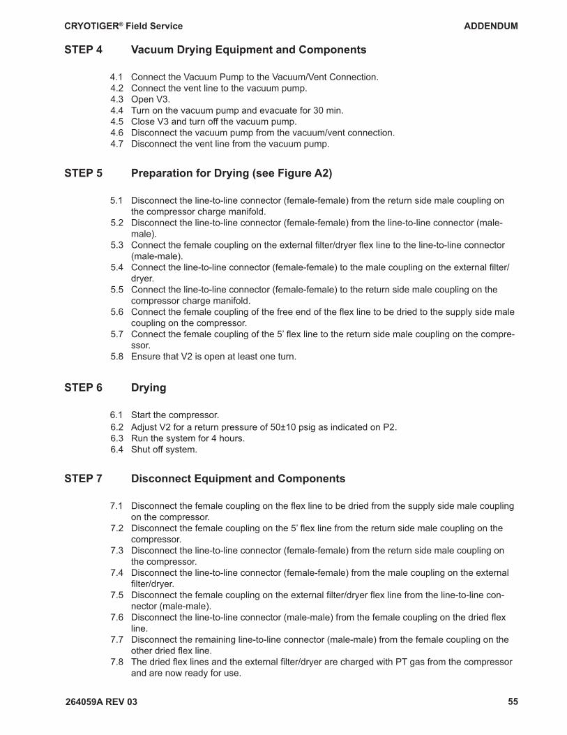
CRYOTIGER® Field Service ADDENDUM
264059A REV 03 55
STEP 4 Vacuum Drying Equipment and Components
4.1 Connect the Vacuum Pump to the Vacuum/Vent Connection. 4.2 Connect the vent line to the vacuum pump. 4.3 Open V3. 4.4 Turn on the vacuum pump and evacuate for 30 min. 4.5 Close V3 and turn off the vacuum pump. 4.6 Disconnect the vacuum pump from the vacuum/vent connection. 4.7 Disconnect the vent line from the vacuum pump.
STEP 5 Preparation for Drying (see Figure A2)
5.1 Disconnect the line-to-line connector (female-female) from the return side male coupling on the compressor charge manifold. 5.2 Disconnect the line-to-line connector (female-female) from the line-to-line connector (male- male). 5.3 Connect the female coupling on the external fi lter/dryer fl ex line to the line-to-line connector (male-male). 5.4 Connect the line-to-line connector (female-female) to the male coupling on the external fi lter/ dryer. 5.5 Connect the line-to-line connector (female-female) to the return side male coupling on the compressor charge manifold. 5.6 Connect the female coupling of the free end of the fl ex line to be dried to the supply side male coupling on the compressor. 5.7 Connect the female coupling of the 5’ fl ex line to the return side male coupling on the compre- ssor. 5.8 Ensure that V2 is open at least one turn.
STEP 6 Drying
6.1 Start the compressor. 6.2 Adjust V2 for a return pressure of 50±10 psig as indicated on P2. 6.3 Run the system for 4 hours. 6.4 Shut off system.
STEP 7 Disconnect Equipment and Components
7.1 Disconnect the female coupling on the fl ex line to be dried from the supply side male coupling on the compressor. 7.2 Disconnect the female coupling on the 5’ fl ex line from the return side male coupling on the compressor. 7.3 Disconnect the line-to-line connector (female-female) from the return side male coupling on the compressor. 7.4 Disconnect the line-to-line connector (female-female) from the male coupling on the external fi lter/dryer. 7.5 Disconnect the female coupling on the external fi lter/dryer fl ex line from the line-to-line con- nector (male-male). 7.6 Disconnect the line-to-line connector (male-male) from the female coupling on the dried fl ex line. 7.7 Disconnect the remaining line-to-line connector (male-male) from the female coupling on the other dried fl ex line. 7.8 The dried fl ex lines and the external fi lter/dryer are charged with PT gas from the compressor and are now ready for use.
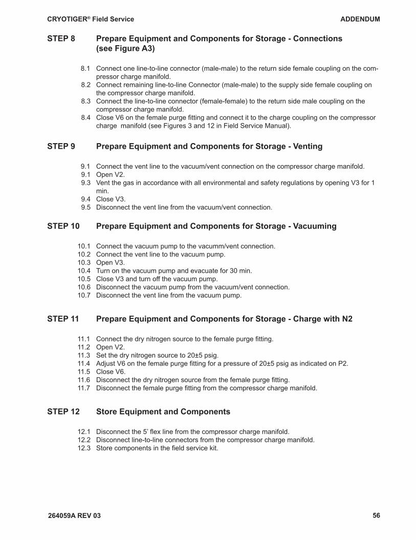
CRYOTIGER® Field Service ADDENDUM
264059A REV 03 56
STEP 8 Prepare Equipment and Components for Storage - Connections (see Figure A3)
8.1 Connect one line-to-line connector (male-male) to the return side female coupling on the com- pressor charge manifold. 8.2 Connect remaining line-to-line Connector (male-male) to the supply side female coupling on the compressor charge manifold. 8.3 Connect the line-to-line connector (female-female) to the return side male coupling on the compressor charge manifold. 8.4 Close V6 on the female purge fi tting and connect it to the charge coupling on the compressor charge manifold (see Figures 3 and 12 in Field Service Manual).
STEP 9 Prepare Equipment and Components for Storage - Venting
9.1 Connect the vent line to the vacuum/vent connection on the compressor charge manifold. 9.1 Open V2. 9.3 Vent the gas in accordance with all environmental and safety regulations by opening V3 for 1 min. 9.4 Close V3. 9.5 Disconnect the vent line from the vacuum/vent connection.
STEP 10 Prepare Equipment and Components for Storage - Vacuuming
10.1 Connect the vacuum pump to the vacumm/vent connection. 10.2 Connect the vent line to the vacuum pump. 10.3 Open V3. 10.4 Turn on the vacuum pump and evacuate for 30 min. 10.5 Close V3 and turn off the vacuum pump. 10.6 Disconnect the vacuum pump from the vacuum/vent connection. 10.7 Disconnect the vent line from the vacuum pump.
STEP 11 Prepare Equipment and Components for Storage - Charge with N2
11.1 Connect the dry nitrogen source to the female purge fi tting. 11.2 Open V2. 11.3 Set the dry nitrogen source to 20±5 psig. 11.4 Adjust V6 on the female purge fi tting for a pressure of 20±5 psig as indicated on P2. 11.5 Close V6. 11.6 Disconnect the dry nitrogen source from the female purge fi tting. 11.7 Disconnect the female purge fi tting from the compressor charge manifold.
STEP 12 Store Equipment and Components
12.1 Disconnect the 5’ fl ex line from the compressor charge manifold. 12.2 Disconnect line-to-line connectors from the compressor charge manifold. 12.3 Store components in the fi eld service kit.
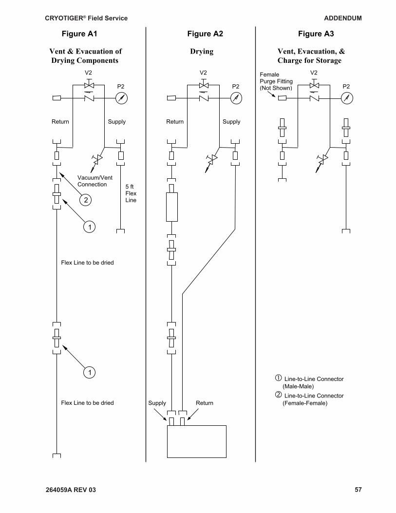
CRYOTIGER® Field Service ADDENDUM
264059A REV 03 57
Figure A1 Figure A2 Figure A3
Vent & Evacuation of Drying Vent, Evacuation, & Drying Components Charge for Storage
P2 P2
V2 Female Purge Fitting (Not Shown)
V2 V2
P2
Vacuum/VentConnection 5 ft
Flex Line
Flex Line to be dried
Flex Line to be dried
� Line-to-Line Connector (Male-Male) � Line-to-Line Connector (Female-Female)
Return Supply
Supply Return
2
1
1
Return Supply